CAD-Based Automated Design of FEA-Ready Cutting Tools

 , and
, and 
<p>Basic geometric parameters of the SNGA120412S01525 (<b>a</b>), the CNGA120408T01020 (<b>b</b>) and the DNGA150404S01020 (<b>c</b>) inserts, along with their common sectioned view (<b>d</b>).</p> "> Figure 2
<p>The micro-geometry of a typical 80° diamond-shaped insert.</p> "> Figure 3
<p>The application’s interface and the corresponding code keys.</p> "> Figure 4
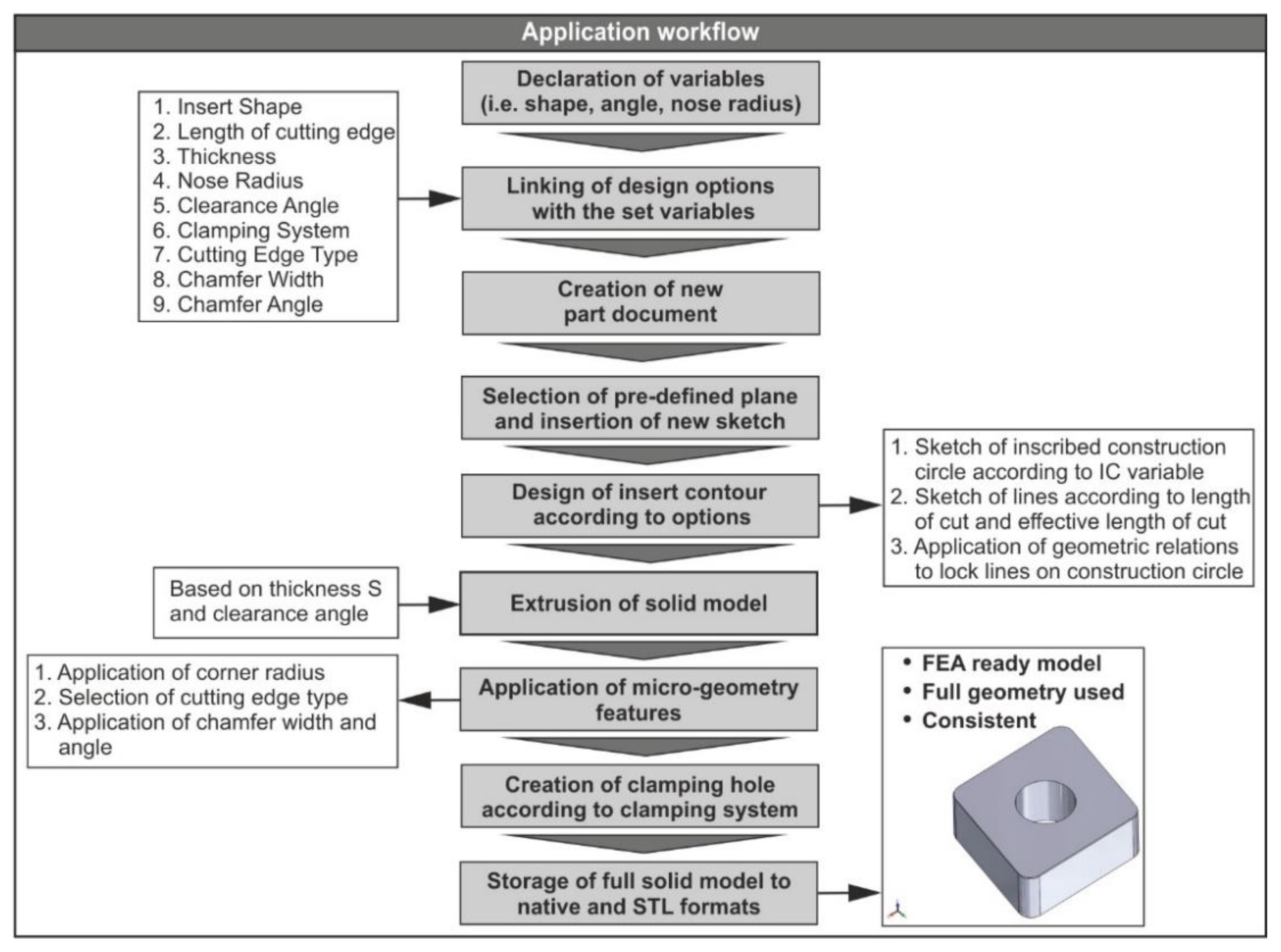
<p>The application’s workflow.</p> "> Figure 5
<p>The design workflow for the CNGA-family inserts: (<b>a</b>) the construction circle, (<b>b</b>) the contour, (<b>c</b>) the extrusion, (<b>d</b>) the corner radius, (<b>e</b>) the micro-geometry and (<b>f</b>) the clamping hole.</p> "> Figure 6
<p>The shape selector algorithm flowchart.</p> "> Figure 7
<p>The test framework including: (<b>a</b>) the Finite Element (FE) model setup, (<b>b</b>) the force diagrams and (<b>c</b>) the results.</p> "> Figure 8
<p>The model setup (<b>a</b>), the analysis domain (<b>b</b>) and the meshed tool (<b>c</b>).</p> "> Figure 9
<p>Simulated versus experimental machining force components: (<b>a</b>) the radial force, (<b>b</b>) the tangential force, (<b>c</b>) the feed force and (<b>d</b>) the resultant machining force.</p> ">
Abstract
:1. Introduction
2. Materials and Methods
2.1. Description of Turning Inserts
2.2. Design of the User Interface
2.3. Modelling Procedure of Turning Cutting Tools
3. Results and Discussion
3.1. Testing of the Generated Cutting Tool Models
3.2. Comparison of the Obtained Results
4. Conclusions
- The generated cutting tool was successfully imported to DEFORM™-3D and meshed with the maximum available number of elements.
- All the performed simulations were successfully completed within a reasonable amount of time.
- The performance of the under study cutting tool model was high, since the yielded results for the machining forces were on par with the experimental ones.
- Finally, the simulated resultant of the machining forces was in high agreement with the experimental one exceeding 90% in most cases.
Author Contributions
Funding
Conflicts of Interest
References
- Wu, Y.; Zhou, Y.; Zhou, Z.; Tang, J.; Ouyang, H. An advanced CAD/CAE integration method for the generative design of face gears. Adv. Eng. Softw. 2018, 126, 90–99. [Google Scholar] [CrossRef]
- Wang, L.; Chen, Z.C. A new CAD/CAM/CAE integration approach to predicting tool deflection of end mills. Int. J. Adv. Manuf. Technol. 2014, 72, 1677–1686. [Google Scholar] [CrossRef]
- Bartłomiej, S. Method of spiral bevel gear tooth contact analysis performed in CAD environment. Aircr. Eng. Aerosp. Technol. 2013, 85, 467–474. [Google Scholar] [CrossRef]
- Garcia-Hernandez, C.; Marín, R.; Talón, J.; Efkolidis, N.; Kyratsis, P. WEDM manufacturing method for noncircular gears using CAD/CAM software. Strojniški Vestn.-J. Mech. Eng. 2016, 62, 137–144. [Google Scholar] [CrossRef] [Green Version]
- Tzivelekis, C.; Yiotis, L.; Fountas, N.A.; Krimpenis, A. Parametrically automated 3D design and manufacturing for spiral-type free-form models in an interactive CAD/CAM environment. Int. J. Interact. Des. Manuf. 2015, 11, 223–232. [Google Scholar] [CrossRef]
- Oancea, G.; Haba, S.-A. Software Tool Used in CAPP/CAM Systems for Rotational Parts. Sci. Bull. Ser. C Fascicle Mech. Tribol. Mach. Manuf. Technol. 2016, 30, 75–78. [Google Scholar]
- Dimitriou, V.; Vidakis, N.; Antoniadis, A. Advanced computer aided design simulation of gear hobbing by means of three-dimensional kinematics modeling. J. Manuf. Sci. Eng. Trans. ASME 2007, 129, 911–918. [Google Scholar] [CrossRef] [Green Version]
- Kyratsis, P.; Bilalis, N.; Antoniadis, A. CAD-based simulations and design of experiments for determining thrust force in drilling operations. Comput. Des. 2011, 43, 1879–1890. [Google Scholar] [CrossRef]
- Ong, S.K.; Nec, A.Y.C. Automating set-up planning in machining operations. J. Mater. Process. Technol. 1997, 63, 151–156. [Google Scholar] [CrossRef]
- Harik, R.F.; Derigent, W.J.E.; Ris, G. Computer aided process planning in aircraft manufacturing. Comput. Aided. Des. Appl. 2008, 5, 953–962. [Google Scholar] [CrossRef]
- Deb, S.; Parra-castillo, J.R.; Ghosh, K. An Integrated and Intelligent Computer-Aided Process Planning Methodology for Machined Rotationally Symmetrical Parts. Int. J. Adv. Manuf. Syst. 2011, 13, 1–26. [Google Scholar]
- Kyratsis, P.; Tzotzis, A.; Tzetzis, D.; Sapidis, N. Pneumatic cylinder design using cad-based programming. Acad. J. Manuf. Eng. 2018, 16, 107–113. [Google Scholar]
- Kyratsis, P.; Tapoglou, N.; Bilalis, N.; Antoniadis, A. Thrust force prediction of twist drill tools using a 3D CAD system application programming interface. Int. J. Mach. Mach. Mater. 2011, 10, 18–33. [Google Scholar] [CrossRef] [Green Version]
- Tzotzis, A.; Garcia-Hernandez, C.; Huertas-Talon, J.-L.; Tzetzis, D.; Kyratsis, P. Engineering applications using CAD based application programming interface. MATEC Web Conf. 2017, 94, 1–7. [Google Scholar] [CrossRef] [Green Version]
- Sapidis, N.; Chatziparasidis, I. Framework to automate mechanical-system design using multiple product-models and assembly feature technology. Int. J. Prod. Lifecycle Manag. 2017, 10, 124–150. [Google Scholar] [CrossRef]
- Du, B.; Wang, X.; Feng, Y.; Yu, D.; Xu, G. Intelligent Assembly Technology Based on Standard Parts Feature of CATIA. Mod. Appl. Sci. 2014, 8, 49–55. [Google Scholar] [CrossRef] [Green Version]
- Roberto, V.; Osorio-Gómez, G. Assembly planning with automated retrieval of assembly sequences from CAD model information. Assem. Autom. 2012, 32, 347–360. [Google Scholar] [CrossRef]
- Vijayaraghavan, A.; Dornfeld, D.A. Automated Drill Modeling for Drilling Process Simulation. J. Comput. Inf. Sci. Eng. 2007, 7, 276–282. [Google Scholar] [CrossRef] [Green Version]
- Li, A.; Zhao, J.; Pei, Z.; Zhu, N. Simulation-based solid carbide end mill design and geometry optimization. Int. J. Adv. Manuf. Technol. 2014, 71, 1889–1900. [Google Scholar] [CrossRef]
- Meyer, R.; Köhler, J.; Denkena, B. Influence of the tool corner radius on the tool wear and process forces during hard turning. Int. J. Adv. Manuf. Technol. 2012, 58, 933–940. [Google Scholar] [CrossRef]
- Karpat, Y.; Ozel, T. Process simulations for 3D turning using uniform and variable microgeometry PCBN tools. Int. J. Mach. Mach. Mater. 2008, 4, 26–38. [Google Scholar] [CrossRef] [Green Version]
- Tzotzis, A.; Garcia-Hernandez, C.; Talón, J.L.H.; Kyratsis, P. Influence of the Nose Radius on the Machining Forces Induced during AISI-4140 Hard Turning: A CAD-Based and 3D FEM Approach. Micromachines 2020, 11, 798. [Google Scholar] [CrossRef]
- Denkena, B.; Lucas, A.; Bassett, E. Effects of the cutting edge microgeometry on tool wear and its thermomechanical load. CIRP Ann.-Manuf. Technol. 2011, 60, 73–76. [Google Scholar] [CrossRef]
- Denkena, B.; Koehler, J.; Rehe, M. Influence of the honed cutting edge on tool wear and surface integrity in slot milling of 42CrMo4 steel. CIRP Ann.-Manuf. Technol. 2012, 1, 190–195. [Google Scholar] [CrossRef] [Green Version]
- Vel, L.; Demazeau, G.; Etourneau, J. Cubic boron nitride: Synthesis, physicochemical properties and applications. Mater. Sci. Eng. B 1991, 10, 149–164. [Google Scholar] [CrossRef]
- Kyratsis, P. Computational design and digital manufacturing. Int. J. Mod. Manuf. Technol. 2020, 12, 82–91. [Google Scholar]
- González-Lluch, C.; Company, P.; Contero, M.; Camba, J.D.; Plumed, R. A survey on 3D CAD model quality assurance and testing tools. CAD Comput. Aided Des. 2017, 83, 64–79. [Google Scholar] [CrossRef] [Green Version]
- Tessier, S.; Wang, Y. Ontology-based feature mapping and verification between CAD systems. Adv. Eng. Inform. 2013, 27, 76–92. [Google Scholar] [CrossRef]
- Dassault Systemes; SOLIDWORKS API Help. Available online: https://help.solidworks.com/2020/English/api/sldworksapiprogguide/Welcome.htm (accessed on 17 July 2020).
- Gaitonde, V.; Karnik, S.; Figueira, L.; Davim, P. Performance comparison of conventional and wiper ceramic inserts in hard turning through artificial neural network modeling. Int. J. Adv. Manuf. Technol. 2011, 52, 101–114. [Google Scholar] [CrossRef]
- Figueira, L.; Davim, P. Machinability evaluation in hard turning of cold work tool steel (D2) with ceramic tools using statistical techniques. Mater. Des. 2007, 28, 1186–1191. [Google Scholar] [CrossRef]
- Aouici, H.; Elbah, M.; Yallese, M.A.; Fnides, B.; Meddour, I.; Benlahmidi, S. Performance comparison of wiper and conventional ceramic inserts in hard turning of AISI 4140 steel: Analysis of machining forces and flank wear. Int. J. Adv. Manuf. Technol. 2016, 87, 2221–2244. [Google Scholar] [CrossRef]
- Tzotzis, A.; Garcia-Hernandez, C.; Talón, J.L.H.; Kyratsis, P. 3D FE Modelling of Machining Forces during AISI 4140 Hard Turning. Strojniški Vestn.-J. Mech. Eng. 2020, 66, 467–478. [Google Scholar] [CrossRef]


| Method | Functionality | Return Value |
|---|---|---|
| ActiveDoc | Connects to the currently active document | Model document |
| NewDocument | Creates a new document using the specified template | Newly created document |
| InsertSketch | Inserts a new sketch in the current part or assembly document | − |
| CreateCircleByRadius2 | Creates a circle based on a center point and a specified radius | Newly created circle |
| CreateConstructionGeometry | Sets selected sketch segments to be construction geometry instead of sketch geometry | − |
| AddDimension2 | Creates a display dimension at the specified location for selected entities | Newly created dimension |
| CreateLine | Creates a sketch line in the currently active 2D or 3D sketch | Sketch segment for the line |
| SketchAddConstraints | Adds the specified constraint to the selected entities | − |
| FeatureExtrusion3 | Creates an extruded feature | IFeature |
| Method | Functionality | Return Value |
|---|---|---|
| GetBodies2 | Gets the bodies in the active part | Array of bodies |
| GetFaces | Gets all the faces on the body | Array of faces on the body |
| GetEdges | Get the edges bounding the selected face | Array of edges |
| SetEntityName | Sets the name of the entity | True/false |
| GetEntityByName | Gets an entity (face, edge, vertex) by name | Entity |
| Select4 | Selects an entity and marks it | True/false |
| FeatureFillet3 | Creates a fillet feature for selected edges and control point references | IFeature |
| InsertFeatureChamfer | Inserts a chamfer | Pointer to the IFeature object |
| FeatureCut4 | Creates a cut extrude feature | Cut extrude feature |
| SaveAs | Saves the active document to the specified name in the specified format | True/false |
| Cutting Conditions | Fr [N] | Ft [N] | Fa [N] | ||||||
|---|---|---|---|---|---|---|---|---|---|
| Std Order | Vc [m/min] | f [mm/rev] | ap [mm] | Exp. | FE Model | Exp. | FE Model | Exp. | FE Model |
| 1 | 80 | 0.08 | 0.30 | 251.0 | 284.2 | 125.1 | 156.8 | 114.1 | 115.7 |
| 2 | 80 | 0.11 | 0.30 | 281.6 | 302.1 | 152.1 | 185.9 | 126.6 | 123.4 |
| 3 | 80 | 0.14 | 0.30 | 319.0 | 339.6 | 200.2 | 205.7 | 144.0 | 125.6 |
| 4 | 115 | 0.08 | 0.30 | 244.3 | 269.4 | 125.3 | 145.5 | 118.4 | 112.1 |
| 5 | 115 | 0.11 | 0.30 | 287.9 | 295.3 | 150.5 | 176.8 | 134.0 | 120.5 |
| 6 | 115 | 0.14 | 0.30 | 297.6 | 324.2 | 179.9 | 202.9 | 133.6 | 120.8 |
| 7 | 150 | 0.08 | 0.30 | 258.4 | 251.7 | 116.1 | 132.7 | 116.6 | 105.9 |
| 8 | 150 | 0.11 | 0.30 | 281.4 | 291.5 | 152.5 | 169.9 | 125.5 | 114.5 |
| 9 | 150 | 0.14 | 0.30 | 323.0 | 337.0 | 176.1 | 199.3 | 140.2 | 113.2 |
Publisher’s Note: MDPI stays neutral with regard to jurisdictional claims in published maps and institutional affiliations. |
© 2020 by the authors. Licensee MDPI, Basel, Switzerland. This article is an open access article distributed under the terms and conditions of the Creative Commons Attribution (CC BY) license (http://creativecommons.org/licenses/by/4.0/).
Share and Cite
Tzotzis, A.; García-Hernández, C.; Huertas-Talón, J.-L.; Kyratsis, P. CAD-Based Automated Design of FEA-Ready Cutting Tools. J. Manuf. Mater. Process. 2020, 4, 104. https://doi.org/10.3390/jmmp4040104
Tzotzis A, García-Hernández C, Huertas-Talón J-L, Kyratsis P. CAD-Based Automated Design of FEA-Ready Cutting Tools. Journal of Manufacturing and Materials Processing. 2020; 4(4):104. https://doi.org/10.3390/jmmp4040104
Chicago/Turabian StyleTzotzis, Anastasios, César García-Hernández, José-Luis Huertas-Talón, and Panagiotis Kyratsis. 2020. "CAD-Based Automated Design of FEA-Ready Cutting Tools" Journal of Manufacturing and Materials Processing 4, no. 4: 104. https://doi.org/10.3390/jmmp4040104