Content from this work may be used under the terms of the CC BY 3.0 licence (© 2018). Any distribution of this work must maintain attribution to the author(s), title of the work, publisher, and DOI.
38th International Free Electron Laser Conference
ISBN: 978-3-95450-179-3
FEL2017, Santa Fe, NM, USA
JACoW Publishing
doi:10.18429/JACoW-FEL2017-TUP066
LUMINOSITY INCREASE IN LASER-COMPTON SCATTERING
BY CRAB CROSSING*
Y. Koshiba†, T. Takahashi, S. Ota, M. Washio, RISE, Waseda University, Tokyo, Japan
K. Sakaue, WIAS, Waseda University, Tokyo, Japan
T. Higashiguchi, Utsunomiya University, Tochigi, Japan
J. Urakawa, KEK, Ibaraki, Japan
Abstract
Laser-Compton scattering X-ray (LCS-X) sources has
been expected as a compact and powerful source, beyond
X-ray tubes. It will enable laboratories and companies,
opening new X-ray science. It is well known that luminosity depends on the collision angle of laser and electron
beam. Head-on collision is ideal in the point of maximizing the luminosity, though difficult to create such system
especially with optical enhancement cavity for laser. In
collider experiments, however, crab crossing is a promising way to increase the luminosity. We are planning to
apply crab crossing to LCS, to achieve a higher luminosity leading to a more intense X-ray source. Electron beam
will be tilted to half of the collision angle using an rfdeflector. Although crab crossing in laser-Compton scattering has been already proposed [1], it has not been
demonstrated yet anywhere. The goal of this study is to
experimentally prove the luminosity increase by adopting
crab crossing. In this conference, we will report about our
compact accelerator system at Waseda University, laser
system favorable for crab crossing LCS, and expected
results of crab crossing LCS.
INTRODUCTION
Laser-Compton scattering (LCS) has been expected as
an attractive X-ray source for years. Brilliance of almost
1010 has been achieved [2], and exceeding 1012 has been
designed [3]. Comparing with magnetic undulators, LCS
could be explained as “laser undulator”, which the undulator period equivalent to laser wavelength (~1 um) while
magnetic undulator is the order of cm. Figure 1 shows the
comparison of undulator radiation and LCS.
Figure 1: Comparison of undulator radiation and LCS.
___________________________________________
* Work supported by Grant-in-Aid for JSPS Research Fellow.
† email address: advanced-yuya@asagi.waseda.jp
In order to produce 1-Å photons, LCS needs to provide
a beam of 25-MeV energy, assuming 6 GeV for undulator
radiation (K = 1, λu = 2 cm) and 4 GeV for synchrotron
radiation (ρ = 12 m). Low required beam energy enable
the whole system compact and low cost so that laboratories and hospitals may take care. The schematic drawing
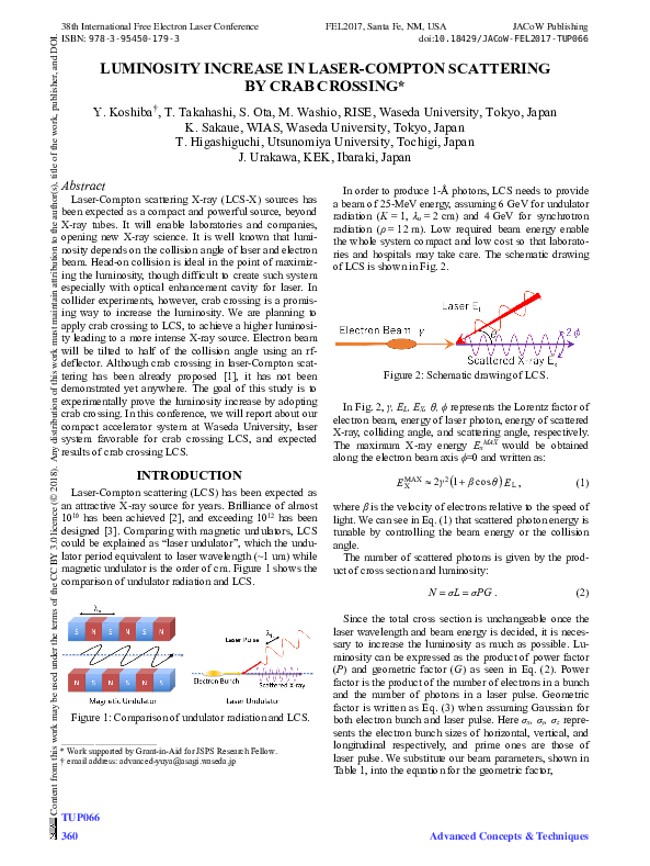
of LCS is shown in Fig. 2.
Figure 2: Schematic drawing of LCS.
In Fig. 2, γ, EL, EX, θ, ϕ represents the Lorentz factor of
electron beam, energy of laser photon, energy of scattered
X-ray, colliding angle, and scattering angle, respectively.
The maximum X-ray energy ExMAX would be obtained
along the electron beam axis ϕ=0 and written as:
2 γ 2 1 β cos θ E L ,
E MAX
X
(1)
where β is the velocity of electrons relative to the speed of
light. We can see in Eq. (1) that scattered photon energy is
tunable by controlling the beam energy or the collision
angle.
The number of scattered photons is given by the product of cross section and luminosity:
N σL σPG .
(2)
Since the total cross section is unchangeable once the
laser wavelength and beam energy is decided, it is necessary to increase the luminosity as much as possible. Luminosity can be expressed as the product of power factor
(P) and geometric factor (G) as seen in Eq. (2). Power
factor is the product of the number of electrons in a bunch
and the number of photons in a laser pulse. Geometric
factor is written as Eq. (3) when assuming Gaussian for
both electron bunch and laser pulse. Here σx, σy, σz represents the electron bunch sizes of horizontal, vertical, and
longitudinal respectively, and prime ones are those of
laser pulse. We substitute our beam parameters, shown in
Table 1, into the equation for the geometric factor,
TUP066
360
Advanced Concepts & Techniques
�G
FEL2017, Santa Fe, NM, USA
JACoW Publishing
doi:10.18429/JACoW-FEL2017-TUP066
1 β cos θ
(3)
2π σ 2y σ '2y σ 2x β cos θ 2 σ ' 2x 1 β cos θ 2 σ 2z σ ' 2z sin 2 θ
Table 1: Parameters of Electron Beam and Laser Pulse
Electron Beam
Laser Pulse
Energy
4.2 MeV
1.2 eV (1030 nm)
Intensity
40 pC
10 mJ
Transverse Size
40 μm
50 μm
Duration
3 ps (rms)
0.43 ps (rms)
CRAB CROSSING LCS
Effect of Crab Crossing
Crab crossing is a proven technique in colliders that allows an angle crossing without luminosity loss. Figure 4
depicts the schematic of crab crossing.
Luminosity is increased by tilting the bunch. In LCS,
since it is a collision of electron bunch and laser, we are
planning to tilt only the electron beam with an rfdeflector. Figure 5 shows the schematic of crab crossing
LCS. Luminosity is maximized when the tilt angle α is
half of collision angle [1]. The enhancement ratio between ordinary crossing and crab crossing would be:
G crab
G non-crab
2x '2x cos2 2 2z '2z sin 2 2 . (4)
2x '2x cos 2 2 '2z sin 2 2
Using those parameters listed in Table 1, the enhancement ratio (crab ratio) in our system is shown in Fig. 6.
Figure 3: Luminosity as a function of collision angle.
For these values, the luminosity depends on collision
angle as depicted in Fig. 3.
We can see that the luminosity is maximum when collision angle is zero, i.e. head-on collision and monotonically decrease as collision angle increase. Despite this fact,
head-on collision is hard to realize especially with an
optical enhancement cavity [4], considering the interference of cavity mirrors and electron beam path. In addition,
scattered X-ray must get across a mirror. This might
cause damages to the mirror. Due to these facts, quite a
few LCS X-ray sources have a certain colliding angle
which causes luminosity loss [5]. One method to overcome this problem is the crab crossing.
Figure 6: Enhancement ratio of crab crossing.
Figure 4: Schematic drawing of crab crossing.
Figure 5: Schematic of crab crossing LCS.
Figure 7: Pulse duration and enhancement ratio.
TUP066
Advanced Concepts & Techniques
361
Content from this work may be used under the terms of the CC BY 3.0 licence (© 2018). Any distribution of this work must maintain attribution to the author(s), title of the work, publisher, and DOI.
38th International Free Electron Laser Conference
ISBN: 978-3-95450-179-3
�Content from this work may be used under the terms of the CC BY 3.0 licence (© 2018). Any distribution of this work must maintain attribution to the author(s), title of the work, publisher, and DOI.
38th International Free Electron Laser Conference
ISBN: 978-3-95450-179-3
We are planning to conduct the proof of principle experiment at 45 degrees and the expected enhancement
ratio is 4.15. By comparing the blue lines, we can say that
the luminosity is compensated by crab crossing.
The effect of pulse duration of colliding laser is shown
in Fig. 7. Short and intense pulse makes crab crossing
more effective. We are developing a laser system based
on Yb fiber oscillator and Yb:YAG thin-disk regenerative
amplifier for crab crossing LCS.
FEL2017, Santa Fe, NM, USA
JACoW Publishing
doi:10.18429/JACoW-FEL2017-TUP066
Figure 9: Experimental Setup for crab crossing LCS.
CAIN Simulation
The expected spectra were calculated by a Monte-Carlo
code, CAIN. Figure 8 shows the calculation of ordinary
45 degrees crossing (blue), 45 degrees crossing with crab
crossing (green), and ideal head-on crossing (red).
EXPERIMENTAL SETUP
The experimental setup for crab crossing LCS is shown
in Fig. 9. A 1.6-cell rf-gun with CsTe photocathode will
generate a 4.2-MeV, 40-pC, 3-ps electron bunch. It will be
focused at the interaction point (I.P.) by a solenoid magnet
to maximize the luminosity. The rf-deflector will give tilt
to the bunch for crab crossing. The bending magnet is
necessary to separate the scattered X-rays from the electron beam. Finally, the MCP (Micro-Channel Plate) will
be used as the X-ray detector. We have already done
background measurement (transporting electron beam
without laser collision) and confirmed it was sufficiently
low. We are now developing a colliding laser system
suitable for crab crossing LCS, based on fiber laser and
thin-disk regenerative amplifier.
CONCLUSION
Figure 8: Calculated spectra by CAIN.
It is clear that the number of photons increase by crab
crossing. We can also see that the maximum energy, i.e.
the Compton edge does not change by crab crossing. The
number of photons is listed in Table 2.
Table 2: Scattered Photons Calculated by CAIN
(θ, α)
Number of Photons
(0, 0)
32900
(45, 0)
5573
(45, 22.5)
24940
We can confirm that the total number of generated photons in crab crossing is more than 4 times larger than that
of ordinary crossing. Furthermore, crab crossing enables
almost 76 % of head-on likeness, while ordinary crossing
is only 17 %.
We are planning to demonstrate the crab crossing LCS
in our compact accelerator system in Waseda University.
Luminosity increase is likely to be more than fourfold
when the colliding angle is 45 deg. Encouraged by such
good prospects, we are now concentrating on constructing
the thin disk regenerative amplifier as a colliding laser,
favorable for the crab crossing LCS.
REFERENCES
[1] A. Variola et al., “Luminosity optimization schemes in
Compton experiments based on Fabry-Perot optical resonators”, Phys. Rev. ST Accel. Beams, vol. 14, p. 031001, 2011.
[2] E. Eggl et al., "The Munich compact light source: initial
performance measures" Journal of synchrotron radiation,
vol. 23, p. 1137-1142, 2016.
[3] W. S. Graves et al., "Compact x-ray source based on burstmode inverse Compton scattering at 100 kHz" Phys. Rev. ST
Accel. Beams, vol. 17, 2014.
[4] K. Sakaue et al., “Laser-compton scattering X-ray source
based on normal conducting linac and optical enhancement
cavity”, in Proc. IPAC’15, Richmond, Virginia, USA, paper
TUPJE011.
[5] T. Akagi et al., “Narrow-band photon beam via laser Compton scattering in an energy recovery linac”, Phys. Rev. ST
Accel. Beams, vol. 19, p. 114701, 2016.
TUP066
362
Advanced Concepts & Techniques
�
 Junji Urakawa