TUPAS031
Proceedings of PAC07, Albuquerque, New Mexico, USA
ANALYSIS OF OPTICS DESIGNS FOR THE LHC IR UPGRADE
Tanaji Sen, John Johnstone, FNAL, Batavia, IL 60510, USA
COMPARISON OF QUAD-FIRST AND
DIPOLE-FIRST
The requirements on the aperture are about the same
in all designs (within 10%) even though the beta functions are about three times larger in the dipole first designs.
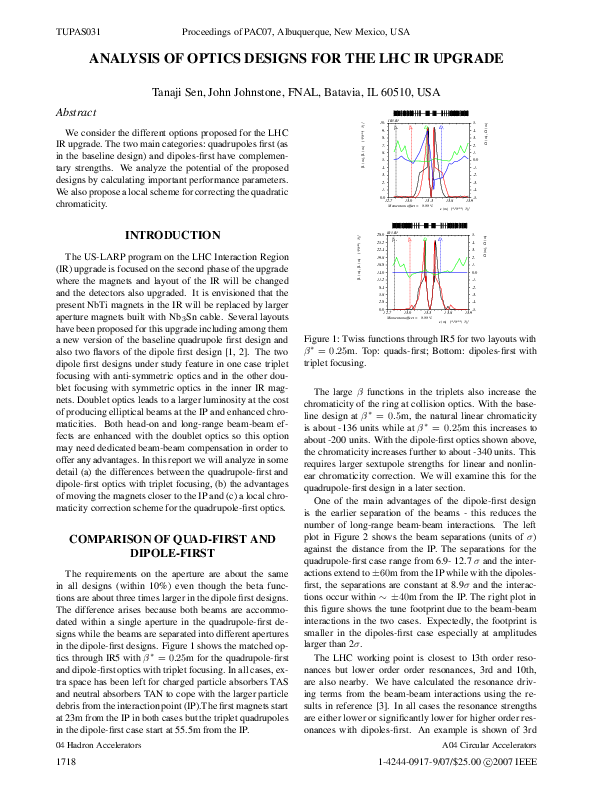
The difference arises because both beams are accommodated within a single aperture in the quadrupole-first designs while the beams are separated into different apertures
in the dipole-first designs. Figure 1 shows the matched optics through IR5 with β ∗ = 0.25m for the quadrupole-first
and dipole-first optics with triplet focusing. In all cases, extra space has been left for charged particle absorbers TAS
and neutral absorbers TAN to cope with the larger particle
debris from the interaction point (IP).The first magnets start
at 23m from the IP in both cases but the triplet quadrupoles
in the dipole-first case start at 55.5m from the IP.
04 Hadron Accelerators
1718
IR5.B1
βx
9.
βy
5.
Dx
Dy
4.
8.
3.
7.
2.
6.
1.
5.
0.0
4.
-1.
3.
-2.
2.
-3.
-4.
0.0
12.7
13.0
13.3
13.6
-5.
13.9
Momentum offset = 0.00 %
28.0
IR5.B1
βx
25.2
βy
5.
Dx
Dy
4.
22.4
3.
19.6
2.
16.8
1.
14.0
0.0
11.2
-1.
8.4
-2.
5.6
-3.
2.8
Dx (m), Dy (m)
s (m) [*10**( 3)]
[*10**( 3)]
The US-LARP program on the LHC Interaction Region
(IR) upgrade is focused on the second phase of the upgrade
where the magnets and layout of the IR will be changed
and the detectors also upgraded. It is envisioned that the
present NbTi magnets in the IR will be replaced by larger
aperture magnets built with Nb 3 Sn cable. Several layouts
have been proposed for this upgrade including among them
a new version of the baseline quadrupole first design and
also two flavors of the dipole first design [1, 2]. The two
dipole first designs under study feature in one case triplet
focusing with anti-symmetric optics and in the other doublet focusing with symmetric optics in the inner IR magnets. Doublet optics leads to a larger luminosity at the cost
of producing elliptical beams at the IP and enhanced chromaticities. Both head-on and long-range beam-beam effects are enhanced with the doublet optics so this option
may need dedicated beam-beam compensation in order to
offer any advantages. In this report we will analyze in some
detail (a) the differences between the quadrupole-first and
dipole-first optics with triplet focusing, (b) the advantages
of moving the magnets closer to the IP and (c) a local chromaticity correction scheme for the quadrupole-first optics.
10.
1.
βx (m), βy (m)
INTRODUCTION
βx (m), βy (m)
We consider the different options proposed for the LHC
IR upgrade. The two main categories: quadrupoles first (as
in the baseline design) and dipoles-first have complementary strengths. We analyze the potential of the proposed
designs by calculating important performance parameters.
We also propose a local scheme for correcting the quadratic
chromaticity.
Dx (m), Dy (m)
[*10**( 3)]
Abstract
-4.
0.0
12.7
13.0
13.3
13.6
-5.
13.9
Momentum offset = 0.00 %
s (m) [*10**( 3)]
Figure 1: Twiss functions through IR5 for two layouts with
β ∗ = 0.25m. Top: quads-first; Bottom: dipoles-first with
triplet focusing.
The large β functions in the triplets also increase the
chromaticity of the ring at collision optics. With the baseline design at β ∗ = 0.5m, the natural linear chromaticity
is about -136 units while at β ∗ = 0.25m this increases to
about -200 units. With the dipole-first optics shown above,
the chromaticity increases further to about -340 units. This
requires larger sextupole strengths for linear and nonlinear chromaticity correction. We will examine this for the
quadrupole-first design in a later section.
One of the main advantages of the dipole-first design
is the earlier separation of the beams - this reduces the
number of long-range beam-beam interactions. The left
plot in Figure 2 shows the beam separations (units of σ)
against the distance from the IP. The separations for the
quadrupole-first case range from 6.9- 12.7 σ and the interactions extend to ±60m from the IP while with the dipolesfirst, the separations are constant at 8.9σ and the interactions occur within ∼ ±40m from the IP. The right plot in
this figure shows the tune footprint due to the beam-beam
interactions in the two cases. Expectedly, the footprint is
smaller in the dipoles-first case especially at amplitudes
larger than 2σ.
The LHC working point is closest to 13th order resonances but lower order order resonances, 3rd and 10th,
are also nearby. We have calculated the resonance driving terms from the beam-beam interactions using the results in reference [3]. In all cases the resonance strengths
are either lower or significantly lower for higher order resonances with dipoles-first. An example is shown of 3rd
A04 Circular Accelerators
1-4244-0917-9/07/$25.00 c 2007 IEEE
�Proceedings of PAC07, Albuquerque, New Mexico, USA
Upgrade: Quads-first and Dipoles-irst
Quads-first
Dipoles-first
10
4
2
0
-40
-20
0
20
Distance from IP5
40
60
Figure 2: Left: Beam separation at the long-range interactions for the two layouts. Right: Tune footprints up to 6σ
from beam-beam interactions in the two cases.
order resonance terms in the left plot of Figure 3. The right
plot in this figure shows the results of diffusion coefficients
from tracking with the code BBSIM. There is a jump in the
diffusion at 7σ with quads-first, but with dipoles-first the
jump occurs at the larger amplitude of 8σ. Table 1 summarizes the main parameters of the two layouts.
Max Diffusion Coefficients Dy vs total Ar
3rd order Resonance Driving Terms
1e-11
Quads-first
Dipoles-first
1e-12
1e-13
1e-14
0.0001
Amplitude 6 σ
mQx + (3-m)Qy = p
Quads-first
Dipoles-first
1e-05
0
1
2
3
Dy
Magnitude of RDT in x
0.001
1e-15
1e-16
1e-17
1e-18
1e-19
2
3
4
5
m
6
7
8
9
10
Ar
Figure 3: Left: Comparison of 3rd order resonance driving terms; Right: Comparison of a diffusion coefficient vs
amplitude for the two layouts
Table 1: Summary of main parameters for the two IR layouts. Abbreviations: RDT - beam-beam resonance driving
term, ED: energy deposition in triplet
β max [m]
Max aperture [mm]
Max pole tip field [T]
Q′ of ring
Max 3rd order RDT
Max 10th order RDT
Beam-beam diffusion
Max ED [mW/g]
Quads
first
9484
101
10.1
-200, -194
0.9×10 −3
0.16×10 −3
Jump at 7σ
-1.0
Dipoles
first
26092
107
10.7
-333, -340
0.5×10⁻³
0.3×10⁻⁵
Jump at 8σ
0.6
DEPENDENCE ON L*
It is possible that the IR magnets can be moved closer to
the IP in the second phase of the IR upgrade. This would
have the benefit of lowering β ∗ for the same β max and increasing the luminosity reach. We have examined the relative increase for the two layouts as a function of L*; the
distance to the first magnet from the IP. For this study the
optics was matched to reasonable values at Q4, the first of
the outer quadrupoles, as the inner triplet focusing strength
increases with lower L*. The luminosity depends directly
on β ∗ through the spot size at the IP but also indirectly on
β ∗ via the crossing angle. In order to keep the beam sepa04 Hadron Accelerators
1-4244-0917-9/07/$25.00 c 2007 IEEE
Scaling for Crossing Angle and Beam-beam interactions
1.12
Quads first
Dipoles first
1.1
1.08
No Scaling for Crossing Angle
Luminosity gain
-60
1.06
1.04
1.02
1
0.98
13
14
15
16
17
18 19
L* [m]
20
21
22
1.45
1.4
1.35
1.3
1.25
1.2
1.15
1.1
1.05
1
23
Quads first
Dipoles first
13
14
15
16
17
18 19
L* [m]
20
21
22
23
Figure 4: Left: Relative luminosity
gain with lower L* if
�
the crossing angle scales as NLR /β ∗ for the two layouts. Right: The same but in the case that the crossing
angle stays constant, for example due to beam-beam compensation.
The two plots in Figure 5 show the change in chromaticity of the insertion as L* is changed in the two layouts. Figure 6 shows the geometric aberrations due to a multipole
error b3 in each of the IR quadrupoles for the two layouts.
With quadrupoles-first, the aberrations are nearly constant
as L* is reduced below 17m. On the other hand with the
dipoles-first layout, the aberrations are significantly larger
and also keep increasing as L* is reduced. This also shows
that the dipoles-first layout will be more sensitive to alignment errors.
Quadrupoles First
-46
Dipoles First
Horizontal
Vertical
-46.5
Chromaticity of Inner Triplet
6
∗
ration constant when
√ β∗ decreases, the crossing angle must
be increased as 1/ β . This reduces the luminosity gain.
If L* is decreased by more than half the bunch spacing,
then the number of long-range interactions also decreases.
An empirical scaling relation derived in reference [4] suggests that√the crossing angle needs to scale with this number
NLR as NLR . It is possible that if some form of longrange beam-beam compensation such as wire compensation were shown to be effective, then the crossing angle
would not have to be increased with decreasing β ∗ . This
would allow the full increase in luminosity to be attained.
The left plot in Figure 4 shows the increase in luminosity
if
�
the crossing angle does indeed have to scale as NLR /β ∗ ,
i.e. without any compensation, for the two layouts. The
right plot shows the luminosity gain if the crossing angle
stays constant. Long-range compensation together with the
quads-first layout could potentially allow a 40% increase in
luminosity if L* is reduced to 13m from the present 23m.
Without an effective compensation scheme, the gains in luminosity are low but instead lower values of L* may still
be useful for gaining operational margin. Instead of lowering β ∗ , β max could be lowered while keeping β ∗ constant
thereby increasing the available aperture in the quadrupoles
and lowering the chromaticity.
Luminosity gain
8
Upgrade: Quads-first and Dipoles-irst
0.002
Quads-first
0.001
Dipoles-first
0
-0.001
-0.002
-0.003
-0.004
-0.005
-0.006
-0.007
-0.007
-0.006
-0.005
-0.004
-0.003
-0.002
-0.001 0 0.001
0.002
Δ Qx
Chromaticity of Inner Triplet
12
Δ Qy
Beam separation [σ]
14
TUPAS031
-47
-47.5
-48
-48.5
-49
-49.5
-50
13
14 15 16 17 18 19 20 21 22
L*: Free space from IP to 1st magnet [m]
23
-80
-82
-84
-86
-88
-90
-92
-94
-96
-98
-100
Horizontal
Vertical
13
14 15 16 17 18 19 20 21 22
L*: Free space from IP to 1st magnet [m]
23
Figure 5: Left: Chromaticity of an insertion with quadsfirst vs L*, Right: The same but for dipole-first.
A04 Circular Accelerators
1719
�TUPAS031
Proceedings of PAC07, Albuquerque, New Mexico, USA
strengths to the SF1 and SF2 sextupoles, respectively, Q ′
is guaranteed not to change to first order, but provides the
flexibility to cancel Q ′′ as well. (Similarly for SD1 and
SD2). The final sextupole fields are given in Table 2. The
maximum available sextupole strength is 4500 T/m 2 .
Geometric Aberrations from b3
Aberration in x [Arb. Units]
100
Quads-first
Dipoles-first
10
Table 2: Sextupole strengths for correcting Q ′ and Q′′
SF1/SF2 [T/m2 ]
2136/1955
1
13
14
15
16
17
18
19
20
21
22
23
L*: Free space from IP to 1st magnet [m]
22 cells
22 cells
4
Q’=0
Q’=0, Q’’=0
3
Q’=0
Q’=0, Q’’=0
3
µy(Δp/p)-µy(0) [x 10-4]
2.5
2
1.5
1
0.5
0
-0.5
-1
2
1
0
-1
-1.5
-2
-2
-4
-3
-2
-1
0
1
2
3
4
-4
-3
-2
-1
Δp/p [x 10-4]
0
1
2
3
4
Δp/p [x 10-4]
Figure 8: Tune variation (left: horizontal, right: vertical)
with only linear chromatic correction and with both linear
and quadratic chromatic correction.
2.5
2.5
Q’=0
Q’=0, Q’’=0
Q’=0
Q’=0, Q’’=0
2
Δβy(Δp/p)/βy(0) [%]
2
1.5
1
0.5
1.5
1
0.5
0
0
-0.5
-0.5
-4
-3
-2
-1
0
1
2
3
4
-4
-3
-2
-4
-1
0
1
2
3
4
-4
Δp/p [x 10 ]
Δp/p [x 10 ]
Figure 9: Relative variation in β ∗ (left: horizontal, right:
vertical) with only linear chromatic correction and with
both linear and quadratic chromatic correction.
Δµ=7π
x 2
Δµ=3π
x
Δµ=3π
x
Δµ=5π
x
2
SF1
SF2
3.5
-4
The correction schemes for the chromaticity and geometric aberrations due to the IR quadrupoles will need to
be revisited for the upgrade. We consider here an alternative method for correcting the quadratic chromaticity in the
quadrupoles-first layout. The presently envisioned compensating method is via a global scheme using 4 x 8 = 32
sextupole families per beam [5]. The alternative local correction scheme discussed here is based on one proposed in
Reference [6] to correct both Q ′ and Q′′ with a set of 4 sextupole families per beam. Localized correction has the advantage that the IR’s can be operated independently and the
global chromaticity and tunes fixed by other constraints.
The local scheme requires using the arc sextupoles in
the 22 cells in each sector bracketing the IR’s. With the
phase advance in the arc cells close to 90 ◦ in both planes,
the fractional tunes across the entire IR plus 44 cell section
are tuned to (.75, .75), which helps to reduce the first order
chromatic β-waves . The distribution of sextupoles is illustrated in Figure 7. The SF1 and SD1 families are situated
(2n + 1)π/2 in phase from the IP. The SF2 and SD2 are
interleaved with members of the first families and spaced
mπ in phase from the IP.
µx(Δp/p)-µx(0) [x 10 ]
NONLINEAR CHROMATICITY
CORRECTION
Figure 8 shows the tune variation with momentum across
the 2 sectors plus IR for Q ′ = 0, and also both Q ′ and
Q′′ = 0. (∆p/p = ±3.33 × 10⁻⁴ is the full bucket size).
Correction of the second order terms significantly flattens
the tune variation. The residual curvature is due to third
order terms. Figure 9 shows that after cancelling Q ′ and
Q′′ , ∆β ∗ /β ∗ changes are on the level of 1% across the
momentum range.
Δβx(Δp/p)/βx(0) [%]
Figure 6: The geometric aberrations of insertions due to the
b3 multipole in the triplet quads for the two layouts. b 3 is
assumed to be constant.
SD1/SD2 [T/m2 ]
-4392/-3984
REFERENCES
SF2
SF1
[1] Proceedings of the Lumi 05 workshop, Arcidosso, 2005
SD2
SD1
Δµ=7π
y
2
IP
Δµ=3π
y
SD1
Δµ=5π
y 2
SD2
[2] Proceedings of the Lumi 06 workshop, Valencia, 2006
[3] T. Sen et al, Phys. Rev. ST AB, Vol 7, 041001 (2004)
Δµ=3π
y
Figure 7: Schematic layout of the sextupoles for 2nd order
chromaticity correction with the quadrupole-first IR optics.
[4] Y. Papaphilippou and F. Zimmermann, Phys. Rev. ST AB Vol
5, 074001 (2002)
[5] S. Fartoukh, LHC-project-report-308, October (1999)
[6] T. Sen et al, Proceedings of PAC 1993, p 143 (1993)
Correction of the second order chromaticity Q ′′ requires
all 4 sextupole families. By adding and subtracting equal
04 Hadron Accelerators
1720
A04 Circular Accelerators
1-4244-0917-9/07/$25.00 c 2007 IEEE
�
 Tanaji Sen