PHYSICAL REVIEW B 85, 085440 (2012)
Effect of surface stress on the stiffness of thin elastic plates and beams
Michael J. Lachut and John E. Sader*
Department of Mathematics and Statistics, The University of Melbourne, Victoria 3010, Australia
(Received 7 September 2011; revised manuscript received 23 January 2012; published 28 February 2012)
Nanomechanical doubly-clamped beams and cantilever plates are often used to sense a host of environmental
effects, including biomolecular interations, mass measurements, and responses to chemical stimuli. Understanding the effects of surface stress on the stiffness of such nanoscale devices is essential for rigorous analysis
of experimental data. Recently, we explored the effects of surface stress on cantilever plates and presented
a theoretical framework valid for thin plate structures. Here, we generalize this framework and apply it to
cantilever plates and doubly-clamped beams, exploring in detail the relative physical mechanisms causing a
stiffness change in each case. Specifically, Poisson’s ratio is found to exert a dramatically different effect in
cantilevers than in doubly-clamped beams, and here we explain why. The relative change in effective spring
constant is also examined, and its connection to the relative frequency shift is discussed. Interestingly, this differs
from what is naively expected from elementary mechanics. Finally, a discussion of the practical implications of
our theoretical findings is presented, which includes an assessment of available experimental results and potential
future measurements on nanoscale devices.
DOI: 10.1103/PhysRevB.85.085440
PACS number(s): 68.37.Ps, 85.85.+j
I. INTRODUCTION
Mechanical devices such as microcantilever beams have
emerged as a standard platform for a host of applications,
including ultrasensitive mass measurements, biomolecular
sensing, and detection of chemical analytes,1–23 and has
driven recent developments in nanoelectromechanical systems
(NEMS).5–24 Reduction in size, however, also enhances the
influence of surface effects, which must be considered when
interpreting measurements. In particular, knowledge of the
effects of surface stress on device stiffness is essential for
accurate mass measurements and has motivated a plethora of
experimental and theoretical studies.5–34 Surface stress can be
routinely measured using the plate bending technique, which
has been investigated theoretically in several studies.35–38
One approach to modeling the effects of surface stress on
the stiffness of microcantilever beams, uses the so-called axial
force model.18–21,30–32 First proposed by Lagowski et al.,21 this
model assumes that application of strain-independent surface
stress is equivalent to an axial force along its longitudinal
axis. However, this model was subsequently shown to be
unphysical by Gurtin et al.,25 who concluded that within
the framework of classical beam theory, strain-independent
surface stress has no effect on cantilever beam stiffness. Even
so, numerous reports have since used this unphysical axial
force model and coincidentally show good agreement with
measurements.20,21,32
Surface elasticity was also investigated by Gurtin et al.,25
who proposed a general constitutive equation for surface
stress.39 Gurtin et al. showed that cantilever stiffness can indeed be affected by surface elasticity, but this effect is too small
to explain the experimental results of Ref. 21. Subsequent
theoretical investigations have also included surface elasticity,
with similar conclusions.26,29,30,33,34
In a previous study,27 we examined the effect of surface stress on a cantilever plate of arbitrary aspect ratio
(length/width). Solution using a rigorous three-dimensional
analysis revealed that strain-independent surface stress does
indeed affect the stiffness of cantilever plates of finite aspect
1098-0121/2012/85(8)/085440(11)
ratio. Importantly, this effect vanishes as the plate aspect
ratio tends to infinity – consistent with Gurtin et al.25 who
implicitly considered this formal limit. Even so, the predicted
effect is orders of magnitude smaller than experimental
observations.15,16,19–21,32 Experimental observations claiming
that strain-independent surface stress affects the stiffness of
cantilever beams thus remain unaccounted for theoretically.
The situation for doubly-clamped beams differs significantly. First, we note that the effect of in-plane stress, due
to piezoelectric loading, on the stiffness of doubly-clamped
beams has been studied rigorously.40 This theoretical and
experimental investigation established that the underlying
mechanism is indeed due to an axial load along the axis of the
doubly-clamped beam. However, the effect of surface stress on
doubly-clamped beams has not been extensively investigated
in comparison. We address this issue here and provide a
detailed analysis of this loading case for doubly-clamped
beams.
In this article, we expand and generalize the theoretical
formalism of Ref. 27 and explore the physical mechanisms
underlying the numerical results in that study. Specifically, we
(i) present a general theoretical framework to calculate the
effects of strain-independent surface stress on the stiffness of
thin plates and beams, under arbitrary boundary conditions;
(ii) examine application of this formalism to thin doublyclamped beams and cantilever plates; (iii) present numerical
results for the stress distribution and curvature which explains
the coupling mechanism driving the change in cantilever
stiffness due to surface stress; (iv) investigate the physical
mechanism behind the observed Poisson’s ratio dependence
on the stiffness change in cantilever plates, which differs
significantly to that of doubly-clamped beams; (v) explain
the observed difference in the relative frequency shift and the
relative stiffness change, for cantilever plates, which differs
from the result naively expected from elementary mechanics;
(vi) examine the relationship between the effective stiffness
of doubly-clamped beams and cantilever plates, demonstrating that the former gives higher sensitivity to surface
085440-1
©2012 American Physical Society
�PHYSICAL REVIEW B 85, 085440 (2012)
MICHAEL J. LACHUT AND JOHN E. SADER
stress, and (vii) present an expanded discussion of current
and potential measurements in the context of the present
theory.
We commence by reviewing the theoretical framework of
Refs. 27 and 28, while summarizing all key assumptions.
An analytical solution is obtained for doubly-clamped beams.
Results for cantilever plates are then presented, together with
a detailed discussion of the underlying physical mechanisms
driving the observed change in stiffness – stress distributions
and deflection functions are also presented. A comparison
between doubly-clamped beams and cantilever plates follows,
and we conclude with a discussion of the practical implications
of the presented theory.
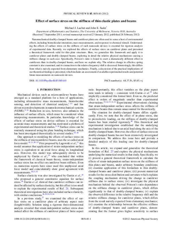
x3
x2
x1
σs
+
σs−
(a)
II. THEORY
In this section, we present a formal analysis of surface stress
effects on the stiffness of thin doubly-clamped beams and
cantilever plates. To examine the stiffness of both mechanical
devices, two equivalent approaches can be used: (i) calculate
the change in resonant frequency ω or (ii) the change
in effective spring constant keff . The former case is most
commonly reported in practice and was the preferred choice
in our previous work.27,28 Here, we explore both cases and
discuss their relationship for thin doubly-clamped beams and
cantilever plates.
We, first, consider the related problem of a completely
unrestrained thin isotropic linearly elastic plate, with strainindependent surface stress applied to both faces, i.e., σs+
and σs− on upper and lower faces, respectively; see Fig. 1.
Throughout this article, both σs+ and σs− are taken to be the
changes in surface stress from their base (intrinsic) values.
We focus on the total surface stress defined by, σsT = σs+ +
− 27,28,39,41
which is complimentary to the differential surface
σs ,
stress, �σs = σs+ − σs− .35,36,41 Within the framework of linear
elasticity, bending does not affect the stiffness of a beam or
plate. Since differential surface stress, �σs , induces bending,
it is ignored in the analysis that follows.35,36,41
Application of a uniform and isotropic total surface stress
will give rise to in-plane deformation of the unrestrained plate.
Solution to the corresponding displacement field of this plate
is given by
−(1 − ν) T
(1a)
σs x1 ,
Eh
−(1 − ν) T
σs x2 ,
v(x2 ) =
(1b)
Eh
where u, v, E, ν, and h are the displacements in the x1 and
x2 -directions, Young’s modulus, Poisson’s ratio, and thickness,
respectively. Importantly, other isotropic loads commonly
encountered in practice can produce displacement fields in
the x1 , x2 -plane that are identical to Eq. (1), including thermal
and piezoelectric loads.23,40,42,43
We next consider the general problem of a thin isotropic
linearly elastic plate whose edges can be free, simply supported, or clamped; a few examples are illustrated in Figs. 1(a)
and 1(b). The unrestrained plate solution is used to calculate the
deformation of the original (restrained) plate using the method
of linear superposition.27,28 This is achieved by decomposing
the original plate problem into two subproblems as follows:
u(x1 ) =
x3
σ s+
x2
x1
σs−
(b)
FREE
ORIGINAL
σs
T
σ sT
CLAMP LOADED
(c)
FIG. 1. Schematic of (a) a doubly-clamped beam and (b) a
cantilever plate showing coordinate system and applied surface
stresses. The origin of the coordinate system is at the center of mass
of the doubly-clamped beam and the clamped end of the cantilever
plate. Decomposition of original problem (c) highlights the removable
clamp, present for doubly-clamped beams and removed for cantilever
plates.
Subproblem (1): Deformation of the unrestrained plate
under application of an isotropic surface stress load.
Subproblem (2): A plate with no imposed surface stress load
but specified in-plane displacements at its restrained edges
that are identical and opposite in sign to those obtained in
subproblem (1). Addition of subproblems (1) and (2) thus
ensures satisfaction of the original boundary conditions; see
Fig. 1(c).
Superposition of these two subproblems yields an identical
in-plane deformation to that of the original problem. The net inplane stress of the original problem is captured by subproblem
(2), since subproblem (1) is unrestrained. As such, the stiffness
085440-2
�PHYSICAL REVIEW B 85, 085440 (2012)
EFFECT OF SURFACE STRESS ON THE STIFFNESS OF . . .
change of the original problem is given by that of subproblem (2).
Importantly, subproblem (2) has displacement conditions
at the restrained edge(s) and no-traction conditions at the free
edge(s). This subproblem is, thus, a mixed boundary value
problem that can pose a formidable challenge to calculate
analytically, and numerical techniques may be required.
We now solve subproblem (2) for two cases of practical
interest as follows:
(i) Doubly-clamped beams: Subproblem (1) produces an
axial extension/contraction along the x1 -direction. This can
be easily calculated by substituting the beam length L into
Eq. (1a). Since this axial displacement is incommensurate with
the boundary conditions at both ends of the original problem,
subproblem (2) must involve an axial contraction/extension
along the same longitudinal axis, i.e., u = (1 − ν) σsT L/(Eh);
deformation in the x2 -direction is irrelevant since the beam
length is assumed to greatly exceeds its width, in accord
with Saint-Venant’s principle.43 In this case, subproblem (2)
reduces to the axial loading of a thin beam, which can be
solved using Euler-Bernoulli beam theory.
(ii) Cantilever plates: Subproblem (1) gives rise to an
isotropic biaxial expansion/compression parallel to the plane
of the plate. Since this violates the boundary condition at the
restrained edge of the original cantilever plate, subproblem
(2) contains a linear displacement along the clamp, i.e., v =
(1 − ν) σsT x2 /(Eh). This displacement induces a complex
in-plane stress distribution within the vicinity of the clamp.
Such behavior can only be captured using a theory of higher
order than Euler-Bernoulli beam theory; the latter inherently
ignores the details in the immediate vicinity of the clamp.
Here, a rigorous three-dimensional finite element analysis is
used to solve subproblem (2); see Sec. III.
A scaling analysis for this problem is presented in Sec. II B
to elucidate the dominate physical mechanisms. It is also used
to generalize the numerical results.
A. Subproblem (2): Doubly-clamped beams
We now derive analytical expressions for the relative
frequency shift and relative change in effective spring constant
of doubly-clamped beams.
To begin, consider the governing equation of an EulerBernoulli beam under axial loading,
EI ∂ 4 w
T ∂ 2w
∂ 2w
− 2
+ μ 2 = 0,
4
4
2
L ∂X
L ∂X
∂t
(2)
where X ≡ x1 /L is the scaled axial distance, t is time, w
the beam deflection in the x3 -direction, I the second moment
of area, T the axial load, and μ the linear mass density.
Since geometric nonlinearities are ignored, the axial load T
is decoupled from the out-of-plane deflection of the beam.44
In this case, the axial displacement of subproblem (2) induces
the axial load,
T = (1 − ν)σsT b,
where b is the beam width. This axial load can then affect the
stiffness and, hence, the resonant frequency of the beam.
1. Resonant frequency
We, first, calculate the change in resonant frequency due to
an applied surface stress load. The case of an infinitesimal load
is considered, which allows for calculation of the leading-order
change in resonant frequency. This is obtained by expressing
the deflection function in terms of the explicit time dependence
exp(−iωt), where ω is the resonant frequency in the presence
of an arbitrary surface stress, i.e., w(X,t) = W (X)exp(−iωt).
Substituting w(X,t) into Eq. (2) and cross-multiplying the
resulting equations in both the presence and absence of surface
stress, with the deflections W0 (X) and W (X), leads to
�� 1
�
�1
′′
2
EI
T L2 0 W0 (X)W ′′ (X) dX
0 W0 (X) dX
2
ω =
,
−
�1
�
μL4
EI 1 W0 (X)W (X) dX
W0 (X)2 dX
0
0
(3)
where W (X) and W0 (X) are the dynamic deflection functions
in the presence and absence of surface stress, respectively.
To calculate the leading-order effect of surface stress on
the fundamental mode resonant frequency, we replace the
fundamental mode dynamic deflection function W (X) in
Eq. (3) with W0 (X). The required expression for the relative
frequency shift then immediately follows,
� �
(1 − ν)σsT L 2
�ω
,
(4)
= 0.1475
ω0
Eh
h
where ω0 is the (reference) resonant frequency in the absence
of surface stress and �ω = ω − ω0 .
Equation (4) demonstrates that a positive (tensile) surface
stress increases the stiffness of doubly-clamped beams; a
negative (compressive) surface stress decreases the stiffness.
It is also found that the length-to-thickness ratio L/ h has a
quadratic dependence on beam stiffness. This illustrates that
increasing the length or reducing the thickness will enhance
the sensitivity of doubly-clamped beams to surface stress.
Interestingly, we find that Eq. (4) depends on Poisson’s ratio.
This may appear surprising at first, given that the deflection
function for elementary beam theory does not depend on
Poisson’s ratio. However, the axial load giving rise to this
effect originates from a biaxial strain in the plate. This is the
origin of the observed Poisson’s ratio dependence.
2. Effective spring constant
To calculate the change in effective spring constant of a
beam due to a change in surface stress, we first consider the
potential energy of the beam due to a distributed lateral load
q. Using a similar approach to the resonant frequency above,
we now consider the Euler-Bernoulli beam equation for static
deflection, which yields
� 1
� 1
�
T 1
qw(X) dX = qw0 (X) dX + 2
w0 (X)w ′′ (X) dX,
L 0
0
0
(5)
where w0 (X) and w(X) refer to the static mode deflection
functions in the presence of surface stress and in its absence,
respectively. We again consider the case of infinitesimal loads
and, thus, calculate the leading-order change in effective
stiffness. This is obtained by replacing the static deflection
function w(X) on the right-hand side of Eq. (5) by w0 (X). In
085440-3
�PHYSICAL REVIEW B 85, 085440 (2012)
MICHAEL J. LACHUT AND JOHN E. SADER
addition, ignoring geometric nonlinearities and considering a
point load at the center of the beam results in its deflection
being inversely proportional to its stiffness at that position.
These simplifications then lead to the required expression
� �
�keff
3 (1 − ν)σsT L 2
,
(6)
=
k0
10
Eh
h
where k0 is the (reference) effective spring constant, �keff =
keff − k0 , and keff is the effective spring constant when arbitrary
surface stresses are imposed.
Equation (6) demonstrates that the relative change in the
effective spring constant has an identical scaling dependence
to Eq. (4) for the resonant frequency shift, as expected.
Comparing Eq. (4) to Eq. (6) establishes that the relative
change in spring constant and resonant frequency shift differ
by a factor of 2.03. The slight increase from the usual value
of 2 expected from elementary mechanics results from the
difference in mode shape for the static and dynamic cases.
In the next section we present a scaling analysis for
cantilever plates under surface stress loads.
B. Scaling analysis for cantilever plates
We begin by considering the (two-dimensional) governing
equation for the small deflection of a thin plate, subject to an
arbitrary in-plane load,
� 2
�
∂ w
∂2
∂ 2w
− Nij
D
= q,
(7)
∂xi ∂xi ∂xj ∂xj
∂xi ∂xj
where w is the plate deflection in the x3 -direction (that now
depends on x1 and x2 ), D is the flexural rigidity, N is the
in-plane stress tensor, and q is the applied load per unit area.
Since all nonlinearities are also ignored for cantilever
plates, the in-plane stress problem is decoupled from the outof-plane deflection.42,44,45 Solution to this in-plane problem is
obtained by solving the equations of equilibrium ∂i Nij = 0
and compatibility condition ∂ii Njj = 0.42,43,46
In accordance with Saint-Venant’s principle, the strain
applied at the clamped edge induces localized nonzero in-plane
stresses that decay along the length of the cantilever, with a
characteristic length scale b. This results in nonzero in-plane
stress confined within a region near the clamp [x1 < O(b)],
outside of which is zero. From the boundary conditions of
subproblem (2), the in-plane stress obeys the scaling relation
N ∼ O(σ̄ Eh), where
(1 − ν) σsT
.
(8)
Eh
Substituting this scaling relation for N into Eq. (7) reveals
that the effective flexural rigidity is altered only in the region
x1 < O(b). For x1 > O(b), the effective rigidity is unaffected.
The overall change in stiffness is, thus, induced by a localized
perturbation to the governing equation in the immediate
vicinity of the clamp.
The scaling behavior of this effective flexural rigidity in the
region x1 < O(b) is, therefore, Deff /D0 − 1 ∼ O[σ̄ (b/ h)2 ],
where Deff is the effective flexural rigidity and D0 the
(unloaded) flexural rigidity of the cantilever plate. As the
aspect ratio L/b increases, the effect of the in-plane load
decreases, since the region containing nonzero in-plane stress
σ̄ ≡
is reduced relative to the entire region of the cantilever.
Since the in-plane load affects the plate rigidity only in the
region where x1 < O(b), it then follows that the leading-order
behavior of the (total) effective rigidity is captured by
� � �� � �
b 2
b
Deff
− 1 ∼ O σ̄
(9)
D
L
h
in the limit L/b ≫ 1.
In the next section we present numerical solutions to
subproblem (2) for cantilever plates. The underlying physical
mechanisms driving the stiffness change in cantilever plates
are also explored.
III. RESULTS AND DISCUSSION
We solved subproblem (2) for a cantilever plate using a
full three-dimensional finite element analysis.47 The mesh
was systematically refined to ensure a convergence of 98%.
Results are presented for a wide range of geometries, which
correspond to width ratios between 16 � b/ h � 48 and aspect
ratios 2 < L/b � 100. The effect of nonzero Poisson’s ratio is
also investigated over the practical range 0 � ν � 0.49. Using
the above scaling analysis allows for appropriate normalization
of the numerical data in the asymptotic limit as L/b → ∞.
As discussed above, we consider two complementary
approaches to examine the effect of surface stress on cantilever
stiffness: (i) Apply a fixed load at the tip and observe changes in
the static deflection; this subsequently allows for calculation
of changes in the effective spring constant keff . (ii) Use an
eigenvalue analysis to obtain the resonant frequency ω of
the cantilever plate; explicit results for the latter case were
presented in Ref. 27. Here, we expand on that previous study27
and present a detailed analysis for both approaches.
A. Subproblem (2): Cantilever plates
Equation (9) gives the leading-order scaling behavior for
the effective rigidity Deff as a function of surface stress. Since
cantilever stiffness is proportional to the effective rigidity Deff ,
the leading-order dependence of both the relative change in the
effective spring constant and relative frequency shift inherently
yield identical scaling behavior.
For the relative change in resonant frequency ω, we obtain
� � � �2
b
�ω
b
,
(10)
= φω (ν)σ̄
ω0
L
h
where ω0 is the resonant frequency in the absence of an applied
surface stress load, �ω = ω − ω0 , and φω (ν) is a function
purely dependent on Poisson’s ratio ν.
Similarly, the general expression for the relative change in
the effective spring constant keff is
� � � �2
b
�keff
b
,
(11)
= φk (ν)σ̄
k0
L
h
where k0 is the effective spring constant without a surface stress
load, �keff = keff − k0 , and φk (ν) is another function purely
dependent on Poisson’s ratio ν. These expressions are derived
in the asymptotic limit L ≫ b ≫ h. The unknown functions,
which depend only on Poisson’s ratio, are now evaluated.
085440-4
�PHYSICAL REVIEW B 85, 085440 (2012)
EFFECT OF SURFACE STRESS ON THE STIFFNESS OF . . .
Normalized Change in
Effective Stiffness
ν = 0.25
0.015
Increasing b
Ωk
h
0.010
Ωω
0.005
0
0
0.1
0.2
0.3
0.4
0.5
b L
/
(a)
(a)
(b)
/
FIG. 2. Results for (a) relative frequency shift �ω/ω0 vs.
σ̄ (b/ h)2 and (b) relative change in effective spring constant �keff /k0
vs. σ̄ (b/ h)2 for L/b = 25/3. Both figures show three groups
of Poisson’s ratio: ν = 0,0.25,0.49. Each group contains b/ h =
16,19.2,24,32,48.
FIG. 3. (a) Results for normalized frequency shift �ω ≡
|�ωlin /ω0 |/|σ̄ (b/L)(b/ h)2 | and normalized change in effective
spring constant �k ≡ |�klin /k0 |/|σ̄ (b/L)(b/ h)2 |; b/ h = 16, 19.2,
24, 32, 48; ν = 0.25. Subscript “lin” indicates the result from linear
regression. (b) Relationship between resonant frequency shift and
change in effective spring constant (�ω/ω0 )/(�keff /k0 ) vs. b/L.
Results extrapolated to zero thickness; ν = 0.25.
Figure 2 presents numerical results for both the relative
change in resonant frequency and effective spring constant;
both cases have been scaled with (b/ h)2 , in accordance with
Eqs. (10) and (11). Figure 2 demonstrates that Eqs. (10)
and (11) accurately capture the dominate width ratio b/ h
dependence, for both the resonant frequency ω and effective
spring constant keff , with all curves collapsing for a given
Poisson’s ratio ν. It is also evident that the effective stiffness
depends strongly on Poisson’s ratio, with increasing ν enhancing the effect. We investigate the mechanism behind this
Poisson’s ratio dependence in Sec. III B.
Importantly, Fig. 2 includes all nonlinear effects, which are
ignored in the formulation of Eqs. (10) and (11). Consequently,
to make a quantitative and rigorous comparison to Eqs. (10)
and (11) and evaluate φω (ν) and φk (ν), we henceforth extract
the linear portion of these numerical results using linear
regression and report these results only.
In Fig. 3(a), we illustrate the aspect ratio L/b dependence
predicted in Eqs. (10) and (11). Results are presented for a
range of aspect ratios L/b, Poisson’s ratio ν = 0.25, with
width ratios b/ h corresponding to those used in Fig. 2. Results
for other nonzero Poisson’s ratios are similar to those in
Fig. 3(a), while differing in magnitude. The vertical axis is
scaled in accordance with Eqs. (10) and (11) to explore their
validity. From Fig. 3(a), it is clear that Eqs. (10) and (11)
also capture the dominant aspect ratio dependence for large
L/b, which is the regime in which they were derived, while
a higher-order dependence on aspect ratio is also visible for
smaller L/b; this higher-order dependence can be calculated
from the results in Fig. 3(a), if required. These results confirm
the validity of the scaling argument behind Eqs. (10) and (11)
for small surface stress loads.
Figure 3(b) demonstrates the aspect ratio L/b dependence
of the ratio between the resonant frequency shift and relative
change in effective spring constant, i.e., (�ω/ω0 )/(�keff /k0 ).
Since Eqs. (10) and (11) were derived within the framework
of the classical theory of thin plates, numerical results for
each aspect ratio L/b are extrapolated to the zero thickness
limit, h/b → 0. Figure 3(b) illustrates that in the formal limit,
L/b → ∞, this ratio becomes (�ω/ω0 )/(�keff /k0 ) ≈ 2/3.
This contrasts to doubly-clamped beams, where the relative
change in resonant frequency and effective spring constant
differ by a factor of 2.03. The mechanism giving rise to this
factor of 2/3 is explored in detail in Sec. III C.
To determine the functions φω (ν) and φk (ν) in Eqs. (10)
and (11), numerical data for the resonant frequency shift and
relative change in effective spring constant are extrapolated in
the binary limit L/b → ∞ and b/ h → ∞. This is precisely
the regime in which these asymptotic expressions are formulated. Given the linearity of the data in this limit, extrapolation
(b)
085440-5
�PHYSICAL REVIEW B 85, 085440 (2012)
MICHAEL J. LACHUT AND JOHN E. SADER
is robust and accurate. Results for various Poisson’s ratio are
then used to evaluate φω (ν) and φk (ν). We find that both φω (ν)
and φk (ν) vary approximately linearly with Poisson’s ratio and
are well described by φω (ν) ≈ −0.042ν and φk (ν) ≈ −0.063ν
for the resonant frequency and effective spring constant,
respectively. Substituting φω (ν) into Eq. (10) and φk (ν) into
Eq. (11) gives the required resonant frequency shift,
� � � �2
b
�ω
b
= −0.042ν σ̄
,
(12)
ω0
L
h
and relative change in effective spring constant,
� � � �2
�keff
b
b
= −0.063ν σ̄
.
k0
L
h
(13)
We emphasize that these results are consistent with the null
result of Gurtin et al.,25 that was derived in the formal limit
L/b → ∞ using classical beam theory. In this limit, Eqs. (12)
and (13) also predict that surface stress loads have no effect
on the stiffness. The mechanism giving rise to stiffness change
due to surface stress lies in the development of localized inplane loads near the clamp, which are inherently ignored in
beam theory. This also yields the observed Poisson’s ratio
dependence that only can be captured using a theory of higher
dimension, such as thin plate theory.
We now examine the mechanism underlying (i) the observed Poisson’s ratio dependence, and (ii) the observed
ratio between the relative frequency shift and relative change
in effective spring constant, (�ω/ω0 )/(�keff /k0 ) ≈ 2/3 for
L/b ≫ 1.
B. Poisson’s ratio dependence
To examine the origin of the Poisson’s ratio dependence
on effective stiffness, we derive an analytical expression for
the leading-order change in resonant frequency of a cantilever
plate. To begin, consider the governing equation of a thin plate
under in-plane loading
� 2
�
∂ w
∂ 2w
∂2
∂ 2w
− Nij
+ ρh 2 = 0, (14)
D
∂xi ∂xi ∂xj ∂xj
∂xi ∂xj
∂t
where w is the deflection function in the x3 -direction
and ρ is the plate density. By again considering an explicit time dependence of exp(−iωt), the deflection function becomes w(x1 ,x2 ,t) = W (x1 ,x2 )exp(−iωt). Substituting
w(x1 ,x2 ,t) into Eq. (14), and cross-multiplying the resulting
equations for the two cases where in-plane loads are present
and absent, with the deflections W0 and W , respectively, yields
��
W0 Nij ∂ij W dS
2
2
ω − ω0 = − S ��
,
(15)
ρh S W0 W dS
where W and W0 are the deflection functions in the presence of
in-plane loads and in their absence, respectively; the integrals
are over the surface S of the plate. Since infinitesimal in-plane
loads are applied, the leading-order change in the fundamental
mode resonant frequency is obtained by replacing W in
Eq. (15) with W0 . This then leads to
��
1
W0 Nij ∂ij W0 dS,
(16)
�ω = −
2M
S
where �ω = ω − ω0 is now the leading-order change in
resonant frequency due to small changes in surface stress,
where M is
��
W02 dS
M = ω0 ρh
S
and
ω02 =
D
��
S
W0 ∂ii ∂jj W0 dS
��
.
2
S W0 dS
(17)
ρh
Equation (16) clearly shows coupling between the deflection
function and the in-plane stresses. Modification of either term
can potentially change the cantilever stiffness. In the following
discussion, we examine the importance of each term in Eq. (16)
to elucidate the origin of the Poisson’s ratio dependence
observed in Eqs. (12) and (13).
1. Zero Poisson’s ratio
For ν = 0, the deflection function, W0 , is independent
of x2 and identical to the result from Euler-Bernoulli beam
theory. The change in resonant frequency for ν = 0, therefore,
simplifies to give
�� b
� L 2
2
d W0
1
�ω|ν=0 = −
W0
N11 dx2 dx1 . (18)
2
2M 0 dx1
− b2
We next prove that the above integral of N11 with respect to
x2 is zero. Consider a rectangular region within the plate, with
three sides coinciding with the free edges, and an arbitrary
slice in the interior of the plate; see Fig. 4. The equilibrium
equation, ∂i Nij = 0, is integrated over this rectangular region.
Use of the divergence theorem then yields
��
∂Nij
(19)
Nij n̂i dC = 0,
dS1 =
S1 ∂xi
∂C
where n̂i is the outward normal to the boundary. Applying
the usual no-traction boundary condition, Nij n̂i = 0, along
the free edges reduces the integral on the right-hand side of
Eq. (19) to
� b
� b
2
2
x̂1
N11 dx2 + x̂2
N12 dx2 = 0,
(20)
− b2
n̂
− b2
S1
∂C
FIG. 4. Plan view of cantilever plate showing rectangular region
within interior; this specifies the boundary of integration used to prove
the stiffness change vanishes for zero Poisson’s ratio.
085440-6
�PHYSICAL REVIEW B 85, 085440 (2012)
EFFECT OF SURFACE STRESS ON THE STIFFNESS OF . . .
Contributions to Resonant
Frequency Shift
0.01
ν = 0.25
�ω12
0.008
TOTAL
0.006
22
0.004
11
0.002
12
0
−0.002
0
0.1
0.2
0.3
0.4
0.5
b L
FIG. 5. Normalized relative change in resonant frequency,
TOTAL ≡ ��ω/ω0 , and its normalized components, 11 ≡
��ω11 /ω0 , 22 ≡ ��ω22 /ω0 , and 12 ≡ ��ω12 /ω0 , plotted against
b/L, where � = −1/{σ̄ (b/L)(b/ h)2 }; h/b → 0, ν = 0.25.
where x̂1 and x̂2 are unit vectors in the x1 and x2 -directions,
respectively. This establishes that the integral of N11 with
respect to x2 is zero. Substituting this result into Eq. (18) proves
that a Poisson’s ratio of zero yields no change in the resonant
frequency of the plate. This verifies the empirically derived
result in Fig. 2 for ν = 0, from which a negligible variation in
stiffness for an arbitrary in-plane load was observed.
2. Nonzero Poisson’s ratio
In the case of nonzero Poisson’s ratio, the deflection
function depends on x2 . Therefore, the above analysis for
zero Poisson’s ratio no longer holds. Thus, all terms in the
integral of Eq. (16) can potentially be nonzero. To investigate
the contribution of each term in Eq. (16), we expand the relative
change in resonant frequency as
�ω
�ω11
�ω12
�ω22
=
+
+
,
ω0
ω0
ω0
ω0
(21)
where
�ω11 = −
�ω22 = −
1
2M
��
N11
∂ 2 W0
W0 dS,
∂x12
(22a)
1
2M
��
N22
∂ 2 W0
W0 dS,
∂x22
(22b)
S
S
1
=−
M
��
N12
S
∂ 2 W0
W0 dS.
∂x1 ∂x2
(22c)
The expressions in Eqs. (22) define contributions from each
in-plane stress component Nij to the total frequency shift.
Note that each contribution results from coupling between the
in-plane stress, deflection function, and curvature.
Using our full three-dimensional model, we now numerically evaluate each term in Eq. (21). As in Ref. 27, results
are first computed for finite thickness cantilever plates. The
numerical data are then extrapolated to zero thickness to obtain
the required results that are consistent with thin plate theory.27
Results in Fig. 5 are given for a Poisson’s ratio of ν = 0.25
and illustrate the contributions from each term in Eq. (21) to
the overall frequency shift. Figure 5 demonstrates that each
term in Eq. (21) exhibits an approximate linear dependence
on b/L, provided b/L ≪ 1; higher-order effects are clearly
present for b/L > 0.3. This reveals that the components of the
change in resonant frequency have a significant dependence
on aspect ratio, L/b. From the results in Fig. 5, it is evident
that the dominant contribution for large L/b is given by �ω22 ,
with �ω11 and �ω12 playing a relatively minor role. Note
that �ω11 and �ω12 are approximately equal and opposite in
magnitude for b/L < 0.3. The following analysis will, thus,
focus only on the dominant component, �ω22 , for L/b ≫ 1.
a. Contribution from �ω22 . Since the resonant frequency
ω0 and deflection function w0 are insensitive to Poisson’s ratio
ν, for L ≫ b, it then follows that M will also be insensitive to
ν; this feature has been verified numerically. Thus, M cannot
lead to the observed Poisson’s ratio dependence in Fig. 2.
Results for the normalized in-plane stress, N ≡
N22 /(σ̄ Eh), are presented in Fig. 6(a) for ν = 0.25. Figure 6(a)
demonstrates that the uniform strain applied along the clamp
induces a nonuniform stress distribution in the vicinity of the
clamp. Since the in-plane stress distribution decays rapidly
for x1 > 2b, Fig. 6(a) gives the distribution for all aspect
ratios, L/b > 2. To examine the Poisson’s ratio dependence
on N , Fig. 6(b) gives the difference between the normalized
in-plane stress N for ν = 0.25 and 0.49. Interestingly, Fig. 6(b)
reveals that the contours of the normalized in-plane stress, N,
are virtually unaffected by Poisson’s ratio. This establishes
that N22 also does not contribute to the linear Poisson’s ratio
dependence observed in Fig. 2.
(a)
(b)
FIG. 6. (a) Normalized in-plane stress N ≡ N22 /(σ̄ Eh) for ν = 0.25 and (b) difference between the normalized in-plane stress N for
ν = 0.25 and 0.49; x1 < 2b. Actual contour values are 10−3 times those given in both figures. Results given for aspect ratio L/b = 2.
085440-7
�PHYSICAL REVIEW B 85, 085440 (2012)
MICHAEL J. LACHUT AND JOHN E. SADER
(a)
(b)
FIG. 7. (a) Scaled product of dynamic deflection and curvature in the x2 -direction, W ≡ W0 ∂22 W0 b2 /(νA2 ), for ν = 0.25. (b) Difference
between the scaled product of dynamic deflection and curvature, W , for ν = 0.25 and 0.49. The deflection function, W0 , has been normalized
by its amplitude, A, at the center of the free-end of the cantilever, i.e., (x1 ,x2 ) = (L,0). The coordinate x2 is scaled by b. Both cases shown
over entire length for an aspect ratio of L/b = 25/3. The vertical axis is scaled by 10−3 .
We, thus, turn our attention to variations in the deflection
function of the cantilever plate. In Fig. 7(a), we give results
for the scaled product of the dynamic deflection and curvature
in the x2 -direction, W0 ∂22 W0 , for a Poisson’s ratio of ν = 0.25;
the contribution of this component to the total frequency
shift is specified by Eq. (22b). Results are given for the
fundamental mode of vibration only. To assess the Poisson’s
ratio dependence of W0 ∂22 W0 , Fig. 7(b) plots the difference
between the scaled product of dynamic deflection and curvature for ν = 0.25 and 0.49. Significantly, this difference is an
order of magnitude smaller than the results in Fig. 7(a). This
establishes that the dominant mechanism underlying the linear
Poisson’s ratio dependence results from coupling of N22 with
the Poisson’s ratio dependence of the deflection function – N11
and N12 play a relatively minor role. This finding is consistent
with the proof in Sec. III B 1 that N22 does not contribute to
the change in stiffness when Poisson’s ratio is zero.
In the next section, we investigate the origin of the observed
ratio between the relative frequency shift and relative change
in effective spring constant.
C. Relationship between frequency shift and effective
spring constant
The numerical results in Fig. 3(b) demonstrate that the
ratio of the relative frequency shift and relative change in
effective spring constant approaches 2/3 as the aspect ratio
L/b tends to infinity; i.e., (�ω/ω0 )/(�keff /k0 ) → 2/3. This
differs from the result for doubly-clamped beams and from
what is naively expected from elementary mechanics. The
underlying mechanism giving rise to this unexpected behavior
for cantilever plates is now explored. To begin, we introduce
analytical formulas for the relative frequency shift and relative
change in effective spring constant. These are obtained for
small surface stress changes.
The formula for the relative frequency shift follows immediately from Eqs. (16) and (17):
��
�ω
1
S W0 Nij ∂ij W0 dS
��
.
(23)
=−
ω0
2 D S W0 ∂ii ∂jj W0 dS
The change in effective spring constant of a cantilever plate
is derived by considering the potential energy of the plate due
to a lateral load q. By using a similar approach to the resonant
frequency above, we consider the governing equation of a thin
plate for static deflection, which immediately gives
��
��
��
∂ 2w
w0 Nij
dS, (24)
qw0 dS =
qw dS −
∂xi ∂xj
S
S
S
where w and w0 are the static deflection functions when inplane loads are present and absent, respectively. If infinitesimal
loads are again imposed on the plate, the leading-order relative
change in effective stiffness is obtained by replacing the
deflection w on the right-hand side of Eq. (24) with w0 .
Furthermore, if a lateral force per unit length is applied along
the width of the cantilever tip, the deflection at that position
will be inversely proportional to the effective stiffness at that
position, which leads to
��
�keff
S w0 Nij ∂ij w0 dS
,
(25)
= − ��
k0
D S w0 ∂ii ∂jj w0 dS
where �keff = keff − k0 is now the leading-order change in the
effective spring constant.
Next, to obtain an analytical expression for the relationship
between the relative resonant frequency shift and relative
change in effective spring constant, we take the ratio of Eq. (23)
and Eq. (25), i.e.,
�ω
ω0
�keff
k0
=
1�
,
2 0
(26)
where
0
��
W0 ∂ii ∂jj W0 dS
,
= ��S
S w0 ∂ii ∂jj w0 dS
(27)
is the ratio between the dynamic and static spring constant in
the absence of in-plane loads and
��
W0 Nij ∂ij W0 dS
,
(28)
� = ��S
S w0 Nij ∂ij w0 dS
is the contribution of the in-plane stress Nij . In the asymptotic
limit, L/b → ∞, the ratio between the dynamic and static
spring constant is 0 = 1.03. As such, for L ≫ b, the value of
0 can be rounded off to unity without introducing significant
errors in Eq. (26). We now turn our attention to � .
085440-8
�PHYSICAL REVIEW B 85, 085440 (2012)
EFFECT OF SURFACE STRESS ON THE STIFFNESS OF . . .
This relationship has a cubic dependence on aspect ratio L/b,
which establishes that increasing the aspect ratio strongly
enhances the sensitivity of doubly-clamped beams to surface
stress change, in comparison to cantilever plates. We remind
the reader that all calculations have been derived in the
asymptotic limit where the plate width greatly exceeds its
thickness.
It is also found that Poisson’s ratio plays a significant
role in Eq. (29). This is expected, since cantilever plates
are insensitive to surface stress variations in the limit of
zero Poisson’s ratio (see Sec. III B); the frequency shift in
doubly-clamped beams is much more weakly dependent on
Poisson’s ratio.
Equation (29) establishes that doubly-clamped beams offer
superior sensitivity to surface stress effects in comparison to
cantilever plates in the asymptotic limit L ≫ b. The analogous
expression to Eq. (29) for the change in stiffness is larger by a
factor of 4/3 in the limit L/b → ∞. The physical mechanisms
underlying this factor are detailed above.
(a)
(b)
FIG. 8. (a) Scaled product of static deflection and curvature in the
x2 -direction, w ≡ w0 ∂22 w0 b2 /A2 . (b) Difference between the scaled
product of static deflection and curvature, w, and 3/4 times the scaled
product of dynamic deflection and curvature, W ≡ W0 ∂22 W0 b2 /A2 ;
L/b = 100, x1 � 2b. The deflection functions, w0 and W0 , have been
normalized by their amplitudes, A, at the center of the free-end of the
cantilever, i.e., (x1 ,x2 ) = (L,0). The coordinate x2 is scaled by b and
the vertical axis is scaled by 10−7 .
Since the in-plane loads in � are identical in the static
and dynamic cases, and decay rapidly for x1 > O(b), we focus
on contributions from the product of deflection and curvature
in the immediate vicinity of the clamp; i.e., x1 < O(b). An
example is given in Fig. 8(a) for the normalized product of
static deflection and curvature, w0 ∂ij w0 , for L/b ≫ 1. Near
the clamp, all products of the deflection and curvature in the
numerator (dynamic problem) of Eq. (28) differ by a factor
of ∼4/3 to the denominator (static problem), i.e., W0 ∂ij W0 ≈
4/3 w0 ∂ij w0 . This feature is highlighted in Fig. 8(b), which
presents the relative difference between these products. Substituting the result W0 ∂ij W0 ≈ 4/3 w0 ∂ij w0 into Eq. (28),
then gives � ≈ 4/3, which from Eq. (26) reproduces the
numerical result of Fig. 3(b), i.e., (�ω/ω0 )/(�keff /k0 ) ≈ 2/3,
for L/b ≫ 1.
This analysis establishes that the difference in �ω/ω0 and
�keff /k0 is due to variations in the local plate curvature near
the clamp for the static and dynamic cases, respectively.
D. Comparison between doubly-clamped beams
and cantilever plates
We now compare the relative sensitivity of doubly-clamped
beams and cantilever plates to surface stress change. Throughout, we focus on the relative change in frequency. Taking the
ratio of Eqs. (4) and (12) gives
�ω
ω0 Clamp-Clamp
�ω
ω0 Cantilever
� �
−3.51 L 3
.
≈
ν
b
(29)
E. Practical implications
To conclude, we discuss the practical implications of
the theoretical findings and models presented above. For
completeness, we first summarize the discussion presented in
Ref. 27, while elaborating on some pertinent points. We then
explore potential future measurements on nanoscale devices
that can make use of the presented theory.
Interestingly, the effective stiffness change in Eqs. (12)
and (13) is controlled by the ratio of the modified surface stress
ν(1 − ν)σsT to the (reference) stiffness K ≡ Eh3 L/b3 , i.e., the
stiffness probed with characteristic length b rather than cantilever length L. This demonstrates that changes in thickness
h or width b have a stronger effect in comparison to varying
the length L. This scaling dependence differs considerably
to that of surface elasticity (strain-dependent surface stress)
and can be used to identify the influence of strain-independent
surface stress. Examining the scaling dependence of strainindependent and strain-dependent surface stress contributions
on cantilever geometry may provide further understanding of
underlying physical mechanisms driving stiffness changes in
cantilever plates.
Static bending due to differential surface stresses could also
be combined with Eqs. (12) and (13) to determine changes in
the (intrinsic) surface stresses, i.e., σs+ and σs− . The accuracy
of such measurements achievable in practice is contingent on
the precision of the measured effective stiffness or resonant
frequency. This generalizes the approach of Müller et al.,41
who suggested this approach for thin circular plates.
Clearly, Eqs. (12) and (13) indicate that short cantilever
aspect ratio and reduced thickness offer higher sensitivity
to surface stress effects. Thus, miniaturization to nanoscale
devices, under the constraint that the classical theory of
elasticity still holds,48 presents a promising avenue for future
developments. We provide a theoretical example demonstrating the enhanced sensitivity to surface stress changes of such
miniaturized devices in the discussion that follows.
085440-9
�PHYSICAL REVIEW B 85, 085440 (2012)
MICHAEL J. LACHUT AND JOHN E. SADER
1. Available and proposed measurements
We now compare the predictions of the above surface stress
model to available experimental data and propose a series of
experiments to provide further insight into this phenomenon.
In Ref. 21, modifications to the surface of a series of
cantilevers was achieved by etching. This was shown to
affect the resonant frequency of the devices; see Fig. 4 of
Ref. 21. In that study,21 resonant frequency shifts due to
etching ranged from a few percent to nearly 100%. Based
on their (unphysical) axial force model, discussed above, the
frequency shifts corresponded to changes in surface stress of
approximately 0.2 N/m; this was within the expected values
for such etching processes. As discussed in Ref. 27, the present
model grossly underpredicts the resonant frequency shifts for
these surface stress values, yielding �ω/ω0 ≈ 10−4 . Thus, the
derived model is unable to explain the observations.
More recent experiments elaborated on these earlier reports
through adsorption to the cantilever surface, which changed the
surface stress.15,16,19,20,32 Measured resonant frequency shifts
were found to vary between studies, with reported values
ranging from �ω/ω0 ≈ 0.002 – 0.06. For example, in Ref. 32
gold-coated silicon rectangular cantilevers of dimensions
499 × 97 × 0.8 μm3 displayed a resonant frequency shift
up to �ω/ω0 ≈ 0.01 following an amino-ethanethiol-gold
adsorption binding event. The surface stress change was
measured using the usual bending technique.1 Good agreement
was also found between the measured surface stress and the
predictions of the (unphysical) axial force model for the first
six modes of vibration. In contrast, our model in Eq. (12)
predicts a surface stress change of σsT ≈ −60 N/m. Thus
again, we are unable to account for these measurements.
Analysis of the works of Refs. 15, 16, 19, and 20 yields a
similar conclusion.
In Ref. 27, we also mentioned a number of other possible mechanisms leading to these experimental observations.
Nonetheless, we must note the distinct possibility that these
experimentally observed changes in cantilever stiffness are due
to mechanism(s) that are unrelated to surface stress. While a
change in surface stress was induced and a subsequent change
in resonant frequency observed, the suggested “cause and
effect” has not been proven. Further work is required to unravel
the mechanism leading to these observations and permit a
definitive statement to be made. To this end, we propose some
measurements that accentuate the theoretical effects described
in this article for strain-independent surface stress.
Modern materials, such as graphene, provide an ideal
platform for investigating the effects of strain-independent
surface stress. These ultrathin materials amplify the effects
of surfaces, and theory predicts a dramatic enhancement in the
resulting resonant frequency shifts. Recently, Zhang et al.49
demonstrated that materials down to a bilayer of graphene,
corresponding to a thickness 6 Å, behave in accord with
continuum mechanics. We, therefore, explore the application
of the above theory to devices made of such ultrathin materials.
Importantly, measurements of surface stress induced
changes in doubly-clamped beams have not been reported –
measurements have only been provided for piezoelectric
induced stress.40 Consider a doubly-clamped beam made of
graphene of length 3.2 μm, width 0.8 μm, and thickness
0.6 nm. Applying a surface stress change to such a device,
Eq. (4) yields a scaled frequency shift of 1/σsT (�ω/ω0 ) ≈
3.8 × 10³ m N−1 ; increasing the thickness reduces this value
in accordance with the square of the thickness change. Using
a typical value of σsT ≈ 1 × 10⁻³ N/m32 yields a relative
frequency shift of �ω/ω0 ≈ 3.8, which greatly exceeds the
measurements reported in the literature for piezoelectricinduced stress.40 While this value is beyond the limits
of the present (linear) theory, it highlights the fact that
miniaturization to the nano/atomic scale can enable gigantic
tunability of the mechanical properties of these devices.
Thus, measurements of surface stress change should be easily
discernible on doubly-clamped beams made from ultrathin
materials such as graphene.
Using a graphene cantilever of identical dimensions to the
doubly-clamped device would result in a scaled frequency
shift of 1/σsT (�ω/ω0 ) ≈ −4.1 m N−1 , according to Eq. (29).
While this effect is smaller than that predicted for the
doubly-clamped device, it is orders of magnitude higher in
comparison to that predicted for micron-scale cantilevers used
in previous studies. For example, a surface stress change of
σsT ≈ −2.5 × 10⁻³ N m−1 is required to induce a frequency
shift of �ω/ω0 ≈ 0.01 in cantilever devices of identical
dimensions to the above doubly-clamped graphene device.
Microscale cantilevers of dimensions used in Ref. 32 reporting
this frequency shift require an unrealistic surface stress change
of σsT ≈ −60 N m−1 , as discussed above. This comparison
indicates that dynamic measurements on ultrathin devices
should be highly sensitive to the effects of surface stress
change. This provides a promising route to investigating
the origin of observed changes in cantilever stiffness due
to surface modification. Any deviations from the presented
theory could then be studied independently to identify their
origin.
IV. CONCLUSION
We have presented a general theoretical formalism to
calculate the effect of surface stress change on the stiffness
of thin plates with arbitrary boundary (edge) conditions. The
utility of this formalism was demonstrated by application
to both doubly-clamped beams and cantilever plates. In so
doing, we established that the stiffness of these two configurations exhibits vastly different sensitivities to surface stress
change.
Specifically, Poisson’s ratio was found to dramatically affect the surface stress sensitivity of cantilever plates, in contrast
to doubly-clamped beams that are relatively insensitive to
Poisson’s ratio. Furthermore, doubly-clamped beams were
found to exhibit a much stronger dependence on surface stress
in comparison to cantilever plates. This superior performance
increases with increasing aspect ratio (length/width). The
difference in the relative stiffness change and frequency shift
in cantilever devices was also examined and found to be due to
the difference in local curvature near the clamped end. Finally,
we proposed and theoretically analyzed experiments aimed
at elucidating the origin of the observed stiffness changes in
cantilever devices. The findings of this study are expected to
085440-10
�PHYSICAL REVIEW B 85, 085440 (2012)
EFFECT OF SURFACE STRESS ON THE STIFFNESS OF . . .
be of value to the design and application of sensors that utilize
the dynamic response of nanomechanical beam devices.
*
jsader@unimelb.edu.au
G. G. Stoney, Proc. R. Soc. London A 82, 172 (1909).
2
G. Hass and R. E. Thun, Physics of Thin Films (Academic Press,
New York, 1966).
3
S. Boskovic, J. W. M. Chon, P. Mulvaney, and J. E. Sader, J. Rheol.
46, 891 (2002).
4
H. Ibach, Surf. Sci. Rep. 29, 193 (1997).
5
M. Alvarez and L. M. Lechuga, Analyst 135, 827 (2010).
6
S. Sukuabol, D. K. Sood, and G. Rosengarten, Proceedings of
the 2005 Intelligent Sensors, Sensor Networks & Information
Processing Conference (IEEE, New York, 2005), p. 247.
7
K. Eoma, H. S. Park, D. S. Yoonc, and T. Kwonc, Phys. Rep. 503,
115 (2011).
8
N. V. Lavrik, M. J. Sepaniak, and P. G. Datskos, Rev. Sci. Instrum.
75, 2229 (2004).
9
B. Gheshlaghi and S. M. Hasheminejad, Composites B 42, 934
(2011).
10
T. Thundat, E. A. Wachter, S. L. Sharp, and R. J. Warmack, Appl.
Phys. Lett. 66, 1695 (1995).
11
D. Ramos, M. Arroyo-Hernández, E. Gil-Santos, H. D. Tong,
C. van Rijn, M. Calleja, and J. Tamayo, Anal. Chem. 81, 2274
(2009).
12
J. Tamayo, D. Ramos, J. Mertens, and M. Calleja, Appl. Phys. Lett.
89, 224104 (2006).
13
D. Ramos, J. Mertens, M. Calleja, and J. Tamayo, Sensors 7, 1757
(2007).
14
R. Berger, E. Delamarche, H. P. Lang, C. Gerber, J. K. Gimzewski,
E. Meyer, and H. J. Guntherodt, Science 276, 2021 (1997).
15
J. H. Lee, T. S. Kim, and K. H. Yoon, Appl. Phys. Lett. 84, 3187
(2004).
16
S. Cherian, and T. Thundat, Appl. Phys. Lett. 80, 2219 (2002).
17
S. Cherian, A. Mehta, and T. Thundat, Langmuir 18, 6935 (2002).
18
J. Dorignac, A. Kalinowski, S. Erramilli, and P. Mohanty, Phys.
Rev. Lett. 96, 186105 (2006).
19
K. S. Hwang, K. Eom, J. H. Lee, D. W. Chun, B. H. Cha, D. S.
Yoon, T. S. Kim, and J. H. Park, Appl. Phys. Lett. 89, 173905
(2006).
20
G. Y. Chen, T. Thundat, E. A. Wachter, and R. J. Warmack, J. Appl.
Phys. 77, 3618 (1995).
21
J. Lagowski, H. C. Gatos, and E. S. Sproles Jr., Appl. Phys. Lett.
26, 493 (1975).
22
V. Fiorentini, M. Methfessel, and M. Scheffler, Phys. Rev. Lett. 71,
1051 (1993).
23
V. Pini, J. Tamayo, E. Gil-Santos, D. Ramos, P. Kosaka, H. D. Tong,
C. van Rijn, and M. Calleja, ACS Nano 5, 4269 (2011).
1
ACKNOWLEDGMENTS
The authors gratefully acknowledge support of the
Australian Research Council Grants Scheme.
24
A. Husain, J. Hone, H. W. C. Postma, X. M. H. Huang, T. Drake,
M. Barbic, A. Scherer, and M. L. Roukes, Appl. Phys. Lett. 83,
1240 (2003).
25
M. E. Gurtin, X. Markenscoff, and R. N. Thurston, Appl. Phys.
Lett. 29, 529 (1976).
26
P. Lu, H. P. Lee, C. Lu, and S. J. O’Shea, Phys. Rev. B 72, 085405
(2005).
27
M. J. Lachut and J. E. Sader, Phys. Rev. Lett. 99, 206102 (2007).
28
M. J. Lachut and J. E. Sader, Appl. Phys. Lett. 95, 193505 (2009).
29
D. W. Dareing and T. Thundat, J. Appl. Phys. 97, 043526 (2005).
30
G. F. Wang and X. Q. Feng, Appl. Phys. Lett. 90, 231904 (2007).
31
Y. Zhang, Q. Ren, and Y.-P. Zhao, J. Phys. D: Appl. Phys. 37, 2140
(2004).
32
A. W. McFarland, M. A. Poggi, M. J. Doyle, L. A. Bottomley, and
J. S. Colton, Appl. Phys. Lett. 87, 053505 (2005).
33
X. Yi and H. L. Duan, J. Mech. Phys. Solids 57, 1254 (2009).
34
H. Duan, Acta Mechanica Solida Sinica 23, 1 (2010).
35
J. E. Sader, J. Appl. Phys. 89, 2911 (2001).
36
J. E. Sader, J. Appl. Phys. 91, 9354 (2002).
37
K. Dahmen, S. Lehwald, and H. Ibach, Surf. Sci. 446, 161 (2000).
38
K. Dahmen, H. Ibach, and D. Sander, J. Magn. Magn. Mater. 74,
231 (2001).
39
M. E. Gurtin and A. I. Murdoch, Arch. Ration. Mech. Anal. 57, 291
(1974).
40
S. C. Masmanidis, R. B. Karabalin, I. De Vlaminck, G. Borghs,
M. R. Freeman, and M. L. Roukes, Science 317, 780 (2007).
41
P. Müller and R. Kern, Surf. Sci. 301, 386 (1994).
42
E. H. Mansfield, The Bending and Stretching of Plates (Pergamon,
New York, 1964).
43
S. P. Timoshenko and J. N. Goodier, Theory of Elasticity (McGrawHill, New York, 1951).
44
S. S. Rao, Vibration of Continous Systems (John Wiley & Sons,
New Jersey, 2007).
45
S. P. Timoshenko and S. Woinowsky-Krieger, Theory of Plates and
Shells (McGraw-Hill, New York, 1959).
46
L. D. Landau and E. M. Lifshitz, Theory of Elasticity (Pergamon,
Oxford, 1959).
47
LUSAS is a trademark of and is available from FEA Ltd. Forge
House, 66 High St., Kingston Upon Thames, Surrey KT1 1HN,
UK. 3D quadrilateral elements were used. Mesh was refined to
98% convergence.
48
R. Maranganti and P. Sharma, Phys. Rev. Lett. 98, 195504
(2007).
49
D. B. Zhang, E. Akatyeva, and T. Dumitrică, Phys. Rev. Lett. 106,
255503 (2011).
085440-11
�
 Michael Lachut