International Journal of Engineering Science Invention Research & Development; Vol. III, Issue XII, JUNE 2017
www.ijesird.com, e-ISSN: 2349-6185
RESPONSE OF PRECAST WALL INFILLED
STEEL FRAMED STRUCTURE IN LATERAL
LOAD
Hafeef M T1, Dr Sunilaa George2
1
2
P.G. Student, Professor and Head , Department of Civil Engineering, EASA College of Engineering and Technology
Navakkarai, Coimbatore, India
Abstract- Precast wall panel are now a day’s gaining
importance due to speedy construction, economy, good quality
due to controlled environment, exact shape due to factory
condition, less wastage of materials etc. The panels can be
made more effective by insulation sections within concrete
panels in making of sandwich panels. The main drawback in
using the precast panels is in the resistance to lateral loads
.This can be made more beneficial by using them as infill in
steel frames.
Steel framed models are made with and without
precast infill walls and shake table tests are performed for
both the models. The response in terms of displacement,
velocity and acceleration and storey drift are studied. The
results of the study showed that the precast panel filled in
steel frames showed better performance in lateral loads
compared to conventional steel framed models.
Keyword: Precast walls, steel framed structures, lateral load,
shake table
Improper design of the structure will lead
to collapse of the structure when subjected to
lateral loads. By implementing proper
connections with the main frame the precast walls
provide better performances. By using the precast
walls in steel frame the fixing and fastening
becomes easier and gives more stiffness. In this
study, an attempt is made to know whether
precast walls can be used in seismic areas, the
concept of precast wall in steel framed structure
for seismic regions.
2. MODEL SPECIFICATION
2.1CONVENTIONAL FRAME MODEL
1. INTRODUCTION
Pre fabricated structures are now getting
more popular. The difficult form works are not
needed in precast construction.In the construction
of multi storied structures . The construction time
can be reduced drastically. When using precast
walls they should be fastened properly to resist
the lateral loads also. [N.Uchinda et.al].Precast
walls can be used successfully in structures if the
connections are given carefully with respect to
lateral strength, stiffness and unity of components
[Bindurani.P, A. et.al]. Though precast structures
precast panels can also be used to clad building
façade have got many advantages, the main
disadvantage is the vulnerability to earthquake.
[Fintel, M. ] Hence the solution for achieving
these qualities to the structure or making the
precast structures to withstand from earthquake is
by steel framing. i.e., Steel framed precast infill
walls will be having all the benefits of precast
structures as well as the steel framed structure.
Hafeef M T and Dr Sunilaa George
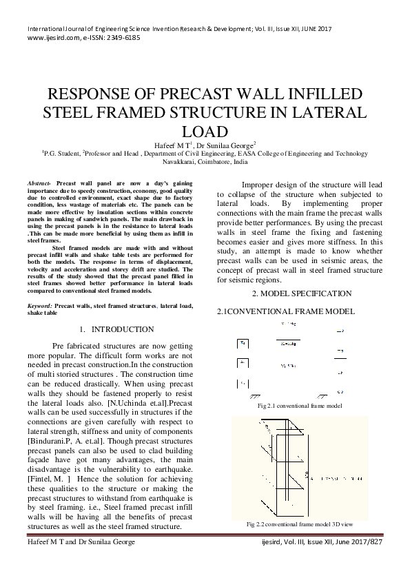
Fig 2.1 conventional frame model
Fig 2.2 conventional frame model 3D view
ijesird, Vol. III, Issue XII, June 2017/827
�International Journal of Engineering Science Invention Research & Development; Vol. III, Issue XII, JUNE 2017
www.ijesird.com, e-ISSN: 2349-6185
For studying the earthquake responses, a
three-storied steel model was fabricated as
shown in Fig2.1. The overall external dimension
of the model is 300 mm X 240 mm at the base
and a floor height of 300mm each. The total
height of the structure is 900 mm and the model
is made of mild steel. The total dead load on the
steel structure was 10kg. Live load of 2kg, 2kg,
1kg was kept at first, second and third floors
respectively the 3D view of model for study is
shown in fig2.2.
`Columns were made up of hollow mild steel
section of 30mm x 30mm, which has a thickness
of 2mm. Slab sections were made with 300mm
x 230mm plate with a thickness of 2mm
All the members were connected using welding.
4 holes were kept on the bottom plate for fixing
the model in the shake table apparatus.
table the structural models or building
components can be subjected to lateral loads with
a wide range of simulated ground motions,
including reproductions of recorded Earthquake
time-histories. The specifications of the shake
table are given in table3.1 and the picture of
shake table given in figure 3.1
2.2 PRECAST INFILLED FRAME MODEL
Three storied steel model was made for
the precast infilled framed model. The total dead
load on the steel structure was 12kg. The live load
on the each story was 2kg, 2kg and 1kg for first,
second and third floor respectively.
Same model as that of conventional
framed model are made, with same size and
shape. The structure was made of mild steel and
all the members are connected using welding. The
difficult task in this model making was the
making of precast wall members for this model
which should only have a 5mm thick. For this
special moulds were made with 5mm thickness
and precastmembers were made for the model.
Precast wall was cast with steel mesh of 1mm
thickness sandwiched between concrete of mix
M30. The size of the precast wall for the bigger
face was 240mm x 300mm. And for smaller face
was 180mm x300mm. The wall panel mesh
protruding from the wall is fixed with the steel
frame.
3.1SHAKE TABLE SPECIFICATION
1) Maximum payload
30 kg
2) Sliding table dimension
400mm x 400
mm
3) Circular mounting plate dimension
390
mm diameter
4) Motor
1 HP
5) Frequency
0-25 Hertz
6) Frequency Control
5%
7) Amplitude
0 to 10 mm
8) Resolution
1 mm
Fig 3.1 Horizontal Shake Table
3. EXPERIMENTAL STUDY
A shake table study was carried out for
both the frames of conventional model as well as
for the infill precast wall model. By using shake
Fig3.2 Shake table with precast in fill in steel frame
Hafeef M T and Dr Sunilaa George
ijesird, Vol. III, Issue XII, June 2017/828
�International Journal of Engineering Science Invention Research & Development; Vol. III, Issue XII, JUNE 2017
www.ijesird.com, e-ISSN: 2349-6185
4. RESULT AND DISCUSSION
ACCELERATION SPECTRA
ACEELERATION vs TIME PERIOD
The responses of two models are studied
by performing shake table tests. Responses such
as relative displacement spectra, acceleration
spectra, velocity spectra are found out and the
results are tabulated. Story drift are also found out
using the relative displacement obtained from the
tests. Graphs are plotted with these obtained
values and compared between both the models.
The responses are discussed in section 4.1
GF Acceleration
SF Acceleration
1
Acceleration (G)
1
1
1
1
0
0
0
1.111
0.541
0.357
4.1 RELATIVE DISPLACEMENT SPECTRA
RELATIVE DISPLACEMENT (mm)
0.263
0.208
0.176
0.152
0.131
TIME PERIOD (S)
DISPLACEMENT SPECTRA
RELATIVE DISPLACEMENT vs TIME PERIOD
FF Displacemet
FF Acceleration
TF Acceleration
Fig 4.4 Acceleration Spectra-Precast Infilled
SF Displacement
TF Displacement
4.3 VELOCITY SPECTRA
20
VELOCITY SPECTRA CONVENTIONAL
VELOCITY vs TIME PERIOD
GF Velocity
SF Velocity
15
10
5
FF Velocity
TF Velocity
0
1
0.5
0.33
0.25
0.2
0.17
0.14
0.13
900
TIME PERIOD (S)
Fig 4.1 Displacement Spectra for conventional frame
VELOCITY (mm/s)
800
RELATIVE DISPLACEMENT (mm)
DISPLACEMENT SPECTRA
RELATIVE DISPLACEMENT vs TIME PERIOD
FF Displacemet
SF Displacement
TF Displacement
700
600
500
400
300
200
100
12
0
10
1.111
8
0.526
0.352
0.263
0.212
0.174
0.149
0.129
TIME PERIOD (S)
6
4
Fig 4.5 Velocity Spectra – Conventional frame
2
0
1
0.5
0.33
0.25
0.2
TIME PERIOD (S)
0.17
0.14
0.13
VELOCITY SPECTRA PRECAST WALL
VELOCITY vs TIME PERIOD
Fig 4.2 Displacement Spectra of precast infilled model
4.2 ACCELERATION SPECTRA
GF Velocity
FF Velocity
SF Velocity
TF Velocity
GF Acceleration
FF Acceleration
SF Acceleration
TF Acceleration
Acceleration (G)
3
2
VELOCITY (mm/s)
400
ACCELERATION SPECTRA
ACEELERATION vs TIME PERIOD
300
200
100
2
1
0
1
1.111
0
0.541
0.357
0.263
0.208
0.176
0.152
0.131
TIME PERIOD (S)
1.111
0.526
0.352
0.263
0.212
0.174
0.149
0.129
TIME PERIOD (S)
Fig 4.6 Velocity Spectra – Precast infilled
Fig 4.3 Acceleration Spectra for Conventional frame
Hafeef M T and Dr Sunilaa George
ijesird, Vol. III, Issue XII, June 2017/829
�International Journal of Engineering Science Invention Research & Development; Vol. III, Issue XII, JUNE 2017
www.ijesird.com, e-ISSN: 2349-6185
STORY DRIFT vs TIME PERIOD
FF
SF
TF
0.0200
0.0180
0.0160
0.0140
STORY DRIFT
The response of the in filled precast wall
was found to be appreciable and the as the wall is
a sandwiched one with middle layer of steel mesh
the wall in lateral load showed good repose. This
may be due to the resistance in shear by the steel
mesh. Hence the diagonal crack was not seen in
the wall the failure was seen in the connection
between the wall and the steel frame. as an
overview to the response of the infill precast wall
in steel frame showed better performance than
the conventional frame without precast wall.
0.0120
0.0100
0.0080
0.0060
0.0040
0.0020
0.0000
1
0.52
0.33
0.25
0.2
0.17
0.14
0.13
TIME PERIOD (S)
5.0 STOREY DRIFT
Fig 5.2 Story Drift of Infilled frame
Story drift refers to the movement of a
story with respect to others storeys for a given
story height. It is the relative displacement for that
particular storey height. Story drift of a floor can
be can calculated using a simple equation.
Story drift= relative displacement between the
floors /story height of that floor.
From the graph of conventional framed model, it
can be noted from the peak that at 5Hz
frequency, drift is at the maximum for all the
floors.Whereas from the graph of precast infilled
model, the peak for all the floors appears at 6Hz
STORY DRIFT vs TIME PERIOD
FF
SF
TF
0.0300
STORY DRIFT
0.0250
0.0200
0.0150
0.0100
0.0050
0.0000
1
0.5
0.33
0.25
0.2
0.17
0.14
0.13
TIME PERIOD (S)
Fig 5.1 Storey Drift Conventional Frame
Hafeef M T and Dr Sunilaa George
6. CONCLUSION
The following conclusions are drawn from the
study
The maximum relative displacement
obtained was 8.35 mm for 5Hz at the third
floor for conventional frame
The maximum relative displacement
obtained was 5.2 mm for 6Hz at the third
floor for precast infilled frame.
The minimum relative displacement
obtained was 0.18 mm for 3Hz at first
floor for conventional framed model
whereas for precast infilled model it was
obtained at 8Hz frequency for the first
floor
For conventional frame, the maximum
acceleration obtained was 0.96 m/s2 and
for infilled frame maximum acceleration
was 0.56 m/s2.
At the time when conventional frame
reached a maximum of 420.35 mm/s at 5
Hz, it was only 118.58 mm/s for the
precast infilled frame for third floors
In the case conventional framed model, it
can be noted from the peak that at 5Hz
frequency, drift is at the maximum for all
the floors.
Whereas in the caseof precast infilled
model, the peak for all the floors appears
at 6Hz
ijesird, Vol. III, Issue XII, June 2017/830
�International Journal of Engineering Science Invention Research & Development; Vol. III, Issue XII, JUNE 2017
www.ijesird.com, e-ISSN: 2349-6185
REFERENCES
1.
Sri Sritharan, Sriram Aaleti Derek J.
Thomas“Seismic Analysis and Design of Precast
ConcreteJointed Wall Systems”Iowa state
university , digital repositoty , Reports and White
Papers. December 2007, Pp1-129
2.
Absar Khan , P.M. Kulkarni “Analytical
Investigation of Precast Panel and its Utilization
in Low Cost Housing” international journal of
advanced research and innovative ideas in
education Vol-3 Issue-1 2017, Pp 2395-4396
3.
Patrick Liq Yee Tiong, Sing Ping Chiew,
Beng Hur Teow,”Case study of load-bearing
precast wall system subject to low seismic
intensity
by
linear
and
nonlinear
analyses”Elsevier Open acess journal Volume
6, December 2016, Pp11-21
4.
A.Surekha , J.D.Chaitanya Kumar ,
E.Arunakanthi “ANALYSIS AND CONNECTION
DESIGNS OF PRECAST LOAD BEARING
WALL” International Journal of Research in
Engineering and Technology , Volume: 03 Issue:
09 | Sep-2014,Pp449-457
5.
Mohammed Nauman , Nazrul Islam ,
“Behaviour of RCC Multistorey Structure With
and Without Infill Walls,International Journal of
Innovative Research in Science, Engineering and
Technology, Vol. 3, Issue 1, JANUARY
2014Pp8455-8465
6.
Polat Gulkan “Dynamic seismic response
of precast panel structures” Paper No. 838
Eleventh world conference on world quake
engineering, Elsevier science Ltd,Pp1-8
7.
Fintel, M. “Shear walls: An Answer for
Seismic Resistance?”, Concrete International,PCI
Journal, Vol.40, No.3, June may 1995 ,Pp62-80
8.
Anil k Chopra (2007) „Dynamic of
Structures‟ Pearson Education, Inc. and Dorling
Kindersley, India.
9.
Pankaj Agarwal and Manish Shrikhande
(2011) Earthquake resistant Design of Structures’,
PHI Learning Private Limited, New Delhi
Hafeef M T and Dr Sunilaa George
ijesird, Vol. III, Issue XII, June 2017/831
�
 IJESIRD journal