zyxwv
zyx
zyxw
zyxwv
zyxwvu
3248
IEEE TRANSACTIONS ON MAGNETICS, VOL. 25, NO. 5, SEPTEMBER 1989
MAGNETICALLY TUNEABLE OSCILLATORS AND FILTERS
H. Tanbakuchj.*, D. Nicholson** ,
B. Kunz***, W. Ishak***
'*Hewlett-Packard Co., Rohnert Park, CA
**Hewlett-Packard Co., Santa Rosa, CA
***Hewlett-Packard Labs, Palo Alto, CA
Abstract
INPUT
Magnetically tuneable oscillators and
filters can be made using a number of ferrite
materials and varied geometries of the
ferrites for the magnetically tuneable elements. This paper will survey current trends
and state of the art results for oscillators
and filters using: 1. YIG spheres, 2 . YIG
films, and 3 . Hexagonal ferrites as the magnetically tuneable elements.
*
2
. Y I G SPHERE
I
Devices with YIG Sphere Tunins Elements
YIG tuned filters (YTFs) are capable of
covering a broad frequency bandwidth (up to
one decade) with excellent power handling
capability and tuning linearity. Their
performance characteristics are in sharp
contrast to the narrow bandwidth, poor power
handling capability, and nonlinear tuning of
the less expensive varactor tuned filters.
Because of these performance advantages, YTFs
(both bandpass and notch) are widely used
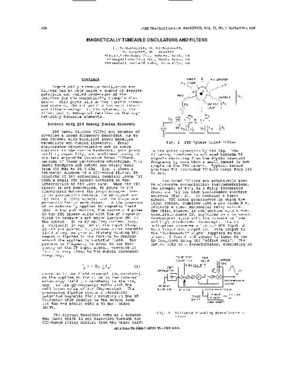
from 5 0 0 MHz to 2 6 . 5 GHz. Fig. 1 shows a
schematic diagram of a YIG-tuned filter. It
consists of two orthogonal coupling loops [l]
with a small YIG sphere centered on the
intersection of the loop axes. When the YIG
sphere is not magnetized, RF power is not
transferred between the loops because there
is no interaction between the RF signal and
the ferrite (YIG) sphere, and the loops are
perpendicular to each other. In the presence
of an externally applied DC magnetic field
(Ho) in the z-direction, the magnetic dipoles
in the YIG sphere align with the DC magnetic
field to produce a net magnetization (M) in
the sphere. If an RF driving current (say,
i exp[jwt]) is applied at the input (loop
in the x-z plane), it produces an RF magnetic
field along the y-axis, thereby causing the
magnetic dipoles in the ferrite to precess
around the applied DC magnetic field. The
precession frequency is equal to the frequency of the RF input signal, provided it
is at or very close to the dipole resonance
frequency,
Fig.
1
YIG Sphere Tuned Filter
in the other direction by 1 8 0 deg. The
filtering function is achieved because RF
signals deviating from the dipole resonant
frequency by more than a small amount do not
couple to the YIG sphere. Typical loaded
Q-values for YIG-tuned filters range from 1 0 0
to 4 0 0 .
YIG tuned filters are extensively used
in microwave communication instrumentations.
One example of this is a fully integrated
front end [ 2 ] for high performance spectrum
analyzer (Fig. 2). It contains a three
sphere, YIG tuned preselector in which the
input sphere, combined with a pin diode MIC,
replaces a slow, mechanical relay switch,
The third sphere, in conjunction with a GaAs
monolithic diode IC, functions as a balanced,
fundamental mixer with low conversion loss
and high third-order intercept. The LO
multiplier converts a 3 . 0 - 6 . 7 GHz input LO
to a 3 - 2 2 . 3 GHz output LO. This output is
the lrfundamental"signal supplied to the
mixer. A fourth YIG sphere is tuned to the
LO frequency using the "offset coil". The
sphere acts as a discriminator, generating an
TO RF FIRST
CONVERTOR
where Ho is the field strength (in oersteds)
of the applied DC field, Ha is the internal
anisotropy field (in oersteds) in the YIG,
and
is the gyromagnetic ratio with the
well-known value of 2.8 MHz/oersted. The
precessing dipoles create a circularly
polarized magnetic field rotating at the RF
frequency that couples to the output loop
(in the y-z plane) with a 9 0 deg. phase
shift.
The circuit therefore acts as a gyrator
the phase shift in one direction through the
YIG-tuned filter differs from the phase shift
321.4
M H IF
~
, , OFFSE1
DC-22 GHz
GHz LO
LO MULTIPLIER
zyxwvuts
Fig.
2
Switched Tracking Preselector
Mixer
0018-9464/89/0900-3248$01.0001989 IEEE
-
�3249
zy
error voltage signal which is fed back to the
magnetic tuning circuitry in order to frequency lock the preselector. This eliminates
swept amplitude inaccuracies in the filter
caused by the nonlinearity, hystersis, and
eddy current delay in the magnetic tuning
elements. Fig. 3 shows the center puck of
this integrated component.
zyxwvutsrq
zyxw
zyxwvut
zyxwvuts
zyxwvutsr
/
&
YIG SPHERE
YIG Sphere Tuned Oscillators (YTOs)
Fig. 4
YIG sphere tuned oscillators (YTOs) are
important components of modern communication
systems. They are used in many applications
that require broad frequency coverage and low
noise, such as high performance local oscillators and synthesizers. YIG resonators used
in YTOs have excellent linearity and can tune
over one decade of bandwidth, in addition to
exhibiting high unloaded Q t s (1000 to 5 0 0 0 )
that help to minimize phase noise.
T,
s,;
Fig. 4 shows the equivalent circuit of a
spherical YIG resonator with coupling loop,
Lo, Ro, and CO can be calculated from well
established formulas [ 3 ] . Lc is the inductance of the coupling loop.
Currently the most common YTO topology
is the negative resistance reflection oscillator. It consists of a YIG resonator
connected to an active device, usually a
silicon bipolar transistor or a GaAs FET.
Negative resistance is produced by the
active device through positive feedback.
Fig. 5 illustrates this general topology.
For oscillation to start, the product of the
reflection coefficient of the resonator TL
and the reflection coefficient of the input
port S11' must be greater than or equal to
one. In equation form,
(3)
Equivalent Circuit for YIG in
LOOP
2,
2 1
Fig.
5
General YTO Topology
after oscillation has stabilized, the magnitude of TL becomes equal to the magnitude
of S11' while the phase of TL (OL) becomes
opposite to the phase of Silt (Os). In
equation form,
zyxwvu
(4)
eL
=
es
(5)
The common-base configuration for silicon
bipolars and common-gate configuration for
GaAs FETs are the most common topologies for
generating negative admittance across the YIG
resonator. These configurations are shown in
Figures 6a and 6b, respectively.
" - 4
b
b.
COMMON BASE
COMMON GATE
Fig.
Fig. 3
Center Puck
A
6
a.
6
Sample YTO Topologies
A
z
�3250
zyxwvutsrqponm
zyx
zyxwvutsrqp
zyxwvutsr
Other topologies have been reported.
Fig. 6c shows the flsource capacitor" feedback
topology [4]. The MESFET transforms the
reactive source termination into a capacitive
reactance and negative resistance at the
gate. Typically a negative resistance is
also presented at the drain. Figure 6d shows
the topology of oscillators built by Letron
et a1 [5] utilizing two coupling loops with
separate spheres. The resonant frequencies
were slightly offset to realize a capacitive
termination at the source and the appropriate
inductive impedance for oscillation at the
gate. A 3.5 - 14 GHz oscillator was also
constructed by coupling two loops to the same
sphere as shown in fig. 6e.[6!.
Schiebold
extended these works by building a 3.5 - 19.5
GHz oscillator also with two loops coupled to
the same sphere [7]. The terminating impedances and sphere feedback were optimized
along with interloop capacitive coupling and
angular spacing. Since the resonator is
doubly loaded, phase noise performance is
compromised.
Although bipolar YTOs have 10 to 15 dB
lower phase noise than comparable GaAs FET
YTOs, bipolar YTOs have largely been limited
to low frequency operation (below 10 GHz) due
to the lower fT of bipolar transistors. With
the availability of submicron bipolar transistors from NEC (ie NE64700 and NE64800),
however, broadband 3-18 GHz bipolar based
YTOs have become feasible.
I
of the transducer width and YIG film width
wideband filters, tuning from .3 to 12 GHz
have been built with insertion loss of 1634 dB and off resonance isolation >45 dB.
'a6
d.
C.
e.
SOURCE FEEDBACK TOPOLOGIES
Fig. 6
Sample YTO Topologies
zyxwvuts
BIAS FIELD ORlENTATlQN
@
Above 18 GHz, YTOs still have to rely on
GaAs FETS or GUNN diodes as active devices.
Both devices work well up to 40 GHz with GaAs
FETs exhibiting better DC to RF conversion
efficiency than Gunn diodes.
DISPERSION DIAGRAM
Msw"p
k
YIG Film Tuned Devices
Thin films of YIG grown by liquid phase
epitaxy (LPE) on gadolinium gallium garnet
(GGG) substrates are used for nearly all MSW
devices presently reported. Three pure MSW
modes exist [8-101 depending on the orientation of bias magnetic field relative to the
YIG film and the propagation direction.
These modes are: magnetostatic surface waves
(MSSWs), magnetostatic forward volume waves
(MSFVWs) and magnetostatic backward volume
(MSBVWs) with frequency limits shown in Fig.
7. All three modes are dispersive, with the
dispersion modified by the boundary conditions [11, 121. coupling of microwave circuits to the spin waves in an MSW device is
commonly done with short circuited or open
circuited microstrip transducers in meander
line or grating configuration. The entire
MSSW, MSFVW or MSBVW frequency band can be
excited by using microstrip transducers as
narrow as 10 um.
Fig. 7
MSW Filters
Filters can be built using MSW devices
in either a delay line or a resonator configuration. Narrowband filters built utilizing
MSW delay lines have been demonstrated in the
3-7 GHz range with low passband ripple as
shown in Fig. 8. The bandwidth of this
filter is -30-50 MHz. By careful adjustment
zyxwv
START
STOP
Fig.
MSW Dispersion
8
3 000000800 GHz
7 0000140W00 GI4z
MSW Narrowband Filter
�325 1
MSW straight edge resonators (SERs) can
be formed by placing a ferrimagnetic resonator cavity on a thin film transducer structure (Fig. 9). The resonant cavity is made
of a piece of GGG/YIG cut into a rectangle by
a wafer SAW. Short circuited microstrip
transducers couple the energy in and out of
the resonator, which can use MSSWs or MSFVWs.
These waves propagate along the surface of
the YIG film and are reflected back at the
straight edges resulting in a high Q resonator. A MSSW SER was built which tuned from
1-22 GHz with the performance shown in Fig.
10. Thick YIG films were used to increase
the power handling capability and the 1 dB
power compression level was above 0 dBm for
this device over most of the tuning range.
One port SERs using MSSWs and MSFVWs suitable for tuneable oscillator applications
have been reported by Kunz et a1 [14].
zy
TOP VIEW
zyxwvutsrqpo
zyxwvutsrqpon
zyxwvuts
q
SIDE VIEW
YlOlGGG
@J HYSSW
GROUND PLANE
'
Fig. 9 MSW Straight Edge Resonator
Oscillators
Two configurations for MSW oscillators
have been built to date: the first uses a
two port delay line or resonator in a feedback configuration while the second uses a
one port resonator in a reflection configuration.
The schematic for a two-port feedback
oscillator using an MSW delay line is shown
in Fig. 11. Oscillations occur at frequencies where the loop gain exceeds unity and
the phase shifts around the loop are 2rn.
The delay line oscillators exhibit good phase
noise and tuning range (4-24 GHz) but have
problems with multimoding and modehopping as
well as oscillation dropouts over parts of
the tuning range. The multimoding can be
solved by changing coupling gratings but
the oscillation dropouts are generic to the
two port feedback configuration as the
integer n in the 2an of phase shift around
the loop increments to higher numbers with
increasing frequency. If the MSW delayline
is replaced with an MSW resonator in the
feedback configuration you can get rid of
the mode hopping problems and also use a
smaller magnet. The oscillation dropout
problem is not helped by using the resonator
however.
: am
4:
0
2
zy
4
6
zyxwvutsrq
8
10
12
14
16
18
20
FREQUENCY ( G k )
I
0,
MAIN R W N A N C E
-
SPUmOUSYODE2
4
6
8
10
12
14
16
18
20
FREQUENCY ( G k )
Fig. 10 MSW SER Performance
A one port oscillator can be constructed
by replacing the sphere in Fig. 6a with a
MSW-SER. Kunz et a1 have designed and tested
several oscillators in the 1.4-4.0 and 3-9
GHz regions with bipolar transistors as the
active device. Tuneable oscillations with no
dropouts were achieved with typical phase
noise of -105 dBc/Hz @ 10 KHz off the
carrier.
zyxwvutsrq
YSW DELAY LINE
DIRECTIDNAL
AMPLIFIER
Fig. 11 MSW Delay Line Oscillator
�3252
zyxwvutsrqponm
zyxwvuts
zyxwv
Hexasonal Ferrite Sphere Tuning
MAGNET POLE
k
Although YIG can be tuned to an arbitrarily high frequency as long as a suitably
strong magnetic field can be generated,
alloys with low hysterisis and high permeability for magnets saturate at -15K gauss,
and generating fields higher than this also
begins to consume considerable power. From
equation #1 it can be seen that if a ferrite
material with a high Ha is available the
applied magnetic field needed to tune to
high frequencies could be greatly reduced.
The hexagonal ferrites are a class of
materials like this. There are many different phases and dopings available such that
the anisotropy field for these materials can
vary from -0 XOe up to >30K Oe [15]. Using
hexagonal ferrites, researchers have made
one, two, three and four sphere filters [16,
17, 181 as well as tuneable oscillators that
operate in the millimeter wave region [19].
At this time all known devices using hexagonal ferrites use spheres, although there
there have been several reports of thin film
growth of hexagonal ferrites which could be
used for MSW devices.
zyxw
I
Fig. 12
:L,
Two Sphere Hexagonal Ferrite
Filter
Hexasonal Ferrite Tuned Filters
YIG sphere filters typically have
coaxial inputs and outputs with loop coupling
(Fig. 1) to the YIG spheres. Hexagonal
ferrite bandpass filters have also been built
with loop coupling, but the more common
method is to use waveguide inputs, outputs
and coupling to the spheres like the two
sphere filter shown in Fig. 12.
0
40
30
20
10
50
Fig. 13
zyxw
zyxwvut
60
70
80
90
100
x Of Band
Two Sphere Filter O R 1
zyxwvutsrqp
zyxwvutsrq
The input and output waveguides are
crossed at 90 deg. angles to create a
magnetic field mode mismatch and increase off
resonance isolation ( O R I ) . Two sphere
hexagonal ferrite tuned filters have been
built in waveguide bands [18] from A band,
26 1/2-40 GHz, to W band, 75-110 GHz, with
typical insertion loss of -6 dB (7-8 dB for
75-110 GHz) and O R 1 as shown in Fig. 13.
Magnets used to tune all of these filters
were made out of 48% Ni, 51% Fe low
hysterisis material. In order to increase
the O R I , a four sphere filter was designed
and built combining two, two sphere crossed
waveguide filters under one magnet assembly.
The O R 1 of these four sphere filters is
typically >75 d% with typical insertion loss
of -10 dB. The response of a four sphere
filter displayed at 20 points across the band
is shown in Fig. 14 with -6 dB I.L.
57STmr
75.0000.0000
50.00.O00000
Linz
Linl
Fig. 14 Four Sphere Filter Response
Hexasonal Ferrite Tuned Oscillators
Oscillators tuned by an hexagonal
ferrite sphere were first reported by Lemke
[19] with a GaAs Gunn Diode being tuned by a
barium ferrite sphere from 62.5-65.7 GHz with
-7 mW output power. By utilizing InP Gunn
Diodes which can oscillate much more efficiently at mm waves, later researchers [20]
produced an oscillator that used an hexagonal
ferrite sphere to tune from 40-50 GHz with
-10 mW output power as shown in Fig. 15.
2
8-
I [COIL-lnP BARIUMI
4 ~
0
InP (BARIUM FERRITE)'
33 34
'
35
'
36
'
I
37 38
_ _ _ - -L-= - ,
,
30 40 41
42 43
'
44 45
"
I
46 47
48 48 50
FREQUENCY (GHz)
Fig. 15 Hexagonal Ferrite Tuned
Oscillator Response
�zyxwvutsr
zyxwvutsr
zyxwvutsr
3253
Conclusion
Magnetically tuneable filters and oscillators can be built throughout the 5 0 0 MHz
1 1 0 GHz range. They can be built with YIG
spheres, YIG thin films or hexagonal ferrite
spheres as the tuning element to cover broad
bandwidths, and they fill a unique role in
the world of microwave components.
-
References
r11
P.S. Carter, Jr., "Equivalent Circuit of
Orthogonal-Loop Coupled Magnetic
Resonance Filters and Bandwidth Narrowing Due to Coupling Inductance*t,vol.
MTT-18, no. 2 , pp. 1 0 0 - 1 0 5 , Feb. 1 9 7 0 .
[21
H . Tanbakuchi, "A Broadband Tracking YIG
[31
Tuned Mixer For a State of the Aqt
Spectrum Analyzert1,17th European Microwave Conf., Sept. 1 9 8 7 , pp. 4 8 2 - 4 9 0 .
P.M. Ollivier,llMicrowaveYIG-Tuned
Transistor Oscillator Amplifier
Design:Application to C Band", IEEE
Journal of Solid State Circuits, vol.
S C - 7 , pp. 5 4 - 6 0 , Feb. 1 9 7 2 .
R.T.Oyafuso,IlAn 8 - 1 8 GHZ FET YIG-Tuned
Oscillator1v,Proc. of IEEE MTT Symp.
1 9 7 9 , pp. 1 8 3 - 1 8 4 .
pp. 1 8 3 - 1 8 4 .
[51
Y. Letron et all "Broadband YIG-Tuned
FET Oscil1ators1l, Proceedings of the
European Microwave Conference, 1 9 7 8 , pp.
r71
[81
[ l l ] T.W. O'Keefe and R.W. Patterson,
I1Magnetostatic Surface Wave Propogation
in Finite Samplesg1,J. Appl. Phys., vol.
4 9 , pp. 4 8 8 6 - 4 8 9 5 , Sept. 1 9 7 8 .
[ 1 2 ] J.D. Adam and S.N. Bajpai, "Magneto-
static Forward Volume Wave Propogation
in YIG Strips", IEEE Trans. Magn. vol.
MAG - 1 8 , pp. 1 5 9 8 - 1 6 0 0 , Sept. 1 9 8 2 .
[ 1 3 ] W.S. Ishak, "Magnetostatic Wave Technology: A Review", IEEE Proc. , vol. 7 6 ,
pp. 1 7 1 - 1 8 7 , Feb. 1 9 8 8 .
[ 1 4 ] W.E. Kunz, K.W. Chang, and W.S. Ishak,
"MSW-SER Based Tuneable Oscillatorsg1,
Proc. IEEE Ultrasonics Symp., 1 9 8 6 .
[ 1 5 ] G. Winkler and H. Dotsch, "Hexagonal
Ferrites at Millimeter Wavelengthsp1,
Proc. of 9th Euro. Microwave Conf.,
pp. 1 3 - 1 9 , 1 9 7 9 .
Lemke et all "Magnetically Tuneable
Millimeter-Wave Filter with SingleCrystal Barium Ferriten1,Microwaves,
Optics, and Acoustics, vol. 3 , pp. 2 5 3 2 5 4 , Nov. 1 9 7 9 .
[ 1 6 ] M.
[ 1 7 ] J.A. Sweschenikow et all "Bandfilter aus
274-278.
Hexaferriten im Mikrowel1enbereichl1,
Nachrichtechnik Elektronik, vol. 2 6 , pp.
Y. Letron et all Wultioctave FET
Oscillators Double Tuned by a Single
YIGII, IEEE Int. Solid State Circuit
Conf., 1 9 7 9 , pp 1 6 2 - 1 6 3 .
262-264,
C.F. Schiebold, "An Approach to
Realizing Multioctave Performance in
GaAs FET YIG-Tuned Oscillators, "IEEE
MTT-S Digest, 1 9 8 5 , pp. 2 6 1 - 2 6 3 .
R.W. Damon and J.R. Eshbach, Magnetostatic Modes of a Ferromagnetic Slab",
J. Phys. Chem. Solids, vol. 1 9 , pp. 308320, 1961.
r91
teristics of Magnetostatic Waves", Circuits Syst. sign. Processing, vol. 4 ,
pp. 9 - 3 9 , 1 9 8 5 .
zyxwvut
r41
161
[ l o ] J.P. Parekh et all I'Propogation Charac-
W. L. Bongianni, "Magnetostatic Propagation in a Dielectric Layered Structure",
J. Appl. Phys., Vol. 4 3 , pp. 2 5 4 1 - 2 5 4 4 ,
1972.
1976.
[ 1 8 ] D. Nicholson, "Ferrite Tuned Millimeter
Wave Bandpass Filters with High Off
Resonance Isolationt1,Proc. of IEEE MTT
Symp., 1 9 8 8 , pp. 8 6 7 - 8 7 0 .
Lemke, "A Millimeter-Wave Gunn Oscillator, Tuneable with a Barium-Ferrite
Spherefo,Proc. of 9th Euro. Microwave
Conf., 1 9 7 9 , pp. 6 1 7 - 6 2 0 .
[ 1 9 ] M.
[ 2 0 ] Y.S. Lau and D. Nicholson, "Barium
Ferrite Tuned-Indium Phosphide Gunn
Millimeter Wave Oscillators', Proc. of
IEEE MTT Spp., 1 9 8 6 , pp. 1 8 3 - 1 8 6 .
�
 Dean Nicholson