WO2025142412A1 - Stent - Google Patents
Stent Download PDFInfo
- Publication number
- WO2025142412A1 WO2025142412A1 PCT/JP2024/043332 JP2024043332W WO2025142412A1 WO 2025142412 A1 WO2025142412 A1 WO 2025142412A1 JP 2024043332 W JP2024043332 W JP 2024043332W WO 2025142412 A1 WO2025142412 A1 WO 2025142412A1
- Authority
- WO
- WIPO (PCT)
- Prior art keywords
- stent
- stent body
- struts
- cell
- strut
- Prior art date
- Legal status (The legal status is an assumption and is not a legal conclusion. Google has not performed a legal analysis and makes no representation as to the accuracy of the status listed.)
- Pending
Links
Images


Classifications
-
- A—HUMAN NECESSITIES
- A61—MEDICAL OR VETERINARY SCIENCE; HYGIENE
- A61F—FILTERS IMPLANTABLE INTO BLOOD VESSELS; PROSTHESES; DEVICES PROVIDING PATENCY TO, OR PREVENTING COLLAPSING OF, TUBULAR STRUCTURES OF THE BODY, e.g. STENTS; ORTHOPAEDIC, NURSING OR CONTRACEPTIVE DEVICES; FOMENTATION; TREATMENT OR PROTECTION OF EYES OR EARS; BANDAGES, DRESSINGS OR ABSORBENT PADS; FIRST-AID KITS
- A61F2/00—Filters implantable into blood vessels; Prostheses, i.e. artificial substitutes or replacements for parts of the body; Appliances for connecting them with the body; Devices providing patency to, or preventing collapsing of, tubular structures of the body, e.g. stents
- A61F2/82—Devices providing patency to, or preventing collapsing of, tubular structures of the body, e.g. stents
- A61F2/852—Two or more distinct overlapping stents
-
- A—HUMAN NECESSITIES
- A61—MEDICAL OR VETERINARY SCIENCE; HYGIENE
- A61F—FILTERS IMPLANTABLE INTO BLOOD VESSELS; PROSTHESES; DEVICES PROVIDING PATENCY TO, OR PREVENTING COLLAPSING OF, TUBULAR STRUCTURES OF THE BODY, e.g. STENTS; ORTHOPAEDIC, NURSING OR CONTRACEPTIVE DEVICES; FOMENTATION; TREATMENT OR PROTECTION OF EYES OR EARS; BANDAGES, DRESSINGS OR ABSORBENT PADS; FIRST-AID KITS
- A61F2/00—Filters implantable into blood vessels; Prostheses, i.e. artificial substitutes or replacements for parts of the body; Appliances for connecting them with the body; Devices providing patency to, or preventing collapsing of, tubular structures of the body, e.g. stents
- A61F2/82—Devices providing patency to, or preventing collapsing of, tubular structures of the body, e.g. stents
- A61F2/86—Stents in a form characterised by the wire-like elements; Stents in the form characterised by a net-like or mesh-like structure
- A61F2/90—Stents in a form characterised by the wire-like elements; Stents in the form characterised by a net-like or mesh-like structure characterised by a net-like or mesh-like structure
Definitions
- This disclosure relates to stents.
- catheter therapy has been known in which a stent is deployed at the lesion site in the blood vessel lumen.
- Patent Document 3 the cutting balloon catheter disclosed in Patent Document 3 is manufactured by attaching a cutting member to a balloon, which makes manufacturing difficult and also poses the risk of the cutting member falling off the balloon.
- the objective of this disclosure is to provide a stent that is highly safe and has excellent expandability.
- the second disclosure is a stent (1, 1B) in which, in the stent (1) described in claim 1, the outer struts (11) are arranged in an area of the cylindrical portion (1a) where the mesh pattern of the outer stent body (10) is coarser than the mesh pattern of the inner stent body (20), and function as the blade portion.
- the fourth disclosure is a stent (1, 1B) according to claim 3, in which the blade portion where the outer strut (11) is partially twisted in the cylindrical portion (1a) that expands into a cylindrical shape in a freely expanding state protrudes outward from the cylindrical shape formed by the surface of the outer strut (11) other than the blade portion.
- the fifth disclosure is a stent (1, 1B) according to any one of claims 1 to 4, in which the width of the outer stent body (10, 10B) in a direction perpendicular to the extending direction of the blade portion as viewed from the radial direction is 0.5 mm or less.
- the sixth disclosure is a method for expanding a biological organ having a luminal structure using a stent (1, 1B), the stent (1, 1B) comprising an outer stent body (10, 10B) in which a plurality of outer cells (12) surrounded by outer struts (11) are arranged at least in the central axis direction, and an inner stent body (20, 20B) in which a plurality of inner cells (22, 22A, 22B, 22C) surrounded by inner struts (21, 21A, 21B) are arranged at least in the central axis direction and inserted into the outer stent body (10, 10B) at least in the region in which the biological lumen is expanded, and in a cylindrical portion (1a) in which the stent (1, 1B) expands into a cylindrical shape in a free state in which the diameter of the stent (1, 1B) is freely expanded, the outermost portion in the radial direction of the inner stent body (20, 20B) is inserted into the
- the outer outermost surface has an area smaller than that of the inner outermost surface and has a blade portion for cutting into a lesion site in a biological lumen
- the method includes delivering the stent (1, 1B) housed in a catheter (50) in a contracted state together with the catheter (50) through the biological organ to a planned position of expansion of the biological organ, withdrawing the catheter (50) proximally and starting the expansion of the stent (1, 1B) from the distal side, completing the expansion of the stent (1, 1B), and re-accommodating the expanded stent (1, 1B) into the catheter (50).
- This disclosure makes it possible to provide a stent that is highly safe and has excellent expandability.
- FIG. 1 is a side view of a stent 1 according to a first embodiment.
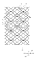
- FIG. 2 is a virtual development view of a part of a cylindrical portion 1a of an outer stent body 10 and an inner stent body 20 of the first embodiment.
- FIG. 2 is a virtual development view of a part of the cylindrical portion 1a of the outer stent body 10 of the first embodiment.
- FIG. 2 is a virtual development view of a part of the cylindrical portion 1a of the inner stent body 20 of the first embodiment.
- FIG. 2 is a diagram illustrating the outer diameter D1 of the outer stent body 10 before assembly.
- FIG. 2 is a diagram illustrating the outer diameter D2 of the inner stent body 20 before assembly.
- FIG. 1A to 1C are diagrams showing a process of inserting an inner stent body 20 into an outer stent body 10. This is a cross-sectional view taken along line s1-s1 in FIG.
- FIG. 13 is a schematic side view of a stent 1B according to a second embodiment.
- FIG. 11 is a virtual development view of a part of a cylindrical portion 1a of an outer stent body 10B and an inner stent body 20B of a second embodiment.
- FIG. 11 is a virtual development view of a part of a cylindrical portion 1a of an outer stent body 10B of a second embodiment.
- FIG. 11 is a virtual development view of a part of a cylindrical portion 1a of an inner stent body 20B of the second embodiment.
- FIG. 2 is an enlarged perspective view of a twisted portion 16.
- FIG. 13 is a diagram showing a state before the twisting portion 16 is twisted.
- FIG. 13 is a view of a stent 1B of a second embodiment as viewed from the distal LD2 side.
- FIG. 13 is a diagram showing a modification of the second embodiment.
- FIG. 1C is a side view of a stent 1C according to a third embodiment.
- 1A to 1C are schematic diagrams showing a procedure for expanding a stenosed area in a blood vessel using a stent 1.
- 1A to 1C are schematic diagrams showing a procedure for expanding a stenosed area in a blood vessel using a stent 1.
- 1A to 1C are schematic diagrams showing a procedure for expanding a stenosed area in a blood vessel using a stent 1.
- 1A to 1C are schematic diagrams showing a procedure for expanding a stenosed area in a blood vessel using a stent 1.
- the shape, geometric conditions, and the degree of these include the strict meaning of the term as well as the range in which it can be considered nearly orthogonal and the range in which it can be considered roughly in that direction.
- the side closer to the practitioner in the axial direction (longitudinal direction) LD is the LD1 side (or proximal LD1 side), and the side farther from the practitioner is the LD2 side (or distal LD2 side), and the direction perpendicular to the axial direction LD is the radial direction RD.
- the direction in which the cells are arranged is the circumferential direction OD.
- the circumferential direction may be the radial direction RD or a direction inclined relative to the radial direction RD.
- Fig. 1 is a side view of a stent 1 of the first embodiment.
- Fig. 2A is a virtual development view of a part of a cylindrical portion 1a of an outer stent body 10 and an inner stent body 20 of the first embodiment.
- Fig. 2B is a virtual development view of a part of a cylindrical portion 1a of the outer stent body 10 of the first embodiment.
- Fig. 2C is a virtual development view of a part of a cylindrical portion 1a of the inner stent body 20 of the first embodiment.
- a "cell” refers to a portion surrounded by struts that form a stent.
- the “cells” may be the same in shape and size, or may be different from each other.
- a “strut” refers to a portion made of the wire-like material. In this specification, etc., the opening of a cell is called an “opening portion,” and the portion where the struts of adjacent cells are connected or overlapped is called an "overlapping portion.”
- the stent 1 of the first embodiment can be used, for example, to dilate a narrowed or blocked blood vessel by being housed in a catheter and being pushed out of the catheter in the blood vessel lumen to expand in diameter.
- the stent 1 is used in applications where it is temporarily placed in the blood vessel and then retrieved from the body, but it can also be used to leave the stent 1 in the blood vessel without being retrieved from the body. When used in such applications, it is preferable to configure the stent 1 so that the wire 2 and the stent 1 can be separated by the operator's operation.
- the stent 1 has a cylindrical portion 1a and a converging portion 1b.
- the cylindrical portion 1a In a free state where the diameter is freely expanded, the cylindrical portion 1a has a cylindrical shape as shown in Figs. 3A and 3B described later, and has a mesh pattern structure composed of outer cells 12 and inner cells 22 described later.
- the converging portion 1b is a portion where the proximal LD1 side of the cylindrical portion 1a converges to the wire 2.
- the stent 1 is configured to have a substantially cylindrical shape when it is taken out of the catheter and expanded in a free state (see Figs. 3A and 3B described later). Although not shown, the stent 1 has an elongated cylindrical shape in a contracted state.
- the stent 1 comprises an outer stent body 10 and an inner stent body 20, which are substantially cylindrical structures.
- the stent 1 is configured as a two-layered stent in which the inner stent body 20 is inserted into the outer stent body 10 at least in the region that expands the narrowed portion of the biological lumen.
- the region that expands the narrowed portion of the biological lumen refers to the region that substantially contributes to the expansion of the narrowed portion when in use, and in the case of the stent 1 of this embodiment, it refers to the region that expands into a substantially cylindrical shape in the expanded state shown in Figure 1.
- the outer stent body 10 and the inner stent body 20 are not connected to each other in the radial direction.
- the outer stent body 10 and the inner stent body 20 are connected via the wire 2, but are not connected in other areas. Therefore, the stent 1 allows the outer stent body 10 and the inner stent body 20 to deform independently on each layer.
- the outer stent body 10 and the inner stent body 20 are only in close contact with each other in the radial direction and are not connected (connected) to each other in the radial direction. Therefore, the outer stent body 10 and the inner stent body 20 are in a state where they can deform independently and do not restrict each other's deformation.
- the proximal LD1 side of the outer stent body 10, the proximal LD1 side of the inner stent body 20, and the distal LD2 side of the wire 2 are directly connected.
- directly connected means, for example, that the proximal LD1 side of the outer stent body 10 is connected to the distal LD2 side of the wire 2, and the proximal LD1 side of the inner stent body 20 is connected to the distal LD2 side of the wire 2.
- the position where the proximal LD1 side of the outer stent body 10 is connected to the wire 2 and the position where the proximal LD1 side of the inner stent body 20 is connected to the wire 2 may be the same or different.
- the proximal LD1 side of the inner stent body 20 is indirectly connected to the wire 2 via the proximal LD1 side of the outer stent body 10.
- the proximal LD1 side of the outer stent body 10 and the proximal LD1 side of the inner stent body 20 are connected via a pipe-shaped sleeve (not shown) that is inserted onto the distal LD2 side of the wire 2.
- the proximal LD1 side of the outer stent body 10 and the proximal LD1 side of the inner stent body 20 are indirectly connected to the distal LD2 side of the wire 2 via the sleeve.
- the stent 1 of the first embodiment is produced by inserting the inner stent body 20, which has an outer diameter larger than that of the outer stent body 10, into the outer stent body 10 in a contracted state.
- the inserted inner stent body 20 is always pressing the outer stent body 10 outward in the radial direction RD. Therefore, the stent 1 can more firmly adhere the outer stent body 10 to the inner stent body 20 while maintaining a state in which the outer stent body 10 and the inner stent body 20 can deform independently on each layer.
- the outer stent body 10 has multiple outer cells 12 arranged in the circumferential direction OD, each of which is made up of outer struts 11 arranged to surround an area in a predetermined shape.
- the multiple outer cells 12 arranged in the circumferential direction OD are arranged in the axial direction LD.
- the outer stent body 10 has a mesh pattern in which the multiple outer cells 12 are arranged in the circumferential direction OD and the axial direction LD.
- the outer cells 12 have openings 13 formed therein.
- the outer cells 12 adjacent to each other in the circumferential direction OD are connected at overlapping portions 14.
- the overlapping portion 14 is a portion where the outer struts 11 of the four adjacent outer cells 12 are connected.
- the overlapping portion 14 has an elongated, approximately rectangular shape in the axial direction LD.
- Each outer strut 11 is connected to the four corners of the overlapping portion 14.
- a curved portion 15 is formed in each outer strut 11 at the portion where it is connected to the overlapping portion 14. Therefore, when the expanded stent 1 is bent into an approximately U-shape, each outer strut 11 connected to the overlapping portion 14 can be deformed independently. Therefore, the outer cells 12 arranged in the circumferential direction OD can be bent more flexibly. In this way, the outer stent body 10 has excellent shape conformability and diameter reduction properties because the outer cells 12 arranged in the circumferential direction OD can be bent flexibly.
- the inner stent body 20 has multiple inner cells (22A, 22B, 22C) arranged in the circumferential direction OD, each of which is made up of inner struts 21A, 21B arranged to surround an area in a predetermined shape. More specifically, a first inner cell 22A, a second inner cell 22B, and a third inner cell 22C are arranged in the circumferential direction OD.
- the first inner cell 22A has a similar shape to the outer cell 12, is surrounded by inner struts 21A, and is smaller than the outer cell 12.
- the width in the circumferential direction OD of the first inner cell 22A can be, for example, 20% to 60% of the width in the circumferential direction OD of the outer cell 12.
- the first inner cell 22A is arranged so that the center position of the first inner cell 22A and the center position of the outer cell 12 coincide when viewed from the radial direction RD.
- the second inner cell 22B is surrounded by the inner struts 21B and is formed in a similar shape to the outer cell 12 of the outer stent body 10, but smaller than the outer cell 12. Also, as shown in FIGS. 2A and 2B, the second inner cell 22B is formed in a similar shape to the outer cell 12, but larger than the first inner cell 22A.
- the second inner cell 22B is arranged so that the center position of the first inner cell 22A and the center position of the overlapping portion 14 of the outer stent body 10 coincide when viewed from the radial direction RD. Also, both ends of the second inner cell 22B in the circumferential direction OD are connected to the overlapping portion 24A provided at both ends of the circumferential direction OD of the first inner cell 22A.
- the first inner cell 22A and the second inner cell 22B which are connected and arranged in the circumferential direction OD as described above, are arranged in the axial direction LD.
- the first inner cell 22A and the second inner cell 22B are connected at the overlapping portion 24B. That is, the inner stent body 20 has a mesh pattern in which a plurality of first inner cells 22A and second inner cells 22B are arranged in the circumferential direction OD and the axial direction LD.
- the area surrounded by the first inner cell 22A and the second inner cell 22B is the third inner cell 22C, which is an irregularly shaped cell that is dissimilar in shape to the first inner cell 22A and the second inner cell 22B.
- the inner stent body 20 which has an outer diameter larger than that of the outer stent body 10, is reduced in diameter to form the inner stent body 20A, and this is inserted into the outer stent body 10.
- a two-layered stent 1 can be produced in which the inner stent body 20 is in close contact with the inside of the outer stent body 10 due to the self-expansion force of the inner stent body 20.
- Figure 4 shows only the annular cell rows arranged in the circumferential direction in each stent body, and the number of cells is greater than in other figures and the shape of the cells is simplified to make it easier to understand the tubular shape.
- the outer stent body 10 and the inner stent body 20 are in close contact with each other without any gaps in the radial direction RD due to the self-expansion force of the inner stent body 20 described above (see FIG. 5 described later). Therefore, the outer stent body 10 and the inner stent body 20 are less likely to be misaligned relative to each other in the axial direction LD of the stent 1 (see FIG. 1).
- the inner stent body 20 inserted into the outer stent body 10 in a contracted state is itself a self-expanding body (elastic body). Therefore, the inner stent body 20 is always in a state of pressing the outer stent body 10 outward in the radial direction RD. Therefore, even if the outer stent body 10 and the inner stent body 20 are not connected to each other in the radial direction, the outer stent body 10 and the inner stent body 20 can be more firmly attached to each other.
- the outer stent body 10 and the inner stent body 20 are not connected to each other in the radial direction, the outer stent body 10 and the inner stent body 20 can maintain a state in which they can deform independently on each layer. Furthermore, the two-layered stent 1 has an expansion force that is the sum of the expansion force of the outer stent body 10 and the expansion force of the inner stent body 20. Therefore, even if the surface area is the same, the expansion force can be made larger than that of a single-layered stent.
- the stent 1 (outer stent body 10, inner stent body 20) may be made of a material that is highly biocompatible. Although not particularly limited, a material with superelastic properties such as a nickel-titanium (Ni-Ti) alloy is preferable.
- the outer stent body 10 and inner stent body 20 can be produced, for example, by laser processing a roughly cylindrical tube made of the above material.
- the stent 1 may be loaded with a drug such as a physiologically active substance (such as a drug that inhibits intimal thickening), and more specifically, may carry the drug so that the drug is dissolved in the lumen structure.
- a drug such as a physiologically active substance (such as a drug that inhibits intimal thickening)
- a physiologically active substance such as a drug that inhibits intimal thickening
- the outer stent body 10 and the inner stent body 20 are produced, for example, by laser processing a tube with an outer diameter of about 0.4 to 3 mm to form a mesh pattern, and then stretching it radially to obtain the desired diameter.
- a two-layered stent 1 can be produced by inserting the inner stent body 20 into the outer stent body 10. This two-layered stent 1 is housed in the lumen of a catheter (not shown) in a state where it has been radially contracted from its natural state. If the stent is made of an elastic material such as a superelastic alloy or a shape-memory alloy, the stent 1 housed in the catheter will attempt to expand in diameter by its own expansion force when pushed outward.
- the first inner cell 22A is formed in a similar shape to the outer cell 12, which is smaller than the outer cell 12, and is arranged so that the center position of the first inner cell 22A coincides with the center position of the outer cell 12 when viewed from the radial direction RD.
- the mesh pattern of the outer stent body 10 is coarser than the mesh pattern of the inner stent body 20.
- the width of the outer strut 11 of the outer stent body 10 is approximately equal to the width of the inner strut 21A and the inner strut 21B of the inner stent body 20, or is narrower than the width of the inner strut 21A and the inner strut 21B of the inner stent body 20.
- the surface located most outside in the radial direction of the inner stent body 20 is called the inner outermost surface
- the surface located most outside in the radial direction of the outer stent body 10 is called the outer outermost surface.
- the outer outermost surface is the surface of the shape of the outer stent body 10 within the range of the cylindrical portion 1a shown in the development diagram of FIG. 2B.
- the inner outermost surface is the surface of the shape of the inner stent body 20 within the range of the cylindrical portion 1a shown in the development diagram of FIG. 2C.
- the mesh pattern of the outer stent body 10 is coarser than the mesh pattern of the inner stent body 20. Therefore, the area of the outer outermost surface is smaller than the area of the inner outermost surface.
- the outer outermost surface of the outer stent body 10, mainly the outer struts 11, function as a blade portion that makes an incision into the diseased site in the biological lumen.
- FIG. 5 is a cross-sectional view taken along line s1-s1 in FIG. 1.
- the mesh pattern of the outer stent body 10 is coarser than that of the inner stent body 20, so the outermost surface area of the outer struts 11 of the outer stent body 10, which come into contact with the inner wall of the biological lumen first, is small, and the expansion force of the entire stent 1 is concentrated and acts on this small surface area.
- the expansion force of the entire stent 1 is the sum of the expansion forces of the outer stent body 10 and the inner stent body 20. Therefore, a large expansion force is concentrated and acts on the outer struts 11 of the outer stent body 10, which have a small surface area and come into contact with the inner wall of the biological lumen first.
- the outer struts 11 act as a blade that presses a very thin linear body strongly against the inner wall of the biological lumen, making it possible to cut, for example, calcified lesions in blood vessels during the expansion process of the stent 1.
- the width of the blade portion (outer strut 11) in the expanded state in the direction perpendicular to the extension direction as viewed from the radial direction of the outer stent body 10 is 0.5 mm or less.
- the mesh pattern of the inner stent body 20 is finer than that of the outer stent body 10.
- the width of the inner struts 21A and 21B of the inner stent body 20 is equal to or wider than the width of the outer struts 11 of the outer stent body 10. Therefore, the inner stent body 20 abuts against the inner wall of the biological lumen, preventing the outer struts 11 from cutting into the inner wall of the biological lumen more than necessary.
- the outer struts 11 can promote expansion by making cuts, and in a situation where the inner stent body 20 abuts against the inner wall of the biological lumen, the cuts made by the outer struts 11 are suppressed. In this way, the stent 1 of this embodiment has high expandability and is highly safe.
- the stent 1 of the first embodiment When the stent 1 of the first embodiment is expanded in the same way as a conventional normal stent is expanded, the outer struts 11 acting as blades strike first, applying concentrated force and cutting into the lesion, causing it to break. By making the cuts, even hard lesions can be expanded with less force than with a stent, and by making the cuts, it is possible to obtain the effect of smoothly expanding without expanding into a distorted shape due to the lesion.
- the stent 1 of the first embodiment has a self-expanding structure, and the operation itself is the same as that of a conventionally known two-layered stent, and it self-expands and spreads when deployed from a microcatheter.
Landscapes
- Health & Medical Sciences (AREA)
- Engineering & Computer Science (AREA)
- Biomedical Technology (AREA)
- Cardiology (AREA)
- Oral & Maxillofacial Surgery (AREA)
- Transplantation (AREA)
- Heart & Thoracic Surgery (AREA)
- Vascular Medicine (AREA)
- Life Sciences & Earth Sciences (AREA)
- Animal Behavior & Ethology (AREA)
- General Health & Medical Sciences (AREA)
- Public Health (AREA)
- Veterinary Medicine (AREA)
- Media Introduction/Drainage Providing Device (AREA)
Abstract
Description
本開示は、ステントに関する。 This disclosure relates to stents.
従来、ステントを血管内腔の病変部位で展開するカテーテル治療が知られている。 Conventionally, catheter therapy has been known in which a stent is deployed at the lesion site in the blood vessel lumen.
また、より表面積を大きくし、且つ、血管構造への形状追従性及び縮径性に優れるステントとして、外側のステント本体と、この外側のステント本体に内挿される内側のステント本体とを備えたステント(以下、2層構造ステントとも呼ぶ)が開示されている(特許文献2参照)。特許文献2に記載の2層構造ステントでは、外側のステント本体と内側のステント本体とが同じステントパターンとなっている。
Furthermore, as a stent with a larger surface area and excellent shape conformability to the vascular structure and diameter reduction properties, a stent with an outer stent body and an inner stent body inserted into the outer stent body (hereinafter also referred to as a two-layer structure stent) has been disclosed (see Patent Document 2). In the two-layer structure stent described in
また、血管の石灰病変等による狭窄部を拡張する治療を行う際に使用するカッティングバルーンカテーテルやスコアリングバルーンカテーテル等と呼ばれる医療器具も知られている(特許文献3参照)。 There are also known medical devices called cutting balloon catheters and scoring balloon catheters that are used to treat and expand narrowed areas caused by calcified lesions in blood vessels, etc. (see Patent Document 3).
しかし、特許文献3に開示されているカッティングバルーンカテーテルでは、バルーンに対してカッティング部材を取り付けて作製されるため、製造の難易度が高く、また、カッティング部材がバルーンから脱落するおそれが否定できなかった。 However, the cutting balloon catheter disclosed in Patent Document 3 is manufactured by attaching a cutting member to a balloon, which makes manufacturing difficult and also poses the risk of the cutting member falling off the balloon.
本開示の課題は、安全性が高く、拡張性に優れたステントを提供することである。 The objective of this disclosure is to provide a stent that is highly safe and has excellent expandability.
本開示は、以下のような解決手段により、前記課題を解決する。なお、理解を容易にするために、本開示の実施形態に対応する符号を付して説明するが、これに限定されるものではない。 The present disclosure solves the above problems by the following solutions. Note that, for ease of understanding, the following explanations are given with reference symbols corresponding to the embodiments of the present disclosure, but the present disclosure is not limited to these.
第1の開示は、ステント(1)であって、外側ストラット(11)により囲まれた複数の外側セル(12)が少なくとも中心軸方向に配列する外側ステント本体(10、10B)と、内側ストラット(21、21A、21B)により囲まれた複数の内側セル(22、22A、22B、22C)が少なくとも中心軸方向に配列され、少なくとも生体管腔を拡張させる領域において前記外側ステント本体(10、10B)に内挿される内側ステント本体(20、20B)と、を備え、前記ステント(1、1B)が自由に拡径した自由状態で円筒形状に拡径する円筒形状部(1a)において、前記内側ステント本体(20、20B)の径方向で最も外側に位置する面を内側最表面とし、前記外側ステント本体(10、10B)の径方向で最も外側に位置する面を外側最表面としたとき、前記外側最表面は、その面積が前記内側最表面の面積よりも小さく、生体管腔内の病変部位に切り込みを入れる刃部を有する、ステント(1、1B)である。 The first disclosure is a stent (1) comprising an outer stent body (10, 10B) in which a plurality of outer cells (12) surrounded by outer struts (11) are arranged at least in the central axis direction, and an inner stent body (20, 20B) in which a plurality of inner cells (22, 22A, 22B, 22C) surrounded by inner struts (21, 21A, 21B) are arranged at least in the central axis direction, and which is inserted into the outer stent body (10, 10B) at least in a region that expands a biological lumen. In the cylindrical section (1a) in which the stent (1, 1B) expands into a cylindrical shape when the stent (1, 1B) is in a free state, the surface located most outside in the radial direction of the inner stent body (20, 20B) is the inner outermost surface, and the surface located most outside in the radial direction of the outer stent body (10, 10B) is the outer outermost surface. The outer outermost surface has an area smaller than that of the inner outermost surface, and has a blade portion for cutting into a lesion in a biological lumen.
第2の開示は、請求項1に記載のステント(1)において、前記外側ストラット(11)のうち、前記円筒形状部(1a)において、前記外側ステント本体(10)のメッシュパターンが、前記内側ステント本体(20)のメッシュパターンよりも網目が粗い範囲に設けられた前記外側ストラット(11)が前記刃部として機能する、ステント(1、1B)である。
The second disclosure is a stent (1, 1B) in which, in the stent (1) described in
第3の開示は、請求項1に記載のステント(1B)において、前記外側ストラット(11)のうち、部分的に捩じられている部分が前記刃部として機能する、ステント(1B)である。
The third disclosure is a stent (1B) as described in
第4の開示は、請求項3に記載のステント(1B)において、自由に拡径した自由状態で円筒形状に拡径する円筒形状部(1a)において、前記外側ストラット(11)が部分的に捩じられている前記刃部は、前記刃部以外の前記外側ストラット(11)の表面が形成する円筒形状から外側へ突出している、ステント(1、1B)である。 The fourth disclosure is a stent (1, 1B) according to claim 3, in which the blade portion where the outer strut (11) is partially twisted in the cylindrical portion (1a) that expands into a cylindrical shape in a freely expanding state protrudes outward from the cylindrical shape formed by the surface of the outer strut (11) other than the blade portion.
第5の開示は、請求項1から請求項4までのいずれかに記載のステント(1、1B)において、前記外側ステント本体(10、10B)の径方向から見た前記刃部の延在方向に直交する方向の幅は、0.5mm以下である、ステント(1、1B)である。
The fifth disclosure is a stent (1, 1B) according to any one of
第6の開示は、ステント(1、1B)を用いて管腔構造を有する生体器官を拡張する方法であって、前記ステント(1、1B)は、外側ストラット(11)により囲まれた複数の外側セル(12)が少なくとも中心軸方向に配列する外側ステント本体(10、10B)と、内側ストラット(21、21A、21B)により囲まれた複数の内側セル(22、22A、22B、22C)が少なくとも中心軸方向に配列され、少なくとも生体管腔を拡張させる領域において前記外側ステント本体(10、10B)に内挿される内側ステント本体(20、20B)と、を備え、前記ステント(1、1B)が自由に拡径した自由状態で円筒形状に拡径する円筒形状部(1a)において、前記内側ステント本体(20、20B)の径方向で最も外側に位置する面を内側最表面とし、前記外側ステント本体(10、10B)の径方向で最も外側に位置する面を外側最表面としたとき、前記外側最表面は、その面積が前記内側最表面の面積よりも小さく、生体管腔内の病変部位に切り込みを入れる刃部を有しており、前記方法は、縮径した状態でカテーテル(50)内に収容された前記ステント(1、1B)を前記カテーテル(50)と共に生体器官の拡径予定位置まで生体器官内を通して送達を行うことと、前記カテーテル(50)を近位側へ引き抜き、前記ステント(1、1B)を遠位側から拡径を開始することと、前記ステント(1、1B)の拡径を完了させることと、拡径後の前記ステント(1、1B)を前記カテーテル(50)内へ再収容することと、を含む方法である。 The sixth disclosure is a method for expanding a biological organ having a luminal structure using a stent (1, 1B), the stent (1, 1B) comprising an outer stent body (10, 10B) in which a plurality of outer cells (12) surrounded by outer struts (11) are arranged at least in the central axis direction, and an inner stent body (20, 20B) in which a plurality of inner cells (22, 22A, 22B, 22C) surrounded by inner struts (21, 21A, 21B) are arranged at least in the central axis direction and inserted into the outer stent body (10, 10B) at least in the region in which the biological lumen is expanded, and in a cylindrical portion (1a) in which the stent (1, 1B) expands into a cylindrical shape in a free state in which the diameter of the stent (1, 1B) is freely expanded, the outermost portion in the radial direction of the inner stent body (20, 20B) is inserted into the outer stent body (10, 10B). When the surface located on the side of the outer stent body (10, 10B) is defined as the inner outermost surface, and the surface located on the outermost side in the radial direction of the outer stent body (10, 10B) is defined as the outer outermost surface, the outer outermost surface has an area smaller than that of the inner outermost surface and has a blade portion for cutting into a lesion site in a biological lumen, and the method includes delivering the stent (1, 1B) housed in a catheter (50) in a contracted state together with the catheter (50) through the biological organ to a planned position of expansion of the biological organ, withdrawing the catheter (50) proximally and starting the expansion of the stent (1, 1B) from the distal side, completing the expansion of the stent (1, 1B), and re-accommodating the expanded stent (1, 1B) into the catheter (50).
本開示によれば、安全性が高く、拡張性に優れたステントを提供することができる。 This disclosure makes it possible to provide a stent that is highly safe and has excellent expandability.
以下、ステントの実施形態について説明する。なお、本明細書に添付した図面は、いずれも模式図であり、形状、縮尺、縦横の寸法比等を、実物から変更又は誇張している場合がある。また、図面においては、部材の断面を示すハッチングを適宜省略する場合がある。 Below, an embodiment of a stent will be described. Note that all drawings attached to this specification are schematic diagrams, and the shape, scale, aspect ratio, etc. may be modified or exaggerated from the actual product. In addition, hatching showing the cross section of a component may be omitted as appropriate in the drawings.
本明細書等において、形状、幾何学的条件、これらの程度を特定する用語、例えば、「直交」、「方向」等の用語は、その用語の厳密な意味に加えて、ほぼ直交しているとみなせる範囲、概ねその方向とみなせる範囲を含む。本明細書等においては、軸線方向(長手方向)LDにおいて、施術者に近い(近位)側をLD1側(又は近位LD1側)、施術者から離れた(遠位)側をLD2側(又は遠位LD2側)とし、軸線方向LDと直交する方向を径方向RDとする。また、本明細書等においては、セルが配列する方向を周方向ODとする。周方向は、径方向RDの他、径方向RDに対して傾斜する方向であってもよい。 In this specification, terms specifying the shape, geometric conditions, and the degree of these, such as "orthogonal" and "direction", include the strict meaning of the term as well as the range in which it can be considered nearly orthogonal and the range in which it can be considered roughly in that direction. In this specification, the side closer to the practitioner in the axial direction (longitudinal direction) LD is the LD1 side (or proximal LD1 side), and the side farther from the practitioner is the LD2 side (or distal LD2 side), and the direction perpendicular to the axial direction LD is the radial direction RD. Also, in this specification, the direction in which the cells are arranged is the circumferential direction OD. The circumferential direction may be the radial direction RD or a direction inclined relative to the radial direction RD.
(第1実施形態)
図1は、第1実施形態のステント1の側面図である。図2Aは、第1実施形態の外側ステント本体10と内側ステント本体20との円筒形状部1aの一部の仮想的展開図である。図2Bは、第1実施形態の外側ステント本体10の円筒形状部1aの一部の仮想的展開図である。図2Cは、第1実施形態の内側ステント本体20の円筒形状部1aの一部の仮想的展開図である。
First Embodiment
Fig. 1 is a side view of a
図面においては、外側ステント本体10と内側ステント本体20とを区別しやすくするため、外側ステント本体10のストラットを黒地で示し、内側ステント本体20のストラットを白地で示す。また、本明細書等において、「セル」とは、ステントを形成するストラットで囲まれた部分をいう。「セル」は、形状や大きさが互いに同一であってもよく、互いに異なってもよい。「ストラット」とは、前記ワイヤー状の材料からなる部分をいう。本明細書等では、セルの開口を「開口部分」、隣接するセルのストラット同士が接続又は重なり合った部分を「重なり部分」という。
In the drawings, in order to easily distinguish between the
第1実施形態のステント1は、例えば、カテーテル内に収容され、血管内腔においてカテーテルから押し出されて拡径することにより、狭窄又は閉塞された血管を拡張するために使用され得る。ステント1は、血管内に一時的に留置した後、体外に回収される用途に使用されるが、ステント1を体内から回収せずに血管内に留置したままとするために使用され得る。そのような用途で使用する場合には、施術者の操作によりワイヤー2とステント1とを分離できる構成とするとよい。
The
ステント1は、円筒形状部1aと、収束部1bと、を備える。円筒形状部1aは、自由に拡径した自由状態において、後述する図3A、図3Bに示すように円筒形状であり、後述する外側セル12及び内側セル22により構成されるメッシュパターン構造を有する。収束部1bは、円筒形状部1aの近位LD1側をワイヤー2へ収束する部分である。ステント1は、カテーテルから外部に出されて自由状態で拡径した形態において、略円筒形状となるように構成されている(後述の図3A、図3B参照)。図示していないが、ステント1は、縮径状態において、細長い円筒形状である。また、ステント1は、近位LD1側の端部にワイヤー2が接続されている。ステント1の近位側の端部とワイヤー2との接続は、一般的な医療機器に使用されている接続方法であれば、特に制限されず、例えば、溶接、UV接着、銀ロウの浸潤等が挙げられる。
The
ワイヤー2は、ステント1を移動させる際に、施術者により操作される部材である。施術者は、ワイヤー2の近位LD1側に連結された操作部(不図示)を介してワイヤー2を押し引きすることにより、カテーテル内又は血管内において、ステント1を前進、後退する。また、施術者は、ワイヤー2(ステント1)を移動させずにカテーテルを引き(後退)、押(前進)すことにより、ステント1をカテーテルから出して拡径させたり、カテーテルに再格納したりすることもできる。
The
ステント1は、略円筒形状の構造体の、外側ステント本体10と、内側ステント本体20と、を備えている。ステント1は、外側ステント本体10に内側ステント本体20が少なくとも生体管腔の狭窄部位を拡張させる領域において内挿された2層構造のステントとして構成されている。ここで、生体管腔の狭窄部位を拡張させる領域とは、使用時に実質的に狭窄部位の拡張に寄与する領域を指しており、本実施形態のステント1では、図1に示す拡張状態において、略円筒形状に拡張される領域を指している。また、上述の「少なくとも」とは、上記狭窄部位を拡張させる領域においては外側ステント本体10に内側ステント本体20が内挿されていることを要する意味である。なお、外側ステント本体10に内側ステント本体20が内挿されている範囲は、上述した狭窄部位を実質的に拡張させる領域(本実施形態の例では略円筒形状に拡張される円筒形状部1a)に限るものではなく、本実施形態では、ワイヤー2に連結される直近まで外側ステント本体10に内側ステント本体20が内挿されている。
The
また、内側ステント本体20は、外側ステント本体10の内側に配置(又は、内挿)されているとは、ステントの全ての位置で完全に内側ステント本体20が外側ステント本体10の内側にあることを指すものではない。すなわち、内側ステント本体20が外側ステント本体10の内側に配置(内挿)されている領域であっても、内側ステント本体20の一部が径方向で外側ステント本体10の内面よりも外側にあってもよいし、外側ステント本体10の表面(外面)よりも外側にあってもよい。なお、上記と同様に、外側ステント本体10の一部が内側ステント本体20の表面(外面)よりも内側にあってもよい。
In addition, the fact that the
外側ステント本体10に内側ステント本体20が内挿された状態において、外側ステント本体10と内側ステント本体20は、径方向において互いに連結されていない。詳細には、外側ステント本体10と内側ステント本体20は、ワイヤー2を介して連結されているが、その他の領域においては、連結されていない。そのため、ステント1は、外側ステント本体10と内側ステント本体20を、それぞれの層上で独立して変形させることができる。また、拡径状態においても、外側ステント本体10と内側ステント本体20とは径方向で密着するだけであり径方向で連結(接続)はされていない。よって外側ステント本体10と内側ステント本体20とはそれぞれが独立して変形可能な状態であり、互いの変形を拘束することはない。
When the
外側ステント本体10の近位LD1側、内側ステント本体20の近位LD1側及びワイヤー2の遠位LD2側は、直接的に接続されている。ここで、直接的に接続されるとは、例えば、外側ステント本体10の近位LD1側とワイヤー2の遠位LD2側とが接続され、且つ、内側ステント本体20の近位LD1側とワイヤー2の遠位LD2側とが接続される形態である。この場合、外側ステント本体10の近位LD1側がワイヤー2に接続される位置と内側ステント本体20の近位LD1側がワイヤー2に接続される位置は、同じでもよいし、異なっていてもよい。
The proximal LD1 side of the
また、外側ステント本体10の近位LD1側、内側ステント本体20の近位LD1側及びワイヤー2の遠位LD2側は、間接的に接続されていてもよい。ここで、間接的に接続されるとは、例えば、外側ステント本体10の近位LD1側とワイヤー2の遠位LD2側とが接続され、且つ、外側ステント本体10の近位LD1側と内側ステント本体20の近位LD1側とが接続される形態(又は2つのステント本体の接続が逆の関係となる接続形態)である。この場合、内側ステント本体20の近位LD1側は、外側ステント本体10の近位LD1側を介して間接的にワイヤー2と接続される。或いは、外側ステント本体10の近位LD1側と内側ステント本体20の近位LD1側とが、ワイヤー2の遠位LD2側に外挿されたパイプ状のスリーブ(不図示)を介して接続される形態である。この場合、外側ステント本体10の近位LD1側と内側ステント本体20の近位LD1側とは、スリーブを介してワイヤー2の遠位LD2側と間接的に接続される。このように、本明細書において、間接的に接続されるとは、外側ステント本体10の近位LD1側又は内側ステント本体20の近位LD1側の一方がワイヤー2に直接的に接続され、他方のステント本体が直接的に接続された前記ステント本体を介して間接的にワイヤー2に接続される形態を含む。各ステント本体の近位側の端部とワイヤー2との接続方法としては、例えば、溶接、UV接着、銀ロウの含浸等が挙げられるが、一般的な医療機器に使用される接続方法であれば、特に制限されない。
The proximal LD1 side of the
また、後述するように、第1実施形態のステント1は、外側ステント本体10よりも外径の大きな内側ステント本体20を、縮径状態で外側ステント本体10に内挿することにより作製される。これにより、縮径状態及び拡径状態のステント1において、内挿された内側ステント本体20は、外側ステント本体10を径方向RDの外側に常に押圧した状態となる。したがって、ステント1は、外側ステント本体10と内側ステント本体20とがそれぞれの層上で独立して変形できる状態を維持しつつ、外側ステント本体10と内側ステント本体20とをより強固に密着させることができる。
As described later, the
図1に示すように、ステント1の近位LD1側において、外側ステント本体10及び内側ステント本体20の端部には収束部1bが設けられており、ワイヤー2の側に向かうにつれて徐々に縮径され、ワイヤー2と接続されている。これにより、内側ステント本体20は、外側ステント本体10に対して軸方向への移動が規制されている。
As shown in FIG. 1, on the proximal LD1 side of the
ステント1は、マーカーとして、第1ワイヤーマーカー部31、第2ワイヤーマーカー部32を備えている。これらのマーカーは、血管等の管状器官内において、放射線による観察下でステント1の位置や状態を確認するための目印となる部材であり、放射線の不透過性が高い(造影性が高い)材料により形成される。ここで、放射線不透過とは、施術時における放射線を用いた観察下において、ステント1におけるマーカー以外の部分(放射線不透過性を備えない他の部位)よりも放射線の不透過性が高く、マーカーを像として観察できる程度に放射線を不透過であることを指している。「放射線の不透過性」は、放射線を用いた観察下における「視認性」や「造影性」を得るために必要である。
The
マーカーとして用いることができる放射線不透過性の高い材料としては、金属でもよく、合成樹脂でもよく、金属材料としては、例えば、金、タンタル、プラチナ、タングステン、イリジウム、プラチナタングステン等、及び、これらの合金材料が挙げられる。また、放射線不透過性フィラー等を添加した放射線不透過性を有するポリマー材料が挙げられる。また、マーカーを線状部材として構成する場合には、例えば、ニッケルチタン製ワイヤーの中に同軸で、前述の金属材料からなるコア材を有する複合材料によるワイヤーを用いることができる。 Materials with high radiopacity that can be used as markers may be metals or synthetic resins. Metal materials include, for example, gold, tantalum, platinum, tungsten, iridium, platinum tungsten, etc., and alloy materials thereof. Also included are radiopaque polymer materials to which radiopaque fillers or the like have been added. When configuring the marker as a linear member, for example, a wire made of a composite material having a core material made of the aforementioned metal material coaxially within a nickel-titanium wire can be used.
また、マーカーをステント1に取り付ける方法としては、例えば、金錫や銀錫等の半田付けレーザー溶接や機械的圧着、樹脂による接着等、従来から公知のステントにマーカーを設置する際に用いられる加工法を適宜用いることができる。
The method of attaching the marker to the
第1ワイヤーマーカー部31は、放射線不透過性の高い材料により形成された線状の部材をコイル状に形成したコイルマーカーであり、外側ストラット11の近位LD1側の端部を覆う位置に溶接されて固定されている。第2ワイヤーマーカー部32は、放射線不透過性の高い材料により円管形状に形成されたマーカー部品をストラットに半田によって固定するリングマーカーであり、内側ステント本体20の近位LD1側の端部を覆う位置に半田によって固定されている。なお、本実施形態における第1ワイヤーマーカー部31、第2ワイヤーマーカー部32は、マーカーの具体的な形態の一部を例示したものであり、その場所や数は適宜変更することができる。例えば、ステント部分にもマーカーを設けてもよい。
The first
外側ステント本体10は、図2Bに示すように、所定の形状で領域を囲むように配置された外側ストラット11からなる複数の外側セル12が周方向ODに配列されている。外側ステント本体10において、周方向ODに配列された複数の外側セル12は、軸線方向LDに配置されている。すなわち、外側ステント本体10は、複数の外側セル12が周方向OD及び軸線方向LDに配列するメッシュパターンを有する。外側セル12には、開口部分13が形成されている。また、周方向ODに隣接する外側セル12同士は、重なり部分14において接続されている。
As shown in FIG. 2B, the
重なり部分14は、隣接する4つの外側セル12の各外側ストラット11が接続される部分である。重なり部分14は、軸線方向LDに細長い略矩形状を有している。各外側ストラット11は、重なり部分14の四隅にそれぞれ接続されている。各外側ストラット11は、重なり部分14と接続される部分に曲線部15が形成されている。そのため、拡径したステント1を略U字形に屈曲させた場合に、重なり部分14に接続された各外側ストラット11を、それぞれ独立して変形させることができる。よって、周方向ODに配列された外側セル12をより柔軟に屈曲させることができる。このように、外側ステント本体10は、周方向ODに配列された外側セル12を柔軟に屈曲させることができるため、形状追従性及び縮径性に優れている。
The overlapping
内側ステント本体20は、図2Cに示すように、所定の形状で領域を囲むように配置された内側ストラット21A、21Bからなる複数の内側セル(22A,22B,22C)が周方向ODに配列されている。より具体的には、第1内側セル22Aと、第2内側セル22Bと、第3内側セル22Cとが周方向ODに配列されている。
As shown in FIG. 2C, the
第1内側セル22Aは、図2Aに示すように、外側セル12の相似形状であって、内側ストラット21Aに囲まれて外側セル12よりも小さく形成されている。第1内側セル22Aの周方向ODの幅は、例えば、外側セル12の周方向ODの幅の20%以上60%以下とすることができる。第1内側セル22Aは、第1内側セル22Aの中心位置と外側セル12の中心位置とが径方向RDから見たときに一致するように配置されている。
As shown in FIG. 2A, the first
第2内側セル22Bは、図2Aに示すように、内側ストラット21Bに囲まれて外側ステント本体10の外側セル12よりも小さい外側セル12の相似形状に形成されている。また、第2内側セル22Bは、図2A及び図2Bに示すように、第1内側セル22Aよりも大きい外側セル12の相似形状に形成されている。第2内側セル22Bは、第1内側セル22Aの中心位置と外側ステント本体10の重なり部分14の中心位置とが径方向RDから見たときに一致するように配置されている。また、第2内側セル22Bは、周方向ODの両端が第1内側セル22Aの周方向ODの両端に設けられた重なり部分24Aにおいて接続されている。いい換えると、第2内側セル22Bの大きさは、周方向ODの両端が第1内側セル22Aの周方向ODの両端に設けられた重なり部分24Aにおいて接続できる大きさに形成されている。よって、第2内側セル22Bの大きさは、第1内側セル22Aの大きさ合わせて設定される。本実施形態では、上述したように、第2内側セル22Bは、第1内側セル22Aよりも大きい外側セル12の相似形状に形成されているが、これとは逆に第2内側セル22Bは、第1内側セル22Aよりも小さい外側セル12の相似形状に形成されていてもよいし、第2内側セル22Bの大きさと第1内側セル22Aの大きさとを同じに形成してもよい。
2A, the second
上述した周方向ODに接続されて配列された第1内側セル22A及び第2内側セル22Bは、軸線方向LDに配置されている。軸線方向LDでは、第1内側セル22Aと第2内側セル22Bとが重なり部分24Bで接続されている。すなわち、内側ステント本体20は、複数の第1内側セル22A及び第2内側セル22Bが周方向OD及び軸線方向LDに配列するメッシュパターンを有する。このメッシュパターンでは、第1内側セル22Aと第2内側セル22Bとに囲まれた領域は第1内側セル22A及び第2内側セル22Bと非相似形状の異形のセルである第3内側セル22Cとなっている。
The first
第1内側セル22Aは、第1開口部分23Aを有し、周方向ODの両端に重なり部分24Aを有している。重なり部分24Aは、隣接する4つのセルの各内側ストラット21A、21Bが接続される部分である。重なり部分24Aは、軸線方向LDに細長い略矩形状を有している。第2内側セル22Bは第2開口部分23Bを有し、周方向ODの両端の重なり部分24Aで第1内側セル22Aに接続されている。第3内側セル22Cは第3開口部分23Cを有し、周方向ODの両端に重なり部分24Bを有している。重なり部分24Bは、隣接する4つのセルの各内側ストラット21A、21Bが接続される部分である。重なり部分24Bは、軸線方向LDに細長い略矩形状を有している。各内側ストラット21A、21Bは、重なり部分24A又は重なり部分24Bの四隅にそれぞれ接続されている。各内側ストラット21A、21Bは、重なり部分24A又は重なり部分24Bと接続される部分に曲線部25が形成されている。そのため、拡径したステント1を略U字形に屈曲させた場合に、重なり部分24又は重なり部分24Bに接続された各内側ストラット21A、21Bを、それぞれ独立して変形させることができる。よって、周方向ODに配列された第1内側セル22Aと第2内側セル22Bと第3内側セル22Cとをより柔軟に屈曲させることができる。このように、内側ステント本体20は、周方向ODに配列された第1内側セル22Aと第2内側セル22Bと第3内側セル22Cとをより柔軟に屈曲させることができるため、形状追従性及び縮径性に優れている。
The first
図3Aは、単体の外側ステント本体10の外径D1を説明する図である。図3Bは、単体の内側ステント本体20の外径D2を説明する図である。図4は、外側ステント本体10に内側ステント本体20を内挿する手順を説明する図である。図3A及び図3Bに示すように、第1実施形態において、単体の外側ステント本体10の外径D1と、単体の内側ステント本体20の外径D2との関係は、D1<D2となるように設定される。そのため、図4に矢印で示す手順にしたがって、外側ステント本体10よりも外径の大きな内側ステント本体20を縮径して内側ステント本体20Aとし、これを外側ステント本体10に内挿すると、内側ステント本体20の自己の拡張力により、外側ステント本体10の内側に内側ステント本体20が密着した2層構造のステント1を作製することができる。なお、図4では、理解を容易にするため、各ステント本体において、周方向に配列された環状のセル列のみを示しており、管状の形態を理解しやすいようにセルの数を他の図よりも多くし、且つ、セルの形状を簡素化して示している。
3A is a diagram illustrating the outer diameter D1 of the single
上記のようにして作製されたステント1において、外側ステント本体10及び内側ステント本体20は、上述した内側ステント本体20の自己の拡張力により、径方向RDにおいて互いに隙間なく密着した状態となる(後述する図5参照)。そのため、ステント1の軸線方向LD(図1参照)において、外側ステント本体10と内側ステント本体20の位置が相対的にずれてしまう不具合が起こりにくい。
In the
第1実施形態において、縮径状態で外側ステント本体10に内挿された内側ステント本体20は、それ自体が自己拡張体(弾性体)となる。そのため、内側ステント本体20は、外側ステント本体10を、径方向RDの外側に向けて常に押圧した状態となる。したがって、外側ステント本体10と内側ステント本体20とが径方向において互いに連結されていなくても、外側ステント本体10と内側ステント本体20とをより強固に密着させることができる。また、ステント1は、外側ステント本体10と内側ステント本体20とが径方向において互いに連結されていないため、外側ステント本体10と内側ステント本体20が、それぞれの層上で独立して変形できる状態を維持することができる。さらに、2層構造となるステント1は、外側ステント本体10の拡張力と、内側ステント本体20の拡張力とが加算された拡張力を有する。そのため、同じ表面積であっても、一層構造のステントよりも拡張力を大きくすることができる。
In the first embodiment, the
ステント1(外側ステント本体10、内側ステント本体20)は生体適合性が高い材料からなってよい。特に限定されないが、ニッケルチタン(Ni-Ti)合金のような超弾性特性を有した材料が好ましい。外側ステント本体10及び内側ステント本体20は、例えば、上記材料からなる略円筒形状のチューブをレーザー加工することにより作製することができる。
The stent 1 (
ステント1は、生理活性物質(内膜肥厚を抑制する薬剤等)等の薬剤を搭載してもよく、具体的には、管腔構造中で薬剤が溶出されるように薬剤を担持していてよい。
The
外側ステント本体10及び内側ステント本体20は、例えば、外径が0.4~3mm程度のチューブをレーザー加工してメッシュパターンを形成し、この後、径方向に引き延ばす加工を行うことにより、それぞれ所望の径とすることで、作製される。前述したように、外側ステント本体10に内側ステント本体20を内挿することにより、2層構造のステント1を作製することができる。この2層構造のステント1は、自然状態から半径方向に縮径された状態で、カテーテル(不図示)の内腔に収容される。ステントを、超弾性合金や形状記憶合金のような弾性材料等で形成すると、カテーテルに収容されたステント1を外部に押し出すことで、自己拡張力によって拡径しようとする。
The
本実施形態では、上述したように第1内側セル22Aは、外側セル12よりも小さい外側セル12の相似形状に形成されており、第1内側セル22Aの中心位置と外側セル12の中心位置とが径方向RDから見たときに一致するように配置されている。すなわち外側ステント本体10のメッシュパターンは、内側ステント本体20のメッシュパターンよりも網目が粗い。また、ステント1を径方向RDから見たとき、外側ステント本体10の外側ストラット11の幅は、内側ステント本体20の内側ストラット21A及び内側ストラット21Bの幅と略等しいか、又は、内側ステント本体20の内側ストラット21A及び内側ストラット21Bの幅よりも細い。
In this embodiment, as described above, the first
ここで、ステント1が自由に拡径した自由状態で円筒形状に拡径する円筒形状部1aにおいて、内側ステント本体20の径方向で最も外側に位置する面を内側最表面とし、外側ステント本体10の径方向で最も外側に位置する面を外側最表面と呼称する。第1実施形態では、外側最表面は、図2Bに展開図として示した円筒形状部1aの範囲の外側ステント本体10の形状の表面である。同様に、内側最表面は、図2Cに展開図として示した円筒形状部1aの範囲の内側ステント本体20の形状の表面である。第1実施形態では、外側ステント本体10のメッシュパターンは、内側ステント本体20のメッシュパターンよりも網目が粗い。よって、外側最表面は、その面積が内側最表面の面積よりも小さい。これにより、外側ステント本体10の外側最表面の内、主に外側ストラット11の部分が生体管腔内の病変部位に切り込みを入れる刃部として機能する。
Here, in the
図5は、図1のs1-s1線断面図である。外側ステント本体10のメッシュパターンは、内側ステント本体20のメッシュパターンよりも網目が粗いことから、生体管腔内の内壁に最初に接触する外側ステント本体10の外側ストラット11の最表面側の表面積は小さく、この小さい表面積の部分にステント1全体の拡張力が集中して作用する。ステント1全体の拡張力は、外側ステント本体10の拡張力と、内側ステント本体20の拡張力とが加算された拡張力となる。したがって、生体管腔内の内壁に最初に接触する小さい表面積の外側ステント本体10の外側ストラット11に対して大きな拡張力が集中して作用する。これにより、外側ストラット11は、非常に細い線状体を強く生体管腔内の内壁に押し当てた刃部として作用し、例えば、血管の石灰病変等をステント1の拡張過程において切り込むことが可能となる。ここで、外側ストラット11は、血管の石灰病変等を切り込みやすくするために、拡径状態において外側ステント本体10の径方向から見た刃部(外側ストラット11)の延在方向に直交する方向の幅は、0.5mm以下であることが望ましい。
5 is a cross-sectional view taken along line s1-s1 in FIG. 1. The mesh pattern of the
その一方で、内側ステント本体20のメッシュパターンは、外側ステント本体10のメッシュパターンよりも網目が細かい。また、ステント1を径方向RDから見たとき、内側ステント本体20の内側ストラット21A及び内側ストラット21Bの幅は、外側ステント本体10の外側ストラット11の幅と等しいか、又は、外側ストラット11の幅よりも広い。よって、内側ステント本体20が生体管腔内の内壁に当接することにより、外側ストラット11が必要以上に生体管腔内の内壁を切り込むことを防止できる。したがって、血管の石灰病変等のような固い箇所に対しては、外側ストラット11が切り込みを入れることにより、拡張を促進でき、内側ステント本体20が生体管腔内の内壁に当接する状況では、外側ストラット11による切込みが抑制される。このように、本実施形態のステント1は、高い拡張性を備え、且つ、安全性が高い。
On the other hand, the mesh pattern of the
次に、第1実施形態のステント1を血管内腔で使用する方法について説明する。第1実施形態のステント1は、従来の通常のステントを拡張する場合と同様に拡張すると、刃として作用する外側ストラット11の部分が先に当たり集中的に力が加わるので、病変が切り込まれて割れる。切り込みを入れることで、硬い病変でもステントより低い力で拡張可能であり、切り込みを入れることで病変によって歪な形に拡張することなく、スムーズに拡張できるという効果を得られる。第1実施形態のステント1は、自己拡張型の構造であり、操作自体は従来公知の2層構造ステントと同様に、マイクロカテーテルから展開することで自己拡張して広がる。
Next, a method of using the
また、第1実施形態のステント1では、病変を切り込むことができるが、切り込むことが目的としていない。第1実施形態のステント1は、切り込むことによって拡張を適切に行えるようにすることができる。したがって、第1実施形態のステント1は、従来公知のX線を使った確認方法を用いて、従来と同様に拡張状態を確認することができる。例えば、第1実施形態のステント1を用いた治療中には、拡張前、拡張中、拡張後に血管造影によって病変及びステント1の状態を観察することができる。また、コーンビームCTを用いてステント1の状態を確認してもよい。
Furthermore, although the
また、第1実施形態のステント1では、病変を切り込むことができるが、病変を切り込むことができない従来のステントと比べて、特別な操作を必要とするものではない。したがって、ステント1を拡張した後についても、従来と同様に病変を拡張し血流を再開させた状態を一定時間維持することにより、治療することができる。
In addition, the
また、一定時間拡張して展開した後にステント1をマイクロカテーテル内に一旦回収して、マイクロカテーテル内で、又は、マイクロカテーテルとともにステント1を中心軸周りで回転させた後、マイクロカテーテルのみを近位LD1側へ移動させ、ステント1を再度拡張してもよい。これにより、複数の箇所に切りこみをいれることが可能となり、より硬い病変であっても、拡張することが可能となる。
In addition, after expanding and deploying for a certain period of time, the
また、病変の状態によっては、ステント1によって切り込みを入れたことによって病変部位の破片が発生することが想定される場合があり得る。そのような場合には、ステント1よりも遠位LD2側にフィルタ部材を設置したり、ステント1よりも近位LD1側に吸引カテーテルを配置して吸引したりしてもよい。
In addition, depending on the condition of the lesion, it may be expected that fragments will be generated at the lesion site due to the incision made by the
また、第1実施形態のステント1の回収(リシース)についても、従来公知の2層構造ステントと同様に行うことができる。すなわち、ステント1を近位LD1側へ引くのではなく、マイクロカテーテルを遠位LD2側へ向けて前進させることによりステント1をマイクロカテーテル内に回収する。このような操作によって、刃として作用する部位が血管内壁を損傷してしまうことを防止でき、安全にステント1の回収を行うことができる。
Furthermore, the retrieval (resheathing) of the
第1実施形態のステント1を、血管内腔の病変部位で展開することにより、血管内腔が拡張され、病変部位の開通性を確保できる。所定期間の経過後にステント1を血管内腔から抜去(回収)することにより、留置ステントによる再狭窄や再閉塞、血栓症等の合併症等を予防することができる。また、第1実施形態のステント1は、形状追従性に優れているため、血液愛護性が高い。なお、第1実施形態のステント1は、血管に限らず、管腔構造全般、例えば、食道、大腸等の治療にも用いることができる。
By deploying the
また、第1実施形態のステント1は、脳血管攣縮の治療にも用いることができる。なお、後述する他の実施形態のステントにおいても、第1実施形態のステント1と同等の効果を奏する。
The
また、第1実施形態のステント1は、血管内に所定期間、又は、永久に留置する用途に用いてもよい。血管内にステントを留置する用途としては、例えば、動脈瘤治療用ステントがある。動脈瘤治療用ステントを標的位置で展開させて、その場に留置する。動脈瘤治療用ステントを標的位置に留置する目的は、例えば、標的位置に存在する動脈瘤に流入する血液を減らしたり、動脈瘤に留置する塞栓コイルを保持したりするためである。動脈瘤治療用ステントを標的位置に留置した後、カテーテルに内挿したマイクロカテーテルを介して塞栓コイル(いずれも不図示)を遠位LD2側へ送り込むことにより、塞栓コイルを動脈瘤治療用ステントの網目の間から動脈瘤に留置できる。さらに、ステント1はメッシュが細かいため、コイルを併用することなくステント単独で瘤内への血流を減少させ、瘤内を血栓化させて治療させる目的でも使用できる。
The
また、血管内にステントを留置する用途としては、例えば、脳血管内留置用ステントがあり、第1実施形態のステント1は、脳血管障害の治療に用いることができる。脳血管障害には、主に虚血性脳血管障害と出血性脳血管障害があり、虚血性脳血管障害としては、アテローム血栓性脳梗塞やラクナ梗塞、心原性脳塞栓症等の脳梗塞等が挙げられ、出血性脳血管障害としては、脳出血やくも膜下出血等が挙げられる。さらにステント1は、脳血管攣縮等の治療に用いることができる。なお、血管内等に留置されたステントは、所定期間経過後、又は、ステントを留置する目的を達したのちに抜去される。
Furthermore, an example of an application for placing a stent in a blood vessel is a stent for placement in a cerebrovascular vessel, and the
(第2実施形態)
図6は、第2実施形態のステント1Bの模式的な側面図である。図7Aは、第2実施形態の外側ステント本体10Bと内側ステント本体20Bとの円筒形状部1aの一部を仮想的に平面状に広げた展開図である。図7Bは、第2実施形態の外側ステント本体10Bの円筒形状部1aの一部を仮想的に平面状に広げた展開図である。図7Cは、第2実施形態の内側ステント本体20Bの円筒形状部1aの一部を仮想的に平面状に広げた展開図である。第2実施形態のステント1Bは、外側ステント本体10B及び内側ステント本体20Bのメッシュパターンが第1実施形態と異なる点と、捩じり部16を備える点で第1実施形態のステント1と異なる他は、第1実施形態と同様である。よって、前述した第1実施形態と同様の機能を果たす部分には、同一の符号を付して、重複する説明を適宜省略する。
Second Embodiment
Fig. 6 is a schematic side view of the
第2実施形態の外側ステント本体10Bは、捩じり部16を第1実施形態の重なり部分14に代えて有している他は、第1実施形態の外側ステント本体10と同様である。捩じり部16は、第1実施形態の重なり部分14よりも軸線方向LDの長さが長く形成されている。また、捩じり部16は、外側ストラット11が部分的に捩じられた形態をしている。図8は、捩じり部16を拡大して示した斜視図である。図9は、捩じり部16を捩じる前の状態を示す図である。捩じり部16は、外側ストラット11が複数集まる重なり部分に相当する部分の幅を部分的に広くした幅広部160を略90度捩じることにより、図8に示すような形態となる。よって、捩じり部16は、拡径状態のステント1の状態では、捩じり部16以外の外側ストラット11の表面が形成する円筒形状から外側へ部分的に突出した形態となっている。この捩じり部16の最も外側に形成されている面が外側最表面となり、その面積が内側最表面の面積よりも小さい。これにより、第2実施形態の外側ステント本体10Bでは、捩じり部16が生体管腔内の病変部位に切り込みを入れる刃部として機能する。ここで、捩じり部16は、血管の石灰病変等を切り込みやすくするために、拡径状態において外側ステント本体10Bの径方向から見た刃部(捩じり部16)の延在方向に直交する方向の幅は、0.5mm以下であることが望ましい。
The
内側ステント本体20Bは、図7Cに示すように、所定の形状で領域を囲むように配置された内側ストラット21からなる複数の内側セル22が周方向ODに配列されている。内側ステント本体20Bにおいて、周方向ODに配列された複数の内側セル22は、軸線方向LDに配置されている。すなわち、内側ステント本体20Bは、複数の内側セル22が周方向OD及び軸線方向LDに配列するメッシュパターンを有する。内側セル22には、開口部分23が形成されている。また、周方向ODに隣接する内側セル22同士は、重なり部分24において接続されている。
As shown in FIG. 7C, the
重なり部分24は、隣接する4つの内側セル22の各内側ストラット21が接続される部分である。重なり部分24は、軸線方向LDに細長い略矩形状を有している。各内側ストラット21は、重なり部分24の四隅にそれぞれ接続されている。各内側ストラット21は、重なり部分24と接続される部分に曲線部25が形成されている。そのため、拡径したステント1を略U字形に屈曲させた場合に、重なり部分24に接続された各内側ストラット21を、それぞれ独立して変形させることができる。よって、周方向ODに配列された内側セル22をより柔軟に屈曲させることができる。このように、内側ステント本体20Bは、周方向ODに配列された内側セル22を柔軟に屈曲させることができるため、形状追従性及び縮径性に優れている。第2実施形態においては、内側最表面は、図7Cに展開図として示した円筒形状部1aの範囲の内側ステント本体20Bの形状の表面である。
The overlapping
図7Aに示すように、第2実施形態の外側ステント本体10Bと内側ステント本体20Bとは、捩じり部16と重なり部分24とを除いて、同一のメッシュパターンとなっており、捩じり部16と重なり部分24とが重ならないように両者の相対的な位置をずらして配置している。すなわち、図7Aに示すように、ステント1Bにおいて、外側ステント本体10Bと内側ステント本体20Bは、外側セル12(外側ステント本体10B)の開口部分13に、内側セル22(内側ステント本体20B)の重なり部分24が配置されるように重ねられている。具体的には、外側セル12の開口部分13に内側セル22の重なり部分24が配置されている構成において、1つの外側セル12の開口部分13に1つの内側セル22の重なり部分24が配置されるように重ねられている。
As shown in FIG. 7A, the
図10は、第2実施形態のステント1Bを遠位LD2側から見た図である。図10に示すように、捩じり部16は、拡径状態のステント1の状態では外側ストラット11の外形形状よりも外側へ部分的に突出した形態となっており、外側最表面を構成している。よって、捩じり部16は、生体管腔内の病変部位に切り込みを入れる刃部として機能する。第2実施形態の捩じり部16は、第1実施形態の外側ストラット11よりもさらに小さい表面積の外側最表面を構成しているので、生体管腔内の病変部位に切り込みを入れる能力がさらに高くなっている。よって、第2実施形態のステント1Bによれば、第1実施形態よりもさらに高い拡張性を備え、且つ、第1実施形態と同様に安全性が高いステントを提供できる。
FIG. 10 is a view of the
(第3実施形態)
図12は、第3実施形態のステント1Cの模式的な側面図である。第3実施形態は、外側ステント本体10Bと内側ステント本体20Bとが有するステントのパターンが同じである点と、遠位側LD2の端部に遠位端シャフト3が接続されている点とで、第1実施形態のステント1と異なっている。また、第3実施形態のステント1Cは、サブストラット51を備えている点で、第1実施形態のステント1と異なっている。第3実施形態のステント1Cのその他の構成については、第1実施形態のステント1と同様であるので、重複する説明は省略する。
Third Embodiment
12 is a schematic side view of a
遠位端シャフト3は、X線画像において、ステント1の遠位LD2側の位置を確認するための目印であり、少なくとも一部がX線不透過性の素材からなる。外側ステント本体10及び内側ステント本体20の端部は、遠位端シャフト3の側に向かうにつれて徐々に縮径され、遠位端シャフト3と接続されている。
The distal end shaft 3 is a marker for identifying the position of the distal LD2 side of the
サブストラット51は、ステント1Cの外側に位置する外側ステント本体10Cに螺旋状に巻き付けられている。サブストラット51の一方の端部51aは、外側ステント本体10Cの近位LD1側に接続されている。また、サブストラット51の他方の端部51bは、外側ステント本体10Cの遠位LD2側に接続されている。サブストラット51の線径は、外側ストラット11の延在方向に直交する方向の幅よりも細いことが望ましい。サブストラット51を外側ステント本体10Cに螺旋状に巻き付けることにより、サブストラット51が血管内壁の病変部位に先に当接すると、接触面積が小さいので病変部位を切り込む効果を得ることができる。なお、サブストラット51は、複数本巻き付けられていてもよい。なお、サブストラット51は、外側ステント本体10Cの外側ストラット11に溶接等により接続されてもよい。また、サブストラット51を造影性の高い素材により形成してもよい。また、本実施形態では、外側ステント本体10C及び内側ステント本体20Cのステントパターンを同一としたが、外側ステント本体10Cと内側ステント本体20Cとでステントパターンを異ならせてもよい。
The sub-strut 51 is wound in a spiral shape around the outer stent body 10C located outside the
第3実施形態のステント1Cによれば、外側ステント本体10C及び内側ステント本体20Cのステントパターンの影響を受けずに、病変部位へ切り込みを入れることができる、拡張性の高いステントとすることができる。
The third embodiment of the
(使用方法)
次に、各実施形態のステント1、1B、1Cの使用方法の一例について説明する。ここでは、第1実施形態のステント1として説明するが、他の実施形態のステント1B、1Cについても同様である。図13A~図13Dは、ステント1により血管内の狭窄部位を拡張する手順を示す模式図である。図13C及び図13Dでは、ステント1の形状を簡略化して示している。ここでは、血管BV内に形成された狭窄部位CSを広げて、血流を確保する施術について説明する。なお、以下の施術は、視認性マーカー(放射線不透過マーカー)によって、ステント等の位置を把握して行われる。
(How to use)
Next, an example of a method of using the
まず、図13Aに示すように、狭窄部位CSにガイドワイヤ40を貫通させる。ガイドワイヤ40には、カテーテル50が外挿されている。次に、図13Bに示すように、貫通させたガイドワイヤ40に沿って、ガイドワイヤ40に外挿したカテーテル50の先端を狭窄部位CSに挿し込み、狭窄部位CSの遠位LD2側に到達するように貫通させる。次に、図示していないが、カテーテル50からガイドワイヤ40を生体の外に引き出して回収する。そして、カテーテル50の近位LD1側からステント1を挿入する。ステント1は、縮径した状態でカテーテル50に挿入される。
First, as shown in FIG. 13A, a
次に、図13Cに示すように、狭窄部位CSの遠位LD2側において、カテーテル50の先端からステント1を展開させる。カテーテル50の先端を狭窄部位CSの遠位LD2側に位置させて、カテーテル50を近位LD1側へ引き込むことにより、ステント1をカテーテル50の先端から展開させることができる。ステント1をカテーテル50の先端から展開させると、ステント1は、自己拡張力により拡張するため、狭窄部位CSが内側から押し広げられる。拡張したステント1により狭窄部位CSを内側から押し広げることにより、血管BVの血流を確保できる。
Next, as shown in FIG. 13C,
血管BVの血流が確保されたことが確認された後、例えば、5~60分程度の経過観察が行われる。経過観察の後、図13Dに示すように、カテーテル50の先端をステント1の遠位LD2側へ前進させて、ステント1全体を再びカテーテル50に収納する。これにより、ステント1をカテーテル50と共に生体外に回収できる。
After it has been confirmed that blood flow in the blood vessel BV has been secured, the patient is observed for a period of time, for example, 5 to 60 minutes. After the observation, as shown in FIG. 13D, the tip of the
(変形形態)
以上説明した実施形態に限定されることなく、種々の変形や変更が可能であって、それらも本開示の範囲内である。
(Modifications)
The present disclosure is not limited to the above-described embodiment, and various modifications and variations are possible, and these are also within the scope of the present disclosure.
図11は、第2実施形態の変形形態を示す図である。第2実施形態では、複数の外側ストラット11が集まる部分に捩じり部16を設けた。これに限らず、例えば、図11に示すように1本の外側ストラット11の途中に設けた幅広部160Bを略90度捩じることにより、捩じり部16Bを設けてもよい。また、この変形形態の捩じり部16Bは、図11で例示した位置以外の他の外側ストラット11にも設けて捩じり部16Bの密度を多くしてもよい。また、この変形形態の捩じり部16Bを第2実施形態の捩じり部16と併せて配置してもよい。
FIG. 11 is a diagram showing a modified form of the second embodiment. In the second embodiment, a
なお、各実施形態及び変形形態は、適宜組み合わせて用いることもできるが、詳細な説明は省略する。また、本開示は以上説明した各実施形態によって限定されることはない。 Note that the various embodiments and variations can be used in appropriate combination, but detailed explanations will be omitted. Furthermore, the present disclosure is not limited to the various embodiments described above.
1 ステント
1B ステント
1a 円筒形状部
1b 収束部
2 ワイヤー
10 外側ステント本体
10B 外側ステント本体
11 外側ストラット
12 外側セル
13 開口部分
14 重なり部分
15 曲線部
16 捩じり部
16B 捩じり部
20 内側ステント本体
20A 内側ステント本体
20B 内側ステント本体
21 内側ストラット
21A ストラット
21B ストラット
22 内側セル
22A 第1内側セル
22B 第2内側セル
22C 第3内側セル
23 開口部分
23A 第1開口部分
23B 第2開口部分
23C 第3開口部分
24 重なり部分
24A 重なり部分
24B 重なり部分
25 曲線部
31 第1ワイヤーマーカー部
32 第2ワイヤーマーカー部
51 サブストラット
160 幅広部
160B 幅広部
1
Claims (5)
外側ストラットで囲まれた複数の外側セルが少なくとも中心軸方向に配列する外側ステント本体と、
内側ストラットで囲まれた複数の内側セルが少なくとも中心軸方向に配列され、少なくとも生体管腔を拡張させる領域において前記外側ステント本体に内挿される内側ステント本体と、
を備え、
前記ステントが自由に拡径した自由状態で円筒形状に拡径する円筒形状部において、前記内側ステント本体の径方向で最も外側に位置する面を内側最表面とし、前記外側ステント本体の径方向で最も外側に位置する面を外側最表面としたとき、
前記外側最表面は、その面積が前記内側最表面の面積よりも小さく、生体管腔内の病変部位に切り込みを入れる刃部を有する、ステント。 1. A stent comprising:
an outer stent body having a plurality of outer cells surrounded by outer struts arranged at least in a central axis direction;
an inner stent body in which a plurality of inner cells surrounded by inner struts are arranged at least in a central axis direction and which is inserted into the outer stent body at least in a region where the biological lumen is expanded;
Equipped with
In a cylindrical portion in which the stent freely expands in diameter into a cylindrical shape in a free state, when the surface located most outside in the radial direction of the inner stent body is defined as the inner outermost surface, and the surface located most outside in the radial direction of the outer stent body is defined as the outer outermost surface,
The outermost surface has an area smaller than that of the innermost surface, and has a blade portion for cutting into a diseased site in a biological lumen.
前記外側ストラットのうち、前記円筒形状部において、前記外側ステント本体のメッシュパターンが、前記内側ステント本体のメッシュパターンよりも網目が粗い範囲に設けられた前記外側ストラットが前記刃部として機能する、ステント。 2. The stent of claim 1,
A stent in which the outer struts function as the blade portion when the mesh pattern of the outer stent body is arranged in an area of the cylindrical portion where the mesh pattern of the outer stent body is coarser than the mesh pattern of the inner stent body.
前記外側ストラットのうち、部分的に捩じられている部分が前記刃部として機能する、ステント。 2. The stent of claim 1,
A stent wherein partially twisted portions of the outer struts function as the blades.
自由に拡径した自由状態で円筒形状に拡径する円筒形状部において、前記外側ストラットが部分的に捩じられている前記刃部は、前記刃部以外の前記外側ストラットの表面が形成する円筒形状から外側へ突出している、ステント。 4. The stent of claim 3,
A stent having a cylindrical portion that expands into a cylindrical shape in a free state in which the blade portions where the outer struts are partially twisted protrude outward from the cylindrical shape formed by the surface of the outer struts other than the blade portions.
前記外側ステント本体の径方向から見た前記刃部の延在方向に直交する方向の幅は、0.5mm以下である、ステント。 The stent according to any one of claims 1 to 4,
A stent, wherein the width of the outer stent body in a direction perpendicular to the extending direction of the blade portion as viewed from a radial direction of the outer stent body is 0.5 mm or less.
Applications Claiming Priority (2)
| Application Number | Priority Date | Filing Date | Title |
|---|---|---|---|
| JP2023-218650 | 2023-12-25 | ||
| JP2023218650 | 2023-12-25 |
Publications (1)
| Publication Number | Publication Date |
|---|---|
| WO2025142412A1 true WO2025142412A1 (en) | 2025-07-03 |
Family
ID=96217708
Family Applications (1)
| Application Number | Title | Priority Date | Filing Date |
|---|---|---|---|
| PCT/JP2024/043332 Pending WO2025142412A1 (en) | 2023-12-25 | 2024-12-09 | Stent |
Country Status (1)
| Country | Link |
|---|---|
| WO (1) | WO2025142412A1 (en) |
Citations (6)
| Publication number | Priority date | Publication date | Assignee | Title |
|---|---|---|---|---|
| JP2003520055A (en) * | 1998-09-08 | 2003-07-02 | インターベンショナル テクノロジィーズ インコーポレイテッド | Low pressure stent |
| WO2004080521A1 (en) * | 2003-03-10 | 2004-09-23 | Kaneka Corporation | Stent |
| JP2013508083A (en) * | 2009-10-20 | 2013-03-07 | クック メディカル テクノロジーズ エルエルシー | In-stent stent structure |
| JP2015513931A (en) * | 2012-03-16 | 2015-05-18 | マイクロベンション インコーポレイテッド | Stent and stent delivery device |
| JP2015142711A (en) * | 2013-12-24 | 2015-08-06 | ニプロ株式会社 | Stent |
| WO2022085313A1 (en) * | 2020-10-20 | 2022-04-28 | 株式会社T.G.Medical | Stent |
-
2024
- 2024-12-09 WO PCT/JP2024/043332 patent/WO2025142412A1/en active Pending
Patent Citations (6)
| Publication number | Priority date | Publication date | Assignee | Title |
|---|---|---|---|---|
| JP2003520055A (en) * | 1998-09-08 | 2003-07-02 | インターベンショナル テクノロジィーズ インコーポレイテッド | Low pressure stent |
| WO2004080521A1 (en) * | 2003-03-10 | 2004-09-23 | Kaneka Corporation | Stent |
| JP2013508083A (en) * | 2009-10-20 | 2013-03-07 | クック メディカル テクノロジーズ エルエルシー | In-stent stent structure |
| JP2015513931A (en) * | 2012-03-16 | 2015-05-18 | マイクロベンション インコーポレイテッド | Stent and stent delivery device |
| JP2015142711A (en) * | 2013-12-24 | 2015-08-06 | ニプロ株式会社 | Stent |
| WO2022085313A1 (en) * | 2020-10-20 | 2022-04-28 | 株式会社T.G.Medical | Stent |
Similar Documents
| Publication | Publication Date | Title |
|---|---|---|
| US10561439B2 (en) | Angioplasty balloon having selectively deployable cutting or scoring element and related methods | |
| JP7562380B2 (en) | Implant delivery system having a braided cup shape - Patents.com | |
| JP5945119B2 (en) | Apparatus and method for improved stent deployment | |
| JP4731719B2 (en) | Stent | |
| US5797952A (en) | System and method for delivering helical stents | |
| US6641590B1 (en) | Snare | |
| US10369033B2 (en) | Delivery system and method of use for deployment of self-expandable vascular device | |
| JP2022504291A (en) | Medical implant delivery system | |
| JP2005118571A (en) | Stent design having stent segment which uncouple upon deployment | |
| JP5153767B2 (en) | Guide wire placement device | |
| JP2005118572A (en) | Stent design having independent stent segment which uncouple upon deployment | |
| JP2008543427A (en) | Stent delivery and guidewire system | |
| WO1997048343A9 (en) | System and method for delivering helical stents | |
| JP2004358242A (en) | Improved radiopacity intraluminal medical device | |
| CN105873547A (en) | Endoluminal device | |
| JP2007283112A (en) | Mechanism to ensure placement of ostial renal stent | |
| JP2008508936A (en) | Intravascular stent assembly and method of placement thereof | |
| WO2022004850A1 (en) | Distal stabilizer for delivery of catheter within biological lumen, system for delivering treatment device, and treatment device | |
| WO1991012770A1 (en) | Wire for opening obstructed part of blood vessel | |
| JP2024042127A (en) | Distal stabilizer used for catheter delivery in organism lumen, delivery system for treatment device, and treatment device | |
| WO2025142412A1 (en) | Stent | |
| JP2010540194A (en) | Medical device with curved struts | |
| WO2025142418A1 (en) | Stent | |
| US20240156624A1 (en) | Hybrid stent and stent retriever | |
| WO2025142419A1 (en) | Stent |
Legal Events
| Date | Code | Title | Description |
|---|---|---|---|
| 121 | Ep: the epo has been informed by wipo that ep was designated in this application |
Ref document number: 24912301 Country of ref document: EP Kind code of ref document: A1 |
|
| DPE2 | Request for preliminary examination filed before expiration of 19th month from priority date (pct application filed from 20040101) |