WO2025120404A1 - Composite cooling films including a diffusely reflective layer and a uv reflecting composite layer - Google Patents
Composite cooling films including a diffusely reflective layer and a uv reflecting composite layer Download PDFInfo
- Publication number
- WO2025120404A1 WO2025120404A1 PCT/IB2024/060774 IB2024060774W WO2025120404A1 WO 2025120404 A1 WO2025120404 A1 WO 2025120404A1 IB 2024060774 W IB2024060774 W IB 2024060774W WO 2025120404 A1 WO2025120404 A1 WO 2025120404A1
- Authority
- WO
- WIPO (PCT)
- Prior art keywords
- layer
- micro
- composite
- composite cooling
- film
- Prior art date
- Legal status (The legal status is an assumption and is not a legal conclusion. Google has not performed a legal analysis and makes no representation as to the accuracy of the status listed.)
- Pending
Links
Classifications
-
- B—PERFORMING OPERATIONS; TRANSPORTING
- B32—LAYERED PRODUCTS
- B32B—LAYERED PRODUCTS, i.e. PRODUCTS BUILT-UP OF STRATA OF FLAT OR NON-FLAT, e.g. CELLULAR OR HONEYCOMB, FORM
- B32B27/00—Layered products comprising a layer of synthetic resin
- B32B27/18—Layered products comprising a layer of synthetic resin characterised by the use of special additives
-
- B—PERFORMING OPERATIONS; TRANSPORTING
- B32—LAYERED PRODUCTS
- B32B—LAYERED PRODUCTS, i.e. PRODUCTS BUILT-UP OF STRATA OF FLAT OR NON-FLAT, e.g. CELLULAR OR HONEYCOMB, FORM
- B32B27/00—Layered products comprising a layer of synthetic resin
- B32B27/06—Layered products comprising a layer of synthetic resin as the main or only constituent of a layer, which is next to another layer of the same or of a different material
- B32B27/08—Layered products comprising a layer of synthetic resin as the main or only constituent of a layer, which is next to another layer of the same or of a different material of synthetic resin
-
- B—PERFORMING OPERATIONS; TRANSPORTING
- B32—LAYERED PRODUCTS
- B32B—LAYERED PRODUCTS, i.e. PRODUCTS BUILT-UP OF STRATA OF FLAT OR NON-FLAT, e.g. CELLULAR OR HONEYCOMB, FORM
- B32B27/00—Layered products comprising a layer of synthetic resin
- B32B27/18—Layered products comprising a layer of synthetic resin characterised by the use of special additives
- B32B27/20—Layered products comprising a layer of synthetic resin characterised by the use of special additives using fillers, pigments, thixotroping agents
- B32B27/205—Layered products comprising a layer of synthetic resin characterised by the use of special additives using fillers, pigments, thixotroping agents the fillers creating voids or cavities, e.g. by stretching
-
- B—PERFORMING OPERATIONS; TRANSPORTING
- B32—LAYERED PRODUCTS
- B32B—LAYERED PRODUCTS, i.e. PRODUCTS BUILT-UP OF STRATA OF FLAT OR NON-FLAT, e.g. CELLULAR OR HONEYCOMB, FORM
- B32B27/00—Layered products comprising a layer of synthetic resin
- B32B27/30—Layered products comprising a layer of synthetic resin comprising vinyl (co)polymers; comprising acrylic (co)polymers
- B32B27/308—Layered products comprising a layer of synthetic resin comprising vinyl (co)polymers; comprising acrylic (co)polymers comprising acrylic (co)polymers
-
- B—PERFORMING OPERATIONS; TRANSPORTING
- B32—LAYERED PRODUCTS
- B32B—LAYERED PRODUCTS, i.e. PRODUCTS BUILT-UP OF STRATA OF FLAT OR NON-FLAT, e.g. CELLULAR OR HONEYCOMB, FORM
- B32B27/00—Layered products comprising a layer of synthetic resin
- B32B27/36—Layered products comprising a layer of synthetic resin comprising polyesters
-
- B—PERFORMING OPERATIONS; TRANSPORTING
- B32—LAYERED PRODUCTS
- B32B—LAYERED PRODUCTS, i.e. PRODUCTS BUILT-UP OF STRATA OF FLAT OR NON-FLAT, e.g. CELLULAR OR HONEYCOMB, FORM
- B32B3/00—Layered products comprising a layer with external or internal discontinuities or unevennesses, or a layer of non-planar shape; Layered products comprising a layer having particular features of form
- B32B3/26—Layered products comprising a layer with external or internal discontinuities or unevennesses, or a layer of non-planar shape; Layered products comprising a layer having particular features of form characterised by a particular shape of the outline of the cross-section of a continuous layer; characterised by a layer with cavities or internal voids ; characterised by an apertured layer
- B32B3/30—Layered products comprising a layer with external or internal discontinuities or unevennesses, or a layer of non-planar shape; Layered products comprising a layer having particular features of form characterised by a particular shape of the outline of the cross-section of a continuous layer; characterised by a layer with cavities or internal voids ; characterised by an apertured layer characterised by a layer formed with recesses or projections, e.g. hollows, grooves, protuberances, ribs
-
- B—PERFORMING OPERATIONS; TRANSPORTING
- B32—LAYERED PRODUCTS
- B32B—LAYERED PRODUCTS, i.e. PRODUCTS BUILT-UP OF STRATA OF FLAT OR NON-FLAT, e.g. CELLULAR OR HONEYCOMB, FORM
- B32B7/00—Layered products characterised by the relation between layers; Layered products characterised by the relative orientation of features between layers, or by the relative values of a measurable parameter between layers, i.e. products comprising layers having different physical, chemical or physicochemical properties; Layered products characterised by the interconnection of layers
- B32B7/04—Interconnection of layers
- B32B7/12—Interconnection of layers using interposed adhesives or interposed materials with bonding properties
-
- B—PERFORMING OPERATIONS; TRANSPORTING
- B32—LAYERED PRODUCTS
- B32B—LAYERED PRODUCTS, i.e. PRODUCTS BUILT-UP OF STRATA OF FLAT OR NON-FLAT, e.g. CELLULAR OR HONEYCOMB, FORM
- B32B2255/00—Coating on the layer surface
- B32B2255/10—Coating on the layer surface on synthetic resin layer or on natural or synthetic rubber layer
-
- B—PERFORMING OPERATIONS; TRANSPORTING
- B32—LAYERED PRODUCTS
- B32B—LAYERED PRODUCTS, i.e. PRODUCTS BUILT-UP OF STRATA OF FLAT OR NON-FLAT, e.g. CELLULAR OR HONEYCOMB, FORM
- B32B2255/00—Coating on the layer surface
- B32B2255/20—Inorganic coating
-
- B—PERFORMING OPERATIONS; TRANSPORTING
- B32—LAYERED PRODUCTS
- B32B—LAYERED PRODUCTS, i.e. PRODUCTS BUILT-UP OF STRATA OF FLAT OR NON-FLAT, e.g. CELLULAR OR HONEYCOMB, FORM
- B32B2255/00—Coating on the layer surface
- B32B2255/28—Multiple coating on one surface
-
- B—PERFORMING OPERATIONS; TRANSPORTING
- B32—LAYERED PRODUCTS
- B32B—LAYERED PRODUCTS, i.e. PRODUCTS BUILT-UP OF STRATA OF FLAT OR NON-FLAT, e.g. CELLULAR OR HONEYCOMB, FORM
- B32B2264/00—Composition or properties of particles which form a particulate layer or are present as additives
- B32B2264/10—Inorganic particles
- B32B2264/102—Oxide or hydroxide
-
- B—PERFORMING OPERATIONS; TRANSPORTING
- B32—LAYERED PRODUCTS
- B32B—LAYERED PRODUCTS, i.e. PRODUCTS BUILT-UP OF STRATA OF FLAT OR NON-FLAT, e.g. CELLULAR OR HONEYCOMB, FORM
- B32B2307/00—Properties of the layers or laminate
- B32B2307/40—Properties of the layers or laminate having particular optical properties
- B32B2307/416—Reflective
-
- B—PERFORMING OPERATIONS; TRANSPORTING
- B32—LAYERED PRODUCTS
- B32B—LAYERED PRODUCTS, i.e. PRODUCTS BUILT-UP OF STRATA OF FLAT OR NON-FLAT, e.g. CELLULAR OR HONEYCOMB, FORM
- B32B2307/00—Properties of the layers or laminate
- B32B2307/50—Properties of the layers or laminate having particular mechanical properties
- B32B2307/514—Oriented
- B32B2307/518—Oriented bi-axially
-
- B—PERFORMING OPERATIONS; TRANSPORTING
- B32—LAYERED PRODUCTS
- B32B—LAYERED PRODUCTS, i.e. PRODUCTS BUILT-UP OF STRATA OF FLAT OR NON-FLAT, e.g. CELLULAR OR HONEYCOMB, FORM
- B32B2419/00—Buildings or parts thereof
-
- B—PERFORMING OPERATIONS; TRANSPORTING
- B32—LAYERED PRODUCTS
- B32B—LAYERED PRODUCTS, i.e. PRODUCTS BUILT-UP OF STRATA OF FLAT OR NON-FLAT, e.g. CELLULAR OR HONEYCOMB, FORM
- B32B2457/00—Electrical equipment
-
- B—PERFORMING OPERATIONS; TRANSPORTING
- B32—LAYERED PRODUCTS
- B32B—LAYERED PRODUCTS, i.e. PRODUCTS BUILT-UP OF STRATA OF FLAT OR NON-FLAT, e.g. CELLULAR OR HONEYCOMB, FORM
- B32B2605/00—Vehicles
Definitions
- COMPOSITE COOLING FILMS INCLUDING A DIFFUSELY REFLECTIVE LAYER AND A UV REFLECTING COMPOSITE LAYER
- the present disclosure generally relates to passive radiative cooling articles.
- Passive radiative cooling without external energy sources may be appealing for reducing electricity needed in cooling applications such as refrigeration, air conditioning, vehicles, electrical transformers, and communication antennas.
- Surface material properties for passive radiative cooling to occur during the day include low emittance over the solar energy wavelengths of 0.3 to 2.5 micrometers and high emittance over infrared wavelength range of 3 to 20 micrometers.
- the surface may have high emittance in the infrared wavelength range of 8 to 13 micrometers and not in the wavelength range of 3 to 8 micrometers (or 13 to 20 micrometers). According to Kirchhoffs law of thermal radiation, high emittance correlates to high absorbance.
- the orientation of the radiative cooling surface relative to the sky, especially on vertical surfaces, may affect performance. Some investigation into the ability to conduct passive cooling during the day has been conducted. Some cooling panels made with films for passive cooling have been described. Further advancements in passive radiative cooling technologies would be desirable.
- a composite cooling film comprising a micro-voided film layer that has a solar weighted reflectivity at normal incidence of electromagnetic radiation over a majority of wavelengths in a range of 400 nanometers (nm) to 2500 nm of 0.8 or greater, 0.85, 0.9, or 0.95 or greater.
- the composite cooling film also comprises a UV reflecting composite layer disposed adjacent to a major surface of the micro-voided film layer.
- the UV reflecting composite layer comprises a polymeric matrix and a plurality of inorganic particles distributed in the polymeric matrix.
- the UV reflecting composite layer exhibits an average reflectance of electromagnetic radiation of at least 55% over a wavelength bandwidth of at least 30 nm within a wavelength range from 300 nm and up to but not including 400 nm.
- the composite cooling film may be useful for applications including vehicles, buildings, modular data centers, electrical transformers, refrigerators or air conditioners.
- a composite cooling system comprises a composite cooling film according to the first aspect, attached to a substrate.
- FIG. 1 is a schematic cross-sectional view of an exemplary composite cooling film preparable according to the present disclosure.
- FIG. 2 is a schematic cross-sectional view of another exemplary composite cooling film preparable according to the present disclosure.
- FIG. 3 is a schematic cross-sectional view of a further exemplary composite cooling film preparable according to the present disclosure.
- FIGS. 4A, 4B, and 4C are views of an antisoiling surface structure having micro-structures.
- FIG. 4A shows a perspective view of a cross section relative to xyz-axes.
- FIG. 4C shows the cross section of FIG. 4A in an xz-plane.
- FIG. 4B shows another cross section in a yz-plane.
- FIG. 5 is a cross-sectional illustration of various nano-structures of the antisoiling surface stmcture of FIGS. 4A-4C in an xz-plane.
- FIG. 6 is a cross-sectional illustration of various nano-structures including masking elements in an xz-plane as an alternative to the nano -structures of FIG. 5 that may be used with the antisoiling surface structure of FIGS. 4A-4C.
- FIGS. 7A and 7B show illustrations of lines representing the cross-sectional profile of different forms of micro-structures for an antisoiling surface structure in an xz-plane.
- FIG. 8 is a perspective illustration of a portion of a first antisoiling surface structure with discontinuous micro-structures.
- FIG. 9 is a perspective illustration of a portion of a second antisoiling surface structure with discontinuous micro-structures.
- FIGS. 10 and 11 are perspective illustrations of different portions of a third antisoiling surface structure with discontinuous micro-structures.
- FIG. 12A is a schematic side view of a composite cooling system including a composite cooling film and a substrate.
- FIG. 12B is a schematic top view of a composite cooling system including composite cooling films on a vehicle.
- FIG. 13A is a top-down view of a surface of an outer layer of a composite cooling film.
- FIGS. 13B-13E are illustrations of various surface structures that may be used on the surface shown in FIG. 13 A.
- FIG. 14 is a graph of BaSO4 particle size distribution (PSD) of a starting material and after 60 minutes of media milling.
- copolymer refers to a polymer formed of two or more different monomers.
- fluoropolymer refers to any organic polymer containing fluorine.
- nonfluorinated means not containing fluorine.
- film refers to planar forms of plastic that are thick enough to be self-supporting but thin enough to be flexed, folded, conformed or creased without cracking. Film thickness depends upon desired applications and manufacturing methods.
- adjacent encompasses both in direct contact (e.g., directly adjacent) and having one or more intermediate layers present between the adjacent materials.
- secured to means directly or indirectly affixed to (e.g., in direct contact with, or adhesively bonded to by a unitary layer of adhesive).
- incident with respect to light refers to the light falling on or striking a material.
- microporous means having internal porosity (continuous and/or discontinuous) having average pore diameters of 50 to 10,000 nm.
- Micro-voided means having internal discrete voids having an average void diameter of 50 to 10,000 nm. Microporous and micro-voided are used interchangeably herein for the same purpose of reflecting solar energy and emitting far infrared energy in the atmospheric window region.
- the “atmospheric window region” or “atmospheric window wavelength range” of the electromagnetic spectrum refers to a portion of the electromagnetic spectrum that partially or fully includes wavelengths that can be partially transmitted through the atmosphere.
- the atmospheric window region may include at least some infrared wavelengths of light.
- the atmospheric window region may be defined as wavelengths ranging from 8 to 13 micrometers, 7 to 14 micrometers, or even 6 to 14 micrometers
- infrared refers to infrared electromagnetic radiation having a wavelength of >700 nm to 1 mm, unless otherwise indicated.
- VIS visible light
- UV ultraviolet ultraviolet
- radiation refers to electromagnetic radiation unless otherwise specified.
- absorption refers to a material converting the energy of light radiation to internal energy.
- absorb with respect to wavelengths of light encompasses both absorption and scattering, as scattered tight also eventually gets absorbed.
- scattering with respect to wavelengths of light refers to causing the light to depart from a straight path and travel in different directions with different intensities.
- reflectance is the measure of the proportion of tight or other radiation striking a surface at normal incidence which is reflected off it. Reflectivity typically varies with wavelength and is reported as the percent of incident light that is reflected from a surface (0 percent - no reflected light, 100 - all tight reflected. Reflectivity and reflectance are used interchangeably herein.
- reflective and “reflectivity” refer to the property of reflecting light or radiation, especially reflectance as measured independently of the thickness of a material.
- average reflectance refers to reflectance averaged over a specified wavelength range.
- Absorbance can be measured with methods described in ASTM E903-12 "Standard Test Method for Solar Absorptance, Reflectance, and Transmittance of Materials Using Integrating Spheres". Absorbance measurements described herein were made by making transmission measurements as previously described and then calculating absorbance using Equation 1.
- the term “absorbance” with respect to a quantitative measurement refers to the base 10 logarithm of a ratio of incident radiant power to transmitted radiant power through a material. The ratio may be described as the radiant flux received by the material divided by the radiant flux transmitted by the material. Absorbance (A) may be calculated based on transmittance (T) according to Equation 1 :
- Emissivity can be measured using infrared imaging radiometers with methods described in ASTM E1933-14 (2016) “Standard Practice for Measuring and Compensating for Emissivity Using Infrared Imaging Radiometers.” According to Kirchhoff’s law of thermal radiation, absorbance correlates with emittance. Absorbance, absorptivity, emissivity, and emittance are used interchangeably herein for the same purpose of emitting infrared energy to the atmosphere. Absorb and emit are also used interchangeably herein.
- Transmittance and “transmission” refer to the ratio of total transmission of a layer of a material compared to that received by the material, which may account for the effects of absorption, scattering, reflection, etc.
- Transmittance (T) may range from 0 to 1 or be expressed as a percentage (T%).
- transparent refers to a material (e.g., film or layer) that absorbs less than 20% of light having wavelengths between 350 nm and 2500 nm.
- bandwidth refers to a width of a contiguous band of wavelengths.
- Passive radiative cooling refers to providing cooling without consuming energy from a source of energy, such as a battery or other electricity source. Passive radiative cooling may be defined in contrast to “active cooling” for which a source of energy is consumed (for example, cooling by air conditioning unit having a compressor and fan powered by electricity).
- sub-ambient cooling refers to cooling a surface below ambient air temperature.
- the present disclosure provides a composite (e.g., radiative) cooling film.
- the composite cooling film comprises:
- a micro-voided film layer that has a solar weighted reflectivity at normal incidence of electromagnetic radiation over a majority of wavelengths in a range of 400 nanometers (nm) to 2500 nm of 0.8 or greater, 0.85, 0.9, or 0.95 or greater;
- a UV reflecting composite layer disposed adjacent to a major surface of the micro-voided film layer, the UV reflecting composite layer comprising a polymeric matrix and a plurality of inorganic particles distributed in the polymeric matrix, wherein the UV reflecting composite layer exhibits an average reflectance of electromagnetic radiation of at least 55% over a wavelength bandwidth of at least 30 nm within a wavelength range from 300 nanometers (nm) and up to but not including 400 nm.
- the present disclosure provides a composite cooling film 100 by combining a UV reflecting composite layer 120 with a micro-voided film layer 110.
- Unique combinations of a UV reflecting composite layer with a micro-voided film layer creates a composite cooling film capable of reflecting greater than 80% of solar energy, which is a requirement for sub-ambient cooling of surfaces.
- These unique combinations also tend to have an emissivity in the atmospheric window range of 8-13 micrometers, which is another requirement for subambient cooling of surfaces.
- Such radiative cooling films may be especially useful for applications on substrates such those that are a part of a vehicle, a building, a modular data center, an electrical transformer, a refrigerator, or an air conditioner.
- composite cooling films according to the present disclosure have an average absorbance of electromagnetic radiation of at least 0.80 over the wavelength range of 8-13 micrometers, such as 0.81 or greater, 0.82, 0.83, 0.84, 0.85, 0.86, 0.87, 0.88, 0.89, or 0.90 or greater. It is to be understood that the percent of incident light absorbed refers to the amount absorbed integrated over a particular wavelength range (as opposed to the amount of a single wavelength that is absorbed).
- composite cooling films according to at least certain embodiments of the present disclosure exhibit passive radiative cooling to below ambient temperature under direct sunlight.
- the composite cooling film exhibits a solar reflectance that is at least 1.5% greater than the same composite cooling film except lacking the plurality of inorganic particles distributed in the polymeric matrix, such as at least 2%, 3%, 4%, 5%, or even at least 6% or greater.
- Reflectance can be measured with methods described in ASTM E903-12 “Standard Test Method for Solar Absorptance, Reflectance, and Transmittance of Materials Using Integrating Spheres”.
- the composite cooling film advantageously exhibits a thermal emittance that is at least 1.5% greater than the same composite cooling film except lacking the plurality of inorganic particles distributed in the polymeric matrix, such as at least 2%, 3%, 4%, 5%, or even at least 6% or greater.
- emissivity can be measured using infrared imaging radiometers with methods described in ASTM E1933-14 (2016) “Standard Practice for Measuring and Compensating for Emissivity Using Infrared Imaging Radiometers.”
- micro-voided film layer and the UV reflecting composite layer will be described in detail below:
- the micro-voided film layer may comprise a network of interconnected voids and/or discrete voids, which may be spherical, oblate, or some other shape.
- Primary functions of the micro-voided film layer include reflecting at least a portion of visible and infrared radiation of the solar spectmm and to emit thermal radiation in the atmospheric window (i.e., wavelengths of 8 to 14 micrometers).
- the micro-voided film layer has voids that are of appropriate size that they diffusely reflect wavelengths in the 350 to 2500 nm wavelength range. Generally, this means that the void sizes should be in a size range (e.g., 100 to 3000 nm). Preferably, a range of void sizes corresponding to those dimensions is present so that effective broadband reflection will be achieved.
- the term “polymer” includes synthetic and natural organic polymers (e.g., cellulose and its derivatives).
- the micro-voided film layer comprises a polyester or polyester copolymer.
- the micro-voided film layer comprises at least one of polyethylene, such as polyethylene terephthalate (PET), polypropylene, a polysaccharide, a fluoropolymer, or a fluoropolymer copolymer.
- polyethylene such as polyethylene terephthalate (PET), polypropylene, a polysaccharide, a fluoropolymer, or a fluoropolymer copolymer.
- Reflectivity of the micro-voided film layer is generally a function of the number of polymer film/void interfaces, since reflection (typically diffuse reflection) occurs at those locations. Accordingly, the porosity and thickness of the micro-voided film layer will be important variable. In general, higher porosity and higher thickness correlate with higher reflectivity. However, for cost considerations film thickness is preferably minimized, although this is not a requirement. Accordingly, the thickness of the micro-voided film layer is typically in the range of 10 micrometers to 500 micrometers, preferably in the range of 10 micrometers to 200 micrometers, although this is not a requirement. Likewise, the porosity of the micro-voided film layer is typically in the range of 10 volume percent to 90 volume percent, preferably in the range of 20 volume percent to 85 volume percent, although this is not a requirement.
- Micro-voided films are known in the art and are described, for example, in U.S. Pat. No. 8,962,214 (Smith et al.) entitled “Microporous PVDF Films”, in U.S. Pat. No. 10,240,013 (Mrozinski et al.) entitled “Microporous Material from Ethylene-Chlorotrifluoroethylene Copolymer and Method for Making Same”, and in U.S. Pat. No. 4,874,567 (Lopatin et al.) entitled “Microporous Membranes from Polypropylene”. These films may have average pore diameters of at least 0.05 micrometers.
- the micro-voided film layer includes at least one Thermally Induced Phase Separation (TIPS) material.
- TIPS Thermally Induced Phase Separation
- the pore size of TIPS materials can be generally controlled due to the ability to select the extent of stretching of the layer.
- TIPS materials are relatively inexpensive to make, and methods for making them are known to the skilled practitioner. For example, various materials and methods are described in detail in U.S. Patent Nos. 4,726,989 (Mrozinski), 5,238,623 (Mrozinski), 5,993,954 (Radovanovic et al.), and 6,632,850 (Hughes et al.).
- Micro-voided film layers for use in aspects of the present disclosure also include Solvent Induced Phase Separated (SIPS) materials (e.g., U.S. Pat. No. 4,976,859 (Wechs)) and other micro-voided film layers made by extrusion, extrusion/stretching and extrusion/stretching/extraction processes.
- Suitable micro-voided film layers that may be formed by SIPS include for example and without limitation polyvinylidene fluoride (PVDF), polyether sulfone (PES), polysulfone (PS), polyacrylonitrile (PAN), nylon (i.e., polyamide), cellulose acetate, cellulose nitrate, regenerated cellulose, and polyimide.
- PVDF polyvinylidene fluoride
- PES polyether sulfone
- PS polysulfone
- PAN polyacrylonitrile
- nylon i.e., polyamide
- cellulose acetate cellulose
- Suitable micro-voided film layers that may be formed by stretching techniques (e.g., U.S. Pat. No. 6,368,742 (Fisher et al.)) include for example and without limitation polytetrafluoroethylene (PTFE) and polypropylene.
- PTFE polytetrafluoroethylene
- polypropylene polypropylene
- the micro-voided film layer comprises a thermoplastic polymer, for instance polyethylene, polypropylene, 1-octene, styrene, polyolefin copolymer, polyamide, poly-1- butene, poly-4-methyl-l -pentene, poly ethersulfone, ethylene tetrafluoroethylene, polyvinylidene fluoride, polysulfone, polyacrylonitrile, polyamide, cellulose acetate, cellulose nitrate, regenerated cellulose, polyvinyl chloride, polycarbonate, polyethylene terephthalate, polyimide, polytetrafluoroethylene, ethylene chlorotrifluoroethylene, or combinations thereof.
- a thermoplastic polymer for instance polyethylene, polypropylene, 1-octene, styrene, polyolefin copolymer, polyamide, poly-1- butene, poly-4-methyl-l -pentene, poly ethersulfone, ethylene
- Materials suitable for use as the micro-voided film layer include nonwoven fibrous layers.
- Polymeric nonwoven layers can be made using a melt blowing process. Melt blown nonwoven fibrous layers can contain very fine fibers.
- melt-blowing one or more thermoplastic polymer streams are extruded through a die containing closely arranged orifices. These polymer streams are attenuated by convergent streams of hot air at high velocities to form fine fibers, which are then collected on a surface to provide a melt-blown nonwoven fibrous layer. Depending on the operating parameters chosen, the collected fibers may be semi-continuous or essentially discontinuous.
- Polymeric nonwoven layers can also be made by a process known as melt spinning.
- the nonwoven fibers are extruded as filaments out of a set of orifices and allowed to cool and solidify to form fibers.
- the filaments are passed through an air space, which may contain streams of moving air, to assist in cooling the filaments and passing through an attenuation (i.e., drawing) unit to at least partially draw the filaments.
- Fibers made through a melt spinning process can be “spunbonded”, whereby a web comprising a set of melt-spun fibers are collected as a fibrous web and optionally subjected to one or more bonding operations to fuse the fibers to each other. Melt-spun fibers are generally larger in diameter than melt-blown fibers.
- Polymers suitable for use in a melt blown or melt spinning process include polyolefins such as polypropylene and polyethylene, polyester, polyethylene terephthalate, polybutylene terephthalate, polyamide, polyurethane, polybutene, polylactic acid, polyphenylene sulfide, polysulfone, liquid crystalline polymer, polyethylene-co-vinyl acetate, polyacrylonitrile, cyclic polyolefin, and copolymers and blends thereof.
- the polymer, copolymer, or blend thereof represents at least 35% of the overall weight of the directly formed fibers present in the nonwoven fibrous layer.
- Nonwoven fibers can be made from a thermoplastic semi-crystalline polymer, such as a semicrystalline polyester.
- Useful polyesters include aliphatic polyesters.
- Nonwoven materials based on aliphatic polyester fibers can be especially advantageous in resisting degradation or shrinkage at high temperature applications. This property can be achieved by making the nonwoven fibrous layer using a melt blowing process where the melt blown fibers are subjected to a controlled in-flight heat treatment operation immediately upon exit of the melt blown fibers from the multiplicity of orifices.
- the controlled in-flight heat treatment operation takes place at a temperature below a melting temperature of the portion of the melt blown fibers for a time sufficient to achieve stress relaxation of at least a portion of the molecules within the portion of the fibers subjected to the controlled in-flight heat treatment operation. Details of the in-flight heat treatment are described in U.S. Pat. Appl. Publ. No. 2016/0298266 (Zillig et al.).
- Nonwoven fibrous layers that may be used for the micro-voided film layer include ones made using an air laid process, in which a wall of air blows fibers onto a perforated collection drum having negative pressure inside the drum. The air is pulled though the drum and the fibers are collected on the outside of the drum where they are removed as a web.
- Exemplary embodiments of microporous membrane fabricated with nonwoven fibers are highly reflective white papers comprising polysaccharides.
- Micro-porous polysaccharide white papers having greater than 90 % reflectance over visible wavelengths of 400 to 700 nm are available from International Paper, Memphis, Tennessee, under the trade designations IP ACCENT OPAQUE DIGITAL (100 lbs), IP ACCENT OPAQUE DIGITAL (100 lbs), HAMMERMILL PREMIUM COLOR COPY (80 lbs), and HAMMERMILL PREMIUM COLOR COPY (100 lbs). Titania, BaSO4 and other white pigments are often added to paper to increase their reflection of visible light (400-700 nm).
- nonwoven fibrous layers that may be used for the micro-voided film layer include those made using a wet laid process.
- a wet laying or “wetlaid” process comprises (a) forming a dispersion comprising one or more types of fibers, optionally a polymeric binder, and optionally a particle filler(s) in at least one dispersing liquid (preferably water); and (b) removing the dispersing liquid from the dispersion.
- Suitable fibers for use in air laid and wet laid processes include those made from natural (animal or vegetable) and/or synthetic polymers, including thermoplastic and solvent-dispersible polymers.
- Useful polymers include wool; silk; cellulosic polymers (e.g., cellulose and cellulose derivatives); fluorinated polymers (e.g., polyvinyl fluoride, polyvinylidene fluoride, copolymers of vinylidene fluoride such as poly(vinylidene fluoride-co-hexafluoropropylene), and copolymers of chlorotrifluoroethylene such as poly(ethylene-co-chlorotrifluoroethylene)); chlorinated polymers; polyolefins (e.g., polyethylene, polypropylene, poly- 1 -butene, copolymers of ethylene and/or propylene, with 1-butene, 1-hexene, 1- octene, and/or 1-decene (e.
- a reflective micro-voided polymer film as the micro-voided film layer may provide a reflectance that is even greater than that of a silvered mirror.
- a reflective microvoided polymer film reflects a maximum amount of solar energy in a range from 350 to 2500 nanometers (nm).
- the use of a fluoropolymer blended into the micro-voided polymer film may provide a reflectance that is greater than other conventional multilayer optical films.
- inorganic particles including barium sulfate, calcium carbonate, silica, alumina, aluminum silicate, zirconia, and titania may be blended into the micro-voided polymer film for providing high solar reflectance in solar radiation spectra of 0.4 to 2.5 micrometers and high absorbance in the atmospheric window of 8 to 13 micrometers.
- the inorganic particles are white inorganic particles.
- the article may form part of a cooling panel that may be disposed on the exterior of at least part of a building or a heat transfer system.
- the heat transfer system can cool a fluid, liquid or gas, which can then be used to remove heat from a building or vehicle, including an electric vehicle battery.
- the outer layer may be suitable for protecting the micro-voided film layer, particularly, in outdoor environments. Including the outer layer may also facilitate less soiling of the surface and ease of cleaning the surface.
- Exemplary polymers useful for forming the reflective micro-voided polymer film include polyethylene terephthalate (PET) available from 3M Company.
- PET polyethylene terephthalate
- Modified PET copolyesters including PETG available, for example, as SPECTAR 14471 and EASTAR GN071 from Eastman Chemical Company, Kingsport, TN, and PCTG available, for example, as TIGLAZE ST and EB0062 also from Eastman Chemical Company are also useful high refractive index polymers.
- the molecular orientation of PET and PET modified copolyesters may be increased by stretching which increases its in-plane refractive indices providing even more reflectivity in the multilayer optical film.
- an incompatible polymer additive, or inorganic particle additive is blended into the PET host polymer at levels of at least 10 wt. %, at least 20 wt. %, at least 30 wt. %, at least 40 wt. %, or even at least 49 wt. % during extrusion prior to stretching to nucleate voids during the stretching process.
- Suitable incompatible polymer additives for PET include: fluoropolymers, polypropylenes, polyethylenes, and other polymers which do not adhere well to PET.
- incompatible polymer additives such as PET or fluoropolymers can be added to the polypropylene host polymer at levels of at least 1 wt. %, at least 5 wt. %, at least 10 wt. %, at least 20 wt. %, at least 30 wt. %, at least 40 wt. %, or even at least 49 wt. % during extrusion prior to stretching to nucleate voids during the stretching process.
- Exemplary suitable inorganic particle additives for nucleating voids in micro-voided polymer films include titania, silica, alumina, aluminum silicate, zirconia, calcium carbonate, barium sulfate, and glass beads and hollow glass bubbles, although other inorganic particles and combinations of inorganic particles may also be used.
- Crosslinked polymeric microspheres can also be used instead of inorganic particles.
- the polymeric particles comprise particles of an aromatic polyester.
- Inorganic particles can be added to the host polymer at levels of at least 10 wt. %, at least 20 wt. %, at least 30 wt. %, at least 40 wt. %, or even at least 49 wt.
- the inorganic particles preferably have a volume average particle diameter of 5 nm to 1 micrometer, although other particle sizes may also be used.
- Hard particles including glass beads and/or glass bubbles can be present on the surface layer of UV mirror skin layer or the antisoiling layer to provide scratch resistance. In some embodiments, glass beads and/or glass bubbles may even protrude from the surface as hemispheres or even quarter spheres.
- Crosslinked polymer beads such as those available from Soken Chemical and Engineering Co. under the trade designation “CHEMISNOW” can be effective void nucleating agents.
- Glass beads such as those available from Potters Industries LLC under the trade designation “SPHERIGLASS” can be effective nucleating agents.
- incompatible polymer additives such as PET or fluoropolymers or crosslinked polymer beads or glass beads can be added to the polypropylene host polymer at levels of at least 1 wt. %, at least 5 wt. %, at least 10 wt. %, at least 20 wt. %, at least 30 wt. %, at least 40 wt. %, or even at least 49 wt. % during extrusion prior to stretching to nucleate voids during the stretching process.
- micro-voided polymer films comprise a fluoropolymer continuous phase.
- suitable polymers include ECTFE, PVDF, and copolymers of tetrafluoroethylene, hexafluoropropylene, and vinylidene fluoride such as, for example, those available under the trade designation THV from 3M Company.
- Employing a fluoropolymer continuous phase can be advantageous when the composite cooling fdm is formed to be at least partially nonplanar because fluoropolymers are often more flexible than other polymers (e.g., PET).
- Exemplary micro-voided PET film comprising barium sulfate is available as LUMIRROR XJSA2 from Toray Plastics (America) Inc., North Kingstown, RI.
- LUMIRROR XJSA2 comprises CaCOs inorganic additive and crosslinked polymer beads to increase its reflectivity of visible light (400- 700 nm) and solar energy (350-2500 nm).
- Additional exemplary reflective micro-voided polymer films are available from Mitsubishi Polymer Film, Inc., Greer, SC, as HOSTAPHAN V54B, HOSTAPHAN WDI3, and HOSTAPHAN W270.
- micro-voided polyolefin films are described in, for example, U.S. Pat. No. 6,261,994 (Bourdelais et al.).
- the micro-voided film layer is preferably diffusely reflective, for example, of visible radiation over a majority of wavelengths in the range of 350 to 700 nanometers, inclusive.
- the micro-voided film layer may have an average reflectance of at least 85% (in some embodiments, at least 90%, at least 91%, at least 92%, at least 93%, at least 94%, at least 95%, at least 96%, at least 97%, at least 98%, at least 99%, or even at least 99.5%) over a wavelength range of at least 350 nm (in some embodiments 375 nm or greater, 400 nm, 425 nm, 450 nm 475 nm, 500 nm, 525 nm, 550 nm, 575 nm, or 600 nm or greater) up to 700 nm (in some embodiments 675 nm or less, 650 nm, 625 nm, 600 nm, 575 nm, 550
- Such reflectivity of a micro-voided film layer may be reflective over a broader wavelength range.
- the reflectivity of a microporous polymer layer may have an average reflectance of at least 85% (in some embodiments, at least 90%, at least 91%, at least 92%, at least 93%, at least 94%, at least 95%, at least 96%, at least 97%, at least 98%, at least 99%, or even at least 99.5%) over a wavelength range of at least 400 nm up to 2.5 micrometers, preferably at least 300 nm to 3.0 micrometers, although this is not a requirement.
- a UV reflecting composite layer comprises a polymeric matrix and a plurality of inorganic particles distributed in the polymeric matrix. Further, the UV reflecting composite layer exhibits an average reflectance of electromagnetic radiation of at least 55% over a wavelength bandwidth of at least 30 nm within a wavelength range from 300 nanometers (nm) and up to but not including 400 nm. In some cases, the UV reflecting composite layer exhibits an average reflectance of electromagnetic radiation of at least 60%, 65%, 70%, 75%, 80%, or at least 85%, over such a wavelength bandwidth.
- the UV reflecting composite layer can reflect a wavelength bandwidth of at least 31 nm, (in some embodiments 32 nm or greater, 35 nm, 37 nm, 40 nm, 42 nm, 45 nm, 47 nm, 50 nm, 52 nm, 55 nm, 57 nm, 60 nm, 62 nm, 65 nm, 67 nm, 70 nm, 72 nm, or even 75 nm or greater), within a wavelength range from 300 nm up to but not including 400 nm (e.g., 399 nm).
- the UV reflecting composite layer has an average thickness of 10 micrometers to 100 micrometers.
- Suitable UV reflecting composite layers comprise an organic polymeric material that is filled (e.g., loaded) with a suitable amount of one or more suitable inorganic particles that provide the desired reflectivity.
- suitable inorganic particles may be chosen from, for example, titanium dioxide, magnesium oxide, aluminum oxide, zinc oxide, calcium carbonate, calcium phosphate, barium sulfate, silicon dioxide, zirconium dioxide, cerium oxide, aluminum silicate, kaolinite clay, hydroxyapatite, and combinations and blends thereof.
- the plurality of inorganic particles is selected from the group consisting of titanium dioxide, calcium carbonate, barium sulfate, and combinations and blends thereof.
- the inorganic particles comprise barium sulfate.
- the inorganic particles comprise calcium carbonate. In some cases, the inorganic particles comprise titanium dioxide. In select embodiments, suitable titanium dioxide (TiCh) particles include passivation applied to at least a portion of their exterior surfaces to decrease photocatalytic activity of the titanium dioxide.
- titanium dioxide particles include those available under the trade designation “TI-PURE”, such as products R-101, R-103, R-104, R-105, R-350, R-900, R-931, R-960, R- 706, R-746, R-741, R-902+, TS-6200, TS-6300, TS-1510, TS-6700, and TS-1516, from Chemours (Wilmington, DE); “AEROXIDE” P25 from Evonik Industries AG (Essen, Germany); “TIPAQUE” PFC- 105 from ISK (Osaka, Japan); and 2160 from Kronos Worldwide Inc (Dallas, TX).
- TI-PURE such as products R-101, R-103, R-104, R-105, R-350, R-900, R-931, R-960, R- 706, R-746, R-741, R-902+, TS-6200, TS-6300, TS-1510, TS-6700, and TS-1516, from Chemours
- the inorganic particles may be present at any loading (weight percent, based on the total weight of the layer) that will provide the desired reflectivity.
- an inorganic -particle-filled organic polymeric layer will comprise at least 5 weight percent of reflective inorganic particles.
- the reflective inorganic particles may comprise at least 10, 15, 20, 30, 40, 50, 60, or 70 weight percent of the UV reflecting composite layer; and 95 weight percent or less, based on the total weight of the UV reflecting composite layer.
- the plurality of inorganic particles may be present in an amount of at least 40 volume percent (vol.%), 45, 50, 55, 60, 65, or at least 70 vol.%; and up to 90 vol.%; such as 40 vol.% to 90 vol.%, based on the total volume of the UV reflecting composite layer.
- the reflective inorganic particles may comprise any suitable average particle size and particle size distribution.
- the plurality of inorganic particles has a volume average particle diameter D50 of 600 nm or less, 300 nm or less, or 100 nm or less and at least one of: i) a D90 of 900 nm or less, 750 nm or less, 500 nm or less, or 250 nm or less or ii) a D95 of 1000 nm or less, 800 nm or less, 500 nm or less, or 300 nm or less.
- the particles may be, e.g., surface-treated to enhance the ability of the particles to be dispersed into the organic polymeric material.
- a UV reflecting composite layer may take the form of a pre-made inorganic -particle-filled film, meaning that the reflective layer already exists in a stable and handleable form prior to being combined with other layers to form a composite cooling film.
- a pre-made (e.g., stand-alone) inorganic particle-filled film might be, for example, a film of a (meth)acrylate polymer (e.g., polymethylmethacrylate or co-polymethylmethacrylate (e.g., a co-PMMA such as those available from Kuraray)), a silicone polymer, or a fluoropolymer blended with, the inorganic particles in a sufficient amount.
- Any such layer may be combined with any other layers mentioned herein by, for example, being laminated together with such layers through the use of one or more layers of pressure-sensitive adhesive.
- a UV reflecting composite layer may be provided as a fluid coating that is cured or solidified after application to another layer (e.g., a micro-voided film layer).
- the polymeric matrix comprises a (meth)acrylate polymer, such as a copolymer of methyl methacrylate (coPMMA).
- the polymeric matrix comprises a block copolymer of methyl methacrylate and butyl acrylate.
- the polymeric matrix comprises a silicone polymer.
- One suitable silicone polymer includes a poly(diorganosiloxane)- polyoxamide copolymer (e.g., SPOx), which is described in detail in US Patent No. 7,947,376 (Sherman et al.), incorporated herein by reference in its entirety.
- the polymeric matrix comprises a polyvinyl chloride polymer.
- the polymeric matrix comprises a polyurethane. In some cases, the polymeric matrix comprises a fluoropolymer. In some cases, the polymeric matrix comprises a copolymer of a (meth)acrylate and dimethylsiloxane. Optionally, that copolymer is a block copolymer.
- one suitable copolymer of a (meth)acrylate and dimethylsiloxane includes a block copolymer of methylmethacrylate and dimethylsiloxane, wherein the block copolymer has a methylmethacrylate polymer backbone with dimethylsiloxane side chains (e.g., a comb-like block copolymer or a brush-like block copolymer).
- any suitable organic polymeric material may be used, as long as it exhibits sufficient mechanical properties and can be loaded with an acceptable amount of reflective inorganic particles.
- a composite cooling film 1200 may be secured to a substrate 1210 such that composite cooling film 1200 is in thermal communication with substrate 1210, and together form a composite cooling system 1250.
- Composite cooling film 1200 may be generally planar in shape; however it does not need to be planar and may be flexible to conform to substrate 1210.
- Composite cooling system 1250 may reflect sunlight 1204 to cool substrate 1210, which may be particularly effective in daytime environment. Without a composite cooling film 1200, sunlight 1204 may be absorbed by the substrate 1210 and converted into heat. Reflected sunlight 1205 may be directed into atmosphere 1208.
- Composite cooling film 1200 may radiate light 1206 in the atmospheric window region of the electromagnetic spectrum into atmosphere 1208 to cool substrate 1210, which may be particularly effective in the nighttime environment.
- Composite cooling film 1200 may allow heat to be converted into light 1206 (e.g., infrared light) capable of escaping atmosphere 1208 through the atmospheric window.
- the radiation of light 1206 may be a property of composite cooling film 1200 that does not require additional energy and may be described as passive radiation, which may cool composite cooling film 1200 and substrate 1210, which is thermally coupled to composite cooling film 1200.
- the reflective properties allow composite cooling film 1200 to emit more energy than is absorbed.
- the radiative properties in combination with the reflective properties, to reflect sunlight during the day, the composite cooling film 1200 may provide more cooling than an article that only radiates energy through the atmosphere and into space.
- Composite cooling film 1200 may be suitable for outdoor environments and have, for example, a suitable operating temperature range, water resistance, and ultraviolet (UV) stability. Resistance to photo -oxidation can be measured by changes in reflectivity. Passive radiation cooling articles described herein may not have a change in reflectivity of greater than 5% over at least 5 years. One mechanism for detecting the change in physical characteristics is the use of the weathering cycle described in ASTM G155-05a (October 2005) using a D65 light source in the reflected mode. Under the noted test, the article should withstand an exposure of at least 18,700 kJ/m 2 at 340 nanometers without change in reflectivity, color, onset of cracking, or surface pitting.
- Exemplary substrates for substrate 1210 include vehicles (e.g., the roof, body panels and or windows), buildings (e.g., roofs, walls), modular data centers, electrical transformers, refrigerators, and/or air conditioners. Exemplary substrates may be part of a larger article, apparatus, or system (e.g., a window of building).
- vehicles e.g., the roof, body panels and or windows
- buildings e.g., roofs, walls
- modular data centers e.g., electrical transformers, refrigerators, and/or air conditioners.
- Exemplary substrates may be part of a larger article, apparatus, or system (e.g., a window of building).
- the present disclosure provides a composite cooling system.
- the composite cooling system comprises a composite cooling film attached to a substrate.
- a composite cooling film 1200 may be secured to a substrate 1210 that is a vehicle, such that the one or more composite cooling film 1200 are in thermal communication with substrate 1210 and together form a composite cooling system 1250.
- Composite cooling film 1200 may be generally planar in shape; however it does not need to be planar and may be flexible to conform to substrate 1210. Radiative cooling may be achieved with composite cooling system 1250 as described above with respect to FIG. 12 A.
- the amount of cooling and temperature reduction may depend on the reflective and absorptive properties of composite cooling film 1200.
- the cooling effect of composite cooling film 1200 may be described with reference to a first temperature of the ambient air proximate or adjacent to the substrate 1210 and a second temperature of the portion of substrate 1210 proximate or adjacent to composite cooling film 1200.
- the first temperature is greater than the second temperature by at least 0.5 degrees Celsius (in some embodiments, at least 1, 1.5, 1.7, 2, 2.5, 2.7, 3, 3.5, 4, 4.5, 5, 5.5, 8.3, or even at least 11.1) degrees Celsius (e.g., at least 0.9, 1.8, 3.6, 5, 10, 15, or even at least 20 degrees Fahrenheit) and 12 degrees Celsius or less.
- the composite cooling film 200 comprises a UV reflecting composite layer 220, a microvoided film layer 210 adjacent to the UV reflecting composite layer 220, and an optional adhesive layer 230 adjacent to the micro-voided film layer 210 opposite the UV reflecting composite layer 220.
- an adhesive layer 230 may be used to affix the composite cooling film 200 to another article, such as a substrate.
- the adhesive layer 230 comprises a pressure-sensitive adhesive.
- the adhesive layer comprises a transparent adhesive.
- the adhesive layer comprises an air bleed adhesive layer.
- a release liner may be provided directly adjacent to the adhesive layer 330 (not shown).
- Optional releasable liners used with an optional adhesive layer may comprise, for example, a polyolefin film, a fluoropolymer film, a coated PET film, or a siliconized film or paper.
- FIG. 3 a schematic cross-sectional view of an exemplary composite cooling film 300 is shown.
- the composite cooling film 300 comprises a UV reflecting composite layer 320 and a micro-voided film layer 310 adjacent to the UV reflecting composite layer 320.
- four optional layers are depicted in FIG. 3, although it is expressly contemplated that only one, two, or three of the optional layers may be present in a particular composite cooling film 300, and/or additional optional layers (e.g., transparent adhesive tie layer(s)) may be included in the composite cooling film 300.
- the composite cooling film 300 additionally comprises an optional adhesive layer 330 adjacent to the micro-voided film layer 310 opposite the UV reflecting composite layer 320; an optional UV absorbing layer 340 disposed adjacent to a major surface 322 of the UV reflecting composite layer 320 opposite the micro-voided film layer 310; an optional UV absorbing layer 340 disposed between the UV reflecting composite layer 320 and the micro-voided film layer 310; and an antisoiling layer 350 disposed adjacent to a major surface 322 of the UV reflecting composite layer 320 opposite the micro-voided film layer 310.
- “adjacent” encompasses both directly adjacent and with one or more intervening layers.
- a single UV absorbing layer 340 is present in a composite cooling film 300.
- a UV absorbing layer 340 is present as an outermost layer (e.g., opposite the micro-voided film layer 310), it may advantageously assist in the manufacturing process by masking the UV reflecting composite layer 320 that contains inorganic particles, which may be abrasive, transfer from the layer 320 onto the manufacturing equipment, etc.
- the composite cooling film 300 comprises an optional antisoiling layer 350 that is typically an outer layer of composite cooling film 300.
- An outer layer is typically configured to protect the UV reflecting composite layer 320 from degradation due to issues such as corrosion, weathering, dirt, scratches, and the like.
- the composite cooling film optionally further comprises an antisoiling layer disposed adjacent to (e.g., a major surface of) the UV reflecting composite layer and opposite the micro-voided film layer.
- the antisoiling layer is an outer layer.
- the antisoiling layer provides a degree of protection from soil accumulation on the surface that could impede the function of the composite cooling film (e.g., by absorbing solar radiation).
- the optional antisoiling layer is a polymer film, preferably comprising one or more repellent polymers such as, for example, fluoropolymers.
- repellent polymers such as, for example, fluoropolymers.
- examples of comonomers for making fluoropolymers that may be used include TFE, HFP, THV, PPVE.
- Exemplary fluoropolymers for use as the antisoiling layer include PVDF, ECTFE, ETFE, PF A, FEP, PTFE, HTE, and combinations thereof.
- the fluoropolymer includes FEP.
- the fluoropolymer includes PFA.
- the antisoiling layer is applied as a coating onto the UV reflecting composite layer.
- Numerous applied antisoiling compositions are known in the art including, for example, those described in U.S Pat. Appln. Pubs. 2015/0175479 (Brown et al.), 2005/0233070 (Pellerite et al.), U.S Pat. No. 6,277,485 (Invie et al.), and WO 02/12404 (Liu et al.)
- the outward facing surface of the optional antisoiling layer (i.e., opposite the micro-voided film layer) may be microstmctured and/or nanostructured over some or all of its surface; for example, as described in PCT International Publication No. WO 2019/130198 and entitled “ANTI-REFLECTIVE SURFACE STRUCTURES”.
- the nanostructure may be superimposed on the microstructure on the surface of the antisoiling layer.
- the antisoiling layer has a major surface (i.e., an antisoiling surface) that includes microstructures and/or nano-structures.
- the micro-structures may be arranged as a series of alternating micropeaks and micro-spaces. The size and shape of the micro-spaces between micro-peaks may mitigate the adhesion of dirt particles to the micro-peaks.
- the nano-structures may be arranged as at least one series of nano-peaks disposed on at least the micro-spaces. The micro-peaks may be more durable to environmental effects than the nano-peaks. Because the micro-peaks are spaced only by a micro-space, and the micro-spaces are significantly taller than the nano-peaks, the micro-peaks may serve to protect the nano-peaks on the surface of the micro-spaces from abrasion.
- micro refers to at least one dimension defining a structure or shape being in a range from 1 micrometer to 1 millimeter.
- a microstructure may have a height or a width that is in a range from 1 micrometer to 1 millimeter.
- nano refers to at least one dimension defining a structure or a shape being less than 1 micrometer.
- a nano-structure may have at least one of a height or a width that is less than 1 micrometer.
- FIGS. 4A, 4B, and 4C show cross-sections 400, 401 of an antisoiling surface structure, shown as antisoiling layer 408 having antisoiling surface 402 defined by a series of micro-structures 418.
- FIG. 4 A shows a perspective view of the cross section 401 relative to xyz-axes.
- FIG. 4C shows cross section 401 in an xz-plane parallel to axis 410.
- FIG. 4B shows cross section 400 in a yz- plane orthogonal to cross section 401 and orthogonal to axis 410.
- Antisoiling surface 402 is depicted in FIGS. 4A-4C as if antisoiling layer 408 were lying on a flat horizontal surface.
- Antisoiling layer 408, however, may be flexible and may conform to substrates that are not flat.
- micro-structures 418 are formed in antisoiling layer 408. Micro-structures 418 and remaining portions of antisoiling layer 408 below the micro-structures may be formed of the same material.
- Antisoiling layer 408 may be formed of any suitable material capable of defining microstructures 418, which may at least partially define antisoiling surface 402. Antisoiling layer 408 may be transparent to various frequencies of light. In at least one embodiment, antisoiling layer 408 may be nontransparent, or even opaque, to various frequencies of light. In some embodiments, antisoiling layer 408 may include an ultraviolet (UV) stable material. In some embodiments, antisoiling layer 408 may include a polymer material such as a fluoropolymer or a polyolefin polymer.
- Antisoiling surface 402 may extend along axis 410, for example, parallel or substantially parallel to the axis.
- Plane 412 may contain axis 410, for example, parallel or intersecting such that axis 410 is in plane 412.
- Both axis 410 and plane 412 may be imaginary constructs used herein to illustrate various features related to antisoiling surface 402.
- the intersection of plane 412 and antisoiling surface 402 may define line 414 describing a cross-sectional profile of the surface as shown in FIG. 4C that includes micro-peaks 420 and micro-spaces 422 as described herein in more detail.
- Line 414 may include at least one straight segment or curved segments.
- Line 414 may at least partially define series of micro-structures 418.
- Micro-structures 418 may be three-dimensional (3D) structures disposed on antisoiling layer 408, and line 414 may describe only two dimensions (e.g., height and width) of that 3D structure.
- micro-structures 418 may have a length that extends along surface 402 from one side 430 to another side 432.
- Micro-structures 418 may include a series of alternating micro-peaks 420 and micro-spaces 422 along, or in the direction of, axis 410, which may be defined by, or included in, line 414.
- the direction of axis 410 may coincide with a width dimension.
- Micro-spaces 422 may each be disposed between pair of micro-peaks 420.
- plurality of micro-peaks 420 may be separated from one another by at least one micro-spaces 422.
- at least one pair of micro-peaks 420 may not include micro-space 422 in-between.
- Pattern of alternating micro-peaks 420 and micro-spaces 422 may be described as a “skipped tooth riblet” (STR).
- STR skipped tooth riblet
- a slope of line 414 may be defined relative to the direction of axis 410 as an x-coordinate (run) and relative to the direction of plane 412 as a y-axis (rise).
- a maximum absolute slope may be defined for at least one portion of line 414.
- the term “maximum absolute slope” refers to a maximum value selected from the absolute value of the slopes throughout a particular portion of line 414.
- the maximum absolute slope of one micro-space 422 may refer to a maximum value selected from calculating the absolute values of the slopes at every point along line 414 defining the micro-space.
- a line defined the maximum absolute slope of each micro-space 422 may be used to define an angle relative to axis 410.
- the angle corresponding to the maximum absolute slope may be at most 30 (in some embodiments, at most 25, 20, 15, 10, 5, or even at most 1) degrees.
- the maximum absolute slope of at least some (in some embodiments, all) of micropeaks 420 may be greater than the maximum absolute slope of at least some (in some embodiments, all) of micro-spaces 422.
- line 414 may include boundary 416 between each adjacent micro-peak 420 and micro-space 422.
- Boundary 416 may include at least one of straight segment or curved segment. Boundary 416 may be a point along line 414.
- boundary 416 may include a bend. The bend may include the intersection of two segments of line 414. The bend may include a point at which line 414 changes direction in a locale (e.g., a change in slope between two different straight lines). The bend may also include a point at which line 414 has the sharpest change in direction in a locale (e.g., a sharper turn compared to adjacent curved segments).
- boundary 416 may include an inflection point. An inflection point may be a point of a line at which the direction of curvature changes.
- FIG. 5 shows antisoiling surface 402 of antisoiling layer 408 with nano-structures 530, 532, which are visible in two magnified overlays.
- At least one micro-peak 420 may include at least one first micro-segment 424 or at least one second micro-segment 426.
- Micro-segments 424, 426 may be disposed on opposite sides of apex 448 of micro-peak 420. Apex 448 may be, for example, the highest point or local maxima of line 414.
- Each micro-segment 424, 426 may include at least one: straight segment or curved segment.
- Line 414 defining first and second micro -segments 424, 426 may have a first average slope and a second average slope, respectively.
- the slopes may be defined relative to baseline 450 as an x-axis (run), wherein an orthogonal direction is the z-axis (rise).
- the term “average slope” refers to an average slope throughout a particular portion of a line.
- the average slope of first micro-segment 424 may refer to the slope between the endpoints of the first micro-segment.
- the average slope of first micro-segment 424 may refer to an average value calculated from the slopes measured at multiple points along the first micro-segment.
- the micro-peak first average slope may be defined as positive and the micro-peak second average slope may be defined as negative. In other words, the first average slope and the second average slope have opposite signs.
- the absolute value of the micro-peak first average slope may be equal to the absolute value of the micro-peak second average slope. In some embodiments, the absolute values may be different. In some embodiments, the absolute value of each average slope of micro-segments 424, 426 may be greater than the absolute value of the average slope of micro-space 422.
- Angle A of micro-peaks 420 may be defined between the micro-peak first and second average slopes.
- the first and second average slopes may be calculated and then an angle between those calculated lines may be determined.
- angle A is shown as relating to first and second micro-segments 424, 426. In some embodiments, however, when the first and second micro-segments are not straight lines, the angle A may not necessarily be equal to the angle between two micro-segments 424, 426. Angle A may be in a range to provide sufficient antisoiling properties for surface 402.
- angle A may be at most 120 (in some embodiments, at most 110, 100, 95, 90, 85, 80, 75, 70, 65, 60, 55, 50, 45, 40, 35, 30, 25, 20, or even at most 10) degrees. In some embodiments, angle A is at most 85 (in some embodiments, at most 75) degrees. In some embodiments, angle A is, at the low end, at least 30 (in some embodiments, at least 25, 40, 45, or even at least 50) degrees. In some embodiments, angle A is, at the high end, at most 75 (in some embodiments, at most 60, or even at most 55) degrees.
- Micro-peaks 420 may be any suitable shape capable of providing angle A based on the average slopes of micro-segments 424, 426. In some embodiments, micro-peaks 420 are generally formed in the shape of a triangle. In some embodiments, micro-peaks 420 are not in the shape of a triangle. The shape may be symmetrical across a z-axis intersecting apex 448. In some embodiments, the shape may be asymmetrical.
- Each micro-space 422 may define micro-space width 242.
- Micro-space width 442 may be defined as a distance between corresponding boundaries 416, which may be between adjacent micropeaks 420. A minimum for micro-space width 442 may be defined in terms of micrometers. I n some embodiments, micro-space width 442 may be at least 10 (in some embodiments, at least 20, 25, 30, 40, 50, 60, 70, 75, 80, 90, 100, 150, 200, or even at least 250) micrometers. In some applications, microspace width 442 is, at the low end, at least 50 (in some embodiments, at least 60) micrometers. In some applications, micro-space width 442 is, at the high end, at most 90 (in some embodiments, at most 80) micrometers. In some applications, micro-space width 442 is 70 micrometers.
- micro-space width 442 may also be defined relative to micro-peak distance 440.
- a minimum for micro-space width 442 may be defined relative to corresponding micro-peak distance 440, which may refer to the distance between the closest pair of micro-peaks 420 surrounding micro-space 422 measured at each apex 448 of the micro-peaks.
- micro-space width 442 may be at least 10% (in some embodiments, at least 20%, 25%, 30%, 40%, 50%, 60%, 70%, 80%, or even at least 90%) of the maximum for micro-peak distance 440.
- the minimum for micro-space width 442 is, at the low end, at least 30% (in some embodiments, at least 40%) of the maximum for micro-peak distance 440. In some embodiments, the minimum for micro-space width 442 is, at the high end, at most 60% (in some embodiments, at most 50%) of the maximum for micro-peak distance 440. In some embodiments, micro-space width 442 is 45% of micro-peak distance 440.
- micro-peak distance 440 may be defined in terms of micrometers.
- micro-peak distance 440 may be at least 1 (in some embodiments, at least 2, 3, 4, 5, 10, 25, 50, 75, 100, 150, 200, 250, or even at least 500) micrometers.
- micro-peak distance 440 is at least 100 micrometers.
- a maximum for micro-peak distance 440 may be defined in terms of micrometers.
- Micro-peak distance 440 may be at most 1000 (in some embodiments, at most 900, 800, 700, 600, 500, 400, 300, 250, 200, 150, 100, or even at most 50) micrometers.
- micro-peak distance 440 is, at the high end, at most 200 micrometers.
- micro-peak distance 440 is, at the low end, at least 100 micrometers.
- micro-peak distance 440 is 150 micrometers.
- Each micro-peak 420 may define micro-peak height 446.
- Micro-peak height 446 may be defined as a distance between baseline 550 and apex 448 of micro-peak 420. A minimum may be defined for micro-peak height 446 in terms of micrometers.
- micro-peak height 446 may be at least 10 (in some embodiments, at least 20, 25, 30, 40, 50, 60, 70, 80, 90, 100, 150, 200, or even at least 250) micrometers.
- micro-peak height 446 is at least 60 (in some embodiments, at least 70) micrometers.
- micro-peak height 446 is 80 micrometers.
- Plurality of nano-structures 530, 532 may be defined at least partially by line 414.
- Plurality of nano-structures 530 may be disposed on at least one or micro-space 422.
- line 514 defining nano-structures 530 may include at least one series of nano-peaks 520 disposed on at least one microspace 422.
- at least one series of nano-peaks 520 of plurality of nano-structures 532 may also be disposed on at least one micro-peak 420.
- micro-structures 418 may be more durable than nanostructures 530, 532 in terms of abrasion resistance.
- plurality of nano-structures 532 are disposed only on micro-spaces 422 or at least not disposed proximate to or adjacent to apex 448 of micro-peaks 420.
- Each nano-peak 520 may include at least one of first nano-segment 524 and second nanosegment 526. Each nano-peak 520 may include both nano-segments 524, 526. Nano-segments 524, 526 may be disposed on opposite sides of apex 548 of nano-peak 520. First and second nano-segments 524, 526 may define a first average slope and a second average slope, respectively, which describe line 514 defining the nano-segment. For nano-structures 530, 532, the slope of line 514 may be defined relative to baseline 550 as an x-axis (run), wherein an orthogonal direction is the z-axis (rise).
- the nano-peak first average slope may be defined as positive and the nano-peak second average slope may be defined as negative, or vice versa. In other words, the first average slope and the second average slope at least have opposite signs.
- the absolute value of the nano-peak first average slope may be equal to the absolute value of the nano-peak second average slope (e.g., nano-structures 530). In some embodiments, the absolute values may be different (e.g., nanostructures 532).
- Angle B of nano-peaks 520 may be defined between lines defined by the nano-peak first and second average slopes. Similar to angle A, angle B as shown is for purposes of illustration and may not necessarily equal to any directly measured angle between nano-segments 524, 526.
- Angle B may be a range to provide sufficient antisoiling properties for surface 402.
- angle B may be at most 120 (in some embodiments, at most 110, 100, 90, 85, 80, 75, 70, 65, 60, 55, 50, 45, 40, 35, 30, 25, 20, or even at most 10) degrees.
- angle B is, at the high end, at most 85 (in some embodiments, at most 80, or even at most 75) degrees.
- angle B is, at the low end, at least 55 (in some embodiments, at least 60, or even at least 65) degrees.
- angle B is 70 degrees.
- Angle B may be the same or different for each nano-peak 520. For example, in some embodiments, angle B for nano-peaks 520 on micro-peaks 420 may be different than angle B for nano-peaks 520 on micro-spaces 422.
- Nano-peaks 520 may be any suitable shape capable of providing angle B based on lines defined by the average slopes of nano-segments 524, 526.
- nano-peaks 520 are generally formed in the shape of a triangle.
- nano-peaks 520 are not in the shape of a triangle.
- the shape may be symmetrical across apex 548.
- nano-peaks 520 of nanostructures 530 disposed on micro-spaces 422 may be symmetrical.
- the shape may be asymmetrical.
- nano-peaks 520 of nano-structures 532 disposed on micro-peaks 420 may be asymmetrical with one nano-segment 524 being longer than other nano-segment 526.
- nano-peaks 520 may be formed with no undercutting.
- Nano-peak height 546 may be defined as a distance between baseline 550 and apex 548 of nano-peak 520. A minimum may be defined for nanopeak height 546 in terms of nanometers. In some embodiments, nano-peak height 546 may be at least 10 (in some embodiments, at least 50, 75, 100, 120, 140, 150, 160, 180, 200, 250, or even at least 500) nanometers. In some embodiments, nano-peak height 546 is at most 250 (in some embodiments, at most 200) nanometers, particularly for nano-structures 530 on micro-spaces 422. In some embodiments, nanopeak height 546 is in a range from 100 to 250 (in some embodiments, 160 to 200) nanometers. In some embodiments, nano-peak height 546 is 180 nanometers.
- nano-peak height 546 is at most 160 (in some embodiments, at most 140) nanometers, particularly for nano-structures 532 on micro-peaks 420. In some embodiments, nano-peak height 546 is in a range from 75 to 160 (in some embodiments, 100 to 140) nanometers. In some embodiments, nano-peak height 546 is 120 nanometers.
- corresponding micro-peak or “corresponding micro-peaks” refer to micro-peak 420 upon which nano-peak 520 is disposed or, if the nano-peak is disposed on corresponding micro-space 422, refers to one or both of the closest micro-peaks that surround that micro-space.
- micro-peaks 420 that correspond to micro-space 422 refer to the micro-peaks in the series of micro-peaks that precede and succeed the micro-space.
- Nano-peak height 546 may also be defined relative to micro-peak height 446 of corresponding micro-peak 420.
- corresponding micro-peak height 446 may be at least 10 (in some embodiments, at least 50, 100, 150, 200, 300, 400, 500, 600, 700, 800, 900, or even at least 1000) times nano-peak height 546.
- corresponding micro-peak height 446 is, at the low end, at least 300 (in some embodiments, at least 400, 500, or even at least 600) times nano-peak height 546.
- corresponding micro-peak height 446 is, at the high end, at most 900 (in some embodiments, at most 800, or even at most 700) times nano-peak height 546.
- Nano-peak distance 540 may be defined between nano-peaks 520. A maximum for nano-peak distance 540 may be defined. In some embodiments, nano-peak distance 540 may be at most 1000 (in some embodiments, at most 750, 700, 600, 500, 400, 300, 250, 200, 150, or even at most 100) nanometers. In some embodiments, nano-peak distance 540 is at most 400 (in some embodiments, at most 300) nanometers. A minimum for the nano-peak distance 540 may be defined. In some embodiments, nano-peak distance 540 may be at least 1 (in some embodiments, at least 5, 10, 25, 50, 75, 100, 150, 200, 250, 300, 350, 400, 450, or even at least 500) nanometers.
- nanopeak distance 540 is at least 150 (in some embodiments, at least 200) nanometers. In some embodiments, the nano-peak distance 540 is in a range from 150 to 400 (in some embodiments, 200 to 300) nanometers. In some embodiments, the nano-peak distance 540 is 250 nanometers.
- Nano-peak distance 540 may be defined relative to the micro-peak distance 440 between corresponding micro-peaks 420.
- corresponding micro-peak distance 440 is at least 10 (in some embodiments, at least 50, 100, 200, 300, 400, 500, 600, 700, 800, 900, or even at least 1000) times nano-peak distance 540.
- corresponding micro-peak distance 440 is, at the low end, at least 200 (in some embodiments, at least 300) times nano-peak distance 540.
- corresponding micro-peak distance 440 is, at the high end, at most 500 (in some embodiments, at most 400) times the nano-peak distance 540.
- a method may include extruding a hot melt material having a UV-stable material.
- the extruded material may be shaped with a microreplication tool.
- the micro-replication tool may include a mirror image of a series of micro-structures, which may form the series of micro-structures on the surface of antisoiling layer 408.
- the series of micro-structures may include a series of alternating micro-peaks and micro-spaces along an axis.
- a plurality of nano-structures may be formed on the surface of the layer on at least the micro-spaces.
- the plurality of nano-peaks may include at least one series of nano-peaks along the axis.
- the plurality nano-structures may be formed by exposing the surface to reactive ion etching.
- masking elements may be used to define the nano-peaks.
- the plurality of nano-structures may be formed by shaping the extruded material with the micro-replication tool further having an ion-etched diamond.
- This method may involve providing a diamond tool wherein at least a portion of the tool comprises a plurality of tips, wherein the pitch of the tips may be less than 1 micrometer, and cutting a substrate with the diamond tool, wherein the diamond tool may be moved in and out along a direction at a pitch (pl).
- the diamond tool may have a maximum cutter width (p2) and — > 2.
- the nano-structures may be characterized as being embedded within the micro-structured surface of the antisoiling layer 408. Except for the portion of the nano-structure exposed to air, the shape of the nano-structure may generally be defined by the adjacent micro-structured material.
- a micro-structured surface layer including nano-structures can be formed by use of a multitipped diamond tool.
- Diamond Turning Machines DTM
- DTM Diamond Turning Machines
- a micro-structured surface further comprising nano-structures can be formed by use of a multi-tipped diamond tool, which may have a single radius, wherein the plurality of tips has a pitch of less than 1 micrometer.
- Such multi-tipped diamond tool may also be referred to as a “nano-structured diamond tool.”
- a micro-structured surface wherein the micro-structures further comprise nano-structures can be concurrently formed during diamond tooling fabrication of the microstructured tool.
- Focused ion beam milling processes can be used to form the tips and may also be used to form the valley of the diamond tool.
- focused ion beam milling can be used to ensure that inner surfaces of the tips meet along a common axis to form a bottom of valley.
- Focused ion beam milling can be used to form features in the valley, such as concave or convex arc ellipses, parabolas, mathematically defined surface patterns, or random or pseudo-random patterns.
- Exemplary diamond turning machines and methods for creating discontinuous, or non-uniform, surface structures can include and utilize a fast tool servo (FTS) as described in, for example, PCT Pub. No. WO 00/48037 (Campbell et al.); U.S. Pat. Nos. 7,350,442 (Ehnes et al.) and 7,328,638 (Gardiner et al.); and U.S. Pat. Pub. No. 2009/0147361 (Gardiner et al.).
- FTS fast tool servo
- the plurality of nano-structures may be formed by shaping the extruded material, or antisoiling layer 408, with the micro-replication tool further having a nano-structured granular plating for embossing.
- Electrodeposition, or more specifically electrochemical deposition can also be used to generate various surface structures including nano-structures to form a micro-replication tool.
- the tool may be made using a 2-part electroplating process, wherein a first electroplating procedure may form a first metal layer with a first major surface, and a second electroplating procedure may form a second metal layer on the first metal layer.
- the second metal layer may have a second major surface with a smaller average roughness than that of the first major surface.
- the second major surface can function as the stmctured surface of the tool. A replica of this surface can then be made in a major surface of an optical film to provide light diffusing properties.
- An electrochemical deposition technique is described in PCT Pub. No. WO 2018/130926 (Derks et al.).
- FIG. 6 shows a cross section 600 of antisoiling layer 608 having antisoiling surface 602.
- Antisoiling surface 602 may be similar to antisoiling surface 402, for example, in that micro-structures 418, 618 of antisoiling layer 408, 608 may have the same or similar dimensions and may also form a skipped tooth riblet pattern of alternating micro-peaks 620 and micro-spaces 622.
- Antisoiling surface 602 differs from surface 402 in that, for example, nano-structures 720 may include nanosized masking elements 722. [00136]Nano-structures 720 may be formed using masking elements 722.
- masking elements 722 may be used in a subtractive manufacturing process, such as reactive ion etching (RIE), to form nano-structures 720 of surface 602 having micro-structures 618.
- a method of making a nanostructure and nano-structured articles may involve depositing a layer to a major surface of a substrate, such as antisoiling layer 408, by plasma chemical vapor deposition from a gaseous mixture while substantially simultaneously etching the surface with a reactive species.
- the method may include providing a substrate, mixing a first gaseous species capable of depositing a layer onto the substrate when formed into a plasma, with a second gaseous species capable of etching the substrate when formed into a plasma, thereby forming a gaseous mixture.
- the method may include forming the gaseous mixture into a plasma and exposing a surface of the substrate to the plasma, wherein the surface may be etched, and a layer may be deposited on at least a portion of the etched surface substantially simultaneously, thereby forming the nano-structure.
- the substrate can be a (co)polymeric material, an inorganic material, an alloy, a solid solution, or a combination thereof.
- the deposited layer can include the reaction product of plasma chemical vapor deposition using a reactant gas comprising a compound selected from the group consisting of organosilicon compounds, metal alkyl compounds, metal isopropoxide compounds, metal acetylacetonate compounds, metal halide compounds, and combinations thereof. Nano-structures of high aspect ratio, and optionally with random dimensions in at least one dimension, and even in three orthogonal dimensions, can be prepared.
- antisoiling layer 608 having a series of micro-structures 618 disposed on antisoiling surface 602 of the layer may be provided.
- the series of micro-structures 618 may include a series of alternating micro-peaks 620 and micro-spaces 622.
- a series of nanosized masking elements 722 may be disposed on at least micro-spaces 622.
- Antisoiling surface 602 of antisoiling layer 608 may be exposed to reactive ion etching to form plurality of nano-structures 718 on the surface of the layer including series of nano-peaks 720.
- Each nano-peak 720 may include masking element 722 and column 760 of layer material between masking element 722 and layer 608.
- Masking element 722 may be formed of any suitable material more resistant to the effects of RIE than the material of antisoiling layer 608.
- masking element 722 includes an inorganic material.
- Non-limiting examples of inorganic materials include silica and silicon dioxide.
- the masking element 722 is hydrophilic.
- Non-limiting examples of hydrophilic materials include silica and silicon dioxide.
- maximum diameter refers to a longest dimension based on a straight line passing through an element having any shape.
- Masking elements 722 may be nanosized. Each masking element 722 may define maximum diameter 742. In some embodiments, the maximum diameter of masking element 722 may be at most 1000 (in some embodiments, at most 750, 500, 400, 300, 250, 200, 150, or even at most 100) nanometers. Maximum diameter 742 of each masking element 722 may be described relative to micro-peak height 640 of corresponding micro-peak 620. In some embodiments, corresponding micro-peak height 640 is at least 10 (in some embodiments, at least 25, 50, 100, 200, 250, 300, 400, 500, 750, or even at least 1000) times maximum diameter 742 of masking element 722.
- Each nano-peak 720 may define height 722. Height 722 may be defined between baseline 750 and the apex 748 of masking element 722.
- FIGS. 7A and 7B show lines 800 and 820 representing the cross-sectional profile of different forms of peaks 802, 822, which may be micro-peaks of micro-structures or nano-peaks of nanostructures, for any of the antisoiling surfaces, such as surfaces 402, 602.
- peaks 802, 822 may be micro-peaks of micro-structures or nano-peaks of nanostructures, for any of the antisoiling surfaces, such as surfaces 402, 602.
- structures do not need to be strictly in the shape of a triangle.
- Line 800 shows that first portion 804 (top portion) of peak 802, including apex 812, may have a generally triangular shape, whereas adjacent side portions 806 may be curved. In some embodiments, as illustrated, side portions 806 of peak 802 may not have a sharper turn as it transitions into space 808.
- Boundary 810 between side portion 806 of peak 802 and space 808 may be defined by a threshold slope of line 800 as discussed herein, for example, with respect to
- Space 808 may also be defined in terms of height relative to height 814 of peak 802.
- Height 814 of peak 802 may be defined between one of boundaries 810 and apex 812.
- Height of space 808 may be defined between bottom 816, or lowest point of space 808, and one of boundaries 810.
- the height of space 808 may be at most 40% (in some embodiments, at most 30%, 25%, 20%, 15%, 10%, 5%, 4%, 3%, or even at most 2%) of height 814 of peak 802.
- the height of space 808 is at most 10% (in some embodiments, at most 5%, 4%, 3%, or even at most 2%) of height 814 of peak 802.
- Line 820 shows that first portion 824 (top portion) of peak 820, including the apex, may have a generally rounded shape without a sharp turn between adjacent side portions 826.
- Apex 832 may be defined as the highest point of stmcture 820, for example, where the slope changes from positive to negative.
- first portion 824 (top portion) may be rounded at apex 832, peak 820 may still define an angle, such as angle A (see FIG. 5), between first and second average slopes.
- Boundary 830 between side portion 826 of peak 820 and space 828 may be defined, for example, by a sharper turn. Boundary 830 may also be defined by slope or relative height, as discussed herein.
- the antisoiling surface may be discontinuous, intermittent, or non- uniform.
- the antisoiling surface may also be described as including micro-pyramids with micro-spaces surrounding the micro-pyramids (see FIGS. 8 and 11).
- FIG. 8 shows first antisoiling surface 1001 defined at least partially by non-uniform microstructures 1210.
- at least one micro-peak 1012 may have a non-uniform height from the left side to the right side of the view, which can be contrasted to FIG. 4B showing micro-peak 420 having a uniform height from the left side to the right side of the view.
- micro-peaks 1012 defined by the micro-structures 1010 may be non-uniform in at least one of height or shape.
- the micro-peaks 1012 are spaced by microspaces (not shown in this perspective view), similar to other surfaces described herein, such as microspace 422 of surface 402 (FIGS. 4 A and 4C).
- FIG. 9 shows second antisoiling surface 1002 with discontinuous micro-structures 1020.
- antisoiling surface 1002 were viewed on the yz-plane (similar to FIG. 4B), more than one nano-peak 1022 may be shown spaced by micro-structures 1020, which can be contrasted to FIG. 4B showing micro-peak 420 extending continuously from the left side to the right side of the view.
- micro-peaks 1022 of micro -structures 1020 may be surrounded by micro-spaces 1024.
- Micropeaks 1022 may each have a half dome-like shape.
- the half dome-like shape may be a hemisphere, a half ovoid, a half-prolate spheroid, or a half-oblate spheroid.
- Edge 1026 of the base of each micro-peak 1022, extending around each micro-peak, may be a rounded shape (e.g., a circle, an oval, or a rounded rectangle).
- the shape of the micro-peaks 1022 may be uniform, as depicted in the illustrated embodiment, or can be non-uniform.
- FIGS. 10 and 11 are perspective illustrations of first portion 1004 (FIG. 10) and second portion 1005 (FIG. 11) of third antisoiling surface 1003 with discontinuous micro-structures 1030. Both are perspective views.
- the FIG. 10 view shows more of a “front” side of the micro-structures 1030 close to a 45-degree angle, whereas the FIG. 11 view shows some of a “back” side of the micro-structures closer to an overhead angle.
- Micro-peaks 1032 of micro-structures 1030 surrounded by micro-spaces 1034 may have a pyramid-like shape (e.g., micro-pyramids).
- the pyramid-like shape may be a rectangular pyramid or a triangular pyramid.
- Sides 1036 of the pyramid-like shape may be non-uniform in shape or area, as depicted in the illustrated embodiment, or can be uniform in shape or area.
- Edges 1038 of the pyramid-like shape may be non-linear, as depicted in the illustrated embodiment, or can be linear.
- the overall volume of each micro-peak 1032 may be non-uniform, as depicted in the illustrated embodiment, or can be uniform.
- Multilayer films can be advantageous for having physical and chemical properties on the top surface of the film that differ from the physical and chemical properties on the bottom surface of the film.
- highly fluorinated polymers are beneficial for stain, chemical, and dirt resistance, but inherently do not adhere well to other polymers or adhesives.
- a first fluoropolymer layer 1501 having a high content of tetra-fluoroethylene (TFE) have higher fluorine content and thus can be beneficial as the micro-structured surface layer in articles described herein.
- the second fluoropolymer layer 1502 may have a lower content of TFE and still adhere well to the first fluoropolymer layer 1501.
- the second fluoropolymer layer also comprises vinylidene fluoride (VDF), it will adhere well to other fluoropolymers comprising VDF, such as polyvinylidene fluoride (PVDF). If the second, or third, fluoropolymer 1503 layer comprises enough VDF, it will adhere well to non-fluorinated polymer layer 1504 such as acrylate polymers and even urethane polymers.
- VDF vinylidene fluoride
- PVDF polyvinylidene fluoride
- non-fluorinated polymer layer 1504 such as acrylate polymers and even urethane polymers.
- Useful multi-layer fluoropolymer films for antisoiling surface structured films having highly fluorinated top surface layers and less fluorinated bottom surface layers are described in PCT Pub. No. WO2017/172564 (Hebrink et al.).
- Antistatic agent(s) may also be incorporated into the antisoiling layer to reduce unwanted attraction of dust, dirt, and debris.
- Ionic antistatic agents e.g., under the trade designation 3M IONIC LIQUID ANTI-STAT FC-4400 or 3M IONIC LIQUID ANTI-STAT FC-5000 available from 3M Company
- PVDF fluoropolymer layers may be incorporated into PVDF fluoropolymer layers to provide static dissipation.
- Antistatic agents for PMMA and methyl methacrylate copolymer (CoPMMA) optical polymer layers may be provided as STATRITE from Lubrizol Engineered Polymers, Brecksville, OH.
- antistatic agents for PMMA and CoPMMA optical polymer layers may be provided as PELESTAT from Sanyo Chemical Industries, Tokyo, Japan.
- antistatic properties can be provided with transparent conductive coatings, such as: indium tin oxide (ITO), fluorine doped tin oxide (FTO), aluminum doped zinc oxide (AZO), metallic nanowires, carbon nanotubes, or a thin layer of graphene, any of which may be disposed, or coated, onto one of the layers of the antisoiling surface structured films described herein.
- transparent conductive coatings such as: indium tin oxide (ITO), fluorine doped tin oxide (FTO), aluminum doped zinc oxide (AZO), metallic nanowires, carbon nanotubes, or a thin layer of graphene, any of which may be disposed, or coated, onto one of the layers of the antisoiling surface structured films described herein.
- the antisoiling layer comprises ceramic or glass beads, ceramic or glass bubbles, or combinations thereof.
- ceramic or glass beads and/or ceramic or glass bubbles are hard particles that can be present on the surface (e.g., outer) layer to provide scratch resistance.
- such beads and/or bubbles may even protrude from the surface as hemispheres or even quarter spheres.
- an outer surface 301 of an outer (e.g., protective) layer 202 of a composite cooling film may include structures that provide high absorptivity in the atmospheric window region.
- the structures may be sized appropriately to increase the absorptivity of composite cooling film (e.g., 200 of FIG. 2).
- Surface 301 of outer layer 202 may be seen in a top-down view in FIG. 13A.
- plurality of structures 302 may be disposed in or on the surface of at least one of the layers, such as outer layer 202.
- the structures may be dispersed evenly through at least one of the layers, such as outer layer 202.
- structures 302 may be disposed in or on the surface and be dispersed evenly through at least one of the layers.
- the arrangement of structures 302 may be described as an array, which may be two dimensional or three dimensional.
- Structures 302 may include inorganic particles.
- each structure 302 depicted may correspond to one inorganic particle.
- the inorganic particles may be dispersed in or disposed on at least one layer.
- the inorganic particles may comprise titania, silica, zirconia, or zinc oxide.
- the inorganic particles may be in the form of nanoparticles including; nanotitania, nanosilica, nanozironia, or even nano-scale zinc oxide particles.
- the inorganic particles may be in the form of beads or microbeads.
- the inorganic particles may be formed of a ceramic material, glass, or various combinations of thereof.
- the inorganic particles have an effective D90 particle size of at least 1 (in some embodiments, at least 3, 5, 6, 7, 8, 9, 10, or even at least 13) micrometers. In some embodiments, the inorganic particles have an effective D90 particle size of at most 40 (in some embodiments, at most 25, 20, 15, 14, 13, 12, 11, 10, 9, or even at most 8) micrometers.
- D90 particle Size Characterization ASTM E-2578-07 (2012) describes D90 as the intercept where 90% of the samples mass has particles with a diameter less than the value. For example, a D90 of 10 micrometers specifies that 90% of the samples mass includes particles with diameters less than 10 micrometers. Particle diameter may be measured with a particle size analyzer (e.g., available under the trade designation “HORIBA PARTICLE SIZE ANALYZER” from Horiba, Kyoto, Japan).
- Suitable ceramic microspheres are available under the trade designations “3M CERAMIC MICROSPHERES WHITE GRADE W-210” (alkali aluminosilicate ceramic, effective D90 particle size of 12 micrometers), “3M CERAMIC MICROSPHERES WHITE GRADE W-410” (alkali aluminosilicate ceramic, effective D90 particle size of 21 micrometers), “CERAMIC MICROSPHERES WHITE GRADE W-610” (alkali aluminosilicate ceramic, effective D90 particle size of 32 micrometers), from 3M Company, or various combinations thereof. Additional suitable ceramic microspheres are available under the trade designations “3M GLASS BUBBLES” from 3M Company. In general, various combinations of inorganic particles of the same or different size may be used.
- Structures 302 may include surface structures.
- the surface structures may be disposed on a surface, such as surface 301 of outer layer 202.
- the surface structures may be integrated into or on the surface.
- the surface structures may be formed by extrusion replication or micro-replication on at least one of the layers of the composite cooling film, as described in International Publication No. WO 2019/130199 (Hebrink et al.).
- the surface structures may or may not be formed of the same material as the at least one layer.
- surface structures 304, 305, 306, 307 may define first widths 311, 321, 331, 341 and second widths 313, 323, 333, 343.
- First widths 311, 321, 331, 341 may be described as outer widths
- second widths 313, 323, 333, 343 may be described as base widths.
- the surface structures 304, 305, 306, 307 may have an average width in a range of 1 to 40 micrometers, which may facilitate emissivity or absorptivity in the atmospheric window region.
- a surface structure 304, 305, 306, 307 may include sidewall 324, 325, 326, 327 defining each width 311, 313, 321, 323, 331, 333, 341, 343.
- the sidewalls 324, 325, 326, 327 may take various geometries. Some geometries may be particularly suited to certain manufacturing processes. The geometries may be defined by a cross-section extending between first width 311, 321, 331, 341 and second width 313, 323, 333, 343.
- Surface structures 304, 305, 306 may be described as conical or having a cone-like shape.
- width may refer to a diameter of structure 304, 305, 306, for example, when the cross-section of the structure is circular, oval, or cone-like.
- the cross-section of sidewall 324 of surface structure 304 may include at least one straight line between widths 311, 313.
- First width 311 may be smaller than the second width 313 to define a slope.
- the cross-section of sidewalls 325, 326 of surface structures 305, 306, respectively may include at least one curve or arc between respective first and second widths 321, 323 and 331, 333.
- width 321 is non-zero to give a tapered cylindrical shape to surface structure 305.
- FIG. 13C width 321 is non-zero to give a tapered cylindrical shape to surface structure 305.
- width 331 is equal to zero to give a hemispherical shape to surface structure 306.
- the surface structure 306 may be spheroid, or even an ellipsoid shape.
- surface structure 307 may be described as a square- or rectangular-shaped post.
- the cross-section of sidewall 327 of surface structure 307 may be include a straight line between widths 341, 343, as illustrated, or may even include at least one curve or arc between the widths.
- Sidewall 327 may define a slope, wherein first width 341 is less than second width 343, as illustrated, or may even be vertical, wherein the first and second widths are equal.
- Each structure 304, 305, 306, 307 may protrude from the surface 301 by a height extending orthogonal to the surface.
- the width of each structure 304, 305, 306, 307 may be defined orthogonal to the height and parallel to the surface 301.
- each surface structure 304, 305, 306, 307 has an average width of at least 1 (in some embodiments, at least 3, 5, 6, 7, 8, 9, or even at least 10) micrometers.
- each surface structure 304, 305, 306, 307 has an average width of at most 50 (in some embodiments, at most 20, 15, 14, 13, 12, 11, 10, 9, or even at most 8) micrometers.
- each surface structure 304, 305, 306, 307 has an average height of at least 1 (in some embodiments, at least 3, 5, 6, 7, 8, 9, or even at least 10) micrometers. In some embodiments, each surface structure 304, 305, 306, 307 has an average height of at most 50 (in some embodiments, at most 20, 15, 14, 13, 12, 11, 10, 9, or even at most 8) micrometers.
- Suitable adhesives for the one or more layers include for instance, pressure sensitive adhesives.
- Classes of suitable pressure sensitive adhesives include acrylics, tackified rubber, tackified synthetic rubber, ethylene vinyl acetate and the like.
- Suitable acrylic adhesives are disclosed, for example, in U.S. Pat. Nos. 3,239,478 (Harlan); 3,935,338 (Robertson); 5,169,727 (Boardman); 4,952,650 (Young et al.) and 4,181,752 (Martens et al.), incorporated herein by reference.
- a transparent adhesive is optically clear, which means that the adhesive has both transparency and clarity (e.g., low haze).
- an optically clear adhesive is selected from an acrylate, a polyurethane, a polyolefin (such as a polyisobutylene (PIB)), a silicone, or a combination thereof.
- OCAs include those described in International Pub. No. WO 2008/128073 (Everaerts et al.) relating to antistatic optically clear pressure sensitive adhesives, U.S. Pat. App. Pub. Nos.
- Suitable OCAs include acrylic optically clear pressure sensitive adhesives such as, for example, 3M OCA 8146, 8211, 8212, 8213, 8214, and 8215, each available from 3M Company, St. Paul, MN.
- the adhesive may be resistant to ultraviolet radiation damage.
- exemplary adhesives which are typically resistant to ultraviolet radiation damage include silicone adhesives and acrylic adhesives containing UV-stabilizing/blocking additive(s), for example.
- U.S Pat. No. 5,504,134 Patent et al.
- U.S Pat. No. 5,504,134 describes attenuation of polymer substrate degradation due to ultraviolet radiation through the use of metal oxide particles in a size range of about 0.001 to about 0.2 micrometers (in some embodiments, about 0.01 micrometers to about 0.15 micrometers) in diameter.
- 5,876,688 (Laundon), describes a method for producing micronized zinc oxide that are small enough to be transparent when incorporated as UV blocking and/or scattering agents in paints, coatings, finishes, plastic articles, cosmetics and the like which are well suited for use in the present invention.
- These fine particles such as zinc oxide and titanium oxide with particle sizes ranging from 10 nm to 100 nm that can attenuate UV radiation are available, for example, from Kobo Products, Inc., South Plainfield, NJ.
- the composite cooling film optionally includes an air bleed adhesive as the adhesive layer (e.g., disposed adjacent to the micro-voided film layer opposite the UV reflecting composite layer).
- Adhesives that allow for air (or other fluid) to be released from between the adhesive layer and a substrate are well known in the art.
- micro-structured adhesive articles have been prepared by applying a flowable pressure sensitive adhesive to the surface of a microstmctured release liner or the surface of a microstructured molding tool. The process results in the creation of an adhesive having a microstmctured surface.
- the resulting articles are dry laminated under pressure to substrates such as glass or polymer films, the microstructural features created in the adhesive surface allow air to escape from the bonding interface, thereby minimizing or preventing the formation of bubbles and pinholes.
- the microstructural features may flatten out and wet the substrate surface.
- applied pressure is used to collapse the structures during lamination and form the adhesive bond.
- this process introduces stresses into the adhesive as the adhesive relaxes and tries to return to its initial microstmctured state. These stresses can create defects in the adhesive that adversely affect its adhesive and optical properties.
- microstmctured pressure sensitive adhesives are formed by molding an adhesive layer against a microstmctured tool or a microstmctured liner, and in U.S. Patent Publication No.
- 2006/0188704 fluid egress stmctures are formed in an adhesive surface by contacting the adhesive to a stmctured release tool or a stmctured release liner.
- Japanese Utility Model Publication 7-29569 Japanese Utility Model Publication 7-29569 (Kawada et al.) describes forming a tack label for a container such as a bottle. The tack label is readily removable from the bottle surface by soaking the bottle in an aqueous solution, because the adhesive contains an uneven shape to form penetration channels permitting fluid entry to the bond line.
- the labels are formed by contacting an adhesive to a stmctured release liner, the release liner having been formed by embossing, and then contacting the label material to the exposed adhesive surface.
- a stmctured adhesive surface is formed by pressing a microstmctured tool or release liner to a crosslinked adhesive surface.
- Another example of a temporary topography formed on an adhesive surface is disclosed in U.S. Pat. No. 5,268,228 (Orr).
- a double-sided adhesive-coated tape has fine grooves on one or both sides of the tape to facilitate air venting to minimize non-contact areas.
- Example 1 describes scribing lines through a protective sheet that placed grooves 70-150 micrometers deep in the underlying adhesive surface.
- microstructured adhesive layers have beads or pegs that protrude from the adhesive surface to make the adhesive surface positionable or repositionable upon contact with a substrate surface.
- U.S. Pat. No. 5,296,277 Wang et al.
- U.S. Pat. No. 7,060,351 Haynington
- a continuous layer of adhesive is adhered to a surface that has a plurality of spaced-apart nonadhesive material, and the non-adhesive material becomes embedded in the adhesive layer.
- a segmented pressure-sensitive adhesive transfer tape is designed to prevent lateral flow of the adhesive prior to transfer but allows flow after transfer to form a continuous adhesive bond.
- the small adhesive segments have controllable thickness.
- An adhesive transfer tape comprises: a carrier with two opposed surfaces with one containing a series of recesses and the other being relatively smooth; a pressure sensitive adhesive being present in the recesses which are surrounded by an adhesive free area such that when the tape is wound about itself with the surfaces contacting and then unwound, adhesive transfers from the one surface to the other.
- the recesses are formed by embossing and are in spaced-apart relationship.
- they are oval, circular, polygonal or rectangular in cross section.
- the adhesive is acrylic or rubber resin, pressure sensitive.
- the optional UV absorbing layer preferably transmits less than 20 % of radiation over a 30 nm bandwidth in a wavelength range of 300 nm to 400 nm. If multiple UV absorbing layers are present this would be the case for the UV absorbing layers in combination. That is, even if no single layer achieves this threshold, the layers will preferably meet this threshold in combination. In various embodiments, a UV absorbing layer will transmit (or, multiple layers will transmit in the aggregate) less than 15, 10, or 5 % of radiation over a 30 nm bandwidth in a wavelength range of 300 nm to 400 nm.
- a UV absorbing layer denotes a layer that absorbs, obstructs, dissipates, or otherwise prevents UV radiation passing through the UV absorbing layer, by a mechanism or combination of mechanisms that does not rely on reflectance to a significant extent.
- a UV absorbing layer (or set of layers) will be less than 40, 30, 20, 10 or 5 percent reflective of ultraviolet radiation over a majority of the wavelength range of 300-400 nm.
- UV absorbing layers as disclosed herein are thus distinguished from reflective layers such as, e.g., vapor-coated metal layers and the like, and are likewise distinguished from reflective items such as reflective multilayer optical films (MOFs) and individual optical layers thereof, and from dielectric mirrors comprised of, e.g., inorganic layers.
- reflective layers such as, e.g., vapor-coated metal layers and the like
- reflective items such as reflective multilayer optical films (MOFs) and individual optical layers thereof, and from dielectric mirrors comprised of, e.g., inorganic layers.
- MOFs reflective multilayer optical films
- a UV absorbing layer may include additives that have properties (e.g., wavelength-specific extinction coefficient, absorbance and/or /transmittance, etc.) that allow the additive to convert impinging UV radiation to heat which is then dissipated. (Such additives are often referred to as UV absorbers.)
- such a layer may include additives that act synergistically with a UV absorber to enhance the performance of the UV absorber.
- Such additives include many materials that are known as light-stabilizers or UV-stabilizers (e.g., hindered-amine light stabilizers or HALS).
- Various additives, of various categories, are discussed in detail later herein. Although some such additives may be discussed in the context of being present in a particular layer (e.g., in an adhesive layer or in a hardcoat layer), it is expressly noted that any such additive may be incorporated into any of the layers disclosed herein.
- a UV absorbing layer may include opaque particles (e.g., inorganic fillers such as titanium dioxide, barium sulfate, kaolinite, and so on) that may be somewhat reflective in nature (different fillers may exhibit varying degrees of reflectivity versus absorption).
- opaque particles e.g., inorganic fillers such as titanium dioxide, barium sulfate, kaolinite, and so on
- the primary function of the UV-absorbing layer is to block UV radiation by mechanisms other than reflection.
- any such particles may serve primarily to dissipate UV radiation by scattering it.
- a UV-absorbing layer may comprise less than 5, 2, 1, 0.5, 0.2, or 0.1 percent by weight of any such inorganic filler.
- any such additive that, when present in a UV absorbing layer and whether acting alone or in concert with some other additive, acts to block (e.g., mitigate or reduce) the passage of UV radiation to reach other layers of the composite cooling film will be referred to herein as a UV-blocking additive.
- a UV-blocking additive any such additive that, when present in a UV absorbing layer and whether acting alone or in concert with some other additive, acts to block (e.g., mitigate or reduce) the passage of UV radiation to reach other layers of the composite cooling film.
- Such a layer may be referred to herein for convenience as a UV absorbing layer.
- a layer is not limited to including only additives that operate solely by direct absorption of UV radiation and dissipation of the UV energy in the form of heat.
- a layer may equivalently be termed a UV- blocking layer or a UV-dissipating layer.
- UV-blockers as disclosed herein encompass those compounds known as UV absorbers (UVAs) and those compounds known as UV-stabilizers, in particular Hindered Amine Light Stabilizers (HALS) that can, for example, intervene in the prevention of photo-oxidation degradation of various polymers (for example, PET, PMMA, and CoPMMAs).
- UVAs for incorporation into, e.g., PET, PMMA, or CoPMMA include benzophenones, benzotriazoles, and benzotriazines.
- UVAs for incorporation into, e.g., PET, PMMA, or CoPMMA include those available as TINUVIN 1577 and TINUVIN 1600 from BASF Corporation, Florham Park, New Jersey.
- Another exemplary UV absorber is available, for example, in a polymethylmethacrylate (PMMA) UVA master batch from Sukano Polymers Corporation, Duncan, SC, under the trade designation “TAI 1-10 MB03.” UVAs may be incorporated in these or any other suitable polymers at a concentration of, for example, 1 to 10 weight percent.
- Exemplary HALS compounds for incorporation into PET, PMMA, or CoPMMA include those available as CHIMMASORB 944 and TINUVIN 123 from BASF Corporation.
- HALS is available, for example, from BASF Corp., under the trade designation “TINUVIN 944.” HALS compounds may be into these or any other polymers at a concentration of, for example, 0.1-1.0 wt. %. A 10:1 ratio of UVA to HALS may be preferred. As noted, in some instances a HALS may synergistically enhance the performance of a UVA.
- exemplary anti-oxidants include those available under the trade designations “IRGANOX 1010” and “ULTRANOX 626” from BASF.
- UVAs and HALS compounds can also be incorporated into a fluoropolymer layer.
- U. S. Pat. Nos. 9,670,300 (Olson et al.) and 10,125,251 (Olson et al.) describe exemplary UVA oligomers that are compatible with PVDF fluoropolymers.
- Other UV-blocking additives may be included in the fluoropolymer layers (or, in general, in any polymer layer).
- small particle non-pigmentary zinc oxide and titanium oxide can be used. Nanoscale particles of zinc oxide, calcium carbonate, and barium sulfate may scatter UV-light (and may be somewhat reflective) while being transparent to visible and near infrared light.
- UV-blocking layer Small zinc oxide and barium sulfate particles in the size range of 10-100 nanometers can scatter or reflect UV-radiation are available, for example, from Kobo Products Inc., South Plainfield, New Jersey. Any such materials are suitable as long as the resulting UV-blocking layer (or layers) meets the criteria established previously herein.
- a UV-absorbing additive may be a red shifted UV absorber (RUVA) that, for example, absorbs at least 70% (in some embodiments, at least 80%, or even at least 90%) of the UV light in the wavelength region from 180 nm to 400 nm.
- RUVA red shifted UV absorber
- a RUVA may have enhanced spectral coverage in the long-wave UV region (i.e., 300 nm to 400 nm), enabling it to block long-wavelength UV light.
- Exemplary RUVAs include, e.g., 5-trifluoromethyl-2-(2-hydroxy-3-alpha-cumyl-5-tert-octylphenyl)-2H- benzotriazole (available under the trade designation “CGL-0139” from BASF Corporation, Florham, NJ), benzotriazoles (e.g., 2-(2-hydroxy-3,5-di-alpha-cumylphehyl)-2H-benzotriazole, 5 -chloro-2-(2 -hydroxy- 3-tert-butyl-5-methylphenyl)-2H-benzotiazole, 5-chloro-2-(2 -hydroxy-3, 5-di-tert-butylphenyl)-2H- benzotriazole, 2-(2 -hydroxy-3, 5-di-tert-amylphenyl)-2H-benzotriazole, 2-(2 -hydroxy -3-alpha-cumyl-5- tert-octylphenyl
- a composite cooling film comprising a micro-voided film layer that has a solar weighted reflectivity at normal incidence of electromagnetic radiation over a majority of wavelengths in a range of 400 nanometers (nm) to 2500 nm of 0.8 or greater, 0.85, 0.9, or 0.95 or greater.
- the composite cooling film also comprises a UV reflecting composite layer disposed adjacent to a major surface of the micro-voided film layer.
- the UV reflecting composite layer comprises a polymeric matrix and a plurality of inorganic particles distributed in the polymeric matrix.
- the UV reflecting composite layer exhibits an average reflectance of electromagnetic radiation of at least 55% over a wavelength bandwidth of at least 30 nm within a wavelength range from 300 nm and up to but not including 400 nm.
- the present disclosure provides a composite cooling film according to the first embodiment, wherein the plurality of inorganic particles is selected from the group consisting of titanium dioxide, magnesium oxide, aluminum oxide, zinc oxide, calcium carbonate, calcium phosphate, barium sulfate, silicon dioxide, zirconium dioxide, cerium oxide, aluminum silicate, kaolinite clay, hydroxyapatite, and combinations and blends thereof.
- the present disclosure provides a composite cooling film according to the first embodiment or the second embodiment, wherein the plurality of inorganic particles is selected from the group consisting of titanium dioxide, calcium carbonate, barium sulfate, and combinations and blends thereof.
- the present disclosure provides a composite cooling film according to any of the first through third embodiments, wherein the plurality of inorganic particles comprises barium sulfate.
- the present disclosure provides a composite cooling film according to any of the first through fourth embodiments, wherein the plurality of inorganic particles comprises calcium carbonate.
- the present disclosure provides a composite cooling film according to any of the first through fifth embodiments, wherein the plurality of inorganic particles comprises titanium dioxide.
- the present disclosure provides a composite cooling film according to any of the first through sixth embodiments, wherein the plurality of inorganic particles has a volume average particle diameter D50 of 600 nm or less, 300 nm or less, or 100 nm or less and at least one of: i) a D90 of 900 nm or less, 750 nm or less, 500 nm or less, or 250 nm or less or ii) a D95 of 1000 nm or less, 800 nm or less, 500 nm or less, or 300 nm or less.
- the present disclosure provides a composite cooling film according to any of the first through seventh embodiments, wherein the plurality of inorganic particles is present in an amount of 5 weight percent (wt.%) to 95 wt.%, based on the total weight of the UV reflecting composite layer.
- the present disclosure provides a composite cooling film according to any of the first through seventh embodiments, wherein the plurality of inorganic particles is present in an amount of 40 volume percent (vol.%) to 90 vol.%, based on the total volume of the UV reflecting composite layer.
- the present disclosure provides a composite cooling film according to any of the first through ninth embodiments, wherein the polymeric matrix comprises a (meth)acrylate polymer, a silicone polymer, a polyvinyl chloride polymer, a polyurethane, or a fluoropolymer.
- the polymeric matrix comprises a (meth)acrylate polymer, a silicone polymer, a polyvinyl chloride polymer, a polyurethane, or a fluoropolymer.
- the present disclosure provides a composite cooling film according to any of the first through tenth embodiments, wherein the polymeric matrix comprises a (meth)acrylate polymer.
- the present disclosure provides a composite cooling film according to any of the first through eleventh embodiments, wherein the polymeric matrix comprises a copolymer of methyl methacrylate (coPMMA).
- the polymeric matrix comprises a copolymer of methyl methacrylate (coPMMA).
- the present disclosure provides a composite cooling film according to any of the first through twelfth embodiments, wherein the polymeric matrix comprises a block copolymer of methyl methacrylate and butyl acrylate.
- the present disclosure provides a composite cooling film according to any of the first through thirteenth embodiments, wherein the polymeric matrix comprises a silicone polymer.
- the present disclosure provides a composite cooling film according to any of the first through fourteenth embodiments, wherein the polymeric matrix comprises a fluoropolymer.
- the present disclosure provides a composite cooling film according to any of the first through fifteenth embodiments, wherein the polymeric matrix comprises a copolymer of a (meth)acrylate and dimethylsiloxane.
- the present disclosure provides a composite cooling film according to the sixteenth embodiment, wherein the copolymer of a (meth)acrylate and dimethylsiloxane is a block copolymer.
- the present disclosure provides a composite cooling film according to any of the first through seventeenth embodiments, wherein the micro-voided fdm layer has an average thickness of 10 to 500 micrometers.
- the present disclosure provides a composite cooling film according to any of the first through eighteenth embodiments, wherein the UV reflecting composite layer has an average thickness of 10 micrometers to 100 micrometers.
- the present disclosure provides a composite cooling film according to any of the first through nineteenth embodiments, further comprising an adhesive layer disposed adjacent to the micro-voided film layer opposite the UV reflecting composite layer.
- the present disclosure provides a composite cooling film according to the twentieth embodiment, wherein the adhesive layer comprises a pressure-sensitive adhesive.
- the present disclosure provides a composite cooling film according to any of the first through twenty -first embodiments, further comprising an antisoiling layer disposed adjacent to a major surface of the UV reflecting composite layer opposite the micro-voided film layer.
- the present disclosure provides a composite cooling film according to the twenty-second embodiment, wherein the antisoiling layer comprises surface structures.
- the present disclosure provides a composite cooling film according to any of the first through twenty -third embodiments, further comprising a UV absorbing layer disposed between the UV reflecting composite layer and the micro-voided film layer and/or disposed adjacent to a major surface of the UV reflecting composite layer opposite the micro-voided film layer.
- the present disclosure provides a composite cooling film according to any of the first through twenty -fourth embodiments, wherein the micro-voided film layer comprises polyethylene terephthalate (PET).
- PET polyethylene terephthalate
- the present disclosure provides a composite cooling film according to any of the first through twenty -fifth embodiments, exhibiting a solar reflectance that is at least 1.5% greater than the same composite cooling film except lacking the plurality of inorganic particles distributed in the polymeric matrix.
- the present disclosure provides a composite cooling film according to any of the first through twenty-sixth embodiments, exhibiting a thermal emittance that is at least 1.5% greater than the same composite cooling film except lacking the plurality of inorganic particles distributed in the polymeric matrix.
- the present disclosure provides a composite cooling system.
- the composite cooling system comprises a composite cooling film according to any of the first through twenty-seventh embodiments, attached to a substrate.
- the present disclosure provides a composite cooling system according to the twenty -eighth embodiment, wherein the substrate is part of a vehicle, a building, a modular data center, an electrical transformer, a refrigerator, or an air conditioner.
- the agitator bead milling process entailed the grinding of particles in a liquid dispersion.
- Particle size distribution was determined by measurement of volume average particle diameter using Partica LA-950 Laser Diffraction Particle Size Analyzer (HORIBA, Ltd (Irvine, CA)). Samples were collected during the milling process and measured for change in particle size distribution.
- the particle size distribution before milling and after milling for 60 minutes is shown in FIG. 14.
- An initial particle size profile measurement specified the variability of the BaSO4 particles, along with large particles.
- the high energy media milling the BaSO4 solution for 60 minutes produced a very narrow particle distribution.
- D50 means a cumulative 50% point of diameter (or 50% pass particle size), also refer to median diameter.
- D90 means a cumulative 90% point of diameter. The volume average D50, D90, and D95 values (in micrometers, pm) are used.
- a diffusely reflecting composite cooling film was made by coextruding three layers with the core layer being a CaCCh particle filled PET (polyethylene terephthalate) layer and the outer skin layers being PETG (glycol modified copolyethylene terepthalate).
- a 2.5” single screw extruder was used to extrude a polymer blend of PET (available from 3M Company (St.
- PETG available from Eastman Chemical Company (Kingsport, TN) as PETG6763
- FRX flame retardant available from Performance Polymers and Additives LLC (Eaton, PA) as HM7000
- the 3-layer film was cast onto a chilled roll having a temperature of 70 degrees Fahrenheit at a line speed of 20 feet per minute (6.1 meters per minute).
- the 3-layer cast film was then heated to 190 degrees Fahrenheit and stretched in the machine direction to a draw ratio of 3.6:1 and quenched back to 90 degrees Fahrenheit to form a length oriented diffusely reflecting length-oriented film.
- the length-oriented diffusely reflecting film was then heated to 210 degrees Fahrenheit and stretched transversely at a draw ratio of 3.8:1 to create a biaxially oriented diffusely reflecting composite cooling film.
- Solar Reflectance of the diffusely reflecting composite cooling film was measured to be 0.95 with a Surface Optics 410-Solar reflectometer (Surface Optics Corporation (San Diego, CA)).
- the diffusely reflective composite cooling film described in Example 1 was coated with a 12 microns thick UV absorbing acrylic hard coat described in Example 5 of US Patent No. 10,072, 173B2 (Clear et. al.) to protect the PET from UV degradation.
- UV absorption by the UV absorbing hard coat decreased the Solar Reflectance of the coated diffusely reflective composite cooling film to 0.92 as measured with a Surface Optics 410-Solar reflectometer.
- UV reflectance from 335 nm to 380 nm was measured to be 0.058 with a Surface Optics 410-Solar reflectometer.
- the 86 wt.% BaSO4 in MEK solution was mixed with the 20 wt.% CoPMMA in MEK solution to produce a coating solution that was 50 wt.% MEK, 48.5 wt.% BaSO4, and 1.5 wt.% CoPMMA.
- This coating solution was hand spread coated onto the diffusely reflective composite cooling film described in Example 2 with a #55 Meyer Rod. After allowing the MEK solvent to air dry for 10 minutes, the coating contained 97 wt.% BaSCL in 3 wt.% LA4285 CoPMMA. The coating solution thickness was measured to be 1.8 mil (45 microns).
- UV reflectance from 335 nm to 380 nm of the diffusely reflective composite cooling film coated with the UV absorbing inner coating and a UV reflective outer coating was measured to be 0.64 with a Surface Optics 410-Solar reflectometer.
- Solar Reflectance of the diffusely reflecting composite cooling film with the UV absorbing inner coating and the UV reflecting outer coating was measured to be 0.935 with a Surface Optics 410-Solar reflectometer.
- Example 4 UV absorbing diffusely reflecting composite cooling film.
- a diffusely reflecting composite cooling film was made by coextruding three layers with the core layer being a CaCOs particle filled PET (polyethylene terephthalate) layer and the bottom skin layer being PETG (glycol modified copolyethylene terepthalate) and the top layer being an acrylate copolymer blend comprising 57 wt.% CA24, 40 wt.% LA4285, and 3 wt.% Tinuvin 1600.
- a 40 mm twin screw extruder was used to extrude a polymer blend of PET (available from 3M Company (St.
- PETG available from Eastman Chemical Company (Kingsport, TN) as PETG6763
- FRX flame retardant available from Performance Polymers and Additives LLC (Eaton, PA) as HM7000
- a 25 mm twin screw extruder was used to blend 57 wt.% CA24 (a random copolymer of 75 mole % methylmethacrylate and 25 mole % ethylacrylate, available from Plaskolite (Columbus, OH) with 40 wt.% LA4285 (CoPMMA available from Kuraray America Inc (Houston, TX)) and 3 wt.% Tinuvin 1600 (available from BASF (Florham Park, NJ)) at a ratio of 57:40:3 resulting in 3 wt.% Tinuvin 1600 in the top skin layer of a 3-layer die at a rate of 10 pounds per hour (4.55 kilograms per hour).
- CA24 a random copolymer of 75 mole % methylmethacrylate and 25 mole % ethylacrylate, available from Plaskolite (Columbus, OH) with 40 wt.% LA4285 (CoPMMA available from Kuraray America Inc (Houston, TX)
- the 3-layer film was cast onto a chilled roll having a temperature of 70 degrees Fahrenheit at a line speed of 20 feet per minute (6.1 meters per minute).
- the 3-layer cast film was then heated to 190 degrees Fahrenheit and stretched in the machine direction to a draw ratio of 3.6: 1 and quenched back to 90 degrees Fahrenheit to form a length oriented diffusely reflecting length-oriented film.
- the length-oriented diffusely reflecting film was then heated to 210 degrees Fahrenheit and stretched transversely at a draw ratio of 3.8: 1 to create a biaxially oriented diffusely reflecting composite cooling film.
- UV reflectance from 335 nm to 380 nm was measured to be 0.058 with a Surface Optics 410-Solar reflectometer.
- Solar Reflectance of the diffusely reflecting composite cooling film was measured to be 0.85 with a Surface Optics 410-Solar reflectometer (Surface Optics Corporation (San Diego, CA)).
- Example 5 UV reflecting coating applied to UV absorbing side of White PET film
- BaSO4 particles from CIMBAR Performance Materials (Chatsworth, GA) as Barite 7727-43-7) were milled into nano-particles using the Particle Milling Procedure at 86 wt.% BaSO4 in MEK (Methyl Ethyl Ketone, from Sigma-Aldrich (St. Louis, MO)).
- CoPMMA available as LA4285 from Kuraray America Ltd (Houston, TX) was dissolved in MEK at 20 wt.% CoPMMA.
- the 86 wt.% BaSO4 in MEK solution was mixed with the 20 wt.% CoPMMA in MEK solution to produce a coating solution that was 50 wt.% MEK, 48.5 wt.% BaSO4, and 1.5 wt.% CoPMMA.
- This coating solution was hand spread coated onto the diffusely reflective composite cooling film described in Example 4 with a #55 Meyer Rod. After allowing the MEK solvent to air dry for 10 minutes, the coating contained 97 wt.% BaSCL in 3 wt.% CoPMMA.
- the coating solution thickness was measured to be 1.8 mil (45 microns).
- UV reflectance from 335 nm to 380 nm of the diffusely reflective composite cooling fdm coated with the UV absorbing inner coating and a UV reflective outer coating was measured to be 0.64 with a Surface Optics 410-Solar reflectometer.
- Solar Reflectance of the diffusely reflecting composite cooling film with the UV absorbing inner coating and the UV reflecting outer coating was measured to be 0.87 with a Surface Optics 410-Solar reflectometer.
Landscapes
- Laminated Bodies (AREA)
Abstract
The present disclosure provides a composite cooling film including a micro-voided film layer that has a solar weighted reflectivity at normal incidence of electromagnetic radiation over a majority of wavelengths in a range of 400 nanometers (nm) to 2500 nm of 0.8 or greater. The composite cooling film also includes a UV reflecting composite layer disposed adjacent to a major surface of the micro-voided film layer. The UV reflecting composite layer includes a polymeric matrix and inorganic particles distributed in the polymeric matrix. The UV reflecting composite layer exhibits an average reflectance of electromagnetic radiation of at least 55% over a wavelength bandwidth of at least 30 nm within a wavelength range from 300 nm and up to but not including 400 nm.
Description
COMPOSITE COOLING FILMS INCLUDING A DIFFUSELY REFLECTIVE LAYER AND A UV REFLECTING COMPOSITE LAYER
Field
[0001] The present disclosure generally relates to passive radiative cooling articles.
Background
[0002] Passive radiative cooling without external energy sources may be appealing for reducing electricity needed in cooling applications such as refrigeration, air conditioning, vehicles, electrical transformers, and communication antennas. Surface material properties for passive radiative cooling to occur during the day include low emittance over the solar energy wavelengths of 0.3 to 2.5 micrometers and high emittance over infrared wavelength range of 3 to 20 micrometers. For cooling surfaces below air temperature by passive radiative cooling, the surface may have high emittance in the infrared wavelength range of 8 to 13 micrometers and not in the wavelength range of 3 to 8 micrometers (or 13 to 20 micrometers). According to Kirchhoffs law of thermal radiation, high emittance correlates to high absorbance. The orientation of the radiative cooling surface relative to the sky, especially on vertical surfaces, may affect performance. Some investigation into the ability to conduct passive cooling during the day has been conducted. Some cooling panels made with films for passive cooling have been described. Further advancements in passive radiative cooling technologies would be desirable.
Summary
[0003] In a first aspect, a composite cooling film is provided. The composite cooling film comprise a micro-voided film layer that has a solar weighted reflectivity at normal incidence of electromagnetic radiation over a majority of wavelengths in a range of 400 nanometers (nm) to 2500 nm of 0.8 or greater, 0.85, 0.9, or 0.95 or greater. The composite cooling film also comprises a UV reflecting composite layer disposed adjacent to a major surface of the micro-voided film layer. The UV reflecting composite layer comprises a polymeric matrix and a plurality of inorganic particles distributed in the polymeric matrix. The UV reflecting composite layer exhibits an average reflectance of electromagnetic radiation of at least 55% over a wavelength bandwidth of at least 30 nm within a wavelength range from 300 nm and up to but not including 400 nm. The composite cooling film may be useful for applications including vehicles, buildings, modular data centers, electrical transformers, refrigerators or air conditioners.
[0004] In a second aspect, a composite cooling system is provided. The composite cooling system comprises a composite cooling film according to the first aspect, attached to a substrate.
Brief Description of the Drawings
[0005] FIG. 1 is a schematic cross-sectional view of an exemplary composite cooling film preparable according to the present disclosure.
[0006] FIG. 2 is a schematic cross-sectional view of another exemplary composite cooling film preparable according to the present disclosure.
[0007] FIG. 3 is a schematic cross-sectional view of a further exemplary composite cooling film preparable according to the present disclosure.
[0008] FIGS. 4A, 4B, and 4C are views of an antisoiling surface structure having micro-structures. FIG. 4A shows a perspective view of a cross section relative to xyz-axes. FIG. 4C shows the cross section of FIG. 4A in an xz-plane. FIG. 4B shows another cross section in a yz-plane.
[0009] FIG. 5 is a cross-sectional illustration of various nano-structures of the antisoiling surface stmcture of FIGS. 4A-4C in an xz-plane.
[0010] FIG. 6 is a cross-sectional illustration of various nano-structures including masking elements in an xz-plane as an alternative to the nano -structures of FIG. 5 that may be used with the antisoiling surface structure of FIGS. 4A-4C.
[0011] FIGS. 7A and 7B show illustrations of lines representing the cross-sectional profile of different forms of micro-structures for an antisoiling surface structure in an xz-plane.
[0012] FIG. 8 is a perspective illustration of a portion of a first antisoiling surface structure with discontinuous micro-structures.
[0013] FIG. 9 is a perspective illustration of a portion of a second antisoiling surface structure with discontinuous micro-structures.
[0014] FIGS. 10 and 11 are perspective illustrations of different portions of a third antisoiling surface structure with discontinuous micro-structures.
[0015] FIG. 12A is a schematic side view of a composite cooling system including a composite cooling film and a substrate.
[0016] FIG. 12B is a schematic top view of a composite cooling system including composite cooling films on a vehicle.
[0017] FIG. 13A is a top-down view of a surface of an outer layer of a composite cooling film.
[0018] FIGS. 13B-13E are illustrations of various surface structures that may be used on the surface shown in FIG. 13 A.
[0019] FIG. 14 is a graph of BaSO4 particle size distribution (PSD) of a starting material and after 60 minutes of media milling.
Detailed Description
[0020] Glossary
[0021] As used herein, “majority” means greater than 50%.
[0022] As used herein, “copolymer” refers to a polymer formed of two or more different monomers.
[0023] As used herein, “fluoropolymer” refers to any organic polymer containing fluorine.
[0024] As used herein, “nonfluorinated” means not containing fluorine.
[0025] As used herein, “film” refers to planar forms of plastic that are thick enough to be self-supporting but thin enough to be flexed, folded, conformed or creased without cracking. Film thickness depends upon desired applications and manufacturing methods.
[0026] As used herein, “adjacent” encompasses both in direct contact (e.g., directly adjacent) and having one or more intermediate layers present between the adjacent materials.
[0027] As used herein, “secured to” means directly or indirectly affixed to (e.g., in direct contact with, or adhesively bonded to by a unitary layer of adhesive).
[0028] As used herein, “incident” with respect to light refers to the light falling on or striking a material.
[0029] As used herein, “microporous” means having internal porosity (continuous and/or discontinuous) having average pore diameters of 50 to 10,000 nm. “Micro-voided” means having internal discrete voids having an average void diameter of 50 to 10,000 nm. Microporous and micro-voided are used interchangeably herein for the same purpose of reflecting solar energy and emitting far infrared energy in the atmospheric window region.
[0030] As used herein, the “atmospheric window region” or “atmospheric window wavelength range” of the electromagnetic spectrum refers to a portion of the electromagnetic spectrum that partially or fully includes wavelengths that can be partially transmitted through the atmosphere. The atmospheric window region may include at least some infrared wavelengths of light. The atmospheric window region may be defined as wavelengths ranging from 8 to 13 micrometers, 7 to 14 micrometers, or even 6 to 14 micrometers
[0031] As used herein, “infrared” (IR) refers to infrared electromagnetic radiation having a wavelength of >700 nm to 1 mm, unless otherwise indicated.
[0032] As used herein, “visible” (VIS) refers to visible electromagnetic radiation having a wavelength to from 400 nm to 700 nm, inclusive, unless otherwise indicated.
[0033] As used herein, “ultraviolet” (UV) refers to ultraviolet electromagnetic radiation having a wavelength of at least 250 nm and up to but not including 400 nm, unless otherwise indicated.
[0034] As used herein, “radiation” refers to electromagnetic radiation unless otherwise specified.
[0035] As used herein, “absorption” refers to a material converting the energy of light radiation to internal energy.
[0036] As used herein, “absorb” with respect to wavelengths of light encompasses both absorption and scattering, as scattered tight also eventually gets absorbed.
[0037] As used herein, “scattering” with respect to wavelengths of light refers to causing the light to depart from a straight path and travel in different directions with different intensities.
[0038] As used herein, “reflectance” is the measure of the proportion of tight or other radiation striking a surface at normal incidence which is reflected off it. Reflectivity typically varies with wavelength and is reported as the percent of incident light that is reflected from a surface (0 percent - no reflected light, 100 - all tight reflected. Reflectivity and reflectance are used interchangeably herein.
[0039] As used herein, “reflective” and “reflectivity” refer to the property of reflecting light or radiation, especially reflectance as measured independently of the thickness of a material.
[0040] As used herein, “average reflectance” refers to reflectance averaged over a specified wavelength range.
[0041] Absorbance can be measured with methods described in ASTM E903-12 "Standard Test Method for Solar Absorptance, Reflectance, and Transmittance of Materials Using Integrating Spheres". Absorbance measurements described herein were made by making transmission measurements as previously described and then calculating absorbance using Equation 1.
[0042] As used herein, the term “absorbance” with respect to a quantitative measurement refers to the base 10 logarithm of a ratio of incident radiant power to transmitted radiant power through a material. The ratio may be described as the radiant flux received by the material divided by the radiant flux transmitted by the material. Absorbance (A) may be calculated based on transmittance (T) according to Equation 1 :
A = -log10 T (1)
[0043] Emissivity can be measured using infrared imaging radiometers with methods described in ASTM E1933-14 (2018) “Standard Practice for Measuring and Compensating for Emissivity Using Infrared Imaging Radiometers.” According to Kirchhoff’s law of thermal radiation, absorbance correlates with emittance. Absorbance, absorptivity, emissivity, and emittance are used interchangeably herein for the same purpose of emitting infrared energy to the atmosphere. Absorb and emit are also used interchangeably herein.
[0044] As used herein, the terms “transmittance” and “transmission” refer to the ratio of total transmission of a layer of a material compared to that received by the material, which may account for the
effects of absorption, scattering, reflection, etc. Transmittance (T) may range from 0 to 1 or be expressed as a percentage (T%).
[0045] As used herein, “transparent” refers to a material (e.g., film or layer) that absorbs less than 20% of light having wavelengths between 350 nm and 2500 nm.
[0046] As used herein, “bandwidth” refers to a width of a contiguous band of wavelengths.
[0047] As used herein, the term “passive radiative cooling” refers to providing cooling without consuming energy from a source of energy, such as a battery or other electricity source. Passive radiative cooling may be defined in contrast to “active cooling” for which a source of energy is consumed (for example, cooling by air conditioning unit having a compressor and fan powered by electricity).
[0048] As used herein, the term “sub-ambient cooling” refers to cooling a surface below ambient air temperature.
Composite Cooling Films
[0049] In a first aspect, the present disclosure provides a composite (e.g., radiative) cooling film. The composite cooling film comprises:
[0050] a micro-voided film layer that has a solar weighted reflectivity at normal incidence of electromagnetic radiation over a majority of wavelengths in a range of 400 nanometers (nm) to 2500 nm of 0.8 or greater, 0.85, 0.9, or 0.95 or greater; and
[0051] a UV reflecting composite layer disposed adjacent to a major surface of the micro-voided film layer, the UV reflecting composite layer comprising a polymeric matrix and a plurality of inorganic particles distributed in the polymeric matrix, wherein the UV reflecting composite layer exhibits an average reflectance of electromagnetic radiation of at least 55% over a wavelength bandwidth of at least 30 nm within a wavelength range from 300 nanometers (nm) and up to but not including 400 nm.
[0052] Referring to the schematic cross-sectional view of FIG. 1, the present disclosure provides a composite cooling film 100 by combining a UV reflecting composite layer 120 with a micro-voided film layer 110. Unique combinations of a UV reflecting composite layer with a micro-voided film layer creates a composite cooling film capable of reflecting greater than 80% of solar energy, which is a requirement for sub-ambient cooling of surfaces. These unique combinations also tend to have an emissivity in the atmospheric window range of 8-13 micrometers, which is another requirement for subambient cooling of surfaces. Such radiative cooling films may be especially useful for applications on substrates such those that are a part of a vehicle, a building, a modular data center, an electrical transformer, a refrigerator, or an air conditioner.
[0053] In certain embodiments, composite cooling films according to the present disclosure have an average absorbance of electromagnetic radiation of at least 0.80 over the wavelength range of 8-13 micrometers, such as 0.81 or greater, 0.82, 0.83, 0.84, 0.85, 0.86, 0.87, 0.88, 0.89, or 0.90 or greater. It is
to be understood that the percent of incident light absorbed refers to the amount absorbed integrated over a particular wavelength range (as opposed to the amount of a single wavelength that is absorbed). Preferably, composite cooling films according to at least certain embodiments of the present disclosure exhibit passive radiative cooling to below ambient temperature under direct sunlight.
[0054] Advantageously, in at least certain embodiments according to the present disclosure, the composite cooling film exhibits a solar reflectance that is at least 1.5% greater than the same composite cooling film except lacking the plurality of inorganic particles distributed in the polymeric matrix, such as at least 2%, 3%, 4%, 5%, or even at least 6% or greater. Reflectance can be measured with methods described in ASTM E903-12 “Standard Test Method for Solar Absorptance, Reflectance, and Transmittance of Materials Using Integrating Spheres”. In at least certain embodiments according to the present disclosure, the composite cooling film advantageously exhibits a thermal emittance that is at least 1.5% greater than the same composite cooling film except lacking the plurality of inorganic particles distributed in the polymeric matrix, such as at least 2%, 3%, 4%, 5%, or even at least 6% or greater. As mentioned above, emissivity can be measured using infrared imaging radiometers with methods described in ASTM E1933-14 (2018) “Standard Practice for Measuring and Compensating for Emissivity Using Infrared Imaging Radiometers.”
[0055] Each of the micro-voided film layer and the UV reflecting composite layer will be described in detail below:
[0056] Micro-voided Film Layer
[0057] The micro-voided film layer may comprise a network of interconnected voids and/or discrete voids, which may be spherical, oblate, or some other shape. Primary functions of the micro-voided film layer include reflecting at least a portion of visible and infrared radiation of the solar spectmm and to emit thermal radiation in the atmospheric window (i.e., wavelengths of 8 to 14 micrometers).
[0058] Accordingly, the micro-voided film layer has voids that are of appropriate size that they diffusely reflect wavelengths in the 350 to 2500 nm wavelength range. Generally, this means that the void sizes should be in a size range (e.g., 100 to 3000 nm). Preferably, a range of void sizes corresponding to those dimensions is present so that effective broadband reflection will be achieved. As used herein the term “polymer” includes synthetic and natural organic polymers (e.g., cellulose and its derivatives). In some embodiments, the micro-voided film layer comprises a polyester or polyester copolymer. In certain embodiments, the micro-voided film layer comprises at least one of polyethylene, such as polyethylene terephthalate (PET), polypropylene, a polysaccharide, a fluoropolymer, or a fluoropolymer copolymer.
[0059] Reflectivity of the micro-voided film layer is generally a function of the number of polymer film/void interfaces, since reflection (typically diffuse reflection) occurs at those locations. Accordingly, the porosity and thickness of the micro-voided film layer will be important variable. In general, higher porosity and higher thickness correlate with higher reflectivity. However, for cost considerations film thickness is preferably minimized, although this is not a requirement. Accordingly, the thickness of the
micro-voided film layer is typically in the range of 10 micrometers to 500 micrometers, preferably in the range of 10 micrometers to 200 micrometers, although this is not a requirement. Likewise, the porosity of the micro-voided film layer is typically in the range of 10 volume percent to 90 volume percent, preferably in the range of 20 volume percent to 85 volume percent, although this is not a requirement.
[0060] Micro-voided films are known in the art and are described, for example, in U.S. Pat. No. 8,962,214 (Smith et al.) entitled “Microporous PVDF Films”, in U.S. Pat. No. 10,240,013 (Mrozinski et al.) entitled “Microporous Material from Ethylene-Chlorotrifluoroethylene Copolymer and Method for Making Same”, and in U.S. Pat. No. 4,874,567 (Lopatin et al.) entitled “Microporous Membranes from Polypropylene”. These films may have average pore diameters of at least 0.05 micrometers.
[0061] In certain embodiments, the micro-voided film layer includes at least one Thermally Induced Phase Separation (TIPS) material. The pore size of TIPS materials can be generally controlled due to the ability to select the extent of stretching of the layer. TIPS materials are relatively inexpensive to make, and methods for making them are known to the skilled practitioner. For example, various materials and methods are described in detail in U.S. Patent Nos. 4,726,989 (Mrozinski), 5,238,623 (Mrozinski), 5,993,954 (Radovanovic et al.), and 6,632,850 (Hughes et al.). Micro-voided film layers for use in aspects of the present disclosure also include Solvent Induced Phase Separated (SIPS) materials (e.g., U.S. Pat. No. 4,976,859 (Wechs)) and other micro-voided film layers made by extrusion, extrusion/stretching and extrusion/stretching/extraction processes. Suitable micro-voided film layers that may be formed by SIPS include for example and without limitation polyvinylidene fluoride (PVDF), polyether sulfone (PES), polysulfone (PS), polyacrylonitrile (PAN), nylon (i.e., polyamide), cellulose acetate, cellulose nitrate, regenerated cellulose, and polyimide. Suitable micro-voided film layers that may be formed by stretching techniques (e.g., U.S. Pat. No. 6,368,742 (Fisher et al.)) include for example and without limitation polytetrafluoroethylene (PTFE) and polypropylene.
[0062] In certain embodiments, the micro-voided film layer comprises a thermoplastic polymer, for instance polyethylene, polypropylene, 1-octene, styrene, polyolefin copolymer, polyamide, poly-1- butene, poly-4-methyl-l -pentene, poly ethersulfone, ethylene tetrafluoroethylene, polyvinylidene fluoride, polysulfone, polyacrylonitrile, polyamide, cellulose acetate, cellulose nitrate, regenerated cellulose, polyvinyl chloride, polycarbonate, polyethylene terephthalate, polyimide, polytetrafluoroethylene, ethylene chlorotrifluoroethylene, or combinations thereof.
[0063] Materials suitable for use as the micro-voided film layer include nonwoven fibrous layers. Polymeric nonwoven layers can be made using a melt blowing process. Melt blown nonwoven fibrous layers can contain very fine fibers. In melt-blowing, one or more thermoplastic polymer streams are extruded through a die containing closely arranged orifices. These polymer streams are attenuated by convergent streams of hot air at high velocities to form fine fibers, which are then collected on a surface to provide a melt-blown nonwoven fibrous layer. Depending on the operating parameters chosen, the collected fibers may be semi-continuous or essentially discontinuous. Polymeric nonwoven layers can
also be made by a process known as melt spinning. In melt spinning, the nonwoven fibers are extruded as filaments out of a set of orifices and allowed to cool and solidify to form fibers. The filaments are passed through an air space, which may contain streams of moving air, to assist in cooling the filaments and passing through an attenuation (i.e., drawing) unit to at least partially draw the filaments. Fibers made through a melt spinning process can be “spunbonded”, whereby a web comprising a set of melt-spun fibers are collected as a fibrous web and optionally subjected to one or more bonding operations to fuse the fibers to each other. Melt-spun fibers are generally larger in diameter than melt-blown fibers.
[0064] Polymers suitable for use in a melt blown or melt spinning process include polyolefins such as polypropylene and polyethylene, polyester, polyethylene terephthalate, polybutylene terephthalate, polyamide, polyurethane, polybutene, polylactic acid, polyphenylene sulfide, polysulfone, liquid crystalline polymer, polyethylene-co-vinyl acetate, polyacrylonitrile, cyclic polyolefin, and copolymers and blends thereof. In some embodiments, the polymer, copolymer, or blend thereof represents at least 35% of the overall weight of the directly formed fibers present in the nonwoven fibrous layer.
[0065] Nonwoven fibers can be made from a thermoplastic semi-crystalline polymer, such as a semicrystalline polyester. Useful polyesters include aliphatic polyesters. Nonwoven materials based on aliphatic polyester fibers can be especially advantageous in resisting degradation or shrinkage at high temperature applications. This property can be achieved by making the nonwoven fibrous layer using a melt blowing process where the melt blown fibers are subjected to a controlled in-flight heat treatment operation immediately upon exit of the melt blown fibers from the multiplicity of orifices. The controlled in-flight heat treatment operation takes place at a temperature below a melting temperature of the portion of the melt blown fibers for a time sufficient to achieve stress relaxation of at least a portion of the molecules within the portion of the fibers subjected to the controlled in-flight heat treatment operation. Details of the in-flight heat treatment are described in U.S. Pat. Appl. Publ. No. 2016/0298266 (Zillig et al.).
[0066] Nonwoven fibrous layers that may be used for the micro-voided film layer include ones made using an air laid process, in which a wall of air blows fibers onto a perforated collection drum having negative pressure inside the drum. The air is pulled though the drum and the fibers are collected on the outside of the drum where they are removed as a web.
[0067] Exemplary embodiments of microporous membrane fabricated with nonwoven fibers are highly reflective white papers comprising polysaccharides. Micro-porous polysaccharide white papers having greater than 90 % reflectance over visible wavelengths of 400 to 700 nm are available from International Paper, Memphis, Tennessee, under the trade designations IP ACCENT OPAQUE DIGITAL (100 lbs), IP ACCENT OPAQUE DIGITAL (100 lbs), HAMMERMILL PREMIUM COLOR COPY (80 lbs), and HAMMERMILL PREMIUM COLOR COPY (100 lbs). Titania, BaSO4 and other white pigments are often added to paper to increase their reflection of visible light (400-700 nm).
[0068] Other nonwoven fibrous layers that may be used for the micro-voided film layer include those made using a wet laid process. A wet laying or “wetlaid” process comprises (a) forming a dispersion comprising one or more types of fibers, optionally a polymeric binder, and optionally a particle filler(s) in at least one dispersing liquid (preferably water); and (b) removing the dispersing liquid from the dispersion.
[0069] Suitable fibers for use in air laid and wet laid processes include those made from natural (animal or vegetable) and/or synthetic polymers, including thermoplastic and solvent-dispersible polymers. Useful polymers include wool; silk; cellulosic polymers (e.g., cellulose and cellulose derivatives); fluorinated polymers (e.g., polyvinyl fluoride, polyvinylidene fluoride, copolymers of vinylidene fluoride such as poly(vinylidene fluoride-co-hexafluoropropylene), and copolymers of chlorotrifluoroethylene such as poly(ethylene-co-chlorotrifluoroethylene)); chlorinated polymers; polyolefins (e.g., polyethylene, polypropylene, poly- 1 -butene, copolymers of ethylene and/or propylene, with 1-butene, 1-hexene, 1- octene, and/or 1-decene (e.g., poly(ethylene-co- 1-butene), poly(ethylene-co-l-butene-co-l-hexene)); polyisoprenes; polybutadienes; polyamides (e.g., nylon 6, nylon 6,6, nylon 6,12, poly(iminoadipoyliminohexamethylene), poly(iminoadipoyliminodecamethylene), or poly caprolactam); polyimides (e.g., poly(pyromellitimide)); polyethers; polyether sulfones (e,g., poly(diphenyl ether sulfone), or poly(diphenyl sulfone-co-diphenylene oxide sulfone)); polysulfones; polyvinyl acetates; copolymers of vinyl acetate (e.g., poly(ethylene-co-vinyl acetate), copolymers in which at least some of the acetate groups have been hydrolyzed to provide various poly(vinyl alcohols) including poly(ethylene- co-vinyl alcohol)); polyphosphazenes; polyvinyl esters; polyvinyl ethers; poly(vinyl alcohols); polyaramids (e.g., para-aramids such as poly(paraphenylene terephthalamide) and fibers sold under the trade designation KEVLAR by DuPont Co., Wilmington, DE, pulps of which are commercially available in various grades based on the length of the fibers that make up the pulp such as, e.g., KEVLAR 1F306 and KEVLAR 1F694, both of which include aramid fibers that are at least 4 mm in length); polycarbonates; and combinations thereof. Nonwoven fibrous layers may be calendered to adjust the pore size.
[0070] The use of a reflective micro-voided polymer film as the micro-voided film layer may provide a reflectance that is even greater than that of a silvered mirror. In some embodiments, a reflective microvoided polymer film reflects a maximum amount of solar energy in a range from 350 to 2500 nanometers (nm). In particular, the use of a fluoropolymer blended into the micro-voided polymer film may provide a reflectance that is greater than other conventional multilayer optical films. Further, inorganic particles including barium sulfate, calcium carbonate, silica, alumina, aluminum silicate, zirconia, and titania may be blended into the micro-voided polymer film for providing high solar reflectance in solar radiation spectra of 0.4 to 2.5 micrometers and high absorbance in the atmospheric window of 8 to 13 micrometers. Preferably, the inorganic particles are white inorganic particles. In some embodiments, the article may form part of a cooling panel that may be disposed on the exterior of at least part of a building or a heat transfer system. The heat transfer system can cool a fluid, liquid or gas, which can then be used to
remove heat from a building or vehicle, including an electric vehicle battery. The outer layer may be suitable for protecting the micro-voided film layer, particularly, in outdoor environments. Including the outer layer may also facilitate less soiling of the surface and ease of cleaning the surface.
[0071] Exemplary polymers useful for forming the reflective micro-voided polymer film include polyethylene terephthalate (PET) available from 3M Company. Modified PET copolyesters including PETG available, for example, as SPECTAR 14471 and EASTAR GN071 from Eastman Chemical Company, Kingsport, TN, and PCTG available, for example, as TIGLAZE ST and EB0062 also from Eastman Chemical Company are also useful high refractive index polymers. The molecular orientation of PET and PET modified copolyesters may be increased by stretching which increases its in-plane refractive indices providing even more reflectivity in the multilayer optical film. In general, an incompatible polymer additive, or inorganic particle additive, is blended into the PET host polymer at levels of at least 10 wt. %, at least 20 wt. %, at least 30 wt. %, at least 40 wt. %, or even at least 49 wt. % during extrusion prior to stretching to nucleate voids during the stretching process. Suitable incompatible polymer additives for PET include: fluoropolymers, polypropylenes, polyethylenes, and other polymers which do not adhere well to PET. Similarly, if polypropylene is the host polymer, then incompatible polymer additives such as PET or fluoropolymers can be added to the polypropylene host polymer at levels of at least 1 wt. %, at least 5 wt. %, at least 10 wt. %, at least 20 wt. %, at least 30 wt. %, at least 40 wt. %, or even at least 49 wt. % during extrusion prior to stretching to nucleate voids during the stretching process. Exemplary suitable inorganic particle additives for nucleating voids in micro-voided polymer films include titania, silica, alumina, aluminum silicate, zirconia, calcium carbonate, barium sulfate, and glass beads and hollow glass bubbles, although other inorganic particles and combinations of inorganic particles may also be used. Crosslinked polymeric microspheres can also be used instead of inorganic particles. Preferably, the polymeric particles comprise particles of an aromatic polyester. Inorganic particles can be added to the host polymer at levels of at least 10 wt. %, at least 20 wt. %, at least 30 wt. %, at least 40 wt. %, or even at least 49 wt. % during extrusion prior to stretching to nucleate voids during the stretching process. If present, the inorganic particles preferably have a volume average particle diameter of 5 nm to 1 micrometer, although other particle sizes may also be used. Hard particles including glass beads and/or glass bubbles can be present on the surface layer of UV mirror skin layer or the antisoiling layer to provide scratch resistance. In some embodiments, glass beads and/or glass bubbles may even protrude from the surface as hemispheres or even quarter spheres. Crosslinked polymer beads such as those available from Soken Chemical and Engineering Co. under the trade designation “CHEMISNOW” can be effective void nucleating agents. Glass beads such as those available from Potters Industries LLC under the trade designation “SPHERIGLASS” can be effective nucleating agents. Similarly, if polypropylene is the host polymer, then incompatible polymer additives such as PET or fluoropolymers or crosslinked polymer beads or glass beads can be added to the polypropylene host polymer at levels of at least 1 wt. %, at least 5 wt. %, at least 10 wt. %, at least 20 wt. %, at least 30 wt. %, at least 40 wt. %, or even at least 49 wt. % during extrusion prior to stretching to nucleate voids during the stretching process.
[0072] In some embodiments, micro-voided polymer films comprise a fluoropolymer continuous phase. Exemplary suitable polymers include ECTFE, PVDF, and copolymers of tetrafluoroethylene, hexafluoropropylene, and vinylidene fluoride such as, for example, those available under the trade designation THV from 3M Company. Employing a fluoropolymer continuous phase can be advantageous when the composite cooling fdm is formed to be at least partially nonplanar because fluoropolymers are often more flexible than other polymers (e.g., PET).
[0073] Exemplary micro-voided PET film comprising barium sulfate is available as LUMIRROR XJSA2 from Toray Plastics (America) Inc., North Kingstown, RI. LUMIRROR XJSA2 comprises CaCOs inorganic additive and crosslinked polymer beads to increase its reflectivity of visible light (400- 700 nm) and solar energy (350-2500 nm). Additional exemplary reflective micro-voided polymer films are available from Mitsubishi Polymer Film, Inc., Greer, SC, as HOSTAPHAN V54B, HOSTAPHAN WDI3, and HOSTAPHAN W270.
[0074] Exemplary micro-voided polyolefin films are described in, for example, U.S. Pat. No. 6,261,994 (Bourdelais et al.).
[0075] The micro-voided film layer is preferably diffusely reflective, for example, of visible radiation over a majority of wavelengths in the range of 350 to 700 nanometers, inclusive. In some embodiments, the micro-voided film layer may have an average reflectance of at least 85% (in some embodiments, at least 90%, at least 91%, at least 92%, at least 93%, at least 94%, at least 95%, at least 96%, at least 97%, at least 98%, at least 99%, or even at least 99.5%) over a wavelength range of at least 350 nm (in some embodiments 375 nm or greater, 400 nm, 425 nm, 450 nm 475 nm, 500 nm, 525 nm, 550 nm, 575 nm, or 600 nm or greater) up to 700 nm (in some embodiments 675 nm or less, 650 nm, 625 nm, 600 nm, 575 nm, 550 nm, 525 nm, or 500 nm or less).
[0076] Such reflectivity of a micro-voided film layer may be reflective over a broader wavelength range. Accordingly, in some embodiments, the reflectivity of a microporous polymer layer may have an average reflectance of at least 85% (in some embodiments, at least 90%, at least 91%, at least 92%, at least 93%, at least 94%, at least 95%, at least 96%, at least 97%, at least 98%, at least 99%, or even at least 99.5%) over a wavelength range of at least 400 nm up to 2.5 micrometers, preferably at least 300 nm to 3.0 micrometers, although this is not a requirement.
[0077] UV reflecting Composite Layer
[0078] As noted above, a UV reflecting composite layer comprises a polymeric matrix and a plurality of inorganic particles distributed in the polymeric matrix. Further, the UV reflecting composite layer exhibits an average reflectance of electromagnetic radiation of at least 55% over a wavelength bandwidth of at least 30 nm within a wavelength range from 300 nanometers (nm) and up to but not including 400 nm. In some cases, the UV reflecting composite layer exhibits an average reflectance of electromagnetic radiation of at least 60%, 65%, 70%, 75%, 80%, or at least 85%, over such a wavelength bandwidth. Optionally, the UV reflecting composite layer can reflect a wavelength bandwidth of at least 31 nm, (in
some embodiments 32 nm or greater, 35 nm, 37 nm, 40 nm, 42 nm, 45 nm, 47 nm, 50 nm, 52 nm, 55 nm, 57 nm, 60 nm, 62 nm, 65 nm, 67 nm, 70 nm, 72 nm, or even 75 nm or greater), within a wavelength range from 300 nm up to but not including 400 nm (e.g., 399 nm). In some embodiments, the UV reflecting composite layer has an average thickness of 10 micrometers to 100 micrometers.
[0079] Suitable UV reflecting composite layers comprise an organic polymeric material that is filled (e.g., loaded) with a suitable amount of one or more suitable inorganic particles that provide the desired reflectivity. Such inorganic particles may be chosen from, for example, titanium dioxide, magnesium oxide, aluminum oxide, zinc oxide, calcium carbonate, calcium phosphate, barium sulfate, silicon dioxide, zirconium dioxide, cerium oxide, aluminum silicate, kaolinite clay, hydroxyapatite, and combinations and blends thereof. In certain embodiments, the plurality of inorganic particles is selected from the group consisting of titanium dioxide, calcium carbonate, barium sulfate, and combinations and blends thereof. In some cases, the inorganic particles comprise barium sulfate. In some cases, the inorganic particles comprise calcium carbonate. In some cases, the inorganic particles comprise titanium dioxide. In select embodiments, suitable titanium dioxide (TiCh) particles include passivation applied to at least a portion of their exterior surfaces to decrease photocatalytic activity of the titanium dioxide. Some suitable commercially available titanium dioxide particles include those available under the trade designation “TI-PURE”, such as products R-101, R-103, R-104, R-105, R-350, R-900, R-931, R-960, R- 706, R-746, R-741, R-902+, TS-6200, TS-6300, TS-1510, TS-6700, and TS-1516, from Chemours (Wilmington, DE); “AEROXIDE” P25 from Evonik Industries AG (Essen, Germany); “TIPAQUE” PFC- 105 from ISK (Osaka, Japan); and 2160 from Kronos Worldwide Inc (Dallas, TX). The inorganic particles may be present at any loading (weight percent, based on the total weight of the layer) that will provide the desired reflectivity. Typically, an inorganic -particle-filled organic polymeric layer will comprise at least 5 weight percent of reflective inorganic particles. In various embodiments, the reflective inorganic particles may comprise at least 10, 15, 20, 30, 40, 50, 60, or 70 weight percent of the UV reflecting composite layer; and 95 weight percent or less, based on the total weight of the UV reflecting composite layer. Alternatively, the plurality of inorganic particles may be present in an amount of at least 40 volume percent (vol.%), 45, 50, 55, 60, 65, or at least 70 vol.%; and up to 90 vol.%; such as 40 vol.% to 90 vol.%, based on the total volume of the UV reflecting composite layer.
[0080] The reflective inorganic particles may comprise any suitable average particle size and particle size distribution. In certain embodiments, the plurality of inorganic particles has a volume average particle diameter D50 of 600 nm or less, 300 nm or less, or 100 nm or less and at least one of: i) a D90 of 900 nm or less, 750 nm or less, 500 nm or less, or 250 nm or less or ii) a D95 of 1000 nm or less, 800 nm or less, 500 nm or less, or 300 nm or less. If desired, the particles may be, e.g., surface-treated to enhance the ability of the particles to be dispersed into the organic polymeric material.
[0081] In some embodiments, a UV reflecting composite layer may take the form of a pre-made inorganic -particle-filled film, meaning that the reflective layer already exists in a stable and handleable form prior to being combined with other layers to form a composite cooling film. Such a pre-made (e.g.,
stand-alone) inorganic particle-filled film might be, for example, a film of a (meth)acrylate polymer (e.g., polymethylmethacrylate or co-polymethylmethacrylate (e.g., a co-PMMA such as those available from Kuraray)), a silicone polymer, or a fluoropolymer blended with, the inorganic particles in a sufficient amount. Any such layer may be combined with any other layers mentioned herein by, for example, being laminated together with such layers through the use of one or more layers of pressure-sensitive adhesive.
[0082] In other embodiments, a UV reflecting composite layer may be provided as a fluid coating that is cured or solidified after application to another layer (e.g., a micro-voided film layer).
[0083] Regardless of initial form, in some cases, the polymeric matrix comprises a (meth)acrylate polymer, such as a copolymer of methyl methacrylate (coPMMA). In some cases, the polymeric matrix comprises a block copolymer of methyl methacrylate and butyl acrylate. In some cases, the polymeric matrix comprises a silicone polymer. One suitable silicone polymer includes a poly(diorganosiloxane)- polyoxamide copolymer (e.g., SPOx), which is described in detail in US Patent No. 7,947,376 (Sherman et al.), incorporated herein by reference in its entirety. In some cases, the polymeric matrix comprises a polyvinyl chloride polymer. In some cases, the polymeric matrix comprises a polyurethane. In some cases, the polymeric matrix comprises a fluoropolymer. In some cases, the polymeric matrix comprises a copolymer of a (meth)acrylate and dimethylsiloxane. Optionally, that copolymer is a block copolymer. For instance, one suitable copolymer of a (meth)acrylate and dimethylsiloxane includes a block copolymer of methylmethacrylate and dimethylsiloxane, wherein the block copolymer has a methylmethacrylate polymer backbone with dimethylsiloxane side chains (e.g., a comb-like block copolymer or a brush-like block copolymer). However, any suitable organic polymeric material may be used, as long as it exhibits sufficient mechanical properties and can be loaded with an acceptable amount of reflective inorganic particles.
[0084] Referring now to FIG. 12A, in use a composite cooling film 1200 may be secured to a substrate 1210 such that composite cooling film 1200 is in thermal communication with substrate 1210, and together form a composite cooling system 1250. Composite cooling film 1200 may be generally planar in shape; however it does not need to be planar and may be flexible to conform to substrate 1210. Composite cooling system 1250 may reflect sunlight 1204 to cool substrate 1210, which may be particularly effective in daytime environment. Without a composite cooling film 1200, sunlight 1204 may be absorbed by the substrate 1210 and converted into heat. Reflected sunlight 1205 may be directed into atmosphere 1208. Composite cooling film 1200 may radiate light 1206 in the atmospheric window region of the electromagnetic spectrum into atmosphere 1208 to cool substrate 1210, which may be particularly effective in the nighttime environment. Composite cooling film 1200 may allow heat to be converted into light 1206 (e.g., infrared light) capable of escaping atmosphere 1208 through the atmospheric window. The radiation of light 1206 may be a property of composite cooling film 1200 that does not require additional energy and may be described as passive radiation, which may cool composite cooling film 1200 and substrate 1210, which is thermally coupled to composite cooling film 1200. During the day, the reflective properties allow composite cooling film 1200 to emit more energy than is
absorbed. The radiative properties in combination with the reflective properties, to reflect sunlight during the day, the composite cooling film 1200 may provide more cooling than an article that only radiates energy through the atmosphere and into space.
[0085] Composite cooling film 1200 may be suitable for outdoor environments and have, for example, a suitable operating temperature range, water resistance, and ultraviolet (UV) stability. Resistance to photo -oxidation can be measured by changes in reflectivity. Passive radiation cooling articles described herein may not have a change in reflectivity of greater than 5% over at least 5 years. One mechanism for detecting the change in physical characteristics is the use of the weathering cycle described in ASTM G155-05a (October 2005) using a D65 light source in the reflected mode. Under the noted test, the article should withstand an exposure of at least 18,700 kJ/m2 at 340 nanometers without change in reflectivity, color, onset of cracking, or surface pitting.
[0086] Exemplary substrates for substrate 1210 include vehicles (e.g., the roof, body panels and or windows), buildings (e.g., roofs, walls), modular data centers, electrical transformers, refrigerators, and/or air conditioners. Exemplary substrates may be part of a larger article, apparatus, or system (e.g., a window of building).
[0087] In a second aspect, the present disclosure provides a composite cooling system. The composite cooling system comprises a composite cooling film attached to a substrate. For instance, referring to FIG. 12B, in use one or more composite cooling film 1200 may be secured to a substrate 1210 that is a vehicle, such that the one or more composite cooling film 1200 are in thermal communication with substrate 1210 and together form a composite cooling system 1250. Composite cooling film 1200 may be generally planar in shape; however it does not need to be planar and may be flexible to conform to substrate 1210. Radiative cooling may be achieved with composite cooling system 1250 as described above with respect to FIG. 12 A.
[0088] Among other parameters, the amount of cooling and temperature reduction may depend on the reflective and absorptive properties of composite cooling film 1200. The cooling effect of composite cooling film 1200 may be described with reference to a first temperature of the ambient air proximate or adjacent to the substrate 1210 and a second temperature of the portion of substrate 1210 proximate or adjacent to composite cooling film 1200. In some embodiments, the first temperature is greater than the second temperature by at least 0.5 degrees Celsius (in some embodiments, at least 1, 1.5, 1.7, 2, 2.5, 2.7, 3, 3.5, 4, 4.5, 5, 5.5, 8.3, or even at least 11.1) degrees Celsius (e.g., at least 0.9, 1.8, 3.6, 5, 10, 15, or even at least 20 degrees Fahrenheit) and 12 degrees Celsius or less.
[0089] Optional Layers
[0090] Referring to FIG. 2, a schematic cross-sectional view of an exemplary composite cooling film 200 is shown. The composite cooling film 200 comprises a UV reflecting composite layer 220, a microvoided film layer 210 adjacent to the UV reflecting composite layer 220, and an optional adhesive layer 230 adjacent to the micro-voided film layer 210 opposite the UV reflecting composite layer 220. Such an
adhesive layer 230 may be used to affix the composite cooling film 200 to another article, such as a substrate. In some cases, the adhesive layer 230 comprises a pressure-sensitive adhesive. Often, the adhesive layer comprises a transparent adhesive. In select embodiments, the adhesive layer comprises an air bleed adhesive layer. Further optionally, a release liner may be provided directly adjacent to the adhesive layer 330 (not shown). Optional releasable liners used with an optional adhesive layer may comprise, for example, a polyolefin film, a fluoropolymer film, a coated PET film, or a siliconized film or paper.
[0091] Referring to FIG. 3, a schematic cross-sectional view of an exemplary composite cooling film 300 is shown. The composite cooling film 300 comprises a UV reflecting composite layer 320 and a micro-voided film layer 310 adjacent to the UV reflecting composite layer 320. Further, four optional layers are depicted in FIG. 3, although it is expressly contemplated that only one, two, or three of the optional layers may be present in a particular composite cooling film 300, and/or additional optional layers (e.g., transparent adhesive tie layer(s)) may be included in the composite cooling film 300.
[0092] As shown in FIG. 3, the composite cooling film 300 additionally comprises an optional adhesive layer 330 adjacent to the micro-voided film layer 310 opposite the UV reflecting composite layer 320; an optional UV absorbing layer 340 disposed adjacent to a major surface 322 of the UV reflecting composite layer 320 opposite the micro-voided film layer 310; an optional UV absorbing layer 340 disposed between the UV reflecting composite layer 320 and the micro-voided film layer 310; and an antisoiling layer 350 disposed adjacent to a major surface 322 of the UV reflecting composite layer 320 opposite the micro-voided film layer 310. It is noted that “adjacent” encompasses both directly adjacent and with one or more intervening layers. In some cases, a single UV absorbing layer 340 is present in a composite cooling film 300.
[0093] When a UV absorbing layer 340 is present as an outermost layer (e.g., opposite the micro-voided film layer 310), it may advantageously assist in the manufacturing process by masking the UV reflecting composite layer 320 that contains inorganic particles, which may be abrasive, transfer from the layer 320 onto the manufacturing equipment, etc.
[0094] In some embodiments, the composite cooling film 300 comprises an optional antisoiling layer 350 that is typically an outer layer of composite cooling film 300. An outer layer is typically configured to protect the UV reflecting composite layer 320 from degradation due to issues such as corrosion, weathering, dirt, scratches, and the like.
[0095] Each of the above-mentioned optional layers is described below in detail.
[0096] Antisoiling Layer
[0097] In some embodiments, the composite cooling film optionally further comprises an antisoiling layer disposed adjacent to (e.g., a major surface of) the UV reflecting composite layer and opposite the micro-voided film layer. The antisoiling layer is an outer layer. The antisoiling layer provides a degree
of protection from soil accumulation on the surface that could impede the function of the composite cooling film (e.g., by absorbing solar radiation).
[0098] In some embodiments the optional antisoiling layer is a polymer film, preferably comprising one or more repellent polymers such as, for example, fluoropolymers. Examples of comonomers for making fluoropolymers that may be used include TFE, HFP, THV, PPVE. Exemplary fluoropolymers for use as the antisoiling layer include PVDF, ECTFE, ETFE, PF A, FEP, PTFE, HTE, and combinations thereof. In some embodiments, the fluoropolymer includes FEP. In some embodiments, the fluoropolymer includes PFA.
[0099] In some embodiments, the antisoiling layer is applied as a coating onto the UV reflecting composite layer. Numerous applied antisoiling compositions are known in the art including, for example, those described in U.S Pat. Appln. Pubs. 2015/0175479 (Brown et al.), 2005/0233070 (Pellerite et al.), U.S Pat. No. 6,277,485 (Invie et al.), and WO 02/12404 (Liu et al.)
[00100] In some embodiments, the outward facing surface of the optional antisoiling layer (i.e., opposite the micro-voided film layer) may be microstmctured and/or nanostructured over some or all of its surface; for example, as described in PCT International Publication No. WO 2019/130198 and entitled “ANTI-REFLECTIVE SURFACE STRUCTURES”. In some embodiments, the nanostructure may be superimposed on the microstructure on the surface of the antisoiling layer.
[00101] The antisoiling layer has a major surface (i.e., an antisoiling surface) that includes microstructures and/or nano-structures. The micro-structures may be arranged as a series of alternating micropeaks and micro-spaces. The size and shape of the micro-spaces between micro-peaks may mitigate the adhesion of dirt particles to the micro-peaks. The nano-structures may be arranged as at least one series of nano-peaks disposed on at least the micro-spaces. The micro-peaks may be more durable to environmental effects than the nano-peaks. Because the micro-peaks are spaced only by a micro-space, and the micro-spaces are significantly taller than the nano-peaks, the micro-peaks may serve to protect the nano-peaks on the surface of the micro-spaces from abrasion.
[00102] In reference to the antisoiling layer, the term or prefix “micro” refers to at least one dimension defining a structure or shape being in a range from 1 micrometer to 1 millimeter. For example, a microstructure may have a height or a width that is in a range from 1 micrometer to 1 millimeter. As used herein, the term or prefix “nano” refers to at least one dimension defining a structure or a shape being less than 1 micrometer. For example, a nano-structure may have at least one of a height or a width that is less than 1 micrometer.
[00103] FIGS. 4A, 4B, and 4C show cross-sections 400, 401 of an antisoiling surface structure, shown as antisoiling layer 408 having antisoiling surface 402 defined by a series of micro-structures 418. In particular, FIG. 4 A shows a perspective view of the cross section 401 relative to xyz-axes. FIG. 4C shows cross section 401 in an xz-plane parallel to axis 410. FIG. 4B shows cross section 400 in a yz- plane orthogonal to cross section 401 and orthogonal to axis 410. Antisoiling surface 402 is depicted in
FIGS. 4A-4C as if antisoiling layer 408 were lying on a flat horizontal surface. Antisoiling layer 408, however, may be flexible and may conform to substrates that are not flat.
[00104] In some embodiments, micro-structures 418 are formed in antisoiling layer 408. Micro-structures 418 and remaining portions of antisoiling layer 408 below the micro-structures may be formed of the same material. Antisoiling layer 408 may be formed of any suitable material capable of defining microstructures 418, which may at least partially define antisoiling surface 402. Antisoiling layer 408 may be transparent to various frequencies of light. In at least one embodiment, antisoiling layer 408 may be nontransparent, or even opaque, to various frequencies of light. In some embodiments, antisoiling layer 408 may include an ultraviolet (UV) stable material. In some embodiments, antisoiling layer 408 may include a polymer material such as a fluoropolymer or a polyolefin polymer.
[00105] Antisoiling surface 402 may extend along axis 410, for example, parallel or substantially parallel to the axis. Plane 412 may contain axis 410, for example, parallel or intersecting such that axis 410 is in plane 412. Both axis 410 and plane 412 may be imaginary constructs used herein to illustrate various features related to antisoiling surface 402. For example, the intersection of plane 412 and antisoiling surface 402 may define line 414 describing a cross-sectional profile of the surface as shown in FIG. 4C that includes micro-peaks 420 and micro-spaces 422 as described herein in more detail. Line 414 may include at least one straight segment or curved segments. Line 414 may at least partially define series of micro-structures 418. Micro-structures 418 may be three-dimensional (3D) structures disposed on antisoiling layer 408, and line 414 may describe only two dimensions (e.g., height and width) of that 3D structure. As can be seen in FIG. 4B, micro-structures 418 may have a length that extends along surface 402 from one side 430 to another side 432.
[00106] Micro-structures 418 may include a series of alternating micro-peaks 420 and micro-spaces 422 along, or in the direction of, axis 410, which may be defined by, or included in, line 414. The direction of axis 410 may coincide with a width dimension. Micro-spaces 422 may each be disposed between pair of micro-peaks 420. In other words, plurality of micro-peaks 420 may be separated from one another by at least one micro-spaces 422. In at least one embodiment, at least one pair of micro-peaks 420 may not include micro-space 422 in-between. Pattern of alternating micro-peaks 420 and micro-spaces 422 may be described as a “skipped tooth riblet” (STR). Each of micro-peaks 420 and micro-spaces 422 may include at least one straight segment or curved segment.
[00107] A slope of line 414 (e.g., rise over run) may be defined relative to the direction of axis 410 as an x-coordinate (run) and relative to the direction of plane 412 as a y-axis (rise). A maximum absolute slope may be defined for at least one portion of line 414. As used herein, the term “maximum absolute slope” refers to a maximum value selected from the absolute value of the slopes throughout a particular portion of line 414. For example, the maximum absolute slope of one micro-space 422 may refer to a maximum value selected from calculating the absolute values of the slopes at every point along line 414 defining the micro-space. A line defined the maximum absolute slope of each micro-space 422 may be used to define
an angle relative to axis 410. In some embodiments, the angle corresponding to the maximum absolute slope may be at most 30 (in some embodiments, at most 25, 20, 15, 10, 5, or even at most 1) degrees. In some embodiments, the maximum absolute slope of at least some (in some embodiments, all) of micropeaks 420 may be greater than the maximum absolute slope of at least some (in some embodiments, all) of micro-spaces 422.
[00108] In some embodiments, line 414 may include boundary 416 between each adjacent micro-peak 420 and micro-space 422. Boundary 416 may include at least one of straight segment or curved segment. Boundary 416 may be a point along line 414. In some embodiments, boundary 416 may include a bend. The bend may include the intersection of two segments of line 414. The bend may include a point at which line 414 changes direction in a locale (e.g., a change in slope between two different straight lines). The bend may also include a point at which line 414 has the sharpest change in direction in a locale (e.g., a sharper turn compared to adjacent curved segments). In some embodiments, boundary 416 may include an inflection point. An inflection point may be a point of a line at which the direction of curvature changes.
[00109]FIG. 5 shows antisoiling surface 402 of antisoiling layer 408 with nano-structures 530, 532, which are visible in two magnified overlays. At least one micro-peak 420 may include at least one first micro-segment 424 or at least one second micro-segment 426. Micro-segments 424, 426 may be disposed on opposite sides of apex 448 of micro-peak 420. Apex 448 may be, for example, the highest point or local maxima of line 414. Each micro-segment 424, 426 may include at least one: straight segment or curved segment.
[00110] Line 414 defining first and second micro -segments 424, 426 may have a first average slope and a second average slope, respectively. The slopes may be defined relative to baseline 450 as an x-axis (run), wherein an orthogonal direction is the z-axis (rise). As used herein, the term “average slope” refers to an average slope throughout a particular portion of a line. In some embodiments, the average slope of first micro-segment 424 may refer to the slope between the endpoints of the first micro-segment. In some embodiments, the average slope of first micro-segment 424 may refer to an average value calculated from the slopes measured at multiple points along the first micro-segment. In general, the micro-peak first average slope may be defined as positive and the micro-peak second average slope may be defined as negative. In other words, the first average slope and the second average slope have opposite signs. In some embodiments, the absolute value of the micro-peak first average slope may be equal to the absolute value of the micro-peak second average slope. In some embodiments, the absolute values may be different. In some embodiments, the absolute value of each average slope of micro-segments 424, 426 may be greater than the absolute value of the average slope of micro-space 422.
[00111] Angle A of micro-peaks 420 may be defined between the micro-peak first and second average slopes. In other words, the first and second average slopes may be calculated and then an angle between those calculated lines may be determined. For purposes of illustration, angle A is shown as relating to
first and second micro-segments 424, 426. In some embodiments, however, when the first and second micro-segments are not straight lines, the angle A may not necessarily be equal to the angle between two micro-segments 424, 426. Angle A may be in a range to provide sufficient antisoiling properties for surface 402. In some embodiments, angle A may be at most 120 (in some embodiments, at most 110, 100, 95, 90, 85, 80, 75, 70, 65, 60, 55, 50, 45, 40, 35, 30, 25, 20, or even at most 10) degrees. In some embodiments, angle A is at most 85 (in some embodiments, at most 75) degrees. In some embodiments, angle A is, at the low end, at least 30 (in some embodiments, at least 25, 40, 45, or even at least 50) degrees. In some embodiments, angle A is, at the high end, at most 75 (in some embodiments, at most 60, or even at most 55) degrees.
[00112] Micro-peaks 420 may be any suitable shape capable of providing angle A based on the average slopes of micro-segments 424, 426. In some embodiments, micro-peaks 420 are generally formed in the shape of a triangle. In some embodiments, micro-peaks 420 are not in the shape of a triangle. The shape may be symmetrical across a z-axis intersecting apex 448. In some embodiments, the shape may be asymmetrical.
[00113] Each micro-space 422 may define micro-space width 242. Micro-space width 442 may be defined as a distance between corresponding boundaries 416, which may be between adjacent micropeaks 420. A minimum for micro-space width 442 may be defined in terms of micrometers. I n some embodiments, micro-space width 442 may be at least 10 (in some embodiments, at least 20, 25, 30, 40, 50, 60, 70, 75, 80, 90, 100, 150, 200, or even at least 250) micrometers. In some applications, microspace width 442 is, at the low end, at least 50 (in some embodiments, at least 60) micrometers. In some applications, micro-space width 442 is, at the high end, at most 90 (in some embodiments, at most 80) micrometers. In some applications, micro-space width 442 is 70 micrometers.
[00114] As used herein, the term “peak distance” refers to the distance between consecutive peaks, or between the closest pair of peaks, measured at each apex or highest point of the peak. Micro-space width 442 may also be defined relative to micro-peak distance 440. In particular, a minimum for micro-space width 442 may be defined relative to corresponding micro-peak distance 440, which may refer to the distance between the closest pair of micro-peaks 420 surrounding micro-space 422 measured at each apex 448 of the micro-peaks. In some embodiments, micro-space width 442 may be at least 10% (in some embodiments, at least 20%, 25%, 30%, 40%, 50%, 60%, 70%, 80%, or even at least 90%) of the maximum for micro-peak distance 440. In some embodiments, the minimum for micro-space width 442 is, at the low end, at least 30% (in some embodiments, at least 40%) of the maximum for micro-peak distance 440. In some embodiments, the minimum for micro-space width 442 is, at the high end, at most 60% (in some embodiments, at most 50%) of the maximum for micro-peak distance 440. In some embodiments, micro-space width 442 is 45% of micro-peak distance 440.
[00115] A minimum the micro-peak distance 440 may be defined in terms of micrometers. In some embodiments, micro-peak distance 440 may be at least 1 (in some embodiments, at least 2, 3, 4, 5, 10, 25,
50, 75, 100, 150, 200, 250, or even at least 500) micrometers. In some embodiments, micro-peak distance 440 is at least 100 micrometers. A maximum for micro-peak distance 440 may be defined in terms of micrometers. Micro-peak distance 440 may be at most 1000 (in some embodiments, at most 900, 800, 700, 600, 500, 400, 300, 250, 200, 150, 100, or even at most 50) micrometers. In some embodiments, micro-peak distance 440 is, at the high end, at most 200 micrometers. In some embodiments, micro-peak distance 440 is, at the low end, at least 100 micrometers. In some embodiments, micro-peak distance 440 is 150 micrometers.
[00116] Each micro-peak 420 may define micro-peak height 446. Micro-peak height 446 may be defined as a distance between baseline 550 and apex 448 of micro-peak 420. A minimum may be defined for micro-peak height 446 in terms of micrometers. In some embodiments, micro-peak height 446 may be at least 10 (in some embodiments, at least 20, 25, 30, 40, 50, 60, 70, 80, 90, 100, 150, 200, or even at least 250) micrometers. In some embodiments, micro-peak height 446 is at least 60 (in some embodiments, at least 70) micrometers. In some embodiments, micro-peak height 446 is 80 micrometers.
[00117] Plurality of nano-structures 530, 532 may be defined at least partially by line 414. Plurality of nano-structures 530 may be disposed on at least one or micro-space 422. In particular, line 514 defining nano-structures 530 may include at least one series of nano-peaks 520 disposed on at least one microspace 422. In some embodiments, at least one series of nano-peaks 520 of plurality of nano-structures 532 may also be disposed on at least one micro-peak 420.
[00118] Due to at least their difference in size, micro-structures 418 may be more durable than nanostructures 530, 532 in terms of abrasion resistance. In some embodiments, plurality of nano-structures 532 are disposed only on micro-spaces 422 or at least not disposed proximate to or adjacent to apex 448 of micro-peaks 420.
[00119] Each nano-peak 520 may include at least one of first nano-segment 524 and second nanosegment 526. Each nano-peak 520 may include both nano-segments 524, 526. Nano-segments 524, 526 may be disposed on opposite sides of apex 548 of nano-peak 520. First and second nano-segments 524, 526 may define a first average slope and a second average slope, respectively, which describe line 514 defining the nano-segment. For nano-structures 530, 532, the slope of line 514 may be defined relative to baseline 550 as an x-axis (run), wherein an orthogonal direction is the z-axis (rise).
[00120] In general, the nano-peak first average slope may be defined as positive and the nano-peak second average slope may be defined as negative, or vice versa. In other words, the first average slope and the second average slope at least have opposite signs. In some embodiments, the absolute value of the nano-peak first average slope may be equal to the absolute value of the nano-peak second average slope (e.g., nano-structures 530). In some embodiments, the absolute values may be different (e.g., nanostructures 532). Angle B of nano-peaks 520 may be defined between lines defined by the nano-peak first and second average slopes. Similar to angle A, angle B as shown is for purposes of illustration and may not necessarily equal to any directly measured angle between nano-segments 524, 526.
[00121] Angle B may be a range to provide sufficient antisoiling properties for surface 402. In some embodiments, angle B may be at most 120 (in some embodiments, at most 110, 100, 90, 85, 80, 75, 70, 65, 60, 55, 50, 45, 40, 35, 30, 25, 20, or even at most 10) degrees. In some embodiments, angle B is, at the high end, at most 85 (in some embodiments, at most 80, or even at most 75) degrees. In some embodiments, angle B is, at the low end, at least 55 (in some embodiments, at least 60, or even at least 65) degrees. In some embodiments, angle B is 70 degrees. Angle B may be the same or different for each nano-peak 520. For example, in some embodiments, angle B for nano-peaks 520 on micro-peaks 420 may be different than angle B for nano-peaks 520 on micro-spaces 422.
[00122] Nano-peaks 520 may be any suitable shape capable of providing angle B based on lines defined by the average slopes of nano-segments 524, 526. In some embodiments, nano-peaks 520 are generally formed in the shape of a triangle. In at least one embodiment, nano-peaks 520 are not in the shape of a triangle. The shape may be symmetrical across apex 548. For example, nano-peaks 520 of nanostructures 530 disposed on micro-spaces 422 may be symmetrical. In at least one embodiment, the shape may be asymmetrical. For example, nano-peaks 520 of nano-structures 532 disposed on micro-peaks 420 may be asymmetrical with one nano-segment 524 being longer than other nano-segment 526. In some embodiments, nano-peaks 520 may be formed with no undercutting.
[00123] Each nano-peak 520 may define nano-peak height 546. Nano-peak height 546 may be defined as a distance between baseline 550 and apex 548 of nano-peak 520. A minimum may be defined for nanopeak height 546 in terms of nanometers. In some embodiments, nano-peak height 546 may be at least 10 (in some embodiments, at least 50, 75, 100, 120, 140, 150, 160, 180, 200, 250, or even at least 500) nanometers. In some embodiments, nano-peak height 546 is at most 250 (in some embodiments, at most 200) nanometers, particularly for nano-structures 530 on micro-spaces 422. In some embodiments, nanopeak height 546 is in a range from 100 to 250 (in some embodiments, 160 to 200) nanometers. In some embodiments, nano-peak height 546 is 180 nanometers.
[00124] In some embodiments, nano-peak height 546 is at most 160 (in some embodiments, at most 140) nanometers, particularly for nano-structures 532 on micro-peaks 420. In some embodiments, nano-peak height 546 is in a range from 75 to 160 (in some embodiments, 100 to 140) nanometers. In some embodiments, nano-peak height 546 is 120 nanometers.
[00125] As used herein, the terms “corresponding micro-peak” or “corresponding micro-peaks” refer to micro-peak 420 upon which nano-peak 520 is disposed or, if the nano-peak is disposed on corresponding micro-space 422, refers to one or both of the closest micro-peaks that surround that micro-space. In other words, micro-peaks 420 that correspond to micro-space 422 refer to the micro-peaks in the series of micro-peaks that precede and succeed the micro-space.
[00126] Nano-peak height 546 may also be defined relative to micro-peak height 446 of corresponding micro-peak 420. In some embodiments, corresponding micro-peak height 446 may be at least 10 (in some embodiments, at least 50, 100, 150, 200, 300, 400, 500, 600, 700, 800, 900, or even at least 1000)
times nano-peak height 546. In some embodiments, corresponding micro-peak height 446 is, at the low end, at least 300 (in some embodiments, at least 400, 500, or even at least 600) times nano-peak height 546. In some embodiments, corresponding micro-peak height 446 is, at the high end, at most 900 (in some embodiments, at most 800, or even at most 700) times nano-peak height 546.
[00127] Nano-peak distance 540 may be defined between nano-peaks 520. A maximum for nano-peak distance 540 may be defined. In some embodiments, nano-peak distance 540 may be at most 1000 (in some embodiments, at most 750, 700, 600, 500, 400, 300, 250, 200, 150, or even at most 100) nanometers. In some embodiments, nano-peak distance 540 is at most 400 (in some embodiments, at most 300) nanometers. A minimum for the nano-peak distance 540 may be defined. In some embodiments, nano-peak distance 540 may be at least 1 (in some embodiments, at least 5, 10, 25, 50, 75, 100, 150, 200, 250, 300, 350, 400, 450, or even at least 500) nanometers. In some embodiments, nanopeak distance 540 is at least 150 (in some embodiments, at least 200) nanometers. In some embodiments, the nano-peak distance 540 is in a range from 150 to 400 (in some embodiments, 200 to 300) nanometers. In some embodiments, the nano-peak distance 540 is 250 nanometers.
[00128] Nano-peak distance 540 may be defined relative to the micro-peak distance 440 between corresponding micro-peaks 420. In some embodiments, corresponding micro-peak distance 440 is at least 10 (in some embodiments, at least 50, 100, 200, 300, 400, 500, 600, 700, 800, 900, or even at least 1000) times nano-peak distance 540. In some embodiments, corresponding micro-peak distance 440 is, at the low end, at least 200 (in some embodiments, at least 300) times nano-peak distance 540. In some embodiments, corresponding micro-peak distance 440 is, at the high end, at most 500 (in some embodiments, at most 400) times the nano-peak distance 540.
[00129] In some embodiments of forming the antisoiling surface, a method may include extruding a hot melt material having a UV-stable material. The extruded material may be shaped with a microreplication tool. The micro-replication tool may include a mirror image of a series of micro-structures, which may form the series of micro-structures on the surface of antisoiling layer 408. The series of micro-structures may include a series of alternating micro-peaks and micro-spaces along an axis. A plurality of nano-structures may be formed on the surface of the layer on at least the micro-spaces. The plurality of nano-peaks may include at least one series of nano-peaks along the axis.
[00130] In some embodiments, the plurality nano-structures may be formed by exposing the surface to reactive ion etching. For example, masking elements may be used to define the nano-peaks.
[00131] In some embodiments, the plurality of nano-structures may be formed by shaping the extruded material with the micro-replication tool further having an ion-etched diamond. This method may involve providing a diamond tool wherein at least a portion of the tool comprises a plurality of tips, wherein the pitch of the tips may be less than 1 micrometer, and cutting a substrate with the diamond tool, wherein the diamond tool may be moved in and out along a direction at a pitch (pl). The diamond tool may have a maximum cutter width (p2) and — > 2.
[00132] The nano-structures may be characterized as being embedded within the micro-structured surface of the antisoiling layer 408. Except for the portion of the nano-structure exposed to air, the shape of the nano-structure may generally be defined by the adjacent micro-structured material.
[00133] A micro-structured surface layer including nano-structures can be formed by use of a multitipped diamond tool. Diamond Turning Machines (DTM) can be used to generate micro-replication tools for creating antisoiling surface structures including nano-structures as described in U.S. Pat. Appl. Publ. No. 2013/0236697 (Walker et al.) A micro-structured surface further comprising nano-structures can be formed by use of a multi-tipped diamond tool, which may have a single radius, wherein the plurality of tips has a pitch of less than 1 micrometer. Such multi-tipped diamond tool may also be referred to as a “nano-structured diamond tool.” Hence, a micro-structured surface wherein the micro-structures further comprise nano-structures can be concurrently formed during diamond tooling fabrication of the microstructured tool. Focused ion beam milling processes can be used to form the tips and may also be used to form the valley of the diamond tool. For example, focused ion beam milling can be used to ensure that inner surfaces of the tips meet along a common axis to form a bottom of valley. Focused ion beam milling can be used to form features in the valley, such as concave or convex arc ellipses, parabolas, mathematically defined surface patterns, or random or pseudo-random patterns. A wide variety of other shapes of valley can also be formed. Exemplary diamond turning machines and methods for creating discontinuous, or non-uniform, surface structures can include and utilize a fast tool servo (FTS) as described in, for example, PCT Pub. No. WO 00/48037 (Campbell et al.); U.S. Pat. Nos. 7,350,442 (Ehnes et al.) and 7,328,638 (Gardiner et al.); and U.S. Pat. Pub. No. 2009/0147361 (Gardiner et al.).
[00134] In some embodiments, the plurality of nano-structures may be formed by shaping the extruded material, or antisoiling layer 408, with the micro-replication tool further having a nano-structured granular plating for embossing. Electrodeposition, or more specifically electrochemical deposition, can also be used to generate various surface structures including nano-structures to form a micro-replication tool. The tool may be made using a 2-part electroplating process, wherein a first electroplating procedure may form a first metal layer with a first major surface, and a second electroplating procedure may form a second metal layer on the first metal layer. The second metal layer may have a second major surface with a smaller average roughness than that of the first major surface. The second major surface can function as the stmctured surface of the tool. A replica of this surface can then be made in a major surface of an optical film to provide light diffusing properties. One example of an electrochemical deposition technique is described in PCT Pub. No. WO 2018/130926 (Derks et al.).
[00135] FIG. 6 shows a cross section 600 of antisoiling layer 608 having antisoiling surface 602. Antisoiling surface 602 may be similar to antisoiling surface 402, for example, in that micro-structures 418, 618 of antisoiling layer 408, 608 may have the same or similar dimensions and may also form a skipped tooth riblet pattern of alternating micro-peaks 620 and micro-spaces 622. Antisoiling surface 602 differs from surface 402 in that, for example, nano-structures 720 may include nanosized masking elements 722.
[00136]Nano-structures 720 may be formed using masking elements 722. For example, masking elements 722 may be used in a subtractive manufacturing process, such as reactive ion etching (RIE), to form nano-structures 720 of surface 602 having micro-structures 618. A method of making a nanostructure and nano-structured articles may involve depositing a layer to a major surface of a substrate, such as antisoiling layer 408, by plasma chemical vapor deposition from a gaseous mixture while substantially simultaneously etching the surface with a reactive species. The method may include providing a substrate, mixing a first gaseous species capable of depositing a layer onto the substrate when formed into a plasma, with a second gaseous species capable of etching the substrate when formed into a plasma, thereby forming a gaseous mixture. The method may include forming the gaseous mixture into a plasma and exposing a surface of the substrate to the plasma, wherein the surface may be etched, and a layer may be deposited on at least a portion of the etched surface substantially simultaneously, thereby forming the nano-structure.
[00137] The substrate can be a (co)polymeric material, an inorganic material, an alloy, a solid solution, or a combination thereof. The deposited layer can include the reaction product of plasma chemical vapor deposition using a reactant gas comprising a compound selected from the group consisting of organosilicon compounds, metal alkyl compounds, metal isopropoxide compounds, metal acetylacetonate compounds, metal halide compounds, and combinations thereof. Nano-structures of high aspect ratio, and optionally with random dimensions in at least one dimension, and even in three orthogonal dimensions, can be prepared.
[00138] In some embodiments, antisoiling layer 608 having a series of micro-structures 618 disposed on antisoiling surface 602 of the layer may be provided. The series of micro-structures 618 may include a series of alternating micro-peaks 620 and micro-spaces 622.
[00139] A series of nanosized masking elements 722 may be disposed on at least micro-spaces 622. Antisoiling surface 602 of antisoiling layer 608 may be exposed to reactive ion etching to form plurality of nano-structures 718 on the surface of the layer including series of nano-peaks 720. Each nano-peak 720 may include masking element 722 and column 760 of layer material between masking element 722 and layer 608. Masking element 722 may be formed of any suitable material more resistant to the effects of RIE than the material of antisoiling layer 608. In some embodiments, masking element 722 includes an inorganic material. Non-limiting examples of inorganic materials include silica and silicon dioxide. In some embodiments, the masking element 722 is hydrophilic. Non-limiting examples of hydrophilic materials include silica and silicon dioxide.
[00140] As used herein, the term “maximum diameter” refers to a longest dimension based on a straight line passing through an element having any shape. Masking elements 722 may be nanosized. Each masking element 722 may define maximum diameter 742. In some embodiments, the maximum diameter of masking element 722 may be at most 1000 (in some embodiments, at most 750, 500, 400, 300, 250, 200, 150, or even at most 100) nanometers. Maximum diameter 742 of each masking element 722 may
be described relative to micro-peak height 640 of corresponding micro-peak 620. In some embodiments, corresponding micro-peak height 640 is at least 10 (in some embodiments, at least 25, 50, 100, 200, 250, 300, 400, 500, 750, or even at least 1000) times maximum diameter 742 of masking element 722.
[00141] Each nano-peak 720 may define height 722. Height 722 may be defined between baseline 750 and the apex 748 of masking element 722.
[00142]FIGS. 7A and 7B show lines 800 and 820 representing the cross-sectional profile of different forms of peaks 802, 822, which may be micro-peaks of micro-structures or nano-peaks of nanostructures, for any of the antisoiling surfaces, such as surfaces 402, 602. As mentioned, structures do not need to be strictly in the shape of a triangle. Line 800 shows that first portion 804 (top portion) of peak 802, including apex 812, may have a generally triangular shape, whereas adjacent side portions 806 may be curved. In some embodiments, as illustrated, side portions 806 of peak 802 may not have a sharper turn as it transitions into space 808. Boundary 810 between side portion 806 of peak 802 and space 808 may be defined by a threshold slope of line 800 as discussed herein, for example, with respect to FIGS. 4A - 4C and 5.
[00143] Space 808 may also be defined in terms of height relative to height 814 of peak 802. Height 814 of peak 802 may be defined between one of boundaries 810 and apex 812. Height of space 808 may be defined between bottom 816, or lowest point of space 808, and one of boundaries 810. In some embodiments, the height of space 808 may be at most 40% (in some embodiments, at most 30%, 25%, 20%, 15%, 10%, 5%, 4%, 3%, or even at most 2%) of height 814 of peak 802. In some embodiments, the height of space 808 is at most 10% (in some embodiments, at most 5%, 4%, 3%, or even at most 2%) of height 814 of peak 802.
[00144] Line 820 shows that first portion 824 (top portion) of peak 820, including the apex, may have a generally rounded shape without a sharp turn between adjacent side portions 826. Apex 832 may be defined as the highest point of stmcture 820, for example, where the slope changes from positive to negative. Although first portion 824 (top portion) may be rounded at apex 832, peak 820 may still define an angle, such as angle A (see FIG. 5), between first and second average slopes. Boundary 830 between side portion 826 of peak 820 and space 828 may be defined, for example, by a sharper turn. Boundary 830 may also be defined by slope or relative height, as discussed herein.
[00145] As shown in FIGS. 8 to 11, the antisoiling surface may be discontinuous, intermittent, or non- uniform. For example, the antisoiling surface may also be described as including micro-pyramids with micro-spaces surrounding the micro-pyramids (see FIGS. 8 and 11).
[00146] FIG. 8 shows first antisoiling surface 1001 defined at least partially by non-uniform microstructures 1210. For example, if antisoiling surface 1000 were viewed in the yz-plane (similar to FIG. 4B), at least one micro-peak 1012 may have a non-uniform height from the left side to the right side of the view, which can be contrasted to FIG. 4B showing micro-peak 420 having a uniform height from the left side to the right side of the view. In particular, micro-peaks 1012 defined by the micro-structures
1010 may be non-uniform in at least one of height or shape. The micro-peaks 1012 are spaced by microspaces (not shown in this perspective view), similar to other surfaces described herein, such as microspace 422 of surface 402 (FIGS. 4 A and 4C).
[00147] FIG. 9 shows second antisoiling surface 1002 with discontinuous micro-structures 1020. For example, if antisoiling surface 1002 were viewed on the yz-plane (similar to FIG. 4B), more than one nano-peak 1022 may be shown spaced by micro-structures 1020, which can be contrasted to FIG. 4B showing micro-peak 420 extending continuously from the left side to the right side of the view. In particular, micro-peaks 1022 of micro -structures 1020 may be surrounded by micro-spaces 1024. Micropeaks 1022 may each have a half dome-like shape. For example, the half dome-like shape may be a hemisphere, a half ovoid, a half-prolate spheroid, or a half-oblate spheroid. Edge 1026 of the base of each micro-peak 1022, extending around each micro-peak, may be a rounded shape (e.g., a circle, an oval, or a rounded rectangle). The shape of the micro-peaks 1022 may be uniform, as depicted in the illustrated embodiment, or can be non-uniform.
[00148] FIGS. 10 and 11 are perspective illustrations of first portion 1004 (FIG. 10) and second portion 1005 (FIG. 11) of third antisoiling surface 1003 with discontinuous micro-structures 1030. Both are perspective views. The FIG. 10 view shows more of a “front” side of the micro-structures 1030 close to a 45-degree angle, whereas the FIG. 11 view shows some of a “back” side of the micro-structures closer to an overhead angle. Micro-peaks 1032 of micro-structures 1030 surrounded by micro-spaces 1034 may have a pyramid-like shape (e.g., micro-pyramids). For example, the pyramid-like shape may be a rectangular pyramid or a triangular pyramid. Sides 1036 of the pyramid-like shape may be non-uniform in shape or area, as depicted in the illustrated embodiment, or can be uniform in shape or area. Edges 1038 of the pyramid-like shape may be non-linear, as depicted in the illustrated embodiment, or can be linear. The overall volume of each micro-peak 1032 may be non-uniform, as depicted in the illustrated embodiment, or can be uniform.
[00149] Multilayer films can be advantageous for having physical and chemical properties on the top surface of the film that differ from the physical and chemical properties on the bottom surface of the film. For example, highly fluorinated polymers are beneficial for stain, chemical, and dirt resistance, but inherently do not adhere well to other polymers or adhesives. A first fluoropolymer layer 1501 having a high content of tetra-fluoroethylene (TFE) have higher fluorine content and thus can be beneficial as the micro-structured surface layer in articles described herein. The second fluoropolymer layer 1502 may have a lower content of TFE and still adhere well to the first fluoropolymer layer 1501. If the second fluoropolymer layer also comprises vinylidene fluoride (VDF), it will adhere well to other fluoropolymers comprising VDF, such as polyvinylidene fluoride (PVDF). If the second, or third, fluoropolymer 1503 layer comprises enough VDF, it will adhere well to non-fluorinated polymer layer 1504 such as acrylate polymers and even urethane polymers. Useful multi-layer fluoropolymer films for antisoiling surface structured films having highly fluorinated top surface layers and less fluorinated bottom surface layers are described in PCT Pub. No. WO2017/172564 (Hebrink et al.).
[00150] Antistatic agent(s) may also be incorporated into the antisoiling layer to reduce unwanted attraction of dust, dirt, and debris. Ionic antistatic agents (e.g., under the trade designation 3M IONIC LIQUID ANTI-STAT FC-4400 or 3M IONIC LIQUID ANTI-STAT FC-5000 available from 3M Company) may be incorporated into PVDF fluoropolymer layers to provide static dissipation. Antistatic agents for PMMA and methyl methacrylate copolymer (CoPMMA) optical polymer layers may be provided as STATRITE from Lubrizol Engineered Polymers, Brecksville, OH. Additional antistatic agents for PMMA and CoPMMA optical polymer layers may be provided as PELESTAT from Sanyo Chemical Industries, Tokyo, Japan. Optionally, antistatic properties can be provided with transparent conductive coatings, such as: indium tin oxide (ITO), fluorine doped tin oxide (FTO), aluminum doped zinc oxide (AZO), metallic nanowires, carbon nanotubes, or a thin layer of graphene, any of which may be disposed, or coated, onto one of the layers of the antisoiling surface structured films described herein.
[00151] Preferably, the antisoiling layer comprises ceramic or glass beads, ceramic or glass bubbles, or combinations thereof. For example, ceramic or glass beads and/or ceramic or glass bubbles are hard particles that can be present on the surface (e.g., outer) layer to provide scratch resistance. In some embodiments, such beads and/or bubbles may even protrude from the surface as hemispheres or even quarter spheres.
[00152] Referring now to FIGS. 13A-13E, an outer surface 301 of an outer (e.g., protective) layer 202 of a composite cooling film may include structures that provide high absorptivity in the atmospheric window region. In particular, the structures may be sized appropriately to increase the absorptivity of composite cooling film (e.g., 200 of FIG. 2). Surface 301 of outer layer 202 may be seen in a top-down view in FIG. 13A. As illustrated, plurality of structures 302 may be disposed in or on the surface of at least one of the layers, such as outer layer 202. The structures may be dispersed evenly through at least one of the layers, such as outer layer 202. In some embodiments, structures 302 may be disposed in or on the surface and be dispersed evenly through at least one of the layers. The arrangement of structures 302 may be described as an array, which may be two dimensional or three dimensional.
[00153] Structures 302 may include inorganic particles. For example, each structure 302 depicted may correspond to one inorganic particle. The inorganic particles may be dispersed in or disposed on at least one layer. The inorganic particles may comprise titania, silica, zirconia, or zinc oxide. The inorganic particles may be in the form of nanoparticles including; nanotitania, nanosilica, nanozironia, or even nano-scale zinc oxide particles. The inorganic particles may be in the form of beads or microbeads. The inorganic particles may be formed of a ceramic material, glass, or various combinations of thereof. In some embodiments, the inorganic particles have an effective D90 particle size of at least 1 (in some embodiments, at least 3, 5, 6, 7, 8, 9, 10, or even at least 13) micrometers. In some embodiments, the inorganic particles have an effective D90 particle size of at most 40 (in some embodiments, at most 25, 20, 15, 14, 13, 12, 11, 10, 9, or even at most 8) micrometers. As defined in NIST “Particle Size Characterization,” ASTM E-2578-07 (2012) describes D90 as the intercept where 90% of the samples mass has particles with a diameter less than the value. For example, a D90 of 10 micrometers specifies
that 90% of the samples mass includes particles with diameters less than 10 micrometers. Particle diameter may be measured with a particle size analyzer (e.g., available under the trade designation “HORIBA PARTICLE SIZE ANALYZER” from Horiba, Kyoto, Japan).
[00154] Suitable ceramic microspheres are available under the trade designations “3M CERAMIC MICROSPHERES WHITE GRADE W-210” (alkali aluminosilicate ceramic, effective D90 particle size of 12 micrometers), “3M CERAMIC MICROSPHERES WHITE GRADE W-410” (alkali aluminosilicate ceramic, effective D90 particle size of 21 micrometers), “CERAMIC MICROSPHERES WHITE GRADE W-610” (alkali aluminosilicate ceramic, effective D90 particle size of 32 micrometers), from 3M Company, or various combinations thereof. Additional suitable ceramic microspheres are available under the trade designations “3M GLASS BUBBLES” from 3M Company. In general, various combinations of inorganic particles of the same or different size may be used.
[00155] Structures 302 may include surface structures. The surface structures may be disposed on a surface, such as surface 301 of outer layer 202. In some embodiments, the surface structures may be integrated into or on the surface. For example, the surface structures may be formed by extrusion replication or micro-replication on at least one of the layers of the composite cooling film, as described in International Publication No. WO 2019/130199 (Hebrink et al.). The surface structures may or may not be formed of the same material as the at least one layer.
[00156] As can be seen in FIGS. 13B-13E, surface structures 304, 305, 306, 307 may define first widths 311, 321, 331, 341 and second widths 313, 323, 333, 343. First widths 311, 321, 331, 341 may be described as outer widths, and second widths 313, 323, 333, 343 may be described as base widths. In some embodiments, the surface structures 304, 305, 306, 307 may have an average width in a range of 1 to 40 micrometers, which may facilitate emissivity or absorptivity in the atmospheric window region. A surface structure 304, 305, 306, 307 may include sidewall 324, 325, 326, 327 defining each width 311, 313, 321, 323, 331, 333, 341, 343. The sidewalls 324, 325, 326, 327 may take various geometries. Some geometries may be particularly suited to certain manufacturing processes. The geometries may be defined by a cross-section extending between first width 311, 321, 331, 341 and second width 313, 323, 333, 343. Surface structures 304, 305, 306 may be described as conical or having a cone-like shape. As used herein, the term “width” may refer to a diameter of structure 304, 305, 306, for example, when the cross-section of the structure is circular, oval, or cone-like. In FIG. 13B, the cross-section of sidewall 324 of surface structure 304 may include at least one straight line between widths 311, 313. First width 311 may be smaller than the second width 313 to define a slope. In FIGS. 13C-13D, the cross-section of sidewalls 325, 326 of surface structures 305, 306, respectively, may include at least one curve or arc between respective first and second widths 321, 323 and 331, 333. In FIG. 13C, width 321 is non-zero to give a tapered cylindrical shape to surface structure 305. In FIG. 13D, width 331 is equal to zero to give a hemispherical shape to surface structure 306. In some embodiments, the surface structure 306 may be spheroid, or even an ellipsoid shape. As can be seen in FIG. 13E, surface structure 307 may be described as a square- or rectangular-shaped post. The cross-section of sidewall 327 of surface structure 307 may
be include a straight line between widths 341, 343, as illustrated, or may even include at least one curve or arc between the widths. Sidewall 327 may define a slope, wherein first width 341 is less than second width 343, as illustrated, or may even be vertical, wherein the first and second widths are equal.
[00157] Each structure 304, 305, 306, 307 may protrude from the surface 301 by a height extending orthogonal to the surface. The width of each structure 304, 305, 306, 307 may be defined orthogonal to the height and parallel to the surface 301. In some embodiments, each surface structure 304, 305, 306, 307 has an average width of at least 1 (in some embodiments, at least 3, 5, 6, 7, 8, 9, or even at least 10) micrometers. In some embodiments, each surface structure 304, 305, 306, 307 has an average width of at most 50 (in some embodiments, at most 20, 15, 14, 13, 12, 11, 10, 9, or even at most 8) micrometers. In some embodiments, each surface structure 304, 305, 306, 307 has an average height of at least 1 (in some embodiments, at least 3, 5, 6, 7, 8, 9, or even at least 10) micrometers. In some embodiments, each surface structure 304, 305, 306, 307 has an average height of at most 50 (in some embodiments, at most 20, 15, 14, 13, 12, 11, 10, 9, or even at most 8) micrometers.
|00158|. lt/// .s7vv Layer
[00159] Suitable adhesives for the one or more layers include for instance, pressure sensitive adhesives. Classes of suitable pressure sensitive adhesives include acrylics, tackified rubber, tackified synthetic rubber, ethylene vinyl acetate and the like. Suitable acrylic adhesives are disclosed, for example, in U.S. Pat. Nos. 3,239,478 (Harlan); 3,935,338 (Robertson); 5,169,727 (Boardman); 4,952,650 (Young et al.) and 4,181,752 (Martens et al.), incorporated herein by reference.
[00160] Often the adhesive is transparent. In select embodiments, a transparent adhesive is optically clear, which means that the adhesive has both transparency and clarity (e.g., low haze). In certain embodiments, an optically clear adhesive (OCA) is selected from an acrylate, a polyurethane, a polyolefin (such as a polyisobutylene (PIB)), a silicone, or a combination thereof. Illustrative OCAs include those described in International Pub. No. WO 2008/128073 (Everaerts et al.) relating to antistatic optically clear pressure sensitive adhesives, U.S. Pat. App. Pub. Nos. US 2009/089137 (Sherman et al.) relating to stretch releasing OCA, US 2009/0087629 (Everaerts et al.) relating to indium tin oxide compatible OCA, US 2010/0028564 (Cheng et al.) relating to antistatic optical constructions having optically transmissive adhesive, US 2010/0040842 (Everaerts et al.) relating to adhesives compatible with corrosion sensitive layers, US 2011/0126968 (Dolezal et al.) relating to optically clear stretch release adhesive tape, and U.S. Pat. No. 8,557,378 (Yamanaka et al.) relating to stretch release adhesive tapes. Suitable OCAs include acrylic optically clear pressure sensitive adhesives such as, for example, 3M OCA 8146, 8211, 8212, 8213, 8214, and 8215, each available from 3M Company, St. Paul, MN.
[00161] In some embodiments, the adhesive may be resistant to ultraviolet radiation damage. Exemplary adhesives which are typically resistant to ultraviolet radiation damage include silicone adhesives and acrylic adhesives containing UV-stabilizing/blocking additive(s), for example. U.S Pat. No. 5,504,134 (Palmer et al.), for instance, describes attenuation of polymer substrate degradation due to ultraviolet
radiation through the use of metal oxide particles in a size range of about 0.001 to about 0.2 micrometers (in some embodiments, about 0.01 micrometers to about 0.15 micrometers) in diameter. U.S. Pat. No. 5,876,688 (Laundon), describes a method for producing micronized zinc oxide that are small enough to be transparent when incorporated as UV blocking and/or scattering agents in paints, coatings, finishes, plastic articles, cosmetics and the like which are well suited for use in the present invention. These fine particles such as zinc oxide and titanium oxide with particle sizes ranging from 10 nm to 100 nm that can attenuate UV radiation are available, for example, from Kobo Products, Inc., South Plainfield, NJ.
[00162] The composite cooling film optionally includes an air bleed adhesive as the adhesive layer (e.g., disposed adjacent to the micro-voided film layer opposite the UV reflecting composite layer). Adhesives that allow for air (or other fluid) to be released from between the adhesive layer and a substrate are well known in the art. For example, micro-structured adhesive articles have been prepared by applying a flowable pressure sensitive adhesive to the surface of a microstmctured release liner or the surface of a microstructured molding tool. The process results in the creation of an adhesive having a microstmctured surface. When the resulting articles are dry laminated under pressure to substrates such as glass or polymer films, the microstructural features created in the adhesive surface allow air to escape from the bonding interface, thereby minimizing or preventing the formation of bubbles and pinholes.
[00163] During lamination, the microstructural features may flatten out and wet the substrate surface. Typically, applied pressure is used to collapse the structures during lamination and form the adhesive bond. However, this process introduces stresses into the adhesive as the adhesive relaxes and tries to return to its initial microstmctured state. These stresses can create defects in the adhesive that adversely affect its adhesive and optical properties.
[00164] A variety of techniques have been used to prepare adhesive articles with microstmctured surfaces. Typically, the adhesive surface is contacted to a structured tool or release liner to form a structured pattern in the adhesive layer. For example, in U.S. Pat. No. 6,315,651 (Mazurek et al.) microstmctured pressure sensitive adhesives are formed by molding an adhesive layer against a microstmctured tool or a microstmctured liner, and in U.S. Patent Publication No. 2006/0188704 (Mikami et al.) fluid egress stmctures are formed in an adhesive surface by contacting the adhesive to a stmctured release tool or a stmctured release liner. Japanese Utility Model Publication 7-29569 (Kawada et al.) describes forming a tack label for a container such as a bottle. The tack label is readily removable from the bottle surface by soaking the bottle in an aqueous solution, because the adhesive contains an uneven shape to form penetration channels permitting fluid entry to the bond line. The labels are formed by contacting an adhesive to a stmctured release liner, the release liner having been formed by embossing, and then contacting the label material to the exposed adhesive surface. Additionally, in U.S. Patent Publication No. 2007/0212635 (Sherman et al.), a stmctured adhesive surface is formed by pressing a microstmctured tool or release liner to a crosslinked adhesive surface.
[00165] Another example of a temporary topography formed on an adhesive surface is disclosed in U.S. Pat. No. 5,268,228 (Orr). A double-sided adhesive-coated tape has fine grooves on one or both sides of the tape to facilitate air venting to minimize non-contact areas. The grooves in the tape are fine enough that, once the two surfaces to be bonded are in position, the grooves largely or completely disappear. Example 1 describes scribing lines through a protective sheet that placed grooves 70-150 micrometers deep in the underlying adhesive surface.
[00166] In Japanese Patent Publication 7-138541 (Shimizu), an adhesion process film is prepared with an embossing process to form fine continuous concave grooves.
[00167] In addition, several applications have been described in which microstructured adhesive layers have beads or pegs that protrude from the adhesive surface to make the adhesive surface positionable or repositionable upon contact with a substrate surface. U.S. Pat. No. 5,296,277 (Wilson et al.) describes such a system. U.S. Pat. No. 7,060,351 (Hannington), describes an adhesive article that provides air egress, by providing an area of no initial adhesion for the air to flow out from under the construction. In the article, a continuous layer of adhesive is adhered to a surface that has a plurality of spaced-apart nonadhesive material, and the non-adhesive material becomes embedded in the adhesive layer.
[00168] Representative examples of patents describing how an adhesive's topography is built from the interface between the adhesive and the release liner include U.S. Pat. Nos. 5,296,277 and 5,362,516 (both Wilson et al.) and 5,141,790 (Calhoun et al.). The principal topographical features in the adhesive surface are isolated protrusions from the adhesive surface with identified contact areas.
[00169] An example of a temporary topography formed on an adhesive surface is disclosed in U.S. Pat. Nos. 5,344,681 and 5,449,540 (both Calhoun et al.). A segmented pressure-sensitive adhesive transfer tape is designed to prevent lateral flow of the adhesive prior to transfer but allows flow after transfer to form a continuous adhesive bond. The small adhesive segments have controllable thickness. An adhesive transfer tape comprises: a carrier with two opposed surfaces with one containing a series of recesses and the other being relatively smooth; a pressure sensitive adhesive being present in the recesses which are surrounded by an adhesive free area such that when the tape is wound about itself with the surfaces contacting and then unwound, adhesive transfers from the one surface to the other. Preferably, the recesses are formed by embossing and are in spaced-apart relationship. Preferably, they are oval, circular, polygonal or rectangular in cross section. Preferably, the adhesive is acrylic or rubber resin, pressure sensitive.
[00170] Any of the adhesive layers described above may be suitable for use with the composite cooling film.
[00171] UV Absorbing Layer
[00172] The optional UV absorbing layer preferably transmits less than 20 % of radiation over a 30 nm bandwidth in a wavelength range of 300 nm to 400 nm. If multiple UV absorbing layers are present this
would be the case for the UV absorbing layers in combination. That is, even if no single layer achieves this threshold, the layers will preferably meet this threshold in combination. In various embodiments, a UV absorbing layer will transmit (or, multiple layers will transmit in the aggregate) less than 15, 10, or 5 % of radiation over a 30 nm bandwidth in a wavelength range of 300 nm to 400 nm.
[00173] As used herein, the terminology of a UV absorbing layer denotes a layer that absorbs, obstructs, dissipates, or otherwise prevents UV radiation passing through the UV absorbing layer, by a mechanism or combination of mechanisms that does not rely on reflectance to a significant extent. In some embodiments, a UV absorbing layer (or set of layers) will be less than 40, 30, 20, 10 or 5 percent reflective of ultraviolet radiation over a majority of the wavelength range of 300-400 nm. UV absorbing layers as disclosed herein are thus distinguished from reflective layers such as, e.g., vapor-coated metal layers and the like, and are likewise distinguished from reflective items such as reflective multilayer optical films (MOFs) and individual optical layers thereof, and from dielectric mirrors comprised of, e.g., inorganic layers.
[00174] In some embodiments, a UV absorbing layer may include additives that have properties (e.g., wavelength-specific extinction coefficient, absorbance and/or /transmittance, etc.) that allow the additive to convert impinging UV radiation to heat which is then dissipated. (Such additives are often referred to as UV absorbers.) In some embodiments, such a layer may include additives that act synergistically with a UV absorber to enhance the performance of the UV absorber. Such additives include many materials that are known as light-stabilizers or UV-stabilizers (e.g., hindered-amine light stabilizers or HALS). Various additives, of various categories, are discussed in detail later herein. Although some such additives may be discussed in the context of being present in a particular layer (e.g., in an adhesive layer or in a hardcoat layer), it is expressly noted that any such additive may be incorporated into any of the layers disclosed herein.
[00175] In some embodiments, a UV absorbing layer may include opaque particles (e.g., inorganic fillers such as titanium dioxide, barium sulfate, kaolinite, and so on) that may be somewhat reflective in nature (different fillers may exhibit varying degrees of reflectivity versus absorption). However, as noted, the primary function of the UV-absorbing layer is to block UV radiation by mechanisms other than reflection. Thus, in some embodiments, any such particles may serve primarily to dissipate UV radiation by scattering it. In some embodiments, a UV-absorbing layer may comprise less than 5, 2, 1, 0.5, 0.2, or 0.1 percent by weight of any such inorganic filler.
[00176] Any such additive that, when present in a UV absorbing layer and whether acting alone or in concert with some other additive, acts to block (e.g., mitigate or reduce) the passage of UV radiation to reach other layers of the composite cooling film will be referred to herein as a UV-blocking additive. (As noted, such terminology encompasses additives that may be commonly referred to as, e.g., UV-absorbing, UV-scattering, and UV-stabilizing.) Such a layer may be referred to herein for convenience as a UV absorbing layer. However, this term is used in a general sense; in view of the above discussions, such a
layer is not limited to including only additives that operate solely by direct absorption of UV radiation and dissipation of the UV energy in the form of heat. Such a layer may equivalently be termed a UV- blocking layer or a UV-dissipating layer.
[00177] As noted above, UV-blockers as disclosed herein encompass those compounds known as UV absorbers (UVAs) and those compounds known as UV-stabilizers, in particular Hindered Amine Light Stabilizers (HALS) that can, for example, intervene in the prevention of photo-oxidation degradation of various polymers (for example, PET, PMMA, and CoPMMAs). Exemplary UVAs for incorporation into, e.g., PET, PMMA, or CoPMMA include benzophenones, benzotriazoles, and benzotriazines.
Commercially available UVAs for incorporation into, e.g., PET, PMMA, or CoPMMA include those available as TINUVIN 1577 and TINUVIN 1600 from BASF Corporation, Florham Park, New Jersey. Another exemplary UV absorber is available, for example, in a polymethylmethacrylate (PMMA) UVA master batch from Sukano Polymers Corporation, Duncan, SC, under the trade designation “TAI 1-10 MB03.” UVAs may be incorporated in these or any other suitable polymers at a concentration of, for example, 1 to 10 weight percent. Exemplary HALS compounds for incorporation into PET, PMMA, or CoPMMA include those available as CHIMMASORB 944 and TINUVIN 123 from BASF Corporation. Another exemplary HALS is available, for example, from BASF Corp., under the trade designation “TINUVIN 944.” HALS compounds may be into these or any other polymers at a concentration of, for example, 0.1-1.0 wt. %. A 10:1 ratio of UVA to HALS may be preferred. As noted, in some instances a HALS may synergistically enhance the performance of a UVA. Exemplary anti-oxidants include those available under the trade designations “IRGANOX 1010” and “ULTRANOX 626” from BASF.
[00178] UVAs and HALS compounds can also be incorporated into a fluoropolymer layer. U. S. Pat. Nos. 9,670,300 (Olson et al.) and 10,125,251 (Olson et al.) describe exemplary UVA oligomers that are compatible with PVDF fluoropolymers. Other UV-blocking additives may be included in the fluoropolymer layers (or, in general, in any polymer layer). For example, small particle non-pigmentary zinc oxide and titanium oxide can be used. Nanoscale particles of zinc oxide, calcium carbonate, and barium sulfate may scatter UV-light (and may be somewhat reflective) while being transparent to visible and near infrared light. Small zinc oxide and barium sulfate particles in the size range of 10-100 nanometers can scatter or reflect UV-radiation are available, for example, from Kobo Products Inc., South Plainfield, New Jersey. Any such materials are suitable as long as the resulting UV-blocking layer (or layers) meets the criteria established previously herein.
[00179] In some embodiments, a UV-absorbing additive may be a red shifted UV absorber (RUVA) that, for example, absorbs at least 70% (in some embodiments, at least 80%, or even at least 90%) of the UV light in the wavelength region from 180 nm to 400 nm. A RUVA may have enhanced spectral coverage in the long-wave UV region (i.e., 300 nm to 400 nm), enabling it to block long-wavelength UV light. Exemplary RUVAs include, e.g., 5-trifluoromethyl-2-(2-hydroxy-3-alpha-cumyl-5-tert-octylphenyl)-2H- benzotriazole (available under the trade designation “CGL-0139” from BASF Corporation, Florham, NJ), benzotriazoles (e.g., 2-(2-hydroxy-3,5-di-alpha-cumylphehyl)-2H-benzotriazole, 5 -chloro-2-(2 -hydroxy-
3-tert-butyl-5-methylphenyl)-2H-benzotiazole, 5-chloro-2-(2 -hydroxy-3, 5-di-tert-butylphenyl)-2H- benzotriazole, 2-(2 -hydroxy-3, 5-di-tert-amylphenyl)-2H-benzotriazole, 2-(2 -hydroxy -3-alpha-cumyl-5- tert-octylphenyl)-2H -benzotriazole, 2-(3-tert-butyl-2-hydroxy-5-methylphenyl)-5-chloro-2H- benzotriazole), and 2(-4,6-diphenyl-l -3, 5-triazin-2-yl)-5-hexyloxy -phenol.
Exemplary Embodiments
[00180] In a first embodiment, a composite cooling film is provided. The composite cooling film comprise a micro-voided film layer that has a solar weighted reflectivity at normal incidence of electromagnetic radiation over a majority of wavelengths in a range of 400 nanometers (nm) to 2500 nm of 0.8 or greater, 0.85, 0.9, or 0.95 or greater. The composite cooling film also comprises a UV reflecting composite layer disposed adjacent to a major surface of the micro-voided film layer. The UV reflecting composite layer comprises a polymeric matrix and a plurality of inorganic particles distributed in the polymeric matrix. The UV reflecting composite layer exhibits an average reflectance of electromagnetic radiation of at least 55% over a wavelength bandwidth of at least 30 nm within a wavelength range from 300 nm and up to but not including 400 nm.
[00181] In a second embodiment, the present disclosure provides a composite cooling film according to the first embodiment, wherein the plurality of inorganic particles is selected from the group consisting of titanium dioxide, magnesium oxide, aluminum oxide, zinc oxide, calcium carbonate, calcium phosphate, barium sulfate, silicon dioxide, zirconium dioxide, cerium oxide, aluminum silicate, kaolinite clay, hydroxyapatite, and combinations and blends thereof.
[00182] In a third embodiment, the present disclosure provides a composite cooling film according to the first embodiment or the second embodiment, wherein the plurality of inorganic particles is selected from the group consisting of titanium dioxide, calcium carbonate, barium sulfate, and combinations and blends thereof.
[00183] In a fourth embodiment, the present disclosure provides a composite cooling film according to any of the first through third embodiments, wherein the plurality of inorganic particles comprises barium sulfate.
[00184] In a fifth embodiment, the present disclosure provides a composite cooling film according to any of the first through fourth embodiments, wherein the plurality of inorganic particles comprises calcium carbonate.
[00185] In a sixth embodiment, the present disclosure provides a composite cooling film according to any of the first through fifth embodiments, wherein the plurality of inorganic particles comprises titanium dioxide.
[00186] In a seventh embodiment, the present disclosure provides a composite cooling film according to any of the first through sixth embodiments, wherein the plurality of inorganic particles has a volume average particle diameter D50 of 600 nm or less, 300 nm or less, or 100 nm or less and at least one of: i) a D90 of 900 nm or less, 750 nm or less, 500 nm or less, or 250 nm or less or ii) a D95 of 1000 nm or less, 800 nm or less, 500 nm or less, or 300 nm or less.
[00187] In an eighth embodiment, the present disclosure provides a composite cooling film according to any of the first through seventh embodiments, wherein the plurality of inorganic particles is present in an amount of 5 weight percent (wt.%) to 95 wt.%, based on the total weight of the UV reflecting composite layer.
[00188] In a ninth embodiment, the present disclosure provides a composite cooling film according to any of the first through seventh embodiments, wherein the plurality of inorganic particles is present in an amount of 40 volume percent (vol.%) to 90 vol.%, based on the total volume of the UV reflecting composite layer.
[00189] In a tenth embodiment, the present disclosure provides a composite cooling film according to any of the first through ninth embodiments, wherein the polymeric matrix comprises a (meth)acrylate polymer, a silicone polymer, a polyvinyl chloride polymer, a polyurethane, or a fluoropolymer.
[00190] In an eleventh embodiment, the present disclosure provides a composite cooling film according to any of the first through tenth embodiments, wherein the polymeric matrix comprises a (meth)acrylate polymer.
[00191] In a twelfth embodiment, the present disclosure provides a composite cooling film according to any of the first through eleventh embodiments, wherein the polymeric matrix comprises a copolymer of methyl methacrylate (coPMMA).
[00192] In a thirteenth embodiment, the present disclosure provides a composite cooling film according to any of the first through twelfth embodiments, wherein the polymeric matrix comprises a block copolymer of methyl methacrylate and butyl acrylate.
[00193] In a fourteenth embodiment, the present disclosure provides a composite cooling film according to any of the first through thirteenth embodiments, wherein the polymeric matrix comprises a silicone polymer.
[00194] In a fifteenth embodiment, the present disclosure provides a composite cooling film according to any of the first through fourteenth embodiments, wherein the polymeric matrix comprises a fluoropolymer.
[00195] In a sixteenth embodiment, the present disclosure provides a composite cooling film according to any of the first through fifteenth embodiments, wherein the polymeric matrix comprises a copolymer of a (meth)acrylate and dimethylsiloxane.
[00196] In a seventeenth embodiment, the present disclosure provides a composite cooling film according to the sixteenth embodiment, wherein the copolymer of a (meth)acrylate and dimethylsiloxane is a block copolymer.
[00197] In an eighteenth embodiment, the present disclosure provides a composite cooling film according to any of the first through seventeenth embodiments, wherein the micro-voided fdm layer has an average thickness of 10 to 500 micrometers.
[00198] In a nineteenth embodiment, the present disclosure provides a composite cooling film according to any of the first through eighteenth embodiments, wherein the UV reflecting composite layer has an average thickness of 10 micrometers to 100 micrometers.
[00199] In a twentieth embodiment, the present disclosure provides a composite cooling film according to any of the first through nineteenth embodiments, further comprising an adhesive layer disposed adjacent to the micro-voided film layer opposite the UV reflecting composite layer.
[00200] In a twenty -first embodiment, the present disclosure provides a composite cooling film according to the twentieth embodiment, wherein the adhesive layer comprises a pressure-sensitive adhesive.
[00201] In a twenty-second embodiment, the present disclosure provides a composite cooling film according to any of the first through twenty -first embodiments, further comprising an antisoiling layer disposed adjacent to a major surface of the UV reflecting composite layer opposite the micro-voided film layer.
[00202] In a twenty -third embodiment, the present disclosure provides a composite cooling film according to the twenty-second embodiment, wherein the antisoiling layer comprises surface structures.
[00203] In a twenty -fourth embodiment, the present disclosure provides a composite cooling film according to any of the first through twenty -third embodiments, further comprising a UV absorbing layer disposed between the UV reflecting composite layer and the micro-voided film layer and/or disposed adjacent to a major surface of the UV reflecting composite layer opposite the micro-voided film layer.
[00204] In a twenty -fifth embodiment, the present disclosure provides a composite cooling film according to any of the first through twenty -fourth embodiments, wherein the micro-voided film layer comprises polyethylene terephthalate (PET).
[00205] In a twenty-sixth embodiment, the present disclosure provides a composite cooling film according to any of the first through twenty -fifth embodiments, exhibiting a solar reflectance that is at least 1.5% greater than the same composite cooling film except lacking the plurality of inorganic particles distributed in the polymeric matrix.
[00206] In a twenty-seventh embodiment, the present disclosure provides a composite cooling film according to any of the first through twenty-sixth embodiments, exhibiting a thermal emittance that is at
least 1.5% greater than the same composite cooling film except lacking the plurality of inorganic particles distributed in the polymeric matrix.
[00207] In a twenty-eighth embodiment, the present disclosure provides a composite cooling system. The composite cooling system comprises a composite cooling film according to any of the first through twenty-seventh embodiments, attached to a substrate.
[00208] In a twenty -ninth embodiment, the present disclosure provides a composite cooling system according to the twenty -eighth embodiment, wherein the substrate is part of a vehicle, a building, a modular data center, an electrical transformer, a refrigerator, or an air conditioner.
EXAMPLES
[00209] Particle Milling Procedure
[00210] The agitator bead milling process entailed the grinding of particles in a liquid dispersion.
[00211] The grinding of the Barium Sulfate (BaSOj) particles was completed on a Netzsch MiniCer™ agitator media mill (Netzsch Premier Technologies, LLC (Exton, PA)) loaded with 0.5 mm Zirconia media and a 0.2 mm screen, operating in a re-circulation setup. Transporting the BaSOj solution from the mixed vessel to the mill was done with a peristaltic pump using 1.42 mm ID Tygon™ tubing. The dispersion flow rate and agitator rotations per minute (rpm) parameters were maintained throughout the milling process and are listed in Table 1.
Table 1 : Milling parameters
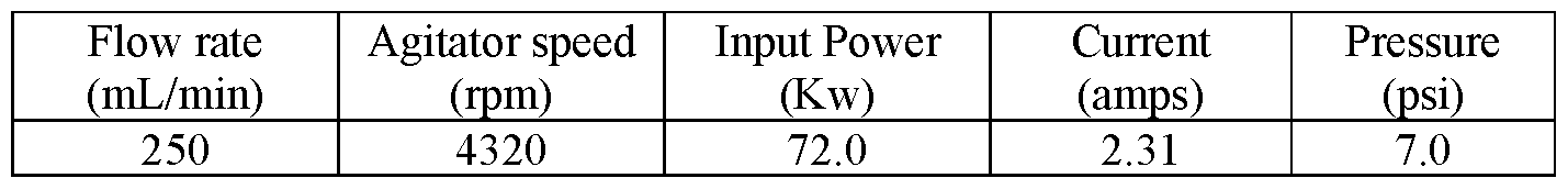
[00212] Particle size distribution was determined by measurement of volume average particle diameter using Partica LA-950 Laser Diffraction Particle Size Analyzer (HORIBA, Ltd (Irvine, CA)). Samples were collected during the milling process and measured for change in particle size distribution.
[00213] A mixture of 47.6 wt.% of BaSOj dispersed into 47.6 wt.% MEK solvent and including 4.8 wt.% Lubrizol IrCosperse™ 2176 (from The Lubrizol Corporation (Wickliffe, OH) was milled. The particle size distribution before milling and after milling for 60 minutes is shown in FIG. 14. An initial particle size profile measurement specified the variability of the BaSO4 particles, along with large particles. The high energy media milling the BaSO4 solution for 60 minutes produced a very narrow particle distribution.
[00214] Small amounts of samples were taken out periodically to monitor the milling progress. The dispersion samples were further diluted with MEK and the particle sizes were measured by Partica LA-
950 Laser Diffraction Particle Size Distribution Analyzer (Horiba, Irvine CA). D50 means a cumulative 50% point of diameter (or 50% pass particle size), also refer to median diameter. D90 means a cumulative 90% point of diameter. The volume average D50, D90, and D95 values (in micrometers, pm) are used.
Table 2: Particle Size Distributions of BaSOj in MEK

[00215] Diffusely reflecting composite cooling film Example 1
[00216] A diffusely reflecting composite cooling film was made by coextruding three layers with the core layer being a CaCCh particle filled PET (polyethylene terephthalate) layer and the outer skin layers being PETG (glycol modified copolyethylene terepthalate). A 2.5” single screw extruder was used to extrude a polymer blend of PET (available from 3M Company (St. Paul, MN) as PTA Clear 72) and CaCO, particle filled PET masterbatch blend (available from SUKANO Polymers (Duncan, SC) as TA31-16-MB30-OB) at a ratio of 70:30 resulting in 15 wt.% CaCO’, into the core layer of a 3-layer die at an extrusion rate of 500 pounds per hour (227.3 kilograms per hour). A 40 mm twin screw extruder was used to blend PETG (available from Eastman Chemical Company (Kingsport, TN) as PETG6763) with FRX flame retardant (available from Performance Polymers and Additives LLC (Eaton, PA) as HM7000) at a ratio of 70:30 resulting in 30 wt.% flame retardant into the skin layers of a 3-layer die at a rate of 50 pounds per hour (22.7 kilograms per hour). The 3-layer film was cast onto a chilled roll having a temperature of 70 degrees Fahrenheit at a line speed of 20 feet per minute (6.1 meters per minute). The 3-layer cast film was then heated to 190 degrees Fahrenheit and stretched in the machine direction to a draw ratio of 3.6:1 and quenched back to 90 degrees Fahrenheit to form a length oriented diffusely reflecting length-oriented film. The length-oriented diffusely reflecting film was then heated to 210 degrees Fahrenheit and stretched transversely at a draw ratio of 3.8:1 to create a biaxially oriented diffusely reflecting composite cooling film. Solar Reflectance of the diffusely reflecting composite cooling film was measured to be 0.95 with a Surface Optics 410-Solar reflectometer (Surface Optics Corporation (San Diego, CA)).
[00217] UV absorbing hard coat applied to white PET film Example 2
[00218] The diffusely reflective composite cooling film described in Example 1 was coated with a 12 microns thick UV absorbing acrylic hard coat described in Example 5 of US Patent No. 10,072, 173B2 (Clear et. al.) to protect the PET from UV degradation. UV absorption by the UV absorbing hard coat decreased the Solar Reflectance of the coated diffusely reflective composite cooling film to 0.92 as measured with a Surface Optics 410-Solar reflectometer. UV reflectance from 335 nm to 380 nm was measured to be 0.058 with a Surface Optics 410-Solar reflectometer.
[00219]UV reflecting coating applied to UV absorbing coated side of White PET film Example 3
[00220] BaSC>4 particles (from CIMBAR Performance Materials (Chatsworth, GA) as Barite 7727-43-7) were milled into nano-particles using the Particle Milling Procedure at 86 wt.% BaSOj in MEK (Methyl Ethyl Ketone, from Sigma-Aldrich (St. Louis, MO)). CoPMMA (available as LA4285 from Kuraray Ltd) was dissolved in MEK at 20 wt.% CoPMMA. The 86 wt.% BaSO4 in MEK solution was mixed with the 20 wt.% CoPMMA in MEK solution to produce a coating solution that was 50 wt.% MEK, 48.5 wt.% BaSO4, and 1.5 wt.% CoPMMA. This coating solution was hand spread coated onto the diffusely reflective composite cooling film described in Example 2 with a #55 Meyer Rod. After allowing the MEK solvent to air dry for 10 minutes, the coating contained 97 wt.% BaSCL in 3 wt.% LA4285 CoPMMA. The coating solution thickness was measured to be 1.8 mil (45 microns). UV reflectance from 335 nm to 380 nm of the diffusely reflective composite cooling film coated with the UV absorbing inner coating and a UV reflective outer coating was measured to be 0.64 with a Surface Optics 410-Solar reflectometer. Solar Reflectance of the diffusely reflecting composite cooling film with the UV absorbing inner coating and the UV reflecting outer coating was measured to be 0.935 with a Surface Optics 410-Solar reflectometer.
[00221] Example 4. UV absorbing diffusely reflecting composite cooling film.
[00222] A diffusely reflecting composite cooling film was made by coextruding three layers with the core layer being a CaCOs particle filled PET (polyethylene terephthalate) layer and the bottom skin layer being PETG (glycol modified copolyethylene terepthalate) and the top layer being an acrylate copolymer blend comprising 57 wt.% CA24, 40 wt.% LA4285, and 3 wt.% Tinuvin 1600. A 40 mm twin screw extruder was used to extrude a polymer blend of PET (available from 3M Company (St. Paul, MN) as PTA Clear 72) and CaCOs particle filled PET masterbatch blend (available from SUKANO Polymers (Duncan, SC)) as TA31-16-MB30-OB) at a ratio of 50:50 resulting in 25 wt.% CaCOs into the core layer of a 3-layer die at an extrusion rate of 80 pounds per hour (36.4 kilograms per hour). A 25 mm twin screw extruder was used to blend PETG (available from Eastman Chemical Company (Kingsport, TN) as PETG6763) with FRX flame retardant (available from Performance Polymers and Additives LLC (Eaton, PA) as HM7000) at a ratio of 70:30 resulting in 30 wt.% flame retardant into the bottom skin layer of a 3- layer die at a rate of 10 pounds per hour (4.55 kilograms per hour). A 25 mm twin screw extruder was used to blend 57 wt.% CA24 (a random copolymer of 75 mole % methylmethacrylate and 25 mole % ethylacrylate, available from Plaskolite (Columbus, OH) with 40 wt.% LA4285 (CoPMMA available from Kuraray America Inc (Houston, TX)) and 3 wt.% Tinuvin 1600 (available from BASF (Florham Park, NJ)) at a ratio of 57:40:3 resulting in 3 wt.% Tinuvin 1600 in the top skin layer of a 3-layer die at a rate of 10 pounds per hour (4.55 kilograms per hour). The 3-layer film was cast onto a chilled roll having a temperature of 70 degrees Fahrenheit at a line speed of 20 feet per minute (6.1 meters per minute). The 3-layer cast film was then heated to 190 degrees Fahrenheit and stretched in the machine direction to a draw ratio of 3.6: 1 and quenched back to 90 degrees Fahrenheit to form a length oriented diffusely reflecting length-oriented film. The length-oriented diffusely reflecting film was then heated to 210 degrees Fahrenheit and stretched transversely at a draw ratio of 3.8: 1 to create a biaxially oriented diffusely reflecting composite cooling film. UV reflectance from 335 nm to 380 nm was measured to be
0.058 with a Surface Optics 410-Solar reflectometer. Solar Reflectance of the diffusely reflecting composite cooling film was measured to be 0.85 with a Surface Optics 410-Solar reflectometer (Surface Optics Corporation (San Diego, CA)).
[00223] Example 5. UV reflecting coating applied to UV absorbing side of White PET film Example 4. BaSO4 particles (from CIMBAR Performance Materials (Chatsworth, GA) as Barite 7727-43-7) were milled into nano-particles using the Particle Milling Procedure at 86 wt.% BaSO4 in MEK (Methyl Ethyl Ketone, from Sigma-Aldrich (St. Louis, MO)). CoPMMA (available as LA4285 from Kuraray America Ltd (Houston, TX)) was dissolved in MEK at 20 wt.% CoPMMA. The 86 wt.% BaSO4 in MEK solution was mixed with the 20 wt.% CoPMMA in MEK solution to produce a coating solution that was 50 wt.% MEK, 48.5 wt.% BaSO4, and 1.5 wt.% CoPMMA. This coating solution was hand spread coated onto the diffusely reflective composite cooling film described in Example 4 with a #55 Meyer Rod. After allowing the MEK solvent to air dry for 10 minutes, the coating contained 97 wt.% BaSCL in 3 wt.% CoPMMA. The coating solution thickness was measured to be 1.8 mil (45 microns). UV reflectance from 335 nm to 380 nm of the diffusely reflective composite cooling fdm coated with the UV absorbing inner coating and a UV reflective outer coating was measured to be 0.64 with a Surface Optics 410-Solar reflectometer. Solar Reflectance of the diffusely reflecting composite cooling film with the UV absorbing inner coating and the UV reflecting outer coating was measured to be 0.87 with a Surface Optics 410-Solar reflectometer.
[00224] Foreseeable modifications and alterations of this invention will be apparent to those skilled in the art without departing from the scope and spirit of this invention. This invention should not be restricted to the embodiments that are set forth in this application for illustrative purposes.
Claims
1. A composite cooling film comprising: a micro-voided film layer that has a solar weighted reflectivity at normal incidence of electromagnetic radiation over a majority of wavelengths in a range of 400 nanometers (nm) to 2500 nm of 0.8 or greater, 0.85, 0.9, or 0.95 or greater; and a UV reflecting composite layer disposed adjacent to a major surface of the micro-voided film layer, the UV reflecting composite layer comprising a polymeric matrix and a plurality of inorganic particles distributed in the polymeric matrix, wherein the UV reflecting composite layer exhibits an average reflectance of electromagnetic radiation of at least 55% over a wavelength bandwidth of at least 30 nm within a wavelength range from 300 nanometers (nm) and up to but not including 400 nm.
2. The composite cooling film of claim 1, wherein the plurality of inorganic particles is selected from the group consisting of titanium dioxide, magnesium oxide, aluminum oxide, zinc oxide, calcium carbonate, calcium phosphate, barium sulfate, silicon dioxide, zirconium dioxide, cerium oxide, aluminum silicate, kaolinite clay, hydroxyapatite, and combinations and blends thereof.
3. The composite cooling film of claim 1 or claim 2, wherein the plurality of inorganic particles is selected from the group consisting of titanium dioxide, calcium carbonate, barium sulfate, and combinations and blends thereof.
4. The composite cooling film of any of claims 1 to 3, wherein the plurality of inorganic particles has a volume average particle diameter D50 of 600 nm or less, 300 nm or less, or 100 nm or less and at least one of: i) a D90 of 900 nm or less, 750 nm or less, 500 nm or less, or 250 nm or less or ii) a D95 of 1000 nm or less, 800 nm or less, 500 nm or less, or 300 nm or less.
5. The composite cooling film of any of claims 1 to 4, wherein the polymeric matrix comprises a (methjacrylate polymer, a silicone polymer, a polyvinyl chloride polymer, a polyurethane, or a fluoropolymer.
6. The composite cooling film of any of claims 1 to 5, wherein the polymeric matrix comprises a (methjacrylate polymer.
7. The composite cooling film of any of claims 1 to 6, wherein the polymeric matrix comprises a copolymer of methyl methacrylate (coPMMA).
8. The composite cooling film of any of claims 1 to 7, wherein the polymeric matrix comprises a block copolymer of methyl methacrylate and butyl acrylate.
9. The composite cooling film of any of claims 1 to 8, wherein the polymeric matrix comprises a silicone polymer.
10. The composite cooling film of claim 9, wherein the silicone polymer is a poly(diorganosiloxane)- polyoxamide copolymer.
11. The composite cooling film of any of claims 1 to 10, wherein the polymeric matrix comprises a fluoropolymer.
12. The composite cooling film of any of claims 1 to 11, wherein the polymeric matrix comprises a copolymer of a (meth)acrylate and dimethylsiloxane.
13. The composite cooling film of claim 12, wherein the copolymer of a (meth)acrylate and dimethylsiloxane is a block copolymer.
14. The composite cooling film of any of claims 1 to 13, further comprising an adhesive layer disposed adjacent to the micro-voided film layer opposite the UV reflecting composite layer.
15. The composite cooling film of any of claims 1 to 14, further comprising an antisoiling layer disposed adjacent to a major surface of the UV reflecting composite layer opposite the microvoided film layer.
16. The composite cooling film of claim 15, wherein the antisoiling layer comprises surface structures.
17. The composite cooling film of any of claims 1 to 16, further comprising a UV absorbing layer disposed between the UV reflecting composite layer and the micro-voided film layer and/or disposed adjacent to a major surface of the UV reflecting composite layer opposite the microvoided film layer.
18. The composite cooling film of any of claims 1 to 17, wherein the micro-voided film layer comprises polyethylene terephthalate (PET).
19. The composite cooling film of any of claims 1 to 18, exhibiting a solar reflectance that is at least 1.5% greater than the same composite cooling film except lacking the plurality of inorganic particles distributed in the polymeric matrix.
20. The composite cooling film of any of claims 1 to 19, exhibiting a thermal emittance that is at least 1.5% greater than the same composite cooling film except lacking the plurality of inorganic particles distributed in the polymeric matrix.
21. A composite cooling system comprising the composite cooling film of any of claims 1 to 20 attached to a substrate.
22. The composite cooling system of claim 21, wherein the substrate is part of a vehicle, a building, a modular data center, an electrical transformer, a refrigerator, or an air conditioner.
Applications Claiming Priority (2)
| Application Number | Priority Date | Filing Date | Title |
|---|---|---|---|
| US202363606621P | 2023-12-06 | 2023-12-06 | |
| US63/606,621 | 2023-12-06 |
Publications (1)
| Publication Number | Publication Date |
|---|---|
| WO2025120404A1 true WO2025120404A1 (en) | 2025-06-12 |
Family
ID=93430641
Family Applications (1)
| Application Number | Title | Priority Date | Filing Date |
|---|---|---|---|
| PCT/IB2024/060774 Pending WO2025120404A1 (en) | 2023-12-06 | 2024-10-31 | Composite cooling films including a diffusely reflective layer and a uv reflecting composite layer |
Country Status (1)
| Country | Link |
|---|---|
| WO (1) | WO2025120404A1 (en) |
Citations (56)
| Publication number | Priority date | Publication date | Assignee | Title |
|---|---|---|---|---|
| US3239478A (en) | 1963-06-26 | 1966-03-08 | Shell Oil Co | Block copolymer adhesive compositions and articles prepared therefrom |
| US3935338A (en) | 1973-04-23 | 1976-01-27 | Shell Oil Company | Process for the preparation of pressure-sensitive adhesive articles |
| US4181752A (en) | 1974-09-03 | 1980-01-01 | Minnesota Mining And Manufacturing Company | Acrylic-type pressure sensitive adhesives by means of ultraviolet radiation curing |
| US4726989A (en) | 1986-12-11 | 1988-02-23 | Minnesota Mining And Manufacturing | Microporous materials incorporating a nucleating agent and methods for making same |
| US4874567A (en) | 1987-04-24 | 1989-10-17 | Millipore Corporation | Microporous membranes from polypropylene |
| US4952650A (en) | 1987-07-27 | 1990-08-28 | Minnesota Mining And Manufacturing Company | Suspension polymerization |
| US4976859A (en) | 1988-09-01 | 1990-12-11 | Akzo N.V. | Integral asymmetric polyether-sulfone membrane, process for its production, and use for ultrafiltration and microfiltration |
| US5141790A (en) | 1989-11-20 | 1992-08-25 | Minnesota Mining And Manufacturing Company | Repositionable pressure-sensitive adhesive tape |
| US5169727A (en) | 1988-08-04 | 1992-12-08 | Minnesota Mining And Manufacturing Company | Silicone-based pressure-sensitive adhesives having high solids content |
| US5238623A (en) | 1989-11-20 | 1993-08-24 | Minnesota Mining And Manufacturing Company | Method for preparing microporous polyolefin shaped articles |
| US5268228A (en) | 1992-09-21 | 1993-12-07 | Norwood Industries, Inc. | Grooved pressure-sensitive adhesive tape |
| US5296277A (en) | 1992-06-26 | 1994-03-22 | Minnesota Mining And Manufacturing Company | Positionable and repositionable adhesive articles |
| US5344681A (en) | 1991-09-12 | 1994-09-06 | Minnesota Mining And Manufacturing Company | Patterned pressure sensitive adhesive transfer tape |
| JPH07138541A (en) | 1993-11-15 | 1995-05-30 | Nichiei Kako Kk | Protected self-adhesive film |
| JPH0729569U (en) | 1993-11-04 | 1995-06-02 | 株式会社フジシール | Easy peeling tack label |
| US5504134A (en) | 1991-09-27 | 1996-04-02 | Kerr-Mcgee Chemical Corporation | Attenuation of polymer substrate degradation due to ultraviolet radiation |
| US5876688A (en) | 1993-08-06 | 1999-03-02 | Elementis Uk Limited | Zinc oxide and a process of making it |
| US5993954A (en) | 1997-04-29 | 1999-11-30 | 3M Innovative Properties Company | Temperature-sensitive microporous film |
| WO2000048037A2 (en) | 1999-02-09 | 2000-08-17 | 3M Innovative Properties Company | Optical film with defect-reducing surface and method for making same |
| US6261994B1 (en) | 1998-09-17 | 2001-07-17 | Eastman Kodak Company | Reflective imaging display material with biaxially oriented polyolefin sheet |
| US6277485B1 (en) | 1998-01-27 | 2001-08-21 | 3M Innovative Properties Company | Antisoiling coatings for antireflective surfaces and methods of preparation |
| US6315651B1 (en) | 2001-03-22 | 2001-11-13 | Taiwan Semiconductor Manufacturing Company Ltd | Easy on/off cover for a pad conditioning assembly |
| WO2002012404A2 (en) | 2000-08-07 | 2002-02-14 | 3M Innovative Properties Company | Antisoiling hardcoat |
| US6368742B2 (en) | 1998-06-26 | 2002-04-09 | Celgard, Inc. | Polypropylene microporous membrane for battery separator |
| US6632850B2 (en) | 2001-04-04 | 2003-10-14 | 3M Innovative Properties Company | Microporous materials and methods of making the same |
| US20050233070A1 (en) | 2004-04-20 | 2005-10-20 | 3M Innovative Properties Company | Antisoiling coatings for antireflective substrates |
| US7060351B2 (en) | 2000-04-24 | 2006-06-13 | Avery Dennison Corporation | Adhesive article with improved air egress |
| US20060188704A1 (en) | 1999-05-13 | 2006-08-24 | 3M Innovative Properties Company | Adhesive-backed articles |
| US20070212635A1 (en) | 2006-02-28 | 2007-09-13 | Fujifilm Corporation | Image-forming method using heat-sensitive transfer system |
| US7328638B2 (en) | 2005-12-27 | 2008-02-12 | 3M Innovative Properties Company | Cutting tool using interrupted cut fast tool servo |
| US7350442B2 (en) | 2005-11-15 | 2008-04-01 | 3M Innovative Properties Company | Cutting tool having variable movement in a z-direction laterally along a work piece for making microstructures |
| WO2008128073A2 (en) | 2007-04-13 | 2008-10-23 | 3M Innovative Properties Company | Antistatic optically clear pressure sensitive adhesive |
| US20090087629A1 (en) | 2007-09-28 | 2009-04-02 | Everaerts Albert I | Indium-tin-oxide compatible optically clear adhesive |
| US20090089137A1 (en) | 2007-10-02 | 2009-04-02 | Ucn, Inc. | Rapid deployment of training for company representatives in contact handling systems |
| US20090147361A1 (en) | 2007-12-07 | 2009-06-11 | 3M Innovative Properties Company | Microreplicated films having diffractive features on macro-scale features |
| US20100028564A1 (en) | 2008-07-29 | 2010-02-04 | Ming Cheng | Antistatic optical constructions having optically-transmissive adhesives |
| US20100040842A1 (en) | 2008-08-12 | 2010-02-18 | 3M Innovative Properties Company | Adhesives compatible with corrosion sensitive layers |
| US7947376B2 (en) | 2005-12-23 | 2011-05-24 | 3M Innovative Properties Company | Adhesive compositions |
| US20110126968A1 (en) | 2008-03-14 | 2011-06-02 | Determan Michael D | Stretch releasable adhesive tape |
| US20130236697A1 (en) | 2010-12-01 | 2013-09-12 | 3M Innovative Properties Company | Microstructured articles comprising nanostructures and method |
| US8557378B2 (en) | 2008-12-31 | 2013-10-15 | 3M Innovative Properties Company | Stretch releasable adhesive tape |
| US8962214B2 (en) | 2003-09-12 | 2015-02-24 | 3M Innovative Properties Company | Microporous PVDF films |
| US20150175479A1 (en) | 2012-07-06 | 2015-06-25 | 3M Innovative Properties Company | Anti-soiling compositions, methods of applying, and application equipment |
| US20160298266A1 (en) | 2013-11-26 | 2016-10-13 | 3M Innovative Properties Company | Dimensionally-stable melt blown nonwoven fibrous structures, and methods and apparatus for making same |
| US9670300B2 (en) | 2012-12-20 | 2017-06-06 | 3M Innovative Properties Company | Copolymers including ultraviolet absorbing groups and fluoropolymer compositions including them |
| WO2017172564A2 (en) | 2016-04-01 | 2017-10-05 | 3M Innovative Properties Company | Multilayer fluoropolymer films |
| WO2018130926A1 (en) | 2017-01-16 | 2018-07-19 | 3M Innovative Properties Company | Faceted microstructured surface |
| US10072173B2 (en) | 2012-03-22 | 2018-09-11 | 3M Innovative Properties Company | Polymethylmethacrylate based hardcoat composition and coated article |
| US10125251B2 (en) | 2014-06-25 | 2018-11-13 | 3M Innovative Properties Company | Fluoropolymer composition including at least one oligomer |
| US10240013B2 (en) | 2008-12-19 | 2019-03-26 | 3M Innovative Properties Company | Microporous material from ethylene-chlorotrifluoroethylene copolymer and method for making same |
| WO2019130198A1 (en) | 2017-12-29 | 2019-07-04 | 3M Innovative Properties Company | Anti-reflective surface structures |
| WO2019130199A1 (en) | 2017-12-29 | 2019-07-04 | 3M Innovative Properties Company | Passive cooling articles having a fluoropolymer |
| CN111574732A (en) * | 2020-04-29 | 2020-08-25 | 诸暨瑞讯新材料有限公司 | Preparation method of low-cost radiation cooling film |
| CN114506141A (en) * | 2022-01-30 | 2022-05-17 | 浙江大学 | Radiation refrigeration film |
| US20220355567A1 (en) * | 2019-12-19 | 2022-11-10 | 3M Innovative Properties Company | Composite cooling film comprising a reflective microporous layer and a uv-absorbing layer |
| US20230366642A1 (en) * | 2020-11-24 | 2023-11-16 | 3M Innovative Properties Company | Radiative cooling articles including a white diffusely reflective layer and a non-white color reflective mirror |
-
2024
- 2024-10-31 WO PCT/IB2024/060774 patent/WO2025120404A1/en active Pending
Patent Citations (58)
| Publication number | Priority date | Publication date | Assignee | Title |
|---|---|---|---|---|
| US3239478A (en) | 1963-06-26 | 1966-03-08 | Shell Oil Co | Block copolymer adhesive compositions and articles prepared therefrom |
| US3935338A (en) | 1973-04-23 | 1976-01-27 | Shell Oil Company | Process for the preparation of pressure-sensitive adhesive articles |
| US4181752A (en) | 1974-09-03 | 1980-01-01 | Minnesota Mining And Manufacturing Company | Acrylic-type pressure sensitive adhesives by means of ultraviolet radiation curing |
| US4726989A (en) | 1986-12-11 | 1988-02-23 | Minnesota Mining And Manufacturing | Microporous materials incorporating a nucleating agent and methods for making same |
| US4874567A (en) | 1987-04-24 | 1989-10-17 | Millipore Corporation | Microporous membranes from polypropylene |
| US4952650A (en) | 1987-07-27 | 1990-08-28 | Minnesota Mining And Manufacturing Company | Suspension polymerization |
| US5169727A (en) | 1988-08-04 | 1992-12-08 | Minnesota Mining And Manufacturing Company | Silicone-based pressure-sensitive adhesives having high solids content |
| US4976859A (en) | 1988-09-01 | 1990-12-11 | Akzo N.V. | Integral asymmetric polyether-sulfone membrane, process for its production, and use for ultrafiltration and microfiltration |
| US5141790A (en) | 1989-11-20 | 1992-08-25 | Minnesota Mining And Manufacturing Company | Repositionable pressure-sensitive adhesive tape |
| US5238623A (en) | 1989-11-20 | 1993-08-24 | Minnesota Mining And Manufacturing Company | Method for preparing microporous polyolefin shaped articles |
| US5344681A (en) | 1991-09-12 | 1994-09-06 | Minnesota Mining And Manufacturing Company | Patterned pressure sensitive adhesive transfer tape |
| US5449540A (en) | 1991-09-12 | 1995-09-12 | Minnesota Mining And Manufacturing Company | Patterned pressure sensitive adhesive transfer tape |
| US5504134A (en) | 1991-09-27 | 1996-04-02 | Kerr-Mcgee Chemical Corporation | Attenuation of polymer substrate degradation due to ultraviolet radiation |
| US5362516A (en) | 1992-06-26 | 1994-11-08 | Minnesota Mining And Manufacturing Company | Method of preparing an adhesive article |
| US5296277A (en) | 1992-06-26 | 1994-03-22 | Minnesota Mining And Manufacturing Company | Positionable and repositionable adhesive articles |
| US5268228A (en) | 1992-09-21 | 1993-12-07 | Norwood Industries, Inc. | Grooved pressure-sensitive adhesive tape |
| US5876688A (en) | 1993-08-06 | 1999-03-02 | Elementis Uk Limited | Zinc oxide and a process of making it |
| JPH0729569U (en) | 1993-11-04 | 1995-06-02 | 株式会社フジシール | Easy peeling tack label |
| JPH07138541A (en) | 1993-11-15 | 1995-05-30 | Nichiei Kako Kk | Protected self-adhesive film |
| US5993954A (en) | 1997-04-29 | 1999-11-30 | 3M Innovative Properties Company | Temperature-sensitive microporous film |
| US6277485B1 (en) | 1998-01-27 | 2001-08-21 | 3M Innovative Properties Company | Antisoiling coatings for antireflective surfaces and methods of preparation |
| US6368742B2 (en) | 1998-06-26 | 2002-04-09 | Celgard, Inc. | Polypropylene microporous membrane for battery separator |
| US6261994B1 (en) | 1998-09-17 | 2001-07-17 | Eastman Kodak Company | Reflective imaging display material with biaxially oriented polyolefin sheet |
| WO2000048037A2 (en) | 1999-02-09 | 2000-08-17 | 3M Innovative Properties Company | Optical film with defect-reducing surface and method for making same |
| US20060188704A1 (en) | 1999-05-13 | 2006-08-24 | 3M Innovative Properties Company | Adhesive-backed articles |
| US7060351B2 (en) | 2000-04-24 | 2006-06-13 | Avery Dennison Corporation | Adhesive article with improved air egress |
| WO2002012404A2 (en) | 2000-08-07 | 2002-02-14 | 3M Innovative Properties Company | Antisoiling hardcoat |
| US6315651B1 (en) | 2001-03-22 | 2001-11-13 | Taiwan Semiconductor Manufacturing Company Ltd | Easy on/off cover for a pad conditioning assembly |
| US6632850B2 (en) | 2001-04-04 | 2003-10-14 | 3M Innovative Properties Company | Microporous materials and methods of making the same |
| US8962214B2 (en) | 2003-09-12 | 2015-02-24 | 3M Innovative Properties Company | Microporous PVDF films |
| US20050233070A1 (en) | 2004-04-20 | 2005-10-20 | 3M Innovative Properties Company | Antisoiling coatings for antireflective substrates |
| US7350442B2 (en) | 2005-11-15 | 2008-04-01 | 3M Innovative Properties Company | Cutting tool having variable movement in a z-direction laterally along a work piece for making microstructures |
| US7947376B2 (en) | 2005-12-23 | 2011-05-24 | 3M Innovative Properties Company | Adhesive compositions |
| US7328638B2 (en) | 2005-12-27 | 2008-02-12 | 3M Innovative Properties Company | Cutting tool using interrupted cut fast tool servo |
| US20070212635A1 (en) | 2006-02-28 | 2007-09-13 | Fujifilm Corporation | Image-forming method using heat-sensitive transfer system |
| WO2008128073A2 (en) | 2007-04-13 | 2008-10-23 | 3M Innovative Properties Company | Antistatic optically clear pressure sensitive adhesive |
| US20090087629A1 (en) | 2007-09-28 | 2009-04-02 | Everaerts Albert I | Indium-tin-oxide compatible optically clear adhesive |
| US20090089137A1 (en) | 2007-10-02 | 2009-04-02 | Ucn, Inc. | Rapid deployment of training for company representatives in contact handling systems |
| US20090147361A1 (en) | 2007-12-07 | 2009-06-11 | 3M Innovative Properties Company | Microreplicated films having diffractive features on macro-scale features |
| US20110126968A1 (en) | 2008-03-14 | 2011-06-02 | Determan Michael D | Stretch releasable adhesive tape |
| US20100028564A1 (en) | 2008-07-29 | 2010-02-04 | Ming Cheng | Antistatic optical constructions having optically-transmissive adhesives |
| US20100040842A1 (en) | 2008-08-12 | 2010-02-18 | 3M Innovative Properties Company | Adhesives compatible with corrosion sensitive layers |
| US10240013B2 (en) | 2008-12-19 | 2019-03-26 | 3M Innovative Properties Company | Microporous material from ethylene-chlorotrifluoroethylene copolymer and method for making same |
| US8557378B2 (en) | 2008-12-31 | 2013-10-15 | 3M Innovative Properties Company | Stretch releasable adhesive tape |
| US20130236697A1 (en) | 2010-12-01 | 2013-09-12 | 3M Innovative Properties Company | Microstructured articles comprising nanostructures and method |
| US10072173B2 (en) | 2012-03-22 | 2018-09-11 | 3M Innovative Properties Company | Polymethylmethacrylate based hardcoat composition and coated article |
| US20150175479A1 (en) | 2012-07-06 | 2015-06-25 | 3M Innovative Properties Company | Anti-soiling compositions, methods of applying, and application equipment |
| US9670300B2 (en) | 2012-12-20 | 2017-06-06 | 3M Innovative Properties Company | Copolymers including ultraviolet absorbing groups and fluoropolymer compositions including them |
| US20160298266A1 (en) | 2013-11-26 | 2016-10-13 | 3M Innovative Properties Company | Dimensionally-stable melt blown nonwoven fibrous structures, and methods and apparatus for making same |
| US10125251B2 (en) | 2014-06-25 | 2018-11-13 | 3M Innovative Properties Company | Fluoropolymer composition including at least one oligomer |
| WO2017172564A2 (en) | 2016-04-01 | 2017-10-05 | 3M Innovative Properties Company | Multilayer fluoropolymer films |
| WO2018130926A1 (en) | 2017-01-16 | 2018-07-19 | 3M Innovative Properties Company | Faceted microstructured surface |
| WO2019130198A1 (en) | 2017-12-29 | 2019-07-04 | 3M Innovative Properties Company | Anti-reflective surface structures |
| WO2019130199A1 (en) | 2017-12-29 | 2019-07-04 | 3M Innovative Properties Company | Passive cooling articles having a fluoropolymer |
| US20220355567A1 (en) * | 2019-12-19 | 2022-11-10 | 3M Innovative Properties Company | Composite cooling film comprising a reflective microporous layer and a uv-absorbing layer |
| CN111574732A (en) * | 2020-04-29 | 2020-08-25 | 诸暨瑞讯新材料有限公司 | Preparation method of low-cost radiation cooling film |
| US20230366642A1 (en) * | 2020-11-24 | 2023-11-16 | 3M Innovative Properties Company | Radiative cooling articles including a white diffusely reflective layer and a non-white color reflective mirror |
| CN114506141A (en) * | 2022-01-30 | 2022-05-17 | 浙江大学 | Radiation refrigeration film |
Similar Documents
| Publication | Publication Date | Title |
|---|---|---|
| US20230366642A1 (en) | Radiative cooling articles including a white diffusely reflective layer and a non-white color reflective mirror | |
| CN113874213B (en) | Composite cooling film and article including the same | |
| EP3977024B1 (en) | Composite cooling film and article including the same | |
| US12352464B2 (en) | Multi-surface passive cooling articles | |
| US11634613B2 (en) | Composite cooling film comprising an organic polymeric layer, a UV-absorbing layer, and a reflective metal layer | |
| US20220355567A1 (en) | Composite cooling film comprising a reflective microporous layer and a uv-absorbing layer | |
| US11654664B2 (en) | Composite cooling film comprising a reflective nonporous organic polymeric layer and a UV-protective layer | |
| WO2025120404A1 (en) | Composite cooling films including a diffusely reflective layer and a uv reflecting composite layer | |
| US20230001676A1 (en) | Composite cooling film comprising a fluorinated antisoiling layer and a reflective metal layer | |
| WO2025040970A1 (en) | Systems, solar articles, and methods comprising a structured protective film | |
| WO2023203390A1 (en) | Broadband reflectors including polymeric layers, and composite cooling systems |
Legal Events
| Date | Code | Title | Description |
|---|---|---|---|
| 121 | Ep: the epo has been informed by wipo that ep was designated in this application |
Ref document number: 24802026 Country of ref document: EP Kind code of ref document: A1 |