WO2025109882A1 - Analysis device, analysis method, program, learned machine learning model, and machine learning method - Google Patents
Analysis device, analysis method, program, learned machine learning model, and machine learning method Download PDFInfo
- Publication number
- WO2025109882A1 WO2025109882A1 PCT/JP2024/035579 JP2024035579W WO2025109882A1 WO 2025109882 A1 WO2025109882 A1 WO 2025109882A1 JP 2024035579 W JP2024035579 W JP 2024035579W WO 2025109882 A1 WO2025109882 A1 WO 2025109882A1
- Authority
- WO
- WIPO (PCT)
- Prior art keywords
- movable part
- operating state
- series data
- machine learning
- work
- Prior art date
- Legal status (The legal status is an assumption and is not a legal conclusion. Google has not performed a legal analysis and makes no representation as to the accuracy of the status listed.)
- Pending
Links
Images


Classifications
-
- E—FIXED CONSTRUCTIONS
- E02—HYDRAULIC ENGINEERING; FOUNDATIONS; SOIL SHIFTING
- E02F—DREDGING; SOIL-SHIFTING
- E02F9/00—Component parts of dredgers or soil-shifting machines, not restricted to one of the kinds covered by groups E02F3/00 - E02F7/00
- E02F9/26—Indicating devices
Definitions
- This disclosure relates to an analysis device, an analysis method, a program, a trained machine learning model, and a machine learning method.
- Patent Document 1 discloses a technology that, when an operator operates a wheel loader to perform a cyclical operation (loading operation in this example) that repeats each of the operation modes of unladen forward movement, excavation, loaded reverse movement, loaded forward movement, loading, and unladen reverse movement, distinguishes each operation mode included in the cyclical operation based on a numerical value that indicates the state of the wheel loader.
- wheel loaders perform multiple types of work, including loading, sorting of excavated material, and shoveling.
- work machines such as wheel loaders
- the present disclosure has been made in consideration of the above circumstances, and aims to provide an analysis device, an analysis method, a program, a trained machine learning model, and a machine learning method that can efficiently classify work based on time-series data that represents the operating status of a work machine.
- the analysis device disclosed herein includes an acquisition unit that acquires time series data representing at least the operating state of a first movable part and the operating state of a second movable part of a work machine having a first movable part and a second movable part, a first operating state classification unit that classifies the operating state of the first movable part based on the time series data, a division unit that divides the time axis of the time series data into a plurality of sections based on the classification result of the operating state of the first movable part, a second operating state classification unit that classifies the operating state of the second movable part for each of the sections based on the time series data, and a work classification unit that classifies work performed by the work machine based on the classification result of the operating state of the first movable part and the classification result of the operating state of the second movable part.
- the analysis method disclosed herein also includes the steps of acquiring time series data representing at least the operating state of a first movable part and the operating state of a second movable part of a work machine having a first movable part, classifying the operating state of the first movable part based on the time series data, dividing the time axis of the time series data into a plurality of sections based on the classification result of the operating state of the first movable part, classifying the operating state of the second movable part for each section based on the time series data, and classifying work performed by the work machine based on the classification result of the operating state of the first movable part and the classification result of the operating state of the second movable part.
- the program disclosed herein also causes a computer to execute the steps of acquiring time series data representing at least the operating state of a first movable part and the operating state of a second movable part of a work machine having a first movable part and a second movable part, classifying the operating state of the first movable part based on the time series data, dividing the time axis of the time series data into a plurality of sections based on the classification results of the operating state of the first movable part, classifying the operating state of the second movable part for each section based on the time series data, and classifying work performed by the work machine based on the classification results of the operating state of the first movable part and the classification results of the operating state of the second movable part.
- the trained machine learning model of the present disclosure is a machine learning model that inputs predetermined input information based on time series data representing at least the operating state of a first movable part and the operating state of a second movable part of a work machine having the first movable part and the second movable part, and outputs output information representing the result of classifying the operating state of the second movable part, the input information including a plurality of predetermined feature quantities related to the operating state of the second movable part for each of the sections obtained by dividing the time axis of the time series data into a plurality of sections based on the classification result of the operating state of the first movable part, and is machine-trained using the input information labeled with the type of the operating state of the second movable part.
- the machine learning method disclosed herein is a machine learning method for a machine learning model that inputs predetermined input information based on time series data representing at least the operating state of a first movable part and the operating state of a second movable part of a work machine having the first movable part and the second movable part, and outputs output information representing the result of classifying the operating state of the second movable part, the input information including a plurality of predetermined feature quantities related to the operating state of the second movable part for each of the sections obtained by dividing the time axis of the time series data into a plurality of sections based on the classification result of the operating state of the first movable part, and machine learning the machine learning model using the input information labeled with the type of the operating state of the second movable part.
- the analysis device, analysis method, program, trained machine learning model, and machine learning method disclosed herein classify the operating state of the second moving part for each of a plurality of sections into which time series data is divided based on the classification result of the first moving part, and therefore can efficiently classify the operating state of the second moving part. Therefore, the work of a work machine having a first moving part and a second moving part can be efficiently classified based on the time series data.
- FIG. 1 is a schematic diagram illustrating a configuration example of an analysis system according to an embodiment of the present disclosure.
- 1 is a side view showing an example configuration of a work machine according to an embodiment of the present disclosure.
- FIG. FIG. 2 is a schematic diagram illustrating an example of the configuration of a time-series data file according to an embodiment of the present disclosure.
- 4 is a schematic diagram showing an example of a behavior discrimination flag of a traveling device (undercarriage of a work machine) according to an embodiment of the present disclosure.
- FIG. FIG. 13 is a diagram illustrating an example of time-series data related to behavior determination of a traveling device according to an embodiment of the present disclosure.
- FIG. 13 is a diagram illustrating an example of time-series data related to behavior determination of a traveling device according to an embodiment of the present disclosure.
- FIG. 1 is a diagram illustrating an example in which time-series data is divided into a plurality of intervals according to an embodiment of the present disclosure.
- 11 is a diagram showing an example of time-series data relating to behavior determination of a work machine according to an embodiment of the present disclosure.
- FIG. FIG. 9 is a diagram illustrating an example of an operating state of a work machine in section (k) illustrated in FIGS. 7 and 8 .
- FIG. 9 is a diagram illustrating an example of an operating state of a work machine in a section (k+1) illustrated in FIGS. 7 and 8 .
- FIG. 9 is a diagram illustrating an example of an operating state of a work machine in a section (k+2) illustrated in FIGS. 7 and 8 .
- FIG. 9 is a diagram illustrating an example of an operating state of a work machine in a section (k+3) illustrated in FIGS. 7 and 8 .
- FIG. 9 is a diagram illustrating an example of an operating state of a work machine in a section (k+4) illustrated in FIGS. 7 and 8 .
- FIG. 11 is a diagram illustrating an example of feature amounts according to an embodiment of the present disclosure.
- FIG. 13 is a diagram illustrating an example of feature amounts of a section (k) according to an embodiment of the present disclosure.
- FIG. 11 is a diagram illustrating an example of feature amounts according to an embodiment of the present disclosure.
- FIG. 11 is a schematic diagram showing an example of a behavior determination flag of a work machine according to an embodiment of the present disclosure.
- FIG. FIG. 13 is a diagram illustrating an example of feature amounts in a section (k+1) according to an embodiment of the present disclosure.
- FIG. 13 is a diagram illustrating an example of feature amounts in a section (k+2) according to an embodiment of the present disclosure.
- FIG. 13 is a diagram illustrating an example of feature amounts in a section (k+3) according to an embodiment of the present disclosure.
- FIG. 13 is a diagram illustrating an example of feature amounts in a section (k+4) according to an embodiment of the present disclosure.
- FIG. 11 is a diagram illustrating an example of teacher data according to an embodiment of the present disclosure.
- FIG. 1 is a schematic diagram illustrating an example of task classification according to an embodiment of the present disclosure.
- FIG. 1 is a schematic diagram for explaining an example of task classification according to an embodiment of the present disclosure.
- FIG. 9 is a schematic diagram for explaining an example of task classification of sections (k) to (k+4) shown in FIGS. 7 and 8.
- FIG. 13 is a diagram illustrating an example of a classification result according to an embodiment of the present disclosure.
- FIG. 13 is a diagram illustrating an example of a result of a detailed analysis according to an embodiment of the present disclosure.
- FIG. 13 is a diagram illustrating an example of a result of a detailed analysis according to an embodiment of the present disclosure.
- FIG. 13 is a diagram illustrating an example of a result of a detailed analysis according to an embodiment of the present disclosure.
- FIG. 13 is a diagram illustrating an example of a result of a detailed analysis according to an embodiment of the present disclosure.
- FIG. 13 is a diagram illustrating an example of a result of a detailed analysis according to an embodiment of the present disclosure.
- 10 is a flowchart illustrating an example of the operation of an analysis device according to an embodiment of the present disclosure.
- FIG. 1 is a schematic diagram showing a configuration example of an analysis system according to an embodiment of the present disclosure.
- the analysis system SY1 shown in FIG. 1 includes a wheel loader 1 as an example of a work machine to be analyzed, a data management server 20 that is communicatively connected to the wheel loader 1 via a communication network NW, and an analysis device 30.
- the wheel loader 1 includes a vehicle body control device 100 and an operation information recording device 101.
- the vehicle body control device 100 inputs sensor information measured by a plurality of sensors included in the wheel loader 1, and controls each part of the wheel loader 1 according to an operation of an operator.
- the operation information recording device 101 records time series data representing the operating state of the wheel loader 1, such as a predetermined control signal and sensor information generated by the vehicle body control device 100, for a certain period (or a certain amount of data), and transmits the time series data to the data management server 20 via the communication network NW.
- the data management server 20 accumulates the time series data received from the operation information recording device 101 as a time series data file 21.
- the analysis device 30 is provided separately from the data management server 20, but is not limited to this. The analysis device 30 may be provided within the data management server 20 .
- FIG. 2 is a side view showing an example configuration of a work machine (wheel loader 1) according to an embodiment of the present disclosure.
- the wheel loader 1 has a vehicle body 2, a cab 3, a traveling device 4, and a working implement 10.
- the wheel loader 1 travels on the traveling device 4 at a work site.
- the wheel loader 1 performs work at the work site using the working implement 10.
- the wheel loader 1 can perform work such as excavation work, loading work, transporting work, and snow removal work using the working implement 10.
- the cab 3 is supported by the vehicle body 2. Inside the cab 3, a driver's seat where the operator sits, operating devices, a display input unit, etc. are arranged.
- the traveling device 4 has a power transmission device, rotatable wheels 5, etc., not shown.
- the wheels 5 support the vehicle body 2.
- the wheel loader 1 is capable of traveling on the road surface (or ground) RS by the traveling device 4. Note that in FIG. 2, only the left front wheel 5F and rear wheel 5R are shown.
- the power transmission device transmits the driving force of a power source, which will be described later, to the wheels 5.
- the power transmission device has a transmission with four forward speeds, neutral, and four reverse speeds (speed stages). Note that the traveling device 4 is one example configuration of the "traveling section" of this disclosure.
- the work machine 10 is supported by the vehicle body 2.
- the work machine 10 is composed of a bucket 12, which is an example of a work tool, and a movable support part 17 that changes the position and attitude of the bucket 12.
- the movable support part 17 includes a boom 11, a boom cylinder 13, a bucket cylinder 14, a bell crank 15, and a link 16.
- the boom 11 is supported rotatably on the vehicle body 2, and moves up and down in response to the extension and contraction of the boom cylinder 13.
- the boom cylinder 13 is an actuator that generates power to move the boom 11, with one end connected to the vehicle body 2 and the other end connected to the boom 11.
- the boom cylinder 13 extends and contracts. This causes the boom 11 to move up and down.
- the boom cylinder 13 is, for example, a hydraulic cylinder. Note that in this embodiment, the angle of the boom 11 is expressed as shown by arrow A1, with the horizontal direction being 0 [deg], and a positive value being when pointing upward and a negative value being when pointing downward.
- the bucket 12 has a cutting edge 12T and is a work tool for excavating and loading soil and other objects to be excavated.
- the bucket 12 is rotatably connected to the boom 11 and one end of a link 16.
- the other end of the link 16 is rotatably connected to one end of a bell crank 15.
- the center of the bell crank 15 is rotatably connected to the boom 11, and the other end is rotatably connected to one end of a bucket cylinder 14.
- the other end of the bucket cylinder 14 is rotatably connected to the vehicle body 2.
- the bucket 12 is operated by the power generated by the bucket cylinder 14.
- the bucket cylinder 14 is an actuator that generates power for moving the bucket 12. When the operator operates a bucket operating device (not shown), the bucket cylinder 14 expands and contracts.
- the bucket cylinder 14 is, for example, a hydraulic cylinder.
- the cutting edge 12T has a shape such as a crest or flat blade, and is attached to the end of the bucket 12 in a replaceable manner.
- the angle of the bucket 12 (the angle of the direction in which the cutting edge 12T faces (the cutting edge direction)) is expressed as a value, as shown by the arrow A2, with the horizontal direction being 0 degrees, and when it faces upwards it is positive and when it faces downwards it is negative.
- the position of the bucket 12c in which the cutting edge 12T faces downward is called the dump position.
- the dump position is, for example, a position in which the excavated material in the bucket 12 can be loaded onto a transport vehicle, hopper, etc. (soil discharge position).
- the position of the bucket 12a in which the cutting edge 12T faces upward is called the tilt position (holding position).
- the tilt position is, for example, a position in which the excavated material can be held in the bucket 12 (transport position).
- the position of the bucket 12b in which the cutting edge 12T faces horizontally (including substantially horizontally) with the road surface RS is called the excavation position (or the traveling position during excavation).
- the excavation position is, for example, a position when starting to excavate an excavation target such as soil or sand or traveling toward the excavation target (or a position suitable for starting to excavate or traveling).
- the position of the bucket 12 in which the cutting edge 12T is in contact with the road surface RS with the boom 11 lowered is called the ground contact position.
- the wheel loader 1 places the bucket 12 in an excavation position (or a position in which the cutting edge 12T is lower than the road surface RS from the excavation position) and travels forward to start excavating an object to be excavated that is located in front.
- the excavation position can also be called the horizontal position because the cutting edge direction is substantially horizontal to the road surface RS.
- the wheel loader 1 includes a power source, a PTO (Power Take Off), a hydraulic pump, a control valve, an operation device, a display input unit, and other components (not shown).
- the power source generates a driving force for operating the wheel loader 1. Examples of the power source include an internal combustion engine and an electric motor.
- the PTO transmits at least a portion of the driving force of the power source to the hydraulic pump.
- the PTO distributes the driving force of the power source to the traveling device 4 and the hydraulic pump.
- the hydraulic pump is driven by the power source and discharges hydraulic oil. At least a portion of the hydraulic oil discharged from the hydraulic pump is supplied to each of the boom cylinder 13 and the bucket cylinder 14 via a control valve.
- the control valve controls the flow rate and direction of the hydraulic oil supplied from the hydraulic pump to each of the boom cylinder 13 and the bucket cylinder 14.
- the work machine 10 operates using the hydraulic oil from the hydraulic pump.
- the operating device is disposed inside the cab 3.
- the operating device is operated by an operator.
- the operator operates the operating device to adjust the travel direction and travel speed of the wheel loader 1, switch between forward and reverse, and operate the work implement 10.
- the operating device includes, for example, a steering wheel, a shift lever, an accelerator pedal, a brake pedal, and operating devices for operating the boom 11 and bucket 12 of the work implement 10.
- the wheel loader 1 also includes sensors such as a GNSS (Global Navigation Satellite System) receiver, an engine RPM sensor, a vehicle speed sensor, a fuel consumption sensor, a work equipment load sensor, a boom angle sensor, and a bucket angle sensor.
- the GNSS receiver has two receivers (antennas), each of which acquires position information (latitude, longitude, and altitude).
- the orientation of the wheel loader 1 can be calculated based on the two pieces of position information.
- the engine RPM sensor detects the rotation speed of the engine (power source).
- the vehicle speed sensor detects the traveling speed of the wheel loader 1.
- the fuel consumption sensor detects the fuel consumption of the wheel loader 1.
- the work equipment load sensor detects, for example, the weight (load) of the excavated material held in the bucket 12.
- the boom angle sensor detects the angle of the boom 11.
- the bucket angle sensor detects the angle of the bucket 12.
- the working machine to be analyzed by the analysis device in the present disclosure has a first movable part and a second movable part.
- the first movable part is, for example, a traveling part (traveling body), and corresponds to the traveling device 4 in the present embodiment.
- the second movable part is, for example, a working machine, and corresponds to the working machine 10, the boom 11, and the bucket 12 in the present embodiment.
- the working machine to be analyzed is, for example, a hydraulic excavator
- the first movable part corresponds to the rotating part (rotating body)
- the second movable part corresponds to the working machine (bucket, arm, and boom).
- the first movable part corresponds to the rotating part and the traveling part
- the second movable part corresponds to the working machine.
- the first movable part corresponds to the traveling part
- the second movable part corresponds to the rotating part and the working machine.
- examples of the working machine in the present disclosure include a dump truck, a bulldozer, and the like.
- FIG. 3 is a schematic diagram showing an example of the configuration of a time-series data file according to an embodiment of the present disclosure.
- the time-series data file 21 shown in FIG. 3 includes work machine information 22, operator information 23, and time-series data 24.
- the work machine information 22 includes, for example, information such as individual identification information, model, and manufacturing date of the wheel loader 1.
- the operator information 23 includes identification information of the operator of the wheel loader 1.
- the time-series data 24 is time-series data representing the operating state of each part of the wheel loader 1.
- the time-series data 24 includes data representing date and time, position information, engine speed, gear shift, vehicle speed, fuel consumption, load, boom angle, bucket angle, etc.
- Each time-series data file 21 can be created, for example, for each time from when the engine key is turned on to when it is turned off, or can be created in a form divided into multiple files for each predetermined time.
- the gear shift and vehicle speed are examples of data representing the operating state of the first movable part
- the boom angle and bucket angle are examples of data representing the operating state of the second movable part.
- the time series data 24 is data that at least represents the operating state of a first movable part (traveling device 4) and a second movable part (work implement 10) of a work machine (wheel loader 1) having the first movable part and the operating state of the second movable part.
- the analysis device 30 can be configured using a computer such as a personal computer or a tablet terminal.
- the analysis device 30 includes the following units as a functional configuration including a combination of hardware such as a computer and peripheral devices of the computer, and software executed by the computer. That is, the analysis device 30 includes an acquisition unit 31, a first operation state classification unit 32, a division unit 33, a second operation state classification unit 34, a trained machine learning model 35, a task classification unit 36, a detailed analysis unit 37, a memory unit 38, and an output unit 39 as a functional configuration.
- the acquisition unit 31 acquires a time series data file 21 including the time series data 24 to be analyzed, and stores it in the storage unit 38.
- the time series data file 21 may be acquired automatically from the data management server 20 and stored in the storage unit 38, or may be acquired manually and stored in the storage unit 38.
- the first operating state classification unit 32 classifies the operating state of the traveling device 4 (first movable part) based on the time series data 24.
- FIG. 4 is a schematic diagram showing an example of a behavior discrimination flag of the traveling device 4 (the undercarriage of the work machine; in this embodiment, the traveling device 4 is also simply referred to as the traveling device) according to an embodiment of the present disclosure.
- the first operating state classification unit 32 classifies the behavior of the traveling device into four types (stop, forward, reverse, or neutral coasting), and sets a behavior discrimination flag (1, 2, 3, or 4) of the traveling device for each type.
- neutral coasting is a state in which the gear shift is in neutral and the vehicle is traveling while lightly applying the brake, for example, to limit the vehicle speed.
- FIGS. 5 and 6 are diagrams showing examples of time series data relating to behavior discrimination of a traveling device according to an embodiment of the present disclosure.
- the horizontal axis is time
- the vertical axis (left side) is vehicle speed and gear position
- the vertical axis (right side) is behavior discrimination flag of the traveling device
- the changes in the vehicle speed, gear position, and value of the behavior discrimination flag of the traveling device are shown.
- the vehicle speed is shown as an absolute value regardless of whether the vehicle is moving forward or backward
- the gear position is shown as +1 to +4 for forward gears 1 to 4, 0 for neutral, and -1 to -4 for reverse gears 1 to 4.
- the vehicle speed becomes 0 at 10 seconds and 15 seconds, and the value of the behavior discrimination flag of the traveling device is 1 ("stop"). If this continues, the behavior will be frequently determined to be "stop” when switching between forward and reverse. Therefore, in the example shown in FIG. 6, a correction process is performed so that the vehicle is not stopped if the vehicle does not stop continuously.
- the vehicle speed is 0 at 10 seconds and 15 seconds, but if the time when the speed is 0 does not continue (for example, if the speed is 0 for only one sampling), the value of the behavior discrimination flag for the traveling device is not set to 1 ("stopped"), but is changed to the behavior value before the vehicle speed became 0.
- the division unit 33 divides the time axis of the time series data 24 into a plurality of sections based on the classification result of the operating state of the traveling device 4 (first movable part) by the first operating state classification unit 32.
- FIG. 7 is a diagram showing an example of dividing the time series data into a plurality of sections according to an embodiment of the present disclosure.
- the division unit 33 divides the time axis of the time series data so that a period classified as "forward", “reverse” or “stop” by the first operating state classification unit 32 becomes one section. Note that the period classified as "neutral coasting" is combined with the previous classification period and included in the previous type of period. For the classification result of the period (0 to 42 seconds) shown in FIG.
- the division unit 33 divides the period (0 to 42 seconds) into five sections, section (k) to section (k+4), as shown in FIG. 7 (k is any natural number). Note that in this embodiment, each section is divided every second, and the last time of each section is the first time of the next section. For this reason, for example, in the period from 0 to 43 seconds, the time 43 seconds is classified as the next period (k+5) not shown. As will be described later, the period (0 to 42 seconds) is classified as loading work, and in the example shown in FIG. 7, the period from period (k) to period (k+4) is one loading work period, and period (k) corresponds to the forward movement (1), period (k+1) to period (k+2) to period (2), period (k+3) to period (k+4) to period (2).
- the second operating state classification unit 34 classifies the operating state of the working machine 10 (second moving part) for each section based on the time series data 24.
- the second operating state classification unit 34 is a machine learning model that inputs input information including a plurality of predetermined feature amounts related to the operating state of the working machine 10 (second moving part) for each section, and outputs output information representing the result of classifying the operating state of the working machine 10 (second moving part), and classifies the operating state of the working machine 10 (second moving part) using a trained machine learning model 35 that has been trained in a supervised manner using input information labeled with the type of operating state of the working machine 10 (second moving part) as training data.
- FIG. 8 is a diagram showing an example of time series data related to behavior discrimination of the working machine 10 (note that in this embodiment, the working machine 10 is also simply referred to as the working machine) according to an embodiment of the present disclosure.
- the trained machine learning model 35 is composed of, for example, a combination of a program that performs calculations from input to output and weighting coefficients (parameters) used in the calculations. Furthermore, the coefficients used in the calculations are optimized by machine learning so that the desired solution is output for a large amount of input data. In this embodiment, it has been confirmed that good accuracy can be obtained by using the k-nearest neighbor method as the algorithm for the machine learning model. However, there are no limitations specific to this embodiment regarding the algorithm for the machine learning model.
- the horizontal axis is time
- the vertical axis (left side) is vehicle speed, boom angle, and bucket angle
- the vertical axis (right side) is the traveling gear behavior discrimination flag
- the values on the time axis and the vehicle speed and traveling gear behavior discrimination flag values are the same as those in Figure 7.
- Figures 9 to 13 are diagrams showing examples of the operating state of the work machine 10 in sections (k) to (k+4) shown in Figures 7 and 8.
- the horizontal axis is the boom angle
- the vertical axis is the bucket angle, and points based on the boom angle and bucket angle at the same time within the target section are plotted.
- FIG. 14 is a diagram showing an example of a feature quantity according to an embodiment of the present disclosure.
- a feature quantity is a numerical value that quantitatively represents the characteristics of the object of analysis.
- four types of feature quantities are defined.
- the first is the "area” (FV1), which can be expressed by the maximum and minimum values of the boom angle and the maximum and minimum values of the bucket angle for the purpose of grasping the position of the work machine 10.
- the second is the "entrance/exit coordinates" (FV2), which can be expressed by the initial and final values of the boom angle for the section and the initial and final values of the bucket angle for the section for the purpose of grasping the movement.
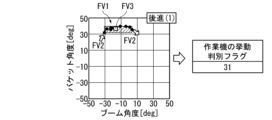
- FIG. 15 is a diagram showing an example of a feature amount for section (k) according to an embodiment of the present disclosure.
- FIG. 16 is a diagram showing an example of a feature amount according to an embodiment of the present disclosure.
- FIG. 15 is a diagram in which figures explaining feature amounts FV1 to FV3 have been added to FIG. 9.
- FIG. 16 also shows an example including a peak (an example during warm-up operation).
- the second operating state classification unit 34 sets the value of the behavior discrimination flag of the work machine shown in FIG. 17 for the relevant section as a result of classifying the operating state of the work machine 10 (second movable part).
- the trained machine learning model 35 inputs the four types of feature amounts shown in FIG. 14 and outputs the value of the behavior discrimination flag of the work machine shown in FIG. 17. In the example shown in FIG. 17, the behavior of the work machine is classified into 13 types.
- FIGS. 18 to 21 are diagrams showing examples of feature amounts of sections (k+1) to (k+4) according to an embodiment of the present disclosure. 18 to 21 are diagrams in which figures explaining the feature quantities FV1 to FV3 are added to FIGS. 10 to 13. When the feature quantities shown in FIG.
- the trained machine learning model 35 outputs, for example, the behavior discrimination flag "20" of the work machine.
- the behavior discrimination flag "20" of the work machine corresponds to the behavior of the work machine in the "scooping" operation.
- the "scooping" operation is, for example, an operation in which the boom 11 is lowered while moving forward to scoop the excavated material into the bucket 12, and then the bucket 12 is scooped up.
- the trained machine learning model 35 outputs, for example, the behavior discrimination flags "31", "51", "12", and "41" of the work machine.
- FIG. 22 is a diagram showing an example of training data according to an embodiment of the present disclosure.
- the training data (data set) 351 shown in FIG. 22 includes multiple sets of data that associate the initial value, maximum value, minimum value, average value, number of peaks, and final value of the boom angle in the target section with the initial value, maximum value, minimum value, average value, number of peaks, and final value of the bucket angle and the value of the behavior determination flag of the work machine (this is the label value).
- the trained machine learning model 35 of this embodiment can be understood as follows. That is, the trained machine learning model 35 is a machine learning model that inputs predetermined input information based on time series data representing at least the operating state of the first movable part and the operating state of the second movable part of a work machine having a first movable part and a second movable part, and outputs output information representing the result of classifying the operating state of the second movable part, and the input information includes a plurality of predetermined feature amounts related to the operating state of the second movable part for each section obtained by dividing the time axis of the time series data into a plurality of sections based on the classification result of the operating state of the first movable part, and is a trained machine learning model that has been machine-learned using input information labeled with the type of the operating state of the second movable part.
- the second movable part is, for example, a work machine having a plurality of partial movable parts
- the plurality of feature amounts can include one or more values that represent the respective movable amounts of the plurality of partial movable parts that correspond to each other on the time axis by respective coordinate values on a plurality of different coordinate axes.
- the plurality of partial movable parts correspond to, for example, the boom 11 and the bucket 12.
- the coordinate axes can include one or more values represented by each coordinate value on the three or more coordinate axes.
- each coordinate value can include values corresponding to the initial value, maximum value, minimum value, average value, or final value of each coordinate value for each section.
- the multiple feature amounts can include a value representing the number of repeated operations of the second movable part that occur for each section.
- the work classification unit 36 classifies the work performed by the wheel loader 1 based on the classification results of the operating state of the traveling device 4 (first movable part) and the classification results of the operating state of the work machine 10 (second movable part).
- the work classification unit 36 classifies the work by using one or more sections as a unit.
- FIG. 23 is a schematic diagram showing an example of work classification according to an embodiment of the present disclosure. In the example shown in FIG. 23, the types of work are classified into nine types: "loading", “raising”, “leveling”, “sorting”, “moving”, “parking”, "loading-related work", “sorting-related work", and "other".
- the work classification flag is information that specifies the type of work.
- “Loading” is, for example, the work of loading excavated materials onto the bed or hopper of a transport vehicle. “Raising” is the work of piling up excavated materials. “Leveling” is the work of leveling the work site. “Sorting” is, for example, the work of separating materials to be excavated from materials to be excavated. “Moving” is the work of moving a predetermined distance or more. “Stopping” refers to work in which the vehicle stops for a specified period of time or more. “Loading-related work” refers to, for example, loading work in which a single scooping action is usually repeated two or more times. “Sorting-related work” refers to, for example, sorting work in which more sorting actions are performed than usual. “Other” refers to work that does not fall into the above categories.
- the work classification unit 36 classifies the five sections as sections for loading work. That is, the work classification unit 36 predetermines the combination of the behavior of the traveling device and the behavior of the working machine in one or more sections corresponding to each type of work, or the transition of the combination, and identifies the work in the section when the combination of the behavior of the traveling device and the behavior of the working machine in one or more sections of the time series data 24, or the transition of the combination, matches.
- the work classification unit 36 preferentially selects the section and determines the type. Next, for sections in which work is not classified, it searches for a section that matches the next typical combination of the behavior of the traveling device and the behavior of the working machine in one or more sections different from the work initially classified, or the transition of the combination, and determines the type if there is a match.
- the work classification unit 36 classifies the work in all target sections by, for example, repeating the above process. As described above, by giving priority to identifying the type of work that is easy to identify, highly accurate identification is possible. FIG.
- the work classification unit 36 determines that the transition of the combination of the traveling device behavior discrimination flag and the work machine behavior discrimination flag for each section divided according to the classification result of the traveling device behavior matches the transition shown in FIG. 24, and classifies the work in the section (k) to (k+4) as loading work.
- the first operating state classification unit 32, the second operating state classification unit 34, and the task classification unit 36 generate time series data 24R in which the values of the traveling device behavior discrimination flag, the work machine behavior discrimination flag, and the task classification flag are set for each piece of time series data (each sampling) as shown in FIG. 26, for example, and store the data in the memory unit 38.
- the classification result is not limited to the example shown in FIG. 26, and the classification result may be represented, for example, by recording the values of the traveling device behavior discrimination flag, the work machine behavior discrimination flag, and the task classification flag in association with information such as a timestamp of the time series data 24 that identifies each section.
- the detailed analysis unit 37 statistically analyzes the time series data 24 for each section based on, for example, the operation of the operator.
- Figures 27 to 31 are diagrams showing examples of the results of detailed analysis by the detailed analysis unit 37.
- Figure 27 is a pie chart showing the proportion of work for a specific period, a specific work machine, and a specific operator.
- Figure 28 is a histogram showing the frequency of the boom angle at the time of earth discharge in loading work for a specific period, a specific work machine, and a specific operator.
- the detailed analysis unit 37 calculates the frequency of the boom angle for each section where the work classification result is "loading work” and the behavior discrimination flag of the work machine shown in Figure 17 is classified as "50", "51", or "52" (earth discharge).
- Figure 29 is a scatter diagram showing the relationship between fuel consumption [L/h] and work volume [ton/h] in loading work for a specific period, a specific work machine, and a specific operator.
- the scatter diagram in Figure 29 includes a regression line.
- FIG. 30 is a histogram showing the frequency of cycle times in loading operations for a specific period, a specific work machine, and a specific operator.
- FIG. 31 is a histogram showing the frequency of cycle times in loading operations for a specific period, a specific work machine, and two different operators, allowing comparison between the operators.
- the output unit 39 outputs, for example, the analysis results of the detailed analysis unit 37 to a display device, etc.
- Example of analysis device operation is a flowchart showing an example of the operation of the analysis device according to the embodiment of the present disclosure.
- the acquisition unit 31 first acquires a file of the time series data 24 (step S1).
- the first operating state classification unit 32 classifies the behavior of the traveling device based on the vehicle speed and the gear for the entire target time of the time series data 24 (step S2).
- the division unit 33 divides the time axis of the time series data 24 into a plurality of sections based on the classification result of the behavior of the traveling device (step S3).
- the second operating state classification unit 34 calculates a plurality of feature amounts for each section based on the boom angle and the bucket angle (step S4).
- the second operating state classification unit 34 classifies the behavior of the work machine for each section using the trained machine learning model 35 (step S5).
- training data is prepared, and, for example, in the processing of step S5, machine learning is performed to generate a trained machine learning model 35, and then classification processing is performed.
- the trained machine learning model 35 may be generated in advance, for example, before starting the processing shown in FIG. 32.
- the task classification unit 36 classifies the tasks into one or more sections based on the classification results of the traveling gear behavior and the classification results of the work machine behavior (step S6).
- the detailed analysis unit 37 statistically analyzes the time series data, for example, by section, and the output unit 39 outputs the analysis results (step S7).
- the time series data 24 is divided into a plurality of sections based on the classification result of the traveling unit 4 (first movable part), and the operating state of the work machine 10 (second movable part) is classified for each section, so that the operating state of the work machine 10 (second movable part) can be efficiently classified. Therefore, the work of the wheel loader 1 (work machine) having the traveling unit 4 (first movable part) and the work machine 10 (second movable part) can be efficiently classified based on the time series data 24.
- the analysis device, analysis method, program, trained machine learning model, and machine learning method according to the present disclosure can be understood, for example, as follows.
- Appendix 1 an acquisition unit that acquires time series data representing at least an operating state of the first movable part and an operating state of the second movable part of a work machine having a first movable part and a second movable part; a first operating state classification unit that classifies an operating state of the first movable part based on the time-series data; a division unit that divides a time axis of the time series data into a plurality of sections based on a classification result of the operating state of the first movable part; a second operating state classification unit that classifies an operating state of the second movable part for each section based on the time series data; an analysis device comprising: a task classification unit that classifies tasks performed by the work machine based on a classification result of the operating state of the first movable part and a classification result of the operating state of the second movable part.
- the second operating state classification unit is inputting input information including a plurality of predetermined feature amounts related to the operating state of the second movable part for each of the sections; A machine learning model that outputs output information representing a result of classifying an operating state of the second movable part, Using a trained machine learning model that has been machine-learned using the input information labeled with the type of the operating state of the second movable part,
- the analysis device according to claim 1 or 2, further comprising: a second movable part configured to: classify an operating state of the second movable part.
- the first movable part is a running part
- the analysis device according to any one of appendices 1 to 3, wherein the second movable part is a work machine.
- the analysis device according to claim 1, further comprising a detailed analysis unit that statistically analyzes the time series data in units of the intervals.
- (Appendix 6) acquiring time series data representing at least an operating state of the first movable part and an operating state of the second movable part of a work machine having a first movable part and a second movable part; classifying an operating state of the first movable part based on the time series data; Dividing a time axis of the time series data into a plurality of sections based on a classification result of the operating state of the first movable part; classifying an operating state of the second movable part for each of the sections based on the time-series data; classifying work performed by the work machine based on the classification result of the operating state of the first movable part and the classification result of the operating state of the second movable part.
- (Appendix 7) acquiring time series data representing at least an operating state of the first movable part and an operating state of the second movable part of a work machine having a first movable part and a second movable part; classifying an operating state of the first movable part based on the time series data; Dividing a time axis of the time series data into a plurality of sections based on a classification result of the operating state of the first movable part; classifying an operating state of the second movable part for each of the sections based on the time-series data; and a step of classifying work performed by the work machine based on a classification result of the operating state of the first movable part and a classification result of the operating state of the second movable part.
- Appendix 8 inputting predetermined input information based on time-series data representing at least an operating state of the first movable part and an operating state of the second movable part of a work machine having a first movable part and a second movable part;
- a machine learning model that outputs output information representing a result of classifying an operating state of the second movable part, the input information includes a plurality of predetermined feature amounts related to the operating state of the second movable part for each of a plurality of sections obtained by dividing a time axis of the time series data into a plurality of sections based on a classification result of the operating state of the first movable part,
- a trained machine learning model that has been machine-learned using the input information in which the type of operating state of the second movable part is labeled.
- the second movable part is a work machine having a plurality of partial movable parts
- the one or more values represented by each coordinate value include a value corresponding to an initial value, a maximum value, a minimum value, an average value, or a final value of each coordinate value for each of the divisions.
- Appendix 11 The trained machine learning model according to any one of appendices 8 to 10, wherein the plurality of feature amounts include a value representing the number of times the second movable part has been moved repeatedly for each of the sections.
- a machine learning method for a machine learning model comprising: inputting predetermined input information based on time-series data representing at least an operating state of a first movable part and an operating state of a second movable part of a work machine having a first movable part and a second movable part; and outputting output information representing a result of classifying the operating state of the second movable part, the input information includes a plurality of predetermined feature amounts related to the operating state of the second movable part for each of a plurality of sections obtained by dividing a time axis of the time series data into a plurality of sections based on a classification result of the operating state of the first movable part, A machine learning method for machine learning the machine learning model using the input information labeled with the type of operating state of the second movable part.
- the operating state of the second movable part is classified for each of a plurality of sections into which time series data is divided based on the classification result of the first movable part, so that the operating state of the second movable part can be efficiently classified. Therefore, the work of a work machine having a first movable part and a second movable part can be efficiently classified based on the time series data.
Landscapes
- Engineering & Computer Science (AREA)
- Mining & Mineral Resources (AREA)
- Civil Engineering (AREA)
- General Engineering & Computer Science (AREA)
- Structural Engineering (AREA)
- Component Parts Of Construction Machinery (AREA)
Abstract
Description
本開示は、解析装置、解析方法、プログラム、学習済み機械学習モデル、および、機械学習方法に関する。本願は、2023年11月20日に、日本に出願された特願2023-196595号に基づき優先権を主張し、その内容をここに援用する。 This disclosure relates to an analysis device, an analysis method, a program, a trained machine learning model, and a machine learning method. This application claims priority to Japanese Patent Application No. 2023-196595, filed on November 20, 2023, the contents of which are incorporated herein by reference.
特許文献1には、空荷前進、掘削、積荷後進、積荷前進、積込、および、空荷後進の各作業モードを繰り返すサイクル作業(この例では積込作業)を実施するようにホイールローダがオペレータにより運転されたときに、サイクル作業が含む各作業モードを、ホイールローダの状態を表す数値に基づいて判別する技術が開示されている。
ところで、ホイールローダが実施する作業には、積込作業のほか、掘削物の選別作業、かき上げ作業等、複数種類の作業がある。また、ホイールローダ等の作業機械では、作業機械の稼働状態を表す時系列のデータに基づいて、作業機械がどのような作業を実施しているのかを効率的に解析したいというニーズがある。 Incidentally, wheel loaders perform multiple types of work, including loading, sorting of excavated material, and shoveling. In addition, with work machines such as wheel loaders, there is a need to efficiently analyze what type of work the work machine is performing based on time-series data that indicates the operating status of the work machine.
本開示は、上記事情に鑑みてなされたものであり、作業機械の稼働状態を表す時系列のデータに基づいて作業を効率的に分類することができる解析装置、解析方法、プログラム、学習済み機械学習モデル、および、機械学習方法を提供することを目的とする。 The present disclosure has been made in consideration of the above circumstances, and aims to provide an analysis device, an analysis method, a program, a trained machine learning model, and a machine learning method that can efficiently classify work based on time-series data that represents the operating status of a work machine.
本開示の解析装置は、第1可動部と第2可動部とを有する作業機械の前記第1可動部の稼働状態と前記第2可動部の稼働状態とを少なくとも表す時系列データを取得する取得部と、前記時系列データに基づき前記第1可動部の稼働状態を分類する第1稼働状態分類部と、前記第1可動部の稼働状態の分類結果に基づき前記時系列データの時間軸を複数の区間に区分する区分部と、前記時系列データに基づき前記区間毎に前記第2可動部の稼働状態を分類する第2稼働状態分類部と、前記第1可動部の稼働状態の分類結果と前記第2可動部の稼働状態の分類結果とに基づき前記作業機械による作業を分類する作業分類部とを備える。 The analysis device disclosed herein includes an acquisition unit that acquires time series data representing at least the operating state of a first movable part and the operating state of a second movable part of a work machine having a first movable part and a second movable part, a first operating state classification unit that classifies the operating state of the first movable part based on the time series data, a division unit that divides the time axis of the time series data into a plurality of sections based on the classification result of the operating state of the first movable part, a second operating state classification unit that classifies the operating state of the second movable part for each of the sections based on the time series data, and a work classification unit that classifies work performed by the work machine based on the classification result of the operating state of the first movable part and the classification result of the operating state of the second movable part.
また、本開示の解析方法は、第1可動部と第2可動部とを有する作業機械の前記第1可動部の稼働状態と前記第2可動部の稼働状態とを少なくとも表す時系列データを取得するステップと、前記時系列データに基づき前記第1可動部の稼働状態を分類するステップと、前記第1可動部の稼働状態の分類結果に基づき前記時系列データの時間軸を複数の区間に区分するステップと、前記時系列データに基づき前記区間毎に前記第2可動部の稼働状態を分類するステップと、前記第1可動部の稼働状態の分類結果と前記第2可動部の稼働状態の分類結果とに基づき前記作業機械による作業を分類するステップとを含む。 The analysis method disclosed herein also includes the steps of acquiring time series data representing at least the operating state of a first movable part and the operating state of a second movable part of a work machine having a first movable part, classifying the operating state of the first movable part based on the time series data, dividing the time axis of the time series data into a plurality of sections based on the classification result of the operating state of the first movable part, classifying the operating state of the second movable part for each section based on the time series data, and classifying work performed by the work machine based on the classification result of the operating state of the first movable part and the classification result of the operating state of the second movable part.
また、本開示のプログラムは、第1可動部と第2可動部とを有する作業機械の前記第1可動部の稼働状態と前記第2可動部の稼働状態とを少なくとも表す時系列データを取得するステップと、前記時系列データに基づき前記第1可動部の稼働状態を分類するステップと、前記第1可動部の稼働状態の分類結果に基づき前記時系列データの時間軸を複数の区間に区分するステップと、前記時系列データに基づき前記区間毎に前記第2可動部の稼働状態を分類するステップと、前記第1可動部の稼働状態の分類結果と前記第2可動部の稼働状態の分類結果とに基づき前記作業機械による作業を分類するステップとをコンピュータに実行させる。 The program disclosed herein also causes a computer to execute the steps of acquiring time series data representing at least the operating state of a first movable part and the operating state of a second movable part of a work machine having a first movable part and a second movable part, classifying the operating state of the first movable part based on the time series data, dividing the time axis of the time series data into a plurality of sections based on the classification results of the operating state of the first movable part, classifying the operating state of the second movable part for each section based on the time series data, and classifying work performed by the work machine based on the classification results of the operating state of the first movable part and the classification results of the operating state of the second movable part.
また、本開示の学習済み機械学習モデルは、第1可動部と第2可動部とを有する作業機械の前記第1可動部の稼働状態と前記第2可動部の稼働状態とを少なくとも表す時系列データに基づく所定の入力情報を入力し、前記第2可動部の稼働状態を分類した結果を表す出力情報を出力する機械学習モデルであって、前記入力情報は、前記第1可動部の稼働状態の分類結果に基づいて前記時系列データの時間軸を複数の区間に区分した前記区間毎の前記第2可動部の稼働状態に関する複数の所定の特徴量を含み、前記第2可動部の稼働状態の種類がラベル付けされた前記入力情報を用いて機械学習されている。 The trained machine learning model of the present disclosure is a machine learning model that inputs predetermined input information based on time series data representing at least the operating state of a first movable part and the operating state of a second movable part of a work machine having the first movable part and the second movable part, and outputs output information representing the result of classifying the operating state of the second movable part, the input information including a plurality of predetermined feature quantities related to the operating state of the second movable part for each of the sections obtained by dividing the time axis of the time series data into a plurality of sections based on the classification result of the operating state of the first movable part, and is machine-trained using the input information labeled with the type of the operating state of the second movable part.
また、本開示の機械学習方法は、第1可動部と第2可動部とを有する作業機械の前記第1可動部の稼働状態と前記第2可動部の稼働状態とを少なくとも表す時系列データに基づく所定の入力情報を入力し、前記第2可動部の稼働状態を分類した結果を表す出力情報を出力する機械学習モデル、の機械学習方法であって、前記入力情報は、前記第1可動部の稼働状態の分類結果に基づいて前記時系列データの時間軸を複数の区間に区分した前記区間毎の前記第2可動部の稼働状態に関する複数の所定の特徴量を含み、前記第2可動部の稼働状態の種類がラベル付けされた前記入力情報を用いて前記機械学習モデルを機械学習する。 The machine learning method disclosed herein is a machine learning method for a machine learning model that inputs predetermined input information based on time series data representing at least the operating state of a first movable part and the operating state of a second movable part of a work machine having the first movable part and the second movable part, and outputs output information representing the result of classifying the operating state of the second movable part, the input information including a plurality of predetermined feature quantities related to the operating state of the second movable part for each of the sections obtained by dividing the time axis of the time series data into a plurality of sections based on the classification result of the operating state of the first movable part, and machine learning the machine learning model using the input information labeled with the type of the operating state of the second movable part.
本開示の解析装置、解析方法、プログラム、学習済み機械学習モデル、および、機械学習方法は、時系列データを第1可動部の分類結果に基づき複数の区間に区分した区分毎に第2可動部の稼働状態を分類するので、第2可動部の稼働状態を効率的に分類することができる。したがって、時系列データに基づいて、第1可動部と第2可動部とを有する作業機械の作業を効率的に分類することができる。 The analysis device, analysis method, program, trained machine learning model, and machine learning method disclosed herein classify the operating state of the second moving part for each of a plurality of sections into which time series data is divided based on the classification result of the first moving part, and therefore can efficiently classify the operating state of the second moving part. Therefore, the work of a work machine having a first moving part and a second moving part can be efficiently classified based on the time series data.
以下、図面を参照して本開示の実施形態について説明する。なお、各図において同一または対応する構成には同一の符号を用いて説明を適宜省略する。 Below, an embodiment of the present disclosure will be described with reference to the drawings. Note that the same or corresponding components in each drawing will be designated by the same reference numerals and their description will be omitted as appropriate.
(解析システム)
図1は、本開示の実施形態に係る解析システムの構成例を示す模式図である。図1に示す解析システムSY1は、解析対象とする作業機械の一例としてのホイールローダ1と、通信網NWを介してホイールローダ1と通信接続するデータ管理サーバ20と、解析装置30とを備える。ホイールローダ1は、車体制御装置100と、稼働情報記録装置101とを備える。車体制御装置100は、ホイールローダ1が備える複数のセンサが計測したセンサ情報を入力するとともに、オペレータの操作に従って、ホイールローダ1の各部を制御する。稼働情報記録装置101は、車体制御装置100が生成した所定の制御信号、センサ情報等のホイールローダ1の稼働状態を表す時系列データを一定期間分(あるいは一定データ量分)記録し、通信網NWを介して、データ管理サーバ20へ送信する。データ管理サーバ20は、稼働情報記録装置101から受信した時系列データを、時系列データファイル21として蓄積する。本実施形態では、解析装置30はデータ管理サーバ20とは別に設けられているが、これに限られない。データ管理サーバ20内に解析装置30が設けられていてもよい。
(Analysis system)
FIG. 1 is a schematic diagram showing a configuration example of an analysis system according to an embodiment of the present disclosure. The analysis system SY1 shown in FIG. 1 includes a
(作業機械)
ここで、図2を参照して、ホイールローダ1について説明する。図2は、本開示の実施形態に係る作業機械(ホイールローダ1)の構成例を示す側面図である。図2に示すように、ホイールローダ1は、車体2と、キャブ3と、走行装置4と、作業機10とを有する。ホイールローダ1は、走行装置4により、作業現場を走行する。ホイールローダ1は、作業現場において、作業機10を用いて作業を実施する。ホイールローダ1は、作業機10を用いて、例えば、掘削作業、積込作業、運搬作業、除雪作業等の作業を実施することができる。
(Work machine)
Here, the
キャブ3は、車体2に支持される。キャブ3の内部には、オペレータが着座する運転席、操作装置、表示入力部等が配置される。
The
走行装置4は、図示していない動力伝達装置、回転可能な車輪5等を有する。車輪5は、車体2を支持する。ホイールローダ1は、走行装置4によって路面(あるいは地面)RSを走行可能である。なお、図2では、左側の前輪5Fおよび後輪5Rのみが図示されている。動力伝達装置は、後述する動力源の駆動力を車輪5に伝達する。本実施形態では、動力伝達装置は、前進4速、ニュートラルおよび後進4速の変速段(速度段)のトランスミッションを有しているものとする。なお、走行装置4は、本開示の「走行部」の一構成例である。
The traveling
作業機10は、車体2に支持される。作業機10は、作業工具の一例としてのバケット12と、バケット12の位置と姿勢を変化させる可動支持部17とから構成されている。図2に示す例では、可動支持部17は、ブーム11と、ブームシリンダ13と、バケットシリンダ14と、ベルクランク15と、リンク16とを備える。
The
ブーム11は、車体2に対して回動可能に支持され、ブームシリンダ13の伸縮に応じて上下方向に移動する。ブームシリンダ13は、ブーム11を移動させるための動力を発生するアクチュエータであり、一端部は車体2に連結され、他端部はブーム11に連結される。オペレータがブーム操作装置(図示しない)を操作すると、ブームシリンダ13が伸縮する。これにより、ブーム11は上下方向に移動する。ブームシリンダ13は、例えば油圧シリンダである。なお、本実施形態では、ブーム11の角度を矢印A1で示すように、水平方向を0[deg]として、上を向いた場合が正、下を向いた場合が負となる値で表す。
The
バケット12は、刃先12Tを有し、土砂等の掘削対象物の掘削や、積み込みを行うための作業工具である。バケット12は、ブーム11に対して回動可能に連結されるとともに、リンク16の一端部に対して回動可能に連結されている。リンク16の他端部は、ベルクランク15の一端部に回動可能に連結されている。ベルクランク15は、中央部がブーム11に回動可能に連結され、他端部がバケットシリンダ14の一端部に回動可能に連結されている。バケットシリンダ14の他端部は車体2に回動可能に連結されている。バケット12は、バケットシリンダ14が発生する動力によって作動する。バケットシリンダ14は、バケット12を移動するための動力を発生するアクチュエータである。オペレータが図示していないバケット操作装置を操作すると、バケットシリンダ14が伸縮する。これにより、バケット12は揺動する。バケットシリンダ14は、例えば油圧シリンダである。刃先12Tは、山刃、平刃等の形状を有し、交換可能にバケット12の端部に取り付けられている。なお、本実施形態では、バケット12の角度(刃先12Tが向く方向(刃先方向)の角度)を、矢印A2で示すように、水平方向を0[deg]として、上を向いた場合が正、下を向いた場合が負となる値で表す。
The
なお、本実施形態では、刃先12Tが下を向いているバケット12cの姿勢を、ダンプ姿勢という。ダンプ姿勢は、例えば、バケット12内の掘削物を運搬車両、ホッパ等に積み込むことができる姿勢(排土姿勢)である。また刃先12Tが上を向いているバケット12aの姿勢を、チルト姿勢(抱え込み姿勢)という。チルト姿勢は、例えば、掘削物をバケット12内に保持することができる姿勢(運搬姿勢)である。また、刃先12Tが路面RSと水平方向(ほぼ水平方向を含む)を向いているバケット12bの姿勢を、掘削姿勢(あるいは掘削時の走行姿勢)という。掘削姿勢は、例えば、土砂等の掘削対象物の掘削を開始するときや掘削対象物に向かって走行するときの姿勢(あるいは掘削を開始するときや走行するときに適した姿勢)である。また、ブーム11が下げられた状態で、刃先12Tが路面RSに接しているバケット12の姿勢を、接地姿勢という。ホイールローダ1は、例えば、バケット12を掘削姿勢(あるいは掘削姿勢から刃先12Tが路面RSより低くなる姿勢)とし、前方方向へ走行することで前方に位置する掘削対象物の掘削を開始する。なお、ホイールローダ1では、掘削姿勢は、刃先方向が路面RSと実質的に水平であるということから水平姿勢と呼ぶこともできる。
In this embodiment, the position of the
なお、ホイールローダ1は、図示していない動力源、PTO(Power Take Off)、油圧ポンプ、制御弁、操作装置、表示入力部等の構成を備える。動力源は、ホイールローダ1を作動させるための駆動力を発生する。動力源として、内燃機関や電動機が例示される。PTOは、動力源の駆動力の少なくとも一部を油圧ポンプに伝達する。PTOは、動力源の駆動力を走行装置4と油圧ポンプとに分配する。油圧ポンプは、動力源によって駆動され、作動油を吐出する。油圧ポンプから吐出された作動油の少なくとも一部は、制御弁を介して、ブームシリンダ13およびバケットシリンダ14のそれぞれに供給される。制御弁は、油圧ポンプからブームシリンダ13およびバケットシリンダ14のそれぞれに供給される作動油の流量および方向を制御する。作業機10は、油圧ポンプからの作動油により動作する。
The
操作装置は、キャブ3の内部に配置される。操作装置は、オペレータにより操作される。オペレータは、操作装置を操作して、ホイールローダ1の進行方向と走行速度の調整、前進または後進の切替え、および作業機10の操作を実施する。操作装置は、例えば、ステアリング、シフトレバー、アクセルペダル、ブレーキペダル、および作業機10のブーム11やバケット12を操作するための操作装置を含む。
The operating device is disposed inside the
また、ホイールローダ1は、例えば、GNSS(全地球航法衛星システム(Global Navigation Satellite System))受信機、エンジン回転数センサ、車速センサ、燃料消費量センサ、作業機負荷センサ、ブーム角センサ、バケット角センサ等のセンサを備えている。GNSS受信機は、2個の受信機(アンテナ)を有し、それぞれ位置情報(緯度、経度および高度)の情報を取得する。2つの位置情報に基づいて、ホイールローダ1の向きを算出することができる。エンジン回転数センサは、エンジン(動力源)の回転速度を検知する。車速センサはホイールローダ1の走行速度を検知する。燃料消費量センサはホイールローダ1の燃料消費量を検知する。作業機負荷センサは、例えばバケット12に保持された掘削物の重量(負荷)を検知する。ブーム角センサはブーム11の角度を検知する。バケット角センサはバケット12の角度を検知する。
The
(本開示の第1可動部および第2可動部との関係)
課題を解決するための手段の項に記載したように、本開示において解析装置が解析対象とする作業機械は、第1可動部と第2可動部とを有する。第1可動部は、例えば走行部(走行体)であり、本実施形態では走行装置4に対応する。第2可動部は、例えば作業機であり、本実施形態では、作業機10、ブーム11およびバケット12に対応する。なお、解析対象の作業機械を例えば油圧ショベルとする場合には、例えば、第1可動部が旋回部(旋回体)に対応し、第2可動部が作業機(バケット、アームおよびブーム)に対応する。あるは、第1可動部が旋回部と走行部とに対応し、第2可動部が作業機に対応する。あるいは、第1可動部が走行部に対応し、第2可動部が旋回部と作業機とに対応する。なお、本開示の作業機械の例としては、他に、ダンプトラック、ブルドーザ等が挙げられる。
(Relationship between the first movable portion and the second movable portion of the present disclosure)
As described in the section of the means for solving the problem, the working machine to be analyzed by the analysis device in the present disclosure has a first movable part and a second movable part. The first movable part is, for example, a traveling part (traveling body), and corresponds to the traveling
(時系列データ)
図3は、本開示の実施形態に係る時系列データファイルの構成例を示す模式図である。図3に示す時系列データファイル21は、作業機械情報22、オペレータ情報23および時系列データ24を含む。作業機械情報22は、例えば、ホイールローダ1の個体識別情報、型式、製造日等の情報を含む。オペレータ情報23は、ホイールローダ1のオペレータの識別情報等を含む。時系列データ24は、ホイールローダ1の各部の稼働状態を表す時系列のデータである。図3に示す例では、時系列データ24は、所定のサンプリング周期で(例えば1秒毎の)、日時、位置情報、エンジン回転数、変速段、車速、燃料消費量、負荷、ブーム角度、バケット角度等を表すデータを含む。各時系列データファイル21は、例えばエンジンキーオンからオフまでの時間毎に作成したり、所定時間毎に複数のファイルに分割する形で作成したりすることができる。なお、例えば、変速段と車速が、第1可動部の稼働状態を表すデータの例であり、ブーム角度とバケット角度が、第2可動部の稼働状態を表すデータの例である。この場合、時系列データ24は、第1可動部(走行装置4)と第2可動部(作業機10)とを有する作業機械(ホイールローダ1)の第1可動部の稼働状態と第2可動部の稼働状態とを少なくとも表すデータである。
(Time series data)
FIG. 3 is a schematic diagram showing an example of the configuration of a time-series data file according to an embodiment of the present disclosure. The time-series data file 21 shown in FIG. 3 includes
(解析装置の構成)
解析装置30は、例えば、パーソナルコンピュータ、タブレット端末等のコンピュータを用いて構成することができる。解析装置30は、コンピュータ、そのコンピュータの周辺装置等のハードウェアと、そのコンピュータが実行するソフトウェアとの組み合わせ等から構成される機能的構成として、次の各部を備える。すなわち、解析装置30は、機能的構成として、取得部31、第1稼働状態分類部32、区分部33、第2稼働状態分類部34、学習済み機械学習モデル35、作業分類部36、詳細分析部37、記憶部38および出力部39を備える。
(Configuration of analysis device)
The
取得部31は、解析対象とする時系列データ24を含む時系列データファイル21を取得し、記憶部38に格納する。時系列データファイル21は、データ管理サーバ20から自動で取得され、記憶部38に格納されてもよいし、手動で取得され、記憶部38に格納されてもよい。
The
第1稼働状態分類部32は、時系列データ24に基づき走行装置4(第1可動部)の稼働状態を分類する。図4は、本開示の実施形態に係る走行装置4(作業機械の足回り、なお、本実施形態では走行装置4を単に走行装置ともいう)の挙動判別フラグの例を示す模式図である。第1稼働状態分類部32は、図4に示すように、走行装置の挙動を4種類(停止、前進、後進またはニュートラル惰性走行)に区別し、種類毎に走行装置の挙動判別フラグ(1、2、3または4)を設定する。ここで、ニュートラル惰性走行は、変速段をニュートラルにし、例えばブレーキを軽く踏み車速を制限しながら走行している状態である。図4に示す例では、車速の値が「0」[km/h]の場合、変速段の値にかかわらず、走行装置4の稼働状態が「停止」に分類される。また、車速の値が「0」でない場合、変速段が前進1~4速(F1~F2)で「前進」、後進1~4速(R1~R2)で「後進」、ニュートラル(N)で「ニュートラル惰性走行」である。
The first operating
図5および図6は、本開示の実施形態に係る走行装置の挙動判別に係る時系列データの例を示す図である。図5および図6は、横軸に時間、縦軸(左側)に車速と変速段、縦軸(右側)に走行装置の挙動判別フラグをとり、車速と変速段と走行装置の挙動判別フラグの値の変化を示す。なお、車速は前後進に関わらず絶対値で示し、変速段は、前進1速~4速を+1~+4、ニュートラルを0、後進1速~4速を-1~-4で示している。図5に示す例では、10秒と15秒で車速が0となり、走行装置の挙動判別フラグの値は1(「停止」)となっている。このままでは前進と後進が切り替わるような場合に頻繁に挙動が「停止」と判別されることになる。そこで、図6に示す例では、停止が連続しない場合には停止とならないようにする補正処理を行い、10秒と15秒で車速が0となっているが、0となる時間が継続しない場合(例えば1サンプリングのみ0となるような場合)、走行装置の挙動判別フラグの値を1(「停止」)とせず、車速が0となる前の挙動の値に変更している。
5 and 6 are diagrams showing examples of time series data relating to behavior discrimination of a traveling device according to an embodiment of the present disclosure. In Figs. 5 and 6, the horizontal axis is time, the vertical axis (left side) is vehicle speed and gear position, and the vertical axis (right side) is behavior discrimination flag of the traveling device, and the changes in the vehicle speed, gear position, and value of the behavior discrimination flag of the traveling device are shown. Note that the vehicle speed is shown as an absolute value regardless of whether the vehicle is moving forward or backward, and the gear position is shown as +1 to +4 for
区分部33は、第1稼働状態分類部32による走行装置4(第1可動部)の稼働状態の分類結果に基づき時系列データ24の時間軸を複数の区間に区分する。図7は、本開示の実施形態に係る時系列データを複数の区間に区分した例を示す図である。図7に示す例では、区分部33は、第1稼働状態分類部32によって「前進」、「後進」または「停止」と種類分けされた期間が1区間となるように時系列データの時間軸を区分する。なお、「ニュートラル惰性走行」に種類分けされた期間については前の種類分け期間と合体させて前の種類の期間に含ませている。図6に示す期間(0~42秒)の分類結果に対して、区分部33は、図7に示すように、期間(0~42秒)を区間(k)~区間(k+4)の5区間に区分している(kは任意の自然数)。なお、本実施形態において各区間は1秒ごとに区分され、各区間の最後の時刻は次の区間の最初の時刻とされる。このため、例えば、期間0~43秒において時刻43秒は図示していない次の区間(k+5)に区分される。また、後述するようにして、期間(0~42秒)は積込作業に分類されることとなり、図7に示す例では、区間(k)~区間(k+4)が積込作業の1回分の期間であり、区間(k)が前進(1)、区間(k+1)が後進(1)、区間(k+2)が前進(2)、区間(k+3)が停止、区間(k+4)が後進(2)の各挙動に対応している。
The
第2稼働状態分類部34は、時系列データ24に基づき区間毎に作業機10(第2可動部)の稼働状態を分類する。第2稼働状態分類部34は、例えば、区間毎の作業機10(第2可動部)の稼働状態に関する複数の所定の特徴量を含む入力情報を入力し、作業機10(第2可動部)の稼働状態を分類した結果を表す出力情報を出力する機械学習モデルであって、作業機10(第2可動部)の稼働状態の種類がラベル付けされた入力情報を教師データとして用いて教師ありで機械学習された学習済み機械学習モデル35を用いて、作業機10(第2可動部)の稼働状態を分類する。図8は、本開示の実施形態に係る作業機10(なお、本実施形態では作業機10を単に作業機ともいう)の挙動判別に係る時系列データの例を示す図である。
The second operating
なお、学習済み機械学習モデル35は、例えば、入力から出力までの演算を行うプログラムと当該演算に用いられる重み付け係数(パラメータ)の組合せ等で構成される。また、入力される多数のデータに対して求める解が出力されるよう、機械学習により算出で用いる係数等が最適化されている。本実施形態では、機械学習モデルのアルゴリズムとしてk近傍法を用いることで良好な精度が得られることを確認している。ただし、機械学習モデルのアルゴリズムについて本実施形態特有の限定はない。
The trained
図8は、横軸に時間、縦軸(左側)に車速とブーム角度とバケット角度、縦軸(右側)に走行装置の挙動判別フラグをとり、車速とブーム角度とバケット角度と走行装置の挙動判別フラグの値の変化を示す。時間軸の値と車速および走行装置の挙動判別フラグの値は、図7の各値と同一である。図9~図13は、図7および図8に示す区間(k)~区間(k+4)の作業機10の稼働状態の例を表す図である。横軸をブーム角度、縦軸をバケット角度とし、対象区間内の互いに同一時刻のブーム角度とバケット角度に基づく各点をプロットしている。
In Figure 8, the horizontal axis is time, the vertical axis (left side) is vehicle speed, boom angle, and bucket angle, and the vertical axis (right side) is the traveling gear behavior discrimination flag, and the change in the values of the vehicle speed, boom angle, bucket angle, and traveling gear behavior discrimination flag is shown. The values on the time axis and the vehicle speed and traveling gear behavior discrimination flag values are the same as those in Figure 7. Figures 9 to 13 are diagrams showing examples of the operating state of the
図14は、本開示の実施形態に係る特徴量の例を示す図である。なお、特徴量は、分析対象の特徴を定量的に表す数値である。本実施形態では、4種類の特徴量を定義している。例えば、図9~図13に示す区間毎の各プロットについて、1つ目は「面積」(FV1)であり、作業機10の位置把握を目的として、ブーム角度の最大値および最小値と、バケット角度の最大値および最小値で表すことができる。2つ目は「入出口座標」(FV2)であり、動きの把握を目的として、ブーム角度の当該区間の初期値および最終値と、バケット角度の当該区間の初期値および最終値で表すことができる。3つ目は「重心座標」(FV3)であり、面積内部の動きの把握を目的として、ブーム角度の平均値と、バケット角度の平均値で表すことができる。4つ目は「ピークの山の数」(FV4)であり、面積内部の繰り返しの把握を目的として、ブーム角度とバケット角度のプロットを時系列で結ぶ曲線にピーク状の変化(局所的最大値、所定の閾値を超える曲線の傾きの値の変化等)があった場合のその変化の個数で表すことができる。図15は、本開示の実施形態に係る区間(k)の特徴量の例を示す図である。図16は、本開示の実施形態に係る特徴量の例を示す図である。図15は、図9に対して特徴量FV1~FV3の説明となる図形を追加した図である。また、図16は、ピークを含む例(暖機運転時の例)を示す。
FIG. 14 is a diagram showing an example of a feature quantity according to an embodiment of the present disclosure. Note that a feature quantity is a numerical value that quantitatively represents the characteristics of the object of analysis. In this embodiment, four types of feature quantities are defined. For example, for each plot for each section shown in FIGS. 9 to 13, the first is the "area" (FV1), which can be expressed by the maximum and minimum values of the boom angle and the maximum and minimum values of the bucket angle for the purpose of grasping the position of the
図17は、本開示の実施形態に係る作業機の挙動判別フラグの例を示す模式図である。第2稼働状態分類部34は、作業機10(第2可動部)の稼働状態を分類した結果として、図17に示す作業機の挙動判別フラグの値を当該区間対して設定する。また、本実施形態において学習済み機械学習モデル35は、図14に示す4種類の特徴量を入力し、図17に示す作業機の挙動判別フラグの値を出力する。図17に示す例では作業機の挙動が13種類に類別されている。図17に示す、作業機の挙動判別フラグと、「区分」、「バケット」の「姿勢」および「動き」、「ブーム」の「姿勢」および「動き」の各内容との対応付けは、例えば、教師あり学習での入力情報にラベル付けを行う際のおおまかな基準である。なお、「レベラ」は自動で水平状態に調整する機能を使用している状態である。図18~図21は、本開示の実施形態に係る区間(k+1)~(k+4)の特徴量の例を示す図である。図18~図21は、図10~図13に特徴量FV1~FV3の説明となる図形を追加した図である。なお、図15に示す特徴量を入力した場合、学習済み機械学習モデル35は、例えば作業機の挙動判別フラグ「20」を出力する。作業機の挙動判別フラグ「20」は、「すくい込み」動作における作業機の挙動に対応する。「すくい込み」動作は、例えば、前進しながらブーム11を下げて掘削物をバケット12にかき入れた後、バケット12をかかえ込むようにする動作である。また、図18、図19、図20および図21に示す特徴量を入力した場合、学習済み機械学習モデル35は、例えば作業機の挙動判別フラグ「31」、「51」、「12」および「41」を出力する。
17 is a schematic diagram showing an example of a behavior discrimination flag of the work machine according to an embodiment of the present disclosure. The second operating
図22は、本開示の実施形態に係る教師データの例を示す図である。図22に示す教師データ(データセット)351は、対象区間におけるブーム角度の初期値、最大値、最小値、平均値、ピーク山数および最終値とバケット角度の初期値、最大値、最小値、平均値、ピーク山数および最終値と作業機の挙動判別フラグの値(これがラベルの値である)を対応付けたデータを、複数組含んでいる。 FIG. 22 is a diagram showing an example of training data according to an embodiment of the present disclosure. The training data (data set) 351 shown in FIG. 22 includes multiple sets of data that associate the initial value, maximum value, minimum value, average value, number of peaks, and final value of the boom angle in the target section with the initial value, maximum value, minimum value, average value, number of peaks, and final value of the bucket angle and the value of the behavior determination flag of the work machine (this is the label value).
なお、本実施形態の学習済み機械学習モデル35は、次のように把握することができる。すなわち、学習済み機械学習モデル35は、第1可動部と第2可動部とを有する作業機械の第1可動部の稼働状態と第2可動部の稼働状態とを少なくとも表す時系列データに基づく所定の入力情報を入力し、第2可動部の稼働状態を分類した結果を表す出力情報を出力する機械学習モデルであって、入力情報は、第1可動部の稼働状態の分類結果に基づいて時系列データの時間軸を複数の区間に区分した区間毎の第2可動部の稼働状態に関する複数の所定の特徴量を含み、第2可動部の稼働状態の種類がラベル付けされた入力情報を用いて機械学習されている学習済み機械学習モデルである。なお、第2可動部は、例えば、複数の部分可動部を有する作業機であり、複数の特徴量は、時間軸上で互いに対応する複数の部分可動部の各可動量を異なる複数の座標軸上の各座標値で表した1以上の値を含むものとすることができる。ここで、複数の部分可動部は、例えばブーム11とバケット12に対応する。この場合、作業機が3以上の部分可動部(例えばバケット、アームおよびブーム)を含む場合、座標軸は3以上の座標軸上の各座標値で表した1以上の値を含むものとすることができる。また、各座標値で表した1以上の値は、区分毎の各座標値の初期値、最大値、最小値、平均値、または、最終値に対応した値を含むことができる。また、複数の特徴量は、区間毎に発生した第2可動部の繰り返し動作の回数を表す値を含むことができる。
The trained
作業分類部36は、走行装置4(第1可動部)の稼働状態の分類結果と作業機10(第2可動部)の稼働状態の分類結果とに基づきホイールローダ1による作業を分類する。なお、作業分類部36は、1または複数の区間を単位として、作業を分類する。図23は、本開示の実施形態に係る作業分類の例を示す模式図である。図23に示す例では、作業の種類が、「積込み」、「かき上げ」、「整地」、「選別」、「移動」、「停車」、「積込み付帯作業」、「選別付帯作業」および「その他」の9種類に分類される。作業分類フラグは、作業の種類を特定する情報である。なお、「積込み」は、例えば掘削物を運搬車両の荷台、ホッパ等に積み込む作業である。「かき上げ」は、掘削物を積み上げる作業である。「整地」は、作業現場を整地する作業である。「選別」は、例えば掘削する物と掘削しない物とをえりわける作業である。「移動」は、所定距離以上を移動する作業である。「停車」は、所定時間以上停車する作業である。「積込み付帯作業」は例えば通常1回のすくい込み動作を2回以上繰り返した積込作業等である。「選別付帯作業」は例えば通常よりも多い回数の選別動作を行った選別作業等である。「その他」は以上の作業に分類されない作業である。
The
作業分類部36は、例えば連続する5区間の走行装置の挙動と作業機の挙動の組み合わせの推移が予め定めた図24に示すような推移になった場合、その5区間が積込作業の区間であると分類する。すなわち、作業分類部36は、作業の各種類に該当する、1または複数区間の走行装置の挙動と作業機の挙動の組み合わせ、またはその組み合わせの推移を予め定めて置き、時系列データ24の1区間または複数区間の走行装置の挙動と作業機の挙動の組み合わせ、またはその組み合わせの推移が一致した場合に、当該区間の作業を特定する。作業分類部36は、例えば、分類対象の各区間について、典型的な走行装置の挙動と作業機の挙動の組み合わせの推移があった場合にはその区間を優先的に選択して種類を判別する。次に、作業が分類されていない区間について、最初に分類した作業とは異なる、次に典型的な1または複数区間の走行装置の挙動と作業機の挙動の組み合わせ、または、その組み合わせの推移と一致する区間を検索し、一致した場合に種類を判別する。作業分類部36は、例えば以上の処理を繰り返すことで対象となる全区間の作業を分類する。以上のように、判別しやすい作業の種類を優先的に判別することで、精度の高い判別が可能となる。図25は、図7および図8に示す区間(k)~(k+4)の作業分類の例を説明するための模式図である。作業分類部36は、例えば、走行装置の挙動の分類結果に応じて区分された各区間の走行装置の挙動判別フラグと作業機の挙動判別フラグの組み合わせの推移が、図24に示す推移と一致していると判定し、当該区間(k)~(k+4)の作業が積込作業であると分類する。
When the transition of the combination of the behavior of the traveling device and the behavior of the working machine in five consecutive sections becomes the predetermined transition shown in FIG. 24, for example, the
図26は、本開示の実施形態に係る分類結果の例を示す図である。第1稼働状態分類部32、第2稼働状態分類部34、および、作業分類部36は、例えば図26に示すように時系列データ毎(サンプリング毎)に、走行装置の挙動判別フラグの値、作業機の挙動判別フラグの値、および、作業分類フラグの値を設定した時系列データ24Rを生成し、記憶部38に格納する。なお、分類結果は、図26に示す例に限定されず、例えば、各区間を特定する時系列データ24のタイムスタンプ等の情報に対応付けて、走行装置の挙動判別フラグの値、作業機の挙動判別フラグの値、および、作業分類フラグの値を記録する等の仕方で分類結果を表すようにしてもよい。
26 is a diagram showing an example of a classification result according to an embodiment of the present disclosure. The first operating
詳細分析部37は、例えば、オペレータの操作に基づいて、時系列データ24を、区間を単位として統計的に分析する。図27~図31は、詳細分析部37による詳細分析の結果の例を示す図である。図27は、特定の期間、特定の作業機械、特定のオペレータについての作業の割合を表す円グラフである。図28は、特定の期間、特定の作業機械、特定のオペレータについて、積込作業における、排土時のブーム角度の頻度を表すヒストグラムである。詳細分析部37は、例えば作業分類結果が「積込作業」であり、かつ、図17に示す作業機の挙動判別フラグが「50」、「51」または「52」(排土)に分類された各区間を対象として、ブーム角度の頻度を算出する。図29は、特定の期間、特定の作業機械、特定のオペレータについて、積込作業における燃費[L/h]と作業量[ton/h]との関係を表す散布図である。図29の散布図は回帰直線を含んでいる。図30は、特定の期間、特定の作業機械、特定のオペレータについて、積込作業におけるサイクルタイムの頻度を表すヒストグラムである。図31は、特定の期間、特定の作業機械、異なる2人のオペレータについて、積込作業におけるサイクルタイムの頻度をオペレータ間で比較可能に表すヒストグラムである。
The
出力部39は、例えば詳細分析部37の分析結果を、表示装置等に出力する。
The
(解析装置の動作例)
図32は、本開示の実施形態に係る解析装置の動作例を示すフローチャートである。解析装置30は、オペレータが解析対象を特定した上で解析の実行を指示した場合、まず、取得部31が、時系列データ24のファイルを取得する(ステップS1)。次に、第1稼働状態分類部32が、時系列データ24の全対象時間について、車速と変速段に基づいて走行装置の挙動を分類する(ステップS2)。次に、区分部33が、走行装置の挙動の分類結果に基づいて時系列データ24の時間軸を複数の区間に区分する(ステップS3)。次に、第2稼働状態分類部34が、ブーム角度およびバケット角度に基づいて区間毎に複数の特徴量を算出する(ステップS4)。次に、第2稼働状態分類部34が、学習済み機械学習モデル35を用いて作業機の挙動を区間毎に分類する(ステップS5)。機械学習モデルの学習は、教師データを用意しておき、例えばステップS5の処理において、機械学習を行って学習済み機械学習モデル35を生成し、その後、分類処理を行ってもよいし、例えば図32に示す処理を開始する前に予め学習済み機械学習モデル35を生成しておいてもよい。
(Example of analysis device operation)
32 is a flowchart showing an example of the operation of the analysis device according to the embodiment of the present disclosure. When the operator specifies an analysis target and instructs the
次に、作業分類部36が、走行装置の挙動の分類結果と作業機の挙動の分類結果に基づいて1または複数区間ごとに作業を分類する(ステップS6)。次に、詳細分析部37が、時系列データを例えば区間を単位として統計的に分析し、出力部39が分析結果を出力する(ステップS7)。
Next, the
(作用・効果)
本開示の解析装置、解析方法、プログラム、学習済み機械学習モデル、および、機械学習方法によれば、時系列データ24を走行装置4(第1可動部)の分類結果に基づき複数の区間に区分した区分毎に作業機10(第2可動部)の稼働状態を分類するので、作業機10(第2可動部)の稼働状態を効率的に分類することができる。したがって、時系列データ24に基づいて、走行装置4(第1可動部)と作業機10(第2可動部)とを有するホイールローダ1(作業機械)の作業を効率的に分類することができる。
(Action and Effects)
According to the analysis device, analysis method, program, trained machine learning model, and machine learning method disclosed herein, the
以上、この発明の実施形態について図面を参照して説明してきたが、具体的な構成は上記実施形態に限られるものではなく、この発明の要旨を逸脱しない範囲の設計変更等も含まれる。また、上記実施形態でコンピュータが実行するプログラムの一部または全部は、コンピュータ読取可能な記録媒体や通信回線を介して頒布することができる。 Although the embodiments of the present invention have been described above with reference to the drawings, the specific configuration is not limited to the above-mentioned embodiments, and includes design modifications within the scope of the gist of the present invention. In addition, part or all of the programs executed by the computer in the above-mentioned embodiments can be distributed via computer-readable recording media or communication lines.
(付記)
本開示に係る解析装置、解析方法、プログラム、学習済み機械学習モデル、および、機械学習方法は、例えば次のように把握される。
(Additional Note)
The analysis device, analysis method, program, trained machine learning model, and machine learning method according to the present disclosure can be understood, for example, as follows.
(付記1)
第1可動部と第2可動部とを有する作業機械の前記第1可動部の稼働状態と前記第2可動部の稼働状態とを少なくとも表す時系列データを取得する取得部と、
前記時系列データに基づき前記第1可動部の稼働状態を分類する第1稼働状態分類部と、
前記第1可動部の稼働状態の分類結果に基づき前記時系列データの時間軸を複数の区間に区分する区分部と、
前記時系列データに基づき前記区間毎に前記第2可動部の稼働状態を分類する第2稼働状態分類部と、
前記第1可動部の稼働状態の分類結果と前記第2可動部の稼働状態の分類結果とに基づき前記作業機械による作業を分類する作業分類部と
を備える解析装置。
(Appendix 1)
an acquisition unit that acquires time series data representing at least an operating state of the first movable part and an operating state of the second movable part of a work machine having a first movable part and a second movable part;
a first operating state classification unit that classifies an operating state of the first movable part based on the time-series data;
a division unit that divides a time axis of the time series data into a plurality of sections based on a classification result of the operating state of the first movable part;
a second operating state classification unit that classifies an operating state of the second movable part for each section based on the time series data;
an analysis device comprising: a task classification unit that classifies tasks performed by the work machine based on a classification result of the operating state of the first movable part and a classification result of the operating state of the second movable part.
(付記2)
前記作業分類部は、1または複数の前記区間を単位として、前記作業を分類する
付記1に記載の解析装置。
(Appendix 2)
The analysis device according to
(付記3)
前記第2稼働状態分類部は、
前記区間毎の前記第2可動部の稼働状態に関する複数の所定の特徴量を含む入力情報を入力し、
前記第2可動部の稼働状態を分類した結果を表す出力情報を出力する機械学習モデルであって、
前記第2可動部の稼働状態の種類がラベル付けされた前記入力情報を用いて機械学習された学習済み機械学習モデルを用いて、
前記第2可動部の稼働状態を分類する
付記1または付記2に記載の解析装置。
(Appendix 3)
The second operating state classification unit is
inputting input information including a plurality of predetermined feature amounts related to the operating state of the second movable part for each of the sections;
A machine learning model that outputs output information representing a result of classifying an operating state of the second movable part,
Using a trained machine learning model that has been machine-learned using the input information labeled with the type of the operating state of the second movable part,
The analysis device according to
(付記4)
前記第1可動部は走行部であり、
前記第2可動部は作業機である
付記1~3のいずれかに記載の解析装置。
(Appendix 4)
The first movable part is a running part,
The analysis device according to any one of
(付記5)
前記時系列データを、前記区間を単位として統計的に分析する詳細分析部を
備える付記1~4のいずれかに記載の解析装置。
(Appendix 5)
5. The analysis device according to
(付記6)
第1可動部と第2可動部とを有する作業機械の前記第1可動部の稼働状態と前記第2可動部の稼働状態とを少なくとも表す時系列データを取得するステップと、
前記時系列データに基づき前記第1可動部の稼働状態を分類するステップと、
前記第1可動部の稼働状態の分類結果に基づき前記時系列データの時間軸を複数の区間に区分するステップと、
前記時系列データに基づき前記区間毎に前記第2可動部の稼働状態を分類するステップと、
前記第1可動部の稼働状態の分類結果と前記第2可動部の稼働状態の分類結果とに基づき前記作業機械による作業を分類するステップと
を含む解析方法。
(Appendix 6)
acquiring time series data representing at least an operating state of the first movable part and an operating state of the second movable part of a work machine having a first movable part and a second movable part;
classifying an operating state of the first movable part based on the time series data;
Dividing a time axis of the time series data into a plurality of sections based on a classification result of the operating state of the first movable part;
classifying an operating state of the second movable part for each of the sections based on the time-series data;
classifying work performed by the work machine based on the classification result of the operating state of the first movable part and the classification result of the operating state of the second movable part.
(付記7)
第1可動部と第2可動部とを有する作業機械の前記第1可動部の稼働状態と前記第2可動部の稼働状態とを少なくとも表す時系列データを取得するステップと、
前記時系列データに基づき前記第1可動部の稼働状態を分類するステップと、
前記第1可動部の稼働状態の分類結果に基づき前記時系列データの時間軸を複数の区間に区分するステップと、
前記時系列データに基づき前記区間毎に前記第2可動部の稼働状態を分類するステップと、
前記第1可動部の稼働状態の分類結果と前記第2可動部の稼働状態の分類結果とに基づき前記作業機械による作業を分類するステップと
をコンピュータに実行させるプログラム。
(Appendix 7)
acquiring time series data representing at least an operating state of the first movable part and an operating state of the second movable part of a work machine having a first movable part and a second movable part;
classifying an operating state of the first movable part based on the time series data;
Dividing a time axis of the time series data into a plurality of sections based on a classification result of the operating state of the first movable part;
classifying an operating state of the second movable part for each of the sections based on the time-series data;
and a step of classifying work performed by the work machine based on a classification result of the operating state of the first movable part and a classification result of the operating state of the second movable part.
(付記8)
第1可動部と第2可動部とを有する作業機械の前記第1可動部の稼働状態と前記第2可動部の稼働状態とを少なくとも表す時系列データに基づく所定の入力情報を入力し、
前記第2可動部の稼働状態を分類した結果を表す出力情報を出力する機械学習モデルであって、
前記入力情報は、前記第1可動部の稼働状態の分類結果に基づいて前記時系列データの時間軸を複数の区間に区分した前記区間毎の前記第2可動部の稼働状態に関する複数の所定の特徴量を含み、
前記第2可動部の稼働状態の種類がラベル付けされた前記入力情報を用いて機械学習されている
学習済み機械学習モデル。
(Appendix 8)
inputting predetermined input information based on time-series data representing at least an operating state of the first movable part and an operating state of the second movable part of a work machine having a first movable part and a second movable part;
A machine learning model that outputs output information representing a result of classifying an operating state of the second movable part,
the input information includes a plurality of predetermined feature amounts related to the operating state of the second movable part for each of a plurality of sections obtained by dividing a time axis of the time series data into a plurality of sections based on a classification result of the operating state of the first movable part,
A trained machine learning model that has been machine-learned using the input information in which the type of operating state of the second movable part is labeled.
(付記9)
前記第2可動部が、複数の部分可動部を有する作業機であり、
前記複数の特徴量は、時間軸上で互いに対応する前記複数の部分可動部の各可動量を異なる複数の座標軸上の各座標値で表した1以上の値を含む
付記8に記載の学習済み機械学習モデル。
(Appendix 9)
The second movable part is a work machine having a plurality of partial movable parts,
The trained machine learning model of claim 8, wherein the plurality of feature amounts include one or more values that represent the respective moving amounts of the plurality of partial moving parts that correspond to each other on a time axis as coordinate values on a plurality of different coordinate axes.
(付記10)
前記各座標値で表した1以上の値は、前記区分毎の前記各座標値の初期値、最大値、最小値、平均値、または、最終値に対応した値を含む
付記9に記載の学習済み機械学習モデル。
(Appendix 10)
The one or more values represented by each coordinate value include a value corresponding to an initial value, a maximum value, a minimum value, an average value, or a final value of each coordinate value for each of the divisions.
(付記11)
前記複数の特徴量は、前記区間毎に発生した前記第2可動部の繰り返し動作の回数を表す値を含む
付記8~10のいずれかに記載の学習済み機械学習モデル。
(Appendix 11)
The trained machine learning model according to any one of appendices 8 to 10, wherein the plurality of feature amounts include a value representing the number of times the second movable part has been moved repeatedly for each of the sections.
(付記12)
第1可動部と第2可動部とを有する作業機械の前記第1可動部の稼働状態と前記第2可動部の稼働状態とを少なくとも表す時系列データに基づく所定の入力情報を入力し、前記第2可動部の稼働状態を分類した結果を表す出力情報を出力する機械学習モデル、の機械学習方法であって、
前記入力情報は、前記第1可動部の稼働状態の分類結果に基づいて前記時系列データの時間軸を複数の区間に区分した前記区間毎の前記第2可動部の稼働状態に関する複数の所定の特徴量を含み、
前記第2可動部の稼働状態の種類がラベル付けされた前記入力情報を用いて前記機械学習モデルを機械学習する
機械学習方法。
(Appendix 12)
A machine learning method for a machine learning model, the machine learning method comprising: inputting predetermined input information based on time-series data representing at least an operating state of a first movable part and an operating state of a second movable part of a work machine having a first movable part and a second movable part; and outputting output information representing a result of classifying the operating state of the second movable part,
the input information includes a plurality of predetermined feature amounts related to the operating state of the second movable part for each of a plurality of sections obtained by dividing a time axis of the time series data into a plurality of sections based on a classification result of the operating state of the first movable part,
A machine learning method for machine learning the machine learning model using the input information labeled with the type of operating state of the second movable part.
本開示の各態様によれば、時系列データを第1可動部の分類結果に基づき複数の区間に区分した区分毎に第2可動部の稼働状態を分類するので、第2可動部の稼働状態を効率的に分類することができる。したがって、時系列データに基づいて、第1可動部と第2可動部とを有する作業機械の作業を効率的に分類することができる。 According to each aspect of the present disclosure, the operating state of the second movable part is classified for each of a plurality of sections into which time series data is divided based on the classification result of the first movable part, so that the operating state of the second movable part can be efficiently classified. Therefore, the work of a work machine having a first movable part and a second movable part can be efficiently classified based on the time series data.
1 ホイールローダ、24 時系列データ、30 解析装置、31 取得部、32 第1稼働状態分類部、33 区分部、34 第2稼働状態分類部、35 学習済み機械学習モデル、36 作業分類部、37 詳細分析部 1 Wheel loader, 24 Time series data, 30 Analysis device, 31 Acquisition unit, 32 First operation state classification unit, 33 Division unit, 34 Second operation state classification unit, 35 Trained machine learning model, 36 Work classification unit, 37 Detailed analysis unit
Claims (12)
前記時系列データに基づき前記第1可動部の稼働状態を分類する第1稼働状態分類部と、
前記第1可動部の稼働状態の分類結果に基づき前記時系列データの時間軸を複数の区間に区分する区分部と、
前記時系列データに基づき前記区間毎に前記第2可動部の稼働状態を分類する第2稼働状態分類部と、
前記第1可動部の稼働状態の分類結果と前記第2可動部の稼働状態の分類結果とに基づき前記作業機械による作業を分類する作業分類部と
を備える解析装置。 an acquisition unit that acquires time series data representing at least an operating state of the first movable part and an operating state of the second movable part of a work machine having a first movable part and a second movable part;
a first operating state classification unit that classifies an operating state of the first movable part based on the time-series data;
a division unit that divides a time axis of the time series data into a plurality of sections based on a classification result of the operating state of the first movable part;
a second operating state classification unit that classifies an operating state of the second movable part for each section based on the time series data;
an analysis device comprising: a task classification unit that classifies tasks performed by the work machine based on a classification result of the operating state of the first movable part and a classification result of the operating state of the second movable part.
請求項1に記載の解析装置。 The analysis device according to claim 1 , wherein the task classification unit classifies the tasks into units of one or more of the sections.
前記区間毎の前記第2可動部の稼働状態に関する複数の所定の特徴量を含む入力情報を入力し、
前記第2可動部の稼働状態を分類した結果を表す出力情報を出力する機械学習モデルであって、
前記第2可動部の稼働状態の種類がラベル付けされた前記入力情報を用いて機械学習された学習済み機械学習モデルを用いて、
前記第2可動部の稼働状態を分類する
請求項2に記載の解析装置。 The second operating state classification unit is
inputting input information including a plurality of predetermined feature amounts related to the operating state of the second movable part for each of the sections;
A machine learning model that outputs output information representing a result of classifying an operating state of the second movable part,
Using a trained machine learning model that has been machine-learned using the input information labeled with the type of the operating state of the second movable part,
The analysis device according to claim 2 , further comprising: a detector configured to detect an operating state of the second movable part.
前記第2可動部は作業機である
請求項3に記載の解析装置。 The first movable part is a running part,
The analysis device according to claim 3 , wherein the second movable part is a work machine.
備える請求項4に記載の解析装置。 The analysis device according to claim 4 , further comprising a detailed analysis unit that statistically analyzes the time series data in units of the intervals.
前記時系列データに基づき前記第1可動部の稼働状態を分類するステップと、
前記第1可動部の稼働状態の分類結果に基づき前記時系列データの時間軸を複数の区間に区分するステップと、
前記時系列データに基づき前記区間毎に前記第2可動部の稼働状態を分類するステップと、
前記第1可動部の稼働状態の分類結果と前記第2可動部の稼働状態の分類結果とに基づき前記作業機械による作業を分類するステップと
を含む解析方法。 acquiring time series data representing at least an operating state of the first movable part and an operating state of the second movable part of a work machine having a first movable part and a second movable part;
classifying an operating state of the first movable part based on the time series data;
Dividing a time axis of the time series data into a plurality of sections based on a classification result of the operating state of the first movable part;
classifying an operating state of the second movable part for each of the sections based on the time-series data;
classifying work performed by the work machine based on the classification result of the operating state of the first movable part and the classification result of the operating state of the second movable part.
前記時系列データに基づき前記第1可動部の稼働状態を分類するステップと、
前記第1可動部の稼働状態の分類結果に基づき前記時系列データの時間軸を複数の区間に区分するステップと、
前記時系列データに基づき前記区間毎に前記第2可動部の稼働状態を分類するステップと、
前記第1可動部の稼働状態の分類結果と前記第2可動部の稼働状態の分類結果とに基づき前記作業機械による作業を分類するステップと
をコンピュータに実行させるプログラム。 acquiring time series data representing at least an operating state of the first movable part and an operating state of the second movable part of a work machine having a first movable part and a second movable part;
classifying an operating state of the first movable part based on the time series data;
Dividing a time axis of the time series data into a plurality of sections based on a classification result of the operating state of the first movable part;
classifying an operating state of the second movable part for each of the sections based on the time-series data;
and a step of classifying work performed by the work machine based on a classification result of the operating state of the first movable part and a classification result of the operating state of the second movable part.
前記第2可動部の稼働状態を分類した結果を表す出力情報を出力する機械学習モデルであって、
前記入力情報は、前記第1可動部の稼働状態の分類結果に基づいて前記時系列データの時間軸を複数の区間に区分した前記区間毎の前記第2可動部の稼働状態に関する複数の所定の特徴量を含み、
前記第2可動部の稼働状態の種類がラベル付けされた前記入力情報を用いて機械学習されている
学習済み機械学習モデル。 inputting predetermined input information based on time-series data representing at least an operating state of the first movable part and an operating state of the second movable part of a work machine having a first movable part and a second movable part;
A machine learning model that outputs output information representing a result of classifying an operating state of the second movable part,
the input information includes a plurality of predetermined feature amounts related to the operating state of the second movable part for each of a plurality of sections obtained by dividing a time axis of the time series data into a plurality of sections based on a classification result of the operating state of the first movable part,
A trained machine learning model that has been machine-learned using the input information in which the type of operating state of the second movable part is labeled.
前記複数の特徴量は、時間軸上で互いに対応する前記複数の部分可動部の各可動量を異なる複数の座標軸上の各座標値で表した1以上の値を含む
請求項8に記載の学習済み機械学習モデル。 The second movable part is a work machine having a plurality of partial movable parts,
The trained machine learning model according to claim 8 , wherein the plurality of feature quantities include one or more values that represent the respective movable amounts of the plurality of partial movable parts that correspond to each other on a time axis as coordinate values on a plurality of different coordinate axes.
請求項9に記載の学習済み機械学習モデル。 The trained machine learning model of claim 9 , wherein the one or more values represented by each coordinate value include a value corresponding to an initial value, a maximum value, a minimum value, an average value, or a final value of each coordinate value for each of the sections.
請求項10に記載の学習済み機械学習モデル。 The trained machine learning model according to claim 10 , wherein the plurality of feature amounts include a value representing the number of repeated movements of the second movable part that have occurred for each of the sections.
前記入力情報は、前記第1可動部の稼働状態の分類結果に基づいて前記時系列データの時間軸を複数の区間に区分した前記区間毎の前記第2可動部の稼働状態に関する複数の所定の特徴量を含み、
前記第2可動部の稼働状態の種類がラベル付けされた前記入力情報を用いて前記機械学習モデルを機械学習する
機械学習方法。 A machine learning method for a machine learning model, the machine learning method comprising: inputting predetermined input information based on time-series data representing at least an operating state of a first movable part and an operating state of a second movable part of a work machine having a first movable part and a second movable part; and outputting output information representing a result of classifying the operating state of the second movable part,
the input information includes a plurality of predetermined feature amounts related to the operating state of the second movable part for each of a plurality of sections obtained by dividing a time axis of the time series data into a plurality of sections based on a classification result of the operating state of the first movable part,
A machine learning method for machine learning the machine learning model using the input information labeled with the type of operating state of the second movable part.
Applications Claiming Priority (2)
| Application Number | Priority Date | Filing Date | Title |
|---|---|---|---|
| JP2023196595A JP2025082990A (en) | 2023-11-20 | 2023-11-20 | Analyzer, analysis method, program, trained machine learning model, and machine learning method |
| JP2023-196595 | 2023-11-20 |
Publications (1)
| Publication Number | Publication Date |
|---|---|
| WO2025109882A1 true WO2025109882A1 (en) | 2025-05-30 |
Family
ID=95826529
Family Applications (1)
| Application Number | Title | Priority Date | Filing Date |
|---|---|---|---|
| PCT/JP2024/035579 Pending WO2025109882A1 (en) | 2023-11-20 | 2024-10-04 | Analysis device, analysis method, program, learned machine learning model, and machine learning method |
Country Status (2)
| Country | Link |
|---|---|
| JP (1) | JP2025082990A (en) |
| WO (1) | WO2025109882A1 (en) |
Citations (4)
| Publication number | Priority date | Publication date | Assignee | Title |
|---|---|---|---|---|
| JP2014112329A (en) * | 2012-12-05 | 2014-06-19 | Kajima Corp | System and method for classifying operation content |
| JP2014214566A (en) * | 2013-04-30 | 2014-11-17 | 住友重機械工業株式会社 | Device and method for managing work machine |
| WO2019181685A1 (en) * | 2018-03-19 | 2019-09-26 | 株式会社小松製作所 | Work analysis device and work analysis method |
| WO2021019951A1 (en) * | 2019-07-29 | 2021-02-04 | コベルコ建機株式会社 | Construction machine work information generation system and work information generation method |
-
2023
- 2023-11-20 JP JP2023196595A patent/JP2025082990A/en active Pending
-
2024
- 2024-10-04 WO PCT/JP2024/035579 patent/WO2025109882A1/en active Pending
Patent Citations (4)
| Publication number | Priority date | Publication date | Assignee | Title |
|---|---|---|---|---|
| JP2014112329A (en) * | 2012-12-05 | 2014-06-19 | Kajima Corp | System and method for classifying operation content |
| JP2014214566A (en) * | 2013-04-30 | 2014-11-17 | 住友重機械工業株式会社 | Device and method for managing work machine |
| WO2019181685A1 (en) * | 2018-03-19 | 2019-09-26 | 株式会社小松製作所 | Work analysis device and work analysis method |
| WO2021019951A1 (en) * | 2019-07-29 | 2021-02-04 | コベルコ建機株式会社 | Construction machine work information generation system and work information generation method |
Also Published As
| Publication number | Publication date |
|---|---|
| JP2025082990A (en) | 2025-05-30 |
Similar Documents
| Publication | Publication Date | Title |
|---|---|---|
| EP2183437B1 (en) | A method for providing an operator of a work machine with operation instructions and a computer program for implementing the method | |
| US11808007B2 (en) | Earth-moving machine sensing and control system | |
| US20160076222A1 (en) | System and Method for Optimizing a Work Implement Path | |
| US10552775B2 (en) | System and method for optimizing a material moving operation | |
| CN113646487B (en) | System including work machine, method executed by computer, method for manufacturing learned posture estimation model, and data for learning | |
| JP7154026B2 (en) | Working machine control device, excavating machine control device, and working machine control method | |
| US10794039B2 (en) | System and method for controlling the operation of a machine | |
| US10774506B2 (en) | System and method for controlling the operation of a machine | |
| EP4079971A1 (en) | Work system, computer-executed method, method for producing trained orientation estimation models, and learning data | |
| WO2021002245A1 (en) | System including work machine and work machine | |
| WO2021002249A1 (en) | Manufacturing method of trained work classification estimation model, data for training, method executed by computer, and system including work machine | |
| CN111094663B (en) | Work machine and system including work machine | |
| US10975546B2 (en) | System and method of layering material | |
| US10174479B2 (en) | Dual blade implement system | |
| WO2025109882A1 (en) | Analysis device, analysis method, program, learned machine learning model, and machine learning method | |
| CN110924465A (en) | Tire size calibration and control system | |
| US20240273954A1 (en) | Selective capture of work machine productivity factors based on work state estimation | |
| US12141895B2 (en) | System and method for communicating traction device slippage | |
| US20240117597A1 (en) | Customized work planning for automated loading, unloading, and transport operations by scraper systems | |
| US20230123877A1 (en) | Material tracking based on vehicle work tool location | |
| JP2024043780A (en) | System including a work machine and method for controlling a work machine | |
| WO2025183197A1 (en) | Work vehicle control system and work vehicle control method |
Legal Events
| Date | Code | Title | Description |
|---|---|---|---|
| 121 | Ep: the epo has been informed by wipo that ep was designated in this application |
Ref document number: 24893876 Country of ref document: EP Kind code of ref document: A1 |