WO2025083610A1 - An automatic voltage regulating permanent magnet alternator for a power generation set - Google Patents
An automatic voltage regulating permanent magnet alternator for a power generation set Download PDFInfo
- Publication number
- WO2025083610A1 WO2025083610A1 PCT/IB2024/060219 IB2024060219W WO2025083610A1 WO 2025083610 A1 WO2025083610 A1 WO 2025083610A1 IB 2024060219 W IB2024060219 W IB 2024060219W WO 2025083610 A1 WO2025083610 A1 WO 2025083610A1
- Authority
- WO
- WIPO (PCT)
- Prior art keywords
- alternator
- output voltage
- rotor
- voltage value
- stator
- Prior art date
- Legal status (The legal status is an assumption and is not a legal conclusion. Google has not performed a legal analysis and makes no representation as to the accuracy of the status listed.)
- Pending
Links
Classifications
-
- H—ELECTRICITY
- H02—GENERATION; CONVERSION OR DISTRIBUTION OF ELECTRIC POWER
- H02K—DYNAMO-ELECTRIC MACHINES
- H02K11/00—Structural association of dynamo-electric machines with electric components or with devices for shielding, monitoring or protection
- H02K11/20—Structural association of dynamo-electric machines with electric components or with devices for shielding, monitoring or protection for measuring, monitoring, testing, protecting or switching
- H02K11/26—Devices for sensing voltage, or actuated thereby, e.g. overvoltage protection devices
-
- H—ELECTRICITY
- H02—GENERATION; CONVERSION OR DISTRIBUTION OF ELECTRIC POWER
- H02K—DYNAMO-ELECTRIC MACHINES
- H02K23/00—DC commutator motors or generators having mechanical commutator; Universal AC/DC commutator motors
- H02K23/02—DC commutator motors or generators having mechanical commutator; Universal AC/DC commutator motors characterised by arrangement for exciting
- H02K23/22—DC commutator motors or generators having mechanical commutator; Universal AC/DC commutator motors characterised by arrangement for exciting having compensating or damping windings
-
- H—ELECTRICITY
- H02—GENERATION; CONVERSION OR DISTRIBUTION OF ELECTRIC POWER
- H02P—CONTROL OR REGULATION OF ELECTRIC MOTORS, ELECTRIC GENERATORS OR DYNAMO-ELECTRIC CONVERTERS; CONTROLLING TRANSFORMERS, REACTORS OR CHOKE COILS
- H02P9/00—Arrangements for controlling electric generators for the purpose of obtaining a desired output
- H02P9/48—Arrangements for obtaining a constant output value at varying speed of the generator, e.g. on vehicle
Definitions
- the present disclosure relates to permanent magnet alternators for power generation sets.
- the PMA has a compact envelop sized and light weight configuration, but provides poor voltage regulation.
- the brushless synchronous alternators are usually desired for better voltage regulation, but have a larger envelop size and is heavier although it has a smaller alternator and a smaller rectifier assembly to provide controlled excitation to facilitate a fairly stable voltage at a given variation in applied load as well as speed of rotation.
- the PMA although provided with a stator and excitation created through a permanent magnet based magnetic field, is incapable of controlling regulation of output voltage within ⁇ 2% over an entire range of electrical loading from 0 to 100%. Its voltage varies based on applied load as well as speed of rotation.
- PMA permanent magnet alternator
- An object of the present disclosure is to provide a permanent magnet alternator (PMA) for a power generation set.
- PMA permanent magnet alternator
- Another object of the present disclosure is to provide a permanent magnet alternator (PMA) which is capable of regulating voltage within ⁇ 2% over an entire range of electrical loading from 0 to 100%.
- PMA permanent magnet alternator
- Yet another object of the present disclosure is to provide a permanent magnet alternator (PMA) which has a relatively smaller envelop size and weight.
- PMA permanent magnet alternator
- Still another object of the present disclosure is to provide a permanent magnet alternator (PMA) which is cost effective.
- PMA permanent magnet alternator
- Another object of the present disclosure is to provide a permanent magnet alternator (PMA) which allows real-time continuous voltage correction within ⁇ 2% irrespective of load changes.
- PMA permanent magnet alternator
- the present disclosure envisages an automatic voltage regulating permanent magnet alternator for a power generation set.
- the alternator comprises a stator and a rotor.
- the stator has a laminated stator core includes a plurality of slots configured thereon, and a main winding configured to generate an output voltage.
- the rotor is configured to be positioned within the stator.
- the rotor includes a plurality of permanent magnets arranged in a predetermined configuration.
- the rotor is configured to be rotated to facilitate generation of a rotating magnetic field in the air gap between the rotor and the stator.
- the rotating magnetic field interacts with the main winding to induce an electromotive force (EMF) therewithin to generate the output voltage.
- EMF electromotive force
- the alternator further comprises an automatic voltage regulator (AVR) electrically connected to the main winding.
- AVR automatic voltage regulator
- the AVR is configured to a) sense the output voltage value of the main winding, b) compare the sensed output voltage value with a pre-set threshold voltage value, and c) calculate the difference between the sensed output voltage value and the threshold voltage value, and generate a first control signal if the sensed output voltage value is greater than the threshold voltage value, or a second control signal if the sensed output voltage value is lesser than the threshold voltage value.
- the alternator comprises a compensating winding configured to be embedded in the stator core.
- the compensating winding is configured to electrically communicate with the AVR to receive the first control signal or the second control signal, and is further configured to regulate the excitation current flowing therethrough in response to the received control signal to adjust the air-gap flux, thereby maintaining the output voltage within desired limits in varying electrical load conditions.
- Figure 1 illustrates a circuit diagram of the automatic voltage regulating permanent magnet alternator of the present disclosure
- Figure 2A illustrates a side view of the alternator of Figure 1 ;
- Embodiments are provided so as to thoroughly and fully convey the scope of the present disclosure to the person skilled in the art. Numerous details are set forth relating to specific components, and methods, to provide a complete understanding of embodiments of the present disclosure. It will be apparent to the person skilled in the art that the details provided in the embodiments should not be construed to limit the scope of the present disclosure. In some embodiments, well-known processes, well-known apparatus structures, and well-known techniques are not described in detail.
- the present disclosure envisages an automatic voltage regulating permanent magnet alternator (100) for a power generation set, and describes it with reference to Figure 1 through Figure 3.
- the alternator (100) (hereinafter referred to as ‘the alternator (100)’) is configured to provide regulated output voltage under varying electrical load conditions, leveraging the principles of electromagnetic induction and advanced control mechanisms.
- the alternator (100) comprises a stator (102) having a laminated stator core (104) which includes a plurality of slots, and a main winding (106) configured to generate an output voltage in an operative configuration of the alternator (100).
- the alternator (100) further comprises a rotor (108) positioned within the stator (102).
- the rotor (108) includes a plurality of permanent magnets (110) arranged in a predetermined configuration. In an embodiment, the magnets (110) are configured to be arranged in a buried configuration.
- the rotor (108) is configured to be rotated to facilitate generation of a rotating magnetic field in the air gap between the rotor (108) and the stator (102). The interaction between the rotating magnetic field and the main winding (106) induces an electromotive force (EMF) within the winding, ultimately generating the desired output voltage.
- EMF electromotive force
- the alternator (100) also comprises an automatic voltage regulator (AVR) (112) which is electrically connected to the main winding (106).
- the AVR (112) is configured to sense the output voltage value generated by the main winding (106).
- the AVR (112) is further configured to compare the sensed output voltage value with a preset threshold voltage value. If the sensed output voltage exceeds the threshold, the AVR (112) calculates the difference and generates a first control signal. Conversely, if the sensed output voltage is below the threshold, the AVR (112) generates a second control signal. This ensures that the output voltage remains stable under varying load conditions.
- the alternator (100) comprises a compensating winding (114) configured to be embedded within the stator core (104).
- the compensating winding (114) is configured to electrically communicate with the AVR (112) to receive either the first or the second control signal from the AVR.
- the compensating winding (114) is configured to regulate the excitation current flowing therethrough, in response to the received control signal, to adjust the air-gap flux, thereby maintaining the output voltage within desired limits in varying electrical load conditions.
- the output voltage is maintained within ⁇ 2% over an entire range of electrical loading from 0 to 100%.
- the main flux could be 90% field with 10% boosting; and in accordance with the second embodiment, the main flux could be 100% field with 10% weakening.
- the compensating winding (114) is configured to increase the excitation current flowing therethrough, in response to the first control signal, to strengthen the air-gap flux, and boost the output voltage.
- the compensating winding (114) is configured to decrease the excitation current flowing therethrough, in response to the second control signal, to weaken the air-gap flux, and lower the output voltage.
- the main winding (106) of the alternator (100) is preferably a three-phase winding, which produces a corresponding three-phase output voltage, thereby enhancing its suitability for various applications.
- the main winding (106) of the alternator (100) is a single-phase winding, which produces a corresponding single -phase output voltage, to enhance its suitability for various applications.
- the stator (102) includes a plurality of bearings.
- the rotor (108) includes a rotor shaft (109) configured to be supported by the bearings to facilitate positioning of the rotor (108) in the stator (102).
- the rotor (108) is configured to be rotated about its operative central axis by an external power source, further contributing to the generation of the rotating magnetic field.
- the permanent magnets (110) are of rare-earth materials such as neodymium (NdFeB) or samarium-cobalt (SmCo).
- NdFeB neodymium
- SmCo samarium-cobalt
- the configuration of the rotor with rare-earth permanent magnets arranged in a buried configuration provides several advantages in an alternator: a. Improved Magnetic Flux Density: Rare-earth permanent magnets, such as neodymium or samarium-cobalt, have a high magnetic flux density, which enhances the overall efficiency of the alternator. This means that the alternator can produce more electrical power for the same physical size compared to traditional magnet materials. b. Protection from Demagnetization: By arranging the permanent magnets in a buried configuration (embedded within the rotor core), the magnets are shielded from external mechanical stress and thermal effects, reducing the risk of demagnetization.
- c. Compact and Lightweight Design The use of rare-earth magnets allows the alternator to be more compact and lightweight while maintaining high power output. The buried configuration further contributes to a more compact rotor design, allowing better space utilization.
- d. Reduced Cogging Torque The buried configuration helps to reduce cogging torque, which is the variation in rotational resistance that occurs due to the interaction between the stator teeth and the rotor magnets. This leads to smoother operation, especially at low speeds, which is important in applications like electric and hybrid vehicles or wind turbines.
- e. Increased Rotational Speeds The mechanical integrity provided by embedding the magnets allows the rotor to operate at higher rotational speeds without risk of centrifugal forces causing damage to the magnets. This increases the overall performance of the alternator.
- the stator core (104) is of a material selected from a group that includes silicon steel and other suitable magnetic materials.
- the AVR (112) includes a closed-loop feedback mechanism that continuously monitors and adjusts the excitation current in the compensating winding (114), thereby maintaining the output voltage value within predetermined limits.
- the preset threshold voltage value is adjustable based on the operational requirements of the electrical system connected to the alternator (100).
- the alternator (100) includes a terminal box (116) that is configured to receive the AVR (112) and integrates all necessary components for streamlined operation.
- the alternator (100) includes a mounting flange (118) and a mounting foot (120).
- the alternator (100) is configured to operate continuously across a temperature range of - 40°C to +55 °C, at an operational altitude of up to 5000 meters, and in relative humidity conditions of up to 95% RH. This robust design ensures that the alternator (100) can perform reliably in various environmental conditions.
- the alternator (100) of the present disclosure is configured to adhere to the following parameters.
- the alternator (100), of the present disclosure offers significant advantages over conventional permanent magnet alternators (PMA) and brushless synchronous alternators (BSA), particularly in terms of voltage regulation, compactness, and efficiency.
- PMA permanent magnet alternators
- BSA brushless synchronous alternators
- the alternator (100) effectively regulates voltage within ⁇ 2% across the entire electrical load range from 0 to 100% using a compensating winding (114) controlled by an Automatic Voltage Regulator (AVR) (112). This precise control eliminates the need for additional components like converters or inverters, making the alternator (100) more efficient and stable under variable load conditions.
- AVR Automatic Voltage Regulator
- alternator (100) achieves the same level of voltage control without the additional bulk, using an integrated compensating winding (114) and an AVR (112) to adjust the excitation current and maintain output voltage within desired limits. This results in a more compact and lightweight alternator (100), ideal for mobile applications where both stability and reduced size are essential.
- the alternator (100) also outperforms the conventional alternators in terms of efficiency.
- the BSAs are heavy and complex due to their rotating components for voltage control, while PMAs require external devices to maintain stable voltage, reducing their overall efficiency.
- the alternator (100) combines high efficiency with stable power delivery, making it a versatile solution for applications requiring regulated voltage in a compact and lightweight design.
Landscapes
- Engineering & Computer Science (AREA)
- Power Engineering (AREA)
- Microelectronics & Electronic Packaging (AREA)
- Permanent Magnet Type Synchronous Machine (AREA)
Abstract
The present disclosure envisages an automatic voltage-regulating permanent magnet alternator (100) for a power generation set. The alternator (100) comprises a stator (102) with a laminated core, and main winding (106) to generate output voltage. A rotor (108), containing permanent magnets (110) arranged in a specific configuration, rotates within the stator (102) to create a rotating magnetic field that induces an electromotive force (EMF) in the main winding (106). The alternator (100) features an automatic voltage regulator (AVR) (112), which senses and compares the output voltage with a pre-set threshold. It adjusts the voltage by generating control signals when the sensed voltage deviates. A compensating winding (114), embedded in the stator core (104), adjusts the excitation current based on the AVR's signals, regulating the air-gap flux to maintain stable output voltage under varying electrical loads.
Description
AN AUTOMATIC VOLTAGE REGULATING PERMANENT MAGNET ALTERNATOR FOR A POWER GENERATION SET
FIELD
The present disclosure relates to permanent magnet alternators for power generation sets.
BACKGROUND
The background information herein below relates to the present disclosure but is not necessarily prior art.
At present, an increasing demand of mobile power supply system for various requirements in consumer as well defense segment has been observed. The increased use of electronic controlled systems has called out for a need of a stable and regulated power source. Further, as these applications are mobile in nature, there is an emerging need for compact and light weight power generation sets.
Currently there are various options available for prime movers having high power to weight ratio, but these available options come with their own challenges especially when it comes to alternators. For example, let us consider the widely available permanent magnet alternators (PMA) and Brushless synchronous alternators.
The PMA has a compact envelop sized and light weight configuration, but provides poor voltage regulation. The brushless synchronous alternators are usually desired for better voltage regulation, but have a larger envelop size and is heavier although it has a smaller alternator and a smaller rectifier assembly to provide controlled excitation to facilitate a fairly stable voltage at a given variation in applied load as well as speed of rotation. On the other hand, the PMA although provided with a stator and excitation created through a permanent magnet based magnetic field, is incapable of controlling regulation of output voltage within ±2% over an entire range of electrical loading from 0 to 100%. Its voltage varies based on applied load as well as speed of rotation. Also additional components such as a converter and/or an inverter are required along with the PMA to regulate the output voltage, if the application demands a controlled output voltage.
There is therefore, felt a need of a permanent magnet alternator (PMA) for a power generation set which alleviates the aforementioned drawbacks.
OBJECTS
Some of the objects of the present disclosure, which at least one embodiment herein satisfies, are as follows:
An object of the present disclosure is to provide a permanent magnet alternator (PMA) for a power generation set.
Another object of the present disclosure is to provide a permanent magnet alternator (PMA) which is capable of regulating voltage within ±2% over an entire range of electrical loading from 0 to 100%.
Yet another object of the present disclosure is to provide a permanent magnet alternator (PMA) which has a relatively smaller envelop size and weight.
Still another object of the present disclosure is to provide a permanent magnet alternator (PMA) which is cost effective.
Another object of the present disclosure is to provide a permanent magnet alternator (PMA) which allows real-time continuous voltage correction within ±2% irrespective of load changes.
Other objects and advantages of the present disclosure will be more apparent from the following description, which is not intended to limit the scope of the present disclosure.
SUMMARY
The present disclosure envisages an automatic voltage regulating permanent magnet alternator for a power generation set. The alternator comprises a stator and a rotor. The stator has a laminated stator core includes a plurality of slots configured thereon, and a main winding configured to generate an output voltage. The rotor is configured to be positioned within the stator. The rotor includes a plurality of permanent magnets arranged in a predetermined configuration. The rotor is configured to be rotated to facilitate generation of a rotating magnetic field in the air gap between the rotor and the stator. The rotating magnetic
field interacts with the main winding to induce an electromotive force (EMF) therewithin to generate the output voltage.
The alternator further comprises an automatic voltage regulator (AVR) electrically connected to the main winding. The AVR is configured to a) sense the output voltage value of the main winding, b) compare the sensed output voltage value with a pre-set threshold voltage value, and c) calculate the difference between the sensed output voltage value and the threshold voltage value, and generate a first control signal if the sensed output voltage value is greater than the threshold voltage value, or a second control signal if the sensed output voltage value is lesser than the threshold voltage value.
The alternator comprises a compensating winding configured to be embedded in the stator core. The compensating winding is configured to electrically communicate with the AVR to receive the first control signal or the second control signal, and is further configured to regulate the excitation current flowing therethrough in response to the received control signal to adjust the air-gap flux, thereby maintaining the output voltage within desired limits in varying electrical load conditions.
BRIEF DESCRIPTION OF ACCOMPANYING DRAWING
An automatic voltage regulating permanent magnet alternator, of the present disclosure, for a power generation set will now be described with the help of the accompanying drawing, in which:
Figure 1 illustrates a circuit diagram of the automatic voltage regulating permanent magnet alternator of the present disclosure;
Figure 2A illustrates a side view of the alternator of Figure 1 ;
Figure 2B illustrates a front view of the alternator of Figure 2A; and
Figure 3 illustrates a cross-sectional view of the alternator of Figure 1.
LIST OF REFERENCE NUMERALS
100 automatic voltage regulating permanent magnet alternator
102 stator
104 stator core
106 main winding
108 rotor
109 rotor shaft
110 permanent magnet
112 automatic voltage regulator
114 compensating winding
116 terminal box
118 mounting flange
120 mounting foot
DETAILED DESCRIPTION
Embodiments, of the present disclosure, will now be described with reference to the accompanying drawing.
Embodiments are provided so as to thoroughly and fully convey the scope of the present disclosure to the person skilled in the art. Numerous details are set forth relating to specific components, and methods, to provide a complete understanding of embodiments of the present disclosure. It will be apparent to the person skilled in the art that the details provided in the embodiments should not be construed to limit the scope of the present disclosure. In some embodiments, well-known processes, well-known apparatus structures, and well-known techniques are not described in detail.
The terminology used, in the present disclosure, is only for the purpose of explaining a particular embodiment and such terminology shall not be considered to limit the scope of the present disclosure. As used in the present disclosure, the forms "a,” "an," and "the" may be intended to include the plural forms as well, unless the context clearly suggests otherwise. The terms "comprises," "comprising," “including,” and “having,” are open ended transitional phrases and therefore specify the presence of stated features, elements, modules, units and/or
components, but do not forbid the presence or addition of one or more other features, elements, components, and/or groups thereof.
The present disclosure envisages an automatic voltage regulating permanent magnet alternator (100) for a power generation set, and describes it with reference to Figure 1 through Figure 3.
The alternator (100) (hereinafter referred to as ‘the alternator (100)’) is configured to provide regulated output voltage under varying electrical load conditions, leveraging the principles of electromagnetic induction and advanced control mechanisms.
The alternator (100) comprises a stator (102) having a laminated stator core (104) which includes a plurality of slots, and a main winding (106) configured to generate an output voltage in an operative configuration of the alternator (100). The alternator (100) further comprises a rotor (108) positioned within the stator (102). The rotor (108) includes a plurality of permanent magnets (110) arranged in a predetermined configuration. In an embodiment, the magnets (110) are configured to be arranged in a buried configuration. The rotor (108) is configured to be rotated to facilitate generation of a rotating magnetic field in the air gap between the rotor (108) and the stator (102). The interaction between the rotating magnetic field and the main winding (106) induces an electromotive force (EMF) within the winding, ultimately generating the desired output voltage.
The alternator (100) also comprises an automatic voltage regulator (AVR) (112) which is electrically connected to the main winding (106). The AVR (112) is configured to sense the output voltage value generated by the main winding (106). The AVR (112) is further configured to compare the sensed output voltage value with a preset threshold voltage value. If the sensed output voltage exceeds the threshold, the AVR (112) calculates the difference and generates a first control signal. Conversely, if the sensed output voltage is below the threshold, the AVR (112) generates a second control signal. This ensures that the output voltage remains stable under varying load conditions.
The alternator (100) comprises a compensating winding (114) configured to be embedded within the stator core (104). The compensating winding (114) is configured to electrically communicate with the AVR (112) to receive either the first or the second control signal from the AVR. The compensating winding (114) is configured to regulate the excitation current flowing therethrough, in response to the received control signal, to adjust the air-gap flux,
thereby maintaining the output voltage within desired limits in varying electrical load conditions.
In an embodiment, the output voltage is maintained within ±2% over an entire range of electrical loading from 0 to 100%. In accordance with the first embodiment, the main flux could be 90% field with 10% boosting; and in accordance with the second embodiment, the main flux could be 100% field with 10% weakening.
In a first embodiment, the compensating winding (114) is configured to increase the excitation current flowing therethrough, in response to the first control signal, to strengthen the air-gap flux, and boost the output voltage. In a second embodiment, the compensating winding (114) is configured to decrease the excitation current flowing therethrough, in response to the second control signal, to weaken the air-gap flux, and lower the output voltage. Both the first embodiment and the second embodiment illustrate a dynamic regulation which allows the alternator (100) to maintain the output voltage within desired limits, even as the electrical load changes.
In an embodiment, the main winding (106) of the alternator (100) is preferably a three-phase winding, which produces a corresponding three-phase output voltage, thereby enhancing its suitability for various applications.
In another embodiment, the main winding (106) of the alternator (100) is a single-phase winding, which produces a corresponding single -phase output voltage, to enhance its suitability for various applications.
In another embodiment, the stator (102) includes a plurality of bearings.
In yet another embodiment, the rotor (108) includes a rotor shaft (109) configured to be supported by the bearings to facilitate positioning of the rotor (108) in the stator (102).
In another embodiment, the rotor (108) is configured to be rotated about its operative central axis by an external power source, further contributing to the generation of the rotating magnetic field.
In one embodiment, the permanent magnets (110) are of rare-earth materials such as neodymium (NdFeB) or samarium-cobalt (SmCo). The use of the rare-earth materials for
manufacturing the permanent magnets (110) enhances the magnetic field strength, resulting in improved efficiency and performance.
The configuration of the rotor with rare-earth permanent magnets arranged in a buried configuration provides several advantages in an alternator: a. Improved Magnetic Flux Density: Rare-earth permanent magnets, such as neodymium or samarium-cobalt, have a high magnetic flux density, which enhances the overall efficiency of the alternator. This means that the alternator can produce more electrical power for the same physical size compared to traditional magnet materials. b. Protection from Demagnetization: By arranging the permanent magnets in a buried configuration (embedded within the rotor core), the magnets are shielded from external mechanical stress and thermal effects, reducing the risk of demagnetization. This improves the longevity and durability of the alternator, especially in high- temperature or high-stress conditions. c. Compact and Lightweight Design: The use of rare-earth magnets allows the alternator to be more compact and lightweight while maintaining high power output. The buried configuration further contributes to a more compact rotor design, allowing better space utilization. d. Reduced Cogging Torque: The buried configuration helps to reduce cogging torque, which is the variation in rotational resistance that occurs due to the interaction between the stator teeth and the rotor magnets. This leads to smoother operation, especially at low speeds, which is important in applications like electric and hybrid vehicles or wind turbines. e. Increased Rotational Speeds: The mechanical integrity provided by embedding the magnets allows the rotor to operate at higher rotational speeds without risk of centrifugal forces causing damage to the magnets. This increases the overall performance of the alternator.
To minimize eddy current losses, the stator core (104) is of a material selected from a group that includes silicon steel and other suitable magnetic materials.
In an embodiment, the AVR (112) includes a closed-loop feedback mechanism that continuously monitors and adjusts the excitation current in the compensating winding (114), thereby maintaining the output voltage value within predetermined limits.
In one embodiment, the preset threshold voltage value is adjustable based on the operational requirements of the electrical system connected to the alternator (100).
In another embodiment, the alternator (100) includes a terminal box (116) that is configured to receive the AVR (112) and integrates all necessary components for streamlined operation. The alternator (100) includes a mounting flange (118) and a mounting foot (120).
The alternator (100) is configured to operate continuously across a temperature range of - 40°C to +55 °C, at an operational altitude of up to 5000 meters, and in relative humidity conditions of up to 95% RH. This robust design ensures that the alternator (100) can perform reliably in various environmental conditions.
As shown in Table 1, the alternator (100) of the present disclosure is configured to adhere to the following parameters.

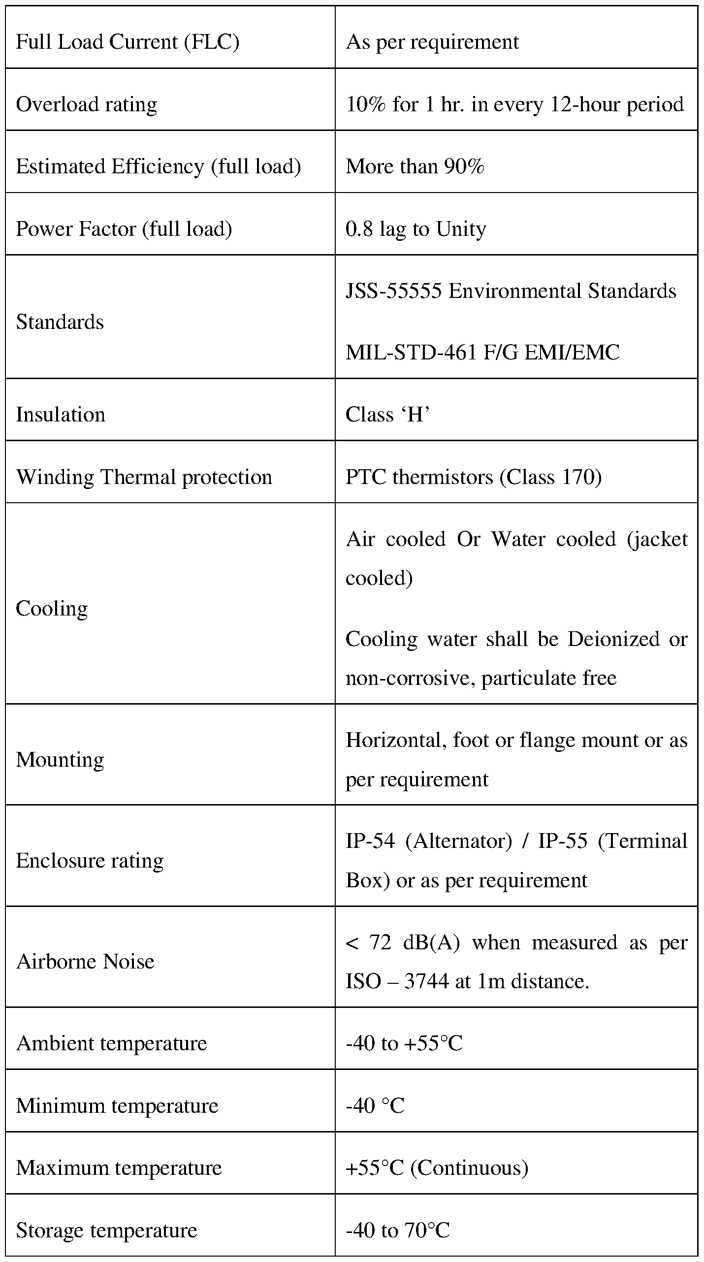

TABLE 1
The alternator (100), of the present disclosure, offers significant advantages over conventional permanent magnet alternators (PMA) and brushless synchronous alternators (BSA), particularly in terms of voltage regulation, compactness, and efficiency. Conventional PMAs, while lightweight and compact, suffer from poor voltage regulation, with their output voltage fluctuating based on load and rotational speed. In contrast, the alternator (100) effectively regulates voltage within ±2% across the entire electrical load range from 0 to 100% using a compensating winding (114) controlled by an Automatic Voltage Regulator (AVR) (112). This precise control eliminates the need for additional components like converters or inverters, making the alternator (100) more efficient and stable under variable load conditions.
Moreover, while BSAs provide good voltage regulation, they rely on auxiliary generators and rectifier assemblies, increasing their size and weight. The alternator (100) achieves the same level of voltage control without the additional bulk, using an integrated compensating winding (114) and an AVR (112) to adjust the excitation current and maintain output voltage within desired limits. This results in a more compact and lightweight alternator (100), ideal for mobile applications where both stability and reduced size are essential.
The alternator (100) also outperforms the conventional alternators in terms of efficiency. The BSAs are heavy and complex due to their rotating components for voltage control, while PMAs require external devices to maintain stable voltage, reducing their overall efficiency. The alternator (100) combines high efficiency with stable power delivery, making it a versatile solution for applications requiring regulated voltage in a compact and lightweight design.
The foregoing description of the embodiments has been provided for purposes of illustration and not intended to limit the scope of the present disclosure. Individual components of a particular embodiment are generally not limited to that particular embodiment, but, are interchangeable. Such variations are not to be regarded as a departure from the present disclosure, and all such modifications are considered to be within the scope of the present disclosure.
TECHNICAL ADVANCES AND ECONOMICAL SIGNIFICANCE
The present disclosure described herein above has several technical advantages including, but not limited to, the realization of an automatic voltage regulating permanent magnet alternator for a power generation set that:
• is capable of regulating voltage within ±2% over an entire range of electrical loading from 0 to 100%;
• has a relatively smaller envelop size and weight;
• is cost effective; and
• allows real-time continuous voltage correction within ±2% irrespective of load changes.
The foregoing description of the specific embodiments so fully reveals the general nature of the embodiments herein that others can, by applying current knowledge, readily modify and/or adapt for various applications such specific embodiments without departing from the generic concept, and, therefore, such adaptations and modifications should and are intended to be comprehended within the meaning and range of equivalents of the disclosed embodiments. It is to be understood that the phraseology or terminology employed herein is for the purpose of description and not of limitation. Therefore, while the embodiments herein have been described in terms of preferred embodiments, those skilled in the art will recognize that the embodiments herein can be practiced with modification within the spirit and scope of the embodiments as described herein.
Throughout this specification the word “comprise”, or variations such as “comprises” or “comprising”, will be understood to imply the inclusion of a stated element, step, or group of elements, steps, but not the exclusion of any other element, step, or group of elements, or steps.
While considerable emphasis has been placed herein on the components and component parts of the preferred embodiments, it will be appreciated that many embodiments can be made and that many changes can be made in the preferred embodiments without departing from the principles of the disclosure. These and other changes in the preferred embodiment as well as other embodiments of the disclosure will be apparent to those skilled in the art from the
disclosure herein, whereby it is to be distinctly understood that the foregoing descriptive matter is to be interpreted merely as illustrative of the disclosure and not as a limitation.
Claims
1. An automatic voltage regulating permanent magnet alternator (100) for a power generation set, said alternator (100) comprising:
• a stator (102) including a laminated stator core (104) having a plurality of slots configured thereon, and a main winding (106) configured to generate an output voltage;
• a rotor (108) configured to be positioned within said stator (102), said rotor (108) including a plurality of permanent magnets (110) arranged in a predetermined configuration, said rotor (108) configured to be rotated to facilitate generation of a rotating magnetic field in the air gap between said rotor (108) and said stator (102), wherein said rotating magnetic field interacts with said main winding (106) to induce an electromotive force (EMF) there within to generate said output voltage;
• an automatic voltage regulator (AVR) (112) electrically connected to the main winding (106), said AVR (112) configured to: o sense the output voltage value of said main winding (106), o compare said sensed output voltage value with a pre-set threshold voltage value, and o calculate the difference between said sensed output voltage value and said threshold voltage value, and generate a first control signal if the sensed output voltage value is greater than said threshold voltage value, or a second control signal if the sensed output voltage value is lesser than said threshold voltage value; and
• a compensating winding (114) configured to be embedded in said stator core (104), said compensating winding (114) configured to electrically communicate with the AVR (112) to receive said first control signal or said second control signal, and further configured to regulate the excitation current flowing therethrough in response to said received control signal to adjust the air-gap flux, thereby maintaining the output voltage within desired limits in varying electrical load conditions.
2. The alternator (100) as claimed in claim 1, wherein said compensating winding (114) is configured to increase the excitation current flowing therethrough, in response to said first control signal, to strengthen the air-gap flux, thereby boosting said output voltage.
3. The alternator (100) as claimed in claim 1, wherein said compensating winding (114) is configured to decrease the excitation current flowing therethrough, in response to said second control signal, to weaken the air-gap flux, thereby lowering said output voltage.
4. The alternator (100) as claimed in claim 1, wherein said main winding (106) is a three-phase winding configured to produce a three-phase output voltage.
5. The alternator (100) as claimed in claim 1, wherein said main winding (106) is a single-phase winding configured to produce a single -phase output voltage.
6. The alternator (100) as claimed in claim 1, wherein said stator (102) includes a plurality of bearings.
7. The alternator (100) as claimed in claim 1, wherein said rotor (108) includes a rotor shaft (109) configured to be supported by said bearings to facilitate positioning of said rotor (108) in said stator (102).
8. The alternator (100) as claimed in claim 1, wherein said rotor (108) is configured to be rotated about its operative central axis by an external power source to facilitate generation of the rotating magnetic field.
9. The alternator (100) as claimed in claim 1, wherein said magnets (110) are configured to be arranged in a buried configuration.
10. The alternator (100) as claimed in claim 1, wherein said permanent magnets (110) are of rare-earth materials such as neodymium (NdFeB) or samarium-cobalt (SmCo).
11. The alternator (100) as claimed in claim 1, wherein said stator core (104) is of a material selected from the group consisting of silicon steel and other magnetic materials configured to minimize eddy current losses.
12. The alternator (100) as claimed in claim 1, wherein said AVR (112) includes a closed- loop feedback mechanism configured to continuously adjust the excitation current in said compensating winding (114) to maintain the output voltage value within said desired limits.
13. The alternator (100) as claimed in claim 1, wherein the preset threshold voltage value is adjustable based on the operational requirements of the electrical system connected to the alternator (100).
14. The alternator (100) as claimed in claim 1, which includes a terminal box (116) configured to receive said AVR (112) therein.
15. The alternator (100) as claimed in claim 1, which is configured to be actuated continuously across a temperature range of -40°C to +55 °C, an operational altitude of up to 5000 meters, and a relative humidity of up to 95% RH.
Applications Claiming Priority (2)
| Application Number | Priority Date | Filing Date | Title |
|---|---|---|---|
| IN202321070761 | 2023-10-17 | ||
| IN202321070761 | 2023-10-17 |
Publications (1)
| Publication Number | Publication Date |
|---|---|
| WO2025083610A1 true WO2025083610A1 (en) | 2025-04-24 |
Family
ID=95447823
Family Applications (1)
| Application Number | Title | Priority Date | Filing Date |
|---|---|---|---|
| PCT/IB2024/060219 Pending WO2025083610A1 (en) | 2023-10-17 | 2024-10-17 | An automatic voltage regulating permanent magnet alternator for a power generation set |
Country Status (1)
| Country | Link |
|---|---|
| WO (1) | WO2025083610A1 (en) |
Citations (2)
| Publication number | Priority date | Publication date | Assignee | Title |
|---|---|---|---|---|
| GB2045983A (en) * | 1979-02-09 | 1980-11-05 | Murray J F | Electrical Generator Voltage Regulation |
| CN218733971U (en) * | 2022-11-15 | 2023-03-24 | 福州金钥匙机电设备有限公司 | Permanent magnet synchronous alternating current generator |
-
2024
- 2024-10-17 WO PCT/IB2024/060219 patent/WO2025083610A1/en active Pending
Patent Citations (2)
| Publication number | Priority date | Publication date | Assignee | Title |
|---|---|---|---|---|
| GB2045983A (en) * | 1979-02-09 | 1980-11-05 | Murray J F | Electrical Generator Voltage Regulation |
| CN218733971U (en) * | 2022-11-15 | 2023-03-24 | 福州金钥匙机电设备有限公司 | Permanent magnet synchronous alternating current generator |
Similar Documents
| Publication | Publication Date | Title |
|---|---|---|
| US4959605A (en) | Hybrid permanent magnet and variable reluctance generator | |
| US9231504B2 (en) | Electrical control system | |
| US7863868B2 (en) | Generator with quadrature AC excitation | |
| EP2109932B1 (en) | Method of and apparatus for controlling excitation | |
| Beik et al. | High-voltage hybrid generator and conversion system for wind turbine applications | |
| US8044527B2 (en) | Electric power generation with magnetically geared machine | |
| EP1936785B1 (en) | Self-regulating permanent magnet device | |
| RU2474950C2 (en) | Device and method of electric supply to at least one asynchronous machine on board of aircraft | |
| CN118020239A (en) | High-efficiency electric generator | |
| CN113162354A (en) | Brushless electric excitation synchronous generator with wide rotating speed range | |
| KR101417509B1 (en) | Synchronous generator system haing dual rotor | |
| WO2025083610A1 (en) | An automatic voltage regulating permanent magnet alternator for a power generation set | |
| Gwóźdź et al. | Generator with modulated magnetic flux for wind turbines | |
| CN102427291A (en) | Brushless generator in automatic voltage regulation state | |
| Gupta et al. | DC-Link voltage regulation of full-power converter for WECS in weak-grid using a variable-flux dual-stator PMSG | |
| Chakraborty et al. | A new series of brushless and permanent magnetless synchronous machines | |
| KR100777809B1 (en) | Synchronous Generator Having Heterogeneous Stimulation Exciter | |
| Obuah et al. | Steady-state performance analysis of permanent magnet synchronous generator with capacitive assistance | |
| JP3249535U (en) | Power Generation System | |
| Hazra et al. | Power conversion and control of a magnetic gear integrated permanent magnet generator for wave energy generation | |
| JP2002345297A (en) | Synchronous generator system for wind-turbine power generation and its operating method | |
| Woo et al. | Characteristic analysis of parallel-rotor hybrid generator based on exciter types | |
| Poskovic et al. | The Study of Hybrid Permanent Magnets in Synchronous Generators for Hydroelectric Application | |
| Dezhin et al. | 12-phases magneto-electric direct drive turbo generator | |
| CN118739923A (en) | Parallel hybrid excitation brushless DC generator system with reactive power suppression |
Legal Events
| Date | Code | Title | Description |
|---|---|---|---|
| 121 | Ep: the epo has been informed by wipo that ep was designated in this application |
Ref document number: 24879261 Country of ref document: EP Kind code of ref document: A1 |