WO2025072677A1 - Tagmentation methods and kits - Google Patents
Tagmentation methods and kits Download PDFInfo
- Publication number
- WO2025072677A1 WO2025072677A1 PCT/US2024/048860 US2024048860W WO2025072677A1 WO 2025072677 A1 WO2025072677 A1 WO 2025072677A1 US 2024048860 W US2024048860 W US 2024048860W WO 2025072677 A1 WO2025072677 A1 WO 2025072677A1
- Authority
- WO
- WIPO (PCT)
- Prior art keywords
- core
- primer
- transposome
- sample
- attached
- Prior art date
- Legal status (The legal status is an assumption and is not a legal conclusion. Google has not performed a legal analysis and makes no representation as to the accuracy of the status listed.)
- Pending
Links
Classifications
-
- C—CHEMISTRY; METALLURGY
- C12—BIOCHEMISTRY; BEER; SPIRITS; WINE; VINEGAR; MICROBIOLOGY; ENZYMOLOGY; MUTATION OR GENETIC ENGINEERING
- C12Q—MEASURING OR TESTING PROCESSES INVOLVING ENZYMES, NUCLEIC ACIDS OR MICROORGANISMS; COMPOSITIONS OR TEST PAPERS THEREFOR; PROCESSES OF PREPARING SUCH COMPOSITIONS; CONDITION-RESPONSIVE CONTROL IN MICROBIOLOGICAL OR ENZYMOLOGICAL PROCESSES
- C12Q1/00—Measuring or testing processes involving enzymes, nucleic acids or microorganisms; Compositions therefor; Processes of preparing such compositions
- C12Q1/68—Measuring or testing processes involving enzymes, nucleic acids or microorganisms; Compositions therefor; Processes of preparing such compositions involving nucleic acids
- C12Q1/6806—Preparing nucleic acids for analysis, e.g. for polymerase chain reaction [PCR] assay
Definitions
- Double-stranded DNA (dsDNA) target molecules can be fragmented and tagged to generate a library of smaller dsDNA that can be further processed to form single-stranded DNA molecules (ssDNA). These smaller, single-stranded DNA molecules may be used as templates in DNA sequencing reactions. The templates may enable short read lengths to be obtained; and then during data analysis, overlapping short sequence reads can be aligned to reconstruct the longer nucleic acid sequences.
- Some methods for fragmentation and tagging of double-stranded DNA are limited to single samples as they do not involve indexing, generate small fragments, generate excessive waste, involve expensive instruments for fragmentation, and/or are time-consuming.
- pre-grafted particles include both a primer set and a transposome dimer, and thus enable both sample tagmentation and sample fragment amplification to take place at the surface of the particles.
- Some examples of the pre-grafted particles and the method herein allow different DNA samples to be uniquely indexed by the set of particles used for tagmentation and amplification.
- Other examples of the pre-grafted particles and the method described herein help with tuning the insert size of the tagmented fragments.
- Still other examples can be used in an enrichment process that increases the yield in terms of sequencing reads that pass filter.
- a flow cell is also disclosed herein that helps with tuning the insert size of the tagmented fragments.
- Fig.1A is a schematic illustration of one example of a pre-grafted particle disclosed herein;
- Fig.1B is a schematic illustration of another example of a pre-grafted particle disclosed herein;
- Fig.1C is a schematic illustration of still another example of a pre-grafted particle disclosed herein;
- Fig.2 schematically illustrates a uniquely indexed transposome dimer;
- Fig.3 is a top view of an example flow cell;
- Fig.4A is an enlarged, cross-sectional view, taken along the 4A-4A line of Fig.3, depicting one example of the flow cell architecture including pre-clustered particles (which have been exposed to tagmentation and amplification) anchored to a lane of an example of a patterned substrate;
- Fig.4B is an enlarged, cross-sectional view, taken along the 4B-4B line of Fig.3, depicting another example of the flow cell architecture including the pre
- pre-grafted particles are utilized.
- the pre-grafted particles include both a primer set and a transposome dimer (made up of two individual transposome complexes). These particles enable both sample tagmentation and sample fragment amplification to take place at the surface of the particle. This eliminates the need for on flow cell DNA sample preparation and/or amplification, and thus simplifies the surface chemistry onboard the flow cell. This type of flow cell may be reused with fresh pre-grafted particles that have been used in off flow cell tagmentation and amplification processes.
- the transposome dimers on a particular set of pre- grafted particles are uniquely indexed.
- each transposome complex of each particle in a set includes a particular nucleic acid sequence that functions as a barcode for the particles in the set.
- the particles in the set are used to index the DNA sample that is tagmented and amplified using the particles in the set.
- the pre-grafted particles are used to tune the insert size of the DNA sample fragment that is tagmented on the surface of particles.
- the core of each particle is reversibly responsive to a particular stimulus, such as temperature or pH. Prior to or during tagmentation, the core is exposed to the stimulus and is expanded, which creates a greater distance between pairs of transposome dimers.
- the pre-grafted particles are used for tagmentation and fragment amplification, and then are exposed to an enrichment process.
- the enrichment process disclosed herein utilizes the fact that, as a result of amplification, asymmetrical amplicons are generated on some particles and symmetrical amplicons are generated on other particles. After amplification, statistically about 50% of the particles will include asymmetrical amplicons, about 25% of the particles will include a first type of symmetrical amplicon, and about 25% of the particles will include a second type of symmetrical amplicon.
- the particles including the asymmetrical amplicons are able to hybridize to a flow cell surface due to complementarity between end of the amplicon and a surface primer. Also during enrichment, the particles including the first type of symmetrical amplicons are not able to hybridize to the flow cell surface due to a mismatch between the amplicon end and the surface primer.
- the particles including the second type of symmetrical amplicons are capable of hybridizing to the flow cell surface if linearization of these amplicons is not performed, but such hybridization would take place at orders of magnitude less than the particles with the asymmetrical amplicons due to fewer of these types of particles being present for attachment and/or due to the presence of fewer symmetrical amplicons on the particle surface.
- Adapter A linear oligonucleotide sequence that can be fused or otherwise added to a nucleic acid molecule, for example, by ligation or tagmentation or an extension reaction.
- Suitable adapter lengths may range from about 10 nucleotides to about 100 nucleotides, or from about 12 nucleotides to about 60 nucleotides, or from about 15 nucleotides to about 50 nucleotides.
- the adapter may include any combination of nucleotides and/or nucleic acids.
- the adapter can include an amplification domain, e.g., having a universal nucleotide sequence, such as a P5 or P7 sequence, that can serve as a starting point for template amplification and cluster generation.
- the adapter can include a sequence that is complementary to at least a portion of a surface bound primer (which may be attached to a particle or to a flow cell, and which includes the universal nucleotide sequence).
- the adapter sequence can hybridize to the complementary surface bound primer during amplification and cluster generation.
- the adapter can also include a sequencing primer sequence (i.e., sequencing binding site) or an index sequence (i.e., a barcode sequence). Combinations of different adapters may be incorporated into the nucleic acid molecule, such as the DNA fragments generated via tagmentation.
- Amplification Domain A portion of an adapter having a universal nucleotide sequence, such as a P5 or P7 sequence or a complement thereof, which can serve as a starting point for template amplification and cluster generation.
- Asymmetrical Fully Adapted Fragments Tagmented DNA sample fragments that have a first amplification domain sequence at one end (e.g., the 5’ end) and a second amplification domain sequence at the other end (e.g., the 3’ end), where the first and second amplification domain sequences are different from one another. Together, the adapters enable amplification and cluster generation. Asymmetrical fully adapted fragments are amplified exponentially.
- Asymmetrical Amplicons Amplified DNA sample fragments that have a first amplification domain sequence at one end (e.g., the 5’ end) and a second flow cell primer complement at the other end 3’ end), or have a second amplification domain sequence at one end (e.g., the 5’ end) and a first flow cell primer complement at the other end (e.g., the 3’ end).
- Capture site A portion of a flow cell substrate having been modified, chemically, magnetically or electrostatically, that allows for anchoring of a pre-grafted particle (whether it has been exposed to tagmentation and amplification or not).
- the capture site may include a chemical capture agent, a magnetic capture agent, and/or an electrostatic capture agent.
- Chemical Capture Agent A material, molecule or moiety that is capable of anchoring to a functional agent of a pre-grafted particle via a chemical mechanism.
- One example chemical capture agent includes a capture nucleic acid (e.g., a capture oligonucleotide) that is complementary to at least a portion of a target nucleic acid attached to a pre-grafted particle.
- Still another example chemical capture agent includes a member of a binding pair that is capable of binding to a second member of a binding pair that is attached to the functionalized nanostructure.
- Example binding pairs include a NiNTA (nickel- nitrilotriacetic acid) ligand and a histidine tag, or streptavidin or avidin and biotin, etc.
- the chemical capture agent is a chemical reagent that is capable of forming a hydrogen bond, or a covalent bond with the functionalized nanostructure. Covalent bonds may be formed, for example, through thiol-disulfide exchange, click chemistry, Diels-Alder, Michael additions, amine-aldehyde coupling, amine-acid chloride reactions, amine-carboxylic acid reactions, nucleophilic substitution reactions, etc.
- Depositing Any suitable application technique, which may be manual or automated, and, in some instances, results in modification of the surface properties. Generally, depositing may be performed using vapor deposition techniques, coating techniques, grafting techniques, or the like. Some specific examples include chemical vapor deposition (CVD), spray coating (e.g., ultrasonic spray coating), spin coating, dunk or dip coating, doctor blade coating, puddle dispensing, flow through coating, aerosol printing, screen printing, microcontact printing, inkjet printing, or the like.
- CVD chemical vapor deposition
- spray coating e.g., ultrasonic spray coating
- spin coating dunk or dip coating
- doctor blade coating puddle dispensing
- Depression A discrete concave feature in a substrate or a layer of a substrate (e.g., a patterned resin) having a surface opening that is at least partially surrounded by interstitial region(s) of the or the layer.
- Depressions can have any of a variety of shapes at their opening in a surface including, as examples, round, elliptical, square, polygonal, star shaped (with any number of vertices), etc.
- the cross- section of a depression taken orthogonally with the surface can be curved, square, polygonal, hyperbolic, conical, angular, etc.
- the depression may also have more complex architectures, such as ridges, step features, etc.
- DNA Sample Multiple stands of a polymeric form of nucleotides of any length that includes deoxyribonucleotides, deoxyribonucleotide analogs, or complementary deoxyribonucleotides derived from an RNA (ribonucleic acid) sample.
- the DNA sample is double stranded.
- the DNA sample may include naturally occurring DNA, which includes a nitrogen containing heterocyclic base (a nucleobase such as adenine, thymine, cytosine and/or guanine), a sugar (specifically deoxyribose, i.e., a sugar lacking a hydroxyl group that is present at the 2’ position in ribose), and a backbone containing phosphodiester bonds.
- a nucleobase such as adenine, thymine, cytosine and/or guanine
- a sugar specifically deoxyribose, i.e., a sugar lacking a hydroxyl group that is present
- the DNA sample may be genomic DNA (gDNA) that can be isolated from one or more cells, bodily fluids (e.g., whole blood, blood spots, saliva) or tissues.
- gDNA can be prepared by lysing a cell that contains the DNA. The cell may be lysed under conditions that substantially preserve the integrity of the cell’s gDNA.
- thermal lysis may be used to lyse a cell.
- exposure of a cell to alkaline pH can be used to lyse a cell while causing relatively little damage to gDNA.
- gDNA can be obtained from a cell lysed by an enzyme that degrades the cell wall.
- Cells lacking a cell wall either naturally, or due to enzymatic removal, can also be lysed by exposure to osmotic stress.
- Other conditions that can be used to lyse a cell include exposure to detergents, mechanical disruption, sonication heat, pressure differential such as in a French press device, or Dounce homogenization.
- Electrostatic Capture Agent refers to a charged material that is capable of electrostatically anchoring a charged or reversibly charged pre-grafted particle. For pre-grafted particles exposed to tagmentation and amplification, the attached DNA fragments are negatively charged.
- positively charged pads e.g., made of silanes, polymers with azide functional groups, poly-lysine, polyimines (e.g., polyethyleneimine, polypropylene imine, etc.), and other positively charged materials
- an electrostatic capture agent is an electrode that can attract, when a proper voltage is applied, a reversibly chargeable functional group that is incorporated into the pre-grafted particle.
- amines or carboxylic acids can be reversibly switched between a neutral and a charged species in response to a pH change, and the charged species can be attracted to the electrode.
- Flow Cell A vessel having an enclosed or open flow channel where a reaction can be carried out.
- a flow cell with an enclosed channel also includes an inlet for delivering reagent(s) to the chamber and an outlet for removing reagent(s) from the chamber.
- the flow cell enables the detection of the reaction that occurs therein.
- the flow cell can include one or more transparent surfaces allowing for the optical detection of arrays, optically labeled molecules, or the like.
- Flow channel An area i) defined between two bonded or otherwise attached components or ii) defined in an open substrate, which can selectively receive a liquid sample.
- the flow channel may be defined between two patterned or non-patterned substrates or a patterned or non-patterned substrate and a lid, and thus may be in fluid communication with one or more components of the substrate(s).
- Fragment A portion or piece of a strand in a DNA sample.
- a “partially adapted fragment” is a portion or piece of the strand in the DNA sample that has been tagmented, and thus includes an to the 5’ end of the strand.
- a “fully adapted fragment” is a portion or piece of the strand in the DNA sample that has adapters incorporated at both the 3’ and 5’ ends of the tagmented DNA fragment.
- Functional agent A material, molecule or moiety that is capable of anchoring to a chemical capture site of a flow cell via a chemical mechanism.
- One example functional agent includes a target nucleic acid that is complementary to a capture nucleic acid (e.g., a capture oligonucleotide) on the flow cell.
- Still another example functional agent includes a member of a binding pair that is capable of binding to a second member of a binding pair that is attached to the flow cell.
- Interstitial Region An area, e.g., of a patterned substrate, that separates depressions, posts, or capture sites.
- an interstitial region can separate one depression or post of an array from another depression or post of the array.
- the two depressions or posts that are separated from each other can be discrete, i.e., lacking physical contact with each other.
- the interstitial region is continuous, whereas the depressions or posts are discrete, for example, as is the case for a plurality of depressions defined in an otherwise continuous surface.
- the separation provided by an interstitial region can be partial or full separation.
- Interstitial regions may have a surface material that differs from the surface material of the depressions or posts, or capture sites defined therein or thereon.
- Magnetic Capture Agent A magnetic material that is capable of magnetically anchoring a pre-grafted particle.
- Example magnetic capture agents include ferromagnetic materials and ferrimagnetic materials.
- Mechanism A functional agent, a magnetic material or a reversibly chargeable functional group that is incorporated into the pre-grafted particle in order to render the pre-grafted particles capable of anchoring to a capture site in a flow cell.
- Non-Patterned Substrate A structure of a flow cell that supports a continuous capture site that is not arranged in a pattern.
- Patterned Substrate A structure of a flow cell that supports capture sites that are arranged in a pattern.
- Primer A single stranded acid molecule that can hybridize to a target sequence, such as an adapter attached to a fragment.
- a particle surface bound primer can serve as a starting point for fragment amplification and cluster generation.
- a primer e.g., a sequencing primer
- Any primer can include any combination of nucleotides or analogs thereof.
- the primer is a single-stranded oligonucleotide or polynucleotide.
- the primer length can be any number of bases long.
- each of the flow cell surface bound primer and the sequencing primer is a short strand, ranging from 10 to 60 bases, or from 20 to 40 bases.
- Symmetrical Fully Adapted Fragments Tagmented DNA sample fragments that have an amplification domain sequence at one end (e.g., the 5’ end) and a complement of the amplification domain at the other end (e.g., the 3’ end). Symmetrical fully adapted fragments are amplified linearly. This is due, in part, to the fact that all generated amplicons utilize the same type of surface primer for bridging, which limits the bridging capability.
- Symmetrical Amplicons Amplified DNA sample fragments that have a first amplification domain sequence at one end (e.g., the 5’ end) and a first flow cell primer complement at the other end (e.g., the 3’ end), or have a second amplification domain sequence at one end (e.g., the 5’ end) and a second flow cell primer complement at the other end (e.g., the 3’ end).
- Some particles containing symmetrical amplicons have all of their amplicons cleaved during linearization.
- Other particles containing symmetrical amplicons include a sequence at the 3’ end that is not capable of hybridizing to a flow cell surface primer.
- Tagmentation A process in which the DNA sample is cleaved/fragmented and tagged (e.g., with adapter(s)) for analysis. Tagmentation is an in vitro transposition reaction.
- Transferred and Non-Transferred Strands The term “transferred strand” refers to a sequence that includes a transferred portion of a transposon end.
- non-transferred strand refers to a sequence that includes the non- transferred portion of a transposon end. 3’-end of a transferred strand is joined or transferred to a double stranded fragment during tagmentation. The non-transferred strand is not joined or transferred to the double stranded fragment during tagmentation.
- the transferred and non-transferred strands include at least partially complementary portions that are covalently bound together.
- Transposase An enzyme that is capable of forming a functional complex with a transposon end-containing composition (e.g., transposons, transposon ends, transposon end compositions) and catalyzing insertion or transposition of the transposon end-containing composition into the double-stranded DNA sample with which it is incubated, for example, in the in vitro transposition reaction (i.e., tagmentation).
- a transposase as presented herein can also include integrases from retrotransposons and retroviruses.
- Transposome or Transposome Complex A complex formed between a transposase and a double stranded nucleic acid including a transposase integration recognition site.
- the transposome complex can be a transposase enzyme pre-incubated with double-stranded transposon DNA under conditions that support non-covalent complex formation.
- Double-stranded transposon DNA can include, for example, Tn5 DNA, a portion of Tn5 DNA, a transposon end composition, a mixture of transposon end compositions or other double-stranded DNAs capable of interacting with a transposase, such as the hyperactive Tn5 transposase.
- Transposon End A double-stranded nucleic acid strand that exhibits only the nucleotide sequences (the “transposon end sequences”) that are necessary to form the complex with the transposase that is functional in tagmentation.
- the double- stranded nucleic acid strand of the transposon end can include any nucleic acid or nucleic acid analogue suitable for forming the functional complex with the transposase.
- the transposon end can include natural DNA or DNA analogs (with modified bases and/or backbones), and can include nicks in one or both strands.
- the (’) designations for any of the reference numeral, e.g., amplification domain 38’, index sequence 40’, etc. do not refer to complementary sequences to the corresponding element, e.g., amplification domain 38, index sequence 40, etc., but rather, are additional examples of the element.
- Pre-grafted Particles Each of the examples set forth herein involves a pre-grafted particle. Different examples of the pre-grafted particles 10A, 10B, 10C are shown in Fig.1A, Fig.1B, and Fig.1C, respectively. Each of the pre-grafted particles 10A, 10B, 10C illustrates some examples of the transposome complexes 20A, 20B, 20C, 20D attached thereto.
- the pre-grafted particles 10A, 10B, 10C may not yet have the transposome complexes 20A, 20B, 20C, 20D attached thereto, and that the transposome complexes 20A, 20B, 20C, 20D may be added during the methods described herein.
- the pre-grafted particle 10A includes a core 12; a primer set (including primers 14 and 16) attached to the core 12; and a uniquely indexed transposome dimer 18 (including two transposome complexes 20A and 20B that form a duplex) attached to the core 12.
- the pre-grafted particle 10A may initially include the core 12 and the primer set (including primers 14 and 16) attached to the core 12, and the transposome complexes 20A, 20B may be added during the method.
- the entire core 12 is formed of a polymeric hydrogel.
- the polymeric hydrogel material may be poly(N-(5- azidoacetamidylpentyl)acrylamide-co-acrylamide (PAZAM) or another of the acrylamide copolymers disclosed herein, PEG-acrylate, PEG-diacrylate, PEG-amine, PEG-carboxylate, PEG-dithiol, PEG-epoxide, PEG-isocyanate, PEG-maleimide, crosslinked poly(methyl methacrylate) (PMMA), polyvinylpyrrolidone (PVPON), polyvinyl alcohol (PVA), polyethylene oxide-polypropylene oxide block copolymers (PEO-PPO), poly(hydroxyethyl methacrylate) (PHEMA), poly(N-isopropylacrylamide) (PNIPAAm), poly(lactic acid)-poly glycol) block copolymers, poly(ethylene glycol)-poly(lactic-co-glycolic acid) block copolymers, poly((N
- the polymeric hydrogel is a copolymer including at least one acrylamide monomer unit, and is a linear polymeric hydrogel or branched polymeric hydrogel (e.g., a dendrimer).
- the linear or branched polymeric hydrogel may include a first recurring unit of -H, a halogen, an alkyl, an alkoxy, an alkenyl, an alkynyl, a cycloalkyl, an aryl, a heteroaryl, a heterocycle, and optionally substituted variants thereof;
- R 2 is selected from the group consisting of an azido, an optionally substituted amino, an optionally substituted alkenyl, an optionally substituted alkyne, a halogen, an optionally substituted hydrazone, an optionally substituted hydrazine, a carboxyl, a hydroxy, an optionally substituted tetrazole, an optionally substituted tetrazine, nitrile oxide, nitrone, sulfate, and thiol; each (CH 2 ) p can be optionally substituted; and p is an integer from 1 to 50; a second recurring unit of formula (II)
- R 1 is –H; R 2 is an azido; each of R 3’ , R 4 , and R 4’ is –H; R 3 is -C(O)NR 6 R 7 , where each of R 6 and R 7 is –H; and p is 5.
- This polymeric hydrogel is poly(N-(5-azidoacetamidylpentyl)acrylamide-co-acrylamide, or PAZAM.
- R 1 is –H; R 2 is an azido; each of R 3’ , R 4 , and R 4’ is –H; R 3 is -C(O)NR 6 R 7 , where each of R 6 and R 7 is a C1-C6 alkyl (e.g., –CH 3 ); and p is 5.
- R 2 of some of the recurring units of formula (I) is replaced with tetramethylethylenediamine (TEMED).
- TEMED is a reaction promoter that may be introduced during copolymerization. As a result of a side reaction, TEMED replaces some of the azide (N3) or other R 2 groups.
- each of R 3’ , R 4 , and R 4’ is –H;
- R 3 is -C(O)NR 6 R 7 , where each of R 6 and R 7 is –H, and in the third recurring unit, each of R 3’ , R 4 , and R 4’ is –H;
- R 3 is - C(O)NR 6 R 7 , where each of R 6 and R 7 is a C1-C6 alkyl.
- the number of first recurring units (formula (I)) may be an integer ranging from 2 to 50,000, and the number of second recurring units (formula (II)) may be an integer ranging from 2 to 100,000.
- the number of units may be an integer in the range of 1 to 100,000. It is to be understood that the incorporation of the individual units may be statistical, random, or in block, and may depend upon the method used to synthesize the polymeric hydrogel.
- the first recurring unit of formula (I) may be replaced with a heterocyclic azido group of formula (III): wherein R 8 is H or including a linear chain with 2 to 20 atoms selected from the group consisting of carbon, oxygen, and nitrogen and 10 optional substituents on the carbon and any nitrogen atoms in the chain; E is a linear chain including 1 to 4 atoms selected from the group consisting of carbon, oxygen and nitrogen, and optional substituents on the carbon and any nitrogen atoms in the chain; A is an N substituted amide with an H or a C1-C4 alkyl attached to the N; and Z is a nitrogen containing heterocycle.
- R 8 is H or including a linear chain with 2 to 20 atoms selected from the group consisting of carbon, oxygen, and nitrogen and 10 optional substituents on the carbon and any nitrogen atoms in the chain
- E is a linear chain including 1 to 4 atoms selected from the group consisting of carbon, oxygen and nitrogen, and optional substituents on the carbon and any nitrogen atoms
- Z examples include 5 to 10 carbon-containing ring members present as a single cyclic structure or a fused structure. Some specific examples of Z include pyrrolidinyl, pyridinyl, or pyrimidinyl.
- formula (III) is the first recurring unit and formula (II) is the second recurring unit.
- formula (III) is the first recurring unit, one example of formula (II) is the second recurring unit, and a different example of formula (III) is the third recurring unit.
- hydrogel materials may be used for the polymeric hydrogel of the particle core 12, as long as they are functionalized to graft oligonucleotide primers 14, 16 and the transposome dimers 18 thereto.
- Other examples of other polymeric hydrogels include functionalized polysilanes, such as norbornene silane, azido silane, alkyne functionalized silane, amine functionalized silane, maleimide silane, or any other polysilane having functional groups that can attach the oligonucleotide primers.
- suitable polymeric hydrogels include those having a colloidal structure, such as agarose; or a polymer mesh structure, such as gelatin; or a cross-linked polymer structure, such as polyacrylamide polymers and copolymers, silane free acrylamide (SFA), or an azidolyzed version of SFA.
- suitable polyacrylamide polymers may be synthesized from acrylamide and an acrylic acid or an acrylic acid containing a vinyl group, or from monomers that form [2+2] photo- cycloaddition reactions.
- Still other examples of suitable polymeric hydrogel materials include mixed copolymers of acrylamides and acrylates.
- a variety of polymer architectures containing acrylic monomers may be utilized in the examples disclosed herein, such as highly branched polymers, including dendrimers.
- the monomers e.g., acrylamide, etc.
- the branches (arms) of a dendrimer may be incorporated, either randomly or in block, into the branches (arms) of a dendrimer.
- functional groups in one or more of the recurring units of the polymeric hydrogel of the core 12 are capable of attaching the primers 14, 16 and the transposome complexes 20A, 20B.
- a binding pair member may be introduced to the core 12, e.g., as part of a monomer used in polymerization, or in a grafting process after core 12 formation, or in a chemical modification reaction. This binding pair member is capable of attaching to another binding pair member that is at the 5’ end of the primers 14, 16 and/or the transposomes 20A, 20B.
- binding pairs include: those capable of peptide coupling (e.g., spytag and a spycatcher); a NiNTA (nickel- nitrilotriacetic acid) ligand and a histidine tag; or biotin and streptavidin.
- the polymeric hydrogel is biotinylated.
- biotin is attached to the surface of the polymeric hydrogel through some of the R 2 groups (i.e., the azide, tetrazine, or other functional group that can attach to an alkyne).
- the biotin is attached to a as bicyclo[6.1.0]nonyne (BCN), which can covalently attach to some of the R 2 groups.
- BCN bicyclo[6.1.0]nonyne
- the largest dimension (e.g., diameter, length, median, etc.) of the core 12 is on the nanoscale, and thus ranges from about 1 nm to less than 1000 nm.
- the core 12 is a nanoparticle having a diameter of greater than or equal to 1 nm, 2 nm, 3 nm, 4 nm, 5 nm, 6 nm, 7 nm, 8 nm, 9 nm, 10 nm, 20 nm, 30 nm, 40 nm, 50 nm, 60 nm, 70 nm, 80 nm, 90 nm, or greater than or equal to 100 nm.
- the pre-grafted particle 10A includes a uniquely indexed transposome dimer 18.
- the uniquely indexed transposome dimer 18 includes two separate transposome complexes 20A, 20B that are capable of forming dimers in solution.
- the transposome complexes 20A, 20B in solution (with no cores 12 present) to form the dimers 18. These pre-formed dimers 18 are then grafted to the core 12.
- the individual transposome complexes 20A, 20B and the cores 12 are mixed together in solution. In these examples, some dimers 18 will form and attach to the core 12.
- Other transposome complexes 20A, 20B may not dimerize, and these individual transposome complexes 20A, 20B can also attach to the core 12.
Landscapes
- Chemical & Material Sciences (AREA)
- Organic Chemistry (AREA)
- Life Sciences & Earth Sciences (AREA)
- Analytical Chemistry (AREA)
- Zoology (AREA)
- Wood Science & Technology (AREA)
- Proteomics, Peptides & Aminoacids (AREA)
- Health & Medical Sciences (AREA)
- Engineering & Computer Science (AREA)
- Biophysics (AREA)
- Immunology (AREA)
- Microbiology (AREA)
- Molecular Biology (AREA)
- Biotechnology (AREA)
- Physics & Mathematics (AREA)
- Chemical Kinetics & Catalysis (AREA)
- Biochemistry (AREA)
- Bioinformatics & Cheminformatics (AREA)
- General Engineering & Computer Science (AREA)
- General Health & Medical Sciences (AREA)
- Genetics & Genomics (AREA)
- Measuring Or Testing Involving Enzymes Or Micro-Organisms (AREA)
Abstract
Pre-grafted particles include a core, and both a primer set and a transposome dimer attached to the core. In one example method, the transposome dimer is uniquely indexed. In this method, different sets of pre-grafted particles are introduced into respective wells of a well plate. A first sample is introduced into a first well, where it is tagmented to generate first sample fragments that are attached to the pre-grafted particles of a first set present in the first well. A second sample is introduced into a second well, where it is tagmented to generate second sample fragments that are attached to the pre-grafted particles of a second set present in the second well. The first and second sample fragments respectively include first and second index sequences. The different sets are pooled to form a particle mixture, and the particle mixture is introduced into a flow cell.
Description
TAGMENTATION METHODS AND KITS CROSS-REFERENCE TO RELATED APPLICATION [0001] This application claims the benefit of U.S. Provisional Application S.N. 63/586,975, filed September 29, 2023, the contents of which is incorporated by reference herein in its entirety. REFERENCE TO SEQUENCE LISTING [0002] The instant application contains a Sequence Listing which has been submitted electronically in XML file format and is hereby incorporated by reference in its entirety. Said XML copy, created on September 22, 2024, is named ILI267BPCT_IP-2681-PCT_Sequence_Listing.xml and is 14,897 bytes in size. BACKGROUND [0003] Double-stranded DNA (dsDNA) target molecules can be fragmented and tagged to generate a library of smaller dsDNA that can be further processed to form single-stranded DNA molecules (ssDNA). These smaller, single-stranded DNA molecules may be used as templates in DNA sequencing reactions. The templates may enable short read lengths to be obtained; and then during data analysis, overlapping short sequence reads can be aligned to reconstruct the longer nucleic acid sequences. Some methods for fragmentation and tagging of double-stranded DNA are limited to single samples as they do not involve indexing, generate small fragments, generate excessive waste, involve expensive instruments for fragmentation, and/or are time-consuming. SUMMARY [0004] In the examples disclosed herein, pre-grafted particles include both a primer set and a transposome dimer, and thus enable both sample tagmentation and sample fragment amplification to take place at the surface of the particles. Some examples of
the pre-grafted particles and the method herein allow different DNA samples to be uniquely indexed by the set of particles used for tagmentation and amplification. Other examples of the pre-grafted particles and the method described herein help with tuning the insert size of the tagmented fragments. Still other examples can be used in an enrichment process that increases the yield in terms of sequencing reads that pass filter. [0005] A flow cell is also disclosed herein that helps with tuning the insert size of the tagmented fragments. BRIEF DESCRIPTION OF THE DRAWINGS [0006] Features of examples of the present disclosure will become apparent by reference to the following detailed description and drawings, in which like reference numerals correspond to similar, though perhaps not identical, components. For the sake of brevity, reference numerals or features having a previously described function may or may not be described in connection with other drawings in which they appear. [0007] Fig.1A is a schematic illustration of one example of a pre-grafted particle disclosed herein; [0008] Fig.1B is a schematic illustration of another example of a pre-grafted particle disclosed herein; [0009] Fig.1C is a schematic illustration of still another example of a pre-grafted particle disclosed herein; [0010] Fig.2 schematically illustrates a uniquely indexed transposome dimer; [0011] Fig.3 is a top view of an example flow cell; [0012] Fig.4A is an enlarged, cross-sectional view, taken along the 4A-4A line of Fig.3, depicting one example of the flow cell architecture including pre-clustered particles (which have been exposed to tagmentation and amplification) anchored to a lane of an example of a patterned substrate; [0013] Fig.4B is an enlarged, cross-sectional view, taken along the 4B-4B line of Fig.3, depicting another example of the flow cell architecture including the pre- clustered particles anchored to posts of another example of a patterned substrate;
[0014] Fig.4C is an enlarged, cross- view, taken along the 4C-4C line of Fig.3, depicting yet another example of the flow cell architecture including the pre- clustered particles anchored to depressions of yet another example of a patterned substrate; [0015] Fig.4D is an enlarged, cross-sectional view, taken along the 4D-4D line of Fig.3, depicting yet another example of the flow cell architecture including the pre- clustered particles anchored to a lane of an example of a non-patterned substrate; [0016] Fig.5 is a schematic flow diagram illustrating examples of an indexing method; [0017] Fig.6 is a schematic flow diagram illustrating an example of tagmentation followed by an extension reaction; [0018] Fig.7 is a schematic flow diagram illustrating an example of tagmentation followed by ligation; [0019] Fig.8 is a schematic flow diagram illustrating an example of a method for tuning an insert size of DNA fragments generated during tagmentation; [0020] Fig.9 schematically illustrates a portion of a particle having symmetrical fully adapted fragments generated thereon; [0021] Fig.10A is a schematic flow diagram illustrating an example of a method for enriching DNA fragments; [0022] Fig.10B includes schematic and cut-away views of different particles in a particle mixture generated after amplification in the method of Fig.10A; [0023] Fig.11 is a schematic view of a few depressions of a flow cell used in conjunction with the enrichment method of Fig.10A; [0024] Fig.12 is an enlarged, cross-sectional view, taken along the 12-12 line of Fig.3, depicting another example the flow cell architecture that includes surface chemistry for tagmentation and amplification; and [0025] Fig.13 is a graph depicting sequencing metrics (%passing filter (top portion) and C1 intensity (bottom portion)) for positive controls (lanes 1 and 8), three different examples utilizing the pre-grafted particles described herein (lanes 2 through 4), and a negative control (lane 5).
DETAILED [0026] In some of the examples disclosed herein, pre-grafted particles are utilized. The pre-grafted particles include both a primer set and a transposome dimer (made up of two individual transposome complexes). These particles enable both sample tagmentation and sample fragment amplification to take place at the surface of the particle. This eliminates the need for on flow cell DNA sample preparation and/or amplification, and thus simplifies the surface chemistry onboard the flow cell. This type of flow cell may be reused with fresh pre-grafted particles that have been used in off flow cell tagmentation and amplification processes. [0027] In some examples, the transposome dimers on a particular set of pre- grafted particles are uniquely indexed. By “uniquely indexed,” it is meant that each transposome complex of each particle in a set includes a particular nucleic acid sequence that functions as a barcode for the particles in the set. Thus, the particles in the set are used to index the DNA sample that is tagmented and amplified using the particles in the set. [0028] In other examples, the pre-grafted particles are used to tune the insert size of the DNA sample fragment that is tagmented on the surface of particles. In these examples, the core of each particle is reversibly responsive to a particular stimulus, such as temperature or pH. Prior to or during tagmentation, the core is exposed to the stimulus and is expanded, which creates a greater distance between pairs of transposome dimers. The greater distance between the pairs of transposome dimers allows longer DNA fragments to be obtained as a result of tagmentation. [0029] In still other examples, the pre-grafted particles are used for tagmentation and fragment amplification, and then are exposed to an enrichment process. The enrichment process disclosed herein utilizes the fact that, as a result of amplification, asymmetrical amplicons are generated on some particles and symmetrical amplicons are generated on other particles. After amplification, statistically about 50% of the particles will include asymmetrical amplicons, about 25% of the particles will include a first type of symmetrical amplicon, and about 25% of the particles will include a second type of symmetrical amplicon. During the enrichment process disclosed herein, the particles including the asymmetrical amplicons are able to hybridize to a flow cell
surface due to complementarity between end of the amplicon and a surface primer. Also during enrichment, the particles including the first type of symmetrical amplicons are not able to hybridize to the flow cell surface due to a mismatch between the amplicon end and the surface primer. The particles including the second type of symmetrical amplicons are capable of hybridizing to the flow cell surface if linearization of these amplicons is not performed, but such hybridization would take place at orders of magnitude less than the particles with the asymmetrical amplicons due to fewer of these types of particles being present for attachment and/or due to the presence of fewer symmetrical amplicons on the particle surface. [0030] Definitions [0031] Terms used herein will be understood to take on their ordinary meaning in the relevant art unless specified otherwise. Several terms used herein and their meanings are set forth below. [0032] As used herein, the singular forms “a,” “an,” and “the” refer to both the singular as well as plural, unless the context clearly indicates otherwise. The term “comprising” as used herein is synonymous with “including,” “containing,” or “characterized by,” and is inclusive or open-ended and does not exclude additional, unrecited elements or method steps. [0033] Reference throughout the specification to “one example,” “another example,” “an example,” and so forth, means that a particular element (e.g., feature, structure, composition, configuration, and/or characteristic) described in connection with the example is included in at least one example described herein, and may or may not be present in other examples. In addition, it is to be understood that the described elements for any example may be combined in any suitable manner in the various examples unless the context clearly dictates otherwise. [0034] The terms “substantially” and “about” used throughout this disclosure, including the claims, are used to describe and account for small fluctuations, such as those due to variations in processing. For example, these terms can refer to less than or equal to ±5% from a stated value, such as less than or equal to ±2% from a stated value, such as less than or equal to ±1% from a stated value, such as less than or
equal to ±0.5% from a stated value, such less than or equal to ±0.2% from a stated value, such as less than or equal to ±0.1% from a stated value, such as less than or equal to ±0.05% from a stated value. [0035] Adapter: A linear oligonucleotide sequence that can be fused or otherwise added to a nucleic acid molecule, for example, by ligation or tagmentation or an extension reaction. Suitable adapter lengths may range from about 10 nucleotides to about 100 nucleotides, or from about 12 nucleotides to about 60 nucleotides, or from about 15 nucleotides to about 50 nucleotides. The adapter may include any combination of nucleotides and/or nucleic acids. In some examples, the adapter can include an amplification domain, e.g., having a universal nucleotide sequence, such as a P5 or P7 sequence, that can serve as a starting point for template amplification and cluster generation. In other examples, the adapter can include a sequence that is complementary to at least a portion of a surface bound primer (which may be attached to a particle or to a flow cell, and which includes the universal nucleotide sequence). In the latter example, the adapter sequence can hybridize to the complementary surface bound primer during amplification and cluster generation. In some examples, the adapter can also include a sequencing primer sequence (i.e., sequencing binding site) or an index sequence (i.e., a barcode sequence). Combinations of different adapters may be incorporated into the nucleic acid molecule, such as the DNA fragments generated via tagmentation. [0036] Amplification Domain: A portion of an adapter having a universal nucleotide sequence, such as a P5 or P7 sequence or a complement thereof, which can serve as a starting point for template amplification and cluster generation. [0037] Asymmetrical Fully Adapted Fragments: Tagmented DNA sample fragments that have a first amplification domain sequence at one end (e.g., the 5’ end) and a second amplification domain sequence at the other end (e.g., the 3’ end), where the first and second amplification domain sequences are different from one another. Together, the adapters enable amplification and cluster generation. Asymmetrical fully adapted fragments are amplified exponentially. [0038] Asymmetrical Amplicons: Amplified DNA sample fragments that have a first amplification domain sequence at one end (e.g., the 5’ end) and a second flow cell
primer complement at the other end 3’ end), or have a second amplification domain sequence at one end (e.g., the 5’ end) and a first flow cell primer complement at the other end (e.g., the 3’ end). [0039] Capture site: A portion of a flow cell substrate having been modified, chemically, magnetically or electrostatically, that allows for anchoring of a pre-grafted particle (whether it has been exposed to tagmentation and amplification or not). In an example, the capture site may include a chemical capture agent, a magnetic capture agent, and/or an electrostatic capture agent. [0040] Chemical Capture Agent: A material, molecule or moiety that is capable of anchoring to a functional agent of a pre-grafted particle via a chemical mechanism. One example chemical capture agent includes a capture nucleic acid (e.g., a capture oligonucleotide) that is complementary to at least a portion of a target nucleic acid attached to a pre-grafted particle. Still another example chemical capture agent includes a member of a binding pair that is capable of binding to a second member of a binding pair that is attached to the functionalized nanostructure. Example binding pairs include a NiNTA (nickel- nitrilotriacetic acid) ligand and a histidine tag, or streptavidin or avidin and biotin, etc. Yet another example of the chemical capture agent is a chemical reagent that is capable of forming a hydrogen bond, or a covalent bond with the functionalized nanostructure. Covalent bonds may be formed, for example, through thiol-disulfide exchange, click chemistry, Diels-Alder, Michael additions, amine-aldehyde coupling, amine-acid chloride reactions, amine-carboxylic acid reactions, nucleophilic substitution reactions, etc. [0041] Depositing: Any suitable application technique, which may be manual or automated, and, in some instances, results in modification of the surface properties. Generally, depositing may be performed using vapor deposition techniques, coating techniques, grafting techniques, or the like. Some specific examples include chemical vapor deposition (CVD), spray coating (e.g., ultrasonic spray coating), spin coating, dunk or dip coating, doctor blade coating, puddle dispensing, flow through coating, aerosol printing, screen printing, microcontact printing, inkjet printing, or the like. [0042] Depression: A discrete concave feature in a substrate or a layer of a substrate (e.g., a patterned resin) having a surface opening that is at least partially
surrounded by interstitial region(s) of the or the layer. Depressions can have any of a variety of shapes at their opening in a surface including, as examples, round, elliptical, square, polygonal, star shaped (with any number of vertices), etc. The cross- section of a depression taken orthogonally with the surface can be curved, square, polygonal, hyperbolic, conical, angular, etc. The depression may also have more complex architectures, such as ridges, step features, etc. [0043] DNA Sample: Multiple stands of a polymeric form of nucleotides of any length that includes deoxyribonucleotides, deoxyribonucleotide analogs, or complementary deoxyribonucleotides derived from an RNA (ribonucleic acid) sample. The DNA sample is double stranded. The DNA sample may include naturally occurring DNA, which includes a nitrogen containing heterocyclic base (a nucleobase such as adenine, thymine, cytosine and/or guanine), a sugar (specifically deoxyribose, i.e., a sugar lacking a hydroxyl group that is present at the 2’ position in ribose), and a backbone containing phosphodiester bonds. An analog structure can have an alternate backbone linkage including any of a variety known in the art. [0044] The DNA sample may be genomic DNA (gDNA) that can be isolated from one or more cells, bodily fluids (e.g., whole blood, blood spots, saliva) or tissues. gDNA can be prepared by lysing a cell that contains the DNA. The cell may be lysed under conditions that substantially preserve the integrity of the cell’s gDNA. In one particular example, thermal lysis may be used to lyse a cell. In another particular example, exposure of a cell to alkaline pH can be used to lyse a cell while causing relatively little damage to gDNA. Any of a variety of basic compounds can be used for lysis including, for example, potassium hydroxide, sodium hydroxide, and the like. Additionally, relatively undamaged gDNA can be obtained from a cell lysed by an enzyme that degrades the cell wall. Cells lacking a cell wall either naturally, or due to enzymatic removal, can also be lysed by exposure to osmotic stress. Other conditions that can be used to lyse a cell include exposure to detergents, mechanical disruption, sonication heat, pressure differential such as in a French press device, or Dounce homogenization. Agents that stabilize gDNA can be included in a cell lysate or isolated gDNA sample including, for example, nuclease inhibitors, chelating agents, salts, buffers and the like.
[0045] Each: When used in reference a collection of items, each identifies an individual item in the collection, but does not necessarily refer to every item in the collection. Exceptions can occur if explicit disclosure or context clearly dictates otherwise. [0046] Electrostatic Capture Agent: refers to a charged material that is capable of electrostatically anchoring a charged or reversibly charged pre-grafted particle. For pre-grafted particles exposed to tagmentation and amplification, the attached DNA fragments are negatively charged. As such, positively charged pads, e.g., made of silanes, polymers with azide functional groups, poly-lysine, polyimines (e.g., polyethyleneimine, polypropylene imine, etc.), and other positively charged materials, may be used as the electrostatic capture agent. Another example of an electrostatic capture agent is an electrode that can attract, when a proper voltage is applied, a reversibly chargeable functional group that is incorporated into the pre-grafted particle. As examples, amines or carboxylic acids can be reversibly switched between a neutral and a charged species in response to a pH change, and the charged species can be attracted to the electrode. The amines or carboxylic acids may be functional groups of a polymeric hydrogel that forms or coats a core material of the pre-grafted particle. [0047] Flow Cell: A vessel having an enclosed or open flow channel where a reaction can be carried out. A flow cell with an enclosed channel also includes an inlet for delivering reagent(s) to the chamber and an outlet for removing reagent(s) from the chamber. In some examples, the flow cell enables the detection of the reaction that occurs therein. For example, the flow cell can include one or more transparent surfaces allowing for the optical detection of arrays, optically labeled molecules, or the like. [0048] Flow channel: An area i) defined between two bonded or otherwise attached components or ii) defined in an open substrate, which can selectively receive a liquid sample. In some examples, the flow channel may be defined between two patterned or non-patterned substrates or a patterned or non-patterned substrate and a lid, and thus may be in fluid communication with one or more components of the substrate(s). [0049] Fragment: A portion or piece of a strand in a DNA sample. A “partially adapted fragment” is a portion or piece of the strand in the DNA sample that has been
tagmented, and thus includes an to the 5’ end of the strand. A “fully adapted fragment” is a portion or piece of the strand in the DNA sample that has adapters incorporated at both the 3’ and 5’ ends of the tagmented DNA fragment. [0050] Functional agent: A material, molecule or moiety that is capable of anchoring to a chemical capture site of a flow cell via a chemical mechanism. One example functional agent includes a target nucleic acid that is complementary to a capture nucleic acid (e.g., a capture oligonucleotide) on the flow cell. Still another example functional agent includes a member of a binding pair that is capable of binding to a second member of a binding pair that is attached to the flow cell. [0051] Interstitial Region: An area, e.g., of a patterned substrate, that separates depressions, posts, or capture sites. For example, an interstitial region can separate one depression or post of an array from another depression or post of the array. The two depressions or posts that are separated from each other can be discrete, i.e., lacking physical contact with each other. In many examples, the interstitial region is continuous, whereas the depressions or posts are discrete, for example, as is the case for a plurality of depressions defined in an otherwise continuous surface. The separation provided by an interstitial region can be partial or full separation. Interstitial regions may have a surface material that differs from the surface material of the depressions or posts, or capture sites defined therein or thereon. [0052] Magnetic Capture Agent: A magnetic material that is capable of magnetically anchoring a pre-grafted particle. Example magnetic capture agents include ferromagnetic materials and ferrimagnetic materials. [0053] Mechanism: A functional agent, a magnetic material or a reversibly chargeable functional group that is incorporated into the pre-grafted particle in order to render the pre-grafted particles capable of anchoring to a capture site in a flow cell. [0054] Non-Patterned Substrate: A structure of a flow cell that supports a continuous capture site that is not arranged in a pattern. [0055] Patterned Substrate: A structure of a flow cell that supports capture sites that are arranged in a pattern. The pattern can be defined by physical features of the structure or by the arrangement of the capture sites.
[0056] Primer: A single stranded acid molecule that can hybridize to a target sequence, such as an adapter attached to a fragment. As one example, a particle surface bound primer can serve as a starting point for fragment amplification and cluster generation. As another example, a primer (e.g., a sequencing primer) may be introduced that can hybridize to fragments or fragment amplicons in order to prime synthesis of a new strand that is complementary to the fragments or fragment amplicons. Any primer can include any combination of nucleotides or analogs thereof. In some examples, the primer is a single-stranded oligonucleotide or polynucleotide. The primer length can be any number of bases long. In an example, each of the flow cell surface bound primer and the sequencing primer is a short strand, ranging from 10 to 60 bases, or from 20 to 40 bases. [0057] Symmetrical Fully Adapted Fragments: Tagmented DNA sample fragments that have an amplification domain sequence at one end (e.g., the 5’ end) and a complement of the amplification domain at the other end (e.g., the 3’ end). Symmetrical fully adapted fragments are amplified linearly. This is due, in part, to the fact that all generated amplicons utilize the same type of surface primer for bridging, which limits the bridging capability. [0058] Symmetrical Amplicons: Amplified DNA sample fragments that have a first amplification domain sequence at one end (e.g., the 5’ end) and a first flow cell primer complement at the other end (e.g., the 3’ end), or have a second amplification domain sequence at one end (e.g., the 5’ end) and a second flow cell primer complement at the other end (e.g., the 3’ end). Some particles containing symmetrical amplicons have all of their amplicons cleaved during linearization. Other particles containing symmetrical amplicons include a sequence at the 3’ end that is not capable of hybridizing to a flow cell surface primer. [0059] Tagmentation: A process in which the DNA sample is cleaved/fragmented and tagged (e.g., with adapter(s)) for analysis. Tagmentation is an in vitro transposition reaction. [0060] Transferred and Non-Transferred Strands: The term “transferred strand” refers to a sequence that includes a transferred portion of a transposon end. Similarly, the term “non-transferred strand” refers to a sequence that includes the non-
transferred portion of a transposon end. 3’-end of a transferred strand is joined or transferred to a double stranded fragment during tagmentation. The non-transferred strand is not joined or transferred to the double stranded fragment during tagmentation. In an example, the transferred and non-transferred strands include at least partially complementary portions that are covalently bound together. [0061] Transposase: An enzyme that is capable of forming a functional complex with a transposon end-containing composition (e.g., transposons, transposon ends, transposon end compositions) and catalyzing insertion or transposition of the transposon end-containing composition into the double-stranded DNA sample with which it is incubated, for example, in the in vitro transposition reaction (i.e., tagmentation). A transposase as presented herein can also include integrases from retrotransposons and retroviruses. Although many examples described herein refer to Tn5 transposase and/or hyperactive Tn5 transposase, it will be appreciated that any transposase that is capable of inserting a transposon end with sufficient efficiency to 5’-tag and fragment the DNA sample for its intended purpose can be used. [0062] Transposome or Transposome Complex: A complex formed between a transposase and a double stranded nucleic acid including a transposase integration recognition site. For example, the transposome complex can be a transposase enzyme pre-incubated with double-stranded transposon DNA under conditions that support non-covalent complex formation. Double-stranded transposon DNA can include, for example, Tn5 DNA, a portion of Tn5 DNA, a transposon end composition, a mixture of transposon end compositions or other double-stranded DNAs capable of interacting with a transposase, such as the hyperactive Tn5 transposase. [0063] Transposon End: A double-stranded nucleic acid strand that exhibits only the nucleotide sequences (the “transposon end sequences”) that are necessary to form the complex with the transposase that is functional in tagmentation. The double- stranded nucleic acid strand of the transposon end can include any nucleic acid or nucleic acid analogue suitable for forming the functional complex with the transposase. For example, the transposon end can include natural DNA or DNA analogs (with modified bases and/or backbones), and can include nicks in one or both strands.
[0064] It is to be understood that the (’) designations for any of the reference numeral, e.g., amplification domain 38’, index sequence 40’, etc. do not refer to complementary sequences to the corresponding element, e.g., amplification domain 38, index sequence 40, etc., but rather, are additional examples of the element. When used to describe a specific primer, e.g., P5’ or P7’, the prime (’) does refer to the complementary sequence. [0065] Pre-grafted Particles [0066] Each of the examples set forth herein involves a pre-grafted particle. Different examples of the pre-grafted particles 10A, 10B, 10C are shown in Fig.1A, Fig.1B, and Fig.1C, respectively. Each of the pre-grafted particles 10A, 10B, 10C illustrates some examples of the transposome complexes 20A, 20B, 20C, 20D attached thereto. It is to be understood that in a kit and/or at the outset of a method, the pre-grafted particles 10A, 10B, 10C may not yet have the transposome complexes 20A, 20B, 20C, 20D attached thereto, and that the transposome complexes 20A, 20B, 20C, 20D may be added during the methods described herein. [0067] In Fig.1A, the pre-grafted particle 10A includes a core 12; a primer set (including primers 14 and 16) attached to the core 12; and a uniquely indexed transposome dimer 18 (including two transposome complexes 20A and 20B that form a duplex) attached to the core 12. As mentioned, the pre-grafted particle 10A may initially include the core 12 and the primer set (including primers 14 and 16) attached to the core 12, and the transposome complexes 20A, 20B may be added during the method. [0068] In some examples, the entire core 12 is formed of a polymeric hydrogel. As examples, the polymeric hydrogel material may be poly(N-(5- azidoacetamidylpentyl)acrylamide-co-acrylamide (PAZAM) or another of the acrylamide copolymers disclosed herein, PEG-acrylate, PEG-diacrylate, PEG-amine, PEG-carboxylate, PEG-dithiol, PEG-epoxide, PEG-isocyanate, PEG-maleimide, crosslinked poly(methyl methacrylate) (PMMA), polyvinylpyrrolidone (PVPON), polyvinyl alcohol (PVA), polyethylene oxide-polypropylene oxide block copolymers (PEO-PPO), poly(hydroxyethyl methacrylate) (PHEMA), poly(N-isopropylacrylamide)
(PNIPAAm), poly(lactic acid)-poly glycol) block copolymers, poly(ethylene glycol)-poly(lactic-co-glycolic acid) block copolymers, poly(acrylic-co-vinylsulfonic acid), poly(acrylamide-co-vinylsulfonic acid), poly(L-aspartic acid), poly(aspartamide), adipic dihydrazide modified or aldehyde modified poly(L-glutamic acid), bisacrylamide, or hydrogels based on one or more of polylysine, starch, agar, agarose, heparin, alginate, alginate sulfate, dextran sulfate, hyaluronan, pectin, carrageenan, gelatin, chitosan, cellulose, and collagen, or combinations or mixtures thereof. [0069] In some of the examples disclosed herein, the polymeric hydrogel is a copolymer including at least one acrylamide monomer unit, and is a linear polymeric hydrogel or branched polymeric hydrogel (e.g., a dendrimer). [0070] The linear or branched polymeric hydrogel may include a first recurring unit
 of -H, a halogen, an alkyl, an alkoxy, an alkenyl, an alkynyl, a cycloalkyl, an aryl, a heteroaryl, a heterocycle, and optionally substituted variants thereof; R2 is selected from the group consisting of an azido, an optionally substituted amino, an optionally substituted alkenyl, an optionally substituted alkyne, a halogen, an optionally substituted hydrazone, an optionally substituted hydrazine, a carboxyl, a hydroxy, an optionally substituted tetrazole, an optionally substituted tetrazine, nitrile oxide, nitrone, sulfate, and thiol; each (CH2)p can be optionally substituted; and p is an integer from 1 to 50;
a second recurring unit of formula (II): , wherein: each of R3, R3’, R4, R4’ is independently selected from of -H, R5, -OR5, -C(O)OR5,
of -H, a halogen, an alkyl, an alkoxy, an alkenyl, an alkynyl, a cycloalkyl, an aryl, a heteroaryl, a heterocycle, and optionally substituted variants thereof; R2 is selected from the group consisting of an azido, an optionally substituted amino, an optionally substituted alkenyl, an optionally substituted alkyne, a halogen, an optionally substituted hydrazone, an optionally substituted hydrazine, a carboxyl, a hydroxy, an optionally substituted tetrazole, an optionally substituted tetrazine, nitrile oxide, nitrone, sulfate, and thiol; each (CH2)p can be optionally substituted; and p is an integer from 1 to 50;
a second recurring unit of formula (II): , wherein: each of R3, R3’, R4, R4’ is independently selected from of -H, R5, -OR5, -C(O)OR5,
 -C(O)R5, -OC(O)R5, -C(O)NR6R7, and -NR6R7; R5 is selected from the group consisting of -H, -OH, an alkyl, a cycloalkyl, a hydroxyalkyl, an aryl, a heteroaryl, a heterocycle, and optionally substituted variants thereof; and each of R6 and R7 is independently selected from the group consisting of –H and an alkyl. [0071] In an example of the polymeric hydrogel, R1 is –H; R2 is an azido; each of R3’, R4, and R4’ is –H; R3 is -C(O)NR6R7, where each of R6 and R7 is –H; and p is 5. This polymeric hydrogel is poly(N-(5-azidoacetamidylpentyl)acrylamide-co-acrylamide, or PAZAM. In a variation of PAZAM, R1 is –H; R2 is an azido; each of R3’, R4, and R4’ is –H; R3 is -C(O)NR6R7, where each of R6 and R7 is a C1-C6 alkyl (e.g., –CH3); and p is 5. [0072] In some examples, R2 of some of the recurring units of formula (I) is replaced with tetramethylethylenediamine (TEMED). TEMED is a reaction promoter that may be introduced during copolymerization. As a result of a side reaction, TEMED replaces some of the azide (N3) or other R2 groups. While this reaction reduces the azide (or other R2 examples) content of the copolymer chains, it also introduces a branching site. The branching sites may provide a location where the copolymer chains can branch to one other. [0073] In other examples, a third recurring unit of formula (II) may be included, with the caveat that the second and third recurring units are different. For example, in the second recurring unit each of R3’, R4, and R4’ is –H; R3 is -C(O)NR6R7, where each of R6 and R7 is –H, and in the third recurring unit, each of R3’, R4, and R4’ is –H; R3 is - C(O)NR6R7, where each of R6 and R7 is a C1-C6 alkyl. [0074] The number of first recurring units (formula (I)) may be an integer ranging from 2 to 50,000, and the number of second recurring units (formula (II)) may
be an integer ranging from 2 to 100,000. the third recurring unit is included, the number of units may be an integer in the range of 1 to 100,000. It is to be understood that the incorporation of the individual units may be statistical, random, or in block, and may depend upon the method used to synthesize the polymeric hydrogel. [0075] In other examples of the polymeric hydrogel, the first recurring unit of formula (I) may be replaced with a heterocyclic azido group of formula (III): wherein R8 is H or
-C(O)R5, -OC(O)R5, -C(O)NR6R7, and -NR6R7; R5 is selected from the group consisting of -H, -OH, an alkyl, a cycloalkyl, a hydroxyalkyl, an aryl, a heteroaryl, a heterocycle, and optionally substituted variants thereof; and each of R6 and R7 is independently selected from the group consisting of –H and an alkyl. [0071] In an example of the polymeric hydrogel, R1 is –H; R2 is an azido; each of R3’, R4, and R4’ is –H; R3 is -C(O)NR6R7, where each of R6 and R7 is –H; and p is 5. This polymeric hydrogel is poly(N-(5-azidoacetamidylpentyl)acrylamide-co-acrylamide, or PAZAM. In a variation of PAZAM, R1 is –H; R2 is an azido; each of R3’, R4, and R4’ is –H; R3 is -C(O)NR6R7, where each of R6 and R7 is a C1-C6 alkyl (e.g., –CH3); and p is 5. [0072] In some examples, R2 of some of the recurring units of formula (I) is replaced with tetramethylethylenediamine (TEMED). TEMED is a reaction promoter that may be introduced during copolymerization. As a result of a side reaction, TEMED replaces some of the azide (N3) or other R2 groups. While this reaction reduces the azide (or other R2 examples) content of the copolymer chains, it also introduces a branching site. The branching sites may provide a location where the copolymer chains can branch to one other. [0073] In other examples, a third recurring unit of formula (II) may be included, with the caveat that the second and third recurring units are different. For example, in the second recurring unit each of R3’, R4, and R4’ is –H; R3 is -C(O)NR6R7, where each of R6 and R7 is –H, and in the third recurring unit, each of R3’, R4, and R4’ is –H; R3 is - C(O)NR6R7, where each of R6 and R7 is a C1-C6 alkyl. [0074] The number of first recurring units (formula (I)) may be an integer ranging from 2 to 50,000, and the number of second recurring units (formula (II)) may
be an integer ranging from 2 to 100,000. the third recurring unit is included, the number of units may be an integer in the range of 1 to 100,000. It is to be understood that the incorporation of the individual units may be statistical, random, or in block, and may depend upon the method used to synthesize the polymeric hydrogel. [0075] In other examples of the polymeric hydrogel, the first recurring unit of formula (I) may be replaced with a heterocyclic azido group of formula (III): wherein R8 is H or
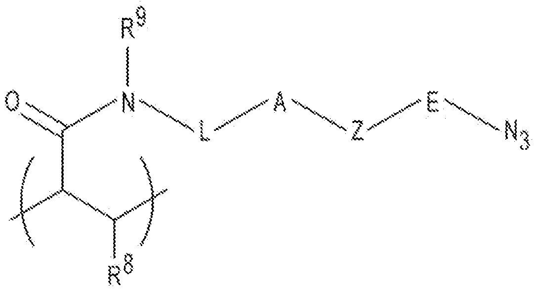 including a linear chain with 2 to 20 atoms selected from the group consisting of carbon, oxygen, and nitrogen and 10 optional substituents on the carbon and any nitrogen atoms in the chain; E is a linear chain including 1 to 4 atoms selected from the group consisting of carbon, oxygen and nitrogen, and optional substituents on the carbon and any nitrogen atoms in the chain; A is an N substituted amide with an H or a C1-C4 alkyl attached to the N; and Z is a nitrogen containing heterocycle. Examples of Z include 5 to 10 carbon-containing ring members present as a single cyclic structure or a fused structure. Some specific examples of Z include pyrrolidinyl, pyridinyl, or pyrimidinyl. [0076] In one example of the polymeric hydrogel, formula (III) is the first recurring unit and formula (II) is the second recurring unit. In another example, formula (III) is the first recurring unit, one example of formula (II) is the second recurring unit, and a different example of formula (III) is the third recurring unit. [0077] It is to be understood that other hydrogel materials may be used for the polymeric hydrogel of the particle core 12, as long as they are functionalized to graft oligonucleotide primers 14, 16 and the transposome dimers 18 thereto.
[0078] Other examples of other polymeric hydrogels include functionalized polysilanes, such as norbornene silane, azido silane, alkyne functionalized silane, amine functionalized silane, maleimide silane, or any other polysilane having functional groups that can attach the oligonucleotide primers. Other examples of suitable polymeric hydrogels include those having a colloidal structure, such as agarose; or a polymer mesh structure, such as gelatin; or a cross-linked polymer structure, such as polyacrylamide polymers and copolymers, silane free acrylamide (SFA), or an azidolyzed version of SFA. Examples of suitable polyacrylamide polymers may be synthesized from acrylamide and an acrylic acid or an acrylic acid containing a vinyl group, or from monomers that form [2+2] photo- cycloaddition reactions. Still other examples of suitable polymeric hydrogel materials include mixed copolymers of acrylamides and acrylates. A variety of polymer architectures containing acrylic monomers (e.g., acrylamides, acrylates etc.) may be utilized in the examples disclosed herein, such as highly branched polymers, including dendrimers. For example, the monomers (e.g., acrylamide, etc.) may be incorporated, either randomly or in block, into the branches (arms) of a dendrimer. [0079] It is to be understood that functional groups in one or more of the recurring units of the polymeric hydrogel of the core 12 are capable of attaching the primers 14, 16 and the transposome complexes 20A, 20B. These functional groups (e.g., R2 in formula (I), NH2, N3, etc.) may be located in the side chains of the linear or branched polymeric hydrogel material. [0080] In another example, a binding pair member may be introduced to the core 12, e.g., as part of a monomer used in polymerization, or in a grafting process after core 12 formation, or in a chemical modification reaction. This binding pair member is capable of attaching to another binding pair member that is at the 5’ end of the primers 14, 16 and/or the transposomes 20A, 20B. Examples of binding pairs include: those capable of peptide coupling (e.g., spytag and a spycatcher); a NiNTA (nickel- nitrilotriacetic acid) ligand and a histidine tag; or biotin and streptavidin. [0081] In some examples, the polymeric hydrogel is biotinylated. In these examples, biotin is attached to the surface of the polymeric hydrogel through some of the R2 groups (i.e., the azide, tetrazine, or other functional group that can attach to an
alkyne). The biotin is attached to a as bicyclo[6.1.0]nonyne (BCN), which can covalently attach to some of the R2 groups. In other examples, streptavidin and biotin are attached to one another, and the biotin portion is attached to the surface of the polymeric hydrogel through some of the R2 groups or the linker. [0082] In other examples (as shown in Fig.1A), the core 12 is a multi-layered particle including a core material 21 coated with any example of the polymeric hydrogel disclosed herein (shown as coating 22). In these examples, the core material 21 is generally rigid and is insoluble in an aqueous liquid. Examples of suitable core materials include magnetic materials (e.g., magnetic FeOx, silica coated FeOx), plastics (e.g., polytetrafluoroethylene (PTFE), some polyacrylics, polypropylene, polyethylene, polybutylene, polyurethanes, polystyrene and other styrene copolymers, nylon (i.e., polyamide), etc.), polycaprolactone (PCL), nitrocellulose, silica (SiO2), silica-based materials (e.g., functionalized SiO2), carbon, or metals. Also in these examples, the polymeric hydrogel forms the coating 22 on the core material 21. The thickness of the polymeric hydrogel coating 22 on the core material 21 ranges from about 10 nm to about 200 nm. [0083] In an example, the core 12 is a spherical nanoparticle. In another example, the core 12 is a non-spherical nanoparticle, such as a cube, a triangular prism, rod shaped, a platelet, cage-like (e.g., non-spherical, hollow particles having a porous shell), a tube, etc. In still another example, the core 12 is an irregularly shaped nanoparticle. [0084] The dimensions of the core 12 may vary depending upon its shape. In the examples disclosed herein, the largest dimension (e.g., diameter, length, median, etc.) of the core 12 is on the nanoscale, and thus ranges from about 1 nm to less than 1000 nm. In some examples, the core 12 is a nanoparticle having a diameter of greater than or equal to 1 nm, 2 nm, 3 nm, 4 nm, 5 nm, 6 nm, 7 nm, 8 nm, 9 nm, 10 nm, 20 nm, 30 nm, 40 nm, 50 nm, 60 nm, 70 nm, 80 nm, 90 nm, or greater than or equal to 100 nm. [0085] The pre-grafted particle 10A includes a uniquely indexed transposome dimer 18. The uniquely indexed transposome dimer 18 includes two separate transposome complexes 20A, 20B that are capable of forming dimers in solution. In one example,
the transposome complexes 20A, 20B in solution (with no cores 12 present) to form the dimers 18. These pre-formed dimers 18 are then grafted to the core 12. In another example, the individual transposome complexes 20A, 20B and the cores 12 are mixed together in solution. In these examples, some dimers 18 will form and attach to the core 12. Other transposome complexes 20A, 20B may not dimerize, and these individual transposome complexes 20A, 20B can also attach to the core 12. The monomeric transposome complex(es) 20A, 20B attached to the core 12 will not participate in tagmentation. [0086] Fig.2 depicts an example of the dimer 18, and the transposome complexes 20A or 20B that make up the dimer 18. Each transposome complex 20A, 20B includes a transposase enzyme 24, 24’ non-covalently bound to a transposon end 26, 26’. Each transposon end 26, 26’ is a double-stranded nucleic acid strand, one strand 28, 28’ of which is part of a transferred strand 30, 30’ and the other strand 32, 32’ of which is part of a non-transferred strand 34, 34’. In other words, the transposon end 26, 26’ includes a portion (strand 28, 28’) of the transferred strand 30, 30’ that is hybridized to at least a portion (e.g., strand 32, 32’) of the non-transferred strand 34, 34’. [0087] The transferred strand 30 includes a 5’ end functional group 36 that is capable of covalently or non-covalently attaching to surface functional groups of the core 12 (whether it is formed of a single material or includes the coating 22), a first amplification domain 38, an index sequence 40, and a sequencing primer sequence 42 that is attached to the strand 28 of the transposon end 26. The strand 28 of the transposon end 26 is positioned at the 3’ end of the transferred strand 30. Similar to the transferred strand 30, the transferred strand 30’ includes a 5’ end functional group 36’ that is capable of covalently or non-covalently attaching to surface functional groups of the core 12, a second amplification domain 38’, an index sequence 40’, and a sequencing primer sequence 42’ that is attached to the strand 28’ of the transposon end 26’. The strand 28’ of the transposon end 26’ is positioned at the 3’ end of the transferred strand 30’. [0088] The 5’ end functional groups 36, 36’ may be any functional group that is capable of covalently or non-covalently attaching to surface functional groups of the
core 12, and thus will depend upon functional groups. In one example, the core 12 includes azide or tetrazine surface groups, and the 5’ end functional groups 36, 36’ include a terminal alkyne (e.g., hexynyl) or an internal alkyne, where the alkyne is part of a cyclic compound (e.g., bicyclo[6.1.0]nonyne (BCN) or dibenzocyclooctyne (DBCO)). In another example, the core 12 is functionalized with biotin surface groups, and the 5’ end functional groups 36, 36’ also include biotin. In these examples, additional streptavidin or avidin is added to indirectly attach the biotin groups to one another. In still another example, the core 12 is functionalized with one member of a binding pair, and the second member of the binding pair is the 5’ end functional group 36, 36’. [0089] The first and second amplification domains 38, 38’ have different sequences from each other, but have the same sequence, respectively, as first and second primers 14, 16 attached to the core 12. The first amplification domain 38, its complement, and the primer 14, together with the second amplification domain 38’, its complement, and the primer 16 enable the amplification of the DNA sample fragments generated during tagmentation. [0090] Examples of suitable sequences for the first amplification domain 38/primer 14 and for the second amplification domain 38’/primer 16 include P5 and P7 primer sequences; P15 and P7 primer sequences; or any combination of the PA primer sequences, the PB primer sequences, the PC primer sequences, and the PD primer sequences set forth herein. Examples of P5 and P7 primer sequences are used on the surface of commercial flow cells sold by Illumina Inc. for sequencing, for example, on HISEQ™, HISEQX™, MISEQ™, MISEQDX™, MINISEQ™, NEXTSEQ™, NEXTSEQDX™, NOVASEQ™, ISEQTM, GENOME ANALYZER™, and other instrument platforms. [0091] The P5 primer sequence is: P5 #1: 5’ → 3’ AATGATACGGCGACCACCGAGAUCTACAC (SEQ. ID. NO.1); or
P5 #2: 5’ → 3’ AATGATACGGCGACCACCGAGAnCTACAC (SEQ. ID. NO.2) where “n” is alkene-thymidine (i.e., alkene-dT) in SEQ. ID. NO.2; or P5 #3: 5’ → 3’ AATGATACGGCGACCACCGAGAnCTACAC (SEQ. ID. NO.3) where “n” is inosine in SEQ. ID. NO.3. The P7 primer sequence may be any of the following: P7 #1: 5’ → 3’ CAAGCAGAAGACGGCATACGAnAT (SEQ. ID. NO.4); or P7 #2: 5’ → 3’ CAAGCAGAAGACGGCATACnAGAT (SEQ. ID. NO.5); or P7 #3: 5’ → 3’ CAAGCAGAAGACGGCATACnAnAT (SEQ. ID. NO.6) where “n” is 8-oxoguanine in each of the sequences. The P15 primer sequence is: P15: 5’ → 3’ AATGATACGGCGACCACCGAGAnCTACAC (SEQ. ID. NO.7) where “n” is allyl-T (a thymine nucleotide analog having an allyl functionality). The other primer sequences (PA-PD) mentioned above include:
PA 5’ → 3’ GCTGGCACGTCCGAACGCTTCGTTAATCCGTTGAG (SEQ. ID. NO.8) PB 5’ → 3’ CGTCGTCTGCCATGGCGCTTCGGTGGATATGAACT (SEQ. ID. NO.9) PC 5’ → 3’ ACGGCCGCTAATATCAACGCGTCGAATCCGCAACT (SEQ. ID. NO.10) PD 5’ → 3’ GCCGCGTTACGTTAGCCGGACTATTCGATGCAGC (SEQ. ID. NO.11). [0092] While not shown in the example sequences for PA-PD, it is to be understood that any of these sequences may include a cleavage site, such as uracil, 8- oxoguanine, allyl-T, diols, etc. at any point in the strand. The sequences for the first amplification domain 38/primer 14 and for the second amplification domain 38’/primer 16 may be selected to have orthogonal cleavage sites (i.e., one cleavage site is not susceptible to the cleaving agent used for the other cleavage site), so that after amplification, forward or reverse strands can be cleaved, leaving the other of the reverse or forward strands for sequencing. [0093] The primers 14, 16 may also include a polyT sequence at the 5’ end of the primer sequence. In some examples, the polyT region includes from 2 T bases to 20 T bases. As specific examples, the polyT region may include 3, 4, 5, 6, 7, or 10 T bases. [0094] The index sequences 40, 40’ of the transposome complexes 20A, 20B are the same unique barcode sequence that can be used for sample identification and indexing. As will be described herein in reference to Fig.5, different DNA samples can be tagmented in different wells of a well plate with the pre-grafted particles 10A. In these examples, the set of pre-grafted particles 10A that is introduced into each of the wells includes a unique index sequence 40, 40’ relative to the set of pre-grafted
particles 10A that is introduced into well, and thus the index sequence 40, 40’ used in a particular well can be used for sample identification. Index sequences 40, 40’ may range from 7 bases to 15 bases long. The number of indexes can be increased using a combinatorial approach. [0095] The sequencing primer sequences 42, 42’ have different sequences from each other that respectively bind to sequencing primers that are introduced, e.g., to a flow cell surface that binds the pre-grafted particles 10A after tagmentation and amplification have been performed. As examples, the sequencing primer sequence 42 may bind a sequencing primer that primes synthesis of a new strand that is complementary to forward strand fragments/fragment amplicons and the sequencing primer sequence 42’ may bind a sequencing primer that primes synthesis of a new strand that is complementary to reverse strand fragments/fragment amplicons. [0096] The transposon ends 26, 26’ of each transposome complex 20A, 20B include the strands 28, 28’ respectively hybridized to the strands 32, 32’. As such, the strands 28 and 32 are complementary and the strands 28’, 32’ are complementary. The double stranded transposon ends 26, 26’ are respectively capable of complexing with the transposases 24, 24’. As examples, the strands 28, 32 and 28’, 32’ of the transposon ends 26, 26’ may be the related but non-identical 19-base pair (bp) outer end (e.g., strands 28, 28’) and inner end (e.g., strands 32, 32’) sequences that serve as the substrate for the activity of the Tn5 transposase, or the mosaic ends recognized by a wild-type or mutant Tn5 transposase, or the R1 end (e.g., strands 30, 30’) and the R2 end (strands 32, 32’) recognized by the MuA transposase. [0097] In some examples (see Fig.2 and Fig.6), the non-transferred strands 34, 34’ are made up of the strands 32, 32’. [0098] In other examples (see Fig.7), the non-transferred strand 34 or 34’ is made up of the strand 32 or 32’ and adapter segments 78 that create a forked adapter when hybridized to the transferred strands 30, 30’. This is illustrated as transposome complex 20E in Fig.7. When the non-transferred strand 34 or 34’ includes the adapter segments 78 and creates a forked adapter, it is to be understood that the transposome complexes 20E alone (not two types as with 20A and 20B or 20C and 20D) are grafted to the surface of the core 12. This is because the individual complex 20E includes the
adapter segments 78 needed to create adapted DNA fragments, and thus two complexes 20A and 20B or 20C and 20D with the respective amplification domains 38, 38’ are not needed. As one example, the transposome complex 20E includes the transferred strand 30 as described herein with the first amplification domain 38 (and may or may not include the index sequence 40), and the non-transferred strand 34 includes the strand 32, a complement of the sequencing primer sequence 42’ (shown as 42’C in Fig.7), and a complement of the second amplification domain 38’ (shown as 38’C in Fig.7). The complements of the sequencing primer 42’C second amplification domain 38’C make up the adapter segment 78. [0099] Referring back to Fig.1A, while the dimer 18 that is depicted includes one of each complex 20A, 20B (i.e., heterodimers), it is to be understood that some dimers 18 that form may include the same type of complex 20A, 20A or 20B, 20B (i.e., homodimers may form). Additionally, it is to be understood that depending upon the number of available attachment groups at the surface of the core 12, individual complexes 20A, 20B may attach to the core 12 and the dimers 18 may not form. Still further, when the adapter segments 78 are used to form forked adapters, one type of transposome complex 20A or 20B is grafted to the core 12. If the dimers 18 are formed before being grafted to the core 12, the formation of homodimers or heterodimers can be controlled. For example, the transposome complexes 20A and 20B can be dimerized in separate solutions, thus only forming homodimers of transposome complexes 20A in one solution and homodimers of transposome complexes 20B in the other solution. The mixture of homodimers can be attached to the core 12. For another example, the transposome complexes 20A and 20B can be dimerized in the same solution, and thus heterodimers and homodimers may be formed, and then attached to the core 12. For another example, the transposome complexes 20A and 20B can be dimerized in the same solution and in the presence of the core 12, and thus heterodimers and homodimers may be formed and attached to the core 12 in the same solution. [0100] As shown in Fig.1A, the pre-grafted particle 10A also includes primers 14, 16. The primers 14, 16 include any two of the primer sequences set forth herein for the first and second amplification domains 38, 38’. The 5’ terminal end of the primers
14, 16 will vary depending upon the at the surface of the core 12. Examples of 5’ terminal end groups for the primers 14, 16’ include a terminal alkyne, an internal alkyne, biotin, biotin-streptavidin (where the streptavidin is the terminal group), or other functional groups that can attach to the surface groups of the core 12. [0101] Fig.1B depicts another example of the pre-grafted particle 10B. In Fig.1B, the pre-grafted particle 10B includes a stimuli-responsive core 12’; a primer set (including primers 14 and 16) attached to the stimuli-responsive core 12’; and at least two transposome dimers 18’ (each of which includes complexes 20C and 20D) attached to the stimuli-responsive core 12’. As mentioned herein, the pre-grafted particle 10B may initially include the core 12’ and the primer set (including primers 14 and 16) attached to the core 12’, and the dimers 18’ (including two transposome complexes 20C, 20D) may be added during the method. [0102] The stimuli-responsive core 12’ may include any material that is responsive to an external stimulus, such as temperature, pH, ionic strength, light, redox conditions, or analyte concentration. In some examples of the pre-grafted particle 10B, the entire core 12’ is formed of the stimuli-responsive material. It is also believed that solvent responsive, electric field responsive, or magnetic field responsive materials could be used. [0103] In one example, the stimuli-responsive core 12’ is a temperature-responsive material. Examples of thermo-responsive materials include low critical solution temperature (LCST) polymers or upper critical solution temperature (USCT) polymers, which exhibit reversible volume-phase transitions. The thermo-responsive properties enable the core 12’ to be expanded or contracted at desirable times, e.g., during tagmentation or primer grafting, respectively. The transition can be controlled through the critical solution temperature. [0104] With the LCST polymer, an increase in the temperature above the LCST shrinks the polymer. In contrast, a decrease in the temperature to below the LCST renders the polymer more hydrophilic, which expands the polymer. An example of the lower critical solution temperature polymer is selected from the group consisting of poly(N-isopropylacrylamide) and diethylene glycol methacrylate. Other examples include co-polymers of N-isopropylacrylamide, such as i) those derived from a
monomer mixture of N-(5-(2- pentyl)acrylamide (AzAPA), N- isopropylacrylamide (NiPAM), acrylic acid (AAc), and N,N’-methylenebisacrylamide (BisAM), ii) those derived from a monomer mixture of N-(5-(2- azidoacetamido)pentyl)acrylamide, N-isopropylacrylamide, and acrylic acid, or iii) those derived from a monomer mixture of propargyl acrylate (PAG) and/or N-propargyl acrylamide (PAM), N-isopropylacrylamide, acrylic acid, and N,N ’- methylenebisacrylamide. [0105] With the UCST polymer, a decrease in the temperature below the UCST shrinks the polymer. In contrast, an increase in the temperature to above the UCST renders the polymer more hydrophilic, which expands the polymer. Examples of the UCST polymer may be selected from the group consisting of poly(N-acryloyl glycinamide) (PNAGA), poly(methacrylamide) (PMAAm), poly(uracilacrylate) (PAU), poly(N-(2-hydroxypropyl)methacrylamide) functionalized with glycolamide (Poly(HPMA-GA)), poly(sulfobetaine methacrylate), poly(N,N-dimethyl aminoethyl methacrylate) (PDMAEMA), poly(allylamin-co-allylurea) (P(Am-co-AU), poly(acrylamide-co-2-methylene-1,3-dioxepane) (P(AAm-co-MDO), and poly(acrylamide-co-acrylonitrile) (P(AAm-co-AN). [0106] Other temperature responsive materials include biologically inspired polymers that are capable of covalently binding the primer set and the transposome complexes 20C, 20D, such as natural globular proteins, artificial intrinsically disordered protein polymers, poly(peptides), and poly(peptoids). [0107] In another example, the stimuli-responsive core 12’ is a pH-responsive material. Examples of the pH-responsive material include poly(acrylic acid) (PAA) (decomposition and hydrolysis at pH ranging from 8.2 to 9.0) and poly(2- (dimethylamino)ethyl methacrylate) (PDMAEMA) (water soluble at pH 2.0). [0108] In yet another example, the stimuli-responsive core 12’ is an ionic strength- responsive material. An example of the ionic strength-responsive material poly(ethylene glycol) (PEG)-block-poly(L-lysine) (PLL). [0109] In still another example, the stimuli-responsive core 12’ is a light-responsive material. Examples of the light-responsive materials are those containing azobenzene groups, such as poly(ethylene glycol) methacrylate-co-azobenzene methacrylate).
[0110] Other suitable stimuli- cores 12’ are those that are redox- responsive. Some redox-responsive polymers are those containing disulfide bonds, such as poly(disulfides). [0111] Still another stimuli-responsive core 12’ is made up of a material that is responsive to a particular analyte. In one example, the analyte stimulus is glucose, and the core 12’ is a polymeric particle coated with a glucose-responsive polymer, e.g., poly(N-isopropylacrylamide) including embedded glucose-sensitive enzymes. [0112] Some examples of the stimuli-responsive material include functional groups (e.g., azides or alkynes) that are capable of attaching the primers 14, 16 and the transposome complexes 20C, 20D. In these examples, the entire core 12’ is made of the stimuli-responsive material. [0113] In other examples (as shown in Fig.1B), the core 12’ is a multi-layered particle including a stimuli-responsive core material 21’ coated with any example of the polymeric hydrogel disclosed herein (shown as coating 22’). Any examples of the stimuli-responsive material set forth herein may be used for the core material 21’, and any example of the polymeric hydrogel may be used as the coating 22’. The thickness of the polymeric hydrogel coating 22’ on the stimuli-responsive core material 21’ ranges from about 10 nm to about 1 µm. [0114] The pre-grafted particle 10B includes the primers 14, 16. Any example of the primers 14, 16 set forth herein for the pre-grafted particle 10A may be used. [0115] The pre-grafted particle 10B also includes the dimers 18’ made up of the transposome complexes 20C and 20D. The transposome complexes 20C and 20D are similar to the transposome complexes 20A and 20B, except that they do not include the index sequences 40, 40’. The dimers 18’ are similar to the dimers 18, and may be pre-formed in solution and then grafted to the core 12’, or may be formed as they are grafted to the core 12’. In the latter example, some transposome complexes 20C, 20D may not dimerize and these individual transposome complexes 20C, 20D can attach to the core 12’. The monomeric transposome complex(es) 20C, 20D attached to the core 12’ will not participate in tagmentation. [0116] Fig.1C depicts still another example of the pre-grafted particle 10C. This pre-grafted particle 10C includes the core 12 as described in reference to Fig.1A and
the complexes 20C, 20D (in dimer 18’ as described in reference to Fig.1B. In this particle 10C, the primers 14, 16 may be any of the examples disclosed herein. [0117] Each of the pre-grafted particles 10A, 10B, 10C may also include or be functionalized with a mechanism that is capable of anchoring to a capture site on a flow cell substrate. The mechanism may be chemical (e.g., a functional agent), electrostatic, or magnetic. [0118] In some examples, the mechanism is a component of pre-grafted particles 10A, 10B, 10C that enables it to be anchored without further functionalization. For example, when the pre-grafted particles 10A, 10B, 10C include a magnetic material as the core material 21, the pre-grafted particles 10A, 10B, 10C may be anchored to a magnetic capture agent on the flow cell substrate. For another example, a reversibly chargeable functional group, such as an amine or a carboxylic acid, may be attached (e.g., through a thiol linkage) to the surface of the core 12, 12’ along with the primers 14, 16 and the transposome complexes 20A, 20B, 20C, 20D. In this example, the reversibly chargeable functional group (as the mechanism) enables the pre-grafted particles 10A, 10B, 10C to be anchored to an electrostatic capture agent on the flow cell substrate. For still another example, the mechanism is a functional agent that is added to the pre-grafted particles 10A, 10B, 10C that enables it to be anchored on the flow cell substrate. As one example, a primer complement may be introduced to DNA sample fragments as a result of amplification, and the primer complement is complementary to a capture oligonucleotide on the flow cell substrate. As another example, a functional group for covalent attachment or a member of a binding pair may be attached to the pre-grafted particle 10A, 10B, 10C. [0119] Flow Cells for use with Pre-Grafted Particles [0120] The pre-grafted particles 10A, 10B, 10B may be used with any flow cell 50 (Fig.3) that includes capture sites 60, 60’, 60’’ (Fig.4A, Fig.4B, Fig.4C, Fig.4D). An example of the flow cell 50 is depicted from the top view in Fig.3, and different examples of the flow cell architecture, including different configurations of the capture sites 60, 60’, are shown in Fig.4A, Fig.4B, Fig.4C, and Fig.4D.
[0121] A top view of an example of cell 50 is shown in Fig.3. As will be discussed in reference to Fig.4A, Fig.4B, Fig.4C, and Fig.4D some examples of the flow cell 50 include two opposed substrates 52A, 52A’ or 52B, 52B’ or 52C, 52C’ or 52D, 52D’, each of which is configured with capture sites 60 or 60’ or 60’’. In these examples, a flow channel 54 is defined between the two opposed substrates 52A, 52A’ or 52B, 52B’ or 52C, 52C’ or 52D, 52D’. In other examples, the flow cell 50 includes one substrate 52A or 52B or 52C or 52D configured with capture sites 60, 60’, 60’’ and a lid attached to the substrate 52A or 52B or 52C or 52D. In these examples, the flow channel 54 is defined between the substrate 52A or 52B or 52C or 52D and the lid. In still other examples, the substrate 52A or 52B or 52C or 52D may be an open wafer that is not bonded to another component. In these examples, the substrate surface chemistry is open to the external environment. [0122] Different patterned substrates 52A, 52A’ and 52B, 52B’ and 52C, 52C’ are shown in Fig.4A, Fig.4B, and Fig.4C. A non-patterned substrate 52D, 52D’ is shown in Fig.4D. [0123] In the examples shown in Fig.4A and Fig.4D, the substrates 52A, 52A’ and 52D, 52’D are single layered structures. Examples of suitable single layered structures for the substrate 52A, 52A’ and 52D, 52D’ include epoxy siloxane, glass, modified or functionalized glass, polymers (including acrylics, polystyrene and copolymers of styrene and other materials, polypropylene, polyethylene, polybutylene, polyurethanes, polytetrafluoroethylene (such as TEFLON® from Chemours), cyclic olefins/cyclo-olefin polymers (COP) (such as ZEONOR® from Zeon), polyimides, nylon (polyamides), etc.), ceramics/ceramic oxides, silica, fused silica, or silica-based materials, aluminum silicate, silicon and modified silicon (e.g., boron doped p+ silicon), silicon nitride (Si3N4), silicon oxide (SiO2), tantalum pentoxide (Ta2O5) or other tantalum oxide(s) (TaOx), hafnium oxide (HfO2), carbon, metals, inorganic glasses, or the like. [0124] In the examples shown in Fig.4B and Fig.4C, the substrates 52B, 52B’ and 52C, 52C’ are multi-layered structures. The multi-layered structures of the substrates 52B, 52B’ and 52C, 52C’ include a base support 66, 66’ and a patterned material 64 or 64’ on the base support 66, 66’.
[0125] The base support 66, 66’ may any of the examples set forth herein for the single layered structure of the substrates 52A, 52A’ and 52D, 52D’. [0126] The patterned material 64 or 64’ may be any material that is capable of being patterned with posts 70, 70’ (Fig.4B) or depressions 72, 72’ (Fig.4C). [0127] In an example, the patterned material 64, 64’ may be an inorganic oxide that is selectively applied to the base support 66, 66’, e.g., via vapor deposition, aerosol printing, or inkjet printing, in the desired pattern. Examples of suitable inorganic oxides include tantalum oxide (e.g., Ta2O5), aluminum oxide (e.g., Al2O3), silicon oxide (e.g., SiO2), hafnium oxide (e.g., HfO2), etc. [0128] In another example, the patterned material 64, 64’ may be a resin matrix material that is applied to the base support 66, 66’ and then patterned. Suitable deposition techniques include chemical vapor deposition, dip coating, dunk coating, spin coating, spray coating, puddle dispensing, ultrasonic spray coating, doctor blade coating, aerosol printing, screen printing, microcontact printing, etc. Suitable patterning techniques include photolithography, nanoimprint lithography (NIL), stamping techniques, embossing techniques, molding techniques, microetching techniques, printing techniques, etc. Some examples of suitable resins include a polyhedral oligomeric silsesquioxane-based resin, a non-polyhedral oligomeric silsesquioxane epoxy resin, a poly(ethylene glycol) resin, a polyether resin (e.g., ring opened epoxies), an acrylic resin, an acrylate resin, a methacrylate resin, an amorphous fluoropolymer resin (e.g., CYTOP® from Bellex), and combinations thereof. [0129] As used herein, the term “polyhedral oligomeric silsesquioxane” (commercially available under the tradename POSS® from Hybrid Platics) refers to a chemical composition that is a hybrid intermediate (e.g., RSiO1.5) between that of silica (SiO2) and silicone (R2SiO). An example of polyhedral oligomeric silsesquioxane can be that described in Kehagias et al., Microelectronic Engineering 86 (2009), pp.776- 778, which is incorporated by reference in its entirety. In an example, the composition is an organosilicon compound with the chemical formula [RSiO3/2]n, where the R groups can be the same or different. Example R groups for polyhedral oligomeric silsesquioxane include epoxy, azide/azido, a thiol, a poly(ethylene glycol), a
norbornene, a tetrazine, acrylates, or further, for example, alkyl, aryl, alkoxy, and/or haloalkyl groups. The resin composition disclosed herein may comprise one or more different cage or core structures as monomeric units. The average cage content can be adjusted during the synthesis, and/or controlled by purification methods, and a distribution of cage sizes of the monomeric unit(s) may be used in the examples disclosed herein. [0130] In an example, the substrates 52A, 52A’ or 52B, 52B’ or 52C, 52C’ or 52D, 52D’ (whether single or multi-layered) may be round and have a diameter ranging from about 2 mm to about 300 mm, or may be a rectangular sheet or panel having its largest dimension up to about 10 feet (~ 3 meters). In an example, the substrate 52A, 52A’ or 52B, 52B’ or 52C, 52C’ or 52D, 52D’ is a wafer having a diameter ranging from about 200 mm to about 300 mm. Wafers may subsequently be diced to form an individual flow cell substrate. In another example, the substrate 52A, 52A’ or 52B, 52B’ or 52C, 52C’ or 52D, 52D’ is a die having a width ranging from about 0.1 mm to about 10 mm. While example dimensions have been provided, it is to be understood that a substrate 52A, 52A’ or 52B, 52B’ or 52C, 52C’ or 52D, 52D’ with any suitable dimensions may be used. For another example, a panel may be used that is a rectangular support, which has a greater surface area than a 300 mm round wafer. Panels may subsequently be diced to form individual flow cells. [0131] The flow cell 50 also includes the flow channel 54. While several flow channels 54 are shown in Fig.3, it is to be understood that any number of flow channels 54 may be included in the flow cell 50 (e.g., a single channel 54, four channels 54, etc.). Each flow channel 54 may be isolated from each other flow channel 54 in a flow cell 50 so that fluid introduced into any particular flow channel 54 does not flow into any adjacent flow channel 54. [0132] A portion of the flow channel 54 may be defined in the substrate 52A, 52A’ or 52B, 52B’ or 52C, 52C’ or 52D, 52D’ using any suitable technique that depends, in part, upon the material(s) of the substrate 52A, 52A’ or 52B, 52B’ or 52C, 52C’ or 52D, 52D’. In one example, a portion of the flow channel 54 is etched into a glass substrate, such as substrate 52A, 52A’. In another example, a portion of the flow channel 54 may be patterned into a resin matrix material of a multi-layered structure
using photolithography, nanoimprint etc. A separate material (e.g., material 62 in Fig.4A, Fig.4B, Fig.4C and 52D, 52D’ may be applied to the substrate 52A, 52A’ or 52B, 52B’ or 52C, 52C’ or 52D, 52D’ at bonding regions 88, 88’ so that the separate material 62 defines at least a portion of the walls of the flow channel 54. As examples, the separate material 62 may be an adhesive, a radiation-absorbing material that aids in bonding, or the like. In some examples, the separate material 62 is a radiation-absorbing material, e.g., KAPTON® black. The separate material 62 may be positioned at the perimeter of the flow cell 50, and between adjacent channels 54 if multiple channels 54 are included. [0133] In an example, the flow channel 54 has a substantially rectangular configuration with rounded ends. The length and width of the flow channel 54 may be smaller, respectively, than the length and width of the substrate 52A, 52A’ or 52B, 52B’ or 52C, 52C’ or 52D, 52D’ so that a portion of the substrate surface surrounding the flow channel 54 is available for attachment to another substrate 52A, 52A’ or 52B, 52B’ or 52C, 52C’ or 52D, 52D’ or to a lid. In some instances, the width of each flow channel 54 can be at least about 1 mm, at least about 2.5 mm, at least about 5 mm, at least about 7 mm, at least about 10 mm, or more. In some instances, the length of each flow channel 54 can be at least about 10 mm, at least about 25 mm, at least about 50 mm, at least about 100 mm, or more. The width and/or length of each flow channel 54 can be greater than, less than or between the values specified above. In another example, the flow channel 54 is square (e.g., 10 mm x 10 mm). [0134] The depth of each flow channel 54 can be as small as a few monolayers thick, for example, when microcontact, aerosol, or inkjet printing is used to deposit the separate material 62 that defines the flow channel walls. In other examples, the depth of each flow channel 54 can be about 1 μm, about 10 μm, about 50 μm, about 100 μm, or more. In an example, the depth may range from about 10 μm to about 100 μm. In another example, the depth is about 5 μm or less. It is to be understood that the depth of each flow channel 54 can also be greater than, less than or between the values specified above. The depth of the flow channel 54 may also vary along the length and width of the flow cell 50, e.g., when posts 70, 70’ or depressions 72, 72’ are used.
[0135] In the example shown in each substrate 52A, 52A’ has a substantially flat surface 58, 58’; and the plurality of capture sites 60, 60’ are positioned in a pattern across the substantially flat surfaces 58, 58’. [0136] The substantially flat surfaces 58, 58’ may be the bottom surface of lanes 56, 56’ that are defined in the single layer substrate 52A, 52A’. A lane 56, 56’ may also be defined in the patterned layer 64, 64’ of a multi-layered substrate 52B, 52B’, 52C, 52C’. The lanes 56, 56’ may be etched into the substrate or defined, e.g., by lithography or another suitable technique. [0137] The plurality of capture sites 60, 60’ is positioned in a pattern across the substantially flat surface 58, 58’. [0138] Many different patterns for the capture sites 60, 60’ may be envisaged, including regular, repeating, and non-regular patterns. In an example, the capture sites 60, 60’ are disposed in a hexagonal grid for close packing and improved density. Other layouts may include, for example, rectilinear (rectangular) layouts, triangular layouts, and so forth. In some examples, the layout or pattern can be an x-y format of capture sites 60, 60’ that are in rows and columns. In some other examples, the layout or pattern can be a repeating arrangement of capture sites 60, 60’ separated by regions of the substantially flat surface 58, 58’. In still other examples, the layout or pattern can be a seemingly random arrangement of capture sites 60, 60’. The pattern may include stripes, swirls, lines, triangles, rectangles, circles, arcs, checks, diagonals, arrows, and/or squares. [0139] The layout or pattern of the capture sites 60, 60’ may be characterized with respect to the density of the capture sites 60, 60’ (e.g., number of capture sites 60, 60’) in a defined area. For example, the capture sites 60, 60’ may be present at a density of approximately 2 million per mm2. The density may be tuned to different densities including, for example, a density of about 100 per mm2, about 1,000 per mm2, about 0.1 million per mm2, about 1 million per mm2, about 2 million per mm2, about 5 million per mm2, about 10 million per mm2, about 50 million per mm2, or more, or less. It is to be further understood that the density of capture sites 60, 60’ can be between one of the lower values and one of the upper values selected from the ranges above. As examples, a high density array may be characterized as having capture
sites 60, 60’ separated by less than nm, a medium density array may be characterized as having capture sites 60, 60’ separated by about 400 nm to about 1 µm, and a low density array may be characterized as having capture sites 60, 60’ separated by greater than about 1 µm. While example densities have been provided, it is to be understood that any suitable densities may be used. In some instances, it may be desirable for the spacing between capture sites 60, 60’ to be even greater than the examples listed herein. [0140] The layout or pattern of the capture sites 60, 60’ may also or alternatively be characterized in terms of the average pitch, or the spacing from the center of one capture site 60, 60’ to the center of an adjacent capture site 60, 60’ (center-to-center spacing) or from the left edge of one capture site 60, 60’ to the right edge of an adjacent capture site 60, 60’ (edge-to-edge spacing). The pattern can be regular, such that the coefficient of variation around the average pitch is small, or the pattern can be non-regular in which case the coefficient of variation can be relatively large. In either case, the average pitch can be, for example, about 50 nm, about 0.1 μm, about 0.5 μm, about 1 μm, about 5 μm, about 10 μm, about 100 μm, or more or less. The average pitch for a particular pattern of capture sites 60, 60’ can be between one of the lower values and one of the upper values selected from the ranges above. In an example, the capture sites 60, 60’ have a pitch (center-to-center spacing) of about 1.5 μm. While example average pitch values have been provided, it is to be understood that other average pitch values may be used. [0141] The capture sites 60, 60’ may have any suitable shape, geometry and dimensions, which may depend, at least in part, on the pre-grafted particle 10A, 10B, 10C (which, after amplification, is referred to herein as a pre-clustered particle 80A, 80B, 80C) that is to be captured by the capture site 60, 60’. [0142] The capture sites 60, 60’ may be chemical capture sites, electrostatic captures sites, or magnetic capture sites. [0143] Chemical capture sites include any example of the chemical capture agent set forth herein that can be deposited on or otherwise attached to predefined locations of the substantially flat surface 58, 58’. In one example, the chemical capture agent may be deposited, e.g., using microcontact printing, aerosol printing, etc., in a
desirable location on the substantially 58, 58’ to form the capture sites 60, 60’. In another example, a mask (e.g., a photoresist) may be used to define the space/location where the chemical capture agent will be deposited. The chemical capture agent may then be deposited, and the mask removed (e.g., via lift-off, dissolution, or another suitable technique). In this example, the chemical capture agent may form a monolayer or thin layer of the chemical capture agent. In still another example, a polymer grafted with capture nucleic acids may be selectively applied to the substantially flat surface 58, 58’ to form the chemical captures sites. [0144] Electrostatic captures sites include any example of the electrostatic capture agents set forth herein that can be deposited on predefined locations of the substantially flat surface 58, 58’. For example, electrode materials may be deposited using chemical vapor deposition, masking and deposition, or another suitable technique to form the capture sites 60, 60’. When electrostatic capture sites are used, the substrate 52A, 52A’ may include additional circuitry to address the individual capture sites 60, 60’. [0145] Magnetic capture sites include any example of the magnetic capture agent set forth herein that can be deposited on predefined locations of the substantially flat surface 58, 58’. For example, magnetic materials may be deposited using chemical vapor deposition, masking and deposition, or another suitable technique to form the capture sites 60, 60’. [0146] In the example of Fig.4A, areas of the substantially flat surface 58, 58’ that do not contain the capture sites 60, 60’ function as interstitial regions 68, 68’ between the capture sites 60, 60’. [0147] In the example shown in Fig.4B, the substrate 52B, 52B’ includes posts 70, 70’ separated by interstitial regions 68, 68’; and a capture site 60, 60’ is positioned over each of the posts 70, 70’. [0148] Each post 70, 70’ is a three-dimensional structure that extends outward (upward) from an adjacent surface. The post 70, 70’ is thus a convex region with respect to the interstitial regions 68, 68’ that surround the posts 70, 70’. Posts 70, 70’ may be formed in or on a substrate 52B, 52B’. In Fig.4B, the posts 70, 70’ are formed in the substrate 52B, 52B’. When the post 70, 70’ is formed “in the substrate”, it is
meant that the layer 64, 64’ is patterned via etching, photolithography, imprinting, etc.,) so that the resulting posts 70, 70’ extend above the adjacent surrounding interstitial regions 68, 68’. Alternatively, when the post 70, 70’ is formed “on the substrate”, it is meant that an additional material may be deposited on the substrate (e.g., on the single layer substrate) so that it extends above the underlying substrate (e.g., above the base support 66, 66’). [0149] The layout or pattern of the posts 70, 70’ may be any of the examples set forth herein for the capture sites 60, 60’. The layout or pattern of the posts 70, 70’ may be characterized with respect to the density of the posts 70, 70’ (e.g., number of posts 70, 70’) in a defined area. Any of the densities set forth for the capture sites 60, 60’ may be used for the posts 70, 70’. The layout or pattern of the posts 70, 70’ may also be characterized in terms of the average pitch, or the spacing from the center of one post 70, 70’ to the center of an adjacent post 70, 70’ (center-to-center spacing) or from the left edge of one post 70, 70’ to the right edge of an adjacent post 70, 70’ (edge-to- edge spacing). Any of the average pitches set forth for the capture sites 60, 60’ may be used for the posts 70, 70’. [0150] While any suitable three-dimensional geometry may be used for the posts 70, 70’, a geometry with an at least substantially flat top surface may be desirable so that the capture site 60, 60’ may be formed thereon. Example post geometries include a sphere, a cylinder, a cube, polygonal prisms (e.g., rectangular prisms, hexagonal prisms, etc.), or the like. [0151] The size of each post 70, 70’ may also be characterized by its top surface area, height, and/or diameter. [0152] The top surface area of each post 70, 70’ can be selected based upon the size of the pre-clustered particles 80A, 80B, 80C that is to be anchored to the capture site 60, 60’ that is supported by the post 70, 70’. For example, the top surface area of each post 70, 70’ can be at least about 1×10⁻⁴ μm2, at least about 1×10⁻³ μm2, at least about 0.1 μm2, at least about 1 μm2, at least about 10 μm2, at least about 100 μm2, or more. Alternatively or additionally, the top surface area of each post 70, 70’ can be at most about 1×104 μm2, at most about 100 μm2, at most about 10 μm2, at most about 1 μm2, at most about 0.1 μm2, at most about 1×10⁻² μm2, or less. The area occupied by
each post top surface can be greater less than or between the values specified above. [0153] The height of each post 70, 70’ can depend upon the channel 54 dimensions. In an example, the height may be at least about 0.1 μm, at least about 0.5 μm, at least about 1 μm, at least about 10 μm, at least about 100 μm, or more. Alternatively or additionally, the height can be at most about 1×103 μm, at most about 100 μm, at most about 10 μm, or less. In some examples, the height is about 0.4 μm. The height of each post 70, 70’ can be greater than, less than or between the values specified above. [0154] In some instances, the diameter or length and width of each post 70, 70’ can be at least about 50 nm, at least about 0.1 μm, at least about 0.5 μm, at least about 1 μm, at least about 10 μm, at least about 100 μm, or more. Alternatively or additionally, the diameter or length and width can be at most about 1×103 μm, at most about 100 μm, at most about 10 μm, at most about 1 μm, at most about 0.5 μm, at most about 0.1 μm, or less (e.g., about 50 nm). In some examples, the diameter or length and width is about 0.4 μm. The diameter or length and width of each post 70, 70’ can be greater than, less than or between the values specified above. [0155] In the example shown in Fig.4B, a respective capture site 60, 60’ is positioned on each of the posts 70, 70’. The capture sites 60, 60’ may be chemical capture sites, electrostatic captures sites, or magnetic capture sites. [0156] Chemical capture sites include any example of the chemical capture agent set forth herein that can be deposited on or otherwise attached to the top surface of each post 70, 70’. In one example, the chemical capture agent may be deposited, e.g., using microcontact printing, aerosol printing, etc., on each post 70, 70’ to form the capture site 60, 60’. In another example, a mask (e.g., a photoresist) may be used to cover the interstitial regions 68, 68’ and not the posts 70, 70’. The chemical capture agent may then be deposited on the exposed posts 70, 70’, and the mask removed (e.g., via lift-off, dissolution, or another suitable technique). In this example, the chemical capture agent may form a monolayer or thin layer of the chemical capture agent on the post 70, 70’. In still another example, a polymer grafted with capture
nucleic acids may be selectively applied the top surface of each post 70, 70’ to form the chemical captures sites. [0157] Electrostatic captures sites include any example of the electrostatic capture agent set forth herein that can be deposited on the top surface of each post 70, 70’. For example, electrode materials may be deposited using chemical vapor deposition, masking and deposition, or another suitable technique to form the capture sites 60, 60’. When electrostatic capture sites are used, the substrate 52B, 52B’ may include additional circuitry to address the individual capture sites 60, 60’. [0158] Magnetic capture sites include any example of the magnetic capture agent set forth herein that can be deposited on the top surface of each post 70, 70’. For example, magnetic materials may be deposited using chemical vapor deposition, masking and deposition, or another suitable technique to form the capture sites 60, 60’. [0159] In the example shown in Fig.4C, the substrate 52C, 52C’ includes depressions 72, 72’ separated by interstitial regions 68, 68’; and a capture site 60, 60’ is positioned in each of the depressions 72, 72’. [0160] Each depression 72, 72’ is a three-dimensional structure that extends inward (downward) from an adjacent surface. The depression 72, 72’ is thus a concave region with respect to the interstitial regions 68, 68’ that surround the depressions 72, 72’. Depressions 72, 72’ may be formed in a substrate 52C, 52C’. In the example shown in Fig.4C, the layer 64, 64’ is patterned (e.g., via etching, photolithography, imprinting, etc.,) to define the depressions 72, 72’ so that the interstitial regions 68, 68’ extend above and surround the adjacent depressions 72, 72’. In other examples, the depressions 72, 72’ may be defined in the single layer substrate 52A, 52A’ or 52D, 52D’. [0161] The layout or pattern of the depressions 72, 72’ may be any of the examples set forth herein for the capture sites 60, 60’. The layout or pattern of the depressions 72, 72’ may be characterized with respect to the density of the depressions 72, 72’ (e.g., number of depressions 72, 72’) in a defined area. Any of the densities set forth for the capture sites 60, 60’ may be used for the depressions 72, 72’. The layout or pattern of the depressions 72, 72’ may also be characterized in terms of the average
pitch, or the spacing from the center of depression 72, 72’ to the center of an adjacent depression 72, 72’ (center-to-center spacing) or from the left edge of one depression 72, 72’ to the right edge of an adjacent depression 72, 72’ (edge-to-edge spacing). Any of the average pitches set forth for the capture sites 60, 60’ may be used for the depressions 72, 72’. [0162] While any suitable three-dimensional geometry may be used for the depressions 72, 72’, a geometry with an at least substantially flat bottom surface may be desirable so that the capture site 60, 60’ may be formed thereon. Example depression geometries include a sphere, a cylinder, a cube, polygonal prisms (e.g., rectangular prisms, hexagonal prisms, etc.), or the like. [0163] The size of each depression 72, 72’ may be characterized by its volume, opening area, depth, and/or diameter. [0164] Each depression 72, 72’ can have any volume that is capable of receiving the material of the capture site 60, 60’. For example, the volume can be at least about 1×10⁻³ μm3, at least about 1×10⁻² μm3, at least about 0.1 μm3, at least about 1 μm3, at least about 10 μm3, at least about 100 μm3, or more. Alternatively or additionally, the volume can be at most about 1×104 μm3, at most about 1×103 μm3, at most about 100 μm3, at most about 10 μm3, at most about 1 μm3, at most about 0.1 μm3, or less. [0165] The area occupied by each depression opening can be selected based on the size of the pre-clustered particles 80A, 80B, 80C to be anchored by the capture site 60, 60’. It may be desirable for the pre-clustered particles 80A, 80B, 80C to enter the depression 72, 72’, and thus the area occupied by the depression opening may be bigger than the size of the pre-clustered particles 80A, 80B, 80C. For example, the area for each depression opening can be at least about 1×10⁻³ μm2, at least about 1×10⁻² μm2, at least about 0.1 μm2, at least about 1 μm2, at least about 10 μm2, at least about 100 μm2, or more. Alternatively or additionally, the area can be at most about 1×103 μm2, at most about 100 μm2, at most about 10 μm2, at most about 1 μm2, at most about 0.1 μm2, at most about 1×10⁻² μm2, or less. The area occupied by each depression opening can be greater than, less than or between the values specified above.
[0166] The depth of each depression 72’ is large enough to house at least the capture site 60, 60’. In one example, the depression 72, 72’ may be filled with the capture site 60, 60’. In this example, the pre-clustered particles 80A, 80B, 80C becomes anchored to the capture site 60, 60’ but does not enter the depression 72, 72’. In another example, the depression 72, 72’ may be partially filled with the capture site 60, 60’ (e.g., may align the bottom or the bottom and sidewalls). In this example, the pre-clustered particle(s) 80A, 80B, 80C at least partially enters the depression 72, 72’ and becomes anchored to the capture site 60, 60’ in the depression 72, 72’. In an example, the depth may be at least about 0.1 μm, at least about 0.5 μm, at least about 1 μm, at least about 10 μm, at least about 100 μm, or more. Alternatively or additionally, the depth can be at most about 1×103 μm, at most about 100 μm, at most about 10 μm, or less. In some examples, the depth is about 0.4 μm. The depth of each depression 72, 72’ can be greater than, less than or between the values specified above. [0167] In some instances, the diameter or length and width of each depression 72, 72’ can be at least about 50 nm, at least about 0.1 μm, at least about 0.5 μm, at least about 1 μm, at least about 10 μm, at least about 100 μm, or more. Alternatively or additionally, the diameter or length and width can be at most about 1×103 μm, at most about 100 μm, at most about 10 μm, at most about 1 μm, at most about 0.5 μm, at most about 0.1 μm, or less (e.g., about 50 nm). In some examples, the diameter or length and width is about 0.4 μm. The diameter or length and width of each depression 72, 72’ can be greater than, less than or between the values specified above. [0168] In the example shown in Fig.4C, the capture site 60, 60’ is positioned in each of the depressions 72, 72’. The capture sites 60, 60’ may be chemical capture sites, electrostatic captures sites, or magnetic capture sites. [0169] Chemical capture sites include any example of the chemical capture agent set forth herein that can be deposited on or otherwise attached to the bottom surface of each depression 72, 72’. In one example, the chemical capture agent may be deposited, e.g., using microcontact printing, aerosol printing, etc., on each depression 72, 72’ to form the capture sites 60, 60’. In another example, a mask (e.g., a
photoresist) may be used to cover the regions 68, 68’ and not the depressions 72, 72’. The chemical capture agent may then be deposited in the exposed depression 72, 72’, and the mask removed (e.g., via lift-off, dissolution, or another suitable technique). In this example, the chemical capture agent may form a monolayer or thin layer of the chemical capture agent in the depression 72, 72’. In still another example, a polymer grafted with capture nucleic acids may be selectively applied to the bottom surface of each depression 72, 72’. [0170] Electrostatic captures sites include any example of the electrostatic capture agent set forth herein that can be deposited on the bottom surface of each depression 72, 72’. For example, electrode materials may be deposited using chemical vapor deposition, masking and deposition, or another suitable technique to form the capture sites 60, 60’. When electrostatic capture sites are used, the substrate 52C, 52C’ may include additional circuitry to address the individual capture sites 60, 60’. [0171] Magnetic capture sites include any example of the magnetic capture agent set forth herein that can be deposited on the bottom surface of each depression 72, 72’. For example, magnetic materials may be deposited using chemical vapor deposition, masking and deposition, or another suitable technique to form the capture sites 60, 60’. [0172] Fig.4A through Fig.4C depict examples of the patterned substrate because they support capture sites 60, 60’ that are arranged in a pattern. Fig.4D depicts an example of the non-patterned substrate. As shown in Fig.4D, the substrate 52D, 52D’ includes the lane 56, 56’ and its substantially flat surface 58, 58’; and a continuous capture site 60’’ that is positioned on the substantially flat surface 58, 58’ and in the lane 56, 56’. [0173] The lane 56, 56’ is defined in the substrate 52D, 52D’, or it may be defined in the outermost layer 64, 64’ of a multi-layered substrate. The depth of lane 56, 56’ is large enough to house at least the capture site 60’’. In one example, the lane 56, 56’ may be filled with the capture site 60’’. In this example, the pre-clustered particles 80A, 80B, 80C become anchored to the capture site 60’’ but do not enter the lane 56, 56’. In another example, the lane 56, 56’ may be partially filled with the capture site 60’’ (e.g., may align the bottom or the bottom and sidewalls). In this example, the pre-
clustered particle(s) 80A, 80B, 80C at partially enters the lane 56, 56’ and becomes anchored to the capture site 60’’ in the lane 56, 56’. In an example, the depth may be at least about 0.1 μm, at least about 0.5 μm, at least about 1 μm, at least about 10 μm, at least about 100 μm, or more. Alternatively or additionally, the depth can be at most about 1×103 μm, at most about 100 μm, at most about 10 μm, or less. In some examples, the depth is about 0.4 μm. The depth of the lane 56, 56’ can be greater than, less than or between the values specified above. [0174] The capture sites 60’’ in Fig.4D may be a chemical capture site, an electrostatic captures site, or a magnetic capture site. [0175] Chemical capture sites include any example of the chemical capture agent set forth herein that can be deposited on or otherwise attached to the bottom surface of the lane 56, 56’. In one example, the chemical capture agent may be deposited, e.g., using microcontact printing, aerosol printing, etc., in the lane 56, 56’ to form the capture site 60’’. In another example, a mask (e.g., a photoresist) may be used to cover the bonding regions 88, 88’ and not the substantially flat surface 58, 58’. The chemical capture agent may then be deposited on the exposed substantially flat surface 58, 58’, and the mask removed (e.g., via lift-off, dissolution, or another suitable technique). In this example, the chemical capture agent may form a monolayer or thin layer of the chemical capture agent on the substantially flat surface 58, 58’. In still another example, a polymer grafted with capture nucleic acids may be selectively applied to the substantially flat surface 58, 58’. [0176] Electrostatic captures sites include any example of the electrostatic capture agent set forth herein that can be deposited on substantially flat surface 58, 58’. For example, electrode materials may be deposited using chemical vapor deposition, masking and deposition, or another suitable technique to form the capture sites 60’’. When electrostatic capture sites are used, the substrate 52D, 52D’ may include additional circuitry to address the capture sites 60’’. [0177] Magnetic capture sites include any example of the magnetic capture agent set forth herein that can be deposited on the substantially flat surface 58, 58’. For example, magnetic materials may be deposited using chemical vapor deposition, masking and deposition, or another suitable technique to form the capture sites 60’’.
[0178] Unlike the patterned substrate Fig.4A through Fig.4C which include discrete capture sites 60, 60’ for the pre-clustered particles 80A, 80B, 80C, the capture site 60’’ is a continuous layer and thus the pre-clustered particles 80A, 80B, 80C will randomly attach across the capture site 60’’. [0179] While the example architectures shown in Fig.4A, Fig.4B, Fig.4C, and Fig. 4D depict the pre-clustered particles 80A, 80B, 80C anchored at the capture sites 60, 60’, 60’’ it is to be understood that the flow cell 50 does not include the pre-clustered particles 80A, 80B, 80C until they are introduced thereto, e.g., during one of the methods disclosed herein. [0180] Method for Indexing [0181] Example methods involving the pre-grafted particle 10A (which includes the index sequences 40, 40’) are schematically depicted in the flow diagram of Fig.5. [0182] One example method for indexing involves introducing different sets 44A, 44B of pre-grafted particles 10A into respective wells 46, 46’, 46’’ of a well plate 48; introducing a first sample into a first well 46 of the respective wells 46, 46’, thereby tagmenting the first sample and generating first sample fragments attached to the pre- grafted particles 10A of a first set 44A present in the first well 46, the first sample fragments including a first index sequence 40, 40’; introducing a second sample into a second well 46’ of the respective wells 46, 46’, 46’’, thereby tagmenting the second sample and generating second sample fragments attached to the pre-grafted particles of a second set 44B present in the second well 46’, the second sample fragments including a second index sequence 40, 40’; pooling the different sets 44A, 44B to form a particle mixture 79; and introducing the particle mixture to a flow cell 50. [0183] A kit may be used in this example method, and the kit may include the well plate 48 including at least two wells 46, 46’, etc., and a plurality of particle suspensions, each of which includes a liquid carrier and a different set 44A, 44B of pre-grafted particles 10A, where the pre-grafted particles 10A in each of the different sets 44A, 44B includes the core 12, the primer set attached to the core 12, and the uniquely indexed transposome complexes 20A, 20B attached to the core 12. In one example, the kit also includes any example of the flow cell 50 disclosed herein.
[0184] Each particle suspension the liquid carrier. The liquid carrier may be water. Each particle suspension also includes different uniquely indexed transposome complexes 20A, 20B. As such, within respective sets 44A or 44B, the index sequences 40, 40’ of the uniquely indexed transposome complexes 20A, 20B are the same, and among different sets 44A and 44B, the index sequences 40, 40’ of the uniquely indexed transposome complexes 20A, 20B are different. [0185] Respective particle suspensions (each including a different set 44A, 44B of pre-grafted particles 10A) are introduced into respective wells 46, 46’, 46’’ of the well plate 48. While a single particle 10A is illustrated in each well 46, 46’, 46’’, etc. of the well plate 48 of Fig.5, it is to be understood that each well 46, 46’, 46’’ may include a plurality of the individual particles 10A. The introduction of the individual particle suspensions into each of the wells 46, 46’, 46’’ may be performed manually (e.g., using a pipette), or using an automated sample preparation instrument. Additionally, while each of the wells 46, 46’, 46’’ is depicted with a different set 44A, 44B of pre- grafted particles 10A therein, it is to be understood that any number of wells ranging from 2 wells to all of the wells 46, 46’, 46’’ of the well plate 48 may be used for a given set or for many more sets. [0186] Different DNA samples are then introduced into the respective wells 46, 46’, 46’’ of the well plate 48. The introduction of the individual DNA samples into each of the wells 46, 46’, 46’’ may be performed manually (e.g., using a pipette), or using an automated sample preparation instrument. [0187] Each DNA sample may be introduced with a tagmentation buffer, which may include water, an optional co-solvent (e.g., dimethylformamide), a metal co-factor for the transposase (e.g., magnesium acetate), and a buffer salt (e.g., Tris acetate salt, pH 7.6). In an example, the optional co-solvent may be present in an amount up to about 11%, the metal co-factor may be present in a concentration ranging from about 3 mM to about 5.5 mM, and the buffer salt may be present in a concentration ranging from about 7 mM to about 12 mM. [0188] Within the wells 46, 46’, 46’’, the different DNA samples are tagmented. Two examples of tagmentation are illustrated in Fig.6 and Fig.7. In Fig.6, tagmentation involves two different tagmentation complexes 20A, 20B, and is followed
by an extension reaction to generate DNA fragments 74’, 76’. In Fig.7, tagmentation involves one type of tagmentation complex 20E that includes the adapter segments 78 as part of the non-transferred strand 34 or 34’ (which forms the forked adapter), and is followed by ligation of the non-transferred strand 34 or 34’ (including the adapter segments 78) to generate fully adapted DNA fragments 74’’, 76’’. [0189] When the DNA samples are respectively introduced into the wells 46, 46’, 46’’ including the uniquely indexed particles 10A, the DNA samples are respectively fragmented. As depicted in both Fig.6 and Fig.7 to left side of the respective arrows, the 5’ ends of both strands 74, 76 of the duplex fragments are ligated to respective 3’ ends of the transferred strands 30, 30’ of the transposome complexes 20A and 20B. Because the transferred strands 30, 30’ include the index sequence 40, 40’, the DNA fragment strands 74, 76 generated within a given well 46, 46’, 46’’ are uniquely indexed. Fragmentation and ligation may take place at a temperature at or above 30°C. In one example, the temperature may range from 30°C to about 55°C. In another example, the temperature may range from 35°C to about 45°C. The 3’ ends of both strands 74, 76 are not ligated to the 5’ ends of the non-transferred strands 34, 34’ (which in this example are made up of the strands 32, 32’ alone). As such, a gap G1 exists between the 3’ end of the DNA fragment strand 74 and the 5’ end of the non- transferred strand 34’, and a gap G2 exists between the 3’ end of the DNA fragment strand 76 and the 5’ end of the non-transferred strand 34. In one example, each gap G1, G2 is nine (9) base pairs long. [0190] In the examples shown in both Fig.6 and Fig.7, the methods further include removing the transposase 24, 24’ from the uniquely indexed transposome dimer 18 of the pre-grafted particles 10A of each of the different sets 44A, 44B. More specifically, the transposases 24, 24’ are removed from the complexes 20A, 20B, which are now attached to the fragments 76, 74 via the transferred strands 30, 30’. Transposase 24, 24’ removal may be accomplished, for example, using sodium dodecyl sulfate (SDS) or proteinase, or by heating the flow cell to about 60°C. When heat is used, some example methods involve introducing a washing solution into the wells 46, 46’, 46’’, and heating the well plate 48, containing the washing solution, to about 60°C. An example washing solution is an aqueous solution including a buffer agent (e.g., Tris), a
salt (e.g., sodium chloride, sodium , a surfactant (e.g., TWEEN polysorbates), and/or a chelating agent (e.g., EDTA). In one example, the washing solution includes water, the salt at a concentration ranging from about 25 mM to about 50 mM, the surfactant in an amount ranging from about 0.01 wt% to about 0.1 wt%, and optionally the chelating agent. The washing solution may have a relatively high pH, e.g., ranging from about 7 to about 10. [0191] In the example shown in Fig.6, the washing solution is removed, and then an extension mix is introduced into each well 46, 46’, 46’’ that contains the now tagmented DNA samples. Prior to the introduction of the extension mix, the temperature of the well plate 48 may be lowered to about 38°C. [0192] An example of the extension mix may include nucleotides, a polymerase, and accessory proteins. If immediate amplification is desired after the initial extension, the extension mix may also include a recombinase. The extension mix may also include a buffer agent (e.g., Tris), enzymes, stabilizers, a metal co-factor, a surfactant (e.g., TWEEN polysorbates), and/or a co-solvent (e.g., glycerol, dimethylformamide, etc.). An example extension mix includes from about 0.1 mM to about 0.5 mM of the nucleotides, from about 40 U/mL to about 165 U/mL of the polymerase, from about 15 mM to about 25 mM of the neutral buffer, from about 1.8 M to about 2.2 M of the stabilizer(s) (e.g., about 10 mM ammonium sulfate and/or about 2M betaine), from about 2 mM to about 5.5 mM of the metal co-factor, from about 0.1% to about 0.4% of the surfactant, and from about 1.0% to about 2.0% of the co-solvent. [0193] At the outset of extension reaction, the non-transferred strands 34, 34’ are dehybridized and additional sequences (adapters) are added to the 3’ ends of the partially adapted fragments by an extension reaction. The extension reaction involves the addition of nucleotides in a template dependent fashion from the 3’ ends of the DNA fragments 74, 76 using the respective transferred strands 30’, 30 as the template. The DNA fragment 74 is extended along the transferred strand 30’ attached to the DNA fragment 76 to generate complementary sections 38’C, 40’C, 42’C, 28’C of the second amplification domain 38’, the index sequence 40’, the sequencing primer sequence 42’, and strand 29’; and the DNA fragment 76 is extended along the transferred strand 30 attached to the DNA fragment 74 to generate complementary
sections 38C, 40C, 42C, 28C of the first domain 38, the index sequence 40, the sequencing primer sequence 42, and the strand 28. The sequences resulting from the extension reaction render the partially adapted fragments 74, 76 (i.e., the tagmented fragments that have not been extended) fully adapted and ready for further amplification and cluster generation. The fully adapted DNA fragments 74’, 76’ are shown to the right of the arrow in Fig.6. [0194] While not shown, it is to be understood that in other examples, partially adapted fragments 74, 76 may be dehybridized, and the complete adapters may be added to the partially adapted fragments 74, 76 using a polymerase chain reaction. In this example, one of the complete adapters that is incorporated to the DNA fragment 74 post tagmentation includes the complements of the second amplification domain 38’C, the index sequence 40C’, the sequencing primer sequence 42C’, and the strand 28’C; and the other of the complete adapters that is incorporated to the DNA fragment 76 post tagmentation includes complements of the first amplification domain 38C, the index sequence 40C, the sequencing primer sequence 42C, and the strand 28C. [0195] In the example shown in Fig.7, the washing solution is removed, and then gap fill ligation is then performed to attach the DNA sample fragments 74, 76 to the non-transferred strands 34, which include the adapter components 78. Gap fill ligation may be performed with any suitable gap fill ligation enzyme (e.g., tTaq608 polymerase, T7 exo minus polymerase, etc.) and any suitable ligase (e.g., EColi DNA ligase, T4 DNA ligase, etc.), in combination with a solution of nucleotides. Gap fill ligation may take place at a temperature ranging from about 37°C to about 50°C for about 5 minutes. As a result of gap fill ligation, fully adapted DNA fragments 74’’, 76’’ are attached to the core 12. In this example, the fully adapted DNA fragments 74’’, 76’’ have one amplification domain 38 at one end and the complement 38’C of the other amplification domain 38’ at the other end. [0196] The tagmentation and extension or ligation reactions take place in each well 46, 46’, 46’’ of the well plate 48 that has the pre-grafted particles 10A and the DNA samples added thereto. The fully adapted DNA fragments 74’, 76’ or 74’’, 76’’ generated in each of the wells 46, 46’, 46’’ are uniquely sequenced.
[0197] After the fully adapted DNA 74’, 76’ or 74’’, 76’’ are generated, they are amplified across the surface of the core 12. [0198] One example method involves initiating amplification of the fully adapted DNA fragments 74’, 76’ or 74’’, 76’’ after removal of the transposase 24, 24’ and before the pooling of the different sets 44A, 44B to form the particle mixture. In this example, the fully adapted DNA fragments 74’, 76’ or 74’’, 76’’ are exposed to amplification in the respective wells 46, 46’ of the well plate 48. In this example, the extension mix may include the recombinase, which enables the fully adapted DNA fragments to be amplified immediately upon being formed via extension. [0199] Another example method involves initiating amplification of the DNA fragments 74’, 76’ or 74’’, 76’’ while the different sets 44A, 44B are present in the particle mixture and before the particle mixture is introduced into the flow cell 50. In this example, the fully adapted DNA fragments 74’, 76’ or 74’’, 76’’ are exposed to amplification in the vessel in which the pre-grafted particles 10A are pooled. In this example, the extension mix does not include the recombinase because the fully adapted DNA fragments 74’, 76’ or 74’’, 76’’ are transferred into a different vessel for amplification. [0200] In one example of amplification, the fully adapted fragments 74’, 76’ or 74’’, 76’’ are denatured from one another, and loop over to hybridize to an adjacent, complementary primer 14, 16, and a polymerase copies the copied templates to form double stranded bridges, which are denatured to form two single stranded strands. These two strands loop over and hybridize to adjacent, complementary primers 14, 16 and are extended again to form two new double stranded loops. The process is repeated on each template copy by cycles of isothermal denaturation and amplification to create dense clonal clusters. Each cluster of double stranded bridges is denatured. In an example, the reverse strands are removed by a cleaving agent suitable for the cleavage site of the primers 14 or 16 to which the reverse strands are attached (e.g., specific base cleavage), leaving forward template strands/amplicons. In another example, the forward strands are removed by a cleaving agent suitable for the cleavage site of the primers 14 or 16 to which the forward strands are attached (e.g., specific base cleavage), leaving reverse template strands/amplicons. Clustering
results in the formation of several strands attached to the core 12. In this example, amplification generates the pre-clustered particles 80A. [0201] As mentioned, pooling may be performed before or after amplification. When the particles 10A including the fully adapted DNA fragments 74’, 76’ or 74’’, 76’’ are pooled before amplification, the particles 10A be transferred from the well plate 48 into a suitable container to form the particle mixture 79. Amplification may be performed within the container to generate the pre-clustered particles 80A. When the pre-clustered particles 80A are pooled after amplification, the pre-clustered particles 80A are transferred from the well plate 48 into a suitable container to form the particle mixture 79. In either example, pooling mixes the uniquely indexed sets 44A, 44B and forms the particle mixture 79. [0202] The particle mixture 79 may then be introduced into any example of the flow cell 50 disclosed herein. Within the flow cell 50, at least some of pre-clustered particles 80A attach to respective capture sites 60, 60’, 60’’ on a surface of the flow cell 50. As described herein, the pre-clustered particles 80A include a functional agent, a reversibly chargeable functional group, or magnetic material that specifically binds, attaches, or is otherwise attracted (e.g., electrostatically, magnetically, etc.) to the capture site 60, 60’, 60’’. The particle mixture 79 may be allowed to incubate in the flow cell 50 for a predetermined time to allow the pre-clustered particles 80A to become anchored. When electrostatic capture sites 60, 60’, 60’’ are used, the individual sites 60, 60’, 60’’ may be electrically addressed to move the pre-clustered particles 80A toward individual capture sites 60, 60’, 60’’. In this example, the pre- clustered particles 80A may include a reversibly chargeable functional group that can be converted from a neutral species to a charged species at a suitable pH. The charged species can be generated by adjusting the pH, and then attracted to the electrostatic capture sites 60, 60’, 60’’ that are individually or globally addressed. A rinse may be performed to remove any non-immobilized pre-clustered particles 80A, and sequencing may be performed on-board the flow cell 50 as described herein. [0203] To initiate sequencing, sequencing primers may then be introduced to the flow cell 50. The sequencing primers hybridize to a complementary portion of the
sequence of the amplicons that are to pre-clustered particles 80A. These sequencing primers render the amplicons ready for sequencing. [0204] An incorporation mix including labeled nucleotides may then be introduced into the flow cell 50, e.g., via an inlet port. In addition to the labeled nucleotides, the incorporation mix may include water and/or an ionic salt buffer fluid, such as saline citrate at milli-molar to molar concentrations, sodium chloride, potassium chloride, phosphate buffered saline, etc., and/or other buffers, such as tris(hydroxymethyl)aminomethane (TRIS) or (4-(2-hydroxyethyl)-1- piperazineethanesulfonic acid) (HEPES). The liquid carrier may also include catalytic metal(s) intended for the incorporation reaction, such as Mg2+, Mn2+, Ca2+, etc. A single catalytic metal or a combination of catalytic metals may be used, and the total concentration may range from about 0.01 mM to about 100 mM. The incorporation mix also includes a polymerase that can accept the labeled nucleotides, and that can successfully incorporate the nucleotide base into a nascent strand along an amplicon. Examples polymerases include those polymerases from family A, such as Bsu Polymerase, Bst Polymerase, Taq Polymerase, T7 Polymerase, and many others; polymerases from families B and B2, such as Phi29 polymerase and other highly processive polymerases (family B2), Pfu Polymerase (family B), KOD Polymerase (family B), 9oN (family B), and many others; polymerases from family C, such as Escherichia coli DNA Pol III, and many others, polymerases from family D, such as Pyrococcus furiosus DNA Pol II, and many others; polymerases from family X, such as DNA Pol µ, DNA Pol β, DNA Pol σ, and many others. [0205] When the incorporation mix is introduced into the flow cell 50, the mix enters the flow channel 54, and contacts the amplicons (on the pre-clustered particles 80A). The incorporation mix is allowed to incubate in the flow cell 50, and labeled nucleotides (including optical labels) are incorporated by respective polymerases into the nascent strands along the amplicons on the pre-clustered particles 80A. [0206] During incorporation, one of the labeled nucleotides is incorporated, by a respective polymerase, into one nascent strand that extends one sequencing primer and that is complementary to one of the template strands/amplicons. Incorporation is performed in a template strand dependent fashion, and thus detection of the order and
type of labeled nucleotides added to the strand can be used to determine the sequence of the amplicon and thus the original DNA sample stands. Incorporation occurs in at least some of the amplicons across the pre-clustered particles 80A during a single sequencing cycle. [0207] The incorporated labeled nucleotides may include a reversible termination property due to the presence of a 3’ OH blocking group, which terminates further sequencing primer extension once the labeled nucleotide has been added. After a desired time for incubation and incorporation, the incorporation mix, including non- incorporated labeled nucleotides, may be removed from the flow cell 50 during a wash cycle. The wash cycle may involve a flow-through technique, where a washing solution (e.g., buffer) is directed into, through, and then out of flow channel 54, e.g., by a pump or other suitable mechanism. [0208] Without further incorporation taking place, the most recently incorporated labeled nucleotides can be detected through an imaging event or a data collection event. [0209] During the imaging event, an illumination system may provide excitation light to the flow cell 50. The optical labels of the incorporated labeled nucleotides emit optical signals in response to the excitation light. An optical imager captures images of the optical signals. [0210] After imaging is performed, a cleavage mix may then be introduced into the flow cell 50. In an example, the cleavage mix is capable of i) removing the 3’ OH blocking group from the incorporated nucleotides, and ii) cleaving the optical label from the incorporated nucleotide. Examples of 3’ OH blocking groups and suitable de- blocking agents/components in the cleavage mix may include: ester moieties that can be removed by base hydrolysis; allyl-moieties that can be removed with Nal, chlorotrimethylsilane and Na2S2O3 or with Hg(II) in acetone/water; azidomethyl which can be cleaved with phosphines, such as tris(2-carboxyethyl)phosphine (TCEP) or tri(hydroxypropyl)phosphine (THP); acetals, such as tert-butoxy-ethoxy which can be cleaved with acidic conditions; MOM (—CH2OCH3) moieties that can be cleaved with LiBF4 and CH3CN/H2O; 2,4-dinitrobenzene sulfenyl which can be cleaved with nucleophiles such as thiophenol and thiosulfate; tetrahydrofuranyl ether which can be
cleaved with Ag(I) or Hg(II); and 3’ which can be cleaved by phosphatase enzymes (e.g., polynucleotide kinase). Examples of suitable optical label cleaving agents/components in the cleavage mix may include: sodium periodate, which can cleave a vicinal diol; phosphines, such as tris(2-carboxyethyl)phosphine (TCEP) or tris(hydroxypropyl)phosphine (THP), which can cleave azidomethyl linkages; palladium and THP, which can cleave an allyl; bases, which can cleave ester moieties; or any other suitable cleaving agent. [0211] Additional sequencing cycles may then be performed until the amplicons are sequenced. [0212] Another example method for indexing involves introducing pre-grafted particles 10A into wells 46, 46’ 46’’ of a well plate 48; introducing uniquely indexed transposome complexes 20A and 20B or 20E into each of the wells 46, 46’, 46’’, thereby generating uniquely indexed sets of pre-grafted particles 10A in each of the wells 46, 46’, 46’’; introducing a first sample into a first well 46, thereby tagmenting the first sample and generating first sample fragments 74, 76 attached to the pre-grafted particles 10A of a first uniquely indexed set 44A present in the first well 46, the first sample fragments 74, 76 including a first index sequence 40, 40’; introducing a second sample into a second well 46’, thereby tagmenting the second sample and generating second sample fragments 74, 76 attached to the pre-grafted particles 10A of a second uniquely indexed set 44B present in the second well 46’, the second sample fragments including a second index sequence 40, 40’; pooling the different sets 44A, 44B to form a particle mixture 79; and introducing the particle mixture 79 to a flow cell 50. [0213] A kit may be used in this example method, and the kit may include the well plate 48 including at least two wells 46, 46’, etc., a particle suspension including a plurality of the pre-grafted particles 10A, each including the core 12 and the primer set 14, 16 attached to the core 12; and a plurality of transposome complex fluids. In one example, the kit also includes any example of the flow cell 50 disclosed herein. [0214] In this example, one particle suspension is used because the pre-grafted particles 10A do not yet include the uniquely indexed transposome complexes 20A and 20B or 20E. Thus, the same pre-grafted particles 10A can be added to each of
the wells 46, 46’, 46’’. The liquid carrier suspension may be water. The particle suspension may be introduced into the wells 46, 46’, 46’’ as described herein. [0215] In this example method, respective transposome complex fluids (each including different uniquely indexed transposome complexes 20A and 20B or 20E) are introduced into respective wells 46, 46’, 46’’ of the well plate 48. When the tagmentation of Fig.6 is to be performed, the uniquely indexed transposome complexes 20A and 20B are included, and form dimers 18 within the respective transposome complex fluids. When the tagmentation of Fig.7 is to be performed, the uniquely indexed transposome complexes 20E with the adapter components 78 are included within the respective transposome complex fluids. In either example, the transposome complex fluids include a carrier liquid and uniquely indexed transposome complexes 20A and 20B or 20E in a concentration ranging from about 0.1 µM to about 1 µM. The carrier liquid of each transposome complex fluid may be water. When the polymeric hydrogel is used as the core 12 or coating 22, a buffer and/or salt may be added to the carrier liquid for grafting the transposome complexes 20A, 20B or 20E to suitable functional groups of the polymeric hydrogel. The buffer has a pH ranging from 5 to 12. An example of a neutral buffer is Tris-HCl (pH 8). The neutral buffer may be present in a concentration ranging from about 25 mM to about 100 mM. Examples of suitable salts include inorganic salt, e.g., sodium salts, such as sodium chloride, sodium sulfate, and sodium carbonate; potassium salts, such as potassium chloride; and lithium salts, such as lithium chloride. Within respective transposome complex fluids, the index sequences 40, 40’ of the uniquely indexed transposome complexes 20A and/or 20B are the same, and among different transposome complex fluids, the index sequences 40, 40’ of the uniquely indexed transposome complexes 20A and 20B or 20E are different. That way, all of the DNA fragments 74, 76 generated within a single well 46 or 46’ or 46’’ have the same index, and the DNA fragments 74, 76 generated in different wells 46 or 46 or 46’’ have different indices. [0216] The introduction of the individual transposome complex fluids into each of the wells 46, 46’, 46’’ may be performed manually (e.g., using a pipette), or using an automated sample preparation instrument. After the fluids are respectively introduced, the well plate 48 may be brought to a temperature ranging from about 35°C to about
45°C for a time ranging from about 30 to about 120 minutes in order to graft the transposome complexes 20A and 20B or 20E (which may be in dimer 18 form) to the pre-grafted particle 10A. In one example during grafting, the transposome complexes 20A, 20B or 20E attach to at least some of the azide or tetrazine groups of the polymeric hydrogel that makes up the core 12 or coating 22. [0217] Different DNA samples are then introduced into the respective wells 46, 46’, 46’’ of the well plate 48 as described herein. The DNA samples undergo tagmentation and extension (Fig.6) or ligation (Fig.7) to form the DNA sample fragments 74’, 76’ or 74’’, 76’’. After the fully adapted DNA fragments 74’, 76’ or 74’’, 76’’ are generated, they are amplified across the surface of the core 12 either before or after being pooled to form the particle mixture 79. Amplification and pooling may be performed as described herein. [0218] The particle mixture 79 may then be introduced into any example of the flow cell 50 disclosed herein. Within the flow cell 50, at least some of pre-clustered particles 80A attach to respective capture sites 60, 60’, 60’’ on a surface of the flow cell 50. Sequencing may then be performed as described herein. [0219] Method for Tuning Insert (DNA Fragment) Size [0220] An example method involving the pre-grafted particle 10B is schematically depicted in the flow diagram of Fig.8. [0221] This example method involves exposing the pre-grafted particles 10B (including the stimuli-responsive core 12’ and the primer set 14, 16 grafted to the stimuli-responsive core 12’) to a first condition C1 that renders the pre-grafted particles 10B in a contracted state; while the pre-grafted particles 10B are in the contracted state, attaching at least two transposome dimers 18’ (including complexes 20C and 20D or 20E) to the pre-grafted particles 10B; exposing the pre-grafted particles 10B to a second condition C2 that renders the stimuli-responsive pre-grafted particles 10B in a swollen state; and while the pre-grafted particles 10B are in the swollen state, exposing the pre-grafted particles 10B to a deoxyribonucleic acid (DNA) sample, thereby tagmenting the DNA sample and generating sample fragments 74, 76.
[0222] As described herein, the 12’ may be made of the stimuli- responsive material, or the core 12’ may include the stimuli-responsive core material 21’ having the polymeric hydrogel coating 22’ applied thereto. The conditions C1, C2 that are used will depend upon the stimuli-responsive material that is used to form the core 12’. As described herein, the first and second conditions C1, C2 may be a predetermined temperature, pH, ionic strength, light, redox conditions, or analyte concentration. In one example, the stimuli-responsive core 12’ is an upper critical solution temperature (UCST) polymer; the first condition C1 is a temperature below an upper critical solution temperature of the UCST polymer; and the second condition C2 is a temperature above the upper critical solution temperature of the UCST polymer. In another example, the stimuli-responsive core 12’ is a lower critical solution temperature (LCST) polymer; the first condition C1 is a temperature above a lower critical solution temperature of the LCST polymer; and the second condition C2 is a temperature below the lower critical solution temperature of the LCST polymer. [0223] The method shown in Fig.8 first illustrates the attachment of the primers 14, 16 to the stimuli-responsive core 12’. As such, prior to exposing the pre-grafted particles 10B to the first condition C1 that renders the pre-grafted particles 10B in the contracted state, the method may further include exposing the pre-grafted particles 10B to the second condition C2 that renders the pre-grafted particles 10B in the expanded state; and while in the expanded state, grafting the primers 14, 16 to the core 12’. [0224] The primers 14, 16 may be included in a carrier liquid in a concentration ranging from about 0.5 µM to about 100 µM. In one example, the primer concentration ranges from about 5 µM to about 25 µM. The carrier liquid of the primer fluid may be water. A buffer and/or salt may be added to the carrier liquid for grafting the primers 36, 36’ to suitable functional groups of the core 12’ (which may or may not include the coating 22 as described herein). The buffer has a pH ranging from 5 to 12, and the buffer used will depend upon the functional group at the 5’ end of the primers 14, 16. A neutral buffer and/or salt may be added to the primer fluid for grafting BCN terminated primers, while an alkaline buffer may be added to the primer fluid for copper-assisted grafting methods (e.g., the click reaction). Any of the primer fluids
used in copper-assisted grafting also include a copper catalyst. Examples of neutral buffers include Tris(hydroxymethyl) aminomethane (Tris or TRIS) buffers, such as Tris-HCl or Tris-EDTA, or a carbonate buffer (e.g., 0.25 M to 1 M). Sodium sulfate (e.g., 1 M to 2 M) is a suitable salt that may be used. Examples of alkaline buffers include Tris(hydroxymethyl) aminomethane (CHES), 3- (Cyclohexylamino)-1-propanesulphonic acid (CAPS), and alkaline buffer solution (from Sigma-Aldrich). [0225] For grafting, the primer fluid is mixed with a plurality of the cores 12’ and the mixture is exposed to the second condition C2. Grafting may be performed at a temperature ranging from about 55°C to about 65°C for a time ranging from about 20 minutes to about 60 minutes. In one example, a UCST polymer may be selected for the core 12’ so that the temperature for grafting is the same as the second condition C2. Some primer grafting techniques, such as those involving BCN grafting to tetrazine units, may be performed at room temperature (e.g., 18°C to about 25°C) or a higher temperature. In these examples, it may be desirable to utilize a core 12’ that is responsive to another stimulus (aside from temperature) to expand the core 12’. [0226] Grafting the primer 14, 16 while the core 12’ is in the expanded state provides more space, and thus greater surface availability, for the primers 14, 16 to graft. [0227] The pre-grafted particles 10B can then be washed to remove ungrafted primers 14, 16. [0228] After primer 14, 16 grafting, the pre-grafted particles 10B can be exposed to the first condition C1, which cases the core 12’ to contract. The transposome complexes 20C and 20D or 20E (which may already be in dimer 18’ form) are then mixed with the contracted core 12’ (which already has the primers 14, 16 grafted thereon). With the primers 14, 16 already grafted, the number of free surface groups on the core 12’ that is available for transposome complex anchorage is reduced relative to the number that is available pre-primer grafting, thus limiting the number of transposome complexes 20C and 20D or 20E that can attach. Additionally, the shrunken or contracted form of the pre-grafted particles 10B may also minimize (e.g., by masking) the number of available transposome complex anchorage sites. The
transposome complexes 20C and 20D may be included in a transposome complex fluid as described herein in reference to Fig.5. In one example, transposome complex 20C and 20D or 20E grafting takes place at a temperature that is less than 30°C and this temperature may correspond with the first condition C1. Fewer transposomes 20C and 20D or 20E grafted means more spacing between transposomes 20C and 20D or 20E (which may be in dimer 18’ form) and longer DNA inserts/fragments. [0229] The pre-grafted particles 10B can then be washed to remove ungrafted transposome complexes 20C and 20D or 20E. [0230] After the transposome complexes 20C and 20D or 20E are grafted, the pre- grafted particles 10B can again be exposed to the second condition C2 to expand the core 12’. The transition of the core 12’ to the expanded state causes the transposome complexes 20C and 20D or 20E or dimers 18’ attached thereto to spread out. Thus, the distance between the transposome complexes 20C and 20D or 20E or dimers 18’ is increased relative to the distance when the core 12’ is contracted. [0231] A DNA sample is then mixed with the pre-grafted particles 10B in the expanded state. The DNA samples undergo tagmentation and extension or ligation to form the DNA sample fragments 74’, 76’ or 74’’, 76’’. These processes may be performed as described in reference to Fig.6 or Fig.7. Because the distance between the transposome complexes 20C and 20D or 20E is increased when the pre-grafted particles 10B are in the expanded state, DNA fragments 74, 76 with a higher insert size may be generated during tagmentation. [0232] After the fully adapted DNA fragments 74’, 76’ or 74’’, 76’’ are generated, they are amplified across the surface of the core 12. Amplification may be performed as described herein, which forms the pre-clustered particles 80B having forward or reverse amplicons 82 attached thereto. [0233] The pre-clustered particles 80B may then be introduced into any example of the flow cell 50 disclosed herein. Within the flow cell 50, at least some of the pre- clustered particles 80B attach to respective capture sites 60, 60’, 60’’ on a surface of the flow cell 50. Sequencing may then be performed as described herein. If desirable, the pre-clustered particles 80B can be expanded during sequencing. Sequencing in
the expanded state can generate more for enzymes, enable better accessibility for nucleotide incorporation, and lead to improved base calling. [0234] Enrichment Method [0235] Any of the examples disclosed herein that utilize the tagmentation and extension process shown in Fig.6 can result in a random distribution of fully adapted DNA sample fragments 74’, 76’ with different amplification domains 38, 38’C and 38’, 38C (as shown in Fig.6) and those with the same amplification domains 38, 38C or 38’, 38’C. An example of the fully adapted DNA sample fragments 74’’’, 76’’’ with the same amplification domains 38, 38C or 38’, 38’C is shown in Fig.9. These fragments 74’’’, 76’’’ are generated when the 5’ ends of both strands 74, 76 of a duplex fragment are ligated to respective 3’ ends of the same type of transposome complex 20A, 20B, 20C or 20D, and an extension reaction is used to complete the formation of the fully adapted DNA fragments 74’’’, 76’’’. After the extension reaction, these fully adapted fragments 74’’’, 76’’’ have the same amplification domain (e.g., amplification domain 38 or 38’ and its complement 38C or 38’C) at both ends (e.g., in the original transferred strand and in the complementary section generated during extension). The particles with symmetrical fully adapted fragments 74’’’, 76’’’ are shown at reference numeral 84 in Fig.9, Fig.10A, and Fig.11. [0236] The enrichment method described in reference to Fig.10A, Fig.10B, and Fig.11 reduces or eliminates the capture of symmetrical pre-clustered particles 84A, 84B formed from particles 84 having symmetrical fully adapted fragments 74’’’, 76’’’ attached thereto. Reducing the capture of these particles 84A, 84B on the flow cell surface (where sequencing takes place) can increase the percentage of reads passing filter (i.e., the metric used to describe clusters which pass a chastity threshold and are used for further processing and analysis of sequencing data). [0237] The enrichment method may be used with any of the particles 10A, 10B, 10C disclosed herein. The enrichment method includes incubating a DNA sample in the presence of pre-grafted particles 10A, 10B, or 10C including the core 12 or 12’, a primer set 14, 16 attached to the core 12 or 12’, and a plurality of transposome dimers 18 or 18’ attached to the core 12 or 12’, whereby tagmentation of the DNA sample
takes place at some of the plurality of dimers 18, 18’ to generate partially adapted sample fragments 74, 76; removing the transposase enzyme 24, 24’ from each of the plurality of transposome dimers 18, 18’; performing an extension reaction to generate symmetrical fully adapted sample fragments 74’’’, 76’’’ attached to some of the pre-grafted particles 10A, 10B, or 10C and asymmetrical fully adapted fragments 74’, 76’ attached to some other of the pre-grafted particles 10A, 10B, or 10C; exposing the symmetrical fully adapted sample fragments 74’’’, 76’’’ and the asymmetrical fully adapted fragments 74’, 76’ to amplification conditions, whereby the asymmetrical fully adapted fragments 74’, 76’ amplify to generate a plurality of asymmetrical single stranded amplicons 82 or 82’, and whereby the symmetrical fully adapted sample fragments amplify to generate at least some symmetrical single stranded amplicons 82’’ ; and hybridizing a first primer complement 38C or a second primer complement 38’C at a 3’ end of at least some of the plurality of asymmetrical single stranded amplicons 82, 82’ to a first primer 14 or a second primer 16, respectively, attached to a flow cell surface. [0238] A kit that can be used in the enrichment method may include a pre-grafted suspension including a liquid carrier and pre-grafted particles 10A, 10B, or 10C suspended in the liquid carrier. In one example, the pre-grafted particles 10A, 10B, or 10C include the core 12 or 12’; a primer set 14, 16 attached to the core 12 or 12'; and a plurality of transposome complexes 20A and 20B or 20C and 20C (or dimers 18, 18’) attached to the core 12 or 12’. In another example, the pre-grafted particles 10A, 10B, or 10C include the core 12 or 12’ and the primer set 14, 16 attached to the core 12. In the latter example, the kit may also include a transposome complex fluid including a liquid carrier and a plurality of transposome complexes 20A and 20B or 20C and 20D (or dimers 18 or 18’). This fluid may be used in the method to attach the transposome complexes 20A and 20B or 20C and 20D to the core 12 or 12’. Either example kit also includes an example of the flow cell 50 having depressions 72, 72’ separated by interstitial regions 68, each depression 72, 72’ including a polymeric hydrogel 22’’ and a plurality of one primer 14 or 16 attached to the polymeric hydrogel 22’’. In this example, the primer 14 or 16 functions as the capture site 60.
[0239] Fig.10A depicts the pre- 10C used in the method, but it is to be understood that the pre-grafted particles 10A or 10B could be used instead. [0240] In the example shown in Fig.10A, the pre-grafted particles 10C include the core 12 and the primers 14, 16 grafted thereto. The pre-grafted particles 10C are mixed with a transposome complex fluid to graft the complexes 20C, 20D (in the form of dimers 18’) to the core 12. Alternatively, the pre-grafted particles 10C may initially include the complexes 20C, 20D (in the form of dimers 18’) attached to the core 12. Fig.10A illustrates a single pre-grafted particle 10C and then the two types of fragments (asymmetrical 74’, 76’ or symmetrical 74’’’ or 76’’’) that can form as a result of tagmentation and extension. [0241] When used, the transposome complex fluid includes any of the carrier fluids described herein and the transposome complexes 20C, 20D. These complexes 20C, 20D include the transposon end strand 32, 32’ as the non-transferred strand 34, 34’. After the pre-grafted particles 10C and the transposome complex fluid are mixed, they may be brought to a temperature ranging from about 35°C to about 45°C for a time ranging from about 30 minutes to about 120 minutes in order to graft the transposome complexes 20C and 20D to the pre-grafted particles 10C. In one example during grafting, the transposome complexes 20C, 20D attach to at least some of the azide or tetrazine groups of the polymeric hydrogel that makes up the core 12 or coating 22. [0242] The pre-grafted particles 10C containing the transposome complex dimers 18’ are then mixed with a DNA sample. [0243] Tagmentation of the DNA is accomplished as described in reference to Fig. 6. Within the mixture, some of the tagmented DNA fragments 74, 76 are attached, at their 5’ ends, to different complexes 20C and 20D (one of which includes the first amplification domain 38 and the other of which includes the second amplification domain 38’). This is shown in Fig.6. Also within the mixture, some of the tagmented DNA fragments 74, 76 are attached, at their 5’ ends, to the same complexes 20C or 20D (both of which include the first amplification domain 38 or the second amplification domain 38’). This is shown in Fig.9. [0244] While not specifically illustrated in Fig.10A, it is to be understood that the transposase enzymes 24, 24’ are then removed from each of the plurality of
transposome complexes 20C, 20D. enzyme removal may be performed as described herein in reference to Fig.5. [0245] Extension of the DNA is also accomplished as described in reference to Fig. 6. When the tagmented DNA fragments 74, 76 are attached to different types of transposome complexes 20C and 20D, the asymmetrical fully adapted fragments 74’, 76’ are formed, as shown in Fig.6. When the tagmented DNA fragments 74, 76 are attached to the same type of transposome complexes 20C or 20D, the symmetrical fully adapted fragments 74’’’, 76’’’ are formed, as shown in Fig.9. As a result of tagmentation and extension, a particle mixture may include both particles 10C with the asymmetrical fully adapted fragments 74’, 76’ and particles 84 with the symmetrical fully adapted fragments 74’’’, 76’’’. [0246] The particle mixture may then be exposed to amplification conditions (e.g., amplification as described in reference to Fig.5). Under these conditions, each of the asymmetrical fully adapted fragments 74’, 76’ amplifies exponentially to generate a plurality of single stranded amplicons 82 having a first primer complement (e.g., complement 38C) at a 3’ end and to generate a plurality of single stranded amplicons 82’ having a second primer complement (e.g., complement 38’C) at a 3’ end. These amplicons 82, 82’ are referred to herein as asymmetrical single stranded amplicons. While one type of asymmetrical single stranded amplicon 82 or 82’ is shown in Fig. 10A, it is to be understood that amplification will generate both types of asymmetrical single stranded amplicons 82, 82’ (see Fig.10B), and one type 82 or 82’ can be removed via linearization before the pre-clustered particles 80C are introduced into the flow cell 50. [0247] In contrast, the symmetrical fully adapted sample fragments 74’’’, 76’’’ are amplified linearly, resulting in orders of magnitude fewer amplicons 82’’ than the amplicons 82, 82’ generated via amplification of the asymmetrical fully adapted fragments 74’, 76’. Because the 5’ and 3’ ends of the symmetrical fully adapted sample fragments 74’’’, 76’’’ are complements of each other (i.e., one end is the amplification domain 38 or 38’ and the other end is the complement of the same amplification domain 38C or 38’C), the resulting amplicons 82’’ are also symmetrical (i.e., one end is the complement of the amplification domain 38C or 38’C and the other
end is the same amplification domain 38 38’). Further amplification of such symmetrical amplicons 82’’ is limited when the initially generated amplicons 82’’ cannot bridge to the appropriate primer 14 or 16 (e.g., due to distance). [0248] Fig.10B depicts specific examples of the symmetrical pre-clustered particles 84A, 84B and the asymmetrical pre-clustered particles 80C. In these examples, the first amplification domain is P5 and its complement is P5’ and the second amplification domain is P7 and its complement is P7’. The asymmetrical pre-clustered particles 80C include asymmetrical single stranded amplicons 82 and 82’, the opposed ends of which are, respectively, P5-P7’ and P7-P5’. The symmetrical pre-clustered particles 84A, 84B includes two different types of symmetrical amplicons 82A’’, 82B’’. The opposed ends of the symmetrical amplicons 82A’’ are P5-P5’, and the opposed ends of the symmetrical amplicons 82B’’ are P7-P7’. [0249] Due to the orthogonal cleavage sites in the amplification domains 38, 38’ of the asymmetrical single stranded amplicons 82, 82’, specific site cleavage may be performed to remove either the asymmetrical amplicons 82 or the asymmetrical amplicons 82’. When specific site cleavage is performed, one type of asymmetrical amplicon 82 or 82’ is removed, while the other type of asymmetrical amplicon 82’ or 82 remains attached to the core 12 or 12’. The entire particle mixture, including both symmetrical pre-clustered particles 84A, 84B and the asymmetrical pre-clustered particles 80C can be exposed to this process. As such, any particles 84A or 84B whose symmetrical amplicons 82’’ have the same cleavage site as the asymmetrical amplicons 82 or 82’ being cleaved are susceptible to the specific site cleavage. Similarly, any particles 84B or 84A whose symmetrical amplicons 82’’ have a different cleavage site than the amplicons 82 or 82’ being cleaved are not susceptible to the specific site cleavage. In one example of Fig.10B, a cleaving agent may be used to attack the cleavage site of P5, which would remove the asymmetrical amplicons 82 and the symmetrical amplicons 82A’’ and leave intact the asymmetrical amplicons 82’ and the symmetrical amplicons 82B’’. In another example of Fig.10B, a cleaving agent may be used to attack the cleavage site of P7, which would remove the asymmetrical amplicons 82’ and the symmetrical amplicons 82B’’ and leave intact the
asymmetrical amplicons 82 and the amplicons 82A’’. In either instance, the remaining amplicons 82’ and 82B’’ or 82, 82A’’ have different 3’ end groups. [0250] The mixture of particles (i.e., particles 84A, 84B, 80C post linearization) may then be introduced into a specific example of the flow cell 50, as shown in Fig.11. In this example, the capture site 60 is the primer 14 or 16 that is complementary to the primer complement 38C or 38’C of the remaining amplicons 82 or 82’. In the example shown in Fig.11, the capture site 60/primer 14 or 16 is attached within the depressions 72 that are defined in the substrate 52C via a polymeric hydrogel coating 22’’ that is incorporated into each of the depressions 72. [0251] The polymeric hydrogel coating 22’’ may be any of the examples disclosed herein that includes functional groups to attach the capture site 60/primer 14 or 16. The polymeric hydrogel coating 22’’ may be formed by selectively depositing the polymeric hydrogel material intro the depression 72, or by blanketly depositing the polymeric hydrogel material onto the substrate 52C and removing the material from the interstitial regions 68 using a polishing technique. [0252] The mixture of particles is introduced into the flow cell 50 under conditions that initiate hybridization. For example, the flow cell 50 may be heated to about 55°C. Under these conditions, the primer complement 38C or 38’C of the amplicons 82 or 82’ are able to hybridize to the capture site 60/primer 14 or 16 within the depressions 72. This is depicted in the left and right depressions 72 in Fig.11. In contrast, the symmetrical particles (i.e., particles 84A, 84B post linearization) do not include the primer complement 38C or 38’C, and thus are not able to attach to the capture site 60/primer 14 or 16 within the depressions 72. This is depicted in the middle depression 72 in Fig.11. In particular, one of the particles 84A or 84B has no amplicons (due to the specific site cleavage) and the other of the particles 84B or 84A has the opposite primer complement 38’C or 38C of the capture site 60/primer 14 or 16. [0253] After hybridization, the flow cell 50 may be exposed to a washing solution to remove unbound particles. Sequencing may then be performed as described in reference to Fig.5.
[0254] Stimuli Responsive Flow [0255] Another example flow cell 50’ is shown in Fig.12. This flow cell 50’ includes the surface chemistry for tagmentation and amplification within the depressions 72, and thus is not used with the pre-grafted particles 10A, 10B, 10C. [0256] The flow cell 50’ shown in Fig.12 includes the substrate 52C in an open wafer format, although it could be configured as an enclosed flow cell with a lid or second substrate 52C’. Any of the materials described herein for the base support 66 and the patterned material 64 may be used. The depressions 72 are defined in the patterned material 64 as described herein. [0257] This example flow cell 50’ includes a stimuli-responsive material 86 applied within the depressions 72. Any of the stimuli-responsive materials described herein for the core 12’ may be used for the material 86. The stimuli-responsive material 86 may be applied directly into the depressions 72 using selective deposition techniques, or may be blanketly applied (e.g., via spin coating, dip coating, or the like) and removed from the interstitial regions 68 by polishing. [0258] The primers 14, 16 and transposome dimers 18, 18’ are attached to the stimuli-responsive material 86 using a similar method as described in Fig.8. The first and second conditions C1, C2 that are used during the method will depend upon the stimuli-responsive material 86 in the depressions 72. At the outset of the method, the stimuli-responsive material 86 is exposed to the second condition C2 that renders the stimuli-responsive material 86 in the expanded state; and while in the expanded state, the primers 14, 16 are grafted to the stimuli-responsive material 86. The stimuli- responsive material 86 is exposed to the first condition C1 that renders the stimuli- responsive material 86 in a contracted state; while the stimuli-responsive material 86 is in the contracted state, at least two transposome dimers 18 or 18’ (including complexes 20A and 20B or 20C and 20D or 20E (the latter of which is not shown)) are grafted to the stimuli-responsive material 86; the stimuli-responsive material 86 is then exposed to the second condition C2 that renders the stimuli-responsive material 86 in a swollen state; and while the stimuli-responsive material 86 is in the swollen state, the stimuli-responsive material 86 is exposed to a deoxyribonucleic acid (DNA) sample,
which is tagmented within the 72 to generate sample fragments 74, 76 (not shown in Fig.12). [0259] Grafting the primer 14, 16 while the stimuli-responsive material 86 is in the expanded state provides more space, and thus greater surface availability, for the primers 14, 16 to graft. With the primers 14, 16 already grafted, the number of free surface groups on the stimuli-responsive material 86 that is available for transposome complex anchorage is reduced relative to the number that is available pre-primer grafting, thus limiting the number of transposome complexes 20A and 20B or 20C and 20D or 20E that can attach. Additionally, the shrunken or contracted form of the stimuli-responsive material 86 may also minimize (e.g., by masking) the number of available transposome complex anchorage sites. Generating sample fragments 74, 76 while the stimuli-responsive material 86 is in the expanded state can spread the transposome dimers 18, 18’, which leads to increased insert sizes of the fragments 74, 76. [0260] The flow cell 50’ may be exposed to a washing solution and exposed to the processes described in Fig.6 or Fig.7 (depending upon the type of transposomes used) to generate fully adapted fragments within the depressions 72 of the flow cell 50’. Sequencing may then be performed on board the flow cell 50’ as described in reference to Fig.5. [0261] To further illustrate the present disclosure, examples are given herein. It is to be understood that these examples are provided for illustrative purposes and are not to be construed as limiting the scope of the present disclosure. NON-LIMITING WORKING EXAMPLES [0262] Biotinylated poly(N-(5-azidoacetamidylpentyl)acrylamide-co-acrylamide was coated onto silicananoparticles. The particles were grafted with P5 and P7 primers. [0263] Different concentrations (10 µM, 20 µM, and 30 µM) of the pre-grafted particles were then introduced into and anchored, respectively, to lanes 2 through 4 of a flow cell patterned with depressions. The depressions had a layer of PAZAM attached thereto. The azides were converted to amines, and the positively charged
polymer layer was used to anchor the (through charged interaction with the negatively charged DNA primers). [0264] Transposome complexes similar to those described in reference to Fig.1C having biotin-streptavidin 5’ end groups were introduced into lanes 2 through 4 and were allowed to incubate so that at least some of the transposome complexes attached to the nanoparticles. [0265] Lanes 1 and 8 of the flow cell were used as positive controls. In these lanes, the primers and transposomes were grafted within the depressions (i.e., no nanoparticles were used). [0266] Lane 5 was used as a negative control. In this lane, the transposomes alone were grafted within the depressions. No nanoparticles were used and no primers were grafted. [0267] Lanes 6 and 7 of the flow cell were not used. [0268] Genomic DNA was introduced into each of lanes 1 through 5 and 8 of the flow cell with a tagmentation buffer. The transposome complexes within the lanes tagmented the gDNA sample. The lanes were flushed with a washing solution, and then the tagmented sample fragments were amplified and sequenced. The following sequencing metrics were analyzed: C1 intensity and passing filter (PF). The C1 intensity is the fluorescence intensity for all channels after one sequencing cycle (including read 1 data). Passing filter (PF) is the metric used to describe clusters which pass a chastity threshold and are used for further processing and analysis of sequencing data. The %PF calculation involves the application of a chastity filter to each cluster. The results are shown in Fig.12, with the %PF shown at the top and the C1 intensity shown at the bottom. [0269] The data shown in Fig.13 demonstrates that DNA samples can be successfully tagmented, amplified, and sequences on the surface of nanoparticles that are incorporated into a flow cell at a desired concentration. [0270] Additional Notes [0271] In any of the methods disclosed herein, if the pre-clustered particles 80A, 80B, 80C are captured in the flow cell 50 using a reversible strategy, such as stimuli
responsive chemistry, hybridization, or streptavidin, they can be removed after the sequencing operation. The sequenced particles can be unattached and washed away, which cleans the flow cell 50 for new pre-clustered particles 80A, 80B, 80C. [0272] It should be appreciated that all combinations of the foregoing concepts and additional concepts discussed in greater detail below (provided such concepts are not mutually inconsistent) are contemplated as being part of the inventive subject matter disclosed herein. In particular, all combinations of claimed subject matter appearing at the end of this disclosure are contemplated as being part of the inventive subject matter disclosed herein. It should also be appreciated that terminology explicitly employed herein that also may appear in any disclosure incorporated by reference should be accorded a meaning most consistent with the particular concepts disclosed herein. [0273] Reference throughout the specification to “one example”, “another example”, “an example”, and so forth, means that a particular element (e.g., feature, structure, and/or characteristic) described in connection with the example is included in at least one example described herein, and may or may not be present in other examples. In addition, it is to be understood that the described elements for any example may be combined in any suitable manner in the various examples unless the context clearly dictates otherwise. [0274] While several examples have been described in detail, it is to be understood that the disclosed examples may be modified. Therefore, the foregoing description is to be considered non-limiting.
including a linear chain with 2 to 20 atoms selected from the group consisting of carbon, oxygen, and nitrogen and 10 optional substituents on the carbon and any nitrogen atoms in the chain; E is a linear chain including 1 to 4 atoms selected from the group consisting of carbon, oxygen and nitrogen, and optional substituents on the carbon and any nitrogen atoms in the chain; A is an N substituted amide with an H or a C1-C4 alkyl attached to the N; and Z is a nitrogen containing heterocycle. Examples of Z include 5 to 10 carbon-containing ring members present as a single cyclic structure or a fused structure. Some specific examples of Z include pyrrolidinyl, pyridinyl, or pyrimidinyl. [0076] In one example of the polymeric hydrogel, formula (III) is the first recurring unit and formula (II) is the second recurring unit. In another example, formula (III) is the first recurring unit, one example of formula (II) is the second recurring unit, and a different example of formula (III) is the third recurring unit. [0077] It is to be understood that other hydrogel materials may be used for the polymeric hydrogel of the particle core 12, as long as they are functionalized to graft oligonucleotide primers 14, 16 and the transposome dimers 18 thereto.
[0078] Other examples of other polymeric hydrogels include functionalized polysilanes, such as norbornene silane, azido silane, alkyne functionalized silane, amine functionalized silane, maleimide silane, or any other polysilane having functional groups that can attach the oligonucleotide primers. Other examples of suitable polymeric hydrogels include those having a colloidal structure, such as agarose; or a polymer mesh structure, such as gelatin; or a cross-linked polymer structure, such as polyacrylamide polymers and copolymers, silane free acrylamide (SFA), or an azidolyzed version of SFA. Examples of suitable polyacrylamide polymers may be synthesized from acrylamide and an acrylic acid or an acrylic acid containing a vinyl group, or from monomers that form [2+2] photo- cycloaddition reactions. Still other examples of suitable polymeric hydrogel materials include mixed copolymers of acrylamides and acrylates. A variety of polymer architectures containing acrylic monomers (e.g., acrylamides, acrylates etc.) may be utilized in the examples disclosed herein, such as highly branched polymers, including dendrimers. For example, the monomers (e.g., acrylamide, etc.) may be incorporated, either randomly or in block, into the branches (arms) of a dendrimer. [0079] It is to be understood that functional groups in one or more of the recurring units of the polymeric hydrogel of the core 12 are capable of attaching the primers 14, 16 and the transposome complexes 20A, 20B. These functional groups (e.g., R2 in formula (I), NH2, N3, etc.) may be located in the side chains of the linear or branched polymeric hydrogel material. [0080] In another example, a binding pair member may be introduced to the core 12, e.g., as part of a monomer used in polymerization, or in a grafting process after core 12 formation, or in a chemical modification reaction. This binding pair member is capable of attaching to another binding pair member that is at the 5’ end of the primers 14, 16 and/or the transposomes 20A, 20B. Examples of binding pairs include: those capable of peptide coupling (e.g., spytag and a spycatcher); a NiNTA (nickel- nitrilotriacetic acid) ligand and a histidine tag; or biotin and streptavidin. [0081] In some examples, the polymeric hydrogel is biotinylated. In these examples, biotin is attached to the surface of the polymeric hydrogel through some of the R2 groups (i.e., the azide, tetrazine, or other functional group that can attach to an
alkyne). The biotin is attached to a as bicyclo[6.1.0]nonyne (BCN), which can covalently attach to some of the R2 groups. In other examples, streptavidin and biotin are attached to one another, and the biotin portion is attached to the surface of the polymeric hydrogel through some of the R2 groups or the linker. [0082] In other examples (as shown in Fig.1A), the core 12 is a multi-layered particle including a core material 21 coated with any example of the polymeric hydrogel disclosed herein (shown as coating 22). In these examples, the core material 21 is generally rigid and is insoluble in an aqueous liquid. Examples of suitable core materials include magnetic materials (e.g., magnetic FeOx, silica coated FeOx), plastics (e.g., polytetrafluoroethylene (PTFE), some polyacrylics, polypropylene, polyethylene, polybutylene, polyurethanes, polystyrene and other styrene copolymers, nylon (i.e., polyamide), etc.), polycaprolactone (PCL), nitrocellulose, silica (SiO2), silica-based materials (e.g., functionalized SiO2), carbon, or metals. Also in these examples, the polymeric hydrogel forms the coating 22 on the core material 21. The thickness of the polymeric hydrogel coating 22 on the core material 21 ranges from about 10 nm to about 200 nm. [0083] In an example, the core 12 is a spherical nanoparticle. In another example, the core 12 is a non-spherical nanoparticle, such as a cube, a triangular prism, rod shaped, a platelet, cage-like (e.g., non-spherical, hollow particles having a porous shell), a tube, etc. In still another example, the core 12 is an irregularly shaped nanoparticle. [0084] The dimensions of the core 12 may vary depending upon its shape. In the examples disclosed herein, the largest dimension (e.g., diameter, length, median, etc.) of the core 12 is on the nanoscale, and thus ranges from about 1 nm to less than 1000 nm. In some examples, the core 12 is a nanoparticle having a diameter of greater than or equal to 1 nm, 2 nm, 3 nm, 4 nm, 5 nm, 6 nm, 7 nm, 8 nm, 9 nm, 10 nm, 20 nm, 30 nm, 40 nm, 50 nm, 60 nm, 70 nm, 80 nm, 90 nm, or greater than or equal to 100 nm. [0085] The pre-grafted particle 10A includes a uniquely indexed transposome dimer 18. The uniquely indexed transposome dimer 18 includes two separate transposome complexes 20A, 20B that are capable of forming dimers in solution. In one example,
the transposome complexes 20A, 20B in solution (with no cores 12 present) to form the dimers 18. These pre-formed dimers 18 are then grafted to the core 12. In another example, the individual transposome complexes 20A, 20B and the cores 12 are mixed together in solution. In these examples, some dimers 18 will form and attach to the core 12. Other transposome complexes 20A, 20B may not dimerize, and these individual transposome complexes 20A, 20B can also attach to the core 12. The monomeric transposome complex(es) 20A, 20B attached to the core 12 will not participate in tagmentation. [0086] Fig.2 depicts an example of the dimer 18, and the transposome complexes 20A or 20B that make up the dimer 18. Each transposome complex 20A, 20B includes a transposase enzyme 24, 24’ non-covalently bound to a transposon end 26, 26’. Each transposon end 26, 26’ is a double-stranded nucleic acid strand, one strand 28, 28’ of which is part of a transferred strand 30, 30’ and the other strand 32, 32’ of which is part of a non-transferred strand 34, 34’. In other words, the transposon end 26, 26’ includes a portion (strand 28, 28’) of the transferred strand 30, 30’ that is hybridized to at least a portion (e.g., strand 32, 32’) of the non-transferred strand 34, 34’. [0087] The transferred strand 30 includes a 5’ end functional group 36 that is capable of covalently or non-covalently attaching to surface functional groups of the core 12 (whether it is formed of a single material or includes the coating 22), a first amplification domain 38, an index sequence 40, and a sequencing primer sequence 42 that is attached to the strand 28 of the transposon end 26. The strand 28 of the transposon end 26 is positioned at the 3’ end of the transferred strand 30. Similar to the transferred strand 30, the transferred strand 30’ includes a 5’ end functional group 36’ that is capable of covalently or non-covalently attaching to surface functional groups of the core 12, a second amplification domain 38’, an index sequence 40’, and a sequencing primer sequence 42’ that is attached to the strand 28’ of the transposon end 26’. The strand 28’ of the transposon end 26’ is positioned at the 3’ end of the transferred strand 30’. [0088] The 5’ end functional groups 36, 36’ may be any functional group that is capable of covalently or non-covalently attaching to surface functional groups of the
core 12, and thus will depend upon functional groups. In one example, the core 12 includes azide or tetrazine surface groups, and the 5’ end functional groups 36, 36’ include a terminal alkyne (e.g., hexynyl) or an internal alkyne, where the alkyne is part of a cyclic compound (e.g., bicyclo[6.1.0]nonyne (BCN) or dibenzocyclooctyne (DBCO)). In another example, the core 12 is functionalized with biotin surface groups, and the 5’ end functional groups 36, 36’ also include biotin. In these examples, additional streptavidin or avidin is added to indirectly attach the biotin groups to one another. In still another example, the core 12 is functionalized with one member of a binding pair, and the second member of the binding pair is the 5’ end functional group 36, 36’. [0089] The first and second amplification domains 38, 38’ have different sequences from each other, but have the same sequence, respectively, as first and second primers 14, 16 attached to the core 12. The first amplification domain 38, its complement, and the primer 14, together with the second amplification domain 38’, its complement, and the primer 16 enable the amplification of the DNA sample fragments generated during tagmentation. [0090] Examples of suitable sequences for the first amplification domain 38/primer 14 and for the second amplification domain 38’/primer 16 include P5 and P7 primer sequences; P15 and P7 primer sequences; or any combination of the PA primer sequences, the PB primer sequences, the PC primer sequences, and the PD primer sequences set forth herein. Examples of P5 and P7 primer sequences are used on the surface of commercial flow cells sold by Illumina Inc. for sequencing, for example, on HISEQ™, HISEQX™, MISEQ™, MISEQDX™, MINISEQ™, NEXTSEQ™, NEXTSEQDX™, NOVASEQ™, ISEQTM, GENOME ANALYZER™, and other instrument platforms. [0091] The P5 primer sequence is: P5 #1: 5’ → 3’ AATGATACGGCGACCACCGAGAUCTACAC (SEQ. ID. NO.1); or
P5 #2: 5’ → 3’ AATGATACGGCGACCACCGAGAnCTACAC (SEQ. ID. NO.2) where “n” is alkene-thymidine (i.e., alkene-dT) in SEQ. ID. NO.2; or P5 #3: 5’ → 3’ AATGATACGGCGACCACCGAGAnCTACAC (SEQ. ID. NO.3) where “n” is inosine in SEQ. ID. NO.3. The P7 primer sequence may be any of the following: P7 #1: 5’ → 3’ CAAGCAGAAGACGGCATACGAnAT (SEQ. ID. NO.4); or P7 #2: 5’ → 3’ CAAGCAGAAGACGGCATACnAGAT (SEQ. ID. NO.5); or P7 #3: 5’ → 3’ CAAGCAGAAGACGGCATACnAnAT (SEQ. ID. NO.6) where “n” is 8-oxoguanine in each of the sequences. The P15 primer sequence is: P15: 5’ → 3’ AATGATACGGCGACCACCGAGAnCTACAC (SEQ. ID. NO.7) where “n” is allyl-T (a thymine nucleotide analog having an allyl functionality). The other primer sequences (PA-PD) mentioned above include:
PA 5’ → 3’ GCTGGCACGTCCGAACGCTTCGTTAATCCGTTGAG (SEQ. ID. NO.8) PB 5’ → 3’ CGTCGTCTGCCATGGCGCTTCGGTGGATATGAACT (SEQ. ID. NO.9) PC 5’ → 3’ ACGGCCGCTAATATCAACGCGTCGAATCCGCAACT (SEQ. ID. NO.10) PD 5’ → 3’ GCCGCGTTACGTTAGCCGGACTATTCGATGCAGC (SEQ. ID. NO.11). [0092] While not shown in the example sequences for PA-PD, it is to be understood that any of these sequences may include a cleavage site, such as uracil, 8- oxoguanine, allyl-T, diols, etc. at any point in the strand. The sequences for the first amplification domain 38/primer 14 and for the second amplification domain 38’/primer 16 may be selected to have orthogonal cleavage sites (i.e., one cleavage site is not susceptible to the cleaving agent used for the other cleavage site), so that after amplification, forward or reverse strands can be cleaved, leaving the other of the reverse or forward strands for sequencing. [0093] The primers 14, 16 may also include a polyT sequence at the 5’ end of the primer sequence. In some examples, the polyT region includes from 2 T bases to 20 T bases. As specific examples, the polyT region may include 3, 4, 5, 6, 7, or 10 T bases. [0094] The index sequences 40, 40’ of the transposome complexes 20A, 20B are the same unique barcode sequence that can be used for sample identification and indexing. As will be described herein in reference to Fig.5, different DNA samples can be tagmented in different wells of a well plate with the pre-grafted particles 10A. In these examples, the set of pre-grafted particles 10A that is introduced into each of the wells includes a unique index sequence 40, 40’ relative to the set of pre-grafted
particles 10A that is introduced into well, and thus the index sequence 40, 40’ used in a particular well can be used for sample identification. Index sequences 40, 40’ may range from 7 bases to 15 bases long. The number of indexes can be increased using a combinatorial approach. [0095] The sequencing primer sequences 42, 42’ have different sequences from each other that respectively bind to sequencing primers that are introduced, e.g., to a flow cell surface that binds the pre-grafted particles 10A after tagmentation and amplification have been performed. As examples, the sequencing primer sequence 42 may bind a sequencing primer that primes synthesis of a new strand that is complementary to forward strand fragments/fragment amplicons and the sequencing primer sequence 42’ may bind a sequencing primer that primes synthesis of a new strand that is complementary to reverse strand fragments/fragment amplicons. [0096] The transposon ends 26, 26’ of each transposome complex 20A, 20B include the strands 28, 28’ respectively hybridized to the strands 32, 32’. As such, the strands 28 and 32 are complementary and the strands 28’, 32’ are complementary. The double stranded transposon ends 26, 26’ are respectively capable of complexing with the transposases 24, 24’. As examples, the strands 28, 32 and 28’, 32’ of the transposon ends 26, 26’ may be the related but non-identical 19-base pair (bp) outer end (e.g., strands 28, 28’) and inner end (e.g., strands 32, 32’) sequences that serve as the substrate for the activity of the Tn5 transposase, or the mosaic ends recognized by a wild-type or mutant Tn5 transposase, or the R1 end (e.g., strands 30, 30’) and the R2 end (strands 32, 32’) recognized by the MuA transposase. [0097] In some examples (see Fig.2 and Fig.6), the non-transferred strands 34, 34’ are made up of the strands 32, 32’. [0098] In other examples (see Fig.7), the non-transferred strand 34 or 34’ is made up of the strand 32 or 32’ and adapter segments 78 that create a forked adapter when hybridized to the transferred strands 30, 30’. This is illustrated as transposome complex 20E in Fig.7. When the non-transferred strand 34 or 34’ includes the adapter segments 78 and creates a forked adapter, it is to be understood that the transposome complexes 20E alone (not two types as with 20A and 20B or 20C and 20D) are grafted to the surface of the core 12. This is because the individual complex 20E includes the
adapter segments 78 needed to create adapted DNA fragments, and thus two complexes 20A and 20B or 20C and 20D with the respective amplification domains 38, 38’ are not needed. As one example, the transposome complex 20E includes the transferred strand 30 as described herein with the first amplification domain 38 (and may or may not include the index sequence 40), and the non-transferred strand 34 includes the strand 32, a complement of the sequencing primer sequence 42’ (shown as 42’C in Fig.7), and a complement of the second amplification domain 38’ (shown as 38’C in Fig.7). The complements of the sequencing primer 42’C second amplification domain 38’C make up the adapter segment 78. [0099] Referring back to Fig.1A, while the dimer 18 that is depicted includes one of each complex 20A, 20B (i.e., heterodimers), it is to be understood that some dimers 18 that form may include the same type of complex 20A, 20A or 20B, 20B (i.e., homodimers may form). Additionally, it is to be understood that depending upon the number of available attachment groups at the surface of the core 12, individual complexes 20A, 20B may attach to the core 12 and the dimers 18 may not form. Still further, when the adapter segments 78 are used to form forked adapters, one type of transposome complex 20A or 20B is grafted to the core 12. If the dimers 18 are formed before being grafted to the core 12, the formation of homodimers or heterodimers can be controlled. For example, the transposome complexes 20A and 20B can be dimerized in separate solutions, thus only forming homodimers of transposome complexes 20A in one solution and homodimers of transposome complexes 20B in the other solution. The mixture of homodimers can be attached to the core 12. For another example, the transposome complexes 20A and 20B can be dimerized in the same solution, and thus heterodimers and homodimers may be formed, and then attached to the core 12. For another example, the transposome complexes 20A and 20B can be dimerized in the same solution and in the presence of the core 12, and thus heterodimers and homodimers may be formed and attached to the core 12 in the same solution. [0100] As shown in Fig.1A, the pre-grafted particle 10A also includes primers 14, 16. The primers 14, 16 include any two of the primer sequences set forth herein for the first and second amplification domains 38, 38’. The 5’ terminal end of the primers
14, 16 will vary depending upon the at the surface of the core 12. Examples of 5’ terminal end groups for the primers 14, 16’ include a terminal alkyne, an internal alkyne, biotin, biotin-streptavidin (where the streptavidin is the terminal group), or other functional groups that can attach to the surface groups of the core 12. [0101] Fig.1B depicts another example of the pre-grafted particle 10B. In Fig.1B, the pre-grafted particle 10B includes a stimuli-responsive core 12’; a primer set (including primers 14 and 16) attached to the stimuli-responsive core 12’; and at least two transposome dimers 18’ (each of which includes complexes 20C and 20D) attached to the stimuli-responsive core 12’. As mentioned herein, the pre-grafted particle 10B may initially include the core 12’ and the primer set (including primers 14 and 16) attached to the core 12’, and the dimers 18’ (including two transposome complexes 20C, 20D) may be added during the method. [0102] The stimuli-responsive core 12’ may include any material that is responsive to an external stimulus, such as temperature, pH, ionic strength, light, redox conditions, or analyte concentration. In some examples of the pre-grafted particle 10B, the entire core 12’ is formed of the stimuli-responsive material. It is also believed that solvent responsive, electric field responsive, or magnetic field responsive materials could be used. [0103] In one example, the stimuli-responsive core 12’ is a temperature-responsive material. Examples of thermo-responsive materials include low critical solution temperature (LCST) polymers or upper critical solution temperature (USCT) polymers, which exhibit reversible volume-phase transitions. The thermo-responsive properties enable the core 12’ to be expanded or contracted at desirable times, e.g., during tagmentation or primer grafting, respectively. The transition can be controlled through the critical solution temperature. [0104] With the LCST polymer, an increase in the temperature above the LCST shrinks the polymer. In contrast, a decrease in the temperature to below the LCST renders the polymer more hydrophilic, which expands the polymer. An example of the lower critical solution temperature polymer is selected from the group consisting of poly(N-isopropylacrylamide) and diethylene glycol methacrylate. Other examples include co-polymers of N-isopropylacrylamide, such as i) those derived from a
monomer mixture of N-(5-(2- pentyl)acrylamide (AzAPA), N- isopropylacrylamide (NiPAM), acrylic acid (AAc), and N,N’-methylenebisacrylamide (BisAM), ii) those derived from a monomer mixture of N-(5-(2- azidoacetamido)pentyl)acrylamide, N-isopropylacrylamide, and acrylic acid, or iii) those derived from a monomer mixture of propargyl acrylate (PAG) and/or N-propargyl acrylamide (PAM), N-isopropylacrylamide, acrylic acid, and N,N ’- methylenebisacrylamide. [0105] With the UCST polymer, a decrease in the temperature below the UCST shrinks the polymer. In contrast, an increase in the temperature to above the UCST renders the polymer more hydrophilic, which expands the polymer. Examples of the UCST polymer may be selected from the group consisting of poly(N-acryloyl glycinamide) (PNAGA), poly(methacrylamide) (PMAAm), poly(uracilacrylate) (PAU), poly(N-(2-hydroxypropyl)methacrylamide) functionalized with glycolamide (Poly(HPMA-GA)), poly(sulfobetaine methacrylate), poly(N,N-dimethyl aminoethyl methacrylate) (PDMAEMA), poly(allylamin-co-allylurea) (P(Am-co-AU), poly(acrylamide-co-2-methylene-1,3-dioxepane) (P(AAm-co-MDO), and poly(acrylamide-co-acrylonitrile) (P(AAm-co-AN). [0106] Other temperature responsive materials include biologically inspired polymers that are capable of covalently binding the primer set and the transposome complexes 20C, 20D, such as natural globular proteins, artificial intrinsically disordered protein polymers, poly(peptides), and poly(peptoids). [0107] In another example, the stimuli-responsive core 12’ is a pH-responsive material. Examples of the pH-responsive material include poly(acrylic acid) (PAA) (decomposition and hydrolysis at pH ranging from 8.2 to 9.0) and poly(2- (dimethylamino)ethyl methacrylate) (PDMAEMA) (water soluble at pH 2.0). [0108] In yet another example, the stimuli-responsive core 12’ is an ionic strength- responsive material. An example of the ionic strength-responsive material poly(ethylene glycol) (PEG)-block-poly(L-lysine) (PLL). [0109] In still another example, the stimuli-responsive core 12’ is a light-responsive material. Examples of the light-responsive materials are those containing azobenzene groups, such as poly(ethylene glycol) methacrylate-co-azobenzene methacrylate).
[0110] Other suitable stimuli- cores 12’ are those that are redox- responsive. Some redox-responsive polymers are those containing disulfide bonds, such as poly(disulfides). [0111] Still another stimuli-responsive core 12’ is made up of a material that is responsive to a particular analyte. In one example, the analyte stimulus is glucose, and the core 12’ is a polymeric particle coated with a glucose-responsive polymer, e.g., poly(N-isopropylacrylamide) including embedded glucose-sensitive enzymes. [0112] Some examples of the stimuli-responsive material include functional groups (e.g., azides or alkynes) that are capable of attaching the primers 14, 16 and the transposome complexes 20C, 20D. In these examples, the entire core 12’ is made of the stimuli-responsive material. [0113] In other examples (as shown in Fig.1B), the core 12’ is a multi-layered particle including a stimuli-responsive core material 21’ coated with any example of the polymeric hydrogel disclosed herein (shown as coating 22’). Any examples of the stimuli-responsive material set forth herein may be used for the core material 21’, and any example of the polymeric hydrogel may be used as the coating 22’. The thickness of the polymeric hydrogel coating 22’ on the stimuli-responsive core material 21’ ranges from about 10 nm to about 1 µm. [0114] The pre-grafted particle 10B includes the primers 14, 16. Any example of the primers 14, 16 set forth herein for the pre-grafted particle 10A may be used. [0115] The pre-grafted particle 10B also includes the dimers 18’ made up of the transposome complexes 20C and 20D. The transposome complexes 20C and 20D are similar to the transposome complexes 20A and 20B, except that they do not include the index sequences 40, 40’. The dimers 18’ are similar to the dimers 18, and may be pre-formed in solution and then grafted to the core 12’, or may be formed as they are grafted to the core 12’. In the latter example, some transposome complexes 20C, 20D may not dimerize and these individual transposome complexes 20C, 20D can attach to the core 12’. The monomeric transposome complex(es) 20C, 20D attached to the core 12’ will not participate in tagmentation. [0116] Fig.1C depicts still another example of the pre-grafted particle 10C. This pre-grafted particle 10C includes the core 12 as described in reference to Fig.1A and
the complexes 20C, 20D (in dimer 18’ as described in reference to Fig.1B. In this particle 10C, the primers 14, 16 may be any of the examples disclosed herein. [0117] Each of the pre-grafted particles 10A, 10B, 10C may also include or be functionalized with a mechanism that is capable of anchoring to a capture site on a flow cell substrate. The mechanism may be chemical (e.g., a functional agent), electrostatic, or magnetic. [0118] In some examples, the mechanism is a component of pre-grafted particles 10A, 10B, 10C that enables it to be anchored without further functionalization. For example, when the pre-grafted particles 10A, 10B, 10C include a magnetic material as the core material 21, the pre-grafted particles 10A, 10B, 10C may be anchored to a magnetic capture agent on the flow cell substrate. For another example, a reversibly chargeable functional group, such as an amine or a carboxylic acid, may be attached (e.g., through a thiol linkage) to the surface of the core 12, 12’ along with the primers 14, 16 and the transposome complexes 20A, 20B, 20C, 20D. In this example, the reversibly chargeable functional group (as the mechanism) enables the pre-grafted particles 10A, 10B, 10C to be anchored to an electrostatic capture agent on the flow cell substrate. For still another example, the mechanism is a functional agent that is added to the pre-grafted particles 10A, 10B, 10C that enables it to be anchored on the flow cell substrate. As one example, a primer complement may be introduced to DNA sample fragments as a result of amplification, and the primer complement is complementary to a capture oligonucleotide on the flow cell substrate. As another example, a functional group for covalent attachment or a member of a binding pair may be attached to the pre-grafted particle 10A, 10B, 10C. [0119] Flow Cells for use with Pre-Grafted Particles [0120] The pre-grafted particles 10A, 10B, 10B may be used with any flow cell 50 (Fig.3) that includes capture sites 60, 60’, 60’’ (Fig.4A, Fig.4B, Fig.4C, Fig.4D). An example of the flow cell 50 is depicted from the top view in Fig.3, and different examples of the flow cell architecture, including different configurations of the capture sites 60, 60’, are shown in Fig.4A, Fig.4B, Fig.4C, and Fig.4D.
[0121] A top view of an example of cell 50 is shown in Fig.3. As will be discussed in reference to Fig.4A, Fig.4B, Fig.4C, and Fig.4D some examples of the flow cell 50 include two opposed substrates 52A, 52A’ or 52B, 52B’ or 52C, 52C’ or 52D, 52D’, each of which is configured with capture sites 60 or 60’ or 60’’. In these examples, a flow channel 54 is defined between the two opposed substrates 52A, 52A’ or 52B, 52B’ or 52C, 52C’ or 52D, 52D’. In other examples, the flow cell 50 includes one substrate 52A or 52B or 52C or 52D configured with capture sites 60, 60’, 60’’ and a lid attached to the substrate 52A or 52B or 52C or 52D. In these examples, the flow channel 54 is defined between the substrate 52A or 52B or 52C or 52D and the lid. In still other examples, the substrate 52A or 52B or 52C or 52D may be an open wafer that is not bonded to another component. In these examples, the substrate surface chemistry is open to the external environment. [0122] Different patterned substrates 52A, 52A’ and 52B, 52B’ and 52C, 52C’ are shown in Fig.4A, Fig.4B, and Fig.4C. A non-patterned substrate 52D, 52D’ is shown in Fig.4D. [0123] In the examples shown in Fig.4A and Fig.4D, the substrates 52A, 52A’ and 52D, 52’D are single layered structures. Examples of suitable single layered structures for the substrate 52A, 52A’ and 52D, 52D’ include epoxy siloxane, glass, modified or functionalized glass, polymers (including acrylics, polystyrene and copolymers of styrene and other materials, polypropylene, polyethylene, polybutylene, polyurethanes, polytetrafluoroethylene (such as TEFLON® from Chemours), cyclic olefins/cyclo-olefin polymers (COP) (such as ZEONOR® from Zeon), polyimides, nylon (polyamides), etc.), ceramics/ceramic oxides, silica, fused silica, or silica-based materials, aluminum silicate, silicon and modified silicon (e.g., boron doped p+ silicon), silicon nitride (Si3N4), silicon oxide (SiO2), tantalum pentoxide (Ta2O5) or other tantalum oxide(s) (TaOx), hafnium oxide (HfO2), carbon, metals, inorganic glasses, or the like. [0124] In the examples shown in Fig.4B and Fig.4C, the substrates 52B, 52B’ and 52C, 52C’ are multi-layered structures. The multi-layered structures of the substrates 52B, 52B’ and 52C, 52C’ include a base support 66, 66’ and a patterned material 64 or 64’ on the base support 66, 66’.
[0125] The base support 66, 66’ may any of the examples set forth herein for the single layered structure of the substrates 52A, 52A’ and 52D, 52D’. [0126] The patterned material 64 or 64’ may be any material that is capable of being patterned with posts 70, 70’ (Fig.4B) or depressions 72, 72’ (Fig.4C). [0127] In an example, the patterned material 64, 64’ may be an inorganic oxide that is selectively applied to the base support 66, 66’, e.g., via vapor deposition, aerosol printing, or inkjet printing, in the desired pattern. Examples of suitable inorganic oxides include tantalum oxide (e.g., Ta2O5), aluminum oxide (e.g., Al2O3), silicon oxide (e.g., SiO2), hafnium oxide (e.g., HfO2), etc. [0128] In another example, the patterned material 64, 64’ may be a resin matrix material that is applied to the base support 66, 66’ and then patterned. Suitable deposition techniques include chemical vapor deposition, dip coating, dunk coating, spin coating, spray coating, puddle dispensing, ultrasonic spray coating, doctor blade coating, aerosol printing, screen printing, microcontact printing, etc. Suitable patterning techniques include photolithography, nanoimprint lithography (NIL), stamping techniques, embossing techniques, molding techniques, microetching techniques, printing techniques, etc. Some examples of suitable resins include a polyhedral oligomeric silsesquioxane-based resin, a non-polyhedral oligomeric silsesquioxane epoxy resin, a poly(ethylene glycol) resin, a polyether resin (e.g., ring opened epoxies), an acrylic resin, an acrylate resin, a methacrylate resin, an amorphous fluoropolymer resin (e.g., CYTOP® from Bellex), and combinations thereof. [0129] As used herein, the term “polyhedral oligomeric silsesquioxane” (commercially available under the tradename POSS® from Hybrid Platics) refers to a chemical composition that is a hybrid intermediate (e.g., RSiO1.5) between that of silica (SiO2) and silicone (R2SiO). An example of polyhedral oligomeric silsesquioxane can be that described in Kehagias et al., Microelectronic Engineering 86 (2009), pp.776- 778, which is incorporated by reference in its entirety. In an example, the composition is an organosilicon compound with the chemical formula [RSiO3/2]n, where the R groups can be the same or different. Example R groups for polyhedral oligomeric silsesquioxane include epoxy, azide/azido, a thiol, a poly(ethylene glycol), a
norbornene, a tetrazine, acrylates, or further, for example, alkyl, aryl, alkoxy, and/or haloalkyl groups. The resin composition disclosed herein may comprise one or more different cage or core structures as monomeric units. The average cage content can be adjusted during the synthesis, and/or controlled by purification methods, and a distribution of cage sizes of the monomeric unit(s) may be used in the examples disclosed herein. [0130] In an example, the substrates 52A, 52A’ or 52B, 52B’ or 52C, 52C’ or 52D, 52D’ (whether single or multi-layered) may be round and have a diameter ranging from about 2 mm to about 300 mm, or may be a rectangular sheet or panel having its largest dimension up to about 10 feet (~ 3 meters). In an example, the substrate 52A, 52A’ or 52B, 52B’ or 52C, 52C’ or 52D, 52D’ is a wafer having a diameter ranging from about 200 mm to about 300 mm. Wafers may subsequently be diced to form an individual flow cell substrate. In another example, the substrate 52A, 52A’ or 52B, 52B’ or 52C, 52C’ or 52D, 52D’ is a die having a width ranging from about 0.1 mm to about 10 mm. While example dimensions have been provided, it is to be understood that a substrate 52A, 52A’ or 52B, 52B’ or 52C, 52C’ or 52D, 52D’ with any suitable dimensions may be used. For another example, a panel may be used that is a rectangular support, which has a greater surface area than a 300 mm round wafer. Panels may subsequently be diced to form individual flow cells. [0131] The flow cell 50 also includes the flow channel 54. While several flow channels 54 are shown in Fig.3, it is to be understood that any number of flow channels 54 may be included in the flow cell 50 (e.g., a single channel 54, four channels 54, etc.). Each flow channel 54 may be isolated from each other flow channel 54 in a flow cell 50 so that fluid introduced into any particular flow channel 54 does not flow into any adjacent flow channel 54. [0132] A portion of the flow channel 54 may be defined in the substrate 52A, 52A’ or 52B, 52B’ or 52C, 52C’ or 52D, 52D’ using any suitable technique that depends, in part, upon the material(s) of the substrate 52A, 52A’ or 52B, 52B’ or 52C, 52C’ or 52D, 52D’. In one example, a portion of the flow channel 54 is etched into a glass substrate, such as substrate 52A, 52A’. In another example, a portion of the flow channel 54 may be patterned into a resin matrix material of a multi-layered structure
using photolithography, nanoimprint etc. A separate material (e.g., material 62 in Fig.4A, Fig.4B, Fig.4C and 52D, 52D’ may be applied to the substrate 52A, 52A’ or 52B, 52B’ or 52C, 52C’ or 52D, 52D’ at bonding regions 88, 88’ so that the separate material 62 defines at least a portion of the walls of the flow channel 54. As examples, the separate material 62 may be an adhesive, a radiation-absorbing material that aids in bonding, or the like. In some examples, the separate material 62 is a radiation-absorbing material, e.g., KAPTON® black. The separate material 62 may be positioned at the perimeter of the flow cell 50, and between adjacent channels 54 if multiple channels 54 are included. [0133] In an example, the flow channel 54 has a substantially rectangular configuration with rounded ends. The length and width of the flow channel 54 may be smaller, respectively, than the length and width of the substrate 52A, 52A’ or 52B, 52B’ or 52C, 52C’ or 52D, 52D’ so that a portion of the substrate surface surrounding the flow channel 54 is available for attachment to another substrate 52A, 52A’ or 52B, 52B’ or 52C, 52C’ or 52D, 52D’ or to a lid. In some instances, the width of each flow channel 54 can be at least about 1 mm, at least about 2.5 mm, at least about 5 mm, at least about 7 mm, at least about 10 mm, or more. In some instances, the length of each flow channel 54 can be at least about 10 mm, at least about 25 mm, at least about 50 mm, at least about 100 mm, or more. The width and/or length of each flow channel 54 can be greater than, less than or between the values specified above. In another example, the flow channel 54 is square (e.g., 10 mm x 10 mm). [0134] The depth of each flow channel 54 can be as small as a few monolayers thick, for example, when microcontact, aerosol, or inkjet printing is used to deposit the separate material 62 that defines the flow channel walls. In other examples, the depth of each flow channel 54 can be about 1 μm, about 10 μm, about 50 μm, about 100 μm, or more. In an example, the depth may range from about 10 μm to about 100 μm. In another example, the depth is about 5 μm or less. It is to be understood that the depth of each flow channel 54 can also be greater than, less than or between the values specified above. The depth of the flow channel 54 may also vary along the length and width of the flow cell 50, e.g., when posts 70, 70’ or depressions 72, 72’ are used.
[0135] In the example shown in each substrate 52A, 52A’ has a substantially flat surface 58, 58’; and the plurality of capture sites 60, 60’ are positioned in a pattern across the substantially flat surfaces 58, 58’. [0136] The substantially flat surfaces 58, 58’ may be the bottom surface of lanes 56, 56’ that are defined in the single layer substrate 52A, 52A’. A lane 56, 56’ may also be defined in the patterned layer 64, 64’ of a multi-layered substrate 52B, 52B’, 52C, 52C’. The lanes 56, 56’ may be etched into the substrate or defined, e.g., by lithography or another suitable technique. [0137] The plurality of capture sites 60, 60’ is positioned in a pattern across the substantially flat surface 58, 58’. [0138] Many different patterns for the capture sites 60, 60’ may be envisaged, including regular, repeating, and non-regular patterns. In an example, the capture sites 60, 60’ are disposed in a hexagonal grid for close packing and improved density. Other layouts may include, for example, rectilinear (rectangular) layouts, triangular layouts, and so forth. In some examples, the layout or pattern can be an x-y format of capture sites 60, 60’ that are in rows and columns. In some other examples, the layout or pattern can be a repeating arrangement of capture sites 60, 60’ separated by regions of the substantially flat surface 58, 58’. In still other examples, the layout or pattern can be a seemingly random arrangement of capture sites 60, 60’. The pattern may include stripes, swirls, lines, triangles, rectangles, circles, arcs, checks, diagonals, arrows, and/or squares. [0139] The layout or pattern of the capture sites 60, 60’ may be characterized with respect to the density of the capture sites 60, 60’ (e.g., number of capture sites 60, 60’) in a defined area. For example, the capture sites 60, 60’ may be present at a density of approximately 2 million per mm2. The density may be tuned to different densities including, for example, a density of about 100 per mm2, about 1,000 per mm2, about 0.1 million per mm2, about 1 million per mm2, about 2 million per mm2, about 5 million per mm2, about 10 million per mm2, about 50 million per mm2, or more, or less. It is to be further understood that the density of capture sites 60, 60’ can be between one of the lower values and one of the upper values selected from the ranges above. As examples, a high density array may be characterized as having capture
sites 60, 60’ separated by less than nm, a medium density array may be characterized as having capture sites 60, 60’ separated by about 400 nm to about 1 µm, and a low density array may be characterized as having capture sites 60, 60’ separated by greater than about 1 µm. While example densities have been provided, it is to be understood that any suitable densities may be used. In some instances, it may be desirable for the spacing between capture sites 60, 60’ to be even greater than the examples listed herein. [0140] The layout or pattern of the capture sites 60, 60’ may also or alternatively be characterized in terms of the average pitch, or the spacing from the center of one capture site 60, 60’ to the center of an adjacent capture site 60, 60’ (center-to-center spacing) or from the left edge of one capture site 60, 60’ to the right edge of an adjacent capture site 60, 60’ (edge-to-edge spacing). The pattern can be regular, such that the coefficient of variation around the average pitch is small, or the pattern can be non-regular in which case the coefficient of variation can be relatively large. In either case, the average pitch can be, for example, about 50 nm, about 0.1 μm, about 0.5 μm, about 1 μm, about 5 μm, about 10 μm, about 100 μm, or more or less. The average pitch for a particular pattern of capture sites 60, 60’ can be between one of the lower values and one of the upper values selected from the ranges above. In an example, the capture sites 60, 60’ have a pitch (center-to-center spacing) of about 1.5 μm. While example average pitch values have been provided, it is to be understood that other average pitch values may be used. [0141] The capture sites 60, 60’ may have any suitable shape, geometry and dimensions, which may depend, at least in part, on the pre-grafted particle 10A, 10B, 10C (which, after amplification, is referred to herein as a pre-clustered particle 80A, 80B, 80C) that is to be captured by the capture site 60, 60’. [0142] The capture sites 60, 60’ may be chemical capture sites, electrostatic captures sites, or magnetic capture sites. [0143] Chemical capture sites include any example of the chemical capture agent set forth herein that can be deposited on or otherwise attached to predefined locations of the substantially flat surface 58, 58’. In one example, the chemical capture agent may be deposited, e.g., using microcontact printing, aerosol printing, etc., in a
desirable location on the substantially 58, 58’ to form the capture sites 60, 60’. In another example, a mask (e.g., a photoresist) may be used to define the space/location where the chemical capture agent will be deposited. The chemical capture agent may then be deposited, and the mask removed (e.g., via lift-off, dissolution, or another suitable technique). In this example, the chemical capture agent may form a monolayer or thin layer of the chemical capture agent. In still another example, a polymer grafted with capture nucleic acids may be selectively applied to the substantially flat surface 58, 58’ to form the chemical captures sites. [0144] Electrostatic captures sites include any example of the electrostatic capture agents set forth herein that can be deposited on predefined locations of the substantially flat surface 58, 58’. For example, electrode materials may be deposited using chemical vapor deposition, masking and deposition, or another suitable technique to form the capture sites 60, 60’. When electrostatic capture sites are used, the substrate 52A, 52A’ may include additional circuitry to address the individual capture sites 60, 60’. [0145] Magnetic capture sites include any example of the magnetic capture agent set forth herein that can be deposited on predefined locations of the substantially flat surface 58, 58’. For example, magnetic materials may be deposited using chemical vapor deposition, masking and deposition, or another suitable technique to form the capture sites 60, 60’. [0146] In the example of Fig.4A, areas of the substantially flat surface 58, 58’ that do not contain the capture sites 60, 60’ function as interstitial regions 68, 68’ between the capture sites 60, 60’. [0147] In the example shown in Fig.4B, the substrate 52B, 52B’ includes posts 70, 70’ separated by interstitial regions 68, 68’; and a capture site 60, 60’ is positioned over each of the posts 70, 70’. [0148] Each post 70, 70’ is a three-dimensional structure that extends outward (upward) from an adjacent surface. The post 70, 70’ is thus a convex region with respect to the interstitial regions 68, 68’ that surround the posts 70, 70’. Posts 70, 70’ may be formed in or on a substrate 52B, 52B’. In Fig.4B, the posts 70, 70’ are formed in the substrate 52B, 52B’. When the post 70, 70’ is formed “in the substrate”, it is
meant that the layer 64, 64’ is patterned via etching, photolithography, imprinting, etc.,) so that the resulting posts 70, 70’ extend above the adjacent surrounding interstitial regions 68, 68’. Alternatively, when the post 70, 70’ is formed “on the substrate”, it is meant that an additional material may be deposited on the substrate (e.g., on the single layer substrate) so that it extends above the underlying substrate (e.g., above the base support 66, 66’). [0149] The layout or pattern of the posts 70, 70’ may be any of the examples set forth herein for the capture sites 60, 60’. The layout or pattern of the posts 70, 70’ may be characterized with respect to the density of the posts 70, 70’ (e.g., number of posts 70, 70’) in a defined area. Any of the densities set forth for the capture sites 60, 60’ may be used for the posts 70, 70’. The layout or pattern of the posts 70, 70’ may also be characterized in terms of the average pitch, or the spacing from the center of one post 70, 70’ to the center of an adjacent post 70, 70’ (center-to-center spacing) or from the left edge of one post 70, 70’ to the right edge of an adjacent post 70, 70’ (edge-to- edge spacing). Any of the average pitches set forth for the capture sites 60, 60’ may be used for the posts 70, 70’. [0150] While any suitable three-dimensional geometry may be used for the posts 70, 70’, a geometry with an at least substantially flat top surface may be desirable so that the capture site 60, 60’ may be formed thereon. Example post geometries include a sphere, a cylinder, a cube, polygonal prisms (e.g., rectangular prisms, hexagonal prisms, etc.), or the like. [0151] The size of each post 70, 70’ may also be characterized by its top surface area, height, and/or diameter. [0152] The top surface area of each post 70, 70’ can be selected based upon the size of the pre-clustered particles 80A, 80B, 80C that is to be anchored to the capture site 60, 60’ that is supported by the post 70, 70’. For example, the top surface area of each post 70, 70’ can be at least about 1×10⁻⁴ μm2, at least about 1×10⁻³ μm2, at least about 0.1 μm2, at least about 1 μm2, at least about 10 μm2, at least about 100 μm2, or more. Alternatively or additionally, the top surface area of each post 70, 70’ can be at most about 1×104 μm2, at most about 100 μm2, at most about 10 μm2, at most about 1 μm2, at most about 0.1 μm2, at most about 1×10⁻² μm2, or less. The area occupied by
each post top surface can be greater less than or between the values specified above. [0153] The height of each post 70, 70’ can depend upon the channel 54 dimensions. In an example, the height may be at least about 0.1 μm, at least about 0.5 μm, at least about 1 μm, at least about 10 μm, at least about 100 μm, or more. Alternatively or additionally, the height can be at most about 1×103 μm, at most about 100 μm, at most about 10 μm, or less. In some examples, the height is about 0.4 μm. The height of each post 70, 70’ can be greater than, less than or between the values specified above. [0154] In some instances, the diameter or length and width of each post 70, 70’ can be at least about 50 nm, at least about 0.1 μm, at least about 0.5 μm, at least about 1 μm, at least about 10 μm, at least about 100 μm, or more. Alternatively or additionally, the diameter or length and width can be at most about 1×103 μm, at most about 100 μm, at most about 10 μm, at most about 1 μm, at most about 0.5 μm, at most about 0.1 μm, or less (e.g., about 50 nm). In some examples, the diameter or length and width is about 0.4 μm. The diameter or length and width of each post 70, 70’ can be greater than, less than or between the values specified above. [0155] In the example shown in Fig.4B, a respective capture site 60, 60’ is positioned on each of the posts 70, 70’. The capture sites 60, 60’ may be chemical capture sites, electrostatic captures sites, or magnetic capture sites. [0156] Chemical capture sites include any example of the chemical capture agent set forth herein that can be deposited on or otherwise attached to the top surface of each post 70, 70’. In one example, the chemical capture agent may be deposited, e.g., using microcontact printing, aerosol printing, etc., on each post 70, 70’ to form the capture site 60, 60’. In another example, a mask (e.g., a photoresist) may be used to cover the interstitial regions 68, 68’ and not the posts 70, 70’. The chemical capture agent may then be deposited on the exposed posts 70, 70’, and the mask removed (e.g., via lift-off, dissolution, or another suitable technique). In this example, the chemical capture agent may form a monolayer or thin layer of the chemical capture agent on the post 70, 70’. In still another example, a polymer grafted with capture
nucleic acids may be selectively applied the top surface of each post 70, 70’ to form the chemical captures sites. [0157] Electrostatic captures sites include any example of the electrostatic capture agent set forth herein that can be deposited on the top surface of each post 70, 70’. For example, electrode materials may be deposited using chemical vapor deposition, masking and deposition, or another suitable technique to form the capture sites 60, 60’. When electrostatic capture sites are used, the substrate 52B, 52B’ may include additional circuitry to address the individual capture sites 60, 60’. [0158] Magnetic capture sites include any example of the magnetic capture agent set forth herein that can be deposited on the top surface of each post 70, 70’. For example, magnetic materials may be deposited using chemical vapor deposition, masking and deposition, or another suitable technique to form the capture sites 60, 60’. [0159] In the example shown in Fig.4C, the substrate 52C, 52C’ includes depressions 72, 72’ separated by interstitial regions 68, 68’; and a capture site 60, 60’ is positioned in each of the depressions 72, 72’. [0160] Each depression 72, 72’ is a three-dimensional structure that extends inward (downward) from an adjacent surface. The depression 72, 72’ is thus a concave region with respect to the interstitial regions 68, 68’ that surround the depressions 72, 72’. Depressions 72, 72’ may be formed in a substrate 52C, 52C’. In the example shown in Fig.4C, the layer 64, 64’ is patterned (e.g., via etching, photolithography, imprinting, etc.,) to define the depressions 72, 72’ so that the interstitial regions 68, 68’ extend above and surround the adjacent depressions 72, 72’. In other examples, the depressions 72, 72’ may be defined in the single layer substrate 52A, 52A’ or 52D, 52D’. [0161] The layout or pattern of the depressions 72, 72’ may be any of the examples set forth herein for the capture sites 60, 60’. The layout or pattern of the depressions 72, 72’ may be characterized with respect to the density of the depressions 72, 72’ (e.g., number of depressions 72, 72’) in a defined area. Any of the densities set forth for the capture sites 60, 60’ may be used for the depressions 72, 72’. The layout or pattern of the depressions 72, 72’ may also be characterized in terms of the average
pitch, or the spacing from the center of depression 72, 72’ to the center of an adjacent depression 72, 72’ (center-to-center spacing) or from the left edge of one depression 72, 72’ to the right edge of an adjacent depression 72, 72’ (edge-to-edge spacing). Any of the average pitches set forth for the capture sites 60, 60’ may be used for the depressions 72, 72’. [0162] While any suitable three-dimensional geometry may be used for the depressions 72, 72’, a geometry with an at least substantially flat bottom surface may be desirable so that the capture site 60, 60’ may be formed thereon. Example depression geometries include a sphere, a cylinder, a cube, polygonal prisms (e.g., rectangular prisms, hexagonal prisms, etc.), or the like. [0163] The size of each depression 72, 72’ may be characterized by its volume, opening area, depth, and/or diameter. [0164] Each depression 72, 72’ can have any volume that is capable of receiving the material of the capture site 60, 60’. For example, the volume can be at least about 1×10⁻³ μm3, at least about 1×10⁻² μm3, at least about 0.1 μm3, at least about 1 μm3, at least about 10 μm3, at least about 100 μm3, or more. Alternatively or additionally, the volume can be at most about 1×104 μm3, at most about 1×103 μm3, at most about 100 μm3, at most about 10 μm3, at most about 1 μm3, at most about 0.1 μm3, or less. [0165] The area occupied by each depression opening can be selected based on the size of the pre-clustered particles 80A, 80B, 80C to be anchored by the capture site 60, 60’. It may be desirable for the pre-clustered particles 80A, 80B, 80C to enter the depression 72, 72’, and thus the area occupied by the depression opening may be bigger than the size of the pre-clustered particles 80A, 80B, 80C. For example, the area for each depression opening can be at least about 1×10⁻³ μm2, at least about 1×10⁻² μm2, at least about 0.1 μm2, at least about 1 μm2, at least about 10 μm2, at least about 100 μm2, or more. Alternatively or additionally, the area can be at most about 1×103 μm2, at most about 100 μm2, at most about 10 μm2, at most about 1 μm2, at most about 0.1 μm2, at most about 1×10⁻² μm2, or less. The area occupied by each depression opening can be greater than, less than or between the values specified above.
[0166] The depth of each depression 72’ is large enough to house at least the capture site 60, 60’. In one example, the depression 72, 72’ may be filled with the capture site 60, 60’. In this example, the pre-clustered particles 80A, 80B, 80C becomes anchored to the capture site 60, 60’ but does not enter the depression 72, 72’. In another example, the depression 72, 72’ may be partially filled with the capture site 60, 60’ (e.g., may align the bottom or the bottom and sidewalls). In this example, the pre-clustered particle(s) 80A, 80B, 80C at least partially enters the depression 72, 72’ and becomes anchored to the capture site 60, 60’ in the depression 72, 72’. In an example, the depth may be at least about 0.1 μm, at least about 0.5 μm, at least about 1 μm, at least about 10 μm, at least about 100 μm, or more. Alternatively or additionally, the depth can be at most about 1×103 μm, at most about 100 μm, at most about 10 μm, or less. In some examples, the depth is about 0.4 μm. The depth of each depression 72, 72’ can be greater than, less than or between the values specified above. [0167] In some instances, the diameter or length and width of each depression 72, 72’ can be at least about 50 nm, at least about 0.1 μm, at least about 0.5 μm, at least about 1 μm, at least about 10 μm, at least about 100 μm, or more. Alternatively or additionally, the diameter or length and width can be at most about 1×103 μm, at most about 100 μm, at most about 10 μm, at most about 1 μm, at most about 0.5 μm, at most about 0.1 μm, or less (e.g., about 50 nm). In some examples, the diameter or length and width is about 0.4 μm. The diameter or length and width of each depression 72, 72’ can be greater than, less than or between the values specified above. [0168] In the example shown in Fig.4C, the capture site 60, 60’ is positioned in each of the depressions 72, 72’. The capture sites 60, 60’ may be chemical capture sites, electrostatic captures sites, or magnetic capture sites. [0169] Chemical capture sites include any example of the chemical capture agent set forth herein that can be deposited on or otherwise attached to the bottom surface of each depression 72, 72’. In one example, the chemical capture agent may be deposited, e.g., using microcontact printing, aerosol printing, etc., on each depression 72, 72’ to form the capture sites 60, 60’. In another example, a mask (e.g., a
photoresist) may be used to cover the regions 68, 68’ and not the depressions 72, 72’. The chemical capture agent may then be deposited in the exposed depression 72, 72’, and the mask removed (e.g., via lift-off, dissolution, or another suitable technique). In this example, the chemical capture agent may form a monolayer or thin layer of the chemical capture agent in the depression 72, 72’. In still another example, a polymer grafted with capture nucleic acids may be selectively applied to the bottom surface of each depression 72, 72’. [0170] Electrostatic captures sites include any example of the electrostatic capture agent set forth herein that can be deposited on the bottom surface of each depression 72, 72’. For example, electrode materials may be deposited using chemical vapor deposition, masking and deposition, or another suitable technique to form the capture sites 60, 60’. When electrostatic capture sites are used, the substrate 52C, 52C’ may include additional circuitry to address the individual capture sites 60, 60’. [0171] Magnetic capture sites include any example of the magnetic capture agent set forth herein that can be deposited on the bottom surface of each depression 72, 72’. For example, magnetic materials may be deposited using chemical vapor deposition, masking and deposition, or another suitable technique to form the capture sites 60, 60’. [0172] Fig.4A through Fig.4C depict examples of the patterned substrate because they support capture sites 60, 60’ that are arranged in a pattern. Fig.4D depicts an example of the non-patterned substrate. As shown in Fig.4D, the substrate 52D, 52D’ includes the lane 56, 56’ and its substantially flat surface 58, 58’; and a continuous capture site 60’’ that is positioned on the substantially flat surface 58, 58’ and in the lane 56, 56’. [0173] The lane 56, 56’ is defined in the substrate 52D, 52D’, or it may be defined in the outermost layer 64, 64’ of a multi-layered substrate. The depth of lane 56, 56’ is large enough to house at least the capture site 60’’. In one example, the lane 56, 56’ may be filled with the capture site 60’’. In this example, the pre-clustered particles 80A, 80B, 80C become anchored to the capture site 60’’ but do not enter the lane 56, 56’. In another example, the lane 56, 56’ may be partially filled with the capture site 60’’ (e.g., may align the bottom or the bottom and sidewalls). In this example, the pre-
clustered particle(s) 80A, 80B, 80C at partially enters the lane 56, 56’ and becomes anchored to the capture site 60’’ in the lane 56, 56’. In an example, the depth may be at least about 0.1 μm, at least about 0.5 μm, at least about 1 μm, at least about 10 μm, at least about 100 μm, or more. Alternatively or additionally, the depth can be at most about 1×103 μm, at most about 100 μm, at most about 10 μm, or less. In some examples, the depth is about 0.4 μm. The depth of the lane 56, 56’ can be greater than, less than or between the values specified above. [0174] The capture sites 60’’ in Fig.4D may be a chemical capture site, an electrostatic captures site, or a magnetic capture site. [0175] Chemical capture sites include any example of the chemical capture agent set forth herein that can be deposited on or otherwise attached to the bottom surface of the lane 56, 56’. In one example, the chemical capture agent may be deposited, e.g., using microcontact printing, aerosol printing, etc., in the lane 56, 56’ to form the capture site 60’’. In another example, a mask (e.g., a photoresist) may be used to cover the bonding regions 88, 88’ and not the substantially flat surface 58, 58’. The chemical capture agent may then be deposited on the exposed substantially flat surface 58, 58’, and the mask removed (e.g., via lift-off, dissolution, or another suitable technique). In this example, the chemical capture agent may form a monolayer or thin layer of the chemical capture agent on the substantially flat surface 58, 58’. In still another example, a polymer grafted with capture nucleic acids may be selectively applied to the substantially flat surface 58, 58’. [0176] Electrostatic captures sites include any example of the electrostatic capture agent set forth herein that can be deposited on substantially flat surface 58, 58’. For example, electrode materials may be deposited using chemical vapor deposition, masking and deposition, or another suitable technique to form the capture sites 60’’. When electrostatic capture sites are used, the substrate 52D, 52D’ may include additional circuitry to address the capture sites 60’’. [0177] Magnetic capture sites include any example of the magnetic capture agent set forth herein that can be deposited on the substantially flat surface 58, 58’. For example, magnetic materials may be deposited using chemical vapor deposition, masking and deposition, or another suitable technique to form the capture sites 60’’.
[0178] Unlike the patterned substrate Fig.4A through Fig.4C which include discrete capture sites 60, 60’ for the pre-clustered particles 80A, 80B, 80C, the capture site 60’’ is a continuous layer and thus the pre-clustered particles 80A, 80B, 80C will randomly attach across the capture site 60’’. [0179] While the example architectures shown in Fig.4A, Fig.4B, Fig.4C, and Fig. 4D depict the pre-clustered particles 80A, 80B, 80C anchored at the capture sites 60, 60’, 60’’ it is to be understood that the flow cell 50 does not include the pre-clustered particles 80A, 80B, 80C until they are introduced thereto, e.g., during one of the methods disclosed herein. [0180] Method for Indexing [0181] Example methods involving the pre-grafted particle 10A (which includes the index sequences 40, 40’) are schematically depicted in the flow diagram of Fig.5. [0182] One example method for indexing involves introducing different sets 44A, 44B of pre-grafted particles 10A into respective wells 46, 46’, 46’’ of a well plate 48; introducing a first sample into a first well 46 of the respective wells 46, 46’, thereby tagmenting the first sample and generating first sample fragments attached to the pre- grafted particles 10A of a first set 44A present in the first well 46, the first sample fragments including a first index sequence 40, 40’; introducing a second sample into a second well 46’ of the respective wells 46, 46’, 46’’, thereby tagmenting the second sample and generating second sample fragments attached to the pre-grafted particles of a second set 44B present in the second well 46’, the second sample fragments including a second index sequence 40, 40’; pooling the different sets 44A, 44B to form a particle mixture 79; and introducing the particle mixture to a flow cell 50. [0183] A kit may be used in this example method, and the kit may include the well plate 48 including at least two wells 46, 46’, etc., and a plurality of particle suspensions, each of which includes a liquid carrier and a different set 44A, 44B of pre-grafted particles 10A, where the pre-grafted particles 10A in each of the different sets 44A, 44B includes the core 12, the primer set attached to the core 12, and the uniquely indexed transposome complexes 20A, 20B attached to the core 12. In one example, the kit also includes any example of the flow cell 50 disclosed herein.
[0184] Each particle suspension the liquid carrier. The liquid carrier may be water. Each particle suspension also includes different uniquely indexed transposome complexes 20A, 20B. As such, within respective sets 44A or 44B, the index sequences 40, 40’ of the uniquely indexed transposome complexes 20A, 20B are the same, and among different sets 44A and 44B, the index sequences 40, 40’ of the uniquely indexed transposome complexes 20A, 20B are different. [0185] Respective particle suspensions (each including a different set 44A, 44B of pre-grafted particles 10A) are introduced into respective wells 46, 46’, 46’’ of the well plate 48. While a single particle 10A is illustrated in each well 46, 46’, 46’’, etc. of the well plate 48 of Fig.5, it is to be understood that each well 46, 46’, 46’’ may include a plurality of the individual particles 10A. The introduction of the individual particle suspensions into each of the wells 46, 46’, 46’’ may be performed manually (e.g., using a pipette), or using an automated sample preparation instrument. Additionally, while each of the wells 46, 46’, 46’’ is depicted with a different set 44A, 44B of pre- grafted particles 10A therein, it is to be understood that any number of wells ranging from 2 wells to all of the wells 46, 46’, 46’’ of the well plate 48 may be used for a given set or for many more sets. [0186] Different DNA samples are then introduced into the respective wells 46, 46’, 46’’ of the well plate 48. The introduction of the individual DNA samples into each of the wells 46, 46’, 46’’ may be performed manually (e.g., using a pipette), or using an automated sample preparation instrument. [0187] Each DNA sample may be introduced with a tagmentation buffer, which may include water, an optional co-solvent (e.g., dimethylformamide), a metal co-factor for the transposase (e.g., magnesium acetate), and a buffer salt (e.g., Tris acetate salt, pH 7.6). In an example, the optional co-solvent may be present in an amount up to about 11%, the metal co-factor may be present in a concentration ranging from about 3 mM to about 5.5 mM, and the buffer salt may be present in a concentration ranging from about 7 mM to about 12 mM. [0188] Within the wells 46, 46’, 46’’, the different DNA samples are tagmented. Two examples of tagmentation are illustrated in Fig.6 and Fig.7. In Fig.6, tagmentation involves two different tagmentation complexes 20A, 20B, and is followed
by an extension reaction to generate DNA fragments 74’, 76’. In Fig.7, tagmentation involves one type of tagmentation complex 20E that includes the adapter segments 78 as part of the non-transferred strand 34 or 34’ (which forms the forked adapter), and is followed by ligation of the non-transferred strand 34 or 34’ (including the adapter segments 78) to generate fully adapted DNA fragments 74’’, 76’’. [0189] When the DNA samples are respectively introduced into the wells 46, 46’, 46’’ including the uniquely indexed particles 10A, the DNA samples are respectively fragmented. As depicted in both Fig.6 and Fig.7 to left side of the respective arrows, the 5’ ends of both strands 74, 76 of the duplex fragments are ligated to respective 3’ ends of the transferred strands 30, 30’ of the transposome complexes 20A and 20B. Because the transferred strands 30, 30’ include the index sequence 40, 40’, the DNA fragment strands 74, 76 generated within a given well 46, 46’, 46’’ are uniquely indexed. Fragmentation and ligation may take place at a temperature at or above 30°C. In one example, the temperature may range from 30°C to about 55°C. In another example, the temperature may range from 35°C to about 45°C. The 3’ ends of both strands 74, 76 are not ligated to the 5’ ends of the non-transferred strands 34, 34’ (which in this example are made up of the strands 32, 32’ alone). As such, a gap G1 exists between the 3’ end of the DNA fragment strand 74 and the 5’ end of the non- transferred strand 34’, and a gap G2 exists between the 3’ end of the DNA fragment strand 76 and the 5’ end of the non-transferred strand 34. In one example, each gap G1, G2 is nine (9) base pairs long. [0190] In the examples shown in both Fig.6 and Fig.7, the methods further include removing the transposase 24, 24’ from the uniquely indexed transposome dimer 18 of the pre-grafted particles 10A of each of the different sets 44A, 44B. More specifically, the transposases 24, 24’ are removed from the complexes 20A, 20B, which are now attached to the fragments 76, 74 via the transferred strands 30, 30’. Transposase 24, 24’ removal may be accomplished, for example, using sodium dodecyl sulfate (SDS) or proteinase, or by heating the flow cell to about 60°C. When heat is used, some example methods involve introducing a washing solution into the wells 46, 46’, 46’’, and heating the well plate 48, containing the washing solution, to about 60°C. An example washing solution is an aqueous solution including a buffer agent (e.g., Tris), a
salt (e.g., sodium chloride, sodium , a surfactant (e.g., TWEEN polysorbates), and/or a chelating agent (e.g., EDTA). In one example, the washing solution includes water, the salt at a concentration ranging from about 25 mM to about 50 mM, the surfactant in an amount ranging from about 0.01 wt% to about 0.1 wt%, and optionally the chelating agent. The washing solution may have a relatively high pH, e.g., ranging from about 7 to about 10. [0191] In the example shown in Fig.6, the washing solution is removed, and then an extension mix is introduced into each well 46, 46’, 46’’ that contains the now tagmented DNA samples. Prior to the introduction of the extension mix, the temperature of the well plate 48 may be lowered to about 38°C. [0192] An example of the extension mix may include nucleotides, a polymerase, and accessory proteins. If immediate amplification is desired after the initial extension, the extension mix may also include a recombinase. The extension mix may also include a buffer agent (e.g., Tris), enzymes, stabilizers, a metal co-factor, a surfactant (e.g., TWEEN polysorbates), and/or a co-solvent (e.g., glycerol, dimethylformamide, etc.). An example extension mix includes from about 0.1 mM to about 0.5 mM of the nucleotides, from about 40 U/mL to about 165 U/mL of the polymerase, from about 15 mM to about 25 mM of the neutral buffer, from about 1.8 M to about 2.2 M of the stabilizer(s) (e.g., about 10 mM ammonium sulfate and/or about 2M betaine), from about 2 mM to about 5.5 mM of the metal co-factor, from about 0.1% to about 0.4% of the surfactant, and from about 1.0% to about 2.0% of the co-solvent. [0193] At the outset of extension reaction, the non-transferred strands 34, 34’ are dehybridized and additional sequences (adapters) are added to the 3’ ends of the partially adapted fragments by an extension reaction. The extension reaction involves the addition of nucleotides in a template dependent fashion from the 3’ ends of the DNA fragments 74, 76 using the respective transferred strands 30’, 30 as the template. The DNA fragment 74 is extended along the transferred strand 30’ attached to the DNA fragment 76 to generate complementary sections 38’C, 40’C, 42’C, 28’C of the second amplification domain 38’, the index sequence 40’, the sequencing primer sequence 42’, and strand 29’; and the DNA fragment 76 is extended along the transferred strand 30 attached to the DNA fragment 74 to generate complementary
sections 38C, 40C, 42C, 28C of the first domain 38, the index sequence 40, the sequencing primer sequence 42, and the strand 28. The sequences resulting from the extension reaction render the partially adapted fragments 74, 76 (i.e., the tagmented fragments that have not been extended) fully adapted and ready for further amplification and cluster generation. The fully adapted DNA fragments 74’, 76’ are shown to the right of the arrow in Fig.6. [0194] While not shown, it is to be understood that in other examples, partially adapted fragments 74, 76 may be dehybridized, and the complete adapters may be added to the partially adapted fragments 74, 76 using a polymerase chain reaction. In this example, one of the complete adapters that is incorporated to the DNA fragment 74 post tagmentation includes the complements of the second amplification domain 38’C, the index sequence 40C’, the sequencing primer sequence 42C’, and the strand 28’C; and the other of the complete adapters that is incorporated to the DNA fragment 76 post tagmentation includes complements of the first amplification domain 38C, the index sequence 40C, the sequencing primer sequence 42C, and the strand 28C. [0195] In the example shown in Fig.7, the washing solution is removed, and then gap fill ligation is then performed to attach the DNA sample fragments 74, 76 to the non-transferred strands 34, which include the adapter components 78. Gap fill ligation may be performed with any suitable gap fill ligation enzyme (e.g., tTaq608 polymerase, T7 exo minus polymerase, etc.) and any suitable ligase (e.g., EColi DNA ligase, T4 DNA ligase, etc.), in combination with a solution of nucleotides. Gap fill ligation may take place at a temperature ranging from about 37°C to about 50°C for about 5 minutes. As a result of gap fill ligation, fully adapted DNA fragments 74’’, 76’’ are attached to the core 12. In this example, the fully adapted DNA fragments 74’’, 76’’ have one amplification domain 38 at one end and the complement 38’C of the other amplification domain 38’ at the other end. [0196] The tagmentation and extension or ligation reactions take place in each well 46, 46’, 46’’ of the well plate 48 that has the pre-grafted particles 10A and the DNA samples added thereto. The fully adapted DNA fragments 74’, 76’ or 74’’, 76’’ generated in each of the wells 46, 46’, 46’’ are uniquely sequenced.
[0197] After the fully adapted DNA 74’, 76’ or 74’’, 76’’ are generated, they are amplified across the surface of the core 12. [0198] One example method involves initiating amplification of the fully adapted DNA fragments 74’, 76’ or 74’’, 76’’ after removal of the transposase 24, 24’ and before the pooling of the different sets 44A, 44B to form the particle mixture. In this example, the fully adapted DNA fragments 74’, 76’ or 74’’, 76’’ are exposed to amplification in the respective wells 46, 46’ of the well plate 48. In this example, the extension mix may include the recombinase, which enables the fully adapted DNA fragments to be amplified immediately upon being formed via extension. [0199] Another example method involves initiating amplification of the DNA fragments 74’, 76’ or 74’’, 76’’ while the different sets 44A, 44B are present in the particle mixture and before the particle mixture is introduced into the flow cell 50. In this example, the fully adapted DNA fragments 74’, 76’ or 74’’, 76’’ are exposed to amplification in the vessel in which the pre-grafted particles 10A are pooled. In this example, the extension mix does not include the recombinase because the fully adapted DNA fragments 74’, 76’ or 74’’, 76’’ are transferred into a different vessel for amplification. [0200] In one example of amplification, the fully adapted fragments 74’, 76’ or 74’’, 76’’ are denatured from one another, and loop over to hybridize to an adjacent, complementary primer 14, 16, and a polymerase copies the copied templates to form double stranded bridges, which are denatured to form two single stranded strands. These two strands loop over and hybridize to adjacent, complementary primers 14, 16 and are extended again to form two new double stranded loops. The process is repeated on each template copy by cycles of isothermal denaturation and amplification to create dense clonal clusters. Each cluster of double stranded bridges is denatured. In an example, the reverse strands are removed by a cleaving agent suitable for the cleavage site of the primers 14 or 16 to which the reverse strands are attached (e.g., specific base cleavage), leaving forward template strands/amplicons. In another example, the forward strands are removed by a cleaving agent suitable for the cleavage site of the primers 14 or 16 to which the forward strands are attached (e.g., specific base cleavage), leaving reverse template strands/amplicons. Clustering
results in the formation of several strands attached to the core 12. In this example, amplification generates the pre-clustered particles 80A. [0201] As mentioned, pooling may be performed before or after amplification. When the particles 10A including the fully adapted DNA fragments 74’, 76’ or 74’’, 76’’ are pooled before amplification, the particles 10A be transferred from the well plate 48 into a suitable container to form the particle mixture 79. Amplification may be performed within the container to generate the pre-clustered particles 80A. When the pre-clustered particles 80A are pooled after amplification, the pre-clustered particles 80A are transferred from the well plate 48 into a suitable container to form the particle mixture 79. In either example, pooling mixes the uniquely indexed sets 44A, 44B and forms the particle mixture 79. [0202] The particle mixture 79 may then be introduced into any example of the flow cell 50 disclosed herein. Within the flow cell 50, at least some of pre-clustered particles 80A attach to respective capture sites 60, 60’, 60’’ on a surface of the flow cell 50. As described herein, the pre-clustered particles 80A include a functional agent, a reversibly chargeable functional group, or magnetic material that specifically binds, attaches, or is otherwise attracted (e.g., electrostatically, magnetically, etc.) to the capture site 60, 60’, 60’’. The particle mixture 79 may be allowed to incubate in the flow cell 50 for a predetermined time to allow the pre-clustered particles 80A to become anchored. When electrostatic capture sites 60, 60’, 60’’ are used, the individual sites 60, 60’, 60’’ may be electrically addressed to move the pre-clustered particles 80A toward individual capture sites 60, 60’, 60’’. In this example, the pre- clustered particles 80A may include a reversibly chargeable functional group that can be converted from a neutral species to a charged species at a suitable pH. The charged species can be generated by adjusting the pH, and then attracted to the electrostatic capture sites 60, 60’, 60’’ that are individually or globally addressed. A rinse may be performed to remove any non-immobilized pre-clustered particles 80A, and sequencing may be performed on-board the flow cell 50 as described herein. [0203] To initiate sequencing, sequencing primers may then be introduced to the flow cell 50. The sequencing primers hybridize to a complementary portion of the
sequence of the amplicons that are to pre-clustered particles 80A. These sequencing primers render the amplicons ready for sequencing. [0204] An incorporation mix including labeled nucleotides may then be introduced into the flow cell 50, e.g., via an inlet port. In addition to the labeled nucleotides, the incorporation mix may include water and/or an ionic salt buffer fluid, such as saline citrate at milli-molar to molar concentrations, sodium chloride, potassium chloride, phosphate buffered saline, etc., and/or other buffers, such as tris(hydroxymethyl)aminomethane (TRIS) or (4-(2-hydroxyethyl)-1- piperazineethanesulfonic acid) (HEPES). The liquid carrier may also include catalytic metal(s) intended for the incorporation reaction, such as Mg2+, Mn2+, Ca2+, etc. A single catalytic metal or a combination of catalytic metals may be used, and the total concentration may range from about 0.01 mM to about 100 mM. The incorporation mix also includes a polymerase that can accept the labeled nucleotides, and that can successfully incorporate the nucleotide base into a nascent strand along an amplicon. Examples polymerases include those polymerases from family A, such as Bsu Polymerase, Bst Polymerase, Taq Polymerase, T7 Polymerase, and many others; polymerases from families B and B2, such as Phi29 polymerase and other highly processive polymerases (family B2), Pfu Polymerase (family B), KOD Polymerase (family B), 9oN (family B), and many others; polymerases from family C, such as Escherichia coli DNA Pol III, and many others, polymerases from family D, such as Pyrococcus furiosus DNA Pol II, and many others; polymerases from family X, such as DNA Pol µ, DNA Pol β, DNA Pol σ, and many others. [0205] When the incorporation mix is introduced into the flow cell 50, the mix enters the flow channel 54, and contacts the amplicons (on the pre-clustered particles 80A). The incorporation mix is allowed to incubate in the flow cell 50, and labeled nucleotides (including optical labels) are incorporated by respective polymerases into the nascent strands along the amplicons on the pre-clustered particles 80A. [0206] During incorporation, one of the labeled nucleotides is incorporated, by a respective polymerase, into one nascent strand that extends one sequencing primer and that is complementary to one of the template strands/amplicons. Incorporation is performed in a template strand dependent fashion, and thus detection of the order and
type of labeled nucleotides added to the strand can be used to determine the sequence of the amplicon and thus the original DNA sample stands. Incorporation occurs in at least some of the amplicons across the pre-clustered particles 80A during a single sequencing cycle. [0207] The incorporated labeled nucleotides may include a reversible termination property due to the presence of a 3’ OH blocking group, which terminates further sequencing primer extension once the labeled nucleotide has been added. After a desired time for incubation and incorporation, the incorporation mix, including non- incorporated labeled nucleotides, may be removed from the flow cell 50 during a wash cycle. The wash cycle may involve a flow-through technique, where a washing solution (e.g., buffer) is directed into, through, and then out of flow channel 54, e.g., by a pump or other suitable mechanism. [0208] Without further incorporation taking place, the most recently incorporated labeled nucleotides can be detected through an imaging event or a data collection event. [0209] During the imaging event, an illumination system may provide excitation light to the flow cell 50. The optical labels of the incorporated labeled nucleotides emit optical signals in response to the excitation light. An optical imager captures images of the optical signals. [0210] After imaging is performed, a cleavage mix may then be introduced into the flow cell 50. In an example, the cleavage mix is capable of i) removing the 3’ OH blocking group from the incorporated nucleotides, and ii) cleaving the optical label from the incorporated nucleotide. Examples of 3’ OH blocking groups and suitable de- blocking agents/components in the cleavage mix may include: ester moieties that can be removed by base hydrolysis; allyl-moieties that can be removed with Nal, chlorotrimethylsilane and Na2S2O3 or with Hg(II) in acetone/water; azidomethyl which can be cleaved with phosphines, such as tris(2-carboxyethyl)phosphine (TCEP) or tri(hydroxypropyl)phosphine (THP); acetals, such as tert-butoxy-ethoxy which can be cleaved with acidic conditions; MOM (—CH2OCH3) moieties that can be cleaved with LiBF4 and CH3CN/H2O; 2,4-dinitrobenzene sulfenyl which can be cleaved with nucleophiles such as thiophenol and thiosulfate; tetrahydrofuranyl ether which can be
cleaved with Ag(I) or Hg(II); and 3’ which can be cleaved by phosphatase enzymes (e.g., polynucleotide kinase). Examples of suitable optical label cleaving agents/components in the cleavage mix may include: sodium periodate, which can cleave a vicinal diol; phosphines, such as tris(2-carboxyethyl)phosphine (TCEP) or tris(hydroxypropyl)phosphine (THP), which can cleave azidomethyl linkages; palladium and THP, which can cleave an allyl; bases, which can cleave ester moieties; or any other suitable cleaving agent. [0211] Additional sequencing cycles may then be performed until the amplicons are sequenced. [0212] Another example method for indexing involves introducing pre-grafted particles 10A into wells 46, 46’ 46’’ of a well plate 48; introducing uniquely indexed transposome complexes 20A and 20B or 20E into each of the wells 46, 46’, 46’’, thereby generating uniquely indexed sets of pre-grafted particles 10A in each of the wells 46, 46’, 46’’; introducing a first sample into a first well 46, thereby tagmenting the first sample and generating first sample fragments 74, 76 attached to the pre-grafted particles 10A of a first uniquely indexed set 44A present in the first well 46, the first sample fragments 74, 76 including a first index sequence 40, 40’; introducing a second sample into a second well 46’, thereby tagmenting the second sample and generating second sample fragments 74, 76 attached to the pre-grafted particles 10A of a second uniquely indexed set 44B present in the second well 46’, the second sample fragments including a second index sequence 40, 40’; pooling the different sets 44A, 44B to form a particle mixture 79; and introducing the particle mixture 79 to a flow cell 50. [0213] A kit may be used in this example method, and the kit may include the well plate 48 including at least two wells 46, 46’, etc., a particle suspension including a plurality of the pre-grafted particles 10A, each including the core 12 and the primer set 14, 16 attached to the core 12; and a plurality of transposome complex fluids. In one example, the kit also includes any example of the flow cell 50 disclosed herein. [0214] In this example, one particle suspension is used because the pre-grafted particles 10A do not yet include the uniquely indexed transposome complexes 20A and 20B or 20E. Thus, the same pre-grafted particles 10A can be added to each of
the wells 46, 46’, 46’’. The liquid carrier suspension may be water. The particle suspension may be introduced into the wells 46, 46’, 46’’ as described herein. [0215] In this example method, respective transposome complex fluids (each including different uniquely indexed transposome complexes 20A and 20B or 20E) are introduced into respective wells 46, 46’, 46’’ of the well plate 48. When the tagmentation of Fig.6 is to be performed, the uniquely indexed transposome complexes 20A and 20B are included, and form dimers 18 within the respective transposome complex fluids. When the tagmentation of Fig.7 is to be performed, the uniquely indexed transposome complexes 20E with the adapter components 78 are included within the respective transposome complex fluids. In either example, the transposome complex fluids include a carrier liquid and uniquely indexed transposome complexes 20A and 20B or 20E in a concentration ranging from about 0.1 µM to about 1 µM. The carrier liquid of each transposome complex fluid may be water. When the polymeric hydrogel is used as the core 12 or coating 22, a buffer and/or salt may be added to the carrier liquid for grafting the transposome complexes 20A, 20B or 20E to suitable functional groups of the polymeric hydrogel. The buffer has a pH ranging from 5 to 12. An example of a neutral buffer is Tris-HCl (pH 8). The neutral buffer may be present in a concentration ranging from about 25 mM to about 100 mM. Examples of suitable salts include inorganic salt, e.g., sodium salts, such as sodium chloride, sodium sulfate, and sodium carbonate; potassium salts, such as potassium chloride; and lithium salts, such as lithium chloride. Within respective transposome complex fluids, the index sequences 40, 40’ of the uniquely indexed transposome complexes 20A and/or 20B are the same, and among different transposome complex fluids, the index sequences 40, 40’ of the uniquely indexed transposome complexes 20A and 20B or 20E are different. That way, all of the DNA fragments 74, 76 generated within a single well 46 or 46’ or 46’’ have the same index, and the DNA fragments 74, 76 generated in different wells 46 or 46 or 46’’ have different indices. [0216] The introduction of the individual transposome complex fluids into each of the wells 46, 46’, 46’’ may be performed manually (e.g., using a pipette), or using an automated sample preparation instrument. After the fluids are respectively introduced, the well plate 48 may be brought to a temperature ranging from about 35°C to about
45°C for a time ranging from about 30 to about 120 minutes in order to graft the transposome complexes 20A and 20B or 20E (which may be in dimer 18 form) to the pre-grafted particle 10A. In one example during grafting, the transposome complexes 20A, 20B or 20E attach to at least some of the azide or tetrazine groups of the polymeric hydrogel that makes up the core 12 or coating 22. [0217] Different DNA samples are then introduced into the respective wells 46, 46’, 46’’ of the well plate 48 as described herein. The DNA samples undergo tagmentation and extension (Fig.6) or ligation (Fig.7) to form the DNA sample fragments 74’, 76’ or 74’’, 76’’. After the fully adapted DNA fragments 74’, 76’ or 74’’, 76’’ are generated, they are amplified across the surface of the core 12 either before or after being pooled to form the particle mixture 79. Amplification and pooling may be performed as described herein. [0218] The particle mixture 79 may then be introduced into any example of the flow cell 50 disclosed herein. Within the flow cell 50, at least some of pre-clustered particles 80A attach to respective capture sites 60, 60’, 60’’ on a surface of the flow cell 50. Sequencing may then be performed as described herein. [0219] Method for Tuning Insert (DNA Fragment) Size [0220] An example method involving the pre-grafted particle 10B is schematically depicted in the flow diagram of Fig.8. [0221] This example method involves exposing the pre-grafted particles 10B (including the stimuli-responsive core 12’ and the primer set 14, 16 grafted to the stimuli-responsive core 12’) to a first condition C1 that renders the pre-grafted particles 10B in a contracted state; while the pre-grafted particles 10B are in the contracted state, attaching at least two transposome dimers 18’ (including complexes 20C and 20D or 20E) to the pre-grafted particles 10B; exposing the pre-grafted particles 10B to a second condition C2 that renders the stimuli-responsive pre-grafted particles 10B in a swollen state; and while the pre-grafted particles 10B are in the swollen state, exposing the pre-grafted particles 10B to a deoxyribonucleic acid (DNA) sample, thereby tagmenting the DNA sample and generating sample fragments 74, 76.
[0222] As described herein, the 12’ may be made of the stimuli- responsive material, or the core 12’ may include the stimuli-responsive core material 21’ having the polymeric hydrogel coating 22’ applied thereto. The conditions C1, C2 that are used will depend upon the stimuli-responsive material that is used to form the core 12’. As described herein, the first and second conditions C1, C2 may be a predetermined temperature, pH, ionic strength, light, redox conditions, or analyte concentration. In one example, the stimuli-responsive core 12’ is an upper critical solution temperature (UCST) polymer; the first condition C1 is a temperature below an upper critical solution temperature of the UCST polymer; and the second condition C2 is a temperature above the upper critical solution temperature of the UCST polymer. In another example, the stimuli-responsive core 12’ is a lower critical solution temperature (LCST) polymer; the first condition C1 is a temperature above a lower critical solution temperature of the LCST polymer; and the second condition C2 is a temperature below the lower critical solution temperature of the LCST polymer. [0223] The method shown in Fig.8 first illustrates the attachment of the primers 14, 16 to the stimuli-responsive core 12’. As such, prior to exposing the pre-grafted particles 10B to the first condition C1 that renders the pre-grafted particles 10B in the contracted state, the method may further include exposing the pre-grafted particles 10B to the second condition C2 that renders the pre-grafted particles 10B in the expanded state; and while in the expanded state, grafting the primers 14, 16 to the core 12’. [0224] The primers 14, 16 may be included in a carrier liquid in a concentration ranging from about 0.5 µM to about 100 µM. In one example, the primer concentration ranges from about 5 µM to about 25 µM. The carrier liquid of the primer fluid may be water. A buffer and/or salt may be added to the carrier liquid for grafting the primers 36, 36’ to suitable functional groups of the core 12’ (which may or may not include the coating 22 as described herein). The buffer has a pH ranging from 5 to 12, and the buffer used will depend upon the functional group at the 5’ end of the primers 14, 16. A neutral buffer and/or salt may be added to the primer fluid for grafting BCN terminated primers, while an alkaline buffer may be added to the primer fluid for copper-assisted grafting methods (e.g., the click reaction). Any of the primer fluids
used in copper-assisted grafting also include a copper catalyst. Examples of neutral buffers include Tris(hydroxymethyl) aminomethane (Tris or TRIS) buffers, such as Tris-HCl or Tris-EDTA, or a carbonate buffer (e.g., 0.25 M to 1 M). Sodium sulfate (e.g., 1 M to 2 M) is a suitable salt that may be used. Examples of alkaline buffers include Tris(hydroxymethyl) aminomethane (CHES), 3- (Cyclohexylamino)-1-propanesulphonic acid (CAPS), and alkaline buffer solution (from Sigma-Aldrich). [0225] For grafting, the primer fluid is mixed with a plurality of the cores 12’ and the mixture is exposed to the second condition C2. Grafting may be performed at a temperature ranging from about 55°C to about 65°C for a time ranging from about 20 minutes to about 60 minutes. In one example, a UCST polymer may be selected for the core 12’ so that the temperature for grafting is the same as the second condition C2. Some primer grafting techniques, such as those involving BCN grafting to tetrazine units, may be performed at room temperature (e.g., 18°C to about 25°C) or a higher temperature. In these examples, it may be desirable to utilize a core 12’ that is responsive to another stimulus (aside from temperature) to expand the core 12’. [0226] Grafting the primer 14, 16 while the core 12’ is in the expanded state provides more space, and thus greater surface availability, for the primers 14, 16 to graft. [0227] The pre-grafted particles 10B can then be washed to remove ungrafted primers 14, 16. [0228] After primer 14, 16 grafting, the pre-grafted particles 10B can be exposed to the first condition C1, which cases the core 12’ to contract. The transposome complexes 20C and 20D or 20E (which may already be in dimer 18’ form) are then mixed with the contracted core 12’ (which already has the primers 14, 16 grafted thereon). With the primers 14, 16 already grafted, the number of free surface groups on the core 12’ that is available for transposome complex anchorage is reduced relative to the number that is available pre-primer grafting, thus limiting the number of transposome complexes 20C and 20D or 20E that can attach. Additionally, the shrunken or contracted form of the pre-grafted particles 10B may also minimize (e.g., by masking) the number of available transposome complex anchorage sites. The
transposome complexes 20C and 20D may be included in a transposome complex fluid as described herein in reference to Fig.5. In one example, transposome complex 20C and 20D or 20E grafting takes place at a temperature that is less than 30°C and this temperature may correspond with the first condition C1. Fewer transposomes 20C and 20D or 20E grafted means more spacing between transposomes 20C and 20D or 20E (which may be in dimer 18’ form) and longer DNA inserts/fragments. [0229] The pre-grafted particles 10B can then be washed to remove ungrafted transposome complexes 20C and 20D or 20E. [0230] After the transposome complexes 20C and 20D or 20E are grafted, the pre- grafted particles 10B can again be exposed to the second condition C2 to expand the core 12’. The transition of the core 12’ to the expanded state causes the transposome complexes 20C and 20D or 20E or dimers 18’ attached thereto to spread out. Thus, the distance between the transposome complexes 20C and 20D or 20E or dimers 18’ is increased relative to the distance when the core 12’ is contracted. [0231] A DNA sample is then mixed with the pre-grafted particles 10B in the expanded state. The DNA samples undergo tagmentation and extension or ligation to form the DNA sample fragments 74’, 76’ or 74’’, 76’’. These processes may be performed as described in reference to Fig.6 or Fig.7. Because the distance between the transposome complexes 20C and 20D or 20E is increased when the pre-grafted particles 10B are in the expanded state, DNA fragments 74, 76 with a higher insert size may be generated during tagmentation. [0232] After the fully adapted DNA fragments 74’, 76’ or 74’’, 76’’ are generated, they are amplified across the surface of the core 12. Amplification may be performed as described herein, which forms the pre-clustered particles 80B having forward or reverse amplicons 82 attached thereto. [0233] The pre-clustered particles 80B may then be introduced into any example of the flow cell 50 disclosed herein. Within the flow cell 50, at least some of the pre- clustered particles 80B attach to respective capture sites 60, 60’, 60’’ on a surface of the flow cell 50. Sequencing may then be performed as described herein. If desirable, the pre-clustered particles 80B can be expanded during sequencing. Sequencing in
the expanded state can generate more for enzymes, enable better accessibility for nucleotide incorporation, and lead to improved base calling. [0234] Enrichment Method [0235] Any of the examples disclosed herein that utilize the tagmentation and extension process shown in Fig.6 can result in a random distribution of fully adapted DNA sample fragments 74’, 76’ with different amplification domains 38, 38’C and 38’, 38C (as shown in Fig.6) and those with the same amplification domains 38, 38C or 38’, 38’C. An example of the fully adapted DNA sample fragments 74’’’, 76’’’ with the same amplification domains 38, 38C or 38’, 38’C is shown in Fig.9. These fragments 74’’’, 76’’’ are generated when the 5’ ends of both strands 74, 76 of a duplex fragment are ligated to respective 3’ ends of the same type of transposome complex 20A, 20B, 20C or 20D, and an extension reaction is used to complete the formation of the fully adapted DNA fragments 74’’’, 76’’’. After the extension reaction, these fully adapted fragments 74’’’, 76’’’ have the same amplification domain (e.g., amplification domain 38 or 38’ and its complement 38C or 38’C) at both ends (e.g., in the original transferred strand and in the complementary section generated during extension). The particles with symmetrical fully adapted fragments 74’’’, 76’’’ are shown at reference numeral 84 in Fig.9, Fig.10A, and Fig.11. [0236] The enrichment method described in reference to Fig.10A, Fig.10B, and Fig.11 reduces or eliminates the capture of symmetrical pre-clustered particles 84A, 84B formed from particles 84 having symmetrical fully adapted fragments 74’’’, 76’’’ attached thereto. Reducing the capture of these particles 84A, 84B on the flow cell surface (where sequencing takes place) can increase the percentage of reads passing filter (i.e., the metric used to describe clusters which pass a chastity threshold and are used for further processing and analysis of sequencing data). [0237] The enrichment method may be used with any of the particles 10A, 10B, 10C disclosed herein. The enrichment method includes incubating a DNA sample in the presence of pre-grafted particles 10A, 10B, or 10C including the core 12 or 12’, a primer set 14, 16 attached to the core 12 or 12’, and a plurality of transposome dimers 18 or 18’ attached to the core 12 or 12’, whereby tagmentation of the DNA sample
takes place at some of the plurality of dimers 18, 18’ to generate partially adapted sample fragments 74, 76; removing the transposase enzyme 24, 24’ from each of the plurality of transposome dimers 18, 18’; performing an extension reaction to generate symmetrical fully adapted sample fragments 74’’’, 76’’’ attached to some of the pre-grafted particles 10A, 10B, or 10C and asymmetrical fully adapted fragments 74’, 76’ attached to some other of the pre-grafted particles 10A, 10B, or 10C; exposing the symmetrical fully adapted sample fragments 74’’’, 76’’’ and the asymmetrical fully adapted fragments 74’, 76’ to amplification conditions, whereby the asymmetrical fully adapted fragments 74’, 76’ amplify to generate a plurality of asymmetrical single stranded amplicons 82 or 82’, and whereby the symmetrical fully adapted sample fragments amplify to generate at least some symmetrical single stranded amplicons 82’’ ; and hybridizing a first primer complement 38C or a second primer complement 38’C at a 3’ end of at least some of the plurality of asymmetrical single stranded amplicons 82, 82’ to a first primer 14 or a second primer 16, respectively, attached to a flow cell surface. [0238] A kit that can be used in the enrichment method may include a pre-grafted suspension including a liquid carrier and pre-grafted particles 10A, 10B, or 10C suspended in the liquid carrier. In one example, the pre-grafted particles 10A, 10B, or 10C include the core 12 or 12’; a primer set 14, 16 attached to the core 12 or 12'; and a plurality of transposome complexes 20A and 20B or 20C and 20C (or dimers 18, 18’) attached to the core 12 or 12’. In another example, the pre-grafted particles 10A, 10B, or 10C include the core 12 or 12’ and the primer set 14, 16 attached to the core 12. In the latter example, the kit may also include a transposome complex fluid including a liquid carrier and a plurality of transposome complexes 20A and 20B or 20C and 20D (or dimers 18 or 18’). This fluid may be used in the method to attach the transposome complexes 20A and 20B or 20C and 20D to the core 12 or 12’. Either example kit also includes an example of the flow cell 50 having depressions 72, 72’ separated by interstitial regions 68, each depression 72, 72’ including a polymeric hydrogel 22’’ and a plurality of one primer 14 or 16 attached to the polymeric hydrogel 22’’. In this example, the primer 14 or 16 functions as the capture site 60.
[0239] Fig.10A depicts the pre- 10C used in the method, but it is to be understood that the pre-grafted particles 10A or 10B could be used instead. [0240] In the example shown in Fig.10A, the pre-grafted particles 10C include the core 12 and the primers 14, 16 grafted thereto. The pre-grafted particles 10C are mixed with a transposome complex fluid to graft the complexes 20C, 20D (in the form of dimers 18’) to the core 12. Alternatively, the pre-grafted particles 10C may initially include the complexes 20C, 20D (in the form of dimers 18’) attached to the core 12. Fig.10A illustrates a single pre-grafted particle 10C and then the two types of fragments (asymmetrical 74’, 76’ or symmetrical 74’’’ or 76’’’) that can form as a result of tagmentation and extension. [0241] When used, the transposome complex fluid includes any of the carrier fluids described herein and the transposome complexes 20C, 20D. These complexes 20C, 20D include the transposon end strand 32, 32’ as the non-transferred strand 34, 34’. After the pre-grafted particles 10C and the transposome complex fluid are mixed, they may be brought to a temperature ranging from about 35°C to about 45°C for a time ranging from about 30 minutes to about 120 minutes in order to graft the transposome complexes 20C and 20D to the pre-grafted particles 10C. In one example during grafting, the transposome complexes 20C, 20D attach to at least some of the azide or tetrazine groups of the polymeric hydrogel that makes up the core 12 or coating 22. [0242] The pre-grafted particles 10C containing the transposome complex dimers 18’ are then mixed with a DNA sample. [0243] Tagmentation of the DNA is accomplished as described in reference to Fig. 6. Within the mixture, some of the tagmented DNA fragments 74, 76 are attached, at their 5’ ends, to different complexes 20C and 20D (one of which includes the first amplification domain 38 and the other of which includes the second amplification domain 38’). This is shown in Fig.6. Also within the mixture, some of the tagmented DNA fragments 74, 76 are attached, at their 5’ ends, to the same complexes 20C or 20D (both of which include the first amplification domain 38 or the second amplification domain 38’). This is shown in Fig.9. [0244] While not specifically illustrated in Fig.10A, it is to be understood that the transposase enzymes 24, 24’ are then removed from each of the plurality of
transposome complexes 20C, 20D. enzyme removal may be performed as described herein in reference to Fig.5. [0245] Extension of the DNA is also accomplished as described in reference to Fig. 6. When the tagmented DNA fragments 74, 76 are attached to different types of transposome complexes 20C and 20D, the asymmetrical fully adapted fragments 74’, 76’ are formed, as shown in Fig.6. When the tagmented DNA fragments 74, 76 are attached to the same type of transposome complexes 20C or 20D, the symmetrical fully adapted fragments 74’’’, 76’’’ are formed, as shown in Fig.9. As a result of tagmentation and extension, a particle mixture may include both particles 10C with the asymmetrical fully adapted fragments 74’, 76’ and particles 84 with the symmetrical fully adapted fragments 74’’’, 76’’’. [0246] The particle mixture may then be exposed to amplification conditions (e.g., amplification as described in reference to Fig.5). Under these conditions, each of the asymmetrical fully adapted fragments 74’, 76’ amplifies exponentially to generate a plurality of single stranded amplicons 82 having a first primer complement (e.g., complement 38C) at a 3’ end and to generate a plurality of single stranded amplicons 82’ having a second primer complement (e.g., complement 38’C) at a 3’ end. These amplicons 82, 82’ are referred to herein as asymmetrical single stranded amplicons. While one type of asymmetrical single stranded amplicon 82 or 82’ is shown in Fig. 10A, it is to be understood that amplification will generate both types of asymmetrical single stranded amplicons 82, 82’ (see Fig.10B), and one type 82 or 82’ can be removed via linearization before the pre-clustered particles 80C are introduced into the flow cell 50. [0247] In contrast, the symmetrical fully adapted sample fragments 74’’’, 76’’’ are amplified linearly, resulting in orders of magnitude fewer amplicons 82’’ than the amplicons 82, 82’ generated via amplification of the asymmetrical fully adapted fragments 74’, 76’. Because the 5’ and 3’ ends of the symmetrical fully adapted sample fragments 74’’’, 76’’’ are complements of each other (i.e., one end is the amplification domain 38 or 38’ and the other end is the complement of the same amplification domain 38C or 38’C), the resulting amplicons 82’’ are also symmetrical (i.e., one end is the complement of the amplification domain 38C or 38’C and the other
end is the same amplification domain 38 38’). Further amplification of such symmetrical amplicons 82’’ is limited when the initially generated amplicons 82’’ cannot bridge to the appropriate primer 14 or 16 (e.g., due to distance). [0248] Fig.10B depicts specific examples of the symmetrical pre-clustered particles 84A, 84B and the asymmetrical pre-clustered particles 80C. In these examples, the first amplification domain is P5 and its complement is P5’ and the second amplification domain is P7 and its complement is P7’. The asymmetrical pre-clustered particles 80C include asymmetrical single stranded amplicons 82 and 82’, the opposed ends of which are, respectively, P5-P7’ and P7-P5’. The symmetrical pre-clustered particles 84A, 84B includes two different types of symmetrical amplicons 82A’’, 82B’’. The opposed ends of the symmetrical amplicons 82A’’ are P5-P5’, and the opposed ends of the symmetrical amplicons 82B’’ are P7-P7’. [0249] Due to the orthogonal cleavage sites in the amplification domains 38, 38’ of the asymmetrical single stranded amplicons 82, 82’, specific site cleavage may be performed to remove either the asymmetrical amplicons 82 or the asymmetrical amplicons 82’. When specific site cleavage is performed, one type of asymmetrical amplicon 82 or 82’ is removed, while the other type of asymmetrical amplicon 82’ or 82 remains attached to the core 12 or 12’. The entire particle mixture, including both symmetrical pre-clustered particles 84A, 84B and the asymmetrical pre-clustered particles 80C can be exposed to this process. As such, any particles 84A or 84B whose symmetrical amplicons 82’’ have the same cleavage site as the asymmetrical amplicons 82 or 82’ being cleaved are susceptible to the specific site cleavage. Similarly, any particles 84B or 84A whose symmetrical amplicons 82’’ have a different cleavage site than the amplicons 82 or 82’ being cleaved are not susceptible to the specific site cleavage. In one example of Fig.10B, a cleaving agent may be used to attack the cleavage site of P5, which would remove the asymmetrical amplicons 82 and the symmetrical amplicons 82A’’ and leave intact the asymmetrical amplicons 82’ and the symmetrical amplicons 82B’’. In another example of Fig.10B, a cleaving agent may be used to attack the cleavage site of P7, which would remove the asymmetrical amplicons 82’ and the symmetrical amplicons 82B’’ and leave intact the
asymmetrical amplicons 82 and the amplicons 82A’’. In either instance, the remaining amplicons 82’ and 82B’’ or 82, 82A’’ have different 3’ end groups. [0250] The mixture of particles (i.e., particles 84A, 84B, 80C post linearization) may then be introduced into a specific example of the flow cell 50, as shown in Fig.11. In this example, the capture site 60 is the primer 14 or 16 that is complementary to the primer complement 38C or 38’C of the remaining amplicons 82 or 82’. In the example shown in Fig.11, the capture site 60/primer 14 or 16 is attached within the depressions 72 that are defined in the substrate 52C via a polymeric hydrogel coating 22’’ that is incorporated into each of the depressions 72. [0251] The polymeric hydrogel coating 22’’ may be any of the examples disclosed herein that includes functional groups to attach the capture site 60/primer 14 or 16. The polymeric hydrogel coating 22’’ may be formed by selectively depositing the polymeric hydrogel material intro the depression 72, or by blanketly depositing the polymeric hydrogel material onto the substrate 52C and removing the material from the interstitial regions 68 using a polishing technique. [0252] The mixture of particles is introduced into the flow cell 50 under conditions that initiate hybridization. For example, the flow cell 50 may be heated to about 55°C. Under these conditions, the primer complement 38C or 38’C of the amplicons 82 or 82’ are able to hybridize to the capture site 60/primer 14 or 16 within the depressions 72. This is depicted in the left and right depressions 72 in Fig.11. In contrast, the symmetrical particles (i.e., particles 84A, 84B post linearization) do not include the primer complement 38C or 38’C, and thus are not able to attach to the capture site 60/primer 14 or 16 within the depressions 72. This is depicted in the middle depression 72 in Fig.11. In particular, one of the particles 84A or 84B has no amplicons (due to the specific site cleavage) and the other of the particles 84B or 84A has the opposite primer complement 38’C or 38C of the capture site 60/primer 14 or 16. [0253] After hybridization, the flow cell 50 may be exposed to a washing solution to remove unbound particles. Sequencing may then be performed as described in reference to Fig.5.
[0254] Stimuli Responsive Flow [0255] Another example flow cell 50’ is shown in Fig.12. This flow cell 50’ includes the surface chemistry for tagmentation and amplification within the depressions 72, and thus is not used with the pre-grafted particles 10A, 10B, 10C. [0256] The flow cell 50’ shown in Fig.12 includes the substrate 52C in an open wafer format, although it could be configured as an enclosed flow cell with a lid or second substrate 52C’. Any of the materials described herein for the base support 66 and the patterned material 64 may be used. The depressions 72 are defined in the patterned material 64 as described herein. [0257] This example flow cell 50’ includes a stimuli-responsive material 86 applied within the depressions 72. Any of the stimuli-responsive materials described herein for the core 12’ may be used for the material 86. The stimuli-responsive material 86 may be applied directly into the depressions 72 using selective deposition techniques, or may be blanketly applied (e.g., via spin coating, dip coating, or the like) and removed from the interstitial regions 68 by polishing. [0258] The primers 14, 16 and transposome dimers 18, 18’ are attached to the stimuli-responsive material 86 using a similar method as described in Fig.8. The first and second conditions C1, C2 that are used during the method will depend upon the stimuli-responsive material 86 in the depressions 72. At the outset of the method, the stimuli-responsive material 86 is exposed to the second condition C2 that renders the stimuli-responsive material 86 in the expanded state; and while in the expanded state, the primers 14, 16 are grafted to the stimuli-responsive material 86. The stimuli- responsive material 86 is exposed to the first condition C1 that renders the stimuli- responsive material 86 in a contracted state; while the stimuli-responsive material 86 is in the contracted state, at least two transposome dimers 18 or 18’ (including complexes 20A and 20B or 20C and 20D or 20E (the latter of which is not shown)) are grafted to the stimuli-responsive material 86; the stimuli-responsive material 86 is then exposed to the second condition C2 that renders the stimuli-responsive material 86 in a swollen state; and while the stimuli-responsive material 86 is in the swollen state, the stimuli-responsive material 86 is exposed to a deoxyribonucleic acid (DNA) sample,
which is tagmented within the 72 to generate sample fragments 74, 76 (not shown in Fig.12). [0259] Grafting the primer 14, 16 while the stimuli-responsive material 86 is in the expanded state provides more space, and thus greater surface availability, for the primers 14, 16 to graft. With the primers 14, 16 already grafted, the number of free surface groups on the stimuli-responsive material 86 that is available for transposome complex anchorage is reduced relative to the number that is available pre-primer grafting, thus limiting the number of transposome complexes 20A and 20B or 20C and 20D or 20E that can attach. Additionally, the shrunken or contracted form of the stimuli-responsive material 86 may also minimize (e.g., by masking) the number of available transposome complex anchorage sites. Generating sample fragments 74, 76 while the stimuli-responsive material 86 is in the expanded state can spread the transposome dimers 18, 18’, which leads to increased insert sizes of the fragments 74, 76. [0260] The flow cell 50’ may be exposed to a washing solution and exposed to the processes described in Fig.6 or Fig.7 (depending upon the type of transposomes used) to generate fully adapted fragments within the depressions 72 of the flow cell 50’. Sequencing may then be performed on board the flow cell 50’ as described in reference to Fig.5. [0261] To further illustrate the present disclosure, examples are given herein. It is to be understood that these examples are provided for illustrative purposes and are not to be construed as limiting the scope of the present disclosure. NON-LIMITING WORKING EXAMPLES [0262] Biotinylated poly(N-(5-azidoacetamidylpentyl)acrylamide-co-acrylamide was coated onto silicananoparticles. The particles were grafted with P5 and P7 primers. [0263] Different concentrations (10 µM, 20 µM, and 30 µM) of the pre-grafted particles were then introduced into and anchored, respectively, to lanes 2 through 4 of a flow cell patterned with depressions. The depressions had a layer of PAZAM attached thereto. The azides were converted to amines, and the positively charged
polymer layer was used to anchor the (through charged interaction with the negatively charged DNA primers). [0264] Transposome complexes similar to those described in reference to Fig.1C having biotin-streptavidin 5’ end groups were introduced into lanes 2 through 4 and were allowed to incubate so that at least some of the transposome complexes attached to the nanoparticles. [0265] Lanes 1 and 8 of the flow cell were used as positive controls. In these lanes, the primers and transposomes were grafted within the depressions (i.e., no nanoparticles were used). [0266] Lane 5 was used as a negative control. In this lane, the transposomes alone were grafted within the depressions. No nanoparticles were used and no primers were grafted. [0267] Lanes 6 and 7 of the flow cell were not used. [0268] Genomic DNA was introduced into each of lanes 1 through 5 and 8 of the flow cell with a tagmentation buffer. The transposome complexes within the lanes tagmented the gDNA sample. The lanes were flushed with a washing solution, and then the tagmented sample fragments were amplified and sequenced. The following sequencing metrics were analyzed: C1 intensity and passing filter (PF). The C1 intensity is the fluorescence intensity for all channels after one sequencing cycle (including read 1 data). Passing filter (PF) is the metric used to describe clusters which pass a chastity threshold and are used for further processing and analysis of sequencing data. The %PF calculation involves the application of a chastity filter to each cluster. The results are shown in Fig.12, with the %PF shown at the top and the C1 intensity shown at the bottom. [0269] The data shown in Fig.13 demonstrates that DNA samples can be successfully tagmented, amplified, and sequences on the surface of nanoparticles that are incorporated into a flow cell at a desired concentration. [0270] Additional Notes [0271] In any of the methods disclosed herein, if the pre-clustered particles 80A, 80B, 80C are captured in the flow cell 50 using a reversible strategy, such as stimuli
responsive chemistry, hybridization, or streptavidin, they can be removed after the sequencing operation. The sequenced particles can be unattached and washed away, which cleans the flow cell 50 for new pre-clustered particles 80A, 80B, 80C. [0272] It should be appreciated that all combinations of the foregoing concepts and additional concepts discussed in greater detail below (provided such concepts are not mutually inconsistent) are contemplated as being part of the inventive subject matter disclosed herein. In particular, all combinations of claimed subject matter appearing at the end of this disclosure are contemplated as being part of the inventive subject matter disclosed herein. It should also be appreciated that terminology explicitly employed herein that also may appear in any disclosure incorporated by reference should be accorded a meaning most consistent with the particular concepts disclosed herein. [0273] Reference throughout the specification to “one example”, “another example”, “an example”, and so forth, means that a particular element (e.g., feature, structure, and/or characteristic) described in connection with the example is included in at least one example described herein, and may or may not be present in other examples. In addition, it is to be understood that the described elements for any example may be combined in any suitable manner in the various examples unless the context clearly dictates otherwise. [0274] While several examples have been described in detail, it is to be understood that the disclosed examples may be modified. Therefore, the foregoing description is to be considered non-limiting.
Claims
What is claimed is: 1. A method, comprising: introducing different sets of pre-grafted particles into respective wells of a well plate, the pre-grafted particles in each of the different sets including: a core; a primer set attached to the core; and a uniquely indexed transposome dimer attached to the core; introducing a first sample into a first well of the respective wells, thereby tagmenting the first sample and generating first sample fragments attached to the pre- grafted particles of a first set present in the first well, the first sample fragments including a first index sequence; introducing a second sample into a second well of the respective wells, thereby tagmenting the second sample and generating second sample fragments attached to the pre-grafted particles of a second set present in the second well, the second sample fragments including a second index sequence; pooling the different sets to form a particle mixture; and introducing the particle mixture to a flow cell.
2. The method as defined in claim 1, further comprising removing a transposase from the uniquely indexed transposome dimer of the pre-grafted particles of each of the different sets.
3. The method as defined in claim 2, further comprising initiating amplification of the first and second sample fragments after removal of the transposase and before the pooling.
4. The method as defined in claim 2, further comprising initiating amplification of the first and second sample fragments while the different sets are present in the particle mixture and before the particle mixture is introduced into the flow cell.
5. A method, comprising: introducing pre-grafted particles into wells of a well plate, each of the pre- grafted particles including: a core; and a primer set attached to the core; introducing uniquely indexed transposome complexes into each of the wells, thereby generating uniquely indexed sets of pre-grafted particles in each of the wells; introducing a first sample into a first well, thereby tagmenting the first sample and generating first sample fragments attached to the pre-grafted particles of a first uniquely indexed set present in the first well, the first sample fragments including a first index sequence; introducing a second sample into a second well, thereby tagmenting the second sample and generating second sample fragments attached to the pre-grafted particles of a second uniquely indexed set present in the second well, the second sample fragments including a second index sequence; pooling the different sets to form a particle mixture; and introducing the particle mixture to a flow cell.
6. The method as defined in claim 5, further comprising removing a transposase from the uniquely indexed transposome complexes of the pre-grafted particles of each of the uniquely indexed sets.
7. The method as defined in claim 6, further comprising initiating amplification of the first and second sample fragments after removal of the transposase and before the pooling.
8. The method as defined in claim 6, further comprising initiating amplification of the first and second sample fragments while the uniquely indexed sets are present in the particle mixture and before the particle mixture is introduced into the flow cell.
9. A kit, comprising: a well plate including at least two wells; a suspension including: a liquid carrier; and pre-grafted particles suspended in the liquid carrier, each of the pre- grafted particles including: a core; and a primer set attached to the core; and a plurality of transposome complex suspensions, each of the plurality of transposome complex suspensions including uniquely indexed transposome complexes.
10. The kit as defined in claim 9, further comprising a flow cell including particle capture sites.
11. The kit as defined in any of claim 9 or claim 10, wherein the uniquely indexed transposome complexes in each of the plurality of transposome complex suspensions includes: a first transposome complex including: a first transferred strand including: a first amplification domain having the same sequence as a first primer in the primer set; a set differentiating index sequence; and a first transposon end portion; a first transposon end including the first transposon end portion hybridized to a first non-transferred strand; and a first transposase enzyme non-covalently bound to the first transposon end; a second transposome complex including: a second transferred strand including:
a second domain having the same sequence as a second primer in the primer set; the set differentiating index sequence; and a second transposon end portion; a second transposon end including the second transposon end portion hybridized to a second non-transferred strand; and a second transposase enzyme non-covalently bound to the second transposon end.
12. A method, comprising: exposing pre-grafted particles to a first condition that renders the pre-grafted particles in a contracted state, the pre-grafted particles including: a stimuli-responsive core; and a primer set grafted to the stimuli-responsive core; while the pre-grafted particles are in the contracted state, attaching at least two transposome dimers to the pre-grafted particles; exposing the pre-grafted particles to a second condition that renders the stimuli- pre-grafted particles in a swollen state; and while the pre-grafted particles are in the swollen state, exposing the pre-grafted particles to a deoxyribonucleic acid (DNA) sample, thereby tagmenting the DNA sample and generating sample fragments.
13. The method as defined in claim 12, wherein: the stimuli-responsive core is an upper critical solution temperature (UCST) polymer; the first condition is a temperature below an upper critical solution temperature of the UCST polymer; and the second condition is a temperature above the upper critical solution temperature of the UCST polymer.
14. The method as defined in 13, wherein the UCST polymer is selected from the group consisting of poly(N-acryloyl glycinamide), poly(methacrylamide), poly(uracilacrylate), poly(N-(2-hydroxypropyl)methacrylamide) functionalized with glycolamide, poly(sulfobetaine methacrylate), poly(N,N-dimethyl aminoethyl methacrylate), poly(allylamin-co-allylurea), poly(acrylamide-co-2-methylene-1,3- dioxepane), and poly(acrylamide-co-acrylonitrile).
15. The method as defined in claim 12, wherein: the stimuli-responsive core is a lower critical solution temperature (LCST) polymer; the first condition is a temperature above a lower critical solution temperature of the LCST polymer; and the second condition is a temperature below the lower critical solution temperature of the LCST polymer.
16. The method as defined in claim 15, wherein the LCST polymer is selected from the group consisting of poly(N-isopropylacrylamide) and diethylene glycol methacrylate.
17. A kit, comprising: a particle suspension including: a first liquid carrier; and pre-grafted particles including: a stimuli-responsive core; and a primer set grafted to the stimuli-responsive core; and a transposome complex fluid including: a second liquid carrier; a first transposome complex including: a first transferred strand including: a first amplification domain having the same sequence as a first primer in the primer set; and
a first end portion; a first transposon end including the first transposon end portion hybridized to a first non-transferred strand; and a first transposase enzyme non-covalently bound to the first transposon end; and a second transposome complex including: a second transferred strand including: a second amplification domain having the same sequence as a second primer in the primer set; and a second transposon end portion; a second transposon end including the second transposon end portion hybridized to a second non-transferred strand; and a second transposase enzyme non-covalently bound to the second transposon end.
18. The kit as defined in claim 17, wherein the stimuli-responsive core is selected from the group consisting of an upper critical solution temperature (UCST) polymer and a lower critical solution temperature (LCST) polymer.
19. A method, comprising: incubating a DNA sample in the presence of pre-grafted particles including: a core; a primer set attached to the core; and a plurality of transposome dimers attached to the core, whereby tagmentation of the DNA sample takes place at some of the plurality of transposome dimers to generate partially adapted sample fragments; removing a transposase enzyme from each of the plurality of transposome dimers; performing an extension reaction to generate symmetrical fully adapted sample fragments attached to some of the pre-grafted particles and asymmetrical fully adapted fragments attached to some other of the pre-grafted particles;
exposing the symmetrical fully sample fragments and the asymmetrical fully adapted fragments to amplification conditions, whereby the asymmetrical fully adapted fragments amplify to generate a plurality of asymmetrical single stranded amplicons, and whereby the symmetrical fully adapted sample fragments amplify to generate at least some symmetrical single stranded amplicons; and hybridizing a first primer complement or a second primer complement at a 3’ end of at least some of the plurality of asymmetrical single stranded amplicons to a first capture oligonucleotide or a second capture oligonucleotide, respectively, attached to a flow cell surface.
20. The method as defined in claim 19, wherein prior to the hybridizing, the method further comprises cleaving the plurality of asymmetrical single stranded amplicons having the second primer complement at the 3’ end and the at least some symmetrical single stranded amplicons having the first primer complement at the 3’ end, and wherein the plurality of asymmetrical single stranded amplicons having the first primer complement the 3’ end remain for hybridization to the first primer attached to the flow cell surface.
21. The method as defined in any of claim 19 or claim 20, wherein after the first primer complement or the second primer complement of at least some of the plurality of asymmetrical single stranded amplicons is hybridized to the first capture oligonucleotide or the second capture oligonucleotide, respectively, attached to the flow cell surface, the method further comprises washing away the some of the pre- grafted particles having the symmetrical single stranded amplicons attached thereto.
22. The method as defined in any of claims 19-21, wherein the first capture oligonucleotide or the second capture oligonucleotide is attached to a polymeric hydrogel in each depression defined in the flow cell surface.
23. A kit, comprising: a suspension including a liquid carrier and pre-grafted particles suspended in the liquid carrier, the pre-grafted particles including: a core; a primer set attached to the core; and a plurality of transposome dimers attached to the core; and a flow cell including depressions separated by interstitial regions, each depression including: a polymeric hydrogel; and a plurality of one primer attached to the polymeric hydrogel.
24. A flow cell, comprising: a substrate including depressions separated by interstitial regions; a stimuli-responsive material present in the depressions; a plurality of transposome dimers attached to the stimuli-responsive material; and a primer set attached to the stimuli-responsive material.
25. The flow cell as defined in claim 24, wherein the stimuli-responsive material is responsive to an external stimulus selected from the group consisting of temperature, pH, ionic strength, light, redox conditions, and analyte concentration.
26. The flow cell as defined in any of claim 24 or claim 25, wherein each transposome dimer includes: a first transposome complex including: a first transferred strand including: a first amplification domain having the same sequence as a first primer in the primer set; and a first transposon end portion; a first transposon end including the first transposon end portion hybridized to a first non-transferred strand; and
a first transposase enzyme covalently bound to the first transposon end; and a second transposome complex including: a second transferred strand including: a second amplification domain having the same sequence as a second primer in the primer set; and a second transposon end portion; a second transposon end including the second transposon end portion hybridized to a second non-transferred strand; and a second transposase enzyme non-covalently bound to the second transposon end.
Applications Claiming Priority (2)
| Application Number | Priority Date | Filing Date | Title |
|---|---|---|---|
| US202363586975P | 2023-09-29 | 2023-09-29 | |
| US63/586,975 | 2023-09-29 |
Publications (1)
| Publication Number | Publication Date |
|---|---|
| WO2025072677A1 true WO2025072677A1 (en) | 2025-04-03 |
Family
ID=93150161
Family Applications (1)
| Application Number | Title | Priority Date | Filing Date |
|---|---|---|---|
| PCT/US2024/048860 Pending WO2025072677A1 (en) | 2023-09-29 | 2024-09-27 | Tagmentation methods and kits |
Country Status (1)
| Country | Link |
|---|---|
| WO (1) | WO2025072677A1 (en) |
Citations (5)
| Publication number | Priority date | Publication date | Assignee | Title |
|---|---|---|---|---|
| WO2015189636A1 (en) * | 2014-06-13 | 2015-12-17 | Illumina Cambridge Limited | Methods and compositions for preparing sequencing libraries |
| WO2016061517A2 (en) * | 2014-10-17 | 2016-04-21 | Illumina Cambridge Limited | Contiguity preserving transposition |
| WO2022169972A1 (en) * | 2021-02-04 | 2022-08-11 | Illumina, Inc. | Long indexed-linked read generation on transposome bound beads |
| WO2023122755A2 (en) * | 2021-12-23 | 2023-06-29 | Illumina Cambridge Limited | Flow cells and methods |
| WO2023130019A2 (en) * | 2021-12-31 | 2023-07-06 | Illumina, Inc. | Spatial omics platforms and systems |
-
2024
- 2024-09-27 WO PCT/US2024/048860 patent/WO2025072677A1/en active Pending
Patent Citations (5)
| Publication number | Priority date | Publication date | Assignee | Title |
|---|---|---|---|---|
| WO2015189636A1 (en) * | 2014-06-13 | 2015-12-17 | Illumina Cambridge Limited | Methods and compositions for preparing sequencing libraries |
| WO2016061517A2 (en) * | 2014-10-17 | 2016-04-21 | Illumina Cambridge Limited | Contiguity preserving transposition |
| WO2022169972A1 (en) * | 2021-02-04 | 2022-08-11 | Illumina, Inc. | Long indexed-linked read generation on transposome bound beads |
| WO2023122755A2 (en) * | 2021-12-23 | 2023-06-29 | Illumina Cambridge Limited | Flow cells and methods |
| WO2023130019A2 (en) * | 2021-12-31 | 2023-07-06 | Illumina, Inc. | Spatial omics platforms and systems |
Non-Patent Citations (1)
| Title |
|---|
| KEHAGIAS ET AL., MICROELECTRONIC ENGINEERING, vol. 86, 2009, pages 776 - 778 |
Similar Documents
| Publication | Publication Date | Title |
|---|---|---|
| US20250387789A1 (en) | Flow cells | |
| US20260028620A1 (en) | Kit, system, and flow cell | |
| US20250115900A1 (en) | Biotin-streptavidin cleavage composition and library fragment cleavage | |
| CA3223264A1 (en) | Primer sets and methods and kits incorporating the primer sets | |
| US20250361557A1 (en) | Immobilization in flow cells | |
| WO2021154648A2 (en) | Kit, system, and flow cell | |
| WO2025072677A1 (en) | Tagmentation methods and kits | |
| WO2025075875A1 (en) | Tagmentation methods and kits | |
| US20250382660A1 (en) | Enrichment methods and kits | |
| RU2804754C2 (en) | Immobilization in flow cuvetes | |
| US11714848B2 (en) | Time-based cluster imaging of amplified contiguity-preserved library fragments of genomic DNA | |
| WO2025189105A1 (en) | Size thresholding of dna fragments | |
| HK40058905B (en) | Immobilization in flow cells | |
| HK40058905A (en) | Immobilization in flow cells | |
| HK40059581A (en) | Flow cells |
Legal Events
| Date | Code | Title | Description |
|---|---|---|---|
| 121 | Ep: the epo has been informed by wipo that ep was designated in this application |
Ref document number: 24791153 Country of ref document: EP Kind code of ref document: A1 |