WO2025063768A1 - Encoder and decoder using compression of region of interest in feature map - Google Patents
Encoder and decoder using compression of region of interest in feature map Download PDFInfo
- Publication number
- WO2025063768A1 WO2025063768A1 PCT/KR2024/014241 KR2024014241W WO2025063768A1 WO 2025063768 A1 WO2025063768 A1 WO 2025063768A1 KR 2024014241 W KR2024014241 W KR 2024014241W WO 2025063768 A1 WO2025063768 A1 WO 2025063768A1
- Authority
- WO
- WIPO (PCT)
- Prior art keywords
- feature map
- unit
- feature
- vcm
- interest
- Prior art date
- Legal status (The legal status is an assumption and is not a legal conclusion. Google has not performed a legal analysis and makes no representation as to the accuracy of the status listed.)
- Pending
Links
Images


Classifications
-
- G—PHYSICS
- G06—COMPUTING OR CALCULATING; COUNTING
- G06N—COMPUTING ARRANGEMENTS BASED ON SPECIFIC COMPUTATIONAL MODELS
- G06N3/00—Computing arrangements based on biological models
- G06N3/02—Neural networks
- G06N3/04—Architecture, e.g. interconnection topology
- G06N3/045—Combinations of networks
- G06N3/0455—Auto-encoder networks; Encoder-decoder networks
-
- G—PHYSICS
- G06—COMPUTING OR CALCULATING; COUNTING
- G06N—COMPUTING ARRANGEMENTS BASED ON SPECIFIC COMPUTATIONAL MODELS
- G06N3/00—Computing arrangements based on biological models
- G06N3/02—Neural networks
- G06N3/04—Architecture, e.g. interconnection topology
- G06N3/0464—Convolutional networks [CNN, ConvNet]
-
- G—PHYSICS
- G06—COMPUTING OR CALCULATING; COUNTING
- G06N—COMPUTING ARRANGEMENTS BASED ON SPECIFIC COMPUTATIONAL MODELS
- G06N3/00—Computing arrangements based on biological models
- G06N3/02—Neural networks
- G06N3/04—Architecture, e.g. interconnection topology
- G06N3/048—Activation functions
-
- G—PHYSICS
- G06—COMPUTING OR CALCULATING; COUNTING
- G06V—IMAGE OR VIDEO RECOGNITION OR UNDERSTANDING
- G06V10/00—Arrangements for image or video recognition or understanding
- G06V10/20—Image preprocessing
- G06V10/25—Determination of region of interest [ROI] or a volume of interest [VOI]
-
- H—ELECTRICITY
- H04—ELECTRIC COMMUNICATION TECHNIQUE
- H04N—PICTORIAL COMMUNICATION, e.g. TELEVISION
- H04N19/00—Methods or arrangements for coding, decoding, compressing or decompressing digital video signals
- H04N19/10—Methods or arrangements for coding, decoding, compressing or decompressing digital video signals using adaptive coding
- H04N19/102—Methods or arrangements for coding, decoding, compressing or decompressing digital video signals using adaptive coding characterised by the element, parameter or selection affected or controlled by the adaptive coding
- H04N19/124—Quantisation
-
- H—ELECTRICITY
- H04—ELECTRIC COMMUNICATION TECHNIQUE
- H04N—PICTORIAL COMMUNICATION, e.g. TELEVISION
- H04N19/00—Methods or arrangements for coding, decoding, compressing or decompressing digital video signals
- H04N19/10—Methods or arrangements for coding, decoding, compressing or decompressing digital video signals using adaptive coding
- H04N19/134—Methods or arrangements for coding, decoding, compressing or decompressing digital video signals using adaptive coding characterised by the element, parameter or criterion affecting or controlling the adaptive coding
- H04N19/167—Position within a video image, e.g. region of interest [ROI]
-
- H—ELECTRICITY
- H04—ELECTRIC COMMUNICATION TECHNIQUE
- H04N—PICTORIAL COMMUNICATION, e.g. TELEVISION
- H04N19/00—Methods or arrangements for coding, decoding, compressing or decompressing digital video signals
- H04N19/44—Decoders specially adapted therefor, e.g. video decoders which are asymmetric with respect to the encoder
-
- H—ELECTRICITY
- H04—ELECTRIC COMMUNICATION TECHNIQUE
- H04N—PICTORIAL COMMUNICATION, e.g. TELEVISION
- H04N19/00—Methods or arrangements for coding, decoding, compressing or decompressing digital video signals
- H04N19/70—Methods or arrangements for coding, decoding, compressing or decompressing digital video signals characterised by syntax aspects related to video coding, e.g. related to compression standards
Definitions
- the present disclosure relates to an encoder and decoder using region-of-interest compression within a feature map.
- HEVC is a next-generation video compression technology with a higher compression ratio and lower complexity than the previous H.264/AVC technology, and is a key technology for effectively compressing massive data of HD and UHD video.
- HEVC performs block-by-block encoding, like previous compression standards.
- the core encoding technologies included in the only profile of HEVC are in eight areas: hierarchical encoding structure technology, transformation technology, quantization technology, intra-picture prediction encoding technology, inter-picture motion prediction technology, entropy encoding technology, loop filter technology, and other technologies.
- VVC Versatile Video Coding
- VVC H.266
- H.265 H.265
- HEVC previous generation codec
- HEVC previous generation codec
- VVC was initially developed with resolutions over 4K in mind, but it was also developed for ultra-high-resolution image processing at a whopping 16K level to support 360-degree images due to the expansion of the VR market.
- the HDR market is gradually expanding due to the development of display technology, it supports 16-bit color depth as well as 10-bit color depth in order to respond to this, and supports brightness expressions of 1000 nits, 4000 nits, and 10000 nits.
- it since it is being developed with the VR and 360-degree image markets in mind, it supports partial frame rates in the range of 0 to 120 FPS.
- AI Artificial intelligence
- AI refers to artificially imitating human intelligence, that is, intelligence that can recognize, classify, infer, predict, and control/decision making.
- the present disclosure aims to provide an encoder and decoder that utilize compression of a region of interest within a feature map to enable effective performance of image analysis by a machine.
- a VCM encoding device is provided.
- An encoding device for a machine may include a feature map extraction unit for extracting one or more feature maps for an input image; a region of interest derivation unit for deriving one or more spatial regions of interest from the one or more feature maps; a feature map conversion unit for converting the feature map into a coding group unit including the one or more feature maps; and a feature map encoding unit for encoding the one or more feature maps or the converted feature map into a coding group unit and outputting a bitstream.
- the VCM decoding device may include a feature map decoding unit which receives a bitstream and restores one or more feature maps or feature map transform coefficients in units of coding groups; a feature map inverse transform unit which performs inverse transform by multiplying the restored feature map transform coefficients in units of coding groups by an inverse transform matrix in response to restoring the feature map transform coefficients; a feature map reconstruction unit which predicts an untransmitted feature map or a portion of a feature map based on the restored feature map to reconstruct an entire feature map; and a machine task analysis unit which performs a pre-requested machine task based on the restored entire feature map.
- a non-volatile computer-readable storage medium having instructions recorded thereon, wherein the instructions, when executed by one or more processors, cause the one or more processors to perform the steps of: extracting one or more feature maps for an input image; deriving one or more spatial regions of interest from the one or more feature maps; transforming the feature maps into coding group units including the one or more feature maps; and encoding the one or more feature maps or the transformed feature maps into coding group units and outputting a bitstream.
- Figure 3 is a drawing schematically illustrating the configuration of a video/image decoding device.
- FIG. 9a is an example of a single feature map extraction structure according to an embodiment of the present disclosure
- FIG. 9b is an example of a plurality of feature map extraction structures according to an embodiment of the present disclosure.
- FIG. 13 is an example of input values (a) and output values (b1, b2) of a coding group derivation unit (840) according to one embodiment of the present disclosure.
- FIG. 14 is a flowchart including a matrix multiplication-based feature map transformation process according to one embodiment of the present disclosure.
- FIG. 15 illustrates an example of a matrix multiplication-based feature map transformation according to an embodiment of the present disclosure.
- FIG. 16 illustrates an example of feature map transformation based on multiple convolutional layers according to an embodiment of the present disclosure.
- FIG. 17 is a block diagram including components of a VCM decoding device according to one embodiment of the present disclosure.
- FIG. 18 is a flowchart including an inverse transformation process of a feature map based on matrix multiplication according to an embodiment of the present disclosure.
- FIG. 19 illustrates an example of inverse transformation of a feature map based on matrix multiplication according to an embodiment of the present disclosure.
- FIG. 20 illustrates an example of inverse transformation of a feature map based on multiple convolutional layers according to an embodiment of the present disclosure.
- FIG. 21 is a flowchart illustrating a feature map reconstruction process according to an embodiment of the present disclosure.
- FIG. 22 is an example of combining a region of interest and a region of non-interest according to one embodiment of the present disclosure.
- FIG. 23 illustrates an example of feature map inverse transformation based on multiple convolutional layers according to one embodiment of the present disclosure.
- FIG. 24 illustrates a picture_parameter_set syntax including information about a region of interest according to one embodiment of the present disclosure.
- FIG. 25a illustrates a coding group header (coding_group_header) syntax according to one embodiment of the present disclosure.
- FIG. 25b illustrates the decryption reference attribute (is_intra_coded) syntax included in a coding group header according to one embodiment of the present disclosure.
- first and/or second may be used to describe various components, the components should not be limited by the terms. The terms are only intended to distinguish one component from another, for example, without departing from the scope of the rights according to the concept of the present disclosure, a first component may be referred to as a second component, and similarly, a second component may also be referred to as a first component.
- VVC Versatile Video Coding
- HEVC High Efficiency Video Coding
- EVC essential video coding
- video can mean a series of images over time.
- Picture generally means a unit representing one image from a specific time period
- slice/tile is a unit that constitutes part of a picture in coding.
- a slice/tile may contain one or more coding tree units (CTUs).
- a picture may consist of one or more slices/tiles.
- a picture may consist of one or more tile groups.
- a tile group may contain one or more tiles.
- a pixel or pel can mean the smallest unit that constitutes a picture (or image).
- a 'sample' can be used as a term corresponding to a pixel.
- a sample can generally represent a pixel or a pixel value, and can represent only a pixel/pixel value of a luma component, or only a pixel/pixel value of a chroma component.
- a sample can mean a pixel value in the spatial domain, or when such a pixel value is converted to the frequency domain, it can mean a transform coefficient in the frequency domain.
- a unit may represent a basic unit of image processing.
- a unit may include at least one of a specific region of a picture and information related to the region.
- a unit can contain one luma block and two chroma (e.g. cb, cr) blocks.
- the term unit may be used interchangeably with the terms block or area, depending on the case.
- an MxN block can contain a set (or array) of samples (or array of samples) or transform coefficients consisting of M columns and N rows.
- Figure 1 schematically illustrates an example of a video/image coding system.
- a video/image coding system may include a source device and a receiving device.
- the source device may transmit encoded video/image information or data to a receiving device via a digital storage medium or a network in the form of a file or streaming.
- the source device may include a video source, an encoding device, and a transmitter.
- the receiving device may include a receiving device, a decoding device, and a renderer.
- the above encoding device may be called a video/image encoding device, and the above decoding device may be called a video/image decoding device.
- the transmitter may be included in the encoding device.
- the receiver may be included in the decoding device.
- the renderer may include a display unit, and the display unit may be configured as a separate device or an external component.
- the video source can obtain the video/image through a process of capturing, compositing, or generating the video/image.
- the video source can include a video/image capture device and/or a video/image generation device.
- the video/image capture device can include, for example, one or more cameras, a video/image archive containing previously captured video/image, etc.
- the video/image generation device can include, for example, a computer, a tablet, a smart phone, etc., and can (electronically) generate the video/image.
- a virtual video/image can be generated through a computer, etc., in which case the video/image capture process can be replaced by a process in which related data is generated.
- the encoding device can encode input video/image.
- the encoding device can perform a series of procedures such as prediction, transformation, and quantization for compression and coding efficiency.
- the encoded data (encoded video/image information) can be output in the form of a bitstream.
- the transmission unit can transmit encoded video/image information or data output in the form of a bitstream to the reception unit of the receiving device through a digital storage medium or network in the form of a file or streaming.
- the digital storage medium can include various storage media such as USB, SD, CD, DVD, Blu-ray, HDD, SSD, etc.
- the transmission unit can include an element for generating a media file through a predetermined file format and can include an element for transmission through a broadcasting/communication network.
- the receiver can receive/extract the bitstream and transmit it to a decoding device.
- the decoding device can decode video/image by performing a series of procedures such as inverse quantization, inverse transformation, and prediction corresponding to the operation of the encoding device.
- the renderer can render the decoded video/image.
- the rendered video/image can be displayed through the display unit.
- Figure 2 is a drawing schematically illustrating the configuration of a video/image encoding device.
- video encoding device hereinafter may include a video encoding device.
- the encoding device (10a) may be configured to include an image partitioner (10a-10), a prediction unit (predictor) 10a-20, a residual processor (residual processor) 10a-30, an entropy encoder (entropy encoder) 10a-40, an adder (adder) 10a-50, a filter (filter) 10a-60, and a memory (memory) 10a-70.
- the prediction unit (10a-20) may include an inter prediction unit (10a-21) and an intra prediction unit (10a-22).
- the residual processing unit (10a-30) may include a transformer (10a-32), a quantizer (10a-33), a dequantizer (10a-34), and an inverse transformer (10a-35).
- the residual processing unit (10a-30) may further include a subtractor (10a-31).
- the adder (10a-50) may be called a reconstructor or a reconstructed block generator.
- the above-described image segmentation unit (10a-10), prediction unit (10a-20), residual processing unit (10a-30), entropy encoding unit (10a-40), adding unit (10a-50), and filtering unit (10a-60) may be configured by one or more hardware components (e.g., encoder chipset or processor) according to an embodiment.
- the memory (10a-70) may include a DPB (decoded picture buffer) and may be configured by a digital storage medium.
- the hardware component may further include the memory (10a-70) as an internal/external component.
- the image segmentation unit (10a-10) can segment an input image (or picture, frame) input to the encoding device (10a) into one or more processing units.
- the processing unit may be called a coding unit (CU).
- the coding unit may be recursively split from a coding tree unit (CTU) or a largest coding unit (LCU) according to a Quad-tree binary-tree ternary-tree (QTBTTT) structure.
- CTU coding tree unit
- LCU largest coding unit
- QTBTTT Quad-tree binary-tree ternary-tree
- one coding unit may be split into a plurality of coding units of deeper depth based on a quad-tree structure, a binary tree structure, and/or a ternary structure.
- the quad-tree structure may be applied first and the binary tree structure and/or the ternary structure may be applied later.
- the binary tree structure may be applied first.
- the coding procedure according to the present document may be performed based on the final coding unit that is not split any further.
- the maximum coding unit can be used as the final coding unit, or, if necessary, the coding unit can be recursively divided into coding units of lower depths, and the coding unit of the optimal size can be used as the final coding unit.
- the coding procedure may include procedures such as prediction, transformation, and restoration described below.
- the processing unit may further include a prediction unit (PU) or a transformation unit (TU). In this case, the prediction unit and the transformation unit may be divided or partitioned from the final coding unit described above, respectively.
- the prediction unit may be a unit of sample prediction
- the transformation unit may be a unit for deriving a transform coefficient and/or a unit for deriving a residual signal from a transform coefficient.
- an MxN block can represent a set of samples or transform coefficients consisting of M columns and N rows.
- a sample can generally represent a pixel or a pixel value, and may represent only a pixel/pixel value of a luma component, or only a pixel/pixel value of a chroma component.
- a sample can be used as a term corresponding to a pixel or pel in a picture (or image).
- the subtraction unit (10a-31) can subtract the prediction signal (predicted block, prediction samples, or prediction sample array) output from the prediction unit (10a-20) from the input image signal (original block, original samples, or original sample array) to generate a residual signal (residual block, residual samples, or residual sample array), and the generated residual signal is transmitted to the conversion unit (10a-32).
- the prediction unit (10a-20) can perform prediction on a block to be processed (hereinafter, referred to as a current block) and generate a predicted block including prediction samples for the current block.
- the prediction unit (10a-20) can determine whether intra prediction or inter prediction is applied to the current block or CU unit.
- the prediction unit can generate various information about prediction, such as prediction mode information, as described later in the description of each prediction mode, and transmit the information to the entropy encoding unit (10a-40).
- the information about prediction can be encoded in the entropy encoding unit (10a-40) and output in the form of a bitstream.
- the intra prediction unit (10a-22) can predict the current block by referring to samples within the current picture.
- the referenced samples may be located in the neighborhood of the current block or may be located away from it depending on the prediction mode.
- prediction modes can include multiple non-directional modes and multiple directional modes.
- Non-directional modes can include, for example, DC modes and planar modes.
- Directional modes can include, for example, 33 directional prediction modes or 65 directional prediction modes, depending on the granularity of the prediction direction.
- the intra prediction unit (10a-22) may also determine the prediction mode to be applied to the current block by using the prediction mode applied to the surrounding blocks.
- the inter prediction unit (10a-21) can derive a predicted block for a current block based on a reference block (reference sample array) specified by a motion vector on a reference picture.
- the motion information can be predicted in units of blocks, subblocks, or samples based on the correlation of motion information between neighboring blocks and the current block.
- the motion information can include a motion vector and a reference picture index.
- the motion information can further include information on an inter prediction direction (such as L0 prediction, L1 prediction, Bi prediction, etc.).
- the neighboring block can include a spatial neighboring block existing in the current picture and a temporal neighboring block existing in the reference picture.
- the reference picture including the reference block and the reference picture including the temporal neighboring block may be the same or different.
- the above temporal neighboring blocks may be called collocated reference blocks, collocated CUs (colCUs), etc., and a reference picture including the above temporal neighboring blocks may be called a collocated picture (colPic).
- the inter prediction unit (10a-21) may configure a motion information candidate list based on the neighboring blocks, and generate information indicating which candidate is used to derive the motion vector and/or reference picture index of the current block. Inter prediction may be performed based on various prediction modes, and for example, in the case of the skip mode and the merge mode, the inter prediction unit (10a-21) may use the motion information of the neighboring blocks as the motion information of the current block.
- a residual signal may not be transmitted.
- MVP motion vector prediction
- the prediction unit (10a-20) can generate a prediction signal based on various prediction methods described below.
- the prediction unit can apply intra prediction or inter prediction for prediction of one block, and can also apply intra prediction and inter prediction at the same time. This can be called combined inter and intra prediction (CIIP).
- the prediction unit can perform intra block copy (IBC) for prediction of a block.
- the intra block copy can be used for content image/video coding such as games, such as screen content coding (SCC).
- SCC screen content coding
- IBC basically performs prediction within the current picture, but can be performed similarly to inter prediction in that it derives a reference block within the current picture. That is, IBC can utilize at least one of the inter prediction techniques described in this document.
- the prediction signal generated through the inter prediction unit (10a-21) and/or the intra prediction unit (10a-22) may be used to generate a reconstructed signal or may be used to generate a residual signal.
- the transform unit (10a-32) may apply a transform technique to the residual signal to generate transform coefficients.
- the transform technique may include a Discrete Cosine Transform (DCT), a Discrete Sine Transform (DST), a Graph-Based Transform (GBT), or a Conditionally Non-linear Transform (CNT).
- DCT Discrete Cosine Transform
- DST Discrete Sine Transform
- GBT Graph-Based Transform
- CNT Conditionally Non-linear Transform
- GBT refers to a transform obtained from a graph when the relationship information between pixels is expressed as a graph.
- CNT refers to a transform obtained based on generating a prediction signal using all previously reconstructed pixels.
- the transform process may be applied to a pixel block having a square equal size,
- the quantization unit (10a-33) quantizes the transform coefficients and transmits them to the entropy encoding unit (10a-40), and the entropy encoding unit (10a-40) can encode the quantized signal (information about the quantized transform coefficients) and output it as a bitstream.
- the information about the quantized transform coefficients can be called residual information.
- the quantization unit (10a-33) can rearrange the quantized transform coefficients in the form of a block into a one-dimensional vector based on a coefficient scan order, and can also generate information about the quantized transform coefficients based on the quantized transform coefficients in the form of the one-dimensional vector.
- the entropy encoding unit (10a-40) can perform various encoding methods, such as, for example, exponential Golomb, context-adaptive variable length coding (CAVLC), and context-adaptive binary arithmetic coding (CABAC).
- the entropy encoding unit (10a-40) may encode, together or separately, information (e.g., values of syntax elements, etc.) necessary for video/image restoration in addition to quantized transform coefficients.
- the encoded information (e.g., encoded video/image information) may be transmitted or stored in the form of a bitstream in the form of a network abstraction layer (NAL) unit.
- the video/image information may further include information about various parameter sets, such as an adaptation parameter set (APS), a picture parameter set (PPS), a sequence parameter set (SPS), or a video parameter set (VPS).
- the video/image information may further include general constraint information.
- the signaling/transmitted information and/or syntax elements described later in this document may be encoded through the above-described encoding procedure and included in the bitstream.
- the bitstream may be transmitted through a network or stored in a digital storage medium.
- the network may include a broadcasting network and/or a communication network
- the digital storage medium may include various storage media such as USB, SD, CD, DVD, Blu-ray, HDD, SSD, etc.
- the signal output from the entropy encoding unit (10a-40) may be configured as an internal/external element of the encoding device (10a) by a transmitting unit (not shown) and/or a storing unit (not shown), or the transmitting unit may be included in the entropy encoding unit (10a-40).
- the quantized transform coefficients output from the quantization unit (10a-33) can be used to generate a prediction signal. For example, by applying inverse quantization and inverse transformation to the quantized transform coefficients through the inverse quantization unit (10a-34) and the inverse transform unit (10a-35), a residual signal (residual block or residual samples) can be reconstructed.
- the adding unit (10a-50) adds the reconstructed residual signal to the prediction signal output from the prediction unit (10a-20), so that a reconstructed signal (reconstructed picture, reconstructed block, reconstructed samples, or reconstructed sample array) can be generated.
- the predicted block can be used as a reconstructed block.
- the generated restoration signal can be used for intra prediction of the next target block within the current picture, and can also be used for inter prediction of the next picture after filtering as described below.
- LMCS luma mapping with chroma scaling
- the filtering unit (10a-60) can improve subjective/objective picture quality by applying filtering to a restoration signal.
- the filtering unit (10a-60) can apply various filtering methods to a restoration picture to generate a modified restoration picture, and store the modified restoration picture in the memory (10a-70), specifically, in the DPB of the memory (10a-70).
- the various filtering methods may include, for example, deblocking filtering, a sample adaptive offset (SAO), an adaptive loop filter, a bilateral filter, etc.
- the filtering unit (10a-60) can generate various information regarding filtering as described below in the description of each filtering method and transmit the information to the entropy encoding unit (10a-90).
- the information regarding filtering can be encoded by the entropy encoding unit (10a-90) and output in the form of a bitstream.
- the modified restored picture transmitted to the memory (10a-70) can be used as a reference picture in the inter prediction unit (10a-80).
- the encoding device can avoid prediction mismatch between the encoding device (10a) and the decoding device, and can also improve encoding efficiency.
- the DPB of the memory (10a-70) can store the modified restored picture to be used as a reference picture in the inter prediction unit (10a-21).
- the memory (10a-70) can store motion information of a block from which motion information in the current picture is derived (or encoded) and/or motion information of blocks in a picture that has already been restored.
- the stored motion information can be transferred to the inter prediction unit (10a-21) to be used as motion information of a spatial neighboring block or motion information of a temporal neighboring block.
- the memory (10a-70) can store restored samples of restored blocks in the current picture and transfer them to the intra prediction unit (10a-22).
- Figure 3 is a drawing schematically illustrating the configuration of a video/image decoding device.
- the decoding device (10b) may be configured to include an entropy decoder (10b-10), a residual processor (10b-20), a predictor (10b-30), an adder (10b-40), a filter (10b-50), and a memory (10b-60).
- the predictor (10b-30) may include an inter prediction unit (10b-31) and an intra prediction unit (10b-32).
- the residual processor (10b-20) may include a dequantizer (10b-21) and an inverse transformer (10b-21).
- the entropy decoding unit (10b-10), residual processing unit (10b-20), prediction unit (10b-30), adding unit (10b-40), and filtering unit (10b-50) described above may be configured by one hardware component (e.g., decoder chipset or processor) according to an embodiment.
- the memory (10b-60) may include a DPB (decoded picture buffer) and may be configured by a digital storage medium.
- the hardware component may further include the memory (10b-60) as an internal/external component.
- the decoding device (10b) can restore the image corresponding to the process in which the video/image information is processed in the encoding device of FIG. 2.
- the decoding device (10b) can derive units/blocks based on block division related information acquired from the bitstream.
- the decoding device (10b) can perform decoding using a processing unit applied in the encoding device. Therefore, the processing unit of the decoding can be, for example, a coding unit, and the coding unit can be divided from a coding tree unit or a maximum coding unit according to a quad tree structure, a binary tree structure, and/or a ternary tree structure.
- One or more transform units can be derived from the coding unit. Then, the restored image signal decoded and output by the decoding device (10b) can be reproduced through a reproduction device.
- the decoding device (10b) can receive a signal output from the encoding device of FIG. 2 in the form of a bitstream, and the received signal can be decoded through the entropy decoding unit (10b-10).
- the entropy decoding unit (10b-10) can parse the bitstream to derive information (e.g., video/image information) necessary for image restoration (or picture restoration).
- the video/image information may further include information on various parameter sets, such as an adaptation parameter set (APS), a picture parameter set (PPS), a sequence parameter set (SPS), or a video parameter set (VPS).
- the video/image information may further include general constraint information.
- the decoding device can decode the picture further based on the information about the parameter set and/or the general restriction information.
- the signaling/received information and/or syntax elements described later in this document can be decoded and obtained from the bitstream through the decoding procedure.
- the entropy decoding unit (10b-10) can decode information in the bitstream based on a coding method such as exponential Golomb coding, CAVLC or CABAC, and output values of syntax elements necessary for image restoration and quantized values of transform coefficients for the residual.
- the CABAC entropy decoding method receives a bin corresponding to each syntax element from a bitstream, determines a context model by using information of a syntax element to be decoded and decoding information of surrounding and decoding target blocks or information of symbols/bins decoded in a previous step, and predicts an occurrence probability of a bin according to the determined context model to perform arithmetic decoding of the bin to generate a symbol corresponding to the value of each syntax element.
- the CABAC entropy decoding method can update the context model by using information of the decoded symbol/bin for the context model of the next symbol/bin after determining the context model.
- Information regarding prediction among the information decoded by the entropy decoding unit (10b-10) is provided to the prediction unit (10b-30), and information regarding the residual on which entropy decoding has been performed by the entropy decoding unit (10b-10), i.e., quantized transform coefficients and related parameter information, can be input to the inverse quantization unit (10b-21).
- information regarding filtering among the information decoded by the entropy decoding unit (10b-10) may be provided to the filtering unit (10b-50).
- a receiving unit (not shown) that receives a signal output from an encoding device may be further configured as an internal/external element of the decoding device (10b), or the receiving unit may be a component of the entropy decoding unit (10b-10).
- the decoding device according to this document may be called a video/video/picture decoding device, and the decoding device may be divided into an information decoder (video/video/picture information decoder) and a sample decoder (video/video/picture sample decoder).
- the above information decoder may include the entropy decoding unit (10b-10), and the sample decoder may include at least one of the inverse quantization unit (10b-21), the inverse transformation unit (10b-22), the prediction unit (10b-30), the addition unit (10b-40), the filtering unit (10b-50), and the memory (10b-60).
- the inverse quantization unit (10b-21) can inverse quantize the quantized transform coefficients and output the transform coefficients.
- the inverse quantization unit (10b-21) can rearrange the quantized transform coefficients into a two-dimensional block form. In this case, the rearrangement can be performed based on the coefficient scan order performed in the encoding device.
- the inverse quantization unit (10b-21) can perform inverse quantization on the quantized transform coefficients using quantization parameters (e.g., quantization step size information) and obtain transform coefficients.
- the transform coefficients are inversely transformed to obtain a residual signal (residual block, residual sample array).
- the prediction unit can perform a prediction for the current block and generate a predicted block including prediction samples for the current block.
- the prediction unit can determine whether intra prediction or inter prediction is applied to the current block based on the information about the prediction output from the entropy decoding unit (10b-10), and can determine a specific intra/inter prediction mode.
- the prediction unit can generate a prediction signal based on various prediction methods described below.
- the prediction unit can apply intra prediction or inter prediction for prediction of one block, and can also apply intra prediction and inter prediction at the same time. This can be called combined inter and intra prediction (CIIP).
- the prediction unit can perform intra block copy (IBC) for prediction of a block.
- the intra block copy can be used for content image/video coding such as game, such as screen content coding (SCC).
- SCC screen content coding
- IBC basically performs prediction within the current picture, but can be performed similarly to inter prediction in that it derives a reference block within the current picture. That is, IBC can utilize at least one of the inter prediction techniques described in this document.
- the intra prediction unit (10b-32) can predict the current block by referring to samples within the current picture.
- the referenced samples may be located in the neighborhood of the current block or may be located away from it depending on the prediction mode.
- prediction modes may include multiple non-directional modes and multiple directional modes.
- the intra prediction unit (10b-32) may determine the prediction mode to be applied to the current block by using the prediction mode applied to the surrounding blocks.
- the inter prediction unit (10b-31) can derive a predicted block for a current block based on a reference block (reference sample array) specified by a motion vector on a reference picture.
- the motion information can be predicted in units of blocks, subblocks, or samples based on the correlation of motion information between surrounding blocks and the current block.
- the motion information can include a motion vector and a reference picture index.
- the motion information can further include information on an inter prediction direction (L0 prediction, L1 prediction, Bi prediction, etc.).
- the neighboring blocks may include spatial neighboring blocks existing in the current picture and temporal neighboring blocks existing in the reference picture.
- the inter prediction unit (10b-31) may configure a motion information candidate list based on the neighboring blocks, and derive a motion vector and/or a reference picture index of the current block based on the received candidate selection information.
- Inter prediction may be performed based on various prediction modes, and the information about the prediction may include information indicating a mode of inter prediction for the current block.
- the addition unit (10b-40) can generate a restoration signal (restored picture, restored block, restored sample array) by adding the acquired residual signal to the prediction signal (predicted block, predicted sample array) output from the prediction unit (10b-30).
- the predicted block can be used as the restoration block.
- the addition unit (10b-40) may be called a restoration unit or a restoration block generation unit.
- the generated restoration signal can be used for intra prediction of the next processing target block within the current picture, can be output after filtering as described below, or can be used for inter prediction of the next picture.
- LMCS luma mapping with chroma scaling
- the filtering unit (10b-50) can improve subjective/objective image quality by applying filtering to the restoration signal.
- the filtering unit (10b-50) can apply various filtering methods to the restoration picture to generate a modified restoration picture, and transmit the modified restoration picture to the memory (60), specifically, the DPB of the memory (10b-60).
- the various filtering methods can include, for example, deblocking filtering, sample adaptive offset, adaptive loop filter, bilateral filter, etc.
- the (corrected) reconstructed picture stored in the DPB of the memory (10b-60) can be used as a reference picture in the inter prediction unit (10b-31).
- the memory (10b-60) can store motion information of a block from which motion information in the current picture is derived (or decoded) and/or motion information of blocks in a picture that has already been reconstructed.
- the stored motion information can be transferred to the inter prediction unit (10b-31) to be used as motion information of a spatial neighboring block or motion information of a temporal neighboring block.
- the memory (10b-60) can store reconstructed samples of reconstructed blocks in the current picture and transfer them to the intra prediction unit (10b-32).
- the embodiments described in the prediction unit (10b-30), the inverse quantization unit (10b-21), the inverse transformation unit (10b-22), and the filtering unit (10b-50) of the decoding device (10b) may be applied identically or correspondingly to the prediction unit (10a-20), the inverse quantization unit (10a-34), the inverse transformation unit (10a-35), and the filtering unit (10a-60) of the encoding device (10a).
- a predicted block including prediction samples for a current block which is a coding target block
- the predicted block includes prediction samples in a spatial domain (or pixel domain).
- the predicted block is derived identically by an encoding device and a decoding device, and the encoding device can increase image coding efficiency by signaling information (residual information) about a residual between the original block and the predicted block, rather than the original sample value of the original block itself, to a decoding device.
- the decoding device can derive a residual block including residual samples based on the residual information, and generate a reconstructed block including reconstructed samples by combining the residual block and the predicted block, and can generate a reconstructed picture including the reconstructed blocks.
- the above residual information can be generated through transformation and quantization procedures.
- the encoding device can derive a residual block between the original block and the predicted block, perform a transform procedure on residual samples (residual sample array) included in the residual block to derive transform coefficients, perform a quantization procedure on the transform coefficients to derive quantized transform coefficients, and signal related residual information to a decoding device (via a bitstream).
- the residual information can include information such as value information, position information, transform technique, transform kernel, and quantization parameter of the quantized transform coefficients.
- the decoding device can perform an inverse quantization/inverse transform procedure based on the residual information and derive residual samples (or residual block).
- the decoding device can generate a reconstructed picture based on the predicted block and the residual block.
- the encoding device can also inverse quantize/inverse transform the quantized transform coefficients to derive a residual block for reference for inter prediction of a subsequent picture, and generate a reconstructed picture based on the residual block.
- the traditional image compression method currently in use is a technology developed by considering the characteristics of the vision perceived by the viewer (human vision), so it includes unnecessary information and is inefficient for performing machine tasks. For example, the resolution of the image based on the viewer's vision may be higher than that of the image (e.g., feature map) based on the machine's data consumption time. Therefore, research on video codec technology for efficiently compressing feature maps for performing machine tasks is required.
- VCM Video Coding for Machines
- Figures 4a to 4d are examples showing a VCM encoder and a VCM decoder.
- VCM encoder (100a) and a VCM decoder (100b) are shown.
- a VCM decoder (100b) When a VCM encoder (100a) encodes a video and/or a feature map and transmits it as a bitstream, a VCM decoder (100b) can decode and output the bitstream. At this time, the VCM decoder (100b) can output one or more videos and/or feature maps. For example, the VCM decoder (100b) can output a first feature map for analysis using a machine, and can output a first image for viewing by a user. The first image can have a higher resolution than the first feature map.
- a feature extractor for extracting a feature map may be connected to the front end of the VCM encoder (100a).
- the VCM encoder (100a) may include a feature encoder.
- the VCM decoder (100b) may include a feature decoder and a video reconstructor.
- the feature decoder may decode a feature map from a bitstream and output a first feature map for machine-based analysis.
- the video reconstructor may regenerate and output a first video from the bitstream for viewing by a user.
- a feature extractor for extracting a feature map is connected to the front end of the VCM encoder (100).
- the VCM encoder (100a) may include a feature encoder.
- the VCM decoder (100b) may include a feature decoder.
- the feature decoder may decode a feature map from a bitstream and output a first feature map for analysis using a machine. That is, the bitstream may be encoded only as a feature map, not as an image.
- the feature map may be data including information about features for processing a specific task of a machine based on an image.
- a feature extractor may be connected to the front end of the VCM encoder (100a).
- the VCM encoder (100a) may include a feature converter and a video encoder.
- the video encoder may be the encoding device (10a) illustrated in FIG. 2.
- the VCM decoder (100b) illustrated in FIG. 4d may include a video decoder and an inverse converter.
- the video decoder may be the decoding device (10b) illustrated in FIG. 3.
- FIG. 5 is an exemplary diagram showing an example of a VCM encoder that compresses a feature map and then transmits it as a bitstream, and a VCM decoder that restores a received bitstream, according to an example
- FIG. 6 is an exemplary diagram showing an example of generating feature maps P2 to P5 shown in FIG. 5
- FIG. 7 is an exemplary diagram showing in detail the MSFF execution unit shown in FIG. 5.
- the VCM encoder (100a) (or transmitter) may include an MSFF (Multi-scale feature fusion) performing unit (100a-1) and an SSFC (Singlestream feature codec) encoder (100a-2).
- the VCM decoder (100b) (or receiver) may include an SSFC decoder (100b-1) and an MSFR (Multi-Scale Feature Reconstruction) performing unit (100b-2).
- the above MSFF execution unit (100a-1) aligns and then concatenates the feature maps P2 to P5 of the P layer.
- Feature maps P2 to P5 of the above P layer can be generated as shown in Fig. 6.
- feature maps P2 to P5 can be generated using a combination of a first artificial neural network model, for example, ResNet, and a second artificial neural network model, for example, a Feature Pyramid Network (FPN).
- the first artificial neural network model may be called a backbone
- the second artificial neural network model may be called a neck or a head.
- the first artificial neural network model e.g., ResNet
- Convolution may be performed on outputs from each stage of the first artificial neural network model (e.g., ResNet), so that feature maps C2 to C5 of the C layer may be generated.
- the above second artificial neural network model e.g., FPN
- FPN can receive feature maps C2 to C5 of the C layer as input and accumulate them in a top-down manner to generate feature maps M2 to M5 of the M layer.
- feature maps P2 to P5 of the P layer can be generated.
- the MSFF performing unit (100a-1) aligns and then concatenates the feature maps P2 to P5 of the P layer. Specifically, the MSFF performing unit (100a-1) downsamples the sizes of the feature maps P2 to P4 to match the size of the feature map P5 and then concatenates them.
- the MSFF execution unit (100a-1) performs pooling on each of the feature maps P2 to P5.
- each of the feature maps P2 to P5 can be reduced to a specific size, for example, a size of 64 x 64 or a size of 32 x 32.
- the feature map P5 having the smallest size among the feature maps P2 to P5 can be used as a reference for the remaining feature maps (i.e., feature maps P2, feature maps P3, and P4) to have the same size. That is, pooling can be performed on each of the remaining feature maps (i.e., feature maps P2, feature maps P3, and P4) to make them the same size as the feature map P5.
- the MSFF execution unit (100a-1) can concatenate the feature maps P2 to P5. For example, if each of the feature maps P2 to P5 is in the shape of a cube with a size of 64 x 64 and 256 channels, after concatenation, they can become a cube shape with a size of 64 x 64 and 1024 channels.
- the above concatenated feature maps can pass through SEblock.
- the SEBlock is a processing operation by SE (Squeeze-and-Excitation), calculates channel-wise weights of a feature map, and multiplies the weights by the output feature map of the residual unit.
- the MSFF performing unit can perform channel-wise reduction on the output of the SEBlock using convolution.
- the MSFF performing unit can finally transfer the output F to the SSFC encoder (100a-2).
- the above SSFC encoder (100a-2) can reduce the number of channels and transmit a bitstream after receiving the output F from the MSFF performing unit (100a-1).
- the SSFC encoder (100a-2) may include convolution, batch normalization, and Tanh function.
- the above VCM decoder (100b) (i.e., the receiving end) may include an MSFR performing unit (100b-1) and an SSFC decoder (100b-2).
- the SSFC decoder (100b-2) receives the bitstream, it may generate an output F'*.
- the SSFC decoder (100b-2) may include convolution, batch normalization, PReLu, etc.
- the MSFR performing unit (100b-1) of the above VCM decoder (100b) can restore the feature map P2' to the feature map P5' of the P' layer from the output F'* from the SSFC decoder (100b-2). To this end, the MSFR performing unit (100b-1) can perform upsampling/downsampling and accumulation, etc.
- a VCM encoding device (100a) can extract a feature map from an input image, encode the feature map, and output a bitstream.
- the VCM encoding device (100a) can include a feature map extraction and selection unit (810), a region of interest derivation unit (820), a region of interest extraction unit (830), a coding group derivation unit (840), a feature map conversion unit (850), and a feature map encoding unit (860).
- the feature map extraction and selection unit (810) can extract one or more feature maps from an image or video, select a feature map to be encoded from among the one or more feature maps, and further scale the selected feature map.
- the region of interest derivation unit (820) can derive a region of interest in a spatial axis or channel axis from a feature map.
- the feature map extraction and selection unit (810) of the VCM encoding device (100a) can extract one or more feature maps from a frame input to the feature map encoder and select and scale one or more feature maps to be encoded.
- a single feature map extraction structure may be composed of one or more convolution layers, and may have a structure such as, for example, FIG. 9A.
- the feature map extraction and selection unit (810) may sequentially perform one or more convolution layers on an input image (one frame or multiple frames) to derive one feature map.
- the structure for extracting multiple feature maps may be composed of one or more convolution layers, and may have a structure as in FIG. 9b, for example.
- the feature map extraction and selection unit (810) may perform a form in which one or more convolution layers are combined in series or in parallel on an input image to derive multiple feature maps.
- the multiple extracted feature maps may have different spatial resolutions and different channel lengths.
- the multiple extracted feature maps may all have the same channel length and the spatial resolution may increase linearly.
- four feature maps (feature maps 0 to 3) extracted from the input image have the same channel length c, and the height h and the width w increase linearly from feature map 3 to feature map 0.
- the VCM encoding device (100a) can transmit information related to feature map extraction to the VCM decoding device (100b).
- the information related to feature map extraction includes an index of a layer from which a feature map is extracted, the total number of extracted feature maps, the number of selected feature maps, the index/width/height/channel length of each selected feature map, etc., and the corresponding information can be transmitted to the VCM decoding device (100b) at a higher level of a sequence or frame group or frame level.
- the feature map extraction and selection unit (810) can perform spatial resolution scaling on the feature map selected in the feature map selection step.
- a syntax indicating whether spatial resolution scaling is performed can be transmitted at the sequence level, the frame group level, or the frame level.
- a parameter indicating a scale degree for changing the spatial resolution can be transmitted at the sequence level, the frame group level, or the frame level.
- a method for deriving and a method for expressing a parameter indicating the scale degree can be, for example, as follows.
- the scaling value for each feature map can be derived from a specific fixed value, a user-specified value, or a specific algorithm on a sequence/frame group/frame basis.
- the specific algorithm can be, for example, an algorithm for deriving a scale parameter for downsampling all feature maps to have the same spatial resolution as the smallest feature map, or an algorithm for deriving a scaling parameter based on the size of objects existing in the current frame or frame group.
- the width and height of the feature map can be used by sharing a single scale parameter, or can use and transmit separate scale parameters for the width and height respectively.
- the equations for calculating the spatial resolution width and height (FM_scaled_width, FM_scaled_height) after scaling the feature map can be as shown in Equations 1 to 6.
- Equations 1 and 2 can be cases where the original values of the scale parameters are transmitted
- Equations 3 and 4 can be cases where the values obtained by performing a log2 operation on the scale parameters are transmitted
- Equations 5 and 6 can be cases where the indexes of the scale parameters to be used in the scale parameter table are transmitted.
- the scale parameter table can be in the form of a vector in which a plurality of scale parameters are listed.
- Method 2 for deriving parameters A single scaling value commonly applied to multiple feature maps can be transmitted as a specific fixed value, a user-specified value, or a value derived through a specific algorithm on a sequence/frame group/frame basis.
- the process of deriving the scaled spatial resolution width and height using the scaling parameter can be the same as Method 1.
- FIG. 10 is an example of a spatial region of interest according to an embodiment of the present disclosure.
- the region of interest derivation unit (820) of the VCM encoding device (100a) can derive one or more spatial regions of interest from a feature map.
- the region of interest may be an arbitrary-shaped region composed of a continuous set of unit regions (NxM).
- the region of interest may be defined by location and size information of a region of interest map or polygon.
- the region of interest map can be a two-dimensional map of the spatial resolution size of the feature map and can be as shown in (a) of Fig. 10.
- the values of pixels included in the region of interest and the values of pixels included in the non-region of interest can be different values.
- the values of pixels included in the region of interest can be set to 1, and the values of pixels not included in the region of interest can be set to 0.
- the region of interest can be defined by the location and size information of the polygon and can be as in (b) of Fig. 10. If the polygon is, for example, a rectangle, the region of interest can be defined by the upper left coordinate, width, and height of the rectangle.
- the VCM encoding device (100a) can transmit information syntax about a region of interest to the VCM decoding device (100b).
- the region of interest information syntax can be included in picture_parameter_set and transmitted to the VCM decoding device (100b).
- the picture_parameter_set syntax can be defined as shown in FIG. 24.
- the region of interest information syntax can include a width (N) and a height (M) of a unit region of the region of interest. If the region of interest is defined as a region of interest map, the region of interest map can be transmitted by downsampling it to the width and height of the unit region, respectively. If the region of interest is defined as a rectangle, the upper left coordinate of the rectangle, the width and height values of the rectangle, and the scale parameter can be transmitted as values that are downscaled to the width and height of the unit region, respectively.
- Regions of interest can be derived one or more times using neural network-based or non-neural network-based methods, or the user can specify regions of interest on a sequence or frame-by-frame basis.
- Fig. 11 is a flowchart showing a process of extracting a region of interest according to an embodiment of the present disclosure.
- Fig. 12 shows examples of input values (a) of a region of interest extraction unit and output values (b) of a region of interest extraction unit.
- the region of interest extraction unit (830) of the VCM encoding device (100a) can extract a portion of a region from a feature map according to a region of interest derived from the region of interest derivation unit (820) and can be performed in the order of FIG. 11. Each step of FIG. 11 can be selectively performed.
- the region of interest extraction unit (830) can receive a feature map to be encoded and select a feature map to be extracted. When there are multiple feature maps, the region of interest extraction unit (830) can select one or more feature maps for performing region of interest extraction. The following steps S1102 and S1103 can be performed for each feature map selected as a region of interest extraction target. The number of feature maps from which regions of interest are extracted and each index can be included in picture_parameter_set and transmitted to the VCM decoding device (100b).
- the region of interest extraction unit (830) can scale the spatial resolution scale of the region of interest to be the same as the spatial resolution scale of the feature map from which the region of interest is to be extracted. For example, when the scale of the region of interest is the scale of the feature map having the smallest spatial resolution among the feature maps to be encoded, and the width and height of the current feature map to be extracted are a and b times larger in spatial resolution than the smallest feature map, the width and height of the region of interest can be scaled by multiplying a and b, respectively.
- the scaling can be performed by calculating a predetermined formula, or downsampling or upsampling based on a neural network can be performed.
- the region of interest extraction unit (830) can extract a set of elements whose spatial axis coordinates are included in the region of interest among the elements in the feature map.
- Fig. 12 (a) may represent an input of the region of interest extraction unit (830)
- Fig. 12 (b) may represent an output of the region of interest extraction unit (830).
- feature maps 0 to 3 may not extract regions of interest
- feature map 0 may represent an example in which two regions of interest are extracted.
- the coding group derivation unit (840) can group one or more feature maps to be encoded into one or more coding groups.
- the coding group can be an execution unit of the feature map conversion unit (850) or feature map encoding unit (860) of FIG. 8, or a transmission unit.
- the coding group derivation unit (840) can group feature maps into coding groups according to the following criteria.
- Criterion 1 All feature maps to be encoded can be grouped into one coding group.
- Criterion 2 Full-resolution feature maps from which the region of interest is not extracted and feature maps from which only the region of interest is extracted can be grouped into different coding groups.
- Criterion 3 Full-resolution feature maps from which regions of interest are not extracted can be grouped into one coding group.
- Criterion 4 Regions of interest with the same region of interest index can be grouped into one coding group.
- FIG. 13 is an example of an input value (a) and output values (b1, b2) of a coding group derivation unit (840) according to an embodiment of the present disclosure.
- the input value (a) of the coding group derivation unit (840) is a feature map to be encoded.
- the output value (b1) of the coding group derivation unit (840) exemplifies a result grouped according to the grouping criterion 1.
- the output value (b2) of the coding group derivation unit (840) exemplifies a result grouped according to the grouping criteria 2, 3, and 4.
- Coding group information may be included in the header (coding_group_header) of each coding group and transmitted to the VCM decoding device (100b).
- the coding_group_header syntax may be defined as in Fig. 25a.
- Coding group information may include a coding group index, the number of feature maps included in the coding group, an index of each feature map, and an ROI index if the feature map is ROI extracted.
- the feature map transformation unit (850) can perform transformation on feature maps within a coding group in units of coding groups.
- the type of transformation may be, for example, matrix multiplication-based transformation, multi-convolution layer-based transformation, etc.
- FIG. 15 illustrates an example of matrix multiplication-based feature map transformation according to an embodiment of the present disclosure
- FIG. 16 illustrates an example of multi-convolution layer-based feature map transformation according to an embodiment of the present disclosure.
- the reference attribute or type of transformation may be included in the coding_group_header and transmitted to the VCM decoding device (100b).
- the reference attribute of the transformation may mean whether only information within the feature map is used when performing transformation on an arbitrary feature map or whether information of another feature map is also used.
- the type of transformation may mean the type of algorithm that performs the transformation.
- FIG. 14 is a flowchart including a matrix multiplication-based feature map transformation process according to an embodiment of the present disclosure.
- the process of FIG. 14 can be performed by the feature map transformation unit (850), and each step of FIG. 14 can be selectively performed.
- FIG. 15 is an example of a matrix multiplication-based feature map transformation according to an embodiment of the present disclosure, in which (a) represents an input feature map, (b) represents a scale-transformed feature map, and (c) represents each example of a transformation unit.
- the feature map conversion unit (850) can perform spatial resolution scaling on each feature map in the coding group.
- the feature map conversion unit (850) can specify a degree of spatial resolution scaling for each feature map, and the scaling parameter can be included in the coding_group_header and transmitted to the VCM decoding device (100b).
- the feature map conversion unit (850) can fixedly use a method of downscaling each feature map to the spatial resolution of the feature map with the smallest spatial resolution in the conversion group.
- FIG. 15 (a) shows a coding group including a plurality of feature maps (feature maps 1 to 3) as an input value of the feature map conversion unit (850).
- FIG. 15 (b) can show an example of performing downsampling on each feature map (feature map 1, feature map 2) to the spatial resolution of feature map 3 with the smallest spatial resolution.
- the feature map transformation unit (850) can divide each feature map into transformation units (transformation units) and list them.
- the transformation unit can be data divided into a size of w_tu x h_tu x c_tu that does not overlap the feature map.
- Each of w_tu, h_tu, and c_tu can have a value of a divisor of a minimum width, a minimum height, and a minimum channel length among the scaled feature maps, respectively.
- FIG. 15 (c) is an example in which, when the scaled feature maps have the same width, height, and channel length, they are divided into transformation units having sizes of feature map width/2, feature map height/2, and 1, respectively.
- the w_tu, h_tu, and c_tu of the transformation unit can represent a case in which they are feature map width/2, feature map height/2, and 1, respectively. In this case, since the width and height of each feature map are reduced by 1/2, channel length * 4 transformation units per feature map can be derived.
- the feature map transformation unit (850) can perform matrix multiplication-based transformation for each derived transformation unit. For each transformation unit, a multiplication operation can be performed with matrix_num matrices to derive matrix_num transformation coefficients.
- FIG. 16 shows an example of feature map transformation based on multiple convolution layers according to an embodiment of the present disclosure.
- the feature map transformation unit (850) can perform multiple convolution layers that adjust the spatial resolution of one or more feature maps in a coding group to be the same, combine them into a channel axis, and then encapsulate them into a channel axis.
- the feature map transformation unit (850) can receive a coding group including feature maps 1 to 3, and adjust the spatial resolution to be the same based on feature map 3 having the smallest spatial resolution.
- the feature map transformation unit (850) can downscale the spatial resolutions of feature maps 1 and 2 to be the same as the spatial resolution of feature map 3.
- the feature map conversion unit (850) can combine feature maps 1 to 3 with the same spatial resolution along a channel axis, and then perform a multi-convolution layer that encapsulates the feature maps along the channel axis to output a feature map in which feature maps 1 to 3 are combined and converted.
- the feature map encoding unit (860) of the VCM encoding device (100a) can encode a transformed feature map output from the feature map conversion unit (850) or a feature map on which transformation has not been performed (a feature map output from the region of interest derivation unit (820)) in groups to output a bitstream.
- the feature map encoding unit (860) determines an encoding method to be used for feature map encoding among various encoding methods, and a syntax indicating the determined encoding method can be included in the coding_group_header and transmitted to the VCM decoding device (100b).
- the encoding method that can be used in the feature map encoding unit (860) may depend on the encoding reference attribute.
- the encoding reference attribute may mean whether only information inside the feature map is used when encoding an arbitrary feature map or whether information of another feature map is also used.
- the encoding reference attribute syntax may be included in the coding_group_header and transmitted to the VCM decoding device (100b), or may not be transmitted and the same value as the transformation reference attribute may be used.
- the feature map encoding unit (860) may transmit an index of an encoding algorithm to be used among encoding algorithms that can be performed on the encoding reference attribute of the current frame.
- the encoding method when the encoding reference attribute is intra, the encoding method may be an entropy coding-based method.
- the encoding method when the encoding reference attribute is inter, the encoding method may be a video-based non-deep learning method, a video-based deep learning method, etc. If the encoded reference attribute information is not transmitted, the same value as the converted reference attribute information may be used.
- the encoding process may be composed of stages such as prediction, transformation, quantization, and entropy coding, and each stage may be omitted.
- the prediction, transformation, and quantization stages may be omitted and only the entropy coding stage may be performed.
- the feature map encoding unit (860) may perform encoding after reconstructing the feature map or the transformed feature map within the coding group in the form of a one-dimensional array, a two-dimensional frame, or a three-dimensional matrix before performing feature map encoding.
- the feature map encoding unit (860) may designate local quantization parameters within the frame based on the region of interest received from the region of interest derivation unit (820).
- the feature map encoding unit (860) may designate different quantization parameters for the region of interest and the non-region of interest. For example, the feature map encoding unit (860) can designate a low quantization parameter for a region of interest and a high quantization parameter for a region of no interest.
- the feature map encoding unit (860) can perform encoding using a neural network structure composed of multiple convolution layers.
- FIG. 17 is a block diagram including components of a VCM decoding device according to one embodiment of the present disclosure.
- a VCM decoding device (100b) can receive a bitstream in which a feature map is compressed, restore the feature map, perform machine task analysis, and output the analysis result.
- the VCM decoding device (100b) can include a feature map decoding unit (1710), a feature map inverse transformation unit (1720), a feature map reconstruction unit (1730), and a machine task analysis unit (1740). Each component can be selectively performed at a sequence or frame level.
- the feature map decoding unit (1710) can restore a feature map or feature map transform coefficients by coding group unit from the received bitstream.
- the feature map inverse transform unit (1720) can perform inverse transform on feature map transform coefficients restored in units of coding groups.
- the feature map reconstruction unit (1730) can restore the number and size of feature maps initially extracted by the feature map extraction and selection unit (810) of the VCM encoding device (100a) by generating a feature map or a portion of a feature map that has not been transmitted or restored based on the restored feature map.
- the machine task analysis unit (1740) can perform machine tasks such as object detection, region segmentation, object tracking, action recognition, and situation interpretation using the restored feature map.
- the structure of the machine task analysis unit (1740) can be composed of multiple convolution layers and can include multiple convolution layers in front of the feature map extraction and selection unit (810) of the VCM encoding device (100a) that extracts the feature map.
- the machine task analysis unit (1740) can induce which layer among the multiple convolution layers of the machine task analysis unit (1740) will input the restored feature map to perform machine analysis based on the feature map extraction layer position (FM_extract_layer_idx) received from the picture level parameter set (picture_parameter_set).
- the feature map decoding unit (1710) can restore a feature map or a feature map transformation coefficient from the transmitted bitstream in units of coding groups. If a decoding reference attribute exists, the value transmitted in the coding group header (coding_group_header) can be parsed (is_intra_coded) or derived to a value equal to the transformation reference attribute value.
- the is_intra_coded syntax can be defined as in FIG. 25b.
- an index (intra_coding_method_idx, inter_coding_method_idx) indicating a decoding method to be used among the possible decoding methods can be parsed from the coding group header (coding_group_header). If the decoding reference attribute does not exist, the index (coding_method_idx) indicating the decoding method can be parsed independently.
- the feature map decoding unit (1710) may be performed using a neural network-based or non-neural network-based method. If performed using a non-neural network-based method, the decoding process may consist of steps such as prediction, transformation, quantization, and entropy coding, and each step may be omitted.
- the restored feature map or transformed feature map in the feature map decoding unit (1710) may be in a reconstructed form, and data restored to the original form of the feature map may be reversely reconstructed.
- the reconstructed form may be in the form of, for example, a one-dimensional array, a two-dimensional frame, or a three-dimensional matrix.
- the feature map inverse transformation unit (1720) can perform inverse transformation on feature map transformation coefficients within a coding group by coding group unit.
- the type of inverse transformation may be, for example, inverse transformation based on matrix multiplication, inverse transformation based on performing multiple convolution layers, etc.
- the feature map inverse transformation unit (1720) can perform inverse transformation corresponding to an inverse transformation method index (transform_method_idx) included in a coding group header (coding_group_header).
- the feature map inverse transformation unit (1720) can first parse a transformation reference attribute (is_intra_transformed) in the coding group header (coding_group_header), and when it is a parsed reference attribute, can parse an inverse transformation type index (intra_transform_method_idx, inter_transform_method_idx) to be used among possible inverse transformation methods.
- the feature map inverse transformation unit (1720) can parse the intra_transform_method_idx syntax as the inverse transformation type index when the transformation reference attribute (is_intra_transformed) is true, and can parse the inter_transform_method_idx syntax as the inverse transformation type index when the transformation reference attribute (is_intra_transformed) is false.
- the inverse transformation can be performed by a predefined inverse transformation method mapped to the value of intra_transform_method_idx or inter_transform_method_idx.
- the feature map inverse transformation unit (1720) can parse only the inverse transformation type index (transform_method_idx) when the transformation reference attribute (is_intra_transformed) syntax does not exist.
- the inverse transformation type of the feature map inverse transformation unit (1720) is a matrix multiplication-based method, it can be performed by the process of Fig. 18.
- FIG. 18 is a flowchart including a process of inverse transformation of a feature map based on matrix multiplication according to an embodiment of the present disclosure.
- FIG. 19 shows an example of inverse transformation of a feature map based on matrix multiplication according to an embodiment of the present disclosure.
- the feature map inverse transform unit (1720) can perform inverse transformation by multiplying the feature map transform coefficients of each inverse transform unit by an inverse transform matrix.
- An inverse transform matrix that matches the width and height (TU_width, TU_height) of the inverse transform unit transmitted in the coding group header (coding_group_header) is selected, and inverse transformation is performed to derive feature values of the size of the inverse transform unit.
- Fig. 19 (a) can represent result data in which inverse transformation is performed for each inverse transform unit for an arbitrary coding group.
- step S1802 the feature map inverse transformation unit (1720) can combine the inversely transformed data into the original feature map form.
- Fig. 19 (b) can represent the result of rearranging the inversely transformed data to the inverse transformation unit position in the original feature map.
- the feature map inverse transformation unit (1720) can perform inverse scaling on the inversely transformed feature map.
- the inverse scaling parameter (scale_param) of each feature map can be transmitted by being included in a coding group header (coding_group_header) or can be derived in a fixed manner.
- the fixed manner can calculate the inverse scaling parameter based on, for example, the size of the inversely transformed feature map and the original size of the feature map included in pps.
- the inverse scaling can be performed based on a fixed formula or can be performed by a neural network-based method.
- Fig. 19 (c) can represent a inversely scaled feature map. Fig. 19 (a), (b), and (c) respectively correspond to Fig. 15 (c), (b), and (a), respectively.
- FIG. 20 illustrates an example of inverse transformation of a feature map based on multiple convolutional layers according to an embodiment of the present disclosure.
- the feature map inverse transformation unit (1720) can input transformed data into a neural network composed of a combination of convolution layers and output an inversely transformed feature map when the type of inverse transformation is a multi-convolution layer-based inverse transformation.
- the structure and input/output data of the neural network performing the inverse transformation may be as shown in Fig. 20. Each step of Fig. 20 corresponds to the reverse order of each step of Fig. 16.
- FIG. 21 is a flowchart showing a feature map reconstruction process according to an embodiment of the present disclosure.
- a VCM encoding device (100a) can extract a region of interest for a feature map to be encoded, and since a region not included in the region of interest is not encoded in a feature map from which a region of interest has been extracted, a portion not transmitted from the VCM encoding device (100a) (a region not included in the region of interest) can be predicted based on a portion restored by a VCM decoding device (100b) to restore the feature map before extracting the region of interest.
- An example of extracting a region of interest in a VCM encoding device (100a) is as shown in FIGS. 12a and 12b, and when a feature map is reconstructed according to FIG. 21, FIG. 22 can show that FIG. 12a is restored.
- the feature map reconstruction unit (1730) can place the region of interest at its original location in the feature map if the region of interest is restored in any feature map, and predict feature values of non-interest regions that have not been restored, and combine the region of interest with the predicted non-interest regions.
- FIG. 22 is an example of combining a region of interest and a non-interest region according to an embodiment of the present disclosure. Referring to FIG. 22, the feature map reconstruction unit (1730) can predict feature values of non-interest regions that have not been restored in feature map 0 based on restored feature maps 1 to 3, and combine the predicted non-interest regions with the restored region of interest to generate restored feature map 0.
- the feature map reconstruction unit (1730) can predict the spatial resolution of a non-interest region of a feature map in which only the region of interest is restored using one or more feature maps in which the entire spatial resolution is restored.
- a neural network-based method can be performed as a non-interest region prediction method.
- the entire original resolution of the feature map can be predicted, or prediction can be performed by excluding features included in the region of interest from the entire resolution.
- the feature values of the non-interest region can be predicted based on the boundary feature values (boundary values) of the restored region of interest.
- the feature values of the non-interest region can be designated as specific determined values.
- the feature map reconstruction unit (1730) can restore a feature map of full resolution by combining the restored region of interest and the predicted non-region of interest. If the feature value within the region of interest is also predicted in the non-region of interest prediction step of Fig. 22, the predicted value can be replaced with the restored region of interest value.
- the feature map reconstruction unit (1730) can descale the spatial resolution of the restored feature map. Whether to perform spatial resolution descale of the restored feature map of the current frame can be derived based on a syntax indicating whether to perform spatial resolution descale, which is transmitted in a sequence or a frame group or a frame unit.
- the transmission level can be in descending order of sequence->frame group->frame, and if the performance of spatial resolution descale transmitted at any transmission level means not to perform descale, the syntax indicating whether to perform spatial resolution descale of all lower levels can be omitted and spatial resolution descale may not be performed on the feature map of the current frame.
- the feature map reconstruction unit (1730) When the feature map reconstruction unit (1730) performs spatial resolution inverse scaling on the current frame, it can parse the scale parameter for each feature map or parse the scale parameter common to the feature maps.
- the scale parameter can be transmitted in the form of a parameter original value, a log2-operated value, an index value, etc.
- the relationship between the original resolution and the scaled resolution can be as in mathematical expressions 7 and 8
- the relationship between the original resolution and the scaled resolution when the scale parameter is a log2-operated value, the relationship between the original resolution and the scaled resolution can be as in mathematical expressions 9 and 10
- the scale parameter when the scale parameter is in the form of an index value of a scale table, the relationship between the original resolution and the scaled resolution can be as in mathematical expressions 11 and 12.
- the feature map reconstruction unit (1730) can perform reverse scaling using a deep learning-based or non-deep learning-based spatial resolution conversion algorithm so that the restored feature map has the original spatial resolution.
- the feature map reconstruction unit (1730) can predict a feature map that is not selected by the feature map extraction and selection unit (810) of the VCM encoding device (100a) to generate a feature map and thus is not encoded and decoded, using the decoded feature map.
- the feature map can be generated using a method based on a multi-convolution layer.
- FIG. 23 shows an example of feature map inverse transformation based on a multi-convolution layer according to an embodiment of the present disclosure.
- feature maps 1, 2, 3, and 4 when there are four feature maps (feature maps 1, 2, 3, and 4) initially extracted from the VCM encoding device (100a) and only feature map 3 and feature map 2 are encoded and decoded, the feature values of the non-restored feature map 1 and feature map 0 can be predicted using the restored feature map 2 and feature map 3.
- Figures 24, 25a and 25b illustrate syntaxes according to an embodiment of the present disclosure.
- Figure 24 illustrates picture_parameter_set syntax including information on a region of interest.
- Figure 25a illustrates coding group header (coding_group_header) syntax.
- Figure 25b illustrates decoding reference attribute (is_intra_coded) syntax included in a coding group header.
Landscapes
- Engineering & Computer Science (AREA)
- Theoretical Computer Science (AREA)
- Physics & Mathematics (AREA)
- Multimedia (AREA)
- General Physics & Mathematics (AREA)
- Biophysics (AREA)
- Data Mining & Analysis (AREA)
- Life Sciences & Earth Sciences (AREA)
- Artificial Intelligence (AREA)
- Biomedical Technology (AREA)
- Signal Processing (AREA)
- Computational Linguistics (AREA)
- Health & Medical Sciences (AREA)
- Evolutionary Computation (AREA)
- General Health & Medical Sciences (AREA)
- Molecular Biology (AREA)
- Computing Systems (AREA)
- General Engineering & Computer Science (AREA)
- Mathematical Physics (AREA)
- Software Systems (AREA)
- Compression Or Coding Systems Of Tv Signals (AREA)
Abstract
Description
본 개시는 피쳐맵 내 관심 영역 압축을 이용한 인코더 및 디코더에 관한 것이다.The present disclosure relates to an encoder and decoder using region-of-interest compression within a feature map.
정보 통신 산업의 지속적인 발달을 통해 HD(High Definition) 해상도를 가지는 방송 서비스가 세계적으로 확산되었다. With the continuous development of the information and communication industry, broadcasting services with HD (High Definition) resolution have spread worldwide.
이러한 확산을 통해, 많은 사용자들이 고해상도이며 고화질인 영상(image) 및/또는 비디오(video)에 익숙해지게 되었고, 보다 높은 화질, 즉 4K 또는 8K 이상의 UHD(Ultra High Definition) 영상/비디오와 같은 고해상도, 고품질의 영상/비디오에 대한 수요가 다양한 분야에서 증가되었다. Through this diffusion, many users have become accustomed to high-resolution and high-quality images and/or videos, and the demand for higher-quality images and/or videos, such as 4K or 8K or higher UHD (Ultra High Definition) images/videos, has increased in various fields.
이러한 UHD 영상데이터를 코딩하는 기술은 2013년 표준 기술인 HEVC(High Efficiency Video Coding)를 통해 완성되었다.The technology for coding this UHD video data was completed in 2013 through the standard technology HEVC (High Efficiency Video Coding).
HEVC는 이전의 H.264/AVC 기술보다 더 높은 압축률과 더 낮은 복잡도를 갖는 차세대 영상 압축 기술이며, HD급, UHD급 영상의 방대한 데이터를 효과적으로 압축하기 위한 핵심 기술이다.HEVC is a next-generation video compression technology with a higher compression ratio and lower complexity than the previous H.264/AVC technology, and is a key technology for effectively compressing massive data of HD and UHD video.
HEVC는 이전의 압축 표준들과 같이 블록 단위의 부호화를 수행한다.HEVC performs block-by-block encoding, like previous compression standards.
다만 H.264/AVC와 달리 하나의 프로파일만 존재하는 차이점이 있다. HEVC의 유일한 프로파일에 포함된 핵심 부호화 기술은 총 8개 분야로 계층적 부호화 구조 기술, 변환 기술, 양자화 기술, 화면 내 예측 부호화 기술, 화면 간 움직임 예측 기술, 엔트로피 부호화 기술, 루프 필터 기술 및 기타 기술이 있다.However, unlike H.264/AVC, there is a difference in that there is only one profile. The core encoding technologies included in the only profile of HEVC are in eight areas: hierarchical encoding structure technology, transformation technology, quantization technology, intra-picture prediction encoding technology, inter-picture motion prediction technology, entropy encoding technology, loop filter technology, and other technologies.
2013년 HEVC 비디오 코덱 제정 이후, 4K, 8K를 비디오 영상을 이용한 실감 영상 및 가상 현실 서비스 등이 확대됨에 따라 HEVC 대비 2배 이상 성능 개선을 목표로 하는 차세대 비디오 코덱인, 다용도 비디오 부호화(VVC: Versatile Video Coding) 표준이 개발되었다. VVC는 H.266으로 불린다.Since the establishment of the HEVC video codec in 2013, the Versatile Video Coding (VVC) standard, a next-generation video codec that aims to improve performance by more than twice that of HEVC, has been developed as immersive video and virtual reality services using 4K and 8K video images have expanded. VVC is called H.266.
H.266(VVC)은 이전 세대 코덱인 H.265(HEVC)보다 2배 이상의 효율을 목표로 개발되었다. VVC는 처음에는 4K 이상의 해상도를 감안하고 개발되었으나 점점 VR 시장의 확장으로 인한 360도 영상을 대응할 목적으로 무려 16K 수준의 초고해상도 영상처리용으로도 개발되었다. 또한 점차 디스플레이 기술의 발달로 HDR 시장이 확대됨에 따라 이에 대응하기 위해 10비트 색심도는 물론이고 16비트 색심도를 지원하며 1000니트, 4000니트, 10000니트의 밝기 표현을 지원한다. 또한 VR시장과 360도 영상시장을 염두하여 개발되고 있기에 0~120 FPS 범위의 부분 프레임 속도를 지원한다.H.266 (VVC) was developed with the goal of being more than twice as efficient as the previous generation codec, H.265 (HEVC). VVC was initially developed with resolutions over 4K in mind, but it was also developed for ultra-high-resolution image processing at a whopping 16K level to support 360-degree images due to the expansion of the VR market. In addition, as the HDR market is gradually expanding due to the development of display technology, it supports 16-bit color depth as well as 10-bit color depth in order to respond to this, and supports brightness expressions of 1000 nits, 4000 nits, and 10000 nits. In addition, since it is being developed with the VR and 360-degree image markets in mind, it supports partial frame rates in the range of 0 to 120 FPS.
<인공 지능의 발전><Development of Artificial Intelligence>
인공지능(artificial intelligence: AI)도 점차 발전하고 있다. AI는 인간의 지능, 즉 인식(Recognition), 분류(Classification), 추론(Inference), 예측(Predict), 조작/의사결정(Control/Decision making) 등을 할 수 있는 지능을 인공적으로 모방하는 것을 의미한다.Artificial intelligence (AI) is also gradually developing. AI refers to artificially imitating human intelligence, that is, intelligence that can recognize, classify, infer, predict, and control/decision making.
인공 지능 기술의 발전 및 사물인터넷(Internet Of Things; IOT) 기기의 증가로 인해 기계 간 트래픽이 폭증할 것으로 예측되고, 기계(machine)에 의존하는 영상 분석이 널리 사용될 것으로 예측되고 있다.With the advancement of artificial intelligence technology and the increase in Internet of Things (IoT) devices, machine-to-machine traffic is expected to explode, and machine-dependent image analysis is expected to become widely used.
그러나, 기계에 의해 분석되어야 할 영상이 기하급수적으로 증가될 것으로 예상됨에 따라, 서버의 부하 및 전력 소모 문제가 제기될 것으로 예측된다.However, as the amount of images to be analyzed by machines is expected to increase exponentially, issues regarding server load and power consumption are expected to arise.
따라서, 본 개시는 기계에 의한 영상 분석을 효과적으로 수행할 수 있도록 하기 위하여, 피쳐맵 내 관심 영역 압축을 이용한 인코더 및 디코더를 제공하는 것을 목적으로 한다.Accordingly, the present disclosure aims to provide an encoder and decoder that utilize compression of a region of interest within a feature map to enable effective performance of image analysis by a machine.
전술한 목적을 달성하기 위하여, 본 명세서의 일 개시에 따르면, VCM 인코딩 장치가 제공된다. To achieve the above-mentioned purpose, according to one disclosure of the present specification, a VCM encoding device is provided.
기계를 위한 인코딩 장치는, 입력 영상에 대하여 하나 이상의 피쳐맵(Feature Map)을 추출하는 피쳐맵 추출부; 상기 하나 이상의 피쳐맵에서 하나 이상의 공간적 관심 영역을 도출하는 관심영역 도출부; 상기 하나 이상의 피쳐맵을 포함하는 코딩 그룹 단위로 피쳐맵을 변환하는 피쳐맵 변환부; 및 상기 하나 이상의 피쳐맵 또는 상기 변환된 피쳐맵을 코딩 그룹 단위로 부호화하여 비트스트림을 출력하는 피쳐맵 부호화부를 포함할 수 있다.An encoding device for a machine may include a feature map extraction unit for extracting one or more feature maps for an input image; a region of interest derivation unit for deriving one or more spatial regions of interest from the one or more feature maps; a feature map conversion unit for converting the feature map into a coding group unit including the one or more feature maps; and a feature map encoding unit for encoding the one or more feature maps or the converted feature map into a coding group unit and outputting a bitstream.
본 명세서의 일 개시에 따른 VCM 디코딩 장치가 제공된다. VCM 디코딩 장치는, 비트스트림을 수신하여 코딩 그룹 단위로 하나 이상의 피쳐맵 또는 피쳐맵 변환 계수를 복원하는 피쳐맵 복호화부; 상기 피쳐맵 변환 계수를 복원하는 것에 응답하여 코딩 그룹 단위로 복원된 피쳐맵 변환 계수에 역변환 매트릭스를 곱하여 역변환을 수행하는 피쳐맵 역변환부; 상기 복원된 피쳐맵을 기반으로 전송되지 않은 피쳐맵 또는 피쳐맵 일부 영역을 예측하여 전체 피쳐맵을 재구성하는 피쳐맵 재구성부; 및 상기 복원된 전체 피쳐맵을 기반으로 미리 요청된 머신 태스크를 수행하는 머신 태스크 분석부를 포함할 수 있다.A VCM decoding device according to one disclosure of the present specification is provided. The VCM decoding device may include a feature map decoding unit which receives a bitstream and restores one or more feature maps or feature map transform coefficients in units of coding groups; a feature map inverse transform unit which performs inverse transform by multiplying the restored feature map transform coefficients in units of coding groups by an inverse transform matrix in response to restoring the feature map transform coefficients; a feature map reconstruction unit which predicts an untransmitted feature map or a portion of a feature map based on the restored feature map to reconstruct an entire feature map; and a machine task analysis unit which performs a pre-requested machine task based on the restored entire feature map.
본 명세서의 일 개시에 따르면, 명령어들을 기록하고 있는 비휘발성(non-volatile) 컴퓨터 판독가능 저장매체로서,상기 명령어들은, 하나 이상의프로세서들에 의해 실행될 때, 상기 하나 이상의 프로세서들로 하여금: 입력 영상에 대하여 하나 이상의 피쳐맵(Feature Map)을 추출하는 단계; 상기 하나 이상의 피쳐맵에서 하나 이상의 공간적 관심 영역을 도출하는 단계; 상기 하나 이상의 피쳐맵을 포함하는 코딩 그룹 단위로 피쳐맵을 변환하는 단계; 및 상기 하나 이상의 피쳐맵 또는 상기 변환된 피쳐맵을 코딩 그룹 단위로 부호화하여 비트스트림을 출력하는 단계를 수행하도록 할 수 있다.According to one disclosure of the present specification, a non-volatile computer-readable storage medium having instructions recorded thereon, wherein the instructions, when executed by one or more processors, cause the one or more processors to perform the steps of: extracting one or more feature maps for an input image; deriving one or more spatial regions of interest from the one or more feature maps; transforming the feature maps into coding group units including the one or more feature maps; and encoding the one or more feature maps or the transformed feature maps into coding group units and outputting a bitstream.
본 개시에 의하면, 기계에 의한 영상 분석을 효과적으로 수행할 수 있다.According to the present disclosure, image analysis by a machine can be effectively performed.
도 1은 비디오/영상 코딩 시스템의 예를 개략적으로 나타낸다.Figure 1 schematically illustrates an example of a video/image coding system.
도 2는 비디오/영상 인코딩 장치의 구성을 개략적으로 설명하는 도면이다.Figure 2 is a drawing schematically illustrating the configuration of a video/image encoding device.
도 3은 비디오/영상 디코딩 장치의 구성을 개략적으로 설명하는 도면이다.Figure 3 is a drawing schematically illustrating the configuration of a video/image decoding device.
도 4a 내지 도 4d는 VCM 인코더와 VCM 디코더를 나타낸 예시도들이다.Figures 4a to 4d are examples showing a VCM encoder and a VCM decoder.
도 5은 특징맵을 압축한 후 비트스트림으로 전송하는 VCM 인코더와 그리고 수신된 비트스트림을 복원하는 VCM 디코더를 일 예시에 따라 나타낸 예시도이다.Figure 5 is an example diagram showing a VCM encoder that compresses a feature map and then transmits it as a bitstream, and a VCM decoder that restores the received bitstream.
도 6은 5에 도시된 특징맵 P2 내지 특징맵 P5를 생성하는 예를 나타낸 예시도이다.Figure 6 is an exemplary diagram showing an example of generating feature maps P2 to P5 illustrated in 5.
도 7은 도 5에 도시된 MSFF 수행부를 자세하게 나타낸 예시도이다.Figure 7 is an example diagram showing in detail the MSFF execution unit illustrated in Figure 5.
도 8은 본 개시의 일 실시예에 따른 VCM 인코딩 장치의 구성요소를 포함하는 블록도이다.FIG. 8 is a block diagram including components of a VCM encoding device according to one embodiment of the present disclosure.
도 9a는 본 개시의 일 실시 예에 따른 단일 피쳐맵 추출 구조의 예시이고, 도 9b는 본 개시의 일 실시 예에 따른 복수 개의 피쳐맵 추출 구조의 예시이다.FIG. 9a is an example of a single feature map extraction structure according to an embodiment of the present disclosure, and FIG. 9b is an example of a plurality of feature map extraction structures according to an embodiment of the present disclosure.
도 10은 본 개시의 일 실시 예에 따른 공간적 관심 영역의 예시들이다.FIG. 10 is an example of a spatial region of interest according to an embodiment of the present disclosure.
도 11은 본 개시의 일 실시 예에 따른 관심 영역 추출 과정을 나타내는 순서도이다. FIG. 11 is a flowchart illustrating a process for extracting a region of interest according to an embodiment of the present disclosure.
도 12는 관심 영역 추출부의 입력 값(a) 및 관심 영역 추출부의 출력 값(b)의 예시를 나타낸다.Figure 12 shows examples of input values (a) of the region of interest extraction unit and output values (b) of the region of interest extraction unit.
도 13은 본 개시의 일 실시 예에 따른 코딩 그룹 도출부(840)의 입력 값(a)과 출력 값(b1, b2)의 예시이다. FIG. 13 is an example of input values (a) and output values (b1, b2) of a coding group derivation unit (840) according to one embodiment of the present disclosure.
도 14는 본 개시의 일 실시 예에 따른 매트릭스 곱셈 기반 피쳐맵 변환 과정을 포함하는 순서도이다. FIG. 14 is a flowchart including a matrix multiplication-based feature map transformation process according to one embodiment of the present disclosure.
도 15는 본 개시의 일 실시 예에 따른 매트릭스 곱셈 기반 피쳐맵 변환 예시를 나타낸다.FIG. 15 illustrates an example of a matrix multiplication-based feature map transformation according to an embodiment of the present disclosure.
도 16은 본 개시의 일 실시 예에 따른 다중 합성곱 레이어 기반 피쳐맵 변환 예시를 나타낸다. FIG. 16 illustrates an example of feature map transformation based on multiple convolutional layers according to an embodiment of the present disclosure.
도 17은 본 개시의 일 실시 예에 따른 VCM 디코딩 장치의 구성요소를 포함하는 블록도이다.FIG. 17 is a block diagram including components of a VCM decoding device according to one embodiment of the present disclosure.
도 18은 본 개시의 일 실시 예에 따른 매트릭스 곱셈 기반 피쳐맵의 역변환 과정을 포함하는 순서도이다.FIG. 18 is a flowchart including an inverse transformation process of a feature map based on matrix multiplication according to an embodiment of the present disclosure.
도 19는 본 개시의 일 실시 예에 따른 매트릭스 곱셈 기반 피쳐맵의 역변환 예시를 나타낸다.FIG. 19 illustrates an example of inverse transformation of a feature map based on matrix multiplication according to an embodiment of the present disclosure.
도 20은 본 개시의 일 실시 예에 따른 다중 합성곱 레이어 기반 피쳐맵의 역변환 예시를 나타낸다. FIG. 20 illustrates an example of inverse transformation of a feature map based on multiple convolutional layers according to an embodiment of the present disclosure.
도 21은 본 개시의 일 실시 예에 따른 피쳐맵 재구성 과정을 나타내는 순서도이다. FIG. 21 is a flowchart illustrating a feature map reconstruction process according to an embodiment of the present disclosure.
도 22는 본 개시의 일 실시 예에 따른 관심 영역과 비 관심 영역을 결합하는 예시이다.FIG. 22 is an example of combining a region of interest and a region of non-interest according to one embodiment of the present disclosure.
도 23은 본 개시의 일 실시 예에 따른 다중 합성곱 레이어 기반 피쳐맵 역변환 예시를 나타낸다. FIG. 23 illustrates an example of feature map inverse transformation based on multiple convolutional layers according to one embodiment of the present disclosure.
도 24는 본 개시의 일 실시 예에 따른 관심 영역에 대한 정보를 포함하는 picture_parameter_set 신택스를 나타낸다. FIG. 24 illustrates a picture_parameter_set syntax including information about a region of interest according to one embodiment of the present disclosure.
도 25a는 본 개시의 일 실시 예에 따른 코딩 그룹 헤더(coding_group_header) 신택스를 나타낸다. FIG. 25a illustrates a coding group header (coding_group_header) syntax according to one embodiment of the present disclosure.
도 25b는 본 개시의 일 실시 예에 따른 코딩 그룹 헤더에 포함된 복호화 참조 속성(is_intra_coded) 신택스를 나타낸다.FIG. 25b illustrates the decryption reference attribute (is_intra_coded) syntax included in a coding group header according to one embodiment of the present disclosure.
본 명세서 또는 출원에 개시되어 있는 본 개시의 개념에 따른 실시 예들에 대해서 특정한 구조적 내지 단계적 설명들은 단지 본 개시의 개념에 따른 실시 예를 설명하기 위한 목적으로 예시된 것으로, 본 개시의 개념에 따른 실시 예들은 다양한 형태로 실시될 수 있으며 본 개시의 개념에 따른 실시 예들은 다양한 형태로 실시될 수 있으며 본 명세서 또는 출원에 설명된 실시 예들에 한정되는 것으로 해석되어서는 아니 된다.Specific structural or step-by-step descriptions of embodiments according to the concept of the present disclosure disclosed in this specification or application are merely exemplified for the purpose of explaining embodiments according to the concept of the present disclosure, and embodiments according to the concept of the present disclosure may be implemented in various forms, and embodiments according to the concept of the present disclosure may be implemented in various forms and should not be construed as being limited to the embodiments described in this specification or application.
본 개시의 개념에 따른 실시 예는 다양한 변경을 가할 수 있고 여러 가지 형태를 가질 수 있으므로 특정 실시 예들을 도면에 예시하고 본 명세서 또는 출원에 상세하게 설명하고자 한다. 그러나, 이는 본 개시의 개념에 따른 실시 예를 특정한 개시 형태에 대해 한정하려는 것이 아니며, 본 개시의 사상 및 기술 범위에 포함되는 모든 변경, 균등물 내지 대체물을 포함하는 것으로 이해되어야 한다.Since embodiments according to the concept of the present disclosure can have various changes and can take various forms, specific embodiments are illustrated in the drawings and described in detail in this specification or application. However, this is not intended to limit embodiments according to the concept of the present disclosure to specific disclosed forms, but should be understood to include all modifications, equivalents, or substitutes included in the spirit and technical scope of the present disclosure.
제1 및/또는 제2 등의 용어는 다양한 구성 요소들을 설명하는데 사용될 수 있지만, 상기 구성 요소들은 상기 용어들에 의해 한정되어서는 안 된다. 상기 용어들은 하나의 구성 요소를 다른 구성 요소로부터 구별하는 목적으로만, 예컨대 본 개시의 개념에 따른 권리 범위로부터 이탈되지 않은 채, 제1 구성요소는 제2 구성요소로 명명될 수 있고, 유사하게 제2 구성요소는 제1 구성요소로도 명명될 수 있다.Although the terms first and/or second may be used to describe various components, the components should not be limited by the terms. The terms are only intended to distinguish one component from another, for example, without departing from the scope of the rights according to the concept of the present disclosure, a first component may be referred to as a second component, and similarly, a second component may also be referred to as a first component.
어떤 구성요소가 다른 구성요소에 "연결되어" 있다거나 "접속되어" 있다고 언급된 때에는, 그 다른 구성요소에 직접적으로 연결되어 있거나 또는 접속되어 있을 수도 있지만, 중간에 다른 구성요소가 존재할 수도 있다고 이해되어야 할 것이다. 반면에, 어떤 구성요소가 다른 구성요소에 "직접 연결되어" 있다거나 "직접 접속되어" 있다고 언급된 때에는, 중간에 다른 구성요소가 존재하지 않는 것으로 이해되어야 할 것이다. 구성요소들 간의 관계를 설명하는 다른 표현들, 즉 "~사이에"와 "바로 ~사이에" 또는 "~에 이웃하는"과 "~에 직접 이웃하는" 등도 마찬가지로 해석되어야 한다.When it is said that an element is "connected" or "connected" to another element, it should be understood that it may be directly connected or connected to that other element, but that there may be other elements in between. On the other hand, when it is said that an element is "directly connected" or "directly connected" to another element, it should be understood that there are no other elements in between. Other expressions that describe the relationship between elements, such as "between" and "directly between" or "adjacent to" and "directly adjacent to", should be interpreted similarly.
본 명세서에서 사용한 용어는 단지 특정한 실시 예를 설명하기 위해 사용된 것으로, 본 개시를 한정하려는 의도가 아니다. 단수의 표현은 문맥상 명백하게 다르게 뜻하지 않는 한, 복수의 표현을 포함한다. 본 명세서에서, "포함하다" 또는 "가지다" 등의 용어는 서술된 특징, 숫자, 단계, 동작, 구성요소, 부분품 또는 이들을 조합한 것이 존재함을 지정하려는 것이지, 하나 또는 그 이상의 다른 특징들이나 숫자, 단계, 동작, 구성요소, 부분품 또는 이들을 조합한 것들의 존재 또는 부가 가능성을 미리 배제하지 않는 것으로 이해되어야 한다.The terminology used herein is for the purpose of describing particular embodiments only and is not intended to be limiting of the present disclosure. The singular expressions include plural expressions unless the context clearly dictates otherwise. It should be understood that, as used herein, the terms "comprises" or "has" are intended to specify the presence of a described feature, number, step, operation, component, part, or combination thereof, but do not exclude in advance the possibility of the presence or addition of one or more other features, numbers, steps, operations, components, parts, or combinations thereof.
다르게 정의되지 않는 한, 기술적이거나 과학적인 용어를 포함해서 여기서 사용되는 모든 용어들은 본 개시가 속하는 기술 분야에서 통상의 지식을 가진 자에 의해 일반적으로 이해되는 것과 동일한 의미를 가지고 있다.Unless otherwise defined, all terms used herein, including technical or scientific terms, have the same meaning as commonly understood by one of ordinary skill in the art to which this disclosure belongs.
일반적으로 사용되는 사전에 정의되어 있는 것과 같은 용어들은 관련 기술의 문맥상 가지는 의미와 일치하는 의미를 가지는 것으로 해석되어야 하며, 본 명세서에서 명백하게 정의하지 않는 한, 이상적이거나 과도하게 형식적인 의미로 해석되지 않는다.Terms defined in commonly used dictionaries should be interpreted as having a meaning consistent with their meaning in the context of the relevant technology and will not be interpreted in an idealized or overly formal sense unless expressly defined otherwise herein.
실시 예를 설명함에 있어서 본 개시가 속하는 기술 분야에 익히 알려져 있고 본 개시와 직접적으로 관련이 없는 기술 내용에 대해서는 설명을 생략한다.In describing the embodiments, description of technical contents that are well known in the technical field to which the present disclosure belongs and are not directly related to the present disclosure will be omitted.
이는 불필요한 설명을 생략함으로써 본 개시의 요지를 흐리지 않고 더욱 명확히 전달하기 위함이다.This is to convey the gist of the present disclosure more clearly without obscuring it by omitting unnecessary explanations.
이 문서는 비디오/영상 코딩에 관한 것이다. 예를 들어 이 문서에서 개시된 방법/실시예는 VVC (Versatile Video Coding) 표준 (ITU-T Rec. H.266), VVC 이후의 차세대 비디오/이미지 코딩 표준, 또는 그 이외의 비디오 코딩 관련 표준들(예를 들어, HEVC (High Efficiency Video Coding) 표준 (ITU-T Rec. H.265), EVC(essential video coding) 표준, AVS2 표준 등)과 관련될 수 있다.This document relates to video/image coding. For example, the method/embodiment disclosed in this document may be related to the Versatile Video Coding (VVC) standard (ITU-T Rec. H.266), the next generation video/image coding standard after VVC, or other video coding related standards (e.g., the High Efficiency Video Coding (HEVC) standard (ITU-T Rec. H.265), the EVC (essential video coding) standard, the AVS2 standard, etc.).
이 문서에서는 비디오/영상 코딩에 관한 다양한 실시예들을 제시하며, 다른 언급이 없는 한 상기 실시예들은 서로 조합되어 수행될 수도 있다.This document presents various embodiments of video/image coding, and unless otherwise stated, the embodiments may be performed in combination with each other.
이 문서에서 비디오(video)는 시간의 흐름에 따른 일련의 영상(image)들의 집합을 의미할 수 있다. 픽처(picture)는 일반적으로 특정 시간대의 하나의 영상을 나타내는 단위를 의미하며, 슬라이스(slice)/타일(tile)는 코딩에 있어서 픽처의 일부를 구성하는 단위이다.In this document, video can mean a series of images over time. Picture generally means a unit representing one image from a specific time period, and slice/tile is a unit that constitutes part of a picture in coding.
슬라이스/타일은 하나 이상의 CTU(coding tree unit)을 포함할 수 있다. 하나의 픽처는 하나 이상의 슬라이스/타일로 구성될 수 있다. 하나의 픽처는 하나 이상의 타일 그룹으로 구성될 수 있다. 하나의 타일 그룹은 하나 이상의 타일들을 포함할 수 있다.A slice/tile may contain one or more coding tree units (CTUs). A picture may consist of one or more slices/tiles. A picture may consist of one or more tile groups. A tile group may contain one or more tiles.
픽셀(pixel) 또는 펠(pel)은 하나의 픽처(또는 영상)을 구성하는 최소의 단위를 의미할 수 있다. 또한, 픽셀에 대응하는 용어로서 '샘플(sample)'이 사용될 수 있다. 샘플은 일반적으로 픽셀 또는 픽셀의 값을 나타낼 수 있으며, 루마(luma) 성분의 픽셀/픽셀값만을 나타낼 수도 있고, 크로마(chroma) 성분의 픽셀/픽셀 값만을 나타낼 수도 있다. 또는 샘플은 공간 도메인에서의 픽셀값을 의미할 수도 있고, 이러한 픽셀값이 주파수 도메인으로 변환되면 주파수 도메인에서의 변환 계수를 의미할 수도 있다.A pixel or pel can mean the smallest unit that constitutes a picture (or image). In addition, a 'sample' can be used as a term corresponding to a pixel. A sample can generally represent a pixel or a pixel value, and can represent only a pixel/pixel value of a luma component, or only a pixel/pixel value of a chroma component. Alternatively, a sample can mean a pixel value in the spatial domain, or when such a pixel value is converted to the frequency domain, it can mean a transform coefficient in the frequency domain.
유닛(unit)은 영상 처리의 기본 단위를 나타낼 수 있다. 유닛은 픽처의 특정 영역 및 해당 영역에 관련된 정보 중 적어도 하나를 포함할 수 있다.A unit may represent a basic unit of image processing. A unit may include at least one of a specific region of a picture and information related to the region.
하나의 유닛은 하나의 루마 블록 및 두개의 크로마(ex. cb, cr) 블록을 포함할 수 있다. 유닛은 경우에 따라서 블록(block) 또는 영역(area) 등의 용어와 혼용하여 사용될 수 있다. 일반적인 경우, MxN 블록은 M개의 열과 N개의 행으로 이루어진 샘플들(또는 샘플 어레이) 또는 변환 계수(transform coefficient)들의 집합(또는 어레이)을 포함할 수 있다.A unit can contain one luma block and two chroma (e.g. cb, cr) blocks. The term unit may be used interchangeably with the terms block or area, depending on the case. In general, an MxN block can contain a set (or array) of samples (or array of samples) or transform coefficients consisting of M columns and N rows.
도 1은 비디오/영상 코딩 시스템의 예를 개략적으로 나타낸다.Figure 1 schematically illustrates an example of a video/image coding system.
도 1을 참조하면, 비디오/영상 코딩 시스템은 소스 디바이스 및 수신 디바이스를 포함할 수 있다. 소스 디바이스는 인코딩된 비디오(video)/영상(image) 정보 또는 데이터를 파일 또는 스트리밍 형태로 디지털 저장매체 또는 네트워크를 통하여 수신 디바이스로 전달할 수 있다.Referring to FIG. 1, a video/image coding system may include a source device and a receiving device. The source device may transmit encoded video/image information or data to a receiving device via a digital storage medium or a network in the form of a file or streaming.
상기 소스 디바이스는 비디오 소스, 인코딩 장치, 전송부를 포함할 수 있다. 상기 수신 디바이스는 수신부, 디코딩 장치 및 렌더러를 포함할 수 있다.The source device may include a video source, an encoding device, and a transmitter. The receiving device may include a receiving device, a decoding device, and a renderer.
상기 인코딩 장치는 비디오/영상 인코딩 장치라고 불릴 수 있고, 상기 디코딩 장치는 비디오/영상 디코딩 장치라고 불릴 수 있다. 송신기는 인코딩 장치에 포함될 수 있다. 수신기는 디코딩 장치에 포함될 수 있다. 렌더러는 디스플레이부를 포함할 수도 있고, 디스플레이부는 별개의 디바이스 또는 외부 컴포넌트로 구성될 수도 있다.The above encoding device may be called a video/image encoding device, and the above decoding device may be called a video/image decoding device. The transmitter may be included in the encoding device. The receiver may be included in the decoding device. The renderer may include a display unit, and the display unit may be configured as a separate device or an external component.
비디오 소스는 비디오/영상의 캡쳐, 합성 또는 생성 과정 등을 통하여 비디오/영상을 획득할 수 있다. 비디오 소스는 비디오/영상 캡쳐 디바이스 및/또는 비디오/영상 생성 디바이스를 포함할 수 있다. 비디오/영상 캡쳐 디바이스는 예를 들어, 하나 이상의 카메라, 이전에 캡쳐된 비디오/영상을 포함하는 비디오/영상 아카이브 등을 포함할 수 있다. 비디오/영상 생성 디바이스는 예를 들어 컴퓨터, 타블렛 및 스마트폰 등을 포함할 수 있으며 (전자적으로) 비디오/영상을 생성할 수 있다. 예를 들어, 컴퓨터 등을 통하여 가상의 비디오/영상이 생성될 수 있으며, 이 경우 관련 데이터가 생성되는 과정으로 비디오/영상 캡쳐 과정이 갈음될 수 있다.The video source can obtain the video/image through a process of capturing, compositing, or generating the video/image. The video source can include a video/image capture device and/or a video/image generation device. The video/image capture device can include, for example, one or more cameras, a video/image archive containing previously captured video/image, etc. The video/image generation device can include, for example, a computer, a tablet, a smart phone, etc., and can (electronically) generate the video/image. For example, a virtual video/image can be generated through a computer, etc., in which case the video/image capture process can be replaced by a process in which related data is generated.
인코딩 장치는 입력 비디오/영상을 인코딩할 수 있다. 인코딩 장치는 압축 및 코딩 효율을 위하여 예측, 변환, 양자화 등 일련의 절차를 수행할 수 있다. 인코딩된 데이터(인코딩된 비디오/영상 정보)는 비트스트림(bitstream) 형태로 출력될 수 있다.The encoding device can encode input video/image. The encoding device can perform a series of procedures such as prediction, transformation, and quantization for compression and coding efficiency. The encoded data (encoded video/image information) can be output in the form of a bitstream.
전송부는 비트스트림 형태로 출력된 인코딩된 비디오/영상 정보 또는 데이터를 파일 또는 스트리밍 형태로 디지털 저장매체 또는 네트워크를 통하여 수신 디바이스의 수신부로 전달할 수 있다. 디지털 저장 매체는 USB, SD, CD, DVD, 블루레이, HDD, SSD 등 다양한 저장 매체를 포함할 수 있다. 전송부는 미리 정해진 파일 포맷을 통하여 미디어 파일을 생성하기 위한 엘리먼트를 포함할 수 있고, 방송/통신 네트워크를 통한 전송을 위한 엘리먼트를 포함할 수 있다.The transmission unit can transmit encoded video/image information or data output in the form of a bitstream to the reception unit of the receiving device through a digital storage medium or network in the form of a file or streaming. The digital storage medium can include various storage media such as USB, SD, CD, DVD, Blu-ray, HDD, SSD, etc. The transmission unit can include an element for generating a media file through a predetermined file format and can include an element for transmission through a broadcasting/communication network.
수신부는 상기 비트스트림을 수신/추출하여 디코딩 장치로 전달할 수 있다.The receiver can receive/extract the bitstream and transmit it to a decoding device.
디코딩 장치는 인코딩 장치의 동작에 대응하는 역양자화, 역변환, 예측 등 일련의 절차를 수행하여 비디오/영상을 디코딩할 수 있다.The decoding device can decode video/image by performing a series of procedures such as inverse quantization, inverse transformation, and prediction corresponding to the operation of the encoding device.
렌더러는 디코딩된 비디오/영상을 렌더링할 수 있다. 렌더링된 비디오/영상은 디스플레이부를 통하여 디스플레이될 수 있다.The renderer can render the decoded video/image. The rendered video/image can be displayed through the display unit.
도 2는 비디오/영상 인코딩 장치의 구성을 개략적으로 설명하는 도면이다.Figure 2 is a drawing schematically illustrating the configuration of a video/image encoding device.
이하 비디오 인코딩 장치라 함은 영상 인코딩 장치를 포함할 수 있다.The term “video encoding device” hereinafter may include a video encoding device.
도 2를 참조하면, 인코딩 장치(10a)는 영상 분할부(image partitioner, 10a-10), 예측부(predictor, 10a-20), 레지듀얼 처리부(residual processor, 10a-30), 엔트로피 인코딩부(entropy encoder, 10a-40), 가산부(adder, 10a-50), 필터링부(filter, 10a-60) 및 메모리(memory, 10a-70)를 포함하여 구성될 수 있다. 예측부(10a-20)는 인터 예측부(10a-21) 및 인트라 예측부(10a-22)를 포함할 수 있다. 레지듀얼 처리부(10a-30)는 변환부(transformer, 10a-32), 양자화부(quantizer 10a-33), 역양자화부(dequantizer 10a-34), 역변환부(inverse transformer, 10a-35)를 포함할 수 있다. 레지듀얼 처리부(10a-30)는 감산부(subtractor, 10a-31)를 더 포함할 수 있다. 가산부(10a-50)는 복원부(reconstructor) 또는 복원 블록 생성부(reconstructed block generator)로 불릴 수 있다. 상술한 영상 분할부(10a-10), 예측부(10a-20), 레지듀얼 처리부(10a-30), 엔트로피 인코딩부(10a-40), 가산부(10a-50) 및 필터링부(10a-60)는 실시예에 따라 하나 이상의 하드웨어 컴포넌트(예를 들어 인코더 칩셋 또는 프로세서)에 의하여 구성될 수 있다. 또한 메모리(10a-70)는 DPB(decoded picture buffer)를 포함할 수 있고, 디지털 저장 매체에 의하여 구성될 수도 있다. 상기 하드웨어 컴포넌트는 메모리(10a-70)를 내/외부 컴포넌트로 더 포함할 수도 있다.Referring to FIG. 2, the encoding device (10a) may be configured to include an image partitioner (10a-10), a prediction unit (predictor) 10a-20, a residual processor (residual processor) 10a-30, an entropy encoder (entropy encoder) 10a-40, an adder (adder) 10a-50, a filter (filter) 10a-60, and a memory (memory) 10a-70. The prediction unit (10a-20) may include an inter prediction unit (10a-21) and an intra prediction unit (10a-22). The residual processing unit (10a-30) may include a transformer (10a-32), a quantizer (10a-33), a dequantizer (10a-34), and an inverse transformer (10a-35). The residual processing unit (10a-30) may further include a subtractor (10a-31). The adder (10a-50) may be called a reconstructor or a reconstructed block generator. The above-described image segmentation unit (10a-10), prediction unit (10a-20), residual processing unit (10a-30), entropy encoding unit (10a-40), adding unit (10a-50), and filtering unit (10a-60) may be configured by one or more hardware components (e.g., encoder chipset or processor) according to an embodiment. In addition, the memory (10a-70) may include a DPB (decoded picture buffer) and may be configured by a digital storage medium. The hardware component may further include the memory (10a-70) as an internal/external component.
영상 분할부(10a-10)는 인코딩 장치(10a)에 입력된 입력 영상(또는, 픽처, 프레임)를 하나 이상의 처리 유닛(processing unit)으로 분할할 수 있다.The image segmentation unit (10a-10) can segment an input image (or picture, frame) input to the encoding device (10a) into one or more processing units.
일 예로, 상기 처리 유닛은 코딩 유닛(coding unit, CU)이라고 불릴 수 있다. 이 경우 코딩 유닛은 코딩 트리 유닛(coding tree unit, CTU) 또는 최대 코딩 유닛(largest coding unit, LCU)으로부터 QTBTTT (Quad-tree binary-tree ternary-tree) 구조에 따라 재귀적으로(recursively) 분할될 수 있다. 예를 들어, 하나의 코딩 유닛은 쿼드 트리 구조, 바이너리 트리 구조, 및/또는 터너리 구조를 기반으로 하위(deeper) 뎁스의 복수의 코딩 유닛들로 분할될 수 있다. 이 경우 예를 들어 쿼드 트리 구조가 먼저 적용되고 바이너리 트리 구조 및/또는 터너리 구조가 나중에 적용될 수 있다. 또는 바이너리 트리 구조가 먼저 적용될 수도 있다. 더 이상 분할되지 않는 최종 코딩 유닛을 기반으로 본 문서에 따른 코딩 절차가 수행될 수 있다. 이 경우 영상 특성에 따른 코딩 효율 등을 기반으로, 최대 코딩 유닛이 바로 최종 코딩 유닛으로 사용될 수 있고, 또는 필요에 따라 코딩 유닛은 재귀적으로(recursively) 보다 하위 뎁스의 코딩 유닛들로 분할되어 최적의 사이즈의 코딩 유닛이 최종 코딩 유닛으로 사용될 수 있다. 여기서 코딩 절차라 함은 후술하는 예측, 변환, 및 복원 등의 절차를 포함할 수 있다. 다른 예로, 상기 처리 유닛은 예측 유닛(PU: Prediction Unit) 또는 변환 유닛(TU: Transform Unit)을 더 포함할 수 있다. 이 경우 상기 예측 유닛 및 상기 변환 유닛은 각각 상술한 최종 코딩 유닛으로부터 분할 또는 파티셔닝될 수 있다. 상기 예측 유닛은 샘플 예측의 단위일 수 있고, 상기 변환 유닛은 변환 계수를 유도하는 단위 및/또는 변환 계수로부터 레지듀얼 신호(residual signal)를 유도하는 단위일 수 있다.For example, the processing unit may be called a coding unit (CU). In this case, the coding unit may be recursively split from a coding tree unit (CTU) or a largest coding unit (LCU) according to a Quad-tree binary-tree ternary-tree (QTBTTT) structure. For example, one coding unit may be split into a plurality of coding units of deeper depth based on a quad-tree structure, a binary tree structure, and/or a ternary structure. In this case, for example, the quad-tree structure may be applied first and the binary tree structure and/or the ternary structure may be applied later. Alternatively, the binary tree structure may be applied first. The coding procedure according to the present document may be performed based on the final coding unit that is not split any further. In this case, based on coding efficiency according to image characteristics, etc., the maximum coding unit can be used as the final coding unit, or, if necessary, the coding unit can be recursively divided into coding units of lower depths, and the coding unit of the optimal size can be used as the final coding unit. Here, the coding procedure may include procedures such as prediction, transformation, and restoration described below. As another example, the processing unit may further include a prediction unit (PU) or a transformation unit (TU). In this case, the prediction unit and the transformation unit may be divided or partitioned from the final coding unit described above, respectively. The prediction unit may be a unit of sample prediction, and the transformation unit may be a unit for deriving a transform coefficient and/or a unit for deriving a residual signal from a transform coefficient.
유닛은 경우에 따라서 블록(block) 또는 영역(area) 등의 용어와 혼용하여 사용될 수 있다. 일반적인 경우, MxN 블록은 M개의 열과 N개의 행으로 이루어진 샘플들 또는 변환 계수(transform coefficient)들의 집합을 나타낼 수 있다. 샘플은 일반적으로 픽셀 또는 픽셀의 값을 나타낼 수 있으며, 휘도(luma) 성분의 픽셀/픽셀값만을 나타낼 수도 있고, 채도(chroma) 성분의 픽셀/픽셀 값만을 나타낼 수도 있다. 샘플은 하나의 픽처(또는 영상)을 픽셀(pixel) 또는 펠(pel)에 대응하는 용어로서 사용될 수 있다. The term unit may be used interchangeably with terms such as block or area, depending on the case. In general, an MxN block can represent a set of samples or transform coefficients consisting of M columns and N rows. A sample can generally represent a pixel or a pixel value, and may represent only a pixel/pixel value of a luma component, or only a pixel/pixel value of a chroma component. A sample can be used as a term corresponding to a pixel or pel in a picture (or image).
감산부(10a-31)는 입력 영상 신호(원본 블록, 원본 샘플들 또는 원본 샘플 어레이)에서 예측부(10a-20)로부터 출력된 예측 신호(예측된 블록, 예측 샘플들 또는 예측 샘플 어레이)를 감산하여 레지듀얼 신호(레지듀얼 블록, 레지듀얼 샘플들 또는 레지듀얼 샘플 어레이)를 생성할 수 있고, 생성된 레지듀얼 신호는 변환부(10a-32)로 전송된다. 예측부(10a-20)는 처리 대상 블록(이하, 현재 블록이라 함)에 대한 예측을 수행하고, 상기 현재 블록에 대한 예측 샘플들을 포함하는 예측된 블록(predicted block)을 생성할 수 있다.The subtraction unit (10a-31) can subtract the prediction signal (predicted block, prediction samples, or prediction sample array) output from the prediction unit (10a-20) from the input image signal (original block, original samples, or original sample array) to generate a residual signal (residual block, residual samples, or residual sample array), and the generated residual signal is transmitted to the conversion unit (10a-32). The prediction unit (10a-20) can perform prediction on a block to be processed (hereinafter, referred to as a current block) and generate a predicted block including prediction samples for the current block.
예측부(10a-20)는 현재 블록 또는 CU 단위로 인트라 예측이 적용되는지 또는 인터 예측이 적용되는지 결정할 수 있다. 예측부는 각 예측모드에 대한 설명에서 후술하는 바와 같이 예측 모드 정보 등 예측에 관한 다양한 정보를 생성하여 엔트로피 인코딩부(10a-40)로 전달할 수 있다. 예측에 관한 정보는 엔트로피 인코딩부(10a-40)에서 인코딩되어 비트스트림 형태로 출력될 수 있다.The prediction unit (10a-20) can determine whether intra prediction or inter prediction is applied to the current block or CU unit. The prediction unit can generate various information about prediction, such as prediction mode information, as described later in the description of each prediction mode, and transmit the information to the entropy encoding unit (10a-40). The information about prediction can be encoded in the entropy encoding unit (10a-40) and output in the form of a bitstream.
인트라 예측부(10a-22)는 현재 픽처 내의 샘플들을 참조하여 현재 블록을 예측할 수 있다. 상기 참조되는 샘플들은 예측 모드에 따라 상기 현재 블록의 주변(neighbor)에 위치할 수 있고, 또는 떨어져서 위치할 수도 있다.The intra prediction unit (10a-22) can predict the current block by referring to samples within the current picture. The referenced samples may be located in the neighborhood of the current block or may be located away from it depending on the prediction mode.
인트라 예측에서 예측 모드들은 복수의 비방향성 모드와 복수의 방향성 모드를 포함할 수 있다. 비방향성 모드는 예를 들어 DC 모드 및 플래너 모드(Planar 모드)를 포함할 수 있다. 방향성 모드는 예측 방향의 세밀한 정도에 따라 예를 들어 33개의 방향성 예측 모드 또는 65개의 방향성 예측 모드를 포함할 수 있다.In intra prediction, prediction modes can include multiple non-directional modes and multiple directional modes. Non-directional modes can include, for example, DC modes and planar modes. Directional modes can include, for example, 33 directional prediction modes or 65 directional prediction modes, depending on the granularity of the prediction direction.
다만, 이는 예시로서 설정에 따라 그 이상 또는 그 이하의 개수의 방향성 예측 모드들이 사용될 수 있다. 인트라 예측부(10a-22)는 주변 블록에 적용된 예측 모드를 이용하여, 현재 블록에 적용되는 예측 모드를 결정할 수도 있다.However, this is an example and a number of directional prediction modes more or less than this may be used depending on the settings. The intra prediction unit (10a-22) may also determine the prediction mode to be applied to the current block by using the prediction mode applied to the surrounding blocks.
인터 예측부(10a-21)는 참조 픽처 상에서 움직임 벡터에 의해 특정되는 참조 블록(참조 샘플 어레이)을 기반으로, 현재 블록에 대한 예측된 블록을 유도할 수 있다. 이때, 인터 예측 모드에서 전송되는 움직임 정보의 양을 줄이기 위해 주변 블록과 현재 블록 간의 움직임 정보의 상관성에 기초하여 움직임 정보를 블록, 서브블록 또는 샘플 단위로 예측할 수 있다. 상기 움직임 정보는 움직임 벡터 및 참조 픽처 인덱스를 포함할 수 있다. 상기 움직임 정보는 인터 예측 방향(L0 예측, L1 예측, Bi 예측 등) 정보를 더 포함할 수 있다. 인터 예측의 경우에, 주변 블록은 현재 픽처 내에 존재하는 공간적 주변 블록(spatial neighboring block)과 참조 픽처에 존재하는 시간적 주변 블록(temporal neighboring block)을 포함할 수 있다. 상기 참조 블록을 포함하는 참조 픽처와 상기 시간적 주변 블록을 포함하는 참조 픽처는 동일할 수도 있고, 다를 수도 있다. 상기 시간적 주변 블록은 동일 위치 참조 블록(collocated reference block), 동일 위치 CU(colCU) 등의 이름으로 불릴 수 있으며, 상기 시간적 주변 블록을 포함하는 참조 픽처는 동일 위치 픽처(collocated picture, colPic)라고 불릴 수도 있다. 예를 들어, 인터 예측부(10a-21)는 주변 블록들을 기반으로 움직임 정보 후보 리스트를 구성하고, 상기 현재 블록의 움직임 벡터 및/또는 참조 픽처 인덱스를 도출하기 위하여 어떤 후보가 사용되는지를 지시하는 정보를 생성할 수 있다. 다양한 예측 모드를 기반으로 인터 예측이 수행될 수 있으며, 예를 들어 스킵 모드와 머지 모드의 경우에, 인터 예측부(10a-21)는 주변 블록의 움직임 정보를 현재 블록의 움직임 정보로 이용할 수 있다. 스킵 모드의 경우, 머지 모드와 달리 레지듀얼 신호가 전송되지 않을 수 있다. 움직임 정보 예측(motion vector prediction, MVP) 모드의 경우, 주변 블록의 움직임 벡터를 움직임 벡터 예측자(motion vector predictor)로 이용하고, 움직임 벡터 차분(motion vector difference)을 시그널링함으로써 현재 블록의 움직임 벡터를 지시할 수 있다.The inter prediction unit (10a-21) can derive a predicted block for a current block based on a reference block (reference sample array) specified by a motion vector on a reference picture. At this time, in order to reduce the amount of motion information transmitted in the inter prediction mode, the motion information can be predicted in units of blocks, subblocks, or samples based on the correlation of motion information between neighboring blocks and the current block. The motion information can include a motion vector and a reference picture index. The motion information can further include information on an inter prediction direction (such as L0 prediction, L1 prediction, Bi prediction, etc.). In the case of inter prediction, the neighboring block can include a spatial neighboring block existing in the current picture and a temporal neighboring block existing in the reference picture. The reference picture including the reference block and the reference picture including the temporal neighboring block may be the same or different. The above temporal neighboring blocks may be called collocated reference blocks, collocated CUs (colCUs), etc., and a reference picture including the above temporal neighboring blocks may be called a collocated picture (colPic). For example, the inter prediction unit (10a-21) may configure a motion information candidate list based on the neighboring blocks, and generate information indicating which candidate is used to derive the motion vector and/or reference picture index of the current block. Inter prediction may be performed based on various prediction modes, and for example, in the case of the skip mode and the merge mode, the inter prediction unit (10a-21) may use the motion information of the neighboring blocks as the motion information of the current block. In the case of the skip mode, unlike the merge mode, a residual signal may not be transmitted. In the motion vector prediction (MVP) mode, the motion vector of the surrounding blocks is used as a motion vector predictor, and the motion vector of the current block can be indicated by signaling the motion vector difference.
예측부(10a-20)는 후술하는 다양한 예측 방법을 기반으로 예측 신호를 생성할 수 있다. 예를 들어, 예측부는 하나의 블록에 대한 예측을 위하여 인트라 예측 또는 인터 예측을 적용할 수 있을 뿐 아니라, 인트라 예측과 인터 예측을 동시에 적용할 수 있다. 이는 combined inter and intra prediction (CIIP)라고 불릴 수 있다. 또한, 예측부는 블록에 대한 예측을 위하여 인트라 블록 카피(intra block copy, IBC)를 수행할 수도 있다. 상기 인트라 블록 카피는 예를 들어 SCC(screen content coding) 등과 같이 게임 등의 컨텐츠 영상/동영상 코딩을 위하여 사용될 수 있다. IBC는 기본적으로 현재 픽처 내에서 예측을 수행하나 현재 픽처 내에서 참조 블록을 도출하는 점에서 인터 예측과 유사하게 수행될 수 있다. 즉, IBC는 본 문서에서 설명되는 인터 예측 기법들 중 적어도 하나를 이용할 수 있다.The prediction unit (10a-20) can generate a prediction signal based on various prediction methods described below. For example, the prediction unit can apply intra prediction or inter prediction for prediction of one block, and can also apply intra prediction and inter prediction at the same time. This can be called combined inter and intra prediction (CIIP). In addition, the prediction unit can perform intra block copy (IBC) for prediction of a block. The intra block copy can be used for content image/video coding such as games, such as screen content coding (SCC). IBC basically performs prediction within the current picture, but can be performed similarly to inter prediction in that it derives a reference block within the current picture. That is, IBC can utilize at least one of the inter prediction techniques described in this document.
인터 예측부(10a-21) 및/또는 인트라 예측부(10a-22)를 통해 생성된 예측 신호는 복원 신호를 생성하기 위해 이용되거나 레지듀얼 신호를 생성하기 위해 이용될 수 있다. 변환부(10a-32)는 레지듀얼 신호에 변환 기법을 적용하여 변환 계수들(transform coefficients)를 생성할 수 있다. 예를 들어, 변환 기법은 DCT(Discrete Cosine Transform), DST(Discrete Sine Transform), GBT(Graph-Based Transform), 또는 CNT(Conditionally Non-linear Transform) 등을 포함할 수 있다. 여기서, GBT는 픽셀 간의 관계 정보를 그래프로 표현한다고 할 때 이 그래프로부터 얻어진 변환을 의미한다. CNT는 이전에 복원된 모든 픽셀(all previously reconstructed pixel)를 이용하여 예측 신호를 생성하고 그에 기초하여 획득되는 변환을 의미한다. 또한, 변환 과정은 정사각형의 동일한 크기를 갖는 픽셀 블록에 적용될 수도 있고, 정사각형이 아닌 가변 크기의 블록에도 적용될 수 있다.The prediction signal generated through the inter prediction unit (10a-21) and/or the intra prediction unit (10a-22) may be used to generate a reconstructed signal or may be used to generate a residual signal. The transform unit (10a-32) may apply a transform technique to the residual signal to generate transform coefficients. For example, the transform technique may include a Discrete Cosine Transform (DCT), a Discrete Sine Transform (DST), a Graph-Based Transform (GBT), or a Conditionally Non-linear Transform (CNT). Here, GBT refers to a transform obtained from a graph when the relationship information between pixels is expressed as a graph. CNT refers to a transform obtained based on generating a prediction signal using all previously reconstructed pixels. In addition, the transform process may be applied to a pixel block having a square equal size, or may be applied to a block of a non-square variable size.
양자화부(10a-33)는 변환 계수들을 양자화하여 엔트로피 인코딩부(10a-40)로 전송되고, 엔트로피 인코딩부(10a-40)는 양자화된 신호(양자화된 변환 계수들에 관한 정보)를 인코딩하여 비트스트림으로 출력할 수 있다. 상기 양자화된 변환 계수들에 관한 정보는 레지듀얼 정보라고 불릴 수 있다.The quantization unit (10a-33) quantizes the transform coefficients and transmits them to the entropy encoding unit (10a-40), and the entropy encoding unit (10a-40) can encode the quantized signal (information about the quantized transform coefficients) and output it as a bitstream. The information about the quantized transform coefficients can be called residual information.
양자화부(10a-33)는 계수 스캔 순서(scan order)를 기반으로 블록 형태의 양자화된 변환 계수들을 1차원 벡터 형태로 재정렬할 수 있고, 상기 1차원 벡터 형태의 양자화된 변환 계수들을 기반으로 상기 양자화된 변환 계수들에 관한 정보를 생성할 수도 있다. 엔트로피 인코딩부(10a-40)는 예를 들어 지수 골롬(exponential Golomb), CAVLC(context-adaptive variable length coding), CABAC(context-adaptive binary arithmetic coding) 등과 같은 다양한 인코딩 방법을 수행할 수 있다.The quantization unit (10a-33) can rearrange the quantized transform coefficients in the form of a block into a one-dimensional vector based on a coefficient scan order, and can also generate information about the quantized transform coefficients based on the quantized transform coefficients in the form of the one-dimensional vector. The entropy encoding unit (10a-40) can perform various encoding methods, such as, for example, exponential Golomb, context-adaptive variable length coding (CAVLC), and context-adaptive binary arithmetic coding (CABAC).
엔트로피 인코딩부(10a-40)는 양자화된 변환 계수들 외 비디오/이미지 복원에 필요한 정보들(예컨대 신택스 요소들(syntax elements)의 값 등)을 함께 또는 별도로 인코딩할 수도 있다. 인코딩된 정보(ex. 인코딩된 비디오/영상 정보)는 비트스트림 형태로 NAL(network abstraction layer) 유닛 단위로 전송 또는 저장될 수 있다. 상기 비디오/영상 정보는 어댑테이션 파라미터 세트(APS), 픽처 파라미터 세트(PPS), 시퀀스 파라미터 세트(SPS) 또는 비디오 파라미터 세트(VPS) 등 다양한 파라미터 세트에 관한 정보를 더 포함할 수 있다. 또한 상기 비디오/영상 정보는 일반 제한 정보(general constraint information)을 더 포함할 수 있다. 본 문서에서 후술되는 시그널링/전송되는 정보 및/또는 신택스 요소들은 상술한 인코딩 절차를 통하여 인코딩되어 상기 비트스트림에 포함될 수 있다. 상기 비트스트림은 네트워크를 통하여 전송될 수 있고, 또는 디지털 저장매체에 저장될 수 있다. 여기서 네트워크는 방송망 및/또는 통신망 등을 포함할 수 있고, 디지털 저장매체는 USB, SD, CD, DVD, 블루레이, HDD, SSD 등 다양한 저장매체를 포함할 수 있다. 엔트로피 인코딩부(10a-40)로부터 출력된 신호는 전송하는 전송부(미도시) 및/또는 저장하는 저장부(미도시)가 인코딩 장치(10a)의 내/외부 엘리먼트로서 구성될 수 있고, 또는 전송부는 엔트로피 인코딩부(10a-40)에 포함될 수도 있다.The entropy encoding unit (10a-40) may encode, together or separately, information (e.g., values of syntax elements, etc.) necessary for video/image restoration in addition to quantized transform coefficients. The encoded information (e.g., encoded video/image information) may be transmitted or stored in the form of a bitstream in the form of a network abstraction layer (NAL) unit. The video/image information may further include information about various parameter sets, such as an adaptation parameter set (APS), a picture parameter set (PPS), a sequence parameter set (SPS), or a video parameter set (VPS). In addition, the video/image information may further include general constraint information. The signaling/transmitted information and/or syntax elements described later in this document may be encoded through the above-described encoding procedure and included in the bitstream. The bitstream may be transmitted through a network or stored in a digital storage medium. Here, the network may include a broadcasting network and/or a communication network, and the digital storage medium may include various storage media such as USB, SD, CD, DVD, Blu-ray, HDD, SSD, etc. The signal output from the entropy encoding unit (10a-40) may be configured as an internal/external element of the encoding device (10a) by a transmitting unit (not shown) and/or a storing unit (not shown), or the transmitting unit may be included in the entropy encoding unit (10a-40).
양자화부(10a-33)로부터 출력된 양자화된 변환 계수들은 예측 신호를 생성하기 위해 이용될 수 있다. 예를 들어, 양자화된 변환 계수들에 역양자화부(10a-34) 및 역변환부(10a-35)를 통해 역양자화 및 역변환을 적용함으로써 레지듀얼 신호(레지듀얼 블록 or 레지듀얼 샘플들)를 복원할 수 있다. 가산부(10a-50)는 복원된 레지듀얼 신호를 예측부(10a-20)로부터 출력된 예측 신호에 더함으로써 복원(reconstructed) 신호(복원 픽처, 복원 블록, 복원 샘플들 또는 복원 샘플 어레이)가 생성될 수 있다. 스킵 모드가 적용된 경우와 같이 처리 대상 블록에 대한 레지듀얼이 없는 경우, 예측된 블록이 복원 블록으로 사용될 수 있다. 생성된 복원 신호는 현재 픽처 내 다음 처리 대상 블록의 인트라 예측을 위하여 사용될 수 있고, 후술하는 바와 같이 필터링을 거쳐서 다음 픽처의 인터 예측을 위하여 사용될 수도 있다.The quantized transform coefficients output from the quantization unit (10a-33) can be used to generate a prediction signal. For example, by applying inverse quantization and inverse transformation to the quantized transform coefficients through the inverse quantization unit (10a-34) and the inverse transform unit (10a-35), a residual signal (residual block or residual samples) can be reconstructed. The adding unit (10a-50) adds the reconstructed residual signal to the prediction signal output from the prediction unit (10a-20), so that a reconstructed signal (reconstructed picture, reconstructed block, reconstructed samples, or reconstructed sample array) can be generated. When there is no residual for a target block to be processed, such as when the skip mode is applied, the predicted block can be used as a reconstructed block. The generated restoration signal can be used for intra prediction of the next target block within the current picture, and can also be used for inter prediction of the next picture after filtering as described below.
한편 픽처 인코딩 및/또는 복원 과정에서 LMCS (luma mapping with chroma scaling)가 적용될 수도 있다.Meanwhile, LMCS (luma mapping with chroma scaling) may be applied during the picture encoding and/or restoration process.
필터링부(10a-60)는 복원 신호에 필터링을 적용하여 주관적/객관적 화질을 향상시킬 수 있다. 예를 들어 필터링부(10a-60)는 복원 픽처에 다양한 필터링 방법을 적용하여 수정된(modified) 복원 픽처를 생성할 수 있고, 상기 수정된 복원 픽처를 메모리(10a-70), 구체적으로 메모리(10a-70)의 DPB에 저장할 수 있다. 상기 다양한 필터링 방법은 예를 들어, 디블록킹 필터링, 샘플 적응적 오프셋(sample adaptive offset, SAO), 적응적 루프 필터(adaptive loop filter), 양방향 필터(bilateral filter) 등을 포함할 수 있다. 필터링부(10a-60)는 각 필터링 방법에 대한 설명에서 후술하는 바와 같이 필터링에 관한 다양한 정보를 생성하여 엔트로피 인코딩부(10a-90)로 전달할 수 있다. 필터링 관한 정보는 엔트로피 인코딩부(10a-90)에서 인코딩되어 비트스트림 형태로 출력될 수 있다.The filtering unit (10a-60) can improve subjective/objective picture quality by applying filtering to a restoration signal. For example, the filtering unit (10a-60) can apply various filtering methods to a restoration picture to generate a modified restoration picture, and store the modified restoration picture in the memory (10a-70), specifically, in the DPB of the memory (10a-70). The various filtering methods may include, for example, deblocking filtering, a sample adaptive offset (SAO), an adaptive loop filter, a bilateral filter, etc. The filtering unit (10a-60) can generate various information regarding filtering as described below in the description of each filtering method and transmit the information to the entropy encoding unit (10a-90). The information regarding filtering can be encoded by the entropy encoding unit (10a-90) and output in the form of a bitstream.
메모리(10a-70)에 전송된 수정된 복원 픽처는 인터 예측부(10a-80)에서 참조 픽처로 사용될 수 있다. 인코딩 장치는 이를 통하여 인터 예측이 적용되는 경우, 인코딩 장치(10a)와 디코딩 장치에서의 예측 미스매치를 피할 수 있고, 부호화 효율도 향상시킬 수 있다.The modified restored picture transmitted to the memory (10a-70) can be used as a reference picture in the inter prediction unit (10a-80). Through this, when inter prediction is applied, the encoding device can avoid prediction mismatch between the encoding device (10a) and the decoding device, and can also improve encoding efficiency.
메모리(10a-70)의 DPB는 수정된 복원 픽처를 인터 예측부(10a-21)에서의 참조 픽처로 사용하기 위해 저장할 수 있다. 메모리(10a-70)는 현재 픽처 내 움직임 정보가 도출된(또는 인코딩된) 블록의 움직임 정보 및/또는 이미 복원된 픽처 내 블록들의 움직임 정보를 저장할 수 있다. 상기 저장된 움직임 정보는 공간적 주변 블록의 움직임 정보 또는 시간적 주변 블록의 움직임 정보로 활용하기 위하여 인터 예측부(10a-21)에 전달할 수 있다. 메모리(10a-70)는 현재 픽처 내 복원된 블록들의 복원 샘플들을 저장할 수 있고, 인트라 예측부(10a-22)에 전달할 수 있다.The DPB of the memory (10a-70) can store the modified restored picture to be used as a reference picture in the inter prediction unit (10a-21). The memory (10a-70) can store motion information of a block from which motion information in the current picture is derived (or encoded) and/or motion information of blocks in a picture that has already been restored. The stored motion information can be transferred to the inter prediction unit (10a-21) to be used as motion information of a spatial neighboring block or motion information of a temporal neighboring block. The memory (10a-70) can store restored samples of restored blocks in the current picture and transfer them to the intra prediction unit (10a-22).
도 3은 비디오/영상 디코딩 장치의 구성을 개략적으로 설명하는 도면이다.Figure 3 is a drawing schematically illustrating the configuration of a video/image decoding device.
도 3을 참조하면, 디코딩 장치(10b)는 엔트로피 디코딩부(entropy decoder, 10b-10), 레지듀얼 처리부(residual processor, 10b-20), 예측부(predictor, 10b-30), 가산부(adder, 10b-40), 필터링부(filter, 10b-50) 및 메모리(memory, 10b-60)를 포함하여 구성될 수 있다. 예측부(10b-30)는 인터 예측부(10b-31) 및 인트라 예측부(10b-32)를 포함할 수 있다. 레지듀얼 처리부(10b-20)는 역양자화부(dequantizer, 10b-21) 및 역변환부(inverse transformer, 10b-21)를 포함할 수 있다. 상술한 엔트로피 디코딩부(10b-10), 레지듀얼 처리부(10b-20), 예측부(10b-30), 가산부(10b-40) 및 필터링부(10b-50)는 실시예에 따라 하나의 하드웨어 컴포넌트(예를 들어 디코더 칩셋 또는 프로세서)에 의하여 구성될 수 있다. 또한 메모리(10b-60)는 DPB(decoded picture buffer)를 포함할 수 있고, 디지털 저장 매체에 의하여 구성될 수도 있다. 상기 하드웨어 컴포넌트는 메모리(10b-60)을 내/외부 컴포넌트로 더 포함할 수도 있다.Referring to FIG. 3, the decoding device (10b) may be configured to include an entropy decoder (10b-10), a residual processor (10b-20), a predictor (10b-30), an adder (10b-40), a filter (10b-50), and a memory (10b-60). The predictor (10b-30) may include an inter prediction unit (10b-31) and an intra prediction unit (10b-32). The residual processor (10b-20) may include a dequantizer (10b-21) and an inverse transformer (10b-21). The entropy decoding unit (10b-10), residual processing unit (10b-20), prediction unit (10b-30), adding unit (10b-40), and filtering unit (10b-50) described above may be configured by one hardware component (e.g., decoder chipset or processor) according to an embodiment. In addition, the memory (10b-60) may include a DPB (decoded picture buffer) and may be configured by a digital storage medium. The hardware component may further include the memory (10b-60) as an internal/external component.
비디오/영상 정보를 포함하는 비트스트림이 입력되면, 디코딩 장치(10b)는 도 2의 인코딩 장치에서 비디오/영상 정보가 처리된 프로세스에 대응하여 영상을 복원할 수 있다. 예를 들어, 디코딩 장치(10b)는 상기 비트스트림으로부터 획득한 블록 분할 관련 정보를 기반으로 유닛들/블록들을 도출할 수 있다. 디코딩 장치(10b)는 인코딩 장치에서 적용된 처리 유닛을 이용하여 디코딩을 수행할 수 있다. 따라서 디코딩의 처리 유닛은 예를 들어 코딩 유닛일 수 있고, 코딩 유닛은 코딩 트리 유닛 또는 최대 코딩 유닛으로부터 쿼드 트리 구조, 바이너리 트리 구조 및/또는 터너리 트리 구조를 따라서 분할될 수 있다. 코딩 유닛으로부터 하나 이상의 변환 유닛이 도출될 수 있다. 그리고, 디코딩 장치(10b)를 통해 디코딩 및 출력된 복원 영상 신호는 재생 장치를 통해 재생될 수 있다.When a bitstream including video/image information is input, the decoding device (10b) can restore the image corresponding to the process in which the video/image information is processed in the encoding device of FIG. 2. For example, the decoding device (10b) can derive units/blocks based on block division related information acquired from the bitstream. The decoding device (10b) can perform decoding using a processing unit applied in the encoding device. Therefore, the processing unit of the decoding can be, for example, a coding unit, and the coding unit can be divided from a coding tree unit or a maximum coding unit according to a quad tree structure, a binary tree structure, and/or a ternary tree structure. One or more transform units can be derived from the coding unit. Then, the restored image signal decoded and output by the decoding device (10b) can be reproduced through a reproduction device.
디코딩 장치(10b)는 도 2의 인코딩 장치로부터 출력된 신호를 비트스트림 형태로 수신할 수 있고, 수신된 신호는 엔트로피 디코딩부(10b-10)를 통해 디코딩될 수 있다. 예를 들어, 엔트로피 디코딩부(10b-10)는 상기 비트스트림을 파싱하여 영상 복원(또는 픽처 복원)에 필요한 정보(ex. 비디오/영상 정보)를 도출할 수 있다. 상기 비디오/영상 정보는 어댑테이션 파라미터 세트(APS), 픽처 파라미터 세트(PPS), 시퀀스 파라미터 세트(SPS) 또는 비디오 파라미터 세트(VPS) 등 다양한 파라미터 세트에 관한 정보를 더 포함할 수 있다. 또한 상기 비디오/영상 정보는 일반 제한 정보(general constraint information)을 더 포함할 수 있다.The decoding device (10b) can receive a signal output from the encoding device of FIG. 2 in the form of a bitstream, and the received signal can be decoded through the entropy decoding unit (10b-10). For example, the entropy decoding unit (10b-10) can parse the bitstream to derive information (e.g., video/image information) necessary for image restoration (or picture restoration). The video/image information may further include information on various parameter sets, such as an adaptation parameter set (APS), a picture parameter set (PPS), a sequence parameter set (SPS), or a video parameter set (VPS). In addition, the video/image information may further include general constraint information.
디코딩 장치는 상기 파라미터 세트에 관한 정보 및/또는 상기 일반 제한 정보를 더 기반으로 픽처를 디코딩할 수 있다. 본 문서에서 후술되는 시그널링/수신되는 정보 및/또는 신택스 요소들은 상기 디코딩 절차를 통하여 디코딩되어 상기 비트스트림으로부터 획득될 수 있다. 예컨대, 엔트로피 디코딩부(10b-10)는 지수 골롬 부호화, CAVLC 또는 CABAC 등의 코딩 방법을 기초로 비트스트림 내 정보를 디코딩하고, 영상 복원에 필요한 신택스 엘리먼트의 값, 레지듀얼에 관한 변환 계수의 양자화된 값 들을 출력할 수 있다. The decoding device can decode the picture further based on the information about the parameter set and/or the general restriction information. The signaling/received information and/or syntax elements described later in this document can be decoded and obtained from the bitstream through the decoding procedure. For example, the entropy decoding unit (10b-10) can decode information in the bitstream based on a coding method such as exponential Golomb coding, CAVLC or CABAC, and output values of syntax elements necessary for image restoration and quantized values of transform coefficients for the residual.
보다 상세하게, CABAC 엔트로피 디코딩 방법은, 비트스트림에서 각 구문 요소에 해당하는 빈을 수신하고, 디코딩 대상 구문 요소 정보와 주변 및 디코딩 대상 블록의 디코딩 정보 혹은 이전 단계에서 디코딩된 심볼/빈의 정보를 이용하여 문맥(context) 모델을 결정하고, 결정된 문맥 모델에 따라 빈(bin)의 발생 확률을 예측하여 빈의 산술 디코딩(arithmetic decoding)를 수행하여 각 구문 요소의 값에 해당하는 심볼을 생성할 수 있다. 이때, CABAC 엔트로피 디코딩 방법은 문맥 모델 결정 후 다음 심볼/빈의 문맥 모델을 위해 디코딩된 심볼/빈의 정보를 이용하여 문맥 모델을 업데이트할 수 있다. 엔트로피 디코딩부(10b-10)에서 디코딩된 정보 중 예측에 관한 정보는 예측부(10b-30)로 제공되고, 엔트로피 디코딩부(10b-10)에서 엔트로피 디코딩이 수행된 레지듀얼에 대한 정보, 즉 양자화된 변환 계수들 및 관련 파라미터 정보는 역양자화부(10b-21)로 입력될 수 있다.In more detail, the CABAC entropy decoding method receives a bin corresponding to each syntax element from a bitstream, determines a context model by using information of a syntax element to be decoded and decoding information of surrounding and decoding target blocks or information of symbols/bins decoded in a previous step, and predicts an occurrence probability of a bin according to the determined context model to perform arithmetic decoding of the bin to generate a symbol corresponding to the value of each syntax element. At this time, the CABAC entropy decoding method can update the context model by using information of the decoded symbol/bin for the context model of the next symbol/bin after determining the context model. Information regarding prediction among the information decoded by the entropy decoding unit (10b-10) is provided to the prediction unit (10b-30), and information regarding the residual on which entropy decoding has been performed by the entropy decoding unit (10b-10), i.e., quantized transform coefficients and related parameter information, can be input to the inverse quantization unit (10b-21).
또한, 엔트로피 디코딩부(10b-10)에서 디코딩된 정보 중 필터링에 관한 정보는 필터링부(10b-50)으로 제공될 수 있다. 한편, 인코딩 장치로부터 출력된 신호를 수신하는 수신부(미도시)가 디코딩 장치(10b)의 내/외부 엘리먼트로서 더 구성될 수 있고, 또는 수신부는 엔트로피 디코딩부(10b-10)의 구성요소일 수도 있다. 한편, 본 문서에 따른 디코딩 장치는 비디오/영상/픽처 디코딩 장치라고 불릴 수 있고, 상기 디코딩 장치는 정보 디코더(비디오/영상/픽처 정보 디코더) 및 샘플 디코더(비디오/영상/픽처 샘플 디코더)로 구분할 수도 있다. 상기 정보 디코더는 상기 엔트로피 디코딩부(10b-10)를 포함할 수 있고, 상기 샘플 디코더는 상기 역양자화부(10b-21), 역변환부(10b-22), 예측부(10b-30), 가산부(10b-40), 필터링부(10b-50) 및 메모리(10b-60) 중 적어도 하나를 포함할 수 있다.In addition, information regarding filtering among the information decoded by the entropy decoding unit (10b-10) may be provided to the filtering unit (10b-50). Meanwhile, a receiving unit (not shown) that receives a signal output from an encoding device may be further configured as an internal/external element of the decoding device (10b), or the receiving unit may be a component of the entropy decoding unit (10b-10). Meanwhile, the decoding device according to this document may be called a video/video/picture decoding device, and the decoding device may be divided into an information decoder (video/video/picture information decoder) and a sample decoder (video/video/picture sample decoder). The above information decoder may include the entropy decoding unit (10b-10), and the sample decoder may include at least one of the inverse quantization unit (10b-21), the inverse transformation unit (10b-22), the prediction unit (10b-30), the addition unit (10b-40), the filtering unit (10b-50), and the memory (10b-60).
역양자화부(10b-21)에서는 양자화된 변환 계수들을 역양자화하여 변환 계수들을 출력할 수 있다. 역양자화부(10b-21)는 양자화된 변환 계수들을 2차원의 블록 형태로 재정렬할 수 있다. 이 경우 상기 재정렬은 인코딩 장치에서 수행된 계수 스캔 순서를 기반하여 재정렬을 수행할 수 있다. 역양자화부(10b-21)는 양자화 파라미터(예를 들어 양자화 스텝 사이즈 정보)를 이용하여 양자화된 변환 계수들에 대한 역양자화를 수행하고, 변환 계수들(transform coefficient)를 획득할 수 있다.The inverse quantization unit (10b-21) can inverse quantize the quantized transform coefficients and output the transform coefficients. The inverse quantization unit (10b-21) can rearrange the quantized transform coefficients into a two-dimensional block form. In this case, the rearrangement can be performed based on the coefficient scan order performed in the encoding device. The inverse quantization unit (10b-21) can perform inverse quantization on the quantized transform coefficients using quantization parameters (e.g., quantization step size information) and obtain transform coefficients.
역변환부(10b-22)에서는 변환 계수들를 역변환하여 레지듀얼 신호(레지듀얼 블록, 레지듀얼 샘플 어레이)를 획득하게 된다.In the inverse transform unit (10b-22), the transform coefficients are inversely transformed to obtain a residual signal (residual block, residual sample array).
예측부는 현재 블록에 대한 예측을 수행하고, 상기 현재 블록에 대한 예측 샘플들을 포함하는 예측된 블록(predicted block)을 생성할 수 있다.The prediction unit can perform a prediction for the current block and generate a predicted block including prediction samples for the current block.
예측부는 엔트로피 디코딩부(10b-10)로부터 출력된 상기 예측에 관한 정보를 기반으로 상기 현재 블록에 인트라 예측이 적용되는지 또는 인터 예측이 적용되는지 결정할 수 있고, 구체적인 인트라/인터 예측 모드를 결정할 수 있다.The prediction unit can determine whether intra prediction or inter prediction is applied to the current block based on the information about the prediction output from the entropy decoding unit (10b-10), and can determine a specific intra/inter prediction mode.
예측부는 후술하는 다양한 예측 방법을 기반으로 예측 신호를 생성할 수 있다. 예를 들어, 예측부는 하나의 블록에 대한 예측을 위하여 인트라 예측 또는 인터 예측을 적용할 수 있을 뿐 아니라, 인트라 예측과 인터 예측을 동시에 적용할 수 있다. 이는 combined inter and intra prediction (CIIP)라고 불릴 수 있다. 또한, 예측부는 블록에 대한 예측을 위하여 인트라 블록 카피(intra block copy, IBC)를 수행할 수도 있다. 상기 인트라 블록 카피는 예를 들어 SCC(screen content coding) 등과 같이 게임 등의 컨텐츠 영상/동영상 코딩을 위하여 사용될 수 있다. IBC는 기본적으로 현재 픽처 내에서 예측을 수행하나 현재 픽처 내에서 참조 블록을 도출하는 점에서 인터 예측과 유사하게 수행될 수 있다. 즉, IBC는 본 문서에서 설명되는 인터 예측 기법들 중 적어도 하나를 이용할 수 있다.The prediction unit can generate a prediction signal based on various prediction methods described below. For example, the prediction unit can apply intra prediction or inter prediction for prediction of one block, and can also apply intra prediction and inter prediction at the same time. This can be called combined inter and intra prediction (CIIP). In addition, the prediction unit can perform intra block copy (IBC) for prediction of a block. The intra block copy can be used for content image/video coding such as game, such as screen content coding (SCC). IBC basically performs prediction within the current picture, but can be performed similarly to inter prediction in that it derives a reference block within the current picture. That is, IBC can utilize at least one of the inter prediction techniques described in this document.
인트라 예측부(10b-32)는 현재 픽처 내의 샘플들을 참조하여 현재 블록을 예측할 수 있다. 상기 참조되는 샘플들은 예측 모드에 따라 상기 현재 블록의 주변(neighbor)에 위치할 수 있고, 또는 떨어져서 위치할 수도 있다.The intra prediction unit (10b-32) can predict the current block by referring to samples within the current picture. The referenced samples may be located in the neighborhood of the current block or may be located away from it depending on the prediction mode.
인트라 예측에서 예측 모드들은 복수의 비방향성 모드와 복수의 방향성 모드를 포함할 수 있다. 인트라 예측부(10b-32)는 주변 블록에 적용된 예측 모드를 이용하여, 현재 블록에 적용되는 예측 모드를 결정할 수도 있다.In intra prediction, prediction modes may include multiple non-directional modes and multiple directional modes. The intra prediction unit (10b-32) may determine the prediction mode to be applied to the current block by using the prediction mode applied to the surrounding blocks.
인터 예측부(10b-31)는 참조 픽처 상에서 움직임 벡터에 의해 특정되는 참조 블록(참조 샘플 어레이)을 기반으로, 현재 블록에 대한 예측된 블록을 유도할 수 있다. 이때, 인터 예측 모드에서 전송되는 움직임 정보의 양을 줄이기 위해 주변 블록과 현재 블록 간의 움직임 정보의 상관성에 기초하여 움직임 정보를 블록, 서브블록 또는 샘플 단위로 예측할 수 있다. 상기 움직임 정보는 움직임 벡터 및 참조 픽처 인덱스를 포함할 수 있다. 상기 움직임 정보는 인터 예측 방향(L0 예측, L1 예측, Bi 예측 등) 정보를 더 포함할 수 있다.The inter prediction unit (10b-31) can derive a predicted block for a current block based on a reference block (reference sample array) specified by a motion vector on a reference picture. At this time, in order to reduce the amount of motion information transmitted in the inter prediction mode, the motion information can be predicted in units of blocks, subblocks, or samples based on the correlation of motion information between surrounding blocks and the current block. The motion information can include a motion vector and a reference picture index. The motion information can further include information on an inter prediction direction (L0 prediction, L1 prediction, Bi prediction, etc.).
인터 예측의 경우에, 주변 블록은 현재 픽처 내에 존재하는 공간적 주변 블록(spatial neighboring block)과 참조 픽처에 존재하는 시간적 주변 블록(temporal neighboring block)을 포함할 수 있다. 예를 들어, 인터 예측부(10b-31)는 주변 블록들을 기반으로 움직임 정보 후보 리스트를 구성하고, 수신한 후보 선택 정보를 기반으로 상기 현재 블록의 움직임 벡터 및/또는 참조 픽처 인덱스를 도출할 수 있다. 다양한 예측 모드를 기반으로 인터 예측이 수행될 수 있으며, 상기 예측에 관한 정보는 상기 현재 블록에 대한 인터 예측의 모드를 지시하는 정보를 포함할 수 있다.In the case of inter prediction, the neighboring blocks may include spatial neighboring blocks existing in the current picture and temporal neighboring blocks existing in the reference picture. For example, the inter prediction unit (10b-31) may configure a motion information candidate list based on the neighboring blocks, and derive a motion vector and/or a reference picture index of the current block based on the received candidate selection information. Inter prediction may be performed based on various prediction modes, and the information about the prediction may include information indicating a mode of inter prediction for the current block.
가산부(10b-40)는 획득된 레지듀얼 신호를 예측부(10b-30)로부터 출력된 예측 신호(예측된 블록, 예측 샘플 어레이)에 더함으로써 복원 신호(복원 픽처, 복원 블록, 복원 샘플 어레이)를 생성할 수 있다. 스킵 모드가 적용된 경우와 같이 처리 대상 블록에 대한 레지듀얼이 없는 경우, 예측된 블록이 복원 블록으로 사용될 수 있다.The addition unit (10b-40) can generate a restoration signal (restored picture, restored block, restored sample array) by adding the acquired residual signal to the prediction signal (predicted block, predicted sample array) output from the prediction unit (10b-30). When there is no residual for the target block to be processed, such as when skip mode is applied, the predicted block can be used as the restoration block.
가산부(10b-40)는 복원부 또는 복원 블록 생성부라고 불릴 수 있다.The addition unit (10b-40) may be called a restoration unit or a restoration block generation unit.
생성된 복원 신호는 현재 픽처 내 다음 처리 대상 블록의 인트라 예측을 위하여 사용될 수 있고, 후술하는 바와 같이 필터링을 거쳐서 출력될 수도 있고 또는 다음 픽처의 인터 예측을 위하여 사용될 수도 있다.The generated restoration signal can be used for intra prediction of the next processing target block within the current picture, can be output after filtering as described below, or can be used for inter prediction of the next picture.
한편, 픽처 디코딩 과정에서 LMCS (luma mapping with chroma scaling)가 적용될 수도 있다.Meanwhile, LMCS (luma mapping with chroma scaling) may be applied during the picture decoding process.
필터링부(10b-50)는 복원 신호에 필터링을 적용하여 주관적/객관적 화질을 향상시킬 수 있다. 예를 들어 필터링부(10b-50)는 복원 픽처에 다양한 필터링 방법을 적용하여 수정된(modified) 복원 픽처를 생성할 수 있고, 상기 수정된 복원 픽처를 메모리(60), 구체적으로 메모리(10b-60)의 DPB에 전송할 수 있다. 상기 다양한 필터링 방법은 예를 들어, 디블록킹 필터링, 샘플 적응적 오프셋(sample adaptive offset), 적응적 루프 필터(adaptive loop filter), 양방향 필터(bilateral filter) 등을 포함할 수 있다.The filtering unit (10b-50) can improve subjective/objective image quality by applying filtering to the restoration signal. For example, the filtering unit (10b-50) can apply various filtering methods to the restoration picture to generate a modified restoration picture, and transmit the modified restoration picture to the memory (60), specifically, the DPB of the memory (10b-60). The various filtering methods can include, for example, deblocking filtering, sample adaptive offset, adaptive loop filter, bilateral filter, etc.
메모리(10b-60)의 DPB에 저장된 (수정된) 복원 픽처는 인터 예측부(10b-31)에서 참조 픽쳐로 사용될 수 있다. 메모리(10b-60)는 현재 픽처 내 움직임 정보가 도출된(또는 디코딩된) 블록의 움직임 정보 및/또는 이미 복원된 픽처 내 블록들의 움직임 정보를 저장할 수 있다. 상기 저장된 움직임 정보는 공간적 주변 블록의 움직임 정보 또는 시간적 주변 블록의 움직임 정보로 활용하기 위하여 인터 예측부(10b-31)에 전달할 수 있다. 메모리(10b-60)는 현재 픽처 내 복원된 블록들의 복원 샘플들을 저장할 수 있고, 인트라 예측부(10b-32)에 전달할 수 있다.The (corrected) reconstructed picture stored in the DPB of the memory (10b-60) can be used as a reference picture in the inter prediction unit (10b-31). The memory (10b-60) can store motion information of a block from which motion information in the current picture is derived (or decoded) and/or motion information of blocks in a picture that has already been reconstructed. The stored motion information can be transferred to the inter prediction unit (10b-31) to be used as motion information of a spatial neighboring block or motion information of a temporal neighboring block. The memory (10b-60) can store reconstructed samples of reconstructed blocks in the current picture and transfer them to the intra prediction unit (10b-32).
본 명세서에서, 디코딩 장치(10b)의 예측부(10b-30), 역양자화부(10b-21), 역변환부(10b-22) 및 필터링부(10b-50) 등에서 설명된 실시예들은 각각 인코딩 장치(10a)의 예측부(10a-20), 역양자화부(10a-34), 역변환부(10a-35) 및 필터링부(10a-60) 등에도 동일 또는 대응되도록 적용될 수 있다.In this specification, the embodiments described in the prediction unit (10b-30), the inverse quantization unit (10b-21), the inverse transformation unit (10b-22), and the filtering unit (10b-50) of the decoding device (10b) may be applied identically or correspondingly to the prediction unit (10a-20), the inverse quantization unit (10a-34), the inverse transformation unit (10a-35), and the filtering unit (10a-60) of the encoding device (10a).
상술한 바와 같이 비디오 코딩을 수행함에 있어 압축 효율을 높이기 위하여 예측을 수행한다. 이를 통하여 코딩 대상 블록인 현재 블록에 대한 예측 샘플들을 포함하는 예측된 블록을 생성할 수 있다. 여기서 상기 예측된 블록은 공간 도메인(또는 픽셀 도메인)에서의 예측 샘플들을 포함한다. 상기 예측된 블록은 인코딩 장치 및 디코딩 장치에서 동일하게 도출되며, 상기 인코딩 장치는 원본 블록의 원본 샘플 값 자체가 아닌 상기 원본 블록과 상기 예측된 블록 간의 레지듀얼에 대한 정보(레지듀얼 정보)를 디코딩 장치로 시그널링함으로써 영상 코딩 효율을 높일 수 있다. 디코딩 장치는 상기 레지듀얼 정보를 기반으로 레지듀얼 샘플들을 포함하는 레지듀얼 블록을 도출하고, 상기 레지듀얼 블록과 상기 예측된 블록을 합하여 복원 샘플들을 포함하는 복원 블록을 생성할 수 있고, 복원 블록들을 포함하는 복원 픽처를 생성할 수 있다.As described above, prediction is performed in order to increase compression efficiency when performing video coding. Through this, a predicted block including prediction samples for a current block, which is a coding target block, can be generated. Here, the predicted block includes prediction samples in a spatial domain (or pixel domain). The predicted block is derived identically by an encoding device and a decoding device, and the encoding device can increase image coding efficiency by signaling information (residual information) about a residual between the original block and the predicted block, rather than the original sample value of the original block itself, to a decoding device. The decoding device can derive a residual block including residual samples based on the residual information, and generate a reconstructed block including reconstructed samples by combining the residual block and the predicted block, and can generate a reconstructed picture including the reconstructed blocks.
상기 레지듀얼 정보는 변환 및 양자화 절차를 통하여 생성될 수 있다.The above residual information can be generated through transformation and quantization procedures.
예를 들어, 인코딩 장치는 상기 원본 블록과 상기 예측된 블록 간의 레지듀얼 블록을 도출하고, 상기 레지듀얼 블록에 포함된 레지듀얼 샘플들(레지듀얼 샘플 어레이)에 변환 절차를 수행하여 변환 계수들을 도출하고, 상기 변환 계수들에 양자화 절차를 수행하여 양자화된 변환 계수들을 도출하여 관련된 레지듀얼 정보를 (비트스트림을 통하여) 디코딩 장치로 시그널링할 수 있다. 여기서 상기 레지듀얼 정보는 상기 양자화된 변환 계수들의 값 정보, 위치 정보, 변환 기법, 변환 커널, 양자화 파라미터 등의 정보를 포함할 수 있다. 디코딩 장치는 상기 레지듀얼 정보를 기반으로 역양자화/역변환 절차를 수행하고 레지듀얼 샘플들(또는 레지듀얼 블록)을 도출할 수 있다. 디코딩 장치는 예측된 블록과 상기 레지듀얼 블록을 기반으로 복원 픽처를 생성할 수 있다. 인코딩 장치는 또한 이후 픽처의 인터 예측을 위한 참조를 위하여 양자화된 변환 계수들을 역양자화/역변환하여 레지듀얼 블록을 도출하고, 이를 기반으로 복원 픽처를 생성할 수 있다.For example, the encoding device can derive a residual block between the original block and the predicted block, perform a transform procedure on residual samples (residual sample array) included in the residual block to derive transform coefficients, perform a quantization procedure on the transform coefficients to derive quantized transform coefficients, and signal related residual information to a decoding device (via a bitstream). Here, the residual information can include information such as value information, position information, transform technique, transform kernel, and quantization parameter of the quantized transform coefficients. The decoding device can perform an inverse quantization/inverse transform procedure based on the residual information and derive residual samples (or residual block). The decoding device can generate a reconstructed picture based on the predicted block and the residual block. The encoding device can also inverse quantize/inverse transform the quantized transform coefficients to derive a residual block for reference for inter prediction of a subsequent picture, and generate a reconstructed picture based on the residual block.
<VCM(Video coding for Machines)><VCM(Video coding for Machines)>
최근에 Surveillance, Intelligent Transportation, Smart City, Intelligent Industry, Intelligent Content와 같은 다양한 산업 분야가 발전함에 따라 기계에 의해 소비되는 영상 또는 특징맵(Feature Map) 데이터양이 증가하고 있다. 이에 반해, 현재 사용 중인 전통적인 영상 압축방식은 시청자가 인지하는 시각(Human Vision)의 특성을 고려해 개발된 기술이기에 불필요한 정보들을 포함하고 있어 기계 임무 수행에 비효율적이다. 예를 들어, 시청자 시각 기준의 영상은 기계의 데이터 소비시각의 영상(예, 특징맵)보다 해상도가 높을 수 있다. 따라서, 기계 임무 수행에 대해 효율적으로 특징맵을 압축하기 위한 비디오 코덱 기술에 관한 연구가 요구되고 있다.Recently, with the development of various industries such as Surveillance, Intelligent Transportation, Smart City, Intelligent Industry, and Intelligent Content, the amount of image or feature map data consumed by machines is increasing. In contrast, the traditional image compression method currently in use is a technology developed by considering the characteristics of the vision perceived by the viewer (human vision), so it includes unnecessary information and is inefficient for performing machine tasks. For example, the resolution of the image based on the viewer's vision may be higher than that of the image (e.g., feature map) based on the machine's data consumption time. Therefore, research on video codec technology for efficiently compressing feature maps for performing machine tasks is required.
멀티미디어 부호화 국제표준화 그룹인 MPEG(Moving Picture Experts Group)에서 VCM(Video Coding for Machine) 기술이 논의되고 있다. VCM은 사람이 보는 시청자 시각 기준이 아닌 기계의 데이터 소비시각(Machine Vision)에 대한 기준의 영상 또는 특징맵 부호화 기술이다. 이 문서에서는 특징맵을 피처맵이라 지칭할 수 있고, 특징은 피처라 지칭할 수 있다.The Moving Picture Experts Group (MPEG), an international standardization group for multimedia encoding, is discussing VCM (Video Coding for Machines) technology. VCM is an image or feature map encoding technology that is based on machine vision, not human viewer vision. In this document, a feature map can be referred to as a feature map, and a feature can be referred to as a feature.
도 4a 내지 도 4d는 VCM 인코더와 VCM 디코더를 나타낸 예시도들이다.Figures 4a to 4d are examples showing a VCM encoder and a VCM decoder.
도 4a을 참조하면, VCM 인코더(100a)와 VCM 디코더(100b)가 나타나 있다.Referring to FIG. 4a, a VCM encoder (100a) and a VCM decoder (100b) are shown.
VCM 인코더(100a)가 비디오 및/또는 특징맵을 인코딩하여 비트스트림으로 전송하면, VCM 디코더(100b)는 상기 비트스트림을 디코딩하여 출력할 수 있다. 이때, VCM 디코더(100b)는 하나 이상의 비디오 및/또는 특징맵을 출력할 수 있다. 예를 들어, VCM 디코더(100b)는 머신을 이용한 분석을 위한 제1 특징맵을 출력할 수 있고, 사용자에 의한 시청을 위한 제1 영상을 출력할 수 있다. 상기 제1 영상은 상기 제1 특징맵에 비하여 보다 고해상도일 수 있다. When a VCM encoder (100a) encodes a video and/or a feature map and transmits it as a bitstream, a VCM decoder (100b) can decode and output the bitstream. At this time, the VCM decoder (100b) can output one or more videos and/or feature maps. For example, the VCM decoder (100b) can output a first feature map for analysis using a machine, and can output a first image for viewing by a user. The first image can have a higher resolution than the first feature map.
도 4b를 참조하면, VCM 인코더(100a)의 전단에는 특징맵을 추출하는 특징 추출기(Feature Extractor)가 연결될 수 있다.Referring to FIG. 4b, a feature extractor for extracting a feature map may be connected to the front end of the VCM encoder (100a).
VCM 인코더(100a)는 피처 인코더(Feature Encoder)를 포함할 수 있다.The VCM encoder (100a) may include a feature encoder.
VCM 디코더(100b)는 피처 디코더(Feature Decoder)와 비디오 재생성기(Video reconstructor)를 포함할 수 있다. 상기 피처 디코더는 비트스트림으로부터 피처맵(Feature Map)을 디코딩하여, 머신을 이용한 분석을 위한 제1 특징맵을 출력할 수 있다. 상기 비디오 재생성기는 비트스트림으로부터 사용자에 의한 시청을 위한 제1 영상을 재생성하여 출력할 수 있다. The VCM decoder (100b) may include a feature decoder and a video reconstructor. The feature decoder may decode a feature map from a bitstream and output a first feature map for machine-based analysis. The video reconstructor may regenerate and output a first video from the bitstream for viewing by a user.
도 4c 참조하면, VCM 인코더(100)의 전단에는 특징맵을 추출하는 특징 추출기(Feature Extractor)가 연결되어 있다. VCM 인코더(100a)는 피처 인코더를 포함할 수 있다.Referring to Fig. 4c, a feature extractor for extracting a feature map is connected to the front end of the VCM encoder (100). The VCM encoder (100a) may include a feature encoder.
VCM 디코더(100b)는 피처 디코더를 포함할 수 있다. 상기 피처 디코더는 비트스트림으로부터 피처맵을 디코딩하여, 머신을 이용한 분석을 위한 제1 피처맵을 출력할 수 있다. 즉, 비트스트림은 영상이 아닌 피처맵으로만 인코딩될 수 있다. 부연 설명하면, 피처맵은 영상을 기초로 머신의 특정 타스크를 처리하기 위한 특징에 대한 정보를 포함한 데이터 일 수 있다.The VCM decoder (100b) may include a feature decoder. The feature decoder may decode a feature map from a bitstream and output a first feature map for analysis using a machine. That is, the bitstream may be encoded only as a feature map, not as an image. In further detail, the feature map may be data including information about features for processing a specific task of a machine based on an image.
도 4d를 참조하면, VCM 인코더(100a)의 전단에는 특징 추출기(Feature Extractor)가 연결되어 있을 수 있다.Referring to FIG. 4d, a feature extractor may be connected to the front end of the VCM encoder (100a).
VCM 인코더(100a)는 피처 컨버터와 비디오 인코더를 포함할 수 있다. 상기 비디오 인코더는 도 2에 도시된 인코딩 장치(10a)일 수 있다.The VCM encoder (100a) may include a feature converter and a video encoder. The video encoder may be the encoding device (10a) illustrated in FIG. 2.
도 4d를 도시된 VCM 디코더(100b)는 비디오 디코더와 인버스 컨버터를 포함할 수 있다. 상기 비디오 디코더는 도 3에 도시된 디코딩 장치(10b)일 수 있다.The VCM decoder (100b) illustrated in FIG. 4d may include a video decoder and an inverse converter. The video decoder may be the decoding device (10b) illustrated in FIG. 3.
도 5은 특징맵을 압축한 후 비트스트림으로 전송하는 VCM 인코더와 그리고 수신된 비트스트림을 복원하는 VCM 디코더를 일 예시에 따라 나타낸 예시도이고, 도 6은 5에 도시된 특징맵 P2 내지 특징맵 P5를 생성하는 예를 나타낸 예시도이고, 도 7은 도 5에 도시된 MSFF 수행부를 자세하게 나타낸 예시도이다.FIG. 5 is an exemplary diagram showing an example of a VCM encoder that compresses a feature map and then transmits it as a bitstream, and a VCM decoder that restores a received bitstream, according to an example, FIG. 6 is an exemplary diagram showing an example of generating feature maps P2 to P5 shown in FIG. 5, and FIG. 7 is an exemplary diagram showing in detail the MSFF execution unit shown in FIG. 5.
도 5를 참고하여 알 수 있는 바와 같이, VCM 인코더(100a)(혹은 송신단)은 MSFF(Multi-scale feature fusion) 수행부(100a-1)와, SSFC(Singlestream feature codec) 인코더(100a-2)를 포함할 수 있다. VCM 디코더(100b)(혹은 수신단)은 SSFC 디코더(100b-1)와 MSFR(Multi-Scale Feature Reconstruction) 수행부(100b-2)을 포함할 수 있다.As can be seen with reference to FIG. 5, the VCM encoder (100a) (or transmitter) may include an MSFF (Multi-scale feature fusion) performing unit (100a-1) and an SSFC (Singlestream feature codec) encoder (100a-2). The VCM decoder (100b) (or receiver) may include an SSFC decoder (100b-1) and an MSFR (Multi-Scale Feature Reconstruction) performing unit (100b-2).
상기 MSFF 수행부(100a-1)는 P 레이어의 특징맵 P2 내지 특징맵 P5를 정렬(Align)시킨 후, 연접(Concatenate)시킨다.The above MSFF execution unit (100a-1) aligns and then concatenates the feature maps P2 to P5 of the P layer.
상기 P 레이어의 특징맵 P2 내지 특징맵 P5는 도 6에서 도시된 바와 같이 생성될 수 있다.Feature maps P2 to P5 of the above P layer can be generated as shown in Fig. 6.
도 6를 참조하여 설명하면, 제1 인공신경망 모델, 예컨대 ResNet과 제2 인공신경망 모델, 예컨대 FPN(Feature Pyramid Network)의 조합을 이용하여 특징맵 P2 내지 특징맵 P5가 생성될 수 있다. 상기 제1 인공신경망 모델은 백본(Back-bone)으로 불릴 수 있고, 상기 제2 인공신경망 모델은 넥(Neck) 혹은 헤드(Head)로 불릴 수 있다. 도 6에 도시된 바와 같이 이미지가 입력되면 제1 인공신경망 모델(예컨대 ResNet)은 Bottom-up 방식으로 여러 단계들(예컨대, Stage 1에서 Stage 5)까지를 수행할 수 있다. 각 단계는 예를 들어, 컨볼류션, 배치 정규화(Batch Normalization), ReLu(Rectified Linear Unit) 등을 포함할 수 있다. 상기 제1 인공신경망 모델(예컨대 ResNet)의 각 단계로부터의 출력에 대해서는 컨볼류션이 수행되어, C 레이어의 특징맵 C2 내지 특징맵 C5가 생성될 수 있다. 상기 제2 인공신경망 모델(예컨대, FPN)은 상기 C 레이어의 특징맵 C2 내지 특징맵 C5을 입력받아, Top-Down 방식으로 누적하여 M 레이어의 특징맵 M2 내지 특징맵 M5를 생성할 수 있다. 상기 M 레이어의 특징맵 M2 내지 특징맵 M5에 대해서 각기 컨볼류션이 수행됨으로써, P 레이어의 특징맵 P2 내지 특징맵 P5가 생성될 수 있다.Referring to FIG. 6, feature maps P2 to P5 can be generated using a combination of a first artificial neural network model, for example, ResNet, and a second artificial neural network model, for example, a Feature Pyramid Network (FPN). The first artificial neural network model may be called a backbone, and the second artificial neural network model may be called a neck or a head. As illustrated in FIG. 6, when an image is input, the first artificial neural network model (e.g., ResNet) may perform several stages (e.g.,
다시 도 5를 참조하면, 상기 MSFF 수행부(100a-1)는 P 레이어의 특징맵 P2 내지 특징맵 P5를 정렬(Align)시킨 후, 연접(Concatenate)시킨다. 구체적으로, 상기 MSFF 수행부(100a-1)는 상기 특징맵 P5의 사이즈에 맞추어 특징맵 P2 내지 특징맵 P4의 사이즈를 다운샘플링한 후, 연접시킨다.Referring again to FIG. 5, the MSFF performing unit (100a-1) aligns and then concatenates the feature maps P2 to P5 of the P layer. Specifically, the MSFF performing unit (100a-1) downsamples the sizes of the feature maps P2 to P4 to match the size of the feature map P5 and then concatenates them.
도 7를 참조하여 자세히 설명하면, 상기 MSFF 수행부(100a-1)는 특징맵 P2 내지 특징맵 P5 각각에 대하여 풀링(pooling)을 수행한다. 상기 풀링에 의하여, 특징맵 P2 내지 특징맵 P5 각각은 특정 크기, 예컨대 64 x 64 크기 혹은 32 x 32 크기로 줄어들 수 있다. 또는, 특징맵 P2 내지 특징맵 P5 중에서 가장 작은 크기를 갖는 특징맵 P5을 기준으로 나머지 특징맵들(즉, 특징맵 P2, 특징맵 P3 및 P4)이 동일 크기를 갖도록 할 수 있다. 즉, 나머지 특징맵들(즉, 특징맵 P2, 특징맵 P3 및 P4) 각각에 대해서 풀링(pooling)을 수행하여, 특징맵 P5 크기와 동일하게 만들 수 있다.Referring to FIG. 7 for more detailed explanation, the MSFF execution unit (100a-1) performs pooling on each of the feature maps P2 to P5. By the pooling, each of the feature maps P2 to P5 can be reduced to a specific size, for example, a size of 64 x 64 or a size of 32 x 32. Alternatively, the feature map P5 having the smallest size among the feature maps P2 to P5 can be used as a reference for the remaining feature maps (i.e., feature maps P2, feature maps P3, and P4) to have the same size. That is, pooling can be performed on each of the remaining feature maps (i.e., feature maps P2, feature maps P3, and P4) to make them the same size as the feature map P5.
그런 다음, 상기 MSFF 수행부(100a-1)는 특징맵 P2 내지 특징맵 P5를 연접시킬 수 있다. 예를 들어 특징맵 P2 내지 특징맵 P5 각각이 64 x 64 크기이면서 256 채널인 큐브(cube) 형태인 경우, 연접후에는 64 x 64 크기이면서 1024 채널인 큐브 형태로 될 수 있다.Then, the MSFF execution unit (100a-1) can concatenate the feature maps P2 to P5. For example, if each of the feature maps P2 to P5 is in the shape of a cube with a size of 64 x 64 and 256 channels, after concatenation, they can become a cube shape with a size of 64 x 64 and 1024 channels.
상기 연접된 특징맵들은 SEblock을 통과할 수 있다.The above concatenated feature maps can pass through SEblock.
다시 도 5를 참조하면, 상기 SEBlock은 SE(Squeeze-and-Excitation)에 의한 처리 동작으로서, 피쳐맵의 채널별 가중치를 계산하고, 이 가중치를 residual unit의 출력 피쳐맵에 곱해줍니다. 또한, 상기 MSFF 수행부는 상기 SEBlock의 출력에 대하여 컨볼류션을 이용하여 채널 방향의 축소(channel-wise reduction)를 수행할 수 있다. 상기 MSFF 수행부는 최종적으로 출력 F를 상기 SSFC 인코더(100a-2)로 전달할 수 있다.Referring back to FIG. 5, the SEBlock is a processing operation by SE (Squeeze-and-Excitation), calculates channel-wise weights of a feature map, and multiplies the weights by the output feature map of the residual unit. In addition, the MSFF performing unit can perform channel-wise reduction on the output of the SEBlock using convolution. The MSFF performing unit can finally transfer the output F to the SSFC encoder (100a-2).
상기 SSFC 인코더(100a-2)는 상기 MSFF 수행부(100a-1)로부터의 출력 F를 입력받으면, 채널의 개수를 축소시킨 후, 비트스트림을 전송할 수 있다.The above SSFC encoder (100a-2) can reduce the number of channels and transmit a bitstream after receiving the output F from the MSFF performing unit (100a-1).
이를 위하여, 상기 SSFC 인코더(100a-2)는 컨볼류션과, 배치 정규화 그리고 Tanh 함수를 포함할 수 있다.For this purpose, the SSFC encoder (100a-2) may include convolution, batch normalization, and Tanh function.
상기 VCM 디코더(100b)(즉, 수신단)은 MSFR 수행부(100b-1)와 SSFC 디코더(100b-2)를 포함할 수 있다. 상기 SSFC 디코더(100b-2)는 상기 비트스트림을 수신하면, 출력 F'*를 생성할 수 있다. 이를 위하여, 상기 SSFC 디코더(100b-2)는 컨볼류션과, 배치 정규화 그리고 PReLu 등을 포함할 수 있다.The above VCM decoder (100b) (i.e., the receiving end) may include an MSFR performing unit (100b-1) and an SSFC decoder (100b-2). When the SSFC decoder (100b-2) receives the bitstream, it may generate an output F'*. To this end, the SSFC decoder (100b-2) may include convolution, batch normalization, PReLu, etc.
상기 VCM 디코더(100b)의 MSFR 수행부(100b-1)는 상기 SSFC 디코더(100b-2)로부터의 출력 F'*로부터 P'레이어의 특징맵 P2'내지 특징맵 P5'을 복원해낼 수 있다. 이를 위하여, 상기 MSFR 수행부(100b-1)는 업 샘플링/다운 샘플링과 누적 등을 수행할 수 있다.The MSFR performing unit (100b-1) of the above VCM decoder (100b) can restore the feature map P2' to the feature map P5' of the P' layer from the output F'* from the SSFC decoder (100b-2). To this end, the MSFR performing unit (100b-1) can perform upsampling/downsampling and accumulation, etc.
도 8은 본 개시의 일 실시예에 따른 VCM 인코딩 장치의 구성요소를 포함하는 블록도이다. 본 개시에서 설명의 편의를 위해 인코딩 장치는 인코더 또는 부호화기라 지칭할 수 있고, 디코딩 장치는 디코더 또는 복호화기라 지칭할 수 있다.FIG. 8 is a block diagram including components of a VCM encoding device according to one embodiment of the present disclosure. For convenience of explanation in the present disclosure, the encoding device may be referred to as an encoder or encoder, and the decoding device may be referred to as a decoder or decoder.
본 개시의 일 실시예에 따른 VCM 인코딩 장치(100a)는 입력 받은 영상에서 피쳐맵(Feature Map)을 추출하고, 피쳐맵을 부호화하여 비트스트림을 출력할 수 있다. VCM 인코딩 장치(100a)는 피쳐맵 추출 및 선택부(810), 관심영역 도출부(820), 관심영역 추출부(830) 코딩그룹 도출부(840), 피쳐맵 변환부(850), 및 피쳐맵 부호화부(860)를 포함할 수 있다. A VCM encoding device (100a) according to one embodiment of the present disclosure can extract a feature map from an input image, encode the feature map, and output a bitstream. The VCM encoding device (100a) can include a feature map extraction and selection unit (810), a region of interest derivation unit (820), a region of interest extraction unit (830), a coding group derivation unit (840), a feature map conversion unit (850), and a feature map encoding unit (860).
피쳐맵 추출 및 선택부(810)는 영상 또는 이미지에서 한 개 이상의 피쳐맵을 추출하고, 한 개 이상의 피쳐맵 중에서 부호화할 피쳐맵을 선택하고, 나아가 선택된 피쳐맵을 스케일링 할 수 있다.The feature map extraction and selection unit (810) can extract one or more feature maps from an image or video, select a feature map to be encoded from among the one or more feature maps, and further scale the selected feature map.
관심영역 도출부(820)는 피쳐맵에서 공간축 또는 채널축에서의 관심 영역을 도출할 수 있다.The region of interest derivation unit (820) can derive a region of interest in a spatial axis or channel axis from a feature map.
관심영역 추출부(830)는 피쳐맵에서 공간축 또는 채널축에서 관심 영역만 추출할 수 있다. 관심영역 추출부(830)는 관심 영역 도출부(820)에 포함될 수 있다. 일 실시 예에서 관심 영역 도출부(820)는 피쳐맵에서 공간축 또는 채널축에서 관심 영역을 도출하고, 관심 영역만 추출하여 이후 단계를 진행할 수 있다The region of interest extraction unit (830) can extract only the region of interest from the spatial axis or channel axis in the feature map. The region of interest extraction unit (830) can be included in the region of interest derivation unit (820). In one embodiment, the region of interest derivation unit (820) can extract only the region of interest from the spatial axis or channel axis in the feature map and proceed to the next step by extracting only the region of interest.
코딩그룹 도출부(840)는 부호화 대상 피쳐맵들을 코딩 그룹으로 그룹핑할 수 있다. 코딩 그룹 단위로 독립적으로 피쳐맵 변환부(850) 및 피쳐맵 부호화부(860)가 수행될 수 있다. 코딩 그룹은 피쳐맵 변환 및 부호화를 위한 단계로, ⅰ)부호화 대상을 모두 하나의 그룹으로 지정하거나, ⅱ)관심 영역이 추출되지 않은 전체 해상도를 가지는 피쳐맵과 관심 영역만 추출한 피쳐맵을 서로 다른 그룹으로 지정하거나, ⅲ)관심 영역이 추출되지 않은 전체 해상도의 피쳐맵을 모두 하나의 그룹으로 지정하거나, ⅳ)동일한 관심 영역 인덱스를 갖는 관심 영역을 하나의 코딩 그룹으로 지정하는 기준을 정의하고, 해당 기준에 따라 입력 영상에서 추출된 하나 이상의 피쳐맵들을 하나 이상의 그룹으로 분류할 수 있다.The coding group derivation unit (840) can group feature maps to be encoded into coding groups. The feature map conversion unit (850) and the feature map encoding unit (860) can be performed independently for each coding group. The coding group is a step for feature map conversion and encoding, and can define criteria for: i) designating all encoding targets as one group; ii) designating feature maps with full resolution from which regions of interest are not extracted and feature maps from which only regions of interest are extracted as different groups; iii) designating all feature maps with full resolution from which regions of interest are not extracted as one group; or iv) designating regions of interest having the same region of interest index as one coding group, and can classify one or more feature maps extracted from an input image into one or more groups according to the criteria.
피쳐맵 변환부(850)는 코딩 그룹 내 피쳐맵에 변환을 수행할 수 있다. 변환 방법은 매트릭스 곱셈 기반 방법 또는 다중 합성곱 레이어 수행 방법 등일 수 있다. 일 실시 예에서, 매트릭스 곱셈 기반 변환인 경우 피쳐맵 변환부(850)는 코딩 그룹 단위로 피쳐맵 공간 해상도를 스케일링하고, 변환 유닛으로 분할한 후, 매트릭스 곱셈 기반 변환을 수행하여, 변환 계수를 도출할 수 있다. 다른 일 실시 예에서, 다중 합성곱 레이어 기반 변환인 경우, 코딩그룹 단위로 피쳐맵의 공간 해상도를 동일하게 조정하고, 채널축으로 결합한 뒤, 채널축으로 함축하여 다중 합성곱 레이어를 수행하여 변환 피쳐맵을 도출할 수 있다. 피쳐맵 변환부(850)는 입력 영상 또는 프레임 레벨에서 선택적으로 수행될 수 있다. The feature map transformation unit (850) can perform transformation on the feature map within the coding group. The transformation method may be a matrix multiplication-based method or a multi-convolution layer performing method. In one embodiment, in the case of matrix multiplication-based transformation, the feature map transformation unit (850) can scale the spatial resolution of the feature map by coding group units, divide it into transformation units, and then perform matrix multiplication-based transformation to derive transformation coefficients. In another embodiment, in the case of multi-convolution layer-based transformation, the spatial resolution of the feature map can be adjusted to the same extent by coding group units, combined into channel axes, and then implicitly performed by multi-convolution layers along the channel axes to derive a transformed feature map. The feature map transformation unit (850) can be selectively performed at the input image or frame level.
피쳐맵 부호화부(860)는 코딩 그룹 단위로 피쳐맵 변환부(850)에 따라 변환된 피쳐맵 또는 피쳐맵 변환이 수행되지 않은 피쳐맵(관심영역 도출부(820)로부터 전송된 피쳐맵)을 부호화하여 비트스트림을 출력할 수 있다. 피쳐맵 부호화부(860)는 피쳐맵 또는 변환된 피쳐맵을 예측, 변환, 양자화, 엔트로피 코딩 등의 방법을 기반으로 부호화하여 비트스트림을 출력할 수 있다.The feature map encoding unit (860) can encode a feature map that has been converted by the feature map conversion unit (850) in units of coding groups or a feature map that has not been converted (a feature map transmitted from the region of interest derivation unit (820)) and output a bit stream. The feature map encoding unit (860) can encode a feature map or a converted feature map based on a method such as prediction, conversion, quantization, or entropy coding and output a bit stream.
도 9a는 본 개시의 일 실시 예에 따른 단일 피쳐맵 추출 구조의 예시이고, 도 9b는 본 개시의 일 실시 예에 따른 복수 개의 피쳐맵 추출 구조의 예시이다.FIG. 9a is an example of a single feature map extraction structure according to an embodiment of the present disclosure, and FIG. 9b is an example of a plurality of feature map extraction structures according to an embodiment of the present disclosure.
VCM 인코딩 장치(100a)의 피쳐맵 추출 및 선택부(810)는 피쳐맵 부호화기로 입력된 프레임에서 한 개 이상의 피쳐맵을 추출하고 부호화할 피쳐맵을 한 개 이상 선택 및 스케일링 할 수 있다.The feature map extraction and selection unit (810) of the VCM encoding device (100a) can extract one or more feature maps from a frame input to the feature map encoder and select and scale one or more feature maps to be encoded.
피쳐맵 추출 단계에서, 단일 피쳐맵 추출 구조는 한 개 이상의 합성곱 레이어로 구성될 수 있고, 예를 들어 도 9a와 같은 구조를 가질 수 있다. 도 9a를 참조하면, 피쳐맵 추출 및 선택부(810)는 입력 영상(한 프레임 또는 다수프레임)에 한 개 이상의 합성곱 레이어를 순차적으로 수행하여 한 개의 피쳐맵을 도출할 수 있다.In the feature map extraction step, a single feature map extraction structure may be composed of one or more convolution layers, and may have a structure such as, for example, FIG. 9A. Referring to FIG. 9A, the feature map extraction and selection unit (810) may sequentially perform one or more convolution layers on an input image (one frame or multiple frames) to derive one feature map.
또는 복수 개의 피쳐맵 추출 구조는 한 개 이상의 합성곱 레이어로 구성될 수 있고, 예를 들어 도 9b와 같은 구조를 가질 수 있다. 도 9b를 참조하면, 피쳐맵 추출 및 선택부(810)는 입력 영상에 한 개 이상의 합성곱 레이어를 직렬 또는 병렬로 조합한 형태로 수행하여 복수 개의 피쳐맵을 도출할 수 있다. 추출된 복수 개의 피쳐맵들은 공간해상도 및 채널 길이가 각기 다를 수 있다. 예를 들어 추출된 복수 개의 피쳐맵들은 채널 길이는 모두 같고 공간해상도는 선형적으로 증가할 수 있다. 도 9b에서는 입력 영상으로부터 추출된 4개의 피쳐맵(피쳐맵 0 내지 3)은 채널 길이 c는 동일하고, 높이 h 및 너비 w가 피쳐맵 3부터 피쳐맵 0까지 선형 증가한다. 구체적으로 피쳐맵 3은 c, h, w이고, 피쳐맵 2는 c, 2h, 2w, 피쳐맵 1은 c, 4h, 4w, 피쳐맵 0은 c, 8h, 8w로 구성된다.Alternatively, the structure for extracting multiple feature maps may be composed of one or more convolution layers, and may have a structure as in FIG. 9b, for example. Referring to FIG. 9b, the feature map extraction and selection unit (810) may perform a form in which one or more convolution layers are combined in series or in parallel on an input image to derive multiple feature maps. The multiple extracted feature maps may have different spatial resolutions and different channel lengths. For example, the multiple extracted feature maps may all have the same channel length and the spatial resolution may increase linearly. In FIG. 9b, four feature maps (feature maps 0 to 3) extracted from the input image have the same channel length c, and the height h and the width w increase linearly from
피쳐맵 선택 단계에서, 피쳐맵 추출 및 선택부(810)는 추출된 한 개 이상의 피쳐맵들 중 부호화할 피쳐맵을 선택할 수 있다. 선택되지 않은 피쳐맵은 VCM 인코딩 장치(100a)에서 부호화되지 않으며, VCM 디코딩 장치(100b)에 전송되지 않는다. 다만 필요한 경우, VCM 디코딩 장치(100b)는 수신하여 복원한 피쳐맵(VCM 인코딩 장치(100a)에서 선택된 피쳐맵)을 기반으로 복원되지 않은 피쳐맵(VCM 인코딩 장치(100a)에서 선택되지 않은 피쳐맵)을 생성할 수 있다.In the feature map selection step, the feature map extraction and selection unit (810) can select a feature map to be encoded from one or more extracted feature maps. Unselected feature maps are not encoded by the VCM encoding device (100a) and are not transmitted to the VCM decoding device (100b). However, if necessary, the VCM decoding device (100b) can generate an unrestored feature map (a feature map not selected by the VCM encoding device (100a)) based on a received and restored feature map (a feature map selected by the VCM encoding device (100a)).
VCM 인코딩 장치(100a)는 피쳐맵 추출과 관련된 정보를 VCM 디코딩 장치(100b)에 전송할 수 있다. 피쳐맵 추출과 관련된 정보는, 피쳐맵이 추출된 레이어의 인덱스, 추출된 피쳐맵의 전체 개수, 선택된 피쳐맵의 개수, 선택된 각 피쳐맵의 인덱스/너비/높이/채널길이 등을 포함하고, 해당 정보는 시퀀스 또는 프레임 그룹 또는 프레임 레벨의 상위레벨에서 VCM 디코딩 장치(100b)에 전송될 수 있다.The VCM encoding device (100a) can transmit information related to feature map extraction to the VCM decoding device (100b). The information related to feature map extraction includes an index of a layer from which a feature map is extracted, the total number of extracted feature maps, the number of selected feature maps, the index/width/height/channel length of each selected feature map, etc., and the corresponding information can be transmitted to the VCM decoding device (100b) at a higher level of a sequence or frame group or frame level.
피쳐맵 스케일링 단계에서, 피쳐맵 추출 및 선택부(810)는 피쳐맵 선택 단계에서 선택된 피쳐맵에 대해서 공간해상도 스케일링을 수행할 수 있다. 공간해상도 스케일링 수행 유무를 나타내는 신택스가 시퀀스 레벨 또는 프레임 그룹 레벨 또는 프레임 레벨에서 전송될 수 있다. 공간해상도 변경을 위한 스케일 정도를 의미하는 파라미터가 시퀀스 레벨 또는 프레임 그룹 레벨 또는 프레임 레벨에서 전송될 수 있다. 상기 스케일 정도를 의미하는 파라미터의 도출 방법 및 표현 방법은 예를 들어 다음과 같을 수 있다.In the feature map scaling step, the feature map extraction and selection unit (810) can perform spatial resolution scaling on the feature map selected in the feature map selection step. A syntax indicating whether spatial resolution scaling is performed can be transmitted at the sequence level, the frame group level, or the frame level. A parameter indicating a scale degree for changing the spatial resolution can be transmitted at the sequence level, the frame group level, or the frame level. A method for deriving and a method for expressing a parameter indicating the scale degree can be, for example, as follows.
파라미터의 도출 방법 1 : 각 피쳐맵 마다의 스케일링 값은 특정 고정된 값, 또는 사용자가 지정한 값, 또는 시퀀스/프레임그룹/프레임 단위로 특정 알고리즘을 통해서 도출될 수 있다. 상기 특정 알고리즘은 예를 들면, 모든 피쳐맵이 가장 작은 피쳐맵과 동일한 공간해상도를 갖도록 다운샘플링하기 위한 스케일 파라미터를 도출하는 알고리즘, 또는 현재 프레임 또는 프레임 그룹에 존재하는 객체들의 크기에 기반한 스케일링 파라미터를 도출하는 알고리즘 등일 수 있다.
피쳐맵의 너비와 높이는 한 개의 스케일 파라미터를 공유하여 사용할 수 있고 또는 너비와 높이 각각의 스케일 파라미터를 사용하고 전송할 수 있다. 전송되는 스케일 파라미터의 의미에 따라서 피쳐맵의 스케일링 후 공간해상도 너비와 높이 (FM_scaled_width, FM_scaled_height)를 계산하는 수식은 수학식1~6과 같을 수 있다. 수학식 1과 수학식 2는 스케일 파라미터의 원본 값이 전송되는 경우일 수 있고, 수학식 3과 수학식 4는 스케일 파라미터에 log2 연산을 수행한 값이 전송되는 경우일 수 있고, 수학식 5와 수학식 6은 스케일 파라미터 테이블에서 사용할 스케일 파라미터의 인덱스가 전송되는 경우일 수 있다. 상기 스케일 파라미터 테이블은 다수개의 스케일 파라미터가 나열된 벡터 형태일 수 있다.The width and height of the feature map can be used by sharing a single scale parameter, or can use and transmit separate scale parameters for the width and height respectively. Depending on the meaning of the transmitted scale parameter, the equations for calculating the spatial resolution width and height (FM_scaled_width, FM_scaled_height) after scaling the feature map can be as shown in
![]()
![]()
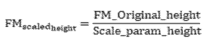
![]()
![]()
![]()
![]()

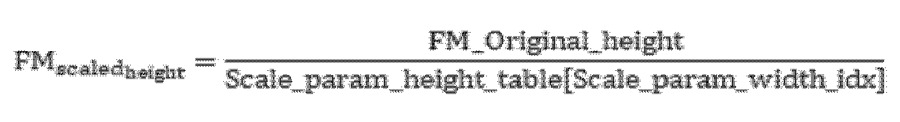
파라미터의 도출 방법 2 : 복수 개의 피쳐맵에 공통적으로 적용되는 한 개의 스케일링 값이 특정 고정된 값, 또는 사용자가 지정한 값, 또는 시퀀스/프레임그룹/프레임 단위로 특정 알고리즘을 통해서 도출된 값으로 전송될 수 있다. 스케일링 파라미터를 이용하여 스케일링된 공간해상도 너비와 높이를 도출하는 과정은 방법 1과 동일할 수 있다.
도 10은 본 개시의 일 실시 예에 따른 공간적 관심 영역의 예시들이다.FIG. 10 is an example of a spatial region of interest according to an embodiment of the present disclosure.
본 개시의 일 실시 예에 따른 VCM 인코딩 장치(100a)의 관심영역 도출부(820)는 피쳐맵에서 한 개 이상의 공간적 관심 영역을 도출할 수 있다.The region of interest derivation unit (820) of the VCM encoding device (100a) according to one embodiment of the present disclosure can derive one or more spatial regions of interest from a feature map.
상기 관심 영역은 단위 영역(NxM)의 연속적인 집합으로 구성된 임의 모양의 영역일 수 있다. 관심 영역은 관심 영역 맵 또는 다각형의 위치 및 크기 정보로 정의될 수 있다.The region of interest may be an arbitrary-shaped region composed of a continuous set of unit regions (NxM). The region of interest may be defined by location and size information of a region of interest map or polygon.
관심 영역이 관심 영역 맵으로 정의되는 경우, 관심 영역 맵은 피쳐맵의 공간해상도 크기의 2차원 맵일 수 있고 도 10의 (a)와 같을 수 있다. 관심 영역 맵에서 관심 영역에 포함되는 픽셀의 값과 비 관심 영역에 포함되는 픽셀값을 서로 다른 값일 수 있다. 예를 들어, 관심 영역 맵에서 관심 영역에 포함되는 픽셀 값은 1로 설정하고, 관심 영역에 포함되지 않는 픽셀 값은 0으로 설정할 수 있다.When the region of interest is defined as a region of interest map, the region of interest map can be a two-dimensional map of the spatial resolution size of the feature map and can be as shown in (a) of Fig. 10. In the region of interest map, the values of pixels included in the region of interest and the values of pixels included in the non-region of interest can be different values. For example, in the region of interest map, the values of pixels included in the region of interest can be set to 1, and the values of pixels not included in the region of interest can be set to 0.
관심 영역이 다각형의 위치 및 크기 정보로 정의될 수 있고 도 10의 (b)와 같을 수 있다. 다각형이 예를 들어 직사각형일 경우, 관심 영역은 직사각형의 좌상단 좌표, 너비, 높이로 정의될 수 있다.The region of interest can be defined by the location and size information of the polygon and can be as in (b) of Fig. 10. If the polygon is, for example, a rectangle, the region of interest can be defined by the upper left coordinate, width, and height of the rectangle.
VCM 인코딩 장치(100a)는 관심 영역에 관한 정보 신택스를 VCM 디코딩 장치(100b)에 전송할 수 있다. 관심 영역 정보 신택스는 picture_parameter_set 에 포함되어 VCM 디코딩 장치(100b)에 전송될 수 있다. picture_parameter_set 신택스는 도 24와 같이 정의될 수 있다. 상기 관심 영역 정보 신택스는 관심 영역의 단위 영역의 너비 (N), 높이 (M)를 포함할 수 있다. 관심 영역이 관심 영역 맵으로 정의되는 경우, 관심 영역 맵을 각각 단위 영역의 너비와 높이로 다운샘플링 하여 전송될 수 있다. 관심 영역이 직사각형으로 정의되는 경우, 직사각형의 좌상단 좌표, 직사각형의 너비 및 높이 값이 각각 단위 영역의 너비 및 높이로 다운스케일링된 값, 스케일 파라미터가 전송될 수 있다.The VCM encoding device (100a) can transmit information syntax about a region of interest to the VCM decoding device (100b). The region of interest information syntax can be included in picture_parameter_set and transmitted to the VCM decoding device (100b). The picture_parameter_set syntax can be defined as shown in FIG. 24. The region of interest information syntax can include a width (N) and a height (M) of a unit region of the region of interest. If the region of interest is defined as a region of interest map, the region of interest map can be transmitted by downsampling it to the width and height of the unit region, respectively. If the region of interest is defined as a rectangle, the upper left coordinate of the rectangle, the width and height values of the rectangle, and the scale parameter can be transmitted as values that are downscaled to the width and height of the unit region, respectively.
관심 영역은 뉴럴 네트워크 기반의 또는 비 뉴럴 네트워크 기반의 방법으로 한 개 이상 도출될 수 있다. 또는 시퀀스 또는 프레임 단위로 사용자가 관심 영역을 지정할 수 있다.Regions of interest can be derived one or more times using neural network-based or non-neural network-based methods, or the user can specify regions of interest on a sequence or frame-by-frame basis.
도 11은 본 개시의 일 실시 예에 따른 관심 영역 추출 과정을 나타내는 순서도이다. 도 12는 관심 영역 추출부의 입력 값(a) 및 관심 영역 추출부의 출력 값(b)의 예시를 나타낸다.Fig. 11 is a flowchart showing a process of extracting a region of interest according to an embodiment of the present disclosure. Fig. 12 shows examples of input values (a) of a region of interest extraction unit and output values (b) of a region of interest extraction unit.
본 개시의 일 실시 예에 따른 VCM 인코딩 장치(100a)의 관심 영역 추출부(830)는 관심 영역 도출부(820)에서 도출된 관심 영역에 따라 피쳐맵에서 일부 영역을 추출할 수 있고 도 11의 순서로 수행될 수 있다. 도 11의 각 단계는 선택적으로 수행될 수 있다.The region of interest extraction unit (830) of the VCM encoding device (100a) according to one embodiment of the present disclosure can extract a portion of a region from a feature map according to a region of interest derived from the region of interest derivation unit (820) and can be performed in the order of FIG. 11. Each step of FIG. 11 can be selectively performed.
S1101 단계에서, 관심 영역 추출부(830)는 부호화 대상 피쳐맵을 입력받아, 추출 대상 피쳐맵을 선택할 수 있다. 관심 영역 추출부(830)는 피쳐맵이 복수 개일때 관심 영역 추출을 수행할 피쳐맵을 하나 이상 선택할 수 있다. 관심 영역 추출 대상으로 선택된 각 피쳐맵에 대하여 다음 S1102, 및 S1103 단계를 수행할 수 있다. 관심영역을 추출한 피쳐맵의 개수 및 각 인덱스는 picture_parameter_set에 포함되어 VCM 디코딩 장치(100b)에 전송될 수 있다.In step S1101, the region of interest extraction unit (830) can receive a feature map to be encoded and select a feature map to be extracted. When there are multiple feature maps, the region of interest extraction unit (830) can select one or more feature maps for performing region of interest extraction. The following steps S1102 and S1103 can be performed for each feature map selected as a region of interest extraction target. The number of feature maps from which regions of interest are extracted and each index can be included in picture_parameter_set and transmitted to the VCM decoding device (100b).
S1102 단계에서, 관심 영역 추출부(830)는 관심 영역의 공간해상도 스케일을 관심 영역을 추출하고자 하는 피쳐맵의 공간해상도 스케일과 동일하게 스케일링 할 수 있다. 예를 들어 관심 영역의 스케일이 부호화 대상 피쳐맵들 중 가장 작은 공간해상도를 갖는 피쳐맵의 스케일이고, 현재 추출 대상 피쳐맵이 가장 작은 피쳐맵보다 너비 및 높이가 각각 a, b 배 만큼 공간해상도가 클 때, 관심 영역의 너비와 높이에 각각 a, b를 곱하여 스케일링할 수 있다. 스케일링은 정해진 수식을 계산하여 수행될 수 있고, 또는 뉴럴 네트워크 기반의 다운샘플링 또는 업샘플링이 수행될 수 있다.In step S1102, the region of interest extraction unit (830) can scale the spatial resolution scale of the region of interest to be the same as the spatial resolution scale of the feature map from which the region of interest is to be extracted. For example, when the scale of the region of interest is the scale of the feature map having the smallest spatial resolution among the feature maps to be encoded, and the width and height of the current feature map to be extracted are a and b times larger in spatial resolution than the smallest feature map, the width and height of the region of interest can be scaled by multiplying a and b, respectively. The scaling can be performed by calculating a predetermined formula, or downsampling or upsampling based on a neural network can be performed.
S1103 단계에서, 관심 영역 추출부(830)는 피쳐맵 내 원소들 중에서 공간축 좌표가 관심 영역에 포함되는 원소들의 집합을 추출할 수 있다. 도 12의 (a)는 관심 영역 추출부(830)의 입력을 나타내고, 도 12의 (b)는 관심 영역 추출부(830)의 출력을 나타낼 수 있다. 예를 들어, 4개의 피쳐맵 (피쳐맵 0~3)이 입력되었을 때 피쳐맵 1~3은 관심 영역을 추출하지 않고, 피쳐맵 0은 두 개의 관심영역을 추출한 예시를 나타낼 수 있다.In step S1103, the region of interest extraction unit (830) can extract a set of elements whose spatial axis coordinates are included in the region of interest among the elements in the feature map. Fig. 12 (a) may represent an input of the region of interest extraction unit (830), and Fig. 12 (b) may represent an output of the region of interest extraction unit (830). For example, when four feature maps (feature maps 0 to 3) are input,
다시 도 8을 참조하면, 코딩그룹 도출부(840)는 부호화 대상인 한 개 이상의 피쳐맵들을 한 개 이상의 코딩 그룹으로 그룹핑할 수 있다. 코딩 그룹은 도 8의 피쳐맵 변환부(850) 또는 피쳐맵 부호화부(860)의 수행 단위, 또는 전송 단위가 될 수 있다.Referring again to FIG. 8, the coding group derivation unit (840) can group one or more feature maps to be encoded into one or more coding groups. The coding group can be an execution unit of the feature map conversion unit (850) or feature map encoding unit (860) of FIG. 8, or a transmission unit.
코딩그룹 도출부(840)는 다음 기준에 따라 피쳐맵을 코딩 그룹으로 그룹핑할 수 있다.The coding group derivation unit (840) can group feature maps into coding groups according to the following criteria.
기준 1 : 부호화 대상인 모든 피쳐맵을 한 개의 코딩 그룹으로 그룹핑할 수 있다.Criterion 1: All feature maps to be encoded can be grouped into one coding group.
기준 2 : 관심 영역이 추출되지 않은 전체 해상도의 피쳐맵과 관심 영역만 추출한 피쳐맵은 서로 다른 코딩 그룹으로 그룹핑될 수 있다.Criterion 2: Full-resolution feature maps from which the region of interest is not extracted and feature maps from which only the region of interest is extracted can be grouped into different coding groups.
기준 3 : 관심 영역이 추출되지 않은 전체 해상도의 피쳐맵은 한 개의 코딩 그룹으로 그룹핑될 수 있다.Criterion 3: Full-resolution feature maps from which regions of interest are not extracted can be grouped into one coding group.
기준 4 : 동일한 관심 영역 인덱스를 갖는 관심 영역은 한 개의 코딩 그룹으로 그룹핑될 수 있다.Criterion 4: Regions of interest with the same region of interest index can be grouped into one coding group.
도 13은 본 개시의 일 실시 예에 따른 코딩 그룹 도출부(840)의 입력 값(a)과 출력 값(b1, b2)의 예시이다. 예를 들어, 코딩 그룹 도출부(840)의 입력 값(a)은 부호화 대상 피쳐맵이다. 코딩 그룹 도출부(840)의 출력 값(b1)은 상기 그룹핑 기준 1에 따라 그룹핑된 결과를 예시한다. 코딩 그룹 도출부(840)의 출력 값(b2)은 상기 그룹핑 기준 2, 3, 4에 따라서 그룹핑된 결과를 예시한다.FIG. 13 is an example of an input value (a) and output values (b1, b2) of a coding group derivation unit (840) according to an embodiment of the present disclosure. For example, the input value (a) of the coding group derivation unit (840) is a feature map to be encoded. The output value (b1) of the coding group derivation unit (840) exemplifies a result grouped according to the
코딩 그룹 정보는 각 코딩 그룹의 헤더인(coding_group_header)에 포함되어 VCM 디코딩 장치(100b)에 전송될 수 있다. coding_group_header 신택스는 도 25a와 같이 정의될 수 있다. 코딩 그룹 정보는 코딩 그룹 인덱스, 코딩 그룹 내 포함된 피쳐 맵의 개수, 각 피쳐 맵의 인덱스, 피쳐 맵이 ROI 추출된 경우라면 ROI 인덱스를 포함할 수 있다.Coding group information may be included in the header (coding_group_header) of each coding group and transmitted to the VCM decoding device (100b). The coding_group_header syntax may be defined as in Fig. 25a. Coding group information may include a coding group index, the number of feature maps included in the coding group, an index of each feature map, and an ROI index if the feature map is ROI extracted.
다시 도 8을 참조하면, 피쳐맵 변환부(850)는 코딩 그룹 단위로 코딩 그룹 내 피쳐맵에 대하여 변환을 수행할 수 있다. 변환의 종류는 예를 들면 매트릭스 곱셈 기반의 변환, 다중 합성곱 레이어 수행 기반의 변환 등일 수 있다. 도 15는 본 개시의 일 실시 예에 따른 매트릭스 곱셈 기반 피쳐맵 변환 예시이고, 도 16은 본 개시의 일 실시 예에 따른 다중 합성곱 레이어 기반 피쳐맵 변환 예시를 나타낸다. 변환의 참조 속성 또는 종류는 coding_group_header에 포함되어 VCM 디코딩 장치(100b)에 전송될 수 있다. 변환의 참조 속성은 임의의 피쳐맵에 변환을 수행할 때 해당 피쳐맵 내부의 정보만을 이용하는지 또는 다른 피쳐맵의 정보도 이용하는지를 의미할 수 있다. 변환의 종류는 변환을 수행하는 알고리즘 종류를 의미할 수 있다.Referring back to FIG. 8, the feature map transformation unit (850) can perform transformation on feature maps within a coding group in units of coding groups. The type of transformation may be, for example, matrix multiplication-based transformation, multi-convolution layer-based transformation, etc. FIG. 15 illustrates an example of matrix multiplication-based feature map transformation according to an embodiment of the present disclosure, and FIG. 16 illustrates an example of multi-convolution layer-based feature map transformation according to an embodiment of the present disclosure. The reference attribute or type of transformation may be included in the coding_group_header and transmitted to the VCM decoding device (100b). The reference attribute of the transformation may mean whether only information within the feature map is used when performing transformation on an arbitrary feature map or whether information of another feature map is also used. The type of transformation may mean the type of algorithm that performs the transformation.
도 14는 본 개시의 일 실시 예에 따른 매트릭스 곱셈 기반 피쳐맵 변환 과정을 포함하는 순서도이다. 피쳐맵 변환부(850)는 변환의 종류가 매트릭스 곱셈 기반 변환일 경우 도 14의 과정이 수행될 수 있고 도 14의 각 단계는 선택적으로 수행될 수 있다. 도 15는 본 개시의 일 실시 예에 따른 매트릭스 곱셈 기반 피쳐맵 변환 예시로써, (a)는 입력 피쳐맵, (b)는 스케일 변환된 피쳐맵, (c)는 변환 유닛의 각 예시를 나타낸다. FIG. 14 is a flowchart including a matrix multiplication-based feature map transformation process according to an embodiment of the present disclosure. When the type of transformation is matrix multiplication-based transformation, the process of FIG. 14 can be performed by the feature map transformation unit (850), and each step of FIG. 14 can be selectively performed. FIG. 15 is an example of a matrix multiplication-based feature map transformation according to an embodiment of the present disclosure, in which (a) represents an input feature map, (b) represents a scale-transformed feature map, and (c) represents each example of a transformation unit.
S1401 단계에서, 피쳐맵 변환부(850)는 코딩 그룹 내 각 피쳐맵에 대하여 공간해상도 스케일링을 수행할 수 있다. 피쳐맵 변환부(850)는 각 피쳐맵마다 공간해상도 스케일링 정도를 지정할 수 있고, 스케일링 파라미터는 coding_group_header에 포함되어 VCM 디코딩 장치(100b)에 전송될 수 있다. 또는 피쳐맵 변환부(850)는 변환 그룹 내 가장 작은 공간해상도를 갖는 피쳐맵의 공간해상도로 각 피쳐맵을 다운스케일링하는 방법을 고정적으로 사용할 수 있다. 도 15의 (a)는 피쳐맵 변환부(850)의 입력 값으로써, 복수 개의 피쳐맵(피쳐맵 1~3)을 포함하는 코딩 그룹을 나타낸다. 도 15의 (b)는 공간해상도가 가장 작은 피쳐맵 3의 공간해상도로 각 피쳐맵(피쳐맵1, 피쳐맵2)에 다운샘플링을 수행한 예시를 나타낼 수 있다.In step S1401, the feature map conversion unit (850) can perform spatial resolution scaling on each feature map in the coding group. The feature map conversion unit (850) can specify a degree of spatial resolution scaling for each feature map, and the scaling parameter can be included in the coding_group_header and transmitted to the VCM decoding device (100b). Alternatively, the feature map conversion unit (850) can fixedly use a method of downscaling each feature map to the spatial resolution of the feature map with the smallest spatial resolution in the conversion group. FIG. 15 (a) shows a coding group including a plurality of feature maps (feature maps 1 to 3) as an input value of the feature map conversion unit (850). FIG. 15 (b) can show an example of performing downsampling on each feature map (
S1402 단계에서, 피쳐맵 변환부(850)는 각 피쳐맵을 변환 유닛(변환 단위)으로 분할하여 나열할 수 있다. 변환 유닛은 피쳐맵을 오버랩하지 않는 w_tu x h_tu x c_tu의 크기로 분할한 데이터일 수 있다. w_tu, h_tu, c_tu 각각은 스케일링된 피쳐맵들 중 최소 너비, 최소 높이, 최소 채널 길이 각각의 약수의 값을 가질 수 있다. 도 15의 (c)는 스케일링된 피쳐맵들이 동일한 너비, 높이, 채널 길이를 갖는 경우에, 각각 피쳐맵 너비/2, 피쳐맵 높이/2, 1의 크기를 갖는 변환 유닛으로 분할한 예시이다. 변환 유닛의 w_tu, h_tu, c_tu는 각각 피쳐맵의 너비/2, 피쳐맵 높이/2, 1인 경우를 나타낼 수 있다. 이 경우, 각 피쳐맵의 너비와 높이를 1/2로 줄였으므로, 피쳐맵 당 채널길이 * 4개의 변환 유닛이 도출될 수 있다.In step S1402, the feature map transformation unit (850) can divide each feature map into transformation units (transformation units) and list them. The transformation unit can be data divided into a size of w_tu x h_tu x c_tu that does not overlap the feature map. Each of w_tu, h_tu, and c_tu can have a value of a divisor of a minimum width, a minimum height, and a minimum channel length among the scaled feature maps, respectively. FIG. 15 (c) is an example in which, when the scaled feature maps have the same width, height, and channel length, they are divided into transformation units having sizes of feature map width/2, feature map height/2, and 1, respectively. The w_tu, h_tu, and c_tu of the transformation unit can represent a case in which they are feature map width/2, feature map height/2, and 1, respectively. In this case, since the width and height of each feature map are reduced by 1/2, channel length * 4 transformation units per feature map can be derived.
S1403 단계에서, 피쳐맵 변환부(850)는 도출된 각 변환 유닛에 대하여 매트릭스 곱셈 기반 변환을 수행할 수 있다. 각 변환 유닛에 대하여 matrix_num 개의 매트릭스와 곱셈연산을 수행하여 matrix_num개의 변환 계수를 도출할 수 있다.In step S1403, the feature map transformation unit (850) can perform matrix multiplication-based transformation for each derived transformation unit. For each transformation unit, a multiplication operation can be performed with matrix_num matrices to derive matrix_num transformation coefficients.
도 16은 본 개시의 일 실시 예에 따른 다중 합성곱 레이어 기반 피쳐맵 변환 예시를 나타낸다. 변환의 종류가 다중 합성곱 레이어 기반 변환일 경우, 피쳐맵 변환부(850)는 코딩 그룹 내 한 개 이상의 피쳐맵의 공간해상도를 동일하게 조정하고 채널축으로 결합한 뒤 채널축으로 함축하는 다중 합성곱 레이어를 수행할 수 있다. 도 16을 참조하면, 피쳐맵 변환부(850)는 피쳐맵 1 내지 3을 포함하는 코딩 그룹을 입력받아, 공간해상도가 제일 작은 피쳐맵3을 기준으로 공간해상도를 동일하게 조정할 수 있다. 피쳐맵 변환부(850)는 피쳐맵 1 및 2의 공간 해상도를 피쳐맵 3의 공간해상도와 동일하도록 다운스케일링할 수 있다. 피쳐맵 변환부(850)는 공간해상도가 동일해진 피쳐맵 1 내지 3을 채널축으로 결합한 뒤, 채널축으로 함축하는 다중 합성곱 레이어를 수행하여, 피쳐맵 1 내지 3이 결합되어 변환된 피쳐맵을 출력할 수 있다.FIG. 16 shows an example of feature map transformation based on multiple convolution layers according to an embodiment of the present disclosure. When the type of transformation is multiple convolution layer-based transformation, the feature map transformation unit (850) can perform multiple convolution layers that adjust the spatial resolution of one or more feature maps in a coding group to be the same, combine them into a channel axis, and then encapsulate them into a channel axis. Referring to FIG. 16, the feature map transformation unit (850) can receive a coding group including
다시 도 8을 참조하면, VCM 인코딩 장치(100a)의 피쳐맵 부호화부(860)는 그룹 단위로 피쳐맵 변환부(850)에서 출력된 변환된 피쳐맵 또는 변환이 수행되지 않은 피쳐맵(관심영역 도출부(820)에서 출력된 피쳐맵)을 부호화하여 비트스트림을 출력할 수 있다.Referring again to FIG. 8, the feature map encoding unit (860) of the VCM encoding device (100a) can encode a transformed feature map output from the feature map conversion unit (850) or a feature map on which transformation has not been performed (a feature map output from the region of interest derivation unit (820)) in groups to output a bitstream.
피쳐맵 부호화부(860)는 다양한 부호화 방법 중 피쳐맵 부호화에 사용할 부호화 방법을 결정하고, 결정된 부호화 방법을 의미하는 신택스가 coding_group_header 에 포함되어 VCM 디코딩 장치(100b)에 전송될 수 있다.The feature map encoding unit (860) determines an encoding method to be used for feature map encoding among various encoding methods, and a syntax indicating the determined encoding method can be included in the coding_group_header and transmitted to the VCM decoding device (100b).
피쳐맵 부호화부(860)에서 사용할 수 있는 부호화 방법은 부호화 참조 속성에 의존적일 수 있다. 부호화 참조 속성은 임의의 피쳐맵에 부호화를 수행할 때 해당 피쳐맵 내부의 정보만을 이용하는지 또는 다른 피쳐맵의 정보도 이용하는지를 의미할 수 있다. 부호화 참조 속성 신택스는 coding_group_header에 포함되어 VCM 디코딩 장치(100b)에 전송될 수 있고, 또는 전송되지 않고 변환 참조 속성과 동일한 값이 사용될 수 있다. 피쳐맵 부호화부(860)는 부호화 참조 속성 정보가 존재하는 경우, 현재 프레임의 부호화 참조 속성에서 수행할 수 있는 부호화 알고리즘들 중 사용할 부호화 알고리즘의 인덱스를 전송할 수 있다. 예를 들어 부호화 참조 속성이 인트라일 경우, 부호화 방법은 엔트로피코딩 기반의 방법을 수 있다. 예를 들어 부호화 참조 속성이 인터일 경우 부호화 방법은 비디오 기반의 비-딥러닝 방법, 비디오 기반의 딥러닝 방법, 등일 수 있다. 부호화 참조 속성 정보가 전송되지 않을 경우에는 변환 참조 속성 정보의 값과 동일한 값이 사용될 수 있다.The encoding method that can be used in the feature map encoding unit (860) may depend on the encoding reference attribute. The encoding reference attribute may mean whether only information inside the feature map is used when encoding an arbitrary feature map or whether information of another feature map is also used. The encoding reference attribute syntax may be included in the coding_group_header and transmitted to the VCM decoding device (100b), or may not be transmitted and the same value as the transformation reference attribute may be used. When the encoding reference attribute information exists, the feature map encoding unit (860) may transmit an index of an encoding algorithm to be used among encoding algorithms that can be performed on the encoding reference attribute of the current frame. For example, when the encoding reference attribute is intra, the encoding method may be an entropy coding-based method. For example, when the encoding reference attribute is inter, the encoding method may be a video-based non-deep learning method, a video-based deep learning method, etc. If the encoded reference attribute information is not transmitted, the same value as the converted reference attribute information may be used.
1)부호화 방법이 비디오 기반의 비-딥러닝 방법일 경우, 부호화 과정은 예측, 변환, 양자화, 엔트로피 코딩 등의 단계로 구성될 수 있고 각 단계는 생략될 수 있다. 예를 들어 예측, 변환, 양자화 단계가 생략되고 엔트로피 코딩 단계만 수행될 수 있다. 피쳐맵 부호화부(860)는 피쳐맵 부호화를 수행하기 이전에, 코딩 그룹 내 피쳐맵 또는 변환된 피쳐맵을 1차원 배열 또는 2차원 프레임 또는 3차원 매트릭스의 형태로 재구성한 뒤 부호화를 수행할 수 있다. 피쳐맵 또는 변환된 피쳐맵이 2차원 프레임으로 재구성되고 예측, 변환, 양자화, 엔트로피 코딩 단계로 구성된 비디오 기반의 압축을 수행하는 경우에, 피쳐맵 부호화부(860)는 관심 영역 도출부(820)로부터 입력받은 관심 영역을 기반으로 프레임 내에서 지역적인 양자화 파라미터를 지정할 수 있다. 피쳐맵 부호화부(860)는 관심 영역과 비 관심 영역의 양자화 파라미터를 다르게 지정할 수 있다. 예를 들면 피쳐맵 부호화부(860)는 관심 영역은 양자화 파라미터를 낮게 지정하고 비 관심 영역은 양자화 파라미터를 높게 지정할 수 있다.1) When the encoding method is a video-based non-deep learning method, the encoding process may be composed of stages such as prediction, transformation, quantization, and entropy coding, and each stage may be omitted. For example, the prediction, transformation, and quantization stages may be omitted and only the entropy coding stage may be performed. The feature map encoding unit (860) may perform encoding after reconstructing the feature map or the transformed feature map within the coding group in the form of a one-dimensional array, a two-dimensional frame, or a three-dimensional matrix before performing feature map encoding. When the feature map or the transformed feature map is reconstructed into a two-dimensional frame and video-based compression consisting of prediction, transformation, quantization, and entropy coding stages is performed, the feature map encoding unit (860) may designate local quantization parameters within the frame based on the region of interest received from the region of interest derivation unit (820). The feature map encoding unit (860) may designate different quantization parameters for the region of interest and the non-region of interest. For example, the feature map encoding unit (860) can designate a low quantization parameter for a region of interest and a high quantization parameter for a region of no interest.
2)부호화 방법이 비디오 기반의 딥러닝 방법일 경우, 피쳐맵 부호화부(860)는 다중 합성곱 레이어로 구성된 뉴럴 네트워크 구조를 사용하여 부호화를 수행할 수 있다.2) When the encoding method is a video-based deep learning method, the feature map encoding unit (860) can perform encoding using a neural network structure composed of multiple convolution layers.
도 17은 본 개시의 일 실시 예에 따른 VCM 디코딩 장치의 구성요소를 포함하는 블록도이다.FIG. 17 is a block diagram including components of a VCM decoding device according to one embodiment of the present disclosure.
본 개시의 일 실시 예에 따른 VCM 디코딩 장치(100b)는 피쳐맵이 압축된 비트스트림을 입력받아 피쳐맵을 복원하고, 머신 태스크 분석을 수행하여 분석 결과를 출력할 수 있다. VCM 디코딩 장치(100b)는 피쳐맵 복호화부(1710), 피쳐맵 역변환부(1720), 피쳐맵 재구성부(1730) 및 머신 태스크 분석부(1740)를 포함할 수 있다. 각 구성요소는 시퀀스 또는 프레임 레벨에서 선택적으로 수행될 수 있다.A VCM decoding device (100b) according to an embodiment of the present disclosure can receive a bitstream in which a feature map is compressed, restore the feature map, perform machine task analysis, and output the analysis result. The VCM decoding device (100b) can include a feature map decoding unit (1710), a feature map inverse transformation unit (1720), a feature map reconstruction unit (1730), and a machine task analysis unit (1740). Each component can be selectively performed at a sequence or frame level.
피쳐맵 복호화부(1710)는 전송받은 비트스트림으로부터 코딩 그룹 단위로 피쳐맵 또는 피쳐맵 변환 계수를 복원할 수 있다. The feature map decoding unit (1710) can restore a feature map or feature map transform coefficients by coding group unit from the received bitstream.
피쳐맵 역변환부(1720)는 코딩 그룹 단위로 복원된 피쳐맵 변환 계수에 역변환을 수행할 수 있다.The feature map inverse transform unit (1720) can perform inverse transform on feature map transform coefficients restored in units of coding groups.
피쳐맵 재구성부(1730)는 복원된 피쳐맵을 기반으로 전송 및 복원되지 않은 피쳐맵 또는 피쳐맵의 일부 영역을 생성하여 VCM 인코딩 장치(100a)의 피쳐맵 추출 및 선택부(810)에서 최초 추출된 피쳐맵의 개수 및 크기를 복원할 수 있다.The feature map reconstruction unit (1730) can restore the number and size of feature maps initially extracted by the feature map extraction and selection unit (810) of the VCM encoding device (100a) by generating a feature map or a portion of a feature map that has not been transmitted or restored based on the restored feature map.
머신 태스크 분석부(1740)는 복원된 피쳐맵을 사용하여 객체 탐지, 영역 세그멘테이션, 객체 추적, 행동 인식, 상황 해석 등의 머신 태스크를 수행할 수 있다. 머신 태스크 분석부(1740)의 구조는 다중 컨볼루션 레이어로 구성될 수 있고 VCM 인코딩 장치(100a)의 피쳐맵 추출 및 선택부(810)에서 피쳐맵을 추출하는 다중 컨볼루션 레이어를 앞단에 포함할 수 있다. 머신 태스크 분석부(1740)는 픽쳐 레벨 파라미터 셋 (picture_parameter_set)에서 전송받는 피쳐맵 추출 레이어 위치(FM_extract_layer_idx)를 기반으로, 머신 태스크 분석부(1740)의 다중 컨볼루션 레이어들 중 어느 레이어에 복원된 피쳐맵을 입력하여 머신 분석을 수행할지 유도할 수 있다.The machine task analysis unit (1740) can perform machine tasks such as object detection, region segmentation, object tracking, action recognition, and situation interpretation using the restored feature map. The structure of the machine task analysis unit (1740) can be composed of multiple convolution layers and can include multiple convolution layers in front of the feature map extraction and selection unit (810) of the VCM encoding device (100a) that extracts the feature map. The machine task analysis unit (1740) can induce which layer among the multiple convolution layers of the machine task analysis unit (1740) will input the restored feature map to perform machine analysis based on the feature map extraction layer position (FM_extract_layer_idx) received from the picture level parameter set (picture_parameter_set).
피쳐맵 복호화부(1710)는 전송받은 비트스트림으로부터 코딩 그룹 단위로 피쳐맵 또는 피쳐맵 변환 계수를 복원할 수 있다. 복호화 참조 속성이 존재할 경우 코딩 그룹 헤더(coding_group_header)에서 전송받은 값을 파싱 (is_intra_coded) 하거나 또는 변환 참조 속성 값과 같은 값으로 유도할 수 있다. is_intra_coded 신택스는 도 25b와 같이 정의될 수 있다. 파싱 또는 유도된 복호화 참조 속성 값에 따라서 수행 가능한 복호화 방법들 중 사용할 복호화 방법을 의미하는 인덱스 (intra_coding_method_idx, inter_coding_method_idx)를 코딩 그룹 헤더(coding_group_header)에서 파싱할 수 있다. 복호화 참조 속성이 존재하지 않을 경우 복호화 방법을 의미하는 인덱스 (coding_method_idx)는 독립적으로 파싱될 수 있다.The feature map decoding unit (1710) can restore a feature map or a feature map transformation coefficient from the transmitted bitstream in units of coding groups. If a decoding reference attribute exists, the value transmitted in the coding group header (coding_group_header) can be parsed (is_intra_coded) or derived to a value equal to the transformation reference attribute value. The is_intra_coded syntax can be defined as in FIG. 25b. Depending on the parsed or derived decoding reference attribute value, an index (intra_coding_method_idx, inter_coding_method_idx) indicating a decoding method to be used among the possible decoding methods can be parsed from the coding group header (coding_group_header). If the decoding reference attribute does not exist, the index (coding_method_idx) indicating the decoding method can be parsed independently.
피쳐맵 복호화부(1710)는 뉴럴 네트워크 기반이거나 비 뉴럴 네트워크 기반의 방법으로 수행될 수 있다. 비 뉴럴 네트워크 기반으로 수행될 경우 복호화 과정은 예측, 변환, 양자화, 엔트로피 코딩 등의 단계로 구성될 수 있고 각 단계는 생략될 수 있다.The feature map decoding unit (1710) may be performed using a neural network-based or non-neural network-based method. If performed using a non-neural network-based method, the decoding process may consist of steps such as prediction, transformation, quantization, and entropy coding, and each step may be omitted.
피쳐맵 복호화부(1710)에서 복원된 피쳐맵 또는 변환된 피쳐맵은 재구성된 형태일 수 있으며 피쳐맵의 본래 형태로 복원된 데이터를 역 재구성을 수행할 수 있다. 재구성된 형태는 예를 들어, 1차원 배열 또는 2차원 프레임 또는 3차원 매트릭스의 형태일 수 있다.The restored feature map or transformed feature map in the feature map decoding unit (1710) may be in a reconstructed form, and data restored to the original form of the feature map may be reversely reconstructed. The reconstructed form may be in the form of, for example, a one-dimensional array, a two-dimensional frame, or a three-dimensional matrix.
피쳐맵 역변환부(1720)는 코딩 그룹 단위로 코딩 그룹 내 피쳐맵 변환 계수에 대하여 역변환을 수행할 수 있다. 역변환의 종류는 예를들면 매트릭스 곱셈 기반의 역변환, 다중 합성곱 레이어 수행 기반의 역변환 등일 수 있다. 피쳐맵 역변환부(1720)는 코딩 그룹 헤더(coding_group_header)에 포함된 역변환 방법 인덱스(transform_method_idx)에 해당하는 역변환을 수행할 수 있다. 피쳐맵 역변환부(1720)는 코딩 그룹 헤더(coding_group_header)에서 변환 참조 속성(is_intra_transformed)을 먼저 파싱하고, 파싱된 참조 속성일 때 가능한 역변환 방법들 중 사용할 역변환 종류 인덱스(intra_transform_method_idx, inter_transform_method_idx)를 파싱할 수 있다. 피쳐맵 역변환부(1720)는 변환 참조 속성(is_intra_transformed)이 참일 경우, 역변환 종류 인덱스로서 intra_transform_method_idx 신택스를 파싱할 수 있고, 변환 참조 속성(is_intra_transformed)이 거짓일 경우, 역변환 종류 인덱스로서 inter_transform_method_idx 신택스를 파싱할 수 있다. intra_transform_method_idx 또는 inter_transform_method_idx의 값에 매핑된 사전에 정의된 역변환 방법으로 역변환이 수행될 수 있다. 피쳐맵 역변환부(1720)는 변환 참조 속성(is_intra_transformed) 신택스가 존재하지 않을 경우 역변환 종류 인덱스(transform_method_idx)만 파싱할 수 있다.The feature map inverse transformation unit (1720) can perform inverse transformation on feature map transformation coefficients within a coding group by coding group unit. The type of inverse transformation may be, for example, inverse transformation based on matrix multiplication, inverse transformation based on performing multiple convolution layers, etc. The feature map inverse transformation unit (1720) can perform inverse transformation corresponding to an inverse transformation method index (transform_method_idx) included in a coding group header (coding_group_header). The feature map inverse transformation unit (1720) can first parse a transformation reference attribute (is_intra_transformed) in the coding group header (coding_group_header), and when it is a parsed reference attribute, can parse an inverse transformation type index (intra_transform_method_idx, inter_transform_method_idx) to be used among possible inverse transformation methods. The feature map inverse transformation unit (1720) can parse the intra_transform_method_idx syntax as the inverse transformation type index when the transformation reference attribute (is_intra_transformed) is true, and can parse the inter_transform_method_idx syntax as the inverse transformation type index when the transformation reference attribute (is_intra_transformed) is false. The inverse transformation can be performed by a predefined inverse transformation method mapped to the value of intra_transform_method_idx or inter_transform_method_idx. The feature map inverse transformation unit (1720) can parse only the inverse transformation type index (transform_method_idx) when the transformation reference attribute (is_intra_transformed) syntax does not exist.
피쳐맵 역변환부(1720)의 역변환 종류가 매트릭스 곱셈 기반 방법일 경우 도 18의 과정으로 수행될 수 있다.If the inverse transformation type of the feature map inverse transformation unit (1720) is a matrix multiplication-based method, it can be performed by the process of Fig. 18.
도 18은 본 개시의 일 실시 예에 따른 매트릭스 곱셈 기반 피쳐맵의 역변환 과정을 포함하는 순서도이다. 도 19는 본 개시의 일 실시 예에 따른 매트릭스 곱셈 기반 피쳐맵의 역변환 예시를 나타낸다.FIG. 18 is a flowchart including a process of inverse transformation of a feature map based on matrix multiplication according to an embodiment of the present disclosure. FIG. 19 shows an example of inverse transformation of a feature map based on matrix multiplication according to an embodiment of the present disclosure.
S1801 단계에서, 피쳐맵 역변환부(1720)는 역변환 유닛마다의 피쳐맵 변환 계수에 역변환 매트릭스를 곱하여 역변환을 수행할 수 있다. 코딩 그룹 헤더(coding_group_header)에서 전송된 역변환 유닛의 너비, 높이(TU_width, TU_height)에 맞는 역변환 매트릭스를 선택하고 역변환을 수행하여 역변환 단위 크기의 피쳐 값이 도출될 수 있다. 도 19의 (a)는 임의의 코딩 그룹에 대하여 역변환 유닛 단위로 역변환이 수행된 결과 데이터를 나타낼 수 있다.In step S1801, the feature map inverse transform unit (1720) can perform inverse transformation by multiplying the feature map transform coefficients of each inverse transform unit by an inverse transform matrix. An inverse transform matrix that matches the width and height (TU_width, TU_height) of the inverse transform unit transmitted in the coding group header (coding_group_header) is selected, and inverse transformation is performed to derive feature values of the size of the inverse transform unit. Fig. 19 (a) can represent result data in which inverse transformation is performed for each inverse transform unit for an arbitrary coding group.
S1802 단계에서, 피쳐맵 역변환부(1720)는 역변환된 데이터를 본래의 피쳐맵 형태로 결합할 수 있다. 도 19의 (b)는 역변환된 데이터를 본래 피쳐맵에서의 역변환 유닛 위치로 재배치한 결과를 나타낼 수 있다.In step S1802, the feature map inverse transformation unit (1720) can combine the inversely transformed data into the original feature map form. Fig. 19 (b) can represent the result of rearranging the inversely transformed data to the inverse transformation unit position in the original feature map.
S1803 단계에서, 피쳐맵 역변환부(1720)는 역변환된 피쳐맵에 역스케일링을 수행할 수 있다. 각 피쳐맵의 역스케일링 파라미터(scale_param)는 코딩 그룹 헤더(coding_group_header)에 포함되어 전송되거나 고정된 방법으로 유도될 수 있다. 상기 고정된 방법은 예를 들면, 역변환된 피쳐맵의 크기와 pps에 포함된 피쳐맵의 본래 크기를 기반으로 역스케일링 파라미터를 계산할 수 있다. 역스케일링은 고정된 수식에 기반하여 수행될 수 있고 또는 뉴럴 네트워크 기반의 방법으로 수행될 수 있다. 도 19의 (c)는 역스케일링된 피쳐맵을 나타낼 수 있다. 도 19의 (a), (b), (c)는 각각 도 15의 (c), (b), (a)에 각각 대응된다.In step S1803, the feature map inverse transformation unit (1720) can perform inverse scaling on the inversely transformed feature map. The inverse scaling parameter (scale_param) of each feature map can be transmitted by being included in a coding group header (coding_group_header) or can be derived in a fixed manner. The fixed manner can calculate the inverse scaling parameter based on, for example, the size of the inversely transformed feature map and the original size of the feature map included in pps. The inverse scaling can be performed based on a fixed formula or can be performed by a neural network-based method. Fig. 19 (c) can represent a inversely scaled feature map. Fig. 19 (a), (b), and (c) respectively correspond to Fig. 15 (c), (b), and (a), respectively.
도 20은 본 개시의 일 실시 예에 따른 다중 합성곱 레이어 기반 피쳐맵의 역변환 예시를 나타낸다.FIG. 20 illustrates an example of inverse transformation of a feature map based on multiple convolutional layers according to an embodiment of the present disclosure.
피쳐맵 역변환부(1720)는 역변환의 종류가 다중 합성곱 레이어 기반 역변환일 경우, 변환된 데이터를 합성곱 레이어의 조합으로 구성된 뉴럴 네트워크에 입력하여 역변환된 피쳐맵을 출력할 수 있다. 상기 역변환을 수행하는 뉴럴 네트워크의 구조 및 입출력 데이터는 도 20과 같을 수 있다. 도 20의 각 단계는 도 16의 각 단계의 역순으로 대응된다.The feature map inverse transformation unit (1720) can input transformed data into a neural network composed of a combination of convolution layers and output an inversely transformed feature map when the type of inverse transformation is a multi-convolution layer-based inverse transformation. The structure and input/output data of the neural network performing the inverse transformation may be as shown in Fig. 20. Each step of Fig. 20 corresponds to the reverse order of each step of Fig. 16.
도 17을 다시 참조하면, 피쳐맵 재구성부(1730)는 피쳐맵 복호화부(1710) 또는 피쳐맵 역변환부(1720)에서 복원된 피쳐맵을 기반으로 전송 및 복원되지 않은 피쳐맵 또는 피쳐맵의 일부 영역을 예측하여 VCM 인코딩 장치(100a)의 피쳐맵 추출 및 선택부(810)에서 최초 추출된 피쳐맵의 개수 및 크기를 복원할 수 있다. 피쳐맵 추출 및 선택부(810)에서 최초 추출된 피쳐맵들 중 VCM 디코딩 장치(100b)에서 복원된 피쳐맵 및 피쳐맵 내 영역 정보는 시퀀스 또는 프레임 그룹 또는 프레임 레벨에서 전송받은 피쳐맵 개수, 인덱스, 너비, 높이, 채널 길이 등의 정보를 조합하여 유도할 수 있다. 피쳐맵 재구성부(1730)는 도 21의 각 단계에 따라 피쳐맵을 재구성할 수 있다.Referring back to FIG. 17, the feature map reconstruction unit (1730) can predict a feature map or a part of a feature map that has not been transmitted and restored based on a feature map restored by the feature map decoding unit (1710) or the feature map inverse transformation unit (1720), and restore the number and size of feature maps initially extracted by the feature map extraction and selection unit (810) of the VCM encoding device (100a). Among the feature maps initially extracted by the feature map extraction and selection unit (810), the feature map restored by the VCM decoding device (100b) and the region information within the feature map can be derived by combining information such as the number of feature maps, index, width, height, and channel length transmitted at the sequence or frame group or frame level. The feature map reconstruction unit (1730) can reconstruct a feature map according to each step of FIG. 21.
도 21은 본 개시의 일 실시 예에 따른 피쳐맵 재구성 과정을 나타내는 순서도이다. VCM 인코딩 장치(100a)는 부호화 대상 피쳐맵에 대하여 관심 영역을 추출할 수 있고, 관심 영역이 추출된 피쳐맵의 경우 관심 영역에 포함되지 않은 영역은 부호화되지 않기 때문에 VCM 디코딩 장치(100b)에서 복원된 부분을 기준으로 VCM 인코딩 장치(100a)로부터 전송받지 못한 부분(관심 영역에 포함되지 않은 영역)을 예측하여 관심 영역을 추출하기 전 피쳐맵을 복원할 수 있다. VCM 인코딩 장치(100a)에서 관심 영역을 추출하는 예시는 도 12a 및 12b와 같고, 도 21에 따라 피쳐맵을 재구성하는 경우, 도 12a가 복원되는 것을 도 22에서 나타낼 수 있다.FIG. 21 is a flowchart showing a feature map reconstruction process according to an embodiment of the present disclosure. A VCM encoding device (100a) can extract a region of interest for a feature map to be encoded, and since a region not included in the region of interest is not encoded in a feature map from which a region of interest has been extracted, a portion not transmitted from the VCM encoding device (100a) (a region not included in the region of interest) can be predicted based on a portion restored by a VCM decoding device (100b) to restore the feature map before extracting the region of interest. An example of extracting a region of interest in a VCM encoding device (100a) is as shown in FIGS. 12a and 12b, and when a feature map is reconstructed according to FIG. 21, FIG. 22 can show that FIG. 12a is restored.
S2101 단계에서, 피쳐맵 재구성부(1730)는 임의의 피쳐맵에서 관심 영역이 복원된 경우 관심 영역을 피쳐맵에서의 본래 위치에 배치하고, 복원되지 않은 비 관심 영역의 피쳐 값을 예측하여, 관심 영역과 예측된 비 관심 영역을 결합할 수 있다. 도 22는 본 개시의 일 실시 예에 따른 관심 영역과 비 관심 영역을 결합하는 예시이다. 도 22를 참조하면, 피쳐맵 재구성부(1730)는 복원된 피쳐맵 1 내지 3을 기반으로, 피쳐맵 0의 복원되지 않은 비 관심 영역의 피쳐 값을 예측하고, 예측된 비 관심 영역과 복원된 관심 영역을 결합하여 복원된 피쳐맵 0을 생성할 수 있다. In step S2101, the feature map reconstruction unit (1730) can place the region of interest at its original location in the feature map if the region of interest is restored in any feature map, and predict feature values of non-interest regions that have not been restored, and combine the region of interest with the predicted non-interest regions. FIG. 22 is an example of combining a region of interest and a non-interest region according to an embodiment of the present disclosure. Referring to FIG. 22, the feature map reconstruction unit (1730) can predict feature values of non-interest regions that have not been restored in
피쳐맵 재구성부(1730)는 전체 공간해상도가 복원된 한 개 이상의 피쳐맵을 이용하여 관심 영역만 복원된 피쳐맵의 비 관심 영역의 공간해상도를 예측할 수 있다. 비 관심 영역 예측 방법으로 뉴럴 네트워크 기반의 방법이 수행될 수 있다. 피쳐맵의 본래 해상도 전체를 예측할 수 있고 또는 전체 해상도에서 관심 영역에 포함되는 피쳐는 제외하고 예측을 수행할 수 있다. 또는 복원된 관심영역의 바운더리 피쳐 값(경계값)에 기반하여 비 관심 영역의 피쳐 값을 예측할 수 있다. 또는 특정 정해진 값으로 비 관심 영역의 피쳐값을 지정할 수 있다.The feature map reconstruction unit (1730) can predict the spatial resolution of a non-interest region of a feature map in which only the region of interest is restored using one or more feature maps in which the entire spatial resolution is restored. A neural network-based method can be performed as a non-interest region prediction method. The entire original resolution of the feature map can be predicted, or prediction can be performed by excluding features included in the region of interest from the entire resolution. Alternatively, the feature values of the non-interest region can be predicted based on the boundary feature values (boundary values) of the restored region of interest. Alternatively, the feature values of the non-interest region can be designated as specific determined values.
피쳐맵 재구성부(1730)는 복원된 관심 영역과 예측된 비 관심 영역을 결합하여 전체 해상도의 피쳐맵을 복원할 수 있다. 도 22의 비 관심 영역 예측 단계에서 관심 영역 내 피쳐 값도 예측된 경우, 해당 예측 값을 복원된 관심 영역 값으로 대체할 수 있다.The feature map reconstruction unit (1730) can restore a feature map of full resolution by combining the restored region of interest and the predicted non-region of interest. If the feature value within the region of interest is also predicted in the non-region of interest prediction step of Fig. 22, the predicted value can be replaced with the restored region of interest value.
S2102 단계에서, 피쳐맵 재구성부(1730)는 복원된 피쳐맵의 공간해상도를 역스케일링 할 수 있다. 현재 프레임의 복원된 피쳐맵의 공간해상도 역스케일링을 수행할지 여부는 시퀀스 또는 프레임 그룹 또는 프레임 단위로 전송받은 공간해상도 역스케일링 수행 여부를 의미하는 신택스에 기반하여 도출될 수 있다. 시퀀스->프레임 그룹->프레임 순서로 전송 레벨 내림차순일 수 있고, 임의의 전송 레벨에서 전송된 공간해상도 역스케일링 수행 여부가 역스케일링을 수행하지 않음을 의미할 경우, 모든 하위 레벨의 공간해상도 역스케일링 수행 여부 신택스를 파싱하지 않을 수 있고 현재 프레임의 피쳐맵에 공간해상도 역스케일링을 수행하지 않을 수 있다.In step S2102, the feature map reconstruction unit (1730) can descale the spatial resolution of the restored feature map. Whether to perform spatial resolution descale of the restored feature map of the current frame can be derived based on a syntax indicating whether to perform spatial resolution descale, which is transmitted in a sequence or a frame group or a frame unit. The transmission level can be in descending order of sequence->frame group->frame, and if the performance of spatial resolution descale transmitted at any transmission level means not to perform descale, the syntax indicating whether to perform spatial resolution descale of all lower levels can be omitted and spatial resolution descale may not be performed on the feature map of the current frame.
피쳐맵 재구성부(1730)는 현재 프레임에 공간해상도 역스케일링을 수행하는 경우, 피쳐맵 마다 스케일 파라미터를 파싱하거나 피쳐맵 공통의 스케일 파라미터를 파싱할 수 있다. 스케일 파라미터는 파라미터 원본 값, log2연산된 값, 인덱스 값 등의 형태로 전송될 수 있다. 스케일 파라미터가 원본 값일 경우 원본 해상도와 스케일링된 해상도의 관계는 수학식 7, 8과 같을 수 있고, 스케일 파라미터가 log2연산된 값일 경우 원본 해상도와 스케일링된 해상도의 관계는 수학식 9,10과 같을 수 있고, 스케일 파라미터가 스케일 테이블의 인덱스 값 형태일 경우 원본 해상도와 스케일링된 해상도의 관계는 수학식 11, 12와 같을 수 있다.When the feature map reconstruction unit (1730) performs spatial resolution inverse scaling on the current frame, it can parse the scale parameter for each feature map or parse the scale parameter common to the feature maps. The scale parameter can be transmitted in the form of a parameter original value, a log2-operated value, an index value, etc. When the scale parameter is an original value, the relationship between the original resolution and the scaled resolution can be as in
![]()
![]()

![]()
![]()

![]()
![]()
![]()
![]()
피쳐맵 재구성부(1730)는 복원된 피쳐맵이 원본 공간해상도를 갖도록 딥러닝 기반의 또는 비-딥러닝 기반의 공간해상도 변환 알고리즘을 사용하여 역스케일링을 수행할 수 있다.The feature map reconstruction unit (1730) can perform reverse scaling using a deep learning-based or non-deep learning-based spatial resolution conversion algorithm so that the restored feature map has the original spatial resolution.
S2103 단계에서, 피쳐맵 재구성부(1730)는 피쳐맵을 생성하기 위해 VCM 인코딩 장치(100a)의 피쳐맵 추출 및 선택부(810)에서 선택되지 않아서 부호화 및 복호화가 수행되지 않은 피쳐맵을 복호화된 피쳐맵을 이용하여 예측할 수 있다. 피쳐맵 생성은 다중 합성곱 레이어 기반의 방법을 통해서 생성할 수 있다. 도 23은 본 개시의 일 실시 예에 따른 다중 합성곱 레이어 기반 피쳐맵 역변환 예시를 나타낸다. 예를 들어, VCM 인코딩 장치(100a)에서 최초 추출된 피쳐맵이 4개(피쳐맵 1, 2, 3,4)이고 피쳐맵 3과 피쳐맵 2만 부호화 및 복호화 된 경우에, 복원된 피쳐맵 2 및 피쳐맵 3을 이용하여 복원되지 않은 피쳐맵 1 및 피쳐맵 0의 피쳐 값을 예측할 수 있다.In step S2103, the feature map reconstruction unit (1730) can predict a feature map that is not selected by the feature map extraction and selection unit (810) of the VCM encoding device (100a) to generate a feature map and thus is not encoded and decoded, using the decoded feature map. The feature map can be generated using a method based on a multi-convolution layer. FIG. 23 shows an example of feature map inverse transformation based on a multi-convolution layer according to an embodiment of the present disclosure. For example, when there are four feature maps (feature maps 1, 2, 3, and 4) initially extracted from the VCM encoding device (100a) and only feature
도 24, 도 25a 및 25b는 본 개시의 일 실시 예에 따른 신택스들을 나타낸다. 도 24는 관심 영역에 대한 정보를 포함하는 picture_parameter_set 신택스를 나타낸다. 도 25a는 코딩 그룹 헤더(coding_group_header) 신택스를 나타낸다. 도 25b는 코딩 그룹 헤더에 포함된 복호화 참조 속성(is_intra_coded) 신택스를 나타낸다. Figures 24, 25a and 25b illustrate syntaxes according to an embodiment of the present disclosure. Figure 24 illustrates picture_parameter_set syntax including information on a region of interest. Figure 25a illustrates coding group header (coding_group_header) syntax. Figure 25b illustrates decoding reference attribute (is_intra_coded) syntax included in a coding group header.
본 명세서와 도면에 나타난 본 개시의 예시들은 본 개시의 기술 내용을 쉽게 설명하고 본 개시의 이해를 돕기 위해 특정 예를 제시한 것뿐이며, 본 명의 범위를 한정하고자 하는 것은 아니다. 지금까지 설명한 예시들 이외에도 다른 변형 예들이 실시 가능하다는 것은 본 개시가 속하는 기술 분야에서 통상의 지식을 가진 자에게 자명한 것이다.The examples of the present disclosure shown in this specification and drawings are only specific examples presented to easily explain the technical content of the present disclosure and to help understand the present disclosure, and are not intended to limit the scope of the present disclosure. It will be apparent to those skilled in the art to which the present disclosure pertains that other modified examples are possible in addition to the examples described so far.
본 명세서에 기재된 청구항들은 다양한 방식으로 조합될 수 있다. 예를 들어, 본 명세서의 방법 청구항의 기술적 특징이 조합되어 장치로 구현될 수 있고, 본 명세서의 장치 청구항의 기술적 특징이 조합되어 방법으로 구현될 수 있다. 또한, 본 명세서의 방법 청구항의 기술적 특징과 장치 청구항의 기술적 특징이 조합되어 장치로 구현될 수 있고, 본 명세서의 방법 청구항의 기술적 특징과 장치 청구항의 기술적 특징이 조합되어 방법으로 구현될 수 있다.The claims set forth in this specification may be combined in various ways. For example, the technical features of the method claims of this specification may be combined and implemented as a device, and the technical features of the device claims of this specification may be combined and implemented as a method. In addition, the technical features of the method claims of this specification and the technical features of the device claims of this specification may be combined and implemented as a device, and the technical features of the method claims of this specification and the technical features of the device claims of this specification may be combined and implemented as a method.
Claims (20)
Applications Claiming Priority (6)
| Application Number | Priority Date | Filing Date | Title |
|---|---|---|---|
| KR10-2023-0126487 | 2023-09-21 | ||
| KR20230126487 | 2023-09-21 | ||
| KR10-2023-0162787 | 2023-11-21 | ||
| KR20230162787 | 2023-11-21 | ||
| KR1020240042998A KR20250043221A (en) | 2023-09-21 | 2024-03-29 | Encoder and decoder using compression of interested region in feature map |
| KR10-2024-0042998 | 2024-03-29 |
Publications (1)
| Publication Number | Publication Date |
|---|---|
| WO2025063768A1 true WO2025063768A1 (en) | 2025-03-27 |
Family
ID=95071859
Family Applications (1)
| Application Number | Title | Priority Date | Filing Date |
|---|---|---|---|
| PCT/KR2024/014241 Pending WO2025063768A1 (en) | 2023-09-21 | 2024-09-20 | Encoder and decoder using compression of region of interest in feature map |
Country Status (1)
| Country | Link |
|---|---|
| WO (1) | WO2025063768A1 (en) |
Citations (5)
| Publication number | Priority date | Publication date | Assignee | Title |
|---|---|---|---|---|
| KR20220147641A (en) * | 2020-02-28 | 2022-11-03 | 엘지전자 주식회사 | Image encoding/decoding method, apparatus and method for transmitting bitstream for image feature information signaling |
| KR20230067644A (en) * | 2021-09-20 | 2023-05-16 | 텐센트 아메리카 엘엘씨 | Feature Compression for Video Coding for Machines |
| KR20230091180A (en) * | 2020-11-09 | 2023-06-22 | 포틀랜드 스테이트 유니버시티 | Systems and methods for hybrid machine learning and DCT-based video compression |
| KR20230125739A (en) * | 2022-02-21 | 2023-08-29 | 한국전자통신연구원 | Method, apparatus and recording medium for encoding/decoding image using feature map of artificial neural network |
| KR20230127852A (en) * | 2022-02-25 | 2023-09-01 | 광운대학교 산학협력단 | Method for encoding and decoding video with scalable structure for hybrid task |
-
2024
- 2024-09-20 WO PCT/KR2024/014241 patent/WO2025063768A1/en active Pending
Patent Citations (5)
| Publication number | Priority date | Publication date | Assignee | Title |
|---|---|---|---|---|
| KR20220147641A (en) * | 2020-02-28 | 2022-11-03 | 엘지전자 주식회사 | Image encoding/decoding method, apparatus and method for transmitting bitstream for image feature information signaling |
| KR20230091180A (en) * | 2020-11-09 | 2023-06-22 | 포틀랜드 스테이트 유니버시티 | Systems and methods for hybrid machine learning and DCT-based video compression |
| KR20230067644A (en) * | 2021-09-20 | 2023-05-16 | 텐센트 아메리카 엘엘씨 | Feature Compression for Video Coding for Machines |
| KR20230125739A (en) * | 2022-02-21 | 2023-08-29 | 한국전자통신연구원 | Method, apparatus and recording medium for encoding/decoding image using feature map of artificial neural network |
| KR20230127852A (en) * | 2022-02-25 | 2023-09-01 | 광운대학교 산학협력단 | Method for encoding and decoding video with scalable structure for hybrid task |
Similar Documents
| Publication | Publication Date | Title |
|---|---|---|
| WO2020246849A1 (en) | Transform-based image coding method and device for same | |
| WO2020256344A1 (en) | Signaling of information indicating transform kernel set in image coding | |
| WO2020256346A1 (en) | Coding of information about transform kernel set | |
| WO2021040402A1 (en) | Image or video coding based on palette coding | |
| WO2021034161A1 (en) | Intra prediction device and method | |
| WO2021118293A1 (en) | Filtering-based image coding device and method | |
| WO2023075563A1 (en) | Feature encoding/decoding method and device, and recording medium storing bitstream | |
| WO2020256345A1 (en) | Context coding for information on transform kernel set in image coding system | |
| WO2021118296A1 (en) | Image coding device and method for controlling loop filtering | |
| WO2020251321A1 (en) | Sbtmvp-based image or video coding | |
| WO2020180043A1 (en) | Image coding method based on lmcs, and device therefor | |
| WO2020076028A1 (en) | Transform coefficient coding method and device | |
| WO2021034160A1 (en) | Matrix intra prediction-based image coding apparatus and method | |
| WO2021118297A1 (en) | Apparatus and method for coding image on basis of signaling of information for filtering | |
| WO2021034158A1 (en) | Matrix-based intra prediction device and method | |
| WO2020185039A1 (en) | Residual coding method and device | |
| WO2024195991A1 (en) | Method and apparatus for video coding using implicit neural representation model | |
| WO2020180044A1 (en) | Lmcs-based image coding method and device therefor | |
| WO2020060259A1 (en) | Method for decoding image by using block partitioning in image coding system, and device therefor | |
| WO2024080784A1 (en) | Video encoding/decoding method and device based on non-separable first-order transformation, and recording medium for storing bitstream | |
| WO2024063559A1 (en) | Image encoding/decoding method and device based on high-level syntax for defining profile, and recording medium on which bitstream is stored | |
| WO2024005616A1 (en) | Image encoding/decoding method and device, and recording medium having bitstream stored thereon | |
| WO2022216051A1 (en) | Image decoding method and apparatus therefor | |
| WO2023055176A1 (en) | Method and device for image coding based on decoder-side motion vector refinement | |
| WO2025063768A1 (en) | Encoder and decoder using compression of region of interest in feature map |
Legal Events
| Date | Code | Title | Description |
|---|---|---|---|
| 121 | Ep: the epo has been informed by wipo that ep was designated in this application |
Ref document number: 24868744 Country of ref document: EP Kind code of ref document: A1 |