Attorney Docket No.: 2967398-000032-WO1 Date of Filing: August 16, 2024 DEVICES FOR WOUND HEALING MADE FROM FLOWABLE MATERIALS CLAIM OF PRIORITY This application claims prior to U.S. Application No.63/520231, filed on August 17, 2023, U.S. Application No.63/520243, filed on August 17, 2023, U.S. Application No.63/520250, filed on August 17, 2023, and U.S. Application No.63/520252, filed on August 17, 2023, the entire contents of which are incorporated herein by reference. GOVERNMENT SUPPORT The invention was made with government support under Grant No. D20AC00002 awarded by the Defense Advance Research Projects Agency. The government has certain rights in the invention. BACKGROUND Wound healing is a complex and essential process in the health and survival of nearly all higher organisms. Often times, wound healing is impeded by one or more factors, which if left addressed, can improper or impaired tissue repair, and even systemic disease, permanent scarring, loss of function, or death. A significant challenge lies in chronic/non-healing wounds which cause pain, hospitalization, and increased health costs. Improved approaches to wound healing, particularly in the chronic wound context, are therefore in great need. SUMMARY OF THE INVENTION The present disclosure features a wound healing device, such as a single or multi- component patch, comprising a first component and a second component, as well as cells capable of producing a plurality of therapeutic agents (e.g., cytokines). The wound healing device may be used in a manner to coordinate the release of the therapeutic agents, either temporally or geographically, to provide customized support of the wound healing process. In an embodiment, the first component comprises a polymer, which may be a naturally occurring polymer or a non-naturally occurring polymer. The first component may further comprise a chamber for housing a cell or cells (e.g., living cells) that produce the therapeutic agents. Exemplary therapeutic agents include a growth factor, a cytokine, a lymphokine, a
Attorney Docket No.: 2967398-000032-WO1 Date of Filing: August 16, 2024 chemokine, or a neurotropic factor or hormone, such as interleukin 4 (IL-4), brain-derived neurotrophic factor (BDNF), tumor necrosis factor alpha (TNF-α), nerve growth factor (NGF), interleukin 12 (IL-12), interleukin 10 (IL-10), epidermal growth factor (EGF), fibroblast growth factor (FGF-2), platelet derived growth factor (PDGF), vascular endothelial growth factors (VEGF), interleukin 1 (IL-1), interleukin 6 (IL-6), connective tissue growth factor (CTGF), granulocyte-macrophage colony-stimulating factor (GM-CSF), leptin, adiponectin, interferon gamma-induced protein 10 (IP-10), nerve growth factor (NGF), insulin-like growth factor 1 (IGF-1), dopamine, acetylcholine, fractalkine, high mobility group box 1 (HMGB1), interleukin 1β (IL-1β), IL-1RA, interleukin 2 (IL-2), sIL-2Rα, interleukin 5 (IL-5), interleukin 7 (IL-7), interleukin 8 (IL-8, CCL8), interleukin 13 (IL-13), interleukin 15 (IL-15), interleukin 17A (IL- 17A), interleukin 18 (IL-18), interferon-gamma (IFN-γ), monokine induced by gamma (MIG,CXCL9), macrophage inflammatory protein 1 alpha (MIP-1
α), chemokine (C-C motif) ligand 3CCL3), macrophage inflammatory protein 1 beta (MIP-1β,) chemokine (C-C motif) ligands 4CCL4), monocyte chemoattractant protein-1 (MCP-1), chemokine (C-C motif) ligand 2 (CCL2), macrophage colony-stimulating factor (M-CSF), Eotaxin (CCL11), active/latent transforming growth factor beta 1 (TGF-β1), and/or lactic acid other metabolites for glycolysis. The living cells may be mesenchymal stem cells, induced pluripotent stem cells (IPSCs), keratinocytes, fibroblasts, chondrocytes or retinal pigment epithelial cells. In an aspect, the present disclosure features a wound healing device, such as a single or multicomponent patch, comprising a first component made from a flowable material. The flowable material is a material that is capable of assuming the geometry of the wound, e.g., prior to setting or curing. In an embodiment, the flowable material will set or cure under a set of conditions or responsive to a particular stimulus, e.g., temperature, pH, light, moisture, the presence or absence of a chemical or biological actor, vibration, or a crystal nucleation/denucleation trigger. In this instance, the flowable material may harden. In an embodiment, after setting or curing, the flowable material is substantially nondeformable or rigid. In an embodiment, after setting or curing, the flowable material may again be converted to the flowable state. Prior to setting or curing, the flowable material may be modified to contain a feature useful for wound healing. For example, the flowable material may be modified to contain a chamber for housing a cell (e.g., a living cell). In an embodiment, the chamber comprises about
Attorney Docket No.: 2967398-000032-WO1 Date of Filing: August 16, 2024 10 and 10,000,000 cells/ml of said first component. The cell may be engineered to secrete an agent, for example, a protein or small molecule. Exemplary agents include, e.g., any of the agents as described herein. In an aspect, the present disclosure features a wound healing device, such as a single or multicomponent patch, comprising a first component; a second component capable of sensing a pathogen and/or treating an infection, e.g., caused by said pathogen; and a cell. In an aspect, the present disclosure features a closed wound healing device, such as a single or multi-component patch, for transdermal delivery of wound healing factors to a closed wound such as scars, e.g., a keloid or a keloidal scar. The closed wound healing device comprises a first component and a second component, as well as cells capable of producing a therapeutic agent (e.g., a cytokine). The closed wound healing device may be placed on the surface of the closed wound or in close proximity to the closed wound, e.g., in order to provide support of the wound healing process. The first component may comprise or be in the form of a chamber or array, such as a needle array, e.g., a microneedle array. The wound healing device may be formed from a first and a second component, said first component comprising, for example, a chamber for housing a cell, and a second component providing, for example, structural support to said first component. Alternatively, the wound healing device may be formed exclusively by said first component. The wound healing device may further comprise an immunomodulatory agent in either or both the first and/or second component to, for example, mitigate an immune response against the wound healing device when placed into contact with living tissue in a subject. The first component may comprise a biocompatible material, such as a hydrogel comprising a naturally occurring or non-naturally occurring substance. For example, the hydrogel may comprise an alginate, alginate-acrylamide, chitosan, alginate-gelatin, hyaluronic acid, chondroitin sulfate, polyethylene glycol (PEG), PEGylated fibronectin, or peptide gel. In an embodiment, the second component comprises a biocompatible material, such as a structurally supportive biocompatible material, e.g., polydimethylsiloxane (PDMS), polyimide, polyurethane, polyethylene or polytetrafluoroethylene (PTFE). The cells, e.g., engineered cells, may secrete said growth factor, cytokine, lymphokine, chemokine, or peptide (a) constitutively, (b) in response to light, such as blue light or red light or (c) constitutively but secretion is increased in response to light, such as blue light, orange light,
Attorney Docket No.: 2967398-000032-WO1 Date of Filing: August 16, 2024 green light, violet light, near infrared or red light. The device may further comprise (a) a biomarker sensor to map wound healing and/or (b) an electrical stimulator, such as biomarker sensor that measures nitric oxide, a chemokine or a cytokine, e.g., TGF-β. The biomarker sensor may provide a spatial map of healing in said wound, said sensor optionally being operably connected to a light emitting device. The electrical stimulator may be a low impedance/high charge injection stimulator. In another embodiment, there is provided a method of treating a wound in a subject (e.g., a living subject) comprising applying a wound healing device as described herein to a wound. Engineered cells in the device may secrete an agent, e.g., a growth factor, cytokine, lymphokine, chemokine, or neurotropic factor or hormone constitutively or in response to light, such as blue light, orange light, green light, violet light, near infrared or red light or constitutively but secretion can be increased in response to light, such as blue, orange light, green light, violet light, near infrared light or red light. The method may thus further comprise subjecting said wound healing device or portion thereof to light. The wound healing device may further comprise a biomarker sensor to map wound healing, such as a nitric oxide, a chemokine or a cytokine, e.g., TGF-β, an electrical stimulator, or both. The biomarker sensor may provide a spatial map of healing in said wound, said sensor optionally being operably connected to a light emitting device. The electrical stimulator may be a low impedance/high charge injection stimulator. The method may further comprise applying an electrical current to said wound. The wound may be a skin wound, a muscle wound, a penetrating wound, a closed wound, an open wound, muscle loss, or organ damage, may be a chronic/non-healing wound, may be a traumatic wound or a surgical wound. It is contemplated that any method or composition described herein can be implemented with respect to any other method or composition described herein. Other objects, features and advantages of the present disclosure will become apparent from the following Detailed Description, Drawings, Examples, and Claims. It should be understood, however, that the Detailed Description, Drawings, Examples, and Claims while indicating specific embodiments of the disclosure, are given by way of illustration only, since various changes and modifications within the spirit and scope of the disclosure will become apparent to those skilled in the art. BRIEF DESCRIPTION OF THE DRAWINGS
Attorney Docket No.: 2967398-000032-WO1 Date of Filing: August 16, 2024 FIGS.1A-D show results of an in vivo material screen of alginate slabs and Pluronic F127 +Alginate Capsules + IL-10 cells in a murine wound model. FIG 1A is a murine wound model in which the treatment is applied to a 1 cm excisional wound. FIG.1B is a timeline of the in vivo screening experiment in which wound creation and application of treatment occurred on Day 0, removal of treatment occurred on Day 7, and the wounds were imaged on Day 14. FIG. 1C is a bar graph illustrating the percent of original wound size after 14 days of the five treatment groups: (1) sham (untreated wound); (2) Pluronic F127 + alginate capsules + unengineered cells; (3) Pluronic F127 + Alginate Capsules + IL-10 engineered cells; (4) alginate slab + unengineered cells; and (5) alginate slab + IL-10 engineered cells. FIG.1D is a bar graph illustrating the percent of original wound size after 14 days of Pluronic F127 + alginate capsules + IL-10 engineered cells relative to sham (Control). FIGS.2A-M show a wound healing patch for localized delivery of wound healing factors to a wound bed. FIG.2A is a schematic of the wound healing patch for localized delivery of cytokines disposed in a wound bed. FIG.2B shows a magnified view of the patch needles: loaded into each of the needles is a calcium alginate hydrogel containing engineered cells for localized release of cytokines, e.g., IL-10, IL-12, TNF-α, and TGF-β. FIG.2C is a schematic of the optogenetic method for modulating the localized release of interchangeable cytokines. Cells are engineered to express the cytokine of interest via an optogenetically controlled promoter system after Lipofectamine transfection with a plasmid encoding for the cytokine. FIG.2D is an image of the PDMS-alginate patch relative to the size of a human hand. FIG.2E is a picture of a needle of the PDMS-alginate patch, in which the alginate is dye blue. FIG.2F is a chart of in vitro cell viability in the PDMS-alginate patch after seven days. FIG.2G is a chart of in vitro production of IL-10 from the PDMS-alginate patch. FIG.2H is a chart of in vitro production of IL-12 from the PDMS-alginate patch. FIG.2I is a chart of in vitro production of TNF-α from the PDMS-alginate patch. FIG.2J is a chart of in vitro production of TGF-β from the PDMS- alginate patch. FIG.2K shows in vivo cell viability in the PDMS-alginate in a murine wound model employing the LIVE-DEAD assay. FIG.2L shows in vivo production of IL-10 from the PDMS-alginate patch over seven days in a murine wound model. FIG 2M is a Qupath analysis showing localized delivery of IL-10 in a canine volumetric muscle loss wound model. FIGS.3A-F show a wound healing patch that accelerates wound healing and diminishes scarring indicators in a murine wound model. FIG.3A is a schematic of the study design in
Attorney Docket No.: 2967398-000032-WO1 Date of Filing: August 16, 2024 mice. FIG.3B is a collection of raw photographs of the wound with and without the PDMS- alginate patch, wherein the patch is loaded with engineered cells that express IL-10, IL-12, TNF- α, and TGF-β. FIG.3C is a graph of the relative wound size, as a percentage of the original wound, treated with no patch, the control with no wound healing factors, and the wound healing patch comprising engineered cells expressing IL-10, IL-12, TNF-α, and TGF-β, respectively. FIG.3D is a bar graph of the relative wound size, as a percentage of the original wound, for the wound treated with the wound healing patch constitutively expressing IL-10, IL-12, TNF-α, and TGF-β, respectively, on day 7. FIG.3E is a bar graph of the relative wound size, as a percentage of the original wound, for the wound treated with the wound healing patch constitutively expressing IL-10, IL-12, TNF-α, and TGF-β, respectively, on day 14. FIG.3F shows pictures of the histology of the murine wound bed treated with PDMS-alginate patches constitutively expressing IL-10, IL-12, TNF-α, and TGF-β, respectively, relative to healthy skin at 100% cell density. FIGS.4A-J. show single cell RNA sequencing (scRNAseq) analysis of the murine wound bed. FIG.4A is a schematic of the study design in mice. PDMS-alginate patches were designed to deliver IL-10, IL-12, TNF-α, or TGF-β and observed any consequent differences in healing presentation in the wound bed. FIG.4B shows the identification of cell types in the wound healing process including macrophages, monocytes, fibroblasts, T-cells, dendritic cells, and muscle cells in each sample treated with the wound healing patch. FIG.4C shows the quantification of the immune cell types in B in the wound beds of the Control and each of those with a wound healing patch expressing IL-10, IL-12, TNF-α, or TGF-β. FIG.4D shows a UMAP of the analyzed immune cells used to visualize the clustering of cell types in the wound beds of the Control and each of the samples with a patch expressing IL-10, IL-12, TNF-α, or TGF-β. FIG.4E shows the gene expression profile derived from the clustering of cells determined in the UMAP analysis. FIG.4F is a violin plot of selected genes in the wound bed treated with the control and the wound healing patches delivering IL-10, IL-12, TNF-α, or TGF- β. FIG.4G shows a heatmap of cytokine expression in the wound bed. FIG.4H is a Circose plot showing the communication between immune cell types in the wound bed treated with the control and the wound healing patches delivering IL-10, IL-12, TNF-α, or TGF-β, wherein the receiver cells are fibroblasts, and the sender cells are general, macrophages, monocytes, T-cells, and dendritic cells. FIG.4I shows a second series of Circose plots illustrating the
Attorney Docket No.: 2967398-000032-WO1 Date of Filing: August 16, 2024 communication between immune cell types in the wound bed treated with the control and the wound healing patches delivering IL-10, IL-12, TNF-α, or TGF-β, wherein the receiver cells are fibroblasts, and the sender cells are general, macrophages, monocytes, T-cells, and dendritic cells. FIG.4J is a depiction of the particular pathways upregulated as a result of the expression of the cytokines of interest delivered by the engineered cells of the wound healing patches. FIGS.5A-G. demonstrates that the wound healing patch accelerates wound healing and may reduce scarring indicators in a swine wound model. FIG.5A is a schematic of the study design in swine, wherein the wounds are created, and the patches are applied on day 0, the patches are removed on day 7, and the investigation ends on day 15. FIG.5B shows a compilation of the raw wound images treated with Control and the wound healing patches delivering IL-10, IL-12, and TGF-β on days 0, 7 and 15. FIG.5C is a graph of the wound closure, relative to the original size of the wound for the 15-day study period with the samples treated with IL-10 delivered for 1 day, 4 days, and 7 days. FIG.5D is a graph of the wound closure, relative to the original size of the wound for the 15-day study period with the samples treated with IL-12 and TGF-β. FIG.5E is a bar graph of the wound closure, relative to the original size of the wound, at the end of the 15-day study period for the control and the wound healing patches delivering IL-10, IL-12, TGF-β, TNF-α, IL-10 delivered for 1 day, and I:-10 delivered for 4 days. FIG.5F show the histology of the swine wound beds at day 15. FIG.5G further illustrates the wound bed histology at the end of the study period. DETAILED DESCRIPTION Although the wound bed is known to be dynamic and heterogenous, most current treatments for wound healing are static and homogeneous such as Apligraf®, a wound healing treatment that is composed of Matrigel with dermal fibroblasts and epidermal keratinocytes. This limits the effectiveness of such therapies and does not address particularly challenging clinical situations such as chronic/non-healing wounds. The present disclosure describes a unique treatment approach comprising a patch that has controllable release of wound healing factors with optogenetically engineered cells. Since the light applied to a wound can be controlled, this allows for different wound healing factors to be delivered to different parts of the wound bed and at different times. This also allows for wound
Attorney Docket No.: 2967398-000032-WO1 Date of Filing: August 16, 2024 healing factors to be delivered over longer time periods in an ongoing and dynamic fashion much like the natural progression of wound healing. In some embodiments, the wound is a scar or a closed wound. The light applied to a closed wound can be controlled as well, allowing for different wound healing factors to be delivered to different parts of the closed wound or scar tissue at different times. The wound healing device may comprise a first component made from a flowable material. In some embodiments, the wound healing device is capable of adopting the custom size, shape, and depth of a wound, in order to provide treatment to the entirety of the wound bed. Described herein are wound healing devices made capable of releasing a plurality of therapeutic agents in a customized fashion, e.g., in order to provide control of when and where certain therapeutic agents are released at the wound site. For example, the wound healing device may be loaded with cells capable of producing multiple different types of cytokines, which may be released depending on the stage of the wound healing process. In addition, the types of therapeutic agents to be released may vary depending on where along the wound site the cells are located. This tunable control over wound healing is helpful, as different regions of a wound may heal at different rates. In addition, the devices may include a biosensor to monitor healing, such as nitric oxide (NO) or TGF-β1. Current NO sensors have limitations such as high limit of detection, low selectivity, low stability over time and single detected point. Thus, the inventors have developed a micro-fabricated NO sensor arrays with high sensitivity and selectivity, which can achieve the multi-point NO mapping on the wound and direct the factor release. Therapeutic electrical stimulation directly to a wound is also proposed as s a further therapy provided by the device. These and other aspects of the disclosure are described in detail below. Definitions The use of the word “a” or “an” when used in conjunction with the term “comprising” in the claims and/or the specification may mean “one,” but it is also consistent with the meaning of “one or more,” “at least one,” and “one or more than one.” The word “about” means plus or minus 5% of the stated number. “Heal” as used herein refers to the partial or complete restoration of a cell or tissue containing a wound, e.g., a wound described herein.
Attorney Docket No.: 2967398-000032-WO1 Date of Filing: August 16, 2024 The term “flowable material,” as used herein, can refer to a material capable of flowing or adopting the shape of a space. In an embodiment, the flowable material may be movable or flowable under certain conditions, e.g., at a certain temperature, pH, light, moisture or humidity, vibration, the presence, absence or change in the concentration of a chemical actor, or absence or change in the concentration of a biological actor, or responsive to certain stimuli, e.g., the flowable material is thermo-responsive, pH-responsive, photo-responsive, moisture-responsive, chemically responsive, biologically responsive, or vibration-responsive. In an embodiment, the flowable material may be substantially hard, but still modifiable. The terms “subject” or “patient,” as used herein, can refer to an individual bearing a wound and/or the recipient of a wound healing device described herein. The subject may include a human (i.e., a male or female of any age group, e.g., a pediatric subject (e.g., infant, child, adolescent) or adult subject (e.g., young adult, middle–aged adult, or senior adult)) and/or other non–human animals, for example, mammals (e.g., primates (e.g., cynomolgus monkeys, rhesus monkeys); commercially relevant mammals such as cattle, pigs, horses, sheep, goats, cats, and/or dogs) and birds (e.g., commercially relevant birds such as chickens, ducks, geese, and/or turkeys). In certain embodiments, the animal is a mammal. The animal may be a male or female and at any stage of development. A non–human animal may be a transgenic animal. As used herein, the terms “treatment,” “treat,” and “treating” can refer to reversing, alleviating, delaying the onset of, or inhibiting the progress of one or more of a symptom, manifestation, or underlying cause of, e.g., a wound, e.g., as described herein. Treating may entail administering or applying the wound healing device described herein. In an embodiment, treating comprises reducing, reversing, alleviating, delaying the onset of, or inhibiting the worsening of a wound in a subject. In some embodiments, “treatment,” “treat,” and “treating” require that signs or symptoms of the disease, disorder, or condition have developed or have been observed. In other embodiments, treatment may be administered in the absence of signs or symptoms of the disease or condition, e.g., in preventive treatment. In some embodiments, treatment comprises prevention and in other embodiments it does not. The term “wound,” as used herein, can refer to any disruption, from whatever cause, of the skin or underlying tissue. Exemplary wounds include, e.g., abrasions, surgical incisions, cuts, punctures, tears, sores, ulcers, blisters, burns, amputations, and bites. Exemplary disruptions include, e.g., inflamed areas, polyps, and ulcers. Underlying tissues include those tissues not
Attorney Docket No.: 2967398-000032-WO1 Date of Filing: August 16, 2024 normally exposed in the absence of a wound or disruption, such as, e.g., muscle or connective tissue. A wound is not necessarily visible, nor does it necessarily involve rupture of superficial tissue. A wound may be further described as an open wound or a closed wound. An “open wound,” as used herein, refers to a break in the skin that leaves internal tissue exposed. Exemplary open wounds include, e.g., incisions, lacerations, abrasions, and avulsions. A “closed wound,” as used herein, refers to a wound where tissue damage or bleeding occurs below the surface of the skin. Exemplary closed wounds include, e.g., bruises, contusions, blisters, scars, e.g., pathological scars such as keloidal scars or keloids, hypertrophic scars, and scars presenting with a normal phenotype, seromas, and hematomas. A “scar,” as used herein, refers to the resulting collagenous tissue which appears as a wound heals after experiencing an injury, e.g., after a traumatic injury such as surgery, or an accident, e.g., an automobile accident. A “keloid” or “keloidal scar,” as used herein, is a scar characterized by the hypertrophy of granulation tissue wherein there is an excessive amount of collagen extending beyond the initial area of the wound bed. A “hypertrophic scar,” as used herein, is a scar characterized by an overabundance of collagen relative to a scar presenting with a normal phenotype. Chemical Definitions Definitions of specific functional groups are described in more detail below. The chemical elements are identified in accordance with the Periodic Table of the Elements, CAS version, Handbook of Chemistry and Physics, 75
th Ed., inside cover, and specific functional groups are generally defined as described therein. Additionally, general principles of organic chemistry, as well as specific functional moieties and reactivity, are described in Thomas Sorrell, Organic Chemistry, University Science Books, Sausalito, 1999; Smith and March, March’s Advanced Organic Chemistry, 5
th Edition, John Wiley & Sons, Inc., New York, 2001; Larock, Comprehensive Organic Transformations, VCH Publishers, Inc., New York, 1989; and Carruthers, Some Modern Methods of Organic Synthesis, 3
rd Edition, Cambridge University Press, Cambridge, 1987. The chemical structures and formulae set forth herein are constructed according to the standard rules of chemical valency known in the chemical and biological arts. Also, all
Attorney Docket No.: 2967398-000032-WO1 Date of Filing: August 16, 2024 publications, patent applications, patents and other references mentioned herein are incorporated by reference in their entirety. When a range of values is listed, it is intended to encompass each value and sub-range within the range. For example, “C1-C6 alkyl” is intended to encompass, C1, C2, C3, C4, C5, C6, C1-C6, C1-C5, C1-C4, C1-C3, C1-C2, C2-C6, C2-C5, C2-C4, C2-C3, C3-C6, C3-C5, C3-C4, C4-C6, C4- C
5, and C
5-C
6 alkyl. The compounds disclosed herein may possess one or more chiral centers and so exist in a number of stereoisomeric forms. All stereoisomers and mixtures thereof are included in the scope of the present disclosure. Racemic compounds may either be separated using preparative HPLC and a column with a chiral stationary phase or resolved to yield individual enantiomers utilizing methods known to those skilled in the art. In addition, chiral intermediate compounds may be resolved and used to prepare chiral compounds of the disclosure. The compounds disclosed herein may also comprise one or more isotopic substitutions. For example, H may be in any isotopic form, including
1H,
2H (D or deuterium), and
3H (T or tritium); C may be in any isotopic form, including
12C,
13C, and
14C; O may be in any isotopic form, including
16O and
18O; and the like. “Alkyl” can refer to a hydrocarbon group containing one or more carbon atoms, where multiple carbon atoms if present are joined by single bonds. The alkyl hydrocarbon group may be straight-chain or contain one or more branches or cyclic groups having from 1 to 24 carbon atoms (“C
1-C
24 alkyl”). In some embodiments, an alkyl group has 1 to 12 carbon atoms (“C
1-C
12 alkyl”), 1 to 10 carbon atoms (“C1-C12 alkyl”), 1 to 8 carbon atoms (“C1-C8 alkyl”), 1 to 6 carbon atoms (“C
1-C
6 alkyl”), 1 to 5 carbon atoms (“C
1-C
5 alkyl”), 1 to 4 carbon atoms (“C
1-C
4alkyl”), 1 to 3 carbon atoms (“C
1-C
3 alkyl”), 1 to 2 carbon atoms (“C
1-C
2 alkyl”), or 1 carbon atom (“C
1 alkyl”). In some embodiments, an alkyl group has 2 to 6 carbon atoms (“C2-C6 alkyl”). Examples of C1-C6 alkyl groups include methyl (C1), ethyl (C2), n–propyl (C3), isopropyl (C3), n–butyl (C
4), tert–butyl (C
4), sec–butyl (C
4), iso–butyl (C
4), n–pentyl (C
5), 3–pentanyl (C
5), amyl (C5), neopentyl (C5), 3–methyl–2–butanyl (C5), tertiary amyl (C5), and n–hexyl (C6). Additional examples of alkyl groups include n–heptyl (C7), n–octyl (C8) and the like. Each instance of an alkyl group may be independently optionally substituted, i.e., unsubstituted (an “unsubstituted alkyl”) or substituted (a “substituted alkyl”) with one or more substituents; e.g., for instance from 1 to 5 substituents, 1 to 3 substituents, or 1 substituent.
Attorney Docket No.: 2967398-000032-WO1 Date of Filing: August 16, 2024 “Haloalkyl” can refer to an alkyl, wherein one or more hydrogen atoms of the hydrocarbon group are replaced with a halogen, i.e., fluorine, chlorine, bromine, and iodine. “Fluoroalkyl” refers to an alkyl, wherein one or more hydrogen atoms of the hydrocarbon group are replaced with a fluorine. “Chloroalkyl” refers to an alkyl, wherein one or more hydrogen atoms of the hydrocarbon group are replaced with a chlorine. “Bromoalkyl” refers to an alkyl, wherein one or more hydrogen atoms of the hydrocarbon group are replaced with a bromine. “Iodoalkyl” refers to an alkyl, wherein one or more hydrogen atoms of the hydrocarbon group are replaced with a iodine. The term “halo” encompasses fluoro, chloro, bromo, and iodo. As used herein, “alkenyl” can refer to a radical of a straight–chain or branched hydrocarbon group having from 2 to 24 carbon atoms, one or more carbon–carbon double bonds, and no triple bonds (“C2-C24 alkenyl”). In some embodiments, an alkenyl group has 2 to 12 carbon atoms (“C
2-C
12 alkenyl”), 2 to 10 carbon atoms (“C
2-C
10 alkenyl”), 2 to 8 carbon atoms (“C2-C8 alkenyl”), 2 to 6 carbon atoms (“C2-C6 alkenyl”), 2 to 5 carbon atoms (“C2-C5 alkenyl”), 2 to 4 carbon atoms (“C2-C4 alkenyl”), 2 to 3 carbon atoms (“C2-C3 alkenyl”), or 2 carbon atoms (“C
2 alkenyl”). The one or more carbon–carbon double bonds can be internal (such as in 2– butenyl) or terminal (such as in 1–butenyl). Examples of C
2-C
4 alkenyl groups include ethenyl (C2), 1–propenyl (C3), 2–propenyl (C3), 1–butenyl (C4), 2–butenyl (C4), butadienyl (C4), and the like. Examples of C
2-C
6 alkenyl groups include the aforementioned C
2–4 alkenyl groups as well as pentenyl (C
5), pentadienyl (C
5), hexenyl (C
6), and the like. Each instance of an alkenyl group may be independently optionally substituted, i.e., unsubstituted (an “unsubstituted alkenyl”) or substituted (a “substituted alkenyl”) with one or more substituents e.g., for instance from 1 to 5 substituents, 1 to 3 substituents, or 1 substituent. As used herein, the term “alkynyl” can refer to a radical of a straight–chain or branched hydrocarbon group having from 2 to 24 carbon atoms, one or more carbon–carbon triple bonds (“C
2-C
24 alkenyl”). In some embodiments, an alkynyl group has 2 to 12 carbon atoms (“C
2-C
10 alkynyl”), 2 to 10 carbon atoms (“C2-C10 alkynyl”), 2 to 8 carbon atoms (“C2-C8 alkynyl”), 2 to 6 carbon atoms (“C2-C6 alkynyl”), 2 to 5 carbon atoms (“C2-C5 alkynyl”), 2 to 4 carbon atoms (“C
2-C
4 alkynyl”), 2 to 3 carbon atoms (“C
2-C
3 alkynyl”), or 2 carbon atoms (“C
2 alkynyl”). The one or more carbon–carbon triple bonds can be internal (such as in 2–butynyl) or terminal (such as in 1–butynyl). Examples of C2-C4 alkynyl groups include ethynyl (C2), 1–propynyl
Attorney Docket No.: 2967398-000032-WO1 Date of Filing: August 16, 2024 (C3), 2–propynyl (C3), 1–butynyl (C4), 2–butynyl (C4), and the like. Each instance of an alkynyl group may be independently optionally substituted, i.e., unsubstituted (an “unsubstituted alkynyl”) or substituted (a “substituted alkynyl”) with one or more substituents e.g., for instance from 1 to 5 substituents, 1 to 3 substituents, or 1 substituent. As used herein, the term "heteroalkyl," can refer to a non-cyclic stable straight or branched chain, or combinations thereof, including at least one carbon atom and at least one heteroatom selected from the group consisting of O, N, P, Si, and S, and wherein the nitrogen and sulfur atoms may optionally be oxidized, and the nitrogen heteroatom may optionally be quaternized. The heteroatom(s) O, N, P, S, and Si may be placed at any position of the heteroalkyl group. Exemplary heteroalkyl groups include, but are not limited to: -CH
2-CH
2-O- CH3, -CH2-CH2-NH-CH3, -CH2-CH2-N(CH3)-CH3, -CH2-S-CH2-CH3, -CH2-CH2, -S(O)-CH3, - CH2-CH2-S(O)2-CH3, -CH=CH-O-CH3, -Si(CH3)3, -CH2-CH=N-OCH3, -CH=CH-N(CH3)-CH3, - O-CH
3, and -O-CH
2-CH
3. Up to two or three heteroatoms may be consecutive, such as, for example, -CH2-NH-OCH3 and -CH2-O-Si(CH3)3. Where "heteroalkyl" is recited, followed by recitations of specific heteroalkyl groups, such as –CH2O, –NR
CR
D, or the like, it will be understood that the terms heteroalkyl and –CH
2O or –NR
CR
D are not redundant or mutually exclusive. Rather, the specific heteroalkyl groups are recited to add clarity. Thus, the term "heteroalkyl" should not be interpreted herein as excluding specific heteroalkyl groups, such as – CH
2O, –NR
CR
D, or the like. Each instance of a heteroalkyl group may be independently optionally substituted, i.e., unsubstituted (an “unsubstituted heteroalkyl”) or substituted (a “substituted heteroalkyl”) with one or more substituents e.g., for instance from 1 to 5 substituents, 1 to 3 substituents, or 1 substituent. As used herein, “cycloalkyl” can refer to a radical of a non–aromatic cyclic hydrocarbon group having from 3 to 10 ring carbon atoms (“C3-C10 cycloalkyl”) and zero heteroatoms in the non–aromatic ring system. In some embodiments, a cycloalkyl group has 3 to 8 ring carbon atoms (“C
3-C
8cycloalkyl”), 3 to 6 ring carbon atoms (“C
3-C
6 cycloalkyl”), or 5 to 10 ring carbon atoms (“C5-C10 cycloalkyl”). A cycloalkyl group may be described as, e.g., a C4-C7-membered cycloalkyl, wherein the term “membered” refers to the non-hydrogen ring atoms within the moiety. Exemplary C
3-C
6 cycloalkyl groups include, without limitation, cyclopropyl (C
3), cyclopropenyl (C
3), cyclobutyl (C
4), cyclobutenyl (C
4), cyclopentyl (C
5), cyclopentenyl (C
5), cyclohexyl (C6), cyclohexenyl (C6), cyclohexadienyl (C6), and the like. Exemplary C3-C8
Attorney Docket No.: 2967398-000032-WO1 Date of Filing: August 16, 2024 cycloalkyl groups include, without limitation, the aforementioned C3-C6 cycloalkyl groups as well as cycloheptyl (C7), cycloheptenyl (C7), cycloheptadienyl (C7), cycloheptatrienyl (C7), cyclooctyl (C
8), cyclooctenyl (C
8), cubanyl (C
8), bicyclo[1.1.1]pentanyl (C
5), bicyclo[2.2.2]octanyl (C8), bicyclo[2.1.1]hexanyl (C6), bicyclo[3.1.1]heptanyl (C7), and the like. Exemplary C3-C10 cycloalkyl groups include, without limitation, the aforementioned C3-C8 cycloalkyl groups as well as cyclononyl (C
9), cyclononenyl (C
9), cyclodecyl (C
10), cyclodecenyl (C
10), octahydro–1H–indenyl (C
9), decahydronaphthalenyl (C
10), spiro [4.5] decanyl (C
10), and the like. As the foregoing examples illustrate, in certain embodiments, the cycloalkyl group is either monocyclic (“monocyclic cycloalkyl”) or contain a fused, bridged or spiro ring system such as a bicyclic system (“bicyclic cycloalkyl”) and can be saturated or can be partially unsaturated. “Cycloalkyl” also includes ring systems wherein the cycloalkyl ring, as defined above, is fused with one or more aryl groups wherein the point of attachment is on the cycloalkyl ring, and in such instances, the number of carbons continue to designate the number of carbons in the cycloalkyl ring system. Each instance of a cycloalkyl group may be independently optionally substituted, i.e., unsubstituted (an “unsubstituted cycloalkyl”) or substituted (a “substituted cycloalkyl”) with one or more substituents. “Heterocyclyl” as used herein can refer to a radical of a 3– to 10–membered non– aromatic ring system having ring carbon atoms and 1 to 4 ring heteroatoms, wherein each heteroatom is independently selected from nitrogen, oxygen, sulfur, boron, phosphorus, and silicon (“3–10 membered heterocyclyl”). In heterocyclyl groups that contain one or more nitrogen atoms, the point of attachment can be a carbon or nitrogen atom, as valency permits. A heterocyclyl group can either be monocyclic (“monocyclic heterocyclyl”) or a fused, bridged or spiro ring system such as a bicyclic system (“bicyclic heterocyclyl”), and can be saturated or can be partially unsaturated. Heterocyclyl bicyclic ring systems can include one or more heteroatoms in one or both rings. “Heterocyclyl” also includes ring systems wherein the heterocyclyl ring, as defined above, is fused with one or more cycloalkyl groups wherein the point of attachment is either on the cycloalkyl or heterocyclyl ring, or ring systems wherein the heterocyclyl ring, as defined above, is fused with one or more aryl or heteroaryl groups, wherein the point of attachment is on the heterocyclyl ring, and in such instances, the number of ring members continue to designate the number of ring members in the heterocyclyl ring system. A heterocyclyl group may be described as, e.g., a 3-7-membered heterocyclyl, wherein the term
Attorney Docket No.: 2967398-000032-WO1 Date of Filing: August 16, 2024 “membered” refers to the non-hydrogen ring atoms, i.e., carbon, nitrogen, oxygen, sulfur, boron, phosphorus, and silicon, within the moiety. Each instance of heterocyclyl may be independently optionally substituted, i.e., unsubstituted (an “unsubstituted heterocyclyl”) or substituted (a “substituted heterocyclyl”) with one or more substituents. In certain embodiments, the heterocyclyl group is unsubstituted 3–10 membered heterocyclyl. In certain embodiments, the heterocyclyl group is substituted 3–10 membered heterocyclyl. As used herein, “hydroxy” can refer to the radical –OH. The term “small organic compound” can refer to a C. Alkyl, alkenyl, alkynyl, heteroalkyl, cycloalkyl, and heterocyclyl groups, as defined herein, are optionally substituted (e.g., “substituted” or “unsubstituted” alkyl, “substituted” or “unsubstituted” alkenyl, “substituted” or “unsubstituted” alkynyl, “substituted” or “unsubstituted” heteroalkyl, “substituted” or “unsubstituted” cycloalkyl, “substituted” or “unsubstituted” heterocyclyl, “substituted” or “unsubstituted” aryl or “substituted” or “unsubstituted” heteroaryl group). In general, the term “substituted”, whether preceded by the term “optionally” or not, can mean that at least one hydrogen present on a group (e.g., a carbon or nitrogen atom) is replaced with a permissible substituent, e.g., a substituent which upon substitution results in a stable compound, e.g., a compound which does not spontaneously undergo transformation such as by rearrangement, cyclization, elimination, or other reaction. Unless otherwise indicated, a “substituted” group has a substituent at one or more substitutable positions of the group, and when more than one position in any given structure is substituted, the substituent is either the same or different at each position. The term “substituted” can include substitution with all permissible substituents of organic compounds, such as any of the substituents described herein that result in the formation of a stable compound. The present disclosure contemplates any and all such combinations to arrive at a stable compound. For purposes of this disclosure, heteroatoms such as nitrogen may have hydrogen substituents and/or any suitable substituent as described herein which satisfy the valencies of the heteroatoms and results in the formation of a stable moiety. “Polymer,” as used herein, can refer to a molecule comprising one or more repeating units, or monomers. Polymers may comprise only one species of repeating unit, i.e., a “homopolymer” as used herein, or may comprise multiple species of repeating units, i.e., a
Attorney Docket No.: 2967398-000032-WO1 Date of Filing: August 16, 2024 “heteropolymer.” For example, polyethylene oxide is a homopolymer of ethylene oxide monomers. “Copolymer” as used herein can refer to a polymer comprising a plurality of different species of monomers, e.g., a copolymer may comprise the block copolymer PEG-PLA, which comprises the monomers ethylene glycol (EG) and lactic acid (LA). A “random copolymer,” as used herein, can refer to a copolymer wherein each species of the monomer is distributed randomly in the copolymer chain, e.g., for a copolymer with monomeric species X and Y, an exemplary random copolymer comprising X and Y monomers may be ...-X-Y-Y-X-Y-X-X-X-Y-Y-.... An “alternating copolymer,” as used herein, can refer to a copolymer wherein each species of the monomer alternates in the copolymer chain, e.g., ...-X-Y-X-Y-X-Y-... or alternatively represented as (X-Y)n, with the value of n being greater than 1. A “block copolymer,” as used herein, can refer to a copolymer wherein each species of the monomer is contained in a “block”, i.e., a segment of the copolymer containing identical monomers, e.g., the copolymer X-b-Y is represented by the structural formula ...X-X-X-Y-Y-Y- ... or (X)
n-(Y)
m, wherein the value of n and m is each independently greater than 1. A block copolymer may have multiple blocks, e.g., poloxamers, which are triblock copolymers comprising a central polypropylene oxide flanked by two polyethylene oxide blocks, i.e., PEO-b- PPO-b-PEO or PEO-PPO-PEO. A “graft copolymer,” as used herein, can refer to a copolymer wherein each species of the monomer is localized to discrete “branches” of the copolymer chain. A “branch” as used herein can refer to a portion of the polymeric chain connected, e.g., covalently connected, to another portion of the polymeric chain. Below are a list of selected abbreviations and their corresponding meanings for chemical terms used throughout the present disclosure. Selected Abbreviations Meaning
Attorney Docket No.: 2967398-000032-WO1 Date of Filing: August 16, 2024 EG ethylene glycol LCST lower critical solution temperature
Attorney Docket No.: 2967398-000032-WO1 Date of Filing: August 16, 2024 PNVP polyvinylpyrrolidone PVA poly(vinyl alcohol) or polyvinyl alcohol

Wounds Classification of Wounds A wound is a type of injury which may happen quickly and can result in a disruption, defect, or tear in the skin and/or underlying tissue. For example, the skin may be torn, cut, or punctured (an “open” wound) or where blunt force trauma causes a contusion (a “closed” wound). In pathology, it can refer to a sharp injury which damages the epidermis of the skin. According to level of contamination, a wound can be classified as: Clean wound – made under sterile conditions where there are no organisms present, and the skin is likely to heal without complications. Contaminated wound – usually resulting from accidental injury; there are pathogenic organisms and foreign bodies in the wound. Infected wound – the wound has pathogenic organisms present and multiplying, exhibiting clinical signs of infection (yellow appearance, soreness, redness, oozing pus). Colonized wound – a wound containing pathogenic organisms, difficult to heal (e.g., bedsore). Wounds can also be categorized as acute or chronic, with the latter presenting particular challenges in the healing process. In an embodiment, an acute wound refers to a wound that quickly heals. In an embodiment, chronic wounds that are not healing should be investigated to find the causes; many microbiological agents may be responsible. The basic workup includes evaluating the wound, its extent and severity. Cultures are usually obtained both from the wound site and blood. X-rays are obtained and a tetanus shot may be administered if there is any doubt about prior vaccination. Bacterial infection of wound is a potential issue for nearly all wounds and can impede the healing process, even leading to life-threatening complications. Wound size is often the first and most important assessment of a wound. There are many methods known in the art for measuring the size of wounds (see, e.g., Int. Wound J.2016 Aug;
Attorney Docket No.: 2967398-000032-WO1 Date of Filing: August 16, 2024 13(4): 540–553) A wound may be measured by, e.g., its linear dimensions (e.g., length and width). Exemplary methods of obtaining the dimensions of a wound include ruler-based methods, transparency tracings, and photography. In other instances, ascertaining the volume of a wound may be necessary. Exemplary methods of determining the volume of a wound include, e.g., ruler-based methods, casts (i.e., creating a mold), saline methods, stereophotogrammetry, and structured light readings (see, e.g., J. Wound Care 2009; 18(6): 250-253). The severity of a wound may be quantified by one or more wound assessment systems or scales known in the art. Exemplary wound assessments or scales include, e.g., Wagner System, Southampton Wound Scoring system, DEPA Scoring System, The University Of Texas System, Bates-Jensen Wound Assessment Tool TIME-H system, HEDI system, red-yellow-black-scheme (RYB) and others. The wound healing device described herein may be used to treat a wound of any size in a subject. A wound may be about, e.g., 0.1 mm, 0.5 mm, 0.75 mm, 1 mm, 1.5 mm, 2 mm, 2.5 mm, 3 mm, 4 mm, 5 mm, 6 mm, 7 mm, 8 mm, 9 mm, 10 mm, 12.5 mm, 15 mm, 20 mm, 25 mm, 30 mm, 35 mm, 40 mm, 45 mm, 50 mm, 55 mm, 60 mm, 65 mm, 70 mm, 75 mm, 80 mm, 85 mm, 90 mm, 95 mm, or 100 mm, 200 mm, or 300 mm, e.g., in a longest linear dimension, e.g., length or width. In an embodiment, the wound is greater than 5 mm, 10 mm, 20 mm, 30 mm, 35 mm, 40 mm, 45 mm, 50 mm, 55 mm, 60 mm, 65 mm, 70 mm, 75 mm, 80 mm, 85 mm, 90 mm, 95 mm, or 100 mm, 200 mm, or 300 mm, e.g., in a longest linear dimension, e.g., length or width. . In an embodiment, the wound is less than 5 mm, 10 mm, 20 mm, 30 mm, 35 mm, 40 mm, 45 mm, 50 mm, 55 mm, 60 mm, 65 mm, 70 mm, 75 mm, 80 mm, 85 mm, 90 mm, 95 mm, or 100 mm, 200 mm, or 300 mm, . e.g., in a longest linear dimension, e.g., length or width. In an embodiment, the wound is greater than 5 mm, 10 mm, 20 mm, 30 mm, 35 mm, 40 mm, 45 mm, 50 mm, 55 mm, 60 mm, 65 mm, 70 mm, 75 mm, 80 mm, 85 mm, 90 mm, 95 mm, 100 mm, 200 mm, or 300 mm, e.g., in a longest linear dimension, e.g., length or width. For example, a wound may be about 0.1 cm, 0.5 cm, 0.75 cm, 1 cm, 1.5 cm, 2 cm, 2.5 cm, 3 cm, 4 cm, 5 cm, 6 cm, 7 cm, 8 cm, 9 cm, 10 cm, 12.5 cm, 15 cm, 20 cm, 25 cm, 30 cm, 35 cm, 40 cm, or 45 cm, e.g., in a longest linear dimension, e.g., length or width. In an embodiment, the wound is greater than 5 mm, 10 mm, 20 mm, 30 mm, 35 cm, 40 cm, or 45 cm, e.g., in a longest linear dimension, e.g., length or width. In an embodiment, the wound is less than 5 mm, 10 mm, 20 mm, 30 mm, 35 cm, 40 cm, or 45 cm, e.g., in a longest linear dimension, e.g., length or width.
Attorney Docket No.: 2967398-000032-WO1 Date of Filing: August 16, 2024 The wound healing device described herein may be used to treat a wound of any depth in a subject. For example, a wound may be about 0.1 mm, 0.5 mm, 0.75 mm, 1 mm, 1.5 mm, 2 mm, 2.5 mm, 3 mm, 4 mm, 5 mm, 6 mm, 7 mm, 8 mm, 9 mm, 10 mm, 12.5 mm, 15 mm, 20 mm, 25 mm, 30 mm, 35 mm, 40 mm, 45 mm, 50 mm, 55 mm, 60 mm in depth . In an embodiment, a wound may greater than 0.1 mm, 0.5 mm, 0.75 mm, 1 mm, 1.5 mm, 2 mm, 2.5 mm, 3 mm, 4 mm, 5 mm, 6 mm, 7 mm, 8 mm, 9 mm, 10 mm, 12.5 mm, 15 mm, 20 mm, 25 mm, 30 mm, 35 mm, 40 mm, 45 mm, 50 mm, 55 mm, or 60 mm in depth. In an embodiment, the wound is less than 0.1 mm, 0.5 mm, 0.75 mm, 1 mm, 1.5 mm, 2 mm, 2.5 mm, 3 mm, 4 mm, 5 mm, 6 mm, 7 mm, 8 mm, 9 mm, 10 mm, 12.5 mm, 15 mm, 20 mm, 25 mm, 30 mm, 35 mm, 40 mm, 45 mm, 50 mm, 55 mm, or 60 mm in depth. A wound may be about 0.1 cm, 0.2 cm, 0.3 cm, 0.4 cm, 0.5 cm, 0.6 cm, 0.7 cm, 0.8 cm, 0.9 cm, 1 cm, 1.1 cm, 1.2 cm, 1.3 cm, 1.4 cm, 1.5 cm, 1.6 cm, 1.7 cm, 1.8 cm, 1.9 cm, 2 cm, 2.5 cm, 3 cm, 4 cm, 5 cm, 6 cm, 7 or cm in depth. In an embodiment, a wound may be greater than about 0.1 cm, 0.2 cm, 0.3 cm, 0.4 cm, 0.5 cm, 0.6 cm, 0.7 cm, 0.8 cm, 0.9 cm, 1 cm, 1.1 cm, 1.2 cm, 1.3 cm, 1.4 cm, 1.5 cm, 1.6 cm, 1.7 cm, 1.8 cm, 1.9 cm, 2 cm, 2.5 cm, 3 cm, 4 cm, 5 cm, 6 cm, 7 or cm in depth. In an embodiment, the wound is less than about 0.1 cm, 0.2 cm, 0.3 cm, 0.4 cm, 0.5 cm, 0.6 cm, 0.7 cm, 0.8 cm, 0.9 cm, 1 cm, 1.1 cm, 1.2 cm, 1.3 cm, 1.4 cm, 1.5 cm, 1.6 cm, 1.7 cm, 1.8 cm, 1.9 cm, 2 cm, 2.5 cm, 3 cm, 4 cm, 5 cm, 6 cm, 7 or cm in depth. The wound healing device described herein may be used to treat or heal a wound of any shape. Wounds may be symmetrical (i.e., have one or more planes of symmetry) or be asymmetrical. For example, a wound may be circular, oblong, elliptical, oval-shaped, square, rectangular, or rod-shaped. A wound may have a complex or irregular shape. The wound healing device described herein may be used to treat a wound comprising areas of necrotic tissue in a subject. The wound healing device described herein may be used to treat a wound comprising areas of eschar or induration (i.e., thick or hardened skin). In some embodiments, the wound comprises 1 %, 2 %, 3%, 4%, 5%, 6%, 7%, 8%, 9%, 10%, 15%, 20%, 25%, 30%, 35%, 40%, 45%, 50%, 55%, 60%, 65%, 70%, 75%, 80%, 85%, 90%, 95%, 99% necrotic tissue. In some embodiments, the wound comprises greater than 1 %, 2 %, 3%, 4%, 5%, 6%, 7%, 8%, 9%, 10%, 15%, 20%, 25%, 30%, 35%, 40%, 45%, 50%, 55%, 60%, 65%, 70%, 75%, 80%, 85%, 90%, 95%, 99% necrotic tissue. In some embodiments, the wound comprises
Attorney Docket No.: 2967398-000032-WO1 Date of Filing: August 16, 2024 less than 1 %, 2 %, 3%, 4%, 5%, 6%, 7%, 8%, 9%, 10%, 15%, 20%, 25%, 30%, 35%, 40%, 45%, 50%, 55%, 60%, 65%, 70%, 75%, 80%, 85%, 90%, 95%, 99% necrotic tissue. The wound healing device described herein may be used to treat a wound comprising a exudate, e.g., a seeping material from the wound. The extent of exudate may be described as heavy (e.g., wound dressing or bandage is soaked), medium, minimal, or absent. Wound Healing Processes To heal a wound, the body undertakes a series of actions collectively known as the wound healing process. Actions taken by the medical professional or patient may greatly improve the healing process. The overall treatment depends on the type, cause, and depth of the wound, and whether other structures beyond the skin (dermis) are involved. Treatment of recent lacerations involves examining, cleaning, and closing the wound. Minor wounds, like bruises, will heal on their own, with skin discoloration usually disappearing in 1–2 weeks. Abrasions, which are wounds with intact skin (non-penetration through dermis to subcutaneous fat), usually require no active treatment except keeping the area clean, initially with soap and water. Puncture wounds may be prone to infection depending on the depth of penetration. The entry of puncture wound is left open to allow for bacteria or debris to be removed from inside. Evidence to support the cleaning of wounds before closure is scant. For simple lacerations, cleaning can be accomplished using a number of different solutions, including tap water and sterile saline solution. Infection rates may be lower with the use of tap water in regions where water quality is high. Cleaning of a wound is also known as 'wound toilet'. It is not clear if delaying a shower following a surgery helps reduce complications related to wound healing. Evidence is insufficient to conclude whether cleaning wounds is beneficial or whether wound cleaning solutions (polyhexamethylene biguanide, aqueous oxygen peroxide, etc.) are better than sterile water or saline solutions to help venous leg ulcers heal. It is also uncertain whether the choice of cleaning solution or method of application makes any difference to venous leg ulcer healing. After this point in time, however, there is a theoretical concern of increased risks of infection if closed immediately. Thus, some healthcare providers may delay closure while others may be willing to immediately close up to 24 hours after the injury. If closure of a wound is decided upon a number of techniques can be used. These include bandages, a cyanoacrylate glue, staples, and sutures. Absorbable sutures have the benefit
Attorney Docket No.: 2967398-000032-WO1 Date of Filing: August 16, 2024 over non absorbable sutures of not requiring removal. They are often preferred in children. Buffering the pH of lidocaine makes the injection less painful. Adhesive glue and sutures have comparable cosmetic outcomes for minor lacerations <5 cm in adults and children. The use of adhesive glue involves considerably less time for the doctor and less pain for the person. The wound opens at a slightly higher rate but there is less redness. The risk for infections (1.1%) is the same for both. Adhesive glue should not be used in areas of high tension or repetitive movements, such as joints or the posterior trunk. Split-thickness skin grafting (STSG) is also a surgical technique that features rapid wound closure, multiple possible donor sites with minimal morbidity. In the case of clean surgical wounds, there is no evidence that the use of topical antibiotics reduces infection rates in comparison with non-antibiotic ointment or no ointment at all. Antibiotic ointments can irritate the skin, slow healing, and greatly increase the risk of developing contact dermatitis and antibiotic resistance. Because of this, they should only be used when a person shows signs of infection and not as a preventative. Stages of Wound Healing Hemostatic Phase The hemostatic phase is initiated immediately after the occurrence of trauma to cease the loss of blood locally at the trauma site and restore vascular integrity, while globally maintaining blood circulation elsewhere in the body. The hemostatic phase is segmented into two complementary pathways, which act synergistically to restore normal blood flow to the area: (1) primary hemostasis, which consists of platelet degranulation, aggregation and ultimately, platelet plugging of the vascular injury; and (2) secondary hemostasis, which consists of the activation of a nonlinear network of serine proteases, ultimately leading to the polymerization of fibrinogen to form a fibrin mesh, thereby ceasing the loss of blood at the wound site. Upon the occurrence of trauma, the damaged endothelium is exposed to the circulation, thereby activating von Willebrand Factor (vWF), which initiates the recruitment of platelets and triggers their aggregation to form a platelet plug. Simultaneously, the damaged endothelium triggers the activation of the serine protease Factor VIIa (FVIIa), also referred to as tissue factor (TF) of the extrinsic pathway of coagulation. Factor VIIa then proteolytically catalyzes the formation the prothrombinase complex (Factor Xa), which modulates the activation of thrombin. Thrombin
Attorney Docket No.: 2967398-000032-WO1 Date of Filing: August 16, 2024 subsequently catalyzes the cleavage of fibrinogen monomers to form the polymerized fibrin mesh at the wound site. The hemostatic phase typically occurs on the order of minutes to hours and is highly nonlinear. Multiple actors, e.g., activators and inhibitors, function in concert to modulate an appropriate hemostatic response requisite to the trauma incurred. For example, thrombin, in turn, is the most important platelet activator and activated platelets secrete fibrinogen, which facilitates formation of the fibrin clot. See Gale, A.J. Toxicol Pathol.2011, 39, 1, 273-280; and Smith, S.A. Crit Rev Biochem Mol Bio.2015, 50, 4, 326-336. Inflammatory Phase The inflammatory phase of the wound healing process begins within minutes of injury as activated platelets are recruited to the wound bed. Activated platelets secrete a myriad of factors upon degranulation that modulate the inflammatory response and that aid in the recruitment and coordination of various white blood cells to the wound bed for the removal of pathogens and debris. Serotonin secreted from platelet dense granules facilitates the localization of neutrophils at the epithelium. Activated platelets also express the integrin P-selectin, which modulates their interaction with various white blood cells, such as eosinophils, monocytes, and neutrophils. Activated platelets further secrete various chemokines and cytokines such as CCL3, CCL5, CXLCL1, CXCL4 (platelet factor 4 or PF4), CXCL5, CXCL5, CXCL7, CXCL8 (IL-8), CXCL12, which help to further amplify the inflammatory signal and recruit other cells to aid in the wound healing process and eliminate pathogens which may have entered the body as a result of trauma. See Seong-Hoon, Y. BioMed Research International.2016, 9060143 and Ellis, S. Current Dermatology Reports, 2018, 7, 350-358. Wound healing factors beneficial to the wound healing process in the inflammatory phase help modulate the inflammatory response, and recruit and coordinate the actions of white blood cells at the site of injury. Additional wound healing factors useful for secretion from the wound healing patch in the inflammatory phase are pro-inflammatory. Exemplary wound healing factors useful for secretion from the wound healing patch in the inflammatory phase include IL-12 and TNF-α. In some embodiments, the wound healing device spatiotemporally delivers IL-12 to accelerate the healing process in the inflammatory phase. In some embodiments, the wound healing device spatiotemporally delivers TNF-α to accelerate the healing process in the inflammatory phase.
Attorney Docket No.: 2967398-000032-WO1 Date of Filing: August 16, 2024 Proliferative Phase Within 2-5 days from the time of injury, the inflammatory response subsides, and the wound healing process evolves into a proliferative phase, characterized by the repair and growth of a new vasculature, a new epithelium, and growth of a collagen-rich extracellular matrix (ECM) at the trauma site. Anti-inflammatory cells such as macrophages mediate the growth and repair process by secreting growth factors such as VEGF, leading to angiogenesis. Fibroblasts secrete IL-1, IL-6, and TNF-α, factors which propagate the initiation of the growth of new epithelial cells and promote collagen formation. Other critical wound healing factors include epidermal growth factor (EGF), keratinocyte growth factor (KGF), transforming growth factor- alpha (TGF-α), and transforming growth factor-beta (TGF-β), which assist in modulating the formation of new blood vessels and generation of the ECM. See Ellis, S. Current Dermatology Reports, 2018, 7, 350-358. Wound healing factors beneficial to the wound healing process in the proliferative phase are anti-inflammatory to promote the transition away from the inflammatory phase. Other wound factors that are beneficial include growth factors that assist in angiogenesis and re- epithelialization. Exemplary wound healing factors useful for secretion from the wound healing patch in the proliferative device include IL-10, VEGF, IL-1, IL-6, TNF-α, EGF, TGF-α, and TGF-β. In some embodiments, the wound healing device spatiotemporally delivers IL-10 to accelerate the healing process in the proliferative phase. In some embodiments, the wound healing device spatiotemporally delivers a wound healing factor selected from one or more of VEGF, IL-1, IL-6, TNF-α, EGF, TGF-α, and TGF-β. Remodeling Phase Weeks after injury, the revascularization is nearly complete, and the collagen-rich extracellular matrix is transformed into scar tissue. In the remodeling phase, myofibroblasts secrete wound healing factors such as TGF-β and matrix metalloproteinases (MMPs), which mediate the diminution in size of the wound area and the conversion of collagen in the extracellular matrix. See Ellis, S. Current Dermatology Reports, 2018, 7, 350-358. Wound healing factors beneficial to the wound healing process in the remodeling phase are factors that assist in the modification of the ECM and the conversion of type III collagen to
Attorney Docket No.: 2967398-000032-WO1 Date of Filing: August 16, 2024 type I collagen. Wound healing factors useful for secretion from the wound healing patch include growth factors and matrix metalloproteinases. Exemplary wound healing factors useful for secretion from the wound healing patch in the remodeling phase include TGF-β and MMPs, e.g., MMP-1. In some embodiments, the wound healing device spatiotemporally delivers TGF-β to accelerate the healing process in the remodeling phase. In some embodiments, the wound healing device spatiotemporally delivers MMP-1 to accelerate the healing process in the remodeling phase. Acute Wounds Acute wounds include both surgical and non-surgical wounds, and in some cases from disease. Acute wounds may transition into chronic wounds, which are discussed below. Surgical wounds are at least initially classified as traumatic wounds. Non-surgical wounds can be caused by disease but, in most instances, are also traumatic wounds. Types of non-surgical trauma include car/train/bus/motorcycle/bicycle/ATV accidents, gunshot wounds, concussions, knife wounds, construction site accidents, industrial accidents, explosions, crushing injuries, and a host of other events leading to acute injury. Airway management, monitoring, and management of injuries are all key guidelines when it comes to medical trauma care. Airway management is a key component of emergency on-scene care. Using a systematic approach, first responders must access that a patient's airway is not blocked in order to ensure the patient gets enough circulation and remain as calm as they can.
Monitoring patients and making sure their body does not go into shock is another essential guideline when it comes to medical trauma care. Nurses are required to watch over patients and check blood pressure, heart rate, etc. to make sure that patients are doing well and are not crashing. When it comes to managing injuries, head and neck injuries require the most care post-surgery. Head injuries are one of the major causes of trauma related death and disabilities worldwide. It is important for patients of head trauma to get CT scans post-surgery to ensure that there are no problems. Chronic Wounds A chronic wound is a wound that may not not heal in an orderly set of stages and in a predictable amount of time; wounds that do not heal within three months are often considered
Attorney Docket No.: 2967398-000032-WO1 Date of Filing: August 16, 2024 chronic. Chronic wounds seem to be detained in one or more of the phases of wound healing. For example, chronic wounds often remain in the inflammatory stage. To overcome that stage and jump-start the healing process, a number of factors need to be addressed such as bacterial burden, necrotic tissue, and moisture balance of the whole wound. In acute wounds, there may be a balance between production and degradation of molecules such as collagen; in chronic wounds this balance is lost and degradation may play an outsized role. Chronic wounds may never heal or may take years to do so. These wounds may cause patients emotional and physical stress. Acute and chronic wounds may be at opposite ends of a spectrum of wound-healing types that progress toward being healed at different rates. Chronic wound patients often report pain as dominant in their lives. It is recommended that healthcare providers handle the pain related to chronic wounds as a priority in chronic wound management (together with addressing the cause). Six out of ten venous leg ulcer patients experience pain with their ulcer, and similar trends are observed for other chronic wounds. Persistent pain (at night, at rest, and with activity) is the main problem for patients with chronic ulcers. Frustrations regarding ineffective analgesics and plans of care that they were unable to adhere to were also identified. In addition to poor circulation, neuropathy, and difficulty moving, factors that contribute to chronic wounds include systemic illnesses, age, and repeated trauma. The genetic skin disorders collectively known as epidermolysis bullosa display skin fragility and a tendency to develop chronic, non-healing wounds. Comorbid ailments that may contribute to the formation of chronic wounds include vasculitis (an inflammation of blood vessels), immune suppression, pyoderma gangrenosum, and diseases that cause ischemia. Immune suppression can be caused by illnesses or medical drugs used over a long period, for example steroids. Emotional stress can also negatively affect the healing of a wound, possibly by raising blood pressure and levels of cortisol, which lowers immunity. Another factor that may contribute to chronic wounds is age. The skin of older people may be more easily damaged, and older cells may not proliferate as fast and may not exhibit an adequate response to stress in terms of gene upregulation of stress-related proteins. In older cells, stress response genes may be overexpressed when the cell is not stressed, but when it is, the expression of these proteins is not upregulated by as much as in younger cells.
Attorney Docket No.: 2967398-000032-WO1 Date of Filing: August 16, 2024 Comorbid factors that can lead to ischemia are especially likely to contribute to chronic wounds. Such factors include chronic fibrosis, edema, sickle cell disease, and peripheral artery disease such as by atherosclerosis. Repeated physical trauma plays a role in chronic wound formation by continually initiating the inflammatory cascade. The trauma may occur by accident, for example when a leg is repeatedly bumped against a wheelchair rest, or it may be due to intentional acts. Heroin users who lose venous access may resort to 'skin popping', or injecting the drug subcutaneously, which is highly damaging to tissue and frequently leads to chronic ulcers. Periwound skin damage caused by excessive amounts of exudate and other bodily fluids can perpetuate the non-healing status of chronic wounds. Maceration, excoriation, dry (fragile) skin, hyperkeratosis, callus and eczema are frequent problems that interfere with the integrity of periwound skin. They can create a gateway for infection as well as cause wound edge deterioration preventing wound closure. Chronic wounds may affect only the epidermis and dermis, or they may affect tissues all the way to the fascia. They may be caused by surgery or accidental trauma, or they may form as the result of systemic infection, vascular, immune, or nerve insufficiency, or comorbidities such as neoplasias or metabolic disorders. The reason a wound becomes chronic may be due in part to the body's ability to deal with the damage is overwhelmed by factors such as repeated trauma, continued pressure, ischemia, or illness. Though much progress has been accomplished in the study of chronic wounds lately, advances in the study of their healing have lagged behind expectations. This is partly because animal studies are difficult because animals do not get chronic wounds, since they usually have loose skin that quickly contracts, and they normally do not get old enough or have contributing diseases such as neuropathy or chronic debilitating illnesses. Nonetheless, current researchers now understand some of the major factors that lead to chronic wounds, among which are ischemia, reperfusion injury, and bacterial colonization. Factors influencing chronic wounds Ischemia is an important factor in the formation and persistence of wounds, especially when it occurs repetitively (as it usually does) or when combined with a patient's age. Ischemia causes tissue to become inflamed and cells to release factors that attract neutrophils such as interleukins, chemokines, leukotrienes, and complement factors.
Attorney Docket No.: 2967398-000032-WO1 Date of Filing: August 16, 2024 While they fight pathogens, neutrophils also release inflammatory cytokines and enzymes that damage cells. One of their important jobs is to produce Reactive Oxygen Species (ROS) to kill bacteria, for which they use an enzyme called myeloperoxidase. The enzymes and ROS produced by neutrophils and other leukocytes damage cells and prevent cell proliferation and wound closure by damaging DNA, lipids, proteins, the extracellular matrix (ECM), and cytokines that speed healing. Neutrophils remain in chronic wounds for longer than they do in acute wounds, and contribute to the fact that chronic wounds have higher levels of inflammatory cytokines and ROS. Since wound fluid from chronic wounds has an excess of proteases and ROS, the fluid itself can inhibit healing by inhibiting cell growth and breaking down growth factors and proteins in the ECM. This impaired healing response is considered uncoordinated. However, soluble mediators of the immune system (growth factors), cell-based therapies and therapeutic chemicals can propagate coordinated healing. It has been suggested that the three fundamental factors underlying chronic wound pathogenesis are cellular and systemic changes of aging, repeated bouts of ischemia- reperfusion injury, and bacterial colonization with resulting inflammatory host response. Since more oxygen in the wound environment allows white blood cells to produce ROS to kill bacteria, patients with inadequate tissue oxygenation, for example those who suffered hypothermia during surgery, are at higher risk for infection. The host's immune response to the presence of bacteria prolongs inflammation, delays healing, and damages tissue. Infection can lead not only to chronic wounds but also to gangrene, loss of the infected limb, and death of the patient. More recently, an interplay between bacterial colonization and increases in reactive oxygen species leading to formation and production of biofilms has been shown to the generate chronic wounds. Like ischemia, bacterial colonization and infection damage tissue by causing a greater number of neutrophils to enter the wound site. In patients with chronic wounds, bacteria with resistances to antibiotics may have time to develop. In addition, patients that carry drug resistant bacterial strains such as methicillin-resistant Staphylococcus aureus (MRSA) have more chronic wounds. Chronic wounds also differ in makeup from acute wounds in that their levels of proteolytic enzymes such as elastase. and matrix metalloproteinases (MMPs) are higher, while
Attorney Docket No.: 2967398-000032-WO1 Date of Filing: August 16, 2024 their concentrations of growth factors such as Platelet-derived growth factor and Keratinocyte Growth Factor are lower. Since growth factors (GFs) are imperative in timely wound healing, inadequate GF levels may be an important factor in chronic wound formation. In chronic wounds, the formation and release of growth factors may be prevented, the factors may be sequestered and unable to perform their metabolic roles or degraded in excess by cellular or bacterial proteases. Chronic wounds such as diabetic and venous ulcers may also be caused by a failure of fibroblasts to produce adequate ECM proteins and by keratinocytes to epithelialize the wound. Fibroblast gene expression is different in chronic wounds than in acute wounds. Though most wounds require a certain level of elastase and proteases for proper healing, too high a concentration may be damaging. Leukocytes in the wound area release elastase, which increases inflammation, destroys tissue, proteoglycans, and collagen, and damages growth factors, fibronectin, and factors that inhibit proteases. The activity of elastase is increased by human serum albumin, which is the most abundant protein found in chronic wounds. However, chronic wounds with inadequate albumin may be especially unlikely to heal, so regulating the wound's levels of that protein may in the future can prove helpful in healing chronic wounds. Excess matrix metalloproteinases, which are released by leukocytes, may also cause wounds to become chronic. MMPs break down ECM molecules, growth factors, and protease inhibitors, and thus increase degradation while reducing construction, throwing the delicate compromise between production and degradation out of balance. Diagnosis The vast majority of chronic wounds can be classified into three categories: venous ulcers, diabetic, and pressure ulcers. A small number of wounds that do not fall into these categories may be due to causes such as radiation poisoning or ischemia. Venous ulcers, which usually occur in the legs, account for about 70% to 90% of chronic wounds and mostly affect the elderly. They are thought to be due to venous hypertension caused by improper function of valves that exist in the veins to prevent blood from flowing backward. Ischemia results from the dysfunction and, combined with reperfusion injury, causes the tissue damage that leads to the wounds. Another major cause of chronic wounds, diabetes, is increasing in prevalence. Diabetics have a 15% higher risk for amputation than the general population due to, for example, chronic
Attorney Docket No.: 2967398-000032-WO1 Date of Filing: August 16, 2024 ulcers. Diabetes may cause neuropathy, which can inhibit nociception and the perception of pain. Thus patients may not initially notice small wounds to legs and feet, and may therefore fail to prevent infection or repeated injury. Further, diabetes causes immune compromise and damage to small blood vessels, preventing adequate oxygenation of tissue, which can cause chronic wounds. Pressure also plays a role in the formation of diabetic ulcers. Another leading type of chronic wounds is pressure ulcers, which usually occur in people with conditions such as paralysis that inhibit movement of body parts that are commonly subjected to pressure such as the heels, shoulder blades, and sacrum. Pressure ulcers are caused by ischemia that occurs when pressure on the tissue is greater than the pressure in capillaries, and thus restricts blood flow into the area. Muscle tissue, which needs more oxygen and nutrients than skin does, shows the worst effects from prolonged pressure. As in other chronic ulcers, reperfusion injury damages tissue. Treatment Though treatment of the different chronic wound types varies slightly, appropriate treatment seeks to address the problems at the root of chronic wounds, including ischemia, bacterial load, and imbalance of proteases. Periwound skin issues should be assessed, and their abatement included in a proposed treatment plan. Various methods exist to ameliorate these problems, including antibiotic and antibacterial use, debridement, irrigation, vacuum-assisted closure, warming, oxygenation, moist wound healing (the term pioneered by George D. Winter), removing mechanical stress, and adding cells or other materials to secrete or enhance levels of healing factors. It is uncertain whether intravenous metronidazole is useful in reducing foul smelling from malignant wounds. There is insufficient evidence to use silver-containing dressings or topical agents for the treatment of infected or contaminated chronic wounds. To lower the bacterial count in wounds, therapists may use topical antibiotics, which kill bacteria and can also help by keeping the wound environment moist, which is important for speeding the healing of chronic wounds. Some researchers have experimented with the use of tea tree oil, an antibacterial agent which also has anti-inflammatory effects. Disinfectants are contraindicated because they damage tissues and delay wound contraction. Further, they are rendered ineffective by organic matter in wounds like blood and exudate and are thus not useful in open wounds.
Attorney Docket No.: 2967398-000032-WO1 Date of Filing: August 16, 2024 A greater amount of exudate and necrotic tissue in a wound increases likelihood of infection by serving as a medium for bacterial growth away from the host's defenses. Since bacteria thrive on dead tissue, wounds are often surgically debrided to remove the devitalized tissue. Debridement and drainage of wound fluid are an especially important part of the treatment for diabetic ulcers, which may create the need for amputation if infection gets out of control. Mechanical removal of bacteria and devitalized tissue is also the idea behind wound irrigation, which is accomplished using pulsed lavage. Removing necrotic or devitalized tissue is also the aim of maggot therapy, the intentional introduction by a health care practitioner of live, disinfected maggots into non-healing wounds. Maggots dissolve only necrotic, infected tissue; disinfect the wound by killing bacteria; and stimulate wound healing. Maggot therapy has been shown to accelerate debridement of necrotic wounds and reduce the bacterial load of the wound, leading to earlier healing, reduced wound odor and less pain. The combination and interactions of these actions make maggots an extremely potent tool in chronic wound care. Negative pressure wound therapy (NPWT) is a treatment that improves ischemic tissues and removes wound fluid used by bacteria. This therapy, also known as vacuum-assisted closure, reduces swelling in tissues, which brings more blood and nutrients to the area, as does the negative pressure itself. The treatment also decompresses tissues and alters the shape of cells, causes them to express different mRNAs and to proliferate and produce ECM molecules. Recent technological advancements produced novel approaches such as self-adaptive wound dressings that rely on properties of smart polymers sensitive to changes in humidity levels. The dressing delivers absorption or hydration as needed over each independent wound area and aids in the natural process of autolytic debridement. It effectively removes liquefied slough and necrotic tissue, disintegrated bacterial biofilm as well as harmful exudate components, known to slow the healing process. The treatment also reduces bacterial load by effective evacuation and immobilization of microorganisms from the wound bed, and subsequent chemical binding of available water that is necessary for their replication. Self-adaptive dressings protect periwound skin from extrinsic factors and infection while regulating moisture balance over vulnerable skin around the wound. Persistent chronic pain associated with non-healing wounds is caused by tissue (nociceptive) or nerve (neuropathic) damage and is influenced by dressing changes and
Attorney Docket No.: 2967398-000032-WO1 Date of Filing: August 16, 2024 chronic inflammation. Chronic wounds take a long time to heal and patients can suffer from chronic wounds for many years. Chronic wound healing may be compromised by coexisting underlying conditions, such as venous valve backflow, peripheral vascular disease, uncontrolled edema and diabetes mellitus. If wound pain is not assessed and documented, it may be ignored and/or not addressed properly. It is important to remember that increased wound pain may be an indicator of wound complications that need treatment, and therefore practitioners must constantly reassess the wound as well as the associated pain. Optimal management of wounds requires holistic assessment. Documentation of the patient's pain experience is critical and may range from the use of a patient diary, (which should be patient driven), to recording pain entirely by the healthcare professional or caregiver. Effective communication between the patient and the healthcare team is fundamental to this holistic approach. The more frequently healthcare professionals measure pain, the greater the likelihood of introducing or changing pain management practices. At present there are few local options for the treatment of persistent pain, whilst managing the exudate levels present in many chronic wounds. Important properties of such local options are that they provide an optimal wound healing environment, while providing a constant local low dose release of ibuprofen during wear-time. If local treatment does not provide adequate pain reduction, it may be necessary for patients with chronic painful wounds to be prescribed additional systemic treatment for the physical component of their pain. Clinicians should consult with their prescribing colleagues referring to the WHO pain relief ladder of systemic treatment options for guidance. For every pharmacological intervention there are possible benefits and adverse events that the prescribing clinician will need to consider in conjunction with the wound care treatment team. Blood vessels constrict in tissue that becomes cold and dilate in warm tissue, altering blood flow to the area. Thus, keeping the tissues warm is probably necessary to fight both infection and ischemia. Some healthcare professionals use ‘radiant bandages’ to keep the area warm, and care must be taken during surgery to prevent hypothermia, which increases rates of post-surgical infection.
Attorney Docket No.: 2967398-000032-WO1 Date of Filing: August 16, 2024 Underlying ischemia may also be treated surgically by arterial revascularization, for example in diabetic ulcers, and patients with venous ulcers may undergo surgery to correct vein dysfunction. Diabetics that are not candidates for surgery (and others) may also have their tissue oxygenation increased by Hyperbaric Oxygen Therapy, or HBOT, which may provide a short- term improvement in healing by improving the oxygenated blood supply to the wound. In addition to killing bacteria, higher oxygen content in tissues speeds growth factor production, fibroblast growth, and angiogenesis. However, increased oxygen levels also indicates increased production of ROS. Antioxidants, molecules that can lose an electron to free radicals without themselves becoming radicals, can lower levels of oxidants in the body and have been used with some success in wound healing. Low level laser therapy has been repeatedly shown to significantly reduce the size and severity of diabetic ulcers as well as other pressure ulcers. Pressure wounds are often the result of local ischemia from the increased pressure. Increased pressure also plays a role in many diabetic foot ulcerations as changes due to the disease causes the foot to suffer limited joint mobility and creates pressure points on the bottom of the foot. Effective measures to treat this includes a surgical procedure called the gastrocnemius recession in which the calf muscle is lengthened to decrease the fulcrum created by this muscle and resulting in a decrease in plantar forefoot pressure. Since chronic wounds underexpress growth factors necessary for healing tissue, chronic wound healing may be speeded by replacing or stimulating those factors and by preventing the excessive formation of proteases like elastase that break them down. One way to increase growth factor concentrations in wounds is to apply the growth factors directly. This generally takes many repetitions and requires large amounts of the factors, although biomaterials are being developed that control the delivery of growth factors over time. Another way is to spread onto the wound a gel of the patient's own blood platelets, which then secrete growth factors such as vascular endothelial growth factor (VEGF), insulin-like growth factor 1–2 (IGF), PDGF, transforming growth factor-β (TGF-β), and epidermal growth factor (EGF). Other treatments include implanting cultured keratinocytes into the wound to reepithelialize it and culturing and implanting fibroblasts into wounds. Some patients are treated
Attorney Docket No.: 2967398-000032-WO1 Date of Filing: August 16, 2024 with artificial skin substitutes that have fibroblasts and keratinocytes in a matrix of collagen to replicate skin and release growth factors. In other cases, skin from cadavers is grafted onto wounds, providing a cover to keep out bacteria and preventing the buildup of too much granulation tissue, which can lead to excessive scarring. Though the allograft (skin transplanted from a member of the same species) is replaced by granulation tissue and is not actually incorporated into the healing wound, it encourages cellular proliferation and provides a structure for epithelial cells to crawl across. On the most difficult chronic wounds, allografts may not work, requiring skin grafts from elsewhere on the patient, which can cause pain and further stress on the patient's system. Collagen dressings are another way to provide the matrix for cellular proliferation and migration, while also keeping the wound moist and absorbing exudate. Additionally, collagen has been shown to be chemotactic to human blood monocytes, which can enter the wound site and transform into beneficial wound-healing cells. Since levels of protease inhibitors are lowered in chronic wounds, some researchers are seeking ways to heal tissues by replacing these inhibitors in them. Secretory leukocyte protease inhibitor (SLPI), which inhibits not only proteases but also inflammation and microorganisms like viruses, bacteria, and fungi, may prove to be an effective treatment. Research into hormones and wound healing has shown estrogen to speed wound healing in elderly humans and in animals that have had their ovaries removed, possibly by preventing excess neutrophils from entering the wound and releasing elastase. Thus, the use of estrogen is a future possibility for treating chronic wounds. The rate of treating of a wound may be measured or assessed according to methods known in the art. In some embodiments, the rate of wound healing is measured or assessed according to one of the methods of e.g., Cukjati et al. Medical and Biological Engineering and Computing 39 (2001): 263-271. In some embodiments, the wound healing rate is measured as the total area healed per day. In some embodiments, the wound healing device results in a wound healing rate of about 0.1 mm
2/day, 0.5 mm
2/day, 0.75 mm
2/day, 1 mm
2/day, 1.5 mm
2/day, 2 mm
2/day, 2.5 mm
2/day, 3 mm
2/day, 4 mm
2/day, 5 mm
2/day, 6 mm
2/day, 7 mm
2/day, 8 mm
2/day, 9 mm
2/day, 10 mm
2/day, 12.5 mm
2/day, 15 mm
2/day, 20 mm
2/day, 25 mm
2/day, 30 mm
2/day, 35 mm
2/day, 40 mm
2/day, 45 mm
2/day, 50 mm
2/day, 55 mm
2/day, 60 mm
2/day, 65 mm
2/day, or 70 mm
2/day in a subject, e.g., as measured by known methods in the art.
Attorney Docket No.: 2967398-000032-WO1 Date of Filing: August 16, 2024 In some embodiments, the wound healing device results in an absolute wound healing rate of greater than about 0.1 mm
2/day, 0.5 mm
2/day, 0.75 mm
2/day, 1 mm
2/day, 1.5 mm
2/day, 2 mm
2/day, 2.5 mm
2/day, 3 mm
2/day, 4 mm
2/day, 5 mm
2/day, 6 mm
2/day, 7 mm
2/day, 8 mm
2/day, 9 mm
2/day, 10 mm
2/day, 12.5 mm
2/day, 15 mm
2/day, 20 mm
2/day, 25 mm
2/day, 30 mm
2/day, 35 mm
2/day, 40 mm
2/day, 45 mm
2/day, 50 mm
2/day, 55 mm
2/day, 60 mm
2/day, 65 mm
2/day, or 70 mm
2/day in a subject, e.g., as measured by known methods in the art. In some embodiments, the wound healing device results in an absolute wound healing rate of less than about 0.1 mm
2/day, 0.5 mm
2/day, 0.75 mm
2/day, 1 mm
2/day, 1.5 mm
2/day, 2 mm
2/day, 2.5 mm
2/day, 3 mm
2/day, 4 mm
2/day, 5 mm
2/day, 6 mm
2/day, 7 mm
2/day, 8 mm
2/day, 9 mm
2/day, 10 mm
2/day, 12.5 mm
2/day, 15 mm
2/day, 20 mm
2/day, 25 mm
2/day, 30 mm
2/day, 35 mm
2/day, 40 mm
2/day, 45 mm
2/day, 50 mm
2/day, 55 mm
2/day, 60 mm
2/day, 65 mm
2/day, or 70 mm
2/day in a subject, e.g., as measured by known methods in the art. In some embodiments, the wound healing rate is measured or assessed as the percentage area of the wound healed per day. In some embodiments, the wound healing device results in a percentage healing rate of about 1 %/day, 2 %/day, 3%/day, 4%/day, 5%/day, 6%/day, 7%/day, 8%/day, 9%/day, 10%/day, 15%/day, 20%/day, 25%/day, 30%/day, 35%/day, 40%/day, 45%/day, 50%/day, 55%/day, 60%/day, 65%/day, 70%/day, 75%/day, 80%/day, 85%/day, 90%/day, 95%/day, 99%/day in a subject, e.g., as measured by known methods in the art. In some embodiments, the wound healing device results in a percentage healing rate of greater than about 1 %/day, 2 %/day, 3%/day, 4%/day, 5%/day, 6%/day, 7%/day, 8%/day, 9%/day, 10%/day, 15%/day, 20%/day, 25%/day, 30%/day, 35%/day, 40%/day, 45%/day, 50%/day, 55%/day, 60%/day, 65%/day, 70%/day, 75%/day, 80%/day, 85%/day, 90%/day, 95%/day, 99%/day in a subject, e.g., as measured by known methods in the art. In some embodiments, the wound healing device results in a percentage healing rates of less than about 1 %/day, 2 %/day, 3%/day, 4%/day, 5%/day, 6%/day, 7%/day, 8%/day, 9%/day, 10%/day, 15%/day, 20%/day, 25%/day, 30%/day, 35%/day, 40%/day, 45%/day, 50%/day, 55%/day, 60%/day, 65%/day, 70%/day, 75%/day, 80%/day, 85%/day, 90%/day, 95%/day, 99%/day in a subject, e.g., as measured by known methods in the art. In some embodiments, the wound healing rate is measured as the advance of the wound margin (i.e., the edge of the wound) towards the center of the wound per day. In an embodiment, the advance of the wound margin towards the center of the wound per day is about 0.1 mm/day,
Attorney Docket No.: 2967398-000032-WO1 Date of Filing: August 16, 2024 0.5 mm/day, 0.75 mm/day, 1 mm/day, 1.5 mm/day, 2 mm/day, 2.5 mm/day, 3 mm/day, 4 mm/day, 5 mm/day, 6 mm/day, 7 mm/day, 8 mm/day, 9 mm/day, 10 mm/day, 12.5 mm/day, 15 mm/day, 20 mm/day, 25 mm/day, 30 mm/day, 35 mm/day, 40 mm/day, 45 mm/day, 50 mm/day, 55 mm/day, 60 mm/day, 65 mm/day, or 70 mm/day in a subject, e.g., as measured by known methods in the art. In some embodiments, the wound healing rate is measured as the advance of the wound margin (i.e., the edge of the wound) towards the center of the wound per day. In an embodiment, the advance of the wound margin towards the center of the wound per day is greater than about 0.1 mm/day, 0.5 mm/day, 0.75 mm/day, 1 mm/day, 1.5 mm/day, 2 mm/day, 2.5 mm/day, 3 mm/day, 4 mm/day, 5 mm/day, 6 mm/day, 7 mm/day, 8 mm/day, 9 mm/day, 10 mm/day, 12.5 mm/day, 15 mm/day, 20 mm/day, 25 mm/day, 30 mm/day, 35 mm/day, 40 mm/day, 45 mm/day, 50 mm/day, 55 mm/day, 60 mm/day, 65 mm/day, or 70 mm/day in a subject, e.g., as measured by known methods in the art. In some embodiments, the wound healing rate is measured as the advance of the wound margin (i.e., the edge of the wound) towards the center of the wound per day. In an embodiment, the advance of the wound margin towards the center of the wound per day is less than about 0.1 mm/day, 0.5 mm/day, 0.75 mm/day, 1 mm/day, 1.5 mm/day, 2 mm/day, 2.5 mm/day, 3 mm/day, 4 mm/day, 5 mm/day, 6 mm/day, 7 mm/day, 8 mm/day, 9 mm/day, 10 mm/day, 12.5 mm/day, 15 mm/day, 20 mm/day, 25 mm/day, 30 mm/day, 35 mm/day, 40 mm/day, 45 mm/day, 50 mm/day, 55 mm/day, 60 mm/day, 65 mm/day, or 70 mm/day in a subject, e.g., as measured by known methods in the art. The rate of healing of a wound may be measured or assessed as the increase or decrease in the level of a biomarker e.g., a biomarker associated with the healing response, e.g., nitric oxide or TGF-β1. In an embodiment, the increase or decrease in biomarker levels may be measured or assessed by electrochemical methods (e.g., by current measurements). In an, the increase or decrease in biomarker levels may be measured or assessed by protein quantification methods known in the art, e.g., Luminex assay or Western blot. In an embodiment, the wound healing device causes a decrease in the level of nitric oxide production by 0.1 µM/day, 0.2 µM/day, 0.5 µM/day, 0.8 µM/day, 1 µM/day, 2 µM/day, 3 µM/day, 4 µM/day, 5 µM/day, 6 µM/day, 7 µM/day, 8 µM/day, 9 µM/day, 10 µM/day, 15 µM/day, 2025 µM/day, 30 µM/day, 40 µM/day, 50 µM/day, 60 µM/day, 70 µM/day, 80 µM/day, 90 µM/day, 100 µM/day, 150 µM/day, 200 µM/day, 250 µM/day, 300 µM/day, 350 µM/day, 400 µM/day, 450 µM/day, 500 µM/day, 550 µM/day, 600 µM/day, 650 µM/day, 700
Attorney Docket No.: 2967398-000032-WO1 Date of Filing: August 16, 2024 µM/day, 750 µM/day, 800 µM/day, 850 µM/day, 900 µM/day, 950 µM/day, 1000 µM/day, 1500 µM/day, 2000 µM/day, or 2500 µM/day in a subject, e.g., as measured by known methods in the art. In an embodiment, the wound healing device causes a decrease in the level of nitric oxide production by greater than 0.1 µM/day, 0.2 µM/day, 0.5 µM/day, 0.8 µM/day, 1 µM/day, 2 µM/day, 3 µM/day, 4 µM/day, 5 µM/day, 6 µM/day, 7 µM/day, 8 µM/day, 9 µM/day, 10 µM/day, 15 µM/day, 2025 µM/day, 30 µM/day, 40 µM/day, 50 µM/day, 60 µM/day, 70 µM/day, 80 µM/day, 90 µM/day, 100 µM/day, 150 µM/day, 200 µM/day, 250 µM/day, 300 µM/day, 350 µM/day, 400 µM/day, 450 µM/day, 500 µM/day, 550 µM/day, 600 µM/day, 650 µM/day, 700 µM/day, 750 µM/day, 800 µM/day, 850 µM/day, 900 µM/day, 950 µM/day, 1000 µM/day, 1500 µM/day, 2000 µM/day, or 2500 µM/day in a subject, e.g., as measured by known methods in the art in a subject, e.g., as measured by known methods in the art. In an embodiment, the wound healing device causes a decrease in the level of nitric oxide production by less than 0.1 µM/day, 0.2 µM/day, 0.5 µM/day, 0.8 µM/day, 1 µM/day, 2 µM/day, 3 µM/day, 4 µM/day, 5 µM/day, 6 µM/day, 7 µM/day, 8 µM/day, 9 µM/day, 10 µM/day, 15 µM/day, 2025 µM/day, 30 µM/day, 40 µM/day, 50 µM/day, 60 µM/day, 70 µM/day, 80 µM/day, 90 µM/day, 100 µM/day, 150 µM/day, 200 µM/day, 250 µM/day, 300 µM/day, 350 µM/day, 400 µM/day, 450 µM/day, 500 µM/day, 550 µM/day, 600 µM/day, 650 µM/day, 700 µM/day, 750 µM/day, 800 µM/day, 850 µM/day, 900 µM/day, 950 µM/day, 1000 µM/day, 1500 µM/day, 2000 µM/day, or 2500 µM/day in a subject, e.g., as measured by known methods in the art. In an embodiment, the wound healing device causes an increase in the level of nitric oxide production by 0.1 µM/day, 0.2 µM/day, 0.5 µM/day, 0.8 µM/day, 1 µM/day, 2 µM/day, 3 µM/day, 4 µM/day, 5 µM/day, 6 µM/day, 7 µM/day, 8 µM/day, 9 µM/day, 10 µM/day, 15 µM/day, 2025 µM/day, 30 µM/day, 40 µM/day, 50 µM/day, 60 µM/day, 70 µM/day, 80 µM/day, 90 µM/day, 100 µM/day, 150 µM/day, 200 µM/day, 250 µM/day, 300 µM/day, 350 µM/day, 400 µM/day, 450 µM/day, 500 µM/day, 550 µM/day, 600 µM/day, 650 µM/day, 700 µM/day, 750 µM/day, 800 µM/day, 850 µM/day, 900 µM/day, 950 µM/day, 1000 µM/day, 1500 µM/day, 2000 µM/day, or 2500 µM/day, in a subject, e.g., as measured by known methods in the art. In an embodiment, the wound healing device causes an increase in the level of nitric oxide production by greater than 0.1 µM/day, 0.2 µM/day, 0.5 µM/day, 0.8 µM/day, 1 µM/day, 2 µM/day, 3 µM/day, 4 µM/day, 5 µM/day, 6 µM/day, 7 µM/day, 8 µM/day, 9 µM/day, 10 µM/day, 15 µM/day, 2025 µM/day, 30 µM/day, 40 µM/day, 50 µM/day, 60 µM/day, 70
Attorney Docket No.: 2967398-000032-WO1 Date of Filing: August 16, 2024 µM/day, 80 µM/day, 90 µM/day, 100 µM/day, 150 µM/day, 200 µM/day, 250 µM/day, 300 µM/day, 350 µM/day, 400 µM/day, 450 µM/day, 500 µM/day, 550 µM/day, 600 µM/day, 650 µM/day, 700 µM/day, 750 µM/day, 800 µM/day, 850 µM/day, 900 µM/day, 950 µM/day, 1000 µM/day, 1500 µM/day, 2000 µM/day, or 2500 µM/day, in a subject, e.g., as measured by known methods in the art. In an embodiment, the wound healing device causes an increase in the level of nitric oxide production by less than 0.1 µM/day, 0.2 µM/day, 0.5 µM/day, 0.8 µM/day, 1 µM/day, 2 µM/day, 3 µM/day, 4 µM/day, 5 µM/day, 6 µM/day, 7 µM/day, 8 µM/day, 9 µM/day, 10 µM/day, 15 µM/day, 2025 µM/day, 30 µM/day, 40 µM/day, 50 µM/day, 60 µM/day, 70 µM/day, 80 µM/day, 90 µM/day, 100 µM/day, 150 µM/day, 200 µM/day, 250 µM/day, 300 µM/day, 350 µM/day, 400 µM/day, 450 µM/day, 500 µM/day, 550 µM/day, 600 µM/day, 650 µM/day, 700 µM/day, 750 µM/day, 800 µM/day, 850 µM/day, 900 µM/day, 950 µM/day, 1000 µM/day, 1500 µM/day, 2000 µM/day, or 2500 µM/day in a subject, e.g., as measured by known methods in the art. In an embodiment, the wound healing device causes a decrease in the level of a biomarker in a subject, for example, a decrease in the level of one of interleukin 4 (IL-4), brain- derived neurotrophic factor (BDNF), tumor necrosis factor alpha (TNF-α), nerve growth factor (NGF), interleukin 12 (IL-12), interleukin 10 (IL-10), epidermal growth factor (EGF), fibroblast growth factor (FGF-2), platelet derived growth factor (PDGF), vascular endothelial growth factors (VEGF), interleukin 1 (IL-1), interleukin 6 (IL-6), connective tissue growth factor (CTGF), granulocyte-macrophage colony-stimulating factor (GM-CSF), leptin, adiponectin, interferon gamma-induced protein 10 (IP-10), nerve growth factor (NGF), insulin-like growth factor 1 (IGF-1), dopamine, acetylcholine, fractalkine, high mobility group box 1 (HMGB1), interleukin 1β (IL-1β), IL-1RA, interleukin 2 (IL-2), sIL-2Rα, interleukin 5 (IL-5), interleukin 7 (IL-7), interleukin 8 (IL-8, (CCL8), interleukin 13 (IL-13), interleukin 15 (IL-15), interleukin 17A (IL-17A), interleukin 18 (IL-18), interferon-gamma (IFN-γ), IP-10 (CXCL10), monokine induced by gamma (MIG, (CXCL9), macrophage inflammatory protein 1 alpha (MIP-1α), chemokine (C-C motif) ligand 3 (CCL3), macrophage inflammatory protein 1 beta (MIP-1β,) chemokine (C-C motif) ligands 4 (CCL4), monocyte chemoattractant protein-1 (MCP-1), chemokine (C-C motif) ligand 2 (CCL2), macrophage colony-stimulating factor (M-CSF), Eotaxin (CCL11), and active/latent transforming growth factor beta 1 (TGF-β1), by about 0.1 µM/day, 0.2 µM/day, 0.5 µM/day, 0.8 µM/day, 1 µM/day, 2 µM/day, 3 µM/day, 4 µM/day, 5
Attorney Docket No.: 2967398-000032-WO1 Date of Filing: August 16, 2024 µM/day, 6 µM/day, 7 µM/day, 8 µM/day, 9 µM/day, 10 µM/day, 15 µM/day, 2025 µM/day, 30 µM/day, 40 µM/day, 50 µM/day, 60 µM/day, 70 µM/day, 80 µM/day, 90 µM/day, 100 µM/day, 150 µM/day, 200 µM/day, 250 µM/day, 300 µM/day, 350 µM/day, 400 µM/day, 450 µM/day, 500 µM/day, 550 µM/day, 600 µM/day, 650 µM/day, 700 µM/day, 750 µM/day, 800 µM/day, 850 µM/day, 900 µM/day, 950 µM/day, 1000 µM/day, 1500 µM/day, 2000 µM/day, or 2500 µM/day, in a subject, e.g., as measured by known methods in the art. In an embodiment, the wound healing device causes a decrease in the level of a biomarker in a subject, for example, a decrease in the level of one of interleukin 4 (IL-4), brain- derived neurotrophic factor (BDNF), tumor necrosis factor alpha (TNF-α), nerve growth factor (NGF), interleukin 12 (IL-12), interleukin 10 (IL-10), epidermal growth factor (EGF), fibroblast growth factor (FGF-2), platelet derived growth factor (PDGF), vascular endothelial growth factors (VEGF), interleukin 1 (IL-1), interleukin 6 (IL-6), connective tissue growth factor (CTGF), granulocyte-macrophage colony-stimulating factor (GM-CSF), leptin, adiponectin, interferon gamma-induced protein 10 (IP-10), nerve growth factor (NGF), insulin-like growth factor 1 (IGF-1), dopamine, acetylcholine, fractalkine, high mobility group box 1 (HMGB1), interleukin 1β (IL-1β), IL-1RA, interleukin 2 (IL-2), sIL-2Rα, interleukin 5 (IL-5), interleukin 7 (IL-7), interleukin 8 (IL-8, (CCL8), interleukin 13 (IL-13), interleukin 15 (IL-15), interleukin 17A (IL-17A), interleukin 18 (IL-18), interferon-gamma (IFN-γ), IP-10 (CXCL10), monokine induced by gamma (MIG, (CXCL9), macrophage inflammatory protein 1 alpha (MIP-1α), chemokine (C-C motif) ligand 3 (CCL3), macrophage inflammatory protein 1 beta (MIP-1β,) chemokine (C-C motif) ligands 4 (CCL4), monocyte chemoattractant protein-1 (MCP-1), chemokine (C-C motif) ligand 2 (CCL2), macrophage colony-stimulating factor (M-CSF), Eotaxin (CCL11), and active/latent transforming growth factor beta 1 (TGF-β1) by greater than about 0.1 µM/day, 0.2 µM/day, 0.5 µM/day, 0.8 µM/day, 1 µM/day, 2 µM/day, 3 µM/day, 4 µM/day, 5 µM/day, 6 µM/day, 7 µM/day, 8 µM/day, 9 µM/day, 10 µM/day, 15 µM/day, 2025 µM/day, 30 µM/day, 40 µM/day, 50 µM/day, 60 µM/day, 70 µM/day, 80 µM/day, 90 µM/day, 100 µM/day, 150 µM/day, 200 µM/day, 250 µM/day, 300 µM/day, 350 µM/day, 400 µM/day, 450 µM/day, 500 µM/day, 550 µM/day, 600 µM/day, 650 µM/day, 700 µM/day, 750 µM/day, 800 µM/day, 850 µM/day, 900 µM/day, 950 µM/day, 1000 µM/day, 1500 µM/day, 2000 µM/day, or 2500 µM/day, in a subject, e.g., as measured by known methods in the art.
Attorney Docket No.: 2967398-000032-WO1 Date of Filing: August 16, 2024 In an embodiment, the wound healing device causes a decrease in the level a biomarker in a subject, for example, a decrease in the level of one of interleukin 4 (IL-4), brain-derived neurotrophic factor (BDNF), tumor necrosis factor alpha (TNF-α), nerve growth factor (NGF), interleukin 12 (IL-12), interleukin 10 (IL-10), epidermal growth factor (EGF), fibroblast growth factor (FGF-2), platelet derived growth factor (PDGF), vascular endothelial growth factors (VEGF), interleukin 1 (IL-1), interleukin 6 (IL-6), connective tissue growth factor (CTGF), granulocyte-macrophage colony-stimulating factor (GM-CSF), leptin, adiponectin, interferon gamma-induced protein 10 (IP-10), nerve growth factor (NGF), insulin-like growth factor 1 (IGF-1), dopamine, acetylcholine, fractalkine, high mobility group box 1 (HMGB1), interleukin 1β (IL-1β), IL-1RA, interleukin 2 (IL-2), sIL-2Rα, interleukin 5 (IL-5), interleukin 7 (IL-7), interleukin 8 (IL-8, (CCL8), interleukin 13 (IL-13), interleukin 15 (IL-15), interleukin 17A (IL- 17A), interleukin 18 (IL-18), interferon-gamma (IFN-γ), IP-10 (CXCL10), monokine induced by gamma (MIG, (CXCL9), macrophage inflammatory protein 1 alpha (MIP-1α), chemokine (C-C motif) ligand 3 (CCL3), macrophage inflammatory protein 1 beta (MIP-1β,) chemokine (C-C motif) ligands 4 (CCL4), monocyte chemoattractant protein-1 (MCP-1), chemokine (C-C motif) ligand 2 (CCL2), macrophage colony-stimulating factor (M-CSF), Eotaxin (CCL11), and active/latent transforming growth factor beta 1 (TGF-β1) by less than about 0.1 µM/day, 0.2 µM/day, 0.5 µM/day, 0.8 µM/day, 1 µM/day, 2 µM/day, 3 µM/day, 4 µM/day, 5 µM/day, 6 µM/day, 7 µM/day, 8 µM/day, 9 µM/day, 10 µM/day, 15 µM/day, 2025 µM/day, 30 µM/day, 40 µM/day, 50 µM/day, 60 µM/day, 70 µM/day, 80 µM/day, 90 µM/day, 100 µM/day, 150 µM/day, 200 µM/day, 250 µM/day, 300 µM/day, 350 µM/day, 400 µM/day, 450 µM/day, 500 µM/day, 550 µM/day, 600 µM/day, 650 µM/day, 700 µM/day, 750 µM/day, 800 µM/day, 850 µM/day, 900 µM/day, 950 µM/day, 1000 µM/day, 1500 µM/day, 2000 µM/day, or 2500 µM/day in a subject, e.g., as measured by known methods in the art. Closed Wounds in an aspect, the present disclosure features a closed wound healing device for use in treating a closed wound. Closed wounds are wounds that may be characterized by a contusion or ecchymosis, wherein the integrity of the skin remains intact and is not torn, cut, or otherwise punctured, as in the case of open wounds. Closed wounds may be the result of blunt force trauma that does not damage the epidermal layer of the skin. Blunt force trauma may occur when an
Attorney Docket No.: 2967398-000032-WO1 Date of Filing: August 16, 2024 individual suffers from a collision with a blunt object, e.g., as result of a vehicle accident, an exercise or athletic-related collision, or a fall. A closed wound may also comprise a scar, a skin patch, or other damage or abnormality in the tissue (e.g., dermal tissue). In an embodiment, the closed wound comprises a contusion. Contusions may be rated on an increasing integer scale from 0-5, which characterizes the risk of morbidity and fatality associated with the contusion. Contusions may be assessed by, e.g., their physical presentation, injury to organs and body compartments, and determination of the inflammatory response. In an embodiment, the contusion is characterized by a harm score of 0, indicating that the risk of morbidity and fatality is effectively 0. In an embodiment, the contusion is characterized by a harm score of 1, indicating that the risk of morbidity and fatality is minor. In an embodiment In an embodiment, the contusion is characterized by a harm score of 1, indicating that the risk of morbidity and fatality is moderate. In an embodiment In an embodiment, the contusion is characterized by a harm score of 1, indicating that the risk of morbidity and fatality is high. In an embodiment In an embodiment, the contusion is characterized by a harm score of 1, indicating that the risk of morbidity and fatality is extremely high. See Urakov, A. IP International Journal of Comprehensive and Advanced Pharmacology.2020, 5, 1, 1-5. Closed wounds may be equally as dangerous to livelihood as puncture wounds. For example, blunt force trauma may result in traumatic brain injury resulting in intracranial hemorrhage and permanent neurological impairment; or, blunt force injury may cause thoracic injury, resulting in damage to the lung, heart and/or pleural cavity impacting breathing, blood oxygenation, and proper cardiac function. In an embodiment, the closed wound comprises a scar. The scarring process is an integral part of the stages of wound healing as the body repairs and replaces damaged tissue through the action of fibroblasts which help to deposit extracellular matrix proteins such as fibronectin, convert immature type III collagen to type I collagen, and seed new epithelial cells at the injury site. However, the scarring process may become pathological when the underlying mechanisms modulating the fibrotic process are not in equilibrium. For example, hypertrophic scars are scars characterized by an overabundance of collagen relative to a nonpathological scar. It is suggested that hypertrophic scars arise from hyperactive TGF-β production, e.g., from macrophages, during the proliferative stage of wound healing. The closed wound healing device, as contemplated herein, is useful for treating a closed wound,
Attorney Docket No.: 2967398-000032-WO1 Date of Filing: August 16, 2024 wherein the closed wound is a hypertrophic scar. In an embodiment, the closed wound healing device useful for treating a hypertrophic scar comprises the transdermal delivery of one or more of the wound factors selected from IL-1β, IL-4, IL-6, IL-8, IL-10, IL-12, IL-17, IL-18, IL-22, IL- 23, TNF-α, TGF-β, and IFN-γ, MMP, VEGF, EGF, PDGF, and FGF. In a preferred embodiment, the closed wound healing device useful for treating a hypertrophic scar comprises the delivery of one or more TGF-β receptor inhibitors, e.g., TGF-βR1/ALK5. The closed wound healing device is contemplated to improve several aspects of a hypertrophic scar. In an embodiment, the closed wound healing device is useful for treating a scar, wherein the scar is a hypertrophic scar, by improving its appearance. In an embodiment, the closed wound healing device is useful for treating a scar, wherein the scar is a hypertrophic scar, by modulating revascularization or angiogenesis. In an embodiment, the device is useful for treating a scar, wherein the scar is a hypertrophic scar, by modulating the composition of the ECM, e.g., the amount, density, and/or orientation of fibrotic tissues and proteins, e.g., collagen, fibronectin, or elastin. In an embodiment, closed wound healing device is useful for treating a scar, wherein the scar is a hypertrophic scar, by modulating the amount, density, and/or orientation of collagen is a type-I collagen or a type-III collagen. In an embodiment, the closed wound healing device is useful for treating a scar, wherein the scar is a hypertrophic scar, by modulating the amount, density, and/or orientation of collagen is a type-I collagen. In an embodiment, the closed wound healing device is useful for treating a scar, wherein the scar is a hypertrophic scar, by modulating the amount, density, and/or orientation of collagen is a type-III collagen. In an embodiment, the closed wound healing device is useful for treating a scar, wherein the scar is a hypertrophic scar, by modulating the activity of a matrix metalloproteinase (MMP), wherein the MMP is selected from MMP1, MMP2, MMP8, MMP9, and MMP13. In an embodiment, the closed wound healing device is useful for treating a scar, wherein the scar is a hypertrophic scar, by modulating the activity of a matrix metalloproteinase (MMP), wherein the MMP is MMP1. In an embodiment, the closed wound healing device is useful for treating a scar, wherein the scar manifest a normal phenotype, by modulating the activity of a matrix metalloproteinase (MMP), wherein the MMP is MMP2. In an embodiment, the closed wound healing device is useful for treating scar, where the scar is a hypertrophic scar, by modulating the activity of a matrix metalloproteinase (MMP), wherein the MMP is MMP8. In an embodiment, the closed wound healing device modulates the activity of a matrix metalloproteinase (MMP),
Attorney Docket No.: 2967398-000032-WO1 Date of Filing: August 16, 2024 wherein the MMP is MMP9. In an embodiment, the closed wound healing device is useful for treating a scar, wherein the scar is a hypertrophic scar, by modulating the activity of a matrix metalloproteinase (MMP), wherein the MMP is MMP13. Keloids or keloidal scars are scars characterized by fibrous hypertrophy of granulation tissue, which extends beyond the initial area of the wound. Certain demographic groups, such as individuals of African, Asian, and Latino origin are more susceptible to developing keloidal formations in response to traumatic injury. Although a specific locus has not been identified, growing scientific consensus has emerged that there exists a prominent genetic etiological component in developing keloids. In an embodiment, the closed wound healing device useful for treating a keloid or keloidal scar comprises the transdermal delivery of one or more of the wound factors selected from IL-1β, IL-4, IL-6, IL-8, IL-10, IL-12, IL-17, IL-18, IL-22, IL-23, TNF-α, TGF-β, and IFN- γ, MMP, VEGF, EGF, PDGF, and FGF. In a preferred embodiment, the closed wound healing device for treating a keloid or keloidal scar comprises the transdermal delivery of a matrix metalloproteinase (MMP), wherein the MMP is selected from one or more of MMP1, MMP2, MMP8, MMP9, and MMP13. In a preferred embodiment, the closed wound healing device for treating a keloid or keloidal scar comprises the transdermal delivery of a matrix metalloproteinase (MMP), wherein the MMP is selected from MMP1. In a preferred embodiment, the closed wound healing device for treating a keloid or keloidal scar comprises the transdermal delivery of a matrix metalloproteinase (MMP), wherein the MMP is selected from MMP2. In a preferred embodiment, the closed wound healing device for treating a keloid or keloidal scar comprises the transdermal delivery of a matrix metalloproteinase (MMP), wherein the MMP is selected from MMP8. In a preferred embodiment, the closed wound healing device for treating a keloid or keloidal scar comprises the transdermal delivery of a matrix metalloproteinase (MMP), wherein the MMP is selected from MMP9.. In a preferred embodiment, the closed wound healing device for treating a keloid or keloidal scar comprises the transdermal delivery of a matrix metalloproteinase (MMP), wherein the MMP is selected from MMP13. The closed wound healing device is contemplated to improve several aspects of a keloid or keloidal scar. In an embodiment, the closed wound healing device is useful for treating a scar, wherein the scar is a keloid or keloidal scar, by improving its appearance. In an embodiment, the
Attorney Docket No.: 2967398-000032-WO1 Date of Filing: August 16, 2024 closed wound healing device is useful for treating a scar, wherein the scar is a keloid or keloidal scar, by modulating revascularization or angiogenesis. In an embodiment, the device is useful for treating a scar, wherein the scar is a keloid or keloidal scar, by modulating the composition of the ECM, e.g., the amount, density, and/or orientation of fibrotic tissues and proteins, e.g., collagen, fibronectin, or elastin. In an embodiment, closed wound healing device is useful for treating a scar, wherein the scar is a keloid or keloidal scar, by modulating the amount, density, and/or orientation of collagen is a type-I collagen or a type-III collagen. In an embodiment, the closed wound healing device is useful for treating a scar, wherein the scar is a keloid or keloidal scar, by modulating the amount, density, and/or orientation of collagen is a type-I collagen. In an embodiment, the closed wound healing device is useful for treating a scar, wherein the scar is a keloid or keloidal scar, by modulating the amount, density, and/or orientation of collagen is a type-III collagen. In an embodiment, the closed wound healing device is useful for treating a scar, wherein the scar is a keloid or keloidal scar, by modulating the activity of a matrix metalloproteinase (MMP), wherein the MMP is selected from MMP1, MMP2, MMP8, MMP9, and MMP13. In an embodiment, the closed wound healing device is useful for treating a scar, wherein the scar is a keloid or keloidal scar, by modulating the activity of a matrix metalloproteinase (MMP), wherein the MMP is MMP1. In an embodiment, the closed wound healing device is useful for treating a scar, wherein the scar manifest a normal phenotype, by modulating the activity of a matrix metalloproteinase (MMP), wherein the MMP is MMP2. In an embodiment, the closed wound healing device is useful for treating scar, where the scar is a keloid or keloidal scar, by modulating the activity of a matrix metalloproteinase (MMP), wherein the MMP is MMP8. In an embodiment, the closed wound healing device modulates the activity of a matrix metalloproteinase (MMP), wherein the MMP is MMP9. In an embodiment, the closed wound healing device is useful for treating a scar, wherein the scar is a keloid or keloidal scar, by modulating the activity of a matrix metalloproteinase (MMP), wherein the MMP is MMP13. The closed wound healing device, as contemplated in the present disclosure, may be useful for treating a scar, wherein the scar is a normal phenotype. In an embodiment, the closed wound healing device is useful for improving the appearance of a scar exhibiting a normal phenotype. In an embodiment, the closed wound healing device useful for treating scar presenting a normal phenotype comprises the transdermal delivery of one or more of the wound
Attorney Docket No.: 2967398-000032-WO1 Date of Filing: August 16, 2024 factors selected from IL-1β, IL-4, IL-6, IL-8, IL-10, IL-12, IL-17, IL-18, IL-22, IL-23, TNF-α, TGF-β, and IFN-γ, MMP, VEGF, EGF, PDGF, and FGF. In a preferred embodiment, the closed wound healing device useful for treating a scar presenting with a normal phenotype comprises the transdermal delivery of one or more matrix metalloproteinases (MMPs) selected from MMP1, MMP2, MMP8, MMP9, and MMP13. In a preferred embodiment, the closed wound healing device is useful for delivering a matrix metalloproteinase (MMP), wherein the MMP is MMP1. In a preferred embodiment, the closed wound healing device is useful for delivering a matrix metalloproteinase (MMP), wherein the MMP is MMP2. In a preferred embodiment, the closed wound healing device is useful for delivering a matrix metalloproteinase (MMP), wherein the MMP is MMP8. In a preferred embodiment, the closed wound healing device is useful for delivering a matrix metalloproteinase (MMP), wherein the MMP is MMP9. In a preferred embodiment, the closed wound healing device is useful for delivering a matrix metalloproteinase (MMP), wherein the MMP is MMP13. In an aspect, the closed wound healing device is contemplated to improve several aspects of a scar presenting with a normal phenotype. In an embodiment, the closed wound healing device is useful for treating a scar, wherein the scar manifests a normal phenotype, by modulating revascularization or angiogenesis. In an embodiment, the device is useful for treating a scar, wherein the scar manifests a normal phenotype, by modulating the composition of the ECM, e.g., the amount, density, and/or orientation of fibrotic tissues and proteins, e.g., collagen, fibronectin, or elastin. In an embodiment, closed wound healing device is useful for treating a scar, wherein the scar manifests a normal phenotype, by modulating the amount, density, and/or orientation of collagen is a type-I collagen or a type-III collagen. In an embodiment, the closed wound healing device is useful for treating a scar, wherein the scar manifests a normal phenotype, by modulating the amount, density, and/or orientation of collagen is a type-I collagen. In an embodiment, the closed wound healing device is useful for treating a scar, wherein the scar manifests a normal phenotype, by modulating the amount, density, and/or orientation of collagen is a type-III collagen. In an embodiment, the closed wound healing device is useful for treating a scar, wherein the scar manifests a normal phenotype, by modulating the activity of a matrix metalloproteinase (MMP), wherein the MMP is selected from MMP1, MMP2, MMP8, MMP9, and MMP13. In an embodiment, the closed wound healing device is useful for treating a scar, wherein the scar manifests a normal phenotype, by modulating the
Attorney Docket No.: 2967398-000032-WO1 Date of Filing: August 16, 2024 activity of a matrix metalloproteinase (MMP), wherein the MMP is MMP1. In an embodiment, the closed wound healing device is useful for treating a scar, wherein the scarmanifest a normal phenotype, by modulating the activity of a matrix metalloproteinase (MMP), wherein the MMP is MMP2. In an embodiment, the closed wound healing device is useful for treating scar, where the scar manifests a normal phenotype, by modulating the activity of a matrix metalloproteinase (MMP), wherein the MMP is MMP8. In an embodiment, the closed wound healing device modulates the activity of a matrix metalloproteinase (MMP), wherein the MMP is MMP9. In an embodiment, the closed wound healing device is useful for treating a scar, wherein the scar manifests a normal phenotype, by modulating the activity of a matrix metalloproteinase (MMP), wherein the MMP is MMP13. Flowable Materials The wound healing devices described herein may comprise a first component made from a flowable material. The flowable materials may comprise one or more of the following features: (i) the dynamic viscosity of the material is sufficient for the material to flow in the presence of an applied shear stress; (ii) the flowable material is characterized as a shear-thinning fluid, wherein the dynamic viscosity of the flowable material at any point in time decreases as a function of shear rate; (iii) the flowable material is thixotropic, characterized in that the dynamic viscosity of the flowable material decreases as a function of applied shear rate, and upon removal of the applied shear stress, the dynamic viscosity gradually increases towards an equilibrium value, e.g., as non-covalent interactions in the flowable material are reestablished in the absence of the applied shear stress; (iv) the flowable material has a static yield stress, characterized in that the static yield stress is sufficiently low for the material to flow in the presence of an applied shear stress; (v) the flowable material has a dynamic yield stress, characterized in that the flowable material will cease flowing in the absence of an applied shear stress; (vi) the flowable material rapidly develops mechanical strength that is sufficiently great, characterized in that the mechanical strength is sufficiently great for the material to not deform upon application of a sufficiently great strain after it has assumed the shape of the device for wound healing, e.g., after pouring the flowable material into the wound bed; (vii), the flowable material readily wets the substrate for forming the device for wound healing, e.g., the wound site, characterized in that the wetting dynamics are sufficiently rapid for the flowable material to spread across the substrate
Attorney Docket No.: 2967398-000032-WO1 Date of Filing: August 16, 2024 for forming the device for wound healing, e.g., the contact angle, Capillary number (e.g., the dimensionless ratio of the flowable material’s dynamic viscosity to its interfacial tension) and Bond number (the dimensionless ratio of gravitational forces to the interfacial tension of the flowable material) are suitable for the flowable material to readily flow. In an aspect, the dynamic viscosity of the flowable material is sufficient for the material to flow in the presence of an applied shear stress. In an embodiment, the dynamic viscosity is less than about 5000 centipoise (cps). In an embodiment, the dynamic viscosity is less than about 4500 cps, about 4000 cps, about 3500 cps, about 3000 cps, about 2500 cps, about 2000 cps, about 1500 cps, about 1000 cps, about 900 cps, about 800 cps, about 700 cps, about 600 cps, about 500 cps, about 400 cps, about 300 cps, about 200 cps, about 100 cps, or about 10 cps. In an embodiment, the dynamic viscosity is less than about 4500 cps. In an embodiment, the dynamic viscosity is less than about 4000 cps. In an embodiment, the dynamic viscosity is less than about 3500 cps. In an embodiment, the dynamic viscosity is less than about 3000 cps. In an embodiment, the dynamic viscosity is less than about 2500 cps. In an embodiment, the dynamic viscosity is less than about 2000 cps. In an embodiment, the dynamic viscosity is less than about 1500 cps. In an embodiment, the dynamic viscosity is less than about 1000 cps. In an embodiment, the dynamic viscosity is less than about 900 cps. In an embodiment, the dynamic viscosity is less than about 800 cps. In an embodiment, the dynamic viscosity is less than about 700 cps. In an embodiment, the dynamic viscosity is less than about 600 cps. In an embodiment, the dynamic viscosity is less than about 500 cps. In an embodiment, the dynamic viscosity is less than about 400 cps. In an embodiment, the dynamic viscosity is less than about 300 cps. In an embodiment, the dynamic viscosity is less than about 200 cps. In an embodiment, the dynamic viscosity is less than about 100 cps. In an embodiment, the dynamic viscosity is less than about 10 cps. In an aspect, the flowable material is characterized as a shear-thinning fluid, wherein the dynamic viscosity of the flowable material at any point in time decreases as a function of shear rate. In an embodiment, the dynamic viscosity of the flowable material is about 10
6 cps when a shear rate of 10
-31/s is applied to the flowable material. In an embodiment, the dynamic viscosity of the flowable material is about 10
7 cps when a shear rate of 10
-31/s is applied to the flowable material. In an embodiment, the dynamic viscosity of the flowable material is about 10
8 cps when a shear rate of 10
-31/s is applied to the flowable material. In an embodiment, the
Attorney Docket No.: 2967398-000032-WO1 Date of Filing: August 16, 2024 dynamic viscosity of the flowable material is about 10
9 cps when a shear rate of 01/s is applied to the flowable material. In an embodiment, the dynamic viscosity of the flowable material is about 1000 cps when a shear rate of 101/s is applied to the flowable material. In an embodiment, the dynamic viscosity of the flowable material is about 10
4 cps when a shear rate of 101/s is applied to the flowable material. In an embodiment, the dynamic viscosity of the flowable material is about 10
5 cps when a shear rate of 101/s is applied to the flowable material. In an embodiment, the dynamic viscosity of the flowable material is about 10
6 cps when a shear rate of 101/s is applied to the flowable material. In an embodiment, the dynamic viscosity of the flowable material is about 100 cps when a shear rate of 301/s is applied to the flowable material. In an embodiment, the dynamic viscosity of the flowable material is about 1000 cps when a shear rate of 301/s is applied to the flowable material. In an embodiment, the dynamic viscosity of the flowable material is about 10
4 cps when a shear rate of 301/s is applied to the flowable material. In an embodiment, the dynamic viscosity of the flowable material is about 10
5 cps when a shear rate of 301/s is applied to the flowable material. In an aspect, the flowable material is thixotropic, characterized in that the dynamic viscosity of the flowable material decreases as a function of applied shear rate, and upon removal of the applied shear stress, the dynamic viscosity gradually increases towards an equilibrium value, e.g., as non-covalent interactions in the flowable material are reestablished in the absence of the applied shear stress. In embodiments, the dynamic viscosity achieves an equilibrium value after x time upon removal of an applied shear stress. In an aspect, the flowable material has a static yield stress, characterized in that the static yield stress is sufficiently low for the material to flow in the presence of an applied shear stress. In an embodiment, the static yield stress is greater than 1 Pa. In an embodiment, the static yield stress is greater than 2 Pa, 3 Pa, 4 Pa, 5 Pa, 10 Pa, 20 Pa, 50 Pa, 100 Pa, or greater. In an embodiment, the static yield stress is greater than 2 Pa. In an embodiment, the static yield stress is greater than 3 Pa. In an embodiment, the static yield stress is greater than 4 Pa. In an embodiment, the static yield stress is greater than 5 Pa. In an embodiment, the static yield stress is greater than 10 Pa. In an embodiment, the static yield stress is greater than 20 Pa. In an embodiment, the static yield stress is greater than 50 Pa. In an embodiment, the static yield stress is greater than 1 Pa.
Attorney Docket No.: 2967398-000032-WO1 Date of Filing: August 16, 2024 In an aspect, the flowable material has a dynamic yield stress, characterized in that the flowable material will cease flowing in the absence of an applied shear stress. In an embodiment, the dynamic yield stress is less than 100 Pa. In an embodiment, the dynamic yield stress is less than 50 Pa, 20 Pa, 10 Pa, 5 Pa, 4 Pa, 3 Pa, 2 Pa, 1 Pa or less. In an embodiment the dynamic yield stress is less than 50 Pa. In an embodiment the dynamic yield stress is less than 20 Pa. In an embodiment the dynamic yield stress is less than 10 Pa. In an embodiment the dynamic yield stress is less than 5 Pa. In an embodiment the dynamic yield stress is less than 4 Pa. In an embodiment the dynamic yield stress is less than 3 Pa. In an embodiment the dynamic yield stress is less than 2 Pa. In an embodiment the dynamic yield stress is less than 1 Pa. In an aspect, the flowable material rapidly develops mechanical strength that is sufficiently great, characterized in that the tensile strength is sufficiently great for the material to not deform upon application of a sufficiently great strain after it has assumed the shape of the device for wound healing, e.g., after pouring the flowable material into the wound bed. In an embodiment, the tensile strength of the flowable material after assuming the shape of the device for wound healing is greater than about 1 MPa. In an embodiment, the tensile strength of the flowable material is greater than 2 MPa, 3 MPa, 4 MPa, 5 MPa, 10 MPa, 15 MPa, 20 MPa, 25 MPa, 30 MPa or greater. In an embodiment, the tensile strength of the flowable material after assuming the shape of the device for wound healing is greater than about 2 MPa. In an embodiment, the tensile strength of the flowable material after assuming the shape of the device for wound healing is greater than about 3 MPa. In an embodiment, the tensile strength of the flowable material after assuming the shape of the device for wound healing is greater than about 4 MPa. In an embodiment, the tensile strength of the flowable material after assuming the shape of the device for wound healing is greater than about 5 MPa. In an embodiment, the tensile strength of the flowable material after assuming the shape of the device for wound healing is greater than 10 MPa. In an embodiment, the tensile strength of the flowable material after assuming the shape of the device for wound healing is greater than 15 MPa. In an embodiment, the tensile strength of the flowable material after assuming the shape of the device for wound healing is greater than 20 MPa. In an embodiment, the tensile strength of the flowable material after assuming the shape of the device for wound healing is greater than 25 MPa. In an embodiment, the tensile strength of the flowable material after assuming the shape of the device for wound healing is greater than 30 MPa.
Attorney Docket No.: 2967398-000032-WO1 Date of Filing: August 16, 2024 In an embodiment, the tensile strength of the flowable material after assuming the shape of the device for wound healing is less than 30 MPa. In an embodiment, the tensile strength of the flowable material after assuming the shape of the device for wound healing is less than 25 MPa, 20 MPa, 15 MPa, 10 MPa, 5 MPa, 4 MPa, 3 MPa, 2 MPa, or 1 MPa. In an embodiment, the tensile strength of the flowable material after assuming the shape of the device for wound healing is less than 25 MPa. In an embodiment, the tensile strength of the flowable material after assuming the shape of the device for wound healing is less than 20 MPa. In an embodiment, the tensile strength of the flowable material after assuming the shape of the device for wound healing is less than 15 MPa. In an embodiment, the tensile strength of the flowable material after assuming the shape of the device for wound healing is less than 10 MPa. In an embodiment, the tensile strength of the flowable material after assuming the shape of the device for wound healing is less than 5 MPa. In an embodiment, the tensile strength of the flowable material after assuming the shape of the device for wound healing is less than 4 MPa. In an embodiment, the tensile strength of the flowable material after assuming the shape of the device for wound healing is less than 3 MPa. In an embodiment, the tensile strength of the flowable material after assuming the shape of the device for wound healing is less than 2 MPa. In an embodiment, the tensile strength of the flowable material after assuming the shape of the device for wound healing is less than 1 MPa. In an aspect, the flowable material readily wets the substrate for forming the device for wound healing, e.g., the wound site, characterized in that the wetting dynamics are sufficiently rapid for the flowable material to spread across the substrate for forming the device for wound healing. In an embodiment, the contact angle between the substrate and the flowable material is less than 90
o. In an embodiment, the flowable material is activated by a stimulus. In an embodiment, the flowable material is (i) thermo-responsive, wherein the flowable material flows, ceases flowing, or is capable of flowing responsive to a change in temperature. In an embodiment, the flowable material is (ii) pH-responsive, wherein the flowable material flows, ceases flowing or is capable of flowing responsive to a change in pH. In an embodiment, the flowable material is (iii) photo-responsive, wherein the material flows, ceases flowing, or is capable of flowing responsive to the introduction, removal, or change in the intensity of light a particular wavelength or a range of wavelengths, e.g., UV-A, UV-B, Infrared, X-Ray, inter alia. In an
Attorney Docket No.: 2967398-000032-WO1 Date of Filing: August 16, 2024 embodiment, the flowable material is (iv) moisture-responsive, wherein the material flows, ceases flowing, or is capable of flowing, responsive to a change in the moisture content, e.g., of the material or the adjacent environment. In an embodiment, the flowable material is (v) chemically responsive, wherein the flowable material flows, ceases flowing, or is capable of flowing responsive to the introduction or removal of a chemical stimulus. In an embodiment, the flowable material is (vi) biologically responsive, wherein the flowable material flows, ceases flowing, or is capable of flowing, responsive to the introduction or removal of a biological stimulus. In an embodiment, the flowable material is (vii) crystallizable, wherein flows, ceases flows, or is capable of flowing, responsive to the introduction or removal of factors contributing to crystallization, e.g., solvent supersaturation. In an embodiment, the flowable material is (viii) vibration responsive, wherein the flowable material flows, ceases flowing, or is capable of flowing responsive to the introduction or removal of a stimulus. In an embodiment, the flowable material is responsive to at least one or more of (i)-(viii), wherein the flowable material flows, ceases flows, or is capable of flowing responsive to at least one or more of (i)-(viii). In an embodiment, the flowable material is responsive to at least two of (i)-(viii), wherein the flowable material flows, ceases flows, or is capable of flowing responsive to at least two of (i)-(viii)). In an embodiment, the flowable material is responsive to at least three of (i)-(viii), wherein the flowable material flows, ceases flows, or is capable of flowing responsive to at three of (i)-(viii). In an embodiment, the flowable material is responsive to at least four of (i)-(viii), wherein the flowable material flows, ceases flows, or is capable of flowing responsive to at four of (i)-(viii). In an embodiment, the flowable material is responsive to at least five of (i)-(viii), wherein the flowable material flows, ceases flows, or is capable of flowing responsive to at five of (i)-(viii). In an embodiment, the flowable material is responsive to at least six of (i)-(viii), wherein the flowable material flows, ceases flows, or is capable of flowing responsive to at six of (i)-(viii). In an embodiment, the flowable material is responsive to at least seven of (i)-(viii), wherein the flowable material flows, ceases flows, or is capable of flowing responsive to at seven of (i)-(viii). In an embodiment, the flowable material is responsive to all of (i)-(viii), wherein the flowable material flows, ceases flows, or is capable of flowing responsive to all of (i)-(viii). In embodiments, flowable material is responsive to (i) and (ii), wherein the material wherein the flowable material flows, ceases flows, or is capable of flowing responsive to (i) and
Attorney Docket No.: 2967398-000032-WO1 Date of Filing: August 16, 2024 (ii). In embodiments, flowable material is responsive to (i)-(iii), wherein the material wherein the flowable material flows, ceases flows, or is capable of flowing responsive to (i)-(iii). In embodiments, flowable material is responsive to (i) and (vi), wherein the material wherein the flowable material flows, ceases flows, or is capable of flowing responsive to (i) and (vi). In embodiments, flowable material is responsive to (i), (ii) and (iv), wherein the material wherein the flowable material flows, ceases flows, or is capable of flowing responsive to (i), (ii) and (iv). In embodiments, flowable material is responsive to (i) and (v), wherein the material wherein the flowable material flows, ceases flows, or is capable of flowing responsive to (i) and (v). In embodiments, flowable material is responsive to (i), (iv), and (v), wherein the material wherein the flowable material flows, ceases flows, or is capable of flowing responsive to (i), (iv), and (v). In embodiments, flowable material is responsive to (i), (ii), (iv), and (v), wherein the material wherein the flowable material flows, ceases flows, or is capable of flowing responsive to (i), (ii), (iv) and (v). In embodiments, flowable material is responsive to (v) and (vi), wherein the material wherein the flowable material flows, ceases flows, or is capable of flowing responsive to (v) and (vi). In an aspect, the flowable material is a thermo-responsive material, wherein the flowable material flows, ceases flowing, or is capable of flowing, upon a change in temperature. In embodiments, the thermo-responsive material flows, or is capable of flowing, when the temperature equals or exceeds the glass transition temperature of the thermo-responsive material. In embodiments, the thermo-responsive material flows, or is capable of flowing, when the temperature equals or exceeds the melting temperature of the thermo-responsive material. In embodiments, the thermo-responsive material flows, or is capable of flowing, when the temperature equals or exceeds the lower critical solution temperature (LCST) of the thermo- responsive material. the thermo-responsive material flows, or is capable of flowing, when the temperature equals or is less than the upper critical solution temperature (UCST). In embodiments, the thermo-responsive material flows, or is capable of flowing, when the temperature equals or exceeds lower critical solution temperature (LCST) and equals or is less than the upper critical solution temperature (UCST). Thermo-responsive polymers contemplated in this invention include thermoplastics, thermosets, composites, and polymers with LCST and/or UCST behavior.
Attorney Docket No.: 2967398-000032-WO1 Date of Filing: August 16, 2024 In an aspect, the wound healing device may comprise a flowable material that is thermo- responsive, wherein the thermo-responsive polymer is a thermoplastic. Exemplary thermoplastics include acrylonitrile-butadiene-styrene (ABS), polyurethane, polylactic acid (PLA), polyvinyl alcohol (PVA), polymethylmethacrylate (PMMA)/methacrylate-butadiene-styrene/ABS, and poly(vinylpyridine) (P2VP). In some embodiments, the flowable material may be a thermoplastic, characterized in that the thermoplastic is flowable or is capable of flowing at or above the melting temperature of the thermoplastic. In some embodiments, the melting temperature of the thermoplastic is less than about 80
oC. In embodiments, the melting temperature of the thermoplastic is less than about 70
oC, about 60
oC, about 50
oC, about 40
oC, about 30
oC, or about 20
oC. In some embodiments, the melting temperature of the thermoplastic is less than about 70
oC. In some embodiments, the melting temperature of the thermoplastic is less than about 60
oC. In some embodiments, the melting temperature of the thermoplastic is less than about 50
oC. In some embodiments, the melting temperature of the thermoplastic is less than about 40
oC. In some embodiments, the melting temperature of the thermoplastic is less than about 30
oC. In some embodiments, the melting temperature of the thermoplastic is less than about 20
oC. In some embodiments, the melting temperature of the thermoplastic is between about 20
oC and 80
oC. In some embodiments, the melting temperature of the thermoplastic is between about 20
oC and 70
oC. In some embodiments, the melting temperature of the thermoplastic is between about 20
oC and 60
oC. In some embodiments, the melting temperature of the thermoplastic is between about 20
oC and 50
oC. In some embodiments, the melting temperature of the thermoplastic is between about 20
oC and 40
oC. In some embodiments, the melting temperature of the thermoplastic is between about 20
oC and 30
oC. In some embodiments, the melting temperature of the thermoplastic is between about 30
oC and 80
oC. In some embodiments, the melting temperature of the thermoplastic is between about 30
oC and 70
oC. In some embodiments, the melting temperature of the thermoplastic is between about 30
oC and 60
oC. In some embodiments, the melting temperature of the thermoplastic is between about 30
oC and 50
oC. In some embodiments, the melting temperature of the thermoplastic is between about 30
oC and 40
oC.
Attorney Docket No.: 2967398-000032-WO1 Date of Filing: August 16, 2024 In some embodiments, the melting temperature of the thermoplastic is between about 40
oC and 80
oC. In some embodiments, the melting temperature of the thermoplastic is between about 40
oC and 70
oC. In some embodiments, the melting temperature of the thermoplastic is between about 40
oC and 60
oC. In some embodiments, the melting temperature of the thermoplastic is between about 40
oC and 50
oC. In some embodiments, the melting temperature of the thermoplastic is between about 50
oC and 80
oC. In some embodiments, the melting temperature of the thermoplastic is between about 50
oC and 70
oC. In some embodiments, the melting temperature of the thermoplastic is between about 50
oC and 60
oC. In some embodiments, the melting temperature of the thermoplastic is between about 60
oC and 80
oC. In some embodiments, the melting temperature of the thermoplastic is between about 60
oC and 70
oC. In some embodiments, the melting temperature of the thermoplastic is between about 70
oC and 80
oC. In some embodiments, the melting temperature of the thermoplastic is greater than about 20
oC. In some embodiments, the melting temperature of the thermoplastic is greater than about 30
oC, about 40
oC, about 50
oC, about 60
oC, about 70
oC, or about 80
oC. In some embodiments, the melting temperature of the thermoplastic is greater than about 30
oC. In some embodiments, the melting temperature of the thermoplastic is greater than about 40
oC. In some embodiments, the melting temperature of the thermoplastic is greater than about 50
oC. In some embodiments, the melting temperature of the thermoplastic is greater than about 60
oC. In some embodiments, the melting temperature of the thermoplastic is greater than about 70
oC. In some embodiments, the melting temperature of the thermoplastic is greater than about 80
oC. In some embodiments, the flowable material is a thermoplastic, characterized in that the thermoplastic is flowable or is capable of flowing at or above the glass transition temperature of the thermoplastic. In some embodiments, the glass transition temperature of the thermoplastic is less than about 80
oC. In some embodiments, the glass transition temperature of the thermoplastic is less than about 70
oC, about 60
oC, about 50
oC, about 40
oC, about 30
oC, or about 20
oC. In some embodiments, the glass transition temperature of the thermoplastic is less than about 70
oC. In some embodiments, the glass transition temperature of the thermoplastic is less than about 60
oC.
Attorney Docket No.: 2967398-000032-WO1 Date of Filing: August 16, 2024 In some embodiments, the glass transition temperature of the thermoplastic is less than about 50
oC. In some embodiments, the glass transition temperature of the thermoplastic is less than about 40
oC. In some embodiments, the glass transition temperature of the thermoplastic is less than about 30
oC. In some embodiments, the glass transition temperature of the thermoplastic is less than about 20
oC. In some embodiments, the glass transition temperature of the thermoplastic is between about 20
oC and 80
oC. In some embodiments, the glass transition temperature of the thermoplastic is between about 20
oC and 70
oC. In some embodiments, the glass transition temperature of the thermoplastic is between about 20
oC and 60
oC. In some embodiments, the glass transition temperature of the thermoplastic is between about 20
oC and 50
oC. In some embodiments, the glass transition temperature of the thermoplastic is between about 20
oC and 40
oC. In some embodiments, the glass transition temperature of the thermoplastic is between about 20
oC and 30
oC. In some embodiments, the glass transition temperature of the thermoplastic is between about 30
oC and 80
oC. In some embodiments, the glass transition temperature of the thermoplastic is between about 30
oC and 70
oC. In some embodiments, the glass transition temperature of the thermoplastic is between about 30
oC and 60
oC. In some embodiments, the glass transition temperature of the thermoplastic is between about 30
oC and 50
oC. In some embodiments, the glass transition temperature of the thermoplastic is between about 30
oC and 40
oC. In some embodiments, the glass transition temperature of the thermoplastic is between about 40
oC and 80
oC. In some embodiments, the glass transition temperature of the thermoplastic is between about 40
oC and 70
oC. In some embodiments, the glass transition temperature of the thermoplastic is between about 40
oC and 60
oC. In some embodiments, the glass transition temperature of the thermoplastic is between about 40
oC and 50
oC. In some embodiments, the glass transition temperature of the thermoplastic is between about 50
oC and 80
oC. In some embodiments, the glass transition temperature of the thermoplastic is between about 50
oC and 70
oC. In some embodiments, the glass transition temperature of the thermoplastic is between about 50
oC and 60
oC.
Attorney Docket No.: 2967398-000032-WO1 Date of Filing: August 16, 2024 In some embodiments, the glass transition temperature of the thermoplastic is between about 60
oC and 80
oC. In some embodiments, the glass transition temperature of the thermoplastic is between about 60
oC and 70
oC. In some embodiments, the glass transition temperature of the thermoplastic is between about 70
oC and 80
oC. In some embodiments, the glass transition temperature of the thermoplastic is greater than about 20
oC. In some embodiments, the glass transition temperature of the thermoplastic is greater than about 30
oC, about 40
oC, about 50
oC, about 60
oC, about 70
oC, or about 80
oC. In some embodiments, the glass transition temperature of the thermoplastic is greater than about 30
oC. In some embodiments, the glass transition temperature of the thermoplastic is greater than about 40
oC. In some embodiments, the glass transition temperature of the thermoplastic is greater than about 50
oC. In some embodiments, the glass transition temperature of the thermoplastic is greater than about 60
oC. In some embodiments, the glass transition temperature of the thermoplastic is greater than about 70
oC. In some embodiments, the glass transition temperature of the thermoplastic is greater than about 80
oC. In some embodiments, the flowable material is a thermoset, characterized in that the thermoset is flowable or is capable of flowing until it solidifies at or above the curing temperature. In some embodiments, the thermoset crosslinks, e.g., covalently crosslinks, at or above the curing temperature. In some embodiments, the thermoset polymerizes at or above the curing temperature. In some embodiments, the thermoset polymerizes at the curing temperature with an initiator or crosslinking agent. In some embodiments, the thermoset polymerizes at the curing temperature with an initiator or crosslinking agent. Exemplary thermoset materials include epoxies, cyanate ester resins, and polymers with furan-maleimide linkages. In some embodiments, the flowable material is a thermoset, characterized in that the thermoset is flowable or is capable of flowing at or below the curing temperature of the thermoset. In some embodiments, the curing temperature of the thermoset is less than about 80
oC. In embodiments, the curing temperature of the thermoset is less than about 70
oC, about 60
oC, about 50
oC, about 40
oC, about 30
oC, or about 20
oC. In some embodiments, the curing temperature of the thermoset is less than about 70
oC. In some embodiments, the curing temperature of the thermoset is less than about 60
oC. In some embodiments, the curing temperature of the thermoset
Attorney Docket No.: 2967398-000032-WO1 Date of Filing: August 16, 2024 is less than about 50
oC. In some embodiments, the curing temperature of the thermoset is less than about 40
oC. In some embodiments, the curing temperature of the thermoset is less than about 30
oC. In some embodiments, the curing temperature of the thermoset is less than about 20
oC. In some embodiments, the curing temperature of the thermoset is between about 20
oC and 80
oC. In some embodiments, the curing temperature of the thermoset is between about 20
oC and 70
oC. In some embodiments, the curing temperature of the thermoset is between about 20
oC and 60
oC. In some embodiments, the curing temperature of the thermoset is between about 20
oC and 50
oC. In some embodiments, the curing temperature of the thermoset is between about 20
oC and 40
oC. In some embodiments, the curing temperature of the thermoset is between about 20
oC and 30
oC. In some embodiments, the curing temperature of the thermoset is between about 30
oC and 80
oC. In some embodiments, the curing temperature of the thermoset is between about 30
oC and 70
oC. In some embodiments, the curing temperature of the thermoset is between about 30
oC and 60
oC. In some embodiments, the curing temperature of the thermoset is between about 30
oC and 50
oC. In some embodiments, the curing temperature of the thermoset is between about 30
oC and 40
oC. In some embodiments, the curing temperature of the thermoset is between about 40
oC and 80
oC. In some embodiments, the curing temperature of the thermoset is between about 40
oC and 70
oC. In some embodiments, the curing temperature of the thermoset is between about 40
oC and 60
oC. In some embodiments, the curing temperature of the thermoset is between about 40
oC and 50
oC. In some embodiments, the curing temperature of the thermoset is between about 50
oC and 80
oC. In some embodiments, the curing temperature of the thermoset is between about 50
oC and 70
oC. In some embodiments, the curing temperature of the thermoset is between about 50
oC and 60
oC. In some embodiments, the curing temperature of the thermoset is between about 60
oC and 80
oC. In some embodiments, the curing temperature of the thermoset is between about 60
oC and 70
oC. In some embodiments, the curing temperature of the thermoset is between about 70
oC and 80
oC.
Attorney Docket No.: 2967398-000032-WO1 Date of Filing: August 16, 2024 In some embodiments, the curing temperature of the thermoset is greater than about 20
oC. In embodiments, the curing temperature of the thermoset is greater than about 30
oC, about 40
oC, about 50
oC, about 60
oC, about 70
oC, or about 80
oC. In some embodiments, the curing temperature of the thermoset is greater than about 30
oC. In some embodiments, the curing temperature of the thermoset is greater than about 40
oC. In some embodiments, the curing temperature of the thermoset is greater than about 50
oC. In some embodiments, the curing temperature of the thermoset is greater than about 60
oC. In some embodiments, the curing temperature of the thermoset is greater than about 70
oC. In some embodiments, the curing temperature of the thermoset is greater than about 80
oC. In aspect, the flowable material is a composite, i.e., a flowable composition comprising a plurality of components, wherein at least or more of the components is flowable, e.g., a thermo- responsive polymer that is a thermoplastic, a thermoset, or a polymer with LCST and/or UCST behavior, or a combination thereof. In some embodiments, the flowable material is a composite, characterized in that the composite is flowable or capable of flowing at or above a particular temperature, e.g., the melting temperature of a component of the composite, the glass transition temperature of a component of the composite, or the UCST of a component of the composite. In some embodiments, the flowable material is a composite, characterized in that the composite is flowable or capable of flowing at or below a particular temperature, e.g., the curing temperature of a component of the composite, or the LCST of a component of the composite. Exemplary composites include e.g. ABS with carbon fibers and/or glass fibers, graphene, carbon nanotubes and a plasticizer, or hydrogel composites such as hyaluronic acid/poly(ε-caprolactone) and hyaluronic acid/polyvinyl alcohol as presented in Zhen J. et al Adv Sci.2020, 7, 17, 2001379 and Petta D. et al. Biofabrication.2020, 12, 032001. In an embodiment, the thermo-responsive polymer includes a thermo-responsive polymer provided in U.S. Patent No.11, 207,187, which is incorporated herein by reference in its entirety. In an embodiment, the flowable material is thermo-responsive, wherein the thermo- responsive material comprises a compound of Formula (I) represented by the following structural formula:
Attorney Docket No.: 2967398-000032-WO1 Date of Filing: August 16, 2024 , or a pharmaceutically or a tautomer

thereof, wherein X, Y and , ; R
2a, R
2b, R
3a, R
3b, R
4a, R
4b, R
5, R
6, and R
7 is independently hydrogen, alkyl, alkenyl, alkynyl, heteroalkyl, halogen, cyano, azido, oxo, -ORA1, –C(O)OR
A1, –C(O)OR
B1, –N(R
C1)(R
D1), –N(R
C1)C(O)R
B1, –C(O)N(R
C1), SR
E1, cycloalkyl, heterocyclyl, aryl, or heteroaryl; each R
A1, R
B1, R
C1, R
D1, and R
E1 is independently hydrogen, alkyl, alkenyl, alkynyl, heteroalkyl, cycloalkyl, heterocyclyl, aryl, heteroaryl, wherein each of alkyl, alkenyl, alkynyl, heteroalkyl, cycloalkyl, heterocyclyl, aryl, heteroaryl is optionally substituted with 1-6 R
7; and each R
7 is independently alkyl, alkenyl, alkynyl, heteroalkyl, halogen, cyano, oxo, hydroxyl, cycloalkyl, or heterocyclyl; and j, k and n are each independently an integer from 1-100. In an embodiment, the flowable material is thermo-responsive, wherein the thermo- responsive material comprises a compound of Formula (I-a) represented by the following structural formula: , or a pharmaceutically
or a tautomer thereof, wherein X and Y is C(R
5)(R
6), O, N(R
7); each of R
1a, R
1b, R
2a, R
2b, R
3a, R
3b, R
4a, R
4b, R
5, R
6, and R
7 is independently hydrogen, alkyl, alkenyl, alkynyl, heteroalkyl, halogen, cyano, azido, oxo, -ORA1, –C(O)OR
A1, –C(O)OR
B1, –N(R
C1)(R
D1), –N(R
C1)C(O)R
B1, –C(O)N(R
C1), SR
E1, cycloalkyl, heterocyclyl, aryl, or heteroaryl; each R
A1, R
B1, R
C1, R
D1, and R
E1 is independently hydrogen, alkyl, alkenyl, alkynyl, heteroalkyl, cycloalkyl, heterocyclyl, aryl, heteroaryl, wherein each of alkyl, alkenyl, alkynyl, heteroalkyl, cycloalkyl, heterocyclyl, aryl,
Attorney Docket No.: 2967398-000032-WO1 Date of Filing: August 16, 2024 heteroaryl is optionally substituted with 1-6 R
8; and each R
8 is independently alkyl, alkenyl, alkynyl, heteroalkyl, halogen, cyano, oxo, hydroxyl, cycloalkyl, or heterocyclyl; and j, k and n are each independently an integer from 1-100. In an embodiment, the flowable material is thermo-responsive, wherein the thermo- responsive material comprises a compound of Formula (I-b) represented by the following structural formula: b) or a pharmaceutically or a tautomer
thereof, wherein X and Y is C(R
5)(R
6), O, N(R
7); each of R
2a, R
2b, R
3a, R
3b, R
4a, R
4b, R
5, R
6, and R
7 is independently hydrogen, alkyl, alkenyl, alkynyl, heteroalkyl, halogen, cyano, azido, oxo, - ORA1, –C(O)OR
A1, –C(O)OR
B1, –N(R
C1)(R
D1), –N(R
C1)C(O)R
B1, –C(O)N(R
C1), SR
E1, cycloalkyl, heterocyclyl, aryl, or heteroaryl; each R
A1, R
B1, R
C1, R
D1, and R
E1 is independently hydrogen, alkyl, alkenyl, alkynyl, heteroalkyl, cycloalkyl, heterocyclyl, aryl, heteroaryl, wherein each of alkyl, alkenyl, alkynyl, heteroalkyl, cycloalkyl, heterocyclyl, aryl, heteroaryl is optionally substituted with 1-6 R
8; and each R
8 is independently alkyl, alkenyl, alkynyl, heteroalkyl, halogen, cyano, oxo, hydroxyl, cycloalkyl, or heterocyclyl; and j, k and n are each independently an integer from 1-100. In an embodiment, the flowable material is thermo-responsive, wherein the thermo- responsive material comprises a compound of Formula (I-c) represented by the following structural formula: , or a pharmaceutically
or a tautomer thereof, wherein X and Y is C(R
5)(R
6), O, N(R
7); each of R
3a, R
3b R
4a, R
4b, R
5, R
6, and R
7 is
Attorney Docket No.: 2967398-000032-WO1 Date of Filing: August 16, 2024 independently hydrogen, alkyl, alkenyl, alkynyl, heteroalkyl, halogen, cyano, azido, oxo, - ORA1, –C(O)OR
A1, –C(O)OR
B1, –N(R
C1)(R
D1), –N(R
C1)C(O)R
B1, –C(O)N(R
C1), SR
E1, cycloalkyl, heterocyclyl, aryl, or heteroaryl; each R
A1, R
B1, R
C1, R
D1, and R
E1 is independently hydrogen, alkyl, alkenyl, alkynyl, heteroalkyl, cycloalkyl, heterocyclyl, aryl, heteroaryl, wherein each of alkyl, alkenyl, alkynyl, heteroalkyl, cycloalkyl, heterocyclyl, aryl, heteroaryl is optionally substituted with 1-6 R
8; and each R
8 is independently alkyl, alkenyl, alkynyl, heteroalkyl, halogen, cyano, oxo, hydroxyl, cycloalkyl, or heterocyclyl; and j, k and n are each independently an integer from 1-100. In an embodiment, the flowable material is thermo-responsive, wherein the thermo- responsive material comprises a compound of Formula (I-d) represented by the following structural formula: , or a pharmaceutically or a tautomer
thereof, wherein X and Y is C(R
5)(R
6), O, N(R
7); each of R
4a, R
4b, R
5, R
6, and R
7 is independently hydrogen, alkyl, alkenyl, alkynyl, heteroalkyl, halogen, cyano, azido, oxo, - ORA1, –C(O)OR
A1, –C(O)OR
B1, –N(R
C1)(R
D1), –N(R
C1)C(O)R
B1, –C(O)N(R
C1), SR
E1, cycloalkyl, heterocyclyl, aryl, or heteroaryl; each R
A1, R
B1, R
C1, R
D1, and R
E1 is independently hydrogen, alkyl, alkenyl, alkynyl, heteroalkyl, cycloalkyl, heterocyclyl, aryl, heteroaryl, wherein each of alkyl, alkenyl, alkynyl, heteroalkyl, cycloalkyl, heterocyclyl, aryl, heteroaryl is optionally substituted with 1-6 R
8; and each R
8 is independently alkyl, alkenyl, alkynyl, heteroalkyl, halogen, cyano, oxo, hydroxyl, cycloalkyl, or heterocyclyl; and j, k and n are each independently an integer from 1-100. In an embodiment, the flowable material is thermo-responsive, wherein the thermo- responsive material comprises a compound of Formula (I-e) represented by the following structural formula:
Attorney Docket No.: 2967398-000032-WO1 Date of Filing: August 16, 2024 , or a pharmaceutically or a tautomer thereof, wherein X and Y
, R
5, R
6, and R
7 is independently hydrogen, alkyl, alkenyl, alkynyl, heteroalkyl, halogen, cyano, azido, oxo, - ORA1, –C(O)OR
A1, –C(O)OR
B1, –N(R
C1)(R
D1), –N(R
C1)C(O)R
B1, –C(O)N(R
C1), SR
E1, cycloalkyl, heterocyclyl, aryl, or heteroaryl; each R
A1, R
B1, R
C1, R
D1, and R
E1 is independently hydrogen, alkyl, alkenyl, alkynyl, heteroalkyl, cycloalkyl, heterocyclyl, aryl, heteroaryl, wherein each of alkyl, alkenyl, alkynyl, heteroalkyl, cycloalkyl, heterocyclyl, aryl, heteroaryl is optionally substituted with 1-6 R
8; and each R
8 is independently alkyl, alkenyl, alkynyl, heteroalkyl, halogen, cyano, oxo, hydroxyl, cycloalkyl, or heterocyclyl; and j, k and n are each independently an integer from 1-100. In a preferred embodiment, the flowable material comprises a compound of Formula (I), wherein the flowable material comprises PEO-PPO-PEO. Also commonly referred to as poly(ethylene glycol)-b-poly(propylene glycol)-b-poly(ethylene glycol) triblock copolymer (PEG-PPG-PEG) and poloxamer, the polymer is commercially available under the Kolliphor®, Pluronic®, and Synperonic® registered tradenames. Exemplary polymers include Kolliphor® P 188, Kolliphor® P407, Pluronic® F-127, poloxamer 124, poloxamer 188, poloxamer 237, poloxamer 338, poloxamer 407, poloxalene, Synperonic® PE P105, Synperonic® PE/P84, and Synperonic® F108. In some embodiments, the average molecular weight of the PEO-PPO-PEO is less than about 50,000 Da. In some embodiments, the average molecular weight of the PEO-PPO-PEO is less than about 40,000 Da, about 30,000 Da, about 20,000 Da, about 18,000 Da, about 16,000 Da, about 14,000 Da, about 12,000 Da, about 10,000 Da, about 9,000 Da, about 8,000 Da, about 7,000 Da, about 6,000 Da, about 5,000 Da, about 4,000 Da, about 3,000 Da, about 2,000 Da, about 1,000 Da, or about 500 Da. In some embodiments, the average molecular weight of the PEO-PPO-PEO is less than about 40,000 Da. In some embodiments, the average molecular weight of the PEO-PPO-PEO is less than about 30,000 Da. In some embodiments, the average molecular weight of the PEO-PPO-PEO is less than about 20,000 Da. In some embodiments, the
Attorney Docket No.: 2967398-000032-WO1 Date of Filing: August 16, 2024 average molecular weight of the PEO-PPO-PEO is less than about 18,000 Da. In some embodiments, the average molecular weight of the PEO-PPO-PEO is less than about 16,000 Da. In some embodiments, the average molecular weight of the PEO-PPO-PEO is less than about 14,000 Da. In some embodiments, the average molecular weight of the PEO-PPO-PEO is less than about 12,000 Da. In some embodiments, the average molecular weight of the PEO-PPO- PEO is less than about 10,000 Da. In some embodiments, the average molecular weight of the PEO-PPO-PEO is less than about 9,000 Da. In some embodiments, the average molecular weight of the PEO-PPO-PEO is less than about 8,000 Da. In some embodiments, the average molecular weight of the PEO-PPO-PEO is less than about 7,000 Da. In some embodiments, the average molecular weight of the PEO-PPO-PEO is less than about 6,000 Da. In some embodiments, the average molecular weight of the PEO-PPO-PEO is less than about 5,000 Da. In some embodiments, the average molecular weight of the PEO-PPO-PEO is less than about 4,000 Da. In some embodiments, the average molecular weight of the PEO-PPO-PEO is less than about 3,000 Da. In some embodiments, the average molecular weight of the PEO-PPO-PEO is less than about 2,000 Da. In some embodiments, the average molecular weight of the PEO-PPO-PEO is less than about 1,000 Da. In some embodiments, the average molecular weight of the PEO-PPO-PEO is between about 500 Da and 50,000 Da. In some embodiments, the average molecular weight of the PEO- PPO-PEO is between about 500 Da and 40,000 Da, about 500 Da and 30,000 Da, about 500 Da and 20,000 Da, about 500 Da and 18,000 Da, about 500 Da and 16,000 Da, about 500 Da and 14,000 Da, about 500 Da and 12,000 Da, about 500 Da and 10,000 Da, about 500 Da and 9,000 Da, about 500 Da and 8,000 Da, about 500 Da and 7,000 Da, about 500 Da and 6,000 Da, about 500 Da and 5,000 Da, about 500 Da and 4,000 Da, about 500 Da and 3,000 Da, about 500 Da and 2,000 Da, or about 500 Da and 1,000 Da. In some embodiments, the average molecular weight of the PEO-PPO-PEO is between about 500 Da and 40,000 Da. In some embodiments, the average molecular weight of the PEO-PPO-PEO is between about 500 Da and 30,000 Da. In some embodiments, the average molecular weight of the PEO-PPO-PEO is between about 500 Da and 20,000 Da. In some embodiments, the average molecular weight of the PEO-PPO-PEO is between about 500 Da and 18,000 Da. In some embodiments, the average molecular weight of the PEO-PPO-PEO is between about 500 Da and 16,000 Da. In some embodiments, the average molecular weight of the PEO-PPO-PEO is between about 500 Da and 14,000 Da. In some
Attorney Docket No.: 2967398-000032-WO1 Date of Filing: August 16, 2024 embodiments, the average molecular weight of the PEO-PPO-PEO is between about 500 Da and 12,000 Da. In some embodiments, the average molecular weight of the PEO-PPO-PEO is between about 500 Da and 10,000 Da. In some embodiments, the average molecular weight of the PEO-PPO-PEO is between about 500 Da and 9,000 Da. In some embodiments, the average molecular weight of the PEO-PPO-PEO is between about 500 Da and 8,000 Da. In some embodiments, the average molecular weight of the PEO-PPO-PEO is between about 500 Da and 7,000 Da. In some embodiments, the average molecular weight of the PEO-PPO-PEO is between about 500 Da and 6,000 Da. In some embodiments, the average molecular weight of the PEO- PPO-PEO is between about 500 Da and 5,000 Da. In some embodiments, the average molecular weight of the PEO-PPO-PEO is between about 500 Da and 4,000 Da. In some embodiments, the average molecular weight of the PEO-PPO-PEO is between about 500 Da and 3,000 Da. In some embodiments, the average molecular weight of the PEO-PPO-PEO is between about 500 Da and 2,000 Da. In some embodiments, the average molecular weight of the PEO-PPO-PEO is between about 500 Da and 1,000 Da. In some embodiments, the average molecular weight of the PEO-PPO-PEO is between about 1,000 Da and 50,000 Da. In some embodiments, the average molecular weight of the PEO- PPO-PEO is between about 1,000 Da and 40,000 Da, about 1,000 Da and 30,000 Da, about 1,000 Da and 20,000 Da, about 1,000 Da and 18,000 Da, about 1,000 Da and 16,000 Da, about 1,000 Da and 14,000 Da, about 1,000 Da and 12,000 Da, about 1,000 Da and 10,000 Da, about 1,000 Da and 9,000 Da, about 1,000 Da and 8,000 Da, about 1,000 Da and 7,000 Da, about 1,000 Da and 6,000 Da, about 1,000 Da and 5,000 Da, about 1,000 Da and 4,000 Da, about 1,000 Da and 3,000 Da, or about 1,000 Da and 2,000 Da. In some embodiments, the average molecular weight of the PEO-PPO-PEO is between about 1,000 Da and 40,000 Da. In some embodiments, the average molecular weight of the PEO-PPO-PEO is between about 1,000 Da and 30,000 Da. In embodiments, the average molecular weight of the PEO-PPO-PEO is between about 1,000 Da and 20,000 Da. In some embodiments, the average molecular weight of the PEO-PPO-PEO is between about 1,000 Da and 18,000 Da. In some embodiments, the average molecular weight of the PEO-PPO-PEO is between about 1,000 Da and 16,000 Da. In some embodiments, the average molecular weight of the PEO-PPO-PEO is between about 1,000 Da and 14,000 Da. In embodiments, the average molecular weight of the PEO-PPO-PEO is between about 1,000 Da and 12,000 Da. In some embodiments, the average molecular weight of the PEO-PPO-PEO is
Attorney Docket No.: 2967398-000032-WO1 Date of Filing: August 16, 2024 between about 1,000 Da and 10,000 Da. In some embodiments, the average molecular weight of the PEO-PPO-PEO is between about 1000 Da and 9,000 Da. In some embodiments, the average molecular weight of the PEO-PPO-PEO is between about 1,000 Da and 8,000 Da. In some embodiments, the average molecular weight of the PEO-PPO-PEO is between about 1,000 Da and 7,000 Da. In some embodiments, the average molecular weight of the PEO-PPO-PEO is between about 1,000 Da and 6,000 Da. In some embodiments, the average molecular weight of the PEO-PPO-PEO is between about 1,000 Da and 5,000 Da. In some embodiments, the average molecular weight of the PEO-PPO-PEO is between about 1,000 Da and 4,000 Da. In some embodiments, the average molecular weight of the PEO-PPO-PEO is between about 1,000 Da and 3,000 Da. In embodiments, the average molecular weight of the PEO-PPO-PEO is between about 1,000 Da and 2,000 Da. In some embodiments, the average molecular weight of the PEO-PPO-PEO is between about 2,000 Da and 50,000 Da. In some embodiments, the average molecular weight of the PEO- PPO-PEO is between about 2,000 Da and 40,000 Da, about 2,000 Da and 30,000 Da, about 2,000 Da and 20,000 Da, about 2,000 Da and 18,000 Da, about 2,000 Da and 16,000 Da, about 2,000 Da and 14,000 Da, about 2,000 Da and 12,000 Da, about 2,000 Da and 10,000 Da, about 2,000 Da and 9,000 Da, about 2,000 Da and 8,000 Da, about 2,000 Da and 7,000 Da, about 2,000 Da and 6,000 Da, about 2,000 Da and 5,000 Da, about 2,000 Da and 4,000 Da, or about 2,000 Da and 3,000 Da. In some embodiments, the average molecular weight of the PEO-PPO- PEO is between about 2,000 Da and 40,000 Da. In some embodiments, the average molecular weight of the PEO-PPO-PEO is between about 2,000 Da and 30,000 Da. In some embodiments, the average molecular weight of the PEO-PPO-PEO is between about 2,000 Da and 20,000 Da. In some embodiments, the average molecular weight of the PEO-PPO-PEO is between about 2,000 Da and 18,000 Da. In some embodiments, the average molecular weight of the PEO-PPO- PEO is between about 2,000 Da and 16,000 Da. In some embodiments, the average molecular weight of the PEO-PPO-PEO is between about 2,000 Da and 14,000 Da. In some embodiments, the average molecular weight of the PEO-PPO-PEO is between about 2,000 Da and 12,000 Da. In embodiments, the average molecular weight of the PEO-PPO-PEO is between about 2,000 Da and 10,000 Da. In some embodiments, the average molecular weight of the PEO-PPO-PEO is between about 2,000 Da and 9,000 Da. In some embodiments, the average molecular weight of the PEO-PPO-PEO is between about 2,000 Da and 8,000 Da. In embodiments, the average
Attorney Docket No.: 2967398-000032-WO1 Date of Filing: August 16, 2024 molecular weight of the PEO-PPO-PEO is between about 2,000 Da and 7,000 Da. In some embodiments, the average molecular weight of the PEO-PPO-PEO is between about 2,000 Da and 6,000 Da. In some embodiments, the average molecular weight of the PEO-PPO-PEO is between about 2,000 Da and 5,000 Da. In some embodiments, the average molecular weight of the PEO-PPO-PEO is between about 2,000 Da and 4,000 Da. In some embodiments, the average molecular weight of the PEO-PPO-PEO is between about 2,000 Da and 3,000 Da. In some embodiments, the average molecular weight of the PEO-PPO-PEO is between about 5,000 Da and 50,000 Da. In some embodiments, the average molecular weight of the PEO- PPO-PEO is between about 5,000 Da and 40,000 Da, about 5,000 Da and 30,000 Da, about 5,000 Da and 20,000 Da, about 5,000 Da and 18,000 Da, about 5,000 Da and 16,000 Da, about 5,000 Da and 14,000 Da, about 5,000 Da and 12,000 Da, about 5,000 Da and 10,000 Da, about 5,000 Da and 9,000 Da, about 5,000 Da and 8,000 Da, about 5,000 Da and 7,000 Da, or about 5,000 Da and 6,000 Da. In some embodiments, the average molecular weight of the PEO-PPO- PEO is between about 5,000 Da and 40,000 Da. In some embodiments, the average molecular weight of the PEO-PPO-PEO is between about 5,000 Da and 30,000 Da. In some embodiments, the average molecular weight of the PEO-PPO-PEO is between about 5,000 Da and 20,000 Da. In embodiments, the average molecular weight of the PEO-PPO-PEO is between about 5,000 Da and 18,000 Da. In some embodiments, the average molecular weight of the PEO-PPO-PEO is between about 5,000 Da and 16,000 Da. In some embodiments, the average molecular weight of the PEO-PPO-PEO is between about 5,000 Da and 14,000 Da. In some embodiments, the average molecular weight of the PEO-PPO-PEO is between about 5,000 Da and 12,000 Da. In some embodiments, the average molecular weight of the PEO-PPO-PEO is between about 5,000 Da and 10,000 Da. In some embodiments, the average molecular weight of the PEO-PPO-PEO is between about 5,000 Da and 9,000 Da. In some embodiments, the average molecular weight of the PEO-PPO-PEO is between about 5,000 Da and 8,000 Da. In some embodiments, the average molecular weight of the PEO-PPO-PEO is between about 5,000 Da and 7,000 Da. In embodiments, the average molecular weight of the PEO-PPO-PEO is between about 5,000 Da and 6,000 Da. In some embodiments, the average molecular weight of the PEO-PPO-PEO is between about 10,000 Da and 50,000 Da. In some embodiments, the average molecular weight of the PEO-PPO-PEO is between about 10,000 Da and 40,000 Da, about 10,000 Da and 30,000 Da,
Attorney Docket No.: 2967398-000032-WO1 Date of Filing: August 16, 2024 about 10,000 Da and 20,000 Da, about 10,000 Da and 18,000 Da, about 10,000 Da and 16,000 Da, about 10,000 Da and 14,000 Da, or about 10,000 Da and 12,000 Da. In some embodiments, the average molecular weight of the PEO-PPO-PEO is between about 10,000 Da and 40,000 Da. In some embodiments, the average molecular weight of the PEO-PPO-PEO is between about 10,000 Da and 30,000 Da. In some embodiments, the average molecular weight of the PEO- PPO-PEO is between about 10,000 Da and 20,000 Da. In some embodiments, the average molecular weight of the PEO-PPO-PEO is between about 10,000 Da and 18,000 Da. In some embodiments, the average molecular weight of the PEO-PPO-PEO is between about 10,000 Da and 16,000 Da. In some embodiments, the average molecular weight of the PEO-PPO-PEO is between about 10,000 Da and 14,000 Da. In some embodiments, the average molecular weight of the PEO-PPO-PEO is between about 10,000 Da and 12,000 Da. In some embodiments, the average molecular weight of the PEO-PPO-PEO is greater than about 500 Da. In some embodiments, the average molecular weight of the PEO-PPO-PEO is greater than about 1,000 Da, about 2,000 Da, about 3,000 Da, about 4,000 Da, about 5,000 Da, about 6,000 Da, about 7,000 Da, about 8,000 Da, about 9,000 Da, about 10,000 Da, about 12,000 Da, about 14,000 Da, about 16,000 Da, about 18,000 Da, about 20,000 Da, about 30,000 Da, about 40,000 Da or about 50,000 Da. In some embodiments, the average molecular weight of the PEO-PPO-PEO is greater than about 1,000 Da. In some embodiments, the average molecular weight of the PEO-PPO-PEO is greater than about 2,000 Da. In some embodiments, the average molecular weight of the PEO-PPO-PEO is greater than about 3,000 Da. In some embodiments, the average molecular weight of the PEO-PPO-PEO is greater than about 4,000 Da. In some embodiments, the average molecular weight of the PEO-PPO-PEO is greater than about 5,000 Da. In some embodiments, the average molecular weight of the PEO-PPO-PEO is greater than about 6,000 Da. In some embodiments, the average molecular weight of the PEO-PPO-PEO is greater than about 7,000 Da. In some embodiments, the average molecular weight of the PEO- PPO-PEO is greater than about 8,000 Da. In some embodiments, the average molecular weight of the PEO-PPO-PEO is greater than about 9,000 Da. In some embodiments, the average molecular weight of the PEO-PPO-PEO is greater than about 10,000 Da. In some embodiments, the average molecular weight of the PEO-PPO-PEO is greater than about 12,000 Da. In some embodiments, the average molecular weight of the PEO-PPO-PEO is greater than about 14,000 Da. In some embodiments, the average molecular weight of the PEO-PPO-PEO is greater than
Attorney Docket No.: 2967398-000032-WO1 Date of Filing: August 16, 2024 about 16,000 Da. In some embodiments, the average molecular weight of the PEO-PPO-PEO is greater than about 18,000 Da. In some embodiments, the average molecular weight of the PEO- PPO-PEO is greater than about 20,000 Da. In some embodiments, the average molecular weight of the PEO-PPO-PEO is greater than about 30,000 Da. In some embodiments, the average molecular weight of the PEO-PPO-PEO is greater than about 40,000 Da. In an embodiment, the flowable material is thermo-responsive, wherein the thermo- responsive material comprises a compound of Formula (II) represented by the following structural formula: , or a pharmaceutically acceptable salt, stereoisomers, or a tautomer

thereof, wherein X and Y are independently C(R
5)(R
6), O, N(R
7); each of R
10a, R
10b, R
10c, R
11a, R
11b, R
5, R
6, and R
7 is independently hydrogen, alkyl, alkenyl, alkynyl, heteroalkyl, halogen, cyano, azido, oxo, -ORA1, –C(O)OR
A1, –C(O)OR
B1, –N(R
C1)(R
D1), –N(R
C1)C(O)R
B1, – C(O)N(R
C1), SR
E1, cycloalkyl, heterocyclyl, aryl, or heteroaryl; each R
A1, R
B1, R
C1, R
D1, and R
E1 is independently hydrogen, alkyl, alkenyl, alkynyl, heteroalkyl, cycloalkyl, heterocyclyl, aryl, heteroaryl, wherein each of alkyl, alkenyl, alkynyl, heteroalkyl, cycloalkyl, heterocyclyl, aryl, heteroaryl is optionally substituted with 1-6 R
8; and each R
8 is independently alkyl, alkenyl, alkynyl, heteroalkyl, halogen, cyano, oxo, hydroxyl, cycloalkyl, or heterocyclyl; and j, k and m are each independently an integer from 1-100. In an embodiment, the flowable material is thermo-responsive, wherein the thermo- responsive material comprises a compound of Formula (II-a) represented by the following structural formula:
Attorney Docket No.: 2967398-000032-WO1 Date of Filing: August 16, 2024 , or a pharmaceutically acceptable of stereoisomers, or a tautomer
thereof, wherein X and Y are , (R
7); each of R
10c, R
11a, R
11b, R
5, R
6, and R
7 is independently hydrogen, alkyl, alkenyl, alkynyl, heteroalkyl, halogen, cyano, azido, oxo, -ORA1, –C(O)OR
A1, –C(O)OR
B1, –N(R
C1)(R
D1), –N(R
C1)C(O)R
B1, –C(O)N(R
C1), SR
E1, cycloalkyl, heterocyclyl, aryl, or heteroaryl; each R
A1, R
B1, R
C1, R
D1, and R
E1 is independently hydrogen, alkyl, alkenyl, alkynyl, heteroalkyl, cycloalkyl, heterocyclyl, aryl, heteroaryl, wherein each of alkyl, alkenyl, alkynyl, heteroalkyl, cycloalkyl, heterocyclyl, aryl, heteroaryl is optionally substituted with 1-6 R
8; and each R
8 is independently alkyl, alkenyl, alkynyl, heteroalkyl, halogen, cyano, oxo, hydroxyl, cycloalkyl, or heterocyclyl; and j, k and m are each independently an integer from 1-100. In an embodiment, the flowable material is thermo-responsive, wherein the thermo- responsive material comprises a compound of Formula (II-b) represented by the following structural formula: , or a pharmaceutically
or a tautomer thereof, wherein X and Y are independently C(R
5)(R
6), O, N(R
7); each of R
10c, R
11a, R
11b, R
12a, R
12b, R
5, R
6, and R
7 is independently hydrogen, alkyl, alkenyl, alkynyl, heteroalkyl, halogen, cyano, azido, oxo, -ORA1, –C(O)OR
A1, –C(O)OR
B1, –N(R
C1)(R
D1), –N(R
C1)C(O)R
B1, – C(O)N(R
C1), SR
E1, cycloalkyl, heterocyclyl, aryl, or heteroaryl; each R
A1, R
B1, R
C1, R
D1, and R
E1
Attorney Docket No.: 2967398-000032-WO1 Date of Filing: August 16, 2024 is independently hydrogen, alkyl, alkenyl, alkynyl, heteroalkyl, cycloalkyl, heterocyclyl, aryl, heteroaryl, wherein each of alkyl, alkenyl, alkynyl, heteroalkyl, cycloalkyl, heterocyclyl, aryl, heteroaryl is optionally substituted with 1-6 R
8; and each R
8 is independently alkyl, alkenyl, alkynyl, heteroalkyl, halogen, cyano, oxo, hydroxyl, cycloalkyl, or heterocyclyl; and j, k and m are each independently an integer from 1-100. In an embodiment, the flowable material is thermo-responsive, wherein the thermo- responsive material comprises a compound of Formula (II-c) represented by the following structural formula: , or a pharmaceutically acceptable of stereoisomers, or a tautomer
thereof, wherein A is cycloalkyl, heterocyclyl, aryl, or heteroaryl optionally substituted with one or more R
8 as valency permits; X and Y are independently C(R
5)(R
6), O, N(R
7); each of R
11a, R
11b, R
5, R
6, and R
7 is independently hydrogen, alkyl, alkenyl, alkynyl, heteroalkyl, halogen, cyano, azido, oxo, -ORA1, –C(O)OR
A1, –C(O)OR
B1, –N(R
C1)(R
D1), –N(R
C1)C(O)R
B1, – C(O)N(R
C1), SR
E1, cycloalkyl, heterocyclyl, aryl, or heteroaryl; each R
A1, R
B1, R
C1, R
D1, and R
E1 is independently hydrogen, alkyl, alkenyl, alkynyl, heteroalkyl, cycloalkyl, heterocyclyl, aryl, heteroaryl, wherein each of alkyl, alkenyl, alkynyl, heteroalkyl, cycloalkyl, heterocyclyl, aryl, heteroaryl is optionally substituted with 1-6 R
8; and each R
8 is independently alkyl, alkenyl, alkynyl, heteroalkyl, halogen, cyano, oxo, hydroxyl, cycloalkyl, or heterocyclyl; and j, k and m are each independently an integer from 1-100. In an embodiment, the flowable material is thermo-responsive, wherein the thermo- responsive material comprises a compound of Formula (II-d) represented by the following structural formula:
Attorney Docket No.: 2967398-000032-WO1 Date of Filing: August 16, 2024 , or a pharmaceutically or a tautomer
thereof, wherein; X and Y are , ; each of R
11a, R
11b, R
5, R
6, R
7, and R
13 is independently hydrogen, alkyl, alkenyl, alkynyl, heteroalkyl, halogen, cyano, azido, oxo, -ORA1, –C(O)OR
A1, –C(O)OR
B1, –N(R
C1)(R
D1), –N(R
C1)C(O)R
B1, –C(O)N(R
C1), SR
E1, cycloalkyl, heterocyclyl, aryl, or heteroaryl; each R
A1, R
B1, R
C1, R
D1, and R
E1 is independently hydrogen, alkyl, alkenyl, alkynyl, heteroalkyl, cycloalkyl, heterocyclyl, aryl, heteroaryl, wherein each of alkyl, alkenyl, alkynyl, heteroalkyl, cycloalkyl, heterocyclyl, aryl, heteroaryl is optionally substituted with 1-6 R
8; and each R
8 is independently alkyl, alkenyl, alkynyl, heteroalkyl, halogen, cyano, oxo, hydroxyl, cycloalkyl, or heterocyclyl; and j, k and m are each independently an integer from 1-100. In an aspect, the flowable material is thermo-responsive, characterized in that the material has a lower critical solution temperature (LCST), wherein the material is flowable or is capable of flowing below the LCST but ceases flowing or is incapable of flowing at or above the LCST. Exemplary LCST materials include poly(N-isopropyl)acrylamide (PNIPAAM), poly(N,N- diethylacrylamide), poly(methyl vinyl ether), poly(N-vinylcaprolactam), poly(ethylene) oxide-b- poly(p-phenylene oxide) (PEO-b-PPO), poly(GVGVP), poly(N-ethyloxazoline) (PEtOx), poly(N-alkylacrylamide), poly(acrylic acid -coacrylamide), poly(N-tert-butylacrylamide), poly(butylacrylate), elastin oligopeptide analogs, poly((N-morpholino)ethyl methacrylate) (PMEMA), oligo(ethylene glycol)methacrylate, elastin pentapeptide, poly(ethylene) oxide, poly(propylene oxide), pluronic F-127, hydroxypropylcellulose (HPC), and chitosan. In some embodiments, the LCST of the flowable material is less than about 80
oC. In embodiments, the LCST of the flowable material is less than about 80
oC, about 75
oC, about 70
oC, about 65
oC, about 60
oC, about 55
oC, about 50
oC, about 45
oC, about 40
oC, about 35
oC,
Attorney Docket No.: 2967398-000032-WO1 Date of Filing: August 16, 2024 about 30
oC, or about 25
oC. In some embodiments, the LCST of the flowable material is less than about 80
oC. In some embodiments, the LCST of the flowable material is less than about 75
oC. In embodiments, the LCST of the flowable material is less than about 70
oC. In some embodiments, the LCST of the flowable material is less than about 65
oC. In some embodiments, the LCST of the flowable material is less than about 60
oC. In some embodiments, the LCST of the flowable material is less than about 55
oC. In some embodiments, the LCST of the flowable material is less than about 50
oC. In some embodiments, the LCST of the flowable material is less than about 45
oC. In some embodiments, the LCST of the flowable material is less than about 40
oC. In some embodiments, the LCST of the flowable material is less than about 35
oC. In some embodiments, the LCST of the flowable material is less than about 30
oC. In embodiments, the LCST of the flowable material is less than about 25
oC. In some embodiments, the LCST of the flowable material is less than about 50
oC. In embodiments, the LCST of the flowable material is less than about 50
oC, about 49
oC, about 48
oC, about 47
oC, about 46
oC, about 45
oC, about 44
oC, about 43
oC, about 42
oC, about 41
oC, about 40
oC, about 39
oC, about 38
oC, about 37
oC, about 36
oC, about 35
oC, about 34
oC, about 33
oC, about 32
oC, about 31
oC or about 30
oC. In some embodiments, the LCST of the flowable material is less than about 50
oC. In some embodiments, the LCST of the flowable material is less than about 49
oC. In some embodiments, the LCST of the flowable material is less than about 48
oC. In some embodiments, the LCST of the flowable material is less than about 47
oC. In embodiments, the LCST of the flowable material is less than about 46
oC. In some embodiments, the LCST of the flowable material is less than about 45
oC. In some embodiments, the LCST of the flowable material is less than about 44
oC. In some embodiments, the LCST of the flowable material is less than about 43
oC. In some embodiments, the LCST of the flowable material is less than about 42
oC. In some embodiments, the LCST of the flowable material is less than about 41
oC. In some embodiments, the LCST of the flowable material is less than about 40
oC. In embodiments, the LCST of the flowable material is less than about 39
oC. In some embodiments, the LCST of the flowable material is less than about 38
oC. In some embodiments, the LCST of the flowable material is less than about 37
oC. In some embodiments, the LCST of the flowable material is less than about 36
oC. In some embodiments, the LCST of the flowable material is less than about 35
oC. In some embodiments, the LCST of the flowable material is less than about 34
oC. In some embodiments, the LCST of the flowable material is less than about 33
oC. In
Attorney Docket No.: 2967398-000032-WO1 Date of Filing: August 16, 2024 embodiments, the LCST of the flowable material is less than about 32
oC. In some embodiments, the LCST of the flowable material is less than about 31
oC. In embodiments, the LCST of the flowable material is less than about 30
oC. In some embodiments, the LCST of the flowable material is between about 20
oC and 80
oC. In some embodiments, the LCST of the flowable material is between about 20
oC and 80
oC, between about 20
oC and 75
oC, between about 20
oC and 70
oC, between about 20
oC and 65
oC, between about 20
oC and 60
oC, between about 20
oC and 55
oC, between about 20
oC and 50
oC, between about 20
oC and 45
oC, between about 20
oC and 40
o, between about 20
oC and 35
oC, between about 20
oC and 30
oC, or between about 20
oC and 25
oC. In some embodiments, the LCST of the flowable material is between about 20
oC and 75
oC. In some embodiments, the LCST of the flowable material is between about 20
oC and 70
oC. In some embodiments, the LCST of the flowable material is between about 20
oC and 65
oC. In some embodiments, the LCST of the flowable material is between about 20
oC and 60
oC. In some embodiments, the LCST of the flowable material is between about 20
oC and 55
oC. In some embodiments, the LCST of the flowable material is between about 20
oC and 50
oC. In some embodiments, the LCST of the flowable material is between about 20
oC and 45
oC. In some embodiments, the LCST of the flowable material is between about 20
oC and 40
oC. In some embodiments, the LCST of the flowable material is between about 20
oC and 35
oC. In some embodiments, the LCST of the flowable material is between about 20
oC and 30
oC. In some embodiments, the LCST of the flowable material is between about 20
oC and 25
oC. In embodiments, the LCST of the flowable material is between about 25
oC and 80
oC. In embodiments, the LCST of the flowable material is between about 25
oC and 80
oC, between about 25
oC and 75
oC, between about 25
oC and 70
oC, between about 25
oC and 65
oC, between about 25
oC and 60
oC, between about 25
oC and 55
oC, between about 25
oC and 50
oC, between about 25
oC and 45
oC, between about 25
oC and 40
oC, between about 25
oC and 35
oC, or between about 25
oC and 30
oC. In embodiments, the LCST of the flowable material is between about 25
oC and 75
oC. In embodiments, the LCST of the flowable material is between about 25
oC and 70
oC. In embodiments, the LCST of the flowable material is between about 25
oC and 65
oC. In embodiments, the LCST of the flowable material is between about 25
oC and 60
oC. In embodiments, the LCST of the flowable material is between about 25
oC and 55
oC. In embodiments, the LCST of the flowable material is between about 25
oC and 50
oC. In
Attorney Docket No.: 2967398-000032-WO1 Date of Filing: August 16, 2024 embodiments, the LCST of the flowable material is between about 25
oC and 45
oC. In embodiments, the LCST of the flowable material is between about 25
oC and 40
oC. In embodiments, the LCST of the flowable material is between about 25
oC and 35
oC. In embodiments, the LCST of the flowable material is between about 25
oC and 30
oC. In embodiments, the LCST of the flowable material is between about 30
oC and 80
oC. In embodiments, the LCST of the flowable material is between about 30
oC and 80
oC, between about 30
oC and 75
oC, between about 30
oC and 70
oC, between about 30
oC and 65
oC, between about 30
oC and 60
oC, between about 30
oC and 55
oC, between about 30
oC and 50
oC, between about 30
oC and 45
oC, between about 30
oC and 40
oC, or between about 30
oC and 35
oC. In embodiments, the LCST of the flowable material is between about 30
oC and 75
oC. In embodiments, the LCST of the flowable material is between about 30
oC and 70
oC. In embodiments, the LCST of the flowable material is between about 30
oC and 65
oC. In embodiments, the LCST of the flowable material is between about 30
oC and 60
oC. In embodiments, the LCST of the flowable material is between about 30
oC and 55
oC. In embodiments, the LCST of the flowable material is between about 30
oC and 50
oC. In embodiments, the LCST of the flowable material is between about 30
oC and 45
oC. In embodiments, the LCST of the flowable material is between about 30
oC and 40
oC. In embodiments, the LCST of the flowable material is between about 30
oC and 35
oC. In embodiments, the LCST of the flowable material is between about 35
oC and 80
oC. In embodiments, the LCST of the flowable material is between about 35
oC and 80
oC, between about 35
oC and 75
oC, between about 35
oC and 70
oC, between about 35
oC and 65
oC, between about 35
oC and 60
oC, between about 35
oC and 55
oC, between about 35
oC and 50
oC, between about 35
oC and 45
oC, or between about 35
oC and 40
oC. In embodiments, the LCST of the flowable material is between about 35
oC and 75
oC. In embodiments, the LCST of the flowable material is between about 35
oC and 70
oC. In embodiments, the LCST of the flowable material is between about 35
oC and 65
oC. In embodiments, the LCST of the flowable material is between about 35
oC and 60
oC. In embodiments, the LCST of the flowable material is between about 35
oC and 55
oC. In embodiments, the LCST of the flowable material is between about 35
oC and 50
oC. In embodiments, the LCST of the flowable material is between about 35
oC and 45
oC. In embodiments, the LCST of the flowable material is between about 35
oC and 40
oC.
Attorney Docket No.: 2967398-000032-WO1 Date of Filing: August 16, 2024 In embodiments, the LCST of the flowable material is between about 40
oC and 80
oC. In embodiments, the LCST of the flowable material is between about 40
oC and 80
oC, between about 40
oC and 75
oC, between about 40
oC and 70
oC, between about 40
oC and 65
oC, between about 40
oC and 60
oC, between about 40
oC and 55
oC, between about 40
oC and 50
oC, or between about 40
oC and 45
oC. In embodiments, the LCST of the flowable material is between about 40
oC and 75
oC. In embodiments, the LCST of the flowable material is between about 40
oC and 70
oC. In embodiments, the LCST of the flowable material is between about 40
oC and 65
oC. In embodiments, the LCST of the flowable material is between about 40
oC and 60
oC. In embodiments, the LCST of the flowable material is between about 40
oC and 55
oC. In embodiments, the LCST of the flowable material is between about 40
oC and 50
oC. In embodiments, the LCST of the flowable material is between about 40
oC and 45
oC. In embodiments, the LCST of the flowable material is between about 45
oC and 80
oC. In embodiments, the LCST of the flowable material is between about 45
oC and 80
oC, between about 45
oC and 75
oC, between about 45
oC and 70
oC, between about 45
oC and 65
oC, between about 45
oC and 60
oC, between about 45
oC and 55
oC, or between about 45
oC and 50
oC. In embodiments, the LCST of the flowable material is between about 45
oC and 75
oC. In embodiments, the LCST of the flowable material is between about 45
oC and 70
oC. In embodiments, the LCST of the flowable material is between about 45
oC and 65
oC. In embodiments, the LCST of the flowable material is between about 45
oC and 60
oC. In embodiments, the LCST of the flowable material is between about 45
oC and 55
oC. In embodiments, the LCST of the flowable material is between about 45
oC and 50
oC. In embodiments, the LCST of the flowable material is between about 50
oC and 80
oC. In embodiments, the LCST of the flowable material is between about 50
oC and 80
oC, between about 50
oC and 75
oC, between about 50
oC and 70
oC, between about 50
oC and 65
oC, between about 50
oC and 60
oC, or between about 50
oC and 55
oC. In embodiments, the LCST of the flowable material is between about 50
oC and 75
oC. In embodiments, the LCST of the flowable material is between about 50
oC and 70
oC. In embodiments, the LCST of the flowable material is between about 50
oC and 65
oC. In embodiments, the LCST of the flowable material is between about 50
oC and 60
oC. In embodiments, the LCST of the flowable material is between about 50
oC and 55
oC.
Attorney Docket No.: 2967398-000032-WO1 Date of Filing: August 16, 2024 In embodiments, the LCST of the flowable material is between about 55
oC and 80
oC. In embodiments, the LCST of the flowable material is between about 55
oC and 80
oC, between about 55
oC and 75
oC, between about 55
oC and 70
oC, between about 55
oC and 65
oC, or between about 55
oC and 60
oC. In embodiments, the LCST of the flowable material is between about 55
oC and 75
oC. In embodiments, the LCST of the flowable material is between about 55
oC and 70
oC. In embodiments, the LCST of the flowable material is between about 55
oC and 65
oC. In embodiments, the LCST of the flowable material is between about 55
oC and 60
oC. In embodiments, the LCST of the flowable material is between about 60
oC and 80
oC. In embodiments, the LCST of the flowable material is between about 60
oC and 80
oC, between about 60
oC and 75
oC, between about 60
oC and 70
oC, or between about 60
oC and 65
oC. In embodiments, the LCST of the flowable material is between about 60
oC and 75
oC. In embodiments, the LCST of the flowable material is between about 60
oC and 70
oC. In embodiments, the LCST of the flowable material is between about 60
oC and 65
oC. In embodiments, the LCST of the flowable material is between about 65
oC and 80
oC. In embodiments, the LCST of the flowable material is between about 65
oC and 80
oC, between about 65
oC and 75
oC, or between about 65
oC and 70
oC. In embodiments, the LCST of the flowable material is between about 65
oC and 75
oC. In embodiments, the LCST of the flowable material is between about 65
oC and 70
oC. In embodiments, the LCST of the flowable material is between about 70
oC and 80
oC or between about 70
oC and 75
oC. In embodiments, the LCST of the flowable material is between about 70
oC and 75
oC. In embodiments, the LCST of the flowable material is between about 75
oC and 80
oC. In embodiments, the LCST of the flowable material is greater than about 20
oC. In embodiments, the LCST of the flowable material is greater than about 20
oC, about 25
oC, about 30
oC, about 35
oC, about 40
oC, about 45
oC, about 50
oC, about 55
oC, about 60
oC, about 65
oC, about 70
oC, or about 75
oC. In embodiments, the LCST of the flowable material is greater than about 25
oC. In embodiments, the LCST of the flowable material is greater than about 30
oC. In embodiments, the LCST of the flowable material is greater than about 35
oC. In embodiments, the LCST of the flowable material is greater than about 40
oC. In embodiments, the LCST of the flowable material is greater than about 45
oC. In embodiments, the LCST of the flowable material is greater than about 50
oC. In embodiments, the LCST of the flowable material is greater than
Attorney Docket No.: 2967398-000032-WO1 Date of Filing: August 16, 2024 about 55
oC. In embodiments, the LCST of the flowable material is greater than about 60
oC. In embodiments, the LCST of the flowable material is greater than about 65
oC. In embodiments, the LCST of the flowable material is greater than about 70
oC. In embodiments, the LCST of the flowable material is greater than about 75
oC. In embodiments, the LCST of the flowable material is greater than about 30
oC. In embodiments, the LCST of the flowable material is greater than about 30
oC, about 31
oC, about 32
oC, about 33
oC, about 34
oC, about 35
oC, about 36
oC, about 37
oC, about 38
oC, about 39
oC, about 40
oC, about 41
oC, about 42
oC, about 43
oC, about 44
oC, about 45
oC, about 46
oC, about 47
oC, about 48
oC, about 49
oC, or about 50
oC. In embodiments, the LCST of the flowable material is greater than about 31
oC. In embodiments, the LCST of the flowable material is greater than about 32
oC. In embodiments, the LCST of the flowable material is greater than about 33
oC. In embodiments, the LCST of the flowable material is greater than about 34
oC. In embodiments, the LCST of the flowable material is greater than about 35
oC. In embodiments, the LCST of the flowable material is greater than about 36
oC. In embodiments, the LCST of the flowable material is greater than about 37
oC. In embodiments, the LCST of the flowable material is greater than about 38
oC. In embodiments, the LCST of the flowable material is greater than about 39
oC. In embodiments, the LCST of the flowable material is greater than about 40
oC. In embodiments, the LCST of the flowable material is greater than about 41
oC. In embodiments, the LCST of the flowable material is greater than about 42
oC. In embodiments, the LCST of the flowable material is greater than about 43
oC. In embodiments, the LCST of the flowable material is greater than about 44
oC. In embodiments, the LCST of the flowable material is greater than about 45
oC. In embodiments, the LCST of the flowable material is greater than about 46
oC. In embodiments, the LCST of the flowable material is greater than about 47
oC. In embodiments, the LCST of the flowable material is greater than about 48
oC. In embodiments, the LCST of the flowable material is greater than about 49
oC. In embodiments, the LCST of the flowable material is greater than about 50
oC. In embodiments, the LCST of the flowable material is about 30
oC. In embodiments, the LCST of the flowable material is about 31
oC. In embodiments, the LCST of the flowable material is about 32
oC. In embodiments, the LCST of the flowable material is about 33
oC. In embodiments, the LCST of the flowable material is about 34
oC. In embodiments, the LCST of the flowable material is about 35
oC. In embodiments, the LCST of the flowable material is about
Attorney Docket No.: 2967398-000032-WO1 Date of Filing: August 16, 2024 36
oC. In embodiments, the LCST of the flowable material is about 37
oC. In embodiments, the LCST of the flowable material is about 38
oC. In embodiments, the LCST of the flowable material is about 39
oC. In embodiments, the LCST of the flowable material is about 40
oC. In embodiments, the LCST of the flowable material is about 41
oC. In embodiments, the LCST of the flowable material is about 42
oC. In embodiments, the LCST of the flowable material is about 43
oC. In embodiments, the LCST of the flowable material is about 44
oC. In embodiments, the LCST of the flowable material is about 45
oC. In embodiments, the LCST of the flowable material is about 46
oC. In embodiments, the LCST of the flowable material is about 47
oC. In embodiments, the LCST of the flowable material is about 48
oC. In embodiments, the LCST of the flowable material is about 49
oC. In embodiments, the LCST of the flowable material is about 50
oC. In an aspect, the flowable material is thermo-responsive, characterized in that the material has an upper critical solution temperature (UCST), wherein the material is flowable or is capable of flowing above the UCST but ceases flowing or is incapable of flowing at or below the UCST. Exemplary UCST materials include collagen and polyacrylic acid. In embodiments, the UCST of the flowable material is less than about 80
oC. In embodiments, the UCST of the flowable material is less than about 80
oC, about 75
oC, about 70
oC, about 65
oC, about 60
oC, about 55
oC, about 50
oC, about 45
oC, about 40
oC, about 35
oC, about 30
oC, or about 25
oC. In embodiments, the UCST of the flowable material is less than about 80
oC. In embodiments, the UCST of the flowable material is less than about 75
oC. In embodiments, the UCST of the flowable material is less than about 70
oC. In embodiments, the UCST of the flowable material is less than about 65
oC. In embodiments, the UCST of the flowable material is less than about 60
oC. In embodiments, the UCST of the flowable material is less than about 55
oC. In embodiments, the UCST of the flowable material is less than about 50
oC. In embodiments, the UCST of the flowable material is less than about 45
oC. In embodiments, the UCST of the flowable material is less than about 40
oC. In embodiments, the UCST of the flowable material is less than about 35
oC. In embodiments, the UCST of the flowable material is less than about 30
oC. In embodiments, the UCST of the flowable material is less than about 25
oC. In embodiments, the UCST of the flowable material is less than about 50
oC. In embodiments, the UCST of the flowable material is less than about 50
oC, about 49
oC, about
Attorney Docket No.: 2967398-000032-WO1 Date of Filing: August 16, 2024 48
oC, about 47
oC, about 46
oC, about 45
oC, about 44
oC, about 43
oC, about 42
oC, about 41
oC, about 40
oC, about 39
oC, about 38
oC, about 37
oC, about 36
oC, about 35
oC, about 34
oC, about 33
oC, about 32
oC, about 31
oC or about 30
oC. In embodiments, the UCST of the flowable material is less than about 50
oC. In embodiments, the UCST of the flowable material is less than about 49
oC. In embodiments, the UCST of the flowable material is less than about 48
oC. In embodiments, the UCST of the flowable material is less than about 47
oC. In embodiments, the UCST of the flowable material is less than about 46
oC. In embodiments, the UCST of the flowable material is less than about 45
oC. In embodiments, the UCST of the flowable material is less than about 44
oC. In embodiments, the UCST of the flowable material is less than about 43
oC. In embodiments, the UCST of the flowable material is less than about 42
oC. In embodiments, the UCST of the flowable material is less than about 41
oC. In embodiments, the UCST of the flowable material is less than about 40
oC. In embodiments, the UCST of the flowable material is less than about 39
oC. In embodiments, the UCST of the flowable material is less than about 38
oC. In embodiments, the UCST of the flowable material is less than about 37
oC. In embodiments, the UCST of the flowable material is less than about 36
oC. In embodiments, the UCST of the flowable material is less than about 35
oC. In embodiments, the UCST of the flowable material is less than about 34
oC. In embodiments, the UCST of the flowable material is less than about 33
oC. In embodiments, the UCST of the flowable material is less than about 32
oC. In embodiments, the UCST of the flowable material is less than about 31
oC. In embodiments, the UCST of the flowable material is less than about 30
oC. In embodiments, the UCST of the flowable material is between about 20
oC and 80
oC. In embodiments, the UCST of the flowable material is between about 20
oC and 80
oC, between about 20
oC and 75
oC, between about 20
oC and 70
oC, between about 20
oC and 65
oC, between about 20
oC and 60
oC, between about 20
oC and 55
oC, between about 20
oC and 50
oC, between about 20
oC and 45
oC, between about 20
oC and 40
o, between about 20
oC and 35
oC, between about 20
oC and 30
oC, or between about 20
oC and 25
oC. In embodiments, the UCST of the flowable material is between about 20
oC and 75
oC. In embodiments, the UCST of the flowable material is between about 20
oC and 70
oC. In embodiments, the UCST of the flowable material is between about 20
oC and 65
oC. In embodiments, the UCST of the flowable material is between about 20
oC and 60
oC. In embodiments, the UCST of the flowable material is between about 20
oC and 55
oC. In embodiments, the UCST of the flowable material is between about 20
oC and 50
oC.
Attorney Docket No.: 2967398-000032-WO1 Date of Filing: August 16, 2024 In embodiments, the UCST of the flowable material is between about 20
oC and 45
oC. In embodiments, the UCST of the flowable material is between about 20
oC and 40
oC. In embodiments, the UCST of the flowable material is between about 20
oC and 35
oC. In embodiments, the UCST of the flowable material is between about 20
oC and 30
oC. In embodiments, the UCST of the flowable material is between about 20
oC and 25
oC. In embodiments, the UCST of the flowable material is between about 25
oC and 80
oC. In embodiments, the UCST of the flowable material is between about 25
oC and 80
oC, between about 25
oC and 75
oC, between about 25
oC and 70
oC, between about 25
oC and 65
oC, between about 25
oC and 60
oC, between about 25
oC and 55
oC, between about 25
oC and 50
oC, between about 25
oC and 45
oC, between about 25
oC and 40
oC, between about 25
oC and 35
oC, or between about 25
oC and 30
oC. In embodiments, the UCST of the flowable material is between about 25
oC and 75
oC. In embodiments, the UCST of the flowable material is between about 25
oC and 70
oC. In embodiments, the UCST of the flowable material is between about 25
oC and 65
oC. In embodiments, the UCST of the flowable material is between about 25
oC and 60
oC. In embodiments, the UCST of the flowable material is between about 25
oC and 55
oC. In embodiments, the UCST of the flowable material is between about 25
oC and 50
oC. In embodiments, the UCST of the flowable material is between about 25
oC and 45
oC. In embodiments, the UCST of the flowable material is between about 25
oC and 40
oC. In embodiments, the UCST of the flowable material is between about 25
oC and 35
oC. In embodiments, the UCST of the flowable material is between about 25
oC and 30
oC. In embodiments, the UCST of the flowable material is between about 30
oC and 80
oC. In embodiments, the UCST of the flowable material is between about 30
oC and 80
oC, between about 30
oC and 75
oC, between about 30
oC and 70
oC, between about 30
oC and 65
oC, between about 30
oC and 60
oC, between about 30
oC and 55
oC, between about 30
oC and 50
oC, between about 30
oC and 45
oC, between about 30
oC and 40
oC, or between about 30
oC and 35
oC. In embodiments, the UCST of the flowable material is between about 30
oC and 75
oC. In embodiments, the UCST of the flowable material is between about 30
oC and 70
oC. In embodiments, the UCST of the flowable material is between about 30
oC and 65
oC. In embodiments, the UCST of the flowable material is between about 30
oC and 60
oC. In embodiments, the UCST of the flowable material is between about 30
oC and 55
oC. In embodiments, the UCST of the flowable material is between about 30
oC and 50
oC. In
Attorney Docket No.: 2967398-000032-WO1 Date of Filing: August 16, 2024 embodiments, the UCST of the flowable material is between about 30
oC and 45
oC. In embodiments, the UCST of the flowable material is between about 30
oC and 40
oC. In embodiments, the UCST of the flowable material is between about 30
oC and 35
oC. In embodiments, the UCST of the flowable material is between about 35
oC and 80
oC. In embodiments, the UCST of the flowable material is between about 35
oC and 80
oC, between about 35
oC and 75
oC, between about 35
oC and 70
oC, between about 35
oC and 65
oC, between about 35
oC and 60
oC, between about 35
oC and 55
oC, between about 35
oC and 50
oC, between about 35
oC and 45
oC, or between about 35
oC and 40
oC. In embodiments, the UCST of the flowable material is between about 35
oC and 75
oC. In embodiments, the UCST of the flowable material is between about 35
oC and 70
oC. In embodiments, the UCST of the flowable material is between about 35
oC and 65
oC. In embodiments, the UCST of the flowable material is between about 35
oC and 60
oC. In embodiments, the UCST of the flowable material is between about 35
oC and 55
oC. In embodiments, the UCST of the flowable material is between about 35
oC and 50
oC. In embodiments, the UCST of the flowable material is between about 35
oC and 45
oC. In embodiments, the UCST of the flowable material is between about 35
oC and 40
oC. In embodiments, the UCST of the flowable material is between about 40
oC and 80
oC. In embodiments, the UCST of the flowable material is between about 40
oC and 80
oC, between about 40
oC and 75
oC, between about 40
oC and 70
oC, between about 40
oC and 65
oC, between about 40
oC and 60
oC, between about 40
oC and 55
oC, between about 40
oC and 50
oC, or between about 40
oC and 45
oC. In embodiments, the UCST of the flowable material is between about 40
oC and 75
oC. In embodiments, the UCST of the flowable material is between about 40
oC and 70
oC. In embodiments, the UCST of the flowable material is between about 40
oC and 65
oC. In embodiments, the UCST of the flowable material is between about 40
oC and 60
oC. In embodiments, the UCST of the flowable material is between about 40
oC and 55
oC. In embodiments, the UCST of the flowable material is between about 40
oC and 50
oC. In embodiments, the UCST of the flowable material is between about 40
oC and 45
oC. In embodiments, the UCST of the flowable material is between about 45
oC and 80
oC. In embodiments, the UCST of the flowable material is between about 45
oC and 80
oC, between about 45
oC and 75
oC, between about 45
oC and 70
oC, between about 45
oC and 65
oC, between about 45
oC and 60
oC, between about 45
oC and 55
oC, or between about 45
oC and 50
oC. In embodiments, the UCST of the flowable material is between about 45
oC and 75
oC. In
Attorney Docket No.: 2967398-000032-WO1 Date of Filing: August 16, 2024 embodiments, the UCST of the flowable material is between about 45
oC and 70
oC. In embodiments, the UCST of the flowable material is between about 45
oC and 65
oC. In embodiments, the UCST of the flowable material is between about 45
oC and 60
oC. In embodiments, the UCST of the flowable material is between about 45
oC and 55
oC. In embodiments, the UCST of the flowable material is between about 45
oC and 50
oC. In embodiments, the UCST of the flowable material is between about 50
oC and 80
oC. In embodiments, the UCST of the flowable material is between about 50
oC and 80
oC, between about 50
oC and 75
oC, between about 50
oC and 70
oC, between about 50
oC and 65
oC, between about 50
oC and 60
oC, or between about 50
oC and 55
oC. In embodiments, the UCST of the flowable material is between about 50
oC and 75
oC. In embodiments, the UCST of the flowable material is between about 50
oC and 70
oC. In embodiments, the UCST of the flowable material is between about 50
oC and 65
oC. In embodiments, the UCST of the flowable material is between about 50
oC and 60
oC. In embodiments, the UCST of the flowable material is between about 50
oC and 55
oC. In embodiments, the UCST of the flowable material is between about 55
oC and 80
oC. In embodiments, the UCST of the flowable material is between about 55
oC and 80
oC, between about 55
oC and 75
oC, between about 55
oC and 70
oC, between about 55
oC and 65
oC, or between about 55
oC and 60
oC. In embodiments, the UCST of the flowable material is between about 55
oC and 75
oC. In embodiments, the UCST of the flowable material is between about 55
oC and 70
oC. In embodiments, the UCST of the flowable material is between about 55
oC and 65
oC. In embodiments, the UCST of the flowable material is between about 55
oC and 60
oC. In embodiments, the UCST of the flowable material is between about 60
oC and 80
oC. In embodiments, the UCST of the flowable material is between about 60
oC and 80
oC, between about 60
oC and 75
oC, between about 60
oC and 70
oC, or between about 60
oC and 65
oC. In embodiments, the UCST of the flowable material is between about 60
oC and 75
oC. In embodiments, the UCST of the flowable material is between about 60
oC and 70
oC. In embodiments, the UCST of the flowable material is between about 60
oC and 65
oC. In embodiments, the UCST of the flowable material is between about 65
oC and 80
oC. In embodiments, the UCST of the flowable material is between about 65
oC and 80
oC, between about 65
oC and 75
oC, or between about 65
oC and 70
oC. In embodiments, the UCST of the
Attorney Docket No.: 2967398-000032-WO1 Date of Filing: August 16, 2024 flowable material is between about 65
oC and 75
oC. In embodiments, the UCST of the flowable material is between about 65
oC and 70
oC. In embodiments, the UCST of the flowable material is between about 70
oC and 80
oC or between about 70
oC and 75
oC. In embodiments, the UCST of the flowable material is between about 70
oC and 75
oC. In embodiments, the UCST of the flowable material is between about 75
oC and 80
oC. In embodiments, the UCST of the flowable material is greater than about 20
oC. In embodiments, the UCST of the flowable material is greater than about 20
oC, about 25
oC, about 30
oC, about 35
oC, about 40
oC, about 45
oC, about 50
oC, about 55
oC, about 60
oC, about 65
oC, about 70
oC, or about 75
oC. In embodiments, the UCST of the flowable material is greater than about 25
oC. In embodiments, the UCST of the flowable material is greater than about 30
oC. In embodiments, the UCST of the flowable material is greater than about 35
oC. In embodiments, the UCST of the flowable material is greater than about 40
oC. In embodiments, the UCST of the flowable material is greater than about 45
oC. In embodiments, the UCST of the flowable material is greater than about 50
oC. In embodiments, the UCST of the flowable material is greater than about 55
oC. In embodiments, the UCST of the flowable material is greater than about 60
oC. In embodiments, the UCST of the flowable material is greater than about 65
oC. In embodiments, the UCST of the flowable material is greater than about 70
oC. In embodiments, the UCST of the flowable material is greater than about 75
oC. In embodiments, the UCST of the flowable material is greater than about 30
oC. In embodiments, the UCST of the flowable material is greater than about 30
oC, about 31
oC, about 32
oC, about 33
oC, about 34
oC, about 35
oC, about 36
oC, about 37
oC, about 38
oC, about 39
oC, about 40
oC, about 41
oC, about 42
oC, about 43
oC, about 44
oC, about 45
oC, about 46
oC, about 47
oC, about 48
oC, about 49
oC, or about 50
oC. In embodiments, the UCST of the flowable material is greater than about 31
oC. In embodiments, the UCST of the flowable material is greater than about 32
oC. In embodiments, the UCST of the flowable material is greater than about 33
oC. In embodiments, the UCST of the flowable material is greater than about 34
oC. In embodiments, the UCST of the flowable material is greater than about 35
oC. In embodiments, the UCST of the flowable material is greater than about 36
oC. In embodiments, the UCST of the flowable material is greater than about 37
oC. In embodiments, the UCST of the flowable material is greater than about 38
oC. In embodiments, the UCST of the flowable material is greater than
Attorney Docket No.: 2967398-000032-WO1 Date of Filing: August 16, 2024 about 39
oC. In embodiments, the UCST of the flowable material is greater than about 40
oC. In embodiments, the UCST of the flowable material is greater than about 41
oC. In embodiments, the UCST of the flowable material is greater than about 42
oC. In embodiments, the UCST of the flowable material is greater than about 43
oC. In embodiments, the UCST of the flowable material is greater than about 44
oC. In embodiments, the UCST of the flowable material is greater than about 45
oC. In embodiments, the UCST of the flowable material is greater than about 46
oC. In embodiments, the UCST of the flowable material is greater than about 47
oC. In embodiments, the UCST of the flowable material is greater than about 48
oC. In embodiments, the UCST of the flowable material is greater than about 49
oC. In embodiments, the UCST of the flowable material is greater than about 50
oC. In some embodiments, the UCST of the flowable material is about 30
oC. In embodiments, the UCST of the flowable material is about 31
oC. In some embodiments, the UCST of the flowable material is about 32
oC. In some embodiments, the UCST of the flowable material is about 33
oC. In embodiments, the UCST of the flowable material is about 34
oC. In some embodiments, the UCST of the flowable material is about 35
oC. In some embodiments, the UCST of the flowable material is about 36
oC. In some embodiments, the UCST of the flowable material is about 37
oC. In some embodiments, the UCST of the flowable material is about 38
oC. In some embodiments, the UCST of the flowable material is about 39
oC. In some embodiments, the UCST of the flowable material is about 40
oC. In embodiments, the UCST of the flowable material is about 41
oC. In some embodiments, the UCST of the flowable material is about 42
oC. In some embodiments, the UCST of the flowable material is about 43
oC. In some embodiments, the UCST of the flowable material is about 44
oC. In some embodiments, the UCST of the flowable material is about 45
oC. In some embodiments, the UCST of the flowable material is about 46
oC. In some embodiments, the UCST of the flowable material is about 47
oC. In embodiments, the UCST of the flowable material is about 48
oC. In embodiments, the UCST of the flowable material is about 49
oC. In some embodiments, the UCST of the flowable material is about 50
oC. In an aspect, the flowable material is a pH-responsive material, wherein the flowable material flows, ceases flowing, or is capable of flowing, upon a change in pH. In embodiments, the thermo-responsive material flows, or is capable of flowing, when the pH is acidic, e.g., less than pH 7. In embodiments, the thermo-responsive material flows, or is capable of flowing, when
Attorney Docket No.: 2967398-000032-WO1 Date of Filing: August 16, 2024 the pH is basic, e.g., greater than pH 7. In embodiments, the thermo-responsive material flows, or is capable of flowing, when the pH is neutral, e.g., about pH 7. In embodiments, the thermo- responsive material flows, or is capable of flowing, when the pH is above or below the acid dissociation (Ka) or the base dissociation constant (Kb) of a moiety of the pH-responsive material. Exemplary pH responsive materials may include poly(acrylic acid), poly(methacrylic acid), poly(maleic anhydride), poly(N,N-dimethylaminoethyl methacrylate) (PDMAEMA), poly(amidoamine) (PAMAM), linear and branched polethyleneimine (PEI), poly(L-lysine), cationic chitosan. In an aspect, the flowable material is a photo-responsive material, wherein the flowable material flows, ceases flowing, or is capable of flowing, upon the introduction, removal or change in the intensity of light of a particular wavelength or a range of wavelengths, e.g., visible, UV-A, UV-B, Infrared, X-Ray, inter alia. In embodiments, the flowable material flows, ceases flowing, or is capable of flowing wherein the introduction of light of a particular wavelength or a range of wavelengths of a sufficient intensity triggers photopolymerization, optionally with a photo initiator. Exemplary photo-responsive polymers may include the photopolymerized polyelectrolyte complex comprising poly(methacrylic acid) (PMAA) and polyethyleneimine (PEI). In an aspect, the flowable material is a moisture-responsive material, wherein the flowable material flows, ceases flowing, or is capable of flowing, upon a change in the moisture content of the material or adjacent environment. In embodiments, the flowable material is a hydrogel, wherein the polymeric components undergo self-assembly to form the resulting hydrogel in the presence of water. Materials for assembling hydrogels include any provided in Hoffman, A.S. Adv Drug Deliv Rev 2012, 64, 18-23, such as agarose, alginate (e.g., the calcium or barium salt of alginic acid), alginate-g-(PEO-PPO-PEO), carboxymethyl chitin, carrageenan, chitosan, chondroitin sulfate, collagen-acrylate, dextran, dextran sulfate, fibrin, gelatin, hyaluronic acid (HA), hyaluronic acid/glycidyl methacrylate, HA-g-NIPAAM, PAAM, P(AN-co-allyl sulfonate), P(biscarboxyl-phenoxy-phosphazene),pectin, PEG optionally with cyclodextrins (CDs), PEG-g- P(AAM-co-Vamine), PEG-bis(PLA-acrylate), PEG-PCL-PEG, , PEG-PLA-PEG, PEG-PLGA- PEG, P(PF-co-EG) optionally with acrylate groups, P(GEMA-sulfate), P(HEMA/Matrigel®),
Attorney Docket No.: 2967398-000032-WO1 Date of Filing: August 16, 2024 PHB, PLA-PEG-PLA, Pluronics, Pluronics and bioactive glass, P(MMA-co-HEMA), P(NIPAAM-co-AAC), P(NIPAAM-co-EMA,) PNVP, poly(D-lysine), poly(L-lysine), poly(L- lysine)/polyacrylic acid pair, P(PEG/PBO terephthalate), P(PEG-co-peptides), PPO-PEO), P(PLGA-co-serine), pullulan, and PVAC/PVA. In a preferred embodiment, the flowable material comprises alginate, e.g., calcium alginate, and a Pluronic. In a preferred embodiment, the flowable material comprises alginate, e.g., calcium alginate. In a preferred embodiment, the flowable material comprises a Pluronic. In an aspect, the flowable material is a chemically responsive material, wherein the flowable material flows, ceases flowing, or is capable of flowing, upon the introduction or removal of a chemical stimulus. In embodiments, the flowable material ceases flowing upon the completion or initiation of a chemical stimulus, e.g., a chemical stimulus provided in Zhang Y.S. et al. Science.2017, 356 (6337), eaaf3627. In an aspect, the flowable material comprises a polysaccharide or a suitable salt thereof. In an embodiment, the flowable material is a compound of Formula (III), represented by the following structural formula: , or a
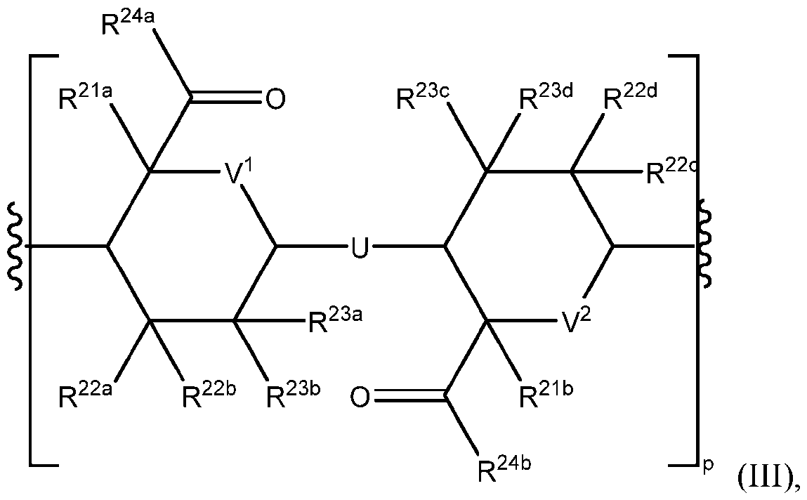
or tautomer thereof, wherein each of U, V
1, and V
2 is independently C(R
25)(R
26), O, or N(R
27); each of R
21a, R
21b, R
22a, R
22b, R
22c, R
22d, R
23a, R
23b, R
23c, R
24a, R
24b, R
25, R
26, and R
27 is independently hydrogen, alkyl, alkenyl, alkynyl, heteroalkyl, halogen, cyano, azido, oxo, -ORA1, –C(O)OR
A1, –C(O)OR
B1, –N(R
C1)(R
D1), –N(R
C1)C(O)R
B1, –C(O)N(R
C1), SR
E1, cycloalkyl, heterocyclyl, aryl, or heteroaryl; each R
A1, R
B1, R
C1, R
D1, and R
E1 is independently hydrogen, alkyl, alkenyl, alkynyl, heteroalkyl, cycloalkyl, heterocyclyl, aryl, heteroaryl, wherein each of alkyl, alkenyl,
Attorney Docket No.: 2967398-000032-WO1 Date of Filing: August 16, 2024 alkynyl, heteroalkyl, cycloalkyl, heterocyclyl, aryl, heteroaryl is optionally substituted with 1-6 R
7; and each R
7 is independently alkyl, alkenyl, alkynyl, heteroalkyl, halogen, cyano, oxo, hydroxyl, cycloalkyl, or heterocyclyl; and p is an integer from 1-100. In an embodiment, the flowable material comprises a polysaccharide or suitable salt thereof, wherein the polysaccharide is a compound of Formula (II-a): , or a or a tautomer
thereof, wherein each of R
21a, R
21b, R
22a, R
22b, R
22c, R
22d, R
23a, R
23b, R
23c, R
24a, R
24b, R
25, R
26, and R
27 is independently hydrogen, alkyl, alkenyl, alkynyl, heteroalkyl, halogen, cyano, azido, oxo, - ORA1, –C(O)OR
A1, –C(O)OR
B1, –N(R
C1)(R
D1), –N(R
C1)C(O)R
B1, –C(O)N(R
C1), SR
E1, cycloalkyl, heterocyclyl, aryl, or heteroaryl; each R
A1, R
B1, R
C1, R
D1, and R
E1 is independently hydrogen, alkyl, alkenyl, alkynyl, heteroalkyl, cycloalkyl, heterocyclyl, aryl, heteroaryl, wherein each of alkyl, alkenyl, alkynyl, heteroalkyl, cycloalkyl, heterocyclyl, aryl, heteroaryl is optionally substituted with 1-6 R
7; and each R
7 is independently alkyl, alkenyl, alkynyl, heteroalkyl, halogen, cyano, oxo, hydroxyl, cycloalkyl, or heterocyclyl; and p is an integer from 1-100. In an embodiment, the flowable material comprises a polysaccharide or suitable salt thereof, wherein the polysaccharide is a compound of Formula (III-b):
Attorney Docket No.: 2967398-000032-WO1 Date of Filing: August 16, 2024 , or a or a tautomer
R
24b, R
25, R
26, and R
27 is independently hydrogen, alkyl, alkenyl, alkynyl, heteroalkyl, halogen, cyano, azido, oxo, - ORA1, –C(O)OR
A1, –C(O)OR
B1, –N(R
C1)(R
D1), –N(R
C1)C(O)R
B1, –C(O)N(R
C1), SR
E1, cycloalkyl, heterocyclyl, aryl, or heteroaryl; each R
A1, R
B1, R
C1, R
D1, and R
E1 is independently hydrogen, alkyl, alkenyl, alkynyl, heteroalkyl, cycloalkyl, heterocyclyl, aryl, heteroaryl, wherein each of alkyl, alkenyl, alkynyl, heteroalkyl, cycloalkyl, heterocyclyl, aryl, heteroaryl is optionally substituted with 1-6 R
7; and each R
7 is independently alkyl, alkenyl, alkynyl, heteroalkyl, halogen, cyano, oxo, hydroxyl, cycloalkyl, or heterocyclyl; and p is an integer from 1-100. In a preferred embodiment the flowable material comprises a compound of formula (III), wherein the flowable material comprises alginic acid or a suitable salt or derivative thereof, e.g., sodium alginate, potassium alginate, calcium alginate, barium alginate, ammonium alginate and the like. In an aspect, the flowable material is a polysaccharide, wherein the polysaccharide comprises D-mannuronic acid and L-guluronic acid. In embodiments, the flowable material is a polysaccharide, wherein the polysaccharide comprises 90% D-mannuronic acid and 10% L- guluronic acid by weight. In embodiments, the flowable material is a polysaccharide, wherein the polysaccharide comprises 80% D-mannuronic acid and 20% L-guluronic acid by weight. In embodiments, the flowable material is a polysaccharide, wherein the polysaccharide comprises 70% D-mannuronic acid and 30% L-guluronic acid by weight. In embodiments, the flowable material is a polysaccharide, wherein the polysaccharide comprises 60% D-mannuronic acid and
Attorney Docket No.: 2967398-000032-WO1 Date of Filing: August 16, 2024 40% L-guluronic acid by weight. In embodiments, the flowable material is a polysaccharide, wherein the polysaccharide comprises 50% D-mannuronic acid and 50% L-guluronic acid by weight. In embodiments, the flowable material is a polysaccharide, wherein the polysaccharide comprises 40% D-mannuronic acid and 60% L-guluronic acid by weight. In embodiments, the flowable material is a polysaccharide, wherein the polysaccharide comprises 30% D-mannuronic acid and 70% L-guluronic acid by weight. In embodiments, the flowable material is a polysaccharide, wherein the polysaccharide comprises 20% D-mannuronic acid and 80% L- guluronic acid by weight. In embodiments, the flowable material is a polysaccharide, wherein the polysaccharide comprises 10% D-mannuronic acid and 90% L-guluronic acid by weight. In an aspect, the flowable material is a polysaccharide, wherein the polysaccharide comprises D-mannuronic acid and L-guluronic acid. In embodiments, the flowable material is a polysaccharide, wherein the polysaccharide comprises 90% D-mannuronic acid and 10% L- guluronic acid mole-per-mole. In embodiments, the flowable material is a polysaccharide, wherein the polysaccharide comprises 80% D-mannuronic acid and 20% L-guluronic acid mole- per-mole. In embodiments, the flowable material is a polysaccharide, wherein the polysaccharide comprises 70% D-mannuronic acid and 30% L-guluronic acid mole-per-mole. In embodiments, the flowable material is a polysaccharide, wherein the polysaccharide comprises 60% D- mannuronic acid and 40% L-guluronic acid mole-per-mole. In embodiments, the flowable material is a polysaccharide, wherein the polysaccharide comprises 50% D-mannuronic acid and 50% L-guluronic acid mole-per-mole. In embodiments, the flowable material is a polysaccharide, wherein the polysaccharide comprises 40% D-mannuronic acid and 60% L- guluronic acid mole-per-mole. In embodiments, the flowable material is a polysaccharide, wherein the polysaccharide comprises 30% D-mannuronic acid and 70% L-guluronic acid mole- per-mole. In embodiments, the flowable material is a polysaccharide, wherein the polysaccharide comprises 20% D-mannuronic acid and 80% L-guluronic acid mole-per-mole. In embodiments, the flowable material is a polysaccharide, wherein the polysaccharide comprises 10% D- mannuronic acid and 90% L-guluronic acid mole-per-mole. In an aspect, the flowable material is a biologically responsive material, wherein the flowable material flows, ceases flowing, or is capable of flowing, upon the introduction or removal of a biological stimulus. In an embodiment flow, ceases flowing, or is capable of flowing, upon the introduction of a biochemical stimulus, e.g., a peptide, polypeptide, antibody
Attorney Docket No.: 2967398-000032-WO1 Date of Filing: August 16, 2024 or antibody fragment, or an enzyme. In an embodiment flow, ceases flowing, or is capable of flowing, upon the introduction of a biochemical stimulus, e.g., a lipid or a carbohydrate. In an embodiment flow, ceases flowing, or is capable of flowing, upon the introduction of an organism or, e.g., a cell, e.g., a cell from Archaea, a prokaryotic cell, or a eukaryotic cell. Exemplary biologically responsive materials include hybrid materials comprising a polymer and a cell, e.g., a synthetic polymer intermingled with a cell or a plurality of cells or a naturally derived polymer intermingled with a cell or a plurality of cells. The synthetic polymer or naturally derived polymer may be any of the polymers contemplated herein, e.g., alginic acid or a suitable alginate salt (e.g., calcium alginate), PEO-PPO-PEO or Pluronic or poloxamer, hyaluronic acid, poly(ε-caprolactone), or poly(PNIPAAm). In an embodiment, the biologically responsive material is a naturally derived, biologically active material, e.g., collagen, hyaluronic acid, elastin, gelatin, cellulose, starch and the like. In an aspect, the flowable material is a crystallizable material, wherein the flowable material flows, ceases flowing, or is capable of flowing, upon the introduction or removal of factors leads to crystallization, e.g., solvent supersaturation. In embodiments, the flowable material flows, ceases flowing, or is capable of flowing when the flowable material crystallizes in a solvent, wherein the flowable material becomes supersaturated in the solvent. Exemplary crystallizable materials include the biomaterials chitin, an amidated polysaccharide of glucose monomers, or chitosan, a polysaccharide copolymer of D-glucosamine and N-acetylglucosamine. In an embodiment, the crystallizable material comprises chitin or chitosan and any of the flowable materials described herein, e.g., alginic acid or suitable alginate salt (e.g. calcium alginate), hyaluronic acid, PEO-PPO-PEO or PEG-PPO—PEG or Pluronic or poloxamer, poly(PNIPAAm), PCL inter alia. In an aspect, the flowable material is a crystallizable material, wherein the flowable material flows, ceases flowing, or is capable of flowing, upon the introduction or removal of a vibration. Exemplary vibration-responsive materials include, e.g., materials that undergo reversible or irreversible crosslinking as a result of a vibrational stimulus, e.g., a polymer composite hydrogel comprising ZnO, wherein the ZnO modulates the chemical crosslinking of a first moiety of the material with a second moiety of the material, as described in Wang et al. Nature Materials 2021, 20, 869-874.
Attorney Docket No.: 2967398-000032-WO1 Date of Filing: August 16, 2024 Elastomers are highly viscoelastic polymers. In an aspect, functionalized elastomers may be employed such that they are responsive to a stimulus. In embodiments, an elastomer is functionalized with a thermoplastic, wherein the functionalized elastomer is thereby thermo- responsive. In embodiments, the thermo-responsive elastomer comprising a thermoplastic will flow or be capable of flowing at or above the melting temperature of the thermo-responsive elastomer. In embodiments, the thermo-responsive elastomer comprising a thermoplastic will flow or will be capable of flowing at or above the glass transition temperature of the thermo- responsive elastomer. In embodiments, the thermo-responsive elastomer comprising a thermoplastic will flow or will be capable of flowing at or above the (UCST) of the thermo- responsive elastomer. In embodiments, the thermo-responsive elastomer comprising a thermoplastic will flow or will be capable of flowing at or below the LCST of the thermo- responsive elastomer. In embodiments, the elastomer polydimethylsiloxane (PDMS) is functionalized with a flowable material, e.g., a flowable material that is thermo-responsive. In embodiments, the PDMS is functionalized with a thermo-responsive polymer displaying LCST and/or UCST behavior, e.g., forming graft copolymer of PNIPAAM-g-PDMS having an LCST near physiological temperature. In embodiments, the PDMS is functionalized with a thermo- responsive polymer displaying LCST and/or UCST behavior, e.g., a graft copolymer of PEO-b- PPO-b-PEO-g-PDMS (Pluronic-g-PDMS, e.g., Pluronic F127-g-PDMS) having an LCST near physiological temperature. In embodiments, the functionalized elastomer is functionalized with a pH responsive material, wherein the functionalized elastomer is thereby pH responsive. In embodiments, the functionalized elastomer is functionalized with a photo- responsive material, wherein the functionalized elastomer is thereby photo-responsive. In embodiments, the functionalized elastomer is functionalized with a moisture- responsive material, wherein the functionalized elastomer is thereby moisture-responsive. In embodiments, the functionalized elastomer is functionalized with a chemically responsive material, wherein the functionalized elastomer is thereby chemically responsive.. In embodiments, the elastomer polydimethylsiloxane (PDMS) is functionalized with a flowable material, e.g., a flowable material that is chemically responsive. In embodiments the PDMS is functionalized with e.g., alginic acid or a suitable alginate salt, thereby forming PDMS-g- alginate which forms a hydrogel in the presence of divalent cations, e.g., Ca
2+.
Attorney Docket No.: 2967398-000032-WO1 Date of Filing: August 16, 2024 In embodiments, the functionalized elastomer is functionalized with a biologically responsive material, wherein the functionalized elastomer is thereby biologically responsive. In embodiments, the functionalized elastomer is functionalized with a crystallizable material, wherein the functionalized elastomer is thereby crystallizable. In embodiments, the functionalized elastomer is functionalized with a vibration responsive material, wherein the functionalized elastomer is thereby vibration responsive. In embodiments, the functionalized elastomer, e.g., PNIPAAM-g-PDMS, Pluronic-g- PDMS, or PDMS-g-alginate, forms in situ in the wound bed in the presence of a catalyst, initiator, orereagent. In embodiments, the functionalized elastomer, e.g., PNIPAAM-g-PDMS, Pluronic-g-PDMS, or PDMS-g-alginate, is synthesized prior to adding the wound healing patch comprising the functionalized elastomer to the wound bed. Pathogens In another aspect, the present disclosure describes a wound dealing device that provides for the detection of a pathogen, e.g., an organism that causes an infection, e.g., manifesting as a disease, disorder, or condition in a subject. Infections acquired in hospital settings represent a significant and growing global healthcare burden, with approximately 100,000 people succumbing annually and billions of dollars being spent by healthcare systems to treat patients afflicted with such infections. Hospital-acquired infections typically arise in patients with an attenuated immunity profile, e.g., after experiencing severe trauma or in patients with an immunodeficiency as a result of another infection, disease, or disorder, e.g., cancer or HIV. Hospital-acquired infections are typically a result of a bacterial infection, particularly gram-negative bacteria. In some embodiments, the wound healing device provides for the detection of a pathogen, wherein the pathogen is a bacterium. In some embodiments, the bacterium is a gram-negative bacterium, characterized in that the cellular outer membrane of said bacterium lacks sufficient peptidoglycan to stain after treatment with crystal violet dye under the method developed by Hans Christian Gram, conventionally referred to as Gram staining. In some embodiments, the gram-negative bacterium belongs to the genus Escherichia, e.g., E. coli. Exemplary pathogenic E. coli strains include the pathotypes: enteropathogenic E. coli (EPEC), enterohaemorrhagic E. coli (EHEC), enterotoxigenic E. coli (ETEC), enteroaggregative E. coli (EAEC), enteroinvasive E. coli (EIEC), diffusely adherent E. coli (DAEC), uropathogenic E.
Attorney Docket No.: 2967398-000032-WO1 Date of Filing: August 16, 2024 coli (UPEC), meningitis/sepsis-associated E. coli (MNEC), adherent-invasive E. coli (AIEC), necrotoxic E. coli (NTEC), and cell-detaching E. coli (CDEC), or any of the pathotypes provided in Kaper, J. Nat Rev Microbiol.2004, 2, 123-140. In some embodiments, the gram-negative bacterium belongs to the genus Acinetobacter. In some embodiments, the gram-negative bacterium is Acetinobacter anitratus. In some embodiments, the gram-negative bacterium is Acintetobacter baumanii. In some embodiments, the gram-negative bacterium belongs to the genus Enterobacter. In some embodiments, the gram-negative bacterium is Enterobacter cloacae. In some embodiments, the gram-negative bacterium belongs to the genus Klebsiella. In some embodiments, the gram-negative bacterium is Klebsiella pneumoniae. In some embodiments, the gram-negative bacterium belongs to the genus Legionella. In some embodiments, the gram-negative bacterium is Legionella pneumophila. In some embodiments, the gram-negative bacterium belongs to the genus Pseudomonas. In embodiments, the gram-negative bacterium is Pseudomonas aeruginosa. In some embodiments, the gram-negative bacterium belongs to the genus Proteus. In some embodiments, the gram-negative bacterium is Proteus mirabilis. In some embodiments, the gram-negative bacterium belongs to the genus Serratia. In some embodiments, the gram-negative bacterium is Serratia marcescens. In some embodiments, the gram-negative bacterium belongs to the genus Salmonella. In some embodiments, the gram-negative bacterium comprises Salmonella enterica or Salmonella bongori, or a combination thereof. In some embodiments, the gram-negative bacterium is Salmonella enterica. In some embodiments, the gram-negative bacterium is Salmonella bongori. In some embodiments, the gram-negative bacterium is Salmonella enterica enterica or its encompassing serotypes. In some embodiments, the bacterium is a gram-positive bacterium, characterized in that the cellular outer membrane of said bacterium contains sufficient peptidoglycan to stain after treatment with crystal violet under the method developed by Hans Christian Gram, the method now conventionally known to those of skill in the art as Gram staining. In some embodiments, the gram-positive bacterium belongs to the genus Staphylococcus. In some embodiments, the bacterium is Staphylococcus aureus. In some embodiments, the bacterium is methicillin-resistant S. aureus (MRSA), wherein the S. aureus is resistant to
Attorney Docket No.: 2967398-000032-WO1 Date of Filing: August 16, 2024 treatment with a beta-lactam antibiotic, e.g., methicillin, penicillin, amoxicillin, ampicillin and the like. In some embodiments, the gram-positive bacterium belongs to the genus Enterococcus. In some embodiments, the gram-positive bacterium is Enterococcus faecalis. In some embodiments, the gram-positive bacterium belongs to the genus Streptococcus. In some embodiments, the bacterium is Streptococcus pneumoniae. In some embodiments, the bacterium is Streptococcus pyogenes. In some embodiments, the bacterium is Streptococcus agalactiae. In some embodiments, the gram-positive bacterium belongs to the genus Clostridioides. In some embodiments, the gram-positive bacterium is Clostridioides dificile, i.e., Clostridium dificile. In some embodiments, the gram-positive bacterium belongs to the genus Mycobacterium. In some embodiments, the gram-positive bacterium comprises Mycobacterium avium. In some embodiments, the gram-positive bacterium comprises Mycobacterium intracellulare. Fungi, protozoa, and virus are also etiological factors in the emergence of hospital- acquired infections. In some embodiments, the wound healing device provides for the detection of a pathogen, wherein the pathogen is a fungus. In some embodiments, the fungus belongs to the genus Aspergillus. In some embodiments, the fungus is Aspergillus fumigatus. In some embodiments, the fungus belongs to the genus Candida. In some embodiments, the fungus is Candida albicans. In some embodiments, the fungus belongs to the Coccidioides. In some embodiments, the fungus is Coccidioides immitis. In some embodiments, the fungus belongs to the genus Cryptococcus. In some embodiments, the fungus is Cryptococcus neoformans. In some embodiments, the fungus belongs to the genus Histoplasma. In some embodiments, the fungus is Histoplasma capsulatum. In some embodiments, the fungus belongs to the class Microsporidia. In some embodiments, the fungus belongs to the genus Pneumocystis. In some embodiments, the fungus is Pneumocystis jirovecii, i.e., Pneumocystis carinii.
Attorney Docket No.: 2967398-000032-WO1 Date of Filing: August 16, 2024 In some embodiments, the wound healing device provides for the detection of a pathogen, wherein the pathogen is a protozoan. In some embodiments, the protozoan belongs to the genus Cryptosporidium. In some embodiments, the protozoan is comprises one or more of C. andersoni, C. bailey, C. bovis, C. cervine, C. canis, C. cuniculus, C. ducismarci, C. fayeri, C. felis, C. fragile, C. galli, C. hominis, C. marcopodum, C. meleagridis, C. molnari, C. muris, C. parvum, C. ryanae, C. saurophilum, C. serpentis, C. suis, C. ubiquitum, C. viatorum, C. wrairi, or C. xiaoi. In some embodiments, the protozoan belongs to the genus Toxoplasma. In some embodiments, the protozoan is Toxoplasma gondii. In some embodiments, the wound dealing device provides for the detection of a pathogen, wherein the pathogen is a virus. In some embodiments, the virus belongs to the genus Cytomegalovirus. Diseases The present disclosure describes a wound healing device that provides for detection of a pathogen, wherein the pathogen is associated with a disease, disorder, or condition. To that end, the wound healing device provides for the detection of a pathogen contributing to the emergence of a hospital-acquired infection, a significant causal factor in global morbidity and a formidable financial strain on global healthcare systems. In some embodiments, the disease, disorder, or infection is a respiratory disease. In some embodiments, the disease, disorder, or condition is pneumonia, e.g., bacterial pneumonia or viral pneumonia. In some embodiments, the disease, disorder, or condition is acute respiratory distress syndrome (ARDS). In some embodiments, the disease, disorder, or condition is sepsis. In some embodiments, the disease, disorder, or condition is an infection of the circulatory system. In some embodiments, the disease, disorder, or condition comprises a bacteremia or a fungemia. In some embodiments, the disease, disorder, or condition is a bacteremia. In some embodiments, the disease, disorder, or condition is a fungemia. In some embodiments, the disease, disorder, or condition is a urinary tract disease or infection, e.g., of the bladder, kidney, ureter, or urethra. In embodiments, the disease, disorder, or condition is associated with the bladder. In some embodiments, the disease, disorder, or condition is associated with the kidney. In some embodiments, the disease, disorder, or condition
Attorney Docket No.: 2967398-000032-WO1 Date of Filing: August 16, 2024 is associated with the ureter. In some embodiments, the disease, disorder, or condition is associated with the urethra. In some embodiments, the disease, disorder, or condition is associated with inflammation of the heart and/or surrounding tissue, e.g., cardiomyopathy. In some embodiments, the disease, disorder, or condition is cardiomyopathy. In some embodiments, the disease, disorder, or condition is pericarditis. In some embodiments, the disease, disorder, or condition is an integumentary condition. In some embodiments, the disease, disorder, or condition is a skin condition. In some embodiments, the disease, disorder, or condition is associated with the hair. In some embodiments, the disease, disorder, or condition is associated with the cuticle. In some embodiments, the disease, disorder, or condition is associated with cellulitis. In some embodiments, the disease, disorder, or condition is associated with necrotizing fasciitis. In some embodiments, the disease, disorder, or condition is folliculitis. In some embodiments, the disease, disorder, or condition is a gastrointestinal disease, associated with e.g., inflammation of the stomach, small intestine, or colon. In some embodiments, the disease, disorder, or condition is a gastroenteritis presenting with or without diarrhea. In some embodiments, the disease, disorder, or condition is a neurological condition associated with the brain, nerves, or spinal cord. In some embodiments, the disease, disorder, or condition is meningitis. In some embodiments, the disease, disorder, or condition is associated with organ failure or organ malfunction, e.g., acute kidney failure, pancreatitis, or acute liver failure. In some embodiments, the disease, disorder, or condition is associated with acute kidney failure. In some embodiments, the disease, disorder, or condition is pancreatitis. In some embodiments, the disease, disorder, or condition is associated with acute liver failure. In some embodiments, the disease, disorder, or condition is systemic inflammatory response syndrome (SIRS). In some embodiments, the disease, disorder, or condition is multiple organic dysfunction syndrome (MODS). In some embodiments, the disease, disorder, or condition is anaphylaxis. In some embodiments, the disease, disorder, or condition is circulatory shock.
Attorney Docket No.: 2967398-000032-WO1 Date of Filing: August 16, 2024 In some embodiments, the disease, disorder, or condition is associated with a coagulopathy, i.e., impaired blood clotting ability. In some embodiments, the disease, disorder, or condition is associated with thermal dysregulation, i.e., hypothermia or hyperthermia. In some embodiments, the disease, disorder, or condition is associated with hypothermia. In some embodiments, the disease, disorder, or condition is associated with hyperthermia. In some embodiments, the disease, disorder, or condition is a failure in pH homeostasis, e.g., alkalosis (abnormally high pH) or acidosis (abnormally low pH). In some embodiments, the disease, disorder, or condition is associated with alkalosis. In some embodiments, the disease, disorder, or condition is associated with acidosis. In some embodiments, the disease, disorder, or condition is associated with a lymphatic condition, e.g., a condition affecting the lymph nodes, lymphatic vessels, and or spleen. In some embodiments, the disease, disorder, or condition is associated with lymphedema. In some embodiments, the disease, disorder, or condition is associated with a change in blood pressure. In some embodiments, the disease, disorder, or condition is associated with a reduction in blood pressure. In some embodiments, the disease, disorder, or condition is associated with an increase in blood pressure. In some embodiments, the disease, disorder, or condition is associated with a reduction in blood volume. In some embodiments, the disease, disorder, or condition is associated with empyema, e.g., pleural empyema, wherein the exudate from an infection accumulates in the cavity adjacent to the lungs, compromising the ability to breathe. Pathogen Sensing In an aspect, the wound healing device comprises a sensor for detecting a pathogen. In some embodiments, the sensor is fixedly connected to an actuator. In some embodiments, the sensor is indirectly connected to an actuator, e.g., via the propagation of a signal, wherein the signal is electrical, mechanical, chemical, or a combination thereof. In some embodiments, responsive to detecting a pathogen, the sensor propagates a signal to the actuator, wherein the signal is propagated electrically, mechanically, chemically, or a combination thereof.
Attorney Docket No.: 2967398-000032-WO1 Date of Filing: August 16, 2024 In some embodiments, responsive to detecting a pathogen, the sensor propagates a signal to the actuator, wherein the actuator processes the signal, and responsive to the processing thereby acquires information regarding the pathogen. In some embodiments, acquiring information regarding the pathogen includes acquiring information about an infection, e.g., the status of the infection. In embodiments, acquiring information regarding the status of the infection also includes acquiring information from the surrounding milieu of the wound bed., e.g., the pH, temperature, spatial or temporal distribution of cytokines, chemokines, coagulation factors, and cells, e.g., white blood cells, platelets, and epithelial cells. In some embodiments, responsive to detecting a pathogen, the actuator acquires information from the surrounding milieu of the wound bed, e.g., the pH, temperature, spatial or temporal distribution of cytokines, chemokines, coagulation factors, and cells, e.g., white blood cells, platelets, and epithelial cells. In some embodiments, in the absence of detecting a pathogen, the actuator acquires information from the surrounding milieu of the wound bed, e.g., the pH, temperature, spatial or temporal distribution of cytokines, chemokines, coagulation factors, and cells, e.g., white blood cells, platelets, and epithelial cells. In some embodiments, the pathogen is acquired in a healthcare setting, e.g., a hospital, a clinic, or a trauma center. In some embodiments, the pathogen is an opportunistic infection, wherein the pathogen infects a subject, wherein the subject’s immune system is attenuated, e.g., as a result of trauma. In some embodiments, the pathogen is a bacterium, e.g., a gram-negative bacterium or a gram-positive bacterium. In some embodiments, the pathogen is a fungus. In some embodiments, the pathogen is a protozoan. In some embodiments, the pathogen is a virus. In some embodiments, responsive to detecting a pathogen, the sensor propagates a signal to the actuator, wherein the actuator processes the signal, and responsive to the processing, propagates an external signal in the milieu of the wound bed, thereby modulating the effects of the pathogen in the wound bed. In some embodiments, in the absence of detecting a pathogen, the actuator propagates an external signal in the external milieu of a wound bed, as a result of stimulus, e.g., an applied light source, e.g., red light at a wavelength of 740 nm or blue light at a wavelength of 450 nm. In some embodiments, the actuator, responsive to detecting a pathogen, potentiates the transport of a therapeutic agent from the wound healing device to the surrounding milieu of the
Attorney Docket No.: 2967398-000032-WO1 Date of Filing: August 16, 2024 wound bed, wherein upon processing of a signal, a therapeutic agent is released into the milieu of the wound bed, thereby modulating the effects of the pathogen in the wound bed. In some embodiments, the therapeutic agent is a cytokine comprising one or more of IL1-β, IL4, IL6, IL- 10, IL-12, IL-17, IL-18, IL-22, IL-23, TNF-α, TGF-β, or IFN-γ. In some embodiments, the therapeutic agent comprises a peptide or a polypeptide, e.g., one or more of matrix metalloproteinase (MMP), VEGF, PDGF, or FGF. In some embodiments, the actuator, in the absence of detecting a pathogen, potentiates the transport of a therapeutic agent from the wound healing device to the surrounding milieu of the wound bed, wherein a therapeutic agent is released into the milieu of the wound bed, thereby modulating the environment in the wound bed. In some embodiments, the therapeutic agent is a cytokine comprising one or more of IL1-β, IL4, IL6, IL-10, IL-12, IL-17, IL-18, IL-22, IL-23, TNF-α, TGF-β, or IFN-γ. In some embodiments, the therapeutic agent comprises a peptide or a polypeptide, e.g., one or more of matrix metalloproteinase (MMP), VEGF, PDGF, or FGF. In some embodiments, in the absence of detecting a pathogen, the actuator potentiates the transport of a therapeutic agent from the wound healing device to the surrounding milieu of the wound bed, as a result of stimulus, e.g., an applied light source, e.g., red light at a wavelength of 740 nm or blue light at a wavelength of 450 nm. In some embodiments, the therapeutic agent is a polypeptide comprising an antibody, functional antibody fragment, or immunoglobulin, capable of binding to an epitope of an antigen, e.g., an antigen expressed by the pathogen or its metabolite. In some embodiments, the therapeutic agent is an antibiotic, e.g., a beta-lactam, a cephalosporin, a macrolide, or a tetracycline, inter alia. In some embodiments, the therapeutic agent is an antibiotic, wherein the antibiotic is a broad-spectrum antibiotic, capable of treating multiple bacterial species, or a bacterial species which is resistant to a particular class of antibiotics, e.g., resistant to a beta-lactam antibiotic such as methicillin. In some embodiments, the pathogen is acquired in a healthcare setting, e.g., a hospital, a clinic, or a trauma center. In some embodiments, the pathogen is an opportunistic infection, wherein the pathogen infects a subject, wherein the subject’s immune system is attenuated, e.g., as a result of trauma. In some embodiments, the pathogen is MRSA. In some embodiments, the therapeutic agent is an antifungal agent. Examples of antifungal agents include amphotericin B, miconazole, and itraconazole.
Attorney Docket No.: 2967398-000032-WO1 Date of Filing: August 16, 2024 In some embodiments, the therapeutic agent is an antiprotozoal agent. An example of an antiprotozoal agent includes metronidazole. In some embodiments, the therapeutic agent is an antiviral agent. In some embodiments, the therapeutic agent is a nucleic acid. In some embodiments, the nucleic acid is DNA. In some embodiments, the therapeutic agent is double-stranded DNA (dsDNA). In some embodiments, the therapeutic agent is RNA. In some embodiments, the therapeutic agent is single-stranded RNA (ssRNA). In some embodiments, the therapeutic agent is double-stranded RNA (dsRNA). In some embodiments, the therapeutic agent is interfering RNA (RNAi). In some embodiments, the therapeutic agent is small interfering RNA (siRNA). In some embodiments, the actuator, responsive to detecting a pathogen, initiates a chemical reaction to produce a therapeutic agent, wherein the therapeutic agent is thereby secreted into the surrounding milieu of the wound bed to modulate the effects of the pathogen. For example, the processing of a signal may potentiate a change in the connectivity or diffusivity of two or more compartments of the wound healing device containing reagents, thereby initiating a reaction to produce a therapeutic agent, e.g., an antibiotic that may be transported to the surrounding milieu of the wound bed. In some embodiments, the actuator, in the absence of detecting a pathogen, initiates a chemical reaction to produce a therapeutic agent, wherein the therapeutic agent is thereby secreted into the surrounding milieu to modulate the environment of the wound bed. For example, in the absence of detecting a pathogen, the actuator may potentiate a change in the connectivity or diffusivity of two or more compartments of the wound healing device containing reagents, thereby initiating a reaction to produce a therapeutic agent, e.g., an antibiotic that may be transported to the surrounding milieu of the wound bed. In some embodiments, in the absence of detecting a pathogen, the actuator initiates a chemical reaction to produce a therapeutic agent, wherein the therapeutic agent is thereby secreted into the surrounding milieu to modulate the environment of the wound bed as a result of stimulus, e.g., an applied light source, e.g., red light at a wavelength of 740 nm or blue light at a wavelength of 450 nm. In some embodiments, the pathogen is acquired in a healthcare setting, e.g., a hospital, a clinic, or a trauma center. In some embodiments, the acquiring the pathogen results an opportunistic infection, wherein the pathogen infects a subject, wherein the subject’s immune
Attorney Docket No.: 2967398-000032-WO1 Date of Filing: August 16, 2024 system is attenuated, e.g., as a result of trauma. In some embodiments, the pathogen is a bacterium, e.g., a gram-negative bacterium or a gram-positive bacterium. In some embodiments, the pathogen is a fungus. In some embodiments, the pathogen is a protozoan. In embodiments, the pathogen is methicillin-resistant S. aureus (MRSA). In embodiments, the pathogen is P. aeruginosa. In embodiments, the pathogen is S. pneumoniae. In embodiments, the pathogen is S. pyogenes. In some embodiments, the wound healing device for detecting a pathogen comprises a sensor. In embodiments, the sensor is a chemical sensor, an electrical sensor, a mechanical sensor, or a combination thereof. In some embodiments, the sensor is a cell or a plurality of cells. In some embodiments, the sensor is an optogenetically engineered cell capable of photoinducible protein expression, e.g., upon exposure to a certain wavelength of light, e.g., red light at 740 nm or blue light at 450 nm. In embodiments, the sensor is a chemical sensor. In embodiments, the sensor is an electrical sensor. In embodiments, the sensor is a mechanical sensor. In some embodiments, the sensor detects a pathogen particle, wherein the particle is a whole microorganism, e.g., a whole bacterium, a whole protozoan, or a virion. In some embodiments, the sensor detects a marker associated with the pathogen. In some embodiments, the marker is a chemical marker. In some embodiments, the chemical marker is a biochemical marker. In some embodiments, the sensor detects a marker that is associated with a pathogen, e.g., a marker expressed on the cell wall, cell membrane, or envelope of a pathogen. In some embodiments, the marker is a small molecule, e.g., a small organic molecule or a small inorganic molecule. In some embodiments, the marker is a polysaccharide, a lipid, a nucleic acid, a peptide or a polypeptide, or a functionalized variant or combination thereof. In some embodiments, the marker is a polysaccharide. In some embodiments, the marker is a lipid, e.g., a phospholipid. In some embodiments, the marker is a glycolipid, e.g., a glycophospholipid. In some embodiments, the marker is a nucleic acid, e.g., DNA or RNA. In some embodiments, the nucleic acid is DNA. In some embodiments, the nucleic acid is RNA. In some embodiments, the marker is a peptide or a polypeptide. In some embodiments, the peptide or polypeptide is contemplated to be any membrane expressing protein, e.g., a G-protein coupled receptor or an ion channel or transporter protein, which is in contact with the surrounding milieu. In some embodiments, the peptide or polypeptide is glycosylated, e.g., the peptide comprises peptidoglycan, a major constituent of bacterial cell walls. In some embodiments, the marker is an
Attorney Docket No.: 2967398-000032-WO1 Date of Filing: August 16, 2024 antigen, e.g., an antigen comprising an epitope, wherein the epitope is capable of binding to an antibody or functional antibody fragment, e.g., an antibody or functional antibody fragment as an element of the sensor of the wound healing device for detecting a pathogen. In some embodiments, the sensor detects a marker that is associated with a pathogen, e.g., a marker that is secreted into the milieu of the wound bed. In some embodiments, the marker is a metabolite of the pathogen, e.g., a species of the pathogen metabolome. In some embodiments, the marker is a toxin, e.g., a toxin that is toxic to the host or to another organism. In some embodiments, the marker is an antibiotic. In some embodiments, the marker is a small molecule, e.g., a small organic molecule or a small inorganic molecule. In some embodiments, the marker is a polysaccharide, a lipid, a nucleic acid, a peptide or a polypeptide, or a functionalized variant or combination thereof. In some embodiments, the marker is a polysaccharide. In some embodiments, the marker is a lipid, e.g., a phospholipid. In some embodiments, the marker is a nucleic acid, e.g., DNA or RNA. In some embodiments, the nucleic acid is DNA. In some embodiments, the nucleic acid is double-stranded DNA (dsDNA). In some embodiments, the nucleic acid is RNA. In some embodiments, the nucleic acid is single-stranded RNA (ssRNA). In some embodiments, the nucleic acid is messenger RNA (mRNA) or pre-messenger RNA (pre-mRNA), e.g., an un-spliced mRNA transcript. In some embodiments, the nucleic acid is double-stranded RNA (dsRNA). In some embodiments, the nucleic acid is interfering RNA (RNAi). In some embodiments, the nucleic acid is small interfering RNA (siRNA). In some embodiments, the marker is a peptide or a polypeptide. In some embodiments, the marker is an antigen, e.g., an antigen comprising an epitope, wherein the epitope is capable of binding to an antibody or functional antibody fragment, e.g., an antibody or functional antibody fragment as an element of the sensor for detecting a pathogen. In some embodiments, the sensor detects a marker that is indirectly associated with a pathogen, e.g., a marker propagated by a host indicative of an infection or of an immune response, e.g., spatiotemporal changes in macrophages, cytokines, or chemokines; pyrexia, or blood oxygenation, heart rate, blood pressure, or respiration rate indicative of the presence of a pathogen. In some embodiments, the sensor detects a spatiotemporal change in macrophages in the wound bed, indicative of the presence of a pathogen. In some embodiments, the sensor detects a spatiotemporal change in cytokines in the wound bed, e.g., one or more of IL1-β, IL4, IL6, IL-10, IL-12, IL-17, IL-18, IL-22, IL-23, TNF-α, TGF-β, or IFN-γ, indicative of the
Attorney Docket No.: 2967398-000032-WO1 Date of Filing: August 16, 2024 presence of a pathogen. In some embodiments, the sensor detects a spatiotemporal change in chemokines in the wound bed, e.g., inflammatory chemokines such as CCL2, CCL3, CCL4, CCL5, CCL11, IL-8, and IP-10, indicative of the presence of the pathogen. In some embodiments, the sensor detects hypothermia or pyrexia, indicative of the presence of a pathogen. In embodiments, the sensor detects a change in blood oxygenation, indicative of the presence of a pathogen. In some embodiments, the sensor detects a change in heart rate, indicative of the presence of a pathogen. In some embodiments, the sensor detects a change in blood pressure, indicative of the presence of a pathogen. In some embodiments, the sensor detects a change in respiration rate, indicative of the presence of a pathogen. In some embodiments, the pathogen is acquired in a healthcare setting, e.g., a hospital, a clinic, or a trauma center. In some embodiments, acquiring the pathogen results in an opportunistic infection, wherein the pathogen infects a subject, wherein the subject’s immune system is attenuated, e.g., as a result of trauma. In some embodiments, the pathogen is a bacterium, e.g., a gram-negative bacterium or a gram-positive bacterium. In some embodiments, the pathogen is a fungus. In some embodiments, the pathogen is a protozoan. In some embodiments, the pathogen is a virus. In some embodiments, the pathogen is methicillin- resistant S. aureus (MRSA). In some embodiments, the pathogen is P. aeruginosa. In some embodiments, the pathogen is S. pneumoniae. In some embodiments, the pathogen is S. pyogenes. In an aspect, the wound healing device comprises a sensor for detecting a pathogen, wherein the sensor detects a chemical marker. The method for sensing a pathogen with a wound healing device, wherein the wound healing device comprises a sensor for detecting the chemical marker, and wherein the detecting comprises acquiring information about the pathogen, comprises the following steps: (i) interacting a chemical marker with a moiety of the sensor, wherein the moiety is disposed on a surface of the wound healing device that is contacting the surrounding milieu of the wound bed, i.e., via direct contact or indirectly, i.e., allowing for the transport or diffusion of said chemical marker from the surrounding milieu of the wound bed to the moiety of the sensor; (ii) responsive to the interaction between the chemical marker and the moiety of the sensor, initiating a signal, wherein the signal is chemical, electrical, mechanical, or a combination thereof;
Attorney Docket No.: 2967398-000032-WO1 Date of Filing: August 16, 2024 (iii) propagating the signal to an actuator for processing; and (iv) processing the signal, and as a result of the processing, thereby detecting a pathogen in the wound bed with a wound healing device comprising a sensor and acquiring information about the pathogen from the interaction between the chemical marker and the moiety of the sensor. In some embodiments, the method for sensing a pathogen with a wound healing device, wherein the wound healing device comprises a sensor for detecting a chemical marker, and wherein the detecting further comprises modulating the effects of the pathogen, comprises the following steps: (i) interacting the chemical marker with a moiety of the sensor, wherein the moiety is disposed on a surface of the wound healing device that is contacting the surrounding milieu of the wound bed, i.e., via direct contact or indirectly, i.e., allowing for the transport or diffusion of said chemical marker from the surrounding milieu of the wound bed to the second moiety of the sensor; (ii) responsive to the interaction between the chemical marker and the moiety of the sensor, initiating a first signal, wherein the signal is chemical, electrical, mechanical, or a combination thereof; (iii) propagating the first signal to an actuator for processing; and (iv) processing the first signal, (v) responsive to the processing, propagating a second signal to the surrounding milieu of the wound bed, thereby detecting a pathogen in the wound bed with a wound healing device comprising a sensor and modulating the effects of said pathogen. In some embodiments, the method for sensing a pathogen with a wound healing device, wherein the wound healing device comprises a sensor for detecting a chemical marker, and wherein the detecting further comprises modulating the effects of the pathogen, comprises the following steps: (i) interacting the chemical marker with a moiety of the sensor, wherein the moiety is disposed on a surface of the wound healing device that is contacting the surrounding milieu of the wound bed, i.e., via direct contact or indirectly, i.e., allowing for the transport or diffusion of said chemical marker from the surrounding milieu of the wound bed to the moiety of the sensor;
Attorney Docket No.: 2967398-000032-WO1 Date of Filing: August 16, 2024 (ii) responsive to the interaction between the chemical marker and the moiety of the sensor, initiating a first signal, wherein the signal is chemical, electrical, mechanical, or a combination thereof; (iii) propagating the first signal to an actuator for processing; (iv) processing the first signal; and (v) responsive to the processing, propagating a second signal to the surrounding milieu of the wound bed, wherein the propagating comprises propagating a therapeutic agent from the wound healing device for modulating the effects of the pathogen, thereby detecting a pathogen in the wound bed with a wound healing device comprising a sensor and modulating the effects of said pathogen. In some embodiments, the method for sensing a pathogen with a wound healing device, wherein the wound healing device comprises a sensor for detecting a chemical marker, wherein the detecting further comprises modulating the effects of the pathogen, comprises the following steps: (i) interacting the chemical marker with a moiety of the sensor, wherein the moiety is disposed on a surface of the wound healing device that is contacting the surrounding milieu of the wound bed, i.e., via direct contact or indirectly, i.e., allowing for the transport or diffusion of said chemical marker from the surrounding milieu of the wound bed to the second moiety of the sensor; (ii) responsive to the interaction between the chemical marker and the moiety of the sensor, initiating a first signal, wherein the signal is chemical, electrical, mechanical, or a combination thereof; (iii) propagating the first signal to an actuator for processing; and (iv) processing the first signal; and (v) responsive to the processing, propagating a second signal to the external milieu of the wound bed, wherein the propagating comprises: (a) initiating a chemical reaction for producing a therapeutic agent; (b) propagating the therapeutic agent from the wound healing device for modulating the effects of the pathogen, thereby detecting a pathogen in the wound bed with a wound healing device comprising a sensor and modulating the effects of said pathogen.
Attorney Docket No.: 2967398-000032-WO1 Date of Filing: August 16, 2024 In some embodiments, the signal, e.g., the first signal or the second signal, is propagated chemically, electrically, mechanically or a combination thereof. In some embodiments, the interaction is chemical, electrical, mechanical, or a combination thereof. In embodiments, the interaction is a chemical interaction. In embodiments, the interaction is an electrical interaction. In embodiments, the interaction is a mechanical interaction. In embodiments, the interaction is a biochemical interaction. In some embodiments, the pathogen is acquired in a healthcare setting, e.g., a hospital, a clinic, or a trauma center. In some embodiments, acquiring the pathogen results in an opportunistic infection, wherein the pathogen infects a subject, wherein the subject’s immune system is attenuated, e.g., as a result of trauma. In some embodiments, the pathogen is a bacterium, e.g., a gram-negative bacterium or a gram-positive bacterium. In some embodiments, the pathogen is a fungus. In some embodiments, the pathogen is a protozoan. In some embodiments, the pathogen is methicillin-resistant S. aureus (MRSA). In some embodiments, the pathogen is P. aeruginosa. In some embodiments, the pathogen is S. pneumoniae. In some embodiments, the pathogen is S. pyogenes. In an aspect, the method for sensing a pathogen with a wound healing device, wherein the wound healing device comprises a sensor for detecting a chemical marker, wherein the chemical marker is a nucleic acid, and wherein the detecting further comprises acquiring information, comprises the following steps: (i) interacting the chemical marker comprising a single stranded nucleic acid, e.g., DNA or RNA, with a moiety of the sensor, wherein the moiety comprises a complementary nucleic acid for hybridization with the chemical marker, wherein the moiety is disposed on a surface of the wound healing device that is contacting the surrounding milieu of the wound bed, i.e., via direct contact or indirectly, i.e., allowing for the transport or diffusion of said chemical marker from the surrounding milieu of the wound bed to the second moiety of the sensor; (ii) responsive to the interaction, e.g., nucleic acid hybridization, between the chemical marker and the moiety of the sensor, initiating a first signal, wherein the signal is chemical, electrical, mechanical, or a combination thereof; (iii) propagating the signal to an actuator for processing; and (iv) processing the signal,
Attorney Docket No.: 2967398-000032-WO1 Date of Filing: August 16, 2024 thereby detecting a pathogen in the wound bed with a wound healing device comprising a sensor and acquiring information about the pathogen from the interaction between chemical marker and the moiety of the sensor. In an aspect, the method for sensing a pathogen with a wound healing device, wherein the wound healing device comprises a sensor for detecting a chemical marker, wherein the chemical marker is a nucleic acid, and wherein the detecting further comprises modulating the effects of the pathogen, comprises the following steps: (i) interacting the chemical marker comprising a single stranded nucleic acid, e.g., DNA or RNA, with a moiety of the sensor, wherein the moiety comprises a complementary nucleic acid for hybridization with the chemical marker, wherein the moiety is disposed on a surface of the wound healing device that is contacting the surrounding milieu of the wound bed, i.e., via direct contact or indirectly, i.e., allowing for the transport or diffusion of said chemical marker from the surrounding milieu of the wound bed to the moiety of the sensor; (ii) responsive to the interaction, e.g., nucleic acid hybridization, between the chemical marker and the moiety of the sensor, initiating a first signal, wherein the signal is chemical, electrical, mechanical, or a combination thereof; (iii) propagating the first signal to an actuator for processing; and (iv) processing the first signal; and (v) responsive to the processing, propagating a second signal to the surrounding milieu comprising the wound bed, wherein the propagating comprises propagating a therapeutic agent from the wound healing device for modulating the effects of the pathogen, thereby detecting a pathogen in the wound bed with a wound healing device comprising a sensor and modulating the effects of said pathogen. In an aspect, the method for sensing a pathogen with a wound healing device, wherein the wound healing device comprises a sensor for detecting a chemical marker, wherein the chemical marker is a nucleic acid, and wherein the detecting further comprises modulating the effects of the pathogen, comprises the following steps: (i) interacting the chemical marker comprising a single stranded nucleic acid, e.g., DNA or RNA, with a moiety of the sensor, wherein the moiety comprises a complementary nucleic acid for hybridization with the chemical marker, wherein the moiety is disposed on a surface of the wound healing device that is contacting the surrounding milieu of the wound bed, i.e., via
Attorney Docket No.: 2967398-000032-WO1 Date of Filing: August 16, 2024 direct contact or indirectly, i.e., allowing for the transport or diffusion of said chemical marker from the surrounding milieu of the wound bed to the moiety of the sensor; (ii) responsive to the interaction, e.g., nucleic acid hybridization, between chemical marker and the moiety of the sensor, initiating a first signal, wherein the signal is chemical, electrical, mechanical, or a combination thereof; (iii) propagating the first signal to an actuator for processing; and (iv) processing the first signal; and (v) responsive to the processing, propagating a second signal to the external milieu comprising the wound bed, wherein the propagating comprises: (a) initiating a chemical reaction for producing a therapeutic agent; (b) propagating the therapeutic agent from the wound healing device for modulating the effects of the pathogen, thereby detecting a pathogen in the wound bed with a wound healing device comprising a sensor and modulating the effects of said pathogen. In embodiments, the signal, e.g., the first signal or the second signal, is propagated chemically, electrically, mechanically or a combination thereof. In some embodiments, the pathogen is acquired in a healthcare setting, e.g., a hospital, a clinic, or a trauma center. In some embodiments, acquiring the pathogen results in an opportunistic infection, wherein the pathogen infects a subject, wherein the subject’s immune system is attenuated, e.g., as a result of trauma. In some embodiments, the pathogen is a bacterium, e.g., a gram-negative bacterium or a gram-positive bacterium. In some embodiments, the pathogen is a fungus. In some embodiments, the pathogen is a protozoan. In some embodiments, the pathogen is a virus. In embodiments, the pathogen is methicillin-resistant S. aureus (MRSA). In some embodiments, the pathogen is P. aeruginosa. In some embodiments, the pathogen is S. pneumoniae. In some embodiments, the pathogen is S. pyogenes. In an aspect, the method for sensing a pathogen with a wound healing device, wherein the wound healing device comprises a sensor for detecting a chemical marker, wherein the chemical marker is an antigen, and wherein the detecting further comprises acquiring information, comprises the following steps: (i) interacting the chemical marker comprising an antigen, with a moiety of the sensor, wherein the moiety comprising an antibody or a functional antibody fragment capable of binding
Attorney Docket No.: 2967398-000032-WO1 Date of Filing: August 16, 2024 to the epitope of the antigen, is disposed on a surface of the wound healing device that is contacting the surrounding milieu of the wound bed, i.e., via direct contact or indirectly, i.e., allowing for the transport or diffusion of said chemical marker from the surrounding milieu of the wound bed to the moiety of the sensor; (ii) responsive to the interaction, e.g., binding of the antibody or functional antibody fragment to the antigen, initiating a signal, wherein the signal is chemical, electrical, mechanical, or a combination thereof; (iii) propagating the signal to an actuator for processing; and (iv) processing the signal, thereby detecting a pathogen in the wound bed with a wound healing device comprising a sensor and acquiring information about the pathogen from the interaction between the chemical marker and the moiety of the sensor. In an aspect, the method for sensing a pathogen with a wound healing device, wherein the wound healing device comprises a sensor for detecting a chemical marker, wherein the chemical marker is an antigen, and wherein the detecting further comprises modulating the effects of the pathogen, comprises the following steps: (i) interacting the chemical marker comprising an antigen, with a moiety of the sensor, wherein the moiety, comprising an antibody or a functional antibody fragment capable of binding to the epitope of the antigen, is disposed on a surface of the wound healing device that is contacting the surrounding milieu of the wound bed, i.e., via direct contact or indirectly, i.e., allowing for the transport or diffusion of said chemical marker from the surrounding milieu of the wound bed to the moiety of the sensor; (ii) responsive to the interaction, e.g., binding of the antibody or functional antibody fragment to the antigen, initiating a first signal, wherein the signal is chemical, electrical, mechanical, or a combination thereof; (iii) propagating the first signal to an actuator for processing; and (iv) processing the first signal; and (v) responsive to the processing, propagating a second signal to the surrounding milieu of the wound bed, wherein the propagating comprises propagating a therapeutic agent from the wound healing device for modulating the effects of the pathogen,
Attorney Docket No.: 2967398-000032-WO1 Date of Filing: August 16, 2024 thereby detecting a pathogen in the wound bed with a wound healing device comprising a sensor and modulating the effects of said pathogen. In an aspect, the method for sensing a pathogen with a wound healing device, wherein the wound healing device comprises a sensor for detecting a chemical marker, wherein the chemical marker is an antigen, and wherein the detecting further comprises modulating the effects of the pathogen, comprises the following steps: (i) interacting the chemical marker comprising an antigen, with a moiety of the sensor, wherein the moiety, comprising an antibody or a functional antibody fragment capable of binding to the epitope of the antigen, is disposed on a surface of the wound healing device that is contacting the surrounding milieu of the wound bed, i.e., via direct contact or indirectly, i.e., allowing for the transport or diffusion of said chemical marker from the surrounding milieu of the wound bed to moiety of the sensor; (ii) responsive to the interaction, e.g., nucleic acid hybridization, between chemical marker and the moiety of the sensor, initiating a first signal, wherein the signal is chemical, electrical, mechanical, or a combination thereof; (iii) propagating the first signal to an actuator for processing; and (iv) processing the first signal; and (v) responsive to the processing, propagating a second signal to the external milieu of the wound bed, wherein the propagating comprises: (a) initiating a chemical reaction for producing a therapeutic agent; (b) propagating the therapeutic agent from the wound healing device for modulating the effects of the pathogen, thereby detecting a pathogen in the wound bed with a wound healing device comprising a sensor and modulating the effects of said pathogen. In embodiments, the signal, e.g., the first signal or the second signal, is propagated chemically, electrically, mechanically or a combination thereof. In some embodiments, the pathogen is acquired in a healthcare setting, e.g., a hospital, a clinic, or a trauma center. In some embodiments, acquiring the pathogen results in an opportunistic infection, wherein the pathogen infects a subject, wherein the subject’s immune system is attenuated, e.g., as a result of trauma. In some embodiments, the pathogen is a bacterium, e.g., a gram-negative bacterium or a gram-positive bacterium. In some embodiments,
Attorney Docket No.: 2967398-000032-WO1 Date of Filing: August 16, 2024 the pathogen is a fungus. In some embodiments, the pathogen is a protozoan. In some embodiments, the pathogen is a virus. In some embodiments, the pathogen is methicillin- resistant S. aureus (MRSA). In some embodiments, the pathogen is P. aeruginosa. In some embodiments, the pathogen is S. pneumoniae. In some embodiments, the pathogen is S. pyogenes. In an aspect, the wound healing device comprises a sensor for detecting a pathogen particle, wherein the sensor detects a whole microorganism, e.g., a whole bacterium, a whole protozoan, or a whole virion. In some embodiments, a method for sensing a pathogen with a wound healing device, wherein the wound healing device comprises an sensor with a compartment for disposing a pathogen particle, comprises the following steps: (i) disposing the pathogen particle in the compartment; (ii) acquiring a value, e.g., a chemical value or an electrical value; (iii) comparing the value during the disposition of the pathogen particle in the compartment, relative to a control value, e.g., the value acquired in the absence of the pathogen particle disposed in the compartment; (iv) responsive to the comparison, acquiring information about the presence of the pathogen particle, Thereby sensing a pathogen with a wound healing device comprising a sensor. In some embodiments, the pathogen is acquired in a healthcare setting, e.g., a hospital, a clinic, or a trauma center. In some embodiments, acquiring the pathogen results in an opportunistic infection, wherein the pathogen infects a subject, wherein the subject’s immune system is attenuated, e.g., as a result of trauma. In some embodiments, the pathogen is a bacterium, e.g., a gram-negative bacterium or a gram-positive bacterium. In some embodiments, the pathogen is a fungus. In some embodiments, the pathogen is a protozoan. In some embodiments, the pathogen is a virus. In some embodiments, the pathogen is methicillin- resistant S. aureus (MRSA). In some embodiments, the pathogen is P. aeruginosa. In some embodiments, the pathogen is S. pneumoniae. In some embodiments, the pathogen is S. pyogenes. Optogenetics and Engineered Cells
Attorney Docket No.: 2967398-000032-WO1 Date of Filing: August 16, 2024 Optogenetics is a biological technique useful for controlling the activity of neurons or other cell types with light. This control is achieved by expression of light-sensitive ion channels, pumps or enzymes specifically in the target cells. On the level of individual cells, light-activated enzymes and transcription factors may allow for precise control of biochemical signaling pathways. In systems neuroscience, the ability to control the activity of a genetically defined set of neurons has been used to understand their contribution to decision making, learning, fear memory, mating and addiction. In a first medical application of optogenetic technology, vision was partially restored in a blind patient. In a broader sense, optogenetics also includes methods to record cellular activity with genetically encoded indicators. Optogenetics may provide millisecond-scale temporal precision which allows the experimenter to keep pace with fast biological information processing (for example, in probing the causal role of specific action potential patterns in defined neurons). Indeed, to probe the neural code, optogenetics may operate on the millisecond timescale to allow addition or deletion of precise activity patterns within specific cells in the brains of intact animals, such as mammals (e.g., a human). By comparison, the temporal precision of traditional genetic manipulations (employed to probe the causal role of specific genes within cells, via "loss-of-function" or "gain of function" changes in these genes) is rather slow, from hours or days to months. It may also be important to also have fast readouts in optogenetics that can keep pace with the optical control. This can be done with electrical recordings ("optrodes") or with reporter proteins that are biosensors, where scientists have fused fluorescent proteins to detector proteins. Additionally, beyond its scientific impact optogenetics represents an important case study in the value of both ecological conservation (as many of the key tools of optogenetics arise from microbial organisms occupying specialized environmental niches), and in the importance of pure basic science as these opsins were studied over decades for their own sake by biophysicists and microbiologists. The hallmark of optogenetics therefore is introduction of fast light-activated channels, pumps, and enzymes that allow temporally precise manipulation of electrical and biochemical events while maintaining cell-type resolution through the use of specific targeting mechanisms. Among the microbial opsins which can be used to investigate the function of neural systems are the channelrhodopsins (ChR2, ChR1, VChR1, and SFOs) to excite neurons and anion- conducting channelrhodopsins for light-induced inhibition. Indirectly light-controlled potassium
Attorney Docket No.: 2967398-000032-WO1 Date of Filing: August 16, 2024 channels have recently been engineered to prevent action potential generation in neurons during blue light illumination. Light-driven ion pumps are also used to inhibit neuronal activity, e.g., halorhodopsin (NpHR), enhanced halorhodopsins (eNpHR2.0 and eNpHR3.0), archaerhodopsin (Arch), fungal opsins (Mac) and enhanced bacteriorhodopsin (eBR). Optogenetic control of well-defined biochemical events within behaving mammals is now also possible. Building on prior work fusing vertebrate opsins to specific G-protein coupled receptors a family of chimeric single-component optogenetic tools was created that allowed researchers to manipulate within behaving mammals the concentration of defined intracellular messengers such as cAMP and IP3 in targeted cells. Other biochemical approaches to optogenetics (crucially, with tools that displayed low activity in the dark) followed soon thereafter, when optical control over small GTPases and adenylyl cyclase was achieved in cultured cells using novel strategies from several different laboratories. Photoactivated adenylyl cyclases have been discovered in fungi and successfully used to control cAMP levels in mammalian neurons. This emerging repertoire of optogenetic actuators now allows cell-type- specific and temporally precise control of multiple axes of cellular function within intact animals. Another important component in many optogenetic systems is hardware (e.g., integrated fiberoptic and solid-state light sources) to allow specific cell types, even deep within the brain, to be controlled in freely behaving animals. Most commonly, the latter is now often achieved using the fiberoptic-coupled diode technology introduced in 2007, though to avoid use of implanted electrodes, researchers have engineered ways to inscribe a "window" made of zirconia that has been modified to be transparent and implanted in mice skulls, to allow optical waves to penetrate more deeply to stimulate or inhibit individual neurons. To stimulate superficial brain areas such as the cerebral cortex, optical fibers or LEDs can be directly mounted to the skull of the animal. More deeply implanted optical fibers have been used to deliver light to deeper brain areas. Complementary to fiber-tethered approaches, completely wireless techniques have been developed utilizing wirelessly delivered power to headborne LEDs for unhindered study of complex behaviors in freely behaving organisms. Recent studies have examined the use of organic LEDs (OLEDs) as stimuli for optogenetics. The precise and controlled stimulation of neurons expressing microbial opsin has been demonstrated in-vitro on a time scale in the order of a millisecond. Pulsed mode operation allows neural stimulation within compatible low
Attorney Docket No.: 2967398-000032-WO1 Date of Filing: August 16, 2024 temperature. Moreover, organic light-emitting diodes (OLED) are suitable for implantation in the brain for their very thin thickness which can be less than 1 µm. Optogenetics also necessarily includes the development of genetic targeting strategies such as cell-specific promoters or other customized conditionally-active viruses, to deliver the light-sensitive probes to specific populations of neurons in the brain of living animals (e.g., worms, fruit flies, mice, rats, and monkeys). In invertebrates such as worms and fruit flies, some amount of all-trans-retinal (ATR) is supplemented with food. A key advantage of microbial opsins as noted above is that they are fully functional without the addition of exogenous co- factors in vertebrates. The technique of using optogenetics is flexible and adaptable to the experimenter's needs. For starters, experimenters genetically engineer a microbial opsin based on the gating properties (rate of excitability, refractory period, etc.) required for the experiment. There is a challenge in introducing the microbial opsin, an optogenetic actuator, into a specific region of the organism in question. A rudimentary approach is to introduce an engineered viral vector that contains the optogenetic actuator gene attached to a recognizable promoter such as CAMKIIα. This allows for some level of specificity as cells that already contain and can translate the given promoter will be infected with the viral vector and hopefully express the optogenetic actuator gene. Another approach is the creation of transgenic mice where the optogenetic actuator gene is introduced into mice zygotes with a given promoter, most commonly Thy1. Introduction of the optogenetic actuator at an early stage allows for a larger genetic code to be incorporated and as a result, increases the specificity of cells to be infected. A third approach that has been developed is creating transgenic mice with Cre recombinase, an enzyme that catalyzes recombination between two lox-P sites. Then by introducing an engineered viral vector containing the optogenetic actuator gene in between two lox-P sites, only the cells containing the Cre recombinase will express the microbial opsin. This last technique has allowed for multiple modified optogenetic actuators to be used without the need to create a whole line of transgenic animals every time a new microbial opsin is needed. After the introduction and expression of the microbial opsin, depending on the type of analysis being performed, application of light can be placed at the terminal ends or the main region where the infected cells are situated. Light stimulation can be performed with a vast array of
Attorney Docket No.: 2967398-000032-WO1 Date of Filing: August 16, 2024 instruments from light-emitting diodes (LEDs) or diode-pumped solid-state laser (DPSS). These light sources are most commonly connected to a computer through a fiber optic cable. Recent advances include the advent of wireless head-mounted devices that also apply LED to targeted areas and as a result give the animal more freedom of mobility to reproduce in vivo results. Moreover, fiber-based approaches can now offer simultaneous single-cellular resolution optical stimulation and Calcium imaging. This enables researchers to visualize and manipulate the activity of single neurons while preserving naturalistic animal behaviours. Further, these techniques allow one to record in multiple deep brain regions at the same using GRIN lenses connected via optical fiber to an externally positioned photodetector and photostimulator. Moreover, mathematical modelling shows that selective expression of opsin in specific cell types can dramatically alter the dynamical behavior of the neural circuitry. In particular, optogenetic stimulation that preferentially targets inhibitory cells can transform the excitability of the neural tissue from Type 1 — where neurons operate as integrators — to Type 2 where neurons operate as resonators. Type 1 excitable media sustain propagating waves of activity whereas Type 2 excitable media do not. The transformation from one to the other explains how constant optical stimulation of primate motor cortex elicits gamma-band (40–80 Hz) oscillations in the manner of a Type 2 excitable medium. Yet those same oscillations propagate far into the surrounding tissue in the manner of a Type 1 excitable medium. It may be difficult to target opsin to defined subcellular compartments, e.g., the plasma membrane, synaptic vesicles, or mitochondria. Restricting the opsin to specific regions of the plasma membrane such as dendrites, somata or axon terminals would provide a more robust understanding of neuronal circuitry. Analogously to how natural light-gated ion channels such as channelrhodopsin-2 allows optical control of ion flux, which is especially useful in neuroscience, natural light-controlled signal transduction proteins also allow optical control of biochemical pathways, including both second-messenger generation and protein-protein interactions, which is especially useful in studying cell and developmental biology. In 2002, the first example of using photoproteins from another organism for controlling a biochemical pathway was demonstrated using the light- induced interaction between plant phytochrome and phytochrome-interacting factor (PIF) to control gene transcription in yeast. By fusing phytochrome to a DNA-binding domain and PIF to
Attorney Docket No.: 2967398-000032-WO1 Date of Filing: August 16, 2024 a transcriptional activation domain, transcriptional activation of genes recognized by the DNA- binding domain could be induced by light. This study anticipated aspects of the later development of optogenetics in the brain, for example, by suggesting that "Directed light delivery by fiber optics has the potential to target selected cells or tissues, even within larger, more-opaque organisms." The literature has been inconsistent as to whether control of cellular biochemistry with photoproteins should be subsumed within the definition of optogenetics, as optogenetics in common usage refers specifically to the control of neuronal firing with opsins, and as control of neuronal firing with opsins postdates and utilizes distinct mechanisms from control of cellular biochemistry with photoproteins. In addition to phytochromes, which are found in plants and cyanobacteria, LOV domains (Light-oxygen-voltage-sensing domain) from plants and yeast and cryptochrome domains from plants are other natural photosensory domains that have been used for optical control of biochemical pathways in cells. In addition, a synthetic photosensory domain has been engineered from the fluorescent protein Dronpa for optical control of biochemical pathways. In photosensory domains, light absorption is either coupled to a change in protein-protein interactions (in the case of phytochromes, some LOV domains, cryptochromes, and Dronpa mutants) or a conformational change that exposes a linked protein segment or alters the activity of a linked protein domain (in the case of phytochromes and some LOV domains). Light- regulated protein-protein interactions can then be used to recruit proteins to DNA, for example to induce gene transcription or DNA modifications, or to the plasma membrane, for example to activate resident signaling proteins. CRY2 also clusters when active, so has been fused with signaling domains and subsequently photoactivated to allow for clustering-based activation. The LOV2 domain of Avena sativa (common oat) has been used to expose short peptides or an active protein domain in a light-dependent manner. Introduction of this LOV domain into another protein can regulate function through light induced peptide disorder. The asLOV2 protein, which optogenetically exposes a peptide, has also been used as a scaffold for several synthetic light induced dimerization and light induced dissociation systems (iLID and LOVTRAP, respectively).
] The systems can be used to control proteins through a protein splitting strategy. Photodissociable Dronpa domains have also been used to cage a protein active site in the dark, uncage it after cyan light illumination, and recage it after violet light illumination.
Attorney Docket No.: 2967398-000032-WO1 Date of Filing: August 16, 2024 The ability to optically control signals for various time durations is being explored to elucidate how cell signaling pathways convert signal duration and response to different outputs. Natural signaling cascades are capable of responding with different outputs to differences in stimulus timing duration and dynamics.
[147] For example, treating PC12 cells with epidermal growth factor (EGF, inducing a transient profile of ERK activity) leads to cellular proliferation whereas introduction of nerve growth factor (NGF, inducing a sustained profile of ERK activity) leads to differentiation into neuron-like cells.
[148] This behavior was initially characterized using EGF and NGF application, but the finding has been partially replicated with optical inputs. In addition, a rapid negative feedback loop in the RAF-MEK-ERK pathway was discovered using pulsatile activation of a photoswitchable RAF engineered with photodissociable Dronpa domains. Red and NIR light-responsive Phytochromes are photoreceptors that utilize tetrapyrrole chromophores such as biliverdin IXα (BV) or phycocyanobilin (PCB) to absorb red and NIR light and induce reversible conformational changes in the protein structure. One common photoreceptor used to control gene expression is Phytochrome protein B (PhyB), and its interaction partner Phytochrome-Interacting Factor 3 (PIF3) that dimerise under red light and dissociate under far-red light. By fusing DNA- Binding Domains (DBDs) and transActivation Domains (ADs) to distinct PhyB and PIF modules, red light inducible two-hybrid systems have been used to activate gene expression in yeast and mammalian cells. In bacteria, Two-Component signaling Systems (TCSs) comprising of a natural or engineered light-responsive kinase and a downstream response regulator are used. For example, Cph8 is a light-responsive kinase engineered by replacing the osmosensory domain of a membrane-bound histidine kinase with the Cph1 phytochrome. In the absence of light, Cph8 phosphorylates the transcription factor OmpR and promotes gene expression, while in the presence of red light the kinase activity and gene expression are inactivated. The natural cyanobacteriochrome TCS and CcaS/CcaR regulate gene expression according to green and red light in a similar fashion. Most red light-responsive gene expression systems require a PCB chromophore to function. PCB can be added to the growth media and taken up by cells or, alternatively, gene
Attorney Docket No.: 2967398-000032-WO1 Date of Filing: August 16, 2024 cassettes encoding enzymes for PCB biosynthesis are used to enable cells to synthesize PCB from intracellular heme. NIR-responsive phytochromes utilize BV chromophores that are produced endogenously by mammalian cells. Such NIR-responsive gene expression systems can be derived from BphP1 and PpsR2 proteins, the latter being sequestered by BphP1 in NIR light and released in the presence of red light or absence of light. NIR-responsive transcription factors have been created by fusing BphP1 and PpsR2 to DBDs and Ads. These constructs activate reporter gene expression in bacteria, mammalian cells, and mice. LOV domain proteins and cryptochromes are two distinct protein families that differ in their protein architecture, yet both use blue light absorbing flavin chromophores to induce conformational changes in the protein. Cryptochrome-based systems are based primarily on the interaction of Cryptochrome protein 2 (CRY2) with Cryptochrome-Interacting Basic-helix-loop- helix protein (CIB1). Blue light responsive elements Blue light-responsive transcription systems are also known, such as TCS implementing an engineered light-sensitive kinase called YF1. This construct was created by replacing an oxygen-sensing domain of a natural kinase with the YvtA LOV domain. In the absence of light, YF1 phosphorylated and activated a transcription factor, whereas in the presence of blue-light, kinase activity and gene expression were inactivated. Using this system as a model, a bacterial repression switch, pDusk, and activation switch, pDawn, were developed. Blue light-regulated gene expression in eukaryotic cells, however, is typically controlled with photoactivatable transcription factors. Flavin-binding, Kelch domain, F-box protein (FKF1) and its interaction partner GIGANTEA (GI) can be fused to ADs and DBDs and for blue light-activated transcription control in mammalian cells. Similar light-activated effector proteins based on CRY2/CIB1, and smaller LOV domain proteins also function in this way. Another is Vivid (VVD), a photoreceptor that rapidly and reversibly forms homodimers. These constructs have been fused to a variety of DBDs and effector domains to control both transcription and translation in mammalian cells, bacteria, and yeast. Light-inducible transcription factors often depend on the heterodimerization of two different proteins to modulate gene expression. Single component blue light-activated transcription factors do exist, however, and are typically derived from AsLOV2 or EL222. Upon
Attorney Docket No.: 2967398-000032-WO1 Date of Filing: August 16, 2024 exposure to blue light, both AsLOV2 and EL222 undergo conformational changes involving the release of an alpha helix from the LOV domain. Nuclear localization signals (NLS) or nuclear export signals (NES) inserted into the Jα helix of AsLOV2 permit switching of cellular locations using blue light. Genes can then be expressed via the import of AsLOV2-based transactivators into the nucleus, or export of AsLOV2-based repressors into the cytoplasm. Alternatively, uncaging of the 4α helix in EL222 is accompanied by the release of a DBD and exposure of a dimerization interface. EL222 fused to an AD has been shown to rapidly induce gene expression in mammalian cells and zebrafish embryos following irradiation and has also been used in yeast to improve their chemical production capabilities. Single component gene expression systems in bacteria and cell-free expression systems have used the transcription factor activity of wild type EL222. Technologies that target specific sites on the genome may allow for precise control of endogenous genes, for example the Clustered, Regularly Interspaced, Short Palindromic Repeat (CRISPR)-associated nuclease Cas9 system, ZF proteins, Transcription Activator-Like Effectors (TALEs), and recombinases. Photocages and naturally light-sensitive proteins have been incorporated into these technologies for spatiotemporal control of gene knockouts and transcription. CRISPR-Cas systems can be modified to create light-activated CRISPR-Cas9 systems with both Ca9 and gRNA modifications. For example, a protector DNA, containing 2- nitrobenzyls in the backbone and bound to gRNA has permitted controlled gene knockout in mammalian cells. Attaching 2-nitrobenzyls to the Watson–Crick face of nucleobases in the gRNA provided improved gene editing in zebrafish cells. To control the Cas9 nuclease, a 2- nitrobenzyl-modified amino acid was installed using an orthogonal tRNA/tRNA synthetase pair. Cas9 has also been covalently linked to UCNPs, via a 2-nitrobenzyl photocage, allowing NIR- activated gene editing and reduction of tumor size in mice. Naturally light-sensitive proteins have been used with both Cas9 and dCas9 to achieve light-activated gene knockout and transcriptional control, respectively. These rely on the dimerization of split Cas9 domains and/or dCas9 with ADs via photoreceptors, such as CRY2/CIB1 and magnet proteins. Other light-activated CRISPR-Cas9 systems employ light- activated phosphorylation or cyclic diguanylate monophosphate (c-di-GMP) signalling cascades, as well as a dimeric green fluorescent protein, pdDronpa.
Attorney Docket No.: 2967398-000032-WO1 Date of Filing: August 16, 2024 ZF proteins recognize a specific 3-base pair DNA sequence; similarly, individual TALE proteins each recognize a single base pair. Thus, effector proteins can be targeted to specific locations on a genome by fusing them to ZF and TALE domains. Gene expression in mammalian cells has been controlled through fusion of ZFs to GI and an AD to FKF1. TALEs and ADs using the CRY2/CIB1 pair have been used to regulate gene expression in mouse and rat cells. In addition, incorporating artificial recognition, such as LoxP sites, in a host cell genom, light activated recombinases can control the expression of targeted genes. Some systems use 2- nitrobenzyl-photocaged tamoxifen that can control light-dependent recombination and gene expression in mouse cells. CRY2/CIB1, magnet, or VVD pairs have also been fused to split Cre and Flp recombinase domains to control gene expression in mouse and zebrafish cells. Disclosed herein are wound healing devices comprising engineered cells, e.g., a living cell, e.g., an active cell, and methods of making or manufacturing such medical patches comprising engineered cells. Engineered cells are described herein and have advantageous properties that can be exploited for use in the present disclosure. In an embodiment, the engineered cells maintain a density or number of cells that does not vary by more than about 10, 20, 30, 40 or 50% over a preselected period of time, in in vitro culture, or applied to a subject, e.g., to a wound bed, e.g., over about 0.1, 0.5, 1, 2, 3, 4, 5, 10, 20, 30, 45, 60, or 90 days or more. In some embodiments, the engineered cells produce an agent, such as a protein or small molecule. Exemplary proteins or small molecules include interleukin 4 (IL-4), brain-derived neurotrophic Factor (BDNF), tumor necrosis factor alpha (TNF-α), nerve growth factor (NGF), interleukin 12 (IL-12), interleukin 10 (IL-10), epidermal growth factor (EGF), fibroblast growth factor (FGF-2), Platelet derived growth factor (PDGF), vascular endothelial growth factors (VEGF), interleukin 1 (IL-1), interleukin 6 (IL-6), connective tissue growth factor (CTGF), Granulocyte-macrophage colony-stimulating factor (GM-CSF), leptin, adiponectin, interferon gamma-induced protein 10 (IP-10), Nerve growth factor (NGF), insulin-like growth factor 1 (IGF-1), dopamine, acetylcholine, fractalkine, high mobility group box 1 (HMGB1), interleukin 1β (IL-1β), IL-1RA, interleukin 2 (IL-2), sIL-2Rα, interleukin 5 (IL-5), interleukin 7 (IL-7), interleukin 8 (IL-8, CCL8), interleukin 13 (IL-13), interleukin 15 (IL-15), interleukin 17A (IL- 17A), interleukin 18 (IL-18), interferon-gamma (IFN-γ), monokine induced by gamma (MIG,CXCL9), macrophage inflammatory protein 1 alpha (MIP-1
α), chemokine (C-C motif)
Attorney Docket No.: 2967398-000032-WO1 Date of Filing: August 16, 2024 ligand 3CCL3), macrophage inflammatory protein 1 beta (MIP-1β,) chemokine (C-C motif) ligands 4CCL4), monocyte chemoattractant protein-1 (MCP-1), chemokine (C-C motif) ligand 2 (CCL2), macrophage colony-stimulating factor (M-CSF), eotaxin (CCL11), active/latent transforming growth factor beta 1 (TGF-β1), and/or lactic acid other metabolites for glycolysis. In an embodiment, the engineered cell is an autologous, allogeneic, or xenogeneic cell. In an embodiment, the engineered cell is an immortalized cell or is derived from an immortalized cell. In an embodiment, the engineered cell is a non-immortalized cell or is derived from a non- immortalized cell. In an embodiment, the engineered cell is cell derived from a less differentiated cell, e.g., a pluripotent cell, multipotent cell, a stem cell, an embryonic stem cell, a mesenchymal stem cell, an induced pluripotent stem cell; a reprogrammed cell, a reprogrammed stem cell, or a cell derived from reprogrammed stem cells. In an embodiment, the engineered cell is derived from a naturally a derived source, xenotissue, allotissue, a cadaver, a cell line, or a primary cell. The engineered cell may express an agent, such as a protein or nucleic acid, or produce a metabolic product. An engineered cell can be a mammalian cell, e.g., a human cell. In an embodiment, the engineered cell is a mammalian cell that comprises at least one exogenous transcription unit, which may be present in an extra-chromosomal expression vector or integrated into one or more chromosomal sites in the cell. In an embodiment, the transcription unit comprises a promoter operably linked to a coding sequence for a polypeptide. In an embodiment, the polypeptide coding sequence is a naturally-occurring sequence (e.g., wild-type of native) or a codon-optimized sequence. In an embodiment, the transcription unit is present in an extra- chromosomal expression vector. In an embodiment, the engineered cell comprises two, three, four or more copies of the exogenous transcription unit that are integrated in tandem in the same site of the cell genome. In an embodiment, the exogenous transcription unit comprises a coding sequence for a light-responsive protein, e.g., a protein whose activity depends on induction by various wavelengths of light, e.g., a protein that exhibits a light-induced structural change e.g., a protein that exhibits light-induced allostery. In an embodiment, the exogenous transcription unit comprises a coding sequence for a polypeptide that is responsive to blue light. In an embodiment, the exogenous transcription unit comprises a coding sequence for a transcription factor that is responsive to blue light. In an embodiment, the coding sequence of the polypeptide is EL222.
Attorney Docket No.: 2967398-000032-WO1 Date of Filing: August 16, 2024 In an embodiment, the exogenous transcription unit comprises a coding sequence for a polypeptide that is responsive to red light. In an embodiment, the exogenous transcription unit a coding sequence for a transcription factor that is responsive to red light. In an embodiment, the polypeptide is a cytokine. In an embodiment, the engineered cells described herein comprise 1, 2, 3, 4, 5 or more exogenous transcription units, which may be present in an extra-chromosomal expression vector or integrated into one or more chromosomal sites in the cell. In an embodiment, the engineered cells comprise one or more exogenous transcription units, which may be present in an extra- chromosomal expression vector or integrated into one or more chromosomal sites in the cell. In an embodiment, the engineered cells comprise two exogenous transcription units, which may be present in an extra-chromosomal expression vector or integrated into one or more chromosomal sites in the cell. In an embodiment, the transcription units comprise a promoter operably linked to a coding sequence for a polypeptide. In an embodiment, each of the exogenous transcription units comprises a coding sequence for a light-responsive protein. In an embodiment, the engineered cells comprise the same exogenous transcription unit. In an embodiment, the engineered cells comprise different exogenous transcription units. In an embodiment, the first exogenous transcription unit comprises a coding sequence for a polypeptide that is responsive to blue light and the second exogenous transcription unit comprises a coding sequence for a polypeptide that is responsive to red light. In an embodiment, the first exogenous transcription unit comprises a coding sequence for a transcription factor that is responsive to blue light and the second exogenous transcription unit comprises a coding sequence for a transcription factor that is responsive to red light. In an embodiment, the exogenous transcription unit comprises a coding sequence for a phytochrome. In an embodiment, the exogenous transcription unit comprises a coding sequence for a native or “wild-type” phytochrome. In an embodiment, the exogenous transcription unit comprises a coding sequence for a mutated phytochrome, i.e., a coding sequence having at least 95% identity to a native or “wild-type” phytochrome. In an embodiment, the exogenous transcription unit transcription unit comprises a promoter operably linked to coding sequence for a phytochrome described in e.g.,Quail, Peter H. "Phytochrome photosensory signalling networks." Nature reviews Molecular cell biology 3.2 (2002): 85-93 or US Patent No.: 9,296,797, each of which is incorporated herein by reference in its entirety.
Attorney Docket No.: 2967398-000032-WO1 Date of Filing: August 16, 2024 In an embodiment, the exogenous transcription unit comprises a coding sequence for a phototropin, e.g., a flavoprotein e.g., a protein comprising a flavin chromophore, e.g., a polypeptide comprising a light-oxygen-voltage-sensing domain. In an embodiment, the exogenous transcription unit comprises a coding sequence for a native or “wild-type” phototropin. In an embodiment, the exogenous transcription unit comprises a coding sequence for a mutated phototropin, i.e., a coding sequence having at least 95% identity to a native or “wild-type” phototropin. In an embodiment, the exogenous transcription unit transcription unit comprises a promoter operably linked to coding sequence for one of eBDNF, TNF-α, NGF, and IL4. In an embodiment, cells comprising the PhB/PIF6 red-light optogenetic system have a secretion rate of about 0.05 pg eBDNF /cell/hour, 0.01 pg eBDNF /cell/hour, 0.02 pg eBDNF /cell/hour, 0.03 pg eBDNF /cell/hour, 0.04 pg eBDNF/cell/hour, 0.05 pg eBDNF /cell/hour, 0.06 pg eBDNF /cell/hour, 0.07 pg eBDNF /cell/hour, 0.08 pg eBDNF /cell/hour, 0.09 pg eBDNF /cell/hour, 0.1 pg eBDNF /cell/hour, 0.2 pg eBDNF /cell/hour, 0.3 pg eBDNF /cell/hour, 0.4 pg eBDNF /cell/hour, 0.5 pg eBDNF/cell/hour, 0.6 pg eBDNF/cell/hour , 0.7 pg eBDNF/cell/hour, 0.8 pg eBDNF/cell/hour, 0.9 pg eBDNF/cell/hour, or 1 pg eBDNF/cell/hour. In an embodiment, cells comprising the PhB/PIF6 red-light optogenetic system have a secretion rate of greater than about 0.05 pg eBDNF /cell/hour, 0.01 pg eBDNF /cell/hour, 0.02 pg eBDNF /cell/hour, 0.03 pg eBDNF /cell/hour, 0.04 pg eBDNF/cell/hour, 0.05 pg eBDNF /cell/hour, 0.06 pg eBDNF /cell/hour, 0.07 pg eBDNF /cell/hour, 0.08 pg eBDNF /cell/hour, 0.09 pg eBDNF /cell/hour, 0.1 pg eBDNF /cell/hour, 0.2 pg eBDNF /cell/hour, 0.3 pg eBDNF /cell/hour, 0.4 pg eBDNF /cell/hour, 0.5 pg eBDNF/cell/hour, 0.6 pg eBDNF/cell/hour , 0.7 pg eBDNF/cell/hour, 0.8 pg eBDNF/cell/hour, 0.9 pg eBDNF/cell/hour, or 1 pg eBDNF/cell/hour. In an embodiment, cells comprising the PhB/PIF6 red-light optogenetic system have a secretion rate of less than about 0.05 pg eBDNF /cell/hour, 0.01 pg eBDNF /cell/hour, 0.02 pg eBDNF /cell/hour, 0.03 pg eBDNF /cell/hour, 0.04 pg eBDNF/cell/hour, 0.05 pg eBDNF /cell/hour, 0.06 pg eBDNF /cell/hour, 0.07 pg eBDNF /cell/hour, 0.08 pg eBDNF /cell/hour, 0.09 pg eBDNF /cell/hour, 0.1 pg eBDNF /cell/hour, 0.2 pg eBDNF /cell/hour, 0.3 pg eBDNF /cell/hour, 0.4 pg eBDNF /cell/hour, 0.5 pg eBDNF/cell/hour, 0.6 pg eBDNF/cell/hour , 0.7 pg eBDNF/cell/hour, 0.8 pg eBDNF/cell/hour, 0.9 pg eBDNF/cell/hour, or 1 pg eBDNF/cell/hour.
Attorney Docket No.: 2967398-000032-WO1 Date of Filing: August 16, 2024 In an embodiment, cells comprising the EL222 blue-light optogenetic system have a secretion rate of about 0.05 pg eBDNF /cell/hour, 0.01 pg eBDNF /cell/hour, 0.02 pg eBDNF /cell/hour, 0.03 pg eBDNF /cell/hour, 0.04 pg eBDNF/cell/hour, 0.05 pg eBDNF /cell/hour, 0.06 pg eBDNF /cell/hour, 0.07 pg eBDNF /cell/hour, 0.08 pg eBDNF /cell/hour, 0.09 pg eBDNF /cell/hour, 0.1 pg eBDNF /cell/hour, 0.2 pg eBDNF /cell/hour, 0.3 pg eBDNF /cell/hour, 0.4 pg eBDNF /cell/hour, 0.5 pg eBDNF/cell/hour, 0.6 pg eBDNF/cell/hour , 0.7 pg eBDNF/cell/hour, 0.8 pg eBDNF/cell/hour, 0.9 pg eBDNF/cell/hour, or 1 pg eBDNF/cell/hour. In an embodiment, cells comprising the EL222 blue-light optogenetic system have a secretion rate of greater than about 0.05 pg eBDNF /cell/hour, 0.01 pg eBDNF /cell/hour, 0.02 pg eBDNF /cell/hour, 0.03 pg eBDNF /cell/hour, 0.04 pg eBDNF/cell/hour, 0.05 pg eBDNF /cell/hour, 0.06 pg eBDNF /cell/hour, 0.07 pg eBDNF /cell/hour, 0.08 pg eBDNF /cell/hour, 0.09 pg eBDNF /cell/hour, 0.1 pg eBDNF /cell/hour, 0.2 pg eBDNF /cell/hour, 0.3 pg eBDNF /cell/hour, 0.4 pg eBDNF /cell/hour, 0.5 pg eBDNF/cell/hour, 0.6 pg eBDNF/cell/hour , 0.7 pg eBDNF/cell/hour, 0.8 pg eBDNF/cell/hour, 0.9 pg eBDNF/cell/hour, or 1 pg eBDNF/cell/hour. In an embodiment, cells comprising the EL222 blue-light optogenetic system have a secretion rate of less than about 0.05 pg eBDNF /cell/hour, 0.01 pg eBDNF /cell/hour, 0.02 pg eBDNF /cell/hour, 0.03 pg eBDNF /cell/hour, 0.04 pg eBDNF/cell/hour, 0.05 pg eBDNF /cell/hour, 0.06 pg eBDNF /cell/hour, 0.07 pg eBDNF /cell/hour, 0.08 pg eBDNF /cell/hour, 0.09 pg eBDNF /cell/hour, 0.1 pg eBDNF /cell/hour, 0.2 pg eBDNF /cell/hour, 0.3 pg eBDNF /cell/hour, 0.4 pg eBDNF /cell/hour, 0.5 pg eBDNF/cell/hour, 0.6 pg eBDNF/cell/hour , 0.7 pg eBDNF/cell/hour, 0.8 pg eBDNF/cell/hour, 0.9 pg eBDNF/cell/hour, or 1 pg eBDNF/cell/hour. In an embodiment, an engineered cell is derived from a culture in which at least 10, 20, 30, 40, 50, 60, 79, 80, 90, 95, 98, or 99% of the cells in the culture are engineered cells, e.g., RPE cells, e.g., engineered RPE cells. In an embodiment, a culture comprises engineered cells, e.g., RPE cells, or engineered RPE cells, and a second cell type, e.g., a feeder cell or a contaminating cell. In an embodiment, an engineered cell is an RPE cell, e.g., an engineered RPE cell derived from an individual, e.g., the same or a different individual to whom the cells are administered. An active cell can be derived from any of a variety of strains. Exemplary strains of RPE cells include ARPE-19 cells, ARPE-19-SEAP-2-neo cells, RPE-J cells, and hTERT RPE-1 cells. In some embodiments, the engineered cell is an ARPE-19 cell or derived from an ARPE-19 cell.
Attorney Docket No.: 2967398-000032-WO1 Date of Filing: August 16, 2024 In some embodiments, the engineered cell is an engineered ARPE-19 cell, which is derived from the ARPE-19 (ATCC® CRL-2302™) cell line. Devices The devices described herein are wound healing devices capable of inducing healing a wound in a subject. In an embodiment, the wound healing device comprises a first component comprising a cell or cells provided in an array of needle tips. The cell or cells may be engineered to secrete a wound healing factor in response to a stimulus, such as light, thereby allowing for spatial-temporal control of the delivery of the wound healing factor to a wound bed. In an embodiment, the device comprises two main components: Engineered cells - Cells engineered to secrete wound healing factors in response to light utilizing optogenetics. Wound healing factors include all biologics important for wound healing, for example IL4, BDNF, TNF-alpha, NGF, IL12 and IL10. Needle patch - Biomaterial needle patch into which engineered cells can be loaded; varies in dimension from a microneedle patch to a blunt needle patch; comprises at least a two- component system of first component of material for optimal cell loading (such as alginate, a hydrogel used widely in cell encapsulation) and a second component that is structurally stable (such as PDMS). In additional embodiments, further features may be included in or with the patch including: Nitric oxide sensor - Micro-fabricated NO sensor array with high sensitivity and selectivity, achieving the multi-point NO mapping on the wound and directing factor release. Electrical stimulator - High density microfabricated electrical stimulation electrodes with low impedance and high charge injection capacity to enhance muscular stem cell proliferation and differentiation. In an embodiment, the first component may comprise a polysaccharide, e.g., an alginate, cellulose, hyaluronic acid, or chitosan. Alginate is a naturally occurring polymer comprising β - (1-4)-linked mannuronic acid and guluronic acid residues, and as a result of its high density of negatively charged carboxylates, may be cross-linked with certain cations to form a larger structure, such as a hydrogel. Alginate polymers described herein may have an average molecular weight from about 2 kDa to about 500 kDa (e.g., from about 2.5 kDa to about 175
Attorney Docket No.: 2967398-000032-WO1 Date of Filing: August 16, 2024 kDa, from about 5 kDa about 150 kDa, from about 10 kDa to about 125 kDa, from about 12.5 kDa to about 100 kDa, from about 15 kDa to about 90 kDa, from about 17.5 kDa to about about 80 kDa, from about 20 kDa to about 70 kDa, from about 22.5 kDa to about 60 kDa, or from about 25 kDa to about 50 kDa). In an embodiment, the first component comprises at least 0.5%, 1%, 2%, 3%, 4%, 5%, 7.5%, 10%, 15%, 20%, 30%, 40%, 50%, 60%, 70%, 80% or more of an alginate. In an embodiment, the alginate is an ultrapure alginate (e.g., SLG20 alginate). In an embodiment, the second component may comprise a polymer (e.g., a naturally occurring polymer or a synthetic polymer). For example, a polymer may comprise polystyrene, polyester, polycarbonate, polyethylene, polypropylene, polyfluorocarbon, nylon, polyacetylene, polyvinyl chloride (PVC), polyolefin, polyurethane, polyacrylate, polymethacrylate, polyacrylamide, polymethacrylamide, polymethyl methacrylate, poly(2-hydroxyethyl methacrylate), polysiloxane, polydimethylsiloxane (PDMS), polyhydroxyalkanoate, PEEK®, polytetrafluoroethylene, polyethylene glycol, polysulfone, polyacrylonitrile, collagen, cellulose, cellulosic polymers, polysaccharides, polyglycolic acid, poly(L-lactic acid) (PLLA), poly(lactic glycolic acid) (PLGA), polydioxanone (PDA), poly(lactic acid), hyaluronic acid, agarose, alginate, chitosan, or a blend or copolymer thereof. In an embodiment, the second component may comprise a polysaccharide (e.g., alginate, cellulose, hyaluronic acid, or chitosan). In some embodiments, the average molecular weight of the polymer is from about 2 kDa to about 500 kDa (e.g., from about 2.5 kDa to about 175 kDa, from about 5 kDa about 150 kDa, from about 10 kDa to about 125 kDa, from about 12.5 kDa to about 100 kDa, from about 15 kDa to about 90 kDa, from about 17.5 kDa to about about 80 kDa, from about 20 kDa to about 70 kDa, from about 22.5 kDa to about 60 kDa, or from about 25 kDa to about 50 kDa). The second component may comprise at least 0.5%, 1%, 2%, 3%, 4%, 5%, 7.5%, 10%, 15%, 20%, 30%, 40%, 50%, 60%, 70%, 80% or more of a polymer, e.g., a polymer described herein. Needle Patch Array Microneedles or Microneedle Patches or Microarray Patches are micron-scaled medical devices used to administer vaccines, drugs and other therapeutic agents. While microneedles were initially explored for transdermal drug delivery applications their use has been extended for the intraocular, vaginal, transungual, cardiac, vascular, gastrointestinal and intracochlear delivery of drugs. Microneedles are constructed through various methods usually involving
Attorney Docket No.: 2967398-000032-WO1 Date of Filing: August 16, 2024 photolithographic processes or micromolding. These methods involve etching microscopic structure into resin or silicon in order to cast microneedles. Microneedles are made from a variety of material ranging from silicon, titanium, stainless steel, and polymers. Some microneedles are made of a drug to be delivered to the body but are shaped into a needle so they will penetrate the skin. The microneedles range in size, shape, and function but are all used as an alternative to other delivery methods like the conventional hypodermic needle or other injection apparatus. Microneedles are usually applied through even single needle or small arrays. The arrays used are a collection of microneedles, ranging from only a few microneedles to several hundred, attached to an applicator, sometimes a patch or other solid stamping device. The arrays are applied to the skin of patients and are given time to allow for the effective administration of drugs. Microneedles are an easier method for physicians as they require less training to apply and because they are not as hazardous as other needles, making the administration of drugs to patients safer and less painful while also avoiding some of the drawbacks of using other forms of drug delivery, such as risk of infection, production of hazardous waste, or cost. Microneedles were first mentioned in a 1998 paper demonstrating that microneedles could penetrate the uppermost layer (stratum corneum) of the human skin and were therefore suitable for the transdermal delivery of therapeutic agents. Subsequent research into microneedle drug delivery has explored the medical and cosmetic applications of this technology through its design. This early paper sought to explore the possibility of using microneedles in the future for vaccination. Since then researchers have studied microneedle delivery of insulin, vaccines, anti- inflammatories, and other pharmaceuticals. In dermatology, microneedles are used for scarring treatment with skin rollers. The major goal of any microneedle design is to penetrate the skin’s outermost layer, the stratum corneum (10-15μm). Microneedles are long enough to cross the stratum corneum but not so long that they stimulate nerves which are located deeper in the tissues and therefore cause no or little pain. Research has shown that there is a limit on the type of drugs that can be delivered through intact skin. Only compounds with a relatively low molecular weight, like the common allergen nickel (130 Da), can penetrate the skin. Compounds that weigh more than 500 Da cannot penetrate the skin.
Attorney Docket No.: 2967398-000032-WO1 Date of Filing: August 16, 2024 Since their conceptualization in 1998, several advances have been made in terms of the variety of types of microneedles that can be fabricated. The 4 main types of microneedles are Solid, Hollow, Coated and Dissolvable/Dissolving. Solid. This type of array is designed as a two-part system; the microneedle array is first applied to the skin to create microscopic wells just deep enough to penetrate the outermost layer of skin, and then the drug is applied via transdermal patch. Solid microneedles are already used by dermatologists in collagen induction therapy, a method which uses repeated puncturing of the skin with microneedles to induce the expression and deposition of the proteins, collagen and elastin in the skin. Hollow. Hollow microneedles are similar to solid microneedles in material. They contain reservoirs that deliver the drug directly into the site. Since the delivery of the drug is dependent on the flow rate of the microneedle, there is a possibility that this type of array could become clogged by excessive swelling or flawed design. This design also increases the likelihood of buckling under the pressure of, and therefore failing to deliver any drugs. Coated. Just like solid microneedles, coated microneedles are usually designed from polymers or metals. In this method the drug is applied directly to the microneedle array instead of being applied through other patches or applicators. Coated microneedles are often covered in other surfactants or thickening agents to assure that the drug is delivered properly. Some of the chemicals used on coated microneedles are known irritants. While there is risk of local inflammation to the area where the array was, the array can be removed immediately with no harm to the patient. Dissolvable. In a more recent adaptation of the microneedle design, dissolvable microneedles encapsulate the drug in a nontoxic polymer which dissolves once inside the skin. This polymer would allow the drug to be delivered into the skin and could be broken down once inside the body. Pharmaceutical companies and researchers have begun to study and implement polymers such as Fibroin, a silk-based protein that can be molded into structures like microneedles and dissolved once in the body. Microneedle patches or arrays may be fabricated according to methods known in the art, e.g., micro molding, photolithography, 3D printing (e.g., additive manufacturing), drawing lithography, solvent casting, mold-based etching, and lithography. Combinations of the above methods may be used in the fabrication of a microneedle patch. In an embodiment, microneedles
Attorney Docket No.: 2967398-000032-WO1 Date of Filing: August 16, 2024 and microneedle arrays are produced by three-dimensional (3D) printing using a suitable resin. In some embodiments, microneedles and microneedle arrays are produced by three-dimensional (3D) printing using a biocompatible resin. The wound healing device described herein may comprise a microneedle patch of any size. In some embodiments, the microneedle array is about 0.5 cm, 1 cm, 1.5 cm, 2 cm, 2.5 cm, 3 cm, 3.5 cm, 4 cm, 4.5 cm, 5 cm, 5.5 cm, 6 cm, 6.5 cm, 7 cm, 7.5 cm, 8 cm, 8.5 cm, 9 cm, 9.5 cm, 10 cm, 10.5 cm, 11 cm, 11.5 cm, 12 cm, 12.5 cm, 13 cm, 13.5 cm, 14 cm, e.g., in its longest linear dimension, e.g., its length or width. In some embodiments, the microneedle array is less than about 0.5 cm, less than 1 cm, less than 1.5 cm, less than 2 cm, less than 2.5 cm, less than 3 cm, less than 3.5 cm, less than 4 cm, less than 4.5 cm, less than 5 cm, less than 5.5 cm, less than 6 cm, less than 6.5 cm, less than 7 cm, less than 7.5 cm, less than 8 cm, less than 8.5 cm, less than 9 cm, less than 9.5 cm, less than 10 cm, less than 10.5 cm, less than 11 cm, less than 11.5 cm, less than 12 cm, less than 12.5 cm, less than 13 cm, less than 13.5 cm, less than 14 cm, e.g., in its longest linear dimension, e.g., its length or width. In some embodiments, the microneedle array is greater than about 0.5 cm, greater than 1 cm, greater than 1.5 cm, greater than 2 cm, greater than 2.5 cm, greater than 3 cm, greater than 3.5 cm, greater than 4 cm, greater than 4.5 cm, greater than 5 cm, greater than 5.5 cm, greater than 6 cm, greater than 6.5 cm, greater than 7 cm, greater than 7.5 cm, greater than 8 cm, greater than 8.5 cm, greater than 9 cm, greater than 9.5 cm, greater than 10 cm, greater than 10.5 cm, greater than 11 cm, greater than 11.5 cm, greater than 12 cm, greater than 12.5 cm, greater than 13 cm, greater than 13.5 cm, greater than 14 cm, e.g., in its longest linear dimension, e.g., its length or width. The wound healing device described herein may comprise a microneedle patch of any size. In some embodiments, the microneedle array is about 0.25 cm
2, 0.5 cm
2, 1 cm
2, 1.5 cm
2, 2 cm
2, 2.5 cm
2, 3 cm
2, 3.5 cm
2, 4 cm
2, 4.5 cm
2, 5 cm
2, 5.5 cm
2, 6 cm
2, 6.5 cm
2, 7 cm
2, 7.5 cm
2, 8 cm
2, 8.5 cm
2, 9 cm
2, 9.5 cm
2, 10 cm
2, 10.5 cm
211 cm, 11.5 cm
2, 12 cm
2, 12.5 cm
2, 13 cm
2, 13.5 cm
2, 14 cm
2, 15 cm
2, 16 cm
2, 17 cm
2, 18 cm
2, 19 cm
2, 20 cm
2, 25 cm
2, 30 cm
2, 35 cm
2, or 40 cm
2, e .g., in surface area.. In some embodiments, the microneedle array is greater than about 0.25 cm
2, 0.5 cm
2, 1 cm
2, 1.5 cm
2, 2 cm
2, 2.5 cm
2, 3 cm
2, 3.5 cm
2, 4 cm
2, 4.5 cm
2, 5 cm
2, 5.5 cm
2, 6 cm
2, 6.5 cm
2, 7 cm
2, 7.5 cm
2, 8 cm
2, 8.5 cm
2, 9 cm
2, 9.5 cm
2, 10 cm
2, 10.5 cm
211 cm, 11.5 cm
2, 12 cm
2, 12.5 cm
2, 13 cm
2, 13.5 cm
2, 14 cm
2, 15 cm
2, 16 cm
2, 17 cm
2, 18 cm
2, 19 cm
2, 20 cm
2, 25 cm
2, 30 cm
2, 35 cm
2, or 40 cm
2, e .g., in surface area. In some embodiments, the microneedle
Attorney Docket No.: 2967398-000032-WO1 Date of Filing: August 16, 2024 array is less than about 0.25 cm
2, 0.5 cm
2, 1 cm
2, 1.5 cm
2, 2 cm
2, 2.5 cm
2, 3 cm
2, 3.5 cm
2, 4 cm
2, 4.5 cm
2, 5 cm
2, 5.5 cm
2, 6 cm
2, 6.5 cm
2, 7 cm
2, 7.5 cm
2, 8 cm
2, 8.5 cm
2, 9 cm
2, 9.5 cm
2, 10 cm
2, 10.5 cm
211 cm, 11.5 cm
2, 12 cm
2, 12.5 cm
2, 13 cm
2, 13.5 cm
2, 14 cm
2, 15 cm
2, 16 cm
2, 17 cm
2, 18 cm
2, 19 cm
2, 20 cm
2, 25 cm
2, 30 cm
2, 35 cm
2, or 40 cm
2, e .g., in surface area. The wound healing device may comprise a microneedle array comprising individual needles. In some embodiments, the microneedle array comprises 1, 2, 3, 4, 5, 6, 7, 8, 9, 10, 11, 12, 13, 14, 15, 16, 17, 18, 19, 20, 21, 22, 23, 24, 25, 26, 27, 28, 29, 30, 31, 32, 33, 34, 35, 36, 37, 38, 39, 40, 41, 42, 43, 44, 45, 46, 47, 48, 49, 50, 51, 52, 53, 54, 55, 56, 57, 58, 59, 60, 61, 62, 63, 64, 65, 66, 67, 68, 69, 70, 71, 72, 73, 74, 75, 76 ,77, 78, 79, 80, 81, 82, 83, 84, 85, 86, 87, 88, 89, 90, 91, 92, 93, 94, 95, 96, 97, 98, 99, 100 or more needles. In some embodiments, the microneedle array comprises greater than 1, 2, 3, 4, 5, 6, 7, 8, 9, 10, 11, 12, 13, 14, 15, 16, 17, 18, 19, 20, 21, 22, 23, 24, 25, 26, 27, 28, 29, 30, 31, 32, 33, 34, 35, 36, 37, 38, 39, 40, 41, 42, 43, 44, 45, 46, 47, 48, 49, 50, 51, 52, 53, 54, 55, 56, 57, 58, 59, 60, 61, 62, 63, 64, 65, 66, 67, 68, 69, 70, 71, 72, 73, 74, 75, 76 ,77, 78, 79, 80, 81, 82, 83, 84, 85, 86, 87, 88, 89, 90, 91, 92, 93, 94, 95, 96, 97, 98, 99, 100 needles. In some embodiments, the microneedle array comprises less than 1, 2, 3, 4, 5, 6, 7, 8, 9, 10, 11, 12, 13, 14, 15, 16, 17, 18, 19, 20, 21, 22, 23, 24, 25, 26, 27, 28, 29, 30, 31, 32, 33, 34, 35, 36, 37, 38, 39, 40, 41, 42, 43, 44, 45, 46, 47, 48, 49, 50, 51, 52, 53, 54, 55, 56, 57, 58, 59, 60, 61, 62, 63, 64, 65, 66, 67, 68, 69, 70, 71, 72, 73, 74, 75, 76 ,77, 78, 79, 80, 81, 82, 83, 84, 85, 86, 87, 88, 89, 90, 91, 92, 93, 94, 95, 96, 97, 98, 99, 100 needles. The microneedle patch may comprise needles of different shapes. Each needle may be in any shape as long as it can pierce the skin or reach the wound bed. Each microneedle can be various shapes such as a cone, pyramid, cylinder, prism, or pencil-like shape (meaning a shape having a column body and a cone-shaped end portion). In some embodiments, the microneedle has a conical or pyramidal shape. In some embodiments, a single microneedle is provided on the support base. In other cases, a plurality of microneedles may be disposed closely together on the support base. When a plurality of microneedles are disposed, the microneedles may be arranged in an array. As used herein, the term “array” means that microneedles are arranged in a specific pattern, for example in a matrix arrangement, concentric circle arrangement, or random arrangement. As described herein, microneedles can be hollow or solid. Microneedles can be produced by any method that yields microneedles and microneedle arrays that are smooth and sharp
Attorney Docket No.: 2967398-000032-WO1 Date of Filing: August 16, 2024 enough to penetrate wounded skin. The resin can be a thermoplastic resin. In some embodiments, the resin is biodegradable. The microneedle array described herein may comprise needles with different lengths, e.g., as measured from a base or support. In some embodiments, the needles are about 100 µm, 150 µm, 200 µm, 250 µm, 300 µm, 350 µm, 400 µm, 450 µm, 500 µm, 550 µm, 600 µm, 650 µm, 700 µm, 750 µm, 800 µm, 900 µm, 950 µm, 1000 µm, 1250 µm, 1500 µm, 1750 µm, 2000 µm in, e.g., in length, e.g., as measured from a base or support. In some embodiments, the needles are greater than about 100 µm, 150 µm, 200 µm, 250 µm, 300 µm, 350 µm, 400 µm, 450 µm, 500 µm, 550 µm, 600 µm, 650 µm, 700 µm, 750 µm, 800 µm, 900 µm, 950 µm, 1000 µm, 1250 µm, 1500 µm, 1750 µm, 2000 µm in, e.g., in length, e.g., as measured from a base or support. In some embodiments, the needles are less than about 100 µm, 150 µm, 200 µm, 250 µm, 300 µm, 350 µm, 400 µm, 450 µm, 500 µm, 550 µm, 600 µm, 650 µm, 700 µm, 750 µm, 800 µm, 900 µm, 950 µm, 1000 µm, 1250 µm, 1500 µm, 1750 µm, 2000 µm in, e.g., in length, e.g., as measured from a base or support. The microneedle array described herein may comprise needle tips with different radii. In some embodiments, the needle tip radii are about 10 µm, 25 µm, 50 µm, 60 µm, 70 µm, 80 µm, 90 µm, 100 µm, 110 µm, 120 µm, 130 µm, 140 µm, 150 µm, 160 µm, 170 µm, 180 µm, 190 µm, 200 µm, 250 µm, 300 µm, 350 µm, 400 µm, 450 µm, 500 µm, 550 µm, 600 µm, 650 µm, 700 µm, 750 µm, 800 µm, 900 µm, 950 µm, 1000 µm in, e.g., diameter or longest linear dimension. In some embodiments, the needle tip radii are greater than about 10 µm, 25 µm, 50 µm, 60 µm, 70 µm, 80 µm, 90 µm, 100 µm, 110 µm, 120 µm, 130 µm, 140 µm, 150 µm, 160 µm, 170 µm, 180 µm, 190 µm, 200 µm, 250 µm, 300 µm, 350 µm, 400 µm, 450 µm, 500 µm, 550 µm, 600 µm, 650 µm, 700 µm, 750 µm, 800 µm, 900 µm, 950 µm, 1000 µm in, e.g., diameter or longest linear dimension. In some embodiments, the needle tip radii are less than about 10 µm, 25 µm, 50 µm, 60 µm, 70 µm, 80 µm, 90 µm, 100 µm, 110 µm, 120 µm, 130 µm, 140 µm, 150 µm, 160 µm, 170 µm, 180 µm, 190 µm, 200 µm, 250 µm, 300 µm, 350 µm, 400 µm, 450 µm, 500 µm, 550 µm, 600 µm, 650 µm, 700 µm, 750 µm, 800 µm, 900 µm, 950 µm, 1000 µm in, e.g., diameter or longest linear dimension. The wound healing patches described herein may comprise reservoirs suitable for disposing additional materials e.g., cells, e.g., engineered cells, e.g., polymer solutions comprising engineered cells. In some embodiments, the wound healing patch may comprise 1, 2,
Attorney Docket No.: 2967398-000032-WO1 Date of Filing: August 16, 2024 3, 4, 5, 6, 7, 8, 9, 10, 11, 12, 13, 14, 15, 16, 17, 18, 19, 20, 21, 22, 23, 24, 25, 26, 27, 28, 29, 30, 31, 32, 33, 34, 35, 36, 37, 38, 39, 40, 41, 42, 43, 44, 45, 46, 47, 48, 49, 50, 51, 52, 53, 54, 55, 56, 57, 58, 59, 60, 61, 62, 63, 64, 65, 66, 67, 68, 69, 70, 71, 72, 73, 74, 75, 76 ,77, 78, 79, 80, 81, 82, 83, 84, 85, 86, 87, 88, 89, 90, 91, 92, 93, 94, 95, 96, 97, 98, 99, 100 or more reservoirs for, e.g., disposing additional materials, e.g., cells. In some embodiments, the wound healing patch may comprise greater than 1, 2, 3, 4, 5, 6, 7, 8, 9, 10, 11, 12, 13, 14, 15, 16, 17, 18, 19, 20, 21, 22, 23, 24, 25, 26, 27, 28, 29, 30, 31, 32, 33, 34, 35, 36, 37, 38, 39, 40, 41, 42, 43, 44, 45, 46, 47, 48, 49, 50, 51, 52, 53, 54, 55, 56, 57, 58, 59, 60, 61, 62, 63, 64, 65, 66, 67, 68, 69, 70, 71, 72, 73, 74, 75, 76 ,77, 78, 79, 80, 81, 82, 83, 84, 85, 86, 87, 88, 89, 90, 91, 92, 93, 94, 95, 96, 97, 98, 99, 100 reservoirs for, e.g., disposing additional materials, e.g., cells. In some embodiments, the wound healing patch may comprise less than 1, 2, 3, 4, 5, 6, 7, 8, 9, 10, 11, 12, 13, 14, 15, 16, 17, 18, 19, 20, 21, 22, 23, 24, 25, 26, 27, 28, 29, 30, 31, 32, 33, 34, 35, 36, 37, 38, 39, 40, 41, 42, 43, 44, 45, 46, 47, 48, 49, 50, 51, 52, 53, 54, 55, 56, 57, 58, 59, 60, 61, 62, 63, 64, 65, 66, 67, 68, 69, 70, 71, 72, 73, 74, 75, 76 ,77, 78, 79, 80, 81, 82, 83, 84, 85, 86, 87, 88, 89, 90, 91, 92, 93, 94, 95, 96, 97, 98, 99, 100 reservoirs for, e.g., disposing additional materials, e.g., cells . The wound healing patches described herein may comprise reservoirs suitable for disposing additional materials e.g., cells, e.g., engineered cells, e.g., polymer solutions comprising engineered cells. In some embodiments, the wound healing patch may comprise reservoirs capable of containing a volume of a substance, e.g., a polymer, e.g., a hydrogel, e.g., a hydrogel comprising cells, e.g., a liquid. In some embodiments, the reservoirs may comprise 10 µL, 20 µL, 30 µL, 40 µL, 50 µL, 60 µL, 70 µL, 80 µL, 90 µL, 100 µL, 150 µL, 200 µL, 250 µL, 300 µL, 350 µL, 400 µL, 450 µL, 500 µL, 550 µL, 600 µL, 650 µL, 700 µL, 750 µL, 800 µL, 850 µL, 900 µL, 950 µL, 1000 µL, 1100 µL, 1200 µL, 1300 µL, 1400 µL, 1500 µL, 1600 µL, 1700 µL, 1800 µL, 1900 µL, 2000 µL, 2100 µL, 2200 µL, 2300 µL, 2400 µL, 2500 µL, 2600 µL, 2700 µL, 2800 µL, 2900 µL, 3000 µL, 3100 µL, 3200 µL, 3300 µL, 3400 µL, 3500 µL, 3600 µL, 3700 µL, 3800 µL, 3900 µL, or 4000 µL. In some embodiments, the wound healing patch may comprise reservoirs capable of containing a volume of a substance, e.g., a polymer, e.g., a hydrogel, e.g., a hydrogel comprising cells, e.g., a liquid. In some embodiments, the reservoirs may comprise greater than 10 µL, 20 µL, 30 µL, 40 µL, 50 µL, 60 µL, 70 µL, 80 µL, 90 µL, 100 µL, 150 µL, 200 µL, 250 µL, 300 µL, 350 µL, 400 µL, 450 µL, 500 µL, 550 µL, 600 µL, 650 µL, 700 µL, 750 µL, 800 µL, 850
Attorney Docket No.: 2967398-000032-WO1 Date of Filing: August 16, 2024 µL, 900 µL, 950 µL, 1000 µL, 1100 µL, 1200 µL, 1300 µL, 1400 µL, 1500 µL, 1600 µL, 1700 µL, 1800 µL, 1900 µL, 2000 µL, 2100 µL, 2200 µL, 2300 µL, 2400 µL, 2500 µL, 2600 µL, 2700 µL, 2800 µL, 2900 µL, 3000 µL, 3100 µL, 3200 µL, 3300 µL, 3400 µL, 3500 µL, 3600 µL, 3700 µL, 3800 µL, 3900 µL, or 4000 µL. In some embodiments, the wound healing patch may comprise reservoirs capable of containing a volume of a substance, e.g., a polymer, e.g., a hydrogel, e.g., a hydrogel comprising cells, e.g., a liquid. In some embodiments, the reservoirs may comprise less than 10 µL, 20 µL, 30 µL, 40 µL, 50 µL, 60 µL, 70 µL, 80 µL, 90 µL, 100 µL, 150 µL, 200 µL, 250 µL, 300 µL, 350 µL, 400 µL, 450 µL, 500 µL, 550 µL, 600 µL, 650 µL, 700 µL, 750 µL, 800 µL, 850 µL, 900 µL, 950 µL, 1000 µL, 1100 µL, 1200 µL, 1300 µL, 1400 µL, 1500 µL, 1600 µL, 1700 µL, 1800 µL, 1900 µL, 2000 µL, 2100 µL, 2200 µL, 2300 µL, 2400 µL, 2500 µL, 2600 µL, 2700 µL, 2800 µL, 2900 µL, 3000 µL, 3100 µL, 3200 µL, 3300 µL, 3400 µL, 3500 µL, 3600 µL, 3700 µL, 3800 µL, 3900 µL, or 4000 µL. Biosensors A biosensor is an analytical device, used for the detection of chemical or biological substances, that typically combines a biological component with a physicochemical detector. The analyte can be any biological or chemical element, e.g., often an enzyme, hormone, growth factor, antibody, nucleic acid, etc., for which the sensor provides a detection agent. The detector element can then transforms the detected presence of an analyte into a signal, often working in a physicochemical way, such as in optical, piezoelectric, electrochemical, or electro- chemiluminescence modes, etc., such that measurement as well as quantification of the analyte can be achieved. The biosensor device can connect with associated electronics or signal processors that are primarily responsible for the display of the results in a user-friendly way. These are usually custom-designed and manufactured to suit the different working principles of biosensors. A well-known example is glucose monitoring sensors for diabetic patients. Nitric oxide sensors Nitric oxide (nitrogen monoxide) is a signaling molecule involved a number of physiological and pathological processes, including those in the in the nervous, immune, and cardiovascular systems. It is a powerful vasodilator with a half-life of a few seconds in the blood.
Attorney Docket No.: 2967398-000032-WO1 Date of Filing: August 16, 2024 Standard pharmaceuticals such as nitroglycerine and amyl nitrite are precursors to nitric oxide. Low levels of nitric oxide production are typically due to ischemic damage in the liver. Platelet- derived factors, shear stress, acetylcholine, and cytokines stimulate the production of NO by endothelial nitric oxide synthase (eNOS). NO is also a neurotransmitter and has been associated with neuronal activity, partially mediates macrophage cytotoxicity against microbes and tumor cells, and is implicated in pathophysiologic states as diverse as septic shock, hypertension, stroke, and neurodegenerative diseases. One very important and helpful function for NO is in wound healing. Wound healing is a complex process that involves coordinated interactions between diverse immunological and biological systems and long-term/chronic wound healing is challenging clinical problem affecting millions of people per year and leading to significant health costs. In recent years, nitric oxide (NO) has emerged as a critical molecule in wound healing, with NO levels increasing rapidly after skin damage and gradually decreasing as the healing process progresses. Studies have shown that the NO significantly accelerated wound healing by promoting angiogenesis and collagen deposition in wounded tissue. The chemical sensor may comprise a component or a plurality of concatenated sensor components intermingled in the flowable material to create a pattern for analyte detection from the additive responses of individual sensor components, wherein the concatenated sensor components are wirelessly connected to each other and a receiver by a wireless communications protocol, e.g., Bluetooth or Wi-Fi. A chemical sensor array is a sensor architecture with multiple sensor components that create a pattern for analyte detection from the additive responses of individual sensor components. There exist several types of chemical sensor arrays including electronic, optical, acoustic wave, and potentiometric devices, which are described below. These chemical sensor arrays can employ multiple sensor types that are cross-reactive or tuned to sense specific analytes. The signal(s) coming from an array sensor must be processed and compared with already-known patterns. Many techniques are useful in processing array data including principal component analysis (PCA), least square analysis, and more recently training of neural networks and utilization of machine learning for pattern development and identification. Machine learning has been a more recent development for generation and
Attorney Docket No.: 2967398-000032-WO1 Date of Filing: August 16, 2024 recognition of patterns for chemical sensor array data. The method of data analysis chosen depends on a variety of factors including sensing parameters, desired use of the information (quantitative or qualitative), and the method of detection which can be classified under four major types of chemical sensor array: electronic, optical, acoustic wave, and electrochemical sensor arrays. One type of chemical sensor array relies on modulation of an electronic signal for signal acquisition. This type of chemical sensor array often utilizes a semiconductive material such as metal-oxide semiconductors, conductive polymers, nanomaterials, or framework materials such as metal-organic and covalent-organic frameworks. One of the simplest device architectures for an electronic chemical sensor is a chemiresistor, and other architectures include capacitors and transistors; these materials have a resistance which can be altered through physisorption or chemisorption of target molecules and thus a measurable signal as a change in electrical current, capacitance, or voltage. The inventors will employ NO sensor in the wound device to both monitor wound healing and to guide further treatment, such as electrical stimulation and deliver of growth factors, cytokines, chemokines and lymphokines through light- controlled expression systems. The wound healing device described herein may detect nitric oxide concentration at one or more positions in the wound bed. In some embodiments, the wound healing device is capable of detecting nitric oxide concentration at different placement positions on the wound. In an embodiment, the wound healing device is capable of measuring NO at 1, 2, 3, 4, 5, 6, 7, 8, 9, 10, 11, 12, 13, 14, 15, 16, 17, 18, 19, 20, 21, 22, 23, 24, 25, 26, 27, 28, 29, 30, 31, 32, 33, 34, 35, 36, 37, 38, 39, 40, 41, 42,43, 44, 45, 46, 47, 48, 49, 50, 51, 52, 53, 54, 55, 56, 57, 58, 59, 60, 61, 62, 63, or 64 different positions on the wound, e.g., measure current from this number of electrodes. In an embodiment, the wound healing device is capable of measuring NO at less than 1, 2, 3, 4, 5, 6, 7, 8, 9, 10, 11, 12, 13, 14, 15, 16, 17, 18, 19, 20, 21, 22, 23, 24, 25, 26, 27, 28, 29, 30, 31, 32, 33, 34, 35, 36, 37, 38, 39, 40, 41, 42,43, 44, 45, 46, 47, 48, 49, 50, 51, 52, 53, 54, 55, 56, 57, 58, 59, 60, 61, 62, 63, or 64 different positions on the wound, e.g., measure current from this number of electrodes. In an embodiment, the wound healing device is capable of measuring NO at greater than 1, 2, 3, 4, 5, 6, 7, 8, 9, 10, 11, 12, 13, 14, 15, 16, 17, 18, 19, 20, 21, 22, 23, 24, 25, 26, 27, 28, 29, 30, 31, 32, 33, 34, 35, 36, 37, 38, 39, 40, 41, 42,43, 44, 45, 46,
Attorney Docket No.: 2967398-000032-WO1 Date of Filing: August 16, 2024 47, 48, 49, 50, 51, 52, 53, 54, 55, 56, 57, 58, 59, 60, 61, 62, 63, or 64 different positions on the wound, e.g., measure current from this number of electrodes. In some embodiments, the nitric oxide sensor comprises a 3-dimentional fuzzy graphene (3DFG), gold, or platinum electrode. In an embodiment, the nitric oxide sensor comprises a 3DGF electrode. In an embodiment, the NO sensor detects NO through an electrochemical reaction. In an embodiment of the invention, the NO detector detects NO through an oxidation reaction. The nitric oxide sensing electrodes may be coated with semi-permeable membranes to improve selectivity of nitric oxide signal. Appropriate semi-permeable membranes are known in the art. Exemplary semi-permeable membranes of the current invention include Nafion, Eugenol, FePc and 5AN1. The nitric oxide sensors may additionally comprise a catalyst for the oxidation of NO. In some embodiments, the catalyst is a metalloporphyrin. In a preferred embodiment of the invention, the catalyst is Ni- porphyrin (e.g., Nickel(II) tetrakis(3-methoxy-4-hydroxyphenyl) porphyrin, Ni-TMHPP). Nitric oxide sensors can measure nitric oxide concentration over time via chronoamperometry measurements. In some embodiments, the nitric oxide sensors monitor NO production for 0.1 days, 0.2 days, 0.3 days, 0.4 days, 0.5 days, 0.6 days, 0.7 days, 0.8 days, 0.9 days, 1 days, 1.1 days, 1.2 days, 1.3 days, 1.4 days, 1.5 days, 1.6 days, 1.7 days, 1.8 days, 1.9 days, 2.0 days, 2.1 days, 2.2 days, 2.3 days, 2.4 days, 2.5 days, 2.6 days, 2.7 days, 2.8 days, 2.9 days, 3.0 days, 4 days, 5 days, 6 days, 7 days, 8 days, 9 days, 10 days, 11 days, 12 days, 13 days, 14 days, 15 days, 16 days, 17 days, 18 days, 19 days, 20 days, 21 days, 22 days, 23 days, 24 days, 25 days, 26 days, 27 days, 28 days, 29 days, 30 days, or 31 days. In some embodiments, the nitric oxide sensors monitor NO production for more than 0.1 days, 0.2 days, 0.3 days, 0.4 days, 0.5 days, 0.6 days, 0.7 days, 0.8 days, 0.9 days, 1 days, 1.1 days, 1.2 days, 1.3 days, 1.4 days, 1.5 days, 1.6 days, 1.7 days, 1.8 days, 1.9 days, 2.0 days, 2.1 days, 2.2 days, 2.3 days, 2.4 days, 2.5 days, 2.6 days, 2.7 days, 2.8 days, 2.9 days, 3.0 days, 4 days, 5 days, 6 days, 7 days, 8 days, 9 days, 10 days, 11 days, 12 days, 13 days, 14 days, 15 days, 16 days, 17 days, 18 days, 19 days, 20 days, 21 days, 22 days, 23 days, 24 days, 25 days, 26 days, 27 days, 28 days, 29 days, 30 days, or 31 days. In some embodiments, the nitric oxide sensors monitor NO production for less than 0.1 days, 0.2 days, 0.3 days, 0.4 days, 0.5 days, 0.6 days, 0.7 days, 0.8 days, 0.9 days, 1 days, 1.1
Attorney Docket No.: 2967398-000032-WO1 Date of Filing: August 16, 2024 days, 1.2 days, 1.3 days, 1.4 days, 1.5 days, 1.6 days, 1.7 days, 1.8 days, 1.9 days, 2.0 days, 2.1 days, 2.2 days, 2.3 days, 2.4 days, 2.5 days, 2.6 days, 2.7 days, 2.8 days, 2.9 days, 3.0 days, 4 days, 5 days, 6 days, 7 days, 8 days, 9 days, 10 days, 11 days, 12 days, 13 days, 14 days, 15 days, 16 days, 17 days, 18 days, 19 days, 20 days, 21 days, 22 days, 23 days, 24 days, 25 days, 26 days, 27 days, 28 days, 29 days, 30 days, or 31 days. TGF-β sensors TGF-β is another important molecule in wound healing. Matharu et al., Anal. Chem. 86(17): 8865-8874 (2014) reported the development of a cell-culture/biosensor platform consisting of aptamer-modified Au electrodes integrated with reconfigurable microfluidics for monitoring of transforming growth factor-beta 1 (TGF-β1), an important inflammatory and pro- fibrotic cytokine. Aptamers were thiolated, labeled with redox reporters, and self-assembled on gold surfaces. The biosensor was determined to be specific for TGF-β1 with an experimental detection limit of 1 ng/mL and linear range extending to 250 ng/mL. The sensor was miniaturized and integrated with human hepatic stellate cells inside microfluidic devices. This microsystem with integrated aptasensors and used to monitor TGF-β1 release from activated stellate cells over the course of 20 hours. Electrical Stimulation and Wound Therapy Electrotherapy is any use of electrical energy as a medical treatment. In medicine, the term electrotherapy can apply to a variety of treatments, including the use of electrical devices such as deep brain stimulators for neurological disease. The term has also been applied specifically to the use of electric current to speed wound healing. Additionally, the term "electrotherapy" or "electromagnetic therapy" has also been applied to a range of alternative medical devices and treatments. In recent years, electrical stimulation (ES) for the treatment of both acute and chronic wounds has gained prominence in the literature. This is because an injury to the skin results in a flow of current through the wound pathway that generates a lateral electrical field. This has been called the “current of injury” or “skin battery” effect which is thought to be significant in initiating repair. Numerous studies now suggest that ES therapy in conjunction with standard wound care can provide improved clinical outcomes. In this context, ES is defined as the
Attorney Docket No.: 2967398-000032-WO1 Date of Filing: August 16, 2024 application of electrical current through electrodes placed on the skin either near or directly on the wound. Beneficial effects on different phases of cutaneous wound healing in both chronic and acute contexts have been reported. ES appears to reduce infection, improve cellular immunity, increase perfusion, and accelerate cutaneous wound healing. Important parameters for using of ES devices in wound healing are voltage, current, mode and length of time of application. Also, mono- or bipolar and bi- or tri-electrodes have been used with different types of wounds being receptive to different modalities. While a number of ES devices and methods of application exist, the majority of studies apply the electrodes directly on the skin, often directly onto the wound. Different modalities and electrical waveforms include direct current (DC), alternating current (AC), high-voltage pulsed current (HVPC), and low-intensity direct current (LIDC). One of the common is transcutaneous electrical nerve stimulation (TENS), previously used extensively for treating pain. Frequency rhythmic electrical modulation systems (FREMS) is another form of transcutaneous electrotherapy that varies the pulse, frequency, duration, and voltage. Recently, an electrobiofeedback device has been used in the treatment of acute cutaneous wound healing and for reducing the symptoms associated with abnormal skin scarring. This “Fenzian system” device is characterized as waveform found to appear as degenerate waves (DW), which degenerate over time. The wound healing patch described herein may provide electrical stimulation to biological structures. In some embodiments, the biological structure is a wound bed, subdermal muscle, or nerve bundles. In an embodiment, the biological structure is a wound bed. In an embodiment, the biological structure is subdermal muscle. In an embodiment, the biological structure is a nerve bundle (e.g., sciatic nerve). In an embodiment, electrical stimulation of the biological structure (e.g., wound bed) is facilitated by a concatenation of electrodes, e.g., polymer-coated Au electrodes, intermingled with the flowable material, wherein the concatenation of electrodes is wirelessly connected by a wireless communication protocol, e.g., Bluetooth or Wi-Fi. In an embodiment, electrical stimulation of the biological structure (e.g., wound bed) is facilitated by high density electrode arrays. The electrode arrays described herein may be arranged in any configuration. In an embodiment, the electrodes are arranged in a symmetrical arrangement or an asymmetrical
Attorney Docket No.: 2967398-000032-WO1 Date of Filing: August 16, 2024 arrangement. In an embodiment, the electrodes are arranged at random. In an embodiment, the high-density electrode arrays have a density of about 0.1 mm
-2, 0.2 mm
-2, 0.3 mm
-2, 0.4 mm
-2, 0.5 mm
-2, 0.6 mm
-2, 0.7 mm
-2, 0.8 mm
-2, 0.9 mm
-2, 1 mm
-2, 2 mm
-2, 3 mm
-2, or 4 mm
-2. In an embodiment, the high-density electrode arrays have a density of greater than about 0.1 mm
-2, 0.2 mm
-2, 0.3 mm
-2, 0.4 mm
-2, 0.5 mm
-2, 0.6 mm
-2, 0.7 mm
-2, 0.8 mm
-2, 0.9 mm
-2, 1 mm
-2, 2 mm
-2, 3 mm
-2, or 4 mm
-2. In an embodiment, the high-density electrode arrays have a density of less than about 0.1 mm
-2, 0.2 mm
-2, 0.3 mm
-2, 0.4 mm
-2, 0.5 mm
-2, 0.6 mm
-2, 0.7 mm
-2, 0.8 mm
-2, 0.9 mm-
2, 1 mm
-2, 2 mm
-2, 3 mm
-2, or 4 mm
-2 electrodes. The high-density electrode arrays described herein may comprise electrodes of different shapes and sizes. In an embodiment, the high-density electrode array comprises circular electrodes or elliptical electrodes. In an embodiment, the high-density electrode arrays comprise an electrode that is about 10 µm, 20 µm, 50 µm, 75 µm, 100 µm, 150 µm, 200 µm, 250 µm, 300 µm, 350 µm, 400 µm, 450 µm, 500 µm, 550 µm, 600 µm, 650 µm, 700 µm, 750 µm, 800 µm, 850 µm, 900 µm, 950 µm, 1000 µm, 1250 µm, 1500 µm, 1750 µm, 2000 µm, 2500 µm, or 3000 µm, e.g., in diameter or longest linear dimension. In an embodiment, the high-density electrode arrays comprise an electrode that is greater than about 10 µm, 20 µm, 50 µm, 75 µm, 100 µm, 150 µm, 200 µm, 250 µm, 300 µm, 350 µm, 400 µm, 450 µm, 500 µm, 550 µm, 600 µm, 650 µm, 700 µm, 750 µm, 800 µm, 850 µm, 900 µm, 950 µm, 1000 µm, 1250 µm, 1500 µm, 1750 µm, 2000 µm, 2500 µm, or 3000 µm, e.g., in diameter or longest linear dimension. In an embodiment, the high-density electrode arrays comprise an electrode that is less than about 10 µm, 20 µm, 50 µm, 75 µm, 100 µm, 150 µm, 200 µm, 250 µm, 300 µm, 350 µm, 400 µm, 450 µm, 500 µm, 550 µm, 600 µm, 650 µm, 700 µm, 750 µm, 800 µm, 850 µm, 900 µm, 950 µm, 1000 µm, 1250 µm, 1500 µm, 1750 µm, 2000 µm, 2500 µm, or 3000 µm, e.g., in diameter or longest linear dimension. The high-density electrode arrays described herein may comprise any material suitable for conducting electric charge. In an embodiment, the electrodes comprise a metal, metal oxide, or group 14 element. In an embodiment, the electrodes comprise a metal or metal oxide. In an embodiment, the electrodes of the high-density electrode arrays comprise a metal selected from the group consisting of gold or platinum. In an embodiment, the electrodes of the high-density electrode arrays comprise a metal oxide selected from the group consisting of indium tin oxide or titanium nitride. In an embodiment, the electrodes comprise a group 14 element. In some
Attorney Docket No.: 2967398-000032-WO1 Date of Filing: August 16, 2024 embodiments, the electrodes comprise a carbon allotrope (e.g., graphene) or silicon. In an embodiment, the electrodes comprise three-dimensional fuzzy graphene (3DFG)_ The high-density electrode arrays described herein may comprise electrodes that are coated with one or more layers of an organic polymer. In an embodiment, the electrodes are coated with one layer of an organic polymer. In an embodiment of the invention, the electrodes comprise gold coated by one or more layers of organic polymer. In an embodiment of the invention, the electrodes comprise 3DFG coated by one or more layers of organic polymer. In an embodiment, the electrodes comprise gold coated by poly(3,4- ethylenedioxythiophene) polystyrene sulfonate (PEDOT:PSS). In another embodiment, the electrodes comprise gold coated by PEDOT:PSS and an additional organic polymer. In yet another embodiment of the invention, the electrodes comprise gold coated by a first layer of PEDOT:PSS and a second layer of Xerogel. The high-density electrode arrays described herein may be characterized by methods known in the art. In some embodiments, the electrodes are characterized by impedance measurements. Electrochemical impedance provides a direct estimate of the recording capabilities of an electrode. Designing bioelectronics interfaces with low impedances is important for enhancing their signal-to-noise ratio. In some embodiments, the electrodes are characterized by impedance measurements over the frequency range of 1 to 10
5 Hz. In some embodiments, the electrodes are characterized by impedance measurements at frequencies of 1 kHz or less. In some embodiments, impedance values of the electrodes at 1 kHz are from about 5 x 10
3 to 2 x 10
5 Ohm. The capacitive and faradaic currents generated at the cell membrane during the cathodal current phase at the stimulating electrode lead to the depolarization of the membrane and result in electrical stimulation. To prevent damage of biological entities during electrical stimulation, the maximum cathodic potential drop (Emc) and the maximum anodic potential drop (Ema) across the electrode-electrolyte interface should not exceed the electrolysis window for H
2O under any stimulating current pulse. The magnitude of the stimulation current pulses that can be safely applied at the electrode-electrolyte interface is governed by the charge injection capacity (CIC) of the microelectrodes. Therefore, CIC is determined as the amount of charge that can be injected to the electrode without crossing E
mc and is assessed through voltage transient
Attorney Docket No.: 2967398-000032-WO1 Date of Filing: August 16, 2024 measurements. The charge injection capacity of the electrodes described herein ay be measured according to methods known in the art. Patient Selection Described herein are wound healing devices useful for decreasing wound healing time in a subject. In an embodiment, the subject may have a disease, disorder, or condition resulting in a wound. For example, the subject may have or be identified as having an immune disorder, a proliferative disorder, endocrine disorder, neurological disorder, cardiovascular disorder, pulmonary disorder, or dermatological disorder. For example, the subject may have diabetes, a cancer, eczema, psoriasis. In an embodiment, the disease, disorder, or condition is an immune disorder, e.g., rheumatoid arthritis, lupus, multiple sclerosis, psoriasis, Graves’ disease, scleroderma, Crohn’s disease, or celiac disease. In an embodiment, the disease, disorder, or condition is a proliferative disorder, e.g., cancer, e.g., basal cell carcinoma or squamous cell carcinoma. In an embodiment, the disease, disorder, or condition is melanoma. In an embodiment, the disease, disorder, or condition is an endocrine disorder, e.g., diabetes, Cushing’s disease, hypothyroidism, or hyperthyroidism. In an embodiment, the disease, disorder, or condition is a dermatological disorder, e.g., atopic dermatitis, actinic keratosis, rosacea, eczema, cellulitis, or impetigo. In an embodiment, the subject has a detectable amount of a biomarker, e.g., a cytokine, e.g., nitric oxide. In an embodiment, the biomarker is selected from nitric oxide, IL-4, BDNF, TNF-α, NGF, IL-12, IL-10, EGF, FGF-2, PDGF, VEGF, IL-1, IL-6, CTGF, GM-CSF, leptin, adiponectin, IP-10, NGF, IGF-1, dopamine, acetylcholine, fractalkine, HMGB1, IL-1β, IL-1RA, IL-2, sIL-2Rα, IL-5, IL-7, IL-8 (CCL8), IL-13, IL-15, IL-17A, IL-18, IFN-γ, IP-10 (CXCL10), MIG (CXCL9), MIP-1α (CCL3), MIP-1β (CCL4), MCP-1 (CCL2), M-CSF, Eotaxin (CCL11), active/latent TGF-β1, and/or lactic acid. In an embodiment, the subject shows a reduction/increase in the level of a biomarker. In an embodiment, upon administration of the wound healing device, the subject exhibits a detectable reduction in the size of the wound, e.g., compared to a reference standard, e.g., compared to the size of the wound prior to administration of the wound healing device. In an embodiment, upon administration of the wound healing device, the wound exhibits a change in a wound feature e.g., compared to a reference standard, e.g., compared to the wound feature prior to administration of the wound healing device. Exemplary wound features include
Attorney Docket No.: 2967398-000032-WO1 Date of Filing: August 16, 2024 size of the wound, depth of the wound, texture of the wound, level of hardening, scarring, scabbing of the wound, decrease in infection of the wound, color of wound, increase in tissue growth (e.g., muscle or skin). In an embodiment, upon administration of the wound healing device, the subject exhibits a decrease in wound healing time. In an embodiment, the subject has one wound or a plurality of wounds. In an embodiment, the subject receives one course of treatment of a wound healing device described herein. In some embodiments, the subject is mammal, e.g., a mouse, a pig, a dog, or a human. In some embodiments, the wound healing device can be applied to a wound with a dimension measuring 10 mm, 100 mm, 200 mm, 300 mm, 400 mm, 500 mm, 1 cm, 2 cm, 3 cm, 4 cm, 5 cm, or more. In some embodiments, the wound is a 1 cm excisional wound. In some embodiments, the wound healing device comprises alginate capsules, e.g., 300 µM-diameter alginate capsules. In some embodiments, the wound healing device comprises an alginate slab. In some embodiments, the wound healing device comprises a flowable material, e.g., Pluronic F127. In some embodiments, the wound healing device comprises cells, e.g., ARPE-19 cells. In some embodiments, the cells are engineered, e.g., capable of secreting a cytokine, e.g., IL-10. In some embodiments, the cells are unengineered. In some embodiments, the wound healing device comprises 0.5 mL of 25% Pluronic F127, 0.5 mL of 300 µM-diameter alginate capsules and engineered ARPE-19 cells capable of secreting IL-10. In some embodiments, the treatment comprises: (i) administering the wound healing device to the subject, e.g., a pig, a dog, a mouse, or a human; (ii) allowing the wound healing device to set; (iii) covering the wound with a wound dressing (e.g., Tegaderm
TM from the 3M company) and corseting, e.g., with Vetwrap; and (iv) removing the wound dressing at the end of treatment. In some embodiments, the duration of treatment is 7 days or more, e.g., 7, 8, 9, 10, 11, 12, 13, 14 days or more. In some embodiments, the wound healing device is removed by rinsing with a liquid, e.g., cold saline. In some embodiments, the removal of the wound healing device is facilitated by a property of the flowable material, e.g., thermo-responsive property of Pluronic F127. In some embodiments, the wound healing device is characterized by accelerated healing of a wound in a subject relative to a wound treated with sham, control patch, or devices comprising unengineered cells. In some embodiments, a wound healing device comprising Pluronic F127 and IL-10 secreting alginate capsules reduces the size of the original wound to
Attorney Docket No.: 2967398-000032-WO1 Date of Filing: August 16, 2024 less than 10% of the original size as imaged on Day 14, 7 days after removal of the wound healing device. In some embodiments, the percent viability of engineered cells, e.g., engineered ARPE- 19 cells, disposed in a wound healing device is 80% or more, e.g., 81%, 82%, 83%, 84%, 85%, 86%, 87%, 88%, 89%, 90%, 91%, 92%, 93%, 94%, 95% or more after 7 days. In some embodiments, the productivity of IL-10 produced from IL-10 engineered cells is about 100, 200, 300, or 400 pg/mL on day 1. In some embodiments, the productivity of IL-10 produced from IL-10 engineered cells is about 100, 200, 300, or 400 pg/mL on day 4. In some embodiments, the productivity of IL-10 produced from IL-10 engineered cells is about 100, 200, 300, or 400 pg/mL on day 7. In some embodiments, the productivity of IL-12 produced from IL-12 engineered cells is about 1000, 2000, or 3000 pg/mL on day 1. In some embodiments, the productivity of IL-12 produced from IL-12 engineered cells is about 1000, 2000, or 3000 pg/mL on day 4. In some embodiments, the productivity of IL-12 produced from IL-12 engineered cells is about 1000, 2000, or 3000 pg/mL on day 7. In some embodiments, the productivity of TNF-α produced from TNF-α engineered cells is about 2000, 4000, or 6000 pg/mL on day 1. In some embodiments, the productivity of TNF-α produced from TNF-α engineered cells is about 2000, 4000, or 6000 pg/mL on day 4. In some embodiments, the productivity of TNF-α produced from TNF-α engineered cells is about 2000, 4000, or 6000 pg/mL on day 7. In some embodiments, the productivity of TGF-β produced from TGF-β engineered cells is about 200, 400, or 600 pg/mL on day 1. In some embodiments, the productivity of TGF-β produced from TGF-β engineered cells is about 200, 400, or 600 pg/mL on day 4. In some embodiments, the productivity of TGF-β produced from TGF-β engineered cells is about 200, 400, or 600 pg/mL on day 7. In some embodiments, a cell viability assay can be used to assess the cell viability of engineered cells in the wound healing device in the subject in vivo. In some embodiments, the cell viability assay is a LIVE/DEAD assay. In some embodiments, the subject is a mammal, e.g., a pig, a dog, a mouse, or a human. In some embodiments, the in vivo production of a cytokine, e.g., IL-10, is about 200, 400, or 600 pg/mL in a subject from a PDMS/alginate patch on day 1 of treatment. In some
Attorney Docket No.: 2967398-000032-WO1 Date of Filing: August 16, 2024 embodiments, the in vivo production of a cytokine, e.g., IL-10, is about 200, 400, or 600 pg/mL in a subject from a PDMS/alginate patch on day 3 of treatment. In some embodiments, the in vivo production of a cytokine, e.g., IL-10, is about 200, 400, or 600 pg/mL in a subject from a PDMS/alginate patch on day 7 of treatment. In some embodiments, the subject is a mammal, e.g., a pig, a dog, a mouse, or a human. In some embodiments, the wound healing device locally delivers a cytokine, e.g., IL-10 to a subject in a muscle loss wound model. In some embodiments, the subject is a mammal, e.g., a pig, a dog, a mouse, or a human. In some embodiments, the subject is a dog. In some embodiments, the local delivery of the cytokine, e.g., IL-10 is characterized by a Qupath analysis. In some embodiments, the wound size at day 14 as a percentage of the original wound size after 7 days of treatment with a wound healing device comprising engineered cells expressing IL-10, IL-12, and TGF-β is less than the wound size with no patch or control in a mammalian wound model. In some embodiments, the wound model is a murine wound model. In some embodiments, the wound size at day 7 as a percentage of the original wound size after 7 days of treatment with a wound healing device comprising engineered cells expressing IL-10, IL-12, and TGF-β is less than the wound size with no patch or control patch in a mammalian wound model. In some embodiments, the wound size at day 7 as a percentage of the original wound size after 7 days of treatment with a wound healing device comprising engineered cells expressing IL-10, IL-12, and TGF-β is less than 75%, 70%, 65%, 60%, 55%, 50% or less relative to the wound size with no patch or control patch In some embodiments, the wound size at day 14 as a percentage of the original wound size after 7 days of treatment with a wound healing device comprising engineered cells expressing IL-10, IL-12, and TGF-β is less than the wound size with no patch or control patch in a mammalian wound model. In some embodiments, the wound size at day 14 as a percentage of the original wound size after 7 days of treatment with a wound healing device comprising engineered cells expressing IL-10, IL-12, and TGF-β is than 10%, 9%, 8%, 7%, 6%, 5%, 4%, 3%, 2%, 1% or less relative to the wound size with no patch or control patch. In some embodiments, a mammalian wound bed has 93% skin density after 7 days or longer, e.g., 7, 8, 9, 10, 11, 12, 13, 14 days or longer, after treatment with a PDMS/alginate patch comprising IL-10 engineered cells relative to healthy skin with no wound. In some embodiments,
Attorney Docket No.: 2967398-000032-WO1 Date of Filing: August 16, 2024 a mammalian wound bed has 136% skin density after 7 days or longer, e.g., 7, 8, 9, 10, 11, 12, 13, 14 days or longer, after treatment with a PDMS/alginate patch comprising IL-12 engineered cells relative to healthy skin with no wound. In some embodiments, a mammalian wound bed has 154% skin density after 7 days or longer, e.g., 7, 8, 9, 10, 11, 12, 13, 14 days or longer, after treatment with a PDMS/alginate patch comprising TNF-α engineered cells relative to healthy skin with no wound. In some embodiments, a mammalian wound bed has 142% skin density after 7 days or longer, e.g., 7, 8, 9, 10, 11, 12, 13, 14 days or longer, after treatment with a PDMS/alginate patch comprising TGF-β engineered cells relative to healthy skin with no wound. In some embodiments, the cell types, e.g., immune cell types, involved in the wound healing process include macrophages, monocytes, fibroblasts, T-cells, dendritic cells, and muscle cells. In some embodiments, the cell types, e.g., immune cell types, involved in the wound healing process include macrophages. In some embodiments, the cell types, e.g., immune cell types, involved in the wound healing process include monocytes. In some embodiments, the cell types, e.g., immune cell types, involved in the wound healing process include fibroblasts. In some embodiments, the cell types, e.g., immune cell types, involved in the wound healing process include T-cells. In some embodiments, the cell types, e.g., immune cell types, involved in the wound healing process include dendritic cells. In some embodiments, the cell types involved in the wound healing process include muscle cells. In some embodiments, the relative amount of macrophages, monocytes, fibroblasts, T- cells, and dendritic cells in a wound bed after application of a wound healing device, e.g., a PDMS/alginate patch comprising IL-10, IL-12, TNF-α, or TGF-β engineered cells, diverges from the relative amounts in the wound bed applied a control patch. In some embodiments, uniform manifold approximation and projection (UMAP) analysis may be utilized to analyze immune cell types and visualize the clustering of cell types in the wound bed, e.g., a control patch, or a PDMS/alginate patch comprising IL-10, IL-12, TNF-α, or TGF-β engineered cells. In some embodiments, a gene expression profile may be derived from the clustering of cells as determined from the UMAP analysis. In some embodiments, a violin plot may be used to visualize selected genes in the wound bed, e.g., a wound bed treated with a control patch, or a PDMS/alginate patch comprising IL-10, IL-12, TNF-α, or TGF-β engineered cells. In some embodiments, a Circose plot may be used to visualize the communication between immune cell types in the wound bed, e.g., a wound bed treated with a control patch, or a PDMS/alginate patch
Attorney Docket No.: 2967398-000032-WO1 Date of Filing: August 16, 2024 comprising IL-10, IL-12, TNF-α, or TGF-β engineered cells. In some embodiments, the receiver cells are fibroblasts, and the sender cells are macrophages, monocytes, T-cells, or dendritic cells. In some embodiments, the sender cells are generic cells. In some embodiments, the analysis of the wound bed is accomplished by single cell RNA sequencing (scRNAseq). In some embodiments, the wound healing device reduces scarring in a mammalian wound model. In some embodiments, the mammalian wound model is a swine wound model. In some embodiments, the wound healing device is a PDMS/alginate patch comprising engineered cells, e.g., IL-10 engineered ARPE-19 cells. In some embodiments, the wound healing device is a PDMS/alginate patch comprising engineered cells, e.g., IL-12 engineered ARPE-19 cells. In some embodiments, the wound healing device is a PDMS/alginate patch comprising engineered cells, e.g., TGF-β engineered ARPE-19 cells. In some embodiments, the wound on day 15 after 1 day of treatment with a PDMS/alginate patch comprising IL-10 engineered ARPE-19 cells is 60% or less, e.g., 60%, 55%, 50%, 45%, 40%, 35%, 30%, 25%, 20%, 15%, 10%, 5%, 1% or less, relative to the original wound size on day 0. In some embodiments, the wound on day 15 after 4 day of treatment with a PDMS/alginate patch comprising IL-10 engineered ARPE-19 cells is 60% or less, e.g., 60%, 55%, 50%, 45%, 40%, 35%, 30%, 25%, 20%, 15%, 10%, 5%, 1% or less, relative to the original wound size on day 0. In some embodiments, the wound on day 15 after 7 days of treatment with a PDMS/alginate patch comprising IL-10 engineered ARPE-19 cells is 60% or less, e.g., 60%, 55%, 50%, 45%, 40%, 35%, 30%, 25%, 20%, 15%, 10%, 5%, 1% or less, relative to the original wound size on day 0. In some embodiments, the wound on day 15 after 1 day of treatment with a PDMS/alginate patch comprising IL-12 engineered ARPE-19 cells is 60% or less, e.g., 60%, 55%, 50%, 45%, 40%, 35%, 30%, 25%, 20%, 15%, 10%, 5%, 1% or less, relative to the original wound size on day 0. In some embodiments, the wound on day 15 after 1 day of treatment with a PDMS/alginate patch comprising TGF-β engineered ARPE-19 cells is 60% or less, e.g., 60%, 55%, 50%, 45%, 40%, 35%, 30%, 25%, 20%, 15%, 10%, 5%, 1% or less, relative to the original wound size on day 0. Combination Therapy
Attorney Docket No.: 2967398-000032-WO1 Date of Filing: August 16, 2024 In the context of the present disclosure, it also is contemplated that the wound healing patch described herein could be used similarly in conjunction with other standard wound treatments. It also may prove effective, in particular, to combine the wound healing patch with other therapies, such as those mentioned in Section I above. To effect an improved or enhanced therapy using the wound healing patch of the present invention and another agent to therapy, one would generally contact a wound with the wound healing patch at the same time or with one modality preceding the other such that, if applied separately, one would generally ensure that a significant period of time did not expire between the time of each treatment such that the wound healing patch and other would still be able to exert an advantageously combined effect on the cell. In such instances, it is contemplated that one would contact the wound with both modalities within about 12-24 hours of each other and, more preferably, within about 6-12 hours of each other, with a delay time of only about 12 hours being most preferred. In some situations, it may be desirable to extend the time period for treatment significantly, however, where several days (2, 3, 4, 5, 6 or 7) to several weeks (1, 2, 3, 4, 5, 6, 7 or 8) lapse between the respective administrations. It also is conceivable that more than one administration of either the wound healing patch or the other agent will be desired. Various combinations may be employed, where the wound healing patch according to the present disclosure is “A” and the other therapy is “B”, as exemplified below: A/B/A B/A/B B/B/A A/A/B B/A/A A/B/B B/B/B/A B/B/A/B A/A/B/B A/B/A/B A/B/B/A B/B/A/A B/A/B/A B/A/A/B B/B/B/A A/A/A/B B/A/A/A A/B/A/A A/A/B/A A/B/B/B B/A/B/B B/B/A/B Other combinations are contemplated. The closed wound healing device described herein may be combined with any clinically acceptable wound treatment article (e.g., negative pressure therapy devices, bandages, films, adhesives, and the like). In some embodiments, the closed wound healing device and the other clinically acceptable superficial wound treatment article are used concurrently. In some embodiments, the closed wound healing device is used before the clinically acceptable superficial wound treatment article. In some embodiments, the closed wound healing device is used after the clinically acceptable superficial wound treatment article. In some embodiments,
Attorney Docket No.: 2967398-000032-WO1 Date of Filing: August 16, 2024 the clinically acceptable superficial wound treatment article is a bandage. In some embodiments, the clinically acceptable superficial wound treatment article is a thin film. In some embodiments, the clinically acceptable superficial wound treatment article is a Tegaderm
TM, a transparent film dressing. The closed wound healing device described herein may be combined with any clinically acceptable wound treatment modality (e.g., hyperbaric oxygen treatment, low energy laser, ultrasound/ultraviolet treatment, skin grafts, drug administration, hormone administration and the like). In some embodiments, the closed wound healing device and the other clinically acceptable wound treatment modality are used concurrently. In some embodiments, the closed wound healing device is used before the clinically acceptable wound treatment modality. In some embodiments, the closed wound healing device is used after the clinically acceptable wound treatment modality. Methods of Making The present disclosure further comprises methods for making a wound healing patch described herein, e.g., a wound healing patch comprising a first component comprising a cell, a second component, and, optionally, one or more sensors or actuators (e.g., a nitric oxide sensor, electrodes for delivering electrical stimulation, and the like). In some embodiments, the method of making the wound healing patch comprises (i). fabricating a first component (e.g., through 3D printing, additive manufacturing and the like); (ii). contacting a polymer solution (e.g., a hydrogel-forming polymer) comprising a cell or a plurality of cells; and (iii) optionally laminating one or more electrode arrays onto the first component. In an embodiment, the method of making the wound-healing device features: (i) disposing a flowable material in a container, e.g., a vial; (ii) mixing a cell or a plurality of cells with the flowable material the container, thereby forming a mixture of the flowable material intermingled with the cell or plurality of cells; (iii) Responsive to a set of conditions or a stimulus, disposing the mixture comprising the flowable material intermingled with the cell or plurality of cells onto the wound bed; (iv) Removing said set of conditions or said stimulus, Thereby forming a wound-healing device comprising a flowable material. In an embodiment, the method of making the wound-healing device features:
Attorney Docket No.: 2967398-000032-WO1 Date of Filing: August 16, 2024 (i) fabricating a first component (e.g., through 3D printing, additive manufacturing and the like); (ii) contacting a flowable material, optionally comprising a cell or a plurality of cells; (iii) optionally laminating one or more electrode arrays onto the first component; (iv) responsive to a set of conditions or a stimulus, disposing the flowable material in the wound in conjunction with the first component and optionally one or more electrode arrays onto the first component; (v) Removing said set of conditions or said stimulus, thereby forming a wound-healing device comprising a flowable material. In an embodiment, the method of making the wound healing device features: (i) fabricating a first component (e.g., through 3D printing, additive manufacturing and the like); (ii) contacting a flowable material, optionally comprising a cell or a plurality of cells; (iii) optionally laminating one or more electrode arrays onto the first component; (iv) responsive to a set of conditions or a stimulus, disposing the flowable material in the wound in conjunction with the first component and optionally one or more electrode arrays onto the first component, wherein the stimulus is temperature and the flowable material is thermo-responsive; (v) Removing said set of conditions or said stimulus, thereby forming a wound-healing device comprising a flowable material. In an embodiment, the method of making the wound-healing device features: (i) fabricating a first component (e.g., through 3D printing, additive manufacturing and the like); (ii) contacting a flowable material, optionally comprising a cell or a plurality of cells; (iii) optionally laminating one or more electrode arrays onto the first component; (iv) responsive to a set of conditions or a stimulus, disposing the flowable material in the wound in conjunction with the first component and optionally one or more electrode arrays onto the first component, wherein the stimulus is temperature and the flowable material comprises a PEO- PPO-PEO (i.e., PEG-PPG-PEG or Pluronic); (v) Removing said set of conditions or said stimulus, thereby forming a wound-healing device comprising a flowable material. In an embodiment, the method of making the wound-healing device features: (i) fabricating a first component (e.g., through 3D printing, additive manufacturing and the like); (ii) contacting a flowable material, optionally comprising a cell or a plurality of cells; (iii) optionally laminating one or more electrode arrays onto the first component;
Attorney Docket No.: 2967398-000032-WO1 Date of Filing: August 16, 2024 (iv) responsive to a set of conditions or a stimulus, disposing the flowable material in the wound in conjunction with the first component and optionally one or more electrode arrays onto the first component, wherein the stimulus is temperature and the flowable material comprises alginic acid or a suitable salt thereof; (v) Removing said set of conditions or said stimulus, thereby forming a wound-healing device comprising a flowable material. In an embodiment, the method of making the wound healing device features: (i) fabricating a first component (e.g., through 3D printing, additive manufacturing and the like); (ii) contacting a flowable material, optionally comprising a cell or a plurality of cells; (iii) optionally laminating one or more electrode arrays onto the first component; (iv) responsive to a set of conditions or a stimulus, disposing the flowable material in the wound in conjunction with the first component and optionally one or more electrode arrays onto the first component, wherein the stimulus is temperature and the flowable material comprises a PEO- PPO-PEO (i.e., PEG-PPG-PEG or Pluronic) and alginic acid or a suitable salt thereof; (v) Removing said set of conditions or said stimulus, thereby forming a wound-healing device comprising a flowable material. In an embodiment, the method of making the wound-healing device features: (i) fabricating a first component (e.g., through 3D printing, additive manufacturing and the like); (ii) contacting a flowable material, optionally comprising a cell or a plurality of cells; (iii) optionally laminating one or more electrode arrays onto the first component; (iv) responsive to a set of conditions or a stimulus, disposing the flowable material in the wound in conjunction with the first component and optionally one or more electrode arrays onto the first component; (v) Removing said set of conditions or said stimulus, wherein, upon removal, the flowable material forms a hydrogel comprising a cell or a plurality of cells. thereby forming a wound-healing device comprising a flowable material. In an embodiment, the method of making the wound-healing device features: (i) fabricating a first component (e.g., through 3D printing, additive manufacturing and the like); (ii) contacting a flowable material, optionally comprising a cell or a plurality of cells; (iii) optionally laminating one or more electrode arrays onto the first component;
Attorney Docket No.: 2967398-000032-WO1 Date of Filing: August 16, 2024 (iv) responsive to a set of conditions or a stimulus, disposing the flowable material in the wound in conjunction with the first component and optionally one or more electrode arrays onto the first component, wherein the stimulus is temperature and the flowable material comprises a PEO- PPO-PEO (i.e., PEG-PPG-PEG or Pluronic) (v) Removing said set of conditions or said stimulus, wherein, upon removal, the flowable material forms a hydrogel comprising a cell or a plurality of cells. thereby forming a wound-healing device comprising a flowable material. In embodiments, the method of making the wound-healing device features: (i) fabricating a first component (e.g., through 3D printing, additive manufacturing and the like); (ii) contacting a flowable material, optionally comprising a cell or a plurality of cells; (iii) optionally laminating one or more electrode arrays onto the first component; (iv) responsive to a set of conditions or a stimulus, disposing the flowable material in the wound in conjunction with the first component and optionally one or more electrode arrays onto the first component, wherein the stimulus is temperature and the flowable material comprises a alginic acid or a suitable salt thereof. (v) Removing said set of conditions or said stimulus, wherein, upon removal, the flowable material forms a hydrogel comprising a cell or a plurality of cells. thereby forming a wound-healing device comprising a flowable material. In embodiments, the method of making the wound-healing device features: (i) fabricating a first component (e.g., through 3D printing, additive manufacturing and the like); (ii) contacting a flowable material, optionally comprising a cell or a plurality of cells; (iii) optionally laminating one or more electrode arrays onto the first component; (iv) responsive to a set of conditions or a stimulus, disposing the flowable material in the wound in conjunction with the first component and optionally one or more electrode arrays onto the first component, wherein the stimulus is temperature and the flowable material comprises a PEO- PPO-PEO (i.e., PEG-PPG-PEG or Pluronic) and alginic acid or a suitable salt thereof. (v) Removing said set of conditions or said stimulus, wherein, upon removal, the flowable material forms a hydrogel comprising a cell or a plurality of cells. thereby forming a wound-healing device comprising a flowable material. Briefly, a Form2 three-dimensional (3-D) printer was used to print the top and bottom molds of the patch. Black V4 resin was employed for molds with a layer thickness setting of 25
Attorney Docket No.: 2967398-000032-WO1 Date of Filing: August 16, 2024 microns. Rafts and supports were generated automatically. Immediately after the print finished and before removal from the baseplate, the molds were submerged into an isopropanol bath for 30 minutes. Molds were gently removed from the baseplate with a metal spatula and were submerged again in an isopropanol bath and vigorously swirled for 1 minute. Molds were subsequently brushed and cleansed with warm water to remove excess resin. The steps comprising submersion of the mold in the isopropanol bath and the brushing and cleansing steps with warm water were repeated twice for a cumulative total of three washes with isopropanol and water. Excess water was removed via flow of compressed nitrogen gas. Molds were placed in an oven at 60⁰C overnight. The molds were optionally clamped to a plane (level) surface to mitigate mold deformation during the drying process when forming large molds. PDMS silicone elastomer, e.g., the commercially available grade SYLGARD 184 from Dow® Chemical, was prepared by mixing the base and polymerizing agent in a 8:1 ratio. PDMS and polymerizing agent were stirred until the solution was an opaque, pearly white. The PDMS was then degassed in a vacuum chamber, and the PDMS solution was poured into the molds, such that that the level of the solution was congruent with the top of the mold. Excess bubbles were removed by allowing the PDMS to sit in the mold before curing. If air bubbles persisted a needle syringe was optionally employed for removal. PDMS was then allowed to cure at 65°C overnight. Thereafter, the cured PDMS was demolded and cell-laden alginate was incorporated and subsequently crosslinked in the patch. Cell laden-alginate comprising 15 million cells/ml in 1.4% SLG20 alginate, wherein the cells are ARPE-19 cells engineered to secrete the indicated factor, was injected into the hollow chamber of the needle tips or pillars, and then submerged in crosslinking solution (CaCl
2) for 10 minutes. Patches were then washed in phosphate-buffered saline (PBS) thrice and placed in media for storage in a cell culture incubator. In embodiments of the invention, porous (i.e., partially hollow) PDMS microneedle patches were fabricated to facilitate diffusion of therapeutic factors to the wound site. Originally, molding PDMS with 3D printed molds was problematic due to the PDMS adhering to the molds after curing. To solve this, the molds were heated to 65⁰C overnight prior to pouring the molds. The manner in which the molds aligned caused the backs of the needles to only be partially hollow. In yet other embodiments of the invention, porous PDMS was employed comprising alginate and cells. To fabricate porous PDMS, salt was added to PDMS while curing
Attorney Docket No.: 2967398-000032-WO1 Date of Filing: August 16, 2024 and then dissolved afterward. Sustained release without attenuation of wound-healing factors from optigenetically engineered cells inducible by red light was detected employing patches comprising porous (partially hollow) PDMS needles. In embodiments, cells were loaded in hydrogel and subsequently crosslinked in needle patches with semi-hollow backs. Further validation in a murine wound model was also investigated. EXAMPLES The following examples are included to demonstrate preferred embodiments. It should be appreciated by those of skill in the art that the techniques disclosed in the examples that follow represent techniques discovered by the inventor to function well in the practice of embodiments, and thus can be considered to constitute preferred modes for its practice. However, those of skill in the art should, in light of the present disclosure, appreciate that many changes can be made in the specific embodiments which are disclosed and still obtain a like or similar result without departing from the spirit and scope of the disclosure. Example 1. In Vivo Screening of Alginate Slabs and Pluronic F-127 Wound Healing Patch The example set forth below describes an in vivo screen of flowable wound-healing devices in a murine wound model.25 C57/B6 mice were divided into five groups: (1) Sham (untreated wound); (2) Pluronic F127 + alginate capsules + unengineered cells; (3) Pluronic F127 + alginate capsules + IL-10 engineered cells; (4) alginate slab + unengineered cells; and (5) alginate slab + IL-10 engineered cells. Briefly, 300 µM alginate capsules (both unengineered and IL-10 secreting) and alginate slabs were prepared and maintained in culture for three days. Both IL-10 slabs and unengineered groups were prepared from the same batch of cells.25% Pluronic F-127 hydrogel was prepared using deionized water and mixed on ice until dissolved. On the day of administration, the alginate slabs and capsules were washed three times with phosphate buffered saline to remove any residual storage media. After washing, 0.5 mL of 25% Pluronic F-127 was combined with 0.5 mL of 300 µM alginate capsules for both IL-10 and unengineered cells and subsequently kept on ice until administration. Mice were administered the wound-healing devices on Day 0 as shown in FIG.1B. Mice were anesthetized under isoflurane, shaved, weighed, and Ethiqa
® (buprenorphine) was dosed to
Attorney Docket No.: 2967398-000032-WO1 Date of Filing: August 16, 2024 each mouse based on body weight. After sterilizing the surgical area with Betadine® (povidone iodine) and alcohol, 1 cm
2 wounds were excised from the backs of each mouse, as shown in FIG 1A. Before treatment was applied to each mouse, the wounds were imaged for comparison at Day 14. The wound healing devices were subsequently applied to the backs of each mouse. For the Pluronic F-127 + alginate groups, 70 µL of Pluronic F-127/alginate was applied to the wound and allowed to set before covering. After treatment was applied, wounds were covered with Tegaderm
TM (available from 3M Company), and mice were corseted with Vetwrap. After seven days, the treatments were removed. In particular, Pluronic F-127 + alginate groups were removed by rinsing the wounds with cold saline, facilitated by the thermosensitive properties of Pluronic F-127. Wounds were then allowed for another seven days, to Day 14, at which time the wounds were imaged, mice were euthanized, and tissue samples were removed for histology. FIGS.1C-D demonstrate that the Pluronic F-127 wound healing devices comprising IL- 10 engineered cells are characterized by significantly accelerated healing of murine excisional wounds relative to sham, control patch, or devices comprising unengineered cells. In particular,Pluronic + IL-10 secreting alginate capsules reduced the size of the original wounds to less than 10%, whereas sham wounds were still greater than 20% of the original size as shown in the bar graph in FIG.1D. Example 2: Fabrication of a Flowable Alginate Wound Healing Device The example below sets forth the fabrication of a flowable alginate wound healing device. Briefly, 1.4% SLK alginate will be disposed in a 50 mL sterilized Eppendorf tube and combined at a 1:1 proportion with a cell suspension of ARPE-19 cells at a density of 15 million cells/mL and sufficiently mixed to obtain a substantially homogeneous mixture with a handheld vortex. The ARPE-19 cells will be engineered to secrete a factor, e.g., an interleukin or wound healing factor, e.g., an interleukin or wound healing factor, e.g., IL-10, IL-12, TNF-α, or TNF-β. The mixture comprising the SLK alginate intermingled with the ARPE-19 cells will then be subsequently poured onto the wound bed, wherein it will assume the shape of the wound. Finally, an excess amount of sterile buffered calcium chloride solution will be added to the wound bed to crosslink the alginate, thereby forming an alginate hydrogel assuming the shape of the wound comprising ARPE-19 cells.
Attorney Docket No.: 2967398-000032-WO1 Date of Filing: August 16, 2024 Example 3: Fabrication of a Pluronic Wound Healing Device The example below sets forth the fabrication of a flowable Pluronic F127 wound healing device. Briefly, 1-10% Pluronic F127 will be disposed in a 50 mL sterilized Eppendorf tube and combined at a 1:1 proportion with a cell suspension of ARPE-19 cells at a density of 15 million cells/mL and sufficiently mixed to obtain a substantially homogeneous mixture with a handheld vortex. The ARPE-19 cells will be engineered to secrete a factor, e.g., an interleukin or wound healing factor, e.g., an interleukin or wound healing factor, e.g., IL-10, IL-12, TNF-α, or TNF-β. The mixture comprising the Pluronic F127 intermingled with the ARPE-19 cells will then be subsequently poured onto the wound bed, wherein it will assume the shape of the wound. Upon contacting the physiological temperature above the LCST of the polymer, the mixture comprising the Pluronic F127 and the ARPE-19 cells will form a hydrogel assuming the shape of the wound. Example 4. Fabrication of a Flowable PDMS/Alginate Wound Healing Patch Recited below is a protocol for fabrication of a flowable PDMS/alginate wound healing patch which will employ three-dimensional printing or additive manufacturing techniques, comprising: (i) forming the top and bottom faces of the mold comprising a resin; (ii) preparing the PDMS elastomer; (ii) the method of incorporating alginate comprising ARPE-19 cells, thereby making a flowable material that ceases flowing responsive to the presence of aqueous calcium ions. Briefly, a Form2 three-dimensional printer will be used to print the top and bottom molds for use in forming the patch. Black V4 resin will be employed for molds with a layer thickness setting of 25 microns. Rafts and supports will be generated automatically. Immediately after the print finished and before removal from the baseplate, the molds will be submerged into an isopropanol bath for 30 minutes. Molds will be gently removed from the baseplate with a metal spatula and then will be submerged again in an isopropanol bath and vigorously swirled for 1 minute. Molds will be subsequently brushed and cleansed with warm water to remove excess resin. The steps comprising submersion of the mold in the isopropanol bath and the brushing and cleansing steps with warm water will be repeated twice for a cumulative total of three washes with isopropanol and water. Excess water will be removed via flow of compressed nitrogen
Attorney Docket No.: 2967398-000032-WO1 Date of Filing: August 16, 2024 gas. Molds will then be placed in an oven at 60⁰C overnight. The molds will be optionally clamped to a plane (level) surface to mitigate mold deformation during the drying process when forming large molds. PDMS silicone elastomer, e.g., the commercially available grade SYLGARD 184 from Dow® Chemical, will be prepared by mixing the base and polymerizing agent in a 8:1 ratio. PDMS and polymerizing agent will be stirred until the solution is an opaque, pearly white. The PDMS will then be degassed in a vacuum chamber, and the PDMS solution will be poured into the molds, such that that the level of the solution will be congruent with the top of the mold. Excess bubbles will be removed by allowing the PDMS to sit in the mold before curing. If air bubbles persist a needle syringe will optionally be employed for removal. PDMS will then be allowed to cure at 65°C overnight. The cured PDMS will be demolded and disposed in a wound bed. Thereafter, a substantially homogeneous mixture comprising 1.4% SLK alginic acid and 15 million ARPE-19 cells/mL, wherein the ARPE-19 cells will be engineered to secrete a factor, e.g., an interleukin, e.g., IL-10, IL-12, TNF-α, or TNF-β will be combined with the PDMS and flow into the wound bed, thereby assuming the shape of the wound bed. Finally, an excess amount of buffered calcium chloride crosslinking solution will be combined with the cured PDMS and the mixture of alginic acid and ARPE-19 cells, thereby forming a PDMS/alginate hydrogel assuming the shape of the wound. Example 5. Fabrication of a Flowable PDMS/Pluronic Wound Healing Patch Recited below is a protocol for fabrication of a flowable PDMS/alginate wound healing patch which will employ three-dimensional printing or additive manufacturing techniques, comprising: (i) forming the top and bottom faces of the mold comprising a resin; (ii) preparing the PDMS elastomer; (ii) the method of incorporating Pluronic F127 comprising ARPE-19 cells, thereby making a flowable material that ceases flowing at the LCST of 37
oC of the Pluronic F- 127. Briefly, a Form2 three-dimensional printer will be used to print the top and bottom molds for use in forming the patch. Black V4 resin will be employed for molds with a layer thickness setting of 25 microns. Rafts and supports will be generated automatically. Immediately after the print finished and before removal from the baseplate, the molds will be submerged into an
Attorney Docket No.: 2967398-000032-WO1 Date of Filing: August 16, 2024 isopropanol bath for 30 minutes. Molds will be gently removed from the baseplate with a metal spatula and then will be submerged again in an isopropanol bath and vigorously swirled for 1 minute. Molds will be subsequently brushed and cleansed with warm water to remove excess resin. The steps comprising submersion of the mold in the isopropanol bath and the brushing and cleansing steps with warm water will be repeated twice for a cumulative total of three washes with isopropanol and water. Excess water will be removed via flow of compressed nitrogen gas. Molds will then be placed in an oven at 60⁰C overnight. The molds will be optionally clamped to a plane (level) surface to mitigate mold deformation during the drying process when forming large molds. PDMS silicone elastomer, e.g., the commercially available grade SYLGARD 184 from Dow® Chemical, will be prepared by mixing the base and polymerizing agent in a 8:1 ratio. PDMS and polymerizing agent will be stirred until the solution is an opaque, pearly white. The PDMS will then be degassed in a vacuum chamber, and the PDMS solution will be poured into the molds, such that that the level of the solution will be congruent with the top of the mold. Excess bubbles will be removed by allowing the PDMS to sit in the mold before curing. If air bubbles persist a needle syringe will optionally beemployed for removal. PDMS will then be allowed to cure at 65°C overnight. The cured PDMS will be demolded and disposed in a wound bed. Thereafter, a substantially homogeneous mixture comprising ~1-10wt% Pluronic F127 and 15 million ARPE- 19 cells/mL, wherein the ARPE-19 cells will be engineered to secrete a factor, e.g., an interleukin, e.g., IL-10, IL-12, TNF-α, or TNF-β will be combined with the PDMS and flow into the wound bed, thereby assuming the shape of the wound bed. Upon contacting the physiological temperature above the LCST of the Pluronic F127, the Pluronic F127 comprising the ARPE-19 cells will form a PDMS/Pluronic F127 composite hydrogel assuming the shape of the wound. Example 6. Fabrication of a Flowable PDMS/Pluronic/Alginate Wound Healing Patch Recited below is a protocol for fabrication of a flowable PDMS/Pluronic/Alginate wound healing patch which will employ three-dimensional printing or additive manufacturing techniques, comprising: (i) forming the top and bottom faces of the mold comprising a resin; (ii) preparing the PDMS elastomer; (iii) incorporating a Pluronic F127/alginic acid mixture
Attorney Docket No.: 2967398-000032-WO1 Date of Filing: August 16, 2024 comprising ARPE-19 cells, thereby making a flowable material that ceases flowing at the LCST of 37
oC of the Pluronic F-127. Briefly, a Form2 three-dimensional printer will be used to print the top and bottom molds for use in forming the patch. Black V4 resin will be employed for molds with a layer thickness setting of 25 microns. Rafts and supports will be generated automatically. Immediately after the print finished and before removal from the baseplate, the molds will be submerged into an isopropanol bath for 30 minutes. Molds will be gently removed from the baseplate with a metal spatula and then will be submerged again in an isopropanol bath and vigorously swirled for 1 minute. Molds will be subsequently brushed and cleansed with warm water to remove excess resin. The steps comprising submersion of the mold in the isopropanol bath and the brushing and cleansing steps with warm water will be repeated twice for a cumulative total of three washes with isopropanol and water. Excess water will be removed via flow of compressed nitrogen gas. Molds will then be placed in an oven at 60⁰C overnight. The molds will be optionally clamped to a plane (level) surface to mitigate mold deformation during the drying process when forming large molds. PDMS silicone elastomer, e.g., the commercially available grade SYLGARD 184 from Dow® Chemical, will be prepared by mixing the base and polymerizing agent in a 8:1 ratio. PDMS and polymerizing agent will be stirred until the solution is an opaque, pearly white. The PDMS will then be degassed in a vacuum chamber, and the PDMS solution will be poured into the molds, such that that the level of the solution will be congruent with the top of the mold. Excess bubbles will be removed by allowing the PDMS to sit in the mold before curing. If air bubbles persist a needle syringe will optionally be employed for removal. PDMS will then be allowed to cure at 65°C overnight. The cured PDMS will be demolded and disposed in a wound bed. Thereafter, a substantially homogeneous mixture comprising ~1-10wt% Pluronic F127, 1.4% SLK alginic acid, and 15 million ARPE-19 cells/mL, wherein the ARPE-19 cells will be engineered to secrete a factor, e.g., an interleukin, e.g., IL-10, IL-12, TNF-α, or TNF-β, will be combined with the PDMS and flow into the wound bed, thereby assuming the shape of the wound bed. Upon contacting the physiological temperature above the LCST of the Pluronic F127, the Pluronic F127 comprising the ARPE-19 cells will form a PDMS/Pluronic F127/alginate composite hydrogel assuming the shape of the wound.
Attorney Docket No.: 2967398-000032-WO1 Date of Filing: August 16, 2024 Example 7: Fabrication of a Flowable PDMS-g-Alginate Wound Healing Patch PDMS silicone elastomer, e.g., the commercially available grade SYLGARD 184 from Dow® Chemical, will be functionalized with a homogenous mixture of 1.4% SLK alginate to form the alginate-grafted copolymer, PDMS-g-alginate. The functionalized PDMS-g-alginate will be combined with a cell suspension of ARPE-19 cells at a density of 15 million cells/mL and subsequently disposed in a wound bed. The ARPE-19 cells will be engineered to secrete a factor, e.g., an interleukin or wound healing factor, e.g., IL-10, IL-12, TNF-α, or TNF-β. Finally, an excess amount of buffered calcium chloride crosslinking solution will be combined with the PDMS-g-alginate and the ARPE-19 cells, thereby forming a PDMS-g-alginate composite hydrogel assuming the shape of the wound. Example 8: Fabrication of a Flowable PDMS-g-Alginate Wound Healing Patch Formed In Situ PDMS silicone elastomer, e.g., the commercially available grade SYLGARD 184 from Dow® Chemical, will be combined with 1.4wt% SLK alginate solution, and ARPE-19 cells at a density of 15 million cells/mL and subsequently be disposed in a wound bed. The ARPE-19 cells will be engineered to secrete a factor, e.g., an interleukin or wound healing factor, e.g., IL-10, IL-12, TNF-α, or TNF-β. Finally, an excess amount of buffered calcium chloride crosslinking solution and a reagent will be added to form PDMS-g-alginate in situ, thereby forming a PDMS- g-alginate composite hydrogel assuming the shape of the wound comprising ARPE-19 cells. Example 9: Fabrication of a Flowable Pluronic-g-PDMS Wound Healing Patch PDMS silicone elastomer, e.g., the commercially available grade SYLGARD 184 from Dow® Chemical, will be functionalized with a homogenous mixture of 1-10wt% Pluronic F127 to form the poloxamer-grafted copolymer, PEO-b-PPO-b-PEO-g-alginate. The functionalized PEO-b-PPO-b-PEO-g-alginate will be combined with a cell suspension of ARPE-19 cells at a density of 15 million cells/mL and subsequently disposed in a wound bed. The ARPE-19 cells will be engineered to secrete a factor, e.g., an interleukin or wound healing factor, e.g., IL-10, IL-12, TNF-α, or TNF-β. Upon contacting the physiological temperature above the LCST of the
Attorney Docket No.: 2967398-000032-WO1 Date of Filing: August 16, 2024 Pluronic F127, the Pluronic F127-g-PDMS comprising the ARPE-19 cells will form a Pluronic- PDMS composite hydrogel assuming the shape of the wound. Example 10: Fabrication of a Flowable Pluronic-g-PDMS Wound Healing Patch Formed In Situ PDMS silicone elastomer, e.g., the commercially available grade SYLGARD 184 from Dow® Chemical, will be combined with 1-10wt% Pluronic F127, and a cell suspension of ARPE-19 cells at a density of 15 million cells/mL and be subsequently disposed in a wound bed. The ARPE-19 cells will be engineered to secrete a factor, e.g., an interleukin or wound healing factor, e.g., IL-10, IL-12, TNF-α, or TNF-β. Upon contacting the physiological temperature above the LCST of the Pluronic F127 and a reagent to form the grafted polymer in situ, the Pluronic-g-PDMS comprising ARPE-19 cels will form a composite hydrogel assuming the shape of the wound. Example 11: Fabrication of a Flowable PNIPAAM-g-PDMS Wound Healing Patch PDMS silicone elastomer, e.g., the commercially available grade SYLGARD 184 from Dow® Chemical, will be functionalized with a homogenous mixture of 1-10wt% PNIPAAM to form the PNIPAAM-grafted copolymer, PNIPAAM-g-alginate. The functionalized PNIPAAM- g-alginate will be combined with a cell suspension of ARPE-19 cells at a density of 15 million cells/mL and subsequently disposed in a wound bed. The ARPE-19 cells will be engineered to secrete a factor, e.g., an interleukin or wound healing factor, e.g., IL-10, IL-12, TNF-α, or TNF- β. Upon contacting the physiological temperature above the LCST of the PNIPAAM, the PNIPAAM-g-PDMS comprising the ARPE-19 cells will form a PNIPAAM-g-PDMS composite hydrogel assuming the shape of the wound. Example 12: Fabrication of a Flowable PNIPAAM-g-PDMS Wound Healing Patch Formed in Situ PDMS silicone elastomer, e.g., the commercially available grade SYLGARD 184 from Dow® Chemical, will be combined with a 1-10wt% PNIPAAM mixture, and a cell suspension of ARPE-19 cells at a density of 15 million cells/mL and be subsequently disposed in a wound bed. The ARPE-19 cells will be engineered to secrete a factor, e.g., an interleukin or wound
Attorney Docket No.: 2967398-000032-WO1 Date of Filing: August 16, 2024 healing factor, e.g., IL-10, IL-12, TNF-α, or TNF-β. Upon contacting the physiological temperature above the LCST of the PNIPAAM and a reagent to form a grafted polymer in situ, the PNIPAAM-g-PDMS comprising the ARPE-19 cells will form a PNIPAAM-g-PDMS composite hydrogel assuming the shape of the wound. Example 13: Culturing and Transfection of Exemplary Cell Lines for Inducible Secretion of Wound Healing Factors The example set forth below provides a protocol for the culturing and transfection of exemplary cell lines constitutively expressing wound-healing factors in a light-responsive manner. Briefly, model retinal epithelial cells, e.g., ARPE-19, will be cultured in media and transfected with Lipofectamine 3000(ThermoFisher, Catalog# L3000001) using ThermoFisher’s standard protocol. Transfection of cell lines with light-responsive plasmids will be tailored to achieve differential secretion of wound-healing factors dependent on induction by particular wavelengths or ranges of wavelengths of light. For blue-light responsive systems, the first plasmid will comprise, e.g., EL222, driven by the CAG promoter, and the second plasmid will encode for the wound healing factor of interest, e.g., BDNF, IL-10, IL-12, TNFα, inter alia, driven by the C120 promoter, which is induced by the EL222 promoter. For red light responsive systems, the first plasmid will comprise PhyB/PIF6 driven by the CAG constitutive promoter, while the second plasmid will contain the wound healing factor of interest, e.g., BDNF, IL-10, IL-12, TNFα, inter alia, driven by NFAT-RE, which is induced by PhyB/PIF6). Stable cell lines will be created with puromycin + neomycin selection. Unless stated otherwise, when performing in vitro validation experiments, cells will be seeded in a 12 well plate at 500,000 cells per well (n=3 per condition). After a media change, cells will be left in the dark for 24 hours and media will be harvested. New media will be added, and the same cells will then be exposed to red (740 nm) or blue light (450 nm) for 24 hours, and media will be subsequently harvested immediately. For experiments with PhyB/PIF6 cells, phycocyanobilin will also be mixed in the media (the PhyB/PIF6’s cofactor) to a final concentration of 15 µM to allow the system to be activated. Harvested media will be analyzed via SEAP assay (Abcam, Catalog #ab133077) or via ELISA (Bio-techne, Catalog# variable depending on cytokine analyzed). Example 14: Murine Wound Model
Attorney Docket No.: 2967398-000032-WO1 Date of Filing: August 16, 2024 A protocol for a murine wound model for interrogating the efficacy of the wound healing patch is described herein. Full thickness wounds will be created on mice according to conventional methods familiar to one of skill in the art (cf. Murine Model of Wound Healing - PMC accessed from: https://www.nih.gov; Dunn L, Prosser HC, Tan JT, Vanags LZ, Ng MK, Bursill CA. Murine model of wound healing. J Vis Exp.2013 May 28;(75):e50265. doi: 10.3791/50265. PMID: 23748713; PMCID: PMC3724564). In order to interrogate the delivery of cytokines to the wound bed, the wound tissue will then be extracted and homogenized. Briefly, about 30 mg of each sample will be trimmed and a weight will be recorded for each sample. Then 400 µl of extraction buffer (e.g., Tissue Protein Extraction Buffer, T-PER
TM available from Thermo-Fischer Scientific, and a protease mixture) will be added to each sample tube. Samples will then be subsequently homogenized with an electric homogenizer on ice for 30 seconds.400 µl of extraction buffer will be used to wash the tip of the homogenizer into the sample tube. The tip of the homogenizer will then be washed with ethanol, water, and phosphate-buffered saline (PBS). Between washing liquids, the homogenizer will be allowed to run in an empty beaker to expel excess liquid remaining on the homogenizer tip. Samples will then be centrifuged for 20 minutes at 13,000 rpm in a tabletop centrifuge at 4
oC, and the supernatant will be collected and stored at -80
oC for later analysis. Example 15: Gibson Assembly Method for Cloning of Optogenetic DNA Constructs Described below is a method to clone photoinducible plasmid systems de novo from individual DNA fragments. The Gibson Assembly protocol, which is accessible from New England BioLabs (available at: https://www.neb.com/protocols/2012/12/11/gibson-assembly- protocol-e5510), is well-known to those of skill in the art and prescribes the following in brief: firstly, pipette 0.02-0.5 pmol DNA fragments together with 10µl reaction mix, Gibson Assembly Master Mix
TM, and balance DI H2O to a total volume of 20 µl, in conjunction with a positive control mixture; second, place reaction mixtures in a thermocycler for polymerase chain reaction (PCR) amplification for 15 minutes at 50
oC (instances with two or three (2-3) DNA fragments) or 60 minutes (instances with four to six (4-6) DNA fragments); third, store reaction products at -20
oC prior to transformation; and finally, transform NEB 5-α Competent E. coli cells as delineated per kit instructions.
Attorney Docket No.: 2967398-000032-WO1 Date of Filing: August 16, 2024 Example 16: In Vitro Characterization of Blue-Light Responsive Optogenetic Cells The example set forth below describes a method to characterize optogenetic cells responsive to blue light that inducibly secrete BDNF, TNF-α, NGF, and IL4, alone or in combination. Plasmids containing BDNF, TNF-α, NGF, and IL4 under control of the blue-light optogenetic system, EL222, will be synthesized following cloning methods as described previously herein. The EL222 blue-light triggered optogenetic system will be used to drive therapeutic protein production at a rate of 0.01 pg/cell/hour of light or greater. Likewise, TNF-α expression will be triggered by blue light in the optogentically engineered cells at similar rates. Example 17: Cell Viability Assay and Fluorescence Microscopy Imaging Provided below is a method for determining the viability of cells incorporated wound- healing patch comprising a flowable material. A standard cell viability assay will be followed, namely the LIVE/DEAD Viability/Cytotoxicity Kit for Mammalian Cells which is commercially available from Thermo Fisher Scientific. In short, wound healing patches, comprising a flowable material, e.g., any of the embodied patches described above, loaded with ARPE-19 cells in crosslinked alginate, will be incubated in staining solution containing 5 µL of calcein AM and 20 µL ethidium homodimer-1 in 10 mL Dulbecco’s Phosphate-Buffered Saline (DPBS) for 30 minutes. Cells will then be imaged on an EVOS fluorescence microscope. A green color will indicate the presence of live cells. Example 18: Macrophage Transcriptome Analysis of the Wound Bed After Wound Healing Factor Exposure The following protocol describes a method to determine the transcription levels of immune cells in extracted murine wound tissue that has been treated with wound-healing factors and or cytokines. Subsequent to wounds being created, a wound healing patch comprising a flowable material e.g., Pluronic F127 or calcium alginate, and optogenetically engineered cells, e.g., ARPE-19 cells, will be formed in situ in the wound bed and left for four days. Controls will also be included comprising unengineered cells and a wound with no patch. The wound healing patches will first be removed followed by the wounds themselves, and a single cell suspension will be created. Mice will be euthanized via CO
2 euthanasia under isoflurane anesthesia. Wounds will be excised to ensure ~1mm of tissue around the wound remains. Tissue
Attorney Docket No.: 2967398-000032-WO1 Date of Filing: August 16, 2024 will be minced and put into tubes of media with liberase
TM (1.2 ml DMEM NO FBS OR ANTIBIOTICS, with 60 µg/ml liberase). The tissue will then be incubated for 1.5 hours at 37 ºC in a rotator. Samples will be moved to homogenizer tubes (gentleMACS C tubes available from Miltenyi Biotec), with all five wounds from a condition pooled together. Tissues will be physically homogenized with the gentleMACS tubes with the human-tissue setting 3x for each tube. Tubes will be alternated so that no tube is off ice for a substantial period. The fluid in the tubes will then be poured through a 70 µm cell strainer into a new 50 ml conical tube. The fluid will be centrifuged in a refrigerated centrifuge for 5 min at 300g, 4°C, the supernatant will be removed, and the cells will be suspended in 5 ml RBC lysis buffer for 5 minutes.25 mL of ice- cold DPBS will then be added to quench the lysis buffer, and the cells will be subsequently spun down for 5 mins at 300g, 4°C. The supernatant will be discarded, and the cells will be gently resuspended in ice-cold DPBS media by gently tapping the bottom of the tube and pipetting up and down. Cells will then be counted using a 1:1 ratio of trypan blue to cell stock. Thereafter, cells will then be spun down for 5 mins at 300g, 4°C and resuspended in sorting buffer with the dead cell stain Propidium Iodide (15 million cells/mL max for the sorter). For example, the “Propidium Iodide Ready Flow Reagent” from Invitrogen may be used (R37169), following the standard protocol as provided by the vendor. An exemplary sorting buffer may be used comprises: 500ml 1x DPBS, 12.5 mL 1M HEPES, 5 mL FBS, and 5 mL 0.5M EDTA. FACS analysis will be used to sort the dead cells. After sorting, the cells may be prepared for sequencing. Example 19: Wound Healing Patch with Electrical Stimulation Capabilities Employing PEDOT:PSS Au Electrodes In this example, the feasibility of combining electrical stimulation and biochemical actuation in a wound healing patch comprising a flowable material will be recited. Electrode arrays comprising gold electrodes of 0.2 and 1 mm in diameter will be synthesized by photolithography under clean room conditions and subsequently coated in poly(3,4- ethylnedioxythiophene)-polystyrene sulfonate (PEDOT:PSS). For electrode surfaces of the same size, coating with PEDOT:PSS will decrease electrical impedance relative to an uncoated metal surface. Electrochemical impedance will provide a direct estimate of the recording capabilities of the electrode. Designing bioelectrical interfaces with low impedances will be significant for
Attorney Docket No.: 2967398-000032-WO1 Date of Filing: August 16, 2024 enhancing the signal-to-noise ratio during electrophysiology recordings. The PEDOT:PSS gold electrodes will then be deposited on the wound healing patches subsequent to the flowable material has assumed the shape of the wound bed and ceased flowing. Example 20. Wound Healing Patch with Electrical Stimulation Capabilities Employing Electro-Polymerized Ni-TMHPP on 3DFG Electrodes In this example, a metal catalyst will be added to the 3DFG surface to catalyze the NO oxidation reaction. Nickel-tetrakis(3-methoxy-4-hydroxy-phenyl)porphyrin (Ni-TMHPP) will be deposited on the surface of 3DFG by electro-polymerization according to established protocols and will be verified by cyclic voltammetry and electrochemical impedance. The prepared film will be further analyzed by Raman spectroscopy to confirm electro-polymerization has occurred. Example 21. Electrochemical Sensing of NO via Square Wave Voltammetry Method In this example, the ability of various bare and modified substrates to detect nitric oxide will be assessed by square wave voltammetry. The detection of NO by 3DFG modified with iron phthalocyanine (FePc) and 3DFG modified by Ni-TMHPP will be investigated for an augmented sensitivity towards nitric oxide. Example 22. Electrochemical Sensing of NO via Chronoamperometry Method In this example, 3DFG electrodes modified by Ni-TMHPP will be used to detect NO using chronoamperometry. Standard NO solutions will be prepared and peak current readings will be recorded. The peak current reading and the cumulative nitric oxide concentration will be analyzed by linear regression, wherein the sensitivity of the electrode is characterized by the slope of the regression line. Example 23. Wireless Electrochemical Stimulation by Concatenated PEDOT:PSS Au Electrodes in a Alginate Wound Healing Device In this example, the feasibility of combining wireless electrical stimulation and biochemical actuation in a wound healing patch comprising a flowable material will be recited. Electrode beads comprising gold electrodes of 0.2 and 1 mm in diameter will be synthesized by photolithography under clean room conditions and subsequently coated in poly(3,4-
Attorney Docket No.: 2967398-000032-WO1 Date of Filing: August 16, 2024 ethylnedioxythiophene)-polystyrene sulfonate (PEDOT:PSS) and enable for wireless communication via Bluetooth. For electrode surfaces of the same size, coating with PEDOT:PSS will decrease electrical impedance relative to an uncoated metal surface. Electrochemical impedance will provide a direct estimate of the recording capabilities of the electrode. Designing bioelectrical interfaces with low impedances will be significant for enhancing the signal-to-noise ratio during electrophysiology recordings. The PEDOT:PSS gold electrode beads will then be combined with 1.4% SLK alginate and a cell suspension of ARPE- 19 cells at a density of 15 million cells/mL and sufficiently mixed to obtain a substantially homogeneous mixture with a handheld vortex. The ARPE-19 cells will be engineered to secrete a factor, e.g., an interleukin or wound healing factor, e.g., an interleukin or wound healing factor, e.g., IL-10, IL-12, TNF-α, or TNF-β. The mixture comprising the SLK alginate intermingled with the ARPE-19 cells and wirelessly enable PEDOT:PSS Au electrode beads will then be subsequently poured onto the wound bed, wherein it will assume the shape of the wound. Finally, an excess amount of sterile buffered calcium chloride solution will be added to the wound bed to crosslink the alginate, thereby forming an alginate hydrogel assuming the shape of the wound comprising ARPE-19 cells and the Bluetooth-enabled PEDOT:PSS Au electro beads. The wound bed may then be electrically stimulated via wireless instructions over Bluetooth protocol. Example 24. Wireless NO Detection Capabilities Employing Electro-Polymerized Ni- TMHPP on 3DFG Electrode Beads in a Pluronic Wound Healing Device In this example, a metal catalyst will be added to the 3DFG surface to catalyze the NO oxidation reaction. Nickel-tetrakis(3-methoxy-4-hydroxy-phenyl)porphyrin (Ni-TMHPP) will be deposited on the surface of 3DFG by electro-polymerization according to established protocols and will be verified by cyclic voltammetry and electrochemical impedance. The prepared film will be further analyzed by Raman spectroscopy to confirm electro-polymerization has occurred. The Ni-TMHPP 3DFG will be wirelessly enabled for Bluetooth communication and prepared as electrode beads for mixing with the flowable material. Then, 1-10% Pluronic F127 will be disposed in a 50 mL sterilized Eppendorf tube and combined with the wirelessly enabled Ni-TMHPP 3DFG and a cell suspension of ARPE-19 cells at a density of 15 million cells/mL and sufficiently mixed to obtain a substantially homogeneous
Attorney Docket No.: 2967398-000032-WO1 Date of Filing: August 16, 2024 mixture with a handheld vortex. The ARPE-19 cells will be engineered to secrete a factor, e.g., an interleukin or wound healing factor, e.g., an interleukin or wound healing factor, e.g., IL-10, IL-12, TNF-α, or TNF-β. The mixture comprising the Pluronic F127 intermingled with the ARPE-19 cells and the wirelessly enabled Ni-TMHPP 3DFG beads will then be subsequently poured onto the wound bed, wherein it will assume the shape of the wound. Upon contacting the physiological temperature above the LCST of the polymer, the mixture comprising the Pluronic F127, Ni-TMHPP 3DFG beads, and the ARPE-19 cells will form a hydrogel assuming the shape of the wound. Wireless electrochemical sensing of NO is achieved facilitated by Bluetooth protocol via a square wave voltammetry method or chronoamperometry method as described herein above. Example 25. Fabrication of PDMS/Alginate Patch Recited below is a protocol delineating the fabrication of the PDMS/alginate patch employing a three-dimensional printer: the method of forming the top and bottom faces of the mold comprising resin, the method of preparing the PDMS elastomer, and the method of incorporating the cross-linked alginate comprising ARPE-19 cells into the needle tips or pillars of the patch. Briefly, a Form2 three-dimensional (3-D) printer was used to print the top and bottom molds of the patch. Black V4 resin was employed for molds with a layer thickness setting of 25 microns. Rafts and supports were generated automatically. Immediately after the print finished and before removal from the baseplate, the molds were submerged into an isopropanol bath for 30 minutes. Molds were gently removed from the baseplate with a metal spatula and were submerged again in an isopropanol bath and vigorously swirled for 1 minute. Molds were subsequently brushed and cleansed with warm water to remove excess resin. The steps comprising submersion of the mold in the isopropanol bath and the brushing and cleansing steps with warm water were repeated twice for a cumulative total of three washes with isopropanol and water. Excess water was removed via flow of compressed nitrogen gas. Molds were placed in an oven at 60⁰C overnight. The molds were optionally clamped to a plane (level) surface to mitigate mold deformation during the drying process when forming large molds. PDMS silicone elastomer, e.g., the commercially available grade SYLGARD 184 from Dow® Chemical, was prepared by mixing the base and polymerizing agent in a 8:1 ratio. PDMS and
Attorney Docket No.: 2967398-000032-WO1 Date of Filing: August 16, 2024 polymerizing agent were stirred until the solution was an opaque, pearly white. The PDMS was then degassed in a vacuum chamber, and the PDMS solution was poured into the molds, such that that the level of the solution was congruent with the top of the mold. Excess bubbles were removed by allowing the PDMS to sit in the mold before curing. If air bubbles persisted a needle syringe was optionally employed for removal. PDMS was then allowed to cure at 65°C overnight. Thereafter, the cured PDMS was de-molded and cell-laden alginate was incorporated and subsequently crosslinked in the patch. Cell laden-alginate comprising 15 million cells/ml in 1.4% SLG20 alginate, wherein the cells are ARPE-19 cells engineered to secrete the indicated factor, was injected into the hollow chamber of the needle tips or pillars, and then submerged in crosslinking solution (CaCl2) for 10 minutes. Patches were then washed in phosphate-buffered saline (PBS) thrice and placed in media for storage in a cell culture incubator. Example 26: In vitro and in vivo characterization of cytokine release from patches Described below is a protocol to interrogate cytokine secretion from wound healing patches by employing enzyme-linked immunosorbent assay (ELISA). For in vitro samples, media is siphoned off cells at the indicated times for analysis. For in vivo samples, after having the patches applied for the indicated times, the tissue was first homogenized. Flash frozen tissue samples were weighed to determine their mass before 400 microliters of extraction buffer (T- PER and protease mixture) was added to each sample. Samples were then homogenized with an electric homogenizer for 30 seconds on ice.400 microliters of the extraction buffer were used to wash the tips of the homogenizer into the sample tube. The tip of the homogenizer was then cleaned with ethanol, water, and then PBS. Samples were then centrifuged for 20 minutes at 13,000 rpm in a tabletop centrifuge at 4 degrees Celsius, and the supernatant was taken and stored at -80 for later ELISA analysis. Specific ELISAs for each cytokine were performed using vendor supplied instructions. Example 27: LIVE/DEAD staining protocol Provided below is a method for determining the viability of cells incorporated in the hollow chambers of needles or pillars in the wound-healing patch. A standard cell viability assay was followed, namely the LIVE/DEAD Viability/Cytotoxicity Kit for Mammalian Cells which is
Attorney Docket No.: 2967398-000032-WO1 Date of Filing: August 16, 2024 commercially available from Thermo Fisher Scientific. In short, patches, which were loaded with ARPE-19 cells in crosslinked alginate, were incubated in staining solution containing 5 µL of calcein AM and 20 µL ethidium homodimer-1 in 10 mL Dulbecco’s Phosphate-Buffered Saline (DPBS) for 30 minutes. Cells were then imaged on an EVOS fluorescence microscope. A green color indicated the presence of live cells. Example 28: Canine Wound Model A protocol for a canine wound model for interrogating the efficacy of the wound-healing patch is delineated herein. Full thickness wounds were created on dogs according to conventional methods familiar to one of skill in the art. After wound creation, patches fabricated by methods as described herein were first applied over the wound, followed by placement of Tegaderm
TM, a transparent film dressing available from the 3M Company, over the entirety of its back. Then a self-adhesive bandage over the Tegaderm
TM was wrapped around the dog to secure the aforementioned wound dressings. In order to interrogate the delivery of cytokines to the wound bed, the wound tissue was extracted and homogenized. Briefly, about 30 mg of each sample was trimmed and weighed to record a weight for each sample. Then 400 microliters of extraction buffer (Tissue Protein Extraction Buffer, T-PER
TM available from Thermo-Fisher Scientific, and protease mixture) was added to each sample tube. Samples were subsequently homogenized with an electric homogenizer for 30 seconds on ice.400 microliters of extraction buffer were used to wash the tips of the homogenizer into the sample tube. The tip of the homogenizer was then washed with ethanol, water, and PBS. Between liquids the homogenizer was allowed to run in an empty beaker to expel excess liquid remaining on the homogenizer tip. Samples were then centrifuged for 20 minutes at 13,000 rpm in a tabletop centrifuge at 4
oC, and the supernatant was collected and stored at -80
oC for later analysis. Example 29: Swine Wound Model A protocol for a swine wound model for interrogating the efficacy of the wound-healing patch is delineated herein. Full thickness wounds were created on pigs according to conventional methods familiar to one of skill in the art. After wound creation, patches fabricated by methods as described herein were first applied over the wound, followed by placement of Tegaderm
TM, a
Attorney Docket No.: 2967398-000032-WO1 Date of Filing: August 16, 2024 transparent film dressing available from the 3M Company, over the entirety of its back. Then a self-adhesive bandage over the Tegaderm
TM was wrapped around the pig to secure the aforementioned wound dressings. In order to interrogate the delivery of cytokines to the wound bed, the wound tissue was extracted and homogenized. Briefly, about 30 mg of each sample was trimmed and weighed to record a weight for each sample. Then 400 microliters of extraction buffer (Tissue Protein Extraction Buffer, T-PER
TM available from Thermo-Fisher Scientific, and protease mixture) was added to each sample tube. Samples were subsequently homogenized with an electric homogenizer for 30 seconds on ice.400 microliters of extraction buffer were used to wash the tips of the homogenizer into the sample tube. The tip of the homogenizer was then washed with ethanol, water, and PBS. Between liquids the homogenizer was allowed to run in an empty beaker to expel excess liquid remaining on the homogenizer tip. Samples were then centrifuged for 20 minutes at 13,000 rpm in a tabletop centrifuge at 4
oC, and the supernatant was collected and stored at -80
oC for later analysis. Example 30: In vitro characterization of red-light responsive optogenetically engineered cells The example set forth below describes a method to characterize optogenetic cells responsive to red light that inducibly secrete one or more wound healing factors selected from IL1-β, IL-4, IL-6, IL-8, IL-10, IL-12, IL-17, IL-18, IL-22, IL-23, TNF-α, TGF-β, IFN-γ, MMP, VEGF, PDGF and FGF. Plasmids containing the genes encoding for the aforementioned wound healing factors under control of an optogenetic system will be designed and subsequently ordered from VectorBuilder. VectorBuilder will provide the fully synthesized plasmids containing genes encoding for the aforementioned wound healing factors. An increased expression of the SEAP reporter protein will be observed upon induction with red light. Primer design and PCR amplification of the components to fabricate plasmids that have the PhyB/PIF6 red-light optogenetic system for driving expression of the therapeutic proteins will be confirmed by sequencing analysis. Engineered ARPE-19 cells comprising the PhB/PIF6 red-light optogenetic system will have a secretion rate above 0.1 pg/cell/hour of illumination.
Attorney Docket No.: 2967398-000032-WO1 Date of Filing: August 16, 2024 Example 31: In vitro characterization of blue-light responsive optogenetically engineered cells The example set forth below describes a method to characterize optogenetic cells responsive to blue light that inducibly secrete one or more wound healing factors selected from IL1-β, IL-4, IL-6, IL-8, IL-10, IL-12, IL-17, IL-18, IL-22, IL-23, TNF-α, TGF-β, IFN-γ, MMP, VEGF, PDGF and FGF. Plasmids containing the genes encoding for the aforementioned wound factors under control of the blue-light optogenetic system, EL222, will be synthesized following cloning methods as described previously herein. The EL222 blue-light triggered optogenetic system will be used to drive therapeutic protein production at a rate of 0.01 pg/cell/hour of light or more. Example 32: In vitro characterization of optogenetically engineered cells dually responsive to red light and blue light The example set forth below describes a method to characterize optogenetic cells dually responsive to red light and blue light, e.g., engineered cells which differentially secrete one or wound healing factors as a function of light exposure at selected wavelengths. ARPE-19 cells will be co-transfected and cloned with a PhyB/PIF6 red-light optogenetic system, wherein the plasmid encodes for a gene encoding a wound healing factor selected from IL1-β, IL-4, IL-6, IL- 8, IL-10, IL-12, IL-17, IL-18, IL-22, IL-23, TNF-α, TGF-β, IFN-γ, MMP, VEGF, PDGF and FGF, and simultaneously an EL222 blue-light triggered optogenetic system, wherein the plasmid encodes for a gene encoding a wound healing factor selected from IL1-β, IL-4, IL-6, IL-8, IL-10, IL-12, IL-17, IL-18, IL-22, IL-23, TNF-α, TGF-β, IFN-γ, MMP, VEGF, PDGF and FGF. Upon induction with red light at about 740 nm wavelength or blue light at about 450 nm wavelength the ARPE-19 engineered cells will differentially secrete the desired wound healing factors from the respective optogenetic expression system. Example 33: Spatiotemporal delivery of wound healing factors from a PDMS-Alginate patch in a murine wound model employing differential optogenetic control The example set forth below describes the spatiotemporal delivery of wound healing factors in a murine wound model employing differential optogenetic control of wound healing factor protein expression. ARPE-19 cells engineered with a red-light responsive PhyB/PIF6
Attorney Docket No.: 2967398-000032-WO1 Date of Filing: August 16, 2024 optogenetic system for IL-12 expression and a blue-light responsive EL222 optogenetic system for TGF-β will be incorporated into a PDMS-alginate patch and applied to a murine wound bed as delineated above. During days 2-5 after wound creation, red light with a mean wavelength of 740 nm will be applied over the wound bed to stimulate production and secretion of IL-12 from the wound healing patch to accelerate the inflammatory phase of wound healing. At day 14, blue light with a mean wavelength of 450 nm will be applied over the wound bed to stimulate production and secretion of TGF-β from the wound healing patch to accelerate the remodeling of the ECM and reduce the presentation of scarring during the remodeling phase. Example 34: Spatiotemporal Delivery of Wound Healing Factors from a PDMS-Alginate Patch in a Swine Wound Model Employing Differential Optogenetic Control The example set forth below describes the spatiotemporal delivery of wound healing factors in a swine wound model employing differential optogenetic control of wound healing factor protein expression. ARPE-19 cells engineered with a red-light responsive PhyB/PIF6 optogenetic system for IL-12 expression and a blue-light responsive EL222 optogenetic system for TGF-β will be incorporated into a PDMS-alginate patch and applied to a swine wound bed as delineated above. During days 2-5 after wound creation, red light with a mean wavelength of 740 nm will be applied over the wound bed to stimulate production and secretion of IL-12 from the wound healing patch to accelerate the inflammatory phase of wound healing. At day 14, blue light with a mean wavelength of 450 nm will be applied over the wound bed to stimulate production and secretion of TGF-β from the wound healing patch to accelerate the remodeling of the ECM and reduce the presentation of scarring during the remodeling phase. Example 35: Fabrication of multiplexed biosensors for detection of NO and MRSA Recited below is a protocol for the fabrication of multiplexed biosensors for the detection of NO and MRSA. Flexible electrode arrays will be fabricated by standard cleanroom nanofabrication techniques such as spin coating of photoresist, photolithography and metal deposition. Wafer-scale fabrication of flexible sensor arrays on an Si/600 nm SiO2 substrate will be synthesized. Flexible sensors comprising different size electrodes will be imaged on a glass slide and magnified images of the electrode area will be taken. Electrochemical impedance
Attorney Docket No.: 2967398-000032-WO1 Date of Filing: August 16, 2024 spectroscopy will be performed to compare the impedance and phage angle of various sizes of electrodes. Before lamination on the PDMS-alginate patch, the flexible sensor arrays will be functionalized with N-hydroxylsuccinimide (NHS) in order to prepare the surface for covalent attachment of anti-Pseudomonas aeruginosa antibody [B11] (ab35835, available from abcam) Briefly, after NHS activation, the activated flexible sensor arrays will be incubated with anti- Pseudomonas aeruginosa antibody at 37
oC for 24 h and subsequently washed with PBS, pH.7.4 three times. Anti-Pseudomonas aeruginosa antibodies are associated with an enzyme that catalyzes the formation of a chromophore for induction of a PhyB/PIF6 or EL222 optogenetic expression system. Example 36: Fabrication of multiplexed biosensors for detection of NO and P. aeruginosa Recited below is a protocol for the fabrication of multiplexed biosensors for the detection of NO and P. aeruginosa. Flexible electrode arrays will be fabricated by standard cleanroom nanofabrication techniques such as spin coating of photoresist, photolithography and metal deposition. Wafer-scale fabrication of flexible sensor arrays on an Si/600 nm SiO
2 substrate will be synthesized. Flexible sensors comprising different size electrodes will be imaged on a glass slide and magnified images of the electrode area will be taken. Electrochemical impedance spectroscopy will be performed to compare the impedance and phage angle of various sizes of electrodes. Before lamination on the PDMS-alginate patch, the flexible sensor arrays will be functionalized with N-hydroxylsuccinimide (NHS) in order to prepare the surface for covalent attachment of anti-PBP2a monoclonal antibodies specific for MRSA. Briefly, after NHS activation, the activated flexible sensor arrays will be incubated with anti-PBP2a monoclonal antibodies specific for MRSA at 37
oC for 24 h and subsequently washed with PBS, pH.7.4 three times Anti-PBP2a monoclonal antibodies are associated with an enzyme that catalyzes the formation of a chromophore for induction of a PhyB/PIF6 or EL222 optogenetic expression system. The electrode array will thereby allow for the detection of NO and Pseudomonas aeruginosa when integrated into a wound healing device, e.g., a PDMS/alginate patch.
Attorney Docket No.: 2967398-000032-WO1 Date of Filing: August 16, 2024 Example 37: Fabrication of PDMS/Alginate patch comprising a pathogen sensor for detection of MRSA and secretion of IL-10 Recited below is a protocol delineating the fabrication of a PDMS/alginate patch comprising a pathogen sensor for the detection of MRSA. Briefly, a Form2 three-dimensional (3-D) printer will be used to print the top and bottom molds of the patch. Black V4 resin will be employed for molds with a layer thickness setting of 25 microns. Rafts and supports will be generated automatically. Immediately after the print finishes and before removal from the baseplate, the molds will be submerged into an isopropanol bath for 30 minutes. Molds will be gently removed from the baseplate with a metal spatula and be submerged again in an isopropanol bath and vigorously swirled for 1 minute. Molds will then be subsequently brushed and cleansed with warm water to remove excess resin. The steps comprising submersion of the mold in the isopropanol bath and the brushing and cleansing steps with warm water will be repeated twice for a cumulative total of three washes with isopropanol and water. Excess water will be removed via flow of compressed nitrogen gas. Molds will then be placed in an oven at 60⁰C overnight. The molds will then be optionally clamped to a plane (level) surface to mitigate mold deformation during the drying process when forming large molds. PDMS silicone elastomer, e.g., the commercially available grade SYLGARD 184 from Dow® Chemical, will be prepared by mixing the base and polymerizing agent in a 8:1 ratio. PDMS and polymerizing agent will be stirred until the solution turns an opaque, pearly white. The PDMS will then be degassed in a vacuum chamber, and the PDMS solution will bepoured into the molds, such that that the level of the solution will be congruent with the top of the mold. Excess bubbles will be removed by allowing the PDMS to sit in the mold before curing. If air bubbles persist a needle syringe will be optionally employed for removal. PDMS will then be allowed to cure at 65°C overnight. Thereafter, the cured PDMS will be de-molded and cell-laden alginate will be incorporated and subsequently crosslinked in the patch. Cell laden-alginate comprising 15 million cells/ml in 1.4% SLG20 alginate, wherein the cells are ARPE-19 cells engineered to secrete the IL-10, will be injected into the hollow chamber of the needle tips or pillars, and then submerged in crosslinking solution (CaCl
2) for 10 minutes. The patches will then be washed in
Attorney Docket No.: 2967398-000032-WO1 Date of Filing: August 16, 2024 phosphate-buffered saline (PBS) thrice and placed in media for storage in a cell culture incubator. The patch will then be laminated with a sensor for performing an enzyme-linked immunosorbent assay, wherein the surface of the sensor is coated with anti-PBP2a monoclonal antibodies specific for MRSA. Responsive to the binding of the PBP2a antigen, an enzyme associated with the anti-PBP2a monoclonal antibodies will emit a chromophore, which induces optogenetic expression of PhyB/PIF6 engineered ARPE-19 cells for releasing a pro- inflammatory cytokine, e.g., IL-10, to the surrounding milieu of the wound bed. Example 38: Fabrication of PDMS/Alginate patch comprising a pathogen sensor for detection of P. aeruginosa and secretion of IL-10 Recited below is a protocol delineating the fabrication of a PDMS/alginate patch comprising a pathogen sensor for the detection of P. aeruginosa. PDMS-Alginate patches comprising EL222 engineered ARPE-19 cells for inducible expression of IL-10 upon exposure to blue light at a wavelength of about 450 nm will be fabricated as described herein, with minor modifications. The patch will then be laminated with a sensor for performing an enzyme-linked immunosorbent assay, wherein the surface of the sensor is coated with anti-Pseudomonas aeruginosa antibody [B11] (ab35835, available form Abcam) specific for Pseudomonas aeruginosa. Responsive to the binding of the Pseudomonas aeruginosa antigen, an enzyme associated with the anti-Pseudomonas aeruginosa antibody will emit a chromophore, which induces optogenetic expression of EL222 engineered ARPE-19 cells for releasing a pro- inflammatory cytokine, e.g., IL-10, to the surrounding milieu of the wound bed. Example 39: Fabrication of multiplexed biosensors for wireless detection of NO and P. aeruginosa Recited below is a protocol for the fabrication of multiplexed biosensors for the wireless detection of NO and P. aeruginosa. Polymer-coated electrode beads will be fabricated by standard cleanroom nanofabrication techniques such as spin coating of photoresist, photolithography and metal deposition and coated with, e.g, Ni-THMPP or PEDOT:PSS.
Attorney Docket No.: 2967398-000032-WO1 Date of Filing: August 16, 2024 Electrochemical impedance spectroscopy will be performed to compare the impedance and phage angle of the electrode beads. The sensors will be functionalized with N-hydroxylsuccinimide (NHS) in order to prepare the surface of the beads for covalent attachment of anti-PBP2a monoclonal antibodies specific for MRSA. Briefly, after NHS activation, the activated polymer-coated sensor beads will be incubated with anti-PBP2a monoclonal antibodies specific for MRSA at 37
oC for 24 h and subsequently washed with PBS, pH.7.4 three times Anti-PBP2a monoclonal antibodies are associated with an enzyme that catalyzes the formation of a chromophore for induction of a PhyB/PIF6 or EL222 optogenetic expression system. The polymer-coated electrode beads will be wirelessly concatenated, when combined with alginate or another biomaterial, such that it allows for the detection of NO and P. aeruginosa over a wireless communication protocol, e.g., Bluetooth or Wi-Fi. Example 40: Fabrication of an Alginate hydrogel patch for transdermal delivery of wound- healing factors Recited below is a protocol delineating the fabrication of an alginate patch for transdermal delivery of wound-healing factors to a closed wound. Briefly, 1.4% SLG20 alginate will be combined at a 1:1 ratio with a cell suspension of ARPE-19 cells at a cell density of 15 million cells/mL in a sterile 50 mL Eppendorf tube. ARPE-19 cells will be engineered to secrete the indicated factor for transdermal delivery to the wound site, wherein the wound healing factor is selected from one or more of IL-1β, IL-4, IL-6, IL-8, IL-10, IL-12, IL-17, IL-18, IL-22, IL-23, TNF-α, TGF-β, and IFN-γ, MMP, VEGF, EGF, PDGF, and FGF, inter alia. The alginate-ARPE- 19 cell suspension will be mixed with a hand vortex briefly to ensure a homogeneous mixture. Then, the mixture comprising the SLG20 alginate and ARPE-19 cells will be disposed over a closed wound. Excess sterile, buffered CalCl2 solution will be used to crosslink the SLG20 alginate-ARPE-19 cell mixture, resulting in a composite hydrogel for transdermal delivery of wound healing factors to the closed wound. Example 41: Optimization of patch microneedle design, viability of optogenetic cells in crosslinked alginate-acrylamide, and transdermal delivery of wound-healing factors
Attorney Docket No.: 2967398-000032-WO1 Date of Filing: August 16, 2024 Optimization of the microneedle design, viability of optogenetic cells in crosslinked hydrogel, and detection of trans-dermally delivered wound-healing factors into a closed wound are presented in the example below. Cell viability and cytotoxicity assays will be used to assess and ensure that the optogenetically engineered cells maintain high viability in crosslinked hydrogels, e.g., crosslinked alginate-acrylamide. Further, production rates of wound-healing factors such as IL-1β, IL-4, IL-6, IL-8, IL-10, IL-12, IL-17, IL-18, IL-22, IL-23, TNF-α, TGF-β, and IFN-γ, MMP, VEGF, EGF, PDGF, and FGF will be measured in encapsulated cells to ensure that the production rates are not materially different relative to the productions rates of these factors in unencapsulated factors. Conditions will be systematically varied to optimize microneedle patch fabrication. The alginate and acrylamide concentrations will be modulated. After optimization, transdermal release of wound-healing factors from optogenetically engineered, light-triggered cells will be interrogated. Transdermal delivery of wound-healing factors from ARPE-19 engineered cells cultured in covalently crosslinked alginate-acrylamide will be measured by immunochemical techniques, e.g., enzyme-linked immune assay (ELISA), which is well-known to those of skill in the art. Transdermal delivery of wound-healing factors such as IL-10 should penetrate into the interior of a closed wound or keloidal scar within 15 minutes of application. Example 42: Fabrication of porous PDMS microneedle patches to facilitate transdermal delivery of wound-healing factors to a closed wound A method for fabricating porous PDMS microneedle patches is described in the example below. In embodiments porous PDMS microneedle patches will be fabricated to facilitate transdermal delivery of therapeutic factors to the closed wound site. Typically, molding PDMS with 3D printed molds is problematic due to the PDMS adhering to the molds after curing. Porous PDMS will be employed comprising alginate and cells. To fabricate porous PDMS, salt will be added to PDMS while curing and then dissolved afterward. Sustained release without attenuation of wound-healing factors from optogenetically engineered cells inducible by red light will be measured employing patches comprising porous PDMS needles). Cells will be loaded in hydrogel and subsequently crosslinked in needle patches with semi-hollow backs. Further validation in a murine closed-wound model will also be investigated.
Attorney Docket No.: 2967398-000032-WO1 Date of Filing: August 16, 2024 Example 43: Synthesis and electrochemical characterization of bare and polymer coated metal electrode arrays In this example, electrode arrays comprising gold electrodes of 0.2 and 1 mm in diameter will be synthesized by photolithography under clean room conditions and imaged by optical microscopy. The gold electrodes will optionally be coated with poly(3,4- ethylenedioxythiophene)-polystyrene sulfonate (PEDOT:PSS). For electrode surfaces of the same size, coating with PEDOT:PSS will decrease electrical impedance compared to a bare metal surface. Electrochemical impedance provides a direct estimate of the recording capabilities of an electrode. Designing bioelectrical interfaces with low impedances is important for enhancing the signal-to-noise ratio during electrophysiology recordings. Example 44: Patch fabrication for electrical and bio-chemical actuator integration In this example, the feasibility of combining electrical stimulation and biochemical actuation in a wound-healing patch transdermal delivery to a closed wound is demonstrated. A PDMS-alginate patch will be fabricated that can house both the electrical and cellular components. It is conceived that the patch will be able to be easily applied to a murine closed wound by first applying a Tegaderm
TM wrap followed by a conventional bandage wrapping. Example 45: Electrochemical sensing of NO via square wave voltammetry method In this example, the ability of different bare and modified substrates to detect nitric oxide will be assessed by square wave voltammetry. It is predicted that 3DFG will exhibit a higher current response towards NO oxidation compared to Pt. The detection of NO by 3DGF modified with iron phthalocyanine (FePc) and 3DGF modified by Ni-TMHPP will be evaluated. The presence of these catalyst compounds on the 3DFG is expected to lead to an increase in sensitivity towards nitric oxide. Example 46: Fabrication of an Alginate hydrogel patch for transdermal delivery of wound- healing factors and wireless electrical stimulation Recited below is a protocol delineating the fabrication of an alginate hydrogel patch for transdermal delivery of wound-healing factors to a closed wound with wireless electrical stimulation capability. Briefly, 1.4% SLG20 alginate will be combined with a cell suspension of
Attorney Docket No.: 2967398-000032-WO1 Date of Filing: August 16, 2024 ARPE-19 cells at a cell density of 15 million cells/mL and PEDOT:PSS coated Au microelectrode beads in a sterile 50 mL Eppendorf tube. ARPE-19 cells will be engineered to secrete the indicated factor for transdermal delivery to the wound site, wherein the ound healing factor is selected from one or more of IL-1β, IL-4, IL-6, IL-8, IL-10, IL-12, IL-17, IL-18, IL-22, IL-23, TNF-α, TGF-β, and IFN-γ, MMP, VEGF, EGF, PDGF, and FGF, inter alia. The alginate- ARPE-19 cell suspension comprising the PEDOT:PSS Au microelectrode beads will be mixed with a hand vortex briefly to ensure a homogeneous mixture. Then, the mixture comprising the SLG20 alginate, ARPE-19 cells, and PEDOT:PSS Au microelectrodes will be disposed over a closed wound. Excess sterile, buffered CalCl
2 solution will be used to crosslink the SLG20 alginate-ARPE-19 cell mixture, resulting in a composite hydrogel for transdermal delivery of wound healing factors to the closed wound. The PEDOT:PSS Au microelectrodes will be designed to be wirelessly concatenated to enable wireless control with a wireless communication protocol, e.g., Bluetooth or Wi-Fi. Example 47: Fabrication of an Alginate hydrogel patch for transdermal delivery of wound- healing factors and wireless NO detection Recited below is a protocol delineating the fabrication of an alginate hydrogel patch for transdermal delivery of wound-healing factors to a closed wound with wireless electrical stimulation capability. Briefly, 1.4% SLG20 alginate will be combined with a cell suspension of ARPE-19 cells at a cell density of 15 million cells/mL and Ni-TMHPP coated 3DFG microelectrode beads in a sterile 50 mL Eppendorf tube. ARPE-19 cells will be engineered to secrete the indicated factor for transdermal delivery to the wound site, wherein the ound healing factor is selected from one or more of IL-1β, IL-4, IL-6, IL-8, IL-10, IL-12, IL-17, IL-18, IL-22, IL-23, TNF-α, TGF-β, and IFN-γ, MMP, VEGF, EGF, PDGF, and FGF, inter alia. The alginate- ARPE-19 cell suspension comprising the Ni-TMHPP 3DFG microelectrode beads will be mixed with a hand vortex briefly to ensure a homogeneous mixture. Then, the mixture comprising the SLG20 alginate, ARPE-19 cells, and Ni-TMHPP 3DFG microelectrodes will be disposed over a closed wound. Excess sterile, buffered CalCl2 solution will be used to crosslink the SLG20 alginate-ARPE-19 cell mixture, resulting in a composite hydrogel for transdermal delivery of wound healing factors to the closed wound. The Ni-TMHPP 3DFG microelectrodes will be
Attorney Docket No.: 2967398-000032-WO1 Date of Filing: August 16, 2024 designed to be wirelessly concatenated to enable wireless sensing of NO via a wireless communication protocol, e.g., Bluetooth or Wi-Fi. Example 48: Wound Healing Patch for Localized Delivery of Wound Healing Factors The example set forth below describes methods for treating a wound with a PDMS/alginate microneedle patch capable of localized delivery of wound healing factors, e.g., IL-10, IL-12, TNF-α, and TGF-β (FIGS.2A-B). Briefly, the PDMS/alginate patch was fabricated as described in Example 25 with encapsulated ARPE-19 cells capable of producing wound healing factors. The PDMS/alginate microneedle patch is seen relative to the size of the human hand in FIG.2D. A magnified image of the PDMS/alginate microneedle in which alginate is stained blue is shown in FIG.2E. Wound healing factors were selected to accelerate the wound healing process: IL-10 for fibrotic response, IL-12 for activating the immune system, TNF-α for amplifying re- epithelialization, and TGF-β for forming and remodeling the extracellular matrix (ECM). The photoinducible plasmid system was designed to be cytokine-interchangeable as shown in FIG. 2C. LIVE/DEAD assay was utilized to assess the in vitro cell viability of the engineered ARPE- 19 cells on Day 1 and Day 7. As demonstrated in FIG.2F, the percent viability on both Day 1 and Day 7 exceeds 80%. The in vitro productivity of each of the wound healing factors produced from the engineered cells was subsequently assessed. The in vitro productivity of IL-10 engineered cells was between about 200 and 400 pg/mL, on Day 1, Day 4, and Day 7, reaching a maximum on Day 4, as shown in FIG.2G. The in vitro productivity of IL-12 engineered cells was between about 1000 and 2000 pg/mL, on Day 1, Day 4, and Day 7, reaching a maximum on Day 4, as shown in FIG.2H. The in vitro productivity of TNF-α engineered cells was between about 100 and 4000 pg/mL, on Day 1, Day 4, and Day 7, reaching a maximum on Day 4, as shown in FIG. 2I. Finally, the in vitro productivity of TGF-β engineered cells was between about 400 and 500 pg/mL, on Day 1, Day 4, and Day 7, reaching a maximum on Day 7, as shown in FIG.2J. The in vivo cell viability in the PDMS-alginate was subsequently assessed in a murine wound model as shown in FIG.2K, substantially following the protocols outlined in Examples 1 and 14. On Days 1, 3, and 7, 99%, 98%, and 52% of the cells were alive or viable, respectively. In vivo administration of the IL-10 patch demonstrated that tissue IL-10 concentration was above
Attorney Docket No.: 2967398-000032-WO1 Date of Filing: August 16, 2024 200 pg/ml on Day 1, and then gradually diminished after seven days. IL-10 concentration was significantly greater than both Control (Sham) and blood IL-10 during the seven period as demonstrated in FIG.2L. Finally, the IL-10 patch was assessed in a canine volumetric muscle loss wound model, substantially following the protocol as outlined in Example 28. As depicted in FIG.2M, a Qupath analysis demonstrated localized delivery of IL-10 to the wound. Example 49: Wound Healing Patch for Accelerated Wound Healing and Diminution of Scarring Indicators in a Murine Wound Model The Example set forth below describes a wound healing patch for accelerated wound healing and diminution of scarring indicators in a murine wound model. Briefly, on Day 0 of the study, excisional wounds were created and PDMS/alginate and Control patches were applied. On Day 7, patches were removed, and on Day 14, mice were euthanized and histology was performed on the wound bed as seen in FIG.3A. Wounds were imaged throughout the experiment. FIG.3B is a series of images of the wounds with and without the PDMS-alginate patch, wherein the patch is loaded with engineered cells that express IL-10, IL-12, TNF-α, and TGF-β. The wound size was measured with a ruler and compared to the percentage of the original wound size on the day of wound creation. As seen in FIGS.3C-3E, the wounds treated with patches comprising IL-10, IL-12, and TGF-β engineered cells had significantly reduced wound size relative to no patch or Control (sham) on both Day 7 (when the patch was removed) and on Day 14. In addition to measuring wound size, histological sections were taken to assess cell density. On Day 14, wounds treated with IL-10, IL-12, TNF-α, and TGF-β patches had 93%, 136%, 154%, and 142% cell density relative to healthy skin (no wound) as shown in the series of images in FIG.3F. Example 50: Single Cell RNA Sequencing (scRNAseq) Analysis of the Murine Wound Bed The example set forth below describes single cell RNA sequencing (scRNAseq) analysis of a murine wound bed. A schematic of the study design is given in FIG.4A. Excisional wounds were created and PDMS/alginate patches were applied containing IL-10, IL-12, TNF-α, or TGF- β on Day 0. On Day 4, the patches were removed, histology and scRNAseq analysis was performed on the wound bed. The cell types involved in the wound healing process, including
Attorney Docket No.: 2967398-000032-WO1 Date of Filing: August 16, 2024 macrophages, monocytes, fibroblasts, T-cells, dendritic cells, and muscle cells in each sample treated with the wound healing patches is presented in FIG.4B. The cell types were subsequently quantified in each of the wound beds and the distribution of immune cells is given in FIG.4C. Uniform manifold approximation and projection (UMAP) analysis was carried out (as shown in FIG.4D) to visualize the clustering of cell types in the wound beds of the Control and each of the samples with a patch expressing IL-10, IL-12, TNF-α, or TGF-β. The gene expression profile derived from the UMAP analysis is shown in in FIG.4E. Violin plots were utilized to determine probability distributions of selected genes in wound bed (FIG 4F), and a heatmap of cytokine expression was generated (FIG.4G). In addition, Circose plots were used to further visualize genomic relationships and show the communication between immune cell types in the wound bed as illustrated in FIG.4H-I. The latter Circose plot illustrates communication between immune cell types wherein the receiver cells are fibroblasts, and the sender cells are general, macrophages, monocytes, T-cells, and dendritic cells. Finally, the particular pathways upregulated as a result of the production of cytokines from the wound healing devices is depicted in FIG.4J. Example 51: Wound Healing Patch for Accelerated Wound Healing and Diminution of Scarring Indicators in a Swine Wound Model The Example set forth below describes a wound healing patch for accelerated wound healing and a diminution of scarring indicators in a swine wound model. Briefly, on Day 0 of the study excisional wounds were created and PDMS/alginate patches were applied. On Day 7, patches were removed, and on Day 15, pigs were euthanized and histology was performed on the wound bed as seen in FIG.5A. FIG.5B is a series of images of the wounds with and without the PDMS-alginate patch, wherein the patch is loaded with engineered cells that express IL-10, IL- 12, TGF-β, IL-10 (4 days), and IL-10 (1 day). The wound size was measured and compared to the percentage of the original wound size. As seen in FIG.5C, the wound closure is about 20% to 50% of the original wound size with IL-10 patch on Day 15, which is statistically less than with Control patch. In FIG.5D, the wound closure is about 20% to 40% of the original wound size with IL-12 or TGF-β patch on Day 15, which is statistically less than with Control patch. FIG.5E demonstrates that wound closure with IL-10 (regardless of duration), IL-12, TGF-β, and TNF-α is statistically less than wound closure with treatment with Control patch on Day 15.
Attorney Docket No.: 2967398-000032-WO1 Date of Filing: August 16, 2024 Finally, histology was performed to measure cell density. Treatment with IL-10 patch, IL-12- patch, and TGF-β restored a healthy skin phenotype and normal cell density. All of the compositions and methods disclosed and claimed herein can be made and executed without undue experimentation in light of the present disclosure. While the compositions and methods of this disclosure have been described in terms of preferred embodiments, it will be apparent to those of skill in the art that variations may be applied to the compositions and methods and in the steps or in the sequence of steps of the method described herein without departing from the concept, spirit and scope of the disclosure. More specifically, it will be apparent that certain agents which are both chemically and physiologically related may be substituted for the agents described herein while the same or similar results would be achieved. All such similar substitutes and modifications apparent to those skilled in the art are deemed to be within the spirit, scope and concept of the disclosure as defined by the appended claims.
 Attorney Docket No.: 2967398-000032-WO1 Date of Filing: August 16, 2024 EG ethylene glycol LCST lower critical solution temperature
 Attorney Docket No.: 2967398-000032-WO1 Date of Filing: August 16, 2024 PNVP polyvinylpyrrolidone PVA poly(vinyl alcohol) or polyvinyl alcohol
 or a tautomer thereof, wherein X and Y is C(R5)(R6), O, N(R7); each of R1a, R1b, R2a, R2b, R3a, R3b, R4a, R4b, R5, R6, and R7 is independently hydrogen, alkyl, alkenyl, alkynyl, heteroalkyl, halogen, cyano, azido, oxo, -ORA1, –C(O)ORA1, –C(O)ORB1, –N(RC1)(RD1), –N(RC1)C(O)RB1, –C(O)N(RC1), SRE1, cycloalkyl, heterocyclyl, aryl, or heteroaryl; each RA1, RB1, RC1, RD1, and RE1 is independently hydrogen, alkyl, alkenyl, alkynyl, heteroalkyl, cycloalkyl, heterocyclyl, aryl, heteroaryl, wherein each of alkyl, alkenyl, alkynyl, heteroalkyl, cycloalkyl, heterocyclyl, aryl,
Attorney Docket No.: 2967398-000032-WO1 Date of Filing: August 16, 2024 heteroaryl is optionally substituted with 1-6 R8; and each R8 is independently alkyl, alkenyl, alkynyl, heteroalkyl, halogen, cyano, oxo, hydroxyl, cycloalkyl, or heterocyclyl; and j, k and n are each independently an integer from 1-100. In an embodiment, the flowable material is thermo-responsive, wherein the thermo- responsive material comprises a compound of Formula (I-b) represented by the following structural formula: b) or a pharmaceutically or a tautomer
or a tautomer thereof, wherein X and Y is C(R5)(R6), O, N(R7); each of R1a, R1b, R2a, R2b, R3a, R3b, R4a, R4b, R5, R6, and R7 is independently hydrogen, alkyl, alkenyl, alkynyl, heteroalkyl, halogen, cyano, azido, oxo, -ORA1, –C(O)ORA1, –C(O)ORB1, –N(RC1)(RD1), –N(RC1)C(O)RB1, –C(O)N(RC1), SRE1, cycloalkyl, heterocyclyl, aryl, or heteroaryl; each RA1, RB1, RC1, RD1, and RE1 is independently hydrogen, alkyl, alkenyl, alkynyl, heteroalkyl, cycloalkyl, heterocyclyl, aryl, heteroaryl, wherein each of alkyl, alkenyl, alkynyl, heteroalkyl, cycloalkyl, heterocyclyl, aryl,
Attorney Docket No.: 2967398-000032-WO1 Date of Filing: August 16, 2024 heteroaryl is optionally substituted with 1-6 R8; and each R8 is independently alkyl, alkenyl, alkynyl, heteroalkyl, halogen, cyano, oxo, hydroxyl, cycloalkyl, or heterocyclyl; and j, k and n are each independently an integer from 1-100. In an embodiment, the flowable material is thermo-responsive, wherein the thermo- responsive material comprises a compound of Formula (I-b) represented by the following structural formula: b) or a pharmaceutically or a tautomer
 thereof, wherein X and Y is C(R5)(R6), O, N(R7); each of R2a, R2b, R3a, R3b, R4a, R4b, R5, R6, and R7 is independently hydrogen, alkyl, alkenyl, alkynyl, heteroalkyl, halogen, cyano, azido, oxo, - ORA1, –C(O)ORA1, –C(O)ORB1, –N(RC1)(RD1), –N(RC1)C(O)RB1, –C(O)N(RC1), SRE1, cycloalkyl, heterocyclyl, aryl, or heteroaryl; each RA1, RB1, RC1, RD1, and RE1 is independently hydrogen, alkyl, alkenyl, alkynyl, heteroalkyl, cycloalkyl, heterocyclyl, aryl, heteroaryl, wherein each of alkyl, alkenyl, alkynyl, heteroalkyl, cycloalkyl, heterocyclyl, aryl, heteroaryl is optionally substituted with 1-6 R8; and each R8 is independently alkyl, alkenyl, alkynyl, heteroalkyl, halogen, cyano, oxo, hydroxyl, cycloalkyl, or heterocyclyl; and j, k and n are each independently an integer from 1-100. In an embodiment, the flowable material is thermo-responsive, wherein the thermo- responsive material comprises a compound of Formula (I-c) represented by the following structural formula: , or a pharmaceutically
 or a tautomer thereof, wherein X and Y is C(R5)(R6), O, N(R7); each of R3a, R3b R4a, R4b, R5, R6, and R7 is
Attorney Docket No.: 2967398-000032-WO1 Date of Filing: August 16, 2024 independently hydrogen, alkyl, alkenyl, alkynyl, heteroalkyl, halogen, cyano, azido, oxo, - ORA1, –C(O)ORA1, –C(O)ORB1, –N(RC1)(RD1), –N(RC1)C(O)RB1, –C(O)N(RC1), SRE1, cycloalkyl, heterocyclyl, aryl, or heteroaryl; each RA1, RB1, RC1, RD1, and RE1 is independently hydrogen, alkyl, alkenyl, alkynyl, heteroalkyl, cycloalkyl, heterocyclyl, aryl, heteroaryl, wherein each of alkyl, alkenyl, alkynyl, heteroalkyl, cycloalkyl, heterocyclyl, aryl, heteroaryl is optionally substituted with 1-6 R8; and each R8 is independently alkyl, alkenyl, alkynyl, heteroalkyl, halogen, cyano, oxo, hydroxyl, cycloalkyl, or heterocyclyl; and j, k and n are each independently an integer from 1-100. In an embodiment, the flowable material is thermo-responsive, wherein the thermo- responsive material comprises a compound of Formula (I-d) represented by the following structural formula: , or a pharmaceutically or a tautomer
or a tautomer thereof, wherein X and Y is C(R5)(R6), O, N(R7); each of R3a, R3b R4a, R4b, R5, R6, and R7 is
Attorney Docket No.: 2967398-000032-WO1 Date of Filing: August 16, 2024 independently hydrogen, alkyl, alkenyl, alkynyl, heteroalkyl, halogen, cyano, azido, oxo, - ORA1, –C(O)ORA1, –C(O)ORB1, –N(RC1)(RD1), –N(RC1)C(O)RB1, –C(O)N(RC1), SRE1, cycloalkyl, heterocyclyl, aryl, or heteroaryl; each RA1, RB1, RC1, RD1, and RE1 is independently hydrogen, alkyl, alkenyl, alkynyl, heteroalkyl, cycloalkyl, heterocyclyl, aryl, heteroaryl, wherein each of alkyl, alkenyl, alkynyl, heteroalkyl, cycloalkyl, heterocyclyl, aryl, heteroaryl is optionally substituted with 1-6 R8; and each R8 is independently alkyl, alkenyl, alkynyl, heteroalkyl, halogen, cyano, oxo, hydroxyl, cycloalkyl, or heterocyclyl; and j, k and n are each independently an integer from 1-100. In an embodiment, the flowable material is thermo-responsive, wherein the thermo- responsive material comprises a compound of Formula (I-d) represented by the following structural formula: , or a pharmaceutically or a tautomer
 thereof, wherein X and Y is C(R5)(R6), O, N(R7); each of R4a, R4b, R5, R6, and R7 is independently hydrogen, alkyl, alkenyl, alkynyl, heteroalkyl, halogen, cyano, azido, oxo, - ORA1, –C(O)ORA1, –C(O)ORB1, –N(RC1)(RD1), –N(RC1)C(O)RB1, –C(O)N(RC1), SRE1, cycloalkyl, heterocyclyl, aryl, or heteroaryl; each RA1, RB1, RC1, RD1, and RE1 is independently hydrogen, alkyl, alkenyl, alkynyl, heteroalkyl, cycloalkyl, heterocyclyl, aryl, heteroaryl, wherein each of alkyl, alkenyl, alkynyl, heteroalkyl, cycloalkyl, heterocyclyl, aryl, heteroaryl is optionally substituted with 1-6 R8; and each R8 is independently alkyl, alkenyl, alkynyl, heteroalkyl, halogen, cyano, oxo, hydroxyl, cycloalkyl, or heterocyclyl; and j, k and n are each independently an integer from 1-100. In an embodiment, the flowable material is thermo-responsive, wherein the thermo- responsive material comprises a compound of Formula (I-e) represented by the following structural formula:
Attorney Docket No.: 2967398-000032-WO1 Date of Filing: August 16, 2024 , or a pharmaceutically or a tautomer thereof, wherein X and Y
thereof, wherein X and Y is C(R5)(R6), O, N(R7); each of R4a, R4b, R5, R6, and R7 is independently hydrogen, alkyl, alkenyl, alkynyl, heteroalkyl, halogen, cyano, azido, oxo, - ORA1, –C(O)ORA1, –C(O)ORB1, –N(RC1)(RD1), –N(RC1)C(O)RB1, –C(O)N(RC1), SRE1, cycloalkyl, heterocyclyl, aryl, or heteroaryl; each RA1, RB1, RC1, RD1, and RE1 is independently hydrogen, alkyl, alkenyl, alkynyl, heteroalkyl, cycloalkyl, heterocyclyl, aryl, heteroaryl, wherein each of alkyl, alkenyl, alkynyl, heteroalkyl, cycloalkyl, heterocyclyl, aryl, heteroaryl is optionally substituted with 1-6 R8; and each R8 is independently alkyl, alkenyl, alkynyl, heteroalkyl, halogen, cyano, oxo, hydroxyl, cycloalkyl, or heterocyclyl; and j, k and n are each independently an integer from 1-100. In an embodiment, the flowable material is thermo-responsive, wherein the thermo- responsive material comprises a compound of Formula (I-e) represented by the following structural formula:
Attorney Docket No.: 2967398-000032-WO1 Date of Filing: August 16, 2024 , or a pharmaceutically or a tautomer thereof, wherein X and Y
 , R5, R6, and R7 is independently hydrogen, alkyl, alkenyl, alkynyl, heteroalkyl, halogen, cyano, azido, oxo, - ORA1, –C(O)ORA1, –C(O)ORB1, –N(RC1)(RD1), –N(RC1)C(O)RB1, –C(O)N(RC1), SRE1, cycloalkyl, heterocyclyl, aryl, or heteroaryl; each RA1, RB1, RC1, RD1, and RE1 is independently hydrogen, alkyl, alkenyl, alkynyl, heteroalkyl, cycloalkyl, heterocyclyl, aryl, heteroaryl, wherein each of alkyl, alkenyl, alkynyl, heteroalkyl, cycloalkyl, heterocyclyl, aryl, heteroaryl is optionally substituted with 1-6 R8; and each R8 is independently alkyl, alkenyl, alkynyl, heteroalkyl, halogen, cyano, oxo, hydroxyl, cycloalkyl, or heterocyclyl; and j, k and n are each independently an integer from 1-100. In a preferred embodiment, the flowable material comprises a compound of Formula (I), wherein the flowable material comprises PEO-PPO-PEO. Also commonly referred to as poly(ethylene glycol)-b-poly(propylene glycol)-b-poly(ethylene glycol) triblock copolymer (PEG-PPG-PEG) and poloxamer, the polymer is commercially available under the Kolliphor®, Pluronic®, and Synperonic® registered tradenames. Exemplary polymers include Kolliphor® P 188, Kolliphor® P407, Pluronic® F-127, poloxamer 124, poloxamer 188, poloxamer 237, poloxamer 338, poloxamer 407, poloxalene, Synperonic® PE P105, Synperonic® PE/P84, and Synperonic® F108. In some embodiments, the average molecular weight of the PEO-PPO-PEO is less than about 50,000 Da. In some embodiments, the average molecular weight of the PEO-PPO-PEO is less than about 40,000 Da, about 30,000 Da, about 20,000 Da, about 18,000 Da, about 16,000 Da, about 14,000 Da, about 12,000 Da, about 10,000 Da, about 9,000 Da, about 8,000 Da, about 7,000 Da, about 6,000 Da, about 5,000 Da, about 4,000 Da, about 3,000 Da, about 2,000 Da, about 1,000 Da, or about 500 Da. In some embodiments, the average molecular weight of the PEO-PPO-PEO is less than about 40,000 Da. In some embodiments, the average molecular weight of the PEO-PPO-PEO is less than about 30,000 Da. In some embodiments, the average molecular weight of the PEO-PPO-PEO is less than about 20,000 Da. In some embodiments, the
Attorney Docket No.: 2967398-000032-WO1 Date of Filing: August 16, 2024 average molecular weight of the PEO-PPO-PEO is less than about 18,000 Da. In some embodiments, the average molecular weight of the PEO-PPO-PEO is less than about 16,000 Da. In some embodiments, the average molecular weight of the PEO-PPO-PEO is less than about 14,000 Da. In some embodiments, the average molecular weight of the PEO-PPO-PEO is less than about 12,000 Da. In some embodiments, the average molecular weight of the PEO-PPO- PEO is less than about 10,000 Da. In some embodiments, the average molecular weight of the PEO-PPO-PEO is less than about 9,000 Da. In some embodiments, the average molecular weight of the PEO-PPO-PEO is less than about 8,000 Da. In some embodiments, the average molecular weight of the PEO-PPO-PEO is less than about 7,000 Da. In some embodiments, the average molecular weight of the PEO-PPO-PEO is less than about 6,000 Da. In some embodiments, the average molecular weight of the PEO-PPO-PEO is less than about 5,000 Da. In some embodiments, the average molecular weight of the PEO-PPO-PEO is less than about 4,000 Da. In some embodiments, the average molecular weight of the PEO-PPO-PEO is less than about 3,000 Da. In some embodiments, the average molecular weight of the PEO-PPO-PEO is less than about 2,000 Da. In some embodiments, the average molecular weight of the PEO-PPO-PEO is less than about 1,000 Da. In some embodiments, the average molecular weight of the PEO-PPO-PEO is between about 500 Da and 50,000 Da. In some embodiments, the average molecular weight of the PEO- PPO-PEO is between about 500 Da and 40,000 Da, about 500 Da and 30,000 Da, about 500 Da and 20,000 Da, about 500 Da and 18,000 Da, about 500 Da and 16,000 Da, about 500 Da and 14,000 Da, about 500 Da and 12,000 Da, about 500 Da and 10,000 Da, about 500 Da and 9,000 Da, about 500 Da and 8,000 Da, about 500 Da and 7,000 Da, about 500 Da and 6,000 Da, about 500 Da and 5,000 Da, about 500 Da and 4,000 Da, about 500 Da and 3,000 Da, about 500 Da and 2,000 Da, or about 500 Da and 1,000 Da. In some embodiments, the average molecular weight of the PEO-PPO-PEO is between about 500 Da and 40,000 Da. In some embodiments, the average molecular weight of the PEO-PPO-PEO is between about 500 Da and 30,000 Da. In some embodiments, the average molecular weight of the PEO-PPO-PEO is between about 500 Da and 20,000 Da. In some embodiments, the average molecular weight of the PEO-PPO-PEO is between about 500 Da and 18,000 Da. In some embodiments, the average molecular weight of the PEO-PPO-PEO is between about 500 Da and 16,000 Da. In some embodiments, the average molecular weight of the PEO-PPO-PEO is between about 500 Da and 14,000 Da. In some
Attorney Docket No.: 2967398-000032-WO1 Date of Filing: August 16, 2024 embodiments, the average molecular weight of the PEO-PPO-PEO is between about 500 Da and 12,000 Da. In some embodiments, the average molecular weight of the PEO-PPO-PEO is between about 500 Da and 10,000 Da. In some embodiments, the average molecular weight of the PEO-PPO-PEO is between about 500 Da and 9,000 Da. In some embodiments, the average molecular weight of the PEO-PPO-PEO is between about 500 Da and 8,000 Da. In some embodiments, the average molecular weight of the PEO-PPO-PEO is between about 500 Da and 7,000 Da. In some embodiments, the average molecular weight of the PEO-PPO-PEO is between about 500 Da and 6,000 Da. In some embodiments, the average molecular weight of the PEO- PPO-PEO is between about 500 Da and 5,000 Da. In some embodiments, the average molecular weight of the PEO-PPO-PEO is between about 500 Da and 4,000 Da. In some embodiments, the average molecular weight of the PEO-PPO-PEO is between about 500 Da and 3,000 Da. In some embodiments, the average molecular weight of the PEO-PPO-PEO is between about 500 Da and 2,000 Da. In some embodiments, the average molecular weight of the PEO-PPO-PEO is between about 500 Da and 1,000 Da. In some embodiments, the average molecular weight of the PEO-PPO-PEO is between about 1,000 Da and 50,000 Da. In some embodiments, the average molecular weight of the PEO- PPO-PEO is between about 1,000 Da and 40,000 Da, about 1,000 Da and 30,000 Da, about 1,000 Da and 20,000 Da, about 1,000 Da and 18,000 Da, about 1,000 Da and 16,000 Da, about 1,000 Da and 14,000 Da, about 1,000 Da and 12,000 Da, about 1,000 Da and 10,000 Da, about 1,000 Da and 9,000 Da, about 1,000 Da and 8,000 Da, about 1,000 Da and 7,000 Da, about 1,000 Da and 6,000 Da, about 1,000 Da and 5,000 Da, about 1,000 Da and 4,000 Da, about 1,000 Da and 3,000 Da, or about 1,000 Da and 2,000 Da. In some embodiments, the average molecular weight of the PEO-PPO-PEO is between about 1,000 Da and 40,000 Da. In some embodiments, the average molecular weight of the PEO-PPO-PEO is between about 1,000 Da and 30,000 Da. In embodiments, the average molecular weight of the PEO-PPO-PEO is between about 1,000 Da and 20,000 Da. In some embodiments, the average molecular weight of the PEO-PPO-PEO is between about 1,000 Da and 18,000 Da. In some embodiments, the average molecular weight of the PEO-PPO-PEO is between about 1,000 Da and 16,000 Da. In some embodiments, the average molecular weight of the PEO-PPO-PEO is between about 1,000 Da and 14,000 Da. In embodiments, the average molecular weight of the PEO-PPO-PEO is between about 1,000 Da and 12,000 Da. In some embodiments, the average molecular weight of the PEO-PPO-PEO is
Attorney Docket No.: 2967398-000032-WO1 Date of Filing: August 16, 2024 between about 1,000 Da and 10,000 Da. In some embodiments, the average molecular weight of the PEO-PPO-PEO is between about 1000 Da and 9,000 Da. In some embodiments, the average molecular weight of the PEO-PPO-PEO is between about 1,000 Da and 8,000 Da. In some embodiments, the average molecular weight of the PEO-PPO-PEO is between about 1,000 Da and 7,000 Da. In some embodiments, the average molecular weight of the PEO-PPO-PEO is between about 1,000 Da and 6,000 Da. In some embodiments, the average molecular weight of the PEO-PPO-PEO is between about 1,000 Da and 5,000 Da. In some embodiments, the average molecular weight of the PEO-PPO-PEO is between about 1,000 Da and 4,000 Da. In some embodiments, the average molecular weight of the PEO-PPO-PEO is between about 1,000 Da and 3,000 Da. In embodiments, the average molecular weight of the PEO-PPO-PEO is between about 1,000 Da and 2,000 Da. In some embodiments, the average molecular weight of the PEO-PPO-PEO is between about 2,000 Da and 50,000 Da. In some embodiments, the average molecular weight of the PEO- PPO-PEO is between about 2,000 Da and 40,000 Da, about 2,000 Da and 30,000 Da, about 2,000 Da and 20,000 Da, about 2,000 Da and 18,000 Da, about 2,000 Da and 16,000 Da, about 2,000 Da and 14,000 Da, about 2,000 Da and 12,000 Da, about 2,000 Da and 10,000 Da, about 2,000 Da and 9,000 Da, about 2,000 Da and 8,000 Da, about 2,000 Da and 7,000 Da, about 2,000 Da and 6,000 Da, about 2,000 Da and 5,000 Da, about 2,000 Da and 4,000 Da, or about 2,000 Da and 3,000 Da. In some embodiments, the average molecular weight of the PEO-PPO- PEO is between about 2,000 Da and 40,000 Da. In some embodiments, the average molecular weight of the PEO-PPO-PEO is between about 2,000 Da and 30,000 Da. In some embodiments, the average molecular weight of the PEO-PPO-PEO is between about 2,000 Da and 20,000 Da. In some embodiments, the average molecular weight of the PEO-PPO-PEO is between about 2,000 Da and 18,000 Da. In some embodiments, the average molecular weight of the PEO-PPO- PEO is between about 2,000 Da and 16,000 Da. In some embodiments, the average molecular weight of the PEO-PPO-PEO is between about 2,000 Da and 14,000 Da. In some embodiments, the average molecular weight of the PEO-PPO-PEO is between about 2,000 Da and 12,000 Da. In embodiments, the average molecular weight of the PEO-PPO-PEO is between about 2,000 Da and 10,000 Da. In some embodiments, the average molecular weight of the PEO-PPO-PEO is between about 2,000 Da and 9,000 Da. In some embodiments, the average molecular weight of the PEO-PPO-PEO is between about 2,000 Da and 8,000 Da. In embodiments, the average
Attorney Docket No.: 2967398-000032-WO1 Date of Filing: August 16, 2024 molecular weight of the PEO-PPO-PEO is between about 2,000 Da and 7,000 Da. In some embodiments, the average molecular weight of the PEO-PPO-PEO is between about 2,000 Da and 6,000 Da. In some embodiments, the average molecular weight of the PEO-PPO-PEO is between about 2,000 Da and 5,000 Da. In some embodiments, the average molecular weight of the PEO-PPO-PEO is between about 2,000 Da and 4,000 Da. In some embodiments, the average molecular weight of the PEO-PPO-PEO is between about 2,000 Da and 3,000 Da. In some embodiments, the average molecular weight of the PEO-PPO-PEO is between about 5,000 Da and 50,000 Da. In some embodiments, the average molecular weight of the PEO- PPO-PEO is between about 5,000 Da and 40,000 Da, about 5,000 Da and 30,000 Da, about 5,000 Da and 20,000 Da, about 5,000 Da and 18,000 Da, about 5,000 Da and 16,000 Da, about 5,000 Da and 14,000 Da, about 5,000 Da and 12,000 Da, about 5,000 Da and 10,000 Da, about 5,000 Da and 9,000 Da, about 5,000 Da and 8,000 Da, about 5,000 Da and 7,000 Da, or about 5,000 Da and 6,000 Da. In some embodiments, the average molecular weight of the PEO-PPO- PEO is between about 5,000 Da and 40,000 Da. In some embodiments, the average molecular weight of the PEO-PPO-PEO is between about 5,000 Da and 30,000 Da. In some embodiments, the average molecular weight of the PEO-PPO-PEO is between about 5,000 Da and 20,000 Da. In embodiments, the average molecular weight of the PEO-PPO-PEO is between about 5,000 Da and 18,000 Da. In some embodiments, the average molecular weight of the PEO-PPO-PEO is between about 5,000 Da and 16,000 Da. In some embodiments, the average molecular weight of the PEO-PPO-PEO is between about 5,000 Da and 14,000 Da. In some embodiments, the average molecular weight of the PEO-PPO-PEO is between about 5,000 Da and 12,000 Da. In some embodiments, the average molecular weight of the PEO-PPO-PEO is between about 5,000 Da and 10,000 Da. In some embodiments, the average molecular weight of the PEO-PPO-PEO is between about 5,000 Da and 9,000 Da. In some embodiments, the average molecular weight of the PEO-PPO-PEO is between about 5,000 Da and 8,000 Da. In some embodiments, the average molecular weight of the PEO-PPO-PEO is between about 5,000 Da and 7,000 Da. In embodiments, the average molecular weight of the PEO-PPO-PEO is between about 5,000 Da and 6,000 Da. In some embodiments, the average molecular weight of the PEO-PPO-PEO is between about 10,000 Da and 50,000 Da. In some embodiments, the average molecular weight of the PEO-PPO-PEO is between about 10,000 Da and 40,000 Da, about 10,000 Da and 30,000 Da,
Attorney Docket No.: 2967398-000032-WO1 Date of Filing: August 16, 2024 about 10,000 Da and 20,000 Da, about 10,000 Da and 18,000 Da, about 10,000 Da and 16,000 Da, about 10,000 Da and 14,000 Da, or about 10,000 Da and 12,000 Da. In some embodiments, the average molecular weight of the PEO-PPO-PEO is between about 10,000 Da and 40,000 Da. In some embodiments, the average molecular weight of the PEO-PPO-PEO is between about 10,000 Da and 30,000 Da. In some embodiments, the average molecular weight of the PEO- PPO-PEO is between about 10,000 Da and 20,000 Da. In some embodiments, the average molecular weight of the PEO-PPO-PEO is between about 10,000 Da and 18,000 Da. In some embodiments, the average molecular weight of the PEO-PPO-PEO is between about 10,000 Da and 16,000 Da. In some embodiments, the average molecular weight of the PEO-PPO-PEO is between about 10,000 Da and 14,000 Da. In some embodiments, the average molecular weight of the PEO-PPO-PEO is between about 10,000 Da and 12,000 Da. In some embodiments, the average molecular weight of the PEO-PPO-PEO is greater than about 500 Da. In some embodiments, the average molecular weight of the PEO-PPO-PEO is greater than about 1,000 Da, about 2,000 Da, about 3,000 Da, about 4,000 Da, about 5,000 Da, about 6,000 Da, about 7,000 Da, about 8,000 Da, about 9,000 Da, about 10,000 Da, about 12,000 Da, about 14,000 Da, about 16,000 Da, about 18,000 Da, about 20,000 Da, about 30,000 Da, about 40,000 Da or about 50,000 Da. In some embodiments, the average molecular weight of the PEO-PPO-PEO is greater than about 1,000 Da. In some embodiments, the average molecular weight of the PEO-PPO-PEO is greater than about 2,000 Da. In some embodiments, the average molecular weight of the PEO-PPO-PEO is greater than about 3,000 Da. In some embodiments, the average molecular weight of the PEO-PPO-PEO is greater than about 4,000 Da. In some embodiments, the average molecular weight of the PEO-PPO-PEO is greater than about 5,000 Da. In some embodiments, the average molecular weight of the PEO-PPO-PEO is greater than about 6,000 Da. In some embodiments, the average molecular weight of the PEO-PPO-PEO is greater than about 7,000 Da. In some embodiments, the average molecular weight of the PEO- PPO-PEO is greater than about 8,000 Da. In some embodiments, the average molecular weight of the PEO-PPO-PEO is greater than about 9,000 Da. In some embodiments, the average molecular weight of the PEO-PPO-PEO is greater than about 10,000 Da. In some embodiments, the average molecular weight of the PEO-PPO-PEO is greater than about 12,000 Da. In some embodiments, the average molecular weight of the PEO-PPO-PEO is greater than about 14,000 Da. In some embodiments, the average molecular weight of the PEO-PPO-PEO is greater than
Attorney Docket No.: 2967398-000032-WO1 Date of Filing: August 16, 2024 about 16,000 Da. In some embodiments, the average molecular weight of the PEO-PPO-PEO is greater than about 18,000 Da. In some embodiments, the average molecular weight of the PEO- PPO-PEO is greater than about 20,000 Da. In some embodiments, the average molecular weight of the PEO-PPO-PEO is greater than about 30,000 Da. In some embodiments, the average molecular weight of the PEO-PPO-PEO is greater than about 40,000 Da. In an embodiment, the flowable material is thermo-responsive, wherein the thermo- responsive material comprises a compound of Formula (II) represented by the following structural formula: , or a pharmaceutically acceptable salt, stereoisomers, or a tautomer
, R5, R6, and R7 is independently hydrogen, alkyl, alkenyl, alkynyl, heteroalkyl, halogen, cyano, azido, oxo, - ORA1, –C(O)ORA1, –C(O)ORB1, –N(RC1)(RD1), –N(RC1)C(O)RB1, –C(O)N(RC1), SRE1, cycloalkyl, heterocyclyl, aryl, or heteroaryl; each RA1, RB1, RC1, RD1, and RE1 is independently hydrogen, alkyl, alkenyl, alkynyl, heteroalkyl, cycloalkyl, heterocyclyl, aryl, heteroaryl, wherein each of alkyl, alkenyl, alkynyl, heteroalkyl, cycloalkyl, heterocyclyl, aryl, heteroaryl is optionally substituted with 1-6 R8; and each R8 is independently alkyl, alkenyl, alkynyl, heteroalkyl, halogen, cyano, oxo, hydroxyl, cycloalkyl, or heterocyclyl; and j, k and n are each independently an integer from 1-100. In a preferred embodiment, the flowable material comprises a compound of Formula (I), wherein the flowable material comprises PEO-PPO-PEO. Also commonly referred to as poly(ethylene glycol)-b-poly(propylene glycol)-b-poly(ethylene glycol) triblock copolymer (PEG-PPG-PEG) and poloxamer, the polymer is commercially available under the Kolliphor®, Pluronic®, and Synperonic® registered tradenames. Exemplary polymers include Kolliphor® P 188, Kolliphor® P407, Pluronic® F-127, poloxamer 124, poloxamer 188, poloxamer 237, poloxamer 338, poloxamer 407, poloxalene, Synperonic® PE P105, Synperonic® PE/P84, and Synperonic® F108. In some embodiments, the average molecular weight of the PEO-PPO-PEO is less than about 50,000 Da. In some embodiments, the average molecular weight of the PEO-PPO-PEO is less than about 40,000 Da, about 30,000 Da, about 20,000 Da, about 18,000 Da, about 16,000 Da, about 14,000 Da, about 12,000 Da, about 10,000 Da, about 9,000 Da, about 8,000 Da, about 7,000 Da, about 6,000 Da, about 5,000 Da, about 4,000 Da, about 3,000 Da, about 2,000 Da, about 1,000 Da, or about 500 Da. In some embodiments, the average molecular weight of the PEO-PPO-PEO is less than about 40,000 Da. In some embodiments, the average molecular weight of the PEO-PPO-PEO is less than about 30,000 Da. In some embodiments, the average molecular weight of the PEO-PPO-PEO is less than about 20,000 Da. In some embodiments, the
Attorney Docket No.: 2967398-000032-WO1 Date of Filing: August 16, 2024 average molecular weight of the PEO-PPO-PEO is less than about 18,000 Da. In some embodiments, the average molecular weight of the PEO-PPO-PEO is less than about 16,000 Da. In some embodiments, the average molecular weight of the PEO-PPO-PEO is less than about 14,000 Da. In some embodiments, the average molecular weight of the PEO-PPO-PEO is less than about 12,000 Da. In some embodiments, the average molecular weight of the PEO-PPO- PEO is less than about 10,000 Da. In some embodiments, the average molecular weight of the PEO-PPO-PEO is less than about 9,000 Da. In some embodiments, the average molecular weight of the PEO-PPO-PEO is less than about 8,000 Da. In some embodiments, the average molecular weight of the PEO-PPO-PEO is less than about 7,000 Da. In some embodiments, the average molecular weight of the PEO-PPO-PEO is less than about 6,000 Da. In some embodiments, the average molecular weight of the PEO-PPO-PEO is less than about 5,000 Da. In some embodiments, the average molecular weight of the PEO-PPO-PEO is less than about 4,000 Da. In some embodiments, the average molecular weight of the PEO-PPO-PEO is less than about 3,000 Da. In some embodiments, the average molecular weight of the PEO-PPO-PEO is less than about 2,000 Da. In some embodiments, the average molecular weight of the PEO-PPO-PEO is less than about 1,000 Da. In some embodiments, the average molecular weight of the PEO-PPO-PEO is between about 500 Da and 50,000 Da. In some embodiments, the average molecular weight of the PEO- PPO-PEO is between about 500 Da and 40,000 Da, about 500 Da and 30,000 Da, about 500 Da and 20,000 Da, about 500 Da and 18,000 Da, about 500 Da and 16,000 Da, about 500 Da and 14,000 Da, about 500 Da and 12,000 Da, about 500 Da and 10,000 Da, about 500 Da and 9,000 Da, about 500 Da and 8,000 Da, about 500 Da and 7,000 Da, about 500 Da and 6,000 Da, about 500 Da and 5,000 Da, about 500 Da and 4,000 Da, about 500 Da and 3,000 Da, about 500 Da and 2,000 Da, or about 500 Da and 1,000 Da. In some embodiments, the average molecular weight of the PEO-PPO-PEO is between about 500 Da and 40,000 Da. In some embodiments, the average molecular weight of the PEO-PPO-PEO is between about 500 Da and 30,000 Da. In some embodiments, the average molecular weight of the PEO-PPO-PEO is between about 500 Da and 20,000 Da. In some embodiments, the average molecular weight of the PEO-PPO-PEO is between about 500 Da and 18,000 Da. In some embodiments, the average molecular weight of the PEO-PPO-PEO is between about 500 Da and 16,000 Da. In some embodiments, the average molecular weight of the PEO-PPO-PEO is between about 500 Da and 14,000 Da. In some
Attorney Docket No.: 2967398-000032-WO1 Date of Filing: August 16, 2024 embodiments, the average molecular weight of the PEO-PPO-PEO is between about 500 Da and 12,000 Da. In some embodiments, the average molecular weight of the PEO-PPO-PEO is between about 500 Da and 10,000 Da. In some embodiments, the average molecular weight of the PEO-PPO-PEO is between about 500 Da and 9,000 Da. In some embodiments, the average molecular weight of the PEO-PPO-PEO is between about 500 Da and 8,000 Da. In some embodiments, the average molecular weight of the PEO-PPO-PEO is between about 500 Da and 7,000 Da. In some embodiments, the average molecular weight of the PEO-PPO-PEO is between about 500 Da and 6,000 Da. In some embodiments, the average molecular weight of the PEO- PPO-PEO is between about 500 Da and 5,000 Da. In some embodiments, the average molecular weight of the PEO-PPO-PEO is between about 500 Da and 4,000 Da. In some embodiments, the average molecular weight of the PEO-PPO-PEO is between about 500 Da and 3,000 Da. In some embodiments, the average molecular weight of the PEO-PPO-PEO is between about 500 Da and 2,000 Da. In some embodiments, the average molecular weight of the PEO-PPO-PEO is between about 500 Da and 1,000 Da. In some embodiments, the average molecular weight of the PEO-PPO-PEO is between about 1,000 Da and 50,000 Da. In some embodiments, the average molecular weight of the PEO- PPO-PEO is between about 1,000 Da and 40,000 Da, about 1,000 Da and 30,000 Da, about 1,000 Da and 20,000 Da, about 1,000 Da and 18,000 Da, about 1,000 Da and 16,000 Da, about 1,000 Da and 14,000 Da, about 1,000 Da and 12,000 Da, about 1,000 Da and 10,000 Da, about 1,000 Da and 9,000 Da, about 1,000 Da and 8,000 Da, about 1,000 Da and 7,000 Da, about 1,000 Da and 6,000 Da, about 1,000 Da and 5,000 Da, about 1,000 Da and 4,000 Da, about 1,000 Da and 3,000 Da, or about 1,000 Da and 2,000 Da. In some embodiments, the average molecular weight of the PEO-PPO-PEO is between about 1,000 Da and 40,000 Da. In some embodiments, the average molecular weight of the PEO-PPO-PEO is between about 1,000 Da and 30,000 Da. In embodiments, the average molecular weight of the PEO-PPO-PEO is between about 1,000 Da and 20,000 Da. In some embodiments, the average molecular weight of the PEO-PPO-PEO is between about 1,000 Da and 18,000 Da. In some embodiments, the average molecular weight of the PEO-PPO-PEO is between about 1,000 Da and 16,000 Da. In some embodiments, the average molecular weight of the PEO-PPO-PEO is between about 1,000 Da and 14,000 Da. In embodiments, the average molecular weight of the PEO-PPO-PEO is between about 1,000 Da and 12,000 Da. In some embodiments, the average molecular weight of the PEO-PPO-PEO is
Attorney Docket No.: 2967398-000032-WO1 Date of Filing: August 16, 2024 between about 1,000 Da and 10,000 Da. In some embodiments, the average molecular weight of the PEO-PPO-PEO is between about 1000 Da and 9,000 Da. In some embodiments, the average molecular weight of the PEO-PPO-PEO is between about 1,000 Da and 8,000 Da. In some embodiments, the average molecular weight of the PEO-PPO-PEO is between about 1,000 Da and 7,000 Da. In some embodiments, the average molecular weight of the PEO-PPO-PEO is between about 1,000 Da and 6,000 Da. In some embodiments, the average molecular weight of the PEO-PPO-PEO is between about 1,000 Da and 5,000 Da. In some embodiments, the average molecular weight of the PEO-PPO-PEO is between about 1,000 Da and 4,000 Da. In some embodiments, the average molecular weight of the PEO-PPO-PEO is between about 1,000 Da and 3,000 Da. In embodiments, the average molecular weight of the PEO-PPO-PEO is between about 1,000 Da and 2,000 Da. In some embodiments, the average molecular weight of the PEO-PPO-PEO is between about 2,000 Da and 50,000 Da. In some embodiments, the average molecular weight of the PEO- PPO-PEO is between about 2,000 Da and 40,000 Da, about 2,000 Da and 30,000 Da, about 2,000 Da and 20,000 Da, about 2,000 Da and 18,000 Da, about 2,000 Da and 16,000 Da, about 2,000 Da and 14,000 Da, about 2,000 Da and 12,000 Da, about 2,000 Da and 10,000 Da, about 2,000 Da and 9,000 Da, about 2,000 Da and 8,000 Da, about 2,000 Da and 7,000 Da, about 2,000 Da and 6,000 Da, about 2,000 Da and 5,000 Da, about 2,000 Da and 4,000 Da, or about 2,000 Da and 3,000 Da. In some embodiments, the average molecular weight of the PEO-PPO- PEO is between about 2,000 Da and 40,000 Da. In some embodiments, the average molecular weight of the PEO-PPO-PEO is between about 2,000 Da and 30,000 Da. In some embodiments, the average molecular weight of the PEO-PPO-PEO is between about 2,000 Da and 20,000 Da. In some embodiments, the average molecular weight of the PEO-PPO-PEO is between about 2,000 Da and 18,000 Da. In some embodiments, the average molecular weight of the PEO-PPO- PEO is between about 2,000 Da and 16,000 Da. In some embodiments, the average molecular weight of the PEO-PPO-PEO is between about 2,000 Da and 14,000 Da. In some embodiments, the average molecular weight of the PEO-PPO-PEO is between about 2,000 Da and 12,000 Da. In embodiments, the average molecular weight of the PEO-PPO-PEO is between about 2,000 Da and 10,000 Da. In some embodiments, the average molecular weight of the PEO-PPO-PEO is between about 2,000 Da and 9,000 Da. In some embodiments, the average molecular weight of the PEO-PPO-PEO is between about 2,000 Da and 8,000 Da. In embodiments, the average
Attorney Docket No.: 2967398-000032-WO1 Date of Filing: August 16, 2024 molecular weight of the PEO-PPO-PEO is between about 2,000 Da and 7,000 Da. In some embodiments, the average molecular weight of the PEO-PPO-PEO is between about 2,000 Da and 6,000 Da. In some embodiments, the average molecular weight of the PEO-PPO-PEO is between about 2,000 Da and 5,000 Da. In some embodiments, the average molecular weight of the PEO-PPO-PEO is between about 2,000 Da and 4,000 Da. In some embodiments, the average molecular weight of the PEO-PPO-PEO is between about 2,000 Da and 3,000 Da. In some embodiments, the average molecular weight of the PEO-PPO-PEO is between about 5,000 Da and 50,000 Da. In some embodiments, the average molecular weight of the PEO- PPO-PEO is between about 5,000 Da and 40,000 Da, about 5,000 Da and 30,000 Da, about 5,000 Da and 20,000 Da, about 5,000 Da and 18,000 Da, about 5,000 Da and 16,000 Da, about 5,000 Da and 14,000 Da, about 5,000 Da and 12,000 Da, about 5,000 Da and 10,000 Da, about 5,000 Da and 9,000 Da, about 5,000 Da and 8,000 Da, about 5,000 Da and 7,000 Da, or about 5,000 Da and 6,000 Da. In some embodiments, the average molecular weight of the PEO-PPO- PEO is between about 5,000 Da and 40,000 Da. In some embodiments, the average molecular weight of the PEO-PPO-PEO is between about 5,000 Da and 30,000 Da. In some embodiments, the average molecular weight of the PEO-PPO-PEO is between about 5,000 Da and 20,000 Da. In embodiments, the average molecular weight of the PEO-PPO-PEO is between about 5,000 Da and 18,000 Da. In some embodiments, the average molecular weight of the PEO-PPO-PEO is between about 5,000 Da and 16,000 Da. In some embodiments, the average molecular weight of the PEO-PPO-PEO is between about 5,000 Da and 14,000 Da. In some embodiments, the average molecular weight of the PEO-PPO-PEO is between about 5,000 Da and 12,000 Da. In some embodiments, the average molecular weight of the PEO-PPO-PEO is between about 5,000 Da and 10,000 Da. In some embodiments, the average molecular weight of the PEO-PPO-PEO is between about 5,000 Da and 9,000 Da. In some embodiments, the average molecular weight of the PEO-PPO-PEO is between about 5,000 Da and 8,000 Da. In some embodiments, the average molecular weight of the PEO-PPO-PEO is between about 5,000 Da and 7,000 Da. In embodiments, the average molecular weight of the PEO-PPO-PEO is between about 5,000 Da and 6,000 Da. In some embodiments, the average molecular weight of the PEO-PPO-PEO is between about 10,000 Da and 50,000 Da. In some embodiments, the average molecular weight of the PEO-PPO-PEO is between about 10,000 Da and 40,000 Da, about 10,000 Da and 30,000 Da,
Attorney Docket No.: 2967398-000032-WO1 Date of Filing: August 16, 2024 about 10,000 Da and 20,000 Da, about 10,000 Da and 18,000 Da, about 10,000 Da and 16,000 Da, about 10,000 Da and 14,000 Da, or about 10,000 Da and 12,000 Da. In some embodiments, the average molecular weight of the PEO-PPO-PEO is between about 10,000 Da and 40,000 Da. In some embodiments, the average molecular weight of the PEO-PPO-PEO is between about 10,000 Da and 30,000 Da. In some embodiments, the average molecular weight of the PEO- PPO-PEO is between about 10,000 Da and 20,000 Da. In some embodiments, the average molecular weight of the PEO-PPO-PEO is between about 10,000 Da and 18,000 Da. In some embodiments, the average molecular weight of the PEO-PPO-PEO is between about 10,000 Da and 16,000 Da. In some embodiments, the average molecular weight of the PEO-PPO-PEO is between about 10,000 Da and 14,000 Da. In some embodiments, the average molecular weight of the PEO-PPO-PEO is between about 10,000 Da and 12,000 Da. In some embodiments, the average molecular weight of the PEO-PPO-PEO is greater than about 500 Da. In some embodiments, the average molecular weight of the PEO-PPO-PEO is greater than about 1,000 Da, about 2,000 Da, about 3,000 Da, about 4,000 Da, about 5,000 Da, about 6,000 Da, about 7,000 Da, about 8,000 Da, about 9,000 Da, about 10,000 Da, about 12,000 Da, about 14,000 Da, about 16,000 Da, about 18,000 Da, about 20,000 Da, about 30,000 Da, about 40,000 Da or about 50,000 Da. In some embodiments, the average molecular weight of the PEO-PPO-PEO is greater than about 1,000 Da. In some embodiments, the average molecular weight of the PEO-PPO-PEO is greater than about 2,000 Da. In some embodiments, the average molecular weight of the PEO-PPO-PEO is greater than about 3,000 Da. In some embodiments, the average molecular weight of the PEO-PPO-PEO is greater than about 4,000 Da. In some embodiments, the average molecular weight of the PEO-PPO-PEO is greater than about 5,000 Da. In some embodiments, the average molecular weight of the PEO-PPO-PEO is greater than about 6,000 Da. In some embodiments, the average molecular weight of the PEO-PPO-PEO is greater than about 7,000 Da. In some embodiments, the average molecular weight of the PEO- PPO-PEO is greater than about 8,000 Da. In some embodiments, the average molecular weight of the PEO-PPO-PEO is greater than about 9,000 Da. In some embodiments, the average molecular weight of the PEO-PPO-PEO is greater than about 10,000 Da. In some embodiments, the average molecular weight of the PEO-PPO-PEO is greater than about 12,000 Da. In some embodiments, the average molecular weight of the PEO-PPO-PEO is greater than about 14,000 Da. In some embodiments, the average molecular weight of the PEO-PPO-PEO is greater than
Attorney Docket No.: 2967398-000032-WO1 Date of Filing: August 16, 2024 about 16,000 Da. In some embodiments, the average molecular weight of the PEO-PPO-PEO is greater than about 18,000 Da. In some embodiments, the average molecular weight of the PEO- PPO-PEO is greater than about 20,000 Da. In some embodiments, the average molecular weight of the PEO-PPO-PEO is greater than about 30,000 Da. In some embodiments, the average molecular weight of the PEO-PPO-PEO is greater than about 40,000 Da. In an embodiment, the flowable material is thermo-responsive, wherein the thermo- responsive material comprises a compound of Formula (II) represented by the following structural formula: , or a pharmaceutically acceptable salt, stereoisomers, or a tautomer
 thereof, wherein X and Y are , (R7); each of R10c, R11a, R11b, R5, R6, and R7 is independently hydrogen, alkyl, alkenyl, alkynyl, heteroalkyl, halogen, cyano, azido, oxo, -ORA1, –C(O)ORA1, –C(O)ORB1, –N(RC1)(RD1), –N(RC1)C(O)RB1, –C(O)N(RC1), SRE1, cycloalkyl, heterocyclyl, aryl, or heteroaryl; each RA1, RB1, RC1, RD1, and RE1 is independently hydrogen, alkyl, alkenyl, alkynyl, heteroalkyl, cycloalkyl, heterocyclyl, aryl, heteroaryl, wherein each of alkyl, alkenyl, alkynyl, heteroalkyl, cycloalkyl, heterocyclyl, aryl, heteroaryl is optionally substituted with 1-6 R8; and each R8 is independently alkyl, alkenyl, alkynyl, heteroalkyl, halogen, cyano, oxo, hydroxyl, cycloalkyl, or heterocyclyl; and j, k and m are each independently an integer from 1-100. In an embodiment, the flowable material is thermo-responsive, wherein the thermo- responsive material comprises a compound of Formula (II-b) represented by the following structural formula: , or a pharmaceutically
 or a tautomer thereof, wherein X and Y are independently C(R5)(R6), O, N(R7); each of R10c, R11a, R11b, R12a, R12b, R5, R6, and R7 is independently hydrogen, alkyl, alkenyl, alkynyl, heteroalkyl, halogen, cyano, azido, oxo, -ORA1, –C(O)ORA1, –C(O)ORB1, –N(RC1)(RD1), –N(RC1)C(O)RB1, – C(O)N(RC1), SRE1, cycloalkyl, heterocyclyl, aryl, or heteroaryl; each RA1, RB1, RC1, RD1, and RE1
Attorney Docket No.: 2967398-000032-WO1 Date of Filing: August 16, 2024 is independently hydrogen, alkyl, alkenyl, alkynyl, heteroalkyl, cycloalkyl, heterocyclyl, aryl, heteroaryl, wherein each of alkyl, alkenyl, alkynyl, heteroalkyl, cycloalkyl, heterocyclyl, aryl, heteroaryl is optionally substituted with 1-6 R8; and each R8 is independently alkyl, alkenyl, alkynyl, heteroalkyl, halogen, cyano, oxo, hydroxyl, cycloalkyl, or heterocyclyl; and j, k and m are each independently an integer from 1-100. In an embodiment, the flowable material is thermo-responsive, wherein the thermo- responsive material comprises a compound of Formula (II-c) represented by the following structural formula: , or a pharmaceutically acceptable of stereoisomers, or a tautomer
or a tautomer thereof, wherein X and Y are independently C(R5)(R6), O, N(R7); each of R10c, R11a, R11b, R12a, R12b, R5, R6, and R7 is independently hydrogen, alkyl, alkenyl, alkynyl, heteroalkyl, halogen, cyano, azido, oxo, -ORA1, –C(O)ORA1, –C(O)ORB1, –N(RC1)(RD1), –N(RC1)C(O)RB1, – C(O)N(RC1), SRE1, cycloalkyl, heterocyclyl, aryl, or heteroaryl; each RA1, RB1, RC1, RD1, and RE1
Attorney Docket No.: 2967398-000032-WO1 Date of Filing: August 16, 2024 is independently hydrogen, alkyl, alkenyl, alkynyl, heteroalkyl, cycloalkyl, heterocyclyl, aryl, heteroaryl, wherein each of alkyl, alkenyl, alkynyl, heteroalkyl, cycloalkyl, heterocyclyl, aryl, heteroaryl is optionally substituted with 1-6 R8; and each R8 is independently alkyl, alkenyl, alkynyl, heteroalkyl, halogen, cyano, oxo, hydroxyl, cycloalkyl, or heterocyclyl; and j, k and m are each independently an integer from 1-100. In an embodiment, the flowable material is thermo-responsive, wherein the thermo- responsive material comprises a compound of Formula (II-c) represented by the following structural formula: , or a pharmaceutically acceptable of stereoisomers, or a tautomer
 thereof, wherein A is cycloalkyl, heterocyclyl, aryl, or heteroaryl optionally substituted with one or more R8 as valency permits; X and Y are independently C(R5)(R6), O, N(R7); each of R11a, R11b, R5, R6, and R7 is independently hydrogen, alkyl, alkenyl, alkynyl, heteroalkyl, halogen, cyano, azido, oxo, -ORA1, –C(O)ORA1, –C(O)ORB1, –N(RC1)(RD1), –N(RC1)C(O)RB1, – C(O)N(RC1), SRE1, cycloalkyl, heterocyclyl, aryl, or heteroaryl; each RA1, RB1, RC1, RD1, and RE1 is independently hydrogen, alkyl, alkenyl, alkynyl, heteroalkyl, cycloalkyl, heterocyclyl, aryl, heteroaryl, wherein each of alkyl, alkenyl, alkynyl, heteroalkyl, cycloalkyl, heterocyclyl, aryl, heteroaryl is optionally substituted with 1-6 R8; and each R8 is independently alkyl, alkenyl, alkynyl, heteroalkyl, halogen, cyano, oxo, hydroxyl, cycloalkyl, or heterocyclyl; and j, k and m are each independently an integer from 1-100. In an embodiment, the flowable material is thermo-responsive, wherein the thermo- responsive material comprises a compound of Formula (II-d) represented by the following structural formula:
Attorney Docket No.: 2967398-000032-WO1 Date of Filing: August 16, 2024 , or a pharmaceutically or a tautomer
thereof, wherein A is cycloalkyl, heterocyclyl, aryl, or heteroaryl optionally substituted with one or more R8 as valency permits; X and Y are independently C(R5)(R6), O, N(R7); each of R11a, R11b, R5, R6, and R7 is independently hydrogen, alkyl, alkenyl, alkynyl, heteroalkyl, halogen, cyano, azido, oxo, -ORA1, –C(O)ORA1, –C(O)ORB1, –N(RC1)(RD1), –N(RC1)C(O)RB1, – C(O)N(RC1), SRE1, cycloalkyl, heterocyclyl, aryl, or heteroaryl; each RA1, RB1, RC1, RD1, and RE1 is independently hydrogen, alkyl, alkenyl, alkynyl, heteroalkyl, cycloalkyl, heterocyclyl, aryl, heteroaryl, wherein each of alkyl, alkenyl, alkynyl, heteroalkyl, cycloalkyl, heterocyclyl, aryl, heteroaryl is optionally substituted with 1-6 R8; and each R8 is independently alkyl, alkenyl, alkynyl, heteroalkyl, halogen, cyano, oxo, hydroxyl, cycloalkyl, or heterocyclyl; and j, k and m are each independently an integer from 1-100. In an embodiment, the flowable material is thermo-responsive, wherein the thermo- responsive material comprises a compound of Formula (II-d) represented by the following structural formula:
Attorney Docket No.: 2967398-000032-WO1 Date of Filing: August 16, 2024 , or a pharmaceutically or a tautomer
 thereof, wherein; X and Y are , ; each of R11a, R11b, R5, R6, R7, and R13 is independently hydrogen, alkyl, alkenyl, alkynyl, heteroalkyl, halogen, cyano, azido, oxo, -ORA1, –C(O)ORA1, –C(O)ORB1, –N(RC1)(RD1), –N(RC1)C(O)RB1, –C(O)N(RC1), SRE1, cycloalkyl, heterocyclyl, aryl, or heteroaryl; each RA1, RB1, RC1, RD1, and RE1 is independently hydrogen, alkyl, alkenyl, alkynyl, heteroalkyl, cycloalkyl, heterocyclyl, aryl, heteroaryl, wherein each of alkyl, alkenyl, alkynyl, heteroalkyl, cycloalkyl, heterocyclyl, aryl, heteroaryl is optionally substituted with 1-6 R8; and each R8 is independently alkyl, alkenyl, alkynyl, heteroalkyl, halogen, cyano, oxo, hydroxyl, cycloalkyl, or heterocyclyl; and j, k and m are each independently an integer from 1-100. In an aspect, the flowable material is thermo-responsive, characterized in that the material has a lower critical solution temperature (LCST), wherein the material is flowable or is capable of flowing below the LCST but ceases flowing or is incapable of flowing at or above the LCST. Exemplary LCST materials include poly(N-isopropyl)acrylamide (PNIPAAM), poly(N,N- diethylacrylamide), poly(methyl vinyl ether), poly(N-vinylcaprolactam), poly(ethylene) oxide-b- poly(p-phenylene oxide) (PEO-b-PPO), poly(GVGVP), poly(N-ethyloxazoline) (PEtOx), poly(N-alkylacrylamide), poly(acrylic acid -coacrylamide), poly(N-tert-butylacrylamide), poly(butylacrylate), elastin oligopeptide analogs, poly((N-morpholino)ethyl methacrylate) (PMEMA), oligo(ethylene glycol)methacrylate, elastin pentapeptide, poly(ethylene) oxide, poly(propylene oxide), pluronic F-127, hydroxypropylcellulose (HPC), and chitosan. In some embodiments, the LCST of the flowable material is less than about 80oC. In embodiments, the LCST of the flowable material is less than about 80oC, about 75oC, about 70oC, about 65oC, about 60oC, about 55oC, about 50oC, about 45oC, about 40oC, about 35oC,
Attorney Docket No.: 2967398-000032-WO1 Date of Filing: August 16, 2024 about 30oC, or about 25oC. In some embodiments, the LCST of the flowable material is less than about 80oC. In some embodiments, the LCST of the flowable material is less than about 75oC. In embodiments, the LCST of the flowable material is less than about 70oC. In some embodiments, the LCST of the flowable material is less than about 65oC. In some embodiments, the LCST of the flowable material is less than about 60oC. In some embodiments, the LCST of the flowable material is less than about 55oC. In some embodiments, the LCST of the flowable material is less than about 50oC. In some embodiments, the LCST of the flowable material is less than about 45oC. In some embodiments, the LCST of the flowable material is less than about 40oC. In some embodiments, the LCST of the flowable material is less than about 35oC. In some embodiments, the LCST of the flowable material is less than about 30oC. In embodiments, the LCST of the flowable material is less than about 25oC. In some embodiments, the LCST of the flowable material is less than about 50oC. In embodiments, the LCST of the flowable material is less than about 50oC, about 49oC, about 48oC, about 47oC, about 46oC, about 45oC, about 44oC, about 43oC, about 42oC, about 41oC, about 40oC, about 39oC, about 38oC, about 37oC, about 36oC, about 35oC, about 34oC, about 33oC, about 32oC, about 31oC or about 30oC. In some embodiments, the LCST of the flowable material is less than about 50oC. In some embodiments, the LCST of the flowable material is less than about 49oC. In some embodiments, the LCST of the flowable material is less than about 48oC. In some embodiments, the LCST of the flowable material is less than about 47oC. In embodiments, the LCST of the flowable material is less than about 46oC. In some embodiments, the LCST of the flowable material is less than about 45oC. In some embodiments, the LCST of the flowable material is less than about 44oC. In some embodiments, the LCST of the flowable material is less than about 43oC. In some embodiments, the LCST of the flowable material is less than about 42oC. In some embodiments, the LCST of the flowable material is less than about 41oC. In some embodiments, the LCST of the flowable material is less than about 40oC. In embodiments, the LCST of the flowable material is less than about 39oC. In some embodiments, the LCST of the flowable material is less than about 38oC. In some embodiments, the LCST of the flowable material is less than about 37oC. In some embodiments, the LCST of the flowable material is less than about 36oC. In some embodiments, the LCST of the flowable material is less than about 35oC. In some embodiments, the LCST of the flowable material is less than about 34oC. In some embodiments, the LCST of the flowable material is less than about 33oC. In
Attorney Docket No.: 2967398-000032-WO1 Date of Filing: August 16, 2024 embodiments, the LCST of the flowable material is less than about 32oC. In some embodiments, the LCST of the flowable material is less than about 31oC. In embodiments, the LCST of the flowable material is less than about 30oC. In some embodiments, the LCST of the flowable material is between about 20oC and 80oC. In some embodiments, the LCST of the flowable material is between about 20oC and 80oC, between about 20oC and 75oC, between about 20oC and 70oC, between about 20oC and 65oC, between about 20oC and 60oC, between about 20oC and 55oC, between about 20oC and 50oC, between about 20oC and 45oC, between about 20oC and 40o, between about 20oC and 35oC, between about 20oC and 30oC, or between about 20oC and 25oC. In some embodiments, the LCST of the flowable material is between about 20oC and 75oC. In some embodiments, the LCST of the flowable material is between about 20oC and 70oC. In some embodiments, the LCST of the flowable material is between about 20oC and 65oC. In some embodiments, the LCST of the flowable material is between about 20oC and 60oC. In some embodiments, the LCST of the flowable material is between about 20oC and 55oC. In some embodiments, the LCST of the flowable material is between about 20oC and 50oC. In some embodiments, the LCST of the flowable material is between about 20oC and 45oC. In some embodiments, the LCST of the flowable material is between about 20oC and 40oC. In some embodiments, the LCST of the flowable material is between about 20oC and 35oC. In some embodiments, the LCST of the flowable material is between about 20oC and 30oC. In some embodiments, the LCST of the flowable material is between about 20oC and 25oC. In embodiments, the LCST of the flowable material is between about 25oC and 80oC. In embodiments, the LCST of the flowable material is between about 25oC and 80oC, between about 25oC and 75oC, between about 25oC and 70oC, between about 25oC and 65oC, between about 25oC and 60oC, between about 25oC and 55oC, between about 25oC and 50oC, between about 25oC and 45oC, between about 25oC and 40oC, between about 25oC and 35oC, or between about 25oC and 30oC. In embodiments, the LCST of the flowable material is between about 25oC and 75oC. In embodiments, the LCST of the flowable material is between about 25oC and 70oC. In embodiments, the LCST of the flowable material is between about 25oC and 65oC. In embodiments, the LCST of the flowable material is between about 25oC and 60oC. In embodiments, the LCST of the flowable material is between about 25oC and 55oC. In embodiments, the LCST of the flowable material is between about 25oC and 50oC. In
Attorney Docket No.: 2967398-000032-WO1 Date of Filing: August 16, 2024 embodiments, the LCST of the flowable material is between about 25oC and 45oC. In embodiments, the LCST of the flowable material is between about 25oC and 40oC. In embodiments, the LCST of the flowable material is between about 25oC and 35oC. In embodiments, the LCST of the flowable material is between about 25oC and 30oC. In embodiments, the LCST of the flowable material is between about 30oC and 80oC. In embodiments, the LCST of the flowable material is between about 30oC and 80oC, between about 30oC and 75oC, between about 30oC and 70oC, between about 30oC and 65oC, between about 30oC and 60oC, between about 30oC and 55oC, between about 30oC and 50oC, between about 30oC and 45oC, between about 30oC and 40oC, or between about 30oC and 35oC. In embodiments, the LCST of the flowable material is between about 30oC and 75oC. In embodiments, the LCST of the flowable material is between about 30oC and 70oC. In embodiments, the LCST of the flowable material is between about 30oC and 65oC. In embodiments, the LCST of the flowable material is between about 30oC and 60oC. In embodiments, the LCST of the flowable material is between about 30oC and 55oC. In embodiments, the LCST of the flowable material is between about 30oC and 50oC. In embodiments, the LCST of the flowable material is between about 30oC and 45oC. In embodiments, the LCST of the flowable material is between about 30oC and 40oC. In embodiments, the LCST of the flowable material is between about 30oC and 35oC. In embodiments, the LCST of the flowable material is between about 35oC and 80oC. In embodiments, the LCST of the flowable material is between about 35oC and 80oC, between about 35oC and 75oC, between about 35oC and 70oC, between about 35oC and 65oC, between about 35oC and 60oC, between about 35oC and 55oC, between about 35oC and 50oC, between about 35oC and 45oC, or between about 35oC and 40oC. In embodiments, the LCST of the flowable material is between about 35oC and 75oC. In embodiments, the LCST of the flowable material is between about 35oC and 70oC. In embodiments, the LCST of the flowable material is between about 35oC and 65oC. In embodiments, the LCST of the flowable material is between about 35oC and 60oC. In embodiments, the LCST of the flowable material is between about 35oC and 55oC. In embodiments, the LCST of the flowable material is between about 35oC and 50oC. In embodiments, the LCST of the flowable material is between about 35oC and 45oC. In embodiments, the LCST of the flowable material is between about 35oC and 40oC.
Attorney Docket No.: 2967398-000032-WO1 Date of Filing: August 16, 2024 In embodiments, the LCST of the flowable material is between about 40oC and 80oC. In embodiments, the LCST of the flowable material is between about 40oC and 80oC, between about 40oC and 75oC, between about 40oC and 70oC, between about 40oC and 65oC, between about 40oC and 60oC, between about 40oC and 55oC, between about 40oC and 50oC, or between about 40oC and 45oC. In embodiments, the LCST of the flowable material is between about 40oC and 75oC. In embodiments, the LCST of the flowable material is between about 40oC and 70oC. In embodiments, the LCST of the flowable material is between about 40oC and 65oC. In embodiments, the LCST of the flowable material is between about 40oC and 60oC. In embodiments, the LCST of the flowable material is between about 40oC and 55oC. In embodiments, the LCST of the flowable material is between about 40oC and 50oC. In embodiments, the LCST of the flowable material is between about 40oC and 45oC. In embodiments, the LCST of the flowable material is between about 45oC and 80oC. In embodiments, the LCST of the flowable material is between about 45oC and 80oC, between about 45oC and 75oC, between about 45oC and 70oC, between about 45oC and 65oC, between about 45oC and 60oC, between about 45oC and 55oC, or between about 45oC and 50oC. In embodiments, the LCST of the flowable material is between about 45oC and 75oC. In embodiments, the LCST of the flowable material is between about 45oC and 70oC. In embodiments, the LCST of the flowable material is between about 45oC and 65oC. In embodiments, the LCST of the flowable material is between about 45oC and 60oC. In embodiments, the LCST of the flowable material is between about 45oC and 55oC. In embodiments, the LCST of the flowable material is between about 45oC and 50oC. In embodiments, the LCST of the flowable material is between about 50oC and 80oC. In embodiments, the LCST of the flowable material is between about 50oC and 80oC, between about 50oC and 75oC, between about 50oC and 70oC, between about 50oC and 65oC, between about 50oC and 60oC, or between about 50oC and 55oC. In embodiments, the LCST of the flowable material is between about 50oC and 75oC. In embodiments, the LCST of the flowable material is between about 50oC and 70oC. In embodiments, the LCST of the flowable material is between about 50oC and 65oC. In embodiments, the LCST of the flowable material is between about 50oC and 60oC. In embodiments, the LCST of the flowable material is between about 50oC and 55oC.
Attorney Docket No.: 2967398-000032-WO1 Date of Filing: August 16, 2024 In embodiments, the LCST of the flowable material is between about 55oC and 80oC. In embodiments, the LCST of the flowable material is between about 55oC and 80oC, between about 55oC and 75oC, between about 55oC and 70oC, between about 55oC and 65oC, or between about 55oC and 60oC. In embodiments, the LCST of the flowable material is between about 55oC and 75oC. In embodiments, the LCST of the flowable material is between about 55oC and 70oC. In embodiments, the LCST of the flowable material is between about 55oC and 65oC. In embodiments, the LCST of the flowable material is between about 55oC and 60oC. In embodiments, the LCST of the flowable material is between about 60oC and 80oC. In embodiments, the LCST of the flowable material is between about 60oC and 80oC, between about 60oC and 75oC, between about 60oC and 70oC, or between about 60oC and 65oC. In embodiments, the LCST of the flowable material is between about 60oC and 75oC. In embodiments, the LCST of the flowable material is between about 60oC and 70oC. In embodiments, the LCST of the flowable material is between about 60oC and 65oC. In embodiments, the LCST of the flowable material is between about 65oC and 80oC. In embodiments, the LCST of the flowable material is between about 65oC and 80oC, between about 65oC and 75oC, or between about 65oC and 70oC. In embodiments, the LCST of the flowable material is between about 65oC and 75oC. In embodiments, the LCST of the flowable material is between about 65oC and 70oC. In embodiments, the LCST of the flowable material is between about 70oC and 80oC or between about 70oC and 75oC. In embodiments, the LCST of the flowable material is between about 70oC and 75oC. In embodiments, the LCST of the flowable material is between about 75oC and 80oC. In embodiments, the LCST of the flowable material is greater than about 20oC. In embodiments, the LCST of the flowable material is greater than about 20oC, about 25oC, about 30oC, about 35oC, about 40oC, about 45oC, about 50oC, about 55oC, about 60oC, about 65oC, about 70oC, or about 75oC. In embodiments, the LCST of the flowable material is greater than about 25oC. In embodiments, the LCST of the flowable material is greater than about 30oC. In embodiments, the LCST of the flowable material is greater than about 35oC. In embodiments, the LCST of the flowable material is greater than about 40oC. In embodiments, the LCST of the flowable material is greater than about 45oC. In embodiments, the LCST of the flowable material is greater than about 50oC. In embodiments, the LCST of the flowable material is greater than
Attorney Docket No.: 2967398-000032-WO1 Date of Filing: August 16, 2024 about 55oC. In embodiments, the LCST of the flowable material is greater than about 60oC. In embodiments, the LCST of the flowable material is greater than about 65oC. In embodiments, the LCST of the flowable material is greater than about 70oC. In embodiments, the LCST of the flowable material is greater than about 75oC. In embodiments, the LCST of the flowable material is greater than about 30oC. In embodiments, the LCST of the flowable material is greater than about 30oC, about 31oC, about 32oC, about 33oC, about 34oC, about 35oC, about 36oC, about 37oC, about 38oC, about 39oC, about 40oC, about 41oC, about 42oC, about 43oC, about 44oC, about 45oC, about 46oC, about 47oC, about 48oC, about 49oC, or about 50oC. In embodiments, the LCST of the flowable material is greater than about 31oC. In embodiments, the LCST of the flowable material is greater than about 32oC. In embodiments, the LCST of the flowable material is greater than about 33oC. In embodiments, the LCST of the flowable material is greater than about 34oC. In embodiments, the LCST of the flowable material is greater than about 35oC. In embodiments, the LCST of the flowable material is greater than about 36oC. In embodiments, the LCST of the flowable material is greater than about 37oC. In embodiments, the LCST of the flowable material is greater than about 38oC. In embodiments, the LCST of the flowable material is greater than about 39oC. In embodiments, the LCST of the flowable material is greater than about 40oC. In embodiments, the LCST of the flowable material is greater than about 41oC. In embodiments, the LCST of the flowable material is greater than about 42oC. In embodiments, the LCST of the flowable material is greater than about 43oC. In embodiments, the LCST of the flowable material is greater than about 44oC. In embodiments, the LCST of the flowable material is greater than about 45oC. In embodiments, the LCST of the flowable material is greater than about 46oC. In embodiments, the LCST of the flowable material is greater than about 47oC. In embodiments, the LCST of the flowable material is greater than about 48oC. In embodiments, the LCST of the flowable material is greater than about 49oC. In embodiments, the LCST of the flowable material is greater than about 50oC. In embodiments, the LCST of the flowable material is about 30oC. In embodiments, the LCST of the flowable material is about 31oC. In embodiments, the LCST of the flowable material is about 32oC. In embodiments, the LCST of the flowable material is about 33oC. In embodiments, the LCST of the flowable material is about 34oC. In embodiments, the LCST of the flowable material is about 35oC. In embodiments, the LCST of the flowable material is about
Attorney Docket No.: 2967398-000032-WO1 Date of Filing: August 16, 2024 36oC. In embodiments, the LCST of the flowable material is about 37oC. In embodiments, the LCST of the flowable material is about 38oC. In embodiments, the LCST of the flowable material is about 39oC. In embodiments, the LCST of the flowable material is about 40oC. In embodiments, the LCST of the flowable material is about 41oC. In embodiments, the LCST of the flowable material is about 42oC. In embodiments, the LCST of the flowable material is about 43oC. In embodiments, the LCST of the flowable material is about 44oC. In embodiments, the LCST of the flowable material is about 45oC. In embodiments, the LCST of the flowable material is about 46oC. In embodiments, the LCST of the flowable material is about 47oC. In embodiments, the LCST of the flowable material is about 48oC. In embodiments, the LCST of the flowable material is about 49oC. In embodiments, the LCST of the flowable material is about 50oC. In an aspect, the flowable material is thermo-responsive, characterized in that the material has an upper critical solution temperature (UCST), wherein the material is flowable or is capable of flowing above the UCST but ceases flowing or is incapable of flowing at or below the UCST. Exemplary UCST materials include collagen and polyacrylic acid. In embodiments, the UCST of the flowable material is less than about 80oC. In embodiments, the UCST of the flowable material is less than about 80oC, about 75oC, about 70oC, about 65oC, about 60oC, about 55oC, about 50oC, about 45oC, about 40oC, about 35oC, about 30oC, or about 25oC. In embodiments, the UCST of the flowable material is less than about 80oC. In embodiments, the UCST of the flowable material is less than about 75oC. In embodiments, the UCST of the flowable material is less than about 70oC. In embodiments, the UCST of the flowable material is less than about 65oC. In embodiments, the UCST of the flowable material is less than about 60oC. In embodiments, the UCST of the flowable material is less than about 55oC. In embodiments, the UCST of the flowable material is less than about 50oC. In embodiments, the UCST of the flowable material is less than about 45oC. In embodiments, the UCST of the flowable material is less than about 40oC. In embodiments, the UCST of the flowable material is less than about 35oC. In embodiments, the UCST of the flowable material is less than about 30oC. In embodiments, the UCST of the flowable material is less than about 25oC. In embodiments, the UCST of the flowable material is less than about 50oC. In embodiments, the UCST of the flowable material is less than about 50oC, about 49oC, about
Attorney Docket No.: 2967398-000032-WO1 Date of Filing: August 16, 2024 48oC, about 47oC, about 46oC, about 45oC, about 44oC, about 43oC, about 42oC, about 41oC, about 40oC, about 39oC, about 38oC, about 37oC, about 36oC, about 35oC, about 34oC, about 33oC, about 32oC, about 31oC or about 30oC. In embodiments, the UCST of the flowable material is less than about 50oC. In embodiments, the UCST of the flowable material is less than about 49oC. In embodiments, the UCST of the flowable material is less than about 48oC. In embodiments, the UCST of the flowable material is less than about 47oC. In embodiments, the UCST of the flowable material is less than about 46oC. In embodiments, the UCST of the flowable material is less than about 45oC. In embodiments, the UCST of the flowable material is less than about 44oC. In embodiments, the UCST of the flowable material is less than about 43oC. In embodiments, the UCST of the flowable material is less than about 42oC. In embodiments, the UCST of the flowable material is less than about 41oC. In embodiments, the UCST of the flowable material is less than about 40oC. In embodiments, the UCST of the flowable material is less than about 39oC. In embodiments, the UCST of the flowable material is less than about 38oC. In embodiments, the UCST of the flowable material is less than about 37oC. In embodiments, the UCST of the flowable material is less than about 36oC. In embodiments, the UCST of the flowable material is less than about 35oC. In embodiments, the UCST of the flowable material is less than about 34oC. In embodiments, the UCST of the flowable material is less than about 33oC. In embodiments, the UCST of the flowable material is less than about 32oC. In embodiments, the UCST of the flowable material is less than about 31oC. In embodiments, the UCST of the flowable material is less than about 30oC. In embodiments, the UCST of the flowable material is between about 20oC and 80oC. In embodiments, the UCST of the flowable material is between about 20oC and 80oC, between about 20oC and 75oC, between about 20oC and 70oC, between about 20oC and 65oC, between about 20oC and 60oC, between about 20oC and 55oC, between about 20oC and 50oC, between about 20oC and 45oC, between about 20oC and 40o, between about 20oC and 35oC, between about 20oC and 30oC, or between about 20oC and 25oC. In embodiments, the UCST of the flowable material is between about 20oC and 75oC. In embodiments, the UCST of the flowable material is between about 20oC and 70oC. In embodiments, the UCST of the flowable material is between about 20oC and 65oC. In embodiments, the UCST of the flowable material is between about 20oC and 60oC. In embodiments, the UCST of the flowable material is between about 20oC and 55oC. In embodiments, the UCST of the flowable material is between about 20oC and 50oC.
Attorney Docket No.: 2967398-000032-WO1 Date of Filing: August 16, 2024 In embodiments, the UCST of the flowable material is between about 20oC and 45oC. In embodiments, the UCST of the flowable material is between about 20oC and 40oC. In embodiments, the UCST of the flowable material is between about 20oC and 35oC. In embodiments, the UCST of the flowable material is between about 20oC and 30oC. In embodiments, the UCST of the flowable material is between about 20oC and 25oC. In embodiments, the UCST of the flowable material is between about 25oC and 80oC. In embodiments, the UCST of the flowable material is between about 25oC and 80oC, between about 25oC and 75oC, between about 25oC and 70oC, between about 25oC and 65oC, between about 25oC and 60oC, between about 25oC and 55oC, between about 25oC and 50oC, between about 25oC and 45oC, between about 25oC and 40oC, between about 25oC and 35oC, or between about 25oC and 30oC. In embodiments, the UCST of the flowable material is between about 25oC and 75oC. In embodiments, the UCST of the flowable material is between about 25oC and 70oC. In embodiments, the UCST of the flowable material is between about 25oC and 65oC. In embodiments, the UCST of the flowable material is between about 25oC and 60oC. In embodiments, the UCST of the flowable material is between about 25oC and 55oC. In embodiments, the UCST of the flowable material is between about 25oC and 50oC. In embodiments, the UCST of the flowable material is between about 25oC and 45oC. In embodiments, the UCST of the flowable material is between about 25oC and 40oC. In embodiments, the UCST of the flowable material is between about 25oC and 35oC. In embodiments, the UCST of the flowable material is between about 25oC and 30oC. In embodiments, the UCST of the flowable material is between about 30oC and 80oC. In embodiments, the UCST of the flowable material is between about 30oC and 80oC, between about 30oC and 75oC, between about 30oC and 70oC, between about 30oC and 65oC, between about 30oC and 60oC, between about 30oC and 55oC, between about 30oC and 50oC, between about 30oC and 45oC, between about 30oC and 40oC, or between about 30oC and 35oC. In embodiments, the UCST of the flowable material is between about 30oC and 75oC. In embodiments, the UCST of the flowable material is between about 30oC and 70oC. In embodiments, the UCST of the flowable material is between about 30oC and 65oC. In embodiments, the UCST of the flowable material is between about 30oC and 60oC. In embodiments, the UCST of the flowable material is between about 30oC and 55oC. In embodiments, the UCST of the flowable material is between about 30oC and 50oC. In
Attorney Docket No.: 2967398-000032-WO1 Date of Filing: August 16, 2024 embodiments, the UCST of the flowable material is between about 30oC and 45oC. In embodiments, the UCST of the flowable material is between about 30oC and 40oC. In embodiments, the UCST of the flowable material is between about 30oC and 35oC. In embodiments, the UCST of the flowable material is between about 35oC and 80oC. In embodiments, the UCST of the flowable material is between about 35oC and 80oC, between about 35oC and 75oC, between about 35oC and 70oC, between about 35oC and 65oC, between about 35oC and 60oC, between about 35oC and 55oC, between about 35oC and 50oC, between about 35oC and 45oC, or between about 35oC and 40oC. In embodiments, the UCST of the flowable material is between about 35oC and 75oC. In embodiments, the UCST of the flowable material is between about 35oC and 70oC. In embodiments, the UCST of the flowable material is between about 35oC and 65oC. In embodiments, the UCST of the flowable material is between about 35oC and 60oC. In embodiments, the UCST of the flowable material is between about 35oC and 55oC. In embodiments, the UCST of the flowable material is between about 35oC and 50oC. In embodiments, the UCST of the flowable material is between about 35oC and 45oC. In embodiments, the UCST of the flowable material is between about 35oC and 40oC. In embodiments, the UCST of the flowable material is between about 40oC and 80oC. In embodiments, the UCST of the flowable material is between about 40oC and 80oC, between about 40oC and 75oC, between about 40oC and 70oC, between about 40oC and 65oC, between about 40oC and 60oC, between about 40oC and 55oC, between about 40oC and 50oC, or between about 40oC and 45oC. In embodiments, the UCST of the flowable material is between about 40oC and 75oC. In embodiments, the UCST of the flowable material is between about 40oC and 70oC. In embodiments, the UCST of the flowable material is between about 40oC and 65oC. In embodiments, the UCST of the flowable material is between about 40oC and 60oC. In embodiments, the UCST of the flowable material is between about 40oC and 55oC. In embodiments, the UCST of the flowable material is between about 40oC and 50oC. In embodiments, the UCST of the flowable material is between about 40oC and 45oC. In embodiments, the UCST of the flowable material is between about 45oC and 80oC. In embodiments, the UCST of the flowable material is between about 45oC and 80oC, between about 45oC and 75oC, between about 45oC and 70oC, between about 45oC and 65oC, between about 45oC and 60oC, between about 45oC and 55oC, or between about 45oC and 50oC. In embodiments, the UCST of the flowable material is between about 45oC and 75oC. In
Attorney Docket No.: 2967398-000032-WO1 Date of Filing: August 16, 2024 embodiments, the UCST of the flowable material is between about 45oC and 70oC. In embodiments, the UCST of the flowable material is between about 45oC and 65oC. In embodiments, the UCST of the flowable material is between about 45oC and 60oC. In embodiments, the UCST of the flowable material is between about 45oC and 55oC. In embodiments, the UCST of the flowable material is between about 45oC and 50oC. In embodiments, the UCST of the flowable material is between about 50oC and 80oC. In embodiments, the UCST of the flowable material is between about 50oC and 80oC, between about 50oC and 75oC, between about 50oC and 70oC, between about 50oC and 65oC, between about 50oC and 60oC, or between about 50oC and 55oC. In embodiments, the UCST of the flowable material is between about 50oC and 75oC. In embodiments, the UCST of the flowable material is between about 50oC and 70oC. In embodiments, the UCST of the flowable material is between about 50oC and 65oC. In embodiments, the UCST of the flowable material is between about 50oC and 60oC. In embodiments, the UCST of the flowable material is between about 50oC and 55oC. In embodiments, the UCST of the flowable material is between about 55oC and 80oC. In embodiments, the UCST of the flowable material is between about 55oC and 80oC, between about 55oC and 75oC, between about 55oC and 70oC, between about 55oC and 65oC, or between about 55oC and 60oC. In embodiments, the UCST of the flowable material is between about 55oC and 75oC. In embodiments, the UCST of the flowable material is between about 55oC and 70oC. In embodiments, the UCST of the flowable material is between about 55oC and 65oC. In embodiments, the UCST of the flowable material is between about 55oC and 60oC. In embodiments, the UCST of the flowable material is between about 60oC and 80oC. In embodiments, the UCST of the flowable material is between about 60oC and 80oC, between about 60oC and 75oC, between about 60oC and 70oC, or between about 60oC and 65oC. In embodiments, the UCST of the flowable material is between about 60oC and 75oC. In embodiments, the UCST of the flowable material is between about 60oC and 70oC. In embodiments, the UCST of the flowable material is between about 60oC and 65oC. In embodiments, the UCST of the flowable material is between about 65oC and 80oC. In embodiments, the UCST of the flowable material is between about 65oC and 80oC, between about 65oC and 75oC, or between about 65oC and 70oC. In embodiments, the UCST of the
Attorney Docket No.: 2967398-000032-WO1 Date of Filing: August 16, 2024 flowable material is between about 65oC and 75oC. In embodiments, the UCST of the flowable material is between about 65oC and 70oC. In embodiments, the UCST of the flowable material is between about 70oC and 80oC or between about 70oC and 75oC. In embodiments, the UCST of the flowable material is between about 70oC and 75oC. In embodiments, the UCST of the flowable material is between about 75oC and 80oC. In embodiments, the UCST of the flowable material is greater than about 20oC. In embodiments, the UCST of the flowable material is greater than about 20oC, about 25oC, about 30oC, about 35oC, about 40oC, about 45oC, about 50oC, about 55oC, about 60oC, about 65oC, about 70oC, or about 75oC. In embodiments, the UCST of the flowable material is greater than about 25oC. In embodiments, the UCST of the flowable material is greater than about 30oC. In embodiments, the UCST of the flowable material is greater than about 35oC. In embodiments, the UCST of the flowable material is greater than about 40oC. In embodiments, the UCST of the flowable material is greater than about 45oC. In embodiments, the UCST of the flowable material is greater than about 50oC. In embodiments, the UCST of the flowable material is greater than about 55oC. In embodiments, the UCST of the flowable material is greater than about 60oC. In embodiments, the UCST of the flowable material is greater than about 65oC. In embodiments, the UCST of the flowable material is greater than about 70oC. In embodiments, the UCST of the flowable material is greater than about 75oC. In embodiments, the UCST of the flowable material is greater than about 30oC. In embodiments, the UCST of the flowable material is greater than about 30oC, about 31oC, about 32oC, about 33oC, about 34oC, about 35oC, about 36oC, about 37oC, about 38oC, about 39oC, about 40oC, about 41oC, about 42oC, about 43oC, about 44oC, about 45oC, about 46oC, about 47oC, about 48oC, about 49oC, or about 50oC. In embodiments, the UCST of the flowable material is greater than about 31oC. In embodiments, the UCST of the flowable material is greater than about 32oC. In embodiments, the UCST of the flowable material is greater than about 33oC. In embodiments, the UCST of the flowable material is greater than about 34oC. In embodiments, the UCST of the flowable material is greater than about 35oC. In embodiments, the UCST of the flowable material is greater than about 36oC. In embodiments, the UCST of the flowable material is greater than about 37oC. In embodiments, the UCST of the flowable material is greater than about 38oC. In embodiments, the UCST of the flowable material is greater than
Attorney Docket No.: 2967398-000032-WO1 Date of Filing: August 16, 2024 about 39oC. In embodiments, the UCST of the flowable material is greater than about 40oC. In embodiments, the UCST of the flowable material is greater than about 41oC. In embodiments, the UCST of the flowable material is greater than about 42oC. In embodiments, the UCST of the flowable material is greater than about 43oC. In embodiments, the UCST of the flowable material is greater than about 44oC. In embodiments, the UCST of the flowable material is greater than about 45oC. In embodiments, the UCST of the flowable material is greater than about 46oC. In embodiments, the UCST of the flowable material is greater than about 47oC. In embodiments, the UCST of the flowable material is greater than about 48oC. In embodiments, the UCST of the flowable material is greater than about 49oC. In embodiments, the UCST of the flowable material is greater than about 50oC. In some embodiments, the UCST of the flowable material is about 30oC. In embodiments, the UCST of the flowable material is about 31oC. In some embodiments, the UCST of the flowable material is about 32oC. In some embodiments, the UCST of the flowable material is about 33oC. In embodiments, the UCST of the flowable material is about 34oC. In some embodiments, the UCST of the flowable material is about 35oC. In some embodiments, the UCST of the flowable material is about 36oC. In some embodiments, the UCST of the flowable material is about 37oC. In some embodiments, the UCST of the flowable material is about 38oC. In some embodiments, the UCST of the flowable material is about 39oC. In some embodiments, the UCST of the flowable material is about 40oC. In embodiments, the UCST of the flowable material is about 41oC. In some embodiments, the UCST of the flowable material is about 42oC. In some embodiments, the UCST of the flowable material is about 43oC. In some embodiments, the UCST of the flowable material is about 44oC. In some embodiments, the UCST of the flowable material is about 45oC. In some embodiments, the UCST of the flowable material is about 46oC. In some embodiments, the UCST of the flowable material is about 47oC. In embodiments, the UCST of the flowable material is about 48oC. In embodiments, the UCST of the flowable material is about 49oC. In some embodiments, the UCST of the flowable material is about 50oC. In an aspect, the flowable material is a pH-responsive material, wherein the flowable material flows, ceases flowing, or is capable of flowing, upon a change in pH. In embodiments, the thermo-responsive material flows, or is capable of flowing, when the pH is acidic, e.g., less than pH 7. In embodiments, the thermo-responsive material flows, or is capable of flowing, when
Attorney Docket No.: 2967398-000032-WO1 Date of Filing: August 16, 2024 the pH is basic, e.g., greater than pH 7. In embodiments, the thermo-responsive material flows, or is capable of flowing, when the pH is neutral, e.g., about pH 7. In embodiments, the thermo- responsive material flows, or is capable of flowing, when the pH is above or below the acid dissociation (Ka) or the base dissociation constant (Kb) of a moiety of the pH-responsive material. Exemplary pH responsive materials may include poly(acrylic acid), poly(methacrylic acid), poly(maleic anhydride), poly(N,N-dimethylaminoethyl methacrylate) (PDMAEMA), poly(amidoamine) (PAMAM), linear and branched polethyleneimine (PEI), poly(L-lysine), cationic chitosan. In an aspect, the flowable material is a photo-responsive material, wherein the flowable material flows, ceases flowing, or is capable of flowing, upon the introduction, removal or change in the intensity of light of a particular wavelength or a range of wavelengths, e.g., visible, UV-A, UV-B, Infrared, X-Ray, inter alia. In embodiments, the flowable material flows, ceases flowing, or is capable of flowing wherein the introduction of light of a particular wavelength or a range of wavelengths of a sufficient intensity triggers photopolymerization, optionally with a photo initiator. Exemplary photo-responsive polymers may include the photopolymerized polyelectrolyte complex comprising poly(methacrylic acid) (PMAA) and polyethyleneimine (PEI). In an aspect, the flowable material is a moisture-responsive material, wherein the flowable material flows, ceases flowing, or is capable of flowing, upon a change in the moisture content of the material or adjacent environment. In embodiments, the flowable material is a hydrogel, wherein the polymeric components undergo self-assembly to form the resulting hydrogel in the presence of water. Materials for assembling hydrogels include any provided in Hoffman, A.S. Adv Drug Deliv Rev 2012, 64, 18-23, such as agarose, alginate (e.g., the calcium or barium salt of alginic acid), alginate-g-(PEO-PPO-PEO), carboxymethyl chitin, carrageenan, chitosan, chondroitin sulfate, collagen-acrylate, dextran, dextran sulfate, fibrin, gelatin, hyaluronic acid (HA), hyaluronic acid/glycidyl methacrylate, HA-g-NIPAAM, PAAM, P(AN-co-allyl sulfonate), P(biscarboxyl-phenoxy-phosphazene),pectin, PEG optionally with cyclodextrins (CDs), PEG-g- P(AAM-co-Vamine), PEG-bis(PLA-acrylate), PEG-PCL-PEG, , PEG-PLA-PEG, PEG-PLGA- PEG, P(PF-co-EG) optionally with acrylate groups, P(GEMA-sulfate), P(HEMA/Matrigel®),
Attorney Docket No.: 2967398-000032-WO1 Date of Filing: August 16, 2024 PHB, PLA-PEG-PLA, Pluronics, Pluronics and bioactive glass, P(MMA-co-HEMA), P(NIPAAM-co-AAC), P(NIPAAM-co-EMA,) PNVP, poly(D-lysine), poly(L-lysine), poly(L- lysine)/polyacrylic acid pair, P(PEG/PBO terephthalate), P(PEG-co-peptides), PPO-PEO), P(PLGA-co-serine), pullulan, and PVAC/PVA. In a preferred embodiment, the flowable material comprises alginate, e.g., calcium alginate, and a Pluronic. In a preferred embodiment, the flowable material comprises alginate, e.g., calcium alginate. In a preferred embodiment, the flowable material comprises a Pluronic. In an aspect, the flowable material is a chemically responsive material, wherein the flowable material flows, ceases flowing, or is capable of flowing, upon the introduction or removal of a chemical stimulus. In embodiments, the flowable material ceases flowing upon the completion or initiation of a chemical stimulus, e.g., a chemical stimulus provided in Zhang Y.S. et al. Science.2017, 356 (6337), eaaf3627. In an aspect, the flowable material comprises a polysaccharide or a suitable salt thereof. In an embodiment, the flowable material is a compound of Formula (III), represented by the following structural formula: , or a
thereof, wherein; X and Y are , ; each of R11a, R11b, R5, R6, R7, and R13 is independently hydrogen, alkyl, alkenyl, alkynyl, heteroalkyl, halogen, cyano, azido, oxo, -ORA1, –C(O)ORA1, –C(O)ORB1, –N(RC1)(RD1), –N(RC1)C(O)RB1, –C(O)N(RC1), SRE1, cycloalkyl, heterocyclyl, aryl, or heteroaryl; each RA1, RB1, RC1, RD1, and RE1 is independently hydrogen, alkyl, alkenyl, alkynyl, heteroalkyl, cycloalkyl, heterocyclyl, aryl, heteroaryl, wherein each of alkyl, alkenyl, alkynyl, heteroalkyl, cycloalkyl, heterocyclyl, aryl, heteroaryl is optionally substituted with 1-6 R8; and each R8 is independently alkyl, alkenyl, alkynyl, heteroalkyl, halogen, cyano, oxo, hydroxyl, cycloalkyl, or heterocyclyl; and j, k and m are each independently an integer from 1-100. In an aspect, the flowable material is thermo-responsive, characterized in that the material has a lower critical solution temperature (LCST), wherein the material is flowable or is capable of flowing below the LCST but ceases flowing or is incapable of flowing at or above the LCST. Exemplary LCST materials include poly(N-isopropyl)acrylamide (PNIPAAM), poly(N,N- diethylacrylamide), poly(methyl vinyl ether), poly(N-vinylcaprolactam), poly(ethylene) oxide-b- poly(p-phenylene oxide) (PEO-b-PPO), poly(GVGVP), poly(N-ethyloxazoline) (PEtOx), poly(N-alkylacrylamide), poly(acrylic acid -coacrylamide), poly(N-tert-butylacrylamide), poly(butylacrylate), elastin oligopeptide analogs, poly((N-morpholino)ethyl methacrylate) (PMEMA), oligo(ethylene glycol)methacrylate, elastin pentapeptide, poly(ethylene) oxide, poly(propylene oxide), pluronic F-127, hydroxypropylcellulose (HPC), and chitosan. In some embodiments, the LCST of the flowable material is less than about 80oC. In embodiments, the LCST of the flowable material is less than about 80oC, about 75oC, about 70oC, about 65oC, about 60oC, about 55oC, about 50oC, about 45oC, about 40oC, about 35oC,
Attorney Docket No.: 2967398-000032-WO1 Date of Filing: August 16, 2024 about 30oC, or about 25oC. In some embodiments, the LCST of the flowable material is less than about 80oC. In some embodiments, the LCST of the flowable material is less than about 75oC. In embodiments, the LCST of the flowable material is less than about 70oC. In some embodiments, the LCST of the flowable material is less than about 65oC. In some embodiments, the LCST of the flowable material is less than about 60oC. In some embodiments, the LCST of the flowable material is less than about 55oC. In some embodiments, the LCST of the flowable material is less than about 50oC. In some embodiments, the LCST of the flowable material is less than about 45oC. In some embodiments, the LCST of the flowable material is less than about 40oC. In some embodiments, the LCST of the flowable material is less than about 35oC. In some embodiments, the LCST of the flowable material is less than about 30oC. In embodiments, the LCST of the flowable material is less than about 25oC. In some embodiments, the LCST of the flowable material is less than about 50oC. In embodiments, the LCST of the flowable material is less than about 50oC, about 49oC, about 48oC, about 47oC, about 46oC, about 45oC, about 44oC, about 43oC, about 42oC, about 41oC, about 40oC, about 39oC, about 38oC, about 37oC, about 36oC, about 35oC, about 34oC, about 33oC, about 32oC, about 31oC or about 30oC. In some embodiments, the LCST of the flowable material is less than about 50oC. In some embodiments, the LCST of the flowable material is less than about 49oC. In some embodiments, the LCST of the flowable material is less than about 48oC. In some embodiments, the LCST of the flowable material is less than about 47oC. In embodiments, the LCST of the flowable material is less than about 46oC. In some embodiments, the LCST of the flowable material is less than about 45oC. In some embodiments, the LCST of the flowable material is less than about 44oC. In some embodiments, the LCST of the flowable material is less than about 43oC. In some embodiments, the LCST of the flowable material is less than about 42oC. In some embodiments, the LCST of the flowable material is less than about 41oC. In some embodiments, the LCST of the flowable material is less than about 40oC. In embodiments, the LCST of the flowable material is less than about 39oC. In some embodiments, the LCST of the flowable material is less than about 38oC. In some embodiments, the LCST of the flowable material is less than about 37oC. In some embodiments, the LCST of the flowable material is less than about 36oC. In some embodiments, the LCST of the flowable material is less than about 35oC. In some embodiments, the LCST of the flowable material is less than about 34oC. In some embodiments, the LCST of the flowable material is less than about 33oC. In
Attorney Docket No.: 2967398-000032-WO1 Date of Filing: August 16, 2024 embodiments, the LCST of the flowable material is less than about 32oC. In some embodiments, the LCST of the flowable material is less than about 31oC. In embodiments, the LCST of the flowable material is less than about 30oC. In some embodiments, the LCST of the flowable material is between about 20oC and 80oC. In some embodiments, the LCST of the flowable material is between about 20oC and 80oC, between about 20oC and 75oC, between about 20oC and 70oC, between about 20oC and 65oC, between about 20oC and 60oC, between about 20oC and 55oC, between about 20oC and 50oC, between about 20oC and 45oC, between about 20oC and 40o, between about 20oC and 35oC, between about 20oC and 30oC, or between about 20oC and 25oC. In some embodiments, the LCST of the flowable material is between about 20oC and 75oC. In some embodiments, the LCST of the flowable material is between about 20oC and 70oC. In some embodiments, the LCST of the flowable material is between about 20oC and 65oC. In some embodiments, the LCST of the flowable material is between about 20oC and 60oC. In some embodiments, the LCST of the flowable material is between about 20oC and 55oC. In some embodiments, the LCST of the flowable material is between about 20oC and 50oC. In some embodiments, the LCST of the flowable material is between about 20oC and 45oC. In some embodiments, the LCST of the flowable material is between about 20oC and 40oC. In some embodiments, the LCST of the flowable material is between about 20oC and 35oC. In some embodiments, the LCST of the flowable material is between about 20oC and 30oC. In some embodiments, the LCST of the flowable material is between about 20oC and 25oC. In embodiments, the LCST of the flowable material is between about 25oC and 80oC. In embodiments, the LCST of the flowable material is between about 25oC and 80oC, between about 25oC and 75oC, between about 25oC and 70oC, between about 25oC and 65oC, between about 25oC and 60oC, between about 25oC and 55oC, between about 25oC and 50oC, between about 25oC and 45oC, between about 25oC and 40oC, between about 25oC and 35oC, or between about 25oC and 30oC. In embodiments, the LCST of the flowable material is between about 25oC and 75oC. In embodiments, the LCST of the flowable material is between about 25oC and 70oC. In embodiments, the LCST of the flowable material is between about 25oC and 65oC. In embodiments, the LCST of the flowable material is between about 25oC and 60oC. In embodiments, the LCST of the flowable material is between about 25oC and 55oC. In embodiments, the LCST of the flowable material is between about 25oC and 50oC. In
Attorney Docket No.: 2967398-000032-WO1 Date of Filing: August 16, 2024 embodiments, the LCST of the flowable material is between about 25oC and 45oC. In embodiments, the LCST of the flowable material is between about 25oC and 40oC. In embodiments, the LCST of the flowable material is between about 25oC and 35oC. In embodiments, the LCST of the flowable material is between about 25oC and 30oC. In embodiments, the LCST of the flowable material is between about 30oC and 80oC. In embodiments, the LCST of the flowable material is between about 30oC and 80oC, between about 30oC and 75oC, between about 30oC and 70oC, between about 30oC and 65oC, between about 30oC and 60oC, between about 30oC and 55oC, between about 30oC and 50oC, between about 30oC and 45oC, between about 30oC and 40oC, or between about 30oC and 35oC. In embodiments, the LCST of the flowable material is between about 30oC and 75oC. In embodiments, the LCST of the flowable material is between about 30oC and 70oC. In embodiments, the LCST of the flowable material is between about 30oC and 65oC. In embodiments, the LCST of the flowable material is between about 30oC and 60oC. In embodiments, the LCST of the flowable material is between about 30oC and 55oC. In embodiments, the LCST of the flowable material is between about 30oC and 50oC. In embodiments, the LCST of the flowable material is between about 30oC and 45oC. In embodiments, the LCST of the flowable material is between about 30oC and 40oC. In embodiments, the LCST of the flowable material is between about 30oC and 35oC. In embodiments, the LCST of the flowable material is between about 35oC and 80oC. In embodiments, the LCST of the flowable material is between about 35oC and 80oC, between about 35oC and 75oC, between about 35oC and 70oC, between about 35oC and 65oC, between about 35oC and 60oC, between about 35oC and 55oC, between about 35oC and 50oC, between about 35oC and 45oC, or between about 35oC and 40oC. In embodiments, the LCST of the flowable material is between about 35oC and 75oC. In embodiments, the LCST of the flowable material is between about 35oC and 70oC. In embodiments, the LCST of the flowable material is between about 35oC and 65oC. In embodiments, the LCST of the flowable material is between about 35oC and 60oC. In embodiments, the LCST of the flowable material is between about 35oC and 55oC. In embodiments, the LCST of the flowable material is between about 35oC and 50oC. In embodiments, the LCST of the flowable material is between about 35oC and 45oC. In embodiments, the LCST of the flowable material is between about 35oC and 40oC.
Attorney Docket No.: 2967398-000032-WO1 Date of Filing: August 16, 2024 In embodiments, the LCST of the flowable material is between about 40oC and 80oC. In embodiments, the LCST of the flowable material is between about 40oC and 80oC, between about 40oC and 75oC, between about 40oC and 70oC, between about 40oC and 65oC, between about 40oC and 60oC, between about 40oC and 55oC, between about 40oC and 50oC, or between about 40oC and 45oC. In embodiments, the LCST of the flowable material is between about 40oC and 75oC. In embodiments, the LCST of the flowable material is between about 40oC and 70oC. In embodiments, the LCST of the flowable material is between about 40oC and 65oC. In embodiments, the LCST of the flowable material is between about 40oC and 60oC. In embodiments, the LCST of the flowable material is between about 40oC and 55oC. In embodiments, the LCST of the flowable material is between about 40oC and 50oC. In embodiments, the LCST of the flowable material is between about 40oC and 45oC. In embodiments, the LCST of the flowable material is between about 45oC and 80oC. In embodiments, the LCST of the flowable material is between about 45oC and 80oC, between about 45oC and 75oC, between about 45oC and 70oC, between about 45oC and 65oC, between about 45oC and 60oC, between about 45oC and 55oC, or between about 45oC and 50oC. In embodiments, the LCST of the flowable material is between about 45oC and 75oC. In embodiments, the LCST of the flowable material is between about 45oC and 70oC. In embodiments, the LCST of the flowable material is between about 45oC and 65oC. In embodiments, the LCST of the flowable material is between about 45oC and 60oC. In embodiments, the LCST of the flowable material is between about 45oC and 55oC. In embodiments, the LCST of the flowable material is between about 45oC and 50oC. In embodiments, the LCST of the flowable material is between about 50oC and 80oC. In embodiments, the LCST of the flowable material is between about 50oC and 80oC, between about 50oC and 75oC, between about 50oC and 70oC, between about 50oC and 65oC, between about 50oC and 60oC, or between about 50oC and 55oC. In embodiments, the LCST of the flowable material is between about 50oC and 75oC. In embodiments, the LCST of the flowable material is between about 50oC and 70oC. In embodiments, the LCST of the flowable material is between about 50oC and 65oC. In embodiments, the LCST of the flowable material is between about 50oC and 60oC. In embodiments, the LCST of the flowable material is between about 50oC and 55oC.
Attorney Docket No.: 2967398-000032-WO1 Date of Filing: August 16, 2024 In embodiments, the LCST of the flowable material is between about 55oC and 80oC. In embodiments, the LCST of the flowable material is between about 55oC and 80oC, between about 55oC and 75oC, between about 55oC and 70oC, between about 55oC and 65oC, or between about 55oC and 60oC. In embodiments, the LCST of the flowable material is between about 55oC and 75oC. In embodiments, the LCST of the flowable material is between about 55oC and 70oC. In embodiments, the LCST of the flowable material is between about 55oC and 65oC. In embodiments, the LCST of the flowable material is between about 55oC and 60oC. In embodiments, the LCST of the flowable material is between about 60oC and 80oC. In embodiments, the LCST of the flowable material is between about 60oC and 80oC, between about 60oC and 75oC, between about 60oC and 70oC, or between about 60oC and 65oC. In embodiments, the LCST of the flowable material is between about 60oC and 75oC. In embodiments, the LCST of the flowable material is between about 60oC and 70oC. In embodiments, the LCST of the flowable material is between about 60oC and 65oC. In embodiments, the LCST of the flowable material is between about 65oC and 80oC. In embodiments, the LCST of the flowable material is between about 65oC and 80oC, between about 65oC and 75oC, or between about 65oC and 70oC. In embodiments, the LCST of the flowable material is between about 65oC and 75oC. In embodiments, the LCST of the flowable material is between about 65oC and 70oC. In embodiments, the LCST of the flowable material is between about 70oC and 80oC or between about 70oC and 75oC. In embodiments, the LCST of the flowable material is between about 70oC and 75oC. In embodiments, the LCST of the flowable material is between about 75oC and 80oC. In embodiments, the LCST of the flowable material is greater than about 20oC. In embodiments, the LCST of the flowable material is greater than about 20oC, about 25oC, about 30oC, about 35oC, about 40oC, about 45oC, about 50oC, about 55oC, about 60oC, about 65oC, about 70oC, or about 75oC. In embodiments, the LCST of the flowable material is greater than about 25oC. In embodiments, the LCST of the flowable material is greater than about 30oC. In embodiments, the LCST of the flowable material is greater than about 35oC. In embodiments, the LCST of the flowable material is greater than about 40oC. In embodiments, the LCST of the flowable material is greater than about 45oC. In embodiments, the LCST of the flowable material is greater than about 50oC. In embodiments, the LCST of the flowable material is greater than
Attorney Docket No.: 2967398-000032-WO1 Date of Filing: August 16, 2024 about 55oC. In embodiments, the LCST of the flowable material is greater than about 60oC. In embodiments, the LCST of the flowable material is greater than about 65oC. In embodiments, the LCST of the flowable material is greater than about 70oC. In embodiments, the LCST of the flowable material is greater than about 75oC. In embodiments, the LCST of the flowable material is greater than about 30oC. In embodiments, the LCST of the flowable material is greater than about 30oC, about 31oC, about 32oC, about 33oC, about 34oC, about 35oC, about 36oC, about 37oC, about 38oC, about 39oC, about 40oC, about 41oC, about 42oC, about 43oC, about 44oC, about 45oC, about 46oC, about 47oC, about 48oC, about 49oC, or about 50oC. In embodiments, the LCST of the flowable material is greater than about 31oC. In embodiments, the LCST of the flowable material is greater than about 32oC. In embodiments, the LCST of the flowable material is greater than about 33oC. In embodiments, the LCST of the flowable material is greater than about 34oC. In embodiments, the LCST of the flowable material is greater than about 35oC. In embodiments, the LCST of the flowable material is greater than about 36oC. In embodiments, the LCST of the flowable material is greater than about 37oC. In embodiments, the LCST of the flowable material is greater than about 38oC. In embodiments, the LCST of the flowable material is greater than about 39oC. In embodiments, the LCST of the flowable material is greater than about 40oC. In embodiments, the LCST of the flowable material is greater than about 41oC. In embodiments, the LCST of the flowable material is greater than about 42oC. In embodiments, the LCST of the flowable material is greater than about 43oC. In embodiments, the LCST of the flowable material is greater than about 44oC. In embodiments, the LCST of the flowable material is greater than about 45oC. In embodiments, the LCST of the flowable material is greater than about 46oC. In embodiments, the LCST of the flowable material is greater than about 47oC. In embodiments, the LCST of the flowable material is greater than about 48oC. In embodiments, the LCST of the flowable material is greater than about 49oC. In embodiments, the LCST of the flowable material is greater than about 50oC. In embodiments, the LCST of the flowable material is about 30oC. In embodiments, the LCST of the flowable material is about 31oC. In embodiments, the LCST of the flowable material is about 32oC. In embodiments, the LCST of the flowable material is about 33oC. In embodiments, the LCST of the flowable material is about 34oC. In embodiments, the LCST of the flowable material is about 35oC. In embodiments, the LCST of the flowable material is about
Attorney Docket No.: 2967398-000032-WO1 Date of Filing: August 16, 2024 36oC. In embodiments, the LCST of the flowable material is about 37oC. In embodiments, the LCST of the flowable material is about 38oC. In embodiments, the LCST of the flowable material is about 39oC. In embodiments, the LCST of the flowable material is about 40oC. In embodiments, the LCST of the flowable material is about 41oC. In embodiments, the LCST of the flowable material is about 42oC. In embodiments, the LCST of the flowable material is about 43oC. In embodiments, the LCST of the flowable material is about 44oC. In embodiments, the LCST of the flowable material is about 45oC. In embodiments, the LCST of the flowable material is about 46oC. In embodiments, the LCST of the flowable material is about 47oC. In embodiments, the LCST of the flowable material is about 48oC. In embodiments, the LCST of the flowable material is about 49oC. In embodiments, the LCST of the flowable material is about 50oC. In an aspect, the flowable material is thermo-responsive, characterized in that the material has an upper critical solution temperature (UCST), wherein the material is flowable or is capable of flowing above the UCST but ceases flowing or is incapable of flowing at or below the UCST. Exemplary UCST materials include collagen and polyacrylic acid. In embodiments, the UCST of the flowable material is less than about 80oC. In embodiments, the UCST of the flowable material is less than about 80oC, about 75oC, about 70oC, about 65oC, about 60oC, about 55oC, about 50oC, about 45oC, about 40oC, about 35oC, about 30oC, or about 25oC. In embodiments, the UCST of the flowable material is less than about 80oC. In embodiments, the UCST of the flowable material is less than about 75oC. In embodiments, the UCST of the flowable material is less than about 70oC. In embodiments, the UCST of the flowable material is less than about 65oC. In embodiments, the UCST of the flowable material is less than about 60oC. In embodiments, the UCST of the flowable material is less than about 55oC. In embodiments, the UCST of the flowable material is less than about 50oC. In embodiments, the UCST of the flowable material is less than about 45oC. In embodiments, the UCST of the flowable material is less than about 40oC. In embodiments, the UCST of the flowable material is less than about 35oC. In embodiments, the UCST of the flowable material is less than about 30oC. In embodiments, the UCST of the flowable material is less than about 25oC. In embodiments, the UCST of the flowable material is less than about 50oC. In embodiments, the UCST of the flowable material is less than about 50oC, about 49oC, about
Attorney Docket No.: 2967398-000032-WO1 Date of Filing: August 16, 2024 48oC, about 47oC, about 46oC, about 45oC, about 44oC, about 43oC, about 42oC, about 41oC, about 40oC, about 39oC, about 38oC, about 37oC, about 36oC, about 35oC, about 34oC, about 33oC, about 32oC, about 31oC or about 30oC. In embodiments, the UCST of the flowable material is less than about 50oC. In embodiments, the UCST of the flowable material is less than about 49oC. In embodiments, the UCST of the flowable material is less than about 48oC. In embodiments, the UCST of the flowable material is less than about 47oC. In embodiments, the UCST of the flowable material is less than about 46oC. In embodiments, the UCST of the flowable material is less than about 45oC. In embodiments, the UCST of the flowable material is less than about 44oC. In embodiments, the UCST of the flowable material is less than about 43oC. In embodiments, the UCST of the flowable material is less than about 42oC. In embodiments, the UCST of the flowable material is less than about 41oC. In embodiments, the UCST of the flowable material is less than about 40oC. In embodiments, the UCST of the flowable material is less than about 39oC. In embodiments, the UCST of the flowable material is less than about 38oC. In embodiments, the UCST of the flowable material is less than about 37oC. In embodiments, the UCST of the flowable material is less than about 36oC. In embodiments, the UCST of the flowable material is less than about 35oC. In embodiments, the UCST of the flowable material is less than about 34oC. In embodiments, the UCST of the flowable material is less than about 33oC. In embodiments, the UCST of the flowable material is less than about 32oC. In embodiments, the UCST of the flowable material is less than about 31oC. In embodiments, the UCST of the flowable material is less than about 30oC. In embodiments, the UCST of the flowable material is between about 20oC and 80oC. In embodiments, the UCST of the flowable material is between about 20oC and 80oC, between about 20oC and 75oC, between about 20oC and 70oC, between about 20oC and 65oC, between about 20oC and 60oC, between about 20oC and 55oC, between about 20oC and 50oC, between about 20oC and 45oC, between about 20oC and 40o, between about 20oC and 35oC, between about 20oC and 30oC, or between about 20oC and 25oC. In embodiments, the UCST of the flowable material is between about 20oC and 75oC. In embodiments, the UCST of the flowable material is between about 20oC and 70oC. In embodiments, the UCST of the flowable material is between about 20oC and 65oC. In embodiments, the UCST of the flowable material is between about 20oC and 60oC. In embodiments, the UCST of the flowable material is between about 20oC and 55oC. In embodiments, the UCST of the flowable material is between about 20oC and 50oC.
Attorney Docket No.: 2967398-000032-WO1 Date of Filing: August 16, 2024 In embodiments, the UCST of the flowable material is between about 20oC and 45oC. In embodiments, the UCST of the flowable material is between about 20oC and 40oC. In embodiments, the UCST of the flowable material is between about 20oC and 35oC. In embodiments, the UCST of the flowable material is between about 20oC and 30oC. In embodiments, the UCST of the flowable material is between about 20oC and 25oC. In embodiments, the UCST of the flowable material is between about 25oC and 80oC. In embodiments, the UCST of the flowable material is between about 25oC and 80oC, between about 25oC and 75oC, between about 25oC and 70oC, between about 25oC and 65oC, between about 25oC and 60oC, between about 25oC and 55oC, between about 25oC and 50oC, between about 25oC and 45oC, between about 25oC and 40oC, between about 25oC and 35oC, or between about 25oC and 30oC. In embodiments, the UCST of the flowable material is between about 25oC and 75oC. In embodiments, the UCST of the flowable material is between about 25oC and 70oC. In embodiments, the UCST of the flowable material is between about 25oC and 65oC. In embodiments, the UCST of the flowable material is between about 25oC and 60oC. In embodiments, the UCST of the flowable material is between about 25oC and 55oC. In embodiments, the UCST of the flowable material is between about 25oC and 50oC. In embodiments, the UCST of the flowable material is between about 25oC and 45oC. In embodiments, the UCST of the flowable material is between about 25oC and 40oC. In embodiments, the UCST of the flowable material is between about 25oC and 35oC. In embodiments, the UCST of the flowable material is between about 25oC and 30oC. In embodiments, the UCST of the flowable material is between about 30oC and 80oC. In embodiments, the UCST of the flowable material is between about 30oC and 80oC, between about 30oC and 75oC, between about 30oC and 70oC, between about 30oC and 65oC, between about 30oC and 60oC, between about 30oC and 55oC, between about 30oC and 50oC, between about 30oC and 45oC, between about 30oC and 40oC, or between about 30oC and 35oC. In embodiments, the UCST of the flowable material is between about 30oC and 75oC. In embodiments, the UCST of the flowable material is between about 30oC and 70oC. In embodiments, the UCST of the flowable material is between about 30oC and 65oC. In embodiments, the UCST of the flowable material is between about 30oC and 60oC. In embodiments, the UCST of the flowable material is between about 30oC and 55oC. In embodiments, the UCST of the flowable material is between about 30oC and 50oC. In
Attorney Docket No.: 2967398-000032-WO1 Date of Filing: August 16, 2024 embodiments, the UCST of the flowable material is between about 30oC and 45oC. In embodiments, the UCST of the flowable material is between about 30oC and 40oC. In embodiments, the UCST of the flowable material is between about 30oC and 35oC. In embodiments, the UCST of the flowable material is between about 35oC and 80oC. In embodiments, the UCST of the flowable material is between about 35oC and 80oC, between about 35oC and 75oC, between about 35oC and 70oC, between about 35oC and 65oC, between about 35oC and 60oC, between about 35oC and 55oC, between about 35oC and 50oC, between about 35oC and 45oC, or between about 35oC and 40oC. In embodiments, the UCST of the flowable material is between about 35oC and 75oC. In embodiments, the UCST of the flowable material is between about 35oC and 70oC. In embodiments, the UCST of the flowable material is between about 35oC and 65oC. In embodiments, the UCST of the flowable material is between about 35oC and 60oC. In embodiments, the UCST of the flowable material is between about 35oC and 55oC. In embodiments, the UCST of the flowable material is between about 35oC and 50oC. In embodiments, the UCST of the flowable material is between about 35oC and 45oC. In embodiments, the UCST of the flowable material is between about 35oC and 40oC. In embodiments, the UCST of the flowable material is between about 40oC and 80oC. In embodiments, the UCST of the flowable material is between about 40oC and 80oC, between about 40oC and 75oC, between about 40oC and 70oC, between about 40oC and 65oC, between about 40oC and 60oC, between about 40oC and 55oC, between about 40oC and 50oC, or between about 40oC and 45oC. In embodiments, the UCST of the flowable material is between about 40oC and 75oC. In embodiments, the UCST of the flowable material is between about 40oC and 70oC. In embodiments, the UCST of the flowable material is between about 40oC and 65oC. In embodiments, the UCST of the flowable material is between about 40oC and 60oC. In embodiments, the UCST of the flowable material is between about 40oC and 55oC. In embodiments, the UCST of the flowable material is between about 40oC and 50oC. In embodiments, the UCST of the flowable material is between about 40oC and 45oC. In embodiments, the UCST of the flowable material is between about 45oC and 80oC. In embodiments, the UCST of the flowable material is between about 45oC and 80oC, between about 45oC and 75oC, between about 45oC and 70oC, between about 45oC and 65oC, between about 45oC and 60oC, between about 45oC and 55oC, or between about 45oC and 50oC. In embodiments, the UCST of the flowable material is between about 45oC and 75oC. In
Attorney Docket No.: 2967398-000032-WO1 Date of Filing: August 16, 2024 embodiments, the UCST of the flowable material is between about 45oC and 70oC. In embodiments, the UCST of the flowable material is between about 45oC and 65oC. In embodiments, the UCST of the flowable material is between about 45oC and 60oC. In embodiments, the UCST of the flowable material is between about 45oC and 55oC. In embodiments, the UCST of the flowable material is between about 45oC and 50oC. In embodiments, the UCST of the flowable material is between about 50oC and 80oC. In embodiments, the UCST of the flowable material is between about 50oC and 80oC, between about 50oC and 75oC, between about 50oC and 70oC, between about 50oC and 65oC, between about 50oC and 60oC, or between about 50oC and 55oC. In embodiments, the UCST of the flowable material is between about 50oC and 75oC. In embodiments, the UCST of the flowable material is between about 50oC and 70oC. In embodiments, the UCST of the flowable material is between about 50oC and 65oC. In embodiments, the UCST of the flowable material is between about 50oC and 60oC. In embodiments, the UCST of the flowable material is between about 50oC and 55oC. In embodiments, the UCST of the flowable material is between about 55oC and 80oC. In embodiments, the UCST of the flowable material is between about 55oC and 80oC, between about 55oC and 75oC, between about 55oC and 70oC, between about 55oC and 65oC, or between about 55oC and 60oC. In embodiments, the UCST of the flowable material is between about 55oC and 75oC. In embodiments, the UCST of the flowable material is between about 55oC and 70oC. In embodiments, the UCST of the flowable material is between about 55oC and 65oC. In embodiments, the UCST of the flowable material is between about 55oC and 60oC. In embodiments, the UCST of the flowable material is between about 60oC and 80oC. In embodiments, the UCST of the flowable material is between about 60oC and 80oC, between about 60oC and 75oC, between about 60oC and 70oC, or between about 60oC and 65oC. In embodiments, the UCST of the flowable material is between about 60oC and 75oC. In embodiments, the UCST of the flowable material is between about 60oC and 70oC. In embodiments, the UCST of the flowable material is between about 60oC and 65oC. In embodiments, the UCST of the flowable material is between about 65oC and 80oC. In embodiments, the UCST of the flowable material is between about 65oC and 80oC, between about 65oC and 75oC, or between about 65oC and 70oC. In embodiments, the UCST of the
Attorney Docket No.: 2967398-000032-WO1 Date of Filing: August 16, 2024 flowable material is between about 65oC and 75oC. In embodiments, the UCST of the flowable material is between about 65oC and 70oC. In embodiments, the UCST of the flowable material is between about 70oC and 80oC or between about 70oC and 75oC. In embodiments, the UCST of the flowable material is between about 70oC and 75oC. In embodiments, the UCST of the flowable material is between about 75oC and 80oC. In embodiments, the UCST of the flowable material is greater than about 20oC. In embodiments, the UCST of the flowable material is greater than about 20oC, about 25oC, about 30oC, about 35oC, about 40oC, about 45oC, about 50oC, about 55oC, about 60oC, about 65oC, about 70oC, or about 75oC. In embodiments, the UCST of the flowable material is greater than about 25oC. In embodiments, the UCST of the flowable material is greater than about 30oC. In embodiments, the UCST of the flowable material is greater than about 35oC. In embodiments, the UCST of the flowable material is greater than about 40oC. In embodiments, the UCST of the flowable material is greater than about 45oC. In embodiments, the UCST of the flowable material is greater than about 50oC. In embodiments, the UCST of the flowable material is greater than about 55oC. In embodiments, the UCST of the flowable material is greater than about 60oC. In embodiments, the UCST of the flowable material is greater than about 65oC. In embodiments, the UCST of the flowable material is greater than about 70oC. In embodiments, the UCST of the flowable material is greater than about 75oC. In embodiments, the UCST of the flowable material is greater than about 30oC. In embodiments, the UCST of the flowable material is greater than about 30oC, about 31oC, about 32oC, about 33oC, about 34oC, about 35oC, about 36oC, about 37oC, about 38oC, about 39oC, about 40oC, about 41oC, about 42oC, about 43oC, about 44oC, about 45oC, about 46oC, about 47oC, about 48oC, about 49oC, or about 50oC. In embodiments, the UCST of the flowable material is greater than about 31oC. In embodiments, the UCST of the flowable material is greater than about 32oC. In embodiments, the UCST of the flowable material is greater than about 33oC. In embodiments, the UCST of the flowable material is greater than about 34oC. In embodiments, the UCST of the flowable material is greater than about 35oC. In embodiments, the UCST of the flowable material is greater than about 36oC. In embodiments, the UCST of the flowable material is greater than about 37oC. In embodiments, the UCST of the flowable material is greater than about 38oC. In embodiments, the UCST of the flowable material is greater than
Attorney Docket No.: 2967398-000032-WO1 Date of Filing: August 16, 2024 about 39oC. In embodiments, the UCST of the flowable material is greater than about 40oC. In embodiments, the UCST of the flowable material is greater than about 41oC. In embodiments, the UCST of the flowable material is greater than about 42oC. In embodiments, the UCST of the flowable material is greater than about 43oC. In embodiments, the UCST of the flowable material is greater than about 44oC. In embodiments, the UCST of the flowable material is greater than about 45oC. In embodiments, the UCST of the flowable material is greater than about 46oC. In embodiments, the UCST of the flowable material is greater than about 47oC. In embodiments, the UCST of the flowable material is greater than about 48oC. In embodiments, the UCST of the flowable material is greater than about 49oC. In embodiments, the UCST of the flowable material is greater than about 50oC. In some embodiments, the UCST of the flowable material is about 30oC. In embodiments, the UCST of the flowable material is about 31oC. In some embodiments, the UCST of the flowable material is about 32oC. In some embodiments, the UCST of the flowable material is about 33oC. In embodiments, the UCST of the flowable material is about 34oC. In some embodiments, the UCST of the flowable material is about 35oC. In some embodiments, the UCST of the flowable material is about 36oC. In some embodiments, the UCST of the flowable material is about 37oC. In some embodiments, the UCST of the flowable material is about 38oC. In some embodiments, the UCST of the flowable material is about 39oC. In some embodiments, the UCST of the flowable material is about 40oC. In embodiments, the UCST of the flowable material is about 41oC. In some embodiments, the UCST of the flowable material is about 42oC. In some embodiments, the UCST of the flowable material is about 43oC. In some embodiments, the UCST of the flowable material is about 44oC. In some embodiments, the UCST of the flowable material is about 45oC. In some embodiments, the UCST of the flowable material is about 46oC. In some embodiments, the UCST of the flowable material is about 47oC. In embodiments, the UCST of the flowable material is about 48oC. In embodiments, the UCST of the flowable material is about 49oC. In some embodiments, the UCST of the flowable material is about 50oC. In an aspect, the flowable material is a pH-responsive material, wherein the flowable material flows, ceases flowing, or is capable of flowing, upon a change in pH. In embodiments, the thermo-responsive material flows, or is capable of flowing, when the pH is acidic, e.g., less than pH 7. In embodiments, the thermo-responsive material flows, or is capable of flowing, when
Attorney Docket No.: 2967398-000032-WO1 Date of Filing: August 16, 2024 the pH is basic, e.g., greater than pH 7. In embodiments, the thermo-responsive material flows, or is capable of flowing, when the pH is neutral, e.g., about pH 7. In embodiments, the thermo- responsive material flows, or is capable of flowing, when the pH is above or below the acid dissociation (Ka) or the base dissociation constant (Kb) of a moiety of the pH-responsive material. Exemplary pH responsive materials may include poly(acrylic acid), poly(methacrylic acid), poly(maleic anhydride), poly(N,N-dimethylaminoethyl methacrylate) (PDMAEMA), poly(amidoamine) (PAMAM), linear and branched polethyleneimine (PEI), poly(L-lysine), cationic chitosan. In an aspect, the flowable material is a photo-responsive material, wherein the flowable material flows, ceases flowing, or is capable of flowing, upon the introduction, removal or change in the intensity of light of a particular wavelength or a range of wavelengths, e.g., visible, UV-A, UV-B, Infrared, X-Ray, inter alia. In embodiments, the flowable material flows, ceases flowing, or is capable of flowing wherein the introduction of light of a particular wavelength or a range of wavelengths of a sufficient intensity triggers photopolymerization, optionally with a photo initiator. Exemplary photo-responsive polymers may include the photopolymerized polyelectrolyte complex comprising poly(methacrylic acid) (PMAA) and polyethyleneimine (PEI). In an aspect, the flowable material is a moisture-responsive material, wherein the flowable material flows, ceases flowing, or is capable of flowing, upon a change in the moisture content of the material or adjacent environment. In embodiments, the flowable material is a hydrogel, wherein the polymeric components undergo self-assembly to form the resulting hydrogel in the presence of water. Materials for assembling hydrogels include any provided in Hoffman, A.S. Adv Drug Deliv Rev 2012, 64, 18-23, such as agarose, alginate (e.g., the calcium or barium salt of alginic acid), alginate-g-(PEO-PPO-PEO), carboxymethyl chitin, carrageenan, chitosan, chondroitin sulfate, collagen-acrylate, dextran, dextran sulfate, fibrin, gelatin, hyaluronic acid (HA), hyaluronic acid/glycidyl methacrylate, HA-g-NIPAAM, PAAM, P(AN-co-allyl sulfonate), P(biscarboxyl-phenoxy-phosphazene),pectin, PEG optionally with cyclodextrins (CDs), PEG-g- P(AAM-co-Vamine), PEG-bis(PLA-acrylate), PEG-PCL-PEG, , PEG-PLA-PEG, PEG-PLGA- PEG, P(PF-co-EG) optionally with acrylate groups, P(GEMA-sulfate), P(HEMA/Matrigel®),
Attorney Docket No.: 2967398-000032-WO1 Date of Filing: August 16, 2024 PHB, PLA-PEG-PLA, Pluronics, Pluronics and bioactive glass, P(MMA-co-HEMA), P(NIPAAM-co-AAC), P(NIPAAM-co-EMA,) PNVP, poly(D-lysine), poly(L-lysine), poly(L- lysine)/polyacrylic acid pair, P(PEG/PBO terephthalate), P(PEG-co-peptides), PPO-PEO), P(PLGA-co-serine), pullulan, and PVAC/PVA. In a preferred embodiment, the flowable material comprises alginate, e.g., calcium alginate, and a Pluronic. In a preferred embodiment, the flowable material comprises alginate, e.g., calcium alginate. In a preferred embodiment, the flowable material comprises a Pluronic. In an aspect, the flowable material is a chemically responsive material, wherein the flowable material flows, ceases flowing, or is capable of flowing, upon the introduction or removal of a chemical stimulus. In embodiments, the flowable material ceases flowing upon the completion or initiation of a chemical stimulus, e.g., a chemical stimulus provided in Zhang Y.S. et al. Science.2017, 356 (6337), eaaf3627. In an aspect, the flowable material comprises a polysaccharide or a suitable salt thereof. In an embodiment, the flowable material is a compound of Formula (III), represented by the following structural formula: , or a
 thereof, wherein each of R21a, R21b, R22a, R22b, R22c, R22d, R23a, R23b, R23c, R24a, R24b, R25, R26, and R27 is independently hydrogen, alkyl, alkenyl, alkynyl, heteroalkyl, halogen, cyano, azido, oxo, - ORA1, –C(O)ORA1, –C(O)ORB1, –N(RC1)(RD1), –N(RC1)C(O)RB1, –C(O)N(RC1), SRE1, cycloalkyl, heterocyclyl, aryl, or heteroaryl; each RA1, RB1, RC1, RD1, and RE1 is independently hydrogen, alkyl, alkenyl, alkynyl, heteroalkyl, cycloalkyl, heterocyclyl, aryl, heteroaryl, wherein each of alkyl, alkenyl, alkynyl, heteroalkyl, cycloalkyl, heterocyclyl, aryl, heteroaryl is optionally substituted with 1-6 R7; and each R7 is independently alkyl, alkenyl, alkynyl, heteroalkyl, halogen, cyano, oxo, hydroxyl, cycloalkyl, or heterocyclyl; and p is an integer from 1-100. In an embodiment, the flowable material comprises a polysaccharide or suitable salt thereof, wherein the polysaccharide is a compound of Formula (III-b):
 R24b, R25, R26, and R27 is independently hydrogen, alkyl, alkenyl, alkynyl, heteroalkyl, halogen, cyano, azido, oxo, - ORA1, –C(O)ORA1, –C(O)ORB1, –N(RC1)(RD1), –N(RC1)C(O)RB1, –C(O)N(RC1), SRE1, cycloalkyl, heterocyclyl, aryl, or heteroaryl; each RA1, RB1, RC1, RD1, and RE1 is independently hydrogen, alkyl, alkenyl, alkynyl, heteroalkyl, cycloalkyl, heterocyclyl, aryl, heteroaryl, wherein each of alkyl, alkenyl, alkynyl, heteroalkyl, cycloalkyl, heterocyclyl, aryl, heteroaryl is optionally substituted with 1-6 R7; and each R7 is independently alkyl, alkenyl, alkynyl, heteroalkyl, halogen, cyano, oxo, hydroxyl, cycloalkyl, or heterocyclyl; and p is an integer from 1-100. In a preferred embodiment the flowable material comprises a compound of formula (III), wherein the flowable material comprises alginic acid or a suitable salt or derivative thereof, e.g., sodium alginate, potassium alginate, calcium alginate, barium alginate, ammonium alginate and the like. In an aspect, the flowable material is a polysaccharide, wherein the polysaccharide comprises D-mannuronic acid and L-guluronic acid. In embodiments, the flowable material is a polysaccharide, wherein the polysaccharide comprises 90% D-mannuronic acid and 10% L- guluronic acid by weight. In embodiments, the flowable material is a polysaccharide, wherein the polysaccharide comprises 80% D-mannuronic acid and 20% L-guluronic acid by weight. In embodiments, the flowable material is a polysaccharide, wherein the polysaccharide comprises 70% D-mannuronic acid and 30% L-guluronic acid by weight. In embodiments, the flowable material is a polysaccharide, wherein the polysaccharide comprises 60% D-mannuronic acid and
Attorney Docket No.: 2967398-000032-WO1 Date of Filing: August 16, 2024 40% L-guluronic acid by weight. In embodiments, the flowable material is a polysaccharide, wherein the polysaccharide comprises 50% D-mannuronic acid and 50% L-guluronic acid by weight. In embodiments, the flowable material is a polysaccharide, wherein the polysaccharide comprises 40% D-mannuronic acid and 60% L-guluronic acid by weight. In embodiments, the flowable material is a polysaccharide, wherein the polysaccharide comprises 30% D-mannuronic acid and 70% L-guluronic acid by weight. In embodiments, the flowable material is a polysaccharide, wherein the polysaccharide comprises 20% D-mannuronic acid and 80% L- guluronic acid by weight. In embodiments, the flowable material is a polysaccharide, wherein the polysaccharide comprises 10% D-mannuronic acid and 90% L-guluronic acid by weight. In an aspect, the flowable material is a polysaccharide, wherein the polysaccharide comprises D-mannuronic acid and L-guluronic acid. In embodiments, the flowable material is a polysaccharide, wherein the polysaccharide comprises 90% D-mannuronic acid and 10% L- guluronic acid mole-per-mole. In embodiments, the flowable material is a polysaccharide, wherein the polysaccharide comprises 80% D-mannuronic acid and 20% L-guluronic acid mole- per-mole. In embodiments, the flowable material is a polysaccharide, wherein the polysaccharide comprises 70% D-mannuronic acid and 30% L-guluronic acid mole-per-mole. In embodiments, the flowable material is a polysaccharide, wherein the polysaccharide comprises 60% D- mannuronic acid and 40% L-guluronic acid mole-per-mole. In embodiments, the flowable material is a polysaccharide, wherein the polysaccharide comprises 50% D-mannuronic acid and 50% L-guluronic acid mole-per-mole. In embodiments, the flowable material is a polysaccharide, wherein the polysaccharide comprises 40% D-mannuronic acid and 60% L- guluronic acid mole-per-mole. In embodiments, the flowable material is a polysaccharide, wherein the polysaccharide comprises 30% D-mannuronic acid and 70% L-guluronic acid mole- per-mole. In embodiments, the flowable material is a polysaccharide, wherein the polysaccharide comprises 20% D-mannuronic acid and 80% L-guluronic acid mole-per-mole. In embodiments, the flowable material is a polysaccharide, wherein the polysaccharide comprises 10% D- mannuronic acid and 90% L-guluronic acid mole-per-mole. In an aspect, the flowable material is a biologically responsive material, wherein the flowable material flows, ceases flowing, or is capable of flowing, upon the introduction or removal of a biological stimulus. In an embodiment flow, ceases flowing, or is capable of flowing, upon the introduction of a biochemical stimulus, e.g., a peptide, polypeptide, antibody
Attorney Docket No.: 2967398-000032-WO1 Date of Filing: August 16, 2024 or antibody fragment, or an enzyme. In an embodiment flow, ceases flowing, or is capable of flowing, upon the introduction of a biochemical stimulus, e.g., a lipid or a carbohydrate. In an embodiment flow, ceases flowing, or is capable of flowing, upon the introduction of an organism or, e.g., a cell, e.g., a cell from Archaea, a prokaryotic cell, or a eukaryotic cell. Exemplary biologically responsive materials include hybrid materials comprising a polymer and a cell, e.g., a synthetic polymer intermingled with a cell or a plurality of cells or a naturally derived polymer intermingled with a cell or a plurality of cells. The synthetic polymer or naturally derived polymer may be any of the polymers contemplated herein, e.g., alginic acid or a suitable alginate salt (e.g., calcium alginate), PEO-PPO-PEO or Pluronic or poloxamer, hyaluronic acid, poly(ε-caprolactone), or poly(PNIPAAm). In an embodiment, the biologically responsive material is a naturally derived, biologically active material, e.g., collagen, hyaluronic acid, elastin, gelatin, cellulose, starch and the like. In an aspect, the flowable material is a crystallizable material, wherein the flowable material flows, ceases flowing, or is capable of flowing, upon the introduction or removal of factors leads to crystallization, e.g., solvent supersaturation. In embodiments, the flowable material flows, ceases flowing, or is capable of flowing when the flowable material crystallizes in a solvent, wherein the flowable material becomes supersaturated in the solvent. Exemplary crystallizable materials include the biomaterials chitin, an amidated polysaccharide of glucose monomers, or chitosan, a polysaccharide copolymer of D-glucosamine and N-acetylglucosamine. In an embodiment, the crystallizable material comprises chitin or chitosan and any of the flowable materials described herein, e.g., alginic acid or suitable alginate salt (e.g. calcium alginate), hyaluronic acid, PEO-PPO-PEO or PEG-PPO—PEG or Pluronic or poloxamer, poly(PNIPAAm), PCL inter alia. In an aspect, the flowable material is a crystallizable material, wherein the flowable material flows, ceases flowing, or is capable of flowing, upon the introduction or removal of a vibration. Exemplary vibration-responsive materials include, e.g., materials that undergo reversible or irreversible crosslinking as a result of a vibrational stimulus, e.g., a polymer composite hydrogel comprising ZnO, wherein the ZnO modulates the chemical crosslinking of a first moiety of the material with a second moiety of the material, as described in Wang et al. Nature Materials 2021, 20, 869-874.
Attorney Docket No.: 2967398-000032-WO1 Date of Filing: August 16, 2024 Elastomers are highly viscoelastic polymers. In an aspect, functionalized elastomers may be employed such that they are responsive to a stimulus. In embodiments, an elastomer is functionalized with a thermoplastic, wherein the functionalized elastomer is thereby thermo- responsive. In embodiments, the thermo-responsive elastomer comprising a thermoplastic will flow or be capable of flowing at or above the melting temperature of the thermo-responsive elastomer. In embodiments, the thermo-responsive elastomer comprising a thermoplastic will flow or will be capable of flowing at or above the glass transition temperature of the thermo- responsive elastomer. In embodiments, the thermo-responsive elastomer comprising a thermoplastic will flow or will be capable of flowing at or above the (UCST) of the thermo- responsive elastomer. In embodiments, the thermo-responsive elastomer comprising a thermoplastic will flow or will be capable of flowing at or below the LCST of the thermo- responsive elastomer. In embodiments, the elastomer polydimethylsiloxane (PDMS) is functionalized with a flowable material, e.g., a flowable material that is thermo-responsive. In embodiments, the PDMS is functionalized with a thermo-responsive polymer displaying LCST and/or UCST behavior, e.g., forming graft copolymer of PNIPAAM-g-PDMS having an LCST near physiological temperature. In embodiments, the PDMS is functionalized with a thermo- responsive polymer displaying LCST and/or UCST behavior, e.g., a graft copolymer of PEO-b- PPO-b-PEO-g-PDMS (Pluronic-g-PDMS, e.g., Pluronic F127-g-PDMS) having an LCST near physiological temperature. In embodiments, the functionalized elastomer is functionalized with a pH responsive material, wherein the functionalized elastomer is thereby pH responsive. In embodiments, the functionalized elastomer is functionalized with a photo- responsive material, wherein the functionalized elastomer is thereby photo-responsive. In embodiments, the functionalized elastomer is functionalized with a moisture- responsive material, wherein the functionalized elastomer is thereby moisture-responsive. In embodiments, the functionalized elastomer is functionalized with a chemically responsive material, wherein the functionalized elastomer is thereby chemically responsive.. In embodiments, the elastomer polydimethylsiloxane (PDMS) is functionalized with a flowable material, e.g., a flowable material that is chemically responsive. In embodiments the PDMS is functionalized with e.g., alginic acid or a suitable alginate salt, thereby forming PDMS-g- alginate which forms a hydrogel in the presence of divalent cations, e.g., Ca2+.
Attorney Docket No.: 2967398-000032-WO1 Date of Filing: August 16, 2024 In embodiments, the functionalized elastomer is functionalized with a biologically responsive material, wherein the functionalized elastomer is thereby biologically responsive. In embodiments, the functionalized elastomer is functionalized with a crystallizable material, wherein the functionalized elastomer is thereby crystallizable. In embodiments, the functionalized elastomer is functionalized with a vibration responsive material, wherein the functionalized elastomer is thereby vibration responsive. In embodiments, the functionalized elastomer, e.g., PNIPAAM-g-PDMS, Pluronic-g- PDMS, or PDMS-g-alginate, forms in situ in the wound bed in the presence of a catalyst, initiator, orereagent. In embodiments, the functionalized elastomer, e.g., PNIPAAM-g-PDMS, Pluronic-g-PDMS, or PDMS-g-alginate, is synthesized prior to adding the wound healing patch comprising the functionalized elastomer to the wound bed. Pathogens In another aspect, the present disclosure describes a wound dealing device that provides for the detection of a pathogen, e.g., an organism that causes an infection, e.g., manifesting as a disease, disorder, or condition in a subject. Infections acquired in hospital settings represent a significant and growing global healthcare burden, with approximately 100,000 people succumbing annually and billions of dollars being spent by healthcare systems to treat patients afflicted with such infections. Hospital-acquired infections typically arise in patients with an attenuated immunity profile, e.g., after experiencing severe trauma or in patients with an immunodeficiency as a result of another infection, disease, or disorder, e.g., cancer or HIV. Hospital-acquired infections are typically a result of a bacterial infection, particularly gram-negative bacteria. In some embodiments, the wound healing device provides for the detection of a pathogen, wherein the pathogen is a bacterium. In some embodiments, the bacterium is a gram-negative bacterium, characterized in that the cellular outer membrane of said bacterium lacks sufficient peptidoglycan to stain after treatment with crystal violet dye under the method developed by Hans Christian Gram, conventionally referred to as Gram staining. In some embodiments, the gram-negative bacterium belongs to the genus Escherichia, e.g., E. coli. Exemplary pathogenic E. coli strains include the pathotypes: enteropathogenic E. coli (EPEC), enterohaemorrhagic E. coli (EHEC), enterotoxigenic E. coli (ETEC), enteroaggregative E. coli (EAEC), enteroinvasive E. coli (EIEC), diffusely adherent E. coli (DAEC), uropathogenic E.
Attorney Docket No.: 2967398-000032-WO1 Date of Filing: August 16, 2024 coli (UPEC), meningitis/sepsis-associated E. coli (MNEC), adherent-invasive E. coli (AIEC), necrotoxic E. coli (NTEC), and cell-detaching E. coli (CDEC), or any of the pathotypes provided in Kaper, J. Nat Rev Microbiol.2004, 2, 123-140. In some embodiments, the gram-negative bacterium belongs to the genus Acinetobacter. In some embodiments, the gram-negative bacterium is Acetinobacter anitratus. In some embodiments, the gram-negative bacterium is Acintetobacter baumanii. In some embodiments, the gram-negative bacterium belongs to the genus Enterobacter. In some embodiments, the gram-negative bacterium is Enterobacter cloacae. In some embodiments, the gram-negative bacterium belongs to the genus Klebsiella. In some embodiments, the gram-negative bacterium is Klebsiella pneumoniae. In some embodiments, the gram-negative bacterium belongs to the genus Legionella. In some embodiments, the gram-negative bacterium is Legionella pneumophila. In some embodiments, the gram-negative bacterium belongs to the genus Pseudomonas. In embodiments, the gram-negative bacterium is Pseudomonas aeruginosa. In some embodiments, the gram-negative bacterium belongs to the genus Proteus. In some embodiments, the gram-negative bacterium is Proteus mirabilis. In some embodiments, the gram-negative bacterium belongs to the genus Serratia. In some embodiments, the gram-negative bacterium is Serratia marcescens. In some embodiments, the gram-negative bacterium belongs to the genus Salmonella. In some embodiments, the gram-negative bacterium comprises Salmonella enterica or Salmonella bongori, or a combination thereof. In some embodiments, the gram-negative bacterium is Salmonella enterica. In some embodiments, the gram-negative bacterium is Salmonella bongori. In some embodiments, the gram-negative bacterium is Salmonella enterica enterica or its encompassing serotypes. In some embodiments, the bacterium is a gram-positive bacterium, characterized in that the cellular outer membrane of said bacterium contains sufficient peptidoglycan to stain after treatment with crystal violet under the method developed by Hans Christian Gram, the method now conventionally known to those of skill in the art as Gram staining. In some embodiments, the gram-positive bacterium belongs to the genus Staphylococcus. In some embodiments, the bacterium is Staphylococcus aureus. In some embodiments, the bacterium is methicillin-resistant S. aureus (MRSA), wherein the S. aureus is resistant to
Attorney Docket No.: 2967398-000032-WO1 Date of Filing: August 16, 2024 treatment with a beta-lactam antibiotic, e.g., methicillin, penicillin, amoxicillin, ampicillin and the like. In some embodiments, the gram-positive bacterium belongs to the genus Enterococcus. In some embodiments, the gram-positive bacterium is Enterococcus faecalis. In some embodiments, the gram-positive bacterium belongs to the genus Streptococcus. In some embodiments, the bacterium is Streptococcus pneumoniae. In some embodiments, the bacterium is Streptococcus pyogenes. In some embodiments, the bacterium is Streptococcus agalactiae. In some embodiments, the gram-positive bacterium belongs to the genus Clostridioides. In some embodiments, the gram-positive bacterium is Clostridioides dificile, i.e., Clostridium dificile. In some embodiments, the gram-positive bacterium belongs to the genus Mycobacterium. In some embodiments, the gram-positive bacterium comprises Mycobacterium avium. In some embodiments, the gram-positive bacterium comprises Mycobacterium intracellulare. Fungi, protozoa, and virus are also etiological factors in the emergence of hospital- acquired infections. In some embodiments, the wound healing device provides for the detection of a pathogen, wherein the pathogen is a fungus. In some embodiments, the fungus belongs to the genus Aspergillus. In some embodiments, the fungus is Aspergillus fumigatus. In some embodiments, the fungus belongs to the genus Candida. In some embodiments, the fungus is Candida albicans. In some embodiments, the fungus belongs to the Coccidioides. In some embodiments, the fungus is Coccidioides immitis. In some embodiments, the fungus belongs to the genus Cryptococcus. In some embodiments, the fungus is Cryptococcus neoformans. In some embodiments, the fungus belongs to the genus Histoplasma. In some embodiments, the fungus is Histoplasma capsulatum. In some embodiments, the fungus belongs to the class Microsporidia. In some embodiments, the fungus belongs to the genus Pneumocystis. In some embodiments, the fungus is Pneumocystis jirovecii, i.e., Pneumocystis carinii.
Attorney Docket No.: 2967398-000032-WO1 Date of Filing: August 16, 2024 In some embodiments, the wound healing device provides for the detection of a pathogen, wherein the pathogen is a protozoan. In some embodiments, the protozoan belongs to the genus Cryptosporidium. In some embodiments, the protozoan is comprises one or more of C. andersoni, C. bailey, C. bovis, C. cervine, C. canis, C. cuniculus, C. ducismarci, C. fayeri, C. felis, C. fragile, C. galli, C. hominis, C. marcopodum, C. meleagridis, C. molnari, C. muris, C. parvum, C. ryanae, C. saurophilum, C. serpentis, C. suis, C. ubiquitum, C. viatorum, C. wrairi, or C. xiaoi. In some embodiments, the protozoan belongs to the genus Toxoplasma. In some embodiments, the protozoan is Toxoplasma gondii. In some embodiments, the wound dealing device provides for the detection of a pathogen, wherein the pathogen is a virus. In some embodiments, the virus belongs to the genus Cytomegalovirus. Diseases The present disclosure describes a wound healing device that provides for detection of a pathogen, wherein the pathogen is associated with a disease, disorder, or condition. To that end, the wound healing device provides for the detection of a pathogen contributing to the emergence of a hospital-acquired infection, a significant causal factor in global morbidity and a formidable financial strain on global healthcare systems. In some embodiments, the disease, disorder, or infection is a respiratory disease. In some embodiments, the disease, disorder, or condition is pneumonia, e.g., bacterial pneumonia or viral pneumonia. In some embodiments, the disease, disorder, or condition is acute respiratory distress syndrome (ARDS). In some embodiments, the disease, disorder, or condition is sepsis. In some embodiments, the disease, disorder, or condition is an infection of the circulatory system. In some embodiments, the disease, disorder, or condition comprises a bacteremia or a fungemia. In some embodiments, the disease, disorder, or condition is a bacteremia. In some embodiments, the disease, disorder, or condition is a fungemia. In some embodiments, the disease, disorder, or condition is a urinary tract disease or infection, e.g., of the bladder, kidney, ureter, or urethra. In embodiments, the disease, disorder, or condition is associated with the bladder. In some embodiments, the disease, disorder, or condition is associated with the kidney. In some embodiments, the disease, disorder, or condition
Attorney Docket No.: 2967398-000032-WO1 Date of Filing: August 16, 2024 is associated with the ureter. In some embodiments, the disease, disorder, or condition is associated with the urethra. In some embodiments, the disease, disorder, or condition is associated with inflammation of the heart and/or surrounding tissue, e.g., cardiomyopathy. In some embodiments, the disease, disorder, or condition is cardiomyopathy. In some embodiments, the disease, disorder, or condition is pericarditis. In some embodiments, the disease, disorder, or condition is an integumentary condition. In some embodiments, the disease, disorder, or condition is a skin condition. In some embodiments, the disease, disorder, or condition is associated with the hair. In some embodiments, the disease, disorder, or condition is associated with the cuticle. In some embodiments, the disease, disorder, or condition is associated with cellulitis. In some embodiments, the disease, disorder, or condition is associated with necrotizing fasciitis. In some embodiments, the disease, disorder, or condition is folliculitis. In some embodiments, the disease, disorder, or condition is a gastrointestinal disease, associated with e.g., inflammation of the stomach, small intestine, or colon. In some embodiments, the disease, disorder, or condition is a gastroenteritis presenting with or without diarrhea. In some embodiments, the disease, disorder, or condition is a neurological condition associated with the brain, nerves, or spinal cord. In some embodiments, the disease, disorder, or condition is meningitis. In some embodiments, the disease, disorder, or condition is associated with organ failure or organ malfunction, e.g., acute kidney failure, pancreatitis, or acute liver failure. In some embodiments, the disease, disorder, or condition is associated with acute kidney failure. In some embodiments, the disease, disorder, or condition is pancreatitis. In some embodiments, the disease, disorder, or condition is associated with acute liver failure. In some embodiments, the disease, disorder, or condition is systemic inflammatory response syndrome (SIRS). In some embodiments, the disease, disorder, or condition is multiple organic dysfunction syndrome (MODS). In some embodiments, the disease, disorder, or condition is anaphylaxis. In some embodiments, the disease, disorder, or condition is circulatory shock.
Attorney Docket No.: 2967398-000032-WO1 Date of Filing: August 16, 2024 In some embodiments, the disease, disorder, or condition is associated with a coagulopathy, i.e., impaired blood clotting ability. In some embodiments, the disease, disorder, or condition is associated with thermal dysregulation, i.e., hypothermia or hyperthermia. In some embodiments, the disease, disorder, or condition is associated with hypothermia. In some embodiments, the disease, disorder, or condition is associated with hyperthermia. In some embodiments, the disease, disorder, or condition is a failure in pH homeostasis, e.g., alkalosis (abnormally high pH) or acidosis (abnormally low pH). In some embodiments, the disease, disorder, or condition is associated with alkalosis. In some embodiments, the disease, disorder, or condition is associated with acidosis. In some embodiments, the disease, disorder, or condition is associated with a lymphatic condition, e.g., a condition affecting the lymph nodes, lymphatic vessels, and or spleen. In some embodiments, the disease, disorder, or condition is associated with lymphedema. In some embodiments, the disease, disorder, or condition is associated with a change in blood pressure. In some embodiments, the disease, disorder, or condition is associated with a reduction in blood pressure. In some embodiments, the disease, disorder, or condition is associated with an increase in blood pressure. In some embodiments, the disease, disorder, or condition is associated with a reduction in blood volume. In some embodiments, the disease, disorder, or condition is associated with empyema, e.g., pleural empyema, wherein the exudate from an infection accumulates in the cavity adjacent to the lungs, compromising the ability to breathe. Pathogen Sensing In an aspect, the wound healing device comprises a sensor for detecting a pathogen. In some embodiments, the sensor is fixedly connected to an actuator. In some embodiments, the sensor is indirectly connected to an actuator, e.g., via the propagation of a signal, wherein the signal is electrical, mechanical, chemical, or a combination thereof. In some embodiments, responsive to detecting a pathogen, the sensor propagates a signal to the actuator, wherein the signal is propagated electrically, mechanically, chemically, or a combination thereof.
Attorney Docket No.: 2967398-000032-WO1 Date of Filing: August 16, 2024 In some embodiments, responsive to detecting a pathogen, the sensor propagates a signal to the actuator, wherein the actuator processes the signal, and responsive to the processing thereby acquires information regarding the pathogen. In some embodiments, acquiring information regarding the pathogen includes acquiring information about an infection, e.g., the status of the infection. In embodiments, acquiring information regarding the status of the infection also includes acquiring information from the surrounding milieu of the wound bed., e.g., the pH, temperature, spatial or temporal distribution of cytokines, chemokines, coagulation factors, and cells, e.g., white blood cells, platelets, and epithelial cells. In some embodiments, responsive to detecting a pathogen, the actuator acquires information from the surrounding milieu of the wound bed, e.g., the pH, temperature, spatial or temporal distribution of cytokines, chemokines, coagulation factors, and cells, e.g., white blood cells, platelets, and epithelial cells. In some embodiments, in the absence of detecting a pathogen, the actuator acquires information from the surrounding milieu of the wound bed, e.g., the pH, temperature, spatial or temporal distribution of cytokines, chemokines, coagulation factors, and cells, e.g., white blood cells, platelets, and epithelial cells. In some embodiments, the pathogen is acquired in a healthcare setting, e.g., a hospital, a clinic, or a trauma center. In some embodiments, the pathogen is an opportunistic infection, wherein the pathogen infects a subject, wherein the subject’s immune system is attenuated, e.g., as a result of trauma. In some embodiments, the pathogen is a bacterium, e.g., a gram-negative bacterium or a gram-positive bacterium. In some embodiments, the pathogen is a fungus. In some embodiments, the pathogen is a protozoan. In some embodiments, the pathogen is a virus. In some embodiments, responsive to detecting a pathogen, the sensor propagates a signal to the actuator, wherein the actuator processes the signal, and responsive to the processing, propagates an external signal in the milieu of the wound bed, thereby modulating the effects of the pathogen in the wound bed. In some embodiments, in the absence of detecting a pathogen, the actuator propagates an external signal in the external milieu of a wound bed, as a result of stimulus, e.g., an applied light source, e.g., red light at a wavelength of 740 nm or blue light at a wavelength of 450 nm. In some embodiments, the actuator, responsive to detecting a pathogen, potentiates the transport of a therapeutic agent from the wound healing device to the surrounding milieu of the
Attorney Docket No.: 2967398-000032-WO1 Date of Filing: August 16, 2024 wound bed, wherein upon processing of a signal, a therapeutic agent is released into the milieu of the wound bed, thereby modulating the effects of the pathogen in the wound bed. In some embodiments, the therapeutic agent is a cytokine comprising one or more of IL1-β, IL4, IL6, IL- 10, IL-12, IL-17, IL-18, IL-22, IL-23, TNF-α, TGF-β, or IFN-γ. In some embodiments, the therapeutic agent comprises a peptide or a polypeptide, e.g., one or more of matrix metalloproteinase (MMP), VEGF, PDGF, or FGF. In some embodiments, the actuator, in the absence of detecting a pathogen, potentiates the transport of a therapeutic agent from the wound healing device to the surrounding milieu of the wound bed, wherein a therapeutic agent is released into the milieu of the wound bed, thereby modulating the environment in the wound bed. In some embodiments, the therapeutic agent is a cytokine comprising one or more of IL1-β, IL4, IL6, IL-10, IL-12, IL-17, IL-18, IL-22, IL-23, TNF-α, TGF-β, or IFN-γ. In some embodiments, the therapeutic agent comprises a peptide or a polypeptide, e.g., one or more of matrix metalloproteinase (MMP), VEGF, PDGF, or FGF. In some embodiments, in the absence of detecting a pathogen, the actuator potentiates the transport of a therapeutic agent from the wound healing device to the surrounding milieu of the wound bed, as a result of stimulus, e.g., an applied light source, e.g., red light at a wavelength of 740 nm or blue light at a wavelength of 450 nm. In some embodiments, the therapeutic agent is a polypeptide comprising an antibody, functional antibody fragment, or immunoglobulin, capable of binding to an epitope of an antigen, e.g., an antigen expressed by the pathogen or its metabolite. In some embodiments, the therapeutic agent is an antibiotic, e.g., a beta-lactam, a cephalosporin, a macrolide, or a tetracycline, inter alia. In some embodiments, the therapeutic agent is an antibiotic, wherein the antibiotic is a broad-spectrum antibiotic, capable of treating multiple bacterial species, or a bacterial species which is resistant to a particular class of antibiotics, e.g., resistant to a beta-lactam antibiotic such as methicillin. In some embodiments, the pathogen is acquired in a healthcare setting, e.g., a hospital, a clinic, or a trauma center. In some embodiments, the pathogen is an opportunistic infection, wherein the pathogen infects a subject, wherein the subject’s immune system is attenuated, e.g., as a result of trauma. In some embodiments, the pathogen is MRSA. In some embodiments, the therapeutic agent is an antifungal agent. Examples of antifungal agents include amphotericin B, miconazole, and itraconazole.
Attorney Docket No.: 2967398-000032-WO1 Date of Filing: August 16, 2024 In some embodiments, the therapeutic agent is an antiprotozoal agent. An example of an antiprotozoal agent includes metronidazole. In some embodiments, the therapeutic agent is an antiviral agent. In some embodiments, the therapeutic agent is a nucleic acid. In some embodiments, the nucleic acid is DNA. In some embodiments, the therapeutic agent is double-stranded DNA (dsDNA). In some embodiments, the therapeutic agent is RNA. In some embodiments, the therapeutic agent is single-stranded RNA (ssRNA). In some embodiments, the therapeutic agent is double-stranded RNA (dsRNA). In some embodiments, the therapeutic agent is interfering RNA (RNAi). In some embodiments, the therapeutic agent is small interfering RNA (siRNA). In some embodiments, the actuator, responsive to detecting a pathogen, initiates a chemical reaction to produce a therapeutic agent, wherein the therapeutic agent is thereby secreted into the surrounding milieu of the wound bed to modulate the effects of the pathogen. For example, the processing of a signal may potentiate a change in the connectivity or diffusivity of two or more compartments of the wound healing device containing reagents, thereby initiating a reaction to produce a therapeutic agent, e.g., an antibiotic that may be transported to the surrounding milieu of the wound bed. In some embodiments, the actuator, in the absence of detecting a pathogen, initiates a chemical reaction to produce a therapeutic agent, wherein the therapeutic agent is thereby secreted into the surrounding milieu to modulate the environment of the wound bed. For example, in the absence of detecting a pathogen, the actuator may potentiate a change in the connectivity or diffusivity of two or more compartments of the wound healing device containing reagents, thereby initiating a reaction to produce a therapeutic agent, e.g., an antibiotic that may be transported to the surrounding milieu of the wound bed. In some embodiments, in the absence of detecting a pathogen, the actuator initiates a chemical reaction to produce a therapeutic agent, wherein the therapeutic agent is thereby secreted into the surrounding milieu to modulate the environment of the wound bed as a result of stimulus, e.g., an applied light source, e.g., red light at a wavelength of 740 nm or blue light at a wavelength of 450 nm. In some embodiments, the pathogen is acquired in a healthcare setting, e.g., a hospital, a clinic, or a trauma center. In some embodiments, the acquiring the pathogen results an opportunistic infection, wherein the pathogen infects a subject, wherein the subject’s immune
Attorney Docket No.: 2967398-000032-WO1 Date of Filing: August 16, 2024 system is attenuated, e.g., as a result of trauma. In some embodiments, the pathogen is a bacterium, e.g., a gram-negative bacterium or a gram-positive bacterium. In some embodiments, the pathogen is a fungus. In some embodiments, the pathogen is a protozoan. In embodiments, the pathogen is methicillin-resistant S. aureus (MRSA). In embodiments, the pathogen is P. aeruginosa. In embodiments, the pathogen is S. pneumoniae. In embodiments, the pathogen is S. pyogenes. In some embodiments, the wound healing device for detecting a pathogen comprises a sensor. In embodiments, the sensor is a chemical sensor, an electrical sensor, a mechanical sensor, or a combination thereof. In some embodiments, the sensor is a cell or a plurality of cells. In some embodiments, the sensor is an optogenetically engineered cell capable of photoinducible protein expression, e.g., upon exposure to a certain wavelength of light, e.g., red light at 740 nm or blue light at 450 nm. In embodiments, the sensor is a chemical sensor. In embodiments, the sensor is an electrical sensor. In embodiments, the sensor is a mechanical sensor. In some embodiments, the sensor detects a pathogen particle, wherein the particle is a whole microorganism, e.g., a whole bacterium, a whole protozoan, or a virion. In some embodiments, the sensor detects a marker associated with the pathogen. In some embodiments, the marker is a chemical marker. In some embodiments, the chemical marker is a biochemical marker. In some embodiments, the sensor detects a marker that is associated with a pathogen, e.g., a marker expressed on the cell wall, cell membrane, or envelope of a pathogen. In some embodiments, the marker is a small molecule, e.g., a small organic molecule or a small inorganic molecule. In some embodiments, the marker is a polysaccharide, a lipid, a nucleic acid, a peptide or a polypeptide, or a functionalized variant or combination thereof. In some embodiments, the marker is a polysaccharide. In some embodiments, the marker is a lipid, e.g., a phospholipid. In some embodiments, the marker is a glycolipid, e.g., a glycophospholipid. In some embodiments, the marker is a nucleic acid, e.g., DNA or RNA. In some embodiments, the nucleic acid is DNA. In some embodiments, the nucleic acid is RNA. In some embodiments, the marker is a peptide or a polypeptide. In some embodiments, the peptide or polypeptide is contemplated to be any membrane expressing protein, e.g., a G-protein coupled receptor or an ion channel or transporter protein, which is in contact with the surrounding milieu. In some embodiments, the peptide or polypeptide is glycosylated, e.g., the peptide comprises peptidoglycan, a major constituent of bacterial cell walls. In some embodiments, the marker is an
Attorney Docket No.: 2967398-000032-WO1 Date of Filing: August 16, 2024 antigen, e.g., an antigen comprising an epitope, wherein the epitope is capable of binding to an antibody or functional antibody fragment, e.g., an antibody or functional antibody fragment as an element of the sensor of the wound healing device for detecting a pathogen. In some embodiments, the sensor detects a marker that is associated with a pathogen, e.g., a marker that is secreted into the milieu of the wound bed. In some embodiments, the marker is a metabolite of the pathogen, e.g., a species of the pathogen metabolome. In some embodiments, the marker is a toxin, e.g., a toxin that is toxic to the host or to another organism. In some embodiments, the marker is an antibiotic. In some embodiments, the marker is a small molecule, e.g., a small organic molecule or a small inorganic molecule. In some embodiments, the marker is a polysaccharide, a lipid, a nucleic acid, a peptide or a polypeptide, or a functionalized variant or combination thereof. In some embodiments, the marker is a polysaccharide. In some embodiments, the marker is a lipid, e.g., a phospholipid. In some embodiments, the marker is a nucleic acid, e.g., DNA or RNA. In some embodiments, the nucleic acid is DNA. In some embodiments, the nucleic acid is double-stranded DNA (dsDNA). In some embodiments, the nucleic acid is RNA. In some embodiments, the nucleic acid is single-stranded RNA (ssRNA). In some embodiments, the nucleic acid is messenger RNA (mRNA) or pre-messenger RNA (pre-mRNA), e.g., an un-spliced mRNA transcript. In some embodiments, the nucleic acid is double-stranded RNA (dsRNA). In some embodiments, the nucleic acid is interfering RNA (RNAi). In some embodiments, the nucleic acid is small interfering RNA (siRNA). In some embodiments, the marker is a peptide or a polypeptide. In some embodiments, the marker is an antigen, e.g., an antigen comprising an epitope, wherein the epitope is capable of binding to an antibody or functional antibody fragment, e.g., an antibody or functional antibody fragment as an element of the sensor for detecting a pathogen. In some embodiments, the sensor detects a marker that is indirectly associated with a pathogen, e.g., a marker propagated by a host indicative of an infection or of an immune response, e.g., spatiotemporal changes in macrophages, cytokines, or chemokines; pyrexia, or blood oxygenation, heart rate, blood pressure, or respiration rate indicative of the presence of a pathogen. In some embodiments, the sensor detects a spatiotemporal change in macrophages in the wound bed, indicative of the presence of a pathogen. In some embodiments, the sensor detects a spatiotemporal change in cytokines in the wound bed, e.g., one or more of IL1-β, IL4, IL6, IL-10, IL-12, IL-17, IL-18, IL-22, IL-23, TNF-α, TGF-β, or IFN-γ, indicative of the
Attorney Docket No.: 2967398-000032-WO1 Date of Filing: August 16, 2024 presence of a pathogen. In some embodiments, the sensor detects a spatiotemporal change in chemokines in the wound bed, e.g., inflammatory chemokines such as CCL2, CCL3, CCL4, CCL5, CCL11, IL-8, and IP-10, indicative of the presence of the pathogen. In some embodiments, the sensor detects hypothermia or pyrexia, indicative of the presence of a pathogen. In embodiments, the sensor detects a change in blood oxygenation, indicative of the presence of a pathogen. In some embodiments, the sensor detects a change in heart rate, indicative of the presence of a pathogen. In some embodiments, the sensor detects a change in blood pressure, indicative of the presence of a pathogen. In some embodiments, the sensor detects a change in respiration rate, indicative of the presence of a pathogen. In some embodiments, the pathogen is acquired in a healthcare setting, e.g., a hospital, a clinic, or a trauma center. In some embodiments, acquiring the pathogen results in an opportunistic infection, wherein the pathogen infects a subject, wherein the subject’s immune system is attenuated, e.g., as a result of trauma. In some embodiments, the pathogen is a bacterium, e.g., a gram-negative bacterium or a gram-positive bacterium. In some embodiments, the pathogen is a fungus. In some embodiments, the pathogen is a protozoan. In some embodiments, the pathogen is a virus. In some embodiments, the pathogen is methicillin- resistant S. aureus (MRSA). In some embodiments, the pathogen is P. aeruginosa. In some embodiments, the pathogen is S. pneumoniae. In some embodiments, the pathogen is S. pyogenes. In an aspect, the wound healing device comprises a sensor for detecting a pathogen, wherein the sensor detects a chemical marker. The method for sensing a pathogen with a wound healing device, wherein the wound healing device comprises a sensor for detecting the chemical marker, and wherein the detecting comprises acquiring information about the pathogen, comprises the following steps: (i) interacting a chemical marker with a moiety of the sensor, wherein the moiety is disposed on a surface of the wound healing device that is contacting the surrounding milieu of the wound bed, i.e., via direct contact or indirectly, i.e., allowing for the transport or diffusion of said chemical marker from the surrounding milieu of the wound bed to the moiety of the sensor; (ii) responsive to the interaction between the chemical marker and the moiety of the sensor, initiating a signal, wherein the signal is chemical, electrical, mechanical, or a combination thereof;
Attorney Docket No.: 2967398-000032-WO1 Date of Filing: August 16, 2024 (iii) propagating the signal to an actuator for processing; and (iv) processing the signal, and as a result of the processing, thereby detecting a pathogen in the wound bed with a wound healing device comprising a sensor and acquiring information about the pathogen from the interaction between the chemical marker and the moiety of the sensor. In some embodiments, the method for sensing a pathogen with a wound healing device, wherein the wound healing device comprises a sensor for detecting a chemical marker, and wherein the detecting further comprises modulating the effects of the pathogen, comprises the following steps: (i) interacting the chemical marker with a moiety of the sensor, wherein the moiety is disposed on a surface of the wound healing device that is contacting the surrounding milieu of the wound bed, i.e., via direct contact or indirectly, i.e., allowing for the transport or diffusion of said chemical marker from the surrounding milieu of the wound bed to the second moiety of the sensor; (ii) responsive to the interaction between the chemical marker and the moiety of the sensor, initiating a first signal, wherein the signal is chemical, electrical, mechanical, or a combination thereof; (iii) propagating the first signal to an actuator for processing; and (iv) processing the first signal, (v) responsive to the processing, propagating a second signal to the surrounding milieu of the wound bed, thereby detecting a pathogen in the wound bed with a wound healing device comprising a sensor and modulating the effects of said pathogen. In some embodiments, the method for sensing a pathogen with a wound healing device, wherein the wound healing device comprises a sensor for detecting a chemical marker, and wherein the detecting further comprises modulating the effects of the pathogen, comprises the following steps: (i) interacting the chemical marker with a moiety of the sensor, wherein the moiety is disposed on a surface of the wound healing device that is contacting the surrounding milieu of the wound bed, i.e., via direct contact or indirectly, i.e., allowing for the transport or diffusion of said chemical marker from the surrounding milieu of the wound bed to the moiety of the sensor;
Attorney Docket No.: 2967398-000032-WO1 Date of Filing: August 16, 2024 (ii) responsive to the interaction between the chemical marker and the moiety of the sensor, initiating a first signal, wherein the signal is chemical, electrical, mechanical, or a combination thereof; (iii) propagating the first signal to an actuator for processing; (iv) processing the first signal; and (v) responsive to the processing, propagating a second signal to the surrounding milieu of the wound bed, wherein the propagating comprises propagating a therapeutic agent from the wound healing device for modulating the effects of the pathogen, thereby detecting a pathogen in the wound bed with a wound healing device comprising a sensor and modulating the effects of said pathogen. In some embodiments, the method for sensing a pathogen with a wound healing device, wherein the wound healing device comprises a sensor for detecting a chemical marker, wherein the detecting further comprises modulating the effects of the pathogen, comprises the following steps: (i) interacting the chemical marker with a moiety of the sensor, wherein the moiety is disposed on a surface of the wound healing device that is contacting the surrounding milieu of the wound bed, i.e., via direct contact or indirectly, i.e., allowing for the transport or diffusion of said chemical marker from the surrounding milieu of the wound bed to the second moiety of the sensor; (ii) responsive to the interaction between the chemical marker and the moiety of the sensor, initiating a first signal, wherein the signal is chemical, electrical, mechanical, or a combination thereof; (iii) propagating the first signal to an actuator for processing; and (iv) processing the first signal; and (v) responsive to the processing, propagating a second signal to the external milieu of the wound bed, wherein the propagating comprises: (a) initiating a chemical reaction for producing a therapeutic agent; (b) propagating the therapeutic agent from the wound healing device for modulating the effects of the pathogen, thereby detecting a pathogen in the wound bed with a wound healing device comprising a sensor and modulating the effects of said pathogen.
Attorney Docket No.: 2967398-000032-WO1 Date of Filing: August 16, 2024 In some embodiments, the signal, e.g., the first signal or the second signal, is propagated chemically, electrically, mechanically or a combination thereof. In some embodiments, the interaction is chemical, electrical, mechanical, or a combination thereof. In embodiments, the interaction is a chemical interaction. In embodiments, the interaction is an electrical interaction. In embodiments, the interaction is a mechanical interaction. In embodiments, the interaction is a biochemical interaction. In some embodiments, the pathogen is acquired in a healthcare setting, e.g., a hospital, a clinic, or a trauma center. In some embodiments, acquiring the pathogen results in an opportunistic infection, wherein the pathogen infects a subject, wherein the subject’s immune system is attenuated, e.g., as a result of trauma. In some embodiments, the pathogen is a bacterium, e.g., a gram-negative bacterium or a gram-positive bacterium. In some embodiments, the pathogen is a fungus. In some embodiments, the pathogen is a protozoan. In some embodiments, the pathogen is methicillin-resistant S. aureus (MRSA). In some embodiments, the pathogen is P. aeruginosa. In some embodiments, the pathogen is S. pneumoniae. In some embodiments, the pathogen is S. pyogenes. In an aspect, the method for sensing a pathogen with a wound healing device, wherein the wound healing device comprises a sensor for detecting a chemical marker, wherein the chemical marker is a nucleic acid, and wherein the detecting further comprises acquiring information, comprises the following steps: (i) interacting the chemical marker comprising a single stranded nucleic acid, e.g., DNA or RNA, with a moiety of the sensor, wherein the moiety comprises a complementary nucleic acid for hybridization with the chemical marker, wherein the moiety is disposed on a surface of the wound healing device that is contacting the surrounding milieu of the wound bed, i.e., via direct contact or indirectly, i.e., allowing for the transport or diffusion of said chemical marker from the surrounding milieu of the wound bed to the second moiety of the sensor; (ii) responsive to the interaction, e.g., nucleic acid hybridization, between the chemical marker and the moiety of the sensor, initiating a first signal, wherein the signal is chemical, electrical, mechanical, or a combination thereof; (iii) propagating the signal to an actuator for processing; and (iv) processing the signal,
Attorney Docket No.: 2967398-000032-WO1 Date of Filing: August 16, 2024 thereby detecting a pathogen in the wound bed with a wound healing device comprising a sensor and acquiring information about the pathogen from the interaction between chemical marker and the moiety of the sensor. In an aspect, the method for sensing a pathogen with a wound healing device, wherein the wound healing device comprises a sensor for detecting a chemical marker, wherein the chemical marker is a nucleic acid, and wherein the detecting further comprises modulating the effects of the pathogen, comprises the following steps: (i) interacting the chemical marker comprising a single stranded nucleic acid, e.g., DNA or RNA, with a moiety of the sensor, wherein the moiety comprises a complementary nucleic acid for hybridization with the chemical marker, wherein the moiety is disposed on a surface of the wound healing device that is contacting the surrounding milieu of the wound bed, i.e., via direct contact or indirectly, i.e., allowing for the transport or diffusion of said chemical marker from the surrounding milieu of the wound bed to the moiety of the sensor; (ii) responsive to the interaction, e.g., nucleic acid hybridization, between the chemical marker and the moiety of the sensor, initiating a first signal, wherein the signal is chemical, electrical, mechanical, or a combination thereof; (iii) propagating the first signal to an actuator for processing; and (iv) processing the first signal; and (v) responsive to the processing, propagating a second signal to the surrounding milieu comprising the wound bed, wherein the propagating comprises propagating a therapeutic agent from the wound healing device for modulating the effects of the pathogen, thereby detecting a pathogen in the wound bed with a wound healing device comprising a sensor and modulating the effects of said pathogen. In an aspect, the method for sensing a pathogen with a wound healing device, wherein the wound healing device comprises a sensor for detecting a chemical marker, wherein the chemical marker is a nucleic acid, and wherein the detecting further comprises modulating the effects of the pathogen, comprises the following steps: (i) interacting the chemical marker comprising a single stranded nucleic acid, e.g., DNA or RNA, with a moiety of the sensor, wherein the moiety comprises a complementary nucleic acid for hybridization with the chemical marker, wherein the moiety is disposed on a surface of the wound healing device that is contacting the surrounding milieu of the wound bed, i.e., via
Attorney Docket No.: 2967398-000032-WO1 Date of Filing: August 16, 2024 direct contact or indirectly, i.e., allowing for the transport or diffusion of said chemical marker from the surrounding milieu of the wound bed to the moiety of the sensor; (ii) responsive to the interaction, e.g., nucleic acid hybridization, between chemical marker and the moiety of the sensor, initiating a first signal, wherein the signal is chemical, electrical, mechanical, or a combination thereof; (iii) propagating the first signal to an actuator for processing; and (iv) processing the first signal; and (v) responsive to the processing, propagating a second signal to the external milieu comprising the wound bed, wherein the propagating comprises: (a) initiating a chemical reaction for producing a therapeutic agent; (b) propagating the therapeutic agent from the wound healing device for modulating the effects of the pathogen, thereby detecting a pathogen in the wound bed with a wound healing device comprising a sensor and modulating the effects of said pathogen. In embodiments, the signal, e.g., the first signal or the second signal, is propagated chemically, electrically, mechanically or a combination thereof. In some embodiments, the pathogen is acquired in a healthcare setting, e.g., a hospital, a clinic, or a trauma center. In some embodiments, acquiring the pathogen results in an opportunistic infection, wherein the pathogen infects a subject, wherein the subject’s immune system is attenuated, e.g., as a result of trauma. In some embodiments, the pathogen is a bacterium, e.g., a gram-negative bacterium or a gram-positive bacterium. In some embodiments, the pathogen is a fungus. In some embodiments, the pathogen is a protozoan. In some embodiments, the pathogen is a virus. In embodiments, the pathogen is methicillin-resistant S. aureus (MRSA). In some embodiments, the pathogen is P. aeruginosa. In some embodiments, the pathogen is S. pneumoniae. In some embodiments, the pathogen is S. pyogenes. In an aspect, the method for sensing a pathogen with a wound healing device, wherein the wound healing device comprises a sensor for detecting a chemical marker, wherein the chemical marker is an antigen, and wherein the detecting further comprises acquiring information, comprises the following steps: (i) interacting the chemical marker comprising an antigen, with a moiety of the sensor, wherein the moiety comprising an antibody or a functional antibody fragment capable of binding
Attorney Docket No.: 2967398-000032-WO1 Date of Filing: August 16, 2024 to the epitope of the antigen, is disposed on a surface of the wound healing device that is contacting the surrounding milieu of the wound bed, i.e., via direct contact or indirectly, i.e., allowing for the transport or diffusion of said chemical marker from the surrounding milieu of the wound bed to the moiety of the sensor; (ii) responsive to the interaction, e.g., binding of the antibody or functional antibody fragment to the antigen, initiating a signal, wherein the signal is chemical, electrical, mechanical, or a combination thereof; (iii) propagating the signal to an actuator for processing; and (iv) processing the signal, thereby detecting a pathogen in the wound bed with a wound healing device comprising a sensor and acquiring information about the pathogen from the interaction between the chemical marker and the moiety of the sensor. In an aspect, the method for sensing a pathogen with a wound healing device, wherein the wound healing device comprises a sensor for detecting a chemical marker, wherein the chemical marker is an antigen, and wherein the detecting further comprises modulating the effects of the pathogen, comprises the following steps: (i) interacting the chemical marker comprising an antigen, with a moiety of the sensor, wherein the moiety, comprising an antibody or a functional antibody fragment capable of binding to the epitope of the antigen, is disposed on a surface of the wound healing device that is contacting the surrounding milieu of the wound bed, i.e., via direct contact or indirectly, i.e., allowing for the transport or diffusion of said chemical marker from the surrounding milieu of the wound bed to the moiety of the sensor; (ii) responsive to the interaction, e.g., binding of the antibody or functional antibody fragment to the antigen, initiating a first signal, wherein the signal is chemical, electrical, mechanical, or a combination thereof; (iii) propagating the first signal to an actuator for processing; and (iv) processing the first signal; and (v) responsive to the processing, propagating a second signal to the surrounding milieu of the wound bed, wherein the propagating comprises propagating a therapeutic agent from the wound healing device for modulating the effects of the pathogen,
Attorney Docket No.: 2967398-000032-WO1 Date of Filing: August 16, 2024 thereby detecting a pathogen in the wound bed with a wound healing device comprising a sensor and modulating the effects of said pathogen. In an aspect, the method for sensing a pathogen with a wound healing device, wherein the wound healing device comprises a sensor for detecting a chemical marker, wherein the chemical marker is an antigen, and wherein the detecting further comprises modulating the effects of the pathogen, comprises the following steps: (i) interacting the chemical marker comprising an antigen, with a moiety of the sensor, wherein the moiety, comprising an antibody or a functional antibody fragment capable of binding to the epitope of the antigen, is disposed on a surface of the wound healing device that is contacting the surrounding milieu of the wound bed, i.e., via direct contact or indirectly, i.e., allowing for the transport or diffusion of said chemical marker from the surrounding milieu of the wound bed to moiety of the sensor; (ii) responsive to the interaction, e.g., nucleic acid hybridization, between chemical marker and the moiety of the sensor, initiating a first signal, wherein the signal is chemical, electrical, mechanical, or a combination thereof; (iii) propagating the first signal to an actuator for processing; and (iv) processing the first signal; and (v) responsive to the processing, propagating a second signal to the external milieu of the wound bed, wherein the propagating comprises: (a) initiating a chemical reaction for producing a therapeutic agent; (b) propagating the therapeutic agent from the wound healing device for modulating the effects of the pathogen, thereby detecting a pathogen in the wound bed with a wound healing device comprising a sensor and modulating the effects of said pathogen. In embodiments, the signal, e.g., the first signal or the second signal, is propagated chemically, electrically, mechanically or a combination thereof. In some embodiments, the pathogen is acquired in a healthcare setting, e.g., a hospital, a clinic, or a trauma center. In some embodiments, acquiring the pathogen results in an opportunistic infection, wherein the pathogen infects a subject, wherein the subject’s immune system is attenuated, e.g., as a result of trauma. In some embodiments, the pathogen is a bacterium, e.g., a gram-negative bacterium or a gram-positive bacterium. In some embodiments,
Attorney Docket No.: 2967398-000032-WO1 Date of Filing: August 16, 2024 the pathogen is a fungus. In some embodiments, the pathogen is a protozoan. In some embodiments, the pathogen is a virus. In some embodiments, the pathogen is methicillin- resistant S. aureus (MRSA). In some embodiments, the pathogen is P. aeruginosa. In some embodiments, the pathogen is S. pneumoniae. In some embodiments, the pathogen is S. pyogenes. In an aspect, the wound healing device comprises a sensor for detecting a pathogen particle, wherein the sensor detects a whole microorganism, e.g., a whole bacterium, a whole protozoan, or a whole virion. In some embodiments, a method for sensing a pathogen with a wound healing device, wherein the wound healing device comprises an sensor with a compartment for disposing a pathogen particle, comprises the following steps: (i) disposing the pathogen particle in the compartment; (ii) acquiring a value, e.g., a chemical value or an electrical value; (iii) comparing the value during the disposition of the pathogen particle in the compartment, relative to a control value, e.g., the value acquired in the absence of the pathogen particle disposed in the compartment; (iv) responsive to the comparison, acquiring information about the presence of the pathogen particle, Thereby sensing a pathogen with a wound healing device comprising a sensor. In some embodiments, the pathogen is acquired in a healthcare setting, e.g., a hospital, a clinic, or a trauma center. In some embodiments, acquiring the pathogen results in an opportunistic infection, wherein the pathogen infects a subject, wherein the subject’s immune system is attenuated, e.g., as a result of trauma. In some embodiments, the pathogen is a bacterium, e.g., a gram-negative bacterium or a gram-positive bacterium. In some embodiments, the pathogen is a fungus. In some embodiments, the pathogen is a protozoan. In some embodiments, the pathogen is a virus. In some embodiments, the pathogen is methicillin- resistant S. aureus (MRSA). In some embodiments, the pathogen is P. aeruginosa. In some embodiments, the pathogen is S. pneumoniae. In some embodiments, the pathogen is S. pyogenes. Optogenetics and Engineered Cells
Attorney Docket No.: 2967398-000032-WO1 Date of Filing: August 16, 2024 Optogenetics is a biological technique useful for controlling the activity of neurons or other cell types with light. This control is achieved by expression of light-sensitive ion channels, pumps or enzymes specifically in the target cells. On the level of individual cells, light-activated enzymes and transcription factors may allow for precise control of biochemical signaling pathways. In systems neuroscience, the ability to control the activity of a genetically defined set of neurons has been used to understand their contribution to decision making, learning, fear memory, mating and addiction. In a first medical application of optogenetic technology, vision was partially restored in a blind patient. In a broader sense, optogenetics also includes methods to record cellular activity with genetically encoded indicators. Optogenetics may provide millisecond-scale temporal precision which allows the experimenter to keep pace with fast biological information processing (for example, in probing the causal role of specific action potential patterns in defined neurons). Indeed, to probe the neural code, optogenetics may operate on the millisecond timescale to allow addition or deletion of precise activity patterns within specific cells in the brains of intact animals, such as mammals (e.g., a human). By comparison, the temporal precision of traditional genetic manipulations (employed to probe the causal role of specific genes within cells, via "loss-of-function" or "gain of function" changes in these genes) is rather slow, from hours or days to months. It may also be important to also have fast readouts in optogenetics that can keep pace with the optical control. This can be done with electrical recordings ("optrodes") or with reporter proteins that are biosensors, where scientists have fused fluorescent proteins to detector proteins. Additionally, beyond its scientific impact optogenetics represents an important case study in the value of both ecological conservation (as many of the key tools of optogenetics arise from microbial organisms occupying specialized environmental niches), and in the importance of pure basic science as these opsins were studied over decades for their own sake by biophysicists and microbiologists. The hallmark of optogenetics therefore is introduction of fast light-activated channels, pumps, and enzymes that allow temporally precise manipulation of electrical and biochemical events while maintaining cell-type resolution through the use of specific targeting mechanisms. Among the microbial opsins which can be used to investigate the function of neural systems are the channelrhodopsins (ChR2, ChR1, VChR1, and SFOs) to excite neurons and anion- conducting channelrhodopsins for light-induced inhibition. Indirectly light-controlled potassium
Attorney Docket No.: 2967398-000032-WO1 Date of Filing: August 16, 2024 channels have recently been engineered to prevent action potential generation in neurons during blue light illumination. Light-driven ion pumps are also used to inhibit neuronal activity, e.g., halorhodopsin (NpHR), enhanced halorhodopsins (eNpHR2.0 and eNpHR3.0), archaerhodopsin (Arch), fungal opsins (Mac) and enhanced bacteriorhodopsin (eBR). Optogenetic control of well-defined biochemical events within behaving mammals is now also possible. Building on prior work fusing vertebrate opsins to specific G-protein coupled receptors a family of chimeric single-component optogenetic tools was created that allowed researchers to manipulate within behaving mammals the concentration of defined intracellular messengers such as cAMP and IP3 in targeted cells. Other biochemical approaches to optogenetics (crucially, with tools that displayed low activity in the dark) followed soon thereafter, when optical control over small GTPases and adenylyl cyclase was achieved in cultured cells using novel strategies from several different laboratories. Photoactivated adenylyl cyclases have been discovered in fungi and successfully used to control cAMP levels in mammalian neurons. This emerging repertoire of optogenetic actuators now allows cell-type- specific and temporally precise control of multiple axes of cellular function within intact animals. Another important component in many optogenetic systems is hardware (e.g., integrated fiberoptic and solid-state light sources) to allow specific cell types, even deep within the brain, to be controlled in freely behaving animals. Most commonly, the latter is now often achieved using the fiberoptic-coupled diode technology introduced in 2007, though to avoid use of implanted electrodes, researchers have engineered ways to inscribe a "window" made of zirconia that has been modified to be transparent and implanted in mice skulls, to allow optical waves to penetrate more deeply to stimulate or inhibit individual neurons. To stimulate superficial brain areas such as the cerebral cortex, optical fibers or LEDs can be directly mounted to the skull of the animal. More deeply implanted optical fibers have been used to deliver light to deeper brain areas. Complementary to fiber-tethered approaches, completely wireless techniques have been developed utilizing wirelessly delivered power to headborne LEDs for unhindered study of complex behaviors in freely behaving organisms. Recent studies have examined the use of organic LEDs (OLEDs) as stimuli for optogenetics. The precise and controlled stimulation of neurons expressing microbial opsin has been demonstrated in-vitro on a time scale in the order of a millisecond. Pulsed mode operation allows neural stimulation within compatible low
Attorney Docket No.: 2967398-000032-WO1 Date of Filing: August 16, 2024 temperature. Moreover, organic light-emitting diodes (OLED) are suitable for implantation in the brain for their very thin thickness which can be less than 1 µm. Optogenetics also necessarily includes the development of genetic targeting strategies such as cell-specific promoters or other customized conditionally-active viruses, to deliver the light-sensitive probes to specific populations of neurons in the brain of living animals (e.g., worms, fruit flies, mice, rats, and monkeys). In invertebrates such as worms and fruit flies, some amount of all-trans-retinal (ATR) is supplemented with food. A key advantage of microbial opsins as noted above is that they are fully functional without the addition of exogenous co- factors in vertebrates. The technique of using optogenetics is flexible and adaptable to the experimenter's needs. For starters, experimenters genetically engineer a microbial opsin based on the gating properties (rate of excitability, refractory period, etc.) required for the experiment. There is a challenge in introducing the microbial opsin, an optogenetic actuator, into a specific region of the organism in question. A rudimentary approach is to introduce an engineered viral vector that contains the optogenetic actuator gene attached to a recognizable promoter such as CAMKIIα. This allows for some level of specificity as cells that already contain and can translate the given promoter will be infected with the viral vector and hopefully express the optogenetic actuator gene. Another approach is the creation of transgenic mice where the optogenetic actuator gene is introduced into mice zygotes with a given promoter, most commonly Thy1. Introduction of the optogenetic actuator at an early stage allows for a larger genetic code to be incorporated and as a result, increases the specificity of cells to be infected. A third approach that has been developed is creating transgenic mice with Cre recombinase, an enzyme that catalyzes recombination between two lox-P sites. Then by introducing an engineered viral vector containing the optogenetic actuator gene in between two lox-P sites, only the cells containing the Cre recombinase will express the microbial opsin. This last technique has allowed for multiple modified optogenetic actuators to be used without the need to create a whole line of transgenic animals every time a new microbial opsin is needed. After the introduction and expression of the microbial opsin, depending on the type of analysis being performed, application of light can be placed at the terminal ends or the main region where the infected cells are situated. Light stimulation can be performed with a vast array of
Attorney Docket No.: 2967398-000032-WO1 Date of Filing: August 16, 2024 instruments from light-emitting diodes (LEDs) or diode-pumped solid-state laser (DPSS). These light sources are most commonly connected to a computer through a fiber optic cable. Recent advances include the advent of wireless head-mounted devices that also apply LED to targeted areas and as a result give the animal more freedom of mobility to reproduce in vivo results. Moreover, fiber-based approaches can now offer simultaneous single-cellular resolution optical stimulation and Calcium imaging. This enables researchers to visualize and manipulate the activity of single neurons while preserving naturalistic animal behaviours. Further, these techniques allow one to record in multiple deep brain regions at the same using GRIN lenses connected via optical fiber to an externally positioned photodetector and photostimulator. Moreover, mathematical modelling shows that selective expression of opsin in specific cell types can dramatically alter the dynamical behavior of the neural circuitry. In particular, optogenetic stimulation that preferentially targets inhibitory cells can transform the excitability of the neural tissue from Type 1 — where neurons operate as integrators — to Type 2 where neurons operate as resonators. Type 1 excitable media sustain propagating waves of activity whereas Type 2 excitable media do not. The transformation from one to the other explains how constant optical stimulation of primate motor cortex elicits gamma-band (40–80 Hz) oscillations in the manner of a Type 2 excitable medium. Yet those same oscillations propagate far into the surrounding tissue in the manner of a Type 1 excitable medium. It may be difficult to target opsin to defined subcellular compartments, e.g., the plasma membrane, synaptic vesicles, or mitochondria. Restricting the opsin to specific regions of the plasma membrane such as dendrites, somata or axon terminals would provide a more robust understanding of neuronal circuitry. Analogously to how natural light-gated ion channels such as channelrhodopsin-2 allows optical control of ion flux, which is especially useful in neuroscience, natural light-controlled signal transduction proteins also allow optical control of biochemical pathways, including both second-messenger generation and protein-protein interactions, which is especially useful in studying cell and developmental biology. In 2002, the first example of using photoproteins from another organism for controlling a biochemical pathway was demonstrated using the light- induced interaction between plant phytochrome and phytochrome-interacting factor (PIF) to control gene transcription in yeast. By fusing phytochrome to a DNA-binding domain and PIF to
Attorney Docket No.: 2967398-000032-WO1 Date of Filing: August 16, 2024 a transcriptional activation domain, transcriptional activation of genes recognized by the DNA- binding domain could be induced by light. This study anticipated aspects of the later development of optogenetics in the brain, for example, by suggesting that "Directed light delivery by fiber optics has the potential to target selected cells or tissues, even within larger, more-opaque organisms." The literature has been inconsistent as to whether control of cellular biochemistry with photoproteins should be subsumed within the definition of optogenetics, as optogenetics in common usage refers specifically to the control of neuronal firing with opsins, and as control of neuronal firing with opsins postdates and utilizes distinct mechanisms from control of cellular biochemistry with photoproteins. In addition to phytochromes, which are found in plants and cyanobacteria, LOV domains (Light-oxygen-voltage-sensing domain) from plants and yeast and cryptochrome domains from plants are other natural photosensory domains that have been used for optical control of biochemical pathways in cells. In addition, a synthetic photosensory domain has been engineered from the fluorescent protein Dronpa for optical control of biochemical pathways. In photosensory domains, light absorption is either coupled to a change in protein-protein interactions (in the case of phytochromes, some LOV domains, cryptochromes, and Dronpa mutants) or a conformational change that exposes a linked protein segment or alters the activity of a linked protein domain (in the case of phytochromes and some LOV domains). Light- regulated protein-protein interactions can then be used to recruit proteins to DNA, for example to induce gene transcription or DNA modifications, or to the plasma membrane, for example to activate resident signaling proteins. CRY2 also clusters when active, so has been fused with signaling domains and subsequently photoactivated to allow for clustering-based activation. The LOV2 domain of Avena sativa (common oat) has been used to expose short peptides or an active protein domain in a light-dependent manner. Introduction of this LOV domain into another protein can regulate function through light induced peptide disorder. The asLOV2 protein, which optogenetically exposes a peptide, has also been used as a scaffold for several synthetic light induced dimerization and light induced dissociation systems (iLID and LOVTRAP, respectively).] The systems can be used to control proteins through a protein splitting strategy. Photodissociable Dronpa domains have also been used to cage a protein active site in the dark, uncage it after cyan light illumination, and recage it after violet light illumination.
Attorney Docket No.: 2967398-000032-WO1 Date of Filing: August 16, 2024 The ability to optically control signals for various time durations is being explored to elucidate how cell signaling pathways convert signal duration and response to different outputs. Natural signaling cascades are capable of responding with different outputs to differences in stimulus timing duration and dynamics.[147] For example, treating PC12 cells with epidermal growth factor (EGF, inducing a transient profile of ERK activity) leads to cellular proliferation whereas introduction of nerve growth factor (NGF, inducing a sustained profile of ERK activity) leads to differentiation into neuron-like cells.[148] This behavior was initially characterized using EGF and NGF application, but the finding has been partially replicated with optical inputs. In addition, a rapid negative feedback loop in the RAF-MEK-ERK pathway was discovered using pulsatile activation of a photoswitchable RAF engineered with photodissociable Dronpa domains. Red and NIR light-responsive Phytochromes are photoreceptors that utilize tetrapyrrole chromophores such as biliverdin IXα (BV) or phycocyanobilin (PCB) to absorb red and NIR light and induce reversible conformational changes in the protein structure. One common photoreceptor used to control gene expression is Phytochrome protein B (PhyB), and its interaction partner Phytochrome-Interacting Factor 3 (PIF3) that dimerise under red light and dissociate under far-red light. By fusing DNA- Binding Domains (DBDs) and transActivation Domains (ADs) to distinct PhyB and PIF modules, red light inducible two-hybrid systems have been used to activate gene expression in yeast and mammalian cells. In bacteria, Two-Component signaling Systems (TCSs) comprising of a natural or engineered light-responsive kinase and a downstream response regulator are used. For example, Cph8 is a light-responsive kinase engineered by replacing the osmosensory domain of a membrane-bound histidine kinase with the Cph1 phytochrome. In the absence of light, Cph8 phosphorylates the transcription factor OmpR and promotes gene expression, while in the presence of red light the kinase activity and gene expression are inactivated. The natural cyanobacteriochrome TCS and CcaS/CcaR regulate gene expression according to green and red light in a similar fashion. Most red light-responsive gene expression systems require a PCB chromophore to function. PCB can be added to the growth media and taken up by cells or, alternatively, gene
Attorney Docket No.: 2967398-000032-WO1 Date of Filing: August 16, 2024 cassettes encoding enzymes for PCB biosynthesis are used to enable cells to synthesize PCB from intracellular heme. NIR-responsive phytochromes utilize BV chromophores that are produced endogenously by mammalian cells. Such NIR-responsive gene expression systems can be derived from BphP1 and PpsR2 proteins, the latter being sequestered by BphP1 in NIR light and released in the presence of red light or absence of light. NIR-responsive transcription factors have been created by fusing BphP1 and PpsR2 to DBDs and Ads. These constructs activate reporter gene expression in bacteria, mammalian cells, and mice. LOV domain proteins and cryptochromes are two distinct protein families that differ in their protein architecture, yet both use blue light absorbing flavin chromophores to induce conformational changes in the protein. Cryptochrome-based systems are based primarily on the interaction of Cryptochrome protein 2 (CRY2) with Cryptochrome-Interacting Basic-helix-loop- helix protein (CIB1). Blue light responsive elements Blue light-responsive transcription systems are also known, such as TCS implementing an engineered light-sensitive kinase called YF1. This construct was created by replacing an oxygen-sensing domain of a natural kinase with the YvtA LOV domain. In the absence of light, YF1 phosphorylated and activated a transcription factor, whereas in the presence of blue-light, kinase activity and gene expression were inactivated. Using this system as a model, a bacterial repression switch, pDusk, and activation switch, pDawn, were developed. Blue light-regulated gene expression in eukaryotic cells, however, is typically controlled with photoactivatable transcription factors. Flavin-binding, Kelch domain, F-box protein (FKF1) and its interaction partner GIGANTEA (GI) can be fused to ADs and DBDs and for blue light-activated transcription control in mammalian cells. Similar light-activated effector proteins based on CRY2/CIB1, and smaller LOV domain proteins also function in this way. Another is Vivid (VVD), a photoreceptor that rapidly and reversibly forms homodimers. These constructs have been fused to a variety of DBDs and effector domains to control both transcription and translation in mammalian cells, bacteria, and yeast. Light-inducible transcription factors often depend on the heterodimerization of two different proteins to modulate gene expression. Single component blue light-activated transcription factors do exist, however, and are typically derived from AsLOV2 or EL222. Upon
Attorney Docket No.: 2967398-000032-WO1 Date of Filing: August 16, 2024 exposure to blue light, both AsLOV2 and EL222 undergo conformational changes involving the release of an alpha helix from the LOV domain. Nuclear localization signals (NLS) or nuclear export signals (NES) inserted into the Jα helix of AsLOV2 permit switching of cellular locations using blue light. Genes can then be expressed via the import of AsLOV2-based transactivators into the nucleus, or export of AsLOV2-based repressors into the cytoplasm. Alternatively, uncaging of the 4α helix in EL222 is accompanied by the release of a DBD and exposure of a dimerization interface. EL222 fused to an AD has been shown to rapidly induce gene expression in mammalian cells and zebrafish embryos following irradiation and has also been used in yeast to improve their chemical production capabilities. Single component gene expression systems in bacteria and cell-free expression systems have used the transcription factor activity of wild type EL222. Technologies that target specific sites on the genome may allow for precise control of endogenous genes, for example the Clustered, Regularly Interspaced, Short Palindromic Repeat (CRISPR)-associated nuclease Cas9 system, ZF proteins, Transcription Activator-Like Effectors (TALEs), and recombinases. Photocages and naturally light-sensitive proteins have been incorporated into these technologies for spatiotemporal control of gene knockouts and transcription. CRISPR-Cas systems can be modified to create light-activated CRISPR-Cas9 systems with both Ca9 and gRNA modifications. For example, a protector DNA, containing 2- nitrobenzyls in the backbone and bound to gRNA has permitted controlled gene knockout in mammalian cells. Attaching 2-nitrobenzyls to the Watson–Crick face of nucleobases in the gRNA provided improved gene editing in zebrafish cells. To control the Cas9 nuclease, a 2- nitrobenzyl-modified amino acid was installed using an orthogonal tRNA/tRNA synthetase pair. Cas9 has also been covalently linked to UCNPs, via a 2-nitrobenzyl photocage, allowing NIR- activated gene editing and reduction of tumor size in mice. Naturally light-sensitive proteins have been used with both Cas9 and dCas9 to achieve light-activated gene knockout and transcriptional control, respectively. These rely on the dimerization of split Cas9 domains and/or dCas9 with ADs via photoreceptors, such as CRY2/CIB1 and magnet proteins. Other light-activated CRISPR-Cas9 systems employ light- activated phosphorylation or cyclic diguanylate monophosphate (c-di-GMP) signalling cascades, as well as a dimeric green fluorescent protein, pdDronpa.
Attorney Docket No.: 2967398-000032-WO1 Date of Filing: August 16, 2024 ZF proteins recognize a specific 3-base pair DNA sequence; similarly, individual TALE proteins each recognize a single base pair. Thus, effector proteins can be targeted to specific locations on a genome by fusing them to ZF and TALE domains. Gene expression in mammalian cells has been controlled through fusion of ZFs to GI and an AD to FKF1. TALEs and ADs using the CRY2/CIB1 pair have been used to regulate gene expression in mouse and rat cells. In addition, incorporating artificial recognition, such as LoxP sites, in a host cell genom, light activated recombinases can control the expression of targeted genes. Some systems use 2- nitrobenzyl-photocaged tamoxifen that can control light-dependent recombination and gene expression in mouse cells. CRY2/CIB1, magnet, or VVD pairs have also been fused to split Cre and Flp recombinase domains to control gene expression in mouse and zebrafish cells. Disclosed herein are wound healing devices comprising engineered cells, e.g., a living cell, e.g., an active cell, and methods of making or manufacturing such medical patches comprising engineered cells. Engineered cells are described herein and have advantageous properties that can be exploited for use in the present disclosure. In an embodiment, the engineered cells maintain a density or number of cells that does not vary by more than about 10, 20, 30, 40 or 50% over a preselected period of time, in in vitro culture, or applied to a subject, e.g., to a wound bed, e.g., over about 0.1, 0.5, 1, 2, 3, 4, 5, 10, 20, 30, 45, 60, or 90 days or more. In some embodiments, the engineered cells produce an agent, such as a protein or small molecule. Exemplary proteins or small molecules include interleukin 4 (IL-4), brain-derived neurotrophic Factor (BDNF), tumor necrosis factor alpha (TNF-α), nerve growth factor (NGF), interleukin 12 (IL-12), interleukin 10 (IL-10), epidermal growth factor (EGF), fibroblast growth factor (FGF-2), Platelet derived growth factor (PDGF), vascular endothelial growth factors (VEGF), interleukin 1 (IL-1), interleukin 6 (IL-6), connective tissue growth factor (CTGF), Granulocyte-macrophage colony-stimulating factor (GM-CSF), leptin, adiponectin, interferon gamma-induced protein 10 (IP-10), Nerve growth factor (NGF), insulin-like growth factor 1 (IGF-1), dopamine, acetylcholine, fractalkine, high mobility group box 1 (HMGB1), interleukin 1β (IL-1β), IL-1RA, interleukin 2 (IL-2), sIL-2Rα, interleukin 5 (IL-5), interleukin 7 (IL-7), interleukin 8 (IL-8, CCL8), interleukin 13 (IL-13), interleukin 15 (IL-15), interleukin 17A (IL- 17A), interleukin 18 (IL-18), interferon-gamma (IFN-γ), monokine induced by gamma (MIG,CXCL9), macrophage inflammatory protein 1 alpha (MIP-1α), chemokine (C-C motif)
Attorney Docket No.: 2967398-000032-WO1 Date of Filing: August 16, 2024 ligand 3CCL3), macrophage inflammatory protein 1 beta (MIP-1β,) chemokine (C-C motif) ligands 4CCL4), monocyte chemoattractant protein-1 (MCP-1), chemokine (C-C motif) ligand 2 (CCL2), macrophage colony-stimulating factor (M-CSF), eotaxin (CCL11), active/latent transforming growth factor beta 1 (TGF-β1), and/or lactic acid other metabolites for glycolysis. In an embodiment, the engineered cell is an autologous, allogeneic, or xenogeneic cell. In an embodiment, the engineered cell is an immortalized cell or is derived from an immortalized cell. In an embodiment, the engineered cell is a non-immortalized cell or is derived from a non- immortalized cell. In an embodiment, the engineered cell is cell derived from a less differentiated cell, e.g., a pluripotent cell, multipotent cell, a stem cell, an embryonic stem cell, a mesenchymal stem cell, an induced pluripotent stem cell; a reprogrammed cell, a reprogrammed stem cell, or a cell derived from reprogrammed stem cells. In an embodiment, the engineered cell is derived from a naturally a derived source, xenotissue, allotissue, a cadaver, a cell line, or a primary cell. The engineered cell may express an agent, such as a protein or nucleic acid, or produce a metabolic product. An engineered cell can be a mammalian cell, e.g., a human cell. In an embodiment, the engineered cell is a mammalian cell that comprises at least one exogenous transcription unit, which may be present in an extra-chromosomal expression vector or integrated into one or more chromosomal sites in the cell. In an embodiment, the transcription unit comprises a promoter operably linked to a coding sequence for a polypeptide. In an embodiment, the polypeptide coding sequence is a naturally-occurring sequence (e.g., wild-type of native) or a codon-optimized sequence. In an embodiment, the transcription unit is present in an extra- chromosomal expression vector. In an embodiment, the engineered cell comprises two, three, four or more copies of the exogenous transcription unit that are integrated in tandem in the same site of the cell genome. In an embodiment, the exogenous transcription unit comprises a coding sequence for a light-responsive protein, e.g., a protein whose activity depends on induction by various wavelengths of light, e.g., a protein that exhibits a light-induced structural change e.g., a protein that exhibits light-induced allostery. In an embodiment, the exogenous transcription unit comprises a coding sequence for a polypeptide that is responsive to blue light. In an embodiment, the exogenous transcription unit comprises a coding sequence for a transcription factor that is responsive to blue light. In an embodiment, the coding sequence of the polypeptide is EL222.
Attorney Docket No.: 2967398-000032-WO1 Date of Filing: August 16, 2024 In an embodiment, the exogenous transcription unit comprises a coding sequence for a polypeptide that is responsive to red light. In an embodiment, the exogenous transcription unit a coding sequence for a transcription factor that is responsive to red light. In an embodiment, the polypeptide is a cytokine. In an embodiment, the engineered cells described herein comprise 1, 2, 3, 4, 5 or more exogenous transcription units, which may be present in an extra-chromosomal expression vector or integrated into one or more chromosomal sites in the cell. In an embodiment, the engineered cells comprise one or more exogenous transcription units, which may be present in an extra- chromosomal expression vector or integrated into one or more chromosomal sites in the cell. In an embodiment, the engineered cells comprise two exogenous transcription units, which may be present in an extra-chromosomal expression vector or integrated into one or more chromosomal sites in the cell. In an embodiment, the transcription units comprise a promoter operably linked to a coding sequence for a polypeptide. In an embodiment, each of the exogenous transcription units comprises a coding sequence for a light-responsive protein. In an embodiment, the engineered cells comprise the same exogenous transcription unit. In an embodiment, the engineered cells comprise different exogenous transcription units. In an embodiment, the first exogenous transcription unit comprises a coding sequence for a polypeptide that is responsive to blue light and the second exogenous transcription unit comprises a coding sequence for a polypeptide that is responsive to red light. In an embodiment, the first exogenous transcription unit comprises a coding sequence for a transcription factor that is responsive to blue light and the second exogenous transcription unit comprises a coding sequence for a transcription factor that is responsive to red light. In an embodiment, the exogenous transcription unit comprises a coding sequence for a phytochrome. In an embodiment, the exogenous transcription unit comprises a coding sequence for a native or “wild-type” phytochrome. In an embodiment, the exogenous transcription unit comprises a coding sequence for a mutated phytochrome, i.e., a coding sequence having at least 95% identity to a native or “wild-type” phytochrome. In an embodiment, the exogenous transcription unit transcription unit comprises a promoter operably linked to coding sequence for a phytochrome described in e.g.,Quail, Peter H. "Phytochrome photosensory signalling networks." Nature reviews Molecular cell biology 3.2 (2002): 85-93 or US Patent No.: 9,296,797, each of which is incorporated herein by reference in its entirety.
Attorney Docket No.: 2967398-000032-WO1 Date of Filing: August 16, 2024 In an embodiment, the exogenous transcription unit comprises a coding sequence for a phototropin, e.g., a flavoprotein e.g., a protein comprising a flavin chromophore, e.g., a polypeptide comprising a light-oxygen-voltage-sensing domain. In an embodiment, the exogenous transcription unit comprises a coding sequence for a native or “wild-type” phototropin. In an embodiment, the exogenous transcription unit comprises a coding sequence for a mutated phototropin, i.e., a coding sequence having at least 95% identity to a native or “wild-type” phototropin. In an embodiment, the exogenous transcription unit transcription unit comprises a promoter operably linked to coding sequence for one of eBDNF, TNF-α, NGF, and IL4. In an embodiment, cells comprising the PhB/PIF6 red-light optogenetic system have a secretion rate of about 0.05 pg eBDNF /cell/hour, 0.01 pg eBDNF /cell/hour, 0.02 pg eBDNF /cell/hour, 0.03 pg eBDNF /cell/hour, 0.04 pg eBDNF/cell/hour, 0.05 pg eBDNF /cell/hour, 0.06 pg eBDNF /cell/hour, 0.07 pg eBDNF /cell/hour, 0.08 pg eBDNF /cell/hour, 0.09 pg eBDNF /cell/hour, 0.1 pg eBDNF /cell/hour, 0.2 pg eBDNF /cell/hour, 0.3 pg eBDNF /cell/hour, 0.4 pg eBDNF /cell/hour, 0.5 pg eBDNF/cell/hour, 0.6 pg eBDNF/cell/hour , 0.7 pg eBDNF/cell/hour, 0.8 pg eBDNF/cell/hour, 0.9 pg eBDNF/cell/hour, or 1 pg eBDNF/cell/hour. In an embodiment, cells comprising the PhB/PIF6 red-light optogenetic system have a secretion rate of greater than about 0.05 pg eBDNF /cell/hour, 0.01 pg eBDNF /cell/hour, 0.02 pg eBDNF /cell/hour, 0.03 pg eBDNF /cell/hour, 0.04 pg eBDNF/cell/hour, 0.05 pg eBDNF /cell/hour, 0.06 pg eBDNF /cell/hour, 0.07 pg eBDNF /cell/hour, 0.08 pg eBDNF /cell/hour, 0.09 pg eBDNF /cell/hour, 0.1 pg eBDNF /cell/hour, 0.2 pg eBDNF /cell/hour, 0.3 pg eBDNF /cell/hour, 0.4 pg eBDNF /cell/hour, 0.5 pg eBDNF/cell/hour, 0.6 pg eBDNF/cell/hour , 0.7 pg eBDNF/cell/hour, 0.8 pg eBDNF/cell/hour, 0.9 pg eBDNF/cell/hour, or 1 pg eBDNF/cell/hour. In an embodiment, cells comprising the PhB/PIF6 red-light optogenetic system have a secretion rate of less than about 0.05 pg eBDNF /cell/hour, 0.01 pg eBDNF /cell/hour, 0.02 pg eBDNF /cell/hour, 0.03 pg eBDNF /cell/hour, 0.04 pg eBDNF/cell/hour, 0.05 pg eBDNF /cell/hour, 0.06 pg eBDNF /cell/hour, 0.07 pg eBDNF /cell/hour, 0.08 pg eBDNF /cell/hour, 0.09 pg eBDNF /cell/hour, 0.1 pg eBDNF /cell/hour, 0.2 pg eBDNF /cell/hour, 0.3 pg eBDNF /cell/hour, 0.4 pg eBDNF /cell/hour, 0.5 pg eBDNF/cell/hour, 0.6 pg eBDNF/cell/hour , 0.7 pg eBDNF/cell/hour, 0.8 pg eBDNF/cell/hour, 0.9 pg eBDNF/cell/hour, or 1 pg eBDNF/cell/hour.
Attorney Docket No.: 2967398-000032-WO1 Date of Filing: August 16, 2024 In an embodiment, cells comprising the EL222 blue-light optogenetic system have a secretion rate of about 0.05 pg eBDNF /cell/hour, 0.01 pg eBDNF /cell/hour, 0.02 pg eBDNF /cell/hour, 0.03 pg eBDNF /cell/hour, 0.04 pg eBDNF/cell/hour, 0.05 pg eBDNF /cell/hour, 0.06 pg eBDNF /cell/hour, 0.07 pg eBDNF /cell/hour, 0.08 pg eBDNF /cell/hour, 0.09 pg eBDNF /cell/hour, 0.1 pg eBDNF /cell/hour, 0.2 pg eBDNF /cell/hour, 0.3 pg eBDNF /cell/hour, 0.4 pg eBDNF /cell/hour, 0.5 pg eBDNF/cell/hour, 0.6 pg eBDNF/cell/hour , 0.7 pg eBDNF/cell/hour, 0.8 pg eBDNF/cell/hour, 0.9 pg eBDNF/cell/hour, or 1 pg eBDNF/cell/hour. In an embodiment, cells comprising the EL222 blue-light optogenetic system have a secretion rate of greater than about 0.05 pg eBDNF /cell/hour, 0.01 pg eBDNF /cell/hour, 0.02 pg eBDNF /cell/hour, 0.03 pg eBDNF /cell/hour, 0.04 pg eBDNF/cell/hour, 0.05 pg eBDNF /cell/hour, 0.06 pg eBDNF /cell/hour, 0.07 pg eBDNF /cell/hour, 0.08 pg eBDNF /cell/hour, 0.09 pg eBDNF /cell/hour, 0.1 pg eBDNF /cell/hour, 0.2 pg eBDNF /cell/hour, 0.3 pg eBDNF /cell/hour, 0.4 pg eBDNF /cell/hour, 0.5 pg eBDNF/cell/hour, 0.6 pg eBDNF/cell/hour , 0.7 pg eBDNF/cell/hour, 0.8 pg eBDNF/cell/hour, 0.9 pg eBDNF/cell/hour, or 1 pg eBDNF/cell/hour. In an embodiment, cells comprising the EL222 blue-light optogenetic system have a secretion rate of less than about 0.05 pg eBDNF /cell/hour, 0.01 pg eBDNF /cell/hour, 0.02 pg eBDNF /cell/hour, 0.03 pg eBDNF /cell/hour, 0.04 pg eBDNF/cell/hour, 0.05 pg eBDNF /cell/hour, 0.06 pg eBDNF /cell/hour, 0.07 pg eBDNF /cell/hour, 0.08 pg eBDNF /cell/hour, 0.09 pg eBDNF /cell/hour, 0.1 pg eBDNF /cell/hour, 0.2 pg eBDNF /cell/hour, 0.3 pg eBDNF /cell/hour, 0.4 pg eBDNF /cell/hour, 0.5 pg eBDNF/cell/hour, 0.6 pg eBDNF/cell/hour , 0.7 pg eBDNF/cell/hour, 0.8 pg eBDNF/cell/hour, 0.9 pg eBDNF/cell/hour, or 1 pg eBDNF/cell/hour. In an embodiment, an engineered cell is derived from a culture in which at least 10, 20, 30, 40, 50, 60, 79, 80, 90, 95, 98, or 99% of the cells in the culture are engineered cells, e.g., RPE cells, e.g., engineered RPE cells. In an embodiment, a culture comprises engineered cells, e.g., RPE cells, or engineered RPE cells, and a second cell type, e.g., a feeder cell or a contaminating cell. In an embodiment, an engineered cell is an RPE cell, e.g., an engineered RPE cell derived from an individual, e.g., the same or a different individual to whom the cells are administered. An active cell can be derived from any of a variety of strains. Exemplary strains of RPE cells include ARPE-19 cells, ARPE-19-SEAP-2-neo cells, RPE-J cells, and hTERT RPE-1 cells. In some embodiments, the engineered cell is an ARPE-19 cell or derived from an ARPE-19 cell.
Attorney Docket No.: 2967398-000032-WO1 Date of Filing: August 16, 2024 In some embodiments, the engineered cell is an engineered ARPE-19 cell, which is derived from the ARPE-19 (ATCC® CRL-2302™) cell line. Devices The devices described herein are wound healing devices capable of inducing healing a wound in a subject. In an embodiment, the wound healing device comprises a first component comprising a cell or cells provided in an array of needle tips. The cell or cells may be engineered to secrete a wound healing factor in response to a stimulus, such as light, thereby allowing for spatial-temporal control of the delivery of the wound healing factor to a wound bed. In an embodiment, the device comprises two main components: Engineered cells - Cells engineered to secrete wound healing factors in response to light utilizing optogenetics. Wound healing factors include all biologics important for wound healing, for example IL4, BDNF, TNF-alpha, NGF, IL12 and IL10. Needle patch - Biomaterial needle patch into which engineered cells can be loaded; varies in dimension from a microneedle patch to a blunt needle patch; comprises at least a two- component system of first component of material for optimal cell loading (such as alginate, a hydrogel used widely in cell encapsulation) and a second component that is structurally stable (such as PDMS). In additional embodiments, further features may be included in or with the patch including: Nitric oxide sensor - Micro-fabricated NO sensor array with high sensitivity and selectivity, achieving the multi-point NO mapping on the wound and directing factor release. Electrical stimulator - High density microfabricated electrical stimulation electrodes with low impedance and high charge injection capacity to enhance muscular stem cell proliferation and differentiation. In an embodiment, the first component may comprise a polysaccharide, e.g., an alginate, cellulose, hyaluronic acid, or chitosan. Alginate is a naturally occurring polymer comprising β - (1-4)-linked mannuronic acid and guluronic acid residues, and as a result of its high density of negatively charged carboxylates, may be cross-linked with certain cations to form a larger structure, such as a hydrogel. Alginate polymers described herein may have an average molecular weight from about 2 kDa to about 500 kDa (e.g., from about 2.5 kDa to about 175
Attorney Docket No.: 2967398-000032-WO1 Date of Filing: August 16, 2024 kDa, from about 5 kDa about 150 kDa, from about 10 kDa to about 125 kDa, from about 12.5 kDa to about 100 kDa, from about 15 kDa to about 90 kDa, from about 17.5 kDa to about about 80 kDa, from about 20 kDa to about 70 kDa, from about 22.5 kDa to about 60 kDa, or from about 25 kDa to about 50 kDa). In an embodiment, the first component comprises at least 0.5%, 1%, 2%, 3%, 4%, 5%, 7.5%, 10%, 15%, 20%, 30%, 40%, 50%, 60%, 70%, 80% or more of an alginate. In an embodiment, the alginate is an ultrapure alginate (e.g., SLG20 alginate). In an embodiment, the second component may comprise a polymer (e.g., a naturally occurring polymer or a synthetic polymer). For example, a polymer may comprise polystyrene, polyester, polycarbonate, polyethylene, polypropylene, polyfluorocarbon, nylon, polyacetylene, polyvinyl chloride (PVC), polyolefin, polyurethane, polyacrylate, polymethacrylate, polyacrylamide, polymethacrylamide, polymethyl methacrylate, poly(2-hydroxyethyl methacrylate), polysiloxane, polydimethylsiloxane (PDMS), polyhydroxyalkanoate, PEEK®, polytetrafluoroethylene, polyethylene glycol, polysulfone, polyacrylonitrile, collagen, cellulose, cellulosic polymers, polysaccharides, polyglycolic acid, poly(L-lactic acid) (PLLA), poly(lactic glycolic acid) (PLGA), polydioxanone (PDA), poly(lactic acid), hyaluronic acid, agarose, alginate, chitosan, or a blend or copolymer thereof. In an embodiment, the second component may comprise a polysaccharide (e.g., alginate, cellulose, hyaluronic acid, or chitosan). In some embodiments, the average molecular weight of the polymer is from about 2 kDa to about 500 kDa (e.g., from about 2.5 kDa to about 175 kDa, from about 5 kDa about 150 kDa, from about 10 kDa to about 125 kDa, from about 12.5 kDa to about 100 kDa, from about 15 kDa to about 90 kDa, from about 17.5 kDa to about about 80 kDa, from about 20 kDa to about 70 kDa, from about 22.5 kDa to about 60 kDa, or from about 25 kDa to about 50 kDa). The second component may comprise at least 0.5%, 1%, 2%, 3%, 4%, 5%, 7.5%, 10%, 15%, 20%, 30%, 40%, 50%, 60%, 70%, 80% or more of a polymer, e.g., a polymer described herein. Needle Patch Array Microneedles or Microneedle Patches or Microarray Patches are micron-scaled medical devices used to administer vaccines, drugs and other therapeutic agents. While microneedles were initially explored for transdermal drug delivery applications their use has been extended for the intraocular, vaginal, transungual, cardiac, vascular, gastrointestinal and intracochlear delivery of drugs. Microneedles are constructed through various methods usually involving
Attorney Docket No.: 2967398-000032-WO1 Date of Filing: August 16, 2024 photolithographic processes or micromolding. These methods involve etching microscopic structure into resin or silicon in order to cast microneedles. Microneedles are made from a variety of material ranging from silicon, titanium, stainless steel, and polymers. Some microneedles are made of a drug to be delivered to the body but are shaped into a needle so they will penetrate the skin. The microneedles range in size, shape, and function but are all used as an alternative to other delivery methods like the conventional hypodermic needle or other injection apparatus. Microneedles are usually applied through even single needle or small arrays. The arrays used are a collection of microneedles, ranging from only a few microneedles to several hundred, attached to an applicator, sometimes a patch or other solid stamping device. The arrays are applied to the skin of patients and are given time to allow for the effective administration of drugs. Microneedles are an easier method for physicians as they require less training to apply and because they are not as hazardous as other needles, making the administration of drugs to patients safer and less painful while also avoiding some of the drawbacks of using other forms of drug delivery, such as risk of infection, production of hazardous waste, or cost. Microneedles were first mentioned in a 1998 paper demonstrating that microneedles could penetrate the uppermost layer (stratum corneum) of the human skin and were therefore suitable for the transdermal delivery of therapeutic agents. Subsequent research into microneedle drug delivery has explored the medical and cosmetic applications of this technology through its design. This early paper sought to explore the possibility of using microneedles in the future for vaccination. Since then researchers have studied microneedle delivery of insulin, vaccines, anti- inflammatories, and other pharmaceuticals. In dermatology, microneedles are used for scarring treatment with skin rollers. The major goal of any microneedle design is to penetrate the skin’s outermost layer, the stratum corneum (10-15μm). Microneedles are long enough to cross the stratum corneum but not so long that they stimulate nerves which are located deeper in the tissues and therefore cause no or little pain. Research has shown that there is a limit on the type of drugs that can be delivered through intact skin. Only compounds with a relatively low molecular weight, like the common allergen nickel (130 Da), can penetrate the skin. Compounds that weigh more than 500 Da cannot penetrate the skin.
Attorney Docket No.: 2967398-000032-WO1 Date of Filing: August 16, 2024 Since their conceptualization in 1998, several advances have been made in terms of the variety of types of microneedles that can be fabricated. The 4 main types of microneedles are Solid, Hollow, Coated and Dissolvable/Dissolving. Solid. This type of array is designed as a two-part system; the microneedle array is first applied to the skin to create microscopic wells just deep enough to penetrate the outermost layer of skin, and then the drug is applied via transdermal patch. Solid microneedles are already used by dermatologists in collagen induction therapy, a method which uses repeated puncturing of the skin with microneedles to induce the expression and deposition of the proteins, collagen and elastin in the skin. Hollow. Hollow microneedles are similar to solid microneedles in material. They contain reservoirs that deliver the drug directly into the site. Since the delivery of the drug is dependent on the flow rate of the microneedle, there is a possibility that this type of array could become clogged by excessive swelling or flawed design. This design also increases the likelihood of buckling under the pressure of, and therefore failing to deliver any drugs. Coated. Just like solid microneedles, coated microneedles are usually designed from polymers or metals. In this method the drug is applied directly to the microneedle array instead of being applied through other patches or applicators. Coated microneedles are often covered in other surfactants or thickening agents to assure that the drug is delivered properly. Some of the chemicals used on coated microneedles are known irritants. While there is risk of local inflammation to the area where the array was, the array can be removed immediately with no harm to the patient. Dissolvable. In a more recent adaptation of the microneedle design, dissolvable microneedles encapsulate the drug in a nontoxic polymer which dissolves once inside the skin. This polymer would allow the drug to be delivered into the skin and could be broken down once inside the body. Pharmaceutical companies and researchers have begun to study and implement polymers such as Fibroin, a silk-based protein that can be molded into structures like microneedles and dissolved once in the body. Microneedle patches or arrays may be fabricated according to methods known in the art, e.g., micro molding, photolithography, 3D printing (e.g., additive manufacturing), drawing lithography, solvent casting, mold-based etching, and lithography. Combinations of the above methods may be used in the fabrication of a microneedle patch. In an embodiment, microneedles
Attorney Docket No.: 2967398-000032-WO1 Date of Filing: August 16, 2024 and microneedle arrays are produced by three-dimensional (3D) printing using a suitable resin. In some embodiments, microneedles and microneedle arrays are produced by three-dimensional (3D) printing using a biocompatible resin. The wound healing device described herein may comprise a microneedle patch of any size. In some embodiments, the microneedle array is about 0.5 cm, 1 cm, 1.5 cm, 2 cm, 2.5 cm, 3 cm, 3.5 cm, 4 cm, 4.5 cm, 5 cm, 5.5 cm, 6 cm, 6.5 cm, 7 cm, 7.5 cm, 8 cm, 8.5 cm, 9 cm, 9.5 cm, 10 cm, 10.5 cm, 11 cm, 11.5 cm, 12 cm, 12.5 cm, 13 cm, 13.5 cm, 14 cm, e.g., in its longest linear dimension, e.g., its length or width. In some embodiments, the microneedle array is less than about 0.5 cm, less than 1 cm, less than 1.5 cm, less than 2 cm, less than 2.5 cm, less than 3 cm, less than 3.5 cm, less than 4 cm, less than 4.5 cm, less than 5 cm, less than 5.5 cm, less than 6 cm, less than 6.5 cm, less than 7 cm, less than 7.5 cm, less than 8 cm, less than 8.5 cm, less than 9 cm, less than 9.5 cm, less than 10 cm, less than 10.5 cm, less than 11 cm, less than 11.5 cm, less than 12 cm, less than 12.5 cm, less than 13 cm, less than 13.5 cm, less than 14 cm, e.g., in its longest linear dimension, e.g., its length or width. In some embodiments, the microneedle array is greater than about 0.5 cm, greater than 1 cm, greater than 1.5 cm, greater than 2 cm, greater than 2.5 cm, greater than 3 cm, greater than 3.5 cm, greater than 4 cm, greater than 4.5 cm, greater than 5 cm, greater than 5.5 cm, greater than 6 cm, greater than 6.5 cm, greater than 7 cm, greater than 7.5 cm, greater than 8 cm, greater than 8.5 cm, greater than 9 cm, greater than 9.5 cm, greater than 10 cm, greater than 10.5 cm, greater than 11 cm, greater than 11.5 cm, greater than 12 cm, greater than 12.5 cm, greater than 13 cm, greater than 13.5 cm, greater than 14 cm, e.g., in its longest linear dimension, e.g., its length or width. The wound healing device described herein may comprise a microneedle patch of any size. In some embodiments, the microneedle array is about 0.25 cm2, 0.5 cm2, 1 cm2, 1.5 cm2, 2 cm2, 2.5 cm2, 3 cm2, 3.5 cm2, 4 cm2, 4.5 cm2, 5 cm2, 5.5 cm2, 6 cm2, 6.5 cm2, 7 cm2, 7.5 cm2, 8 cm2, 8.5 cm2, 9 cm2, 9.5 cm2, 10 cm2, 10.5 cm211 cm, 11.5 cm2, 12 cm2, 12.5 cm2, 13 cm2, 13.5 cm2, 14 cm2, 15 cm2, 16 cm2, 17 cm2, 18 cm2, 19 cm2, 20 cm2, 25 cm2, 30 cm2, 35 cm2, or 40 cm2, e .g., in surface area.. In some embodiments, the microneedle array is greater than about 0.25 cm2, 0.5 cm2, 1 cm2, 1.5 cm2, 2 cm2, 2.5 cm2, 3 cm2, 3.5 cm2, 4 cm2, 4.5 cm2, 5 cm2, 5.5 cm2, 6 cm2, 6.5 cm2, 7 cm2, 7.5 cm2, 8 cm2, 8.5 cm2, 9 cm2, 9.5 cm2, 10 cm2, 10.5 cm211 cm, 11.5 cm2, 12 cm2, 12.5 cm2, 13 cm2, 13.5 cm2, 14 cm2, 15 cm2, 16 cm2, 17 cm2, 18 cm2, 19 cm2, 20 cm2, 25 cm2, 30 cm2, 35 cm2, or 40 cm2, e .g., in surface area. In some embodiments, the microneedle
Attorney Docket No.: 2967398-000032-WO1 Date of Filing: August 16, 2024 array is less than about 0.25 cm2, 0.5 cm2, 1 cm2, 1.5 cm2, 2 cm2, 2.5 cm2, 3 cm2, 3.5 cm2, 4 cm2, 4.5 cm2, 5 cm2, 5.5 cm2, 6 cm2, 6.5 cm2, 7 cm2, 7.5 cm2, 8 cm2, 8.5 cm2, 9 cm2, 9.5 cm2, 10 cm2, 10.5 cm211 cm, 11.5 cm2, 12 cm2, 12.5 cm2, 13 cm2, 13.5 cm2, 14 cm2, 15 cm2, 16 cm2, 17 cm2, 18 cm2, 19 cm2, 20 cm2, 25 cm2, 30 cm2, 35 cm2, or 40 cm2, e .g., in surface area. The wound healing device may comprise a microneedle array comprising individual needles. In some embodiments, the microneedle array comprises 1, 2, 3, 4, 5, 6, 7, 8, 9, 10, 11, 12, 13, 14, 15, 16, 17, 18, 19, 20, 21, 22, 23, 24, 25, 26, 27, 28, 29, 30, 31, 32, 33, 34, 35, 36, 37, 38, 39, 40, 41, 42, 43, 44, 45, 46, 47, 48, 49, 50, 51, 52, 53, 54, 55, 56, 57, 58, 59, 60, 61, 62, 63, 64, 65, 66, 67, 68, 69, 70, 71, 72, 73, 74, 75, 76 ,77, 78, 79, 80, 81, 82, 83, 84, 85, 86, 87, 88, 89, 90, 91, 92, 93, 94, 95, 96, 97, 98, 99, 100 or more needles. In some embodiments, the microneedle array comprises greater than 1, 2, 3, 4, 5, 6, 7, 8, 9, 10, 11, 12, 13, 14, 15, 16, 17, 18, 19, 20, 21, 22, 23, 24, 25, 26, 27, 28, 29, 30, 31, 32, 33, 34, 35, 36, 37, 38, 39, 40, 41, 42, 43, 44, 45, 46, 47, 48, 49, 50, 51, 52, 53, 54, 55, 56, 57, 58, 59, 60, 61, 62, 63, 64, 65, 66, 67, 68, 69, 70, 71, 72, 73, 74, 75, 76 ,77, 78, 79, 80, 81, 82, 83, 84, 85, 86, 87, 88, 89, 90, 91, 92, 93, 94, 95, 96, 97, 98, 99, 100 needles. In some embodiments, the microneedle array comprises less than 1, 2, 3, 4, 5, 6, 7, 8, 9, 10, 11, 12, 13, 14, 15, 16, 17, 18, 19, 20, 21, 22, 23, 24, 25, 26, 27, 28, 29, 30, 31, 32, 33, 34, 35, 36, 37, 38, 39, 40, 41, 42, 43, 44, 45, 46, 47, 48, 49, 50, 51, 52, 53, 54, 55, 56, 57, 58, 59, 60, 61, 62, 63, 64, 65, 66, 67, 68, 69, 70, 71, 72, 73, 74, 75, 76 ,77, 78, 79, 80, 81, 82, 83, 84, 85, 86, 87, 88, 89, 90, 91, 92, 93, 94, 95, 96, 97, 98, 99, 100 needles. The microneedle patch may comprise needles of different shapes. Each needle may be in any shape as long as it can pierce the skin or reach the wound bed. Each microneedle can be various shapes such as a cone, pyramid, cylinder, prism, or pencil-like shape (meaning a shape having a column body and a cone-shaped end portion). In some embodiments, the microneedle has a conical or pyramidal shape. In some embodiments, a single microneedle is provided on the support base. In other cases, a plurality of microneedles may be disposed closely together on the support base. When a plurality of microneedles are disposed, the microneedles may be arranged in an array. As used herein, the term “array” means that microneedles are arranged in a specific pattern, for example in a matrix arrangement, concentric circle arrangement, or random arrangement. As described herein, microneedles can be hollow or solid. Microneedles can be produced by any method that yields microneedles and microneedle arrays that are smooth and sharp
Attorney Docket No.: 2967398-000032-WO1 Date of Filing: August 16, 2024 enough to penetrate wounded skin. The resin can be a thermoplastic resin. In some embodiments, the resin is biodegradable. The microneedle array described herein may comprise needles with different lengths, e.g., as measured from a base or support. In some embodiments, the needles are about 100 µm, 150 µm, 200 µm, 250 µm, 300 µm, 350 µm, 400 µm, 450 µm, 500 µm, 550 µm, 600 µm, 650 µm, 700 µm, 750 µm, 800 µm, 900 µm, 950 µm, 1000 µm, 1250 µm, 1500 µm, 1750 µm, 2000 µm in, e.g., in length, e.g., as measured from a base or support. In some embodiments, the needles are greater than about 100 µm, 150 µm, 200 µm, 250 µm, 300 µm, 350 µm, 400 µm, 450 µm, 500 µm, 550 µm, 600 µm, 650 µm, 700 µm, 750 µm, 800 µm, 900 µm, 950 µm, 1000 µm, 1250 µm, 1500 µm, 1750 µm, 2000 µm in, e.g., in length, e.g., as measured from a base or support. In some embodiments, the needles are less than about 100 µm, 150 µm, 200 µm, 250 µm, 300 µm, 350 µm, 400 µm, 450 µm, 500 µm, 550 µm, 600 µm, 650 µm, 700 µm, 750 µm, 800 µm, 900 µm, 950 µm, 1000 µm, 1250 µm, 1500 µm, 1750 µm, 2000 µm in, e.g., in length, e.g., as measured from a base or support. The microneedle array described herein may comprise needle tips with different radii. In some embodiments, the needle tip radii are about 10 µm, 25 µm, 50 µm, 60 µm, 70 µm, 80 µm, 90 µm, 100 µm, 110 µm, 120 µm, 130 µm, 140 µm, 150 µm, 160 µm, 170 µm, 180 µm, 190 µm, 200 µm, 250 µm, 300 µm, 350 µm, 400 µm, 450 µm, 500 µm, 550 µm, 600 µm, 650 µm, 700 µm, 750 µm, 800 µm, 900 µm, 950 µm, 1000 µm in, e.g., diameter or longest linear dimension. In some embodiments, the needle tip radii are greater than about 10 µm, 25 µm, 50 µm, 60 µm, 70 µm, 80 µm, 90 µm, 100 µm, 110 µm, 120 µm, 130 µm, 140 µm, 150 µm, 160 µm, 170 µm, 180 µm, 190 µm, 200 µm, 250 µm, 300 µm, 350 µm, 400 µm, 450 µm, 500 µm, 550 µm, 600 µm, 650 µm, 700 µm, 750 µm, 800 µm, 900 µm, 950 µm, 1000 µm in, e.g., diameter or longest linear dimension. In some embodiments, the needle tip radii are less than about 10 µm, 25 µm, 50 µm, 60 µm, 70 µm, 80 µm, 90 µm, 100 µm, 110 µm, 120 µm, 130 µm, 140 µm, 150 µm, 160 µm, 170 µm, 180 µm, 190 µm, 200 µm, 250 µm, 300 µm, 350 µm, 400 µm, 450 µm, 500 µm, 550 µm, 600 µm, 650 µm, 700 µm, 750 µm, 800 µm, 900 µm, 950 µm, 1000 µm in, e.g., diameter or longest linear dimension. The wound healing patches described herein may comprise reservoirs suitable for disposing additional materials e.g., cells, e.g., engineered cells, e.g., polymer solutions comprising engineered cells. In some embodiments, the wound healing patch may comprise 1, 2,
Attorney Docket No.: 2967398-000032-WO1 Date of Filing: August 16, 2024 3, 4, 5, 6, 7, 8, 9, 10, 11, 12, 13, 14, 15, 16, 17, 18, 19, 20, 21, 22, 23, 24, 25, 26, 27, 28, 29, 30, 31, 32, 33, 34, 35, 36, 37, 38, 39, 40, 41, 42, 43, 44, 45, 46, 47, 48, 49, 50, 51, 52, 53, 54, 55, 56, 57, 58, 59, 60, 61, 62, 63, 64, 65, 66, 67, 68, 69, 70, 71, 72, 73, 74, 75, 76 ,77, 78, 79, 80, 81, 82, 83, 84, 85, 86, 87, 88, 89, 90, 91, 92, 93, 94, 95, 96, 97, 98, 99, 100 or more reservoirs for, e.g., disposing additional materials, e.g., cells. In some embodiments, the wound healing patch may comprise greater than 1, 2, 3, 4, 5, 6, 7, 8, 9, 10, 11, 12, 13, 14, 15, 16, 17, 18, 19, 20, 21, 22, 23, 24, 25, 26, 27, 28, 29, 30, 31, 32, 33, 34, 35, 36, 37, 38, 39, 40, 41, 42, 43, 44, 45, 46, 47, 48, 49, 50, 51, 52, 53, 54, 55, 56, 57, 58, 59, 60, 61, 62, 63, 64, 65, 66, 67, 68, 69, 70, 71, 72, 73, 74, 75, 76 ,77, 78, 79, 80, 81, 82, 83, 84, 85, 86, 87, 88, 89, 90, 91, 92, 93, 94, 95, 96, 97, 98, 99, 100 reservoirs for, e.g., disposing additional materials, e.g., cells. In some embodiments, the wound healing patch may comprise less than 1, 2, 3, 4, 5, 6, 7, 8, 9, 10, 11, 12, 13, 14, 15, 16, 17, 18, 19, 20, 21, 22, 23, 24, 25, 26, 27, 28, 29, 30, 31, 32, 33, 34, 35, 36, 37, 38, 39, 40, 41, 42, 43, 44, 45, 46, 47, 48, 49, 50, 51, 52, 53, 54, 55, 56, 57, 58, 59, 60, 61, 62, 63, 64, 65, 66, 67, 68, 69, 70, 71, 72, 73, 74, 75, 76 ,77, 78, 79, 80, 81, 82, 83, 84, 85, 86, 87, 88, 89, 90, 91, 92, 93, 94, 95, 96, 97, 98, 99, 100 reservoirs for, e.g., disposing additional materials, e.g., cells . The wound healing patches described herein may comprise reservoirs suitable for disposing additional materials e.g., cells, e.g., engineered cells, e.g., polymer solutions comprising engineered cells. In some embodiments, the wound healing patch may comprise reservoirs capable of containing a volume of a substance, e.g., a polymer, e.g., a hydrogel, e.g., a hydrogel comprising cells, e.g., a liquid. In some embodiments, the reservoirs may comprise 10 µL, 20 µL, 30 µL, 40 µL, 50 µL, 60 µL, 70 µL, 80 µL, 90 µL, 100 µL, 150 µL, 200 µL, 250 µL, 300 µL, 350 µL, 400 µL, 450 µL, 500 µL, 550 µL, 600 µL, 650 µL, 700 µL, 750 µL, 800 µL, 850 µL, 900 µL, 950 µL, 1000 µL, 1100 µL, 1200 µL, 1300 µL, 1400 µL, 1500 µL, 1600 µL, 1700 µL, 1800 µL, 1900 µL, 2000 µL, 2100 µL, 2200 µL, 2300 µL, 2400 µL, 2500 µL, 2600 µL, 2700 µL, 2800 µL, 2900 µL, 3000 µL, 3100 µL, 3200 µL, 3300 µL, 3400 µL, 3500 µL, 3600 µL, 3700 µL, 3800 µL, 3900 µL, or 4000 µL. In some embodiments, the wound healing patch may comprise reservoirs capable of containing a volume of a substance, e.g., a polymer, e.g., a hydrogel, e.g., a hydrogel comprising cells, e.g., a liquid. In some embodiments, the reservoirs may comprise greater than 10 µL, 20 µL, 30 µL, 40 µL, 50 µL, 60 µL, 70 µL, 80 µL, 90 µL, 100 µL, 150 µL, 200 µL, 250 µL, 300 µL, 350 µL, 400 µL, 450 µL, 500 µL, 550 µL, 600 µL, 650 µL, 700 µL, 750 µL, 800 µL, 850
Attorney Docket No.: 2967398-000032-WO1 Date of Filing: August 16, 2024 µL, 900 µL, 950 µL, 1000 µL, 1100 µL, 1200 µL, 1300 µL, 1400 µL, 1500 µL, 1600 µL, 1700 µL, 1800 µL, 1900 µL, 2000 µL, 2100 µL, 2200 µL, 2300 µL, 2400 µL, 2500 µL, 2600 µL, 2700 µL, 2800 µL, 2900 µL, 3000 µL, 3100 µL, 3200 µL, 3300 µL, 3400 µL, 3500 µL, 3600 µL, 3700 µL, 3800 µL, 3900 µL, or 4000 µL. In some embodiments, the wound healing patch may comprise reservoirs capable of containing a volume of a substance, e.g., a polymer, e.g., a hydrogel, e.g., a hydrogel comprising cells, e.g., a liquid. In some embodiments, the reservoirs may comprise less than 10 µL, 20 µL, 30 µL, 40 µL, 50 µL, 60 µL, 70 µL, 80 µL, 90 µL, 100 µL, 150 µL, 200 µL, 250 µL, 300 µL, 350 µL, 400 µL, 450 µL, 500 µL, 550 µL, 600 µL, 650 µL, 700 µL, 750 µL, 800 µL, 850 µL, 900 µL, 950 µL, 1000 µL, 1100 µL, 1200 µL, 1300 µL, 1400 µL, 1500 µL, 1600 µL, 1700 µL, 1800 µL, 1900 µL, 2000 µL, 2100 µL, 2200 µL, 2300 µL, 2400 µL, 2500 µL, 2600 µL, 2700 µL, 2800 µL, 2900 µL, 3000 µL, 3100 µL, 3200 µL, 3300 µL, 3400 µL, 3500 µL, 3600 µL, 3700 µL, 3800 µL, 3900 µL, or 4000 µL. Biosensors A biosensor is an analytical device, used for the detection of chemical or biological substances, that typically combines a biological component with a physicochemical detector. The analyte can be any biological or chemical element, e.g., often an enzyme, hormone, growth factor, antibody, nucleic acid, etc., for which the sensor provides a detection agent. The detector element can then transforms the detected presence of an analyte into a signal, often working in a physicochemical way, such as in optical, piezoelectric, electrochemical, or electro- chemiluminescence modes, etc., such that measurement as well as quantification of the analyte can be achieved. The biosensor device can connect with associated electronics or signal processors that are primarily responsible for the display of the results in a user-friendly way. These are usually custom-designed and manufactured to suit the different working principles of biosensors. A well-known example is glucose monitoring sensors for diabetic patients. Nitric oxide sensors Nitric oxide (nitrogen monoxide) is a signaling molecule involved a number of physiological and pathological processes, including those in the in the nervous, immune, and cardiovascular systems. It is a powerful vasodilator with a half-life of a few seconds in the blood.
Attorney Docket No.: 2967398-000032-WO1 Date of Filing: August 16, 2024 Standard pharmaceuticals such as nitroglycerine and amyl nitrite are precursors to nitric oxide. Low levels of nitric oxide production are typically due to ischemic damage in the liver. Platelet- derived factors, shear stress, acetylcholine, and cytokines stimulate the production of NO by endothelial nitric oxide synthase (eNOS). NO is also a neurotransmitter and has been associated with neuronal activity, partially mediates macrophage cytotoxicity against microbes and tumor cells, and is implicated in pathophysiologic states as diverse as septic shock, hypertension, stroke, and neurodegenerative diseases. One very important and helpful function for NO is in wound healing. Wound healing is a complex process that involves coordinated interactions between diverse immunological and biological systems and long-term/chronic wound healing is challenging clinical problem affecting millions of people per year and leading to significant health costs. In recent years, nitric oxide (NO) has emerged as a critical molecule in wound healing, with NO levels increasing rapidly after skin damage and gradually decreasing as the healing process progresses. Studies have shown that the NO significantly accelerated wound healing by promoting angiogenesis and collagen deposition in wounded tissue. The chemical sensor may comprise a component or a plurality of concatenated sensor components intermingled in the flowable material to create a pattern for analyte detection from the additive responses of individual sensor components, wherein the concatenated sensor components are wirelessly connected to each other and a receiver by a wireless communications protocol, e.g., Bluetooth or Wi-Fi. A chemical sensor array is a sensor architecture with multiple sensor components that create a pattern for analyte detection from the additive responses of individual sensor components. There exist several types of chemical sensor arrays including electronic, optical, acoustic wave, and potentiometric devices, which are described below. These chemical sensor arrays can employ multiple sensor types that are cross-reactive or tuned to sense specific analytes. The signal(s) coming from an array sensor must be processed and compared with already-known patterns. Many techniques are useful in processing array data including principal component analysis (PCA), least square analysis, and more recently training of neural networks and utilization of machine learning for pattern development and identification. Machine learning has been a more recent development for generation and
Attorney Docket No.: 2967398-000032-WO1 Date of Filing: August 16, 2024 recognition of patterns for chemical sensor array data. The method of data analysis chosen depends on a variety of factors including sensing parameters, desired use of the information (quantitative or qualitative), and the method of detection which can be classified under four major types of chemical sensor array: electronic, optical, acoustic wave, and electrochemical sensor arrays. One type of chemical sensor array relies on modulation of an electronic signal for signal acquisition. This type of chemical sensor array often utilizes a semiconductive material such as metal-oxide semiconductors, conductive polymers, nanomaterials, or framework materials such as metal-organic and covalent-organic frameworks. One of the simplest device architectures for an electronic chemical sensor is a chemiresistor, and other architectures include capacitors and transistors; these materials have a resistance which can be altered through physisorption or chemisorption of target molecules and thus a measurable signal as a change in electrical current, capacitance, or voltage. The inventors will employ NO sensor in the wound device to both monitor wound healing and to guide further treatment, such as electrical stimulation and deliver of growth factors, cytokines, chemokines and lymphokines through light- controlled expression systems. The wound healing device described herein may detect nitric oxide concentration at one or more positions in the wound bed. In some embodiments, the wound healing device is capable of detecting nitric oxide concentration at different placement positions on the wound. In an embodiment, the wound healing device is capable of measuring NO at 1, 2, 3, 4, 5, 6, 7, 8, 9, 10, 11, 12, 13, 14, 15, 16, 17, 18, 19, 20, 21, 22, 23, 24, 25, 26, 27, 28, 29, 30, 31, 32, 33, 34, 35, 36, 37, 38, 39, 40, 41, 42,43, 44, 45, 46, 47, 48, 49, 50, 51, 52, 53, 54, 55, 56, 57, 58, 59, 60, 61, 62, 63, or 64 different positions on the wound, e.g., measure current from this number of electrodes. In an embodiment, the wound healing device is capable of measuring NO at less than 1, 2, 3, 4, 5, 6, 7, 8, 9, 10, 11, 12, 13, 14, 15, 16, 17, 18, 19, 20, 21, 22, 23, 24, 25, 26, 27, 28, 29, 30, 31, 32, 33, 34, 35, 36, 37, 38, 39, 40, 41, 42,43, 44, 45, 46, 47, 48, 49, 50, 51, 52, 53, 54, 55, 56, 57, 58, 59, 60, 61, 62, 63, or 64 different positions on the wound, e.g., measure current from this number of electrodes. In an embodiment, the wound healing device is capable of measuring NO at greater than 1, 2, 3, 4, 5, 6, 7, 8, 9, 10, 11, 12, 13, 14, 15, 16, 17, 18, 19, 20, 21, 22, 23, 24, 25, 26, 27, 28, 29, 30, 31, 32, 33, 34, 35, 36, 37, 38, 39, 40, 41, 42,43, 44, 45, 46,
Attorney Docket No.: 2967398-000032-WO1 Date of Filing: August 16, 2024 47, 48, 49, 50, 51, 52, 53, 54, 55, 56, 57, 58, 59, 60, 61, 62, 63, or 64 different positions on the wound, e.g., measure current from this number of electrodes. In some embodiments, the nitric oxide sensor comprises a 3-dimentional fuzzy graphene (3DFG), gold, or platinum electrode. In an embodiment, the nitric oxide sensor comprises a 3DGF electrode. In an embodiment, the NO sensor detects NO through an electrochemical reaction. In an embodiment of the invention, the NO detector detects NO through an oxidation reaction. The nitric oxide sensing electrodes may be coated with semi-permeable membranes to improve selectivity of nitric oxide signal. Appropriate semi-permeable membranes are known in the art. Exemplary semi-permeable membranes of the current invention include Nafion, Eugenol, FePc and 5AN1. The nitric oxide sensors may additionally comprise a catalyst for the oxidation of NO. In some embodiments, the catalyst is a metalloporphyrin. In a preferred embodiment of the invention, the catalyst is Ni- porphyrin (e.g., Nickel(II) tetrakis(3-methoxy-4-hydroxyphenyl) porphyrin, Ni-TMHPP). Nitric oxide sensors can measure nitric oxide concentration over time via chronoamperometry measurements. In some embodiments, the nitric oxide sensors monitor NO production for 0.1 days, 0.2 days, 0.3 days, 0.4 days, 0.5 days, 0.6 days, 0.7 days, 0.8 days, 0.9 days, 1 days, 1.1 days, 1.2 days, 1.3 days, 1.4 days, 1.5 days, 1.6 days, 1.7 days, 1.8 days, 1.9 days, 2.0 days, 2.1 days, 2.2 days, 2.3 days, 2.4 days, 2.5 days, 2.6 days, 2.7 days, 2.8 days, 2.9 days, 3.0 days, 4 days, 5 days, 6 days, 7 days, 8 days, 9 days, 10 days, 11 days, 12 days, 13 days, 14 days, 15 days, 16 days, 17 days, 18 days, 19 days, 20 days, 21 days, 22 days, 23 days, 24 days, 25 days, 26 days, 27 days, 28 days, 29 days, 30 days, or 31 days. In some embodiments, the nitric oxide sensors monitor NO production for more than 0.1 days, 0.2 days, 0.3 days, 0.4 days, 0.5 days, 0.6 days, 0.7 days, 0.8 days, 0.9 days, 1 days, 1.1 days, 1.2 days, 1.3 days, 1.4 days, 1.5 days, 1.6 days, 1.7 days, 1.8 days, 1.9 days, 2.0 days, 2.1 days, 2.2 days, 2.3 days, 2.4 days, 2.5 days, 2.6 days, 2.7 days, 2.8 days, 2.9 days, 3.0 days, 4 days, 5 days, 6 days, 7 days, 8 days, 9 days, 10 days, 11 days, 12 days, 13 days, 14 days, 15 days, 16 days, 17 days, 18 days, 19 days, 20 days, 21 days, 22 days, 23 days, 24 days, 25 days, 26 days, 27 days, 28 days, 29 days, 30 days, or 31 days. In some embodiments, the nitric oxide sensors monitor NO production for less than 0.1 days, 0.2 days, 0.3 days, 0.4 days, 0.5 days, 0.6 days, 0.7 days, 0.8 days, 0.9 days, 1 days, 1.1
Attorney Docket No.: 2967398-000032-WO1 Date of Filing: August 16, 2024 days, 1.2 days, 1.3 days, 1.4 days, 1.5 days, 1.6 days, 1.7 days, 1.8 days, 1.9 days, 2.0 days, 2.1 days, 2.2 days, 2.3 days, 2.4 days, 2.5 days, 2.6 days, 2.7 days, 2.8 days, 2.9 days, 3.0 days, 4 days, 5 days, 6 days, 7 days, 8 days, 9 days, 10 days, 11 days, 12 days, 13 days, 14 days, 15 days, 16 days, 17 days, 18 days, 19 days, 20 days, 21 days, 22 days, 23 days, 24 days, 25 days, 26 days, 27 days, 28 days, 29 days, 30 days, or 31 days. TGF-β sensors TGF-β is another important molecule in wound healing. Matharu et al., Anal. Chem. 86(17): 8865-8874 (2014) reported the development of a cell-culture/biosensor platform consisting of aptamer-modified Au electrodes integrated with reconfigurable microfluidics for monitoring of transforming growth factor-beta 1 (TGF-β1), an important inflammatory and pro- fibrotic cytokine. Aptamers were thiolated, labeled with redox reporters, and self-assembled on gold surfaces. The biosensor was determined to be specific for TGF-β1 with an experimental detection limit of 1 ng/mL and linear range extending to 250 ng/mL. The sensor was miniaturized and integrated with human hepatic stellate cells inside microfluidic devices. This microsystem with integrated aptasensors and used to monitor TGF-β1 release from activated stellate cells over the course of 20 hours. Electrical Stimulation and Wound Therapy Electrotherapy is any use of electrical energy as a medical treatment. In medicine, the term electrotherapy can apply to a variety of treatments, including the use of electrical devices such as deep brain stimulators for neurological disease. The term has also been applied specifically to the use of electric current to speed wound healing. Additionally, the term "electrotherapy" or "electromagnetic therapy" has also been applied to a range of alternative medical devices and treatments. In recent years, electrical stimulation (ES) for the treatment of both acute and chronic wounds has gained prominence in the literature. This is because an injury to the skin results in a flow of current through the wound pathway that generates a lateral electrical field. This has been called the “current of injury” or “skin battery” effect which is thought to be significant in initiating repair. Numerous studies now suggest that ES therapy in conjunction with standard wound care can provide improved clinical outcomes. In this context, ES is defined as the
Attorney Docket No.: 2967398-000032-WO1 Date of Filing: August 16, 2024 application of electrical current through electrodes placed on the skin either near or directly on the wound. Beneficial effects on different phases of cutaneous wound healing in both chronic and acute contexts have been reported. ES appears to reduce infection, improve cellular immunity, increase perfusion, and accelerate cutaneous wound healing. Important parameters for using of ES devices in wound healing are voltage, current, mode and length of time of application. Also, mono- or bipolar and bi- or tri-electrodes have been used with different types of wounds being receptive to different modalities. While a number of ES devices and methods of application exist, the majority of studies apply the electrodes directly on the skin, often directly onto the wound. Different modalities and electrical waveforms include direct current (DC), alternating current (AC), high-voltage pulsed current (HVPC), and low-intensity direct current (LIDC). One of the common is transcutaneous electrical nerve stimulation (TENS), previously used extensively for treating pain. Frequency rhythmic electrical modulation systems (FREMS) is another form of transcutaneous electrotherapy that varies the pulse, frequency, duration, and voltage. Recently, an electrobiofeedback device has been used in the treatment of acute cutaneous wound healing and for reducing the symptoms associated with abnormal skin scarring. This “Fenzian system” device is characterized as waveform found to appear as degenerate waves (DW), which degenerate over time. The wound healing patch described herein may provide electrical stimulation to biological structures. In some embodiments, the biological structure is a wound bed, subdermal muscle, or nerve bundles. In an embodiment, the biological structure is a wound bed. In an embodiment, the biological structure is subdermal muscle. In an embodiment, the biological structure is a nerve bundle (e.g., sciatic nerve). In an embodiment, electrical stimulation of the biological structure (e.g., wound bed) is facilitated by a concatenation of electrodes, e.g., polymer-coated Au electrodes, intermingled with the flowable material, wherein the concatenation of electrodes is wirelessly connected by a wireless communication protocol, e.g., Bluetooth or Wi-Fi. In an embodiment, electrical stimulation of the biological structure (e.g., wound bed) is facilitated by high density electrode arrays. The electrode arrays described herein may be arranged in any configuration. In an embodiment, the electrodes are arranged in a symmetrical arrangement or an asymmetrical
Attorney Docket No.: 2967398-000032-WO1 Date of Filing: August 16, 2024 arrangement. In an embodiment, the electrodes are arranged at random. In an embodiment, the high-density electrode arrays have a density of about 0.1 mm-2, 0.2 mm-2, 0.3 mm-2, 0.4 mm-2, 0.5 mm-2, 0.6 mm-2, 0.7 mm-2, 0.8 mm-2, 0.9 mm-2, 1 mm-2, 2 mm-2, 3 mm-2, or 4 mm-2. In an embodiment, the high-density electrode arrays have a density of greater than about 0.1 mm-2, 0.2 mm-2, 0.3 mm-2, 0.4 mm-2, 0.5 mm-2, 0.6 mm-2, 0.7 mm-2, 0.8 mm-2, 0.9 mm-2, 1 mm-2, 2 mm-2, 3 mm-2, or 4 mm-2. In an embodiment, the high-density electrode arrays have a density of less than about 0.1 mm-2, 0.2 mm-2, 0.3 mm-2, 0.4 mm-2, 0.5 mm-2, 0.6 mm-2, 0.7 mm-2, 0.8 mm-2, 0.9 mm- 2, 1 mm-2, 2 mm-2, 3 mm-2, or 4 mm-2 electrodes. The high-density electrode arrays described herein may comprise electrodes of different shapes and sizes. In an embodiment, the high-density electrode array comprises circular electrodes or elliptical electrodes. In an embodiment, the high-density electrode arrays comprise an electrode that is about 10 µm, 20 µm, 50 µm, 75 µm, 100 µm, 150 µm, 200 µm, 250 µm, 300 µm, 350 µm, 400 µm, 450 µm, 500 µm, 550 µm, 600 µm, 650 µm, 700 µm, 750 µm, 800 µm, 850 µm, 900 µm, 950 µm, 1000 µm, 1250 µm, 1500 µm, 1750 µm, 2000 µm, 2500 µm, or 3000 µm, e.g., in diameter or longest linear dimension. In an embodiment, the high-density electrode arrays comprise an electrode that is greater than about 10 µm, 20 µm, 50 µm, 75 µm, 100 µm, 150 µm, 200 µm, 250 µm, 300 µm, 350 µm, 400 µm, 450 µm, 500 µm, 550 µm, 600 µm, 650 µm, 700 µm, 750 µm, 800 µm, 850 µm, 900 µm, 950 µm, 1000 µm, 1250 µm, 1500 µm, 1750 µm, 2000 µm, 2500 µm, or 3000 µm, e.g., in diameter or longest linear dimension. In an embodiment, the high-density electrode arrays comprise an electrode that is less than about 10 µm, 20 µm, 50 µm, 75 µm, 100 µm, 150 µm, 200 µm, 250 µm, 300 µm, 350 µm, 400 µm, 450 µm, 500 µm, 550 µm, 600 µm, 650 µm, 700 µm, 750 µm, 800 µm, 850 µm, 900 µm, 950 µm, 1000 µm, 1250 µm, 1500 µm, 1750 µm, 2000 µm, 2500 µm, or 3000 µm, e.g., in diameter or longest linear dimension. The high-density electrode arrays described herein may comprise any material suitable for conducting electric charge. In an embodiment, the electrodes comprise a metal, metal oxide, or group 14 element. In an embodiment, the electrodes comprise a metal or metal oxide. In an embodiment, the electrodes of the high-density electrode arrays comprise a metal selected from the group consisting of gold or platinum. In an embodiment, the electrodes of the high-density electrode arrays comprise a metal oxide selected from the group consisting of indium tin oxide or titanium nitride. In an embodiment, the electrodes comprise a group 14 element. In some
Attorney Docket No.: 2967398-000032-WO1 Date of Filing: August 16, 2024 embodiments, the electrodes comprise a carbon allotrope (e.g., graphene) or silicon. In an embodiment, the electrodes comprise three-dimensional fuzzy graphene (3DFG)_ The high-density electrode arrays described herein may comprise electrodes that are coated with one or more layers of an organic polymer. In an embodiment, the electrodes are coated with one layer of an organic polymer. In an embodiment of the invention, the electrodes comprise gold coated by one or more layers of organic polymer. In an embodiment of the invention, the electrodes comprise 3DFG coated by one or more layers of organic polymer. In an embodiment, the electrodes comprise gold coated by poly(3,4- ethylenedioxythiophene) polystyrene sulfonate (PEDOT:PSS). In another embodiment, the electrodes comprise gold coated by PEDOT:PSS and an additional organic polymer. In yet another embodiment of the invention, the electrodes comprise gold coated by a first layer of PEDOT:PSS and a second layer of Xerogel. The high-density electrode arrays described herein may be characterized by methods known in the art. In some embodiments, the electrodes are characterized by impedance measurements. Electrochemical impedance provides a direct estimate of the recording capabilities of an electrode. Designing bioelectronics interfaces with low impedances is important for enhancing their signal-to-noise ratio. In some embodiments, the electrodes are characterized by impedance measurements over the frequency range of 1 to 105 Hz. In some embodiments, the electrodes are characterized by impedance measurements at frequencies of 1 kHz or less. In some embodiments, impedance values of the electrodes at 1 kHz are from about 5 x 10³ to 2 x 10⁵ Ohm. The capacitive and faradaic currents generated at the cell membrane during the cathodal current phase at the stimulating electrode lead to the depolarization of the membrane and result in electrical stimulation. To prevent damage of biological entities during electrical stimulation, the maximum cathodic potential drop (Emc) and the maximum anodic potential drop (Ema) across the electrode-electrolyte interface should not exceed the electrolysis window for H2O under any stimulating current pulse. The magnitude of the stimulation current pulses that can be safely applied at the electrode-electrolyte interface is governed by the charge injection capacity (CIC) of the microelectrodes. Therefore, CIC is determined as the amount of charge that can be injected to the electrode without crossing Emc and is assessed through voltage transient
Attorney Docket No.: 2967398-000032-WO1 Date of Filing: August 16, 2024 measurements. The charge injection capacity of the electrodes described herein ay be measured according to methods known in the art. Patient Selection Described herein are wound healing devices useful for decreasing wound healing time in a subject. In an embodiment, the subject may have a disease, disorder, or condition resulting in a wound. For example, the subject may have or be identified as having an immune disorder, a proliferative disorder, endocrine disorder, neurological disorder, cardiovascular disorder, pulmonary disorder, or dermatological disorder. For example, the subject may have diabetes, a cancer, eczema, psoriasis. In an embodiment, the disease, disorder, or condition is an immune disorder, e.g., rheumatoid arthritis, lupus, multiple sclerosis, psoriasis, Graves’ disease, scleroderma, Crohn’s disease, or celiac disease. In an embodiment, the disease, disorder, or condition is a proliferative disorder, e.g., cancer, e.g., basal cell carcinoma or squamous cell carcinoma. In an embodiment, the disease, disorder, or condition is melanoma. In an embodiment, the disease, disorder, or condition is an endocrine disorder, e.g., diabetes, Cushing’s disease, hypothyroidism, or hyperthyroidism. In an embodiment, the disease, disorder, or condition is a dermatological disorder, e.g., atopic dermatitis, actinic keratosis, rosacea, eczema, cellulitis, or impetigo. In an embodiment, the subject has a detectable amount of a biomarker, e.g., a cytokine, e.g., nitric oxide. In an embodiment, the biomarker is selected from nitric oxide, IL-4, BDNF, TNF-α, NGF, IL-12, IL-10, EGF, FGF-2, PDGF, VEGF, IL-1, IL-6, CTGF, GM-CSF, leptin, adiponectin, IP-10, NGF, IGF-1, dopamine, acetylcholine, fractalkine, HMGB1, IL-1β, IL-1RA, IL-2, sIL-2Rα, IL-5, IL-7, IL-8 (CCL8), IL-13, IL-15, IL-17A, IL-18, IFN-γ, IP-10 (CXCL10), MIG (CXCL9), MIP-1α (CCL3), MIP-1β (CCL4), MCP-1 (CCL2), M-CSF, Eotaxin (CCL11), active/latent TGF-β1, and/or lactic acid. In an embodiment, the subject shows a reduction/increase in the level of a biomarker. In an embodiment, upon administration of the wound healing device, the subject exhibits a detectable reduction in the size of the wound, e.g., compared to a reference standard, e.g., compared to the size of the wound prior to administration of the wound healing device. In an embodiment, upon administration of the wound healing device, the wound exhibits a change in a wound feature e.g., compared to a reference standard, e.g., compared to the wound feature prior to administration of the wound healing device. Exemplary wound features include
Attorney Docket No.: 2967398-000032-WO1 Date of Filing: August 16, 2024 size of the wound, depth of the wound, texture of the wound, level of hardening, scarring, scabbing of the wound, decrease in infection of the wound, color of wound, increase in tissue growth (e.g., muscle or skin). In an embodiment, upon administration of the wound healing device, the subject exhibits a decrease in wound healing time. In an embodiment, the subject has one wound or a plurality of wounds. In an embodiment, the subject receives one course of treatment of a wound healing device described herein. In some embodiments, the subject is mammal, e.g., a mouse, a pig, a dog, or a human. In some embodiments, the wound healing device can be applied to a wound with a dimension measuring 10 mm, 100 mm, 200 mm, 300 mm, 400 mm, 500 mm, 1 cm, 2 cm, 3 cm, 4 cm, 5 cm, or more. In some embodiments, the wound is a 1 cm excisional wound. In some embodiments, the wound healing device comprises alginate capsules, e.g., 300 µM-diameter alginate capsules. In some embodiments, the wound healing device comprises an alginate slab. In some embodiments, the wound healing device comprises a flowable material, e.g., Pluronic F127. In some embodiments, the wound healing device comprises cells, e.g., ARPE-19 cells. In some embodiments, the cells are engineered, e.g., capable of secreting a cytokine, e.g., IL-10. In some embodiments, the cells are unengineered. In some embodiments, the wound healing device comprises 0.5 mL of 25% Pluronic F127, 0.5 mL of 300 µM-diameter alginate capsules and engineered ARPE-19 cells capable of secreting IL-10. In some embodiments, the treatment comprises: (i) administering the wound healing device to the subject, e.g., a pig, a dog, a mouse, or a human; (ii) allowing the wound healing device to set; (iii) covering the wound with a wound dressing (e.g., TegadermTM from the 3M company) and corseting, e.g., with Vetwrap; and (iv) removing the wound dressing at the end of treatment. In some embodiments, the duration of treatment is 7 days or more, e.g., 7, 8, 9, 10, 11, 12, 13, 14 days or more. In some embodiments, the wound healing device is removed by rinsing with a liquid, e.g., cold saline. In some embodiments, the removal of the wound healing device is facilitated by a property of the flowable material, e.g., thermo-responsive property of Pluronic F127. In some embodiments, the wound healing device is characterized by accelerated healing of a wound in a subject relative to a wound treated with sham, control patch, or devices comprising unengineered cells. In some embodiments, a wound healing device comprising Pluronic F127 and IL-10 secreting alginate capsules reduces the size of the original wound to
Attorney Docket No.: 2967398-000032-WO1 Date of Filing: August 16, 2024 less than 10% of the original size as imaged on Day 14, 7 days after removal of the wound healing device. In some embodiments, the percent viability of engineered cells, e.g., engineered ARPE- 19 cells, disposed in a wound healing device is 80% or more, e.g., 81%, 82%, 83%, 84%, 85%, 86%, 87%, 88%, 89%, 90%, 91%, 92%, 93%, 94%, 95% or more after 7 days. In some embodiments, the productivity of IL-10 produced from IL-10 engineered cells is about 100, 200, 300, or 400 pg/mL on day 1. In some embodiments, the productivity of IL-10 produced from IL-10 engineered cells is about 100, 200, 300, or 400 pg/mL on day 4. In some embodiments, the productivity of IL-10 produced from IL-10 engineered cells is about 100, 200, 300, or 400 pg/mL on day 7. In some embodiments, the productivity of IL-12 produced from IL-12 engineered cells is about 1000, 2000, or 3000 pg/mL on day 1. In some embodiments, the productivity of IL-12 produced from IL-12 engineered cells is about 1000, 2000, or 3000 pg/mL on day 4. In some embodiments, the productivity of IL-12 produced from IL-12 engineered cells is about 1000, 2000, or 3000 pg/mL on day 7. In some embodiments, the productivity of TNF-α produced from TNF-α engineered cells is about 2000, 4000, or 6000 pg/mL on day 1. In some embodiments, the productivity of TNF-α produced from TNF-α engineered cells is about 2000, 4000, or 6000 pg/mL on day 4. In some embodiments, the productivity of TNF-α produced from TNF-α engineered cells is about 2000, 4000, or 6000 pg/mL on day 7. In some embodiments, the productivity of TGF-β produced from TGF-β engineered cells is about 200, 400, or 600 pg/mL on day 1. In some embodiments, the productivity of TGF-β produced from TGF-β engineered cells is about 200, 400, or 600 pg/mL on day 4. In some embodiments, the productivity of TGF-β produced from TGF-β engineered cells is about 200, 400, or 600 pg/mL on day 7. In some embodiments, a cell viability assay can be used to assess the cell viability of engineered cells in the wound healing device in the subject in vivo. In some embodiments, the cell viability assay is a LIVE/DEAD assay. In some embodiments, the subject is a mammal, e.g., a pig, a dog, a mouse, or a human. In some embodiments, the in vivo production of a cytokine, e.g., IL-10, is about 200, 400, or 600 pg/mL in a subject from a PDMS/alginate patch on day 1 of treatment. In some
Attorney Docket No.: 2967398-000032-WO1 Date of Filing: August 16, 2024 embodiments, the in vivo production of a cytokine, e.g., IL-10, is about 200, 400, or 600 pg/mL in a subject from a PDMS/alginate patch on day 3 of treatment. In some embodiments, the in vivo production of a cytokine, e.g., IL-10, is about 200, 400, or 600 pg/mL in a subject from a PDMS/alginate patch on day 7 of treatment. In some embodiments, the subject is a mammal, e.g., a pig, a dog, a mouse, or a human. In some embodiments, the wound healing device locally delivers a cytokine, e.g., IL-10 to a subject in a muscle loss wound model. In some embodiments, the subject is a mammal, e.g., a pig, a dog, a mouse, or a human. In some embodiments, the subject is a dog. In some embodiments, the local delivery of the cytokine, e.g., IL-10 is characterized by a Qupath analysis. In some embodiments, the wound size at day 14 as a percentage of the original wound size after 7 days of treatment with a wound healing device comprising engineered cells expressing IL-10, IL-12, and TGF-β is less than the wound size with no patch or control in a mammalian wound model. In some embodiments, the wound model is a murine wound model. In some embodiments, the wound size at day 7 as a percentage of the original wound size after 7 days of treatment with a wound healing device comprising engineered cells expressing IL-10, IL-12, and TGF-β is less than the wound size with no patch or control patch in a mammalian wound model. In some embodiments, the wound size at day 7 as a percentage of the original wound size after 7 days of treatment with a wound healing device comprising engineered cells expressing IL-10, IL-12, and TGF-β is less than 75%, 70%, 65%, 60%, 55%, 50% or less relative to the wound size with no patch or control patch In some embodiments, the wound size at day 14 as a percentage of the original wound size after 7 days of treatment with a wound healing device comprising engineered cells expressing IL-10, IL-12, and TGF-β is less than the wound size with no patch or control patch in a mammalian wound model. In some embodiments, the wound size at day 14 as a percentage of the original wound size after 7 days of treatment with a wound healing device comprising engineered cells expressing IL-10, IL-12, and TGF-β is than 10%, 9%, 8%, 7%, 6%, 5%, 4%, 3%, 2%, 1% or less relative to the wound size with no patch or control patch. In some embodiments, a mammalian wound bed has 93% skin density after 7 days or longer, e.g., 7, 8, 9, 10, 11, 12, 13, 14 days or longer, after treatment with a PDMS/alginate patch comprising IL-10 engineered cells relative to healthy skin with no wound. In some embodiments,
Attorney Docket No.: 2967398-000032-WO1 Date of Filing: August 16, 2024 a mammalian wound bed has 136% skin density after 7 days or longer, e.g., 7, 8, 9, 10, 11, 12, 13, 14 days or longer, after treatment with a PDMS/alginate patch comprising IL-12 engineered cells relative to healthy skin with no wound. In some embodiments, a mammalian wound bed has 154% skin density after 7 days or longer, e.g., 7, 8, 9, 10, 11, 12, 13, 14 days or longer, after treatment with a PDMS/alginate patch comprising TNF-α engineered cells relative to healthy skin with no wound. In some embodiments, a mammalian wound bed has 142% skin density after 7 days or longer, e.g., 7, 8, 9, 10, 11, 12, 13, 14 days or longer, after treatment with a PDMS/alginate patch comprising TGF-β engineered cells relative to healthy skin with no wound. In some embodiments, the cell types, e.g., immune cell types, involved in the wound healing process include macrophages, monocytes, fibroblasts, T-cells, dendritic cells, and muscle cells. In some embodiments, the cell types, e.g., immune cell types, involved in the wound healing process include macrophages. In some embodiments, the cell types, e.g., immune cell types, involved in the wound healing process include monocytes. In some embodiments, the cell types, e.g., immune cell types, involved in the wound healing process include fibroblasts. In some embodiments, the cell types, e.g., immune cell types, involved in the wound healing process include T-cells. In some embodiments, the cell types, e.g., immune cell types, involved in the wound healing process include dendritic cells. In some embodiments, the cell types involved in the wound healing process include muscle cells. In some embodiments, the relative amount of macrophages, monocytes, fibroblasts, T- cells, and dendritic cells in a wound bed after application of a wound healing device, e.g., a PDMS/alginate patch comprising IL-10, IL-12, TNF-α, or TGF-β engineered cells, diverges from the relative amounts in the wound bed applied a control patch. In some embodiments, uniform manifold approximation and projection (UMAP) analysis may be utilized to analyze immune cell types and visualize the clustering of cell types in the wound bed, e.g., a control patch, or a PDMS/alginate patch comprising IL-10, IL-12, TNF-α, or TGF-β engineered cells. In some embodiments, a gene expression profile may be derived from the clustering of cells as determined from the UMAP analysis. In some embodiments, a violin plot may be used to visualize selected genes in the wound bed, e.g., a wound bed treated with a control patch, or a PDMS/alginate patch comprising IL-10, IL-12, TNF-α, or TGF-β engineered cells. In some embodiments, a Circose plot may be used to visualize the communication between immune cell types in the wound bed, e.g., a wound bed treated with a control patch, or a PDMS/alginate patch
Attorney Docket No.: 2967398-000032-WO1 Date of Filing: August 16, 2024 comprising IL-10, IL-12, TNF-α, or TGF-β engineered cells. In some embodiments, the receiver cells are fibroblasts, and the sender cells are macrophages, monocytes, T-cells, or dendritic cells. In some embodiments, the sender cells are generic cells. In some embodiments, the analysis of the wound bed is accomplished by single cell RNA sequencing (scRNAseq). In some embodiments, the wound healing device reduces scarring in a mammalian wound model. In some embodiments, the mammalian wound model is a swine wound model. In some embodiments, the wound healing device is a PDMS/alginate patch comprising engineered cells, e.g., IL-10 engineered ARPE-19 cells. In some embodiments, the wound healing device is a PDMS/alginate patch comprising engineered cells, e.g., IL-12 engineered ARPE-19 cells. In some embodiments, the wound healing device is a PDMS/alginate patch comprising engineered cells, e.g., TGF-β engineered ARPE-19 cells. In some embodiments, the wound on day 15 after 1 day of treatment with a PDMS/alginate patch comprising IL-10 engineered ARPE-19 cells is 60% or less, e.g., 60%, 55%, 50%, 45%, 40%, 35%, 30%, 25%, 20%, 15%, 10%, 5%, 1% or less, relative to the original wound size on day 0. In some embodiments, the wound on day 15 after 4 day of treatment with a PDMS/alginate patch comprising IL-10 engineered ARPE-19 cells is 60% or less, e.g., 60%, 55%, 50%, 45%, 40%, 35%, 30%, 25%, 20%, 15%, 10%, 5%, 1% or less, relative to the original wound size on day 0. In some embodiments, the wound on day 15 after 7 days of treatment with a PDMS/alginate patch comprising IL-10 engineered ARPE-19 cells is 60% or less, e.g., 60%, 55%, 50%, 45%, 40%, 35%, 30%, 25%, 20%, 15%, 10%, 5%, 1% or less, relative to the original wound size on day 0. In some embodiments, the wound on day 15 after 1 day of treatment with a PDMS/alginate patch comprising IL-12 engineered ARPE-19 cells is 60% or less, e.g., 60%, 55%, 50%, 45%, 40%, 35%, 30%, 25%, 20%, 15%, 10%, 5%, 1% or less, relative to the original wound size on day 0. In some embodiments, the wound on day 15 after 1 day of treatment with a PDMS/alginate patch comprising TGF-β engineered ARPE-19 cells is 60% or less, e.g., 60%, 55%, 50%, 45%, 40%, 35%, 30%, 25%, 20%, 15%, 10%, 5%, 1% or less, relative to the original wound size on day 0. Combination Therapy
Attorney Docket No.: 2967398-000032-WO1 Date of Filing: August 16, 2024 In the context of the present disclosure, it also is contemplated that the wound healing patch described herein could be used similarly in conjunction with other standard wound treatments. It also may prove effective, in particular, to combine the wound healing patch with other therapies, such as those mentioned in Section I above. To effect an improved or enhanced therapy using the wound healing patch of the present invention and another agent to therapy, one would generally contact a wound with the wound healing patch at the same time or with one modality preceding the other such that, if applied separately, one would generally ensure that a significant period of time did not expire between the time of each treatment such that the wound healing patch and other would still be able to exert an advantageously combined effect on the cell. In such instances, it is contemplated that one would contact the wound with both modalities within about 12-24 hours of each other and, more preferably, within about 6-12 hours of each other, with a delay time of only about 12 hours being most preferred. In some situations, it may be desirable to extend the time period for treatment significantly, however, where several days (2, 3, 4, 5, 6 or 7) to several weeks (1, 2, 3, 4, 5, 6, 7 or 8) lapse between the respective administrations. It also is conceivable that more than one administration of either the wound healing patch or the other agent will be desired. Various combinations may be employed, where the wound healing patch according to the present disclosure is “A” and the other therapy is “B”, as exemplified below: A/B/A B/A/B B/B/A A/A/B B/A/A A/B/B B/B/B/A B/B/A/B A/A/B/B A/B/A/B A/B/B/A B/B/A/A B/A/B/A B/A/A/B B/B/B/A A/A/A/B B/A/A/A A/B/A/A A/A/B/A A/B/B/B B/A/B/B B/B/A/B Other combinations are contemplated. The closed wound healing device described herein may be combined with any clinically acceptable wound treatment article (e.g., negative pressure therapy devices, bandages, films, adhesives, and the like). In some embodiments, the closed wound healing device and the other clinically acceptable superficial wound treatment article are used concurrently. In some embodiments, the closed wound healing device is used before the clinically acceptable superficial wound treatment article. In some embodiments, the closed wound healing device is used after the clinically acceptable superficial wound treatment article. In some embodiments,
Attorney Docket No.: 2967398-000032-WO1 Date of Filing: August 16, 2024 the clinically acceptable superficial wound treatment article is a bandage. In some embodiments, the clinically acceptable superficial wound treatment article is a thin film. In some embodiments, the clinically acceptable superficial wound treatment article is a TegadermTM, a transparent film dressing. The closed wound healing device described herein may be combined with any clinically acceptable wound treatment modality (e.g., hyperbaric oxygen treatment, low energy laser, ultrasound/ultraviolet treatment, skin grafts, drug administration, hormone administration and the like). In some embodiments, the closed wound healing device and the other clinically acceptable wound treatment modality are used concurrently. In some embodiments, the closed wound healing device is used before the clinically acceptable wound treatment modality. In some embodiments, the closed wound healing device is used after the clinically acceptable wound treatment modality. Methods of Making The present disclosure further comprises methods for making a wound healing patch described herein, e.g., a wound healing patch comprising a first component comprising a cell, a second component, and, optionally, one or more sensors or actuators (e.g., a nitric oxide sensor, electrodes for delivering electrical stimulation, and the like). In some embodiments, the method of making the wound healing patch comprises (i). fabricating a first component (e.g., through 3D printing, additive manufacturing and the like); (ii). contacting a polymer solution (e.g., a hydrogel-forming polymer) comprising a cell or a plurality of cells; and (iii) optionally laminating one or more electrode arrays onto the first component. In an embodiment, the method of making the wound-healing device features: (i) disposing a flowable material in a container, e.g., a vial; (ii) mixing a cell or a plurality of cells with the flowable material the container, thereby forming a mixture of the flowable material intermingled with the cell or plurality of cells; (iii) Responsive to a set of conditions or a stimulus, disposing the mixture comprising the flowable material intermingled with the cell or plurality of cells onto the wound bed; (iv) Removing said set of conditions or said stimulus, Thereby forming a wound-healing device comprising a flowable material. In an embodiment, the method of making the wound-healing device features:
Attorney Docket No.: 2967398-000032-WO1 Date of Filing: August 16, 2024 (i) fabricating a first component (e.g., through 3D printing, additive manufacturing and the like); (ii) contacting a flowable material, optionally comprising a cell or a plurality of cells; (iii) optionally laminating one or more electrode arrays onto the first component; (iv) responsive to a set of conditions or a stimulus, disposing the flowable material in the wound in conjunction with the first component and optionally one or more electrode arrays onto the first component; (v) Removing said set of conditions or said stimulus, thereby forming a wound-healing device comprising a flowable material. In an embodiment, the method of making the wound healing device features: (i) fabricating a first component (e.g., through 3D printing, additive manufacturing and the like); (ii) contacting a flowable material, optionally comprising a cell or a plurality of cells; (iii) optionally laminating one or more electrode arrays onto the first component; (iv) responsive to a set of conditions or a stimulus, disposing the flowable material in the wound in conjunction with the first component and optionally one or more electrode arrays onto the first component, wherein the stimulus is temperature and the flowable material is thermo-responsive; (v) Removing said set of conditions or said stimulus, thereby forming a wound-healing device comprising a flowable material. In an embodiment, the method of making the wound-healing device features: (i) fabricating a first component (e.g., through 3D printing, additive manufacturing and the like); (ii) contacting a flowable material, optionally comprising a cell or a plurality of cells; (iii) optionally laminating one or more electrode arrays onto the first component; (iv) responsive to a set of conditions or a stimulus, disposing the flowable material in the wound in conjunction with the first component and optionally one or more electrode arrays onto the first component, wherein the stimulus is temperature and the flowable material comprises a PEO- PPO-PEO (i.e., PEG-PPG-PEG or Pluronic); (v) Removing said set of conditions or said stimulus, thereby forming a wound-healing device comprising a flowable material. In an embodiment, the method of making the wound-healing device features: (i) fabricating a first component (e.g., through 3D printing, additive manufacturing and the like); (ii) contacting a flowable material, optionally comprising a cell or a plurality of cells; (iii) optionally laminating one or more electrode arrays onto the first component;
Attorney Docket No.: 2967398-000032-WO1 Date of Filing: August 16, 2024 (iv) responsive to a set of conditions or a stimulus, disposing the flowable material in the wound in conjunction with the first component and optionally one or more electrode arrays onto the first component, wherein the stimulus is temperature and the flowable material comprises alginic acid or a suitable salt thereof; (v) Removing said set of conditions or said stimulus, thereby forming a wound-healing device comprising a flowable material. In an embodiment, the method of making the wound healing device features: (i) fabricating a first component (e.g., through 3D printing, additive manufacturing and the like); (ii) contacting a flowable material, optionally comprising a cell or a plurality of cells; (iii) optionally laminating one or more electrode arrays onto the first component; (iv) responsive to a set of conditions or a stimulus, disposing the flowable material in the wound in conjunction with the first component and optionally one or more electrode arrays onto the first component, wherein the stimulus is temperature and the flowable material comprises a PEO- PPO-PEO (i.e., PEG-PPG-PEG or Pluronic) and alginic acid or a suitable salt thereof; (v) Removing said set of conditions or said stimulus, thereby forming a wound-healing device comprising a flowable material. In an embodiment, the method of making the wound-healing device features: (i) fabricating a first component (e.g., through 3D printing, additive manufacturing and the like); (ii) contacting a flowable material, optionally comprising a cell or a plurality of cells; (iii) optionally laminating one or more electrode arrays onto the first component; (iv) responsive to a set of conditions or a stimulus, disposing the flowable material in the wound in conjunction with the first component and optionally one or more electrode arrays onto the first component; (v) Removing said set of conditions or said stimulus, wherein, upon removal, the flowable material forms a hydrogel comprising a cell or a plurality of cells. thereby forming a wound-healing device comprising a flowable material. In an embodiment, the method of making the wound-healing device features: (i) fabricating a first component (e.g., through 3D printing, additive manufacturing and the like); (ii) contacting a flowable material, optionally comprising a cell or a plurality of cells; (iii) optionally laminating one or more electrode arrays onto the first component;
Attorney Docket No.: 2967398-000032-WO1 Date of Filing: August 16, 2024 (iv) responsive to a set of conditions or a stimulus, disposing the flowable material in the wound in conjunction with the first component and optionally one or more electrode arrays onto the first component, wherein the stimulus is temperature and the flowable material comprises a PEO- PPO-PEO (i.e., PEG-PPG-PEG or Pluronic) (v) Removing said set of conditions or said stimulus, wherein, upon removal, the flowable material forms a hydrogel comprising a cell or a plurality of cells. thereby forming a wound-healing device comprising a flowable material. In embodiments, the method of making the wound-healing device features: (i) fabricating a first component (e.g., through 3D printing, additive manufacturing and the like); (ii) contacting a flowable material, optionally comprising a cell or a plurality of cells; (iii) optionally laminating one or more electrode arrays onto the first component; (iv) responsive to a set of conditions or a stimulus, disposing the flowable material in the wound in conjunction with the first component and optionally one or more electrode arrays onto the first component, wherein the stimulus is temperature and the flowable material comprises a alginic acid or a suitable salt thereof. (v) Removing said set of conditions or said stimulus, wherein, upon removal, the flowable material forms a hydrogel comprising a cell or a plurality of cells. thereby forming a wound-healing device comprising a flowable material. In embodiments, the method of making the wound-healing device features: (i) fabricating a first component (e.g., through 3D printing, additive manufacturing and the like); (ii) contacting a flowable material, optionally comprising a cell or a plurality of cells; (iii) optionally laminating one or more electrode arrays onto the first component; (iv) responsive to a set of conditions or a stimulus, disposing the flowable material in the wound in conjunction with the first component and optionally one or more electrode arrays onto the first component, wherein the stimulus is temperature and the flowable material comprises a PEO- PPO-PEO (i.e., PEG-PPG-PEG or Pluronic) and alginic acid or a suitable salt thereof. (v) Removing said set of conditions or said stimulus, wherein, upon removal, the flowable material forms a hydrogel comprising a cell or a plurality of cells. thereby forming a wound-healing device comprising a flowable material. Briefly, a Form2 three-dimensional (3-D) printer was used to print the top and bottom molds of the patch. Black V4 resin was employed for molds with a layer thickness setting of 25
Attorney Docket No.: 2967398-000032-WO1 Date of Filing: August 16, 2024 microns. Rafts and supports were generated automatically. Immediately after the print finished and before removal from the baseplate, the molds were submerged into an isopropanol bath for 30 minutes. Molds were gently removed from the baseplate with a metal spatula and were submerged again in an isopropanol bath and vigorously swirled for 1 minute. Molds were subsequently brushed and cleansed with warm water to remove excess resin. The steps comprising submersion of the mold in the isopropanol bath and the brushing and cleansing steps with warm water were repeated twice for a cumulative total of three washes with isopropanol and water. Excess water was removed via flow of compressed nitrogen gas. Molds were placed in an oven at 60⁰C overnight. The molds were optionally clamped to a plane (level) surface to mitigate mold deformation during the drying process when forming large molds. PDMS silicone elastomer, e.g., the commercially available grade SYLGARD 184 from Dow® Chemical, was prepared by mixing the base and polymerizing agent in a 8:1 ratio. PDMS and polymerizing agent were stirred until the solution was an opaque, pearly white. The PDMS was then degassed in a vacuum chamber, and the PDMS solution was poured into the molds, such that that the level of the solution was congruent with the top of the mold. Excess bubbles were removed by allowing the PDMS to sit in the mold before curing. If air bubbles persisted a needle syringe was optionally employed for removal. PDMS was then allowed to cure at 65°C overnight. Thereafter, the cured PDMS was demolded and cell-laden alginate was incorporated and subsequently crosslinked in the patch. Cell laden-alginate comprising 15 million cells/ml in 1.4% SLG20 alginate, wherein the cells are ARPE-19 cells engineered to secrete the indicated factor, was injected into the hollow chamber of the needle tips or pillars, and then submerged in crosslinking solution (CaCl2) for 10 minutes. Patches were then washed in phosphate-buffered saline (PBS) thrice and placed in media for storage in a cell culture incubator. In embodiments of the invention, porous (i.e., partially hollow) PDMS microneedle patches were fabricated to facilitate diffusion of therapeutic factors to the wound site. Originally, molding PDMS with 3D printed molds was problematic due to the PDMS adhering to the molds after curing. To solve this, the molds were heated to 65⁰C overnight prior to pouring the molds. The manner in which the molds aligned caused the backs of the needles to only be partially hollow. In yet other embodiments of the invention, porous PDMS was employed comprising alginate and cells. To fabricate porous PDMS, salt was added to PDMS while curing
Attorney Docket No.: 2967398-000032-WO1 Date of Filing: August 16, 2024 and then dissolved afterward. Sustained release without attenuation of wound-healing factors from optigenetically engineered cells inducible by red light was detected employing patches comprising porous (partially hollow) PDMS needles. In embodiments, cells were loaded in hydrogel and subsequently crosslinked in needle patches with semi-hollow backs. Further validation in a murine wound model was also investigated. EXAMPLES The following examples are included to demonstrate preferred embodiments. It should be appreciated by those of skill in the art that the techniques disclosed in the examples that follow represent techniques discovered by the inventor to function well in the practice of embodiments, and thus can be considered to constitute preferred modes for its practice. However, those of skill in the art should, in light of the present disclosure, appreciate that many changes can be made in the specific embodiments which are disclosed and still obtain a like or similar result without departing from the spirit and scope of the disclosure. Example 1. In Vivo Screening of Alginate Slabs and Pluronic F-127 Wound Healing Patch The example set forth below describes an in vivo screen of flowable wound-healing devices in a murine wound model.25 C57/B6 mice were divided into five groups: (1) Sham (untreated wound); (2) Pluronic F127 + alginate capsules + unengineered cells; (3) Pluronic F127 + alginate capsules + IL-10 engineered cells; (4) alginate slab + unengineered cells; and (5) alginate slab + IL-10 engineered cells. Briefly, 300 µM alginate capsules (both unengineered and IL-10 secreting) and alginate slabs were prepared and maintained in culture for three days. Both IL-10 slabs and unengineered groups were prepared from the same batch of cells.25% Pluronic F-127 hydrogel was prepared using deionized water and mixed on ice until dissolved. On the day of administration, the alginate slabs and capsules were washed three times with phosphate buffered saline to remove any residual storage media. After washing, 0.5 mL of 25% Pluronic F-127 was combined with 0.5 mL of 300 µM alginate capsules for both IL-10 and unengineered cells and subsequently kept on ice until administration. Mice were administered the wound-healing devices on Day 0 as shown in FIG.1B. Mice were anesthetized under isoflurane, shaved, weighed, and Ethiqa® (buprenorphine) was dosed to
Attorney Docket No.: 2967398-000032-WO1 Date of Filing: August 16, 2024 each mouse based on body weight. After sterilizing the surgical area with Betadine® (povidone iodine) and alcohol, 1 cm2 wounds were excised from the backs of each mouse, as shown in FIG 1A. Before treatment was applied to each mouse, the wounds were imaged for comparison at Day 14. The wound healing devices were subsequently applied to the backs of each mouse. For the Pluronic F-127 + alginate groups, 70 µL of Pluronic F-127/alginate was applied to the wound and allowed to set before covering. After treatment was applied, wounds were covered with TegadermTM (available from 3M Company), and mice were corseted with Vetwrap. After seven days, the treatments were removed. In particular, Pluronic F-127 + alginate groups were removed by rinsing the wounds with cold saline, facilitated by the thermosensitive properties of Pluronic F-127. Wounds were then allowed for another seven days, to Day 14, at which time the wounds were imaged, mice were euthanized, and tissue samples were removed for histology. FIGS.1C-D demonstrate that the Pluronic F-127 wound healing devices comprising IL- 10 engineered cells are characterized by significantly accelerated healing of murine excisional wounds relative to sham, control patch, or devices comprising unengineered cells. In particular,Pluronic + IL-10 secreting alginate capsules reduced the size of the original wounds to less than 10%, whereas sham wounds were still greater than 20% of the original size as shown in the bar graph in FIG.1D. Example 2: Fabrication of a Flowable Alginate Wound Healing Device The example below sets forth the fabrication of a flowable alginate wound healing device. Briefly, 1.4% SLK alginate will be disposed in a 50 mL sterilized Eppendorf tube and combined at a 1:1 proportion with a cell suspension of ARPE-19 cells at a density of 15 million cells/mL and sufficiently mixed to obtain a substantially homogeneous mixture with a handheld vortex. The ARPE-19 cells will be engineered to secrete a factor, e.g., an interleukin or wound healing factor, e.g., an interleukin or wound healing factor, e.g., IL-10, IL-12, TNF-α, or TNF-β. The mixture comprising the SLK alginate intermingled with the ARPE-19 cells will then be subsequently poured onto the wound bed, wherein it will assume the shape of the wound. Finally, an excess amount of sterile buffered calcium chloride solution will be added to the wound bed to crosslink the alginate, thereby forming an alginate hydrogel assuming the shape of the wound comprising ARPE-19 cells.
Attorney Docket No.: 2967398-000032-WO1 Date of Filing: August 16, 2024 Example 3: Fabrication of a Pluronic Wound Healing Device The example below sets forth the fabrication of a flowable Pluronic F127 wound healing device. Briefly, 1-10% Pluronic F127 will be disposed in a 50 mL sterilized Eppendorf tube and combined at a 1:1 proportion with a cell suspension of ARPE-19 cells at a density of 15 million cells/mL and sufficiently mixed to obtain a substantially homogeneous mixture with a handheld vortex. The ARPE-19 cells will be engineered to secrete a factor, e.g., an interleukin or wound healing factor, e.g., an interleukin or wound healing factor, e.g., IL-10, IL-12, TNF-α, or TNF-β. The mixture comprising the Pluronic F127 intermingled with the ARPE-19 cells will then be subsequently poured onto the wound bed, wherein it will assume the shape of the wound. Upon contacting the physiological temperature above the LCST of the polymer, the mixture comprising the Pluronic F127 and the ARPE-19 cells will form a hydrogel assuming the shape of the wound. Example 4. Fabrication of a Flowable PDMS/Alginate Wound Healing Patch Recited below is a protocol for fabrication of a flowable PDMS/alginate wound healing patch which will employ three-dimensional printing or additive manufacturing techniques, comprising: (i) forming the top and bottom faces of the mold comprising a resin; (ii) preparing the PDMS elastomer; (ii) the method of incorporating alginate comprising ARPE-19 cells, thereby making a flowable material that ceases flowing responsive to the presence of aqueous calcium ions. Briefly, a Form2 three-dimensional printer will be used to print the top and bottom molds for use in forming the patch. Black V4 resin will be employed for molds with a layer thickness setting of 25 microns. Rafts and supports will be generated automatically. Immediately after the print finished and before removal from the baseplate, the molds will be submerged into an isopropanol bath for 30 minutes. Molds will be gently removed from the baseplate with a metal spatula and then will be submerged again in an isopropanol bath and vigorously swirled for 1 minute. Molds will be subsequently brushed and cleansed with warm water to remove excess resin. The steps comprising submersion of the mold in the isopropanol bath and the brushing and cleansing steps with warm water will be repeated twice for a cumulative total of three washes with isopropanol and water. Excess water will be removed via flow of compressed nitrogen
Attorney Docket No.: 2967398-000032-WO1 Date of Filing: August 16, 2024 gas. Molds will then be placed in an oven at 60⁰C overnight. The molds will be optionally clamped to a plane (level) surface to mitigate mold deformation during the drying process when forming large molds. PDMS silicone elastomer, e.g., the commercially available grade SYLGARD 184 from Dow® Chemical, will be prepared by mixing the base and polymerizing agent in a 8:1 ratio. PDMS and polymerizing agent will be stirred until the solution is an opaque, pearly white. The PDMS will then be degassed in a vacuum chamber, and the PDMS solution will be poured into the molds, such that that the level of the solution will be congruent with the top of the mold. Excess bubbles will be removed by allowing the PDMS to sit in the mold before curing. If air bubbles persist a needle syringe will optionally be employed for removal. PDMS will then be allowed to cure at 65°C overnight. The cured PDMS will be demolded and disposed in a wound bed. Thereafter, a substantially homogeneous mixture comprising 1.4% SLK alginic acid and 15 million ARPE-19 cells/mL, wherein the ARPE-19 cells will be engineered to secrete a factor, e.g., an interleukin, e.g., IL-10, IL-12, TNF-α, or TNF-β will be combined with the PDMS and flow into the wound bed, thereby assuming the shape of the wound bed. Finally, an excess amount of buffered calcium chloride crosslinking solution will be combined with the cured PDMS and the mixture of alginic acid and ARPE-19 cells, thereby forming a PDMS/alginate hydrogel assuming the shape of the wound. Example 5. Fabrication of a Flowable PDMS/Pluronic Wound Healing Patch Recited below is a protocol for fabrication of a flowable PDMS/alginate wound healing patch which will employ three-dimensional printing or additive manufacturing techniques, comprising: (i) forming the top and bottom faces of the mold comprising a resin; (ii) preparing the PDMS elastomer; (ii) the method of incorporating Pluronic F127 comprising ARPE-19 cells, thereby making a flowable material that ceases flowing at the LCST of 37oC of the Pluronic F- 127. Briefly, a Form2 three-dimensional printer will be used to print the top and bottom molds for use in forming the patch. Black V4 resin will be employed for molds with a layer thickness setting of 25 microns. Rafts and supports will be generated automatically. Immediately after the print finished and before removal from the baseplate, the molds will be submerged into an
Attorney Docket No.: 2967398-000032-WO1 Date of Filing: August 16, 2024 isopropanol bath for 30 minutes. Molds will be gently removed from the baseplate with a metal spatula and then will be submerged again in an isopropanol bath and vigorously swirled for 1 minute. Molds will be subsequently brushed and cleansed with warm water to remove excess resin. The steps comprising submersion of the mold in the isopropanol bath and the brushing and cleansing steps with warm water will be repeated twice for a cumulative total of three washes with isopropanol and water. Excess water will be removed via flow of compressed nitrogen gas. Molds will then be placed in an oven at 60⁰C overnight. The molds will be optionally clamped to a plane (level) surface to mitigate mold deformation during the drying process when forming large molds. PDMS silicone elastomer, e.g., the commercially available grade SYLGARD 184 from Dow® Chemical, will be prepared by mixing the base and polymerizing agent in a 8:1 ratio. PDMS and polymerizing agent will be stirred until the solution is an opaque, pearly white. The PDMS will then be degassed in a vacuum chamber, and the PDMS solution will be poured into the molds, such that that the level of the solution will be congruent with the top of the mold. Excess bubbles will be removed by allowing the PDMS to sit in the mold before curing. If air bubbles persist a needle syringe will optionally beemployed for removal. PDMS will then be allowed to cure at 65°C overnight. The cured PDMS will be demolded and disposed in a wound bed. Thereafter, a substantially homogeneous mixture comprising ~1-10wt% Pluronic F127 and 15 million ARPE- 19 cells/mL, wherein the ARPE-19 cells will be engineered to secrete a factor, e.g., an interleukin, e.g., IL-10, IL-12, TNF-α, or TNF-β will be combined with the PDMS and flow into the wound bed, thereby assuming the shape of the wound bed. Upon contacting the physiological temperature above the LCST of the Pluronic F127, the Pluronic F127 comprising the ARPE-19 cells will form a PDMS/Pluronic F127 composite hydrogel assuming the shape of the wound. Example 6. Fabrication of a Flowable PDMS/Pluronic/Alginate Wound Healing Patch Recited below is a protocol for fabrication of a flowable PDMS/Pluronic/Alginate wound healing patch which will employ three-dimensional printing or additive manufacturing techniques, comprising: (i) forming the top and bottom faces of the mold comprising a resin; (ii) preparing the PDMS elastomer; (iii) incorporating a Pluronic F127/alginic acid mixture
Attorney Docket No.: 2967398-000032-WO1 Date of Filing: August 16, 2024 comprising ARPE-19 cells, thereby making a flowable material that ceases flowing at the LCST of 37oC of the Pluronic F-127. Briefly, a Form2 three-dimensional printer will be used to print the top and bottom molds for use in forming the patch. Black V4 resin will be employed for molds with a layer thickness setting of 25 microns. Rafts and supports will be generated automatically. Immediately after the print finished and before removal from the baseplate, the molds will be submerged into an isopropanol bath for 30 minutes. Molds will be gently removed from the baseplate with a metal spatula and then will be submerged again in an isopropanol bath and vigorously swirled for 1 minute. Molds will be subsequently brushed and cleansed with warm water to remove excess resin. The steps comprising submersion of the mold in the isopropanol bath and the brushing and cleansing steps with warm water will be repeated twice for a cumulative total of three washes with isopropanol and water. Excess water will be removed via flow of compressed nitrogen gas. Molds will then be placed in an oven at 60⁰C overnight. The molds will be optionally clamped to a plane (level) surface to mitigate mold deformation during the drying process when forming large molds. PDMS silicone elastomer, e.g., the commercially available grade SYLGARD 184 from Dow® Chemical, will be prepared by mixing the base and polymerizing agent in a 8:1 ratio. PDMS and polymerizing agent will be stirred until the solution is an opaque, pearly white. The PDMS will then be degassed in a vacuum chamber, and the PDMS solution will be poured into the molds, such that that the level of the solution will be congruent with the top of the mold. Excess bubbles will be removed by allowing the PDMS to sit in the mold before curing. If air bubbles persist a needle syringe will optionally be employed for removal. PDMS will then be allowed to cure at 65°C overnight. The cured PDMS will be demolded and disposed in a wound bed. Thereafter, a substantially homogeneous mixture comprising ~1-10wt% Pluronic F127, 1.4% SLK alginic acid, and 15 million ARPE-19 cells/mL, wherein the ARPE-19 cells will be engineered to secrete a factor, e.g., an interleukin, e.g., IL-10, IL-12, TNF-α, or TNF-β, will be combined with the PDMS and flow into the wound bed, thereby assuming the shape of the wound bed. Upon contacting the physiological temperature above the LCST of the Pluronic F127, the Pluronic F127 comprising the ARPE-19 cells will form a PDMS/Pluronic F127/alginate composite hydrogel assuming the shape of the wound.
Attorney Docket No.: 2967398-000032-WO1 Date of Filing: August 16, 2024 Example 7: Fabrication of a Flowable PDMS-g-Alginate Wound Healing Patch PDMS silicone elastomer, e.g., the commercially available grade SYLGARD 184 from Dow® Chemical, will be functionalized with a homogenous mixture of 1.4% SLK alginate to form the alginate-grafted copolymer, PDMS-g-alginate. The functionalized PDMS-g-alginate will be combined with a cell suspension of ARPE-19 cells at a density of 15 million cells/mL and subsequently disposed in a wound bed. The ARPE-19 cells will be engineered to secrete a factor, e.g., an interleukin or wound healing factor, e.g., IL-10, IL-12, TNF-α, or TNF-β. Finally, an excess amount of buffered calcium chloride crosslinking solution will be combined with the PDMS-g-alginate and the ARPE-19 cells, thereby forming a PDMS-g-alginate composite hydrogel assuming the shape of the wound. Example 8: Fabrication of a Flowable PDMS-g-Alginate Wound Healing Patch Formed In Situ PDMS silicone elastomer, e.g., the commercially available grade SYLGARD 184 from Dow® Chemical, will be combined with 1.4wt% SLK alginate solution, and ARPE-19 cells at a density of 15 million cells/mL and subsequently be disposed in a wound bed. The ARPE-19 cells will be engineered to secrete a factor, e.g., an interleukin or wound healing factor, e.g., IL-10, IL-12, TNF-α, or TNF-β. Finally, an excess amount of buffered calcium chloride crosslinking solution and a reagent will be added to form PDMS-g-alginate in situ, thereby forming a PDMS- g-alginate composite hydrogel assuming the shape of the wound comprising ARPE-19 cells. Example 9: Fabrication of a Flowable Pluronic-g-PDMS Wound Healing Patch PDMS silicone elastomer, e.g., the commercially available grade SYLGARD 184 from Dow® Chemical, will be functionalized with a homogenous mixture of 1-10wt% Pluronic F127 to form the poloxamer-grafted copolymer, PEO-b-PPO-b-PEO-g-alginate. The functionalized PEO-b-PPO-b-PEO-g-alginate will be combined with a cell suspension of ARPE-19 cells at a density of 15 million cells/mL and subsequently disposed in a wound bed. The ARPE-19 cells will be engineered to secrete a factor, e.g., an interleukin or wound healing factor, e.g., IL-10, IL-12, TNF-α, or TNF-β. Upon contacting the physiological temperature above the LCST of the
Attorney Docket No.: 2967398-000032-WO1 Date of Filing: August 16, 2024 Pluronic F127, the Pluronic F127-g-PDMS comprising the ARPE-19 cells will form a Pluronic- PDMS composite hydrogel assuming the shape of the wound. Example 10: Fabrication of a Flowable Pluronic-g-PDMS Wound Healing Patch Formed In Situ PDMS silicone elastomer, e.g., the commercially available grade SYLGARD 184 from Dow® Chemical, will be combined with 1-10wt% Pluronic F127, and a cell suspension of ARPE-19 cells at a density of 15 million cells/mL and be subsequently disposed in a wound bed. The ARPE-19 cells will be engineered to secrete a factor, e.g., an interleukin or wound healing factor, e.g., IL-10, IL-12, TNF-α, or TNF-β. Upon contacting the physiological temperature above the LCST of the Pluronic F127 and a reagent to form the grafted polymer in situ, the Pluronic-g-PDMS comprising ARPE-19 cels will form a composite hydrogel assuming the shape of the wound. Example 11: Fabrication of a Flowable PNIPAAM-g-PDMS Wound Healing Patch PDMS silicone elastomer, e.g., the commercially available grade SYLGARD 184 from Dow® Chemical, will be functionalized with a homogenous mixture of 1-10wt% PNIPAAM to form the PNIPAAM-grafted copolymer, PNIPAAM-g-alginate. The functionalized PNIPAAM- g-alginate will be combined with a cell suspension of ARPE-19 cells at a density of 15 million cells/mL and subsequently disposed in a wound bed. The ARPE-19 cells will be engineered to secrete a factor, e.g., an interleukin or wound healing factor, e.g., IL-10, IL-12, TNF-α, or TNF- β. Upon contacting the physiological temperature above the LCST of the PNIPAAM, the PNIPAAM-g-PDMS comprising the ARPE-19 cells will form a PNIPAAM-g-PDMS composite hydrogel assuming the shape of the wound. Example 12: Fabrication of a Flowable PNIPAAM-g-PDMS Wound Healing Patch Formed in Situ PDMS silicone elastomer, e.g., the commercially available grade SYLGARD 184 from Dow® Chemical, will be combined with a 1-10wt% PNIPAAM mixture, and a cell suspension of ARPE-19 cells at a density of 15 million cells/mL and be subsequently disposed in a wound bed. The ARPE-19 cells will be engineered to secrete a factor, e.g., an interleukin or wound
Attorney Docket No.: 2967398-000032-WO1 Date of Filing: August 16, 2024 healing factor, e.g., IL-10, IL-12, TNF-α, or TNF-β. Upon contacting the physiological temperature above the LCST of the PNIPAAM and a reagent to form a grafted polymer in situ, the PNIPAAM-g-PDMS comprising the ARPE-19 cells will form a PNIPAAM-g-PDMS composite hydrogel assuming the shape of the wound. Example 13: Culturing and Transfection of Exemplary Cell Lines for Inducible Secretion of Wound Healing Factors The example set forth below provides a protocol for the culturing and transfection of exemplary cell lines constitutively expressing wound-healing factors in a light-responsive manner. Briefly, model retinal epithelial cells, e.g., ARPE-19, will be cultured in media and transfected with Lipofectamine 3000(ThermoFisher, Catalog# L3000001) using ThermoFisher’s standard protocol. Transfection of cell lines with light-responsive plasmids will be tailored to achieve differential secretion of wound-healing factors dependent on induction by particular wavelengths or ranges of wavelengths of light. For blue-light responsive systems, the first plasmid will comprise, e.g., EL222, driven by the CAG promoter, and the second plasmid will encode for the wound healing factor of interest, e.g., BDNF, IL-10, IL-12, TNFα, inter alia, driven by the C120 promoter, which is induced by the EL222 promoter. For red light responsive systems, the first plasmid will comprise PhyB/PIF6 driven by the CAG constitutive promoter, while the second plasmid will contain the wound healing factor of interest, e.g., BDNF, IL-10, IL-12, TNFα, inter alia, driven by NFAT-RE, which is induced by PhyB/PIF6). Stable cell lines will be created with puromycin + neomycin selection. Unless stated otherwise, when performing in vitro validation experiments, cells will be seeded in a 12 well plate at 500,000 cells per well (n=3 per condition). After a media change, cells will be left in the dark for 24 hours and media will be harvested. New media will be added, and the same cells will then be exposed to red (740 nm) or blue light (450 nm) for 24 hours, and media will be subsequently harvested immediately. For experiments with PhyB/PIF6 cells, phycocyanobilin will also be mixed in the media (the PhyB/PIF6’s cofactor) to a final concentration of 15 µM to allow the system to be activated. Harvested media will be analyzed via SEAP assay (Abcam, Catalog #ab133077) or via ELISA (Bio-techne, Catalog# variable depending on cytokine analyzed). Example 14: Murine Wound Model
Attorney Docket No.: 2967398-000032-WO1 Date of Filing: August 16, 2024 A protocol for a murine wound model for interrogating the efficacy of the wound healing patch is described herein. Full thickness wounds will be created on mice according to conventional methods familiar to one of skill in the art (cf. Murine Model of Wound Healing - PMC accessed from: https://www.nih.gov; Dunn L, Prosser HC, Tan JT, Vanags LZ, Ng MK, Bursill CA. Murine model of wound healing. J Vis Exp.2013 May 28;(75):e50265. doi: 10.3791/50265. PMID: 23748713; PMCID: PMC3724564). In order to interrogate the delivery of cytokines to the wound bed, the wound tissue will then be extracted and homogenized. Briefly, about 30 mg of each sample will be trimmed and a weight will be recorded for each sample. Then 400 µl of extraction buffer (e.g., Tissue Protein Extraction Buffer, T-PERTM available from Thermo-Fischer Scientific, and a protease mixture) will be added to each sample tube. Samples will then be subsequently homogenized with an electric homogenizer on ice for 30 seconds.400 µl of extraction buffer will be used to wash the tip of the homogenizer into the sample tube. The tip of the homogenizer will then be washed with ethanol, water, and phosphate-buffered saline (PBS). Between washing liquids, the homogenizer will be allowed to run in an empty beaker to expel excess liquid remaining on the homogenizer tip. Samples will then be centrifuged for 20 minutes at 13,000 rpm in a tabletop centrifuge at 4oC, and the supernatant will be collected and stored at -80oC for later analysis. Example 15: Gibson Assembly Method for Cloning of Optogenetic DNA Constructs Described below is a method to clone photoinducible plasmid systems de novo from individual DNA fragments. The Gibson Assembly protocol, which is accessible from New England BioLabs (available at: https://www.neb.com/protocols/2012/12/11/gibson-assembly- protocol-e5510), is well-known to those of skill in the art and prescribes the following in brief: firstly, pipette 0.02-0.5 pmol DNA fragments together with 10µl reaction mix, Gibson Assembly Master MixTM, and balance DI H2O to a total volume of 20 µl, in conjunction with a positive control mixture; second, place reaction mixtures in a thermocycler for polymerase chain reaction (PCR) amplification for 15 minutes at 50oC (instances with two or three (2-3) DNA fragments) or 60 minutes (instances with four to six (4-6) DNA fragments); third, store reaction products at -20oC prior to transformation; and finally, transform NEB 5-α Competent E. coli cells as delineated per kit instructions.
Attorney Docket No.: 2967398-000032-WO1 Date of Filing: August 16, 2024 Example 16: In Vitro Characterization of Blue-Light Responsive Optogenetic Cells The example set forth below describes a method to characterize optogenetic cells responsive to blue light that inducibly secrete BDNF, TNF-α, NGF, and IL4, alone or in combination. Plasmids containing BDNF, TNF-α, NGF, and IL4 under control of the blue-light optogenetic system, EL222, will be synthesized following cloning methods as described previously herein. The EL222 blue-light triggered optogenetic system will be used to drive therapeutic protein production at a rate of 0.01 pg/cell/hour of light or greater. Likewise, TNF-α expression will be triggered by blue light in the optogentically engineered cells at similar rates. Example 17: Cell Viability Assay and Fluorescence Microscopy Imaging Provided below is a method for determining the viability of cells incorporated wound- healing patch comprising a flowable material. A standard cell viability assay will be followed, namely the LIVE/DEAD Viability/Cytotoxicity Kit for Mammalian Cells which is commercially available from Thermo Fisher Scientific. In short, wound healing patches, comprising a flowable material, e.g., any of the embodied patches described above, loaded with ARPE-19 cells in crosslinked alginate, will be incubated in staining solution containing 5 µL of calcein AM and 20 µL ethidium homodimer-1 in 10 mL Dulbecco’s Phosphate-Buffered Saline (DPBS) for 30 minutes. Cells will then be imaged on an EVOS fluorescence microscope. A green color will indicate the presence of live cells. Example 18: Macrophage Transcriptome Analysis of the Wound Bed After Wound Healing Factor Exposure The following protocol describes a method to determine the transcription levels of immune cells in extracted murine wound tissue that has been treated with wound-healing factors and or cytokines. Subsequent to wounds being created, a wound healing patch comprising a flowable material e.g., Pluronic F127 or calcium alginate, and optogenetically engineered cells, e.g., ARPE-19 cells, will be formed in situ in the wound bed and left for four days. Controls will also be included comprising unengineered cells and a wound with no patch. The wound healing patches will first be removed followed by the wounds themselves, and a single cell suspension will be created. Mice will be euthanized via CO2 euthanasia under isoflurane anesthesia. Wounds will be excised to ensure ~1mm of tissue around the wound remains. Tissue
Attorney Docket No.: 2967398-000032-WO1 Date of Filing: August 16, 2024 will be minced and put into tubes of media with liberaseTM (1.2 ml DMEM NO FBS OR ANTIBIOTICS, with 60 µg/ml liberase). The tissue will then be incubated for 1.5 hours at 37 ºC in a rotator. Samples will be moved to homogenizer tubes (gentleMACS C tubes available from Miltenyi Biotec), with all five wounds from a condition pooled together. Tissues will be physically homogenized with the gentleMACS tubes with the human-tissue setting 3x for each tube. Tubes will be alternated so that no tube is off ice for a substantial period. The fluid in the tubes will then be poured through a 70 µm cell strainer into a new 50 ml conical tube. The fluid will be centrifuged in a refrigerated centrifuge for 5 min at 300g, 4°C, the supernatant will be removed, and the cells will be suspended in 5 ml RBC lysis buffer for 5 minutes.25 mL of ice- cold DPBS will then be added to quench the lysis buffer, and the cells will be subsequently spun down for 5 mins at 300g, 4°C. The supernatant will be discarded, and the cells will be gently resuspended in ice-cold DPBS media by gently tapping the bottom of the tube and pipetting up and down. Cells will then be counted using a 1:1 ratio of trypan blue to cell stock. Thereafter, cells will then be spun down for 5 mins at 300g, 4°C and resuspended in sorting buffer with the dead cell stain Propidium Iodide (15 million cells/mL max for the sorter). For example, the “Propidium Iodide Ready Flow Reagent” from Invitrogen may be used (R37169), following the standard protocol as provided by the vendor. An exemplary sorting buffer may be used comprises: 500ml 1x DPBS, 12.5 mL 1M HEPES, 5 mL FBS, and 5 mL 0.5M EDTA. FACS analysis will be used to sort the dead cells. After sorting, the cells may be prepared for sequencing. Example 19: Wound Healing Patch with Electrical Stimulation Capabilities Employing PEDOT:PSS Au Electrodes In this example, the feasibility of combining electrical stimulation and biochemical actuation in a wound healing patch comprising a flowable material will be recited. Electrode arrays comprising gold electrodes of 0.2 and 1 mm in diameter will be synthesized by photolithography under clean room conditions and subsequently coated in poly(3,4- ethylnedioxythiophene)-polystyrene sulfonate (PEDOT:PSS). For electrode surfaces of the same size, coating with PEDOT:PSS will decrease electrical impedance relative to an uncoated metal surface. Electrochemical impedance will provide a direct estimate of the recording capabilities of the electrode. Designing bioelectrical interfaces with low impedances will be significant for
Attorney Docket No.: 2967398-000032-WO1 Date of Filing: August 16, 2024 enhancing the signal-to-noise ratio during electrophysiology recordings. The PEDOT:PSS gold electrodes will then be deposited on the wound healing patches subsequent to the flowable material has assumed the shape of the wound bed and ceased flowing. Example 20. Wound Healing Patch with Electrical Stimulation Capabilities Employing Electro-Polymerized Ni-TMHPP on 3DFG Electrodes In this example, a metal catalyst will be added to the 3DFG surface to catalyze the NO oxidation reaction. Nickel-tetrakis(3-methoxy-4-hydroxy-phenyl)porphyrin (Ni-TMHPP) will be deposited on the surface of 3DFG by electro-polymerization according to established protocols and will be verified by cyclic voltammetry and electrochemical impedance. The prepared film will be further analyzed by Raman spectroscopy to confirm electro-polymerization has occurred. Example 21. Electrochemical Sensing of NO via Square Wave Voltammetry Method In this example, the ability of various bare and modified substrates to detect nitric oxide will be assessed by square wave voltammetry. The detection of NO by 3DFG modified with iron phthalocyanine (FePc) and 3DFG modified by Ni-TMHPP will be investigated for an augmented sensitivity towards nitric oxide. Example 22. Electrochemical Sensing of NO via Chronoamperometry Method In this example, 3DFG electrodes modified by Ni-TMHPP will be used to detect NO using chronoamperometry. Standard NO solutions will be prepared and peak current readings will be recorded. The peak current reading and the cumulative nitric oxide concentration will be analyzed by linear regression, wherein the sensitivity of the electrode is characterized by the slope of the regression line. Example 23. Wireless Electrochemical Stimulation by Concatenated PEDOT:PSS Au Electrodes in a Alginate Wound Healing Device In this example, the feasibility of combining wireless electrical stimulation and biochemical actuation in a wound healing patch comprising a flowable material will be recited. Electrode beads comprising gold electrodes of 0.2 and 1 mm in diameter will be synthesized by photolithography under clean room conditions and subsequently coated in poly(3,4-
Attorney Docket No.: 2967398-000032-WO1 Date of Filing: August 16, 2024 ethylnedioxythiophene)-polystyrene sulfonate (PEDOT:PSS) and enable for wireless communication via Bluetooth. For electrode surfaces of the same size, coating with PEDOT:PSS will decrease electrical impedance relative to an uncoated metal surface. Electrochemical impedance will provide a direct estimate of the recording capabilities of the electrode. Designing bioelectrical interfaces with low impedances will be significant for enhancing the signal-to-noise ratio during electrophysiology recordings. The PEDOT:PSS gold electrode beads will then be combined with 1.4% SLK alginate and a cell suspension of ARPE- 19 cells at a density of 15 million cells/mL and sufficiently mixed to obtain a substantially homogeneous mixture with a handheld vortex. The ARPE-19 cells will be engineered to secrete a factor, e.g., an interleukin or wound healing factor, e.g., an interleukin or wound healing factor, e.g., IL-10, IL-12, TNF-α, or TNF-β. The mixture comprising the SLK alginate intermingled with the ARPE-19 cells and wirelessly enable PEDOT:PSS Au electrode beads will then be subsequently poured onto the wound bed, wherein it will assume the shape of the wound. Finally, an excess amount of sterile buffered calcium chloride solution will be added to the wound bed to crosslink the alginate, thereby forming an alginate hydrogel assuming the shape of the wound comprising ARPE-19 cells and the Bluetooth-enabled PEDOT:PSS Au electro beads. The wound bed may then be electrically stimulated via wireless instructions over Bluetooth protocol. Example 24. Wireless NO Detection Capabilities Employing Electro-Polymerized Ni- TMHPP on 3DFG Electrode Beads in a Pluronic Wound Healing Device In this example, a metal catalyst will be added to the 3DFG surface to catalyze the NO oxidation reaction. Nickel-tetrakis(3-methoxy-4-hydroxy-phenyl)porphyrin (Ni-TMHPP) will be deposited on the surface of 3DFG by electro-polymerization according to established protocols and will be verified by cyclic voltammetry and electrochemical impedance. The prepared film will be further analyzed by Raman spectroscopy to confirm electro-polymerization has occurred. The Ni-TMHPP 3DFG will be wirelessly enabled for Bluetooth communication and prepared as electrode beads for mixing with the flowable material. Then, 1-10% Pluronic F127 will be disposed in a 50 mL sterilized Eppendorf tube and combined with the wirelessly enabled Ni-TMHPP 3DFG and a cell suspension of ARPE-19 cells at a density of 15 million cells/mL and sufficiently mixed to obtain a substantially homogeneous
Attorney Docket No.: 2967398-000032-WO1 Date of Filing: August 16, 2024 mixture with a handheld vortex. The ARPE-19 cells will be engineered to secrete a factor, e.g., an interleukin or wound healing factor, e.g., an interleukin or wound healing factor, e.g., IL-10, IL-12, TNF-α, or TNF-β. The mixture comprising the Pluronic F127 intermingled with the ARPE-19 cells and the wirelessly enabled Ni-TMHPP 3DFG beads will then be subsequently poured onto the wound bed, wherein it will assume the shape of the wound. Upon contacting the physiological temperature above the LCST of the polymer, the mixture comprising the Pluronic F127, Ni-TMHPP 3DFG beads, and the ARPE-19 cells will form a hydrogel assuming the shape of the wound. Wireless electrochemical sensing of NO is achieved facilitated by Bluetooth protocol via a square wave voltammetry method or chronoamperometry method as described herein above. Example 25. Fabrication of PDMS/Alginate Patch Recited below is a protocol delineating the fabrication of the PDMS/alginate patch employing a three-dimensional printer: the method of forming the top and bottom faces of the mold comprising resin, the method of preparing the PDMS elastomer, and the method of incorporating the cross-linked alginate comprising ARPE-19 cells into the needle tips or pillars of the patch. Briefly, a Form2 three-dimensional (3-D) printer was used to print the top and bottom molds of the patch. Black V4 resin was employed for molds with a layer thickness setting of 25 microns. Rafts and supports were generated automatically. Immediately after the print finished and before removal from the baseplate, the molds were submerged into an isopropanol bath for 30 minutes. Molds were gently removed from the baseplate with a metal spatula and were submerged again in an isopropanol bath and vigorously swirled for 1 minute. Molds were subsequently brushed and cleansed with warm water to remove excess resin. The steps comprising submersion of the mold in the isopropanol bath and the brushing and cleansing steps with warm water were repeated twice for a cumulative total of three washes with isopropanol and water. Excess water was removed via flow of compressed nitrogen gas. Molds were placed in an oven at 60⁰C overnight. The molds were optionally clamped to a plane (level) surface to mitigate mold deformation during the drying process when forming large molds. PDMS silicone elastomer, e.g., the commercially available grade SYLGARD 184 from Dow® Chemical, was prepared by mixing the base and polymerizing agent in a 8:1 ratio. PDMS and
Attorney Docket No.: 2967398-000032-WO1 Date of Filing: August 16, 2024 polymerizing agent were stirred until the solution was an opaque, pearly white. The PDMS was then degassed in a vacuum chamber, and the PDMS solution was poured into the molds, such that that the level of the solution was congruent with the top of the mold. Excess bubbles were removed by allowing the PDMS to sit in the mold before curing. If air bubbles persisted a needle syringe was optionally employed for removal. PDMS was then allowed to cure at 65°C overnight. Thereafter, the cured PDMS was de-molded and cell-laden alginate was incorporated and subsequently crosslinked in the patch. Cell laden-alginate comprising 15 million cells/ml in 1.4% SLG20 alginate, wherein the cells are ARPE-19 cells engineered to secrete the indicated factor, was injected into the hollow chamber of the needle tips or pillars, and then submerged in crosslinking solution (CaCl2) for 10 minutes. Patches were then washed in phosphate-buffered saline (PBS) thrice and placed in media for storage in a cell culture incubator. Example 26: In vitro and in vivo characterization of cytokine release from patches Described below is a protocol to interrogate cytokine secretion from wound healing patches by employing enzyme-linked immunosorbent assay (ELISA). For in vitro samples, media is siphoned off cells at the indicated times for analysis. For in vivo samples, after having the patches applied for the indicated times, the tissue was first homogenized. Flash frozen tissue samples were weighed to determine their mass before 400 microliters of extraction buffer (T- PER and protease mixture) was added to each sample. Samples were then homogenized with an electric homogenizer for 30 seconds on ice.400 microliters of the extraction buffer were used to wash the tips of the homogenizer into the sample tube. The tip of the homogenizer was then cleaned with ethanol, water, and then PBS. Samples were then centrifuged for 20 minutes at 13,000 rpm in a tabletop centrifuge at 4 degrees Celsius, and the supernatant was taken and stored at -80 for later ELISA analysis. Specific ELISAs for each cytokine were performed using vendor supplied instructions. Example 27: LIVE/DEAD staining protocol Provided below is a method for determining the viability of cells incorporated in the hollow chambers of needles or pillars in the wound-healing patch. A standard cell viability assay was followed, namely the LIVE/DEAD Viability/Cytotoxicity Kit for Mammalian Cells which is
Attorney Docket No.: 2967398-000032-WO1 Date of Filing: August 16, 2024 commercially available from Thermo Fisher Scientific. In short, patches, which were loaded with ARPE-19 cells in crosslinked alginate, were incubated in staining solution containing 5 µL of calcein AM and 20 µL ethidium homodimer-1 in 10 mL Dulbecco’s Phosphate-Buffered Saline (DPBS) for 30 minutes. Cells were then imaged on an EVOS fluorescence microscope. A green color indicated the presence of live cells. Example 28: Canine Wound Model A protocol for a canine wound model for interrogating the efficacy of the wound-healing patch is delineated herein. Full thickness wounds were created on dogs according to conventional methods familiar to one of skill in the art. After wound creation, patches fabricated by methods as described herein were first applied over the wound, followed by placement of TegadermTM, a transparent film dressing available from the 3M Company, over the entirety of its back. Then a self-adhesive bandage over the TegadermTM was wrapped around the dog to secure the aforementioned wound dressings. In order to interrogate the delivery of cytokines to the wound bed, the wound tissue was extracted and homogenized. Briefly, about 30 mg of each sample was trimmed and weighed to record a weight for each sample. Then 400 microliters of extraction buffer (Tissue Protein Extraction Buffer, T-PERTM available from Thermo-Fisher Scientific, and protease mixture) was added to each sample tube. Samples were subsequently homogenized with an electric homogenizer for 30 seconds on ice.400 microliters of extraction buffer were used to wash the tips of the homogenizer into the sample tube. The tip of the homogenizer was then washed with ethanol, water, and PBS. Between liquids the homogenizer was allowed to run in an empty beaker to expel excess liquid remaining on the homogenizer tip. Samples were then centrifuged for 20 minutes at 13,000 rpm in a tabletop centrifuge at 4oC, and the supernatant was collected and stored at -80oC for later analysis. Example 29: Swine Wound Model A protocol for a swine wound model for interrogating the efficacy of the wound-healing patch is delineated herein. Full thickness wounds were created on pigs according to conventional methods familiar to one of skill in the art. After wound creation, patches fabricated by methods as described herein were first applied over the wound, followed by placement of TegadermTM, a
Attorney Docket No.: 2967398-000032-WO1 Date of Filing: August 16, 2024 transparent film dressing available from the 3M Company, over the entirety of its back. Then a self-adhesive bandage over the TegadermTM was wrapped around the pig to secure the aforementioned wound dressings. In order to interrogate the delivery of cytokines to the wound bed, the wound tissue was extracted and homogenized. Briefly, about 30 mg of each sample was trimmed and weighed to record a weight for each sample. Then 400 microliters of extraction buffer (Tissue Protein Extraction Buffer, T-PERTM available from Thermo-Fisher Scientific, and protease mixture) was added to each sample tube. Samples were subsequently homogenized with an electric homogenizer for 30 seconds on ice.400 microliters of extraction buffer were used to wash the tips of the homogenizer into the sample tube. The tip of the homogenizer was then washed with ethanol, water, and PBS. Between liquids the homogenizer was allowed to run in an empty beaker to expel excess liquid remaining on the homogenizer tip. Samples were then centrifuged for 20 minutes at 13,000 rpm in a tabletop centrifuge at 4oC, and the supernatant was collected and stored at -80oC for later analysis. Example 30: In vitro characterization of red-light responsive optogenetically engineered cells The example set forth below describes a method to characterize optogenetic cells responsive to red light that inducibly secrete one or more wound healing factors selected from IL1-β, IL-4, IL-6, IL-8, IL-10, IL-12, IL-17, IL-18, IL-22, IL-23, TNF-α, TGF-β, IFN-γ, MMP, VEGF, PDGF and FGF. Plasmids containing the genes encoding for the aforementioned wound healing factors under control of an optogenetic system will be designed and subsequently ordered from VectorBuilder. VectorBuilder will provide the fully synthesized plasmids containing genes encoding for the aforementioned wound healing factors. An increased expression of the SEAP reporter protein will be observed upon induction with red light. Primer design and PCR amplification of the components to fabricate plasmids that have the PhyB/PIF6 red-light optogenetic system for driving expression of the therapeutic proteins will be confirmed by sequencing analysis. Engineered ARPE-19 cells comprising the PhB/PIF6 red-light optogenetic system will have a secretion rate above 0.1 pg/cell/hour of illumination.
Attorney Docket No.: 2967398-000032-WO1 Date of Filing: August 16, 2024 Example 31: In vitro characterization of blue-light responsive optogenetically engineered cells The example set forth below describes a method to characterize optogenetic cells responsive to blue light that inducibly secrete one or more wound healing factors selected from IL1-β, IL-4, IL-6, IL-8, IL-10, IL-12, IL-17, IL-18, IL-22, IL-23, TNF-α, TGF-β, IFN-γ, MMP, VEGF, PDGF and FGF. Plasmids containing the genes encoding for the aforementioned wound factors under control of the blue-light optogenetic system, EL222, will be synthesized following cloning methods as described previously herein. The EL222 blue-light triggered optogenetic system will be used to drive therapeutic protein production at a rate of 0.01 pg/cell/hour of light or more. Example 32: In vitro characterization of optogenetically engineered cells dually responsive to red light and blue light The example set forth below describes a method to characterize optogenetic cells dually responsive to red light and blue light, e.g., engineered cells which differentially secrete one or wound healing factors as a function of light exposure at selected wavelengths. ARPE-19 cells will be co-transfected and cloned with a PhyB/PIF6 red-light optogenetic system, wherein the plasmid encodes for a gene encoding a wound healing factor selected from IL1-β, IL-4, IL-6, IL- 8, IL-10, IL-12, IL-17, IL-18, IL-22, IL-23, TNF-α, TGF-β, IFN-γ, MMP, VEGF, PDGF and FGF, and simultaneously an EL222 blue-light triggered optogenetic system, wherein the plasmid encodes for a gene encoding a wound healing factor selected from IL1-β, IL-4, IL-6, IL-8, IL-10, IL-12, IL-17, IL-18, IL-22, IL-23, TNF-α, TGF-β, IFN-γ, MMP, VEGF, PDGF and FGF. Upon induction with red light at about 740 nm wavelength or blue light at about 450 nm wavelength the ARPE-19 engineered cells will differentially secrete the desired wound healing factors from the respective optogenetic expression system. Example 33: Spatiotemporal delivery of wound healing factors from a PDMS-Alginate patch in a murine wound model employing differential optogenetic control The example set forth below describes the spatiotemporal delivery of wound healing factors in a murine wound model employing differential optogenetic control of wound healing factor protein expression. ARPE-19 cells engineered with a red-light responsive PhyB/PIF6
Attorney Docket No.: 2967398-000032-WO1 Date of Filing: August 16, 2024 optogenetic system for IL-12 expression and a blue-light responsive EL222 optogenetic system for TGF-β will be incorporated into a PDMS-alginate patch and applied to a murine wound bed as delineated above. During days 2-5 after wound creation, red light with a mean wavelength of 740 nm will be applied over the wound bed to stimulate production and secretion of IL-12 from the wound healing patch to accelerate the inflammatory phase of wound healing. At day 14, blue light with a mean wavelength of 450 nm will be applied over the wound bed to stimulate production and secretion of TGF-β from the wound healing patch to accelerate the remodeling of the ECM and reduce the presentation of scarring during the remodeling phase. Example 34: Spatiotemporal Delivery of Wound Healing Factors from a PDMS-Alginate Patch in a Swine Wound Model Employing Differential Optogenetic Control The example set forth below describes the spatiotemporal delivery of wound healing factors in a swine wound model employing differential optogenetic control of wound healing factor protein expression. ARPE-19 cells engineered with a red-light responsive PhyB/PIF6 optogenetic system for IL-12 expression and a blue-light responsive EL222 optogenetic system for TGF-β will be incorporated into a PDMS-alginate patch and applied to a swine wound bed as delineated above. During days 2-5 after wound creation, red light with a mean wavelength of 740 nm will be applied over the wound bed to stimulate production and secretion of IL-12 from the wound healing patch to accelerate the inflammatory phase of wound healing. At day 14, blue light with a mean wavelength of 450 nm will be applied over the wound bed to stimulate production and secretion of TGF-β from the wound healing patch to accelerate the remodeling of the ECM and reduce the presentation of scarring during the remodeling phase. Example 35: Fabrication of multiplexed biosensors for detection of NO and MRSA Recited below is a protocol for the fabrication of multiplexed biosensors for the detection of NO and MRSA. Flexible electrode arrays will be fabricated by standard cleanroom nanofabrication techniques such as spin coating of photoresist, photolithography and metal deposition. Wafer-scale fabrication of flexible sensor arrays on an Si/600 nm SiO2 substrate will be synthesized. Flexible sensors comprising different size electrodes will be imaged on a glass slide and magnified images of the electrode area will be taken. Electrochemical impedance
Attorney Docket No.: 2967398-000032-WO1 Date of Filing: August 16, 2024 spectroscopy will be performed to compare the impedance and phage angle of various sizes of electrodes. Before lamination on the PDMS-alginate patch, the flexible sensor arrays will be functionalized with N-hydroxylsuccinimide (NHS) in order to prepare the surface for covalent attachment of anti-Pseudomonas aeruginosa antibody [B11] (ab35835, available from abcam) Briefly, after NHS activation, the activated flexible sensor arrays will be incubated with anti- Pseudomonas aeruginosa antibody at 37oC for 24 h and subsequently washed with PBS, pH.7.4 three times. Anti-Pseudomonas aeruginosa antibodies are associated with an enzyme that catalyzes the formation of a chromophore for induction of a PhyB/PIF6 or EL222 optogenetic expression system. Example 36: Fabrication of multiplexed biosensors for detection of NO and P. aeruginosa Recited below is a protocol for the fabrication of multiplexed biosensors for the detection of NO and P. aeruginosa. Flexible electrode arrays will be fabricated by standard cleanroom nanofabrication techniques such as spin coating of photoresist, photolithography and metal deposition. Wafer-scale fabrication of flexible sensor arrays on an Si/600 nm SiO2 substrate will be synthesized. Flexible sensors comprising different size electrodes will be imaged on a glass slide and magnified images of the electrode area will be taken. Electrochemical impedance spectroscopy will be performed to compare the impedance and phage angle of various sizes of electrodes. Before lamination on the PDMS-alginate patch, the flexible sensor arrays will be functionalized with N-hydroxylsuccinimide (NHS) in order to prepare the surface for covalent attachment of anti-PBP2a monoclonal antibodies specific for MRSA. Briefly, after NHS activation, the activated flexible sensor arrays will be incubated with anti-PBP2a monoclonal antibodies specific for MRSA at 37oC for 24 h and subsequently washed with PBS, pH.7.4 three times Anti-PBP2a monoclonal antibodies are associated with an enzyme that catalyzes the formation of a chromophore for induction of a PhyB/PIF6 or EL222 optogenetic expression system. The electrode array will thereby allow for the detection of NO and Pseudomonas aeruginosa when integrated into a wound healing device, e.g., a PDMS/alginate patch.
Attorney Docket No.: 2967398-000032-WO1 Date of Filing: August 16, 2024 Example 37: Fabrication of PDMS/Alginate patch comprising a pathogen sensor for detection of MRSA and secretion of IL-10 Recited below is a protocol delineating the fabrication of a PDMS/alginate patch comprising a pathogen sensor for the detection of MRSA. Briefly, a Form2 three-dimensional (3-D) printer will be used to print the top and bottom molds of the patch. Black V4 resin will be employed for molds with a layer thickness setting of 25 microns. Rafts and supports will be generated automatically. Immediately after the print finishes and before removal from the baseplate, the molds will be submerged into an isopropanol bath for 30 minutes. Molds will be gently removed from the baseplate with a metal spatula and be submerged again in an isopropanol bath and vigorously swirled for 1 minute. Molds will then be subsequently brushed and cleansed with warm water to remove excess resin. The steps comprising submersion of the mold in the isopropanol bath and the brushing and cleansing steps with warm water will be repeated twice for a cumulative total of three washes with isopropanol and water. Excess water will be removed via flow of compressed nitrogen gas. Molds will then be placed in an oven at 60⁰C overnight. The molds will then be optionally clamped to a plane (level) surface to mitigate mold deformation during the drying process when forming large molds. PDMS silicone elastomer, e.g., the commercially available grade SYLGARD 184 from Dow® Chemical, will be prepared by mixing the base and polymerizing agent in a 8:1 ratio. PDMS and polymerizing agent will be stirred until the solution turns an opaque, pearly white. The PDMS will then be degassed in a vacuum chamber, and the PDMS solution will bepoured into the molds, such that that the level of the solution will be congruent with the top of the mold. Excess bubbles will be removed by allowing the PDMS to sit in the mold before curing. If air bubbles persist a needle syringe will be optionally employed for removal. PDMS will then be allowed to cure at 65°C overnight. Thereafter, the cured PDMS will be de-molded and cell-laden alginate will be incorporated and subsequently crosslinked in the patch. Cell laden-alginate comprising 15 million cells/ml in 1.4% SLG20 alginate, wherein the cells are ARPE-19 cells engineered to secrete the IL-10, will be injected into the hollow chamber of the needle tips or pillars, and then submerged in crosslinking solution (CaCl2) for 10 minutes. The patches will then be washed in
Attorney Docket No.: 2967398-000032-WO1 Date of Filing: August 16, 2024 phosphate-buffered saline (PBS) thrice and placed in media for storage in a cell culture incubator. The patch will then be laminated with a sensor for performing an enzyme-linked immunosorbent assay, wherein the surface of the sensor is coated with anti-PBP2a monoclonal antibodies specific for MRSA. Responsive to the binding of the PBP2a antigen, an enzyme associated with the anti-PBP2a monoclonal antibodies will emit a chromophore, which induces optogenetic expression of PhyB/PIF6 engineered ARPE-19 cells for releasing a pro- inflammatory cytokine, e.g., IL-10, to the surrounding milieu of the wound bed. Example 38: Fabrication of PDMS/Alginate patch comprising a pathogen sensor for detection of P. aeruginosa and secretion of IL-10 Recited below is a protocol delineating the fabrication of a PDMS/alginate patch comprising a pathogen sensor for the detection of P. aeruginosa. PDMS-Alginate patches comprising EL222 engineered ARPE-19 cells for inducible expression of IL-10 upon exposure to blue light at a wavelength of about 450 nm will be fabricated as described herein, with minor modifications. The patch will then be laminated with a sensor for performing an enzyme-linked immunosorbent assay, wherein the surface of the sensor is coated with anti-Pseudomonas aeruginosa antibody [B11] (ab35835, available form Abcam) specific for Pseudomonas aeruginosa. Responsive to the binding of the Pseudomonas aeruginosa antigen, an enzyme associated with the anti-Pseudomonas aeruginosa antibody will emit a chromophore, which induces optogenetic expression of EL222 engineered ARPE-19 cells for releasing a pro- inflammatory cytokine, e.g., IL-10, to the surrounding milieu of the wound bed. Example 39: Fabrication of multiplexed biosensors for wireless detection of NO and P. aeruginosa Recited below is a protocol for the fabrication of multiplexed biosensors for the wireless detection of NO and P. aeruginosa. Polymer-coated electrode beads will be fabricated by standard cleanroom nanofabrication techniques such as spin coating of photoresist, photolithography and metal deposition and coated with, e.g, Ni-THMPP or PEDOT:PSS.
Attorney Docket No.: 2967398-000032-WO1 Date of Filing: August 16, 2024 Electrochemical impedance spectroscopy will be performed to compare the impedance and phage angle of the electrode beads. The sensors will be functionalized with N-hydroxylsuccinimide (NHS) in order to prepare the surface of the beads for covalent attachment of anti-PBP2a monoclonal antibodies specific for MRSA. Briefly, after NHS activation, the activated polymer-coated sensor beads will be incubated with anti-PBP2a monoclonal antibodies specific for MRSA at 37oC for 24 h and subsequently washed with PBS, pH.7.4 three times Anti-PBP2a monoclonal antibodies are associated with an enzyme that catalyzes the formation of a chromophore for induction of a PhyB/PIF6 or EL222 optogenetic expression system. The polymer-coated electrode beads will be wirelessly concatenated, when combined with alginate or another biomaterial, such that it allows for the detection of NO and P. aeruginosa over a wireless communication protocol, e.g., Bluetooth or Wi-Fi. Example 40: Fabrication of an Alginate hydrogel patch for transdermal delivery of wound- healing factors Recited below is a protocol delineating the fabrication of an alginate patch for transdermal delivery of wound-healing factors to a closed wound. Briefly, 1.4% SLG20 alginate will be combined at a 1:1 ratio with a cell suspension of ARPE-19 cells at a cell density of 15 million cells/mL in a sterile 50 mL Eppendorf tube. ARPE-19 cells will be engineered to secrete the indicated factor for transdermal delivery to the wound site, wherein the wound healing factor is selected from one or more of IL-1β, IL-4, IL-6, IL-8, IL-10, IL-12, IL-17, IL-18, IL-22, IL-23, TNF-α, TGF-β, and IFN-γ, MMP, VEGF, EGF, PDGF, and FGF, inter alia. The alginate-ARPE- 19 cell suspension will be mixed with a hand vortex briefly to ensure a homogeneous mixture. Then, the mixture comprising the SLG20 alginate and ARPE-19 cells will be disposed over a closed wound. Excess sterile, buffered CalCl2 solution will be used to crosslink the SLG20 alginate-ARPE-19 cell mixture, resulting in a composite hydrogel for transdermal delivery of wound healing factors to the closed wound. Example 41: Optimization of patch microneedle design, viability of optogenetic cells in crosslinked alginate-acrylamide, and transdermal delivery of wound-healing factors
Attorney Docket No.: 2967398-000032-WO1 Date of Filing: August 16, 2024 Optimization of the microneedle design, viability of optogenetic cells in crosslinked hydrogel, and detection of trans-dermally delivered wound-healing factors into a closed wound are presented in the example below. Cell viability and cytotoxicity assays will be used to assess and ensure that the optogenetically engineered cells maintain high viability in crosslinked hydrogels, e.g., crosslinked alginate-acrylamide. Further, production rates of wound-healing factors such as IL-1β, IL-4, IL-6, IL-8, IL-10, IL-12, IL-17, IL-18, IL-22, IL-23, TNF-α, TGF-β, and IFN-γ, MMP, VEGF, EGF, PDGF, and FGF will be measured in encapsulated cells to ensure that the production rates are not materially different relative to the productions rates of these factors in unencapsulated factors. Conditions will be systematically varied to optimize microneedle patch fabrication. The alginate and acrylamide concentrations will be modulated. After optimization, transdermal release of wound-healing factors from optogenetically engineered, light-triggered cells will be interrogated. Transdermal delivery of wound-healing factors from ARPE-19 engineered cells cultured in covalently crosslinked alginate-acrylamide will be measured by immunochemical techniques, e.g., enzyme-linked immune assay (ELISA), which is well-known to those of skill in the art. Transdermal delivery of wound-healing factors such as IL-10 should penetrate into the interior of a closed wound or keloidal scar within 15 minutes of application. Example 42: Fabrication of porous PDMS microneedle patches to facilitate transdermal delivery of wound-healing factors to a closed wound A method for fabricating porous PDMS microneedle patches is described in the example below. In embodiments porous PDMS microneedle patches will be fabricated to facilitate transdermal delivery of therapeutic factors to the closed wound site. Typically, molding PDMS with 3D printed molds is problematic due to the PDMS adhering to the molds after curing. Porous PDMS will be employed comprising alginate and cells. To fabricate porous PDMS, salt will be added to PDMS while curing and then dissolved afterward. Sustained release without attenuation of wound-healing factors from optogenetically engineered cells inducible by red light will be measured employing patches comprising porous PDMS needles). Cells will be loaded in hydrogel and subsequently crosslinked in needle patches with semi-hollow backs. Further validation in a murine closed-wound model will also be investigated.
Attorney Docket No.: 2967398-000032-WO1 Date of Filing: August 16, 2024 Example 43: Synthesis and electrochemical characterization of bare and polymer coated metal electrode arrays In this example, electrode arrays comprising gold electrodes of 0.2 and 1 mm in diameter will be synthesized by photolithography under clean room conditions and imaged by optical microscopy. The gold electrodes will optionally be coated with poly(3,4- ethylenedioxythiophene)-polystyrene sulfonate (PEDOT:PSS). For electrode surfaces of the same size, coating with PEDOT:PSS will decrease electrical impedance compared to a bare metal surface. Electrochemical impedance provides a direct estimate of the recording capabilities of an electrode. Designing bioelectrical interfaces with low impedances is important for enhancing the signal-to-noise ratio during electrophysiology recordings. Example 44: Patch fabrication for electrical and bio-chemical actuator integration In this example, the feasibility of combining electrical stimulation and biochemical actuation in a wound-healing patch transdermal delivery to a closed wound is demonstrated. A PDMS-alginate patch will be fabricated that can house both the electrical and cellular components. It is conceived that the patch will be able to be easily applied to a murine closed wound by first applying a TegadermTM wrap followed by a conventional bandage wrapping. Example 45: Electrochemical sensing of NO via square wave voltammetry method In this example, the ability of different bare and modified substrates to detect nitric oxide will be assessed by square wave voltammetry. It is predicted that 3DFG will exhibit a higher current response towards NO oxidation compared to Pt. The detection of NO by 3DGF modified with iron phthalocyanine (FePc) and 3DGF modified by Ni-TMHPP will be evaluated. The presence of these catalyst compounds on the 3DFG is expected to lead to an increase in sensitivity towards nitric oxide. Example 46: Fabrication of an Alginate hydrogel patch for transdermal delivery of wound- healing factors and wireless electrical stimulation Recited below is a protocol delineating the fabrication of an alginate hydrogel patch for transdermal delivery of wound-healing factors to a closed wound with wireless electrical stimulation capability. Briefly, 1.4% SLG20 alginate will be combined with a cell suspension of
Attorney Docket No.: 2967398-000032-WO1 Date of Filing: August 16, 2024 ARPE-19 cells at a cell density of 15 million cells/mL and PEDOT:PSS coated Au microelectrode beads in a sterile 50 mL Eppendorf tube. ARPE-19 cells will be engineered to secrete the indicated factor for transdermal delivery to the wound site, wherein the ound healing factor is selected from one or more of IL-1β, IL-4, IL-6, IL-8, IL-10, IL-12, IL-17, IL-18, IL-22, IL-23, TNF-α, TGF-β, and IFN-γ, MMP, VEGF, EGF, PDGF, and FGF, inter alia. The alginate- ARPE-19 cell suspension comprising the PEDOT:PSS Au microelectrode beads will be mixed with a hand vortex briefly to ensure a homogeneous mixture. Then, the mixture comprising the SLG20 alginate, ARPE-19 cells, and PEDOT:PSS Au microelectrodes will be disposed over a closed wound. Excess sterile, buffered CalCl2 solution will be used to crosslink the SLG20 alginate-ARPE-19 cell mixture, resulting in a composite hydrogel for transdermal delivery of wound healing factors to the closed wound. The PEDOT:PSS Au microelectrodes will be designed to be wirelessly concatenated to enable wireless control with a wireless communication protocol, e.g., Bluetooth or Wi-Fi. Example 47: Fabrication of an Alginate hydrogel patch for transdermal delivery of wound- healing factors and wireless NO detection Recited below is a protocol delineating the fabrication of an alginate hydrogel patch for transdermal delivery of wound-healing factors to a closed wound with wireless electrical stimulation capability. Briefly, 1.4% SLG20 alginate will be combined with a cell suspension of ARPE-19 cells at a cell density of 15 million cells/mL and Ni-TMHPP coated 3DFG microelectrode beads in a sterile 50 mL Eppendorf tube. ARPE-19 cells will be engineered to secrete the indicated factor for transdermal delivery to the wound site, wherein the ound healing factor is selected from one or more of IL-1β, IL-4, IL-6, IL-8, IL-10, IL-12, IL-17, IL-18, IL-22, IL-23, TNF-α, TGF-β, and IFN-γ, MMP, VEGF, EGF, PDGF, and FGF, inter alia. The alginate- ARPE-19 cell suspension comprising the Ni-TMHPP 3DFG microelectrode beads will be mixed with a hand vortex briefly to ensure a homogeneous mixture. Then, the mixture comprising the SLG20 alginate, ARPE-19 cells, and Ni-TMHPP 3DFG microelectrodes will be disposed over a closed wound. Excess sterile, buffered CalCl2 solution will be used to crosslink the SLG20 alginate-ARPE-19 cell mixture, resulting in a composite hydrogel for transdermal delivery of wound healing factors to the closed wound. The Ni-TMHPP 3DFG microelectrodes will be
Attorney Docket No.: 2967398-000032-WO1 Date of Filing: August 16, 2024 designed to be wirelessly concatenated to enable wireless sensing of NO via a wireless communication protocol, e.g., Bluetooth or Wi-Fi. Example 48: Wound Healing Patch for Localized Delivery of Wound Healing Factors The example set forth below describes methods for treating a wound with a PDMS/alginate microneedle patch capable of localized delivery of wound healing factors, e.g., IL-10, IL-12, TNF-α, and TGF-β (FIGS.2A-B). Briefly, the PDMS/alginate patch was fabricated as described in Example 25 with encapsulated ARPE-19 cells capable of producing wound healing factors. The PDMS/alginate microneedle patch is seen relative to the size of the human hand in FIG.2D. A magnified image of the PDMS/alginate microneedle in which alginate is stained blue is shown in FIG.2E. Wound healing factors were selected to accelerate the wound healing process: IL-10 for fibrotic response, IL-12 for activating the immune system, TNF-α for amplifying re- epithelialization, and TGF-β for forming and remodeling the extracellular matrix (ECM). The photoinducible plasmid system was designed to be cytokine-interchangeable as shown in FIG. 2C. LIVE/DEAD assay was utilized to assess the in vitro cell viability of the engineered ARPE- 19 cells on Day 1 and Day 7. As demonstrated in FIG.2F, the percent viability on both Day 1 and Day 7 exceeds 80%. The in vitro productivity of each of the wound healing factors produced from the engineered cells was subsequently assessed. The in vitro productivity of IL-10 engineered cells was between about 200 and 400 pg/mL, on Day 1, Day 4, and Day 7, reaching a maximum on Day 4, as shown in FIG.2G. The in vitro productivity of IL-12 engineered cells was between about 1000 and 2000 pg/mL, on Day 1, Day 4, and Day 7, reaching a maximum on Day 4, as shown in FIG.2H. The in vitro productivity of TNF-α engineered cells was between about 100 and 4000 pg/mL, on Day 1, Day 4, and Day 7, reaching a maximum on Day 4, as shown in FIG. 2I. Finally, the in vitro productivity of TGF-β engineered cells was between about 400 and 500 pg/mL, on Day 1, Day 4, and Day 7, reaching a maximum on Day 7, as shown in FIG.2J. The in vivo cell viability in the PDMS-alginate was subsequently assessed in a murine wound model as shown in FIG.2K, substantially following the protocols outlined in Examples 1 and 14. On Days 1, 3, and 7, 99%, 98%, and 52% of the cells were alive or viable, respectively. In vivo administration of the IL-10 patch demonstrated that tissue IL-10 concentration was above
Attorney Docket No.: 2967398-000032-WO1 Date of Filing: August 16, 2024 200 pg/ml on Day 1, and then gradually diminished after seven days. IL-10 concentration was significantly greater than both Control (Sham) and blood IL-10 during the seven period as demonstrated in FIG.2L. Finally, the IL-10 patch was assessed in a canine volumetric muscle loss wound model, substantially following the protocol as outlined in Example 28. As depicted in FIG.2M, a Qupath analysis demonstrated localized delivery of IL-10 to the wound. Example 49: Wound Healing Patch for Accelerated Wound Healing and Diminution of Scarring Indicators in a Murine Wound Model The Example set forth below describes a wound healing patch for accelerated wound healing and diminution of scarring indicators in a murine wound model. Briefly, on Day 0 of the study, excisional wounds were created and PDMS/alginate and Control patches were applied. On Day 7, patches were removed, and on Day 14, mice were euthanized and histology was performed on the wound bed as seen in FIG.3A. Wounds were imaged throughout the experiment. FIG.3B is a series of images of the wounds with and without the PDMS-alginate patch, wherein the patch is loaded with engineered cells that express IL-10, IL-12, TNF-α, and TGF-β. The wound size was measured with a ruler and compared to the percentage of the original wound size on the day of wound creation. As seen in FIGS.3C-3E, the wounds treated with patches comprising IL-10, IL-12, and TGF-β engineered cells had significantly reduced wound size relative to no patch or Control (sham) on both Day 7 (when the patch was removed) and on Day 14. In addition to measuring wound size, histological sections were taken to assess cell density. On Day 14, wounds treated with IL-10, IL-12, TNF-α, and TGF-β patches had 93%, 136%, 154%, and 142% cell density relative to healthy skin (no wound) as shown in the series of images in FIG.3F. Example 50: Single Cell RNA Sequencing (scRNAseq) Analysis of the Murine Wound Bed The example set forth below describes single cell RNA sequencing (scRNAseq) analysis of a murine wound bed. A schematic of the study design is given in FIG.4A. Excisional wounds were created and PDMS/alginate patches were applied containing IL-10, IL-12, TNF-α, or TGF- β on Day 0. On Day 4, the patches were removed, histology and scRNAseq analysis was performed on the wound bed. The cell types involved in the wound healing process, including
Attorney Docket No.: 2967398-000032-WO1 Date of Filing: August 16, 2024 macrophages, monocytes, fibroblasts, T-cells, dendritic cells, and muscle cells in each sample treated with the wound healing patches is presented in FIG.4B. The cell types were subsequently quantified in each of the wound beds and the distribution of immune cells is given in FIG.4C. Uniform manifold approximation and projection (UMAP) analysis was carried out (as shown in FIG.4D) to visualize the clustering of cell types in the wound beds of the Control and each of the samples with a patch expressing IL-10, IL-12, TNF-α, or TGF-β. The gene expression profile derived from the UMAP analysis is shown in in FIG.4E. Violin plots were utilized to determine probability distributions of selected genes in wound bed (FIG 4F), and a heatmap of cytokine expression was generated (FIG.4G). In addition, Circose plots were used to further visualize genomic relationships and show the communication between immune cell types in the wound bed as illustrated in FIG.4H-I. The latter Circose plot illustrates communication between immune cell types wherein the receiver cells are fibroblasts, and the sender cells are general, macrophages, monocytes, T-cells, and dendritic cells. Finally, the particular pathways upregulated as a result of the production of cytokines from the wound healing devices is depicted in FIG.4J. Example 51: Wound Healing Patch for Accelerated Wound Healing and Diminution of Scarring Indicators in a Swine Wound Model The Example set forth below describes a wound healing patch for accelerated wound healing and a diminution of scarring indicators in a swine wound model. Briefly, on Day 0 of the study excisional wounds were created and PDMS/alginate patches were applied. On Day 7, patches were removed, and on Day 15, pigs were euthanized and histology was performed on the wound bed as seen in FIG.5A. FIG.5B is a series of images of the wounds with and without the PDMS-alginate patch, wherein the patch is loaded with engineered cells that express IL-10, IL- 12, TGF-β, IL-10 (4 days), and IL-10 (1 day). The wound size was measured and compared to the percentage of the original wound size. As seen in FIG.5C, the wound closure is about 20% to 50% of the original wound size with IL-10 patch on Day 15, which is statistically less than with Control patch. In FIG.5D, the wound closure is about 20% to 40% of the original wound size with IL-12 or TGF-β patch on Day 15, which is statistically less than with Control patch. FIG.5E demonstrates that wound closure with IL-10 (regardless of duration), IL-12, TGF-β, and TNF-α is statistically less than wound closure with treatment with Control patch on Day 15.
Attorney Docket No.: 2967398-000032-WO1 Date of Filing: August 16, 2024 Finally, histology was performed to measure cell density. Treatment with IL-10 patch, IL-12- patch, and TGF-β restored a healthy skin phenotype and normal cell density. All of the compositions and methods disclosed and claimed herein can be made and executed without undue experimentation in light of the present disclosure. While the compositions and methods of this disclosure have been described in terms of preferred embodiments, it will be apparent to those of skill in the art that variations may be applied to the compositions and methods and in the steps or in the sequence of steps of the method described herein without departing from the concept, spirit and scope of the disclosure. More specifically, it will be apparent that certain agents which are both chemically and physiologically related may be substituted for the agents described herein while the same or similar results would be achieved. All such similar substitutes and modifications apparent to those skilled in the art are deemed to be within the spirit, scope and concept of the disclosure as defined by the appended claims.
R24b, R25, R26, and R27 is independently hydrogen, alkyl, alkenyl, alkynyl, heteroalkyl, halogen, cyano, azido, oxo, - ORA1, –C(O)ORA1, –C(O)ORB1, –N(RC1)(RD1), –N(RC1)C(O)RB1, –C(O)N(RC1), SRE1, cycloalkyl, heterocyclyl, aryl, or heteroaryl; each RA1, RB1, RC1, RD1, and RE1 is independently hydrogen, alkyl, alkenyl, alkynyl, heteroalkyl, cycloalkyl, heterocyclyl, aryl, heteroaryl, wherein each of alkyl, alkenyl, alkynyl, heteroalkyl, cycloalkyl, heterocyclyl, aryl, heteroaryl is optionally substituted with 1-6 R7; and each R7 is independently alkyl, alkenyl, alkynyl, heteroalkyl, halogen, cyano, oxo, hydroxyl, cycloalkyl, or heterocyclyl; and p is an integer from 1-100. In a preferred embodiment the flowable material comprises a compound of formula (III), wherein the flowable material comprises alginic acid or a suitable salt or derivative thereof, e.g., sodium alginate, potassium alginate, calcium alginate, barium alginate, ammonium alginate and the like. In an aspect, the flowable material is a polysaccharide, wherein the polysaccharide comprises D-mannuronic acid and L-guluronic acid. In embodiments, the flowable material is a polysaccharide, wherein the polysaccharide comprises 90% D-mannuronic acid and 10% L- guluronic acid by weight. In embodiments, the flowable material is a polysaccharide, wherein the polysaccharide comprises 80% D-mannuronic acid and 20% L-guluronic acid by weight. In embodiments, the flowable material is a polysaccharide, wherein the polysaccharide comprises 70% D-mannuronic acid and 30% L-guluronic acid by weight. In embodiments, the flowable material is a polysaccharide, wherein the polysaccharide comprises 60% D-mannuronic acid and
Attorney Docket No.: 2967398-000032-WO1 Date of Filing: August 16, 2024 40% L-guluronic acid by weight. In embodiments, the flowable material is a polysaccharide, wherein the polysaccharide comprises 50% D-mannuronic acid and 50% L-guluronic acid by weight. In embodiments, the flowable material is a polysaccharide, wherein the polysaccharide comprises 40% D-mannuronic acid and 60% L-guluronic acid by weight. In embodiments, the flowable material is a polysaccharide, wherein the polysaccharide comprises 30% D-mannuronic acid and 70% L-guluronic acid by weight. In embodiments, the flowable material is a polysaccharide, wherein the polysaccharide comprises 20% D-mannuronic acid and 80% L- guluronic acid by weight. In embodiments, the flowable material is a polysaccharide, wherein the polysaccharide comprises 10% D-mannuronic acid and 90% L-guluronic acid by weight. In an aspect, the flowable material is a polysaccharide, wherein the polysaccharide comprises D-mannuronic acid and L-guluronic acid. In embodiments, the flowable material is a polysaccharide, wherein the polysaccharide comprises 90% D-mannuronic acid and 10% L- guluronic acid mole-per-mole. In embodiments, the flowable material is a polysaccharide, wherein the polysaccharide comprises 80% D-mannuronic acid and 20% L-guluronic acid mole- per-mole. In embodiments, the flowable material is a polysaccharide, wherein the polysaccharide comprises 70% D-mannuronic acid and 30% L-guluronic acid mole-per-mole. In embodiments, the flowable material is a polysaccharide, wherein the polysaccharide comprises 60% D- mannuronic acid and 40% L-guluronic acid mole-per-mole. In embodiments, the flowable material is a polysaccharide, wherein the polysaccharide comprises 50% D-mannuronic acid and 50% L-guluronic acid mole-per-mole. In embodiments, the flowable material is a polysaccharide, wherein the polysaccharide comprises 40% D-mannuronic acid and 60% L- guluronic acid mole-per-mole. In embodiments, the flowable material is a polysaccharide, wherein the polysaccharide comprises 30% D-mannuronic acid and 70% L-guluronic acid mole- per-mole. In embodiments, the flowable material is a polysaccharide, wherein the polysaccharide comprises 20% D-mannuronic acid and 80% L-guluronic acid mole-per-mole. In embodiments, the flowable material is a polysaccharide, wherein the polysaccharide comprises 10% D- mannuronic acid and 90% L-guluronic acid mole-per-mole. In an aspect, the flowable material is a biologically responsive material, wherein the flowable material flows, ceases flowing, or is capable of flowing, upon the introduction or removal of a biological stimulus. In an embodiment flow, ceases flowing, or is capable of flowing, upon the introduction of a biochemical stimulus, e.g., a peptide, polypeptide, antibody
Attorney Docket No.: 2967398-000032-WO1 Date of Filing: August 16, 2024 or antibody fragment, or an enzyme. In an embodiment flow, ceases flowing, or is capable of flowing, upon the introduction of a biochemical stimulus, e.g., a lipid or a carbohydrate. In an embodiment flow, ceases flowing, or is capable of flowing, upon the introduction of an organism or, e.g., a cell, e.g., a cell from Archaea, a prokaryotic cell, or a eukaryotic cell. Exemplary biologically responsive materials include hybrid materials comprising a polymer and a cell, e.g., a synthetic polymer intermingled with a cell or a plurality of cells or a naturally derived polymer intermingled with a cell or a plurality of cells. The synthetic polymer or naturally derived polymer may be any of the polymers contemplated herein, e.g., alginic acid or a suitable alginate salt (e.g., calcium alginate), PEO-PPO-PEO or Pluronic or poloxamer, hyaluronic acid, poly(ε-caprolactone), or poly(PNIPAAm). In an embodiment, the biologically responsive material is a naturally derived, biologically active material, e.g., collagen, hyaluronic acid, elastin, gelatin, cellulose, starch and the like. In an aspect, the flowable material is a crystallizable material, wherein the flowable material flows, ceases flowing, or is capable of flowing, upon the introduction or removal of factors leads to crystallization, e.g., solvent supersaturation. In embodiments, the flowable material flows, ceases flowing, or is capable of flowing when the flowable material crystallizes in a solvent, wherein the flowable material becomes supersaturated in the solvent. Exemplary crystallizable materials include the biomaterials chitin, an amidated polysaccharide of glucose monomers, or chitosan, a polysaccharide copolymer of D-glucosamine and N-acetylglucosamine. In an embodiment, the crystallizable material comprises chitin or chitosan and any of the flowable materials described herein, e.g., alginic acid or suitable alginate salt (e.g. calcium alginate), hyaluronic acid, PEO-PPO-PEO or PEG-PPO—PEG or Pluronic or poloxamer, poly(PNIPAAm), PCL inter alia. In an aspect, the flowable material is a crystallizable material, wherein the flowable material flows, ceases flowing, or is capable of flowing, upon the introduction or removal of a vibration. Exemplary vibration-responsive materials include, e.g., materials that undergo reversible or irreversible crosslinking as a result of a vibrational stimulus, e.g., a polymer composite hydrogel comprising ZnO, wherein the ZnO modulates the chemical crosslinking of a first moiety of the material with a second moiety of the material, as described in Wang et al. Nature Materials 2021, 20, 869-874.
Attorney Docket No.: 2967398-000032-WO1 Date of Filing: August 16, 2024 Elastomers are highly viscoelastic polymers. In an aspect, functionalized elastomers may be employed such that they are responsive to a stimulus. In embodiments, an elastomer is functionalized with a thermoplastic, wherein the functionalized elastomer is thereby thermo- responsive. In embodiments, the thermo-responsive elastomer comprising a thermoplastic will flow or be capable of flowing at or above the melting temperature of the thermo-responsive elastomer. In embodiments, the thermo-responsive elastomer comprising a thermoplastic will flow or will be capable of flowing at or above the glass transition temperature of the thermo- responsive elastomer. In embodiments, the thermo-responsive elastomer comprising a thermoplastic will flow or will be capable of flowing at or above the (UCST) of the thermo- responsive elastomer. In embodiments, the thermo-responsive elastomer comprising a thermoplastic will flow or will be capable of flowing at or below the LCST of the thermo- responsive elastomer. In embodiments, the elastomer polydimethylsiloxane (PDMS) is functionalized with a flowable material, e.g., a flowable material that is thermo-responsive. In embodiments, the PDMS is functionalized with a thermo-responsive polymer displaying LCST and/or UCST behavior, e.g., forming graft copolymer of PNIPAAM-g-PDMS having an LCST near physiological temperature. In embodiments, the PDMS is functionalized with a thermo- responsive polymer displaying LCST and/or UCST behavior, e.g., a graft copolymer of PEO-b- PPO-b-PEO-g-PDMS (Pluronic-g-PDMS, e.g., Pluronic F127-g-PDMS) having an LCST near physiological temperature. In embodiments, the functionalized elastomer is functionalized with a pH responsive material, wherein the functionalized elastomer is thereby pH responsive. In embodiments, the functionalized elastomer is functionalized with a photo- responsive material, wherein the functionalized elastomer is thereby photo-responsive. In embodiments, the functionalized elastomer is functionalized with a moisture- responsive material, wherein the functionalized elastomer is thereby moisture-responsive. In embodiments, the functionalized elastomer is functionalized with a chemically responsive material, wherein the functionalized elastomer is thereby chemically responsive.. In embodiments, the elastomer polydimethylsiloxane (PDMS) is functionalized with a flowable material, e.g., a flowable material that is chemically responsive. In embodiments the PDMS is functionalized with e.g., alginic acid or a suitable alginate salt, thereby forming PDMS-g- alginate which forms a hydrogel in the presence of divalent cations, e.g., Ca2+.
Attorney Docket No.: 2967398-000032-WO1 Date of Filing: August 16, 2024 In embodiments, the functionalized elastomer is functionalized with a biologically responsive material, wherein the functionalized elastomer is thereby biologically responsive. In embodiments, the functionalized elastomer is functionalized with a crystallizable material, wherein the functionalized elastomer is thereby crystallizable. In embodiments, the functionalized elastomer is functionalized with a vibration responsive material, wherein the functionalized elastomer is thereby vibration responsive. In embodiments, the functionalized elastomer, e.g., PNIPAAM-g-PDMS, Pluronic-g- PDMS, or PDMS-g-alginate, forms in situ in the wound bed in the presence of a catalyst, initiator, orereagent. In embodiments, the functionalized elastomer, e.g., PNIPAAM-g-PDMS, Pluronic-g-PDMS, or PDMS-g-alginate, is synthesized prior to adding the wound healing patch comprising the functionalized elastomer to the wound bed. Pathogens In another aspect, the present disclosure describes a wound dealing device that provides for the detection of a pathogen, e.g., an organism that causes an infection, e.g., manifesting as a disease, disorder, or condition in a subject. Infections acquired in hospital settings represent a significant and growing global healthcare burden, with approximately 100,000 people succumbing annually and billions of dollars being spent by healthcare systems to treat patients afflicted with such infections. Hospital-acquired infections typically arise in patients with an attenuated immunity profile, e.g., after experiencing severe trauma or in patients with an immunodeficiency as a result of another infection, disease, or disorder, e.g., cancer or HIV. Hospital-acquired infections are typically a result of a bacterial infection, particularly gram-negative bacteria. In some embodiments, the wound healing device provides for the detection of a pathogen, wherein the pathogen is a bacterium. In some embodiments, the bacterium is a gram-negative bacterium, characterized in that the cellular outer membrane of said bacterium lacks sufficient peptidoglycan to stain after treatment with crystal violet dye under the method developed by Hans Christian Gram, conventionally referred to as Gram staining. In some embodiments, the gram-negative bacterium belongs to the genus Escherichia, e.g., E. coli. Exemplary pathogenic E. coli strains include the pathotypes: enteropathogenic E. coli (EPEC), enterohaemorrhagic E. coli (EHEC), enterotoxigenic E. coli (ETEC), enteroaggregative E. coli (EAEC), enteroinvasive E. coli (EIEC), diffusely adherent E. coli (DAEC), uropathogenic E.
Attorney Docket No.: 2967398-000032-WO1 Date of Filing: August 16, 2024 coli (UPEC), meningitis/sepsis-associated E. coli (MNEC), adherent-invasive E. coli (AIEC), necrotoxic E. coli (NTEC), and cell-detaching E. coli (CDEC), or any of the pathotypes provided in Kaper, J. Nat Rev Microbiol.2004, 2, 123-140. In some embodiments, the gram-negative bacterium belongs to the genus Acinetobacter. In some embodiments, the gram-negative bacterium is Acetinobacter anitratus. In some embodiments, the gram-negative bacterium is Acintetobacter baumanii. In some embodiments, the gram-negative bacterium belongs to the genus Enterobacter. In some embodiments, the gram-negative bacterium is Enterobacter cloacae. In some embodiments, the gram-negative bacterium belongs to the genus Klebsiella. In some embodiments, the gram-negative bacterium is Klebsiella pneumoniae. In some embodiments, the gram-negative bacterium belongs to the genus Legionella. In some embodiments, the gram-negative bacterium is Legionella pneumophila. In some embodiments, the gram-negative bacterium belongs to the genus Pseudomonas. In embodiments, the gram-negative bacterium is Pseudomonas aeruginosa. In some embodiments, the gram-negative bacterium belongs to the genus Proteus. In some embodiments, the gram-negative bacterium is Proteus mirabilis. In some embodiments, the gram-negative bacterium belongs to the genus Serratia. In some embodiments, the gram-negative bacterium is Serratia marcescens. In some embodiments, the gram-negative bacterium belongs to the genus Salmonella. In some embodiments, the gram-negative bacterium comprises Salmonella enterica or Salmonella bongori, or a combination thereof. In some embodiments, the gram-negative bacterium is Salmonella enterica. In some embodiments, the gram-negative bacterium is Salmonella bongori. In some embodiments, the gram-negative bacterium is Salmonella enterica enterica or its encompassing serotypes. In some embodiments, the bacterium is a gram-positive bacterium, characterized in that the cellular outer membrane of said bacterium contains sufficient peptidoglycan to stain after treatment with crystal violet under the method developed by Hans Christian Gram, the method now conventionally known to those of skill in the art as Gram staining. In some embodiments, the gram-positive bacterium belongs to the genus Staphylococcus. In some embodiments, the bacterium is Staphylococcus aureus. In some embodiments, the bacterium is methicillin-resistant S. aureus (MRSA), wherein the S. aureus is resistant to
Attorney Docket No.: 2967398-000032-WO1 Date of Filing: August 16, 2024 treatment with a beta-lactam antibiotic, e.g., methicillin, penicillin, amoxicillin, ampicillin and the like. In some embodiments, the gram-positive bacterium belongs to the genus Enterococcus. In some embodiments, the gram-positive bacterium is Enterococcus faecalis. In some embodiments, the gram-positive bacterium belongs to the genus Streptococcus. In some embodiments, the bacterium is Streptococcus pneumoniae. In some embodiments, the bacterium is Streptococcus pyogenes. In some embodiments, the bacterium is Streptococcus agalactiae. In some embodiments, the gram-positive bacterium belongs to the genus Clostridioides. In some embodiments, the gram-positive bacterium is Clostridioides dificile, i.e., Clostridium dificile. In some embodiments, the gram-positive bacterium belongs to the genus Mycobacterium. In some embodiments, the gram-positive bacterium comprises Mycobacterium avium. In some embodiments, the gram-positive bacterium comprises Mycobacterium intracellulare. Fungi, protozoa, and virus are also etiological factors in the emergence of hospital- acquired infections. In some embodiments, the wound healing device provides for the detection of a pathogen, wherein the pathogen is a fungus. In some embodiments, the fungus belongs to the genus Aspergillus. In some embodiments, the fungus is Aspergillus fumigatus. In some embodiments, the fungus belongs to the genus Candida. In some embodiments, the fungus is Candida albicans. In some embodiments, the fungus belongs to the Coccidioides. In some embodiments, the fungus is Coccidioides immitis. In some embodiments, the fungus belongs to the genus Cryptococcus. In some embodiments, the fungus is Cryptococcus neoformans. In some embodiments, the fungus belongs to the genus Histoplasma. In some embodiments, the fungus is Histoplasma capsulatum. In some embodiments, the fungus belongs to the class Microsporidia. In some embodiments, the fungus belongs to the genus Pneumocystis. In some embodiments, the fungus is Pneumocystis jirovecii, i.e., Pneumocystis carinii.
Attorney Docket No.: 2967398-000032-WO1 Date of Filing: August 16, 2024 In some embodiments, the wound healing device provides for the detection of a pathogen, wherein the pathogen is a protozoan. In some embodiments, the protozoan belongs to the genus Cryptosporidium. In some embodiments, the protozoan is comprises one or more of C. andersoni, C. bailey, C. bovis, C. cervine, C. canis, C. cuniculus, C. ducismarci, C. fayeri, C. felis, C. fragile, C. galli, C. hominis, C. marcopodum, C. meleagridis, C. molnari, C. muris, C. parvum, C. ryanae, C. saurophilum, C. serpentis, C. suis, C. ubiquitum, C. viatorum, C. wrairi, or C. xiaoi. In some embodiments, the protozoan belongs to the genus Toxoplasma. In some embodiments, the protozoan is Toxoplasma gondii. In some embodiments, the wound dealing device provides for the detection of a pathogen, wherein the pathogen is a virus. In some embodiments, the virus belongs to the genus Cytomegalovirus. Diseases The present disclosure describes a wound healing device that provides for detection of a pathogen, wherein the pathogen is associated with a disease, disorder, or condition. To that end, the wound healing device provides for the detection of a pathogen contributing to the emergence of a hospital-acquired infection, a significant causal factor in global morbidity and a formidable financial strain on global healthcare systems. In some embodiments, the disease, disorder, or infection is a respiratory disease. In some embodiments, the disease, disorder, or condition is pneumonia, e.g., bacterial pneumonia or viral pneumonia. In some embodiments, the disease, disorder, or condition is acute respiratory distress syndrome (ARDS). In some embodiments, the disease, disorder, or condition is sepsis. In some embodiments, the disease, disorder, or condition is an infection of the circulatory system. In some embodiments, the disease, disorder, or condition comprises a bacteremia or a fungemia. In some embodiments, the disease, disorder, or condition is a bacteremia. In some embodiments, the disease, disorder, or condition is a fungemia. In some embodiments, the disease, disorder, or condition is a urinary tract disease or infection, e.g., of the bladder, kidney, ureter, or urethra. In embodiments, the disease, disorder, or condition is associated with the bladder. In some embodiments, the disease, disorder, or condition is associated with the kidney. In some embodiments, the disease, disorder, or condition
Attorney Docket No.: 2967398-000032-WO1 Date of Filing: August 16, 2024 is associated with the ureter. In some embodiments, the disease, disorder, or condition is associated with the urethra. In some embodiments, the disease, disorder, or condition is associated with inflammation of the heart and/or surrounding tissue, e.g., cardiomyopathy. In some embodiments, the disease, disorder, or condition is cardiomyopathy. In some embodiments, the disease, disorder, or condition is pericarditis. In some embodiments, the disease, disorder, or condition is an integumentary condition. In some embodiments, the disease, disorder, or condition is a skin condition. In some embodiments, the disease, disorder, or condition is associated with the hair. In some embodiments, the disease, disorder, or condition is associated with the cuticle. In some embodiments, the disease, disorder, or condition is associated with cellulitis. In some embodiments, the disease, disorder, or condition is associated with necrotizing fasciitis. In some embodiments, the disease, disorder, or condition is folliculitis. In some embodiments, the disease, disorder, or condition is a gastrointestinal disease, associated with e.g., inflammation of the stomach, small intestine, or colon. In some embodiments, the disease, disorder, or condition is a gastroenteritis presenting with or without diarrhea. In some embodiments, the disease, disorder, or condition is a neurological condition associated with the brain, nerves, or spinal cord. In some embodiments, the disease, disorder, or condition is meningitis. In some embodiments, the disease, disorder, or condition is associated with organ failure or organ malfunction, e.g., acute kidney failure, pancreatitis, or acute liver failure. In some embodiments, the disease, disorder, or condition is associated with acute kidney failure. In some embodiments, the disease, disorder, or condition is pancreatitis. In some embodiments, the disease, disorder, or condition is associated with acute liver failure. In some embodiments, the disease, disorder, or condition is systemic inflammatory response syndrome (SIRS). In some embodiments, the disease, disorder, or condition is multiple organic dysfunction syndrome (MODS). In some embodiments, the disease, disorder, or condition is anaphylaxis. In some embodiments, the disease, disorder, or condition is circulatory shock.
Attorney Docket No.: 2967398-000032-WO1 Date of Filing: August 16, 2024 In some embodiments, the disease, disorder, or condition is associated with a coagulopathy, i.e., impaired blood clotting ability. In some embodiments, the disease, disorder, or condition is associated with thermal dysregulation, i.e., hypothermia or hyperthermia. In some embodiments, the disease, disorder, or condition is associated with hypothermia. In some embodiments, the disease, disorder, or condition is associated with hyperthermia. In some embodiments, the disease, disorder, or condition is a failure in pH homeostasis, e.g., alkalosis (abnormally high pH) or acidosis (abnormally low pH). In some embodiments, the disease, disorder, or condition is associated with alkalosis. In some embodiments, the disease, disorder, or condition is associated with acidosis. In some embodiments, the disease, disorder, or condition is associated with a lymphatic condition, e.g., a condition affecting the lymph nodes, lymphatic vessels, and or spleen. In some embodiments, the disease, disorder, or condition is associated with lymphedema. In some embodiments, the disease, disorder, or condition is associated with a change in blood pressure. In some embodiments, the disease, disorder, or condition is associated with a reduction in blood pressure. In some embodiments, the disease, disorder, or condition is associated with an increase in blood pressure. In some embodiments, the disease, disorder, or condition is associated with a reduction in blood volume. In some embodiments, the disease, disorder, or condition is associated with empyema, e.g., pleural empyema, wherein the exudate from an infection accumulates in the cavity adjacent to the lungs, compromising the ability to breathe. Pathogen Sensing In an aspect, the wound healing device comprises a sensor for detecting a pathogen. In some embodiments, the sensor is fixedly connected to an actuator. In some embodiments, the sensor is indirectly connected to an actuator, e.g., via the propagation of a signal, wherein the signal is electrical, mechanical, chemical, or a combination thereof. In some embodiments, responsive to detecting a pathogen, the sensor propagates a signal to the actuator, wherein the signal is propagated electrically, mechanically, chemically, or a combination thereof.
Attorney Docket No.: 2967398-000032-WO1 Date of Filing: August 16, 2024 In some embodiments, responsive to detecting a pathogen, the sensor propagates a signal to the actuator, wherein the actuator processes the signal, and responsive to the processing thereby acquires information regarding the pathogen. In some embodiments, acquiring information regarding the pathogen includes acquiring information about an infection, e.g., the status of the infection. In embodiments, acquiring information regarding the status of the infection also includes acquiring information from the surrounding milieu of the wound bed., e.g., the pH, temperature, spatial or temporal distribution of cytokines, chemokines, coagulation factors, and cells, e.g., white blood cells, platelets, and epithelial cells. In some embodiments, responsive to detecting a pathogen, the actuator acquires information from the surrounding milieu of the wound bed, e.g., the pH, temperature, spatial or temporal distribution of cytokines, chemokines, coagulation factors, and cells, e.g., white blood cells, platelets, and epithelial cells. In some embodiments, in the absence of detecting a pathogen, the actuator acquires information from the surrounding milieu of the wound bed, e.g., the pH, temperature, spatial or temporal distribution of cytokines, chemokines, coagulation factors, and cells, e.g., white blood cells, platelets, and epithelial cells. In some embodiments, the pathogen is acquired in a healthcare setting, e.g., a hospital, a clinic, or a trauma center. In some embodiments, the pathogen is an opportunistic infection, wherein the pathogen infects a subject, wherein the subject’s immune system is attenuated, e.g., as a result of trauma. In some embodiments, the pathogen is a bacterium, e.g., a gram-negative bacterium or a gram-positive bacterium. In some embodiments, the pathogen is a fungus. In some embodiments, the pathogen is a protozoan. In some embodiments, the pathogen is a virus. In some embodiments, responsive to detecting a pathogen, the sensor propagates a signal to the actuator, wherein the actuator processes the signal, and responsive to the processing, propagates an external signal in the milieu of the wound bed, thereby modulating the effects of the pathogen in the wound bed. In some embodiments, in the absence of detecting a pathogen, the actuator propagates an external signal in the external milieu of a wound bed, as a result of stimulus, e.g., an applied light source, e.g., red light at a wavelength of 740 nm or blue light at a wavelength of 450 nm. In some embodiments, the actuator, responsive to detecting a pathogen, potentiates the transport of a therapeutic agent from the wound healing device to the surrounding milieu of the
Attorney Docket No.: 2967398-000032-WO1 Date of Filing: August 16, 2024 wound bed, wherein upon processing of a signal, a therapeutic agent is released into the milieu of the wound bed, thereby modulating the effects of the pathogen in the wound bed. In some embodiments, the therapeutic agent is a cytokine comprising one or more of IL1-β, IL4, IL6, IL- 10, IL-12, IL-17, IL-18, IL-22, IL-23, TNF-α, TGF-β, or IFN-γ. In some embodiments, the therapeutic agent comprises a peptide or a polypeptide, e.g., one or more of matrix metalloproteinase (MMP), VEGF, PDGF, or FGF. In some embodiments, the actuator, in the absence of detecting a pathogen, potentiates the transport of a therapeutic agent from the wound healing device to the surrounding milieu of the wound bed, wherein a therapeutic agent is released into the milieu of the wound bed, thereby modulating the environment in the wound bed. In some embodiments, the therapeutic agent is a cytokine comprising one or more of IL1-β, IL4, IL6, IL-10, IL-12, IL-17, IL-18, IL-22, IL-23, TNF-α, TGF-β, or IFN-γ. In some embodiments, the therapeutic agent comprises a peptide or a polypeptide, e.g., one or more of matrix metalloproteinase (MMP), VEGF, PDGF, or FGF. In some embodiments, in the absence of detecting a pathogen, the actuator potentiates the transport of a therapeutic agent from the wound healing device to the surrounding milieu of the wound bed, as a result of stimulus, e.g., an applied light source, e.g., red light at a wavelength of 740 nm or blue light at a wavelength of 450 nm. In some embodiments, the therapeutic agent is a polypeptide comprising an antibody, functional antibody fragment, or immunoglobulin, capable of binding to an epitope of an antigen, e.g., an antigen expressed by the pathogen or its metabolite. In some embodiments, the therapeutic agent is an antibiotic, e.g., a beta-lactam, a cephalosporin, a macrolide, or a tetracycline, inter alia. In some embodiments, the therapeutic agent is an antibiotic, wherein the antibiotic is a broad-spectrum antibiotic, capable of treating multiple bacterial species, or a bacterial species which is resistant to a particular class of antibiotics, e.g., resistant to a beta-lactam antibiotic such as methicillin. In some embodiments, the pathogen is acquired in a healthcare setting, e.g., a hospital, a clinic, or a trauma center. In some embodiments, the pathogen is an opportunistic infection, wherein the pathogen infects a subject, wherein the subject’s immune system is attenuated, e.g., as a result of trauma. In some embodiments, the pathogen is MRSA. In some embodiments, the therapeutic agent is an antifungal agent. Examples of antifungal agents include amphotericin B, miconazole, and itraconazole.
Attorney Docket No.: 2967398-000032-WO1 Date of Filing: August 16, 2024 In some embodiments, the therapeutic agent is an antiprotozoal agent. An example of an antiprotozoal agent includes metronidazole. In some embodiments, the therapeutic agent is an antiviral agent. In some embodiments, the therapeutic agent is a nucleic acid. In some embodiments, the nucleic acid is DNA. In some embodiments, the therapeutic agent is double-stranded DNA (dsDNA). In some embodiments, the therapeutic agent is RNA. In some embodiments, the therapeutic agent is single-stranded RNA (ssRNA). In some embodiments, the therapeutic agent is double-stranded RNA (dsRNA). In some embodiments, the therapeutic agent is interfering RNA (RNAi). In some embodiments, the therapeutic agent is small interfering RNA (siRNA). In some embodiments, the actuator, responsive to detecting a pathogen, initiates a chemical reaction to produce a therapeutic agent, wherein the therapeutic agent is thereby secreted into the surrounding milieu of the wound bed to modulate the effects of the pathogen. For example, the processing of a signal may potentiate a change in the connectivity or diffusivity of two or more compartments of the wound healing device containing reagents, thereby initiating a reaction to produce a therapeutic agent, e.g., an antibiotic that may be transported to the surrounding milieu of the wound bed. In some embodiments, the actuator, in the absence of detecting a pathogen, initiates a chemical reaction to produce a therapeutic agent, wherein the therapeutic agent is thereby secreted into the surrounding milieu to modulate the environment of the wound bed. For example, in the absence of detecting a pathogen, the actuator may potentiate a change in the connectivity or diffusivity of two or more compartments of the wound healing device containing reagents, thereby initiating a reaction to produce a therapeutic agent, e.g., an antibiotic that may be transported to the surrounding milieu of the wound bed. In some embodiments, in the absence of detecting a pathogen, the actuator initiates a chemical reaction to produce a therapeutic agent, wherein the therapeutic agent is thereby secreted into the surrounding milieu to modulate the environment of the wound bed as a result of stimulus, e.g., an applied light source, e.g., red light at a wavelength of 740 nm or blue light at a wavelength of 450 nm. In some embodiments, the pathogen is acquired in a healthcare setting, e.g., a hospital, a clinic, or a trauma center. In some embodiments, the acquiring the pathogen results an opportunistic infection, wherein the pathogen infects a subject, wherein the subject’s immune
Attorney Docket No.: 2967398-000032-WO1 Date of Filing: August 16, 2024 system is attenuated, e.g., as a result of trauma. In some embodiments, the pathogen is a bacterium, e.g., a gram-negative bacterium or a gram-positive bacterium. In some embodiments, the pathogen is a fungus. In some embodiments, the pathogen is a protozoan. In embodiments, the pathogen is methicillin-resistant S. aureus (MRSA). In embodiments, the pathogen is P. aeruginosa. In embodiments, the pathogen is S. pneumoniae. In embodiments, the pathogen is S. pyogenes. In some embodiments, the wound healing device for detecting a pathogen comprises a sensor. In embodiments, the sensor is a chemical sensor, an electrical sensor, a mechanical sensor, or a combination thereof. In some embodiments, the sensor is a cell or a plurality of cells. In some embodiments, the sensor is an optogenetically engineered cell capable of photoinducible protein expression, e.g., upon exposure to a certain wavelength of light, e.g., red light at 740 nm or blue light at 450 nm. In embodiments, the sensor is a chemical sensor. In embodiments, the sensor is an electrical sensor. In embodiments, the sensor is a mechanical sensor. In some embodiments, the sensor detects a pathogen particle, wherein the particle is a whole microorganism, e.g., a whole bacterium, a whole protozoan, or a virion. In some embodiments, the sensor detects a marker associated with the pathogen. In some embodiments, the marker is a chemical marker. In some embodiments, the chemical marker is a biochemical marker. In some embodiments, the sensor detects a marker that is associated with a pathogen, e.g., a marker expressed on the cell wall, cell membrane, or envelope of a pathogen. In some embodiments, the marker is a small molecule, e.g., a small organic molecule or a small inorganic molecule. In some embodiments, the marker is a polysaccharide, a lipid, a nucleic acid, a peptide or a polypeptide, or a functionalized variant or combination thereof. In some embodiments, the marker is a polysaccharide. In some embodiments, the marker is a lipid, e.g., a phospholipid. In some embodiments, the marker is a glycolipid, e.g., a glycophospholipid. In some embodiments, the marker is a nucleic acid, e.g., DNA or RNA. In some embodiments, the nucleic acid is DNA. In some embodiments, the nucleic acid is RNA. In some embodiments, the marker is a peptide or a polypeptide. In some embodiments, the peptide or polypeptide is contemplated to be any membrane expressing protein, e.g., a G-protein coupled receptor or an ion channel or transporter protein, which is in contact with the surrounding milieu. In some embodiments, the peptide or polypeptide is glycosylated, e.g., the peptide comprises peptidoglycan, a major constituent of bacterial cell walls. In some embodiments, the marker is an
Attorney Docket No.: 2967398-000032-WO1 Date of Filing: August 16, 2024 antigen, e.g., an antigen comprising an epitope, wherein the epitope is capable of binding to an antibody or functional antibody fragment, e.g., an antibody or functional antibody fragment as an element of the sensor of the wound healing device for detecting a pathogen. In some embodiments, the sensor detects a marker that is associated with a pathogen, e.g., a marker that is secreted into the milieu of the wound bed. In some embodiments, the marker is a metabolite of the pathogen, e.g., a species of the pathogen metabolome. In some embodiments, the marker is a toxin, e.g., a toxin that is toxic to the host or to another organism. In some embodiments, the marker is an antibiotic. In some embodiments, the marker is a small molecule, e.g., a small organic molecule or a small inorganic molecule. In some embodiments, the marker is a polysaccharide, a lipid, a nucleic acid, a peptide or a polypeptide, or a functionalized variant or combination thereof. In some embodiments, the marker is a polysaccharide. In some embodiments, the marker is a lipid, e.g., a phospholipid. In some embodiments, the marker is a nucleic acid, e.g., DNA or RNA. In some embodiments, the nucleic acid is DNA. In some embodiments, the nucleic acid is double-stranded DNA (dsDNA). In some embodiments, the nucleic acid is RNA. In some embodiments, the nucleic acid is single-stranded RNA (ssRNA). In some embodiments, the nucleic acid is messenger RNA (mRNA) or pre-messenger RNA (pre-mRNA), e.g., an un-spliced mRNA transcript. In some embodiments, the nucleic acid is double-stranded RNA (dsRNA). In some embodiments, the nucleic acid is interfering RNA (RNAi). In some embodiments, the nucleic acid is small interfering RNA (siRNA). In some embodiments, the marker is a peptide or a polypeptide. In some embodiments, the marker is an antigen, e.g., an antigen comprising an epitope, wherein the epitope is capable of binding to an antibody or functional antibody fragment, e.g., an antibody or functional antibody fragment as an element of the sensor for detecting a pathogen. In some embodiments, the sensor detects a marker that is indirectly associated with a pathogen, e.g., a marker propagated by a host indicative of an infection or of an immune response, e.g., spatiotemporal changes in macrophages, cytokines, or chemokines; pyrexia, or blood oxygenation, heart rate, blood pressure, or respiration rate indicative of the presence of a pathogen. In some embodiments, the sensor detects a spatiotemporal change in macrophages in the wound bed, indicative of the presence of a pathogen. In some embodiments, the sensor detects a spatiotemporal change in cytokines in the wound bed, e.g., one or more of IL1-β, IL4, IL6, IL-10, IL-12, IL-17, IL-18, IL-22, IL-23, TNF-α, TGF-β, or IFN-γ, indicative of the
Attorney Docket No.: 2967398-000032-WO1 Date of Filing: August 16, 2024 presence of a pathogen. In some embodiments, the sensor detects a spatiotemporal change in chemokines in the wound bed, e.g., inflammatory chemokines such as CCL2, CCL3, CCL4, CCL5, CCL11, IL-8, and IP-10, indicative of the presence of the pathogen. In some embodiments, the sensor detects hypothermia or pyrexia, indicative of the presence of a pathogen. In embodiments, the sensor detects a change in blood oxygenation, indicative of the presence of a pathogen. In some embodiments, the sensor detects a change in heart rate, indicative of the presence of a pathogen. In some embodiments, the sensor detects a change in blood pressure, indicative of the presence of a pathogen. In some embodiments, the sensor detects a change in respiration rate, indicative of the presence of a pathogen. In some embodiments, the pathogen is acquired in a healthcare setting, e.g., a hospital, a clinic, or a trauma center. In some embodiments, acquiring the pathogen results in an opportunistic infection, wherein the pathogen infects a subject, wherein the subject’s immune system is attenuated, e.g., as a result of trauma. In some embodiments, the pathogen is a bacterium, e.g., a gram-negative bacterium or a gram-positive bacterium. In some embodiments, the pathogen is a fungus. In some embodiments, the pathogen is a protozoan. In some embodiments, the pathogen is a virus. In some embodiments, the pathogen is methicillin- resistant S. aureus (MRSA). In some embodiments, the pathogen is P. aeruginosa. In some embodiments, the pathogen is S. pneumoniae. In some embodiments, the pathogen is S. pyogenes. In an aspect, the wound healing device comprises a sensor for detecting a pathogen, wherein the sensor detects a chemical marker. The method for sensing a pathogen with a wound healing device, wherein the wound healing device comprises a sensor for detecting the chemical marker, and wherein the detecting comprises acquiring information about the pathogen, comprises the following steps: (i) interacting a chemical marker with a moiety of the sensor, wherein the moiety is disposed on a surface of the wound healing device that is contacting the surrounding milieu of the wound bed, i.e., via direct contact or indirectly, i.e., allowing for the transport or diffusion of said chemical marker from the surrounding milieu of the wound bed to the moiety of the sensor; (ii) responsive to the interaction between the chemical marker and the moiety of the sensor, initiating a signal, wherein the signal is chemical, electrical, mechanical, or a combination thereof;
Attorney Docket No.: 2967398-000032-WO1 Date of Filing: August 16, 2024 (iii) propagating the signal to an actuator for processing; and (iv) processing the signal, and as a result of the processing, thereby detecting a pathogen in the wound bed with a wound healing device comprising a sensor and acquiring information about the pathogen from the interaction between the chemical marker and the moiety of the sensor. In some embodiments, the method for sensing a pathogen with a wound healing device, wherein the wound healing device comprises a sensor for detecting a chemical marker, and wherein the detecting further comprises modulating the effects of the pathogen, comprises the following steps: (i) interacting the chemical marker with a moiety of the sensor, wherein the moiety is disposed on a surface of the wound healing device that is contacting the surrounding milieu of the wound bed, i.e., via direct contact or indirectly, i.e., allowing for the transport or diffusion of said chemical marker from the surrounding milieu of the wound bed to the second moiety of the sensor; (ii) responsive to the interaction between the chemical marker and the moiety of the sensor, initiating a first signal, wherein the signal is chemical, electrical, mechanical, or a combination thereof; (iii) propagating the first signal to an actuator for processing; and (iv) processing the first signal, (v) responsive to the processing, propagating a second signal to the surrounding milieu of the wound bed, thereby detecting a pathogen in the wound bed with a wound healing device comprising a sensor and modulating the effects of said pathogen. In some embodiments, the method for sensing a pathogen with a wound healing device, wherein the wound healing device comprises a sensor for detecting a chemical marker, and wherein the detecting further comprises modulating the effects of the pathogen, comprises the following steps: (i) interacting the chemical marker with a moiety of the sensor, wherein the moiety is disposed on a surface of the wound healing device that is contacting the surrounding milieu of the wound bed, i.e., via direct contact or indirectly, i.e., allowing for the transport or diffusion of said chemical marker from the surrounding milieu of the wound bed to the moiety of the sensor;
Attorney Docket No.: 2967398-000032-WO1 Date of Filing: August 16, 2024 (ii) responsive to the interaction between the chemical marker and the moiety of the sensor, initiating a first signal, wherein the signal is chemical, electrical, mechanical, or a combination thereof; (iii) propagating the first signal to an actuator for processing; (iv) processing the first signal; and (v) responsive to the processing, propagating a second signal to the surrounding milieu of the wound bed, wherein the propagating comprises propagating a therapeutic agent from the wound healing device for modulating the effects of the pathogen, thereby detecting a pathogen in the wound bed with a wound healing device comprising a sensor and modulating the effects of said pathogen. In some embodiments, the method for sensing a pathogen with a wound healing device, wherein the wound healing device comprises a sensor for detecting a chemical marker, wherein the detecting further comprises modulating the effects of the pathogen, comprises the following steps: (i) interacting the chemical marker with a moiety of the sensor, wherein the moiety is disposed on a surface of the wound healing device that is contacting the surrounding milieu of the wound bed, i.e., via direct contact or indirectly, i.e., allowing for the transport or diffusion of said chemical marker from the surrounding milieu of the wound bed to the second moiety of the sensor; (ii) responsive to the interaction between the chemical marker and the moiety of the sensor, initiating a first signal, wherein the signal is chemical, electrical, mechanical, or a combination thereof; (iii) propagating the first signal to an actuator for processing; and (iv) processing the first signal; and (v) responsive to the processing, propagating a second signal to the external milieu of the wound bed, wherein the propagating comprises: (a) initiating a chemical reaction for producing a therapeutic agent; (b) propagating the therapeutic agent from the wound healing device for modulating the effects of the pathogen, thereby detecting a pathogen in the wound bed with a wound healing device comprising a sensor and modulating the effects of said pathogen.
Attorney Docket No.: 2967398-000032-WO1 Date of Filing: August 16, 2024 In some embodiments, the signal, e.g., the first signal or the second signal, is propagated chemically, electrically, mechanically or a combination thereof. In some embodiments, the interaction is chemical, electrical, mechanical, or a combination thereof. In embodiments, the interaction is a chemical interaction. In embodiments, the interaction is an electrical interaction. In embodiments, the interaction is a mechanical interaction. In embodiments, the interaction is a biochemical interaction. In some embodiments, the pathogen is acquired in a healthcare setting, e.g., a hospital, a clinic, or a trauma center. In some embodiments, acquiring the pathogen results in an opportunistic infection, wherein the pathogen infects a subject, wherein the subject’s immune system is attenuated, e.g., as a result of trauma. In some embodiments, the pathogen is a bacterium, e.g., a gram-negative bacterium or a gram-positive bacterium. In some embodiments, the pathogen is a fungus. In some embodiments, the pathogen is a protozoan. In some embodiments, the pathogen is methicillin-resistant S. aureus (MRSA). In some embodiments, the pathogen is P. aeruginosa. In some embodiments, the pathogen is S. pneumoniae. In some embodiments, the pathogen is S. pyogenes. In an aspect, the method for sensing a pathogen with a wound healing device, wherein the wound healing device comprises a sensor for detecting a chemical marker, wherein the chemical marker is a nucleic acid, and wherein the detecting further comprises acquiring information, comprises the following steps: (i) interacting the chemical marker comprising a single stranded nucleic acid, e.g., DNA or RNA, with a moiety of the sensor, wherein the moiety comprises a complementary nucleic acid for hybridization with the chemical marker, wherein the moiety is disposed on a surface of the wound healing device that is contacting the surrounding milieu of the wound bed, i.e., via direct contact or indirectly, i.e., allowing for the transport or diffusion of said chemical marker from the surrounding milieu of the wound bed to the second moiety of the sensor; (ii) responsive to the interaction, e.g., nucleic acid hybridization, between the chemical marker and the moiety of the sensor, initiating a first signal, wherein the signal is chemical, electrical, mechanical, or a combination thereof; (iii) propagating the signal to an actuator for processing; and (iv) processing the signal,
Attorney Docket No.: 2967398-000032-WO1 Date of Filing: August 16, 2024 thereby detecting a pathogen in the wound bed with a wound healing device comprising a sensor and acquiring information about the pathogen from the interaction between chemical marker and the moiety of the sensor. In an aspect, the method for sensing a pathogen with a wound healing device, wherein the wound healing device comprises a sensor for detecting a chemical marker, wherein the chemical marker is a nucleic acid, and wherein the detecting further comprises modulating the effects of the pathogen, comprises the following steps: (i) interacting the chemical marker comprising a single stranded nucleic acid, e.g., DNA or RNA, with a moiety of the sensor, wherein the moiety comprises a complementary nucleic acid for hybridization with the chemical marker, wherein the moiety is disposed on a surface of the wound healing device that is contacting the surrounding milieu of the wound bed, i.e., via direct contact or indirectly, i.e., allowing for the transport or diffusion of said chemical marker from the surrounding milieu of the wound bed to the moiety of the sensor; (ii) responsive to the interaction, e.g., nucleic acid hybridization, between the chemical marker and the moiety of the sensor, initiating a first signal, wherein the signal is chemical, electrical, mechanical, or a combination thereof; (iii) propagating the first signal to an actuator for processing; and (iv) processing the first signal; and (v) responsive to the processing, propagating a second signal to the surrounding milieu comprising the wound bed, wherein the propagating comprises propagating a therapeutic agent from the wound healing device for modulating the effects of the pathogen, thereby detecting a pathogen in the wound bed with a wound healing device comprising a sensor and modulating the effects of said pathogen. In an aspect, the method for sensing a pathogen with a wound healing device, wherein the wound healing device comprises a sensor for detecting a chemical marker, wherein the chemical marker is a nucleic acid, and wherein the detecting further comprises modulating the effects of the pathogen, comprises the following steps: (i) interacting the chemical marker comprising a single stranded nucleic acid, e.g., DNA or RNA, with a moiety of the sensor, wherein the moiety comprises a complementary nucleic acid for hybridization with the chemical marker, wherein the moiety is disposed on a surface of the wound healing device that is contacting the surrounding milieu of the wound bed, i.e., via
Attorney Docket No.: 2967398-000032-WO1 Date of Filing: August 16, 2024 direct contact or indirectly, i.e., allowing for the transport or diffusion of said chemical marker from the surrounding milieu of the wound bed to the moiety of the sensor; (ii) responsive to the interaction, e.g., nucleic acid hybridization, between chemical marker and the moiety of the sensor, initiating a first signal, wherein the signal is chemical, electrical, mechanical, or a combination thereof; (iii) propagating the first signal to an actuator for processing; and (iv) processing the first signal; and (v) responsive to the processing, propagating a second signal to the external milieu comprising the wound bed, wherein the propagating comprises: (a) initiating a chemical reaction for producing a therapeutic agent; (b) propagating the therapeutic agent from the wound healing device for modulating the effects of the pathogen, thereby detecting a pathogen in the wound bed with a wound healing device comprising a sensor and modulating the effects of said pathogen. In embodiments, the signal, e.g., the first signal or the second signal, is propagated chemically, electrically, mechanically or a combination thereof. In some embodiments, the pathogen is acquired in a healthcare setting, e.g., a hospital, a clinic, or a trauma center. In some embodiments, acquiring the pathogen results in an opportunistic infection, wherein the pathogen infects a subject, wherein the subject’s immune system is attenuated, e.g., as a result of trauma. In some embodiments, the pathogen is a bacterium, e.g., a gram-negative bacterium or a gram-positive bacterium. In some embodiments, the pathogen is a fungus. In some embodiments, the pathogen is a protozoan. In some embodiments, the pathogen is a virus. In embodiments, the pathogen is methicillin-resistant S. aureus (MRSA). In some embodiments, the pathogen is P. aeruginosa. In some embodiments, the pathogen is S. pneumoniae. In some embodiments, the pathogen is S. pyogenes. In an aspect, the method for sensing a pathogen with a wound healing device, wherein the wound healing device comprises a sensor for detecting a chemical marker, wherein the chemical marker is an antigen, and wherein the detecting further comprises acquiring information, comprises the following steps: (i) interacting the chemical marker comprising an antigen, with a moiety of the sensor, wherein the moiety comprising an antibody or a functional antibody fragment capable of binding
Attorney Docket No.: 2967398-000032-WO1 Date of Filing: August 16, 2024 to the epitope of the antigen, is disposed on a surface of the wound healing device that is contacting the surrounding milieu of the wound bed, i.e., via direct contact or indirectly, i.e., allowing for the transport or diffusion of said chemical marker from the surrounding milieu of the wound bed to the moiety of the sensor; (ii) responsive to the interaction, e.g., binding of the antibody or functional antibody fragment to the antigen, initiating a signal, wherein the signal is chemical, electrical, mechanical, or a combination thereof; (iii) propagating the signal to an actuator for processing; and (iv) processing the signal, thereby detecting a pathogen in the wound bed with a wound healing device comprising a sensor and acquiring information about the pathogen from the interaction between the chemical marker and the moiety of the sensor. In an aspect, the method for sensing a pathogen with a wound healing device, wherein the wound healing device comprises a sensor for detecting a chemical marker, wherein the chemical marker is an antigen, and wherein the detecting further comprises modulating the effects of the pathogen, comprises the following steps: (i) interacting the chemical marker comprising an antigen, with a moiety of the sensor, wherein the moiety, comprising an antibody or a functional antibody fragment capable of binding to the epitope of the antigen, is disposed on a surface of the wound healing device that is contacting the surrounding milieu of the wound bed, i.e., via direct contact or indirectly, i.e., allowing for the transport or diffusion of said chemical marker from the surrounding milieu of the wound bed to the moiety of the sensor; (ii) responsive to the interaction, e.g., binding of the antibody or functional antibody fragment to the antigen, initiating a first signal, wherein the signal is chemical, electrical, mechanical, or a combination thereof; (iii) propagating the first signal to an actuator for processing; and (iv) processing the first signal; and (v) responsive to the processing, propagating a second signal to the surrounding milieu of the wound bed, wherein the propagating comprises propagating a therapeutic agent from the wound healing device for modulating the effects of the pathogen,
Attorney Docket No.: 2967398-000032-WO1 Date of Filing: August 16, 2024 thereby detecting a pathogen in the wound bed with a wound healing device comprising a sensor and modulating the effects of said pathogen. In an aspect, the method for sensing a pathogen with a wound healing device, wherein the wound healing device comprises a sensor for detecting a chemical marker, wherein the chemical marker is an antigen, and wherein the detecting further comprises modulating the effects of the pathogen, comprises the following steps: (i) interacting the chemical marker comprising an antigen, with a moiety of the sensor, wherein the moiety, comprising an antibody or a functional antibody fragment capable of binding to the epitope of the antigen, is disposed on a surface of the wound healing device that is contacting the surrounding milieu of the wound bed, i.e., via direct contact or indirectly, i.e., allowing for the transport or diffusion of said chemical marker from the surrounding milieu of the wound bed to moiety of the sensor; (ii) responsive to the interaction, e.g., nucleic acid hybridization, between chemical marker and the moiety of the sensor, initiating a first signal, wherein the signal is chemical, electrical, mechanical, or a combination thereof; (iii) propagating the first signal to an actuator for processing; and (iv) processing the first signal; and (v) responsive to the processing, propagating a second signal to the external milieu of the wound bed, wherein the propagating comprises: (a) initiating a chemical reaction for producing a therapeutic agent; (b) propagating the therapeutic agent from the wound healing device for modulating the effects of the pathogen, thereby detecting a pathogen in the wound bed with a wound healing device comprising a sensor and modulating the effects of said pathogen. In embodiments, the signal, e.g., the first signal or the second signal, is propagated chemically, electrically, mechanically or a combination thereof. In some embodiments, the pathogen is acquired in a healthcare setting, e.g., a hospital, a clinic, or a trauma center. In some embodiments, acquiring the pathogen results in an opportunistic infection, wherein the pathogen infects a subject, wherein the subject’s immune system is attenuated, e.g., as a result of trauma. In some embodiments, the pathogen is a bacterium, e.g., a gram-negative bacterium or a gram-positive bacterium. In some embodiments,
Attorney Docket No.: 2967398-000032-WO1 Date of Filing: August 16, 2024 the pathogen is a fungus. In some embodiments, the pathogen is a protozoan. In some embodiments, the pathogen is a virus. In some embodiments, the pathogen is methicillin- resistant S. aureus (MRSA). In some embodiments, the pathogen is P. aeruginosa. In some embodiments, the pathogen is S. pneumoniae. In some embodiments, the pathogen is S. pyogenes. In an aspect, the wound healing device comprises a sensor for detecting a pathogen particle, wherein the sensor detects a whole microorganism, e.g., a whole bacterium, a whole protozoan, or a whole virion. In some embodiments, a method for sensing a pathogen with a wound healing device, wherein the wound healing device comprises an sensor with a compartment for disposing a pathogen particle, comprises the following steps: (i) disposing the pathogen particle in the compartment; (ii) acquiring a value, e.g., a chemical value or an electrical value; (iii) comparing the value during the disposition of the pathogen particle in the compartment, relative to a control value, e.g., the value acquired in the absence of the pathogen particle disposed in the compartment; (iv) responsive to the comparison, acquiring information about the presence of the pathogen particle, Thereby sensing a pathogen with a wound healing device comprising a sensor. In some embodiments, the pathogen is acquired in a healthcare setting, e.g., a hospital, a clinic, or a trauma center. In some embodiments, acquiring the pathogen results in an opportunistic infection, wherein the pathogen infects a subject, wherein the subject’s immune system is attenuated, e.g., as a result of trauma. In some embodiments, the pathogen is a bacterium, e.g., a gram-negative bacterium or a gram-positive bacterium. In some embodiments, the pathogen is a fungus. In some embodiments, the pathogen is a protozoan. In some embodiments, the pathogen is a virus. In some embodiments, the pathogen is methicillin- resistant S. aureus (MRSA). In some embodiments, the pathogen is P. aeruginosa. In some embodiments, the pathogen is S. pneumoniae. In some embodiments, the pathogen is S. pyogenes. Optogenetics and Engineered Cells
Attorney Docket No.: 2967398-000032-WO1 Date of Filing: August 16, 2024 Optogenetics is a biological technique useful for controlling the activity of neurons or other cell types with light. This control is achieved by expression of light-sensitive ion channels, pumps or enzymes specifically in the target cells. On the level of individual cells, light-activated enzymes and transcription factors may allow for precise control of biochemical signaling pathways. In systems neuroscience, the ability to control the activity of a genetically defined set of neurons has been used to understand their contribution to decision making, learning, fear memory, mating and addiction. In a first medical application of optogenetic technology, vision was partially restored in a blind patient. In a broader sense, optogenetics also includes methods to record cellular activity with genetically encoded indicators. Optogenetics may provide millisecond-scale temporal precision which allows the experimenter to keep pace with fast biological information processing (for example, in probing the causal role of specific action potential patterns in defined neurons). Indeed, to probe the neural code, optogenetics may operate on the millisecond timescale to allow addition or deletion of precise activity patterns within specific cells in the brains of intact animals, such as mammals (e.g., a human). By comparison, the temporal precision of traditional genetic manipulations (employed to probe the causal role of specific genes within cells, via "loss-of-function" or "gain of function" changes in these genes) is rather slow, from hours or days to months. It may also be important to also have fast readouts in optogenetics that can keep pace with the optical control. This can be done with electrical recordings ("optrodes") or with reporter proteins that are biosensors, where scientists have fused fluorescent proteins to detector proteins. Additionally, beyond its scientific impact optogenetics represents an important case study in the value of both ecological conservation (as many of the key tools of optogenetics arise from microbial organisms occupying specialized environmental niches), and in the importance of pure basic science as these opsins were studied over decades for their own sake by biophysicists and microbiologists. The hallmark of optogenetics therefore is introduction of fast light-activated channels, pumps, and enzymes that allow temporally precise manipulation of electrical and biochemical events while maintaining cell-type resolution through the use of specific targeting mechanisms. Among the microbial opsins which can be used to investigate the function of neural systems are the channelrhodopsins (ChR2, ChR1, VChR1, and SFOs) to excite neurons and anion- conducting channelrhodopsins for light-induced inhibition. Indirectly light-controlled potassium
Attorney Docket No.: 2967398-000032-WO1 Date of Filing: August 16, 2024 channels have recently been engineered to prevent action potential generation in neurons during blue light illumination. Light-driven ion pumps are also used to inhibit neuronal activity, e.g., halorhodopsin (NpHR), enhanced halorhodopsins (eNpHR2.0 and eNpHR3.0), archaerhodopsin (Arch), fungal opsins (Mac) and enhanced bacteriorhodopsin (eBR). Optogenetic control of well-defined biochemical events within behaving mammals is now also possible. Building on prior work fusing vertebrate opsins to specific G-protein coupled receptors a family of chimeric single-component optogenetic tools was created that allowed researchers to manipulate within behaving mammals the concentration of defined intracellular messengers such as cAMP and IP3 in targeted cells. Other biochemical approaches to optogenetics (crucially, with tools that displayed low activity in the dark) followed soon thereafter, when optical control over small GTPases and adenylyl cyclase was achieved in cultured cells using novel strategies from several different laboratories. Photoactivated adenylyl cyclases have been discovered in fungi and successfully used to control cAMP levels in mammalian neurons. This emerging repertoire of optogenetic actuators now allows cell-type- specific and temporally precise control of multiple axes of cellular function within intact animals. Another important component in many optogenetic systems is hardware (e.g., integrated fiberoptic and solid-state light sources) to allow specific cell types, even deep within the brain, to be controlled in freely behaving animals. Most commonly, the latter is now often achieved using the fiberoptic-coupled diode technology introduced in 2007, though to avoid use of implanted electrodes, researchers have engineered ways to inscribe a "window" made of zirconia that has been modified to be transparent and implanted in mice skulls, to allow optical waves to penetrate more deeply to stimulate or inhibit individual neurons. To stimulate superficial brain areas such as the cerebral cortex, optical fibers or LEDs can be directly mounted to the skull of the animal. More deeply implanted optical fibers have been used to deliver light to deeper brain areas. Complementary to fiber-tethered approaches, completely wireless techniques have been developed utilizing wirelessly delivered power to headborne LEDs for unhindered study of complex behaviors in freely behaving organisms. Recent studies have examined the use of organic LEDs (OLEDs) as stimuli for optogenetics. The precise and controlled stimulation of neurons expressing microbial opsin has been demonstrated in-vitro on a time scale in the order of a millisecond. Pulsed mode operation allows neural stimulation within compatible low
Attorney Docket No.: 2967398-000032-WO1 Date of Filing: August 16, 2024 temperature. Moreover, organic light-emitting diodes (OLED) are suitable for implantation in the brain for their very thin thickness which can be less than 1 µm. Optogenetics also necessarily includes the development of genetic targeting strategies such as cell-specific promoters or other customized conditionally-active viruses, to deliver the light-sensitive probes to specific populations of neurons in the brain of living animals (e.g., worms, fruit flies, mice, rats, and monkeys). In invertebrates such as worms and fruit flies, some amount of all-trans-retinal (ATR) is supplemented with food. A key advantage of microbial opsins as noted above is that they are fully functional without the addition of exogenous co- factors in vertebrates. The technique of using optogenetics is flexible and adaptable to the experimenter's needs. For starters, experimenters genetically engineer a microbial opsin based on the gating properties (rate of excitability, refractory period, etc.) required for the experiment. There is a challenge in introducing the microbial opsin, an optogenetic actuator, into a specific region of the organism in question. A rudimentary approach is to introduce an engineered viral vector that contains the optogenetic actuator gene attached to a recognizable promoter such as CAMKIIα. This allows for some level of specificity as cells that already contain and can translate the given promoter will be infected with the viral vector and hopefully express the optogenetic actuator gene. Another approach is the creation of transgenic mice where the optogenetic actuator gene is introduced into mice zygotes with a given promoter, most commonly Thy1. Introduction of the optogenetic actuator at an early stage allows for a larger genetic code to be incorporated and as a result, increases the specificity of cells to be infected. A third approach that has been developed is creating transgenic mice with Cre recombinase, an enzyme that catalyzes recombination between two lox-P sites. Then by introducing an engineered viral vector containing the optogenetic actuator gene in between two lox-P sites, only the cells containing the Cre recombinase will express the microbial opsin. This last technique has allowed for multiple modified optogenetic actuators to be used without the need to create a whole line of transgenic animals every time a new microbial opsin is needed. After the introduction and expression of the microbial opsin, depending on the type of analysis being performed, application of light can be placed at the terminal ends or the main region where the infected cells are situated. Light stimulation can be performed with a vast array of
Attorney Docket No.: 2967398-000032-WO1 Date of Filing: August 16, 2024 instruments from light-emitting diodes (LEDs) or diode-pumped solid-state laser (DPSS). These light sources are most commonly connected to a computer through a fiber optic cable. Recent advances include the advent of wireless head-mounted devices that also apply LED to targeted areas and as a result give the animal more freedom of mobility to reproduce in vivo results. Moreover, fiber-based approaches can now offer simultaneous single-cellular resolution optical stimulation and Calcium imaging. This enables researchers to visualize and manipulate the activity of single neurons while preserving naturalistic animal behaviours. Further, these techniques allow one to record in multiple deep brain regions at the same using GRIN lenses connected via optical fiber to an externally positioned photodetector and photostimulator. Moreover, mathematical modelling shows that selective expression of opsin in specific cell types can dramatically alter the dynamical behavior of the neural circuitry. In particular, optogenetic stimulation that preferentially targets inhibitory cells can transform the excitability of the neural tissue from Type 1 — where neurons operate as integrators — to Type 2 where neurons operate as resonators. Type 1 excitable media sustain propagating waves of activity whereas Type 2 excitable media do not. The transformation from one to the other explains how constant optical stimulation of primate motor cortex elicits gamma-band (40–80 Hz) oscillations in the manner of a Type 2 excitable medium. Yet those same oscillations propagate far into the surrounding tissue in the manner of a Type 1 excitable medium. It may be difficult to target opsin to defined subcellular compartments, e.g., the plasma membrane, synaptic vesicles, or mitochondria. Restricting the opsin to specific regions of the plasma membrane such as dendrites, somata or axon terminals would provide a more robust understanding of neuronal circuitry. Analogously to how natural light-gated ion channels such as channelrhodopsin-2 allows optical control of ion flux, which is especially useful in neuroscience, natural light-controlled signal transduction proteins also allow optical control of biochemical pathways, including both second-messenger generation and protein-protein interactions, which is especially useful in studying cell and developmental biology. In 2002, the first example of using photoproteins from another organism for controlling a biochemical pathway was demonstrated using the light- induced interaction between plant phytochrome and phytochrome-interacting factor (PIF) to control gene transcription in yeast. By fusing phytochrome to a DNA-binding domain and PIF to
Attorney Docket No.: 2967398-000032-WO1 Date of Filing: August 16, 2024 a transcriptional activation domain, transcriptional activation of genes recognized by the DNA- binding domain could be induced by light. This study anticipated aspects of the later development of optogenetics in the brain, for example, by suggesting that "Directed light delivery by fiber optics has the potential to target selected cells or tissues, even within larger, more-opaque organisms." The literature has been inconsistent as to whether control of cellular biochemistry with photoproteins should be subsumed within the definition of optogenetics, as optogenetics in common usage refers specifically to the control of neuronal firing with opsins, and as control of neuronal firing with opsins postdates and utilizes distinct mechanisms from control of cellular biochemistry with photoproteins. In addition to phytochromes, which are found in plants and cyanobacteria, LOV domains (Light-oxygen-voltage-sensing domain) from plants and yeast and cryptochrome domains from plants are other natural photosensory domains that have been used for optical control of biochemical pathways in cells. In addition, a synthetic photosensory domain has been engineered from the fluorescent protein Dronpa for optical control of biochemical pathways. In photosensory domains, light absorption is either coupled to a change in protein-protein interactions (in the case of phytochromes, some LOV domains, cryptochromes, and Dronpa mutants) or a conformational change that exposes a linked protein segment or alters the activity of a linked protein domain (in the case of phytochromes and some LOV domains). Light- regulated protein-protein interactions can then be used to recruit proteins to DNA, for example to induce gene transcription or DNA modifications, or to the plasma membrane, for example to activate resident signaling proteins. CRY2 also clusters when active, so has been fused with signaling domains and subsequently photoactivated to allow for clustering-based activation. The LOV2 domain of Avena sativa (common oat) has been used to expose short peptides or an active protein domain in a light-dependent manner. Introduction of this LOV domain into another protein can regulate function through light induced peptide disorder. The asLOV2 protein, which optogenetically exposes a peptide, has also been used as a scaffold for several synthetic light induced dimerization and light induced dissociation systems (iLID and LOVTRAP, respectively).] The systems can be used to control proteins through a protein splitting strategy. Photodissociable Dronpa domains have also been used to cage a protein active site in the dark, uncage it after cyan light illumination, and recage it after violet light illumination.
Attorney Docket No.: 2967398-000032-WO1 Date of Filing: August 16, 2024 The ability to optically control signals for various time durations is being explored to elucidate how cell signaling pathways convert signal duration and response to different outputs. Natural signaling cascades are capable of responding with different outputs to differences in stimulus timing duration and dynamics.[147] For example, treating PC12 cells with epidermal growth factor (EGF, inducing a transient profile of ERK activity) leads to cellular proliferation whereas introduction of nerve growth factor (NGF, inducing a sustained profile of ERK activity) leads to differentiation into neuron-like cells.[148] This behavior was initially characterized using EGF and NGF application, but the finding has been partially replicated with optical inputs. In addition, a rapid negative feedback loop in the RAF-MEK-ERK pathway was discovered using pulsatile activation of a photoswitchable RAF engineered with photodissociable Dronpa domains. Red and NIR light-responsive Phytochromes are photoreceptors that utilize tetrapyrrole chromophores such as biliverdin IXα (BV) or phycocyanobilin (PCB) to absorb red and NIR light and induce reversible conformational changes in the protein structure. One common photoreceptor used to control gene expression is Phytochrome protein B (PhyB), and its interaction partner Phytochrome-Interacting Factor 3 (PIF3) that dimerise under red light and dissociate under far-red light. By fusing DNA- Binding Domains (DBDs) and transActivation Domains (ADs) to distinct PhyB and PIF modules, red light inducible two-hybrid systems have been used to activate gene expression in yeast and mammalian cells. In bacteria, Two-Component signaling Systems (TCSs) comprising of a natural or engineered light-responsive kinase and a downstream response regulator are used. For example, Cph8 is a light-responsive kinase engineered by replacing the osmosensory domain of a membrane-bound histidine kinase with the Cph1 phytochrome. In the absence of light, Cph8 phosphorylates the transcription factor OmpR and promotes gene expression, while in the presence of red light the kinase activity and gene expression are inactivated. The natural cyanobacteriochrome TCS and CcaS/CcaR regulate gene expression according to green and red light in a similar fashion. Most red light-responsive gene expression systems require a PCB chromophore to function. PCB can be added to the growth media and taken up by cells or, alternatively, gene
Attorney Docket No.: 2967398-000032-WO1 Date of Filing: August 16, 2024 cassettes encoding enzymes for PCB biosynthesis are used to enable cells to synthesize PCB from intracellular heme. NIR-responsive phytochromes utilize BV chromophores that are produced endogenously by mammalian cells. Such NIR-responsive gene expression systems can be derived from BphP1 and PpsR2 proteins, the latter being sequestered by BphP1 in NIR light and released in the presence of red light or absence of light. NIR-responsive transcription factors have been created by fusing BphP1 and PpsR2 to DBDs and Ads. These constructs activate reporter gene expression in bacteria, mammalian cells, and mice. LOV domain proteins and cryptochromes are two distinct protein families that differ in their protein architecture, yet both use blue light absorbing flavin chromophores to induce conformational changes in the protein. Cryptochrome-based systems are based primarily on the interaction of Cryptochrome protein 2 (CRY2) with Cryptochrome-Interacting Basic-helix-loop- helix protein (CIB1). Blue light responsive elements Blue light-responsive transcription systems are also known, such as TCS implementing an engineered light-sensitive kinase called YF1. This construct was created by replacing an oxygen-sensing domain of a natural kinase with the YvtA LOV domain. In the absence of light, YF1 phosphorylated and activated a transcription factor, whereas in the presence of blue-light, kinase activity and gene expression were inactivated. Using this system as a model, a bacterial repression switch, pDusk, and activation switch, pDawn, were developed. Blue light-regulated gene expression in eukaryotic cells, however, is typically controlled with photoactivatable transcription factors. Flavin-binding, Kelch domain, F-box protein (FKF1) and its interaction partner GIGANTEA (GI) can be fused to ADs and DBDs and for blue light-activated transcription control in mammalian cells. Similar light-activated effector proteins based on CRY2/CIB1, and smaller LOV domain proteins also function in this way. Another is Vivid (VVD), a photoreceptor that rapidly and reversibly forms homodimers. These constructs have been fused to a variety of DBDs and effector domains to control both transcription and translation in mammalian cells, bacteria, and yeast. Light-inducible transcription factors often depend on the heterodimerization of two different proteins to modulate gene expression. Single component blue light-activated transcription factors do exist, however, and are typically derived from AsLOV2 or EL222. Upon
Attorney Docket No.: 2967398-000032-WO1 Date of Filing: August 16, 2024 exposure to blue light, both AsLOV2 and EL222 undergo conformational changes involving the release of an alpha helix from the LOV domain. Nuclear localization signals (NLS) or nuclear export signals (NES) inserted into the Jα helix of AsLOV2 permit switching of cellular locations using blue light. Genes can then be expressed via the import of AsLOV2-based transactivators into the nucleus, or export of AsLOV2-based repressors into the cytoplasm. Alternatively, uncaging of the 4α helix in EL222 is accompanied by the release of a DBD and exposure of a dimerization interface. EL222 fused to an AD has been shown to rapidly induce gene expression in mammalian cells and zebrafish embryos following irradiation and has also been used in yeast to improve their chemical production capabilities. Single component gene expression systems in bacteria and cell-free expression systems have used the transcription factor activity of wild type EL222. Technologies that target specific sites on the genome may allow for precise control of endogenous genes, for example the Clustered, Regularly Interspaced, Short Palindromic Repeat (CRISPR)-associated nuclease Cas9 system, ZF proteins, Transcription Activator-Like Effectors (TALEs), and recombinases. Photocages and naturally light-sensitive proteins have been incorporated into these technologies for spatiotemporal control of gene knockouts and transcription. CRISPR-Cas systems can be modified to create light-activated CRISPR-Cas9 systems with both Ca9 and gRNA modifications. For example, a protector DNA, containing 2- nitrobenzyls in the backbone and bound to gRNA has permitted controlled gene knockout in mammalian cells. Attaching 2-nitrobenzyls to the Watson–Crick face of nucleobases in the gRNA provided improved gene editing in zebrafish cells. To control the Cas9 nuclease, a 2- nitrobenzyl-modified amino acid was installed using an orthogonal tRNA/tRNA synthetase pair. Cas9 has also been covalently linked to UCNPs, via a 2-nitrobenzyl photocage, allowing NIR- activated gene editing and reduction of tumor size in mice. Naturally light-sensitive proteins have been used with both Cas9 and dCas9 to achieve light-activated gene knockout and transcriptional control, respectively. These rely on the dimerization of split Cas9 domains and/or dCas9 with ADs via photoreceptors, such as CRY2/CIB1 and magnet proteins. Other light-activated CRISPR-Cas9 systems employ light- activated phosphorylation or cyclic diguanylate monophosphate (c-di-GMP) signalling cascades, as well as a dimeric green fluorescent protein, pdDronpa.
Attorney Docket No.: 2967398-000032-WO1 Date of Filing: August 16, 2024 ZF proteins recognize a specific 3-base pair DNA sequence; similarly, individual TALE proteins each recognize a single base pair. Thus, effector proteins can be targeted to specific locations on a genome by fusing them to ZF and TALE domains. Gene expression in mammalian cells has been controlled through fusion of ZFs to GI and an AD to FKF1. TALEs and ADs using the CRY2/CIB1 pair have been used to regulate gene expression in mouse and rat cells. In addition, incorporating artificial recognition, such as LoxP sites, in a host cell genom, light activated recombinases can control the expression of targeted genes. Some systems use 2- nitrobenzyl-photocaged tamoxifen that can control light-dependent recombination and gene expression in mouse cells. CRY2/CIB1, magnet, or VVD pairs have also been fused to split Cre and Flp recombinase domains to control gene expression in mouse and zebrafish cells. Disclosed herein are wound healing devices comprising engineered cells, e.g., a living cell, e.g., an active cell, and methods of making or manufacturing such medical patches comprising engineered cells. Engineered cells are described herein and have advantageous properties that can be exploited for use in the present disclosure. In an embodiment, the engineered cells maintain a density or number of cells that does not vary by more than about 10, 20, 30, 40 or 50% over a preselected period of time, in in vitro culture, or applied to a subject, e.g., to a wound bed, e.g., over about 0.1, 0.5, 1, 2, 3, 4, 5, 10, 20, 30, 45, 60, or 90 days or more. In some embodiments, the engineered cells produce an agent, such as a protein or small molecule. Exemplary proteins or small molecules include interleukin 4 (IL-4), brain-derived neurotrophic Factor (BDNF), tumor necrosis factor alpha (TNF-α), nerve growth factor (NGF), interleukin 12 (IL-12), interleukin 10 (IL-10), epidermal growth factor (EGF), fibroblast growth factor (FGF-2), Platelet derived growth factor (PDGF), vascular endothelial growth factors (VEGF), interleukin 1 (IL-1), interleukin 6 (IL-6), connective tissue growth factor (CTGF), Granulocyte-macrophage colony-stimulating factor (GM-CSF), leptin, adiponectin, interferon gamma-induced protein 10 (IP-10), Nerve growth factor (NGF), insulin-like growth factor 1 (IGF-1), dopamine, acetylcholine, fractalkine, high mobility group box 1 (HMGB1), interleukin 1β (IL-1β), IL-1RA, interleukin 2 (IL-2), sIL-2Rα, interleukin 5 (IL-5), interleukin 7 (IL-7), interleukin 8 (IL-8, CCL8), interleukin 13 (IL-13), interleukin 15 (IL-15), interleukin 17A (IL- 17A), interleukin 18 (IL-18), interferon-gamma (IFN-γ), monokine induced by gamma (MIG,CXCL9), macrophage inflammatory protein 1 alpha (MIP-1α), chemokine (C-C motif)
Attorney Docket No.: 2967398-000032-WO1 Date of Filing: August 16, 2024 ligand 3CCL3), macrophage inflammatory protein 1 beta (MIP-1β,) chemokine (C-C motif) ligands 4CCL4), monocyte chemoattractant protein-1 (MCP-1), chemokine (C-C motif) ligand 2 (CCL2), macrophage colony-stimulating factor (M-CSF), eotaxin (CCL11), active/latent transforming growth factor beta 1 (TGF-β1), and/or lactic acid other metabolites for glycolysis. In an embodiment, the engineered cell is an autologous, allogeneic, or xenogeneic cell. In an embodiment, the engineered cell is an immortalized cell or is derived from an immortalized cell. In an embodiment, the engineered cell is a non-immortalized cell or is derived from a non- immortalized cell. In an embodiment, the engineered cell is cell derived from a less differentiated cell, e.g., a pluripotent cell, multipotent cell, a stem cell, an embryonic stem cell, a mesenchymal stem cell, an induced pluripotent stem cell; a reprogrammed cell, a reprogrammed stem cell, or a cell derived from reprogrammed stem cells. In an embodiment, the engineered cell is derived from a naturally a derived source, xenotissue, allotissue, a cadaver, a cell line, or a primary cell. The engineered cell may express an agent, such as a protein or nucleic acid, or produce a metabolic product. An engineered cell can be a mammalian cell, e.g., a human cell. In an embodiment, the engineered cell is a mammalian cell that comprises at least one exogenous transcription unit, which may be present in an extra-chromosomal expression vector or integrated into one or more chromosomal sites in the cell. In an embodiment, the transcription unit comprises a promoter operably linked to a coding sequence for a polypeptide. In an embodiment, the polypeptide coding sequence is a naturally-occurring sequence (e.g., wild-type of native) or a codon-optimized sequence. In an embodiment, the transcription unit is present in an extra- chromosomal expression vector. In an embodiment, the engineered cell comprises two, three, four or more copies of the exogenous transcription unit that are integrated in tandem in the same site of the cell genome. In an embodiment, the exogenous transcription unit comprises a coding sequence for a light-responsive protein, e.g., a protein whose activity depends on induction by various wavelengths of light, e.g., a protein that exhibits a light-induced structural change e.g., a protein that exhibits light-induced allostery. In an embodiment, the exogenous transcription unit comprises a coding sequence for a polypeptide that is responsive to blue light. In an embodiment, the exogenous transcription unit comprises a coding sequence for a transcription factor that is responsive to blue light. In an embodiment, the coding sequence of the polypeptide is EL222.
Attorney Docket No.: 2967398-000032-WO1 Date of Filing: August 16, 2024 In an embodiment, the exogenous transcription unit comprises a coding sequence for a polypeptide that is responsive to red light. In an embodiment, the exogenous transcription unit a coding sequence for a transcription factor that is responsive to red light. In an embodiment, the polypeptide is a cytokine. In an embodiment, the engineered cells described herein comprise 1, 2, 3, 4, 5 or more exogenous transcription units, which may be present in an extra-chromosomal expression vector or integrated into one or more chromosomal sites in the cell. In an embodiment, the engineered cells comprise one or more exogenous transcription units, which may be present in an extra- chromosomal expression vector or integrated into one or more chromosomal sites in the cell. In an embodiment, the engineered cells comprise two exogenous transcription units, which may be present in an extra-chromosomal expression vector or integrated into one or more chromosomal sites in the cell. In an embodiment, the transcription units comprise a promoter operably linked to a coding sequence for a polypeptide. In an embodiment, each of the exogenous transcription units comprises a coding sequence for a light-responsive protein. In an embodiment, the engineered cells comprise the same exogenous transcription unit. In an embodiment, the engineered cells comprise different exogenous transcription units. In an embodiment, the first exogenous transcription unit comprises a coding sequence for a polypeptide that is responsive to blue light and the second exogenous transcription unit comprises a coding sequence for a polypeptide that is responsive to red light. In an embodiment, the first exogenous transcription unit comprises a coding sequence for a transcription factor that is responsive to blue light and the second exogenous transcription unit comprises a coding sequence for a transcription factor that is responsive to red light. In an embodiment, the exogenous transcription unit comprises a coding sequence for a phytochrome. In an embodiment, the exogenous transcription unit comprises a coding sequence for a native or “wild-type” phytochrome. In an embodiment, the exogenous transcription unit comprises a coding sequence for a mutated phytochrome, i.e., a coding sequence having at least 95% identity to a native or “wild-type” phytochrome. In an embodiment, the exogenous transcription unit transcription unit comprises a promoter operably linked to coding sequence for a phytochrome described in e.g.,Quail, Peter H. "Phytochrome photosensory signalling networks." Nature reviews Molecular cell biology 3.2 (2002): 85-93 or US Patent No.: 9,296,797, each of which is incorporated herein by reference in its entirety.
Attorney Docket No.: 2967398-000032-WO1 Date of Filing: August 16, 2024 In an embodiment, the exogenous transcription unit comprises a coding sequence for a phototropin, e.g., a flavoprotein e.g., a protein comprising a flavin chromophore, e.g., a polypeptide comprising a light-oxygen-voltage-sensing domain. In an embodiment, the exogenous transcription unit comprises a coding sequence for a native or “wild-type” phototropin. In an embodiment, the exogenous transcription unit comprises a coding sequence for a mutated phototropin, i.e., a coding sequence having at least 95% identity to a native or “wild-type” phototropin. In an embodiment, the exogenous transcription unit transcription unit comprises a promoter operably linked to coding sequence for one of eBDNF, TNF-α, NGF, and IL4. In an embodiment, cells comprising the PhB/PIF6 red-light optogenetic system have a secretion rate of about 0.05 pg eBDNF /cell/hour, 0.01 pg eBDNF /cell/hour, 0.02 pg eBDNF /cell/hour, 0.03 pg eBDNF /cell/hour, 0.04 pg eBDNF/cell/hour, 0.05 pg eBDNF /cell/hour, 0.06 pg eBDNF /cell/hour, 0.07 pg eBDNF /cell/hour, 0.08 pg eBDNF /cell/hour, 0.09 pg eBDNF /cell/hour, 0.1 pg eBDNF /cell/hour, 0.2 pg eBDNF /cell/hour, 0.3 pg eBDNF /cell/hour, 0.4 pg eBDNF /cell/hour, 0.5 pg eBDNF/cell/hour, 0.6 pg eBDNF/cell/hour , 0.7 pg eBDNF/cell/hour, 0.8 pg eBDNF/cell/hour, 0.9 pg eBDNF/cell/hour, or 1 pg eBDNF/cell/hour. In an embodiment, cells comprising the PhB/PIF6 red-light optogenetic system have a secretion rate of greater than about 0.05 pg eBDNF /cell/hour, 0.01 pg eBDNF /cell/hour, 0.02 pg eBDNF /cell/hour, 0.03 pg eBDNF /cell/hour, 0.04 pg eBDNF/cell/hour, 0.05 pg eBDNF /cell/hour, 0.06 pg eBDNF /cell/hour, 0.07 pg eBDNF /cell/hour, 0.08 pg eBDNF /cell/hour, 0.09 pg eBDNF /cell/hour, 0.1 pg eBDNF /cell/hour, 0.2 pg eBDNF /cell/hour, 0.3 pg eBDNF /cell/hour, 0.4 pg eBDNF /cell/hour, 0.5 pg eBDNF/cell/hour, 0.6 pg eBDNF/cell/hour , 0.7 pg eBDNF/cell/hour, 0.8 pg eBDNF/cell/hour, 0.9 pg eBDNF/cell/hour, or 1 pg eBDNF/cell/hour. In an embodiment, cells comprising the PhB/PIF6 red-light optogenetic system have a secretion rate of less than about 0.05 pg eBDNF /cell/hour, 0.01 pg eBDNF /cell/hour, 0.02 pg eBDNF /cell/hour, 0.03 pg eBDNF /cell/hour, 0.04 pg eBDNF/cell/hour, 0.05 pg eBDNF /cell/hour, 0.06 pg eBDNF /cell/hour, 0.07 pg eBDNF /cell/hour, 0.08 pg eBDNF /cell/hour, 0.09 pg eBDNF /cell/hour, 0.1 pg eBDNF /cell/hour, 0.2 pg eBDNF /cell/hour, 0.3 pg eBDNF /cell/hour, 0.4 pg eBDNF /cell/hour, 0.5 pg eBDNF/cell/hour, 0.6 pg eBDNF/cell/hour , 0.7 pg eBDNF/cell/hour, 0.8 pg eBDNF/cell/hour, 0.9 pg eBDNF/cell/hour, or 1 pg eBDNF/cell/hour.
Attorney Docket No.: 2967398-000032-WO1 Date of Filing: August 16, 2024 In an embodiment, cells comprising the EL222 blue-light optogenetic system have a secretion rate of about 0.05 pg eBDNF /cell/hour, 0.01 pg eBDNF /cell/hour, 0.02 pg eBDNF /cell/hour, 0.03 pg eBDNF /cell/hour, 0.04 pg eBDNF/cell/hour, 0.05 pg eBDNF /cell/hour, 0.06 pg eBDNF /cell/hour, 0.07 pg eBDNF /cell/hour, 0.08 pg eBDNF /cell/hour, 0.09 pg eBDNF /cell/hour, 0.1 pg eBDNF /cell/hour, 0.2 pg eBDNF /cell/hour, 0.3 pg eBDNF /cell/hour, 0.4 pg eBDNF /cell/hour, 0.5 pg eBDNF/cell/hour, 0.6 pg eBDNF/cell/hour , 0.7 pg eBDNF/cell/hour, 0.8 pg eBDNF/cell/hour, 0.9 pg eBDNF/cell/hour, or 1 pg eBDNF/cell/hour. In an embodiment, cells comprising the EL222 blue-light optogenetic system have a secretion rate of greater than about 0.05 pg eBDNF /cell/hour, 0.01 pg eBDNF /cell/hour, 0.02 pg eBDNF /cell/hour, 0.03 pg eBDNF /cell/hour, 0.04 pg eBDNF/cell/hour, 0.05 pg eBDNF /cell/hour, 0.06 pg eBDNF /cell/hour, 0.07 pg eBDNF /cell/hour, 0.08 pg eBDNF /cell/hour, 0.09 pg eBDNF /cell/hour, 0.1 pg eBDNF /cell/hour, 0.2 pg eBDNF /cell/hour, 0.3 pg eBDNF /cell/hour, 0.4 pg eBDNF /cell/hour, 0.5 pg eBDNF/cell/hour, 0.6 pg eBDNF/cell/hour , 0.7 pg eBDNF/cell/hour, 0.8 pg eBDNF/cell/hour, 0.9 pg eBDNF/cell/hour, or 1 pg eBDNF/cell/hour. In an embodiment, cells comprising the EL222 blue-light optogenetic system have a secretion rate of less than about 0.05 pg eBDNF /cell/hour, 0.01 pg eBDNF /cell/hour, 0.02 pg eBDNF /cell/hour, 0.03 pg eBDNF /cell/hour, 0.04 pg eBDNF/cell/hour, 0.05 pg eBDNF /cell/hour, 0.06 pg eBDNF /cell/hour, 0.07 pg eBDNF /cell/hour, 0.08 pg eBDNF /cell/hour, 0.09 pg eBDNF /cell/hour, 0.1 pg eBDNF /cell/hour, 0.2 pg eBDNF /cell/hour, 0.3 pg eBDNF /cell/hour, 0.4 pg eBDNF /cell/hour, 0.5 pg eBDNF/cell/hour, 0.6 pg eBDNF/cell/hour , 0.7 pg eBDNF/cell/hour, 0.8 pg eBDNF/cell/hour, 0.9 pg eBDNF/cell/hour, or 1 pg eBDNF/cell/hour. In an embodiment, an engineered cell is derived from a culture in which at least 10, 20, 30, 40, 50, 60, 79, 80, 90, 95, 98, or 99% of the cells in the culture are engineered cells, e.g., RPE cells, e.g., engineered RPE cells. In an embodiment, a culture comprises engineered cells, e.g., RPE cells, or engineered RPE cells, and a second cell type, e.g., a feeder cell or a contaminating cell. In an embodiment, an engineered cell is an RPE cell, e.g., an engineered RPE cell derived from an individual, e.g., the same or a different individual to whom the cells are administered. An active cell can be derived from any of a variety of strains. Exemplary strains of RPE cells include ARPE-19 cells, ARPE-19-SEAP-2-neo cells, RPE-J cells, and hTERT RPE-1 cells. In some embodiments, the engineered cell is an ARPE-19 cell or derived from an ARPE-19 cell.
Attorney Docket No.: 2967398-000032-WO1 Date of Filing: August 16, 2024 In some embodiments, the engineered cell is an engineered ARPE-19 cell, which is derived from the ARPE-19 (ATCC® CRL-2302™) cell line. Devices The devices described herein are wound healing devices capable of inducing healing a wound in a subject. In an embodiment, the wound healing device comprises a first component comprising a cell or cells provided in an array of needle tips. The cell or cells may be engineered to secrete a wound healing factor in response to a stimulus, such as light, thereby allowing for spatial-temporal control of the delivery of the wound healing factor to a wound bed. In an embodiment, the device comprises two main components: Engineered cells - Cells engineered to secrete wound healing factors in response to light utilizing optogenetics. Wound healing factors include all biologics important for wound healing, for example IL4, BDNF, TNF-alpha, NGF, IL12 and IL10. Needle patch - Biomaterial needle patch into which engineered cells can be loaded; varies in dimension from a microneedle patch to a blunt needle patch; comprises at least a two- component system of first component of material for optimal cell loading (such as alginate, a hydrogel used widely in cell encapsulation) and a second component that is structurally stable (such as PDMS). In additional embodiments, further features may be included in or with the patch including: Nitric oxide sensor - Micro-fabricated NO sensor array with high sensitivity and selectivity, achieving the multi-point NO mapping on the wound and directing factor release. Electrical stimulator - High density microfabricated electrical stimulation electrodes with low impedance and high charge injection capacity to enhance muscular stem cell proliferation and differentiation. In an embodiment, the first component may comprise a polysaccharide, e.g., an alginate, cellulose, hyaluronic acid, or chitosan. Alginate is a naturally occurring polymer comprising β - (1-4)-linked mannuronic acid and guluronic acid residues, and as a result of its high density of negatively charged carboxylates, may be cross-linked with certain cations to form a larger structure, such as a hydrogel. Alginate polymers described herein may have an average molecular weight from about 2 kDa to about 500 kDa (e.g., from about 2.5 kDa to about 175
Attorney Docket No.: 2967398-000032-WO1 Date of Filing: August 16, 2024 kDa, from about 5 kDa about 150 kDa, from about 10 kDa to about 125 kDa, from about 12.5 kDa to about 100 kDa, from about 15 kDa to about 90 kDa, from about 17.5 kDa to about about 80 kDa, from about 20 kDa to about 70 kDa, from about 22.5 kDa to about 60 kDa, or from about 25 kDa to about 50 kDa). In an embodiment, the first component comprises at least 0.5%, 1%, 2%, 3%, 4%, 5%, 7.5%, 10%, 15%, 20%, 30%, 40%, 50%, 60%, 70%, 80% or more of an alginate. In an embodiment, the alginate is an ultrapure alginate (e.g., SLG20 alginate). In an embodiment, the second component may comprise a polymer (e.g., a naturally occurring polymer or a synthetic polymer). For example, a polymer may comprise polystyrene, polyester, polycarbonate, polyethylene, polypropylene, polyfluorocarbon, nylon, polyacetylene, polyvinyl chloride (PVC), polyolefin, polyurethane, polyacrylate, polymethacrylate, polyacrylamide, polymethacrylamide, polymethyl methacrylate, poly(2-hydroxyethyl methacrylate), polysiloxane, polydimethylsiloxane (PDMS), polyhydroxyalkanoate, PEEK®, polytetrafluoroethylene, polyethylene glycol, polysulfone, polyacrylonitrile, collagen, cellulose, cellulosic polymers, polysaccharides, polyglycolic acid, poly(L-lactic acid) (PLLA), poly(lactic glycolic acid) (PLGA), polydioxanone (PDA), poly(lactic acid), hyaluronic acid, agarose, alginate, chitosan, or a blend or copolymer thereof. In an embodiment, the second component may comprise a polysaccharide (e.g., alginate, cellulose, hyaluronic acid, or chitosan). In some embodiments, the average molecular weight of the polymer is from about 2 kDa to about 500 kDa (e.g., from about 2.5 kDa to about 175 kDa, from about 5 kDa about 150 kDa, from about 10 kDa to about 125 kDa, from about 12.5 kDa to about 100 kDa, from about 15 kDa to about 90 kDa, from about 17.5 kDa to about about 80 kDa, from about 20 kDa to about 70 kDa, from about 22.5 kDa to about 60 kDa, or from about 25 kDa to about 50 kDa). The second component may comprise at least 0.5%, 1%, 2%, 3%, 4%, 5%, 7.5%, 10%, 15%, 20%, 30%, 40%, 50%, 60%, 70%, 80% or more of a polymer, e.g., a polymer described herein. Needle Patch Array Microneedles or Microneedle Patches or Microarray Patches are micron-scaled medical devices used to administer vaccines, drugs and other therapeutic agents. While microneedles were initially explored for transdermal drug delivery applications their use has been extended for the intraocular, vaginal, transungual, cardiac, vascular, gastrointestinal and intracochlear delivery of drugs. Microneedles are constructed through various methods usually involving
Attorney Docket No.: 2967398-000032-WO1 Date of Filing: August 16, 2024 photolithographic processes or micromolding. These methods involve etching microscopic structure into resin or silicon in order to cast microneedles. Microneedles are made from a variety of material ranging from silicon, titanium, stainless steel, and polymers. Some microneedles are made of a drug to be delivered to the body but are shaped into a needle so they will penetrate the skin. The microneedles range in size, shape, and function but are all used as an alternative to other delivery methods like the conventional hypodermic needle or other injection apparatus. Microneedles are usually applied through even single needle or small arrays. The arrays used are a collection of microneedles, ranging from only a few microneedles to several hundred, attached to an applicator, sometimes a patch or other solid stamping device. The arrays are applied to the skin of patients and are given time to allow for the effective administration of drugs. Microneedles are an easier method for physicians as they require less training to apply and because they are not as hazardous as other needles, making the administration of drugs to patients safer and less painful while also avoiding some of the drawbacks of using other forms of drug delivery, such as risk of infection, production of hazardous waste, or cost. Microneedles were first mentioned in a 1998 paper demonstrating that microneedles could penetrate the uppermost layer (stratum corneum) of the human skin and were therefore suitable for the transdermal delivery of therapeutic agents. Subsequent research into microneedle drug delivery has explored the medical and cosmetic applications of this technology through its design. This early paper sought to explore the possibility of using microneedles in the future for vaccination. Since then researchers have studied microneedle delivery of insulin, vaccines, anti- inflammatories, and other pharmaceuticals. In dermatology, microneedles are used for scarring treatment with skin rollers. The major goal of any microneedle design is to penetrate the skin’s outermost layer, the stratum corneum (10-15μm). Microneedles are long enough to cross the stratum corneum but not so long that they stimulate nerves which are located deeper in the tissues and therefore cause no or little pain. Research has shown that there is a limit on the type of drugs that can be delivered through intact skin. Only compounds with a relatively low molecular weight, like the common allergen nickel (130 Da), can penetrate the skin. Compounds that weigh more than 500 Da cannot penetrate the skin.
Attorney Docket No.: 2967398-000032-WO1 Date of Filing: August 16, 2024 Since their conceptualization in 1998, several advances have been made in terms of the variety of types of microneedles that can be fabricated. The 4 main types of microneedles are Solid, Hollow, Coated and Dissolvable/Dissolving. Solid. This type of array is designed as a two-part system; the microneedle array is first applied to the skin to create microscopic wells just deep enough to penetrate the outermost layer of skin, and then the drug is applied via transdermal patch. Solid microneedles are already used by dermatologists in collagen induction therapy, a method which uses repeated puncturing of the skin with microneedles to induce the expression and deposition of the proteins, collagen and elastin in the skin. Hollow. Hollow microneedles are similar to solid microneedles in material. They contain reservoirs that deliver the drug directly into the site. Since the delivery of the drug is dependent on the flow rate of the microneedle, there is a possibility that this type of array could become clogged by excessive swelling or flawed design. This design also increases the likelihood of buckling under the pressure of, and therefore failing to deliver any drugs. Coated. Just like solid microneedles, coated microneedles are usually designed from polymers or metals. In this method the drug is applied directly to the microneedle array instead of being applied through other patches or applicators. Coated microneedles are often covered in other surfactants or thickening agents to assure that the drug is delivered properly. Some of the chemicals used on coated microneedles are known irritants. While there is risk of local inflammation to the area where the array was, the array can be removed immediately with no harm to the patient. Dissolvable. In a more recent adaptation of the microneedle design, dissolvable microneedles encapsulate the drug in a nontoxic polymer which dissolves once inside the skin. This polymer would allow the drug to be delivered into the skin and could be broken down once inside the body. Pharmaceutical companies and researchers have begun to study and implement polymers such as Fibroin, a silk-based protein that can be molded into structures like microneedles and dissolved once in the body. Microneedle patches or arrays may be fabricated according to methods known in the art, e.g., micro molding, photolithography, 3D printing (e.g., additive manufacturing), drawing lithography, solvent casting, mold-based etching, and lithography. Combinations of the above methods may be used in the fabrication of a microneedle patch. In an embodiment, microneedles
Attorney Docket No.: 2967398-000032-WO1 Date of Filing: August 16, 2024 and microneedle arrays are produced by three-dimensional (3D) printing using a suitable resin. In some embodiments, microneedles and microneedle arrays are produced by three-dimensional (3D) printing using a biocompatible resin. The wound healing device described herein may comprise a microneedle patch of any size. In some embodiments, the microneedle array is about 0.5 cm, 1 cm, 1.5 cm, 2 cm, 2.5 cm, 3 cm, 3.5 cm, 4 cm, 4.5 cm, 5 cm, 5.5 cm, 6 cm, 6.5 cm, 7 cm, 7.5 cm, 8 cm, 8.5 cm, 9 cm, 9.5 cm, 10 cm, 10.5 cm, 11 cm, 11.5 cm, 12 cm, 12.5 cm, 13 cm, 13.5 cm, 14 cm, e.g., in its longest linear dimension, e.g., its length or width. In some embodiments, the microneedle array is less than about 0.5 cm, less than 1 cm, less than 1.5 cm, less than 2 cm, less than 2.5 cm, less than 3 cm, less than 3.5 cm, less than 4 cm, less than 4.5 cm, less than 5 cm, less than 5.5 cm, less than 6 cm, less than 6.5 cm, less than 7 cm, less than 7.5 cm, less than 8 cm, less than 8.5 cm, less than 9 cm, less than 9.5 cm, less than 10 cm, less than 10.5 cm, less than 11 cm, less than 11.5 cm, less than 12 cm, less than 12.5 cm, less than 13 cm, less than 13.5 cm, less than 14 cm, e.g., in its longest linear dimension, e.g., its length or width. In some embodiments, the microneedle array is greater than about 0.5 cm, greater than 1 cm, greater than 1.5 cm, greater than 2 cm, greater than 2.5 cm, greater than 3 cm, greater than 3.5 cm, greater than 4 cm, greater than 4.5 cm, greater than 5 cm, greater than 5.5 cm, greater than 6 cm, greater than 6.5 cm, greater than 7 cm, greater than 7.5 cm, greater than 8 cm, greater than 8.5 cm, greater than 9 cm, greater than 9.5 cm, greater than 10 cm, greater than 10.5 cm, greater than 11 cm, greater than 11.5 cm, greater than 12 cm, greater than 12.5 cm, greater than 13 cm, greater than 13.5 cm, greater than 14 cm, e.g., in its longest linear dimension, e.g., its length or width. The wound healing device described herein may comprise a microneedle patch of any size. In some embodiments, the microneedle array is about 0.25 cm2, 0.5 cm2, 1 cm2, 1.5 cm2, 2 cm2, 2.5 cm2, 3 cm2, 3.5 cm2, 4 cm2, 4.5 cm2, 5 cm2, 5.5 cm2, 6 cm2, 6.5 cm2, 7 cm2, 7.5 cm2, 8 cm2, 8.5 cm2, 9 cm2, 9.5 cm2, 10 cm2, 10.5 cm211 cm, 11.5 cm2, 12 cm2, 12.5 cm2, 13 cm2, 13.5 cm2, 14 cm2, 15 cm2, 16 cm2, 17 cm2, 18 cm2, 19 cm2, 20 cm2, 25 cm2, 30 cm2, 35 cm2, or 40 cm2, e .g., in surface area.. In some embodiments, the microneedle array is greater than about 0.25 cm2, 0.5 cm2, 1 cm2, 1.5 cm2, 2 cm2, 2.5 cm2, 3 cm2, 3.5 cm2, 4 cm2, 4.5 cm2, 5 cm2, 5.5 cm2, 6 cm2, 6.5 cm2, 7 cm2, 7.5 cm2, 8 cm2, 8.5 cm2, 9 cm2, 9.5 cm2, 10 cm2, 10.5 cm211 cm, 11.5 cm2, 12 cm2, 12.5 cm2, 13 cm2, 13.5 cm2, 14 cm2, 15 cm2, 16 cm2, 17 cm2, 18 cm2, 19 cm2, 20 cm2, 25 cm2, 30 cm2, 35 cm2, or 40 cm2, e .g., in surface area. In some embodiments, the microneedle
Attorney Docket No.: 2967398-000032-WO1 Date of Filing: August 16, 2024 array is less than about 0.25 cm2, 0.5 cm2, 1 cm2, 1.5 cm2, 2 cm2, 2.5 cm2, 3 cm2, 3.5 cm2, 4 cm2, 4.5 cm2, 5 cm2, 5.5 cm2, 6 cm2, 6.5 cm2, 7 cm2, 7.5 cm2, 8 cm2, 8.5 cm2, 9 cm2, 9.5 cm2, 10 cm2, 10.5 cm211 cm, 11.5 cm2, 12 cm2, 12.5 cm2, 13 cm2, 13.5 cm2, 14 cm2, 15 cm2, 16 cm2, 17 cm2, 18 cm2, 19 cm2, 20 cm2, 25 cm2, 30 cm2, 35 cm2, or 40 cm2, e .g., in surface area. The wound healing device may comprise a microneedle array comprising individual needles. In some embodiments, the microneedle array comprises 1, 2, 3, 4, 5, 6, 7, 8, 9, 10, 11, 12, 13, 14, 15, 16, 17, 18, 19, 20, 21, 22, 23, 24, 25, 26, 27, 28, 29, 30, 31, 32, 33, 34, 35, 36, 37, 38, 39, 40, 41, 42, 43, 44, 45, 46, 47, 48, 49, 50, 51, 52, 53, 54, 55, 56, 57, 58, 59, 60, 61, 62, 63, 64, 65, 66, 67, 68, 69, 70, 71, 72, 73, 74, 75, 76 ,77, 78, 79, 80, 81, 82, 83, 84, 85, 86, 87, 88, 89, 90, 91, 92, 93, 94, 95, 96, 97, 98, 99, 100 or more needles. In some embodiments, the microneedle array comprises greater than 1, 2, 3, 4, 5, 6, 7, 8, 9, 10, 11, 12, 13, 14, 15, 16, 17, 18, 19, 20, 21, 22, 23, 24, 25, 26, 27, 28, 29, 30, 31, 32, 33, 34, 35, 36, 37, 38, 39, 40, 41, 42, 43, 44, 45, 46, 47, 48, 49, 50, 51, 52, 53, 54, 55, 56, 57, 58, 59, 60, 61, 62, 63, 64, 65, 66, 67, 68, 69, 70, 71, 72, 73, 74, 75, 76 ,77, 78, 79, 80, 81, 82, 83, 84, 85, 86, 87, 88, 89, 90, 91, 92, 93, 94, 95, 96, 97, 98, 99, 100 needles. In some embodiments, the microneedle array comprises less than 1, 2, 3, 4, 5, 6, 7, 8, 9, 10, 11, 12, 13, 14, 15, 16, 17, 18, 19, 20, 21, 22, 23, 24, 25, 26, 27, 28, 29, 30, 31, 32, 33, 34, 35, 36, 37, 38, 39, 40, 41, 42, 43, 44, 45, 46, 47, 48, 49, 50, 51, 52, 53, 54, 55, 56, 57, 58, 59, 60, 61, 62, 63, 64, 65, 66, 67, 68, 69, 70, 71, 72, 73, 74, 75, 76 ,77, 78, 79, 80, 81, 82, 83, 84, 85, 86, 87, 88, 89, 90, 91, 92, 93, 94, 95, 96, 97, 98, 99, 100 needles. The microneedle patch may comprise needles of different shapes. Each needle may be in any shape as long as it can pierce the skin or reach the wound bed. Each microneedle can be various shapes such as a cone, pyramid, cylinder, prism, or pencil-like shape (meaning a shape having a column body and a cone-shaped end portion). In some embodiments, the microneedle has a conical or pyramidal shape. In some embodiments, a single microneedle is provided on the support base. In other cases, a plurality of microneedles may be disposed closely together on the support base. When a plurality of microneedles are disposed, the microneedles may be arranged in an array. As used herein, the term “array” means that microneedles are arranged in a specific pattern, for example in a matrix arrangement, concentric circle arrangement, or random arrangement. As described herein, microneedles can be hollow or solid. Microneedles can be produced by any method that yields microneedles and microneedle arrays that are smooth and sharp
Attorney Docket No.: 2967398-000032-WO1 Date of Filing: August 16, 2024 enough to penetrate wounded skin. The resin can be a thermoplastic resin. In some embodiments, the resin is biodegradable. The microneedle array described herein may comprise needles with different lengths, e.g., as measured from a base or support. In some embodiments, the needles are about 100 µm, 150 µm, 200 µm, 250 µm, 300 µm, 350 µm, 400 µm, 450 µm, 500 µm, 550 µm, 600 µm, 650 µm, 700 µm, 750 µm, 800 µm, 900 µm, 950 µm, 1000 µm, 1250 µm, 1500 µm, 1750 µm, 2000 µm in, e.g., in length, e.g., as measured from a base or support. In some embodiments, the needles are greater than about 100 µm, 150 µm, 200 µm, 250 µm, 300 µm, 350 µm, 400 µm, 450 µm, 500 µm, 550 µm, 600 µm, 650 µm, 700 µm, 750 µm, 800 µm, 900 µm, 950 µm, 1000 µm, 1250 µm, 1500 µm, 1750 µm, 2000 µm in, e.g., in length, e.g., as measured from a base or support. In some embodiments, the needles are less than about 100 µm, 150 µm, 200 µm, 250 µm, 300 µm, 350 µm, 400 µm, 450 µm, 500 µm, 550 µm, 600 µm, 650 µm, 700 µm, 750 µm, 800 µm, 900 µm, 950 µm, 1000 µm, 1250 µm, 1500 µm, 1750 µm, 2000 µm in, e.g., in length, e.g., as measured from a base or support. The microneedle array described herein may comprise needle tips with different radii. In some embodiments, the needle tip radii are about 10 µm, 25 µm, 50 µm, 60 µm, 70 µm, 80 µm, 90 µm, 100 µm, 110 µm, 120 µm, 130 µm, 140 µm, 150 µm, 160 µm, 170 µm, 180 µm, 190 µm, 200 µm, 250 µm, 300 µm, 350 µm, 400 µm, 450 µm, 500 µm, 550 µm, 600 µm, 650 µm, 700 µm, 750 µm, 800 µm, 900 µm, 950 µm, 1000 µm in, e.g., diameter or longest linear dimension. In some embodiments, the needle tip radii are greater than about 10 µm, 25 µm, 50 µm, 60 µm, 70 µm, 80 µm, 90 µm, 100 µm, 110 µm, 120 µm, 130 µm, 140 µm, 150 µm, 160 µm, 170 µm, 180 µm, 190 µm, 200 µm, 250 µm, 300 µm, 350 µm, 400 µm, 450 µm, 500 µm, 550 µm, 600 µm, 650 µm, 700 µm, 750 µm, 800 µm, 900 µm, 950 µm, 1000 µm in, e.g., diameter or longest linear dimension. In some embodiments, the needle tip radii are less than about 10 µm, 25 µm, 50 µm, 60 µm, 70 µm, 80 µm, 90 µm, 100 µm, 110 µm, 120 µm, 130 µm, 140 µm, 150 µm, 160 µm, 170 µm, 180 µm, 190 µm, 200 µm, 250 µm, 300 µm, 350 µm, 400 µm, 450 µm, 500 µm, 550 µm, 600 µm, 650 µm, 700 µm, 750 µm, 800 µm, 900 µm, 950 µm, 1000 µm in, e.g., diameter or longest linear dimension. The wound healing patches described herein may comprise reservoirs suitable for disposing additional materials e.g., cells, e.g., engineered cells, e.g., polymer solutions comprising engineered cells. In some embodiments, the wound healing patch may comprise 1, 2,
Attorney Docket No.: 2967398-000032-WO1 Date of Filing: August 16, 2024 3, 4, 5, 6, 7, 8, 9, 10, 11, 12, 13, 14, 15, 16, 17, 18, 19, 20, 21, 22, 23, 24, 25, 26, 27, 28, 29, 30, 31, 32, 33, 34, 35, 36, 37, 38, 39, 40, 41, 42, 43, 44, 45, 46, 47, 48, 49, 50, 51, 52, 53, 54, 55, 56, 57, 58, 59, 60, 61, 62, 63, 64, 65, 66, 67, 68, 69, 70, 71, 72, 73, 74, 75, 76 ,77, 78, 79, 80, 81, 82, 83, 84, 85, 86, 87, 88, 89, 90, 91, 92, 93, 94, 95, 96, 97, 98, 99, 100 or more reservoirs for, e.g., disposing additional materials, e.g., cells. In some embodiments, the wound healing patch may comprise greater than 1, 2, 3, 4, 5, 6, 7, 8, 9, 10, 11, 12, 13, 14, 15, 16, 17, 18, 19, 20, 21, 22, 23, 24, 25, 26, 27, 28, 29, 30, 31, 32, 33, 34, 35, 36, 37, 38, 39, 40, 41, 42, 43, 44, 45, 46, 47, 48, 49, 50, 51, 52, 53, 54, 55, 56, 57, 58, 59, 60, 61, 62, 63, 64, 65, 66, 67, 68, 69, 70, 71, 72, 73, 74, 75, 76 ,77, 78, 79, 80, 81, 82, 83, 84, 85, 86, 87, 88, 89, 90, 91, 92, 93, 94, 95, 96, 97, 98, 99, 100 reservoirs for, e.g., disposing additional materials, e.g., cells. In some embodiments, the wound healing patch may comprise less than 1, 2, 3, 4, 5, 6, 7, 8, 9, 10, 11, 12, 13, 14, 15, 16, 17, 18, 19, 20, 21, 22, 23, 24, 25, 26, 27, 28, 29, 30, 31, 32, 33, 34, 35, 36, 37, 38, 39, 40, 41, 42, 43, 44, 45, 46, 47, 48, 49, 50, 51, 52, 53, 54, 55, 56, 57, 58, 59, 60, 61, 62, 63, 64, 65, 66, 67, 68, 69, 70, 71, 72, 73, 74, 75, 76 ,77, 78, 79, 80, 81, 82, 83, 84, 85, 86, 87, 88, 89, 90, 91, 92, 93, 94, 95, 96, 97, 98, 99, 100 reservoirs for, e.g., disposing additional materials, e.g., cells . The wound healing patches described herein may comprise reservoirs suitable for disposing additional materials e.g., cells, e.g., engineered cells, e.g., polymer solutions comprising engineered cells. In some embodiments, the wound healing patch may comprise reservoirs capable of containing a volume of a substance, e.g., a polymer, e.g., a hydrogel, e.g., a hydrogel comprising cells, e.g., a liquid. In some embodiments, the reservoirs may comprise 10 µL, 20 µL, 30 µL, 40 µL, 50 µL, 60 µL, 70 µL, 80 µL, 90 µL, 100 µL, 150 µL, 200 µL, 250 µL, 300 µL, 350 µL, 400 µL, 450 µL, 500 µL, 550 µL, 600 µL, 650 µL, 700 µL, 750 µL, 800 µL, 850 µL, 900 µL, 950 µL, 1000 µL, 1100 µL, 1200 µL, 1300 µL, 1400 µL, 1500 µL, 1600 µL, 1700 µL, 1800 µL, 1900 µL, 2000 µL, 2100 µL, 2200 µL, 2300 µL, 2400 µL, 2500 µL, 2600 µL, 2700 µL, 2800 µL, 2900 µL, 3000 µL, 3100 µL, 3200 µL, 3300 µL, 3400 µL, 3500 µL, 3600 µL, 3700 µL, 3800 µL, 3900 µL, or 4000 µL. In some embodiments, the wound healing patch may comprise reservoirs capable of containing a volume of a substance, e.g., a polymer, e.g., a hydrogel, e.g., a hydrogel comprising cells, e.g., a liquid. In some embodiments, the reservoirs may comprise greater than 10 µL, 20 µL, 30 µL, 40 µL, 50 µL, 60 µL, 70 µL, 80 µL, 90 µL, 100 µL, 150 µL, 200 µL, 250 µL, 300 µL, 350 µL, 400 µL, 450 µL, 500 µL, 550 µL, 600 µL, 650 µL, 700 µL, 750 µL, 800 µL, 850
Attorney Docket No.: 2967398-000032-WO1 Date of Filing: August 16, 2024 µL, 900 µL, 950 µL, 1000 µL, 1100 µL, 1200 µL, 1300 µL, 1400 µL, 1500 µL, 1600 µL, 1700 µL, 1800 µL, 1900 µL, 2000 µL, 2100 µL, 2200 µL, 2300 µL, 2400 µL, 2500 µL, 2600 µL, 2700 µL, 2800 µL, 2900 µL, 3000 µL, 3100 µL, 3200 µL, 3300 µL, 3400 µL, 3500 µL, 3600 µL, 3700 µL, 3800 µL, 3900 µL, or 4000 µL. In some embodiments, the wound healing patch may comprise reservoirs capable of containing a volume of a substance, e.g., a polymer, e.g., a hydrogel, e.g., a hydrogel comprising cells, e.g., a liquid. In some embodiments, the reservoirs may comprise less than 10 µL, 20 µL, 30 µL, 40 µL, 50 µL, 60 µL, 70 µL, 80 µL, 90 µL, 100 µL, 150 µL, 200 µL, 250 µL, 300 µL, 350 µL, 400 µL, 450 µL, 500 µL, 550 µL, 600 µL, 650 µL, 700 µL, 750 µL, 800 µL, 850 µL, 900 µL, 950 µL, 1000 µL, 1100 µL, 1200 µL, 1300 µL, 1400 µL, 1500 µL, 1600 µL, 1700 µL, 1800 µL, 1900 µL, 2000 µL, 2100 µL, 2200 µL, 2300 µL, 2400 µL, 2500 µL, 2600 µL, 2700 µL, 2800 µL, 2900 µL, 3000 µL, 3100 µL, 3200 µL, 3300 µL, 3400 µL, 3500 µL, 3600 µL, 3700 µL, 3800 µL, 3900 µL, or 4000 µL. Biosensors A biosensor is an analytical device, used for the detection of chemical or biological substances, that typically combines a biological component with a physicochemical detector. The analyte can be any biological or chemical element, e.g., often an enzyme, hormone, growth factor, antibody, nucleic acid, etc., for which the sensor provides a detection agent. The detector element can then transforms the detected presence of an analyte into a signal, often working in a physicochemical way, such as in optical, piezoelectric, electrochemical, or electro- chemiluminescence modes, etc., such that measurement as well as quantification of the analyte can be achieved. The biosensor device can connect with associated electronics or signal processors that are primarily responsible for the display of the results in a user-friendly way. These are usually custom-designed and manufactured to suit the different working principles of biosensors. A well-known example is glucose monitoring sensors for diabetic patients. Nitric oxide sensors Nitric oxide (nitrogen monoxide) is a signaling molecule involved a number of physiological and pathological processes, including those in the in the nervous, immune, and cardiovascular systems. It is a powerful vasodilator with a half-life of a few seconds in the blood.
Attorney Docket No.: 2967398-000032-WO1 Date of Filing: August 16, 2024 Standard pharmaceuticals such as nitroglycerine and amyl nitrite are precursors to nitric oxide. Low levels of nitric oxide production are typically due to ischemic damage in the liver. Platelet- derived factors, shear stress, acetylcholine, and cytokines stimulate the production of NO by endothelial nitric oxide synthase (eNOS). NO is also a neurotransmitter and has been associated with neuronal activity, partially mediates macrophage cytotoxicity against microbes and tumor cells, and is implicated in pathophysiologic states as diverse as septic shock, hypertension, stroke, and neurodegenerative diseases. One very important and helpful function for NO is in wound healing. Wound healing is a complex process that involves coordinated interactions between diverse immunological and biological systems and long-term/chronic wound healing is challenging clinical problem affecting millions of people per year and leading to significant health costs. In recent years, nitric oxide (NO) has emerged as a critical molecule in wound healing, with NO levels increasing rapidly after skin damage and gradually decreasing as the healing process progresses. Studies have shown that the NO significantly accelerated wound healing by promoting angiogenesis and collagen deposition in wounded tissue. The chemical sensor may comprise a component or a plurality of concatenated sensor components intermingled in the flowable material to create a pattern for analyte detection from the additive responses of individual sensor components, wherein the concatenated sensor components are wirelessly connected to each other and a receiver by a wireless communications protocol, e.g., Bluetooth or Wi-Fi. A chemical sensor array is a sensor architecture with multiple sensor components that create a pattern for analyte detection from the additive responses of individual sensor components. There exist several types of chemical sensor arrays including electronic, optical, acoustic wave, and potentiometric devices, which are described below. These chemical sensor arrays can employ multiple sensor types that are cross-reactive or tuned to sense specific analytes. The signal(s) coming from an array sensor must be processed and compared with already-known patterns. Many techniques are useful in processing array data including principal component analysis (PCA), least square analysis, and more recently training of neural networks and utilization of machine learning for pattern development and identification. Machine learning has been a more recent development for generation and
Attorney Docket No.: 2967398-000032-WO1 Date of Filing: August 16, 2024 recognition of patterns for chemical sensor array data. The method of data analysis chosen depends on a variety of factors including sensing parameters, desired use of the information (quantitative or qualitative), and the method of detection which can be classified under four major types of chemical sensor array: electronic, optical, acoustic wave, and electrochemical sensor arrays. One type of chemical sensor array relies on modulation of an electronic signal for signal acquisition. This type of chemical sensor array often utilizes a semiconductive material such as metal-oxide semiconductors, conductive polymers, nanomaterials, or framework materials such as metal-organic and covalent-organic frameworks. One of the simplest device architectures for an electronic chemical sensor is a chemiresistor, and other architectures include capacitors and transistors; these materials have a resistance which can be altered through physisorption or chemisorption of target molecules and thus a measurable signal as a change in electrical current, capacitance, or voltage. The inventors will employ NO sensor in the wound device to both monitor wound healing and to guide further treatment, such as electrical stimulation and deliver of growth factors, cytokines, chemokines and lymphokines through light- controlled expression systems. The wound healing device described herein may detect nitric oxide concentration at one or more positions in the wound bed. In some embodiments, the wound healing device is capable of detecting nitric oxide concentration at different placement positions on the wound. In an embodiment, the wound healing device is capable of measuring NO at 1, 2, 3, 4, 5, 6, 7, 8, 9, 10, 11, 12, 13, 14, 15, 16, 17, 18, 19, 20, 21, 22, 23, 24, 25, 26, 27, 28, 29, 30, 31, 32, 33, 34, 35, 36, 37, 38, 39, 40, 41, 42,43, 44, 45, 46, 47, 48, 49, 50, 51, 52, 53, 54, 55, 56, 57, 58, 59, 60, 61, 62, 63, or 64 different positions on the wound, e.g., measure current from this number of electrodes. In an embodiment, the wound healing device is capable of measuring NO at less than 1, 2, 3, 4, 5, 6, 7, 8, 9, 10, 11, 12, 13, 14, 15, 16, 17, 18, 19, 20, 21, 22, 23, 24, 25, 26, 27, 28, 29, 30, 31, 32, 33, 34, 35, 36, 37, 38, 39, 40, 41, 42,43, 44, 45, 46, 47, 48, 49, 50, 51, 52, 53, 54, 55, 56, 57, 58, 59, 60, 61, 62, 63, or 64 different positions on the wound, e.g., measure current from this number of electrodes. In an embodiment, the wound healing device is capable of measuring NO at greater than 1, 2, 3, 4, 5, 6, 7, 8, 9, 10, 11, 12, 13, 14, 15, 16, 17, 18, 19, 20, 21, 22, 23, 24, 25, 26, 27, 28, 29, 30, 31, 32, 33, 34, 35, 36, 37, 38, 39, 40, 41, 42,43, 44, 45, 46,
Attorney Docket No.: 2967398-000032-WO1 Date of Filing: August 16, 2024 47, 48, 49, 50, 51, 52, 53, 54, 55, 56, 57, 58, 59, 60, 61, 62, 63, or 64 different positions on the wound, e.g., measure current from this number of electrodes. In some embodiments, the nitric oxide sensor comprises a 3-dimentional fuzzy graphene (3DFG), gold, or platinum electrode. In an embodiment, the nitric oxide sensor comprises a 3DGF electrode. In an embodiment, the NO sensor detects NO through an electrochemical reaction. In an embodiment of the invention, the NO detector detects NO through an oxidation reaction. The nitric oxide sensing electrodes may be coated with semi-permeable membranes to improve selectivity of nitric oxide signal. Appropriate semi-permeable membranes are known in the art. Exemplary semi-permeable membranes of the current invention include Nafion, Eugenol, FePc and 5AN1. The nitric oxide sensors may additionally comprise a catalyst for the oxidation of NO. In some embodiments, the catalyst is a metalloporphyrin. In a preferred embodiment of the invention, the catalyst is Ni- porphyrin (e.g., Nickel(II) tetrakis(3-methoxy-4-hydroxyphenyl) porphyrin, Ni-TMHPP). Nitric oxide sensors can measure nitric oxide concentration over time via chronoamperometry measurements. In some embodiments, the nitric oxide sensors monitor NO production for 0.1 days, 0.2 days, 0.3 days, 0.4 days, 0.5 days, 0.6 days, 0.7 days, 0.8 days, 0.9 days, 1 days, 1.1 days, 1.2 days, 1.3 days, 1.4 days, 1.5 days, 1.6 days, 1.7 days, 1.8 days, 1.9 days, 2.0 days, 2.1 days, 2.2 days, 2.3 days, 2.4 days, 2.5 days, 2.6 days, 2.7 days, 2.8 days, 2.9 days, 3.0 days, 4 days, 5 days, 6 days, 7 days, 8 days, 9 days, 10 days, 11 days, 12 days, 13 days, 14 days, 15 days, 16 days, 17 days, 18 days, 19 days, 20 days, 21 days, 22 days, 23 days, 24 days, 25 days, 26 days, 27 days, 28 days, 29 days, 30 days, or 31 days. In some embodiments, the nitric oxide sensors monitor NO production for more than 0.1 days, 0.2 days, 0.3 days, 0.4 days, 0.5 days, 0.6 days, 0.7 days, 0.8 days, 0.9 days, 1 days, 1.1 days, 1.2 days, 1.3 days, 1.4 days, 1.5 days, 1.6 days, 1.7 days, 1.8 days, 1.9 days, 2.0 days, 2.1 days, 2.2 days, 2.3 days, 2.4 days, 2.5 days, 2.6 days, 2.7 days, 2.8 days, 2.9 days, 3.0 days, 4 days, 5 days, 6 days, 7 days, 8 days, 9 days, 10 days, 11 days, 12 days, 13 days, 14 days, 15 days, 16 days, 17 days, 18 days, 19 days, 20 days, 21 days, 22 days, 23 days, 24 days, 25 days, 26 days, 27 days, 28 days, 29 days, 30 days, or 31 days. In some embodiments, the nitric oxide sensors monitor NO production for less than 0.1 days, 0.2 days, 0.3 days, 0.4 days, 0.5 days, 0.6 days, 0.7 days, 0.8 days, 0.9 days, 1 days, 1.1
Attorney Docket No.: 2967398-000032-WO1 Date of Filing: August 16, 2024 days, 1.2 days, 1.3 days, 1.4 days, 1.5 days, 1.6 days, 1.7 days, 1.8 days, 1.9 days, 2.0 days, 2.1 days, 2.2 days, 2.3 days, 2.4 days, 2.5 days, 2.6 days, 2.7 days, 2.8 days, 2.9 days, 3.0 days, 4 days, 5 days, 6 days, 7 days, 8 days, 9 days, 10 days, 11 days, 12 days, 13 days, 14 days, 15 days, 16 days, 17 days, 18 days, 19 days, 20 days, 21 days, 22 days, 23 days, 24 days, 25 days, 26 days, 27 days, 28 days, 29 days, 30 days, or 31 days. TGF-β sensors TGF-β is another important molecule in wound healing. Matharu et al., Anal. Chem. 86(17): 8865-8874 (2014) reported the development of a cell-culture/biosensor platform consisting of aptamer-modified Au electrodes integrated with reconfigurable microfluidics for monitoring of transforming growth factor-beta 1 (TGF-β1), an important inflammatory and pro- fibrotic cytokine. Aptamers were thiolated, labeled with redox reporters, and self-assembled on gold surfaces. The biosensor was determined to be specific for TGF-β1 with an experimental detection limit of 1 ng/mL and linear range extending to 250 ng/mL. The sensor was miniaturized and integrated with human hepatic stellate cells inside microfluidic devices. This microsystem with integrated aptasensors and used to monitor TGF-β1 release from activated stellate cells over the course of 20 hours. Electrical Stimulation and Wound Therapy Electrotherapy is any use of electrical energy as a medical treatment. In medicine, the term electrotherapy can apply to a variety of treatments, including the use of electrical devices such as deep brain stimulators for neurological disease. The term has also been applied specifically to the use of electric current to speed wound healing. Additionally, the term "electrotherapy" or "electromagnetic therapy" has also been applied to a range of alternative medical devices and treatments. In recent years, electrical stimulation (ES) for the treatment of both acute and chronic wounds has gained prominence in the literature. This is because an injury to the skin results in a flow of current through the wound pathway that generates a lateral electrical field. This has been called the “current of injury” or “skin battery” effect which is thought to be significant in initiating repair. Numerous studies now suggest that ES therapy in conjunction with standard wound care can provide improved clinical outcomes. In this context, ES is defined as the
Attorney Docket No.: 2967398-000032-WO1 Date of Filing: August 16, 2024 application of electrical current through electrodes placed on the skin either near or directly on the wound. Beneficial effects on different phases of cutaneous wound healing in both chronic and acute contexts have been reported. ES appears to reduce infection, improve cellular immunity, increase perfusion, and accelerate cutaneous wound healing. Important parameters for using of ES devices in wound healing are voltage, current, mode and length of time of application. Also, mono- or bipolar and bi- or tri-electrodes have been used with different types of wounds being receptive to different modalities. While a number of ES devices and methods of application exist, the majority of studies apply the electrodes directly on the skin, often directly onto the wound. Different modalities and electrical waveforms include direct current (DC), alternating current (AC), high-voltage pulsed current (HVPC), and low-intensity direct current (LIDC). One of the common is transcutaneous electrical nerve stimulation (TENS), previously used extensively for treating pain. Frequency rhythmic electrical modulation systems (FREMS) is another form of transcutaneous electrotherapy that varies the pulse, frequency, duration, and voltage. Recently, an electrobiofeedback device has been used in the treatment of acute cutaneous wound healing and for reducing the symptoms associated with abnormal skin scarring. This “Fenzian system” device is characterized as waveform found to appear as degenerate waves (DW), which degenerate over time. The wound healing patch described herein may provide electrical stimulation to biological structures. In some embodiments, the biological structure is a wound bed, subdermal muscle, or nerve bundles. In an embodiment, the biological structure is a wound bed. In an embodiment, the biological structure is subdermal muscle. In an embodiment, the biological structure is a nerve bundle (e.g., sciatic nerve). In an embodiment, electrical stimulation of the biological structure (e.g., wound bed) is facilitated by a concatenation of electrodes, e.g., polymer-coated Au electrodes, intermingled with the flowable material, wherein the concatenation of electrodes is wirelessly connected by a wireless communication protocol, e.g., Bluetooth or Wi-Fi. In an embodiment, electrical stimulation of the biological structure (e.g., wound bed) is facilitated by high density electrode arrays. The electrode arrays described herein may be arranged in any configuration. In an embodiment, the electrodes are arranged in a symmetrical arrangement or an asymmetrical
Attorney Docket No.: 2967398-000032-WO1 Date of Filing: August 16, 2024 arrangement. In an embodiment, the electrodes are arranged at random. In an embodiment, the high-density electrode arrays have a density of about 0.1 mm-2, 0.2 mm-2, 0.3 mm-2, 0.4 mm-2, 0.5 mm-2, 0.6 mm-2, 0.7 mm-2, 0.8 mm-2, 0.9 mm-2, 1 mm-2, 2 mm-2, 3 mm-2, or 4 mm-2. In an embodiment, the high-density electrode arrays have a density of greater than about 0.1 mm-2, 0.2 mm-2, 0.3 mm-2, 0.4 mm-2, 0.5 mm-2, 0.6 mm-2, 0.7 mm-2, 0.8 mm-2, 0.9 mm-2, 1 mm-2, 2 mm-2, 3 mm-2, or 4 mm-2. In an embodiment, the high-density electrode arrays have a density of less than about 0.1 mm-2, 0.2 mm-2, 0.3 mm-2, 0.4 mm-2, 0.5 mm-2, 0.6 mm-2, 0.7 mm-2, 0.8 mm-2, 0.9 mm- 2, 1 mm-2, 2 mm-2, 3 mm-2, or 4 mm-2 electrodes. The high-density electrode arrays described herein may comprise electrodes of different shapes and sizes. In an embodiment, the high-density electrode array comprises circular electrodes or elliptical electrodes. In an embodiment, the high-density electrode arrays comprise an electrode that is about 10 µm, 20 µm, 50 µm, 75 µm, 100 µm, 150 µm, 200 µm, 250 µm, 300 µm, 350 µm, 400 µm, 450 µm, 500 µm, 550 µm, 600 µm, 650 µm, 700 µm, 750 µm, 800 µm, 850 µm, 900 µm, 950 µm, 1000 µm, 1250 µm, 1500 µm, 1750 µm, 2000 µm, 2500 µm, or 3000 µm, e.g., in diameter or longest linear dimension. In an embodiment, the high-density electrode arrays comprise an electrode that is greater than about 10 µm, 20 µm, 50 µm, 75 µm, 100 µm, 150 µm, 200 µm, 250 µm, 300 µm, 350 µm, 400 µm, 450 µm, 500 µm, 550 µm, 600 µm, 650 µm, 700 µm, 750 µm, 800 µm, 850 µm, 900 µm, 950 µm, 1000 µm, 1250 µm, 1500 µm, 1750 µm, 2000 µm, 2500 µm, or 3000 µm, e.g., in diameter or longest linear dimension. In an embodiment, the high-density electrode arrays comprise an electrode that is less than about 10 µm, 20 µm, 50 µm, 75 µm, 100 µm, 150 µm, 200 µm, 250 µm, 300 µm, 350 µm, 400 µm, 450 µm, 500 µm, 550 µm, 600 µm, 650 µm, 700 µm, 750 µm, 800 µm, 850 µm, 900 µm, 950 µm, 1000 µm, 1250 µm, 1500 µm, 1750 µm, 2000 µm, 2500 µm, or 3000 µm, e.g., in diameter or longest linear dimension. The high-density electrode arrays described herein may comprise any material suitable for conducting electric charge. In an embodiment, the electrodes comprise a metal, metal oxide, or group 14 element. In an embodiment, the electrodes comprise a metal or metal oxide. In an embodiment, the electrodes of the high-density electrode arrays comprise a metal selected from the group consisting of gold or platinum. In an embodiment, the electrodes of the high-density electrode arrays comprise a metal oxide selected from the group consisting of indium tin oxide or titanium nitride. In an embodiment, the electrodes comprise a group 14 element. In some
Attorney Docket No.: 2967398-000032-WO1 Date of Filing: August 16, 2024 embodiments, the electrodes comprise a carbon allotrope (e.g., graphene) or silicon. In an embodiment, the electrodes comprise three-dimensional fuzzy graphene (3DFG)_ The high-density electrode arrays described herein may comprise electrodes that are coated with one or more layers of an organic polymer. In an embodiment, the electrodes are coated with one layer of an organic polymer. In an embodiment of the invention, the electrodes comprise gold coated by one or more layers of organic polymer. In an embodiment of the invention, the electrodes comprise 3DFG coated by one or more layers of organic polymer. In an embodiment, the electrodes comprise gold coated by poly(3,4- ethylenedioxythiophene) polystyrene sulfonate (PEDOT:PSS). In another embodiment, the electrodes comprise gold coated by PEDOT:PSS and an additional organic polymer. In yet another embodiment of the invention, the electrodes comprise gold coated by a first layer of PEDOT:PSS and a second layer of Xerogel. The high-density electrode arrays described herein may be characterized by methods known in the art. In some embodiments, the electrodes are characterized by impedance measurements. Electrochemical impedance provides a direct estimate of the recording capabilities of an electrode. Designing bioelectronics interfaces with low impedances is important for enhancing their signal-to-noise ratio. In some embodiments, the electrodes are characterized by impedance measurements over the frequency range of 1 to 105 Hz. In some embodiments, the electrodes are characterized by impedance measurements at frequencies of 1 kHz or less. In some embodiments, impedance values of the electrodes at 1 kHz are from about 5 x 10³ to 2 x 10⁵ Ohm. The capacitive and faradaic currents generated at the cell membrane during the cathodal current phase at the stimulating electrode lead to the depolarization of the membrane and result in electrical stimulation. To prevent damage of biological entities during electrical stimulation, the maximum cathodic potential drop (Emc) and the maximum anodic potential drop (Ema) across the electrode-electrolyte interface should not exceed the electrolysis window for H2O under any stimulating current pulse. The magnitude of the stimulation current pulses that can be safely applied at the electrode-electrolyte interface is governed by the charge injection capacity (CIC) of the microelectrodes. Therefore, CIC is determined as the amount of charge that can be injected to the electrode without crossing Emc and is assessed through voltage transient
Attorney Docket No.: 2967398-000032-WO1 Date of Filing: August 16, 2024 measurements. The charge injection capacity of the electrodes described herein ay be measured according to methods known in the art. Patient Selection Described herein are wound healing devices useful for decreasing wound healing time in a subject. In an embodiment, the subject may have a disease, disorder, or condition resulting in a wound. For example, the subject may have or be identified as having an immune disorder, a proliferative disorder, endocrine disorder, neurological disorder, cardiovascular disorder, pulmonary disorder, or dermatological disorder. For example, the subject may have diabetes, a cancer, eczema, psoriasis. In an embodiment, the disease, disorder, or condition is an immune disorder, e.g., rheumatoid arthritis, lupus, multiple sclerosis, psoriasis, Graves’ disease, scleroderma, Crohn’s disease, or celiac disease. In an embodiment, the disease, disorder, or condition is a proliferative disorder, e.g., cancer, e.g., basal cell carcinoma or squamous cell carcinoma. In an embodiment, the disease, disorder, or condition is melanoma. In an embodiment, the disease, disorder, or condition is an endocrine disorder, e.g., diabetes, Cushing’s disease, hypothyroidism, or hyperthyroidism. In an embodiment, the disease, disorder, or condition is a dermatological disorder, e.g., atopic dermatitis, actinic keratosis, rosacea, eczema, cellulitis, or impetigo. In an embodiment, the subject has a detectable amount of a biomarker, e.g., a cytokine, e.g., nitric oxide. In an embodiment, the biomarker is selected from nitric oxide, IL-4, BDNF, TNF-α, NGF, IL-12, IL-10, EGF, FGF-2, PDGF, VEGF, IL-1, IL-6, CTGF, GM-CSF, leptin, adiponectin, IP-10, NGF, IGF-1, dopamine, acetylcholine, fractalkine, HMGB1, IL-1β, IL-1RA, IL-2, sIL-2Rα, IL-5, IL-7, IL-8 (CCL8), IL-13, IL-15, IL-17A, IL-18, IFN-γ, IP-10 (CXCL10), MIG (CXCL9), MIP-1α (CCL3), MIP-1β (CCL4), MCP-1 (CCL2), M-CSF, Eotaxin (CCL11), active/latent TGF-β1, and/or lactic acid. In an embodiment, the subject shows a reduction/increase in the level of a biomarker. In an embodiment, upon administration of the wound healing device, the subject exhibits a detectable reduction in the size of the wound, e.g., compared to a reference standard, e.g., compared to the size of the wound prior to administration of the wound healing device. In an embodiment, upon administration of the wound healing device, the wound exhibits a change in a wound feature e.g., compared to a reference standard, e.g., compared to the wound feature prior to administration of the wound healing device. Exemplary wound features include
Attorney Docket No.: 2967398-000032-WO1 Date of Filing: August 16, 2024 size of the wound, depth of the wound, texture of the wound, level of hardening, scarring, scabbing of the wound, decrease in infection of the wound, color of wound, increase in tissue growth (e.g., muscle or skin). In an embodiment, upon administration of the wound healing device, the subject exhibits a decrease in wound healing time. In an embodiment, the subject has one wound or a plurality of wounds. In an embodiment, the subject receives one course of treatment of a wound healing device described herein. In some embodiments, the subject is mammal, e.g., a mouse, a pig, a dog, or a human. In some embodiments, the wound healing device can be applied to a wound with a dimension measuring 10 mm, 100 mm, 200 mm, 300 mm, 400 mm, 500 mm, 1 cm, 2 cm, 3 cm, 4 cm, 5 cm, or more. In some embodiments, the wound is a 1 cm excisional wound. In some embodiments, the wound healing device comprises alginate capsules, e.g., 300 µM-diameter alginate capsules. In some embodiments, the wound healing device comprises an alginate slab. In some embodiments, the wound healing device comprises a flowable material, e.g., Pluronic F127. In some embodiments, the wound healing device comprises cells, e.g., ARPE-19 cells. In some embodiments, the cells are engineered, e.g., capable of secreting a cytokine, e.g., IL-10. In some embodiments, the cells are unengineered. In some embodiments, the wound healing device comprises 0.5 mL of 25% Pluronic F127, 0.5 mL of 300 µM-diameter alginate capsules and engineered ARPE-19 cells capable of secreting IL-10. In some embodiments, the treatment comprises: (i) administering the wound healing device to the subject, e.g., a pig, a dog, a mouse, or a human; (ii) allowing the wound healing device to set; (iii) covering the wound with a wound dressing (e.g., TegadermTM from the 3M company) and corseting, e.g., with Vetwrap; and (iv) removing the wound dressing at the end of treatment. In some embodiments, the duration of treatment is 7 days or more, e.g., 7, 8, 9, 10, 11, 12, 13, 14 days or more. In some embodiments, the wound healing device is removed by rinsing with a liquid, e.g., cold saline. In some embodiments, the removal of the wound healing device is facilitated by a property of the flowable material, e.g., thermo-responsive property of Pluronic F127. In some embodiments, the wound healing device is characterized by accelerated healing of a wound in a subject relative to a wound treated with sham, control patch, or devices comprising unengineered cells. In some embodiments, a wound healing device comprising Pluronic F127 and IL-10 secreting alginate capsules reduces the size of the original wound to
Attorney Docket No.: 2967398-000032-WO1 Date of Filing: August 16, 2024 less than 10% of the original size as imaged on Day 14, 7 days after removal of the wound healing device. In some embodiments, the percent viability of engineered cells, e.g., engineered ARPE- 19 cells, disposed in a wound healing device is 80% or more, e.g., 81%, 82%, 83%, 84%, 85%, 86%, 87%, 88%, 89%, 90%, 91%, 92%, 93%, 94%, 95% or more after 7 days. In some embodiments, the productivity of IL-10 produced from IL-10 engineered cells is about 100, 200, 300, or 400 pg/mL on day 1. In some embodiments, the productivity of IL-10 produced from IL-10 engineered cells is about 100, 200, 300, or 400 pg/mL on day 4. In some embodiments, the productivity of IL-10 produced from IL-10 engineered cells is about 100, 200, 300, or 400 pg/mL on day 7. In some embodiments, the productivity of IL-12 produced from IL-12 engineered cells is about 1000, 2000, or 3000 pg/mL on day 1. In some embodiments, the productivity of IL-12 produced from IL-12 engineered cells is about 1000, 2000, or 3000 pg/mL on day 4. In some embodiments, the productivity of IL-12 produced from IL-12 engineered cells is about 1000, 2000, or 3000 pg/mL on day 7. In some embodiments, the productivity of TNF-α produced from TNF-α engineered cells is about 2000, 4000, or 6000 pg/mL on day 1. In some embodiments, the productivity of TNF-α produced from TNF-α engineered cells is about 2000, 4000, or 6000 pg/mL on day 4. In some embodiments, the productivity of TNF-α produced from TNF-α engineered cells is about 2000, 4000, or 6000 pg/mL on day 7. In some embodiments, the productivity of TGF-β produced from TGF-β engineered cells is about 200, 400, or 600 pg/mL on day 1. In some embodiments, the productivity of TGF-β produced from TGF-β engineered cells is about 200, 400, or 600 pg/mL on day 4. In some embodiments, the productivity of TGF-β produced from TGF-β engineered cells is about 200, 400, or 600 pg/mL on day 7. In some embodiments, a cell viability assay can be used to assess the cell viability of engineered cells in the wound healing device in the subject in vivo. In some embodiments, the cell viability assay is a LIVE/DEAD assay. In some embodiments, the subject is a mammal, e.g., a pig, a dog, a mouse, or a human. In some embodiments, the in vivo production of a cytokine, e.g., IL-10, is about 200, 400, or 600 pg/mL in a subject from a PDMS/alginate patch on day 1 of treatment. In some
Attorney Docket No.: 2967398-000032-WO1 Date of Filing: August 16, 2024 embodiments, the in vivo production of a cytokine, e.g., IL-10, is about 200, 400, or 600 pg/mL in a subject from a PDMS/alginate patch on day 3 of treatment. In some embodiments, the in vivo production of a cytokine, e.g., IL-10, is about 200, 400, or 600 pg/mL in a subject from a PDMS/alginate patch on day 7 of treatment. In some embodiments, the subject is a mammal, e.g., a pig, a dog, a mouse, or a human. In some embodiments, the wound healing device locally delivers a cytokine, e.g., IL-10 to a subject in a muscle loss wound model. In some embodiments, the subject is a mammal, e.g., a pig, a dog, a mouse, or a human. In some embodiments, the subject is a dog. In some embodiments, the local delivery of the cytokine, e.g., IL-10 is characterized by a Qupath analysis. In some embodiments, the wound size at day 14 as a percentage of the original wound size after 7 days of treatment with a wound healing device comprising engineered cells expressing IL-10, IL-12, and TGF-β is less than the wound size with no patch or control in a mammalian wound model. In some embodiments, the wound model is a murine wound model. In some embodiments, the wound size at day 7 as a percentage of the original wound size after 7 days of treatment with a wound healing device comprising engineered cells expressing IL-10, IL-12, and TGF-β is less than the wound size with no patch or control patch in a mammalian wound model. In some embodiments, the wound size at day 7 as a percentage of the original wound size after 7 days of treatment with a wound healing device comprising engineered cells expressing IL-10, IL-12, and TGF-β is less than 75%, 70%, 65%, 60%, 55%, 50% or less relative to the wound size with no patch or control patch In some embodiments, the wound size at day 14 as a percentage of the original wound size after 7 days of treatment with a wound healing device comprising engineered cells expressing IL-10, IL-12, and TGF-β is less than the wound size with no patch or control patch in a mammalian wound model. In some embodiments, the wound size at day 14 as a percentage of the original wound size after 7 days of treatment with a wound healing device comprising engineered cells expressing IL-10, IL-12, and TGF-β is than 10%, 9%, 8%, 7%, 6%, 5%, 4%, 3%, 2%, 1% or less relative to the wound size with no patch or control patch. In some embodiments, a mammalian wound bed has 93% skin density after 7 days or longer, e.g., 7, 8, 9, 10, 11, 12, 13, 14 days or longer, after treatment with a PDMS/alginate patch comprising IL-10 engineered cells relative to healthy skin with no wound. In some embodiments,
Attorney Docket No.: 2967398-000032-WO1 Date of Filing: August 16, 2024 a mammalian wound bed has 136% skin density after 7 days or longer, e.g., 7, 8, 9, 10, 11, 12, 13, 14 days or longer, after treatment with a PDMS/alginate patch comprising IL-12 engineered cells relative to healthy skin with no wound. In some embodiments, a mammalian wound bed has 154% skin density after 7 days or longer, e.g., 7, 8, 9, 10, 11, 12, 13, 14 days or longer, after treatment with a PDMS/alginate patch comprising TNF-α engineered cells relative to healthy skin with no wound. In some embodiments, a mammalian wound bed has 142% skin density after 7 days or longer, e.g., 7, 8, 9, 10, 11, 12, 13, 14 days or longer, after treatment with a PDMS/alginate patch comprising TGF-β engineered cells relative to healthy skin with no wound. In some embodiments, the cell types, e.g., immune cell types, involved in the wound healing process include macrophages, monocytes, fibroblasts, T-cells, dendritic cells, and muscle cells. In some embodiments, the cell types, e.g., immune cell types, involved in the wound healing process include macrophages. In some embodiments, the cell types, e.g., immune cell types, involved in the wound healing process include monocytes. In some embodiments, the cell types, e.g., immune cell types, involved in the wound healing process include fibroblasts. In some embodiments, the cell types, e.g., immune cell types, involved in the wound healing process include T-cells. In some embodiments, the cell types, e.g., immune cell types, involved in the wound healing process include dendritic cells. In some embodiments, the cell types involved in the wound healing process include muscle cells. In some embodiments, the relative amount of macrophages, monocytes, fibroblasts, T- cells, and dendritic cells in a wound bed after application of a wound healing device, e.g., a PDMS/alginate patch comprising IL-10, IL-12, TNF-α, or TGF-β engineered cells, diverges from the relative amounts in the wound bed applied a control patch. In some embodiments, uniform manifold approximation and projection (UMAP) analysis may be utilized to analyze immune cell types and visualize the clustering of cell types in the wound bed, e.g., a control patch, or a PDMS/alginate patch comprising IL-10, IL-12, TNF-α, or TGF-β engineered cells. In some embodiments, a gene expression profile may be derived from the clustering of cells as determined from the UMAP analysis. In some embodiments, a violin plot may be used to visualize selected genes in the wound bed, e.g., a wound bed treated with a control patch, or a PDMS/alginate patch comprising IL-10, IL-12, TNF-α, or TGF-β engineered cells. In some embodiments, a Circose plot may be used to visualize the communication between immune cell types in the wound bed, e.g., a wound bed treated with a control patch, or a PDMS/alginate patch
Attorney Docket No.: 2967398-000032-WO1 Date of Filing: August 16, 2024 comprising IL-10, IL-12, TNF-α, or TGF-β engineered cells. In some embodiments, the receiver cells are fibroblasts, and the sender cells are macrophages, monocytes, T-cells, or dendritic cells. In some embodiments, the sender cells are generic cells. In some embodiments, the analysis of the wound bed is accomplished by single cell RNA sequencing (scRNAseq). In some embodiments, the wound healing device reduces scarring in a mammalian wound model. In some embodiments, the mammalian wound model is a swine wound model. In some embodiments, the wound healing device is a PDMS/alginate patch comprising engineered cells, e.g., IL-10 engineered ARPE-19 cells. In some embodiments, the wound healing device is a PDMS/alginate patch comprising engineered cells, e.g., IL-12 engineered ARPE-19 cells. In some embodiments, the wound healing device is a PDMS/alginate patch comprising engineered cells, e.g., TGF-β engineered ARPE-19 cells. In some embodiments, the wound on day 15 after 1 day of treatment with a PDMS/alginate patch comprising IL-10 engineered ARPE-19 cells is 60% or less, e.g., 60%, 55%, 50%, 45%, 40%, 35%, 30%, 25%, 20%, 15%, 10%, 5%, 1% or less, relative to the original wound size on day 0. In some embodiments, the wound on day 15 after 4 day of treatment with a PDMS/alginate patch comprising IL-10 engineered ARPE-19 cells is 60% or less, e.g., 60%, 55%, 50%, 45%, 40%, 35%, 30%, 25%, 20%, 15%, 10%, 5%, 1% or less, relative to the original wound size on day 0. In some embodiments, the wound on day 15 after 7 days of treatment with a PDMS/alginate patch comprising IL-10 engineered ARPE-19 cells is 60% or less, e.g., 60%, 55%, 50%, 45%, 40%, 35%, 30%, 25%, 20%, 15%, 10%, 5%, 1% or less, relative to the original wound size on day 0. In some embodiments, the wound on day 15 after 1 day of treatment with a PDMS/alginate patch comprising IL-12 engineered ARPE-19 cells is 60% or less, e.g., 60%, 55%, 50%, 45%, 40%, 35%, 30%, 25%, 20%, 15%, 10%, 5%, 1% or less, relative to the original wound size on day 0. In some embodiments, the wound on day 15 after 1 day of treatment with a PDMS/alginate patch comprising TGF-β engineered ARPE-19 cells is 60% or less, e.g., 60%, 55%, 50%, 45%, 40%, 35%, 30%, 25%, 20%, 15%, 10%, 5%, 1% or less, relative to the original wound size on day 0. Combination Therapy
Attorney Docket No.: 2967398-000032-WO1 Date of Filing: August 16, 2024 In the context of the present disclosure, it also is contemplated that the wound healing patch described herein could be used similarly in conjunction with other standard wound treatments. It also may prove effective, in particular, to combine the wound healing patch with other therapies, such as those mentioned in Section I above. To effect an improved or enhanced therapy using the wound healing patch of the present invention and another agent to therapy, one would generally contact a wound with the wound healing patch at the same time or with one modality preceding the other such that, if applied separately, one would generally ensure that a significant period of time did not expire between the time of each treatment such that the wound healing patch and other would still be able to exert an advantageously combined effect on the cell. In such instances, it is contemplated that one would contact the wound with both modalities within about 12-24 hours of each other and, more preferably, within about 6-12 hours of each other, with a delay time of only about 12 hours being most preferred. In some situations, it may be desirable to extend the time period for treatment significantly, however, where several days (2, 3, 4, 5, 6 or 7) to several weeks (1, 2, 3, 4, 5, 6, 7 or 8) lapse between the respective administrations. It also is conceivable that more than one administration of either the wound healing patch or the other agent will be desired. Various combinations may be employed, where the wound healing patch according to the present disclosure is “A” and the other therapy is “B”, as exemplified below: A/B/A B/A/B B/B/A A/A/B B/A/A A/B/B B/B/B/A B/B/A/B A/A/B/B A/B/A/B A/B/B/A B/B/A/A B/A/B/A B/A/A/B B/B/B/A A/A/A/B B/A/A/A A/B/A/A A/A/B/A A/B/B/B B/A/B/B B/B/A/B Other combinations are contemplated. The closed wound healing device described herein may be combined with any clinically acceptable wound treatment article (e.g., negative pressure therapy devices, bandages, films, adhesives, and the like). In some embodiments, the closed wound healing device and the other clinically acceptable superficial wound treatment article are used concurrently. In some embodiments, the closed wound healing device is used before the clinically acceptable superficial wound treatment article. In some embodiments, the closed wound healing device is used after the clinically acceptable superficial wound treatment article. In some embodiments,
Attorney Docket No.: 2967398-000032-WO1 Date of Filing: August 16, 2024 the clinically acceptable superficial wound treatment article is a bandage. In some embodiments, the clinically acceptable superficial wound treatment article is a thin film. In some embodiments, the clinically acceptable superficial wound treatment article is a TegadermTM, a transparent film dressing. The closed wound healing device described herein may be combined with any clinically acceptable wound treatment modality (e.g., hyperbaric oxygen treatment, low energy laser, ultrasound/ultraviolet treatment, skin grafts, drug administration, hormone administration and the like). In some embodiments, the closed wound healing device and the other clinically acceptable wound treatment modality are used concurrently. In some embodiments, the closed wound healing device is used before the clinically acceptable wound treatment modality. In some embodiments, the closed wound healing device is used after the clinically acceptable wound treatment modality. Methods of Making The present disclosure further comprises methods for making a wound healing patch described herein, e.g., a wound healing patch comprising a first component comprising a cell, a second component, and, optionally, one or more sensors or actuators (e.g., a nitric oxide sensor, electrodes for delivering electrical stimulation, and the like). In some embodiments, the method of making the wound healing patch comprises (i). fabricating a first component (e.g., through 3D printing, additive manufacturing and the like); (ii). contacting a polymer solution (e.g., a hydrogel-forming polymer) comprising a cell or a plurality of cells; and (iii) optionally laminating one or more electrode arrays onto the first component. In an embodiment, the method of making the wound-healing device features: (i) disposing a flowable material in a container, e.g., a vial; (ii) mixing a cell or a plurality of cells with the flowable material the container, thereby forming a mixture of the flowable material intermingled with the cell or plurality of cells; (iii) Responsive to a set of conditions or a stimulus, disposing the mixture comprising the flowable material intermingled with the cell or plurality of cells onto the wound bed; (iv) Removing said set of conditions or said stimulus, Thereby forming a wound-healing device comprising a flowable material. In an embodiment, the method of making the wound-healing device features:
Attorney Docket No.: 2967398-000032-WO1 Date of Filing: August 16, 2024 (i) fabricating a first component (e.g., through 3D printing, additive manufacturing and the like); (ii) contacting a flowable material, optionally comprising a cell or a plurality of cells; (iii) optionally laminating one or more electrode arrays onto the first component; (iv) responsive to a set of conditions or a stimulus, disposing the flowable material in the wound in conjunction with the first component and optionally one or more electrode arrays onto the first component; (v) Removing said set of conditions or said stimulus, thereby forming a wound-healing device comprising a flowable material. In an embodiment, the method of making the wound healing device features: (i) fabricating a first component (e.g., through 3D printing, additive manufacturing and the like); (ii) contacting a flowable material, optionally comprising a cell or a plurality of cells; (iii) optionally laminating one or more electrode arrays onto the first component; (iv) responsive to a set of conditions or a stimulus, disposing the flowable material in the wound in conjunction with the first component and optionally one or more electrode arrays onto the first component, wherein the stimulus is temperature and the flowable material is thermo-responsive; (v) Removing said set of conditions or said stimulus, thereby forming a wound-healing device comprising a flowable material. In an embodiment, the method of making the wound-healing device features: (i) fabricating a first component (e.g., through 3D printing, additive manufacturing and the like); (ii) contacting a flowable material, optionally comprising a cell or a plurality of cells; (iii) optionally laminating one or more electrode arrays onto the first component; (iv) responsive to a set of conditions or a stimulus, disposing the flowable material in the wound in conjunction with the first component and optionally one or more electrode arrays onto the first component, wherein the stimulus is temperature and the flowable material comprises a PEO- PPO-PEO (i.e., PEG-PPG-PEG or Pluronic); (v) Removing said set of conditions or said stimulus, thereby forming a wound-healing device comprising a flowable material. In an embodiment, the method of making the wound-healing device features: (i) fabricating a first component (e.g., through 3D printing, additive manufacturing and the like); (ii) contacting a flowable material, optionally comprising a cell or a plurality of cells; (iii) optionally laminating one or more electrode arrays onto the first component;
Attorney Docket No.: 2967398-000032-WO1 Date of Filing: August 16, 2024 (iv) responsive to a set of conditions or a stimulus, disposing the flowable material in the wound in conjunction with the first component and optionally one or more electrode arrays onto the first component, wherein the stimulus is temperature and the flowable material comprises alginic acid or a suitable salt thereof; (v) Removing said set of conditions or said stimulus, thereby forming a wound-healing device comprising a flowable material. In an embodiment, the method of making the wound healing device features: (i) fabricating a first component (e.g., through 3D printing, additive manufacturing and the like); (ii) contacting a flowable material, optionally comprising a cell or a plurality of cells; (iii) optionally laminating one or more electrode arrays onto the first component; (iv) responsive to a set of conditions or a stimulus, disposing the flowable material in the wound in conjunction with the first component and optionally one or more electrode arrays onto the first component, wherein the stimulus is temperature and the flowable material comprises a PEO- PPO-PEO (i.e., PEG-PPG-PEG or Pluronic) and alginic acid or a suitable salt thereof; (v) Removing said set of conditions or said stimulus, thereby forming a wound-healing device comprising a flowable material. In an embodiment, the method of making the wound-healing device features: (i) fabricating a first component (e.g., through 3D printing, additive manufacturing and the like); (ii) contacting a flowable material, optionally comprising a cell or a plurality of cells; (iii) optionally laminating one or more electrode arrays onto the first component; (iv) responsive to a set of conditions or a stimulus, disposing the flowable material in the wound in conjunction with the first component and optionally one or more electrode arrays onto the first component; (v) Removing said set of conditions or said stimulus, wherein, upon removal, the flowable material forms a hydrogel comprising a cell or a plurality of cells. thereby forming a wound-healing device comprising a flowable material. In an embodiment, the method of making the wound-healing device features: (i) fabricating a first component (e.g., through 3D printing, additive manufacturing and the like); (ii) contacting a flowable material, optionally comprising a cell or a plurality of cells; (iii) optionally laminating one or more electrode arrays onto the first component;
Attorney Docket No.: 2967398-000032-WO1 Date of Filing: August 16, 2024 (iv) responsive to a set of conditions or a stimulus, disposing the flowable material in the wound in conjunction with the first component and optionally one or more electrode arrays onto the first component, wherein the stimulus is temperature and the flowable material comprises a PEO- PPO-PEO (i.e., PEG-PPG-PEG or Pluronic) (v) Removing said set of conditions or said stimulus, wherein, upon removal, the flowable material forms a hydrogel comprising a cell or a plurality of cells. thereby forming a wound-healing device comprising a flowable material. In embodiments, the method of making the wound-healing device features: (i) fabricating a first component (e.g., through 3D printing, additive manufacturing and the like); (ii) contacting a flowable material, optionally comprising a cell or a plurality of cells; (iii) optionally laminating one or more electrode arrays onto the first component; (iv) responsive to a set of conditions or a stimulus, disposing the flowable material in the wound in conjunction with the first component and optionally one or more electrode arrays onto the first component, wherein the stimulus is temperature and the flowable material comprises a alginic acid or a suitable salt thereof. (v) Removing said set of conditions or said stimulus, wherein, upon removal, the flowable material forms a hydrogel comprising a cell or a plurality of cells. thereby forming a wound-healing device comprising a flowable material. In embodiments, the method of making the wound-healing device features: (i) fabricating a first component (e.g., through 3D printing, additive manufacturing and the like); (ii) contacting a flowable material, optionally comprising a cell or a plurality of cells; (iii) optionally laminating one or more electrode arrays onto the first component; (iv) responsive to a set of conditions or a stimulus, disposing the flowable material in the wound in conjunction with the first component and optionally one or more electrode arrays onto the first component, wherein the stimulus is temperature and the flowable material comprises a PEO- PPO-PEO (i.e., PEG-PPG-PEG or Pluronic) and alginic acid or a suitable salt thereof. (v) Removing said set of conditions or said stimulus, wherein, upon removal, the flowable material forms a hydrogel comprising a cell or a plurality of cells. thereby forming a wound-healing device comprising a flowable material. Briefly, a Form2 three-dimensional (3-D) printer was used to print the top and bottom molds of the patch. Black V4 resin was employed for molds with a layer thickness setting of 25
Attorney Docket No.: 2967398-000032-WO1 Date of Filing: August 16, 2024 microns. Rafts and supports were generated automatically. Immediately after the print finished and before removal from the baseplate, the molds were submerged into an isopropanol bath for 30 minutes. Molds were gently removed from the baseplate with a metal spatula and were submerged again in an isopropanol bath and vigorously swirled for 1 minute. Molds were subsequently brushed and cleansed with warm water to remove excess resin. The steps comprising submersion of the mold in the isopropanol bath and the brushing and cleansing steps with warm water were repeated twice for a cumulative total of three washes with isopropanol and water. Excess water was removed via flow of compressed nitrogen gas. Molds were placed in an oven at 60⁰C overnight. The molds were optionally clamped to a plane (level) surface to mitigate mold deformation during the drying process when forming large molds. PDMS silicone elastomer, e.g., the commercially available grade SYLGARD 184 from Dow® Chemical, was prepared by mixing the base and polymerizing agent in a 8:1 ratio. PDMS and polymerizing agent were stirred until the solution was an opaque, pearly white. The PDMS was then degassed in a vacuum chamber, and the PDMS solution was poured into the molds, such that that the level of the solution was congruent with the top of the mold. Excess bubbles were removed by allowing the PDMS to sit in the mold before curing. If air bubbles persisted a needle syringe was optionally employed for removal. PDMS was then allowed to cure at 65°C overnight. Thereafter, the cured PDMS was demolded and cell-laden alginate was incorporated and subsequently crosslinked in the patch. Cell laden-alginate comprising 15 million cells/ml in 1.4% SLG20 alginate, wherein the cells are ARPE-19 cells engineered to secrete the indicated factor, was injected into the hollow chamber of the needle tips or pillars, and then submerged in crosslinking solution (CaCl2) for 10 minutes. Patches were then washed in phosphate-buffered saline (PBS) thrice and placed in media for storage in a cell culture incubator. In embodiments of the invention, porous (i.e., partially hollow) PDMS microneedle patches were fabricated to facilitate diffusion of therapeutic factors to the wound site. Originally, molding PDMS with 3D printed molds was problematic due to the PDMS adhering to the molds after curing. To solve this, the molds were heated to 65⁰C overnight prior to pouring the molds. The manner in which the molds aligned caused the backs of the needles to only be partially hollow. In yet other embodiments of the invention, porous PDMS was employed comprising alginate and cells. To fabricate porous PDMS, salt was added to PDMS while curing
Attorney Docket No.: 2967398-000032-WO1 Date of Filing: August 16, 2024 and then dissolved afterward. Sustained release without attenuation of wound-healing factors from optigenetically engineered cells inducible by red light was detected employing patches comprising porous (partially hollow) PDMS needles. In embodiments, cells were loaded in hydrogel and subsequently crosslinked in needle patches with semi-hollow backs. Further validation in a murine wound model was also investigated. EXAMPLES The following examples are included to demonstrate preferred embodiments. It should be appreciated by those of skill in the art that the techniques disclosed in the examples that follow represent techniques discovered by the inventor to function well in the practice of embodiments, and thus can be considered to constitute preferred modes for its practice. However, those of skill in the art should, in light of the present disclosure, appreciate that many changes can be made in the specific embodiments which are disclosed and still obtain a like or similar result without departing from the spirit and scope of the disclosure. Example 1. In Vivo Screening of Alginate Slabs and Pluronic F-127 Wound Healing Patch The example set forth below describes an in vivo screen of flowable wound-healing devices in a murine wound model.25 C57/B6 mice were divided into five groups: (1) Sham (untreated wound); (2) Pluronic F127 + alginate capsules + unengineered cells; (3) Pluronic F127 + alginate capsules + IL-10 engineered cells; (4) alginate slab + unengineered cells; and (5) alginate slab + IL-10 engineered cells. Briefly, 300 µM alginate capsules (both unengineered and IL-10 secreting) and alginate slabs were prepared and maintained in culture for three days. Both IL-10 slabs and unengineered groups were prepared from the same batch of cells.25% Pluronic F-127 hydrogel was prepared using deionized water and mixed on ice until dissolved. On the day of administration, the alginate slabs and capsules were washed three times with phosphate buffered saline to remove any residual storage media. After washing, 0.5 mL of 25% Pluronic F-127 was combined with 0.5 mL of 300 µM alginate capsules for both IL-10 and unengineered cells and subsequently kept on ice until administration. Mice were administered the wound-healing devices on Day 0 as shown in FIG.1B. Mice were anesthetized under isoflurane, shaved, weighed, and Ethiqa® (buprenorphine) was dosed to
Attorney Docket No.: 2967398-000032-WO1 Date of Filing: August 16, 2024 each mouse based on body weight. After sterilizing the surgical area with Betadine® (povidone iodine) and alcohol, 1 cm2 wounds were excised from the backs of each mouse, as shown in FIG 1A. Before treatment was applied to each mouse, the wounds were imaged for comparison at Day 14. The wound healing devices were subsequently applied to the backs of each mouse. For the Pluronic F-127 + alginate groups, 70 µL of Pluronic F-127/alginate was applied to the wound and allowed to set before covering. After treatment was applied, wounds were covered with TegadermTM (available from 3M Company), and mice were corseted with Vetwrap. After seven days, the treatments were removed. In particular, Pluronic F-127 + alginate groups were removed by rinsing the wounds with cold saline, facilitated by the thermosensitive properties of Pluronic F-127. Wounds were then allowed for another seven days, to Day 14, at which time the wounds were imaged, mice were euthanized, and tissue samples were removed for histology. FIGS.1C-D demonstrate that the Pluronic F-127 wound healing devices comprising IL- 10 engineered cells are characterized by significantly accelerated healing of murine excisional wounds relative to sham, control patch, or devices comprising unengineered cells. In particular,Pluronic + IL-10 secreting alginate capsules reduced the size of the original wounds to less than 10%, whereas sham wounds were still greater than 20% of the original size as shown in the bar graph in FIG.1D. Example 2: Fabrication of a Flowable Alginate Wound Healing Device The example below sets forth the fabrication of a flowable alginate wound healing device. Briefly, 1.4% SLK alginate will be disposed in a 50 mL sterilized Eppendorf tube and combined at a 1:1 proportion with a cell suspension of ARPE-19 cells at a density of 15 million cells/mL and sufficiently mixed to obtain a substantially homogeneous mixture with a handheld vortex. The ARPE-19 cells will be engineered to secrete a factor, e.g., an interleukin or wound healing factor, e.g., an interleukin or wound healing factor, e.g., IL-10, IL-12, TNF-α, or TNF-β. The mixture comprising the SLK alginate intermingled with the ARPE-19 cells will then be subsequently poured onto the wound bed, wherein it will assume the shape of the wound. Finally, an excess amount of sterile buffered calcium chloride solution will be added to the wound bed to crosslink the alginate, thereby forming an alginate hydrogel assuming the shape of the wound comprising ARPE-19 cells.
Attorney Docket No.: 2967398-000032-WO1 Date of Filing: August 16, 2024 Example 3: Fabrication of a Pluronic Wound Healing Device The example below sets forth the fabrication of a flowable Pluronic F127 wound healing device. Briefly, 1-10% Pluronic F127 will be disposed in a 50 mL sterilized Eppendorf tube and combined at a 1:1 proportion with a cell suspension of ARPE-19 cells at a density of 15 million cells/mL and sufficiently mixed to obtain a substantially homogeneous mixture with a handheld vortex. The ARPE-19 cells will be engineered to secrete a factor, e.g., an interleukin or wound healing factor, e.g., an interleukin or wound healing factor, e.g., IL-10, IL-12, TNF-α, or TNF-β. The mixture comprising the Pluronic F127 intermingled with the ARPE-19 cells will then be subsequently poured onto the wound bed, wherein it will assume the shape of the wound. Upon contacting the physiological temperature above the LCST of the polymer, the mixture comprising the Pluronic F127 and the ARPE-19 cells will form a hydrogel assuming the shape of the wound. Example 4. Fabrication of a Flowable PDMS/Alginate Wound Healing Patch Recited below is a protocol for fabrication of a flowable PDMS/alginate wound healing patch which will employ three-dimensional printing or additive manufacturing techniques, comprising: (i) forming the top and bottom faces of the mold comprising a resin; (ii) preparing the PDMS elastomer; (ii) the method of incorporating alginate comprising ARPE-19 cells, thereby making a flowable material that ceases flowing responsive to the presence of aqueous calcium ions. Briefly, a Form2 three-dimensional printer will be used to print the top and bottom molds for use in forming the patch. Black V4 resin will be employed for molds with a layer thickness setting of 25 microns. Rafts and supports will be generated automatically. Immediately after the print finished and before removal from the baseplate, the molds will be submerged into an isopropanol bath for 30 minutes. Molds will be gently removed from the baseplate with a metal spatula and then will be submerged again in an isopropanol bath and vigorously swirled for 1 minute. Molds will be subsequently brushed and cleansed with warm water to remove excess resin. The steps comprising submersion of the mold in the isopropanol bath and the brushing and cleansing steps with warm water will be repeated twice for a cumulative total of three washes with isopropanol and water. Excess water will be removed via flow of compressed nitrogen
Attorney Docket No.: 2967398-000032-WO1 Date of Filing: August 16, 2024 gas. Molds will then be placed in an oven at 60⁰C overnight. The molds will be optionally clamped to a plane (level) surface to mitigate mold deformation during the drying process when forming large molds. PDMS silicone elastomer, e.g., the commercially available grade SYLGARD 184 from Dow® Chemical, will be prepared by mixing the base and polymerizing agent in a 8:1 ratio. PDMS and polymerizing agent will be stirred until the solution is an opaque, pearly white. The PDMS will then be degassed in a vacuum chamber, and the PDMS solution will be poured into the molds, such that that the level of the solution will be congruent with the top of the mold. Excess bubbles will be removed by allowing the PDMS to sit in the mold before curing. If air bubbles persist a needle syringe will optionally be employed for removal. PDMS will then be allowed to cure at 65°C overnight. The cured PDMS will be demolded and disposed in a wound bed. Thereafter, a substantially homogeneous mixture comprising 1.4% SLK alginic acid and 15 million ARPE-19 cells/mL, wherein the ARPE-19 cells will be engineered to secrete a factor, e.g., an interleukin, e.g., IL-10, IL-12, TNF-α, or TNF-β will be combined with the PDMS and flow into the wound bed, thereby assuming the shape of the wound bed. Finally, an excess amount of buffered calcium chloride crosslinking solution will be combined with the cured PDMS and the mixture of alginic acid and ARPE-19 cells, thereby forming a PDMS/alginate hydrogel assuming the shape of the wound. Example 5. Fabrication of a Flowable PDMS/Pluronic Wound Healing Patch Recited below is a protocol for fabrication of a flowable PDMS/alginate wound healing patch which will employ three-dimensional printing or additive manufacturing techniques, comprising: (i) forming the top and bottom faces of the mold comprising a resin; (ii) preparing the PDMS elastomer; (ii) the method of incorporating Pluronic F127 comprising ARPE-19 cells, thereby making a flowable material that ceases flowing at the LCST of 37oC of the Pluronic F- 127. Briefly, a Form2 three-dimensional printer will be used to print the top and bottom molds for use in forming the patch. Black V4 resin will be employed for molds with a layer thickness setting of 25 microns. Rafts and supports will be generated automatically. Immediately after the print finished and before removal from the baseplate, the molds will be submerged into an
Attorney Docket No.: 2967398-000032-WO1 Date of Filing: August 16, 2024 isopropanol bath for 30 minutes. Molds will be gently removed from the baseplate with a metal spatula and then will be submerged again in an isopropanol bath and vigorously swirled for 1 minute. Molds will be subsequently brushed and cleansed with warm water to remove excess resin. The steps comprising submersion of the mold in the isopropanol bath and the brushing and cleansing steps with warm water will be repeated twice for a cumulative total of three washes with isopropanol and water. Excess water will be removed via flow of compressed nitrogen gas. Molds will then be placed in an oven at 60⁰C overnight. The molds will be optionally clamped to a plane (level) surface to mitigate mold deformation during the drying process when forming large molds. PDMS silicone elastomer, e.g., the commercially available grade SYLGARD 184 from Dow® Chemical, will be prepared by mixing the base and polymerizing agent in a 8:1 ratio. PDMS and polymerizing agent will be stirred until the solution is an opaque, pearly white. The PDMS will then be degassed in a vacuum chamber, and the PDMS solution will be poured into the molds, such that that the level of the solution will be congruent with the top of the mold. Excess bubbles will be removed by allowing the PDMS to sit in the mold before curing. If air bubbles persist a needle syringe will optionally beemployed for removal. PDMS will then be allowed to cure at 65°C overnight. The cured PDMS will be demolded and disposed in a wound bed. Thereafter, a substantially homogeneous mixture comprising ~1-10wt% Pluronic F127 and 15 million ARPE- 19 cells/mL, wherein the ARPE-19 cells will be engineered to secrete a factor, e.g., an interleukin, e.g., IL-10, IL-12, TNF-α, or TNF-β will be combined with the PDMS and flow into the wound bed, thereby assuming the shape of the wound bed. Upon contacting the physiological temperature above the LCST of the Pluronic F127, the Pluronic F127 comprising the ARPE-19 cells will form a PDMS/Pluronic F127 composite hydrogel assuming the shape of the wound. Example 6. Fabrication of a Flowable PDMS/Pluronic/Alginate Wound Healing Patch Recited below is a protocol for fabrication of a flowable PDMS/Pluronic/Alginate wound healing patch which will employ three-dimensional printing or additive manufacturing techniques, comprising: (i) forming the top and bottom faces of the mold comprising a resin; (ii) preparing the PDMS elastomer; (iii) incorporating a Pluronic F127/alginic acid mixture
Attorney Docket No.: 2967398-000032-WO1 Date of Filing: August 16, 2024 comprising ARPE-19 cells, thereby making a flowable material that ceases flowing at the LCST of 37oC of the Pluronic F-127. Briefly, a Form2 three-dimensional printer will be used to print the top and bottom molds for use in forming the patch. Black V4 resin will be employed for molds with a layer thickness setting of 25 microns. Rafts and supports will be generated automatically. Immediately after the print finished and before removal from the baseplate, the molds will be submerged into an isopropanol bath for 30 minutes. Molds will be gently removed from the baseplate with a metal spatula and then will be submerged again in an isopropanol bath and vigorously swirled for 1 minute. Molds will be subsequently brushed and cleansed with warm water to remove excess resin. The steps comprising submersion of the mold in the isopropanol bath and the brushing and cleansing steps with warm water will be repeated twice for a cumulative total of three washes with isopropanol and water. Excess water will be removed via flow of compressed nitrogen gas. Molds will then be placed in an oven at 60⁰C overnight. The molds will be optionally clamped to a plane (level) surface to mitigate mold deformation during the drying process when forming large molds. PDMS silicone elastomer, e.g., the commercially available grade SYLGARD 184 from Dow® Chemical, will be prepared by mixing the base and polymerizing agent in a 8:1 ratio. PDMS and polymerizing agent will be stirred until the solution is an opaque, pearly white. The PDMS will then be degassed in a vacuum chamber, and the PDMS solution will be poured into the molds, such that that the level of the solution will be congruent with the top of the mold. Excess bubbles will be removed by allowing the PDMS to sit in the mold before curing. If air bubbles persist a needle syringe will optionally be employed for removal. PDMS will then be allowed to cure at 65°C overnight. The cured PDMS will be demolded and disposed in a wound bed. Thereafter, a substantially homogeneous mixture comprising ~1-10wt% Pluronic F127, 1.4% SLK alginic acid, and 15 million ARPE-19 cells/mL, wherein the ARPE-19 cells will be engineered to secrete a factor, e.g., an interleukin, e.g., IL-10, IL-12, TNF-α, or TNF-β, will be combined with the PDMS and flow into the wound bed, thereby assuming the shape of the wound bed. Upon contacting the physiological temperature above the LCST of the Pluronic F127, the Pluronic F127 comprising the ARPE-19 cells will form a PDMS/Pluronic F127/alginate composite hydrogel assuming the shape of the wound.
Attorney Docket No.: 2967398-000032-WO1 Date of Filing: August 16, 2024 Example 7: Fabrication of a Flowable PDMS-g-Alginate Wound Healing Patch PDMS silicone elastomer, e.g., the commercially available grade SYLGARD 184 from Dow® Chemical, will be functionalized with a homogenous mixture of 1.4% SLK alginate to form the alginate-grafted copolymer, PDMS-g-alginate. The functionalized PDMS-g-alginate will be combined with a cell suspension of ARPE-19 cells at a density of 15 million cells/mL and subsequently disposed in a wound bed. The ARPE-19 cells will be engineered to secrete a factor, e.g., an interleukin or wound healing factor, e.g., IL-10, IL-12, TNF-α, or TNF-β. Finally, an excess amount of buffered calcium chloride crosslinking solution will be combined with the PDMS-g-alginate and the ARPE-19 cells, thereby forming a PDMS-g-alginate composite hydrogel assuming the shape of the wound. Example 8: Fabrication of a Flowable PDMS-g-Alginate Wound Healing Patch Formed In Situ PDMS silicone elastomer, e.g., the commercially available grade SYLGARD 184 from Dow® Chemical, will be combined with 1.4wt% SLK alginate solution, and ARPE-19 cells at a density of 15 million cells/mL and subsequently be disposed in a wound bed. The ARPE-19 cells will be engineered to secrete a factor, e.g., an interleukin or wound healing factor, e.g., IL-10, IL-12, TNF-α, or TNF-β. Finally, an excess amount of buffered calcium chloride crosslinking solution and a reagent will be added to form PDMS-g-alginate in situ, thereby forming a PDMS- g-alginate composite hydrogel assuming the shape of the wound comprising ARPE-19 cells. Example 9: Fabrication of a Flowable Pluronic-g-PDMS Wound Healing Patch PDMS silicone elastomer, e.g., the commercially available grade SYLGARD 184 from Dow® Chemical, will be functionalized with a homogenous mixture of 1-10wt% Pluronic F127 to form the poloxamer-grafted copolymer, PEO-b-PPO-b-PEO-g-alginate. The functionalized PEO-b-PPO-b-PEO-g-alginate will be combined with a cell suspension of ARPE-19 cells at a density of 15 million cells/mL and subsequently disposed in a wound bed. The ARPE-19 cells will be engineered to secrete a factor, e.g., an interleukin or wound healing factor, e.g., IL-10, IL-12, TNF-α, or TNF-β. Upon contacting the physiological temperature above the LCST of the
Attorney Docket No.: 2967398-000032-WO1 Date of Filing: August 16, 2024 Pluronic F127, the Pluronic F127-g-PDMS comprising the ARPE-19 cells will form a Pluronic- PDMS composite hydrogel assuming the shape of the wound. Example 10: Fabrication of a Flowable Pluronic-g-PDMS Wound Healing Patch Formed In Situ PDMS silicone elastomer, e.g., the commercially available grade SYLGARD 184 from Dow® Chemical, will be combined with 1-10wt% Pluronic F127, and a cell suspension of ARPE-19 cells at a density of 15 million cells/mL and be subsequently disposed in a wound bed. The ARPE-19 cells will be engineered to secrete a factor, e.g., an interleukin or wound healing factor, e.g., IL-10, IL-12, TNF-α, or TNF-β. Upon contacting the physiological temperature above the LCST of the Pluronic F127 and a reagent to form the grafted polymer in situ, the Pluronic-g-PDMS comprising ARPE-19 cels will form a composite hydrogel assuming the shape of the wound. Example 11: Fabrication of a Flowable PNIPAAM-g-PDMS Wound Healing Patch PDMS silicone elastomer, e.g., the commercially available grade SYLGARD 184 from Dow® Chemical, will be functionalized with a homogenous mixture of 1-10wt% PNIPAAM to form the PNIPAAM-grafted copolymer, PNIPAAM-g-alginate. The functionalized PNIPAAM- g-alginate will be combined with a cell suspension of ARPE-19 cells at a density of 15 million cells/mL and subsequently disposed in a wound bed. The ARPE-19 cells will be engineered to secrete a factor, e.g., an interleukin or wound healing factor, e.g., IL-10, IL-12, TNF-α, or TNF- β. Upon contacting the physiological temperature above the LCST of the PNIPAAM, the PNIPAAM-g-PDMS comprising the ARPE-19 cells will form a PNIPAAM-g-PDMS composite hydrogel assuming the shape of the wound. Example 12: Fabrication of a Flowable PNIPAAM-g-PDMS Wound Healing Patch Formed in Situ PDMS silicone elastomer, e.g., the commercially available grade SYLGARD 184 from Dow® Chemical, will be combined with a 1-10wt% PNIPAAM mixture, and a cell suspension of ARPE-19 cells at a density of 15 million cells/mL and be subsequently disposed in a wound bed. The ARPE-19 cells will be engineered to secrete a factor, e.g., an interleukin or wound
Attorney Docket No.: 2967398-000032-WO1 Date of Filing: August 16, 2024 healing factor, e.g., IL-10, IL-12, TNF-α, or TNF-β. Upon contacting the physiological temperature above the LCST of the PNIPAAM and a reagent to form a grafted polymer in situ, the PNIPAAM-g-PDMS comprising the ARPE-19 cells will form a PNIPAAM-g-PDMS composite hydrogel assuming the shape of the wound. Example 13: Culturing and Transfection of Exemplary Cell Lines for Inducible Secretion of Wound Healing Factors The example set forth below provides a protocol for the culturing and transfection of exemplary cell lines constitutively expressing wound-healing factors in a light-responsive manner. Briefly, model retinal epithelial cells, e.g., ARPE-19, will be cultured in media and transfected with Lipofectamine 3000(ThermoFisher, Catalog# L3000001) using ThermoFisher’s standard protocol. Transfection of cell lines with light-responsive plasmids will be tailored to achieve differential secretion of wound-healing factors dependent on induction by particular wavelengths or ranges of wavelengths of light. For blue-light responsive systems, the first plasmid will comprise, e.g., EL222, driven by the CAG promoter, and the second plasmid will encode for the wound healing factor of interest, e.g., BDNF, IL-10, IL-12, TNFα, inter alia, driven by the C120 promoter, which is induced by the EL222 promoter. For red light responsive systems, the first plasmid will comprise PhyB/PIF6 driven by the CAG constitutive promoter, while the second plasmid will contain the wound healing factor of interest, e.g., BDNF, IL-10, IL-12, TNFα, inter alia, driven by NFAT-RE, which is induced by PhyB/PIF6). Stable cell lines will be created with puromycin + neomycin selection. Unless stated otherwise, when performing in vitro validation experiments, cells will be seeded in a 12 well plate at 500,000 cells per well (n=3 per condition). After a media change, cells will be left in the dark for 24 hours and media will be harvested. New media will be added, and the same cells will then be exposed to red (740 nm) or blue light (450 nm) for 24 hours, and media will be subsequently harvested immediately. For experiments with PhyB/PIF6 cells, phycocyanobilin will also be mixed in the media (the PhyB/PIF6’s cofactor) to a final concentration of 15 µM to allow the system to be activated. Harvested media will be analyzed via SEAP assay (Abcam, Catalog #ab133077) or via ELISA (Bio-techne, Catalog# variable depending on cytokine analyzed). Example 14: Murine Wound Model
Attorney Docket No.: 2967398-000032-WO1 Date of Filing: August 16, 2024 A protocol for a murine wound model for interrogating the efficacy of the wound healing patch is described herein. Full thickness wounds will be created on mice according to conventional methods familiar to one of skill in the art (cf. Murine Model of Wound Healing - PMC accessed from: https://www.nih.gov; Dunn L, Prosser HC, Tan JT, Vanags LZ, Ng MK, Bursill CA. Murine model of wound healing. J Vis Exp.2013 May 28;(75):e50265. doi: 10.3791/50265. PMID: 23748713; PMCID: PMC3724564). In order to interrogate the delivery of cytokines to the wound bed, the wound tissue will then be extracted and homogenized. Briefly, about 30 mg of each sample will be trimmed and a weight will be recorded for each sample. Then 400 µl of extraction buffer (e.g., Tissue Protein Extraction Buffer, T-PERTM available from Thermo-Fischer Scientific, and a protease mixture) will be added to each sample tube. Samples will then be subsequently homogenized with an electric homogenizer on ice for 30 seconds.400 µl of extraction buffer will be used to wash the tip of the homogenizer into the sample tube. The tip of the homogenizer will then be washed with ethanol, water, and phosphate-buffered saline (PBS). Between washing liquids, the homogenizer will be allowed to run in an empty beaker to expel excess liquid remaining on the homogenizer tip. Samples will then be centrifuged for 20 minutes at 13,000 rpm in a tabletop centrifuge at 4oC, and the supernatant will be collected and stored at -80oC for later analysis. Example 15: Gibson Assembly Method for Cloning of Optogenetic DNA Constructs Described below is a method to clone photoinducible plasmid systems de novo from individual DNA fragments. The Gibson Assembly protocol, which is accessible from New England BioLabs (available at: https://www.neb.com/protocols/2012/12/11/gibson-assembly- protocol-e5510), is well-known to those of skill in the art and prescribes the following in brief: firstly, pipette 0.02-0.5 pmol DNA fragments together with 10µl reaction mix, Gibson Assembly Master MixTM, and balance DI H2O to a total volume of 20 µl, in conjunction with a positive control mixture; second, place reaction mixtures in a thermocycler for polymerase chain reaction (PCR) amplification for 15 minutes at 50oC (instances with two or three (2-3) DNA fragments) or 60 minutes (instances with four to six (4-6) DNA fragments); third, store reaction products at -20oC prior to transformation; and finally, transform NEB 5-α Competent E. coli cells as delineated per kit instructions.
Attorney Docket No.: 2967398-000032-WO1 Date of Filing: August 16, 2024 Example 16: In Vitro Characterization of Blue-Light Responsive Optogenetic Cells The example set forth below describes a method to characterize optogenetic cells responsive to blue light that inducibly secrete BDNF, TNF-α, NGF, and IL4, alone or in combination. Plasmids containing BDNF, TNF-α, NGF, and IL4 under control of the blue-light optogenetic system, EL222, will be synthesized following cloning methods as described previously herein. The EL222 blue-light triggered optogenetic system will be used to drive therapeutic protein production at a rate of 0.01 pg/cell/hour of light or greater. Likewise, TNF-α expression will be triggered by blue light in the optogentically engineered cells at similar rates. Example 17: Cell Viability Assay and Fluorescence Microscopy Imaging Provided below is a method for determining the viability of cells incorporated wound- healing patch comprising a flowable material. A standard cell viability assay will be followed, namely the LIVE/DEAD Viability/Cytotoxicity Kit for Mammalian Cells which is commercially available from Thermo Fisher Scientific. In short, wound healing patches, comprising a flowable material, e.g., any of the embodied patches described above, loaded with ARPE-19 cells in crosslinked alginate, will be incubated in staining solution containing 5 µL of calcein AM and 20 µL ethidium homodimer-1 in 10 mL Dulbecco’s Phosphate-Buffered Saline (DPBS) for 30 minutes. Cells will then be imaged on an EVOS fluorescence microscope. A green color will indicate the presence of live cells. Example 18: Macrophage Transcriptome Analysis of the Wound Bed After Wound Healing Factor Exposure The following protocol describes a method to determine the transcription levels of immune cells in extracted murine wound tissue that has been treated with wound-healing factors and or cytokines. Subsequent to wounds being created, a wound healing patch comprising a flowable material e.g., Pluronic F127 or calcium alginate, and optogenetically engineered cells, e.g., ARPE-19 cells, will be formed in situ in the wound bed and left for four days. Controls will also be included comprising unengineered cells and a wound with no patch. The wound healing patches will first be removed followed by the wounds themselves, and a single cell suspension will be created. Mice will be euthanized via CO2 euthanasia under isoflurane anesthesia. Wounds will be excised to ensure ~1mm of tissue around the wound remains. Tissue
Attorney Docket No.: 2967398-000032-WO1 Date of Filing: August 16, 2024 will be minced and put into tubes of media with liberaseTM (1.2 ml DMEM NO FBS OR ANTIBIOTICS, with 60 µg/ml liberase). The tissue will then be incubated for 1.5 hours at 37 ºC in a rotator. Samples will be moved to homogenizer tubes (gentleMACS C tubes available from Miltenyi Biotec), with all five wounds from a condition pooled together. Tissues will be physically homogenized with the gentleMACS tubes with the human-tissue setting 3x for each tube. Tubes will be alternated so that no tube is off ice for a substantial period. The fluid in the tubes will then be poured through a 70 µm cell strainer into a new 50 ml conical tube. The fluid will be centrifuged in a refrigerated centrifuge for 5 min at 300g, 4°C, the supernatant will be removed, and the cells will be suspended in 5 ml RBC lysis buffer for 5 minutes.25 mL of ice- cold DPBS will then be added to quench the lysis buffer, and the cells will be subsequently spun down for 5 mins at 300g, 4°C. The supernatant will be discarded, and the cells will be gently resuspended in ice-cold DPBS media by gently tapping the bottom of the tube and pipetting up and down. Cells will then be counted using a 1:1 ratio of trypan blue to cell stock. Thereafter, cells will then be spun down for 5 mins at 300g, 4°C and resuspended in sorting buffer with the dead cell stain Propidium Iodide (15 million cells/mL max for the sorter). For example, the “Propidium Iodide Ready Flow Reagent” from Invitrogen may be used (R37169), following the standard protocol as provided by the vendor. An exemplary sorting buffer may be used comprises: 500ml 1x DPBS, 12.5 mL 1M HEPES, 5 mL FBS, and 5 mL 0.5M EDTA. FACS analysis will be used to sort the dead cells. After sorting, the cells may be prepared for sequencing. Example 19: Wound Healing Patch with Electrical Stimulation Capabilities Employing PEDOT:PSS Au Electrodes In this example, the feasibility of combining electrical stimulation and biochemical actuation in a wound healing patch comprising a flowable material will be recited. Electrode arrays comprising gold electrodes of 0.2 and 1 mm in diameter will be synthesized by photolithography under clean room conditions and subsequently coated in poly(3,4- ethylnedioxythiophene)-polystyrene sulfonate (PEDOT:PSS). For electrode surfaces of the same size, coating with PEDOT:PSS will decrease electrical impedance relative to an uncoated metal surface. Electrochemical impedance will provide a direct estimate of the recording capabilities of the electrode. Designing bioelectrical interfaces with low impedances will be significant for
Attorney Docket No.: 2967398-000032-WO1 Date of Filing: August 16, 2024 enhancing the signal-to-noise ratio during electrophysiology recordings. The PEDOT:PSS gold electrodes will then be deposited on the wound healing patches subsequent to the flowable material has assumed the shape of the wound bed and ceased flowing. Example 20. Wound Healing Patch with Electrical Stimulation Capabilities Employing Electro-Polymerized Ni-TMHPP on 3DFG Electrodes In this example, a metal catalyst will be added to the 3DFG surface to catalyze the NO oxidation reaction. Nickel-tetrakis(3-methoxy-4-hydroxy-phenyl)porphyrin (Ni-TMHPP) will be deposited on the surface of 3DFG by electro-polymerization according to established protocols and will be verified by cyclic voltammetry and electrochemical impedance. The prepared film will be further analyzed by Raman spectroscopy to confirm electro-polymerization has occurred. Example 21. Electrochemical Sensing of NO via Square Wave Voltammetry Method In this example, the ability of various bare and modified substrates to detect nitric oxide will be assessed by square wave voltammetry. The detection of NO by 3DFG modified with iron phthalocyanine (FePc) and 3DFG modified by Ni-TMHPP will be investigated for an augmented sensitivity towards nitric oxide. Example 22. Electrochemical Sensing of NO via Chronoamperometry Method In this example, 3DFG electrodes modified by Ni-TMHPP will be used to detect NO using chronoamperometry. Standard NO solutions will be prepared and peak current readings will be recorded. The peak current reading and the cumulative nitric oxide concentration will be analyzed by linear regression, wherein the sensitivity of the electrode is characterized by the slope of the regression line. Example 23. Wireless Electrochemical Stimulation by Concatenated PEDOT:PSS Au Electrodes in a Alginate Wound Healing Device In this example, the feasibility of combining wireless electrical stimulation and biochemical actuation in a wound healing patch comprising a flowable material will be recited. Electrode beads comprising gold electrodes of 0.2 and 1 mm in diameter will be synthesized by photolithography under clean room conditions and subsequently coated in poly(3,4-
Attorney Docket No.: 2967398-000032-WO1 Date of Filing: August 16, 2024 ethylnedioxythiophene)-polystyrene sulfonate (PEDOT:PSS) and enable for wireless communication via Bluetooth. For electrode surfaces of the same size, coating with PEDOT:PSS will decrease electrical impedance relative to an uncoated metal surface. Electrochemical impedance will provide a direct estimate of the recording capabilities of the electrode. Designing bioelectrical interfaces with low impedances will be significant for enhancing the signal-to-noise ratio during electrophysiology recordings. The PEDOT:PSS gold electrode beads will then be combined with 1.4% SLK alginate and a cell suspension of ARPE- 19 cells at a density of 15 million cells/mL and sufficiently mixed to obtain a substantially homogeneous mixture with a handheld vortex. The ARPE-19 cells will be engineered to secrete a factor, e.g., an interleukin or wound healing factor, e.g., an interleukin or wound healing factor, e.g., IL-10, IL-12, TNF-α, or TNF-β. The mixture comprising the SLK alginate intermingled with the ARPE-19 cells and wirelessly enable PEDOT:PSS Au electrode beads will then be subsequently poured onto the wound bed, wherein it will assume the shape of the wound. Finally, an excess amount of sterile buffered calcium chloride solution will be added to the wound bed to crosslink the alginate, thereby forming an alginate hydrogel assuming the shape of the wound comprising ARPE-19 cells and the Bluetooth-enabled PEDOT:PSS Au electro beads. The wound bed may then be electrically stimulated via wireless instructions over Bluetooth protocol. Example 24. Wireless NO Detection Capabilities Employing Electro-Polymerized Ni- TMHPP on 3DFG Electrode Beads in a Pluronic Wound Healing Device In this example, a metal catalyst will be added to the 3DFG surface to catalyze the NO oxidation reaction. Nickel-tetrakis(3-methoxy-4-hydroxy-phenyl)porphyrin (Ni-TMHPP) will be deposited on the surface of 3DFG by electro-polymerization according to established protocols and will be verified by cyclic voltammetry and electrochemical impedance. The prepared film will be further analyzed by Raman spectroscopy to confirm electro-polymerization has occurred. The Ni-TMHPP 3DFG will be wirelessly enabled for Bluetooth communication and prepared as electrode beads for mixing with the flowable material. Then, 1-10% Pluronic F127 will be disposed in a 50 mL sterilized Eppendorf tube and combined with the wirelessly enabled Ni-TMHPP 3DFG and a cell suspension of ARPE-19 cells at a density of 15 million cells/mL and sufficiently mixed to obtain a substantially homogeneous
Attorney Docket No.: 2967398-000032-WO1 Date of Filing: August 16, 2024 mixture with a handheld vortex. The ARPE-19 cells will be engineered to secrete a factor, e.g., an interleukin or wound healing factor, e.g., an interleukin or wound healing factor, e.g., IL-10, IL-12, TNF-α, or TNF-β. The mixture comprising the Pluronic F127 intermingled with the ARPE-19 cells and the wirelessly enabled Ni-TMHPP 3DFG beads will then be subsequently poured onto the wound bed, wherein it will assume the shape of the wound. Upon contacting the physiological temperature above the LCST of the polymer, the mixture comprising the Pluronic F127, Ni-TMHPP 3DFG beads, and the ARPE-19 cells will form a hydrogel assuming the shape of the wound. Wireless electrochemical sensing of NO is achieved facilitated by Bluetooth protocol via a square wave voltammetry method or chronoamperometry method as described herein above. Example 25. Fabrication of PDMS/Alginate Patch Recited below is a protocol delineating the fabrication of the PDMS/alginate patch employing a three-dimensional printer: the method of forming the top and bottom faces of the mold comprising resin, the method of preparing the PDMS elastomer, and the method of incorporating the cross-linked alginate comprising ARPE-19 cells into the needle tips or pillars of the patch. Briefly, a Form2 three-dimensional (3-D) printer was used to print the top and bottom molds of the patch. Black V4 resin was employed for molds with a layer thickness setting of 25 microns. Rafts and supports were generated automatically. Immediately after the print finished and before removal from the baseplate, the molds were submerged into an isopropanol bath for 30 minutes. Molds were gently removed from the baseplate with a metal spatula and were submerged again in an isopropanol bath and vigorously swirled for 1 minute. Molds were subsequently brushed and cleansed with warm water to remove excess resin. The steps comprising submersion of the mold in the isopropanol bath and the brushing and cleansing steps with warm water were repeated twice for a cumulative total of three washes with isopropanol and water. Excess water was removed via flow of compressed nitrogen gas. Molds were placed in an oven at 60⁰C overnight. The molds were optionally clamped to a plane (level) surface to mitigate mold deformation during the drying process when forming large molds. PDMS silicone elastomer, e.g., the commercially available grade SYLGARD 184 from Dow® Chemical, was prepared by mixing the base and polymerizing agent in a 8:1 ratio. PDMS and
Attorney Docket No.: 2967398-000032-WO1 Date of Filing: August 16, 2024 polymerizing agent were stirred until the solution was an opaque, pearly white. The PDMS was then degassed in a vacuum chamber, and the PDMS solution was poured into the molds, such that that the level of the solution was congruent with the top of the mold. Excess bubbles were removed by allowing the PDMS to sit in the mold before curing. If air bubbles persisted a needle syringe was optionally employed for removal. PDMS was then allowed to cure at 65°C overnight. Thereafter, the cured PDMS was de-molded and cell-laden alginate was incorporated and subsequently crosslinked in the patch. Cell laden-alginate comprising 15 million cells/ml in 1.4% SLG20 alginate, wherein the cells are ARPE-19 cells engineered to secrete the indicated factor, was injected into the hollow chamber of the needle tips or pillars, and then submerged in crosslinking solution (CaCl2) for 10 minutes. Patches were then washed in phosphate-buffered saline (PBS) thrice and placed in media for storage in a cell culture incubator. Example 26: In vitro and in vivo characterization of cytokine release from patches Described below is a protocol to interrogate cytokine secretion from wound healing patches by employing enzyme-linked immunosorbent assay (ELISA). For in vitro samples, media is siphoned off cells at the indicated times for analysis. For in vivo samples, after having the patches applied for the indicated times, the tissue was first homogenized. Flash frozen tissue samples were weighed to determine their mass before 400 microliters of extraction buffer (T- PER and protease mixture) was added to each sample. Samples were then homogenized with an electric homogenizer for 30 seconds on ice.400 microliters of the extraction buffer were used to wash the tips of the homogenizer into the sample tube. The tip of the homogenizer was then cleaned with ethanol, water, and then PBS. Samples were then centrifuged for 20 minutes at 13,000 rpm in a tabletop centrifuge at 4 degrees Celsius, and the supernatant was taken and stored at -80 for later ELISA analysis. Specific ELISAs for each cytokine were performed using vendor supplied instructions. Example 27: LIVE/DEAD staining protocol Provided below is a method for determining the viability of cells incorporated in the hollow chambers of needles or pillars in the wound-healing patch. A standard cell viability assay was followed, namely the LIVE/DEAD Viability/Cytotoxicity Kit for Mammalian Cells which is
Attorney Docket No.: 2967398-000032-WO1 Date of Filing: August 16, 2024 commercially available from Thermo Fisher Scientific. In short, patches, which were loaded with ARPE-19 cells in crosslinked alginate, were incubated in staining solution containing 5 µL of calcein AM and 20 µL ethidium homodimer-1 in 10 mL Dulbecco’s Phosphate-Buffered Saline (DPBS) for 30 minutes. Cells were then imaged on an EVOS fluorescence microscope. A green color indicated the presence of live cells. Example 28: Canine Wound Model A protocol for a canine wound model for interrogating the efficacy of the wound-healing patch is delineated herein. Full thickness wounds were created on dogs according to conventional methods familiar to one of skill in the art. After wound creation, patches fabricated by methods as described herein were first applied over the wound, followed by placement of TegadermTM, a transparent film dressing available from the 3M Company, over the entirety of its back. Then a self-adhesive bandage over the TegadermTM was wrapped around the dog to secure the aforementioned wound dressings. In order to interrogate the delivery of cytokines to the wound bed, the wound tissue was extracted and homogenized. Briefly, about 30 mg of each sample was trimmed and weighed to record a weight for each sample. Then 400 microliters of extraction buffer (Tissue Protein Extraction Buffer, T-PERTM available from Thermo-Fisher Scientific, and protease mixture) was added to each sample tube. Samples were subsequently homogenized with an electric homogenizer for 30 seconds on ice.400 microliters of extraction buffer were used to wash the tips of the homogenizer into the sample tube. The tip of the homogenizer was then washed with ethanol, water, and PBS. Between liquids the homogenizer was allowed to run in an empty beaker to expel excess liquid remaining on the homogenizer tip. Samples were then centrifuged for 20 minutes at 13,000 rpm in a tabletop centrifuge at 4oC, and the supernatant was collected and stored at -80oC for later analysis. Example 29: Swine Wound Model A protocol for a swine wound model for interrogating the efficacy of the wound-healing patch is delineated herein. Full thickness wounds were created on pigs according to conventional methods familiar to one of skill in the art. After wound creation, patches fabricated by methods as described herein were first applied over the wound, followed by placement of TegadermTM, a
Attorney Docket No.: 2967398-000032-WO1 Date of Filing: August 16, 2024 transparent film dressing available from the 3M Company, over the entirety of its back. Then a self-adhesive bandage over the TegadermTM was wrapped around the pig to secure the aforementioned wound dressings. In order to interrogate the delivery of cytokines to the wound bed, the wound tissue was extracted and homogenized. Briefly, about 30 mg of each sample was trimmed and weighed to record a weight for each sample. Then 400 microliters of extraction buffer (Tissue Protein Extraction Buffer, T-PERTM available from Thermo-Fisher Scientific, and protease mixture) was added to each sample tube. Samples were subsequently homogenized with an electric homogenizer for 30 seconds on ice.400 microliters of extraction buffer were used to wash the tips of the homogenizer into the sample tube. The tip of the homogenizer was then washed with ethanol, water, and PBS. Between liquids the homogenizer was allowed to run in an empty beaker to expel excess liquid remaining on the homogenizer tip. Samples were then centrifuged for 20 minutes at 13,000 rpm in a tabletop centrifuge at 4oC, and the supernatant was collected and stored at -80oC for later analysis. Example 30: In vitro characterization of red-light responsive optogenetically engineered cells The example set forth below describes a method to characterize optogenetic cells responsive to red light that inducibly secrete one or more wound healing factors selected from IL1-β, IL-4, IL-6, IL-8, IL-10, IL-12, IL-17, IL-18, IL-22, IL-23, TNF-α, TGF-β, IFN-γ, MMP, VEGF, PDGF and FGF. Plasmids containing the genes encoding for the aforementioned wound healing factors under control of an optogenetic system will be designed and subsequently ordered from VectorBuilder. VectorBuilder will provide the fully synthesized plasmids containing genes encoding for the aforementioned wound healing factors. An increased expression of the SEAP reporter protein will be observed upon induction with red light. Primer design and PCR amplification of the components to fabricate plasmids that have the PhyB/PIF6 red-light optogenetic system for driving expression of the therapeutic proteins will be confirmed by sequencing analysis. Engineered ARPE-19 cells comprising the PhB/PIF6 red-light optogenetic system will have a secretion rate above 0.1 pg/cell/hour of illumination.
Attorney Docket No.: 2967398-000032-WO1 Date of Filing: August 16, 2024 Example 31: In vitro characterization of blue-light responsive optogenetically engineered cells The example set forth below describes a method to characterize optogenetic cells responsive to blue light that inducibly secrete one or more wound healing factors selected from IL1-β, IL-4, IL-6, IL-8, IL-10, IL-12, IL-17, IL-18, IL-22, IL-23, TNF-α, TGF-β, IFN-γ, MMP, VEGF, PDGF and FGF. Plasmids containing the genes encoding for the aforementioned wound factors under control of the blue-light optogenetic system, EL222, will be synthesized following cloning methods as described previously herein. The EL222 blue-light triggered optogenetic system will be used to drive therapeutic protein production at a rate of 0.01 pg/cell/hour of light or more. Example 32: In vitro characterization of optogenetically engineered cells dually responsive to red light and blue light The example set forth below describes a method to characterize optogenetic cells dually responsive to red light and blue light, e.g., engineered cells which differentially secrete one or wound healing factors as a function of light exposure at selected wavelengths. ARPE-19 cells will be co-transfected and cloned with a PhyB/PIF6 red-light optogenetic system, wherein the plasmid encodes for a gene encoding a wound healing factor selected from IL1-β, IL-4, IL-6, IL- 8, IL-10, IL-12, IL-17, IL-18, IL-22, IL-23, TNF-α, TGF-β, IFN-γ, MMP, VEGF, PDGF and FGF, and simultaneously an EL222 blue-light triggered optogenetic system, wherein the plasmid encodes for a gene encoding a wound healing factor selected from IL1-β, IL-4, IL-6, IL-8, IL-10, IL-12, IL-17, IL-18, IL-22, IL-23, TNF-α, TGF-β, IFN-γ, MMP, VEGF, PDGF and FGF. Upon induction with red light at about 740 nm wavelength or blue light at about 450 nm wavelength the ARPE-19 engineered cells will differentially secrete the desired wound healing factors from the respective optogenetic expression system. Example 33: Spatiotemporal delivery of wound healing factors from a PDMS-Alginate patch in a murine wound model employing differential optogenetic control The example set forth below describes the spatiotemporal delivery of wound healing factors in a murine wound model employing differential optogenetic control of wound healing factor protein expression. ARPE-19 cells engineered with a red-light responsive PhyB/PIF6
Attorney Docket No.: 2967398-000032-WO1 Date of Filing: August 16, 2024 optogenetic system for IL-12 expression and a blue-light responsive EL222 optogenetic system for TGF-β will be incorporated into a PDMS-alginate patch and applied to a murine wound bed as delineated above. During days 2-5 after wound creation, red light with a mean wavelength of 740 nm will be applied over the wound bed to stimulate production and secretion of IL-12 from the wound healing patch to accelerate the inflammatory phase of wound healing. At day 14, blue light with a mean wavelength of 450 nm will be applied over the wound bed to stimulate production and secretion of TGF-β from the wound healing patch to accelerate the remodeling of the ECM and reduce the presentation of scarring during the remodeling phase. Example 34: Spatiotemporal Delivery of Wound Healing Factors from a PDMS-Alginate Patch in a Swine Wound Model Employing Differential Optogenetic Control The example set forth below describes the spatiotemporal delivery of wound healing factors in a swine wound model employing differential optogenetic control of wound healing factor protein expression. ARPE-19 cells engineered with a red-light responsive PhyB/PIF6 optogenetic system for IL-12 expression and a blue-light responsive EL222 optogenetic system for TGF-β will be incorporated into a PDMS-alginate patch and applied to a swine wound bed as delineated above. During days 2-5 after wound creation, red light with a mean wavelength of 740 nm will be applied over the wound bed to stimulate production and secretion of IL-12 from the wound healing patch to accelerate the inflammatory phase of wound healing. At day 14, blue light with a mean wavelength of 450 nm will be applied over the wound bed to stimulate production and secretion of TGF-β from the wound healing patch to accelerate the remodeling of the ECM and reduce the presentation of scarring during the remodeling phase. Example 35: Fabrication of multiplexed biosensors for detection of NO and MRSA Recited below is a protocol for the fabrication of multiplexed biosensors for the detection of NO and MRSA. Flexible electrode arrays will be fabricated by standard cleanroom nanofabrication techniques such as spin coating of photoresist, photolithography and metal deposition. Wafer-scale fabrication of flexible sensor arrays on an Si/600 nm SiO2 substrate will be synthesized. Flexible sensors comprising different size electrodes will be imaged on a glass slide and magnified images of the electrode area will be taken. Electrochemical impedance
Attorney Docket No.: 2967398-000032-WO1 Date of Filing: August 16, 2024 spectroscopy will be performed to compare the impedance and phage angle of various sizes of electrodes. Before lamination on the PDMS-alginate patch, the flexible sensor arrays will be functionalized with N-hydroxylsuccinimide (NHS) in order to prepare the surface for covalent attachment of anti-Pseudomonas aeruginosa antibody [B11] (ab35835, available from abcam) Briefly, after NHS activation, the activated flexible sensor arrays will be incubated with anti- Pseudomonas aeruginosa antibody at 37oC for 24 h and subsequently washed with PBS, pH.7.4 three times. Anti-Pseudomonas aeruginosa antibodies are associated with an enzyme that catalyzes the formation of a chromophore for induction of a PhyB/PIF6 or EL222 optogenetic expression system. Example 36: Fabrication of multiplexed biosensors for detection of NO and P. aeruginosa Recited below is a protocol for the fabrication of multiplexed biosensors for the detection of NO and P. aeruginosa. Flexible electrode arrays will be fabricated by standard cleanroom nanofabrication techniques such as spin coating of photoresist, photolithography and metal deposition. Wafer-scale fabrication of flexible sensor arrays on an Si/600 nm SiO2 substrate will be synthesized. Flexible sensors comprising different size electrodes will be imaged on a glass slide and magnified images of the electrode area will be taken. Electrochemical impedance spectroscopy will be performed to compare the impedance and phage angle of various sizes of electrodes. Before lamination on the PDMS-alginate patch, the flexible sensor arrays will be functionalized with N-hydroxylsuccinimide (NHS) in order to prepare the surface for covalent attachment of anti-PBP2a monoclonal antibodies specific for MRSA. Briefly, after NHS activation, the activated flexible sensor arrays will be incubated with anti-PBP2a monoclonal antibodies specific for MRSA at 37oC for 24 h and subsequently washed with PBS, pH.7.4 three times Anti-PBP2a monoclonal antibodies are associated with an enzyme that catalyzes the formation of a chromophore for induction of a PhyB/PIF6 or EL222 optogenetic expression system. The electrode array will thereby allow for the detection of NO and Pseudomonas aeruginosa when integrated into a wound healing device, e.g., a PDMS/alginate patch.
Attorney Docket No.: 2967398-000032-WO1 Date of Filing: August 16, 2024 Example 37: Fabrication of PDMS/Alginate patch comprising a pathogen sensor for detection of MRSA and secretion of IL-10 Recited below is a protocol delineating the fabrication of a PDMS/alginate patch comprising a pathogen sensor for the detection of MRSA. Briefly, a Form2 three-dimensional (3-D) printer will be used to print the top and bottom molds of the patch. Black V4 resin will be employed for molds with a layer thickness setting of 25 microns. Rafts and supports will be generated automatically. Immediately after the print finishes and before removal from the baseplate, the molds will be submerged into an isopropanol bath for 30 minutes. Molds will be gently removed from the baseplate with a metal spatula and be submerged again in an isopropanol bath and vigorously swirled for 1 minute. Molds will then be subsequently brushed and cleansed with warm water to remove excess resin. The steps comprising submersion of the mold in the isopropanol bath and the brushing and cleansing steps with warm water will be repeated twice for a cumulative total of three washes with isopropanol and water. Excess water will be removed via flow of compressed nitrogen gas. Molds will then be placed in an oven at 60⁰C overnight. The molds will then be optionally clamped to a plane (level) surface to mitigate mold deformation during the drying process when forming large molds. PDMS silicone elastomer, e.g., the commercially available grade SYLGARD 184 from Dow® Chemical, will be prepared by mixing the base and polymerizing agent in a 8:1 ratio. PDMS and polymerizing agent will be stirred until the solution turns an opaque, pearly white. The PDMS will then be degassed in a vacuum chamber, and the PDMS solution will bepoured into the molds, such that that the level of the solution will be congruent with the top of the mold. Excess bubbles will be removed by allowing the PDMS to sit in the mold before curing. If air bubbles persist a needle syringe will be optionally employed for removal. PDMS will then be allowed to cure at 65°C overnight. Thereafter, the cured PDMS will be de-molded and cell-laden alginate will be incorporated and subsequently crosslinked in the patch. Cell laden-alginate comprising 15 million cells/ml in 1.4% SLG20 alginate, wherein the cells are ARPE-19 cells engineered to secrete the IL-10, will be injected into the hollow chamber of the needle tips or pillars, and then submerged in crosslinking solution (CaCl2) for 10 minutes. The patches will then be washed in
Attorney Docket No.: 2967398-000032-WO1 Date of Filing: August 16, 2024 phosphate-buffered saline (PBS) thrice and placed in media for storage in a cell culture incubator. The patch will then be laminated with a sensor for performing an enzyme-linked immunosorbent assay, wherein the surface of the sensor is coated with anti-PBP2a monoclonal antibodies specific for MRSA. Responsive to the binding of the PBP2a antigen, an enzyme associated with the anti-PBP2a monoclonal antibodies will emit a chromophore, which induces optogenetic expression of PhyB/PIF6 engineered ARPE-19 cells for releasing a pro- inflammatory cytokine, e.g., IL-10, to the surrounding milieu of the wound bed. Example 38: Fabrication of PDMS/Alginate patch comprising a pathogen sensor for detection of P. aeruginosa and secretion of IL-10 Recited below is a protocol delineating the fabrication of a PDMS/alginate patch comprising a pathogen sensor for the detection of P. aeruginosa. PDMS-Alginate patches comprising EL222 engineered ARPE-19 cells for inducible expression of IL-10 upon exposure to blue light at a wavelength of about 450 nm will be fabricated as described herein, with minor modifications. The patch will then be laminated with a sensor for performing an enzyme-linked immunosorbent assay, wherein the surface of the sensor is coated with anti-Pseudomonas aeruginosa antibody [B11] (ab35835, available form Abcam) specific for Pseudomonas aeruginosa. Responsive to the binding of the Pseudomonas aeruginosa antigen, an enzyme associated with the anti-Pseudomonas aeruginosa antibody will emit a chromophore, which induces optogenetic expression of EL222 engineered ARPE-19 cells for releasing a pro- inflammatory cytokine, e.g., IL-10, to the surrounding milieu of the wound bed. Example 39: Fabrication of multiplexed biosensors for wireless detection of NO and P. aeruginosa Recited below is a protocol for the fabrication of multiplexed biosensors for the wireless detection of NO and P. aeruginosa. Polymer-coated electrode beads will be fabricated by standard cleanroom nanofabrication techniques such as spin coating of photoresist, photolithography and metal deposition and coated with, e.g, Ni-THMPP or PEDOT:PSS.
Attorney Docket No.: 2967398-000032-WO1 Date of Filing: August 16, 2024 Electrochemical impedance spectroscopy will be performed to compare the impedance and phage angle of the electrode beads. The sensors will be functionalized with N-hydroxylsuccinimide (NHS) in order to prepare the surface of the beads for covalent attachment of anti-PBP2a monoclonal antibodies specific for MRSA. Briefly, after NHS activation, the activated polymer-coated sensor beads will be incubated with anti-PBP2a monoclonal antibodies specific for MRSA at 37oC for 24 h and subsequently washed with PBS, pH.7.4 three times Anti-PBP2a monoclonal antibodies are associated with an enzyme that catalyzes the formation of a chromophore for induction of a PhyB/PIF6 or EL222 optogenetic expression system. The polymer-coated electrode beads will be wirelessly concatenated, when combined with alginate or another biomaterial, such that it allows for the detection of NO and P. aeruginosa over a wireless communication protocol, e.g., Bluetooth or Wi-Fi. Example 40: Fabrication of an Alginate hydrogel patch for transdermal delivery of wound- healing factors Recited below is a protocol delineating the fabrication of an alginate patch for transdermal delivery of wound-healing factors to a closed wound. Briefly, 1.4% SLG20 alginate will be combined at a 1:1 ratio with a cell suspension of ARPE-19 cells at a cell density of 15 million cells/mL in a sterile 50 mL Eppendorf tube. ARPE-19 cells will be engineered to secrete the indicated factor for transdermal delivery to the wound site, wherein the wound healing factor is selected from one or more of IL-1β, IL-4, IL-6, IL-8, IL-10, IL-12, IL-17, IL-18, IL-22, IL-23, TNF-α, TGF-β, and IFN-γ, MMP, VEGF, EGF, PDGF, and FGF, inter alia. The alginate-ARPE- 19 cell suspension will be mixed with a hand vortex briefly to ensure a homogeneous mixture. Then, the mixture comprising the SLG20 alginate and ARPE-19 cells will be disposed over a closed wound. Excess sterile, buffered CalCl2 solution will be used to crosslink the SLG20 alginate-ARPE-19 cell mixture, resulting in a composite hydrogel for transdermal delivery of wound healing factors to the closed wound. Example 41: Optimization of patch microneedle design, viability of optogenetic cells in crosslinked alginate-acrylamide, and transdermal delivery of wound-healing factors
Attorney Docket No.: 2967398-000032-WO1 Date of Filing: August 16, 2024 Optimization of the microneedle design, viability of optogenetic cells in crosslinked hydrogel, and detection of trans-dermally delivered wound-healing factors into a closed wound are presented in the example below. Cell viability and cytotoxicity assays will be used to assess and ensure that the optogenetically engineered cells maintain high viability in crosslinked hydrogels, e.g., crosslinked alginate-acrylamide. Further, production rates of wound-healing factors such as IL-1β, IL-4, IL-6, IL-8, IL-10, IL-12, IL-17, IL-18, IL-22, IL-23, TNF-α, TGF-β, and IFN-γ, MMP, VEGF, EGF, PDGF, and FGF will be measured in encapsulated cells to ensure that the production rates are not materially different relative to the productions rates of these factors in unencapsulated factors. Conditions will be systematically varied to optimize microneedle patch fabrication. The alginate and acrylamide concentrations will be modulated. After optimization, transdermal release of wound-healing factors from optogenetically engineered, light-triggered cells will be interrogated. Transdermal delivery of wound-healing factors from ARPE-19 engineered cells cultured in covalently crosslinked alginate-acrylamide will be measured by immunochemical techniques, e.g., enzyme-linked immune assay (ELISA), which is well-known to those of skill in the art. Transdermal delivery of wound-healing factors such as IL-10 should penetrate into the interior of a closed wound or keloidal scar within 15 minutes of application. Example 42: Fabrication of porous PDMS microneedle patches to facilitate transdermal delivery of wound-healing factors to a closed wound A method for fabricating porous PDMS microneedle patches is described in the example below. In embodiments porous PDMS microneedle patches will be fabricated to facilitate transdermal delivery of therapeutic factors to the closed wound site. Typically, molding PDMS with 3D printed molds is problematic due to the PDMS adhering to the molds after curing. Porous PDMS will be employed comprising alginate and cells. To fabricate porous PDMS, salt will be added to PDMS while curing and then dissolved afterward. Sustained release without attenuation of wound-healing factors from optogenetically engineered cells inducible by red light will be measured employing patches comprising porous PDMS needles). Cells will be loaded in hydrogel and subsequently crosslinked in needle patches with semi-hollow backs. Further validation in a murine closed-wound model will also be investigated.
Attorney Docket No.: 2967398-000032-WO1 Date of Filing: August 16, 2024 Example 43: Synthesis and electrochemical characterization of bare and polymer coated metal electrode arrays In this example, electrode arrays comprising gold electrodes of 0.2 and 1 mm in diameter will be synthesized by photolithography under clean room conditions and imaged by optical microscopy. The gold electrodes will optionally be coated with poly(3,4- ethylenedioxythiophene)-polystyrene sulfonate (PEDOT:PSS). For electrode surfaces of the same size, coating with PEDOT:PSS will decrease electrical impedance compared to a bare metal surface. Electrochemical impedance provides a direct estimate of the recording capabilities of an electrode. Designing bioelectrical interfaces with low impedances is important for enhancing the signal-to-noise ratio during electrophysiology recordings. Example 44: Patch fabrication for electrical and bio-chemical actuator integration In this example, the feasibility of combining electrical stimulation and biochemical actuation in a wound-healing patch transdermal delivery to a closed wound is demonstrated. A PDMS-alginate patch will be fabricated that can house both the electrical and cellular components. It is conceived that the patch will be able to be easily applied to a murine closed wound by first applying a TegadermTM wrap followed by a conventional bandage wrapping. Example 45: Electrochemical sensing of NO via square wave voltammetry method In this example, the ability of different bare and modified substrates to detect nitric oxide will be assessed by square wave voltammetry. It is predicted that 3DFG will exhibit a higher current response towards NO oxidation compared to Pt. The detection of NO by 3DGF modified with iron phthalocyanine (FePc) and 3DGF modified by Ni-TMHPP will be evaluated. The presence of these catalyst compounds on the 3DFG is expected to lead to an increase in sensitivity towards nitric oxide. Example 46: Fabrication of an Alginate hydrogel patch for transdermal delivery of wound- healing factors and wireless electrical stimulation Recited below is a protocol delineating the fabrication of an alginate hydrogel patch for transdermal delivery of wound-healing factors to a closed wound with wireless electrical stimulation capability. Briefly, 1.4% SLG20 alginate will be combined with a cell suspension of
Attorney Docket No.: 2967398-000032-WO1 Date of Filing: August 16, 2024 ARPE-19 cells at a cell density of 15 million cells/mL and PEDOT:PSS coated Au microelectrode beads in a sterile 50 mL Eppendorf tube. ARPE-19 cells will be engineered to secrete the indicated factor for transdermal delivery to the wound site, wherein the ound healing factor is selected from one or more of IL-1β, IL-4, IL-6, IL-8, IL-10, IL-12, IL-17, IL-18, IL-22, IL-23, TNF-α, TGF-β, and IFN-γ, MMP, VEGF, EGF, PDGF, and FGF, inter alia. The alginate- ARPE-19 cell suspension comprising the PEDOT:PSS Au microelectrode beads will be mixed with a hand vortex briefly to ensure a homogeneous mixture. Then, the mixture comprising the SLG20 alginate, ARPE-19 cells, and PEDOT:PSS Au microelectrodes will be disposed over a closed wound. Excess sterile, buffered CalCl2 solution will be used to crosslink the SLG20 alginate-ARPE-19 cell mixture, resulting in a composite hydrogel for transdermal delivery of wound healing factors to the closed wound. The PEDOT:PSS Au microelectrodes will be designed to be wirelessly concatenated to enable wireless control with a wireless communication protocol, e.g., Bluetooth or Wi-Fi. Example 47: Fabrication of an Alginate hydrogel patch for transdermal delivery of wound- healing factors and wireless NO detection Recited below is a protocol delineating the fabrication of an alginate hydrogel patch for transdermal delivery of wound-healing factors to a closed wound with wireless electrical stimulation capability. Briefly, 1.4% SLG20 alginate will be combined with a cell suspension of ARPE-19 cells at a cell density of 15 million cells/mL and Ni-TMHPP coated 3DFG microelectrode beads in a sterile 50 mL Eppendorf tube. ARPE-19 cells will be engineered to secrete the indicated factor for transdermal delivery to the wound site, wherein the ound healing factor is selected from one or more of IL-1β, IL-4, IL-6, IL-8, IL-10, IL-12, IL-17, IL-18, IL-22, IL-23, TNF-α, TGF-β, and IFN-γ, MMP, VEGF, EGF, PDGF, and FGF, inter alia. The alginate- ARPE-19 cell suspension comprising the Ni-TMHPP 3DFG microelectrode beads will be mixed with a hand vortex briefly to ensure a homogeneous mixture. Then, the mixture comprising the SLG20 alginate, ARPE-19 cells, and Ni-TMHPP 3DFG microelectrodes will be disposed over a closed wound. Excess sterile, buffered CalCl2 solution will be used to crosslink the SLG20 alginate-ARPE-19 cell mixture, resulting in a composite hydrogel for transdermal delivery of wound healing factors to the closed wound. The Ni-TMHPP 3DFG microelectrodes will be
Attorney Docket No.: 2967398-000032-WO1 Date of Filing: August 16, 2024 designed to be wirelessly concatenated to enable wireless sensing of NO via a wireless communication protocol, e.g., Bluetooth or Wi-Fi. Example 48: Wound Healing Patch for Localized Delivery of Wound Healing Factors The example set forth below describes methods for treating a wound with a PDMS/alginate microneedle patch capable of localized delivery of wound healing factors, e.g., IL-10, IL-12, TNF-α, and TGF-β (FIGS.2A-B). Briefly, the PDMS/alginate patch was fabricated as described in Example 25 with encapsulated ARPE-19 cells capable of producing wound healing factors. The PDMS/alginate microneedle patch is seen relative to the size of the human hand in FIG.2D. A magnified image of the PDMS/alginate microneedle in which alginate is stained blue is shown in FIG.2E. Wound healing factors were selected to accelerate the wound healing process: IL-10 for fibrotic response, IL-12 for activating the immune system, TNF-α for amplifying re- epithelialization, and TGF-β for forming and remodeling the extracellular matrix (ECM). The photoinducible plasmid system was designed to be cytokine-interchangeable as shown in FIG. 2C. LIVE/DEAD assay was utilized to assess the in vitro cell viability of the engineered ARPE- 19 cells on Day 1 and Day 7. As demonstrated in FIG.2F, the percent viability on both Day 1 and Day 7 exceeds 80%. The in vitro productivity of each of the wound healing factors produced from the engineered cells was subsequently assessed. The in vitro productivity of IL-10 engineered cells was between about 200 and 400 pg/mL, on Day 1, Day 4, and Day 7, reaching a maximum on Day 4, as shown in FIG.2G. The in vitro productivity of IL-12 engineered cells was between about 1000 and 2000 pg/mL, on Day 1, Day 4, and Day 7, reaching a maximum on Day 4, as shown in FIG.2H. The in vitro productivity of TNF-α engineered cells was between about 100 and 4000 pg/mL, on Day 1, Day 4, and Day 7, reaching a maximum on Day 4, as shown in FIG. 2I. Finally, the in vitro productivity of TGF-β engineered cells was between about 400 and 500 pg/mL, on Day 1, Day 4, and Day 7, reaching a maximum on Day 7, as shown in FIG.2J. The in vivo cell viability in the PDMS-alginate was subsequently assessed in a murine wound model as shown in FIG.2K, substantially following the protocols outlined in Examples 1 and 14. On Days 1, 3, and 7, 99%, 98%, and 52% of the cells were alive or viable, respectively. In vivo administration of the IL-10 patch demonstrated that tissue IL-10 concentration was above
Attorney Docket No.: 2967398-000032-WO1 Date of Filing: August 16, 2024 200 pg/ml on Day 1, and then gradually diminished after seven days. IL-10 concentration was significantly greater than both Control (Sham) and blood IL-10 during the seven period as demonstrated in FIG.2L. Finally, the IL-10 patch was assessed in a canine volumetric muscle loss wound model, substantially following the protocol as outlined in Example 28. As depicted in FIG.2M, a Qupath analysis demonstrated localized delivery of IL-10 to the wound. Example 49: Wound Healing Patch for Accelerated Wound Healing and Diminution of Scarring Indicators in a Murine Wound Model The Example set forth below describes a wound healing patch for accelerated wound healing and diminution of scarring indicators in a murine wound model. Briefly, on Day 0 of the study, excisional wounds were created and PDMS/alginate and Control patches were applied. On Day 7, patches were removed, and on Day 14, mice were euthanized and histology was performed on the wound bed as seen in FIG.3A. Wounds were imaged throughout the experiment. FIG.3B is a series of images of the wounds with and without the PDMS-alginate patch, wherein the patch is loaded with engineered cells that express IL-10, IL-12, TNF-α, and TGF-β. The wound size was measured with a ruler and compared to the percentage of the original wound size on the day of wound creation. As seen in FIGS.3C-3E, the wounds treated with patches comprising IL-10, IL-12, and TGF-β engineered cells had significantly reduced wound size relative to no patch or Control (sham) on both Day 7 (when the patch was removed) and on Day 14. In addition to measuring wound size, histological sections were taken to assess cell density. On Day 14, wounds treated with IL-10, IL-12, TNF-α, and TGF-β patches had 93%, 136%, 154%, and 142% cell density relative to healthy skin (no wound) as shown in the series of images in FIG.3F. Example 50: Single Cell RNA Sequencing (scRNAseq) Analysis of the Murine Wound Bed The example set forth below describes single cell RNA sequencing (scRNAseq) analysis of a murine wound bed. A schematic of the study design is given in FIG.4A. Excisional wounds were created and PDMS/alginate patches were applied containing IL-10, IL-12, TNF-α, or TGF- β on Day 0. On Day 4, the patches were removed, histology and scRNAseq analysis was performed on the wound bed. The cell types involved in the wound healing process, including
Attorney Docket No.: 2967398-000032-WO1 Date of Filing: August 16, 2024 macrophages, monocytes, fibroblasts, T-cells, dendritic cells, and muscle cells in each sample treated with the wound healing patches is presented in FIG.4B. The cell types were subsequently quantified in each of the wound beds and the distribution of immune cells is given in FIG.4C. Uniform manifold approximation and projection (UMAP) analysis was carried out (as shown in FIG.4D) to visualize the clustering of cell types in the wound beds of the Control and each of the samples with a patch expressing IL-10, IL-12, TNF-α, or TGF-β. The gene expression profile derived from the UMAP analysis is shown in in FIG.4E. Violin plots were utilized to determine probability distributions of selected genes in wound bed (FIG 4F), and a heatmap of cytokine expression was generated (FIG.4G). In addition, Circose plots were used to further visualize genomic relationships and show the communication between immune cell types in the wound bed as illustrated in FIG.4H-I. The latter Circose plot illustrates communication between immune cell types wherein the receiver cells are fibroblasts, and the sender cells are general, macrophages, monocytes, T-cells, and dendritic cells. Finally, the particular pathways upregulated as a result of the production of cytokines from the wound healing devices is depicted in FIG.4J. Example 51: Wound Healing Patch for Accelerated Wound Healing and Diminution of Scarring Indicators in a Swine Wound Model The Example set forth below describes a wound healing patch for accelerated wound healing and a diminution of scarring indicators in a swine wound model. Briefly, on Day 0 of the study excisional wounds were created and PDMS/alginate patches were applied. On Day 7, patches were removed, and on Day 15, pigs were euthanized and histology was performed on the wound bed as seen in FIG.5A. FIG.5B is a series of images of the wounds with and without the PDMS-alginate patch, wherein the patch is loaded with engineered cells that express IL-10, IL- 12, TGF-β, IL-10 (4 days), and IL-10 (1 day). The wound size was measured and compared to the percentage of the original wound size. As seen in FIG.5C, the wound closure is about 20% to 50% of the original wound size with IL-10 patch on Day 15, which is statistically less than with Control patch. In FIG.5D, the wound closure is about 20% to 40% of the original wound size with IL-12 or TGF-β patch on Day 15, which is statistically less than with Control patch. FIG.5E demonstrates that wound closure with IL-10 (regardless of duration), IL-12, TGF-β, and TNF-α is statistically less than wound closure with treatment with Control patch on Day 15.
Attorney Docket No.: 2967398-000032-WO1 Date of Filing: August 16, 2024 Finally, histology was performed to measure cell density. Treatment with IL-10 patch, IL-12- patch, and TGF-β restored a healthy skin phenotype and normal cell density. All of the compositions and methods disclosed and claimed herein can be made and executed without undue experimentation in light of the present disclosure. While the compositions and methods of this disclosure have been described in terms of preferred embodiments, it will be apparent to those of skill in the art that variations may be applied to the compositions and methods and in the steps or in the sequence of steps of the method described herein without departing from the concept, spirit and scope of the disclosure. More specifically, it will be apparent that certain agents which are both chemically and physiologically related may be substituted for the agents described herein while the same or similar results would be achieved. All such similar substitutes and modifications apparent to those skilled in the art are deemed to be within the spirit, scope and concept of the disclosure as defined by the appended claims.