WO2024251795A1 - Drug delivery device - Google Patents
Drug delivery device Download PDFInfo
- Publication number
- WO2024251795A1 WO2024251795A1 PCT/EP2024/065439 EP2024065439W WO2024251795A1 WO 2024251795 A1 WO2024251795 A1 WO 2024251795A1 EP 2024065439 W EP2024065439 W EP 2024065439W WO 2024251795 A1 WO2024251795 A1 WO 2024251795A1
- Authority
- WO
- WIPO (PCT)
- Prior art keywords
- drug delivery
- delivery device
- needle
- drug
- housing
- Prior art date
- Legal status (The legal status is an assumption and is not a legal conclusion. Google has not performed a legal analysis and makes no representation as to the accuracy of the status listed.)
- Pending
Links
Classifications
-
- A—HUMAN NECESSITIES
- A61—MEDICAL OR VETERINARY SCIENCE; HYGIENE
- A61M—DEVICES FOR INTRODUCING MEDIA INTO, OR ONTO, THE BODY; DEVICES FOR TRANSDUCING BODY MEDIA OR FOR TAKING MEDIA FROM THE BODY; DEVICES FOR PRODUCING OR ENDING SLEEP OR STUPOR
- A61M5/00—Devices for bringing media into the body in a subcutaneous, intra-vascular or intramuscular way; Accessories therefor, e.g. filling or cleaning devices, arm-rests
- A61M5/14—Infusion devices, e.g. infusing by gravity; Blood infusion; Accessories therefor
- A61M5/142—Pressure infusion, e.g. using pumps
- A61M5/14244—Pressure infusion, e.g. using pumps adapted to be carried by the patient, e.g. portable on the body
- A61M5/14248—Pressure infusion, e.g. using pumps adapted to be carried by the patient, e.g. portable on the body of the skin patch type
-
- A—HUMAN NECESSITIES
- A61—MEDICAL OR VETERINARY SCIENCE; HYGIENE
- A61M—DEVICES FOR INTRODUCING MEDIA INTO, OR ONTO, THE BODY; DEVICES FOR TRANSDUCING BODY MEDIA OR FOR TAKING MEDIA FROM THE BODY; DEVICES FOR PRODUCING OR ENDING SLEEP OR STUPOR
- A61M5/00—Devices for bringing media into the body in a subcutaneous, intra-vascular or intramuscular way; Accessories therefor, e.g. filling or cleaning devices, arm-rests
- A61M5/14—Infusion devices, e.g. infusing by gravity; Blood infusion; Accessories therefor
- A61M5/142—Pressure infusion, e.g. using pumps
- A61M5/145—Pressure infusion, e.g. using pumps using pressurised reservoirs, e.g. pressurised by means of pistons
- A61M5/148—Pressure infusion, e.g. using pumps using pressurised reservoirs, e.g. pressurised by means of pistons flexible, e.g. independent bags
-
- A—HUMAN NECESSITIES
- A61—MEDICAL OR VETERINARY SCIENCE; HYGIENE
- A61M—DEVICES FOR INTRODUCING MEDIA INTO, OR ONTO, THE BODY; DEVICES FOR TRANSDUCING BODY MEDIA OR FOR TAKING MEDIA FROM THE BODY; DEVICES FOR PRODUCING OR ENDING SLEEP OR STUPOR
- A61M5/00—Devices for bringing media into the body in a subcutaneous, intra-vascular or intramuscular way; Accessories therefor, e.g. filling or cleaning devices, arm-rests
- A61M5/14—Infusion devices, e.g. infusing by gravity; Blood infusion; Accessories therefor
- A61M5/142—Pressure infusion, e.g. using pumps
- A61M5/14244—Pressure infusion, e.g. using pumps adapted to be carried by the patient, e.g. portable on the body
- A61M5/14248—Pressure infusion, e.g. using pumps adapted to be carried by the patient, e.g. portable on the body of the skin patch type
- A61M2005/14252—Pressure infusion, e.g. using pumps adapted to be carried by the patient, e.g. portable on the body of the skin patch type with needle insertion means
-
- A—HUMAN NECESSITIES
- A61—MEDICAL OR VETERINARY SCIENCE; HYGIENE
- A61M—DEVICES FOR INTRODUCING MEDIA INTO, OR ONTO, THE BODY; DEVICES FOR TRANSDUCING BODY MEDIA OR FOR TAKING MEDIA FROM THE BODY; DEVICES FOR PRODUCING OR ENDING SLEEP OR STUPOR
- A61M5/00—Devices for bringing media into the body in a subcutaneous, intra-vascular or intramuscular way; Accessories therefor, e.g. filling or cleaning devices, arm-rests
- A61M5/14—Infusion devices, e.g. infusing by gravity; Blood infusion; Accessories therefor
- A61M5/142—Pressure infusion, e.g. using pumps
- A61M5/145—Pressure infusion, e.g. using pumps using pressurised reservoirs, e.g. pressurised by means of pistons
- A61M2005/14506—Pressure infusion, e.g. using pumps using pressurised reservoirs, e.g. pressurised by means of pistons mechanically driven, e.g. spring or clockwork
Definitions
- the present disclosure relates to a drug delivery device, in particular a very compact and flat drug delivery device.
- drug is often delivered to a user via a needle which pierces the skin of the user (or patient).
- the drug may be accommodated within a drug container of the drug delivery device, e.g. within a syringe, cartridge or flexible bag arranged within the drug delivery device.
- Conventional drug delivery devices comprising syringes have a shape basically corresponding to the shape of the syringe.
- conventional drug delivery devices comprising syringes have an elongated cylindrical shape, wherein an axis of the drug delivery device may correspond to an axis of the syringe.
- Such a drug delivery device may be referred to as pen-type device.
- a needle of the syringe may be protected by a protection member, a needle shield, and/or a cap of the drug delivery device.
- Such pen-type devices naturally have a small bearing surface for being in contact with the user.
- an axial end face of the pen-type device may be considered for being in contact with the user during injection of the corresponding dose.
- an end face provides a very small basis for supporting the pen-type device.
- the cylindrical form of the pen-type devices may be hard to handle, in particular if the user has some motoric impairment.
- a drug delivery device comprising: a housing; a drug container within the housing, the drug container having a chamber, a drug within the chamber, and a dispensing portion for dispensing the drug; a roller, which is arranged at a distance from the dispensing portion of the drug container and which comprises an axle oriented obliquely to a dispensing direction; and an energy storage member, which is coupled to the roller, which is locked and loaded in an initial state of the drug delivery device, and which is configured for driving a rolling movement of the roller towards the dispensing portion upon being released such that the roller presses the drug from the drug container through the dispensing portion during a dispensing operation.
- the drug delivery device having the energy storage member which drives the roller over the drug container such that the drug is dispensed enables a very compact design and easy operability of the drug delivery device. In particular, because of the roller, less space is needed in the dispensing direction.
- the drug delivery device may be a fully functional drug delivery device.
- the drug may be a medicament.
- the drug delivery device may be an autoinjector.
- the energy for the drug delivery operation may be prestored in an energy storage member. That is to say, the user does not have to provide the energy for the drug delivery operation, e.g. when preparing the drug delivery device for use. Rather, this energy may be preloaded into the system by the manufacturer.
- a constant force spring e.g. a rolled ribbon of spring steel, may be pre-stressed or pre-biased to provide the energy for the drug delivery operation.
- the housing may have the shape of a (computer-)mouse or similar to a (computer-)mouse.
- a mouse-shape is the flat and compact design. Another advantage is that such a mouse-shaped drug delivery device may be handled, e.g. gripped, easily and comfortably.
- the flat design enlarges the contact area on the skin, i.e. a bearing surface, for the injection, which makes the device more stable in place.
- the bearing surface of such a mouseshaped drug delivery device may correspond in size to a bottom surface of the correspondingly mouse-shaped housing and may be much larger than a bearing surface of a conventional pentype drug delivery device.
- the bearing surface may be parallel to the dispensing direction.
- a height of the housing perpendicular to the dispensing direction may be smaller than a length of the housing parallel to the dispensing direction.
- There may be a grip area opposite to the bearing surface, i.e. facing away from the skin of the user during usage.
- the mouse-design enables to provide a very large grip area compared to a pen-type drug delivery device.
- the large grip area also makes the drug delivery device easier to hold for patients with limited dexterity, as is the case with rheumatic patients, for example.
- the drug may be a medicament.
- the medicament e.g. a liquid medicament, is expediently arranged in the chamber of the drug container.
- the dispensing portion may be arranged at or next to a dispensing end of the drug container opposite to a remote end of the drug container.
- the dispensing direction may extend from the remote end of the drug container to the dispensing end of the drug container.
- the roller may be arranged at or next to the remote end in the initial state of the drug delivery device.
- the roller may be arranged on the energy storage member and/or the drug container.
- the roller in the initial state, the roller may be directly arranged on the energy storage member only, whereas the drug container may be sandwiched between the roller and the energy storage member during the dispensing operation.
- the roller may be fixed to the energy storage member.
- the drug container may be fixed to the energy storage member at or next to the dispensing end and/or the dispensing portion.
- That the axle is oriented obliquely to the dispensing direction also includes an embodiment in which the axle is oriented perpendicular to the dispensing direction.
- the axle may be perpendicular to the dispensing direction and parallel to the bearing surface.
- the roller may be rolled over the drug container thereby squeezing the drug out of the drug container.
- the roller may be rolled over the drug container in the dispensing direction during the dispensing operation.
- the housing comprises two guide rails, wherein each of the guide rails accommodates an axial end of the axle and wherein the guide rails guide the axle and as such the roller, when the roller is rolled over the drug container.
- the guide rails basically extend in the dispensing direction. "Basically” may mean in this context that there is a slight acute angle between the dispensing direction and the guide rails. This acute angle may be provided because, if the roller is driven, the drug container is rolled onto the roller thereby increasing the diameter of the roller including the drug container and because this increasing diameter has to be compensated by the angled guide rails when guiding the axle of the roller.
- the guide rails may be arranged at opposite sides of an interior of the housing, e.g. with the guide rails facing each other.
- the energy storage member comprises a constant force spring, on which the drug container and the roller are arranged and which is fixed to the housing, which is fixed to the roller, which is locked, at least unrolled and as such biased in the initial state, and which is configured for rolling itself up and rolling the roller over the drug container upon being released such that the roller presses the drug from the drug container through the dispensing portion during the dispensing operation.
- constant force spring is used as a fixed technical term in this application and may refer to a spring made from a rolled ribbon or strip of spring material, e.g. spring steel.
- the constant force spring may be a rolled ribbon spring or rolled strip spring.
- a constant force spring is a spring, e.g.
- the constant force spring may be in its unrolled or uncoiled state before drug delivery is commenced.
- the spring may be biased and may try to assume a non-biased state due to the spring force.
- the spring force provided by the spring may try to return the spring to a rolled or coiled state (which may be the non-biased state).
- the constant force spring may be configured to exert a constant or nearly constant force while returning from a biased state into the non-biased state (e.g. throughout the entire process or during the majority thereof).
- the constant force spring may be configured such that the maximum deviation of the spring force from a target force when the spring relaxes or returns from the biased state into the non-biased state (e.g. throughout the entire process or during the majority thereof) is less than or equal to one of the following: 15%, 14%, 13%, 12%, 11%, 10%, 9%, 8%, 7%, 6%, 5%.
- the spring force of the constant force spring may be used to expel drug from the drug container with a constant force.
- a constant force spring (as the spring force is constant or nearly constant) may be a spring which does not obey Hooke's law.
- the drug delivery device comprises a needle for injecting the drug into an injection site, wherein the needle is coupled to the dispensing portion of the drug container and wherein the needle partly extends through the housing in a direction perpendicular to the dispensing direction.
- the needle may extend through a needle recess within the housing.
- the needle may be perpendicular to the bearing surface during the dispensing operation.
- the needle may be in or may be brought into fluid communication with an interior of the drug container.
- the needle may be integrated into the drug container.
- the drug container may have to be brought into fluid communication with the needle, e.g. by piercing a container septum of the drug container with the needle.
- the needle may be configured for piercing the skin of the user.
- the drug delivery device may comprise a second needle.
- the needle piercing the skin of the user may be referred to as first needle and the further needle may be referred to as second needle.
- An opening of the second needle may open out into the chamber of the drug container.
- the first needle may communicate with the second needle, e.g. by a conduit, for guiding the drug from the drug container through the second needle towards the first needle.
- the second needle may extend perpendicular to the first needle and/or parallel to the dispensing direction.
- the conduit may comprise a bended portion, e.g. a 90° bended portion.
- the drug delivery device comprises a release mechanism which is configured for locking the roller and thereby the energy storage member in the initial state, and for releasing the roller and thereby the energy storage member upon activation of the release mechanism.
- the release mechanism When the release mechanism is activated, the drug delivery operation, i.e. the dispensing operation, may be initiated, e.g. resulting in the roller being moved in the dispensing direction relative to the housing.
- the release mechanism comprises an arrestor, which is fixed to the housing and which is engaged with the roller in the initial state, and a releasing member, which extends through the housing with a protruding portion of the releasing member, which is couplable with the arrestor at a distance to the protruding portion, and which is configured for disengaging the arrestor from the roller upon moving the releasing member into the housing from a first position to a second position.
- Enable triggering of the drug delivery operation may comprise that in addition to movement of the releasing member another member such as a trigger member has to be actuated, e.g. a button has to be pressed.
- the releasing member itself may comprise the trigger member, wherein the protruding portion may be used as the button.
- a direction, in which the releasing member extends may be parallel to the dispensing direction and oblique, e.g. perpendicular, to the axle of the roller.
- the direction, in which the releasing member extends may be perpendicular to the dispensing direction and perpendicular to the axle of the roller.
- the releasing member has a U-shape with two arms and a central portion connecting the two arms; the central portion provides the protruding portion of the releasing member; and the arms are configured for being coupled to the arrestor and for disengaging the arrestor from the roller.
- a direction, in which the arms extend may be parallel to the dispensing direction and/or perpendicular to the axle of the roller. Alternatively, the direction, in which the arms extend, may be perpendicular to the dispensing direction and perpendicular to the axle of the roller.
- the central portion may be used as the trigger button.
- the arms may be coupled to the arrestor at or next to an end of the arms facing away from the central portion. For example, these ends of the arms may push the arrestor such that the roller and the energy storage member are released upon pressing the trigger button.
- the drug delivery device comprises a protection member for protecting the needle.
- the protection member may be operatively coupled to the release mechanism and configured such that an activation of the release mechanism is prevented as long as the protection member protects the needle and/or such that the activation of the release mechanism is enabled, when the protection member exposes the needle.
- the protection member may be provided to cover the needle.
- the protection member may be provided to cover the needle before the needle pierces the skin and/or after the needle has been removed from the skin, e.g. after completion of the drug delivery operation.
- a surface of the protection member facing away from the housing may be configured to be in direct contact with the skin of the user during usage of the drug delivery device and may function as the bearing surface of the drug delivery device.
- the bearing surface may provide a very stable base for using the drug delivery device.
- the protection member may be movable relative to the housing.
- the protection member may block the activation of the release mechanism in a first position of the protection member relative to the housing and may release the activation of the release mechanism in a second position of the protection member relative to the housing.
- the drug delivery device may be free of a protection member. This may be achieved, for example, by a device being configured for automatic needle insertion and/or automatic needle retraction.
- the needle may be linearly movable relative to the injection site during needle insertion and/or needle retraction.
- the protection member protrudes from the housing such that the needle is protected by the protection member in the initial state and wherein the protection member is configured for at least partly being moved into the housing and as such for exposing the needle, when the drug delivery device is arranged on an injection site.
- the protection member Before the drug delivery operation is commenced, the protection member may have a given distance to the housing close to the needle, e.g. to cover the tip of the needle.
- the protection member For the drug delivery operation, the protection member may be displaced relative to the housing.
- the protection member may be moved relative to the housing, e.g. to cover the tip of needle again. So, after the drug delivery device has been removed from the skin, the protection member may be locked against a further movement with respect to the housing, such as by a locking mechanism. This may contribute to a safe handling of the drug delivery device after its usage by protecting the used needle.
- a first end of the protection member is pivotably attached to the housing such that the protection member can be rotated around an axis; the protection member is arranged such that it is slidable relative the housing at a second end of the protection member; and the protection member is configured for being at least partly introduced into the housing at the second end by a rotation of the protection member around the axis upon arranging the drug delivery device on the injection site and pressing the housing towards the injection site.
- the protection member may be attached to the housing at the first end by rotatably attaching an axle of the protection member to the housing.
- the axle of the roller may be referred to as first axle and the axle of the protection member may be referred to as second axle.
- the second axle may be parallel to the first axle.
- the drug delivery device may comprise a protection member spring, e.g. a leg spring.
- the leg spring may be operatively couplable to or coupled to the protection member in order to move the protection member, e.g. to rotate the protection member relative to the housing around the axis.
- the force of the leg spring may have to be overcome in order to move the protection member into the housing at the second end.
- the protection member is connected to the housing so as to be axially and/or linearly movable relative to the housing (e.g. into the housing and/or in the opposite direction) and/or relative to the needle.
- the movement may be only axial and/or linear.
- the protection member In a first protection member position, the protection member may protrude from the housing. Movement of the protection member into the housing may enable activation of the release mechanism.
- Linear movement of the protection member facilitates a linear movement of the needle relative to the injection site.
- a protection member spring may be provided to move the protection member linearly and/or axially relative to the housing, e.g. back towards the first position, and/or to maintain the protection member in the first position relative to the housing.
- the drug delivery device comprises a needle shield for removably covering the needle, wherein the needle shield is formed and arranged such that the movement of the protection member into the housing is blocked as long as the needle shield is arranged on the needle and that the movement of the protection member into the housing is enabled when the needle shield is removed from the needle.
- the needle shield may be configured as spacer being arranged and thereby providing a space between the housing and the second end of the protection member.
- the drug delivery device comprises one or more safety features configured for blocking the movement of the protection member into the housing in a safety state and for allowing the movement of the protection member into the housing in an operation state.
- the safety features are arranged at or next to the second end of the protection member such that the second end of the protection member cannot be slide towards and/or into the housing because of the safety features.
- the safety features may comprise a splint component, e.g. a splint pin, which is arranged in corresponding splint recesses of the protection member and the housing.
- the drug delivery device comprises an activator lock, which operatively couples the protection member to the release mechanism and which is configured for blocking a movement of the release member of the release mechanism as long as the protection member protects the needle and for allowing the movement of the release member when the protection member exposes the needle.
- the drug container comprises a flexible bag, which is arranged on the energy storage member in the initial state and which is configured for being rolled onto the roller during the dispensing operation.
- the drug container is coupled to the needle by an interface, which comprises one or more engaging features for coupling the drug container to the housing.
- Figure 1 illustrates a cross-sectional side view of an interior of an exemplary embodiment of a drug delivery device in a first state.
- Figure 2 illustrates a cross-sectional side view of the interior of the drug delivery device of figure 1 in a second state.
- Figure 3 illustrates an exemplary embodiment of an arrestor of the drug delivery device of figure 1.
- Figure 4 illustrates a top view of an exemplary embodiment of an energy storage member of a drug delivery device.
- Figure 5 illustrates a top view of an exemplary embodiment of a drug container of a drug delivery device.
- Figure 6 illustrates a cross-sectional side view of an interior of an exemplary embodiment of a drug delivery device in a first state.
- Figure 7 illustrates an exemplary embodiment of an activator lock of the drug delivery device of figure 6.
- Figure 8 illustrates a cross-sectional side view of the interior of the drug delivery device of figure 6 in a second state.
- Figure 9 illustrates the activator lock of the drug delivery device of figure 8.
- Figure 10 illustrates a cross-sectional side view of the interior of the drug delivery device of figure 6 in a third state.
- Figures 11 illustrates a cross-sectional side view of the interior of the drug delivery device of figure 6 in a fourth state.
- Figure 12 illustrates the activator lock of the drug delivery device of figure 11.
- Figure 13 illustrates a cross-sectional top view of an interior of an exemplary embodiment of a drug delivery device in a first state.
- Figure 14 illustrates a cross-sectional top view of the interior of the drug delivery device of figure 13 in a second state.
- Figure 15 illustrates a cross-sectional top view of the interior of the drug delivery device of figure 13 in a third state.
- Figure 16 illustrates a perspective view of an exemplary embodiment of an arrestor of a drug delivery device.
- Figure 1 illustrates another perspective view of the arrestor of figure 16.
- Figure 18 illustrates a detailed cross-sectional side view of an exemplary embodiment of a drug container of a drug delivery device.
- Figure 19 illustrates a detailed cross-sectional side view of an exemplary embodiment of a drug container of a drug delivery device.
- Figure 20 illustrates a detailed cross-sectional side view of an exemplary embodiment of a drug container of a drug delivery device.
- Figure 21 illustrates a detailed cross-sectional side view of an exemplary embodiment of a drug container of a drug delivery device.
- Figure 22 illustrates a detailed top view of the drug container of figure 21.
- Figure 23 illustrates a detailed cross-sectional front view of an exemplary embodiment of a drug container of a drug delivery device.
- Figure 24 illustrates a detailed cross-sectional front view of an exemplary embodiment of a drug container of a drug delivery device.
- Figure 25 illustrates a detailed cross-sectional front view of an exemplary embodiment of a drug container of a drug delivery device.
- Figure 26 illustrates a partly cross-sectional side view of an exemplary embodiment of a drug delivery device.
- Figure 27 illustrates a side view of a needle shield of the drug delivery device of figure 26.
- Figure 28 illustrates a partly cross-sectional side view of an exemplary embodiment of a drug delivery device in a first state.
- Figure 29 illustrates a partly cross-sectional side view of the drug delivery device of figure 28 in a second state.
- Figure 30 illustrates a cross-sectional side view of an exemplary embodiment of a drug delivery device in a first state.
- Figure 31 illustrates a cross-sectional side view of the drug delivery device of figure 30 in a second state.
- Figure 32 illustrates a cross-sectional side view of the drug delivery device of figure 30 in a third state.
- Figure 33 illustrates a cross-sectional side view of an interior of an exemplary embodiment of a drug delivery device in a first state.
- Figure 34 illustrates a cross-sectional side view of the interior of the drug delivery device of figure 33 in a second state.
- Figure 35 illustrates a side view of an exemplary embodiment of a drug delivery device in a first state.
- Figure 36 illustrates a side view of the drug delivery device of figure 35 in a second state.
- Figure 37 illustrates a cross-sectional side view of an interior of an exemplary embodiment of a drug delivery device in a first state.
- Figure 38 illustrates a cross-sectional side view of the interior of the drug delivery device of figure 37 in a second state.
- Figure 39 illustrates an expanded structural formula, molecular formula, and molecular weight of fitusiran.
- Figure 1 illustrates a cross-sectional side view of an interior of an exemplary embodiment of a drug delivery device 20 in a first state.
- figure 1 shows the drug delivery device 20 in an initial or as delivered state.
- the drug delivery device 20 comprises a housing 22, a roller 32 and an energy storage member 36.
- the housing 22 is provided to retain and/or retains the drug container 24, the roller 32 and the energy storage member 36 in its interior.
- a shape and/or size of the housing 22 may correspond to the shape and, respectively, size of a conventional (computer-)mouse.
- the drug container 24 comprises a dispensing portion 28 and a remote end 30 opposite the dispensing portion 28.
- a dispensing direction may extend from the remote end 30 to the dispensing portion 28.
- the end of the drug container 24 facing away from the remote end and next to the dispensing portion 28 may be referred to as remote end of the drug container 24.
- the drug container 24 comprises a chamber 26.
- a drug i.e. a medicament, e.g. liquid medicament, may be arranged within the chamber 26.
- the chamber 26 is fluid-tight closed.
- the drug container 24 may comprise a flexible bag enclosing the chamber 26.
- the drug may be dispensed through the dispensing portion 28 upon squeezing the drug container 24.
- a needle 48 may permanently communicate with the chamber 26 of the drug container 24.
- An outlet of the drug container 24 at the dispensing portion 28 may be formed or defined by the needle 48.
- the needle 48 may be an integral part of the drug container 24, e.g. (permanently or releasably) connected to a drug container body.
- the needle 48 may be separate from the drug container 24, at least in the initial state. In the latter case, initially, the drug container 24 and the needle 48 may be fluidly disconnected, and a fluid communication between the chamber 26 and the needle 48 may be only established during operation of the drug delivery device 20, e.g. by piercing a septum of the drug container 24 with the needle 48.
- the roller 32 is rotatably and movably retained within the housing 22.
- the roller 32 is arranged at a distance from the dispensing portion 28 of the drug container 24 in the initial state of the drug delivery device 20.
- the roller 32 may be arranged at or close to the remote end 30 in the initial state.
- the roller 32 comprises an axle 34 oriented obliquely to a dispensing direction 40.
- the roller 32 is arranged such that the axle 34 is oriented perpendicular to the dispensing direction. So, "perpendicular" is a special case of "oblique”.
- the axle 34 may be oriented perpendicular to the needle 48.
- the axle 34 may define a rotation axis around which the roller 32 is rotatable, wherein the axle 34 is translatory shifted within the guide rails 38 when the roller 32 rotates.
- the housing 22 comprises two guide rails 38.
- Each of the guide rails 38 accommodates an axial end of the axle 34.
- the guide rails 38 are configured to guide the axle 34 and as such the roller 32, when the roller 32 is rolled.
- the guide rails the 38 may extend in the direction which is basically parallel to the dispensing direction 40. "Basically” may mean in this context that there is a slight acute angle between the dispensing direction 40 and the guide rails 38. This acute angle may be provided because, if the roller 32 is driven, the drug container 24 is rolled onto the roller 32 thereby increasing the diameter of the roller 32 including the drug container 24 and because this increasing diameter shifts the axle 34 perpendicular to the dispensing direction 40 and has to be compensated when guiding the axle 34 of the roller 32.
- the roller 32 may be rolled and thereby displaced towards the outlet of the drug container 24 at the dispensing portion 28 to dispense the drug retained within the chamber 26 through the outlet.
- the roller 32 may be movable basically in the dispensing direction 40 towards the dispensing portion 28. If the roller 32 is rolled and thereby moved in the dispensing direction 40, the drug is dispensed through the outlet at the dispensing portion 28.
- the energy storage member 36 is coupled to the roller 32.
- the energy storage member 36 is locked and loaded in the initial state of the drug delivery device 20.
- the energy storage member 36 is mechanically coupled to the roller 32, wherein the roller 32 is locked in the initial state and thereby locks the energy storage member 36.
- the energy storage member 36 is configured for driving a rolling movement of the roller 32 from its initial position, e.g. at the remote end 30 of the drug container 24, towards the dispensing portion 28 upon being released.
- the rolling roller 32 squeezes the drug container 24 perpendicular to the dispensing direction 40 and thereby the drug within the drug container 24 through the outlet during a dispensing operation.
- the energy storage member 36 may comprise a constant force spring, on which the drug container 24 and the roller 32 are arranged.
- the term "constant force spring” is used as a fixed technical term within this description and refers to any spring comprising a rolled ribbon of any spring material, e.g. a rolled ribbon or strip of spring steel.
- the constant force spring may be fixed to the housing 22, e.g. at or close to the dispensing portion 28.
- the constant force spring may be fixed to the roller 32, e.g. at an end of the constant force spring facing away from the dispensing portion 28.
- the constant force spring may be directly fixed to a circumference of the roller 32.
- “Directly” means in this context that the constant force spring and the roller 32 may have a direct physical contact and/or that a fixing agent, e.g. an adhesive or solder, may be arranged between the constant force spring and the roller 32 only.
- the energy storage member 36 In the initial state, the energy storage member 36 is locked. In case of the constant force spring, the energy storage member 36 is basically unrolled and as such biased in the initial state. So, in the initial state, the energy storage member 36 is loaded, wherein energy is stored in the loaded energy storage member 36.
- the roller 32 may be coupled to the energy storage member 36 such that a locking of the roller 32 corresponds to a locking of the energy storage member 36. So, if the roller 32 is held in its initial state, the energy storage member 36 may be held in its initial state also.
- the drug delivery device 20 may comprise a release mechanism 42 having an arrestor 44 for blocking a movement of the roller 32 in the initial state and a releasing member 46 for moving the arrestor 44 such that the arrestor releases the roller 32.
- the energy storage member 36 is configured for rolling itself up and driving the rolling movement of the roller 32 upon being released such that the roller 32 presses the drug from the drug container 24 through the outlet of the dispensing portion 28 during the dispensing operation. So, if the energy storage member 36 is released, the energy stored in the energy storage member 36 is released and transferred to the roller 32 such that the roller 32 is rolled and guided within the guide rails 28.
- the release mechanism 42 is configured for locking the roller 32 and thereby the energy storage member 36 in the initial state and for releasing the roller 32 and thereby the energy storage member 36 upon activation of the release mechanism 42.
- the release mechanism 42 comprises the arrestor 44, which is fixed to the housing 22 and which is engaged with the roller 32 in the initial state.
- the arrestor 44 may be fixed to the housing 22 at the first end of the arrestor 44 and may define a hook for holding the roller 32, e.g. the axle 34, e.g. axial ends of the axle 34, at a second end of the arrestor 44 facing away from the first end.
- the arrestor 44 may comprise a flexible material, wherein the arrestor 44 may be relaxed in the initial state with the hooks holding the axle 34 and may be bended such that the hooks release the axle 34 in order to initiate the dispensing operation.
- the arrestor 44 may be bended for releasing the roller 32 by the releasing member 46.
- the releasing member 46 may be coupled to the protection member 50. If the protection member 50 is moved relative to the housing 22, the releasing member 46 may also be moved and may act on the arrestor 44 such that the arrestor 44 is bended and releases the roller 32.
- a protection member 50 is arranged for protecting the needle 48, which may protrude from the bottom of the housing 22.
- the protection member 50 may be provided to protect the needle 48 before the drug delivery operation is commenced and as such in the initial state.
- the protection member 50 extends beyond a tip of the needle 48 such that the needle 48 is protected by the protection member 50 in the initial state.
- the protection member 50 is configured for at least partly being moved into the housing 22 and as such for exposing the needle 48, when the drug delivery device 20 is arranged on an injection site 108 (see figures 28, 29).
- the protection member 50 is rotatable relative to the housing 22 from an initial position or first position to a second position or trigger position.
- a first end of the protection member 50 may be pivotably attached to the housing 22 such that the protection member 50 can be rotated around an axis 77 (see figure 28), wherein the first end may be arranged next to and/or below the arrestor 44.
- the protection member 50 may be arranged such that it is slidable relative the housing 22 at a second end of the protection member 50, wherein the second end of the protection member 50 is arranged next to the dispensing portion 28.
- the protection member 50 may be configured for being at least partly introduced into the housing 22 at the second end by a rotation of the protection member 50 around the axis 77 upon arranging the drug delivery device 20 on the injection site 108 and pressing the housing 22 towards the injection site 108 and thereby towards the protection member 50.
- the protection member 50 is pushed into the housing 22 at the second end of the protection member. If the protection member 50 is pushed into the housing 22, the needle 48 is exposed and may pierce the skin.
- a guidance pin 54 may be arranged at the housing, wherein the guidance pin 54 may be arranged in a guidance recess 52 of the protection member 50.
- the guidance recess 52 may comprise a nut within the protection member 50.
- the guidance pin 54 may be movably arranged within the guidance recess 52 and may be moved relative to the guidance recess 52, if the protection member 50 moves relative to the housing 22.
- the second end of the protection member 50 may be moved basically parallel to the needle 48 further into the housing 22 at the second end of the protection member 50 while the guidance pin 54 moves within the guidance recess 52. During this movement, e.g. before the protection member 50 reaches its final or second position, the needle 48 may pierce the skin of the user.
- the protection member 50 may serve as a trigger member of the drug delivery device 20.
- the protection member 50 as trigger member when displaced from the initial or first position depicted in figure 1 to the second or trigger position (see figure 2), may automatically initialize the drug delivery operation, preferably when it is in the second position.
- the drug delivery device 20 may be an autoinjector.
- the energy for driving the drug delivery operation in an autoinjector may be provided by components integral to the drug delivery device 20, e.g. the energy storage member 36 and does not have to be loaded into the drug delivery device 20 by the user during the operation as is the case in many spring driven pen-type variable dose injectors, where, usually, the energy is loaded into a spring by the user during a dose setting procedure.
- the drug delivery device 20 expediently is a single shot device, i.e. it is provided to dispense only one dose.
- the drug delivery device 20 may be a disposable drug delivery device 20, that is to say a drug delivery device 20 which is disposed after its use.
- Figure 2 illustrates a cross-sectional side view of the interior of the drug delivery device 20 of figure 1 in a second state.
- the second state the second end of the protection member 50 is moved into the housing 22, e.g. by placing the drug delivery device 20 onto the injection site 8 with the bearing surface 58 touching the skin of the user.
- the release mechanism 42 in particular the arrestor 44, is released, in particular by the protection member 50 pushing the release member 46 against the arrestor 44.
- the axle 34 of the roller 32 is released but the roller 32 did not start rolling yet. So, the protection member 50, when moved from the first position to the second position and expediently when in the second position, may enable the triggering of the drug delivery operation via the releasing member 46 releasing the arrestor 44.
- the drug delivery operation may be initiated automatically.
- the arrestor 44 may be moved away from the axle 34 automatically and the axle 34 is not blocked by the arrestor 44 anymore.
- the roller 32 may be rolled over the drug container 24 basically in the dispensing direction 40 by the energy storage member 36. So, the roller 32 may be moved only, if the drug delivery device 20 is positioned on the skin and the protection member 50 exposes the needle 48.
- the roller 32 squeezes the drug through the outlet and the needle 48 out of the drug container 24 into the injection site 108.
- Figure 3 illustrates an exemplary embodiment of the arrestor 44 of the drug delivery device 20 of figure 1. From figure 3 it may be seen that the arrestor 44 comprises a shoulder for holding the axle 34 in the initial state of the drug delivery device 20.
- FIG 4 illustrates a top view of an exemplary embodiment of an energy storage member of a drug delivery device, e.g. the above energy storage member 36, in particular in the initial state of the drug delivery device 20.
- the energy storage member 36 may comprise a needle recess 60 for accommodating the needle 48, a part of the dispensing portion 28 and/or an interface 64 of the drug container 24 (see figure 5).
- the energy storage member 36 may be coupled to the housing 22 by one or more fixation features 62, which may be arranged next to the needle recess 60.
- the fixation features 62 may comprise a rivet on each side of the needle recess 60.
- the energy storage member 36 may be fixed to the roller 32 at an end of the energy storage member 36 facing away from the needle recess 60 and the fixation features 62.
- Other potential drive energy sources different from a spring comprise an electrical power cell or battery for driving the plunger arrangement 34 by a motor or a reservoir suitable to provide gas pressure, where the gas pressure can be used to drive the drug delivery operation.
- Figure 5 illustrates an exemplary embodiment of a drug container of a drug delivery device, e.g. the above drug container 24.
- the drug container 24 comprises the dispensing portion 28 and the interface 64 at the dispensing portion 28.
- the interface 64 may couple the needle 48 to the drug container 24.
- the interface 64 may comprise a holder 100 (see figure 23) for coupling the needle 48 and the drug container 24 to the housing 22.
- the drug container 24 is arranged on the energy storage member in the initial state.
- the drug container 24 may be directly coupled to the roller 32 in the initial state. Alternatively, the drug container 24 may be indirectly coupled to the roller 32 via the energy storage member 36 in the initial state.
- Figure 6 illustrates a cross-sectional side view of an interior of an exemplary embodiment of a drug delivery device in a first state, i.e. in the initial state.
- the drug delivery device 20 shown in figure 6 may widely correspond to the above drug delivery device 20. Therefore, only those features of the drug delivery device 20 shown in figure 6 are explained in the following, in which the drug delivery device 20 shown in figure 6 differs from the above drug delivery device 20.
- the releasing member 46 of the drug delivery device 20 of figure 6 may be formed as a rod.
- the rod may be an arm of a U-shaped releasing member 46 (see figures 13 ff.).
- the rod may be coupled to the arrestor 44 at or close to a first end of the rod in an initial state.
- a protruding portion 66 of the releasing member 46 and thereby the rod may be arranged at the second end of the rod facing away from the first end of the rod and may protrude from the housing 22.
- the protruding portion 66 of the rod may be used as a button for triggering the dispensing operation.
- An activator lock 70 operatively couples the protection member 50 to the releasing member 46, e.g. the rod.
- the activator lock 70 is configured for blocking a movement of the releasing member 46 as long as the protection member 50 protects the needle 48 and for allowing the movement of the releasing member 46 when the protection member 50 exposes the needle 48.
- FIG. 7 illustrates an exemplary embodiment of the activator lock 70 of the drug delivery device 20 of figure 6.
- the activator lock 70 may comprise an activator lock recess 72.
- the activator lock recess 72 may have an upper part 74 and a lower part 76.
- the upper part 74 may e.g. have a trapezoidal shape.
- the lower part 76 may have a rounded, e.g. circular, shape.
- the rod may comprise several axial sections having different diameters and/or forms.
- the rod may comprise a rounded, e.g. circular, section 73 and a trapezial-shaped positive lock 74 in front of the rounded section 73.
- a diameter of the rounded section 73 may be chosen such that the rounded section 73 may not pass the upper part 74 of the activator lock recess 72 in the initial position in the first state. So, in the first state, the releasing mechanism 42, in particular the releasing member 46, e.g. the rod, is locked and the roller 32 cannot be released by the releasing mechanism.
- Figure 8 illustrates a cross-sectional side view of the interior of the drug delivery device 20 of figure 6 in a second state.
- the housing 22 is pressed towards the injection site 108 such that the protection member 50 is partly arranged within the housing 22 and the needle 48 is exposed.
- the roller 32 is not yet released and has to be released first, e.g. by pressing the protruding portion 66 of the rod towards the housing 22 (see figure 10). So, in this case, the drug delivery operation may be initiated by pressing the trigger button, i.e. the second end of the rod. Operating the trigger button to initiate the drug delivery operation may only be possible when the protection member 50 is in the second position.
- Figure 9 illustrates the activator lock 70 of the drug delivery device 20 of figure 8 in the second state.
- the rounded section 73 of the rod may be arranged in the lower part 76 of the activator lock recess 72.
- a diameter of the lower part 76 may be larger than the diameter of the rounded section 73. Therefore, in the second state, the rod is not blocked by the activator lock 70 anymore. Then, the rod may be pushed basically against the dispensing direction 40. So, the releasing member 46, e.g. the rod, may be moved only, if the drug delivery device 20 is positioned on the skin and the protection member 50 exposes the needle 48.
- Figure 10 illustrates a cross-sectional side view of the interior of the drug delivery device 20 of figure 6 in a third state.
- the releasing member 50 e.g. the rod
- the arrestor 44 such that the arrestor 44 releases the axle 34 of the roller 32.
- the roller 32 is free to be rolled over the drug container 24 by the energy storage member 36.
- Figures 11 illustrates a cross-sectional side view of the interior of the drug delivery device 20 of figure 6 in a fourth state.
- the energy storage member 36 is released and rolled.
- the drug delivery device 20 is still arranged on the injection site 108 such that the protection member 50 is still partly arranged within the housing 22 and exposes the needle 48.
- the energy storage member 36 rolls the roller 32 over the drug container 24 and squeezes the drug through the outlet of the drug container 24 and the needle 48 by the roller 32.
- the dispensing operation is completed. So, the dispensing operation takes place between the third state and the fourth state.
- Figure 12 illustrates the activator lock 70 of the drug delivery device of figure 11 , in particular in a fifth state of the drug delivery device 20.
- the drug delivery device 20 may be removed from the injection site 108 such that the second end of the protection member 50 may be moved outside of the housing 22 again and that the protection member 50 protects the needle 48.
- the releasing member 46 e.g.
- the rod may extend through the upper part 74 of the activator lock recess 72, wherein the rod has been pressed through the activator lock recess 72 so far that the rounded section 73 may be arranged behind the activator lock recess 74 in the third and/or fourth state and wherein the rounded section 73 abuts the activator lock 70 from behind such that the rod is blocked by the activator lock 70.
- the section of the rod comprising the positive lock 75 may be arranged within the upper part 74 of the activator lock recess 72. Because of the rod comprising the trapezoidal positive lock 75 and the correspondingly formed upper part 74 of the activator lock recess 72, the rod, in particular the positive lock 75, blocks the activator lock 70 and thereby the protection member 50 connected to the activator lock 70. So, in the fifth state, which also may be referred to as final state, the protection member 50 is locked in the state, in which the protection member 50 protects the needle 48.
- Figure 13 illustrates a cross-sectional top view of an interior of an exemplary embodiment of a drug delivery device 20 in a first state.
- the drug delivery device 20 shown in figure 13 may widely correspond to the above drug delivery device 20. Therefore, only those features of the drug delivery device 20 shown in figure 13 are explained in the following, in which the drug delivery device 20 shown in figure 13 differs from the above drug delivery device 20.
- the releasing member 46 may have a U-shape with two arms 78 and a central portion 80 connecting the two arms.
- the central portion 80 may provide the second end of the releasing member 46, thereby the protruding portion 66 and as such the button of the releasing member 46.
- Ends of the arms 78 facing away from the central portion 80 may provide the first end of the releasing member 46.
- the arms 78 may be configured for being coupled to the arrestor 44, in particular at the first end of the arms 78, in the initial state and for disengaging the arrestor 44 from the roller 32 when initiating the dispensing operation.
- the activator lock 70 may be arranged at an inner wall of the housing 22.
- a barb 82 may be formed at the arms 78, wherein the barbs 82 are arranged for snapping into the activator lock recess 72 when initiating the dispensing operation upon pressing the releasing member 46 into the housing 22.
- a button spring 84 may be arranged between the housing 22 and a shoulder of the arms 78. In the initial state, the button spring 84 may be biased and may provide a predetermined resistance against the releasing member 46 being pressed into the housing 22.
- Figure 14 illustrates a cross-sectional top view of the interior of the drug delivery device 20 of figure 13 in a second state.
- the dispensing operation takes place while the arrestor 44 is released by the releasing member 46, in particular by the arms 78.
- the barbs 82 are snapped into the activator lock 72 and the releasing member 46 is pressed in the dispensing direction 48 by the button spring 84 such that a further movement of the releasing member 46 in the dispensing direction 40 is blocked.
- the energy storage member 36 and the drug container 24 are partly rolled up.
- Figure 15 illustrates a cross-sectional top view of the interior of the drug delivery device 20 of figure 13 in a third state. In the third state, the energy storage member 36 and the drug container 24 are completely rolled up and the dispensing operation is completed.
- Figure 16 illustrates a perspective view of an exemplary embodiment of an arrestor of a drug delivery device 20, e.g. of the above arrestor 44.
- the arrestor 44 holds axial ends of the axle 34 of the roller 32 in the initial state of the drug delivery device 20.
- the axial ends of the axle 34 abut at a shoulder of the arrestor 44 in the initial position.
- the arrestor 44 may comprise a chamfer 86.
- the chamfer 86 is configured for being in contact with the releasing member 46, e.g. the rod or the arms 78. If the releasing member 46 is activated by pressing the button, e.g. the protruding portion 66, the arrestor 44 may be moved by the releasing member 46 sliding along the chamfer 86. Thereby, the axle 34 of the roller 32 and as such the roller 32 is released.
- Figure 17 illustrates another perspective view of the arrestor 44 of figure 16.
- Figure 18 illustrates a detailed cross-sectional side view of an exemplary embodiment of a drug container of a drug delivery device, e.g. the above drug container 24 of one of the above drug delivery devices 20.
- the drug container 24 having the chamber 26 may be arranged on the energy storage member 36, e.g. the constant force spring.
- the drug container 24 may comprise a container seam 90 at a peripheral region of the drug container 24.
- the drug container 24 is fluid-tightly sealed at the container seam 90.
- the container seam 90 may be wrapped around an outer edge of the energy storage member 36.
- the container seam 90 may be fixed to the energy storage member 36 by a clamping structure 88.
- the drug container 24 may be fixed to the energy storage member 36 by the container seam 90 and the clamping structure 88 such that the drug container 24 is rolled up together with the energy storage member 36, when the energy stored in the energy storage member 36 is released.
- Figure 19 illustrates a detailed cross-sectional side view of an exemplary embodiment of a drug container of a drug delivery device, e.g. the above drug container 24 of one of the above drug delivery devices 20.
- the drug container 24 having the chamber 26 may be arranged on the energy storage member 36, e.g. the constant force spring.
- the drug container 24 may comprise a container seam 90 at a peripheral region of the drug container 24.
- the drug container 24 is fluid-tightly sealed at the container seam 90.
- the drug container 24 and/or the container seam 90 may be adhered to the energy storage member 36, e.g. by an adhesive or by a solder.
- Figure 20 illustrates a detailed cross-sectional side view of an exemplary embodiment of a drug container of a drug delivery device, e.g. the above drug container 24 of one of the above drug delivery devices 20.
- the drug container 24 having the chamber 26 may be arranged on the energy storage member 36, e.g. the constant force spring.
- the drug container 24 may comprise a container seam 90 at a peripheral region of the drug container 24.
- the energy storage member 36 may be sandwiched between a film 92 and the drug container 24.
- the film 92 may be adhered to the container seam 90 at a film seam 92. So, the energy storage member 36 and the drug container 24 shown in figure 20 form an entity, which may be arranged as a whole in the housing 22 during manufacturing the drug delivery device 20.
- Figure 21 illustrates a detailed cross-sectional side view of an exemplary embodiment of a drug container of a drug delivery device, e.g. the above drug container 24 of one of the above drug delivery devices 20.
- the drug container 24 having the chamber 26 may be arranged on the energy storage member 36, e.g. the constant force spring.
- the drug container 24 may comprise the container seam 90 at the peripheral region of the drug container 24.
- the drug container 24 is fluid-tightly sealed at the container seam 90.
- the energy storage member 36 may be wrapped around the container seam 90 at a clamping area 96 of the energy storage member 36.
- the container seam 90 may be fixed to the energy storage member 36 by the clamping area 96.
- Figure 22 illustrates a detailed top view of the drug container 24 of figure 21. From figure 22 it may be seen that the clamping area 96 may be provided in separated sections around the peripheral region of the drug container 24, in particular the container seam 90, only.
- clamping area 96 may be provided all around the peripheral region of the drug container 24 (not shown) in particular the container seam 90.
- Figure 23 illustrates a detailed cross-sectional front view of an exemplary embodiment of a drug container 24 of a drug delivery device, e.g. the above drug container 24 of one of the above drug delivery devices 20.
- figure 23 illustrates a detailed cross-sectional front view of the dispensing portion 28 of the drug container 24.
- the interface 64 coupling the drug container 24, in particular the chamber 26, with the needle 48 may comprise a holder 98 and a gripping area 100.
- the holder 98 and the gripping area 100 may be made of a piece or may be rigidly coupled to each other.
- the holder 98 is arranged within the chamber 26 and sealingly connected to the walls of the chamber 26. In other words, the holder 98 sealingly closes the chamber 26.
- the gripping area 100 may be arranged for engaging the interface 64 in one or more corresponding engaging features (not shown) of the housing 22.
- the needle 48 may be arranged within a recess within the holder 98 and/or the gripping area 100, or may communicate with the recess within the holder 98 and/or, respectively, the gripping area 100.
- Figure 24 illustrates a detailed cross-sectional front view of an exemplary embodiment of a drug container of a drug delivery device, e.g. the above drug container 24 of one of the above drug delivery devices 20.
- the drug container 24 shown in figure 24 corresponds to the drug container 24 shown in figure 23. Therefore, only those features of the drug container 24 shown in figure 24 are explained in the following, in which the drug container 24 shown in figure 24 differs from the drug container 24 shown in figure 23.
- the holder 98 is arranged outside of the chamber 26.
- Figure 25 illustrates a detailed cross-sectional front view of an exemplary embodiment of a drug container of a drug delivery device, e.g. the above drug container 24 of one of the above drug delivery devices 20.
- the drug container 24 shown in figure 25 corresponds to the drug container
- the holder 98 may be sandwiched between two films of a film holder 102.
- the film holder 102 may be adhered to the drug container 24.
- a seam of the film holder 102 may be adhered to an outer wall of the drug container 24.
- Figure 26 illustrates a partly cross-sectional side view of an exemplary embodiment of a drug delivery device, e.g. one of the above drug delivery devices 20.
- the drug delivery device 20 comprises a needle shield 104 for covering and thereby protecting the needle 48.
- the needle shield 104 may comprise a gripping structure 106.
- the gripping structure 106 may be arranged for gripping the needle shield 104.
- the gripping structure 106 may be hingedly coupled to the rest of the needle shield 106.
- the needle shield 104 may comprise a film hinge or living hinge which couples the gripping structure 106 to the rest of the needle shield 106.
- the needle shield 104 may be formed and arranged such that, if the needle shield 104 is arranged on the needle 48 and thereby protects the needle 48, the needle shield 104 hinders the protection member 50 of being moved into the housing 22. After the needle shield 104 has been removed from the needle 48, the housing 22 may be pushed towards the injection site 108 such that the second end of the protection member 50 is moved into the housing 22.
- Figure 27 illustrates a side view of the needle shield 104 of the drug delivery device 20 of figure 26.
- Figure 28 illustrates a partly cross-sectional side view of an exemplary embodiment of a drug delivery device in a first state, e.g. one of the above drug delivery devices 20.
- the drug delivery device 20 is arranged on an injection site 108, e.g. the skin of the user.
- the bearing surface 58 of the drug delivery device 20 may be in direct physical contact with the injection site 108.
- the drug delivery device 20 comprises one or more safety features configured for blocking the movement of the protection member 50 into the housing 22 in a safety state and for allowing the movement of the protection member 50 into the housing 22 in an operation state.
- the safety features may comprise a splint or splint pin 110, which may be arranged in corresponding splint recesses of the protection member 50 and the housing 22 in the safety state shown in figure 28.
- the safety features may be arranged in addition or as an alternative to the above needle shield 104.
- the safety features may further comprise a ring 112 or gripping feature, e.g. for pulling the splint 110 out of the splint recesses to enter the operation state.
- the drug delivery device 20 may comprise a protection member spring, e.g. a leg spring 114.
- the leg spring 114 may be operatively couplable to or coupled to the protection member 50 in order to move the protection member 50, e.g. to rotate the protection member 50 relative to the housing 22 around the axis 77.
- the force of the leg spring 114 may have to be overcome in order to move the protection member 50 into the housing 22 at the second end thereby exposing the needle 48 when the drug delivery device 20 is arranged on the injection site 108.
- the leg spring 114 rotates the protection member 50 such that the second end of the protection member 50 slides out of the housing 22 and protects the needle 48.
- the protection member spring e.g. the leg spring 114, may be arranged within any of the above or below drug delivery devices 20 for moving the corresponding protection member 50.
- Figure 29 illustrates a partly cross-sectional side view of the drug delivery device 20 of figure 28 in a second state, in particular in the operation state.
- the splint 110 is pulled out of the splint recesses and is not arranged in the splint recesses anymore. Therefore, the movement of the housing 22 towards the injection site 108 is not blocked by the splint 110 anymore and the housing 22 is rotated in a direction of rotation 116.
- the needle 48 pierces the skin and the drug may be injected into the injection site 108.
- Figure 30 illustrates a cross-sectional side view of an exemplary embodiment of a drug delivery device 20 in a first state, which may be the initial state.
- the drug delivery device 20 shown in figure 30 may widely correspond to the above drug delivery device 20 explained with respect to figures 6, 8, 10, and 11. Therefore, only those features of the drug delivery device 20 shown in figure 30 are explained in the following, in which the drug delivery device 20 shown in figure 30 differs from the drug delivery device 20 shown in figures 6, 8, 10, and 11.
- the releasing member 46 may be arranged basically perpendicular to the dispensing direction 40 and/or basically parallel to the needle 48.
- the protruding portion 66 may protrude from the top of the housing 22 facing away from the bearing surface 58. In an area facing away from the protruding portion 66 the releasing member 46 comprises a release recess 118.
- the guide rails 38 comprise a sharp bend, wherein the axle 34 of the roller 32 is blocked by a corner of the sharp bend such that a translational movement of the axle 34 within the guide rails 38 and thereby of the roller 32 is blocked by the corner of the guide rails 38, in the initial state.
- a release pin 120 is fixed to the housing 22 and extends into the guide rails 38 such that the pin 120 is arranged between an end of the guide rails 38 and the corresponding axial end of the axle 34, in the initial state.
- Figure 31 illustrates a cross-sectional side view of the drug delivery device of figure 30 in a second state.
- the housing 22 is pressed against the injection site 108 such that the second end of the protection member 50 is moved into the housing 22 and that the needle 48 is exposed.
- the release pin 120 pushes the axial end of the axle 34 out of the bend of the guide rails 38, in particular above the corner. So, the axle 34 is not blocked by the corner of the guide rails 38 anymore.
- the releasing member 46 may be formed and arranged such that, in the second state, an end of the releasing member 46 facing away from the protruding portion 66 and next to the release recess 118 still blocks the translational movement of the axle 34 within the guide rails 38 and thereby of the roller 32.
- Figure 32 illustrates a cross-sectional side view of the drug delivery device of figure 30 in a third state, which may be referred to as operational state.
- the releasing member 46 is pushed into the housing 22 such that the release recess 118 overlaps with the corresponding axial end of the axle 34. Therefore, the axle 34 and thereby the roller 32 is not blocked anymore.
- the energy storage member 36 may release its energy and rolls up the drug container 24 onto the roller 32 such that the roller 32 squeezes the drug out of the drug container 24.
- Figure 33 illustrates a cross-sectional side view of an interior of an exemplary embodiment of a drug delivery device 20 in a first state.
- the first state may be an initial state of the drug delivery device 20.
- the drug delivery device 20 shown in figure 33 may widely correspond to one of the above-described drug delivery devices 20, in particular with respect to the drug container 24, the roller 32, and the energy storage member 36. Therefore, only those features of the drug delivery device 20 shown in figure 33 are explained in the following, in which the drug delivery device 20 shown in figure 33 differs from the above-described drug delivery devices 20.
- the protection member 50 of the drug delivery device 20 may comprise or may consist of a needle sleeve, e.g. a conventional needle sleeve.
- the needle sleeve may be configured to be moved perpendicular to the bearing surface 58 when the drug delivery device 20 is arranged on the injection site.
- the protection member 50 may be (e.g. only) axially movable relative to the housing 22.
- the housing 22 may comprise a guidance (not shown) for guiding the needle sleeve perpendicular to the bearing surface 58.
- a needle sleeve spring (not shown) may be arranged such that a spring force of the needle sleeve spring may have to be overcome in order to push the needle sleeve into the housing 22.
- the needle sleeve spring may push the needle sleeve out of the housing 22 again when the drug delivery device 20 is removed from the injection site.
- Figure 34 illustrates a cross-sectional side view of the interior of the drug delivery device 20 of figure 33 in a second state.
- the needle sleeve may be pushed into the housing 22, e.g. because the drug delivery device 20 is arranged on the injection site, and the needle 48 may be exposed, but the dispensing operation has not been started yet.
- the dispensing operation may be started automatically or may be initiated by operating the release mechanism 42, e.g. as explained above. Movement of the protection member I needle sleeve relative to the housing 22 may be used to operate or trigger the release mechanism.
- Figure 35 illustrates a side view of an exemplary embodiment of a drug delivery device 20 in a first state.
- the first state may be an initial state of the drug delivery device 20.
- the drug delivery device 20 shown in figure 35 may widely correspond to one of the above-described drug delivery devices 20, in particular with respect to the drug container 24, the roller 32, and the energy storage member 36. Therefore, only those features of the drug delivery device 20 shown in figure 35 are explained in the following, in which the drug delivery device 20 shown in figure 35 differs from the above-described drug delivery devices 20.
- the protection member 50 of the drug delivery device 20 may comprise or may consist of a large needle sleeve, e.g. extending nearly over the whole bottom of the housing 22.
- the protection member may provide at least the majority of the bearing surface area with which the device bears against the skin.
- the bearing surface may be formed by the needle sleeve.
- the large needle sleeve may be configured to be moved axially relative to the housing 22 when the drug delivery device 20 is arranged on the injection site.
- the housing 22 may comprise a guidance (not shown) for guiding the large needle sleeve relative to the housing 22.
- a needle sleeve spring (not shown) may be arranged such that a spring force of the spring may have to be overcome in order to push the large needle sleeve into the housing 22.
- the needle sleeve spring may push the large needle sleeve out of the housing 22 again when the drug delivery device 20 is removed from the injection site.
- Figure 36 illustrates a side view of the drug delivery device 20 of figure 35 in a second state.
- the large needle sleeve may be pushed into the housing 22, e.g. because the drug delivery device 20 is arranged on the injection site, and the needle 48 may be exposed.
- the dispensing operation may be started automatically or may be initiated by operating the release mechanism 42, e.g. as explained above.
- Figure 37 illustrates a cross-sectional side view of an interior of an exemplary embodiment of a drug delivery device 20 in a first state.
- the first state may be an initial state of the drug delivery device 20.
- the drug delivery device 20 shown in figure 37 may widely correspond to one of the above-described drug delivery devices 20, in particular with respect to the drug container 24, the roller 32, and the energy storage member 36. Therefore, only those features of the drug delivery device 20 shown in figure 37 are explained in the following, in which the drug delivery device 20 shown in figure 37 differs from the above-described drug delivery devices 20.
- the drug delivery device 20 may comprise a support structure 126 supporting the drug container 24, the roller 32, the energy storage member 36, and the release mechanism 42, e.g. on a first side of the support structure 126.
- the needle 48 may be attached to the support structure 126 and/or to the drug container, e.g. at a second side of the support structure 126 facing away from the first side of the support structure 126.
- the needle 48 may protrude from the support structure, such that the skin can be pierced by the needle.
- the support structure 126 may be configured to be moved perpendicular to the bearing surface 58 when the drug delivery device 20 is arranged on the injection site.
- the bearing surface may be a surface of the housing 22.
- the housing 22 may comprise a guidance (not shown) for guiding the support structure 126 perpendicular to the bearing surface 58.
- the support structure 126 is expediently movably disposed in the housing 22. As the needle 48 is connected to the support structure (e.g. as it is integrated into the drug container and the drug container is connected to the support structure) the drug delivery device may be configured for automatic needle insertion.
- the support structure 126 may be operatively connected to one or more springs or spring assemblies.
- One spring or spring assembly 122 may be configured to displace the support structure 126 a (first) direction relative to the housing, e.g. towards the injection site.
- Spring or spring assembly 122 may be arranged at the first side of the support structure and bias the support structure towards the injection site (e.g. the spring(s) may be pressure springs).
- the spring or spring assembly 122 may be provided for needle insertion.
- One spring or spring assembly 124 may be configured to displace the support structure 126 in a (second) direction relative to the housing, e.g. away from the injection site and/or in a direction opposite from the (first) direction in which the support structure 126 is moved by the spring or spring assembly 122.
- the spring or spring assembly 124 may be provided for needle retraction e.g. after completion of the delivery operation, to move the needle back into the housing, e.g. into its initial position.
- Figure 38 illustrates a cross-sectional side view of the interior of the drug delivery device 20 of figure 37 in a second state.
- the support structure 126 may be arranged such that the needle 48 may be exposed (expediently a needle insertion operation to pierce the skin has been performed already, e.g. by spring or spring assembly 122), e.g. because the drug delivery device 20 is arranged on the injection site.
- the dispensing or delivery operation may not yet have been started.
- the dispensing operation may be started automatically or may be initiated by operating the release mechanism 42, e.g. as explained above.
- the support structure 126 may be positioned by the spring or spring assembly 124 for needle retraction such that the needle 48 is arranged again within the housing 22.
- the devices shown in figures 33 to 38 do not require a pivoting needle movement during needle insertion.
- needle insertion may be more comfortable for the user or patient than a pivoting needle movement.
- drug or “medicament” are used synonymously herein and describe a pharmaceutical formulation containing one or more active pharmaceutical ingredients or pharmaceutically acceptable salts or solvates thereof, and optionally a pharmaceutically acceptable carrier.
- An active pharmaceutical ingredient (“API”) in the broadest terms, is a chemical structure that has a biological effect on humans or animals. In pharmacology, a drug or medicament is used in the treatment, cure, prevention, or diagnosis of disease or used to otherwise enhance physical or mental well-being. A drug or medicament may be used for a limited duration, or on a regular basis for chronic disorders.
- a drug or medicament can include at least one API, or combinations thereof, in various types of pharmaceutical formulations, for the treatment of one or more diseases.
- API may include small molecules having a molecular weight of 500 Da or less; polypeptides, peptides and proteins (e.g., hormones, growth factors, antibodies, antibody fragments, and enzymes); carbohydrates and polysaccharides; and nucleic acids, double or single stranded DNA (including naked and cDNA), RNA, antisense nucleic acids such as antisense DNA and RNA, small interfering RNA (siRNA), ribozymes, genes, and oligonucleotides. Nucleic acids may be incorporated into molecular delivery systems such as vectors, plasmids, or liposomes. Mixtures of one or more drugs are also contemplated.
- the drug or medicament may be contained in a primary package or “drug reservoir” adapted for use with a drug delivery device.
- the drug reservoir 101a may be, e.g., a cartridge, syringe, reservoir, or other solid or flexible vessel (bag) configured to provide a suitable chamber for storage (e.g., short- or long-term storage) of one or more drugs.
- the chamber may be designed to store a drug for at least one day (e.g., 1 to at least 30 days).
- the chamber may be designed to store a drug for about 1 month to about 2 years.
- the drug reservoir may be or may include a dual-chamber cartridge configured to store two or more components of the pharmaceutical formulation to-be-administered (e.g., an API and a diluent, or two different drugs) separately, one in each chamber.
- the two chambers of the dualchamber cartridge may be configured to allow mixing between the two or more components prior to and/or during dispensing into the human or animal body.
- the two chambers may be configured such that they are in fluid communication with each other (e.g., by way of a conduit between the two chambers) and allow mixing of the two components when desired by a user prior to dispensing.
- the two chambers may be configured to allow mixing as the components are being dispensed into the human or animal body.
- the drugs or medicaments contained in the drug delivery devices as described herein can be used for the treatment and/or prophylaxis of many different types of medical disorders.
- disorders include, e.g., diabetes mellitus or complications associated with diabetes mellitus such as diabetic retinopathy, thromboembolism disorders such as deep vein or pulmonary thromboembolism.
- Further examples of disorders are acute coronary syndrome (ACS), angina, myocardial infarction, cancer, macular degeneration, inflammation, hay fever, atherosclerosis and/or rheumatoid arthritis.
- APIs and drugs are those as described in handbooks such as Rote Liste 2014, for example, without limitation, main groups 12 (antidiabetic drugs) or 86 (oncology drugs), and Merck Index, 15th edition.
- APIs for the treatment and/or prophylaxis of type 1 or type 2 diabetes mellitus or complications associated with type 1 or type 2 diabetes mellitus include an insulin, e.g., human insulin, or a human insulin analogue or derivative, a glucagon-like peptide (GLP-1), GLP-1 analogues or GLP-1 receptor agonists, or an analogue or derivative thereof, a dipeptidyl peptidase-4 (DPP4) inhibitor, or a pharmaceutically acceptable salt or solvate thereof, or any mixture thereof.
- an insulin e.g., human insulin, or a human insulin analogue or derivative
- GLP-1 glucagon-like peptide
- DPP4 dipeptidyl peptidase-4
- analogue and “derivative” refers to a polypeptide which has a molecular structure which formally can be derived from the structure of a naturally occurring peptide, for example that of human insulin, by deleting and/or exchanging at least one amino acid residue occurring in the naturally occurring peptide and/or by adding at least one amino acid residue.
- the added and/or exchanged amino acid residue can either be codable amino acid residues or other naturally occurring residues or purely synthetic amino acid residues.
- Insulin analogues are also referred to as "insulin receptor ligands".
- the term derivative refers to a polypeptide which has a molecular structure which formally can be derived from the structure of a naturally occurring peptide, for example that of human insulin, in which one or more organic substituent (e.g. a fatty acid) is bound to one or more of the amino acids.
- one or more amino acids occurring in the naturally occurring peptide may have been deleted and/or replaced by other amino acids, including non-codeable amino acids, or amino acids, including non-codeable, have been added to the naturally occurring peptide.
- insulin analogues examples include Gly(A21), Arg(B31), Arg(B32) human insulin (insulin glargine); Lys(B3), Glu(B29) human insulin (insulin glulisine); Lys(B28), Pro(B29) human insulin (insulin lispro); Asp(B28) human insulin (insulin aspart); human insulin, wherein proline in position B28 is replaced by Asp, Lys, Leu, Vai or Ala and wherein in position B29 Lys may be replaced by Pro; Ala(B26) human insulin; Des(B28-B30) human insulin; Des(B27) human insulin and Des(B30) human insulin.
- insulin derivatives are, for example, B29-N-myristoyl-des(B30) human insulin, Lys(B29) (N- tetradecanoyl)-des(B30) human insulin (insulin detemir, Levemir®); B29-N- palmitoyl-des(B30) human insulin; B29-N-myristoyl human insulin; B29-N-palmitoyl human insulin; B28-N-myristoyl LysB28ProB29 human insulin; B28-N-palmitoyl-LysB28ProB29 human insulin; B30-N-myristoyl-ThrB29LysB30 human insulin; B30-N-palmitoyl- ThrB29LysB30 human insulin; B29-N-(N-palmitoyl-gamma-glutamyl)-des(B30) human insulin, B29-N-omega- carboxypentadecanoyl-gamma-L-g
- GLP-1 , GLP-1 analogues and GLP-1 receptor agonists are, for example, Lixisenatide (Lyxumia®), Exenatide (Exendin-4, Byetta®, Bydureon®, a 39 amino acid peptide which is produced by the salivary glands of the Gila monster), Liraglutide (Victoza®), Semaglutide, Taspoglutide, Albiglutide (Syncria®), Dulaglutide (Trulicity®), rExendin-4, CJC- 1134-PC, PB-1023, TTP-054, Langlenatide / HM-11260C (Efpeglenatide), HM-15211, CM-3, GLP-1 Eligen, ORMD-0901, NN-9423, NN-9709, NN-9924, NN-9926, NN-9927, Nodexen, Viador-GLP-1 , CVX-096, ZYOG-1, ZYD-1 , GSK-2
- oligonucleotide is, for example: mipomersen sodium (Kynamro®), a cholesterol-reducing antisense therapeutic for the treatment of familial hypercholesterolemia or RG012 for the treatment of Alport syndrom.
- DPP4 inhibitors are Linagliptin, Vildagliptin, Sitagliptin, Denagliptin, Saxagliptin, Berberine.
- hormones include hypophysis hormones or hypothalamus hormones or regulatory active peptides and their antagonists, such as Gonadotropine (Follitropin, Lutropin, Choriongonadotropin, Menotropin), Somatropine (Somatropin), Desmopressin, Terlipressin, Gonadorelin, Triptorelin, Leuprorelin, Buserelin, Nafarelin, and Goserelin.
- Gonadotropine Follitropin, Lutropin, Choriongonadotropin, Menotropin
- Somatropine Somatropin
- Desmopressin Terlipressin
- Gonadorelin Triptorelin
- Leuprorelin Buserelin
- Nafarelin Nafarelin
- Goserelin Goserelin.
- polysaccharides include a glucosaminoglycane, a hyaluronic acid, a heparin, a low molecular weight heparin or an ultra-low molecular weight heparin or a derivative thereof, or a sulphated polysaccharide, e.g. a poly-sulphated form of the above-mentioned polysaccharides, and/or a pharmaceutically acceptable salt thereof.
- a pharmaceutically acceptable salt of a poly-sulphated low molecular weight heparin is enoxaparin sodium.
- An example of a hyaluronic acid derivative is Hylan G-F 20 (Synvisc®), a sodium hyaluronate.
- antibody refers to an immunoglobulin molecule or an antigenbinding portion thereof.
- antigen-binding portions of immunoglobulin molecules include F(ab) and F(ab')2 fragments, which retain the ability to bind antigen.
- the antibody can be polyclonal, monoclonal, recombinant, chimeric, de-immunized or humanized, fully human, non-human, (e.g., murine), or single chain antibody.
- the antibody has effector function and can fix complement.
- the antibody has reduced or no ability to bind an Fc receptor.
- the antibody can be an isotype or subtype, an antibody fragment or mutant, which does not support binding to an Fc receptor, e.g., it has a mutagenized or deleted Fc receptor binding region.
- the term antibody also includes an antigen-binding molecule based on tetravalent bispecific tandem immunoglobulins (TBTI) and/or a dual variable region antibody-like binding protein having cross-over binding region orientation (CODV).
- TBTI tetravalent bispecific tandem immunoglobulins
- CODV cross-over binding region orientation
- fragment refers to a polypeptide derived from an antibody polypeptide molecule (e.g., an antibody heavy and/or light chain polypeptide) that does not comprise a full-length antibody polypeptide, but that still comprises at least a portion of a full- length antibody polypeptide that is capable of binding to an antigen.
- Antibody fragments can comprise a cleaved portion of a full length antibody polypeptide, although the term is not limited to such cleaved fragments.
- Antibody fragments that are useful in the present invention include, for example, Fab fragments, F(ab')2 fragments, scFv (single-chain Fv) fragments, linear antibodies, monospecific or multispecific antibody fragments such as bispecific, trispecific, tetraspecific and multispecific antibodies (e.g., diabodies, triabodies, tetrabodies), monovalent or multivalent antibody fragments such as bivalent, trivalent, tetravalent and multivalent antibodies, minibodies, chelating recombinant antibodies, tribodies or bibodies, intrabodies, nanobodies, small modular immunopharmaceuticals (SMIP), binding-domain immunoglobulin fusion proteins, camelized antibodies, and VHH containing antibodies. Additional examples of antigen-binding antibody fragments are known in the art.
- SMIP small modular immunopharmaceuticals
- CDR complementarity-determining region
- framework region refers to amino acid sequences within the variable region of both heavy and light chain polypeptides that are not CDR sequences, and are primarily responsible for maintaining correct positioning of the CDR sequences to permit antigen binding.
- framework regions themselves typically do not directly participate in antigen binding, as is known in the art, certain residues within the framework regions of certain antibodies can directly participate in antigen binding or can affect the ability of one or more amino acids in CDRs to interact with antigen.
- antibodies are anti PCSK-9 mAb (e.g., Alirocumab), anti IL-6 mAb (e.g., Sarilumab), and anti IL-4 mAb (e.g., Dupilumab).
- PCSK-9 mAb e.g., Alirocumab
- anti IL-6 mAb e.g., Sarilumab
- anti IL-4 mAb e.g., Dupilumab
- APIs for the prophylaxis of hemophilia A or B, with or without inhibitors include an siRNA targeting antithrombin.
- An example of an siRNA targeting antithrombin is fitusiran.
- prophylaxis and prophylactic treatment are used interchangeably herein
- Pharmaceutically acceptable salts of any API described herein are also contemplated for use in a drug or medicament in a drug delivery device.
- Pharmaceutically acceptable salts are for example acid addition salts and basic salts.
- An example drug delivery device may involve a needle-based injection system as described in Table 1 of section 5.2 of ISO 11608-1 :2014(E). As described in ISO 11608-1 :2014(E), needlebased injection systems may be broadly distinguished into multi-dose container systems and single-dose (with partial or full evacuation) container systems.
- the container may be a replaceable container or an integrated non-replaceable container.
- a multi-dose container system may involve a needle-based injection device with a replaceable container. In such a system, each container holds multiple doses, the size of which may be fixed or variable (pre-set by the user).
- Another multi-dose container system may involve a needle-based injection device with an integrated non-replaceable container. In such a system, each container holds multiple doses, the size of which may be fixed or variable (pre-set by the user).
- a single-dose container system may involve a needle-based injection device with a replaceable container.
- each container holds a single dose, whereby the entire deliverable volume is expelled (full evacuation).
- each container holds a single dose, whereby a portion of the deliverable volume is expelled (partial evacuation).
- a single-dose container system may involve a needle-based injection device with an integrated non-replaceable container.
- each container holds a single dose, whereby the entire deliverable volume is expelled (full evacuation).
- each container holds a single dose, whereby a portion of the deliverable volume is expelled (partial evacuation).
- Fitusiran is a synthetic, chemically modified double-stranded small interfering RNA (siRNA) oligonucleotide covalently linked to a tri-antennary N-acetyl-galactosamine (GalNAc) ligand targeting AT3 mRNA in the liver, thereby suppressing the synthesis of antithrombin.
- siRNA small interfering RNA
- GalNAc tri-antennary N-acetyl-galactosamine
- the nucleosides in each strand of fitusiran are connected through either 3’-5’ phosphodiester or phosphorothioate linkages, thus forming the sugar-phosphate backbone of the oligonucleotide.
- the sense strand and the antisense strand contain 21 and 23 nucleotides, respectively.
- the 3’ end of the sense strand is conjugated to the GalNAc containing moiety (referred to herein as L96) through a phosphodiester linkage.
- the sense strand contains two consecutive phosphorothioate linkages at its 5’ end.
- the antisense strand contains four phosphorothioate linkages, two at the 3’ end and two at the 5’ end.
- the 21 nucleotides of the sense strand hybridize with the complementary 21 nucleotides of the antisense strand, thus forming 21 nucleotide base pairs and a two-base overhang at the 3’-end of the antisense strand. See also U.S. Pat. 9,127,274, U.S. Pat. 11,091 ,759, US2020/0163987A1, and WO 2019/014187, the entire contents each of which are expressly incorporated herein by reference.
- sense strand 5’Gf-ps-Gm-ps-Uf-Um-Af-Am-Cf-Am-Cf-Cf-Af-Um-Uf-Um-Af-Cm-Uf-Um-Cf-Am-
- Af-L96 3’ (SEQ ID NO:1), and antisense strand: 5’
- the terms 2’ -deoxy- 2’-fluorocytidine and 2’-fluorocytidine may be used interchangeably.
- the terms 2’ -deoxy- 2’-fluoroguanosine and 2’-fluoroguanosine may be used interchangeably.
- Fitusiran is shown in Figure 39 in sodium salt form.
- the device delivers fitusiran in an aqueous solution, wherein fitusiran is at a concentration of about 40 to about 200 mg/mL (e.g., about 50 to about 150 mg/mL, about 80 to about 110 mg/mL, or about 90 to about 110 mg/mL).
- fitusiran is at a concentration of about 40 to about 200 mg/mL (e.g., about 50 to about 150 mg/mL, about 80 to about 110 mg/mL, or about 90 to about 110 mg/mL).
- values intermediate to recited ranges and values are also intended to be part of this disclosure.
- ranges of values using a combination of any of recited values as upper and/or lower limits are intended to be included.
- the pharmaceutical formulation comprises fitusiran in an aqueous solution at a concentration of about 40, about 50, about 75, about 100, about 125, about 150, or about 200 mg/mL.
- fitusiran is provided in an aqueous solution at a concentration of about 100
- delivery is intended to mean “administer,” “administers,” or “administering.”
- the term “approximately” or “about” refers to a value that is within an acceptable error range for a particular value determined by a person of ordinary skill, a portion of which will depend on how the measurement or determination is made. For example, “approximately” or “about” may mean a range of up to 10% (ie, ⁇ 10%). Therefore, “approximately” or “about” can be understood as greater than or less than 10%, 9%, 8%, 7%, 6%, 5%, 4%, 3%, 2%, 1%, 0.5%, 0.1 %, 0.05%, 0.01%, or 0.001%. When a specific value is provided in this disclosure, unless otherwise stated, the meaning of “approximately” or “about” should be assumed to be within an acceptable error range for that specific value.
- fitusiran dosage weight described herein refers to the weight of fitusiran free acid (active moiety)
- administration of fitusiran to patients herein refers to administration of fitusiran sodium (drug substance) provided in a pharmaceutically suitable aqueous solution (e.g., a phosphate-buffered saline at a physiological pH).
- a pharmaceutically suitable aqueous solution e.g., a phosphate-buffered saline at a physiological pH.
- fitusiran means about 100 mg of fitusiran free acid (equivalent to about 106 mg fitusiran sodium, the drug substance) per ml_.
- a fitusiran weight recited in the present disclosure is the weight of fitusiran free acid (the active moiety).
- a pharmaceutical formulation in the device comprises fitusiran in a phosphate-buffered saline.
- the phosphate concentration in the solution may be about 1 to about 10 mM (e.g., about 2, about 3, about 4, about 5, about 6, about 7, about 8, or about 9 mM), with a pH of about 6.0-8.0.
- the pharmaceutical formulations herein may include a stabilizing agent such as EDTA.
- the pharmaceutical formulations may be preservative-free.
- the fitusiran pharmaceutical formulation in the device is preservative-free and comprises, consists of, or consists essentially of about 100 mg of fitusiran per mL of an approximately 5 mM phosphate buffered saline (PBS) solution.
- PBS phosphate buffered saline
- the fitusiran pharmaceutical formulation in the device is preservative-free and comprises, consists of, or consists essentially of fitusiran in an approximately 5 mM phosphate buffered saline (PBS) solution.
- PBS phosphate buffered saline
- the PBS solution is composed of sodium chloride, dibasic sodium phosphate (heptahydrate), and monobasic sodium phosphate (monohydrate).
- Sodium hydroxide solution and diluted phosphoric acid may be used to adjust the pH of the pharmaceutical formulation to about 7.0 or about 7.1.
- the fitusiran pharmaceutical formulation in the device for subcutaneous delivery contains fitusiran in a 5 mM phosphate buffered saline having 0.64 mM Na ⁇ PC , 4.36 mM Na2HPC>4, and 84 mM NaCI at pH 7.0.
- the pharmaceutical formulation of fitusiran solution for subcutaneous delivery is shown in Table 1 below:
- the pharmaceutical formulation of fitusiran solution for subcutaneous delivery with the device can be described as shown in Table 2 below. Table 2. Exemplary Fitusiran Pharmaceutical Formulation
- the device may be used to deliver a single dose of fitusiran wherein the single dose comprises about 20 to about 80 mg of fitusiran (e.g., about 20 mg, about 25 mg, about 30 mg, about 40 mg, about 50 mg, or about 80 mg). In some embodiments, the device may be used to deliver single dose of fitusiran, wherein the single dose comprises about 1 to about 30 mg of fitusiran (e.g., about 1.25 mg, about 2.5 mg, about 5 mg, about 10 mg, about 20 mg, or about 30 mg).
- the single dose comprises about 1 to about 30 mg of fitusiran (e.g., about 1.25 mg, about 2.5 mg, about 5 mg, about 10 mg, about 20 mg, or about 30 mg).
- the device may be used to deliver a single dose of about 80 mg of fitusiran. In one embodiment, the device may be used to deliver a single dose of about 50 mg of fitusiran.
- the device may be used to deliver a single dose of about 20 mg of fitusiran.
- the device may be used to deliver a single dose of about 30 mg of fitusiran. In one embodiment, the device may be used to deliver a single dose of about 10 mg of fitusiran. In one embodiment, the device may be used to deliver a single dose of about 5 mg of fitusiran. In one embodiment, the device may be used to deliver a single dose of about 2.5 mg of fitusiran. In one embodiment, the device may be used to deliver a single dose of about 1.25 mg of fitusiran.
- the single dose of fitusiran may be delivered in about 0.5 mL to about 1 mL delivery volumes (e.g., about 0.5 mL, about 0.6 mL, about 0.7 mL, about 0.8 mL, about 0.9 mL, or about 1 mL).
- delivery volumes described herein may also be used.
- the device may be used to deliver a single dose of about 80 mg of fitusiran in about 0.8 mL (about 100 mg fitusiran/mL). In one embodiment, the device may be used to deliver a single dose of about 50 mg of fitusiran in about 0.5 mL (about 100 mg fitusiran/mL). In one embodiment, the device may be used to deliver a single dose of about 20 mg of fitusiran in about 0.5 mL (about 40 mg fitusiran/mL). In one embodiment, the device may be used to deliver a single dose of about 30 mg of fitusiran in about 0.5 mL (about 60 mg fitusiran/mL).
- the device may be used to deliver a single dose of about 10 mg of fitusiran in about 0.5 mL (about 20 mg fitusiran/mL). In one embodiment, the device may be used to deliver a single dose of about 5 mg of fitusiran in about 0.5 mL (about 10 mg fitusiran/mL). In one embodiment, the device may be used to deliver a single dose of about 2.5 mg of fitusiran in about 0.5 mL (about 5 mg fitusiran/mL). In one embodiment, the device may be used to deliver a single dose of about 1.25 mg of fitusiran in about 0.5 mL (about 2.5 mg fitusiran/mL).
- the device delivers fitusiran at a prophylactically effective amount to prophylactically treat hemophilia (e.g., hemophilia A or B, in a patient with or without inhibitors) in a patient in need thereof (e.g., a hemophilia A or B patient, with or without inhibitors).
- “Prophylactically effective amount” refers to the amount of fitusiran that helps the patient with hemophilia A or B, with or without inhibitors to achieve a desired clinical endpoint such as reducing the Annualized Bleeding Rate (ABR), Annualized Joint Bleeding Rate (AjBR), Annualized Spontaneous Bleeding Rate (AsBR), or the frequency of bleeding episodes.
- ABR Annualized Bleeding Rate
- AjBR Annualized Joint Bleeding Rate
- AsBR Annualized Spontaneous Bleeding Rate
- the term “treat” “treating,” or “treatment” includes prophylactic treatment of the disease and refers to achievement of a desired clinical
- a hemophilia A or B patient with inhibitors refers to a patient who has developed alloantibodies to the factor he/she has previously received (e.g., factor VIII for hemophilia A patients or factor IX for hemophilia B patients).
- a hemophilia A or B patient with inhibitors may become refractory to replacement coagulation factor therapies.
- a patient without inhibitors refers to a patient who does not have such alloantibodies.
- the present treatment methods may be beneficial for hemophilia A patients with inhibitors, as well as for hemophilia B patients with inhibitors.
- a patient refers to a human patient.
- a patient can also refer to a human subject.
- the device may be used to prophylactically treat a patient with hemophilia A or B, with or without inhibitors, with a subcutaneous dose of about 50 mg of fitusiran once every two months (or every eight weeks). In other embodiments, the device may be used to prophylactically treat a patient with hemophilia A or B, with or without inhibitors, with a subcutaneous dose of about 50 mg of fitusiran every month (or every four weeks). In yet other embodiments, the device may be used to prophylactically treat a patient with hemophilia A or B, with or without inhibitors, with a subcutaneous dose of about 80 mg of fitusiran every two months (or every eight weeks).
- the device may be used to prophylactically treat a patient with hemophilia A or B, with or without inhibitors, with a subcutaneous dose of about 80 mg of fitusiran every month (or every four weeks). In yet other embodiments, the device may be used to prophylactically treat a patient with hemophilia A or B, with or without inhibitors, with a subcutaneous dose of about 20 mg of fitusiran every two months (or every eight weeks). In yet other embodiments, the device may be used to prophylactically treat a patient with hemophilia A or B, with or without inhibitors, with a subcutaneous dose of about 20 mg of fitusiran every month (or every four weeks).
- the device may be used to prophylactically treat a patient with hemophilia A or B, with or without inhibitors, with a subcutaneous dose of about 10 mg of fitusiran every month (or every four weeks). In yet other embodiments, the device may be used to prophylactically treat a patient with hemophilia A or B, with or without inhibitors, with a subcutaneous dose of fitusiran at about 30 mg every month (or every four weeks). In yet other embodiments, the device may be used to prophylactically treat a patient with hemophilia A or B, with or without inhibitors, with a subcutaneous dose of fitusiran at about 5 mg every month (or every four weeks).
- the device may be used to prophylactically treat a patient with hemophilia A or B, with or without inhibitors, with a subcutaneous dose of fitusiran at about 2.5 mg every month (or every four weeks). In yet other embodiments, the device may be used to prophylactically treat a patient with hemophilia A or B, with or without inhibitors, with a subcutaneous dose of fitusiran at about 1.25 mg every month (or every four weeks).
- a method of prophylactic treatment of a patient with hemophilia A or hemophilia B, with or without inhibitors comprising subcutaneously delivering with the device a prophylactical ly effective amount of fitusiran to the patient in need thereof.
- the prophylactically effective amount of fitusiran may be any dose provided herein, such as about 1 to about 80 mg, about 1 to about 30 mg, or about 20 to about 80 mg.
- the prophylactically effective amount of fitusiran may be, for example, about 1.25 mg, about 2.5 mg, about 5 mg, about 25 mg, about 30 mg, about 50 mg, or about 80 mg.
- the prophylactically effective amount of fitusiran may be delivered every month (or every four weeks) or once every two months (or every eight weeks).
- Fitusiran may be delivered in about 0.5 mL to about 1 mL delivery volumes (e.g., about 0.5 mL, about 0.6 mL, about 0.7 mL, about 0.8 mL, about 0.9 mL, or about 1 mL).
- a method of prophylactic treatment of a patient with hemophilia A or hemophilia B, with or without inhibitors may comprise subcutaneously delivering with the device about 50 mg of fitusiran to the patient in need thereof every month (or every four weeks) or once every two months (or every eight weeks).
- the about 50 mg of fitusiran may be delivered in about 0.5 mL PBS (at a concentration of about 100 mg fitusiran/mL).
- the prophylactically effective amount of fitusiran may be any dose provided herein, such as about 1 to about 80 mg, about 1 to about 30 mg, or about 20 to about 80 mg.
- the prophylactically effective amount of fitusiran may be, for example, about 1.25 mg, about 2.5 mg, about 5 mg, about 25 mg, about 30 mg, about 50 mg, or about 80 mg.
- the prophylactically effective amount of fitusiran may be delivered every month (or every four weeks) or once every two months (or every eight weeks).
- Fitusiran may be delivered in about 0.5 mL to about 1 mL delivery volumes (e.g., about 0.5 mL, about 0.6 mL, about 0.7 mL, about 0.8 mL, about 0.9 mL, or about 1 mL).
- a method of reducing the frequency of bleeding episodes in a patient with hemophilia A or B, with or without inhibitors may comprise subcutaneously delivering with the device about 50 mg of fitusiran to the patient in need thereof every month (or every four weeks) or once every two months (or every eight weeks).
- the about 50 mg of fitusiran may be delivered in about 0.5 mL PBS (at a concentration of about 100 mg fitusiran/mL).
- a method of reducing the ABR in a patient with hemophilia A or B, with or without inhibitors comprising subcutaneously delivering with the device a prophylactically effective amount of fitusiran to the patient in need thereof.
- the prophylactically effective amount of fitusiran may be any dose provided herein, such as about 1 to about 80 mg, about 1 to about 30 mg, or about 20 to about 80 mg.
- the prophylactically effective amount of fitusiran may be, for example, about 1.25 mg, about 2.5 mg, about 5 mg, about 25 mg, about 30 mg, about 50 mg, or about 80 mg.
- the prophylactically effective amount of fitusiran may be delivered every month (or every four weeks) or once every two months (or every eight weeks).
- Fitusiran may be delivered in about 0.5 mL to about 1 mL delivery volumes (e.g., about 0.5 ml_, about 0.6 mL, about 0.7 mL, about 0.8 mL, about 0.9 mL, or about 1 mL).
- a method of reducing the ABR in a patient with hemophilia A or B, with or without inhibitors may comprise subcutaneously delivering with the device about 50 mg of fitusiran to the patient in need thereof every month (or every four weeks) or once every two months (or every eight weeks).
- the about 50 mg of fitusiran may be delivered in about 0.5 mL PBS (at a concentration of about 100 mg fitusiran/mL).
- a method of reducing the AjBR in a patient with hemophilia A or B, with or without inhibitors comprising subcutaneously delivering with the device a prophylactically effective amount of fitusiran to the patient in need thereof.
- the prophylactically effective amount of fitusiran may be any dose provided herein, such as about 1 to about 80 mg, about 1 to about 30 mg, or about 20 to about 80 mg.
- the prophylactically effective amount of fitusiran may be, for example, about 1.25 mg, about 2.5 mg, about 5 mg, about 25 mg, about 30 mg, about 50 mg, or about 80 mg.
- the prophylactically effective amount of fitusiran may be delivered every month (or every four weeks) or once every two months (or every eight weeks).
- the fitusiran may be delivered in about 0.5 mL to about 1 mL delivery volumes (e.g., about 0.5 mL, about 0.6 mL, about 0.7 mL, about 0.8 mL, about 0.9 mL, or about 1 mL).
- a method of reducing the AjBR in a patient with hemophilia A or B, with or without inhibitors may comprise subcutaneously delivering with the device about 50 mg of fitusiran to the patient in need thereof every month (or every four weeks) or once every two months (or every eight weeks).
- the about 50 mg of fitusiran may be delivered in about 0.5 mL PBS (at a concentration of about 100 mg fitusiran/mL).
- a method of reducing the AsBR in a patient with hemophilia A or B, with or without inhibitors comprising subcutaneously delivering with the device a prophylactically effective amount of fitusiran to the patient in need thereof.
- the prophylactically effective amount of fitusiran may be any dose provided herein, such as about 1 to about 80 mg, about 1 to about 30 mg, or about 20 to about 80 mg.
- the prophylactically effective amount of fitusiran may be, for example, about 1.25 mg, about 2.5 mg, about 5 mg, about 25 mg, about 30 mg, about 50 mg, or about 80 mg.
- the prophylactically effective amount of fitusiran may be delivered every month (or every four weeks) or once every two months (or every eight weeks).
- Fitusiran may be delivered in about 0.5 mL to about 1 mL delivery volumes (e.g., about 0.5 mL, about 0.6 mL, about 0.7 mL, about 0.8 mL, about 0.9 mL, or about 1 mL).
- a method of reducing the AsBR in a patient with hemophilia A or B, with or without inhibitors may comprise subcutaneously delivering with the device about 50 mg of fitusiran to the patient in need thereof every month (or every four weeks) or once every two months (or every eight weeks).
- the about 50 mg of fitusiran may be delivered in about 0.5 mL PBS (at a concentration of about 100 mg fitusiran/mL).
- the drug delivery device shown in figures 1 and 2 may comprise a releasing mechanism 42 as explained with respect to figures 6, 8, 10, and 11 , a releasing mechanism 42 as explained with respect to figures 13, 14, and 15, or a releasing mechanism 42 as explained with respect to figures 30 to 32.
- the drug delivery device 20 as shown in figures 6, 8, 10, and 11 may comprise a U-shaped releasing member 46 and/or an activator lock 70 as shown in figures 13 to 15.
- the drug delivery device 20 as shown in figures 13 to 15 may comprise a rod-shaped releasing member 46 and/or an activator lock 70 as shown in figures 6, 8, 10, and 11.
- the protection member 50 of the drug delivery device 20 shown in figures 1 and 2, or in figures 13 to 15 may protect the needle 48 in the final state and/or may be locked in the final state, as explained with respect to the drug delivery device 20 as shown in figures 6, 8, 10, and 11.
- the arrestor 44 shown in figures 16 and 17 may be arranged in any of the above drug delivery devices 20.
- the drug container 24 and the energy storage member 36 as shown in figures 18 to 25 may be arranged in any of the above drug delivery devices 20.
- the needle shield 104 and/or the safety features shown in figures 26 to 29 may be arranged at any of the above drug delivery devices 20.
- the drug delivery device 20 explained with respect to figures 30 to 32 may comprise the arrestor 44 of figures 3, 16, or 17, the energy storage member 36 of figure 4, the drug container 24 of any of figures 5, or 18 to 25, the needle shield 104 of figures 26 and 27, and/or the splint 110 of figure 28.
- the releasing member 46 shown in figures 30 to 32 may be rod-shaped as explained with respect to figures 6, 8, 10, and 11, or U-shaped as explained with respect to figures 13 to 15.
- any of the drug delivery devices explained with respect to figures 1 to 32 may be combined with a protection member as shown in figures 33 to 36 and/or with a supporting structure 126 explained with respect to figures 37 and 38.
- Reference numerals as shown in figures 33 to 36 and/or with a supporting structure 126 explained with respect to figures 37 and 38.
Landscapes
- Health & Medical Sciences (AREA)
- Vascular Medicine (AREA)
- Engineering & Computer Science (AREA)
- Anesthesiology (AREA)
- Biomedical Technology (AREA)
- Heart & Thoracic Surgery (AREA)
- Hematology (AREA)
- Life Sciences & Earth Sciences (AREA)
- Animal Behavior & Ethology (AREA)
- General Health & Medical Sciences (AREA)
- Public Health (AREA)
- Veterinary Medicine (AREA)
- Dermatology (AREA)
- Infusion, Injection, And Reservoir Apparatuses (AREA)
Abstract
A drug delivery device (20) is provided. The drug delivery device (20) comprises: a housing (22); a drug container (24) within the housing (22), the drug container (24) having a chamber (26), a drug within the chamber (26), and a dispensing portion (28) for dispensing the drug; a roller (32), which is arranged at a distance from the dispensing portion (28) of the drug container (24) and which comprises an axle (34) oriented obliquely to a dispensing direction (40); and an energy storage member (36), which is coupled to the roller (32), which is locked and loaded in an initial state of the drug delivery device (20), and which is configured for driving a rolling movement of the roller (32) towards the dispensing portion (28) upon being released such that the roller (32) presses the drug from the drug container (24) through the dispensing portion (28) during a dispensing operation.
Description
Title
Drug delivery device
Background
The present disclosure relates to a drug delivery device, in particular a very compact and flat drug delivery device.
In drug delivery devices, drug is often delivered to a user via a needle which pierces the skin of the user (or patient). The drug may be accommodated within a drug container of the drug delivery device, e.g. within a syringe, cartridge or flexible bag arranged within the drug delivery device. Conventional drug delivery devices comprising syringes have a shape basically corresponding to the shape of the syringe. In particular, conventional drug delivery devices comprising syringes have an elongated cylindrical shape, wherein an axis of the drug delivery device may correspond to an axis of the syringe. Such a drug delivery device may be referred to as pen-type device. A needle of the syringe may be protected by a protection member, a needle shield, and/or a cap of the drug delivery device.
Such pen-type devices naturally have a small bearing surface for being in contact with the user. In particular, in most cases, an axial end face of the pen-type device may be considered for being in contact with the user during injection of the corresponding dose. However, such an end face provides a very small basis for supporting the pen-type device. Further, the cylindrical form of the pen-type devices may be hard to handle, in particular if the user has some motoric impairment.
Summary
It is an object of the present disclosure to facilitate improvements associated with drug delivery devices, particularly with respect to size, shape and operability.
This object is achieved by the disclosed subject-matter, for example by the subject-matter defined in the appended independent claim. Advantageous refinements and developments are subject to dependent claims and/or set forth in the description below.
One aspect of the present disclosure relates to a drug delivery device, comprising: a housing; a drug container within the housing, the drug container having a chamber, a drug within the chamber, and a dispensing portion for dispensing the drug; a roller, which is arranged at a distance from the dispensing portion of the drug container and which comprises an axle oriented obliquely to a dispensing direction; and an energy storage member, which is coupled to the roller, which is locked and loaded in an initial state of the drug delivery device, and which is configured for driving a rolling movement of the roller towards the dispensing portion upon being released such that the roller presses the drug from the drug container through the dispensing portion during a dispensing operation.
The drug delivery device having the energy storage member which drives the roller over the drug container such that the drug is dispensed enables a very compact design and easy operability of the drug delivery device. In particular, because of the roller, less space is needed in the dispensing direction.
The drug delivery device may be a fully functional drug delivery device. The drug may be a medicament. The drug delivery device may be an autoinjector. In an autoinjector the energy for the drug delivery operation may be prestored in an energy storage member. That is to say, the user does not have to provide the energy for the drug delivery operation, e.g. when preparing the drug delivery device for use. Rather, this energy may be preloaded into the system by the manufacturer. For example, a constant force spring, e.g. a rolled ribbon of spring steel, may be pre-stressed or pre-biased to provide the energy for the drug delivery operation.
The housing may have the shape of a (computer-)mouse or similar to a (computer-)mouse. One advantage of this mouse-shape is the flat and compact design. Another advantage is that such a mouse-shaped drug delivery device may be handled, e.g. gripped, easily and comfortably. In addition, the flat design enlarges the contact area on the skin, i.e. a bearing surface, for the injection, which makes the device more stable in place. The bearing surface of such a mouseshaped drug delivery device may correspond in size to a bottom surface of the correspondingly mouse-shaped housing and may be much larger than a bearing surface of a conventional pentype drug delivery device. The bearing surface may be parallel to the dispensing direction. A height of the housing perpendicular to the dispensing direction may be smaller than a length of the housing parallel to the dispensing direction. There may be a grip area opposite to the bearing surface, i.e. facing away from the skin of the user during usage. The mouse-design enables to provide a very large grip area compared to a pen-type drug delivery device. The large grip area also makes the drug delivery device easier to hold for patients with limited dexterity, as is the case with rheumatic patients, for example.
The drug may be a medicament. The medicament, e.g. a liquid medicament, is expediently arranged in the chamber of the drug container. The dispensing portion may be arranged at or next to a dispensing end of the drug container opposite to a remote end of the drug container. The dispensing direction may extend from the remote end of the drug container to the dispensing end of the drug container. The roller may be arranged at or next to the remote end in the initial state of the drug delivery device. The roller may be arranged on the energy storage member and/or the drug container. For example, in the initial state, the roller may be directly arranged on the energy storage member only, whereas the drug container may be sandwiched between the roller and the energy storage member during the dispensing operation. The roller may be fixed to the energy storage member. For example, the drug container may be fixed to the energy storage member at or next to the dispensing end and/or the dispensing portion. That the axle is oriented obliquely to the dispensing direction also includes an embodiment in which the axle is oriented perpendicular to the dispensing direction. For example, the axle may be perpendicular to the dispensing direction and parallel to the bearing surface. During the dispensing direction the roller may be rolled over the drug container thereby squeezing the drug out of the drug container. In particular, the roller may be rolled over the drug container in the dispensing direction during the dispensing operation.
In one embodiment, the housing comprises two guide rails, wherein each of the guide rails accommodates an axial end of the axle and wherein the guide rails guide the axle and as such the roller, when the roller is rolled over the drug container. For example, the guide rails basically extend in the dispensing direction. "Basically" may mean in this context that there is a slight acute angle between the dispensing direction and the guide rails. This acute angle may be provided because, if the roller is driven, the drug container is rolled onto the roller thereby increasing the diameter of the roller including the drug container and because this increasing diameter has to be compensated by the angled guide rails when guiding the axle of the roller. Further, the guide rails may be arranged at opposite sides of an interior of the housing, e.g. with the guide rails facing each other.
In one embodiment, the energy storage member comprises a constant force spring, on which the drug container and the roller are arranged and which is fixed to the housing, which is fixed to the roller, which is locked, at least unrolled and as such biased in the initial state, and which is configured for rolling itself up and rolling the roller over the drug container upon being released such that the roller presses the drug from the drug container through the dispensing portion during the dispensing operation. The term "constant force spring" is used as a fixed technical term in this application and may refer to a spring made from a rolled ribbon or strip of spring material, e.g. spring steel. Thus, the constant force spring may be a rolled ribbon spring or rolled strip spring. In general, a constant force spring is a spring, e.g. roll of prestressed strip,
which is configured to exert a constant restraining force to resist uncoiling. In the present case, the constant force spring may be in its unrolled or uncoiled state before drug delivery is commenced. In other words, the spring may be biased and may try to assume a non-biased state due to the spring force. The spring force provided by the spring may try to return the spring to a rolled or coiled state (which may be the non-biased state). The constant force spring may be configured to exert a constant or nearly constant force while returning from a biased state into the non-biased state (e.g. throughout the entire process or during the majority thereof). The constant force spring may be configured such that the maximum deviation of the spring force from a target force when the spring relaxes or returns from the biased state into the non-biased state (e.g. throughout the entire process or during the majority thereof) is less than or equal to one of the following: 15%, 14%, 13%, 12%, 11%, 10%, 9%, 8%, 7%, 6%, 5%. The spring force of the constant force spring may be used to expel drug from the drug container with a constant force. A constant force spring (as the spring force is constant or nearly constant) may be a spring which does not obey Hooke's law.
In one embodiment, the drug delivery device comprises a needle for injecting the drug into an injection site, wherein the needle is coupled to the dispensing portion of the drug container and wherein the needle partly extends through the housing in a direction perpendicular to the dispensing direction. In particular, the needle may extend through a needle recess within the housing. Further, the needle may be perpendicular to the bearing surface during the dispensing operation. The needle may be in or may be brought into fluid communication with an interior of the drug container. The needle may be integrated into the drug container. Alternatively, the drug container may have to be brought into fluid communication with the needle, e.g. by piercing a container septum of the drug container with the needle. The needle may be configured for piercing the skin of the user. Optionally, the drug delivery device may comprise a second needle. In this context, the needle piercing the skin of the user may be referred to as first needle and the further needle may be referred to as second needle. An opening of the second needle may open out into the chamber of the drug container. The first needle may communicate with the second needle, e.g. by a conduit, for guiding the drug from the drug container through the second needle towards the first needle. The second needle may extend perpendicular to the first needle and/or parallel to the dispensing direction. The conduit may comprise a bended portion, e.g. a 90° bended portion.
In one embodiment, the drug delivery device comprises a release mechanism which is configured for locking the roller and thereby the energy storage member in the initial state, and for releasing the roller and thereby the energy storage member upon activation of the release mechanism. When the release mechanism is activated, the drug delivery operation, i.e. the
dispensing operation, may be initiated, e.g. resulting in the roller being moved in the dispensing direction relative to the housing.
In one embodiment, the release mechanism comprises an arrestor, which is fixed to the housing and which is engaged with the roller in the initial state, and a releasing member, which extends through the housing with a protruding portion of the releasing member, which is couplable with the arrestor at a distance to the protruding portion, and which is configured for disengaging the arrestor from the roller upon moving the releasing member into the housing from a first position to a second position. Enable triggering of the drug delivery operation may comprise that in addition to movement of the releasing member another member such as a trigger member has to be actuated, e.g. a button has to be pressed. Alternatively, the releasing member itself may comprise the trigger member, wherein the protruding portion may be used as the button. A direction, in which the releasing member extends, may be parallel to the dispensing direction and oblique, e.g. perpendicular, to the axle of the roller. Alternatively, the direction, in which the releasing member extends, may be perpendicular to the dispensing direction and perpendicular to the axle of the roller.
In one embodiment, the releasing member has a U-shape with two arms and a central portion connecting the two arms; the central portion provides the protruding portion of the releasing member; and the arms are configured for being coupled to the arrestor and for disengaging the arrestor from the roller. A direction, in which the arms extend, may be parallel to the dispensing direction and/or perpendicular to the axle of the roller. Alternatively, the direction, in which the arms extend, may be perpendicular to the dispensing direction and perpendicular to the axle of the roller. The central portion may be used as the trigger button. The arms may be coupled to the arrestor at or next to an end of the arms facing away from the central portion. For example, these ends of the arms may push the arrestor such that the roller and the energy storage member are released upon pressing the trigger button.
In one embodiment, the drug delivery device comprises a protection member for protecting the needle. The protection member may be operatively coupled to the release mechanism and configured such that an activation of the release mechanism is prevented as long as the protection member protects the needle and/or such that the activation of the release mechanism is enabled, when the protection member exposes the needle. The protection member may be provided to cover the needle. The protection member may be provided to cover the needle before the needle pierces the skin and/or after the needle has been removed from the skin, e.g. after completion of the drug delivery operation. A surface of the protection member facing away from the housing may be configured to be in direct contact with the skin of the user during usage of the drug delivery device and may function as the bearing surface of the drug delivery
device. The bearing surface may provide a very stable base for using the drug delivery device. The protection member may be movable relative to the housing. The protection member may block the activation of the release mechanism in a first position of the protection member relative to the housing and may release the activation of the release mechanism in a second position of the protection member relative to the housing. In other embodiments, the drug delivery device may be free of a protection member. This may be achieved, for example, by a device being configured for automatic needle insertion and/or automatic needle retraction. The needle may be linearly movable relative to the injection site during needle insertion and/or needle retraction.
In one embodiment, the protection member protrudes from the housing such that the needle is protected by the protection member in the initial state and wherein the protection member is configured for at least partly being moved into the housing and as such for exposing the needle, when the drug delivery device is arranged on an injection site. Before the drug delivery operation is commenced, the protection member may have a given distance to the housing close to the needle, e.g. to cover the tip of the needle. For the drug delivery operation, the protection member may be displaced relative to the housing. After completion of the drug delivery operation, the protection member may be moved relative to the housing, e.g. to cover the tip of needle again. So, after the drug delivery device has been removed from the skin, the protection member may be locked against a further movement with respect to the housing, such as by a locking mechanism. This may contribute to a safe handling of the drug delivery device after its usage by protecting the used needle.
In one embodiment, a first end of the protection member is pivotably attached to the housing such that the protection member can be rotated around an axis; the protection member is arranged such that it is slidable relative the housing at a second end of the protection member; and the protection member is configured for being at least partly introduced into the housing at the second end by a rotation of the protection member around the axis upon arranging the drug delivery device on the injection site and pressing the housing towards the injection site. For example, the protection member may be attached to the housing at the first end by rotatably attaching an axle of the protection member to the housing. In this context, the axle of the roller may be referred to as first axle and the axle of the protection member may be referred to as second axle. The second axle may be parallel to the first axle.
The drug delivery device may comprise a protection member spring, e.g. a leg spring. The leg spring may be operatively couplable to or coupled to the protection member in order to move the protection member, e.g. to rotate the protection member relative to the housing around the
axis. The force of the leg spring may have to be overcome in order to move the protection member into the housing at the second end.
In one embodiment, the protection member is connected to the housing so as to be axially and/or linearly movable relative to the housing (e.g. into the housing and/or in the opposite direction) and/or relative to the needle. The movement may be only axial and/or linear. In a first protection member position, the protection member may protrude from the housing. Movement of the protection member into the housing may enable activation of the release mechanism. Linear movement of the protection member facilitates a linear movement of the needle relative to the injection site. As opposed to a pivoting movement of the needle, a linear and/or axial needle movement may be more comfortable for the user during needle insertion and/or needle retraction. A protection member spring may be provided to move the protection member linearly and/or axially relative to the housing, e.g. back towards the first position, and/or to maintain the protection member in the first position relative to the housing.
In one embodiment, the drug delivery device comprises a needle shield for removably covering the needle, wherein the needle shield is formed and arranged such that the movement of the protection member into the housing is blocked as long as the needle shield is arranged on the needle and that the movement of the protection member into the housing is enabled when the needle shield is removed from the needle. The needle shield may be configured as spacer being arranged and thereby providing a space between the housing and the second end of the protection member.
In one embodiment, the drug delivery device comprises one or more safety features configured for blocking the movement of the protection member into the housing in a safety state and for allowing the movement of the protection member into the housing in an operation state. For example, the safety features are arranged at or next to the second end of the protection member such that the second end of the protection member cannot be slide towards and/or into the housing because of the safety features. The safety features may comprise a splint component, e.g. a splint pin, which is arranged in corresponding splint recesses of the protection member and the housing.
In one embodiment, the drug delivery device comprises an activator lock, which operatively couples the protection member to the release mechanism and which is configured for blocking a movement of the release member of the release mechanism as long as the protection member protects the needle and for allowing the movement of the release member when the protection member exposes the needle.
In one embodiment, the drug container comprises a flexible bag, which is arranged on the energy storage member in the initial state and which is configured for being rolled onto the roller during the dispensing operation.
In one embodiment, the drug container is coupled to the needle by an interface, which comprises one or more engaging features for coupling the drug container to the housing.
We note that features described above and below in conjunction with different embodiments or aspects can be combined with one another, even if such a combination is not explicitly disclosed herein above or below. Also, features described in combination with one another should be considered as being disclosed separately from each other throughout the entire disclosure. Further features, advantages and expediencies of the disclosure will become apparent from the following description of the exemplary embodiments in conjunction with the drawings.
Brief description of the drawings
Figure 1 illustrates a cross-sectional side view of an interior of an exemplary embodiment of a drug delivery device in a first state.
Figure 2 illustrates a cross-sectional side view of the interior of the drug delivery device of figure 1 in a second state.
Figure 3 illustrates an exemplary embodiment of an arrestor of the drug delivery device of figure 1.
Figure 4 illustrates a top view of an exemplary embodiment of an energy storage member of a drug delivery device.
Figure 5 illustrates a top view of an exemplary embodiment of a drug container of a drug delivery device.
Figure 6 illustrates a cross-sectional side view of an interior of an exemplary embodiment of a drug delivery device in a first state.
Figure 7 illustrates an exemplary embodiment of an activator lock of the drug delivery device of figure 6.
Figure 8 illustrates a cross-sectional side view of the interior of the drug delivery device of figure 6 in a second state.
Figure 9 illustrates the activator lock of the drug delivery device of figure 8.
Figure 10 illustrates a cross-sectional side view of the interior of the drug delivery device of figure 6 in a third state.
Figures 11 illustrates a cross-sectional side view of the interior of the drug delivery device of figure 6 in a fourth state.
Figure 12 illustrates the activator lock of the drug delivery device of figure 11.
Figure 13 illustrates a cross-sectional top view of an interior of an exemplary embodiment of a drug delivery device in a first state.
Figure 14 illustrates a cross-sectional top view of the interior of the drug delivery device of figure 13 in a second state.
Figure 15 illustrates a cross-sectional top view of the interior of the drug delivery device of figure 13 in a third state.
Figure 16 illustrates a perspective view of an exemplary embodiment of an arrestor of a drug delivery device.
Figure 1 illustrates another perspective view of the arrestor of figure 16.
Figure 18 illustrates a detailed cross-sectional side view of an exemplary embodiment of a drug container of a drug delivery device.
Figure 19 illustrates a detailed cross-sectional side view of an exemplary embodiment of a drug container of a drug delivery device.
Figure 20 illustrates a detailed cross-sectional side view of an exemplary embodiment of a drug container of a drug delivery device.
Figure 21 illustrates a detailed cross-sectional side view of an exemplary embodiment of a drug container of a drug delivery device.
Figure 22 illustrates a detailed top view of the drug container of figure 21.
Figure 23 illustrates a detailed cross-sectional front view of an exemplary embodiment of a drug container of a drug delivery device.
Figure 24 illustrates a detailed cross-sectional front view of an exemplary embodiment of a drug container of a drug delivery device.
Figure 25 illustrates a detailed cross-sectional front view of an exemplary embodiment of a drug container of a drug delivery device.
Figure 26 illustrates a partly cross-sectional side view of an exemplary embodiment of a drug delivery device.
Figure 27 illustrates a side view of a needle shield of the drug delivery device of figure 26.
Figure 28 illustrates a partly cross-sectional side view of an exemplary embodiment of a drug delivery device in a first state.
Figure 29 illustrates a partly cross-sectional side view of the drug delivery device of figure 28 in a second state.
Figure 30 illustrates a cross-sectional side view of an exemplary embodiment of a drug delivery device in a first state.
Figure 31 illustrates a cross-sectional side view of the drug delivery device of figure 30 in a second state.
Figure 32 illustrates a cross-sectional side view of the drug delivery device of figure 30 in a third state.
Figure 33 illustrates a cross-sectional side view of an interior of an exemplary embodiment of a drug delivery device in a first state.
Figure 34 illustrates a cross-sectional side view of the interior of the drug delivery device of figure 33 in a second state.
Figure 35 illustrates a side view of an exemplary embodiment of a drug delivery device in a first state.
Figure 36 illustrates a side view of the drug delivery device of figure 35 in a second state.
Figure 37 illustrates a cross-sectional side view of an interior of an exemplary embodiment of a drug delivery device in a first state.
Figure 38 illustrates a cross-sectional side view of the interior of the drug delivery device of figure 37 in a second state.
Figure 39 illustrates an expanded structural formula, molecular formula, and molecular weight of fitusiran.
Description of the exemplary embodiments
Identical elements, elements of the same kind and identically or similarly acting elements may be provided with the same reference numerals in the drawings.
Figure 1 illustrates a cross-sectional side view of an interior of an exemplary embodiment of a drug delivery device 20 in a first state. In particular, figure 1 shows the drug delivery device 20 in an initial or as delivered state.
The drug delivery device 20 comprises a housing 22, a roller 32 and an energy storage member 36. The housing 22 is provided to retain and/or retains the drug container 24, the roller 32 and the energy storage member 36 in its interior. A shape and/or size of the housing 22 may correspond to the shape and, respectively, size of a conventional (computer-)mouse.
The drug container 24 comprises a dispensing portion 28 and a remote end 30 opposite the dispensing portion 28. A dispensing direction may extend from the remote end 30 to the dispensing portion 28. The end of the drug container 24 facing away from the remote end and next to the dispensing portion 28 may be referred to as remote end of the drug container 24. The drug container 24 comprises a chamber 26. A drug, i.e. a medicament, e.g. liquid medicament, may be arranged within the chamber 26. The chamber 26 is fluid-tight closed. The drug container 24 may comprise a flexible bag enclosing the chamber 26. The drug may be dispensed through the dispensing portion 28 upon squeezing the drug container 24.
A needle 48 may permanently communicate with the chamber 26 of the drug container 24. An outlet of the drug container 24 at the dispensing portion 28 may be formed or defined by the needle 48. The needle 48 may be an integral part of the drug container 24, e.g. (permanently or releasably) connected to a drug container body. Alternatively, the needle 48 may be separate from the drug container 24, at least in the initial state. In the latter case, initially, the drug container 24 and the needle 48 may be fluidly disconnected, and a fluid communication between the chamber 26 and the needle 48 may be only established during operation of the drug delivery device 20, e.g. by piercing a septum of the drug container 24 with the needle 48.
The roller 32 is rotatably and movably retained within the housing 22. The roller 32 is arranged at a distance from the dispensing portion 28 of the drug container 24 in the initial state of the drug delivery device 20. For example, the roller 32 may be arranged at or close to the remote end 30 in the initial state. The roller 32 comprises an axle 34 oriented obliquely to a dispensing direction 40. In a preferred embodiment, the roller 32 is arranged such that the axle 34 is oriented perpendicular to the dispensing direction. So, "perpendicular" is a special case of "oblique". Alternatively or additionally, the axle 34 may be oriented perpendicular to the needle 48. The axle 34 may define a rotation axis around which the roller 32 is rotatable, wherein the axle 34 is translatory shifted within the guide rails 38 when the roller 32 rotates.
The housing 22 comprises two guide rails 38. Each of the guide rails 38 accommodates an axial end of the axle 34. The guide rails 38 are configured to guide the axle 34 and as such the roller 32, when the roller 32 is rolled. The guide rails the 38 may extend in the direction which is basically parallel to the dispensing direction 40. "Basically" may mean in this context that there is a slight acute angle between the dispensing direction 40 and the guide rails 38. This acute angle may be provided because, if the roller 32 is driven, the drug container 24 is rolled onto the roller 32 thereby increasing the diameter of the roller 32 including the drug container 24 and because this increasing diameter shifts the axle 34 perpendicular to the dispensing direction 40 and has to be compensated when guiding the axle 34 of the roller 32.
The roller 32 may be rolled and thereby displaced towards the outlet of the drug container 24 at the dispensing portion 28 to dispense the drug retained within the chamber 26 through the outlet. In particular, the roller 32 may be movable basically in the dispensing direction 40 towards the dispensing portion 28. If the roller 32 is rolled and thereby moved in the dispensing direction 40, the drug is dispensed through the outlet at the dispensing portion 28.
The energy storage member 36 is coupled to the roller 32. The energy storage member 36 is locked and loaded in the initial state of the drug delivery device 20. For example, the energy storage member 36 is mechanically coupled to the roller 32, wherein the roller 32 is locked in
the initial state and thereby locks the energy storage member 36. The energy storage member 36 is configured for driving a rolling movement of the roller 32 from its initial position, e.g. at the remote end 30 of the drug container 24, towards the dispensing portion 28 upon being released. The rolling roller 32 squeezes the drug container 24 perpendicular to the dispensing direction 40 and thereby the drug within the drug container 24 through the outlet during a dispensing operation.
The energy storage member 36 may comprise a constant force spring, on which the drug container 24 and the roller 32 are arranged. The term "constant force spring" is used as a fixed technical term within this description and refers to any spring comprising a rolled ribbon of any spring material, e.g. a rolled ribbon or strip of spring steel. The constant force spring may be fixed to the housing 22, e.g. at or close to the dispensing portion 28. The constant force spring may be fixed to the roller 32, e.g. at an end of the constant force spring facing away from the dispensing portion 28. For example, the constant force spring may be directly fixed to a circumference of the roller 32. "Directly" means in this context that the constant force spring and the roller 32 may have a direct physical contact and/or that a fixing agent, e.g. an adhesive or solder, may be arranged between the constant force spring and the roller 32 only.
In the initial state, the energy storage member 36 is locked. In case of the constant force spring, the energy storage member 36 is basically unrolled and as such biased in the initial state. So, in the initial state, the energy storage member 36 is loaded, wherein energy is stored in the loaded energy storage member 36. The roller 32 may be coupled to the energy storage member 36 such that a locking of the roller 32 corresponds to a locking of the energy storage member 36. So, if the roller 32 is held in its initial state, the energy storage member 36 may be held in its initial state also. To hold the roller 32 in its initial state, the drug delivery device 20 may comprise a release mechanism 42 having an arrestor 44 for blocking a movement of the roller 32 in the initial state and a releasing member 46 for moving the arrestor 44 such that the arrestor releases the roller 32.
The energy storage member 36 is configured for rolling itself up and driving the rolling movement of the roller 32 upon being released such that the roller 32 presses the drug from the drug container 24 through the outlet of the dispensing portion 28 during the dispensing operation. So, if the energy storage member 36 is released, the energy stored in the energy storage member 36 is released and transferred to the roller 32 such that the roller 32 is rolled and guided within the guide rails 28.
The release mechanism 42 is configured for locking the roller 32 and thereby the energy storage member 36 in the initial state and for releasing the roller 32 and thereby the energy
storage member 36 upon activation of the release mechanism 42. The release mechanism 42 comprises the arrestor 44, which is fixed to the housing 22 and which is engaged with the roller 32 in the initial state. The arrestor 44 may be fixed to the housing 22 at the first end of the arrestor 44 and may define a hook for holding the roller 32, e.g. the axle 34, e.g. axial ends of the axle 34, at a second end of the arrestor 44 facing away from the first end. The arrestor 44 may comprise a flexible material, wherein the arrestor 44 may be relaxed in the initial state with the hooks holding the axle 34 and may be bended such that the hooks release the axle 34 in order to initiate the dispensing operation. The arrestor 44 may be bended for releasing the roller 32 by the releasing member 46. The releasing member 46 may be coupled to the protection member 50. If the protection member 50 is moved relative to the housing 22, the releasing member 46 may also be moved and may act on the arrestor 44 such that the arrestor 44 is bended and releases the roller 32.
A protection member 50 is arranged for protecting the needle 48, which may protrude from the bottom of the housing 22. The protection member 50 may be provided to protect the needle 48 before the drug delivery operation is commenced and as such in the initial state. In particular, the protection member 50 extends beyond a tip of the needle 48 such that the needle 48 is protected by the protection member 50 in the initial state.
The protection member 50 is configured for at least partly being moved into the housing 22 and as such for exposing the needle 48, when the drug delivery device 20 is arranged on an injection site 108 (see figures 28, 29). In particular, the protection member 50 is rotatable relative to the housing 22 from an initial position or first position to a second position or trigger position. For example, a first end of the protection member 50 may be pivotably attached to the housing 22 such that the protection member 50 can be rotated around an axis 77 (see figure 28), wherein the first end may be arranged next to and/or below the arrestor 44. In addition, the protection member 50 may be arranged such that it is slidable relative the housing 22 at a second end of the protection member 50, wherein the second end of the protection member 50 is arranged next to the dispensing portion 28.
The protection member 50 may be configured for being at least partly introduced into the housing 22 at the second end by a rotation of the protection member 50 around the axis 77 upon arranging the drug delivery device 20 on the injection site 108 and pressing the housing 22 towards the injection site 108 and thereby towards the protection member 50. In particular, if the drug delivery device 20 is positioned on the skin, with a bearing surface 58 at a bottom of the protection member 50 touching the skin, the protection member 50 is pushed into the housing 22 at the second end of the protection member. If the protection member 50 is pushed into the housing 22, the needle 48 is exposed and may pierce the skin.
For example, a guidance pin 54 may be arranged at the housing, wherein the guidance pin 54 may be arranged in a guidance recess 52 of the protection member 50. The guidance recess 52 may comprise a nut within the protection member 50. The guidance pin 54 may be movably arranged within the guidance recess 52 and may be moved relative to the guidance recess 52, if the protection member 50 moves relative to the housing 22. In particular, the second end of the protection member 50 may be moved basically parallel to the needle 48 further into the housing 22 at the second end of the protection member 50 while the guidance pin 54 moves within the guidance recess 52. During this movement, e.g. before the protection member 50 reaches its final or second position, the needle 48 may pierce the skin of the user.
The protection member 50 may serve as a trigger member of the drug delivery device 20. The protection member 50 as trigger member, when displaced from the initial or first position depicted in figure 1 to the second or trigger position (see figure 2), may automatically initialize the drug delivery operation, preferably when it is in the second position.
The drug delivery device 20 may be an autoinjector. The energy for driving the drug delivery operation in an autoinjector may be provided by components integral to the drug delivery device 20, e.g. the energy storage member 36 and does not have to be loaded into the drug delivery device 20 by the user during the operation as is the case in many spring driven pen-type variable dose injectors, where, usually, the energy is loaded into a spring by the user during a dose setting procedure. The drug delivery device 20 expediently is a single shot device, i.e. it is provided to dispense only one dose. The drug delivery device 20 may be a disposable drug delivery device 20, that is to say a drug delivery device 20 which is disposed after its use.
Figure 2 illustrates a cross-sectional side view of the interior of the drug delivery device 20 of figure 1 in a second state. In the second state, the second end of the protection member 50 is moved into the housing 22, e.g. by placing the drug delivery device 20 onto the injection site 8 with the bearing surface 58 touching the skin of the user. The release mechanism 42, in particular the arrestor 44, is released, in particular by the protection member 50 pushing the release member 46 against the arrestor 44. In the second state, the axle 34 of the roller 32 is released but the roller 32 did not start rolling yet. So, the protection member 50, when moved from the first position to the second position and expediently when in the second position, may enable the triggering of the drug delivery operation via the releasing member 46 releasing the arrestor 44. In this case, the drug delivery operation may be initiated automatically. In particular, if the protection member 50 is pushed into the housing 22, the arrestor 44 may be moved away from the axle 34 automatically and the axle 34 is not blocked by the arrestor 44 anymore.
Then, the roller 32 may be rolled over the drug container 24 basically in the dispensing direction 40 by the energy storage member 36. So, the roller 32 may be moved only, if the drug delivery device 20 is positioned on the skin and the protection member 50 exposes the needle 48. When the roller 32 is rolled over the drug container 24, the roller 32 squeezes the drug through the outlet and the needle 48 out of the drug container 24 into the injection site 108.
Figure 3 illustrates an exemplary embodiment of the arrestor 44 of the drug delivery device 20 of figure 1. From figure 3 it may be seen that the arrestor 44 comprises a shoulder for holding the axle 34 in the initial state of the drug delivery device 20.
Figure 4 illustrates a top view of an exemplary embodiment of an energy storage member of a drug delivery device, e.g. the above energy storage member 36, in particular in the initial state of the drug delivery device 20. The energy storage member 36 may comprise a needle recess 60 for accommodating the needle 48, a part of the dispensing portion 28 and/or an interface 64 of the drug container 24 (see figure 5). The energy storage member 36 may be coupled to the housing 22 by one or more fixation features 62, which may be arranged next to the needle recess 60. The fixation features 62 may comprise a rivet on each side of the needle recess 60. The energy storage member 36 may be fixed to the roller 32 at an end of the energy storage member 36 facing away from the needle recess 60 and the fixation features 62.
Other potential drive energy sources different from a spring comprise an electrical power cell or battery for driving the plunger arrangement 34 by a motor or a reservoir suitable to provide gas pressure, where the gas pressure can be used to drive the drug delivery operation.
Figure 5 illustrates an exemplary embodiment of a drug container of a drug delivery device, e.g. the above drug container 24. The drug container 24 comprises the dispensing portion 28 and the interface 64 at the dispensing portion 28. The interface 64 may couple the needle 48 to the drug container 24. The interface 64 may comprise a holder 100 (see figure 23) for coupling the needle 48 and the drug container 24 to the housing 22. The drug container 24 is arranged on the energy storage member in the initial state. The drug container 24 may be directly coupled to the roller 32 in the initial state. Alternatively, the drug container 24 may be indirectly coupled to the roller 32 via the energy storage member 36 in the initial state.
Figure 6 illustrates a cross-sectional side view of an interior of an exemplary embodiment of a drug delivery device in a first state, i.e. in the initial state. The drug delivery device 20 shown in figure 6 may widely correspond to the above drug delivery device 20. Therefore, only those features of the drug delivery device 20 shown in figure 6 are explained in the following, in which the drug delivery device 20 shown in figure 6 differs from the above drug delivery device 20.
The releasing member 46 of the drug delivery device 20 of figure 6 may be formed as a rod. In an alternative embodiment, the rod may be an arm of a U-shaped releasing member 46 (see figures 13 ff.). The rod may be coupled to the arrestor 44 at or close to a first end of the rod in an initial state. A protruding portion 66 of the releasing member 46 and thereby the rod may be arranged at the second end of the rod facing away from the first end of the rod and may protrude from the housing 22. The protruding portion 66 of the rod may be used as a button for triggering the dispensing operation.
An activator lock 70 operatively couples the protection member 50 to the releasing member 46, e.g. the rod. The activator lock 70 is configured for blocking a movement of the releasing member 46 as long as the protection member 50 protects the needle 48 and for allowing the movement of the releasing member 46 when the protection member 50 exposes the needle 48.
Figure 7 illustrates an exemplary embodiment of the activator lock 70 of the drug delivery device 20 of figure 6. The activator lock 70 may comprise an activator lock recess 72. The activator lock recess 72 may have an upper part 74 and a lower part 76. The upper part 74 may e.g. have a trapezoidal shape. The lower part 76 may have a rounded, e.g. circular, shape. The rod may comprise several axial sections having different diameters and/or forms. For example, the rod may comprise a rounded, e.g. circular, section 73 and a trapezial-shaped positive lock 74 in front of the rounded section 73. A diameter of the rounded section 73 may be chosen such that the rounded section 73 may not pass the upper part 74 of the activator lock recess 72 in the initial position in the first state. So, in the first state, the releasing mechanism 42, in particular the releasing member 46, e.g. the rod, is locked and the roller 32 cannot be released by the releasing mechanism.
Figure 8 illustrates a cross-sectional side view of the interior of the drug delivery device 20 of figure 6 in a second state. In the second state, the housing 22 is pressed towards the injection site 108 such that the protection member 50 is partly arranged within the housing 22 and the needle 48 is exposed. However, in contrast to the second state of the drug delivery device shown in figure 2, the roller 32 is not yet released and has to be released first, e.g. by pressing the protruding portion 66 of the rod towards the housing 22 (see figure 10). So, in this case, the drug delivery operation may be initiated by pressing the trigger button, i.e. the second end of the rod. Operating the trigger button to initiate the drug delivery operation may only be possible when the protection member 50 is in the second position. In particular, if the protection member 50 is pushed into the housing 22, the rounded section 73 of the rod may be moved outside of the upper part 74 of the activator lock recess 72 and the rod is not blocked by the activator lock 70 anymore.
Figure 9 illustrates the activator lock 70 of the drug delivery device 20 of figure 8 in the second state. In the second state, the rounded section 73 of the rod may be arranged in the lower part 76 of the activator lock recess 72. A diameter of the lower part 76 may be larger than the diameter of the rounded section 73. Therefore, in the second state, the rod is not blocked by the activator lock 70 anymore. Then, the rod may be pushed basically against the dispensing direction 40. So, the releasing member 46, e.g. the rod, may be moved only, if the drug delivery device 20 is positioned on the skin and the protection member 50 exposes the needle 48.
Figure 10 illustrates a cross-sectional side view of the interior of the drug delivery device 20 of figure 6 in a third state. In the third state, the releasing member 50, e.g. the rod, is pushed in its final position, in which the first end of the rod presses against the arrestor 44 such that the arrestor 44 releases the axle 34 of the roller 32. In the third state, the roller 32 is free to be rolled over the drug container 24 by the energy storage member 36.
Figures 11 illustrates a cross-sectional side view of the interior of the drug delivery device 20 of figure 6 in a fourth state. In the fourth state, the energy storage member 36 is released and rolled. Further, in the fourth state, the drug delivery device 20 is still arranged on the injection site 108 such that the protection member 50 is still partly arranged within the housing 22 and exposes the needle 48. During rolling up of the energy storage member 36, the energy storage member 36 rolls the roller 32 over the drug container 24 and squeezes the drug through the outlet of the drug container 24 and the needle 48 by the roller 32. In the fourth state, the dispensing operation is completed. So, the dispensing operation takes place between the third state and the fourth state.
Figure 12 illustrates the activator lock 70 of the drug delivery device of figure 11 , in particular in a fifth state of the drug delivery device 20. In the fifth state, after the above fourth state, the drug delivery device 20 may be removed from the injection site 108 such that the second end of the protection member 50 may be moved outside of the housing 22 again and that the protection member 50 protects the needle 48. When the second end of the protection member 50 is arranged outside of the housing 22, the releasing member 46, e.g. the rod, may extend through the upper part 74 of the activator lock recess 72, wherein the rod has been pressed through the activator lock recess 72 so far that the rounded section 73 may be arranged behind the activator lock recess 74 in the third and/or fourth state and wherein the rounded section 73 abuts the activator lock 70 from behind such that the rod is blocked by the activator lock 70.
Further, in the fifth state, the section of the rod comprising the positive lock 75 may be arranged within the upper part 74 of the activator lock recess 72. Because of the rod comprising the
trapezoidal positive lock 75 and the correspondingly formed upper part 74 of the activator lock recess 72, the rod, in particular the positive lock 75, blocks the activator lock 70 and thereby the protection member 50 connected to the activator lock 70. So, in the fifth state, which also may be referred to as final state, the protection member 50 is locked in the state, in which the protection member 50 protects the needle 48.
Figure 13 illustrates a cross-sectional top view of an interior of an exemplary embodiment of a drug delivery device 20 in a first state. The drug delivery device 20 shown in figure 13 may widely correspond to the above drug delivery device 20. Therefore, only those features of the drug delivery device 20 shown in figure 13 are explained in the following, in which the drug delivery device 20 shown in figure 13 differs from the above drug delivery device 20.
The releasing member 46 may have a U-shape with two arms 78 and a central portion 80 connecting the two arms. The central portion 80 may provide the second end of the releasing member 46, thereby the protruding portion 66 and as such the button of the releasing member 46. Ends of the arms 78 facing away from the central portion 80 may provide the first end of the releasing member 46. The arms 78 may be configured for being coupled to the arrestor 44, in particular at the first end of the arms 78, in the initial state and for disengaging the arrestor 44 from the roller 32 when initiating the dispensing operation.
The activator lock 70 may be arranged at an inner wall of the housing 22. A barb 82 may be formed at the arms 78, wherein the barbs 82 are arranged for snapping into the activator lock recess 72 when initiating the dispensing operation upon pressing the releasing member 46 into the housing 22.
A button spring 84 may be arranged between the housing 22 and a shoulder of the arms 78. In the initial state, the button spring 84 may be biased and may provide a predetermined resistance against the releasing member 46 being pressed into the housing 22.
Figure 14 illustrates a cross-sectional top view of the interior of the drug delivery device 20 of figure 13 in a second state. In the second state, the dispensing operation takes place while the arrestor 44 is released by the releasing member 46, in particular by the arms 78. The barbs 82 are snapped into the activator lock 72 and the releasing member 46 is pressed in the dispensing direction 48 by the button spring 84 such that a further movement of the releasing member 46 in the dispensing direction 40 is blocked. Further, the energy storage member 36 and the drug container 24 are partly rolled up.
Figure 15 illustrates a cross-sectional top view of the interior of the drug delivery device 20 of figure 13 in a third state. In the third state, the energy storage member 36 and the drug container 24 are completely rolled up and the dispensing operation is completed.
Figure 16 illustrates a perspective view of an exemplary embodiment of an arrestor of a drug delivery device 20, e.g. of the above arrestor 44. The arrestor 44 holds axial ends of the axle 34 of the roller 32 in the initial state of the drug delivery device 20. For example, the axial ends of the axle 34 abut at a shoulder of the arrestor 44 in the initial position. The arrestor 44 may comprise a chamfer 86. The chamfer 86 is configured for being in contact with the releasing member 46, e.g. the rod or the arms 78. If the releasing member 46 is activated by pressing the button, e.g. the protruding portion 66, the arrestor 44 may be moved by the releasing member 46 sliding along the chamfer 86. Thereby, the axle 34 of the roller 32 and as such the roller 32 is released.
Figure 17 illustrates another perspective view of the arrestor 44 of figure 16.
Figure 18 illustrates a detailed cross-sectional side view of an exemplary embodiment of a drug container of a drug delivery device, e.g. the above drug container 24 of one of the above drug delivery devices 20. The drug container 24 having the chamber 26 may be arranged on the energy storage member 36, e.g. the constant force spring. The drug container 24 may comprise a container seam 90 at a peripheral region of the drug container 24. The drug container 24 is fluid-tightly sealed at the container seam 90. The container seam 90 may be wrapped around an outer edge of the energy storage member 36. The container seam 90 may be fixed to the energy storage member 36 by a clamping structure 88. The drug container 24 may be fixed to the energy storage member 36 by the container seam 90 and the clamping structure 88 such that the drug container 24 is rolled up together with the energy storage member 36, when the energy stored in the energy storage member 36 is released.
Figure 19 illustrates a detailed cross-sectional side view of an exemplary embodiment of a drug container of a drug delivery device, e.g. the above drug container 24 of one of the above drug delivery devices 20. The drug container 24 having the chamber 26 may be arranged on the energy storage member 36, e.g. the constant force spring. The drug container 24 may comprise a container seam 90 at a peripheral region of the drug container 24. The drug container 24 is fluid-tightly sealed at the container seam 90. The drug container 24 and/or the container seam 90 may be adhered to the energy storage member 36, e.g. by an adhesive or by a solder.
Figure 20 illustrates a detailed cross-sectional side view of an exemplary embodiment of a drug container of a drug delivery device, e.g. the above drug container 24 of one of the above drug
delivery devices 20. The drug container 24 having the chamber 26 may be arranged on the energy storage member 36, e.g. the constant force spring. The drug container 24 may comprise a container seam 90 at a peripheral region of the drug container 24. The energy storage member 36 may be sandwiched between a film 92 and the drug container 24. The film 92 may be adhered to the container seam 90 at a film seam 92. So, the energy storage member 36 and the drug container 24 shown in figure 20 form an entity, which may be arranged as a whole in the housing 22 during manufacturing the drug delivery device 20.
Figure 21 illustrates a detailed cross-sectional side view of an exemplary embodiment of a drug container of a drug delivery device, e.g. the above drug container 24 of one of the above drug delivery devices 20. The drug container 24 having the chamber 26 may be arranged on the energy storage member 36, e.g. the constant force spring. The drug container 24 may comprise the container seam 90 at the peripheral region of the drug container 24. The drug container 24 is fluid-tightly sealed at the container seam 90. The energy storage member 36 may be wrapped around the container seam 90 at a clamping area 96 of the energy storage member 36. The container seam 90 may be fixed to the energy storage member 36 by the clamping area 96.
Figure 22 illustrates a detailed top view of the drug container 24 of figure 21. From figure 22 it may be seen that the clamping area 96 may be provided in separated sections around the peripheral region of the drug container 24, in particular the container seam 90, only.
Alternatively, the clamping area 96 may be provided all around the peripheral region of the drug container 24 (not shown) in particular the container seam 90.
Figure 23 illustrates a detailed cross-sectional front view of an exemplary embodiment of a drug container 24 of a drug delivery device, e.g. the above drug container 24 of one of the above drug delivery devices 20. In particular, figure 23 illustrates a detailed cross-sectional front view of the dispensing portion 28 of the drug container 24. The interface 64 coupling the drug container 24, in particular the chamber 26, with the needle 48 may comprise a holder 98 and a gripping area 100. The holder 98 and the gripping area 100 may be made of a piece or may be rigidly coupled to each other. The holder 98 is arranged within the chamber 26 and sealingly connected to the walls of the chamber 26. In other words, the holder 98 sealingly closes the chamber 26. The gripping area 100 may be arranged for engaging the interface 64 in one or more corresponding engaging features (not shown) of the housing 22. The needle 48 may be arranged within a recess within the holder 98 and/or the gripping area 100, or may communicate with the recess within the holder 98 and/or, respectively, the gripping area 100.
Figure 24 illustrates a detailed cross-sectional front view of an exemplary embodiment of a drug container of a drug delivery device, e.g. the above drug container 24 of one of the above drug delivery devices 20. The drug container 24 shown in figure 24 corresponds to the drug container 24 shown in figure 23. Therefore, only those features of the drug container 24 shown in figure 24 are explained in the following, in which the drug container 24 shown in figure 24 differs from the drug container 24 shown in figure 23. In the embodiment of figure 24, the holder 98 is arranged outside of the chamber 26.
Figure 25 illustrates a detailed cross-sectional front view of an exemplary embodiment of a drug container of a drug delivery device, e.g. the above drug container 24 of one of the above drug delivery devices 20. The drug container 24 shown in figure 25 corresponds to the drug container
24 shown in figure 23. Therefore, only those features of the drug container 24 shown in figure
25 are explained in the following, in which the drug container 24 shown in figure 25 differs from the drug container 24 shown in figure 23. The holder 98 may be sandwiched between two films of a film holder 102. The film holder 102 may be adhered to the drug container 24. In particular, a seam of the film holder 102 may be adhered to an outer wall of the drug container 24.
Figure 26 illustrates a partly cross-sectional side view of an exemplary embodiment of a drug delivery device, e.g. one of the above drug delivery devices 20. The drug delivery device 20 comprises a needle shield 104 for covering and thereby protecting the needle 48. The needle shield 104 may comprise a gripping structure 106. The gripping structure 106 may be arranged for gripping the needle shield 104. The gripping structure 106 may be hingedly coupled to the rest of the needle shield 106. For example, the needle shield 104 may comprise a film hinge or living hinge which couples the gripping structure 106 to the rest of the needle shield 106.
The needle shield 104 may be formed and arranged such that, if the needle shield 104 is arranged on the needle 48 and thereby protects the needle 48, the needle shield 104 hinders the protection member 50 of being moved into the housing 22. After the needle shield 104 has been removed from the needle 48, the housing 22 may be pushed towards the injection site 108 such that the second end of the protection member 50 is moved into the housing 22.
Figure 27 illustrates a side view of the needle shield 104 of the drug delivery device 20 of figure 26.
Figure 28 illustrates a partly cross-sectional side view of an exemplary embodiment of a drug delivery device in a first state, e.g. one of the above drug delivery devices 20. The drug delivery device 20 is arranged on an injection site 108, e.g. the skin of the user. In particular, the bearing
surface 58 of the drug delivery device 20 may be in direct physical contact with the injection site 108.
The drug delivery device 20 comprises one or more safety features configured for blocking the movement of the protection member 50 into the housing 22 in a safety state and for allowing the movement of the protection member 50 into the housing 22 in an operation state. For example, the safety features may comprise a splint or splint pin 110, which may be arranged in corresponding splint recesses of the protection member 50 and the housing 22 in the safety state shown in figure 28. The safety features may be arranged in addition or as an alternative to the above needle shield 104. The safety features may further comprise a ring 112 or gripping feature, e.g. for pulling the splint 110 out of the splint recesses to enter the operation state.
Alternatively or additionally, the drug delivery device 20 may comprise a protection member spring, e.g. a leg spring 114. The leg spring 114 may be operatively couplable to or coupled to the protection member 50 in order to move the protection member 50, e.g. to rotate the protection member 50 relative to the housing 22 around the axis 77. The force of the leg spring 114 may have to be overcome in order to move the protection member 50 into the housing 22 at the second end thereby exposing the needle 48 when the drug delivery device 20 is arranged on the injection site 108. When the drug delivery device 20 is removed from the injection site 108, the leg spring 114 rotates the protection member 50 such that the second end of the protection member 50 slides out of the housing 22 and protects the needle 48.
The protection member spring, e.g. the leg spring 114, may be arranged within any of the above or below drug delivery devices 20 for moving the corresponding protection member 50.
Figure 29 illustrates a partly cross-sectional side view of the drug delivery device 20 of figure 28 in a second state, in particular in the operation state. In the operation state, the splint 110 is pulled out of the splint recesses and is not arranged in the splint recesses anymore. Therefore, the movement of the housing 22 towards the injection site 108 is not blocked by the splint 110 anymore and the housing 22 is rotated in a direction of rotation 116. In this operation state, the needle 48 pierces the skin and the drug may be injected into the injection site 108.
Figure 30 illustrates a cross-sectional side view of an exemplary embodiment of a drug delivery device 20 in a first state, which may be the initial state. The drug delivery device 20 shown in figure 30 may widely correspond to the above drug delivery device 20 explained with respect to figures 6, 8, 10, and 11. Therefore, only those features of the drug delivery device 20 shown in figure 30 are explained in the following, in which the drug delivery device 20 shown in figure 30 differs from the drug delivery device 20 shown in figures 6, 8, 10, and 11.
The releasing member 46 may be arranged basically perpendicular to the dispensing direction 40 and/or basically parallel to the needle 48. The protruding portion 66 may protrude from the top of the housing 22 facing away from the bearing surface 58. In an area facing away from the protruding portion 66 the releasing member 46 comprises a release recess 118.
The guide rails 38 comprise a sharp bend, wherein the axle 34 of the roller 32 is blocked by a corner of the sharp bend such that a translational movement of the axle 34 within the guide rails 38 and thereby of the roller 32 is blocked by the corner of the guide rails 38, in the initial state.
A release pin 120 is fixed to the housing 22 and extends into the guide rails 38 such that the pin 120 is arranged between an end of the guide rails 38 and the corresponding axial end of the axle 34, in the initial state.
Figure 31 illustrates a cross-sectional side view of the drug delivery device of figure 30 in a second state. In the second state, the housing 22 is pressed against the injection site 108 such that the second end of the protection member 50 is moved into the housing 22 and that the needle 48 is exposed. Further, in the second state, the release pin 120 pushes the axial end of the axle 34 out of the bend of the guide rails 38, in particular above the corner. So, the axle 34 is not blocked by the corner of the guide rails 38 anymore. However, the releasing member 46 may be formed and arranged such that, in the second state, an end of the releasing member 46 facing away from the protruding portion 66 and next to the release recess 118 still blocks the translational movement of the axle 34 within the guide rails 38 and thereby of the roller 32.
Figure 32 illustrates a cross-sectional side view of the drug delivery device of figure 30 in a third state, which may be referred to as operational state. In the third state, the releasing member 46 is pushed into the housing 22 such that the release recess 118 overlaps with the corresponding axial end of the axle 34. Therefore, the axle 34 and thereby the roller 32 is not blocked anymore. Then, the energy storage member 36 may release its energy and rolls up the drug container 24 onto the roller 32 such that the roller 32 squeezes the drug out of the drug container 24.
Figure 33 illustrates a cross-sectional side view of an interior of an exemplary embodiment of a drug delivery device 20 in a first state. The first state may be an initial state of the drug delivery device 20. The drug delivery device 20 shown in figure 33 may widely correspond to one of the above-described drug delivery devices 20, in particular with respect to the drug container 24, the roller 32, and the energy storage member 36. Therefore, only those features of the drug
delivery device 20 shown in figure 33 are explained in the following, in which the drug delivery device 20 shown in figure 33 differs from the above-described drug delivery devices 20.
The protection member 50 of the drug delivery device 20 may comprise or may consist of a needle sleeve, e.g. a conventional needle sleeve. The needle sleeve may be configured to be moved perpendicular to the bearing surface 58 when the drug delivery device 20 is arranged on the injection site. The protection member 50 may be (e.g. only) axially movable relative to the housing 22. For example, the housing 22 may comprise a guidance (not shown) for guiding the needle sleeve perpendicular to the bearing surface 58. A needle sleeve spring (not shown) may be arranged such that a spring force of the needle sleeve spring may have to be overcome in order to push the needle sleeve into the housing 22. The needle sleeve spring may push the needle sleeve out of the housing 22 again when the drug delivery device 20 is removed from the injection site.
Figure 34 illustrates a cross-sectional side view of the interior of the drug delivery device 20 of figure 33 in a second state. In the second state, the needle sleeve may be pushed into the housing 22, e.g. because the drug delivery device 20 is arranged on the injection site, and the needle 48 may be exposed, but the dispensing operation has not been started yet. In the second state, the dispensing operation may be started automatically or may be initiated by operating the release mechanism 42, e.g. as explained above. Movement of the protection member I needle sleeve relative to the housing 22 may be used to operate or trigger the release mechanism.
Figure 35 illustrates a side view of an exemplary embodiment of a drug delivery device 20 in a first state. The first state may be an initial state of the drug delivery device 20. The drug delivery device 20 shown in figure 35 may widely correspond to one of the above-described drug delivery devices 20, in particular with respect to the drug container 24, the roller 32, and the energy storage member 36. Therefore, only those features of the drug delivery device 20 shown in figure 35 are explained in the following, in which the drug delivery device 20 shown in figure 35 differs from the above-described drug delivery devices 20.
The protection member 50 of the drug delivery device 20 may comprise or may consist of a large needle sleeve, e.g. extending nearly over the whole bottom of the housing 22. The protection member may provide at least the majority of the bearing surface area with which the device bears against the skin. The bearing surface may be formed by the needle sleeve. The large needle sleeve may be configured to be moved axially relative to the housing 22 when the drug delivery device 20 is arranged on the injection site. For example, the housing 22 may comprise a guidance (not shown) for guiding the large needle sleeve relative to the housing 22.
A needle sleeve spring (not shown) may be arranged such that a spring force of the spring may have to be overcome in order to push the large needle sleeve into the housing 22. The needle sleeve spring may push the large needle sleeve out of the housing 22 again when the drug delivery device 20 is removed from the injection site.
Figure 36 illustrates a side view of the drug delivery device 20 of figure 35 in a second state. In the second state, the large needle sleeve may be pushed into the housing 22, e.g. because the drug delivery device 20 is arranged on the injection site, and the needle 48 may be exposed. In the second state, the dispensing operation may be started automatically or may be initiated by operating the release mechanism 42, e.g. as explained above.
Figure 37 illustrates a cross-sectional side view of an interior of an exemplary embodiment of a drug delivery device 20 in a first state. The first state may be an initial state of the drug delivery device 20. The drug delivery device 20 shown in figure 37 may widely correspond to one of the above-described drug delivery devices 20, in particular with respect to the drug container 24, the roller 32, and the energy storage member 36. Therefore, only those features of the drug delivery device 20 shown in figure 37 are explained in the following, in which the drug delivery device 20 shown in figure 37 differs from the above-described drug delivery devices 20.
The drug delivery device 20 may comprise a support structure 126 supporting the drug container 24, the roller 32, the energy storage member 36, and the release mechanism 42, e.g. on a first side of the support structure 126. Further, the needle 48 may be attached to the support structure 126 and/or to the drug container, e.g. at a second side of the support structure 126 facing away from the first side of the support structure 126. The needle 48 may protrude from the support structure, such that the skin can be pierced by the needle. The support structure 126 may be configured to be moved perpendicular to the bearing surface 58 when the drug delivery device 20 is arranged on the injection site. The bearing surface may be a surface of the housing 22. For example, the housing 22 may comprise a guidance (not shown) for guiding the support structure 126 perpendicular to the bearing surface 58.
The support structure 126 is expediently movably disposed in the housing 22. As the needle 48 is connected to the support structure (e.g. as it is integrated into the drug container and the drug container is connected to the support structure) the drug delivery device may be configured for automatic needle insertion. The support structure 126 may be operatively connected to one or more springs or spring assemblies. One spring or spring assembly 122 may be configured to displace the support structure 126 a (first) direction relative to the housing, e.g. towards the injection site. Spring or spring assembly 122 may be arranged at the first side of the support structure and bias the support structure towards the injection site (e.g. the spring(s) may be
pressure springs). The spring or spring assembly 122 may be provided for needle insertion. One spring or spring assembly 124 may be configured to displace the support structure 126 in a (second) direction relative to the housing, e.g. away from the injection site and/or in a direction opposite from the (first) direction in which the support structure 126 is moved by the spring or spring assembly 122. The spring or spring assembly 124 may be provided for needle retraction e.g. after completion of the delivery operation, to move the needle back into the housing, e.g. into its initial position.
Figure 38 illustrates a cross-sectional side view of the interior of the drug delivery device 20 of figure 37 in a second state. In the second state, the support structure 126 may be arranged such that the needle 48 may be exposed (expediently a needle insertion operation to pierce the skin has been performed already, e.g. by spring or spring assembly 122), e.g. because the drug delivery device 20 is arranged on the injection site. The dispensing or delivery operation may not yet have been started. In the second state, the dispensing operation may be started automatically or may be initiated by operating the release mechanism 42, e.g. as explained above. Afterwards, e.g. after the drug delivery device has been removed from the injection site, the support structure 126 may be positioned by the spring or spring assembly 124 for needle retraction such that the needle 48 is arranged again within the housing 22.
As opposed to systems using a pivoting needle movement for needle insertion (see e.g. figures 30 and 31), the devices shown in figures 33 to 38 do not require a pivoting needle movement during needle insertion. Hence, needle insertion may be more comfortable for the user or patient than a pivoting needle movement.
The terms “drug” or “medicament” are used synonymously herein and describe a pharmaceutical formulation containing one or more active pharmaceutical ingredients or pharmaceutically acceptable salts or solvates thereof, and optionally a pharmaceutically acceptable carrier. An active pharmaceutical ingredient (“API”), in the broadest terms, is a chemical structure that has a biological effect on humans or animals. In pharmacology, a drug or medicament is used in the treatment, cure, prevention, or diagnosis of disease or used to otherwise enhance physical or mental well-being. A drug or medicament may be used for a limited duration, or on a regular basis for chronic disorders.
As described below, a drug or medicament can include at least one API, or combinations thereof, in various types of pharmaceutical formulations, for the treatment of one or more diseases. Examples of API may include small molecules having a molecular weight of 500 Da or less; polypeptides, peptides and proteins (e.g., hormones, growth factors, antibodies, antibody fragments, and enzymes); carbohydrates and polysaccharides; and nucleic acids,
double or single stranded DNA (including naked and cDNA), RNA, antisense nucleic acids such as antisense DNA and RNA, small interfering RNA (siRNA), ribozymes, genes, and oligonucleotides. Nucleic acids may be incorporated into molecular delivery systems such as vectors, plasmids, or liposomes. Mixtures of one or more drugs are also contemplated.
The drug or medicament may be contained in a primary package or “drug reservoir” adapted for use with a drug delivery device. The drug reservoir 101a may be, e.g., a cartridge, syringe, reservoir, or other solid or flexible vessel (bag) configured to provide a suitable chamber for storage (e.g., short- or long-term storage) of one or more drugs. For example, in some instances, the chamber may be designed to store a drug for at least one day (e.g., 1 to at least 30 days). In some instances, the chamber may be designed to store a drug for about 1 month to about 2 years. Storage may occur at room temperature (e.g., about 20°C), or refrigerated temperatures (e.g., from about - 4°C to about 4°C). In some instances, the drug reservoir may be or may include a dual-chamber cartridge configured to store two or more components of the pharmaceutical formulation to-be-administered (e.g., an API and a diluent, or two different drugs) separately, one in each chamber. In such instances, the two chambers of the dualchamber cartridge may be configured to allow mixing between the two or more components prior to and/or during dispensing into the human or animal body. For example, the two chambers may be configured such that they are in fluid communication with each other (e.g., by way of a conduit between the two chambers) and allow mixing of the two components when desired by a user prior to dispensing. Alternatively or in addition, the two chambers may be configured to allow mixing as the components are being dispensed into the human or animal body.
The drugs or medicaments contained in the drug delivery devices as described herein can be used for the treatment and/or prophylaxis of many different types of medical disorders. Examples of disorders include, e.g., diabetes mellitus or complications associated with diabetes mellitus such as diabetic retinopathy, thromboembolism disorders such as deep vein or pulmonary thromboembolism. Further examples of disorders are acute coronary syndrome (ACS), angina, myocardial infarction, cancer, macular degeneration, inflammation, hay fever, atherosclerosis and/or rheumatoid arthritis. Examples of APIs and drugs are those as described in handbooks such as Rote Liste 2014, for example, without limitation, main groups 12 (antidiabetic drugs) or 86 (oncology drugs), and Merck Index, 15th edition.
Examples of APIs for the treatment and/or prophylaxis of type 1 or type 2 diabetes mellitus or complications associated with type 1 or type 2 diabetes mellitus include an insulin, e.g., human insulin, or a human insulin analogue or derivative, a glucagon-like peptide (GLP-1), GLP-1 analogues or GLP-1 receptor agonists, or an analogue or derivative thereof, a dipeptidyl
peptidase-4 (DPP4) inhibitor, or a pharmaceutically acceptable salt or solvate thereof, or any mixture thereof. As used herein, the terms “analogue” and “derivative” refers to a polypeptide which has a molecular structure which formally can be derived from the structure of a naturally occurring peptide, for example that of human insulin, by deleting and/or exchanging at least one amino acid residue occurring in the naturally occurring peptide and/or by adding at least one amino acid residue. The added and/or exchanged amino acid residue can either be codable amino acid residues or other naturally occurring residues or purely synthetic amino acid residues. Insulin analogues are also referred to as "insulin receptor ligands". In particular, the term derivative” refers to a polypeptide which has a molecular structure which formally can be derived from the structure of a naturally occurring peptide, for example that of human insulin, in which one or more organic substituent (e.g. a fatty acid) is bound to one or more of the amino acids. Optionally, one or more amino acids occurring in the naturally occurring peptide may have been deleted and/or replaced by other amino acids, including non-codeable amino acids, or amino acids, including non-codeable, have been added to the naturally occurring peptide.
Examples of insulin analogues are Gly(A21), Arg(B31), Arg(B32) human insulin (insulin glargine); Lys(B3), Glu(B29) human insulin (insulin glulisine); Lys(B28), Pro(B29) human insulin (insulin lispro); Asp(B28) human insulin (insulin aspart); human insulin, wherein proline in position B28 is replaced by Asp, Lys, Leu, Vai or Ala and wherein in position B29 Lys may be replaced by Pro; Ala(B26) human insulin; Des(B28-B30) human insulin; Des(B27) human insulin and Des(B30) human insulin.
Examples of insulin derivatives are, for example, B29-N-myristoyl-des(B30) human insulin, Lys(B29) (N- tetradecanoyl)-des(B30) human insulin (insulin detemir, Levemir®); B29-N- palmitoyl-des(B30) human insulin; B29-N-myristoyl human insulin; B29-N-palmitoyl human insulin; B28-N-myristoyl LysB28ProB29 human insulin; B28-N-palmitoyl-LysB28ProB29 human insulin; B30-N-myristoyl-ThrB29LysB30 human insulin; B30-N-palmitoyl- ThrB29LysB30 human insulin; B29-N-(N-palmitoyl-gamma-glutamyl)-des(B30) human insulin, B29-N-omega- carboxypentadecanoyl-gamma-L-glutamyl-des(B30) human insulin (insulin degludec, Tresiba®); B29-N-(N-lithocholyl-gamma-glutamyl)-des(B30) human insulin; B29-N-(w- carboxyheptadecanoyl)-des(B30) human insulin and B29-N-(w-carboxyheptadecanoyl) human insulin.
Examples of GLP-1 , GLP-1 analogues and GLP-1 receptor agonists are, for example, Lixisenatide (Lyxumia®), Exenatide (Exendin-4, Byetta®, Bydureon®, a 39 amino acid peptide which is produced by the salivary glands of the Gila monster), Liraglutide (Victoza®), Semaglutide, Taspoglutide, Albiglutide (Syncria®), Dulaglutide (Trulicity®), rExendin-4, CJC- 1134-PC, PB-1023, TTP-054, Langlenatide / HM-11260C (Efpeglenatide), HM-15211, CM-3,
GLP-1 Eligen, ORMD-0901, NN-9423, NN-9709, NN-9924, NN-9926, NN-9927, Nodexen, Viador-GLP-1 , CVX-096, ZYOG-1, ZYD-1 , GSK-2374697, DA-3091, MAR-701 , MAR709, ZP- 2929, ZP-3022, ZP-DI-70, TT-401 (Pegapamodtide), BHM-034. MOD-6030, CAM-2036, DA- 15864, ARI-2651, ARI-2255, Tirzepatide (LY3298176), Bamadutide (SAR425899), Exenatide- XTEN and Glucagon-Xten.
An example of an oligonucleotide is, for example: mipomersen sodium (Kynamro®), a cholesterol-reducing antisense therapeutic for the treatment of familial hypercholesterolemia or RG012 for the treatment of Alport syndrom.
Examples of DPP4 inhibitors are Linagliptin, Vildagliptin, Sitagliptin, Denagliptin, Saxagliptin, Berberine.
Examples of hormones include hypophysis hormones or hypothalamus hormones or regulatory active peptides and their antagonists, such as Gonadotropine (Follitropin, Lutropin, Choriongonadotropin, Menotropin), Somatropine (Somatropin), Desmopressin, Terlipressin, Gonadorelin, Triptorelin, Leuprorelin, Buserelin, Nafarelin, and Goserelin.
Examples of polysaccharides include a glucosaminoglycane, a hyaluronic acid, a heparin, a low molecular weight heparin or an ultra-low molecular weight heparin or a derivative thereof, or a sulphated polysaccharide, e.g. a poly-sulphated form of the above-mentioned polysaccharides, and/or a pharmaceutically acceptable salt thereof. An example of a pharmaceutically acceptable salt of a poly-sulphated low molecular weight heparin is enoxaparin sodium. An example of a hyaluronic acid derivative is Hylan G-F 20 (Synvisc®), a sodium hyaluronate.
The term “antibody”, as used herein, refers to an immunoglobulin molecule or an antigenbinding portion thereof. Examples of antigen-binding portions of immunoglobulin molecules include F(ab) and F(ab')2 fragments, which retain the ability to bind antigen. The antibody can be polyclonal, monoclonal, recombinant, chimeric, de-immunized or humanized, fully human, non-human, (e.g., murine), or single chain antibody. In some embodiments, the antibody has effector function and can fix complement. In some embodiments, the antibody has reduced or no ability to bind an Fc receptor. For example, the antibody can be an isotype or subtype, an antibody fragment or mutant, which does not support binding to an Fc receptor, e.g., it has a mutagenized or deleted Fc receptor binding region. The term antibody also includes an antigen-binding molecule based on tetravalent bispecific tandem immunoglobulins (TBTI) and/or a dual variable region antibody-like binding protein having cross-over binding region orientation (CODV).
The terms “fragment” or “antibody fragment” refer to a polypeptide derived from an antibody polypeptide molecule (e.g., an antibody heavy and/or light chain polypeptide) that does not comprise a full-length antibody polypeptide, but that still comprises at least a portion of a full- length antibody polypeptide that is capable of binding to an antigen. Antibody fragments can comprise a cleaved portion of a full length antibody polypeptide, although the term is not limited to such cleaved fragments. Antibody fragments that are useful in the present invention include, for example, Fab fragments, F(ab')2 fragments, scFv (single-chain Fv) fragments, linear antibodies, monospecific or multispecific antibody fragments such as bispecific, trispecific, tetraspecific and multispecific antibodies (e.g., diabodies, triabodies, tetrabodies), monovalent or multivalent antibody fragments such as bivalent, trivalent, tetravalent and multivalent antibodies, minibodies, chelating recombinant antibodies, tribodies or bibodies, intrabodies, nanobodies, small modular immunopharmaceuticals (SMIP), binding-domain immunoglobulin fusion proteins, camelized antibodies, and VHH containing antibodies. Additional examples of antigen-binding antibody fragments are known in the art.
The terms “Complementarity-determining region” or “CDR” refer to short polypeptide sequences within the variable region of both heavy and light chain polypeptides that are primarily responsible for mediating specific antigen recognition. The term “framework region” refers to amino acid sequences within the variable region of both heavy and light chain polypeptides that are not CDR sequences, and are primarily responsible for maintaining correct positioning of the CDR sequences to permit antigen binding. Although the framework regions themselves typically do not directly participate in antigen binding, as is known in the art, certain residues within the framework regions of certain antibodies can directly participate in antigen binding or can affect the ability of one or more amino acids in CDRs to interact with antigen.
Examples of antibodies are anti PCSK-9 mAb (e.g., Alirocumab), anti IL-6 mAb (e.g., Sarilumab), and anti IL-4 mAb (e.g., Dupilumab).
Further examples of APIs for the prophylaxis of hemophilia A or B, with or without inhibitors, include an siRNA targeting antithrombin. An example of an siRNA targeting antithrombin is fitusiran. The term “prophylaxis” and “prophylactic treatment” are used interchangeably herein
Pharmaceutically acceptable salts of any API described herein are also contemplated for use in a drug or medicament in a drug delivery device. Pharmaceutically acceptable salts are for example acid addition salts and basic salts.
Those of skill in the art will understand that modifications (additions and/or removals) of various components of the APIs, pharmaceutical formulations, apparatuses, methods, systems and
embodiments described herein may be made without departing from the full scope and spirit of the present invention, which encompass such modifications and any and all equivalents thereof.
An example drug delivery device may involve a needle-based injection system as described in Table 1 of section 5.2 of ISO 11608-1 :2014(E). As described in ISO 11608-1 :2014(E), needlebased injection systems may be broadly distinguished into multi-dose container systems and single-dose (with partial or full evacuation) container systems. The container may be a replaceable container or an integrated non-replaceable container.
As further described in ISO 11608-1 :2014(E), a multi-dose container system may involve a needle-based injection device with a replaceable container. In such a system, each container holds multiple doses, the size of which may be fixed or variable (pre-set by the user). Another multi-dose container system may involve a needle-based injection device with an integrated non-replaceable container. In such a system, each container holds multiple doses, the size of which may be fixed or variable (pre-set by the user).
As further described in ISO 11608-1 :2014(E), a single-dose container system may involve a needle-based injection device with a replaceable container. In one example for such a system, each container holds a single dose, whereby the entire deliverable volume is expelled (full evacuation). In a further example, each container holds a single dose, whereby a portion of the deliverable volume is expelled (partial evacuation). As also described in ISO 11608-1 :2014(E), a single-dose container system may involve a needle-based injection device with an integrated non-replaceable container. In one example for such a system, each container holds a single dose, whereby the entire deliverable volume is expelled (full evacuation). In a further example, each container holds a single dose, whereby a portion of the deliverable volume is expelled (partial evacuation).
Fitusiran as the API for the medicament in the device
Fitusiran is a synthetic, chemically modified double-stranded small interfering RNA (siRNA) oligonucleotide covalently linked to a tri-antennary N-acetyl-galactosamine (GalNAc) ligand targeting AT3 mRNA in the liver, thereby suppressing the synthesis of antithrombin. See, e.g., Pasi et al., N Engl J Med. (2017) 377(9):819-28. The nucleosides in each strand of fitusiran are connected through either 3’-5’ phosphodiester or phosphorothioate linkages, thus forming the sugar-phosphate backbone of the oligonucleotide.
The sense strand and the antisense strand contain 21 and 23 nucleotides, respectively. The 3’ end of the sense strand is conjugated to the GalNAc containing moiety (referred to herein as
L96) through a phosphodiester linkage. The sense strand contains two consecutive phosphorothioate linkages at its 5’ end. The antisense strand contains four phosphorothioate linkages, two at the 3’ end and two at the 5’ end. The 21 nucleotides of the sense strand hybridize with the complementary 21 nucleotides of the antisense strand, thus forming 21 nucleotide base pairs and a two-base overhang at the 3’-end of the antisense strand. See also U.S. Pat. 9,127,274, U.S. Pat. 11,091 ,759, US2020/0163987A1, and WO 2019/014187, the entire contents each of which are expressly incorporated herein by reference.
The two nucleotide strands of fitusiran are shown below: sense strand: 5’Gf-ps-Gm-ps-Uf-Um-Af-Am-Cf-Am-Cf-Cf-Af-Um-Uf-Um-Af-Cm-Uf-Um-Cf-Am-
Af-L96 3’ (SEQ ID NO:1), and antisense strand: 5’ Um-ps-Uf-ps-Gm-Af-Am-Gf-Um-Af-Am-Af-Um-Gm-Gm-Uf-Gm-Uf-Um-Af-
Am-Cf-Cm-ps-Am-ps-Gm 3’ (SEQ ID NO:2), wherein
Af = 2’ -deoxy- 2’-fluoroadenosine
Cf = 2’ -deoxy- 2’-fluorocytidine
Gf = 2’ -deoxy- 2’-fluoroguanosine
Uf = 2’ -deoxy- 2’-fluorouridine
Am = 2’-O-methyladenosine
Cm = 2’-O-methylcytidine
Gm = 2’-O-methylguanosine
Um = 2’-O-methyluridine
(hyphen) = 3 -5’ phosphodiester linkage sodium salt
“-ps-” = 3’-5’ phosphorothioate linkage sodium salt and wherein L96 has the following formula:
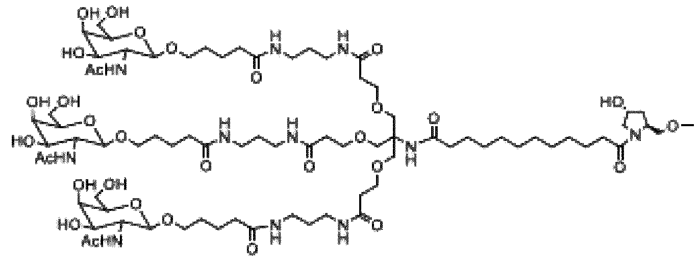
CO-
As used herein, the terms 2’ -deoxy- 2’-fluoroadenosine and 2’-fluoroadenosine may be used interchangeably.
As used herein, the terms 2’ -deoxy- 2’-fluorocytidine and 2’-fluorocytidine may be used interchangeably.
As used herein, the terms 2’ -deoxy- 2’-fluoroguanosine and 2’-fluoroguanosine may be used interchangeably.
As used herein, the terms 2’ -deoxy- 2’-fluorouridine and 2’-fluorouridine may be used interchangeably.
The expanded structural formula, molecular formula, and molecular weight of fitusiran are shown in Figure 39.
The structure of fitusiran can also be described using the following diagram, wherein the X is O:

Fitusiran is shown in Figure 39 in sodium salt form.
In some embodiments, the device delivers fitusiran in an aqueous solution, wherein fitusiran is at a concentration of about 40 to about 200 mg/mL (e.g., about 50 to about 150 mg/mL, about 80 to about 110 mg/mL, or about 90 to about 110 mg/mL). As used herein, values intermediate to recited ranges and values are also intended to be part of this disclosure. In addition, ranges of values using a combination of any of recited values as upper and/or lower limits are intended to be included. In further embodiments, the pharmaceutical formulation comprises fitusiran in an aqueous solution at a concentration of about 40, about 50, about 75, about 100, about 125, about 150, or about 200 mg/mL. In certain embodiments, fitusiran is provided in an aqueous solution at a concentration of about 100 mg/mL.
The term “deliver,” “delivers,” or “delivering” is intended to mean “administer,” “administers,” or “administering.”
Unless specifically stated or otherwise evident from the context, as used herein, the term “approximately” or "about" refers to a value that is within an acceptable error range for a particular value determined by a person of ordinary skill, a portion of which will depend on how the measurement or determination is made. For example, “approximately” or "about" may mean
a range of up to 10% (ie, ±10%). Therefore, “approximately” or "about" can be understood as greater than or less than 10%, 9%, 8%, 7%, 6%, 5%, 4%, 3%, 2%, 1%, 0.5%, 0.1 %, 0.05%, 0.01%, or 0.001%. When a specific value is provided in this disclosure, unless otherwise stated, the meaning of “approximately” or "about" should be assumed to be within an acceptable error range for that specific value.
While the fitusiran dosage weight described herein refers to the weight of fitusiran free acid (active moiety), administration of fitusiran to patients herein refers to administration of fitusiran sodium (drug substance) provided in a pharmaceutically suitable aqueous solution (e.g., a phosphate-buffered saline at a physiological pH). For example, about 100 mg/mL fitusiran means about 100 mg of fitusiran free acid (equivalent to about 106 mg fitusiran sodium, the drug substance) per ml_. Unless otherwise indicated, a fitusiran weight recited in the present disclosure is the weight of fitusiran free acid (the active moiety).
In some embodiments, a pharmaceutical formulation in the device comprises fitusiran in a phosphate-buffered saline. The phosphate concentration in the solution may be about 1 to about 10 mM (e.g., about 2, about 3, about 4, about 5, about 6, about 7, about 8, or about 9 mM), with a pH of about 6.0-8.0. The pharmaceutical formulations herein may include a stabilizing agent such as EDTA. The pharmaceutical formulations may be preservative-free. In some embodiments, the fitusiran pharmaceutical formulation in the device is preservative-free and comprises, consists of, or consists essentially of about 100 mg of fitusiran per mL of an approximately 5 mM phosphate buffered saline (PBS) solution. In some embodiments, the fitusiran pharmaceutical formulation in the device is preservative-free and comprises, consists of, or consists essentially of fitusiran in an approximately 5 mM phosphate buffered saline (PBS) solution. The PBS solution is composed of sodium chloride, dibasic sodium phosphate (heptahydrate), and monobasic sodium phosphate (monohydrate). Sodium hydroxide solution and diluted phosphoric acid may be used to adjust the pH of the pharmaceutical formulation to about 7.0 or about 7.1.
In some embodiments, the fitusiran pharmaceutical formulation in the device for subcutaneous delivery contains fitusiran in a 5 mM phosphate buffered saline having 0.64 mM Na^PC , 4.36 mM Na2HPC>4, and 84 mM NaCI at pH 7.0. In certain embodiments, the pharmaceutical formulation of fitusiran solution for subcutaneous delivery is shown in Table 1 below:
Table 1. Exemplary Fitusiran Pharmaceutical Formulation

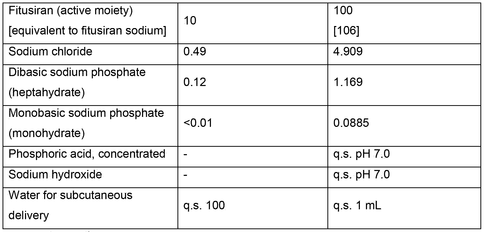
*q.s.: quantum satis
In some embodiments, the pharmaceutical formulation of fitusiran solution for subcutaneous delivery with the device can be described as shown in Table 2 below. Table 2. Exemplary Fitusiran Pharmaceutical Formulation
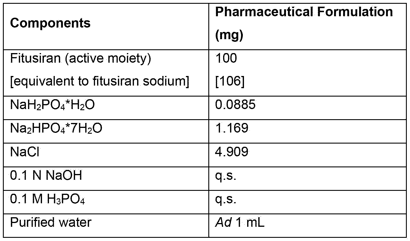
In some embodiments, the device may be used to deliver a single dose of fitusiran wherein the single dose comprises about 20 to about 80 mg of fitusiran (e.g., about 20 mg, about 25 mg, about 30 mg, about 40 mg, about 50 mg, or about 80 mg). In some embodiments, the device may be used to deliver single dose of fitusiran, wherein the single dose comprises about 1 to about 30 mg of fitusiran (e.g., about 1.25 mg, about 2.5 mg, about 5 mg, about 10 mg, about 20 mg, or about 30 mg).
In one embodiment, the device may be used to deliver a single dose of about 80 mg of fitusiran. In one embodiment, the device may be used to deliver a single dose of about 50 mg of fitusiran.
In one embodiment, the device may be used to deliver a single dose of about 20 mg of fitusiran.
In one embodiment, the device may be used to deliver a single dose of about 30 mg of fitusiran.
In one embodiment, the device may be used to deliver a single dose of about 10 mg of fitusiran. In one embodiment, the device may be used to deliver a single dose of about 5 mg of fitusiran. In one embodiment, the device may be used to deliver a single dose of about 2.5 mg of fitusiran. In one embodiment, the device may be used to deliver a single dose of about 1.25 mg of fitusiran.
In some embodiments, the single dose of fitusiran may be delivered in about 0.5 mL to about 1 mL delivery volumes (e.g., about 0.5 mL, about 0.6 mL, about 0.7 mL, about 0.8 mL, about 0.9 mL, or about 1 mL). Other delivery volumes described herein may also be used.
In one embodiment, the device may be used to deliver a single dose of about 80 mg of fitusiran in about 0.8 mL (about 100 mg fitusiran/mL). In one embodiment, the device may be used to deliver a single dose of about 50 mg of fitusiran in about 0.5 mL (about 100 mg fitusiran/mL). In one embodiment, the device may be used to deliver a single dose of about 20 mg of fitusiran in about 0.5 mL (about 40 mg fitusiran/mL). In one embodiment, the device may be used to deliver a single dose of about 30 mg of fitusiran in about 0.5 mL (about 60 mg fitusiran/mL). In one embodiment, the device may be used to deliver a single dose of about 10 mg of fitusiran in about 0.5 mL (about 20 mg fitusiran/mL). In one embodiment, the device may be used to deliver a single dose of about 5 mg of fitusiran in about 0.5 mL (about 10 mg fitusiran/mL). In one embodiment, the device may be used to deliver a single dose of about 2.5 mg of fitusiran in about 0.5 mL (about 5 mg fitusiran/mL). In one embodiment, the device may be used to deliver a single dose of about 1.25 mg of fitusiran in about 0.5 mL (about 2.5 mg fitusiran/mL).
In one embodiment, the device delivers fitusiran at a prophylactically effective amount to prophylactically treat hemophilia (e.g., hemophilia A or B, in a patient with or without inhibitors) in a patient in need thereof (e.g., a hemophilia A or B patient, with or without inhibitors). “Prophylactically effective amount” refers to the amount of fitusiran that helps the patient with hemophilia A or B, with or without inhibitors to achieve a desired clinical endpoint such as reducing the Annualized Bleeding Rate (ABR), Annualized Joint Bleeding Rate (AjBR), Annualized Spontaneous Bleeding Rate (AsBR), or the frequency of bleeding episodes. As used herein in the context of fitusiran, the term “treat” “treating,” or “treatment” includes prophylactic treatment of the disease and refers to achievement of a desired clinical endpoint.
A hemophilia A or B patient with inhibitors refers to a patient who has developed alloantibodies to the factor he/she has previously received (e.g., factor VIII for hemophilia A patients or factor IX for hemophilia B patients). A hemophilia A or B patient with inhibitors may become refractory to replacement coagulation factor therapies. A patient without inhibitors refers to a patient who
does not have such alloantibodies. The present treatment methods may be beneficial for hemophilia A patients with inhibitors, as well as for hemophilia B patients with inhibitors.
As used herein, a patient with “hemophilia A or B, with or without inhibitors,” or refers to 1 ) a hemophilia A patient with inhibitors, or 2) a hemophilia B patient with inhibitors, 3) a hemophilia A patient without inhibitors, or 4) a hemophilia B patient without inhibitors. As used herein, a patient refers to a human patient. A patient can also refer to a human subject.
In some embodiments, the device may be used to prophylactically treat a patient with hemophilia A or B, with or without inhibitors, with a subcutaneous dose of about 50 mg of fitusiran once every two months (or every eight weeks). In other embodiments, the device may be used to prophylactically treat a patient with hemophilia A or B, with or without inhibitors, with a subcutaneous dose of about 50 mg of fitusiran every month (or every four weeks). In yet other embodiments, the device may be used to prophylactically treat a patient with hemophilia A or B, with or without inhibitors, with a subcutaneous dose of about 80 mg of fitusiran every two months (or every eight weeks). In yet other embodiments, the device may be used to prophylactically treat a patient with hemophilia A or B, with or without inhibitors, with a subcutaneous dose of about 80 mg of fitusiran every month (or every four weeks). In yet other embodiments, the device may be used to prophylactically treat a patient with hemophilia A or B, with or without inhibitors, with a subcutaneous dose of about 20 mg of fitusiran every two months (or every eight weeks). In yet other embodiments, the device may be used to prophylactically treat a patient with hemophilia A or B, with or without inhibitors, with a subcutaneous dose of about 20 mg of fitusiran every month (or every four weeks). In yet other embodiments, the device may be used to prophylactically treat a patient with hemophilia A or B, with or without inhibitors, with a subcutaneous dose of about 10 mg of fitusiran every month (or every four weeks). In yet other embodiments, the device may be used to prophylactically treat a patient with hemophilia A or B, with or without inhibitors, with a subcutaneous dose of fitusiran at about 30 mg every month (or every four weeks). In yet other embodiments, the device may be used to prophylactically treat a patient with hemophilia A or B, with or without inhibitors, with a subcutaneous dose of fitusiran at about 5 mg every month (or every four weeks). In yet other embodiments, the device may be used to prophylactically treat a patient with hemophilia A or B, with or without inhibitors, with a subcutaneous dose of fitusiran at about 2.5 mg every month (or every four weeks). In yet other embodiments, the device may be used to prophylactically treat a patient with hemophilia A or B, with or without inhibitors, with a subcutaneous dose of fitusiran at about 1.25 mg every month (or every four weeks).
Accordingly, provided herein is a method of prophylactic treatment of a patient with hemophilia A or hemophilia B, with or without inhibitors, comprising subcutaneously delivering with the
device a prophylactical ly effective amount of fitusiran to the patient in need thereof. The prophylactically effective amount of fitusiran may be any dose provided herein, such as about 1 to about 80 mg, about 1 to about 30 mg, or about 20 to about 80 mg. The prophylactically effective amount of fitusiran may be, for example, about 1.25 mg, about 2.5 mg, about 5 mg, about 25 mg, about 30 mg, about 50 mg, or about 80 mg. The prophylactically effective amount of fitusiran may be delivered every month (or every four weeks) or once every two months (or every eight weeks). Fitusiran may be delivered in about 0.5 mL to about 1 mL delivery volumes (e.g., about 0.5 mL, about 0.6 mL, about 0.7 mL, about 0.8 mL, about 0.9 mL, or about 1 mL).
As an example, a method of prophylactic treatment of a patient with hemophilia A or hemophilia B, with or without inhibitors, may comprise subcutaneously delivering with the device about 50 mg of fitusiran to the patient in need thereof every month (or every four weeks) or once every two months (or every eight weeks). The about 50 mg of fitusiran may be delivered in about 0.5 mL PBS (at a concentration of about 100 mg fitusiran/mL).
Further provided herein is a method of reducing the frequency of bleeding episodes in a patient with hemophilia A or B, with or without inhibitors, comprising subcutaneously delivering with the device a prophylactically effective amount of fitusiran to the patient in need thereof. The prophylactically effective amount of fitusiran may be any dose provided herein, such as about 1 to about 80 mg, about 1 to about 30 mg, or about 20 to about 80 mg. The prophylactically effective amount of fitusiran may be, for example, about 1.25 mg, about 2.5 mg, about 5 mg, about 25 mg, about 30 mg, about 50 mg, or about 80 mg. The prophylactically effective amount of fitusiran may be delivered every month (or every four weeks) or once every two months (or every eight weeks). Fitusiran may be delivered in about 0.5 mL to about 1 mL delivery volumes (e.g., about 0.5 mL, about 0.6 mL, about 0.7 mL, about 0.8 mL, about 0.9 mL, or about 1 mL).
As an example, a method of reducing the frequency of bleeding episodes in a patient with hemophilia A or B, with or without inhibitors, may comprise subcutaneously delivering with the device about 50 mg of fitusiran to the patient in need thereof every month (or every four weeks) or once every two months (or every eight weeks). The about 50 mg of fitusiran may be delivered in about 0.5 mL PBS (at a concentration of about 100 mg fitusiran/mL).
Also, provided herein is a method of reducing the ABR in a patient with hemophilia A or B, with or without inhibitors, comprising subcutaneously delivering with the device a prophylactically effective amount of fitusiran to the patient in need thereof. The prophylactically effective amount of fitusiran may be any dose provided herein, such as about 1 to about 80 mg, about 1 to about 30 mg, or about 20 to about 80 mg. The prophylactically effective amount of fitusiran may be, for example, about 1.25 mg, about 2.5 mg, about 5 mg, about 25 mg, about 30 mg,
about 50 mg, or about 80 mg. The prophylactically effective amount of fitusiran may be delivered every month (or every four weeks) or once every two months (or every eight weeks). Fitusiran may be delivered in about 0.5 mL to about 1 mL delivery volumes (e.g., about 0.5 ml_, about 0.6 mL, about 0.7 mL, about 0.8 mL, about 0.9 mL, or about 1 mL).
As an example, a method of reducing the ABR in a patient with hemophilia A or B, with or without inhibitors, may comprise subcutaneously delivering with the device about 50 mg of fitusiran to the patient in need thereof every month (or every four weeks) or once every two months (or every eight weeks). The about 50 mg of fitusiran may be delivered in about 0.5 mL PBS (at a concentration of about 100 mg fitusiran/mL).
Also, provided herein is a method of reducing the AjBR in a patient with hemophilia A or B, with or without inhibitors, comprising subcutaneously delivering with the device a prophylactically effective amount of fitusiran to the patient in need thereof. The prophylactically effective amount of fitusiran may be any dose provided herein, such as about 1 to about 80 mg, about 1 to about 30 mg, or about 20 to about 80 mg. The prophylactically effective amount of fitusiran may be, for example, about 1.25 mg, about 2.5 mg, about 5 mg, about 25 mg, about 30 mg, about 50 mg, or about 80 mg. The prophylactically effective amount of fitusiran may be delivered every month (or every four weeks) or once every two months (or every eight weeks). The fitusiran may be delivered in about 0.5 mL to about 1 mL delivery volumes (e.g., about 0.5 mL, about 0.6 mL, about 0.7 mL, about 0.8 mL, about 0.9 mL, or about 1 mL).
As an example, a method of reducing the AjBR in a patient with hemophilia A or B, with or without inhibitors, may comprise subcutaneously delivering with the device about 50 mg of fitusiran to the patient in need thereof every month (or every four weeks) or once every two months (or every eight weeks). The about 50 mg of fitusiran may be delivered in about 0.5 mL PBS (at a concentration of about 100 mg fitusiran/mL).
Also, provided herein is a method of reducing the AsBR in a patient with hemophilia A or B, with or without inhibitors, comprising subcutaneously delivering with the device a prophylactically effective amount of fitusiran to the patient in need thereof. The prophylactically effective amount of fitusiran may be any dose provided herein, such as about 1 to about 80 mg, about 1 to about 30 mg, or about 20 to about 80 mg. The prophylactically effective amount of fitusiran may be, for example, about 1.25 mg, about 2.5 mg, about 5 mg, about 25 mg, about 30 mg, about 50 mg, or about 80 mg. The prophylactically effective amount of fitusiran may be delivered every month (or every four weeks) or once every two months (or every eight weeks). Fitusiran may be delivered in about 0.5 mL to about 1 mL delivery volumes (e.g., about 0.5 mL, about 0.6 mL, about 0.7 mL, about 0.8 mL, about 0.9 mL, or about 1 mL).
As an example, a method of reducing the AsBR in a patient with hemophilia A or B, with or without inhibitors, may comprise subcutaneously delivering with the device about 50 mg of fitusiran to the patient in need thereof every month (or every four weeks) or once every two months (or every eight weeks). The about 50 mg of fitusiran may be delivered in about 0.5 mL PBS (at a concentration of about 100 mg fitusiran/mL).
Any invention described herein is not limited by the description in conjunction with the exemplary embodiments. Rather, the invention and the associated disclosure comprise any new feature as well as any combination of features, particularly including any combination of features in the patent claims, even if said feature or said combination per se is not explicitly stated in the patent claims or exemplary embodiments. For example, the drug delivery device shown in figures 1 and 2 may comprise a releasing mechanism 42 as explained with respect to figures 6, 8, 10, and 11 , a releasing mechanism 42 as explained with respect to figures 13, 14, and 15, or a releasing mechanism 42 as explained with respect to figures 30 to 32. Further, the drug delivery device 20 as shown in figures 6, 8, 10, and 11 may comprise a U-shaped releasing member 46 and/or an activator lock 70 as shown in figures 13 to 15. Further, the drug delivery device 20 as shown in figures 13 to 15 may comprise a rod-shaped releasing member 46 and/or an activator lock 70 as shown in figures 6, 8, 10, and 11. Further, the protection member 50 of the drug delivery device 20 shown in figures 1 and 2, or in figures 13 to 15 may protect the needle 48 in the final state and/or may be locked in the final state, as explained with respect to the drug delivery device 20 as shown in figures 6, 8, 10, and 11. Further, the arrestor 44 shown in figures 16 and 17 may be arranged in any of the above drug delivery devices 20. Further, the drug container 24 and the energy storage member 36 as shown in figures 18 to 25 may be arranged in any of the above drug delivery devices 20. Further, the needle shield 104 and/or the safety features shown in figures 26 to 29 may be arranged at any of the above drug delivery devices 20. Further, the drug delivery device 20 explained with respect to figures 30 to 32 may comprise the arrestor 44 of figures 3, 16, or 17, the energy storage member 36 of figure 4, the drug container 24 of any of figures 5, or 18 to 25, the needle shield 104 of figures 26 and 27, and/or the splint 110 of figure 28. Alternatively or additionally, the releasing member 46 shown in figures 30 to 32 may be rod-shaped as explained with respect to figures 6, 8, 10, and 11, or U-shaped as explained with respect to figures 13 to 15. Further, any of the drug delivery devices explained with respect to figures 1 to 32 may be combined with a protection member as shown in figures 33 to 36 and/or with a supporting structure 126 explained with respect to figures 37 and 38.
Reference numerals
20 drug delivery device
22 housing
24 drug container
26 chamber
28 dispensing portion
30 remote end
32 roller
34 axle
36 energy storage member
38 guide rail
40 dispensing direction
42 release mechanism
44 arrestor
46 releasing member
48 needle
50 protection member
52 guidance recess
54 guidance pin
56 bottom recess
58 bearing surface
60 needle recess
62 fixation features
64 interface
66 protruding portion
70 activator lock
73 rounded section
72 activator lock recess
74 upper part
75 positive lock
76 lower part
77 axis
78 arm
80 central portion
82 barb
84 button spring
86 chamfer
88 clamping structure
90 container seam
92 film
94 film seam
96 clamping area
98 holder
100 gripping area
102 film holder
104 needle shield
106 gripping structure
108 injection site
110 splint
112 ring
114 leg spring
116 direction of rotation
118 release recess
120 release pin
122 spring
124 spring
126 support structure
Claims
1. A drug delivery device (20), comprising: a housing (22); a drug container (24) within the housing (22), the drug container (24) having a chamber (26), a drug within the chamber (26), and a dispensing portion (28) for dispensing the drug; a roller (32), which is arranged at a distance from the dispensing portion (28) of the drug container (24) and which comprises an axle (34) oriented obliquely to a dispensing direction (40); and an energy storage member (36), which is coupled to the roller (32), which is locked and loaded in an initial state of the drug delivery device (20), and which is configured for driving a rolling movement of the roller (32) towards the dispensing portion (28) upon being released such that the roller (32) presses the drug from the drug container (24) through the dispensing portion (28) during a dispensing operation.
2. The drug delivery device (20) of claim 1, wherein the housing (22) comprises two guide rails (38), wherein each of the guide rails (38) accommodates an axial end of the axle (34) and wherein the guide rails (38) guide the axle (34) and as such the roller (32), when the roller (32) is rolled.
3. The drug delivery device (20) of any one of the preceding claims, wherein the energy storage member (36) comprises a constant force spring, on which the drug container (24) and the roller (32) are arranged and which is fixed to the housing (22), fixed to the roller (32), locked, at least unrolled and as such biased in the initial state, and configured for rolling itself up and driving the rolling movement of the roller (32) upon being released such that the roller (32) presses the drug from the drug container (24) through the dispensing portion (28) during the dispensing operation.
4. The drug delivery device (20) of any one of the preceding claims, comprising a needle (48) for injecting the drug into an injection site (108), wherein the needle (48) is coupled to the dispensing portion (28) of the drug container (24) and wherein the needle (48) partly extends through the housing (22) in a direction oblique to the dispensing direction (40).
5. The drug delivery device (20) of any one of the preceding claims, comprising a release mechanism (42) which is configured for locking the roller (32) and thereby the energy storage member (36) in the initial state and for releasing the roller (32) and thereby the energy storage member (36) upon activation of the release mechanism (42).
6. The drug delivery device (20) of claim 5, wherein the release mechanism (42) comprises an arrestor (44), which is fixed to the housing (22) and which is engaged with the roller (32) in the initial state, and a releasing member (46), which extends through the housing (22) with a protruding portion (66) of the releasing member (46), which is couplable with the arrestor (44) at a distance to the protruding portion (66), and which is configured for disengaging the arrestor (44) from the roller (32) upon moving the releasing member (46) into the housing (22).
7. The drug delivery device (20) of claim 6, wherein the releasing member (46) has a U-shape with two arms (78) and a central portion (80) connecting the two arms (78); the central portion (80) provides the protruding portion (66) of the releasing member (46); and the arms (78) are configured for being coupled to the arrestor (44) and for disengaging the arrestor (44) from the roller (32).
8. The drug delivery device (20) of any of claims 5 to 7, comprising a protection member (50) for protecting the needle (48), wherein the protection member (50) is operatively coupled to the release mechanism (42) and configured such that an activation of the release mechanism (42) is prevented as long as the protection member (50) protects the needle (48) and that the activation of the release mechanism (42) is enabled, when the protection member (50) exposes the needle (48).
9. The drug delivery device (20) of claim 8, wherein the protection member (50) protrudes from the housing (22) such that the needle (48) is protected by the protection member (50) in the initial state and wherein the protection member (50) is configured for at least partly being moved into the housing (22) and as such for exposing the needle (48), when the drug delivery device (20) is arranged on an injection site (108).
10. The drug delivery device (20) of claim 9, wherein a) a first end of the protection member (50) is pivotably attached to the housing (22) such that the protection member (50) can be rotated around an axis (77);
the protection member (50) is arranged such that it is slidable relative the housing (22) at a second end of the protection member (50); and the protection member (50) is configured for being at least partly introduced into the housing (22) at the second end by a rotation of the protection member (50) around the axis (77) upon arranging the drug delivery device (20) on the injection site (108) and pressing the housing (22) against the injection site (108) or wherein b) the protection member is linearly movable into the housing.
11. The drug delivery device (20) of any of claims 9 or 10, comprising a needle shield (104) for removably covering the needle (48), wherein the needle shield (104) is formed and arranged such that the movement of the protection member (50) into the housing (22) is blocked as long as the needle shield (104) is arranged on the needle (48) and that the movement of the protection member (50) into the housing (22) is enabled when the needle shield (104) is removed from the needle (48).
12. The drug delivery device (20) of claim 11 , comprising one or more safety features (110, 112) configured for blocking the movement of the protection member (50) into the housing (22) in a safety state and for allowing the movement of the protection member (50) into the housing (22) in an operation state.
13. The drug delivery device (20) of any of claims 8 to 11, comprising an activator lock (70), which operatively couples the protection member (50) to the releasing member (46) and which is configured for blocking a movement of the releasing member (46) as long as the protection member (50) protects the needle (48) and for allowing the movement of the releasing member (46) when the protection member (50) exposes the needle (48).
14. The drug delivery device (20) of any of the preceding claims, wherein the drug container (24) comprises a flexible bag, which is arranged on the energy storage member (36) in the initial state and which is configured for being rolled onto the roller (32) during the dispensing operation.
15. The drug delivery device (20) of any of the preceding claims, wherein the drug container (24) is coupled to the needle (48) by an interface (64), which comprises one or more engaging features (100) for coupling the drug container (24) to the housing (22).
Priority Applications (1)
| Application Number | Priority Date | Filing Date | Title |
|---|---|---|---|
| CN202480037912.8A CN121285405A (en) | 2023-06-05 | 2024-06-05 | Drug delivery device |
Applications Claiming Priority (2)
| Application Number | Priority Date | Filing Date | Title |
|---|---|---|---|
| EP23315230.5 | 2023-06-05 | ||
| EP23315230 | 2023-06-05 |
Publications (1)
| Publication Number | Publication Date |
|---|---|
| WO2024251795A1 true WO2024251795A1 (en) | 2024-12-12 |
Family
ID=86861773
Family Applications (1)
| Application Number | Title | Priority Date | Filing Date |
|---|---|---|---|
| PCT/EP2024/065439 Pending WO2024251795A1 (en) | 2023-06-05 | 2024-06-05 | Drug delivery device |
Country Status (2)
| Country | Link |
|---|---|
| CN (1) | CN121285405A (en) |
| WO (1) | WO2024251795A1 (en) |
Citations (6)
| Publication number | Priority date | Publication date | Assignee | Title |
|---|---|---|---|---|
| US20140171871A1 (en) * | 2008-11-25 | 2014-06-19 | Meridian Medical Technologies, Inc. | Auto-Injector Apparatus |
| US9127274B2 (en) | 2012-04-26 | 2015-09-08 | Alnylam Pharmaceuticals, Inc. | Serpinc1 iRNA compositions and methods of use thereof |
| WO2019014187A1 (en) | 2017-07-10 | 2019-01-17 | Genzyme Corporation | Methods and compositions for treating a bleeding event in a subject having hemophilia |
| US11091759B2 (en) | 2015-12-07 | 2021-08-17 | Genzyme Corporation | Methods and compositions for treating a Serpinc1-associated disorder |
| WO2022129288A1 (en) * | 2020-12-17 | 2022-06-23 | Sanofi | Autoinjector with a squeeze arrangement |
| US20230131037A1 (en) * | 2016-09-27 | 2023-04-27 | Sanofi-Aventis Deutschland Gmbh | Medicament delivery device |
-
2024
- 2024-06-05 WO PCT/EP2024/065439 patent/WO2024251795A1/en active Pending
- 2024-06-05 CN CN202480037912.8A patent/CN121285405A/en active Pending
Patent Citations (7)
| Publication number | Priority date | Publication date | Assignee | Title |
|---|---|---|---|---|
| US20140171871A1 (en) * | 2008-11-25 | 2014-06-19 | Meridian Medical Technologies, Inc. | Auto-Injector Apparatus |
| US9127274B2 (en) | 2012-04-26 | 2015-09-08 | Alnylam Pharmaceuticals, Inc. | Serpinc1 iRNA compositions and methods of use thereof |
| US11091759B2 (en) | 2015-12-07 | 2021-08-17 | Genzyme Corporation | Methods and compositions for treating a Serpinc1-associated disorder |
| US20230131037A1 (en) * | 2016-09-27 | 2023-04-27 | Sanofi-Aventis Deutschland Gmbh | Medicament delivery device |
| WO2019014187A1 (en) | 2017-07-10 | 2019-01-17 | Genzyme Corporation | Methods and compositions for treating a bleeding event in a subject having hemophilia |
| US20200163987A1 (en) | 2017-07-10 | 2020-05-28 | Genzyme Corporation | Methods and compositions for treating a bleeding event in a subject having hemophilia |
| WO2022129288A1 (en) * | 2020-12-17 | 2022-06-23 | Sanofi | Autoinjector with a squeeze arrangement |
Non-Patent Citations (1)
| Title |
|---|
| PASI ET AL., N ENGL J MED., vol. 377, no. 9, 2017, pages 819 - 28 |
Also Published As
| Publication number | Publication date |
|---|---|
| CN121285405A (en) | 2026-01-06 |
Similar Documents
| Publication | Publication Date | Title |
|---|---|---|
| US12251542B2 (en) | Medicament delivery device | |
| EP3380154B1 (en) | Medicament injection device | |
| US11071832B2 (en) | Medicament injection device | |
| US12390603B2 (en) | Injection device | |
| US20210308378A1 (en) | Medicament injection device | |
| US11007323B2 (en) | Medicament injection device with pivoting needle holder | |
| US12274866B1 (en) | Rotatable collar for injection devices | |
| US12337160B1 (en) | Medicament delivery device | |
| WO2024251795A1 (en) | Drug delivery device | |
| WO2024251793A1 (en) | Drug delivery device | |
| US12403266B1 (en) | Medicament delivery device | |
| US12268858B1 (en) | Injector device | |
| WO2024251797A1 (en) | Drug delivery device | |
| US12329954B1 (en) | Medicament delivery device | |
| US12434004B1 (en) | Medicament delivery device | |
| WO2024251798A1 (en) | Drug delivery device | |
| US12274873B1 (en) | Medicament delivery device | |
| US20250041536A1 (en) | Drug delivery arrangement comprising a tissue receiving element | |
| WO2024251792A1 (en) | Drug delivery device | |
| WO2024251801A1 (en) | Drug delivery device with laterally flexible needle sleeve | |
| WO2025162928A1 (en) | Needle shroud unlock device for a medicament delivery device | |
| EP4448056A1 (en) | Drug delivery arrangement comprising a skin pinching mechanism | |
| WO2024251796A1 (en) | Drug delivery device having two drug delivery arrangements | |
| WO2024251799A1 (en) | Self-driven medicament container and medicament delivery device | |
| WO2024251800A1 (en) | Drug delivery device |
Legal Events
| Date | Code | Title | Description |
|---|---|---|---|
| 121 | Ep: the epo has been informed by wipo that ep was designated in this application |
Ref document number: 24732419 Country of ref document: EP Kind code of ref document: A1 |
|
| WWE | Wipo information: entry into national phase |
Ref document number: 2024732419 Country of ref document: EP |
|
| NENP | Non-entry into the national phase |
Ref country code: DE |