WO2024206121A2 - Vacuum-assisted integration of implants - Google Patents
Vacuum-assisted integration of implants Download PDFInfo
- Publication number
- WO2024206121A2 WO2024206121A2 PCT/US2024/021095 US2024021095W WO2024206121A2 WO 2024206121 A2 WO2024206121 A2 WO 2024206121A2 US 2024021095 W US2024021095 W US 2024021095W WO 2024206121 A2 WO2024206121 A2 WO 2024206121A2
- Authority
- WO
- WIPO (PCT)
- Prior art keywords
- implant
- vacuum
- porous
- port
- interconnected pores
- Prior art date
- Legal status (The legal status is an assumption and is not a legal conclusion. Google has not performed a legal analysis and makes no representation as to the accuracy of the status listed.)
- Ceased
Links
Classifications
-
- A—HUMAN NECESSITIES
- A61—MEDICAL OR VETERINARY SCIENCE; HYGIENE
- A61L—METHODS OR APPARATUS FOR STERILISING MATERIALS OR OBJECTS IN GENERAL; DISINFECTION, STERILISATION OR DEODORISATION OF AIR; CHEMICAL ASPECTS OF BANDAGES, DRESSINGS, ABSORBENT PADS OR SURGICAL ARTICLES; MATERIALS FOR BANDAGES, DRESSINGS, ABSORBENT PADS OR SURGICAL ARTICLES
- A61L27/00—Materials for grafts or prostheses or for coating grafts or prostheses
- A61L27/50—Materials characterised by their function or physical properties, e.g. injectable or lubricating compositions, shape-memory materials, surface modified materials
- A61L27/56—Porous materials, e.g. foams or sponges
-
- A—HUMAN NECESSITIES
- A61—MEDICAL OR VETERINARY SCIENCE; HYGIENE
- A61F—FILTERS IMPLANTABLE INTO BLOOD VESSELS; PROSTHESES; DEVICES PROVIDING PATENCY TO, OR PREVENTING COLLAPSING OF, TUBULAR STRUCTURES OF THE BODY, e.g. STENTS; ORTHOPAEDIC, NURSING OR CONTRACEPTIVE DEVICES; FOMENTATION; TREATMENT OR PROTECTION OF EYES OR EARS; BANDAGES, DRESSINGS OR ABSORBENT PADS; FIRST-AID KITS
- A61F2/00—Filters implantable into blood vessels; Prostheses, i.e. artificial substitutes or replacements for parts of the body; Appliances for connecting them with the body; Devices providing patency to, or preventing collapsing of, tubular structures of the body, e.g. stents
- A61F2/02—Prostheses implantable into the body
- A61F2/28—Bones
-
- A—HUMAN NECESSITIES
- A61—MEDICAL OR VETERINARY SCIENCE; HYGIENE
- A61F—FILTERS IMPLANTABLE INTO BLOOD VESSELS; PROSTHESES; DEVICES PROVIDING PATENCY TO, OR PREVENTING COLLAPSING OF, TUBULAR STRUCTURES OF THE BODY, e.g. STENTS; ORTHOPAEDIC, NURSING OR CONTRACEPTIVE DEVICES; FOMENTATION; TREATMENT OR PROTECTION OF EYES OR EARS; BANDAGES, DRESSINGS OR ABSORBENT PADS; FIRST-AID KITS
- A61F2/00—Filters implantable into blood vessels; Prostheses, i.e. artificial substitutes or replacements for parts of the body; Appliances for connecting them with the body; Devices providing patency to, or preventing collapsing of, tubular structures of the body, e.g. stents
- A61F2/02—Prostheses implantable into the body
- A61F2/30—Joints
- A61F2/38—Joints for elbows or knees
-
- A—HUMAN NECESSITIES
- A61—MEDICAL OR VETERINARY SCIENCE; HYGIENE
- A61L—METHODS OR APPARATUS FOR STERILISING MATERIALS OR OBJECTS IN GENERAL; DISINFECTION, STERILISATION OR DEODORISATION OF AIR; CHEMICAL ASPECTS OF BANDAGES, DRESSINGS, ABSORBENT PADS OR SURGICAL ARTICLES; MATERIALS FOR BANDAGES, DRESSINGS, ABSORBENT PADS OR SURGICAL ARTICLES
- A61L27/00—Materials for grafts or prostheses or for coating grafts or prostheses
- A61L27/02—Inorganic materials
- A61L27/04—Metals or alloys
- A61L27/047—Other specific metals or alloys not covered by A61L27/042 - A61L27/045 or A61L27/06
-
- A—HUMAN NECESSITIES
- A61—MEDICAL OR VETERINARY SCIENCE; HYGIENE
- A61L—METHODS OR APPARATUS FOR STERILISING MATERIALS OR OBJECTS IN GENERAL; DISINFECTION, STERILISATION OR DEODORISATION OF AIR; CHEMICAL ASPECTS OF BANDAGES, DRESSINGS, ABSORBENT PADS OR SURGICAL ARTICLES; MATERIALS FOR BANDAGES, DRESSINGS, ABSORBENT PADS OR SURGICAL ARTICLES
- A61L27/00—Materials for grafts or prostheses or for coating grafts or prostheses
- A61L27/02—Inorganic materials
- A61L27/04—Metals or alloys
- A61L27/06—Titanium or titanium alloys
-
- A—HUMAN NECESSITIES
- A61—MEDICAL OR VETERINARY SCIENCE; HYGIENE
- A61L—METHODS OR APPARATUS FOR STERILISING MATERIALS OR OBJECTS IN GENERAL; DISINFECTION, STERILISATION OR DEODORISATION OF AIR; CHEMICAL ASPECTS OF BANDAGES, DRESSINGS, ABSORBENT PADS OR SURGICAL ARTICLES; MATERIALS FOR BANDAGES, DRESSINGS, ABSORBENT PADS OR SURGICAL ARTICLES
- A61L27/00—Materials for grafts or prostheses or for coating grafts or prostheses
- A61L27/50—Materials characterised by their function or physical properties, e.g. injectable or lubricating compositions, shape-memory materials, surface modified materials
- A61L27/54—Biologically active materials, e.g. therapeutic substances
-
- A—HUMAN NECESSITIES
- A61—MEDICAL OR VETERINARY SCIENCE; HYGIENE
- A61L—METHODS OR APPARATUS FOR STERILISING MATERIALS OR OBJECTS IN GENERAL; DISINFECTION, STERILISATION OR DEODORISATION OF AIR; CHEMICAL ASPECTS OF BANDAGES, DRESSINGS, ABSORBENT PADS OR SURGICAL ARTICLES; MATERIALS FOR BANDAGES, DRESSINGS, ABSORBENT PADS OR SURGICAL ARTICLES
- A61L31/00—Materials for other surgical articles, e.g. stents, stent-grafts, shunts, surgical drapes, guide wires, materials for adhesion prevention, occluding devices, surgical gloves, tissue fixation devices
- A61L31/02—Inorganic materials
- A61L31/022—Metals or alloys
-
- A—HUMAN NECESSITIES
- A61—MEDICAL OR VETERINARY SCIENCE; HYGIENE
- A61L—METHODS OR APPARATUS FOR STERILISING MATERIALS OR OBJECTS IN GENERAL; DISINFECTION, STERILISATION OR DEODORISATION OF AIR; CHEMICAL ASPECTS OF BANDAGES, DRESSINGS, ABSORBENT PADS OR SURGICAL ARTICLES; MATERIALS FOR BANDAGES, DRESSINGS, ABSORBENT PADS OR SURGICAL ARTICLES
- A61L31/00—Materials for other surgical articles, e.g. stents, stent-grafts, shunts, surgical drapes, guide wires, materials for adhesion prevention, occluding devices, surgical gloves, tissue fixation devices
- A61L31/14—Materials characterised by their function or physical properties, e.g. injectable or lubricating compositions, shape-memory materials, surface modified materials
- A61L31/146—Porous materials, e.g. foams or sponges
-
- A—HUMAN NECESSITIES
- A61—MEDICAL OR VETERINARY SCIENCE; HYGIENE
- A61L—METHODS OR APPARATUS FOR STERILISING MATERIALS OR OBJECTS IN GENERAL; DISINFECTION, STERILISATION OR DEODORISATION OF AIR; CHEMICAL ASPECTS OF BANDAGES, DRESSINGS, ABSORBENT PADS OR SURGICAL ARTICLES; MATERIALS FOR BANDAGES, DRESSINGS, ABSORBENT PADS OR SURGICAL ARTICLES
- A61L31/00—Materials for other surgical articles, e.g. stents, stent-grafts, shunts, surgical drapes, guide wires, materials for adhesion prevention, occluding devices, surgical gloves, tissue fixation devices
- A61L31/14—Materials characterised by their function or physical properties, e.g. injectable or lubricating compositions, shape-memory materials, surface modified materials
- A61L31/16—Biologically active materials, e.g. therapeutic substances
-
- A—HUMAN NECESSITIES
- A61—MEDICAL OR VETERINARY SCIENCE; HYGIENE
- A61B—DIAGNOSIS; SURGERY; IDENTIFICATION
- A61B17/00—Surgical instruments, devices or methods
- A61B17/56—Surgical instruments or methods for treatment of bones or joints; Devices specially adapted therefor
- A61B17/58—Surgical instruments or methods for treatment of bones or joints; Devices specially adapted therefor for osteosynthesis, e.g. bone plates, screws or setting implements
- A61B17/68—Internal fixation devices, including fasteners and spinal fixators, even if a part thereof projects from the skin
- A61B17/72—Intramedullary devices, e.g. pins or nails
-
- A—HUMAN NECESSITIES
- A61—MEDICAL OR VETERINARY SCIENCE; HYGIENE
- A61L—METHODS OR APPARATUS FOR STERILISING MATERIALS OR OBJECTS IN GENERAL; DISINFECTION, STERILISATION OR DEODORISATION OF AIR; CHEMICAL ASPECTS OF BANDAGES, DRESSINGS, ABSORBENT PADS OR SURGICAL ARTICLES; MATERIALS FOR BANDAGES, DRESSINGS, ABSORBENT PADS OR SURGICAL ARTICLES
- A61L2300/00—Biologically active materials used in bandages, wound dressings, absorbent pads or medical devices
- A61L2300/40—Biologically active materials used in bandages, wound dressings, absorbent pads or medical devices characterised by a specific therapeutic activity or mode of action
- A61L2300/404—Biocides, antimicrobial agents, antiseptic agents
- A61L2300/406—Antibiotics
-
- A—HUMAN NECESSITIES
- A61—MEDICAL OR VETERINARY SCIENCE; HYGIENE
- A61L—METHODS OR APPARATUS FOR STERILISING MATERIALS OR OBJECTS IN GENERAL; DISINFECTION, STERILISATION OR DEODORISATION OF AIR; CHEMICAL ASPECTS OF BANDAGES, DRESSINGS, ABSORBENT PADS OR SURGICAL ARTICLES; MATERIALS FOR BANDAGES, DRESSINGS, ABSORBENT PADS OR SURGICAL ARTICLES
- A61L2300/00—Biologically active materials used in bandages, wound dressings, absorbent pads or medical devices
- A61L2300/40—Biologically active materials used in bandages, wound dressings, absorbent pads or medical devices characterised by a specific therapeutic activity or mode of action
- A61L2300/412—Tissue-regenerating or healing or proliferative agents
- A61L2300/414—Growth factors
-
- A—HUMAN NECESSITIES
- A61—MEDICAL OR VETERINARY SCIENCE; HYGIENE
- A61L—METHODS OR APPARATUS FOR STERILISING MATERIALS OR OBJECTS IN GENERAL; DISINFECTION, STERILISATION OR DEODORISATION OF AIR; CHEMICAL ASPECTS OF BANDAGES, DRESSINGS, ABSORBENT PADS OR SURGICAL ARTICLES; MATERIALS FOR BANDAGES, DRESSINGS, ABSORBENT PADS OR SURGICAL ARTICLES
- A61L2300/00—Biologically active materials used in bandages, wound dressings, absorbent pads or medical devices
- A61L2300/40—Biologically active materials used in bandages, wound dressings, absorbent pads or medical devices characterised by a specific therapeutic activity or mode of action
- A61L2300/416—Anti-neoplastic or anti-proliferative or anti-restenosis or anti-angiogenic agents, e.g. paclitaxel, sirolimus
Definitions
- the present embodiments provide, inter alia, implants that include biocompatible, porous structures with a variety of geometries and configurations.
- Porous implants may be comprised of metals such as titanium and tantalum, as well as ceramics and polymers, and may be utilized for a variety of applications, such as the promotion of bone and soft tissue ingrowth.
- provided implants may comprise portions with differing internal pore densities, geometries, and/or distributions.
- vacuum pressure is directly applied to porous implants during and/or after surgery, with the vacuum pressure passing directly through the interior of the porous implants, to encourage ingrowth of tissues and improve integration of implants and to remove fluids and minimize and/or prevent infection.
- the present disclosure includes systems for enhancing ingrowth of at least one biological tissue into an implant, including: the implant; and a vacuum pump in fluid communication with the implant.
- the implant further includes a combination of a porous internal structure, a non-porous internal structure, a porous exterior surface, and a non-porous exterior surface.
- the implant further comprises at least one vacuum port disposed at an interior location or on an exterior surface of the implant.
- the at least one vacuum port is in fluid communication with the vacuum pump.
- the porous internal structure includes a plurality of interconnected pores and/or interconnected variable vacuum delivery channels.
- the porous exterior surface includes a plurality of interconnected pores and/or interconnected variable vacuum delivery channels.
- the interconnected pores and/or the interconnected variable vacuum delivery channels are fluidly connected to the at least one vacuum port.
- the vacuum pump applies a vacuum pressure between about 50 mmHg and 175 mmHg (e.g., between about 90 mmHg and 125 mmHg, between about 100 mmHg and 175 mmHg, between about 130 mmHg and 175 mmHg). In some embodiments, the vacuum pump applies a vacuum pressure that varies in pressure over time in a regular (e.g., periodic) or irregular (e.g., aperiodic) pattern.
- the interconnected pores include rhombic dodecahedral shapes, trabecular shapes, and/or random shapes.
- the implant includes at least one of CoCrMo, titanium, tantalum, steel, and stainless steel.
- the implant is produced by a manufacturing process selected from the group consisting of casting, molding, injection molding, physical deposition, chemical vapor deposition, direct metal laser melting, direct metal laser sintering, stereolithography, fused deposition modeling, and other modalities of additive manufacturing.
- the implant includes at least one of a metal, a ceramic, and a polymer.
- the vacuum pump comprises a portable (e.g., wearable) vacuum pump.
- the system further comprises at least one of a flexible film and a porous foam to distribute the vacuum pressure.
- the present disclosure includes systems for enhancing ingrowth of at least one biological tissue into an implant, including: an implant including a porous internal structure, a porous exterior surface, and at least one vacuum port; and a vacuum pump in fluid communication with the plurality of interconnected pores via the at least one port.
- a porous internal structure includes a plurality of interconnected pores and/or interconnected variable vacuum delivery channels.
- interconnected pores and/or the interconnected variable vacuum delivery channels are fluidly connected to the at least one vacuum port.
- a vacuum pump applies a vacuum pressure between about 50 mmHg and 175 mmHg. In some embodiments, a vacuum pump applies a vacuum pressure between about 90 mmHg and 125 mmHg.
- provided systems may further include: a plurality of flexible vacuum tubing fluidly connected to the at least one vacuum port; one or more reservoirs fluidly connected to the plurality of flexible vacuum tubing, and one or more flexible adhesive films configured to cover one or more regions where the plurality of flexible vacuum tubing connects to the at least one vacuum port and forms one or more interfaces with the biological tissue, wherein the one or more reservoirs are configured to collect biological fluids and tissues.
- the present disclosures are directed to a method for enhancing ingrowth of at least one biological tissue into an implant (e.g., medical implant, orthopedic implant, cosmetic implant, etc.), including the steps of: providing an implant comprising a partially porous internal structure with a plurality of interconnected pores, wherein the interconnected pores are fluidly connected to at least one port for applying vacuum pressure located at an exterior surface or an interior location of the implant; forming an incision in a living patient, the incision of sufficient length and depth to at least partially enclose the implant; inserting the implant into the incision in the living patient, and disposing the implant so that it is in contact with the at least one biological tissue in the living patient; surgically closing the incision; and applying a vacuum pressure in fluid communication with the plurality of interconnected pores via the at least one port for a duration of time that comprises a portion of incision healing time.
- an implant e.g., medical implant, orthopedic implant, cosmetic implant, etc.
- the vacuum pressure may be applied indirectly (e.g., under a flexible shield).
- the porous material includes a random arrangement of pores. In some embodiments, the porous material includes a regular array of pores. In some embodiments, the porous material includes at least one of a porous metallic material, a porous polymeric material, and a porous ceramic material. In some embodiments, the porous material resists collapse when the vacuum pressure is applied.
- any application-appropriate amount of pressure may be used.
- the vacuum pressure is between about 50 mmHg and 175 mmHg. In some embodiments, the vacuum pressure is between about 90 mmHg and 125 mmHg. In some embodiments, the vacuum pressure is between about 100 mmHg and 175 mmHg. In some embodiments, the vacuum pressure is between about 130 mmHg and 175 mmHg.
- the vacuum pressure is applied for a total duration in a range from about one hour to about three weeks.
- the vacuum pressure is applied in a repeated pattern comprising a first duration when the vacuum pressure is on, a second duration when the vacuum pressure is off, and a frequency of the repeated pattern during which the first duration and the second duration are repeated in sequence.
- the first duration and the second duration may vary over time in regular and/or random patterns.
- At least one biological tissue includes at least one member of the group consisting of muscular tissue, connective tissue, skeletal tissue, vascular tissue, epithelial tissue, respiratory tissue, nervous tissue, fat tissue, and mineralized tissue.
- the at least one biological tissue comprises bone.
- a vacuum is applied using a portable vacuum pump worn by the patient. In some embodiments, a vacuum is applied using a non-portable vacuum pump.
- an implant includes between one and five vacuum ports, wherein each of the vacuum ports is in fluid connection with at least a portion of the plurality of interconnected pores of the implant, and wherein each of the vacuum ports is located at a different location on the exterior and/or the interior of the implant.
- provided methods further include applying a different vacuum pressure to each of the vacuum ports, wherein each vacuum pressure is between about 50 mmHg and 150 mmHg.
- provided methods further comprise varying the vacuum pressure over the total duration.
- applying vacuum pressure comprises fluidly connecting one or more lengths of tubing between the interconnected pores to one or more reservoirs and to at least one vacuum pump, wherein the one or more reservoirs are configured to receive biological fluids and/or tissues.
- a living patient is at least one of a human, mammalian animal, or non-mammalian animal.
- the present disclosure includes orthopedic implants for implanting at a distal end of an interior limb stump, including: an elongate shaft (e.g., cylindrical shaft, shaft with elliptical cross-section, shaft with rectangular cross-section, etc.) covered in a layer of a first porous material and a first set of variable vacuum delivery channels; a flared abutment portion aligned longitudinally with an axis of the elongate shaft and attached to the distal end of the elongate shaft, the flared abutment portion covered in a second porous material and a second set of variable vacuum delivery channels; and at least one vacuum port disposed on the exterior surface and/or interior of the orthopedic implant, the at least one vacuum port fluidly connected to 1) at least one porous material, and 2) at least one set of variable vacuum delivery channels, wherein the elongate shaft is configured to be implanted into the distal end of the interior limb stump.
- an external surface of a flared shaft e.g., cylindrical shaft, shaft with ellip
- a first porous material includes fluidly interconnected pores, wherein the pores comprise rhombic dodecahedral shapes, trabecular shapes, and/or random shapes.
- a second porous material includes fluidly interconnected pores, wherein the pores includes rhombic dodecahedral shapes, trabecular shapes, and/or random shapes.
- a first porous material and the second porous material include at least one of CoCrMo, titanium, tantalum, steel, and stainless steel.
- the porosity of the first porous material and the porosity of the second porous material are different. In some embodiments, the porosity of the first porous material and the porosity of the second porous material are the same.
- fixation pins for use as a transcutaneous implant comprising: an inner metallic core comprising an elongate shaft; and an outer metallic layer surrounding the inner metallic core, the outer metallic layer comprising a first porous internal structure and a porous external surface.
- an inner metallic core is solid. In some embodiments, an inner metallic core comprises a second porous internal structure. In some embodiments, a first porous internal structure differs in at least one internal characteristic from a second porous internal structure, wherein the at least one internal characteristic includes a pore diameter, a bulk porosity, a porosity, a pore geometry, and/or a flow resistance.
- a first porous internal structure includes interconnected pores.
- interconnected pores arc rhombic dodecahedral in shape.
- interconnected pores are trabecular in shape.
- interconnected pores have irregular shapes.
- interconnected pores have an average diameter ranging from about 50 microns to about 650 microns.
- the thickness of the outer metallic layer is between about 25% and 75% of a diameter of the inner metallic core. In some embodiments, the thickness of the outer metallic layer is about 50% of a diameter of the inner metallic core.
- a fixation pin is designed to be removable.
- a fixation pin includes a metal or metal alloy.
- a fixation pin includes a member selected from the group consisting of CoCrMo, titanium, tantalum, steel, and stainless steel.
- a fixation pin further includes one or more compounds selected from the group consisting of therapeutics, growth factors, immuno- suppressants, antibiotics, adhesion promoters, and tissue growth promoters, disposed on at least one of an interior surface and an exterior surface of the fixation pin.
- a first porous internal structure varies in porosity along the direction of tissue ingrowth. In some embodiments, a first porous internal structure varies in porosity in the vicinity of an interface between two tissues.
- the present disclosure includes systems including an array of fixation pins as described herein, wherein the array of pins are each fluidly connected to each other, wherein the vacuum source (e.g., vacuum pump) applies vacuum pressure to each of the array of pins, and wherein the array of pins are configured to be implanted near each other in a tissue of a subject.
- the vacuum source e.g., vacuum pump
- fixation pins for use as a transcutaneous implant including: an inner metallic core; and an outer layer surrounding the inner metallic core, wherein the inner metallic core comprises an elongate shaft, wherein the outer layer comprises a porous structure, and wherein the inner metallic core and the outer layer are fabricated monolithically in a single, continuous manufacturing process.
- a single manufacturing process is selected from the group consisting of casting, molding, injection molding, physical deposition, chemical vapor deposition, direct metal laser melting, direct metal laser sintering, stereolithography, fused deposition modeling, and additive manufacturing. In some embodiments, a single manufacturing process is selected from the group consisting of additive manufacturing, investment casting, and injection molding.
- an outer layer includes a metallic material. In some embodiments, an outer layer includes a ceramic or a polymer material.
- the present disclosure includes systems including an array of fixation pins as described herein, wherein the array of pins are each fluidly connected to each other, wherein the vacuum source (e.g., vacuum pump) applies vacuum pressure to each of the array of pins, and wherein the array of pins are configured to be implanted near- each other in a tissue of a subject.
- the vacuum source e.g., vacuum pump
- the present disclosure includes sleeves for use with a fixation pin, including; a tubular portion comprising a hollow tube configured to accept the fixation pin within the interior lumen of the tube; and an attachment portion comprising a means for attaching the fixation pin to the tubular portion, the attachment portion connected to the hollow tube; and wherein the tubular portion includes a porous internal structure including interconnected pores.
- an attachment portion is connected to one end of the hollow tube. In some embodiments, an attachment portion is connected to the hollow tube along at least a portion of a length of the hollow tube. In some embodiments, interconnected pores are configured to facilitate soft tissue ingrowth into at least a portion of the interconnected pores.
- an attachment means includes at least one of a tab, a slot, a thread, a pin, a friction fit, a compression fit, an adhesive, a weld, a clamp, a taper fit, a key way and key, a dovetail, male and female, pin and hole, tang / tab, tongue and groove, a collet with slit and tightening screw, bone cement, bone cement loaded with antibiotics, and other suitable means.
- a porous internal structure includes at least one of a metal, a ceramic, and a polymer.
- a sleeve includes at least one vacuum port for applying a vacuum pressure.
- the present disclosure includes transdermal stump implants including: an elongate shaft (e.g., cylindrical shaft, shaft with elliptical cross-section, shaft with rectangular cross-section, etc.) covered in a layer of a first porous material including variable vacuum delivery channels; a flared abutment portion aligned longitudinally with an axis of the elongate shaft and attached to a proximal end of the elongate shaft, the flared abutment portion covered in a second porous material including variable vacuum delivery channels; an adapter portion aligned longitudinally with the axis of the elongate shaft and attached to the proximal end of the flared abutment portion, wherein the adapter portion includes an attachment mechanism that is a member of the
- a transdermal stump implant further includes a vacuum port positioned at the proximal end of the adapter portion. In some embodiments, a transdermal stump implant further includes a vacuum port positioned at the distal end of the implant and connected to flexible vacuum hose. In some embodiments, a transdermal stump implant further includes a vacuum port positioned in the interior of the implant and connected to a solid vacuum tube within the implant. In some embodiments, a variable vacuum delivery channels further include interconnected channels that fluidly connect the vacuum port to the first porous material and the second porous material.
- a first porous material includes fluidly interconnected pores, wherein the pores have rhombic dodecahedral, trabecular, and/or random shapes.
- a second porous material includes fluidly interconnected pores wherein the pores have rhombic dodecahedral, trabecular, and/or random shapes.
- the present disclosure includes transdermal stump implants including: an elongate shaft (e.g., a cylindrical shaft, a shaft with an elliptical cross-section, a shaft with a rectangular shaft, etc.) including a first plurality of interconnected pores; a flared abutment portion aligned longitudinally with an axis of the elongate shaft and attached to a proximal end of the elongate shaft, the flared abutment portion including a second plurality of interconnected pores; and an adapter portion aligned longitudinally with the axis of the elongate shaft and attached to the proximal end of the flared abutment portion, wherein the elongate shaft further includes: a first vacuum delivery channel in fluid communication with the first plurality of interconnected portions; and a second vacuum delivery channel in fluid communication with the second plurality of interconnected portions, and wherein an internal diameter of the first vacuum delivery channel is different than an internal diameter of the second vacuum delivery channel.
- an elongate shaft e
- the present disclosure includes methods for allowing access to an internal cavity of a body, including the steps of: forming an incision in a patient at a location near the internal cavity; implanting a transcutaneous port into the incision in the body, the transcutaneous port including: a supercutaneous upper flange; a subcutaneous lower flange; and a center portion disposed between the upper and lower flanges, wherein the center portion includes a hollow center bore, and wherein radially outer portions of each of the upper flange, the lower flange, and the center portion may include a plurality of interconnected pores; surgically closing the incision; aseptically sealing the transcutaneous port within the body; and applying a vacuum pressure to the transcutaneous port by connecting a vacuum pump to a vacuum port fluidly connected to the plurality of interconnected pores for a duration of time comprising a portion of a time needed for the incision to heal.
- an upper flange and a lower flange do not include interconnected pores (i
- aseptically sealing a transcutaneous port includes at least one of: removably disposing a flexible plug within the hollow center bore; closing the transcutaneous port using a nipple with a closed tube attached; closing a flip top lid attached to the supercutaneous portion; and closing a threaded cap on the supercutaneous portion.
- the present disclosure includes transcutaneous ports for allowing access to an internal cavity of a body including: a center portion comprising a hollow bore, wherein the transcutaneous port comprises a porous material comprising a plurality of interconnected pores and at least one port for applying an external vacuum pressure.
- the transcutaneous port further includes a supercutaneous upper flange disposed at one end of the center portion; and a subcutaneous lower flange disposed at the other end of the center portion.
- a center portion includes a substantially cylindrical shape.
- a center portion includes a prism, wherein the base of the prism is a member of the group consisting of a rectangle, a square, a triangle, an oval, an octagon, and a hexagon.
- an inner surface of a hollow bore of a center portion comprises a smooth, solid material.
- an upper flange and a lower flange have an overall shape that comprises a member of the group consisting of a circle, an oval, a rectangle, a triangle, an octagon, and a hexagon.
- a transcutaneous port does not include a lower flange. In some embodiments, a transcutaneous port does not include an upper flange. In some embodiments, a transcutaneous port does not include a lower flange and does not include an upper flange.
- the present disclosure includes knee fusion system implants, including: an elongate rod; a porous sleeve surrounding the elongate rod, the porous sleeve including interconnected pores; and a vacuum port disposed on an external surface of the porous sleeve, the vacuum port fluidly connected to the interconnected pores of the porous sleeve.
- an elongate rod includes a solid, rigid metal.
- interconnected pores comprise pores with a random geometric arrangement.
- an elongate rod is configured to be implanted into a femur bone at the upper end of the elongate rod and is configured to be implanted into a tibia bone at the lower end of the elongate rod.
- an implant further comprises a movable trap door for preventing entry of fibrous tissue, the movable trap door movably connected to the implant.
- the present disclosure includes distal limb stump implants, including: a proximal stem portion including a barrel with one or more cross-pins; a core portion distally coupled to the stem portion; a porous portion surrounding the core portion; a trunnion distally coupled to the core portion, wherein the stem portion is configured to be implanted into an interior of a bone in the distal limb stump, and wherein the trunnion is configured to connect to a prosthetic device.
- a core portion includes a diameter that is greater than a diameter of the stem portion and greater than a diameter of the trunnion.
- a porous portion includes a plurality of interconnected pores and at least one vacuum port configured to be connected to vacuum pressure.
- a core portion comprises a cylindrical portion connecting the core portion to the trunnion.
- a trunnion connects to the prosthetic device using at least one of a magnetic connection, a shear pin, and a releasable mechanical connection.
- a porous portion of an implant comprises a reverse bevel feature adjacent to the stem portion.
- a porous portion of an implant comprises a tapered shape with a rolled edge adjacent to the trunnion, the rolled edge comprising a softer external material and a harder interior material.
- an external material includes polyethylene or carbon, and wherein the interior material includes steel.
- the present disclosure includes methods of implanting a custom distal stump implant for a patient including: (1) obtaining (e.g., via 3D scanning, MRI, x-ray, CT scan, manual measurements, LIDAR, etc.) a first digital image of a first limb stump of the patient; (2) obtaining (e.g., based on the opposing limb (if available), based on pre-amputation pictures, scaled from other limbs based on “typical” relative dimensions (e.g., diameter ratios, length ratios, etc.)) of one limb to another) a second digital image of a stump geometry; (3) superimposing (e.g., directly or in mirror geometry) the second image onto the first image to derive an implant scaffold geometry, the implant scaffold geometry comprising at least an implant scaffold length and an implant scaffold radius, the implant scaffold geometry being derived based on a difference between the second digital image and the first digital image; (4) manufacturing (e.g., casting, molding, printing, etc.) a distal
- manufacturing of custom implants at least one of casting or molding using a template, and additive manufacturing (e.g., injection molding, physical deposition, chemical vapor deposition, direct metal laser melting, direct metal laser sintering, stereolithography, fused deposition modeling).
- additive manufacturing e.g., injection molding, physical deposition, chemical vapor deposition, direct metal laser melting, direct metal laser sintering, stereolithography, fused deposition modeling.
- the present disclosure includes orthopedic implants including: an implant body comprising a plurality of interconnected pores; and at least one vacuum port disposed on a portion of the implant body, the at least one vacuum port in fluid connection with at least a portion of the plurality of interconnected ports.
- the implant comprises between one and five vacuum ports, wherein each vacuum port is in fluid connection with at least a portion of the plurality of interconnected pores of the implant, and wherein each of the vacuum ports is located at a different location on an exterior surface and/or an interior location of the implant body.
- the plurality of interconnected pores comprise rhombic dodecahedral shapes, trabecular shapes, and/or random shapes.
- the implant comprises at least one of a metal, a polymer, and a ceramic.
- the implant comprises at least one of CoCrMo, titanium, tantalum, steel, and stainless steel.
- the present disclosure includes methods for enhancing ingrowth of bone into orthopedic implants, including: inserting the orthopedic implant into a bone in a living patient; and applying a vacuum pressure in fluid connection with the orthopedic implant.
- the orthopedic implant includes a plurality of interconnected pores.
- the plurality of interconnected pores include rhombic dodecahedral shapes, trabecular shapes, and/or random shapes.
- the vacuum pressure is between about 50 mmHg and 175 mmHg (e.g., between about 90 mmHg and 125 mmHg, between about 100 mmHg and 175 mmHg, between about 130 mmHg and 175 mmHg). In some embodiments, the vacuum pressure is applied for a total duration in a range from about one hour to about three weeks.
- the present disclosure includes methods for enhancing ingrowth of biological tissues into implants, including: implanting the implant into a living patient so that the implant is in contact with the biological tissue; and applying a vacuum pressure to the implant and to at least a portion of the biological tissue in contact with the implant.
- the implant includes a partially porous structure with a plurality of interconnected pores, wherein the interconnected pores are fluidly connected for applying vacuum pressure.
- applying the vacuum pressure includes applying the vacuum pressure for a duration of time that comprises a portion of healing time.
- FIG. 1 is a schematic diagram of a femoral stump with a porous stump implant, showing porous portions that are implanted in the femur, and a vacuum pump attached at two locations of the implant for enhancing ingrowth of bone, muscle, and skin, resulting in a sealed stump that may be fitted with a socket-style prosthetic limb, according to aspects of the present disclosure.
- FIG. 2 is a schematic diagram of a femoral stump with a porous stump implant, showing porous portions that are implanted in the femur, an external portion for attachment of a prosthetic limb, and a vacuum pump attached at two locations of the implant for enhancing ingrowth of bone, muscle, and skin, according to aspects of the present disclosure.
- FIG. 3 is a flow chart diagram showing a method of implanting a porous orthopedic implant in a patient and applying vacuum to enhance tissue ingrowth, according to aspects of the present disclosure.
- FIG. 4A is a photograph of a cylinder of porous Ta.
- FIG. 4B is a photograph of porous commercially pure (CP) Ti, porous Ta, and porous F-75 Co-Cr alloy.
- FIGS. 5A and 5B are photographs of two samples of porous Ti, where some of the pores are filled in.
- FIG. 6A is a photograph of two cylinders of printed Ti with regular (non-random) porous structure.
- FIG. 6B is a photograph of three blocks of porous alumina with different pore sizes (left to right: 150 pm, 300 pm, and 650 pm, respectively).
- FIG. 7 is a scanning electron microscopy (SEM) image in secondary electron mode of a porous Ta foam material, showing a pore shape that is one half of a dodecahedron, with 550 pm average pore size, according to aspects of the present disclosure.
- SEM scanning electron microscopy
- FIG. 8 is an SEM image in backscatter electron mode showing a cross-section of a porous Ta implant that has been implanted in a rat tibia, where the white regions are the Ta implant and the dark portions are the bone ingrown into the pores, taken 4 weeks after implantation.
- FIG. 9 is an SEM image in backscatter electron mode showing a cross-section of a porous Ta implant in a rat tibia, taken 52 weeks after implantation, according to aspects of the present disclosure.
- the bright white regions are the Ta metal and the slightly darker grey regions between them are the ingrown tibia bone.
- FIG. 10 is a histological section image with hematoxylin and eosin (H&E) stain showing a porous Ta implant with random dodecahedral-like structures implanted in a canine humerus bone, according to aspects of the present disclosure.
- the black regions are the Ta metal
- the reddish regions are bone
- the yellowish ovals are Haversian canals.
- FIG. 11 is a histological section image showing a cross-sectioned sample of a porous Ti implant that has been implanted into a pig, with skin, fat, and Type I collagen, and blood vessels visible, according to aspects of the present disclosure. Ingrowth is of biologically viable live tissue, not scar tissue, and the skin is next to the implant forming a good seal.
- FIG. 12 is a histological section image showing a cross-sectioned sample of a porous Ti implant that has been implanted into a pig, with fat grown into the pores, without application of vacuum.
- FIG. 13 is a histological section image showing a cross-sectioned sample of a porous Ti implant that has been implanted into a pig, with collagen and muscle grown into the pores, without application of vacuum. Multiple blood vessels are also indicated.
- FIG. 14 is a histological section image showing a cross-section sample of a porous Ti implant that has been implanted into a pig, with skin, subcutaneous tissue, fat, and muscle grown into the pores, without application of vacuum.
- FIG. 15 is a photograph showing a pig after surgery to implant porous Ti transcutaneous implants, wearing a vest containing a portable vacuum pump to apply vacuum pressure to one of the implants, according to aspects of the present disclosure.
- FIG. 16A is a photograph showing a pig after surgery to implant two porous Ti transcutaneous implants, focusing on one implant (left implant), surrounded by a foam (dark grey ring), according to aspects of the present disclosure.
- FIG. 16B is a photograph showing a pig after surgery to implant two porous Ti transcutaneous implants, focusing on one implant (right implant), surrounded by foam to distribute vacuum pressure covered by an adhesive plastic sheet connected to a vacuum hose, according to aspects of the present disclosure.
- FIG. 17 shows two photographs of the left Ti implant (no vacuum applied) and right Ti implant (with vacuum implanted), 2 days after surgery, at the exterior of a pig, according to aspects of the present disclosure.
- FIG. 18 shows two photographs of the sections of the skin and muscle of the pig showing the left implant (no vacuum) and right implant (vacuum applied), 2 days after surgery, according to aspects of the present disclosure.
- the left implant (no vacuum applied) has a more visible cut that has not healed (indicated by arrow).
- FIG. 19 shows cross-sectioned H&E stained histology images of the left implant with no vacuum applied, and of the right implant with vacuum applied, 2 days after surgery, according to aspects of the present disclosure.
- the left implant (no vacuum applied) has gaps between the tissue and the implant (indicated by arrow) while the right implant (with vacuum applied) does not have gaps between the tissue and the implant.
- FIG. 20 shows photographs of the left Ti implant (no vacuum applied) and right Ti implant (with vacuum implanted), 4 days after surgery, at the exterior of a pig, according to aspects of the present disclosure.
- FIG. 21 shows photographs of the sections of the skin and muscle of the pig showing the left implant (no vacuum) and right implant (vacuum applied), 4 days after surgery, according to aspects of the present disclosure.
- the left implant (no vacuum applied) has a more visible cut that has not healed (indicated by arrow).
- FIG. 22 shows cross-sectioned H&E stained histology images of the left implant with no vacuum applied, and of the right implant with vacuum applied, 4 days after surgery, according to aspects of the present disclosure.
- the left implant (no vacuum applied) has gaps between the tissue and the implant (indicated by arrow) while the right implant (with vacuum applied) does not have gaps between the tissue and the implant.
- FIG. 23 shows photographs of the left Ti implant (no vacuum applied) and right Ti implant (with vacuum implanted), 8 days after surgery, at the exterior of a pig, according to aspects of the present disclosure.
- FIG. 24 shows photographs of the sections of the skin and muscle of the pig showing the left implant (no vacuum) and right implant (vacuum applied), 8 days after surgery, according to aspects of the present disclosure.
- the left implant (no vacuum applied) has a more visible cut that is less fully healed (indicated by arrow).
- FIG. 25 shows cross-sectioned H&E stained histology images of the left implant with no vacuum applied, and of the right implant with vacuum applied, 8 days after surgery, according to aspects of the present disclosure.
- the left implant (no vacuum applied) has gaps between the tissue and the implant (indicated by arrow) while the right implant (with vacuum applied) does not have gaps between the tissue and the implant.
- FIG. 26 shows cross-sectioned images of a Ti foam implant 2 weeks after surgery in a pig (left image), and the results of histomorphometry applied to the image (right image) to quantify the percent ingrowth of skin, subcutaneous tissue, and muscle, according to aspects of the present disclosure.
- FIG. 27 shows a cross-sectioned image of a porous Ti implant in axial crosssection with a solid core and two different porosities implanted in a pig, 6 weeks after surgery.
- FIG. 28 shows a cross-sectioned image of a porous Ti implant 6 weeks after implantation in a pig, showing cutaneous tissue ingrowth.
- FIG. 29 shows a cross-sectioned image of a porous Ti implant after implantation in a pig, showing muscle tissue ingrowth.
- FIG. 30 shows a cross-sectioned image of a porous Ti implant after implantation in a pig, with no vacuum applied, showing fibrous tissue ingrowth.
- FIG. 31 shows a cross-sectioned image of a porous Ti implant with regular pores, implanted in a pig with no vacuum applied, showing muscle tissue ingrowth.
- FIG. 32 shows a cross-sectioned image of a porous Ti implant, showing soft tissue ingrowth and neovascularization.
- FIG. 33A shows a photograph of a porous implant that includes a cylindrical portion to be implanted within a bone, and a wider portion to resemble the shape of a condyle at the end of a bone.
- FIG. 33B shows a photograph of the implant of FIG. 33A next to a femur bone in which it will be implanted.
- FIG. 33C shows a photograph of the implant of FIG. 33A after it has been installed in in a femur bone at the lower end of the bone.
- FIG. 34A shows a schematic diagram of stump implant for a bone stump, according to aspects of the present disclosure.
- FIG. 34B shows a schematic diagram of the area indicated by the dashed box in FIG. 34A, focusing on the rolled edge of the implant, according to aspects of the present disclosure.
- FIG. 34C shows a schematic diagram of the area indicated by the dashed box in FIG. 34B, showing a cross-section of the rolled of the implant, according to aspects of the present disclosure.
- the rolled edge includes a harder core (e.g., steel) surrounded by a softer material (e.g., polyethylene, carbon, or other material).
- FIG. 35A shows a schematic diagram of cross-section view of a vacuum-assisted stump implant (VASI) for an above-the-knee amputation (AKA) in anteroposterior (AP) view, according to aspects of the present disclosure.
- VASI vacuum-assisted stump implant
- AKA above-the-knee amputation
- AP teroposterior
- FIG. 35B shows a schematic diagram of cross-section view of a vacuum-assisted stump implant (VASI) implant for an above-the-knee amputation (AKA) in lateral view, according to aspects of the present disclosure.
- VASI vacuum-assisted stump implant
- FIG. 36A shows a schematic diagram of cross-section view of a vacuum-assisted stump implant (VASI) for a below-the-knee amputation (BKA) in anteroposterior view, according to aspects of the present disclosure.
- VASI vacuum-assisted stump implant
- BKA below-the-knee amputation
- FIG. 36B shows a schematic diagram of cross-section view of a vacuum-assisted stump implant (VASI) for a below-the-knee amputation (BKA) in lateral view, according to aspects of the present disclosure.
- VASI vacuum-assisted stump implant
- BKA below-the-knee amputation
- FIG. 37A shows a schematic diagram of a cross-section view of an external fixation pin (e.g., CoCr pin) surrounded by a porous sleeve (e.g., Ti foam sleeve), rubber cap, plastic film, and connection to vacuum, according to aspects of the present disclosure.
- FIG. 37B shows a schematic diagram of a cross-section view of an array of external fixation pins each connected to vacuum by a separate vacuum hose, and supported by an external frame, according to aspects of the present disclosure.
- FIG. 37C shows an enlarged view of the region in the dashed rectangle in FIG. 37B, showing the connection of an external fixation pin to the pin array, according to aspects of the present disclosure.
- the pin is surrounded by a cup (e.g., plastic) with a port at the interface with the skin, which is covered with a plastic film.
- a vacuum hose connects to the plastic cup via a vacuum port, and connects to a vacuum pump to provide vacuum pressure.
- FIG. 37D shows a cross-sectional view of the pin, sleeve, and cup along the dashed line in FIG. 37C, according to aspects of the present disclosure.
- Ribs extending radially within the cup provide support and prevent collapse of the cup when vacuum pressure is applied.
- FIG. 38A shows a schematic diagram of a vacuum-assisted bone integration (VABI) total knee replacement implant, with portions in a femur bone and in a tibia bone, and connected to vacuum, according to aspects of the present disclosure.
- VABI vacuum-assisted bone integration
- FIG. 38B shows a cross-section of the portion of the implant along the dashed line in FIG. 38A, according to aspects of the present disclosure.
- FIG. 39A shows a perspective view of a three-dimensional rendering of vacuum- assisted bone ingrowth into a porous metal implant for a knee fusion, according to aspects of the present disclosure.
- FIG. 39B shows a perspective view of a three-dimensional rendering of vacuum- assisted bone ingrowth into a porous metal implant for a knee fusion, according to aspects of the present disclosure.
- FIG. 39C shows a perspective view of a three-dimensional rendering of vacuum- assisted bone ingrowth into a porous metal implant for a knee fusion, according to aspects of the present disclosure.
- FIG. 40 shows a cross-sectional diagram of an example of a generic aseptic port device, according to aspects of the present disclosure.
- FIG. 41 shows a flow chart diagram of a method for allowing access to an internal cavity of a body using a transcutaneous port, according to aspects of the present disclosure.
- FIG. 42 shows a flow chart diagram of a method of implanting a custom distal stump implant for a patient, according to aspects of the present disclosure.
- an assessed value achieved in a subject or system of interest may be “improved” relative to that obtained in the same subject or system under different conditions (e.g., prior to or after an event such as administration of an agent of interest), or in a different, comparable subject (e.g., in a comparable subject or system that differs from the subject or system of interest in presence of one or more indicators of a particular disease, disorder or condition of interest, or in prior exposure to a condition or agent, etc.).
- comparative terms refer to statistically relevant differences (e.g., that are of a prevalence and/or magnitude sufficient to achieve statistical relevance).
- Osseointegration refers to the direct structural and functional connection between living bone and the surface of a load-bearing artificial implant, where new bone is directly integrated with the implant surface so that the implant exhibits mechanical stability.
- a patient refers to any organism to which a provided composition is or may be administered, e.g., for experimental, diagnostic, prophylactic, cosmetic, and/or therapeutic purposes. Typical patients include animals (e.g., mammals such as mice, rats, rabbits, non-human primates, and/or humans). In some embodiments, a patient is a human. In some embodiments, a patient is suffering from or susceptible to one or more disorders or conditions. In some embodiments, a patient displays one or more symptoms of a disorder or condition. In some embodiments, a patient has been diagnosed with one or more disorders or conditions. In some embodiments, the disorder or condition is or includes cancer, or presence of one or more tumors. In some embodiments, the patient is receiving or has received certain therapy to diagnose and/or to treat a disease, disorder, or condition.
- animals e.g., mammals such as mice, rats, rabbits, non-human primates, and/or humans.
- a patient is a human.
- a patient is suffering from or susceptible to one or
- Porous As used herein, the term “porous” describes a material with internal and/or external pores or voids.
- the porous material is made of a solid material to form a skeleton, or matrix, or frame.
- the pores may be disconnected or interconnected, or have a mixture of connectedness.
- the pores may have a distribution of sizes and shapes, and may be arranged in a random or regular or partially random geometry.
- a porous material where the pores contained trapped gas or liquid may also be termed a foam.
- Prosthesis or prosthetic implant or prosthetic limb As used herein, these terms describe an artificial device to replace a missing limb, and designed to be installed on a limb stump or residual limb.
- a prosthesis may be attached via a socket that fits the stump and/or via an external attachment mechanism.
- Reference describes a standard or control relative to which a comparison is performed. For example, in some embodiments, an agent, animal, individual, population, sample, sequence or value of interest is compared with a reference or control agent, animal, individual, population, sample, sequence or value. In some embodiments, a reference or control is tested and/or determined substantially simultaneously with the testing or determination of interest. In some embodiments, a reference or control is a historical reference or control, optionally embodied in a tangible medium. Typically, as would be understood by those skilled in the ail, a reference or control is determined or characterized under comparable conditions or circumstances to those under assessment. Those skilled in the art will appreciate when sufficient similarities are present to justify reliance on and/or comparison to a particular possible reference or control.
- sample typically refers to an aliquot of material obtained or derived from a source of interest, e.g., as described herein.
- a source of interest is a biological or environmental source.
- a source of interest may be or comprise a cell or an organism, such as a microbe, a plant, or an animal (e.g., a mouse).
- a source of interest is or comprises biological tissue or fluid.
- a biological fluid may be or comprise an intracellular fluid, an extracellular fluid, an intravascular fluid (blood plasma), an interstitial fluid, a lymphatic fluid, and/or a transcellular fluid.
- a biological tissue or sample may be obtained, for example, by aspirate, biopsy (e.g., fine needle or tissue biopsy), swab (e.g., oral, nasal, skin, or vaginal swab), scraping, surgery, washing or lavage (e.g., bronchoalveolar, ductal, nasal, ocular, oral, uterine, vaginal, or other washing or lavage).
- a sample is or comprises cells obtained from a subject.
- a sample is a “primary sample” obtained directly from a source of interest by any appropriate means.
- sample refers to a preparation that is obtained by processing (e.g., by removing one or more components of and/or by adding one or more agents to) a primary sample.
- a “processed sample” may comprise, for example nucleic acids or proteins extracted from a sample or obtained by subjecting a primary sample to one or more techniques such as amplification or reverse transcription of nucleic acid, isolation and/or purification of certain components, etc.
- Stump As used herein, the term “stump” refers to the remaining portion of a limb after amputation, injury, or such condition at birth.
- a stump may be on an arm or leg of a patient, and may have different lengths and shapes depending on the nature of the injury or surgery.
- a stump is usually covered in skin after the injury or surgery is healed.
- a prosthetic implant or prosthesis may be attached to a stump.
- Stump revision refers to a surgical procedure to modify a stump to make it more suited to the attachment of a prosthesis. Stump revision surgery may include removal of excess soft tissue, removal of excess scar tissue, reshaping of remaining bone, and implanting of internal and/or external orthopedic implants.
- Vacuum refers to a gas pressure below atmospheric pressure.
- a vacuum pressure may be stated as an absolute numerical pressure value or as a negative number indicating a relative pressure below atmospheric pressure.
- a vacuum pump is a mechanical device that removes gas from a closed volume to decrease the gas pressure in the volume.
- the main types of vacuum pumps include positive displacement pumps, momentum transfer pumps, and entrapment pumps.
- Porous metals, ceramics, and polymers used in orthopedic implants may offer biocompatibility, mechanical strength, and support for ingrowth of bone and soft tissue.
- the present disclosure provides implants including a biocompatible substrate, wherein the biocompatible substrate includes a plurality of substantially and/or partially interconnected pores, and wherein the implant may be configured as a transcutaneous implant, an osseointegration implant, a subcutaneous implant, or an implant with a combination of features.
- the pores are regular and/or substantially uniform in at least one of size and shape while in other embodiments the pores are randomly arranged in size, shape, and/or orientation.
- the regular and/or substantially uniform pores are dodecahedral.
- the pores are irregular and/or exhibit at least two different geometries.
- the pores may vary in size, shape, and/or orientation in a gradient in one or more directions, which may allow control of the rate and/or direction of diffusion of liquids and/or gases through the pores.
- the pores exhibit a trabecular or substantially trabecular geometry.
- the pores exhibit a dodecahedral or substantially dodecahedral geometry.
- the pores exhibit a semi-dodecahedral or substantially semi-dodecahedral geometry. In some embodiments, the pores exhibit a tetrahedral or substantially tetrahedral geometry. In some embodiments, the pores exhibit other lattice structures or substantially lattice (or repeating) geometries. In some embodiments, the pores exhibit a hexagonal or substantially hexagonal geometry.
- the interconnected pores may be directly aligned, wherein the directionality may be parallel to each other, radially arranged with respect to each other, intersecting with each other at different and/or varying angles, or may be randomly oriented.
- the plurality of interconnected pores may form a plurality of passageways that may connect different portions of the implants (e.g., between interior and exterior, between different regions of interior, or between different regions of exterior).
- the present disclosure provides implants that may include one or more bulkheads that may have utility for both integration of biological tissues and control of one or more vacuum pathways.
- the present disclosure provides implants including a biocompatible substrate including multiple internal regions that may each have a plurality of interconnected pores with different geometries and/or sizes, and/or may be separated by impassable bulkheads.
- the pores of some of the regions are regular and/or substantially uniform in at least one of size and shape.
- the regular and/or substantially uniform pores are dodecahedral.
- the pores of some of the regions are irregular and/or exhibit at least two different geometries.
- the pores of some of the regions exhibit a trabecular or substantially trabecular geometry.
- provided implants can have more than two regions (e.g., 3, 4, 5, 6, 7, 8, 9, 10, or more).
- the geometry of the porous network was either trabecular in nature, or a repeating dodecahedral configuration.
- the rhombic dodecahedral pores each comprised 12 open faces, 14 vertices and 24 edges. Diagonal lengths across each open face may be on the order of approximately 0.5 to 1 mm, while square profile struts may include edges of each face that include lengths on the order of 0.3 to 0.4 mm, resulting in pores with internal volumes on the order of 3-4 mm 3 .
- Individual rhombic dodecahedra may be stacked via aligned faces to create a complete space filling, interconnected network.
- the pores described in various embodiments may be fluidly interconnected, meaning that gas and/or vacuum and/or liquid and/or solids may continuously flow between the pores between different regions of the implants.
- the solids may include biological and non-biological entities such as cells, proteins, lipids, drugs, small molecules, large molecules, polymers, nucleic acids, etc.
- the pores may be partially interconnected in some directions while they may not be interconnected in other directions.
- additional fluidly interconnected channels or tunnels may be included in the interior of the implants to provide additional pathways for the flow of gas, liquids, and/or solids between internal pores.
- the interconnected pores are fluidly connected to one or more vacuum ports located on the exterior surface of the implant so that one or more vacuum hoses may be connected to provide one or more connections to one or more vacuum pumps to apply vacuum pressure.
- the vacuum pressure may be in a range from about 90 mmHg to about 175 mmHg (e.g., 90 mmHg to 125 mmHg, 100 mmHg to 175 mmHg, 130 mmHg to 175 mmHg, 130 mmHg to 150 mmHg, or 90 mmHg to 150 mmHg) below atmospheric pressure.
- the vacuum pressure may be in a range from about 50 mmHg to 175 mmHg below atmospheric pressure.
- a pressure above atmospheric pressure may be applied.
- pores with a random arrangement and broad size distribution may be formed using a foaming process with a molten starting material (e.g., molten metal, or molten polymer), for example by injecting gases, adding foaming agents, via chemical vapor deposition, and/or causing dissolved gases to precipitate.
- a molten starting material e.g., molten metal, or molten polymer
- pores with a regular arrangement and defined size distribution may be formed by casting or molding using a template with a regular structure.
- pores with a regular arrangement and defined size distribution may be formed by additive manufacturing (for example, 3D printing) methods.
- methods of 3D printing (additive manufacturing) of metals may include direct metal laser melting (DMLM) and sintering (DMLS).
- methods of 3D printing (additive manufacturing) of polymers may include stereolithography (SLA) and fused deposition modeling (FDM).
- methods of 3D printing (additive manufacturing) of ceramics may include binder jet.
- the pores of a particular implant may be designed or varied in specific ways depending on the medical application in which it may be used.
- the pores may vary across a single layer of an implant in terms shape, size, or some other property or parameter.
- pores have a diameter between 1 - 5,000 pm (e.g., 1 - 4,000 pm, 1 - 3,000 pm, 1 - 2,000 pm, or 1 - 1,000 pm).
- the substrate includes titanium, tantalum, cobalt-chrome alloy, steel, stainless steel, a polymer, or a ceramic material, and/or a combination of any and of all of these materials.
- provided implants may be coated with or otherwise may incorporate (e.g., within the voids of the pores) one or more biological agents and/or non- biological agents that may have biological functions. In some embodiments, such agents may enhance one or more of cell ingrowth, cell viability, or cell differentiation. In some embodiments, agents may be anti-infective agents such as anti-bacterial agents, anti-viral agents, and/or anti-fungal agents. In some embodiments, the substrate is coated with one or more growth factors.
- FIGS. 4-7 Examples of several porous materials are shown in FIGS. 4-7.
- FIG. 4A is a photograph of a cylinder of porous Ta.
- FIG. 4B is a photograph of porous commercially pure (CP) Ti, porous Ta, and porous F-75 Co-Cr alloy.
- FIGS. 5A and 5B are photographs of two samples of porous Ti, where some of the pores are filled in. In some embodiments, these materials with partially filled-in pores may be less suitable for orthopedic and/or biomedical implants. In some embodiments, these materials with partially filled-in pores may be more suitable for orthopedic and/or biomedical implants.
- FIG. 6A is a photograph of two cylinders of printed Ti with regular (non-random) porous structure.
- FIG. 6B is a photograph of three blocks of porous alumina with different pore sizes (left to right: 150 pm, 300 pm, and 650 pm, respectively.
- FIG. 7 is a scanning electron microscopy (SEM) image in secondary electron mode of a porous Ta foam material, showing a pore shape that is one half of a dodecahedron, with 550 pm average pore size, according to aspects of the present disclosure.
- FIG. 3 is a flow chart diagram showing a method 300 of implanting a porous implant in a patient and applying vacuum to enhance tissue ingrowth, according to aspects of the present disclosure.
- an implant is provided, where the implant includes a porous internal structure with a plurality of interconnected pores so that the interconnected pores are fluidly connected to at least one port for applying vacuum pressure.
- the at least one vacuum port is located at an exterior surface of the implant.
- a connection to a vacuum may be via a tube between the skin of the subject and the implant.
- the arrangement of the interconnected pores is such that their orientation, number, direction, and connectivity may be engineered to suit different biological tissues, implant geometries, etc.
- step 304 there may be 1, 2, 3, 4, 5, or more vacuum ports each located at a different position on an exterior surface of the implant and each vacuum port fluidly connected to at least a portion of the interconnected pores.
- each vacuum port may or may not be directly accessible to the exterior skin surface of the subject.
- step 304 an incision is formed in a living patient during a surgical procedure, with the incision being of sufficient length and depth to enclose the implant provided in step 302.
- the implant is inserted into the incision, and the medical implant is disposed such that it is in contact with at least one biological tissue in the living patient.
- step 308 the incision is surgically closed.
- a vacuum pressure is applied at the at least one vacuum port in fluid connection with the plurality of interconnected pores.
- vacuum pressure is distributed throughout portions of the interior of the implant via the interconnected pores, and vacuum may also be controlled and/or directed via other features such as bulkheads, solid components, closed pores, etc.
- FIG. 1 is a schematic diagram of a femoral stump with a porous stump implant, showing porous portions that are implanted in the femur, and a vacuum pump attached at two locations of the implant for enhancing ingrowth of bone, muscle, and skin, resulting in a sealed stump that may be fitted with a socket-style prosthetic limb, according to aspects of the present disclosure.
- the system 100 includes the porous implant 106, sealing film 108, vacuum tubes 110, and vacuum pump and reservoir 112.
- the reservoir may be configured to collect fluid and tissues drawn from the wound and/or implant (for example, by including air and/or watertight drainage channels or passages from the patient to a collection reservoir internal to the pump 112 and/or to a drain line or other receptacle).
- the porous implant 106 shown is for a femoral stump.
- the distal end of the porous implant 106 has an enlarged portion resembling a femoral condyle.
- the distal end of the porous implant 106 has an enlarged portion that is wider than a femoral condyle.
- the vacuum pump 112 is connected via one or more vacuum tubes 110 to connect to one or more vacuum ports located on an exterior surface of the porous implant 106, the vacuum ports in fluid connection with the internal pores of the porous implant 106.
- the internal pores of the porous implant 106 are fluidly interconnected.
- FIG. 1 the thigh 102 shown has been subject to an above-the-knee amputation (AKA), leaving a femoral stump at which an implant can be installed.
- AKA above-the-knee amputation
- ingrowth of bone and soft tissues into the porous implant may ensure a stronger implant that can sustain more forces.
- the widened shape of the implant may better distribute mechanical forces exerted on the leg and implant once a prosthesis is fitted.
- a better seal at the interface between the skin and the porous implant may prevent infection from pathogens entering at the interface.
- the structure and shape of the implant may enable extension and/or contraction of the stump and any attached prosthetic device by muscles that may become integrated with the implant.
- FIG. 2 is a schematic diagram of a femoral stump with a porous stump implant, showing porous portions that are implanted in the femur, an external portion for attachment of a prosthetic limb, and a vacuum pump attached at two locations of the implant for enhancing ingrowth of bone, muscle, and skin, according to aspects of the present disclosure.
- the system 200 includes the porous implant 206, sealing film 208, external portion 210 on the porous implant, vacuum tubes 212, and vacuum pump and reservoir 214.
- the distal end of the porous implant 206 includes an external portion 210 that may have fittings appropriate for attaching a prosthesis.
- the vacuum pump 214 may be connected via one or more vacuum tubes 212 to connect to one more vacuum ports located on an exterior surface of the porous implant 206, the vacuum ports in fluid connection with the internal pores of the porous implant 206.
- Vacuum pressure may be applied for some period of time after the operation (e.g., hours, days, or weeks, e.g., between about 1 hour and 3 weeks, e.g., between about 2 hours and 2 weeks, e.g., between 1 hour and 3 weeks, e.g., between 1 hour and 4 weeks).
- time after the operation e.g., hours, days, or weeks, e.g., between about 1 hour and 3 weeks, e.g., between about 2 hours and 2 weeks, e.g., between 1 hour and 3 weeks, e.g., between 1 hour and 4 weeks.
- the illustrated thigh 202 has been subjected to an above-the-knee amputation (AKA), leaving a femoral stump at which an implant can be installed.
- AKA above-the-knee amputation
- Ingrowth of bone and soft tissues into the porous implant may ensure a stronger implant that can sustain more forces.
- a better seal at the interface between the skin and the porous implant may prevent infection from pathogens entering at the interface.
- the structure and shape of the implant may enable extension and/or contraction of the stump and any attached prosthetic device by muscles that may become integrated with the implant.
- provided implants facilitate skin tissue ingrowth into at least 50% of the plurality of pores (e.g., 60%, 70%, 80%, 90%, 95%, or greater). In some embodiments, provided implants facilitate subcutaneous tissue ingrowth into at least 50% of the plurality of pores (e.g., 60%, 70%, 80%, 90%, 95%, or greater).
- FIG. 8 is an SEM image in backscatter electron mode showing a cross-section of a porous Ta implant that has been implanted in a rat tibia, where the white regions are the Ta implant and the dark portions are the bone ingrown into the pores, taken 4 weeks after implantation, without application of vacuum.
- FIG. 9 is an SEM image in backscatter electron mode showing a cross-section of a porous Ta implant in a rat tibia, taken 52 weeks after implantation, according to aspects of the present disclosure.
- the bright white regions are the Ta metal and the slightly darker grey regions between them are the ingrown tibia bone.
- the porous Ta has 80% porosity that has been infilled with biological material.
- FIGS. 8-10 show that these porous structures osteo-favoring.
- FIGS. 10-32 show various microscopy images of different tissues and implants for various surgical procedures where the tissues have grown into the pores of the implants, without application of vacuum. In these images, there is clear visual evidence that skin, subcutaneous tissue, fascia, fat, collagen, muscle, and vasculature are effectively ingrown and integrated into the pores of the implants even without the application of vacuum.
- FIG. 10 is a histological section image with hematoxylin and eosin (H&E) stain showing a porous Ta implant with random dodecahedral-like structures implanted in a canine humerus bone, according to aspects of the present disclosure.
- the black regions are the Ta metal, the pink regions are bone, and the yellow ovals are Haversian canals, which are microscopic tubes in outer regions of bone that allow blood vessels and nerves to pass through to supply osteocytes.
- Muscle tissue has also attached well, and is vascularized.
- FIG. 11 is a histological section image showing a cross-sectioned sample of printed Ti implant that has been implanted into a pig, with skin, fat, and Type I collagen, and blood vessels visible, according to aspects of the present disclosure. Ingrowth is of biologically viable live tissue, not scar tissue, and the skin is next to the implant forming a good seal.
- FIG. 12 is a histological section image showing a cross-sectioned sample of a porous Ti implant that has been implanted into a pig, with fat grown into the pores, without application of vacuum.
- FIG. 13 is a histological section image showing a cross-sectioned sample of a porous Ti implant that has been implanted into a pig, with collagen and muscle grown into the pores, without application of vacuum. Multiple blood vessels are also indicated.
- FIG. 14 is a histological section image showing a cross-section sample of a porous Ti implant that has been implanted into a pig, with skin, subcutaneous tissue, fat, and muscle grown into the pores, without application of vacuum.
- FIG. 26 shows cross-sectioned images of a Ti foam implant 2 weeks after surgery in a pig (left image), and the results of histomorphometry applied to the image (right image) to quantify the percent ingrowth of skin, subcutaneous tissue (SQ), and muscle, according to aspects of the present disclosure.
- FIG. 27 shows a cross-sectioned image of a porous Ti implant in axial cross-section with a solid core and two different porosities implanted in a pig, 6 weeks after surgery.
- FIG. 28 shows a crosssectioned image of a porous Ti implant 6 weeks after implantation in a pig, showing cutaneous tissue ingrowth.
- FIG. 29 shows a cross-sectioned image of a porous Ti implant after implantation in a pig, showing muscle tissue ingrowth.
- FIG. 30 shows a cross-sectioned image of a porous Ti implant after implantation in a pig, with no vacuum applied, showing fibrous tissue ingrowth.
- FIG. 31 shows a crosssectioned image of a porous Ti implant with regular pores, implanted in a pig with no vacuum applied, showing muscle tissue ingrowth.
- FIG. 32 shows a cross-sectioned image of a porous Ti implant, showing soft tissue ingrowth and neovascularization.
- Transcutaneous Ti implants with printed, porous internal structures were surgically implanted on the backs of pigs, with two implants per animal, one on each side of the back.
- the implant on the left side of each pig was allowed to heal at ambient conditions, while the implant on the right side of each pig had vacuum pressure applied during healing.
- Each implant had a portion that extended into the fat and muscle layers of the animal, and a portion that extended out of the skin into the air.
- Each implant also had a polymer foam block surrounding the external portion of the implant, used to help distribute vacuum pressure.
- FIG. 15 is a photograph showing a pig after surgery wearing a vest containing a portable vacuum pump to apply vacuum pressure to an implant, according to aspects of the present disclosure.
- the vacuum pump was a standard pump used for healing of surgical wounds on human patients, typically about 90 mmHg to 125 mmHg.
- FIG. 16A is a photograph showing a pig after surgery to implant two porous Ti transcutaneous implants, focusing on one implant (left implant), surrounded by a foam (dark grey ring), according to aspects of the present disclosure.
- FIG. 16B is a photograph showing a pig after surgery to implant two porous Ti transcutaneous implants, focusing on one implant (right implant), surrounded by foam to distribute vacuum pressure covered by an adhesive plastic sheet connected to a vacuum hose, according to aspects of the present disclosure.
- the application of vacuum pressure encourages removal of fluid from wounds, as well as improved apposition of skin and soft tissues, according to aspects of the present disclosure.
- FIGS. 17-19 show results at 2 days after surgery
- FIGS. 20-22 show results at 4 days after surgery
- FIGS. 23-25 show results at 8 days after surgery, according to aspects of the present disclosure.
- FIG. 17 shows two photographs of the left Ti implant (no vacuum applied) and right Ti implant (with vacuum implanted), 2 days after surgery, at the exterior of a pig, according to aspects of the present disclosure.
- FIG. 18 shows two photographs of the sections of the skin and muscle of the pig showing the left implant (no vacuum) and right implant (vacuum applied), 2 days after surgery, according to aspects of the present disclosure.
- the left implant (no vacuum applied) has a more visible cut that has not healed (indicated by arrow).
- the right implant (vacuum applied) still has some visible cut, but it is more fully healed and less prominent.
- FIG. 18 shows two photographs of the left Ti implant (no vacuum applied) and right Ti implant (with vacuum implanted), 2 days after surgery, at the exterior of a pig, according to aspects of the present disclosure.
- FIG. 18 shows two photographs of the sections of the skin and muscle of the pig showing the left implant (no vacuum) and right implant (vacuum applied), 2 days after surgery, according to
- FIG. 19 shows cross- sectioned H&E stained histology images of the left implant with no vacuum applied, and of the right implant with vacuum applied, 2 days after surgery, according to aspects of the present disclosure.
- the left implant no vacuum applied
- the right implant with vacuum applied
- the left implant has gaps between the tissue and the implant (indicated by arrow) while the right implant (with vacuum applied) does not have gaps between the tissue and the implant. That is, the tissue is well apposed or grown into the implant.
- FIG. 20 shows photographs of the left Ti implant (no vacuum applied) and right Ti implant (with vacuum implanted), 4 days after surgery, at the exterior of a pig, according to aspects of the present disclosure.
- FIG. 21 shows photographs of the sections of the skin and muscle of the pig showing the left implant (no vacuum) and right implant (vacuum applied), 4 days after surgery, according to aspects of the present disclosure.
- the left implant (no vacuum applied) has a more visible cut that has not healed (indicated by arrow).
- FIG. 22 shows crosssectioned H&E stained histology images of the left implant with no vacuum applied, and of the right implant with vacuum applied, 4 days after surgery, according to aspects of the present disclosure.
- the left implant (no vacuum applied) has gaps between the tissue and the implant (indicated by arrow) while the right implant (with vacuum applied) does not have gaps between the tissue and the implant, i.e., tissue is well apposed.
- FIG. 23 shows photographs of the left Ti implant (no vacuum applied) and right Ti implant (with vacuum implanted), 8 days after surgery, at the exterior of a pig, according to aspects of the present disclosure.
- FIG. 24 shows photographs of the sections of the skin and muscle of the pig showing the left implant (no vacuum) and right implant (vacuum applied), 8 days after surgery, according to aspects of the present disclosure.
- the left implant (no vacuum applied) has a more visible cut that is less fully healed (indicated by arrow).
- the right implant (vacuum applied) does not have a visible cut remaining, as the tissue is fully healed.
- FIG. 25 shows cross-sectioned H&E stained histology images of the left implant with no vacuum applied, and of the right implant with vacuum applied, 8 days after surgery, according to aspects of the present disclosure.
- the left implant (no vacuum applied) has gaps between the tissue and the implant (indicated by arrow) while the right implant (with vacuum applied) does not have gaps between the tissue and the implant.
- the right implant (vacuum applied) also include more complete ingrowth of the tissues into the pores than the left implant (no vacuum), i.e., tissue is well apposed.
- muscle tissue is well-incorporated or interdigitated into the porous of the provided porous structures.
- Table 1 shows a table of histopathology results for titanium implants implanted in pigs with and without vacuum applied during healing, according to aspects of the present disclosure.
- Table 1 summarizes results across cohorts of animals for 2 days, 4 days, 6 days, and 8 days after surgery, showing the percent contribution of different soft tissues (soft/fibrous connective tissues, skin, subcutis/adipose tissue, muscle, and fibrin/hemorrhage. The total amount of tissue increased over time for both groups (with and without vacuum), but there was a higher contribution from skin with the application of vacuum. [01691 Table 1: Histomorphometry Results - All Cohorts
- VAOI Vacuum Assisted Osseous Integration
- FIG. 34A shows a schematic diagram of an implant for integration with an amputated bone (e.g., a femur or other bone), according to aspects of the present disclosure.
- the upper portion of the implant is set in the interior of the bone, with a barrel with cross-pins.
- the lower portion of the implant has a porous portion on the exterior of the implant for in-growth of biological tissues (e.g., muscle, subcutaneous tissue, fat, skin, etc.), with the application of vacuum pressure via one or more vacuum connections.
- biological tissues e.g., muscle, subcutaneous tissue, fat, skin, etc.
- the connection between the trunnion and the prosthetic device may be a magnetic connection, a shear pin, and/or other mechanical connection, which may disconnect in case of prosthetic failure without injuring the implant and subject.
- FIG. 34B shows a schematic diagram of the area indicated by the dashed box in FIG. 34A, focusing on the rolled edge of the implant, according to aspects of the present disclosure.
- FIG. 34C shows a schematic diagram of the area indicated by the dashed box in FIG. 34B, showing a cross-section of the rolled of the implant, according to aspects of the present disclosure.
- the rolled edge includes a harder core (e.g., steel) surrounded by a softer material (e.g., polyethylene, carbon, or other).
- VASI Vacuum Assisted Stump Implant
- Limb stumps may undergo revision surgery to improve the external geometry of the stump so that prostheses may be fitted more comfortably and securely, and to improve comfort and outcomes for the patient. Limb stumps may also be formed during primary surgery (e.g., amputation, after injury, etc.).
- porous implants for vacuum- assisted stump implants VASI
- FIGS. 35A, 35B, 36A, and 36B show different views of a vacuum-assisted stump implant (VASI) for knee amputations.
- FIG. 35A shows a schematic cross-section view of a vacuum-assisted stump implant (VASI) 500 for an above-the-knee amputation (AKA) in anteroposterior (AP) view, according to aspects of the present disclosure.
- the implant 500 is a porous implant, and includes a shaft portion that is implanted inside a femur bone.
- a distal portion of the implant 500 includes suture tunnels or holes, and is shaped like a femur condyle.
- the suture tunnels or holes allow sutures to be passed through them in a “porpoising”-like path (i.e., a serpentine path), and may reach the surface external to the skin of the subject at some locations.
- the implant may also include one or more vacuum ports, in fluid connection with the pores of the porous implant, which may be connected via one or more vacuum hoses to one or more vacuum pumps.
- FIGS. 35B shows a schematic diagram of crosssection view of a vacuum-assisted stump (VASI) 500 for an above-the-knee amputation (AKA) in lateral view, according to aspects of the present disclosure.
- VASI vacuum-assisted stump
- AKA above-the-knee amputation
- FIG. 36A shows a schematic diagram of cross-section view of a vacuum-assisted stump implant (VASI) 600 for a below-the-knee amputation (BKA) in anteroposterior view, according to aspects of the present disclosure.
- the implant 600 includes a cylindrical portion that is implanted within a tibia bone, and a smaller protrusion that is implanted inside a fibula bone.
- the implant has a flat portion distal to the cylindrical portion, which connects to a bulkhead suitable for an Ertl technique implant (i.e., a bridge is created between the tibia and fibula ends).
- the implant is load-bearing.
- the bulkhead prevents movement of soft tissue.
- the lower portion of the implant contains suture tunnels and/or holes.
- the implant 600 includes a porous material with interconnected pores, and a vacuum port in fluid connection with the interconnected pores, which may be connected to a vacuum pump via one or more vacuum hoses.
- FIG. 36B shows a schematic diagram of cross-section view of a vacuum-assisted stump implant (VASI) for a below-the-knee amputation (BKA) in lateral view, according to aspects of the present disclosure.
- VASI vacuum-assisted stump implant
- BKA below-the-knee amputation
- FIG. 33A shows a photograph of a porous implant that includes a cylindrical portion to be implanted within a bone, and a wider portion to resemble the shape of a condyle at the end of a bone.
- FIG. 33B shows a photograph of the implant of FIG. 33A next to a femur bone in which it will be implanted, according to aspects of the present disclosure.
- FIG. 33C shows a photograph of the implant of FIG. 33A after it has been installed in a femur bone at the lower end of the bone (i.e., the distal end of the bone) according to aspects of the present disclosure.
- VAEF Vacuum-Assisted External Fixation
- External fixation pins are pins implanted into bone with portions that extend outside the body to support an external structure, such as a frame, which may assist in healing of bone fractions or other injuries via the controlled application of force.
- an external structure such as a frame
- the interface between the skin and the pin may allow pathogens to enter to cause infections (see Qu, H., et al., “Percutaneous external fixator pins with bactericidal micron-thin sol-gel films for the prevent of pin tract infection”, Biomaterials, 62, 95-105 (2015)).
- FIGS. 37A, 37B, 37C, and 37D show different aspects of a vacuum-assisted external fixation (VAEF) pin along with mechanisms to apply vacuum through an array of multiple pins.
- VAEF vacuum-assisted external fixation
- FIG. 37A shows a schematic diagram of a cross-section view of an external fixation pin (e.g., CoCr pin) 700 surrounded by a porous sleeve (e.g., Ti foam sleeve), rubber cap, plastic film, and connection to vacuum, according to aspects of the present disclosure.
- the porous sleeve is attached to the pin by mechanical and/or chemical means to form a firm junction.
- the porous sleeve may allow better draining of fluids and closer integration of soft tissues, skin, and bone, and may allow faster in-growth and/or integration and/or healing of tissues.
- the porous sleeve may pass through skin, subcutaneous tissue, fascia, muscle, and bone.
- a rubber pin cap and film are placed over the external portion of the pin and sleeve.
- a junction in the rubber pin cap allows a vacuum hose to be connected, and vacuum pressure may be applied for a duration of time to allow for healing of the wound site. Applying the vacuum, in some embodiments for a discrete duration of time, allows fluid to be drained from the tissues and encourages ingrowth of the tissues into the porous sleeve to form a tighter seal.
- FIG. 37B shows a schematic diagram of a cross-section view of an array 800 of external fixation pins each connected to vacuum, according to aspects of the present disclosure.
- An external frame is clamped to each pin, and a separate vacuum hose extends from a cap at each pin to a vacuum pump.
- multiple pins may be connected via multiple vacuum pumps.
- FIG. 37C shows an enlarged view of the region in the dashed rectangle in FIG. 37B, showing the connection of an external fixation pin system 900 to the pin array 800, according to aspects of the present disclosure.
- the pin is clamped to a horizontal member of the external frame.
- a plastic cup with port and plastic film cover the pin and porous sleeve.
- FIG. 37D shows a cross-sectional view of the pin and sleeve along the dashed line in FIG. 37C, according to aspects of the present disclosure.
- This diagram shows the pin (e.g., a CoCr pin) in the center, surrounded by the porous sleeve (e.g., a metal foam sleeve), a space, and ribs extending radially outward within the plastic cup to prevent collapse of the cup upon application of vacuum.
- the pin e.g., a CoCr pin
- VABI Vacuum-Assisted Bone Integration
- FIG. 38A shows a schematic diagram of a vacuum-assisted bone integration (VABI) total knee replacement implant 1000, with portions in a femur bone and in a tibia bone, and connected to vacuum, according to aspects of the present disclosure.
- VABI vacuum-assisted bone integration
- This implant may be used after a failed total knee replacement, in order to address spacing and fusing of the remaining bones.
- the implant 1000 includes an elongate rod, which extends longitudinally into the femur bone and tibia bone (not directly shown in FIG. 38A).
- the implant 1000 may also be called a knee fusion implant or a nail.
- FIG. 38B shows a cross-section of the portion of the implant along the dashed line in FIG.
- the rod is surrounded by a porous sleeve portion that includes a vacuum port to be attached to a vacuum hose for applying vacuum pressure.
- the porous sleeve portion may be better integrated with soft tissues within the knee.
- the porous sleeve portion may include a trap door for fibrous tissue.
- the trap door may be positioned in connection with the implant so that it may prevent soft tissues to be selectively pulled into the implant by the vacuum pressure, so that the bone may be able to grow into the porous portions of the implant.
- the trap door also provides access to screws that are used to hold portions of the implant together. [01821 FIGS.
- 39 A, 39B, and 39C show different views of a three-dimensional rendering of a total knee replacement implant (e.g., a modular knee fusion nail), according to aspects of the present disclosure. These images also show additional screws that are used to anchor pails of the implant to the bones.
- the interior rod may have tapered ends where they are implanted inside bones.
- the interior rod may have flanges where they come into contact with the porous sleeve portion.
- a vacuum hose is visible in FIGS. 39A, 39B, and 39C.
- FIG. 42 shows a flow chart diagram of a method 1300 of implanting a custom distal stump implant for a patient, according to aspects of the present disclosure.
- a first digital image is obtained of a first limb stump of the patient.
- the image may be acquired via 3D scanning, magnetic resonance imaging (MRI), x-ray imaging, computer tomography (CT) imaging, manual measurements, light detection and ranging (LIDAR), etc.
- MRI magnetic resonance imaging
- CT computer tomography
- LIDAR light detection and ranging
- a second digital image of a stump geometry is obtained.
- the second image is superimposed onto the first image to derive an implant scaffold geometry.
- the implant scaffold geometry may include at least the length and radius.
- the implant scaffold geometry may include a complex three-dimensional geometry.
- a distal stump implant is manufactured based on the derived implant scaffold geometry.
- the manufactured stump implant may include a porous internal structure with a plurality of interconnected pores, and at least one vacuum port in fluid connection with the interconnected pores, the at least one vacuum port located on an exterior surface of the implant.
- the manufactured distal stump implant is implanted in the first limb stump.
- standard surgical methods are used for implanting the manufactured stump implant, and standard surgical methods are used to close the wound after implantation.
- the distal stump implant is disposed in contact with at least one biological tissue of the patient.
- a vacuum pressure is applied to the distal stump implant and to the first limb stump for a duration of time, the vacuum pressure configured to encourage ingrowth of the at least one biological tissue.
- the duration of time is for the duration of healing of the surgical wound, and may be between one day and multiple weeks (e.g., 1 day to 1 week, 1 day to 2 weeks, 2 days to 1 week, 2 days to 3 weeks, etc.).
- FIG. 40 shows a cross- sectional diagram of an example of a generic transcutaneous port device, according to aspects of the present disclosure.
- the port generally includes an internal flange portion that is made of a porous material, a central portion that is made of a porous material and having a central hollow bore, an external flange portion which includes a porous portion and a solid portion, and may include a vacuum port fluidly connected to an external surface of the transcutaneous port device.
- the central portion is connected to the internal flange at one end and to the external flange at the other end.
- the central portion has an inner lumen with an interior surface composed of a solid material (e.g., solid metal, solid polymer, and/or solid ceramic) so that other materials (e.g., fluids, tissues, connections, tubes, etc.) may pass through unimpeded.
- the central portion has an outer surface that is composed of a porous material (e.g., porous metal, porous polymer, and/or porous ceramic) having multiple interconnected pores that are also fluidly connected to the interconnected pores of the internal flange and to the interconnected pores of the external flange.
- the vacuum port on the transcutaneous port device is positioned such that it can be connected to a vacuum hose external to the patient’s body after implanting of the transcutaneous port, and such that fluids will be drawn through the porous materials of the transcutaneous port and into the vacuum port.
- Application of vacuum pressure will also encourage ingrowth of biological tissues into the porous portions of the transcutaneous port.
- the vacuum port is positioned at a different location on the external surface of the aseptic port.
- the transcutaneous port device has more than one vacuum port, each vacuum port being located at a different location on an exterior surface of the transcutaneous port, and each vacuum port being in fluid connection with at least a portion of the interconnected pores of the central portion, internal flange, and/or external flange.
- the porous portions of the transcutaneous port may include a porous metal, a porous polymer, or a porous ceramic.
- the porous portion of the external flange is disposed closer to the central portion so that it will be in contact with the skin and may have skin and other tissues ingrown into it.
- the external flange may be generally circular in shape.
- the internal flange may be generally circular in shape.
- the external flange may be generally oval, square, rectangular, hexagonal, octagonal, triangular, or other shape.
- the internal flange may be generally oval, square, rectangular, hexagonal, octagonal, triangular, or other shape.
- the pass-through portion may have a cross-sectional shape that is circular.
- the central portion may be substantially shaped like a prism with a base shape that is oval, square, rectangular, hexagonal, octagonal, triangular, or other shape.
- the transcutaneous port may include a nipple or cap or other closure mechanism to seal the opening of the transcutaneous port.
- the porous portions of the transcutaneous port may include random pores, ordered pores, random channels, and/or ordered channels.
- FIG. 41 shows a flow chart diagram of a method 1200 for allowing access to an internal cavity of a body, according to aspects of the present disclosure.
- method 1200 makes use of a transcutaneous port similar to the one described in FIG. 40.
- an incision is made in a patient body near the internal cavity to which access is desired.
- a transcutaneous port is implanted into the incision made in step 1202.
- the incision is surgically closed, such that the transcutaneous port is secured within the incision with the central portion and internal flange disposed within the body, and the external flange disposed external to the body.
- the transcutaneous port is aseptically sealed by removably disposing a flexible plug within the hollow center bore of the transcutaneous port.
- vacuum pressure is applied to the transcutaneous port by connecting a vacuum pump to a vacuum port fluidly connected to the plurality of interconnected pores for a duration of time for the incision to heal.
- vacuum pressure may be applied instead by covering the transcutaneous port with a film (e.g., plastic film, adhesive film, etc.) that holds a vacuum hose in place.
- aseptic ports and other medical access devices that may be designed following these general principles include: chronic catheters to left ventricular assist devices (LVADs); devices for chronic pleural or cardiac effusions; gastro-jejunal (G-J) tubes; gastrostomy tubes (G-tubes); ileostomy tubes; biliary and nephrostomy tubes; chronic supra pubic catheters; peritoneal dialysis ports; and access for arteriovenous (AV) fistulas for hemodialysis.
- LVADs left ventricular assist devices
- G-J gastro-jejunal tubes
- G-tubes gastrostomy tubes
- ileostomy tubes gastrostomy tubes
- biliary and nephrostomy tubes chronic supra pubic catheters
- peritoneal dialysis ports and access for arteriovenous (AV) fistulas for hemodialysis.
- AV arteriovenous
- a main portion of the device may be made of one or more regions of a porous material (e.g., porous metal, porous polymer, and/or porous ceramic) containing multiple interconnected pores, where the porous structure encourages ingrowth of biological tissues and allows fluids to be drained.
- a porous material e.g., porous metal, porous polymer, and/or porous ceramic
- At least one vacuum port is attached to an exterior surface of the device, and is in fluid connection with at least some of the interconnected pores so that a vacuum pump may be connected to the device via the vacuum port.
- Application of vacuum pressure then allows fluids to be drained through the interior of the device via the interconnected pores, and encourages the ingrowth of biological tissues (e.g., skin, muscle, fat, connective tissue, bone, etc.).
- the vacuum pressure may be applied for a set duration of time (i.e., during healing, e.g., for hours, days, or weeks, e.g., between about 1 hour and 3 weeks).
- the transcutaneous port may allow ingress and egress of materials between the external environment and an internal cavity or viscous of the subject.
- Another category of implants that are disclosed herein are specialized jewelry for humans and animals (i.e., mammalian and non-mammalian animals), and tags for tracking animals and livestock (i.e., mammalian and non-mammalian animals).
- one or more portions are made of a porous material with interconnected pores, and a vacuum port allows vacuum pressure to be applied through the device so that fluid can be drained, and ingrowth of biological tissues is encouraged.
- specialized jewelry such as subdermal or transdermal implants, forming a more reliable integration with biological tissues would also improve implant safety and minimize and/or prevent infections.
- devices such as ear tags are often used for tracking, identification, and communications, but are prone to loss and breakage. Tags that are made of sturdier materials that are more tightly integrated with biological tissues would result in more reliable tags.
Landscapes
- Health & Medical Sciences (AREA)
- Chemical & Material Sciences (AREA)
- Life Sciences & Earth Sciences (AREA)
- Public Health (AREA)
- Veterinary Medicine (AREA)
- Animal Behavior & Ethology (AREA)
- General Health & Medical Sciences (AREA)
- Epidemiology (AREA)
- Medicinal Chemistry (AREA)
- Oral & Maxillofacial Surgery (AREA)
- Transplantation (AREA)
- Heart & Thoracic Surgery (AREA)
- Vascular Medicine (AREA)
- Engineering & Computer Science (AREA)
- Biomedical Technology (AREA)
- Dermatology (AREA)
- Surgery (AREA)
- Orthopedic Medicine & Surgery (AREA)
- Inorganic Chemistry (AREA)
- Cardiology (AREA)
- Molecular Biology (AREA)
- Dispersion Chemistry (AREA)
- Physical Education & Sports Medicine (AREA)
- Prostheses (AREA)
- Materials For Medical Uses (AREA)
Abstract
Description
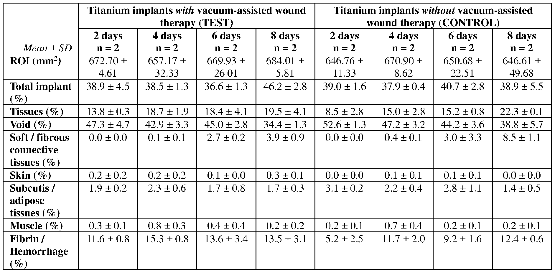
Claims
Priority Applications (1)
| Application Number | Priority Date | Filing Date | Title |
|---|---|---|---|
| EP24781624.2A EP4687752A2 (en) | 2023-03-24 | 2024-03-22 | Vacuum-assisted integration of implants |
Applications Claiming Priority (2)
| Application Number | Priority Date | Filing Date | Title |
|---|---|---|---|
| US202363454448P | 2023-03-24 | 2023-03-24 | |
| US63/454,448 | 2023-03-24 |
Publications (2)
| Publication Number | Publication Date |
|---|---|
| WO2024206121A2 true WO2024206121A2 (en) | 2024-10-03 |
| WO2024206121A3 WO2024206121A3 (en) | 2025-03-27 |
Family
ID=92907662
Family Applications (1)
| Application Number | Title | Priority Date | Filing Date |
|---|---|---|---|
| PCT/US2024/021095 Ceased WO2024206121A2 (en) | 2023-03-24 | 2024-03-22 | Vacuum-assisted integration of implants |
Country Status (2)
| Country | Link |
|---|---|
| EP (1) | EP4687752A2 (en) |
| WO (1) | WO2024206121A2 (en) |
Family Cites Families (9)
| Publication number | Priority date | Publication date | Assignee | Title |
|---|---|---|---|---|
| US7625362B2 (en) * | 2003-09-16 | 2009-12-01 | Boehringer Technologies, L.P. | Apparatus and method for suction-assisted wound healing |
| US6840960B2 (en) * | 2002-09-27 | 2005-01-11 | Stephen K. Bubb | Porous implant system and treatment method |
| US7797072B2 (en) * | 2007-10-05 | 2010-09-14 | Bespoke Innovations, Inc. | Prosthetic limb with replaceable fairing |
| US9907657B2 (en) * | 2012-02-09 | 2018-03-06 | Arthrex, Inc. | Porous coating for orthopedic implant utilizing porous, shape memory materials |
| US9469075B2 (en) * | 2012-12-22 | 2016-10-18 | Joseph T. Zachariasen | Use of additive manufacturing processes in the manufacture of custom wearable and/or implantable medical devices |
| WO2017205446A1 (en) * | 2016-05-24 | 2017-11-30 | Somavac Medical Solutions, Inc. | Portable device with disposable reservoir for collection of internal fluid after surgery |
| CA3049463A1 (en) * | 2017-02-14 | 2018-08-23 | Kci Licensing, Inc. | Dressing with variable contraction zones |
| US10624794B2 (en) * | 2018-02-12 | 2020-04-21 | Healyx Labs, Inc. | Negative pressure wound therapy systems, devices, and methods |
| US20240065846A1 (en) * | 2021-01-14 | 2024-02-29 | Smith & Nephew, Inc. | Additively manufactured orthopaedic implants and making the same |
-
2024
- 2024-03-22 WO PCT/US2024/021095 patent/WO2024206121A2/en not_active Ceased
- 2024-03-22 EP EP24781624.2A patent/EP4687752A2/en active Pending
Also Published As
| Publication number | Publication date |
|---|---|
| EP4687752A2 (en) | 2026-02-11 |
| WO2024206121A3 (en) | 2025-03-27 |
Similar Documents
| Publication | Publication Date | Title |
|---|---|---|
| US6840960B2 (en) | Porous implant system and treatment method | |
| US8915970B2 (en) | Transdermal prosthesis | |
| CN103857415B (en) | Dental implants, vascular implants and tissue implants made of porous three-dimensional structures of polytetrafluoroethylene | |
| KR20170121196A (en) | A spacer device for treating an infected seat within a human body | |
| CN112690930B (en) | A kind of manufacturing method of multi-material porous distal femoral implant | |
| WO2019104392A1 (en) | Modular tissue implants | |
| AU2019201519B1 (en) | Knee spacer system with irrigation device | |
| AU2020357049B2 (en) | Vascular access device with arteriovenous fistula support | |
| WO2024206121A2 (en) | Vacuum-assisted integration of implants | |
| US11633583B2 (en) | Implantable interface device | |
| EP1731191A1 (en) | Cuff member | |
| Suvaneeth et al. | Biomaterials and biocompatibility | |
| Geertsema et al. | Biocompatibility of a novel tissue connector for fixation of tracheostoma valves and shunt valves | |
| Demos et al. | Tracheal regeneration in long-term survivors with silicone prosthesis | |
| Zeifang et al. | Improved osseointegration of PTFEP-coated titanium implants | |
| US20220280286A1 (en) | Implant | |
| KR102344360B1 (en) | Nasal implant for nasal surgery using porous interconnect structure | |
| US20220257362A1 (en) | Connective-tissue body and method for producing same | |
| US8877499B2 (en) | Bone anchor | |
| RU211084U1 (en) | Osseointegrated endoprosthesis for exoprosthesis | |
| RU2658743C2 (en) | Method of spacer femoral component preoperative design and preforming in the hip joint revision arthroplasty | |
| WO2003082366A1 (en) | Tissue engineering scaffold material, aritficial vessel, cuff member and coating for implants | |
| CN118557789B (en) | A zinc-magnesium-polyetheretherketone composite intervertebral fusion cage for intervertebral fusion | |
| RU2759655C1 (en) | Method for manufacturing hip joint spacer at non-operable acetabulum and acetabulum component of hip joint spacer | |
| RU167514U1 (en) | Device for the treatment of osteomyelitis of the spine |
Legal Events
| Date | Code | Title | Description |
|---|---|---|---|
| WWE | Wipo information: entry into national phase |
Ref document number: 2024781624 Country of ref document: EP |
|
| NENP | Non-entry into the national phase |
Ref country code: DE |
|
| 121 | Ep: the epo has been informed by wipo that ep was designated in this application |
Ref document number: 24781624 Country of ref document: EP Kind code of ref document: A2 |
|
| ENP | Entry into the national phase |
Ref document number: 2024781624 Country of ref document: EP Effective date: 20251024 |
|
| ENP | Entry into the national phase |
Ref document number: 2024781624 Country of ref document: EP Effective date: 20251024 |
|
| ENP | Entry into the national phase |
Ref document number: 2024781624 Country of ref document: EP Effective date: 20251024 |
|
| ENP | Entry into the national phase |
Ref document number: 2024781624 Country of ref document: EP Effective date: 20251024 |
|
| ENP | Entry into the national phase |
Ref document number: 2024781624 Country of ref document: EP Effective date: 20251024 |