WO2024195439A1 - Vaporizer and method for supplying material gas to semiconductor manufacturing device - Google Patents
Vaporizer and method for supplying material gas to semiconductor manufacturing device Download PDFInfo
- Publication number
- WO2024195439A1 WO2024195439A1 PCT/JP2024/006780 JP2024006780W WO2024195439A1 WO 2024195439 A1 WO2024195439 A1 WO 2024195439A1 JP 2024006780 W JP2024006780 W JP 2024006780W WO 2024195439 A1 WO2024195439 A1 WO 2024195439A1
- Authority
- WO
- WIPO (PCT)
- Prior art keywords
- material gas
- precursor
- tank
- pipe
- valve
- Prior art date
- Legal status (The legal status is an assumption and is not a legal conclusion. Google has not performed a legal analysis and makes no representation as to the accuracy of the status listed.)
- Ceased
Links
Images


Classifications
-
- C—CHEMISTRY; METALLURGY
- C23—COATING METALLIC MATERIAL; COATING MATERIAL WITH METALLIC MATERIAL; CHEMICAL SURFACE TREATMENT; DIFFUSION TREATMENT OF METALLIC MATERIAL; COATING BY VACUUM EVAPORATION, BY SPUTTERING, BY ION IMPLANTATION OR BY CHEMICAL VAPOUR DEPOSITION, IN GENERAL; INHIBITING CORROSION OF METALLIC MATERIAL OR INCRUSTATION IN GENERAL
- C23C—COATING METALLIC MATERIAL; COATING MATERIAL WITH METALLIC MATERIAL; SURFACE TREATMENT OF METALLIC MATERIAL BY DIFFUSION INTO THE SURFACE, BY CHEMICAL CONVERSION OR SUBSTITUTION; COATING BY VACUUM EVAPORATION, BY SPUTTERING, BY ION IMPLANTATION OR BY CHEMICAL VAPOUR DEPOSITION, IN GENERAL
- C23C16/00—Chemical coating by decomposition of gaseous compounds, without leaving reaction products of surface material in the coating, i.e. chemical vapour deposition [CVD] processes
- C23C16/44—Chemical coating by decomposition of gaseous compounds, without leaving reaction products of surface material in the coating, i.e. chemical vapour deposition [CVD] processes characterised by the method of coating
- C23C16/448—Chemical coating by decomposition of gaseous compounds, without leaving reaction products of surface material in the coating, i.e. chemical vapour deposition [CVD] processes characterised by the method of coating characterised by the method used for generating reactive gas streams, e.g. by evaporation or sublimation of precursor materials
-
- B—PERFORMING OPERATIONS; TRANSPORTING
- B01—PHYSICAL OR CHEMICAL PROCESSES OR APPARATUS IN GENERAL
- B01J—CHEMICAL OR PHYSICAL PROCESSES, e.g. CATALYSIS OR COLLOID CHEMISTRY; THEIR RELEVANT APPARATUS
- B01J7/00—Apparatus for generating gases
-
- C—CHEMISTRY; METALLURGY
- C23—COATING METALLIC MATERIAL; COATING MATERIAL WITH METALLIC MATERIAL; CHEMICAL SURFACE TREATMENT; DIFFUSION TREATMENT OF METALLIC MATERIAL; COATING BY VACUUM EVAPORATION, BY SPUTTERING, BY ION IMPLANTATION OR BY CHEMICAL VAPOUR DEPOSITION, IN GENERAL; INHIBITING CORROSION OF METALLIC MATERIAL OR INCRUSTATION IN GENERAL
- C23C—COATING METALLIC MATERIAL; COATING MATERIAL WITH METALLIC MATERIAL; SURFACE TREATMENT OF METALLIC MATERIAL BY DIFFUSION INTO THE SURFACE, BY CHEMICAL CONVERSION OR SUBSTITUTION; COATING BY VACUUM EVAPORATION, BY SPUTTERING, BY ION IMPLANTATION OR BY CHEMICAL VAPOUR DEPOSITION, IN GENERAL
- C23C16/00—Chemical coating by decomposition of gaseous compounds, without leaving reaction products of surface material in the coating, i.e. chemical vapour deposition [CVD] processes
- C23C16/44—Chemical coating by decomposition of gaseous compounds, without leaving reaction products of surface material in the coating, i.e. chemical vapour deposition [CVD] processes characterised by the method of coating
- C23C16/455—Chemical coating by decomposition of gaseous compounds, without leaving reaction products of surface material in the coating, i.e. chemical vapour deposition [CVD] processes characterised by the method of coating characterised by the method used for introducing gases into reaction chamber or for modifying gas flows in reaction chamber
- C23C16/45523—Pulsed gas flow or change of composition over time
- C23C16/45525—Atomic layer deposition [ALD]
-
- C—CHEMISTRY; METALLURGY
- C23—COATING METALLIC MATERIAL; COATING MATERIAL WITH METALLIC MATERIAL; CHEMICAL SURFACE TREATMENT; DIFFUSION TREATMENT OF METALLIC MATERIAL; COATING BY VACUUM EVAPORATION, BY SPUTTERING, BY ION IMPLANTATION OR BY CHEMICAL VAPOUR DEPOSITION, IN GENERAL; INHIBITING CORROSION OF METALLIC MATERIAL OR INCRUSTATION IN GENERAL
- C23C—COATING METALLIC MATERIAL; COATING MATERIAL WITH METALLIC MATERIAL; SURFACE TREATMENT OF METALLIC MATERIAL BY DIFFUSION INTO THE SURFACE, BY CHEMICAL CONVERSION OR SUBSTITUTION; COATING BY VACUUM EVAPORATION, BY SPUTTERING, BY ION IMPLANTATION OR BY CHEMICAL VAPOUR DEPOSITION, IN GENERAL
- C23C16/00—Chemical coating by decomposition of gaseous compounds, without leaving reaction products of surface material in the coating, i.e. chemical vapour deposition [CVD] processes
- C23C16/44—Chemical coating by decomposition of gaseous compounds, without leaving reaction products of surface material in the coating, i.e. chemical vapour deposition [CVD] processes characterised by the method of coating
- C23C16/455—Chemical coating by decomposition of gaseous compounds, without leaving reaction products of surface material in the coating, i.e. chemical vapour deposition [CVD] processes characterised by the method of coating characterised by the method used for introducing gases into reaction chamber or for modifying gas flows in reaction chamber
- C23C16/45561—Gas plumbing upstream of the reaction chamber
-
- C—CHEMISTRY; METALLURGY
- C23—COATING METALLIC MATERIAL; COATING MATERIAL WITH METALLIC MATERIAL; CHEMICAL SURFACE TREATMENT; DIFFUSION TREATMENT OF METALLIC MATERIAL; COATING BY VACUUM EVAPORATION, BY SPUTTERING, BY ION IMPLANTATION OR BY CHEMICAL VAPOUR DEPOSITION, IN GENERAL; INHIBITING CORROSION OF METALLIC MATERIAL OR INCRUSTATION IN GENERAL
- C23C—COATING METALLIC MATERIAL; COATING MATERIAL WITH METALLIC MATERIAL; SURFACE TREATMENT OF METALLIC MATERIAL BY DIFFUSION INTO THE SURFACE, BY CHEMICAL CONVERSION OR SUBSTITUTION; COATING BY VACUUM EVAPORATION, BY SPUTTERING, BY ION IMPLANTATION OR BY CHEMICAL VAPOUR DEPOSITION, IN GENERAL
- C23C16/00—Chemical coating by decomposition of gaseous compounds, without leaving reaction products of surface material in the coating, i.e. chemical vapour deposition [CVD] processes
- C23C16/44—Chemical coating by decomposition of gaseous compounds, without leaving reaction products of surface material in the coating, i.e. chemical vapour deposition [CVD] processes characterised by the method of coating
- C23C16/455—Chemical coating by decomposition of gaseous compounds, without leaving reaction products of surface material in the coating, i.e. chemical vapour deposition [CVD] processes characterised by the method of coating characterised by the method used for introducing gases into reaction chamber or for modifying gas flows in reaction chamber
- C23C16/45563—Gas nozzles
-
- C—CHEMISTRY; METALLURGY
- C23—COATING METALLIC MATERIAL; COATING MATERIAL WITH METALLIC MATERIAL; CHEMICAL SURFACE TREATMENT; DIFFUSION TREATMENT OF METALLIC MATERIAL; COATING BY VACUUM EVAPORATION, BY SPUTTERING, BY ION IMPLANTATION OR BY CHEMICAL VAPOUR DEPOSITION, IN GENERAL; INHIBITING CORROSION OF METALLIC MATERIAL OR INCRUSTATION IN GENERAL
- C23C—COATING METALLIC MATERIAL; COATING MATERIAL WITH METALLIC MATERIAL; SURFACE TREATMENT OF METALLIC MATERIAL BY DIFFUSION INTO THE SURFACE, BY CHEMICAL CONVERSION OR SUBSTITUTION; COATING BY VACUUM EVAPORATION, BY SPUTTERING, BY ION IMPLANTATION OR BY CHEMICAL VAPOUR DEPOSITION, IN GENERAL
- C23C16/00—Chemical coating by decomposition of gaseous compounds, without leaving reaction products of surface material in the coating, i.e. chemical vapour deposition [CVD] processes
- C23C16/44—Chemical coating by decomposition of gaseous compounds, without leaving reaction products of surface material in the coating, i.e. chemical vapour deposition [CVD] processes characterised by the method of coating
- C23C16/52—Controlling or regulating the coating process
-
- H10P14/60—
Definitions
- the present invention relates to a vaporizer used in the manufacturing process of semiconductor devices, and a method for supplying a material gas to a semiconductor manufacturing apparatus.
- the present invention relates to a vaporizer suitable for manufacturing semiconductor devices by atomic layer deposition, and a method for supplying a material gas to a semiconductor manufacturing apparatus.
- material gases In the manufacturing process of semiconductor devices such as integrated circuits, various types of semiconductor material gases (hereinafter referred to as “material gases”) are used depending on the purpose of the process.
- Material gases generated from precursors that are in a liquid or solid state at room temperature are supplied to the semiconductor manufacturing equipment via piping after vaporizing the precursors stored in a vaporizer.
- One method for generating material gas in a vaporizer is to heat a precursor stored in a tank to generate steam.
- vaporizers are equipped with a valve for starting and stopping the supply of the generated material gas and a mass flow controller for controlling the flow rate of the material gas.
- ALD atomic layer deposition
- Patent documents 1 to 4 describe an invention for an apparatus that can repeatedly supply a constant volume of material gas to semiconductor manufacturing equipment for a short period of time by first filling a closed space consisting of a container or part of a pipe with the material gas and then opening a downstream valve.
- Patent document 5 describes an invention for an apparatus that can repeatedly supply a controlled flow rate of material gas to semiconductor manufacturing equipment for a short period of time by providing an orifice and a high-speed pulse valve in a flow control conduit provided downstream of a gas reservoir whose pressure is kept constant, and opening the high-speed pulse valve. The flow rate of the material gas in this apparatus is calibrated based on pressure changes in the gas reservoir.
- the device In the devices described in Patent Documents 1 to 4 that employ a method of first filling a closed space consisting of a container or part of a pipe with a material gas, the device has a complex configuration, which causes problems such as high manufacturing costs and frequent breakdowns. In addition, there is a problem in that the amount of material gas that is filled into a small-volume container or part of a pipe is easily affected by changes in temperature and pressure, which causes fluctuations in the supply amount of material gas.
- the flow rate of the material gas passing through the orifice is a function of the difference in pressure between the upstream and downstream sides of the orifice, so there is an issue that the supply amount of the material gas is easily affected by fluctuations in downstream pressure.
- the device configuration is complicated because a pressure controller is required to keep the pressure of the gas reservoir constant.
- This disclosure was made in consideration of the above problems, and aims to realize a vaporizer that can supply material gas suitable for ALD with high precision using a simple device configuration and easy operation.
- the vaporizer according to the present disclosure is a vaporizer that generates a material gas from a precursor of the material gas and supplies it to the outside, and includes a tank for storing the precursor, a temperature sensor for measuring the temperature of the precursor stored in the tank, a heater for heating the precursor stored in the tank to generate a material gas, a power control means for controlling the power supplied to the heater so that the temperature of the precursor measured by the temperature sensor becomes equal to a preset temperature, a pipe for directing the material gas stored inside the tank to the outside of the tank, an opening/closing valve installed in the pipe for starting and stopping the flow of the material gas, a valve control means for outputting an open signal and a close signal to the opening/closing valve, and a nozzle installed in the pipe and provided with a flow path that communicates with the internal space of the pipe.
- the cross-sectional area of the flow path installed in the nozzle at the narrowest position is smaller than the cross-sectional area of
- a vaporizer having the above configuration, if the volume of material gas stored in the tank is sufficiently large compared to the flow rate of the material gas supplied to the outside, a pseudo-phase equilibrium is established between the reaction in which material gas is produced from the precursor in a solid or liquid state and the reverse reaction. Then, the pressure of the material gas in the tank is kept equal to the equilibrium vapor pressure at the set temperature, so the flow rate of the material gas when the opening and closing valve is opened is determined only by the temperature of the precursor. Also, because the nozzle acts to prevent the flow rate of the material gas from being affected by pressure fluctuations on the downstream side of the semiconductor manufacturing equipment, the supply amount of the material gas is stable.
- the method according to the present disclosure is a method for supplying a material gas to a semiconductor manufacturing apparatus, the method including the steps of storing a precursor of the material gas in a tank, heating the precursor while controlling the power supplied to the heater so that the temperature of the precursor stored in the tank is equal to a preset temperature to generate a material gas, outputting an open signal from a valve control means to an open/close valve disposed in a pipe that guides the material gas to the outside of the tank to open the open/close valve, supplying the material gas stored inside the tank to the semiconductor manufacturing apparatus via a nozzle disposed in the pipe and provided with a flow path that communicates with the internal space of the pipe, and outputting a close signal from the valve control means to the open/close valve to close the open/close valve and stop the supply of the material gas.
- the cross-sectional area at the narrowest position of the flow path disposed in the nozzle is smaller than the cross-sectional area of the internal space of the pipe.
- the number of vaporizer parts and manufacturing costs can be reduced, and vaporizer failures are reduced.
- the accuracy of the supply amount of material gas can be improved.
- FIG. 1 is a schematic diagram showing an example of the configuration of a vaporizer according to a conventional technique.
- FIG. 2 is a schematic diagram showing an example of the configuration of a vaporizer according to the first embodiment of the present invention.
- FIG. 6 is a schematic diagram showing an example of the configuration of a vaporizer according to a second embodiment of the present invention.
- 5 is a flow chart illustrating a method according to a third embodiment of the present invention.
- 1 is a graph showing the relationship between equilibrium vapor pressure and collection amount in a reference example of the present invention.
- Fig. 1 is a schematic diagram showing an example of the configuration of a vaporizer according to the prior art.
- Methods for vaporizing a precursor of a material gas in a vaporizer used in a manufacturing process of a semiconductor device include a baking method, a bubbling method, and a direct vaporization method.
- the baking method among these methods is adopted, and a precursor P in a liquid state is used.
- Tank 2 is a sealable container capable of storing precursor P.
- Precursor replenishing means 11 is composed of, for example, piping and a valve. The tip of the piping reaches near the bottom inside tank 2. With the valve open, precursor P is replenished into tank 2 via the piping of precursor replenishing means 11. The valve is then closed, and precursor P is stored in a sealed state inside tank 2.
- the temperature sensor 3 is a sensor that measures the temperature of the precursor P.
- the power supplied to the heater 4 is controlled by a power control means 5 (not shown) so that the temperature of the precursor P measured by the temperature sensor 3 becomes equal to a preset temperature.
- the temperature of the heater 4 rises due to the passage of electricity, the precursor P inside the tank 2 that is in contact with the heater 4 is heated.
- the heated precursor P flows and is stirred inside the tank 2 by convection. This makes the temperature of the precursor P almost uniform.
- Material gas G is generated by evaporation from the liquid surface of the heated precursor P.
- the generated material gas G is stored in the space above the liquid surface of the precursor P inside the tank 2 and inside the pipe 6 attached to the top surface of the tank 2.
- a valve opening signal is output from the valve control means built into the flow sensor 8' to the flow control valve 7' to open the flow control valve 7'.
- the arrows in Figure 1 show the flow of this valve opening signal.
- the material gas G flows from the upstream side of the pipe 6 through the flow control valve 7' and the flow sensor 8' to the downstream side and is supplied to a semiconductor manufacturing device (not shown).
- the flow sensor 8' measures the flow rate of the material gas G.
- the flow sensor 8' outputs a valve opening signal to the flow control valve 7' to perform feedback control so that the measured flow rate, which is the measured flow rate of the material gas G, is equal to a preset set flow rate.
- the flow control valve 7' and the flow sensor 8' may each be configured as independent components, or the two may be configured as an integrated mass flow controller.
- the vaporizers according to the above-mentioned prior art are suitable for supplying material gas for a relatively long period of time, for example, several tens of seconds or more, but are not necessarily suitable for applications such as ALD, where the supply and stopping of material gas is repeated at short intervals of a few seconds. This is because, when the flow rate of the material gas is measured by the flow sensor 8' and a valve opening signal is output to the flow control valve 7' so that the measured flow rate is equal to the set flow rate, feedback control is performed, and it takes time to control the flow rate, so that the supply and stopping of the material gas cannot be quickly switched on and off.
- the response time from when the value of the valve opening signal changes until the actual flow rate of the material gas approaches the set value in a mass flow controller that employs feedback control is usually not much less than 0.5 seconds. If it is desired to shorten the response time (for example, to 0.1 seconds or less) in order to realize a supply of material gas suitable for ALD, the response speed of the vaporizer 1' according to the conventional technology is insufficient.
- the present invention has been created with the objective of solving the problem of flow rate control delays that the vaporizers according to the above-mentioned prior art have, and providing a vaporizer suitable for use in ALD.
- the following describes in detail an embodiment of the present invention with reference to the drawings. Note that the following description is merely an example of an embodiment of the present invention, and the embodiment of the present invention is not limited to the embodiment described below.
- the present invention is a vaporizer that generates a material gas from a precursor of the material gas and supplies it to the outside, and includes a tank for storing the precursor, a temperature sensor for measuring the temperature of the precursor stored in the tank, a heater for heating the precursor stored in the tank to generate a material gas, a power control means for controlling the power supplied to the heater so that the temperature of the precursor measured by the temperature sensor becomes equal to a preset temperature, a pipe for directing the material gas stored inside the tank to the outside of the tank, an opening/closing valve installed in the pipe for starting and stopping the flow of the material gas, a valve control means for outputting an open signal and a close signal to the opening/closing valve, and a nozzle installed in the pipe and provided with a flow path that communicates with the internal space of the pipe.
- the cross-sectional area of the flow path installed in the nozzle at the narrowest position is smaller than the cross-sectional area of the internal space of
- FIG. 2 is a schematic diagram showing an example of the configuration of a vaporizer according to a first embodiment of the present invention.
- the configuration of the vaporizer 1 shown in FIG. 2, except for the pipe 6 and its surrounding members, is common to the configuration of the vaporizer 1' according to the prior art shown in FIG. 1.
- the same symbols as those in FIG. 1 are used for these common parts, and explanations will be omitted unless particularly necessary.
- the vaporizer 1 according to the present invention shown in FIG. 2 is significantly different from the vaporizer 1' according to the prior art shown in FIG. 1 in that, whereas in the prior art the flow rate of the material gas G flowing through the pipe 6 is feedback-controlled based on the measured flow rate measured by the flow rate sensor 8', in the present invention no flow rate control is performed during the supply of the material gas G.
- the pipe 6 of the vaporizer 1 is provided with an on-off valve 7 for starting and stopping the flow of the material gas G.
- the on-off valve 7 opens and closes according to an open signal and a close signal output from a valve control means 8 (not shown).
- the on-off valve 7 only switches between open and closed, and does not have the function of finely adjusting the valve opening.
- the on-off valve 7 can be configured, for example, by a pneumatic diaphragm valve and a drive mechanism for opening and closing it.
- a drive mechanism for the pneumatic diaphragm valve for example, an electromagnetic valve that applies or blocks compressed air pressure can be used.
- the on-off valve 7 can be a type of valve that can open and close the valve at high speed by the displacement of a piezoelectric element. Since the configuration of the vaporizer 1 according to the present invention lacks a flow sensor, there is no delay in response time due to the slow response of the flow sensor.
- a nozzle 9 having a flow path that communicates with the internal space of the pipe is interposed in the pipe 6.
- the cross-sectional area of the flow path in the nozzle 9 at its narrowest point is smaller than the cross-sectional area of the internal space of the pipe 6.
- the nozzle 9 may be of any shape as long as the cross-sectional area of the flow path through which the material gas flows at its narrowest point is smaller than the cross-sectional area of the internal space of the pipe.
- the shape of the nozzle 9 does not have to be that of a critical nozzle or sonic nozzle in which the flow rate of the material gas passing through the nozzle 9 exceeds the speed of sound. If the nozzle 9 is to be configured as a critical nozzle or sonic nozzle, the shape of the narrowest part of the flow path, called the "throat,” must be configured with a special curve called a Venturi shape, which increases manufacturing costs.
- the nozzle 9 of the present invention does not have to have such a special shape, and it is sufficient if the minimum cross-sectional area of the flow path provided in the nozzle is smaller than the cross-sectional area of the internal space of the pipe. However, configuring the nozzle 9 as a critical nozzle or sonic nozzle for a special purpose is permitted in the present invention.
- the cross-sectional area of the internal space of the pipe 6 provided in the vaporizer 1 according to the present invention is as large as possible, and it is preferable that the conductance, which is a coefficient that indicates the ease with which the material gas flows in the piping that combines the pipe 6 and the on-off valve 7, is large. In such a case, the material gas flowing through the pipe 6 and the on-off valve 7 experiences less resistance from the piping, so the response time of the material gas flow rate can be shortened.
- the lengths of the open and close signals output by the valve control means 8 to the opening and closing valve 7 can be set appropriately.
- the vaporizer 1 of the present invention has no response time due to a delay in the response of the flow sensor. Therefore, even if the time that the opening and closing valve 7 is kept open is very short (e.g., a few seconds), the proportion of the response time in that period can be made smaller than in the prior art, thereby improving the efficiency of semiconductor manufacturing.
- the vaporizer 1 employs a baking method as a method for vaporizing the precursor P of the material gas, similar to the vaporizer 1' shown in FIG. 1.
- the power control means 5 (not shown) controls the power supplied to the heater 4 so that the temperature of the precursor P measured by the temperature sensor 3 becomes equal to a preset temperature.
- a known control method such as PID control can be adopted as a means for controlling the temperature of the precursor P by the power control means 5.
- the heater 4 may have any configuration as long as it can heat the precursor P stored in the tank 2.
- the heater 4 may be provided in a position in contact with the bottom of the tank 2 as shown in FIG. 2, or in a position in contact with the side or top of the tank 2.
- the heater 4 may be provided inside the tank 2, sealed in a container.
- the number of heaters 4 may be one or more.
- the material gas G is generated by evaporation from the liquid surface of the heated precursor P.
- the generated material gas G is stored in the space above the liquid surface of the precursor P inside the tank 2 and in the space upstream of the opening and closing valve 7 inside the pipe 6 provided on the top surface of the tank 2.
- phase equilibrium refers to a state in which different phases of the same substance coexist in a system and their composition ratio does not appear to change.
- the precursor P and material gas G in the above state meet the conditions for phase equilibrium to be established in the closed system consisting of the tank 2 and pipe 6, since there is no apparent flow of heat or material in or out.
- phase equilibrium is established, the pressure of the material gas G becomes equal to the equilibrium vapor pressure at that temperature. The value of the equilibrium vapor pressure is determined only by the temperature at phase equilibrium.
- the on-off valve 7 is opened to start supplying the material gas G to the semiconductor manufacturing equipment (not shown), and strictly speaking, phase equilibrium is no longer established because the system is no longer closed.
- the amount of precursor P stored in the tank 2 and the amount of material gas G remaining in the vaporizer 1 are sufficiently large compared to the amount of material gas G released from the on-off valve 7, the flow of heat and material can be ignored, and the state of phase equilibrium is maintained in a pseudo manner. Then, as long as the temperature of the precursor P in the tank 2 is managed to be constant by the power control means 5, the pressure of the material gas G in the tank 2 is also maintained at a pressure equal to the equilibrium vapor pressure at that temperature.
- the present invention utilizes the above-described laws of nature.
- the vaporizer 1 according to the first embodiment of the present invention has a simpler configuration than the vaporizer 1' according to the prior art, it can supply a constant amount of pulsed material gas G to the semiconductor manufacturing equipment by opening the opening/closing valve 7 at a predetermined interval for a predetermined holding time while the pressure of the material gas G in the tank 2 is maintained at the equilibrium vapor pressure of the material gas G at the controlled temperature of the precursor P.
- the vaporizer 1 according to the present invention does not require a structure for feedback control of flow rate, such as a mass flow controller, and therefore has the following advantages over the vaporizer 1' according to the prior art.
- a structure for feedback control of flow rate such as a mass flow controller
- the precursor can be heated to a higher temperature.
- it can be operated even if the pressure of the material gas is extremely low. Furthermore, there is little individual difference between devices in the change in flow rate over time when the material gas starts to flow.
- the precursor in a solid state is charged into the tank through an openable and closable insertion port provided in the tank.
- a temperature sensor for measuring the temperature of the precursor can be provided, for example, on the surface of the precursor in a solid state or in a hole provided in the precursor so that the temperature measuring part is in direct contact with the precursor.
- phase equilibrium when the precursor is in a liquid state is a phase equilibrium involving evaporation and condensation between the liquid and the gas, whereas the phase equilibrium when the precursor is in a solid state is a phase equilibrium involving sublimation between the solid and the gas.
- the law of nature utilized in the present invention in which the pressure of the material gas inside the tank is kept equal to the equilibrium vapor pressure at that temperature by maintaining the temperature of the precursor constant, does not change even when the precursor is in a solid state.
- the nozzle provided in the vaporizer according to the present invention is an orifice comprising a plate with holes.
- the nozzle 9 provided in the vaporizer 1 shown in Figure 2 is composed of such an orifice, and Figure 2 shows a cross section of the orifice.
- the nozzle 9 of this configuration can be manufactured by drilling one or more through holes in a plate-shaped member using a drilling process, so that the manufacturing costs can be reduced compared to nozzles with a more complicated configuration.
- the number and diameter of the through holes and the thickness of the plate can be set appropriately depending on the flow rate of the target material gas G.
- a known method can be used, such as fixing the nozzle 9 with a fixing jig that does not interfere with the flow of the material gas G flowing through the pipe 6. It is preferable to fix the nozzle 9 in a manner that allows the nozzle 9 to be easily replaced. In this case, the nozzle 9 can be easily replaced when the nozzle 9 is damaged and/or when it is desired to change the diameter of the nozzle hole.
- the nozzle provided in the vaporizer according to the present invention is located downstream of the on-off valve.
- the nozzle 9 provided in the vaporizer 1 shown in FIG. 2 is configured as such a nozzle, and the nozzle 9 is disposed downstream of the on-off valve 7, i.e., on the opposite side to the tank 2.
- the material gas G stored in the tank 2 exists in the space above the liquid level of the tank 2 and inside the pipe 6.
- the on-off valve 7 when the on-off valve 7 is closed, the material gas G in the pipe 6 is stored upstream of the on-off valve 7.
- the pipe 6 downstream of the on-off valve 7 is connected to a semiconductor manufacturing device, and the internal pressure is maintained in a vacuum state similar to that of the processing chamber of the semiconductor manufacturing device.
- the on-off valve 7 When the on-off valve 7 is opened by an open signal output from the valve control means 8 and the material gas G is released, the space from the outlet of the on-off valve 7 to the nozzle 9 is immediately filled with the material gas G at equilibrium vapor pressure, and the action of the nozzle 9 starts a fixed supply of the material gas G from the material gas G to the semiconductor manufacturing equipment with almost no delay. If the positional relationship between the on-off valve 7 and the nozzle 9 is reversed from that described above, the material gas G stored between the nozzle 9 and the on-off valve 7 is first released all at once toward the semiconductor manufacturing equipment the moment the on-off valve 7 opens, and then the fixed supply of the material gas G starts due to the action of the nozzle 9, so the flow of the material gas G is likely to be irregular.
- the nozzle 9 can be provided inside the joint that connects the outlet of the on-off valve 7 to the pipe 6.
- the vaporizer 1 includes multiple pipes, each of which includes an on-off valve and a nozzle.
- the multiple pipes may be individually connected to a tank, or a pipe connected to the tank may branch into multiple pipes along the way.
- the flow rate of the material gas G can be increased compared to a single pipe.
- the supply amount of the material gas G can be changed or adjusted within a certain range without changing the temperature of the precursor P.
- the pipe 6, on-off valve 7, and nozzle 9 constituting the vaporizer 1 according to the present invention are equipped with a heating means.
- the heating means heats these components to a temperature approximately equal to that of the precursor P. This prevents a drop in the temperature of the material gas G flowing through the flow path of the pipe 6, making it possible to more stabilize the supply amount of the material gas G. Furthermore, in cases where the material gas G is a material that is easily liquefied by a drop in temperature, the liquefaction of the material gas G can be prevented by heating these components.
- the present invention is an invention of a vaporizer including, in addition to the configuration of the first embodiment described above, a liquid level sensor that detects the liquid level of the precursor stored in the tank, and a precursor replenishing means that replenishes the precursor inside the tank when the liquid level of the precursor drops.
- the precursor used in the vaporizer according to the second embodiment is limited to a precursor in a liquid state.
- FIG. 3 is a schematic diagram showing an example of the configuration of a vaporizer according to a second embodiment of the present invention.
- the configuration unique to the second embodiment will be described, and the description of the configuration common to the first embodiment will be omitted unless specifically necessary.
- the vaporizer of the present invention maintains the pressure of the material gas at a pressure equal to the equilibrium vapor pressure by creating a pseudo-phase equilibrium state inside the tank.
- the amount of precursor stored in the tank decreases, and when the precursor is finally consumed, phase equilibrium is no longer maintained.
- the position of the precursor liquid level drops significantly compared to the initial state, the balance between the amount of precursor and the amount of material gas is lost, making it difficult to maintain thermal equilibrium within the system.
- the vaporizer according to the second embodiment of the present invention detects a decrease in the remaining amount of precursor P by including a liquid level sensor 10 that detects the liquid level of precursor P stored in tank 2.
- the liquid level sensor 10 may be any sensor that can detect a change in the liquid level of precursor P.
- the liquid level sensor 10 may be a sensor that includes a float that moves up and down along a rod-shaped member in accordance with the rise and fall of the liquid level.
- the vaporizer according to the second embodiment of the present invention includes a precursor replenishing means for replenishing the precursor inside the tank when the liquid level of the precursor drops.
- the precursor replenishing means 11 illustrated in FIG. 3 includes a reservoir 11a for storing precursor P for replenishing the tank 2.
- the reservoir 11a preferably has a volume larger than the volume of the tank 2 and is a sealable container similar to the tank 2.
- the precursor replenishing means 11 further includes a gas cylinder 11b for replenishing the precursor P from the reservoir 11a to the tank 2 by the pressure of the high-pressure gas.
- the gas cylinder 11b stores a high-pressure gas that is an inert gas such as nitrogen gas or argon gas and does not chemically react with the precursor P.
- the gas cylinder 11b and the reservoir 11a are connected by a pressurized pipe 11d.
- a valve 11e is provided midway through the pressurized pipe 11d.
- a pressure reducing valve (not shown) may be provided in the pressurized pipe 11d.
- the reservoir 11a and the vaporizer tank 2 are joined by a single liquid supply pipe 11c. Both ends of the liquid supply pipe 11c are provided at positions close to the bottom of the reservoir 11a and the tank 2. As a result, both ends of the liquid supply pipe 11c are always located below the liquid level of the precursor P. However, as long as the tip of the liquid supply pipe 11c on the reservoir 11a side is located below the liquid level of the precursor P, a configuration in which the tip of the liquid supply pipe 11c on the tank 2 side is positioned above the liquid level of the precursor P is also permitted in the second embodiment.
- the valve 11e installed in the pressurized pipe 11d connecting the gas cylinder 11b and the reservoir 11a is opened to apply high-pressure gas pressure to the liquid surface of the precursor P stored in the reservoir 11a.
- This pressure is set to be higher than the pressure of the material gas G stored in the tank 2 of the vaporizer 1.
- the precursor P inside the reservoir 11a is replenished into the tank 2 via the liquid delivery pipe 11c.
- the valve 11e is closed to stop the liquid delivery.
- the liquid level of the precursor P inside the tank 2 can be kept constant at all times. This makes the phase equilibrium between the precursor P in a liquid state inside the tank 2 and the material gas G more stable, and the change in the supply amount of the material gas G supplied from the vaporizer 1 to the semiconductor manufacturing equipment becomes smaller.
- the liquid level of the precursor P inside the tank 2 is always kept constant.
- the temperature sensor 3 can be installed horizontally instead of vertically to more accurately measure the temperature at a position close to the liquid surface of the precursor P. This allows the supply amount of the material gas G to be more accurately controlled.
- the vaporizer according to the present invention further includes an exhaust means for degassing the gas dissolved in the precursor stored in the tank.
- an exhaust means for degassing the gas dissolved in the precursor stored in the tank.
- the partial pressure of the material gas G will be equal to the equilibrium vapor pressure at that temperature.
- the flow rate of the gas passing through the nozzle 9 depends on the total pressure of the mixed gas, the presence of the mixed gas causes fluctuations in the supply amount of the material gas G.
- the vaporizer 1 is equipped with an exhaust means for degassing the gas dissolved in the precursor P.
- the exhaust means 12 can be configured with a pipe and a valve installed on the upper surface of the tank 2.
- the dissolved gas can be degassed by connecting a vacuum pump (not shown) to the pipe and reducing the pressure in the space above the liquid level in the tank 2.
- the time required to degas the dissolved gas using the vacuum pump depends on the type and temperature of the precursor P. Typically, a time of, for example, several tens of seconds to several tens of minutes is required. This makes it possible to suppress fluctuations in the supply amount of the material gas due to the influence of the dissolved gas.
- the present invention is a method for supplying a material gas to a semiconductor manufacturing apparatus, the method including the steps of storing a precursor of the material gas in a tank, heating the precursor while controlling the power supplied to the heater so that the temperature of the precursor stored in the tank is equal to a preset temperature, generating a material gas, outputting an open signal from a valve control means to an open/close valve interposed in a pipe that leads the material gas to the outside of the tank to open the open/close valve, supplying the material gas stored in the tank to the semiconductor manufacturing apparatus via a nozzle interposed in the pipe and provided with a flow path communicating with the internal space of the pipe, and outputting a close signal from the valve control means to the open/close valve to close the open/close valve and stop the supply of the material gas.
- the cross-sectional area at the narrowest position of the flow path provided in the nozzle is smaller than the cross-sectional area of the internal space of the pipe.
- FIG. 4 is a flow chart showing a method according to a third embodiment of the present invention.
- the method according to the present invention is a method for supplying a material gas to a semiconductor manufacturing apparatus, and the first step is step S1, in which a precursor P of the material gas G is stored in a tank 2.
- the precursor P stored in the tank 2 may be liquid or solid.
- step S2 in which the precursor P stored in the tank 2 is heated while controlling the power supplied to the heater 4 so that the temperature of the precursor P becomes equal to a preset temperature, thereby generating a material gas G.
- the temperature of the precursor P can be measured, for example, using a temperature sensor 3.
- the temperature control of the precursor P can be performed by a power control means 5 equipped with a known temperature control function.
- step S3 in which an open signal is output from the valve control means 8 to the on-off valve 7 provided in the pipe 6 that guides the material gas G to the outside of the tank 2, thereby opening the on-off valve 7.
- the inlet of the pipe 6 can be provided on the top surface of the tank 2.
- the open signal output by the valve control means 8 is a signal for fully opening the on-off valve 7, and is not a signal for adjusting the valve opening of the on-off valve 7 to control the flow rate of the material gas G.
- step S4 in which the material gas G stored inside the tank 2 is supplied to the semiconductor manufacturing equipment via a nozzle 9 that is installed in the pipe 6 and has a flow path that communicates with the internal space of the pipe.
- the cross-sectional area of the flow path installed in the nozzle 9 at its narrowest position is smaller than the cross-sectional area of the internal space of the pipe 6.
- the nozzle 9 may be installed in the pipe 6 either upstream or downstream of the opening/closing valve 7.
- step S5 in which a close signal is output from the valve control means 8 to the on-off valve 7 to close the on-off valve 7 and stop the supply of the material gas G.
- the close signal output by the valve control means 8 is a signal for fully closing the on-off valve 7.
- steps S1 to S5 By executing steps S1 to S5 above, the material gas G can be rapidly supplied to the semiconductor manufacturing equipment without delays associated with flow rate control. In the case of ALD, steps S3 to S5 can be repeatedly executed after step S5 is completed.
- the method according to the present invention includes, in addition to the method according to the third embodiment, a step of measuring in advance the flow rate of the material gas G supplied to the semiconductor manufacturing equipment between the time when the opening/closing valve 7 is opened and the time when it is closed.
- the flow rate of the material gas G is not measured while the material gas G is actually being supplied to the semiconductor manufacturing equipment.
- step 0 The step of measuring the flow rate of the material gas G in advance (hereinafter referred to as "step 0 (zero)”) is completed before executing steps S3 to S5 in which the material gas G is actually supplied to the semiconductor manufacturing equipment.
- the flow rate of the material gas G is not monitored while the material gas G is actually being supplied to the semiconductor manufacturing equipment, so there is no means of directly knowing the flow rate of the material gas G while the method according to the present invention is being performed.
- step 0 is performed to measure the flow rate of the material gas G in advance, so that the flow rate of the material gas G when steps S3 to S5 are being performed can be estimated.
- Preliminary flow rate measurements can be performed by various methods.
- the flow rate of material gas G per supply can be estimated by measuring the weight loss of tank 2 resulting from supplying material gas G a specified number of times.
- the flow rate of material gas G per supply can be estimated by measuring the thickness of a semiconductor film formed by performing ALD using a known method.
- Another method is to use a flow rate measurement function provided in the semiconductor manufacturing equipment that supplies material gas G by the method of the present invention.
- the flow rate measurement function in this case is, for example, a function that automatically measures pressure changes and temperature changes in the process chamber of the semiconductor manufacturing equipment and estimates the flow rate of material gas G from the measured values.
- step 0 the flow rate measurement in step 0 must be performed in advance, and step 0 must not be performed simultaneously with steps S3 to S5.
- the flow rate of the material gas G may be adjusted in advance by changing the conditions. For example, to adjust the flow rate of the material gas G to be larger, the temperature of the precursor P heated by the heater 4 may be increased to increase the equilibrium vapor pressure. Alternatively, the number of times the material gas G is flowed or the duration of each flow may be increased. Conversely, to adjust the flow rate of the material gas G to be smaller, the equilibrium vapor pressure may be lowered or the number of times or duration the material gas G is flowed may be reduced.
- the measurement of the flow rate of the material gas using step 0 can be performed not only immediately after manufacturing the vaporizer, but also when it is desired to change the type and/or flow rate of the material gas, and when it is desired to check for any changes over time after using the vaporizer for a certain period of time.
- the method according to the present invention is a method for supplying material gas G to a semiconductor manufacturing apparatus using precursor P in a liquid state, and in addition to the method according to the third embodiment, further includes a step of refilling the interior of tank 2 with precursor P when the liquid level of precursor P stored in tank 2 drops.
- the method further includes a step of degassing the gas dissolved in the precursor P stored in the tank 2, this is even more preferable, since, as described above, this can suppress fluctuations in the supply amount of the material gas due to the influence of the dissolved gas.
- the method according to the present invention is a method for supplying material gas G to a semiconductor manufacturing apparatus using precursor P in a liquid state, and in addition to the method according to the third embodiment, further includes a step of adjusting the value of pressure P1 inside the tank 2 to a value equal to or greater than the value of pressure P2 downstream of the nozzle 9.
- the adjustment of pressure P1 can be performed by adjusting the temperature of the precursor P.
- the adjustment of pressure P2 can be performed by adjusting the pressure of the processing chamber of the semiconductor manufacturing apparatus.
- the vaporizer according to the present invention is designed based on the hypothesis (hereinafter referred to as the "vaporizer hypothesis") that "the flow rate of the material gas can be controlled by controlling only the temperature of the precursor in a vaporizer placed in a pseudo-phase equilibrium state.”
- the vaporizer hypothesis the hypothesis that "the flow rate of the material gas can be controlled by controlling only the temperature of the precursor in a vaporizer placed in a pseudo-phase equilibrium state."
- a vaporizer 1 having the structure shown in FIG. 2 was prepared.
- the volume of the tank 2 included in the vaporizer 1 was 2.0 liters.
- the nozzle 9 included in the vaporizer 1 was an orifice with a hole of 0.5 mm in diameter drilled in the center of a gasket with a thickness of 0.8 mm. Only 0.8 liters of ion-exchanged water was stored inside the tank 2 via the precursor replenishing means 11. After that, the exhaust means 12 (not shown) provided on the upper surface of the tank 2 was operated for 10 minutes to degas the gas dissolved in the ion-exchanged water stored in the tank 2.
- a collection vessel for collecting water vapor was prepared.
- the weight of the empty collection vessel was 954.05 grams.
- the outlet of the pipe 6 was connected to the collection vessel downstream of the nozzle 9 using a stainless steel flexible tube.
- the power supplied to the heater 4 was controlled using the power control means 5 (not shown) to adjust the water temperature to 50°C.
- the opening and closing valve 7 was opened using the valve control means 8 (not shown), and the water vapor stored in the space above the liquid level in the tank 2 was sent to the collection vessel via the nozzle 9.
- the opening and closing valve 7 was closed using the valve control means 8. Then, the power supplied to the heater 4 was set to zero.
- Figure 5 shows a graph in which the equilibrium vapor pressure of water vapor shown in Tables 1 and 2 is plotted on the horizontal axis, and the amount of water vapor collected on the vertical axis.
- the circle plots represent the data for Group A
- the triangle plots represent the data for Group B.
- the dotted line is an approximation line obtained by the least squares method based on all the plots.
- both the plots for Group A and Group B match well with the approximation line shown by the dotted line.
- the dotted line extending the plot in the graph of Figure 5 does not pass through the origin. This is thought to be because the weight of the water remaining inside the stainless steel flexible tube connecting the outlet of pipe 6 to the collection vessel is not included in the measured amount of collection.
- the amount of water vapor collected that is, the flow rate of water vapor passing through nozzle 9 within a specified time, can be controlled by controlling only the temperature of the ion-exchanged water, which is regarded as a precursor of the material gas.
- the desired amount of material gas can be supplied by opening and closing the opening and closing valve 7 once.
Landscapes
- Chemical & Material Sciences (AREA)
- Organic Chemistry (AREA)
- Chemical Kinetics & Catalysis (AREA)
- Engineering & Computer Science (AREA)
- General Chemical & Material Sciences (AREA)
- Materials Engineering (AREA)
- Mechanical Engineering (AREA)
- Metallurgy (AREA)
- Chemical Vapour Deposition (AREA)
- Physics & Mathematics (AREA)
- General Physics & Mathematics (AREA)
- Manufacturing & Machinery (AREA)
- Computer Hardware Design (AREA)
- Microelectronics & Electronic Packaging (AREA)
- Power Engineering (AREA)
- Condensed Matter Physics & Semiconductors (AREA)
Abstract
Description
本発明は、半導体デバイスの製造工程に用いられる気化器、及び半導体製造装置に材料ガスを供給する方法に関する。特に限定されないが、本発明は、原子層堆積法による半導体デバイスの製造に好適な気化器、及び半導体製造装置に材料ガスを供給する方法に関する。 The present invention relates to a vaporizer used in the manufacturing process of semiconductor devices, and a method for supplying a material gas to a semiconductor manufacturing apparatus. Although not particularly limited, the present invention relates to a vaporizer suitable for manufacturing semiconductor devices by atomic layer deposition, and a method for supplying a material gas to a semiconductor manufacturing apparatus.
集積回路に代表される半導体デバイスの製造工程においては、工程の目的に応じてさまざまな種類の半導体材料ガス(以下「材料ガス」という。)が使用される。材料ガスのうち常温において液体又は固体の状態にある前駆体から生成される材料ガスについては、気化器に貯蔵された前駆体を気化させた後、配管を経由して半導体製造装置に供給される。気化器において材料ガスを発生させる手段としては、例えば、タンクに貯蔵された前駆体を加熱して蒸気を発生させる方法などを挙げることができる。一般的に、気化器には、発生した材料ガスの供給を開始又は停止するためのバルブ及び材料ガスの流量を制御するためのマスフローコントローラなどが組み込まれる。 In the manufacturing process of semiconductor devices such as integrated circuits, various types of semiconductor material gases (hereinafter referred to as "material gases") are used depending on the purpose of the process. Material gases generated from precursors that are in a liquid or solid state at room temperature are supplied to the semiconductor manufacturing equipment via piping after vaporizing the precursors stored in a vaporizer. One method for generating material gas in a vaporizer is to heat a precursor stored in a tank to generate steam. Generally, vaporizers are equipped with a valve for starting and stopping the supply of the generated material gas and a mass flow controller for controlling the flow rate of the material gas.
半導体デバイスの製造工程の技術革新にともなって、気化器に新たな仕様が要求される。例えば、原子層堆積法(atomic layer deposition、以下、「ALD」という。)と呼ばれる技術においては、基板の表面に複数の種類の材料ガスを少量ずつ交互に供給することによって、原子層レベルで膜厚及び材料がコントロールされた高精度かつ均質な薄膜が形成される。ALDを用いた半導体の製造においては、流量が制御された材料ガスを数秒間だけ供給し、その後供給を停止するというサイクルを、一定の周期にて繰り返す。 With technological innovations in the manufacturing process of semiconductor devices, new specifications are required for vaporizers. For example, in a technology called atomic layer deposition (ALD), small amounts of multiple types of material gas are alternately supplied to the surface of a substrate to form a highly accurate and homogeneous thin film whose thickness and material are controlled at the atomic layer level. In semiconductor manufacturing using ALD, a flow-controlled material gas is supplied for a few seconds, and then the supply is stopped, and this cycle is repeated at regular intervals.
材料ガスの供給のオン/オフを短いサイクルにて繰り返すのに好適な気化器が提案されている。特許文献1から4までには、容器又は配管の一部からなる閉鎖空間に材料ガスを一旦充填した後、下流側のバルブを開くことによって、一定容積の材料ガスを半導体製造装置に短い時間だけ繰り返し供給することができる装置の発明が記載されている。特許文献5には、圧力が一定に保たれたガスリザーバの下流側に設けられた流量制御導管にオリフィスと高速パルス弁とを設け、高速パルス弁を開くことによって、流量が制御された材料ガスを半導体製造装置に短い時間だけ繰り返し供給することができる装置の発明が記載されている。この装置における材料ガスの流量は、ガスリザーバの圧力変化に基づいて較正される。
A vaporizer suitable for repeatedly turning on and off the supply of material gas in short cycles has been proposed.
特許文献1から4までに記載された、容器又は配管の一部からなる閉鎖空間に材料ガスを一旦充填する方式を採用する装置においては、装置の構成が複雑であるため、装置の製造コストが高くなったり、故障の頻度が高くなったりするという課題があった。また、容積の小さな容器又は配管の一部に充填される材料ガスの量が温度及び圧力の変化による影響を受けやすいため、材料ガスの供給量が変動しやすいという課題があった。
In the devices described in
特許文献5に記載された、オリフィスと高速パルス弁とを構成に含む装置においては、オリフィスを通過する材料ガスの流量がオリフィスの上流側と下流側の圧力の差の関数となるため、材料ガスの供給量が下流側の圧力の変動の影響を受けやすいという課題があった。また、ガスリザーバの圧力を一定に保持する圧力コントローラが必要であるため、装置の構成が複雑になるという課題があった。 In the device described in Patent Document 5, which includes an orifice and a high-speed pulse valve, the flow rate of the material gas passing through the orifice is a function of the difference in pressure between the upstream and downstream sides of the orifice, so there is an issue that the supply amount of the material gas is easily affected by fluctuations in downstream pressure. In addition, there is an issue that the device configuration is complicated because a pressure controller is required to keep the pressure of the gas reservoir constant.
本開示は、上記の課題に鑑みてなされたものであり、シンプルな装置構成及び簡単な操作によってALDに適した材料ガスを高い精度にて供給することができる気化器を実現することを目的としている。 This disclosure was made in consideration of the above problems, and aims to realize a vaporizer that can supply material gas suitable for ALD with high precision using a simple device configuration and easy operation.
ある実施の形態において、本開示に係る気化器は、材料ガスの前駆体から材料ガスを生成させて外部に供給する気化器であって、前駆体を貯蔵するタンクと、タンクに貯蔵される前駆体の温度を測定する温度センサと、タンクに貯蔵される前駆体を加熱して材料ガスを生成させるヒータと、温度センサが測定する前駆体の温度があらかじめ設定された設定温度と等しくなるようにヒータに供給される電力を制御する電力制御手段と、タンクの内部に蓄えられる材料ガスをタンクの外部に導くパイプと、パイプに介装され材料ガスを流したり止めたりする開閉バルブと、開閉バルブに開信号及び閉信号を出力するバルブ制御手段と、パイプに介装されパイプの内部空間と連通する流路が設けられたノズルと、を備える、気化器である。本開示に係る気化器においては、ノズルに設けられた流路の最も狭い位置における断面積がパイプの内部空間の断面積よりも小さい。 In one embodiment, the vaporizer according to the present disclosure is a vaporizer that generates a material gas from a precursor of the material gas and supplies it to the outside, and includes a tank for storing the precursor, a temperature sensor for measuring the temperature of the precursor stored in the tank, a heater for heating the precursor stored in the tank to generate a material gas, a power control means for controlling the power supplied to the heater so that the temperature of the precursor measured by the temperature sensor becomes equal to a preset temperature, a pipe for directing the material gas stored inside the tank to the outside of the tank, an opening/closing valve installed in the pipe for starting and stopping the flow of the material gas, a valve control means for outputting an open signal and a close signal to the opening/closing valve, and a nozzle installed in the pipe and provided with a flow path that communicates with the internal space of the pipe. In the vaporizer according to the present disclosure, the cross-sectional area of the flow path installed in the nozzle at the narrowest position is smaller than the cross-sectional area of the internal space of the pipe.
上記構成を有する気化器において、外部に供給される材料ガスの流量と比べてタンクに蓄えられた材料ガスの容量が十分に大きい場合、固体又は液体の状態にある前駆体から材料ガスが生成する反応とその逆の反応との間で疑似的に相平衡が成立する。そうすると、タンク内の材料ガスの圧力は設定温度における平衡蒸気圧と等しい圧力に保たれるので、開閉バルブを開いたときの材料ガスの流量は前駆体の温度のみによって決定される。また、ノズルの作用によって下流側にある半導体製造装置の側の圧力の変動の影響を材料ガスの流量が受けないので、材料ガスの供給量が安定する。 In a vaporizer having the above configuration, if the volume of material gas stored in the tank is sufficiently large compared to the flow rate of the material gas supplied to the outside, a pseudo-phase equilibrium is established between the reaction in which material gas is produced from the precursor in a solid or liquid state and the reverse reaction. Then, the pressure of the material gas in the tank is kept equal to the equilibrium vapor pressure at the set temperature, so the flow rate of the material gas when the opening and closing valve is opened is determined only by the temperature of the precursor. Also, because the nozzle acts to prevent the flow rate of the material gas from being affected by pressure fluctuations on the downstream side of the semiconductor manufacturing equipment, the supply amount of the material gas is stable.
他の実施の形態において、本開示に係る方法は、半導体製造装置に材料ガスを供給する方法であって、材料ガスの前駆体をタンクに貯蔵するステップと、タンクに貯蔵された前駆体の温度があらかじめ設定された設定温度と等しくなるようにヒータに供給される電力を制御しながら前駆体を加熱して材料ガスを生成させるステップと、材料ガスをタンクの外部に導くパイプに介装された開閉バルブにバルブ制御手段から開信号を出力して開閉バルブを開くステップと、パイプに介装されパイプの内部空間と連通する流路が設けられたノズルを経由してタンクの内部に蓄えられた材料ガスを半導体製造装置に供給するステップと、開閉バルブにバルブ制御手段から閉信号を出力して開閉バルブを閉じ材料ガスの供給を停止するステップと、を含む、半導体製造装置に材料ガスを供給する方法である。本開示に係る方法においては、ノズルに設けられた流路の最も狭い位置における断面積がパイプの内部空間の断面積よりも小さい。 In another embodiment, the method according to the present disclosure is a method for supplying a material gas to a semiconductor manufacturing apparatus, the method including the steps of storing a precursor of the material gas in a tank, heating the precursor while controlling the power supplied to the heater so that the temperature of the precursor stored in the tank is equal to a preset temperature to generate a material gas, outputting an open signal from a valve control means to an open/close valve disposed in a pipe that guides the material gas to the outside of the tank to open the open/close valve, supplying the material gas stored inside the tank to the semiconductor manufacturing apparatus via a nozzle disposed in the pipe and provided with a flow path that communicates with the internal space of the pipe, and outputting a close signal from the valve control means to the open/close valve to close the open/close valve and stop the supply of the material gas. In the method according to the present disclosure, the cross-sectional area at the narrowest position of the flow path disposed in the nozzle is smaller than the cross-sectional area of the internal space of the pipe.
本開示に係る気化器又は方法を使用すれば、気化器の部品数及び製造コストを低減することができ、気化器の故障も少ない。また、材料ガスの供給量の精度を高めることができる。 By using the vaporizer or method disclosed herein, the number of vaporizer parts and manufacturing costs can be reduced, and vaporizer failures are reduced. In addition, the accuracy of the supply amount of material gas can be improved.
《従来技術》
本発明に係る気化器及び方法と対比してその特徴を明らかにするために、最初に従来技術に係る気化器について説明する。図1は、従来技術に係る気化器の構成の例を示す模式図である。半導体デバイスの製造工程に用いられる気化器において材料ガスの前駆体を気化させる方法にはベーキング方式、バブリング方式及び直接気化方式などの方法がある。図1に示す気化器1′においては、これらの方法のうちベーキング方式を採用し、液体の状態にある前駆体Pを使用する。
<<Prior Art>>
In order to clarify the features of the vaporizer and method according to the present invention in comparison with the vaporizer and method, a vaporizer according to the prior art will first be described. Fig. 1 is a schematic diagram showing an example of the configuration of a vaporizer according to the prior art. Methods for vaporizing a precursor of a material gas in a vaporizer used in a manufacturing process of a semiconductor device include a baking method, a bubbling method, and a direct vaporization method. In the vaporizer 1' shown in Fig. 1, the baking method among these methods is adopted, and a precursor P in a liquid state is used.
タンク2は、前駆体Pを貯蔵することができる密閉可能な容器である。前駆体補充手段11は、例えば配管とバルブとによって構成される。配管の先端はタンク2の内部の底近くに達している。前駆体Pは、バルブが開いた状態において前駆体補充手段11の配管を経由してタンク2の内部に補充される。その後、バルブが閉じられることによって、前駆体Pはタンク2の内部に密閉状態にて貯蔵される。
温度センサ3は、前駆体Pの温度を測定するセンサである。温度センサ3によって測定された前駆体Pの温度があらかじめ設定された設定温度と等しくなるように、図示しない電力制御手段5によってヒータ4に供給される電力が制御される。ヒータ4の温度が通電によって上昇すると、ヒータ4と接しているタンク2の内部の前駆体Pが加熱される。加熱された前駆体Pは対流によってタンク2の内部において流動し撹拌される。これにより、前駆体Pの温度はほぼ均一になる。
The
加熱された前駆体Pの液面からの蒸発によって材料ガスGが生成する。生成した材料ガスGは、タンク2の内部の前駆体Pの液面よりも上の空間及びタンク2の上面に設けられたパイプ6の内部に蓄えられる。気化器1′から半導体製造装置に材料ガスGを供給するときは、流量センサ8′に内蔵されたバルブ制御手段から流量制御バルブ7′に弁開度信号を出力して流量制御バルブ7′を開く。図1の矢印はこの弁開度信号の流れを示す。
Material gas G is generated by evaporation from the liquid surface of the heated precursor P. The generated material gas G is stored in the space above the liquid surface of the precursor P inside the
材料ガスGは、パイプ6の上流側から流量制御バルブ7′及び流量センサ8′を経由して下流側に流れ、図示しない半導体製造装置に供給される。流量センサ8′は、材料ガスGの流量を測定する。流量センサ8′は、測定された材料ガスGの流量である測定流量があらかじめ設定された設定流量と等しくなるように流量制御バルブ7′に弁開度信号を出力してフィードバック制御を行う。流量制御バルブ7′及び流量センサ8′は、それぞれ独立した部材として構成してもよく、あるいは、両者が一体となったマスフローコントローラとして構成してもよい。
The material gas G flows from the upstream side of the
上述した従来技術に係る気化器は、例えば数十秒以上の比較的長い時間に亘る材料ガスの供給には適しているが、ALDのように材料ガスの供給と停止を数秒の短い間隔にて繰り返すような用途には必ずしも適していない。なぜならば、流量センサ8′で材料ガスの流量を測定して、その測定流量が設定流量と等しくなるように流量制御バルブ7′に弁開度信号を出力してフィードバック制御を行うと、流量の制御に時間がかかるため、材料ガスの供給と停止とをすばやく切り替えることができないからである。 The vaporizers according to the above-mentioned prior art are suitable for supplying material gas for a relatively long period of time, for example, several tens of seconds or more, but are not necessarily suitable for applications such as ALD, where the supply and stopping of material gas is repeated at short intervals of a few seconds. This is because, when the flow rate of the material gas is measured by the flow sensor 8' and a valve opening signal is output to the flow control valve 7' so that the measured flow rate is equal to the set flow rate, feedback control is performed, and it takes time to control the flow rate, so that the supply and stopping of the material gas cannot be quickly switched on and off.
従来技術に係る気化器において流量の制御に時間がかかる原因のひとつは、流量センサ8′の応答時間が長いことである。流量センサには熱式流量センサ及び圧力式流量センサなどの方式がある。いずれの方式を採用した流量センサであっても、流量センサに流れる材料ガスの流量が変化してから流量センサがその流量の変化を検知して出力信号に反映させるまでに時間の遅れが生じる。そのほかの遅れの原因として、流量制御バルブ7′に出力される弁開度信号が変化してから流量制御バルブ7′の弁開度の変化が完了するまでの時間の遅れがある。 One of the reasons why it takes time to control the flow rate in vaporizers according to conventional technology is the long response time of the flow sensor 8'. There are various types of flow sensors, such as thermal flow sensors and pressure flow sensors. Regardless of the type of flow sensor used, there is a time delay between when the flow rate of the material gas flowing through the flow sensor changes and when the flow sensor detects the change in flow rate and reflects it in the output signal. Another cause of delay is the time delay between when the valve opening signal output to the flow control valve 7' changes and when the change in the valve opening of the flow control valve 7' is completed.
これらの遅れの原因によって、フィードバック制御を採用するマスフローコントローラにおいて弁開度信号の値が変化してから実際の材料ガスの流量が設定値に近づくまでの応答時間は、通常0.5秒を大きく下回ることがない。ALDに適した材料ガスの供給を実現する目的で応答時間をより短く(例えば0.1秒以下に)したい場合、従来技術に係る気化器1′の応答速度では不十分である。 Due to these causes of delay, the response time from when the value of the valve opening signal changes until the actual flow rate of the material gas approaches the set value in a mass flow controller that employs feedback control is usually not much less than 0.5 seconds. If it is desired to shorten the response time (for example, to 0.1 seconds or less) in order to realize a supply of material gas suitable for ALD, the response speed of the vaporizer 1' according to the conventional technology is insufficient.
《第1実施形態》
本発明は、上述した従来技術に係る気化器が抱える流量制御の遅れの課題を解決して、ALDにおける使用に適した気化器を提供することを目的として創作されたものである。本発明を実施するための形態について、図面を参照しながら以下に詳しく説明する。なお、以下の説明は本発明を実施するための形態を例示するものに過ぎず、本発明を実施するための形態は以下に説明する形態に限られない。
First Embodiment
The present invention has been created with the objective of solving the problem of flow rate control delays that the vaporizers according to the above-mentioned prior art have, and providing a vaporizer suitable for use in ALD. The following describes in detail an embodiment of the present invention with reference to the drawings. Note that the following description is merely an example of an embodiment of the present invention, and the embodiment of the present invention is not limited to the embodiment described below.
第1実施形態において、本発明は、材料ガスの前駆体から材料ガスを生成させて外部に供給する気化器であって、前駆体を貯蔵するタンクと、タンクに貯蔵される前駆体の温度を測定する温度センサと、タンクに貯蔵される前駆体を加熱して材料ガスを生成させるヒータと、温度センサが測定する前駆体の温度があらかじめ設定された設定温度と等しくなるようにヒータに供給される電力を制御する電力制御手段と、タンクの内部に蓄えられる材料ガスをタンクの外部に導くパイプと、パイプに介装され材料ガスを流したり止めたりする開閉バルブと、開閉バルブに開信号及び閉信号を出力するバルブ制御手段と、パイプに介装されパイプの内部空間と連通する流路が設けられたノズルとを備える、気化器の発明である。本発明に係る気化器においては、ノズルに設けられた流路の最も狭い位置における断面積がパイプの内部空間の断面積よりも小さい。 In a first embodiment, the present invention is a vaporizer that generates a material gas from a precursor of the material gas and supplies it to the outside, and includes a tank for storing the precursor, a temperature sensor for measuring the temperature of the precursor stored in the tank, a heater for heating the precursor stored in the tank to generate a material gas, a power control means for controlling the power supplied to the heater so that the temperature of the precursor measured by the temperature sensor becomes equal to a preset temperature, a pipe for directing the material gas stored inside the tank to the outside of the tank, an opening/closing valve installed in the pipe for starting and stopping the flow of the material gas, a valve control means for outputting an open signal and a close signal to the opening/closing valve, and a nozzle installed in the pipe and provided with a flow path that communicates with the internal space of the pipe. In the vaporizer according to the present invention, the cross-sectional area of the flow path installed in the nozzle at the narrowest position is smaller than the cross-sectional area of the internal space of the pipe.
図2は、本発明の第1実施形態に係る気化器の構成の例を示す模式図である。図2に示す気化器1の構成のうちパイプ6及びその周辺の部材を除く部分の構成は、図1に示した従来技術に係る気化器1′の構成と共通している。これらの共通する部分については図1の記号と同一の記号を採用し、特に必要のない場合には説明を省略する。
FIG. 2 is a schematic diagram showing an example of the configuration of a vaporizer according to a first embodiment of the present invention. The configuration of the
図2に示す本発明に係る気化器1が図1に示す従来技術に係る気化器1′と大きく異なる点は、従来技術においてはパイプ6を流れる材料ガスGの流量が流量センサ8′の測定する測定流量に基づいてフィードバック制御されているのに対し、本発明においては材料ガスGの供給中に一切の流量制御を行わない点である。
The
図2に示すように、本発明に係る気化器1が備えるパイプ6には材料ガスGを流したり止めたりする開閉バルブ7が介装される。この開閉バルブ7は、図示しないバルブ制御手段8から出力される開信号及び閉信号によって開閉動作する。開閉バルブ7の動作は開と閉との切り替えのみであり、弁開度を細かく調整する機能はない。開閉バルブ7は、例えば、空気圧式ダイアフラム弁及びそれを開閉させる駆動機構などによって構成することができる。空気圧式ダイアフラム弁の駆動機構としては、例えば圧縮空気の圧力を加えたり遮断したりする電磁弁などを用いることができる。あるいは、開閉バルブ7として、ピエゾ素子の変位によって弁を高速で開閉することができるタイプのバルブを採用してもよい。本発明に係る気化器1の構成は流量センサを欠くため、流量センサの応答が遅いことに起因する応答時間の遅延はない。
As shown in FIG. 2, the
図2に示すように、パイプ6には、パイプの内部空間と連通する流路が設けられたノズル9が介装される。ノズル9に設けられた流路の最も狭い位置における断面積はパイプ6の内部空間の断面積よりも小さい。ノズル9は、材料ガスが流れる流路の最も狭い位置における断面積がパイプの内部空間の断面積よりも小さいものであれば、どのような形状のノズルであってもよい。これにより、パイプ6よりも下流側の図示しない半導体製造装置において圧力が変化した場合であっても、気化器1から供給される材料ガスの流量の変化が抑制され、材料ガスの供給量が安定する。
As shown in FIG. 2, a
ノズル9の形状は、ノズル9を通過する材料ガスの流量が音速を超えるような臨界ノズル又はソニックノズルの形状でなくてもよい。ノズル9を臨界ノズル又はソニックノズルとして構成しようとする場合、流路の最も狭い「ノド」(throat)と呼ばれる部分の形状をベンチュリ―形状とよばれる特殊な曲線によって構成する必要があるので、製造コストが上昇する。本発明に係るノズル9はそのような特殊な形状でなくてもよく、単にノズルに設けられた流路の最小断面積がパイプの内部空間の断面積よりも小さければよい。ただし、特別な目的のためにノズル9を臨界ノズル又はソニックノズルとして構成することは、本発明において許容される。
The shape of the
一方、本発明に係る気化器1が備えるパイプ6の内部空間の断面積はできるだけ大きい方が好ましく、パイプ6と開閉バルブ7とを合わせた配管における材料ガスの流れやすさを表す係数であるコンダクタンスが大きいことが好ましい。そのような場合においては、パイプ6及び開閉バルブ7を流れる材料ガスが配管から受ける抵抗が少ないので、材料ガスの流量の応答時間を短くすることができる。
On the other hand, it is preferable that the cross-sectional area of the internal space of the
本発明に係る気化器1をALDに適用する場合には、バルブ制御手段8が開閉バルブ7に出力する開信号及び閉信号の長さを適宜設定すればよい。上述したように、本発明に係る気化器1においては流量センサの応答の遅れに起因する応答時間がない。このため、開閉バルブ7を開いておく時間が非常に短い(例えば数秒など)場合であっても、その期間に占める応答時間の割合を従来技術よりも小さくすることができるので、半導体の製造の効率を高めることができる。
When applying the
次に、図2に示す本発明の第1実施形態に係る気化器1の構成のうち、前駆体Pの温度制御に関わる部分について説明する。気化器1は図1に示す気化器1′と同様に材料ガスの前駆体Pを気化させる方法としてベーキング方式を採用する。図示しない電力制御手段5は、温度センサ3が測定する前駆体Pの温度があらかじめ設定された設定温度と等しくなるようにヒータ4に供給する電力を制御する。電力制御手段5による前駆体Pの温度制御の手段としては、たとえばPID制御などの公知の制御方法を採用することができる。
Next, the portion of the configuration of the
ヒータ4は、タンク2に貯蔵される前駆体Pを加熱することができるものであれば、どのような構成を有するヒータであってもよい。ヒータ4を設ける位置は、図2に例示するようにタンク2の底部と接する位置であってもよく、タンク2の側面又は上面と接する位置であってもよい。あるいは、容器に密閉されたヒータ4をタンク2の内部に設けてもよい。ヒータ4の数は1個であってもよく、2個以上であってもよい。
The
上述したように、ヒータ4によって前駆体Pが加熱されると、加熱された前駆体Pの液面からの蒸発によって材料ガスGが生成する。生成した材料ガスGは、タンク2の内部の前駆体Pの液面よりも上の空間及びタンク2の上面に設けられたパイプ6の内部のうち開閉バルブ7よりも上流側の空間に蓄えられる。
As described above, when the precursor P is heated by the
ヒータ4による前駆体Pの加熱の開始から十分に時間が経過すると、タンク2内の前駆体Pの温度が安定し、前駆体Pと材料ガスGとの間で相平衡が成立する。相平衡とは、同一物質の異なる相が系内で共存し、かつ、それらの構成比率がみかけ上変化しない状態をいう。上記状態にある前駆体P及び材料ガスGは、タンク2及びパイプ6からなる閉じられた系において、みかけ上熱及び物質の出入りがないことから、相平衡が成立する条件を満たしている。相平衡が成立するとき、材料ガスGの圧力はその温度における平衡蒸気圧と等しくなる。平衡蒸気圧の値は、相平衡における温度のみによって決定される。
When sufficient time has passed since the
前駆体Pの温度及び材料ガスGの圧力が安定した後、開閉バルブ7を開いて図示しない半導体製造装置への材料ガスGの供給を開始すると、系はもはや閉じられた状態でなくなるため、厳密にいえば相平衡が成立しなくなる。しかしながら、開閉バルブ7から放出される材料ガスGの量に比べて、タンク2に貯蔵される前駆体Pの量及び気化器1に残っている材料ガスGの量が十分に多ければ、熱及び物質の出入りを無視することができ、相平衡の状態は疑似的に維持される。そうすると、電力制御手段5によってタンク2内の前駆体Pの温度が一定の温度に管理されている限り、タンク2内の材料ガスGの圧力もその温度における平衡蒸気圧と等しい圧力に維持される。
After the temperature of the precursor P and the pressure of the material gas G have stabilized, the on-off
本発明は、以上に説明した自然法則を利用している。これにより、本発明の第1実施形態に係る気化器1は、従来技術に係る気化器1′よりも簡単な構成であっても、タンク2内の材料ガスGの圧力が前駆体Pの制御された温度における材料ガスGの平衡蒸気圧に維持された状態において開閉バルブ7を所定の時間間隔で所定の保持時間だけ開くことによって、パルス状の材料ガスGを半導体製造装置に定量的に供給することができる。
The present invention utilizes the above-described laws of nature. As a result, even though the
本発明に係る気化器1は、マスフローコントローラに代表される流量のフィードバック制御のための構造を必要としないため、従来技術に係る気化器1′に比べて次のような利点を有する。まず、小型で低価格であり、故障のリスクが少ない。また、耐熱温度について注意を払う必要がある精密部品がないので、前駆体をより高温まで加熱することができる。次に、材料ガスの圧力が極めて低くても原理的に動作させることが可能である。さらに、材料ガスが流れ始めるときの流量の時間変化について機器間の個体差が少ない。
The
前駆体として液体の状態にある前駆体だけでなく固体の状態にある前駆体を使用することは、第1実施形態において許容される。固体の状態にある前駆体を使用して材料ガスを生成させるには、例えば、タンクに設けられた開閉可能な挿入口からタンクの内部に固体の状態にある前駆体をチャージする。また、前駆体の温度を測定する温度センサは、例えば、固体の状態にある前駆体の表面又は前駆体に設けた穴の中において前駆体に測温部が直接接するようにして設けることができる。相平衡に関して、前駆体が液体状態にある場合における相平衡は液体と気体との間の蒸発及び凝集を伴う相平衡であるのに対し、前駆体が固体状態にある場合における相平衡は固体と気体との間の昇華を伴う相平衡である点が異なる。前駆体の温度を一定に保持することによってタンクの内部の材料ガスの圧力がその温度における平衡蒸気圧と等しい圧力に保たれるという本発明が利用する自然法則は、前駆体が固体の状態にある場合であってもなんら変わることはない。 In the first embodiment, it is permitted to use not only precursors in a liquid state but also precursors in a solid state as precursors. To generate a material gas using a precursor in a solid state, for example, the precursor in a solid state is charged into the tank through an openable and closable insertion port provided in the tank. In addition, a temperature sensor for measuring the temperature of the precursor can be provided, for example, on the surface of the precursor in a solid state or in a hole provided in the precursor so that the temperature measuring part is in direct contact with the precursor. Regarding phase equilibrium, the phase equilibrium when the precursor is in a liquid state is a phase equilibrium involving evaporation and condensation between the liquid and the gas, whereas the phase equilibrium when the precursor is in a solid state is a phase equilibrium involving sublimation between the solid and the gas. The law of nature utilized in the present invention, in which the pressure of the material gas inside the tank is kept equal to the equilibrium vapor pressure at that temperature by maintaining the temperature of the precursor constant, does not change even when the precursor is in a solid state.
次に、第1実施形態の変形例について説明する。好ましい実施の形態において、本発明に係る気化器が備えるノズルが、穴の開けられた板を備えるオリフィスである。図2に示した気化器1が備えるノズル9はこのようなオリフィスによって構成されており、図2にはオリフィスの断面が示されている。この構成に係るノズル9は、穴開け加工によって1又は2以上のスルーホールを板状の部材に開けることによって製造することができるので、より複雑な構成を有するノズルに比べて製造コストを低減することができる。スルーホールの数及び直径並びに板の厚さは、目標とする材料ガスGの流量の大小に応じて適宜設定することができる。
Next, a modified example of the first embodiment will be described. In a preferred embodiment, the nozzle provided in the vaporizer according to the present invention is an orifice comprising a plate with holes. The
パイプ6の途中にオリフィスによって構成されるノズル9を挿入する方法としては、パイプ6を流れる材料ガスGの流れを妨げないような固定治具によってノズル9を固定するなどの公知の方法を採用することができる。ノズル9の固定は、ノズル9を容易に交換することができる態様にて行うことが好ましい。この場合、ノズル9が損傷した場合及び/又はノズルの穴の径を変更したい場合などにおいて、ノズル9を容易に交換することができる。
As a method for inserting the
好ましい実施の形態において、本発明に係る気化器が備えるノズルが、開閉バルブよりも下流側にある。図2に示した気化器1が備えるノズル9はそのようなノズルで構成されており、ノズル9は開閉バルブ7よりも下流側、すなわちタンク2とは反対側、に配設されている。上述したように、タンク2に蓄えられた材料ガスGは、タンク2の液面よりも上の空間とパイプ6の内部に存在する。好ましい実施の形態において、開閉バルブ7が閉じている状態においては、パイプ6の内の材料ガスGは開閉バルブ7よりも上流側に蓄えられている。通常の場合、開閉バルブ7よりも下流側のパイプ6は半導体製造装置に接続されており、内部の圧力は半導体製造装置の処理チャンバと同じく真空状態に保たれる。
In a preferred embodiment, the nozzle provided in the vaporizer according to the present invention is located downstream of the on-off valve. The
バルブ制御手段8から出力される開信号によって開閉バルブ7が開いて材料ガスGが放出されると、開閉バルブ7の出口からノズル9までの空間は直ちに平衡蒸気圧の材料ガスGで満たされて、ノズル9の作用により材料ガスGから半導体製造装置への材料ガスGの定量供給がほぼ遅延なしに開始される。開閉バルブ7とノズル9との位置関係が上記とは逆である場合には、開閉バルブ7が開いた瞬間に最初にノズル9と開閉バルブ7との間に貯まっている材料ガスGが一気に半導体製造装置に向かって放出され、その後にノズル9の作用による材料ガスGの定量供給が始まるので、材料ガスGの流れはイレギュラーになりやすい。
When the on-off
上記好ましい実施の形態において、応答の遅延を短くする観点からは、開閉バルブ7の出口からノズル9までの空間の体積はできるだけ小さくすることがより好ましい。具体的には、例えば、開閉バルブ7の出口とパイプ6とを接続する継手の内部にノズル9を設けることができる。
In the above preferred embodiment, from the viewpoint of shortening the response delay, it is more preferable to make the volume of the space from the outlet of the on-off
好ましい実施の形態において、本発明に係る気化器1は、複数のパイプを備え、複数のパイプのそれぞれが、開閉バルブ及びノズルを1つずつ備える。複数のパイプは個々にタンクと接続されていてもよく、タンクに接続されたパイプが途中で複数のパイプへと分岐されていてもよい。このようにして材料ガスGを半導体製造装置に供給する流路を複数備えることによって、1本のパイプによる場合よりも材料ガスGの流量を増やすことができる。また、流路の断面積が異なる複数のノズルが介装された複数のパイプを設け、開閉バルブの操作によって材料ガスGを流すパイプの選択を変更することによって、前駆体Pの温度を変更することなく材料ガスGの供給量を一定の範囲内において変更又は調整することができる。
In a preferred embodiment, the
好ましい実施の形態において、本発明に係る気化器1を構成するパイプ6、開閉バルブ7及びノズル9が加熱手段を備える。加熱手段はこれらの部材を前駆体Pの温度と同程度の温度となるように加熱する。これにより、パイプ6の流路を流れる材料ガスGの温度の低下を防止して材料ガスGの供給量をより安定させることができる。また、材料ガスGが温度の低下によって液化しやすい材料である場合においては、これらの部材の加熱によって材料ガスGの液化を防止することができる。
In a preferred embodiment, the
《第2実施形態》
第2実施形態において、本発明は、上述した第1実施形態における構成に加えて、タンクに貯蔵される前駆体の液位を検知する液位センサと、前駆体の液位が下がったときにタンクの内部に前駆体を補充する前駆体補充手段と、を備える気化器の発明である。第1実施形態の場合とは異なり、第2実施形態に係る気化器において使用する前駆体は液体の状態にある前駆体に限定される。
Second Embodiment
In the second embodiment, the present invention is an invention of a vaporizer including, in addition to the configuration of the first embodiment described above, a liquid level sensor that detects the liquid level of the precursor stored in the tank, and a precursor replenishing means that replenishes the precursor inside the tank when the liquid level of the precursor drops. Unlike the first embodiment, the precursor used in the vaporizer according to the second embodiment is limited to a precursor in a liquid state.
図3は、本発明の第2実施形態に係る気化器の構成の例を示す模式図である。ここでは、第2実施形態に特有の構成について説明し、第1実施形態と共通する構成については、特に必要がない限り説明を省略する。 FIG. 3 is a schematic diagram showing an example of the configuration of a vaporizer according to a second embodiment of the present invention. Here, the configuration unique to the second embodiment will be described, and the description of the configuration common to the first embodiment will be omitted unless specifically necessary.
上述したように、本発明に係る気化器においては疑似的な相平衡の状態をタンクの内部に作り出すことによって、材料ガスの圧力を平衡蒸気圧と等しい圧力に維持する。しかしながら、パイプを経由して材料ガスを半導体製造装置に供給し続けた結果、タンクに貯蔵される前駆体の量が減少し、ついには前駆体が消費し尽されると、相平衡が成り立たなくなる。また、前駆体が枯渇するまでには至らなくても、前駆体の液面の位置が初期の状態に比べて大きく下がった場合には、前駆体の量と材料ガスの量のバランスが崩れて系内の熱平衡を維持することが困難になる。 As described above, the vaporizer of the present invention maintains the pressure of the material gas at a pressure equal to the equilibrium vapor pressure by creating a pseudo-phase equilibrium state inside the tank. However, as a result of continuing to supply the material gas to the semiconductor manufacturing equipment via a pipe, the amount of precursor stored in the tank decreases, and when the precursor is finally consumed, phase equilibrium is no longer maintained. Furthermore, even if the precursor is not completely depleted, if the position of the precursor liquid level drops significantly compared to the initial state, the balance between the amount of precursor and the amount of material gas is lost, making it difficult to maintain thermal equilibrium within the system.
本発明の第2実施形態に係る気化器は、タンク2に貯蔵される前駆体Pの液位を検知する液位センサ10を備えることによって、前駆体Pの残量の減少を検知する。液位センサ10は、前駆体Pの液位の変化を検知することができるセンサであれば、どのようなセンサであってもよい。液位センサ10は、例えば図3に示すように棒状の部材に沿って液面の上下に伴って上下に移動するフロートを備えるセンサであってもよい。
The vaporizer according to the second embodiment of the present invention detects a decrease in the remaining amount of precursor P by including a
本発明の第2実施形態に係る気化器は、前駆体の液位が下がったときにタンクの内部に前駆体を補充する前駆体補充手段を備える。図3に例示する前駆体補充手段11は、タンク2に補充するための前駆体Pを貯蔵するリザーバ11aを備える。リザーバ11aは、タンク2の容積よりも大きな容積を有し、タンク2と同様に密閉可能な容器であることが好ましい。
The vaporizer according to the second embodiment of the present invention includes a precursor replenishing means for replenishing the precursor inside the tank when the liquid level of the precursor drops. The precursor replenishing means 11 illustrated in FIG. 3 includes a
前駆体補充手段11は、高圧ガスの圧力によってリザーバ11aからタンク2へと前駆体Pを補充するためのガスシリンダ11bをさらに備える。ガスシリンダ11bには窒素ガス又はアルゴンガスなどの不活性ガスであって前駆体Pと化学反応しない高圧ガスが貯蔵される。ガスシリンダ11bとリザーバ11aとは加圧パイプ11dによって接続される。加圧パイプ11dの途中にはバルブ11eが設けられる。加圧パイプ11dには図示しない減圧弁を介装してもよい。
The precursor replenishing means 11 further includes a
リザーバ11aと気化器のタンク2とは1本の送液パイプ11cによって接合される。送液パイプ11cの両端はリザーバ11a及びタンク2の底に近い位置に設けられる。これにより、送液パイプ11cの両端は常に前駆体Pの液面よりも下方に位置する。但し、送液パイプ11cのリザーバ11a側の先端が前駆体Pの液面よりも下方に位置する限りにおいて、送液パイプ11cのタンク2側の先端が前駆体Pの液面よりも上方に位置するように配置される構成もまた、第2実施形態において許容される。
The
上述した構成を有する前駆体補充手段11を使ってタンク2に前駆体Pを補充するには、ガスシリンダ11bとリザーバ11aを接続する加圧パイプ11dに介装されたバルブ11eを開いて、リザーバ11aに貯蔵される前駆体Pの液面に高圧ガスの圧力を加える。この圧力は、気化器1のタンク2に貯まっている材料ガスGの圧力よりも高くなるように設定する。これにより、リザーバ11aの内部の前駆体Pが送液パイプ11cを経由してタンク2に補充される。タンク2に補充された前駆体Pの液位があらかじめ設定された液位に達したら、バルブ11eを閉じて送液を停止する。
To replenish the precursor P into the
第2実施形態によれば、タンク2の内部の前駆体Pの液位を常に一定に保つことができる。これにより、タンク2の内部における液体の状態にある前駆体Pと材料ガスGとの相平衡がより安定になり、気化器1から半導体製造装置に供給される材料ガスGの供給量の変化がより小さくなる。
According to the second embodiment, the liquid level of the precursor P inside the
第2実施形態において、タンク2の内部の前駆体Pの液位は常に一定に保たれている。このため、例えば図3に示すように、温度センサ3を設置する向きを垂直方向ではなく水平方向にして、前駆体Pの液面に近い位置における温度をより正確に測定することができる。これにより、材料ガスGの供給量をより正確に制御することができる。
In the second embodiment, the liquid level of the precursor P inside the
第2実施形態の変形例として、好ましい実施の形態において、本発明に係る気化器は、タンクに貯蔵される前駆体に溶存するガスを脱気する排気手段をさらに備える。ガスシリンダからの高圧ガスの圧力をリザーバ11aに貯蔵される前駆体Pに加えると、高圧ガスの圧力に応じて液体の状態にある前駆体Pにガスが溶解する。ヘンリーの法則によれば、液体に溶解するガスの量はガスの圧力に比例する。ガスシリンダ11bからのガスが溶存する前駆体Pが前駆体補充手段11によってタンク2に補充された後、前駆体Pがヒータ4によって加熱されると、前駆体Pに溶けていたガスが再び気体となって液面から発生し、材料ガスGの中に混入する。そうすると、タンク2の液面よりも上の空間には材料ガスGと溶存ガスとの混合ガスが蓄えられる。
As a modification of the second embodiment, in a preferred embodiment, the vaporizer according to the present invention further includes an exhaust means for degassing the gas dissolved in the precursor stored in the tank. When the pressure of the high-pressure gas from the gas cylinder is applied to the precursor P stored in the
材料ガスGに溶存ガスが混合された場合であっても、材料ガスGの分圧はその温度における平衡蒸気圧と等しい圧力になる。しかしながら、ノズル9を通過するガスの流量は混合ガスの総圧に依存するため、混合ガスの存在は材料ガスGの供給量を変動させる要因となる。
Even if the material gas G is mixed with a dissolved gas, the partial pressure of the material gas G will be equal to the equilibrium vapor pressure at that temperature. However, since the flow rate of the gas passing through the
好ましい実施の形態においては、気化器1は、前駆体Pに溶存するガスを脱気する排気手段を備える。図3に例示するように、排気手段12は、タンク2の上面に設置されたパイプとバルブとによって構成することができる。パイプに図示しない真空ポンプを接続してタンク2の液面よりも上の空間を減圧することによって、溶存ガスを脱気することができる。真空ポンプを用いて溶存ガスを脱気するのに要する時間は前駆体Pの種類及び温度に依存する。典型的には、例えば数十秒から数十分程度の時間が必要である。これにより、溶存ガスの影響による材料ガスの供給量の変動を抑制することができる。
In a preferred embodiment, the
《第3実施形態》
第3実施形態において、本発明は、半導体製造装置に材料ガスを供給する方法であって、材料ガスの前駆体をタンクに貯蔵するステップと、タンクに貯蔵された前駆体の温度があらかじめ設定された設定温度と等しくなるようにヒータに供給される電力を制御しながら前駆体を加熱して材料ガスを生成させるステップと、材料ガスをタンクの外部に導くパイプに介装された開閉バルブにバルブ制御手段から開信号を出力して開閉バルブを開くステップと、パイプに介装されパイプの内部空間と連通する流路が設けられたノズルを経由してタンクの内部に蓄えられた材料ガスを半導体製造装置に供給するステップと、開閉バルブにバルブ制御手段から閉信号を出力して開閉バルブを閉じ材料ガスの供給を停止するステップと、を含む、半導体製造装置に材料ガスを供給する方法の発明である。本発明に係る方法においては、ノズルに設けられた流路の最も狭い位置における断面積がパイプの内部空間の断面積よりも小さい。以下の説明において、第1実施形態及び第2実施形態に係る発明と共通する用語については、同一の記号を記載し、特に必要がない限り説明を省略する。
Third Embodiment
In the third embodiment, the present invention is a method for supplying a material gas to a semiconductor manufacturing apparatus, the method including the steps of storing a precursor of the material gas in a tank, heating the precursor while controlling the power supplied to the heater so that the temperature of the precursor stored in the tank is equal to a preset temperature, generating a material gas, outputting an open signal from a valve control means to an open/close valve interposed in a pipe that leads the material gas to the outside of the tank to open the open/close valve, supplying the material gas stored in the tank to the semiconductor manufacturing apparatus via a nozzle interposed in the pipe and provided with a flow path communicating with the internal space of the pipe, and outputting a close signal from the valve control means to the open/close valve to close the open/close valve and stop the supply of the material gas. In the method according to the present invention, the cross-sectional area at the narrowest position of the flow path provided in the nozzle is smaller than the cross-sectional area of the internal space of the pipe. In the following description, the same symbols are used for terms common to the inventions according to the first and second embodiments, and explanations will be omitted unless otherwise necessary.
図4は、本発明の第3実施形態に係る方法を示すフローチャートである。本発明に係る方法は、半導体製造装置に材料ガスを供給する方法であって、最初のステップは、材料ガスGの前駆体Pをタンク2に貯蔵するステップS1である。タンク2に貯蔵する前駆体Pは液体であっても固体であってもよい。
FIG. 4 is a flow chart showing a method according to a third embodiment of the present invention. The method according to the present invention is a method for supplying a material gas to a semiconductor manufacturing apparatus, and the first step is step S1, in which a precursor P of the material gas G is stored in a
次のステップは、タンク2に貯蔵された前駆体Pの温度があらかじめ設定された設定温度と等しくなるようにヒータ4に供給される電力を制御しながら前駆体Pを加熱して材料ガスGを生成させるステップS2である。前駆体Pの温度は例えば温度センサ3を用いて測定することができる。前駆体Pの温度制御は公知の温度制御機能を備えた電力制御手段5によって実行することができる。
The next step is step S2, in which the precursor P stored in the
次のステップは、材料ガスGをタンク2の外部に導くパイプ6に設けられた開閉バルブ7にバルブ制御手段8から開信号を出力して開閉バルブ7を開くステップS3である。パイプ6の入口はタンク2の上面に設けることができる。バルブ制御手段8が出力する開信号は開閉バルブ7を全開するための信号であって、開閉バルブ7の弁開度を調整して材料ガスGの流量を制御するための信号ではない。
The next step is step S3, in which an open signal is output from the valve control means 8 to the on-off
次のステップは、パイプ6に介装されパイプの内部空間と連通する流路が設けられたノズル9を経由してタンク2の内部に蓄えられた材料ガスGを半導体製造装置に供給するステップS4である。上述したように、ノズル9に設けられた流路の最も狭い位置における断面積は、パイプ6の内部空間の断面積よりも小さい。尚、パイプ6にノズル9を介装する位置は開閉バルブ7の上流側又は下流側のいずれであってもよい。
The next step is step S4, in which the material gas G stored inside the
次のステップは、開閉バルブ7にバルブ制御手段8から閉信号を出力して開閉バルブ7を閉じ材料ガスGの供給を停止するステップS5である。バルブ制御手段8が出力する閉信号は開閉バルブ7を全閉するための信号である。
The next step is step S5, in which a close signal is output from the valve control means 8 to the on-off
上記ステップS1からS5までを実行することによって、流量制御に伴う遅延を起こすことなく材料ガスGを半導体製造装置に迅速に供給することができる。ALDの場合は、ステップS5が終了した後にステップS3からステップS5までを繰り返し実行すればよい。 By executing steps S1 to S5 above, the material gas G can be rapidly supplied to the semiconductor manufacturing equipment without delays associated with flow rate control. In the case of ALD, steps S3 to S5 can be repeatedly executed after step S5 is completed.
次に、第3実施形態の変形例について説明する。好ましい実施の形態において、本発明に係る方法は、第3実施形態に係る方法に加えて、開閉バルブ7が開いてから閉じるまでの間に半導体製造装置に供給される材料ガスGの流量をあらかじめ測定しておくステップをさらに含む。この実施形態において、半導体製造装置に実際に材料ガスGを供給している間は材料ガスGの流量を測定しない。
Next, a modified example of the third embodiment will be described. In a preferred embodiment, the method according to the present invention includes, in addition to the method according to the third embodiment, a step of measuring in advance the flow rate of the material gas G supplied to the semiconductor manufacturing equipment between the time when the opening/
材料ガスGの流量をあらかじめ測定しておくステップ(以下「ステップ0(ゼロ)」という。)は、半導体製造装置に実際に材料ガスGを供給するステップS3からステップS5までを実行する前に完了しておく。本発明に係る方法においては半導体製造装置に実際に材料ガスGを供給している間は材料ガスGの流量をモニタリングしないので、本発明に係る方法を実行している間は材料ガスGの流量を直接知る手段がない。この好ましい実施の形態において、気化器1の製造後、運転前にステップ0を実行して材料ガスGの流量をあらかじめ測定しておくことにより、ステップS3からステップS5を実行しているときの材料ガスGの流量を推定することができる。
The step of measuring the flow rate of the material gas G in advance (hereinafter referred to as "step 0 (zero)") is completed before executing steps S3 to S5 in which the material gas G is actually supplied to the semiconductor manufacturing equipment. In the method according to the present invention, the flow rate of the material gas G is not monitored while the material gas G is actually being supplied to the semiconductor manufacturing equipment, so there is no means of directly knowing the flow rate of the material gas G while the method according to the present invention is being performed. In this preferred embodiment, after manufacturing the
事前の流量測定は、さまざまな方法によって実行することができる。例えば、材料ガスGを所定の回数だけ供給したことに伴うタンク2の重量の減少幅を測定することにより、1回あたりの材料ガスGの流量を推測することができる。あるいは、ALDの実行によって成膜された半導体膜の厚さを公知の方法により測定することによって、1回あたりの材料ガスGの流量を推測することができる。そのほかには、本発明に係る方法により材料ガスGを供給する半導体製造装置が備える流量測定機能を利用する方法がある。この場合における流量測定機能とは、例えば、半導体製造装置のプロセスチャンバの圧力変化や温度変化を自動計測して、その測定値から材料ガスGの流量を推定する機能などである。
Preliminary flow rate measurements can be performed by various methods. For example, the flow rate of material gas G per supply can be estimated by measuring the weight loss of
上記のいずれの方法を採用する場合であっても、ステップ0における流量測定はあくまでも事前に行うものであり、ステップS3からステップS5までの実行と同時にステップ0を実行してはならない。
No matter which of the above methods is adopted, the flow rate measurement in
ステップ0の実行によって求められた材料ガスGの流量が本発明に係る方法の目的とする流量と一致しない場合には、条件を変更することによって材料ガスGの流量をあらかじめ調整してもよい。例えば、材料ガスGの流量が大きくなるように調整する場合は、ヒータ4によって加熱する前駆体Pの温度を高くして平衡蒸気圧を高めればよい。あるいは、材料ガスGを流す回数や、1回当たりの流す時間を増やせばよい。逆に材料ガスGの流量が小さくなるように調整する場合は、平衡蒸気圧を下げたり、材料ガスGを流す回数、時間を減らしたりすればよい。
If the flow rate of the material gas G obtained by executing
ステップ0による材料ガスの流量の測定は、気化器を製造した直後だけでなく、材料ガスの種類及び/又は流量を変更したいとき並びに気化器を一定の期間使用した後の経時変化の有無を確認したいときなどにも実行することができる。
The measurement of the flow rate of the material
好ましい実施の形態において、本発明に係る方法は、液体の状態にある前駆体Pを使用して半導体製造装置に材料ガスGを供給する方法であって、第3実施形態に係る方法に加えて、タンク2に貯蔵される前駆体Pの液位が下がったときにタンク2の内部に前駆体Pを補充するステップをさらに含む。前駆体補充手段11を用いてタンク2の内部の前駆体Pの液位を一定の高さに保つことによって、タンク2の内部における液体の状態にある前駆体Pと材料ガスGとの相平衡がより安定になり、気化器1から半導体製造装置に供給される材料ガスGの供給量の変化がより小さくなる。
In a preferred embodiment, the method according to the present invention is a method for supplying material gas G to a semiconductor manufacturing apparatus using precursor P in a liquid state, and in addition to the method according to the third embodiment, further includes a step of refilling the interior of
この好ましい実施の形態において、タンク2に貯蔵される前駆体Pに溶存するガスを脱気するステップをさらに含む場合には、前述したように、溶存ガスの影響による材料ガスの供給量の変動を抑制することができるので、より好ましい。
In this preferred embodiment, if the method further includes a step of degassing the gas dissolved in the precursor P stored in the
好ましい実施の形態において、本発明に係る方法は、液体の状態にある前駆体Pを使用して半導体製造装置に材料ガスGを供給する方法であって、第3実施形態に係る方法に加えて、タンク2の内部の圧力P1の値をノズル9よりも下流側の圧力P2の値以上の値に調整するステップをさらに含む。圧力P1の調整は、前駆体Pの温度を調整することによって行うことができる。圧力P2の調整は、半導体製造装置の処理チャンバの圧力を調整することによって行うことができる。これにより、ノズル9の下流側から上流側への材料ガスGの逆流を防止することができるので、半導体製造装置の処理チャンバの圧力が変化した場合であっても、気化器1から供給される材料ガスGの流量の変化が抑制され、材料ガスGの供給量がより安定する。圧力P1の値を圧力P2の値の2倍以上に調整した場合は、ノズル9を流れる材料ガスGの速度が音速を越えやすくなり、材料ガスGの供給量がさらに安定するので、より好ましい。
In a preferred embodiment, the method according to the present invention is a method for supplying material gas G to a semiconductor manufacturing apparatus using precursor P in a liquid state, and in addition to the method according to the third embodiment, further includes a step of adjusting the value of pressure P1 inside the
《参考例》
本発明に係る気化器は、「疑似的な相平衡状態に置かれた気化器において前駆体の温度のみを制御することによって材料ガスの流量を制御することができる」という仮説(以下「気化器仮説」という。)に基づいて設計されている。ここでは、気化器仮説が正しいことを示唆する実験データを示して、本発明の実施例に代える。
<<Example>>
The vaporizer according to the present invention is designed based on the hypothesis (hereinafter referred to as the "vaporizer hypothesis") that "the flow rate of the material gas can be controlled by controlling only the temperature of the precursor in a vaporizer placed in a pseudo-phase equilibrium state." Here, experimental data suggesting that the vaporizer hypothesis is correct will be presented in place of an embodiment of the present invention.
図2に示す構造を有する気化器1を用意した。気化器1が備えるタンク2の容積は2.0リットルであった。気化器1が備えるノズル9は、0.8ミリメートルの厚さを有するガスケットの中心に直径0.5ミリメートルの穴を開けたオリフィスであった。タンク2の内部に前駆体補充手段11を経由してイオン交換水を0.8リットルだけ貯蔵した。その後、タンク2の上面に設けられた図示しない排気手段12を10分間作動させて、タンク2に貯蔵したイオン交換水に溶存するガスを脱気した。
A
次に、水蒸気を捕集するための捕集容器を用意した。空の捕集容器の重量は954.05グラムであった。ノズル9よりも下流側において、パイプ6の出口と捕集容器とをステンレス鋼製のフレキシブル管を用いて接続した。次に、タンク2内のイオン交換水の温度を温度センサ3によって測定しながら、図示しない電力制御手段5を用いてヒータ4に供給される電力を制御して、水温を50℃に調整した。水温が十分に安定するのを待った後、図示しないバルブ制御手段8を用いて開閉バルブ7を開き、タンク2の液面よりも上の空間に蓄えられた水蒸気を、ノズル9を経由して捕集容器へと送った。開閉バルブ7を開いてから10分が経過した後に、バルブ制御手段8を用いて開閉バルブ7を閉じた。その後、ヒータ4に供給する電力をゼロにした。
Next, a collection vessel for collecting water vapor was prepared. The weight of the empty collection vessel was 954.05 grams. The outlet of the
加熱を停止してから捕集容器が冷却されるまで待った後、捕集容器をパイプ6から切り離し、捕集容器とその内容物との合計の重量を測定した。そこから上述した空の捕集容器の重量を差し引くことによって、捕集容器に捕集された水蒸気の捕集量を求めた。これらの一連の測定を、50℃から65℃までの範囲において、5℃きざみにて水温を変えながら実施し、このようなサイクルを3回繰り返した。これらの測定データをA群と呼ぶ。A群における水温と水蒸気の捕集量との関係を表1に示す。表1には、それぞれの水温における水蒸気の平衡蒸気圧を文献に基づいて求めた値を併記した。
After stopping the heating and waiting for the collection vessel to cool, the collection vessel was detached from
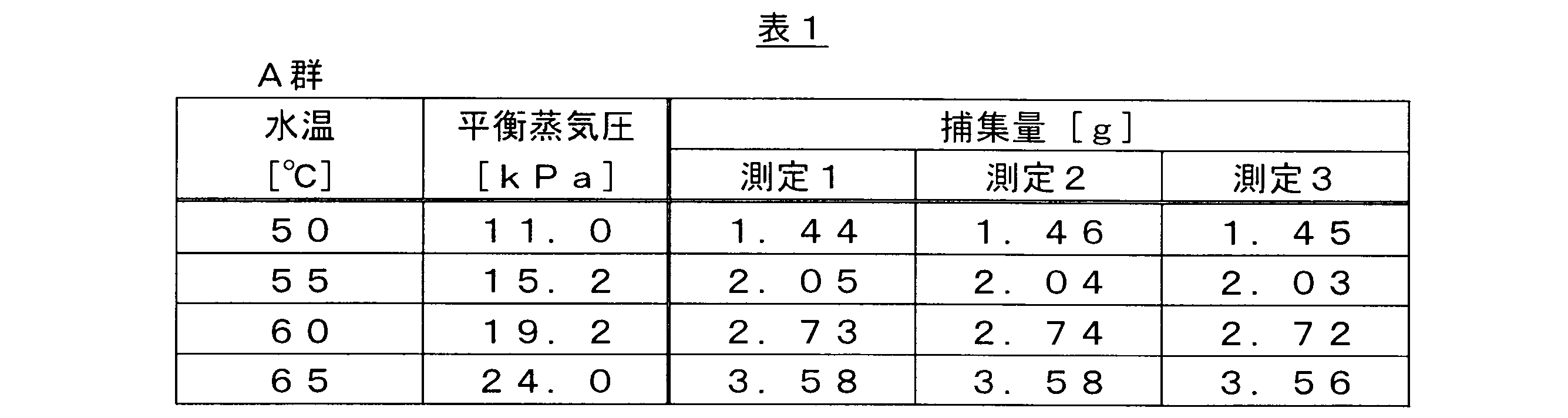
次に、上述したA群の測定を実施した日とは別の日に、上述した一連の測定を、今度は65℃から80℃までの範囲において、5℃きざみにて水温を変えながら実施し、このようなサイクルを3回繰り返した。これらの測定データをB群と呼ぶ。B群における水温と水蒸気の捕集量との関係を表2に示す。 Next, on a different day from the day when the Group A measurements were carried out, the above series of measurements was carried out, this time changing the water temperature in 5°C increments within the range of 65°C to 80°C, and this cycle was repeated three times. These measurement data are referred to as Group B. The relationship between water temperature and the amount of water vapor collected in Group B is shown in Table 2.
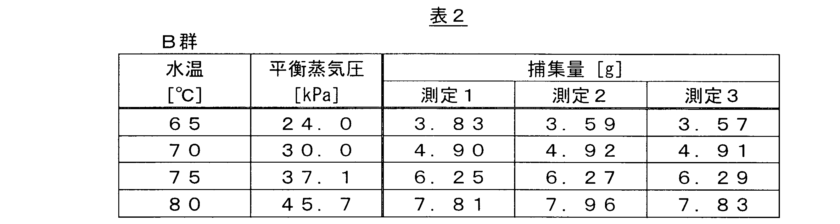
表1及び表2に示すように、A群及びB群のいずれにおいても、合計3回の測定における水蒸気の捕集量は、水温が同じ場合にはほぼ同じ値を示した。このことから、A群及びB群における水蒸気の捕集量は再現性に優れていると考えられる。 As shown in Tables 1 and 2, in both Group A and Group B, the amount of water vapor collected in three measurements was nearly the same when the water temperature was the same. From this, it can be considered that the amount of water vapor collected in Group A and Group B is highly reproducible.
次に、表1及び表2に示す水蒸気の平衡蒸気圧を横軸に、水蒸気の捕集量を縦軸にプロットしたグラフを図5に示す。図5において、丸印のプロットはA群のデータを表し、三角印のプロットはB群のデータを表す。点線は、すべてのプロットに基づいて最小二乗法によって求めた近似直線である。図5のグラフから明らかであるように、A群及びB群のプロットはいずれも点線で示された近似直線とよく一致している。このことから、気化器1において、捕集容器に捕集された水蒸気の捕集量は、タンク2の内部の温度のみによって決定される水蒸気の平衡蒸気圧の一次関数によって表されることがわかる。この実験事実は、上述した気化器仮説が正しいことを示唆している。
Next, Figure 5 shows a graph in which the equilibrium vapor pressure of water vapor shown in Tables 1 and 2 is plotted on the horizontal axis, and the amount of water vapor collected on the vertical axis. In Figure 5, the circle plots represent the data for Group A, and the triangle plots represent the data for Group B. The dotted line is an approximation line obtained by the least squares method based on all the plots. As is clear from the graph in Figure 5, both the plots for Group A and Group B match well with the approximation line shown by the dotted line. This shows that in
なお、図5のグラフにおいてプロットを延長した点線は原点を通らない。これは、パイプ6の出口と捕集容器とを接続するステンレス鋼製のフレキシブル管の内部に残った水の重量が捕集量の測定値に含まれていないためであると考えられる。しかしながら、上記参考例によれば、材料ガスの前駆体に見立てたイオン交換水の温度のみを制御することによって、水蒸気の捕集量、つまり所定の時間内にノズル9を通過する水蒸気の流量、を制御することができることがわかる。さらに、前述したように、材料ガスの流量をあらかじめ測定して流量を調整しておけば、開閉バルブ7の1回の開閉によって所望の量だけ材料ガスを供給することができる。
In addition, the dotted line extending the plot in the graph of Figure 5 does not pass through the origin. This is thought to be because the weight of the water remaining inside the stainless steel flexible tube connecting the outlet of
1 気化器
2 タンク
3 温度センサ
4 ヒータ
5 電力制御手段
6 パイプ
7 開閉バルブ
8 バルブ制御手段
9 ノズル
10 液位センサ
11 前駆体補充手段
11a リザーバ
11b ガスシリンダ
11c 送液パイプ
11d 加圧パイプ
11e バルブ
12 排気手段
P 前駆体
G 材料ガス
1′ 気化器(従来技術)
7′ 流量制御バルブ(従来技術)
8′ 流量センサ(従来技術)
REFERENCE SIGNS
7' Flow Control Valve (Prior Art)
8' Flow sensor (prior art)
Claims (12)
前記ノズルが、穴の開けられた板を備えるオリフィスである、
気化器。 2. The vaporizer of claim 1,
the nozzle is an orifice comprising a plate with holes;
Carburetor.
前記ノズルが、前記開閉バルブよりも下流側にある、
気化器。 2. The vaporizer of claim 1,
The nozzle is located downstream of the opening and closing valve.
Carburetor.
複数の前記パイプを備え、複数の前記パイプのそれぞれが、前記開閉バルブ及び前記ノズルを1つずつ備える、
気化器。 2. The vaporizer of claim 1,
a plurality of the pipes, each of the plurality of pipes including one of the on-off valves and one of the nozzles;
Carburetor.
前記パイプ、前記開閉バルブ及び前記ノズルが加熱手段を備える、
気化器。 2. The vaporizer of claim 1,
The pipe, the on-off valve and the nozzle are equipped with a heating means.
Carburetor.
前記前駆体が液体の状態にあり、
前記タンクに貯蔵される前記前駆体の液位を検知する液位センサと、前記前駆体の液位が下がったときに前記タンクの内部に前記前駆体を補充する前駆体補充手段とを備える、
気化器。 2. The vaporizer of claim 1,
the precursor is in a liquid state;
a liquid level sensor that detects a liquid level of the precursor stored in the tank, and a precursor replenishing means that replenishes the precursor into the tank when the liquid level of the precursor drops.
Carburetor.
前記タンクに貯蔵される前記前駆体に溶存するガスを脱気する排気手段をさらに備える、
気化器。 7. The carburetor of claim 6,
The present invention further includes an exhaust means for degassing a gas dissolved in the precursor stored in the tank.
Carburetor.
前記材料ガスの前駆体をタンクに貯蔵するステップと、
前記タンクに貯蔵された前記前駆体の温度があらかじめ設定された設定温度と等しくなるようにヒータに供給される電力を制御しながら前記前駆体を加熱して前記材料ガスを生成させるステップと、
前記材料ガスを前記タンクの外部に導くパイプに介装された開閉バルブにバルブ制御手段から開信号を出力して前記開閉バルブを開くステップと、
前記パイプに介装され前記パイプの内部空間と連通する流路が設けられたノズルを経由して前記タンクの内部に蓄えられた前記材料ガスを前記半導体製造装置に供給するステップと、
前記開閉バルブに前記バルブ制御手段から閉信号を出力して前記開閉バルブを閉じ前記材料ガスの供給を停止するステップと、を含み、
前記ノズルに設けられた前記流路の最も狭い位置における断面積が前記パイプの内部空間の断面積よりも小さい、
半導体製造装置に材料ガスを供給する方法。 A method for supplying a material gas to a semiconductor manufacturing apparatus, comprising the steps of:
storing the precursor of the material gas in a tank;
a step of heating the precursor while controlling power supplied to a heater so that the temperature of the precursor stored in the tank becomes equal to a preset temperature to generate the material gas;
a step of outputting an open signal from a valve control means to an on-off valve disposed in a pipe for leading the material gas to the outside of the tank, thereby opening the on-off valve;
supplying the material gas stored in the tank to the semiconductor manufacturing equipment through a nozzle that is disposed in the pipe and has a flow path that communicates with an internal space of the pipe;
a step of outputting a close signal from the valve control means to the on-off valve to close the on-off valve and stop the supply of the material gas,
A cross-sectional area at the narrowest position of the flow passage provided in the nozzle is smaller than a cross-sectional area of an internal space of the pipe.
A method for supplying a material gas to a semiconductor manufacturing device.
前記開閉バルブが開いてから閉じるまでの間に前記半導体製造装置に供給される前記材料ガスの流量をあらかじめ測定しておくステップをさらに含む、
半導体製造装置に材料ガスを供給する方法。 9. A method for supplying a material gas to a semiconductor manufacturing apparatus according to claim 8, comprising the steps of:
a step of measuring in advance a flow rate of the material gas supplied to the semiconductor manufacturing equipment during a period from when the on-off valve is opened to when it is closed,
A method for supplying a material gas to a semiconductor manufacturing device.
前記前駆体が液体の状態にあり、
前記タンクに貯蔵される前記前駆体の液位が下がったときに前記タンクの内部に前駆体を補充するステップをさらに含む、
半導体製造装置に材料ガスを供給する方法。 9. A method for supplying a material gas to a semiconductor manufacturing apparatus according to claim 8, comprising the steps of:
the precursor is in a liquid state;
The method further includes replenishing the precursor inside the tank when the liquid level of the precursor stored in the tank drops.
A method for supplying a material gas to a semiconductor manufacturing device.
前記タンクに貯蔵される前記前駆体に溶存するガスを脱気するステップをさらに含む、
半導体製造装置に材料ガスを供給する方法。 11. A method for supplying a material gas to a semiconductor manufacturing apparatus according to claim 10, comprising the steps of:
The method further includes a step of degassing the precursor stored in the tank to remove any dissolved gas.
A method for supplying a material gas to a semiconductor manufacturing device.
前記タンクの内部の圧力の値をノズルよりも下流側の圧力の値以上の値に調整するステップをさらに含む、
半導体製造装置に材料ガスを供給する方法。 9. A method for supplying a material gas to a semiconductor manufacturing apparatus according to claim 8, comprising the steps of:
The pressure value inside the tank is adjusted to a value equal to or greater than a pressure value downstream of the nozzle.
A method for supplying a material gas to a semiconductor manufacturing device.
Priority Applications (3)
| Application Number | Priority Date | Filing Date | Title |
|---|---|---|---|
| CN202480017784.0A CN120882899A (en) | 2023-03-17 | 2024-02-26 | vaporizer and method for supplying material gases to semiconductor manufacturing equipment |
| JP2025508251A JPWO2024195439A1 (en) | 2023-03-17 | 2024-02-26 | |
| KR1020257030512A KR20250163884A (en) | 2023-03-17 | 2024-02-26 | Method for supplying material gas to a vaporizer and a semiconductor manufacturing device |
Applications Claiming Priority (2)
| Application Number | Priority Date | Filing Date | Title |
|---|---|---|---|
| JP2023-043635 | 2023-03-17 | ||
| JP2023043635 | 2023-03-17 |
Publications (1)
| Publication Number | Publication Date |
|---|---|
| WO2024195439A1 true WO2024195439A1 (en) | 2024-09-26 |
Family
ID=92841854
Family Applications (1)
| Application Number | Title | Priority Date | Filing Date |
|---|---|---|---|
| PCT/JP2024/006780 Ceased WO2024195439A1 (en) | 2023-03-17 | 2024-02-26 | Vaporizer and method for supplying material gas to semiconductor manufacturing device |
Country Status (4)
| Country | Link |
|---|---|
| JP (1) | JPWO2024195439A1 (en) |
| KR (1) | KR20250163884A (en) |
| CN (1) | CN120882899A (en) |
| WO (1) | WO2024195439A1 (en) |
Citations (3)
| Publication number | Priority date | Publication date | Assignee | Title |
|---|---|---|---|---|
| JP2012049324A (en) * | 2010-08-26 | 2012-03-08 | Hitachi Kokusai Electric Inc | Substrate treatment apparatus |
| JP2021522587A (en) * | 2018-04-28 | 2021-08-30 | アプライド マテリアルズ インコーポレイテッドApplied Materials,Incorporated | Shared precursor distribution system based on gas pulse and usage |
| WO2023037948A1 (en) * | 2021-09-09 | 2023-03-16 | 株式会社プロテリアル | Vaporizer |
Family Cites Families (4)
| Publication number | Priority date | Publication date | Assignee | Title |
|---|---|---|---|---|
| US7628860B2 (en) | 2004-04-12 | 2009-12-08 | Mks Instruments, Inc. | Pulsed mass flow delivery system and method |
| JP6978865B2 (en) | 2017-07-05 | 2021-12-08 | 株式会社堀場エステック | Fluid control device, fluid control method, and program for fluid control device |
| JP7107648B2 (en) | 2017-07-11 | 2022-07-27 | 株式会社堀場エステック | FLUID CONTROL DEVICE, FLUID CONTROL SYSTEM, FLUID CONTROL METHOD, AND FLUID CONTROL DEVICE PROGRAM |
| JP7122334B2 (en) | 2020-03-30 | 2022-08-19 | Ckd株式会社 | Pulse shot type flow control device, pulse shot type flow control method, and program |
-
2024
- 2024-02-26 WO PCT/JP2024/006780 patent/WO2024195439A1/en not_active Ceased
- 2024-02-26 CN CN202480017784.0A patent/CN120882899A/en active Pending
- 2024-02-26 JP JP2025508251A patent/JPWO2024195439A1/ja active Pending
- 2024-02-26 KR KR1020257030512A patent/KR20250163884A/en active Pending
Patent Citations (3)
| Publication number | Priority date | Publication date | Assignee | Title |
|---|---|---|---|---|
| JP2012049324A (en) * | 2010-08-26 | 2012-03-08 | Hitachi Kokusai Electric Inc | Substrate treatment apparatus |
| JP2021522587A (en) * | 2018-04-28 | 2021-08-30 | アプライド マテリアルズ インコーポレイテッドApplied Materials,Incorporated | Shared precursor distribution system based on gas pulse and usage |
| WO2023037948A1 (en) * | 2021-09-09 | 2023-03-16 | 株式会社プロテリアル | Vaporizer |
Also Published As
| Publication number | Publication date |
|---|---|
| KR20250163884A (en) | 2025-11-21 |
| CN120882899A (en) | 2025-10-31 |
| JPWO2024195439A1 (en) | 2024-09-26 |
Similar Documents
| Publication | Publication Date | Title |
|---|---|---|
| JP6916964B2 (en) | Pulse gas supply method and equipment using a shutoff valve | |
| JP5174805B2 (en) | Device for introducing, injecting or supplying a carrier gas and liquid mixture and method for using the device | |
| JP5350824B2 (en) | Liquid material vaporization supply system | |
| KR101846763B1 (en) | Vapor delivery system | |
| CN107236937B (en) | Substrate processing apparatus, gas supply method, substrate processing method, and film formation method | |
| US20140124064A1 (en) | Raw material vaporizing and supplying apparatus | |
| CN101235487B (en) | Raw gas supply device | |
| CN103547894B (en) | Liquid quality is measured and fluid delivery system | |
| TW200815703A (en) | Vaporizer/supplier of material and automatic pressure regulator for use therein | |
| KR20080044905A (en) | Delivery of precursor gas mixed with carrier gas | |
| KR20100048895A (en) | Material gas concentration control system | |
| WO2018207553A1 (en) | Liquid material atomization and supply device and control program | |
| CN101171368A (en) | Evaporator and method for evaporating liquid to form thin film | |
| EP1844178B1 (en) | High accuracy vapor generation and delivery for thin film deposition | |
| US20110000554A1 (en) | Raw material supply device | |
| WO2024195439A1 (en) | Vaporizer and method for supplying material gas to semiconductor manufacturing device | |
| JP5270813B2 (en) | Apparatus and method for refilling a bubbler | |
| JP7316011B2 (en) | Gas supply system and gas supply method | |
| JP7376959B2 (en) | Gas supply amount measurement method and gas supply amount control method | |
| JP7699797B2 (en) | Gas supply system and gas supply method | |
| JP2003013233A (en) | Device for vaporizing/feeding liquid raw material | |
| WO2022190711A1 (en) | Vaporizer and vaporization supply device | |
| JP5302642B2 (en) | Method for measuring the amount of source material in a chemical vapor deposition process | |
| US20250257459A1 (en) | Precursor Delivery System | |
| JP2025034868A (en) | Vaporizer and gas supply method |
Legal Events
| Date | Code | Title | Description |
|---|---|---|---|
| 121 | Ep: the epo has been informed by wipo that ep was designated in this application |
Ref document number: 24774584 Country of ref document: EP Kind code of ref document: A1 |
|
| ENP | Entry into the national phase |
Ref document number: 2025508251 Country of ref document: JP Kind code of ref document: A |
|
| WWE | Wipo information: entry into national phase |
Ref document number: 2025508251 Country of ref document: JP |
|
| WWE | Wipo information: entry into national phase |
Ref document number: 202480017784.0 Country of ref document: CN |
|
| ENP | Entry into the national phase |
Ref document number: 1020257030512 Country of ref document: KR Free format text: ST27 STATUS EVENT CODE: A-0-1-A10-A15-NAP-PA0105 (AS PROVIDED BY THE NATIONAL OFFICE) |
|
| NENP | Non-entry into the national phase |
Ref country code: DE |
|
| WWP | Wipo information: published in national office |
Ref document number: 202480017784.0 Country of ref document: CN |