WO2024181225A1 - Ion source - Google Patents
Ion source Download PDFInfo
- Publication number
- WO2024181225A1 WO2024181225A1 PCT/JP2024/005970 JP2024005970W WO2024181225A1 WO 2024181225 A1 WO2024181225 A1 WO 2024181225A1 JP 2024005970 W JP2024005970 W JP 2024005970W WO 2024181225 A1 WO2024181225 A1 WO 2024181225A1
- Authority
- WO
- WIPO (PCT)
- Prior art keywords
- ion
- plasma generating
- antenna
- ion source
- magnetic field
- Prior art date
- Legal status (The legal status is an assumption and is not a legal conclusion. Google has not performed a legal analysis and makes no representation as to the accuracy of the status listed.)
- Ceased
Links
Images


Classifications
-
- H—ELECTRICITY
- H01—ELECTRIC ELEMENTS
- H01J—ELECTRIC DISCHARGE TUBES OR DISCHARGE LAMPS
- H01J37/00—Discharge tubes with provision for introducing objects or material to be exposed to the discharge, e.g. for the purpose of examination or processing thereof
- H01J37/02—Details
- H01J37/04—Arrangements of electrodes and associated parts for generating or controlling the discharge, e.g. electron-optical arrangement or ion-optical arrangement
- H01J37/08—Ion sources; Ion guns
-
- H—ELECTRICITY
- H01—ELECTRIC ELEMENTS
- H01J—ELECTRIC DISCHARGE TUBES OR DISCHARGE LAMPS
- H01J27/00—Ion beam tubes
- H01J27/02—Ion sources; Ion guns
- H01J27/16—Ion sources; Ion guns using high-frequency excitation, e.g. microwave excitation
-
- H—ELECTRICITY
- H01—ELECTRIC ELEMENTS
- H01J—ELECTRIC DISCHARGE TUBES OR DISCHARGE LAMPS
- H01J37/00—Discharge tubes with provision for introducing objects or material to be exposed to the discharge, e.g. for the purpose of examination or processing thereof
- H01J37/30—Electron-beam or ion-beam tubes for localised treatment of objects
- H01J37/317—Electron-beam or ion-beam tubes for localised treatment of objects for changing properties of the objects or for applying thin layers thereon, e.g. for ion implantation
Definitions
- the present invention relates to an ion source for use in, for example, an ion implantation device.
- this type of ion source has a rectangular parallelepiped plasma generating vessel into which an ion source gas is introduced, a number of magnets arranged on the outer side of the plasma generating vessel to form a cusp magnetic field inside the plasma generating vessel, and a filament that emits electrons and is inserted into the plasma generating vessel from its side wall.
- the plasma generating vessel also serves as an anode, and electrons emitted from the filament are discharged inside the plasma generating vessel to ionize the ion source gas and generate plasma.
- An extraction electrode system arranged near an ion extraction port formed in one side wall of the plasma generating vessel is used to extract an ion beam from the plasma.
- a negative voltage is applied to the plasma generating vessel to generate plasma, and the filament is worn out due to sputtering by positive ions.
- a halide ion source gas such as BF3
- the filament is subjected to sputtering accompanied by a chemical reaction, and is more likely to be worn out.
- maintenance such as replacement is required, so in conventional ion sources, the life of the filament is the main factor that determines the maintenance cycle of the ion source.
- the present invention was made to solve all of these problems at once, and its main objective is to provide an ion source that has a long maintenance cycle, is highly functional during maintenance, allows the overall device to be made smaller, and has low manufacturing costs.
- the ion source according to the present invention is an elongated vessel having an internal space into which an ion source gas is introduced, and is equipped with a plasma generating vessel having an ion outlet formed on one side wall along the longitudinal direction thereof, plasma generating means for ionizing the ion source gas to generate plasma in the internal space, and an extraction electrode system provided outside the plasma generating vessel and extracting an ion beam from the internal space through the ion outlet, the plasma generating means comprising an antenna provided outside the plasma generating vessel along the longitudinal direction, a high frequency power source for applying high frequency to the antenna, and a magnetic field transmission window formed in a position facing the antenna on the side wall of the plasma generating vessel and allowing a high frequency magnetic field generated by the antenna to pass through to the internal space.
- the present invention thus configured can provide an ion source that has a long maintenance cycle, is highly functional during maintenance, and allows the overall device to be made smaller, while keeping manufacturing costs down.
- FIG. 1 is a schematic diagram showing an overall configuration of an ion implantation apparatus according to an embodiment of the present invention
- FIG. 2 is a cross-sectional view illustrating a schematic configuration of an ion source according to the embodiment.
- FIG. 2 is a vertical cross-sectional view illustrating a schematic configuration of an ion source according to the embodiment.
- 3A is a cross-sectional view of the window member according to the embodiment
- FIG. 3B is a plan view of the window member as viewed from the antenna side
- FIG. 3C is a plan view of the window member as viewed from the internal space side.
- 5 is a graph showing a plasma density distribution of inductively coupled plasma using the ion source of the embodiment.
- FIG. 10A and 10B are diagrams illustrating a configuration of a window member according to another embodiment, in which FIG. 10A is a cross-sectional view and FIG. 10B is a plan view seen from the internal space side.
- 13A and 13B are diagrams for explaining a function of a current distribution monitor in an ion implantation apparatus according to another embodiment.
- FIG. 11 is a cross-sectional view showing a schematic configuration of an ion source according to another embodiment.
- FIG. 11 is a cross-sectional view showing a schematic configuration of an ion source according to another embodiment.
- FIG. 11 is a vertical cross-sectional view illustrating a schematic configuration of an ion source according to another embodiment.
- the ion source of the present invention is used in ion beam irradiation devices such as ion implantation devices and ion doping devices used in, for example, semiconductor manufacturing processes and flat panel display manufacturing processes.
- ion beam irradiation devices such as ion implantation devices and ion doping devices used in, for example, semiconductor manufacturing processes and flat panel display manufacturing processes.
- the ion implantation device 400 of this embodiment is for irradiating an ion beam IB onto a target substrate W to implant ions.
- the ion implantation device 400 includes an ion source 100 that extracts an ion beam IB in a predetermined extraction direction, a mass analysis section 200 that is provided downstream of the ion source 100 and performs mass analysis of the ion beam IB extracted from the ion source 100, and a processing chamber 300 in which the substrate W is placed.
- a ribbon-shaped ion beam IB is extracted from the ion source 100, whose width in the front-to-back direction of the paper surface of FIG. 1 is sufficiently greater than its thickness in the direction perpendicular thereto.
- the mass analysis section 200 has a mass analysis magnet 210 and an analysis slit 220.
- the mass analysis magnet 210 bends the ion beam IB in the thickness direction to select and extract the desired ions.
- the analysis slit 220 is provided downstream of the mass analysis magnet 210 and cooperates with the mass analysis magnet 210 to select and pass the desired ions.
- a slit plate 211 that forms an entrance slit is provided at the entrance of the mass analysis magnet 210. This slit plate 211 limits the incidence angle and beam width of the ion beam IB when it enters the mass analysis magnet 210, thereby improving the analytical performance of the ion beam passing through the analysis slit 220.
- the substrate W is held by the substrate drive device 310 with its processing surface facing the ion beam IB.
- This substrate drive device 310 is configured to hold the substrate W and to mechanically drive it back and forth in a direction along the thickness of the ion beam IB incident on the substrate W.
- the ion implantation device 400 can perform ion implantation by injecting the ion beam IB onto the entire surface of the substrate W through the back and forth drive of the substrate W by the substrate drive device 310 and the irradiation of the ribbon-shaped ion beam IB.
- the configuration of the ion source 100 will be described in detail below. Note that each figure shows only the essential parts of the ion source 100 according to the embodiment of the present invention, and various components are omitted.
- this ion source 100 includes a plasma generating vessel 1 into which an ion source gas is introduced to generate plasma, a plurality of magnets 2 that are provided outside the plasma generating vessel 1 and form a magnetic field (specifically, a cusp magnetic field, or more strictly, a multicusp magnetic field, also called a multipole magnetic field) within the plasma generating vessel 1, a plasma generating means 3 that forms plasma within the plasma generating vessel 1, an extraction electrode system 4 that extracts an ion beam IB from the plasma generating vessel 1, and a gas source 5 that supplies an ion source gas to the plasma generating vessel 1 at a constant flow rate.
- a plasma generating vessel 1 into which an ion source gas is introduced to generate plasma
- a plurality of magnets 2 that are provided outside the plasma generating vessel 1 and form a magnetic field (specifically, a cusp magnetic field, or more strictly, a multicusp magnetic field, also called a multipole magnetic field) within the plasma generating vessel 1
- the plasma generating vessel 1 is an elongated vessel having, for example, a rectangular parallelepiped shape.
- the inner wall surface of this plasma generating vessel 1 forms an internal space 1s into which an ion source gas is introduced to generate plasma.
- This internal space 1s is an elongated space having a roughly rectangular parallelepiped shape formed to extend along the longitudinal direction of the plasma generating vessel 1, and is formed by being surrounded by a pair of inner wall surfaces facing each other along the withdrawal direction and a pair of inner wall surfaces facing each other along the width direction.
- the internal section is evacuated to a vacuum by a vacuum exhaust device (not shown).
- An ion extraction port 1H which is an opening for extracting the ion beam IB from the internal space 1s, is formed in one side wall (hereinafter referred to as the front wall 11a) of the plasma generating vessel 1 parallel to the longitudinal direction.
- the ion extraction port 1H is formed in the front wall 11a so as to extend along the longitudinal direction, similar to the internal space 1s.
- the front wall 11a is formed so as to be perpendicular to the extraction direction of the ion beam IB.
- the width direction is referred to as the width direction.
- the term "elongated shape” refers to any shape formed so that, when viewed from the extraction direction, the length in one axial direction (i.e., the length in the longitudinal direction) is longer than the length in the other axial direction (i.e., the length in the width direction), in two axial directions perpendicular to each other, and is not limited to a rectangular parallelepiped shape.
- a plurality of gas introduction holes 1g are formed which communicate with the gas source 5 and introduce an ion source gas into the internal space 1s via a gas flow regulator (not shown).
- the plurality of gas introduction holes 1g have approximately the same diameter and are provided at approximately equal intervals along the longitudinal direction of the plasma generating vessel 1 near the ion extraction outlet 1H in the side walls 11c, d (i.e., near the joint with the front wall 11a).
- An ion source gas such as BF3 gas or PH3 gas is introduced into the internal space 1s from the gas introduction holes 1g.
- the gas introduction holes 1g may be formed in only one of the two side walls 11c, d, or may be provided in the side walls 11c, d near the joint between the front wall 11a and the opposing rear wall 11b (i.e., near the magnetic field transmission window 3w described later).
- the gas introduction holes 1g may be provided at approximately equal intervals, and the hole diameter at both ends along the longitudinal direction may be relatively larger than the hole diameter at the center.
- the gas introduction holes 1g may have approximately the same hole diameter, and the arrangement interval at both ends along the longitudinal direction may be relatively narrower than the arrangement interval at the center.
- the gas introduction holes 1g are provided to open on the inner surface of the side wall of the plasma generating vessel 1, but they may also be provided to open on the wall of a gas supply pipe arranged in the plasma generating vessel 1.
- the multiple magnets 2 are provided externally along the outer surfaces of the side walls other than the front wall 11a (specifically, the side walls 11c, d), and form a cusp magnetic field near the inner surfaces of the side walls 11c, d.
- each magnet 2 is a permanent magnet, but electromagnets may also be used.
- the multiple magnets 2 are arranged at approximately equal intervals with different polarities along a direction perpendicular to the ion extraction direction. Note that the arrangement of the multiple magnets 2 is not limited to this and can be changed as appropriate.
- the plasma generating means 3 ionizes the ion source gas by supplying a high-frequency magnetic field to the internal space 1s of the plasma generating vessel 1 to generate plasma.
- the extraction electrode system 4 is provided near the ion extraction port 1H of the plasma generating vessel 1, and accelerates and extracts the ion beam IB by applying a potential difference between the extraction electrode system 4 and the plasma generating vessel 1.
- the extraction electrode system 4 has a plurality of plate-shaped electrodes 41 to 44 in which slits 4x are formed. More specifically, as shown in Figures 2 and 3, the extraction electrode system 4 has a plasma electrode 41, an extraction electrode 42, a suppression electrode 43, and a ground electrode 44, which are arranged in order from the plasma generating vessel 1 toward downstream along the ion extraction direction.
- Each of these electrodes has a slender slit 4x formed in the center thereof, which penetrates in the thickness direction and extends along the longitudinal direction.
- Each electrode is arranged so that the slit 4x formed in the center faces the ion extraction port 1H of the plasma generating vessel 1.
- the electrodes are electrically insulated from each other by, for example, an insulator (not shown). It is preferable that the slit width of the electrode (here, the plasma electrode 41) closest to the plasma generating vessel 1 in the extraction electrode system 4 is variable. In this way, the gas pressure in the plasma chamber can be made variable, allowing freedom in setting the pressure in the plasma generating vessel 1 and the degree of vacuum in the extraction electrode area, which allows for a margin in the withstand voltage applied between the electrodes.
- the ion source 100 of this embodiment is configured such that the plasma generating means 3 generates an inductively coupled plasma in the internal space 1s of the plasma generating vessel 1, and includes an antenna 31 provided outside the plasma generating vessel 1, a high frequency power supply 32 that applies high frequency to the antenna 31, and a magnetic field transmission window 3w formed in a position facing the antenna 31 on the side wall of the plasma generating vessel 1 and allowing the high frequency magnetic field generated from the antenna 31 to pass through to the internal space 1s.
- a high frequency current flows through the antenna 31, an induced electric field is generated in the plasma generating vessel 1, and an inductively coupled plasma is generated.
- the antenna 31 is linear (specifically cylindrical) with a length of several tens of centimeters or more when viewed from the outside.
- This antenna 31 is arranged so as to be straight along the longitudinal direction of the plasma generating vessel 1 with a gap from the magnetic field transmission window 3w outside the plasma generating vessel 1. That is, the antenna 31 is arranged so as to be straight along the longitudinal direction of the ion extraction outlet 1H and the slit 4x of the extraction electrode system 4.
- the antenna 31 When viewed from the ion extraction direction, the antenna 31 is arranged at a position facing the ion extraction outlet 1H, and more specifically, on the ion extraction axis L1 described above.
- a high-frequency power source 32 is connected to one end of the antenna 31, which is the power supply end, via a matching circuit 321.
- the high-frequency power supply 32 can pass a high-frequency current through the antenna 31 via the matching circuit 321.
- the frequency of the high-frequency current is, for example, a typical 13.56 MHz, but is not limited to this and may be changed as appropriate.
- the magnetic field transmission window 3w is formed in the side wall (referred to as the rear wall 11b) facing the front wall 11a of the plasma generating vessel 1. Specifically, as shown in Figures 4(a) to (c), this magnetic field transmission window 3w is formed by an opening 1x provided in the rear wall 11b of the plasma generating vessel 1 and a window member 33 attached to the plasma generating vessel 1 so as to close the opening 1x.
- this opening 1x When viewed from the ion extraction direction, this opening 1x has a rectangular shape whose length along the longitudinal direction of the plasma generating vessel 1 is greater than its length along the width direction.
- This opening 1x is formed in the rear wall 11b at a position facing both the antenna 31 and the ion extraction port 1H, and more specifically, is formed so as to be located on the line connecting the antenna 31 and the ion extraction port 1H.
- the window member 33 includes a slit plate 331 that blocks the opening 1x formed in the rear wall 11b of the plasma generating vessel 1 from the outside, and a dielectric plate 332 that blocks the slit 331x formed in the slit plate 331 from the outside of the plasma generating vessel 1.
- the slit plate 331 allows the high-frequency magnetic field generated by the antenna 31 to pass into the plasma generating vessel 1, and prevents an electric field from entering the inside of the plasma generating vessel 1 from the outside.
- the slit plate 331 is a flat plate with multiple slits 331x formed along the longitudinal direction of the antenna 31, penetrating the plate in the thickness direction.
- the slit plate 331 preferably has a higher mechanical strength than the dielectric plate 332 described below, and preferably has a larger thickness dimension than the dielectric plate 332.
- the multiple slits 331x are parallel to each other when viewed from the thickness direction, and are formed so as to intersect with the antenna 31 (specifically, so as to be perpendicular). All of the multiple slits 331x have the same shape (specifically, a rectangular shape when viewed from above).
- the slit plate 331 is made of metal, and is manufactured by rolling (e.g., cold rolling or hot rolling) a metal material such as one metal selected from the group including Cu, Al, Zn, Ni, Sn, Si, Ti, Fe, Cr, Nb, C, Mo, W, or Co, or an alloy thereof (e.g., stainless steel alloy, aluminum alloy, etc.).
- a metal material such as one metal selected from the group including Cu, Al, Zn, Ni, Sn, Si, Ti, Fe, Cr, Nb, C, Mo, W, or Co, or an alloy thereof (e.g., stainless steel alloy, aluminum alloy, etc.).
- This slit plate 331 is larger than the opening 1x of the plasma generating vessel 1 in a plan view, and blocks the opening 1x while supported by the rear wall 11b (i.e., while placed on the rear wall 11b), and is at the same potential as the plasma generating vessel 1.
- a sealing member such as an O-ring or gasket is interposed between the slit plate 331 and the rear wall 11b, and a vacuum seal is formed between them.
- the dielectric plate 332 is placed on the outward surface of the slit plate 331 that faces the outside of the plasma generating vessel 1 (the reverse side of the inward surface that faces the inside of the plasma generating vessel 1) and closes the slits 331x of the slit plate 331.
- a seal member is interposed between the dielectric plate 332 and the slit plate 331, and the space between them is vacuum sealed.
- the dielectric plate 332 is a flat plate made entirely of a dielectric material, such as ceramics such as alumina, silicon carbide, and silicon nitride, inorganic materials such as quartz glass and non-alkali glass, and resin materials such as fluororesin (e.g., Teflon).
- a dielectric material such as ceramics such as alumina, silicon carbide, and silicon nitride, inorganic materials such as quartz glass and non-alkali glass, and resin materials such as fluororesin (e.g., Teflon).
- the slit plate 331 and the dielectric plate 332 function as a magnetic field transmission window 3w that transmits the magnetic field generated by the antenna 31.
- the high frequency magnetic field generated by the antenna 31 passes through the magnetic field transmission window 3w consisting of the slit plate 331 and the dielectric plate 332 and is formed (supplied) inside the plasma generating vessel 1.
- an induced electric field is generated in the space inside the plasma generating vessel 1, and an inductively coupled plasma is generated.
- the window member 33 further includes a mask plate 333 that covers each slit 331x formed in the slit plate 331 from the inside of the plasma generating vessel 1 with a gap therebetween.
- the mask plate 333 is a flat plate with multiple slits 333x formed along the longitudinal direction of the antenna 31, penetrating through the mask plate 333 in the thickness direction.
- the multiple slits 333x are parallel to each other and to the multiple slits 331x formed in the slit plate 331.
- each slit 333x is formed so as to intersect with the antenna 31 (specifically, so as to be perpendicular). All of the multiple slits 333x are formed to have the same shape (specifically, rectangular in a plan view).
- beam-shaped regions 333z are formed parallel to each slit 333x.
- a plurality of beam-shaped regions 333z are formed to correspond to the plurality of slits 331x formed in the slit plate 331, and each beam-shaped region 333z covers each slit 331x of the slit plate 331.
- the length (width) of the beam-shaped region 333z along the longitudinal direction of the antenna 31 is approximately the same as the width of the slit 331x of the slit plate 331, and each beam-shaped region 333z covers approximately the entirety of each slit 331x of the slit plate 331.
- Each beam-shaped region 333z may be formed to cover only a portion of each slit 331x.
- the mask plate 333 is connected to the inner surface of the slit plate 331 and is at the same potential.
- the mask plate 333 is made of a metal material such as one metal selected from the group including Cu, Al, Zn, Ni, Sn, Si, Ti, Fe, Cr, Nb, C, Mo, W, or Co, or an alloy thereof (e.g., stainless steel alloy, aluminum alloy, etc.). It is preferable that the thickness of the mask plate 333 is smaller than the thickness of the slit plate 331.
- a flow path 331r is formed in the slit plate 331, through which a cooling medium such as water flows.
- This flow path 331r is formed along the longitudinal direction of the antenna 31 near the connection area of the mask plate 333 in the slit plate 331.
- the flow path 331r is formed so as to be located directly above the connection area along the thickness direction of the slit plate 331.
- the electrode (plasma electrode 41) in the extraction electrode system 4 closest to the plasma generating vessel 1 is preferably provided near the position where the plasma density peaks when plasma is generated to the position where the plasma density is half of the peak.
- the change in the peak position of the plasma density distribution is small relative to the pressure of the ion source gas supplied and the density of the applied high-frequency power, and therefore providing the plasma electrode 41 near the position where the plasma density peaks is preferable in terms of efficient extraction of the ion current.
- the vicinity of this peak position is an area where a strong high-frequency magnetic field is generated, and so overheating due to induced current may occur. Therefore, from the viewpoint of suppressing overheating due to induced current, the plasma electrode 41 is preferably provided in the plasma diffusion region up to the position where the plasma density is half of the peak.
- the distance between the inward surface of the magnetic field transmission window 3w (specifically, the inward surface of the slit plate 331) and the surface of the electrode in the extraction electrode system 4 closest to the plasma generation vessel 1 be set in the range of about 45 mm to about 140 mm.
- plasma is generated in the internal space 1s by the antenna 31 provided outside the plasma generating vessel 1 without using a filament protruding into the internal space 1s of the plasma generating vessel 1, so that the number of parts that are consumed by sputtering in the plasma generating vessel 1 can be reduced, and the maintenance cycle can be extended.
- the antenna 31 is provided along the longitudinal direction of the plasma generating vessel 1, a substantially uniform plasma can be generated in the internal space 1s by one antenna 31 extending along the ion extraction port 1H and one high frequency power source 32, so that the number of parts can be significantly reduced, the device can be made compact, and the number of processing steps required for installation and the number of control points of the power source can be reduced, so that the manufacturing cost can be suppressed. Furthermore, by reducing the number of power sources, the number of wires for power supply and the control lines for the equipment can be significantly reduced, and the wiring work during assembly and the detachment work during maintenance can be simplified, improving the workability.
- the ion source 100 of another embodiment may include a distance adjustment mechanism 6 for adjusting the distance between the antenna 31 and the magnetic field transmission window 3w, as shown in FIG. 6(a).
- This distance adjustment mechanism 6 is configured to partially adjust the distance between the antenna 31 and the magnetic field transmission window 3w by adjusting the positions of multiple points on the antenna 31, and specifically, is configured to be able to adjust the position of one or multiple parts along the longitudinal direction of the antenna 31.
- the distance adjustment mechanism 6 is provided on the upper surface of the window member 33 and includes an antenna support member 61 that supports both ends of the antenna 31, a number of gripping parts 62 that grip multiple locations of the antenna 31 and displace the gripped parts relative to the magnetic field transmission window 3w (specifically, the dielectric plate 332), and a drive source (not shown) such as a motor that moves these gripping parts 62 independently.
- the multiple gripping parts 62 are insulators that are electrically insulated from the antenna 31. One of these gripping parts 62 is located directly above the center of the opening 1x of the plasma generating vessel 1, and another gripping part 62 is provided at a symmetrical position along the longitudinal direction of the antenna 31 relative to this gripping part 62. In this embodiment, the multiple gripping parts 62 are arranged at equal intervals, and all of them are provided inside the opening 1x when viewed from a direction perpendicular to the opening 1x of the plasma generating vessel 1.
- the gripping portion 62 includes a pressing tool 621 that presses the side of the antenna 31 toward the window member 33, and a gap adjustment tool 622 that is provided so as to be braced between the antenna 31 and the window member 33.
- the pressing tool 621 is configured to constantly press the antenna 31 toward the window member 33, for example, by using a spring material or the like.
- the gap adjustment tool 622 is configured so that its length along the thickness direction of the window member 33 can be adjusted.
- the gap adjustment tool 622 is a tool with an elliptical cross section, and is configured so that its length along the thickness direction can be changed by rotating, thereby adjusting the distance between the antenna 31 and the window member 33.
- the mask plate 333 has a plurality of slits 333x formed therein, and the slits 331x of the slit plate 331 are covered by the beam-shaped regions 333z formed between the plurality of slits 333x, but this is not limited thereto.
- the mask plate 333 may be made of a metal plate having a rectangular shape, as shown in FIG. 6(b). In this case, one or more mask plates 333 may be provided at positions facing each of the plurality of slits 331x formed in the slit plate 331. When multiple mask plates 333 are provided for one slit 331x, it is preferable to arrange them so that they are staggered from each other in the thickness direction.
- the ion implantation device 400 may be configured to adjust the distance between the antenna 31 and the magnetic field transmission window 3w and the output of the high frequency power supply 32 according to the current value of the extracted ion beam IB.
- the ion implantation device 400 may be configured to include a current distribution monitor 7 that monitors the current distribution of the ion beam IB along the longitudinal direction, downstream of the mass analysis magnet 210, to compare the monitored current distribution of the ion beam IB with the target values of the average current density and uniformity using a comparison calculator, and to adjust the distance between the antenna 31 and the magnetic field transmission window 3w and the output of the high frequency power supply 32 according to the comparison result.
- the magnetic field transmission window 3w is formed in the rear side wall 11b of the plasma generating vessel 1, but this is not limited to the above.
- the magnetic field transmission window 3w may be formed in one or both of the two side walls (lateral side walls 11c, d) that face each other across the ion extraction axis L1 when viewed from the longitudinal direction.
- the lateral side walls 11c, d of the plasma generating vessel 1 may be inclined so that their inner wall surfaces face the ion extraction port 1H as shown in FIG. 8, or may be straight along the extraction direction as shown in FIG. 9.
- the magnetic field transmission axis L2 of the two magnetic field transmission windows 3w intersect on the ion extraction axis L1. It is also preferable that the angle between the magnetic field transmission axis L2 and the electrode surface of the plate-shaped electrode that constitutes the extraction electrode system is approximately 20° or more and approximately 45° or less.
- a cooling flow passage 1c is formed on the outer wall side of the rear side wall 11b directly facing the ion extraction port 1H.
- This cooling flow passage 1c is preferably formed so as to pass through the ion extraction axis L1 and extend along the longitudinal direction of the plasma generating vessel 1.
- the magnet 2 is provided on the outer surface of each lateral side wall 11c, 11d so as to sandwich the magnetic field transmission window 3w from both sides when viewed from the longitudinal direction.
- the extraction electrode system 4 (specifically, the plasma electrode 41) can be brought closer to the ion extraction port 1H without considering the peak position of the plasma density. That is, in the configurations shown in Fig. 2 and Fig. 8, the magnetic field transmission window 3w is installed so as to face the ion extraction port 1H, so that the magnetic field in the vicinity of the ion extraction port 1H becomes strong, and it is necessary to install the plasma electrode 41 while taking into consideration overheating due to induced current. In contrast, in the configuration shown in Fig.
- the magnetic field transmission window 3w does not face the ion extraction port 1H, so that the magnetic field at the ion extraction port 1H is weaker than that in Fig. 2 and Fig. 8, so that the plasma electrode 41 can be installed without taking into consideration overheating due to induced current.
- the portion facing the ion outlet 1H is easily heated by the backflow of electrons in the plasma, but by forming the magnetic field transmission window 3w at a position not facing the ion outlet 1H as shown in Fig. 9, it is possible to reduce contamination of the window member 33 (particularly the dielectric plate 332), and to suppress the decrease in the transmittance of the magnetic field and stabilize the operation, compared to Figs. 2 and 8 in which the magnetic field transmission window 3w is formed at a position facing the ion outlet 1H. In addition, it is possible to avoid problems such as the dielectric plate 332 itself heating up or being damaged.
- a cooling passage 1c may be formed on the ion extraction axis L1 on the outer wall side of the rear wall 11b directly facing the ion extraction port 1H. In this way, the heating caused by backflow electrons can be effectively cooled.
- the high frequency power supply 32 and the matching circuit 321 are installed in the high voltage section, but this is not limited to the above.
- the high frequency power supply 32 and the matching circuit 321 may be installed at ground potential. This contributes to reducing the capacity of the insulating transformer for supplying power to the high voltage section, and can also contribute to miniaturization and cost reduction of the entire system, and to avoiding equipment failures when discharge problems occur due to high voltage.
- the antenna 31 may also have a hollow structure with a flow path formed inside through which the coolant can flow.
- the antenna 31 may also be a so-called LC antenna 31 that includes at least two conductor elements and a capacitor that is a fixed element electrically connected in series with adjacent conductor elements.
- the antenna 31 may include three conductor elements and two capacitors, and each conductor element may be of the same shape, forming a straight tube shape (specifically, a circular tube shape) with a linear flow path formed inside through which the coolant flows.
- the material of each conductor element may be, for example, copper, aluminum, an alloy of these, or a metal such as stainless steel.
- the antenna 31 By configuring the antenna 31 in this way, the combined reactance of the antenna 31 is, simply put, the inductive reactance minus the capacitive reactance, so the impedance of the antenna 31 can be reduced. As a result, even if the antenna 31 is lengthened, the increase in impedance can be suppressed, making it easier for high-frequency current to flow through the antenna 31, and efficiently generating inductively coupled plasma in the internal space 1s.
- the disclosure of this specification may further include the following aspects 1-10.
- An ion source comprising: a plasma generating vessel which is an elongated vessel having an internal space into which an ion source gas is introduced and in which an ion outlet is formed on one side wall along the longitudinal direction of the vessel; plasma generating means which ionizes the ion source gas to generate plasma in the internal space; and an extracting electrode system which is provided outside the plasma generating vessel and extracts an ion beam from the internal space through the ion outlet, the plasma generating means comprising: an antenna provided outside the plasma generating vessel along the longitudinal direction; a high frequency power source which applies high frequency to the antenna; and a magnetic field transmission window which is formed in a position facing the antenna on the side wall of the plasma generating vessel and which allows a high frequency magnetic field generated from the antenna to pass through the internal space.
- plasma is generated in the internal space by an antenna installed outside the plasma generating vessel, without using a filament protruding into the internal space of the plasma generating vessel, thereby reducing the number of parts inside the plasma generating vessel that are subject to wear due to sputtering and lengthening the maintenance cycle.
- the antenna is provided along the longitudinal direction of the plasma generating vessel, a substantially uniform plasma can be generated in the internal space by one antenna extending along the ion extraction direction opening and one high frequency power source, the number of parts can be significantly reduced, the device can be made smaller, the number of processing steps required for installation and the number of control points for the power source can be reduced, and the manufacturing cost can be suppressed.
- the number of power supply wires and device control wires can be significantly reduced, and the wiring work during assembly and the removal and attachment work during maintenance can be simplified, improving the workability.
- (Aspect 2) The ion source according to aspect 1, wherein the extraction electrode system includes one or more plate-shaped electrodes provided at a position facing the ion extraction port, and a slit penetrating the electrode in its thickness direction is formed along the longitudinal direction at a position of each electrode corresponding to the ion extraction port, and the direction in which the slit extends coincides with the direction in which the antenna extends.
- the slit formed in the electrode constituting the extraction electrode and the antenna extend in the same direction, making it possible to extract an ion beam with a substantially uniform current density along the longitudinal direction.
- FIG. 3 An ion source according to aspect 1 or 2, wherein the magnetic field transmission window comprises an opening formed in a side wall of the plasma generating vessel, a slit plate that covers the opening, and a dielectric plate that covers the slit formed in the slit plate from the outside of the plasma generating vessel.
- a slit formed in a metal slit plate and a dielectric plate placed on the slit plate form a magnetic field transmission window that transmits the high frequency magnetic field generated from the antenna into the internal space.
- the thickness of the magnetic field transmission window can be made smaller than when the magnetic field transmission window is made of only a dielectric material.
- the dielectric plate is supported in contact with the metal plate, deformation of the dielectric plate during vacuum processing can be reduced, and bending stress generated in the dielectric plate can be reduced. Therefore, the thickness of the dielectric plate itself can be made smaller. This allows the distance from the antenna to the internal space to be shortened, and the high frequency magnetic field generated by the antenna can be efficiently supplied into the plasma generating vessel.
- the magnetic field transmission window further comprises a mask plate that covers the slit formed in the slit plate from the inside of the plasma generating vessel with a gap therebetween.
- the antenna to which high-frequency power is applied is optically and electrically shielded by the mask plate, so that the high-frequency voltage of the antenna can be shielded, and the ion energy and its energy width in the generated plasma can be reduced. This reduces the influence on the mass separation of ions extracted from the ion source. This effect is particularly effective when extracting low-energy ions.
- the ion source while ions are extracted from the plasma by the extraction electrode, electrons flow back from the extraction electrode into the plasma generating vessel.
- the magnetic field transmission window is shielded by a mask plate, it is possible to prevent the electron flow from entering the dielectric plate that constitutes the magnetic field transmission window. This reduces the possibility of the dielectric plate being damaged by heating, charging, or discharge. Furthermore, if a high-melting-point metal is used in this part, thermal deformation can be reduced, enabling stable operation. Furthermore, if a conductive coating generated by plasma passes through the slits and adheres to the dielectric plate, the transmittance of the high-frequency magnetic field decreases, resulting in a decrease in the efficiency of plasma generation, and the heat generated by the deposited coating may damage the components that make up the magnetic field transmission window. However, by providing a mask plate that covers the slits, the adhesion of the conductive coating to the dielectric plate can be prevented.
- (Aspect 7) An ion source according to any one of aspects 1 to 6, wherein the plasma generating vessel has a plurality of gas inlet holes provided along the longitudinal direction for introducing an ion source gas into the internal space, and the plurality of gas inlet holes have a hole diameter at both ends along the longitudinal direction that is relatively larger than the hole diameter at a central portion, or the arrangement spacing at both ends along the longitudinal direction is relatively narrower than the arrangement spacing at the central portion.
- the plasma density tends to be relatively lower at both ends along the longitudinal direction of the antenna in the internal space than at the center.
- the diameter of the gas inlet holes for introducing the ion source gas is larger at both ends along the longitudinal direction than at the center, or by making the spacing between the gas inlet holes at both ends along the longitudinal direction narrower than that at the center, the pressure of the ion source gas in both longitudinal end regions is increased, thereby increasing the plasma density in the both end regions, and thus an ion beam with good uniformity can be extracted.
- an ion beam with an increased average current density can be extracted.
- the present invention described above can provide an ion source that has a long maintenance cycle, is highly functional during maintenance, and allows the overall device to be made smaller, while keeping manufacturing costs down.
- Ion source 1 Plasma generating vessel 1s: Internal space 11a: Side wall (front wall) 1H: Ion extraction port 3: Plasma generating means 31: Antenna 32: High frequency power source 3w: Magnetic field transmission window 4: Extraction electrode system W: Substrate IB: Ion beam
Landscapes
- Chemical & Material Sciences (AREA)
- Analytical Chemistry (AREA)
- Engineering & Computer Science (AREA)
- Combustion & Propulsion (AREA)
- Electron Sources, Ion Sources (AREA)
Abstract
Description
本発明は、例えばイオン注入装置等に用いられるイオン源に関するものである。 The present invention relates to an ion source for use in, for example, an ion implantation device.
この種のイオン源としては、特許文献1に示すように、イオン源ガスが導入される直方体形状をなすプラズマ生成容器と、当該プラズマ生成容器の側面外側に配置され、プラズマ生成容器内部にカスプ磁場を形成する複数の磁石と、プラズマ生成容器の側壁から内部に挿入して設けられた、電子を放出するフィラメントとを有するものがある。このイオン源においては、プラズマ生成容器が陽極を兼ねており、フィラメントから放出される電子をプラズマ生成容器内で放電させて、イオン源ガスを電離させてプラズマが生成される。そして、プラズマ生成容器の1つの側壁に形成されたイオン引出口近傍に設けられた引出電極系を用いて、プラズマからイオンビームを引き出すよう構成されている。
As shown in
上述のような、フィラメントをプラズマ生成容器の側壁から内部に挿入したイオン源では、プラズマを生成するのにプラズマ生成容器に負電圧を印加させるので、フィラメントは、正イオンによるスパッタリングを受けて消耗してしまう。特にBF3等のハロゲン化物のイオン源ガスを使ってプラズマを発生させる場合には、フィラメントは化学反応を伴うスパッタリングを受け、より一層消耗しやすい。フィラメントの消耗が進むと、これを交換する等のメンテナンスが必要となるため、従来のイオン源においては、フィラメントの寿命が、イオン源のメンテナンス周期を決める主たる要因となっている。 In the above-mentioned ion source in which the filament is inserted into the plasma generating vessel from the side wall, a negative voltage is applied to the plasma generating vessel to generate plasma, and the filament is worn out due to sputtering by positive ions. In particular, when a halide ion source gas such as BF3 is used to generate plasma, the filament is subjected to sputtering accompanied by a chemical reaction, and is more likely to be worn out. When the filament wears out, maintenance such as replacement is required, so in conventional ion sources, the life of the filament is the main factor that determines the maintenance cycle of the ion source.
また、プラズマ生成容器内に略均一なプラズマを生成するには、多数のフィラメントを設ける必要があり、そして各フィラメントに対して電源を設ける必要があるため、部品点数が増加し、装置が大型化してしまう。また部品点数が増加することでその取り付けに要する加工工数も増大し、さらには電源が増加することで制御点数も比例して増加し、コストが高くなってしまう。さらには、多数のフィラメントを設けることから、フィラメント結線用の高電流用ケーブルの本数も増加し、これにより配線経路が複雑化しメンテナンス時の作業性が悪いという問題もなる。 Furthermore, to generate a roughly uniform plasma inside the plasma generating vessel, it is necessary to provide a large number of filaments, and a power supply must be provided for each filament, which increases the number of parts and makes the device larger. Furthermore, as the number of parts increases, the amount of processing required for installation also increases, and as the number of power supplies increases, the number of control points also increases proportionally, resulting in higher costs. Furthermore, since a large number of filaments are provided, the number of high-current cables used for connecting the filaments also increases, which complicates the wiring paths and causes problems with workability during maintenance.
本発明は、かかる問題を一挙に解決するべくなされたものであり、メンテナンスの周期が長く、メンテナンス時の作用性がよく、さらには装置全体の小型化を図ることができ、製造コストも抑えられるイオン源を提供することをその主たる課題とするものである。 The present invention was made to solve all of these problems at once, and its main objective is to provide an ion source that has a long maintenance cycle, is highly functional during maintenance, allows the overall device to be made smaller, and has low manufacturing costs.
すなわち本発明に係るイオン源は、イオン源ガスが導入される内部空間を有する長尺状をなす容器であり、その長手方向に沿った1つの側壁にイオン引出口が形成されたプラズマ生成容器と、前記イオン源ガスを電離させて前記内部空間にプラズマを生成させるプラズマ生成手段と、プラズマ生成容器の外部に設けられ、前記イオン引出口を通じて前記内部空間からイオンビームを引き出す引出電極系とを備え、前記プラズマ生成手段が、前記プラズマ生成容器の外部において、前記長手方向に沿って設けられたアンテナと、前記アンテナに高周波を印加する高周波電源と、前記プラズマ生成容器の側壁における前記アンテナに臨む位置に形成され、前記アンテナから生じた高周波磁場を前記内部空間に透過させる磁場透過窓とを備えることを特徴とする。 In other words, the ion source according to the present invention is an elongated vessel having an internal space into which an ion source gas is introduced, and is equipped with a plasma generating vessel having an ion outlet formed on one side wall along the longitudinal direction thereof, plasma generating means for ionizing the ion source gas to generate plasma in the internal space, and an extraction electrode system provided outside the plasma generating vessel and extracting an ion beam from the internal space through the ion outlet, the plasma generating means comprising an antenna provided outside the plasma generating vessel along the longitudinal direction, a high frequency power source for applying high frequency to the antenna, and a magnetic field transmission window formed in a position facing the antenna on the side wall of the plasma generating vessel and allowing a high frequency magnetic field generated by the antenna to pass through to the internal space.
このように構成した本発明によれば、メンテナンスの周期が長く、メンテナンス時の作用性がよく、さらには装置全体の小型化を図ることができ、製造コストも抑えられるイオン源を提供できる。 The present invention thus configured can provide an ion source that has a long maintenance cycle, is highly functional during maintenance, and allows the overall device to be made smaller, while keeping manufacturing costs down.
本発明のイオン源は、例えば、半導体製造工程やフラッットパネルディスプレイ製造工程で使用されるイオン注入装置やイオンドーピング装置等のイオンビーム照射装置に用いられるものである。以下に、本発明の一実施形態に係るイオン源100を備えるイオン注入装置400について、図面を参照して説明する。
The ion source of the present invention is used in ion beam irradiation devices such as ion implantation devices and ion doping devices used in, for example, semiconductor manufacturing processes and flat panel display manufacturing processes. Below, an
本実施形態のイオン注入装置400は、図1に示すように、ターゲットである基板Wに、イオンビームIBを照射してイオン注入をするためのものである。具体的にこのイオン注入装置400は、所定の引出方向にイオンビームIBが引き出されるイオン源100と、イオン源100の下流側に設けられ、イオン源100から引き出されたイオンビームIBの質量分析を行う質量分析部200と、基板Wが設置される処理室300とを備えている。本実施形態のイオン注入装置400では、イオン源100からは図1の紙面の表裏方向である幅が、それに直交する方向の厚さよりも十分に大きいリボン状のイオンビームIBが引き出される。
As shown in FIG. 1, the
質量分析部200は、質量分析磁石210と分析スリット220とを有している。質量分析磁石210は、イオンビームIBをその厚さ方向に曲げて所望のイオンを選別して導出するものである。分析スリット220は、質量分析磁石210の下流側に設けられており、質量分析磁石210と協働することにより、上記した所望のイオンを選別して通過させるものである。質量分析磁石210の入口には、入射スリットを形成するスリット板211が設けられている。このスリット板211は、質量分析磁石210に入射する際のイオンビームIBの入射角度とビーム幅とを制限するものであり、これにより分析スリット220を通過するイオンビームの分析性能を向上できる。
The
処理室300において、基板Wはその処理面をイオンビームIBに向けて基板駆動装置310により保持されている。この基板駆動装置310は、基板Wを保持するとともに、基板Wに入射するイオンビームIBの厚さに沿う方向に機械的に往復駆動するよう構成されている。イオン注入装置400は、この基板駆動装置310による基板Wの往復駆動と、リボン状をなすイオンビームIBの照射とによって、基板Wの全面にイオンビームIBを入射させてイオン注入を行うことができる。
In the
以下、イオン源100の構成について詳細に説明する。なお、各図では本発明の実施形態のイオン源100の要部のみが記されており、各種の部材を省略して記している。
The configuration of the
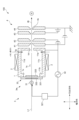
具体的にこのイオン源100は、図2及び図3に示すように、イオン源ガスが導入されてプラズマを生成するためのプラズマ生成容器1と、プラズマ生成容器1の外部に設けられて当該プラズマ生成容器1内に磁場(具体的にはカスプ磁場、より厳密に言えばマルチカスプ磁場。多極磁場ともいう。)を形成する複数の磁石2と、プラズマ生成容器1内にプラズマを形成するプラズマ生成手段3と、プラズマ生成容器1からイオンビームIBを引き出す引出電極系4と、プラズマ生成容器1にイオン源ガスを一定流量で供給するガス源5とを備えている。
Specifically, as shown in Figures 2 and 3, this
プラズマ生成容器1は、例えば直方体形状等をなす長尺状の容器である。このプラズマ生成容器1の内壁面により、イオン源ガスが導入されてプラズマを生成するための内部空間1sが形成されている。この内部空間1sはプラズマ生成容器1の長手方向に沿って延びるように形成された概略直方体形状をなす長尺状の空間であり、引出方向に沿って互いに対向する一対の内壁面と、幅方向に沿って互いに対向する一対の内壁面とによって囲まれて形成されている。なお内部区間は図示しない真空排気装置によって真空排気される。
The
長手方向に平行なプラズマ生成容器1の一つの側壁(以下、前側壁11aという)には、内部空間1sからイオンビームIBを引き出すための開口であるイオン引出口1Hが形成されている。イオン引出口1Hは、内部空間1sと同様に、長手方向に沿って延びるように前側壁11aに形成されている。本実施形態においては、この前側壁11aはイオンビームIBの引出方向に直交するように形成されている。以下において、引出方向及び長手方向に直交する方向を幅方向という。なお長尺状とは、引出方向から視て、互いに直交する2つの軸方向において、一方の軸方向の長さ(すなわち長手方向の長さ)が、他方の軸方向の長さ(すなわち幅方向の長さ)よりも長くなるように形成された任意の形状を意味し、直方体形状に限らない。
An
長手方向から視て、イオン引出口1Hを通って引出方向に伸びる軸線(以下、イオン引出軸線L1ともいう)を挟んで対向(幅方向において対向する)する2つの側壁(以下、横側壁11c、dともいう)には、ガス源5に連通し、ガス流量調整器(図示しない)を介して内部空間1sにイオン源ガスを導入するための複数のガス導入孔1gが形成されている。複数のガス導入孔1gは、互いに略同一径であり、横側壁11c、dにおけるイオン引出口1H近傍(すなわち、前側壁11aとの接合部近傍)に、プラズマ生成容器1の長手方向に沿って略等間隔に設けられている。このガス導入孔1gから、BF3ガスやPH3ガス等のイオン源ガスが内部空間1sに導入される。
In the two side walls (hereinafter also referred to as
なお複数のガス導入孔1gは、2つの横側壁11c、dの一方のみに形成されていてもよく、また横側壁11c、dにおける、前側壁11aと対向する後側壁11bとの接合部近傍(すなわち、後述する磁場透過窓3w近傍)に設けられていてもよい。また複数のガス導入孔1gは、互いに略等間隔に設けるとともに、長手方向に沿った両端部における孔径が、中央部における孔径よりも相対的に大きくなるようにしてもよい。あるいは、複数のガス導入孔1gは、互いに略同一の孔径にするとともに、長手方向に沿った両端部における配置間隔が、中央部における配置間隔よりも相対的に狭くなるようにしてもよい。さらにガス導入孔1gは、プラズマ生成容器1の側壁の内面に開口するように設けられていたが、プラズマ生成容器1内に配置されたガス供給管の管壁に開口するように設けられていてもよい。
The
複数の磁石2は、前側壁11a以外の他の側壁(具体的には横側壁11c、d)の外面に沿って外部に設けられるものであり、横側壁11c、dの内面近傍にカスプ磁場を形成するものである。本実施形態の各磁石2は永久磁石であるが、電磁石を用いてもよい。この複数の磁石2は、イオン引出方向に直交する方向に沿って、極性が互いに異なるように、かつ略等間隔に配列されている。なお、複数の磁石2の配列態様はこれに限らず適宜変更可能である。
The
プラズマ生成手段3は、プラズマ生成容器1の内部空間1sに高周波磁場を供給することでイオン源ガスを電離させてプラズマを生成するものである。
The plasma generating means 3 ionizes the ion source gas by supplying a high-frequency magnetic field to the
引出電極系4は、プラズマ生成容器1のイオン引出口1H近傍に設けられ、プラズマ生成容器1との間に電位差を与えることでイオンビームIBを加速して引き出すものである。具体的にこの引出電極系4は、スリット4xが形成された複数枚の板状電極41~44を有しており、より具体的には、図2及び図3に示すように、イオン引出方向に沿ってプラズマ生成容器1から下流に向けて順に配置された、プラズマ電極41、引出電極42、抑制電極43及び接地電極44を有している。これらの各電極はいずれもその中央部に、厚み方向に貫通し、長手方向に沿って伸びる細長形状のスリット4xが形成されている。そして各電極は中央部に形成されたスリット4xが、プラズマ生成容器1のイオン引出口1Hに向かい合うようにして配置されている。なお各電極間は、例えば絶縁物(図示しない)によって互いに電気的に絶縁されている。なおこの引出電極系4は、プラズマ生成容器1に最も近い電極(ここではプラズマ電極41)のスリット幅が可変に構成されているのが好ましい。このようにすれば、プラズマ室内のガス圧力を可変にすることができ、プラズマ生成容器1内の圧力と、引出電極領域の真空度の設定に自由度を付与することができ、これにより電極間に印加する耐電圧に裕度を持たせることができる。
The
しかして本実施形態のイオン源100は、プラズマ生成手段3が、プラズマ生成容器1の内部空間1sに誘導結合型のプラズマを生じさせるよう構成されており、プラズマ生成容器1の外部に設けられたアンテナ31と、アンテナ31に高周波を引加する高周波電源32と、プラズマ生成容器1の側壁におけるアンテナ31に臨む位置に形成され、アンテナ31から生じた高周波磁場を内部空間1sに透過させる磁場透過窓3wとを備えている。かかる構成において、アンテナ31に高周波電源32から高周波を印加することによりアンテナ31には高周波電流が流れて、プラズマ生成容器1内に誘導電界が発生して誘導結合型のプラズマが生成される。
The
アンテナ31は、外観視して長さが数十cm以上の直線状(具体的には円柱状)をなすものである。このアンテナ31は、プラズマ生成容器1の外部において磁場透過窓3wに対して間隙をもって、プラズマ生成容器1の長手方向に沿って真っすぐになるように設けられている。すなわちアンテナ31は、イオン引出口1Hや引出電極系4のスリット4xの長手方向に沿って真っすぐになるように設けられている。そしてイオン引出方向から視て、アンテナ31は、イオン引出口1Hを望む位置に配置されており、より具体的には前記したイオン引出軸線L1上に配置されている。アンテナ31の一端部である給電端部は、整合回路321を介して高周波電源32が接続されている。
The
高周波電源32は、整合回路321を介してアンテナ31に高周波電流を流すことができる。高周波の周波数は例えば一般的な13.56MHzであるが、これに限られるものではなく適宜変更してもよい。
The high-
磁場透過窓3wは、プラズマ生成容器1における前側壁11aに対向する側壁(後側壁11bという)に形成されている。具体的にこの磁場透過窓3wは、図4(a)~(c)に示すように、プラズマ生成容器1の後側壁11bに設けられた開口1xと、当該開口1xを塞ぐようにプラズマ生成容器1に取付けられた窓部材33とにより形成されている。
The magnetic
この開口1xは、イオン引出方向から視て、プラズマ生成容器1の長手方向に沿った長さが幅方向に沿った長さより大きい矩形状をなしている。そしてこの開口1xは、後側壁11bにおいて、アンテナ31とイオン引出口1Hの両方を臨む位置に形成されており、より具体的にはアンテナ31とイオン引出口1Hとを結ぶ線上に位置するように形成されている。
When viewed from the ion extraction direction, this
窓部材33は、プラズマ生成容器1の後側壁11bに形成された開口1xを外側から塞ぐスリット板331と、スリット板331に形成されたスリット331xをプラズマ生成容器1の外側から塞ぐ誘電体板332とを備えている。
The
スリット板331は、アンテナ31から生じた高周波磁場をプラズマ生成容器1内に透過させるとともに、プラズマ生成容器1の外部からプラズマ生成容器1の内部への電界の入り込みを防ぐものである。具体的にこのスリット板331は、その厚さ方向に貫通してなるスリット331xがアンテナ31の長手方向に沿って複数形成された平板状のものである。このスリット板331は、後述する誘電体板332よりも機械強度が高いことが好ましく、誘電体板332よりも厚み寸法が大きいことが好ましい。そして複数のスリット331xは、厚さ方向から視て、互いに平行であって、且つアンテナ31に交差するように(具体的には直交するように)形成されている。複数のスリット331xはいずれも同形状(具体的には平面視矩形状)である。
The
具体的にこのスリット板331は金属製のものであり、例えばCu、Al、Zn、Ni、Sn、Si、Ti、Fe、Cr、Nb、C、Mo、W又はCoを含む群から選択される1種の金属又はそれらの合金(例えばステンレス合金、アルミニウム合金等)等の金属材料を圧延加工(例えば冷間圧延や熱間圧延)等により製造したものである。
Specifically, the
このスリット板331は、平面視においてプラズマ生成容器1の開口1xよりも大きいものであり、後側壁11bに支持された状態(すなわち、後側壁11bに載せられた状態)で開口1xを塞いでおり、プラズマ生成容器1と同電位にされている。スリット板331と後側壁11bとの間には、Oリングやガスケット等のシール部材が介在しており、これらの間は真空シールされている。
This
誘電体板332は、スリット板331においてプラズマ生成容器1の外側を向く外向き面(プラズマ生成容器1の内部を向く内向き面の裏面)に載せられて、スリット板331のスリット331xを塞ぐものである。この誘電体板332とスリット板331との間にはシール部材が介在しており、これらの間は真空シールされている。
The
誘電体板332は、全体が誘電体物質で構成された平板状をなすものであり、例えばアルミナ、炭化ケイ素、窒化ケイ素等のセラミックス、石英ガラス、無アルカリガラス等の無機材料、フッ素樹脂(例えばテフロン)等の樹脂材料等からなる。
The
かかる構成により、スリット板331及び誘電体板332は、アンテナ31から発生した磁場を透過させる磁場透過窓3wとして機能を担う。すなわち、高周波電源32からアンテナ31に高周波を印加すると、アンテナ31から発生した高周波磁場が、スリット板331及び誘電体板332からなる磁場透過窓3wを透過してプラズマ生成容器1内に形成(供給)される。これにより、プラズマ生成容器1内の空間に誘導電界が発生し、誘導結合型のプラズマが生成される。
With this configuration, the
そして、本実施形態のプラズマ処理装置では、窓部材33はさらに、スリット板331に形成された各スリット331xを、プラズマ生成容器1の内側から間隙を空けて覆うマスク板333をさらに備えている。
In the plasma processing apparatus of this embodiment, the
より具体的に説明すると、マスク板333はその厚さ方向に貫通してなるスリット333xがアンテナ31の長手方向に沿って複数形成された平板状のものである。厚さ方向から視て、この複数のスリット333xは互いに平行であって、かつスリット板331に形成された複数のスリット331xと平行になるように形成されている。ここでは、各スリット333xは、アンテナ31に交差するように(具体的には直交するように)形成されている。複数のスリット333xはいずれも同形状(具体的には平面視矩形状)となるように形成されている。
To explain more specifically, the
マスク板333における隣り合うスリット333x間には、各スリット333xに平行な梁状領域333zが形成されている。この梁状領域333zは、スリット板331に形成された複数のスリット331xに対応するように複数形成されており、各梁状領域333zによりスリット板331の各スリット331xが覆われている。ここでは、アンテナ31の長手方向に沿った梁状領域333zの長さ(幅)は、スリット板331のスリット331xの幅と略同一であり、各梁状領域333zがスリット板331の各スリット331xの略全部を覆っている。各梁状領域333zは、各スリット331xの一部のみを覆うように形成されてもよい。なおマスク板333は、スリット板331の内向き面に接続され、同電位とされている。
Between
具体的にマスク板333は、例えばCu、Al、Zn、Ni、Sn、Si、Ti、Fe、Cr、Nb、C、Mo、W又はCoを含む群から選択される1種の金属又はそれらの合金(例えばステンレス合金、アルミニウム合金等)等の金属材料により構成されている。マスク板333の厚みは、スリット板331の厚みより小さいことが好ましい。
Specifically, the
またこの実施形態では、スリット板331には水等の冷却媒体が流れる流路331rが形成されている。この流路331rは、スリット板331におけるマスク板333の接続領域の近傍にアンテナ31の長手方向に沿って形成されている。ここでは、流路331rは、スリット板331の厚み方向に沿って接続領域の直上に位置するように形成されている。
In addition, in this embodiment, a
また本実施形態のイオン源100では、引出電極系4におけるプラズマ生成容器1に最も近い電極(プラズマ電極41)は、プラズマを生成した際における、プラズマ密度のピークとなる位置近傍~プラズマ密度がピークの半分となる位置近傍に設けられるのが好ましい。プラズマ密度分布のピーク位置の変化は、供給するイオン源ガスの圧力や、印加する高周波電力の密度に対して小さく、そのためプラズマ密度のピークとなる位置近傍にプラズマ電極41を設置することはイオン電流の効率的な引出の点で好ましいためである。一方で、このピーク位置近傍は、強い高周波磁場が生じている領域であるため、誘導電流による過熱を生じることがある。そのため、誘導電流による過熱を抑える観点からは、プラズマ電極41は、プラズマ密度がピークの半分となる位置近傍までの間のプラズマの拡散領域に設置されるのが好ましい。
In the
図5に示すように、本実施形態にかかるイオン源100を用いて、磁場透過窓3wを通して高周波プラズマを点灯させた結果、プラズマ密度分布は約45mmの位置でピークを示し、約140mmの位置で半減することが確認できた。また、供給するイオン源ガスの圧力や、印加する高周波電力の密度の変化に対して、プラズマ密度のピーク位置の変化が小さいことを確認できた。このため、磁場透過窓3wにおける内向き面(具体的にはスリット板331の内向き面)と、引出電極系4におけるプラズマ生成容器1に最も近い電極の表面との間の距離が、約45mm~約140mmの範囲に設定されているのが好ましい。
As shown in FIG. 5, when high-frequency plasma was ignited through the magnetic
<本実施形態の効果>
このように構成した本実施形態のイオン源100によれば、プラズマ生成容器1の内部空間1sに突出するフィラメントを用いることなく、プラズマ生成容器1の外部に設けたアンテナ31により内部空間1sにプラズマを発生させるようにしているので、プラズマ生成容器1内においてスパッタリングによる消耗を受ける部品を低減することができ、メンテナンスの周期を長くすることができる。しかも、プラズマ生成容器1の長手方向に沿ってアンテナ31を設けるようにしているので、イオン引出口1Hに沿って延びる1本のアンテナ31と1台の高周波電源32により内部空間1sに略均一なプラズマを発生させることができ、部品点数を大幅に低減でき、装置を小型化するとともに、取付けに要する加工工数や電源の制御点数を低減でき、製造コストを抑えることができる。さらには、電源数を少なくすることで、電力供給の線材及び機器の制御線の大幅な削減が可能であり、組立時の配線作業やメンテナンス時の脱着作業を簡単にでき、作業性を向上できる。
<Effects of this embodiment>
According to the
<その他の変形実施形態>
なお、本発明は前記実施形態に限られるものではない。
<Other Modified Embodiments>
The present invention is not limited to the above-described embodiment.
例えば他の実施形態のイオン源100は、図6(a)に示すように、アンテナ31と磁場透過窓3wとの間の距離を調整する距離調整機構6を備えていてもよい。この距離調整機構6は、アンテナ31の複数箇所の位置を調整することにより、アンテナ31と磁場透過窓3wとの間の距離を部分的に調整するよう構成されたものであり、具体的にはアンテナ31の長手方向に沿った一部分又は複数部分の位置を調整可能に構成されている。
For example, the
より具体的に説明すると、距離調整機構6は、窓部材33の上面に設けられて、アンテナ31の両端部を支持するアンテナ支持部材61と、アンテナ31の複数箇所を把持するとともに、当該把持した部位を磁場透過窓3w(具体的には誘電体板332)に対して変位させる複数の把持部62と、これらの把持部62を独立して移動させるモータ等の図示しない駆動源とを備えている。
More specifically, the distance adjustment mechanism 6 is provided on the upper surface of the
複数の把持部62は、アンテナ31とは電気的に絶縁された絶縁物である。これらの把持部62のうちの1つは、プラズマ生成容器1の開口1xの中央部の直上に配置されており、この把持部62に対してアンテナ31の長手方向に沿った対称的な位置に別の把持部62が設けられている。また本実施形態では、複数の把持部62が等間隔に配置されており、これらは何れも、プラズマ生成容器1の開口1xに直交する方向から視て、開口1xの内側に設けられている。
The multiple
具体的にこの把持部62は、アンテナ31の側面を窓部材33側に押圧する押し治具621と、アンテナ31と窓部材33との間に突っ張るように設けられたギャップ調整治具622とを備えている。この押し治具621は、例えばバネ材等を用いることで、アンテナ31を常に窓部材33側へ押し込むように構成されたものである。ギャップ調整治具622は、窓部材33の厚み方向に沿った長さを調整可能に構成されたものである。ここではギャップ調整治具622は、断面が楕円形状をなす治具であり、回転することにより厚み方向に沿った長さが変更され、アンテナ31と窓部材33との間の距離を調整するよう構成されている。
Specifically, the gripping
また前記実施形態のイオン源100では、マスク板333は複数のスリット333xが形成され、この複数のスリット333x間に形成される梁状領域333zによりスリット板331のスリット331xを覆うものであったが、これに限らない。他の実施形態のマスク板333は、図6(b)に示すように、短冊状をなす金属板により構成されていてもよい。この場合、マスク板333は、スリット板331に形成された複数のスリット331xのそれぞれに臨む位置に1枚又は複数枚設けられてよい。1つのスリット331xに対して複数枚のマスク板333を設ける場合、これらを厚み方向において互いに段違いとなるように配置するのが好ましい。
In the
また他の実施形態のイオン注入装置400は、引き出したイオンビームIBの電流値に応じて、アンテナ31と磁場透過窓3wの間の距離や、高周波電源32の出力を調整するように構成されてもよい。具体的にイオン注入装置400は、図7に示すように、質量分析磁石210の後段に、長手方向に沿ったイオンビームIBの電流分布をモニタリングする電流分布モニタ7を備えており、モニタリングしたイオンビームIBの電流分布と、平均電流密度や均一性の目標値とを比較演算器により比較し、その比較結果に応じてアンテナ31と磁場透過窓3wの間の距離や、高周波電源32の出力を調整するように構成されてもよい。
In another embodiment, the
また前記実施形態では、磁場透過窓3wはプラズマ生成容器1の後側壁11bに形成されていたがこれに限らない。例えば他の実施形態では、磁場透過窓3wは、長手方向から視て、イオン引出軸線L1を挟んで対向する2つの側壁(横側壁11c、d)の一方又は両方に形成されていてもよい。この場合、プラズマ生成容器1の横側壁11c、dは、図8に示すようにその内壁面がイオン引出口1Hを向くように傾斜していてもよく、図9に示すように引出方向に沿って真っすぐとなっていてもよい。
In the above embodiment, the magnetic
図8のように、傾斜した横側壁11c、dに磁場透過窓3wを設ける場合、アンテナ31と磁場透過窓3wの中心(開口1xの中心)とを結ぶ軸線(以下、磁場透過軸線L2ともいう)が、イオン引出口1H近傍を通るように構成するのが好ましい。また2つの磁場透過窓3wのそれぞれの磁場透過軸線L2が、イオン引出軸線L1上で交わるようにするのが好ましい。また磁場透過軸線L2と、引出電極系を構成する板状の電極の電極面とのなす角度が、約20°以上約45°以下であるのが好ましい。
When providing a magnetic
またこの場合、イオン引出口1Hに正対する後側壁11bの外壁側に、冷却流路1cが形成されているのが好ましい。この冷却流路1cは、イオン引出軸線L1を通り、かつプラズマ生成容器1の長手方向に沿って延びるように形成されているのが好ましい。このようにイオン引出軸線L1条に冷却流路を設けることで、逆流電子による加熱を効率的に冷却することができる。またこの実施形態では、長手方向から視て磁石2は、各横側壁11c、11dの外面において、磁場透過窓3wを両側から挟むように設けられているのが好ましい。
In this case, it is preferable that a
図9のように、プラズマ生成容器1の横側壁11c、dを引出方向に沿って真っすぐとなるようにした場合、プラズマ密度のピーク位置を考慮することなく、引出電極系4(具体的にはプラズマ電極41)をイオン引出口1Hに近付けることができるようになる。すなわち、図2や図8に示すものでは、イオン引出口1Hに対向するように磁場透過窓3wが設置されているため、イオン引出口1H近傍における磁場が強くなり、誘導電流による過熱を考慮してプラズマ電極41を設置する必要がある。これに対して図9に示すものでは、磁場透過窓3wがイオン引出口1Hに対向しておらず、イオン引出口1Hにおける磁場が図2や図8のものに比べて弱くなるため、誘導電流による過熱を考慮することなくプラズマ電極41を設置することができる。
また、プラズマ生成容器1の内壁において、イオン引出口1Hに対向する箇所は、プラズマ内の電子の逆流による加熱を受けやすいが、図9のように、イオン引出口1Hに対向しない位置に磁場透過窓3wを形成することで、イオン引出口1Hに対向する位置に磁場透過窓3wを形成した図2や図8に比べて、窓部材33(特に誘電体板332)の汚れを軽減でき、磁場の透過率の低下を抑えて動作を安定させることができる。また誘電体板332自体が発熱や破損する等といった問題を回避することもできる。
As shown in Fig. 9, when the
In addition, in the inner wall of the
また図9に示す実施形態においても、図8の実施形態と同様に、イオン引出口1Hに正対する後側壁11bの外壁側におけるイオン引出軸線L1上に冷却流路1cが形成されていてもよい。このようにすることで、逆流電子による加熱を効果的に冷却することができる。
Also, in the embodiment shown in FIG. 9, as in the embodiment in FIG. 8, a
また前記実施形態のイオン源100は、高周波電源32と整合回路321が高電圧部に設置されていたがこれに限らない。他の実施形態のイオン源100は、図10に示すように、高周波電源32と整合回路321を接地電位に設置してもよい。このようにすることで、高電圧部に電力供給するための絶縁トランスの容量低減に寄与し、さらにはシステム全体の小型化、低コスト化及び高電圧による放電トラブル時の機器故障回避に寄与し得る。
In addition, in the
またアンテナ31は、内部に冷却液が流通可能な流路が形成されている中空構造のものであってよい。またアンテナ31は、少なくとも2つの導体要素と、互いに隣り合う導体要素と電気的に直列接続された定量素子であるコンデンサとを備える、いわゆるLCアンテナ31であってもよい。例えばアンテナ31は、3つの導体要素と2つのコンデンサとを備えており、各導体要素は、内部に冷却液が流れる直線状の流路が形成された直管状(具体的には円管状)をなす同一形状のものであってもよい。各導体要素の材質は、例えば、銅、アルミニウム、これらの合金又はステンレス等の金属等であってよい。
The
アンテナ31をこのように構成することによって、アンテナ31の合成リアクタンスは、簡単に言えば、誘導性リアクタンスから容量性リアクタンスを引いた形になるので、アンテナ31のインピーダンスを低減させることができる。その結果、アンテナ31を長くする場合でもそのインピーダンスの増大を抑えることができ、アンテナ31に高周波電流が流れやすくなり、内部空間1sに誘導結合型のプラズマを効率良く発生させることができる。
By configuring the
その他、本発明は前記実施形態に限られず、その趣旨を逸脱しない範囲で種々の変形が可能であるのは言うまでもない。 It goes without saying that the present invention is not limited to the above-described embodiment, and various modifications are possible without departing from the spirit of the invention.
さらに本明細書の開示は、以下の態様1-10を含み得る。 The disclosure of this specification may further include the following aspects 1-10.
(態様1)イオン源ガスが導入される内部空間を有する長尺状をなす容器であり、その長手方向に沿った1つの側壁にイオン引出口が形成されたプラズマ生成容器と、前記イオン源ガスを電離させて前記内部空間にプラズマを生成させるプラズマ生成手段と、プラズマ生成容器の外部に設けられ、前記イオン引出口を通じて前記内部空間からイオンビームを引き出す引出電極系とを備え、前記プラズマ生成手段が、前記プラズマ生成容器の外部において、前記長手方向に沿って設けられたアンテナと、前記アンテナに高周波を印加する高周波電源と、前記プラズマ生成容器の側壁における前記アンテナに臨む位置に形成され、前記アンテナから生じた高周波磁場を前記内部空間に透過させる磁場透過窓とを備えるイオン源。 (Mode 1) An ion source comprising: a plasma generating vessel which is an elongated vessel having an internal space into which an ion source gas is introduced and in which an ion outlet is formed on one side wall along the longitudinal direction of the vessel; plasma generating means which ionizes the ion source gas to generate plasma in the internal space; and an extracting electrode system which is provided outside the plasma generating vessel and extracts an ion beam from the internal space through the ion outlet, the plasma generating means comprising: an antenna provided outside the plasma generating vessel along the longitudinal direction; a high frequency power source which applies high frequency to the antenna; and a magnetic field transmission window which is formed in a position facing the antenna on the side wall of the plasma generating vessel and which allows a high frequency magnetic field generated from the antenna to pass through the internal space.
このような態様であれば、プラズマ生成容器の内部空間に突出するフィラメントを用いることなく、プラズマ生成容器の外部に設けたアンテナにより内部空間にプラズマを発生させるようにしているので、プラズマ生成容器内においてスパッタリングによる消耗を受ける部品を低減することができ、メンテナンスの周期を長くすることができる。
しかも、プラズマ生成容器の長手方向に沿ってアンテナを設けるようにしているので、イオン引出方向口に沿って延びる1本のアンテナと1台の高周波電源により内部空間に略均一なプラズマを発生させることができ、部品点数を大幅に低減でき、装置を小型化するとともに、取付けに要する加工工数や電源の制御点数を低減でき、製造コストを抑えることができる。さらには、電源数を少なくすることで、電力供給の線材及び機器の制御線の大幅な削減が可能であり、組立時の配線作業やメンテナンス時の脱着作業を簡単にでき、作業性を向上できる。
In this configuration, plasma is generated in the internal space by an antenna installed outside the plasma generating vessel, without using a filament protruding into the internal space of the plasma generating vessel, thereby reducing the number of parts inside the plasma generating vessel that are subject to wear due to sputtering and lengthening the maintenance cycle.
Moreover, since the antenna is provided along the longitudinal direction of the plasma generating vessel, a substantially uniform plasma can be generated in the internal space by one antenna extending along the ion extraction direction opening and one high frequency power source, the number of parts can be significantly reduced, the device can be made smaller, the number of processing steps required for installation and the number of control points for the power source can be reduced, and the manufacturing cost can be suppressed. Furthermore, by reducing the number of power sources, the number of power supply wires and device control wires can be significantly reduced, and the wiring work during assembly and the removal and attachment work during maintenance can be simplified, improving the workability.
(態様2)前記引出電極系が、前記イオン引出口に臨む位置に設けられた1枚又は複数枚の板状の電極を備えており、当該各電極における前記イオン引出口に対応する位置には、その厚み方向に貫通するスリットが前記長手方向に沿って形成されており、当該スリットが伸びる方向と前記アンテナが伸びる方向とが一致する態様1に記載のイオン源。
このような態様であれば、引出電極を構成する電極に形成されたスリットと、アンテナとの延びる方向が一致しているので、長手方向に沿って略均一な電流密度のイオンビームを引き出すことができるようになる。
(Aspect 2) The ion source according to
In this configuration, the slit formed in the electrode constituting the extraction electrode and the antenna extend in the same direction, making it possible to extract an ion beam with a substantially uniform current density along the longitudinal direction.
(態様3)前記磁場透過窓が、前記プラズマ生成容器の側壁に形成された開口と、当該開口を塞ぐスリット板と、当該スリット板に形成されたスリットを前記プラズマ生成容器の外側から塞ぐ誘電体板とを備える態様1又は2に記載のイオン源。
このような態様であれば、例えば金属製のスリット板に形成されたスリットと、その上に配置された誘電体板とによって、アンテナから発生する高周波磁場を内部空間に透過させる磁場透過窓を形成することで、磁場透過窓を形成する部材の一部をセラミックス等の誘電体材料よりも靭性が大きい金属材料で構成できるので、誘電体材料だけで磁場透過窓を構成する場合に比べて磁場透過窓の厚みを小さくすることができる。また、誘電体板が金属板に接触して支持されているので、真空処理時における誘電体板の変形を軽減し、誘電体板内に発生する曲げ応力を低減できる。そのため誘電体板自体の厚みを小さくすることができる。これにより、アンテナから内部空間までの距離を短くすることができ、アンテナから生じた高周波磁場をプラズマ生成容器内に効率よく供給することができる。
(Aspect 3) An ion source according to
In this embodiment, for example, a slit formed in a metal slit plate and a dielectric plate placed on the slit plate form a magnetic field transmission window that transmits the high frequency magnetic field generated from the antenna into the internal space. Since a part of the member forming the magnetic field transmission window can be made of a metal material that has higher toughness than a dielectric material such as ceramics, the thickness of the magnetic field transmission window can be made smaller than when the magnetic field transmission window is made of only a dielectric material. In addition, since the dielectric plate is supported in contact with the metal plate, deformation of the dielectric plate during vacuum processing can be reduced, and bending stress generated in the dielectric plate can be reduced. Therefore, the thickness of the dielectric plate itself can be made smaller. This allows the distance from the antenna to the internal space to be shortened, and the high frequency magnetic field generated by the antenna can be efficiently supplied into the plasma generating vessel.
(態様4)前記磁場透過窓が、前記スリット板に形成されたスリットを前記プラズマ生成容器の内側から間隙を空けて覆うマスク板を更に備える態様3に記載のイオン源。
このような態様であれば、高周波電力が投入されたアンテナがマスク板で光学的及び電気的に遮蔽されることにより、アンテナの高周波電圧を遮蔽することができ、生成したプラズマ中のイオンエネルギーとそのエネルギー幅を小さくできる。これによりイオン源から引き出されたイオンイオンの質量分離への影響を小さくできる。このような効果は、低エネルギーのイオンを引き出す場合に特に有効である。
またイオン源では、引出電極によりプラズマからイオンが引き出される一方で、引出電極側からプラズマ生成容器内に向かって電子が逆流するが、磁場透過窓をマスク板で遮蔽した構造にすることで、磁場透過窓を構成する誘電体板への電子流の入射を防止できる。これにより加熱・帯電・放電による誘電体板の破損の可能性を低減できる。さらにこの部分に高融点金属を使用すれば、熱変形を低減することができ、安定動作を可能にできる。
さらに、プラズマ生成による導電性被膜がスリットを通って誘電体板に付着して堆積すると、高周波磁場の透過率が低下し、プラズマ生成効率の低下を招くとともに、堆積被膜の発熱により磁場透過窓を構成する部材を破損させるそれがあるが、スリットを覆うマスク板を設けることで、誘電体板への導電性被膜の付着を防止することができる。
(Aspect 4) The ion source according to
In this embodiment, the antenna to which high-frequency power is applied is optically and electrically shielded by the mask plate, so that the high-frequency voltage of the antenna can be shielded, and the ion energy and its energy width in the generated plasma can be reduced. This reduces the influence on the mass separation of ions extracted from the ion source. This effect is particularly effective when extracting low-energy ions.
In the ion source, while ions are extracted from the plasma by the extraction electrode, electrons flow back from the extraction electrode into the plasma generating vessel. However, by using a structure in which the magnetic field transmission window is shielded by a mask plate, it is possible to prevent the electron flow from entering the dielectric plate that constitutes the magnetic field transmission window. This reduces the possibility of the dielectric plate being damaged by heating, charging, or discharge. Furthermore, if a high-melting-point metal is used in this part, thermal deformation can be reduced, enabling stable operation.
Furthermore, if a conductive coating generated by plasma passes through the slits and adheres to the dielectric plate, the transmittance of the high-frequency magnetic field decreases, resulting in a decrease in the efficiency of plasma generation, and the heat generated by the deposited coating may damage the components that make up the magnetic field transmission window. However, by providing a mask plate that covers the slits, the adhesion of the conductive coating to the dielectric plate can be prevented.
(態様5)前記アンテナと前記磁場透過窓との間の距離を部分的に調整する距離調整機構をさらに備える態様1~4のいずれかに記載のイオン源。
このような態様であれば、距離調整機構が、アンテナと磁場透過窓との間の距離を部分的に調整することで、1個の高周波電源の出力調整のみでアンテナの長手方向に沿ったプラズマ密度分布を細やかに調整することができるので、長手方向に沿ったイオンビームの平均電流密度の調整を簡易な構成で実現できる。
(Aspect 5) The ion source according to any one of
In this configuration, the distance adjustment mechanism partially adjusts the distance between the antenna and the magnetic field transmission window, making it possible to finely adjust the plasma density distribution along the longitudinal direction of the antenna by simply adjusting the output of a single high-frequency power supply, thereby enabling adjustment of the average current density of the ion beam along the longitudinal direction with a simple configuration.
(態様6)前記距離調整機構が、前記長手方向に沿った前記アンテナの複数箇所の位置を変位させるものである態様5に記載のイオン源。
このような態様であれば、アンテナの長手方向に沿ったプラズマ密度分布をより細やかに調整できる。
(Aspect 6) The ion source according to
In this manner, the plasma density distribution along the longitudinal direction of the antenna can be adjusted more precisely.
(態様7)前記プラズマ生成容器には、前記内部空間にイオン源ガスを導入するための複数のガス導入孔が前記長手方向に沿って設けられており、当該複数のガス導入孔は、前記長手方向に沿った両端部における孔径が中央部における孔径よりも相対的に大きい、又は前記長手方向に沿った両端部における配置間隔が中央部における配置間隔よりも相対的に狭い態様1~6のいずれかに記載のイオン源。
外部アンテナによりプラズマを生成する場合、内部空間におけるアンテナの長手方向に沿った両端部では、中央部に比べてプラズマ密度が相対的に低下する傾向がある。そこで、イオン源ガスを導入する複数のガス導入孔を、長手方向に沿った両端部における孔径を中央部における孔径よりも大きくしたり、長手方向に沿った両端部における配置間隔を中央部における配置間隔よりも狭くして、長手方向の両端領域におけるイオン源ガスの圧力を増加させることで、当該両端領域におけるプラズマ密度を増加させるようにすることで、均一性がよいイオンビームを引き出すことができるようになる。そしてこのような状態で、例えばアンテナと磁場透過窓との間の距離を調整することで、平均電流密度を増加させたイオンビームを引き出すことができるようにもなる。
(Aspect 7) An ion source according to any one of
When plasma is generated by an external antenna, the plasma density tends to be relatively lower at both ends along the longitudinal direction of the antenna in the internal space than at the center. Therefore, by making the diameter of the gas inlet holes for introducing the ion source gas larger at both ends along the longitudinal direction than at the center, or by making the spacing between the gas inlet holes at both ends along the longitudinal direction narrower than that at the center, the pressure of the ion source gas in both longitudinal end regions is increased, thereby increasing the plasma density in the both end regions, and thus an ion beam with good uniformity can be extracted. In this state, for example, by adjusting the distance between the antenna and the magnetic field transmission window, an ion beam with an increased average current density can be extracted.
(態様8)前記長手方向から視て、前記磁場透過窓が、前記プラズマ生成容器における、前記イオン引出口が形成された側壁に対向する側壁に形成されている態様1~7のいずれかに記載のイオン源。
このような態様であれば、前記長手方向とイオンの引出方向に直交する幅方向において、イオン引出口近傍にプラズマ分布のピークを生じさせることができ、イオン引出口近傍に効率よくプラズマを生成することができ、平均電流密度を増加させたイオンビームを引き出すことができるようになる。
(Aspect 8) An ion source according to any one of
With this configuration, a peak of the plasma distribution can be generated in the vicinity of the ion extraction port in the width direction perpendicular to the longitudinal direction and the ion extraction direction, and plasma can be efficiently generated in the vicinity of the ion extraction port, making it possible to extract an ion beam with an increased average current density.
(態様9)前記長手方向から視て、前記磁場透過窓が、前記プラズマ生成容器における、イオン引出口を通って、前記イオンビームの引出方向に伸びるイオン引出軸線を挟んで対向する2つの側壁の一方又は両方に形成されている態様1~7のいずれかに記載のイオン源。
このような態様であれば、引出電極側からプラズマ生成容器内に流れ込む逆流電子の磁場透過窓への入射を防止でき、プラズマ生成動作を安定化できる。また2つの側壁の両方に磁場透過窓を設ければ、イオン引出口近傍におけるプラズマ密度を高くすることもできる。
(Aspect 9) An ion source according to any one of
In this embodiment, it is possible to prevent the backflow electrons flowing from the extraction electrode side into the plasma generating vessel from entering the magnetic field transmission window, and the plasma generation operation can be stabilized. In addition, if the magnetic field transmission window is provided on both of the two side walls, it is possible to increase the plasma density in the vicinity of the ion extraction port.
(態様10)前記長手方向から視て、前記磁場透過窓が形成された2つの側壁は、その内壁面が前記イオン引出口を向くように、前記イオン引出軸線に対して傾斜している態様9に記載のイオン源。
このような態様であれば、イオン引出口近傍におけるプラズマ密度をより一層高くすることができる。
(Aspect 10) An ion source according to aspect 9, wherein, when viewed from the longitudinal direction, the two side walls in which the magnetic field transmission window is formed are inclined with respect to the ion extraction axis so that their inner wall surfaces face the ion extraction port.
In this embodiment, the plasma density in the vicinity of the ion outlet can be further increased.
上記した本発明によれば、メンテナンスの周期が長く、メンテナンス時の作用性がよく、さらには装置全体の小型化を図ることができ、製造コストも抑えられるイオン源を提供することができる。 The present invention described above can provide an ion source that has a long maintenance cycle, is highly functional during maintenance, and allows the overall device to be made smaller, while keeping manufacturing costs down.
100・・・イオン源
1 ・・・プラズマ生成容器
1s ・・・内部空間
11a・・・側壁(前側壁)
1H ・・・イオン引出口
3 ・・・プラズマ生成手段
31 ・・・アンテナ
32 ・・・高周波電源
3w ・・・磁場透過窓
4 ・・・引出電極系
W ・・・基板
IB ・・・イオンビーム
100: Ion source 1:
1H: Ion extraction port 3: Plasma generating means 31: Antenna 32: High
Claims (10)
前記イオン源ガスを電離させて前記内部空間にプラズマを生成させるプラズマ生成手段と、
プラズマ生成容器の外部に設けられ、前記イオン引出口を通じて前記内部空間からイオンビームを引き出す引出電極系とを備え、
前記プラズマ生成手段が、
前記プラズマ生成容器の外部において、前記長手方向に沿って設けられたアンテナと、
前記アンテナに高周波を印加する高周波電源と、
前記プラズマ生成容器の側壁における前記アンテナに臨む位置に形成され、前記アンテナから生じた高周波磁場を前記内部空間に透過させる磁場透過窓とを備えるイオン源。 a plasma generating vessel which is an elongated vessel having an internal space into which an ion source gas is introduced and in which an ion extraction port is formed on one side wall along the longitudinal direction of the vessel;
a plasma generating means for ionizing the ion source gas to generate plasma in the internal space;
an extraction electrode system provided outside the plasma generating vessel and extracting an ion beam from the internal space through the ion extraction port;
The plasma generating means is
an antenna provided outside the plasma generating chamber along the longitudinal direction;
a high frequency power source that applies a high frequency to the antenna;
an ion source comprising: a magnetic field transmission window formed in a side wall of the plasma generating vessel at a position facing the antenna, the magnetic field transmission window allowing a high frequency magnetic field generated from the antenna to pass through the internal space;
当該スリットが伸びる方向と前記アンテナが伸びる方向とが一致する請求項1に記載のイオン源。 the extraction electrode system includes one or more plate-like electrodes provided at a position facing the ion extraction port, and a slit penetrating the electrode in a thickness direction is formed along the longitudinal direction at a position of each electrode corresponding to the ion extraction port,
2. The ion source according to claim 1, wherein the extending direction of the slit coincides with the extending direction of the antenna.
当該複数のガス導入孔は、前記長手方向に沿った両端部における孔径が中央部における孔径よりも相対的に大きい、又は前記長手方向に沿った両端部における配置間隔が中央部における配置間隔よりも相対的に狭い請求項1に記載のイオン源。 the plasma generating chamber is provided with a plurality of gas inlet holes along the longitudinal direction for introducing an ion source gas into the internal space,
2. The ion source according to claim 1, wherein the plurality of gas introduction holes have a hole diameter at both ends along the longitudinal direction that is relatively larger than a hole diameter at a central portion, or an arrangement interval at both ends along the longitudinal direction that is relatively narrower than an arrangement interval at the central portion.
Priority Applications (2)
| Application Number | Priority Date | Filing Date | Title |
|---|---|---|---|
| CN202480006744.6A CN120548588A (en) | 2023-03-02 | 2024-02-20 | Ion source |
| KR1020257022739A KR20250121069A (en) | 2023-03-02 | 2024-02-20 | ion source |
Applications Claiming Priority (2)
| Application Number | Priority Date | Filing Date | Title |
|---|---|---|---|
| JP2023-031885 | 2023-03-02 | ||
| JP2023031885A JP2024124011A (en) | 2023-03-02 | 2023-03-02 | Ion source |
Publications (1)
| Publication Number | Publication Date |
|---|---|
| WO2024181225A1 true WO2024181225A1 (en) | 2024-09-06 |
Family
ID=92590576
Family Applications (1)
| Application Number | Title | Priority Date | Filing Date |
|---|---|---|---|
| PCT/JP2024/005970 Ceased WO2024181225A1 (en) | 2023-03-02 | 2024-02-20 | Ion source |
Country Status (5)
| Country | Link |
|---|---|
| JP (1) | JP2024124011A (en) |
| KR (1) | KR20250121069A (en) |
| CN (1) | CN120548588A (en) |
| TW (1) | TWI893598B (en) |
| WO (1) | WO2024181225A1 (en) |
Citations (3)
| Publication number | Priority date | Publication date | Assignee | Title |
|---|---|---|---|---|
| JPH06204181A (en) * | 1992-12-29 | 1994-07-22 | Ibiden Co Ltd | Electrode plate for plasma etching |
| WO2012073449A1 (en) * | 2010-11-30 | 2012-06-07 | キヤノンアネルバ株式会社 | Plasma processing device |
| JP2016529704A (en) * | 2013-07-18 | 2016-09-23 | ヴァリアン セミコンダクター イクイップメント アソシエイツ インコーポレイテッド | Method for improving ion beam quality of an implantation system |
Family Cites Families (3)
| Publication number | Priority date | Publication date | Assignee | Title |
|---|---|---|---|---|
| JP5257399B2 (en) | 2010-04-16 | 2013-08-07 | 日新イオン機器株式会社 | Ion source and ion implantation apparatus |
| US8590485B2 (en) * | 2010-04-26 | 2013-11-26 | Varian Semiconductor Equipment Associates, Inc. | Small form factor plasma source for high density wide ribbon ion beam generation |
| US10068758B2 (en) * | 2017-01-27 | 2018-09-04 | Varian Semiconductor Equipment Associates, Inc. | Ion mass separation using RF extraction |
-
2023
- 2023-03-02 JP JP2023031885A patent/JP2024124011A/en active Pending
-
2024
- 2024-01-04 TW TW113100475A patent/TWI893598B/en active
- 2024-02-20 CN CN202480006744.6A patent/CN120548588A/en active Pending
- 2024-02-20 WO PCT/JP2024/005970 patent/WO2024181225A1/en not_active Ceased
- 2024-02-20 KR KR1020257022739A patent/KR20250121069A/en active Pending
Patent Citations (3)
| Publication number | Priority date | Publication date | Assignee | Title |
|---|---|---|---|---|
| JPH06204181A (en) * | 1992-12-29 | 1994-07-22 | Ibiden Co Ltd | Electrode plate for plasma etching |
| WO2012073449A1 (en) * | 2010-11-30 | 2012-06-07 | キヤノンアネルバ株式会社 | Plasma processing device |
| JP2016529704A (en) * | 2013-07-18 | 2016-09-23 | ヴァリアン セミコンダクター イクイップメント アソシエイツ インコーポレイテッド | Method for improving ion beam quality of an implantation system |
Also Published As
| Publication number | Publication date |
|---|---|
| CN120548588A (en) | 2025-08-26 |
| TWI893598B (en) | 2025-08-11 |
| JP2024124011A (en) | 2024-09-12 |
| TW202501529A (en) | 2025-01-01 |
| KR20250121069A (en) | 2025-08-11 |
Similar Documents
| Publication | Publication Date | Title |
|---|---|---|
| JP5747231B2 (en) | Plasma generating apparatus and plasma processing apparatus | |
| US7273533B2 (en) | Plasma processing system with locally-efficient inductive plasma coupling | |
| EP0703597B1 (en) | Microwave energized ion source for ion implantation | |
| US7176469B2 (en) | Negative ion source with external RF antenna | |
| US8436318B2 (en) | Apparatus for controlling the temperature of an RF ion source window | |
| KR101594636B1 (en) | High frequency antenna unit and plasma processing apparatus | |
| KR102325544B1 (en) | sputtering device | |
| JP2021502688A (en) | Radiofrequency plasma ion source of linearized energy | |
| US20160217978A1 (en) | Plasma Generation Device | |
| KR20010043180A (en) | Apparatus for improved biasing and retaining of a workpiece in a workpiece processing system | |
| SE521904C2 (en) | Hybrid Plasma Treatment Device | |
| TWI580323B (en) | Enclosed plasma coil assembly and method of operating same | |
| US20170025255A1 (en) | Plasma processing apparatus | |
| KR20210027488A (en) | Plasma treatment device and plasma treatment method | |
| US20030218430A1 (en) | Ion source with external RF antenna | |
| WO2024181225A1 (en) | Ion source | |
| TWI884675B (en) | Ion source | |
| KR20020004934A (en) | Plasma source of linear beam ions | |
| US6259102B1 (en) | Direct current gas-discharge ion-beam source with quadrupole magnetic separating system | |
| TWI823457B (en) | sputtering device | |
| JP4554117B2 (en) | Surface treatment equipment | |
| US20100098600A1 (en) | Plasma system | |
| CN115565841B (en) | Lower electrode assembly, plasma processing device and method for preventing arc discharge | |
| JP5118607B2 (en) | Vacuum processing equipment | |
| WO2010119947A1 (en) | Plasma processing apparatus |
Legal Events
| Date | Code | Title | Description |
|---|---|---|---|
| 121 | Ep: the epo has been informed by wipo that ep was designated in this application |
Ref document number: 24763706 Country of ref document: EP Kind code of ref document: A1 |
|
| WWE | Wipo information: entry into national phase |
Ref document number: 202480006744.6 Country of ref document: CN |
|
| ENP | Entry into the national phase |
Ref document number: 1020257022739 Country of ref document: KR Free format text: ST27 STATUS EVENT CODE: A-0-1-A10-A15-NAP-PA0105 (AS PROVIDED BY THE NATIONAL OFFICE) |
|
| WWE | Wipo information: entry into national phase |
Ref document number: 1020257022739 Country of ref document: KR |
|
| WWP | Wipo information: published in national office |
Ref document number: 1020257022739 Country of ref document: KR |
|
| WWP | Wipo information: published in national office |
Ref document number: 202480006744.6 Country of ref document: CN |
|
| NENP | Non-entry into the national phase |
Ref country code: DE |