WO2024121662A1 - Method for patterning an adhesive layer - Google Patents
Method for patterning an adhesive layer Download PDFInfo
- Publication number
- WO2024121662A1 WO2024121662A1 PCT/IB2023/061754 IB2023061754W WO2024121662A1 WO 2024121662 A1 WO2024121662 A1 WO 2024121662A1 IB 2023061754 W IB2023061754 W IB 2023061754W WO 2024121662 A1 WO2024121662 A1 WO 2024121662A1
- Authority
- WO
- WIPO (PCT)
- Prior art keywords
- adhesive
- liner
- pattern
- moisture content
- patterned
- Prior art date
- Legal status (The legal status is an assumption and is not a legal conclusion. Google has not performed a legal analysis and makes no representation as to the accuracy of the status listed.)
- Ceased
Links
Classifications
-
- C—CHEMISTRY; METALLURGY
- C09—DYES; PAINTS; POLISHES; NATURAL RESINS; ADHESIVES; COMPOSITIONS NOT OTHERWISE PROVIDED FOR; APPLICATIONS OF MATERIALS NOT OTHERWISE PROVIDED FOR
- C09J—ADHESIVES; NON-MECHANICAL ASPECTS OF ADHESIVE PROCESSES IN GENERAL; ADHESIVE PROCESSES NOT PROVIDED FOR ELSEWHERE; USE OF MATERIALS AS ADHESIVES
- C09J7/00—Adhesives in the form of films or foils
- C09J7/20—Adhesives in the form of films or foils characterised by their carriers
- C09J7/203—Adhesives in the form of films or foils characterised by their carriers characterised by the structure of the release feature on the carrier layer
-
- B—PERFORMING OPERATIONS; TRANSPORTING
- B29—WORKING OF PLASTICS; WORKING OF SUBSTANCES IN A PLASTIC STATE IN GENERAL
- B29C—SHAPING OR JOINING OF PLASTICS; SHAPING OF MATERIAL IN A PLASTIC STATE, NOT OTHERWISE PROVIDED FOR; AFTER-TREATMENT OF THE SHAPED PRODUCTS, e.g. REPAIRING
- B29C59/00—Surface shaping of articles, e.g. embossing; Apparatus therefor
- B29C59/02—Surface shaping of articles, e.g. embossing; Apparatus therefor by mechanical means, e.g. pressing
- B29C59/04—Surface shaping of articles, e.g. embossing; Apparatus therefor by mechanical means, e.g. pressing using rollers or endless belts
-
- C—CHEMISTRY; METALLURGY
- C09—DYES; PAINTS; POLISHES; NATURAL RESINS; ADHESIVES; COMPOSITIONS NOT OTHERWISE PROVIDED FOR; APPLICATIONS OF MATERIALS NOT OTHERWISE PROVIDED FOR
- C09J—ADHESIVES; NON-MECHANICAL ASPECTS OF ADHESIVE PROCESSES IN GENERAL; ADHESIVE PROCESSES NOT PROVIDED FOR ELSEWHERE; USE OF MATERIALS AS ADHESIVES
- C09J2301/00—Additional features of adhesives in the form of films or foils
- C09J2301/20—Additional features of adhesives in the form of films or foils characterized by the structural features of the adhesive itself
Definitions
- This disclosure generally relates to patterning adhesives for use on rough substrates.
- the disclosure relates to methods of patterning adhesives via a roll-to-roll process to promote super adhesion to rough substrates.
- Adhesive laminates are known in the art. Such products are provided in a variety of forms including, for example, tapes, sheets, and labels. Although satisfactory in many respects, a new class of laminates is needed which provide one or more functionalities, and which can be produced in a costefficient manner.
- a variety of techniques are known for applying an adhesive to a face material. Methods are also known in which an adhesive is coated on a secondary material which is then combined with a face material.
- the adhesive layer can be continuous or discontinuous.
- Discontinuous adhesive layers typically include regular or uniform patterns or structures. Although such patterning may reduce the amount of adhesive used, the regular or uniform patterns or structures can have limitations, such as ungummed/uncoated edges of the label resulting in poor dispensing, flagging, poor print quality, and/or poor die cutting. Although satisfactory in many respects, a need remains for additional strategies for depositing adhesive on face materials in which particular properties and/or characteristics of the resulting structure can be maintained or improved.
- Exemplary embodiments relate to a method for patterning an adhesive layer comprising: providing a liner having a first side, a second side, a first edge, and a second edge; contacting the first side of the liner with a deforming member to deform the liner at least temporarily through contact with the deforming member; and substantially simultaneously when the liner is at least temporarily deformed applying an adhesive in a manner that is substantially uniform to at least a portion of the first side of the liner but less than an entirety of the first side of the liner while the liner is temporarily deformed forming a pattern of adhesive; and whereby contact of the pattern of adhesive with a rough substrate leads to enhanced adhesion on the rough substrate with less adhesive than a continuous flood coat.
- This embodiment or another exemplary embodiment may provide for the adhesive to be applied in a discontinuous manner. This embodiment or another exemplary embodiment may provide for the adhesive to be applied in a continuous manner.
- This embodiment or another exemplary embodiment may provide for the liner is a paper derived liner with a moisture content. This embodiment or another exemplary embodiment may provide for prior to contacting, further comprising: adjusting the moisture content of the liner. This embodiment or another exemplary embodiment may provide for adjusting the moisture content by adding moisture to the liner. This embodiment or another exemplary embodiment may provide for adjusting the moisture content by removing moisture to the liner. This embodiment or another exemplary embodiment may provide for adjusting the moisture content of the liner after applying the adhesive. This embodiment or another exemplary embodiment may provide for the liner comprises PET.
- This embodiment or another exemplary embodiment may provide for at least a portion of the liner is siliconized. This embodiment or another exemplary embodiment may provide for laminating the liner with a facestock material. This embodiment or another exemplary embodiment may provide for the applied adhesive has a peak height in the first direction and a peak width between the first edge and second edge and wherein the ratio between the peak height to the width is between about 0.02 and about 0.05. This embodiment or another exemplary embodiment may provide for the average height is in the range of about 20 pm to about 40 pm. This embodiment or another exemplary embodiment may provide for the average width is in the range of 0.4 mm to about 2.0 mm. This embodiment or another exemplary embodiment may provide for the percentage of the first side of the liner covered by the peaks of the adhesive is between about 40% and about 60%.
- This embodiment or another exemplary embodiment may provide for the adhesive to be a pressure sensitive adhesive applied at a weight between about 6 and about 20 gsm.
- This embodiment or another exemplary embodiment may provide for the adhesive to be a hot-melt adhesive and is applied at a weight between about 6 and about 40 gsm.
- This embodiment or another exemplary embodiment may provide for the adhesion of the adhesive to a rough substrate is between about 10% and about 50% greater at identical flood coat weights.
- This embodiment or another exemplary embodiment may provide for the deforming member is a roller having patterned surface etching.
- This embodiment or another exemplary embodiment may provide for the deforming member is a roller having a patterned surface attachment.
- This embodiment or another exemplary embodiment may provide for the deforming step takes place at a pressure between 5-150 PSI.
- Figure 1 is a side schematic view on an exemplary apparatus to effectuate patterning a liner.
- Figure 2a is a side plan view of an exemplary adhesive pattern in accordance with the disclosure.
- Figure 2b is an additional side plan view of another exemplary adhesive pattern in accordance with the disclosure.
- Figure 3 is a side perspective view of an exemplary spherical cap with respect to the disclosure.
- Figure 4 is a side view of an exemplary adhesive construction on a rough substrate in accordance with Example 1.
- Figure 5 is a side view of an exemplary adhesive construction in accordance with Example
- Figure 6 is a side view of an exemplary adhesive construction in accordance with Example
- regular pattern means the evenness, consistency, and/or balance in shape, arrangement, and/or pattern orientation variation and homogeneity that is repeating.
- interferential pattern means not even or balanced in shape, arrangement, and/or pattern orientation variation and heterogeneity that is non-repeating.
- peelat pattern means the pattern of adhesive is regular in terms of shape, arrangement and/or pattern orientation and heterogeneity is repeating.
- discontinuous means that one or more regions, portions, parts, or spaces of the liner is not covered by adhesive.
- continuous means that all of one surface of the liner is covered by the adhesive at some level.
- rough substrate refers to any substrate with inconsistent surface level pattern that possesses known irregularities.
- cardboard and kraft paper are two such substrates that are rough substrates.
- Roughness depending on the source can be expressed by different metrics. For example, R a is a roughness average or the arithmetic mean of the absolute values of the roughness profile. While R z is a mean roughness depth as the arithmetic mean value of the single roughness depth.
- the expression "substantially uniform” means, with respect to the adhesive pattern, that the pattern has fewer than 2% of the area of the applied adhesive pattern having defects with respect to the total area of the applied adhesive pattern, preferably fewer than 1% of the area of the applied adhesive pattern having defects with respect to the total area of the applied adhesive pattern.
- the term "defect" means, with respect to the adhesive pattern, substantial deformity in the adhesive pattern that differs from the desired shape resulting in poor adhesion. For example, if the adhesive is deposited in a standard height and width, any deviation of this in either direction may be considered a defect.
- multilayer means, with respect to laminate construction, the adhesive coated face material with one or more additional layers.
- layers to make up the multilayer include protective layers, spacing layers, adhesive layers, optical componentcontaining layers, metallic layers, barrier layers, release liners, tie coat layers, clear layers, color layers, white layers, reflective layers, fluid transfer layers, strength promoting layers, topcoats, print receptive layers, print containing layers, indicia layers, functional layers, and the like as well as combinations thereof.
- graphics applications such as automobile and architectural wraps
- reflective applications such as road and traffic signs, trains and other commercial vehicles, etc.
- label and packaging applications are examples of packaging applications.
- first direction or along a vertical axis is defined as measured substantially perpendicular to the plane of a first side of the liner between a first side of a liner and a face stock. When measured, this refers to a height of a given component, for example, the height of an adhesive dot within the applied pattern.
- a horizontal axis is defined as measured substantially parallel to the plane of a first side of the liner between a first end and second end of the embossed liner. When measured, this refers to a width of a given component, for example, the width of the adhesive dot within the applied pattern.
- coating includes an array of deposition and/or material transfer techniques besides transfer coating.
- coating includes direct coating, spraying, brushing, immersing, and other methods. These and other aspects are all described in greater detail herein.
- the term “super-adhesion” refers to adhesives performing better or equal to a flood coating of an identical adhesive at less coat weight than the flood coated adhesive.
- “gsm” means grams per square meter.
- Adhesive region(s) and/or adhesive structures disposed on substrates are described herein.
- the adhesive region(s) and/or structures exhibit particular dimensional proportions as described herein.
- the adhesive is a pressure sensitive adhesive (PSA).
- PSA can be applied using a variety of techniques, such as spraying, onto a face material, e.g., release liner or face stock. Once applied, the PSA may optionally be cured and/or otherwise processed.
- the release liner and PSA deposited thereon are then contacted with a face material, such as label stock or a polymeric film, thereby at least partially transferring the PSA to the face material.
- the release liner may be removed at a later time to expose the PSA face and enable the user to adhere the face material to a substrate of interest.
- the face stock e.g., label stock or a polymeric film
- PSA deposited thereon are then contacted with a release liner.
- the release liner may be removed at a later time to expose the PSA face and enable the user to adhere the face material to a substrate of interest.
- Adhesive laminates and/or adhesive coated face materials are also described. Many of these laminates can be configured to provide one or more functions as detailed herein. It will however be understood that the present subject matter includes laminates as described herein, yet which may be produced by techniques other than the unique methods described herein.
- the laminates/constructs described herein contain one or more adhesives.
- the adhesive(s) can be a PSA, a non-pressure sensitive adhesive, a hot-melt adhesive, or combinations thereof.
- the adhesive is a PSA.
- the PSA may be any known PSA.
- the PSA is a solvent type adhesive, an emulsion type adhesive, or non-emulsion type adhesive.
- the PSA is an emulsion adhesive.
- Hot melt PSAs may also be used.
- the adhesive may be acrylic or any other useful adhesive which has the hardness and adhesive properties needed for the laminates and/or adhesive coated facestocks. In certain embodiments, the adhesive should have a hardness sufficient to prevent the adhesive squeezing out of the laminate or article during processing.
- the PSAs may be a solvent based or may be a water based adhesive.
- Conventional PSAs, including acrylic-based PSAs, rubber-based PSAs and silicone-based PSAs may be used in the laminates/constructs described herein.
- the pressure sensitive adhesive contains an acrylic emulsion adhesive.
- the pressure sensitive adhesive is prepared by polymerizing alkyl acrylates, vinyl esters, diesters of dicarboxylic acids and unsaturated acids.
- the alkyl acrylates typically contain from about 2 to about 12, or from about 4 to about 8 carbon atoms in the alkyl group.
- Examples of alkyl acrylates include, but are not limited to, ethyl, n-butyl, hexyl, 2-ethylhexyl, and isooctyl acrylates, with 2-ethylhexyl acrylate preferred.
- the alkyl acrylates are present in an amount of at least about 35%. In some embodiments, the alkyl acrylates are present in an amount from about 35% to about 60% by weight.
- the vinyl esters typically have from about 2 to about 12, or from about 4 to about 8 carbon atoms in the alkyl group.
- vinyl esters include, but are not limited to, vinyl acetate, vinyl propionate, vinyl butyrate, vinyl versatate and the like, with vinyl acetate being preferred.
- the vinyl esters are present in an amount from about 15% to about 35% or from about 20% to about 25% by weight.
- the diesters of the dicarboxylic acids include alkyl esters of unsaturated diacids, such as maleic acid or anhydride and fumaric acids.
- the alkyl group generally contains from about 2 to about 20, or from about 4 to about 16, or from about 6 to about 12 carbon atoms.
- diesters of diacids include, but are not limited to, butyl, octyl fumarate; hexyl, decyl maleate; di-2-ethylhexyl maleate; dibutyl fumarate; and di-2-ethylhexyl fumarate and mixtures thereof.
- the diesters of diacids are present in an amount from about 20% to about 35% by weight.
- the unsaturated acids generally contain from about 2 to about 12, or from about 2 to about 6 carbon atoms.
- the unsaturated acids include, but are not limited to, acrylic acid, methacrylic acid, itaconic acid, and the like.
- the unsaturated acids are present in an amount up to 5% or from about 1% to about 3% by weight.
- the coat weight may be between 4 and 60 gsm.
- the laminates described herein may include one or more release liner(s).
- the liner may have a first side, a second side opposed to the first side, a first edge, and a second edge opposed to the second edge.
- the liner may be any useful liner which provides necessary support and release properties.
- the liner may be made of, or from, a variety of materials including, but not limited to, paper or polymer film liners.
- the caliper of the paper is sufficient to die cut the resulting laminate or article.
- the liner has lay flat properties.
- the liner has a machine glaze or finish.
- the liner has a silicone hold out layer. The hold out layer provides adhesion between the release coating and the release liner. The silicone holdout layer also prevents the silicone release coating from soaking into the liner.
- the release liner includes a liner having a release coating.
- the release coating of the release liner provides a releasable bond with the PSA or other adhesive.
- the release coating may be any composition which provides a desired releasable bond strength.
- the release coating is a silicone release coating.
- the release coating can be prepared by curing silicone polymers in the presence of a control release agent.
- the control release agent is a copolymer of a monofunctional silicone unit of the formula R 3 SiOi/ 2 and tetrafunctional silicone units SiO 4 / 2 wherein R is an alkyl or alkenyl group.
- the alkyl or alkenyl groups contain from about 1 to about 12, or from about 1 to about 6 carbon atoms.
- Non-limiting examples of alkyl and alkenyl groups include methyl, ethyl, propyl, butyl, hexyl, ethenyl, propenyl, butenyl and hexenyl groups.
- the control release agent is typically reacted with a polysiloxane.
- the polysiloxane may be any polysiloxane which is useful in forming a release coating.
- useful polysiloxanes include, but are not limited to, vinyl terminated, hydroxy terminated and epoxy terminated polysiloxanes.
- the polysiloxane is a functional polydialkyl siloxane, wherein the alkyl group contains from about 1 to about 6 carbon atoms.
- the alkyl groups independently include, but are not limited to, methyl, ethyl, propyl, butyl, pentyl, hexyl groups or mixtures thereof.
- the alkyl or alkenyl group contains from 1 to about 12, or from 1 to about 6 carbon atoms.
- the polysiloxane typically has a viscosity average molecular weight of greater than 300,000 centipoise (cps). In another embodiment, the polysiloxane has a viscosity molecular weight from about 300,000 to about 1,000,000 or more.
- the polysiloxane may be represented by the formula (I):
- the release coating is prepared with a cross linking agent.
- the cross linking agent is a reactive polysiloxane, such as a polydialkyl or polyhydroalkyl siloxane.
- the alkyl groups are the same as those described above.
- the release coating may be applied in a solvent, solvent-less or emulsion form.
- the release coating may be cured by any known curing process, e.g. thermal, radiation, etc., to form the release coating.
- the curing may be catalyzed by silicone soluble complexed compounds of Group VIII transition metals, such as platinum.
- Commercially available release agents include, but are not limited to, GE SS-4335, a silicone release agent in unreactive solvent.
- Commercially available polysiloxanes include, but are not limited to, GE SS-4331, a vinyl terminated polydimethyl siloxane.
- linking agents include, but are not limited to, GE SS-4300C, a polymethyvinyl siloxane.
- exemplary catalysts include, but are not limited to, SS-8010 catalyst in toluene. These materials are available commercially from General Electric Company's Silicone Products Division. Similar silicone products are available under the tradename Syl-off from Dow Corning Corporation.
- Suitable face materials include, but are not limited to, synthetic papers such as polyolefin type and polystyrene type; various plastic films or sheets such as polyolefin, polyvinyl chloride, polyethylene terephthalate, polystyrene, polyurethane, polymethacrylate and polycarbonate. Additional examples of suitable face materials include paper and cardboard.
- the face material may be, or may include, a multilayer polymeric sheet. The multi-layers may be coextruded, or the multi-layers may be laminated together. In one embodiment, the face material includes both co-extruded multi-layers and laminated multi-layers.
- a white opaque film may be formed by adding a white pigment to one or more of the aforementioned synthetic resins and used as the face material.
- a foamed film is used as the face material.
- the foamed film may be formed by a conventional foaming operation.
- the face material may be a laminated body formed by combining a plurality of single layered sheets composed of the above listed materials. Examples of such a laminated body may include the combination of cellulose fiber paper with synthetic paper, and a laminated body of combined cellulose fiber paper with a plastic film or sheet.
- the face material includes coated and uncoated papers, metalized papers, aluminum foil, laminated paper and paper with a polymeric material extruded onto the surface of the paper.
- the face material can be coated with a liquid absorbent material.
- the selected face material may be porous or semi-porous.
- the face material may exhibit certain visibility characteristics such as opaqueness, color, and/or brightness.
- the face material may include water or other liquid absorbency properties.
- the face material may be electrically conductive and/or include electrically conductive coatings or regions.
- a wide array of commercially available face materials can be used such as for example those available under the designation TESLIN.
- the thickness of the face material is optionally determined with reference to application specific criteria. Such criteria may include the desired end use.
- the sheet thickness is in a range of from about 10 pm to about 300 pm.
- the sheet thickness is in a range of from about 20 pm to about 200 pm.
- the sheet thickness is in a range of from about 30 pm to about 150 pm.
- a primer treatment or a corona discharging treatment or a plasma treatment may be used on the face material to increase a bonding strength between the face material and a dried topcoat composition to be formed on a surface of the face material.
- the face material exhibits one or more functions or functional characteristics.
- the face material may be selected to enable or promote an indication such as a visual indication of a liquid, outgassing such as directing or allowing flow of air or gas across a thickness of the face material, water or liquid retention within the face material, electrical discharge or conductivity of the face material, chemical delivery across a thickness of the face material, passage of sound across a thickness of the face material, and/or combinations of these functions or characteristics.
- the adhesive coated face material and/or laminates described herein can include one or more additional layers or components.
- additional layers or components include protective layers, tie coat layers, clear layers, color layers, white layers, reflective layers, fluid transfer layers, strength promoting layers, topcoats, print receptive layers, print containing layers, indicia layers, functional layers, and the like.
- the laminates described herein may have specific and useful properties or functionalities.
- the techniques described herein enable formation of laminates in which transfer, propagation, and/or migration of liquid, gas, sound waves, electrical current, and/or other agents or elements can occur and is controlled across or through the laminate in a Z-direction.
- Z- direction refers to a direction across a thickness dimension of a laminate or portion thereof, and thus references to "X-direction” and/or “Y-direction” refer to directions perpendicular to the Z-direction and correspond to width and length dimensions of the laminate.
- Non-limiting representative examples of laminates having certain functionalities which are provided by the present subject matter include liquid indicator laminates, outgassing laminates, water absorbent laminates, sound channeling laminates, electrically conductive laminates, and laminates having combinations of these functionalities and/or laminates having combinations of one or more of these functionalities and additional functionalities.
- a liquid indicator laminate can be produced such that the speed of the indicator color change is linked to the facestock selection and porous adhesive properties.
- a discontinuous structure such as resulting from pores in the adhesive layer or region(s), can allow, for example, liquid to channel through the discontinuous adhesive from one side of the adhesive to the other side and create a permanent discoloration when a dye or other agent in a functional coating in the laminate is dissolved.
- a liquid indicator laminate is provided.
- the speed or rate of the indicator color change is linked to the facestock properties such as for example absorbency of liquid, and porosity of the pattern adhesive in the Z-direction.
- the indication typically is irreversible and can be measured by color change or by a simple visual comparison.
- the discoloration of a face or region of the laminate can be measured and quantified by optical change, such as by CIE Lab or by a simple visual comparison.
- the discoloration can be permanent or nonpermanent.
- the discoloration can also be temporary and revert to an initial state after passage of a period of time. In some embodiments, the period of time is predetermined.
- This phenomenon of transport through discontinuities in an adhesive in the Z-direction can be implemented in other label applications and particularly pressure sensitive adhesive labels, such as for example, labels for outgassing substrates such as by air channeling in the Z-direction, moist substrate labeling such as by liquid channeling in the Z-direction, electrical discharge in the Z-direction, chemical delivery from one layer to another in the Z-direction, and/or sound channeling in the Z-direction.
- This phenomenon enables passage, transfer, and/or migration of a medium or agent from one side of an adhesive region of a laminate, to another side of the adhesive region.
- medium penetration or transport is noted as being in the Z-direction, it will be understood that the present subject matter is not limited to such and may also include penetration/transport in the X-direction and/or Y-direction.
- the laminates described herein include a layer or region of a secondary adhesive.
- the secondary adhesive is typically utilized to adhere the laminate to a substrate of interest.
- the secondary adhesive may contain one or more adhesives which are the same or different than the adhesive of the patterned or porous adhesive. Description of representative examples of secondary adhesives are provided herein.
- the primary adhesive may be coated onto the facestock, the secondary adhesive may be coated onto the release liner, and the coated adhesive and release liner may be laminated together such that the primary and secondary adhesives are in direct contact with each other.
- both the primary and secondary adhesive may be coated on the facestock or the release liner, then laminated together.
- the layering of the primary and secondary adhesive relative to the facestock and the release liner may be either facestock, primary adhesive, secondary adhesive, and release liner or facestock, secondary adhesive, primary adhesive, release liner. Regardless of the order of primary and secondary adhesive, it is contemplated that at least one of the primary and secondary adhesive is patterned, taking into consideration that the other adhesive may be continuous.
- an array of different arrangements of layers and components may be utilized.
- the patterned adhesive e.g., the layer of discontinuous adhesive
- the patterned adhesive may be disposed between the functional facestock and the layer or region of functional agent that is sensitive to liquid passing through the laminate.
- the layer or region of the functional agent may be disposed between the patterned adhesive and the carrier layer.
- the methods of the present subject matter can be performed in a batch, continuous, or semi-continuous fashion.
- typical processing speeds range from about 100 m/min to 1,000 m/min.
- processing speeds less than 100 m/min and/or speeds greater than 1,000 m/min.
- JKR Johnson-Kendall-Roberts peel model
- Fibrils can be maximized through two vectors for rough surfaces.
- patterning of the liner material can be done. This patterning of the liner material is done in order to increase the surface area of an adhesive that will be later applied to the liner material. Patterned structures favor fibrillation. Additionally, the adhesive itself may also be patterned. As a result of dual patterning additional fibrillation occurs resulting in more energy dissipation and a higher peel force required to break the adhesion.
- Figure 1 discusses this general process for patterning liners.
- a pre-siliconized liner 100 is passed through a patterned mechanism 102 and a pressure roller 104.
- the patterned mechanism 102 may be patterned in a variety of ways. This may include, but is not limited to using teflon dots, a steel mesh pattern, an engraved roll, a sleeve on the outside of the patterned mechanism or other such methods known in the art to deform a liner.
- the result is a patterned liner 106.
- the pressures that the liner faces is in between 5-150 PSI.
- the working cylinder pressure (which resulted in good embossing) was in the range of about 20 and about 120 psi.
- the corresponding estimated line pressure is about 50 to about 400 pli and the actual nip pressure is greater than 300psi.
- an adhesive 108 is applied to the patterned liner.
- the adhesive 108 is applied by any known method in the art, including but not limited to, spray, printing, gravure, and additional methods.
- the patterned liner 106 and patterned adhesive 108 can be subject to an optional moisture modification unit 110.
- this step may occur prior to addition of the adhesive 108, the moisture modification unit 110 would therefore be prior to the patterning of the liner.
- the moisture modification could be steam foils, ovens, a liquid water applicator or other such solutions known in the art.
- the pre-siliconized liner 100 may be desired to be more or less malleable to deformation and this can be modulated by its moisture content. In exemplary embodiments, moisture content may be between 2-10%
- a facestock 112 may be laminated to the adhesive 108 thereby creating an exemplary laminate of an embossed liner 104, patterned adhesive 108 and the facestock 112. This is merely exemplary and may have additional layers as discussed above and not repeated for the purposes of brevity.
- the embossed liner 104 with a patterned adhesive 108 is protected and is able to be transported and manipulated without the pattern deforming.
- the adhesive could be patterned in a multitude of ways. Specifically, referring to Figure
- 2A an exemplary embodiment of 2D adhesive application pattern is shown.
- this pattern there are peaks of adhesive 200 with space 202 between said peaks. While shown for the purposes of clarity and understanding, these peaks are merely exemplary and any shape including a given height (H) or width (W) which is shown is not necessarily to scale and is shown to gather an understanding of the exemplary embodiments.
- This exemplary pattern may occur as a regular pattern, allowing for evenness, consistency, and/or balance in shape, arrangement, and/or pattern orientation variation and homogeneity that is repeating across the whole embossed liner. As seen in this embodiment, the exemplary pattern may be a repeat pattern where the adhesive is regular in terms of shape, arrangement and/or pattern orientation and heterogeneity is repeating.
- This exemplary embodiment is a discontinuous pattern, in that one or more regions, portions, parts, or spaces of the liner is not covered by adhesive.
- the exemplary pattern may an irregular pattern, or not even or balanced in shape, arrangement, and/or pattern orientation variation and heterogeneity that is non-repeating.
- coat weights may range from 3 gsm to 40 gsm.
- peaks of the adhesive 200 may be overlaid on top of the flood coated adhesive 204.
- This exemplary pattern may occur as a regular pattern, allowing for evenness, consistency, and/or balance in shape, arrangement, and/or pattern orientation variation and homogeneity that is repeating across the whole embossed liner.
- the exemplary pattern may be a repeat pattern where the adhesive is regular in terms of shape, arrangement and/or pattern orientation and heterogeneity is repeating.
- the exemplary pattern may an irregular pattern, or not even or balanced in shape, arrangement, and/or pattern orientation variation and heterogeneity that is non-repeating.
- coat weights of the continuous flood coated portion may be in the range of about 0.5 to about 8 gsm. This embodiment or another allow for the percentage of the adhesive coatweight in continuous flood to be between 0 and about 70% of the total adhesive.
- the adhesive can be applied using techniques known in the art.
- the adhesive is applied to the tensioned, temporarily deformed substrate or web using a slot die.
- the thickness of the coating can be controlled, for example by metering using a metering pump, or by other techniques known in the art.
- the die body can include a manifold to uniformly distribute the flow of adhesive across the slot width.
- the appearance of the adhesive layer on the liner or web depends on the coating gap or coating angle between the die body and the roller.
- coating may be achieved through electrifying one or more of the substrate of which the coating is to be applied and the adhesive itself. In another embodiment, this coating may be done through electrostatic deposition.
- the patterned adhesives are assumed to be a spherical cap in any sort of packing arrangement, given a certain footprint area of coverage. Referring to Figure 3, this is illustrated. In this figure, it can be seen that there is a "cap” portion of the sphere with a height "h”, a radial width or a cap radius of "a”, a radius "r” and an angle "0".
- the adhesive feature area (V cap ) may be expressed by the formula (III):
- the applied patterned adhesive has a peak height (h) and a width (a+a or 2a) and the ratio between the peak height to the width is between about 0.02 and about 0.05.
- the average height is in the range of about 20 pm to about 40 pm.
- the average width is in the range of 0.4 mm to about 2.0 mm.
- the coverage of the applied patterned adhesives is between about 40 and about 60% of the liner.
- All Examples were produced by contacting the first side of the liner with a deforming member to deform the liner at least temporarily through contact with the deforming member; and substantially simultaneously when the liner is at least temporarily deformed applying an adhesive in a manner that is substantially uniform to at least a portion of the first side of the liner but less than an entirety of the first side of the liner while the liner is temporarily deformed forming a pattern of adhesive.
- Comparative Examples were flood coated with adhesive rather than pattern coated.
- Fasson® S692N is a clear general purpose permanent acrylic adhesive which exhibits a balance of high cohesive strength and adhesion to low surface-energy substrates for lasting performance on squeezable containers and is specifically designed to exhibit excellent wetout characteristics and short-term removability.
- Example 1 The construction of Example 1 can be seen in Figure 4.
- Example 1 was carried out where the adhesive 400 was facing a rough substrate 402 on a patterned liner 404 (not shown as patterned for sake of clarity here).
- the adhesion on a rough surface will be even greater due to the additional factor of peak to peak contact, that is the thicker regions of adhesive have greater probability of interacting with higher features on the surface.
- enhanced fibrillation is merely consequence of higher thickness of the adhesive at that location.
- the facestock was lmil clear PET as the adhesive was coated using a patterned siliconized liner.
- Example 1 was then coated at different coat weights, lOgsm, 15gsm, and 20gsm on the glossy side.
- Figure 5 illustrates Example 2.
- Example 2 was carried out where the facestock was patterned in a manner to match the patterned adhesive.
- the face was 2mil BG40 white, a supercalendered glassine paper (available from Avery Dennison Corporation in Mentor, OH) where the adhesive was coated directly on the matte side of the patterned BG40. The adhesive is in contact with a rough substrate.
- Example 2 was then coated at different coat weights, lOgsm, 15gsm, and 20gsm.
- Example 3 was carried out where the facestock was patterned in a manner to match the patterned adhesive.
- the face was 2mil BG40 white, a supercalendered glassine paper (available from Avery Dennison Corporation in Mentor, OH) where the adhesive was coated directly on the siliconized side of the patterned BG40. The adhesive is in contact with a rough substrate.
- Example 3 was then coated at different coat weights, lOgsm, 15gsm, and 20gsm.
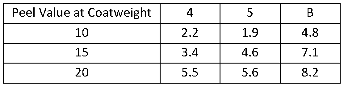
- Comparative Example A was lmil clear PET with the identical adhesive as flood coated on a rough substrate. Example A was then coated at different coat weights, lOgsm, 15gsm and 20gsm.
- the contact of the pattern of adhesive with a rough substrate leads to enhanced adhesion on the rough substrate with less adhesive than a continuous uniform flood coat.
- FIG. 6 illustrates Example 4.
- Example 4 was carried out was carried out where the facestock 604 was patterned in a manner to match the patterned adhesive 600.
- the face was 2mil BG40 white, a supercalendered glassine paper (available from Avery Dennison Corporation in Mentor, OH) where the adhesive was coated directly on the matte side of the patterned BG40.
- the adhesive is in contact with a smooth substrate 602.
- Example 4 was then coated at different coat weights, lOgsm, 15gsm, and 20gsm.
- Example 5 is the same except the adhesive was coated on the siliconized side of the patterned facestock at different coat weights of lOgsm, 15gsm, and 20gsm.
- Comparative Example B was 1 mil clear PET with the identical adhesive as flood coated on a smooth substrate. Example B was then coated at different coat weights, lOgsm, 15gsm, and 20gsm.
- Example 4 and 5 are less than Comparative Example B flood coated at lOgsm, 15gsm, and 20 gsm. This demonstrates for the adhesion of the adhesive to a smooth substrate when pattern coated and patterned lined is not improved at identical flood coat weights.
- the phrase "at least one,” in reference to a list of one or more elements, should be understood to mean at least one element selected from any one or more of the elements in the list of elements, but not necessarily including at least one of each and every element specifically listed within the list of elements and not excluding any combinations of elements in the list of elements.
- This definition also allows that elements may optionally be present other than the elements specifically identified within the list of elements to which the phrase "at least one" refers, whether related or unrelated to those elements specifically identified.
- At least one of A and B can refer, in one embodiment, to at least one, optionally including more than one, A, with no B present (and optionally including elements other than B); in another embodiment, to at least one, optionally including more than one, B, with no A present (and optionally including elements other than A); in yet another embodiment, to at least one, optionally including more than one, A, and at least one, optionally including more than one, B (and optionally including other elements); etc.
- An embodiment is an implementation or example of the present disclosure.
- Reference in the specification to "an embodiment,” “one embodiment,” “some embodiments,” “one particular embodiment,” or “other embodiments,” or the like, means that a particular feature, structure, or characteristic described in connection with the embodiments is included in at least some embodiments, but not necessarily all embodiments, of the invention.
- the various appearances “an embodiment,” “one embodiment,” “some embodiments,” “one particular embodiment,” or “other embodiments,” or the like, are not necessarily all referring to the same embodiments.
- any method of performing the present disclosure may occur in a sequence different than those described herein. Accordingly, no sequence of the method should be read as a limitation unless explicitly stated. It is recognizable that performing some of the steps of the method in a different order could achieve a similar result. [0096] In the claims, as well as in the specification above, all transitional phrases such as
Landscapes
- Chemical & Material Sciences (AREA)
- Organic Chemistry (AREA)
- Laminated Bodies (AREA)
Abstract
Description


Claims
Priority Applications (2)
| Application Number | Priority Date | Filing Date | Title |
|---|---|---|---|
| CN202380082016.9A CN120265722A (en) | 2022-12-06 | 2023-11-21 | Method for patterning adhesive layer |
| EP23813876.2A EP4599015A1 (en) | 2022-12-06 | 2023-11-21 | Method for patterning an adhesive layer |
Applications Claiming Priority (2)
| Application Number | Priority Date | Filing Date | Title |
|---|---|---|---|
| US202263386217P | 2022-12-06 | 2022-12-06 | |
| US63/386,217 | 2022-12-06 |
Publications (1)
| Publication Number | Publication Date |
|---|---|
| WO2024121662A1 true WO2024121662A1 (en) | 2024-06-13 |
Family
ID=88975733
Family Applications (1)
| Application Number | Title | Priority Date | Filing Date |
|---|---|---|---|
| PCT/IB2023/061754 Ceased WO2024121662A1 (en) | 2022-12-06 | 2023-11-21 | Method for patterning an adhesive layer |
Country Status (3)
| Country | Link |
|---|---|
| EP (1) | EP4599015A1 (en) |
| CN (1) | CN120265722A (en) |
| WO (1) | WO2024121662A1 (en) |
Citations (11)
| Publication number | Priority date | Publication date | Assignee | Title |
|---|---|---|---|---|
| US5164444A (en) | 1989-08-14 | 1992-11-17 | Avery Dennison Corporation | Emulsion pressure-sensitive adhesive polymers exhibiting excellent room- and low-temperature performance |
| US5183459A (en) | 1989-08-14 | 1993-02-02 | Avery Dennison Corporation | Emulsion pressure-sensitive adhesive polymers in bandage and medical tape constructions |
| US5264532A (en) | 1989-08-14 | 1993-11-23 | Avery Dennison Corporation | Emulsion pressure-sensitive adhesives |
| US5385965A (en) | 1991-12-24 | 1995-01-31 | Avery Dennison Corporation | Removable pressure-sensitive adhesives for recyclable substrates |
| US20030124293A1 (en) * | 1996-12-31 | 2003-07-03 | 3M Innovative Properties Company, A Delaware Corporation | Adhesives having microreplicated topography and methods of making and using same |
| US20070166501A1 (en) * | 2003-11-21 | 2007-07-19 | 3M Innovative Properties Company | Structured paper release liner, adhesive-backed article assembly and method of making same |
| US20080299346A1 (en) * | 2007-06-04 | 2008-12-04 | Michael Richard Onderisin | Adhesive articles having repositionability or slidability characteristics |
| KR20150041867A (en) * | 2013-10-10 | 2015-04-20 | 광성기업 주식회사 | Pressure-sensitive adhesive sheet with air-eliminable channels |
| KR101719750B1 (en) * | 2016-01-12 | 2017-03-24 | 에스케이씨 주식회사 | Embossed adhesive sheet and preparation method thereof |
| US20210017426A1 (en) * | 2018-04-04 | 2021-01-21 | 3M Innovative Properties Company | Chaotic non-continuous structures useful for functional adhesive systems |
| KR102274596B1 (en) * | 2018-11-09 | 2021-07-07 | 정주석 | Embossing sports tape and manufacturing method thereof |
-
2023
- 2023-11-21 WO PCT/IB2023/061754 patent/WO2024121662A1/en not_active Ceased
- 2023-11-21 EP EP23813876.2A patent/EP4599015A1/en active Pending
- 2023-11-21 CN CN202380082016.9A patent/CN120265722A/en active Pending
Patent Citations (12)
| Publication number | Priority date | Publication date | Assignee | Title |
|---|---|---|---|---|
| US5164444A (en) | 1989-08-14 | 1992-11-17 | Avery Dennison Corporation | Emulsion pressure-sensitive adhesive polymers exhibiting excellent room- and low-temperature performance |
| US5183459A (en) | 1989-08-14 | 1993-02-02 | Avery Dennison Corporation | Emulsion pressure-sensitive adhesive polymers in bandage and medical tape constructions |
| US5264532A (en) | 1989-08-14 | 1993-11-23 | Avery Dennison Corporation | Emulsion pressure-sensitive adhesives |
| US5164444C2 (en) | 1989-08-14 | 2001-10-16 | Avery Dennison Corp | Emulsion pressure-sensitive adhesive polymers exhibiting excellent room-and-low-temperature performance |
| US5385965A (en) | 1991-12-24 | 1995-01-31 | Avery Dennison Corporation | Removable pressure-sensitive adhesives for recyclable substrates |
| US20030124293A1 (en) * | 1996-12-31 | 2003-07-03 | 3M Innovative Properties Company, A Delaware Corporation | Adhesives having microreplicated topography and methods of making and using same |
| US20070166501A1 (en) * | 2003-11-21 | 2007-07-19 | 3M Innovative Properties Company | Structured paper release liner, adhesive-backed article assembly and method of making same |
| US20080299346A1 (en) * | 2007-06-04 | 2008-12-04 | Michael Richard Onderisin | Adhesive articles having repositionability or slidability characteristics |
| KR20150041867A (en) * | 2013-10-10 | 2015-04-20 | 광성기업 주식회사 | Pressure-sensitive adhesive sheet with air-eliminable channels |
| KR101719750B1 (en) * | 2016-01-12 | 2017-03-24 | 에스케이씨 주식회사 | Embossed adhesive sheet and preparation method thereof |
| US20210017426A1 (en) * | 2018-04-04 | 2021-01-21 | 3M Innovative Properties Company | Chaotic non-continuous structures useful for functional adhesive systems |
| KR102274596B1 (en) * | 2018-11-09 | 2021-07-07 | 정주석 | Embossing sports tape and manufacturing method thereof |
Non-Patent Citations (2)
| Title |
|---|
| "Encyclopedia of Polymer Science and Engineering", vol. 13, 1988, WILEY-INTERSCIENCE PUBLISHERS |
| "Polymer Science and Technology", vol. 1, 1964, INTERSCIENCE PUBLISHERS |
Also Published As
| Publication number | Publication date |
|---|---|
| CN120265722A (en) | 2025-07-04 |
| EP4599015A1 (en) | 2025-08-13 |
Similar Documents
| Publication | Publication Date | Title |
|---|---|---|
| US6132829A (en) | Articles useful security printing and methods of making the same | |
| EP0928475B1 (en) | Pressure-sensitive adhesive construction | |
| US20050003216A1 (en) | Microparticle containing silicone release coatings having improved anti-block and release properties | |
| WO1999049440A1 (en) | Pressure-sensitive adhesive constructions | |
| CA3099249C (en) | Adhesive laminates and method for making adhesive laminates | |
| Benedek | Development and manufacture of pressure-sensitive products | |
| EP2643098A2 (en) | Use of a transport coating to apply a thin coated layer | |
| JP5312232B2 (en) | Peelable film and adhesive tape or adhesive label using the same | |
| EP4599015A1 (en) | Method for patterning an adhesive layer | |
| EP4677582A1 (en) | Washable laminate and methods of adhesive isolation | |
| WO2026035858A1 (en) | High gloss machine direction oriented polyolefin films | |
| EP4688442A1 (en) | Patterned adhesives for use with transfer printing | |
| WO2024157155A1 (en) | Hotmelt adhesive | |
| WO2025186706A1 (en) | Adhesive composition | |
| WO2025074306A1 (en) | Adhesive article with patterned microstructure release | |
| BR112020022385B1 (en) | ADHESIVE COATED FACE MATERIAL, ADHESIVE LAMINATES AND PROCESSES FOR MANUFACTURING THE SAME | |
| WO2024261643A2 (en) | Systems and methods for depositing and identifying patterned coatings | |
| Benedek | 2 Buildup and Classification of | |
| EP1644431A2 (en) | Microparticle containing silicone release coating having improved anti-block and release properties |
Legal Events
| Date | Code | Title | Description |
|---|---|---|---|
| 121 | Ep: the epo has been informed by wipo that ep was designated in this application |
Ref document number: 23813876 Country of ref document: EP Kind code of ref document: A1 |
|
| WWE | Wipo information: entry into national phase |
Ref document number: 2023813876 Country of ref document: EP |
|
| ENP | Entry into the national phase |
Ref document number: 2023813876 Country of ref document: EP Effective date: 20250506 |
|
| WWE | Wipo information: entry into national phase |
Ref document number: 202517050512 Country of ref document: IN |
|
| WWE | Wipo information: entry into national phase |
Ref document number: 202380082016.9 Country of ref document: CN |
|
| WWP | Wipo information: published in national office |
Ref document number: 202517050512 Country of ref document: IN |
|
| WWP | Wipo information: published in national office |
Ref document number: 202380082016.9 Country of ref document: CN |
|
| NENP | Non-entry into the national phase |
Ref country code: DE |
|
| WWP | Wipo information: published in national office |
Ref document number: 2023813876 Country of ref document: EP |