WO2024075317A1 - Wireless communication system, user terminal, and wireless communication method - Google Patents
Wireless communication system, user terminal, and wireless communication method Download PDFInfo
- Publication number
- WO2024075317A1 WO2024075317A1 PCT/JP2023/000199 JP2023000199W WO2024075317A1 WO 2024075317 A1 WO2024075317 A1 WO 2024075317A1 JP 2023000199 W JP2023000199 W JP 2023000199W WO 2024075317 A1 WO2024075317 A1 WO 2024075317A1
- Authority
- WO
- WIPO (PCT)
- Prior art keywords
- user terminal
- base station
- wireless communication
- access point
- communication
- Prior art date
- Legal status (The legal status is an assumption and is not a legal conclusion. Google has not performed a legal analysis and makes no representation as to the accuracy of the status listed.)
- Ceased
Links
Images


Classifications
-
- H—ELECTRICITY
- H04—ELECTRIC COMMUNICATION TECHNIQUE
- H04W—WIRELESS COMMUNICATION NETWORKS
- H04W16/00—Network planning, e.g. coverage or traffic planning tools; Network deployment, e.g. resource partitioning or cells structures
- H04W16/24—Cell structures
- H04W16/28—Cell structures using beam steering
-
- H—ELECTRICITY
- H04—ELECTRIC COMMUNICATION TECHNIQUE
- H04W—WIRELESS COMMUNICATION NETWORKS
- H04W36/00—Hand-off or reselection arrangements
- H04W36/08—Reselecting an access point
-
- H—ELECTRICITY
- H04—ELECTRIC COMMUNICATION TECHNIQUE
- H04W—WIRELESS COMMUNICATION NETWORKS
- H04W4/00—Services specially adapted for wireless communication networks; Facilities therefor
- H04W4/30—Services specially adapted for particular environments, situations or purposes
- H04W4/40—Services specially adapted for particular environments, situations or purposes for vehicles, e.g. vehicle-to-pedestrians [V2P]
- H04W4/44—Services specially adapted for particular environments, situations or purposes for vehicles, e.g. vehicle-to-pedestrians [V2P] for communication between vehicles and infrastructures, e.g. vehicle-to-cloud [V2C] or vehicle-to-home [V2H]
-
- H—ELECTRICITY
- H04—ELECTRIC COMMUNICATION TECHNIQUE
- H04W—WIRELESS COMMUNICATION NETWORKS
- H04W88/00—Devices specially adapted for wireless communication networks, e.g. terminals, base stations or access point devices
- H04W88/02—Terminal devices
Definitions
- the present disclosure relates to a wireless communication system in which a user terminal mounted on a mobile object capable of moving on roads and a base station perform wireless communication, a user terminal mounted on a mobile object capable of moving on roads and performing wireless communication with a base station, and a communication control method for controlling wireless communication with a base station in a user terminal mounted on a mobile object capable of moving on roads.
- 5G next generation mobile communications system
- 5G higher frequencies will be used and the service area of each base station will be smaller, making it necessary to place base stations more densely. For this reason, it is conceivable to build a backhaul line network using wireless multi-hop communication between multiple base stations.
- a known technology for constructing a backhaul line network using such multi-hop communication is one in which base stations are grouped, wireless communication paths are constructed using multi-hop communication between base stations belonging to the same group, and edge servers are arranged corresponding to the base station groups (see Patent Document 1). Also known is a technology in which a communication terminal mounted on a moving object (such as a train) is equipped with a communication unit that has directionality in the direction of movement, and selects a communication destination based on the radio wave strength of the communication destination (see Patent Document 2).
- Patent Document 1 appropriately constructs wireless communication paths used for communication between edge servers and user terminals in a network in which the edge servers are located.
- the technology disclosed in Patent Document 2 can prevent interruptions in wireless communication when switching base stations.
- the millimeter wave communication used in 5G has a narrow coverage area (beam), so changes in the orientation of the mobile object significantly degrade the communication quality.
- the millimeter waves used in 5G are vulnerable to obstruction due to their strong tendency to travel in a straight line, and obstruction significantly degrades the communication quality.
- conventional technology cannot adequately solve these problems.
- the main objective of the present invention is to provide a wireless communication system, a user terminal, and a communication control method that can stably ensure good communication between a user terminal and a base station even in situations where communication quality deteriorates due to changes in the orientation of a moving object or due to obstruction.
- the wireless communication system of the present invention is a wireless communication system in which a user terminal mounted on a mobile object capable of moving on roads and a base station perform wireless communication, and the user terminal is configured to include a directional communication unit capable of controlling directivity while performing wireless communication with the base station, and a control unit that controls the directivity of the directional communication unit so as to improve the quality of communication with the base station when the mobile object on which the user terminal is mounted changes direction.
- the user terminal of the present invention is mounted on a mobile body that can move on roads and performs wireless communication with a base station, and is configured to include a directional communication unit that performs wireless communication with the base station and is capable of controlling directivity, and a control unit that controls the directivity of the directional communication unit so as to improve the quality of communication with the base station when the mobile body on which the device is mounted changes direction.
- the communication control method of the present invention is a communication control method for controlling wireless communication with a base station in a user terminal mounted on a mobile object capable of moving on a road, and the control unit of the user terminal is configured to control the directivity of the directional communication unit so as to improve the quality of communication with the base station when the mobile object on which the user terminal is mounted changes its orientation.
- the present invention can prevent communication quality between a user terminal and a base station from deteriorating and causing communication interruptions due to changes in the orientation of a mobile body carrying the user terminal, and can ensure stable, good communication between the user terminal and the base station.
- FIG. 1 is an explanatory diagram showing an example of control of a communication path between a user terminal and an edge server by a network control server; Block diagram showing the schematic configuration of an access point Block diagram showing the schematic configuration of an edge server A block diagram showing the schematic configuration of a network control server. A block diagram showing a schematic configuration of a user terminal.
- FIG. 1 is an explanatory diagram showing an overview of communication control performed in a wireless communication system according to a first embodiment;
- FIG. 1 is a flow chart showing the flow of processing performed by a user terminal 7.
- FIG. 13 is a block diagram showing a schematic configuration of an access point according to a second embodiment.
- FIG. 11 is a block diagram showing a schematic configuration of a user terminal according to a second embodiment.
- FIG. 11 is an explanatory diagram showing an overview of communication control performed in a wireless communication system according to a second embodiment
- FIG. 11 is an explanatory diagram showing an overview of communication control performed in a wireless communication system according to a second embodiment
- FIG. 1 is a flow chart showing the flow of processing performed by a user terminal 7.
- FIG. 13 is an explanatory diagram showing a state of communication control of an access point according to a modification of the second embodiment
- FIG. 13 is an explanatory diagram showing an overview of communication control performed in a wireless communication system according to a third embodiment.
- FIG. 13 is an explanatory diagram showing an overview of communication control performed in a wireless communication system according to a third embodiment.
- FIG. 13 is an explanatory diagram showing an overview of communication control performed in a wireless communication system according to a fourth embodiment.
- FIG. 13 is an explanatory diagram showing an overview of communication control performed in a wireless communication system according to a fourth embodiment.
- FIG. 13 is an explanatory diagram showing an overview of a coverage area of an access point according to a fifth embodiment;
- FIG. 13 is an explanatory diagram showing an overview of a coverage area of an access point according to a fifth embodiment;
- FIG. 1 is an explanatory diagram showing a transition state of communication between a user terminal and an access point;
- the first invention made to solve the above problem is a wireless communication system in which a user terminal mounted on a mobile object capable of moving on roads and a base station perform wireless communication, the user terminal being configured to include a directional communication unit capable of controlling directivity while performing wireless communication with the base station, and a control unit that controls the directivity of the directional communication unit so as to improve the quality of communication with the base station when the mobile object on which the user terminal is mounted changes direction.
- the user terminal is mounted on a vehicle as the moving body, and the control unit of the user terminal is configured to control the directivity of the directional communication unit when the vehicle in which the device is mounted makes a right or left turn at an intersection.
- the third invention is configured such that the control unit of the user terminal controls the directional communication unit so as to change at least one of the width and direction of the coverage area of the directional communication unit of the user terminal.
- the directivity of the directional communication unit can be appropriately controlled, and good communication between the user terminal and the base station can be stably ensured.
- the control of the directivity of the directional communication unit can be performed by beamforming, but the directivity of the directional communication unit may also be controlled mechanically.
- the user terminal is configured to include a forward directional communication unit having forward directivity and a backward directional communication unit having backward directivity.
- coverage areas areas where good communication quality can be obtained are formed at the front and rear, so that good communication between the user terminal and the base station can be stably ensured by using the base station located at the front or the base station located at the rear depending on the situation.
- the base station has a directional communication unit that has directivity toward the upstream side of the lane.
- the base station has an upstream directional communication unit that has directivity on the upstream side of the lane, and a downstream directional communication unit that has directivity on the downstream side of the lane.
- the seventh invention is configured such that the base station forms its own coverage area so as to overlap with the coverage area of another adjacent base station.
- the eighth invention is a wireless communication system in which a user terminal mounted on a mobile body capable of moving on roads and a base station perform wireless communication, and the control unit of the user terminal is configured to first select the base station in front of the vehicle's lane as the connection destination, and if communication with the base station in front of the vehicle's lane is poor, switch the connection destination to the base station in the rear.
- the ninth invention is configured such that the control unit of the user terminal switches the connection to the base station in the rear of the opposite lane when communication with the base station in front of the own lane is poor.
- the tenth invention is configured such that the control unit of the user terminal switches the connection to the base station at the rear of the own lane when communication with the base station at the front of the own lane is poor, and switches the connection to the base station at the rear of the opposite lane when communication with the base station at the rear of the own lane is poor.
- the eleventh invention is configured such that, when communication with the base station in the vicinity is poor, the control unit of the user terminal uses a user terminal mounted on another nearby mobile object as a relay device and carries out communication via that user terminal.
- the user terminal acting as a relay device may be either a user terminal mounted on a car traveling in the opposite lane, or a user terminal mounted on an aircraft flying in the sky. This makes it possible to ensure relatively high-speed communication even when communication with nearby base stations is poor, and also when communication with other user terminals that can be used as relay devices is poor.
- the twelfth invention is a wireless communication system in which a user terminal mounted on a mobile object capable of moving on a road and a base station perform wireless communication, the base station being configured to include a directional communication unit that performs wireless communication with the user terminal and is capable of controlling directivity, and a control unit that controls the directivity of the directional communication unit so as to improve the quality of communication with the user terminal when the mobile object on which the user terminal is mounted changes direction.
- the thirteenth invention is configured such that the base stations are grouped and perform multi-hop communication with other base stations belonging to the same group.
- the fourteenth invention is a user terminal mounted on a mobile body capable of moving on roads, which performs wireless communication with a base station, and is configured to include a directional communication unit that performs wireless communication with the base station and is capable of controlling directivity, and a control unit that controls the directivity of the directional communication unit so as to improve the quality of communication with the base station when the mobile body on which the device is mounted changes direction.
- this prevents communication quality between the user terminal and the base station from deteriorating and causing communication interruptions due to changes in the orientation of the mobile body carrying the user terminal, and ensures stable, good communication between the user terminal and the base station.
- the fifteenth invention is a communication control method for controlling wireless communication with a base station in a user terminal mounted on a mobile object capable of moving on a road, in which a control unit of the user terminal is configured to control the directivity of a directional communication unit so as to improve the quality of communication with the base station when the mobile object on which the user terminal is mounted changes its orientation.
- this prevents communication quality between the user terminal and the base station from deteriorating and causing communication interruptions due to changes in the orientation of the mobile body carrying the user terminal, and ensures stable, good communication between the user terminal and the base station.
- FIG. 1 is a diagram showing the overall configuration of a wireless communication system 1 according to the first embodiment.
- the wireless communication system 1 (abbreviated as system 1) includes a macro cell base station 2, a small cell base station 3, an access point (or base station) 4, an edge server 5, a network control server (abbreviated as NW control server 6), and a user terminal 7.
- system 1 includes a macro cell base station 2, a small cell base station 3, an access point (or base station) 4, an edge server 5, a network control server (abbreviated as NW control server 6), and a user terminal 7.
- the macrocell base station 2 performs wireless communication using a frequency band that makes it easy to build larger cells, such as the UHF band (frequency: 300 MHz to 3 GHz) for LTE (Long Term Evolution).
- the macrocell base station 2 is a base station for the control plane (CPlane) for transmitting control signals.
- the macrocell base station 2 may also be used as a base station for the user plane (U-Plane) for transmitting user data.
- the small cell base station 3 performs wireless communication using a higher frequency than the macro cell base station 2, such as the low SHF band (frequency: 3 GHz to 6 GHz).
- the small cell base station 3 may also use the high SHF band (frequency: 6 GHz to 30 GHz).
- the small cell base station 3 is used as a user plane base station.
- the access point 4 performs, for example, relatively small-capacity wireless communication using Wi-Fi (registered trademark) or relatively large-capacity wireless LAN communication using WiGig (registered trademark).
- Wi-Fi registered trademark
- WiGig registered trademark
- the access point 4 may be a microcell base station that performs wireless communication using a higher frequency band than the small cell base station 3.
- the wireless communication by the access point 4 can be performed using the high SHF band or EHF band (here, 28 GHz band, 40 GHz band, 70 GHz band, etc.) that is 5G NR (New Radio).
- the multiple access points 4 may include both such microcell base stations and base stations that perform wireless LAN communication.
- the communication area 13 corresponds to a microcell, which is the communication area of the microcell base station.
- the macrocell base station 2, the small cell base station 3, and some of the access points 4 are wired-connected to a wired network consisting of a core network 15 and the Internet 16.
- the core network 15 includes an MME (Mobility Management Entity), an S-GW (Serving Gateway), and a P-GW (Packet data network Gateway) that configure an EPC (Evolved Packet Core) that corresponds to the LTE core network, an AMF (Access and Mobility Management Function), and a UPF (User Plane Function) that configure a 5GC (5G Core network) that corresponds to the 5G core network, and the like.
- EPC Evolved Packet Core
- AMF Access and Mobility Management Function
- UPF User Plane Function
- the edge servers 5 are located physically close to the mobile user terminals 7 and execute various applications (programs) as services to the user terminals 7. There are no particular restrictions on the placement of each edge server 5, but here, they are connected to one of the access points 4.
- the NW control server (network control device) 6 controls the communication paths used for communication between the edge servers 5 and user terminals 7 in the network to which the system 1 is applied.
- the NW control server 6 is connected to the core network 15. However, the NW control server 6 may be part of the core network 15, or may be connected to the Internet 16.
- the user terminal 7 is an information device with wireless communication capabilities, such as a smartphone or tablet terminal, carried by each user (not shown).
- the user terminal 7 can be wirelessly connected to the macrocell base station 2, the small cell base station 3, and the access point 4.
- the user terminal 7 can also use applications of the edge server 5 by communicating with the edge server 5 via the macrocell base station 2, the small cell base station 3, and the access point 4.
- the user terminal 7 can also use applications of any server (not shown) by communicating with the server via a wired network consisting of the core network 15 and the Internet 16.
- FIG. 2 is an explanatory diagram showing an example of control of a communication path between a user terminal 7 and an edge server 5 by a network control server 6.
- FIG. 2(A) shows a conventional communication path (comparative example)
- FIG. 2(B) shows a communication path established by the network control server 6.
- multiple access points 4 are arranged in a tree or mesh shape starting from a wired network connection point 18.
- the access points 4 are connected to each other via wireless communication to form a backhaul.
- the access points 4 are labeled AP1-AP12 to distinguish them from one another.
- FIG. 2(A) an example is shown in which an access point is selected based on wireless quality in communication between a user terminal 7 and an edge server 5.
- the user terminal 7 selects the nearby access point AP1 that offers the highest wireless quality as the connection destination, and as a result, it becomes necessary to communicate with the edge server 5 via more access points AP1-AP9.
- the communication path R1 between the user terminal 7 and the edge server 5 uses a backhaul to connect each access point to a connection point 18 in the wired network.
- FIG. 2(B) multiple access points AP9-AP12, including access point AP9 to which edge server 5 is connected, are grouped (see the dashed circle in the figure).
- the NW control server 6 also forms wireless communication routes R2 and R3 using these grouped access points AP9-AP12. Furthermore, the NW control server 6 determines the connection priority of the access lines so that wireless communication routes R2 and R3 are used preferentially, and provides this to the user terminal 7. This enables the user terminal 7 to select access point AP10 or AP11 as the connection destination, and to communicate with edge server 5 using wireless communication routes R2 and R3.
- FIG. 3 is a block diagram showing the general configuration of the access point 4.
- the access point 4 constitutes a roadside unit installed on the side of a road (roadside) or at an intersection.
- the access point 4 only needs to constitute a roadside unit, and may be constituted, for example, by an existing roadside unit and a communication device that cooperates with it.
- the access point 4 includes a wireless communication unit 21, a backhaul communication unit 22, a wired communication unit 23, a memory unit 24, and a control unit 25.
- the wireless communication unit 21 includes an antenna and a communication circuit for wireless communication with the user terminal 7.
- the wireless communication unit 21 has a directional communication unit 26.
- the directional communication unit 26 has directivity toward the upstream side in the lane direction. Furthermore, the directional communication unit 26 has variable directivity, that is, the directivity can be controlled. Specifically, the width and direction of the coverage area (beam) of the directional communication unit 26 can be controlled based on beamforming technology or the like. Furthermore, it is possible to change the direction of the directional communication unit itself.
- the backhaul communication unit 22 is equipped with antennas and circuits for wireless communication with surrounding access points 4. This allows multi-hop communication between multiple access points 4, forming a wireless communication path used for communication between the user terminal 7 and the edge server 5.
- the wired communication unit 23 includes a communication circuit for performing wired communication with the core network 15. However, the wired communication unit 23 does not necessarily need to be provided in all access points 4, and is provided in nearby access points 4 of the wired network as necessary.
- the storage unit 24 stores information about the user terminal 7, information about the macrocell base station 2, small cell base station 3, and other access points 4 in the vicinity, as well as programs executed by the processor constituting the control unit 25.
- the control unit 25 includes a wireless quality measurement unit 31, a location information acquisition unit 32, a route connection unit 33, a wireless control unit 34, a wired control unit 35, and a directivity control unit 36.
- the wireless quality measurement unit 31 measures the quality of wireless communication with other nearby access points 4 based on known indicators such as received signal strength.
- the wireless quality measurement unit 31 also generates wireless quality information based on the measurement results of the wireless communication quality.
- the location information acquisition unit 32 acquires location information of itself (the access point 4).
- the location information acquisition unit 32 can acquire location information by appropriately measuring the location of its own device, or can use location information previously stored in the storage unit 24, etc.
- the route connection unit 33 establishes a communication route used for communication between the user terminal 7 and the edge server 5 based on a route establishment instruction received from the edge server 5.
- the route connection unit 33 realizes multi-hop communication with surrounding access points 4 by controlling wireless communication by the backhaul communication unit 22.
- the wireless control unit 34 controls wireless communication with the user terminal 7 by the wireless communication unit 21.
- the wired control unit 35 controls the communication by the wired communication unit 23.
- the wired control unit 35 can exchange information regarding the connection destination of the user terminal 7 through wired communication with a communication control device in the wired network and with the surrounding macrocell base station 2 and small cell base station 3.
- the directivity control unit 36 controls the directivity of the directional communication unit 26. Specifically, the width and direction of the coverage area (beam) of the directional communication unit 26 are controlled so that the quality of communication with the user terminal 7 is good.
- the directivity control unit 36 also controls the direction of the directional communication unit itself. Note that directivity control can be performed individually for each user terminal 7.
- each part in the control unit 25 described above can be realized by one or more processors executing a predetermined control program.
- FIG. 4 is a block diagram showing the general configuration of the edge server 5.
- the communication unit 41 has a communication circuit for communicating with the access point 4 to which the device is connected.
- the memory unit 42 stores information about the user terminal 7, information about the macro cell base station 2, small cell base station 3, and access point 4 in the vicinity, and programs executed by the processor constituting the control unit 43.
- the control unit 43 includes a route establishment instruction unit 45, a traffic information collection unit 46, an access point operation instruction unit 47, a communication control unit 48, and an application unit 49.
- the route establishment instruction unit 45 sends a route establishment instruction to the access point 4 to establish a communication route based on the information received from the NW control server 6.
- the traffic information collection unit 46 collects information on traffic between each access point 4 that forms a wireless communication path regarding communication between the user terminal 7 and the edge server 5. Note that the traffic information collection unit 46 may be omitted as appropriate.
- the access point operation instruction unit 47 transmits operation instructions to the access point 4 based on information received from the NW control server 6. Such operation instructions include instructions to start or stop the access point 4.
- the access point operation instruction unit 47 may be omitted as appropriate.
- the communication control unit 48 controls the communication by the communication unit 41.
- the communication control unit 48 also exchanges necessary information with nearby access points 4 and user terminals 7.
- the application unit 49 executes various applications according to the service content for the user terminal 7. Processing by the application includes, for example, storing or providing the output (detection results) of sensors installed in a smart factory, and storing or providing traffic images of intersections and other detected information.
- each part in the control unit 43 described above can be realized by one or more processors executing a specific control program.
- FIG. 5 is a block diagram showing the general configuration of the NW control server 6.
- the network control server 6 includes a communication unit 51, a memory unit 52, and a control unit 53.
- the communication unit 51 has a communication circuit for communicating with the edge server 5 and the user terminal 7 via the core network 15.
- the storage unit 52 stores information about the user terminal 7, information about the macrocell base station 2, small cell base station 3, and access point 4 in the vicinity, and programs executed by the processor constituting the control unit 53.
- the control unit 53 includes an information collection unit 61, a grouping unit 62, a route setting unit 63, a traffic analysis unit 64, a connection priority setting unit 65, a service area setting unit 66, an edge server operation control unit 67, an access point operation control unit 68, and a communication control unit 69.
- the information collection unit 61 collects peripheral device information from each access point 4.
- This peripheral device information includes wireless quality information regarding the quality of wireless communication between each access point 4, location information of each access point 4, and edge server information regarding the presence or absence of an edge server 5 connected to each access point 4.
- the grouping unit 62 extracts access points 4 that form a network in a specific area from the multiple access points 4 under its management based on the collected peripheral device information, and groups them. This generates at least one group of access points 4.
- a "specific area" includes, for example, a smart factory or a specific area including an intersection. At least some of the groups of access points 4 may be set by the operator.
- the grouping unit 62 can also reconfigure existing groups of access points 4 based on the results of traffic analysis by the traffic analysis unit 64, which will be described later. In this embodiment, each access point 4 can constitute a corresponding roadside unit.
- the route setting unit 63 sets one or more wireless communication routes used for communication between the user terminal 7 and the edge server 5. Such wireless communication routes are formed by multi-hop communication of the grouped access points 4. Note that at least a part of such wireless communication routes may be set by the operator.
- the traffic analysis unit 64 sequentially acquires from the edge server 5 traffic information on the wireless communication path used for communication between the user terminal 7 and the edge server 5.
- the acquired traffic information is stored in the memory unit 52.
- the traffic analysis unit 64 also performs traffic analysis, such as predicting the traffic distribution of the wireless communication path set by the route setting unit 63.
- the traffic analysis unit 64 can also detect a detour route that uses an access point 4 outside the group that is not included in the target group.
- the connection destination priority setting unit 65 sets the priority of connection destination candidates for the user terminal 7 according to the type of service of the edge server 5 used by the user terminal 7.
- the connection destination priority setting unit 65 also generates connection destination priority information based on the set priority of the connection destination candidates.
- the connection destination candidates for the user terminal 7 are usually any of the access points 4, but the macro cell base station 2 or small cell base station 3 can be connection destination candidates as necessary.
- the connection destination priority information also includes the priority of the connection destination candidates. Without being limited to this, the connection destination priority information may also include information regarding the criteria (rules) for determining the priority of the connection destination candidates, for example.
- the service area setting unit 66 sets the service area (range of the communication area) based on peripheral device information from each access point 4. Such a service area is set according to the type of service of the edge server 5 used by the user terminal 7.
- the service area setting unit 66 also generates service area information related to the range of the set service area. Note that at least a part of the service area information may be set by the operator.
- the edge server operation control unit 67 controls the operation of the edge server 5, including the launch of applications on the edge server 5.
- the access point operation control unit 68 controls the operation of the access point 4, including starting and stopping the access point 4.
- the communication control unit 69 controls the communication by the communication unit 51.
- the communication control unit 69 can also exchange necessary information with the surrounding access points 4, edge servers 5, and user terminals 7.
- each part in the control unit 53 described above can be realized by one or more processors executing a specific control program.
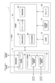
- FIG. 6 is a block diagram showing the general configuration of the user terminal 7.
- the user terminal 7 is a terminal device mounted on a moving body (here, an automobile).
- the user terminal 7 may be configured, for example, by an on-board device provided in the automobile.
- the user terminal 7 may also be a portable computer carried by the user (driver or passenger) of the automobile.
- the user terminal 7 includes a wireless communication unit 71, a memory unit 72, a location information acquisition unit 73, and a control unit 74.
- the wireless communication unit 71 includes a macrocell/small cell communication unit 75 and an access point communication unit 76.
- the macrocell/small cell communication unit 75 is equipped with an antenna and communication circuits for wireless communication with the macrocell base station 2 or the small cell base station 3.
- the access point communication unit 76 is equipped with an antenna and a communication circuit for wireless communication with the access point 4.
- the access point communication unit 76 is equipped with a forward directional communication unit 78 and a rearward directional communication unit 79.
- the forward directional communication unit 78 has directivity in the forward direction (the direction in which the vehicle is moving).
- the rearward directional communication unit 79 has directivity in the rearward direction (the direction opposite to the direction in which the vehicle is moving).
- the forward directional communication unit 78 and the rearward directional communication unit 79 have variable directivity, that is, the directivity can be controlled.
- the width and direction of the coverage area (beam) provided by each of the forward directional communication unit 78 and the rearward directional communication unit 79 can be controlled based on beamforming technology, etc.
- the storage unit 72 stores information about the device itself, information about the macro cell base station 2, small cell base station 3, and access point 4 in the vicinity, and programs executed by the processor constituting the control unit 74.
- the location information acquisition unit 73 acquires location information of the device itself using a known positioning system such as the Global Positioning System (GPS) or a system using a beacon transmitter. Note that the location information acquisition unit 73 may also acquire location information acquired by a device other than the user terminal 7, such as a LiDAR, camera, or radar installed at the access point 4 or on the roadside, via the access point 4, etc.
- GPS Global Positioning System
- a device other than the user terminal 7 such as a LiDAR, camera, or radar installed at the access point 4 or on the roadside, via the access point 4, etc.
- the control unit 74 includes a connection destination selection unit 81, an application unit 82, and a wireless control unit 83.
- connection destination selection unit 81 selects a connection destination such as an access point 4 based on the grouping information, connection destination priority information, and service area information received from the NW control server 6. This allows the user terminal 7 to communicate with the edge server 5 via the selected connection destination and the wireless communication path that includes it.
- the application unit 82 executes processing according to the content of the application executed on the user terminal 7, and transmits and receives application data between the edge server 5 and the user terminal 71 via the wireless communication unit 71.
- the wireless control unit 83 controls wireless communication by the wireless communication unit 71 with the access point 4, and with the macro cell base station 2 and small cell base station 3.
- the directivity control unit 84 controls the directivity of the forward directional communication unit 78 and the backward directional communication unit 79. Specifically, the width and direction of the coverage area (beam) of each of the forward directional communication unit 78 and the backward directional communication unit 79 are controlled so that the communication quality with the access point 4 is good.
- each part in the control unit 74 described above can be realized by one or more processors executing a specific control program.
- FIG. 7 is an explanatory diagram showing an overview of the communication control performed in the wireless communication system according to the first embodiment.
- FIG. 7(A) shows a case where the automobile V1 equipped with the user terminal 7 has moved away from the intersection ahead.
- FIG. 7(B) shows a case where the automobile V1 equipped with the user terminal 7 has approached the intersection ahead.
- Access point 4 is installed at a traffic light L located at a road intersection or the like.
- the directional communication unit 26 forms a coverage area C1 (an area where good communication quality can be obtained) extending from approximately the center of the width of the lane toward the upstream side of the lane (one-way area communication).
- C1 is illustrated as the coverage range from the location of access point 4, but in reality, the beam from access point 4 also has vertical directionality, so at the height of user terminal 7, communication quality deteriorates near directly below access point 4.
- the forward directional communication unit 78 forms a coverage area C21 that extends forward (in the direction in which the vehicle is moving), and the rearward directional communication unit 79 forms a coverage area C22 that extends backward (in the opposite direction to the direction in which the vehicle is moving).
- the forward directional communication unit 78 connects to the access point 4 ahead of it on the side of the user's own lane (the lane in which the automobile in which the user terminal 7 is mounted is traveling) to perform communication.
- the communication quality of the connected access point 4 is good.
- the user terminal 7 i.e., the automobile V1 on which the user terminal 7 is mounted
- the user terminal 7 gets too close to the access point 4 ahead of it on the vehicle's own lane, causing the communication quality of the access point 4 to deteriorate.
- the user terminal 7 performs a handover to switch the connection to the access point 4 behind it on the opposite lane, and the rear directional communication unit 79 connects to the access point 4 behind it on the opposite lane to communicate.
- the user terminal 7 controls the directivity of the rear directional communication unit 79.
- the width and direction of the coverage area C22 (beam) of the rear directional communication unit 79 are controlled so that communication quality with the rear access point 4 on the opposite lane side is good.
- scanning is performed to swing the emitted beam left and right to search for the optimal direction of the coverage area C22 (beam).
- the coverage area C22 (beam) of the rear directional communication unit 79 is formed diagonally backward toward the rear access point 4 on the opposite lane side, and its direction changes depending on the distance between the user terminal 7 and the rear access point 4 on the opposite lane side.
- FIG. 8 is a flow diagram showing the process flow performed by the user terminal 7.
- the user terminal 7 selects the access point 4 ahead on the own lane side as the connection destination (ST101), and connects to that access point 4 to communicate (ST102). Next, the user terminal 7 determines whether the communication quality of the access point 4 ahead on the own lane side has deteriorated (ST103). Here, if the communication quality of the access point 4 ahead on the own lane side has not deteriorated (No in ST103), communication with the access point 4 ahead on the own lane side is continued.
- the user terminal 7 determines whether the communication quality of the access point 4 in the rear on the opposite lane side is good (ST104).
- ST104 the communication quality of the access point 4 in the rear on the opposite lane side is not good (No in ST104)
- communication with the access point 4 in front on the own lane side is continued.
- the user terminal 7 selects the rear access point 4 on the opposite lane side as the connection destination (ST105), performs a handover to switch the connection destination to the rear access point 4 on the opposite lane side, and connects to the rear access point 4 on the opposite lane side to communicate (ST106).
- the user terminal 7 determines whether the communication quality of the rear access point 4 on the opposite lane side has deteriorated (ST107).
- the communication quality of the rear access point 4 on the opposite lane side has not deteriorated (No in ST107)
- communication with the rear access point 4 on the opposite lane side continues.
- the user terminal 7 determines whether the communication quality of the front access point 4 on the own lane is better than the communication quality of the rear access point 4 on the opposite lane (ST108).
- the user terminal 7 controls the directivity of the rear directional communication unit 79 (ST109). At this time, the width and direction of the coverage area (beam) of the rear directional communication unit 79 are controlled so that the communication quality with the rear access point 4 on the opposite lane is good.
- the user terminal 7 selects the access point 4 in front on the own lane side as the connection destination (ST110), performs a handover to switch the connection destination to the access point 4 in front on the own lane side, and connects to the access point 4 in front on the own lane side to communicate (ST111).
- the user terminal 7 first communicates with the access point 4 ahead on the own lane (see FIG. 22(A)).
- a handover is performed to switch the connection to the access point 4 behind on the opposite lane (see FIG. 22(B)).
- the vehicle in which the user terminal 7 is mounted is traveling and the communication quality of the access point 4 ahead on the own lane becomes higher than the access point 4 behind on the opposite lane, a handover is performed to switch the connection to the access point 4 ahead on the own lane (see FIG. 22(C)).
- the communication quality of the rear access point 4 on the opposite lane is better than the communication quality of the front access point 4 on the own lane, communication with the rear access point 4 on the opposite lane is continued, and directivity control is performed to control the directivity of the rear directional communication unit 79 in order to further improve the communication quality of the rear access point 4 on the opposite lane.
- the directivity of the rear directional communication unit 79 gradually changes due to directivity control in accordance with the change in the positional relationship between the rear access point 4 on the opposite lane and the user terminal 7.
- Fig. 9 is a block diagram showing a schematic configuration of an access point 4 according to the second embodiment.
- Fig. 9 the same components as those of the access point 4 according to the first embodiment shown in Fig. 3 are given the same reference numerals.
- Fig. 10 is a block diagram showing a schematic configuration of a user terminal 7 according to the second embodiment.
- Fig. 10 the same components as those of the user terminal 7 according to the first embodiment shown in Fig. 6 are given the same reference numerals.
- matters that are not particularly mentioned below are the same as those in the first embodiment, and therefore detailed description thereof will be omitted.
- the wireless communication unit 21 includes an upstream directional communication unit 27 and a downstream directional communication unit 28.
- the upstream directional communication unit 27 has directivity in the upstream direction of the lane, similar to the direction of the traffic light.
- the downstream directional communication unit 28 has directivity in the downstream direction of the lane, which is opposite to the direction of the traffic light.
- the upstream directional communication unit 27 and the downstream directional communication unit 28 have variable directivity, that is, the directivity can be controlled. Specifically, the width and direction of the coverage area (beam) provided by each of the upstream directional communication unit 27 and the downstream directional communication unit 28 can be controlled based on beamforming technology or the like.
- the user terminal 7 is equipped with a direction sensor 80.
- the direction sensor 80 detects the direction of travel (body orientation) of the automobile, which is a moving body in which the user terminal 7 is mounted. Based on the detection result of the direction sensor 80, the control unit 74 can detect that the automobile in which the user terminal 7 is mounted is making a right or left turn at an intersection.
- the configurations of the edge server 5 and the NW control server 6 are the same as those in the first embodiment (see Figures 4 and 5).
- FIGS. 11 and 12 are explanatory diagrams showing an overview of communication control performed in the wireless communication system according to the second embodiment.
- FIG. 11 shows the state of communication control of the user terminal 7 when the automobile V1 equipped with the user terminal 7 is traveling straight along a road.
- FIG. 12 shows the state of communication control of the user terminal 7 when the automobile V1 equipped with the user terminal 7 is turning right at an intersection. Note that the case where the automobile V1 turns left at an intersection is similar to the case of turning right shown in FIG. 12.
- the upstream directional communication unit 27 forms a coverage area C11 extending from approximately the center of the lane width toward the upstream side in the lane direction
- the downstream directional communication unit 28 forms a coverage area C12 extending toward the downstream side in the lane direction (bidirectional area communication).
- a forward directional communication unit 78 connects to an access point 4 ahead of the own lane to perform communication.
- the user terminal 7 i.e., the automobile V1 on which the user terminal 7 is mounted
- the communication quality of the access point 4 ahead of the own lane is good.
- the user terminal 7 i.e., the automobile V1 on which the user terminal 7 is mounted
- the user terminal 7 gets too close to the access point 4 ahead on the own lane side, causing the communication quality of the access point 4 ahead on the own lane side to deteriorate.
- the user terminal 7 performs a handover to switch the connection to the access point 4 behind the own lane side, and the rear directional communication unit 79 connects to the access point 4 behind the own lane side to communicate.
- the backward directional communication unit 79 and the forward directional communication unit 78 of the user terminal 7 perform control to adjust the direction of the cover areas C21, C22 (beams). At this time, the emitted beam is scanned left and right to search for the optimal direction of the cover areas C21, C22 (beams).
- the backward directional communication unit 79 and the forward directional communication unit 78 perform control to expand the width of the cover areas C21, C22 (beams) left and right.
- a control may be performed that combines the adjustment of the direction of the cover areas C21, C22 (beams) shown in FIG.
- the rear directional communication unit 79 of the user terminal 7 when the automobile V1 equipped with the user terminal 7 makes a right turn at an intersection, the rear directional communication unit 79 of the user terminal 7 is maintained in a state connected to the rear access point 4 on the own lane side, and control is performed to adjust the direction of the cover area C22 so that the communication quality at that time is good (first state in the figure).
- the rear directional communication unit 79 of the user terminal 7 is in a state where it can connect to the rear access point 4 on the opposite lane side of the intersecting road. Therefore, control may be performed to adjust the direction of the cover area C22 so that the communication quality between the rear directional communication unit 79 of the user terminal 7 and the rear access point 4 on the opposite lane side of the intersecting road is good (second state in the figure).
- FIG. 13 is a flow diagram showing the flow of processing performed by the user terminal 7.
- the user terminal 7 selects the access point 4 ahead on the own lane as the connection destination (ST201), and connects to that access point 4 to communicate (ST202).
- the user terminal 7 acquires the direction information that is the detection result of the direction sensor 80, and determines whether the direction has changed by a predetermined value or more (ST203).
- ST203 determines whether the direction has changed by a predetermined value or more.
- the user terminal 7 determines whether the communication quality of the access point 4 ahead on the own lane side has deteriorated (ST204).
- a predetermined value i.e., if the vehicle in which the user terminal 7 is mounted starts to turn right or left at an intersection (Yes in ST203)
- the user terminal 7 determines whether the communication quality of the access point 4 ahead on the own lane side has deteriorated (ST204).
- the communication quality of the access point 4 ahead on the own lane side has not deteriorated (No in ST204)
- communication with the access point 4 ahead on the own lane side continues.
- the user terminal 7 selects the access point 4 in the rear of the own lane as the connection destination (ST205), performs a handover to switch the connection destination to the access point 4 in the rear of the own lane, and connects to the access point 4 in the rear of the own lane to communicate (ST206).
- the user terminal 7 controls the directivity of the rear directional communication unit 79 (ST207). At this time, the width and direction of the coverage area (beam) of the rear directional communication unit 79 are controlled so that the communication quality with the rear access point 4 on the opposite lane side is good.
- the user terminal 7 determines whether the communication quality of the access point 4 ahead is better than that of the access point 4 behind (ST208).
- the access point 4 ahead is the access point 4 located ahead on the crossroad (the road beyond which the vehicle turns right or left at the intersection).
- the communication quality of the access point 4 behind is better than that of the access point 4 ahead (No in ST208)
- communication with the access point 4 behind on the vehicle's own lane is continued.
- the user terminal 7 selects the forward access point 4 on the cross road side as the connection destination (ST209), performs handover to switch the connection destination to the forward access point 4 on the cross road side, and connects to the forward access point 4 on the cross road side to communicate (ST210).
- the user terminal 7 controls the directivity of the forward directional communication unit 78 (ST211). At this time, the width and direction of the coverage area (beam) of the forward directional communication unit 78 are controlled so that the communication quality with the forward access point 4 is good.
- the communication quality of the access point 4 in front of the own lane deteriorates, so a handover is performed to switch the connection destination to the access point 4 in the rear of the own lane.
- directivity control is performed to control the directivity of the rear directional communication unit 79.
- the communication quality of the access point 4 in front of the cross road increases, so a handover is performed to switch the connection destination to the access point 4 in front of the cross road.
- directivity control is performed to control the directivity of the forward directional communication unit 78.
- the beam width may be expanded as shown in FIG. 12(B), or a combination of directivity control and beam width expansion may be used.
- FIG. 14 is an explanatory diagram showing a state of communication control of the access point 4 according to a modified example of the second embodiment.
- the user terminal 7 controls the directivity of the forward directional communication unit 78 and the rearward directional communication unit 79, but in this modified example, the access point 4 controls the directivity of the upstream directional communication unit 27.
- the upstream directional communication unit 27 of the access point 4 performs control to adjust the direction of the cover area C11 (beam). At this time, the emitted beam is scanned left and right to search for the optimal direction of the cover area C11 (beam).
- the upstream directional communication unit 27 performs control to expand the width of the cover area C11 (beam) left and right. Also, a control may be performed that combines the adjustment of the direction of the cover area C11 (beam) shown in FIG. 14(A) and the expansion of the width of the cover area C11 (beam) shown in FIG. 14(B). Note that, since expanding the beam width shortens the communication distance, the control shown in FIG. 14(B) may be performed only when the user terminal 7 approaches the access point 4.
- the control of directivity at the access point 4 is performed individually for each user terminal 7, for example, by time-division control.
- the beam may be controlled to be wide for a user terminal 7 mounted on a car turning right or left at an intersection, and the beam may be controlled to be narrow for a user terminal 7 mounted on a car going straight through the intersection.
- Third Embodiment 15 and 16 are explanatory diagrams showing an overview of communication control performed in the wireless communication system 1 according to the third embodiment.
- matters not specifically mentioned below are the same as those in the above-mentioned embodiments, and detailed explanations will be omitted.
- the configuration of the access point 4 is the same as that of the second embodiment (see FIG. 9).
- the configurations of the edge server 5, the NW control server 6, and the user terminal 7 are the same as those of the first embodiment (see FIG. 4, FIG. 5, FIG. 6).
- the wireless communication unit 21 of the access point 4 includes an upstream directional communication unit 27 and a downstream directional communication unit 28.
- a handover is performed to switch the connection destination to another access point 4.
- a priority order is set for the access points 4 used for communication.
- the connection destination is selected in the following order: the access point 4 in front on the own lane side, the access point 4 in the rear on the own lane side, and the access point 4 in the rear on the opposite lane side.
- a user terminal 7 mounted on an automobile V1 serving as a moving body communicates with an access point 4 located ahead on the vehicle's own lane.
- blocking occurs due to another moving object, automobile V2, in front of the own lane, causing poor communication between the user terminal 7 mounted on automobile V1 and the access point 4 in front of the own lane.
- the user terminal 7 mounted on automobile V1 performs a handover to switch the connection to the access point 4 in the rear of the own lane, and communicates with the access point 4 in the rear of the own lane.
- blocking occurs due to another moving object, automobile V3, located behind the own lane, causing poor communication between the user terminal 7 mounted on automobile V1 and the access point 4 located behind the own lane.
- the user terminal 7 mounted on automobile V1 performs a handover to switch the connection to the access point 4 located behind the own lane, and communicates with the access point 4 located behind the own lane.
- the user terminal 7 controls the directivity of the rear directional communication unit 79.
- the width and direction of the coverage area C22 (beam) of the rear directional communication unit 79 are controlled so that communication quality with the rear access point 4 on the opposite lane side is good.
- scanning is performed to swing the emitted beam left and right to search for the optimal direction of the coverage area C22 (beam).
- the coverage area C22 (beam) of the rear directional communication unit 79 is formed diagonally backward toward the rear access point 4 on the opposite lane side, and its direction changes depending on the distance between the user terminal 7 and the rear access point 4 on the opposite lane side.
- FIG. 17 is a flow diagram showing the flow of processing performed by the user terminal 7.
- the user terminal 7 selects the access point 4 ahead on the own lane side as the connection destination (ST301), and connects to that access point 4 to communicate (ST302).
- the user terminal 7 determines whether the communication quality of the access point 4 ahead on the own lane side has deteriorated (ST303). Here, if the communication quality of the access point 4 ahead on the own lane side has not deteriorated (No in ST303), communication with the access point 4 ahead on the own lane side is continued.
- the user terminal 7 selects the access point 4 in the rear of the own lane as the connection destination (ST304), performs a handover to switch the connection destination to the access point 4 in the rear of the own lane, and connects to the access point 4 in the rear of the own lane to communicate (ST305).
- the width and direction of the coverage area (beam) of the rear directional communication unit 79 may be controlled so that the communication quality with the access point 4 in the rear of the own lane is improved.
- the user terminal 7 determines whether the communication quality of the rear access point 4 on the own lane side has deteriorated (ST306). If the communication quality of the rear access point 4 on the own lane side has not deteriorated (No in ST306), communication with the rear access point 4 on the own lane side is continued.
- the user terminal 7 determines whether the communication quality of the rear access point 4 on the opposite lane is better than the communication quality of the rear access point 4 on the own lane (ST307).
- the communication quality of the rear access point 4 on the opposite lane is not better than the communication quality of the rear access point 4 on the own lane (No in ST307), communication with the rear access point 4 on the own lane continues.
- the user terminal 7 determines whether the communication quality of the front access point 4 is better than that of the rear access point 4 (ST308).
- the user terminal 7 selects the rear access point 4 on the opposite lane as the connection destination (ST309), performs a handover to switch the connection destination to the rear access point 4 on the opposite lane, and connects to the rear access point 4 on the opposite lane to communicate (ST310).
- the user terminal 7 controls the directivity of the rear directional communication unit 79 (ST311). At this time, the width and direction of the coverage area (beam) of the rear directional communication unit 79 are controlled so that the communication quality with the rear access point 4 on the opposite lane side is good.
- the user terminal 7 selects the forward access point 4 on the own lane side as the connection destination (ST312), performs handover to switch the connection destination to the forward access point 4 on the own lane side, and connects to the forward access point 4 on the own lane side to communicate (ST313).
- Fourth Embodiment 18 and 19 are explanatory diagrams showing an overview of communication control performed in the wireless communication system 1 according to the fourth embodiment.
- matters not specifically mentioned below are similar to those in the first embodiment, and detailed explanations will be omitted.
- the configuration of the access point 4 is similar to that of the second embodiment (see FIG. 9).
- the configurations of the edge server 5, the NW control server 6, and the user terminal 7 are similar to those of the first embodiment (see FIG. 4, FIG. 5, FIG. 6).
- a user terminal 7 mounted on an automobile as a mobile body is controlled to connect to nearby access points 4, but due to obstruction by other mobile bodies in the vicinity, communication may be poor at all of the nearby access points 4, specifically, the access point 4 in front of the vehicle's own lane, the access point 4 in the rear of the vehicle's own lane, and the access point 4 in the rear of the opposite lane.
- a user terminal 7 mounted on another mobile body in the vicinity is used as a relay device, and communication is performed via the user terminal 7.
- the user terminal 7 as a relay device can connect to nearby access points 4 that can be connected to, and can perform communication required for itself as well as communication as a relay device.
- blocking occurs due to automobile V4 behind on the opposite lane, causing poor communication between the user terminal 7 mounted on automobile V1 and the access point 4 behind on the opposite lane.
- the user terminal 7 mounted on automobile V1 uses the user terminal 7 mounted on automobile V5, another moving body traveling in the opposite lane, as a relay device and transitions to a communication mode via that user terminal 7.
- the user terminal 7 mounted on automobile V1 performs a handover to switch the connection destination to the user terminal 7 mounted on automobile V5, and communicates with the user terminal 7 mounted on automobile V5.
- blocking occurs due to automobile V6 traveling in the opposite lane, causing poor communication between the user terminal 7 mounted on automobile V1 and the user terminal 7 mounted on automobile V5 traveling in the opposite lane.
- the user terminal 7 mounted on automobile V1 transitions to a communication mode via a user terminal 7 acting as a relay device mounted on a drone D (aircraft) flying in the sky.
- the user terminal 7 mounted on automobile V1 performs a handover to switch the connection destination to the user terminal 7 mounted on drone D, and communicates with the user terminal 7 mounted on drone D.
- the flying object on which the user terminal 7 is mounted is not limited to the drone D, but may be, for example, a balloon.
- the user terminal 7 is also provided with a forward directional communication unit 78 and a backward directional communication unit 79 for communicating with the access point 4, but an upward directional communication unit with directionality in the sky may also be provided to improve communication with the flying object.
- the upward directional communication unit it is preferable for the upward directional communication unit to generate circularly polarized waves pointing toward the sky.
- the forward directional communication unit 78 and the backward directional communication unit 79 may be controlled to switch from horizontal polarization to vertical polarization.
- the user terminal 7 mounted on the automobile V1 performs a handover to switch the connection to the small cell base station 3 or macro cell base station 2 as a base station of the wide area communication network, and communicates with the small cell base station 3 or macro cell base station 2.
- Fifth Embodiment 20 and 21 are explanatory diagrams showing an overview of the coverage area of the access point 4 according to the fifth embodiment.
- matters that are not particularly mentioned below are the same as those in the first embodiment, and therefore detailed descriptions thereof will be omitted.
- the coverage area C1 (beam) by the directional communication unit 26 of the access point 4 has directionality not only in the left-right direction but also in the up-down direction, so communication quality deteriorates in the immediate vicinity of the access point 4. Therefore, it is advisable to configure the access point 4 so that a coverage area C1 is formed, as shown in Figures 20 and 21. This allows the immediate vicinity of the access point 4 to be covered by another coverage area C1, so that either the forward directional communication unit 78 or the backward directional communication unit 79 can connect to the access point 4 with good communication quality, regardless of the position of the user terminal 7 on the road.
- the example shown in Figures 20(A) and (B) is a case where the access point 4 has a one-way area communication configuration, similar to the first embodiment.
- the wireless communication unit 21 of the access point 4 has a directional communication unit 26 that has directionality toward the upstream side in the lane direction.
- the directional communication unit 26 forms a coverage area C1 (an area where good communication quality can be obtained) by extending toward the upstream side in the lane direction.
- the coverage area C1 of the directional communication unit 26 of the access point 4 partially overlaps with the coverage area C1 of the directional communication unit 26 of the adjacent access point 4.
- the coverage areas C1 of an access point 4 installed on the upbound lane side of a road and an access point 4 installed on the downbound lane side are formed alternately so that they partially overlap, and the coverage area C1 of the access point 4 is formed to cover the entire road.
- the example shown in Figures 21 (A) and (B) is a case where the access point 4 has a bidirectional area communication configuration, similar to the second embodiment.
- the wireless communication unit 21 of the access point 4 has an upstream directional communication unit 27 that has directivity toward the upstream side of the lane, and a downstream directional communication unit 28 that has directivity toward the downstream side of the lane.
- the upstream directional communication unit 27 forms a cover area C11 by extending toward the upstream side in the lane direction.
- the downstream directional communication unit 28 forms a cover area C12 by extending toward the downstream side in the lane direction.
- the coverage area C11 of the upstream directional communication unit 27 of an access point 4 partially overlaps with the coverage area C12 of the downstream directional communication unit 28 of an adjacent access point 4 on the upstream side of the lane.
- access point 4 is included in the coverage area C11 of the upstream directional communication unit 27 of the adjacent access point 4 on the downstream side of the lane, and access point 4 is included in the coverage area C12 of the downstream directional communication unit 28 of the adjacent access point 4 on the upstream side of the lane.
- the coverage area C11 of the upstream directional communication unit 27 and the coverage area C12 of the downstream directional communication unit 28 are in a state of partial overlap.
- the downstream directional communication unit 28 is included in the coverage area C11 of the upstream directional communication unit 27, and the upstream directional communication unit 27 is included in the coverage area C12 of the downstream directional communication unit 28.
- the moving body on which the user terminal 7 is mounted is an automobile, but the moving body on which the user terminal 7 is mounted is not limited to an automobile.
- the moving body on which the user terminal 7 is mounted may be other vehicles such as a bicycle, a senior car, a wheelchair, or may be a moving body other than a vehicle such as a pedestrian.
- an automobile as a mobile body on which the user terminal 7 is mounted moves on a road
- the route on which the mobile body on which the user terminal 7 is mounted can move is not limited to a road.
- the mobile body on which the user terminal 7 is mounted may move along a predetermined route, and for example, if the mobile body is a flying object (such as a drone) that flies along a predetermined flight route, the route on which the mobile body can move is the flight route.
- a coverage area is formed by the access point 4 and the user terminal 7 so as to correspond to the lanes of the road along which the automobile, which is the mobile body on which the user terminal 7 is mounted, travels.
- the mobile body moves along a route other than a road, such as a flight route, it is preferable to set multiple traffic segments on the path of the mobile body, which correspond to the lanes of a road.
- the position and direction of the moving body are specified in advance so that two or more mobile bodies can move in opposition to each other (or in parallel).
- the directionality of wireless communication performed by the access point 4 and the user terminal 7 at least one of the width and direction of the coverage area (beam) is changed based on beamforming technology, but is not limited to this.
- the directionality may be mechanically controlled using a gimbal mechanism or the like.
- the directivity of wireless communication is controlled when an automobile, as a moving body on which a user terminal 7 is mounted, turns right or left at an intersection, but this is not limited to this.
- controlling the directivity of wireless communication is also useful when the direction of wireless communication at the base station and the direction of the automobile are misaligned due to a curve in the road.
- the directivity of wireless communication performed by the access point 4 and the user terminal 7 is controlled based on the communication quality, i.e., the directivity is controlled so as to improve the communication quality, but the directivity may be controlled based on the position of the user terminal 7 on the road, i.e., information regarding the positional relationship between the user terminal 7 and the access point 4, which is obtained.
- the wireless communication system, user terminal, and communication control method according to the present invention have the effect of being able to stably ensure good communication between a user terminal and a base station even in situations where communication quality deteriorates due to a change in the orientation of the mobile body or due to obstruction, and are useful as a wireless communication system in which a user terminal mounted on a mobile body that can move on roads and a base station perform wireless communication, a user terminal mounted on a mobile body that can move on roads and performs wireless communication with a base station, and a communication control method for controlling wireless communication with a base station in a user terminal mounted on a mobile body that can move on roads.
- Wireless communication system 2 Macro cell base station 3: Small cell base station 4: Access point (base station) 5: Edge server 6: Network control server 7: User terminal 11: Small cell area 12: Macro cell area 13: Communication area 15: Core network 16: Internet 18: Connection point 21: Wireless communication unit 22: Backhaul communication unit 23: Wired communication unit 24: Memory unit 25: Control unit 26: Directional communication unit 27: Upstream directional communication unit 28: Downstream directional communication unit 31: Wireless quality measurement unit 32: Position information acquisition unit 33: Route connection unit 34: Wireless control unit 35: Wired control unit 36: Directional control unit 41: Communication unit 42: Memory unit 43: Control unit 45: Route establishment instruction unit 46: Traffic information collection unit 47: Access point operation instruction unit 48: Communication control unit 49: Application unit 51: Communication unit 52: Memory unit 53: Control unit 61: Information collection unit 62: Grouping unit 63: Route setting unit 64: Traffic analysis unit 65: Connection destination priority setting unit 66: Service area setting unit 67: Edge server operation control unit 68: Access point operation control unit 69:
Landscapes
- Engineering & Computer Science (AREA)
- Computer Networks & Wireless Communication (AREA)
- Signal Processing (AREA)
- Mobile Radio Communication Systems (AREA)
Abstract
Description
本開示は、道路上を移動可能な移動体に搭載されたユーザ端末と基地局とが無線通信を行う無線通信システム、道路上を移動可能な移動体に搭載されて、基地局と無線通信を行うユーザ端末、及び道路上を移動可能な移動体に搭載されたユーザ端末において、基地局との無線通信を制御する通信制御方法に関するものである。 The present disclosure relates to a wireless communication system in which a user terminal mounted on a mobile object capable of moving on roads and a base station perform wireless communication, a user terminal mounted on a mobile object capable of moving on roads and performing wireless communication with a base station, and a communication control method for controlling wireless communication with a base station in a user terminal mounted on a mobile object capable of moving on roads.
モバイルネットワークの分野では、5G(第5世代移動体通信システム)が商用化の段階にある。このような5Gでは、利用される周波数が高く、1つの基地局のサービスエリアが小さくなるため、基地局をより高密度に配置する必要が生じる。そのため、複数の基地局間の無線マルチホップ通信によりバックホール回線のネットワークを構築することが考えられる。 In the field of mobile networks, 5G (fifth generation mobile communications system) is at the stage of commercialization. With 5G, higher frequencies will be used and the service area of each base station will be smaller, making it necessary to place base stations more densely. For this reason, it is conceivable to build a backhaul line network using wireless multi-hop communication between multiple base stations.
このようなマルチホップ通信によりバックホール回線のネットワークを構築する技術として、基地局がグループ化され、同じグループに属する基地局間のマルチホップ通信によって無線通信経路が構築されると共に、基地局のグループに対応してエッジサーバが配置される技術が知られている(特許文献1参照)。また、移動体(列車など)に搭載された通信端末が、移動方向に指向性を有する通信部を備え、通信先の電波強度に基づいて通信先を選択する技術が知られている(特許文献2参照)。 A known technology for constructing a backhaul line network using such multi-hop communication is one in which base stations are grouped, wireless communication paths are constructed using multi-hop communication between base stations belonging to the same group, and edge servers are arranged corresponding to the base station groups (see Patent Document 1). Also known is a technology in which a communication terminal mounted on a moving object (such as a train) is equipped with a communication unit that has directionality in the direction of movement, and selects a communication destination based on the radio wave strength of the communication destination (see Patent Document 2).
特許文献1に開示された技術では、エッジサーバが配置されたネットワークにおいて、エッジサーバとユーザ端末との通信に用いられる無線通信経路が適切に構築される。また、特許文献2に開示された技術では、基地局の切り換え時における無線通信の途切れを防止することができる。
The technology disclosed in Patent Document 1 appropriately constructs wireless communication paths used for communication between edge servers and user terminals in a network in which the edge servers are located. In addition, the technology disclosed in
一方、道路上を移動可能な移動体、特に比較的高速で走行する自動車に搭載されたユーザ端末では、移動体自体の状況が急激に変化し、また、移動体の周辺の状況も急激に変化する。このため、移動体やその周辺の状況の変化に影響されずに、移動体に搭載されたユーザ端末とその周辺の基地局との良好な通信を確保することが望まれる。また、5Gで利用されるミリ波の通信では、カバーエリア(ビーム)が狭いため、移動体の向きの変更による通信品質の劣化が著しい。また、5Gで利用されるミリ波は、直進性が強いために遮蔽に弱く、遮蔽による通信品質の劣化が著しい。しかしながら、従来の技術では、このような問題を十分に解決できない。 On the other hand, for user terminals mounted on mobile objects that can move on roads, particularly automobiles traveling at relatively high speeds, the conditions of the mobile object itself change rapidly, and the conditions around the mobile object also change rapidly. For this reason, it is desirable to ensure good communication between the user terminal mounted on the mobile object and its surrounding base stations without being affected by changes in the conditions of the mobile object or its surroundings. Furthermore, the millimeter wave communication used in 5G has a narrow coverage area (beam), so changes in the orientation of the mobile object significantly degrade the communication quality. Furthermore, the millimeter waves used in 5G are vulnerable to obstruction due to their strong tendency to travel in a straight line, and obstruction significantly degrades the communication quality. However, conventional technology cannot adequately solve these problems.
そこで、本発明は、移動体の向きの変更による通信品質の劣化や、遮蔽による通信品質の劣化が発生する状況でも、ユーザ端末と基地局との良好な通信を安定して確保することができる無線通信システム、ユーザ端末、及び通信制御方法を提供することを主な目的とする。 The main objective of the present invention is to provide a wireless communication system, a user terminal, and a communication control method that can stably ensure good communication between a user terminal and a base station even in situations where communication quality deteriorates due to changes in the orientation of a moving object or due to obstruction.
本発明の無線通信システムは、道路上を移動可能な移動体に搭載されたユーザ端末と基地局とが無線通信を行う無線通信システムであって、前記ユーザ端末は、前記基地局と無線通信を行うと共に指向性を制御可能な指向性通信部と、自装置が搭載された移動体が向きを変更する場合に、前記基地局との通信品質が向上するように、前記指向性通信部の指向性を制御する制御部と、を備える構成とする。 The wireless communication system of the present invention is a wireless communication system in which a user terminal mounted on a mobile object capable of moving on roads and a base station perform wireless communication, and the user terminal is configured to include a directional communication unit capable of controlling directivity while performing wireless communication with the base station, and a control unit that controls the directivity of the directional communication unit so as to improve the quality of communication with the base station when the mobile object on which the user terminal is mounted changes direction.
また、本発明のユーザ端末は、道路上を移動可能な移動体に搭載されて、基地局と無線通信を行うユーザ端末であって、前記基地局と無線通信を行うと共に指向性を制御可能な指向性通信部と、自装置が搭載された移動体が向きを変更する場合に、前記基地局との通信品質が向上するように、前記指向性通信部の指向性を制御する制御部と、を備える構成とする。 The user terminal of the present invention is mounted on a mobile body that can move on roads and performs wireless communication with a base station, and is configured to include a directional communication unit that performs wireless communication with the base station and is capable of controlling directivity, and a control unit that controls the directivity of the directional communication unit so as to improve the quality of communication with the base station when the mobile body on which the device is mounted changes direction.
また、本発明の通信制御方法は、道路上を移動可能な移動体に搭載されたユーザ端末において、基地局との無線通信を制御する通信制御方法であって、前記ユーザ端末の制御部は、自装置が搭載された移動体が向きを変更する場合に、前記基地局との通信品質が向上するように、指向性通信部の指向性を制御する構成とする。 The communication control method of the present invention is a communication control method for controlling wireless communication with a base station in a user terminal mounted on a mobile object capable of moving on a road, and the control unit of the user terminal is configured to control the directivity of the directional communication unit so as to improve the quality of communication with the base station when the mobile object on which the user terminal is mounted changes its orientation.
本発明によれば、ユーザ端末が搭載された移動体の向きの変更に応じてユーザ端末と基地局との通信品質が劣化して通信が途切れることを防止し、ユーザ端末と基地局との良好な通信を安定して確保することができる。 The present invention can prevent communication quality between a user terminal and a base station from deteriorating and causing communication interruptions due to changes in the orientation of a mobile body carrying the user terminal, and can ensure stable, good communication between the user terminal and the base station.
前記課題を解決するためになされた第1の発明は、道路上を移動可能な移動体に搭載されたユーザ端末と基地局とが無線通信を行う無線通信システムであって、前記ユーザ端末は、前記基地局と無線通信を行うと共に指向性を制御可能な指向性通信部と、自装置が搭載された移動体が向きを変更する場合に、前記基地局との通信品質が向上するように、前記指向性通信部の指向性を制御する制御部と、を備える構成とする。 The first invention made to solve the above problem is a wireless communication system in which a user terminal mounted on a mobile object capable of moving on roads and a base station perform wireless communication, the user terminal being configured to include a directional communication unit capable of controlling directivity while performing wireless communication with the base station, and a control unit that controls the directivity of the directional communication unit so as to improve the quality of communication with the base station when the mobile object on which the user terminal is mounted changes direction.
これによると、ユーザ端末が搭載された移動体の向きの変更に応じてユーザ端末と基地局との通信品質が劣化して通信が途切れることを防止し、ユーザ端末と基地局との良好な通信を安定して確保することができる。 This prevents communication quality between the user terminal and the base station from deteriorating and causing communication interruptions due to changes in the orientation of the mobile body carrying the user terminal, and ensures stable, good communication between the user terminal and the base station.
また、第2の発明は、前記ユーザ端末は、前記移動体としての車両に搭載され、前記ユーザ端末の制御部は、自装置が搭載された車両が交差点において右左折を行う場合に、前記指向性通信部の指向性を制御する構成とする。 In addition, in the second invention, the user terminal is mounted on a vehicle as the moving body, and the control unit of the user terminal is configured to control the directivity of the directional communication unit when the vehicle in which the device is mounted makes a right or left turn at an intersection.
これによると、ユーザ端末が搭載された車両が交差点において右左折を行う場合に、ユーザ端末と基地局との良好な通信を安定して確保することができる。 As a result, when a vehicle equipped with a user terminal makes a right or left turn at an intersection, good and stable communication between the user terminal and the base station can be ensured.
また、第3の発明は、前記ユーザ端末の制御部は、自装置の前記指向性通信部のカバーエリアの幅及び方向の少なくともいずれかを変化させるように前記指向性通信部を制御する構成とする。 In addition, the third invention is configured such that the control unit of the user terminal controls the directional communication unit so as to change at least one of the width and direction of the coverage area of the directional communication unit of the user terminal.
これによると、指向性通信部の指向性を適切に制御して、ユーザ端末と基地局との良好な通信を安定して確保することができる。なお、指向性通信部の指向性の制御は、ビームフォーミングにより行うことができるが、指向性通信部の指向性が機械的に制御されてもよい。 By doing this, the directivity of the directional communication unit can be appropriately controlled, and good communication between the user terminal and the base station can be stably ensured. Note that the control of the directivity of the directional communication unit can be performed by beamforming, but the directivity of the directional communication unit may also be controlled mechanically.
また、第4の発明は、前記ユーザ端末は、前方に指向性を有する前方指向性通信部と、後方に指向性を有する後方指向性通信部とを備える構成とする。 In addition, in the fourth invention, the user terminal is configured to include a forward directional communication unit having forward directivity and a backward directional communication unit having backward directivity.
これによると、前後にカバーエリア(良好な通信品質が得られるエリア)が形成されるため、状況に応じて、前方に位置する基地局を利用したり後方に位置する基地局を利用したりすることで、ユーザ端末と基地局との良好な通信を安定して確保することができる。 As a result, coverage areas (areas where good communication quality can be obtained) are formed at the front and rear, so that good communication between the user terminal and the base station can be stably ensured by using the base station located at the front or the base station located at the rear depending on the situation.
また、第5の発明は、前記基地局は、車線の上流側に指向性を有する指向性通信部を有する構成とする。 In addition, in the fifth invention, the base station has a directional communication unit that has directivity toward the upstream side of the lane.
これによると、車線の上流側にカバーエリアが形成されるため、ユーザ端末と基地局との良好な通信を安定して確保することができる。 This creates a coverage area on the upstream side of the lane, ensuring stable and good communication between the user terminal and the base station.
また、第6の発明は、前記基地局は、車線の上流側に指向性を有する上流側指向性通信部と、車線の下流側に指向性を有する下流側指向性通信部とを有する構成とする。 In addition, in the sixth invention, the base station has an upstream directional communication unit that has directivity on the upstream side of the lane, and a downstream directional communication unit that has directivity on the downstream side of the lane.
これによると、車線の上流側と下流側との両方にカバーエリアが形成されるため、ユーザ端末と基地局との良好な通信をより一層安定して確保することができる。 This creates coverage areas on both the upstream and downstream sides of the lane, ensuring good and stable communication between user terminals and the base station.
また、第7の発明は、前記基地局は、隣り合う他の基地局のカバーエリアとオーバラップするように自身のカバーエリアを形成する構成とする。 In addition, the seventh invention is configured such that the base station forms its own coverage area so as to overlap with the coverage area of another adjacent base station.
これによると、ユーザ端末の位置に関係なく、ユーザ端末と基地局との良好な通信を確保することができる。 This ensures good communication between the user terminal and the base station regardless of the user terminal's location.
また、第8の発明は、道路上を移動可能な移動体に搭載されたユーザ端末と基地局とが無線通信を行う無線通信システムであって、前記ユーザ端末の制御部は、まず、自車線側の前方の前記基地局を接続先に選択し、自車線側の前方の前記基地局との通信が不良である場合、後方の前記基地局に接続先を切り替える構成とする。 The eighth invention is a wireless communication system in which a user terminal mounted on a mobile body capable of moving on roads and a base station perform wireless communication, and the control unit of the user terminal is configured to first select the base station in front of the vehicle's lane as the connection destination, and if communication with the base station in front of the vehicle's lane is poor, switch the connection destination to the base station in the rear.
これによると、遮蔽によりユーザ端末と基地局との通信品質が劣化して通信が途切れることを防止し、ユーザ端末と基地局との良好な通信を安定して確保することができる。 This prevents communication quality between the user terminal and the base station from deteriorating due to obstruction, resulting in interruption of communication, and ensures stable and good communication between the user terminal and the base station.
また、第9の発明は、前記ユーザ端末の制御部は、自車線側の前方の前記基地局との通信が不良である場合、反対車線側の後方の前記基地局に接続先を切り替える構成とする。 In addition, the ninth invention is configured such that the control unit of the user terminal switches the connection to the base station in the rear of the opposite lane when communication with the base station in front of the own lane is poor.
これによると、ユーザ端末は、良好な通信を確保可能な基地局と通信を行うことができる。 This allows user terminals to communicate with base stations that can ensure good communications.
また、第10の発明は、前記ユーザ端末の制御部は、自車線側の前方の前記基地局との通信が不良である場合、自車線側の後方の前記基地局に接続先を切り替え、自車線側の後方の前記基地局の通信が不良である場合、反対車線側の後方の前記基地局に接続先を切り替える構成とする。 In addition, the tenth invention is configured such that the control unit of the user terminal switches the connection to the base station at the rear of the own lane when communication with the base station at the front of the own lane is poor, and switches the connection to the base station at the rear of the opposite lane when communication with the base station at the rear of the own lane is poor.
これによると、ユーザ端末は、良好な通信を確保可能な基地局と通信を行うことができる。 This allows user terminals to communicate with base stations that can ensure good communications.
また、第11の発明は、前記ユーザ端末の制御部は、周辺に存在する前記基地局との通信が不良である場合、周辺に存在する他の移動体に搭載されたユーザ端末を中継装置として利用して、そのユーザ端末を介した通信を実施する構成とする。 In addition, the eleventh invention is configured such that, when communication with the base station in the vicinity is poor, the control unit of the user terminal uses a user terminal mounted on another nearby mobile object as a relay device and carries out communication via that user terminal.
これによると、周辺に存在する基地局との通信が不良である場合でも、比較的高速の通信を確保することができる。なお、中継装置としてのユーザ端末は、反対車線を走行する自動車に搭載されたユーザ端末、及び上空を飛翔する飛翔体に搭載されたユーザ端末のいずれかであるとよい。これにより、周辺に存在する基地局との通信が不良で、しかも、中継装置として利用できる他のユーザ端末との通信も不良である場合でも、比較的高速の通信を確保することができる。 This makes it possible to ensure relatively high-speed communication even when communication with nearby base stations is poor. The user terminal acting as a relay device may be either a user terminal mounted on a car traveling in the opposite lane, or a user terminal mounted on an aircraft flying in the sky. This makes it possible to ensure relatively high-speed communication even when communication with nearby base stations is poor, and also when communication with other user terminals that can be used as relay devices is poor.
また、第12の発明は、道路上を移動可能な移動体に搭載されたユーザ端末と基地局とが無線通信を行う無線通信システムであって、前記基地局は、前記ユーザ端末と無線通信を行うと共に指向性を制御可能な指向性通信部と、前記ユーザ端末が搭載された移動体が向きを変更する場合に、前記ユーザ端末との通信品質が向上するように、前記指向性通信部の指向性を制御する制御部と、を備える構成とする。 The twelfth invention is a wireless communication system in which a user terminal mounted on a mobile object capable of moving on a road and a base station perform wireless communication, the base station being configured to include a directional communication unit that performs wireless communication with the user terminal and is capable of controlling directivity, and a control unit that controls the directivity of the directional communication unit so as to improve the quality of communication with the user terminal when the mobile object on which the user terminal is mounted changes direction.
これによると、ユーザ端末が搭載された移動体の向きの変更に応じてユーザ端末と基地局との通信品質が劣化して通信が途切れることを防止し、ユーザ端末と基地局との良好な通信を安定して確保することができる。 This prevents communication quality between the user terminal and the base station from deteriorating and causing communication interruptions due to changes in the orientation of the mobile body carrying the user terminal, and ensures stable, good communication between the user terminal and the base station.
また、第13の発明は、前記基地局は、グループ化されて、同じグループに属する他の基地局とマルチホップ通信を実行する構成とする。 In addition, the thirteenth invention is configured such that the base stations are grouped and perform multi-hop communication with other base stations belonging to the same group.
これによると、ユーザ端末の通信に用いられる無線通信経路を適切に構築することができる。 This allows the wireless communication path used for user terminal communications to be properly constructed.
また、第14の発明は、道路上を移動可能な移動体に搭載されて、基地局と無線通信を行うユーザ端末であって、前記基地局と無線通信を行うと共に指向性を制御可能な指向性通信部と、自装置が搭載された移動体が向きを変更する場合に、前記基地局との通信品質が向上するように、前記指向性通信部の指向性を制御する制御部と、を備える構成とする。 The fourteenth invention is a user terminal mounted on a mobile body capable of moving on roads, which performs wireless communication with a base station, and is configured to include a directional communication unit that performs wireless communication with the base station and is capable of controlling directivity, and a control unit that controls the directivity of the directional communication unit so as to improve the quality of communication with the base station when the mobile body on which the device is mounted changes direction.
これによると、第1の発明と同様に、ユーザ端末が搭載された移動体の向きの変更に応じてユーザ端末と基地局との通信品質が劣化して通信が途切れることを防止し、ユーザ端末と基地局との良好な通信を安定して確保することができる。 As with the first invention, this prevents communication quality between the user terminal and the base station from deteriorating and causing communication interruptions due to changes in the orientation of the mobile body carrying the user terminal, and ensures stable, good communication between the user terminal and the base station.
また、第15の発明は、道路上を移動可能な移動体に搭載されたユーザ端末において、基地局との無線通信を制御する通信制御方法であって、前記ユーザ端末の制御部は、自装置が搭載された移動体が向きを変更する場合に、前記基地局との通信品質が向上するように、指向性通信部の指向性を制御する構成とする。 The fifteenth invention is a communication control method for controlling wireless communication with a base station in a user terminal mounted on a mobile object capable of moving on a road, in which a control unit of the user terminal is configured to control the directivity of a directional communication unit so as to improve the quality of communication with the base station when the mobile object on which the user terminal is mounted changes its orientation.
これによると、第1の発明と同様に、ユーザ端末が搭載された移動体の向きの変更に応じてユーザ端末と基地局との通信品質が劣化して通信が途切れることを防止し、ユーザ端末と基地局との良好な通信を安定して確保することができる。 As with the first invention, this prevents communication quality between the user terminal and the base station from deteriorating and causing communication interruptions due to changes in the orientation of the mobile body carrying the user terminal, and ensures stable, good communication between the user terminal and the base station.
以下、本開示の実施の形態を、図面を参照しながら説明する。 The following describes an embodiment of the present disclosure with reference to the drawings.
(第1実施形態)
図1は、第1実施形態に係る無線通信システム1の全体構成図である。
First Embodiment
FIG. 1 is a diagram showing the overall configuration of a wireless communication system 1 according to the first embodiment.
無線通信システム1(システム1と略称する。)は、マクロセル基地局2、スモールセル基地局3、アクセスポイント(又は基地局)4、エッジサーバ5、ネットワーク制御サーバ(NW制御サーバ6と略称する。)、及びユーザ端末7を備える。
The wireless communication system 1 (abbreviated as system 1) includes a macro
システム1が適用されるネットワークでは、複数のスモールセル基地局3の通信エリアであるスモールセルエリア11が、マクロセル基地局2の通信エリアであるマクロセルエリア12上にそれぞれ重畳される。
In a network to which system 1 is applied,
マクロセル基地局2は、例えばLTE(Long Term Evolution)などのUHF帯(周波数:300M Hz~3GHz)を代表とするより大きなセルを構築しやすい周波数帯を利用して無線通信を行うものである。マクロセル基地局2は、制御信号を伝送するための制御プレーン(CPlane)の基地局となる。また、マクロセル基地局2は、ユーザデータを伝送するためのユーザプレーン(U-Plane)の基地局として使用される場合もある。
The
スモールセル基地局3は、例えば低SHF帯(周波数:3GHz~6GHz)などのマクロセル基地局2よりも高い周波数を利用して無線通信を行うものである。なお、スモールセル基地局3は、高SHF帯(周波数:6GHz~30GHz帯)を利用するものであってもよい。スモールセル基地局3は、ユーザプレーンの基地局として使用される。
The small cell base station 3 performs wireless communication using a higher frequency than the macro
アクセスポイント4は、例えば、Wi-Fi(登録商標)による比較的小容量の無線通信や、WiGig(登録商標)による比較的大容量の無線LAN通信を行うものである。アクセスポイント4の通信エリア13は、スモールセルエリア11及びマクロセルエリア12の少なくとも一方に重畳される。
The
ただし、アクセスポイント4は、スモールセル基地局3よりも高い周波数帯を利用して無線通信を行うマイクロセル基地局であってもよい。その場合、アクセスポイント4による無線通信は、5GのNR(New Radio)となる高SHF帯またはEHF帯(ここでは、28GHz帯、40GHz帯、及び70GHz帯など)を利用して行うことができる。また、複数のアクセスポイント4には、そのようなマイクロセル基地局と、無線LAN通信を行う基地局とが共に含まれてもよい。アクセスポイント4としてマイクロセル基地局が用いられる場合、通信エリア13は、マイクロセル基地局の通信エリアであるマイクロセルに相当する。
However, the
システム1では、複数のRAT(無線通信方式)が混在する通信環境、いわゆるヘテロジーニアスネットワークが構成される。マクロセル基地局2、スモールセル基地局3、及び一部のアクセスポイント4は、コアネットワーク15及びインターネット16からなる有線ネットワークに有線接続されている。コアネットワーク15には、LTEのコアネットワークに相当するEPC(Evolved Packet Core)を構成するMME(Mobility Management Entity)、S-GW(Serving Gateway)、及びP-GW(Packet data network Gateway)や5Gのコアネットワークに相当する5GC(5G Core network)を構成するAMF(Access and Mobility Management Function)、及びUPF(User Plane Function)などが含まれる。また、システム1において、マクロセル基地局2、スモールセル基地局3、アクセスポイント4、エッジサーバ5、NW制御サーバ6、及びユーザ端末7の数や配置は適宜変更することが可能である。
In the system 1, a communication environment in which multiple RATs (wireless communication methods) coexist, a so-called heterogeneous network, is configured. The
エッジサーバ5は、移動するユーザ端末7と物理的に近い位置において、ユーザ端末7に提供するサービスとして種々のアプリケーション(プログラム)を実行する。各エッジサーバ5の配置には、特に制限はないが、ここではアクセスポイント4のいずれかに接続される。
The
NW制御サーバ(ネットワーク制御装置)6は、システム1が適用されたネットワークにおけるエッジサーバ5とユーザ端末7との通信に用いられる通信経路を制御する。NW制御サーバ6は、コアネットワーク15に接続される。ただし、NW制御サーバ6は、コアネットワーク15の一部を構成してもよいし、インターネット16に接続されてもよい。
The NW control server (network control device) 6 controls the communication paths used for communication between the
ユーザ端末7は、各ユーザ(図示せず)によって携帯されるスマートフォンやタブレット端末などの無線通信機能を有する情報機器である。ユーザ端末7は、マクロセル基地局2、スモールセル基地局3、及びアクセスポイント4にそれぞれ無線接続することができる。また、ユーザ端末7は、それらマクロセル基地局2、スモールセル基地局3、及びアクセスポイント4を介してエッジサーバ5と通信することにより、エッジサーバ5のアプリケーションを利用することができる。また、ユーザ端末7は、コアネットワーク15及びインターネット16からなる有線ネットワークを介して任意のサーバ(図示せず)と通信することにより、当該サーバのアプリケーションを利用することもできる。
The
図2は、NW制御サーバ6によるユーザ端末7とエッジサーバ5との通信経路の制御の一例を示す説明図である。図2(A)は、従来の通信経路(比較例)であり、図2(B)は、NW制御サーバ6によって構築された通信経路である。
FIG. 2 is an explanatory diagram showing an example of control of a communication path between a
図2では、有線ネットワークの接続点18を起点としてツリー状またはメッシュ状に複数のアクセスポイント4が配置されている。各アクセスポイント4は、無線通信によって相互に接続されることにより、バックホールを形成する。なお、図2では、アクセスポイント4を相互に区別するために符号AP1-AP12が付されている。
In FIG. 2,
図2(A)では、ユーザ端末7とエッジサーバ5との通信において、無線品質を基準にアクセスポイントが選択される例が示されている。この場合、ユーザ端末7は、最も高い無線品質を得られる近隣のアクセスポイントAP1を接続先として選択するため、結果として、より多くのアクセスポイントAP1-AP9を介してエッジサーバ5と通信を行う必要が生じる。図2(A)では、ユーザ端末7とエッジサーバ5との通信経路R1には、各アクセスポイントを有線ネットワークの接続点18に接続するためのバックホールを利用することになる。
In FIG. 2(A), an example is shown in which an access point is selected based on wireless quality in communication between a
これに対し、図2(B)では、エッジサーバ5が接続されたアクセスポイントAP9を含む複数のアクセスポイントAP9-AP12がグループ化される(図中の破線の円を参照)。また、NW制御サーバ6は、それらグループ化されたアクセスポイントAP9-AP12によって無線通信経路R2、R3を形成する。さらに、NW制御サーバ6は無線通信経路R2、R3を優先的に利用するようアクセス回線の接続先優先度を決定しユーザ端末7に提供する。これにより、ユーザ端末7は、アクセスポイントAP10またはAP11を接続先として選択し、無線通信経路R2、R3を利用してエッジサーバ5と通信することが可能となる。
In contrast, in FIG. 2(B), multiple access points AP9-AP12, including access point AP9 to which
図3は、アクセスポイント4の概略構成を示すブロック図である。
FIG. 3 is a block diagram showing the general configuration of the
本実施形態では、アクセスポイント4は道路のわき(路側)や交差点に設置された路側機を構成する。だたし、アクセスポイント4は実質的に路側機を構成すればよく、例えば、既設の路側機及びそれと協働する通信装置から構成されてもよい。
In this embodiment, the
アクセスポイント4は、無線通信部21、バックホール通信部22、有線通信部23、記憶部24、及び制御部25を備える。
The
無線通信部21は、ユーザ端末7と無線通信を行うためのアンテナや通信回路を備える。無線通信部21は、指向性通信部26を有する。指向性通信部26は、車線方向の上流側に指向性を有する。また、指向性通信部26は、可変指向性、すなわち、指向性を制御可能である。具体的には、ビームフォーミング技術などに基づいて指向性通信部26によるカバーエリア(ビーム)の幅及び方向が制御可能である。また、指向性通信部自体の方向を変化させることが可能である。
The
バックホール通信部22は、周辺のアクセスポイント4と無線通信を行うためのアンテナや回路を備える。これにより、複数のアクセスポイント4によるマルチホップ通信が行われ、ユーザ端末7とエッジサーバ5との通信に用いられる無線通信経路が形成される。
The
有線通信部23は、コアネットワーク15との有線通信を行うための通信回路を備える。ただし、有線通信部23は、必ずしも全てのアクセスポイント4に設けられる必要はなく、有線ネットワークの近隣のアクセスポイント4に必要に応じて設けられる。
The
記憶部24は、ユーザ端末7に関する情報、周辺にあるマクロセル基地局2、スモールセル基地局3、及び他のアクセスポイント4に関する情報、並びに制御部25を構成するプロセッサで実行されるプログラムなどを記憶する。
The
制御部25は、無線品質測定部31、位置情報取得部32、経路接続部33、無線制御部34、有線制御部35、及び指向性制御部36を備える。
The
無線品質測定部31は、他の周辺のアクセスポイント4との無線通信の品質を受信信号強度などの公知の指標に基づき測定する。また、無線品質測定部31は、無線通信の品質の測定結果に基づき無線品質情報を生成する。
The wireless
位置情報取得部32は、自身(アクセスポイント4)の位置情報を取得する。位置情報取得部32は、自装置の位置を適宜測定することにより位置情報を取得するか、記憶部24等に予め記憶された位置情報を用いることができる。
The location
経路接続部33は、エッジサーバ5から受信する経路確立指示に基づき、ユーザ端末7とエッジサーバ5との通信に用いられる通信経路を確立する。経路接続部33は、そのような通信経路の確立にあたり、バックホール通信部22による無線通信を制御することにより、周辺のアクセスポイント4とのマルチホップ通信を実現する。
The
無線制御部34は、無線通信部21によるユーザ端末7との無線通信を制御する。
The
有線制御部35は、有線通信部23による通信を制御する。また、有線制御部35は、有線ネットワークにおける通信制御装置や、周辺にあるマクロセル基地局2やスモールセル基地局3との有線通信により、ユーザ端末7の接続先などに関する情報を交換することができる。
The
指向性制御部36は、指向性通信部26の指向性を制御する。具体的には、ユーザ端末7との間の通信品質が良好になるように、指向性通信部26によるカバーエリア(ビーム)の幅及び方向が制御される。また、指向性通信部自体の方向の制御を実施する。なお、指向性制御はユーザ端末7ごとに個別に実施することができる。
The
なお、上述の制御部25における各部の機能の少なくとも一部は、1以上のプロセッサが所定の制御プログラムを実行することにより実現可能である。
In addition, at least some of the functions of each part in the
図4は、エッジサーバ5の概略構成を示すブロック図である。
FIG. 4 is a block diagram showing the general configuration of the
エッジサーバ5は、通信部41、記憶部42、及び制御部43を備える。
The
通信部41は、自装置が接続されたアクセスポイント4と通信を行うための通信回路を備える。
The
記憶部42は、ユーザ端末7に関する情報、周辺にあるマクロセル基地局2、スモールセル基地局3、及びアクセスポイント4に関する情報、並びに制御部43を構成するプロセッサで実行されるプログラムなどを記憶する。
The
制御部43は、経路確立指示部45、トラフィック情報収集部46、アクセスポイント動作指示部47、通信制御部48、及びアプリケーション部49を備える。
The
経路確立指示部45は、NW制御サーバ6から受信する情報に基づき、アクセスポイント4に通信経路を確立させるための経路確立指示を送信する。
The route
トラフィック情報収集部46は、ユーザ端末7とエッジサーバ5との通信に関し、無線通信経路を形成する各アクセスポイント4間のトラフィックの情報を収集する。なお、トラフィック情報収集部46は、適宜省略されてもよい。
The traffic
アクセスポイント動作指示部47は、NW制御サーバ6から受信する情報に基づき、アクセスポイント4に対して動作指示を送信する。そのような動作指示には、アクセスポイント4に対する起動または停止の指示が含まれる。なお、アクセスポイント動作指示部47は、適宜省略されてもよい。
The access point
通信制御部48は、通信部41による通信を制御する。また、通信制御部48は、周辺のアクセスポイント4やユーザ端末7と必要な情報を交換する。
The
アプリケーション部49は、ユーザ端末7へのサービス内容に応じて種々のアプリケーションを実行する。アプリケーションによる処理には、例えば、スマート工場に設置されたセンサの出力(検出結果)の格納または提供や、交差点などの交通映像その他の検出情報の格納または提供などが含まれる。
The
なお、上述の制御部43における各部の機能の少なくとも一部は、1以上のプロセッサが所定の制御プログラムを実行することにより実現可能である。
Note that at least some of the functions of each part in the
図5は、NW制御サーバ6の概略構成を示すブロック図である。
FIG. 5 is a block diagram showing the general configuration of the
NW制御サーバ6は、通信部51、記憶部52、及び制御部53を備える。
The
通信部51は、コアネットワーク15を介してエッジサーバ5やユーザ端末7と通信を行うための通信回路を備える。
The
記憶部52は、ユーザ端末7に関する情報、周辺にあるマクロセル基地局2、スモールセル基地局3、及びアクセスポイント4に関する情報、並びに制御部53を構成するプロセッサで実行されるプログラムなどを記憶する。
The
制御部53は、情報収集部61、グループ化部62、経路設定部63、トラフィック分析部64、接続先優先度設定部65、サービスエリア設定部66、エッジサーバ動作制御部67、アクセスポイント動作制御部68、及び通信制御部69を備える。
The
情報収集部61は、各アクセスポイント4から周辺機器情報を収集する。この周辺機器情報には、各アクセスポイント4間の無線通信の品質に関する無線品質情報、各アクセスポイント4の位置情報、及び各アクセスポイント4に接続されたエッジサーバ5の有無に関するエッジサーバ情報が含まれる。
The
グループ化部62は、収集された周辺機器情報に基づき、管理下にある複数のアクセスポイント4から、特定のエリアでネットワークを構成するアクセスポイント4を抽出し、それらをグループ化する。これにより、少なくとも1組以上のアクセスポイント4のグループが生成される。「特定のエリア」には、例えば、スマート工場内や、交差点を含む所定領域などが含まれる。なお、アクセスポイント4のグループの少なくとも一部は、オペレータによって設定されてもよい。また、グループ化部62は、後述するトラフィック分析部64によるトラフィックの分析結果に基づき、既存のアクセスポイント4のグループを再構成することができる。なお、本実施形態では、各アクセスポイント4は、それぞれ対応する路側機を構成し得る。
The
経路設定部63は、ユーザ端末7とエッジサーバ5との通信に用いられる1以上の無線通信経路を設定する。そのような無線通信経路は、グループ化されたアクセスポイント4のマルチホップ通信によって形成される。なお、そのような無線通信経路の少なくとも一部は、オペレータによって設定されてもよい。
The
トラフィック分析部64は、ユーザ端末7とエッジサーバ5との通信に用いられた無線通信経路におけるトラフィック情報をエッジサーバ5から順次取得する。それらの取得されたトラフィック情報は記憶部52に蓄積される。また、トラフィック分析部64は、蓄積されたトラフィック情報に基づき、例えば経路設定部63によって設定された無線通信経路のトラフィックの分布を予測するなどのトラフィックの分析を行う。トラフィック分析部64は、対象のグループに含まれないグループ外のアクセスポイント4を用いる迂回経路の検出を行うこともできる。
The
接続先優先度設定部65は、ユーザ端末7が利用するエッジサーバ5のサービスの種別に応じて、ユーザ端末7の接続先の候補の優先度を設定する。また、接続先優先度設定部65は、設定した接続先の候補の優先度に基づき接続先優先度情報を生成する。ユーザ端末7の接続先の候補は、通常はアクセスポイント4のいずれかであるが、必要に応じてマクロセル基地局2やスモールセル基地局3が接続先の候補となり得る。また、接続先優先度情報には、接続先の候補の優先順位が含まれる。これに限らず、接続先優先度情報には、例えば、接続先の候補の優先順位を決定するための基準(ルール)に関する情報が含まれてもよい。
The connection destination
サービスエリア設定部66は、各アクセスポイント4からの周辺機器情報に基づき、それらのサービスエリア(通信エリアの範囲)を設定する。そのようなサービスエリアは、ユーザ端末7が利用するエッジサーバ5のサービスの種別に応じて設定される。また、サービスエリア設定部66は、設定したサービスエリアの範囲に関するサービスエリア情報を生成する。なお、サービスエリア情報の少なくとも一部は、オペレータによって設定されてもよい。
The service
エッジサーバ動作制御部67は、エッジサーバ5におけるアプリケーションの起動などを含めエッジサーバ5の動作を制御する。
The edge server
アクセスポイント動作制御部68は、アクセスポイント4の起動及び停止を含めアクセスポイント4の動作を制御する。
The access point
通信制御部69は、通信部51による通信を制御する。また、通信制御部69は、周辺のアクセスポイント4、エッジサーバ5、及びユーザ端末7と必要な情報を交換することができる。
The
なお、上述の制御部53における各部の機能の少なくとも一部は、1以上のプロセッサが所定の制御プログラムを実行することにより実現可能である。
Note that at least some of the functions of each part in the
図6は、ユーザ端末7の概略構成を示すブロック図である。
FIG. 6 is a block diagram showing the general configuration of the
本実施形態では、ユーザ端末7は、移動体(ここでは、自動車)に搭載される端末装置である。ユーザ端末7は、例えば、自動車に設けられた車載器によって構成され得る。また、ユーザ端末7は、自動車のユーザ(運転者や乗員)によって携帯される携帯型のコンピュータであってもよい。
In this embodiment, the
ユーザ端末7は、無線通信部71、記憶部72、位置情報取得部73、及び制御部74を備える。
The
無線通信部71は、マクロセル・スモールセル通信部75、及びアクセスポイント通信部76を備える。
The
マクロセル・スモールセル通信部75は、マクロセル基地局2またはスモールセル基地局3と無線通信を行うためのアンテナや通信回路を備える。
The macrocell/small
アクセスポイント通信部76は、アクセスポイント4と無線通信を行うためのアンテナや通信回路を備える。アクセスポイント通信部76は、前方指向性通信部78及び後方指向性通信部79を備える。前方指向性通信部78は、前方(自動車の移動方向)に指向性を有する。後方指向性通信部79は、後方(自動車の移動方向とは逆の方向)に指向性を有する。また、前方指向性通信部78及び後方指向性通信部79は、可変指向性、すなわち、指向性を制御可能である。具体的には、ビームフォーミング技術などに基づいて前方指向性通信部78及び後方指向性通信部79の各々によるカバーエリア(ビーム)の幅及び方向が制御可能である。
The access
記憶部72は、自装置に関する情報、周辺にあるマクロセル基地局2、スモールセル基地局3、及びアクセスポイント4に関する情報、並びに制御部74を構成するプロセッサで実行されるプログラムなどを記憶する。
The
位置情報取得部73は、GPS(Global Positioning System)や、ビーコン発信器を用いたシステムなどの公知の測位システムにより、自装置の位置情報を取得する。なお、位置情報取得部73は、例えばアクセスポイント4や路側などに設置されたLiDAR、カメラ、レーダーなど、ユーザ端末7以外の装置で取得した位置情報を、アクセスポイント4などを経由して取得してもよい。
The location
制御部74は、接続先選択部81、アプリケーション部82、及び無線制御部83を備える。
The
接続先選択部81は、NW制御サーバ6から受信するグループ化情報、接続先優先度情報、及びサービスエリア情報に基づき、アクセスポイント4等の接続先を選択する。これにより、ユーザ端末7は、その選択された接続先及びそれを含む無線通信経路を介してエッジサーバ5と通信可能である。
The connection
アプリケーション部82は、ユーザ端末7で実行されるアプリケーションの内容に応じた処理を実行し、無線通信部71を介してエッジサーバ5との間でアプリケーションデータを送受信する。
The
無線制御部83は、無線通信部71によるアクセスポイント4との無線通信や、マクロセル基地局2及びスモールセル基地局3との無線通信を制御する。
The
指向性制御部84は、前方指向性通信部78及び後方指向性通信部79の指向性を制御する。具体的には、アクセスポイント4との間の通信品質が良好になるように、前方指向性通信部78及び後方指向性通信部79の各々によるカバーエリア(ビーム)の幅及び方向が制御される。
The
なお、上述の制御部74における各部の機能の少なくとも一部は、1以上のプロセッサが所定の制御プログラムを実行することにより実現可能である。
Note that at least some of the functions of each part in the
図7は、第1実施形態に係る無線通信システムで行われる通信制御の概要を示す説明図である。図7(A)は、ユーザ端末7が搭載された自動車V1が前方の交差点から離れた状態の場合を示す。図7(B)は、ユーザ端末7が搭載された自動車V1が前方の交差点に近づいた状態の場合を示す。
FIG. 7 is an explanatory diagram showing an overview of the communication control performed in the wireless communication system according to the first embodiment. FIG. 7(A) shows a case where the automobile V1 equipped with the
アクセスポイント4は、道路の交差点などに配置された信号機Lに設置されている。アクセスポイント4では、指向性通信部26により、車線の幅方向の略中央から車線方向の上流側に向けて延びた状態でカバーエリアC1(良好な通信品質が得られるエリア)が形成される(片方向エリア通信)。すなわち、対応する車線を走行する自動車に対して前方から電波が放射されるようにビームを形成される。なお、C1はアクセスポイント4の地点からカバー範囲として図示しているが、実際はアクセスポイント4からのビームは上下方向の指向性も有するため、ユーザ端末7の高さにおいては、アクセスポイント4の直下付近は通信品質が劣化する。
一方、ユーザ端末7では、前方指向性通信部78により、前方(自動車の移動方向)に向けて延びた状態でカバーエリアC21が形成されると共に、後方指向性通信部79により、後方(自動車の移動方向とは逆の方向)に向けて延びた状態でカバーエリアC22が形成される。
Meanwhile, in the
ユーザ端末7では、前方指向性通信部78が自車線(ユーザ端末7が搭載された自動車が走行する車線)側の前方のアクセスポイント4に接続して通信を行う。ここで、図7(A)に示すように、ユーザ端末7、すなわち、ユーザ端末7が搭載された自動車V1が、前方の交差点から離れた状態では、接続先のアクセスポイント4の通信品質は良好である。
In the
一方、図7(B)に示すように、ユーザ端末7、すなわち、ユーザ端末7が搭載された自動車V1が前方の交差点に近づくと、自車線側の前方のアクセスポイント4にユーザ端末7が近づき過ぎることで、アクセスポイント4の通信品質が劣化する。この場合、ユーザ端末7では、反対車線側の後方のアクセスポイント4に接続先を切り替えるハンドオーバーが行われ、後方指向性通信部79が反対車線側の後方のアクセスポイント4に接続して通信を行う。
On the other hand, as shown in FIG. 7(B), when the
このとき、ユーザ端末7は、後方指向性通信部79の指向性を制御する。具体的には、反対車線側の後方のアクセスポイント4との間の通信品質が良好になるように、後方指向性通信部79のカバーエリアC22(ビーム)の幅及び方向が制御される。なお、カバーエリアC22(ビーム)の方向の制御では、放射されるビームを左右に振る走査が行われて、カバーエリアC22(ビーム)の最適な方向が探索される。また、後方指向性通信部79のカバーエリアC22(ビーム)は、反対車線側の後方のアクセスポイント4に向けて斜め後方に形成され、その方向は、反対車線側の後方のアクセスポイント4とユーザ端末7との距離に応じて変化する。
At this time, the
図8は、ユーザ端末7で行われる処理の流れを示すフロー図である。
FIG. 8 is a flow diagram showing the process flow performed by the
ユーザ端末7は、自車線側の前方のアクセスポイント4を接続先に選択して(ST101)、そのアクセスポイント4に接続して通信を行う(ST102)。次に、ユーザ端末7は、自車線側の前方のアクセスポイント4の通信品質が劣化したか否かを判定する(ST103)。ここで、自車線側の前方のアクセスポイント4の通信品質が劣化していない場合には(ST103でNo)、自車線側の前方のアクセスポイント4との通信が継続される。
The
一方、自車線側の前方のアクセスポイント4の通信品質が劣化した場合には(ST103でYes)、次に、ユーザ端末7は、反対車線側の後方のアクセスポイント4の通信品質が良好であるか否かを判定する(ST104)。ここで、反対車線側の後方のアクセスポイント4の通信品質が良好でない場合には(ST104でNo)、自車線側の前方のアクセスポイント4との通信が継続される。
On the other hand, if the communication quality of the
一方、反対車線側の後方のアクセスポイント4の通信品質が良好である場合には(ST104でYes)、次に、ユーザ端末7は、反対車線側の後方のアクセスポイント4に接続先に選択して(ST105)、その反対車線側の後方のアクセスポイント4に接続先を切り替えるハンドオーバーを実施し、反対車線側の後方のアクセスポイント4に接続して通信を行う(ST106)。次に、ユーザ端末7は、反対車線側の後方のアクセスポイント4の通信品質が劣化したか否かを判定する(ST107)。ここで、反対車線側の後方のアクセスポイント4の通信品質が劣化していない場合には(ST107でNo)、反対車線側の後方のアクセスポイント4との通信が継続される。
On the other hand, if the communication quality of the
一方、反対車線側の後方のアクセスポイント4の通信品質が劣化した場合には(ST107でYes)、次に、ユーザ端末7は、自車線側の前方のアクセスポイント4の通信品質が、反対車線側の後方のアクセスポイント4の通信品質より良好であるか否かを判定する(ST108)。ここで、自車線側の前方のアクセスポイント4の通信品質より、反対車線側の後方のアクセスポイント4の通信品質が良好である場合には(ST108でNo)、次に、ユーザ端末7は、後方指向性通信部79の指向性を制御する(ST109)。このとき、反対車線側の後方のアクセスポイント4との間の通信品質が良好になるように、後方指向性通信部79のカバーエリア(ビーム)の幅及び方向が制御される。
On the other hand, if the communication quality of the
一方、自車線側の前方のアクセスポイント4の通信品質が、反対車線側の後方のアクセスポイント4の通信品質より良好である場合には(ST108でYes)、次に、ユーザ端末7は、自車線側の前方のアクセスポイント4を接続先に選択して(ST110)、その自車線側の前方のアクセスポイント4に接続先を切り替えるハンドオーバーを実施し、自車線側の前方のアクセスポイント4に接続して通信を行う(ST111)。
On the other hand, if the communication quality of the
このようにユーザ端末7では、まず、自車線側の前方のアクセスポイント4と通信が行われ(図22(A)参照)ユーザ端末7が搭載された自動車が走行して、ユーザ端末7が自車線側の前方のアクセスポイント4の直近に到来して、そのアクセスポイント4の通信品質が劣化すると、反対車線側の後方のアクセスポイント4に接続先を切り替えるハンドオーバーが実施され(図22(B)参照)、さらに、ユーザ端末7が搭載された自動車が走行して、自車線側の1つ先の前方のアクセスポイント4の通信品質が、反対車線側の後方のアクセスポイント4より高くなると、その自車線側の1つ先の前方のアクセスポイント4に接続先を切り替えるハンドオーバーが実施される(図22(C)参照)。
In this way, the
また、自車線側の前方のアクセスポイント4の通信品質より、反対車線側の後方のアクセスポイント4の通信品質が良好である場合には、反対車線側の後方のアクセスポイント4との通信が継続されると共に、反対車線側の後方のアクセスポイント4の通信品質をより一層改善するため、後方指向性通信部79の指向性を制御する指向性制御が行われる。この場合、自動車の走行に伴ってユーザ端末7が反対車線側の後方のアクセスポイント4から遠ざかるため、反対車線側の後方のアクセスポイント4とユーザ端末7との位置関係の変化に応じて、指向性制御により後方指向性通信部79の指向性が次第に変化する。
In addition, if the communication quality of the
(第2実施形態)
図9は、第2実施形態に係るアクセスポイント4の概略構成を示すブロック図である。図9では、図3に示した第1実施形態に係るアクセスポイント4と同様の構成要素については、同一の符号が付されている。図10は、第2実施形態に係るユーザ端末7の概略構成を示すブロック図である。図10では、図6に示した第1実施形態に係るユーザ端末7と同様の構成要素については、同一の符号が付されている。第2実施形態において、以下で特に言及しない事項については、第1実施形態の場合と同様であるため詳細な説明を省略する。
Second Embodiment
Fig. 9 is a block diagram showing a schematic configuration of an
図9に示すように、第2実施形態に係るアクセスポイント4では、無線通信部21が、上流側指向性通信部27及び下流側指向性通信部28を備える。上流側指向性通信部27は、信号機の向きと同様に車線の上流側の方向に指向性を有する。下流側指向性通信部28は、信号機の向きと逆の車線の下流側の方向に指向性を有する。また、上流側指向性通信部27及び下流側指向性通信部28は、可変指向性、すなわち、指向性を制御可能である。具体的には、ビームフォーミング技術などに基づいて上流側指向性通信部27及び下流側指向性通信部28の各々によるカバーエリア(ビーム)の幅及び方向が制御可能である。
As shown in FIG. 9, in the
図10に示すように、第2実施形態に係るユーザ端末7は、方位センサ80を備えている。方位センサ80は、ユーザ端末7が搭載された移動体としての自動車の進行方向(車体の向き)を検出する。制御部74は、方位センサ80の検出結果に基づいて、ユーザ端末7が搭載された自動車が、交差点において右左折を行っていることを検知することができる。
As shown in FIG. 10, the
なお、エッジサーバ5、及びNW制御サーバ6の構成は第1実施形態(図4,図5参照)と同様である。
The configurations of the
図11,図12は、第2実施形態に係る無線通信システムで行われる通信制御の概要を示す説明図である。図11は、ユーザ端末7が搭載された自動車V1が道路を直進している状態でのユーザ端末7の通信制御の状況を示す。図12は、ユーザ端末7が搭載された自動車V1が交差点で右折している状態でのユーザ端末7の通信制御の状況を示す。なお、自動車V1が交差点で左折する場合も図12に示される右折の場合と同様である。
FIGS. 11 and 12 are explanatory diagrams showing an overview of communication control performed in the wireless communication system according to the second embodiment. FIG. 11 shows the state of communication control of the
図11に示すように、アクセスポイント4では、上流側指向性通信部27により、車線の幅方向の略中央から車線方向の上流側に向けて延びた状態でカバーエリアC11が形成される共に、下流側指向性通信部28により、車線方向の下流側に向けて延びた状態でカバーエリアC12が形成される(両方向エリア通信)。
As shown in FIG. 11, at
また、図11(A)に示すように、移動体としての自動車V1に搭載されたユーザ端末7では、前方指向性通信部78が自車線側の前方のアクセスポイント4に接続して通信を行う。ここで、ユーザ端末7、すなわちユーザ端末7が搭載された自動車V1が、前方の交差点から離れた状態では、自車線の前方のアクセスポイント4の通信品質は良好である。
Also, as shown in FIG. 11(A), in a
一方、図11(B)に示すように、ユーザ端末7、すなわちユーザ端末7が搭載された自動車V1が前方の交差点に近づくと、自車線側の前方のアクセスポイント4にユーザ端末7が近づき過ぎることで、自車線側の前方のアクセスポイント4の通信品質が劣化する。この場合、ユーザ端末7では、自車線側の後方のアクセスポイント4に接続先を切り替えるハンドオーバーが行われ、後方指向性通信部79が自車線側の後方のアクセスポイント4に接続して通信を行う。
On the other hand, as shown in FIG. 11(B), when the
また、図12に示すように、ユーザ端末7が搭載された自動車V1が、交差点に進入して右折を開始すると、ユーザ端末7では、後方のアクセスポイント4の通信品質が劣化するため、後方指向性通信部79の指向性が制御される。また、交差点において自動車V1の右折が進行すると、後方のアクセスポイント4の通信品質より、交差道路の前方のアクセスポイント4の通信品質が高くなるため、交差道路の前方のアクセスポイント4を接続先に切り替えるハンドオーバーが実施される。このとき、前方指向性通信部78の指向性が制御される。
Also, as shown in FIG. 12, when automobile V1 equipped with a
ここで、図12(A)に示す例では、ユーザ端末7の後方指向性通信部79及び前方指向性通信部78の各々において、カバーエリアC21,C22(ビーム)の方向を調整する制御が行われている。このとき、放射されるビームを左右に振る走査を行って、カバーエリアC21,C22(ビーム)の最適な方向が探索される。図12(B)に示す例では、後方指向性通信部79及び前方指向性通信部78の各々において、カバーエリアC21,C22(ビーム)の幅を左右に拡大する制御が行われている。また、図12(A)に示すカバーエリアC21,C22(ビーム)の方向の調整と図12(B)に示すカバーエリアC21,C22(ビーム)の幅の拡大とを組み合わせた制御が行われてもよい。なお、ビーム幅を拡大すると通信距離が短くなるため、図12(B)に示される制御は、ユーザ端末7がアクセスポイント4に近づいた時のみ実施されてもよい。
12(A), the backward
ところで、図12(A)に示す例では、ユーザ端末7が搭載された自動車V1が交差点で右折を行う場合に、ユーザ端末7の後方指向性通信部79が、自車線側の後方のアクセスポイント4に接続された状態に維持されて、そのときの通信品質が良好となるように、カバーエリアC22の方向を調整する制御が行われる(図中の第1の状態)。一方、交差点において自動車V1の右折が進むと、ユーザ端末7の後方指向性通信部79は、交差道路における反対車線側の後方のアクセスポイント4に接続できる状態になる。このため、ユーザ端末7の後方指向性通信部79と、交差道路における反対車線側の後方のアクセスポイント4との間の通信品質が良好となるように、カバーエリアC22の方向を調整する制御が行われてもよい(図中の第2の状態)。
In the example shown in FIG. 12(A), when the automobile V1 equipped with the
図13は、ユーザ端末7で行われる処理の流れを示すフロー図である。
FIG. 13 is a flow diagram showing the flow of processing performed by the
ユーザ端末7は、自車線側の前方のアクセスポイント4を接続先に選択して(ST201)、そのアクセスポイント4に接続して通信を行う(ST202)。次に、ユーザ端末7は、方位センサ80の検出結果である方位情報を取得して、方位が所定値以上変化したか否かを判定する(ST203)。ここで、方位が所定値以上変化していない場合、すなわち、ユーザ端末7が搭載された自動車が直進している場合には(ST203でNo)、自車線側の前方のアクセスポイント4との通信が継続される。
The
一方、方位が所定値以上変化した場合、すなわち、ユーザ端末7が搭載された自動車が交差点において右左折を開始した場合には(ST203でYes)、次に、ユーザ端末7は、自車線側の前方のアクセスポイント4の通信品質が劣化したか否かを判定する(ST204)。ここで、自車線側の前方のアクセスポイント4の通信品質が劣化していない場合には(ST204でNo)、自車線側の前方のアクセスポイント4との通信が継続される。
On the other hand, if the direction has changed by more than a predetermined value, i.e., if the vehicle in which the
一方、自車線側の前方のアクセスポイント4の通信品質が劣化した場合には(ST204でYes)、次に、ユーザ端末7は、自車線側の後方のアクセスポイント4に接続先に選択して(ST205)、その自車線側の後方のアクセスポイント4に接続先を切り替えるハンドオーバーを実施し、自車線側の後方のアクセスポイント4に接続して通信を行う(ST206)。
On the other hand, if the communication quality of the
次に、ユーザ端末7は、後方指向性通信部79の指向性を制御する(ST207)。このとき、反対車線側の後方のアクセスポイント4との間の通信品質が良好になるように、後方指向性通信部79のカバーエリア(ビーム)の幅及び方向が制御される。
Next, the
次に、ユーザ端末7は、前方のアクセスポイント4の通信品質が、後方のアクセスポイント4の通信品質より良好であるか否かを判定する(ST208)。このとき、自動車が右左折の途中であるため、前方のアクセスポイント4は、交差道路(交差点において右左折を行った先の道路)側の前方に位置するアクセスポイント4である。ここで、前方のアクセスポイント4の通信品質より、後方のアクセスポイント4の通信品質が良好である場合には(ST208でNo)、自車線側の後方のアクセスポイント4との通信が継続される。
Next, the
一方、前方のアクセスポイント4の通信品質が、後方のアクセスポイント4の通信品質より良好である場合には(ST208でYes)、次に、ユーザ端末7は、交差道路側の前方のアクセスポイント4を接続先に選択して(ST209)、その交差道路側の前方のアクセスポイント4に接続先を切り替えるハンドオーバーを実施し、交差道路側の前方のアクセスポイント4に接続して通信を行う(ST210)。
On the other hand, if the communication quality of the
次に、ユーザ端末7は、前方指向性通信部78の指向性を制御する(ST211)。このとき、前方のアクセスポイント4との間の通信品質が良好になるように、前方指向性通信部78のカバーエリア(ビーム)の幅及び方向が制御される。
Next, the
このようにユーザ端末7では、まず、交差点においてユーザ端末7が搭載された自動車が右左折を開始すると、自車線側の前方のアクセスポイント4の通信品質が劣化するため、自車線側の後方のアクセスポイント4に接続先を切り替えるハンドオーバーが実施される。そして、自車線側の後方のアクセスポイント4の通信品質をより一層改善するため、後方指向性通信部79の指向性を制御する指向性制御が行われる。さらに、交差点において自動車の右左折が進行すると、交差道路の前方のアクセスポイント4の通信品質が高くなるため、交差道路の前方のアクセスポイント4を接続先に切り替えるハンドオーバーが実施される。そして、交差道路の前方のアクセスポイント4の通信品質をより一層改善するため、前方指向性通信部78の指向性を制御する指向性制御が行われる。なお、これら指向性制御においては、図12(B)に示すようなビーム幅の拡大、および指向性制御とビーム幅の拡大の組合せを用いてもよい。
In this way, in the
(第2実施形態の変形例)
図14は、第2実施形態の変形例に係るアクセスポイント4の通信制御の状況を示す説明図である。
(Modification of the second embodiment)
FIG. 14 is an explanatory diagram showing a state of communication control of the
第2実施形態では、ユーザ端末7が搭載された自動車V1が交差点で右左折している状態において、ユーザ端末7が、前方指向性通信部78及び後方指向性通信部79の指向性を制御するが、本変形例では、アクセスポイント4が、上流側指向性通信部27の指向性を制御する。
In the second embodiment, when the automobile V1 equipped with the
ここで、図14(A)に示す例では、アクセスポイント4の上流側指向性通信部27において、カバーエリアC11(ビーム)の方向を調整する制御が行われている。このとき、放射されるビームを左右に振る走査を行って、カバーエリアC11(ビーム)の最適な方向が探索される。図14(B)に示す例では、上流側指向性通信部27において、カバーエリアC11(ビーム)の幅を左右に拡大する制御が行われている。また、図14(A)に示すカバーエリアC11(ビーム)の方向の調整と図14(B)に示すカバーエリアC11(ビーム)の幅の拡大とを組み合わせた制御が行われてもよい。なお、ビーム幅を拡大すると通信距離が短くなるため、図14(B)に示される制御は、ユーザ端末7がアクセスポイント4に近づいた時のみ実施されてもよい。
In the example shown in FIG. 14(A), the upstream
なお、アクセスポイント4における指向性の制御は、例えば時分割制御によりユーザ端末7ごとに個別に行われる。具体的には、例えば、交差点で右左折中の自動車に搭載されたユーザ端末7に対しては広いビームに制御され、交差点を直進する自動車に搭載されたユーザ端末7に対しては細いビームに制御されてもよい。
In addition, the control of directivity at the
(第3実施形態)
図15,図16は、第3実施形態に係る無線通信システム1で行われる通信制御の概要を示す説明図である。第3実施形態において、以下で特に言及しない事項については、前記の実施形態の場合と同様であるため詳細な説明を省略する。なお、アクセスポイント4の構成は第2実施形態(図9参照)と同様である。また、エッジサーバ5、NW制御サーバ6、及びユーザ端末7の構成は第1実施形態(図4,図5,図6参照)と同様である。
Third Embodiment
15 and 16 are explanatory diagrams showing an overview of communication control performed in the wireless communication system 1 according to the third embodiment. In the third embodiment, matters not specifically mentioned below are the same as those in the above-mentioned embodiments, and detailed explanations will be omitted. The configuration of the
本実施形態では、第2実施形態と同様に、アクセスポイント4の無線通信部21が、上流側指向性通信部27及び下流側指向性通信部28を備える。
In this embodiment, as in the second embodiment, the
また、本実施形態では、移動体に搭載されたユーザ端末7とアクセスポイント4との通信が、別の移動体による遮蔽により不良となった場合に、別のアクセスポイント4に接続先を切り替えるハンドオーバーが実施される。特にここでは、通信に利用するアクセスポイント4に優先順位が設定されている。具体的には、自車線側の前方のアクセスポイント4、自車線側の後方のアクセスポイント4、反対車線側の後方のアクセスポイント4の順に接続先が選択される。
In addition, in this embodiment, when communication between a
図15(A)に示す例では、移動体としての自動車V1に搭載されたユーザ端末7は、自車線側の前方のアクセスポイント4と通信を行う。
In the example shown in FIG. 15(A), a
図15(B)に示す例では、自車線側の前方にある別の移動体としての自動車V2による遮蔽が発生し、自動車V1に搭載されたユーザ端末7と、自車線側の前方のアクセスポイント4との通信が不良となっている。この場合、自動車V1に搭載されたユーザ端末7は、自車線側の後方のアクセスポイント4に接続先を切り替えるハンドオーバーを実施し、自車線側の後方のアクセスポイント4と通信を行う。
In the example shown in FIG. 15(B), blocking occurs due to another moving object, automobile V2, in front of the own lane, causing poor communication between the
図16に示す例では、自車線側の後方にある別の移動体としての自動車V3による遮蔽が発生し、自動車V1に搭載されたユーザ端末7と、自車線側の後方のアクセスポイント4との通信が不良となっている。この場合、自動車V1に搭載されたユーザ端末7は、反対車線側の後方のアクセスポイント4に接続先を切り替えるハンドオーバーを実施し、反対車線側の後方のアクセスポイント4と通信を行う。
In the example shown in FIG. 16, blocking occurs due to another moving object, automobile V3, located behind the own lane, causing poor communication between the
このとき、ユーザ端末7は、後方指向性通信部79の指向性を制御する。具体的には、反対車線側の後方のアクセスポイント4との間の通信品質が良好になるように、後方指向性通信部79のカバーエリアC22(ビーム)の幅及び方向が制御される。なお、カバーエリアC22(ビーム)の方向の制御では、放射されるビームを左右に振る走査が行われて、カバーエリアC22(ビーム)の最適な方向が探索される。また、後方指向性通信部79のカバーエリアC22(ビーム)は反対車線側の後方のアクセスポイント4に向けて斜め後方に形成され、その方向は、反対車線側の後方のアクセスポイント4とユーザ端末7との距離に応じて変化する。
At this time, the
図17は、ユーザ端末7で行われる処理の流れを示すフロー図である。
FIG. 17 is a flow diagram showing the flow of processing performed by the
ユーザ端末7は、自車線側の前方のアクセスポイント4を接続先に選択して(ST301)、そのアクセスポイント4に接続して通信を行う(ST302)。次に、ユーザ端末7は、自車線側の前方のアクセスポイント4の通信品質が劣化したか否かを判定する(ST303)。ここで、自車線側の前方のアクセスポイント4の通信品質が劣化していない場合には(ST303でNo)、自車線側の前方のアクセスポイント4との通信が継続される。
The
一方、自車線側の前方のアクセスポイント4の通信品質が劣化した場合には(ST303でYes)、次に、ユーザ端末7は、自車線側の後方のアクセスポイント4に接続先に選択して(ST304)、その自車線側の後方のアクセスポイント4に接続先を切り替えるハンドオーバーを実施し、自車線側の後方のアクセスポイント4に接続して通信を行う(ST305)。このとき、自車線側の後方のアクセスポイント4との間の通信品質が良好になるように、後方指向性通信部79のカバーエリア(ビーム)の幅及び方向が制御されてもよい。
On the other hand, if the communication quality of the
次に、ユーザ端末7は、自車線側の後方のアクセスポイント4の通信品質が劣化したか否かを判定する(ST306)。ここで、自車線側の後方のアクセスポイント4の通信品質が劣化していない場合には(ST306でNo)、自車線側の後方のアクセスポイント4との通信が継続される。
Next, the
一方、後方のアクセスポイント4の通信品質が劣化した場合には(ST306でYes)、次に、ユーザ端末7は、反対車線側の後方のアクセスポイント4の通信品質が、自車線側の後方のアクセスポイント4の通信品質より良好であるか否かを判定する(ST307)。ここで、反対車線側の後方のアクセスポイント4の通信品質が、自車線側の後方のアクセスポイント4の通信品質より良好でない場合には(ST307でNo)、自車線側の後方のアクセスポイント4との通信が継続される。
On the other hand, if the communication quality of the
一方、反対車線側の後方のアクセスポイント4の通信品質が、自車線側の後方のアクセスポイント4の通信品質より良好である場合には(ST307でYes)、次に、ユーザ端末7は、前方のアクセスポイント4の通信品質が、後方のアクセスポイント4の通信品質より良好であるか否かを判定する(ST308)。ここで、前方のアクセスポイント4の通信品質より、後方のアクセスポイント4の通信品質が良好である場合には(ST308でNo)、次に、ユーザ端末7は、反対車線側の後方のアクセスポイント4に接続先に選択して(ST309)、その反対車線側の後方のアクセスポイント4に接続先を切り替えるハンドオーバーを実施し、反対車線側の後方のアクセスポイント4に接続して通信を行う(ST310)。
On the other hand, if the communication quality of the
次に、ユーザ端末7は、後方指向性通信部79の指向性を制御する(ST311)。このとき、反対車線側の後方のアクセスポイント4との間の通信品質が良好になるように、後方指向性通信部79のカバーエリア(ビーム)の幅及び方向が制御される。
Next, the
一方、前方のアクセスポイント4の通信品質が、後方のアクセスポイント4の通信品質より良好である場合には(ST308でYes)、次に、ユーザ端末7は、自車線側の前方のアクセスポイント4を接続先に選択して(ST312)、その自車線側の前方のアクセスポイント4に接続先を切り替えるハンドオーバーを実施し、自車線側の前方のアクセスポイント4に接続して通信を行う(ST313)。
On the other hand, if the communication quality of the
(第4実施形態)
図18,図19は、第4実施形態に係る無線通信システム1で行われる通信制御の概要を示す説明図である。第4実施形態において、以下で特に言及しない事項については、第1実施形態の場合と同様であるため詳細な説明を省略する。なお、アクセスポイント4の構成は第2実施形態(図9参照)と同様である。また、エッジサーバ5、NW制御サーバ6、及びユーザ端末7の構成は第1実施形態(図4,図5,図6参照)と同様である。
Fourth Embodiment
18 and 19 are explanatory diagrams showing an overview of communication control performed in the wireless communication system 1 according to the fourth embodiment. In the fourth embodiment, matters not specifically mentioned below are similar to those in the first embodiment, and detailed explanations will be omitted. The configuration of the
第3実施形態では、移動体としての自動車に搭載されたユーザ端末7が、周辺のアクセスポイント4に接続する制御が行われるが、周辺に存在する他の移動体などによる遮蔽により、周辺のアクセスポイント4、具体的には、自車線側の前方のアクセスポイント4、自車線側の後方のアクセスポイント4、及び反対車線側の後方のアクセスポイント4の全てで通信が不良となる場合がある。このような場合に、本実施形態では、周辺に存在する他の移動体に搭載されたユーザ端末7を中継装置として利用して、そのユーザ端末7を介した通信が行われる。なお、中継装置としてのユーザ端末7は、周辺の接続可能なアクセスポイント4に接続して、中継装置としての通信と共に、自身にとって必要な通信を行うことができる。
In the third embodiment, a
図18(A)に示す例では、反対車線側の後方にある自動車V4による遮蔽が発生し、自動車V1に搭載されたユーザ端末7と、反対車線側の後方のアクセスポイント4との通信が不良となっている。この場合、自動車V1に搭載されたユーザ端末7は、反対車線を走行する別の移動体としての自動車V5に搭載されたユーザ端末7を中継装置として利用して、そのユーザ端末7を介した通信モードに遷移する。この通信モードでは、自動車V1に搭載されたユーザ端末7は、自動車V5に搭載されたユーザ端末7に接続先を切り替えるハンドオーバーを実施し、自動車V5に搭載されたユーザ端末7と通信を行う。
In the example shown in FIG. 18(A), blocking occurs due to automobile V4 behind on the opposite lane, causing poor communication between the
図18(B)に示す例では、反対車線を走行する自動車V6による遮蔽が発生し、自動車V1に搭載されたユーザ端末7と、反対車線を走行する自動車V5に搭載されたユーザ端末7との通信が不良となっている。この場合、自動車V1に搭載されたユーザ端末7は、上空を飛翔するドローンD(飛翔体)に搭載された中継装置としてのユーザ端末7を介した通信モードに遷移する。この通信モードでは、自動車V1に搭載されたユーザ端末7は、ドローンDに搭載されたユーザ端末7に接続先を切り替えるハンドオーバーを実施し、ドローンDに搭載されたユーザ端末7と通信を行う。
In the example shown in FIG. 18(B), blocking occurs due to automobile V6 traveling in the opposite lane, causing poor communication between the
なお、ユーザ端末7が搭載された飛翔体は、ドローンDに限定されず、例えば気球などであってもよい。
The flying object on which the
また、ユーザ端末7では、アクセスポイント4と通信するために前方指向性通信部78及び後方指向性通信部79を備えるが、飛翔体との通信を良好とするために、上空に指向性を有する上方指向性通信部が設けられてもよい。この場合、上方指向性通信部において、上空に向けた円状の偏波が形成されるとよい。また、前方指向性通信部78及び後方指向性通信部79において、水平偏波から垂直偏波に切り替える制御が行われてもよい。
The
図19に示す例では、建物などによる遮蔽が発生し、自動車V1に搭載されたユーザ端末7とドローンDに搭載されたユーザ端末7との通信が不良となっている。この場合、自動車V1に搭載されたユーザ端末7は、広域通信網の基地局としてのスモールセル基地局3またはマクロセル基地局2に接続先を切り替えるハンドオーバーを実施し、スモールセル基地局3またはマクロセル基地局2と通信を行う。
In the example shown in FIG. 19, obstruction by a building or the like occurs, causing poor communication between the
(第5実施形態)
図20,図21は、第5実施形態に係るアクセスポイント4のカバーエリアの概要を示す説明図である。第5実施形態において、以下で特に言及しない事項については、第1実施形態の場合と同様であるため詳細な説明を省略する。
Fifth Embodiment
20 and 21 are explanatory diagrams showing an overview of the coverage area of the
アクセスポイント4の指向性通信部26によるカバーエリアC1(ビーム)は、左右方向に加えて上下方向の指向性も有するため、アクセスポイント4の直近の位置では通信品質が劣化する。そこで、図20,図21に示すように、カバーエリアC1が形成されるようにアクセスポイント4が構成されるとよい。これにより、アクセスポイント4の直近の位置が、別のカバーエリアC1で覆われることで、これにより、ユーザ端末7の道路上の位置に関係なく、前方指向性通信部78及び後方指向性通信部79のいずれかがアクセスポイント4に良好な通信品質で接続することができる。
The coverage area C1 (beam) by the
図20(A),(B)に示す例は、アクセスポイント4が、第1実施形態と同様に、片方向エリア通信の構成を備える場合である。具体的には、アクセスポイント4の無線通信部21が、車線方向の上流側に指向性を有する指向性通信部26を備える。指向性通信部26は、車線方向の上流側に向けて延びた状態でカバーエリアC1(良好な通信品質の得られるエリア)を形成する。
The example shown in Figures 20(A) and (B) is a case where the
図20(A)に示す例では、アクセスポイント4の指向性通信部26のカバーエリアC1と、隣り合うアクセスポイント4の指向性通信部26のカバーエリアC1とが一部オーバラップする状態になっている。
In the example shown in FIG. 20(A), the coverage area C1 of the
図20(B)に示す例では、道路の上り車線側に設置されたアクセスポイント4と、下り車線側に設置されたアクセスポイント4とで、カバーエリアC1が一部オーバラップするように交互に形成され、アクセスポイント4のカバーエリアC1が道路を全体的に覆うように形成される。
In the example shown in FIG. 20(B), the coverage areas C1 of an
図21(A),(B)に示す例は、アクセスポイント4が、第2実施形態と同様に、両方向エリア通信の構成を備える場合である。具体的には、アクセスポイント4の無線通信部21が、車線の上流側に指向性を有する上流側指向性通信部27と、車線の下流側に指向性を有する下流側指向性通信部28とを備える。上流側指向性通信部27は、車線方向の上流側に向けて延びた状態でカバーエリアC11を形成する。下流側指向性通信部28は、車線方向の下流側に向けて延びた状態でカバーエリアC12を形成する。
The example shown in Figures 21 (A) and (B) is a case where the
図21(A)に示す例では、アクセスポイント4の上流側指向性通信部27のカバーエリアC11と、車線の上流側で隣り合うアクセスポイント4の下流側指向性通信部28のカバーエリアC12とが一部オーバラップする状態になっている。
In the example shown in FIG. 21(A), the coverage area C11 of the upstream
図21(B)に示す例では、アクセスポイント4が、車線の下流側で隣り合うアクセスポイント4の上流側指向性通信部27のカバーエリアC11に含まれると共に、アクセスポイント4が、車線の上流側で隣り合うアクセスポイント4の下流側指向性通信部28のカバーエリアC12に含まれる状態になっている。
In the example shown in FIG. 21(B),
図21(C)に示す例では、1つのアクセスポイント4において、上流側指向性通信部27のカバーエリアC11と下流側指向性通信部28のカバーエリアC12とが一部オーバラップする状態になっている。すなわち、下流側指向性通信部28が上流側指向性通信部27のカバーエリアC11に含まれると共に、上流側指向性通信部27が下流側指向性通信部28のカバーエリアC12に含まれる状態になっている。
In the example shown in FIG. 21(C), at one
以上のように、本出願において開示する技術の例示として、実施形態を説明した。しかしながら、本開示における技術は、これに限定されず、変更、置き換え、付加、省略などを行った実施形態にも適用できる。また、上記の実施形態で説明した各構成要素を組み合わせて、新たな実施形態とすることも可能である。 As described above, the embodiments have been described as examples of the technology disclosed in this application. However, the technology in this disclosure is not limited to these, and can also be applied to embodiments in which modifications, substitutions, additions, omissions, etc. have been made. It is also possible to combine the components described in the above embodiments to create new embodiments.
例えば、本開示では、ユーザ端末7が搭載される移動体が自動車であるが、ユーザ端末7が搭載される移動体は自動車に限定されない。ユーザ端末7が搭載される移動体は、自転車、シニアカー、車椅子等のその他の車両であってもよく、また、歩行者などの車両以外の移動体であってよい。
For example, in the present disclosure, the moving body on which the
また、本開示では、ユーザ端末7が搭載される移動体としての自動車が道路上を移動するが、ユーザ端末7が搭載される移動体が移動可能な経路は道路に限定されない。ユーザ端末7が搭載される移動体は所定の経路に沿って移動するものであればよく、例えば、移動体が、所定の飛行ルートに沿って飛行する飛翔体(ドローンなど)である場合に、移動体が移動可能な経路は飛行ルートになる。
In addition, in the present disclosure, an automobile as a mobile body on which the
また、本開示では、ユーザ端末7が搭載される移動体としての自動車が走行する道路の車線に対応するように、アクセスポイント4及びユーザ端末7によるカバーエリア(ビーム)が形成される。一方、飛行ルートのように道路以外の経路に沿って移動体が移動する場合では、道路の場合の車線に相当する複数の通行区分が移動体の経路上に設定されるとよい。複数の通行区分では、2以上の移動体が対向(または並行)して移動できるように、移動体が進む際の位置や方向が予め規定される。
Furthermore, in the present disclosure, a coverage area (beam) is formed by the
また、本開示では、アクセスポイント4及びユーザ端末7で行われる無線通信の指向性の制御において、ビームフォーミング技術に基づいてカバーエリア(ビーム)の幅及び方向の少なくともいずれかを変化させるが、これに限定されない。例えば、ジンバル機構などを利用して指向性が機械的に制御されてもよい。
In addition, in the present disclosure, in controlling the directionality of wireless communication performed by the
また、本開示では、ユーザ端末7が搭載される移動体としての自動車が、交差点での右左折時に無線通信の指向性の制御が行われるが、これに限定されない。例えば、道路が曲がっているために、基地局における無線通信の指向性と自動車の方向とがずれる場合にも、無線通信の指向性の制御が有用である。
In addition, in the present disclosure, the directivity of wireless communication is controlled when an automobile, as a moving body on which a
また、本開示では、アクセスポイント4及びユーザ端末7で行われる無線通信の指向性の制御では、通信品質に基づいて指向性を制御する、すなわち、通信品質が良好となるように指向性を制御するが、ユーザ端末7の道路上の位置、すなわちユーザ端末7とアクセスポイント4との位置関係に関する情報を取得して、それに基づいて指向性制御が行われてもよい。
In addition, in the present disclosure, the directivity of wireless communication performed by the
本発明に係る無線通信システム、ユーザ端末、及び通信制御方法は、移動体の向きの変更による通信品質の劣化や、遮蔽による通信品質の劣化が発生する状況でも、ユーザ端末と基地局との良好な通信を安定して確保することができる効果を有し、路上を移動可能な移動体に搭載されたユーザ端末と基地局とが無線通信を行う無線通信システム、道路上を移動可能な移動体に搭載されて、基地局と無線通信を行うユーザ端末、及び道路上を移動可能な移動体に搭載されたユーザ端末において、基地局との無線通信を制御する通信制御方法などとして有用である。 The wireless communication system, user terminal, and communication control method according to the present invention have the effect of being able to stably ensure good communication between a user terminal and a base station even in situations where communication quality deteriorates due to a change in the orientation of the mobile body or due to obstruction, and are useful as a wireless communication system in which a user terminal mounted on a mobile body that can move on roads and a base station perform wireless communication, a user terminal mounted on a mobile body that can move on roads and performs wireless communication with a base station, and a communication control method for controlling wireless communication with a base station in a user terminal mounted on a mobile body that can move on roads.
1 :無線通信システム
2 :マクロセル基地局
3 :スモールセル基地局
4 :アクセスポイント(基地局)
5 :エッジサーバ
6 :NW制御サーバ
7 :ユーザ端末
11:スモールセルエリア
12:マクロセルエリア
13:通信エリア
15:コアネットワーク
16:インターネット
18:接続点
21:無線通信部
22:バックホール通信部
23:有線通信部
24:記憶部
25:制御部
26:指向性通信部
27:上流側指向性通信部
28:下流側指向性通信部
31:無線品質測定部
32:位置情報取得部
33:経路接続部
34:無線制御部
35:有線制御部
36:指向性制御部
41:通信部
42:記憶部
43:制御部
45:経路確立指示部
46:トラフィック情報収集部
47:アクセスポイント動作指示部
48:通信制御部
49:アプリケーション部
51:通信部
52:記憶部
53:制御部
61:情報収集部
62:グループ化部
63:経路設定部
64:トラフィック分析部
65:接続先優先度設定部
66:サービスエリア設定部
67:エッジサーバ動作制御部
68:アクセスポイント動作制御部
69:通信制御部
71:無線通信部
72:記憶部
73:位置情報取得部
74:制御部
75:スモールセル通信部
76:アクセスポイント通信部
78:前方指向性通信部
79:後方指向性通信部
80:方位センサ
81:接続先選択部
82:アプリケーション部
83:無線制御部
84:指向性制御部
C1,C11,C12:カバーエリア
C21,C22:カバーエリア
D :ドローン
L :信号機
V1-V6:自動車
1: Wireless communication system 2: Macro cell base station 3: Small cell base station 4: Access point (base station)
5: Edge server 6: Network control server 7: User terminal 11: Small cell area 12: Macro cell area 13: Communication area 15: Core network 16: Internet 18: Connection point 21: Wireless communication unit 22: Backhaul communication unit 23: Wired communication unit 24: Memory unit 25: Control unit 26: Directional communication unit 27: Upstream directional communication unit 28: Downstream directional communication unit 31: Wireless quality measurement unit 32: Position information acquisition unit 33: Route connection unit 34: Wireless control unit 35: Wired control unit 36: Directional control unit 41: Communication unit 42: Memory unit 43: Control unit 45: Route establishment instruction unit 46: Traffic information collection unit 47: Access point operation instruction unit 48: Communication control unit 49: Application unit 51: Communication unit 52: Memory unit 53: Control unit 61: Information collection unit 62: Grouping unit 63: Route setting unit 64: Traffic analysis unit 65: Connection destination priority setting unit 66: Service area setting unit 67: Edge server operation control unit 68: Access point operation control unit 69: Communication control unit 71: Wireless communication unit 72: Memory unit 73: Location information acquisition unit 74: Control unit 75: Small cell communication unit 76: Access point communication unit 78: Forward directivity communication unit 79: Rear directivity communication unit 80: Orientation sensor 81: Connection destination selection unit 82: Application unit 83: Wireless control unit 84: Directivity control unit C1, C11, C12: Coverage areas C21, C22: Coverage area D: Drone L: Traffic lights V1-V6: Automobile
Claims (15)
前記ユーザ端末は、
前記基地局と無線通信を行うと共に指向性を制御可能な指向性通信部と、
自装置が搭載された移動体が向きを変更する場合に、前記基地局との通信品質が向上するように、前記指向性通信部の指向性を制御する制御部と、を備える、無線通信システム。 A wireless communication system in which a user terminal mounted on a mobile object capable of moving on a road and a base station perform wireless communication,
The user terminal,
a directional communication unit capable of wirelessly communicating with the base station and controlling directivity;
A wireless communication system comprising: a control unit that controls the directivity of the directional communication unit so as to improve communication quality with the base station when a moving object on which the wireless communication system is mounted changes its orientation.
前記ユーザ端末の制御部は、
自装置が搭載された車両が交差点において右左折を行う場合に、前記指向性通信部の指向性を制御する、請求項1に記載の無線通信システム。 The user terminal is mounted on a vehicle as the moving body,
The control unit of the user terminal
The wireless communication system according to claim 1 , wherein the directivity of the directional communication unit is controlled when a vehicle equipped with the wireless communication system makes a right or left turn at an intersection.
自装置の前記指向性通信部のカバーエリアの幅及び方向の少なくともいずれかを変化させるように前記指向性通信部を制御する、請求項1に記載の無線通信システム。 The control unit of the user terminal
The wireless communication system according to claim 1 , wherein the directional communication unit of the wireless communication system is controlled so as to change at least one of a width and a direction of a coverage area of the directional communication unit of the wireless communication system.
前方に指向性を有する前方指向性通信部と、後方に指向性を有する後方指向性通信部とを備える、請求項1に記載の無線通信システム。 The user terminal,
The wireless communication system according to claim 1 , comprising: a forward directional communication unit having forward directivity; and a rearward directional communication unit having rearward directivity.
車線の上流側に指向性を有する指向性通信部を有する、請求項1に記載の無線通信システム。 The base station,
The wireless communication system according to claim 1 , further comprising a directional communication unit having directivity toward the upstream side of a lane.
車線の上流側に指向性を有する上流側指向性通信部と、車線の下流側に指向性を有する下流側指向性通信部とを有する、請求項1に記載の無線通信システム。 The base station,
2. The wireless communication system according to claim 1, further comprising an upstream directional communication unit having directivity on an upstream side of a lane, and a downstream directional communication unit having directivity on a downstream side of the lane.
隣り合う他の基地局のカバーエリアとオーバラップするように自身のカバーエリアを形成する、請求項1に記載の無線通信システム。 The base station,
2. The wireless communication system according to claim 1, wherein a base station forms its own coverage area so as to overlap with the coverage area of another adjacent base station.
前記ユーザ端末の制御部は、
まず、自車線側の前方の前記基地局を接続先に選択し、
自車線側の前方の前記基地局との通信が不良である場合、後方の前記基地局に接続先を切り替える、無線通信システム。 A wireless communication system in which a user terminal mounted on a mobile object capable of moving on a road and a base station perform wireless communication,
The control unit of the user terminal
First, the base station ahead of the vehicle in the vehicle's lane is selected as the connection destination.
A wireless communication system that switches the connection to the base station behind the vehicle when communication with the base station ahead of the vehicle in the vehicle's lane is poor.
自車線側の前方の前記基地局との通信が不良である場合、反対車線側の後方の前記基地局に接続先を切り替える、請求項8に記載の無線通信システム。 The control unit of the user terminal
The wireless communication system according to claim 8 , wherein when communication with the base station ahead on the vehicle's own lane side is poor, the connection destination is switched to the base station behind on the opposite lane side.
自車線側の前方の前記基地局との通信が不良である場合、自車線側の後方の前記基地局に接続先を切り替え、
自車線側の後方の前記基地局の通信が不良である場合、反対車線側の後方の前記基地局に接続先を切り替える、請求項8に記載の無線通信システム。 The control unit of the user terminal
When communication with the base station in front of the vehicle lane is poor, the vehicle switches to the base station in the rear of the vehicle lane;
The wireless communication system according to claim 8 , wherein when communication with the base station behind the vehicle on the vehicle's own lane is poor, the connection is switched to the base station behind the vehicle on the opposite lane.
周辺に存在する前記基地局との通信が不良である場合、周辺に存在する他の移動体に搭載されたユーザ端末を中継装置として利用して、そのユーザ端末を介した通信を実施する、請求項8に記載の無線通信システム。 The control unit of the user terminal
9. The wireless communication system according to claim 8, wherein when communication with the base station in the vicinity is poor, a user terminal mounted on another mobile object in the vicinity is used as a relay device to carry out communication via the user terminal.
前記基地局は、
前記ユーザ端末と無線通信を行うと共に指向性を制御可能な指向性通信部と、
前記ユーザ端末が搭載された移動体が向きを変更する場合に、前記ユーザ端末との通信品質が向上するように、前記指向性通信部の指向性を制御する制御部と、を備える、無線通信システム。 A wireless communication system in which a user terminal mounted on a mobile object capable of moving on a road and a base station perform wireless communication,
The base station,
a directional communication unit capable of wirelessly communicating with the user terminal and controlling directivity;
A wireless communication system comprising: a control unit that controls the directivity of the directional communication unit so as to improve communication quality with the user terminal when a moving body on which the user terminal is mounted changes its orientation.
前記基地局と無線通信を行うと共に指向性を制御可能な指向性通信部と、
自装置が搭載された移動体が向きを変更する場合に、前記基地局との通信品質が向上するように、前記指向性通信部の指向性を制御する制御部と、を備える、ユーザ端末。 A user terminal mounted on a mobile body capable of moving on a road and performing wireless communication with a base station,
a directional communication unit capable of wirelessly communicating with the base station and controlling directivity;
A user terminal comprising: a control unit that controls a directivity of the directional communication unit so as to improve communication quality with the base station when a moving body in which the user terminal is mounted changes its orientation.
前記ユーザ端末の制御部は、
自装置が搭載された移動体が向きを変更する場合に、前記基地局との通信品質が向上するように、指向性通信部の指向性を制御する、通信制御方法。 A communication control method for controlling wireless communication between a user terminal mounted on a mobile object capable of moving on a road and a base station, comprising:
The control unit of the user terminal
A communication control method for controlling a directivity of a directional communication unit so as to improve communication quality with the base station when a moving object in which the device is mounted changes direction.
Applications Claiming Priority (2)
| Application Number | Priority Date | Filing Date | Title |
|---|---|---|---|
| JP2022-160225 | 2022-10-04 | ||
| JP2022160225A JP2024053797A (en) | 2022-10-04 | 2022-10-04 | Wireless communication system, user terminal, and communication control method |
Publications (1)
| Publication Number | Publication Date |
|---|---|
| WO2024075317A1 true WO2024075317A1 (en) | 2024-04-11 |
Family
ID=90607988
Family Applications (1)
| Application Number | Title | Priority Date | Filing Date |
|---|---|---|---|
| PCT/JP2023/000199 Ceased WO2024075317A1 (en) | 2022-10-04 | 2023-01-06 | Wireless communication system, user terminal, and wireless communication method |
Country Status (2)
| Country | Link |
|---|---|
| JP (1) | JP2024053797A (en) |
| WO (1) | WO2024075317A1 (en) |
Citations (7)
| Publication number | Priority date | Publication date | Assignee | Title |
|---|---|---|---|---|
| JP2001177864A (en) * | 1999-12-15 | 2001-06-29 | Toshiba Corp | Wireless communication system, wireless communication method, and wireless control station |
| JP2005174237A (en) * | 2003-12-15 | 2005-06-30 | Denso Corp | Car-to-car communication apparatus |
| JP2007318433A (en) * | 2006-05-25 | 2007-12-06 | Fujitsu Ten Ltd | In-vehicle communication apparatus |
| WO2020013219A1 (en) * | 2018-07-12 | 2020-01-16 | 日本電気株式会社 | Base station, communication system, communication method, and recording medium on which communication control program is recorded |
| WO2020195356A1 (en) * | 2019-03-27 | 2020-10-01 | パナソニックIpマネジメント株式会社 | Wireless communication device, roadside unit, and wireless communication method |
| WO2021065569A1 (en) * | 2019-09-30 | 2021-04-08 | パナソニック株式会社 | Network control device, network control system, and network control method |
| US20210235217A1 (en) * | 2020-01-24 | 2021-07-29 | Qualcomm Incorporated | Application layer safety message with geo-fence information |
-
2022
- 2022-10-04 JP JP2022160225A patent/JP2024053797A/en active Pending
-
2023
- 2023-01-06 WO PCT/JP2023/000199 patent/WO2024075317A1/en not_active Ceased
Patent Citations (7)
| Publication number | Priority date | Publication date | Assignee | Title |
|---|---|---|---|---|
| JP2001177864A (en) * | 1999-12-15 | 2001-06-29 | Toshiba Corp | Wireless communication system, wireless communication method, and wireless control station |
| JP2005174237A (en) * | 2003-12-15 | 2005-06-30 | Denso Corp | Car-to-car communication apparatus |
| JP2007318433A (en) * | 2006-05-25 | 2007-12-06 | Fujitsu Ten Ltd | In-vehicle communication apparatus |
| WO2020013219A1 (en) * | 2018-07-12 | 2020-01-16 | 日本電気株式会社 | Base station, communication system, communication method, and recording medium on which communication control program is recorded |
| WO2020195356A1 (en) * | 2019-03-27 | 2020-10-01 | パナソニックIpマネジメント株式会社 | Wireless communication device, roadside unit, and wireless communication method |
| WO2021065569A1 (en) * | 2019-09-30 | 2021-04-08 | パナソニック株式会社 | Network control device, network control system, and network control method |
| US20210235217A1 (en) * | 2020-01-24 | 2021-07-29 | Qualcomm Incorporated | Application layer safety message with geo-fence information |
Also Published As
| Publication number | Publication date |
|---|---|
| JP2024053797A (en) | 2024-04-16 |
Similar Documents
| Publication | Publication Date | Title |
|---|---|---|
| EP3699885B1 (en) | Method for predicting channel load | |
| JP6916609B2 (en) | Intersection information distribution device and intersection information distribution method | |
| US12082308B2 (en) | Communication system and method for high-reliability low-latency wireless connectivity in mobility application | |
| US8688032B2 (en) | Mobile communication repeating method in moving object and repeater thereof | |
| CN102090134B (en) | wireless communication system, management server, mobile base station device and mobile base station control method | |
| EP2096456B1 (en) | Method and apparatus for determining whether a moving entity is moving in a predetermined direction | |
| JP4289043B2 (en) | Mobile communication system, mobile object, communication control method, and communication control program | |
| CN114122722A (en) | Vehicle-mounted adaptive enhanced antenna control system and method | |
| JP2012105041A (en) | Wireless device | |
| CN118891919A (en) | Electronic device, method and storage medium for wireless communication | |
| JP2019009530A (en) | Radio communication device, base station device, mobile station device, mobile body, and communication system | |
| JP4265329B2 (en) | Narrow wireless communication system, mobile communication terminal, base station | |
| JP4132643B2 (en) | Mobile communication device and base station | |
| WO2024075317A1 (en) | Wireless communication system, user terminal, and wireless communication method | |
| WO2022014350A1 (en) | Communication device and communication method | |
| US20240022308A1 (en) | Selecting One or More Beams for Communication and/or Measurement, or Determining Motion of a Wireless Device | |
| JP7143886B2 (en) | Base station, communication system, communication method, and communication control program | |
| WO2024047886A1 (en) | Roadside machine, roadside machine communication system, and method for detecting movable body | |
| JP3625263B2 (en) | Mobile communication relay system and base station in the system | |
| WO2024069995A1 (en) | Wireless communication system, user terminal, and communication control method | |
| JP2024034876A (en) | Communication control device and communication system | |
| JP7373742B2 (en) | Communication control device, communication control method, and communication system | |
| WO2024057566A1 (en) | Wireless communication system, base station control device, and base station control method | |
| JP7521685B2 (en) | Information processing device and information processing method | |
| JP7309749B2 (en) | Base station, traffic communication system, and control method |
Legal Events
| Date | Code | Title | Description |
|---|---|---|---|
| 121 | Ep: the epo has been informed by wipo that ep was designated in this application |
Ref document number: 23874454 Country of ref document: EP Kind code of ref document: A1 |
|
| NENP | Non-entry into the national phase |
Ref country code: DE |
|
| 122 | Ep: pct application non-entry in european phase |
Ref document number: 23874454 Country of ref document: EP Kind code of ref document: A1 |