WO2024035041A1 - Position estimating device and method - Google Patents
Position estimating device and method Download PDFInfo
- Publication number
- WO2024035041A1 WO2024035041A1 PCT/KR2023/011603 KR2023011603W WO2024035041A1 WO 2024035041 A1 WO2024035041 A1 WO 2024035041A1 KR 2023011603 W KR2023011603 W KR 2023011603W WO 2024035041 A1 WO2024035041 A1 WO 2024035041A1
- Authority
- WO
- WIPO (PCT)
- Prior art keywords
- vehicle
- camera module
- location
- camera
- processor
- Prior art date
- Legal status (The legal status is an assumption and is not a legal conclusion. Google has not performed a legal analysis and makes no representation as to the accuracy of the status listed.)
- Ceased
Links
Images


Classifications
-
- G—PHYSICS
- G01—MEASURING; TESTING
- G01C—MEASURING DISTANCES, LEVELS OR BEARINGS; SURVEYING; NAVIGATION; GYROSCOPIC INSTRUMENTS; PHOTOGRAMMETRY OR VIDEOGRAMMETRY
- G01C11/00—Photogrammetry or videogrammetry, e.g. stereogrammetry; Photographic surveying
- G01C11/04—Interpretation of pictures
- G01C11/30—Interpretation of pictures by triangulation
-
- G—PHYSICS
- G01—MEASURING; TESTING
- G01C—MEASURING DISTANCES, LEVELS OR BEARINGS; SURVEYING; NAVIGATION; GYROSCOPIC INSTRUMENTS; PHOTOGRAMMETRY OR VIDEOGRAMMETRY
- G01C3/00—Measuring distances in line of sight; Optical rangefinders
- G01C3/10—Measuring distances in line of sight; Optical rangefinders using a parallactic triangle with variable angles and a base of fixed length in the observation station, e.g. in the instrument
-
- G—PHYSICS
- G06—COMPUTING OR CALCULATING; COUNTING
- G06V—IMAGE OR VIDEO RECOGNITION OR UNDERSTANDING
- G06V20/00—Scenes; Scene-specific elements
- G06V20/60—Type of objects
- G06V20/62—Text, e.g. of license plates, overlay texts or captions on TV images
Definitions
- Vehicle location can be estimated based on GPS (global positioning system) or RTK (real-time kinematic positioning).
- GPS or RTK signals are not received in shaded areas, such as inside tunnels or roads surrounded by high-rise buildings. It may not work.
- the vehicle location can be estimated using the vehicle location estimated in the GPS reception area and the vehicle movement information.
- the vehicle location estimated using this method may not be accurate.
- accurate vehicle location estimation is very important in advanced driver assistance devices such as autonomous driving systems, so a method for this is needed.
- Various embodiments disclosed in this document may provide a location estimation device and method that can estimate a vehicle location in a shaded area.
- a location estimation device includes a communication module that provides a short-range communication channel within a GPS or RTK shadow area; first and second camera modules spaced apart from each other at a predetermined distance and capable of rotating at least laterally, so as to be able to photograph a road within the shaded area;
- the first camera module includes a processor functionally connected to the second camera module and the communication module, and the processor uses the first camera module to detect a first camera between the second camera module and a vehicle in the shaded area. Obtain a lateral angle value, obtain a second lateral angle value between the first camera module and the one vehicle using the second camera module, and obtain the first lateral angle value, the second lateral angle value, and the first lateral angle value.
- the location of the vehicle may be estimated through triangulation using the separation distance between the first and second cameras, and information related to the estimated location may be transmitted to the vehicle through the short-range communication channel.
- a position estimation method using first and second camera modules that are arranged at a specified distance from each other and can rotate at least to one side so as to be able to photograph a road in a shaded area according to an embodiment disclosed in this document,
- An operation to obtain angle values Obtaining vertical angle values of the first and second camera modules based on perpendicular lines connecting the first and second camera modules and a reference plane at the first time point; and estimating the location of the vehicle through triangulation based on the lateral angle values and the vertical angle values.
- the vehicle location can be estimated in a shaded area.
- various effects that can be directly or indirectly identified through this document may be provided.
- 1 is an implementation environment of a location estimation device according to an embodiment.
- Figure 2 is a diagram for explaining a vehicle location detection technique according to an embodiment.
- FIG. 3 is a configuration diagram of a location estimation device according to an embodiment.
- FIG. 4 is a diagram illustrating a triangulation-based location estimation method according to an embodiment.
- Figure 5 is a flow chart of a location estimation technique according to one embodiment.
- FIG. 1 shows an implementation environment of a location estimation device according to an embodiment
- FIG. 2 is a diagram for explaining a vehicle location detection technique according to an embodiment.
- the position estimation system 10 may include a first fixation device 110, a second fixation device 120, a position estimation device 130, and a user device 140.
- the first fixing device 110 and the second fixing device 120 are cameras such as CCTV equipment installed in a GPS or RTK shaded area (hereinafter referred to as a 'shaded area'). It may be a device that includes.
- the shaded area may include an area where GPS signals or RTK signals cannot be received, such as indoor parking lots, under overpasses, underpasses, or tunnels.
- the first and second fixing devices 110 and 120 may be provided on the left and right sides of the road in the shaded area, respectively.
- the first and second fixing devices 110 and 120 may be arranged to be spaced apart from each other by a certain distance (hereinafter, may be referred to as 'designated separation distance') (e.g., 1 m) within the shaded area.
- 'designated separation distance' e.g. 1 m
- the first fixing device 110 is provided on a first side (eg, left) of the road in the shaded area
- the second fixing device 120 is provided on a second side (eg, right) of the road in the shaded area. It can be provided in .
- each of the first and second fixing devices 110 and 120 may be provided at a designated height (h1, h2) taken by distinguishing license plates of vehicles on a road in a shaded area.
- each of the first and second fixing devices 110 and 120 (or a camera included in the first and second fixing devices 110 and 120) captures the image of a preceding vehicle traveling on a plurality of roads within the shaded area. It can be installed at a height that allows you to separate and photograph the license plate and the license plate of the vehicle behind you.
- each of the first and second fixing devices 110 and 120 may include a camera module rotatable to at least one side.
- the first fixing device 110 rotates and photographs the license plate of a vehicle, so that the second fixing device 120 and the license plate of a vehicle are photographed based on the first fixing device 110.
- the first (lateral) angle value of the liver can be detected and obtained.
- the second fixing device 120 rotates and photographs the license plate of a vehicle, it detects the second (lateral) angle value between the first fixing device 110 and the license plate of a vehicle based on the second fixing device 120. and can be obtained.
- the first and second fixing devices 110 and 120 include identification information, detection (photography) time information, license plate information and detection information of each of the first and second fixing devices 110 and 120.
- the first and second sensed data including the first and second (lateral/up/down) angle values may be transmitted to the position estimation device 130 through a first designated communication channel.
- the first designated communication channel may include, for example, at least one of LAN, FTTH, or xDSL.
- the location estimation device 130 is configured to use at least one designated service among, for example, a traffic information (e.g., TPEG) providing service, a route guidance service (e.g., TMAP), or a black box data-based service. It may include a business operator server that provides. Alternatively, the location estimation device 130 may be a service use terminal provided by a business operator server that provides the designated service.
- a traffic information e.g., TPEG
- TMAP route guidance service
- black box data-based service e.g., a black box data-based service.
- the location estimation device 130 may be a service use terminal provided by a business operator server that provides the designated service.
- the position estimation device 130 receives first and second sensing data from the first and second fixing devices 110 and 120, respectively, through a first designated communication channel, and receives first and second sensing data Based on the sensing data, the location of a vehicle can be determined (e.g., estimated). For example, the position estimation device 130 provides a first lateral angle value ( ⁇ ) between the second fixing device 120 and one vehicle based on the first fixing device 110 based on the first and second sensing data, and The second lateral angle value ( ⁇ ) between the second fixing device 120 and one vehicle based on the second fixing device can be confirmed. The position estimation device 130 uses triangulation using the first lateral angle value ( ⁇ ), the second lateral angle value ( ⁇ ), and the separation distance (d i ) between the first fixing device 110 and the second fixing device. The distance of one vehicle can be estimated.
- the location estimation device 130 includes three-dimensional location information (latitude, longitude, altitude) of the first and second fixing devices 110 and 120, the first fixing device 110 and the second fixing device. (120) An HD map related to the distance (d i ) and road information (e.g., elevation of the road) within the shaded area can be stored.
- the location estimation device 130 may estimate the location of a vehicle by considering the altitude of the road on which the vehicle is traveling based on the HD map.
- the location estimation device 130 receives the first and second detection data from the first fixation device 110 and the second fixation device 120, respectively, the license plate included in the first and second detection data Based on the information, it can be confirmed that the first and second lateral angle values ( ⁇ , ⁇ ) relate to the same vehicle.
- the position estimation device 130 may check the first and second lateral angle values detected at the same time based on the detection time information included in the first and second sensed data.
- the position estimation device 130 may be configured to store (or set) the first fixing device 110 and the second fixing device 120 based on the identification information of the first fixing device 110 and the second sensing data. The separation distance (d i ) between the fixing device 110 and the second fixing device 120 can be confirmed.
- the position estimation device 130 may estimate the position of a vehicle further based on the vertical angles ( ⁇ , ⁇ ) between the first fixing device 110 and the second fixing device 120 and the reference plane. .
- the detailed configuration will be described later.
- the location estimation device 130 may transmit the estimated location information (3D location information) of one vehicle to the user device 140 through a second designated communication channel.
- the second designated communication channel may include, for example, at least one short-range communication channel selected from radio frequency identification (RFID), near field communication (NFC), Bluetooth, Wi-Fi, or Wibro.
- RFID radio frequency identification
- NFC near field communication
- Wi-Fi Wi-Fi
- Wibro Wibro
- the location estimation device 130 may be provided at least a part (eg, a communication module) in a shaded area to enable short-distance communication with a vehicle passing through the shaded area.
- the user device 140 is a device that provides a designated service such as route information guidance/storage to a user (e.g., driver) based on the location information of a vehicle received from the location estimation device 130. You can.
- user device 140 may be a device such as an autonomous driving system, driver assistance device, navigation device, or black box.
- the user device 140 may request location information of a vehicle from the location estimation device 130 while providing a designated service.
- the position estimation device 130 receives first and second sensing data from the first and second fixing devices 110 and 120, respectively, at the request of the user device 140, and detects the first and second sensing data. Based on the data, location information of a vehicle can be provided.
- the user device 140 may be unable to estimate the location information of a vehicle due to a failure state of an inertial device provided therein, a decrease in reliability, a caution section within a shaded area (e.g., a junction in a tunnel), or If the (difficult) condition is confirmed, location information of a vehicle can be requested from the location estimation device 130.
- At least some of the operations of the position estimation device 130 may be performed by at least one of the first fixing device 110, the second fixing device 120, and the user device 140.
- the location estimation device 130 is located in a vehicle through the at least one fixing device.
- Information can be transmitted.
- this document takes the case where the location estimation device 130 directly transmits location information to a vehicle as an example. However, it is not limited to this.
- the position estimation device 130 may include a first fixing device 110 or a second fixing device 120.
- first fixing device 110 and the second fixing device 120 are camera modules included in the position estimation device 130 as an example. However, it is not limited to this.
- two fixing devices 110, 120 was used to calculate the position of the vehicle driving within the shaded area.
- the user device 140 recognizes two markers installed at fixed positions within the shaded area through an image capture module mounted on the vehicle and calculates the two angle values obtained and the distance between the two markers. Based on this, the vehicle's location can also be calculated.
- the location estimation device 130 is a device capable of detecting the location of a vehicle on a road within a GPS or RTK shadow area (e.g., the first and second fixing devices 110 and 120 of FIG. 1). ) or in connection with it, the vehicle location can be accurately estimated based on the 3D location information of the device and its rotation angle.
- FIG. 3 shows a configuration diagram of a location estimation device according to an embodiment
- FIG. 4 is a diagram for explaining a triangulation-based location estimation method according to an embodiment.
- the location estimation device 300 includes a first camera module 310, a second camera module 320, a communication module 330, a memory 340, and a processor 350. It can be included. In one embodiment, the location estimation device 300 may omit some components or may further include additional components. Some of the components of the location estimation device 300 are combined to form a single entity, but the functions of the components before combination can be performed in the same manner.
- the first camera module 310 and the second camera module 320 are provided in at least one first device (e.g., the first fixing device 110 and the second fixing device 120 in FIG.
- At least a portion of the processor 350 and the memory 340 of the communication module 330 are provided in a second device (e.g., the position estimation device 300 of FIG. 1), and exchange data with each other through the first designated communication channel. can be sent and received.
- the processor 350, the communication module 330, and other parts of the memory 340 may be included in the at least one first device.
- the first and second camera modules 310 and 320 may be installed at a predetermined height and spaced apart from each other on at least one side (eg, left and right, respectively) of the road within the shaded area.
- the specified height is a height (e.g., about 2 m) that can detect or photograph the license plate of a preceding vehicle and the license plate of a following vehicle that are separated from each other by at least a specified distance (e.g., 1 m), and can be determined experimentally.
- the first and second camera modules 310 and 320 may be provided to rotate (or switch) their shooting direction to at least one side (e.g., left or right) through a motor member. .
- the first and second camera modules 310 and 320 may be provided to photograph license plates of vehicles driving on roads in shaded areas.
- the first and second camera modules 310 and 320 have a certain angle in the vertical direction (or are equipped to rotate in the vertical direction) with the road in the shaded area, and can take pictures while looking down at the road obliquely. It can be equipped or installed to allow.
- the first and second camera modules 310 and 320 may include at least one image sensor of a charge coupled device (CCD) and a metal oxide semi-conductor (MOS).
- CCD charge coupled device
- MOS metal oxide semi-conductor
- the first and second camera modules 310 and 320 can photograph the license plate of a vehicle under the control of the processor 350.
- the communication module 330 may support establishment of a wired/wireless communication channel between the location estimation device 300 and another device (eg, user device 140), and communication through the established communication channel.
- the communication channel may include, for example, a short-range communication channel (eg, a second designated communication channel).
- the short-range communication channel may include at least one of radio frequency identification (RFID), near field communication (NFC), Bluetooth, Wi-Fi, or Wibro.
- RFID radio frequency identification
- NFC near field communication
- Wi-Fi Wi-Fi
- Wibro Wi-Fi
- the first designated communication channel may include, for example, at least one of LAN, FTTH, or xDSL.
- the first designated channel may include a long-range/near-field communication channel.
- the memory 340 may store various data used by at least one component (eg, the processor 350) of the location estimation device 300. Data may include, for example, input data or output data for software and instructions related thereto. For example, the memory 340 may store at least one instruction for estimating the location of a vehicle. According to one embodiment, the memory 340 may store first location information related to the 3D location of the first camera module 310 and second location information related to the 3D location of the second camera module 320. . The memory 340 may further store the separation distance d i between the first camera module 310 and the second camera module 320 confirmed from the first location information and the second location information. The memory 340 may further store the vertical heights (h1, h2) of the first camera module 310 and the second camera module 320. The memory 340 may store an HD map related to the first location information and the second location information.
- data may include, for example, input data or output data for software and instructions related thereto.
- the memory 340 may store at least one instruction for estimating the location of a
- Memory 340 may include various types of volatile memory or non-volatile memory.
- memory may include read only memory (ROM) and random access memory (RAM).
- ROM read only memory
- RAM random access memory
- the memory may be located inside or outside the processor, and the memory 340 may be connected to the processor 350 through various known means.
- the processor 350 may control at least one other component (eg, hardware or software component) of the position estimation device 300 and may perform various data processing or calculations.
- the processor 350 may include, for example, a central processing unit (CPU), a graphics processing unit (GPU), a microprocessor, an application processor, an application specific integrated circuit (ASIC), or a field programmable gate arrays (FPGA). )), and may have a plurality of cores.
- the processor 350 may monitor the road in the shaded area through the first camera module 310 and the second camera module 320 provided (installed) in the shaded area.
- the processor 350 identifies a previously unidentified vehicle (e.g., a license plate of a vehicle) in the captured image
- the processor 350 rotates the first and second camera modules 310 and 320 to detect the vehicle (hereinafter referred to as one vehicle). (which may be mentioned) can be traced to a license plate number.
- the processor 350 tracks the license plate of a vehicle while rotating the first camera module 310 and the second camera module 320 in at least one direction of up, down, left, and right.
- the reference point and the reference point (e.g., optical axis) of the second camera module 320 each facing the license plate of a vehicle, the first and second cameras between the first camera module 310 and the second camera module 320 and a vehicle 2 Lateral angle values can be obtained.
- the processor 350 compares the reference point of the first camera module 310 to the first state where the reference point of the first camera module 310 is facing the second camera module 320, and compares the reference point of the first camera module 310 to the license plate of the vehicle ( Example: The angle change in the second state toward the center line of the license plate) can be obtained as the first lateral angle value.
- the processor 350 compares the reference point of the second camera module 320 to the third state where the reference point of the second camera module 320 is facing the first camera module 310, and compares the reference point of the second camera module 320 with the license plate (e.g. : The angle change in the fourth state toward the center line of the license plate) can be obtained as the second lateral angle value.
- the processor 350 calculates the work based on the first perpendicular line connecting the first camera module 310 and the reference plane at the first point in time when the first and second lateral angle values ( ⁇ , ⁇ ) are acquired.
- a first vertical angle value ( ⁇ ) of the vehicle and a second vertical angle value ( ⁇ ) of a vehicle based on a second perpendicular line connecting the second camera module 320 and the reference surface may be obtained.
- the processor 350 determines the separation distance between the first camera module 310 and the second camera module 320 stored in the memory 340 and the distance between the first camera module 310 and the second camera module 320. ) You can check each installation height (first height (h1) and second height (h2)). In this regard, when the first (3-dimensional) location information of the first camera module 310 and the second (3-dimensional) location information of the second camera module 320 are stored in the memory 340, the processor 350 Can calculate the separation distance, first height, and second height based on first location information and second location information.
- the first height h1 may be the distance between the ground and the reference point of the first camera module 310.
- the first height h1 may be the height obtained by subtracting the distance between the license plate of one vehicle and the ground from the length of the first perpendicular line connecting the reference point of the first camera module 310 and the ground.
- the second height h2 may be the distance between the ground and the second camera module 320.
- the second height h2 may be the height obtained by subtracting the distance between the license plate of one vehicle and the ground from the length of the second perpendicular line connecting the reference point of the second camera module 320 and the ground.
- the processor 350 may check the distance between the vehicle's license plate and the ground based on the license plate information of one vehicle from the memory 340, for example.
- the processor 350 performs first triangulation using the first and second lateral angle values obtained at the first viewpoint and the separation distance between the first camera module 310 and the second camera module 320. Calculation, a first vertical angle value obtained at the first time point, a second triangulation operation using the angle (90 degrees) of the reference plane and the first perpendicular line, and the first height, and a second upper and lower angle value obtained at the first time point , the three-dimensional position of the vehicle can be determined (estimated) by a third triangulation calculation using the angle (90 degrees) of the reference plane and the second perpendicular line and the second height.
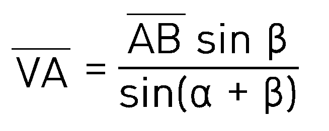
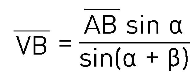
- the reference point of the first camera module 310 is referred to as point A
- the reference point of the second camera module 320 is referred to as point B
- the location of the vehicle's license plate is referred to as point V.
- the first lateral angle value (BAV) ⁇ between the second camera module 320 and the vehicle is confirmed, and the second lateral angle value (BAV) between the first camera module 310 and the vehicle is determined through the lateral rotation of the second camera module 320.
- Equation 1 the distance between the first and second camera modules 310 and 320 and one vehicle can be calculated as shown in Equation 2 and Equation 3 below.
- the point where the reference point and the reference plane of the first camera module 310 connecting the first camera module 310 and the reference plane meet vertically is point C
- the reference point and the reference plane of the second camera module 320 are The point where they meet vertically can be called point D.
- the point C may be a point spaced from the ground by the installation height of a license plate of a vehicle at a point that touches the ground on a first perpendicular line connecting the reference point of the first camera module 310 to the ground.
- the point D may be a point spaced apart from the ground by the installation height of a license plate of a vehicle at a point that touches the ground on a second perpendicular line connecting the reference point of the second camera module 320 to the ground.
- the reference surface may be a surface formed by points C, D, and V.
- the processor 350 checks the height AC (h 1 ) of the first camera module 310 and the height BD (h 2 ) of the second camera module 320 from the memory 340, and Check the first vertical angle value (VAC) ⁇ formed by the vehicle and the first camera module 310 and the first perpendicular line connecting the first camera module 310 and the reference plane according to the vertical rotation of 310, and check the first vertical angle value (VAC) ⁇ of the vehicle
- the second vertical angle value (VBD) ⁇ formed by the second camera module 320 and the second perpendicular line connecting the second camera module 320 and the reference surface can be confirmed. Similar to Equations 1 to 3 above, the processor 350 may calculate the distance BV between the first camera module 310 and a vehicle V and the AV between the second camera module 320 and a vehicle.
- the processor 350 detects a vehicle based on the vehicle's license plate information and detection time information included in (or related to) each captured image through the first and second camera modules 310 and 320. Corresponding captured images, first and second lateral angle values, and first and second vertical angle values can be distinguished.
- the processor 350 may transmit the determined (estimated) location information of a vehicle to the user device 140 provided in the vehicle through a second designated communication channel (short-range communication channel). .
- the processor 350 determines the communication address (e.g., MAC address) of a vehicle from the memory 340 based on the license plate information of the vehicle included in the images used to estimate the location information of the vehicle. You can.
- the processor 350 may transmit location information of a vehicle to the user device 140 provided in the vehicle based on the communication address of the vehicle.
- the processor 350 uses the first image captured by the first camera module 310 and the second image captured by the second camera module 320 as a left-eye image and a right-eye image, By using the separation distance between the first camera module 310 and the second camera module 320 as the parallax, stereo matching is performed on the first and second images to obtain a three-dimensional position coordinate value of a vehicle. It can be estimated.
- each of the first and second camera modules 310 and 320 may be equipped with a distance sensing means such as a lidar, laser, or infrared sensor.
- the processor 350 does not utilize at least some of the rotation angles of the first and second camera modules 310 and 320, and the distance to the vehicle's license plate is the first and second camera modules 310 and 320. You can estimate the 3D position coordinates of a vehicle using .
- the processor 350 estimates the three-dimensional position of a vehicle based on altitude information of the road on which the vehicle is driving from the HD map instead of the above-described first and second vertical angle values. can do.
- the processor 350 may detect the first and second camera modules 310 and 320 by triangulation based on the first and second lateral angle values and the separation distance between the first and second camera modules 310 and 320. ) Check the distance between each and the vehicle, and estimate the three-dimensional position of the vehicle based on the location of the vehicle that meets the line extending the distance from each of the first and second camera modules 310 and 320 from the HD map. .
- the processor 350 may check the altitude of the road on which a vehicle is traveling based on a change in vehicle location in an image including license plate information captured using the first and second camera modules 310 and 320. However, it is not limited to this.
- the position estimation device 300 can accurately estimate the 3D position coordinate value of the vehicle by the vehicle's external camera in a shaded area, so that even when the performance of the vehicle is not guaranteed, the location estimation device 300 The vehicle location can be accurately estimated even in cautionary sections such as .
- the position estimation device 300 may estimate 3D position coordinate values including the lane in which the vehicle driving in the shaded area is traveling based on the HD map.
- the position estimation device 300 can estimate the position of a vehicle located in a wide range of areas within the shaded area using the rotatable first and second camera modules 310 and 320. You can.
- Figure 5 shows a flowchart of a location estimation method according to one embodiment.
- the location estimation device 300 may detect a vehicle traveling on a road within the shaded section using the first and second camera modules 310 and 320.
- the location estimation device 300 may control the rotation of the first and second camera modules 310 and 320 to face one vehicle.
- the location estimation device 300 detects the second camera module 320 based on the first camera module 310 at a first point in time when the first and second camera modules 310 and 320 are facing one vehicle. Second lateral angle values between the first camera module 310 and the vehicle may be obtained based on the first lateral angle value and the second camera module 320 between the first camera module 310 and the vehicle.
- the position estimation device 300 determines the position of the first and second camera modules 310 and 320 based on perpendicular lines connecting the first and second camera modules 310 and 320 and the reference plane at the first time point. Top and bottom angle values (the first and second top and bottom angle values described above) can be obtained.
- the position estimation device 300 may estimate the 3D position coordinate value of a vehicle through triangulation based on the first and second lateral angle values and the first and second vertical angle values.
- Figure 6 is a diagram for explaining a position estimation method according to another embodiment.
- the position estimation device 300 includes only one camera module (e.g., the first camera module 310 in FIG. 3) and estimates the vehicle location by the first camera module. can do.
- the vertical angle of the first camera module 310 may be fixed.
- the memory 340 of the position estimation device 300 includes the height h of the first camera module 310, the angle ⁇ between the first camera module 310 and the reference plane (the reference plane and the tower are perpendicular), and the first camera module 310. ) stores the vertical angle ⁇ at which the vehicle license plate is viewed.
- the location estimation device 300 may detect a vehicle spaced apart from the first camera module 310 at a predetermined distance.
- first, second, or first or second may be used simply to distinguish one element from another, and may be used to distinguish such elements in other respects, such as importance or order) is not limited.
- One (e.g. first) component is said to be “coupled” or “connected” to another (e.g. second) component, with or without the terms “functionally” or “communicatively”. Where mentioned, it means that any of the components can be connected to the other components directly (e.g. wired), wirelessly, or through a third component.
- module used in this document may include a unit implemented in hardware, software, or firmware, and may be used interchangeably with terms such as logic, logic block, component, or circuit, for example.
- a module may be an integrated part or a minimum unit of the parts or a part thereof that performs one or more functions.
- the module may be implemented in the form of an application-specific integrated circuit (ASIC).
- ASIC application-specific integrated circuit
- a storage medium e.g., the memory 340 of FIG. 3
- a machine e.g., a position estimation system
- It may be implemented as software (e.g., a program) containing one or more instructions.
- a processor e.g., processor 350
- a device e.g., location estimation device 300
- the one or more instructions may include code generated by a compiler or code that can be executed by an interpreter.
- a storage medium that can be read by a device may be provided in the form of a non-transitory storage medium.
- 'non-transitory' only means that the storage medium is a tangible device and does not contain signals (e.g. electromagnetic waves). This term refers to cases where data is stored semi-permanently in the storage medium. There is no distinction between temporary storage cases.
- Computer program products are commodities and can be traded between sellers and buyers.
- the computer program product may be distributed in the form of a machine-readable storage medium (e.g. compact disc read only memory (CD-ROM)) or via an application store (e.g. Play Store TM ) or on two user devices (e.g. It can be distributed (e.g. downloaded or uploaded) directly between smartphones) or online.
- a machine-readable storage medium e.g. compact disc read only memory (CD-ROM)
- an application store e.g. Play Store TM
- two user devices e.g. It can be distributed (e.g. downloaded or uploaded) directly between smartphones) or online.
- at least a portion of the computer program product may be at least temporarily stored or temporarily created in a machine-readable storage medium, such as the memory of a manufacturer's server, an application store's server, or a relay server.
- Components according to various embodiments of this document may be implemented in the form of software or hardware such as a digital signal processor (DSP), field programmable gate array (FPGA), or application specific integrated circuit (ASIC), and perform certain roles. can do.
- DSP digital signal processor
- FPGA field programmable gate array
- ASIC application specific integrated circuit
- 'Components' are not limited to software or hardware, and each component may be configured to reside on an addressable storage medium or may be configured to run on one or more processors.
- a component may include components such as software components, object-oriented software components, class components, and task components, as well as processes, functions, properties, procedures, and subroutines. , may include segments of program code, drivers, firmware, microcode, circuitry, data, databases, data structures, tables, arrays, and variables.
- each component (eg, module or program) of the above-described components may include a single entity or a plurality of entities.
- one or more of the components or operations described above may be omitted, or one or more other components or operations may be added.
- multiple components eg, modules or programs
- the integrated component may perform one or more functions of each component of the plurality of components in the same or similar manner as those performed by the corresponding component of the plurality of components prior to the integration. .
- operations performed by a module, program, or other component may be executed sequentially, in parallel, iteratively, or heuristically, or one or more of the operations may be executed in a different order, or omitted. Alternatively, one or more other operations may be added.
Landscapes
- Engineering & Computer Science (AREA)
- Physics & Mathematics (AREA)
- General Physics & Mathematics (AREA)
- Multimedia (AREA)
- Radar, Positioning & Navigation (AREA)
- Remote Sensing (AREA)
- Theoretical Computer Science (AREA)
- Electromagnetism (AREA)
- Traffic Control Systems (AREA)
Abstract
Description
본 연구는 산업통상자원부와 한국산업기술평가관리원이 지원하는 자율주행기술개발혁신사업(20018198)으로 수행된 연구결과입니다.This study is the result of research conducted under the Autonomous Driving Technology Development and Innovation Project (20018198) supported by the Ministry of Trade, Industry and Energy and the Korea Evaluation Institute of Industrial Technology.
본 문서에서 개시되는 다양한 실시 예들은, 차량 위치 추정 기술과 관련된다.Various embodiments disclosed in this document are related to vehicle location estimation technology.
차량 위치는 GPS(global positioning system) 또는 RTK((real-time kinematic positioning)에 기반하여 추정될 수 있다. 그런데, GPS 또는 RTK 신호는 터널 안이나, 고층 빌딩으로 둘러 쌓인 도로와 같은 음영 지역에서는 수신되지 않을 수 있다.Vehicle location can be estimated based on GPS (global positioning system) or RTK (real-time kinematic positioning). However, GPS or RTK signals are not received in shaded areas, such as inside tunnels or roads surrounded by high-rise buildings. It may not work.
음영 지역에서는 GPS 수신 가능 지역에서 추정된 차량 위치와 차량의 움직임 정보를 함께 이용하여 차량 위치를 추정할 수 있다. 하지만, 해당 방식으로 추정된 차량 위치는 정확하지 않을 수 있다. 더욱이, 자율 주행 시스템과 같은 첨단 운전자 지원 장치에서는 정확한 차량 위치 추정이 매우 중요하므로 이를 위한 방안이 필요하다.In shaded areas, the vehicle location can be estimated using the vehicle location estimated in the GPS reception area and the vehicle movement information. However, the vehicle location estimated using this method may not be accurate. Moreover, accurate vehicle location estimation is very important in advanced driver assistance devices such as autonomous driving systems, so a method for this is needed.
본 문서에 개시되는 다양한 실시 예들은 음영 지역에서 차량 위치를 추정할 수 있는 위치 추정 장치 및 방법을 제공할 수 있다.Various embodiments disclosed in this document may provide a location estimation device and method that can estimate a vehicle location in a shaded area.
본 문서에 개시되는 일 실시 예에 따른 위치 추정 장치는, GPS 또는 RTK 음영 지역 내 근거리 통신 채널을 제공하는 통신 모듈; 상기 음영 지역 내 도로를 촬영 가능하도록, 상호 일정 거리 이격되고, 적어도 측방으로 회전 가능하도록 구비된 제1 및 제2 카메라 모듈; 상기 제1 카메라 모듈 상기 제2 카메라 모듈 및 상기 통신 모듈과 기능적으로 연결된 프로세서를 포함하고, 상기 프로세서는, 상기 제1 카메라 모듈을 이용하여 상기 제2 카메라 모듈과 상기 음영 지역 내 일 차량 간의 제1 측방 각도값을 획득하고, 상기 제2 카메라 모듈을 이용하여 상기 제1 카메라 모듈과 상기 일 차량 간의 제2 측방 각도값을 획득하고, 상기 제1 측방 각도값, 상기 제2 측방 각도값 및 상기 제1 및 제2 카메라 간의 이격 거리를 이용한 삼각 측량을 통해 상기 일 차량의 위치를 추정하고, 상기 근거리 통신 채널을 통해 상기 일 차량으로 상기 추정된 위치에 관련된 정보를 송신할 수 있다.A location estimation device according to an embodiment disclosed in this document includes a communication module that provides a short-range communication channel within a GPS or RTK shadow area; first and second camera modules spaced apart from each other at a predetermined distance and capable of rotating at least laterally, so as to be able to photograph a road within the shaded area; The first camera module includes a processor functionally connected to the second camera module and the communication module, and the processor uses the first camera module to detect a first camera between the second camera module and a vehicle in the shaded area. Obtain a lateral angle value, obtain a second lateral angle value between the first camera module and the one vehicle using the second camera module, and obtain the first lateral angle value, the second lateral angle value, and the first lateral angle value. The location of the vehicle may be estimated through triangulation using the separation distance between the first and second cameras, and information related to the estimated location may be transmitted to the vehicle through the short-range communication channel.
또한, 본 문서에 개시되는 일 실시 예에 따른 음영 지역 내 도로를 촬영 가능하도록, 상호 지정된 거리 이격 되어 배치되고 적어도 일 측방으로 회전 가능한 제1 및 제2 카메라 모듈을 이용한 위치 추정 방법은, 상기 제1 및 제2 카메라 모듈을 이용하여 상기 음영 구간 내 도로를 주행하는 일 차량을 검출하는 동작; 상기 제1 카메라 모듈과 상기 제2 카메라 모듈이 상기 일 차량을 향하도록 회전 제어하는 동작; 상기 제1 및 제2 카메라 모듈이 상기 일 차량을 향하는 제1 시점에 상기 제1 카메라 모듈과 상기 제2 카메라 모듈을 잇는 선을 기준으로 상기 제1 및 제2 카메라 모듈 각각과 상기 일 차량 간의 측방 각도값들을 획득하는 동작; 상기 제1 시점에 상기 제1 및 제2 카메라 모듈과 기준면을 잇는 수선들에 기준한 상기 제1 및 제2 카메라 모듈의 상하 각도값들을 획득하는 동작; 및 상기 측방 각도값들 및 상기 상하 각도값들에 기반한 삼각 측량을 통해 상기 일 차량의 위치를 추정하는 동작을 포함할 수 있다.In addition, a position estimation method using first and second camera modules that are arranged at a specified distance from each other and can rotate at least to one side so as to be able to photograph a road in a shaded area according to an embodiment disclosed in this document, An operation of detecting a vehicle driving on a road in the shaded section using first and second camera modules; Controlling the rotation of the first camera module and the second camera module to face the vehicle; A side angle between each of the first and second camera modules and the vehicle based on a line connecting the first and second camera modules at a first point in time when the first and second camera modules are facing the vehicle. An operation to obtain angle values; Obtaining vertical angle values of the first and second camera modules based on perpendicular lines connecting the first and second camera modules and a reference plane at the first time point; and estimating the location of the vehicle through triangulation based on the lateral angle values and the vertical angle values.
본 문서에 개시되는 다양한 실시 예들에 따르면, 음영 지역에서 차량 위치를 추정할 수 있다. 이 외에, 본 문서를 통해 직접적 또는 간접적으로 파악되는 다양한 효과들이 제공될 수 있다.According to various embodiments disclosed in this document, the vehicle location can be estimated in a shaded area. In addition, various effects that can be directly or indirectly identified through this document may be provided.
도 1은 일 실시예에 따른 위치 추정 장치의 구현 환경.1 is an implementation environment of a location estimation device according to an embodiment.
도 2는 일 실시예에 따른 차량 위치 검출 기법을 설명하기 위한 도면.Figure 2 is a diagram for explaining a vehicle location detection technique according to an embodiment.
도 3은 일 실시예에 따른 위치 추정 장치의 구성도.3 is a configuration diagram of a location estimation device according to an embodiment.
도 4는 일 실시예에 따른 삼각 측량 기반의 위치 추정 방법을 설명하기 위한 도면.FIG. 4 is a diagram illustrating a triangulation-based location estimation method according to an embodiment.
도 5는 일 실시예에 따른 위치 추정 기법의 흐름도.Figure 5 is a flow chart of a location estimation technique according to one embodiment.
도면의 설명과 관련하여, 동일 또는 유사한 구성요소에 대해서는 동일 또는 유사한 참조 부호가 사용될 수 있다.In relation to the description of the drawings, identical or similar reference numerals may be used for identical or similar components.
도 1은 일 실시예에 따른 위치 추정 장치의 구현 환경을 나타내고, 도 2는 일 실시예에 따른 차량 위치 검출 기법을 설명하기 위한 도면이다.FIG. 1 shows an implementation environment of a location estimation device according to an embodiment, and FIG. 2 is a diagram for explaining a vehicle location detection technique according to an embodiment.
도 1 및 도 2를 참조하면, 위치 추정 시스템(10)은 제1 고정 장치(110), 제2 고정 장치(120), 위치 추정 장치(130) 및 사용자 장치(140)를 포함할 수 있다.Referring to FIGS. 1 and 2 , the
일 실시예에 따르면, 제1 고정 장치(110) 및 제2 고정 장치(120)는 GPS, 또는 RTK 음영 지역(이하, '음영 지역'으로 언급될 수 있음)에 설치된 예컨대, CCTV 장비와 같은 카메라를 포함하는 장치일 수 있다. 상기 음영 지역은 예를 들어, 실내 주차장, 고가 도로 밑, 지하 차도, 또는 터널과 같이 GPS 신호 또는 RTK 신호를 수신 불가한 지역을 포함할 수 있다. 예를 들어, 제1 및 제2 고정 장치(110, 120)는 음영 지역 내 도로의 좌측과 우측에 각기 구비될 수 있다.According to one embodiment, the
일 실시예에 따르면, 제1 및 제2 고정 장치(110, 120)는 음영 지역 내에 일정 거리(이하, '지정된 이격 거리'로 언급될 수 있음)(예: 1m) 이상 상호 이격되어 배치될 수 있다. 예를 들어, 제1 고정 장치(110)는 음영 지역 내 도로의 제1 측방(예: 좌측)에 구비되고, 제2 고정 장치(120)는 음영 지역 내 도로의 제2 측방(예: 우측)에 구비될 수 있다. According to one embodiment, the first and
일 실시예에 따르면, 제1 및 제2 고정 장치(110, 120) 각각은 음영 지역 내 도로에서 차량의 번호판을 구분하여 촬영한 지정된 높이(h1, h2)로 구비될 수 있다. 예를 들어, 제1 및 제2 고정 장치(110, 120)(또는, 제1 및 제2 고정 장치(110, 120)에 포함된 카메라) 각각은 음영 지영 내 복수의 도로에서 주행하는 선행 차량의 번호판과 후행 차량의 번호판을 구분하여 촬영할 수 있는 높이로 구비될 수 있다.According to one embodiment, each of the first and
일 실시예에 따르면, 제1 및 제2 고정 장치(110, 120) 각각은 적어도 일 측방으로 회전 가능하도록 마련된 카메라 모듈을 포함할 수 있다. 도 2를 참조하면, 예를 들어, 제1 고정 장치(110)는 회전하면서 일 차량의 번호판을 촬영함에 따라 제1 고정 장치(110)를 기준으로 제2 고정 장치(120)와 일 차량의 번호판 간의 제1 (측방) 각도값을 감지 및 획득할 수 있다. 제2 고정 장치(120)는 회전하면서 일 차량의 번호판을 촬영함에 따라 제2 고정 장치(120)를 기준으로 제1 고정 장치(110)와 일 차량의 번호판 간의 제2 (측방) 각도값을 감지 및 획득할 수 있다. According to one embodiment, each of the first and
일 실시예에 따르면, 제1 및 제2 고정 장치(110, 120)는 제1 및 제2 고정 장치(110, 120) 각각의 식별 정보, 감지(촬영) 시간 정보, 일 차량의 번호판 정보 및 감지된 제1 및 제2 (측방/상하) 각도값을 포함하는 제1 및 제2 감지 데이터를 제1 지정된 통신 채널을 통해 위치 추정 장치(130)로 송신할 수 있다. 상기 제1 지정된 통신 채널은 예를 들어, LAN, FTTH 또는 xDSL 중 적어도 하나의 지정된 통신 채널을 포함할 수 있다. According to one embodiment, the first and
일 실시예에 따르면, 위치 추정 장치(130)를 예를 들어, 교통 정보(예: TPEG) 제공 서비스, 경로 안내 서비스(예: 티맵(TMAP)) 또는 블랙박스 데이터 기반 서비스 중 적어도 하나의 지정된 서비스를 제공하는 사업자 서버를 포함할 수 있다. 또는, 위치 추정 장치(130)는 상기 지정된 서비스를 제공하는 사업자 서버에 의해 제공되는 서비스 이용 단말일 수 있다. According to one embodiment, the
일 실시예에 따르면, 위치 추정 장치(130)는 제1 지정된 통신 채널을 통해 제1 및 제2 고정 장치(110, 120)로부터 각기 제1 및 제2 감지 데이터를 수신하고, 제1 및 제2 감지 데이터에 기반하여 일 차량의 위치를 결정(예: 추정)할 수 있다. 예를 들어, 위치 추정 장치(130)는 제1 및 제2 감지 데이터에 기반하여 제1 고정 장치(110) 기준의 제2 고정 장치(120)와 일 차량 간의 제1 측방 각도값(α) 및 제2 고정 장치 기준의 제2 고정 장치(120)와 일 차량 간의 제2 측방 각도값(β)를 확인할 수 있다. 위치 추정 장치(130)는 제1 측방 각도값(α), 제2 측방 각도값(β) 및 제1 고정 장치(110)와 제2 고정 장치 간의 이격 거리(di)를 이용한 삼각 측량을 통해 일 차량의 거리를 추정할 수 있다. According to one embodiment, the
일 실시예에 따르면, 위치 추정 장치(130)는 제1 및 제2 고정 장치(110, 120)의 3차원 위치 정보(위도, 경도, 고도), 제1 고정 장치(110)와 제2 고정 장치(120) 간의 거리(di) 및 상기 음영 지역 내 도로 정보(예: 도로의 고도)와 관련된 HD 맵을 저장할 수 있다.According to one embodiment, the
일 실시예에 따르면, 위치 추정 장치(130)는 HD 맵에 기반하여 일 차량이 주행중인 도로의 고도를 고려하여 일 차량의 위치를 추정할 수 있다. 이와 관련하여, 위치 추정 장치(130)는 제1 고정 장치(110) 및 제2 고정 장치(120)로부터 각기 제1 및 제2 감지 데이터를 수신하면, 제1 및 제2 감지 데이터에 포함된 번호판 정보에 기반하여 제1 및 제2 측방 각도값(α, β)이 동일한 일 차량에 관한 것임을 확인할 수 있다. 또한, 위치 추정 장치(130)는 제1 및 제2 감지 데이터에 포함된 감지 시간 정보에 기반하여 동일 시간에 감지된 제1 및 제2 측방 각도값을 확인할 수 있다. 또는, 위치 추정 장치(130)는 제1 및 제2 감지 데이터에 포함된 제1 고정 장치(110) 및 제2 고정 장치(120)의 식별 정보에 기반하여 기 저장(또는, 설정)된 제1 고정 장치(110)와 제2 고정 장치(120) 간의 이격 거리(di)를 확인할 수 있다. According to one embodiment, the
일 실시예에서, 위치 추정 장치(130)는 제1 고정 장치(110) 및 제2 고정 장치(120)와 기준면 간의 상하 각도(θ, δ)에 더 기반하여 일 차량의 위치를 추정할 수 있다. 그 세부 구성에 대해서는 후술한다.In one embodiment, the
일 실시예에 따르면, 위치 추정 장치(130)는 추정된 일 차량의 위치 정보(3차원 위치 정보)를 제2 지정된 통신 채널을 통해 사용자 장치(140)에 전송할 수 있다. 상기 제2 지정된 통신 채널은 예를 들어, RFID(radio frequency identification), NFC(near field communication), 블루투스, 와이파이(wifi), 또는 와이브로(wibro) 중 적어도 하나의 근거리 통신 채널을 포함할 수 있다. 이와 관련하여, 위치 추정 장치(130)는 그 적어도 일부(예: 통신 모듈)가 그 적어도 일부가 음영 지역에 구비되어, 음영 지역을 통과하는 일 차량과 근거리 통신할 수 있도록 구비될 수 있다. According to one embodiment, the
일 실시예에 따르면, 사용자 장치(140)는 위치 추정 장치(130)로부터 수신된 일 차량의 위치 정보에 기반하여 사용자(예: 운전자)에게 경로 정보 안내/저장과 같은 지정된 서비스를 제공하는 장치일 수 있다. 예를 들어, 사용자 장치(140)는 자율 주행 시스템, 운전자 지원 장치, 내비게이션 장치 또는 블랙박스와 같은 장치일 수 있다.According to one embodiment, the
다양한 실시예에 따르면, 사용자 장치(140)는 지정된 서비스를 제공하는 중에 위치 추정 장치(130)로 일 차량의 위치 정보를 요청할 수 있다. 위치 추정 장치(130)는 사용자 장치(140)의 요청에 따라 제1 고정 장치(110) 및 제2 고정 장치(120)로부터 각기 제1 및 제2 감지 데이터를 수신하고, 제1 및 제2 감지 데이터에 기반하여 일 차량의 위치 정보를 제공할 수 있다. 예를 들어, 사용자 장치(140)는 그에 구비된 관성 장치의 고장 상태나, 신뢰도 저하, 음영 지역 내 주의 구간(예: 터널 내 분기점) 또는 자체적으로 일 차량의 위치 정보를 추정 불가한(또는, 어려운) 상태를 확인하면, 위치 추정 장치(130)로 일 차량의 위치 정보를 요청할 수 있다.According to various embodiments, the
다양한 실시예에 따르면, 위치 추정 장치(130)의 동작 중 적어도 일부의 동작은 제1 고정 장치(110), 제2 고정 장치(120) 또는 사용자 장치(140) 중 적어도 하나의 장치에 의해서 수행될 수 있다. 예를 들어, 제1 고정 장치(110) 또는 제2 고정 장치(120) 중 적어도 하나가 근거리 통신 채널을 제공하는 경우, 위치 추정 장치(130)는 상기 적어도 하나의 고정 장치를 통해 일 차량에 위치 정보를 송신할 수 있다. 본 문서에서는 설명의 편의성을 위하여 위치 추정 장치(130)가 직접 일 차량에 위치 정보를 송신하는 경우를 예로 들어 설명한다. 하지만, 이에 한정되지 않는다.According to various embodiments, at least some of the operations of the
다양한 실시예에 따르면, 위치 추정 장치(130)는 제1 고정 장치(110) 또는 제2 고정 장치(120)를 포함할 수 있다. 본 문서에서는 설명의 편의성을 위하여 제1 고정 장치(110) 및 제2 고정 장치(120)가 위치 추정 장치(130)에 포함된 카메라 모듈인 경우를 예로 들어 설명한다. 하지만, 이에 한정되지 않는다.According to various embodiments, the
상술한 실시예에 따르면, 실내 주차장, 고가 도로 밑, 지하 차도, 터널 등과 같은 GPS(global positioning system) 및 RTK(real-time kinematic positioning) 음영 지역 내에 고정된 위치에 설치된 2개의 고정 장치(110, 120)를 이용하여 음영 지역 내를 주행하고 있는 차량의 위치를 계산하는 것으로 설명하였다. 하지만, 다양한 실시예에 따르면, 사용자 장치(140)는 차량에 탑재된 영상 촬영 모듈을 통해 음영 지역 내에 고정된 위치에 설치된 2개의 마커를 인식하여 획득한 2개의 각도값과 2개의 마커 간의 거리를 토대로 차량의 위치를 계산할 수도 있다.According to the above-described embodiment, two fixing devices (110, 120) was used to calculate the position of the vehicle driving within the shaded area. However, according to various embodiments, the
이와 같이, 일 실시예에 따른 위치 추정 장치(130)는 GPS 또는 RTK 음영 지역 내 도로상에 차량 위치를 감지할 수 있는 장치(예: 도 1의 제1 및 제2 고정 장치(110, 120))를 구비하거나 그와 연계하여 해당 장치의 3차원 위치 정보와 그 회전각에 기반하여 차량 위치를 정확히 추정할 수 있다.As such, the
도 3은 일 실시예에 따른 위치 추정 장치의 구성도를 나타내고, 도 4는 일 실시예에 따른 삼각 측량 기반의 위치 추정 방법을 설명하기 위한 도면이다.FIG. 3 shows a configuration diagram of a location estimation device according to an embodiment, and FIG. 4 is a diagram for explaining a triangulation-based location estimation method according to an embodiment.
도 3을 참조하면, 일 실시예에 따른 위치 추정 장치(300)는 제1 카메라 모듈(310), 제2 카메라 모듈(320), 통신 모듈(330), 메모리(340) 및 프로세서(350)를 포함할 수 있다. 일 실시 예에서, 위치 추정 장치(300)는 일부 구성요소가 생략되거나, 추가적인 구성요소를 더 포함할 수 있다. 위치 추정 장치(300)의 구성요소들 중 일부가 결합되어 하나의 개체로 구성되되, 결합 이전의 해당 구성요소들의 기능을 동일하게 수행할 수 있다. 예를 들어, 제1 카메라 모듈(310) 및 제2 카메라 모듈(320)은 적어도 하나의 제1 장치(예: 도 1의 제1 고정 장치(110) 및 제2 고정 장치(120))에 구비되고, 통신 모듈(330)의 프로세서(350) 및 메모리(340)의 적어도 일부는 제2 장치(예: 도 1의 위치 추정 장치(300))에 구비되어, 상호 제1 지정된 통신 채널을 통해 데이터를 송수신할 수 있다. 이 경우, 프로세서(350), 통신 모듈(330) 및 메모리(340)의 다른 일부는 상기 적어도 하나의 제1 장치에 포함될 수 있다. Referring to FIG. 3, the
일 실시예에 따르면, 제1 및 제2 카메라 모듈(310, 320)은 음영 지역 내 도로의 적어도 하나의 측방(예: 좌측과 우측 각각)에 상호 일정 간격 이격되어 지정된 높이로 구비될 수 있다. 상기 지정된 높이는 상호 적어도 지정된 거리(예: 1m) 이상 이격 되어 있는 선행 차량의 번호판과 후행 차량의 번호판을 각기 구분하여 감지 또는 촬영 가능한 높이(예: 약 2m)로서, 실험적으로 결정될 수 있다.According to one embodiment, the first and
일 실시예에 따르면, 제1 및 제2 카메라 모듈(310, 320)은 모터 부재를 통해 그 촬영 방향을 적어도 한 측방(예: 좌측 또는 우측)으로 회전(또는, 전환) 가능하도록 구비될 수 있다. 제1 및 제2 카메라 모듈(310, 320)은 음영 지역의 도로를 주행하는 차량 번호판을 촬영할 수 있도록 구비될 수 있다. 예를 들어, 제1 및 제2 카메라 모듈(310, 320)은 음영 지역 내 도로와 상하 방향으로 일정 각도를 가지고(또는, 상하 방향으로 회전 가능하도록 구비되어), 해당 도로를 비스듬하게 내려다보면서 촬영할 수 있도록 구비 또는 설치될 수 있다. According to one embodiment, the first and
일 실시예에 따르면, 제1 및 제2 카메라 모듈(310, 320)은 CCD(charge coupled device) 및 MOS(metal oxide semi-conductor) 중 적어도 하나의 이미지 센서를 포함할 수 있다. 제1 및 제2 카메라 모듈(310, 320)은 프로세서(350)의 제어에 따라 차량의 번호판을 촬영할 수 있다. According to one embodiment, the first and
통신 모듈(330)은 위치 추정 장치(300)와 다른 장치(예: 사용자 장치(140)) 간의 유/무선 통신 채널의 수립, 및 수립된 통신 채널을 통한 통신 수행을 지원할 수 있다. 상기 통신 채널은 예를 들어, 근거리 통신 채널(예: 제2 지정된 통신 채널)을 포함할 수 있다. 상기 근거리 통신 채널은 예를 들어, RFID(radio frequency identification), NFC(near field communication), 블루투스, 와이파이(wifi), 또는 와이브로(wibro) 중 적어도 하나의 근거리 통신 채널을 포함할 수 있다. 제1 및 제2 카메라 모듈(310, 320)과 프로세서(350)가 상호 제1 지정된 통신 채널로 연결된 경우 제1 지정된 통신 채널을 더 지원하도록 구비될 수 있다. 상기 제1 지정된 통신 채널은 예를 들어, LAN, FTTH 또는 xDSL 중 적어도 하나의 지정된 통신 채널을 포함할 수 있다. 이와 달리, 제1 지정된 채널은 원거리/근거리 통신 채널을 포함할 수 있다.The
메모리(340)는 위치 추정 장치(300)의 적어도 하나의 구성요소(예: 프로세서(350))에 의해 사용되는 다양한 데이터를 저장할 수 있다. 데이터는 예를 들어, 소프트웨어 및 이와 관련된 명령에 대한 입력 데이터 또는 출력 데이터를 포함할 수 있다. 예를 들어, 메모리(340)는 일 차량의 위치 추정을 위한 적어도 하나의 인스트럭션을 저장할 수 있다. 일 실시예에 따르면, 메모리(340)는 제1 카메라 모듈(310)의 3차원 위치에 관련된 제1 위치 정보 및 제2 카메라 모듈(320)의 3차원 위치에 관련된 제2 위치 정보를 저장할 수 있다. 메모리(340)는 제1 위치 정보 및 상기 제2 위치 정보로부터 확인된 제1 카메라 모듈(310)와 제2 카메라 모듈(320) 간의 이격 거리(di)를 더 저장할 수 있다. 메모리(340)는 제1 카메라 모듈(310)과 제2 카메라 모듈(320)의 수직 높이(h1, h2)를 더 저장할 수 있다. 메모리(340)는 제1 위치 정보 및 제2 위치 정보와 관련된 HD 맵을 저장할 수 있다. The
메모리(340)는 다양한 형태의 휘발성 메모리 또는 비휘발성 메모리를 포함할 수 있다. 예를 들어, 메모리는 ROM(read only memory) 및 RAM(random access memory)를 포함할 수 있다. 본 기재의 실시예에서 메모리는 프로세서의 내부 또는 외부에 위치할 수 있고, 메모리(340)는 이미 알려진 다양한 수단을 통해 프로세서(350)와 연결될 수 있다.
프로세서(350)는 위치 추정 장치(300)의 적어도 하나의 다른 구성요소(예: 하드웨어 또는 소프트웨어 구성요소)를 제어할 수 있고, 다양한 데이터 처리 또는 연산을 수행할 수 있다. 프로세서(350)는 예를 들어, 중앙처리장치(CPU), 그래픽처리장치(GPU), 마이크로프로세서, 애플리케이션 프로세서(application processor), 주문형 반도체(ASIC(application specific integrated circuit), FPGA(field programmable gate arrays)) 중 적어도 하나를 포함할 수 있으며, 복수의 코어를 가질 수 있다.The
일 실시예에 따르면, 프로세서(350)는 음영 지역 내 구비(설치)된 제1 카메라 모듈(310) 및 제2 카메라 모듈(320)을 통해 음영 지역 내 도로를 모니터링할 수 있다. 프로세서(350)는 촬영 영상에서 이전에 확인되지 않은 일 차량(예: 일 차량의 번호판)을 확인하면, 제1 및 제2 카메라 모듈(310, 320)를 회전시키면서 일 차량(이하, 일 차량으로 언급될 수 있음)의 번호판을 추적할 수 있다.According to one embodiment, the
일 실시예에 따르면, 프로세서(350)는 제1 카메라 모듈(310) 및 제2 카메라 모듈(320)을 상하좌우 중 적어도 한 방향으로 회전시키면서 일 차량의 번호판을 추적하면서 제1 카메라 모듈(310)의 기준점과 제2 카메라 모듈(320)의 기준점(예: 광축)이 각기 일 차량의 번호판을 향하는 상태에서 제1 카메라 모듈(310) 및 제2 카메라 모듈(320)과 일 차량 간의 제1 및 제2 측방 각도값을 획득할 수 있다. According to one embodiment, the
일 실시예에서, 프로세서(350)는 제1 카메라 모듈(310)의 기준점이 제2 카메라 모듈(320)을 향하는 제1 상태와 비교하여 제1 카메라 모듈(310)의 기준점이 일 차량의 번호판(예: 번호판의 중심선)을 향하는 제2 상태의 각도 변화를 제1 측방 각도값으로 획득할 수 있다. 이와 유사하게, 프로세서(350)는 제2 카메라 모듈(320)의 기준점이 제1 카메라 모듈(310)을 향하는 제3 상태와 비교하여 제2 카메라 모듈(320)의 기준점이 일 차량의 번호판(예: 번호판의 중심선)을 향하는 제4 상태의 각도 변화를 제2 측방 각도값으로 획득할 수 있다.In one embodiment, the
일 실시예에 따르면, 프로세서(350)는 제1 및 제2 측방 각도값(α, β)을 획득한 제1 시점에 제1 카메라 모듈(310)과 기준면 간을 잇는 제1 수선에 기준한 일 차량의 제1 상하 각도값(θ) 및 제2 카메라 모듈(320)과 기준면 간을 잇는 제2 수선에 기준한 일 차량의 제2 상하 각도값(δ)을 획득할 수 있다. According to one embodiment, the
일 실시예에 따르면, 프로세서(350)는 메모리(340)에 저장된 제1 카메라 모듈(310)과 제2 카메라 모듈(320) 간의 이격 거리와 제1 카메라 모듈(310)과 제2 카메라 모듈(320) 각각의 설치 높이(제1 높이(h1) 및 제2 높이(h2))를 확인할 수 있다. 이와 관련하여, 메모리(340)에 제1 카메라 모듈(310)의 제1 (3차원) 위치 정보 및 제2 카메라 모듈(320)의 제2 (3차원) 위치 정보가 저장된 경우, 프로세서(350)는 제1 위치 정보 및 제2 위치 정보에 기반하여 상기 이격 거리, 제1 높이 및 제2 높이를 산출할 수 있다. 상기 제1 높이(h1)는 지면과 제1 카메라 모듈(310)의 기준점 간의 간격일 수 있다. 또는, 상기 제1 높이(h1)는 제1 카메라 모듈(310)의 기준점과 지면을 잇는 제1 수선의 길이에서 일 차량의 차량 번호판과 지면 간의 간격을 뺀 높이일 수 있다. 유사하게, 상기 제2 높이(h2)는 지면과 제2 카메라 모듈(320) 간의 간격일 수 있다. 또는, 상기 제2 높이(h2)는 제2 카메라 모듈(320)의 기준점과 지면을 잇는 제2 수선의 길이에서 일 차량의 차량 번호판과 지면 간의 간격을 뺀 높이일 수 있다. 이와 관련하여, 차량의 번호판 위치는 차량에 따라 다를 수 있으므로, 프로세서(350)는 예컨대, 메모리(340)로부터 일 차량의 번호판 정보에 기반하여 차량의 번호판과 지면 간의 간격을 확인할 수 있다.According to one embodiment, the
일 실시예에 따르면, 프로세서(350)는 제1 시점에 획득된 제1 및 제2 측방 각도값 및 제1 카메라 모듈(310)과 제2 카메라 모듈(320)의 이격 거리를 이용한 제1 삼각 측량 연산, 상기 제1 시점에 획득된 제1 상하 각도값, 기준면과 제1 수선의 각도(90도) 및 제1 높이를 이용한 제2 삼각 측량 연산 및 상기 제1 시점에 획득된 제2 상하 각도값, 기준면과 제2 수선의 각도(90도) 및 제2 높이를 이용한 제3 삼각 측량 연산에 의하여 차량의 3차원 위치를 결정(추정)할 수 있다. According to one embodiment, the
도 4를 참조하면, 제1 카메라 모듈(310)의 기준점을 A점, 제2 카메라 모듈(320)의 기준점을 B점, 차량의 번호판 위치를 V점으로 칭한다. 프로세서(350)는 메모리(340)로부터 제1 카메라 모듈(310)과 제2 카메라 모듈(320) 간의 이격 거리 AB(=di)를 확인하고, 제1 카메라 모듈(310)의 측방 회전을 통해 제2 카메라 모듈(320)과 일 차량 간의 제1 측방 각도값(BAV) α를 확인하고, 제2 카메라 모듈(320)의 측방 회전을 통해 제1 카메라 모듈(310)과 일 차량 간의 제2 측방 각도값(ABV) β를 확인할 수 있다. Referring to FIG. 4, the reference point of the
<V = 180˚-(α+β)이므로, sinV=sin(α+β)일 수 있다.<V = 180˚-(α+β), so sinV=sin(α+β).
삼각형 ABC의 사인법칙에 의해서 하기 수학식 1이 성립할 수 있다.The following equation 1 can be established according to the sine law of triangle ABC.
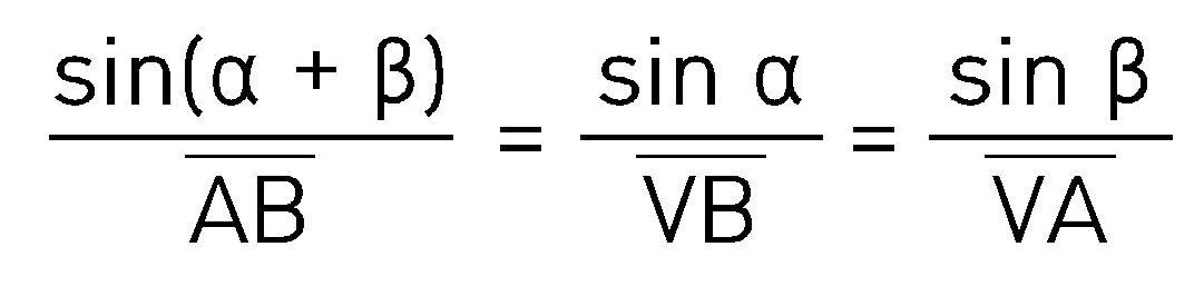
상기 수학식 1에 따라 하기 수학식 2와 수학식 3과 같이 제1 및 제2 카메라 모듈(310, 320)과 일 차량 간의 거리를 산출할 수 있다.According to Equation 1, the distance between the first and
도 4를 참조하면, 제1 카메라 모듈(310)과 기준면 간을 잇는 제1 카메라 모듈(310)의 기준점과 기준면이 수직으로 만나는 지점을 C점, 제2 카메라 모듈(320)의 기준점과 기준면이 수직으로 만나는 지점을 D점으로 칭할 수 있다. 상기 C점은 예를 들면, 제1 카메라 모듈(310)의 기준점에서 지면을 잇는 제1 수선의 지면과 닿는 지점에서 일 차량의 번호판의 설치 높이만큼 지면에서 이격된 지점일 수 있다. 상기 D점은 예를 들면, 제2 카메라 모듈(320)의 기준점에서 지면을 잇는 제2 수선의 지면과 닿는 지점에서 일 차량의 번호판의 설치 높이만큼 지면에서 이격된 지점일 수 있다. 상기 기준면은 C, D, V점에 의해 형성되는 면일 수 있다.Referring to FIG. 4, the point where the reference point and the reference plane of the
이 경우, 프로세서(350)는 메모리(340)로부터 제1 카메라 모듈(310)의 높이 AC(h1)과 제2 카메라 모듈(320)의 높이 BD(h2)를 확인하고, 제1 카메라 모듈(310)의 상하 회전에 따른 일 차량과 제1 카메라 모듈(310) 및 제1 카메라 모듈(310)과 기준면을 잇는 제1 수선이 이루는 제1 상하 각도값(VAC) θ를 확인하고, 일 차량과 제2 카메라 모듈(320) 및 제2 카메라 모듈(320)과 기준면을 잇는 제2 수선이 이루는 제2 상하 각도값(VBD) β를 확인할 수 있다. 상기 수학식 1 내지 3와 유사하게, 프로세서(350)는 제1 카메라 모듈(310)과 일 차량 V 간의 거리 BV, 제2 카메라 모듈(320)과 일 차량 간의 AV를 산출할 수 있다.In this case, the
일 실시예에 따르면, 프로세서(350)는 제1 및 제2 카메라 모듈(310, 320)을 통해 각기 촬영 영상에 포함(또는 관련)된 차량의 번호판 정보 및 감지 시간 정보에 기반하여 일 차량에 대한 서로 대응하는 촬영 영상, 제1 및 제2 측방 각도값 및 제1 및 제2 상하 각도값을 구분할 수 있다. According to one embodiment, the
일 실시예에 따르면, 프로세서(350)는 제2 지정된 통신 채널(근거리 통신 채널)을 통해 상기 결(추)정된 일 차량의 위치 정보를 일 차량에 구비된 사용자 장치(140)로 송신할 수 있다. 이와 관련하여, 프로세서(350)는 일 차량의 위치 정보의 추정에 사용된 영상들에 포함된 일 차량의 번호판 정보에 기반하여 메모리(340)로부터 일 차량의 통신 주소(예: MAC address)를 확인할 수 있다. 프로세서(350)는 일 차량의 통신 주소에 기반하여 일 차량에 구비된 사용자 장치(140)로 일 차량의 위치 정보를 송신할 수 있다.According to one embodiment, the
다양한 실시예에 따르면, 프로세서(350)는 제1 카메라 모듈(310)에 의해 촬영된 제1 영상 및 제2 카메라 모듈(320)에 의해 촬영된 제2 영상을 좌안 영상과 우안 영산을 사용하고, 제1 카메라 모듈(310)과 제2 카메라 모듈(320) 간의 이격 거리를 시차로 사용함에 따라 제1 및 제2 영상을 스테레오 정합(stereo matching)을 수행함에 따라 일 차량의 3차원 위치 좌표값을 추정할 수 있다.According to various embodiments, the
다양한 실시예에 따르면, 제1 및 제2 카메라 모듈(310, 320) 각각은 라이더, 레이저 또는 적외선 센서와 같은 거리 감지 수단과 함께 구비될 수 있다. 이 경우, 프로세서(350)는 제1 및 제2 카메라 모듈(310, 320)의 회전각 중 적어도 일부는 활용하지 않고, 제1 및 제2 카메라 모듈(310, 320)일 차량의 번호판에 이르는 거리를 활용하여 일 차량의 3차원 위치 좌표값을 추정할 수 있다.According to various embodiments, each of the first and
다양한 실시예에 따르면, 프로세서(350)는 상술된 제1 상하 각도값 및 제2 상하 각도값을 대신하여 HD 맵으로부터 일 차량이 주행중인 도로의 고도 정보에 기반하여 일 차량의 3차원 위치를 추정할 수 있다. 예를 들어, 프로세서(350)는 제1 및 제2 측방 각도값과 제1 및 제2 카메라 모듈(310, 320) 간의 이격 거리에 기반한 삼각 측량에 의하여 제1 및 제2 카메라 모듈(310, 320) 각각과 차량 간의 거리를 확인하고, HD 맵으부터 제1 및 제2 카메라 모듈(310, 320) 각각으로부터 해당 거리를 연장한 선과 만나는 일 차량의 위치에 기반하여 차량 3차원 위치를 추정할 수 있다. 또는, 프로세서(350)는 제1 및 제2 카메라 모듈(310, 320)을 이용하여 촬영된 번호판 정보를 포함하는 영상에서 차량 위치 변화에 기반하여 일 차량이 주행중인 도로의 고도를 확인할 수 있다. 하지만, 이에 한정되지 않는다.According to various embodiments, the
이와 같이, 일 실시예에 따른 위치 추정 장치(300)는 음영 지역에서 차량의 외부 카메라에 의해서 차량의 3차원 위치 좌표값을 정확히 추정할 수 있어, 차량의 성능이 보장되지 않는 경우에도 터널 내 분기점과 같은 주의 구간에서도 차량 위치를 정확히 추정할 수 있다.In this way, the
또한, 일 실시예에 따른 위치 추정 장치(300)는 HD 맵에 기반하여 음영 지역내 주행중인 차량이 주행중인 차선을 포함하는 3차원 위치 좌표값을 추정할 수 있다.Additionally, the
뿐만 아니라, 일 실시예에 따른 위치 추정 장치(300)는 회전 가능한 제1 및 제2 카메라 모듈(310, 320)을 이용하여 음영 지역 내 넓은 범위의 영역에 위치하는 차량에 대해 그 위치를 추정할 수 있다.In addition, the
도 5은 일 실시예에 따른 위치 추정 방법의 흐름도를 나타낸다.Figure 5 shows a flowchart of a location estimation method according to one embodiment.
도 5을 참조하면, 동작 510에서, 위치 추정 장치(300)는 제1 및 제2 카메라 모듈(310, 320)을 이용하여 상기 음영 구간 내 도로를 주행하는 일 차량을 검출할 수 있다. Referring to FIG. 5 , in
동작 520에서, 위치 추정 장치(300)는 제1 및 제2 카메라 모듈(310, 320)이 일 차량을 향하도록 그 회전을 제어할 수 있다. In
동작 530에서, 위치 추정 장치(300)는 제1 및 제2 카메라 모듈(310, 320)이 일 차량을 향하는 제1 시점에, 제1 카메라 모듈(310)을 기준으로 제2 카메라 모듈(320)과 일 차량 간의 제1 측방 각도값 및 제2 카메라 모듈(320)을 기준으로 제1 카메라 모듈(310)과 일 차량 간의 제2 측방 각도값들을 획득할 수 있다.In
동작 540에서, 위치 추정 장치(300)는 상기 제1 시점에 제1 및 제2 카메라 모듈(310, 320)과 기준면을 잇는 수선들에 기준한 제1 및 제2 카메라 모듈(310, 320)의 상하 각도값들(상술된 제1 및 제2 상하 각도값)을 획득할 수 있다.In
동작 550에서, 위치 추정 장치(300)는 제1 및 제2 측방 각도값 및 제1 및 제2 상하 각도값에 기반한 삼각 측량을 통해 일 차량의 3차원 위치 좌표값을 추정할 수 있다.In
도 6은 다른 실시예에 따른 위치 추정 방법을 설명하기 위한 도면이다.Figure 6 is a diagram for explaining a position estimation method according to another embodiment.
도 6을 참조하면, 다른 실시예에 따른 위치 추정 장치(300)는 한 대의 카메라 모듈(예: 도 3의 제1 카메라 모듈(310))만을 포함하고, 제1 카메라 모듈에 의해 차량 위치를 추정할 수 있다. 이 경우, 제1 카메라 모듈(310)의 상하 각도는 고정될 수 있다. Referring to FIG. 6, the
위치 추정 장치(300)의 메모리(340)는 제1 카메라 모듈(310)의 높이 h, 제1 카메라 모듈(310)과 기준면 간의 각도 β (기준면과 타워는 수직함), 제1 카메라 모듈(310)이 차량 번호판을 바라보는 상하 각도 α를 저장한다. 이 경우, 프로세서(350)는 각도 θ = 180 -(α + β)를 알고 있으므로, B(x1, y1) 및 C(x2, y2)에 기반하여 차량의 2차원 위치 좌표값 A(x, y)을 산출할 수 있다. The
![]()
![]()
다른 실시예에 따르면, 위치 추정 장치(300)는 제1 카메라 모듈(310)과 일정 간격 이격된 일 차량을 검출할 수 있다. According to another embodiment, the
본 문서의 다양한 실시예들 및 이에 사용된 용어들은 본 문서에 기재된 기술적 특징들을 특정한 실시예들로 한정하려는 것이 아니며, 해당 실시예의 다양한 변경, 균등물, 또는 대체물을 포함하는 것으로 이해되어야 한다. 도면의 설명과 관련하여, 유사한 또는 관련된 구성요소에 대해서는 유사한 참조 부호가 사용될 수 있다. 아이템에 대응하는 명사의 단수 형은 관련된 문맥상 명백하게 다르게 지시하지 않는 한, 상기 아이템 한 개 또는 복수 개를 포함할 수 있다. 본 문서에서, "A 또는 B", "A 및 B 중 적어도 하나",“A 또는 B 중 적어도 하나”, "A, B 또는 C", "A, B 및 C 중 적어도 하나” 및 “A, B, 또는 C 중 적어도 하나"와 같은 문구들 각각은 그 문구들 중 해당하는 문구에 함께 나열된 항목들 중 어느 하나, 또는 그들의 모든 가능한 조합을 포함할 수 있다. "제1", "제2", 또는 "첫째" 또는 "둘째"와 같은 용어들은 단순히 해당 구성요소를 다른 해당 구성요소와 구분하기 위해 사용될 수 있으며, 해당 구성요소들을 다른 측면(예: 중요성 또는 순서)에서 한정하지 않는다. 어떤(예: 제1) 구성요소가 다른(예: 제2) 구성요소에, “기능적으로” 또는 “통신적으로”라는 용어와 함께 또는 이런 용어 없이, “커플드” 또는 “커넥티드”라고 언급된 경우, 그것은 상기 어떤 구성요소가 상기 다른 구성요소에 직접적으로(예: 유선으로), 무선으로, 또는 제3 구성요소를 통하여 연결될 수 있다는 것을 의미한다.The various embodiments of this document and the terms used herein are not intended to limit the technical features described in this document to specific embodiments, and should be understood to include various changes, equivalents, or replacements of the embodiments. In connection with the description of the drawings, similar reference numbers may be used for similar or related components. The singular form of a noun corresponding to an item may include one or more of the above items, unless the relevant context clearly indicates otherwise. In this document: “A or B”, “at least one of A and B”, “at least one of A or B”, “A, B or C”, “at least one of A, B and C” and “A, Each of phrases such as “at least one of B, or C” may include any one of the items listed together in the corresponding phrase, or any possible combination thereof. Terms such as "first", "second", or "first" or "second" may be used simply to distinguish one element from another, and may be used to distinguish such elements in other respects, such as importance or order) is not limited. One (e.g. first) component is said to be “coupled” or “connected” to another (e.g. second) component, with or without the terms “functionally” or “communicatively”. Where mentioned, it means that any of the components can be connected to the other components directly (e.g. wired), wirelessly, or through a third component.
본 문서에서 사용된 용어 "모듈"은 하드웨어, 소프트웨어 또는 펌웨어로 구현된 유닛을 포함할 수 있으며, 예를 들면, 로직, 논리 블록, 부품, 또는 회로와 같은 용어와 상호 호환적으로 사용될 수 있다. 모듈은, 일체로 구성된 부품 또는 하나 또는 그 이상의 기능을 수행하는, 상기 부품의 최소 단위 또는 그 일부가 될 수 있다. 예를 들면, 일실시예에 따르면, 모듈은 ASIC(application-specific integrated circuit)의 형태로 구현될 수 있다.The term “module” used in this document may include a unit implemented in hardware, software, or firmware, and may be used interchangeably with terms such as logic, logic block, component, or circuit, for example. A module may be an integrated part or a minimum unit of the parts or a part thereof that performs one or more functions. For example, according to one embodiment, the module may be implemented in the form of an application-specific integrated circuit (ASIC).
본 문서의 다양한 실시예들은 기기(machine)(예: 위치 추정 시스템) 의해 읽을 수 있는 저장 매체(storage medium)(예: 도 3의 메모리(340))(예: 내장 메모리 또는 외장 메모리)에 저장된 하나 이상의 명령어들을 포함하는 소프트웨어(예: 프로그램)로서 구현될 수 있다. 예를 들면, 기기(예: 위치 추정 장치(300))의 프로세서(예: 프로세서(350))는, 저장 매체로부터 저장된 하나 이상의 명령어들 중 적어도 하나의 명령을 호출하고, 그것을 실행할 수 있다. 이것은 기기가 상기 호출된 적어도 하나의 명령어에 따라 적어도 하나의 기능을 수행하도록 운영되는 것을 가능하게 한다. 상기 하나 이상의 명령어들은 컴파일러에 의해 생성된 코드 또는 인터프리터에 의해 실행될 수 있는 코드를 포함할 수 있다. 기기로 읽을 수 있는 저장매체는, 비일시적(non-transitory) 저장매체의 형태로 제공될 수 있다. 여기서, ‘비일시적’은 저장매체가 실재(tangible)하는 장치이고, 신호(signal)(예: 전자기파)를 포함하지 않는다는 것을 의미할 뿐이며, 이 용어는 데이터가 저장매체에 반영구적으로 저장되는 경우와 임시적으로 저장되는 경우를 구분하지 않는다.Various embodiments of this document are stored in a storage medium (e.g., the
일실시예에 따르면, 본 문서에 개시된 다양한 실시예들에 따른 방법은 컴퓨터 프로그램 제품(computer program product)에 포함되어 제공될 수 있다. 컴퓨터 프로그램 제품은 상품으로서 판매자 및 구매자 간에 거래될 수 있다. 컴퓨터 프로그램 제품은 기기로 읽을 수 있는 저장 매체(예: compact disc read only memory (CD-ROM))의 형태로 배포되거나, 또는 어플리케이션 스토어(예: 플레이 스토어TM)를 통해 또는 두개의 사용자 장치들(예: 스마트폰들) 간에 직접, 온라인으로 배포(예: 다운로드 또는 업로드)될 수 있다. 온라인 배포의 경우에, 컴퓨터 프로그램 제품의 적어도 일부는 제조사의 서버, 어플리케이션 스토어의 서버, 또는 중계 서버의 메모리와 같은 기기로 읽을 수 있는 저장 매체에 적어도 일시 저장되거나, 임시적으로 생성될 수 있다.According to one embodiment, methods according to various embodiments disclosed in this document may be provided and included in a computer program product. Computer program products are commodities and can be traded between sellers and buyers. The computer program product may be distributed in the form of a machine-readable storage medium (e.g. compact disc read only memory (CD-ROM)) or via an application store (e.g. Play Store TM ) or on two user devices (e.g. It can be distributed (e.g. downloaded or uploaded) directly between smartphones) or online. In the case of online distribution, at least a portion of the computer program product may be at least temporarily stored or temporarily created in a machine-readable storage medium, such as the memory of a manufacturer's server, an application store's server, or a relay server.
본 문서의 다양한 실시예에 따른 구성 요소들은 소프트웨어 또는 DSP(digital signal processor), FPGA(Field Programmable Gate Array) 또는 ASIC(Application Specific Integrated Circuit)와 같은 하드웨어 형태로 구현될 수 있으며, 소정의 역할들을 수행할 수 있다. '구성 요소들'은 소프트웨어 또는 하드웨어에 한정되는 의미는 아니며, 각 구성 요소는 어드레싱할 수 있는 저장 매체에 있도록 구성될 수도 있고 하나 또는 그 이상의 프로세서들을 재생시키도록 구성될 수도 있다. 일 예로서 구성 요소는 소프트웨어 구성 요소들, 객체지향 소프트웨어 구성 요소들, 클래스 구성 요소들 및 태스크 구성 요소들과 같은 구성 요소들과, 프로세스들, 함수들, 속성들, 프로시저들, 서브루틴들, 프로그램 코드의 세그먼트들, 드라이버들, 펌웨어, 마이크로 코드, 회로, 데이터, 데이터베이스, 데이터 구조들, 테이블들, 어레이들 및 변수들을 포함할 수 있다. Components according to various embodiments of this document may be implemented in the form of software or hardware such as a digital signal processor (DSP), field programmable gate array (FPGA), or application specific integrated circuit (ASIC), and perform certain roles. can do. 'Components' are not limited to software or hardware, and each component may be configured to reside on an addressable storage medium or may be configured to run on one or more processors. As an example, a component may include components such as software components, object-oriented software components, class components, and task components, as well as processes, functions, properties, procedures, and subroutines. , may include segments of program code, drivers, firmware, microcode, circuitry, data, databases, data structures, tables, arrays, and variables.
다양한 실시예들에 따르면, 상기 기술한 구성요소들의 각각의 구성요소(예: 모듈 또는 프로그램)는 단수 또는 복수의 개체를 포함할 수 있다. 다양한 실시예들에 따르면, 전술한 해당 구성요소들 중 하나 이상의 구성요소들 또는 동작들이 생략되거나, 또는 하나 이상의 다른 구성요소들 또는 동작들이 추가될 수 있다. 대체적으로 또는 추가적으로, 복수의 구성요소들(예: 모듈 또는 프로그램)은 하나의 구성요소로 통합될 수 있다. 이런 경우, 통합된 구성요소는 상기 복수의 구성요소들 각각의 구성요소의 하나 이상의 기능들을 상기 통합 이전에 상기 복수의 구성요소들 중 해당 구성요소에 의해 수행되는 것과 동일 또는 유사하게 수행할 수 있다. 다양한 실시예들에 따르면, 모듈, 프로그램 또는 다른 구성요소에 의해 수행되는 동작들은 순차적으로, 병렬적으로, 반복적으로, 또는 휴리스틱하게 실행되거나, 상기 동작들 중 하나 이상이 다른 순서로 실행되거나, 생략되거나, 또는 하나 이상의 다른 동작들이 추가될 수 있다.According to various embodiments, each component (eg, module or program) of the above-described components may include a single entity or a plurality of entities. According to various embodiments, one or more of the components or operations described above may be omitted, or one or more other components or operations may be added. Alternatively or additionally, multiple components (eg, modules or programs) may be integrated into a single component. In this case, the integrated component may perform one or more functions of each component of the plurality of components in the same or similar manner as those performed by the corresponding component of the plurality of components prior to the integration. . According to various embodiments, operations performed by a module, program, or other component may be executed sequentially, in parallel, iteratively, or heuristically, or one or more of the operations may be executed in a different order, or omitted. Alternatively, one or more other operations may be added.
Claims (10)
Applications Claiming Priority (4)
| Application Number | Priority Date | Filing Date | Title |
|---|---|---|---|
| KR20220098513 | 2022-08-08 | ||
| KR10-2022-0098513 | 2022-08-08 | ||
| KR1020230100709A KR102651108B1 (en) | 2022-08-08 | 2023-08-01 | Apparatus and Method for Estimating Position |
| KR10-2023-0100709 | 2023-08-01 |
Publications (1)
| Publication Number | Publication Date |
|---|---|
| WO2024035041A1 true WO2024035041A1 (en) | 2024-02-15 |
Family
ID=89851973
Family Applications (1)
| Application Number | Title | Priority Date | Filing Date |
|---|---|---|---|
| PCT/KR2023/011603 Ceased WO2024035041A1 (en) | 2022-08-08 | 2023-08-07 | Position estimating device and method |
Country Status (1)
| Country | Link |
|---|---|
| WO (1) | WO2024035041A1 (en) |
Citations (7)
| Publication number | Priority date | Publication date | Assignee | Title |
|---|---|---|---|---|
| JP2008252643A (en) * | 2007-03-30 | 2008-10-16 | Toshiba Corp | Mobile object monitoring system and monitoring method thereof |
| US20120105644A1 (en) * | 2010-10-28 | 2012-05-03 | Disney Enterprises, Inc. | Automated Personalized Imaging System |
| KR20160002178A (en) * | 2014-06-30 | 2016-01-07 | 현대자동차주식회사 | Apparatus and method for self-localization of vehicle |
| KR20160040036A (en) * | 2014-10-02 | 2016-04-12 | (주) 키움소프트 | A car number plate recognition method and recognition device that uses a number of IP cameras |
| KR20170100892A (en) * | 2016-02-26 | 2017-09-05 | 한화테크윈 주식회사 | Position Tracking Apparatus |
| KR20200044420A (en) * | 2018-10-19 | 2020-04-29 | 삼성전자주식회사 | Method and device to estimate position |
| KR20200094818A (en) * | 2019-01-17 | 2020-08-10 | 주식회사 엠제이비전테크 | Vehicle search system based artificial intelligence |
-
2023
- 2023-08-07 WO PCT/KR2023/011603 patent/WO2024035041A1/en not_active Ceased
Patent Citations (7)
| Publication number | Priority date | Publication date | Assignee | Title |
|---|---|---|---|---|
| JP2008252643A (en) * | 2007-03-30 | 2008-10-16 | Toshiba Corp | Mobile object monitoring system and monitoring method thereof |
| US20120105644A1 (en) * | 2010-10-28 | 2012-05-03 | Disney Enterprises, Inc. | Automated Personalized Imaging System |
| KR20160002178A (en) * | 2014-06-30 | 2016-01-07 | 현대자동차주식회사 | Apparatus and method for self-localization of vehicle |
| KR20160040036A (en) * | 2014-10-02 | 2016-04-12 | (주) 키움소프트 | A car number plate recognition method and recognition device that uses a number of IP cameras |
| KR20170100892A (en) * | 2016-02-26 | 2017-09-05 | 한화테크윈 주식회사 | Position Tracking Apparatus |
| KR20200044420A (en) * | 2018-10-19 | 2020-04-29 | 삼성전자주식회사 | Method and device to estimate position |
| KR20200094818A (en) * | 2019-01-17 | 2020-08-10 | 주식회사 엠제이비전테크 | Vehicle search system based artificial intelligence |
Non-Patent Citations (1)
| Title |
|---|
| LEE, CHANG-YONG; PARK, JIN-YOUNG; KWON, SO-YOUNG; LEE, YONG-HWAN: "Distance Measurement Using Two Cameras", PROCEEDINGS OF THE KOREAN SOCIETY OF INFORMATION TECHNOLOGY (KIIT) SUMMER CONFERENCE 2016, KOREAN INSTITUTE OF INFORMATION TECHNOLOGY, 30 June 2016 (2016-06-30), pages 271 - 273, XP009552775 * |
Similar Documents
| Publication | Publication Date | Title |
|---|---|---|
| CN110174093B (en) | Positioning method, device, equipment and computer readable storage medium | |
| WO2019079211A1 (en) | Lidar to camera calibration for generating high definition maps | |
| JP6532412B2 (en) | Self-position estimation system, self-position estimation method, mobile terminal, server and self-position estimation program | |
| KR101880185B1 (en) | Electronic apparatus for estimating pose of moving object and method thereof | |
| AU2019419781A1 (en) | Vehicle using spatial information acquired using sensor, sensing device using spatial information acquired using sensor, and server | |
| KR102006291B1 (en) | Method for estimating pose of moving object of electronic apparatus | |
| CN106291535A (en) | A kind of obstacle detector, robot and obstacle avoidance system | |
| JP2016157197A (en) | Self-position estimation apparatus, self-position estimation method and program | |
| WO2020141694A1 (en) | Vehicle using spatial information acquired using sensor, sensing device using spatial information acquired using sensor, and server | |
| WO2020085692A1 (en) | Apparatus of straight driving recognition for autonomous vehicle dead-reckoning performance improvement, and method thereof | |
| KR102176729B1 (en) | Position recognition method and position recognition system of vehicles | |
| WO2021060599A1 (en) | Vehicle and method for detecting lane | |
| WO2022114455A1 (en) | Device for correcting position signal of autonomous vehicle by using road surface image information | |
| KR102814112B1 (en) | An electronic device detecting a location and a method thereof | |
| JP2021047516A (en) | Information processing device, coordinate conversion system, coordinate conversion method, and coordinate conversion program | |
| WO2024035041A1 (en) | Position estimating device and method | |
| JP7287353B2 (en) | Position estimation device and position estimation computer program | |
| KR102651108B1 (en) | Apparatus and Method for Estimating Position | |
| JP7319824B2 (en) | moving body | |
| WO2023128693A1 (en) | Method and server for remotely controlling vehicle | |
| US20230080301A1 (en) | Method for determining a position of a holding area for a vehicle and for a potential passenger of the vehicle | |
| KR102159721B1 (en) | Communication apparatus providing augmented reality service using amr space position information, and control method thereof | |
| US20240183986A1 (en) | Travelable area extraction apparatus, system, and method, and non-transitory computer readable medium | |
| Somlyai et al. | Map building with rgb-d camera for mobil robot | |
| JP6789440B2 (en) | Object identification device |
Legal Events
| Date | Code | Title | Description |
|---|---|---|---|
| 121 | Ep: the epo has been informed by wipo that ep was designated in this application |
Ref document number: 23852920 Country of ref document: EP Kind code of ref document: A1 |
|
| NENP | Non-entry into the national phase |
Ref country code: DE |
|
| 122 | Ep: pct application non-entry in european phase |
Ref document number: 23852920 Country of ref document: EP Kind code of ref document: A1 |