WO2023133759A1 - Hybrid power system, and vehicle - Google Patents
Hybrid power system, and vehicle Download PDFInfo
- Publication number
- WO2023133759A1 WO2023133759A1 PCT/CN2022/071832 CN2022071832W WO2023133759A1 WO 2023133759 A1 WO2023133759 A1 WO 2023133759A1 CN 2022071832 W CN2022071832 W CN 2022071832W WO 2023133759 A1 WO2023133759 A1 WO 2023133759A1
- Authority
- WO
- WIPO (PCT)
- Prior art keywords
- gear
- power system
- hybrid power
- intermediate shaft
- hybrid
- Prior art date
- Legal status (The legal status is an assumption and is not a legal conclusion. Google has not performed a legal analysis and makes no representation as to the accuracy of the status listed.)
- Ceased
Links
Images


Classifications
-
- B—PERFORMING OPERATIONS; TRANSPORTING
- B60—VEHICLES IN GENERAL
- B60K—ARRANGEMENT OR MOUNTING OF PROPULSION UNITS OR OF TRANSMISSIONS IN VEHICLES; ARRANGEMENT OR MOUNTING OF PLURAL DIVERSE PRIME-MOVERS IN VEHICLES; AUXILIARY DRIVES FOR VEHICLES; INSTRUMENTATION OR DASHBOARDS FOR VEHICLES; ARRANGEMENTS IN CONNECTION WITH COOLING, AIR INTAKE, GAS EXHAUST OR FUEL SUPPLY OF PROPULSION UNITS IN VEHICLES
- B60K6/00—Arrangement or mounting of plural diverse prime-movers for mutual or common propulsion, e.g. hybrid propulsion systems comprising electric motors and internal combustion engines
- B60K6/20—Arrangement or mounting of plural diverse prime-movers for mutual or common propulsion, e.g. hybrid propulsion systems comprising electric motors and internal combustion engines the prime-movers consisting of electric motors and internal combustion engines, e.g. HEVs
- B60K6/22—Arrangement or mounting of plural diverse prime-movers for mutual or common propulsion, e.g. hybrid propulsion systems comprising electric motors and internal combustion engines the prime-movers consisting of electric motors and internal combustion engines, e.g. HEVs characterised by apparatus, components or means specially adapted for HEVs
- B60K6/38—Arrangement or mounting of plural diverse prime-movers for mutual or common propulsion, e.g. hybrid propulsion systems comprising electric motors and internal combustion engines the prime-movers consisting of electric motors and internal combustion engines, e.g. HEVs characterised by apparatus, components or means specially adapted for HEVs characterised by the driveline clutches
- B60K6/383—One-way clutches or freewheel devices
-
- B—PERFORMING OPERATIONS; TRANSPORTING
- B60—VEHICLES IN GENERAL
- B60K—ARRANGEMENT OR MOUNTING OF PROPULSION UNITS OR OF TRANSMISSIONS IN VEHICLES; ARRANGEMENT OR MOUNTING OF PLURAL DIVERSE PRIME-MOVERS IN VEHICLES; AUXILIARY DRIVES FOR VEHICLES; INSTRUMENTATION OR DASHBOARDS FOR VEHICLES; ARRANGEMENTS IN CONNECTION WITH COOLING, AIR INTAKE, GAS EXHAUST OR FUEL SUPPLY OF PROPULSION UNITS IN VEHICLES
- B60K6/00—Arrangement or mounting of plural diverse prime-movers for mutual or common propulsion, e.g. hybrid propulsion systems comprising electric motors and internal combustion engines
- B60K6/20—Arrangement or mounting of plural diverse prime-movers for mutual or common propulsion, e.g. hybrid propulsion systems comprising electric motors and internal combustion engines the prime-movers consisting of electric motors and internal combustion engines, e.g. HEVs
- B60K6/42—Arrangement or mounting of plural diverse prime-movers for mutual or common propulsion, e.g. hybrid propulsion systems comprising electric motors and internal combustion engines the prime-movers consisting of electric motors and internal combustion engines, e.g. HEVs characterised by the architecture of the hybrid electric vehicle
-
- F—MECHANICAL ENGINEERING; LIGHTING; HEATING; WEAPONS; BLASTING
- F16—ENGINEERING ELEMENTS AND UNITS; GENERAL MEASURES FOR PRODUCING AND MAINTAINING EFFECTIVE FUNCTIONING OF MACHINES OR INSTALLATIONS; THERMAL INSULATION IN GENERAL
- F16H—GEARING
- F16H3/00—Toothed gearings for conveying rotary motion with variable gear ratio or for reversing rotary motion
- F16H3/02—Toothed gearings for conveying rotary motion with variable gear ratio or for reversing rotary motion without gears having orbital motion
- F16H3/08—Toothed gearings for conveying rotary motion with variable gear ratio or for reversing rotary motion without gears having orbital motion exclusively or essentially with continuously meshing gears, that can be disengaged from their shafts
- F16H3/10—Toothed gearings for conveying rotary motion with variable gear ratio or for reversing rotary motion without gears having orbital motion exclusively or essentially with continuously meshing gears, that can be disengaged from their shafts with one or more one-way clutches as an essential feature
-
- Y—GENERAL TAGGING OF NEW TECHNOLOGICAL DEVELOPMENTS; GENERAL TAGGING OF CROSS-SECTIONAL TECHNOLOGIES SPANNING OVER SEVERAL SECTIONS OF THE IPC; TECHNICAL SUBJECTS COVERED BY FORMER USPC CROSS-REFERENCE ART COLLECTIONS [XRACs] AND DIGESTS
- Y02—TECHNOLOGIES OR APPLICATIONS FOR MITIGATION OR ADAPTATION AGAINST CLIMATE CHANGE
- Y02T—CLIMATE CHANGE MITIGATION TECHNOLOGIES RELATED TO TRANSPORTATION
- Y02T10/00—Road transport of goods or passengers
- Y02T10/60—Other road transportation technologies with climate change mitigation effect
- Y02T10/62—Hybrid vehicles
Definitions
- the present application relates to the field of vehicles, and more particularly to a hybrid system and a vehicle including the hybrid system.
- the above two-motor hybrid system has the following problems.
- some dual-motor hybrid systems have only one corresponding gear when the engine is used for driving, resulting in poor NVH performance and fuel economy of the hybrid system when the engine is in a high-speed state, and poor performance when the engine is in a low-speed state.
- Deterioration of power performance on the other hand, some dual-motor hybrid systems use friction clutches, which not only leads to higher costs of the entire hybrid system, but also reduces the transmission efficiency of the entire hybrid system due to the drag torque generated by the friction clutch.
- the present application is made in view of the above-mentioned drawbacks of the hybrid system.
- An object of the present application is to provide a hybrid power system, which can reduce the adverse impact on the performance of the hybrid power system due to fewer gears corresponding to the engine, and can avoid the high cost and lower transmission efficiency caused by the use of friction clutches The problem.
- Another object of the present application is to provide a vehicle including the above hybrid system.
- the present application provides a hybrid power system as follows, which includes a first motor, a second motor and a transmission, and the transmission includes:
- a first input shaft drivingly coupled to said first electric machine and adapted to be drivingly coupled to an engine
- a clutch mechanism comprising a one-way clutch and a synchronizer, the clutch mechanism capable of selectively drivingly coupling and decoupling the second countershaft from either the first countershaft or the first input shaft;
- the output assembly is coupled with the second motor and the second countershaft for driving the vehicle.
- the one-way clutch includes an outer ring and an inner ring capable of relative rotation, the outer ring is drivingly coupled with the ring gear of the synchronizer, and the inner ring is connected to the second The countershaft is drivingly coupled, and the synchronizer engagement is capable of selectively drivingly coupling the outer race to the first countershaft or drivingly coupling the outer race to the first input shaft.
- first intermediate shaft and the second intermediate shaft are arranged coaxially, and the first intermediate shaft is inserted through the second intermediate shaft.
- the output assembly includes a differential.
- the transmission further includes a first gear, a second gear, a third gear and a fourth gear, the first gear and the second gear are arranged on The first input shaft, the third gear are arranged on the first intermediate shaft in a torque-proof manner, the fourth gear is arranged on the second intermediate shaft in a non-torque-proof manner, and the fourth the gear is capable of transmission coupling with the second countershaft via the clutch mechanism,
- the first gear is always in mesh with the third gear to form a first gear pair
- the second gear is always in mesh with the fourth gear to form a second gear pair.
- the transmission ratio of the first gear pair is greater than the transmission ratio of the second gear pair
- the transmission further includes a fifth gear, which is drivingly coupled with the rotor of the first motor, and is always in a meshing state with the second gear.
- the hybrid power system further includes a control module, and the control module can control the hybrid power system so that the hybrid power system realizes a pure motor drive mode
- the hybrid system when the hybrid system is in the pure motor driving mode, the engine is in a stopped state, the first electric motor is in a stopped state, the second electric motor is in a driving state, and the one-way clutch is disengaged, so that The second electric machine transfers torque to the output assembly.
- the hybrid power system further includes a control module, and the control module is capable of controlling the hybrid power system so that the hybrid power system realizes a series drive mode,
- the engine When the hybrid power system is in the series driving mode, the engine is in the driving state, the first motor is in the generating state, the second motor is in the driving state, the one-way clutch is disengaged, and the synchronizer disengaged such that the engine drives the first electric machine to generate electricity and the second electric machine transmits torque to the output assembly.
- the hybrid power system further includes a control module, and the control module can control the hybrid power system so that the hybrid power system realizes a parallel driving mode
- the hybrid system When the hybrid system is in the parallel driving mode, the engine is in the driving state, the second electric machine is in the driving state, the one-way clutch is engaged, and the synchronizer is engaged, so that the engine and the A second electric machine transfers torque to the output assembly.
- the hybrid power system further includes a control module, and the control module can control the hybrid power system so that the hybrid power system realizes an energy recovery mode
- the engine When the hybrid power system is in the energy recovery mode, the engine is in a stopped state, the first electric motor is in a stopped state, the second electric motor is in a generating state, the one-way clutch is disengaged, and the second An electric machine receives torque from the output assembly to generate electricity.
- the present application also provides the following vehicle, which includes the hybrid power system described in any one of the above technical solutions.
- the present application provides a novel hybrid power system and a vehicle including the hybrid power system.
- the engine and the first electric machine can be permanently coupled to the first input shaft of the transmission.
- the first input shaft is always drivingly coupled with the first intermediate shaft.
- Via a clutch mechanism including a one-way clutch and a synchronizer it is possible to selectively drive-couple the first countershaft and the second countershaft or the first input shaft and the second countershaft.
- the clutch mechanism of the hybrid power system according to the present application is composed of a one-way clutch and a synchronizer, omitting the complicated actuation system of the friction clutch of the transmission, thereby simplifying the structure and saving the cost, and improving the transmission efficiency.
- the first countershaft and the second countershaft or the first input shaft and the second countershaft can be selectively drive-coupled via a clutch mechanism including a one-way clutch and a synchronizer
- the transmission includes a drive coupling with the engine.
- the corresponding at least two gears can reduce the adverse effect on the performance of the hybrid power system due to fewer gears corresponding to the engine.
- the structure of the hybrid power system of the present application also has better vehicle applicability, so that the hybrid power system can be applied to vehicles of different types and models.
- Fig. 1 is a schematic diagram showing the topology of a hybrid power system according to an embodiment of the present application.
- FIG. 2 is a schematic diagram showing a torque transmission path of the hybrid system in FIG. 1 in a pure motor driving mode, wherein the dotted line with an arrow indicates the torque transmission path.
- FIG. 3 is a schematic diagram illustrating a torque transmission path of the hybrid system in FIG. 1 in a series drive mode, wherein the dashed line with arrows indicates the torque transmission path.
- FIGS. 4A and 4B are schematic diagrams illustrating torque transmission paths of the hybrid system in FIG. 1 in a parallel drive mode, wherein dashed lines with arrows represent torque transmission paths.
- FIG. 5 is a schematic diagram showing the torque transmission path of the hybrid system in FIG. 1 in the energy recovery mode, wherein the dashed line with the arrow indicates the torque transmission path.
- transmission coupling refers to a connection between two components capable of transmitting torque, including direct connection or indirect connection between these two components unless otherwise specified.
- Anways drive connection means that the state of drive connection is always maintained between two components.
- torque-resistant connection refers to a connection in which two parts can rotate together to transmit torque
- the above-mentioned torque-resistant connection can be realized through a spline structure between a gear and a shaft.
- a hybrid power system includes an engine ICE, a first electric machine EM1 , a second electric machine EM2 , a transmission, and a battery (not shown).
- crankshaft of the engine ICE is final drive coupled with the first input shaft S1 of the transmission via a dual mass flywheel.
- the dual-mass flywheel is used to attenuate the torsional vibration from the engine ICE, and other dampers can also be used to attenuate the torsional vibration.
- the first electric machine EM1 includes a stator and a rotor capable of rotating relative to the stator, and the rotor of the first electric machine EM1 is always drivingly coupled with the first input shaft S1 of the transmission.
- the torque of the engine ICE can be transmitted to the first electric machine EM1 to drive the first electric machine EM1 to generate electricity; in addition, the torque of the first electric machine EM1 can be transmitted to the engine ICE to start the engine ICE.
- the first motor EM1 is also electrically connected to the battery. In this way, when the first electric machine EM1 is supplied with electric energy by the battery, the first electric machine EM1 can start the engine ICE as a motor; Charge.
- the first electric machine EM1 is mainly used to generate electricity to charge the battery and start the engine ICE.
- the second electric machine EM2 includes a stator and a rotor capable of rotating relative to the stator, and the rotor of the second electric machine EM2 is always drivingly coupled with the second input shaft S2 of the transmission.
- the second motor EM2 is also electrically connected to the battery. In this way, when the second electric machine EM2 is supplied with electric energy by the battery, the second electric machine EM2 can transmit driving torque to the speed changer as a motor; Charging batteries.
- the second electric machine EM2 is mainly used for driving and energy recovery.
- a transmission of a hybrid power system includes a first input shaft S1, a second input shaft S2, a first intermediate shaft S3, a second intermediate shaft S4, Gears G11, G12, G21, G22, G31, G41, G42, GE1, GE2, GDM and clutch mechanism (one-way clutch C and synchronizer SY) and differential DM.
- the first input shaft S1 can be a solid shaft extending linearly
- the second input shaft S2 can be a solid shaft extending linearly
- the first intermediate shaft S3 can be a solid shaft extending linearly
- the second input shaft S2 can be a solid shaft extending linearly
- the intermediate shaft S4 may be a hollow shaft extending linearly.
- the first intermediate shaft S3 is inserted through the second intermediate shaft S4 in a coaxial manner with the second intermediate shaft S4, and the first intermediate shaft S3 and the second intermediate shaft S4 are freely rotatable relative to each other.
- the first input shaft S1 and the second input shaft S2 are arranged parallel to and staggered with the first intermediate shaft S3 and the second intermediate shaft S4.
- the first input shaft S1 is always in driving connection with the crankshaft of the engine ICE and the rotor of the first electric machine EM1
- the second input shaft S2 is always in driving connection with the rotor of the second electric machine EM2
- the first intermediate shaft S3 and the first input shaft S1 are always in driving connection
- the second intermediate shaft S4 can be selectively connected to the first input shaft S1 or the second intermediate shaft S4 can be connected to the first intermediate shaft through the clutch mechanism.
- the gear G11 (corresponding to the first gear) is provided on the first input shaft S1 in a torque-resistant manner.
- the gear G11 is directly coupled with the first input shaft S1 and the gear G11 can rotate along with the first input shaft S1.
- the gear G31 (corresponding to the third gear) is arranged on the first intermediate shaft S3 in a torque-proof manner.
- the gear G31 is directly coupled with the first intermediate shaft S3 and the gear G31 can rotate with the first intermediate shaft S3.
- the gear G11 and the gear G31 form a first gear pair with external meshing, so that the first input shaft S1 and the first intermediate shaft S3 are always in transmission coupling.
- the gear G12 (corresponding to the second gear) is arranged on the first input shaft S1 in a torque-proof manner.
- the gear G12 is directly coupled with the first input shaft S1 and the gear G12 can rotate along with the first input shaft S1.
- the gear G41 (corresponding to the fourth gear) is disposed on the second countershaft S4 in a non-torsion-resistant manner.
- the gear G41 and the second countershaft S4 cannot directly transmit torque but can freely rotate relative to each other.
- the gear G12 and the gear G41 form a second gear pair with external meshing.
- the transmission ratio of the second gear pair is smaller than that of the first gear pair.
- the first gear pair can be used to transmit torque when the engine ICE is in a low speed state
- the second gear pair can be used to transmit torque when the engine ICE is in a high speed state, thereby improving Engine ICE performance at low speed and altitude.
- the gear GE1 (corresponding to the fifth gear) can be connected with the rotor of the first motor EM1 through the motor shaft, and the gear GE1 is always in mesh with the gear G12.
- the rotor of the first electric machine EM1 and the first input shaft S1 are always drive-coupled through the externally meshed gear pair formed by the gear GE1 and the gear G12.
- the gear G42 is arranged on the second countershaft S4 in a rotationally fixed manner, the gear G42 is in direct transmission coupling with the second countershaft S4 and the gear G42 can rotate with the second countershaft S4.
- the gear GDM is the input gear of the differential DM (output assembly), and the gear GDM and the gear G42 are always in meshing state.
- the second countershaft S4 is always drivingly coupled to the differential DM via the externally meshed gear pair formed by the gear G42 and the gear GDM.
- the gear GE2 can be in constant transmission connection with the rotor of the second electric machine EM2 through the electric machine shaft.
- the gear G21 is arranged on the second input shaft S2 in a torsion-resistant manner, the gear G21 is directly coupled with the second input shaft S2 and the gear G21 can rotate along with the second input shaft S2.
- Gear GE2 is always in mesh with gear G21.
- the rotor of the second electric machine EM2 is permanently coupled to the second input shaft S2 through the externally meshed gear pair formed by the gear GE2 and the gear G21.
- the gear G22 is arranged on the second input shaft S2 in a torsion-resistant manner, the gear G22 is directly coupled with the second input shaft S2 and the gear G22 can rotate along with the second input shaft S2.
- Gear G22 is always in mesh with gear GDM.
- the second input shaft S2 is always in transmission coupling with the differential DM via the externally meshed gear pair formed by the gear G22 and the gear GDM.
- the clutch mechanism is used to selectively drive and couple the second intermediate shaft S4 with the first input shaft S1 and the first intermediate shaft S1 .
- the clutch mechanism includes a one-way clutch C and a synchronizer SY that can be integrated together.
- the one-way clutch C may include an outer ring, an inner ring, and rollers assembled together.
- the inner ring is located radially inside the outer ring, and the inner ring and the outer ring can rotate freely with each other when the one-way clutch C is disengaged, and the inner ring and the outer ring can rotate together when the one-way clutch C is engaged, and the inner ring and the outer ring are capable of transmitting torque via the rollers located between them.
- the outer ring and the ring gear of the synchronizer SY may be in constant transmission connection through splines, and the inner ring and the second intermediate shaft S4 may be in constant transmission connection by being fixed to each other.
- the rotational speed of the outer ring toward the circumferential side is greater than that of the inner ring toward the circumferential side.
- the outer ring can be connected to the inner ring through rollers. In other cases, the one-way clutch C is disengaged.
- the synchronizer SY may include a gear hub (which may be the outer ring of the one-way clutch C), a ring gear and an engaging gear.
- the ring gear and the gear hub are always connected by splines and can slide toward both axial sides of the second intermediate shaft S4 (left and right sides in FIG. 1 ) relative to the gear hub.
- One engaging gear is arranged in a rotationally fixed manner on the first countershaft S3, the other engaging gear can be fixed to the gear G41. After the ring gear moves toward the left side in Fig.
- the ring gear can be engaged with the gear hub and an engaging gear at the same time, so that the outer ring 1 of the one-way clutch C is in contact with the first
- the intermediate shaft S3 realizes the transmission coupling, thus after the one-way clutch C is engaged, the second intermediate shaft S4 realizes the transmission coupling with the first intermediate shaft S3. After the ring gear moves toward the right side in Fig.
- the ring gear can simultaneously engage with the gear hub and another engaging gear, so that the outer ring 1 of the one-way clutch C and the gear G41 realizes the transmission coupling, thus after the one-way clutch C is engaged, the second intermediate shaft S4 and the first input shaft S1 realize the transmission coupling.
- the differential DM may be a bevel gear differential
- the gear GDM is an input gear fixed to the housing of the bevel gear differential.
- the two axle shafts protruding from the differential DM are used to connect with the two wheels of the vehicle.
- the hybrid power system shown in FIG. 1 includes a control module (not shown in the figure), which can control the hybrid power system so that the hybrid power system has multiple operating modes.
- the control module can Switching between these operating modes depends on parameters such as the driving state of the vehicle, battery charge level, etc. These operating modes include, but are not limited to, motor-only drive mode, series drive mode, parallel drive mode, and energy recovery mode.
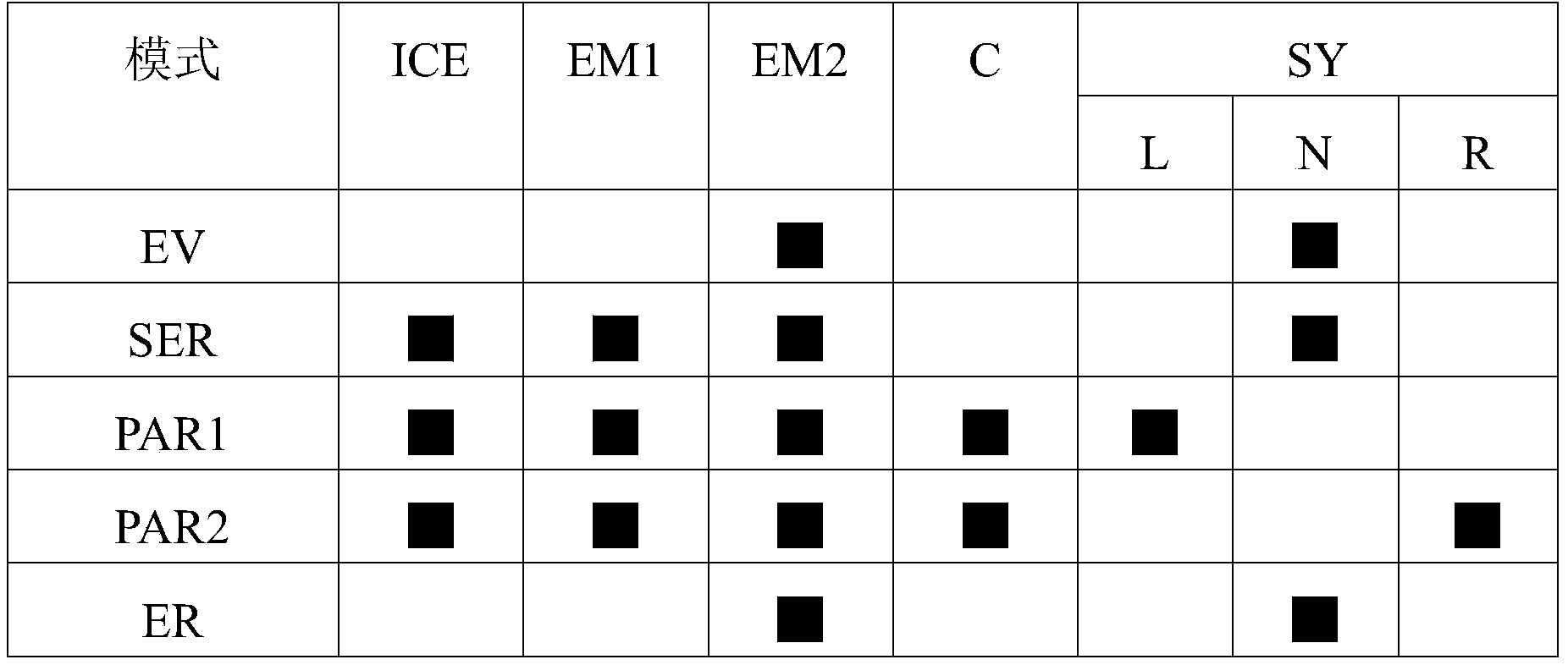
- Table 1 below shows the working states of the engine ICE, the first electric machine EM1 , the second electric machine EM2 , the one-way clutch C and the synchronizer SY in the above-mentioned exemplary working modes.
- EV means pure motor drive mode.
- SER means series drive mode
- PAR1 represents the first parallel driving mode (for the engine at low speed).
- PAR2 represents the second parallel drive mode (for the engine at high speed).
- ICE, EM1, EM2, C, and SY in the first row in Table 1 correspond to the reference numerals in Fig. 1 respectively, that is, respectively represent the engine, the first motor, the first motor in the hybrid power system in Fig. 1 Second motor, one-way clutch, synchronizer.
- control module of the hybrid power system in Fig. 1 can control the hybrid power system so that the hybrid power system can realize pure motor drive mode EV.
- the engine ICE is stopped
- the first motor EM1 is in a stopped state
- the second motor EM2 is in a driving state
- the one-way clutch C is disengaged, and the synchronizer SY can be disengaged.
- the second motor EM2 transmits torque to the differential DM for driving via gear GE2 ⁇ gear G21 ⁇ second input shaft S2 ⁇ gear G22 ⁇ gear GDM.
- the synchronizer SY can be in any state, but not necessarily in the disengaged state.
- control module of the hybrid power system in Fig. 1 can control the hybrid power system so that the hybrid power system realizes the series drive mode SER.
- Engine ICE is in driving state
- the first motor EM1 is in a power generation state
- the second motor EM2 is in a driving state
- the one-way clutch C is disengaged, and the synchronizer SY is disengaged.
- the engine ICE transmits torque to the first electric motor EM1 via the first input shaft S1 ⁇ gear G12 ⁇ gear GE1, so that the first electric motor EM1 generates electricity; the second electric motor EM2 passes through the gear GE2 ⁇ gear G21 ⁇ the second electric motor EM2
- the two input shafts S2 ⁇ gear G22 ⁇ gear GDM transmit torque to the differential DM for driving.
- both the engine ICE and the first electric machine EM1 can be in the high-efficiency working area.
- control module of the hybrid power system in FIG. 1 can control the hybrid power system so that the hybrid power system realizes the first parallel driving mode PAR1.
- the engine ICE is in a low-speed driving state
- the working state of the first motor EM1 can be adjusted as required;
- the second motor EM2 is in a driving state
- the one-way clutch C is engaged, and the synchronizer SY is engaged to the left in FIG. 1 .
- the engine ICE is driven to the ICE via the first input shaft S1 ⁇ gear G11 ⁇ gear G31 ⁇ first countershaft S3 ⁇ synchronizer SY ⁇ one-way clutch C ⁇ second countershaft S4 ⁇ gear G42 ⁇ gear GDM.
- the differential DM transmits torque for driving; if the first electric motor EM1 is in a driving state, the first electric motor EM1 via gear GE1 ⁇ gear G12 ⁇ first input shaft S1 ⁇ gear G11 ⁇ gear G31 ⁇ first intermediate shaft S3 ⁇ Synchronizer SY ⁇ one-way clutch C ⁇ second intermediate shaft S4 ⁇ gear G42 ⁇ gear GDM transmits torque to differential DM for driving; second motor EM2 via gear GE2 ⁇ gear G21 ⁇ second input shaft S2 ⁇ gear G22 ⁇ Gear GDM transmits torque to differential DM for drive.
- control module of the hybrid power system in FIG. 1 can control the hybrid power system so that the hybrid power system realizes the second parallel driving mode PAR2.
- the engine ICE is in a high-speed driving state
- the working state of the first motor EM1 can be adjusted as required;
- the second motor EM2 is in a driving state
- the one-way clutch C is engaged, and the synchronizer SY is engaged to the right in FIG. 1 .
- the engine ICE transmits torque to the differential DM via the first input shaft S1 ⁇ gear G12 ⁇ gear G41 ⁇ synchronizer SY ⁇ one-way clutch C ⁇ second intermediate shaft S4 ⁇ gear G42 ⁇ gear GDM
- the first motor EM1 if the first motor EM1 is in the driving state, the first motor EM1 will go to the The differential DM transmits torque for driving; the second electric motor EM2 transmits torque to the differential DM for driving via gear GE2 ⁇ gear G21 ⁇ second input shaft S2 ⁇ gear G22 ⁇ gear GDM.
- the rotation speed of the outer ring of the one-way clutch C can be adjusted by the first electric machine EM1 .
- gear shifting can be performed by the synchronizer SY. This is also the reason why the arrow of the torque transmission path of the first electric machine EM1 in Fig. 4A and Fig. 4B is shown as being transmitted towards the first electric machine EM1, that is, the first electric machine EM1 can be in the state of generating electricity to realize the above-mentioned regulation function.
- control module of the hybrid power system in Fig. 1 can control the hybrid power system so that the hybrid power system realizes the energy recovery mode ER.
- the engine ICE is stopped
- the first motor EM1 is in a stopped state
- the second electric machine EM2 is in the state of generating electricity
- the one-way clutch C is disengaged, and the synchronizer SY can be disengaged.
- the torque from the differential DM is transmitted to the second motor EM2 via gear GDM ⁇ gear G22 ⁇ second input shaft S2 ⁇ gear G21 ⁇ gear GE2, so that the second motor EM2 generates power.
- the synchronizer SY can be in any state, but not necessarily in the disengaged state.
- the hybrid power system of the present application can realize various working modes according to needs, so as to be applicable to various driving states of the vehicle.
- the hybrid power system according to the present application can also realize other working modes such as pure engine driving mode, charging mode while driving, and charging mode while parking.
- the hybrid power system of the present application has strong fault tolerance, even if the one-way clutch C breaks down, the hybrid power system can continue to work in a serial working mode.
- the hybrid power system of the present application is in the first parallel driving mode, the NVH performance in the low-speed state can be improved, and better acceleration performance in the low-speed state can be achieved.
- the hybrid power system of the present application is in the second parallel driving mode, the hybrid power system can improve NVH performance at high speed and have better fuel economy.
- the one-way clutch C is a roller type one-way overrunning clutch, but the application is not limited thereto, and the one-way clutch C can also be a block type one-way overrunning clutch and a rocker type one-way overrunning clutch. to the overrunning clutch, etc.
- the synchronizer SY can omit the synchronous ring in the traditional synchronizer and the corresponding frictional engagement between the engagement gear and the synchronous ring Part, only retaining the ring gear can realize the required function.
- the structure of the synchronizer SY is simplified, making the structure of the synchronizer SY more compact and reducing the engaging force of the synchronizer SY, and a complicated actuating system is omitted compared with the case of using a friction clutch.
- due to the adoption of the fixed shaft transmission it also has higher transmission efficiency.
- the present application also provides a vehicle including the above-mentioned hybrid system, which can be a plug-in hybrid vehicle or other types of hybrid vehicles, and the vehicle with the above-mentioned hybrid system can balance various driving scenarios driving performance and fuel economy.
- the hybrid power system includes a control module, and the control module can control the hybrid power system so that the hybrid power system has multiple working modes.
- the control module does not have to be mechanically integrated with the hybrid system, particularly the components or features shown in the figures, nor does the control module have to be dedicated to controlling the hybrid system.
- a control module may comprise a plurality of control units. A part of the sub-modules or control unit of the control module may be a control module or control unit of the vehicle.
Landscapes
- Engineering & Computer Science (AREA)
- Mechanical Engineering (AREA)
- General Engineering & Computer Science (AREA)
- Chemical & Material Sciences (AREA)
- Combustion & Propulsion (AREA)
- Transportation (AREA)
- Hybrid Electric Vehicles (AREA)
- Electric Propulsion And Braking For Vehicles (AREA)
Abstract
Description
本申请涉及车辆领域,更具体地涉及混合动力系统及包括该混合动力系统的车辆。The present application relates to the field of vehicles, and more particularly to a hybrid system and a vehicle including the hybrid system.
在现有的车辆中,存在多种双电机混合动力系统,用于驱动车辆行驶。在一些典型的双电机混合动力系统中,发动机和一个电机与变速器的输入轴传动联接,另一个电机与变速器的输出轴传动联接,从而构造成所谓的P1/P3混合动力系统。In existing vehicles, there are various dual-motor hybrid systems for driving the vehicle. In some typical dual-motor hybrid systems, the engine and one motor are drive-coupled to the input shaft of the transmission, and the other motor is drive-coupled to the output shaft of the transmission, thus forming a so-called P1/P3 hybrid system.
但是,在上述双电机混合动力系统中,存在如下问题。一方面,有些双电机混合动力系统在发动机用于驱动时只有一个对应的挡位,导致混合动力系统在发动机处于高速状态时的NVH性能和燃油经济性较差,并且在发动机处于低速状态时的动力性能劣化;另一方面,有些双电机混合动力系统采用摩擦离合器,不仅导致整个混合动力系统的成本较高,而且摩擦离合器产生了拖拽扭矩导致整个混合动力系统的传动效率降低。However, the above two-motor hybrid system has the following problems. On the one hand, some dual-motor hybrid systems have only one corresponding gear when the engine is used for driving, resulting in poor NVH performance and fuel economy of the hybrid system when the engine is in a high-speed state, and poor performance when the engine is in a low-speed state. Deterioration of power performance; on the other hand, some dual-motor hybrid systems use friction clutches, which not only leads to higher costs of the entire hybrid system, but also reduces the transmission efficiency of the entire hybrid system due to the drag torque generated by the friction clutch.
发明内容Contents of the invention
鉴于上述混合动力系统的缺陷而做出了本申请。本申请的一个目的在于提供一种混合动力系统,其能够减小由于对应发动机的挡位较少对混合动力系统性能的不利影响,而且能够避免采用摩擦离合器所导致的成本较高且传动效率降低的问题。本申请的另一个目的在于提供一种包括上述混合动力系统的车辆。The present application is made in view of the above-mentioned drawbacks of the hybrid system. An object of the present application is to provide a hybrid power system, which can reduce the adverse impact on the performance of the hybrid power system due to fewer gears corresponding to the engine, and can avoid the high cost and lower transmission efficiency caused by the use of friction clutches The problem. Another object of the present application is to provide a vehicle including the above hybrid system.
为了实现上述目的,本申请采用如下的技术方案。In order to achieve the above purpose, the present application adopts the following technical solutions.
本申请提供了一种如下的混合动力系统,其包括第一电机、第二电机和变速器,所述变速器包括:The present application provides a hybrid power system as follows, which includes a first motor, a second motor and a transmission, and the transmission includes:
第一输入轴,其与所述第一电机传动联接,并且用于与发动机传动联接;a first input shaft drivingly coupled to said first electric machine and adapted to be drivingly coupled to an engine;
第一中间轴,其与所述第一输入轴传动联接;a first countershaft drivingly coupled to said first input shaft;
第二中间轴;second intermediate shaft;
离合机构,其包括单向离合器和同步器,所述离合机构能够使所述第二中间轴选择性地与所述第一中间轴或所述第一输入轴传动联接和解除传动联接;以及a clutch mechanism comprising a one-way clutch and a synchronizer, the clutch mechanism capable of selectively drivingly coupling and decoupling the second countershaft from either the first countershaft or the first input shaft; and
输出组件,其与所述第二电机和所述第二中间轴传动联接,用于驱动车辆行驶。The output assembly is coupled with the second motor and the second countershaft for driving the vehicle.
在一种可选的技术方案中,所述单向离合器包括能够相对转动的外圈和内圈,所述外圈与所述同步器的齿圈传动联接,所述内圈与所述第二中间轴传动联接,所述同步器接合能够选择性地使所述外圈与所述第一中间轴传动联接或者使所述外圈与所述第一输入轴传动联接。In an optional technical solution, the one-way clutch includes an outer ring and an inner ring capable of relative rotation, the outer ring is drivingly coupled with the ring gear of the synchronizer, and the inner ring is connected to the second The countershaft is drivingly coupled, and the synchronizer engagement is capable of selectively drivingly coupling the outer race to the first countershaft or drivingly coupling the outer race to the first input shaft.
在另一种可选的技术方案中,所述第一中间轴、所述第二中间轴同轴布置,所述第一中间轴插入穿过所述第二中间轴。In another optional technical solution, the first intermediate shaft and the second intermediate shaft are arranged coaxially, and the first intermediate shaft is inserted through the second intermediate shaft.
在另一种可选的技术方案中,所述输出组件包括差速器。In another optional technical solution, the output assembly includes a differential.
在另一种可选的技术方案中,所述变速器还包括第一齿轮、第二齿轮、第三齿轮和第四齿轮,所述第一齿轮和所述第二齿轮以抗扭的方式设置于所述第一输入轴,所述第三齿轮以抗扭的方式设置于所述第一中间轴,所述第四齿轮以非抗扭的方式设置于所述第二中间轴,所述第四齿轮能够经由所述离合机构与所述第二中间轴传动联接,In another optional technical solution, the transmission further includes a first gear, a second gear, a third gear and a fourth gear, the first gear and the second gear are arranged on The first input shaft, the third gear are arranged on the first intermediate shaft in a torque-proof manner, the fourth gear is arranged on the second intermediate shaft in a non-torque-proof manner, and the fourth the gear is capable of transmission coupling with the second countershaft via the clutch mechanism,
所述第一齿轮与所述第三齿轮始终处于啮合状态以构成第一齿轮副,所述第二齿轮与所述第四齿轮始终处于啮合状态以构成第二齿轮副。The first gear is always in mesh with the third gear to form a first gear pair, and the second gear is always in mesh with the fourth gear to form a second gear pair.
在另一种可选的技术方案中,所述第一齿轮副的传动比大于所述第二齿轮副的传动比,In another optional technical solution, the transmission ratio of the first gear pair is greater than the transmission ratio of the second gear pair,
所述变速器还包括第五齿轮,所述第五齿轮与所述第一电机的转子传动联接,所述第五齿轮与所述第二齿轮始终处于啮合状态。The transmission further includes a fifth gear, which is drivingly coupled with the rotor of the first motor, and is always in a meshing state with the second gear.
在另一种可选的技术方案中,所述混合动力系统还包括控制模块,所述控制模块能够控制所述混合动力系统使所述混合动力系统实现纯电机驱动模式,In another optional technical solution, the hybrid power system further includes a control module, and the control module can control the hybrid power system so that the hybrid power system realizes a pure motor drive mode,
其中,当所述混合动力系统处于所述纯电机驱动模式时,所述发动机处于停止状态,所述第一电机处于停止状态,所述第二电机处于驱动状态,所述单向离合器分离,使得所述第二电机向所述输出组件传递扭矩。Wherein, when the hybrid system is in the pure motor driving mode, the engine is in a stopped state, the first electric motor is in a stopped state, the second electric motor is in a driving state, and the one-way clutch is disengaged, so that The second electric machine transfers torque to the output assembly.
在另一种可选的技术方案中,所述混合动力系统还包括控制模块,所述控制模块能够控制所述混合动力系统使所述混合动力系统实现串联驱动模式,In another optional technical solution, the hybrid power system further includes a control module, and the control module is capable of controlling the hybrid power system so that the hybrid power system realizes a series drive mode,
当所述混合动力系统处于所述串联驱动模式时,所述发动机处于驱动状态,所述第一电机处于发电状态,所述第二电机处于驱动状态,所述单向离合器分离,所述同步器分离,使得所述发动机驱动所述第一电机发电,所述第二电机向所述输出组件传递扭矩。When the hybrid power system is in the series driving mode, the engine is in the driving state, the first motor is in the generating state, the second motor is in the driving state, the one-way clutch is disengaged, and the synchronizer disengaged such that the engine drives the first electric machine to generate electricity and the second electric machine transmits torque to the output assembly.
在另一种可选的技术方案中,所述混合动力系统还包括控制模块,所述控制模块能够控制所述混合动力系统使所述混合动力系统实现并联驱动模式,In another optional technical solution, the hybrid power system further includes a control module, and the control module can control the hybrid power system so that the hybrid power system realizes a parallel driving mode,
当所述混合动力系统处于所述并联驱动模式时,所述发动机处于驱动状态,所述第二电机处于驱动状态,所述单向离合器接合,所述同步器接合,使得所述发动机和所述第二电机向所述输出组件传递扭矩。When the hybrid system is in the parallel driving mode, the engine is in the driving state, the second electric machine is in the driving state, the one-way clutch is engaged, and the synchronizer is engaged, so that the engine and the A second electric machine transfers torque to the output assembly.
在另一种可选的技术方案中,所述混合动力系统还包括控制模块,所述 控制模块能够控制所述混合动力系统使所述混合动力系统实现能量回收模式,In another optional technical solution, the hybrid power system further includes a control module, and the control module can control the hybrid power system so that the hybrid power system realizes an energy recovery mode,
当所述混合动力系统处于所述能量回收模式时,所述发动机处于停止状态,所述第一电机处于停止状态,所述第二电机处于发电状态,所述单向离合器分离,所述第二电机接收来自所述输出组件的扭矩而进行发电。When the hybrid power system is in the energy recovery mode, the engine is in a stopped state, the first electric motor is in a stopped state, the second electric motor is in a generating state, the one-way clutch is disengaged, and the second An electric machine receives torque from the output assembly to generate electricity.
本申请还提供了一种如下的车辆,其包括以上技术方案中任意一项技术方案所述的混合动力系统。The present application also provides the following vehicle, which includes the hybrid power system described in any one of the above technical solutions.
通过采用上述技术方案,本申请提供了一种新型的混合动力系统及包括该混合动力系统的车辆。在该混合动力系统中,发动机和第一电机与变速器的第一输入轴可以始终传动联接。在变速器中,第一输入轴与第一中间轴始终传动联接。经由包括单向离合器和同步器的离合机构,能够选择性地使第一中间轴和第二中间轴传动联接或者第一输入轴和第二中间轴传动联接。By adopting the above technical solution, the present application provides a novel hybrid power system and a vehicle including the hybrid power system. In this hybrid power system, the engine and the first electric machine can be permanently coupled to the first input shaft of the transmission. In the transmission, the first input shaft is always drivingly coupled with the first intermediate shaft. Via a clutch mechanism including a one-way clutch and a synchronizer, it is possible to selectively drive-couple the first countershaft and the second countershaft or the first input shaft and the second countershaft.
这样,根据本申请的混合动力系统的离合机构由单向离合器和同步器构成,省略了传动的摩擦离合器复杂的致动系统,由此简化了结构且节省了成本,而且改善了传动效率。进一步地,由于经由包括单向离合器和同步器的离合机构,能够选择性地使第一中间轴和第二中间轴传动联接或者第一输入轴和第二中间轴传动联接,因此变速器包括与发动机对应的至少两个挡位,从而能够减小由于对应发动机的挡位较少对混合动力系统性能的不利影响。而且,本申请的混合动力系统的构造还具有较好的车辆适用性,使得该混合动力系统能够适用于不同种类不同型号的车辆。In this way, the clutch mechanism of the hybrid power system according to the present application is composed of a one-way clutch and a synchronizer, omitting the complicated actuation system of the friction clutch of the transmission, thereby simplifying the structure and saving the cost, and improving the transmission efficiency. Further, since the first countershaft and the second countershaft or the first input shaft and the second countershaft can be selectively drive-coupled via a clutch mechanism including a one-way clutch and a synchronizer, the transmission includes a drive coupling with the engine. The corresponding at least two gears can reduce the adverse effect on the performance of the hybrid power system due to fewer gears corresponding to the engine. Moreover, the structure of the hybrid power system of the present application also has better vehicle applicability, so that the hybrid power system can be applied to vehicles of different types and models.
图1是示出了根据本申请的一实施例的混合动力系统的拓扑结构示意图。Fig. 1 is a schematic diagram showing the topology of a hybrid power system according to an embodiment of the present application.
图2是示出了图1中的混合动力系统处于纯电机驱动模式下的扭矩传递路径的示意图,其中带箭头的虚线表示扭矩传递路径。FIG. 2 is a schematic diagram showing a torque transmission path of the hybrid system in FIG. 1 in a pure motor driving mode, wherein the dotted line with an arrow indicates the torque transmission path.
图3是示出了图1中的混合动力系统处于串联驱动模式下的扭矩传递路径的示意图,其中带箭头的虚线表示扭矩传递路径。FIG. 3 is a schematic diagram illustrating a torque transmission path of the hybrid system in FIG. 1 in a series drive mode, wherein the dashed line with arrows indicates the torque transmission path.
图4A和图4B是示出了图1中的混合动力系统处于并联驱动模式下的扭矩传递路径的示意图,其中带箭头的虚线表示扭矩传递路径。FIGS. 4A and 4B are schematic diagrams illustrating torque transmission paths of the hybrid system in FIG. 1 in a parallel drive mode, wherein dashed lines with arrows represent torque transmission paths.
图5是示出了图1中的混合动力系统处于能量回收模式下的扭矩传递路径的示意图,其中带箭头的虚线表示扭矩传递路径。FIG. 5 is a schematic diagram showing the torque transmission path of the hybrid system in FIG. 1 in the energy recovery mode, wherein the dashed line with the arrow indicates the torque transmission path.
附图标记说明Explanation of reference signs
ICE发动机 EM1第一电机 EM2第二电机ICE engine EM1 first motor EM2 second motor
S1第一输入轴 S2第二输入轴 S3第一中间轴 S4第二中间轴S1 first input shaft S2 second input shaft S3 first intermediate shaft S4 second intermediate shaft
G11、G12、G21、G22、G31、G41、G42、GE1、GE2、GDM齿轮G11, G12, G21, G22, G31, G41, G42, GE1, GE2, GDM gear
C单向离合器 SY同步器 DM差速器。C one-way clutch SY synchronizer DM differential.
下面参照附图描述本申请的示例性实施例。应当理解,这些具体的说明仅用于示教本领域技术人员如何实施本申请,而不用于穷举本申请的所有可行的方式,也不用于限制本申请的范围。Exemplary embodiments of the present application are described below with reference to the accompanying drawings. It should be understood that these specific descriptions are only used to teach those skilled in the art how to implement the present application, but are not intended to exhaust all possible ways of the present application, nor are they used to limit the scope of the present application.
在本申请中,“传动联接”是指两个部件之间能够传递扭矩地连接,如无特殊说明,包括这两个部件之间直接连接或者间接连接。“始终传动联接”是指两个部件之间始终保持传动联接状态。In this application, "transmission coupling" refers to a connection between two components capable of transmitting torque, including direct connection or indirect connection between these two components unless otherwise specified. "Always drive connection" means that the state of drive connection is always maintained between two components.
在本申请中,“抗扭连接”是指两个部件能够一起转动以传递扭矩地连接,例如齿轮与轴之间通过花键结构能够实现上述抗扭连接。In the present application, "torque-resistant connection" refers to a connection in which two parts can rotate together to transmit torque, for example, the above-mentioned torque-resistant connection can be realized through a spline structure between a gear and a shaft.
以下将首先结合说明书附图说明根据本申请的一实施例的混合动力系统的结构。The structure of a hybrid power system according to an embodiment of the present application will be firstly described below with reference to the accompanying drawings.
(根据本申请的一实施例的混合动力系统的结构)(Structure of a hybrid system according to an embodiment of the present application)
如图1所示,根据本申请的一实施例的混合动力系统包括发动机ICE、第一电机EM1、第二电机EM2、变速器以及电池(未示出)。As shown in FIG. 1 , a hybrid power system according to an embodiment of the present application includes an engine ICE, a first electric machine EM1 , a second electric machine EM2 , a transmission, and a battery (not shown).
在本实施例中,发动机ICE的曲轴经由双质量飞轮与变速器的第一输入轴S1终传动联接。双质量飞轮用于衰减来自发动机ICE的扭振,还可以采用其它减振器来实现衰减扭振的功能。In this embodiment, the crankshaft of the engine ICE is final drive coupled with the first input shaft S1 of the transmission via a dual mass flywheel. The dual-mass flywheel is used to attenuate the torsional vibration from the engine ICE, and other dampers can also be used to attenuate the torsional vibration.
在本实施例中,第一电机EM1包括定子和能够相对于定子转动的转子,第一电机EM1的转子与变速器的第一输入轴S1始终传动联接。由此,发动机ICE的扭矩能够传递到第一电机EM1,以驱动第一电机EM1进行发电;另外,第一电机EM1的扭矩能够传递到发动机ICE,以启动发动机ICE。另外,第一电机EM1还与电池电连接。这样,在第一电机EM1由电池供给电能的情况下,第一电机EM1作为电动机能够启动发动机ICE;在第一电机EM1获得来自发动机ICE的扭矩的情况下,第一电机EM1作为发电机向电池充电。第一电机EM1主要用于发电以向电池充电和启动发动机ICE。In this embodiment, the first electric machine EM1 includes a stator and a rotor capable of rotating relative to the stator, and the rotor of the first electric machine EM1 is always drivingly coupled with the first input shaft S1 of the transmission. Thus, the torque of the engine ICE can be transmitted to the first electric machine EM1 to drive the first electric machine EM1 to generate electricity; in addition, the torque of the first electric machine EM1 can be transmitted to the engine ICE to start the engine ICE. In addition, the first motor EM1 is also electrically connected to the battery. In this way, when the first electric machine EM1 is supplied with electric energy by the battery, the first electric machine EM1 can start the engine ICE as a motor; Charge. The first electric machine EM1 is mainly used to generate electricity to charge the battery and start the engine ICE.
在本实施例中,第二电机EM2包括定子和能够相对于定子转动的转子,第二电机EM2的转子与变速器的第二输入轴S2始终传动联接。另外,第二电机EM2还与电池电连接。这样,在第二电机EM2由电池供给电能的情况下,第二电机EM2作为电动机能够向变速器传递驱动扭矩;在第二电机EM2获得来自变速器的扭矩的情况下,第二电机EM2作为发电机向电池充电。第二电机EM2主要用于驱动和进行能量回收。In this embodiment, the second electric machine EM2 includes a stator and a rotor capable of rotating relative to the stator, and the rotor of the second electric machine EM2 is always drivingly coupled with the second input shaft S2 of the transmission. In addition, the second motor EM2 is also electrically connected to the battery. In this way, when the second electric machine EM2 is supplied with electric energy by the battery, the second electric machine EM2 can transmit driving torque to the speed changer as a motor; Charging batteries. The second electric machine EM2 is mainly used for driving and energy recovery.
在本实施例中,如图1所示,根据本申请的一实施例的混合动力系统的变速器包括第一输入轴S1、第二输入轴S2、第一中间轴S3、第二中间轴S4、齿轮G11、G12、G21、G22、G31、G41、G42、GE1、GE2、GDM以及离合机构(单向离合器C和同步器SY)和差速器DM。In this embodiment, as shown in FIG. 1, a transmission of a hybrid power system according to an embodiment of the present application includes a first input shaft S1, a second input shaft S2, a first intermediate shaft S3, a second intermediate shaft S4, Gears G11, G12, G21, G22, G31, G41, G42, GE1, GE2, GDM and clutch mechanism (one-way clutch C and synchronizer SY) and differential DM.
如图1所示,第一输入轴S1可以为直线状延伸的实心轴,第二输入轴S2可以为直线状延伸的实心轴,第一中间轴S3可以为直线状延伸的实心轴,第 二中间轴S4可以为直线状延伸的空心轴。第一中间轴S3以与第二中间轴S4同轴的方式插入穿过第二中间轴S4,第一中间轴S3和第二中间轴S4能够相对于彼此自由转动。第一输入轴S1和第二输入轴S2与第一中间轴S3和第二中间轴S4平行且错开布置。第一输入轴S1与发动机ICE的曲轴和第一电机EM1的转子始终传动联接,第二输入轴S2与第二电机EM2的转子始终传动联接。进一步地,第一中间轴S3与第一输入轴S1始终传动联接,经由离合机构能够选择性地使第二中间轴S4与第一输入轴S1传动联接或者使第二中间轴S4与第一中间轴S3传动联接。As shown in Figure 1, the first input shaft S1 can be a solid shaft extending linearly, the second input shaft S2 can be a solid shaft extending linearly, the first intermediate shaft S3 can be a solid shaft extending linearly, and the second input shaft S2 can be a solid shaft extending linearly. The intermediate shaft S4 may be a hollow shaft extending linearly. The first intermediate shaft S3 is inserted through the second intermediate shaft S4 in a coaxial manner with the second intermediate shaft S4, and the first intermediate shaft S3 and the second intermediate shaft S4 are freely rotatable relative to each other. The first input shaft S1 and the second input shaft S2 are arranged parallel to and staggered with the first intermediate shaft S3 and the second intermediate shaft S4. The first input shaft S1 is always in driving connection with the crankshaft of the engine ICE and the rotor of the first electric machine EM1 , and the second input shaft S2 is always in driving connection with the rotor of the second electric machine EM2 . Further, the first intermediate shaft S3 and the first input shaft S1 are always in driving connection, and the second intermediate shaft S4 can be selectively connected to the first input shaft S1 or the second intermediate shaft S4 can be connected to the first intermediate shaft through the clutch mechanism. Shaft S3 transmission connection.
如图1所示,齿轮G11(对应第一齿轮)以抗扭的方式设置于第一输入轴S1。齿轮G11与第一输入轴S1直接传动联接并且齿轮G11能够随着第一输入轴S1转动。齿轮G31(对应第三齿轮)以抗扭的方式设置于第一中间轴S3。齿轮G31与第一中间轴S3直接传动联接并且齿轮G31能够随着第一中间轴S3转动。齿轮G11与齿轮G31构成外啮合的第一齿轮副,使得第一输入轴S1与第一中间轴S3始终传动联接。As shown in FIG. 1 , the gear G11 (corresponding to the first gear) is provided on the first input shaft S1 in a torque-resistant manner. The gear G11 is directly coupled with the first input shaft S1 and the gear G11 can rotate along with the first input shaft S1. The gear G31 (corresponding to the third gear) is arranged on the first intermediate shaft S3 in a torque-proof manner. The gear G31 is directly coupled with the first intermediate shaft S3 and the gear G31 can rotate with the first intermediate shaft S3. The gear G11 and the gear G31 form a first gear pair with external meshing, so that the first input shaft S1 and the first intermediate shaft S3 are always in transmission coupling.
齿轮G12(对应第二齿轮)以抗扭的方式设置于第一输入轴S1。齿轮G12与第一输入轴S1直接传动联接并且齿轮G12能够随着第一输入轴S1转动。齿轮G41(对应第四齿轮)以非抗扭的方式设置于第二中间轴S4,齿轮G41与第二中间轴S4不能直接传递扭矩而能够相对彼此自由转动。齿轮G12与齿轮G41构成外啮合的第二齿轮副。第二齿轮副的传动比小于第一齿轮副的传动比,第一齿轮副可以用于发动机ICE处于低速状态下传递扭矩,第二齿轮副可以用于发动机ICE处于高速状态下传递扭矩,从而改善发动机ICE在低速和高度状态下的性能。The gear G12 (corresponding to the second gear) is arranged on the first input shaft S1 in a torque-proof manner. The gear G12 is directly coupled with the first input shaft S1 and the gear G12 can rotate along with the first input shaft S1. The gear G41 (corresponding to the fourth gear) is disposed on the second countershaft S4 in a non-torsion-resistant manner. The gear G41 and the second countershaft S4 cannot directly transmit torque but can freely rotate relative to each other. The gear G12 and the gear G41 form a second gear pair with external meshing. The transmission ratio of the second gear pair is smaller than that of the first gear pair. The first gear pair can be used to transmit torque when the engine ICE is in a low speed state, and the second gear pair can be used to transmit torque when the engine ICE is in a high speed state, thereby improving Engine ICE performance at low speed and altitude.
齿轮GE1(对应第五齿轮)可以通过电机轴与第一电机EM1的转子始终传动联接,齿轮GE1还与齿轮G12始终处于啮合状态。由此,第一电机EM1的转子与第一输入轴S1通过齿轮GE1和齿轮G12构成的外啮合的齿轮副始终 传动联接。The gear GE1 (corresponding to the fifth gear) can be connected with the rotor of the first motor EM1 through the motor shaft, and the gear GE1 is always in mesh with the gear G12. As a result, the rotor of the first electric machine EM1 and the first input shaft S1 are always drive-coupled through the externally meshed gear pair formed by the gear GE1 and the gear G12.
齿轮G42以抗扭的方式设置于第二中间轴S4,齿轮G42与第二中间轴S4直接传动联接并且齿轮G42能够随着第二中间轴S4转动。齿轮GDM为差速器DM(输出组件)的输入齿轮,齿轮GDM与齿轮G42始终处于啮合状态。由此,第二中间轴S4与差速器DM经由齿轮G42和齿轮GDM构成的外啮合的齿轮副始终传动联接。The gear G42 is arranged on the second countershaft S4 in a rotationally fixed manner, the gear G42 is in direct transmission coupling with the second countershaft S4 and the gear G42 can rotate with the second countershaft S4. The gear GDM is the input gear of the differential DM (output assembly), and the gear GDM and the gear G42 are always in meshing state. As a result, the second countershaft S4 is always drivingly coupled to the differential DM via the externally meshed gear pair formed by the gear G42 and the gear GDM.
齿轮GE2可以通过电机轴与第二电机EM2的转子始终传动联接。齿轮G21以抗扭的方式设置于第二输入轴S2,齿轮G21与第二输入轴S2直接传动联接并且齿轮G21能够随着第二输入轴S2转动。齿轮GE2与齿轮G21始终处于啮合状态。由此,第二电机EM2的转子与第二输入轴S2通过齿轮GE2和齿轮G21构成的外啮合的齿轮副始终传动联接。The gear GE2 can be in constant transmission connection with the rotor of the second electric machine EM2 through the electric machine shaft. The gear G21 is arranged on the second input shaft S2 in a torsion-resistant manner, the gear G21 is directly coupled with the second input shaft S2 and the gear G21 can rotate along with the second input shaft S2. Gear GE2 is always in mesh with gear G21. As a result, the rotor of the second electric machine EM2 is permanently coupled to the second input shaft S2 through the externally meshed gear pair formed by the gear GE2 and the gear G21.
齿轮G22以抗扭的方式设置于第二输入轴S2,齿轮G22与第二输入轴S2直接传动联接并且齿轮G22能够随着第二输入轴S2转动。齿轮G22与齿轮GDM始终处于啮合状态。由此,第二输入轴S2与差速器DM经由齿轮G22和齿轮GDM构成的外啮合的齿轮副始终传动联接。The gear G22 is arranged on the second input shaft S2 in a torsion-resistant manner, the gear G22 is directly coupled with the second input shaft S2 and the gear G22 can rotate along with the second input shaft S2. Gear G22 is always in mesh with gear GDM. As a result, the second input shaft S2 is always in transmission coupling with the differential DM via the externally meshed gear pair formed by the gear G22 and the gear GDM.
如图1所示,离合机构用于使第二中间轴S4与第一输入轴S1和第一中间轴S1选择性地传动联接。离合机构包括可以整合在一起的单向离合器C和同步器SY。As shown in FIG. 1 , the clutch mechanism is used to selectively drive and couple the second intermediate shaft S4 with the first input shaft S1 and the first intermediate shaft S1 . The clutch mechanism includes a one-way clutch C and a synchronizer SY that can be integrated together.
具体地,单向离合器C可以包括组装在一起的外圈、内圈和滚子。内圈位于外圈的径向内侧,且在单向离合器C分离的状态下内圈和外圈能够彼此自由转动,在单向离合器C接合的状态下内圈和外圈能够一起转动且内圈和外圈能够经由位于它们之间的滚子传递扭矩。外圈与同步器SY的齿圈可以通过花键而始终传动联接,内圈与第二中间轴S4可以通过彼此固定而始终传动联接。在本实施例中,当外圈相对于内圈趋向于产生朝向周向一侧的相对转动时,也就是通俗地说外圈的朝向周向一侧的转速大于内圈朝向周向一侧的 转速时,外圈能够经由滚子与内圈传动联接。在其它情况下,单向离合器C分离。Specifically, the one-way clutch C may include an outer ring, an inner ring, and rollers assembled together. The inner ring is located radially inside the outer ring, and the inner ring and the outer ring can rotate freely with each other when the one-way clutch C is disengaged, and the inner ring and the outer ring can rotate together when the one-way clutch C is engaged, and the inner ring and the outer ring are capable of transmitting torque via the rollers located between them. The outer ring and the ring gear of the synchronizer SY may be in constant transmission connection through splines, and the inner ring and the second intermediate shaft S4 may be in constant transmission connection by being fixed to each other. In this embodiment, when the outer ring tends to produce relative rotation toward one side of the circumferential direction relative to the inner ring, that is to say, the rotational speed of the outer ring toward the circumferential side is greater than that of the inner ring toward the circumferential side. At high speed, the outer ring can be connected to the inner ring through rollers. In other cases, the one-way clutch C is disengaged.
进一步地,同步器SY可以包括齿毂(可以是单向离合器C的外圈)、齿圈和接合齿轮。齿圈与齿毂通过花键始终传动联接且能够相对于齿毂朝向第二中间轴S4的轴向两侧(图1中向左右两侧)滑动。一个接合齿轮抗扭地设置于第一中间轴S3,另一个接合齿轮可以固定于齿轮G41。当齿圈在拨叉等的致动机构的致动下朝向图1中的左侧运动之后,齿圈能够同时与齿毂和一个接合齿轮接合,使得单向离合器C的外圈1与第一中间轴S3实现传动联接,由此在单向离合器C接合之后第二中间轴S4与第一中间轴S3实现传动联接。当齿圈在拨叉等的致动机构的致动下朝向图1中的右侧运动之后,齿圈能够同时与齿毂和另一个接合齿轮接合,使得单向离合器C的外圈1与齿轮G41实现传动联接,由此在单向离合器C接合之后第二中间轴S4与第一输入轴S1实现传动联接。Further, the synchronizer SY may include a gear hub (which may be the outer ring of the one-way clutch C), a ring gear and an engaging gear. The ring gear and the gear hub are always connected by splines and can slide toward both axial sides of the second intermediate shaft S4 (left and right sides in FIG. 1 ) relative to the gear hub. One engaging gear is arranged in a rotationally fixed manner on the first countershaft S3, the other engaging gear can be fixed to the gear G41. After the ring gear moves toward the left side in Fig. 1 under the actuation of the actuating mechanism such as a shift fork, the ring gear can be engaged with the gear hub and an engaging gear at the same time, so that the
在本实施例中,如图1所示,差速器DM可以是锥齿轮差速器,齿轮GDM为固定于锥齿轮差速器的壳体的输入齿轮。从差速器DM伸出的两根半轴用于与车辆的两个车轮相连。In this embodiment, as shown in FIG. 1 , the differential DM may be a bevel gear differential, and the gear GDM is an input gear fixed to the housing of the bevel gear differential. The two axle shafts protruding from the differential DM are used to connect with the two wheels of the vehicle.
这样,通过以上结构,实现了一种新型的混合动力系统,其与包括多个离合器的双电机混合动力系统相比成本较低,而且能够降低与发动机对应的挡位较少对混合动力系统的性能的不利影响,以下将说明该混合动力系统的工作模式。In this way, through the above structure, a new type of hybrid power system is realized, which has a lower cost compared with a dual-motor hybrid power system including multiple clutches, and can reduce the impact of fewer gears corresponding to the engine on the hybrid power system. Detrimental effects on performance, the working mode of the hybrid system will be explained below.
(根据本申请的一实施例的混合动力系统的工作模式)(According to the working mode of the hybrid system of an embodiment of the present application)
图1中示出的根据本申请的一实施例的混合动力系统包括控制模块(图中未示出),该控制模块能够控制混合动力系统使得该混合动力系统具有多种工作模式,控制模块可以根据车辆的行驶状态、电池荷电水平等参数在这些工作模式之间进行切换。这些工作模式包括但不限于纯电机驱动模式、串联驱动模式、并联驱动模式和能量回收模式。The hybrid power system shown in FIG. 1 according to an embodiment of the present application includes a control module (not shown in the figure), which can control the hybrid power system so that the hybrid power system has multiple operating modes. The control module can Switching between these operating modes depends on parameters such as the driving state of the vehicle, battery charge level, etc. These operating modes include, but are not limited to, motor-only drive mode, series drive mode, parallel drive mode, and energy recovery mode.
在以下的表1中示出了上述示例性的工作模式中发动机ICE、第一电机EM1、第二电机EM2、单向离合器C和同步器SY的工作状态。Table 1 below shows the working states of the engine ICE, the first electric machine EM1 , the second electric machine EM2 , the one-way clutch C and the synchronizer SY in the above-mentioned exemplary working modes.
【表1】【Table 1】
对于以上表1中的内容进行如下说明。The contents in the above Table 1 are explained as follows.
1.关于表1中的工作模式1. About the working mode in Table 1
EV表示纯电机驱动模式。EV means pure motor drive mode.
SER表示串联驱动模式。SER means series drive mode.
PAR1表示第一并联驱动模式(用于发动机处于低速状态)。PAR1 represents the first parallel driving mode (for the engine at low speed).
PAR2表示第二并联驱动模式(用于发动机处于高速状态)。PAR2 represents the second parallel drive mode (for the engine at high speed).
ER表示能量回收模式。ER stands for Energy Recovery Mode.
2.表1中的第一行中的ICE、EM1、EM2、C、SY分别与图1中附图标记相对应,即分别表示图1中的混合动力系统中的发动机、第一电机、第二电机、单向离合器、同步器。2. ICE, EM1, EM2, C, and SY in the first row in Table 1 correspond to the reference numerals in Fig. 1 respectively, that is, respectively represent the engine, the first motor, the first motor in the hybrid power system in Fig. 1 Second motor, one-way clutch, synchronizer.
3.关于符号“█”3. About the symbol "█"
对于表1中ICE、EM1、EM2所在的列,有该符号表示发动机ICE、第一电机EM1、第二电机EM2处于工作状态,没有该符号表示发动机ICE、第一电机EM1、第二电机EM2处于非工作状态。For the column where ICE, EM1, and EM2 are located in Table 1, there is this symbol indicating that the engine ICE, the first motor EM1, and the second motor EM2 are in the working state, and the absence of this symbol indicates that the engine ICE, the first motor EM1, and the second motor EM2 are in non-working state.
对于表1中的C所在的列,有该符号表示单向离合器C接合,没有该符号表示单向离合器C分离。For the column of C in Table 1, there is this symbol indicating that the one-way clutch C is engaged, and no such symbol indicates that the one-way clutch C is disengaged.
对于表1中的SY所在的列,在与“L”对应的列中有该符号表示同步器SY向图1中的左侧接合,在与“R”对应的列中有该符号表示同步器SY向图1中的右侧接合,在与“N”对应的列中有该符号表示同步器SY位于中性的分离状态。For the column where SY is located in Table 1, the symbol in the column corresponding to "L" indicates that the synchronizer SY is engaged to the left in Figure 1, and the symbol in the column corresponding to "R" indicates the synchronizer SY engages to the right in FIG. 1, and having this symbol in the column corresponding to "N" indicates that the synchronizer SY is in a neutral disengaged state.
结合以上的表1,对图1中的混合动力系统的工作模式进行更具体的说明。In combination with Table 1 above, the working mode of the hybrid power system in FIG. 1 will be described in more detail.
如表1所示,图1中的混合动力系统的控制模块能够控制混合动力系统使混合动力系统实现纯电机驱动模式EV。As shown in Table 1, the control module of the hybrid power system in Fig. 1 can control the hybrid power system so that the hybrid power system can realize pure motor drive mode EV.
当混合动力系统处于纯电机驱动模式EV时,When the hybrid system is in pure motor drive mode EV,
发动机ICE处于停止状态;The engine ICE is stopped;
第一电机EM1处于停止状态;The first motor EM1 is in a stopped state;
第二电机EM2处于驱动状态;The second motor EM2 is in a driving state;
单向离合器C分离,同步器SY可以分离。The one-way clutch C is disengaged, and the synchronizer SY can be disengaged.
这样,如图2所示,第二电机EM2经由齿轮GE2→齿轮G21→第二输入轴S2→齿轮G22→齿轮GDM向差速器DM传递扭矩以用于驱动。In this way, as shown in FIG. 2 , the second motor EM2 transmits torque to the differential DM for driving via gear GE2→gear G21→second input shaft S2→gear G22→gear GDM.
可以理解,由于在纯电机驱动模式中单向离合器C的内圈速度始终大于外圈速度,因而使得单向离合器C保持分离状态,因此同步器SY可以处于任意状态,而不必须处于分离状态。It can be understood that since the speed of the inner ring of the one-way clutch C is always greater than the speed of the outer ring in the pure motor driving mode, thus keeping the one-way clutch C in the disengaged state, the synchronizer SY can be in any state, but not necessarily in the disengaged state.
如表1所示,图1中的混合动力系统的控制模块能够控制混合动力系统使混合动力系统实现串联驱动模式SER。As shown in Table 1, the control module of the hybrid power system in Fig. 1 can control the hybrid power system so that the hybrid power system realizes the series drive mode SER.
当混合动力系统处于串联驱动模式SER时,When the hybrid system is in the series drive mode SER,
发动机ICE处于驱动状态;Engine ICE is in driving state;
第一电机EM1处于发电状态;The first motor EM1 is in a power generation state;
第二电机EM2处于驱动状态;The second motor EM2 is in a driving state;
单向离合器C分离,同步器SY分离。The one-way clutch C is disengaged, and the synchronizer SY is disengaged.
这样,如图3所示,发动机ICE经由第一输入轴S1→齿轮G12→齿轮GE1 向第一电机EM1传递扭矩,使得第一电机EM1进行发电;第二电机EM2经由齿轮GE2→齿轮G21→第二输入轴S2→齿轮G22→齿轮GDM向差速器DM传递扭矩以用于驱动。In this way, as shown in Figure 3, the engine ICE transmits torque to the first electric motor EM1 via the first input shaft S1→gear G12→gear GE1, so that the first electric motor EM1 generates electricity; the second electric motor EM2 passes through the gear GE2→gear G21→the second electric motor EM2 The two input shafts S2→gear G22→gear GDM transmit torque to the differential DM for driving.
可以理解,由于发动机ICE利用其高速挡齿轮G12与齿轮GE1构成的齿轮副向第一电机EM1传递扭矩,由此发动机ICE和第一电机EM1两者可以都处于高效率工作区域。It can be understood that since the engine ICE transmits torque to the first electric machine EM1 through the gear pair formed by its high gear G12 and gear GE1, both the engine ICE and the first electric machine EM1 can be in the high-efficiency working area.
如表1所示,图1中的混合动力系统的控制模块能够控制混合动力系统使混合动力系统实现第一并联驱动模式PAR1。As shown in Table 1, the control module of the hybrid power system in FIG. 1 can control the hybrid power system so that the hybrid power system realizes the first parallel driving mode PAR1.
当混合动力系统处于第一并联驱动模式PAR1时,When the hybrid system is in the first parallel drive mode PAR1,
发动机ICE处于低速驱动状态;The engine ICE is in a low-speed driving state;
第一电机EM1可以根据需要调节工作状态;The working state of the first motor EM1 can be adjusted as required;
第二电机EM2处于驱动状态;The second motor EM2 is in a driving state;
单向离合器C接合,同步器SY向图1中的左侧接合。The one-way clutch C is engaged, and the synchronizer SY is engaged to the left in FIG. 1 .
这样,如图4A所示,发动机ICE经由第一输入轴S1→齿轮G11→齿轮G31→第一中间轴S3→同步器SY→单向离合器C→第二中间轴S4→齿轮G42→齿轮GDM向差速器DM传递扭矩以用于驱动;如果第一电机EM1处于驱动状态,则第一电机EM1经由齿轮GE1→齿轮G12→第一输入轴S1→齿轮G11→齿轮G31→第一中间轴S3→同步器SY→单向离合器C→第二中间轴S4→齿轮G42→齿轮GDM向差速器DM传递扭矩以用于驱动;第二电机EM2经由齿轮GE2→齿轮G21→第二输入轴S2→齿轮G22→齿轮GDM向差速器DM传递扭矩以用于驱动。In this way, as shown in FIG. 4A, the engine ICE is driven to the ICE via the first input shaft S1→gear G11→gear G31→first countershaft S3→synchronizer SY→one-way clutch C→second countershaft S4→gear G42→gear GDM. The differential DM transmits torque for driving; if the first electric motor EM1 is in a driving state, the first electric motor EM1 via gear GE1 → gear G12 → first input shaft S1 → gear G11 → gear G31 → first intermediate shaft S3 → Synchronizer SY→one-way clutch C→second intermediate shaft S4→gear G42→gear GDM transmits torque to differential DM for driving; second motor EM2 via gear GE2→gear G21→second input shaft S2→gear G22→Gear GDM transmits torque to differential DM for drive.
如表1所示,图1中的混合动力系统的控制模块能够控制混合动力系统使混合动力系统实现第二并联驱动模式PAR2。As shown in Table 1, the control module of the hybrid power system in FIG. 1 can control the hybrid power system so that the hybrid power system realizes the second parallel driving mode PAR2.
当混合动力系统处于第二并联驱动模式PAR2时,When the hybrid system is in the second parallel driving mode PAR2,
发动机ICE处于高速驱动状态;The engine ICE is in a high-speed driving state;
第一电机EM1可以根据需要调节工作状态;The working state of the first motor EM1 can be adjusted as required;
第二电机EM2处于驱动状态;The second motor EM2 is in a driving state;
单向离合器C接合,同步器SY向图1中的右侧接合。The one-way clutch C is engaged, and the synchronizer SY is engaged to the right in FIG. 1 .
这样,如图4B所示,发动机ICE经由第一输入轴S1→齿轮G12→齿轮G41→同步器SY→单向离合器C→第二中间轴S4→齿轮G42→齿轮GDM向差速器DM传递扭矩以用于驱动;如果第一电机EM1处于驱动状态,则第一电机EM1经由齿轮GE1→齿轮G12→齿轮G41→同步器SY→单向离合器C→第二中间轴S4→齿轮G42→齿轮GDM向差速器DM传递扭矩以用于驱动;第二电机EM2经由齿轮GE2→齿轮G21→第二输入轴S2→齿轮G22→齿轮GDM向差速器DM传递扭矩以用于驱动。In this way, as shown in FIG. 4B, the engine ICE transmits torque to the differential DM via the first input shaft S1→gear G12→gear G41→synchronizer SY→one-way clutch C→second intermediate shaft S4→gear G42→gear GDM For driving; if the first motor EM1 is in the driving state, the first motor EM1 will go to the The differential DM transmits torque for driving; the second electric motor EM2 transmits torque to the differential DM for driving via gear GE2→gear G21→second input shaft S2→gear G22→gear GDM.
可以理解,当混合动力系统从第一并联驱动模式PAR1向第二并联驱动模式PAR2进行转换时,可以通过第一电机EM1来调节单向离合器C的外圈的转速。在单向离合器C的外圈的转速小于内圈的转速之后,可以通过同步器SY来进行换挡。这也是在图4A和图4B中第一电机EM1的扭矩传递路径的箭头被示出为朝向第一电机EM1传递的原因,也就是第一电机EM1可以处于发电状态实现上述调节功能。It can be understood that when the hybrid power system switches from the first parallel driving mode PAR1 to the second parallel driving mode PAR2 , the rotation speed of the outer ring of the one-way clutch C can be adjusted by the first electric machine EM1 . After the rotation speed of the outer ring of the one-way clutch C is lower than the rotation speed of the inner ring, gear shifting can be performed by the synchronizer SY. This is also the reason why the arrow of the torque transmission path of the first electric machine EM1 in Fig. 4A and Fig. 4B is shown as being transmitted towards the first electric machine EM1, that is, the first electric machine EM1 can be in the state of generating electricity to realize the above-mentioned regulation function.
如表1所示,图1中的混合动力系统的控制模块能够控制混合动力系统使混合动力系统实现能量回收模式ER。As shown in Table 1, the control module of the hybrid power system in Fig. 1 can control the hybrid power system so that the hybrid power system realizes the energy recovery mode ER.
当混合动力系统处于能量回收模式ER时,When the hybrid system is in energy recovery mode ER,
发动机ICE处于停止状态;The engine ICE is stopped;
第一电机EM1处于停止状态;The first motor EM1 is in a stopped state;
第二电机EM2处于发电状态;The second electric machine EM2 is in the state of generating electricity;
单向离合器C分离,同步器SY可以分离。The one-way clutch C is disengaged, and the synchronizer SY can be disengaged.
这样,如图5所示,来自差速器DM的扭矩经由齿轮GDM→齿轮G22→第二输入轴S2→齿轮G21→齿轮GE2传递到第二电机EM2,以使得第二电机EM2进行发电。Thus, as shown in FIG. 5 , the torque from the differential DM is transmitted to the second motor EM2 via gear GDM→gear G22→second input shaft S2→gear G21→gear GE2, so that the second motor EM2 generates power.
可以理解,由于单向离合器C的内圈速度始终大于外圈速度,因而使得 单向离合器C保持分离状态,因此同步器SY可以处于任意状态,而不必须处于分离状态。It can be understood that since the speed of the inner ring of the one-way clutch C is always greater than the speed of the outer ring, the one-way clutch C remains disengaged, so the synchronizer SY can be in any state, but not necessarily in the disengaged state.
由此,本申请的混合动力系统能够根据需要实现各种工作模式,从而适用车辆的各种不同的行驶状态。Thus, the hybrid power system of the present application can realize various working modes according to needs, so as to be applicable to various driving states of the vehicle.
在以上的具体实施例中对本申请的技术方案进行了详细地阐述,以下进行补充说明。The technical solutions of the present application have been described in detail in the above specific embodiments, and supplementary descriptions are given below.
i.可以理解,根据本申请的混合动力系统还可以实现例如纯发动机驱动模式、行驶时充电模式、停车时充电模式等其它工作模式。另外,本申请的混合动力系统的容错能力强,即使单向离合器C出现故障,混合动力系统也可以采用串联工作模式继续工作。当本申请的混合动力系统处于第一并联驱动模式时,能够改善低速状态下的NVH性能,而且能够实现较好的低速状态下的加速性能。当本申请的混合动力系统处于第二并联驱动模式时,使得混合动力系统能够改善高速状态下的NVH性能并具有较好的燃油经济性。i. It can be understood that the hybrid power system according to the present application can also realize other working modes such as pure engine driving mode, charging mode while driving, and charging mode while parking. In addition, the hybrid power system of the present application has strong fault tolerance, even if the one-way clutch C breaks down, the hybrid power system can continue to work in a serial working mode. When the hybrid power system of the present application is in the first parallel driving mode, the NVH performance in the low-speed state can be improved, and better acceleration performance in the low-speed state can be achieved. When the hybrid power system of the present application is in the second parallel driving mode, the hybrid power system can improve NVH performance at high speed and have better fuel economy.
ii.在以上的实施例中说明了单向离合器C是滚子式单向超越离合器,但是本申请不限于此,该单向离合器C还可以是嵌块式单向超越离合器和摇杆式单向超越离合器等。ii. In the above embodiments, it has been described that the one-way clutch C is a roller type one-way overrunning clutch, but the application is not limited thereto, and the one-way clutch C can also be a block type one-way overrunning clutch and a rocker type one-way overrunning clutch. to the overrunning clutch, etc.
iii.由于本申请采用同步器SY配合单向离合器C实现挡位切换,基于单向离合器C的特性,同步器SY可以省略传统的同步器中的同步环以及接合齿轮与同步环对应的摩擦接合部分,只保留齿圈就能够实现所需的功能。因而,简化了同步器SY的结构,使得同步器SY的结构更紧凑且降低了同步器SY的接合力,而且与采用摩擦离合器的情况相比,省略了复杂的致动系统。进一步地,由于采用固定轴变速器,因而还具有较高的传动效率。iii. Since this application uses the synchronizer SY to cooperate with the one-way clutch C to realize gear switching, based on the characteristics of the one-way clutch C, the synchronizer SY can omit the synchronous ring in the traditional synchronizer and the corresponding frictional engagement between the engagement gear and the synchronous ring Part, only retaining the ring gear can realize the required function. Thus, the structure of the synchronizer SY is simplified, making the structure of the synchronizer SY more compact and reducing the engaging force of the synchronizer SY, and a complicated actuating system is omitted compared with the case of using a friction clutch. Furthermore, due to the adoption of the fixed shaft transmission, it also has higher transmission efficiency.
iv.本申请还提供了一种包括上述混合动力系统的车辆,该车辆可以是插电式混合动力车辆也可以是其它类型的混合动力车辆,具有上述混合动力系统的车辆能够平衡各种行驶场景下的驱动性能和燃油经济性。iv. The present application also provides a vehicle including the above-mentioned hybrid system, which can be a plug-in hybrid vehicle or other types of hybrid vehicles, and the vehicle with the above-mentioned hybrid system can balance various driving scenarios driving performance and fuel economy.
v.可以理解,虽然在上面的描述中,说明了混合动力系统包括控制模块, 该控制模块能够控制混合动力系统使得该混合动力系统具有多种工作模式。但是,该控制模块不必与混合动力系统,特别是附图中示出的各部件或特征机械地整合在一起,控制模块也不必专门用于控制混合动力系统。控制模块可以包括多个控制单元。控制模块的一部分子模块或控制单元可以是车辆的控制模块或控制单元。v. It can be understood that although in the above description, it is described that the hybrid power system includes a control module, and the control module can control the hybrid power system so that the hybrid power system has multiple working modes. However, the control module does not have to be mechanically integrated with the hybrid system, particularly the components or features shown in the figures, nor does the control module have to be dedicated to controlling the hybrid system. A control module may comprise a plurality of control units. A part of the sub-modules or control unit of the control module may be a control module or control unit of the vehicle.
Claims (11)
Priority Applications (1)
| Application Number | Priority Date | Filing Date | Title |
|---|---|---|---|
| PCT/CN2022/071832 WO2023133759A1 (en) | 2022-01-13 | 2022-01-13 | Hybrid power system, and vehicle |
Applications Claiming Priority (1)
| Application Number | Priority Date | Filing Date | Title |
|---|---|---|---|
| PCT/CN2022/071832 WO2023133759A1 (en) | 2022-01-13 | 2022-01-13 | Hybrid power system, and vehicle |
Publications (1)
| Publication Number | Publication Date |
|---|---|
| WO2023133759A1 true WO2023133759A1 (en) | 2023-07-20 |
Family
ID=87280038
Family Applications (1)
| Application Number | Title | Priority Date | Filing Date |
|---|---|---|---|
| PCT/CN2022/071832 Ceased WO2023133759A1 (en) | 2022-01-13 | 2022-01-13 | Hybrid power system, and vehicle |
Country Status (1)
| Country | Link |
|---|---|
| WO (1) | WO2023133759A1 (en) |
Cited By (2)
| Publication number | Priority date | Publication date | Assignee | Title |
|---|---|---|---|---|
| CN118876696A (en) * | 2024-08-01 | 2024-11-01 | 至星(北京)信息技术有限公司 | Vehicle series hybrid power drive system, control method and electronic equipment |
| WO2025103127A1 (en) * | 2023-11-17 | 2025-05-22 | 比亚迪股份有限公司 | Hybrid power transmission device and system thereof, hybrid power system, and vehicle |
Citations (7)
| Publication number | Priority date | Publication date | Assignee | Title |
|---|---|---|---|---|
| JP2016030528A (en) * | 2014-07-29 | 2016-03-07 | トヨタ自動車株式会社 | Vehicle control device |
| US20160348741A1 (en) * | 2015-05-28 | 2016-12-01 | Ford Global Technologies, Llc | Electro-magnetic and centrifugal clutch |
| CN209159400U (en) * | 2018-10-31 | 2019-07-26 | 比亚迪股份有限公司 | Hybrid drive systems and vehicles |
| CN209336487U (en) * | 2018-12-29 | 2019-09-03 | 长城汽车股份有限公司 | Power-driven system and vehicle with it |
| CN110303869A (en) * | 2019-07-09 | 2019-10-08 | 舍弗勒技术股份两合公司 | Hybrid power system |
| WO2021099422A1 (en) * | 2019-11-18 | 2021-05-27 | Delphi Technologies Ip Limited | Clutch arrangement for a hybrid vehicle powertrain |
| CN213799232U (en) * | 2020-09-30 | 2021-07-27 | 重庆青山工业有限责任公司 | Dual-motor hybrid power system |
-
2022
- 2022-01-13 WO PCT/CN2022/071832 patent/WO2023133759A1/en not_active Ceased
Patent Citations (7)
| Publication number | Priority date | Publication date | Assignee | Title |
|---|---|---|---|---|
| JP2016030528A (en) * | 2014-07-29 | 2016-03-07 | トヨタ自動車株式会社 | Vehicle control device |
| US20160348741A1 (en) * | 2015-05-28 | 2016-12-01 | Ford Global Technologies, Llc | Electro-magnetic and centrifugal clutch |
| CN209159400U (en) * | 2018-10-31 | 2019-07-26 | 比亚迪股份有限公司 | Hybrid drive systems and vehicles |
| CN209336487U (en) * | 2018-12-29 | 2019-09-03 | 长城汽车股份有限公司 | Power-driven system and vehicle with it |
| CN110303869A (en) * | 2019-07-09 | 2019-10-08 | 舍弗勒技术股份两合公司 | Hybrid power system |
| WO2021099422A1 (en) * | 2019-11-18 | 2021-05-27 | Delphi Technologies Ip Limited | Clutch arrangement for a hybrid vehicle powertrain |
| CN213799232U (en) * | 2020-09-30 | 2021-07-27 | 重庆青山工业有限责任公司 | Dual-motor hybrid power system |
Cited By (2)
| Publication number | Priority date | Publication date | Assignee | Title |
|---|---|---|---|---|
| WO2025103127A1 (en) * | 2023-11-17 | 2025-05-22 | 比亚迪股份有限公司 | Hybrid power transmission device and system thereof, hybrid power system, and vehicle |
| CN118876696A (en) * | 2024-08-01 | 2024-11-01 | 至星(北京)信息技术有限公司 | Vehicle series hybrid power drive system, control method and electronic equipment |
Similar Documents
| Publication | Publication Date | Title |
|---|---|---|
| US11391348B2 (en) | Transmission and power system for use in hybrid vehicle | |
| CN109130830B (en) | Transmissions and power systems for hybrid vehicles | |
| US8661941B2 (en) | Hybrid drive system | |
| EP3750734B1 (en) | Hybrid transmission and hybrid electric vehicle | |
| US9770971B1 (en) | Drive unit | |
| CN102307744B (en) | Power transmitting device | |
| US11299027B2 (en) | Power system for hybrid vehicles | |
| WO2019218266A1 (en) | Hybrid power transmission and vehicle | |
| WO2019218267A1 (en) | Hybrid power transmission and vehicle | |
| CN110027400B (en) | Dual-motor hybrid power system | |
| US20210309097A1 (en) | Hybrid power transmission and hybrid power vehicle | |
| CN111231646B (en) | Dual-motor hybrid drive system and hybrid vehicle | |
| WO2020093301A1 (en) | Hybrid power module and vehicle | |
| CN110576730A (en) | Hybrid Transmissions and Vehicles | |
| CN111907321A (en) | Transmission, power system for vehicle, and vehicle | |
| WO2019196010A1 (en) | Hybrid transmission and hybrid vehicle | |
| WO2023133759A1 (en) | Hybrid power system, and vehicle | |
| WO2022011648A1 (en) | Dual-motor hybrid power module and operation method therefor | |
| JP2004074990A (en) | Power transmission device for vehicles | |
| US6691808B2 (en) | Drive unit for motor vehicles | |
| US10906522B2 (en) | Road vehicle with dual-clutch transmission and hybrid drive and relative control method | |
| CN114953969A (en) | A hybrid vehicle multi-speed drive system | |
| CN114789652B (en) | Hybrid drive system and vehicle | |
| CN113329898A (en) | Hybrid power system | |
| CN113348101A (en) | Hybrid power system |
Legal Events
| Date | Code | Title | Description |
|---|---|---|---|
| 121 | Ep: the epo has been informed by wipo that ep was designated in this application |
Ref document number: 22919422 Country of ref document: EP Kind code of ref document: A1 |
|
| NENP | Non-entry into the national phase |
Ref country code: DE |
|
| 122 | Ep: pct application non-entry in european phase |
Ref document number: 22919422 Country of ref document: EP Kind code of ref document: A1 |