WO2023073895A1 - Starch-containing resin composition, molded article, and method for adjusting biodegradation rate of starch-containing resin composition - Google Patents
Starch-containing resin composition, molded article, and method for adjusting biodegradation rate of starch-containing resin composition Download PDFInfo
- Publication number
- WO2023073895A1 WO2023073895A1 PCT/JP2021/039921 JP2021039921W WO2023073895A1 WO 2023073895 A1 WO2023073895 A1 WO 2023073895A1 JP 2021039921 W JP2021039921 W JP 2021039921W WO 2023073895 A1 WO2023073895 A1 WO 2023073895A1
- Authority
- WO
- WIPO (PCT)
- Prior art keywords
- starch
- resin composition
- containing resin
- rotating member
- biodegradable
- Prior art date
- Legal status (The legal status is an assumption and is not a legal conclusion. Google has not performed a legal analysis and makes no representation as to the accuracy of the status listed.)
- Ceased
Links
Images


Classifications
-
- C—CHEMISTRY; METALLURGY
- C08—ORGANIC MACROMOLECULAR COMPOUNDS; THEIR PREPARATION OR CHEMICAL WORKING-UP; COMPOSITIONS BASED THEREON
- C08K—Use of inorganic or non-macromolecular organic substances as compounding ingredients
- C08K5/00—Use of organic ingredients
- C08K5/04—Oxygen-containing compounds
- C08K5/05—Alcohols; Metal alcoholates
- C08K5/053—Polyhydroxylic alcohols
-
- C—CHEMISTRY; METALLURGY
- C08—ORGANIC MACROMOLECULAR COMPOUNDS; THEIR PREPARATION OR CHEMICAL WORKING-UP; COMPOSITIONS BASED THEREON
- C08K—Use of inorganic or non-macromolecular organic substances as compounding ingredients
- C08K5/00—Use of organic ingredients
- C08K5/04—Oxygen-containing compounds
- C08K5/10—Esters; Ether-esters
- C08K5/101—Esters; Ether-esters of monocarboxylic acids
- C08K5/103—Esters; Ether-esters of monocarboxylic acids with polyalcohols
-
- C—CHEMISTRY; METALLURGY
- C08—ORGANIC MACROMOLECULAR COMPOUNDS; THEIR PREPARATION OR CHEMICAL WORKING-UP; COMPOSITIONS BASED THEREON
- C08L—COMPOSITIONS OF MACROMOLECULAR COMPOUNDS
- C08L101/00—Compositions of unspecified macromolecular compounds
- C08L101/16—Compositions of unspecified macromolecular compounds the macromolecular compounds being biodegradable
-
- C—CHEMISTRY; METALLURGY
- C08—ORGANIC MACROMOLECULAR COMPOUNDS; THEIR PREPARATION OR CHEMICAL WORKING-UP; COMPOSITIONS BASED THEREON
- C08L—COMPOSITIONS OF MACROMOLECULAR COMPOUNDS
- C08L3/00—Compositions of starch, amylose or amylopectin or of their derivatives or degradation products
- C08L3/02—Starch; Degradation products thereof, e.g. dextrin
-
- C—CHEMISTRY; METALLURGY
- C08—ORGANIC MACROMOLECULAR COMPOUNDS; THEIR PREPARATION OR CHEMICAL WORKING-UP; COMPOSITIONS BASED THEREON
- C08L—COMPOSITIONS OF MACROMOLECULAR COMPOUNDS
- C08L67/00—Compositions of polyesters obtained by reactions forming a carboxylic ester link in the main chain; Compositions of derivatives of such polymers
- C08L67/02—Polyesters derived from dicarboxylic acids and dihydroxy compounds
-
- Y—GENERAL TAGGING OF NEW TECHNOLOGICAL DEVELOPMENTS; GENERAL TAGGING OF CROSS-SECTIONAL TECHNOLOGIES SPANNING OVER SEVERAL SECTIONS OF THE IPC; TECHNICAL SUBJECTS COVERED BY FORMER USPC CROSS-REFERENCE ART COLLECTIONS [XRACs] AND DIGESTS
- Y02—TECHNOLOGIES OR APPLICATIONS FOR MITIGATION OR ADAPTATION AGAINST CLIMATE CHANGE
- Y02W—CLIMATE CHANGE MITIGATION TECHNOLOGIES RELATED TO WASTEWATER TREATMENT OR WASTE MANAGEMENT
- Y02W90/00—Enabling technologies or technologies with a potential or indirect contribution to greenhouse gas [GHG] emissions mitigation
- Y02W90/10—Bio-packaging, e.g. packing containers made from renewable resources or bio-plastics
Definitions
- the present invention relates to a starch-containing resin composition, a molded article, and a method for adjusting the biodegradation rate of a starch-containing resin composition.
- biodegradable resins or biodegradable plastics, and can be used in the same way as ordinary resins and plastics under normal usage conditions. However, it is decomposed over time by the action of microorganisms in soil and water, and is finally decomposed into water and carbon dioxide, so it is expected to contribute to the solution of soil pollution and marine pollution.
- biodegradable resins and biodegradable plastics often use materials derived from biomass (plants, cells and microorganisms), so compared to general resins and plastics, the use of petroleum-derived materials can be reduced. Therefore, the widespread use of biodegradable resins and biodegradable plastics will lead to a reduction in the amount of petroleum used and an increase in carbon dioxide in the environment, which in turn contributes to the prevention of global warming. It is noted that
- Patent Document 1 discloses a biodegradable film having excellent biomass properties, which contains a lactic acid-based resin and a biodegradable resin other than the lactic acid-based resin, and is formed by an inflation film forming method. .
- biodegradable resins and plastics described above have the problem that they take too long to biodegrade.
- the present invention aims to provide a biodegradable resin composition that shortens the period required for biodegradation, and a molding thereof, and / or adjusts the period required for biodegradation of the resin composition.
- the purpose is to provide a method.
- a resin composition according to one aspect of the present invention that solves the above problems is a starch-containing resin composition containing starch, a biodegradable resin, and a compatibilizer. Further, one aspect of the present invention is a molded product obtained by molding the starch-containing resin composition.
- a method for adjusting the biodegradation rate of a resin composition includes a step of kneading starch, a biodegradable resin, and a compatibilizer, and producing a starch-containing resin composition. This is a method for adjusting the decomposition rate.
- a method for adjusting the biodegradation rate of a resin composition includes a step of kneading a starch-containing resin composition and a biodegradable resin. is the adjustment method.
- the starch-containing resin composition and the molded article thereof of the present invention it is possible to provide a biodegradable resin composition and molded article in which the period required for biodegradation is shortened. Moreover, according to the method for adjusting the biodegradation rate of a starch-containing resin composition of the present invention, it is possible to provide a method for adjusting the period required for biodegradation of a biodegradable resin composition.
- FIG. 2 is a front view of FIG. 1;
- FIG. 2 is a plan view of FIG. 1;
- It is a figure which shows the 1st accommodation space of the 1st accommodation part which comprises the manufacturing apparatus of the starch containing resin composition. 1.
- It is a figure which shows several rotating members arrange
- FIG. 4 is an image showing the evaluation of flexibility (toughness) of Example 1 and Comparative Example 1.
- FIG. 2 is an image showing the evaluation of starch aggregation in Example 1, Example 2 and Comparative Example 1.
- FIG. 10 is a graph showing the weight loss rate of Examples 9 to 11 and Comparative Example 3 in a biodegradability test.
- FIG. 10 shows the results of a visual test of Example 9 and Comparative Example 3 in a biodegradability test.
- the starch-containing resin composition according to this embodiment contains starch, a biodegradable resin, and a compatibilizer.
- the starch-containing resin composition according to this embodiment contains starch.
- the starch-containing resin composition can improve the rate of biodegradation as compared with a resin composition consisting only of a biodegradable resin.
- the upper limit of the starch content in the starch-containing resin composition is preferably 90% by weight or less, preferably 70% by weight or less, relative to the total mass of the starch-containing resin composition. It is more preferably 60% by weight or less, particularly preferably 60% by weight or less.
- the lower limit of the starch content in the starch-containing resin composition is preferably 1% or more, preferably 10% by weight or more, based on the total mass of the starch-containing resin composition, from the viewpoint of increasing the rate of biodegradation. More preferably, it is particularly preferably 40% by weight or more.
- the starch content is the same as that of the starch-containing resin composition. It is preferably 5 to 40% by weight, more preferably 6 to 30% by weight, particularly preferably 10 to 20% by weight, relative to the total mass.
- the type of starch is not particularly limited, but from the viewpoint of market price and stable supply, it may be one or more selected from the group consisting of rice, potato, taro, corn, wheat, rye, beans, and sweet potato. preferable.
- the rice when rice is used as starch, polished rice, old rice, ginjo rice, rice bran (medium white flour), etc. can be used.
- the rice is preferably polished rice from the viewpoint of ease of handling because the general size of resin pellets used for molding molded articles is similar to the size of polished rice.
- the general size of pellets is, for example, 2 to 5 mm in diameter.
- rice flour can also be used.
- raw materials for rice flour polished rice, old rice, ginjo rice, rice bran (medium white flour), etc., which have a ⁇ structure (crystal structure), are suitable.
- rice bran is often discarded during the process of rice polishing, the use of rice bran as rice flour is environmentally friendly and environmentally friendly, and is also suitable from the viewpoint of life cycle assessment.
- the upper limit of the content of rice in the starch-containing resin composition is preferably 90% by weight or less, more preferably 70% by weight or less, from the viewpoint of the strength of the starch-containing resin composition. More preferably, it is particularly preferably 60% by weight or less.
- the lower limit of the starch content in the starch-containing resin composition is preferably 1% or more, more preferably 10% by weight or more, and 40% by weight or more, from the viewpoint of increasing the rate of biodegradation. is particularly preferred.
- starch may be read as rice (polished rice) in this specification.
- the starch-containing resin composition according to this embodiment contains a biodegradable resin. Including a biodegradable resin enables the starch-containing resin composition to be degraded by enzymes produced by microorganisms.
- biodegradable resin may be simply referred to as "resin”.
- the biodegradable resin is not particularly limited as long as it is biodegradable, and any resin can be used.
- the biodegradable resin is obtained by a polycondensation reaction between a divalent carboxylic acid and a divalent alcohol.
- divalent carboxylic acids include those in which two hydrogen atoms in aliphatic hydrocarbons having 1 to 4 or 2 to 3 carbon atoms are substituted with carboxy groups, or two hydrogen atoms in aromatic hydrocarbons are replaced by carboxy groups. has been replaced by More specifically, malonic acid, succinic acid, glutaric acid, adipic acid, terephthalic acid, isophthalic acid, orthophthalic acid and the like are suitable. Two or more kinds may be appropriately combined.
- Dihydric alcohols include aliphatic hydrocarbons having 2 to 6 or 3 to 5 carbon atoms in which two hydrogen atoms are substituted with hydroxyl groups. More specifically, ethanediol, propanediol, butanediol, hexanediol and the like are suitable.
- the biodegradable resin contains structural units derived from a divalent carboxylic acid and structural units of a divalent alcohol.
- a biodegradable resin for example, polybutylene succinate (PBS), polybutylene adipate terephthalate (PBAT) and the like are suitable.
- the biodegradable resin is, for example, polylactic acid (PLA), polyvinyl alcohol (PVA), polyglycolic acid (PGA), polybutylene succinate-co-adipate (PBSA), Polybutylene adipate terephthalate (PBAT), polyethylene terephthalate succinate (PETS), PBAT/PLA compound, starch polyester resin, cellulose acetate, polyhydroxyalkanoic acid (PHA), and 3-hydroxybutyrate-co-3-hydroxyhexano It may be at least one selected from the group consisting of ate polymers (PHBH). From the viewpoint of mechanical properties such as viscosity, the biodegradable resin is preferably at least one of polybutylene succinate and polybutylene adipate terephthalate. Nate is best.
- the biodegradable resin is preferably polybutylene succinate or polybutylene adipate terephthalate.
- the upper limit of the melting point of the biodegradable resin is preferably 190°C or lower, more preferably 180°C or lower, and particularly preferably 170°C or lower, so that starch and the like do not burn during kneading.
- the lower limit of the melting point of the biodegradable resin is preferably 120° C. or higher, more preferably 130° C. or higher, and 140° C. or higher, from the viewpoint of facilitating kneading with starch or the like. It is particularly preferred to have
- the upper limit of the content of the biodegradable resin in the starch-containing resin composition is preferably 99% by weight or less based on the total mass of the starch-containing resin composition. It is more preferably not more than 60% by weight, and particularly preferably not more than 60% by weight.
- the lower limit of the biodegradable resin content in the starch-containing resin composition is preferably 10% or more, preferably 20% by weight or more, based on the total mass of the starch-containing resin composition, from the viewpoint of increasing the rate of biodegradation. is more preferable, and 30% by weight or more is particularly preferable.
- the starch-containing resin composition may contain resins that are not biodegradable.
- the content of the non-biodegradable resin in the starch-containing resin composition is less than 50% by weight, 40% by weight or less, 30% by weight or less, and 20% by weight. 10 wt % or less, 5 wt % or less, 1 wt % or less, or 0.5 wt % or less, but preferably the starch-containing resin composition does not contain non-biodegradable resins.
- the ratio of the starch content (% by weight) to the biodegradable resin content (% by weight) in the starch-containing resin composition is the starch content From the viewpoint of strength and biodegradation rate of the resin composition, it is preferably 0.01 to 10, more preferably 0.05 to 5, and particularly preferably 0.5 to 2.5. .
- the starch-containing resin composition according to this embodiment contains a compatibilizer.
- a compatibilizer By including a compatibilizer, uniform kneading of the starch and the biodegradable resin can be promoted.
- the compatibilizer is not particularly limited as long as it has compatibility with the starch and the biodegradable resin, and various compatibilizers can be used.
- the compatibilizer is preferably biodegradable.
- the compatibilizer has biodegradability, it is possible to prevent the compatibilizer from remaining in nature.
- biodegradation of the entire composition may be inhibited, but when a biodegradable compatibilizer is used, biodegradation of the entire composition is inhibited. Very unlikely.
- the substances listed in the biodegradable plastic positive list (PL) (classification number B-3 (lubricant)) of the Japan Bioplastics Association (JBPA) are cited as a whole by reference and incorporated herein. , is a lawful basis for amendment.
- the compatibilizer that can be used in the starch-containing resin composition according to the present embodiment is not particularly limited, but from the viewpoint of compatibility with rice, glycerol, polyglycerol, polyglycerin fatty acid ester, and glycerin fatty acid ester It is preferably at least one selected from the group consisting of:
- the above glycerin fatty acid esters include monoesters, diesters, and triesters, and more specifically, for example, acetic acid monoglyceride, lactic acid monoglyceride, citric acid monoglyceride, diacetyltartaric acid monoglyceride, glycerin diacetomonolaurate, and the like.
- acetylated glyceride diacetyl fatty acid monoglyceride
- succinic acid monoglyceride polyglycerin condensed linosyl acid ester
- glycerin diacetomonolaurate glycerin diacetomonolaurate.
- the diacetyl fatty acid monoglyceride has alkyl groups of 8-15, 9-14, or 10-13 carbon atoms.
- the polyglycerin fatty acid ester has the following structure, where n is, for example, 2-6, alternatively 2-5, and R is 11-20, 13-19 carbon atoms , or 15-18 alkyl groups.
- the upper limit of the content of the compatibilizer in the starch-containing resin composition is preferably 10% by weight or less, more preferably 5% by weight or less, and 3% by weight or less from the viewpoint of making a composite material. is particularly preferred.
- the lower limit of the compatibilizer content is preferably 0.1% by weight or more, more preferably 0.5% by weight or more, and particularly 1% by weight or more. preferable.
- melt flow rate The melt flow rate of the starch-containing resin composition according to the present embodiment (JIS K7210: 1999, temperature 190° C., load 10.0 kgf; also referred to as MFR) is 1 g/10 min to 10 g/10 min from the viewpoint of workability. is preferred.
- the melt flow rate should be 1 g/10 min to 4 g/10 min from the viewpoint of workability. is preferred.
- the melt flow rate is preferably more than 4 g/10 min and 8 g/10 min or less.
- the upper limit of the melting point of the starch-containing resin composition according to the present embodiment is preferably 200° C. or lower, more preferably 190° C. or lower, from the viewpoint of the starch decomposition temperature range.
- the lower limit of the melting point of the starch-containing resin composition is preferably 100° C. or higher from the viewpoint of preventing coexistence of water in the starch-containing resin composition.
- the melting point of the starch-containing resin composition is 120. It is preferably from 140 to 190°C, particularly preferably from 150 to 180°C.
- biodegradation refers to the breaking of molecular bonds of substances by enzymes produced by microorganisms in the soil and water, and finally degrading them into water and carbon dioxide.
- biodegradability meets at least one of ISO 9408, ISO 9439, ISO 10707, JIS K 6950, JIS K 6951, JIS K 6953, or JIS K 6955.
- the starch-containing resin composition according to the present invention is more suitable than a starch-free resin composition (for example, Comparative Examples 1 and 2 shown below, hereinafter also referred to as a starch-free resin composition) or a biodegradable resin itself. , is rapidly biodegradable.
- the biodegradation rate of the starch-containing resin composition is faster than the biodegradation rate of the starch-free resin composition and the biodegradable resin itself. be able to.
- the present invention relates to a molded article obtained by molding the starch-containing resin composition described above.
- the molded product includes not only the final molded product, but also a precursor molded product obtained by molding the starch-containing resin composition and subjected to further molding. By further molding such a precursor molded article, it becomes easy to mold a final molded article having a complicated shape having curved portions and uneven portions.
- molding method of molding As a method for molding a molded article using the starch-containing resin composition of the present invention, various methods can be adopted depending on the application of the molded article. Various methods such as molding and injection molding are included. Specifically, if the molded product is a packaging bag such as a plastic bag or an agricultural sheet, it is preferable to adopt inflation processing, and if the molded product is a food tray, etc., adopt extrusion sheet molding. preferably.
- the molding is a film or sheet. Since the starch-containing resin composition of the present invention can be made into a film molding, it can be used for bags such as garbage bags and plastic shopping bags. Moreover, since the starch-containing resin composition of the present invention can be formed into a sheet, it can be used for containers such as food trays and blister packs.
- the thickness is preferably 10 ⁇ m to 100 ⁇ m, and when the molding is used as a sheet, the thickness is preferably more than 100 ⁇ m and 1 mm or less. The thickness of the molded product can be measured according to JIS B7503:2017.
- the temperature of the starch-containing resin composition during molding is preferably 120 to 190°C, and more preferably 140 to 180°C, from the viewpoint of achieving both suppression of discoloration and strength of the resulting molded product.
- Applications of the molded article according to one embodiment of the present invention include, for example, wrapping materials such as packaging bags such as plastic shopping bags, agricultural materials such as multi-sheets for agriculture, and housings such as electronic devices and home appliances. , reinforcing materials, building material parts, automobile parts, motorcycle parts, aircraft parts, railway vehicle parts, daily miscellaneous goods, and the like. Even if the molded product of the present invention leaks into the natural environment, it is decomposed in the natural environment, so that the load on the environment can be reduced.
- wrapping materials such as packaging bags such as plastic shopping bags, agricultural materials such as multi-sheets for agriculture, and housings such as electronic devices and home appliances.
- reinforcing materials building material parts, automobile parts, motorcycle parts, aircraft parts, railway vehicle parts, daily miscellaneous goods, and the like. Even if the molded product of the present invention leaks into the natural environment, it is decomposed in the natural environment, so that the load on the environment can be reduced.
- One embodiment of the present invention is a method for adjusting the biodegradation rate of the starch-containing resin composition described above.
- the adjustment method includes a step of kneading starch, a biodegradable resin, and a compatibilizer.
- the biodegradation rate can be adjusted by changing the mass of starch added to the biodegradable resin per unit mass.
- the biodegradation rate can be adjusted by changing the ratio of the starch content to the biodegradable resin content in the starch-containing resin composition. For example, increasing the starch content and decreasing the biodegradable resin content increases the rate of biodegradation. On the other hand, lowering the starch content and increasing the biodegradable resin content slows down the rate of biodegradation.
- the biodegradation rate of the starch-containing resin composition it is also possible to adjust the biodegradation rate of the starch-containing resin composition according to the external environment in which the starch-containing resin composition is used.
- the desired biodegradation rate can be obtained by changing the ratio of the starch content to the biodegradable resin content in the starch-containing resin composition. It can be a starch-containing resin composition having.
- the method for adjusting the biodegradation rate of the starch-containing resin composition may include a step of further kneading the starch-containing resin composition and the biodegradable resin. Moreover, the method for adjusting the biodegradation rate of the starch-containing resin composition may have a step of further kneading the starch-containing resin composition and starch. As described above, the biodegradation rate of the starch-containing resin composition can be adjusted by changing the ratio of the starch content to the biodegradable resin content. By adding a biodegradable resin or starch to the starch-containing resin composition containing at a ratio of and kneading, the ratio of the starch content and the biodegradable resin content can be adjusted again. can.
- the biodegradation rate of the starch-containing resin composition can be adjusted by kneading the starch-containing resin composition with a biodegradable resin or starch.
- the versatility of the starch-containing resin composition is further improved.
- a compatibilizing agent may also be kneaded together.
- the method for producing the starch-containing resin composition has a step of charging starch, a biodegradable resin, and a compatibilizer into a production apparatus.
- the production apparatus is not particularly limited as long as the starch, biodegradable resin, and compatibilizer can be kneaded, and various apparatuses can be used.
- the starch introduced into the production apparatus in the production method is in an air-dried state, it is preferable to include a step of introducing water into the production apparatus.
- the starch is in an air-dried state, and the step of introducing water into the manufacturing apparatus causes the starch to be gelatinized in the manufacturing process.
- the starch and the biodegradable resin are in an amorphous state during kneading, so kneading can be facilitated.
- the twin-screw kneading device 100 includes a first housing section 10, an input section 20, a rotating section 30, a dehydrating section 50, a first deaerator 60, and a second deaerator. It has a section 70 , a discharge section 80 , a cooling section 90 and a cutting section 110 .
- X is the direction in which the rotation axis of the rotating portion 30 described later extends, and is defined as the longitudinal direction X.
- Y corresponds to the width direction of the first accommodating portion 10 intersecting with the longitudinal direction X, and is referred to as the width direction Y.
- Z is a direction crossing the longitudinal direction X and the width direction Y, and is defined as the height direction Z. Details will be described below.
- the first storage part 10 forms a first storage space S1 that stores a material containing starch, a biodegradable resin, and a compatibilizer together with water.
- the first housing portion 10 is elongated so as to extend in the longitudinal direction X of the space in which the twin-screw kneading device 100 is installed.
- the first accommodation portion 10 is configured to form a first accommodation space S1 that accommodates a plurality of rotating members 31, 32, 33, 34, 35, 36, 37, 38, 39, 41, and 42 constituting the rotating portion 30. It consists of The first accommodation space S1 formed by the first accommodation portion 10 is configured to extend from directly below the insertion portion 20 to a portion connected to the second degassing portion 70 . As shown in FIG. 4, the first housing space S1 has a cross-sectional inner peripheral portion formed into a shape that combines two arcs so that two rotating shafts of the rotating member of the rotating portion 30 are provided in this embodiment. Configure.
- a heating device (not shown) such as a heater for adjusting the temperature of the first accommodation space S1 can be provided in the first accommodation portion 10 .
- a plurality of heaters can be arranged in the longitudinal direction X of the first housing space S1 of the first housing portion 10, for example, so that the temperature can be adjusted for each specific section of the rotating member described later.
- the input unit 20 includes a hopper capable of inputting the above materials and water into the first housing space S1 as shown in FIG.
- the hopper of the charging section 20 is formed in a funnel shape so that the above-described starch, biodegradable resin, compatibilizing agent and water can be charged.
- the rotating part 30 is rotatably arranged in the first housing space S1.
- the rotating portion 30 is configured such that a plurality of rotating members 31 to 39, 41, and 42 are arranged side by side along the rotating shaft with the direction parallel to the longitudinal direction X as the rotating shaft.
- the rotating members 31 to 39, 41 and 42 are arranged side by side along the width direction Y as shown in FIG.
- Rotation member 31 is referred to herein as the first screw
- rotation member 32 is the first paddle
- rotation member 33 is the second screw
- rotation member 34 is the second paddle
- rotation member 35 is the fourth screw
- rotation member 41 is the second screw. 6 screws
- the rotating member 42 corresponds to the 7th screw.
- Each rotating member will be described in detail below.
- the rotating member 31 is arranged directly below the hopper of the loading section 20 in the first housing space S ⁇ b>1 of the first housing section 10 .
- the rotating member 31 is configured to form a screw.
- the portion of the first accommodation space S1 where the rotating member 31 is arranged is referred to as a material loading section into which materials and water are loaded.
- rotating members 32, 33 As shown in FIG. 5, the rotating member 32 is provided adjacent to the rotating member 31 downstream of the rotating member 31 in the first housing space S1.
- the rotating member 32 is configured such that plate-like members are arranged side by side along the rotating shaft.
- the rotating member 32 is arranged between the rotating member 31 and the rotating member 33 .
- the rotating member 33 is provided adjacent to the rotating member 32 on the downstream side of the rotating member 32 in the first accommodation space S1.
- Rotating member 33 is configured to form a screw, similar to rotating member 31 .
- the rotating member 33 has a shallower spiral groove than the rotating member 31 .
- the rotating member 33 is configured such that the difference between the outermost circumference and the innermost circumference in the radial direction of the spiral is larger than that of the rotating member 31 .
- the rotating member 33 is configured so that the size of the outermost circumference is the same as that of the rotating member 31 and the innermost circumference is smaller than that of the rotating member 31 .
- the portion of the first accommodation space S1 where the rotating members 32 and 33 are arranged can be called a resin dissolving portion that dissolves the resin introduced from the introduction portion 20 .
- the rotating member 34 Similar to the rotating member 32, the rotating member 34 is arranged by arranging a plurality of plate-like members along the rotating shaft. Configure. Although the rotating member 34 is illustrated in FIG. 5 so that the thickness of the plate-like member is of one type, the thickness may not be of one type. By forming the rotating member 34 thinner than the rotating member 32, the shear stress is more exerted to disperse the material and perform uniform stirring.
- the portion of the first accommodation space S1 where the rotating member 34 is arranged can be called a kneading section that kneads the materials introduced from the introduction section 20 .
- a dehydrator 50 is connected near the boundary between the rotating member 33 and the rotating member 34 to discharge gas-liquid components such as water added to the above materials. Details will be described later.
- the rotating member 35 is provided adjacent to the rotating member 34 on the downstream side of the rotating member 34 in the first housing space S1. Rotating member 35 is configured to form a screw, similar to rotating member 33 . The rotary member 35 is configured so that the depth of the spiral groove is the same as that of the rotary member 33 .
- the rotating member 35 is connected to a first deaerator 60 that deaerates the material kneaded in the first housing space S1. Details will be described later.
- the rotating members 36 and 37 are provided adjacent to the rotating member 35 on the downstream side of the rotating member 35 in the first housing space S1.
- the rotating members 36 and 37 are configured by arranging plate-like members in the same manner as the rotating member 32 .
- the rotating members 36 and 37 are spirally formed with small undulations, and the spirals of the rotating members 36 and 37 are configured to rotate in different directions.
- the rotating members 38 and 39 are provided adjacent to the rotating member 37 on the downstream side of the rotating member 37 in the first accommodation space S1. Rotating members 38 and 39 are configured to form a screw, similar to rotating member 33 .
- the screws of the rotating members 38 and 39 have the same helical groove depth as the rotating member 33 .
- the rotating member 38 and the rotating member 39 are configured so that the directions of spiral rotation are reversed.
- the portion of the first accommodation space S1 in which the rotating members 36 to 39 are arranged can be called a compressing portion that compresses the material.
- the rotating member 41 is provided adjacent to the rotating member 39 downstream of the rotating members 35 and 39 in the first housing space S1.
- the rotating member 42 is provided adjacent to the rotating member 41 downstream of the rotating member 41 in the first housing space S1.
- the rotating members 41 and 42 are configured to form a screw like the rotating member 33 , and the rotating member 42 is configured to have a shorter helical pitch than the rotating member 41 .
- the rotary members 41 and 42 are connected to a second degassing section 70 for degassing the material accommodated in the first accommodation space S1.
- the dewatering section 50 is configured to discharge (dehydrate) gas-liquid components such as water generated from the materials kneaded in the first accommodating section 10 .
- the dehydrating section 50 is connected to the first accommodation section 10 in the vicinity of the boundary between the rotating members 33 and 34 in a direction intersecting with the rotating shafts of the rotating members 33 and 34 .
- the internal pressure in the first accommodation space S1 at least during kneading can be configured to be the saturated vapor pressure.
- the dewatering section 50 includes a screw 51 (corresponding to a third screw), a second housing section 52, and a driving section 53, as shown in FIG.
- the screw 51 is configured to rotate in a direction intersecting with the rotating members 31 to 39, 41, and 42 and form a pair.
- the drive unit 53 is configured to include a motor that rotates the screw 51 .
- the second accommodation portion 52 is connected to the first accommodation portion 10 as shown in FIG.
- the second accommodation portion 52 discharges moisture generated in the first accommodation space S1 from the second accommodation space S2.
- the second accommodation portion 52 is provided with an opening (not shown) through which moisture generated in the first accommodation space S1 can be discharged.
- the opening can be provided in the upper portion of the second housing portion 52 or the like.
- the first degassing section 60 is configured to be connected to the vicinity of the rotating member 35 in the first accommodating section 10 .
- the first degassing section 60 includes a screw 61 (corresponding to a fifth screw), a third housing section 62, and a driving section 63, as shown in FIG.
- the screw 61 is configured to rotate in a direction intersecting with the rotation axis of the rotating members 31 to 39, 41, 42 and form a pair.
- the drive section 63 is configured to include a motor or the like for rotating the screw 61 in the same manner as the dewatering section 50 .
- the third accommodation portion 62 is connected to the first accommodation portion 10 in the vicinity of the rotating member 35 and includes a housing provided with a third accommodation space S ⁇ b>3 for accommodating the screw 61 .
- the third housing portion 62 is connected to a vacuum pump or the like capable of sucking gas-liquid components generated in the first housing space S1 through the third housing space S3.
- the second degassing section 70 is configured to be connected in the vicinity of the rotating member 41 in the first accommodating section 10 .
- the second degassing section 70 includes a screw 71 (corresponding to an eighth screw), a fourth housing section 72, and a driving section 73, as shown in FIG.
- the screw 71 is configured to rotate in a direction intersecting with the rotation axis of the rotating members 31 to 39, 41, 42 and form a pair.
- the drive unit 73 is configured to include a motor or the like for rotating the screw 71 in the same manner as the first degassing unit 60 .
- the fourth accommodation portion 72 is connected to the first accommodation portion 10 in the vicinity of the rotating member 41 and includes a housing provided with a fourth accommodation space S4 for accommodating the screw 71, and the like.
- the fourth housing portion 72 is connected via the fourth housing space S4 to a vacuum pump or the like capable of sucking the gas-liquid component generated in the first housing space S1.
- a vacuum pump or the like capable of sucking the gas-liquid component generated in the first housing space S1.
- the discharge section 80 is provided adjacently to the outside of the first housing section 10 on the downstream side.
- the discharge part 80 is provided to form the material deaerated in the first accommodation space S1 of the first accommodation part 10 into a string.
- the discharge portion 80 has a plurality of hole shapes provided at the end portion of the first accommodation portion 10 in the longitudinal direction X and connecting the first accommodation space S1 of the first accommodation portion 10 to the outside. It is configured to include a member.
- the discharge section 80 can be heated by providing a heating device such as a heater, like the rotating members 31 to 39, 41, 42, etc. arranged in the first accommodation section 10.
- the cooling section 90 is provided to cool the string-like material discharged from the first storage section 10 .
- the cooling section 90 includes a conveyor 91, a liquid supply section 92, and a gas supply section 93, as shown in FIG.
- the conveyor 91 is provided adjacent to the discharge section 80. Conveyor 91 is configured to convey the material discharged from discharge section 80 to cutting section 110 as shown in FIG. In this embodiment, the conveyor 91 is configured to extend along an oblique direction inclined from the longitudinal direction X toward the positive direction of the height direction Z, as shown in FIG.
- the direction in which the conveyor 91 extends is merely an example, and the specific direction of conveyance of the conveyor is not limited to that shown in FIG.
- the liquid supply unit 92 is configured to supply cooling water with a relatively low temperature to the material conveyed on the conveyor 91 .
- the liquid supply unit 92 is configured by arranging a plurality of injection nozzles connected to a cooling water supply source by a hose or the like in the conveying direction of the conveyor 91 .
- the gas supply unit 93 is configured to supply gas such as air adjusted to a predetermined temperature to the material conveyed on the conveyor 91 .
- the gas supply unit 93 is configured to include a duct (not shown) and a blower connected to the duct and capable of injecting gas toward the material on the conveyor 91 .
- the cutting section 110 is configured to cut the material discharged from the discharge section 80 and cooled in the cooling section 90 to a predetermined length.
- the cutting section 110 can include feed rollers 111 for feeding material and cutting rollers 112 with blades for cutting the fed material, as shown in FIG.
- the cooled material can also be subjected to a drying process in equipment such as a drying chamber (which can be referred to as a drying section).
- starch, a biodegradable resin, and a compatibilizer are put into the production equipment (ST1). Since the starch introduced here is in an air-dried state, water is also introduced into the manufacturing apparatus in addition to these materials. In this case, the amount of water added can be 0.1 to 20 parts by weight per part by weight of starch (100 parts by weight).
- the rotating members 31 to 39, 41, and 42 arranged in the first accommodation space S1 of the first accommodation portion 10 can be set to a state heated to a predetermined temperature.
- the starch, resin, compatibilizer and water charged from the hopper of the charging section 20 are sent to the rotating member 31 and transported to the rotating members 32 and 33 corresponding to the resin dissolving section.
- the vicinity of the resin dissolving portion of the first housing space S1 is heated to approximately 200.degree.
- the starch contained in the material is kneaded with water in a heated state, thereby starting pregelatinization.
- the material is sent to the rotary member 34 corresponding to the kneading section and kneaded (ST3).
- the rotating member 34 is thinner than the rotating member 32 corresponding to the resin dissolving section, thereby promoting dispersion and stirring of the material.
- the material passing through rotating member 34 is further sent to rotating member 35 .
- the water contained in the material is dehydrated by the dehydrating section 50 when the material is sent from the rotating member 33 to the rotating member 34 .
- the screw 51 rotates near the entrance of the dewatering section 50, so that the solid component of the material is sent downstream while remaining in the first storage space S1, and the gas-liquid component such as moisture is transferred to the second storage section 52. It is discharged to some extent from the opening.
- the gas-liquid component of the material is further discharged by the first deaerator 60 (ST4).
- the first degassing unit 60 is connected to a pump or the like to suck the gas-liquid component of the material, while the screw 61 causes the solid component of the material to remain in the first housing space S1. sent to ⁇ 39.
- the material is sent back to the upstream side at the positions of the rotating members 37 and 39 and then sent to the downstream side, so that the compression process is performed so that the density of the material increases. (ST5).
- the materials that have passed through the rotating members 36 to 39 are further sent toward the discharge section 80 at the rotating members 41 and 42.
- the gas-liquid component of the material is further sucked and degassed by a pump or the like at the position of the rotating member 41, which has different pitches (ST6). While the feeding speed of the material is increased by the rotating member 42 compared to the rotating member 41, the material is formed into a plurality of string-like shapes in the discharge section 80 and discharged to the outside of the first housing space S1.
- the string-shaped material is conveyed toward the cutting section 110 by the conveyor 91 .
- the material is cooled by being sprayed with cooling water by the liquid supply section 92, and then cooled by being exposed to cooling air in the gas supply section 93 (ST7).
- the string-shaped material that has passed through the cooling section 90 is transported by the feeding roller 111 and cut to a predetermined length by the cutting roller 112 (ST8).
- the material cut by the cutting unit 110 is flattened and subjected to a drying step (ST9) to give the starch-containing resin composition a shape that can be suitably molded into the aforementioned plastic bags, agricultural mulch sheets, food trays, and the like. can be formed into
- the method for producing a starch-containing resin composition according to the present embodiment is configured to knead materials containing starch, a biodegradable resin, and a compatibilizer. As a result, it is possible to produce an environmentally friendly starch-containing resin composition that takes a short period of time for biodegradation and has high biomass properties.
- the amount of water added in the manufacturing method described above is configured to be 0.1 to 20 parts by weight with respect to 100 parts by weight of the material.
- the air-dried starch can be kneaded with the biodegradable resin and the compatibilizer to produce (manufacture) the starch-containing resin composition.
- the starch, biodegradable resin, and compatibilizer can be kneaded to produce (manufacture) the resin composition.
- the twin-screw kneading device 100 also includes a dewatering section 50 for dewatering. This makes it possible to remove unnecessary gas-liquid components such as moisture when producing (manufacturing) the starch-containing resin composition.
- the dehydration section 50 is configured to perform dehydration under saturated vapor pressure. Therefore, gas-liquid components such as unnecessary moisture can be removed even if a large amount of moisture is introduced into the device.
- twin-screw kneading device 100 is configured to have a first deaeration section 60 and a second deaeration section 70 as two deaeration sections. Therefore, when the starch and the resin are kneaded using a relatively large amount of water, the starch-containing resin composition is freed from unnecessary moisture and the like by using the first degassing unit 60 and the second degassing unit 70. Gas-liquid components can be removed.
- the twin-screw kneading device 100 has a first housing section 10, an input section 20, and a rotating section 30.
- the first containing portion 10 forms a first containing space S1 capable of containing materials and water.
- the input part 20 is configured to be able to input materials and water in the first housing space S1.
- the rotating part 30 is rotatably arranged in the first accommodation space S1, and a plurality of rotating members 31 to 39, 41 and 42 are arranged side by side along the rotating shafts of the rotating members 31 to 39, 41 and 42.
- the rotating portion 30 has two rotating shafts around which the rotating members 31 to 39, 41, and 42 rotate.
- the rotating members 31 to 39, 41, and 42 have a helical shape, and the rotating member 31 is arranged immediately below the input section 20, and the rotating member 31 is arranged downstream of the rotating shaft from the rotating member 31, and is helically formed from the rotating member 31. and a rotating member 33 having a shallow groove.
- the starch-containing resin composition can be kneaded by sending the starch to the downstream side by the rotating member 31. can be produced (manufactured).
- the rotating members 31 to 39, 41, and 42 are arranged between the rotating member 31 and the rotating member 33.
- the rotating member 32 in which the plate-shaped members are arranged side by side on the rotating shaft and the rotating member 33 downstream of the rotating shaft from the rotating member 33 and a plate-shaped rotating member 34 arranged on the side.
- a dewatering section 50 is connected in the vicinity of the rotating member 33 and the rotating member 34 .
- the dewatering section 50 includes a screw 51 and a second accommodation section 52 .
- the screws 51 are configured to rotate about a rotation axis in a direction parallel to the width direction Y that intersects the rotation axis and form a pair.
- the second accommodation portion 52 has a second accommodation space S2 that accommodates the screw 51, and is connected to the first accommodation portion 10 and has an opening through which moisture generated in the first accommodation space S1 can be discharged.
- the rotating members 31 to 39, 41, and 42 include a rotating member 35 provided downstream of the rotating member 34 in the first housing space S1.
- a first degassing section 60 is connected in the vicinity of the rotating member 35 .
- the first degassing section 60 includes a screw 61 and a third accommodation section 62 .
- the screw 61 is configured to rotate around a rotation axis parallel to the direction intersecting the rotation axis of the rotating members 31 to 39, 41, and 42 and form a pair.
- the third housing portion 62 includes a third housing space S3 for housing the screw 61, is connected to the first housing portion 10, and is connected to a pump or the like capable of discharging the gas generated in the first housing space S1 by suction. .
- the rotating members 31 to 39, 41, and 42 include a rotating member 41 provided downstream of the rotating member 35 in the first accommodation space S1, and a rotating member 42 provided adjacent to the rotating member 41. .
- a second degassing section 70 is connected in the vicinity of the rotating member 41 .
- the second degassing section 70 includes a screw 71 and a fourth accommodation section 72 .
- the screws 71 are configured to rotate about a rotation axis parallel to the direction intersecting the rotation axis of the rotating member 41 and form a pair.
- the fourth accommodation portion 72 has a fourth accommodation space S4 that accommodates the screw 71, is connected to the first accommodation portion 10, and is connected to a pump capable of discharging the gas generated in the first accommodation space S1 by suction.
- Example 1 As a material, A: 47 parts by weight of polybutylene succinate (manufactured by Mitsubishi Chemical Corporation, Fozeus (registered trademark), ZA9005) as a biodegradable resin, B: 3 parts by weight of glycerin fatty acid ester (acetylated monoglyceride; glycerin diacetomonolaurate, manufactured by Riken Vitamin Co., Ltd., Biocizer, listed on the positive list of the Japan Bioplastics Association (JBPA)) as a compatibilizer; C: 56.8 parts by weight of polished rice (manufactured by Niigata Kenbei Co., Ltd., white rice, moisture content 12%) was used as starch.
- JBPA Japan Bioplastics Association
- a starch-containing resin composition sample of Example 1 was prepared by kneading the above materials A to C using a twin-screw kneading device 100 rotating in the same direction.
- the L/D of the rotating member of the twin-screw kneading device 100 was set to 50.
- the rotating members 31 to 39, 41, and 42 described above are used as the rotating members of the rotating portion 30.
- FIG. The ratio (kneading block ratio) of the rotary members 32 and 34 to the total length in the longitudinal direction X of the rotary members 31 to 39, 41 and 42 was set to 25%.
- the above materials A to C were supplied from the input portion 20 to the first accommodation space S1. When the material was solid, it was supplied from the hopper, and when the material was liquid, it was supplied from the hopper using a tube pump. Also, 3 parts by weight of distilled water was supplied from the hopper to the first housing space S1 using a tube pump.
- the number of rotations of the rotating members 31-39, 41, and 42 was set to 280 rpm. Then, the portion corresponding to the charging portion in the first accommodation space S1 was heated to 80°C, the portion corresponding to the resin dissolving portion was heated to 160°C, and the portion corresponding to the kneading portion was heated to 180°C. Also, the connecting portion between the first degassing portion 60 and the second degassing portion 70 in the first housing space S1 was heated to 160°C, the portion corresponding to the compression portion was heated to 170°C, and the discharge portion 80 was heated to 180°C.
- Example 2-8 and Comparative Examples 1-2 Starch-containing resin composition samples of Examples 2 to 8 were prepared in the same manner as in Example 1, except that Material A and Material B were changed to those shown in Table 1.
- Comparative Example 1 was produced in the same manner as in Example 1, except that cellulose (KC Floc (registered commercial product), W-200G, manufactured by Nippon Paper Industries Co., Ltd.) was used as Material C.
- Comparative Example 2 was produced in the same manner as in Example 1, except that lignocellulose (LIGNOCEL (registered trademark), C200, manufactured by Rettenmeyer AG, Germany) was used as material C.
- each material shown in Table 1 is as follows.
- PBS polybutylene succinate (manufactured by Mitsubishi Chemical Corporation, Fozeus (registered trademark), ZA9005)
- PLA Polylactic acid (LX175 manufactured by Total Corbion PLA)
- PBAT polybutylene adipate terephthalate (MINIMA TECHNOLOGY, GP1003)
- Glycerin fatty acid ester acetylated monoglyceride; glycerin diacetomonolaurate, manufactured by Riken Vitamin Co., Ltd., Biocizer, listed on the positive list of the Japan Bioplastics Association (JBPA))
- Glycerol manufactured by Wako Pure Chemical Industries, Ltd., test grade, listed on the positive list of the Japan Bioplastics Association (JBPA)
- Fatty acid ester-based surfactant (Taiyo Kagaku Co., Ltd., Tirabazole, VR-07)
- Polyglycerin fatty acid ester tetraglycerin stearate manufactured by Riken Vitamin
- the MFR is more than 4 g/10 min and 8 g/10 min or less, it can be suitably used for extrusion sheet processing, and when the MFR is 1 g/10 min to 4 g/10 min, it can be suitably used for inflation processing. Table 1 shows the results.
- Flexibility (toughness) Flexibility (toughness) was evaluated by stretching the starch-containing resin composition sent from the cut section 110 into a flat shape by hot pressing at 170° C. and bending the resulting product. Evaluation was performed according to the following criteria. Table 1 shows the results. Also, photographs of the results of Example 1 and Comparative Example 1 are shown in FIG. In Examples 1 to 8 and Comparative Examples 1 and 2, none of them corresponded to the failure (x) in the following evaluation criteria.
- Table 1 shows the evaluation results of the MFR, flexibility (toughness), and degree of starch aggregation of the starch-containing resin composition samples of Examples 1 to 8 and Comparative Examples 1 and 2 described above.
- Example 1 the combination of PBS and glycerin fatty acid ester shown in Example 1 is a particularly good combination, since the MFR is within an appropriate range, the flexibility (toughness) is good, and no aggregation is visible. rice field.
- the combination of PBS and; glycerol, fatty acid ester surfactant or polyglycerin fatty acid ester; shown in Examples 2 to 4 also showed some aggregation, but the MFR was also within an appropriate range and the flexibility was good. The properties (toughness) were also good, suggesting a good combination.
- PBAT glycerin fatty acid ester or a fatty acid ester-based surfactant
- a polyglycerin fatty acid ester without practical problems. guessed.
- the combination of PLA and a fatty acid ester surfactant shown in Example 5 has no practical problem in terms of flexibility (toughness) and starch aggregation, but MFR is preferable. Since it greatly deviates from the range, it is not suitable for extrusion sheet processing or inflation processing, but it is considered that it can be used for injection molding without any practical problems.
- the combination of PLA and glycerin fatty acid ester, glycerol or polyglycerin fatty acid ester may not be a good combination not only from the viewpoint of MFR but also from the viewpoint of evaluation of flexibility (toughness) and starch aggregation. .
- Comparative Example 1 is an example in which cellulose is used instead of the starch in Example 1, but there is a fear that it is not suitable for actual use due to aggregation.
- Comparative Example 2 is an example in which lignocellulose is used instead of starch in Example 1, but there is a fear that it is not suitable for practical use due to aggregation.
- Example 9 As a material, A: 48 parts by weight of polybutylene succinate (manufactured by Mitsubishi Chemical Corporation, Fozeus (registered trademark), ZA9005) as a biodegradable resin, B: 2 parts by weight of acetylated monoglyceride (manufactured by Riken Vitamin Co., Ltd., Biocizer) as a compatibilizer, C: In the same manner as in Example 1, except that 56.8 parts by weight (50% by weight) of polished rice (manufactured by Niigata Kenbei Co., Ltd., white rice, moisture content 12%) was used as starch. A sample of the starch-containing resin composition was prepared.
- polybutylene succinate manufactured by Mitsubishi Chemical Corporation, Fozeus (registered trademark), ZA9005
- B 2 parts by weight of acetylated monoglyceride (manufactured by Riken Vitamin Co., Ltd., Biocizer) as a compatibilizer
- C In the same manner as in Example 1, except that 56.
- Example 10 A starch-containing resin composition sample of Example 10 was prepared in the same manner as in Example 9, except that the amount of polished rice as the starch of Material C was 30% by weight.
- Example 11 A starch-containing resin composition sample of Example 11 was prepared in the same manner as in Example 9, except that the amount of polished rice as the starch of Material C was 10% by weight.
- Examples 9 to 11 which contain starch, exhibited a faster weight loss rate than Comparative Example 3, which does not contain starch, indicating a faster rate of biodegradation. Also, when comparing Examples 9 to 11, the starch-containing resin composition sample with a higher starch content showed a faster weight loss rate than the one with a lower starch content. The results indicated that the higher the starch content of the starch-containing resin composition sample, the faster the rate of biodegradation.
Landscapes
- Chemical & Material Sciences (AREA)
- Health & Medical Sciences (AREA)
- Chemical Kinetics & Catalysis (AREA)
- Medicinal Chemistry (AREA)
- Polymers & Plastics (AREA)
- Organic Chemistry (AREA)
- Compositions Of Macromolecular Compounds (AREA)
- Biological Depolymerization Polymers (AREA)
- Processes Of Treating Macromolecular Substances (AREA)
Abstract
Description
本発明はデンプン含有樹脂組成物、成形物、及びデンプン含有樹脂組成物の生分解速度の調整方法に関する。 The present invention relates to a starch-containing resin composition, a molded article, and a method for adjusting the biodegradation rate of a starch-containing resin composition.
近年、環境問題に対する意識の高まりから、生分解性の機能を有する種々の樹脂製品が上市されている。 In recent years, due to the growing awareness of environmental issues, various resin products with biodegradable functions have been put on the market.
これらの樹脂は、生分解性樹脂や生分解性プラスチックと呼ばれ、通常の使用状況では一般の樹脂やプラスチックと同様に使用可能である。しかしながら、時間の経過とともに土壌や水中の微生物の働きにより分解され、最終的に水と二酸化炭素に分解されるため、土壌汚染や海洋汚染の解決に資すると期待されている。 These resins are called biodegradable resins or biodegradable plastics, and can be used in the same way as ordinary resins and plastics under normal usage conditions. However, it is decomposed over time by the action of microorganisms in soil and water, and is finally decomposed into water and carbon dioxide, so it is expected to contribute to the solution of soil pollution and marine pollution.
また、これらの生分解性樹脂や生分解性プラスチックは、バイオマス(植物、細胞・微生物)に由来する材料を用いることが多いため、一般的な樹脂やプラスチックと比べ、石油に由来する材料の使用を削減できる。そのため、生分解性樹脂や生分解性プラスチックが広く活用されることで、石油の使用量の削減や、環境中の二酸化炭素の増加抑制にもつながり、延いては地球温暖化の防止にも寄与する、と注目されている。 In addition, these biodegradable resins and biodegradable plastics often use materials derived from biomass (plants, cells and microorganisms), so compared to general resins and plastics, the use of petroleum-derived materials can be reduced. Therefore, the widespread use of biodegradable resins and biodegradable plastics will lead to a reduction in the amount of petroleum used and an increase in carbon dioxide in the environment, which in turn contributes to the prevention of global warming. It is noted that
例えば、特許文献1には、乳酸系樹脂と、乳酸系樹脂以外の生分解性樹脂とを含有し、インフレーション製膜法で成形される、バイオマス性に優れた生分解性フィルムが開示されている。 For example, Patent Document 1 discloses a biodegradable film having excellent biomass properties, which contains a lactic acid-based resin and a biodegradable resin other than the lactic acid-based resin, and is formed by an inflation film forming method. .
しかしながら、上記のような生分解性の樹脂やプラスチックは、生分解されるのに要する期間が長すぎるという問題があった。 However, the biodegradable resins and plastics described above have the problem that they take too long to biodegrade.
そこで本発明は、生分解に要する期間を短くした生分解性の樹脂組成物、及びその成形物を提供することを目的とする、及び/または、樹脂組成物の生分解に要する期間を調整する方法を提供することを目的とする。 Therefore, the present invention aims to provide a biodegradable resin composition that shortens the period required for biodegradation, and a molding thereof, and / or adjusts the period required for biodegradation of the resin composition. The purpose is to provide a method.
上記課題を解決する本発明の一態様に係る樹脂組成物は、デンプンと、生分解性の樹脂と、相溶化剤と、を有するデンプン含有樹脂組成物である。また、本発明の一態様は、当該デンプン含有樹脂組成物を成形加工してなる、成形物である。 A resin composition according to one aspect of the present invention that solves the above problems is a starch-containing resin composition containing starch, a biodegradable resin, and a compatibilizer. Further, one aspect of the present invention is a molded product obtained by molding the starch-containing resin composition.
また、本発明の一態様に係る樹脂組成物の生分解速度の調整方法は、デンプンと、生分解性の樹脂と、相溶化剤と、を混練する工程を有する、デンプン含有樹脂組成物の生分解速度の調整方法である。 In addition, a method for adjusting the biodegradation rate of a resin composition according to one aspect of the present invention includes a step of kneading starch, a biodegradable resin, and a compatibilizer, and producing a starch-containing resin composition. This is a method for adjusting the decomposition rate.
また、本発明の一態様に係る樹脂組成物の生分解速度の調整方法は、デンプン含有樹脂組成物と、生分解性の樹脂とを混練する工程を有する、デンプン含有樹脂組成物の生分解速度の調整方法である。 Further, a method for adjusting the biodegradation rate of a resin composition according to one aspect of the present invention includes a step of kneading a starch-containing resin composition and a biodegradable resin. is the adjustment method.
本発明のデンプン含有樹脂組成物、及びその成形物によれば、生分解に要する期間を短くした生分解性の樹脂組成物、及び成形物を提供することができる。また、本発明の、デンプン含有樹脂組成物の生分解速度の調整方法によれば、生分解性の樹脂組成物の生分解に要する期間を調整する方法を提供することができる。 According to the starch-containing resin composition and the molded article thereof of the present invention, it is possible to provide a biodegradable resin composition and molded article in which the period required for biodegradation is shortened. Moreover, according to the method for adjusting the biodegradation rate of a starch-containing resin composition of the present invention, it is possible to provide a method for adjusting the period required for biodegradation of a biodegradable resin composition.
以下、添付した図面を参照しながら、本発明の実施形態を説明する。図面の説明において同一の要素には同一の符号を付し、重複する説明を省略する。ここで示す実施形態は、本発明の技術的思想を具体化するために例示するものであって、本発明を限定するものではない。よって、本発明の要旨を逸脱しない範囲で当業者などにより考え得る実施可能な他の形態、使用方法及び運用技術などは全て本発明の範囲、要旨に含まれるとともに、特許請求の範囲に記載された発明とその均等の範囲に含まれる。本明細書において、範囲を示す「X~Y」は「X以上Y以下」を意味する。また、特記しない限り、操作及び物性等の測定は室温(20~25℃)/相対湿度40~50%RHの条件で測定する。 Hereinafter, embodiments of the present invention will be described with reference to the attached drawings. In the description of the drawings, the same elements are denoted by the same reference numerals, and overlapping descriptions are omitted. The embodiment shown here is an example for embodying the technical idea of the present invention, and does not limit the present invention. Therefore, other possible forms, methods of use, operation techniques, etc. that can be conceived by those skilled in the art without departing from the gist of the present invention are all included in the scope and gist of the present invention, and are described in the scope of claims. included within the scope of the claimed invention and its equivalents. In this specification, "X to Y" indicating a range means "X or more and Y or less". In addition, unless otherwise specified, measurements of operations, physical properties, etc. are carried out under conditions of room temperature (20 to 25° C.)/relative humidity of 40 to 50% RH.
また、本明細書に添付する図面は、図示と理解のしやすさの便宜上、適宜縮尺、縦横の寸法比、形状などについて、実物から変更し模式的に表現される場合があるが、あくまで一例であって、本発明の解釈を限定するものではない。 In addition, the drawings attached to this specification may be represented schematically by appropriately changing the scale, length-to-width ratio, shape, etc. from the actual thing for the convenience of illustration and ease of understanding. and does not limit the interpretation of the present invention.
(デンプン含有樹脂組成物)
本実施形態に係るデンプン含有樹脂組成物は、デンプンと、生分解性の樹脂と、相溶化剤と、を含む。
(Starch-containing resin composition)
The starch-containing resin composition according to this embodiment contains starch, a biodegradable resin, and a compatibilizer.
(デンプン)
本実施形態に係るデンプン含有樹脂組成物は、デンプンを含む。デンプン含有樹脂組成物は、デンプンを含むことにより、生分解性の樹脂のみからなる樹脂組成物と比べ、生分解の速度を向上させることができる。
(starch)
The starch-containing resin composition according to this embodiment contains starch. By containing starch, the starch-containing resin composition can improve the rate of biodegradation as compared with a resin composition consisting only of a biodegradable resin.
デンプン含有樹脂組成物におけるデンプンの含有率の上限は、デンプン含有樹脂組成物の強度の観点から、デンプン含有樹脂組成物全質量に対して90重量%以下であることが好ましく、70重量%以下であることがより好ましく、60重量%以下であることが特に好ましい。デンプン含有樹脂組成物におけるデンプンの含有率の下限は、生分解の速度を高める観点から、デンプン含有樹脂組成物全質量に対して1%以上であることが好ましく、10重量%以上であることがより好ましく、40重量%以上であることが特に好ましい。 From the viewpoint of the strength of the starch-containing resin composition, the upper limit of the starch content in the starch-containing resin composition is preferably 90% by weight or less, preferably 70% by weight or less, relative to the total mass of the starch-containing resin composition. It is more preferably 60% by weight or less, particularly preferably 60% by weight or less. The lower limit of the starch content in the starch-containing resin composition is preferably 1% or more, preferably 10% by weight or more, based on the total mass of the starch-containing resin composition, from the viewpoint of increasing the rate of biodegradation. More preferably, it is particularly preferably 40% by weight or more.
また、デンプン含有樹脂組成物が、袋や農業用マルチシートなどのインフレーション加工による成形物や食品トレーなどの押出シート加工による成形物に用いられる場合は、デンプンの含有率は、デンプン含有樹脂組成物全質量に対して5~40重量%であることが好ましく、6~30重量%であることがより好ましく、10~20重量%であることが特に好ましい。 In addition, when the starch-containing resin composition is used for moldings by inflation processing such as bags and agricultural mulch sheets and moldings by extrusion sheet processing such as food trays, the starch content is the same as that of the starch-containing resin composition. It is preferably 5 to 40% by weight, more preferably 6 to 30% by weight, particularly preferably 10 to 20% by weight, relative to the total mass.
デンプンの種類は、特に制限されないが、市場価格や安定供給の観点から、米、じゃがいも、タロイモ、トウモロコシ、小麦、ライ麦、豆類、及び、サツマイモからなる群より選択される1つ以上であることが好ましい。 The type of starch is not particularly limited, but from the viewpoint of market price and stable supply, it may be one or more selected from the group consisting of rice, potato, taro, corn, wheat, rye, beans, and sweet potato. preferable.
一実施形態において、デンプンとして米を用いる場合は、精米、古米、吟醸米、米ぬか(中白粉)等を用いることができる。中でも、成形物の成形に用いられる樹脂のペレットの一般的なサイズと精米のサイズとが類似しているため、ハンドリングが容易であるという観点から、米は精米であることが好ましい。なお、ペレットの一般的なサイズは、例えば直径2~5mmのものをいう。 In one embodiment, when rice is used as starch, polished rice, old rice, ginjo rice, rice bran (medium white flour), etc. can be used. Among them, the rice is preferably polished rice from the viewpoint of ease of handling because the general size of resin pellets used for molding molded articles is similar to the size of polished rice. The general size of pellets is, for example, 2 to 5 mm in diameter.
また、デンプンとして米を用いる場合、米粉を用いることもできる。米粉の原料としては、β構造(結晶構造)である、精米、古米、吟醸米、米ぬか(中白粉)等が好適である。特に米ぬかは、精米される過程で廃棄されることが多いため、米粉として米ぬかを使用することは、環境負荷が低くエコロジーであり、ライフサイクルアセスメントの観点からも好適である。 Also, when using rice as starch, rice flour can also be used. As raw materials for rice flour, polished rice, old rice, ginjo rice, rice bran (medium white flour), etc., which have a β structure (crystal structure), are suitable. In particular, since rice bran is often discarded during the process of rice polishing, the use of rice bran as rice flour is environmentally friendly and environmentally friendly, and is also suitable from the viewpoint of life cycle assessment.
デンプンが米である場合、デンプン含有樹脂組成物における米の含有率の上限は、デンプン含有樹脂組成物の強度の観点から、90重量%以下であることが好ましく、70重量%以下であることがより好ましく、60重量%以下であることが特に好ましい。デンプン含有樹脂組成物におけるデンプンの含有率の下限は、生分解の速度を高める観点から、1%以上であることが好ましく、10重量%以上であることがより好ましく、40重量%以上であることが特に好ましい。このように、本明細書においてデンプンを米(精米)と読み替えてもよい。 When the starch is rice, the upper limit of the content of rice in the starch-containing resin composition is preferably 90% by weight or less, more preferably 70% by weight or less, from the viewpoint of the strength of the starch-containing resin composition. More preferably, it is particularly preferably 60% by weight or less. The lower limit of the starch content in the starch-containing resin composition is preferably 1% or more, more preferably 10% by weight or more, and 40% by weight or more, from the viewpoint of increasing the rate of biodegradation. is particularly preferred. Thus, starch may be read as rice (polished rice) in this specification.
(生分解性の樹脂)
本実施形態に係るデンプン含有樹脂組成物は、生分解性の樹脂を含む。生分解性の樹脂を含むことにより、デンプン含有樹脂組成物が微生物の生産する酵素によって分解されることを可能とする。本明細書において、「生分解性の樹脂」を単に「樹脂」と称する場合もある。
(biodegradable resin)
The starch-containing resin composition according to this embodiment contains a biodegradable resin. Including a biodegradable resin enables the starch-containing resin composition to be degraded by enzymes produced by microorganisms. In this specification, "biodegradable resin" may be simply referred to as "resin".
生分解性の樹脂は、生分解性を有していれば特に制限されず、任意の樹脂を用いることができる。 The biodegradable resin is not particularly limited as long as it is biodegradable, and any resin can be used.
本発明の一実施形態によれば、生分解性の樹脂は、2価のカルボン酸と、2価のアルコールとの重縮合反応によって得られるものである。2価のカルボン酸としては、例えば、炭素数1~4あるいは2~3の脂肪族炭化水素における2つの水素がカルボキシ基に置換されたもの、あるいは、芳香族炭化水素における2つの水素がカルボキシ基に置換されたものがある。より詳しくは、例えば、マロン酸、コハク酸、グルタル酸、アジピン酸、テレフタル酸、イソフタル酸、オルトフタル酸等が好適である。2種以上のものが適宜組み合わされてもよい。2価のアルコールとしては、炭素数2~6あるいは3~5の脂肪族炭化水素における2つの水素が水酸基に置換されたものがある。より詳しくは、例えば、エタンジオール、プロパンジオール、ブタンジオール、ヘキサンジオール等が好適である。 According to one embodiment of the present invention, the biodegradable resin is obtained by a polycondensation reaction between a divalent carboxylic acid and a divalent alcohol. Examples of divalent carboxylic acids include those in which two hydrogen atoms in aliphatic hydrocarbons having 1 to 4 or 2 to 3 carbon atoms are substituted with carboxy groups, or two hydrogen atoms in aromatic hydrocarbons are replaced by carboxy groups. has been replaced by More specifically, malonic acid, succinic acid, glutaric acid, adipic acid, terephthalic acid, isophthalic acid, orthophthalic acid and the like are suitable. Two or more kinds may be appropriately combined. Dihydric alcohols include aliphatic hydrocarbons having 2 to 6 or 3 to 5 carbon atoms in which two hydrogen atoms are substituted with hydroxyl groups. More specifically, ethanediol, propanediol, butanediol, hexanediol and the like are suitable.
換言すれば、生分解性の樹脂は、2価のカルボン酸由来の構成単位と、2価のアルコールの構成単位とを含む。このような生分解性の樹脂として、例えば、ポリブチレンサクシネート(PBS)、ポリブチレンアジペートテレフタレート(PBAT)等が好適である。 In other words, the biodegradable resin contains structural units derived from a divalent carboxylic acid and structural units of a divalent alcohol. As such a biodegradable resin, for example, polybutylene succinate (PBS), polybutylene adipate terephthalate (PBAT) and the like are suitable.
本発明の一実施形態によれば、生分解性の樹脂は、例えば、ポリ乳酸(PLA)、ポリビニルアルコール(PVA)、ポリグリコール酸(PGA)、ポリブチレンサクシネート-co-アジペート(PBSA)、ポリブチレンアジペートテレフタレート(PBAT)、ポリエチレンテレフタレートサクシネート(PETS)、PBAT・PLAコンパウンド、澱粉ポリエステル樹脂、酢酸セルロース、ポリヒドロキシアルカン酸(PHA)、及び3-ヒドロキシブチレート-co-3-ヒドロキシヘキサノエート重合体(PHBH)からなる群から選択される少なくとも1種であってもよい。粘性等の力学特性の観点から、生分解性の樹脂は、ポリブチレンサクシネート及びポリブチレンアジペートテレフタレートの少なくとも一方であることが好ましく、米との複合材料化の容易性という観点から、ポリブチレンサクシネートが最もよい。 According to one embodiment of the invention, the biodegradable resin is, for example, polylactic acid (PLA), polyvinyl alcohol (PVA), polyglycolic acid (PGA), polybutylene succinate-co-adipate (PBSA), Polybutylene adipate terephthalate (PBAT), polyethylene terephthalate succinate (PETS), PBAT/PLA compound, starch polyester resin, cellulose acetate, polyhydroxyalkanoic acid (PHA), and 3-hydroxybutyrate-co-3-hydroxyhexano It may be at least one selected from the group consisting of ate polymers (PHBH). From the viewpoint of mechanical properties such as viscosity, the biodegradable resin is preferably at least one of polybutylene succinate and polybutylene adipate terephthalate. Nate is best.
また、デンプン含有樹脂組成物が、袋や農業用マルチシートなどのインフレーション加工による成形物に用いられる場合は、生分解性の樹脂は、ポリブチレンサクシネート又はポリブチレンアジペートテレフタレートであることが好ましい。 In addition, when the starch-containing resin composition is used for inflation-processed moldings such as bags and agricultural mulch sheets, the biodegradable resin is preferably polybutylene succinate or polybutylene adipate terephthalate.
生分解性樹脂の融点の上限は、混練時にデンプン等が焦げ付かないために、190℃以下であることが好ましく、180℃以下であることがより好ましく、170℃以下であることが特に好ましい。また、生分解性樹脂の融点の下限は、デンプン等との混練を容易に行うことができる観点から、120℃以上であることが好ましく、130℃以上であることがより好ましく、140℃以上であることが特に好ましい。 The upper limit of the melting point of the biodegradable resin is preferably 190°C or lower, more preferably 180°C or lower, and particularly preferably 170°C or lower, so that starch and the like do not burn during kneading. In addition, the lower limit of the melting point of the biodegradable resin is preferably 120° C. or higher, more preferably 130° C. or higher, and 140° C. or higher, from the viewpoint of facilitating kneading with starch or the like. It is particularly preferred to have
デンプン含有樹脂組成物における生分解性の樹脂の含有率の上限は、デンプン含有樹脂組成物の強度の観点から、デンプン含有樹脂組成物全質量に対して99重量%以下であることが好ましく、70重量%以下であることがより好ましく、60重量%以下であることが特に好ましい。デンプン含有樹脂組成物における生分解性の樹脂の含有率の下限は、生分解の速度を高める観点から、デンプン含有樹脂組成物全質量に対して10%以上であることが好ましく、20重量%以上であることがより好ましく、30重量%以上であることが特に好ましい。 From the viewpoint of the strength of the starch-containing resin composition, the upper limit of the content of the biodegradable resin in the starch-containing resin composition is preferably 99% by weight or less based on the total mass of the starch-containing resin composition. It is more preferably not more than 60% by weight, and particularly preferably not more than 60% by weight. The lower limit of the biodegradable resin content in the starch-containing resin composition is preferably 10% or more, preferably 20% by weight or more, based on the total mass of the starch-containing resin composition, from the viewpoint of increasing the rate of biodegradation. is more preferable, and 30% by weight or more is particularly preferable.
また、デンプン含有樹脂組成物は、生分解性ではない樹脂が含まれていてもよい。デンプン含有樹脂組成物における生分解性ではない樹脂の含有量は、デンプン含有樹脂組成物の生分解性を維持する観点から、50重量%未満、40重量%以下、30重量%以下、20重量%以下、10重量%以下、5重量%以下、1重量%以下、あるいは0.5重量%以下であり得るが、デンプン含有樹脂組成物が生分解性ではない樹脂を含まないことが好ましい。 In addition, the starch-containing resin composition may contain resins that are not biodegradable. From the viewpoint of maintaining the biodegradability of the starch-containing resin composition, the content of the non-biodegradable resin in the starch-containing resin composition is less than 50% by weight, 40% by weight or less, 30% by weight or less, and 20% by weight. 10 wt % or less, 5 wt % or less, 1 wt % or less, or 0.5 wt % or less, but preferably the starch-containing resin composition does not contain non-biodegradable resins.
デンプン含有樹脂組成物におけるデンプンの含有率(重量%)と、生分解性の樹脂の含有率(重量%)との比率(デンプンの含有率/生分解性の樹脂の含有率)は、デンプン含有樹脂組成物の強度や生分解の速度の観点から、0.01~10であることが好ましく、0.05~5であることがより好ましく、0.5~2.5であることが特に好ましい。 The ratio of the starch content (% by weight) to the biodegradable resin content (% by weight) in the starch-containing resin composition (starch content/biodegradable resin content) is the starch content From the viewpoint of strength and biodegradation rate of the resin composition, it is preferably 0.01 to 10, more preferably 0.05 to 5, and particularly preferably 0.5 to 2.5. .
(相溶化剤)
本実施形態に係るデンプン含有樹脂組成物は、相溶化剤を含む。相溶化剤を含むことにより、デンプンと生分解性の樹脂を均一に混練することを促進できる。相溶化剤は、デンプンと生分解性の樹脂に対する相溶性を有していれば、特に制限されず、種々の相溶化剤を用いることができる。
(Compatibilizer)
The starch-containing resin composition according to this embodiment contains a compatibilizer. By including a compatibilizer, uniform kneading of the starch and the biodegradable resin can be promoted. The compatibilizer is not particularly limited as long as it has compatibility with the starch and the biodegradable resin, and various compatibilizers can be used.
相溶化剤は、生分解性を有していることが好ましい。相溶化剤が生分解性を有することにより、相溶化剤が自然界に残存することを防ぐことができる。また、非生分解性の相溶化剤を用いた場合、組成物全体の生分解を阻害する可能性もあるが、生分解性の相溶化剤を用いる場合は組成物全体の生分解を阻害する可能性は極めて低い。なお、日本バイオプラスチック協会(JBPA)の生分解性プラポジティブリスト(PL)(分類番号B-3(滑剤))に列挙されている物質は、参照により全体として引用され、本明細書に組み込まれ、補正の適法な根拠となる。 The compatibilizer is preferably biodegradable. When the compatibilizer has biodegradability, it is possible to prevent the compatibilizer from remaining in nature. In addition, when a non-biodegradable compatibilizer is used, biodegradation of the entire composition may be inhibited, but when a biodegradable compatibilizer is used, biodegradation of the entire composition is inhibited. Very unlikely. In addition, the substances listed in the biodegradable plastic positive list (PL) (classification number B-3 (lubricant)) of the Japan Bioplastics Association (JBPA) are cited as a whole by reference and incorporated herein. , is a lawful basis for amendment.
本実施形態に係るデンプン含有樹脂組成物に用いることができる相溶化剤は、特に制限されないが、米との相溶性の観点から、グリセロール、ポリグリセロール、ポリグリセリン脂肪酸エステル、及び、グリセリン脂肪酸エステルからなる群から選択される少なくとも1種であることが好ましい。 The compatibilizer that can be used in the starch-containing resin composition according to the present embodiment is not particularly limited, but from the viewpoint of compatibility with rice, glycerol, polyglycerol, polyglycerin fatty acid ester, and glycerin fatty acid ester It is preferably at least one selected from the group consisting of:
上記のグリセリン脂肪酸エステルとしては、モノエステル、ジエステル、トリエステルの3種が挙げられ、より具体的には、例えば、酢酸モノグリセリド、乳酸モノグリセリド、クエン酸モノグリセリド、ジアセチル酒石酸モノグリセリド、グリセリンジアセトモノラウレート等のアセチル化グリセライド(ジアセチル脂肪酸モノグリセリド)、コハク酸モノグリセリド、ポリグリセリン縮合リノシール酸エステル、グリセリンジアセトモノラウレートが挙げられる。一実施形態によれば、ジアセチル脂肪酸モノグリセリドは、炭素数が8~15、9~14、あるいは、10~13のアルキル基を有する。 The above glycerin fatty acid esters include monoesters, diesters, and triesters, and more specifically, for example, acetic acid monoglyceride, lactic acid monoglyceride, citric acid monoglyceride, diacetyltartaric acid monoglyceride, glycerin diacetomonolaurate, and the like. acetylated glyceride (diacetyl fatty acid monoglyceride), succinic acid monoglyceride, polyglycerin condensed linosyl acid ester, glycerin diacetomonolaurate. According to one embodiment, the diacetyl fatty acid monoglyceride has alkyl groups of 8-15, 9-14, or 10-13 carbon atoms.
一実施形態によれば、ポリグリセリン脂肪酸エステルは、以下の構造を有し、nは、例えば、2~6、あるいは、2~5であり、Rは、炭素数が11~20、13~19、あるいは、15~18のアルキル基である。 According to one embodiment, the polyglycerin fatty acid ester has the following structure, where n is, for example, 2-6, alternatively 2-5, and R is 11-20, 13-19 carbon atoms , or 15-18 alkyl groups.

デンプン含有樹脂組成物における相溶化剤の含有率における上限は、複合材料化の観点から、10重量%以下であることが好ましく、5重量%以下であることがより好ましく、3重量%以下であることが特に好ましい。相溶化剤の含有率における下限は、相溶性の観点から、0.1重量%以上であることが好ましく、0.5重量%以上であることがより好ましく、1重量%以上であることが特に好ましい。 The upper limit of the content of the compatibilizer in the starch-containing resin composition is preferably 10% by weight or less, more preferably 5% by weight or less, and 3% by weight or less from the viewpoint of making a composite material. is particularly preferred. From the viewpoint of compatibility, the lower limit of the compatibilizer content is preferably 0.1% by weight or more, more preferably 0.5% by weight or more, and particularly 1% by weight or more. preferable.
(メルトフローレイト)
本実施形態に係るデンプン含有樹脂組成物のメルトフローレイト(JIS K7210:1999、温度190℃、荷重10.0kgf;MFRともいう)は、加工性の観点から1g/10min~10g/10minであることが好ましい。
(Melt flow rate)
The melt flow rate of the starch-containing resin composition according to the present embodiment (JIS K7210: 1999, temperature 190° C., load 10.0 kgf; also referred to as MFR) is 1 g/10 min to 10 g/10 min from the viewpoint of workability. is preferred.
本実施形態に係るデンプン含有樹脂組成物が袋や農業用マルチシートなどのインフレーション加工による成形物に用いられる場合、メルトフローレイトは、加工性の観点から、1g/10min~4g/10minであることが好ましい。また、本実施形態に係るデンプン含有樹脂組成物が、食品トレーなどの押出シート加工による成形物に用いられる場合は、メルトフローレイトは、4g/10min超え8g/10min以下であることが好ましい。 When the starch-containing resin composition according to the present embodiment is used for moldings by inflation processing such as bags and agricultural mulch sheets, the melt flow rate should be 1 g/10 min to 4 g/10 min from the viewpoint of workability. is preferred. In addition, when the starch-containing resin composition according to the present embodiment is used for molded articles such as food trays by extrusion sheet processing, the melt flow rate is preferably more than 4 g/10 min and 8 g/10 min or less.
(融点)
本実施形態に係るデンプン含有樹脂組成物の融点の上限は、デンプンの分解温度域の観点から、200℃以下であることが好ましく、190℃以下であることがより好ましい。また、デンプン含有樹脂組成物の融点の下限は、デンプン含有樹脂組成物の水の共存を防ぐ観点から、100℃以上であることが好ましい。
(melting point)
The upper limit of the melting point of the starch-containing resin composition according to the present embodiment is preferably 200° C. or lower, more preferably 190° C. or lower, from the viewpoint of the starch decomposition temperature range. Moreover, the lower limit of the melting point of the starch-containing resin composition is preferably 100° C. or higher from the viewpoint of preventing coexistence of water in the starch-containing resin composition.
本実施形態に係るデンプン含有樹脂組成物が袋や農業用マルチシートなどのインフレーション加工による成形物や食品トレーなどの押出シート加工による成形物に用いられる場合、デンプン含有樹脂組成物の融点は、120~200℃であることが好ましく、140~190℃であることがより好ましく、150~180℃であることが特に好ましい。 When the starch-containing resin composition according to the present embodiment is used for molded products such as bags and agricultural mulch sheets formed by inflation processing, or molded products such as food trays formed by extrusion sheet processing, the melting point of the starch-containing resin composition is 120. It is preferably from 140 to 190°C, particularly preferably from 150 to 180°C.
(生分解性)
一実施形態によれば、生分解とは、土中・水中の微生物が生産する酵素によって、物質の分子結合が切断され、最終的に水と二酸化炭素とに分解されることを指す。一実施形態によれば、生分解性とは、ISO 9408、ISO 9439、ISO 10707、JIS K 6950、JIS K 6951、JIS K 6953又は、JIS K 6955の少なくとも1つを満たすものである。
(Biodegradable)
According to one embodiment, biodegradation refers to the breaking of molecular bonds of substances by enzymes produced by microorganisms in the soil and water, and finally degrading them into water and carbon dioxide. According to one embodiment, biodegradability meets at least one of ISO 9408, ISO 9439, ISO 10707, JIS K 6950, JIS K 6951, JIS K 6953, or JIS K 6955.
本発明に係るデンプン含有樹脂組成物は、デンプンを含有しない樹脂組成物(例えば、下記に示す比較例1及び2。以下、デンプン非含有樹脂組成物とも呼ぶ)や生分解性の樹脂自体よりも、生分解される速度が速い。デンプン含有樹脂組成物の生分解の速度が、デンプン非含有樹脂組成物や生分解性の樹脂自体の生分解の速度よりも速いことは、JIS6955;2017年に規定する生分解性試験によって証明することができる。 The starch-containing resin composition according to the present invention is more suitable than a starch-free resin composition (for example, Comparative Examples 1 and 2 shown below, hereinafter also referred to as a starch-free resin composition) or a biodegradable resin itself. , is rapidly biodegradable. The biodegradation rate of the starch-containing resin composition is faster than the biodegradation rate of the starch-free resin composition and the biodegradable resin itself. be able to.
(成形物)
本発明の一実施形態は、上述したデンプン含有樹脂組成物を成形加工してなる成形物に関するものである。なお、本発明において、成形物には、最終成形物の他に、デンプン含有樹脂組成物を成形加工してなり、さらなる成形加工に供される前駆成形体も含まれている。このような前駆成形体をさらに成形加工することにより、湾曲部や凹凸部を有する複雑な形状の最終成形物を成形することが容易となる。
(molding)
One embodiment of the present invention relates to a molded article obtained by molding the starch-containing resin composition described above. In the present invention, the molded product includes not only the final molded product, but also a precursor molded product obtained by molding the starch-containing resin composition and subjected to further molding. By further molding such a precursor molded article, it becomes easy to mold a final molded article having a complicated shape having curved portions and uneven portions.
(成形物の成形方法)
本発明のデンプン含有樹脂組成物を用いた成形物の成形方法としては、成形物の用途によって種々の方法を採用することが可能であり、例えば、インフレーション加工や押出しシート成形を含む押出し成形、ブロー成形、射出成形などの種々の方法が挙げられる。具体的には、成形物がレジ袋等の包装用袋や農業用シートである場合は、インフレーション加工を採用することが好ましく、成形物が食品トレーなどである場合には、押出しシート成形を採用することが好ましい。
(Molding method of molding)
As a method for molding a molded article using the starch-containing resin composition of the present invention, various methods can be adopted depending on the application of the molded article. Various methods such as molding and injection molding are included. Specifically, if the molded product is a packaging bag such as a plastic bag or an agricultural sheet, it is preferable to adopt inflation processing, and if the molded product is a food tray, etc., adopt extrusion sheet molding. preferably.
一実施形態において、当該成形物は、フィルム又はシートである。本発明のデンプン含有樹脂組成物はフィルム成形物にできるため、ごみ袋やレジ袋などの袋に用いることができる。また、本発明のデンプン含有樹脂組成物はシート形成物にできるため、食品トレーやブリスターパック等の容器に用いることができる。成形物をフィルムとする場合、その厚さは10μm~100μmであることが好ましく、成形物をシートとする場合その厚さは100μmを超え1mm以下であることが好ましい。なお、成形物の厚みはJIS B7503:2017に従って測定することができる。 In one embodiment, the molding is a film or sheet. Since the starch-containing resin composition of the present invention can be made into a film molding, it can be used for bags such as garbage bags and plastic shopping bags. Moreover, since the starch-containing resin composition of the present invention can be formed into a sheet, it can be used for containers such as food trays and blister packs. When the molding is used as a film, the thickness is preferably 10 μm to 100 μm, and when the molding is used as a sheet, the thickness is preferably more than 100 μm and 1 mm or less. The thickness of the molded product can be measured according to JIS B7503:2017.
成形を行う際のデンプン含有樹脂組成物の温度は、得られる成形物の退色抑制と強度を両立する観点から、120~190℃であることが好ましく140~180℃であることがより好ましい。 The temperature of the starch-containing resin composition during molding is preferably 120 to 190°C, and more preferably 140 to 180°C, from the viewpoint of achieving both suppression of discoloration and strength of the resulting molded product.
(成形物の用途)
本発明の一実施形態に係る成形体の用途としては、例えば、レジ袋等の包装用袋などの包袋資材、農業用のマルチシートなどの農業用資材、電子機器や家電製品などの筐体、補強材、建材用部品、自動車部品、二輪車用部品、航空機用部品、鉄道車両用部品、日用雑貨品、等が挙げられる。本発明の成形物は自然環境中に仮に流出しても、自然環境中で分解されるため環境への負荷を減らすことができる。
(Use of moldings)
Applications of the molded article according to one embodiment of the present invention include, for example, wrapping materials such as packaging bags such as plastic shopping bags, agricultural materials such as multi-sheets for agriculture, and housings such as electronic devices and home appliances. , reinforcing materials, building material parts, automobile parts, motorcycle parts, aircraft parts, railway vehicle parts, daily miscellaneous goods, and the like. Even if the molded product of the present invention leaks into the natural environment, it is decomposed in the natural environment, so that the load on the environment can be reduced.
(生分解速度の調整方法)
本発明の一実施形態は、上述したデンプン含有樹脂組成物の生分解速度の調整方法である。当該調整方法は、デンプンと、生分解性の樹脂と、相溶化剤とを、混練する工程を有する。当該工程にて、単位質量あたりの生分解性の樹脂に添加するデンプンの質量を変えることにより、生分解速度の調整が可能となる。言い換えると、デンプン含有樹脂組成物におけるデンプンの含有率と生分解性の樹脂の含有率との比率を変化させることにより、生分解速度の調整が可能となる。例えば、デンプンの含有率を上げ、生分解性の樹脂の含有率を下げることにより、生分解の速度は上がる。一方で、デンプンの含有率を下げ、生分解性の樹脂の含有率を上げることにより、生分解の速度は下がる。
(Method for adjusting biodegradation rate)
One embodiment of the present invention is a method for adjusting the biodegradation rate of the starch-containing resin composition described above. The adjustment method includes a step of kneading starch, a biodegradable resin, and a compatibilizer. In this step, the biodegradation rate can be adjusted by changing the mass of starch added to the biodegradable resin per unit mass. In other words, the biodegradation rate can be adjusted by changing the ratio of the starch content to the biodegradable resin content in the starch-containing resin composition. For example, increasing the starch content and decreasing the biodegradable resin content increases the rate of biodegradation. On the other hand, lowering the starch content and increasing the biodegradable resin content slows down the rate of biodegradation.
また、当該調整方法では、デンプン含有樹脂組成物が使用される外部環境に合わせて、デンプン含有樹脂組成物の生分解速度の調整をすることも可能である。例えば、外部環境が高温かつ多湿である場合には、デンプン含有樹脂組成物を生分解する微生物の数も多く、またその活性も高いため、生分解の速度は速いと考えられる。一方で、外的環境が低温である場合には、微生物の数も少なくその活性も低いため、生分解の速度は遅いとことが考えられる。このような外部環境による生分解速度の変化を勘案し、デンプン含有樹脂組成物中のデンプンの含有率と生分解性の樹脂の含有率との比率を変化させることにより、所望の生分解速度を有するデンプン含有樹脂組成物とすることができる。 In addition, in this adjustment method, it is also possible to adjust the biodegradation rate of the starch-containing resin composition according to the external environment in which the starch-containing resin composition is used. For example, when the external environment is hot and humid, the number of microorganisms that biodegrade the starch-containing resin composition is large and their activity is high, so the rate of biodegradation is thought to be high. On the other hand, when the external environment is cold, the biodegradation rate is considered to be slow because the number of microorganisms is small and their activity is low. In consideration of such changes in the biodegradation rate due to the external environment, the desired biodegradation rate can be obtained by changing the ratio of the starch content to the biodegradable resin content in the starch-containing resin composition. It can be a starch-containing resin composition having.
デンプン含有樹脂組成物の生分解速度の調整方法は、デンプン含有樹脂組成物と、生分解性の樹脂と、をさらに混練する工程を有していてもよい。また、デンプン含有樹脂組成物の生分解速度の調整方法は、デンプン含有樹脂組成物と、デンプンと、をさらに混練する工程を有していてもよい。上述の通り、デンプンの含有率と生分解性の樹脂の含有率との比率を変化させることにより、デンプン含有樹脂組成物の生分解速度を調整できるが、デンプンと生分解性の樹脂とを所定の比率で含有するデンプン含有樹脂組成物に対し、生分解性の樹脂又はデンプンを添加し、混練することにより、デンプンの含有率と生分解性の樹脂の含有率の比率を再び調整することができる。すなわち、デンプン含有樹脂組成物に対し、生分解性の樹脂又はデンプンをさらに混練する工程により、デンプン含有樹脂組成物の生分解速度を調整することが可能となる。当該工程を有することにより、デンプン含有樹脂組成物の汎用性がさらに向上する。なお、当該工程の際に、相溶化剤も併せて混練してもよい。 The method for adjusting the biodegradation rate of the starch-containing resin composition may include a step of further kneading the starch-containing resin composition and the biodegradable resin. Moreover, the method for adjusting the biodegradation rate of the starch-containing resin composition may have a step of further kneading the starch-containing resin composition and starch. As described above, the biodegradation rate of the starch-containing resin composition can be adjusted by changing the ratio of the starch content to the biodegradable resin content. By adding a biodegradable resin or starch to the starch-containing resin composition containing at a ratio of and kneading, the ratio of the starch content and the biodegradable resin content can be adjusted again. can. That is, the biodegradation rate of the starch-containing resin composition can be adjusted by kneading the starch-containing resin composition with a biodegradable resin or starch. By including the step, the versatility of the starch-containing resin composition is further improved. In this step, a compatibilizing agent may also be kneaded together.
(デンプン含有樹脂組成物の製造方法)
次に、本発明の一実施形態である、デンプン含有樹脂組成物の製造方法について説明する。当該デンプン含有樹脂組成物の製造方法は、デンプンと、生分解性の樹脂と、相溶化剤と、を製造装置内に投入する工程を有する。当該製造装置は、デンプンと、生分解性の樹脂と、相溶化剤を混練できれば特に制限されず、種々の装置を用いることができる。しかしながら、当該製造方法において製造装置内に投入されるデンプンが気乾状態である場合には、製造装置内に水を投入する工程を有することが好ましい。デンプンが気乾状態であり、製造装置内に水を投入する工程を有することにより、デンプンは製造工程においてアルファ化する。これにより、デンプンと、生分解性樹脂とが混練時にアモルファスの状態となるため、混練を容易にすることができる。
(Method for producing starch-containing resin composition)
Next, a method for producing a starch-containing resin composition, which is one embodiment of the present invention, will be described. The method for producing the starch-containing resin composition has a step of charging starch, a biodegradable resin, and a compatibilizer into a production apparatus. The production apparatus is not particularly limited as long as the starch, biodegradable resin, and compatibilizer can be kneaded, and various apparatuses can be used. However, when the starch introduced into the production apparatus in the production method is in an air-dried state, it is preferable to include a step of introducing water into the production apparatus. The starch is in an air-dried state, and the step of introducing water into the manufacturing apparatus causes the starch to be gelatinized in the manufacturing process. As a result, the starch and the biodegradable resin are in an amorphous state during kneading, so kneading can be facilitated.
(デンプン含有樹脂組成物の製造装置)
以下では、デンプン含有樹脂組成物の製造方法において、装置に投入されるデンプンが気乾状態であり、且つ、製造装置内に水を投入する工程を有する場合に用いられる二軸混練装置100について説明する。当該二軸混練装置100によってデンプンと、生分解性の樹脂と、相溶化剤とが混練され、デンプン含有樹脂組成物となる。
(Production apparatus for starch-containing resin composition)
Below, in the method for producing a starch-containing resin composition, a description will be given of a twin-
二軸混練装置100は、図1~図5に示すように第1収容部10と、投入部20と、回転部30と、脱水部50と、第1脱気部60と、第2脱気部70と、排出部80と、冷却部90と、切断部110と、を有する。
As shown in FIGS. 1 to 5, the twin-
なお、二軸混練装置100の説明にあたり、図面には直交座標系を表記している。Xは後述する回転部30の回転軸の延在する方向であり、長手方向Xとする。Yは長手方向Xと交差する第1収容部10の幅方向に相当し、幅方向Yとする。Zは長手方向X及び幅方向Yと交差する方向であり、高さ方向Zとする。以下、詳述する。
In describing the
(第1収容部10)
第1収容部10は、デンプンと、生分解性の樹脂と、相溶化剤と、を含む材料を、水とともに収容する第1収容空間S1を形成する。第1収容部10は、二軸混練装置100を設置する空間の長手方向Xに延在するように長尺に構成している。
(First storage unit 10)
The
第1収容部10は、回転部30を構成する複数の回転部材31、32、33、34、35、36、37、38、39、41、42を収容する第1収容空間S1を形成するように構成している。第1収容部10によって形成される第1収容空間S1は投入部20の直下から第2脱気部70と接続される部位まで一続きになるように構成している。第1収容空間S1は、本実施形態において回転部30の回転部材の回転軸を二軸設けるように、図4に示すように断面の内周部分を、2つの円弧を合わせたような形状に構成している。第1収容部10には第1収容空間S1の温度を調整するためのヒーター等の加熱装置(図示省略)を設けることができる。上述したヒーターは第1収容部10の第1収容空間S1の長手方向Xにおいて後述する回転部材の特定の区間毎に温度を調整できるように例えば長手方向Xに複数配置することができる。
The
(投入部)
投入部20は、図1に示すように第1収容空間S1に上述した材料と水を投入可能なホッパーを備える。投入部20のホッパーは、上述したデンプン、生分解性の樹脂、相溶化剤及び水を投入できるように漏斗状に形成している。
(insertion part)
The
(回転部)
回転部30は、第1収容空間S1において回転可能に配置される。回転部30は、複数の回転部材31~39、41、42を長手方向Xに平行な方向を回転軸として回転軸に沿って並べて配置するように構成している。回転部材31~39、41、42は、図5に示すように幅方向Yに沿って2軸並べて設けている。回転部材31は、本明細書において第1スクリュー、回転部材32は第1パドル、回転部材33は第2スクリュー、回転部材34は第2パドル、回転部材35は第4スクリュー、回転部材41は第6スクリュー、回転部材42は第7スクリューに相当する。以下に各々の回転部材について詳述する。
(Rotating part)
The
(回転部材31)
回転部材31は、第1収容部10の第1収容空間S1において投入部20のホッパーの直下に配置している。回転部材31は、スクリューを形成するように構成している。本明細書において回転部材31が配置される第1収容空間S1の部位は材料と水が投入される材料投入部と称する。
(Rotating member 31)
The rotating
(回転部材32、33)
回転部材32は、図5に示すように第1収容空間S1の回転部材31よりも下流側において回転部材31に隣接して設けている。回転部材32は、板状部材を回転軸に沿って並べて配置するように構成している。回転部材32は、回転部材31と回転部材33との間に配置している。
(Rotating
As shown in FIG. 5, the rotating
回転部材33は、第1収容空間S1の回転部材32よりも下流側において回転部材32に隣接して設けている。回転部材33は、回転部材31と同様にスクリューを形成するように構成している。回転部材33は、回転部材31よりも螺旋の溝を浅く形成している。回転部材33は、回転部材31よりも螺旋の径方向における最外周と最内周の差が大きくなるように構成している。回転部材33は、回転部材31と最外周の大きさが同等で、最内周が回転部材31よりも小さくなるように構成している。回転部材32、33が配置される第1収容空間S1の部位は、投入部20から投入された樹脂を溶解させる樹脂溶解部と称することができる。
The rotating
(回転部材34)
回転部材34は、回転部材32と同様に板状部材を回転軸に沿って複数並べるように配置しており、第1収容空間S1において回転部材33よりも回転軸の下流側に配置するように構成している。回転部材34は、図5において板状部材の板厚が一種類となるように図示しているが、一種類でなくてもよい。回転部材34は、回転部材32よりも薄く形成することによってせん断応力をより発揮させて材料を分散させるとともに均一な撹拌を行うように構成している。回転部材34が配置される第1収容空間S1の部位は、投入部20から投入された材料を混練する混練部と称することができる。回転部材33と回転部材34との境界近傍には、上述した材料に加えられた水等の気液成分を排出するために脱水部50を接続するように構成している。詳細は後述する。
(Rotating member 34)
Similar to the rotating
(回転部材35)
回転部材35は、第1収容空間S1において回転部材34よりも下流側において回転部材34に隣接して設けている。回転部材35は、回転部材33と同様にスクリューを形成するように構成している。回転部材35は、螺旋の溝の深さが回転部材33と同等になるように構成している。回転部材35は、第1収容空間S1において混練された材料を脱気する第1脱気部60と接続される。詳しくは後述する。
(Rotating member 35)
The rotating
(回転部材36~39)
回転部材36、37は、第1収容空間S1の回転部材35の下流側において回転部材35に隣接して設けている。回転部材36、37は、回転部材32と同様に板状部材を並べるように構成している。回転部材36、37には起伏の小さい螺旋を形成しており、回転部材36と回転部材37の螺旋の回転方向は異なるように構成している。
(Rotating
The rotating
回転部材38、39は、第1収容空間S1の回転部材37よりも下流側において回転部材37に隣接して設けている。回転部材38、39は、回転部材33と同様にスクリューを形成するように構成している。回転部材38、39のスクリューは螺旋の溝の深さを回転部材33と同様に構成している。回転部材38と回転部材39は螺旋の回転方向が逆転するように構成している。
The rotating
このように回転部材36、38と回転部材37、39の螺旋の回転方向を逆転させることによって、回転部材35から送られる材料は回転部材37、39で回転軸の上流側に一時的に押し返されるようにしたうえで下流側に移動する。これにより、材料が回転部材36~39に比較的長く滞留し、材料の密度が向上するように圧縮が行われる。回転部材36~39が配置される第1収容空間S1の部位は材料の圧縮を行う圧縮部と称することができる。
By reversing the spiral rotation directions of the
(回転部材41、42)
回転部材41は、第1収容空間S1の回転部材35、39よりも下流側において回転部材39に隣接して設けている。回転部材42は、第1収容空間S1の回転部材41よりも下流側において回転部材41に隣接して設けている。回転部材41、42は、回転部材33と同様にスクリューを形成するように構成しており、回転部材42は回転部材41よりも螺旋のピッチが短くなるように構成している。回転部材41、42は第1収容空間S1に収容された材料の脱気を行う第2脱気部70と接続される。
(Rotating
The rotating
(脱水部50)
脱水部50は、第1収容部10で混練される材料から発生する水分等の気液成分を排出(脱水)するように構成している。脱水部50は、図5に示すように回転部材33と回転部材34との境界近傍において回転部材33、34の回転軸と交差する方向から第1収容部10に接続している。第1収容空間S1における回転部材33と回転部材34の境界付近では、少なくとも混練の際の第1収容空間S1における内部圧力が飽和蒸気圧となるように構成できる。
(Dehydration section 50)
The
脱水部50は、図5に示すようにスクリュー51(第3スクリューに相当)と、第2収容部52と、駆動部53と、を備える。スクリュー51は、回転部材31~39、41、42と交差する方向に回転し、対になるように構成している。駆動部53は、スクリュー51を回転させるモーターを備えるように構成している。第2収容部52は、図5に示すように第1収容部10と接続され、スクリュー51を収容する第2収容空間S2を設けた筐体などを備える。第2収容部52は、第2収容空間S2から第1収容空間S1で発生した水分を排出する。第2収容部52には第1収容空間S1で発生した水分を排出可能な開口部(図示省略)を設けている。開口部は、第2収容部52の上部等に設けることができる。
The
(第1脱気部60)
第1脱気部60は、第1収容部10において回転部材35が配置される近傍に接続するように構成している。第1脱気部60は、図5に示すようにスクリュー61(第5スクリューに相当)と、第3収容部62と、駆動部63と、を備える。スクリュー61は、回転部材31~39、41、42の回転軸と交差する方向に回転し、対になるように構成している。駆動部63は、脱水部50と同様にスクリュー61を回転駆動させるモーターなどを備えるように構成している。第3収容部62は、回転部材35の近傍で第1収容部10と接続され、スクリュー61を収容する第3収容空間S3を設けた筐体などを備える。第3収容部62は、第3収容空間S3を介して第1収容空間S1で発生した気液成分を吸引可能な真空ポンプなどと接続している。
(First degassing unit 60)
The
(第2脱気部70)
第2脱気部70は、第1収容部10において回転部材41が配置される近傍において接続するように構成している。第2脱気部70は、図5に示すようにスクリュー71(第8スクリューに相当)と、第4収容部72と、駆動部73と、を、備える。スクリュー71は、回転部材31~39、41、42の回転軸と交差する方向に回転し、対になるように構成している。駆動部73は、第1脱気部60と同様にスクリュー71を回転駆動させるモーターなどを備えるように構成している。第4収容部72は、回転部材41の近傍で第1収容部10と接続され、スクリュー71を収容する第4収容空間S4を設けた筐体などを備える。第4収容部72は、第4収容空間S4を介して第1収容空間S1で発生した気液成分を吸引可能な真空ポンプなどと接続している。なお、第2収容部52、第3収容部62、第4収容部72は、図5において便宜上、簡略化して図示している。
(Second degassing unit 70)
The
(排出部80)
排出部80は、図1等に示すように第1収容部10の下流側における外側に隣接して設けている。排出部80は、第1収容部10の第1収容空間S1において脱気された材料を紐状に形成するために設けられる。排出部80は、本実施形態において第1収容部10の長手方向Xにおける端部であって第1収容部10の第1収容空間S1と外部とを繋ぐ部位に設けた複数の穴形状を設けた部材を備えるように構成している。排出部80は、第1収容部10に配置された回転部材31~39、41、42などと同様にヒーターなどの加熱装置を設けることによって加温することができる。
(Ejection part 80)
As shown in FIG. 1 and the like, the
(冷却部90)
冷却部90は、第1収容部10から排出された紐状の材料を冷却するために設けられる。冷却部90は、図1に示すようにコンベヤー91と、液体供給部92と、気体供給部93と、を備える。
(Cooling unit 90)
The
コンベヤー91は、排出部80に隣接して設けている。コンベヤー91は、図2に示すように排出部80から排出された材料を切断部110まで搬送するように構成している。コンベヤー91は、本実施形態において図2に示すように長手方向Xから高さ方向Zの正の方向に向かって傾斜した斜め方向に沿って延在するように構成している。ただし、コンベヤー91の延在方向は一例であって材料を切断部110に搬送できれば、コンベヤーの具体的な搬送方向は図2等に限定されない。
The
液体供給部92は、コンベヤー91上で搬送される材料に比較的温度の低い冷却水を供給するように構成している。液体供給部92は、ホース等によって冷却水の供給源と接続された噴射ノズルをコンベヤー91の搬送方向に複数配置することによって構成している。
The
気体供給部93は、所定の温度に調整された空気等の気体をコンベヤー91上で搬送される材料に供給するように構成している。気体供給部93は、不図示のダクトと、ダクトに接続され、気体をコンベヤー91上の材料に向けて噴射可能なブロワーを備えるように構成している。
The
(切断部110)
切断部110は、排出部80から排出され、冷却部90において冷却された材料を所定の長さにて切断するように構成している。切断部110は、図1に示すように材料を送る送りローラー111と、送られた材料を切断する刃物を備えた切断ローラー112と、を備えることができる。また、冷却された材料は、乾燥を行うチャンバー等の設備(乾燥部と呼ぶことができる)において乾燥工程を実施することができる。
(Cutting part 110)
The
(二軸混練装置100を用いたデンプン含有樹脂組成物の製造方法)
図6のフローチャートを参照しながら、二軸混練装置100を用いた場合のデンプン含有樹脂組成物の製造方法について具体的に説明する。
(Method for producing starch-containing resin composition using twin-screw kneading device 100)
A method for producing a starch-containing resin composition using the twin-
まず、デンプンと、生分解性の樹脂と、相溶化剤と、を製造装置内に投入する(ST1)。ここで投入されるデンプンは気乾状態であるため、これらの材料に加えて製造装置内に水も投入する。この場合、投入される水の量は、デンプンの質量部(100重量部)に対して0.1~20重量部とすることができる。この時点で第1収容部10の第1収容空間S1に配置された回転部材31~39、41、42は所定の温度に加温した状態に設定することができる。
First, starch, a biodegradable resin, and a compatibilizer are put into the production equipment (ST1). Since the starch introduced here is in an air-dried state, water is also introduced into the manufacturing apparatus in addition to these materials. In this case, the amount of water added can be 0.1 to 20 parts by weight per part by weight of starch (100 parts by weight). At this time, the rotating
次に、投入部20のホッパーから投入されたデンプン、樹脂、相溶化剤及び水は回転部材31に送られて樹脂溶解部に相当する回転部材32、33に搬送される。第1収容空間S1の樹脂溶解部の近傍は約200℃に加温された状態において回転部材32、33によって上述した材料が水分と混練され、溶解する(ST2)。この際に材料に含まれるデンプンは加温された状態で水と混練されることにより、アルファ化が開始される。
Next, the starch, resin, compatibilizer and water charged from the hopper of the charging
そして、材料は混練部に相当する回転部材34へと送られ、混練が行われる(ST3)。混練部に相当する回転部材34では、上述のように回転部材34が樹脂溶解部に相当する回転部材32よりも薄く構成されることによって材料の分散と撹拌が促進される。回転部材34を通過した材料はさらに回転部材35に送られる。
Then, the material is sent to the
また、材料が回転部材33から回転部材34へ送られる際に材料に含まれる水分は脱水部50によって脱水される。このとき、スクリュー51が脱水部50の入り口付近で回転することによって材料の固形成分は第1収容空間S1に残ったまま下流側に送られ、水分等の気液成分が第2収容部52の開口部からある程度排出される。
Also, the water contained in the material is dehydrated by the dehydrating
回転部材35では、材料が回転部材35によって下流側に送られつつ、第1脱気部60によって材料の気液成分がさらに排出される(ST4)。第1脱気部60は、ポンプ等に接続されて材料の気液成分が吸引される一方で、スクリュー61によって材料の固形成分は第1収容空間S1に残り、圧縮部に相当する回転部材36~39に送られる。
In the rotating
圧縮部に相当する回転部材36~39では回転部材37、39の位置において材料が上流側に送り戻されたうえで下流側に送られることによって、材料の密度が高くなるように圧縮の工程が行われる(ST5)。
In the
回転部材36~39を通過した材料は、回転部材41、42において排出部80に向けてさらに送られる。第2脱気部70では、ピッチの異なる回転部材41、42のうち、回転部材41の位置においてポンプ等によって材料の気液成分がさらに吸引されて脱気される(ST6)。材料は、回転部材42によって回転部材41よりも送り速度が上昇しつつ、排出部80において複数の紐形状になって第1収容空間S1の外部に排出される。
The materials that have passed through the rotating
冷却部90では、紐状の材料がコンベヤー91によって切断部110に向けて搬送される。この間に材料は、液体供給部92によって冷却水を吹きかけられて冷却され、その後、気体供給部93において冷却風に曝されることによって冷却される(ST7)。
In the
冷却部90を経た紐状の材料は、送りローラー111によって搬送され、切断ローラー112によって所定の長さに切断される(ST8)。切断部110によって切断された材料は平面状に引き延ばし、乾燥工程(ST9)を経ることによって、デンプン含有樹脂組成物を上述したレジ袋や農業用マルチシート、食品トレー等に好適に成形可能な形状に形成することができる。
The string-shaped material that has passed through the
以上、説明したように本実施形態に係るデンプン含有樹脂組成物の製造方法はデンプンと、生分解性の樹脂と、相溶化剤と、を含む材料を混練するように構成している。これにより、生分解に要する期間が短く、さらにバイオマス性の高い、環境に優しいデンプン含有樹脂組成物を製造することができる。 As described above, the method for producing a starch-containing resin composition according to the present embodiment is configured to knead materials containing starch, a biodegradable resin, and a compatibilizer. As a result, it is possible to produce an environmentally friendly starch-containing resin composition that takes a short period of time for biodegradation and has high biomass properties.
また、上述した製造方法において投入される水の量は、材料100重量部に対して0.1~20重量部となるように構成している。このように構成することによって、気乾状態のデンプンを生分解性の樹脂及び相溶化剤と混練してデンプン含有樹脂組成物を生成(製造)することができる。 In addition, the amount of water added in the manufacturing method described above is configured to be 0.1 to 20 parts by weight with respect to 100 parts by weight of the material. With this configuration, the air-dried starch can be kneaded with the biodegradable resin and the compatibilizer to produce (manufacture) the starch-containing resin composition.
また、混練は二軸混練装置100を用いることによって、デンプンと、生分解性の樹脂と、相溶化剤を混練して樹脂組成物を生成(製造)することができる。
In addition, by using the twin-
また、二軸混練装置100は脱水を行う脱水部50を備える。これにより、デンプン含有樹脂組成物を生成(製造)する場合に不要な水分などの気液成分を取り除くことができる。
The twin-
また、脱水部50では飽和蒸気圧下において脱水を行うように構成している。そのため、装置内に大量の水分を投入しても不要な水分等の気液成分を取り除くことができる。
Also, the
また、二軸混練装置100は2つの脱気部として第1脱気部60と第2脱気部70を備えるように構成している。そのため、比較的量の多い水を用いてデンプンと樹脂の混練を行った際に、第1脱気部60と第2脱気部70を用いることによってデンプン含有樹脂組成物に不要な水分等の気液成分を取り除くことができる。
In addition, the twin-
また、二軸混練装置100は第1収容部10と、投入部20と、回転部30と、を有する。第1収容部10は材料と水を収容可能な第1収容空間S1を形成する。投入部20は第1収容空間S1において材料及び水を投入可能に構成している。回転部30は、第1収容空間S1において回転可能に配置され、複数の回転部材31~39、41、42を回転部材31~39、41、42の回転軸に沿って並べて配置している。回転部30は、回転部材31~39、41、42が回転する回転軸を2軸設けている。回転部材31~39、41、42は、螺旋形状を備え、投入部20の直下に配置された回転部材31と、回転部材31よりも回転軸の下流側に配置され、回転部材31よりも螺旋の溝が浅く形成された回転部材33を備える。このように構成することによって、デンプンが通常、二軸混練装置ではスクリューによって下流側に送り難くても、回転部材31によってデンプンを下流側に送るようにして混練を行うことによってデンプン含有樹脂組成物を生成(製造)することができる。
In addition, the twin-
また、回転部材31~39、41、42は、回転部材31と回転部材33の間に配置され、板状部材を回転軸に並べて配置した回転部材32と、回転部材33よりも回転軸の下流側に配置される板状の回転部材34と、を備える。回転部材33と回転部材34の近傍には、脱水部50を接続している。脱水部50は、スクリュー51と、第2収容部52と、を備える。スクリュー51は、回転軸と交差する幅方向Yに平行な方向を回転軸として回転し、対となるように構成している。第2収容部52は、スクリュー51を収容する第2収容空間S2を備えるとともに第1収容部10と接続され第1収容空間S1で発生した水分を排出可能な開口部を設けている。このように構成することによって、材料に含まれる固形成分を第1収容部10の第1収容空間S1に残しつつ、材料に含まれる不要な水分等の気液成分を取り除くことができる。
The rotating
また、回転部材31~39、41、42は、第1収容空間S1において回転部材34よりも下流側に設けられる回転部材35を備える。回転部材35の近傍には、第1脱気部60を接続している。第1脱気部60は、スクリュー61と、第3収容部62と、を備える。スクリュー61は、回転部材31~39、41、42の回転軸と交差する方向に平行な方向を回転軸として回転し、対になるように構成している。第3収容部62は、スクリュー61を収容する第3収容空間S3を備えるとともに第1収容部10と接続され、第1収容空間S1で発生した気体を吸引により排出可能なポンプなどと接続される。このように構成することによって、脱水部50と同様に材料の固形成分を第1収容空間S1に残しつつ、材料に含まれる不要な気液成分をさらに排出するようにできる。
Further, the rotating
また、回転部材31~39、41、42は、第1収容空間S1において回転部材35よりも下流側に設けられる回転部材41と、回転部材41に隣接して設けられる回転部材42と、を備える。回転部材41の近傍には、第2脱気部70を接続している。第2脱気部70は、スクリュー71と、第4収容部72と、を備える。スクリュー71は、回転部材41の回転軸と交差する方向に平行な方向を回転軸として回転し、対になるように構成している。第4収容部72は、スクリュー71を収容する第4収容空間S4を備えるとともに第1収容部10と接続され、第1収容空間S1で発生した気体を吸引により排出可能なポンプと接続される。このように構成することによって、第1脱気部60と同様に材料の固形成分を第1収容空間S1に残しつつ、材料の不要な気液成分をさらに排出することができる。また、第2脱気部70を回転部材42ではなく、螺旋のピッチが比較的大きい回転部材41の近傍で接続することによって、不要な気液成分を第1収容空間S1から排出し易くすることができる。
The rotating
以下、実施例により本発明をさらに詳細に説明する。ただし、本発明の技術的範囲が以下の実施例のみに制限されるわけではない。 The present invention will be described in more detail below with reference to examples. However, the technical scope of the present invention is not limited only to the following examples.
<実験1:MFR、柔軟性(靱性)及びデンプン凝集の評価>
《デンプン含有樹脂組成物の作製》
以下の手法により、実施例1~8のデンプン含有樹脂組成物サンプルを作製した。
<Experiment 1: Evaluation of MFR, flexibility (toughness) and starch aggregation>
<<Preparation of starch-containing resin composition>>
Starch-containing resin composition samples of Examples 1 to 8 were prepared by the following method.
(実施例1)
材料として、
A:生分解性の樹脂としてポリブチレンサクシネート(三菱ケミカル社製、フォゼアス(登録商標)、ZA9005)を47重量部、
B:相溶化剤としてグリセリン脂肪酸エステル(アセチル化モノグリセライド;グリセリンジアセトモノラウレート、理研ビタミン社製、バイオサイザー、日本バイオプラスチック協会(JBPA)のポジティブリストに掲載済み)を3重量部、
C:デンプンとして精米(新潟ケンベイ社製、中白米、含水率12%)を56.8重量部、を用いた。
(Example 1)
as a material,
A: 47 parts by weight of polybutylene succinate (manufactured by Mitsubishi Chemical Corporation, Fozeus (registered trademark), ZA9005) as a biodegradable resin,
B: 3 parts by weight of glycerin fatty acid ester (acetylated monoglyceride; glycerin diacetomonolaurate, manufactured by Riken Vitamin Co., Ltd., Biocizer, listed on the positive list of the Japan Bioplastics Association (JBPA)) as a compatibilizer;
C: 56.8 parts by weight of polished rice (manufactured by Niigata Kenbei Co., Ltd., white rice, moisture content 12%) was used as starch.
上記のA~Cの材料を、同方向に回転する二軸混練装置100を使用して混練することにより実施例1のデンプン含有樹脂組成物サンプルを作製した。
A starch-containing resin composition sample of Example 1 was prepared by kneading the above materials A to C using a twin-
二軸混練装置100の回転部材のL/Dは50とした。回転部30の回転部材は上述した回転部材31~39、41、42を用いた。回転部材31~39、41、42の長手方向Xの全体長さに対する回転部材32、34の比率(ニーディングブロック比率)は25%とした。上記のA~Cの材料は投入部20から第1収容空間S1に供給した。なお、材料が固体である場合は、ホッパーから供給し、材料が液体である場合はホッパーからチューブポンプを用いて供給した。また、蒸留水 3重量部も、ホッパーからチューブポンプを用いて第1収容空間S1に供給した。
The L/D of the rotating member of the twin-
回転部材31~39、41、42の回転数は、280rpmとした。そして、第1収容空間S1における投入部に相当する部位を80℃、樹脂溶解部に相当する部位を160℃、混練部に相当する部位を180℃に加温した。また、第1収容空間S1における第1脱気部60と第2脱気部70との接続部を160℃、圧縮部に相当する部位を170℃、排出部80を180℃に加温した。
The number of rotations of the rotating members 31-39, 41, and 42 was set to 280 rpm. Then, the portion corresponding to the charging portion in the first accommodation space S1 was heated to 80°C, the portion corresponding to the resin dissolving portion was heated to 160°C, and the portion corresponding to the kneading portion was heated to 180°C. Also, the connecting portion between the
(実施例2~8及び比較例1~2)
材料A及び材料Bを表1に示したものに変更した以外は、実施例1と同様の方法で、実施例2~8のデンプン含有樹脂組成物サンプルを作成した。比較例1は、材料Cをセルロース(KCフロック(登録商用)、W-200G、日本製紙社製)とした以外は、実施例1と同様の方法で作製した。比較例2は、材料Cをリグノセルロース(LIGNOCEL(登録商標)、C200、独国レッテンマイヤー社製)とした以外は、実施例1と同様の方法で作製した。なお、表1中に示す各材料は、以下のものである。
(Examples 2-8 and Comparative Examples 1-2)
Starch-containing resin composition samples of Examples 2 to 8 were prepared in the same manner as in Example 1, except that Material A and Material B were changed to those shown in Table 1. Comparative Example 1 was produced in the same manner as in Example 1, except that cellulose (KC Floc (registered commercial product), W-200G, manufactured by Nippon Paper Industries Co., Ltd.) was used as Material C. Comparative Example 2 was produced in the same manner as in Example 1, except that lignocellulose (LIGNOCEL (registered trademark), C200, manufactured by Rettenmeyer AG, Germany) was used as material C. In addition, each material shown in Table 1 is as follows.
PBS:ポリブチレンサクシネート(三菱ケミカル社製、フォゼアス(登録商標)、ZA9005)
PLA:ポリ乳酸(Total Corbion PLA社製、LX175)
PBAT:ポリブチレンアジペートテレフタレート(MINIMA TECHNOLOGY社製、GP1003)
グリセリン脂肪酸エステル(アセチル化モノグリセライド;グリセリンジアセトモノラウレート、理研ビタミン社製、バイオサイザー、日本バイオプラスチック協会(JBPA)のポジティブリストに掲載済み)
グリセロール(和光純薬社製、試験等級グレード、日本バイオプラスチック協会(JBPA)のポジティブリストに掲載済み)
脂肪酸エステル系界面活性剤(太陽化学社製、チラバゾール、VR-07)
ポリグリセリン脂肪酸エステル(テトラグリセリンステアレート 理研ビタミン社製、ポエム、J-4081V)
《樹脂組成物の評価》
次に、上記で作製した実施例1~8のデンプン含有樹脂組成物サンプル及び比較例1、2の性能について検証した。
PBS: polybutylene succinate (manufactured by Mitsubishi Chemical Corporation, Fozeus (registered trademark), ZA9005)
PLA: Polylactic acid (LX175 manufactured by Total Corbion PLA)
PBAT: polybutylene adipate terephthalate (MINIMA TECHNOLOGY, GP1003)
Glycerin fatty acid ester (acetylated monoglyceride; glycerin diacetomonolaurate, manufactured by Riken Vitamin Co., Ltd., Biocizer, listed on the positive list of the Japan Bioplastics Association (JBPA))
Glycerol (manufactured by Wako Pure Chemical Industries, Ltd., test grade, listed on the positive list of the Japan Bioplastics Association (JBPA))
Fatty acid ester-based surfactant (Taiyo Kagaku Co., Ltd., Tirabazole, VR-07)
Polyglycerin fatty acid ester (tetraglycerin stearate manufactured by Riken Vitamin Co., Poem, J-4081V)
<<Evaluation of Resin Composition>>
Next, the performance of the starch-containing resin composition samples of Examples 1 to 8 and Comparative Examples 1 and 2 prepared above was verified.
本検証では上述した実施例1~8のデンプン含有樹脂組成物サンプル及び比較例1、2において、メルトフローレイト(MFR:g/10min)と、柔軟性(靱性)と、デンプンの凝集の程度と、を確認した。 In this verification, in the starch-containing resin composition samples of Examples 1 to 8 and Comparative Examples 1 and 2 described above, the melt flow rate (MFR: g / 10 min), the flexibility (toughness), and the degree of starch aggregation ,It was confirmed.
(MFR)
実施例1~8のデンプン含有樹脂組成物サンプル及び比較例1、2のMFRは、JIS K7210:1999 (温度=190℃、荷重=10.0kgf)に準拠し、測定した。MFRが4g/10min超8g/10min以下である場合、押出シート加工に好適に用いることができ、MFRが1g/10min~4g/10minである場合にはインフレーション加工に好適に用いることができる。結果を表1に示す。
(MFR)
The starch-containing resin composition samples of Examples 1 to 8 and the MFR of Comparative Examples 1 and 2 were measured according to JIS K7210: 1999 (temperature = 190°C, load = 10.0 kgf). When the MFR is more than 4 g/10 min and 8 g/10 min or less, it can be suitably used for extrusion sheet processing, and when the MFR is 1 g/10 min to 4 g/10 min, it can be suitably used for inflation processing. Table 1 shows the results.
(柔軟性(靱性))
柔軟性(靱性)は、切断部110から送られたデンプン含有樹脂組成物を170℃でホットプレスによる熱圧成形にて平面状に引き延ばしたものを折り曲げることで評価を行った。評価は以下の基準に沿って行った。結果を表1に示す。また、実施例1及び比較例1の結果の写真を図7に示す。なお、実施例1~8及び比較例1、2で、下記の評価基準における不良(×)に該当するものはなかった。
(flexibility (toughness))
Flexibility (toughness) was evaluated by stretching the starch-containing resin composition sent from the
柔軟性の評価基準
○:折り曲げた際に、破断しない(良好)
△:折り曲げた際に、破断はしないがひびが入る(やや脆いが、実用上問題ない)
×:折り曲げた際に、破断する(脆く、実用上問題があるため、不良)。
Evaluation criteria for flexibility ○: Does not break when bent (good)
△: Not broken but cracked when bent (slightly brittle, but no problem for practical use)
x: Broken when bent (defective because it is brittle and poses a practical problem).
(デンプンの凝集)
デンプンの凝集は、同じく切断部110から送られた柔軟性(靱性)を170℃でホットプレスによる熱圧成形にて平面状に引き延ばしたものを目視で観察し、デンプンの凝集が観察されるか確認した。評価は以下の基準に沿って行った。また、実施例1、実施例2及び比較例1のデンプン含有樹脂組成物サンプルにおけるデンプンの凝集を評価した写真を図8に示す。
(Agglomeration of starch)
Aggregation of starch is visually observed after stretching the flexibility (toughness) sent from the
デンプン凝集の評価基準
○:ほとんど観察されない(良好)。
Evaluation Criteria for Starch Aggregation ◯: Hardly observed (good).
△:多くはないが観察される(実用上問題ない)。 △: Not many, but observed (practically no problem).
×:多く観察される(実用上問題があり、不良)。 ×: Often observed (practically problematic and defective).
上述した実施例1~8のデンプン含有樹脂組成物サンプル及び比較例1~2のMFR、柔軟性(靱性)及びデンプン凝集の程度の評価結果を表1に示す。 Table 1 shows the evaluation results of the MFR, flexibility (toughness), and degree of starch aggregation of the starch-containing resin composition samples of Examples 1 to 8 and Comparative Examples 1 and 2 described above.
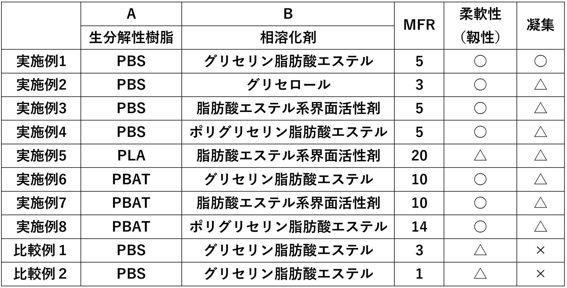
<結果及び考察>
実施例1で示されるPBSとグリセリン脂肪酸エステルとの組み合わせが、MFRも適切な範囲に収まり、柔軟性(靱性)も良好で、且つ、凝集も視認できず、特に良い組み合わせであることが示唆された。また、実施例2~4で示される、PBSと;グリセロール、脂肪酸エステル系界面活性剤又はポリグリセリン脂肪酸エステルと;の組み合わせも、凝集が若干視認されたものの、MFRも適切な範囲に収まり、柔軟性(靱性)も良好であり、良い組み合わせであることが示唆された。
<Results and discussion>
It is suggested that the combination of PBS and glycerin fatty acid ester shown in Example 1 is a particularly good combination, since the MFR is within an appropriate range, the flexibility (toughness) is good, and no aggregation is visible. rice field. In addition, the combination of PBS and; glycerol, fatty acid ester surfactant or polyglycerin fatty acid ester; shown in Examples 2 to 4 also showed some aggregation, but the MFR was also within an appropriate range and the flexibility was good. The properties (toughness) were also good, suggesting a good combination.
実施例6、7に示される、PBAT及びグリセリン脂肪酸エステル、ならびに、PBAT及び脂肪酸エステル系界面活性剤の組み合わせは、凝集が若干視認されたものの、MFRも適切な範囲に収まり、柔軟性(靱性)も良好であり、これらも良い組み合わせであることが示唆された。また、実施例8に示される、PBATと、ポリグリセリン脂肪酸エステルとの組み合わせは、MFRの好ましい範囲は若干逸脱し、凝集が若干視認されたものの、柔軟性(靱性)は良好であり、射出成形用途であれば実用上問題なく使用することできると考えられる。一方、PBATと、グリセロールとの組み合わせは、MFRの好ましい範囲が逸脱し、凝集も増える傾向がある可能性がある。つまり、樹脂としてPBATを使用する場合は、グリセリン脂肪酸エステル又は脂肪酸エステル系界面活性剤と組み合わせて使用することが好適であり、ポリグリセリン脂肪酸エステルと組み合わせても実用上問題なく使用することができると推測される。 In the combinations of PBAT and glycerin fatty acid ester and PBAT and fatty acid ester-based surfactants shown in Examples 6 and 7, aggregation was slightly observed, but MFR was also within an appropriate range, and flexibility (toughness) It was suggested that these are also good combinations. In addition, the combination of PBAT and polyglycerol fatty acid ester shown in Example 8 slightly deviated from the preferred range of MFR, and although aggregation was slightly visible, flexibility (toughness) was good, and injection molding was performed. It is considered that it can be used practically without any problems as long as it is used. On the other hand, the combination of PBAT and glycerol is outside the preferred range of MFR and may also tend to increase aggregation. In other words, when PBAT is used as a resin, it is preferable to use it in combination with a glycerin fatty acid ester or a fatty acid ester-based surfactant, and it can be used in combination with a polyglycerin fatty acid ester without practical problems. guessed.
一方で、実施例5に示される、PLAと、脂肪酸エステル系界面活性剤との組み合わせは、柔軟性(靱性)及びデンプンの凝集の観点では実用上問題ないことが示唆されるものの、MFRの好ましい範囲を大きく逸脱するため、押出シート加工やインフレーション加工には適さないが、射出成形用途であれば実用上問題なく使用することできると考えられる。一方で、PLAと、グリセリン脂肪酸エステル、グリセロール又はポリグリセリン脂肪酸エステルとの組み合わせは、MFRの観点のみならず、柔軟性(靱性)及びデンプン凝集の評価の観点からも、良い組み合わせではない恐れがある。 On the other hand, it is suggested that the combination of PLA and a fatty acid ester surfactant shown in Example 5 has no practical problem in terms of flexibility (toughness) and starch aggregation, but MFR is preferable. Since it greatly deviates from the range, it is not suitable for extrusion sheet processing or inflation processing, but it is considered that it can be used for injection molding without any practical problems. On the other hand, the combination of PLA and glycerin fatty acid ester, glycerol or polyglycerin fatty acid ester may not be a good combination not only from the viewpoint of MFR but also from the viewpoint of evaluation of flexibility (toughness) and starch aggregation. .
なお、比較例1は、実施例1のデンプンの代わりにセルロースを使用した例であるが、凝集があり、実使用には適さない虞がある。また、比較例2は、実施例1のデンプンの代わりにリグノセルロースを使用した例であるが、凝集があり、実使用には適さない虞がある。 It should be noted that Comparative Example 1 is an example in which cellulose is used instead of the starch in Example 1, but there is a fear that it is not suitable for actual use due to aggregation. Also, Comparative Example 2 is an example in which lignocellulose is used instead of starch in Example 1, but there is a fear that it is not suitable for practical use due to aggregation.
<実験2:生分解性試験>
《デンプン含有樹脂組成物の作製》
以下の手法により、実施例9のデンプン含有樹脂組成物サンプルを作製した。
<Experiment 2: Biodegradability test>
<<Preparation of starch-containing resin composition>>
A starch-containing resin composition sample of Example 9 was prepared by the following method.
(実施例9)
材料として、
A:生分解性の樹脂としてポリブチレンサクシネート(三菱ケミカル社製、フォゼアス(登録商標)、ZA9005)を48重量部、
B:相溶化剤としてアセチル化モノグリセライド(理研ビタミン社製、バイオサイザー)を2重量部、
C:デンプンとして精米(新潟ケンベイ社製、中白米、含水率12%)を56.8重量部(50重量%)、を用いた以外は、実施例1と同様の方法で、実施例9のデンプン含有樹脂組成物サンプルを作成した。
(Example 9)
as a material,
A: 48 parts by weight of polybutylene succinate (manufactured by Mitsubishi Chemical Corporation, Fozeus (registered trademark), ZA9005) as a biodegradable resin,
B: 2 parts by weight of acetylated monoglyceride (manufactured by Riken Vitamin Co., Ltd., Biocizer) as a compatibilizer,
C: In the same manner as in Example 1, except that 56.8 parts by weight (50% by weight) of polished rice (manufactured by Niigata Kenbei Co., Ltd., white rice, moisture content 12%) was used as starch. A sample of the starch-containing resin composition was prepared.
(実施例10)
材料Cであるデンプンとしての精米を30重量%とした以外は、実施例9と同様の方法で実施例10のデンプン含有樹脂組成物サンプルを作成した。
(Example 10)
A starch-containing resin composition sample of Example 10 was prepared in the same manner as in Example 9, except that the amount of polished rice as the starch of Material C was 30% by weight.
(実施例11)
材料Cであるデンプンとしての精米を10重量%とした以外は、実施例9と同様の方法で実施例11のデンプン含有樹脂組成物サンプルを作成した。
(Example 11)
A starch-containing resin composition sample of Example 11 was prepared in the same manner as in Example 9, except that the amount of polished rice as the starch of Material C was 10% by weight.
《生分解性試験》
実施例9~11の生分解の速度を、時間経過に伴う重量減少率を求めることにより評価した。重量減少率は、温度58℃、コンポスト中にて、JIS K6953-1:2011に準拠して行った。実施例9の重量は、試験開始から7日後、14日後、24日後、及び31日後に測定した。実施例10及び11の重量は、試験開始から7日後及び14日後に測定した。なお、コントロールとして、材料Cを含まない以外は実施例9と同様の方法で作製した比較例3を用いた。比較例3の重量は、実施例9と同様に、試験開始から7日後、14日後、24日後、及び31日後に測定した。結果を図9に示す。
《Biodegradability test》
The rate of biodegradation of Examples 9-11 was evaluated by determining percent weight loss over time. The weight loss rate was measured in compost at a temperature of 58° C. in accordance with JIS K6953-1:2011. The weight of Example 9 was measured 7 days, 14 days, 24 days, and 31 days after the start of the test. The weights of Examples 10 and 11 were measured 7 days and 14 days after the start of the test. As a control, Comparative Example 3 prepared in the same manner as in Example 9 except that material C was not included was used. As in Example 9, the weight of Comparative Example 3 was measured 7 days, 14 days, 24 days, and 31 days after the start of the test. The results are shown in FIG.
また、実施例9と比較例3の生分解性試験における目視観察も併せて行った。結果を図10に示す。目視観察は、それぞれ試験開始から7日後、14日後、24日後、31日後に行った。なお、実施例9のデンプン含有樹脂組成物サンプルは31日後には完全に分解されていたため、写真は掲載しない。 In addition, visual observation was also conducted in the biodegradability tests of Example 9 and Comparative Example 3. The results are shown in FIG. Visual observation was performed 7 days, 14 days, 24 days and 31 days after the start of the test. In addition, since the starch-containing resin composition sample of Example 9 was completely decomposed after 31 days, no photograph is shown.
<結果及び考察>
図9に示すように、デンプンを含む実施例9~11は、デンプンを含まない比較例3に対して重量減少のスピードが速いことから、生分解の速度が速いことが示された。また、実施例9~11を比較すると、デンプンの含有率が高いデンプン含有樹脂組成物サンプルのほうが、デンプンの含有率が低いものよりも重量減少のスピードが速いという結果となった。当該結果から、デンプン含有樹脂組成物サンプルのデンプンの含有率が高いほうが生分解の速度が速いことが示された。
<Results and discussion>
As shown in FIG. 9, Examples 9 to 11, which contain starch, exhibited a faster weight loss rate than Comparative Example 3, which does not contain starch, indicating a faster rate of biodegradation. Also, when comparing Examples 9 to 11, the starch-containing resin composition sample with a higher starch content showed a faster weight loss rate than the one with a lower starch content. The results indicated that the higher the starch content of the starch-containing resin composition sample, the faster the rate of biodegradation.
加えて、図10の目視観察の結果からも、実施例9のデンプン含有樹脂組成物サンプルは、比較例3よりも生分解の速度が速いことが示された。図10に示した通り、実施例9のデンプン含有樹脂組成物サンプルは、24日目から31日目にかけて完全に分解されたのに対し、比較例3の生分解性樹脂は、31日目の時点でまだ残存していた。 In addition, the results of visual observation in FIG. 10 also showed that the starch-containing resin composition sample of Example 9 biodegraded faster than Comparative Example 3. As shown in FIG. 10, the starch-containing resin composition sample of Example 9 was completely degraded from the 24th day to the 31st day, whereas the biodegradable resin of Comparative Example 3 was completely degraded on the 31st day. still remained at that time.
なお、本発明は上述した実施形態にのみ限定されず、特許請求の範囲において種々の変更が可能である。 It should be noted that the present invention is not limited to the above-described embodiments, and various modifications are possible within the scope of the claims.
Claims (16)
生分解性の樹脂と、
相溶化剤と、
を有する、デンプン含有樹脂組成物。 starch;
a biodegradable resin;
a compatibilizer;
A starch-containing resin composition having
前記生分解性の樹脂が、ポリブチレンサクシネートであり、
前記相溶化剤が、グリセリンジアセトモノラウレートである、請求項1~10のいずれか1項に記載のデンプン含有樹脂組成物。 The starch is polished rice,
The biodegradable resin is polybutylene succinate,
The starch-containing resin composition according to any one of claims 1 to 10, wherein the compatibilizer is glycerine diacetomonolaurate.
デンプンと、生分解性の樹脂と、相溶化剤とを、混練する工程を有する、調整方法。 A method for adjusting the biodegradation rate of a starch-containing resin composition, comprising:
A preparation method comprising a step of kneading starch, a biodegradable resin, and a compatibilizer.
請求項1~12のいずれか1項に記載のデンプン含有樹脂組成物と、生分解性の樹脂とを混練する工程を有する、調整方法。 A method for adjusting the biodegradation rate of a starch-containing resin composition, comprising:
A preparation method comprising a step of kneading the starch-containing resin composition according to any one of claims 1 to 12 and a biodegradable resin.
Priority Applications (4)
| Application Number | Priority Date | Filing Date | Title |
|---|---|---|---|
| PCT/JP2021/039921 WO2023073895A1 (en) | 2021-10-28 | 2021-10-28 | Starch-containing resin composition, molded article, and method for adjusting biodegradation rate of starch-containing resin composition |
| JP2023513395A JP7420431B2 (en) | 2021-10-28 | 2021-10-28 | Starch-containing resin composition, molded product, and method for adjusting biodegradation rate of starch-containing resin composition |
| JP2022171212A JP2023066403A (en) | 2021-10-28 | 2022-10-26 | Resin composition pellet |
| JP2023131805A JP2023159236A (en) | 2021-10-28 | 2023-08-14 | Starch-containing resin composition, molded product, and method for adjusting biodegradation rate of starch-containing resin composition |
Applications Claiming Priority (1)
| Application Number | Priority Date | Filing Date | Title |
|---|---|---|---|
| PCT/JP2021/039921 WO2023073895A1 (en) | 2021-10-28 | 2021-10-28 | Starch-containing resin composition, molded article, and method for adjusting biodegradation rate of starch-containing resin composition |
Publications (1)
| Publication Number | Publication Date |
|---|---|
| WO2023073895A1 true WO2023073895A1 (en) | 2023-05-04 |
Family
ID=86157586
Family Applications (1)
| Application Number | Title | Priority Date | Filing Date |
|---|---|---|---|
| PCT/JP2021/039921 Ceased WO2023073895A1 (en) | 2021-10-28 | 2021-10-28 | Starch-containing resin composition, molded article, and method for adjusting biodegradation rate of starch-containing resin composition |
Country Status (2)
| Country | Link |
|---|---|
| JP (3) | JP7420431B2 (en) |
| WO (1) | WO2023073895A1 (en) |
Citations (9)
| Publication number | Priority date | Publication date | Assignee | Title |
|---|---|---|---|---|
| JP2003073531A (en) * | 2001-06-18 | 2003-03-12 | Mitsui Chemicals Inc | Biodegradable binding material |
| WO2005087857A1 (en) * | 2004-03-10 | 2005-09-22 | Agri Future Joetsu Co., Ltd. | Starch-blended resin composition, molding thereof and process for producing the same |
| JP2009155531A (en) * | 2007-12-27 | 2009-07-16 | Mitsubishi Chemicals Corp | Resin composition, method for producing the same, and film comprising the resin composition |
| WO2013073402A1 (en) * | 2011-11-15 | 2013-05-23 | 昭和電工株式会社 | Biodegradable resin composition, and biodegradable film |
| JP2013537578A (en) * | 2010-08-06 | 2013-10-03 | ノバモント・ソシエタ・ペル・アチオニ | Multiphase biodegradable composition comprising at least one plant-derived polymer |
| JP2016176044A (en) * | 2015-03-23 | 2016-10-06 | 三菱樹脂株式会社 | Polylactic acid-based resin composition and molding |
| JP2020050855A (en) * | 2018-09-20 | 2020-04-02 | アイ‐コンポロジー株式会社 | Biodegradable resin composition, master batch, and molded body thereof |
| JP2020125470A (en) * | 2019-01-31 | 2020-08-20 | 西邦エンジニアリング株式会社 | Biomass plastic composite material and manufacturing method thereof |
| WO2020202813A1 (en) * | 2019-03-29 | 2020-10-08 | 株式会社カネカ | Polyester resin composition, production method therefor, and molded body |
-
2021
- 2021-10-28 WO PCT/JP2021/039921 patent/WO2023073895A1/en not_active Ceased
- 2021-10-28 JP JP2023513395A patent/JP7420431B2/en active Active
-
2022
- 2022-10-26 JP JP2022171212A patent/JP2023066403A/en active Pending
-
2023
- 2023-08-14 JP JP2023131805A patent/JP2023159236A/en active Pending
Patent Citations (9)
| Publication number | Priority date | Publication date | Assignee | Title |
|---|---|---|---|---|
| JP2003073531A (en) * | 2001-06-18 | 2003-03-12 | Mitsui Chemicals Inc | Biodegradable binding material |
| WO2005087857A1 (en) * | 2004-03-10 | 2005-09-22 | Agri Future Joetsu Co., Ltd. | Starch-blended resin composition, molding thereof and process for producing the same |
| JP2009155531A (en) * | 2007-12-27 | 2009-07-16 | Mitsubishi Chemicals Corp | Resin composition, method for producing the same, and film comprising the resin composition |
| JP2013537578A (en) * | 2010-08-06 | 2013-10-03 | ノバモント・ソシエタ・ペル・アチオニ | Multiphase biodegradable composition comprising at least one plant-derived polymer |
| WO2013073402A1 (en) * | 2011-11-15 | 2013-05-23 | 昭和電工株式会社 | Biodegradable resin composition, and biodegradable film |
| JP2016176044A (en) * | 2015-03-23 | 2016-10-06 | 三菱樹脂株式会社 | Polylactic acid-based resin composition and molding |
| JP2020050855A (en) * | 2018-09-20 | 2020-04-02 | アイ‐コンポロジー株式会社 | Biodegradable resin composition, master batch, and molded body thereof |
| JP2020125470A (en) * | 2019-01-31 | 2020-08-20 | 西邦エンジニアリング株式会社 | Biomass plastic composite material and manufacturing method thereof |
| WO2020202813A1 (en) * | 2019-03-29 | 2020-10-08 | 株式会社カネカ | Polyester resin composition, production method therefor, and molded body |
Also Published As
| Publication number | Publication date |
|---|---|
| JP7420431B2 (en) | 2024-01-23 |
| JP2023066403A (en) | 2023-05-15 |
| JPWO2023073895A1 (en) | 2023-05-04 |
| JP2023159236A (en) | 2023-10-31 |
Similar Documents
| Publication | Publication Date | Title |
|---|---|---|
| CN103502356B (en) | The blend of poly(lactic acid) and water-soluble polymers | |
| RU2480485C2 (en) | Mixtures of polylactic acid and thermoplastic polymers for packaging applications | |
| CN103183814B (en) | Polyesters from biomass resources and methods for their manufacture | |
| CN1091118C (en) | Biodegradable materials consisting essentially of or based on thermoplastic starch | |
| KR101000749B1 (en) | Biodegradable resin composition, preparation method thereof and biodegradable film produced therefrom | |
| RU2762161C2 (en) | Biodegradable polymer mixture and its production method | |
| WO2007095709A1 (en) | Environmentally degradable polymeric composition and process for obtaining an environmentally degradable polymeric composition | |
| WO2010125490A2 (en) | Algae-blended compositions for thermoplastic articles | |
| US12049729B2 (en) | Compostable seaweed-based compositions, and associated systems and methods | |
| CN102482499B (en) | Method For Producing A Biodegradable Material | |
| JP2022524150A (en) | Thermoplastic starch and its manufacturing method | |
| US20080036115A1 (en) | Starch Resin Composition, Molded Product Using the Same and Method for Producing the Same | |
| JP2024037690A (en) | Laminates and packaging materials | |
| CN101775199A (en) | High-rigidity PHAs/PLA blending alloy and preparation method thereof | |
| Ribba et al. | Processing and properties of starch-based thermoplastic matrix for green composites | |
| Singh et al. | Green and sustainable packaging materials using thermoplastic starch | |
| JP7420431B2 (en) | Starch-containing resin composition, molded product, and method for adjusting biodegradation rate of starch-containing resin composition | |
| CN113583403B (en) | Completely biodegradable film bag | |
| JP2023014217A (en) | Manufacturing method for rice-containing resin compositions and biaxial kneading equipment | |
| Anne | Environmental-friendly biodegradable polymers and composites | |
| JP3860163B2 (en) | Aliphatic polyester resin composition and film | |
| JP2024094211A (en) | Biomass Masterbatch | |
| CN104559092B (en) | A kind of shock resistance, the preparation method of the modified polylactic acid material of resistance to deformation | |
| JP7653253B2 (en) | Starch-containing resin composition | |
| JP5230078B2 (en) | Resin composition and film using the same |
Legal Events
| Date | Code | Title | Description |
|---|---|---|---|
| WWE | Wipo information: entry into national phase |
Ref document number: 2023513395 Country of ref document: JP |
|
| 121 | Ep: the epo has been informed by wipo that ep was designated in this application |
Ref document number: 21961613 Country of ref document: EP Kind code of ref document: A1 |
|
| NENP | Non-entry into the national phase |
Ref country code: DE |
|
| 122 | Ep: pct application non-entry in european phase |
Ref document number: 21961613 Country of ref document: EP Kind code of ref document: A1 |