WO2023015375A1 - Method and device for limiting of output synthesis distortion in a sound codec - Google Patents
Method and device for limiting of output synthesis distortion in a sound codec Download PDFInfo
- Publication number
- WO2023015375A1 WO2023015375A1 PCT/CA2022/051199 CA2022051199W WO2023015375A1 WO 2023015375 A1 WO2023015375 A1 WO 2023015375A1 CA 2022051199 W CA2022051199 W CA 2022051199W WO 2023015375 A1 WO2023015375 A1 WO 2023015375A1
- Authority
- WO
- WIPO (PCT)
- Prior art keywords
- sound signal
- saturation
- stage
- amplitude value
- control gain
- Prior art date
- Legal status (The legal status is an assumption and is not a legal conclusion. Google has not performed a legal analysis and makes no representation as to the accuracy of the status listed.)
- Ceased
Links
Classifications
-
- G—PHYSICS
- G10—MUSICAL INSTRUMENTS; ACOUSTICS
- G10L—SPEECH ANALYSIS TECHNIQUES OR SPEECH SYNTHESIS; SPEECH RECOGNITION; SPEECH OR VOICE PROCESSING TECHNIQUES; SPEECH OR AUDIO CODING OR DECODING
- G10L19/00—Speech or audio signals analysis-synthesis techniques for redundancy reduction, e.g. in vocoders; Coding or decoding of speech or audio signals, using source filter models or psychoacoustic analysis
- G10L19/005—Correction of errors induced by the transmission channel, if related to the coding algorithm
-
- G—PHYSICS
- G10—MUSICAL INSTRUMENTS; ACOUSTICS
- G10L—SPEECH ANALYSIS TECHNIQUES OR SPEECH SYNTHESIS; SPEECH RECOGNITION; SPEECH OR VOICE PROCESSING TECHNIQUES; SPEECH OR AUDIO CODING OR DECODING
- G10L19/00—Speech or audio signals analysis-synthesis techniques for redundancy reduction, e.g. in vocoders; Coding or decoding of speech or audio signals, using source filter models or psychoacoustic analysis
- G10L19/04—Speech or audio signals analysis-synthesis techniques for redundancy reduction, e.g. in vocoders; Coding or decoding of speech or audio signals, using source filter models or psychoacoustic analysis using predictive techniques
- G10L19/26—Pre-filtering or post-filtering
-
- H—ELECTRICITY
- H03—ELECTRONIC CIRCUITRY
- H03G—CONTROL OF AMPLIFICATION
- H03G11/00—Limiting amplitude; Limiting rate of change of amplitude
- H03G11/08—Limiting rate of change of amplitude
-
- H—ELECTRICITY
- H03—ELECTRONIC CIRCUITRY
- H03G—CONTROL OF AMPLIFICATION
- H03G3/00—Gain control in amplifiers or frequency changers
- H03G3/20—Automatic control
- H03G3/30—Automatic control in amplifiers having semiconductor devices
- H03G3/3005—Automatic control in amplifiers having semiconductor devices in amplifiers suitable for low-frequencies, e.g. audio amplifiers
-
- H—ELECTRICITY
- H03—ELECTRONIC CIRCUITRY
- H03G—CONTROL OF AMPLIFICATION
- H03G3/00—Gain control in amplifiers or frequency changers
- H03G3/20—Automatic control
- H03G3/30—Automatic control in amplifiers having semiconductor devices
- H03G3/3089—Control of digital or coded signals
Definitions
- the present disclosure relates to sound coding, in particular but not exclusively to a method and device (limiter) for limiting distortion in a sound signal, for example an output sound signal synthesis from a sound signal decoder. If a sound renderer is used, the distortion limiting method and device (limiter) may be implemented after or as part of the renderer.
- sound may be related to speech, audio and any other sound
- stereo is an abbreviation for “stereophonic”
- multi-channel may be related to two and more sound signals or sound codecs.
- Efficient stereo coding techniques have been developed and used for low bit-rates.
- the so-called parametric stereo coding constitutes one efficient technique for low bit-rate stereo coding.
- Parametric stereo encodes two, left and right channels as a mono signal using a common mono codec plus a certain amount of stereo side information (corresponding to stereo parameters) which represents a stereo image.
- the two input, left and right channels are down-mixed into a mono signal, for example by summing the left and right channels and dividing the sum by 2.
- the stereo parameters are then computed usually in transform domain, for example in the Discrete Fourier Transform (DFT) domain, and are related to so-called binaural or inter-channel cues.
- DFT Discrete Fourier Transform
- the binaural cues may comprise Interaural Level Difference (ILD), Interaural Time Difference (ITD) and Interaural Correlation (IC). Depending on the signal characteristics, stereo scene configuration, etc., some or all binaural cues are coded and transmitted to the decoder.
- ILD Interaural Level Difference
- ITD Interaural Time Difference
- IC Interaural Correlation
- immersive audio also called 3D (Three- Dimensional) audio
- the sound image is reproduced in all three dimensions around the listener, taking into consideration a wide range of sound characteristics like timbre, directivity, reverberation, transparency and accuracy of (auditory) spaciousness.
- Immersive audio is produced for a particular sound playback or reproduction system such as a loudspeaker-based system, an integrated reproduction system (sound bar), or headphones.
- interactivity of a sound reproduction system may include, for example, an ability to adjust sound levels, change positions of sounds, or select different languages for the reproduction.
- the output sound signal may be corrupted by several types of distortion.
- Distortion may be caused by clippings where samples of sound signal have a value higher or lower than a certain threshold. This situation can typically happen when a sample of sound signal a) is converted from a floating-point representation to a fixed-point representation, b) is converted from one fixed-point representation to another fixed-point representation with a shorter bit length (e. g. from long integer o short integer (e. g.
- Long signed integer type is capable of containing the [-2,147,483,647, +2,147,483,647] 32- bit range while Short signed integer type is capable of containing the [-32,767, +32,767] 16-bit range), c) as a result of an instability in the decoding algorithm of the sound codec, d) during rendering when a sound (voice and/or audio) signal is manipulated, down-mixed etc.
- the amplitude of the sound signal samples can saturate and it is thus clipped, or limited, resulting in a perceptually annoying sound.
- AGC Automatic Gain Control
- the AGC is a closed-loop feedback algorithm regulating and maintaining the varying amplitude of sound signal samples within limits suitable for processing of these sound signal samples without distortion.
- AGC is designed to regulate sound signal samples in time domain with no additional delay.
- the problem of saturation is even more challenging in multi-channel codecs, typically when the number of decoded channels is higher than the number of output channels, or the decoded channels are correlated. An example is the rendering of decoded multi-channel audio to a binaural output.
- Saturation often occurs also as a consequence of an instability in the decoding algorithm, for example when the long-term synthesis filter used in a CELP- based sound codec is unstable or when a received bitstream is corrupted by frame erasures or bit errors.
- the present disclosure relates to a method and device (limiter) for limiting distortion in a sound signal.
- the method and device (limiter) for limiting distortion in the sound signal may be performed on the rendered sound signal.
- the present disclosure relates to a two-stage method for limiting distortion in a sound signal, comprising, in a first stage, detecting an amplitude value of the sound signal and computing a control gain using the detected amplitude value, attenuating the level of the sound signal using the control gain and, in a second stage, detecting saturation in the sound signal and updating the control gain in response to detection of saturation.
- the present disclosure relates to a two- stage method for limiting distortion in an output sound signal synthesis from a sound signal decoder.
- a first stage an amplitude value of the output sound signal synthesis is detected, a control gain is computed using the detected amplitude value, and the level of the output sound signal synthesis is attenuated using the control gain.
- saturation in the output sound signal synthesis is detected and the control gain is updated in response to detection of saturation.
- a two-stage distortion limiter for limiting distortion in a sound signal, comprising (a) a first stage comprising a level detector for detecting an amplitude value of the sound signal and for computing a control gain using the detected amplitude value, and an attenuator of the level of the sound signal using the control gain, and (b) a second stage comprising a saturation detector for detecting saturation in the sound signal and for updating the control gain in response to detection of saturation.
- a two-stage distortion limiter for limiting distortion in an output sound signal synthesis from a sound signal decoder, comprising (a) a first stage comprising a level detector for detecting an amplitude value of the output sound signal synthesis and for computing a control gain using the detected amplitude value, and an attenuator of the level of the output sound signal synthesis using the control gain; and (b) a second stage comprising a saturation detector for detecting saturation in the output sound signal synthesis and for updating the control gain in response to detection of saturation.
- Figure 1 is a schematic block diagram illustrating concurrently an example implementation of a one-stage multi-channel distortion limiter, and a corresponding distortion limiting method
- Figure 2 is a schematic block diagram of a two-stage multi-channel distortion limiter, and a corresponding distortion limiting method
- Figure 3 is a schematic block diagram illustrating concurrently a saturation detector forming part of the device of Figure 2, and a corresponding saturation detecting method;
- Figure 4 is an illustration showing the impact of the two-stage distortion limiter and distortion limiting method on the output sound signal synthesis.
- Figure 5 is a simplified block diagram of an example configuration of hardware components implementing the distortion limiter and distortion limiting method.
- the present disclosure is concerned with limitation of distortion in an output sound signal synthesis from the sound signal decoder of a sound codec.
- the method and device (limiter) for limiting distortion in the output sound signal synthesis from the sound signal decoder may be performed on the rendered sound signal. Distortion may happen as a consequence of an unstable decoding process.
- the present disclosure introduces a second-stage algorithm in the distortion limiter and distortion limiting method for detecting and limiting distortion caused for example by a) bitstreams with bit errors or other types of corrupted bitstreams, and b) saturations in general.
- the distortion limiter can be implemented in a mono, stereo, or multi-channel sound signal decoder for example just before the final float to integer conversion, or before long integer o short integer conversion.
- the distortion limiter detects distortion such as saturation, an attenuation is applied which results in a much more pleasant output sound signal synthesis.
- AGC Automatic Gain Control
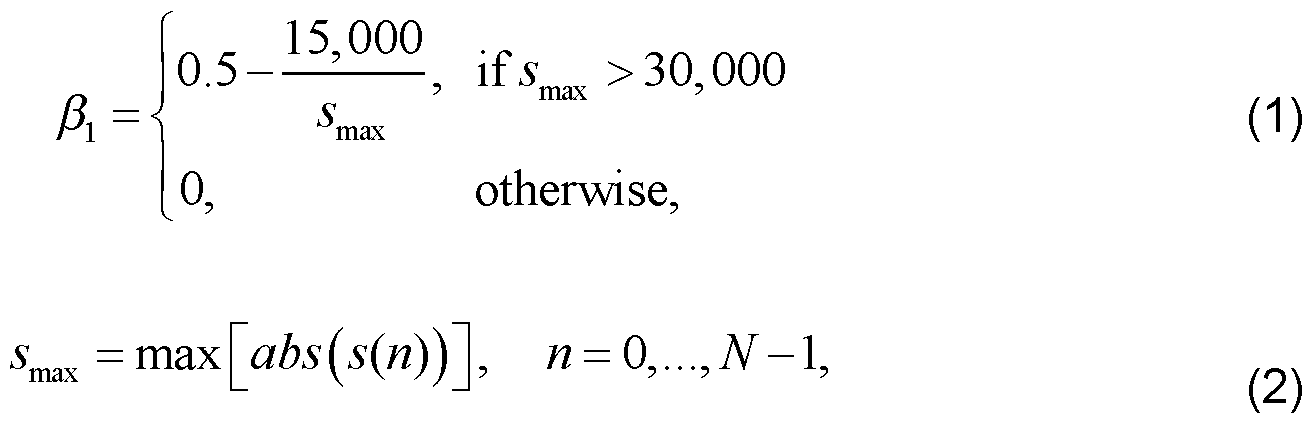
- the frame factor 3i is used to update a long-term AGC factor using relation (3):
- each sample of the output sound signal synthesis is updated using a closed-loop feedback as expressed in relation (4):
- the above described AGC limiter was adopted in several recent speech and audio mono coding standards, such as EVS.
- EVS For stereo and multi-channel codecs, more elaborated distortion limiter and distortion limiting method are implemented.
- the distortion limiter and corresponding distortion limiting method is implemented by way of example in a 3D sound coding framework, i.e. in the IVAS framework.
- An example implementation of a distortion limiter in a multi-channel codec can be a general non-specific digital limiter, for example the audio dynamic range controller with variable parameters as described in Reference [4], of which the full content is incorporated herein by reference. Any other distortion limiter can be used without departing from the spirit and scope of the present disclosure.
- distortion level limitation is used and comprises generating a control gain and using a first order IIR (Infinite Impulse Response) filter for attack and release time processing.
- Figure 1 is a schematic block diagram illustrating concurrently such an example implementation of one-stage multi-channel distortion limiter and corresponding distortion limiting method.
- the distortion limiting method and device can be used in several parts of the sound coding, decoding and/or reproduction system, e.g. in a pre- renderer at the coding end, as part of the decoder, after the decoder, as part of the sound renderer, or after the sound renderer just before outputting sound signals from the system.
- the terms used in the present disclosure focus on the implementation of the distortion limiting method and device (limiter) after the sound renderer.
- the example implementation of one-stage multichannel distortion limiting method 100 comprises an operation 101 of output sound signal synthesis level detection, an operation 102 of setting limiter parameters, and an operation 105 of attenuation filtering that can be split, as illustrated in Figure 1 , into a “gain filtering” sub-operation 103 as described for example by relation (7) and a “gainapplying” sub-operation 104 as described for example by relation (8).
- the output sound signal synthesis is processed in successive blocks of output sound signal synthesis samples called frames (hereinafter output sound signal synthesis processing frames).
- the one-stage multi-channel distortion limiter 150 of Figure 1 comprises a level detector 151 to detect an amplitude value of the sound signal synthesis.
- the level detector is a peak level detector 151 to detect a maximum absolute value p (also called “peak value”) of the sound signal synthesis samples of all output channels m of the output sound signal synthesis in the current frame using, for example, relation (5):
- the peak level detector 151 uses the detected peak value p to compute a control gain (also called “gate attenuation”), denoted as g c .
- Limiting the control gain g c equal to or below r 1 is usually not expected and in general cannot happen in stable sound signal decoders, typically sound signal decoders receiving bitstreams not corrupted by bit errors. If gain limiting is not implemented, however, there might happen that a longer segment of output sound signal synthesis is attenuated too strongly (up to close to zero) and thus the sound might become inaudible.
- the one-stage multi-channel distortion limiter 150 of Figure 1 comprises a calculator 152 of limiter parameters that are computed to generate the desired dynamic characteristics as taught by Reference [4], For example, an attack/release time parameter y is computed and is responsible for defining a shorter or longer attack/release time.
- the attack/release time parameter y provides a control how quickly the distortion limiter acts and can be in general subject to adjustment or tuning during development.
- the attack parameter controls the time taken by the distortion limiter to reduce the control gain after the detected peak value of the output sound signal synthesis has exceeded the limiter threshold Q.
- the release parameter controls the time it takes for the control gain to return to its normal level of 1.0 after the detected peak value of the output sound signal synthesis fell below the limiter threshold Q.
- the one-stage multi-channel distortion limiter 150 of Figure 1 comprises an attenuator 155 of the level of the output sound signal synthesis s m (n) comprising a gain filter 153 such as a first order H low-pass filter using the attack/release time parameter y to obtain a gain g(n) per sample of the output sound signal synthesis.
- Filter 153 can be described, for example, by relation (7): where y denotes the above-mentioned attack/release time parameter.
- the attenuator 155 of Figure 1 also comprises an amplifier 154 for applying the gain g(n) to every n-th sample of all the channels m of the output sound signal synthesis s m (n) to obtain a distortion-limited output sound signal synthesis s’ m (n), using for example relation (8):
- Figure 2 is a schematic block diagram of a two-stage multi-channel distortion limiter 250, and corresponding distortion limiting method 200.
- the example implementation of two-stage multichannel distortion limiting method 200 comprises, as a first stage, the operation 101 of output sound signal synthesis level detection, the operation 102 of setting limiter parameters, and the operation 105 of attenuation filtering including the gain filtering suboperation 103 and the gain-applying sub-operation 104 as described in relation to Figure 1.
- the two-stage multi-channel distortion limiter 250 of Figure 2 comprises, as the first stage, the sound signal synthesis level detector such as the peak level detector 151 , the calculator 152 of limiter parameters, and the attenuator 155 including the gain filter 153 and the amplifier 154 as also described with reference to Figure 1.
- the two-stage multi-channel distortion limiting method 200 comprises, as a second stage, an operation 201 of detecting saturations in the output sound signal synthesis s m (n).
- the two-stage multi-channel distortion limiter 250 of Figure 2 comprises, as the second stage, a saturation detector 251 for performing operation 201 .
- the second stage of the two-stage multi-channel distortion limiter 250 and corresponding distortion limiting method 200 are designed for detecting saturations, in particular strong saturations of the output sound signal synthesis s m (n).
- strong saturations is intended to designate saturations with an unexpectedly high level, e. g. higher than 1 / Fi times the maximum desired output sound signal level.
- the illustrative implementation refers to detection of strong saturations as defined above, it is within the scope of the present disclosure, in view of improving the output sound signal synthesis, to also detect weaker saturations by adapting the values of the parameters, thresholds, counters, constants, etc., used in the saturation detector 251 and the corresponding saturation detecting method 201 as described herein after.
- the second stage (saturation detector 251 and saturation detection operation 201) produces an output 203 indicative of (a) a decision if additional attenuation is to be applied to the output sound signal synthesis s m (n) and (b) an extent of the attenuation to be applied to the output sound signal synthesis s m (n) indicated by an updated control gain g c .
- the second stage cannot only be implemented in the distortion limiter of Figure 1 , but also in any other distortion limiter including the above mentioned mono AGC limiter in which case the second stage is used to alter the frame factor 3i from relation (1) and thus the long-term AGC factor fr> from relation (3).
- Figure 3 is a schematic block diagram illustrating concurrently the saturation detector 251 and the corresponding saturation detecting method 201 of Figure 2.
- the saturation detector 251 produces a saturation detection flag flag indicating whether saturation was detected or not, and an updated control gain g c .
- the saturation detecting operation 201 and the corresponding saturation detector 251 initializes (see 301), at the beginning of every output sound signal synthesis processing frame, the saturation detection flag flag to 0. It should be noted that the saturation detector 251 performs saturation detection on each of the M audio channels in every sound signal synthesis processing frame.
- the saturation detector 251 and the corresponding saturation detecting method 201 then comprises two parts:
- a first calculator 320 which updates a saturation detection counter ent which stores a metric measuring probability that saturation, in particular strong saturation is present in a current output sound signal synthesis processing frame and produces the saturation detection flag flag', and
- a second calculator 330 which, as described herein above, (a) decides if additional attenuation is to be applied to the output sound signal synthesis s m (n) and (b) determines an extent of the attenuation to be applied to the output sound signal synthesis s m (n) by producing an updated control gain g c .
- Pi 3-Q where Q is the limiter threshold from relation (6).
- the first calculator 320 of the saturation detector 251 and the corresponding saturation detecting method 201 continues with a third decision (see 306) whether the peak value p is greater than a given threshold P 2 .
- the saturation detection counter ent is not used to try to detect instabilities of the sound signal decoder other than that caused by bit errors.
- the saturation detection then continues in the second calculator 330 (starting at 309) of the saturation detector 251 and the corresponding saturation detecting method 201.
- the first calculator 320 updates the saturation detection counter ent (see 308) to the maximum between 0 and the difference ent - Cdw (it is ensured that the minimum value of the detection counter ent is 0).
- the saturation detection then continues in the second calculator 330 (starting at 309) of the saturation detector 251 and the corresponding saturation detecting method 201 .
- the contribution of the first calculator 320 of the saturation detector 251 and the saturation detecting method 201 is completed.
- the first calculator 320 takes into consideration a plurality of factors, including bit errors in the bitstream (parameter flag BER ), two thresholds P 1 and P 2 applied to the detected peak value p, and the updated counter ent for an accurate determination of the saturation detection indicating value “1” or no saturation detection indicating value “0” of the flag flag.
- the saturation detecting method 201 is ended and no additional attenuation is requested at the output 314 (corresponding to 203 in Figure 2) of the second stage of the two-stage multi-channel distortion limiter 250.
- the saturation detection flag flag 1 (see 309)
- the second calculator 330 of the saturation detector 251 and the corresponding saturation detecting method 201 computes (see 310) a gain correction factor h c using, for example, relation (9): where ⁇ is the above defined limiter threshold and p the above defined peak value.
- the function of the additional correction factor ⁇ is to control the strength of the additional limitation of the control gain gc (see relation (10)).
- relation (6) used in the peak level detector 151 of the first stage of the two-stage multi-channel distortion limiter 250 is changed, for example, to relation (11): [0061]
- the two-stage multi- channel distortion limiter 250 and corresponding distortion limiting method 200 could be implemented as follows: /*!
- Figure 4 is an illustration showing the impact of the distortion limiter 250 and distortion limiting method 200 on the output sound signal synthesis, in the non limitative example when a bitstream corrupted by bit errors is received by an EVS sound signal decoder.
- the output sound signal synthesis is very distorted when no distortion limiter is used (top graph of Figure 4).
- the number of distortions, or energy overshoots, is reduced when a one-stage distortion limiter as illustrated in Figure 1 is used (middle graph of Figure 4) and further significantly reduced when a two-stage distortion limiter as illustrated in Figure 2 is employed (bottom graph of Figure 4).
- Figure 5 is a simplified block diagram of an example configuration of hardware components forming the above described distortion limiter and distortion limiting method.
- the distortion limiter may be implemented as a part of a mobile terminal, as a part of a portable media player, an audio format converter or any similar device.
- the distortion limiter (identified as 500 in Figure 5) comprises an input 502, an output 504, a processor 506 and a memory 508.
- the input 502 is configured to receive the input sound signal synthesis, in digital or analog form.
- the output 504 is configured to supply the output, distortion limited sound signal synthesis.
- the input 502 and the output 504 may be implemented in a common module, for example a serial input/output device.
- the processor 506 is operatively connected to the input 502, to the output 504, and to the memory 508.
- the processor 506 is realized as one or more processors for executing code instructions in support of the functions of the various components of the distortion limiter as illustrated in Figures 1-3.
- the memory 508 may comprise a non-transient memory for storing code instructions executable by the processor(s) 506, specifically, a processor-readable memory comprising/storing non-transitory instructions that, when executed, cause a processor(s) to implement the operations and components of the distortion limiting method and distortion limiter as described in the present disclosure.
- the memory 508 may also comprise a random access memory or buffer(s) to store intermediate processing data from the various functions performed by the processor(s) 506.
- Those of ordinary skill in the art will realize that the description of the distortion limiter and distortion limiting method is illustrative only and is not intended to be in any way limiting. Other embodiments will readily suggest themselves to such persons with ordinary skill in the art having the benefit of the present disclosure.
- the disclosed distortion limiter and distortion limiting method may be customized to offer valuable solutions to existing needs and problems of encoding and decoding sound.
- the routine features of the implementations of the distortion limiter and distortion limiting method are shown and described. It will, of course, be appreciated that in the development of any such actual implementation of the distortion limiter and distortion limiting method, numerous implementation-specific decisions may need to be made in order to achieve the developer’s specific goals, such as compliance with application-, system-, network- and business-related constraints, and that these specific goals will vary from one implementation to another and from one developer to another.
- the components/processors/modules, processing operations, and/or data structures described herein may be implemented using various types of operating systems, computing platforms, network devices, computer programs, and/or general purpose machines.
- devices of a less general purpose nature such as hardwired devices, field programmable gate arrays (FPGAs), application specific integrated circuits (ASICs), or the like, may also be used.
- a method comprising a series of operations and sub-operations is implemented by a processor, computer or a machine and those operations and sub- operations may be stored as a series of non-transitory code instructions readable by the processor, computer or machine, they may be stored on a tangible and/or non- transient medium.
- the distortion limiter and distortion limiting method as described herein may use software, firmware, hardware, or any combination(s) of software, firmware, or hardware suitable for the purposes described herein.
- the various operations and sub-operations may be performed in various orders and some of the operations and sub-operations may be optional.
- Embodiment 1 A detector of saturation of an output sound signal synthesis from a sound signal decoder, comprising (a) a first calculator of a saturation detection flag indicative of detection of saturation of the output sound signal synthesis, and (b) a second calculator responsive to the saturation detection flag for deciding if additional attenuation is to be applied to the output sound signal synthesis and determining an extent of the attenuation to be applied to the output sound signal synthesis.
- Embodiment 2 The saturation detector according to embodiment 1, wherein the output sound signal synthesis comprises a plurality of channels and wherein the saturation detector is applied to every channel of the output sound signal synthesis.
- Embodiment 3 The saturation detector according to embodiment 1 or 2, wherein the first calculator initializes the saturation detection flag at the beginning of output sound signal synthesis processing frames.
- Embodiment 4 The saturation detector according to any one of the embodiments 1 to 3, wherein the first calculator updates a saturation detection counter which stores a probability that saturation is present in a current output sound signal synthesis processing frame.
- Embodiment 5 The saturation detector according to embodiment 4, wherein the sound signal decoder produces a parameter indicative of bit errors in a bitstream received by the sound signal decoder, and the first calculator updates the saturation detection counter to a maximum value thereof and sets the saturation detection flag to a saturation indicating value when the produced parameter indicates bit errors in the bitstream.
- Embodiment 6 The saturation detector according to embodiment 4 or 5, wherein the first calculator sets the saturation detection flag to a saturation indicating value when a detected sound signal synthesis amplitude value is larger than a given threshold and the saturation detection counter is larger than 0.
- Embodiment 7 The saturation detector according to any one of the embodiments 4 to 6, wherein, if a detected sound signal synthesis amplitude value is larger than a given threshold, the first calculator sets the saturation detection flag to a saturation indicating value and updates the saturation detection counter to the minimum between a maximum value of the saturation detection counter and the sum of the saturation detection counter and a constant.
- Embodiment 8 The saturation detector according to embodiment 4, wherein the first calculator sets the saturation detection flag to a saturation indicating value if (a) a parameter produced by the sound signal decoder indicates bit errors in a bitstream received by the sound signal decoder, (b) a detected sound signal synthesis amplitude value is larger than a first given threshold and the saturation detection counter is larger than 0, or (c) the detected amplitude value is larger than a second given threshold.
- Embodiment 9 The saturation detector according to embodiment 8, wherein the first and second thresholds are related to a sound signal synthesis limiter threshold.
- Embodiment 10 The saturation detector according to embodiment 4, wherein the first calculator updates the saturation detection counter to the maximum between 0 and a difference between the saturation detection counter and a constant if (a) a parameter produced by the sound signal decoder indicates no bit errors in a bitstream received by the sound signal decoder, (b) a detected sound signal synthesis amplitude value is equal to or lower that a first given threshold and/or the saturation detection counter is equal to 0, and (c) the detected amplitude value is equal to or lower than a second given threshold.
- Embodiment 11 The saturation detector according to any one of the embodiments 1 to 10, wherein the second calculator is responsive to the saturation detection flag for updating a control gain for application to the sound signal synthesis.
- Embodiment 12 The saturation detector according to embodiment 11, wherein the second calculator updates the control gain in response to the saturation detection flag equal to a saturation indicating value.
- Embodiment 13 The saturation detector according to embodiment 12, wherein the second calculator calculates a gain correction factor as a function of a detected sound signal synthesis amplitude value and a sound signal synthesis limiter threshold, and uses the gain correction factor to update the control gain.
- Embodiment 14 The saturation detector according to embodiment 13, wherein the second calculator uses another, constant correction factor to update the control gain if the gain correction factor is lower than a certain threshold.
- Embodiment 15 The saturation detector according to embodiment 14, wherein the second calculator performs no updating of the control gain if the gain correction factor is equal to or larger than the certain threshold.
- Embodiment 16 A detector of saturation of an output sound signal synthesis from a sound signal decoder, comprising at least one processor and a memory coupled to the processor and storing non-transitory instructions that when executed cause the processor to implement (a) a first calculator of a saturation detection flag indicative of detection of saturation of the output sound signal synthesis, and (b) a second calculator responsive to the saturation detection flag for deciding if additional attenuation is to be applied to the output sound signal synthesis and determining an extent of the attenuation to be applied to the output sound signal synthesis.
- Embodiment 17 A detector of saturation of an output sound signal synthesis from a sound signal decoder, comprising at least one processor and a memory coupled to the processor and storing non-transitory instructions that when executed cause the processor to (a) calculate a saturation detection flag indicative of detection of saturation of the output sound signal synthesis, and (b) in response to the saturation detection flag, decide if attenuation is to be applied to the output sound signal synthesis and determine an extent of the attenuation to be applied to the output sound signal synthesis.
- Embodiment 18 A method for detecting saturation of an output sound signal synthesis from a sound signal decoder, comprising (a) calculating a saturation detection flag indicative of detection of saturation of the output sound signal synthesis, and (b) in response to the saturation detection flag, deciding if additional attenuation is to be applied to the output sound signal synthesis and determining an extent of the attenuation to be applied to the output sound signal synthesis.
- Embodiment 19 The saturation detecting method according to embodiment 18, wherein the output sound signal synthesis comprises a plurality of channels and wherein the saturation detecting method is applied to every channel of the output sound signal synthesis.
- Embodiment 20 The saturation detecting method according to embodiment 18 or 19, wherein calculating the saturation detection flag comprises initializing the saturation detection flag at the beginning of output sound signal synthesis processing frames.
- Embodiment 21 The saturation detecting method according to any one of the embodiments 18 to 20, wherein calculating the saturation detection flag comprises updating a saturation detection counter which stores a probability that saturation is present in a current output sound signal synthesis processing frame.
- Embodiment 22 The saturation detecting method according to embodiment 21, wherein the sound signal decoder produces a parameter indicative of bit errors in a bitstream received by the sound signal decoder, and calculating the saturation detection flag comprises updating the saturation detection counter to a maximum value thereof and setting the saturation detection flag to a saturation indicating value when the produced parameter indicates bit errors in the bitstream.
- Embodiment 23 The saturation detecting method according to embodiment 21 or 22, wherein calculating the saturation detection flag comprises setting the saturation detection flag to a saturation indicating value when a detected sound signal synthesis amplitude value is larger than a given threshold and the saturation detection counter is larger than 0.
- Embodiment 24 The saturation detecting method according to any one of the embodiments 21 to 23, wherein, if a detected sound signal synthesis amplitude value is larger than a given threshold, calculating the saturation detection flag comprises setting the saturation detection flag to a saturation indicating value and updating the saturation detection counter to the minimum between a maximum value of the saturation detection counter and the sum of the saturation detection counter and a constant.
- Embodiment 25 The saturation detecting method according to embodiment 21, wherein calculating the saturation detection flag comprises setting the saturation detection flag to a saturation indicating value if (a) a parameter produced by the sound signal decoder indicates bit errors in a bitstream received by the sound signal decoder, (b) a detected sound signal synthesis amplitude value is larger than a first given threshold and the saturation detection counter is larger than 0, or (c) the detected amplitude value is larger than a second given threshold.
- Embodiment 26 The saturation detecting method according to embodiment 25, wherein the first and second thresholds are related to a sound signal synthesis limiter threshold.
- Embodiment 27 The saturation detecting method according to embodiment 21, wherein calculating the saturation detection flag comprises updating the saturation detection counter to the maximum between 0 and a difference between the saturation detection counter and a constant if (a) a parameter produced by the sound signal decoder indicates no bit errors in a bitstream received by the sound signal decoder, (b) a detected sound signal synthesis amplitude value is equal to or lower that a first given threshold and/or the saturation detection counter is equal to 0, and (c) the detected amplitude value is equal to or lower than a second given threshold.
- Embodiment 28 The saturation detecting method according to any one of the embodiments 18 to 27, wherein deciding if additional attenuation is to be applied to the output sound signal synthesis and determining an extent of the attenuation to be applied to of the output sound signal synthesis comprises updating, in response to the saturation detection flag, a control gain for application to the sound signal synthesis.
- Embodiment 29 The saturation detecting method according to embodiment 28, wherein updating of the control gain is made in response to the saturation detection flag equal to a saturation indicating value.
- Embodiment 30 The saturation detecting method according to embodiment 29, wherein updating the control gain comprises calculating a gain correction factor as a function of a detected sound signal synthesis amplitude value and a sound signal synthesis limiter threshold, and using the gain correction factor to update the control gain.
- Embodiment 31 The saturation detecting method according to embodiment 30, wherein updating the control gain comprises using another, constant correction factor to update the control gain if the gain correction factor is lower than a certain threshold.
- Embodiment 32 The saturation detecting method according to embodiment 31, comprising performing no updating of the control gain if the gain correction factor is equal to or larger than the certain threshold.
- Embodiment 33 A detector of saturation of a sound signal, comprising (a) a first calculator of a saturation detection flag indicative of detection of saturation of the sound signal, and (b) a second calculator responsive to the saturation detection flag for deciding if additional attenuation is to be applied to the sound signal and determining an extent of the attenuation to be applied to the sound signal.
- Embodiment 34 The saturation detector according to embodiment 33, wherein the sound signal comprises a plurality of channels and wherein the saturation detector is applied to every channel of the sound signal.
- Embodiment 35 The saturation detector according to embodiment 33 or 34, wherein the first calculator initializes the saturation detection flag at the beginning of sound signal processing frames.
- Embodiment 36 The saturation detector according to any one of the embodiments 33 to 35, wherein the first calculator updates a saturation detection counter which stores a probability that saturation is present in a current sound signal processing frame.
- Embodiment 37 The saturation detector according to embodiment 36, wherein a sound signal decoder produces a parameter indicative of bit errors in a bitstream received by the sound signal decoder, and the first calculator updates the saturation detection counter to a maximum value thereof and sets the saturation detection flag to a saturation indicating value when the produced parameter indicates bit errors in the bitstream.
- Embodiment 38 The saturation detector according to embodiment 36 or 37, wherein the first calculator sets the saturation detection flag to a saturation indicating value when a detected sound signal amplitude value is larger than a given threshold and the saturation detection counter is larger than 0.
- Embodiment 39 The saturation detector according to any one of the embodiments 36 to 38, wherein, if a detected sound signal amplitude value is larger than a given threshold, the first calculator sets the saturation detection flag to a saturation indicating value and updates the saturation detection counter to the minimum between a maximum value of the saturation detection counter and the sum of the saturation detection counter and a constant.
- Embodiment 40 The saturation detector according to embodiment 36, wherein the first calculator sets the saturation detection flag to a saturation indicating value if (a) a parameter produced by a sound signal decoder indicates bit errors in a bitstream received by the sound signal decoder, (b) a detected sound signal amplitude value is larger than a first given threshold and the saturation detection counter is larger than 0, or (c) the detected amplitude value is larger than a second given threshold.
- Embodiment 41 The saturation detector according to embodiment 40, wherein the first and second thresholds are related to a sound signal limiter threshold.
- Embodiment 42 The saturation detector according to embodiment 36, wherein the first calculator updates the saturation detection counter to the maximum between 0 and a difference between the saturation detection counter and a constant if (a) a parameter produced by a sound signal decoder indicates no bit errors in a bitstream received by the sound signal decoder, (b) a detected sound signal amplitude value is equal to or lower that a first given threshold and/or the saturation detection counter is equal to 0, and (c) the detected amplitude value is equal to or lower than a second given threshold.
- Embodiment 43 The saturation detector according to any one of the embodiments 33 to 42, wherein the second calculator is responsive to the saturation detection flag for updating a control gain for application to the sound signal.
- Embodiment 44 The saturation detector according to embodiment 43, wherein the second calculator updates the control gain in response to the saturation detection flag equal to a saturation indicating value.
- Embodiment 45 The saturation detector according to embodiment 44, wherein the second calculator calculates a gain correction factor as a function of a detected sound signal amplitude value and a sound signal limiter threshold, and uses the gain correction factor to update the control gain.
- Embodiment 46 The saturation detector according to embodiment 45, wherein the second calculator uses another, constant correction factor to update the control gain if the gain correction factor is lower than a certain threshold.
- Embodiment 47 The saturation detector according to embodiment 46, wherein the second calculator performs no updating of the control gain if the gain correction factor is equal to or larger than the certain threshold.
- Embodiment 48 A detector of saturation of a sound signal, comprising at least one processor and a memory coupled to the processor and storing non-transitory instructions that when executed cause the processor to implement (a) a first calculator of a saturation detection flag indicative of detection of saturation of the sound signal, and (b) a second calculator responsive to the saturation detection flag for deciding if additional attenuation is to be applied to the sound signal and determining an extent of the attenuation to be applied to the sound signal.
- Embodiment 49 A detector of saturation of a sound signal, comprising at least one processor and a memory coupled to the processor and storing non-transitory instructions that when executed cause the processor to (a) calculate a saturation detection flag indicative of detection of saturation of the sound signal, and (b) in response to the saturation detection flag, decide if attenuation is to be applied to the sound signal and determine an extent of the attenuation to be applied to the sound signal.
- Embodiment 50 A method for detecting saturation of a sound signal, comprising (a) calculating a saturation detection flag indicative of detection of saturation of the sound signal, and (b) in response to the saturation detection flag, deciding if additional attenuation is to be applied to the sound signal and determining an extent of the attenuation to be applied to the sound signal.
- Embodiment 51 The saturation detecting method according to embodiment 50, wherein the sound signal comprises a plurality of channels and wherein the saturation detecting method is applied to every channel of the sound signal.
- Embodiment 52 The saturation detecting method according to embodiment 50 or 51, wherein calculating the saturation detection flag comprises initializing the saturation detection flag at the beginning of sound signal processing frames.
- Embodiment 53 The saturation detecting method according to any one of the embodiments 50 to 52, wherein calculating the saturation detection flag comprises updating a saturation detection counter which stores a probability that saturation is present in a current sound signal processing frame.
- Embodiment 54 The saturation detecting method according to embodiment 53, wherein a sound signal decoder produces a parameter indicative of bit errors in a bitstream received by the sound signal decoder, and calculating the saturation detection flag comprises updating the saturation detection counter to a maximum value thereof and setting the saturation detection flag to a saturation indicating value when the produced parameter indicates bit errors in the bitstream.
- Embodiment 55 The saturation detecting method according to embodiment 53 or 54, wherein calculating the saturation detection flag comprises setting the saturation detection flag to a saturation indicating value when a detected sound signal amplitude value is larger than a given threshold and the saturation detection counter is larger than 0.
- Embodiment 56 The saturation detecting method according to any one of the embodiments 53 to 55, wherein, if a detected sound signal amplitude value is larger than a given threshold, calculating the saturation detection flag comprises setting the saturation detection flag to a saturation indicating value and updating the saturation detection counter to the minimum between a maximum value of the saturation detection counter and the sum of the saturation detection counter and a constant.
- Embodiment 57 The saturation detecting method according to embodiment 53, wherein calculating the saturation detection flag comprises setting the saturation detection flag to a saturation indicating value if (a) a parameter produced by a sound signal decoder indicates bit errors in a bitstream received by the sound signal decoder, (b) a detected sound signal amplitude value is larger than a first given threshold and the saturation detection counter is larger than 0, or (c) the detected amplitude value is larger than a second given threshold.
- Embodiment 58 The saturation detecting method according to embodiment 57, wherein the first and second thresholds are related to a sound signal limiter threshold.
- Embodiment 59 The saturation detecting method according to embodiment 53, wherein calculating the saturation detection flag comprises updating the saturation detection counter to the maximum between 0 and a difference between the saturation detection counter and a constant if (a) a parameter produced by a sound signal decoder indicates no bit errors in a bitstream received by the sound signal decoder, (b) a detected sound signal amplitude value is equal to or lower that a first given threshold and/or the saturation detection counter is equal to 0, and (c) the detected amplitude value is equal to or lower than a second given threshold.
- Embodiment 60 The saturation detecting method according to any one of the embodiments 50 to 59, wherein deciding if additional attenuation is to be applied to the sound signal and determining an extent of the attenuation to be applied to of the sound signal comprises updating, in response to the saturation detection flag, a control gain for application to the sound signal.
- Embodiment 61 The saturation detecting method according to embodiment 60, wherein updating of the control gain is made in response to the saturation detection flag equal to a saturation indicating value.
- Embodiment 62 The saturation detecting method according to embodiment 61, wherein updating the control gain comprises calculating a gain correction factor as a function of a detected sound signal amplitude value and a sound signal limiter threshold, and using the gain correction factor to update the control gain.
- Embodiment 63 The saturation detecting method according to embodiment 62, wherein updating the control gain comprises using another, constant correction factor to update the control gain if the gain correction factor is lower than a certain threshold.
- Embodiment 64 The saturation detecting method according to embodiment 63, comprising performing no updating of the control gain if the gain correction factor is equal to or larger than the certain threshold.
Landscapes
- Engineering & Computer Science (AREA)
- Multimedia (AREA)
- Computational Linguistics (AREA)
- Signal Processing (AREA)
- Health & Medical Sciences (AREA)
- Audiology, Speech & Language Pathology (AREA)
- Human Computer Interaction (AREA)
- Physics & Mathematics (AREA)
- Acoustics & Sound (AREA)
- Tone Control, Compression And Expansion, Limiting Amplitude (AREA)
- Control Of Amplification And Gain Control (AREA)
- Stereophonic System (AREA)
- Amplifiers (AREA)
Abstract
Description


Claims
Priority Applications (6)
| Application Number | Priority Date | Filing Date | Title |
|---|---|---|---|
| CN202280063235.8A CN118120012A (en) | 2021-08-10 | 2022-08-05 | Method and apparatus for limiting output synthesis distortion in a sound codec |
| JP2024508526A JP2024529556A (en) | 2021-08-10 | 2022-08-05 | Method and device for limiting output synthesis distortion in an audio codec - Patents.com |
| US18/681,316 US20240339980A1 (en) | 2021-08-10 | 2022-08-05 | Method and device for limiting of output synthesis distortion in a sound codec |
| EP22854818.6A EP4385010A4 (en) | 2021-08-10 | 2022-08-05 | Method and apparatus for limiting output synthesis distortion in an audio codec |
| CA3228059A CA3228059A1 (en) | 2021-08-10 | 2022-08-05 | Method and device for limiting of output synthesis distortion in a sound codec |
| KR1020247004513A KR20240047372A (en) | 2021-08-10 | 2022-08-05 | Method and device for limiting output synthesis distortion in sound codec |
Applications Claiming Priority (2)
| Application Number | Priority Date | Filing Date | Title |
|---|---|---|---|
| US202163231539P | 2021-08-10 | 2021-08-10 | |
| US63/231,539 | 2021-08-10 |
Publications (1)
| Publication Number | Publication Date |
|---|---|
| WO2023015375A1 true WO2023015375A1 (en) | 2023-02-16 |
Family
ID=85199660
Family Applications (1)
| Application Number | Title | Priority Date | Filing Date |
|---|---|---|---|
| PCT/CA2022/051199 Ceased WO2023015375A1 (en) | 2021-08-10 | 2022-08-05 | Method and device for limiting of output synthesis distortion in a sound codec |
Country Status (7)
| Country | Link |
|---|---|
| US (1) | US20240339980A1 (en) |
| EP (1) | EP4385010A4 (en) |
| JP (1) | JP2024529556A (en) |
| KR (1) | KR20240047372A (en) |
| CN (1) | CN118120012A (en) |
| CA (1) | CA3228059A1 (en) |
| WO (1) | WO2023015375A1 (en) |
Citations (2)
| Publication number | Priority date | Publication date | Assignee | Title |
|---|---|---|---|---|
| US8254404B2 (en) * | 1999-04-13 | 2012-08-28 | Broadcom Corporation | Gateway with voice |
| US9060236B2 (en) * | 2009-10-20 | 2015-06-16 | Dolby International Ab | Apparatus for providing an upmix signal representation on the basis of a downmix signal representation, apparatus for providing a bitstream representing a multi-channel audio signal, methods, computer program and bitstream using a distortion control signaling |
Family Cites Families (4)
| Publication number | Priority date | Publication date | Assignee | Title |
|---|---|---|---|---|
| EP2070191B1 (en) * | 2006-08-09 | 2012-11-21 | Dolby Laboratories Licensing Corporation | Audio-peak limiting in slow and fast stages |
| US8548105B2 (en) * | 2008-08-05 | 2013-10-01 | Qualcomm Incorported | Joint time-frequency automatic gain control for wireless communication |
| KR101873325B1 (en) * | 2011-12-08 | 2018-07-03 | 삼성전자 주식회사 | Method and apparatus for processing audio in mobile terminal |
| WO2015124598A1 (en) * | 2014-02-18 | 2015-08-27 | Dolby International Ab | Device and method for tuning a frequency-dependent attenuation stage |
-
2022
- 2022-08-05 CN CN202280063235.8A patent/CN118120012A/en active Pending
- 2022-08-05 US US18/681,316 patent/US20240339980A1/en active Pending
- 2022-08-05 EP EP22854818.6A patent/EP4385010A4/en active Pending
- 2022-08-05 WO PCT/CA2022/051199 patent/WO2023015375A1/en not_active Ceased
- 2022-08-05 JP JP2024508526A patent/JP2024529556A/en active Pending
- 2022-08-05 CA CA3228059A patent/CA3228059A1/en active Pending
- 2022-08-05 KR KR1020247004513A patent/KR20240047372A/en active Pending
Patent Citations (2)
| Publication number | Priority date | Publication date | Assignee | Title |
|---|---|---|---|---|
| US8254404B2 (en) * | 1999-04-13 | 2012-08-28 | Broadcom Corporation | Gateway with voice |
| US9060236B2 (en) * | 2009-10-20 | 2015-06-16 | Dolby International Ab | Apparatus for providing an upmix signal representation on the basis of a downmix signal representation, apparatus for providing a bitstream representing a multi-channel audio signal, methods, computer program and bitstream using a distortion control signaling |
Non-Patent Citations (1)
| Title |
|---|
| See also references of EP4385010A4 * |
Also Published As
| Publication number | Publication date |
|---|---|
| CN118120012A (en) | 2024-05-31 |
| JP2024529556A (en) | 2024-08-06 |
| US20240339980A1 (en) | 2024-10-10 |
| EP4385010A4 (en) | 2025-05-14 |
| KR20240047372A (en) | 2024-04-12 |
| EP4385010A1 (en) | 2024-06-19 |
| CA3228059A1 (en) | 2023-02-16 |
Similar Documents
| Publication | Publication Date | Title |
|---|---|---|
| JP7662227B2 (en) | Loudness adjustment for downmixed audio content | |
| JP7767675B2 (en) | Dynamic range control for various playback environments | |
| KR100904542B1 (en) | Apparatus and method for generating multi-channel synthesizer control signal and apparatus and method for multi-channel synthesizing | |
| RU2577199C2 (en) | Apparatus for providing upmix signal representation based on downmix signal representation, apparatus for providing bitstream representing multichannel audio signal, methods, computer programme and bitstream using distortion control signalling | |
| KR101538623B1 (en) | A method for mixing two input audio signals, and a decoder and computer-readable storage medium for performing the method, and a device for mixing input audio signals | |
| RU2651211C2 (en) | Decoder, encoder and method of informed volume evaluation using bypass signals of audio objects in systems basing on audio encoding objects | |
| JP2007316658A (en) | Stereo sound signal processing method and apparatus | |
| US11545166B2 (en) | Using metadata to aggregate signal processing operations | |
| US20240339980A1 (en) | Method and device for limiting of output synthesis distortion in a sound codec | |
| TW202422318A (en) | Methods, apparatus and systems for performing perceptually motivated gain control | |
| US11343635B2 (en) | Stereo audio | |
| HK40124189A (en) | Methods, apparatus and systems for performing perceptually motivated gain control | |
| JP2026021423A (en) | Dynamic range control for various playback environments | |
| HK40097496A (en) | Method and device for audio band-width detection and audio band-width switching in an audio codec |
Legal Events
| Date | Code | Title | Description |
|---|---|---|---|
| 121 | Ep: the epo has been informed by wipo that ep was designated in this application |
Ref document number: 22854818 Country of ref document: EP Kind code of ref document: A1 |
|
| WWE | Wipo information: entry into national phase |
Ref document number: 3228059 Country of ref document: CA |
|
| WWE | Wipo information: entry into national phase |
Ref document number: 202417007987 Country of ref document: IN |
|
| WWE | Wipo information: entry into national phase |
Ref document number: 2024508526 Country of ref document: JP |
|
| NENP | Non-entry into the national phase |
Ref country code: DE |
|
| ENP | Entry into the national phase |
Ref document number: 2022854818 Country of ref document: EP Effective date: 20240311 |
|
| WWE | Wipo information: entry into national phase |
Ref document number: 202280063235.8 Country of ref document: CN |