WO2022261935A1 - Multifunctional loudspeaker - Google Patents
Multifunctional loudspeaker Download PDFInfo
- Publication number
- WO2022261935A1 WO2022261935A1 PCT/CN2021/100893 CN2021100893W WO2022261935A1 WO 2022261935 A1 WO2022261935 A1 WO 2022261935A1 CN 2021100893 W CN2021100893 W CN 2021100893W WO 2022261935 A1 WO2022261935 A1 WO 2022261935A1
- Authority
- WO
- WIPO (PCT)
- Prior art keywords
- sound
- module
- signal
- light
- microphone
- Prior art date
- Legal status (The legal status is an assumption and is not a legal conclusion. Google has not performed a legal analysis and makes no representation as to the accuracy of the status listed.)
- Ceased
Links
Images


Classifications
-
- H—ELECTRICITY
- H04—ELECTRIC COMMUNICATION TECHNIQUE
- H04R—LOUDSPEAKERS, MICROPHONES, GRAMOPHONE PICK-UPS OR LIKE ACOUSTIC ELECTROMECHANICAL TRANSDUCERS; DEAF-AID SETS; PUBLIC ADDRESS SYSTEMS
- H04R1/00—Details of transducers, loudspeakers or microphones
- H04R1/20—Arrangements for obtaining desired frequency or directional characteristics
Definitions
- the present application relates to the field of audio equipment, in particular to a multifunctional sound box.
- the present application provides a multifunctional speaker.
- a multifunctional sound box comprising a sound box body, at least one sound emitting element is arranged in the sound box body, and a receiving part for placing a microphone is arranged on the sound box body;
- the speaker body is connected with a light box, and the light box is provided with a light emitting part and a driving part, the light emitting part is used to emit light of at least one color, and the driving part is used to drive the light emitting part to rotate;
- the sound box body is provided with a control assembly, and the control assembly includes:
- the signal receiving module is used to receive the audio signal input from the outside world, the audio signal input from the outside world includes the audio signal input by the microphone, the audio signal input by wireless and the audio signal input by cable;
- a main control module configured to receive an audio signal and output an audio processing signal, a first control signal and a second control signal based on the audio signal
- the power amplifier module is electrically connected between the main control module and the sounding element, and is used for receiving and amplifying the audio processing signal and sending it to the sounding element for playback;
- the light driving module is electrically connected between the main control module and the light emitting part, and is used to receive the first control signal and control the light emitting of the light emitting part based on the first control signal, so that the light color and/or brightness of the light emitting part follow the audio signal changes in rhythm;
- the rotation drive module is electrically connected between the main control module and the drive part, and is used to receive the second control signal and control the rotation output of the drive part based on the second control signal, so that the rotation speed of the drive part changes with the rhythm of the audio signal And change.
- the light box includes a box base and a light-transmitting lampshade arranged on the box base, the box base is fixedly connected to the speaker body, and the end surface of the box base away from the end of the speaker body is inclined toward the side of the speaker body.
- the light-emitting part includes a light-emitting lamp board and a refraction cover arranged between the box seat and the light-transmitting lamp cover, and the light-emitting lamp board is provided with a number of lamp beads; the refraction cover is used to refract the light emitted by the lamp beads,
- the inner side of the refraction cover is provided with several polygonal planes spliced with each other, and the outer side of the refraction cover is an arc surface.
- the driving part drives the refraction cover to rotate.
- main control module includes:
- the reverberation unit is electrically connected to the signal receiving module, and is used to mix the audio signal input by the microphone with the audio signal input by wireless or the audio signal input by cable, and output the mixed audio signal to the power amplifier module;
- the audio processing unit is electrically connected to the signal receiving module and the reverberation unit, and is used to extract the rhythm signal of the audio signal and output the first control signal to the light driving module and the second control signal to the rotation driving module based on the rhythm signal.
- the signal receiving module includes a wired signal interface, a Bluetooth receiving unit, and a wireless microphone receiving unit;
- the wireless microphone receiving unit includes a microphone receiving antenna and a microphone decoding module, and the microphone receiving antenna is used to receive The antenna signal, the microphone decoding module is used to decode the audio signal in the antenna signal and transmit the decoded audio signal to the main control module.
- control component is wirelessly connected with the microphone, and the accommodating part is provided with a charging contact for charging the microphone.
- the sound box body includes a housing and a tuning net arranged on the housing, the sound-generating element is fixedly arranged on the housing, and the sound-emitting part of the sound-generating element is set toward the side of the tuning net;
- the casing is provided with a first sound cavity and a second sound cavity, the first sound cavity and the second sound cavity are isolated from each other, the sound emitting elements are an even number, and the sound emitting elements are arranged in the first sound cavity and the second sound cavity In the sound cavity, the number of sound emitting elements in the first sound cavity and the second sound cavity are equal.
- power amplifier modules which are respectively electrically connected between the main control module and the sound emitting element located in the first sound cavity and between the main control module and the sound emitting element located in the second sound cavity.
- suspension fasteners are provided at intervals along the length direction of the casing away from the tuning net, and the suspension fasteners include buckles for fixedly connecting the casing and buckles that are snap-fitted to the buckles.
- the hook is used for fixing on the supporting body.
- the present application includes at least one of the following beneficial technical effects:
- the microphone By setting the receiving part on the speaker, the microphone can be placed in the receiving part when not in use, and the microphone can be charged; the light box is installed on the speaker, and the light driving module and the rotating driving module are integrated in the control system, so that the The speaker has the effect of synchronizing light and sound;
- the speaker has a reverberation effect, which can provide music accompaniment for the audio signal input through the microphone;
- the sound emitting components are respectively placed in the first sound cavity and the second sound cavity, so that the sounds of the left and right channels will not affect each other.
- Fig. 1 is a schematic diagram of the overall structure of a sound box in an embodiment of the present application
- Fig. 2 is a partial exploded view of the sound box in an embodiment of the present application
- Fig. 3 is a functional block diagram of a speaker in an embodiment of the present application.
- Fig. 4 is an exploded view of the overall structure of the sound box in an embodiment of the present application.
- Fig. 5 is the rear side view of the sound box in an embodiment of the present application.
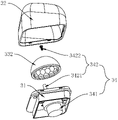
- Fig. 6 is an exploded view of part A in Fig. 5;
- Fig. 7 is a partial cross-sectional view of a sound box in an embodiment of the present application.
- Fig. 8 is an exploded diagram of a light box in an embodiment of the present application.
- Fig. 9 is a front view of a partial structure of a sound box in an embodiment of the present application.
- Fig. 10 is a functional structural diagram of a sound box in an embodiment of the present application.
- Fig. 11 is a structural block diagram of a control component in an embodiment of the present application.
- Fig. 12 is a circuit structure diagram of a wireless microphone receiving unit in an embodiment of the present application.
- Fig. 13 is a circuit structure diagram of the main control module in an embodiment of the present application.
- Fig. 14 is a circuit structure diagram of a light driving module in an embodiment of the present application.
- Fig. 15 is a circuit structure diagram of a rotary drive module in an embodiment of the present application.
- Fig. 16 is a circuit structure diagram of a power amplifier module in an embodiment of the present application.
- multifunctional sound box comprises sound box body 1 and the microphone 2 that is connected with sound box body 1 telecommunication, and microphone 2 is used for collecting external sound signal and converts it into electric current signal, and the external sound collected by microphone 2 in the present application
- the signal is mainly human voice, such as singing and rapping.
- the speaker body 1 is used as the main support structure of the speaker, on which there are sound-generating components 4 for playing audio signals, a light box 3 for creating a lighting atmosphere, and a housing part 13 for placing a microphone 2; wherein the light box 3 is provided with a light emitting The light emitting part 33 and the driving part 34, the light emitting part 33 is used to emit light of at least one color, and the driving part 34 is used to drive the light emitting part 33 to rotate.
- a control assembly 5 is also provided on the speaker body 1 at the same time, and the control assembly 5 includes:
- the signal receiving module 51 is configured to receive an audio signal input from the outside world, the audio signal input from the outside world includes an audio signal input by the microphone 2, an audio signal input wirelessly and an audio signal input wired;
- a main control module 52 configured to receive an audio signal and output an audio processing signal, a first control signal and a second control signal based on the audio signal;
- the power amplifier module 53 is electrically connected between the main control module 52 and the sounding element 4, and is used to receive and amplify the audio processing signal and deliver it to the sounding element 4 for playback;
- the light driving module 54 is electrically connected between the main control module 52 and the light emitting part 33, and is used to receive the first control signal and control the light emitting of the light emitting part 33 based on the first control signal, so that the light color and/or brightness of the light emitting part 33 Change with the rhythm of the audio signal;
- the rotation drive module 55 is electrically connected between the main control module 52 and the drive part 34, and is used to receive the second control signal and control the rotation output of the drive part 34 based on the second control signal, so that the rotation speed of the drive part 34 follows the audio signal The rhythm changes.
- the audio data processing of the speaker and the lighting effect atmosphere control of the light box 3 are realized through the control component 5, so that a speaker can meet the needs of users in various usage scenarios, and users can select functions according to their actual usage requirements.
- the speaker body 1 is the main supporting structure of the speaker body, and the shape of the speaker body 1 can be a conventional three-dimensional figure, such as a cuboid, cube, sphere or hemisphere, ellipsoid, cylinder or cone, or it can be an unconventional shape.
- Three-dimensional graphics, such as irregular polygons, combined three-dimensional graphics and cartoon shapes, etc., the preferred shape of the sound box body 1 in this application is a strip shape or a rod shape.
- the speaker body 1 includes a housing 11 and a tuning net 12 arranged on the housing 11.
- the tuning net 12 is slidably mated with the housing 11.
- the housing 11 can be made of a metal shell or injection molding. plastic case.
- the housing 11 is preferably made of an extruded metal tube through cutting, stamping and punching.
- Metal has good heat dissipation performance, and the housing 11 made of metal can be used as a heat sink for high-power speaker devices. , so that the sound box has a better heat dissipation effect, and at the same time, the use of extruded metal tubes can reduce the processing cost of the shell 11, thereby reducing the cost of the sound box.
- the side on which the housing 11 is provided with the tuning net 12 is the front of the sound box
- the side on which the housing 11 is provided with the accommodation portion 13 is the upper end surface of the sound box
- the accommodation portion 13 is arranged on the shell
- the upper end surface of the body 11 is convenient for the user to access the microphone 2 .
- the microphone 2 is a wireless microphone 2.
- the accommodation part 13 is provided with two vertically opened jacks.
- the bottom of the accommodation part 13 is provided with a charging contact (not shown in the figure).
- the bottom of the microphone 2 is correspondingly provided with a metal ring (not shown in the figure), when the microphone 2 is vertically placed in the accommodating portion 13, due to the gravity of the microphone 2, the charging contacts are in close contact with the metal ring at the bottom of the microphone 2, At this time, if the speaker is powered on, the speaker charges the built-in battery of the microphone 2 .
- the speaker body 1 in order to facilitate the connection between the speaker body 1 and the external power supply, the speaker body 1 is provided with a power interface, and the speaker body 1 is connected to the external power supply through a power adapter.
- the speaker body 1 is provided with an interface area 17.
- the interface area 17 is arranged on the side of the speaker body 1 away from the tuning network 12, and the interface area 17 is for the speaker body 1 to face the tuning network 12.
- the side recess is set to leave room for the interface line to bend.
- the lower end surface of the speaker body 1 is provided with at least two supporting pads 15 at intervals along its length direction. When the speaker is placed on a desktop or other plane, the supporting pads 15 leave a gap between the lower end surface of the speaker and the plane on which it is placed. , to facilitate the heat dissipation and shockproof of the speaker.
- the suspension fasteners 14 include a fixed connection housing.
- the buckle 141 of the body 11 and the hook 142 that is buckled and matched with the buckle 141, the hook 142 is used to be fixed on the support body, the support body can be a wall, and can also be a fixedly installed object, such as a cabinet, a bracket and a door frame, etc.
- the speaker is suspended and installed through the suspension fastener 14.
- the buckle 141 is provided with a snap-in slot 1411 with an opening facing the lower end of the speaker.
- the part of the snap-in 141 provided with the snap-in slot 1411 protrudes toward the side away from the housing 11.
- the snap-in slot 1411 is U-shaped, and the hook 142 is connected to the The slot 1411 cooperates, and under the action of gravity, the hook 142 is in conflict with the snap-in slot 1411, so as to realize the suspension of the speaker.
- the gap facilitates the heat dissipation of the sound box, and at the same time, due to the setting of the interface area 17, space is reserved for the bending of the interface line, so as to prevent the bending part of the interface line from protruding from the sound box body 1 and affecting the suspension of the sound box when the sound box is suspended.
- the sounding element 4 is fixedly arranged on the housing 11 and the sounding part of the sounding element 4 is set towards the side of the tuning net 12.
- the tuning net 12 can not only ensure the dustproof performance of the speaker body 1, but also have ventilation and heat dissipation.
- adding a tuning net 12 to the sound part of the sound generating element 4 can optimize and control the acoustic curve more subtlely, and enhance the sound effect.
- the sound emitting element 4 adopts a full-range speaker and is an even number.
- the housing 11 is provided with a first sound chamber 111 and a second sound chamber 112.
- the first sound chamber 111 Separated from the second sound cavity 112 , the sound emitting elements 4 are arranged in the first sound cavity 111 and the second sound cavity 112 , and the number of 4 sound emitting elements in the first sound cavity 111 and the second sound cavity 112 is equal.
- the sound emitting element 4 in the first sound cavity 111 and the sound emitting element 4 in the second sound cavity 112 are not affected by each other, that is, the left and right sound channels sounds will not interfere with each other.
- the first sound cavity 111 and the second sound cavity 112 are arranged side by side inside the shell, and the inside of the shell is provided with an isolation plate 16, and the first sound cavity 111 and the second sound cavity 112 are separated by the isolation plate 16, the present application
- the middle insulation board 16 is preferably a hard EVA board, and fixing glue is filled between the peripheral side of the insulation board 16 and the inner wall of the housing, and the stability of the insulation board 16 after installation is ensured by the fixing glue.
- the number of sounding elements 4 can be four or six, etc., and a passive diaphragm 6 is provided between adjacent two sounding elements 4 in the same sound cavity, and the passive diaphragm 6 Boosts bass.
- This application shows the situation when there are four sound emitting elements 4 .
- the shell is respectively provided with mounting holes 114 of suitable size and shape corresponding to the sounding element 4 and the passive diaphragm 6, and the sounding element 4 and the passive diaphragm 6 are respectively penetrated in the respective fitting mounting holes 114, and fixed on the mounting hole 114 by screws.
- the gap between the sound emitting element 4 and the passive diaphragm 6 after installation is sealed with soft glue.
- the two light boxes 3 are respectively installed on both ends of the sound box body 1 along the length direction of the sound box body 1, that is, the two light boxes 3 are respectively arranged on the housing 11 at the first sound box.
- the cavity 111 and the second sound cavity 112 are on the side away from each other; similarly, the light box 3 can also be located at other parts of the sound box body 1, such as the light box 3 can also be installed on the upper end of the sound box body 1.
- the light box 3 includes a box base 31 and a light-transmitting lampshade 32 arranged on the box base 31.
- the box base 31 is fixedly connected to the speaker body 1; and cover the end of the speaker body 1, the first sound cavity 111 and the second sound cavity 112 form a complete closed cavity through the box seat 31, and at the same time, the box seat 31 is used to limit the resistance of the tuning net 12 position, to prevent the tuning net 12 from sliding on the housing 11 and causing it to be separated from the housing 11.
- the end face of the box seat 31 away from the speaker body 1 is inclined toward the side of the speaker body 1, and the box seat 31 is far away from the speaker body 1 in this application.
- the end face of one end of the speaker body 1 is inclined toward the front of the speaker body 1 and is inclined toward the upper end face of the speaker body 1 at the same time.
- the inclination angle is greater than or equal to 10°, less than or equal to 60°, preferably 45° in this application, so that the light box 3 The light inside can be more concentrated toward the front and top of the speaker to achieve a better lighting effect.
- the end face of the box seat 31 away from the end of the speaker body 1 is inclined towards the front of the speaker body 1, and the end face of the box seat 31 away from the end of the speaker body 1 can also be inclined towards the two ends of the speaker body 1.
- the light-emitting part 33 includes a light-emitting lamp board 331 and a refracting cover 332 arranged between the box base 31 and the light-transmitting lampshade 32.
- the end faces of the LED are arranged in parallel, and there are several lamp beads on it.
- the lamp beads are lamp beads of various colors, and there are at least two lamp beads of the same color, so that the light emitting part 33 emits lights of various colors. In this application, the lamp beads For LED lights.
- the colors of the lamp beads include but not limited to red, green, blue, white, pink, orange and other colors, and the lamp beads of different colors are staggeredly arranged on the light emitting lamp board 331 to make the light distribution in the light box 3 more uniform.
- the refraction cover 332 is used to refract the light emitted by the lamp beads.
- the refraction cover 332 is hemispherical in appearance, and there are several multi-deformation planes that are spliced with each other inside the refraction cover 332.
- the polygons in this application mainly include hexagons, rhombuses, and triangles.
- the outer surface of the refraction cover 332 is a circular arc surface, so that each polygon forms a small convex lens, and the angle of the light emitted by the lamp bead is changed by the principle of refraction of the light by the convex lens, so that the light scattered by the lamp bead passes through the refraction cover 332 Form a spot of light.
- the drive part 34 is fixedly connected with the refraction cover 332 to drive the refraction cover 332 to rotate, and the light emitting lamp board 331 is fixedly arranged on the box seat 31; due to the special setting of the inner surface of the refraction cover 332, when the drive part 34 drives the refraction cover 332 to rotate, so that the light scattered by the light box 3 rotates and changes following the rotation of the driving part 34 .
- the driving part 34 includes a driving motor 341 and a connector 342 connecting the driving motor 341 and the refracting cover 332.
- the driving motor 341 is preferably a variable frequency motor, and the body of the driving motor 341 is fixedly arranged on the box seat 31 away from the light-emitting lamp board 331- On the side, the output shaft of the drive motor 341 passes through the box seat 31 and the light-emitting lamp board 331 and extends toward the refraction cover 332 , and the output shaft of the drive motor 341 is perpendicular to the light-emitting lamp board 331 .
- the connecting piece 342 includes a connecting shaft 3421 coaxially fixed on the output shaft of the driving motor 341 and a locking bolt 3422 threadedly connected to the end of the connecting shaft 3421 away from the driving motor 341.
- the cover 332 is fixedly connected to the connecting member 342, so that the refracting cover 332 is driven to rotate when the driving motor 341 rotates.
- the axis of the connection shaft 3421 is collinear with the diameter of the refraction cover 332 , and the connection shaft 3421 is arranged perpendicular to the open end surface of the refraction cover 332 .
- the driving part 34 can also be fixedly connected with the light emitting lamp board 331 to drive the light emitting lamp board 331 to rotate, and the refracting cover 332 is fixed on the box seat 31 or the light-transmitting lamp cover 32.
- the driving part 34 drives the light emitting lamp
- the plate 331 rotates
- the light diffused by the light box 3 can also achieve the effect of changing rotation following the rotation of the driving part 34 .
- the drive part 34 drives the refraction cover 331 to rotate, which is easier to realize and lower in production cost, so in this application, the drive mode in which the drive part 34 is fixedly connected to the refraction is preferred.
- the housing 11 is provided with a control chamber 113 corresponding to the interface area 17.
- the control chamber 113 is separated by the isolation plate 16 in the housing 11, and the control chamber 113 is located between the first sound chamber 111 and the Between the second sound cavity 112 , each module of the control assembly 5 is mainly housed in the control cavity 113 .
- the control component 5 is used to transmit the audio signal input from the outside to the sound emitting element 4 for playback, and at the same time control the light box 3 to emit light according to the received audio signal.
- the control assembly 5 also includes a PCB board set, on which a main control module 52 , a signal receiving module 51 , a power amplifier module 53 , a light driving module 54 and a rotation driving module 55 are integrated.
- the control assembly 5 also includes a main control board 56 arranged on the sound box body 1, the main control board 56 is set corresponding to the control cavity 113, the main control board 56 is electrically connected with the main control module 52, and the main control Board 56 is provided with several control buttons.
- the control buttons include but are not limited to the switch button used to control the opening and closing of the speaker, the volume adjustment button used to adjust the playback volume of the speaker, the reverb button used to control the opening and closing of the reverberation function, and the lamp used to control the opening and closing of the lighting effect function effect master button, etc.
- the lighting effect master button is used to control the light driving module 54 and the rotation driving module 55.
- the main control panel 56 is provided with status indicator lights corresponding to the switch button, the reverberation button and the lighting effect master control button one by one.
- the status indicator lights are used to indicate whether the corresponding control button is triggered.
- the corresponding status indicator is on, and when the corresponding control button is not triggered, the corresponding status indicator is off.
- the main control module 52 is composed of a BP1048B2 main control chip and its peripheral circuits, and the BP1048B2 main control chip and its peripheral circuits are integrated and arranged on the PCB circuit board, in order to provide music accompaniment for the user when singing, and improve the user experience.
- the BP1048B2 main control chip of the main control module 52 has a built-in reverberation unit, and the reverberation unit is electrically connected to the signal receiving module 51, and is used to mix the audio signal input by the microphone 2 with the audio signal of the wireless input or the audio signal of the wired input. , and output the mixed audio signal to the power amplifier module 53.
- the left sound channel and the right sound channel there are two power amplifier modules 53, which are respectively electrically connected between the main control module 52 and the sound emitting element 4 located in the first sound chamber 111 and electrically connected between the main control module 52 and the sound emitting element 4 in the first sound chamber 111. It is located between the sound emitting elements 4 in the second sound cavity 112 .
- the main control module 52 when the main control module 52 receives the reverberation instruction, the sound input by the microphone 2 is mixed with the built-in and input sound source through the reverberation unit, so that the listener can hear the sound of singing and the musical instrument Accompaniment sounds are combined to achieve a satisfying singing enjoyment.
- the signal receiving module 51 includes a wired signal interface 511, a Bluetooth receiving unit 512 and a wireless microphone receiving unit 513, wherein the wired signal interface 511 includes several
- the interface for electrical connection the type of interface includes USB interface, audio signal interface, HDMI interface, optical fiber interface and digital coaxial interface integrated on the PCB board group, several interfaces are integrated on the PCB board and the plug-in end of the interface runs through the speaker
- the main body 1 is conveniently connected with the corresponding interface by the interface line. For the convenience of the user to find the corresponding interface, several interfaces are arranged in the interface area 17,
- the Bluetooth receiving unit 512 includes a Bluetooth antenna electrically connected to the main control module 52, the user only needs to turn on the device with Bluetooth function, such as a mobile phone, PC or TV, etc.
- the audio data information on the device is transmitted to the speaker for processing and playback.
- the wireless microphone receiving unit 513 includes a microphone receiving antenna and a microphone decoding module, wherein the microphone receiving antenna is used to receive the antenna signal sent by the microphone 2, and the microphone decoding module is used to decode the audio signal in the antenna signal And the audio signal obtained after decoding is transmitted to the main control module 52.
- the microphone decoding module includes a BK9522 wireless microphone chip with a built-in decoding function.
- the microphone 2 is provided with a transmitting antenna and a wireless transmitting IC that are compatible with the microphone receiving antenna.
- the wireless transmitting IC sends the audio signal through the transmitting antenna, and the speaker receives the antenna signal from the wireless transmitting IC through the microphone receiving antenna, and inputs the antenna signal To the microphone decoding module, the BK9522 wireless microphone chip with built-in decoding function decodes and outputs digital audio signals.
- the number of microphone receiving antennas and microphone decoding modules in the receiving unit of microphone 2 is equal to the number of microphones 2, and the number of microphones 2 in this application is two Therefore, the number of microphone receiving antennas and microphone decoding modules is two.
- the BP1048B2 main control chip of the main control module 52 also has a built-in audio processing unit, which is electrically connected to the signal receiving module 51 and the reverberation unit, and the audio processing unit is integrated with a DRC function for extracting audio signals and output the first control signal to the light driving module 54 and the second control signal to the rotation driving module 55 based on the rhythm signal.
- the BP1048B2 main control chip is electrically connected to several lamp beads in the light box 3 through the light driving module 54 to control the brightness and color change of the several lamp beads in the light box 3; the BP1048B2 main control chip is connected to the drive motor 341 Electrically connected to enable the drive motor 341 to start.
- the audio signal received by the audio processing unit includes the sound source input by the receiving module, such as the sound input by the microphone 2, the audio signal input by wireless, the audio signal input by cable, and the sound source input by the reverberation module; when the main control module 52.
- the reverberation unit performs reverberation processing on the received audio signal and outputs the reverberated audio signal to the audio processing unit.
- the audio processing unit receives the reverberated audio signal and Audio signal is carried out rhythm extraction;
- audio processing unit received the sound of microphone 2 input or the audio signal of wireless input or the audio signal of wired input at this moment, and this audio signal is carried out Rhythm extraction.
- the main control The module 52 drives the light driving module 54 to work through the first control signal to control the brightness and color of the lamp beads to change accordingly, and drives the rotation driving module 55 to work through the second control signal to control the driving motor 341 to rotate to achieve the effect of light flickering.
- the two light boxes 3 The light driving module 54 and the rotation driving module 55 are respectively controlled by the rhythm signal of the left channel and the rhythm signal of the right channel in the audio signal, the first control signal includes LED1-PWM signal and LED2-PWM signal, and the second control signal includes MD1 -PWM signal and MD2-PWM signal; in this application, the LED1-PWM signal corresponds to the light driver module 54 in the light box 3 on the left side of the speaker body 1, and the LED2-PWM signal corresponds to the light driver module in the light box 3 on the right side of the speaker body 1 54.
- the MD1-PWM signal corresponds to the rotary drive module 55 in the light box 3 on the left side of the speaker body 1
- the MD2-PWM signal corresponds to the rotary drive module 55 in the light box 3 on the right side of the speaker body 1.
- each light driving module 54 is a multi-channel light driving circuit electrically connected to the BP1048B2 main control chip.
- the light triode is an NPN type triode, and the collector and emitter of the light triode are connected in series between the power supply and the ground of the speaker.
- the light driving circuit is distinguished according to the color of the lamp bead, and the control electrode of the light triode is electrically connected to the BP1048B2 main control
- On the different output I/O pins of the chip multiple lamp beads of the same color are connected in parallel and then set in series between the emitter of the light triode and the ground or between the collector of the light triode and the power supply of the speaker.
- BP1048B2 main control chip According to the audio rhythm signal, the output tube of the triode of the corresponding color is high, so that the corresponding light triode is turned on, so that the lamp bead of the corresponding color emits light.
- the rotation driving module 55 includes a motor triode, which is also an NPN type triode, and the collector and emitter of the motor triode are connected in series to Between the power supply of the speaker and the ground, the drive motor 341 is connected in series between the emitter of the motor triode and the ground or is set in series between the collector of the motor triode and the power supply of the speaker. When the motor triode outputs a high level, the corresponding motor triode is turned on, and the drive motor 341 connected in series with the triode starts.
- the audio processing unit transmits the processed audio signal to the power amplifier module 53, the sound is amplified by the power amplifier module 53 and then sent to the sound generating element 4 for playback.
- the power amplifier module 53 is electrically connected with the sounding element 4, and the power amplifier module 53 can include a class D audio power amplifier chip and its peripheral circuits whose model is HT368.
- the audio power amplifier chip is connected with the two sounding elements 4 respectively, so that the left The channel audio signal is transmitted to the sound generating element 4 on the left side of the speaker body 1 for playback, and the right channel audio signal in the audio signal is transmitted to the sound emitting element 4 on the right side of the speaker body 1 for playback.
- the microphone 2 is provided with a volume adjustment convenient button for adjusting the volume and a reverberation convenient button for controlling the opening and closing of the reverberation function.
- the ring convenience button has the same function as the volume adjustment button and the reverb button.
- the speaker is also provided with an external audio output interface, which can connect the speaker to other audio equipment, such as a subwoofer unit, to achieve better sound effects in audio playback.
- an external audio output interface can connect the speaker to other audio equipment, such as a subwoofer unit, to achieve better sound effects in audio playback.
- the working process of a multifunctional speaker in the embodiment of the present application is as follows: when the speaker is used as an ordinary audio appreciation and playback device, the speaker is turned on by turning on the switch button on the speaker, and the device that needs to transmit audio data to the speaker is turned on, so that the device The audio is transmitted to the speaker through wired or wireless, and played in the speaker. At the same time, the light effect function on the speaker can be turned on, so that the speaker can emit light synchronized with the music.
- the speaker When the speaker is used as a playback device for singing or dancing, the speaker is turned on by turning on the switch button on the speaker, and the user inputs a voice signal to the microphone 2, and the microphone 2 converts the human voice into a current signal, and transmits the current signal wirelessly
- the IC is transmitted to the main control module 52; when the accompaniment is needed, by turning on the device that needs to transmit audio data to the speaker, the device outputs the song accompaniment to the speaker, and at the same time through the reverb convenient button on the microphone 2 or the mixer on the speaker body 1 Press the button to turn on the reverberation function of the speaker to improve the sound quality of the speaker output.
- the light effect function on the speaker can be turned on through the light effect master button on the speaker body 1, so that the speaker can emit lights synchronized with the music.
Landscapes
- Physics & Mathematics (AREA)
- Engineering & Computer Science (AREA)
- Acoustics & Sound (AREA)
- Signal Processing (AREA)
- Circuit For Audible Band Transducer (AREA)
Abstract
Description
本申请涉及音响设备的领域,尤其是涉及一种多功能音箱。The present application relates to the field of audio equipment, in particular to a multifunctional sound box.
随着社会的发展,休闲娱乐越来越成为人们生活中的重要内容,人们开始购买一些音响设备用作休闲娱乐设施,根据活动场景的不同,所需的设备种类也不同,例如欣赏影视娱乐节目则需要音源、功放和音箱等,唱歌则需要麦克风、音箱和混响等,有时候甚至还需要灯光进行氛围渲染。而现有的音箱通常只具有输出音频的功能,功能较为单一,使用者需要购买不同功能效果的设备来进行配置,不仅多台设备收纳不便,而且多台设备占用空间大。With the development of society, leisure and entertainment have become more and more important content in people's life. People began to buy some audio equipment as leisure and entertainment facilities. According to different activity scenes, the types of equipment required are also different, such as enjoying film and television entertainment programs You need sound sources, power amplifiers and speakers, etc., singing requires microphones, speakers and reverbs, etc., and sometimes even lighting is needed to render the atmosphere. However, the existing speakers usually only have the function of outputting audio, and the function is relatively single. Users need to purchase devices with different functions and effects to configure them. Not only is it inconvenient to store multiple devices, but also multiple devices take up a lot of space.
发明内容Contents of the invention
为了使一套产品就可以满足使用者多种使用需求,降低设备的繁复配置,本申请提供一种多功能音箱。In order to make a set of products meet various needs of users and reduce complicated equipment configurations, the present application provides a multifunctional speaker.
一种多功能音箱,包括音箱本体,所述音箱本体内设置有至少一个发声元件,所述音箱本体上设有用于放置麦克风的容纳部;A multifunctional sound box, comprising a sound box body, at least one sound emitting element is arranged in the sound box body, and a receiving part for placing a microphone is arranged on the sound box body;
所述音箱本体连接有灯光盒,所述灯光盒内设有发光部和驱动部,所述发光部用于发出至少一种颜色的灯光,所述驱动部用于带动发光部转动;The speaker body is connected with a light box, and the light box is provided with a light emitting part and a driving part, the light emitting part is used to emit light of at least one color, and the driving part is used to drive the light emitting part to rotate;
所述音箱本体设有控制组件,所述控制组件包括:The sound box body is provided with a control assembly, and the control assembly includes:
信号接收模块,用于接收外界输入的音频信号,外界输入的音频信号包括麦克风输入的音频信号、无线输入的音频信号和有线输入的音频信号;The signal receiving module is used to receive the audio signal input from the outside world, the audio signal input from the outside world includes the audio signal input by the microphone, the audio signal input by wireless and the audio signal input by cable;
主控模块,用于接收音频信号并基于音频信号输出音频处理信号、第一控制信号和第二控制信号;A main control module, configured to receive an audio signal and output an audio processing signal, a first control signal and a second control signal based on the audio signal;
功放模块,电连接于主控模块和发声元件之间,用于接收并放大音频处理信号并将其输送至发声元件进行播放;The power amplifier module is electrically connected between the main control module and the sounding element, and is used for receiving and amplifying the audio processing signal and sending it to the sounding element for playback;
灯光驱动模块,电连接于主控模块和发光部之间,用于接收第一控制信号并基于第一控制信号控制发光部的发光,使得所述发光部的灯光颜色和/或亮度跟随音频信号的节奏变化而变化;The light driving module is electrically connected between the main control module and the light emitting part, and is used to receive the first control signal and control the light emitting of the light emitting part based on the first control signal, so that the light color and/or brightness of the light emitting part follow the audio signal changes in rhythm;
旋转驱动模块,电连接于主控模块与驱动部之间,用于接收第二控制信号并基于第二控制信号控制驱动部的转动输出,使得所述驱动部的转动速度跟随音频信号的节奏变化而变化。The rotation drive module is electrically connected between the main control module and the drive part, and is used to receive the second control signal and control the rotation output of the drive part based on the second control signal, so that the rotation speed of the drive part changes with the rhythm of the audio signal And change.
进一步地,所述灯光盒包括盒座和设置于盒座上的透光灯罩,所述盒座与音箱本体固定连接,所述盒座远离音箱本体一端的端面朝向音箱本体一侧倾斜。Further, the light box includes a box base and a light-transmitting lampshade arranged on the box base, the box base is fixedly connected to the speaker body, and the end surface of the box base away from the end of the speaker body is inclined toward the side of the speaker body.
进一步地,所述发光部包括设置于盒座与透光灯罩之间的发光灯板以及折射罩,所 述发光灯板设有若干灯珠;所述折射罩用于折射灯珠发出的灯光,所述折射罩内侧面设有若干个相互拼接的多边形平面,所述折射罩外侧面为圆弧面。Further, the light-emitting part includes a light-emitting lamp board and a refraction cover arranged between the box seat and the light-transmitting lamp cover, and the light-emitting lamp board is provided with a number of lamp beads; the refraction cover is used to refract the light emitted by the lamp beads, The inner side of the refraction cover is provided with several polygonal planes spliced with each other, and the outer side of the refraction cover is an arc surface.
进一步地,所述驱动部带动折射罩旋转。Further, the driving part drives the refraction cover to rotate.
进一步地,所述主控模块包括:Further, the main control module includes:
混响单元,电连接于信号接收模块,用于将麦克风输入的音频信号和无线输入的音频信号或有线输入的音频信号进行混合,并将混合后的音频信号输出至功放模块;The reverberation unit is electrically connected to the signal receiving module, and is used to mix the audio signal input by the microphone with the audio signal input by wireless or the audio signal input by cable, and output the mixed audio signal to the power amplifier module;
音频处理单元,电连接于信号接收模块和混响单元,用于提取音频信号的节奏信号并基于节奏信号分别输出第一控制信号至灯光驱动模块和输出第二控制信号至旋转驱动模块。The audio processing unit is electrically connected to the signal receiving module and the reverberation unit, and is used to extract the rhythm signal of the audio signal and output the first control signal to the light driving module and the second control signal to the rotation driving module based on the rhythm signal.
进一步地,所述信号接收模块包括有线信号接口、蓝牙接收单元和无线麦克风接收单元;所述无线麦克风接收单元包括麦克风接收天线和麦克风解码模组,所述麦克风接收天线用于接收无线麦克风所发出的天线信号,所述麦克风解码模组用于解码天线信号中的音频信号并将解码后获得的音频信号传输至主控模块。Further, the signal receiving module includes a wired signal interface, a Bluetooth receiving unit, and a wireless microphone receiving unit; the wireless microphone receiving unit includes a microphone receiving antenna and a microphone decoding module, and the microphone receiving antenna is used to receive The antenna signal, the microphone decoding module is used to decode the audio signal in the antenna signal and transmit the decoded audio signal to the main control module.
进一步地,所述控制组件与麦克风无线连接,所述容纳部设有用于给麦克风充电的充电触点。Further, the control component is wirelessly connected with the microphone, and the accommodating part is provided with a charging contact for charging the microphone.
进一步地,所述音箱本体包括壳体和设置于壳体上的调音网,所述发声元件固定设置于壳体上,且所述发声元件的出音部朝向调音网一侧设置;所述壳体设有第一音腔和第二音腔,所述第一音腔与第二音腔相互隔离,所述发声元件为偶数个,所述发声元件设置于第一音腔和第二音腔内,所述第一音腔和第二音腔内的发声元件个数相等。Further, the sound box body includes a housing and a tuning net arranged on the housing, the sound-generating element is fixedly arranged on the housing, and the sound-emitting part of the sound-generating element is set toward the side of the tuning net; The casing is provided with a first sound cavity and a second sound cavity, the first sound cavity and the second sound cavity are isolated from each other, the sound emitting elements are an even number, and the sound emitting elements are arranged in the first sound cavity and the second sound cavity In the sound cavity, the number of sound emitting elements in the first sound cavity and the second sound cavity are equal.
进一步地,所述功放模块为两个,分别电连接于主控模块与位于第一音腔内的发声元件之间和电连接于主控模块与位于第二音腔内的发声元件之间。Further, there are two power amplifier modules, which are respectively electrically connected between the main control module and the sound emitting element located in the first sound cavity and between the main control module and the sound emitting element located in the second sound cavity.
进一步地,所述壳体背离调音网一侧沿其长度方向间隔设有至少两组悬挂扣件,所述悬挂扣件包括用于固定连接壳体的卡扣和扣接配合于卡扣的挂钩,所述挂钩用于固定于支撑体上。Further, at least two groups of suspension fasteners are provided at intervals along the length direction of the casing away from the tuning net, and the suspension fasteners include buckles for fixedly connecting the casing and buckles that are snap-fitted to the buckles. The hook is used for fixing on the supporting body.
综上所述,本申请包括以下至少一种有益技术效果:In summary, the present application includes at least one of the following beneficial technical effects:
1.通过在音箱上设置容纳部使得麦克风在不使用时可以放置在容纳部内,并可以给麦克风充电;在音箱上设置灯光盒,并在控制系统中集成灯光驱动模块和旋转驱动模块,从而使得音箱具有灯光和声音同步的效果;1. By setting the receiving part on the speaker, the microphone can be placed in the receiving part when not in use, and the microphone can be charged; the light box is installed on the speaker, and the light driving module and the rotating driving module are integrated in the control system, so that the The speaker has the effect of synchronizing light and sound;
2.通过在音箱主控模块中集成混响单元,使得音箱具备混响效果,可以给通过麦克风输入的音频信号提供音乐伴奏;2. By integrating the reverberation unit in the main control module of the speaker, the speaker has a reverberation effect, which can provide music accompaniment for the audio signal input through the microphone;
3.通过设置第一音腔和第二音腔,将发声元件分别置于第一音腔和第二音腔内,使得左右声道的声音不会互相影响。3. By setting the first sound cavity and the second sound cavity, the sound emitting components are respectively placed in the first sound cavity and the second sound cavity, so that the sounds of the left and right channels will not affect each other.
图1是本申请一实施例中的音箱整体结构示意图;Fig. 1 is a schematic diagram of the overall structure of a sound box in an embodiment of the present application;
图2是本申请一实施例中的音箱的部分爆炸图;Fig. 2 is a partial exploded view of the sound box in an embodiment of the present application;
图3是本申请一实施例中的音箱功能模块图;Fig. 3 is a functional block diagram of a speaker in an embodiment of the present application;
图4是本申请一实施例中的音箱的整体结构爆炸图;Fig. 4 is an exploded view of the overall structure of the sound box in an embodiment of the present application;
图5是本申请一实施例中的音箱的后侧视图;Fig. 5 is the rear side view of the sound box in an embodiment of the present application;
图6是图5中A部爆炸图;Fig. 6 is an exploded view of part A in Fig. 5;
图7是本申请一实施例中的音箱部分剖视图;Fig. 7 is a partial cross-sectional view of a sound box in an embodiment of the present application;
图8是本申请一实施例中的灯光盒爆炸图;Fig. 8 is an exploded diagram of a light box in an embodiment of the present application;
图9是本申请一实施例中的音箱部分结构的正视图;Fig. 9 is a front view of a partial structure of a sound box in an embodiment of the present application;
图10是本申请一实施例中的音箱功能结构图;Fig. 10 is a functional structural diagram of a sound box in an embodiment of the present application;
图11是本申请一实施例中的控制组件结构框图;Fig. 11 is a structural block diagram of a control component in an embodiment of the present application;
图12是本申请一实施例中的无线麦克风接收单元的电路结构图;Fig. 12 is a circuit structure diagram of a wireless microphone receiving unit in an embodiment of the present application;
图13是本申请一实施例中的主控模块的电路结构图;Fig. 13 is a circuit structure diagram of the main control module in an embodiment of the present application;
图14是本申请一实施例中的灯光驱动模块的电路结构图;Fig. 14 is a circuit structure diagram of a light driving module in an embodiment of the present application;
图15是本申请一实施例中的旋转驱动模块的电路结构图;Fig. 15 is a circuit structure diagram of a rotary drive module in an embodiment of the present application;
图16是本申请一实施例中的功放模块的电路结构图。Fig. 16 is a circuit structure diagram of a power amplifier module in an embodiment of the present application.
附图标记说明:1、音箱本体;11、壳体;111、第一音腔;112、第二音腔;113、控制腔;114、安装孔;12、调音网;13、容纳部;14、悬挂扣件;141、卡扣;1411、卡接槽;142、挂钩;15、支撑脚垫;16、隔离板;17、接口区;2、麦克风;3、灯光盒;31、盒座;32、透光灯罩;33、发光部;331、发光灯板;332、折射罩;34、驱动部;341、驱动电机;342、连接件;3421、连接轴;3422、锁紧螺栓;4、发声元件;5、控制组件;51、信号接收模块;511、有线信号接口;512、蓝牙接收单元;513、无线麦克风接收单元;52、主控模块;53、功放模块;54、灯光驱动模块;55、旋转驱动模块;56、主操控板;6、被动振膜。Explanation of reference signs: 1. Speaker body; 11. Shell; 111. First sound chamber; 112. Second sound chamber; 113. Control chamber; 114. Installation hole; 12. Tuning net; 13. Accommodating part; 14. Suspension fastener; 141. Buckle; 1411. Clamping groove; 142. Hook; 15. Support pad; 16. Isolation board; 17. Interface area; 2. Microphone; 3. Lighting box; 31. Box seat ; , Sounding components; 5, Control components; 51, Signal receiving module; 511, Wired signal interface; 512, Bluetooth receiving unit; 513, Wireless microphone receiving unit; 52, Main control module; 53, Power amplifier module; 54, Lighting driver module ; 55, the rotary drive module; 56, the main control panel; 6, the passive diaphragm.
以下结合附图1-16对本申请作进一步详细说明。The present application will be described in further detail below in conjunction with accompanying drawings 1-16.
传统的音箱产品通常只具备音频播放功能,随着人们对视听要求的提高,在家庭聚会娱乐过程中,如果需要K歌,则需要搭配使用一对麦克风并且需要搭配具有混响功能的卡拉OK播放系统,如果需要开舞会,则需要搭配舞台灯光,而这一整套设备搭配下来,价格昂贵,且配置复杂,对一般家庭来说,可能使用的频率并不高,购买,则产品实际使用的性价比并不高,不购买,则无法满足自身的使用需求。Traditional speaker products usually only have the function of audio playback. With the improvement of people's audio-visual requirements, in the process of family gathering entertainment, if you need karaoke, you need to use a pair of microphones and karaoke with reverberation function. System, if you need to hold a dance party, you need to match stage lighting, and this whole set of equipment is expensive and complicated to configure. For ordinary families, the frequency of use may not be high. If you buy it, the actual cost performance Not high, if you don't buy it, you can't meet your own needs.
本申请实施例公开涉及一种多功能音箱。参照图1和图2,多功能音箱包括音箱本体1和与音箱本体1电信连接的麦克风2,麦克风2用于采集外界声音信号并将其转化 为电流信号,本申请中麦克风2采集的外界声音信号主要为人声,如唱歌声和说唱声等。音箱本体1作为音箱的主要支撑结构,其上设置有用于播放音频信号的发声元件4、用于营造灯光氛围灯光盒3以及用于放置麦克风2的容纳部13;其中灯光盒3内设有发光部33和驱动部34,发光部33用于发出至少一种颜色的灯光,驱动部34用于带动发光部33转动。The embodiment disclosure of the present application relates to a multifunctional sound box. With reference to Fig. 1 and Fig. 2, multifunctional sound box comprises
参照图3和图4,同时音箱本体1上还设有控制组件5,控制组件5包括:Referring to Fig. 3 and Fig. 4, a
信号接收模块51,用于接收外界输入的音频信号,外界输入的音频信号包括麦克风2输入的音频信号、无线输入的音频信号和有线输入的音频信号;The
主控模块52,用于接收音频信号并基于音频信号输出音频处理信号、第一控制信号和第二控制信号;A
功放模块53,电连接于主控模块52和发声元件4之间,用于接收并放大音频处理信号并将其输送至发声元件4进行播放;The
灯光驱动模块54,电连接于主控模块52和发光部33之间,用于接收第一控制信号并基于第一控制信号控制发光部33的发光,使得发光部33的灯光颜色和/或亮度跟随音频信号的节奏变化而变化;The
旋转驱动模块55,电连接于主控模块52与驱动部34之间,用于接收第二控制信号并基于第二控制信号控制驱动部34的转动输出,使得驱动部34的转动速度跟随音频信号的节奏变化而变化。The
通过控制组件5实现音箱的音频数据处理和灯光盒3的灯效氛围控制,使得一个音箱能够满足使用者的多种使用场景需求,同时使用者能够根据其实际使用需求进行功能选择。The audio data processing of the speaker and the lighting effect atmosphere control of the
参照图4,音箱本体1为音箱的主要支撑结构,音箱本体1外形可为常规的立体图形,例如长方体、立方体、球体或半球体、椭圆体、柱体或者是锥体,也可以为非常规的立体图形,例如非规则的多边形、组合式的立体图形和卡通造型等,本申请中优选的音箱本体1外形为长条形或棒形。Referring to Fig. 4, the
具体地,音箱本体1包括壳体11和设置于壳体11上的调音网12,调音网12与壳体11滑动插接配合,壳体11可以采用金属外壳,也可以采用注塑而成的塑料外壳。本申请中壳体11优选采用挤出成型式的金属管经切割、冲压和冲孔等制成,金属具有良好的散热性能,金属制成的壳体11可以作为大功率音箱器件的散热片使用,使得音箱具有更好的散热效果,同时采用挤出成型的金属管能够降低壳体11的加工成本,从而降低音箱的造价。Specifically, the
参照图4,本申请中定义音箱正常使用时,壳体11设置调音网12的一侧为音箱正面,壳体11设置容纳部13的一侧为音箱上端面,将容纳部13设置于壳体11上端面, 方便使用者存取麦克风2。音箱常规搭配的麦克风2为两个,本申请中麦克风2采用无线麦克风2,容纳部13为两个且为竖直开设的插孔设置,容纳部13底部设置有充电触点(图中未显示),麦克风2底部对应设有金属环(图中未显示),当麦克风2竖直放置在容纳部13内时,由于麦克风2的重力,使得充电触点和麦克风2底部的金属环密切接触,此时,若音箱接通电源,则音箱给麦克风2内置电池充电。Referring to Fig. 4, when the sound box is defined in this application to be in normal use, the side on which the
参照图4和图5,为方便音箱本体1与外接电源的连接,音箱本体1上设置有电源接口,音箱本体1通过电源适配器与外接电源连接。音箱本体1上设置有接口区17,本申请中为提高音箱整体的观感,接口区17设置于音箱本体1背离调音网12一侧,且接口区17为音箱本体1朝向调音网12一侧凹陷设置,为接口线弯折留出空间。音箱本体1的下端面沿其长度方向间隔设有至少两个支撑脚垫15,当音箱放置在桌面或其他平面上时,通过支撑脚垫15使得音箱下端面与其被放置平面之间留有间隙,方便音箱的散热和防震。4 and 5, in order to facilitate the connection between the
参照图5和图6,为方便音箱的摆放安装,壳体11背离调音网12一侧沿其长度方向间隔设有至少两组悬挂扣件14,悬挂扣件14包括用于固定连接壳体11的卡扣141和扣接配合于卡扣141的挂钩142,挂钩142用于固定于支撑体上,支撑体可以为墙体,也可以为固定安装的物体,例如柜子、支架和门框等,通过悬挂扣件14对音箱进行悬挂安装。卡扣141设有开口朝向音箱下端的卡接槽1411,卡扣141设置卡接槽1411的部分朝向远离壳体11一侧凸起,卡接槽1411呈U型设置,挂钩142通过与卡接槽1411配合,在重力作用下使得挂钩142与卡接槽1411抵触,从而实现音箱的悬挂,同时由于卡扣141的凸出设置使得音箱悬挂后,壳体11侧壁与支撑体之间留有间隙,方便音箱的散热,同时由于接口区17的设置,为接口线弯折留出空间,防止音箱悬挂时,接口线弯折部分突出音箱本体1而影响音响悬挂。Referring to Fig. 5 and Fig. 6, in order to facilitate the placement and installation of the sound box, at least two groups of
参照图7,发声元件4固定设置于壳体11上且发声元件4的出音部朝向调音网12一侧设置,调音网12既可以保证音箱本体1的防尘性能,又具有透气散热效果,同时在发声元件4出音部增加调音网12可以更细微的优化和控制声学曲线,增强声音效果。为有效保证声音的分离度和使得听众能够听到立体声音,发声元件4采用全频喇叭且为偶数个,壳体11设有第一音腔111和第二音腔112,第一音腔111与第二音腔112相互隔离,发声元件4设置于第一音腔111和第二音腔112内,且第一音腔111和第二音腔112内的发声元件4个数相等。通过相互隔离的第一音腔111和第二音腔112,使得第一音腔111内的发声元件4与第二音腔112内的发声元件4相互之间不受影响,即使得左右声道的声音不会相互干扰。Referring to Fig. 7, the sounding
参照图7,第一音腔111和第二音腔112并列设置于外壳内部,外壳内部设有隔离板16,通过隔离板16对第一音腔111和第二音腔112进行分隔,本申请中隔离板16 优选为硬质的EVA板,隔离板16周侧与外壳内壁之间填充有固定胶,通过固定胶以保证隔离板16安装后的稳定性。Referring to Fig. 7, the
在一实施例中发声元件4可以为两个,以最低成本实现音频信号左声道声音和右声道声音的分别播放。In an embodiment, there may be two
参照图7,在一实施例中发声元件4可以为四个或六个等,且位于同一音腔内的相邻两个发声元件4之间设有被动振膜6,通过被动振膜6来增强低音效果。本申请中展示发声元件4为四个时的情形。外壳对应发声元件4和被动振膜6分别设有大小、形状适配的安装孔114,发声元件4和被动振膜6分别穿设于各自适配的安装孔114内,并通过螺丝固定安装在外壳上,再通过软胶对发声元件4和被动振膜6安装后的间隙进行密封。Referring to Fig. 7, in one embodiment, the number of
参照图7和图8,本申请中灯光盒3优选为两个且沿音箱本体1长度方向分别安装于音箱本体1的两端,即两个灯光盒3分别设置于壳体11位于第一音腔111和第二音腔112相互背离的一侧上;同理灯光盒3也可以位于音箱本体1的其他部位,如灯光盒3还可以安装于音箱本体1的上端。灯光盒3包括盒座31和设置于盒座31上的透光灯罩32,盒座31与音箱本体1固定连接;当调音网12与外壳插接后,盒座31插接在音箱本体1的端部并对音箱本体1的端部进行盖合,通过盒座31使得第一音腔111和第二音腔112形成完整的封闭腔室,同时通过盒座31对调音网12进行抵触限位,防止调音网12在壳体11上滑动导致脱离壳体11。Referring to Fig. 7 and Fig. 8, in the present application, there are preferably two
参照图8和图9,为使得灯光盒3内的灯光能够更大范围的照射到音箱前方,盒座31远离音箱本体1一端的端面朝向音箱本体1一侧倾斜,本申请中盒座31远离音箱本体1一端的端面朝向音箱本体1正面倾斜同时朝向音箱本体1的上端面倾斜,倾斜角度为大于或等于10°,小于或等于60°,本申请中优选为45°,以使得灯光盒3内的光线能够更加集中的照向音箱的前方和上方,以实现更好地灯光效果。若灯光盒3安装在音箱本体1上端,盒座31远离音箱本体1一端的端面朝向音箱本体1正面倾斜,同时盒座31远离音箱本体1一端的端面也可以朝向音箱本体1两端倾斜。Referring to Fig. 8 and Fig. 9, in order to enable the light in the
参照图8和图9,发光部33包括设置于盒座31和透光灯罩32之间的发光灯板331及折射罩332,发光灯板331采用PCB板且与盒座31远离音箱本体1一端的端面平行设置,其上设有若干灯珠,灯珠为多种颜色灯珠,且同一颜色的灯珠为至少两颗,使得发光部33发出多种不同颜色的灯光,本申请中灯珠为LED灯。灯珠颜色包括但不限于红、绿、蓝、白、粉和橙等多种颜色,且不同颜色的灯珠交错排布在发光灯板331上使得灯光盒3内的光线分布更加均匀。折射罩332用于折射灯珠发出的灯光,折射罩332从外形看呈半球型,折射罩332内侧设有若干个相互拼接的多变形平面,本申请中多边形主要包括六边形、菱形、三角形和矩形,折射罩332外侧面为圆弧面,使得每个多边 形均形成一个小的凸透镜,利用凸透镜对灯光的折射原理改变灯珠射出的光线角度,使得灯珠散射的光线经过折射罩332后形成一个一个斑点状的灯光。Referring to Fig. 8 and Fig. 9, the light-emitting
参照图8和图9,驱动部34与折射罩332固定连接用于带动折射罩332旋转,发光灯板331固定设置于盒座31上;由于折射罩332的内侧面的特殊设置,当驱动部34带动折射罩332旋转时,使得灯光盒3散射的灯光跟随驱动部34的转动而旋转变化。驱动部34包括驱动电机341和连接驱动电机341与折射罩332的连接件342,本申请中驱动电机341优选采用变频电机,驱动电机341的机身固定设置于盒座31背离发光灯板331一侧,驱动电机341的输出轴贯穿盒座31和发光灯板331并朝向折射罩332延伸,且驱动电机341的输出轴与发光灯板331垂直设置。连接件342包括同轴固定设置于驱动电机341输出轴上的连接轴3421和螺纹连接于连接轴3421远离驱动电机341一端端部的锁紧螺栓3422,锁紧螺栓3422贯穿折射罩332,将折射罩332固定连接在连接件342上,从而实现驱动电机341旋转时带动折射罩332旋转。本申请中连接轴3421的轴线与折射罩332的直径共线,且连接轴3421垂直于折射罩332开口端端面设置。8 and 9, the
在一实施例中,驱动部34也可与发光灯板331固定连接用于带动发光灯板331旋转,将折射罩332固定在盒座31或透光灯罩32上,当驱动部34带动发光灯板331旋转时,使得灯光盒3散射的灯光也能实现跟随驱动部34的转动而旋转变化的效果。在实际生产过程中,驱动部34带动折射罩331旋转在生产制造上更易于实现且生产成本更低,因此本申请中优选为驱动部34与折射固定连接的驱动方式。In one embodiment, the driving
参照图7和图10,壳体11对应接口区17设置有控制腔113,本申请中控制腔113由隔离板16在壳体11中分隔而成,且控制腔113位于第一音腔111和第二音腔112之间,控制组件5的各个模块主要收纳设置于控制腔113内。控制组件5用于将外界输入的音频信号输送至发声元件4进行播放,同时可以根据接收到的音频信号控制灯光盒3发光。控制组件5还包括PCB板组,主控模块52、信号接收模块51、功放模块53、灯光驱动模块54以及旋转驱动模块55集成设置于PCB板组上。为方便对音箱进行控制,控制组件5还包括设置于音箱本体1上的主操控板56,主操控板56对应控制腔113设置,主操控板56与主控模块52电性连接,且主操控板56上设有若干控制按钮。控制按钮包括但不限于用于控制音箱启闭的开关按钮、用于调节音箱播放音量的音量调节按钮、用于控制混响功能启闭的混响按钮以及用于控制灯光效果功能启闭的灯效主控按钮等。其中灯效主控按钮用来控制灯光驱动模块54和旋转驱动模块55,当灯效主控按钮开启后,播放音乐时,灯光盒3上的发光部33和驱动部34同步启动。同时主操控板56上设置有与开关按钮、混响按钮以及灯效主控按钮一一对应的状态指示灯,状态指示灯用于指示对应控制按钮是否被触发,当对应控制按钮被触发时,对应状态指示灯亮, 当对应控制按钮没有被触发时,对应状态指示灯灭。7 and 10, the
参照图10,其中主控模块52为BP1048B2主控芯片与其外围电路构成,BP1048B2主控芯片及其外围电路集成设置于PCB电路板上,为给用户唱歌时提供音乐伴奏,提高用户的使用感受,主控模块52的BP1048B2主控芯片中内置有混响单元,混响单元电连接于信号接收模块51,用于将麦克风2输入的音频信号和无线输入的音频信号或有线输入的音频信号进行混合,并将混合后的音频信号输出功放模块53。由于左声道和右声道的存在,功放模块53为两个,且分别电连接于主控模块52与位于第一音腔111内的发声元件4之间和电连接于主控模块52与位于第二音腔112内的发声元件4之间。Referring to Fig. 10, the
参照图10,具体地,在主控模块52接收到混响指令时,通过混响单元将麦克风2输入的声音和内置及输入的音源混合在一起,使得听众听到的自己唱歌的声音和乐器伴奏的声音相结合,达到满意的歌唱享受。Referring to Fig. 10, specifically, when the
参照图10和图11,为丰富音频信号接入的多样化,信号接收模块51包括有线信号接口511、蓝牙接收单元512和无线麦克风接收单元513,其中有线信号接口511包括若干与主控模块52电连接的接口,接口的种类包括集成设置于PCB板组上的USB接口、音频信号接口、HDMI接口、光纤接口和数字同轴接口,若干接口集成在PCB板上且接口的插接端贯穿音箱本体1以方便接口线与对应接口连接。为方便用户寻找对应的接口,若干接口设置于接口区17内,Referring to Fig. 10 and Fig. 11, in order to enrich the diversification of audio signal access, the
参照图10和图11,蓝牙接收单元512包括电连接于主控模块52上的蓝牙天线,用户只需要打开带有蓝牙功能的设备,如手机、PC或者电视等,通过蓝牙之间的相互匹配使得设备上的音频数据信息传送到音箱上进行处理并播放。Referring to Figure 10 and Figure 11, the Bluetooth receiving unit 512 includes a Bluetooth antenna electrically connected to the
参照图11和图12,无线麦克风接收单元513包括麦克风接收天线和麦克风解码模组,其中麦克风接收天线用于接收麦克风2所发出的天线信号,麦克风解码模组用于解码天线信号中的音频信号并将解码后获得的音频信号传输至主控模块52,本申请中麦克风解码模组包括内置有解码功能的BK9522无线麦克风芯片。麦克风2内设置有与麦克风接收天线相适配的发射天线和无线发射IC,无线发射IC将音频信号通过发射天线发出,音箱通过麦克风接收天线接收无线发射IC发出的天线信号,并将天线信号输入至麦克风解码模组,通过内置解码功能的BK9522无线麦克风芯片解码输出数字音频信号。11 and 12, the wireless
为保证多个麦克风2时,麦克风2输出的信号均能被音箱接收,麦克风2接收单元中麦克风接收天线和麦克风解码模组的数量与麦克风2个数相等,本申请中麦克风2的数量为两个,因此麦克风接收天线和麦克风解码模组的数量均为2。In order to ensure
参照图11和图13,主控模块52的BP1048B2主控芯片中还内置有音频处理单元,电连接于信号接收模块51和混响单元,且音频处理单元集成有DRC功能,用于提取音 频信号的节奏信号并基于节奏信号分别输出第一控制信号至灯光驱动模块54和输出第二控制信号至旋转驱动模块55。BP1048B2主控芯片通过灯光驱动模块54与灯光盒3内的若干灯珠电性连接,以控制灯光盒3中若干灯珠的亮度和颜色变化;BP1048B2主控芯片通过旋转驱动模块55与驱动电机341电性连接,以实现驱动电机341启动。Referring to Fig. 11 and Fig. 13, the BP1048B2 main control chip of the
具体地,音频处理单元接收到的音频信号包括接收模块输入的音源,例如麦克风2输入的声音、无线输入的音频信号、有线输入的音频信号,也包括混响模块输入的音源;当主控模块52接收到混响指令时,混响单元对接收到音频信号进行混响处理并向音频处理单元输出混响后的音频信号,此时音频处理单元接收到混响后的音频信号,并对该音频信号进行节奏提取;当主控模块52没有接收到混响指令时,此时音频处理单元接收到麦克风2输入的声音或无线输入的音频信号或有线输入的音频信号,并对该音频信号进行节奏提取。音频处理单元根据其接收到的音频信号进行节奏提取后,并根据其提取的节奏信号的能量值范围输出第一控制信号至灯光驱动模块54和输出第二控制信号至旋转驱动模块55,主控模块52通过第一控制信号驱动灯光驱动模块54工作从而控制灯珠的亮度和颜色进行相应变化,通过第二控制信号驱动旋转驱动模块55工作从而控制驱动电机341旋转,以实现灯光闪烁的效果。Specifically, the audio signal received by the audio processing unit includes the sound source input by the receiving module, such as the sound input by the
参照图10和图11,本申请中,灯光盒3有两个,且根据音频信号有左声道声音和右声道声音之分,为保证更好的灯光氛围效果,两个灯光盒3中的灯光驱动模块54和旋转驱动模块55分别受音频信号中的左声道节奏信号和右声道节奏信号控制,第一控制信号包括LED1-PWM信号和LED2-PWM信号,第二控制信号包括MD1-PWM信号和MD2-PWM信号;本申请中LED1-PWM信号对应音箱本体1左侧灯光盒3内的灯光驱动模块54,LED2-PWM信号对应音箱本体1右侧灯光盒3内的灯光驱动模块54,MD1-PWM信号对应音箱本体1左侧灯光盒3内的旋转驱动模块55,MD2-PWM信号对应音箱本体1右侧灯光盒3内的旋转驱动模块55。Referring to Fig. 10 and Fig. 11, in this application, there are two
参照图13和图14,其中,每个灯光驱动模块54均为多路电性连接于BP1048B2主控芯片的灯光驱动电路,多路灯光驱动电路的电路结构相同,均包括灯光三极管,本申请中灯光三极管为NPN型三极管,且灯光三极管的集电极和发射极串联连接于音箱的供电电源和地之间,灯光驱动电路根据灯珠颜色进行区分,灯光三极管的控制极电性连接于BP1048B2主控芯片不同输出I/O脚上,多个相同颜色的灯珠并联后串联设置于灯光三极管的发射极和地之间或串联设置于灯光三极管的集电极和音箱的供电电源之间,BP1048B2主控芯片根据音频节奏信号向对应颜色的三极管输出管高电平使得对应灯光三极管导通,从而使得对应颜色的灯珠发光。Referring to Fig. 13 and Fig. 14, each
参照图13和图15,两个旋转驱动模块55也电性连接于BP1048B2主控芯片,旋转驱动模块55包括马达三极管,马达三极管也为NPN型三极管,马达三极管的集电极和 发射极串联连接于音箱的供电电源和地之间,驱动电机341串联于马达三极管的发射极和地之间或串联设置于马达三极管的集电极和音箱的供电电源之间,当BP1048B2主控芯片根据音频节奏信号向对应马达三极管输出高电平时,对应马达三极管导通,此时串联于该三极管上的驱动电机341启动。Referring to Fig. 13 and Fig. 15, two
参照图11和图16,音频处理单元将处理后的音频信号传送至功放模块53,通过功放模块53对声音进行放大后输送至发声元件4进行播放,本申请中即为BP1048B2主控芯片通过功放模块53与发声元件4电性连接,功放模块53可包括型号为HT368的D类音频功率放大芯片及其外围电路,音频功率放大芯片分别与两个发声元件4连接,从而将音频信号中的左声道音频信号传送到位于音箱本体1左侧的发声元件4进行播放,将音频信号中的右声道音频信号传送到位于音箱本体1右侧的发声元件4进行播放。Referring to Figure 11 and Figure 16, the audio processing unit transmits the processed audio signal to the
在一实施例中,为提高音箱各功能控制的便捷性,麦克风2上设置有用于调节音量的音量调节便捷按钮和用于控制混响功能启闭的混响便捷按钮,音量调节便捷按钮和混响便捷按钮与音量调节按钮和混响按钮功能相同,当对应按钮被触发时,麦克风2中通过无线发射IC将被触发的控制指令转换成U段信号,通过天线传送到麦克风接收天线上,当麦克法解码模组接收到U段信号时,对接收到的U段信号进行解码,再将解码信号传输至主控模块52上进行对应的输出控制。In one embodiment, in order to improve the convenience of each function control of the sound box, the
在一实施例中,音箱还设有外接音频输出接口,可以将音箱与其他的音响设备进行连接,例如低音炮单元等,以实现音频播放更好的声音效果。In an embodiment, the speaker is also provided with an external audio output interface, which can connect the speaker to other audio equipment, such as a subwoofer unit, to achieve better sound effects in audio playback.
本申请实施例一种多功能音箱的工作过程为:当音箱被用作普通的音频欣赏播放设备使用时,通过开启音箱上的开关按钮打开音箱,打开需要向音箱传送音频数据的设备,使得设备音频通过有线或无线方式传送到音箱中,在音箱中进行播放,同时还可以打开音箱上的灯效功能,使得音箱能够发出跟音乐同步的灯光。The working process of a multifunctional speaker in the embodiment of the present application is as follows: when the speaker is used as an ordinary audio appreciation and playback device, the speaker is turned on by turning on the switch button on the speaker, and the device that needs to transmit audio data to the speaker is turned on, so that the device The audio is transmitted to the speaker through wired or wireless, and played in the speaker. At the same time, the light effect function on the speaker can be turned on, so that the speaker can emit light synchronized with the music.
当音箱被用作唱歌或者舞会的播放设备使用时,通过开启音箱上的开关按钮打开音箱,用户通过向麦克风2输入语音信号,麦克风2将人声转化为电流信号,并将电流信号通过无线发射IC传输至主控模块52中;当需要伴奏时,通过打开需要向音箱传送音频数据的设备,通过设备向音箱输出歌曲伴奏,同时通过麦克风2上的混响便捷按钮或音箱本体1上的混响按钮开启音箱的混响功能,以提高音箱输出的声音质量。可以根据使用场景需要,通过音箱本体1上的灯效主控按钮打开音箱上的灯效功能,使得音箱能够发出跟音乐同步的灯光。When the speaker is used as a playback device for singing or dancing, the speaker is turned on by turning on the switch button on the speaker, and the user inputs a voice signal to the
以上均为本申请的较佳实施例,并非依此限制本申请的保护范围,故:凡依本申请的结构、形状、原理所做的等效变化,均应涵盖于本申请的保护范围之内。All of the above are preferred embodiments of the present application, and are not intended to limit the protection scope of the application. Therefore, all equivalent changes made according to the structure, shape and principle of the application should be covered by the protection scope of the application. Inside.
Claims (10)
Priority Applications (1)
| Application Number | Priority Date | Filing Date | Title |
|---|---|---|---|
| PCT/CN2021/100893 WO2022261935A1 (en) | 2021-06-18 | 2021-06-18 | Multifunctional loudspeaker |
Applications Claiming Priority (1)
| Application Number | Priority Date | Filing Date | Title |
|---|---|---|---|
| PCT/CN2021/100893 WO2022261935A1 (en) | 2021-06-18 | 2021-06-18 | Multifunctional loudspeaker |
Publications (1)
| Publication Number | Publication Date |
|---|---|
| WO2022261935A1 true WO2022261935A1 (en) | 2022-12-22 |
Family
ID=84526632
Family Applications (1)
| Application Number | Title | Priority Date | Filing Date |
|---|---|---|---|
| PCT/CN2021/100893 Ceased WO2022261935A1 (en) | 2021-06-18 | 2021-06-18 | Multifunctional loudspeaker |
Country Status (1)
| Country | Link |
|---|---|
| WO (1) | WO2022261935A1 (en) |
Cited By (4)
| Publication number | Priority date | Publication date | Assignee | Title |
|---|---|---|---|---|
| CN116389967A (en) * | 2023-04-11 | 2023-07-04 | 广东台德智联科技有限公司 | Sound box assembly, microphone and intelligent portable KTV system |
| CN116887130A (en) * | 2023-08-16 | 2023-10-13 | 深圳鑫金运科技有限公司 | A lyrics audio circuit structure |
| CN117750261A (en) * | 2023-12-29 | 2024-03-22 | 深圳市维尔晶科技有限公司 | Adjustable wireless microphone |
| CN119967324A (en) * | 2025-01-23 | 2025-05-09 | 常州美硕音响有限公司 | Portable speaker with adjustable sound cavity volume |
Citations (9)
| Publication number | Priority date | Publication date | Assignee | Title |
|---|---|---|---|---|
| US20100192753A1 (en) * | 2007-06-29 | 2010-08-05 | Multak Technology Development Co., Ltd | Karaoke apparatus |
| CN105578640A (en) * | 2015-12-15 | 2016-05-11 | 武良举 | Audio-based lamp control system and device and control method and application thereof |
| CN205265891U (en) * | 2015-10-14 | 2016-05-25 | 深圳市鼎世嘉电子礼品有限公司 | Stage flash of light circuit and contain mini bluetooth speaker of this circuit |
| TWM547804U (en) * | 2017-05-04 | 2017-08-21 | zhao-yi Chen | Portable music device with sound and light effect |
| CN206596159U (en) * | 2017-03-16 | 2017-10-27 | 冉红梅 | A kind of microphone with stage-lighting effect |
| CN209562774U (en) * | 2019-03-05 | 2019-10-29 | 宿迁学院 | A bluetooth speaker convenient for outdoor activities |
| CN210777819U (en) * | 2019-08-03 | 2020-06-16 | 赵天福 | Multi-functional wireless live broadcast karaoke bluetooth sound stage lamp of recording |
| CN111557548A (en) * | 2020-06-15 | 2020-08-21 | 佛山市迪赛纳科技有限公司 | Sound control light-emitting competition table |
| CN112118512A (en) * | 2019-06-21 | 2020-12-22 | 北京声智科技有限公司 | Sound box |
-
2021
- 2021-06-18 WO PCT/CN2021/100893 patent/WO2022261935A1/en not_active Ceased
Patent Citations (9)
| Publication number | Priority date | Publication date | Assignee | Title |
|---|---|---|---|---|
| US20100192753A1 (en) * | 2007-06-29 | 2010-08-05 | Multak Technology Development Co., Ltd | Karaoke apparatus |
| CN205265891U (en) * | 2015-10-14 | 2016-05-25 | 深圳市鼎世嘉电子礼品有限公司 | Stage flash of light circuit and contain mini bluetooth speaker of this circuit |
| CN105578640A (en) * | 2015-12-15 | 2016-05-11 | 武良举 | Audio-based lamp control system and device and control method and application thereof |
| CN206596159U (en) * | 2017-03-16 | 2017-10-27 | 冉红梅 | A kind of microphone with stage-lighting effect |
| TWM547804U (en) * | 2017-05-04 | 2017-08-21 | zhao-yi Chen | Portable music device with sound and light effect |
| CN209562774U (en) * | 2019-03-05 | 2019-10-29 | 宿迁学院 | A bluetooth speaker convenient for outdoor activities |
| CN112118512A (en) * | 2019-06-21 | 2020-12-22 | 北京声智科技有限公司 | Sound box |
| CN210777819U (en) * | 2019-08-03 | 2020-06-16 | 赵天福 | Multi-functional wireless live broadcast karaoke bluetooth sound stage lamp of recording |
| CN111557548A (en) * | 2020-06-15 | 2020-08-21 | 佛山市迪赛纳科技有限公司 | Sound control light-emitting competition table |
Cited By (5)
| Publication number | Priority date | Publication date | Assignee | Title |
|---|---|---|---|---|
| CN116389967A (en) * | 2023-04-11 | 2023-07-04 | 广东台德智联科技有限公司 | Sound box assembly, microphone and intelligent portable KTV system |
| US20240348955A1 (en) * | 2023-04-11 | 2024-10-17 | Jiangxi Taide Intelligence Technology Co., Ltd. | Speaker assembly, microphone and smart portable karaoke system |
| CN116887130A (en) * | 2023-08-16 | 2023-10-13 | 深圳鑫金运科技有限公司 | A lyrics audio circuit structure |
| CN117750261A (en) * | 2023-12-29 | 2024-03-22 | 深圳市维尔晶科技有限公司 | Adjustable wireless microphone |
| CN119967324A (en) * | 2025-01-23 | 2025-05-09 | 常州美硕音响有限公司 | Portable speaker with adjustable sound cavity volume |
Similar Documents
| Publication | Publication Date | Title |
|---|---|---|
| WO2022261935A1 (en) | Multifunctional loudspeaker | |
| US10731844B2 (en) | Lighting apparatus | |
| US10057551B2 (en) | Wireless audio and video home theater ceiling projector system | |
| CN210777819U (en) | Multi-functional wireless live broadcast karaoke bluetooth sound stage lamp of recording | |
| CN204929155U (en) | Take RGBW light control and music playback control's WIFI audio amplifier | |
| CN206522633U (en) | a lighting device | |
| JP2009055450A (en) | Speaker system | |
| CN113382327A (en) | Multifunctional sound box | |
| US9736589B1 (en) | Music and home theater wireless ceiling system | |
| CN217985310U (en) | Dynamic magnetic suspension Bluetooth sound box | |
| CN209982704U (en) | Multi-functional wireless karaoke bluetooth stereo set magic ball lamp | |
| CN207519968U (en) | Double-deck music thermal insulation cup | |
| CN221513491U (en) | Electronic toy music box | |
| CN105187978A (en) | Outdoor portable solar illumination soundbox | |
| KR102452503B1 (en) | System having portable wireless transmitter and receiver with built-in earphone jack | |
| CN214591937U (en) | A microphone and electronic device assembly | |
| CN206313946U (en) | A kind of high-fidelity music center structure | |
| CN223872366U (en) | An open-back sound system | |
| CN220208124U (en) | Intelligent home theater | |
| CN216217412U (en) | A multifunctional microphone-type speaker with bluetooth and digital playback of desk lamp microphone | |
| CN222339538U (en) | Bluetooth sound equipment with rhythm light effect | |
| CN213551080U (en) | Intelligent Buddha praying machine | |
| CN223435138U (en) | Lamps with speakers | |
| CN216531668U (en) | Sound box | |
| CN212259321U (en) | Omnibearing multifunctional home cinema sound box combination |
Legal Events
| Date | Code | Title | Description |
|---|---|---|---|
| 121 | Ep: the epo has been informed by wipo that ep was designated in this application |
Ref document number: 21945520 Country of ref document: EP Kind code of ref document: A1 |
|
| NENP | Non-entry into the national phase |
Ref country code: DE |
|
| 122 | Ep: pct application non-entry in european phase |
Ref document number: 21945520 Country of ref document: EP Kind code of ref document: A1 |