WO2022217648A1 - Light emitting diode structure and method for manufacturing thereof - Google Patents
Light emitting diode structure and method for manufacturing thereof Download PDFInfo
- Publication number
- WO2022217648A1 WO2022217648A1 PCT/CN2021/089870 CN2021089870W WO2022217648A1 WO 2022217648 A1 WO2022217648 A1 WO 2022217648A1 CN 2021089870 W CN2021089870 W CN 2021089870W WO 2022217648 A1 WO2022217648 A1 WO 2022217648A1
- Authority
- WO
- WIPO (PCT)
- Prior art keywords
- layer
- led
- substrate
- contact
- semiconductor layer
- Prior art date
- Legal status (The legal status is an assumption and is not a legal conclusion. Google has not performed a legal analysis and makes no representation as to the accuracy of the status listed.)
- Ceased
Links
Images


Classifications
-
- H—ELECTRICITY
- H10—SEMICONDUCTOR DEVICES; ELECTRIC SOLID-STATE DEVICES NOT OTHERWISE PROVIDED FOR
- H10H—INORGANIC LIGHT-EMITTING SEMICONDUCTOR DEVICES HAVING POTENTIAL BARRIERS
- H10H20/00—Individual inorganic light-emitting semiconductor devices having potential barriers, e.g. light-emitting diodes [LED]
- H10H20/80—Constructional details
- H10H20/85—Packages
- H10H20/857—Interconnections, e.g. lead-frames, bond wires or solder balls
-
- H10W90/00—
-
- H—ELECTRICITY
- H10—SEMICONDUCTOR DEVICES; ELECTRIC SOLID-STATE DEVICES NOT OTHERWISE PROVIDED FOR
- H10H—INORGANIC LIGHT-EMITTING SEMICONDUCTOR DEVICES HAVING POTENTIAL BARRIERS
- H10H20/00—Individual inorganic light-emitting semiconductor devices having potential barriers, e.g. light-emitting diodes [LED]
- H10H20/01—Manufacture or treatment
- H10H20/036—Manufacture or treatment of packages
- H10H20/0364—Manufacture or treatment of packages of interconnections
Definitions
- the present disclosure relates to a light emitting diode (LED) structure and a method for manufacturing the LED structure, and more particularly, to a LED structure with a plurality of individually functionable LED units bonding to driving circuits with nonconductive adhesive layer and the method for manufacturing the same.
- LED light emitting diode
- LEDs have become popular in lighting applications. As light sources, LEDs have many advantages including higher light efficiency, lower energy consumption, longer lifetime, smaller size, and faster switching.
- Micro-LED displays have arrays of micro-LEDs forming the individual pixel elements.
- a pixel may be a minute area of illumination on a display screen, one of many from which an image is composed.
- pixels may be small discrete elements that together constitute an image on a display.
- Pixels are normally arranged in a two-dimensional (2D) matrix, and are represented using dots, squares, rectangles, or other shapes. Pixels may be the basic building blocks of a display or digital image and with geometric coordinates.
- the LED units are bonded to the driving circuits through a eutectic bonding process.
- the bonding material used in the eutectic bonding process generally includes thick precious metals, e.g., gold, platinum or indium, and the cost of the eutectic bonding process remains high because of the use of precious metals.
- the eutectic bonding process requires a high temperature to bond the LED units with the driving circuits, and the temperature may cause an internal stress because of the thermal mismatch between the semiconductor layers forming the LED units and the driving circuits.
- Embodiments of the disclosure address at least the above problems by providing a LED structure using a nonconductive adhesive layer to bond the LED units and the driving circuits and the method for manufacturing the same.
- Embodiments of the LED structure and method for forming the LED structure are disclosed herein.
- a LED structure in one example, includes a substrate, a plurality of LED units, a bonding layer and a metal contact.
- the substrate includes a driving circuit, and a plurality of LED units is formed on the substrate.
- the bonding layer is formed between the substrate and the plurality of LED units, and the metal contact is formed in the bonding layer beneath each LED unit to electrically connect each LED unit with a contact pad of the driving circuit.
- a first sectional area of the metal contact is smaller than a second sectional area of each LED unit.
- a LED structure in another example, includes a substrate, a plurality of LED units and a nonconductive adhesive layer.
- the substrate includes a driving circuit, and a plurality of LED units is formed on the substrate.
- the nonconductive adhesive layer bonds the substrate and the plurality of LED units.
- the nonconductive adhesive layer is embedded with a metal contact therein, and the metal contact and a portion of the nonconductive adhesive layer are integrally formed beneath each LED unit.
- a method for manufacturing a LED structure is disclosed.
- a driving circuit having a plurality of contact pads is formed in a first substrate.
- a plurality of metal contacts are formed on the first substrate, and each metal contact is located on one of the plurality of contact pads.
- a nonconductive adhesive layer is formed on the first substrate covering the plurality of contact pads and the plurality of metal contacts.
- a plurality of LED units are formed on the nonconductive adhesive layer. Each LED unit is electrically connected to one of the plurality of contact pads through one of the plurality of metal contacts.
- FIGs. 1A-1B illustrate cross sections of an exemplary LED structure, according to some implementations of the present disclosure.
- FIGs. 2A-2I illustrate cross sections of an exemplary LED structure at different stages of a manufacturing process, according to some implementations of the present disclosure.
- FIGs. 3A-3B illustrate cross sections of another exemplary LED structure at different stages of a manufacturing process, according to some implementations of the present disclosure.
- FIG. 4 is a flowchart of an exemplary method for manufacturing a LED structure, according to some implementations of the present disclosure.
- terminology may be understood at least in part from usage in context.
- the term “one or more” as used herein, depending at least in part upon context may be used to describe any feature, structure, or characteristic in a singular sense or may be used to describe combinations of features, structures or characteristics in a plural sense.
- terms, such as “a, ” “an, ” or “the, ” again, may be understood to convey a singular usage or to convey a plural usage, depending at least in part upon context.
- the term “based on” may be understood as not necessarily intended to convey an exclusive set of factors and may, instead, allow for existence of additional factors not necessarily expressly described, again, depending at least in part on context.
- spatially relative terms such as “beneath, ” “below, ” “lower, ” “above, ” “upper, ” and the like, may be used herein for ease of description to describe one element or feature’s relationship to another element (s) or feature (s) as illustrated in the figures.
- the spatially relative terms are intended to encompass different orientations of the device in use or operation in addition to the orientation depicted in the figures.
- the apparatus may be otherwise oriented (rotated 90 degrees or at other orientations) and the spatially relative descriptors used herein may likewise be interpreted accordingly.
- a layer refers to a material portion including a region with a thickness.
- a layer can extend over the entirety of an underlying or overlying structure or may have an extent less than the extent of an underlying or overlying structure. Further, a layer can be a region of a homogeneous or inhomogeneous continuous structure that has a thickness less than the thickness of the continuous structure. For example, a layer can be located between any pair of horizontal planes between, or at, a top surface and a bottom surface of the continuous structure. A layer can extend horizontally, vertically, and/or along a tapered surface.
- a substrate can be a layer, can include one or more layers therein, and/or can have one or more layers thereupon, thereabove, and/or therebelow.
- a layer can include multiple layers.
- a semiconductor layer can include one or more doped or undoped semiconductor layers and may have the same or different materials.
- the term “substrate” refers to a material onto which subsequent material layers are added.
- the substrate itself can be patterned. Materials added on top of the substrate can be patterned or can remain unpatterned.
- the substrate can include a wide array of semiconductor materials, such as silicon, silicon carbide, gallium nitride, germanium, gallium arsenide, indium phosphide, etc.
- the substrate can be made from an electrically non-conductive material, such as a glass, a plastic, or a sapphire wafer. Further alternatively, the substrate can have semiconductor devices or circuits formed therein.
- micro LED, micro” p-n diode or micro refers to the descriptive size of certain devices or structures according to implementations of the invention.
- micro devices or structures are meant to refer to the scale of 0.1 to 100 ⁇ m.
- implementations of the present invention are not necessarily so limited, and that certain aspects of the implementations may be applicable to larger, and possibly smaller size scales.
- Implementations of the present invention describe LED structure or micro-LED structure and a method for manufacturing the structure.
- an epitaxy layer is bonded to a receiving substrate.
- the receiving substrate may be, but is not limited to, a display substrate including CMOS backplane or TFT glass substrate.
- the epitaxy layer is formed with an array of micro-LEDs on the receiving substrate.
- the CMOS backplane or TFT glass substrate forms the driving circuits to drive the micro-LED structure, and the epitaxy layer includes LED units or functional mesas to actively illuminate light.
- an adhesive material is used to bond the epitaxy layer on the receiving substrate.
- the present disclosure introduces the LED structures and the methods for manufacturing the LED structures that using a nonconductive adhesive layer to bond the LED units and the driving circuits.
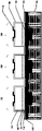
- FIG. 1A illustrates a cross-section view of a LED structure 100, according to some implementations of the present disclosure.
- LED structure 100 includes a substrate 102 having a driving circuit, and the driving circuit includes a plurality of contact pads 104.
- LED structure 100 also includes a plurality of LED units 120 formed on substrate 102.
- a bonding layer 114 is formed between substrate 102 and LED units 120.
- a metal contact 110 is formed in bonding layer 114 beneath each LED unit 120 to electrically connect each LED unit 120 with contact pad 104 of the driving circuit.
- the metal contact 110, each LED unit 120, and the contact pad 104 have their own sectional areas, denoted with A1, A2, and A3, respectively.
- the sectional area A1 of metal contact 110 (the “first sectional area” ) is smaller than the sectional area A2 of each LED unit 120 (the “second sectional area” ) . As shown in FIG. 1A, the sectional area A1 of metal contact 110 is also smaller than the sectional area A3 of the contact pad 104 (the “third sectional area” ) . However, it is contemplated that in some alternative implementations, the sectional area A1 of metal contact 110 may be equal to or larger than the sectional area A3 of the contact pad 104. Because LED units 120 and contact pads 104 are mainly bonded by bonding layer 114, and metal contacts 110 only occupies a small part between LED units 120 and contact pads 104, the using of precious metals could be largely reduced and therefore the manufacturing cost could be lowered.
- first substrate 102 may include a semiconductor material, such as silicon, silicon carbide, gallium nitride, germanium, gallium arsenide, indium phosphide. In some implementations, first substrate 102 may be made from an electrically non-conductive material, such as a glass, a plastic or a sapphire wafer. In some implementations, first substrate 102 may have driving circuits formed therein. In some embodiments, first substrate 102 may be a CMOS backplane or TFT glass substrate.
- the driving circuit provides the electronic signals to LED units 120 to control the luminance. In some implementations, the driving circuit may include an active matrix driving circuit, in which each independent driver corresponds to an individual LED unit 120. In some implementations, the driving circuit may include a passive matrix driving circuit, in which the data lines and the scan lines driven by the driving circuit may be connected to a plurality of LED units 120 aligned in an array.
- bonding layer 114 is a layer of an adhesive material formed on first substrate 102 to bond first substrate 102 and LED units 120.
- bonding layer 114 may include a nonconductive material, such as polyimide (PI) , polydimethylsiloxane (PDMS) , SU-8 photoresist, polymethylglutarimide (PMGI) , non-conductive film (NCF) or other suitable material.
- PI polyimide
- PDMS polydimethylsiloxane
- SU-8 photoresist polymethylglutarimide
- NCF non-conductive film
- bonding layer 114 under each LED unit 120 extends to bonding layer 114 under adjacent LED unit 120.
- the bonding strength between substrate 102 and the plurality of LED units 120 may be strengthened and the risk of peeling-off of LED structure 100 can be reduced.
- Metal contact 110 is formed in bonding layer 114 to electrically connect each LED unit 120 with contact pad 104.
- metal contact 110 may include gold (Au) , platinum (Pt) , chromium (Cr) , aluminum (Al) , nickel (Ni) , titanium (Ti) , or other suitable material.
- the dimensions of metal contact 110 may be selected according to certain criteria.
- the sectional area of metal contact 110 should be significantly small than the sectional area of bonding layer 114, so that the benefit of using nonconductive materials to bond LED units 120 and contact pads 104, such as lowering the manufacturing cost, higher bond yield and reducing the internal stress, could be obtained.
- the sectional area of metal contact 110 should be sufficient to provide an electric path between LED units 120 and contact pads 104 to provide the control signal signals to LED units 120.
- a diameter of the sectional area of metal contact 110 is less than about 1 micrometer. In some other implementations, a diameter of the sectional area of metal contact 110 is between about 0.5 micrometer and about 1 micrometer. In some implementations, a thickness of metal contact 110 is less than about 1 micrometer.
- FIG. 1B illustrates a cross-section view of one LED unit 120 of LED structure 100, according to some implementations of the present disclosure.
- LED unit 120 includes an ohmic contact layer 112, a first doping type semiconductor layer 151, a multiple quantum well (MQW) layer 152, and a second doping type semiconductor layer 153.
- Ohmic contact layer 112 is formed on bonding layer 114 and metal contact 110.
- ohmic contact layer 112 includes a conductive material.
- ohmic contact layer 112 may include Indium tin oxide (ITO) , silver (Ag) , Al, Au, or other suitable material.
- First doping type semiconductor layer 151 is formed on ohmic contact layer 112.
- first doping type semiconductor layer 151 and second doping type semiconductor layer 153 may include one or more layers based on II-VI materials, such as ZnSe or ZnO, or III-V nitride materials, such as GaN, AlN, InN, InGaN, GaP, AlInGaP, AlGaAs, and their alloys.
- first doping type semiconductor layer 151 may be a p-type semiconductor layer and forms an anode of LED units 120.
- first doping type semiconductor layer 151 may be p-type GaN.
- first doping type semiconductor layer 151 may be p-type InGaN.
- first doping type semiconductor layer 151 may be p-type AlInGaP.
- second doping type semiconductor layer 153 may be a n-type semiconductor layer and form a cathode of LED unit 120.
- second doping type semiconductor layer 153 may be n-type GaN.
- second doping type semiconductor layer 153 may be n-type InGaN.
- second doping type semiconductor layer 153 may be n-type AlInGaP.
- LED unit 120 further includes MQW layer 152 formed between first doping type semiconductor layer 151 and second doping type semiconductor layer 153.
- MQW layer 152 is the active region of LED unit 120.
- the thickness including first doping type semiconductor layer 151, MQW layer 152 and second doping type semiconductor layer 153 may be between about 0.3 ⁇ m and about 5 ⁇ m. In some other implementations, the thickness including first doping type semiconductor layer 151, MQW layer 152 and second doping type semiconductor layer 153 may be between about 0.4 ⁇ m and about 4 ⁇ m. In some alternative implementations, the thickness including first doping type semiconductor layer 151, MQW layer 152 and second doping type semiconductor layer 153 may be between about 0.5 ⁇ m and about 3 ⁇ m.
- LED unit 120 has an anode and a cathode connected to the driving circuit formed in substrate 102 (driving circuit not explicitly shown) .
- LED unit 120 has the anode connected to a source/drain electrode of the driving circuit through metal contact 110 and contact pad 104.
- LED unit 120 also has the cathode connected to a constant voltage source. In some implementations, the cathode of the plurality of LED units 120 may be connected to the same constant voltage source.
- LED unit 120 may further include a passivation layer and an electrode layer (not shown) .
- the passivation layer is formed on second doping type semiconductor layer 153 for protecting and isolating LED unit 120.
- the passivation layer may include SiO 2 , Al 2 O 3 , SiN or other suitable materials.
- the passivation layer may include polyimide, SU-8 photoresist, or other photo-patternable polymer.
- the electrode layer is formed on a portion of the passivation layer and connects second doping type semiconductor layer 153 through an opening on the passivation layer.
- the electrode layer of the plurality of LED units 120 may be electrically connected to the same constant voltage source, and the plurality of LED units 120 share a common cathode. By sharing a common cathode, second doping type semiconductor layer 153 of the plurality of LED units 120 may be electrically connected together, and the operation of the plurality of LED units 120 could be controlled by the driving circuit through individually changing the voltage levels of first doping type semiconductor layer 151 of the plurality of LED units 120.
- the electrode layer may be conductive materials, such as indium tin oxide (ITO) , Cr, Ti, Pt, Au, Al, copper (Cu) , germanium (Ge) , Ni, or other suitable material.
- FIGs. 2A-2I illustrate cross sections of LED structure 100 at different stages of a manufacturing process, according to some implementations of the present disclosure.
- FIG. 4 is a flowchart of a method 400 for manufacturing LED structure 100, according to some implementations of the present disclosure. For the purpose of better explaining the present disclosure, FIGs. 2A-2I and the flowchart in FIG. 4 will be described together.
- a driving circuit is formed in first substrate 102 and the driving circuit includes contact pads 104.
- the driving circuit may include CMOS devices manufactured on a silicon wafer and some wafer-level packaging layers or fan-out structures are stacked on the CMOS devices to form contact pads 104.
- the driving circuit may include TFTs manufactured on a glass substrate and some wafer-level packaging layers or fan-out structures are stacked on the TFTs to form contact pads 104.
- a semiconductor layer 108 is formed on a second substrate 106, and semiconductor layer 108 includes first doping type semiconductor layer 151, second doping type semiconductor layer 153 and MQW layer 152.
- first substrate 102 or second substrate 106 may include a semiconductor material, such as silicon, silicon carbide, gallium nitride, germanium, gallium arsenide, indium phosphide.
- first substrate 102 or second substrate 106 may be made from an electrically non-conductive material, such as a glass, a plastic or a sapphire wafer.
- first substrate 102 may have driving circuits formed therein, and first substrate 102 may include a CMOS backplane or TFT glass substrate.
- first doping type semiconductor layer 151 and second doping type semiconductor layer 153 may include one or more layers based on II-VI materials, such as ZnSe or ZnO, or III-V nitride materials, such as GaN, AlN, InN, InGaN, GaP, AlInGaP, AlGaAs, and their alloys.
- first doping type semiconductor layer 151 may include a p-type semiconductor layer
- second doping type semiconductor layer 153 may include a n-type semiconductor layer.
- a plurality of metal contacts 110 are formed on first substrate 102 on each contact pad 104. Each metal contact 110 electrically connects to one contact pad 104 of the driving circuit.
- metal contact 110 may include Au, Pt, Cr, Al, Ni, Ti, or other suitable material.
- a diameter of the sectional area of metal contact 110 is less than about 1 micrometer. In some other implementations, a diameter of the sectional area of metal contact 110 is between about 0.5 micrometer and about 1 micrometer. In some implementations, a thickness of metal contact 110 is less than about 1 micrometer.
- a photoresist layer may be deposited on first substrate 102 covering the plurality of contact pads 104. Then, a photolithography process may be used to form a plurality of openings on each contact pad 104 and expose each contact pad 104.
- the metal materials e.g., Au, Pt, Cr, Al, Ni, Ti, or other suitable material, may be formed in the openings by chemical vapor deposition (CVD) , physical vapor deposition (PVD) , atomic layer deposition (ALD) , or other suitable process.
- the photoresist layer may be removed by an etch or ash process. After removing the photoresist layer, metal contacts 110 are formed on each contact pad 104.
- ohmic contact layer 112 is directly formed on first doping type semiconductor layer 151.
- ohmic contact layer 112 includes a conductive material.
- ohmic contact layer 112 may include indium tin oxide (ITO) , Ag, Al, Au, or other suitable material.
- ITO indium tin oxide
- Ohmic contact layer 112 provides a junction between two conductors, e.g., metal contacts 110 and first doping type semiconductor layer 151, that has a linear current-voltage curve.
- Ohmic contact layer 112 has a low resistance to allow charges to flow easily in both directions between metal contacts 110 and first doping type semiconductor layer 151.
- Ohmic contact layer 112 directly contacts first doping type semiconductor layer 151, which is the anode of LED unit 120, and provides a junction between first doping type semiconductor layer 151 and metal contacts 110. In other words, ohmic contact layer 112 is formed on first doping type semiconductor layer 151 without any layer in between. Hence, after bonding ohmic contact layer 112 with metal contacts 110, ohmic contact layer 112 could provide a linear current-voltage curve between metal contacts 110 and first doping type semiconductor layer 151.
- bonding layer 114 is deposited over first substrate 102, the plurality of contact pads 104, and the plurality of metal contacts 110.
- Bonding layer 114 includes nonconductive adhesive material.
- bonding layer 114 may include polyimide (PI) , polydimethylsiloxane (PDMS) , SU-8 photoresist, polymethylglutarimide (PMGI) , non-conductive film, or other suitable material.
- bonding layer 114 may be deposited over first substrate 102, the plurality of contact pads 104, and the plurality of metal contacts 110 by a spin-coating process, and because of the liquid physical property of bonding layer 114, a thickness of bonding layer 114 on the top of each metal contact 110 is thinner than a thickness of bonding layer 114 on first substrate 102 and contact pads 104.
- second substrate 106, semiconductor layer 108 and ohmic contact layer 112 are flipped over and placed on bonding layer 114.
- First substrate 102 and second substrate 106 are pressed against each other to bond semiconductor layer 108 and ohmic contact layer 112 with bonding layer 114. Because of the pressure applied on first substrate 102 and second substrate 106, bonding layer 114 deposited on the top of each metal contact 110 may be squeezed or extruded so that metal contacts 110 may electrically contact ohmic contact layer 112.
- FIGs. 3A-3B illustrate cross sections of LED structure 100 when operation 408 is performed using alternative operations, according to some implementations of the present disclosure.
- the operations shown in FIGs. 3A-3B may replace the operations shown in FIGs. 2C-2D.
- bonding layer 114 is deposited on the top of each metal contact 110.
- a photolithography process and an etch process may be used to remove bonding layer 114 deposited on the top of each metal contact 110 and expose the top of each metal contact 110, as shown in FIG. 3A.
- second substrate 106 including semiconductor layer 108 and ohmic contact layer 112, is flipped over and placed on bonding layer 114. Because the top of each metal contact 110 is exposed, metal contacts 110 may electrically contact ohmic contact layer 112.
- FIG. 2E shows bonding layer 114 between first substrate 102 and ohmic contact layer 112.
- bonding layer 114 may include one or multiple layers to bond first substrate 102 and ohmic contact layer 112.
- bonding layer 114 may include a single nonconductive layer.
- bonding layer 114 may include multiple nonconductive layers, or an adhesive material and a nonconductive layer.
- a thinning operation may be optionally performed on second doping type semiconductor layer 153 to remove a portion of second doping type semiconductor layer 153.
- the thinning operation may include a dry etching or a wet etching operation.
- the thinning operation may include a chemical-mechanical polishing (CMP) operation.
- CMP chemical-mechanical polishing
- the thickness including first doping type semiconductor layer 151, MQW layer 152 and second doping type semiconductor layer 153 may be between about 0.3 ⁇ m and about 5 ⁇ m.
- the thickness including first doping type semiconductor layer 151, MQW layer 152 and second doping type semiconductor layer 153 may be between about 0.4 ⁇ m and about 4 ⁇ m. In some alternative implementations, after the thinning operation, the thickness including first doping type semiconductor layer 151, MQW layer 152 and second doping type semiconductor layer 153 may be between about 0.5 ⁇ m and about 3 ⁇ m.
- a first etch operation is performed to remove a portion of semiconductor layer 108, including first doping type semiconductor layer 151, MQW layer 152 and second doping type semiconductor layer 153, to form a plurality of LED mesas.
- the first etch operation may include dry etch, wet etch, or other suitable process.
- a second etch operation is performed to remove a portion of ohmic contact layer 112 to form a plurality of LED units 120.
- the second etch operation may include dry etch, wet etch, or other suitable process.
- a passivation layer 116 is formed on semiconductor layer 108 covering first doping type semiconductor layer 151, MQW layer 152, second doping type semiconductor layer 153, ohmic contact layer 112, and bonding layer 114.
- passivation layer 116 may include SiO 2 , Al 2 O 3 , SiN or other suitable materials for isolation and protection.
- passivation layer 116 may include polyimide, SU-8 photoresist, or other photo-patternable polymer.
- passivation layer 116 of adjacent LED units 120 is connected. However, it is understood that passivation layer 116 of adjacent LED units 120 may alternatively be separated.
- Electrode layer 118 may include conductive materials, such as indium tin oxide (ITO) , Cr, Ti, Pt, Au, Al, Cu, Ge or Ni. Electrode layer 118 of the plurality of LED units 120 may be electrically connected to the same constant voltage source, and the plurality of LED units 120 share a common cathode.
- ITO indium tin oxide
- Electrode layer 118 of the plurality of LED units 120 may be electrically connected to the same constant voltage source, and the plurality of LED units 120 share a common cathode.
- the present disclosure provides a LED structure and a method for manufacturing the LED structure in which the bonding layer, or the adhesive material, used to bond the epitaxy layer on the receiving substrate is a nonconductive material.
- the nonconductive adhesive layer is embedded with a metal contact therein to electrically connect the epitaxy layer (including the LED units) with the driving circuit in the receiving substrate.
- the metal material used to bond the epitaxy layer on the receiving substrate is drastically reduced compared to conventional designs, and therefore the manufacturing cost is lowered.
- the thermal process for conductive adhesive materials is not needed, and therefore the internal stress caused by the thermal mismatch between the epitaxy layer and the receiving substrate could be also reduced.
- a LED structure includes a substrate, a plurality of LED units, a bonding layer and a metal contact.
- the substrate includes a driving circuit, and a plurality of LED units is formed on the substrate.
- the bonding layer is formed between the substrate and the plurality of LED units, and the metal contact is formed in the bonding layer beneath each LED unit to electrically connect each LED unit with a contact pad of the driving circuit.
- a first sectional area of the metal contact is smaller than a second sectional area of each LED unit.
- each LED unit includes a first doping type semiconductor layer formed on the bonding layer, a multiple quantum well (MQW) layer formed on the first doping type semiconductor layer, and a second doping type semiconductor layer formed on the MQW layer.
- each LED unit further includes an ohmic contact layer formed between the first doping type semiconductor layer and the bonding layer. The first sectional area of the metal contact is smaller than a fourth sectional area of ohmic contact layer.
- an anode of each LED unit directly contacts the ohmic contact layer.
- the size of the metal contact is designed to be sufficiently small.
- a diameter of the first sectional area of the metal contact is less than about 1 micrometer.
- the metal contact has a thickness less than about 1 micrometer.
- the plurality of LED units includes a first LED unit and a second LED unit adjacent to the first LED unit. The bonding layer of the first LED unit horizontally extends to the bonding layer of the second LED unit adjacent to the first LED unit. In some implementations, the plurality of LED units share a common cathode.
- a LED structure includes a substrate, a plurality of LED units and a nonconductive adhesive layer.
- the substrate includes a driving circuit, and a plurality of LED units is formed on the substrate.
- the nonconductive adhesive layer bonds the substrate and the plurality of LED units.
- the nonconductive adhesive layer is embedded with a metal contact therein, and the metal contact and a portion of the nonconductive adhesive layer are integrally formed beneath each LED unit.
- the nonconductive adhesive layer is formed by polyimide (PI) , polydimethylsiloxane (PDMS) , SU-8 photoresist or polymethylglutarimide (PMGI) .
- PI polyimide
- PDMS polydimethylsiloxane
- PMGI polymethylglutarimide
- the metal contact electrically connects each LED unit with a contact pad of the driving circuit.
- each LED unit includes an ohmic contact layer formed on the metal contact and the portion of the nonconductive adhesive layer, and the metal contact electrically connects the ohmic contact layer with the contact pad of the driving circuit. In some implementations, an anode of each LED unit directly contacts the ohmic contact layer.
- a method for manufacturing a LED structure is disclosed.
- a driving circuit having a plurality of contact pads is formed in a first substrate.
- a plurality of metal contacts are formed on the first substrate, and each metal contact is located on one of the plurality of contact pads.
- a nonconductive adhesive layer is formed on the first substrate covering the plurality of contact pads and the plurality of metal contacts.
- a plurality of LED units are formed on the nonconductive adhesive layer. Each LED unit is electrically connected to one of the plurality of contact pads through one of the plurality of metal contacts.
- a semiconductor layer is formed on a second substrate, the second substrate is flipped over to place the semiconductor layer on the nonconductive adhesive layer, the first substrate and the second substrate are pressed against each other to bond the semiconductor layer with the nonconductive adhesive layer, and the second substrate is removed.
- a portion of the nonconductive adhesive layer above the plurality of metal contacts is extruded to electrically connect the semiconductor layer with the plurality of metal contacts.
- an ohmic contact layer is formed on the semiconductor layer.
- a first etch operation is performed to remove a portion of the semiconductor layer to form the plurality of LED units.
- a second etch operation is performed to remove a portion of the ohmic contact layer between each LED unit.
- a portion of the nonconductive adhesive layer above the plurality of metal contacts is removed to expose the plurality of metal contacts.
Landscapes
- Led Devices (AREA)
Abstract
Description
Claims (20)
- A light emitting diode (LED) structure, comprising:a substrate comprising a driving circuit;a plurality of LED units formed on the substrate;a bonding layer formed between the substrate and the plurality of LED units; anda metal contact formed in the bonding layer beneath each LED unit to electrically connect each LED unit with a contact pad of the driving circuit,wherein a first sectional area of the metal contact is smaller than a second sectional area of each LED unit.
- The LED structure of claim 1, wherein each LED unit comprises:a first doping type semiconductor layer formed on the bonding layer;a multiple quantum well (MQW) layer formed on the first doping type semiconductor layer; anda second doping type semiconductor layer formed on the MQW layer.
- The LED structure of claim 2, wherein each LED unit further comprises an ohmic contact layer formed between the first doping type semiconductor layer and the bonding layer,wherein the first sectional area of the metal contact is smaller than a sectional area of ohmic contact layer.
- The LED structure of claim 3, wherein an anode of each LED unit directly contacts the ohmic contact layer.
- The LED structure of claim 1, wherein a diameter of the first sectional area of the metal contact is less than about 1 micrometer.
- The LED structure of claim 1, wherein the metal contact has a thickness less than about 1 micrometer.
- The LED structure of claim 1, wherein the plurality of LED units comprise a first LED unit and a second LED unit adjacent to the first LED unit, wherein the bonding layer of the first LED unit horizontally extends to the bonding layer of the second LED unit adjacent to the first LED unit.
- The LED structure of claim 1, wherein the plurality of LED units share a common cathode.
- A light emitting diode (LED) structure, comprising:a substrate comprising a driving circuit;a plurality of LED units formed on the substrate; anda nonconductive adhesive layer bonding the substrate and the plurality of LED units,wherein the nonconductive adhesive layer is embedded with a metal contact therein, and the metal contact and a portion of the nonconductive adhesive layer are integrally formed beneath each LED unit.
- The LED structure of claim 9, wherein the nonconductive adhesive layer is formed by polyimide (PI) , polydimethylsiloxane (PDMS) , SU-8 photoresist or polymethylglutarimide (PMGI) .
- The LED structure of claim 9, wherein the metal contact electrically connects each LED unit with a contact pad of the driving circuit.
- The LED structure of claim 11, wherein each LED unit comprises an ohmic contact layer formed on the metal contact and the portion of the nonconductive adhesive layer, and the metal contact electrically connects the ohmic contact layer with the contact pad of the driving circuit.
- The LED structure of claim 12, wherein an anode of each LED unit directly contacts the ohmic contact layer.
- A method for manufacturing a light emitting diode (LED) structure, comprising:forming a driving circuit having a plurality of contact pads in a first substrate;forming a plurality of metal contacts on the first substrate, each metal contact being located on one of the plurality of contact pads;forming a nonconductive adhesive layer on the first substrate covering the plurality of contact pads and the plurality of metal contacts; andforming a plurality of LED units on the nonconductive adhesive layer,wherein each LED unit is electrically connected to one of the plurality of contact pads through one of the plurality of metal contacts.
- The method of claim 14, wherein forming the plurality of LED units on the nonconductive adhesive layer, comprises:forming a semiconductor layer on a second substrate;flipping over the second substrate to place the semiconductor layer on the nonconductive adhesive layer;pressing the first substrate and the second substrate against each other to bond the semiconductor layer with the nonconductive adhesive layer; andremoving the second substrate.
- The method of claim 15, wherein pressing the first substrate and the second substrate against each other to bond the semiconductor layer with the nonconductive adhesive layer, comprises:extruding a portion of the nonconductive adhesive layer above the plurality of metal contacts to electrically connect the semiconductor layer with the plurality of metal contacts.
- The method of claim 15, further comprising:after forming the semiconductor layer on the second substrate, forming an ohmic contact layer on the semiconductor layer.
- The method of claim 17, further comprising:after removing the second substrate, performing a first etch operation to remove a portion of the semiconductor layer to form the plurality of LED units.
- The method of claim 18, further comprising:performing a second etch operation to remove a portion of the ohmic contact layer between each LED unit.
- The method of claim 14, further comprising:after forming the nonconductive adhesive layer on the first substrate covering the plurality of contact pads and the plurality of metal contacts, removing a portion of the nonconductive adhesive layer above the plurality of metal contacts to expose the plurality of metal contacts.
Applications Claiming Priority (2)
| Application Number | Priority Date | Filing Date | Title |
|---|---|---|---|
| US17/228,786 | 2021-04-13 | ||
| US17/228,786 US11817535B2 (en) | 2020-04-21 | 2021-04-13 | Light emitting diode structure and method for manufacturing the same |
Publications (1)
| Publication Number | Publication Date |
|---|---|
| WO2022217648A1 true WO2022217648A1 (en) | 2022-10-20 |
Family
ID=77933480
Family Applications (1)
| Application Number | Title | Priority Date | Filing Date |
|---|---|---|---|
| PCT/CN2021/089870 Ceased WO2022217648A1 (en) | 2021-04-13 | 2021-04-26 | Light emitting diode structure and method for manufacturing thereof |
Country Status (2)
| Country | Link |
|---|---|
| CN (1) | CN113488576A (en) |
| WO (1) | WO2022217648A1 (en) |
Families Citing this family (7)
| Publication number | Priority date | Publication date | Assignee | Title |
|---|---|---|---|---|
| WO2023207004A1 (en) * | 2022-04-29 | 2023-11-02 | 诺视科技(苏州)有限公司 | Pixel unit for semiconductor device, method for manufacturing pixel unit, micro display screen and discrete device |
| CN115064528B (en) * | 2022-04-29 | 2023-06-16 | 诺视科技(苏州)有限公司 | Pixel unit for semiconductor device, manufacturing method thereof and micro display screen |
| CN114759130B (en) * | 2022-06-15 | 2022-09-02 | 镭昱光电科技(苏州)有限公司 | Micro-LED display chip and preparation method thereof |
| CN115939289A (en) * | 2022-12-27 | 2023-04-07 | 天翼物联科技有限公司 | A Micro LED device based on wafer-level packaging and its manufacturing method |
| WO2025065223A1 (en) * | 2023-09-26 | 2025-04-03 | Jade Bird Display (shanghai) Limited | Micro led and micro led display panel |
| WO2025140487A1 (en) * | 2023-12-29 | 2025-07-03 | 诺视科技(苏州)有限公司 | Anti-crosstalk micro-display light-emitting pixel and manufacturing method therefor |
| CN121368238A (en) * | 2024-06-27 | 2026-01-20 | 泉州三安半导体科技有限公司 | Micro-light-emitting element and preparation method thereof |
Citations (5)
| Publication number | Priority date | Publication date | Assignee | Title |
|---|---|---|---|---|
| US20190051792A1 (en) * | 2017-08-08 | 2019-02-14 | PlayNitride Inc. | Micro light emitting diode device and manufacturing method thereof |
| US20190088633A1 (en) * | 2017-03-16 | 2019-03-21 | Invensas Corporation | Direct-Bonded LED Arrays and Applications |
| US20190392751A1 (en) * | 2018-06-22 | 2019-12-26 | Epistar Corporation | Display apparatus with array of light emitting diodes and method of manufacturing the same |
| US20200235077A1 (en) * | 2017-02-01 | 2020-07-23 | Lg Electronics Inc. | Display device using semiconductor light emitting element, and manufacturing method therefor |
| CN112531091A (en) * | 2020-06-12 | 2021-03-19 | 友达光电股份有限公司 | Light emitting device |
Family Cites Families (5)
| Publication number | Priority date | Publication date | Assignee | Title |
|---|---|---|---|---|
| US20030189215A1 (en) * | 2002-04-09 | 2003-10-09 | Jong-Lam Lee | Method of fabricating vertical structure leds |
| CN102479896A (en) * | 2010-11-26 | 2012-05-30 | 大连美明外延片科技有限公司 | Light-emitting diode chip |
| CN102231378B (en) * | 2011-05-25 | 2013-05-29 | 映瑞光电科技(上海)有限公司 | Light-emitting diode (LED) packaging structure and preparation method thereof |
| KR20190061147A (en) * | 2017-11-27 | 2019-06-05 | 주식회사 루멘스 | Led chip and led module with led chip |
| WO2020163436A1 (en) * | 2019-02-05 | 2020-08-13 | Facebook Technologies, Llc | Process flow for hybrid tft-based micro display projector |
-
2021
- 2021-04-26 WO PCT/CN2021/089870 patent/WO2022217648A1/en not_active Ceased
- 2021-04-26 CN CN202110456652.6A patent/CN113488576A/en active Pending
Patent Citations (5)
| Publication number | Priority date | Publication date | Assignee | Title |
|---|---|---|---|---|
| US20200235077A1 (en) * | 2017-02-01 | 2020-07-23 | Lg Electronics Inc. | Display device using semiconductor light emitting element, and manufacturing method therefor |
| US20190088633A1 (en) * | 2017-03-16 | 2019-03-21 | Invensas Corporation | Direct-Bonded LED Arrays and Applications |
| US20190051792A1 (en) * | 2017-08-08 | 2019-02-14 | PlayNitride Inc. | Micro light emitting diode device and manufacturing method thereof |
| US20190392751A1 (en) * | 2018-06-22 | 2019-12-26 | Epistar Corporation | Display apparatus with array of light emitting diodes and method of manufacturing the same |
| CN112531091A (en) * | 2020-06-12 | 2021-03-19 | 友达光电股份有限公司 | Light emitting device |
Also Published As
| Publication number | Publication date |
|---|---|
| CN113488576A (en) | 2021-10-08 |
Similar Documents
| Publication | Publication Date | Title |
|---|---|---|
| WO2022217648A1 (en) | Light emitting diode structure and method for manufacturing thereof | |
| KR102911671B1 (en) | Light-emitting diode structure and manufacturing method thereof | |
| EP4133537B1 (en) | Light emitting diode structure and method for manufacturing the same | |
| CN114566515B (en) | Micro light emitting diode display chip and preparation method thereof | |
| CN107170773A (en) | Micro- LED display panel and preparation method thereof | |
| CN109273574A (en) | Light emitting device package and display device using the same | |
| US11817535B2 (en) | Light emitting diode structure and method for manufacturing the same | |
| US12224304B2 (en) | Light emitting diode structure with individual fuctionable LED units and method for manufacturing the same | |
| KR102455088B1 (en) | Tft substrate, display panel and display device having the same | |
| US12142717B2 (en) | Light emitting diode structure and method for manufacturing the same | |
| KR102456552B1 (en) | Tft substrate, display panel and display device having the same | |
| US12527137B2 (en) | Light emitting diode structure and method for manufacturing the same | |
| KR102455093B1 (en) | Tft substrate, display panel and display device having the same | |
| US20250015243A1 (en) | Display device comprising semiconductor light-emitting element, and manufacturing method therefor | |
| KR102431047B1 (en) | Tft substrate, display panel and display device having the same | |
| KR102445546B1 (en) | Thin film transistor substrate, display panel and display device including same | |
| US20220140217A1 (en) | Light emitting diode structure and method for manufacturing the same | |
| US20240363823A1 (en) | Light emitting diode structure and method for manufacturing the same | |
| CN100401535C (en) | Method for forming light emitting diode with metal substrate | |
| KR102455095B1 (en) | Tft substrate, display panel and display device having the same | |
| KR20170074622A (en) | Tft substrate, display panel and display device having the same | |
| KR20170083753A (en) | Tft substrate, display panel and display device having the same | |
| KR102455094B1 (en) | Tft substrate, display panel and display device having the same | |
| KR20170074619A (en) | Tft substrate, display panel and display device having the same | |
| KR102438224B1 (en) | Tft substrate, display panel and display device having the same |
Legal Events
| Date | Code | Title | Description |
|---|---|---|---|
| 121 | Ep: the epo has been informed by wipo that ep was designated in this application |
Ref document number: 21936522 Country of ref document: EP Kind code of ref document: A1 |
|
| NENP | Non-entry into the national phase |
Ref country code: DE |
|
| 122 | Ep: pct application non-entry in european phase |
Ref document number: 21936522 Country of ref document: EP Kind code of ref document: A1 |
|
| 32PN | Ep: public notification in the ep bulletin as address of the adressee cannot be established |
Free format text: NOTING OF LOSS OF RIGHTS PURSUANT TO RULE 112(1) EPC (EPO FORM 1205A DATED 19/04/2024) |
|
| 122 | Ep: pct application non-entry in european phase |
Ref document number: 21936522 Country of ref document: EP Kind code of ref document: A1 |