WO2022201340A1 - Electrode catheter - Google Patents
Electrode catheter Download PDFInfo
- Publication number
- WO2022201340A1 WO2022201340A1 PCT/JP2021/012137 JP2021012137W WO2022201340A1 WO 2022201340 A1 WO2022201340 A1 WO 2022201340A1 JP 2021012137 W JP2021012137 W JP 2021012137W WO 2022201340 A1 WO2022201340 A1 WO 2022201340A1
- Authority
- WO
- WIPO (PCT)
- Prior art keywords
- electrode
- component
- tip
- distal end
- irrigation
- Prior art date
- Legal status (The legal status is an assumption and is not a legal conclusion. Google has not performed a legal analysis and makes no representation as to the accuracy of the status listed.)
- Ceased
Links
Images


Classifications
-
- A—HUMAN NECESSITIES
- A61—MEDICAL OR VETERINARY SCIENCE; HYGIENE
- A61B—DIAGNOSIS; SURGERY; IDENTIFICATION
- A61B18/00—Surgical instruments, devices or methods for transferring non-mechanical forms of energy to or from the body
- A61B18/04—Surgical instruments, devices or methods for transferring non-mechanical forms of energy to or from the body by heating
- A61B18/12—Surgical instruments, devices or methods for transferring non-mechanical forms of energy to or from the body by heating by passing a current through the tissue to be heated, e.g. high-frequency current
- A61B18/14—Probes or electrodes therefor
- A61B18/1492—Probes or electrodes therefor having a flexible, catheter-like structure, e.g. for heart ablation
-
- A—HUMAN NECESSITIES
- A61—MEDICAL OR VETERINARY SCIENCE; HYGIENE
- A61M—DEVICES FOR INTRODUCING MEDIA INTO, OR ONTO, THE BODY; DEVICES FOR TRANSDUCING BODY MEDIA OR FOR TAKING MEDIA FROM THE BODY; DEVICES FOR PRODUCING OR ENDING SLEEP OR STUPOR
- A61M25/00—Catheters; Hollow probes
- A61M25/0021—Catheters; Hollow probes characterised by the form of the tubing
-
- A—HUMAN NECESSITIES
- A61—MEDICAL OR VETERINARY SCIENCE; HYGIENE
- A61B—DIAGNOSIS; SURGERY; IDENTIFICATION
- A61B18/00—Surgical instruments, devices or methods for transferring non-mechanical forms of energy to or from the body
- A61B2018/00005—Cooling or heating of the probe or tissue immediately surrounding the probe
- A61B2018/00011—Cooling or heating of the probe or tissue immediately surrounding the probe with fluids
- A61B2018/00029—Cooling or heating of the probe or tissue immediately surrounding the probe with fluids open
-
- A—HUMAN NECESSITIES
- A61—MEDICAL OR VETERINARY SCIENCE; HYGIENE
- A61B—DIAGNOSIS; SURGERY; IDENTIFICATION
- A61B18/00—Surgical instruments, devices or methods for transferring non-mechanical forms of energy to or from the body
- A61B2018/00053—Mechanical features of the instrument of device
- A61B2018/00059—Material properties
- A61B2018/00089—Thermal conductivity
- A61B2018/00101—Thermal conductivity low, i.e. thermally insulating
-
- A—HUMAN NECESSITIES
- A61—MEDICAL OR VETERINARY SCIENCE; HYGIENE
- A61B—DIAGNOSIS; SURGERY; IDENTIFICATION
- A61B18/00—Surgical instruments, devices or methods for transferring non-mechanical forms of energy to or from the body
- A61B2018/00053—Mechanical features of the instrument of device
- A61B2018/00166—Multiple lumina
-
- A—HUMAN NECESSITIES
- A61—MEDICAL OR VETERINARY SCIENCE; HYGIENE
- A61B—DIAGNOSIS; SURGERY; IDENTIFICATION
- A61B18/00—Surgical instruments, devices or methods for transferring non-mechanical forms of energy to or from the body
- A61B2018/00315—Surgical instruments, devices or methods for transferring non-mechanical forms of energy to or from the body for treatment of particular body parts
- A61B2018/00345—Vascular system
- A61B2018/00351—Heart
-
- A—HUMAN NECESSITIES
- A61—MEDICAL OR VETERINARY SCIENCE; HYGIENE
- A61B—DIAGNOSIS; SURGERY; IDENTIFICATION
- A61B18/00—Surgical instruments, devices or methods for transferring non-mechanical forms of energy to or from the body
- A61B2018/00571—Surgical instruments, devices or methods for transferring non-mechanical forms of energy to or from the body for achieving a particular surgical effect
- A61B2018/00577—Ablation
-
- A—HUMAN NECESSITIES
- A61—MEDICAL OR VETERINARY SCIENCE; HYGIENE
- A61B—DIAGNOSIS; SURGERY; IDENTIFICATION
- A61B18/00—Surgical instruments, devices or methods for transferring non-mechanical forms of energy to or from the body
- A61B2018/00571—Surgical instruments, devices or methods for transferring non-mechanical forms of energy to or from the body for achieving a particular surgical effect
- A61B2018/00595—Cauterization
-
- A—HUMAN NECESSITIES
- A61—MEDICAL OR VETERINARY SCIENCE; HYGIENE
- A61B—DIAGNOSIS; SURGERY; IDENTIFICATION
- A61B18/00—Surgical instruments, devices or methods for transferring non-mechanical forms of energy to or from the body
- A61B2018/00636—Sensing and controlling the application of energy
- A61B2018/00696—Controlled or regulated parameters
- A61B2018/00714—Temperature
-
- A—HUMAN NECESSITIES
- A61—MEDICAL OR VETERINARY SCIENCE; HYGIENE
- A61B—DIAGNOSIS; SURGERY; IDENTIFICATION
- A61B18/00—Surgical instruments, devices or methods for transferring non-mechanical forms of energy to or from the body
- A61B2018/00636—Sensing and controlling the application of energy
- A61B2018/00773—Sensed parameters
- A61B2018/00791—Temperature
-
- A—HUMAN NECESSITIES
- A61—MEDICAL OR VETERINARY SCIENCE; HYGIENE
- A61B—DIAGNOSIS; SURGERY; IDENTIFICATION
- A61B2218/00—Details of surgical instruments, devices or methods for transferring non-mechanical forms of energy to or from the body
- A61B2218/001—Details of surgical instruments, devices or methods for transferring non-mechanical forms of energy to or from the body having means for irrigation and/or aspiration of substances to and/or from the surgical site
- A61B2218/002—Irrigation
Definitions
- the present invention relates to an electrode catheter, and more particularly to an electrode catheter having an electrode attached to the distal end of the catheter and having a mechanism for irrigating the electrode with a liquid such as physiological saline.
- ablation catheters which are electrode catheters, those equipped with an irrigation mechanism for cooling the tip electrode, which becomes hot during cauterization, are used.
- an electrode catheter having an insulating irrigation member provided between a tip electrode having a temperature sensor and a catheter shaft has been proposed (see Patent Document 1 below).
- the physiological saline supplied inside the tip electrode prevents the tip electrode from being cooled more than necessary, and the temperature sensor accurately monitors the temperature during the ablation treatment. ⁇ It is considered to be controllable.
- the present applicant has proposed a catheter shaft having a distal flexible portion and at least one lumen serving as a liquid flow path formed eccentrically in the distal flexible portion;
- An electrode catheter comprising an insulating irrigating member connected to a distal end thereof and a tip electrode connected to the distal end of the insulating irrigating member,
- a plurality of irrigation openings for irrigating the surface of the tip electrode with the liquid supplied from the catheter shaft are arranged in the insulating irrigating member at equal angular intervals along the outer circumference of the insulating irrigating member.
- At least one eccentric channel communicating with a lumen serving as a liquid channel of the catheter shaft inside the insulating irrigation member; a liquid storage space communicating with the eccentric flow path and having no partition wall in the circumferential direction so that the liquid from the eccentric flow path is uniformly distributed in the circumferential direction of the insulating irrigation member; , forming a plurality of branched channels communicating with the storage space and extending in a distal direction while sloping outward to reach each of the plurality of irrigation openings;
- the insulating irrigation member comprises a first part having a tip shape that can fit into the rear end shape of the tip electrode and a second part having a tip shape that can fit into the rear end shape of the first part. configured,
- the eccentric flow path is formed inside the second component,
- the plurality of branched flow paths are formed inside the first component,
- An electrode catheter has been proposed in which the storage space is formed at the fitting portion between the first part and the second part (see Patent Document 2 below).
- the surface of the tip electrode can be irrigated over the entire circumferential direction. can be done.
- the eccentric flow path is formed inside the insulating irrigation member, the liquid from the lumen of the catheter shaft (the liquid flow path formed eccentrically) can flow toward the storage space.
- the insulating irrigation member has a liquid storage space having no partition wall in its circumferential direction, which communicates with the storage space and extends in the distal direction while sloping outward to reach each of the plurality of irrigation openings.
- the liquid that has reached the storage space through the eccentric flow path is distributed uniformly in the circumferential direction in the storage space, and then flows toward the distal end. Since the liquid is sprayed (irrigated) from the irrigation openings through each of the plurality of branched flow paths extending to the same angle, there is no variation in the amount of liquid sprayed among the plurality of irrigation openings arranged at equal angular intervals, and the insulation Uniform injection can be performed in the circumferential direction of the irrigation member, and the surface of the tip electrode can be uniformly irrigated over the entire circumferential direction.
- the insulating irrigation member is configured by fitting the distal end side small diameter portion of the second part into the rear end side recess of the first part, The cylindrical portion of the tip electrode is fitted to connect the tip electrode to the distal side of the insulating irrigation member.
- the liquid that flows through the branched channel formed in the first part and is jetted from the irrigation opening is sufficiently irrigated to the tip side (tip swelling portion) of the tip electrode.
- the proximal side of the tip electrode cannot be sufficiently cooled.
- the proximal side of the tip electrode has an edge (for example, the proximal edge of the cylindrical portion) that tends to become hot due to the high current density when a high-frequency current is applied. It would be desirable to have an irrigation mechanism that can be cooled at room temperature.
- An object of the present invention is to provide an excellent cooling effect on the surface of the tip electrode and an excellent thrombus formation suppressing effect, and a tip electrode that is firmly connected to the insulating irrigating member so that the insulating irrigating member connected to the catheter shaft can move from the tip to the tip.
- the electrode catheter of the present invention comprises a catheter shaft having a flexible distal end portion and at least one lumen serving as a liquid flow path formed eccentrically in the flexible distal end portion; and a distal end side of the catheter shaft. and a tip electrode having a hollow structure connected to the tip side of the insulating irrigating member, wherein the liquid supplied from the catheter shaft to the tip of the insulating irrigating member a plurality of irrigation openings for irrigating the surface of the tip electrode are arranged at equal angular intervals along the outer periphery of the insulating irrigation member, A female thread is formed on the inner peripheral surface of the tip electrode,
- the insulating irrigation member has an annular first part formed with an opening edge of the irrigation opening, and an eccentric flow path communicating with the lumen serving as the liquid flow path.
- the first component and the tip electrode are fitted together, the first component and the second component are fitted together, and the tip portion of the second component is inserted into the tip electrode to form the female screw.
- the tip electrode and the insulating irrigating member are connected to each other while forming a liquid storage space having no partition wall in the circumferential direction of the insulating irrigating member inside the first component. .
- the first part and the tip electrode are fitted together, the first part and the second part are fitted together, and the inside of the tip electrode fitted with the first part is
- the female thread formed on the peripheral surface and the male thread formed on the second part that is fitted with the first part are screwed together, so that the tip electrode and the second part sandwich the first part.
- the connection provides a rigid connection of the tip electrode to the insulating irrigation member. Moreover, since the base end of the tip electrode can be brought into contact with the liquid stored in the storage space inside the first component, the base end side of the tip electrode can be efficiently cooled.
- the tip electrode has an electrode body portion and a cylindrical portion having an outer diameter smaller than that of the electrode body portion
- the first part of the insulating irrigation member is composed of a first part proximal end and a first part distal end having an inner diameter smaller than that of the first part proximal end
- the second part of the insulating irrigation member includes a second part base end portion in which the eccentric flow path is formed, and an outer diameter smaller than that of the second part base end portion, and the male screw is formed.
- the cylindrical portion is inserted into the distal end of the first component to fit the first component and the distal electrode, and the distal end of the proximal end of the second component is inserted into the proximal end of the first component.
- part is inserted to fit the first part and the second part, the tip part of the tip part of the second part is inserted into the tip electrode, and the female screw and the male screw are screwed together. preferably.
- the proximal end surface of the electrode body portion of the tip electrode abuts against the distal end surface of the first component
- a liquid storage space is formed inside the distal end portion of the first component by abutting the distal end surface of the proximal end portion of the second component against the proximal end surface of the distal end portion of the first component. It is preferable that
- the inner peripheral surface of the distal end portion of the first component, the outer peripheral surface of the distal end portion of the second component, the proximal end surface of the cylindrical portion of the distal electrode, and the proximal end portion of the second component is formed.
- the inner diameter of the distal end of the first component is (d 211 )
- the inner diameter of the proximal end of the first component is (d 212 )
- the outer diameter of the distal end of the second component is (D 221 ), the outer diameter of the proximal end of the second part (D 222 ), the outer diameter of the cylindrical portion of the tip electrode (D 33 ), the proximal end of the electrode body portion of the tip electrode
- the proximal end of the second component can be inserted into the proximal end of the first component, but the distal end of the first component can be inserted. cannot be inserted inside Thereby, the front end surface of the second component base end portion can be brought into contact with the base end surface of the first component front end portion inside the first component.
- the cylindrical portion of the tip electrode can be inserted into the tip portion of the first component, but the electrode body portion of the tip electrode cannot be inserted. Thereby, the proximal end surface of the electrode body portion of the tip electrode can be brought into contact with the distal end surface of the first component (first component distal end portion).
- the liquid from the eccentric channel is evenly distributed in the circumferential direction of the insulating irrigation member, effectively cooling the proximal side of the tip electrode.
- a storage space of sufficient capacity can be formed inside the distal end portion of the first component.
- the proximal end of the first member is annular, It is preferable that the distal end portion of the first member has an outer diameter that decreases along the distal direction.
- the liquid can be jetted outward from the irrigation opening in the distal direction (on the distal end side of the insulating irrigation member in the axial direction and outward in the radial direction). , to irrigate the surface of tip electrodes that are somewhat large in size.
- the electrode main body portion of the tip electrode is formed with a liquid guide groove continuous to each of the irrigation openings.
- the liquid ejected from the irrigation opening can be guided (guided) to the distal end side of the tip electrode, thereby supplying the liquid to the entire surface of the tip electrode. can.
- the lumen serving as the liquid flow path of the catheter shaft and the eccentric flow path of the insulating irrigation member communicate with each other via a joint tube.
- the distal end surface of the catheter shaft (the distal end surface where the lumen serving as the liquid flow channel opens) and the proximal end surface of the insulating irrigation member (the base of the second part where the eccentric flow channel opens) are provided. It is possible to reliably prevent the liquid from leaking (the accompanying liquid from entering the shaft) at the point of contact with the shaft end surface).
- the number of the eccentric channels formed inside the insulating irrigation member is one or two, and the number of the irrigation openings is four or more.
- the tip of the catheter shaft It is particularly effective to mount an insulating irrigation member on the side [flow the liquid supplied from the catheter shaft through the inside of the insulation irrigation member (eccentric flow path/storage space)]. Further, if the number of irrigation openings is four or more, irrigation can be sufficiently uniformly performed in the circumferential direction of the insulating irrigation member.
- the second part has a central through hole formed along its central axis.
- the electrode catheter of the present invention is excellent in the effect of cooling the surface of the tip electrode and the effect of suppressing thrombus formation on the surface of the tip electrode.
- the tip electrode can be rigidly connected to the insulating irrigation member. This prevents the tip electrode from falling off the insulating irrigation member connected to the catheter shaft.
- the base end of the tip electrode can be brought into contact with the liquid stored in the storage space, the base end side of the tip electrode where the edge exists can be efficiently cooled.
- FIG. 1 is a front view of an ablation catheter that is one embodiment of an electrode catheter of the present invention
- FIG. FIG. 2 is a vertical cross-sectional view of the tip portion of the ablation catheter shown in FIG. 1
- FIG. 2 is a cross-sectional view of the tip portion of the ablation catheter shown in FIG. 1 (cross-sectional view taken along line III-III in FIG. 2)
- FIG. 2 is a cross-sectional view of the tip portion of the ablation catheter shown in FIG. 1 (cross-sectional view of FIG. 2 IV-IV);
- FIG. 2 is a cross-sectional view of the tip portion of the ablation catheter shown in FIG. 1 (cross-sectional view taken along the line VV in FIG. 2);
- FIG. 3 is a vertical cross-sectional view (cross-sectional view taken along line VI-VI in FIG. 3) of the tip portion of the ablation catheter shown in FIG. 1;
- FIG. 4 is a vertical cross-sectional view (cross-sectional view taken along line VII-VII in FIG. 4) of the tip portion of the ablation catheter shown in FIG. 1; 1.
- FIG. 2 is a perspective view showing a tip electrode and an irrigation member that constitute the ablation catheter shown in FIG. 1;
- FIG. 2 is an explanatory view showing a tip electrode that constitutes the ablation catheter shown in FIG. 1, (a) is a front view, (b) is a cross-sectional view taken along line Xb-Xb of (a), and (c) is a right side view.
- 9 is an explanatory view showing the first part of the irrigation member shown in FIG. 8, (a) is a front view, (b) is a left side view, (c) is a right side view, (d) is XId of (b) -XId cross-sectional view.
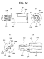
- 9 is an explanatory view showing the second part of the irrigation member shown in FIG. 8, (a) is a front view, (b) is a left side view, (c) is a right side view, and (d) is XIId of (c). -XIId cross-sectional view.
- FIGS. 1 to 7 are ablation catheters of the present invention used for treating cardiac arrhythmias.
- the ablation catheter 100 of this embodiment comprises a catheter shaft 10 having a distal flexible portion 10A, an insulating irrigation member 20 connected to the distal end of the catheter shaft 10, and an irrigation member 20 connected to the distal end of the irrigation member 20.
- a tip electrode 30 having a hollow structure, a ring-shaped electrode 40 attached to the outer peripheral surface of the distal flexible portion 10A of the catheter shaft 10, and a tension member that constitutes a deflection mechanism for deflecting the distal flexible portion 10A of the catheter shaft 10.
- the distal flexible portion 10A of the catheter shaft 10 is formed with two lumens 11, 11, which serve as liquid flow paths, facing each other across the central axis (that is, they are eccentric from the central axis).
- Lumens 121 and 123 as insertion paths for the pull wire 61
- lumens 122 and 124 as insertion paths for the pull wire 62
- lumen 131 as an insertion path for the lead wire 30L of the tip electrode 30, and the lead of the ring electrode 40.
- a lumen 132 that serves as an insertion path for the wire 40L is formed;
- eight irrigating openings 25 for injecting (irrigating) the liquid supplied from the catheter shaft 10 onto the surface of the tip electrode 30 are formed along the circumference of the irrigating member 20 at equal angular intervals ( 45° intervals);
- the tip electrode 30 includes a distal swelling portion 31 which is an electrode body portion, a neck portion 32 which is an electrode body portion continuing from the base end side of the tip swelling portion 31, and a cylindrical shape having an outer diameter smaller than that of the neck portion 32.
- the irrigation member 20 has an annular first part 21 formed with an opening edge of an irrigation opening 25 and two eccentric flow paths 23, 23 communicating with the lumens 11, 11 of the catheter shaft 10, respectively.
- the first component 21 is composed of a first component proximal end portion 212 and a first component distal end portion 211 having an inner diameter smaller than that of the first component proximal end portion 212;
- the second part 22 has a second part base end portion 222 in which the eccentric flow paths 23, 23 are formed, and a male thread 229 having a smaller outer diameter than the second part base end portion 222 and screwed with the female thread 329.
- the cylindrical portion 33 is inserted into the first component distal end portion 211 to fit the first component 21 and the distal end electrode 30, and the distal end of the second component proximal end portion 222 is inserted into the first component proximal end portion 212.
- the first part 21 and the second part 22 are fitted by inserting the first part 21 and the second part 22, and the tip part of the second part tip part 221 is inserted into the tip electrode 30, and the female thread 329 and the male thread 229 are screwed together.
- a fluid storage space 24 having no partition wall in the circumferential direction of the irrigation member 20 is formed inside the first component distal end portion 211 by abutting the distal end surface.
- the ablation catheter 100 of this embodiment includes a catheter shaft 10, an irrigation member 20, a tip electrode 30, a ring-shaped electrode 40, pulling wires 61 and 62, a leaf spring 65, a control handle 70, and a liquid injection device. a tube 80;
- An injection tube 80 shown in FIG. 1, is connected to the catheter shaft 10 through the interior of the control handle 70, through which the lumens 11, 11 of the catheter shaft 10 are supplied with liquid.
- physiological saline can be exemplified as the "liquid”.
- the control handle 70 shown in FIG. 1 is connected to the proximal end of the catheter shaft 10 and has a rotary plate 75 for deflecting the distal end of the catheter.
- a catheter shaft 10 constituting an ablation catheter 100 has a distal flexible portion 10A.
- the term “flexible tip portion” refers to a tip portion of a catheter shaft that can be deflected (bent) by pulling a wire for tip deflection operation.
- pull wires 61 and 62 are arranged in the catheter shaft 10 (lumens 121 and 122) for bending the distal flexible portion 10A (performing tip deflection operation).
- the proximal ends of pull wires 61 and 62 are each connected to rotating plate 75 (see FIG. 1) of control handle 70 .
- the distal ends of the pulling wires 61 and 62 are fixed in a housing groove 226 formed on the outer peripheral surface of the irrigation member 20 (second part 22).
- the pulling wire 61 is pulled, the tip flexible portion 10A of the catheter shaft 10 deflects in the arrow A direction, and rotates in the B1 direction shown in FIG.
- the pull wire 62 is pulled and the distal flexible portion 10A of the catheter shaft 10 is deflected in the arrow B direction.
- the distal flexible portion 10A of the catheter shaft 10 has a plane perpendicular to the arrangement direction of the pulling wires 61 and 62 (the bending direction of the distal flexible portion 10A).
- a leaf spring 65 is arranged along the central axis.
- the distal flexible portion 10A of the catheter shaft 10 is formed with two lumens 11, 11 that serve as liquid flow paths so as to face each other with the central axis of the catheter shaft 10 interposed therebetween. It is The two lumens 11, 11 in the distal flexible portion 10A may merge at a shaft portion on the proximal side of the distal flexible portion 10A.
- the distal flexible portion 10A has two lumens 121 and 123 as passages for the pulling wire 61 and two lumens 122 and 124 as passages for the pulling wire 62. , a lumen 131 through which the lead wire 30L of the tip electrode 30 and the lead wire 35L of the temperature sensor (thermocouple) are inserted, and a lumen 132 through which the lead wire of the ring-shaped electrode 40 is inserted.
- the pull wire 61 is passed through the lumen 121 and the pull wire 62 is passed through the lumen 122, but the lumen through which the pull wires 61 and 62 are passed is located at the proximal end of the distal flexible portion 10A.
- the distal flexible portion 10A of the catheter shaft 10 has a so-called multi-lumen structure.
- the tip of the tip flexible portion 10A is formed with a tip-side recess of a single lumen structure for joining with an irrigation member 20, which will be described later.
- the catheter shaft 10 is made of synthetic resin such as polyolefin, polyamide, polyether polyamide, polyurethane, nylon, and PEBAX (polyether block amide). Also, the proximal end side of the catheter shaft 10 may be a braided tube obtained by braiding a tube made of these synthetic resins with stainless steel wires.
- the outer diameter of the catheter shaft 10 is preferably 2.3-2.9 mm, and a preferred example is 2.65 mm.
- the length (effective length) of the catheter shaft 10 is preferably 600 to 1500 mm, and a preferred example is 1100 mm.
- the tip electrode 30 constituting the ablation catheter 100 has, as shown in FIG.
- the cylindrical portion 33 is inserted inside the first component 21 (first component distal end portion 211) in order to fit the tip electrode 30 and the irrigating member 20 (first component 21), and the external appearance of the ablation catheter 100 is changed. does not appear.
- the tip electrode 30 has a hollow structure, and the tips of the lead wire 30L and the lead wire 35L are arranged inside the tip electrode 30 .
- a female thread 329 is formed on the inner peripheral surface of the tip electrode 30 .
- a liquid guide groove 36 that is continuous with the irrigation opening 25 of the irrigation member 20 is formed in the proximal end (neck 32 ) of the tip electrode 30 .
- the liquid injected from the irrigation opening 25 can be guided (guided) to the distal end portion of the tip electrode 30 .
- the entire surface of electrode 30 can be supplied with liquid. Since the guide groove 36 formed in the tip electrode 30 has a gentle R shape, an abnormal temperature rise does not occur in this portion even during cauterization.
- the outer diameter of the tip bulging portion 31 of the tip electrode 30 is preferably 2.2 to 2.9 mm, and a preferred example is 2.62 mm.
- the outer diameter (D 32 ) at the proximal end of the neck 32 of the tip electrode 30 is preferably 1.9-2.5 mm, and a preferred example is 2.35 mm.
- the outer diameter (D 33 ) of the cylindrical portion 33 of the tip electrode 30 is preferably 1.5 to 2.0 mm, and a preferred example is 1.92 mm.
- the length of the tip electrode 30 (including the cylindrical portion 33) is preferably 1.5 to 10.5 mm, and a preferred example is 4.5 mm.
- the length (L 33 ) of the cylindrical portion 33 is preferably 0.2 to 1.0 mm, and a preferred example is 0.5 mm.
- injection (irrigation) of liquid onto the surface of the tip electrode 30 is performed by the irrigation member 20 located on the distal side of the catheter shaft 10 (the proximal side of the tip electrode 30).
- the irrigation member 20 located on the distal side of the catheter shaft 10 (the proximal side of the tip electrode 30).
- eight irrigating openings 25 for injecting (irrigating) the liquid supplied from the catheter shaft 10 onto the surface of the tip electrode 30 are formed along the circumference of the irrigating member 20 at equal angular intervals ( 45° interval).
- the irrigation member 20 is constructed by fitting a first part 21 and a second part 22 together.
- the first part 21 of the irrigation member 20 is an annular part with an opening edge of the irrigation opening 25 formed therein.
- the first component 21 is a molded body in which a first component proximal end portion 212 and a first component distal end portion 211 having an inner diameter smaller than that of the first component proximal end portion 212 are integrally formed.
- the inner diameter (d 212 ) of the base end portion 212 of the first component is preferably 2.1 to 2.6 mm, and a preferred example is 2.35 mm.
- the inner diameter (d 211 ) of the tip portion 211 of the first component is preferably 1.51 to 2.01 mm, and a preferred example is 1.95 mm.
- the outer diameter of the first component base end portion 212 is substantially the same as the outer diameter of the catheter shaft 10 .
- the first component tip 211 is tapered in the distal direction, and the minimum outer diameter of the first component tip 211 is substantially the same as the outer diameter of the neck 32 of the tip electrode 30 .
- the length of the first part 21 is preferably 1 to 3 mm, and a preferred example is 1.9 mm.
- the length (L 211 ) of the tip portion 211 of the first component is preferably 0.35 to 1.7 mm, and a preferred example is 1.0 mm.
- a central through hole 224 is formed along the central axis, and inside the second part base end portion 222, two eccentric flow paths 23, 23 extending in parallel with a central through-hole 224 interposed therebetween are formed.
- the eccentric channels 23, 23 communicate with the lumens 11, 11 of the catheter shaft 10, respectively.
- the lead wire 30L of the tip electrode 30 and the lead wire 35L of the temperature sensor extend through the central through-hole 224 .
- the lead wire 30L and the lead wire 35L extending through the lumen 131 of the catheter shaft 10 are guided by the tube 54 and connected to the catheter shaft 10 and the irrigation member 20 (the second component base end portion 222). ), it can extend into the central through hole 224 of the second part base end 222 by being displaced in the gap G formed between.
- the gap G is filled with an adhesive except for the passages through which the pulling wires 61 and 62 are inserted.
- the second component 22 is a molded body in which a second component proximal end portion 222 and a second component distal end portion 221 having an outer diameter smaller than that of the second component proximal end portion 222 are integrally formed.
- the outer diameter (D 222 ) of the base end portion 222 of the second component is preferably 2.09 to 2.59 mm, and a preferred example is 2.31 mm.
- the outer diameter (D 221 ) of the tip portion 221 of the second component is preferably 1.0 to 1.5 mm, and a preferred example is 1.4 mm.
- the length of the second part 22 is preferably 4 to 7 mm, and a preferred example is 5.5 mm.
- the length of the tip portion 221 of the second component is preferably 1.5 to 2.5 mm, and a preferred example is 2.0 mm.
- a lead wire housing groove 225 is formed in the outer peripheral surface of the second component base end portion 222 . Further, storage grooves 226 , 226 for storing and fixing the distal end portions of the pull wires 61 , 62 are formed on the outer peripheral surface of the second component base end portion 222 .
- a storage groove 225 is formed on the outer peripheral surface of the second component base end portion 222 to store the lead wire 40L of the ring-shaped electrode 40 (the first second pole from the tip).
- the ring-shaped electrode 40 can be placed on the outer peripheral surface (area) of the catheter shaft 10 inside which the irrigation member is located by forming the storage groove 225 for the lead wire 40L on the outer peripheral surface of the second part base end portion 222. It becomes possible to wear it. As a result, the distance between the tip electrode 30 and the first ring-shaped electrode 40 from the tip can be narrowed (for example, about 2 mm), making it possible to measure the desired potential between these electrodes. .
- a male thread 229 is formed on the outer peripheral surface of the second component tip portion 221 . After the second component distal end portion 221 is inserted into the tip electrode 30 , the male thread 229 is screwed with the female thread 329 formed on the inner peripheral surface of the tip electrode 30 .
- each of the openings of the eccentric channels 23, 23 on the proximal surface of the second component 22 corresponds to each of the openings of the lumens 11, 11 on the distal surface of the catheter shaft 10 (FIG. 3). facing.
- the lumens 11, 11 of the catheter shaft 10 and the eccentric flow paths 23, 23 of the irrigation member 20 (second part 22) are communicated via joint tubes 51, 51.
- the connection between the catheter shaft 10 and the irrigation member 20 can be ensured, and the distal end surface of the catheter shaft 10 (opening surfaces of the lumens 11, 11) and the proximal end surface 22b of the irrigation member 20 (eccentricity) It is possible to prevent leakage of the liquid at the contact points with the opening surfaces of the flow paths 23, 23, and furthermore, infiltration of the liquid into the interior of the shaft associated therewith.
- the first part 21 and the second part 22 that constitute the irrigation member 20 are made of molded bodies of insulating resin.
- the irrigation member 20 has an edge, when the ablation catheter 100 is used (cauterized), the current will not concentrate on the edge and the edge will not become hot.
- the molded body of insulating resin has higher X-ray transparency than the molded body of ceramic material, a ring-shaped body is attached to the outer peripheral surface (region) of the catheter shaft 10 containing the irrigation member 20 .
- the electrodes 40 can be easily identified under X-ray fluoroscopy.
- Suitable insulating resins for irrigation member 20 include rigid resins such as polycarbonate, polystyrene, polypropylene, high-density polyethylene, polyacetal, polymethylmethacrylate, and polyetheretherketone.
- the cylindrical portion 33 is inserted into the distal end portion 211 of the first component so that the first component 21 and the distal electrode 30 are fitted together, and the proximal end portion of the first component
- the tip portion of the second component base end portion 222 is inserted into the interior of the electrode 212 to fit the first component 21 and the second component 22 together, and the tip portion of the second component tip portion 221 is inserted into the tip electrode 30 .
- the tip electrode 30 and the irrigation member 20 are connected by inserting and screwing the female thread 329 and the male thread 229 together, and the proximal end surface of the neck 32 of the tip electrode 30 abuts against the distal end surface of the first part 21 .
- the distal end surface of the second component proximal end portion 222 abuts against the proximal end surface of the first component distal end portion 211, thereby forming a liquid storage space without a partition wall in the circumferential direction of the irrigation member 20.
- 24 is formed inside the first part tip 211 .
- the outer diameter (D 222 ) of the second component proximal end 222 is larger than the inner diameter (d 211 ) of the first component distal end 211, and the inner diameter of the first component proximal end 212 ( d 212 ) or less.
- the outer diameter (D 222 ) of the second component proximal end portion 222 is 2.31 mm
- the inner diameter (d 211 ) of the first component distal end portion 211 is 1.95 mm
- the first component proximal end portion 212 has an inner diameter (d 212 ) of 2.35 mm.
- the second component proximal end portion 222 can be inserted inside the first component proximal end portion 212 but cannot be inserted inside the first component distal end portion 211 .
- the distal end surface of the second component proximal end portion 222 can be brought into contact with the proximal end surface of the first component distal end portion 211 inside the first component 21 .
- the inner diameter (d 211 ) of the first component distal end portion 211 is equal to or greater than the outer diameter (D 33 ) of the cylindrical portion 33 of the tip electrode 30, and the outer diameter (D 32 ).
- the inner diameter (d 211 ) of the distal end portion 211 of the first component is 1.95 mm
- the outer diameter (D 33 ) of the cylindrical portion 33 is 1.92 mm
- the outer diameter at the proximal end of the neck portion 32 ( D 32 ) is 2.35 mm.
- the cylindrical portion 33 of the tip electrode 30 can be inserted into the interior of the first component tip 211, but the neck 32 of the tip electrode cannot be inserted. Thereby, the proximal end surface of the neck portion 32 of the tip electrode 30 can be brought into contact with the distal end surface of the first component 21 (first component distal end portion 211).
- the ratio (D 221 /d 211 ) of the outer diameter (D 221 ) of the second tip part 221 to the inner diameter (d 211 ) of the first tip part 211 is less than 1.0, It is preferably less than 0.8. If the value of the ratio (D 221 /d 211 ) exceeds 1.0, the second component tip 221 cannot be inserted inside the first component tip 211 . Further, if this ratio is 1.0, the liquid storage space 24 cannot be formed inside the first component tip portion 211 .
- the inner diameter (d 211 ) of the first component tip 211 is 1.95 mm
- the outer diameter (D 221 ) of the second component tip 221 is 1.4 mm
- the ratio (D 221 /d 211 ) is 0.72.
- the ratio (L 33 /L 211 ) of the length (L 33 ) of the cylindrical portion 33 of the tip electrode 30 to the length (L 211 ) of the tip portion 211 of the first component is less than 1.0, It is preferably less than 0.6. If the value of the ratio (L 33 /L 211 ) exceeds 1.0, the liquid storage space 24 cannot be formed inside the first component tip portion 211 .
- the length (L 211 ) of the first component distal end portion 211 is 1.0 mm
- the length (L 33 ) of the cylindrical portion 33 is 0.5 mm
- the ratio (L 33 /L 211 ) is The value is 0.5.
- a reservoir space 24 can be formed within the distal portion of the first component that is evenly distributed circumferentially about 20 and of sufficient capacity to effectively cool the proximal side of the tip electrode 30 .
- the irrigation member 20 configured as described above is formed inside the second component 22 (second component base end portion 222) so as to communicate with the lumens 11, 11 of the catheter shaft 10, which serve as the liquid flow path.
- the first part 21 and the tip electrode 30 are fitted, the first part 21 and the second part 22 are fitted, and the first part 21 is fitted.
- a female thread 329 formed on the inner peripheral surface of the tip electrode 30 and a male thread 229 formed on the second part 22 fitted to the first part 21 are screwed together, so that the tip electrode 30 and the Since the second part 22 is connected with the first part 21 therebetween, the tip electrode 30 can be firmly connected to the irrigation member 20 . This can reliably prevent the tip electrode 30 from falling off the irrigation member 20 connected to the catheter shaft 10 .
- the base end of the tip electrode 30 can be brought into contact with the liquid stored in the storage space 24 inside the first component 21, the base end of the tip electrode 30 including the edge that tends to become hot when the high-frequency current is applied. side can be efficiently cooled.
- the present invention is not limited to this, and various modifications are possible.
- the number of branch channels (irrigation openings) in the irrigation member does not have to be 8, and can be appropriately selected within a range of 4 to 12, for example.
- the number of lumens (the number of eccentric flow paths in the irrigation member) serving as liquid flow paths in the catheter shaft may not be two, but may be one or three or more.
- the present invention is effective when using a catheter shaft with a small number of lumens that serve as liquid flow paths.
- the internal structure of the catheter shaft is not particularly limited as long as the lumen serving as the liquid flow path is formed eccentrically at the distal end flexible portion.
- the shape of the tip electrode is not particularly limited, and may be a cannonball shape or the like.
- the electrode catheter of the present invention can be applied not only to conventional high-frequency current ablation, but also to ablation using IRE (Irreversible Electroporation).
Landscapes
- Health & Medical Sciences (AREA)
- Life Sciences & Earth Sciences (AREA)
- Engineering & Computer Science (AREA)
- Surgery (AREA)
- General Health & Medical Sciences (AREA)
- Veterinary Medicine (AREA)
- Biomedical Technology (AREA)
- Heart & Thoracic Surgery (AREA)
- Public Health (AREA)
- Animal Behavior & Ethology (AREA)
- Plasma & Fusion (AREA)
- Cardiology (AREA)
- Physics & Mathematics (AREA)
- Nuclear Medicine, Radiotherapy & Molecular Imaging (AREA)
- Otolaryngology (AREA)
- Medical Informatics (AREA)
- Molecular Biology (AREA)
- Hematology (AREA)
- Anesthesiology (AREA)
- Pulmonology (AREA)
- Biophysics (AREA)
- Surgical Instruments (AREA)
- Media Introduction/Drainage Providing Device (AREA)
Abstract
Description
本発明は、電極カテーテルに関し、更に詳しくは、カテーテルの先端に電極が装着されるとともに、この電極に生理食塩水などの液体を灌注する機構を備えた電極カテーテルに関する。 TECHNICAL FIELD The present invention relates to an electrode catheter, and more particularly to an electrode catheter having an electrode attached to the distal end of the catheter and having a mechanism for irrigating the electrode with a liquid such as physiological saline.
電極カテーテルであるアブレーションカテーテルにおいて、焼灼時に高温となった先端電極を冷却するための灌注機構を備えているものが使用されている。 In ablation catheters, which are electrode catheters, those equipped with an irrigation mechanism for cooling the tip electrode, which becomes hot during cauterization, are used.
灌注機構を備えたカテーテルとして、温度センサが配置された先端電極と、カテーテルシャフトとの間に絶縁性の灌注用部材を設けてなる電極カテーテルが提案されている(下記特許文献1参照)。
このような電極カテーテルによれば、先端電極の内部に供給される生理食塩水によって当該先端電極が必要以上に冷却されてしまうことが防止され、温度センサによって焼灼治療の際の正確な温度の監視・制御ができるとされる。
As a catheter having an irrigation mechanism, an electrode catheter having an insulating irrigation member provided between a tip electrode having a temperature sensor and a catheter shaft has been proposed (see Patent Document 1 below).
According to such an electrode catheter, the physiological saline supplied inside the tip electrode prevents the tip electrode from being cooled more than necessary, and the temperature sensor accurately monitors the temperature during the ablation treatment.・It is considered to be controllable.
ところで、灌注機構を備えた電極カテーテルに板バネによる偏向機構を採用する場合には、カテーテルシャフトの先端可撓部分において生理食塩水の流路となるルーメンを中心軸に沿って形成することはできず、中心軸から偏心して形成しなければならない。
さらに、そのようなカテーテルシャフトに接続される先端電極または灌注部材における生理食塩水の流路も、その中心軸から偏心して形成されるため、生理食塩水は、偏心した開口(流路の出口)から噴射されることになる。
このように、偏心した流路を通り、偏心した開口から噴射される生理食塩水によっては、先端電極の周方向に均一に灌注することができないという問題がある。
By the way, when adopting a deflection mechanism using a leaf spring in an electrode catheter equipped with an irrigation mechanism, it is not possible to form a lumen, which serves as a flow path for physiological saline, along the central axis at the distal flexible portion of the catheter shaft. must be formed eccentrically from the central axis.
Furthermore, the saline flow path in the tip electrode or irrigation member connected to such a catheter shaft is also formed eccentrically from its central axis, so that the saline flows through the eccentric opening (flow path outlet). will be ejected from
Thus, there is a problem that the physiological saline solution that is jetted from the eccentric opening through the eccentric flow path cannot be uniformly irrigated in the circumferential direction of the tip electrode.
このような問題に対して本出願人は、先端可撓部分を有し、液体流路となる少なくとも1つのルーメンが前記先端可撓部分において偏心して形成されているカテーテルシャフトと、前記カテーテルシャフトの先端側に接続された絶縁性灌注部材と、前記絶縁性灌注部材の先端側に接続された先端電極とを備えてなる電極カテーテルであって、
前記絶縁性灌注部材には、前記カテーテルシャフトから供給される液体を前記先端電極の表面に灌注するための複数の灌注用開口が、前記絶縁性灌注部材の外周に沿って等角度間隔に配置され、
前記絶縁性灌注部材の内部には、前記カテーテルシャフトの液体流路となるルーメンに連通する少なくとも1つの偏心流路と、
前記偏心流路に連通する空間であって、前記偏心流路からの液体が前記絶縁性灌注部材の周方向に均一に分布されるように、前記周方向に隔壁を有しない液体の貯留空間と、
前記貯留空間に連通し、外側に傾斜しながら先端方向に延びて前記複数の灌注用開口の各々に至る複数の分岐流路とが形成され、
前記絶縁性灌注部材は、前記先端電極の後端形状と嵌合可能な先端形状を有する第1部品と、前記第1部品の後端形状に嵌合可能な先端形状を有する第2部品とから構成され、
前記第2部品の内部に前記偏心流路が形成され、
前記第1部品の内部に前記複数の分岐流路が形成され、
前記第1部品と前記第2部品との嵌合部分において前記貯留空間が形成されている電極カテーテルを提案している(下記特許文献2参照)。
In response to such problems, the present applicant has proposed a catheter shaft having a distal flexible portion and at least one lumen serving as a liquid flow path formed eccentrically in the distal flexible portion; An electrode catheter comprising an insulating irrigating member connected to a distal end thereof and a tip electrode connected to the distal end of the insulating irrigating member,
A plurality of irrigation openings for irrigating the surface of the tip electrode with the liquid supplied from the catheter shaft are arranged in the insulating irrigating member at equal angular intervals along the outer circumference of the insulating irrigating member. ,
at least one eccentric channel communicating with a lumen serving as a liquid channel of the catheter shaft inside the insulating irrigation member;
a liquid storage space communicating with the eccentric flow path and having no partition wall in the circumferential direction so that the liquid from the eccentric flow path is uniformly distributed in the circumferential direction of the insulating irrigation member; ,
forming a plurality of branched channels communicating with the storage space and extending in a distal direction while sloping outward to reach each of the plurality of irrigation openings;
The insulating irrigation member comprises a first part having a tip shape that can fit into the rear end shape of the tip electrode and a second part having a tip shape that can fit into the rear end shape of the first part. configured,
The eccentric flow path is formed inside the second component,
The plurality of branched flow paths are formed inside the first component,
An electrode catheter has been proposed in which the storage space is formed at the fitting portion between the first part and the second part (see Patent Document 2 below).
この電極カテーテルによれば、絶縁性灌注部材の外周に沿って等角度間隔に配置された複数の灌注用開口が形成されているので、先端電極の表面に対して周方向の全域にわたり
灌注することができる。
また、絶縁性灌注部材の内部に偏心流路が形成されていることにより、カテーテルシャフトのルーメン(偏心して形成されている液体流路)からの液体を貯留空間に向けて流通させることができる。
また、絶縁性灌注部材の内部に、その周方向に隔壁を有しない液体の貯留空間と、この貯留空間に連通し、外側に傾斜しながら先端方向に延びて複数の灌注用開口の各々に至る複数の分岐流路とが形成されていることにより、偏心流路を通って貯留空間に到達した液体は、貯留空間において周方向に均一に分布されるように流れを整えられてから、先端方向に延びる複数の分岐流路の各々を通って灌注用開口から噴射(灌注)されるので、等角度間隔に配置された複数の灌注用開口の間で噴射される液量にバラツキはなく、絶縁性灌注部材の周方向において均一な噴射を行うことが可能となり、先端電極の表面を周方向の全域にわたり均等に灌注することができる。
According to this electrode catheter, since a plurality of irrigation openings are formed along the outer periphery of the insulating irrigation member at equal angular intervals, the surface of the tip electrode can be irrigated over the entire circumferential direction. can be done.
In addition, since the eccentric flow path is formed inside the insulating irrigation member, the liquid from the lumen of the catheter shaft (the liquid flow path formed eccentrically) can flow toward the storage space.
Further, the insulating irrigation member has a liquid storage space having no partition wall in its circumferential direction, which communicates with the storage space and extends in the distal direction while sloping outward to reach each of the plurality of irrigation openings. By forming a plurality of branched flow paths, the liquid that has reached the storage space through the eccentric flow path is distributed uniformly in the circumferential direction in the storage space, and then flows toward the distal end. Since the liquid is sprayed (irrigated) from the irrigation openings through each of the plurality of branched flow paths extending to the same angle, there is no variation in the amount of liquid sprayed among the plurality of irrigation openings arranged at equal angular intervals, and the insulation Uniform injection can be performed in the circumferential direction of the irrigation member, and the surface of the tip electrode can be uniformly irrigated over the entire circumferential direction.
特許文献2に記載された電極カテーテルでは、第1部品の後端側凹部に第2部品の先端側小径部が嵌めこまれることで絶縁性灌注部材が構成され、第1部品の先端側凹部に先端電極の円筒状部分が嵌め込まれることで、絶縁性灌注部材の先端側に先端電極が接続される。 In the electrode catheter described in Patent Document 2, the insulating irrigation member is configured by fitting the distal end side small diameter portion of the second part into the rear end side recess of the first part, The cylindrical portion of the tip electrode is fitted to connect the tip electrode to the distal side of the insulating irrigation member.
然るに、このような嵌め込みによっては、先端電極と絶縁性灌注部材(第1部品)とを強固に接続することができず、カテーテルシャフトに接続された絶縁性灌注部材から先端電極が脱落するおそれがある。 However, such fitting cannot firmly connect the tip electrode and the insulating irrigating member (the first component), and there is a risk that the tip electrode may fall off the insulating irrigating member connected to the catheter shaft. be.
特許文献2に記載された電極カテーテルでは、第1部品に形成された分岐流路を流通して灌注用開口から噴射される液体が先端電極の先端側(先端膨出部)に十分に灌注され、これにより、先端電極の先端側を十分に冷却することができるものの、先端電極の基端側を十分に冷却することができない。
ここに、先端電極の基端側には、高周波電流印加時に電流密度が高くて高温となりやすいエッジ(例えば、円筒状部分の基端縁)が存在するので、先端電極の基端側を効率的に冷却可能な灌注機構が望まれる。
In the electrode catheter described in Patent Literature 2, the liquid that flows through the branched channel formed in the first part and is jetted from the irrigation opening is sufficiently irrigated to the tip side (tip swelling portion) of the tip electrode. As a result, although the distal side of the tip electrode can be sufficiently cooled, the proximal side of the tip electrode cannot be sufficiently cooled.
Here, the proximal side of the tip electrode has an edge (for example, the proximal edge of the cylindrical portion) that tends to become hot due to the high current density when a high-frequency current is applied. It would be desirable to have an irrigation mechanism that can be cooled at room temperature.
本発明は以上のような事情に基いてなされたものである。
本発明の目的は、先端電極の表面の冷却効果および血栓の形成抑制効果に優れ、絶縁性灌注部材に対して先端電極が強固に接続されて、カテーテルシャフトに接続された絶縁性灌注部材から先端電極が脱落することがなく、先端電極の基端側も効率的に冷却することができる灌注機構を備えた電極カテーテルを提供することにある。
The present invention has been made based on the circumstances as described above.
An object of the present invention is to provide an excellent cooling effect on the surface of the tip electrode and an excellent thrombus formation suppressing effect, and a tip electrode that is firmly connected to the insulating irrigating member so that the insulating irrigating member connected to the catheter shaft can move from the tip to the tip. To provide an electrode catheter equipped with an irrigation mechanism capable of efficiently cooling the base end side of the tip electrode without dropping the electrode.
(1)本発明の電極カテーテルは、先端可撓部分を有し、液体流路となる少なくとも1つのルーメンが前記先端可撓部分において偏心して形成されているカテーテルシャフトと、前記カテーテルシャフトの先端側に接続された絶縁性灌注部材と、前記絶縁性灌注部材の先端側に接続された中空構造の先端電極とを備えてなり、前記絶縁性灌注部材の先端に、前記カテーテルシャフトから供給される液体を前記先端電極の表面に灌注するための複数の灌注用開口が、前記絶縁性灌注部材の外周に沿って等角度間隔に配置されている電極カ
テーテルにおいて、
前記先端電極の内周面には雌ねじが形成されており、
前記絶縁性灌注部材は、前記灌注用開口の開口縁が形成された環状の第1部品と、前記液体流路となる前記ルーメンに連通する偏心流路が基端部の内部に形成され、前記雌ねじと螺合する雄ねじが先端部に形成された第2部品とを備えてなり、
前記第1部品と前記先端電極とが嵌合し、前記第1部品と前記第2部品とが嵌合するとともに、前記先端電極の内部に前記第2部品の先端部分が挿入されて前記雌ねじと前記雄ねじとが螺合することにより、
前記絶縁性灌注部材の円周方向に隔壁を有しない液体の貯留空間を前記第1部品の内部に形成しながら、前記先端電極と前記絶縁性灌注部材とが接続されていることを特徴とする。
(1) The electrode catheter of the present invention comprises a catheter shaft having a flexible distal end portion and at least one lumen serving as a liquid flow path formed eccentrically in the flexible distal end portion; and a distal end side of the catheter shaft. and a tip electrode having a hollow structure connected to the tip side of the insulating irrigating member, wherein the liquid supplied from the catheter shaft to the tip of the insulating irrigating member a plurality of irrigation openings for irrigating the surface of the tip electrode are arranged at equal angular intervals along the outer periphery of the insulating irrigation member,
A female thread is formed on the inner peripheral surface of the tip electrode,
The insulating irrigation member has an annular first part formed with an opening edge of the irrigation opening, and an eccentric flow path communicating with the lumen serving as the liquid flow path. and a second part having a male thread formed at the distal end to be screwed with the female thread,
The first component and the tip electrode are fitted together, the first component and the second component are fitted together, and the tip portion of the second component is inserted into the tip electrode to form the female screw. By screwing together the male screw,
The tip electrode and the insulating irrigating member are connected to each other while forming a liquid storage space having no partition wall in the circumferential direction of the insulating irrigating member inside the first component. .
このような構成の電極カテーテルによれば、第1部品と先端電極とが嵌合し、第1部品と第2部品とが嵌合するとともに、第1部品と嵌合している先端電極の内周面に形成された雌ねじと、第1部品と嵌合している第2部品に形成された雄ねじとが螺合していることにより、先端電極と第2部品とが第1部品を挟むようにして接続されているので、絶縁性灌注部材に対して先端電極を強固に接続することができる。
また、第1部品の内部における貯留空間に貯留された液体に、先端電極の基端を接触させることができるので、当該先端電極の基端側を効率的に冷却することができる。
According to the electrode catheter having such a configuration, the first part and the tip electrode are fitted together, the first part and the second part are fitted together, and the inside of the tip electrode fitted with the first part is The female thread formed on the peripheral surface and the male thread formed on the second part that is fitted with the first part are screwed together, so that the tip electrode and the second part sandwich the first part. The connection provides a rigid connection of the tip electrode to the insulating irrigation member.
Moreover, since the base end of the tip electrode can be brought into contact with the liquid stored in the storage space inside the first component, the base end side of the tip electrode can be efficiently cooled.
(2)本発明の電極カテーテルにおいて、前記先端電極は、電極本体部分と、前記電極本体部分よりも外径の小さい円筒状部分とを有し、
前記絶縁性灌注部材の前記第1部品は、第1部品基端部と、前記第1部品基端部よりも内径の小さな第1部品先端部とにより構成され、
前記絶縁性灌注部材の前記第2部品は、前記偏心流路が形成されている第2部品基端部と、前記第2部品基端部よりも外径が小さく、前記雄ねじが形成されている第2部品先端部とにより構成され、
前記第1部品先端部の内部に前記円筒状部分が挿入されて前記第1部品と前記先端電極とが嵌合し、前記第1部品基端部の内部に前記第2部品基端部の先端部分が挿入されて前記第1部品と前記第2部品とが嵌合し、前記先端電極の内部に前記第2部品先端部の先端部分が挿入されて前記雌ねじと前記雄ねじとが螺合していることが好ましい。
(2) In the electrode catheter of the present invention, the tip electrode has an electrode body portion and a cylindrical portion having an outer diameter smaller than that of the electrode body portion,
The first part of the insulating irrigation member is composed of a first part proximal end and a first part distal end having an inner diameter smaller than that of the first part proximal end,
The second part of the insulating irrigation member includes a second part base end portion in which the eccentric flow path is formed, and an outer diameter smaller than that of the second part base end portion, and the male screw is formed. and the tip of the second part,
The cylindrical portion is inserted into the distal end of the first component to fit the first component and the distal electrode, and the distal end of the proximal end of the second component is inserted into the proximal end of the first component. part is inserted to fit the first part and the second part, the tip part of the tip part of the second part is inserted into the tip electrode, and the female screw and the male screw are screwed together. preferably.
(3)本発明の電極カテーテルにおいて、前記第1部品の先端面に、前記先端電極の前記電極本体部分の基端面が当接し、
前記第1部品の内部において、前記第1部品先端部の基端面に、前記第2部品基端部の先端面が当接することにより、前記第1部品先端部の内部に液体の貯留空間が形成されていることが好ましい。
(3) In the electrode catheter of the present invention, the proximal end surface of the electrode body portion of the tip electrode abuts against the distal end surface of the first component,
Inside the first component, a liquid storage space is formed inside the distal end portion of the first component by abutting the distal end surface of the proximal end portion of the second component against the proximal end surface of the distal end portion of the first component. It is preferable that
このような構成の電極カテーテルによれば、第1部品先端部の内周面と、第2部品先端部の外周面と、先端電極の円筒状部分の基端面と、第2部品基端部の先端面とにより区画された液体の貯留空間を形成することができる。 According to the electrode catheter having such a configuration, the inner peripheral surface of the distal end portion of the first component, the outer peripheral surface of the distal end portion of the second component, the proximal end surface of the cylindrical portion of the distal electrode, and the proximal end portion of the second component. It is possible to form a liquid storage space partitioned by the tip surface.
(4)上記(3)の電極カテーテルにおいて、前記第1部品先端部の内径を(d211 )、前記第1部品基端部の内径を(d212 )、前記第2部品先端部の外径を(D221 )、前記第2部品基端部の外径を(D222 )、前記先端電極の前記円筒状部分の外径を(D33)、前記先端電極の前記電極本体部分の基端における外径を(D32)、前記第1部品先端部の長さを(L211 )、前記先端電極の前記円筒状部分の長さを(L33)とするとき、下記の式(i)~(iv)が成立することが好ましい。 (4) In the electrode catheter of (3) above, the inner diameter of the distal end of the first component is (d 211 ), the inner diameter of the proximal end of the first component is (d 212 ), and the outer diameter of the distal end of the second component is (D 221 ), the outer diameter of the proximal end of the second part (D 222 ), the outer diameter of the cylindrical portion of the tip electrode (D 33 ), the proximal end of the electrode body portion of the tip electrode When the outer diameter at (D 32 ), the length of the tip of the first component (L 211 ), and the length of the cylindrical portion of the tip electrode (L 33 ), the following formula (i) ~ (iv) is preferably established.
(i) : d211 < D222 ≦ d212
(ii) : D33 ≦ d211 < D32
(iii): D221 / d211 < 0.8
(iv) : L33 / L211 < 0.6
(i): d211 < D222 ≤ d212
(ii): D33 ≤ d211 < D32
(iii): D221 / d211 < 0.8
(iv): L33/L211 < 0.6
このような構成の電極カテーテルによれば、上記(i)が成立することにより、第2部品基端部は、第1部品基端部の内部に挿入することができるが、第1部品先端部の内部に挿入することはできない。これにより、第1部品の内部において、第1部品先端部の基端面に、第2部品基端部の先端面を当接させることができる。
また、上記式(ii)が成立することにより、第1部品先端部の内部に先端電極の円筒状部分を挿入することができるが、先端電極の電極本体部分を挿入することはできない。これにより、第1部品(第1部品先端部)の先端面に、先端電極の電極本体部分の基端面を当接させることができる。
また、上記式(iii)および(iv)が成立することにより、偏心流路からの液体を絶縁性灌注部材の円周方向に均一に分布させ、先端電極の基端側を効率的に冷却するために十分な容量の貯留空間を第1部品先端部の内部に形成することができる。
According to the electrode catheter having such a configuration, since the above (i) is established, the proximal end of the second component can be inserted into the proximal end of the first component, but the distal end of the first component can be inserted. cannot be inserted inside Thereby, the front end surface of the second component base end portion can be brought into contact with the base end surface of the first component front end portion inside the first component.
Further, since the above formula (ii) holds, the cylindrical portion of the tip electrode can be inserted into the tip portion of the first component, but the electrode body portion of the tip electrode cannot be inserted. Thereby, the proximal end surface of the electrode body portion of the tip electrode can be brought into contact with the distal end surface of the first component (first component distal end portion).
Further, since the above equations (iii) and (iv) are satisfied, the liquid from the eccentric channel is evenly distributed in the circumferential direction of the insulating irrigation member, effectively cooling the proximal side of the tip electrode. A storage space of sufficient capacity can be formed inside the distal end portion of the first component.
(5)本発明の電極カテーテルにおいて、前記第1部材基端部は円環状であり、
前記第1部材先端部は、先端方向に沿って外径が縮小していることが好ましい。
(5) In the electrode catheter of the present invention, the proximal end of the first member is annular,
It is preferable that the distal end portion of the first member has an outer diameter that decreases along the distal direction.
このような構成の電極カテーテルによれば、灌注用開口から先端方向外側(絶縁性灌注部材の軸方向における先端側で、かつ半径方向における外側)に向けて液体を噴射することができるようになり、ある程度サイズの大きな先端電極の表面に対しても灌注することができる。 According to the electrode catheter having such a configuration, the liquid can be jetted outward from the irrigation opening in the distal direction (on the distal end side of the insulating irrigation member in the axial direction and outward in the radial direction). , to irrigate the surface of tip electrodes that are somewhat large in size.
(6)本発明の電極カテーテルにおいて、前記先端電極の前記電極本体部分には、前記灌注用開口の各々に連続する液体の案内溝が形成されていることが好ましい。 (6) In the electrode catheter of the present invention, it is preferable that the electrode main body portion of the tip electrode is formed with a liquid guide groove continuous to each of the irrigation openings.
このような構成の電極カテーテルによれば、灌注用開口から噴射される液体を先端電極の先端側に案内(誘導)することができ、これにより、先端電極の表面全体に液体を供給することができる。 According to the electrode catheter having such a configuration, the liquid ejected from the irrigation opening can be guided (guided) to the distal end side of the tip electrode, thereby supplying the liquid to the entire surface of the tip electrode. can.
(7)本発明の電極カテーテルにおいて、前記カテーテルシャフトの前記液体流路となる前記ルーメンと、前記絶縁性灌注部材の前記偏心流路とが、継手チューブを介して連通していることが好ましい。
このような構成の電極カテーテルによれば、カテーテルシャフトの先端面(液体流路となるルーメンが開口する先端面)と、絶縁性灌注部材の基端面(偏心流路が開口する第2部品の基端面)との当接箇所における液体の漏れ(これに伴うシャフト内部への液体の浸入)を確実に防止することができる。
(7) In the electrode catheter of the present invention, it is preferable that the lumen serving as the liquid flow path of the catheter shaft and the eccentric flow path of the insulating irrigation member communicate with each other via a joint tube.
According to the electrode catheter having such a configuration, the distal end surface of the catheter shaft (the distal end surface where the lumen serving as the liquid flow channel opens) and the proximal end surface of the insulating irrigation member (the base of the second part where the eccentric flow channel opens) are provided. It is possible to reliably prevent the liquid from leaking (the accompanying liquid from entering the shaft) at the point of contact with the shaft end surface).
(8)本発明の電極カテーテルにおいて、前記絶縁性灌注部材の内部に形成された前記偏心流路の数が1または2であり、前記灌注用開口の数が4以上であることが好ましい。 (8) In the electrode catheter of the present invention, it is preferable that the number of the eccentric channels formed inside the insulating irrigation member is one or two, and the number of the irrigation openings is four or more.
絶縁性灌注部材の内部に形成された偏心流路の数が1または2である場合(すなわち、カテーテルシャフトの液体流路となるルーメンの数が1または2である場合)において、カテーテルシャフトの先端側に絶縁性灌注部材を装着すること〔カテーテルシャフトから供給される液体を絶縁性灌注部材の内部(偏心流路・貯留空間)に流通させること〕は、特に効果的である。
また、灌注用開口の数が4以上であれば、絶縁性灌注部材の円周方向に十分均一に灌注することができる。
When the number of eccentric flow paths formed inside the insulating irrigation member is 1 or 2 (that is, when the number of lumens serving as liquid flow paths in the catheter shaft is 1 or 2), the tip of the catheter shaft It is particularly effective to mount an insulating irrigation member on the side [flow the liquid supplied from the catheter shaft through the inside of the insulation irrigation member (eccentric flow path/storage space)].
Further, if the number of irrigation openings is four or more, irrigation can be sufficiently uniformly performed in the circumferential direction of the insulating irrigation member.
(9)前記第2部品には、その中心軸に沿って中央貫通孔が形成されていることが好ましい。 (9) It is preferable that the second part has a central through hole formed along its central axis.
(10)上記(9)の電極カテーテルにおいて、前記中央貫通孔には、先端電極のリード線および/または温度センサのリード線が挿通されていることが好ましい。 (10) In the electrode catheter of (9) above, it is preferable that the lead wire of the tip electrode and/or the lead wire of the temperature sensor are inserted through the central through hole.
本発明の電極カテーテルは、先端電極の表面の冷却効果および先端電極の表面における血栓の形成抑制効果に優れている。
また、絶縁性灌注部材に対して先端電極を強固に接続することができる。これにより、カテーテルシャフトに接続された絶縁性灌注部材から先端電極が脱落することがない。
また、貯留空間に貯留された液体に、先端電極の基端を接触させることができるので、エッジが存在する先端電極の基端側を効率的に冷却することができる。
The electrode catheter of the present invention is excellent in the effect of cooling the surface of the tip electrode and the effect of suppressing thrombus formation on the surface of the tip electrode.
Also, the tip electrode can be rigidly connected to the insulating irrigation member. This prevents the tip electrode from falling off the insulating irrigation member connected to the catheter shaft.
Moreover, since the base end of the tip electrode can be brought into contact with the liquid stored in the storage space, the base end side of the tip electrode where the edge exists can be efficiently cooled.
以下、本発明の電極カテーテルの一実施形態について図面を用いて説明する。
図1~図7に示す電極カテーテルは、心臓における不整脈の治療に用いられる本発明のアブレーションカテーテルである。
An embodiment of the electrode catheter of the present invention will be described below with reference to the drawings.
The electrode catheters shown in FIGS. 1 to 7 are ablation catheters of the present invention used for treating cardiac arrhythmias.
本実施形態アブレーションカテーテル100は、先端可撓部分10Aを有するカテーテルシャフト10と、このカテーテルシャフト10の先端側に接続された絶縁性の灌注部材20と、この灌注部材20の先端側に接続された中空構造の先端電極30と、カテーテル
シャフト10の先端可撓部分10Aの外周面に装着されたリング状電極40と、カテーテルシャフト10の先端可撓部分10Aを撓ませるための偏向機構を構成する引張ワイヤ61,62と、カテーテルシャフト10の中心軸に沿ってに配置され、引張ワイヤ61,62ととともに偏向機構を構成する板バネ65と、カテーテルシャフト10の基端側に接続された制御ハンドル70と、液体の注入管80とを備えてなり;
カテーテルシャフト10の先端可撓部分10Aには、液体流路となる2本のルーメン11,11が中心軸を挟んで対向するよう(すなわち、各々が中心軸から偏心して)形成されているとともに、引張ワイヤ61の挿通路となるルーメン121,123と、引張ワイヤ62の挿通路となるルーメン122,124と、先端電極30のリード線30Lの挿通路となるルーメン131と、リング状電極40のリード線40Lの挿通路となるルーメン132とが形成され;
灌注部材20の先端には、カテーテルシャフト10から供給される液体を先端電極30の表面に噴射(灌注)するための8つの灌注用開口25が、灌注部材20の外周に沿って等角度間隔(45°間隔)に配置され;
先端電極30は、電極本体部分である先端膨出部31と、先端膨出部31の基端側に連続する電極本体部分である頸部32と、頸部32よりも外径の小さい円筒状部分33とを有し、先端電極30の内周面には雌ねじ329が形成されており;
灌注部材20は、灌注用開口25の開口縁が形成された環状の第1部品21と、カテーテルシャフト10のルーメン11,11にそれぞれ連通する2本の偏心流路23,23が内部に形成された第2部品22とを備えてなり;
第1部品21は、第1部品基端部212と、第1部品基端部212よりも内径の小さな第1部品先端部211とにより構成され;
第2部品22は、偏心流路23,23が形成されている第2部品基端部222と、第2部品基端部222よりも外径が小さく、雌ねじ329と螺合する雄ねじ229が形成された第2部品先端部221とにより構成され;
第1部品先端部211の内部に円筒状部分33が挿入されて第1部品21と先端電極30とが嵌合し、第1部品基端部212の内部に第2部品基端部222の先端部分が挿入されて第1部品21と第2部品22とが嵌合するとともに、先端電極30の内部に第2部品先端部221の先端部分が挿入されて雌ねじ329と雄ねじ229とが螺合することにより、先端電極30と灌注部材20とが接続され;
第1部品21の先端面に、先端電極30の頸部32の基端面が当接し、第1部品21の内部において、第1部品先端部211の基端面に、第2部品基端部222の先端面が当接することにより、灌注部材20の円周方向に隔壁のない液体の貯留空間24が、第1部品先端部211の内部に形成されている。
The
The distal
At the distal end of the irrigating
The
The
The
The
The
The proximal end surface of the
本実施形態のアブレーションカテーテル100は、カテーテルシャフト10と、灌注部材20と、先端電極30と、リング状電極40と、引張ワイヤ61,62と、板バネ65と、制御ハンドル70と、液体の注入管80とを備えている。
The
図1に示した注入管80は、制御ハンドル70の内部を通ってカテーテルシャフト10に接続されており、この注入管80を通って、カテーテルシャフト10のルーメン11,11に液体が供給される。ここに、「液体」としては、生理食塩水を例示することができる。
An
図1に示した制御ハンドル70は、カテーテルシャフト10の基端側に接続されており、カテーテルの先端偏向操作を行うための回転板75を備えている。
The control handle 70 shown in FIG. 1 is connected to the proximal end of the
アブレーションカテーテル100を構成するカテーテルシャフト10は、先端可撓部分10Aを有するものである。
ここに、「先端可撓部分」とは、先端偏向操作用のワイヤを引っ張ることによって撓む
(曲がる)ことのできるカテーテルシャフトの先端部分をいう。
A
As used herein, the term “flexible tip portion” refers to a tip portion of a catheter shaft that can be deflected (bent) by pulling a wire for tip deflection operation.
図2および図3に示すように、カテーテルシャフト10(ルーメン121,122)には、先端可撓部分10Aを撓ませる(先端偏向操作する)ための引張ワイヤ61,62が配置されている。引張ワイヤ61,62の基端部は、制御ハンドル70の回転板75(図1参照)にそれぞれ連結されている。一方、引張ワイヤ61,62の先端部は、灌注部材20(第2部品22)の外周面に形成された収納溝226において固定されている。
As shown in FIGS. 2 and 3, pull
例えば、図1に示すA1方向に回転板75を回転させると、引張ワイヤ61が引っ張られ、カテーテルシャフト10の先端可撓部分10Aが矢印A方向に偏向動作し、図1に示すB1方向に回転板75を回転させると、引張ワイヤ62が引っ張られ、カテーテルシャフト10の先端可撓部分10Aが矢印B方向に偏向動作する。
For example, when the
図3に示すように、カテーテルシャフト10の先端可撓部分10Aには、引張ワイヤ61,62の配列方向(先端可撓部分10Aの撓み方向)に対して垂直な平面上において、カテーテルシャフト10の中心軸に沿って板バネ65が配置されている。
先端可撓部分10Aに板バネ65を配置することにより、撓み方向の異方性が担保されるとともに、先端可撓部分10Aに十分な捩れ剛性が付与されて先端偏向操作時の操作性の向上を図ることができる。
As shown in FIG. 3, the distal
By arranging the
図3および図6に示すように、カテーテルシャフト10の先端可撓部分10Aには、カテーテルシャフト10の中心軸を挟んで対向するように、液体流路となる2本のルーメン11,11が形成されている。
なお、先端可撓部分10Aにおける2本のルーメン11,11は、先端可撓部分10Aより基端側のシャフト部分において合流していてもよい。
As shown in FIGS. 3 and 6, the distal
The two
また、図3に示すように、先端可撓部分10Aには、引張ワイヤ61の挿通路となる2本のルーメン121,123と、引張ワイヤ62の挿通路となる2本のルーメン122,124と、先端電極30のリード線30Lおよび温度センサ(熱電対)のリード線35Lの挿通路となるルーメン131と、リング状電極40のリード線の挿通路となるルーメン132とが形成されている。
なお、図3においては、引張ワイヤ61がルーメン121に挿通され、引張ワイヤ62がルーメン122に挿通されているが、先端可撓部分10Aの基端部において引張ワイヤ61および62が挿通されるルーメンがそれぞれ切り替えられ、先端可撓部分10Aの基端部よりも基端側のカテーテルシャフト10においては、引張ワイヤ61がルーメン123に挿通され、引張ワイヤ62がルーメン124に挿通される。
このように、カテーテルシャフト10の先端可撓部分10Aは、いわゆるマルチルーメン構造となっている。但し、先端可撓部分10Aの先端には、後述する灌注部材20との接合のために、シングルルーメン構造の先端側凹部が形成されている。
In addition, as shown in FIG. 3, the distal
In FIG. 3, the
Thus, the distal
カテーテルシャフト10は、例えばポリオレフィン、ポリアミド、ポリエーテルポリアミド、ポリウレタン、ナイロン、PEBAX(ポリエーテルブロックアミド)などの合成樹脂で構成される。また、カテーテルシャフト10の近位端側は、これらの合成樹脂からなるチューブをステンレス素線で編組したブレードチューブであってもよい。
The
カテーテルシャフト10の外径は2.3~2.9mmであることが好ましく、好適な一例を示せば2.65mmである。
カテーテルシャフト10の長さ(有効長)は600~1500mmであることが好ましく、好適な一例を示せば1100mmである。
The outer diameter of the
The length (effective length) of the
アブレーションカテーテル100を構成する先端電極30は、図10に示すように、半球状の先端膨出部31と、頸部32と、円筒状部分33とを有する。
円筒状部分33は、先端電極30と灌注部材20(第1部品21)とを嵌合させるために第1部品21(第1部品先端部211)の内部に挿入され、アブレーションカテーテル100の外観には現れない。
The
The
先端電極30は中空構造を有し、先端電極30の内部にはリード線30Lおよびリード線35Lの先端部が配置される。
先端電極30の内周面には雌ねじ329が形成されている。
The
A
図10に示すように、先端電極30の基端部(頸部32)には、灌注部材20の灌注用開口25に連続する液体の案内溝36が形成されている。
この案内溝36が形成されていることにより、灌注用開口25から噴射された液体を、先端電極30の先端部に案内(誘導)することができ、これにより、先端膨出部31を含む先端電極30の表面全体に液体を供給することができる。
なお、先端電極30に形成された案内溝36は緩やかなR形状を有しているので、焼灼時においても、この部分において異常な温度上昇は起こらない。
As shown in FIG. 10 , a
By forming the
Since the
先端電極30の先端膨出部31の外径としては2.2~2.9mmであることが好ましく、好適な一例を示せば2.62mmである。
先端電極30の頸部32の基端における外径(D32)としては1.9~2.5mmであることが好ましく、好適な一例を示せば2.35mmである。
先端電極30の円筒状部分33の外径(D33)としては1.5~2.0mmであることが好ましく、好適な一例を示せば1.92mmである。
The outer diameter of the
The outer diameter (D 32 ) at the proximal end of the
The outer diameter (D 33 ) of the
先端電極30の長さ(円筒状部分33を含む)としては1.5~10.5mmであることが好ましく、好適な一例を示せば4.5mmである。
円筒状部分33の長さ(L33)としては0.2~1.0mmであることが好ましく、好適な一例を示せば0.5mmである。
The length of the tip electrode 30 (including the cylindrical portion 33) is preferably 1.5 to 10.5 mm, and a preferred example is 4.5 mm.
The length (L 33 ) of the
アブレーションカテーテル100において、先端電極30の表面への液体の噴射(灌注)は、カテーテルシャフト10の先端側(先端電極30の基端側)に位置する灌注部材20によって行われる。
灌注部材20の先端には、カテーテルシャフト10から供給される液体を先端電極30の表面に噴射(灌注)するための8つの灌注用開口25が、灌注部材20の外周に沿って等角度間隔(45°間隔)に配置されている。
In the
At the distal end of the irrigating
図2、図6~図9に示すように、灌注部材20は、第1部品21と、第2部品22とを嵌合することにより構成される。
As shown in FIGS. 2 and 6 to 9, the
図11に示すように、灌注部材20の第1部品21は、灌注用開口25の開口縁が形成された環状の部品である。
第1部品21は、第1部品基端部212と、第1部品基端部212よりも小さな内径を有する第1部品先端部211とが一体的に形成された成型体からなる。
As shown in FIG. 11, the
The
第1部品基端部212の内径(d212 )は2.1~2.6mmであることが好ましく、好適な一例を示せば2.35mmである。
第1部品先端部211の内径(d211 )は1.51~2.01mmであることが好ましく、好適な一例を示せば1.95mmである。
The inner diameter (d 212 ) of the
The inner diameter (d 211 ) of the
第1部品基端部212の外径は、カテーテルシャフト10の外径と実質的に同一である。第1部品先端部211は、先端方向に縮径しており、第1部品先端部211の最小外径は、先端電極30の頸部32の外径と実質的に同一である。
The outer diameter of the first component
第1部品21の長さは1~3mmであることが好ましく、好適な一例を示せば1.9mmである。
第1部品先端部211の長さ(L211 )は0.35~1.7mmであることが好ましく、好適な一例を示せば1.0mmである。
The length of the
The length (L 211 ) of the
図12(d)に示すように、灌注部材20の第2部品22の内部には、中心軸に沿って中央貫通孔224が形成されているとともに、第2部品基端部222の内部には、中央貫通孔224を挟んで平行に延びる2本の偏心流路23,23が形成されている。
As shown in FIG. 12(d), inside the
ここに、偏心流路23,23は、それぞれ、カテーテルシャフト10のルーメン11,11と連通している。
また、中央貫通孔224には、先端電極30のリード線30Lおよび温度センサのリード線35Lが延在している。
図7に示すように、カテーテルシャフト10のルーメン131に延在しているリード線30Lおよびリード線35Lは、チューブ54に案内されて、カテーテルシャフト10と灌注部材20(第2部品基端部222)との間に形成された空隙Gにおいて変位することにより、第2部品基端部222の中央貫通孔224に延在することができる。
なお、空隙Gには、引張ワイヤ61および62の挿通路を除いて、接着剤が充填されている。
Here, the
In addition, the
As shown in FIG. 7, the
Note that the gap G is filled with an adhesive except for the passages through which the pulling
第2部品22は、第2部品基端部222と、第2部品基端部222よりも小さな外径を有する第2部品先端部221とが一体的に形成された成型体からなる。
The
第2部品基端部222の外径(D222 )は2.09~2.59mmであることが好ましく、好適な一例を示せば2.31mmである。
第2部品先端部221の外径(D221 )は1.0~1.5mmであることが好ましく、好適な一例を示せば1.4mmである。
The outer diameter (D 222 ) of the
The outer diameter (D 221 ) of the
第2部品22の長さは4~7mmであることが好ましく、好適な一例を示せば5.5mmである。
第2部品先端部221の長さ1.5~2.5mmであることが好ましく、好適な一例を示せば2.0mmである。
The length of the
The length of the
第2部品基端部222の外周面には、リード線の収納溝225が形成されている。
また、第2部品基端部222の外周面には、引張ワイヤ61,62の先端部を収納して固定する収納溝226,226が形成されている。
A lead
Further,
また、第2部品基端部222の外周面には、リング状電極40(先端から第1番目の第2極)のリード線40Lを収納するために収納溝225が形成されている。
第2部品基端部222の外周面にリード線40Lの収納溝225が形成されていることによりはじめて、灌注部材が内部に位置するカテーテルシャフト10の外周面(領域)に、リング状電極40を装着することが可能になる。
これにより、先端電極30と、先端から第1番目のリング状電極40との離間距離を狭くすること(例えば2mm程度とすること)ができ、これらの電極間において、望ましい電位測定が可能となる。
A
The ring-shaped
As a result, the distance between the
第2部品先端部221の外周面には雄ねじ229が形成されている。
先端電極30の内部に第2部品先端部221が挿入された後に、雄ねじ229は、先端電極30の内周面に形成された雌ねじ329と螺合する。
A
After the second component
図6に示すように、第2部品22の基端面(図4)における偏心流路23,23の開口の各々は、カテーテルシャフト10の先端面(図3)におけるルーメン11,11の開口の各々と対向している。
カテーテルシャフト10のルーメン11,11と、灌注部材20(第2部品22)の偏心流路23,23とは、継手チューブ51,51を介して連通している。
これにより、カテーテルシャフト10と灌注部材20との接続を確実なものとすることができるとともに、カテーテルシャフト10の先端面(ルーメン11,11の開口面)と、灌注部材20の基端面22b(偏心流路23,23の開口面)との当接箇所における液体の漏れ、延いては、これに伴うシャフト内部への液体の浸入を防止することができる。
As shown in FIG. 6, each of the openings of the
The
As a result, the connection between the
灌注部材20を構成する第1部品21および第2部品22は、絶縁性樹脂の成型体からなる。
これにより、灌注部材20にエッジが形成されていても、アブレーションカテーテル100の使用(焼灼)時に、エッジ部分に電流が集中して高温になることもない。
また、絶縁性樹脂の成型体は、セラミック材料の成型体と比較してX線透過性が高いために、灌灌注部材20を内包するカテーテルシャフト10の外周面(領域)に装着されたリング状電極40をX線透視下において容易に判別することができる。
灌注部材20を構成する好適な絶縁性樹脂としては、ポリカーボネート、ポリスチレン、ポリプロピレン、高密度ポリエチレン、ポリアセタール、ポリメチルメタクリレート、ポリエーテルエーテルケトンなどの硬質樹脂を挙げることができる。
The
As a result, even if the
In addition, since the molded body of insulating resin has higher X-ray transparency than the molded body of ceramic material, a ring-shaped body is attached to the outer peripheral surface (region) of the
Suitable insulating resins for
図2、図6および図7に示すように、第1部品先端部211の内部に円筒状部分33が挿入されて第1部品21と先端電極30とが嵌合し、第1部品基端部212の内部に第2部品基端部222の先端部分が挿入されて第1部品21と第2部品22とが嵌合するとともに、先端電極30の内部に第2部品先端部221の先端部分が挿入されて、雌ねじ329と雄ねじ229とが螺合することにより、先端電極30と灌注部材20とが接続され、第1部品21の先端面に先端電極30の頸部32の基端面が当接し、第1部品21の内部において、第1部品先端部211の基端面に第2部品基端部222の先端面が当接することにより、灌注部材20の円周方向に隔壁のない液体の貯留空間24が、第1部品先端部211の内部に形成されている。
As shown in FIGS. 2, 6 and 7, the
本実施形態のアブレーションカテーテル100において、第2部品基端部222の外径(D222 )は、第1部品先端部211の内径(d211 )より大きく、第1部品基端部212の内径(d212 )以下である。
上述した好適な一例において、第2部品基端部222の外径(D222 )は2.31mm、第1部品先端部211の内径(d211 )は1.95mm、第1部品基端部212の内径(d212 )は2.35mmである。
In the
In the preferred example described above, the outer diameter (D 222 ) of the second component
これにより、第2部品基端部222は、第1部品基端部212の内部に挿入することができるが、第1部品先端部211の内部に挿入することはできない。これにより、第1部品21の内部において、第1部品先端部211の基端面に、第2部品基端部222の先端面を当接させることができる。
As a result, the second component
アブレーションカテーテル100において、第1部品先端部211の内径(d211 )は、先端電極30の円筒状部分33の外径(D33)以上であり、頸部32の基端における外
径(D32)より小さい。
上述した好適な一例において、第1部品先端部211の内径(d211 )は1.95mm、円筒状部分33の外径(D33)は1.92mm、頸部32の基端における外径(D32)は2.35mmである。
In the
In the preferred example described above, the inner diameter (d 211 ) of the
これにより、第1部品先端部211の内部に先端電極30の円筒状部分33を挿入することができるが、先端電極の頸部32を挿入することはできない。これにより、第1部品21(第1部品先端部211)の先端面に、先端電極30の頸部32の基端面を当接させうことができる。
Thereby, the
アブレーションカテーテル100において、第1部品先端部211の内径(d211 )に対する第2部品先端部221の外径(D221 )の比(D221 /d211 )の値は1.0未満であり、0.8未満であることが好ましい。
比(D221 /d211 )の値が1.0を超えると、第1部品先端部211の内部に第2部品先端部221を挿入することができない。また、この比が1.0であると、第1部品先端部211の内部に液体の貯留空間24を形成することができない。
上述した好適な一例において、第1部品先端部211の内径(d211 )は1.95mm、第2部品先端部221の外径(D221 )は1.4mm、比(D221 /d211 )の値は0.72である。
In the
If the value of the ratio (D 221 /d 211 ) exceeds 1.0, the
In the preferred example described above, the inner diameter (d 211 ) of the
また、第1部品先端部211の長さ(L211 )に対する先端電極30の円筒状部分33の長さ(L33)の比(L33/L211 )の値は1.0未満であり、0.6未満であることが好ましい。
比(L33/L211 )の値が1.0を超えると、第1部品先端部211の内部に液体の貯留空間24を形成することができない。
上述した好適な一例において、第1部品先端部211の長さ(L211 )は1.0mm、円筒状部分33の長さ(L33)は0.5mm、比(L33/L211 )の値は0.5である。
Further, the ratio (L 33 /L 211 ) of the length (L 33 ) of the
If the value of the ratio (L 33 /L 211 ) exceeds 1.0, the
In the preferred example described above, the length (L 211 ) of the first component
比(D221 /d211 )の値が0.8未満であり、比(L33/L211 )の値が0.6未満であることにより、偏心流路23,23からの液体を灌注部材20の円周方向に均一に分布させ、先端電極30の基端側を効率的に冷却するために十分な容量の貯留空間24を第1部品先端部の内部に形成することができる。
The value of the ratio ( D221/d211) is less than 0.8 and the value of the ratio (L33/L211 ) is less than 0.6 so that the liquid from the
上記のようにして構成される灌注部材20は、液体流路となるカテーテルシャフト10のルーメン11,11に連通するように第2部品22(第2部品基端部222)の内部に形成された2本の偏心流路23,23と、偏心流路23,23に連通する空間であって、偏心流路23,23からの液体が灌注部材20の円周方向に均一に分布されるように第1部品21(第1部品先端部211)の内部に形成された円周方向に隔壁を有しない液体の貯留空間24と、第1部品21(第1部品先端部211)の先端に配置された灌注用開口25を有する。
The
この実施形態のアブレーションカテーテル100によれば、第1部品21と先端電極30とが嵌合し、第1部品21と第2部品22とが嵌合するとともに、第1部品21と嵌合している先端電極30の内周面に形成された雌ねじ329と、第1部品21と嵌合している第2部品22に形成された雄ねじ229とが螺合していることにより、先端電極30と第2部品22とが第1部品21を挟むようにして接続されているので、灌注部材20に対して先端電極30を強固に接続することができる。これにより、カテーテルシャフト10に接続された灌注部材20から先端電極30が脱落することを確実に防止することができる。
また、第1部品21の内部における貯留空間24に貯留された液体に、先端電極30の
基端を接触させることができるので、高周波電流印加時において高温となりやすいエッジを含む先端電極30の基端側を効率的に冷却することができる。
According to the
In addition, since the base end of the
以上、本発明の一実施形態について説明したが、本発明はこれらに限定されるものではなく、種々の変更が可能である。
例えば、灌注部材における分岐流路(灌注用開口)の数は8でなくてもよく、例えば4~12の範囲で適宜選択することができる。
また、カテーテルシャフトの液体流路となるルーメンの数(灌注部材における偏心流路の数)は2でなくてもよく、1つまたは3つ以上であってもよい。但し、液体流路となるルーメンの数が少ないカテーテルシャフトを使用する場合に、本発明は効果的である。
また、カテーテルシャフトの内部構造についても、液体流路となるルーメンが先端可撓部分において偏心して形成されているものであれば、特に制限されるものではない。
また、先端電極の形状は特に限定されるものではなく、砲弾形状などであってもよい。
Although one embodiment of the present invention has been described above, the present invention is not limited to this, and various modifications are possible.
For example, the number of branch channels (irrigation openings) in the irrigation member does not have to be 8, and can be appropriately selected within a range of 4 to 12, for example.
Also, the number of lumens (the number of eccentric flow paths in the irrigation member) serving as liquid flow paths in the catheter shaft may not be two, but may be one or three or more. However, the present invention is effective when using a catheter shaft with a small number of lumens that serve as liquid flow paths.
Also, the internal structure of the catheter shaft is not particularly limited as long as the lumen serving as the liquid flow path is formed eccentrically at the distal end flexible portion.
Also, the shape of the tip electrode is not particularly limited, and may be a cannonball shape or the like.
本発明の電極カテーテルは、従来の高周波電流によるアブレーションのみならず、不可逆電気穿孔法(IRE:Irreversible Electroporation) を用いたアブレーションにも適用することができる。 The electrode catheter of the present invention can be applied not only to conventional high-frequency current ablation, but also to ablation using IRE (Irreversible Electroporation).
100 アブレーションカテーテル
10 カテーテルシャフト
10A 先端可撓部分
11 ルーメン(液体の流路)
121~124 ルーメン(引張ワイヤの挿通路)
131,132 ルーメン(リード線の挿通路)
20 灌注部材
21 第1部品
211 第1部品先端部
212 第1部品基端部
22 第2部品
221 第2部品先端部
222 第2部品基端部
224 中央貫通孔
225 リード線の収納溝
226 引張ワイヤの先端部の収納溝
229 雄ねじ
23 偏心流路
24 液体の貯留空間
25 灌注用開口
30 先端電極
30L 先端電極のリード線
31 先端膨出部
32 頸部
329 雌ねじ
33 円筒状部分
35L 温度センサのリード線
36 液体の案内溝
40 リング状電極
40L リング状電極のリード線
51 継手チューブ
54 チューブ
61 引張ワイヤ
62 引張ワイヤ
65 板バネ
70 制御ハンドル
75 回転板
80 液体の注入管
REFERENCE SIGNS
121 to 124 lumens (pull wire passage)
131, 132 lumens (passage for lead wires)
20
Claims (10)
前記先端電極の内周面には雌ねじが形成されており、
前記絶縁性灌注部材は、前記灌注用開口の開口縁が形成された環状の第1部品と、前記液体流路となる前記ルーメンに連通する偏心流路が基端部の内部に形成され、前記雌ねじと螺合する雄ねじが先端部に形成された第2部品とを備えてなり、
前記第1部品と前記先端電極とが嵌合し、前記第1部品と前記第2部品とが嵌合するとともに、前記先端電極の内部に前記第2部品の先端部分が挿入されて前記雌ねじと前記雄ねじとが螺合することにより、
前記絶縁性灌注部材の円周方向に隔壁を有しない液体の貯留空間を前記第1部品の内部に形成しながら、前記先端電極と前記絶縁性灌注部材とが接続されていることを特徴とする電極カテーテル。 a catheter shaft having a distal flexible portion and at least one lumen serving as a liquid flow path formed eccentrically in the distal flexible portion; an insulating irrigation member connected to the distal end of the catheter shaft; a tip electrode having a hollow structure connected to the tip side of the insulating irrigating member, for irrigating the surface of the tip electrode with the liquid supplied from the catheter shaft to the tip of the insulating irrigating member. A plurality of irrigation openings of are arranged at equal angular intervals along the outer periphery of the insulating irrigation member,
A female thread is formed on the inner peripheral surface of the tip electrode,
The insulating irrigation member has an annular first part formed with an opening edge of the irrigation opening, and an eccentric flow path communicating with the lumen serving as the liquid flow path. and a second part having a male thread formed at the distal end to be screwed with the female thread,
The first component and the tip electrode are fitted together, the first component and the second component are fitted together, and the tip portion of the second component is inserted into the tip electrode to form the female screw. By screwing together the male screw,
The tip electrode and the insulating irrigating member are connected to each other while forming a liquid storage space having no partition wall in the circumferential direction of the insulating irrigating member inside the first component. electrode catheter.
前記絶縁性灌注部材の前記第1部品は、第1部品基端部と、前記第1部品基端部よりも内径の小さな第1部品先端部とにより構成され、
前記絶縁性灌注部材の前記第2部品は、前記偏心流路が形成されている第2部品基端部と、前記第2部品基端部よりも外径が小さく、前記雄ねじが形成されている第2部品先端部とにより構成され、
前記第1部品先端部の内部に前記円筒状部分が挿入されて前記第1部品と前記先端電極とが嵌合し、前記第1部品基端部の内部に前記第2部品基端部の先端部分が挿入されて前記第1部品と前記第2部品とが嵌合し、前記先端電極の内部に前記第2部品先端部の先端部分が挿入されて前記雌ねじと前記雄ねじとが螺合していることを特徴とする請求項1に記載の電極カテーテル。 The tip electrode has an electrode body portion and a cylindrical portion having an outer diameter smaller than that of the electrode body portion,
The first part of the insulating irrigation member is composed of a first part proximal end and a first part distal end having an inner diameter smaller than that of the first part proximal end,
The second part of the insulating irrigation member includes a second part base end portion in which the eccentric flow path is formed, and an outer diameter smaller than that of the second part base end portion, and the male screw is formed. and the tip of the second part,
The cylindrical portion is inserted into the distal end of the first component to fit the first component and the distal electrode, and the distal end of the proximal end of the second component is inserted into the proximal end of the first component. part is inserted to fit the first part and the second part, the tip part of the tip part of the second part is inserted into the tip electrode, and the female screw and the male screw are screwed together. 2. The electrode catheter of claim 1, comprising:
前記第1部品の内部において、前記第1部品先端部の基端面に、前記第2部品基端部の先端面が当接することにより、前記第1部品先端部の内部に液体の貯留空間が形成されていることを特徴とする請求項2に記載の電極カテーテル。 a proximal end surface of the electrode body portion of the tip electrode abuts against the distal end surface of the first component;
Inside the first component, a liquid storage space is formed inside the distal end portion of the first component by abutting the distal end surface of the proximal end portion of the second component against the proximal end surface of the distal end portion of the first component. 3. The electrode catheter of claim 2, wherein the electrode catheter is
(i) : d211 < D222 ≦ d212
(ii) : D33 ≦ d211 < D32
(iii): D221 / d211 < 0.8
(iv) : L33 / L211 < 0.6 The inner diameter of the distal end of the first component (d 211 ), the inner diameter of the proximal end of the first component (d 212 ), the outer diameter of the distal end of the second component (D 221 ), the proximal end of the second component (D 222 ), the outer diameter of the cylindrical portion of the tip electrode (D 33 ), the outer diameter of the proximal end of the electrode body portion of the tip electrode (D 32 ), the first The following equations (i) to (iv) hold when the length of the tip of the component is (L 211 ) and the length of the cylindrical portion of the tip electrode is (L 33 ). 4. The electrode catheter of claim 3.
(i): d211 < D222 ≤ d212
(ii): D33 ≤ d211 < D32
(iii): D221 / d211 < 0.8
(iv): L33/L211 < 0.6
前記第1部材先端部は、先端方向に沿って外径が縮小していることを特徴とする請求項
1~4の何れかに記載の電極カテーテル。 The base end of the first member has an annular shape,
The electrode catheter according to any one of claims 1 to 4, wherein the distal end portion of the first member has an outer diameter that decreases along the distal direction.
Priority Applications (4)
| Application Number | Priority Date | Filing Date | Title |
|---|---|---|---|
| PCT/JP2021/012137 WO2022201340A1 (en) | 2021-03-24 | 2021-03-24 | Electrode catheter |
| PCT/JP2021/032371 WO2022201585A1 (en) | 2021-03-24 | 2021-09-02 | Electrode catheter |
| JP2023508436A JPWO2022201585A1 (en) | 2021-03-24 | 2021-09-02 | |
| US18/325,590 US12508072B2 (en) | 2021-03-24 | 2023-05-30 | Electrode catheter |
Applications Claiming Priority (1)
| Application Number | Priority Date | Filing Date | Title |
|---|---|---|---|
| PCT/JP2021/012137 WO2022201340A1 (en) | 2021-03-24 | 2021-03-24 | Electrode catheter |
Publications (1)
| Publication Number | Publication Date |
|---|---|
| WO2022201340A1 true WO2022201340A1 (en) | 2022-09-29 |
Family
ID=83396468
Family Applications (2)
| Application Number | Title | Priority Date | Filing Date |
|---|---|---|---|
| PCT/JP2021/012137 Ceased WO2022201340A1 (en) | 2021-03-24 | 2021-03-24 | Electrode catheter |
| PCT/JP2021/032371 Ceased WO2022201585A1 (en) | 2021-03-24 | 2021-09-02 | Electrode catheter |
Family Applications After (1)
| Application Number | Title | Priority Date | Filing Date |
|---|---|---|---|
| PCT/JP2021/032371 Ceased WO2022201585A1 (en) | 2021-03-24 | 2021-09-02 | Electrode catheter |
Country Status (3)
| Country | Link |
|---|---|
| US (1) | US12508072B2 (en) |
| JP (1) | JPWO2022201585A1 (en) |
| WO (2) | WO2022201340A1 (en) |
Cited By (1)
| Publication number | Priority date | Publication date | Assignee | Title |
|---|---|---|---|---|
| CN116763405A (en) * | 2023-06-30 | 2023-09-19 | 湖南朗润智慧医疗科技有限公司 | Combined unidirectional lavage needle and puncture equipment |
Citations (4)
| Publication number | Priority date | Publication date | Assignee | Title |
|---|---|---|---|---|
| US20090163913A1 (en) * | 2007-12-21 | 2009-06-25 | Huisun Wang | Irrigated ablation catheter assembly having a flow member to create parallel external flow |
| US20100137859A1 (en) * | 2008-12-02 | 2010-06-03 | St. Jude Medical, Atrial Fibrillation Division, Inc. | Irrigated ablation catheter having a flexible manifold |
| JP2013121384A (en) * | 2011-12-09 | 2013-06-20 | Japan Lifeline Co Ltd | Electrode catheter |
| JP2017143997A (en) * | 2016-02-16 | 2017-08-24 | 日本ライフライン株式会社 | Electrode catheter |
Family Cites Families (4)
| Publication number | Priority date | Publication date | Assignee | Title |
|---|---|---|---|---|
| US7857810B2 (en) | 2006-05-16 | 2010-12-28 | St. Jude Medical, Atrial Fibrillation Division, Inc. | Ablation electrode assembly and methods for improved control of temperature and minimization of coagulation and tissue damage |
| EP2066251B1 (en) * | 2006-10-10 | 2017-05-03 | St. Jude Medical, Atrial Fibrillation Division, Inc. | Ablation electrode assembly with insulated distal outlet |
| US8814857B2 (en) * | 2010-12-17 | 2014-08-26 | St. Jude Medical, Atrial Filbrillation Division, Inc. | Irrigated ablation electrode assemblies |
| JP5888783B2 (en) * | 2012-06-05 | 2016-03-22 | 日本ライフライン株式会社 | Electrode catheter |
-
2021
- 2021-03-24 WO PCT/JP2021/012137 patent/WO2022201340A1/en not_active Ceased
- 2021-09-02 WO PCT/JP2021/032371 patent/WO2022201585A1/en not_active Ceased
- 2021-09-02 JP JP2023508436A patent/JPWO2022201585A1/ja active Pending
-
2023
- 2023-05-30 US US18/325,590 patent/US12508072B2/en active Active
Patent Citations (4)
| Publication number | Priority date | Publication date | Assignee | Title |
|---|---|---|---|---|
| US20090163913A1 (en) * | 2007-12-21 | 2009-06-25 | Huisun Wang | Irrigated ablation catheter assembly having a flow member to create parallel external flow |
| US20100137859A1 (en) * | 2008-12-02 | 2010-06-03 | St. Jude Medical, Atrial Fibrillation Division, Inc. | Irrigated ablation catheter having a flexible manifold |
| JP2013121384A (en) * | 2011-12-09 | 2013-06-20 | Japan Lifeline Co Ltd | Electrode catheter |
| JP2017143997A (en) * | 2016-02-16 | 2017-08-24 | 日本ライフライン株式会社 | Electrode catheter |
Cited By (2)
| Publication number | Priority date | Publication date | Assignee | Title |
|---|---|---|---|---|
| CN116763405A (en) * | 2023-06-30 | 2023-09-19 | 湖南朗润智慧医疗科技有限公司 | Combined unidirectional lavage needle and puncture equipment |
| CN116763405B (en) * | 2023-06-30 | 2024-02-06 | 湖南朗润智慧医疗科技有限公司 | Combined unidirectional lavage needle and puncture equipment |
Also Published As
| Publication number | Publication date |
|---|---|
| US12508072B2 (en) | 2025-12-30 |
| US20230320780A1 (en) | 2023-10-12 |
| JPWO2022201585A1 (en) | 2022-09-29 |
| WO2022201585A1 (en) | 2022-09-29 |
Similar Documents
| Publication | Publication Date | Title |
|---|---|---|
| US8585697B2 (en) | Irrigated ablation catheter assembly having a flow member to create parallel external flow | |
| CN102525647B (en) | Electrode catheter | |
| US20100137859A1 (en) | Irrigated ablation catheter having a flexible manifold | |
| JP5888783B2 (en) | Electrode catheter | |
| KR101760166B1 (en) | Electrode catheter | |
| JP5881229B2 (en) | Electrode catheter | |
| JP5769303B2 (en) | Electrode catheter | |
| JP2012176119A (en) | Electrode catheter | |
| US12508072B2 (en) | Electrode catheter | |
| JP5283135B2 (en) | Electrode catheter | |
| TW202130328A (en) | Balloon type electrode catheter | |
| JP5867917B2 (en) | Electrode catheter | |
| HK1171650B (en) | Electrode catheter | |
| HK1188917B (en) | Electrode catheters | |
| WO2014050570A1 (en) | Medical instrument |
Legal Events
| Date | Code | Title | Description |
|---|---|---|---|
| 121 | Ep: the epo has been informed by wipo that ep was designated in this application |
Ref document number: 21932950 Country of ref document: EP Kind code of ref document: A1 |
|
| NENP | Non-entry into the national phase |
Ref country code: DE |
|
| 122 | Ep: pct application non-entry in european phase |
Ref document number: 21932950 Country of ref document: EP Kind code of ref document: A1 |
|
| NENP | Non-entry into the national phase |
Ref country code: JP |