WO2022187699A1 - Shipping system for storing and/or transporting temperature-sensitive materials - Google Patents
Shipping system for storing and/or transporting temperature-sensitive materials Download PDFInfo
- Publication number
- WO2022187699A1 WO2022187699A1 PCT/US2022/019015 US2022019015W WO2022187699A1 WO 2022187699 A1 WO2022187699 A1 WO 2022187699A1 US 2022019015 W US2022019015 W US 2022019015W WO 2022187699 A1 WO2022187699 A1 WO 2022187699A1
- Authority
- WO
- WIPO (PCT)
- Prior art keywords
- phase
- temperature
- change material
- change
- shipping system
- Prior art date
- Legal status (The legal status is an assumption and is not a legal conclusion. Google has not performed a legal analysis and makes no representation as to the accuracy of the status listed.)
- Ceased
Links
Classifications
-
- B—PERFORMING OPERATIONS; TRANSPORTING
- B65—CONVEYING; PACKING; STORING; HANDLING THIN OR FILAMENTARY MATERIAL
- B65D—CONTAINERS FOR STORAGE OR TRANSPORT OF ARTICLES OR MATERIALS, e.g. BAGS, BARRELS, BOTTLES, BOXES, CANS, CARTONS, CRATES, DRUMS, JARS, TANKS, HOPPERS, FORWARDING CONTAINERS; ACCESSORIES, CLOSURES, OR FITTINGS THEREFOR; PACKAGING ELEMENTS; PACKAGES
- B65D81/00—Containers, packaging elements, or packages, for contents presenting particular transport or storage problems, or adapted to be used for non-packaging purposes after removal of contents
- B65D81/38—Containers, packaging elements, or packages, for contents presenting particular transport or storage problems, or adapted to be used for non-packaging purposes after removal of contents with thermal insulation
- B65D81/3848—Containers, packaging elements, or packages, for contents presenting particular transport or storage problems, or adapted to be used for non-packaging purposes after removal of contents with thermal insulation semi-rigid container folded up from one or more blanks
- B65D81/3862—Containers, packaging elements, or packages, for contents presenting particular transport or storage problems, or adapted to be used for non-packaging purposes after removal of contents with thermal insulation semi-rigid container folded up from one or more blanks with a foam formed container located inside a folded box
-
- F—MECHANICAL ENGINEERING; LIGHTING; HEATING; WEAPONS; BLASTING
- F25—REFRIGERATION OR COOLING; COMBINED HEATING AND REFRIGERATION SYSTEMS; HEAT PUMP SYSTEMS; MANUFACTURE OR STORAGE OF ICE; LIQUEFACTION SOLIDIFICATION OF GASES
- F25D—REFRIGERATORS; COLD ROOMS; ICE-BOXES; COOLING OR FREEZING APPARATUS NOT OTHERWISE PROVIDED FOR
- F25D11/00—Self-contained movable devices, e.g. domestic refrigerators
- F25D11/003—Transport containers
-
- B—PERFORMING OPERATIONS; TRANSPORTING
- B65—CONVEYING; PACKING; STORING; HANDLING THIN OR FILAMENTARY MATERIAL
- B65B—MACHINES, APPARATUS OR DEVICES FOR, OR METHODS OF, PACKAGING ARTICLES OR MATERIALS; UNPACKING
- B65B5/00—Packaging individual articles in containers or receptacles, e.g. bags, sacks, boxes, cartons, cans, jars
- B65B5/06—Packaging groups of articles, the groups being treated as single articles
-
- B—PERFORMING OPERATIONS; TRANSPORTING
- B65—CONVEYING; PACKING; STORING; HANDLING THIN OR FILAMENTARY MATERIAL
- B65B—MACHINES, APPARATUS OR DEVICES FOR, OR METHODS OF, PACKAGING ARTICLES OR MATERIALS; UNPACKING
- B65B55/00—Preserving, protecting or purifying packages or package contents in association with packaging
-
- B—PERFORMING OPERATIONS; TRANSPORTING
- B65—CONVEYING; PACKING; STORING; HANDLING THIN OR FILAMENTARY MATERIAL
- B65D—CONTAINERS FOR STORAGE OR TRANSPORT OF ARTICLES OR MATERIALS, e.g. BAGS, BARRELS, BOTTLES, BOXES, CANS, CARTONS, CRATES, DRUMS, JARS, TANKS, HOPPERS, FORWARDING CONTAINERS; ACCESSORIES, CLOSURES, OR FITTINGS THEREFOR; PACKAGING ELEMENTS; PACKAGES
- B65D81/00—Containers, packaging elements, or packages, for contents presenting particular transport or storage problems, or adapted to be used for non-packaging purposes after removal of contents
- B65D81/02—Containers, packaging elements, or packages, for contents presenting particular transport or storage problems, or adapted to be used for non-packaging purposes after removal of contents specially adapted to protect contents from mechanical damage
- B65D81/05—Containers, packaging elements, or packages, for contents presenting particular transport or storage problems, or adapted to be used for non-packaging purposes after removal of contents specially adapted to protect contents from mechanical damage maintaining contents at spaced relation from package walls, or from other contents
- B65D81/107—Containers, packaging elements, or packages, for contents presenting particular transport or storage problems, or adapted to be used for non-packaging purposes after removal of contents specially adapted to protect contents from mechanical damage maintaining contents at spaced relation from package walls, or from other contents using blocks of shock-absorbing material
-
- B—PERFORMING OPERATIONS; TRANSPORTING
- B65—CONVEYING; PACKING; STORING; HANDLING THIN OR FILAMENTARY MATERIAL
- B65D—CONTAINERS FOR STORAGE OR TRANSPORT OF ARTICLES OR MATERIALS, e.g. BAGS, BARRELS, BOTTLES, BOXES, CANS, CARTONS, CRATES, DRUMS, JARS, TANKS, HOPPERS, FORWARDING CONTAINERS; ACCESSORIES, CLOSURES, OR FITTINGS THEREFOR; PACKAGING ELEMENTS; PACKAGES
- B65D81/00—Containers, packaging elements, or packages, for contents presenting particular transport or storage problems, or adapted to be used for non-packaging purposes after removal of contents
- B65D81/38—Containers, packaging elements, or packages, for contents presenting particular transport or storage problems, or adapted to be used for non-packaging purposes after removal of contents with thermal insulation
- B65D81/3813—Containers, packaging elements, or packages, for contents presenting particular transport or storage problems, or adapted to be used for non-packaging purposes after removal of contents with thermal insulation rigid container being in the form of a box, tray or like container
- B65D81/3818—Containers, packaging elements, or packages, for contents presenting particular transport or storage problems, or adapted to be used for non-packaging purposes after removal of contents with thermal insulation rigid container being in the form of a box, tray or like container formed with double walls, i.e. hollow
-
- B—PERFORMING OPERATIONS; TRANSPORTING
- B65—CONVEYING; PACKING; STORING; HANDLING THIN OR FILAMENTARY MATERIAL
- B65D—CONTAINERS FOR STORAGE OR TRANSPORT OF ARTICLES OR MATERIALS, e.g. BAGS, BARRELS, BOTTLES, BOXES, CANS, CARTONS, CRATES, DRUMS, JARS, TANKS, HOPPERS, FORWARDING CONTAINERS; ACCESSORIES, CLOSURES, OR FITTINGS THEREFOR; PACKAGING ELEMENTS; PACKAGES
- B65D81/00—Containers, packaging elements, or packages, for contents presenting particular transport or storage problems, or adapted to be used for non-packaging purposes after removal of contents
- B65D81/38—Containers, packaging elements, or packages, for contents presenting particular transport or storage problems, or adapted to be used for non-packaging purposes after removal of contents with thermal insulation
- B65D81/3813—Containers, packaging elements, or packages, for contents presenting particular transport or storage problems, or adapted to be used for non-packaging purposes after removal of contents with thermal insulation rigid container being in the form of a box, tray or like container
- B65D81/3823—Containers, packaging elements, or packages, for contents presenting particular transport or storage problems, or adapted to be used for non-packaging purposes after removal of contents with thermal insulation rigid container being in the form of a box, tray or like container formed of different materials, e.g. laminated or foam filling between walls
-
- F—MECHANICAL ENGINEERING; LIGHTING; HEATING; WEAPONS; BLASTING
- F25—REFRIGERATION OR COOLING; COMBINED HEATING AND REFRIGERATION SYSTEMS; HEAT PUMP SYSTEMS; MANUFACTURE OR STORAGE OF ICE; LIQUEFACTION SOLIDIFICATION OF GASES
- F25D—REFRIGERATORS; COLD ROOMS; ICE-BOXES; COOLING OR FREEZING APPARATUS NOT OTHERWISE PROVIDED FOR
- F25D3/00—Devices using other cold materials; Devices using cold-storage bodies
- F25D3/02—Devices using other cold materials; Devices using cold-storage bodies using ice, e.g. ice-boxes
- F25D3/06—Movable containers
- F25D3/08—Movable containers portable, i.e. adapted to be carried personally
-
- F—MECHANICAL ENGINEERING; LIGHTING; HEATING; WEAPONS; BLASTING
- F25—REFRIGERATION OR COOLING; COMBINED HEATING AND REFRIGERATION SYSTEMS; HEAT PUMP SYSTEMS; MANUFACTURE OR STORAGE OF ICE; LIQUEFACTION SOLIDIFICATION OF GASES
- F25D—REFRIGERATORS; COLD ROOMS; ICE-BOXES; COOLING OR FREEZING APPARATUS NOT OTHERWISE PROVIDED FOR
- F25D2303/00—Details of devices using other cold materials; Details of devices using cold-storage bodies
- F25D2303/08—Devices using cold storage material, i.e. ice or other freezable liquid
- F25D2303/084—Position of the cold storage material in relationship to a product to be cooled
- F25D2303/0843—Position of the cold storage material in relationship to a product to be cooled on the side of the product
-
- F—MECHANICAL ENGINEERING; LIGHTING; HEATING; WEAPONS; BLASTING
- F25—REFRIGERATION OR COOLING; COMBINED HEATING AND REFRIGERATION SYSTEMS; HEAT PUMP SYSTEMS; MANUFACTURE OR STORAGE OF ICE; LIQUEFACTION SOLIDIFICATION OF GASES
- F25D—REFRIGERATORS; COLD ROOMS; ICE-BOXES; COOLING OR FREEZING APPARATUS NOT OTHERWISE PROVIDED FOR
- F25D2303/00—Details of devices using other cold materials; Details of devices using cold-storage bodies
- F25D2303/08—Devices using cold storage material, i.e. ice or other freezable liquid
- F25D2303/084—Position of the cold storage material in relationship to a product to be cooled
- F25D2303/0844—Position of the cold storage material in relationship to a product to be cooled above the product
-
- F—MECHANICAL ENGINEERING; LIGHTING; HEATING; WEAPONS; BLASTING
- F25—REFRIGERATION OR COOLING; COMBINED HEATING AND REFRIGERATION SYSTEMS; HEAT PUMP SYSTEMS; MANUFACTURE OR STORAGE OF ICE; LIQUEFACTION SOLIDIFICATION OF GASES
- F25D—REFRIGERATORS; COLD ROOMS; ICE-BOXES; COOLING OR FREEZING APPARATUS NOT OTHERWISE PROVIDED FOR
- F25D2303/00—Details of devices using other cold materials; Details of devices using cold-storage bodies
- F25D2303/08—Devices using cold storage material, i.e. ice or other freezable liquid
- F25D2303/084—Position of the cold storage material in relationship to a product to be cooled
- F25D2303/0845—Position of the cold storage material in relationship to a product to be cooled below the product
-
- F—MECHANICAL ENGINEERING; LIGHTING; HEATING; WEAPONS; BLASTING
- F25—REFRIGERATION OR COOLING; COMBINED HEATING AND REFRIGERATION SYSTEMS; HEAT PUMP SYSTEMS; MANUFACTURE OR STORAGE OF ICE; LIQUEFACTION SOLIDIFICATION OF GASES
- F25D—REFRIGERATORS; COLD ROOMS; ICE-BOXES; COOLING OR FREEZING APPARATUS NOT OTHERWISE PROVIDED FOR
- F25D2303/00—Details of devices using other cold materials; Details of devices using cold-storage bodies
- F25D2303/08—Devices using cold storage material, i.e. ice or other freezable liquid
- F25D2303/085—Compositions of cold storage materials
Definitions
- the present invention relates generally to shipping systems for storing and/or transporting temperature-sensitive materials and relates more particularly to a novel such shipping system.
- the shipping system typically includes a thermally insulated container having a space for receiving a temperature-sensitive material.
- the temperature-sensitive material is placed within a product box (sometimes alternatively referred to as “a payload box”), which, in turn, is positioned within the space of the insulated container.
- a product box may be made of, for example, corrugated cardboard or the like and is often a six-sided rectangular structure having a top, a bottom, and four sides.
- the shipping system also typically includes, usually within the insulated container, one or more passive temperature-control members consisting of or comprising a phase-change material.
- passive temperature-control members may include, but are not limited to, the following: ice packs, gel packs, dry ice, loose pieces of frozen water (i.e., ice), combinations of the foregoing, or the like.
- the type of passive temperature-control member that is used is based, at least in part, on the temperature or temperature range at which one wishes to maintain the temperature-sensitive material in question.
- a cold temperature such as a temperature at or below 0°C
- a frozen ice pack or loose pieces of ice as the passive temperature-control member.
- passive temperature-control members like dry ice or solutions that have a solid/liquid transition temperature well below 0°C (e.g., -20°C).
- the use of ice as a passive temperature-control member may be unsuitable as it may cause the payload to become too cold.
- phase-change material having a solid/liquid transition temperature that is within the desired temperature range.
- the desired temperature range is +2°C to +8°C
- a phase-change material having a solid/liquid transition temperature of approximately +5°C such as n-tetradecane.
- the phase-change material having a solid/liquid transition temperature of approximately +5°C is preconditioned at a temperature of approximately +3°C, whereby the aforementioned phase- change material is in a solid state.
- the solid phase-change material provides thermal protection to the payload against warm ambient temperatures by absorbing thermal energy first while warming from +3°C to +5°C and then while undergoing its solid to liquid phase transition at +5°C.
- phase-change materials Another way of addressing the foregoing problem has been to use, in the shipping system, a combination of two different types of phase-change materials, namely, an aqueous phase-change material that has been preconditioned to a solid state, the aqueous phase- change material having a solid/liquid transition temperature that is below the desired temperature range, and an organic phase-change material that has been preconditioned to a liquid state, the organic phase-change material having a solid/liquid transition temperature that is within the desired temperature range.
- a shipping system of the above-mentioned type is the KoolTemp GTS ExcelTM shipping system, which is commercially available from the present applicant, Cold Chain Technologies, LLC, Franklin, MA.
- the aforementioned shipping system is designed to keep a payload within a temperature range of +2°C to +8°C for an extended period of time and includes an organic phase-change material having a solid/liquid transition temperature of approximately +3°C.
- the organic phase-change material which is situated more proximal to the payload, is preconditioned to a liquid state, for example, by being placed in a refrigerator operating at a temperature of approximately +5°C.
- the aqueous phase-change material which is situated more distal to the payload, has a solid/liquid transition temperature of 0°C and is preconditioned to a solid state, for example, by being placed in a freezer operating at a temperature of approximately -20°C.
- the organic phase-change material acts as a thermal buffer between the aqueous phase-change material and the payload, thereby keeping the payload from becoming too cold.
- phase-change materials being preconditioned to a liquid state and having a solid/liquid transition temperature at or near the minimum of the desired temperature range and the other phase-change material being preconditioned to a solid state and having a solid/liquid transition temperature at or near the maximum of the desired temperature range.
- Documents that may be of interest may include the following, all of which are incorporated herein by reference: U.S. Patent No. 5,899,088, inventor Purdum, issued May 4, 1999; U.S. Patent No. 6,868,982 B2, inventor Gordon, issued March 22, 2005; U.S. Patent No. 7,908,870 B2, inventors Williams et ak, issued March 22, 2011; U.S. Patent No. 8,250,882 B2, inventors Mustafa et al., issued August 28, 2012; U.S. Patent No. 9,045,278 B2, inventors Mustafa et ak, issued June 2, 2015; U.S. Patent No. 9,180,998 B2, inventors Banks et ak, issued November 10, 2015; U.S.
- Patent No. 10,583,978 B2 inventors Longley et al., issued March 10, 2020; U.S. Patent No. 10,604,326 B2, inventors Longley et ak, issued March 31, 2020; U.S. Patent No. 10,661,969 B2, inventors Pranadi et ak, issued May 26, 2020; U.S. Patent No. 11,137,190 B2, inventor Martino, issued October 5, 2021; U.S. Patent Application Publication No. US 2022/0002070 Al, inventors Moghaddas et ak, published January 6, 2022; U.S. Patent Application Publication No. US 2021/0024270 Al, inventor Mirzaee Kakhki, published January 28, 2021; U.S. Patent Application Publication No.
- a passive temperature-control shipping system for use in keeping a payload within a desired temperature range for a period of time while exposed to an ambient environment outside of the desired temperature range, the passive temperature-control shipping system comprising (a) one or more thermal insulation members arranged to at least partially bound a space; (b) a first phase-change material associated with the one or more thermal insulation members, the first phase-change material having a phase-change temperature within the desired temperature range; and (c) a second phase-change material associated with the one or more thermal insulation members, the second phase-change material being physically discrete from the first phase-change material and having a phase-change temperature that is different than that of the first phase-change material; (d) wherein, when the system is adapted to receive the payload, both the first phase-change material and the second phase-change material are in a first phase that is different from a second phase in which the first and second phase-change materials exist when at equilibrium with the ambient environment.
- the ambient environment may be warmer than the desired temperature range
- the phase-change temperature of the second phase-change material may be higher than the phase-change temperature of the first phase-change material
- the first phase may be a solid phase
- the desired temperature range may be about +2°C to +8°C.
- phase-change temperature of the first phase-change material may be about +5°C.
- the phase-change temperature of the second phase-change material may be within the desired temperature range. In a more detailed feature of the invention, the phase-change temperature of the second phase-change material may be about +7°C.
- the first phase change material and the second phase change material may be preconditioned to the solid phase in a first step at a temperature of minus 20°C and then in a second step at a temperature of +3°C.
- first phase-change material and the second phase-change material may be arranged in different planes, with the first phase- change material more proximal to the payload and with the second phase-change material more distal to the payload.
- the first phase-change material may be present in a greater mass, and the second phase-change material may be present in a lesser mass.
- the first phase-change material and the second phase-change material may be present in a 3:1 ratio by mass.
- first phase-change material and the second phase-change material may be arranged coplanar.
- first phase-change material and the second phase-change material may be arranged in different planes.
- first phase-change material and the second phase-change material may be present in equal quantities.
- first phase-change material and the second phase-change material may be present in unequal quantities.
- the passive temperature-control shipping system may be pallet-sized.
- the passive temperature-control shipping system may be parcel-sized.
- the passive temperature-control shipping system may be a pallet cover.
- the desired temperature range may be about +15°C to +25°C.
- the desired temperature range may be about -25°C to -15°C.
- a method of transporting and/or storing a payload comprising a temperature-sensitive material comprising the steps of (a) providing a passive temperature-control shipping system as described above; (b) loading a payload into the passive temperature-control shipping system while both the first phase-change material and the second phase-change material are in the first phase; and (c) then, subjecting the passive temperature-control shipping system to the ambient environment outside of the desired temperature range.
- the method may further comprise the step of transporting the passive temperature-control shipping system.
- the method may further comprise, after step (c), hibernating the passive temperature-control shipping system at a temperature that is within the desired temperature range and that is between the phase-change temperature of the first phase-change material and the phase-change temperature of the second phase-change material.
- the method may further comprise, after the hibernating step, again subjecting the passive temperature-control shipping system to the ambient environment outside of the desired temperature range.
- the ambient environment may be warmer than the desired temperature range
- the phase-change temperature of the second phase-change material may be higher than the phase-change temperature of the first phase-change material
- the first phase may be a solid phase
- the desired temperature range may be about +2°C to +8°C.
- phase-change temperature of the first phase-change material may be about +5°C.
- phase-change temperature of the second phase-change material may be within the desired temperature range.
- phase-change temperature of the second phase-change material may be about +7°C.
- the first phase change material and the second phase change material may be preconditioned to the solid phase in a first step at a temperature of minus 20°C and then in a second step at a temperature of +3°C.
- first phase-change material and the second phase-change material may be arranged in different planes, with the first phase- change material more proximal to the payload and with the second phase-change material more distal to the payload.
- first phase-change material may be present in a greater mass
- second phase-change material may be present in a lesser mass.
- the first phase-change material and the second phase-change material may be present in a 3:1 ratio by mass.
- a method of transporting and/or storing a payload comprising a temperature-sensitive material comprising the steps of (a) providing one or more thermal insulating members; (b) providing a first phase-change material, the first phase-change material having a phase-change temperature that is within a range of about +2°C to +8°C; (c) providing a second phase- change material, the second phase-change material having a phase-change temperature that is greater than that of the first phase-change material; (d) conditioning both the first phase- change material and the second phase-change material at a temperature at which both are in a solid phase; (e) associating the first phase-change material and the second phase-change material with the one or more thermal insulation members to form a system having a payload space; (1) loading the payload into the payload space while the first phase change material and the second phase change material are solid; (g) then, subjecting the system to an ambient environment that is warmer than +8°C;
- the method may further comprise, after the hibernating step, once again subjecting the system to the ambient environment that is warmer than +8°C.
- phase-change temperature of the first phase-change material may be about +5°C
- phase-change temperature of the second phase-change material may be about +7°C
- the conditioning step may comprise subjecting the first phase change material and the second phase change material to a first conditioning temperature of minus 20°C and then to a second conditioning temperature of +3°C.
- FIG. 1 is a partly exploded perspective view of a first embodiment of a shipping system suitable for use in storing and/or transporting temperature-sensitive materials, the shipping system being constructed according to the present invention, with the cover of the lid assembly not being shown;
- FIG. 2 is a side view of the shipping system shown in FIG. 1, with the top flaps of the outer container being shown in an open state;
- FIG. 3 is a partly exploded perspective view of the shipping system shown in FIG. 1, with the payload container, the bottom pad, and the temperature-control members not being shown;
- FIGS. 4A and 4B are top and section views, respectively, of the shipping system of FIG. 1, with only the liner, the product box, and the temperature-control members being shown;
- FIG. 5 is a top view of a blank used to make the outer box shown in FIG. 1;
- FIG. 6 is an enlarged perspective view of the data logger board shown in FIG. 3;
- FIG. 7 is a partly exploded perspective view of the insulation unit shown in FIG. 3;
- FIG. 8 is a rear view, showing the insulation unit of FIG. 7 in an assembled state
- FIG. 9 is an enlarged top view of the support shown in FIG. 3, the support being shown in an unfolded state;
- FIGS. 10A and 10B are enlarged side and enlarged perspective views, respectively, of one of the comer boards shown in FIG. 3;
- FIGS. 11A and 11B are perspective and top views, respectively, of the liner shown in
- FIG. 1 A first figure.
- FIGS. llC and 11D are section views taken along lines 1-1 and 2-2, respectively, of FIG. 11B;
- FIG. 12 is a perspective view of the cover shown in FIG. 3;
- FIG. 13 is a partly exploded perspective view of a second embodiment of a shipping system suitable for use in storing and/or transporting temperature-sensitive materials, the shipping system being constructed according to the teachings of the present invention;
- FIG. 14 is a schematic rendering of the three systems of the Example; and FIG. 15 is a graph depicting the results of the Example.
- the present invention is based, at least in part, on the surprising discovery that a shipping system exhibiting markedly superior thermal protection properties can be obtained by using particular combinations of physically discrete (i.e., unmixed) phase-change materials.
- the shipping system may be designed to keep a payload within a desired temperature range for an extended period of time, wherein the desired temperature range could be, for example, (i) +2°C to +8°C; (ii) +15°C to +25°C; or (iii) -25°C to -15°C, and the shipping system may demonstrate an extended duration of thermal protection within the desired temperature range by using particular combinations of two or more phase-change materials, the two or more phase-change materials having different phase transition temperatures.
- all, or at least two, of the two or more phase-change materials may be in the same physical state (e.g., all, or at least two, of the two or more phase-change materials may be solid or all, or at least two, of the two or more phase-change materials may be liquid).
- the shipping system may be exposed to ambient temperatures external to the shipping system that may cause the phase-change materials to transition towards a phase change.
- phase-change materials are selected so that, following the aforementioned movement towards a phase change, if the shipping system is then subjected, during an interim period, to an ambient temperature that is intermediate to the phase transition temperatures of the phase-change materials, one of the phase-change materials reverses the direction of its phase change (e.g., re-freezes in the case where the phase-change material had previously melted from a preconditioned solid or re-melts in the case where the phase-change material had previously frozen from a preconditioned liquid) while the other phase-change material continues to change phase (i.e., continues to move in its original melting or freezing direction) or stops changing phase altogether.
- the phase-change materials are selected so that, following the aforementioned movement towards a phase change, if the shipping system is then subjected, during an interim period, to an ambient temperature that is intermediate to the phase transition temperatures of the phase-change materials, one of the phase-change materials reverses the direction of its phase change (e.g., re-freezes in the case where the phase
- each of the two or more phase-change materials may be in a solid state at the time of initial pack-out, or each of the two or more phase-change materials may be in a liquid state at the time of initial pack-out.
- one of the at least two phase-change materials may have a solid/liquid transition temperature at or below a refrigerating hibernation temperature of approximately +5°C to +6°C, and another of the at least two phase-change materials may have a solid/liquid transition temperature above the aforementioned refrigerating hibernation temperature.
- hibernation refers to the temporary storage of a shipping system in an active temperature-control device, such as an electrically- powered refrigerator or an electrically-powered freezer, while the shipping system is in transit from its origin to its destination.
- Hibernation may occur, for example, by temporarily placing the shipping system in the active temperature-control device while the shipping system is being processed at customs.)
- one of the at least two phase-change materials may have a solid/liquid transition temperature at or below approximately +5°C to +6°C, and another of the at least two phase-change materials may have a solid/liquid transition temperature above approximately +5°C to +6°C.
- the respective quantities or masses of the at least two phase-change materials in the shipping system may be equal or unequal.
- the quantity or mass of a first phase-change material may be greater than the quantity or mass of a second phase-change material.
- Each of the at least two phase-change materials may be evenly or unevenly distributed around the payload, and the distribution of phase-change material around the payload may be the same or different for each of the at least two phase-change materials.
- the at least two phase-change materials may be located in the same plane as one another, or the at least two phase-change materials may be located in different planes from one another.
- one of the at least two phase-change materials may be located more proximal to the payload, and another of the at least two phase-change materials may be located more distal to the payload.
- FIGS. 1, 2, 3, 4A, and 4B there are shown various views of a first embodiment of a shipping system suitable for use in storing and/or transporting temperature- sensitive materials, the shipping system being constructed according to the present invention and being represented generally by reference numeral 11.
- reference numeral 11 For clarity and/or ease of illustration, certain details of shipping system 11 that are discussed elsewhere in this application or that are not critical to an understanding of the invention may be omitted from one or more of FIGS. 1, 2, 3, 4A and 4B or may be shown therein in a simplified manner.
- System 11 may be used to maintain a payload within a desired temperature range for an extended period of time. Solely for illustrative purposes and not to be limited thereto, system 11 may be configured to maintain a parcel-sized payload within a temperature range of +2°C to +8°C for an extended period of time, for example, up to 96 hours or longer without hibernation, and even longer with hibernation, as discussed further below.
- System 11 may comprise an outer box 13.
- Outer box 13 which may be, for example, a conventional corrugated cardboard box or carton, may comprise a rectangular prismatic cavity 15 bounded by a plurality of rectangular side walls 17-1 through 17-4, a plurality of bottom closure flaps (not shown), and a plurality of top closure flaps 19-1 through 19-4.
- Adhesive strips of tape or other closure means may be used to retain, in a closed condition, the bottom closure flaps and top closure flaps 19-1 through 19-4.
- a tab 21 (see FIGS. 2 and 3) may be secured, for example, by adhesive or similar means, to an interior face 22 of top closure flap 19-1, and tab 21 may be situated on interior face 22 so as to extend across a free edge 23 of top closure flap 19-1. In this manner, a user may swing open top closure flap 19-1 from a closed state by pulling generally upwardly on tab 21.
- Tab 21 may be made of a sheet of polymeric material, such as a polyvinyl chloride or similar material. Instead of being secured to closure flap 19-1, tab 21 may be secured to an insulated lid assembly mounted on closure flap 19-1.
- a plurality of fasteners 25-1 through 25-4 may be secured, for example, by an adhesive or similar means to interior face 22 of top closure flap 19-1.
- fasteners 25-1 through 25-4 may be used to removably couple a vacuum insulated panel (VIP) to top closure flap 19-1.
- VIP vacuum insulated panel
- fasteners 25-1 through 25-4 may be hook (or loop) fasteners, with complementary loop (or hook) fasteners being secured, for example, by adhesive or similar means to the vacuum insulated panel; however, it is to be understood that other types of fasteners, such as adhesive fasteners applied to one or both of the vacuum insulated panel and top closure flap 19-1, may also be used.
- four fasteners 25-1 through 25-4 are shown in the present embodiment, it is to be understood that a greater number or lesser number of fasteners 25-1 through 25-4 may be used without departing from the present invention.
- Blank 27, which may be used to form outer box 13.
- Blank 27, which may be a unitary structure made of corrugated cardboard or a similar material, may be cut and scored to define a plurality of central panels 29-1 through 29-5, a plurality of top panels 31-1 through 31-4, and a plurality of bottom panels 33-1 through 33-4.
- Central panels 29-1 through 29-4 may be folded about lines 34-1 to 34-3 to become side walls 17-1 through 17-4 of outer box 13, and central panel 29-5 may be used to secure central panel 29-1 to central panel 29-4 using an adhesive (not shown) or the like.
- Top panels 31-1 through 31-4 may be folded about lines 35-1 through 35-4, respectively, to become top flaps 19-1 through 19-4, respectively, of outer box 13.
- Bottom panels 33-1 through 33-4 may be folded about lines 37-1 through 37-4, respectively, to become the bottom flaps of outer box 13.
- outer box 13 may be omitted from system 11.
- system 11 may also comprise an environmental data logger 41.
- Environmental data logger 41 may be, for example, a conventional temperature data logger that may be configured to measure and to store the ambient external temperature to which system 11 is exposed over an extended period of time. Additionally or alternatively, environmental data logger 41 may be configured to measure or to detect and, optionally, to store one or more of shock/movement, global position, moisture/humidity, or some other environmental parameter.
- System 11 may additionally comprise a board 43, which is also shown separately in FIG. 6.
- Board 43 which may be, for example, a piece of honeycomb corrugated cardboard, may be shaped to include a transverse opening 45. Opening 45 may be appropriately dimensioned to receive data logger 41. In particular, opening 45 may be dimensioned to have a length and a width to snugly receive data logger 41.
- board 43 has a thickness that is approximately equal to or slightly greater than that of data logger 41. Accordingly, in the present embodiment, data logger 41 may have a thickness of approximately 0.4 inch, and board 43 may have a thickness of approximately 0.5 inch.
- board 43 preferably has a length and a width that are slightly less than those of prismatic cavity 15 of outer box 13 to enable board 43 to be placed horizontally within prismatic cavity 15 of outer box 13.
- System 11 may also include a foam pad 44, which may be made of a polyurethane or the like, positioned between board 43 and the bottom closure flaps of outer box 13.
- Foam pad 44 may serve to keep the components that are contained within outer box 13 from jostling up and down, despite tolerances, and may also provide some shock absorption to protect the contents disposed within outer box 13.
- foam pad 44 may be omitted from system 11.
- System 11 may further comprise an insulation unit 51.
- Insulation unit 51 which is also shown separately in FIGS. 7 and 8, may comprise a plurality of vacuum insulated panels 53-1 through 53-5, which may be similar or identical to one another.
- Vacuum insulated panels 53-1 through 53-5 which may be conventional vacuum insulated panels, may be arranged with vacuum insulated panels 53-2 through 53-5 positioned perpendicularly relative to and sitting directly on top of vacuum insulated panel 53-1 so as to define a generally prismatic cavity bounded by a bottom wall and four side walls.
- the four side walls may be positioned relative to one another in a “pinwheel”-type arrangement, wherein one end of each vacuum insulated panel abuts the inside major surface of its adjacent vacuum insulated panel.
- the four side walls may be positioned relative to one another so that one end of each of two parallel vacuum insulated panels abuts the inside major surface of each of the two remaining parallel vacuum insulated panels.
- Insulation unit 51 may additionally comprise a support 61, which is also shown separately in FIG. 9 in an unfolded state.
- Support 61 which may be made of corrugated cardboard or the like, may be a unitary box-like structure configured to include a central portion 63 and four side portions 65-1 through 65-4.
- Central portion 63 may be rectangular, and each of four side portions 65-1 through 65-4 may extend from a different one of the four sides of the central portion 63.
- Support 61 may be folded along edges 67-1 through 67-4 and may be appropriately dimensioned so that the central portion 63 of support 61 may be positioned under vacuum insulated panel 53-1 and so that side portions 65-1 through 65-4 of support 61 may be positioned along the outside faces of vacuum insulated panels 53-2 through 53-5, as well as along the peripheral edges of vacuum insulated panel 53-1.
- support 61 may be used, in conjunction with other structural members, to help keep vacuum insulation panels 53-1 through 53-5 assembled together.
- support 61 may also provide some additional thermal insulation to insulation unit 51.
- Insulation unit 51 may further comprise a plurality of plastic binding straps 69-1 through 69-3. Straps 69-1 through 69-3, which may be conventional binding straps, may be wrapped around the four sides of support 61 and may be used to help retain vacuum insulated panels 53-1 through 53-5 in an assembled state.
- Straps 69-1 through 69-3 which may be conventional binding straps, may be wrapped around the four sides of support 61 and may be used to help retain vacuum insulated panels 53-1 through 53-5 in an assembled state.
- Insulation unit 51 may further comprise a plurality of comer boards 71-1 through 71- 4.
- Comer boards 71-1 through 71-4 may be identical to one another (comer board 71-1 being shown separately in FIGS. 10A and 10B).
- Comer boards 71-1 through 71-4 may be made of Kraft paper and may have a thickness, for example, of 0.06 to 0.08 inch.
- Comer boards 71-1 through 71-4 may be positioned vertically at the four exterior comers of support 61 and may help to increase the thermal life of insulation unit 51 by keeping panels 53-1 through 53-5 together and tighter for a longer period of time and by protecting support 61 and panels 53-1 through 53-5 from physical damage that may be caused by straps 69-1 through 69-3, particularly at the four comers of insulation unit 51.
- Comer boards 71-1 through 71-4 also may help to increase the length of time that straps 69-1 through 69-3 are able to hold a minimal required tension in a reuse application.
- Insulation unit 51 may be assembled as follows: First, support 61 may be folded and then placed in a fixture (not shown), whereby side portions 65-1 through 65-4 may be maintained in a generally perpendicular orientation relative to central portion 63. Next, panel 53-1 may be positioned with its bottom major surface flush on top of central portion 63. Next, panels 53-2 through 53-5 may be positioned on top of panel 53-1 in a “pinwheel” arrangement. (Preferably, the seams of panels 53-1 through 53-5 face outwardly towards support 61.) Next, comer boards 71-1 through 71-4 may be placed around the exterior four comers of the support 61. Next, straps 69-1 through 69-3 may be wrapped around support 61 and comer boards 71-1 through 71-4.
- each of straps 69-1 through 69-3 provides a tension of at least 10 psi.
- the resulting structure is a five-sided unit defining a cavity bounded by a bottom and four sides and having an open top.
- insulation unit of the present embodiment is shown as comprising a plurality of vacuum insulated panels, said insulation unit need not comprise a plurality of vacuum insulated panels and could, for example, consist of or comprise a single vacuum insulated panel that is shaped to define a cavity of an appropriate shape and size.
- insulation unit 51 need not comprise any vacuum insulated panels and, instead, may consist of or comprise one or more other types of thermal insulation arranged to define a cavity of appropriate shape and size.
- thermal insulation may comprise panels or unitary structures consisting of or comprising expanded polystyrene, polyurethane foam, or the like.
- system 11 may further comprise a protective liner (or shell or insert) 81, which is also shown separately in FIGS. 11A through 1 ID.
- Liner 81 which is appropriately dimensioned to be removably mounted on insulation unit 51, may be a rigid structure, either one-piece or multi-piece, consisting of or comprising materials, such as a thermoformed plastic (e.g., high density polyethylene having a thickness of approximately 0.1 inch), a corrugated cardboard or plastic, polyester paper, expanded polypropylene (EPP), polyethylene terephthalate (PET), plastic corrugate panels, or some combination thereof.
- a thermoformed plastic e.g., high density polyethylene having a thickness of approximately 0.1 inch
- EPP expanded polypropylene
- PET polyethylene terephthalate
- plastic corrugate panels or some combination thereof.
- liner 81 may consist of or comprise a polymer-coated corrugated cardboard, such as a polyurea-coated corrugated cardboard or a polyurethane- coated corrugated cardboard.
- liner 81 may be a one-piece thermoformed member shaped to include a cavity 83 bounded by a bottom wall 85 and four side walls 87-1 through 87-4.
- Each of side walls 87-1 through 87-4 may include a lower portion 89, an intermediate portion 91, and an upper portion 93.
- Lower portion 89 and upper portion 93 may extend generally vertically (although there may be a draft angle where liner 81 is made by thermoforming), with lower portion 89 being spaced inwardly relative to upper portion 93 and with intermediate portion 91 extending generally horizontally.
- cavity 83 may be regarded as having a lower portion 83-1 of relatively smaller footprint and an upper portion 83-2 of relatively larger footprint 83-2, with intermediate portion 91 forming a shelf at the bottom of upper portion 83-2.
- Liner 81 is preferably dimensioned so that bottom wall 85 and side walls 87-1 through 87-4 may be inserted into the cavity of insulation unit 51, with bottom wall 85 being positioned over the top of vacuum insulated panel 53-1 and with side walls 87-1 through 87-4 being positioned along the inner faces of vacuum insulated panels 53-2 through 53-5.
- a flange 96 may extend peripherally outwardly from the open top of liner 81 and may be dimensioned to sit on top of and to cover the tops of vacuum insulated panels 53-2 through 53-5. In this manner, liner 81 may cover the exposed inner and top faces of vacuum insulated panels 53-2 through 53-5.
- Liner 81 may be dimensioned so that bottom wall 85 of liner 81 is spaced from the bottom vacuum insulated panel 53-1, for example, by approximately 1 ⁇ 2-1 ⁇ 4 inch, whereby an air gap is provided between the bottom of liner 81 and panel 53-1. This may be done to allow for tolerances of liner 81.
- System 11 may further comprise a plurality of foam pads 97-1 through 97-4.
- Pads 97- 1 through 97-4 which may be identical to one another, may be made of an open cell urethane or similar material.
- Pads 97-1 through 97-4 may be fixedly mounted, for example, with an adhesive (not shown), on the outside surfaces of side walls 87-1 through 87-4, respectively, of liner 81, preferably on upper portion 93 of side walls 87-1 through 87-4.
- Pads 97-1 through 97-4 may serve to keep liner 81 from moving laterally relative to the remainder of insulation unit 51. In this manner, damage to outer box 13 by flange 96 may be reduced.
- Pads 97-1 through 97-4 may also provide some nominal thermal insulation.
- system 11 is shown as including liner 81 and foam pads 97-1 through 97-4, liner 81 and foam pads 97-1 through 97-4 may be omitted from system 11. Additionally, liner 81 and foam pads 97-1 through 97-4 could be replaced with liner assembly 81 of U.S. Patent Application Publication No. US 2022/0002070 Al, inventors Moghaddas et al., published January 6, 2022, or with any other type of suitable liner.
- System 11 may further comprise a product box 99, in which the temperature-sensitive materials (not shown) may be disposed.
- Product box 99 which may be a conventional corrugated cardboard box, may be appropriately dimensioned to be received within cavity 83 of liner 81. In the present embodiment, product box 99 may be dimensioned to hold a payload volume of approximately 6L.
- System 11 may further comprise a first plurality of temperature-control members 101- 1 through 101-3 and a second plurality of temperature-control members 103-1 through 103-3.
- materials suitable for use as first plurality of temperature-control members 101-1 through 101-3 and second plurality of temperature-control members 103-1 through 103-3 may include flexible mats containing phase-change material of the type disclosed in U.S. Patent No. 9,598,622 B2, inventors Formato et al., issued March 21, 2017; U.S. Patent Application Publication No. US 2018/0093816 Al, inventors Longley et al., published April 5, 2018; and U.S. Patent Application Publication No.
- first plurality of temperature-control members 101-1 through 101-3 may be arranged around product box 99 so as to be comparatively more proximal to product box 99
- second plurality of temperature-control members 103-1 through 103-3 may be arranged around product box 99 so as to be comparatively more distal to product box 99.
- temperature-control members 101-1 through 101-3 may be regarded as “inner” temperature-control members
- temperature-control members 103-1 through 103-3 may be regarded as “outer” temperature-control members.
- each of inner temperature-control members 101-1 through 101-3 may have four generally rectangular, trough-shaped pouches 102, and each of outer temperature-control members 103-1 through 103-3 may have four generally rectangular, trough-shaped pouches 104.
- Inner temperature-control members 101-1 through 101-3 may be arranged around product box 99 so that two pouches 102 of inner temperature-control members 101-1 through 101-3 may face each side of product box 99.
- Outer temperature- control members 103-1 through 103-3 may be similarly arranged around inner temperature- control members 101-1 through 101-3.
- inner temperature-control members 101-1 through 101-3 and outer temperature-control members 103-1 through 103-3 are dimensioned to snugly fit between product box 99 and protective liner 81.
- inner temperature-control members 101-1 through 101-3 and outer temperature-control members 103-1 through 103-3, as well as the number of pouches 102 and 104 therein and their fit between product box 99 and protective liner 81, may be varied without departing from the present invention.
- each of inner temperature-control members 101-1 through 101-3 may contain a first type of phase-change material
- each outer temperature-control members 103-1 through 103-3 may contain a second type of phase-change material that is different from the first type of phase-change material, the first and second types of phase- change material having different phase change (e.g., solid/liquid) temperatures.
- each pouch 102 may contain the same quantity of the first phase-change material
- each pouch 104 may contain the same quantity of the second phase-change material; however, this need not be the case.
- the quantity of first phase-change material contained in each pouch 102 may be the same as the quantity of second phase- change material contained in each pouch 104, but this also need not be the case.
- the quantity of first phase-change material in each pouch 102 may be considerably more than, or may be considerably less than, the quantity of second phase- change material in each pouch 104.
- the first phase-change material may have a lower phase-change temperature than the second phase-change material whereas, in other cases, the first phase-change material may have a higher phase-change temperature than the second phase-change material.
- both the first phase-change material and the second phase-change material are preferably preconditioned to the same state (e.g., both solid or both liquid), and both the first phase- change material and the second phase-change material may be preconditioned to be at the same temperature.
- phase-change materials may have a phase-change temperature that is at or below the hibernation temperature (and preferably, but not necessarily, above the minimum temperature of the desired temperature range), and the other phase-change material may have a phase- change temperature that is above the hibernation temperature (and preferably, but not necessarily, below the maximum temperature of the desired temperature range).
- both phase-change materials are preferably preconditioned to be solid at the time of pack-out.
- phase-change material having the lower phase-change temperature may be positioned more proximal to product box 99 (i.e., in pouches 102), and the phase- change material having the higher phase-change temperature may be positioned more distal to product box 99 (i.e., in pouches 104).
- Analogous considerations may be applied to selecting appropriate phase-change materials for other desired temperature ranges, the selected phase-change materials preferably having phase-change transition temperatures such that, when system 11 is placed into hibernation, one of the phase-change materials reverses the direction of its phase change while the other phase-change material continues to change phase in the original direction or stops changing phase altogether.
- phase-change materials may be suitable for use as the phase-change materials.
- system 11 is intended to keep a payload within a desired temperature range of +2°C to +8°C under summer-like conditions and with an expected hibernation of approximately +5°C to +6°C
- a gelled organic phase-change material having a +5°C phase-change temperature and a gelled organic phase-change material having a +7°C phase-change temperature of the types disclosed in U.S. Patent No. 9,598,622 B2 and U.S. Patent Application Publication No. US 2018/0093816 Al.
- Such preconditioning may involve, for example, preconditioning one or both of the phase change materials at -20°C for a first period of time and then at +3°C for a second period of time.
- the two different types of phase-change material are disposed in different planes, this need not be the case as the two different phase- change materials may be arranged in the same plane. This may be done, for example, by filling some of inner temperature-control members 101-1 through 101-3 with one of the phase change materials and filling the other inner temperature-control members 101-1 through 101-3 with the other phase change material and/or by filling some of outer temperature-control members 103-1 through 103-3 with one of the phase change materials and filling the other outer temperature-control members 103-1 through 103-3 with the other phase change material.
- this may be done, for example, by filling some of the pouches 102 within a given inner temperature-control member 101 (or some of the pouches 104 within a given outer temperature-control member 103) with one phase change material and by filling the other pouches 102 within the same inner temperature-control member 101 (or the other pouches 104 of the same outer temperature-control member 101) with the other phase change material.
- inner temperature-control members 101-1 through 101-3 and/or outer temperature-control members 103-1 through 103-3 may be replaced with any conceivable arrangement of two different phase-change materials, whether they be disposed in one plane, multiple planes, or otherwise.
- the two phase change materials may be arranged as the “C” and “H” phase change materials, respectively, in Fig. 8 of U.S. Patent No. 5,899,088, inventor Purdum, issued May 4, 1999, which is incorporated herein by reference, or in any of the other embodiments disclosed in U.S. Patent No. 5,899,088.
- the relative amounts of the two phase change materials may be substantially equal or may be unequal (e.g., 75% by mass of one phase change material and 25% by mass of the other phase change material).
- the system may contain 75%, by mass, of the +5°C phase-change material and 25%, by mass, of the +7°C phase-change material.
- FIG. 13 shows a shipping system 201 that is similar in some respects to shipping system 11, one difference between shipping systems 11 and 201 being that shipping system 201 includes an outer box 203, a liner 211, a product box 213, and a lid assembly 215, all of which may be of an elongated rectangular shape.
- shipping system 201 may comprise temperature-control members 273-1 through 273-6, each of which may comprise two pouches 277. Each pouch 277 of temperature-control members 273-1, 273-2, 273-5 and 273- 6 may comprise the first phase-change material.
- the side-facing pouches 277 of temperature-control members 273-3 and 273-4 also may comprise the first phase-change material
- the top-facing pouches 277 of temperature-control members 273-3 and 273-4 may comprise the second phase-change material.
- phase-change material in the case of a dual-PCM (phase-change material) system that comprises both a +5°C phase change material and a +7°C phase-change material preconditioned to the same state, each of the phase-change materials has one or more desirable attributes to contribute to the system. For example, on one hand, high latent heat is a desirable attribute, and the +5°C phase change material described above tends to have a greater latent heat than the corresponding +7°C phase change material.
- this unique combination combines the latent heat benefits of the +5°C phase change material with the “recharging” benefits of the +7°C phase-change material; thus, if the shipping system is placed into a refrigerator during transit, the +5°C phase-change material, in theory, neither thaws nor freezes while the +7°C phase-change material re solidifies. Then, if the shipping system is placed into a +5°C customs hold in a country, after a certain amount of time, at least a portion of the +7°C phase-change material will have fully re-solidified to allow for an additional period of thermal protection during transit.
- +5°C/+7°C dual-PCM system is described in the context of systems 11 and 201, the use of a +5°C/+7°C dual-PCM system is not limited to systems 11 and 201. Rather, such a dual-PCM system could be used in any sort of shipping system (parcel, pallet or otherwise), pallet cover or the like, examples of which include, but are not limited to, systems of the type disclosed in U.S. Patent No. 10,583,978, U.S. Patent No. 10,661,969, U.S. Patent No. 10,604,326, and U.S. Patent Application Publication No.
- the two PCMs could be coplanar, layered, or otherwise arranged.
- the two PCMs could be arranged so that one of the PCMs is confined to above a midline of the payload space and the other PCM is confined to below the midline of the payload space.
- inner temperature-control members 101-1 through 101-3 and outer temperature-control members 103-1 through 103-3 may be removably or permanently housed in a sleeve or container (e.g., a corrugate sleeve or container, or a polymeric sleeve or wrap).
- a sleeve or container e.g., a corrugate sleeve or container, or a polymeric sleeve or wrap.
- inner temperature-control member 101-1 and outer temperature-control member 103-1 may be housed within a first sleeve or container
- inner temperature-control member 101-2 and outer temperature-control member 103-2 may be housed within a second sleeve or container
- inner temperature-control member 101-3 and outer temperature-control member 103-3 may be housed within a third sleeve or container.
- one or more inner temperature-control members and one or more outer temperature-control members may be coupled to one another by other techniques, such as, but not limited to, shrink-wrapping, hook and loop fasteners, adhesive tape, glue, and the like.
- Temperature-control members 101-1 through 101-3, temperature-control members 103-1 through 103-3, and product box 99 may be appropriately dimensioned and arranged within liner 81 as follows: First, temperature-control member 101-1 may be arranged within liner 81 so that two of its four pouches are positioned within lower portion 83-1 of cavity 83 and so that two of its four pouches are positioned in upper portion 83-2 of cavity 83 on top of intermediate portion 91 and along side wall 87-3 of liner 81. The two pouches sitting within lower portion 83-1 of cavity 83 may be dimensioned to fit snugly therewithin. Temperature- control member 103-1 may then be arranged in liner 81 in an analogous fashion on top of temperature-control member 101-1.
- Product box 99 may then be positioned on top of the two pouches of temperature-control member 103-1 positioned within lower portion 83-1 of cavity, with the bottom of product box 99 substantially aligned with the bottom of upper portion 83-2 of cavity 83.
- Temperature-control member 101-2 may then be positioned between liner 81 and product box 99 so that two of its four pouches are positioned on top of intermediate portion 91 of side wall 87-1 and so that two of its four pouches are positioned on top of intermediate portion 91 of side wall 87-4.
- Temperature-control member 103-2 may then be arranged in an analogous fashion outside of temperature-control member 101-2.
- Temperature-control member 101-3 may then be positioned within liner 81 so that two of its four pouches are positioned on top of intermediate portion of side wall 87-2 and so that two of its four pouches are positioned on top of product box 99. Temperature-control member 103-3 may then be arranged in an analogous fashion over temperature-control member 101-3.
- liner 81, product box 99, temperature-control members 101-1 through 101-3, and temperature-control members 103-1 through 103-3 are dimensioned so that temperature- control members 101-1 through 101-3 and temperature-control members 103-1 through 103-3 fit snugly around product box 99 within liner 81.
- the method described above is exemplary; accordingly, the order in which temperature-control members 101-1 through 101-3 and temperature-control members 103-1 through 103-3 are placed around product box 99 and the positioning of temperature-control members 101-1 through 101-3 and temperature-control members 103-1 through 103-3 relative to product box 99 and liner 81 may be varied without departing from the present invention.
- System 11 may further comprise a vacuum insulated panel 111.
- Vacuum insulated panel 111 may be similar or identical in construction to vacuum insulated panels 53-1 through 53-5.
- a plurality of fasteners (not shown) that may be complementary to fasteners 25-1 through 25-4 may be secured, for example, by adhesive or similar means to vacuum insulated panel 111 and may be arranged on vacuum insulated panel 111 so as to permit detachable mating with fasteners 25-1 through 25-4. In this manner, vacuum insulated panel 111 may be detachably secured to top closure flap 19-1 of outer box 13.
- System 11 may further comprise a cover 121.
- Cover 121 which is also shown separately in FIG. 12, may be made of the same material as liner 81 or may be made of a material similar thereto.
- Cover 121 may be shaped to include a bottom 123, a plurality of sides 124-1 through 124-4, and an open top. Cover 121 may be appropriately dimensioned to cover the bottom and sides of vacuum insulated panel 111.
- a plurality of fasteners 125-1 through 125-4 may be secured, for example, by an adhesive or similar means to the interior faces of sides 124-1 through 124-4 of cover 121, and complementary fasteners (not shown) may be secured, for example, by an adhesive or similar means to the peripheral edges of vacuum insulated panel 111 at locations thereon that permit detachable mating with fasteners 125-1 through 125-4. In this manner, vacuum insulated panel 111 may be detachably secured to cover 121.
- fasteners 125-1 through 125-4 may be hook (or loop) fasteners, with complementary loop (or hook) fasteners being secured to vacuum insulated panel 111; however, it is to be understood that other types of fasteners, such as adhesive fasteners applied to one or both of vacuum insulated panel 111 and cover 121, may also be used. Also, although four fasteners 125-1 through 125-4 are shown in the present embodiment, it is to be understood that a greater number or lesser number of fasteners 125-1 through 125-4 may be used without departing from the present invention.
- Vacuum insulated panel 111 is preferably positioned on top closure flap 19-1 and cover 121 is preferably positioned on vacuum insulated panel 111 so that liner 81 may be closed simply by the closure of top closure flap 19-1.
- cover 121 and vacuum insulated panel 111 may be collectively regarded as a lid assembly 122 for insulation unit 51.
- the System 11 may further comprise a temperature indicator (not shown).
- the temperature indicator which may be a conventional temperature indicator, may be positionable on top of product box 99 below the top two pouches of temperature-control member 101-3 and may be used to give a real-time indication of whether or not product box 99 is within a desired temperature range.
- the temperature indicator may indicate a positive condition (e.g., by displaying a particular color or symbol) if the temperature is within the desired temperature range and may indicate a negative condition (e.g., by displaying a particular color or symbol) if the temperature is outside of the desired temperature range.
- the temperature indicator may provide a real-time temperature reading.
- the temperature indicator may be replaced with or may additionally have the capability to measure or to detect shock/movement, global position, moisture/humidity or another environmental parameter.
- System 11 minus temperature-control members 101-1 through 101-3 and temperature- control members 103-1 through 103-3 may be referred to herein as a shipper.
- outer box 13 may be formed from blank 27, and the bottom closure flaps of outer box 13 may be closed and, preferably, sealed.
- data logger 41 may be inserted into opening 45 of board 43, and the combination of data logger 41 and board 43 may be placed in the bottom of outer box 13.
- liner 81 (with pads 97-1 through 97-4 secured thereto) may be placed in insulation unit 51, and the combination of insulation unit 51 and liner 81 may be placed in outer box 13 on top of board 43.
- cover 121 may be secured to vacuum insulated panel 111, and the combination of cover 121 and vacuum insulated panel 111 may be secured to closure flap 19-1. (Tab 21 may be secured to closure flap 19-1 prior to securement of cover 121 and vacuum insulated panel 111 to closure flap 19-1.)
- temperature-control members 101-1 through 101-3, temperature-control members 103-1 through 103-3, and product box 99 may be placed in liner 81.
- top closure flaps 19-1 through 19-4 may be closed, the closure of top closure flap 19-1 causing lid assembly 122 to be swung down on top of liner 81 and insulation unit 51.
- the efficacy of a two-PCM approach is demonstrated using Finite Element Analysis (FEA) simulation under simplified conditions.
- the model uses plane walls with the same cross-sectional area to represent heat flow through layers of insulation, phase-change material, and a heat sink.
- FEA Finite Element Analysis
- the model is three-dimensional, all heat flow takes place in one direction, which is often referred to as one-dimensional heat transfer.
- Thermal protection often aims to keep products in a refrigerated state, commonly defined as +2°C to +8°C. Therefore, the various systems discussed below are compared on how long the heat sink remains within the refrigerated temperature range, referred to as the duration.
- the first system which is a dual-PCM system, consists of a layer of insulation followed by a layer of a first phase-change material (designated “PCM A”), a layer of a second phase-change material (designated as “PCM B”), and a layer of a heat sink.
- the second system which is a single- PCM system, consists of a layer of insulation, followed by a layer of PCM A and a layer of the heat sink.
- the third system which is also a single-PCM system, consists of a layer of insulation, followed by a layer of PCM B and a layer of the heat sink.
- each layer of insulation and each heat sink is considered to have a thickness of 25.4 mm.
- the combined masses of PCM A and PCM B in the first system are considered to be equal to the mass of PCM A in the second system and to be equal to the mass of PCM B in the third system (i.e., 0.2152 kg).
- the distribution of PCM in the first system is considered to be 25% PCM A and 75% PCM B.
- the layers are considered to be connected by a perfect contact where the temperature at one surface is equal to the temperature of the surface in contact.
- the cross-section of each layer is considered to measure 100 mm x 100 mm.
- the initial temperature of the heat sink and both PCMs is considered to be 3°C.
- the initial temperature of the insulation is considered to be 20°C.
- the relevant thermal properties of the insulation and the heat sink are found below in Table 1.
- PCM A The relevant thermal properties of PCM A and PCM B are found below in Table 2.
- EPS ethylene glycol dimethacrylate copolymer
- PCM properties are considered to be typical of commercially available phase change materials, such as CrodaTherm waxes (Croda Europe Ltd., Balingen, Germany).
- the software models the phase change such that latent heat is evenly distributed over the phase change range, which is a reasonable approximation of actual PCM behavior.
- the first, second, and third systems of the simulation are considered to be subjected to convection to the environment on the outer face of the insulation.
- the convection coefficient for free convection typically ranges from 2 W/m 2 -K to 25 W/m 2 -K (See Incropera, Frank P., and David P. DeWitt, Fundamentals of Heat and Mass Transfer, 5th Ed, J. Wiley (2002), which is incorporated herein by reference.)
- a convection coefficient of 5 W/m 2 -K is selected.
- the ambient temperature of the environment as a function of time is found below in Table 3. Any intermediate values are determined by linear interpolation.
- the temperature and time conditions are selected to represent a scenario where a shipping system in transit during summer months is exposed first to elevated ambient temperatures, then is abruptly transitioned to refrigeration (such as being held in a customs facility in a cold room), then resumes its journey under elevated ambient temperatures.
- a temperature of 30°C is chosen to represent ambient summer temperatures.
- a temperature of 6.3°C is chosen to represent the refrigerated storage.
- the shipping system is in transit for 42 hours prior to refrigerated storage, and the storage period is 200 hours.
- the temperature as a function of time is shown above in Table 3. Intermediate temperature values are calculated by linear interpolation.
- results from exposing the three systems to the ambient temperatures in Table 3 are depicted graphically in FIG. 15.
- the results represent the average temperature of the heat sink, a proxy for the shipping system payload, which may be, for example, a vaccine requiring refrigerated storage.
- the duration of protection afforded by each system is found below in Table 4.
- the duration can be looked at in several ways.
- the active duration may be regarded as the time the payload spent protecting the heat sink from the 30°C ambient temperature.
- the first system has an active duration that is 13% better than the next best option, namely, the third system. This is despite the fact that the second PCM has a lower latent heat value and is attributable to the fact that the second PCM regains latent heat during the refrigeration period.
- the duration of the first system is also 300% longer than the third system after the refrigeration period (i.e., 8 hours compared to 2 hours).
- the second system has the lowest active duration and has no post-refrigeration duration because it allows the payload to exceed specification temperature before refrigeration.
- FEA finite element analysis
- PCMs phase change materials
- both PCMs have different latent heats and different phase change temperature ranges from each other, although both PCMs may undergo phase change in the same direction (i.e. both changing from liquid to solid or both changing from solid to liquid).
- the utility of the invention is magnified when there is an interim period where the ambient temperature is such that one PCM reverses the direction of its phase change while the other continues to change phase in the original direction or stops changing phase altogether.
Landscapes
- Engineering & Computer Science (AREA)
- Mechanical Engineering (AREA)
- Chemical & Material Sciences (AREA)
- Combustion & Propulsion (AREA)
- Physics & Mathematics (AREA)
- Thermal Sciences (AREA)
- General Engineering & Computer Science (AREA)
- Packages (AREA)
Abstract
Method and system for storing and/or transporting temperature-sensitive materials. In one embodiment, the system is designed to keep a payload within a desired temperature range of +2°C to +8°C for an extended time in a warm ambient environment. The system includes a thermally insulated container and first and second phase-change materials, each of the phase-change materials having a different solid/liquid phase-change temperature. Both phase-change materials are preconditioned to a solid state for pack-out. The first phase-change material has a solid/liquid phase-change temperature that is within the desired temperature range and that is at or below a hibernation temperature of about +5°C to +6°C. The second phase-change material has a solid/liquid phase-change temperature that is above the hibernation temperature. When placed in the warm ambient environment, both phase-change materials move towards melting; however, when subsequently placed in hibernation, the second phase-change material reverses the direction of its phase change, becoming recharged.
Description
SHIPPING SYSTEM FOR STORING AND/OR TRANSPORTING
TEMPERATURE-SENSITIVE MATERIALS
CROSS-REFERENCE TO RELATED APPLICATIONS
The present application claims the benefit under 35 U.S.C. 119(e) of U.S. Provisional Patent Application No. 63/156,855, inventor James R. Chasteen, filed March 4, 2021, the disclosure of which is incorporated herein by reference in its entirety.
BACKGROUND OF THE INVENTION
The present invention relates generally to shipping systems for storing and/or transporting temperature-sensitive materials and relates more particularly to a novel such shipping system.
It is often desirable to store and/or to transport temperature-sensitive materials, examples of such materials including, but not being limited to, pharmaceuticals, medical devices, biological samples, foods, and beverages. As a result, various types of shipping systems for storing and/or transporting such materials have been devised, some of these shipping systems being parcel-sized shipping systems and some of these shipping systems being pallet-sized shipping systems. In either case, whether the shipping system is pallet sized or parcel-sized, the shipping system typically includes a thermally insulated container having a space for receiving a temperature-sensitive material. In some cases, the temperature-sensitive material is placed within a product box (sometimes alternatively referred to as “a payload box”), which, in turn, is positioned within the space of the insulated container. Such a product box may be made of, for example, corrugated cardboard or the like and is often a six-sided rectangular structure having a top, a bottom, and four sides.
In addition, the shipping system also typically includes, usually within the insulated container, one or more passive temperature-control members consisting of or comprising a phase-change material. Examples of such passive temperature-control members may include, but are not limited to, the following: ice packs, gel packs, dry ice, loose pieces of frozen water (i.e., ice), combinations of the foregoing, or the like. Typically, the type of passive temperature-control member that is used is based, at least in part, on the temperature or temperature range at which one wishes to maintain the temperature-sensitive material in question. For example, when it is desired simply to maintain the material at a cold temperature, such as a temperature at or below 0°C, one may choose to use a frozen ice pack or loose pieces of ice as the passive temperature-control member. In fact, if no harm may come to the material even if subjected to temperatures considerably below 0°C, one may
even choose to use passive temperature-control members like dry ice or solutions that have a solid/liquid transition temperature well below 0°C (e.g., -20°C).
On the other hand, when it is desired to maintain the temperature-sensitive material at a temperature above 0°C, such as within a temperature range of +2°C to +8°C (which is the desired temperature range for many pharmaceuticals and other temperature-sensitive items), the use of ice as a passive temperature-control member may be unsuitable as it may cause the payload to become too cold.
One way of addressing the foregoing problem has been to use, in the shipping system, a phase-change material having a solid/liquid transition temperature that is within the desired temperature range. For example, where the desired temperature range is +2°C to +8°C, one may use a phase-change material having a solid/liquid transition temperature of approximately +5°C, such as n-tetradecane. Typically, in this scenario, the phase-change material having a solid/liquid transition temperature of approximately +5°C is preconditioned at a temperature of approximately +3°C, whereby the aforementioned phase- change material is in a solid state. The solid phase-change material provides thermal protection to the payload against warm ambient temperatures by absorbing thermal energy first while warming from +3°C to +5°C and then while undergoing its solid to liquid phase transition at +5°C.
Another way of addressing the foregoing problem has been to use, in the shipping system, a combination of two different types of phase-change materials, namely, an aqueous phase-change material that has been preconditioned to a solid state, the aqueous phase- change material having a solid/liquid transition temperature that is below the desired temperature range, and an organic phase-change material that has been preconditioned to a liquid state, the organic phase-change material having a solid/liquid transition temperature that is within the desired temperature range.
An example of a shipping system of the above-mentioned type is the KoolTemp GTS Excel™ shipping system, which is commercially available from the present applicant, Cold Chain Technologies, LLC, Franklin, MA. In one version, the aforementioned shipping system is designed to keep a payload within a temperature range of +2°C to +8°C for an extended period of time and includes an organic phase-change material having a solid/liquid transition temperature of approximately +3°C. The organic phase-change material, which is situated more proximal to the payload, is preconditioned to a liquid state, for example, by being placed in a refrigerator operating at a temperature of approximately +5°C. The aqueous phase-change material, which is situated more distal to the payload, has a
solid/liquid transition temperature of 0°C and is preconditioned to a solid state, for example, by being placed in a freezer operating at a temperature of approximately -20°C. In use, the organic phase-change material acts as a thermal buffer between the aqueous phase-change material and the payload, thereby keeping the payload from becoming too cold.
Still another way of addressing the foregoing problem has been to use, in the shipping system, a combination of two different types of phase-change materials, one of the phase-change materials being preconditioned to a liquid state and having a solid/liquid transition temperature at or near the minimum of the desired temperature range and the other phase-change material being preconditioned to a solid state and having a solid/liquid transition temperature at or near the maximum of the desired temperature range.
While shipping systems of the types described above have achieved some success in keeping a payload within a desired temperature range, such as +2°C to +8°C, for an extended period of time, there is still some remove for improvement.
Documents that may be of interest may include the following, all of which are incorporated herein by reference: U.S. Patent No. 5,899,088, inventor Purdum, issued May 4, 1999; U.S. Patent No. 6,868,982 B2, inventor Gordon, issued March 22, 2005; U.S. Patent No. 7,908,870 B2, inventors Williams et ak, issued March 22, 2011; U.S. Patent No. 8,250,882 B2, inventors Mustafa et al., issued August 28, 2012; U.S. Patent No. 9,045,278 B2, inventors Mustafa et ak, issued June 2, 2015; U.S. Patent No. 9,180,998 B2, inventors Banks et ak, issued November 10, 2015; U.S. Patent No. 10,583,978 B2, inventors Longley et al., issued March 10, 2020; U.S. Patent No. 10,604,326 B2, inventors Longley et ak, issued March 31, 2020; U.S. Patent No. 10,661,969 B2, inventors Pranadi et ak, issued May 26, 2020; U.S. Patent No. 11,137,190 B2, inventor Martino, issued October 5, 2021; U.S. Patent Application Publication No. US 2022/0002070 Al, inventors Moghaddas et ak, published January 6, 2022; U.S. Patent Application Publication No. US 2021/0024270 Al, inventor Mirzaee Kakhki, published January 28, 2021; U.S. Patent Application Publication No. US 2020/0002075 Al, inventors Lee et ak, published January 2, 2020; U.S. Patent Application Publication No. US 2019/0210790 Al, inventors Rizzo et ak, published July 11, 2019; U.S. Patent Application Publication No. US 2018/0328644 Al, inventors Rizzo et ak, published November 15, 2018; and U.S. Patent Application Publication No. US 2018/0100682 Al, inventors Nilsen et ak, published April 12, 2018.
SUMMARY OF THE INVENTION
It is an object of the present invention to provide a novel shipping system for storing and/or transporting temperature-sensitive materials.
It is another object of the present invention to provide a shipping system as described above that overcomes at least some of the disadvantages associated with existing shipping systems.
It is still another object of the present invention to provide a shipping system as described above that has a minimal number of parts, that is easy to manufacture, and that is easy to use.
Therefore, according to one aspect of the invention, there is provided a passive temperature-control shipping system for use in keeping a payload within a desired temperature range for a period of time while exposed to an ambient environment outside of the desired temperature range, the passive temperature-control shipping system comprising (a) one or more thermal insulation members arranged to at least partially bound a space; (b) a first phase-change material associated with the one or more thermal insulation members, the first phase-change material having a phase-change temperature within the desired temperature range; and (c) a second phase-change material associated with the one or more thermal insulation members, the second phase-change material being physically discrete from the first phase-change material and having a phase-change temperature that is different than that of the first phase-change material; (d) wherein, when the system is adapted to receive the payload, both the first phase-change material and the second phase-change material are in a first phase that is different from a second phase in which the first and second phase-change materials exist when at equilibrium with the ambient environment.
In a more detailed feature of the invention, the ambient environment may be warmer than the desired temperature range, the phase-change temperature of the second phase-change material may be higher than the phase-change temperature of the first phase-change material, and the first phase may be a solid phase.
In a more detailed feature of the invention, the desired temperature range may be about +2°C to +8°C.
In a more detailed feature of the invention, the phase-change temperature of the first phase-change material may be about +5°C.
In a more detailed feature of the invention, the phase-change temperature of the second phase-change material may be within the desired temperature range.
In a more detailed feature of the invention, the phase-change temperature of the second phase-change material may be about +7°C.
In a more detailed feature of the invention, the first phase change material and the second phase change material may be preconditioned to the solid phase in a first step at a temperature of minus 20°C and then in a second step at a temperature of +3°C.
In a more detailed feature of the invention, the first phase-change material and the second phase-change material may be arranged in different planes, with the first phase- change material more proximal to the payload and with the second phase-change material more distal to the payload.
In a more detailed feature of the invention, the first phase-change material may be present in a greater mass, and the second phase-change material may be present in a lesser mass.
In a more detailed feature of the invention, the first phase-change material and the second phase-change material may be present in a 3:1 ratio by mass.
In a more detailed feature of the invention, the first phase-change material and the second phase-change material may be arranged coplanar.
In a more detailed feature of the invention, the first phase-change material and the second phase-change material may be arranged in different planes.
In a more detailed feature of the invention, the first phase-change material and the second phase-change material may be present in equal quantities.
In a more detailed feature of the invention, the first phase-change material and the second phase-change material may be present in unequal quantities.
In a more detailed feature of the invention, the passive temperature-control shipping system may be pallet-sized.
In a more detailed feature of the invention, the passive temperature-control shipping system may be parcel-sized.
In a more detailed feature of the invention, the passive temperature-control shipping system may be a pallet cover.
In a more detailed feature of the invention, the desired temperature range may be about +15°C to +25°C.
In a more detailed feature of the invention, the desired temperature range may be about -25°C to -15°C.
According to another aspect of the invention, there is provided a method of transporting and/or storing a payload comprising a temperature-sensitive material, the method
comprising the steps of (a) providing a passive temperature-control shipping system as described above; (b) loading a payload into the passive temperature-control shipping system while both the first phase-change material and the second phase-change material are in the first phase; and (c) then, subjecting the passive temperature-control shipping system to the ambient environment outside of the desired temperature range.
In a more detailed feature of the invention, the method may further comprise the step of transporting the passive temperature-control shipping system.
In a more detailed feature of the invention, the method may further comprise, after step (c), hibernating the passive temperature-control shipping system at a temperature that is within the desired temperature range and that is between the phase-change temperature of the first phase-change material and the phase-change temperature of the second phase-change material.
In a more detailed feature of the invention, the method may further comprise, after the hibernating step, again subjecting the passive temperature-control shipping system to the ambient environment outside of the desired temperature range.
In a more detailed feature of the invention, the ambient environment may be warmer than the desired temperature range, the phase-change temperature of the second phase-change material may be higher than the phase-change temperature of the first phase-change material, and the first phase may be a solid phase.
In a more detailed feature of the invention, the desired temperature range may be about +2°C to +8°C.
In a more detailed feature of the invention, the phase-change temperature of the first phase-change material may be about +5°C.
In a more detailed feature of the invention, the phase-change temperature of the second phase-change material may be within the desired temperature range.
In a more detailed feature of the invention, the phase-change temperature of the second phase-change material may be about +7°C.
In a more detailed feature of the invention, the first phase change material and the second phase change material may be preconditioned to the solid phase in a first step at a temperature of minus 20°C and then in a second step at a temperature of +3°C.
In a more detailed feature of the invention, the first phase-change material and the second phase-change material may be arranged in different planes, with the first phase- change material more proximal to the payload and with the second phase-change material more distal to the payload.
In a more detailed feature of the invention, the first phase-change material may be present in a greater mass, and the second phase-change material may be present in a lesser mass.
In a more detailed feature of the invention, the first phase-change material and the second phase-change material may be present in a 3:1 ratio by mass.
According to yet another aspect of the invention, there is provided a method of transporting and/or storing a payload comprising a temperature-sensitive material, the method comprising the steps of (a) providing one or more thermal insulating members; (b) providing a first phase-change material, the first phase-change material having a phase-change temperature that is within a range of about +2°C to +8°C; (c) providing a second phase- change material, the second phase-change material having a phase-change temperature that is greater than that of the first phase-change material; (d) conditioning both the first phase- change material and the second phase-change material at a temperature at which both are in a solid phase; (e) associating the first phase-change material and the second phase-change material with the one or more thermal insulation members to form a system having a payload space; (1) loading the payload into the payload space while the first phase change material and the second phase change material are solid; (g) then, subjecting the system to an ambient environment that is warmer than +8°C; and (h) then, hibernating the system at a temperature that is at or above the phase-change temperature of the first phase-change material, that is below the phase-change temperature of the second phase-change material, and that is within the range of about +2°C to +8°C.
In a more detailed feature of the invention, the method may further comprise, after the hibernating step, once again subjecting the system to the ambient environment that is warmer than +8°C.
In a more detailed feature of the invention, the phase-change temperature of the first phase-change material may be about +5°C, and the phase-change temperature of the second phase-change material may be about +7°C.
In a more detailed feature of the invention, the conditioning step may comprise subjecting the first phase change material and the second phase change material to a first conditioning temperature of minus 20°C and then to a second conditioning temperature of +3°C.
For purposes of the present specification and claims, various relational terms like “top,” “bottom,” “proximal,” “distal,” “upper,” “lower,” “front,” and “rear” may be used to describe the present invention when said invention is positioned in or viewed from a given
orientation. It is to be understood that, by altering the orientation of the invention, certain relational terms may need to be adjusted accordingly.
Additional objects, as well as aspects, features and advantages, of the present invention will be set forth in part in the description which follows, and in part will be obvious from the description or may be learned by practice of the invention. In the description, reference is made to the accompanying drawings which form a part thereof and in which is shown by way of illustration various embodiments for practicing the invention. The embodiments will be described in sufficient detail to enable those skilled in the art to practice the invention, and it is to be understood that other embodiments may be utilized and that structural changes may be made without departing from the scope of the invention. The following detailed description is, therefore, not to be taken in a limiting sense.
BRIEF DESCRIPTION OF THE DRAWINGS
The accompanying drawings, which are hereby incorporated into and constitute a part of this specification, illustrate various embodiments of the invention and, together with the description, serve to explain the principles of the invention. These drawings are not necessarily drawn to scale, and certain components may have undersized and/or oversized dimensions for purposes of explication. In the drawings wherein like reference numerals represent like parts:
FIG. 1 is a partly exploded perspective view of a first embodiment of a shipping system suitable for use in storing and/or transporting temperature-sensitive materials, the shipping system being constructed according to the present invention, with the cover of the lid assembly not being shown;
FIG. 2 is a side view of the shipping system shown in FIG. 1, with the top flaps of the outer container being shown in an open state;
FIG. 3 is a partly exploded perspective view of the shipping system shown in FIG. 1, with the payload container, the bottom pad, and the temperature-control members not being shown;
FIGS. 4A and 4B are top and section views, respectively, of the shipping system of FIG. 1, with only the liner, the product box, and the temperature-control members being shown;
FIG. 5 is a top view of a blank used to make the outer box shown in FIG. 1;
FIG. 6 is an enlarged perspective view of the data logger board shown in FIG. 3;
FIG. 7 is a partly exploded perspective view of the insulation unit shown in FIG. 3;
FIG. 8 is a rear view, showing the insulation unit of FIG. 7 in an assembled state;
FIG. 9 is an enlarged top view of the support shown in FIG. 3, the support being shown in an unfolded state;
FIGS. 10A and 10B are enlarged side and enlarged perspective views, respectively, of one of the comer boards shown in FIG. 3;
FIGS. 11A and 11B are perspective and top views, respectively, of the liner shown in
FIG. 1;
FIGS. llC and 11D are section views taken along lines 1-1 and 2-2, respectively, of FIG. 11B;
FIG. 12 is a perspective view of the cover shown in FIG. 3;
FIG. 13 is a partly exploded perspective view of a second embodiment of a shipping system suitable for use in storing and/or transporting temperature-sensitive materials, the shipping system being constructed according to the teachings of the present invention;
FIG. 14 is a schematic rendering of the three systems of the Example; and FIG. 15 is a graph depicting the results of the Example.
DESCRIPTION OF THE INVENTION

The present invention is based, at least in part, on the surprising discovery that a shipping system exhibiting markedly superior thermal protection properties can be obtained by using particular combinations of physically discrete (i.e., unmixed) phase-change materials. In at least one embodiment, the shipping system may be designed to keep a payload within a desired temperature range for an extended period of time, wherein the desired temperature range could be, for example, (i) +2°C to +8°C; (ii) +15°C to +25°C; or (iii) -25°C to -15°C, and the shipping system may demonstrate an extended duration of thermal protection within the desired temperature range by using particular combinations of two or more phase-change materials, the two or more phase-change materials having different phase transition temperatures.
In at least one embodiment, at the time of pack-out (i.e., deployment in the shipping system, together with the payload), all, or at least two, of the two or more phase-change materials may be in the same physical state (e.g., all, or at least two, of the two or more phase-change materials may be solid or all, or at least two, of the two or more phase-change materials may be liquid). Following pack-out, the shipping system may be exposed to ambient temperatures external to the shipping system that may cause the phase-change materials to transition towards a phase change. For example, where all of the two or more phase-change are initially solid and preconditioned to a temperature below their solid/liquid transition temperatures, upon exposure to a warm ambient temperature, such phase-change materials may rise in temperature and, in some cases, may transition from solid to liquid. Preferably, the phase-change materials are selected so that, following the aforementioned movement towards a phase change, if the shipping system is then subjected, during an interim period, to an ambient temperature that is intermediate to the phase transition temperatures of the phase-change materials, one of the phase-change materials reverses the direction of its phase change (e.g., re-freezes in the case where the phase-change material had previously melted from a preconditioned solid or re-melts in the case where the phase-change material had previously frozen from a preconditioned liquid) while the other phase-change material continues to change phase (i.e., continues to move in its original melting or freezing direction) or stops changing phase altogether. In the above manner, the phase-change material that reverses its phase-change, during the interim period, is effectively re-charged to provide additional thermal protection to the payload when, after the interim period, the shipping system is again subjected to ambient temperatures of the type originally experienced.
As noted above, in at least one embodiment, each of the two or more phase-change materials may be in a solid state at the time of initial pack-out, or each of the two or more phase-change materials may be in a liquid state at the time of initial pack-out. In at least one embodiment, for example, where the shipping system is designed to keep its payload within a temperature range of +2°C to +8°C, one of the at least two phase-change materials may have a solid/liquid transition temperature at or below a refrigerating hibernation temperature of approximately +5°C to +6°C, and another of the at least two phase-change materials may have a solid/liquid transition temperature above the aforementioned refrigerating hibernation temperature. (For purposes of the present application, “hibernation” refers to the temporary storage of a shipping system in an active temperature-control device, such as an electrically- powered refrigerator or an electrically-powered freezer, while the shipping system is in transit from its origin to its destination. Hibernation may occur, for example, by temporarily placing the shipping system in the active temperature-control device while the shipping system is being processed at customs.) In at least one embodiment, where hibernation takes place at approximately +5°C to +6°C, one of the at least two phase-change materials may have a solid/liquid transition temperature at or below approximately +5°C to +6°C, and another of the at least two phase-change materials may have a solid/liquid transition temperature above approximately +5°C to +6°C.
The respective quantities or masses of the at least two phase-change materials in the shipping system may be equal or unequal. For example, in one embodiment, the quantity or mass of a first phase-change material may be greater than the quantity or mass of a second phase-change material. Each of the at least two phase-change materials may be evenly or unevenly distributed around the payload, and the distribution of phase-change material around the payload may be the same or different for each of the at least two phase-change materials. The at least two phase-change materials may be located in the same plane as one another, or the at least two phase-change materials may be located in different planes from one another. For example, where the at least two phase-change materials are located in different planes from one another, one of the at least two phase-change materials may be located more proximal to the payload, and another of the at least two phase-change materials may be located more distal to the payload.
Set forth below are illustrative embodiments of a shipping system of the present invention. Such illustrative embodiments are not to be taken as defining or limiting the scope of the present invention.
Referring now to FIGS. 1, 2, 3, 4A, and 4B, there are shown various views of a first embodiment of a shipping system suitable for use in storing and/or transporting temperature- sensitive materials, the shipping system being constructed according to the present invention and being represented generally by reference numeral 11. For clarity and/or ease of illustration, certain details of shipping system 11 that are discussed elsewhere in this application or that are not critical to an understanding of the invention may be omitted from one or more of FIGS. 1, 2, 3, 4A and 4B or may be shown therein in a simplified manner.
System 11 may be used to maintain a payload within a desired temperature range for an extended period of time. Solely for illustrative purposes and not to be limited thereto, system 11 may be configured to maintain a parcel-sized payload within a temperature range of +2°C to +8°C for an extended period of time, for example, up to 96 hours or longer without hibernation, and even longer with hibernation, as discussed further below.
System 11 may comprise an outer box 13. Outer box 13, which may be, for example, a conventional corrugated cardboard box or carton, may comprise a rectangular prismatic cavity 15 bounded by a plurality of rectangular side walls 17-1 through 17-4, a plurality of bottom closure flaps (not shown), and a plurality of top closure flaps 19-1 through 19-4. Adhesive strips of tape or other closure means (not shown) may be used to retain, in a closed condition, the bottom closure flaps and top closure flaps 19-1 through 19-4.
A tab 21 (see FIGS. 2 and 3) may be secured, for example, by adhesive or similar means, to an interior face 22 of top closure flap 19-1, and tab 21 may be situated on interior face 22 so as to extend across a free edge 23 of top closure flap 19-1. In this manner, a user may swing open top closure flap 19-1 from a closed state by pulling generally upwardly on tab 21. Tab 21 may be made of a sheet of polymeric material, such as a polyvinyl chloride or similar material. Instead of being secured to closure flap 19-1, tab 21 may be secured to an insulated lid assembly mounted on closure flap 19-1.
A plurality of fasteners 25-1 through 25-4 may be secured, for example, by an adhesive or similar means to interior face 22 of top closure flap 19-1. As will be discussed further below, fasteners 25-1 through 25-4 may be used to removably couple a vacuum insulated panel (VIP) to top closure flap 19-1. In the present embodiment, fasteners 25-1 through 25-4 may be hook (or loop) fasteners, with complementary loop (or hook) fasteners being secured, for example, by adhesive or similar means to the vacuum insulated panel; however, it is to be understood that other types of fasteners, such as adhesive fasteners applied to one or both of the vacuum insulated panel and top closure flap 19-1, may also be used. Also, although four fasteners 25-1 through 25-4 are shown in the present embodiment,
it is to be understood that a greater number or lesser number of fasteners 25-1 through 25-4 may be used without departing from the present invention.
Referring now to FIG. 5, there is shown a blank 27, which may be used to form outer box 13. Blank 27, which may be a unitary structure made of corrugated cardboard or a similar material, may be cut and scored to define a plurality of central panels 29-1 through 29-5, a plurality of top panels 31-1 through 31-4, and a plurality of bottom panels 33-1 through 33-4. Central panels 29-1 through 29-4 may be folded about lines 34-1 to 34-3 to become side walls 17-1 through 17-4 of outer box 13, and central panel 29-5 may be used to secure central panel 29-1 to central panel 29-4 using an adhesive (not shown) or the like. Top panels 31-1 through 31-4 may be folded about lines 35-1 through 35-4, respectively, to become top flaps 19-1 through 19-4, respectively, of outer box 13. Bottom panels 33-1 through 33-4 may be folded about lines 37-1 through 37-4, respectively, to become the bottom flaps of outer box 13.
Notwithstanding the above, outer box 13 may be omitted from system 11.
Referring back now to FIGS. 1 and 3, system 11 may also comprise an environmental data logger 41. Environmental data logger 41 may be, for example, a conventional temperature data logger that may be configured to measure and to store the ambient external temperature to which system 11 is exposed over an extended period of time. Additionally or alternatively, environmental data logger 41 may be configured to measure or to detect and, optionally, to store one or more of shock/movement, global position, moisture/humidity, or some other environmental parameter.
System 11 may additionally comprise a board 43, which is also shown separately in FIG. 6. Board 43, which may be, for example, a piece of honeycomb corrugated cardboard, may be shaped to include a transverse opening 45. Opening 45 may be appropriately dimensioned to receive data logger 41. In particular, opening 45 may be dimensioned to have a length and a width to snugly receive data logger 41. Preferably, board 43 has a thickness that is approximately equal to or slightly greater than that of data logger 41. Accordingly, in the present embodiment, data logger 41 may have a thickness of approximately 0.4 inch, and board 43 may have a thickness of approximately 0.5 inch. In addition, board 43 preferably has a length and a width that are slightly less than those of prismatic cavity 15 of outer box 13 to enable board 43 to be placed horizontally within prismatic cavity 15 of outer box 13.
Notwithstanding the above, environmental data logger 41 and/or board 43 may be omitted from system 11.
System 11 may also include a foam pad 44, which may be made of a polyurethane or the like, positioned between board 43 and the bottom closure flaps of outer box 13. Foam pad 44 may serve to keep the components that are contained within outer box 13 from jostling up and down, despite tolerances, and may also provide some shock absorption to protect the contents disposed within outer box 13.
Notwithstanding the above, foam pad 44 may be omitted from system 11.
System 11 may further comprise an insulation unit 51. Insulation unit 51, which is also shown separately in FIGS. 7 and 8, may comprise a plurality of vacuum insulated panels 53-1 through 53-5, which may be similar or identical to one another. Vacuum insulated panels 53-1 through 53-5, which may be conventional vacuum insulated panels, may be arranged with vacuum insulated panels 53-2 through 53-5 positioned perpendicularly relative to and sitting directly on top of vacuum insulated panel 53-1 so as to define a generally prismatic cavity bounded by a bottom wall and four side walls. The four side walls may be positioned relative to one another in a “pinwheel”-type arrangement, wherein one end of each vacuum insulated panel abuts the inside major surface of its adjacent vacuum insulated panel. Alternatively, the four side walls may be positioned relative to one another so that one end of each of two parallel vacuum insulated panels abuts the inside major surface of each of the two remaining parallel vacuum insulated panels.
Insulation unit 51 may additionally comprise a support 61, which is also shown separately in FIG. 9 in an unfolded state. Support 61, which may be made of corrugated cardboard or the like, may be a unitary box-like structure configured to include a central portion 63 and four side portions 65-1 through 65-4. Central portion 63 may be rectangular, and each of four side portions 65-1 through 65-4 may extend from a different one of the four sides of the central portion 63. Support 61 may be folded along edges 67-1 through 67-4 and may be appropriately dimensioned so that the central portion 63 of support 61 may be positioned under vacuum insulated panel 53-1 and so that side portions 65-1 through 65-4 of support 61 may be positioned along the outside faces of vacuum insulated panels 53-2 through 53-5, as well as along the peripheral edges of vacuum insulated panel 53-1. As will be discussed further below, support 61 may be used, in conjunction with other structural members, to help keep vacuum insulation panels 53-1 through 53-5 assembled together. In addition, support 61 may also provide some additional thermal insulation to insulation unit 51.
Insulation unit 51 may further comprise a plurality of plastic binding straps 69-1 through 69-3. Straps 69-1 through 69-3, which may be conventional binding straps, may be
wrapped around the four sides of support 61 and may be used to help retain vacuum insulated panels 53-1 through 53-5 in an assembled state.
Insulation unit 51 may further comprise a plurality of comer boards 71-1 through 71- 4. Comer boards 71-1 through 71-4 may be identical to one another (comer board 71-1 being shown separately in FIGS. 10A and 10B). Comer boards 71-1 through 71-4 may be made of Kraft paper and may have a thickness, for example, of 0.06 to 0.08 inch. Comer boards 71-1 through 71-4 may be positioned vertically at the four exterior comers of support 61 and may help to increase the thermal life of insulation unit 51 by keeping panels 53-1 through 53-5 together and tighter for a longer period of time and by protecting support 61 and panels 53-1 through 53-5 from physical damage that may be caused by straps 69-1 through 69-3, particularly at the four comers of insulation unit 51. Comer boards 71-1 through 71-4 also may help to increase the length of time that straps 69-1 through 69-3 are able to hold a minimal required tension in a reuse application.
Insulation unit 51 may be assembled as follows: First, support 61 may be folded and then placed in a fixture (not shown), whereby side portions 65-1 through 65-4 may be maintained in a generally perpendicular orientation relative to central portion 63. Next, panel 53-1 may be positioned with its bottom major surface flush on top of central portion 63. Next, panels 53-2 through 53-5 may be positioned on top of panel 53-1 in a “pinwheel” arrangement. (Preferably, the seams of panels 53-1 through 53-5 face outwardly towards support 61.) Next, comer boards 71-1 through 71-4 may be placed around the exterior four comers of the support 61. Next, straps 69-1 through 69-3 may be wrapped around support 61 and comer boards 71-1 through 71-4. (Preferably, each of straps 69-1 through 69-3 provides a tension of at least 10 psi.) The resulting structure is a five-sided unit defining a cavity bounded by a bottom and four sides and having an open top. As can be appreciated, in the absence of the combination of support 61, straps 69-1 through 69-3, and comer boards 71-1 through 71-4, there is nothing keeping panels 53-1 through 53-5 in an assembled state.
It is to be understood that, although the insulation unit of the present embodiment is shown as comprising a plurality of vacuum insulated panels, said insulation unit need not comprise a plurality of vacuum insulated panels and could, for example, consist of or comprise a single vacuum insulated panel that is shaped to define a cavity of an appropriate shape and size. Moreover, in other embodiments, insulation unit 51 need not comprise any vacuum insulated panels and, instead, may consist of or comprise one or more other types of thermal insulation arranged to define a cavity of appropriate shape and size. Such alternative
forms of thermal insulation may comprise panels or unitary structures consisting of or comprising expanded polystyrene, polyurethane foam, or the like.
Referring back now to FIGS. 1 and 3, system 11 may further comprise a protective liner (or shell or insert) 81, which is also shown separately in FIGS. 11A through 1 ID. Liner 81, which is appropriately dimensioned to be removably mounted on insulation unit 51, may be a rigid structure, either one-piece or multi-piece, consisting of or comprising materials, such as a thermoformed plastic (e.g., high density polyethylene having a thickness of approximately 0.1 inch), a corrugated cardboard or plastic, polyester paper, expanded polypropylene (EPP), polyethylene terephthalate (PET), plastic corrugate panels, or some combination thereof. Alternatively, liner 81 may consist of or comprise a polymer-coated corrugated cardboard, such as a polyurea-coated corrugated cardboard or a polyurethane- coated corrugated cardboard. In the present embodiment, liner 81 may be a one-piece thermoformed member shaped to include a cavity 83 bounded by a bottom wall 85 and four side walls 87-1 through 87-4. Each of side walls 87-1 through 87-4 may include a lower portion 89, an intermediate portion 91, and an upper portion 93. Lower portion 89 and upper portion 93 may extend generally vertically (although there may be a draft angle where liner 81 is made by thermoforming), with lower portion 89 being spaced inwardly relative to upper portion 93 and with intermediate portion 91 extending generally horizontally. In this manner, cavity 83 may be regarded as having a lower portion 83-1 of relatively smaller footprint and an upper portion 83-2 of relatively larger footprint 83-2, with intermediate portion 91 forming a shelf at the bottom of upper portion 83-2. Liner 81 is preferably dimensioned so that bottom wall 85 and side walls 87-1 through 87-4 may be inserted into the cavity of insulation unit 51, with bottom wall 85 being positioned over the top of vacuum insulated panel 53-1 and with side walls 87-1 through 87-4 being positioned along the inner faces of vacuum insulated panels 53-2 through 53-5. A flange 96 may extend peripherally outwardly from the open top of liner 81 and may be dimensioned to sit on top of and to cover the tops of vacuum insulated panels 53-2 through 53-5. In this manner, liner 81 may cover the exposed inner and top faces of vacuum insulated panels 53-2 through 53-5. Liner 81 may be dimensioned so that bottom wall 85 of liner 81 is spaced from the bottom vacuum insulated panel 53-1, for example, by approximately ½-¼ inch, whereby an air gap is provided between the bottom of liner 81 and panel 53-1. This may be done to allow for tolerances of liner 81.
System 11 may further comprise a plurality of foam pads 97-1 through 97-4. Pads 97- 1 through 97-4, which may be identical to one another, may be made of an open cell urethane or similar material. Pads 97-1 through 97-4 may be fixedly mounted, for example, with an
adhesive (not shown), on the outside surfaces of side walls 87-1 through 87-4, respectively, of liner 81, preferably on upper portion 93 of side walls 87-1 through 87-4. Pads 97-1 through 97-4 may serve to keep liner 81 from moving laterally relative to the remainder of insulation unit 51. In this manner, damage to outer box 13 by flange 96 may be reduced. Pads 97-1 through 97-4 may also provide some nominal thermal insulation.
It is to be understood that, although system 11 is shown as including liner 81 and foam pads 97-1 through 97-4, liner 81 and foam pads 97-1 through 97-4 may be omitted from system 11. Additionally, liner 81 and foam pads 97-1 through 97-4 could be replaced with liner assembly 81 of U.S. Patent Application Publication No. US 2022/0002070 Al, inventors Moghaddas et al., published January 6, 2022, or with any other type of suitable liner.
System 11 may further comprise a product box 99, in which the temperature-sensitive materials (not shown) may be disposed. Product box 99, which may be a conventional corrugated cardboard box, may be appropriately dimensioned to be received within cavity 83 of liner 81. In the present embodiment, product box 99 may be dimensioned to hold a payload volume of approximately 6L.
System 11 may further comprise a first plurality of temperature-control members 101- 1 through 101-3 and a second plurality of temperature-control members 103-1 through 103-3. Subject to the compositional requirements detailed below, materials suitable for use as first plurality of temperature-control members 101-1 through 101-3 and second plurality of temperature-control members 103-1 through 103-3 may include flexible mats containing phase-change material of the type disclosed in U.S. Patent No. 9,598,622 B2, inventors Formato et al., issued March 21, 2017; U.S. Patent Application Publication No. US 2018/0093816 Al, inventors Longley et al., published April 5, 2018; and U.S. Patent Application Publication No. US 2019/0210790 Al, inventors Rizzo et al., published July 11, 2019, all of which are incorporated herein by reference. Notwithstanding the above, it is to be understood that, instead of using flexible mats containing phase-change material for temperature-control members 101-1 through 101-3 and 103-1 through 103-3, as in the present embodiment, one could, instead, use temperature-control members of other physical forms, such as an appropriate number of rigid bottles or panels containing phase-change material, wherein each such bottle or panel faces a single side or multiple sides of a payload.
As can be seen in FIGS. 1, 4 A, and 4B, first plurality of temperature-control members 101-1 through 101-3 may be arranged around product box 99 so as to be comparatively more proximal to product box 99, and second plurality of temperature-control members 103-1
through 103-3 may be arranged around product box 99 so as to be comparatively more distal to product box 99. Thus, temperature-control members 101-1 through 101-3 may be regarded as “inner” temperature-control members, and temperature-control members 103-1 through 103-3 may be regarded as “outer” temperature-control members.
In the present embodiment, each of inner temperature-control members 101-1 through 101-3 may have four generally rectangular, trough-shaped pouches 102, and each of outer temperature-control members 103-1 through 103-3 may have four generally rectangular, trough-shaped pouches 104. Inner temperature-control members 101-1 through 101-3 may be arranged around product box 99 so that two pouches 102 of inner temperature-control members 101-1 through 101-3 may face each side of product box 99. Outer temperature- control members 103-1 through 103-3 may be similarly arranged around inner temperature- control members 101-1 through 101-3. Preferably, inner temperature-control members 101-1 through 101-3 and outer temperature-control members 103-1 through 103-3 are dimensioned to snugly fit between product box 99 and protective liner 81. Notwithstanding the above, it is to be understood that the number and/or dimensions of inner temperature-control members 101-1 through 101-3 and outer temperature-control members 103-1 through 103-3, as well as the number of pouches 102 and 104 therein and their fit between product box 99 and protective liner 81, may be varied without departing from the present invention.
In the present embodiment, each of inner temperature-control members 101-1 through 101-3 may contain a first type of phase-change material, and each outer temperature-control members 103-1 through 103-3 may contain a second type of phase-change material that is different from the first type of phase-change material, the first and second types of phase- change material having different phase change (e.g., solid/liquid) temperatures. In the present embodiment, each pouch 102 may contain the same quantity of the first phase-change material, and each pouch 104 may contain the same quantity of the second phase-change material; however, this need not be the case. Moreover, the quantity of first phase-change material contained in each pouch 102 may be the same as the quantity of second phase- change material contained in each pouch 104, but this also need not be the case. In fact, in some cases, the quantity of first phase-change material in each pouch 102 may be considerably more than, or may be considerably less than, the quantity of second phase- change material in each pouch 104. In some cases, the first phase-change material may have a lower phase-change temperature than the second phase-change material whereas, in other cases, the first phase-change material may have a higher phase-change temperature than the second phase-change material. As will be discussed further below, at the time of pack-out,
both the first phase-change material and the second phase-change material are preferably preconditioned to the same state (e.g., both solid or both liquid), and both the first phase- change material and the second phase-change material may be preconditioned to be at the same temperature.
Where, for example, system 11 is intended to keep a payload within a desired temperature range of +2°C to +8°C under summer-like conditions (i.e., ambient temperatures considerably greater than the aforementioned desired temperature range) and with an expected hibernation somewhere within the aforementioned desired temperature range, one of the phase-change materials may have a phase-change temperature that is at or below the hibernation temperature (and preferably, but not necessarily, above the minimum temperature of the desired temperature range), and the other phase-change material may have a phase- change temperature that is above the hibernation temperature (and preferably, but not necessarily, below the maximum temperature of the desired temperature range). In such a case, both phase-change materials are preferably preconditioned to be solid at the time of pack-out. In addition, the phase-change material having the lower phase-change temperature may be positioned more proximal to product box 99 (i.e., in pouches 102), and the phase- change material having the higher phase-change temperature may be positioned more distal to product box 99 (i.e., in pouches 104).
Analogous considerations may be applied to selecting appropriate phase-change materials for other desired temperature ranges, the selected phase-change materials preferably having phase-change transition temperatures such that, when system 11 is placed into hibernation, one of the phase-change materials reverses the direction of its phase change while the other phase-change material continues to change phase in the original direction or stops changing phase altogether.
With the above considerations in mind, various types of water-based phase-change materials and/or organic phase-change materials may be suitable for use as the phase-change materials. For example, where system 11 is intended to keep a payload within a desired temperature range of +2°C to +8°C under summer-like conditions and with an expected hibernation of approximately +5°C to +6°C, one could use, as the two phase-change materials, a gelled organic phase-change material having a +5°C phase-change temperature and a gelled organic phase-change material having a +7°C phase-change temperature of the types disclosed in U.S. Patent No. 9,598,622 B2 and U.S. Patent Application Publication No. US 2018/0093816 Al. One may precondition the +5°C phase-change material and a +7°C phase-change material so that they are both solid at the time of pack-out. Such
preconditioning may involve, for example, preconditioning one or both of the phase change materials at -20°C for a first period of time and then at +3°C for a second period of time.
Although, in the present embodiment, the two different types of phase-change material are disposed in different planes, this need not be the case as the two different phase- change materials may be arranged in the same plane. This may be done, for example, by filling some of inner temperature-control members 101-1 through 101-3 with one of the phase change materials and filling the other inner temperature-control members 101-1 through 101-3 with the other phase change material and/or by filling some of outer temperature-control members 103-1 through 103-3 with one of the phase change materials and filling the other outer temperature-control members 103-1 through 103-3 with the other phase change material. Alternatively, this may be done, for example, by filling some of the pouches 102 within a given inner temperature-control member 101 (or some of the pouches 104 within a given outer temperature-control member 103) with one phase change material and by filling the other pouches 102 within the same inner temperature-control member 101 (or the other pouches 104 of the same outer temperature-control member 101) with the other phase change material. In fact, inner temperature-control members 101-1 through 101-3 and/or outer temperature-control members 103-1 through 103-3 may be replaced with any conceivable arrangement of two different phase-change materials, whether they be disposed in one plane, multiple planes, or otherwise. For example, the two phase change materials may be arranged as the “C” and “H” phase change materials, respectively, in Fig. 8 of U.S. Patent No. 5,899,088, inventor Purdum, issued May 4, 1999, which is incorporated herein by reference, or in any of the other embodiments disclosed in U.S. Patent No. 5,899,088. The relative amounts of the two phase change materials may be substantially equal or may be unequal (e.g., 75% by mass of one phase change material and 25% by mass of the other phase change material). For example, in the case of the above-described +5°C/+7°C system, the system may contain 75%, by mass, of the +5°C phase-change material and 25%, by mass, of the +7°C phase-change material.
As another example, FIG. 13 shows a shipping system 201 that is similar in some respects to shipping system 11, one difference between shipping systems 11 and 201 being that shipping system 201 includes an outer box 203, a liner 211, a product box 213, and a lid assembly 215, all of which may be of an elongated rectangular shape. Another difference between shipping systems 11 and 201 may be that shipping system 201 may comprise temperature-control members 273-1 through 273-6, each of which may comprise two pouches 277. Each pouch 277 of temperature-control members 273-1, 273-2, 273-5 and 273-
6 may comprise the first phase-change material. By contrast, whereas the side-facing pouches 277 of temperature-control members 273-3 and 273-4 also may comprise the first phase-change material, the top-facing pouches 277 of temperature-control members 273-3 and 273-4 may comprise the second phase-change material.
It is believed that a system comprising a combination of phase-change materials of the type described above provides surprisingly superior thermal protection as compared to analogous systems that include only a single phase-change material. For example, in the case of a dual-PCM (phase-change material) system that comprises both a +5°C phase change material and a +7°C phase-change material preconditioned to the same state, each of the phase-change materials has one or more desirable attributes to contribute to the system. For example, on one hand, high latent heat is a desirable attribute, and the +5°C phase change material described above tends to have a greater latent heat than the corresponding +7°C phase change material. On the other hand, as noted above, systems designed to maintain payloads at temperatures +2°C to +8°C are often stored, at some stage during transit, in an active temperature-control system, such as an electric refrigerator, that is typically operated at around +5°C. Consequently, while being held in a +5°C refrigerator or the like, the +7°C phase change material is more likely than the +5°C phase change material to re-solidify. So, in effect, this unique combination combines the latent heat benefits of the +5°C phase change material with the “recharging” benefits of the +7°C phase-change material; thus, if the shipping system is placed into a refrigerator during transit, the +5°C phase-change material, in theory, neither thaws nor freezes while the +7°C phase-change material re solidifies. Then, if the shipping system is placed into a +5°C customs hold in a country, after a certain amount of time, at least a portion of the +7°C phase-change material will have fully re-solidified to allow for an additional period of thermal protection during transit.
It is to be understood that, although the above-described +5°C/+7°C dual-PCM system is described in the context of systems 11 and 201, the use of a +5°C/+7°C dual-PCM system is not limited to systems 11 and 201. Rather, such a dual-PCM system could be used in any sort of shipping system (parcel, pallet or otherwise), pallet cover or the like, examples of which include, but are not limited to, systems of the type disclosed in U.S. Patent No. 10,583,978, U.S. Patent No. 10,661,969, U.S. Patent No. 10,604,326, and U.S. Patent Application Publication No. US 2021/0070539 Al, inventors Chasteen et ak, published March 11, 2021, all of which are incorporated herein by reference. Moreover, the two PCMs could be coplanar, layered, or otherwise arranged. For example, and without limitation, in the pallet shipping system of U.S. Patent Application Publication No. US 2021/0070539 Al,
the two PCMs could be arranged so that one of the PCMs is confined to above a midline of the payload space and the other PCM is confined to below the midline of the payload space.
Although not shown, to facilitate assembly of system 11, one or more of inner temperature-control members 101-1 through 101-3 and outer temperature-control members 103-1 through 103-3 may be removably or permanently housed in a sleeve or container (e.g., a corrugate sleeve or container, or a polymeric sleeve or wrap). For example, inner temperature-control member 101-1 and outer temperature-control member 103-1 may be housed within a first sleeve or container, inner temperature-control member 101-2 and outer temperature-control member 103-2 may be housed within a second sleeve or container, and inner temperature-control member 101-3 and outer temperature-control member 103-3 may be housed within a third sleeve or container. In particular, in instances where the inner and outer temperature-control members are pre-conditioned at the same temperature and are preconditioned prior to being loaded in the insulated container, such pre-conditioning may take place with the inner and outer temperature-control members housed within their corresponding sleeve or container. Instead of using a sleeve or container, one or more inner temperature-control members and one or more outer temperature-control members may be coupled to one another by other techniques, such as, but not limited to, shrink-wrapping, hook and loop fasteners, adhesive tape, glue, and the like.
Temperature-control members 101-1 through 101-3, temperature-control members 103-1 through 103-3, and product box 99 may be appropriately dimensioned and arranged within liner 81 as follows: First, temperature-control member 101-1 may be arranged within liner 81 so that two of its four pouches are positioned within lower portion 83-1 of cavity 83 and so that two of its four pouches are positioned in upper portion 83-2 of cavity 83 on top of intermediate portion 91 and along side wall 87-3 of liner 81. The two pouches sitting within lower portion 83-1 of cavity 83 may be dimensioned to fit snugly therewithin. Temperature- control member 103-1 may then be arranged in liner 81 in an analogous fashion on top of temperature-control member 101-1. Product box 99 may then be positioned on top of the two pouches of temperature-control member 103-1 positioned within lower portion 83-1 of cavity, with the bottom of product box 99 substantially aligned with the bottom of upper portion 83-2 of cavity 83. Temperature-control member 101-2 may then be positioned between liner 81 and product box 99 so that two of its four pouches are positioned on top of intermediate portion 91 of side wall 87-1 and so that two of its four pouches are positioned on top of intermediate portion 91 of side wall 87-4. Temperature-control member 103-2 may then be arranged in an analogous fashion outside of temperature-control member 101-2.
Temperature-control member 101-3 may then be positioned within liner 81 so that two of its four pouches are positioned on top of intermediate portion of side wall 87-2 and so that two of its four pouches are positioned on top of product box 99. Temperature-control member 103-3 may then be arranged in an analogous fashion over temperature-control member 101-3. Preferably, liner 81, product box 99, temperature-control members 101-1 through 101-3, and temperature-control members 103-1 through 103-3 are dimensioned so that temperature- control members 101-1 through 101-3 and temperature-control members 103-1 through 103-3 fit snugly around product box 99 within liner 81. As can be appreciated, the method described above is exemplary; accordingly, the order in which temperature-control members 101-1 through 101-3 and temperature-control members 103-1 through 103-3 are placed around product box 99 and the positioning of temperature-control members 101-1 through 101-3 and temperature-control members 103-1 through 103-3 relative to product box 99 and liner 81 may be varied without departing from the present invention.
System 11 may further comprise a vacuum insulated panel 111. Vacuum insulated panel 111 may be similar or identical in construction to vacuum insulated panels 53-1 through 53-5. A plurality of fasteners (not shown) that may be complementary to fasteners 25-1 through 25-4 may be secured, for example, by adhesive or similar means to vacuum insulated panel 111 and may be arranged on vacuum insulated panel 111 so as to permit detachable mating with fasteners 25-1 through 25-4. In this manner, vacuum insulated panel 111 may be detachably secured to top closure flap 19-1 of outer box 13.
System 11 may further comprise a cover 121. Cover 121, which is also shown separately in FIG. 12, may be made of the same material as liner 81 or may be made of a material similar thereto. Cover 121 may be shaped to include a bottom 123, a plurality of sides 124-1 through 124-4, and an open top. Cover 121 may be appropriately dimensioned to cover the bottom and sides of vacuum insulated panel 111. A plurality of fasteners 125-1 through 125-4 may be secured, for example, by an adhesive or similar means to the interior faces of sides 124-1 through 124-4 of cover 121, and complementary fasteners (not shown) may be secured, for example, by an adhesive or similar means to the peripheral edges of vacuum insulated panel 111 at locations thereon that permit detachable mating with fasteners 125-1 through 125-4. In this manner, vacuum insulated panel 111 may be detachably secured to cover 121. In the present embodiment, fasteners 125-1 through 125-4 may be hook (or loop) fasteners, with complementary loop (or hook) fasteners being secured to vacuum insulated panel 111; however, it is to be understood that other types of fasteners, such as adhesive fasteners applied to one or both of vacuum insulated panel 111 and cover 121, may
also be used. Also, although four fasteners 125-1 through 125-4 are shown in the present embodiment, it is to be understood that a greater number or lesser number of fasteners 125-1 through 125-4 may be used without departing from the present invention.
Vacuum insulated panel 111 is preferably positioned on top closure flap 19-1 and cover 121 is preferably positioned on vacuum insulated panel 111 so that liner 81 may be closed simply by the closure of top closure flap 19-1. In this regard, cover 121 and vacuum insulated panel 111 may be collectively regarded as a lid assembly 122 for insulation unit 51.
System 11 may further comprise a temperature indicator (not shown). The temperature indicator, which may be a conventional temperature indicator, may be positionable on top of product box 99 below the top two pouches of temperature-control member 101-3 and may be used to give a real-time indication of whether or not product box 99 is within a desired temperature range. For example, the temperature indicator may indicate a positive condition (e.g., by displaying a particular color or symbol) if the temperature is within the desired temperature range and may indicate a negative condition (e.g., by displaying a particular color or symbol) if the temperature is outside of the desired temperature range. Alternatively, the temperature indicator may provide a real-time temperature reading. As can readily be appreciated, the temperature indicator may be replaced with or may additionally have the capability to measure or to detect shock/movement, global position, moisture/humidity or another environmental parameter.
System 11 minus temperature-control members 101-1 through 101-3 and temperature- control members 103-1 through 103-3 may be referred to herein as a shipper.
One may assemble system 11 as follows: First, outer box 13 may be formed from blank 27, and the bottom closure flaps of outer box 13 may be closed and, preferably, sealed. Next, data logger 41 may be inserted into opening 45 of board 43, and the combination of data logger 41 and board 43 may be placed in the bottom of outer box 13. Next, liner 81 (with pads 97-1 through 97-4 secured thereto) may be placed in insulation unit 51, and the combination of insulation unit 51 and liner 81 may be placed in outer box 13 on top of board 43. Next, cover 121 may be secured to vacuum insulated panel 111, and the combination of cover 121 and vacuum insulated panel 111 may be secured to closure flap 19-1. (Tab 21 may be secured to closure flap 19-1 prior to securement of cover 121 and vacuum insulated panel 111 to closure flap 19-1.)
Next, temperature-control members 101-1 through 101-3, temperature-control members 103-1 through 103-3, and product box 99 may be placed in liner 81. Next, top
closure flaps 19-1 through 19-4 may be closed, the closure of top closure flap 19-1 causing lid assembly 122 to be swung down on top of liner 81 and insulation unit 51.
The following example is given for illustrative purposes only and is not meant to be a limitation on the invention described herein or on the claims appended hereto.
EXAMPLE
The efficacy of a two-PCM approach is demonstrated using Finite Element Analysis (FEA) simulation under simplified conditions. The model uses plane walls with the same cross-sectional area to represent heat flow through layers of insulation, phase-change material, and a heat sink. Although the model is three-dimensional, all heat flow takes place in one direction, which is often referred to as one-dimensional heat transfer. Thermal protection often aims to keep products in a refrigerated state, commonly defined as +2°C to +8°C. Therefore, the various systems discussed below are compared on how long the heat sink remains within the refrigerated temperature range, referred to as the duration.
Three systems, which are schematically shown in FIG. 14, are investigated. The first system, which is a dual-PCM system, consists of a layer of insulation followed by a layer of a first phase-change material (designated “PCM A”), a layer of a second phase-change material (designated as “PCM B”), and a layer of a heat sink. The second system, which is a single- PCM system, consists of a layer of insulation, followed by a layer of PCM A and a layer of the heat sink. The third system, which is also a single-PCM system, consists of a layer of insulation, followed by a layer of PCM B and a layer of the heat sink.
For purposes of the simulation, each layer of insulation and each heat sink is considered to have a thickness of 25.4 mm. The combined masses of PCM A and PCM B in the first system are considered to be equal to the mass of PCM A in the second system and to be equal to the mass of PCM B in the third system (i.e., 0.2152 kg). The distribution of PCM in the first system is considered to be 25% PCM A and 75% PCM B. The layers are considered to be connected by a perfect contact where the temperature at one surface is equal to the temperature of the surface in contact. The cross-section of each layer is considered to measure 100 mm x 100 mm. The initial temperature of the heat sink and both PCMs is considered to be 3°C. The initial temperature of the insulation is considered to be 20°C. The relevant thermal properties of the insulation and the heat sink are found below in Table 1.
Table 1
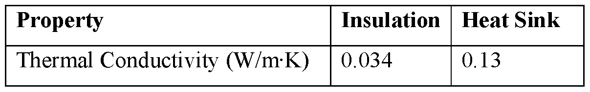
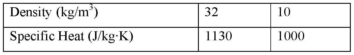
The relevant thermal properties of PCM A and PCM B are found below in Table 2.
Table 2
 The insulation values are representative of a material similar to expanded polystyrene
(EPS), a common insulation material. The PCM properties are considered to be typical of commercially available phase change materials, such as CrodaTherm waxes (Croda Europe Ltd., Balingen, Germany). The software models the phase change such that latent heat is evenly distributed over the phase change range, which is a reasonable approximation of actual PCM behavior.
The first, second, and third systems of the simulation are considered to be subjected to convection to the environment on the outer face of the insulation. The convection coefficient for free convection typically ranges from 2 W/m2-K to 25 W/m2-K (See Incropera, Frank P., and David P. DeWitt, Fundamentals of Heat and Mass Transfer, 5th Ed, J. Wiley (2002), which is incorporated herein by reference.) For this simulation, a convection coefficient of 5 W/m2-K is selected. The ambient temperature of the environment as a function of time is found below in Table 3. Any intermediate values are determined by linear interpolation.
Table 3


The temperature and time conditions are selected to represent a scenario where a shipping system in transit during summer months is exposed first to elevated ambient temperatures, then is abruptly transitioned to refrigeration (such as being held in a customs facility in a cold room), then resumes its journey under elevated ambient temperatures. A temperature of 30°C is chosen to represent ambient summer temperatures. A temperature of 6.3°C is chosen to represent the refrigerated storage. In this scenario, the shipping system is in transit for 42 hours prior to refrigerated storage, and the storage period is 200 hours. The temperature as a function of time is shown above in Table 3. Intermediate temperature values are calculated by linear interpolation.
The results from exposing the three systems to the ambient temperatures in Table 3 are depicted graphically in FIG. 15. The results represent the average temperature of the heat sink, a proxy for the shipping system payload, which may be, for example, a vaccine requiring refrigerated storage. The duration of protection afforded by each system is found below in Table 4.
Table 4

The duration can be looked at in several ways. The active duration may be regarded as the time the payload spent protecting the heat sink from the 30°C ambient temperature. The first system has an active duration that is 13% better than the next best option, namely, the third system. This is despite the fact that the second PCM has a lower latent heat value and is attributable to the fact that the second PCM regains latent heat during the refrigeration period. The duration of the first system is also 300% longer than the third system after the refrigeration period (i.e., 8 hours compared to 2 hours). The second system has the lowest
active duration and has no post-refrigeration duration because it allows the payload to exceed specification temperature before refrigeration.
In summary, finite element analysis (FEA) demonstrates that two phase change materials (PCMs) in an insulated container can provide superior thermal protection to the payload of the container than either of the two PCMs individually under certain conditions. In a preferred embodiment of the invention, both PCMs have different latent heats and different phase change temperature ranges from each other, although both PCMs may undergo phase change in the same direction (i.e. both changing from liquid to solid or both changing from solid to liquid). The utility of the invention is magnified when there is an interim period where the ambient temperature is such that one PCM reverses the direction of its phase change while the other continues to change phase in the original direction or stops changing phase altogether. These conditions may occur in real-life if a temperature- controlled shipment that uses PCMs is exposed to temperatures that are warmer than the product during normal shipping but is interrupted by a delay that causes the shipment to be stored in a refrigerator or other temperature-controlled environment.
The embodiments of the present invention described above are intended to be merely exemplary and those skilled in the art shall be able to make numerous variations and modifications to it without departing from the spirit of the present invention. All such variations and modifications are intended to be within the scope of the present invention.
Claims
1. A passive temperature-control shipping system for use in keeping a payload within a desired temperature range for a period of time while exposed to an ambient environment outside of the desired temperature range, the passive temperature-control shipping system comprising:
(a) one or more thermal insulation members arranged to at least partially bound a space;
(b) a first phase-change material associated with the one or more thermal insulation members, the first phase-change material having a phase-change temperature within the desired temperature range; and
(c) a second phase-change material associated with the one or more thermal insulation members, the second phase-change material being physically discrete from the first phase-change material and having a phase-change temperature that is different than that of the first phase-change material;
(d) wherein, when the system is adapted to receive the payload, both the first phase-change material and the second phase-change material are in a first phase that is different from a second phase in which the first and second phase-change materials exist when at equilibrium with the ambient environment.
2. The passive temperature-control shipping system as claimed in claim 1 wherein the ambient environment is warmer than the desired temperature range, wherein the phase-change temperature of the second phase-change material is higher than the phase-change temperature of the first phase-change material, and wherein the first phase is a solid phase.
3. The passive temperature-control shipping system as claimed in claim 2 wherein the desired temperature range is about +2°C to +8°C.
4. The passive temperature-control shipping system as claimed in claim 3 wherein the phase-change temperature of the first phase-change material is about +5°C.
5. The passive temperature-control shipping system as claimed in claim 4 wherein the phase-change temperature of the second phase-change material is within the desired temperature range.
6. The passive temperature-control shipping system as claimed in claim 5 wherein the phase-change temperature of the second phase-change material is about +7°C.
7. The passive temperature-control shipping system as claimed in claim 6 wherein the first phase change material and the second phase change material are preconditioned to the solid phase in a first step at a temperature of minus 20°C and then in a second step at a temperature of +3°C.
8. The passive temperature-control shipping system as claimed in claim 6 wherein the first phase-change material and the second phase-change material are arranged in different planes, with the first phase-change material more proximal to the payload and with the second phase-change material more distal to the payload.
9. The passive temperature-control shipping system as claimed in claim 8 wherein the first phase-change material is present in a greater mass and the second phase- change material is present in a lesser mass.
10. The passive temperature-control shipping system as claimed in claim 9 wherein the first phase-change material and the second phase-change material are present in a 3:1 ratio by mass.
11. The passive temperature-control shipping system as claimed in claim 1 wherein the first phase-change material and the second phase-change material are arranged coplanar.
12. The passive temperature-control shipping system as claimed in claim 1 wherein the first phase-change material and the second phase-change material are arranged in different planes.
13. The passive temperature-control shipping system as claimed in claim 1 wherein the first phase-change material and the second phase-change material are present in equal quantities.
14. The passive temperature-control shipping system as claimed in claim 1 wherein the first phase-change material and the second phase-change material are present in unequal quantities.
15. The passive temperature-control shipping system as claimed in claim 1 wherein the passive temperature-control shipping system is pallet-sized.
16. The passive temperature-control shipping system as claimed in claim 1 wherein the passive temperature-control shipping system is parcel-sized.
17. The passive temperature-control shipping system as claimed in claim 1 wherein the passive temperature-control shipping system is a pallet cover.
18. The passive temperature-control shipping system as claimed in claim 1 wherein the desired temperature range is about +15°C to +25°C.
19. The passive temperature-control shipping system as claimed in claim 1 wherein the desired temperature range is about -25°C to -15°C.
20. A method of transporting and/or storing a payload comprising a temperature- sensitive material, the method comprising the steps of:
(a) providing the passive temperature-control shipping system of claim 1 ;
(b) loading a payload into the passive temperature-control shipping system while both the first phase-change material and the second phase-change material are in the first phase; and
(c) then, subjecting the passive temperature-control shipping system to the ambient environment outside of the desired temperature range.
21. The method as claimed in claim 20 further comprising the step of transporting the passive temperature-control shipping system.
22. The method as claimed in claim 20 further comprising, after step (c), hibernating the passive temperature-control shipping system at a temperature that is within the desired temperature range and that is between the phase-change temperature of the first phase-change material and the phase-change temperature of the second phase-change material.
23. The method as claimed in claim 22 further comprising, after the hibernating step, again subjecting the passive temperature-control shipping system to the ambient environment outside of the desired temperature range.
24. The method as claimed in claim 23 wherein the ambient environment is warmer than the desired temperature range, wherein the phase-change temperature of the second phase-change material is higher than the phase-change temperature of the first phase-change material, and wherein the first phase is a solid phase.
25. The method as claimed in claim 24 wherein the desired temperature range is about +2°C to +8°C.
26. The method as claimed in claim 25 wherein the phase-change temperature of the first phase-change material is about +5°C.
27. The method as claimed in claim 26 wherein the phase-change temperature of the second phase-change material is within the desired temperature range.
28. The method as claimed in claim 27 wherein the phase-change temperature of the second phase-change material is about +7°C.
29. The method as claimed in claim 28 wherein the first phase change material and the second phase change material are preconditioned to the solid phase in a first step at a temperature of minus 20°C and then in a second step at a temperature of +3°C.
30. The method as claimed in claim 28 wherein the first phase-change material and the second phase-change material are arranged in different planes, with the first phase-change material more proximal to the payload and with the second phase- change material more distal to the payload.
31. The method as claimed in claim 30 wherein the first phase-change material is present in a greater mass and the second phase-change material is present in a lesser mass.
32. The method as claimed in claim 31 wherein the first phase-change material and the second phase-change material are present in a 3:1 ratio by mass.
33. A method of transporting and/or storing a payload comprising a temperature- sensitive material, the method comprising the steps of:
(a) providing one or more thermal insulating members;
(b) providing a first phase-change material, the first phase-change material having a phase-change temperature that is within a range of about +2°C to +8°C;
(c) providing a second phase-change material, the second phase-change material having a phase-change temperature that is greater than that of the first phase-change material;
(d) conditioning both the first phase-change material and the second phase- change material at a temperature at which both are in a solid phase;
(e) associating the first phase-change material and the second phase-change material with the one or more thermal insulation members to form a system having a payload space;
(1) loading the payload into the payload space while the first phase change material and the second phase change material are solid;
(g) then, subjecting the system to an ambient environment that is warmer than +8°C; and
(h) then, hibernating the system at a temperature that is at or above the phase- change temperature of the first phase-change material, that is below the
phase-change temperature of the second phase-change material, and that is within the range of about +2°C to +8°C.
34. The method as claimed in claim 33 further comprising, after the hibernating step, once again subjecting the system to the ambient environment that is warmer than +8°C.
35. The method as claimed in claim 34 wherein the phase-change temperature of the first phase-change material is about +5°C and wherein the phase-change temperature of the second phase-change material is about +7°C.
36. The method as claimed in claim 33 wherein the conditioning step comprising subjecting the first phase change material and the second phase change material to a first conditioning temperature of minus 20°C and then to a second conditioning temperature of +3°C.
Applications Claiming Priority (2)
| Application Number | Priority Date | Filing Date | Title |
|---|---|---|---|
| US202163156855P | 2021-03-04 | 2021-03-04 | |
| US63/156,855 | 2021-03-04 |
Publications (1)
| Publication Number | Publication Date |
|---|---|
| WO2022187699A1 true WO2022187699A1 (en) | 2022-09-09 |
Family
ID=83155350
Family Applications (1)
| Application Number | Title | Priority Date | Filing Date |
|---|---|---|---|
| PCT/US2022/019015 Ceased WO2022187699A1 (en) | 2021-03-04 | 2022-03-04 | Shipping system for storing and/or transporting temperature-sensitive materials |
Country Status (2)
| Country | Link |
|---|---|
| US (1) | US12366400B2 (en) |
| WO (1) | WO2022187699A1 (en) |
Cited By (1)
| Publication number | Priority date | Publication date | Assignee | Title |
|---|---|---|---|---|
| CN116280761A (en) * | 2023-03-17 | 2023-06-23 | 广西保晟汽车进出口有限公司 | A kind of container heat insulation device |
Families Citing this family (6)
| Publication number | Priority date | Publication date | Assignee | Title |
|---|---|---|---|---|
| US11511928B2 (en) | 2017-05-09 | 2022-11-29 | Cold Chain Technologies, Llc | Shipping system for storing and/or transporting temperature-sensitive materials |
| WO2020247456A1 (en) * | 2019-06-03 | 2020-12-10 | Sonoco Development Inc. | Heat pipe cooled pallet shipper |
| US12378057B2 (en) | 2020-07-02 | 2025-08-05 | Cold Chain Technologies, Llc | Shipping system for storing and/or transporting temperature-sensitive materials |
| WO2022187699A1 (en) | 2021-03-04 | 2022-09-09 | Cold Chain Technologies, Llc | Shipping system for storing and/or transporting temperature-sensitive materials |
| MA59995B1 (en) * | 2023-03-29 | 2024-12-31 | Arche Africa | MODULAR, SOTHERMAL, SELF-SUPPORTING AND DURABLE POSITIVE-NEGATIVE COLD ROOM STRUCTURE PANEL SYSTEM |
| WO2024229577A1 (en) * | 2023-05-10 | 2024-11-14 | Héma-Québec | Phase change material thermoregulated container system |
Citations (3)
| Publication number | Priority date | Publication date | Assignee | Title |
|---|---|---|---|---|
| US20190210790A1 (en) * | 2017-05-09 | 2019-07-11 | Cold Chain Technologies, Inc. | Shipping system for storing and/or transporting temperature-sensitive materials |
| US20200002075A1 (en) * | 2018-06-15 | 2020-01-02 | Cold Chain Technologies, Inc. | Shipping system for storing and/or transporting temperature-sensitive materials |
| US20200231362A1 (en) * | 2019-01-17 | 2020-07-23 | Cold Chain Technologies, Llc | Thermally insulated shipping system for parcel-sized payload |
Family Cites Families (395)
| Publication number | Priority date | Publication date | Assignee | Title |
|---|---|---|---|---|
| US2289060A (en) | 1940-03-12 | 1942-07-07 | Merkle Corp | Method of and apparatus for utilizing dry ice |
| US2317005A (en) | 1941-04-14 | 1943-04-20 | Wasserman Nathan | Shipping carton |
| US2467268A (en) | 1943-12-08 | 1949-04-12 | Sherman Paper Products Corp | Shipping package using dry ice |
| US2515709A (en) | 1948-02-27 | 1950-07-18 | John A Heard | Serving device having removable inner receptacle |
| US2844299A (en) | 1957-06-17 | 1958-07-22 | Pabst Brewing Co | Beverage cooler carton |
| DE1486302B1 (en) | 1964-08-07 | 1970-09-24 | Karl Kahmen | Box-shaped insulating container |
| US3828960A (en) | 1972-11-10 | 1974-08-13 | Dow Chemical Co | Heat insulating container having plastic walls retaining vacuum |
| US3890762A (en) | 1973-08-20 | 1975-06-24 | Day Star Corp | Produce shipping container and packing method |
| US3993811A (en) | 1974-08-15 | 1976-11-23 | The Dow Chemical Company | Thermal insulating panel for use in an insulative container and method of making said panel |
| US3980005A (en) | 1974-11-20 | 1976-09-14 | Buonaiuto Robert B | Synthetic plastic foam carton liners |
| DE2731858A1 (en) | 1977-07-14 | 1979-02-01 | Martin A Dipl Ing Frank | PROCEDURE FOR THE REFRIGERATION OF GOODS IN REFRIGERATED CONTAINERS AND REFRIGERATED CONTAINERS |
| US4294079A (en) | 1980-03-12 | 1981-10-13 | Better Agricultural Goals Corporation | Insulated container and process for shipping perishables |
| US4311022A (en) | 1980-04-18 | 1982-01-19 | Hall John M | Foldable ice pack |
| US4292817A (en) | 1980-05-12 | 1981-10-06 | The Mead Corporation | Controlled temperature shipping assembly |
| JPS5796852A (en) | 1980-12-09 | 1982-06-16 | Matsushita Electric Industrial Co Ltd | Heat insulating material |
| US4377075A (en) | 1981-03-09 | 1983-03-22 | New England Nuclear Corporation | Refrigerant and method for shipping perishable materials |
| US4682708A (en) | 1981-10-15 | 1987-07-28 | Leggett & Platt, Incorporated | Insulated shipping container |
| US4527370A (en) | 1982-04-08 | 1985-07-09 | Heinz Schuette | Modular building |
| US4446705A (en) | 1982-05-12 | 1984-05-08 | Environmental Testing & Certif. Corp. | Shipping container |
| US4931333A (en) | 1985-09-23 | 1990-06-05 | Henry D Lindley | Thermal packaging assembly |
| FR2604981B1 (en) | 1986-10-13 | 1989-06-30 | Oris Ind | INSULATED PACKAGING |
| US4819793A (en) | 1987-10-13 | 1989-04-11 | Charles, Fong And Associates | Beverage carrier |
| US5102004A (en) | 1988-06-08 | 1992-04-07 | Transtech Service Network, Inc. | Method and apparatus for packaging refrigerated goods |
| US4928847A (en) | 1988-06-08 | 1990-05-29 | Hollander David S | Apparatus for packaging refrigerated goods |
| US5111957A (en) | 1988-06-08 | 1992-05-12 | Transtech Service Network, Inc. | Method and apparatus for packaging refrigerated goods |
| US4889252A (en) | 1988-11-18 | 1989-12-26 | Allpak Container, Inc. | Insulated container |
| US4903493A (en) | 1989-01-17 | 1990-02-27 | Pymah Corporation | Heat sink protective packaging for thermolabile goods |
| US4947658A (en) | 1989-08-22 | 1990-08-14 | Neorx Corporation | Shipping container |
| US5247747A (en) | 1989-10-26 | 1993-09-28 | Resource America, Inc. | Recycle shipping container |
| US5042260A (en) | 1989-12-26 | 1991-08-27 | George Sr Charles J | Live lobster shipping method |
| US5216900A (en) | 1991-12-27 | 1993-06-08 | Jones Charles E | Soft-sided cooler with soft-sided freeze pack |
| US5218923A (en) | 1992-07-23 | 1993-06-15 | Rose Seafood Industries, Inc. | Container for storage and/or shipment of live lobsters |
| US5323911A (en) | 1992-09-11 | 1994-06-28 | The Morning Star Packing Co. | Palletized container having discrete compartments formed by dividers |
| FR2697809B1 (en) | 1992-11-06 | 1998-01-16 | Monoplast | INSULATED BOX. |
| US5450977A (en) | 1993-01-22 | 1995-09-19 | Moe; James S. | Insulated shipping container |
| JPH06298283A (en) | 1993-04-16 | 1994-10-25 | Kubota Corp | Vacuum insulation box |
| FR2714894B1 (en) | 1994-01-12 | 1996-03-29 | Enthalpy | Foldable insulating transport and packaging box. |
| US5501338A (en) | 1994-02-18 | 1996-03-26 | Preston; Paul E. | Food carrier system |
| US5647226A (en) | 1994-12-07 | 1997-07-15 | Mainstream Engineering Corporation | Phase change apparatus for animal parts, human body parts, body fluids and culture |
| DE69512750T3 (en) | 1994-12-20 | 2005-03-31 | Villa, Joseph N. | Insulated storage / transport container to maintain a constant temperature |
| US5586438A (en) | 1995-03-27 | 1996-12-24 | Organ, Inc. | Portable device for preserving organs by static storage or perfusion |
| US5570588A (en) | 1995-06-26 | 1996-11-05 | Lowe; Scott A. | Freezable insert cooler |
| WO1997017580A1 (en) | 1995-11-06 | 1997-05-15 | Purdum Howard E | Container for transportation of temperature sensitive products |
| US5669233A (en) | 1996-03-11 | 1997-09-23 | Tcp Reliable Inc. | Collapsible and reusable shipping container |
| US5709307A (en) | 1996-03-28 | 1998-01-20 | Rosado; Mildred M. | Insulated lunch container |
| US5897017A (en) | 1996-04-16 | 1999-04-27 | Lantz; Gary W. | Insulated shipping container |
| US6619500B1 (en) | 1996-04-16 | 2003-09-16 | Gary W. Lantz | Compartmentalized insulated shipping container |
| AUPO009896A0 (en) | 1996-05-27 | 1996-06-20 | Armacel Pty Limited | A multi-piece housing |
| US5950450A (en) | 1996-06-12 | 1999-09-14 | Vacupanel, Inc. | Containment system for transporting and storing temperature-sensitive materials |
| ZA974977B (en) | 1996-06-12 | 1997-12-30 | Univ Dayton | Gel compositions for thermal energy storage. |
| US5755987A (en) | 1996-08-23 | 1998-05-26 | The Dow Chemical Company | Dibasic ester based phase change material compositions |
| US6106449A (en) | 1996-12-23 | 2000-08-22 | Vacupanel, Inc. | Vacuum insulated panel and container and method of production |
| US5924302A (en) | 1997-03-27 | 1999-07-20 | Foremost In Packaging Systems, Inc. | Insulated shipping container |
| FR2768907B1 (en) | 1997-09-26 | 1999-12-24 | Joel Maritan | INSULATED SPORTS BAG |
| US6070427A (en) | 1997-10-10 | 2000-06-06 | National Starch And Chemical Investment Holding Corporation | Method for shipping exothermic materials |
| AU1713399A (en) | 1997-12-19 | 1999-07-12 | Federal Express Corporation | Insulated shipping container |
| US5979693A (en) | 1997-12-29 | 1999-11-09 | Bane, Iii; William W. | Panel for shipping containers |
| US6189330B1 (en) | 1998-01-06 | 2001-02-20 | Campbell Soup Company | Container, system and process for shipping and storing food products and method for recycling shipping and storage containers |
| US6055825A (en) | 1998-03-18 | 2000-05-02 | Choy; Anthony | Insulated shipping container |
| US5899088A (en) | 1998-05-14 | 1999-05-04 | Throwleigh Technologies, L.L.C. | Phase change system for temperature control |
| US6244458B1 (en) | 1998-07-09 | 2001-06-12 | Thermo Solutions, Inc. | Thermally insulated container |
| AUPP560398A0 (en) | 1998-08-31 | 1998-09-24 | Laby, Ralph Henry | Cool keeping transport arrangement and method |
| DE19840640A1 (en) | 1998-09-05 | 2000-03-16 | Isovac Ingenieurgesellschaft M | Insulating housing, especially for refrigerator and/or energy storage device |
| US6209343B1 (en) | 1998-09-29 | 2001-04-03 | Life Science Holdings, Inc. | Portable apparatus for storing and/or transporting biological samples, tissues and/or organs |
| SE9804146D0 (en) | 1998-12-01 | 1998-12-01 | Siemens Elema Ab | Packaging |
| US6427475B1 (en) | 1998-12-17 | 2002-08-06 | Abbott Laboratories | Nested cooler system |
| JP2000211667A (en) | 1999-01-21 | 2000-08-02 | New Line:Kk | Packaging and how to store it |
| US6482332B1 (en) | 1999-03-12 | 2002-11-19 | Ted J. Malach | Phase change formulation |
| DE19915311A1 (en) | 1999-04-03 | 2000-10-05 | Bayer Ag | Vacuum insulating panel, especially for refrigerators, has a microporous core encased in a 7-layer plastic foil with a polyolefin sealing layer, a gas barrier, a polyolefin layer and a metallised polymer layer |
| US6886357B2 (en) | 1999-09-30 | 2005-05-03 | Gano, Iii John | Systems and methods for storing items with containers |
| US6557370B2 (en) | 1999-09-30 | 2003-05-06 | Gano, Iii John Henry | Systems and methods for storing items with containers |
| US6338234B1 (en) | 1999-11-24 | 2002-01-15 | Weyerhauser Company | Method of encapsulating shipping container blanks in plastic film |
| FR2802186B1 (en) | 1999-12-13 | 2002-03-01 | Messer France | CONTAINER FOR THE REFRIGERATED TRANSPORT OF VARIOUS PRODUCTS AND METHOD FOR ITS CONSTITUTION AND LOADING |
| US6325281B1 (en) | 2000-03-30 | 2001-12-04 | Polyfoam Packers Corporation | Thermally insulating shipping system |
| EP1365974A2 (en) | 2000-07-03 | 2003-12-03 | Kodiak Technologies, Inc. | Thermal container with data monitoring system |
| EP1177984A3 (en) | 2000-08-03 | 2004-07-14 | Va-Q-tec AG | Insulated container |
| US6490880B1 (en) | 2000-10-26 | 2002-12-10 | Islet Technology Inc. | Regulated organ containment shipping system using dual-layer preservation liquid |
| US6564992B1 (en) | 2000-11-15 | 2003-05-20 | The Jel Sert Company | Combination product package and disposable cooler |
| DE10107478A1 (en) | 2001-02-15 | 2002-09-05 | Fagerdala Deutschland Gmbh | Cool box for storage and transportation of fish in camping has plastics foam walls, especially of particle foam; walls and/or floor and/or top of cool box are at least partly evacuated; evacuated coating has evacuated hollow chamber |
| FR2821067B1 (en) | 2001-02-16 | 2003-08-15 | Bcf Holding | INSULATED CONTAINER |
| US6295830B1 (en) | 2001-02-28 | 2001-10-02 | The Boc Group, Inc. | Portable container for refrigerated or frozen goods |
| US20020134962A1 (en) | 2001-03-25 | 2002-09-26 | Benjamin Romero | Phase change material for maintaining refrigerated temperatures |
| AU2002257127A1 (en) | 2001-04-04 | 2002-10-21 | Advanced Plastics Technologies, Ltd. | Process for coating paper, paperboard, and molded fiber with a water-dispersible polyester polymer |
| WO2002081833A1 (en) | 2001-04-06 | 2002-10-17 | Dow Global Technologies Inc. | Shapeable vacuum insulation panel containing a single core component |
| US6519968B1 (en) | 2001-05-09 | 2003-02-18 | Loctite Corporation | Shipping container for exothermic material |
| DE10123453A1 (en) | 2001-05-14 | 2002-11-21 | Va Q Tec Ag | Vacuum heat insulation system, comprises an insulation plate of an open pore insulating plate covered with first and second films |
| US6584797B1 (en) | 2001-06-06 | 2003-07-01 | Nanopore, Inc. | Temperature-controlled shipping container and method for using same |
| DE10131136A1 (en) | 2001-06-28 | 2003-01-16 | Ecocool Gmbh | Packaging unit comprises an inner cover with insulating and reflecting elements, a temperature stabilizing cover with pre-cooled elements, an intermediate cover and an outer cover |
| US6718776B2 (en) | 2001-07-10 | 2004-04-13 | University Of Alabama In Huntsville | Passive thermal control enclosure for payloads |
| US6868982B2 (en) | 2001-12-05 | 2005-03-22 | Cold Chain Technologies, Inc. | Insulated shipping container and method of making the same |
| US6645598B2 (en) | 2002-01-04 | 2003-11-11 | Robert J. Alderman | Cell insulation blanket with phase change material, and method of making |
| KR20030060191A (en) | 2002-01-07 | 2003-07-16 | 에스아이에스기술(주) | Paper Box Using Vacuum Heat Shield Merterial |
| DE10206109C1 (en) | 2002-02-13 | 2003-06-26 | Ghassan Sowan | Packaging for products, which are sensitive to heat, has outer packaging with foam plates to shroud interior, and inner box with insulating foam walls to take fluid-filled cooling elements |
| US6910582B2 (en) | 2002-05-22 | 2005-06-28 | Gary W. Lantz | Shock absorbing insulated shipping container especially for breakable glass bottles |
| US6758057B2 (en) * | 2002-07-30 | 2004-07-06 | Vince, Ii Gerard C. | Bimodal refrigeration system and method |
| US6838146B2 (en) | 2002-09-09 | 2005-01-04 | Merrill Ezra L | Vacuum thermal insulation product and method for making same |
| US7500593B2 (en) | 2002-10-23 | 2009-03-10 | Minnesota Thermal Science, Llc | Container having passive controlled temperature interior, and method of construction |
| US7422143B2 (en) | 2002-10-23 | 2008-09-09 | Minnesota Thermal Science, Llc | Container having passive controlled temperature interior |
| US6875486B2 (en) | 2003-02-03 | 2005-04-05 | Drayton Miller | Package system and method |
| KR100750456B1 (en) | 2003-04-18 | 2007-08-22 | 마쯔시다덴기산교 가부시키가이샤 | Vacuum thermal insulation material and device using the same |
| US7257963B2 (en) | 2003-05-19 | 2007-08-21 | Minnesota Thermal Science, Llc | Thermal insert for container having a passive controlled temperature interior |
| DE10322764A1 (en) | 2003-05-19 | 2004-12-30 | Va-Q-Tec Ag | Containers with vacuum insulation and melt storage materials |
| US20050208083A1 (en) | 2003-06-04 | 2005-09-22 | Nanobio Corporation | Compositions for inactivating pathogenic microorganisms, methods of making the compositons, and methods of use thereof |
| MXPA06000301A (en) | 2003-07-07 | 2006-07-03 | Rodney M Derifield | Insulated shipping containers. |
| DE10333299B4 (en) | 2003-07-22 | 2006-02-16 | Sto Ag | thermal insulation system |
| US7294374B2 (en) | 2003-08-07 | 2007-11-13 | Tcp Reliable, Inc. | Thermal packaging system |
| DE10336835A1 (en) | 2003-08-11 | 2005-03-10 | Bsh Bosch Siemens Hausgeraete | Cool box for maintaining the temperature of chilled items has an insulated lining against which thermal frozen pads are interlocked |
| CA2483772C (en) | 2003-10-01 | 2014-04-29 | California Innovations Inc. | Container with cover and closure member |
| US20050098255A1 (en) | 2003-11-06 | 2005-05-12 | Lembo Michael J. | Insulation product having nonwoven facing and process for making same |
| SG115594A1 (en) | 2003-11-26 | 2005-10-28 | Fagerdala Singapore Pte Ltd | Insulated panels and shipping container incorporating said panels |
| US7328583B2 (en) | 2004-01-12 | 2008-02-12 | Entropy Solutions, Inc. | Thermally stable containment device and methods |
| CA2535668C (en) | 2004-01-20 | 2010-10-12 | Matsushita Electric Industrial Co., Ltd. | Film for suppressing conduction of radiation heat and heat insulating material using the same |
| CN100455956C (en) | 2004-01-30 | 2009-01-28 | 松下电器产业株式会社 | Collapsible insulated container and method of delivery |
| US20100072211A1 (en) | 2004-03-18 | 2010-03-25 | Eggs Overnight, Inc. | Reusable shipping container and method for using the same |
| US20050224501A1 (en) | 2004-04-09 | 2005-10-13 | Rod Folkert | Thermal storage container |
| US7240513B1 (en) | 2004-04-12 | 2007-07-10 | Conforti Carl J | Thermally-controlled package |
| US7131289B2 (en) | 2004-06-29 | 2006-11-07 | The Glad Products Company | Container |
| WO2007001354A2 (en) | 2004-09-01 | 2007-01-04 | Aspen Aerogels, Inc. | High performance vacuum-sealed insulations |
| SE527546C2 (en) | 2004-09-15 | 2006-04-04 | Hans Bruce | Method and apparatus for securing temperature control in the interior of a transport container or the like |
| US7909806B2 (en) | 2004-09-23 | 2011-03-22 | Anthrogenesis Corporation | Cord blood and placenta collection kit |
| US7147626B2 (en) | 2004-09-23 | 2006-12-12 | Celgene Corporation | Cord blood and placenta collection kit |
| GB0502206D0 (en) | 2005-02-03 | 2005-03-09 | Tattam Edwin F | Transport container |
| US7476068B2 (en) | 2005-02-09 | 2009-01-13 | Sun Pleasure Company, Ltd. | Cargo shipping assembly and method |
| US10457469B2 (en) | 2005-04-14 | 2019-10-29 | James William Howard TUMBER | Insulated shipping container having at least one spacer for improving airflow within the container |
| US7681405B2 (en) | 2005-04-14 | 2010-03-23 | Alton Williams | Insulated shipping container systems and methods thereof |
| FR2884810A1 (en) | 2005-04-21 | 2006-10-27 | Jerome Jarmasson | Product e.g. beverage, display case for e.g. exhibition, has compartments storing products and formed of structures comprising plates which are formed of thermally insulating material, and openings provided on sides of compartments |
| JP2006306422A (en) | 2005-04-27 | 2006-11-09 | Air Water Tansan Kk | Heat insulating box |
| US20070028642A1 (en) | 2005-05-17 | 2007-02-08 | American Thermal Wizards International, Inc. | Container for Transporting Temperature Controlled Items |
| US7624911B2 (en) | 2005-06-29 | 2009-12-01 | International Paper Co. | Container with freestanding insulating encapsulated cellulose-based substrate |
| WO2007030110A1 (en) | 2005-09-07 | 2007-03-15 | Gary Lantz | Variable-volume insulated shipping container |
| US8074465B2 (en) | 2005-09-12 | 2011-12-13 | Genzyme Corporation | Thermally insulated transport container for cell-based products and related methods |
| JP2007191195A (en) | 2006-01-20 | 2007-08-02 | Doi Giken:Kk | Cool box and manufacturing method of cool box body |
| US20070186577A1 (en) | 2006-02-16 | 2007-08-16 | Michael Goncharko | Passively temperature-regulated shipping container suitable for biological, pharmaceutical materials or food products |
| US7677406B2 (en) | 2006-02-16 | 2010-03-16 | Maxson Floyd S | Insulating container |
| WO2007098244A2 (en) | 2006-02-21 | 2007-08-30 | Healthcare Products International, Inc. | Method and device for the transportation of temperature sensitive materials |
| EP1996053B1 (en) | 2006-03-02 | 2015-12-30 | Cold Chain Technologies, Inc. | Insulated shipping container and method of making the same |
| JP2007253974A (en) | 2006-03-22 | 2007-10-04 | Kurabo Ind Ltd | Insulator, opposing structure and heat insulation container |
| US7624873B2 (en) | 2006-06-20 | 2009-12-01 | Tennant Packaging Corporation | Diagnostic specimen shipping kit |
| US20080006628A1 (en) | 2006-07-07 | 2008-01-10 | Michael Goncharko | Insulating container made from rectangular panels of compressible material strapped together |
| DE202006012469U1 (en) | 2006-08-12 | 2007-09-20 | Porextherm-Dämmstoffe Gmbh | Vacuum insulation panel with passage in the insulation support body |
| US7721566B1 (en) | 2006-08-14 | 2010-05-25 | Minnesota Thermal Science, Llc | Collapsible interconnected panels of phase change material |
| DE102006039621A1 (en) | 2006-08-24 | 2008-02-28 | Porextherm-Dämmstoffe Gmbh | Vacuum insulation panel with bushing |
| US20080067098A1 (en) | 2006-08-24 | 2008-03-20 | Raine Packaging & Label, Inc. | Reusable conformable waterproof wrap |
| DE202006013562U1 (en) | 2006-09-01 | 2007-10-11 | Porextherm-Dämmstoffe Gmbh | Vacuum insulation panel with recess in the insulation support body |
| JP2008068871A (en) | 2006-09-11 | 2008-03-27 | Appax Co Ltd | Heat insulating member, and heat insulating container |
| PT2081838E (en) | 2006-10-27 | 2014-11-05 | Dontis & Co O E K | Assembled isothermal box - container |
| DE102006057644A1 (en) | 2006-12-05 | 2008-06-12 | Deutsche Post Ag | Container for shipping objects and method for producing the containers |
| US20080135564A1 (en) | 2006-12-12 | 2008-06-12 | Benjamin Romero | Container for shipping products, which controls temperature of products |
| DE102007059799A1 (en) | 2006-12-12 | 2008-06-19 | Va-Q-Tec Ag | Vakuumdämmkörper with a protective film and method for producing the same |
| US20080145919A1 (en) | 2006-12-18 | 2008-06-19 | Franklin Thomas D | Portable organ and tissue preservation apparatus, kit and methods |
| US20080164265A1 (en) | 2007-01-06 | 2008-07-10 | Conforti Carl J | Thermally-controlled package |
| US8342588B2 (en) | 2007-01-24 | 2013-01-01 | Martin Marietta Materials, Inc. | Insulated composite body panel structure for a refrigerated truck body |
| US7849708B2 (en) | 2007-02-20 | 2010-12-14 | Tcp Reliable, Inc. | Temperature controlled shipping using one or more smaller insulated containers inside a larger insulated container |
| KR20080096089A (en) | 2007-04-26 | 2008-10-30 | 주식회사 탭스인터내셔널 | Cold storage system |
| EP2142431A4 (en) | 2007-05-04 | 2014-06-18 | Entropy Solutions Inc | Package having phase change materials and method of use in transport of temperature sensitive payload |
| US7704584B2 (en) | 2007-06-13 | 2010-04-27 | Alderman Robert J | Thermal insulation with thin phase change layer |
| US7641812B2 (en) | 2007-06-13 | 2010-01-05 | Alderman Robert J | Thermal insulation with thin phase change layer |
| DE202007012289U1 (en) | 2007-09-01 | 2007-11-15 | delta T Gesellschaft für Medizintechnik mbH | Modular, insulating transport containers |
| EP2200904B1 (en) | 2007-09-11 | 2013-06-26 | Cold Chain Technologies, Inc. | Insulated pallet shipper |
| US20090078708A1 (en) | 2007-09-20 | 2009-03-26 | Preston Noel Williams | Temperature Maintaining Package Having Corner Discontinuities |
| DE202007014564U1 (en) | 2007-10-16 | 2008-11-27 | Porextherm-Dämmstoffe Gmbh | Enclosed vacuum insulation panel |
| JP2009113822A (en) | 2007-11-02 | 2009-05-28 | Tatsuya Mimatsu | Low-temperature insulating and heat-insulating container |
| US7823394B2 (en) | 2007-11-02 | 2010-11-02 | Reflect Scientific, Inc. | Thermal insulation technique for ultra low temperature cryogenic processor |
| US8199019B2 (en) | 2007-11-19 | 2012-06-12 | Compx International Inc. | Field retrofittable refrigerator lock with temperature monitoring, temperature based access control and alarming |
| US20090230138A1 (en) | 2007-11-30 | 2009-09-17 | Preston Noel Williams | Temperature Maintaining Shipping Package |
| US7896182B1 (en) | 2007-12-12 | 2011-03-01 | The United States Of America As Represented By The Secretary Of The Army | Coated-poly containers |
| GB0802445D0 (en) | 2008-02-11 | 2008-03-19 | Penfold William L | Low energy cooling device |
| US7950246B1 (en) | 2008-02-13 | 2011-05-31 | Minnesota Thermal Science, Llc | Assembly of abutting vacuum insulated panels arranged to form a retention chamber with a slip surface interposed between the panels |
| US20100038369A1 (en) | 2008-08-01 | 2010-02-18 | Advanced In Vitro Cell Technologies, S.L. | Box for transporting samples |
| DE102008036669B4 (en) | 2008-08-06 | 2020-01-23 | Enertracting Gmbh | Thermal storage container for an interior of a building |
| US8333279B2 (en) | 2008-09-11 | 2012-12-18 | Simple Container Solutions, Inc. | Expandable insulated packaging |
| US8904810B2 (en) | 2008-09-16 | 2014-12-09 | University Of Wyoming Research Corporation | Temperature control transport system |
| JP2010089802A (en) | 2008-10-06 | 2010-04-22 | Nippon Kako Kizai Kk | Insulating container for packing |
| GB2465376B (en) * | 2008-11-14 | 2012-11-28 | Tower Cold Chain Solutions Ltd | Thermally insulated reuseable transportation container |
| EP2394239A4 (en) | 2009-02-05 | 2014-05-28 | Cryoport Systems Inc | Methods for controlling shipment of a temperature controlled material using a spill proof shipping container |
| US20130245991A1 (en) | 2012-02-28 | 2013-09-19 | Richard Kriss | Method for determining the remaining life of a thermal mass in a shipping package while in transit |
| US9751682B2 (en) | 2009-02-20 | 2017-09-05 | Pelican Biothermal Llc | Modular cuboidal passive temperature controlled shipping container |
| CN101811601B (en) | 2009-02-24 | 2012-04-04 | 李茂雄 | nestable incubator |
| JP2010208644A (en) | 2009-03-06 | 2010-09-24 | Inoac Corp | Cold insulation box |
| US8154421B2 (en) | 2009-05-12 | 2012-04-10 | Fisher Clinical Services Inc. | Real time temperature and location tracker |
| US20100314397A1 (en) | 2009-05-13 | 2010-12-16 | Preston Noel Williams | Thermal Containment System Providing Temperature Maintaining Shipping Package with Segmented Flexible PCM Panels |
| GB2459392B (en) | 2009-05-29 | 2010-04-07 | Softbox Systems Ltd | Transport container |
| US8919082B1 (en) | 2009-06-15 | 2014-12-30 | Iowa E. P. S. Products, Inc. | Collapsible foam shipping cooler for perishables and method of making |
| FR2948342B1 (en) | 2009-07-22 | 2011-09-16 | Jean Louis Donato | ISOTHERMAL BODY PRESENTING IN THE FORM OF A KIT |
| RU2530885C2 (en) | 2009-07-29 | 2014-10-20 | ДАУ ГЛОБАЛ ТЕКНОЛОДЖИЗ ЭлЭлСи | Composite for heat-insulating panel |
| US10752434B2 (en) | 2009-09-21 | 2020-08-25 | Sonoca Development, Inc. | Temperature controlled cargo containers |
| US20110067852A1 (en) | 2009-09-21 | 2011-03-24 | David Scott Farrar | Temperature controlled cargo containers |
| EP2488807B1 (en) | 2009-10-13 | 2020-04-08 | Sonoco Development, Inc. | Thermally-controlled packaging device and method of making |
| WO2011049304A2 (en) | 2009-10-23 | 2011-04-28 | Lg Hausys, Ltd. | Vacuum insulation panel |
| US8156703B2 (en) | 2009-11-24 | 2012-04-17 | Alderman Robert J | Multiple phase PCM heat insulation blanket |
| JPWO2011068148A1 (en) | 2009-12-04 | 2013-04-18 | 大倉工業株式会社 | Vacuum insulation film and vacuum insulation film |
| US8424335B2 (en) | 2009-12-17 | 2013-04-23 | Minnesota Thermal Science, Llc | Cascading series of thermally insulated passive temperature controlled containers |
| JP2013522134A (en) | 2010-03-17 | 2013-06-13 | ネステク ソシエテ アノニム | Packaging material containing phase change material |
| US20110248038A1 (en) | 2010-04-09 | 2011-10-13 | Minnesota Thermal Science, Llc | Passive thermally controlled bulk shipping container |
| WO2011130020A1 (en) | 2010-04-15 | 2011-10-20 | Velcro Industries B.V. | Methods of forming composite materials |
| WO2011152610A1 (en) | 2010-06-04 | 2011-12-08 | Park Kyoo Chul | Vacuum insulation panel, and preparation method thereof |
| WO2011159978A1 (en) | 2010-06-18 | 2011-12-22 | American Aerogel Corporation | Insulating inserts, containers comprising them and methods of assembling and using them |
| US20120009376A1 (en) | 2010-07-12 | 2012-01-12 | Rusek Jr Stanley J | Vacuum Insulation Panel, Insulated Masonry Structure Comprising Same, And Method Of Construction |
| WO2012017910A1 (en) | 2010-08-04 | 2012-02-09 | Yamada Yutaka | Thermal insulation device and thermal insulation box for delivery |
| US8938986B2 (en) | 2011-01-04 | 2015-01-27 | Sonoco Development, Inc. | Modular system for thermally controlled packaging devices |
| US8192924B1 (en) | 2011-04-21 | 2012-06-05 | Tcp Reliable, Inc. | Rapid cooling to and maintaining of whole blood at 20 to 24C for processing |
| US8375730B2 (en) | 2011-01-28 | 2013-02-19 | Tcp Reliable, Inc. | Selecting packaging and coolant systems for shipment of biological products |
| CN201980585U (en) | 2011-03-08 | 2011-09-21 | 邵长年 | Constant temperature blood sample transport case |
| WO2012129463A2 (en) | 2011-03-23 | 2012-09-27 | Biocision, Llc | Phase change thermal-sink apparatus |
| FR2974353B1 (en) | 2011-04-19 | 2014-06-13 | Emball Iso | ISOTHERMAL CONDITIONING DEVICE FOR THERMOSENSITIVE PRODUCTS |
| US8763811B2 (en) | 2011-05-05 | 2014-07-01 | Gary Lantz | Insulated shipping container, and method of making |
| US8881398B2 (en) | 2011-05-26 | 2014-11-11 | General Electric Company | Method and apparatus for insulating a refrigeration appliance |
| JP5435435B2 (en) | 2011-06-28 | 2014-03-05 | 株式会社 スギヤマゲン | Insulated container |
| GB201112661D0 (en) | 2011-07-22 | 2011-09-07 | Softbox Systems Ltd | Container temperature control system |
| GB201112674D0 (en) | 2011-07-22 | 2011-09-07 | Softbox Systems Ltd | Container temperture control system |
| CN202244410U (en) | 2011-09-08 | 2012-05-30 | 黄可 | Foldable heat-preservation delivery box |
| US9834365B2 (en) | 2011-10-24 | 2017-12-05 | Eco-Pim Technologies | Temperature stabilizing cargo compartment, including a freeze and heat barrier, for transport container constructed with thermal resistant materials |
| US20130228583A1 (en) | 2012-03-02 | 2013-09-05 | William T. Mayer | Passive thermally regulated knockdown shipping container |
| US20130255306A1 (en) | 2012-03-27 | 2013-10-03 | William T. Mayer | Passive thermally regulated shipping container employing phase change material panels containing dual immiscible phase change materials |
| GB2500657A (en) | 2012-03-28 | 2013-10-02 | Ds Smith Corrugated Packaging Ltd | Thermally Insulated Container with Channels for Coolant Packs |
| US10168090B1 (en) | 2012-05-03 | 2019-01-01 | Efp Llc | Temperature controlled box system |
| US9366469B2 (en) | 2012-05-03 | 2016-06-14 | Efp Llc | Temperature controlled box system |
| US9429350B2 (en) | 2012-05-03 | 2016-08-30 | Efp Llc | Shipping box system with multiple insulation layers |
| CN202728724U (en) | 2012-05-30 | 2013-02-13 | 北京仁创科技集团有限公司 | Fresh-keeping container capable of being spliced |
| KR101389531B1 (en) | 2012-07-03 | 2014-04-25 | 한국식품연구원 | Thermoelectric element-applied apparatus for transporting and delivering agrifood |
| US20140008374A1 (en) | 2012-07-06 | 2014-01-09 | Neil D. Lubart | Containers including insulating materials |
| US9060508B2 (en) | 2012-07-18 | 2015-06-23 | Alex N. Anti | High-performance extended target temperature containers |
| FR2994420A1 (en) | 2012-08-07 | 2014-02-14 | Sofrigam | Protection cover for protecting products placed on pallet during transport of products on vehicle, has rectangular opening part provided in front of bottom, where opening forms parallelepiped space between one of side walls and bottom |
| CN202945694U (en) | 2012-08-20 | 2013-05-22 | 重庆龙者低碳环保科技有限公司 | Puncture resistance vacuum insulated panel |
| US8887515B2 (en) | 2012-08-23 | 2014-11-18 | Pelican Biopharma, Llc | Thermal management systems and methods |
| WO2014052409A2 (en) | 2012-09-25 | 2014-04-03 | Cold Chain Technologies, Inc. | Gel comprising a phase-change material, method of preparing the gel, and thermal exchange implement comprising the gel |
| US9598622B2 (en) | 2012-09-25 | 2017-03-21 | Cold Chain Technologies, Inc. | Gel comprising a phase-change material, method of preparing the gel, thermal exchange implement comprising the gel, and method of preparing the thermal exchange implement |
| US9573754B2 (en) | 2012-09-26 | 2017-02-21 | Sonoco Development, Inc. | Convection based temperature assured packaging system |
| US9513067B2 (en) | 2012-09-26 | 2016-12-06 | Sonoco Development, Inc. | Convection based temperature assured packaging system |
| CN202831270U (en) | 2012-10-12 | 2013-03-27 | 烟台彤祥化工科技有限公司 | Inner-cladding vacuum heat-insulation board type hard foam polyurethane composite board |
| WO2014070167A1 (en) | 2012-10-31 | 2014-05-08 | Hewlett-Packard Development Company, L.P. | Thermal stabilization shipping system and method |
| WO2014067927A1 (en) | 2012-11-01 | 2014-05-08 | Nestec S.A. | Container for temperature sensitive materials |
| US10618695B2 (en) | 2012-11-16 | 2020-04-14 | Savsu Technologies Llc | Contents rack for use in insulated storage containers |
| US9957099B2 (en) | 2012-12-04 | 2018-05-01 | Nanopore, Inc. | Insulated container system for maintaining a controlled payload temperature |
| US20140157797A1 (en) | 2012-12-12 | 2014-06-12 | Souvenirwine.com, Inc | Process to Control the Payload Temperature of a Shipping Container in Transit |
| JP6171025B2 (en) | 2012-12-18 | 2017-07-26 | クリアウォーター シーフーズ リミテッド パートナーシップ | container |
| WO2014100826A1 (en) | 2012-12-23 | 2014-06-26 | Illuminate Consulting, Llc. | Method and apparatus for thermally protecting and/or transporting temperature sensitive products |
| WO2014113035A1 (en) | 2013-01-21 | 2014-07-24 | Hewlett-Packard Development Company, L.P. | Palletized load reactant regulation heating |
| WO2014118821A1 (en) | 2013-01-31 | 2014-08-07 | Kusaka Yasuto | Thermal insulation box |
| US10337784B2 (en) | 2013-02-20 | 2019-07-02 | Doubleday Acquisitions Llc | Phase change material (PCM) belts |
| US9400966B2 (en) | 2013-03-12 | 2016-07-26 | Saak Dertadian | Monitoring temperature-sensitive cargo with automated generation of regulatory qualification |
| US9373099B2 (en) | 2013-03-12 | 2016-06-21 | Tcp Reliable, Inc. | Network of participants in a shipment cold-chain |
| US8935934B2 (en) | 2013-03-12 | 2015-01-20 | Tcp Reliable, Inc. | Monitoring temperature-sensitive cargo with automated generation of regulatory qualification |
| GB2513106A (en) | 2013-03-22 | 2014-10-22 | Peli Cool Logistics Ltd | Packaging |
| KR20140120252A (en) | 2013-04-02 | 2014-10-13 | 오씨아이 주식회사 | Icebox using flexible vacuum insulation panel and method for manufacturing thereof |
| US11046500B2 (en) | 2013-04-30 | 2021-06-29 | Mp Global Products, L.L.C. | Insulated shipping system including one-piece insulative insert with strengthening inner layer |
| US9611067B2 (en) | 2013-04-30 | 2017-04-04 | Chad A. Collison | Insulative bottle shipping system |
| US11953262B2 (en) | 2013-05-10 | 2024-04-09 | Packaging Technology Group, Llc | Recyclable, thermally insulated shipping container with packed, loose-fill organic insulation and PCM bladder insert |
| US9267722B2 (en) | 2013-05-10 | 2016-02-23 | Packaging Technology Group, Inc. | Phase change material bladder for use in a temperature controlled product shipper |
| US11731826B2 (en) | 2021-10-22 | 2023-08-22 | Packaging Technology Group, Llc | Recyclable, thermally insulated shipping container with packed, loose-fill organic insulation |
| US9913777B2 (en) | 2013-05-16 | 2018-03-13 | Sandy Wengreen | Storage systems and methods for medicines |
| US9151531B2 (en) | 2013-05-16 | 2015-10-06 | Sandy Wengreen | Storage systems and methods for medicines |
| US9707156B2 (en) | 2013-05-16 | 2017-07-18 | Sandy Wengreen | Storage systems and methods for medicines |
| US9877894B2 (en) | 2013-05-16 | 2018-01-30 | Sandy Wengreen | Storage systems and methods for medicines |
| US10588820B2 (en) | 2013-05-16 | 2020-03-17 | Sandy Wengreen | Storage systems and methods for medicines |
| US20160262979A1 (en) | 2013-05-16 | 2016-09-15 | Sandy Wengreen | Storage systems and methods for medicines |
| US20140343493A1 (en) | 2013-05-16 | 2014-11-20 | Sandy Wengreen | Storage devices and storage methods for injectable substances |
| US9272475B2 (en) | 2013-06-03 | 2016-03-01 | Sonoco Development, Inc. | Thermally insulated VIP sandwich shipper and method of making same |
| US9022249B2 (en) | 2013-06-17 | 2015-05-05 | Sonocco Development, Inc. | Thermally insulated polyurethane shipper and method of making same |
| US11634264B2 (en) | 2013-09-26 | 2023-04-25 | Va-Q-Tec Ag | Foil-wrapped vacuum insulation element |
| CN103672303B (en) | 2013-09-29 | 2017-01-25 | 安徽中科保瑞特节能科技有限公司 | Puncture-resistant vacuum insulation board and manufacturing method thereof |
| CN203601782U (en) | 2013-11-26 | 2014-05-21 | 成都心海汇才生物科技有限公司 | Self-assembling power-source-free heat preservation box |
| GB2523726A (en) | 2013-12-13 | 2015-09-09 | Peli Biothermal Ltd | Thermally insulated package |
| EP2883811B1 (en) | 2013-12-13 | 2016-11-09 | Peli Biothermal Limited | Thermally insulated package |
| KR101457029B1 (en) | 2014-01-02 | 2014-11-04 | 주식회사 에프엠에스코리아 | Box package for low-temperature materials |
| US20150259126A1 (en) | 2014-01-10 | 2015-09-17 | James MCGOFF | Insulated apparatus for shipping and storage and process for fabricating thereof |
| US20170001406A1 (en) | 2014-01-24 | 2017-01-05 | Edwin X. Graf | Biodegradable multi-layer passive thermal insulator material |
| US8881540B1 (en) | 2014-01-27 | 2014-11-11 | Tcp Reliable, Inc. | Monitoring temperature-sensitive cargo with automated generation of regulatory qualification |
| CN103964076B (en) | 2014-02-10 | 2016-03-30 | 厦门绿链集成服务有限公司 | The adiabatic heat-insulation case of energy dismounting |
| EP3108190B1 (en) | 2014-02-17 | 2020-01-15 | B Medical Systems S.à.r.l. | Cooling device |
| US20160305598A1 (en) | 2014-02-26 | 2016-10-20 | Sonoco Development, Inc. | Method of Manufacturing Vacuum Insulation Panels |
| DE202014003782U1 (en) | 2014-03-05 | 2015-06-08 | Va-Q-Tec Ag | Transport container for transport-sensitive goods |
| US20170072604A1 (en) | 2014-03-10 | 2017-03-16 | Empire Technology Development Llc | Composite foam and methods of preparation and use |
| DE202014002192U1 (en) | 2014-03-13 | 2015-06-17 | Va-Q-Tec Ag | Vacuum insulation panel and container with vacuum insulation panels |
| DE102014003413A1 (en) | 2014-03-13 | 2015-09-17 | Va-Q-Tec Ag | Vacuum insulation panel and container with vacuum insulation panels |
| DE102014003886A1 (en) | 2014-03-19 | 2015-09-24 | Roba Services Gmbh | Functionalized corrugated board |
| DE202014004515U1 (en) | 2014-05-30 | 2015-09-03 | Va-Q-Tec Ag | Transport container system |
| US9926102B2 (en) | 2014-06-05 | 2018-03-27 | Maxwell Properties, Llc | Systems and methods for providing a packaged thermoplastic material |
| US20170158411A1 (en) | 2014-07-18 | 2017-06-08 | Proprietect L.P. | Returnable Cold Chain Packaging Composite |
| US9688454B2 (en) | 2014-08-05 | 2017-06-27 | Sonoco Development, Inc. | Double bag vacuum insulation panel for steam chest molding |
| US20160053219A1 (en) | 2014-08-25 | 2016-02-25 | Opgen, Inc. | Systems, methods, and devices for temperature control |
| GB2530077A (en) | 2014-09-12 | 2016-03-16 | Peli Biothermal Ltd | Thermally insulated containers |
| KR102366410B1 (en) | 2014-10-16 | 2022-02-23 | 삼성전자주식회사 | Refrigerator and vacuum insulation module thereof |
| DE202014008489U1 (en) | 2014-10-27 | 2016-01-28 | Va-Q-Tec Ag | Box-shaped transport container |
| US20160123648A1 (en) | 2014-10-31 | 2016-05-05 | Thomas E. Leaverton | Light Weight Reinforced Ice Chest |
| EP3250323B1 (en) | 2015-01-26 | 2020-12-09 | Ventana Medical Systems, Inc. | Transporter systems, assemblies and associated methods for transporting tissue samples |
| US9476633B2 (en) | 2015-03-02 | 2016-10-25 | Whirlpool Corporation | 3D vacuum panel and a folding approach to create the 3D vacuum panel from a 2D vacuum panel of non-uniform thickness |
| ES2913001T3 (en) | 2015-03-18 | 2022-05-30 | Sonoco Dev Inc | Convection-based temperature-assured packaging system |
| CA2982788C (en) | 2015-04-15 | 2023-08-29 | American Aerogel Corporation | Vessel assemblies for temperature control |
| US9981797B2 (en) | 2015-04-20 | 2018-05-29 | Pratt Corrugated Holdings, Inc. | Nested insulated packaging |
| US9828137B2 (en) | 2015-04-21 | 2017-11-28 | Pith Products, Llc | Article and method of manufacture of resiliant stackable reusable container |
| US10648964B2 (en) | 2015-05-21 | 2020-05-12 | Biologistex Ccm, Llc | Biologic stability, delivery logistics and administration of time and/or temperature sensitive biologic based materials |
| US10568808B2 (en) | 2015-06-10 | 2020-02-25 | Inmark Global Holdings, Llc | Passive temperature controlled container |
| DE202015004047U1 (en) | 2015-06-10 | 2016-09-14 | Va-Q-Tec Ag | Heat-insulating body for a cooling unit and cooling unit with a heat-insulating body |
| WO2016208193A1 (en) | 2015-06-24 | 2016-12-29 | パナソニックIpマネジメント株式会社 | Gas-adsorbing device and evacuated insulating material using same |
| US9963287B2 (en) | 2015-09-08 | 2018-05-08 | Ekopak, Inc. | Insulated shipping system |
| CN108351146B (en) | 2015-09-11 | 2021-04-20 | 确保冷藏有限公司 | Portable Refrigeration Equipment |
| WO2017048793A1 (en) | 2015-09-14 | 2017-03-23 | Viking Cold Solutions, Inc. | Interior integration of phase change material and insulated packaging for the temperature preservation of perishable contents |
| US11591133B2 (en) | 2015-10-06 | 2023-02-28 | Cold Chain Technologies, Llc | Pallet cover comprising one or more temperature-control members and kit for use in making the pallet cover |
| US10583978B2 (en) | 2015-10-06 | 2020-03-10 | Cold Chain Technologies, Llc | Pallet cover compromising one or more temperature-control members and kit for use in making the pallet cover |
| EP3359459B1 (en) | 2015-10-06 | 2021-08-04 | Cold Chain Technologies, LLC | Pallet cover comprising one or more temperature-control members |
| EP3359889B1 (en) | 2015-10-06 | 2020-08-05 | Cold Chain Technologies, LLC | Thermally insulated shipping system for pallet-sized payload |
| KR102718662B1 (en) | 2015-10-19 | 2024-10-16 | 바스프 에스이 | Sandwich structure including VIP and method for manufacturing the same |
| SG11201803407RA (en) | 2015-10-27 | 2018-05-30 | Devendra Jain | A transportation box |
| US20170146276A1 (en) | 2015-11-25 | 2017-05-25 | Michael D. Newman | Disposable food product transport box and ice pouch |
| US10610985B2 (en) | 2015-12-28 | 2020-04-07 | Whirlpool Corporation | Multilayer barrier materials with PVD or plasma coating for vacuum insulated structure |
| GB2546257A (en) | 2016-01-08 | 2017-07-19 | The Wool Packaging Company Ltd | Temperature controlled packaging and transportation method |
| EP3415584B1 (en) | 2016-02-12 | 2021-08-11 | Japan Cold Chain Co., Ltd. | Cold-storage agent, refrigerated container, and method for refrigerated transportation |
| JP6123927B1 (en) | 2016-02-24 | 2017-05-10 | 大日本印刷株式会社 | Vacuum insulation outer packaging, vacuum insulation, and equipment with vacuum insulation |
| GB2548887C (en) | 2016-03-31 | 2024-01-17 | Radmat Building Products Ltd | A method of forming a panel for thermal insulation |
| US9957098B2 (en) | 2016-04-01 | 2018-05-01 | Vericool, Inc. | Shipping container with compostable insulation |
| US9550618B1 (en) | 2016-04-01 | 2017-01-24 | Vericool, Inc. | Shipping container with compostable insulation |
| EP3228962A1 (en) | 2016-04-04 | 2017-10-11 | Linde Aktiengesellschaft | Method for calculating dry ice block and related apparatus |
| US10647498B1 (en) | 2016-04-20 | 2020-05-12 | Walter Anthony Brygier, III | Insulated shipping container with rabbet-joint side panels |
| GB2551115B (en) | 2016-05-31 | 2021-02-10 | Laminar Medica Ltd | A thermally insulated container |
| GB201611031D0 (en) | 2016-06-24 | 2016-08-10 | Softbox Systems Ltd | A passive temperature control system for transport and storage containers |
| GB201611050D0 (en) | 2016-06-24 | 2016-08-10 | Softbox Systems Ltd | A passive temperature control system for transport and storage containers |
| CN105971183B (en) | 2016-07-21 | 2018-12-18 | 同济大学 | A kind of vacuum sealed package brick of easy environmental protection |
| US11340005B2 (en) | 2016-07-25 | 2022-05-24 | Cold Chain Technologies, Llc | Hybrid method and system for transporting and/or storing temperature-sensitive materials |
| CN106081351A (en) | 2016-08-25 | 2016-11-09 | 上海闪锦生物科技有限公司 | A kind of dry ice transport case that can monitor dry ice surplus in real time |
| GB2555099B (en) | 2016-10-13 | 2020-01-29 | Kingspan Holdings Irl Ltd | Vacuum insulation panel |
| US11264697B2 (en) | 2016-10-18 | 2022-03-01 | American Aerogel Corporation | Linked antenna pair for transmission through shielded shipping container |
| DE202016006810U1 (en) | 2016-11-08 | 2018-02-12 | Va-Q-Tec Ag | Thermal insulation panel |
| US20180148245A1 (en) | 2016-11-30 | 2018-05-31 | Google Inc. | Four-piece nestable cooler |
| MY206209A (en) | 2017-02-16 | 2024-12-04 | Vericool Inc | Compostable insulation for shipping container |
| US12338054B2 (en) | 2017-04-03 | 2025-06-24 | Jim TUMBER | Insulated shipping containers with compound insulation having space therebetween |
| GB201706482D0 (en) | 2017-04-24 | 2017-06-07 | Softbox Systems Ltd | An insulating transport and storage container |
| CA3065758C (en) | 2017-05-09 | 2022-10-18 | Cold Chain Technologies, Llc | Shipping system for storing and/or transporting temperature-sensitive materials |
| CA3063700A1 (en) | 2017-05-15 | 2018-11-22 | Cold Chain Technologies, Llc | Pallet cover comprising one or more temperature-control members and kit for use in making the pallet cover |
| DE102017119920A1 (en) | 2017-06-13 | 2018-12-13 | Liebherr-Hausgeräte Lienz Gmbh | Vakuumdämmkörper |
| DE102017113782A1 (en) | 2017-06-21 | 2018-12-27 | Porextherm Dämmstoffe GmbH | Heat insulation body with protective layer |
| GB201711104D0 (en) | 2017-07-10 | 2017-08-23 | Softbox Systems Ltd | An insulating transport and storage container |
| DE202017003908U1 (en) | 2017-07-26 | 2017-09-05 | Kreiter GmbH | Transport box for professional transporting a tempered and / or shock-sensitive goods, such as refrigerated goods |
| US10551110B2 (en) | 2017-07-31 | 2020-02-04 | Pratt Retail Specialties, Llc | Modular box assembly |
| DE202017004137U1 (en) | 2017-08-07 | 2018-11-12 | Va-Q-Tec Ag | Thermal insulation panel arrangement |
| CN107804573B (en) | 2017-11-28 | 2023-11-10 | 杭州鲁尔新材料科技有限公司 | Passive tray type cold chain insulation can capable of repeatedly cooling |
| CN207644932U (en) | 2017-11-28 | 2018-07-24 | 杭州鲁尔新材料科技有限公司 | A kind of repeat fills cold passive pellet type cold chain heat insulation box |
| US12056654B1 (en) | 2018-01-11 | 2024-08-06 | Cold Chain Technologies, Llc | Method and system for customized configuration of a shipper for transporting temperature-sensitive materials |
| US11078008B2 (en) | 2018-02-28 | 2021-08-03 | Smurfit Kappa North America Llc | Cold chain packaging |
| US11130622B2 (en) | 2018-04-25 | 2021-09-28 | Pelican Biothermal, Llc | Thermally insulated shipping container with layered articulating vacuum insulated panels |
| US20190359407A1 (en) | 2018-05-24 | 2019-11-28 | Blue Apron, LLC | Packaged Meal Kit |
| DE102018124162A1 (en) | 2018-05-28 | 2019-11-28 | Va-Q-Tec Ag | A method for providing a transport container system with a desired range of the container inner temperature and a transport container system |
| CN108943947B (en) | 2018-06-07 | 2020-08-25 | 苏州宏久航空防热材料科技有限公司 | Vacuum nested type efficient cold-resistant structural material |
| CN112272750A (en) | 2018-06-08 | 2021-01-26 | 夏普株式会社 | Cold insulation tool, packaging container, and method for transporting cold insulation object |
| US11999559B2 (en) | 2018-08-10 | 2024-06-04 | Cold Chain Technologies, Llc | Apparatus and method for protectively covering temperature sensitive products |
| DE202018104807U1 (en) | 2018-08-21 | 2018-08-28 | Va-Q-Tec Ag | Vacuum-insulated stacking container for the temperature-controlled transport of foodstuffs |
| US20200087052A1 (en) | 2018-08-22 | 2020-03-19 | Kevin Lee Lyons | System, method, and apparatus for an insulating packaging product |
| CN109185603B (en) | 2018-08-24 | 2020-08-04 | 宿迁南航新材料与装备制造研究院有限公司 | Vacuum insulation panel with low thermal bridge effect |
| CN209410800U (en) | 2018-10-15 | 2019-09-20 | 杭州鲁尔新材料科技有限公司 | A kind of cold chain transportation incubator |
| US20200122909A1 (en) | 2018-10-19 | 2020-04-23 | Vericool, Inc. | Shipping container internally lined with compostable or recyclable material |
| CN120942707A (en) | 2018-11-02 | 2025-11-14 | 生命科技股份有限公司 | Insulated Packaging Systems and Related Methods |
| EP3877290A4 (en) | 2018-11-08 | 2022-11-23 | Cold Chain Technologies, LLC | SHIPPING SYSTEM FOR STORING AND/OR TRANSPORTING TEMPERATURE SENSITIVE MATERIALS |
| US11319138B2 (en) | 2018-11-20 | 2022-05-03 | Simple Container Solutions, Inc. | Pop-up liner |
| CN113474589A (en) | 2018-12-11 | 2021-10-01 | 凸版印刷株式会社 | Laminate for vacuum insulation material and vacuum insulation material using same |
| US11287079B2 (en) | 2019-01-22 | 2022-03-29 | Ut-Battelle, Llc | Self-healing barrier films for vacuum insulation panels |
| US10822807B2 (en) | 2019-02-18 | 2020-11-03 | Royal Building Products (Usa) Inc. | Assembly for improved insulation |
| EP3948112A4 (en) | 2019-04-05 | 2022-11-30 | American Aerogel Corporation | SEVERAL IMMISCABLE STORAGE SUBSTANCES IN A COMMON CONTAINER |
| DE202019001700U1 (en) | 2019-04-16 | 2019-09-06 | Sabine Rother | Thermally insulating packaging unit |
| WO2020235481A1 (en) | 2019-05-20 | 2020-11-26 | シャープ株式会社 | Transport container and accommodation method |
| US11446915B2 (en) | 2019-06-14 | 2022-09-20 | Ut-Battelle, Llc | Roll-to-roll slot die coating method to create interleaving multi-layered films with chemical slurry coatings |
| US11137190B2 (en) | 2019-06-28 | 2021-10-05 | Cold Chain Technologies, Llc | Method and system for maintaining temperature-sensitive materials within a desired temperature range for a period of time |
| US11472625B2 (en) | 2019-07-23 | 2022-10-18 | Cold Chain Technologies, Llc | Method and system for maintaining temperature-sensitive materials within a desired temperature range for a period of time |
| CN110549701A (en) | 2019-08-29 | 2019-12-10 | 苏州宏久航空防热材料科技有限公司 | Puncture-resistant vacuum insulation panel for building |
| CN110513569A (en) | 2019-09-03 | 2019-11-29 | 恩若杰纳米技术(上海)有限公司 | A kind of nano-vacuum insulation panel and preparation method thereof |
| WO2021046491A1 (en) | 2019-09-05 | 2021-03-11 | Cold Chain Technologies, Llc | Shipping system for temperature-sensitive materials |
| DE202019105203U1 (en) | 2019-09-19 | 2019-10-10 | Va-Q-Tec Ag | Insert container for a shipping carrier |
| DE202019105519U1 (en) | 2019-10-07 | 2019-10-21 | Va-Q-Tec Ag | Heat insulation container for transport |
| WO2021094614A1 (en) | 2019-11-15 | 2021-05-20 | Oyster Thermal As | Vacuum-insulated container body, container and methods associated |
| CN211944580U (en) | 2019-12-09 | 2020-11-17 | 杭州鲁尔新材料科技有限公司 | Insulation can for cold chain transportation |
| GB2592223B (en) | 2020-02-19 | 2023-11-01 | Hydropac Ltd | Thermal buffer assembly for a shipping package |
| US12091233B2 (en) | 2020-03-25 | 2024-09-17 | Cold Chain Technologies, Llc | Product box suitable for receiving temperature-sensitive materials and shipping system including the same |
| CN211951909U (en) | 2020-04-23 | 2020-11-17 | 安徽弘徽科技有限公司 | Wear-resistant puncture-resistant vacuum insulation panel |
| US12378057B2 (en) | 2020-07-02 | 2025-08-05 | Cold Chain Technologies, Llc | Shipping system for storing and/or transporting temperature-sensitive materials |
| US20230257185A1 (en) | 2020-10-26 | 2023-08-17 | Pelican Biothermal, Llc | Passive thermally controlled shipping container and components thereof |
| DE202020107477U1 (en) | 2020-12-22 | 2021-01-29 | Va-Q-Tec Ag | Insulated container for holding temperature-sensitive products |
| EP4295093A4 (en) | 2021-02-19 | 2025-01-15 | Cold Chain Technologies, LLC | METHOD AND SYSTEM FOR STORING AND/OR TRANSPORTING THERMOSENSITIVE MATERIALS |
| US11857496B2 (en) | 2021-02-20 | 2024-01-02 | Packaging Technology Group, Llc | Temperature controlled product shipper with a dual phase change material liquid suspension |
| US20220267657A1 (en) | 2021-02-20 | 2022-08-25 | Packaging Technology Group, Llc | Dual phase change material liquid suspension and method of making the same |
| WO2022187699A1 (en) | 2021-03-04 | 2022-09-09 | Cold Chain Technologies, Llc | Shipping system for storing and/or transporting temperature-sensitive materials |
| EP4326640A4 (en) | 2021-04-21 | 2025-02-19 | Cold Chain Technologies, LLC | METHOD AND SYSTEM FOR STORING AND/OR TRANSPORTING TEMPERATURE-SENSITIVE MATERIALS |
| US12522421B2 (en) | 2021-08-19 | 2026-01-13 | Cold Chain Technologies, Llc | Method and system for storing and/or transporting temperature-sensitive materials |
| US12304168B2 (en) | 2021-10-22 | 2025-05-20 | Packaging Technology Group, Llc | Method of filling an insulated shipping container with loose-fill organic insulation |
| CN116061527A (en) | 2021-11-02 | 2023-05-05 | 青岛科瑞新型环保材料集团有限公司 | A kind of vacuum insulation board with protective film and preparation method thereof |
| CN116065714A (en) | 2021-11-02 | 2023-05-05 | 青岛科瑞新型环保材料集团有限公司 | High-protection vacuum heat insulation board and preparation method thereof |
| DE102021132179A1 (en) | 2021-12-07 | 2023-06-07 | Va-Q-Tec Ag | vacuum insulation panel |
| US20230227236A1 (en) | 2021-12-20 | 2023-07-20 | Cold Chain Technologies, Llc | System suitable for storing and/or transporting temperature-sensitive materials |
| DE202021107040U1 (en) | 2021-12-23 | 2022-01-13 | Va-Q-Tec Ag | vacuum insulation element |
| CN114321570B (en) | 2021-12-29 | 2023-08-08 | 安徽吉曜玻璃微纤有限公司 | A vacuum insulation panel and its production method |
| US20230249896A1 (en) | 2022-02-10 | 2023-08-10 | Packaging Technology Group, Llc | Temperature controlled product shipper |
| EP4230596A1 (en) | 2022-02-17 | 2023-08-23 | Thomas Dupont | Vacuum insulation panel with a continuous metal coated polymer core box |
| DE202022101226U1 (en) | 2022-03-07 | 2022-03-14 | Va-Q-Tec Ag | Vacuum insulation element with optimized permeability for electromagnetic radiation and transport box |
| US20230312219A1 (en) | 2022-03-11 | 2023-10-05 | Cold Chain Technologies, Llc | Shipping system for temperature-sensitive materials |
| US20230351311A1 (en) | 2022-05-01 | 2023-11-02 | MaxQ Research | Reconfigurable Packaging System for Compact and Efficient Transport of Temperature-Sensitive Payloads and Optional Emptied Return Shipment |
| CN114834112B (en) | 2022-05-19 | 2024-03-29 | 青岛新材料科技工业园发展有限公司 | Puncture-resistant high-heat-insulation vacuum insulation panel and preparation method thereof |
| CN115012544A (en) | 2022-07-15 | 2022-09-06 | 泰山玻璃纤维有限公司 | High-strength wear-resistant puncture-resistant vacuum heat-insulation composite board and production method thereof |
-
2022
- 2022-03-04 WO PCT/US2022/019015 patent/WO2022187699A1/en not_active Ceased
- 2022-03-04 US US17/687,382 patent/US12366400B2/en active Active
Patent Citations (3)
| Publication number | Priority date | Publication date | Assignee | Title |
|---|---|---|---|---|
| US20190210790A1 (en) * | 2017-05-09 | 2019-07-11 | Cold Chain Technologies, Inc. | Shipping system for storing and/or transporting temperature-sensitive materials |
| US20200002075A1 (en) * | 2018-06-15 | 2020-01-02 | Cold Chain Technologies, Inc. | Shipping system for storing and/or transporting temperature-sensitive materials |
| US20200231362A1 (en) * | 2019-01-17 | 2020-07-23 | Cold Chain Technologies, Llc | Thermally insulated shipping system for parcel-sized payload |
Cited By (1)
| Publication number | Priority date | Publication date | Assignee | Title |
|---|---|---|---|---|
| CN116280761A (en) * | 2023-03-17 | 2023-06-23 | 广西保晟汽车进出口有限公司 | A kind of container heat insulation device |
Also Published As
| Publication number | Publication date |
|---|---|
| US12366400B2 (en) | 2025-07-22 |
| US20220333840A1 (en) | 2022-10-20 |
Similar Documents
| Publication | Publication Date | Title |
|---|---|---|
| US12378057B2 (en) | Shipping system for storing and/or transporting temperature-sensitive materials | |
| US12366400B2 (en) | Shipping system for storing and/or transporting temperature-sensitive materials | |
| US12043470B2 (en) | Shipping system for storing and/or transporting temperature-sensitive materials | |
| US11499770B2 (en) | Shipping system for storing and/or transporting temperature-sensitive materials | |
| JP4981889B2 (en) | Container for transporting cooling articles | |
| US11572227B2 (en) | Thermally insulated shipping system for pallet-sized payload, methods of making and using the same, and kit for use therein | |
| US12091233B2 (en) | Product box suitable for receiving temperature-sensitive materials and shipping system including the same | |
| US4682708A (en) | Insulated shipping container | |
| US12077363B2 (en) | Method and system for storing and/or transporting temperature-sensitive materials | |
| GB2513106A (en) | Packaging | |
| EP3877290A1 (en) | Shipping system for storing and/or transporting temperature-sensitive materials | |
| US20190077576A1 (en) | One-piece insulating container and template for making the same | |
| US20220343270A1 (en) | Method and system for storing and/or transporting temperature-sensitive materials | |
| JP2002243340A (en) | Method for transporting perishable food and delivering it to home and container for cold-insulating perishable food | |
| US20190161266A1 (en) | One-piece insulating container | |
| US20250035362A1 (en) | Method and system for storing and/or transporting temperature-sensitive materials |
Legal Events
| Date | Code | Title | Description |
|---|---|---|---|
| 121 | Ep: the epo has been informed by wipo that ep was designated in this application |
Ref document number: 22764188 Country of ref document: EP Kind code of ref document: A1 |
|
| NENP | Non-entry into the national phase |
Ref country code: DE |
|
| 122 | Ep: pct application non-entry in european phase |
Ref document number: 22764188 Country of ref document: EP Kind code of ref document: A1 |