WO2021205656A1 - Travel path generation device - Google Patents
Travel path generation device Download PDFInfo
- Publication number
- WO2021205656A1 WO2021205656A1 PCT/JP2020/016142 JP2020016142W WO2021205656A1 WO 2021205656 A1 WO2021205656 A1 WO 2021205656A1 JP 2020016142 W JP2020016142 W JP 2020016142W WO 2021205656 A1 WO2021205656 A1 WO 2021205656A1
- Authority
- WO
- WIPO (PCT)
- Prior art keywords
- component
- weight
- bird
- autonomous
- vehicle
- Prior art date
- Legal status (The legal status is an assumption and is not a legal conclusion. Google has not performed a legal analysis and makes no representation as to the accuracy of the status listed.)
- Ceased
Links
Images


Classifications
-
- B—PERFORMING OPERATIONS; TRANSPORTING
- B60—VEHICLES IN GENERAL
- B60W—CONJOINT CONTROL OF VEHICLE SUB-UNITS OF DIFFERENT TYPE OR DIFFERENT FUNCTION; CONTROL SYSTEMS SPECIALLY ADAPTED FOR HYBRID VEHICLES; ROAD VEHICLE DRIVE CONTROL SYSTEMS FOR PURPOSES NOT RELATED TO THE CONTROL OF A PARTICULAR SUB-UNIT
- B60W30/00—Purposes of road vehicle drive control systems not related to the control of a particular sub-unit, e.g. of systems using conjoint control of vehicle sub-units
- B60W30/10—Path keeping
-
- B—PERFORMING OPERATIONS; TRANSPORTING
- B60—VEHICLES IN GENERAL
- B60W—CONJOINT CONTROL OF VEHICLE SUB-UNITS OF DIFFERENT TYPE OR DIFFERENT FUNCTION; CONTROL SYSTEMS SPECIALLY ADAPTED FOR HYBRID VEHICLES; ROAD VEHICLE DRIVE CONTROL SYSTEMS FOR PURPOSES NOT RELATED TO THE CONTROL OF A PARTICULAR SUB-UNIT
- B60W60/00—Drive control systems specially adapted for autonomous road vehicles
- B60W60/001—Planning or execution of driving tasks
-
- B—PERFORMING OPERATIONS; TRANSPORTING
- B60—VEHICLES IN GENERAL
- B60W—CONJOINT CONTROL OF VEHICLE SUB-UNITS OF DIFFERENT TYPE OR DIFFERENT FUNCTION; CONTROL SYSTEMS SPECIALLY ADAPTED FOR HYBRID VEHICLES; ROAD VEHICLE DRIVE CONTROL SYSTEMS FOR PURPOSES NOT RELATED TO THE CONTROL OF A PARTICULAR SUB-UNIT
- B60W2520/00—Input parameters relating to overall vehicle dynamics
Definitions
- the present application relates to a traveling route generator.
- Patent Document 1 a high-precision map information including an autonomous sensor traveling route calculated from information from a forward recognition camera, a lane center point group of a road around the own vehicle, and white line position information, GPS, and the like are used.
- the bird's-eye view sensor travel route calculated from GNSS Global Navigation Satellite System
- GNSS Global Navigation Satellite System
- a vehicle control device has been proposed that calculates an integrated travel route according to the weight of each travel route and follows the optimum route.
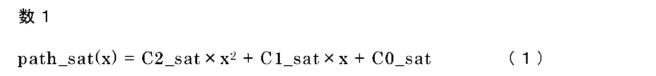
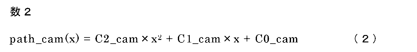
- the route is expressed by a polynomial, and each equation of the bird's-eye view sensor traveling route, the autonomous sensor traveling route, and the integrated route is expressed by equations (1) to (3).
- the coefficient of the first term is the curvature component of the route (hereinafter referred to as the curvature component)
- the coefficient of the second term is the angle component of the vehicle and the route (hereinafter, referred to as the curvature component).
- the coefficients of the third term (section term) represent the lateral position component of the vehicle and the route (hereinafter referred to as the lateral position component).
- each component of the integrated pathway is represented by the formulas (4) to (6).
- w2_sat, w1_sat, and w0_sat are weights for each component of the bird's-eye view sensor travel path
- w2_cam, w1_cam, and w0_cam are weights for each component of the autonomous sensor travel path
- the weighted averages of the components of the plurality of routes By weighted average
- w2_sat Weight of the bird's-eye sensor traveling path in the curvature component of the integrated path
- w2_cam Weight of the autonomous sensor traveling path in the curvature component of the integrated path
- w1_sat Weight of the bird's-eye sensor traveling path in the angle component of the integrated path
- w1_cam Integrated Weight of the autonomous sensor traveling path in the angle component of the route
- w0_sat Weight of the bird's-eye sensor traveling path in the lateral position component of the integrated path
- w0_cam Weight of the autonomous sensor traveling path in the lateral position component of the integrated route.
- the purpose of the present application is to generate a route with higher accuracy as compared with a conventional route generator so that optimum control is performed according to the state in which the vehicle is placed.
- the travel route generation device of the present application is a first route that outputs a bird's-eye view travel route composed of a bird's-eye view curvature component, a bird's-eye view angle component of the own vehicle, and a bird's-eye view lateral position component of the own vehicle based on road map data.
- the generation unit outputs an autonomous traveling path composed of an autonomous curvature component, an autonomous angle component of the own vehicle, and an autonomous lateral position component of the own vehicle based on information from a sensor mounted on the own vehicle.
- the said It Upon receiving the output of the second route generation unit, the first route generation unit, and the second route generation unit, the said It is provided with a route generation unit that generates a traveling path of the own vehicle by setting a curvature component of the traveling path of the own vehicle, an angle component with respect to the traveling path of the own vehicle, and a lateral position component with respect to the traveling path of the own vehicle. It is characterized by that.
- the traveling route generation device of the present application generates an integrated route with higher accuracy than the conventional one by expressing the traveling route to be generated by using the curvature component, the angle component, and the lateral position component of the bird's-eye view traveling route and the autonomous traveling route. It becomes possible.
- FIG. It is a block diagram which shows the structure of the vehicle control device of Embodiment 1.
- FIG. It is explanatory drawing of the operation of the bird's-eye view sensor travel path generation part of Embodiment 1.
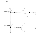
- FIG. It is a flowchart which shows the operation of the vehicle control device of Embodiment 1. It is a figure explaining the coordinate system of the path of the bird's-eye view sensor travel path generation part and the autonomous sensor travel path generation part of Embodiment 1.
- FIG. It is a block diagram which shows another structure of the vehicle control device of Embodiment 1.
- FIG. It is a block diagram which shows another form of the traveling path weight setting part of Embodiment 1.
- FIG. It is a flowchart which shows the operation of another form of the traveling path weight setting part of Embodiment 1.
- It is a block diagram which shows the structure of another form of the vehicle control device of Embodiment 1.
- FIG. It is a block diagram which shows another form of the traveling path weight setting part of Embodiment 1.
- FIG. It is a flowchart which shows the operation of another form of the traveling path weight setting part of Embodiment 1.
- FIG. 1 is a block diagram showing the configuration of the vehicle control device 400 according to the first embodiment.
- the route generation device 300 receives information from the own vehicle position / orientation detection unit 10, the road map data 20, and the camera sensor 30, and outputs information on the integrated route used for controlling the vehicle control unit 110. do.
- the own vehicle position / orientation detection unit 10 outputs the absolute coordinates and orientation of the own vehicle based on the positioning information of the GNSS.
- the road map data 20 includes target point sequence information in the center of the traveling lane around the own vehicle.
- the camera sensor 30 is mounted on the own vehicle and outputs lane marking information of the lane in front of the own vehicle.
- the route generation device 300 includes a bird's-eye view sensor travel route generation unit (first travel route generation unit) 60, an autonomous sensor travel route generation unit (second travel route generation unit) 70, a travel route weight setting unit 90, and an integrated route generation unit.
- the unit 100 is provided.
- the route generation unit 200 is composed of the travel route weight setting unit 90 and the integrated route generation unit 100.
- the bird's-eye view sensor travel route generation unit 60 determines the lane in which the vehicle should travel from the vehicle position / orientation detection unit 10 and the road map data 20 with a specific section in front of the vehicle (referred to as the forward gaze distance) as an approximate range. Outputs the result approximated by a polynomial. That is, as shown in FIG. 2, in the traveling of the own vehicle 1, the own lane 22 restricted by the lane marking information 24 of the road is set, and the specific section in front of the own vehicle 1 is set as the approximation range 23, and this approximation is made. The approximate curve 25 by the polynomial corresponding to the target point sequence information 21 is calculated including the range 23. (See FIG. 2). The forward gaze distance is variable depending on the vehicle speed.
- the autonomous sensor travel route generation unit 70 outputs a result in which the travel route to be traveled by the own vehicle is expressed by a polynomial based on the lane marking information of the front lane by the camera sensor 30.
- the bird's-eye view sensor travel path generation unit 60 and the autonomous sensor travel route generation unit 70 calculate the lateral position deviation, the angle deviation, and the curvature of the route with respect to the own vehicle and the approximate curve as the approximation result by the polynomial, and each of them has a bird's-eye view. Outputs the travel route and autonomous travel route.
- the bird's-eye view sensor travel route is based on the road map data, there is an advantage that the curvature of the route can be expressed more accurately than the autonomous sensor travel route.
- the autonomous sensor travel route is based on the information taken by the camera, the angle between the vehicle and the route and the lateral position of the vehicle and the route can be determined rather than the bird's-eye view sensor travel route that is affected by the position or orientation error due to GNSS. It has the advantage that it can be expressed accurately.
- the "overhead view” represents a state of looking down from a high place, and the “overhead view” represents a state of looking down from a high position.
- the "self-supporting type” represents a state in which various sensors mounted on an automobile such as a camera or sonar are used to recognize and respond to the surroundings.
- the travel route weight setting unit 90 sets weights that are certainty of each travel route of the bird's-eye view sensor travel route generation unit 60 and the autonomous sensor travel route generation unit 70.
- the integrated route generation unit 100 outputs an integrated route that is a single route from the information of the bird's-eye view sensor travel route generation unit 60, the autonomous sensor travel route generation unit 70, and the travel route weight setting unit 90.
- the bird's-eye view sensor travel route generation unit 60 shows the central point sequence of the lane in which the vehicle is currently traveling and the state of the vehicle from the information of the vehicle position / orientation detection unit 10 and the road map data 20. It is calculated as an approximate expression on the own vehicle reference coordinate system shown in 4 and expressed as the equation (1) (step S100).
- the autonomous sensor travel path generation unit 70 approximates the travel path 26 that the vehicle should travel from the lane marking information of the front lane by the camera sensor 30 on the vehicle reference coordinate system of FIG. 4 in the same manner as described above.
- the travel route weight setting unit 90 sets the weight for each travel route calculated in steps S100 and S200, but in the present embodiment, a predetermined value is set (step S400).
- the weight of the bird's-eye view sensor travel route is set higher than the weight of the autonomous sensor travel route, and for the angle component of the vehicle and the route and the lateral position component of the vehicle and the route, the autonomous sensor A predetermined value is set so that the weight of the traveling route is higher than the weight of the bird's-eye view sensor traveling route.
- the weight of the bird's-eye view sensor travel path and the weight of the autonomous sensor travel route are added to be 1, for example, for the curvature component of the route, the weight of the bird's-eye sensor travel route is 0.7, and the weight of the autonomous sensor travel route is 0.7.
- the weight of the autonomous sensor travel route is set to 0.7, and the weight of the bird's-eye sensor travel route is set to 0.3.
- the weight of the bird's-eye sensor travel route is 1, the weight of the autonomous sensor travel route is 0, the angle component of the vehicle and the route, and the lateral position component of the vehicle and the route are the autonomous sensor travel route.
- the weight of the bird's-eye view sensor may be set to 1 and the weight of the bird's-eye view sensor traveling path may be set to 0.
- the weight of the bird's-eye sensor travel route is 1, the weight of the autonomous sensor travel route is 0, the angle component of the vehicle and the route, and the lateral position component of the vehicle and the route are the autonomous sensor travel route.
- the weight of is 1 and the weight of the bird's-eye view sensor travel path is 0, the bird's-eye view sensor travel route is practically used for the curvature component of the route, the angle component between the vehicle and the route, and the lateral position of the vehicle and the route.
- the autonomous sensor travel path will be used.
- the integrated route generation unit 100 uses the coefficients of each route calculated in steps S100 and S200 and the weights for each route set in step S400 to determine the coefficient of the integrated route (equation (3)) that the vehicle should travel. Is calculated by the equations (4) to (6) (step S500).
- the vehicle control unit 110 controls the vehicle using the integrated route (step S600).
- step S600 In the calculation operation of each route in step S100 and step S200, since the calculation result of one does not affect the calculation operation of the other, there is no restriction on the calculation order.
- the weight of the bird's-eye view sensor travel route is higher than the weight of the autonomous sensor travel route for the curvature component of the route.
- the weight of the autonomous sensor travel route is higher than the weight of the bird's-eye sensor travel route, so an integrated route with higher accuracy than before is generated. can.
- the weight of the bird's-eye view sensor traveling path is always higher than the weight of the autonomous sensor traveling path for the curvature component of the path, and the weight of the autonomous sensor traveling path is set for the angle component and the lateral position component.
- the weight is set to be higher than the weight of the bird's-eye view sensor travel path, but the above weighting is performed only in situations where the accuracy of the curvature of the autonomous sensor travel path is low, and in other situations, it is the same as before.
- the vehicle control device has the configuration shown in FIG. 5, the traveling route weight setting unit 90 is shown in FIG.
- step S400 whether or not the travel path weight setting unit is shorter than the threshold d1 set by the distance de between the vehicle and the tunnel based on the flowchart of FIG. 7 (the vehicle is near the entrance of the tunnel). Only when it is determined that the vehicle is traveling near the entrance of the tunnel, the weight of the bird's-eye view sensor travel route is set higher than the weight of the autonomous sensor travel route for the curvature component of the route. For the angle component and the lateral position component, the weight of the autonomous sensor traveling path may be higher than the weight of the bird's-eye view sensor traveling path.
- the vehicle control device 400 is configured to output the detection result by the forward radar 40 and the detection result by the camera sensor 30 to the travel path weight setting unit 90, and the travel path weight setting unit 90 is configured.
- a vehicle proximity determination unit 92 for determining whether or not a preceding vehicle is traveling within a predetermined distance from the own vehicle is provided, and the preceding vehicle is provided with a predetermined distance from the own vehicle.
- the travel path weight setting unit 90 makes it possible to determine whether or not the vehicle is traveling inside, and the distance df from the own vehicle to the preceding vehicle is shorter than the set threshold value d2 based on the flowchart of FIG.
- the weight of the bird's-eye view sensor travel route is autonomously determined for the curvature component of the route.
- the weight of the sensor travel path may be higher than the weight of the sensor travel path, and the weight of the autonomous sensor travel path may be higher than the weight of the bird's-eye view sensor travel path for the angle component and the lateral position component.
- the vehicle control device 400 is configured as shown in FIG. 11, and the travel route weight setting unit 90 is provided with the autonomous sensor travel route effective distance determination unit 93 as shown in FIG. 12, and the lane marking information of the front lane is obtained from the camera. It is possible to determine whether or not the effective distance (that is, the effective distance of the autonomous sensor travel route) is short, and in step S400, the travel route weight setting unit 90 sets the effective distance of the autonomous sensor travel route based on the flowchart of FIG.
- the weight of the bird's-eye sensor travel path is made higher than the weight of the autonomous sensor travel path for the curvature component of the route, and the angle component.
- the weight of the autonomous sensor travel path may be higher than the weight of the bird's-eye sensor travel path.
- FIG. 14 is a block diagram showing the configuration of the vehicle control device 400 according to the second embodiment.
- the vehicle speed sensor 80 is added to the first embodiment, and the output of the vehicle speed sensor 80 is input to the travel path weight setting unit 90.
- the vehicle speed sensor 80 outputs the vehicle speed of the own vehicle, and the traveling route weight setting unit 90 includes a vehicle speed determination unit 94 as shown in FIG.
- step S400 the traveling route weight setting unit 90 sets the weight based on the flowchart of FIG. A description will be given below with reference to FIG.
- step S401 it is determined whether or not the vehicle speed V input from the vehicle sensor 50 is lower than the set threshold value V1 (step S401).
- the weight of the autonomous sensor traveling path is made higher than the weight of the bird's-eye sensor traveling path in all of the curvature component, the angle component, and the lateral position component (step S402). ..
- the curvature component is set so that the weight of the bird's-eye view sensor travel path is higher than the weight of the autonomous sensor travel path, and the angle component and the lateral position component are set. Is set so that the weight of the autonomous sensor travel path is higher than the weight of the bird's-eye sensor travel route (step S403).
- FIG. 17 is a diagram comparing the output results of the operation of the bird's-eye view sensor traveling route generation unit 60 in the present embodiment under the same conditions as the point sequence information of the road map data, when the vehicle speed of the own vehicle is high and when the vehicle speed is low.
- 1 is the own vehicle.
- Reference numeral 21 denotes target point sequence information of the own vehicle traveling lane, which is included in the road map data 20.
- Reference numeral 101 denotes a bird's-eye view sensor traveling route, which is a traveling route calculated by the bird's-eye view sensor traveling route generation unit 60.
- the bird's-eye view sensor travel path 101 is related to the target route with respect to the vehicle 1 by the absolute coordinates and the absolute orientation of the vehicle 1 output from the vehicle position / orientation detection unit 10 and the target point sequence information 21 of the vehicle lane.
- the weight of the autonomous sensor traveling path is made higher than the weight of the bird's-eye sensor traveling path in all of the curvature component, the angle component, and the lateral position component.
- the weight of the autonomous sensor traveling path is made higher than the weight of the bird's-eye sensor traveling path in all of the curvature component, the angle component, and the lateral position component. It is even better to directly determine whether or not the number of target point sequences of the own vehicle traveling lane used for calculating the approximate curve in the bird's-eye view sensor traveling route generation unit 60 is small.
- the vehicle control device 400 is configured as shown in FIG. 18, the travel path weight setting unit 90 is shown in FIG. 19, and the point sequence number determination unit 95 is provided, and the bird's-eye view sensor travel route generation unit 60 calculates an approximate curve.
- step S400 the traveling route weight setting unit is larger than the threshold value N1 set by the number of point rows N based on the flowchart of FIG. It is sufficient to determine whether or not the amount is small, and if it is determined that the amount is small, the weight of the autonomous sensor traveling path may be higher than the weight of the bird's-eye sensor traveling path in all of the curvature component, the angle component, and the lateral position component.
- the bird's-eye view sensor travel path calculated by the bird's-eye view sensor travel route generation unit 60 and the autonomous sensor travel route calculated by the autonomous sensor travel route generation unit 70 are integrated.
- the route is expressed by a quadratic equation composed of the curvature component of the route, the angle component of the vehicle and the route, and the lateral position component of the vehicle and the route as in equations (1) to (6), but it is not always the case.
- the configuration is not limited to the above.
- the curvature change component of the path is expressed by a cubic equation including the third term (Equations (7) to (10)), and the curvature change component of the path is set to the same weight as the curvature component of the path.
- C2_all, C1_all, and C0_all are omitted because they are the same as those in the formulas (4) to (6).
- the travel route generation device 300 is composed of a processor 500 and a storage device 501 as shown in FIG. 21 as an example of hardware. Although the contents of the storage device are not shown, it includes a volatile storage device such as a random access memory and a non-volatile auxiliary storage device such as a flash memory. Further, an auxiliary storage device of a hard disk may be provided instead of the flash memory.
- the processor 500 executes the program input from the storage device 501. In this case, a program is input from the auxiliary storage device to the processor 500 via the volatile storage device. Further, the processor 500 may output data such as a calculation result to the volatile storage device of the storage device 501, or may store the data in the auxiliary storage device via the volatile storage device.
Landscapes
- Engineering & Computer Science (AREA)
- Automation & Control Theory (AREA)
- Transportation (AREA)
- Mechanical Engineering (AREA)
- Human Computer Interaction (AREA)
- Navigation (AREA)
- Traffic Control Systems (AREA)
- Control Of Driving Devices And Active Controlling Of Vehicle (AREA)
Abstract
Description
本願は、走行経路生成装置に関するものである。 The present application relates to a traveling route generator.
近年、車両においては、ドライバの運転をより快適に安全に行えるように自動運転の技術を利用した様々なものが開発され提案されている。例えば、特許文献1においては、前方認識カメラからの情報により算出される自律センサ走行経路と、自車周辺道路の車線中央点群および白線位置情報などが含まれた高精度地図情報とGPS等のGNSS(Global Navigation Satellite System)から算出される俯瞰センサ走行経路を検出し、前記前方認識カメラの検出状態から判定される信頼度と、前記GNSS受信状態から判定される信頼度に基づき決定される、各走行経路の重みに応じた、統合した走行経路を算出し、最適な経路に追従させる車両制御装置が提案されている。
In recent years, various vehicles have been developed and proposed using automatic driving technology so that drivers can drive more comfortably and safely. For example, in
一般的に、経路とは多項式で表現されるものであり、俯瞰センサ走行経路、自律センサ走行経路、統合経路の各式は式(1)~式(3)で表される。各式において、第一項(二次の項)の係数が経路の曲率成分(以下、曲率成分と称する)、第二項(一次の項)の係数が自車と経路の角度成分(以下、角度成分と称する)、第三項(切片の項)の係数が自車と経路の横位置成分(以下、横位置成分と称する)を表す。 Generally, the route is expressed by a polynomial, and each equation of the bird's-eye view sensor traveling route, the autonomous sensor traveling route, and the integrated route is expressed by equations (1) to (3). In each equation, the coefficient of the first term (secondary term) is the curvature component of the route (hereinafter referred to as the curvature component), and the coefficient of the second term (primary term) is the angle component of the vehicle and the route (hereinafter, referred to as the curvature component). The coefficients of the third term (section term) represent the lateral position component of the vehicle and the route (hereinafter referred to as the lateral position component).
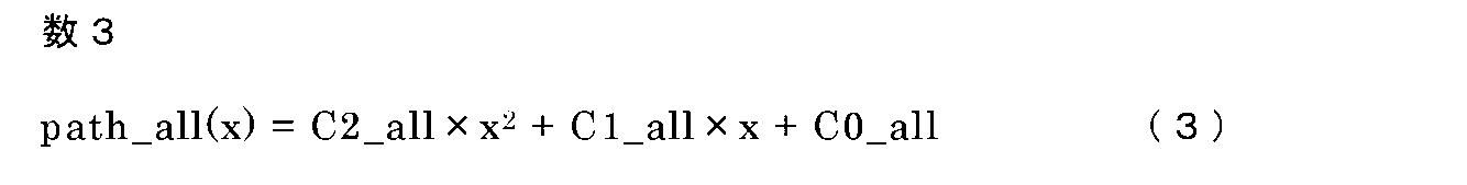
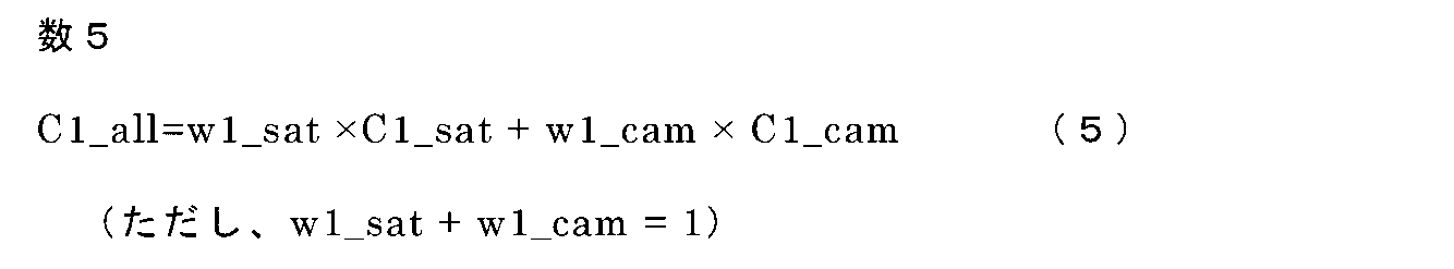
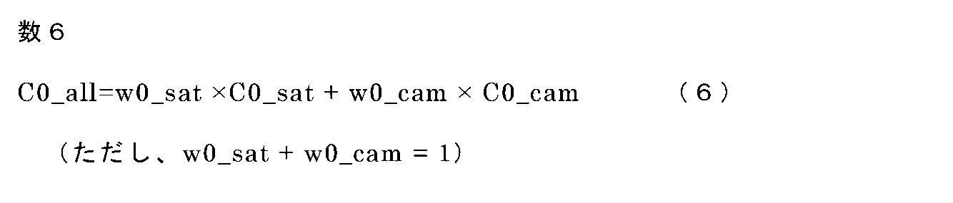
また、統合経路の前記各成分は式(4)~式(6)で表される。各式において、w2_sat、w1_sat、w0_satは俯瞰センサ走行経路の各成分に対する重み、w2_cam、w1_cam、w0_camは自律センサ走行経路の各成分に対する重みであり、複数経路の前記各成分同士を重みづけ平均(加重平均)することで、統合経路の各成分が求まる。 Further, each component of the integrated pathway is represented by the formulas (4) to (6). In each equation, w2_sat, w1_sat, and w0_sat are weights for each component of the bird's-eye view sensor travel path, w2_cam, w1_cam, and w0_cam are weights for each component of the autonomous sensor travel path, and the weighted averages of the components of the plurality of routes ( By weighted average), each component of the integrated pathway can be obtained.
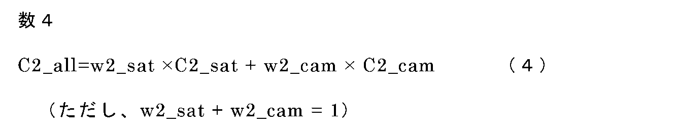
なお、各式において
w2_sat:統合経路の曲率成分における俯瞰センサ走行経路の重み
w2_cam:統合経路の曲率成分における自律センサ走行経路の重み
w1_sat:統合経路の角度成分における俯瞰センサ走行経路の重み
w1_cam:統合経路の角度成分における自律センサ走行経路の重み
w0_sat:統合経路の横位置成分における俯瞰センサ走行経路の重み
w0_cam:統合経路の横位置成分における自律センサ走行経路の重み
である。複数の経路の前記各成分同士を重みづけ平均(加重平均)することで、統合経路の各成分を求めることができる。
In each equation, w2_sat: Weight of the bird's-eye sensor traveling path in the curvature component of the integrated path w2_cam: Weight of the autonomous sensor traveling path in the curvature component of the integrated path w1_sat: Weight of the bird's-eye sensor traveling path in the angle component of the integrated path w1_cam: Integrated Weight of the autonomous sensor traveling path in the angle component of the route w0_sat: Weight of the bird's-eye sensor traveling path in the lateral position component of the integrated path w0_cam: Weight of the autonomous sensor traveling path in the lateral position component of the integrated route. By weighting and averaging the components of the plurality of routes (weighted average), each component of the integrated route can be obtained.
ここで、特許文献1において提案されている技術では、トンネル入口付近などでは、前方認識カメラがトンネル内部を認識しにくく、自律センサ走行経路の角度成分と曲率成分の精度が低いことを想定して、統合経路の角度成分と曲率成分は俯瞰センサ走行経路の重みを自律センサ走行経路の重みよりも高く設定している。
しかしながら実際には、GNSSによる位置および方位の誤差の影響により、俯瞰センサ走行経路の横位置成分と角度成分は、自律センサ走行経路よりも精度が低いため、統合経路の角度成分について俯瞰センサ走行経路の重みを高く設定する従来の重みづけでは、最適な統合経路を生成できないという課題があった。
Here, in the technique proposed in
However, in reality, due to the influence of the position and orientation error due to GNSS, the lateral position component and the angle component of the bird's-eye view sensor travel path are less accurate than the autonomous sensor travel path. There is a problem that the optimum integrated route cannot be generated by the conventional weighting in which the weight of is set high.
本願は、自車の置かれている状態に応じて最適な制御が行われるように、従来の経路生成装置と比較して精度の高い経路を生成することを目的とするものである。 The purpose of the present application is to generate a route with higher accuracy as compared with a conventional route generator so that optimum control is performed according to the state in which the vehicle is placed.
本願の走行経路生成装置は、道路地図データに基づいて俯瞰曲率成分と、自車の俯瞰角度成分と、前記自車の俯瞰横位置成分とによって構成される俯瞰走行経路を出力する第一の経路生成部、前記自車に搭載されたセンサからの情報に基づいて自律曲率成分と、前記自車の自律角度成分と、前記自車の自律横位置成分とによって構成される自律走行経路を出力する第二の経路生成部、および前記第一の経路生成部と前記第二の経路生成部との出力を受けて、前記俯瞰曲率成分、前記自律角度成分、および前記自律横位置成分に基づいて前記自車の走行経路の曲率成分と、前記自車の走行経路に対する角度成分と、前記自車の走行経路に対する横位置成分とを設定して前記自車の走行経路を生成する経路生成部を備えたことを特徴とするものである。 The travel route generation device of the present application is a first route that outputs a bird's-eye view travel route composed of a bird's-eye view curvature component, a bird's-eye view angle component of the own vehicle, and a bird's-eye view lateral position component of the own vehicle based on road map data. The generation unit outputs an autonomous traveling path composed of an autonomous curvature component, an autonomous angle component of the own vehicle, and an autonomous lateral position component of the own vehicle based on information from a sensor mounted on the own vehicle. Upon receiving the output of the second route generation unit, the first route generation unit, and the second route generation unit, the said It is provided with a route generation unit that generates a traveling path of the own vehicle by setting a curvature component of the traveling path of the own vehicle, an angle component with respect to the traveling path of the own vehicle, and a lateral position component with respect to the traveling path of the own vehicle. It is characterized by that.
本願の走行経路生成装置は、俯瞰走行経路および自律走行経路の、曲率成分、角度成分、横位置成分を用いて、生成する走行経路を表すことによって、従来よりも高い精度の統合経路を生成することが可能となる。 The traveling route generation device of the present application generates an integrated route with higher accuracy than the conventional one by expressing the traveling route to be generated by using the curvature component, the angle component, and the lateral position component of the bird's-eye view traveling route and the autonomous traveling route. It becomes possible.
実施の形態1.
以下、実施の形態1について、図に基づいて説明する。なお、図中、同一符号は各々同一または相当する部分を示す。
図1は、実施の形態1における車両制御装置400の構成を示すブロック図である。
図1に示すように、経路生成装置300は、自車位置方位検出部10、道路地図データ20、カメラセンサ30からの情報を受けて、車両制御部110の制御に用いる統合経路の情報を出力する。自車位置方位検出部10は、GNSSの測位情報を元に自車の絶対座標と方位を出力する。道路地図データ20は、自車の周辺走行車線中央の目標点列情報が含まれる。カメラセンサ30は、自車に搭載されており、自車前方の車線の区画線情報を出力する。経路生成装置300は、俯瞰センサ走行経路生成部(第一の走行経路生成部)60、自律センサ走行経路生成部(第二の走行経路生成部)70、走行経路重み設定部90、統合経路生成部100を備えている。ここで、走行経路重み設定部90と統合経路生成部100とによって経路生成部200が構成されている。
Hereinafter, the first embodiment will be described with reference to the drawings. In the figure, the same reference numerals indicate the same or corresponding parts.
FIG. 1 is a block diagram showing the configuration of the
As shown in FIG. 1, the
俯瞰センサ走行経路生成部60は、自車位置方位検出部10、道路地図データ20から、自車前方の特定の区間(前方注視距離とする)を近似範囲として、自車が走行すべき車線を多項式で近似した結果を出力する。すなわち、図2に示すように、自車1の走行において、道路の区画線情報24によって制限された自車線22が設定され、自車1の前方の特定の区間を近似範囲23として、この近似範囲23を含めて、目標点列情報21に応じた多項式による近似曲線25が算出される。(図2参照)。なお、前方注視距離は車速によって可変であり、車速が高い場合には、前方注視距離は長く、車速が低い場合には、前方注視距離は短くなる。自律センサ走行経路生成部70は、カメラセンサ30による前方車線の区画線情報をもとにして、自車が走行すべき走行経路を多項式で表現した結果を出力する。俯瞰センサ走行経路生成部60、自律センサ走行経路生成部70は、多項式による近似結果として、自車と近似曲線に対する横位置偏差、角度偏差、経路の曲率の各係数を算出して、それぞれ、俯瞰走行経路および自律走行経路を出力する。
The bird's-eye view sensor travel
なお、俯瞰センサ走行経路は道路地図データをもとにしているため、自律センサ走行経路よりも、経路の曲率を精度良く表すことができるという利点がある。また、自律センサ走行経路はカメラによる撮影情報に基づいているため、GNSSによる位置あるいは方位の誤差の影響を受ける俯瞰センサ走行経路よりも、自車と経路の角度、自車と経路の横位置を精度良く表すことができるという利点がある。
なお、「俯瞰」とは、高い所から下を見る状態を表しており、「俯瞰的」とは、高い位置から見下ろしているに近い状態を表している。これに対して、「自立型」とは、カメラまたはソナーなどの自動車に搭載した各種のセンサを用いて周囲を認識して対応する状態を表している。
Since the bird's-eye view sensor travel route is based on the road map data, there is an advantage that the curvature of the route can be expressed more accurately than the autonomous sensor travel route. In addition, since the autonomous sensor travel route is based on the information taken by the camera, the angle between the vehicle and the route and the lateral position of the vehicle and the route can be determined rather than the bird's-eye view sensor travel route that is affected by the position or orientation error due to GNSS. It has the advantage that it can be expressed accurately.
The "overhead view" represents a state of looking down from a high place, and the "overhead view" represents a state of looking down from a high position. On the other hand, the "self-supporting type" represents a state in which various sensors mounted on an automobile such as a camera or sonar are used to recognize and respond to the surroundings.
走行経路重み設定部90は、俯瞰センサ走行経路生成部60と自律センサ走行経路生成部70の各走行経路の確からしさとなる重みを設定する。統合経路生成部100は、俯瞰センサ走行経路生成部60、自律センサ走行経路生成部70、走行経路重み設定部90の情報から、単一の経路である統合経路が出力される。
The travel route
次に、実施の形態1における車両制御装置の全体の動作を図3のフローチャートを用いて説明する。なお、図3のフローチャートは車両走行中に繰り返し実行するものである。まず始めに、俯瞰センサ走行経路生成部60が、自車位置方位検出部10と道路地図データ20の情報から、現在自車が走行している車線の中央点列と自車の状態を、図4に示す自車基準座標系上での近似式として算出し、式(1)として表す(ステップS100)。次に、自律センサ走行経路生成部70が、カメラセンサ30による前方車線の区画線情報から、自車が走行すべき走行経路26を上記同様に図4の自車基準座標系上での近似式として算出し、式(2)として表す(ステップS200)。式(1)、式(2)においては、第一項が各経路の曲率を、第二項が各経路に対する自車の角度を、第三項が各経路に対する自車の横位置を表す。次に、走行経路重み設定部90がステップS100とステップS200で算出する各走行経路に対する重みを設定するが、本実施の形態においては予め定めた値を設定する(ステップS400)。
Next, the overall operation of the vehicle control device according to the first embodiment will be described with reference to the flowchart of FIG. The flowchart of FIG. 3 is repeatedly executed while the vehicle is running. First of all, the bird's-eye view sensor travel
ここでは、経路の曲率成分については、俯瞰センサ走行経路の重みを自律センサ走行経路の重みよりも高く設定し、自車と経路の角度成分、自車と経路の横位置成分については、自律センサ走行経路の重みを俯瞰センサ走行経路の重みよりも高くするように予め定めた値を設定する。なお、俯瞰センサ走行経路の重みと自律センサ走行経路の重みは足して1になるものであり、例えば、経路の曲率成分については、俯瞰センサ走行経路の重みを0.7、自律センサ走行経路の重みを0.3、自車と経路の角度成分、自車と経路の横位置成分については、自律センサ走行経路の重みを0.7、俯瞰センサ走行経路の重みを0.3に設定する。あるいは、経路の曲率成分については、俯瞰センサ走行経路の重みを1、自律センサ走行経路の重みを0、自車と経路の角度成分、自車と経路の横位置成分については、自律センサ走行経路の重みを1、俯瞰センサ走行経路の重みを0に設定しても良い。なお、経路の曲率成分については、俯瞰センサ走行経路の重みを1、自律センサ走行経路の重みを0、自車と経路の角度成分、自車と経路の横位置成分については、自律センサ走行経路の重みを1、俯瞰センサ走行経路の重みを0とした場合は、実質的に、経路の曲率成分については俯瞰センサ走行経路を用い、自車と経路の角度成分、自車と経路の横位置成分については自律センサ走行経路を用いることとなる。 Here, for the curvature component of the route, the weight of the bird's-eye view sensor travel route is set higher than the weight of the autonomous sensor travel route, and for the angle component of the vehicle and the route and the lateral position component of the vehicle and the route, the autonomous sensor A predetermined value is set so that the weight of the traveling route is higher than the weight of the bird's-eye view sensor traveling route. The weight of the bird's-eye view sensor travel path and the weight of the autonomous sensor travel route are added to be 1, for example, for the curvature component of the route, the weight of the bird's-eye sensor travel route is 0.7, and the weight of the autonomous sensor travel route is 0.7. For the weight of 0.3, the angle component of the vehicle and the route, and the lateral position component of the vehicle and the route, the weight of the autonomous sensor travel route is set to 0.7, and the weight of the bird's-eye sensor travel route is set to 0.3. Alternatively, for the curvature component of the route, the weight of the bird's-eye sensor travel route is 1, the weight of the autonomous sensor travel route is 0, the angle component of the vehicle and the route, and the lateral position component of the vehicle and the route are the autonomous sensor travel route. The weight of the bird's-eye view sensor may be set to 1 and the weight of the bird's-eye view sensor traveling path may be set to 0. Regarding the curvature component of the route, the weight of the bird's-eye sensor travel route is 1, the weight of the autonomous sensor travel route is 0, the angle component of the vehicle and the route, and the lateral position component of the vehicle and the route are the autonomous sensor travel route. When the weight of is 1 and the weight of the bird's-eye view sensor travel path is 0, the bird's-eye view sensor travel route is practically used for the curvature component of the route, the angle component between the vehicle and the route, and the lateral position of the vehicle and the route. For the components, the autonomous sensor travel path will be used.
その後、統合経路生成部100が、ステップS100とステップS200で算出した各経路の係数と、ステップS400で設定した各経路に対する重みから、自車が走行すべき統合経路(式(3))の係数を、式(4)~(6)によって算出する(ステップS500)。
After that, the integrated
最後に、統合経路を用いて車両制御部110が車両制御を行う(ステップS600)。なお、ステップS100とステップS200の各経路の算出動作は、一方の算出結果が他方の算出動作に影響するものではないため、算出する順序に関する制約はない。
Finally, the
このようにして本実施の形態における経路生成装置では、複数経路の成分同士を重みづけ平均する際に、経路の曲率成分については、俯瞰センサ走行経路の重みを自律センサ走行経路の重みよりも高くし、自車と経路の角度成分、自車と経路の横位置成分については、自律センサ走行経路の重みを俯瞰センサ走行経路の重みよりも高くするので、従来よりも高い精度の統合経路を生成できる。 In this way, in the route generation device of the present embodiment, when the components of the plurality of routes are weighted and averaged, the weight of the bird's-eye view sensor travel route is higher than the weight of the autonomous sensor travel route for the curvature component of the route. However, for the angle component between the vehicle and the route and the lateral position component between the vehicle and the route, the weight of the autonomous sensor travel route is higher than the weight of the bird's-eye sensor travel route, so an integrated route with higher accuracy than before is generated. can.
なお、本実施の形態では常に、経路の曲率成分については、俯瞰センサ走行経路の重みを自律センサ走行経路の重みよりも高くし、角度成分と横位置成分については、自律センサ走行経路の重みを俯瞰センサ走行経路の重みよりも高くするようにしたが、自律センサ走行経路の曲率の精度が低くなるような状況でのみ、上記の重みづけを行うようにし、それ以外の状況では、従来と同じように、前方認識カメラの検出状態から判定される信頼度と、GNSS受信状態から判定される信頼度に基づき重みを設定すればなお良い。その際は、例えば車両制御装置を図5の構成とし、かつ走行経路重み設定部90を図6としてトンネル入口走行判定部91を備え、自車位置と道路地図データからトンネル付近か否かを判定できるようにし、ステップS400では、走行経路重み設定部が図7のフローチャートに基づいて、自車とトンネルまでの距離deが設定した閾値d1よりも短いか否か(自車がトンネルの入口付近を走行しているか否か)を判定し、トンネルの入口付近を走行していると判定した場合のみ、経路の曲率成分については、俯瞰センサ走行経路の重みを自律センサ走行経路の重みよりも高くし、角度成分と横位置成分については、自律センサ走行経路の重みを俯瞰センサ走行経路の重みよりも高くすれば良い。
In the present embodiment, the weight of the bird's-eye view sensor traveling path is always higher than the weight of the autonomous sensor traveling path for the curvature component of the path, and the weight of the autonomous sensor traveling path is set for the angle component and the lateral position component. The weight is set to be higher than the weight of the bird's-eye view sensor travel path, but the above weighting is performed only in situations where the accuracy of the curvature of the autonomous sensor travel path is low, and in other situations, it is the same as before. As described above, it is better to set the weight based on the reliability determined from the detection state of the front recognition camera and the reliability determined from the GNSS reception state. In that case, for example, the vehicle control device has the configuration shown in FIG. 5, the traveling route
あるいは、車両制御装置400を図8に示すように前方レーダ40による検出結果とカメラセンサ30による検出結果とを走行経路重み設定部90に出力するように構成し、かつ走行経路重み設定部90を図9に示すように、自車から予め定めた距離内に先行する車両が走行しているか否かを判定する自車近傍走行判定部92を備え、先行車が前記自車から予め定めた距離内を走行しているか否かを判定できるようにし、ステップS400では、走行経路重み設定部90が図10のフローチャートに基づいて、自車から先行車までの距離dfが設定した閾値d2よりも短い(すなわち、先行車が前記自車から予め定めた距離内を走行している)か否かを判定し、短いと判定した場合のみ、経路の曲率成分については、俯瞰センサ走行経路の重みを自律センサ走行経路の重みよりも高くし、角度成分と横位置成分については、自律センサ走行経路の重みを俯瞰センサ走行経路の重みよりも高くすれば良い。
Alternatively, as shown in FIG. 8, the
あるいは、車両制御装置400を図11に示す構成とし、かつ走行経路重み設定部90を図12に示すようにして自律センサ走行経路有効距離判定部93を備え、カメラから前方車線の区画線情報の有効距離(すなわち、自律センサ走行経路の有効距離)が短いか否かを判定できるようにし、ステップS400では、走行経路重み設定部90が図13のフローチャートに基づいて、自律センサ走行経路の有効距離drが設定した閾値d3よりも短いか否かを判定し、短いと判定した場合のみ、経路の曲率成分については、俯瞰センサ走行経路の重みを自律センサ走行経路の重みよりも高くし、角度成分と横位置成分については、自律センサ走行経路の重みを俯瞰センサ走行経路の重みよりも高くすれば良い。
Alternatively, the
実施の形態2.
次に、実施の形態2について、図に基づいて説明する。図14は実施の形態2における車両制御装置400の構成を示すブロック図である。本実施の形態では、実施の形態1に対して、車速センサ80を追加し、車速センサ80の出力を走行経路重み設定部90に入力している。車速センサ80は自車の車速を出力するものであり、走行経路重み設定部90は図15のように車速判定部94を備えるものである。
Embodiment 2.
Next, the second embodiment will be described with reference to the drawings. FIG. 14 is a block diagram showing the configuration of the
次に、本実施の形態における車両制御装置400の全体の動作を説明するが、全体のフローチャートは実施の形態1と同じである。ただし、ステップS400での重みの設定方法が実施の形態1と異なる。本実施の形態ではステップS400にて、走行経路重み設定部90が図16のフローチャートに基づいて重みの設定を行う。以下に図16に基づいて説明を行う。
Next, the overall operation of the
まず始めに、車両センサ50から入力する車速Vが設定した閾値V1より低いか否かが判定される(ステップS401)。ステップS401にて自車の車速が低いと判定された場合、曲率成分と角度成分と横位置成分の全てにおいて、自律センサ走行経路の重みを俯瞰センサ走行経路の重みよりも高くする(ステップS402)。またステップS401にて自車の車速が低いと判定しなかった場合、曲率成分については、俯瞰センサ走行経路の重みを自律センサ走行経路の重みよりも高くなるよう設定し、角度成分と横位置成分については、自律センサ走行経路の重みを俯瞰センサ走行経路の重みよりも高くなるよう設定する(ステップS403)。 First of all, it is determined whether or not the vehicle speed V input from the vehicle sensor 50 is lower than the set threshold value V1 (step S401). When it is determined in step S401 that the vehicle speed of the own vehicle is low, the weight of the autonomous sensor traveling path is made higher than the weight of the bird's-eye sensor traveling path in all of the curvature component, the angle component, and the lateral position component (step S402). .. If it is not determined in step S401 that the vehicle speed of the own vehicle is low, the curvature component is set so that the weight of the bird's-eye view sensor travel path is higher than the weight of the autonomous sensor travel path, and the angle component and the lateral position component are set. Is set so that the weight of the autonomous sensor travel path is higher than the weight of the bird's-eye sensor travel route (step S403).
図17は、本実施の形態における俯瞰センサ走行経路生成部60の動作について、道路地図データの点列情報を同じ条件として、自車の車速が高い場合と低い場合の各出力結果を比較した図である。図17において、1は自車である。21は自車走行車線の目標点列情報であり、道路地図データ20に含まれる。101は俯瞰センサ走行経路であり、俯瞰センサ走行経路生成部60によって算出される走行経路である。俯瞰センサ走行経路101は、自車位置方位検出部10から出力される自車1の絶対座標と絶対方位と、自車走行車線の目標点列情報21とによって、自車1に対する目標経路の関係を近似曲線で表した走行経路である。ここで、自車1の車速が低いほど前方注視距離が短く近似範囲も狭くなるため、近似曲線算出に用いる自車走行車線の目標点列数が少なく、曲がりくねった走行経路となり易い。
FIG. 17 is a diagram comparing the output results of the operation of the bird's-eye view sensor traveling
このようにして本実施の形態では、自車の車速が低い場合に、曲率成分と角度成分と横位置成分の全てにおいて、自律センサ走行経路の重みを俯瞰センサ走行経路の重みよりも高くするので、上記問題の影響を受けず、車速が低い場合において、実施の形態1よりも高い精度の統合経路を生成できる。 In this way, in the present embodiment, when the vehicle speed of the own vehicle is low, the weight of the autonomous sensor traveling path is made higher than the weight of the bird's-eye sensor traveling path in all of the curvature component, the angle component, and the lateral position component. , It is possible to generate an integrated route with higher accuracy than that of the first embodiment when the vehicle speed is low without being affected by the above problems.
なお、本実施の形態では自車の車速が低い場合に、曲率成分と角度成分と横位置成分の全てにおいて、自律センサ走行経路の重みを俯瞰センサ走行経路の重みよりも高くするようにしたが、俯瞰センサ走行経路生成部60での近似曲線算出に用いる自車走行車線の目標点列数が少ないか否かを直接的に判定すればなお良い。その際は、例えば車両制御装置400を図18に示す構成とし、かつ走行経路重み設定部90を図19として点列数判定部95を備え、俯瞰センサ走行経路生成部60での近似曲線算出に用いる自車走行車線の目標点列数が少ないか否かを判定できるようにし、ステップS400では、走行経路重み設定部が図20のフローチャートに基づいて、点列数Nが設定した閾値N1よりも少ないか否かを判定し、少ないと判定した場合に、曲率成分と角度成分と横位置成分の全てにおいて、自律センサ走行経路の重みを俯瞰センサ走行経路の重みよりも高くすれば良い。
In the present embodiment, when the vehicle speed of the own vehicle is low, the weight of the autonomous sensor traveling path is made higher than the weight of the bird's-eye sensor traveling path in all of the curvature component, the angle component, and the lateral position component. It is even better to directly determine whether or not the number of target point sequences of the own vehicle traveling lane used for calculating the approximate curve in the bird's-eye view sensor traveling
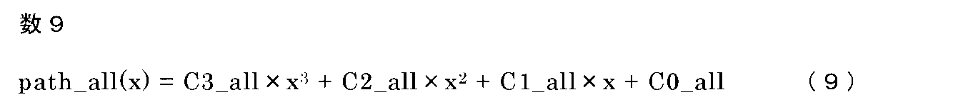
また、実施の形態1及び実施の形態2では、俯瞰センサ走行経路生成部60にて算出される俯瞰センサ走行経路と、自律センサ走行経路生成部70にて算出される自律センサ走行経路と、統合経路を、式(1)~(6)のように経路の曲率成分と、自車と経路の角度成分と、自車と経路の横位置成分で構成される二次式で表現したが、必ずしも前記に限った構成でなくてもよい。例えば、経路の曲率変化成分を第三の項として含めた三次式で表現し(式(7)~(10))、経路の曲率変化成分について、経路の曲率成分と同じ重み設定とすることで、前記各走行経路を二次式で表現した場合と同等の効果を得ることができる。ここで、C2_all、C1_all、C0_allについては、式(4)~(6)と同様のため記載は省く。
Further, in the first embodiment and the second embodiment, the bird's-eye view sensor travel path calculated by the bird's-eye view sensor travel


なお、走行経路生成装置300は、ハードウエアの一例を図21に示すように、プロセッサ500と記憶装置501から構成される。記憶装置の内容は図示していないが、ランダムアクセスメモリ等の揮発性記憶装置と、フラッシュメモリ等の不揮発性の補助記憶装置とを具備する。また、フラッシュメモリの代わりにハードディスクの補助記憶装置を具備してもよい。プロセッサ500は、記憶装置501から入力されたプログラムを実行する。この場合、補助記憶装置から揮発性記憶装置を介してプロセッサ500にプログラムが入力される。また、プロセッサ500は、演算結果等のデータを記憶装置501の揮発性記憶装置に出力してもよいし、揮発性記憶装置を介して補助記憶装置にデータを保存してもよい。
The travel
本願は、例示的な実施の形態が記載されているが、実施の形態に記載された様々な特徴、態様、及び機能は特定の実施の形態の適用に限られるのではなく、単独で、または様々な組み合わせで実施の形態に適用可能である。
従って、例示されていない無数の変形例が、本願明細書に開示される技術の範囲内において想定される。例えば、少なくとも1つの構成要素を変形する場合、追加する場合または省略する場合が含まれるものとする。
Although the present application describes exemplary embodiments, the various features, aspects, and functions described in the embodiments are not limited to the application of a particular embodiment, either alone or. It can be applied to embodiments in various combinations.
Therefore, innumerable variations not illustrated are envisioned within the scope of the techniques disclosed herein. For example, it is assumed that at least one component is modified, added or omitted.
1 自車、10 自車位置方位検出部、20 道路地図データ、21 目標点列情報、22 自車線、23 近似範囲、24 区画線情報、25 近似曲線、26 走行経路、30 カメラセンサ、40 前方レーダ、50 車両センサ、60 俯瞰センサ走行経路生成部、70 自律センサ走行経路生成部、80 車速センサ、90 走行経路重み設定部、91 トンネル入口走行判定部、92 自車近傍走行判定部、93 自律センサ走行経路有効距離判定部、94 車速判定部、95 点列数判定部、100 統合経路生成部、101 俯瞰センサ走行経路、110 車両制御部、200 経路生成部、300 経路生成装置、400 車両制御装置、500 プロセッサ、501 記憶装置 1 own vehicle, 10 own vehicle position / orientation detection unit, 20 road map data, 21 target point sequence information, 22 own lane, 23 approximate range, 24 lane marking information, 25 approximate curve, 26 travel route, 30 camera sensor, 40 forward Radar, 50 vehicle sensor, 60 bird's-eye view sensor driving route generation unit, 70 autonomous sensor driving route generation unit, 80 vehicle speed sensor, 90 driving route weight setting unit, 91 tunnel entrance driving judgment unit, 92 own vehicle proximity driving judgment unit, 93 autonomous Sensor travel route effective distance determination unit, 94 vehicle speed determination unit, 95 point sequence number determination unit, 100 integrated route generation unit, 101 bird's-eye view sensor travel route, 110 vehicle control unit, 200 route generation unit, 300 route generator, 400 vehicle control Device, 500 processor, 501 storage device
Claims (9)
前記自車に搭載されたセンサからの情報に基づいて自律曲率成分と、前記自車の自律角度成分と、前記自車の自律横位置成分とによって構成される自律走行経路を出力する第二の経路生成部、
および前記第一の経路生成部と前記第二の経路生成部との出力を受けて、前記俯瞰曲率成分、前記自律角度成分、および前記自律横位置成分に基づいて前記自車の走行経路の曲率成分と、前記自車の走行経路に対する角度成分と、前記自車の走行経路に対する横位置成分とを設定して前記自車の走行経路を生成する経路生成部を備えたことを特徴とする走行経路生成装置。 A first route generator that outputs a bird's-eye view traveling route composed of a bird's-eye view curvature component, a bird's-eye view angle component of the own vehicle, and a bird's-eye view lateral position component of the own vehicle based on road map data.
A second output of an autonomous traveling path composed of an autonomous curvature component, an autonomous angle component of the own vehicle, and an autonomous lateral position component of the own vehicle based on information from a sensor mounted on the own vehicle. Route generator,
In response to the outputs of the first route generation unit and the second route generation unit, the curvature of the traveling path of the own vehicle is based on the bird's-eye view curvature component, the autonomous angle component, and the autonomous lateral position component. A traveling feature is provided with a route generation unit that generates a traveling route of the own vehicle by setting a component, an angle component with respect to the traveling path of the own vehicle, and a lateral position component with respect to the traveling path of the own vehicle. Route generator.
前記走行経路重み設定部は、前記統合経路の曲率成分については、前記俯瞰曲率成分の重みを前記自律曲率成分の重みよりも高く設定し、前記統合経路の角度成分については、前記自律角度成分の重みを前記俯瞰角度成分の重みよりも高く設定し、前記統合経路の横位置成分については、前記自律横位置成分の重みを前記俯瞰横位置成分の重みよりも高く設定することを特徴とする請求項1に記載の走行経路生成装置。 The route generation unit includes a travel route weight setting unit that weights the adoption of the output of the first route generation unit and the output of the second route generation unit and outputs the weight, and the travel route weight setting unit. Based on the weight output from the unit, the bird's-eye view curvature component, the bird's-eye view angle component, and the bird's-eye view lateral position component of the first path generation unit, the autonomous curvature component of the second path generation unit, and the autonomy. It is provided with an angle component and an integrated path generation unit that generates an integrated path by weighting each component of the autonomous lateral position component.
The traveling path weight setting unit sets the weight of the bird's-eye view curvature component higher than the weight of the autonomous curvature component for the curvature component of the integrated path, and sets the angle component of the integrated path to be higher than the weight of the autonomous angle component. A claim characterized in that the weight is set higher than the weight of the bird's-eye view angle component, and the weight of the autonomous lateral position component is set higher than the weight of the bird's-eye view lateral position component for the lateral position component of the integrated path. Item 1. The traveling route generating device according to item 1.
前記自車に搭載されたセンサからの情報に基づいて自律曲率成分と、前記自車の自律角度成分と、前記自車の自律横位置成分とによって構成される自律走行経路を出力する第二の経路生成部、
および前記第一の経路生成部と前記第二の経路生成部との出力を受けて、前記俯瞰曲率成分、前記俯瞰角度成分、前記俯瞰横位置成分、前記自律曲率成分、前記自律角度成分、および前記自律横位置成分に基づいて前記自車の走行経路の曲率成分と、前記自車の走行経路に対する角度成分と、前記自車の走行経路に対する横位置成分とを設定して前記自車の走行経路を生成する経路生成部とを備え、
前記経路生成部は、前記第一の経路生成部の出力と前記第二の経路生成部の出力との採用の重みづけをして重みを出力する走行経路重み設定部と、前記走行経路重み設定部から出力された重みに基づいて、前記第一の経路生成部の前記俯瞰曲率成分、前記俯瞰角度成分、および前記俯瞰横位置成分、前記第二の経路生成部の前記自律曲率成分、前記自律角度成分、および前記自律横位置成分の各成分の重みづけして統合経路を生成する統合経路生成部とを有し、
前記走行経路重み設定部は、前記統合経路の曲率成分については、前記俯瞰曲率成分の重みを前記自律曲率成分の重みよりも高く設定し、前記統合経路の角度成分については、前記自律角度成分の重みを前記俯瞰角度成分の重みよりも高く設定し、前記統合経路の横位置成分については、前記自律横位置成分の重みを前記俯瞰横位置成分の重みよりも高く設定することを特徴とする走行経路生成装置。 A first route generator that outputs a bird's-eye view traveling route composed of a bird's-eye view curvature component, a bird's-eye view angle component of the own vehicle, and a bird's-eye view lateral position component of the own vehicle based on road map data.
A second output of an autonomous traveling path composed of an autonomous curvature component, an autonomous angle component of the own vehicle, and an autonomous lateral position component of the own vehicle based on information from a sensor mounted on the own vehicle. Route generator,
In response to the outputs of the first path generation unit and the second path generation unit, the bird's-eye view curvature component, the bird's-eye view angle component, the bird's-eye view lateral position component, the autonomous curvature component, the autonomous angle component, and Based on the autonomous lateral position component, the curvature component of the traveling path of the own vehicle, the angle component with respect to the traveling path of the own vehicle, and the lateral position component with respect to the traveling path of the own vehicle are set, and the traveling of the own vehicle is performed. It is equipped with a route generator that generates a route.
The route generation unit includes a travel route weight setting unit that weights the adoption of the output of the first route generation unit and the output of the second route generation unit and outputs the weight, and the travel route weight setting unit. Based on the weight output from the unit, the bird's-eye view curvature component, the bird's-eye view angle component, and the bird's-eye view lateral position component of the first path generation unit, the autonomous curvature component of the second path generation unit, and the autonomy. It has an angular component and an integrated path generation unit that generates an integrated path by weighting each component of the autonomous lateral position component.
The traveling path weight setting unit sets the weight of the bird's-eye view curvature component higher than the weight of the autonomous curvature component for the curvature component of the integrated path, and sets the angle component of the integrated path higher than the weight of the autonomous angle component of the autonomous angle component. The running is characterized in that the weight is set higher than the weight of the bird's-eye view angle component, and the weight of the autonomous lateral position component is set higher than the weight of the bird's-eye view lateral position component for the lateral position component of the integrated path. Route generator.
前記トンネル入口走行判定部において、前記道路地図データから、前記自車がトンネル入口付近を走行していると判断された場合に、前記走行経路の曲率成分については、前記俯瞰曲率成分の重みを前記自律曲率成分の重みよりも高く設定し、前記走行経路の角度成分については、前記自律角度成分の重みを前記俯瞰角度成分の重みよりも高く設定し、前記走行経路の横位置成分については、前記自律横位置成分の重みを前記俯瞰横位置成分の重みよりも高く設定したことを特徴とする請求項2または3に記載の走行経路生成装置。 The travel route weight setting unit includes a tunnel entrance travel determination unit that determines whether or not the vehicle is traveling near the tunnel entrance based on the vehicle position and road map data.
When the tunnel entrance travel determination unit determines from the road map data that the vehicle is traveling near the tunnel entrance, the weight of the bird's-eye view curvature component is used as the curvature component of the travel path. The weight of the autonomous curvature component is set higher than the weight of the autonomic curvature component, the weight of the autonomous angle component is set higher than the weight of the bird's-eye view angle component for the angle component of the traveling path, and the lateral position component of the traveling path is set as described above. The traveling route generation device according to claim 2 or 3, wherein the weight of the autonomous lateral position component is set higher than the weight of the bird's-eye view lateral position component.
前記自律走行経路有効距離判定部において、前記自律走行経路の有効距離が前記閾値よりも短いと判断された場合に、前記走行経路の曲率成分については、前記俯瞰曲率成分の重みを前記自律曲率成分の重みよりも高く設定し、前記走行経路の角度成分については、前記自律角度成分の重みを前記俯瞰角度成分の重みよりも高く設定し、前記走行経路の横位置成分については、前記自律横位置成分の重みを前記俯瞰横位置成分の重みよりも高く設定したことを特徴とする請求項2または3に記載の走行経路生成装置。 The travel route weight setting unit is an autonomous travel route effective distance determination unit that determines whether or not the effective distance of the autonomous travel route is shorter than a predetermined threshold value based on information from a sensor mounted on the own vehicle. With
When the autonomous traveling path effective distance determination unit determines that the effective distance of the autonomous traveling path is shorter than the threshold value, for the curvature component of the traveling path, the weight of the bird's-eye view curvature component is added to the autonomous curvature component. The weight of the autonomous angle component is set higher than the weight of the bird's-eye view angle component for the angle component of the traveling path, and the lateral position component of the traveling path is set higher than the weight of the autonomous lateral position. The traveling route generating device according to claim 2 or 3, wherein the weight of the component is set higher than the weight of the bird's-eye view lateral position component.
前記自車近傍走行判定部において、前記自車から予め定めた距離内に先行する車両が走行していると判断された場合に、前記走行経路の曲率成分については、前記俯瞰曲率成分の重みを前記自律曲率成分の重みよりも高く設定し、前記走行経路の角度成分については、前記自律角度成分の重みを前記俯瞰角度成分の重みよりも高く設定し、前記走行経路の横位置成分については、前記自律横位置成分の重みを前記俯瞰横位置成分の重みよりも高く設定したことを特徴とする請求項2または3に記載の走行経路生成装置。 The travel route weight setting unit includes a vehicle proximity determination unit that determines whether or not a preceding vehicle is traveling within a predetermined distance from the vehicle.
When the traveling determination unit near the own vehicle determines that the preceding vehicle is traveling within a predetermined distance from the own vehicle, the weight of the bird's-eye view curvature component is added to the curvature component of the traveling path. The weight of the autonomous curvature component is set higher than the weight of the autonomic curvature component, the weight of the autonomous angle component is set higher than the weight of the bird's-eye view angle component for the angle component of the traveling path, and the lateral position component of the traveling path is set higher than the weight of the bird's-eye view angle component. The traveling route generating device according to claim 2 or 3, wherein the weight of the autonomous lateral position component is set higher than the weight of the bird's-eye view lateral position component.
前記車速判定部において、前記自車の車速が前記閾値よりも低いと判断された場合に、前記走行経路の曲率成分については、前記自律曲率成分の重みを前記俯瞰曲率成分の重みよりも高く設定し、前記走行経路の角度成分については、前記自律角度成分の重みを前記俯瞰角度成分の重みよりも高く設定し、前記走行経路の横位置成分については、前記自律横位置成分の重みを前記俯瞰横位置成分の重みよりも高く設定したことを特徴とする請求項2または3に記載の走行経路生成装置。 The travel route weight setting unit includes a vehicle speed determination unit that determines whether or not the vehicle speed of the own vehicle is lower than a predetermined threshold value.
When the vehicle speed determination unit determines that the vehicle speed of the own vehicle is lower than the threshold value, the weight of the autonomous curvature component is set higher than the weight of the bird's-eye view curvature component for the curvature component of the traveling path. However, for the angle component of the traveling path, the weight of the autonomous angle component is set higher than the weight of the bird's-eye view angle component, and for the lateral position component of the traveling path, the weight of the autonomous lateral position component is set as the bird's-eye view. The traveling route generating device according to claim 2 or 3, wherein the weight is set higher than the weight of the lateral position component.
前記点列数判定部において、前記自車の車速に応じて算出される前記自車から予め定めた距離内に含まれる前記道路地図データの点群数が前記閾値よりも少ないと判断された場合に、
前記走行経路の曲率成分については、前記自律曲率成分の重みを前記俯瞰曲率成分の重みよりも高く設定し、前記走行経路の角度成分については、前記自律角度成分の重みを前記俯瞰角度成分の重みよりも高く設定し、前記走行経路の横位置成分については、前記自律横位置成分の重みを前記俯瞰横位置成分の重みよりも高く設定したことを特徴とする請求項2または3に記載の走行経路生成装置。 The travel route weight setting unit determines whether or not the number of points in the road map data included within the predetermined distance from the own vehicle, which is calculated according to the vehicle speed of the own vehicle, is less than the predetermined threshold value. Equipped with a point sequence number determination unit for determination
When the point cloud number determination unit determines that the number of point clouds of the road map data included within a predetermined distance from the own vehicle calculated according to the vehicle speed of the own vehicle is less than the threshold value. NS,
For the curvature component of the traveling path, the weight of the autonomous curvature component is set higher than the weight of the bird's-eye view curvature component, and for the angle component of the traveling path, the weight of the autonomous angle component is set to the weight of the bird's-eye view angle component. The traveling according to claim 2 or 3, wherein the weight of the autonomous lateral position component is set higher than the weight of the bird's-eye view lateral position component for the lateral position component of the traveling path. Route generator.
Priority Applications (5)
| Application Number | Priority Date | Filing Date | Title |
|---|---|---|---|
| DE112020007052.2T DE112020007052T5 (en) | 2020-04-10 | 2020-04-10 | driving path generating device |
| CN202080098986.4A CN115348931A (en) | 2020-04-10 | 2020-04-10 | Travel route generation device |
| US17/801,339 US20230079624A1 (en) | 2020-04-10 | 2020-04-10 | Travel path generation device |
| PCT/JP2020/016142 WO2021205656A1 (en) | 2020-04-10 | 2020-04-10 | Travel path generation device |
| JP2022514287A JP7378591B2 (en) | 2020-04-10 | 2020-04-10 | Travel route generation device |
Applications Claiming Priority (1)
| Application Number | Priority Date | Filing Date | Title |
|---|---|---|---|
| PCT/JP2020/016142 WO2021205656A1 (en) | 2020-04-10 | 2020-04-10 | Travel path generation device |
Publications (1)
| Publication Number | Publication Date |
|---|---|
| WO2021205656A1 true WO2021205656A1 (en) | 2021-10-14 |
Family
ID=78022552
Family Applications (1)
| Application Number | Title | Priority Date | Filing Date |
|---|---|---|---|
| PCT/JP2020/016142 Ceased WO2021205656A1 (en) | 2020-04-10 | 2020-04-10 | Travel path generation device |
Country Status (5)
| Country | Link |
|---|---|
| US (1) | US20230079624A1 (en) |
| JP (1) | JP7378591B2 (en) |
| CN (1) | CN115348931A (en) |
| DE (1) | DE112020007052T5 (en) |
| WO (1) | WO2021205656A1 (en) |
Families Citing this family (2)
| Publication number | Priority date | Publication date | Assignee | Title |
|---|---|---|---|---|
| US12311925B2 (en) * | 2020-11-10 | 2025-05-27 | Nec Corporation | Divide-and-conquer for lane-aware diverse trajectory prediction |
| US12240492B2 (en) * | 2022-12-08 | 2025-03-04 | GM Global Technology Operations LLC | Methods and systems for vehicle control under degraded lane perception range |
Citations (5)
| Publication number | Priority date | Publication date | Assignee | Title |
|---|---|---|---|---|
| US20100253489A1 (en) * | 2009-04-02 | 2010-10-07 | Gm Global Technology Operations, Inc. | Distortion and perspective correction of vector projection display |
| JP2016210285A (en) * | 2015-05-08 | 2016-12-15 | トヨタ自動車株式会社 | False recognition determination device |
| JP2017211193A (en) * | 2016-05-23 | 2017-11-30 | 本田技研工業株式会社 | Vehicle position specifying device, vehicle control system, vehicle position specifying method, and vehicle position specifying program |
| JP2018039285A (en) * | 2016-09-05 | 2018-03-15 | 株式会社Subaru | Vehicle travel control device |
| JP2019043192A (en) * | 2017-08-30 | 2019-03-22 | マツダ株式会社 | Vehicle control device |
Family Cites Families (8)
| Publication number | Priority date | Publication date | Assignee | Title |
|---|---|---|---|---|
| US5913376A (en) * | 1995-10-31 | 1999-06-22 | Honda Giken Kogyo Kabushiki Kaisha | Automatic steering control apparatus |
| JP5139939B2 (en) * | 2008-09-25 | 2013-02-06 | 日立オートモティブシステムズ株式会社 | Vehicle deceleration support device |
| JP6055525B1 (en) * | 2015-09-02 | 2016-12-27 | 富士重工業株式会社 | Vehicle travel control device |
| KR102518532B1 (en) * | 2016-11-11 | 2023-04-07 | 현대자동차주식회사 | Apparatus for determining route of autonomous vehicle and method thereof |
| JP6905367B2 (en) * | 2017-03-21 | 2021-07-21 | 株式会社Subaru | Vehicle travel control device |
| CN107702716B (en) * | 2017-08-31 | 2021-04-13 | 广州小鹏汽车科技有限公司 | Unmanned driving path planning method, system and device |
| CN108791289B (en) * | 2018-04-28 | 2021-03-30 | 华为技术有限公司 | Vehicle control method and device |
| EP3730384B1 (en) * | 2019-04-24 | 2022-10-26 | Aptiv Technologies Limited | System and method for trajectory estimation |
-
2020
- 2020-04-10 CN CN202080098986.4A patent/CN115348931A/en active Pending
- 2020-04-10 DE DE112020007052.2T patent/DE112020007052T5/en not_active Withdrawn
- 2020-04-10 JP JP2022514287A patent/JP7378591B2/en active Active
- 2020-04-10 US US17/801,339 patent/US20230079624A1/en not_active Abandoned
- 2020-04-10 WO PCT/JP2020/016142 patent/WO2021205656A1/en not_active Ceased
Patent Citations (5)
| Publication number | Priority date | Publication date | Assignee | Title |
|---|---|---|---|---|
| US20100253489A1 (en) * | 2009-04-02 | 2010-10-07 | Gm Global Technology Operations, Inc. | Distortion and perspective correction of vector projection display |
| JP2016210285A (en) * | 2015-05-08 | 2016-12-15 | トヨタ自動車株式会社 | False recognition determination device |
| JP2017211193A (en) * | 2016-05-23 | 2017-11-30 | 本田技研工業株式会社 | Vehicle position specifying device, vehicle control system, vehicle position specifying method, and vehicle position specifying program |
| JP2018039285A (en) * | 2016-09-05 | 2018-03-15 | 株式会社Subaru | Vehicle travel control device |
| JP2019043192A (en) * | 2017-08-30 | 2019-03-22 | マツダ株式会社 | Vehicle control device |
Also Published As
| Publication number | Publication date |
|---|---|
| DE112020007052T5 (en) | 2023-04-13 |
| JP7378591B2 (en) | 2023-11-13 |
| JPWO2021205656A1 (en) | 2021-10-14 |
| CN115348931A (en) | 2022-11-15 |
| US20230079624A1 (en) | 2023-03-16 |
Similar Documents
| Publication | Publication Date | Title |
|---|---|---|
| US11631257B2 (en) | Surroundings recognition device, and surroundings recognition method | |
| US11845471B2 (en) | Travel assistance method and travel assistance device | |
| US11332141B2 (en) | Path estimation device and path estimation method | |
| US10551509B2 (en) | Methods and systems for vehicle localization | |
| EP4134627B1 (en) | Map information correction method, driving assistance method, and map information correction device | |
| US20180267172A1 (en) | System and method for recognizing position of vehicle | |
| KR102441073B1 (en) | Apparatus for compensating sensing value of gyroscope sensor, system having the same and method thereof | |
| CN114248772B (en) | Control method for U-turn running by using high-definition map | |
| JP2025179126A (en) | Measurement accuracy calculation device, self-position estimation device, control method, program, and storage medium | |
| JP7202982B2 (en) | Driving support method and driving support device | |
| KR102331312B1 (en) | 3D vehicular navigation system using vehicular internal sensor, camera, and GNSS terminal | |
| KR20190047199A (en) | Apparatus for providing a map information for deciding driving situation of vehicle, system having the same and method thereof | |
| US20240116532A1 (en) | Autonomous driving control apparatus and method thereof | |
| JP7378591B2 (en) | Travel route generation device | |
| JP7675359B2 (en) | Location Estimation System | |
| JP7399255B2 (en) | Vehicle travel route generation device and vehicle travel route generation method | |
| JP2019066444A (en) | Position calculation method, vehicle control method, and position calculation device | |
| JP7031748B2 (en) | Self-position estimation method and self-position estimation device | |
| JP7321034B2 (en) | Driving support method and driving support device | |
| CN116182841B (en) | Fusion Vehicle Positioning Method and System | |
| US12536916B2 (en) | System and method for controlling aerial vehicle | |
| US12179760B2 (en) | Vehicle control device, storage medium for storing computer program for vehicle control, and method for controlling vehicle | |
| US20250026366A1 (en) | Controlling vehicle using static objects and vehicle curvature | |
| WO2025019811A1 (en) | Controlling vehicle using vehicle curvature and heading angle | |
| WO2025019810A1 (en) | Controlling vehicle using static objects and heading angle |
Legal Events
| Date | Code | Title | Description |
|---|---|---|---|
| 121 | Ep: the epo has been informed by wipo that ep was designated in this application |
Ref document number: 20930306 Country of ref document: EP Kind code of ref document: A1 |
|
| ENP | Entry into the national phase |
Ref document number: 2022514287 Country of ref document: JP Kind code of ref document: A |
|
| 122 | Ep: pct application non-entry in european phase |
Ref document number: 20930306 Country of ref document: EP Kind code of ref document: A1 |