WO2021070313A1 - Touch detection method and touch detection device - Google Patents
Touch detection method and touch detection device Download PDFInfo
- Publication number
- WO2021070313A1 WO2021070313A1 PCT/JP2019/039965 JP2019039965W WO2021070313A1 WO 2021070313 A1 WO2021070313 A1 WO 2021070313A1 JP 2019039965 W JP2019039965 W JP 2019039965W WO 2021070313 A1 WO2021070313 A1 WO 2021070313A1
- Authority
- WO
- WIPO (PCT)
- Prior art keywords
- capacitances
- touch
- threshold value
- filter
- touch detection
- Prior art date
- Legal status (The legal status is an assumption and is not a legal conclusion. Google has not performed a legal analysis and makes no representation as to the accuracy of the status listed.)
- Ceased
Links
Images


Classifications
-
- G—PHYSICS
- G06—COMPUTING OR CALCULATING; COUNTING
- G06F—ELECTRIC DIGITAL DATA PROCESSING
- G06F3/00—Input arrangements for transferring data to be processed into a form capable of being handled by the computer; Output arrangements for transferring data from processing unit to output unit, e.g. interface arrangements
- G06F3/01—Input arrangements or combined input and output arrangements for interaction between user and computer
- G06F3/03—Arrangements for converting the position or the displacement of a member into a coded form
- G06F3/033—Pointing devices displaced or positioned by the user, e.g. mice, trackballs, pens or joysticks; Accessories therefor
- G06F3/038—Control and interface arrangements therefor, e.g. drivers or device-embedded control circuitry
-
- G—PHYSICS
- G06—COMPUTING OR CALCULATING; COUNTING
- G06F—ELECTRIC DIGITAL DATA PROCESSING
- G06F3/00—Input arrangements for transferring data to be processed into a form capable of being handled by the computer; Output arrangements for transferring data from processing unit to output unit, e.g. interface arrangements
- G06F3/01—Input arrangements or combined input and output arrangements for interaction between user and computer
- G06F3/03—Arrangements for converting the position or the displacement of a member into a coded form
- G06F3/033—Pointing devices displaced or positioned by the user, e.g. mice, trackballs, pens or joysticks; Accessories therefor
- G06F3/0354—Pointing devices displaced or positioned by the user, e.g. mice, trackballs, pens or joysticks; Accessories therefor with detection of 2D relative movements between the device, or an operating part thereof, and a plane or surface, e.g. 2D mice, trackballs, pens or pucks
- G06F3/03545—Pens or stylus
-
- G—PHYSICS
- G06—COMPUTING OR CALCULATING; COUNTING
- G06F—ELECTRIC DIGITAL DATA PROCESSING
- G06F3/00—Input arrangements for transferring data to be processed into a form capable of being handled by the computer; Output arrangements for transferring data from processing unit to output unit, e.g. interface arrangements
- G06F3/01—Input arrangements or combined input and output arrangements for interaction between user and computer
- G06F3/03—Arrangements for converting the position or the displacement of a member into a coded form
- G06F3/041—Digitisers, e.g. for touch screens or touch pads, characterised by the transducing means
- G06F3/0416—Control or interface arrangements specially adapted for digitisers
- G06F3/04166—Details of scanning methods, e.g. sampling time, grouping of sub areas or time sharing with display driving
- G06F3/041661—Details of scanning methods, e.g. sampling time, grouping of sub areas or time sharing with display driving using detection at multiple resolutions, e.g. coarse and fine scanning; using detection within a limited area, e.g. object tracking window
-
- G—PHYSICS
- G06—COMPUTING OR CALCULATING; COUNTING
- G06F—ELECTRIC DIGITAL DATA PROCESSING
- G06F3/00—Input arrangements for transferring data to be processed into a form capable of being handled by the computer; Output arrangements for transferring data from processing unit to output unit, e.g. interface arrangements
- G06F3/01—Input arrangements or combined input and output arrangements for interaction between user and computer
- G06F3/03—Arrangements for converting the position or the displacement of a member into a coded form
- G06F3/041—Digitisers, e.g. for touch screens or touch pads, characterised by the transducing means
- G06F3/0416—Control or interface arrangements specially adapted for digitisers
- G06F3/0418—Control or interface arrangements specially adapted for digitisers for error correction or compensation, e.g. based on parallax, calibration or alignment
- G06F3/04182—Filtering of noise external to the device and not generated by digitiser components
-
- G—PHYSICS
- G06—COMPUTING OR CALCULATING; COUNTING
- G06F—ELECTRIC DIGITAL DATA PROCESSING
- G06F3/00—Input arrangements for transferring data to be processed into a form capable of being handled by the computer; Output arrangements for transferring data from processing unit to output unit, e.g. interface arrangements
- G06F3/01—Input arrangements or combined input and output arrangements for interaction between user and computer
- G06F3/03—Arrangements for converting the position or the displacement of a member into a coded form
- G06F3/041—Digitisers, e.g. for touch screens or touch pads, characterised by the transducing means
- G06F3/044—Digitisers, e.g. for touch screens or touch pads, characterised by the transducing means by capacitive means
- G06F3/0446—Digitisers, e.g. for touch screens or touch pads, characterised by the transducing means by capacitive means using a grid-like structure of electrodes in at least two directions, e.g. using row and column electrodes
-
- G—PHYSICS
- G06—COMPUTING OR CALCULATING; COUNTING
- G06F—ELECTRIC DIGITAL DATA PROCESSING
- G06F2203/00—Indexing scheme relating to G06F3/00 - G06F3/048
- G06F2203/038—Indexing scheme relating to G06F3/038
- G06F2203/0381—Multimodal input, i.e. interface arrangements enabling the user to issue commands by simultaneous use of input devices of different nature, e.g. voice plus gesture on digitizer
Definitions
- the present invention relates to a touch detection method and a touch detection device.
- the capacitance type touch detection device has a touch sensor in which a plurality of X electrodes extending in the Y direction and a plurality of Y electrodes extending in the X direction intersect with each other. For example, the process of inputting a predetermined signal to the Y electrode and extracting this signal from each X electrode in order is repeated for all the Y electrodes in order.
- an indicator such as a finger or a stylus approaches the touch surface, a capacitance is generated between the X electrode and the Y electrode in the vicinity, and a part of the current flowing to the X electrode through this capacitance is indicated. Since the current is absorbed in the body direction, the amplitude of the signal extracted from the X electrode becomes small.
- the touch detection device is configured to detect the capacitance for each coordinate from this change in amplitude and derive the coordinates indicating the center of gravity of the region where the detected capacitance is equal to or greater than the threshold value as the position coordinates of the indicator. Will be done.
- Patent Document 1 discloses an example of a capacitance type touch detection device.
- the touch detection device When the touch detection device according to this example detects the first touch, it first uses the first threshold value to determine whether the touch is a finger or a stylus. Then, it enters a detection mode including a detection mode as a function of the determination result, in which subsequent touches are interpreted with a second threshold value lower than the first threshold value.
- paragraph [0025] of Patent Document 1 describes that a threshold value lower than the first threshold value is used when the stylus is touched.
- paragraph [0028] of Patent Document 1 it is described that, on the contrary, when the finger is touching, a threshold value lower than the first threshold value is used.
- Patent Document 1 may not be able to suitably detect a finger and a stylus. The details will be described below.
- the change in capacitance due to the stylus approaching or contacting the touch surface is very small, so that the capacitance is It is difficult to accurately detect the position of the stylus by the threshold value determination. Therefore, it is difficult to suitably detect the stylus even if a second threshold value lower than the first threshold value is used.
- one of the objects of the present invention is to provide a touch detection method and a touch detection device that can suitably detect a finger and a stylus.
- the touch detection method is a touch detection method executed by a touch detection device connected to a touch sensor constituting the touch surface, and each of a plurality of thirds corresponding to a plurality of coordinates included in the touch surface. Based on the first area in the touch surface where the capacitance of 1 exceeds the first threshold value, the step of determining the type of the detected indicator and the step of determining the indicator is the stylus. When it is determined that, by processing the plurality of first capacitances with the first filter, a plurality of second static values in which the peak is emphasized as compared with the plurality of first capacitances are obtained.
- the said in the touch plane based on the step of acquiring the capacitance and the second area in the touch plane where the plurality of second capacitances are greater than the first threshold and greater than the second threshold.
- the plurality of first capacitances are larger than the first threshold value.
- the touch detection device is a touch detection device connected to a touch sensor constituting the touch surface, and has a plurality of first capacitances corresponding to a plurality of coordinates included in the touch surface.
- the type of the detected indicator is determined based on the first area in the touch surface that exceeds the threshold value of 1, and the indicator is determined to be a stylus, the plurality of first capacitances are determined.
- the capacitance is processed by processing the capacitance with the first filter, a plurality of second capacitances whose peaks are emphasized as compared with the plurality of first capacitances are obtained, and the plurality of second capacitances are obtained.
- the indicator is a finger.
- the position of the finger in the touch surface is based on the third area in the touch surface in which the plurality of first capacitances exceed the third threshold value larger than the first threshold value. It is a touch detection device that derives the coordinates indicating.
- FIG. 1 It is a schematic block diagram which shows the functional block of the touch detection apparatus 1 by embodiment of this invention. It is a flow chart which shows the process executed by touch detection part 15.
- A is a schematic diagram showing the distribution of the capacitance C when the finger F is present in the touch surface
- (b) is a static electricity when the stylus P is present in the touch surface.
- (A) and (b) are diagrams showing an example of a high-pass filter used in step S7 of FIG. 2, respectively.
- A) is a schematic view showing the capacitance C1 obtained by treating the capacitance C shown in FIG.
- (A) is a diagram showing the capacitance C1 obtained by treating the capacitance C shown in FIG. 8 (a) with the Gaussian filter of FIG. 4, and (b) is a diagram showing the capacitance C1 shown in (a). It is a 3D contour diagram which shows the distribution of the capacitance C1.
- (A) is a diagram showing the capacitance C2 obtained by processing the capacitance C1 shown in FIG. 9 (a) with the high-pass filter of FIG. 5 (b), and (b) is a diagram showing (a). It is a 3D contour diagram which shows the distribution of the capacitance C2 shown in).
- FIG. 1 is a schematic block diagram showing a functional block of the touch detection device 1 according to the present embodiment.
- the touch detection device 1 includes a touch sensor 2, a touch sensor controller 10, a storage unit 20, and a host CPU.
- the touch detection method according to the present embodiment is executed by the touch sensor controller 10.
- the touch sensor 2 is a device for detecting a touch operation by the finger F or the stylus P, and is arranged, for example, on the display surface of a display device (not shown).
- the display device is a device that displays characters and images under the control of the host CPU, and for example, a liquid crystal display or an organic EL display can be suitably used as the display device.
- the upper surface of the touch sensor 2 constitutes a flat surface, and constitutes the touch surface of the touch detection device 1.
- the present invention is not limited to the touch detection device 1 having a display function, and can be applied to a touch detection device such as a digitizer which does not have a display function.
- the touch sensor 2 is a capacitive touch sensor, and as shown in FIG. 1, a plurality of X electrodes 2x extending in the Y direction and arranged at equal intervals in the X direction, respectively. Each of them extends in the X direction and has a configuration in which a plurality of Y electrodes 2y arranged at equal intervals in the Y direction intersect with each other.
- the X electrode 2x and the Y electrode 2y form a sensor electrode of the touch sensor 2.
- Each of the X electrode 2x and each Y electrode 2y is made of a transparent conductive material such as an ITO transparent conductive film, so that the user of the touch detection device 1 can see the display surface of the display device through the touch surface. it can.
- the touch sensor controller 10 is configured to detect the position of the finger F or the stylus P on the touch surface by utilizing this change in capacitance. This point will be explained in more detail later.
- the touch sensor controller 10 includes an oscillator 11, multiplexers 12 and 13, an analog-to-digital converter (A / D) 14, and a touch detection unit 15.
- the oscillator 11 is a circuit that oscillates a signal of a predetermined frequency.
- the multiplexer 12 is a circuit that plays a role of sequentially selecting a plurality of X electrodes 2x one by one at predetermined time intervals and connecting the oscillator 11 to the selected X electrodes 2x.
- the signal output by the oscillator 11 is sequentially supplied to each of the plurality of X electrodes 2x.
- the signal supplied to the X electrode 2x is supplied to each Y electrode 2y through the intersection positions (i, j) with each Y electrode 2y.
- i and j are natural numbers indicating the serial numbers of the X electrode 2x and the Y electrode 2y, respectively, and the coordinates of each intersection position on the touch surface are indicated by the combination of i and j (i, j).
- the maximum values of i and j are M and N as shown in FIG.
- the multiplexer 13 is a circuit that sequentially selects a plurality of Y electrodes 2y one by one at predetermined time intervals and connects the selected Y electrodes 2y to the input end of the analog-digital converter 14.
- the analog-to-digital converter 14 has a function of generating a digital signal by sampling and quantizing the signal supplied from each Y electrode 2y and supplying the generated digital signal to the touch detection unit 15.
- the X electrode 2x and the Y electrode 2y and the finger F or stylus P near the intersection position (i, j) are close to each other.
- a capacitance is generated between the and, and the signal is absorbed in the direction of the human body.
- the amplitude of the signal supplied from the Y electrode 2y to the analog-digital converter 14 becomes small, which is reflected in the value of the digital signal.
- the touch detection unit 15 has a capacitance C (i, j) between the finger F or the stylus P and the touch sensor 2 at each intersection position (i, j) based on the change in amplitude reflected in the value of the digital signal.
- the touch detection unit 15 (First capacitance) is detected and written to the frame memory FM in the storage unit 20.
- the touch detection unit 15 it is preferable to configure it with a hardware circuit such as a programmable logic controller, but by reading and executing a program stored in a memory (not shown).
- the touch detection unit 15 may be configured by a processor that realizes each function described later.
- the touch detection unit 15 detects the finger F or the stylus P and derives the coordinates indicating the position of the detected finger F or the stylus P in the touch surface by using the plurality of capacitances C written in the frame memory FM. I do. Hereinafter, these processes will be described in detail.
- FIG. 2 is a flow chart showing a process executed by the touch detection unit 15.
- the touch detection unit 15 is configured to periodically and repeatedly execute the process shown in the figure.
- the touch detection unit 15 first performs global labeling using the threshold value TH1 (first threshold value) (step S1).
- Global labeling is a process of identifying an area (first area) in the touch surface in which a plurality of capacitances C exceed the threshold value TH1, and is executed to determine the type of the detected indicator.
- FIG. 3A is a schematic view showing the distribution of the capacitance C when the finger F is present in the touch surface
- FIG. 3B is a schematic view showing the distribution of the capacitance C when the finger F is present in the touch surface
- FIG. It is a schematic diagram which shows the distribution of the capacitance C in the case of a stylus.
- the distribution in FIG. 3B has a shape in which a small convex portion is arranged on a mountain having a large spread, but the mountain portion is made of noise such as noise (deflection of the touch surface). This is due to (including noise caused by), and the convex portion corresponds to the position of the stylus P.
- FIG. 7A is a diagram showing a more specific example of the capacitance C detected when the finger F is in contact with the touch surface
- FIG. 7B is a diagram showing FIG. 7A.
- FIG. 8A is a diagram showing a more specific example of the capacitance C detected when the stylus P is in contact with the touch surface
- FIG. 8B is a diagram showing FIG. 8 (b).
- FIG. 8 (b) It is a 3D contour line diagram which shows the distribution of the capacitance C shown in a). From these figures, it can be seen that when the finger F is present in the touch surface, the peak value of the capacitance C is considerably larger than when the stylus P is present in the touch surface. Will be done. Further, as will be understood with reference to FIGS. 9 and 10 described later, the distribution of FIG. 8 is such that a small convex portion is arranged on a mountain having an expanse.
- the threshold TH1 is set to a value normally expected to be located between the upper and lower ends of the convex portion.
- the area of the area where the capacitance C exceeds the threshold value TH1 is the area where the finger F is in the touch surface. It becomes relatively large when it exists (area GLF shown in the figure), and becomes relatively small when the stylus P exists in the touch surface (area GLP shown in the figure). Therefore, the touch detection unit 15 can determine the type of the detected indicator by calculating the area of the area in the touch surface where the plurality of capacitances C exceed the threshold value TH1.
- the touch detection unit 15 that has executed step S1 determines the type of the detected indicator based on the area (area GLF or area GLP) specified by global labeling (step S2).
- the touch detection unit 15 derives the finger F detection threshold TH_F (third threshold) from the maximum value of the detected capacitance (step S3).
- the value of the predetermined value D_F is predetermined so that the threshold value TH_F becomes a value larger than the threshold value TH1.
- the touch detection unit 15 performs local labeling using the derived threshold value TH_F (step S4).
- the local labeling in this case is a process of identifying an area (third area) in the touch surface where the capacitance C exceeds the threshold value TH_F.
- the area LLF shown in FIG. 3A is an example of a third area thus identified.
- the touch detection unit 15 derives coordinates indicating the position of the finger F based on the result of local labeling (step S5). In a specific example, the touch detection unit 15 derives the center of gravity of the third area as coordinates indicating the position of the finger F.
- the touch detection unit 15 outputs the coordinates indicating the position of the derived finger F to the host CPU (see FIG. 2), and ends the process.
- the touch detection unit 15 first processes the detected plurality of capacitances by a predetermined second filter, thereby causing noise to be contained in the plurality of capacitances C.
- a process for reducing noise such as noise is performed (step S6).
- the second filter is specifically a Gaussian filter that smoothes a plurality of capacitances C.
- FIG. 4 is a diagram showing an example of the Gaussian filter used in step S6.
- the Gaussian filter according to this example is a matrix of 3 rows and 3 columns, and the touch detection unit 15 acquires the capacitance C1 (i, j) after processing by the Gaussian filter according to the following equation (1).
- m and n in the equation (1) are integers of 1 to 3, respectively, and G (m, n) indicates the elements of the Gaussian filter in m rows and n columns.
- FIG. 6A is a schematic diagram showing the capacitance C1 obtained by treating the capacitance C shown in FIG. 3B with the Gaussian filter shown in FIG.
- the capacitance C1 has less noise such as noise noise as a result of the processing by the Gaussian filter as compared with the capacitance C. It has been done.
- FIG. 9 (a) is a diagram showing the capacitance C1 obtained by processing the capacitance C shown in FIG. 8 (a) with the Gaussian filter of FIG. 4, and FIG. 9 (b) is a diagram. It is a 3D contour line diagram which shows the distribution of the capacitance C1 shown in 9 (a).
- noise such as noise noise can be removed from the capacitance C by processing with a Gaussian filter. ..
- the touch detection unit 15 that has executed step S6 then processes the detected plurality of capacitances C1 by a predetermined first filter to emphasize the peaks contained in the plurality of capacitances C1.
- the first filter is a high-pass filter that emphasizes the change in capacitance C1 in the touch surface.
- FIG. 5 (a) and 5 (b) are diagrams showing an example of the high-pass filter used in step S7, respectively.
- the difference between the vertical sequence (0,9,0) and the horizontal sequence (-2,9, -2) is the deflection of the touch surface. This is to reduce the influence of.
- the high-pass filter according to these examples is a matrix of 3 rows and 3 columns, and the touch detection unit 15 has a capacitance C2 (i, j) (second static electricity) after processing by the high-pass filter according to the following equation (2).
- C2 i, j
- Capacitance is acquired.
- m and n in the equation (2) are integers of 1 to 3, respectively, and H (m, n) indicates each element of the high-pass filter.
- FIG. 6 (b) is a schematic showing the capacitance C2 obtained by treating the capacitance C1 shown in FIG. 6 (a) with the high-pass filter shown in FIG. 5 (a) or FIG. 5 (b). It is a figure. As can be understood by comparing FIG. 6 (b) with FIGS. 3 (b) and 6 (a), the capacitance C2 is higher than the capacitances C and C1 as a result of processing by the high-pass filter. The peak is emphasized.
- FIG. 10 (a) is a diagram showing the capacitance C2 obtained by processing the capacitance C1 shown in FIG. 9 (a) with the high-pass filter of FIG. 5 (b), and is a diagram showing FIG. 10 (b). Is a 3D contour diagram showing the distribution of the capacitance C2 shown in FIG. 10 (a).
- the touch detection unit 15 that has executed steps S6 and S7 derives a threshold value TH_P (second threshold value) for detecting the stylus P from the maximum value of the capacitance C2 (step S8).
- TH_P second threshold value
- the value of the predetermined value D_P is predetermined so that the threshold value TH_P becomes a value larger than the threshold value TH1. It is also possible that the predetermined value D_P is a value equal to the above-mentioned predetermined value D_F.
- the touch detection unit 15 performs local labeling using the derived threshold value TH_P (step S9).
- the local labeling in this case is a process of identifying an area (second area) in the touch surface where the capacitance C2 exceeds the threshold value TH_P.
- the area LLP shown in FIG. 6B is an example of a second area thus identified.
- the touch detection unit 15 derives coordinates indicating the position of the stylus P based on the result of local labeling (step S10).
- the touch detection unit 15 derives the center of gravity of the second area as coordinates indicating the position of the stylus P.
- the touch detection unit 15 outputs the coordinates indicating the position of the derived stylus P to the host CPU (see FIG. 2), and ends the process.
- the finger F is detected using a third threshold value larger than the first threshold value, so that the finger F can be detected. Can be preferably performed. Further, since the stylus P is detected using a second threshold value larger than the first threshold value after the peak is emphasized by the filter, the stylus P can also be preferably detected. Therefore, according to the touch detection method and the touch detection device 1 according to the present embodiment, it is possible to suitably detect the finger F and the stylus P.
- the touch detection unit 15 replaces the capacitance C (i, j) with the intersection position (i, j) from the capacitance C (i, j).
- a value obtained by subtracting the reference value for each may be written to the frame memory FM.
- the detection of the finger F or the stylus P and the coordinates indicating the position of the detected finger F or the stylus P in the touch surface are used. It may be derived. By doing so, it is possible to reduce the influence of bending caused by pressing the touch surface.
- FIGS. 4 and 5 (a) and 5 (b) show the filters which are a matrix of 3 rows and 3 columns.
- FIGS. 4 and 5 (a) and 5 (b) other types of filters can also be used.
- FIG. 2 shows an example in which the Gaussian filter and the high-pass filter are applied in this order, the high-pass filter may be applied first. In addition, noise reduction by the Gaussian filter may be omitted.
- Touch detection device Touch sensor 2x, 2y Electrode 10 Touch sensor controller 11 Oscillator 12, 13 Multiplexer 14 Analog-to-digital converter (A / D) 15 Touch detection unit 20
- Storage units C, C1, C2 Capacitance D_F, D_P Predetermined value
- Finger FM frame memory GLF, GLP Area specified by global labeling LLF, LLP Area specified by local labeling P stylus TH1, TH_F , TH_P threshold
Landscapes
- Engineering & Computer Science (AREA)
- General Engineering & Computer Science (AREA)
- Theoretical Computer Science (AREA)
- Human Computer Interaction (AREA)
- Physics & Mathematics (AREA)
- General Physics & Mathematics (AREA)
- Position Input By Displaying (AREA)
Abstract
Description
本発明は、タッチ検出方法及びタッチ検出装置に関する。 The present invention relates to a touch detection method and a touch detection device.
静電容量方式のタッチ検出装置は、それぞれY方向に延在する複数のX電極と、それぞれX方向に延在する複数のY電極とが交差して配置されたタッチセンサを有しており、例えば、Y電極に対して所定の信号を入力し、各X電極から順にこの信号を取り出す、という処理をすべてのY電極に対して順に繰り返すように構成される。タッチ面に指やスタイラスなどの指示体が近づくと、その近傍にあるX電極及びY電極との間に静電容量が生じ、この静電容量を通じてX電極に流れていた電流の一部が指示体方向に電流が吸い取られるようになるため、X電極から取り出される信号の振幅が小さくなる。タッチ検出装置は、この振幅の変化から座標ごとの静電容量を検出し、検出した静電容量が閾値以上となっている領域の重心を示す座標を、指示体の位置座標として導出するよう構成される。 The capacitance type touch detection device has a touch sensor in which a plurality of X electrodes extending in the Y direction and a plurality of Y electrodes extending in the X direction intersect with each other. For example, the process of inputting a predetermined signal to the Y electrode and extracting this signal from each X electrode in order is repeated for all the Y electrodes in order. When an indicator such as a finger or a stylus approaches the touch surface, a capacitance is generated between the X electrode and the Y electrode in the vicinity, and a part of the current flowing to the X electrode through this capacitance is indicated. Since the current is absorbed in the body direction, the amplitude of the signal extracted from the X electrode becomes small. The touch detection device is configured to detect the capacitance for each coordinate from this change in amplitude and derive the coordinates indicating the center of gravity of the region where the detected capacitance is equal to or greater than the threshold value as the position coordinates of the indicator. Will be done.
特許文献1には、静電容量方式のタッチ検出装置の例が開示されている。この例によるタッチ検出装置は、1回目のタッチを検出すると、まず第1の閾値を用いて、タッチしているのが指及びスタイラスのいずれであるか否かを決定する。そして、決定結果の関数としての検出モードであって、後続のタッチが第1の閾値よりも低い第2の閾値で解釈されるモードを含む検出モードに入る。この第2の閾値に関して、特許文献1の[0025]段落には、タッチしているのがスタイラスであった場合に第1の閾値より低い閾値を用いることが記載されている。一方特許文献1の[0028]段落には、逆に、タッチしているのが指であった場合に第1の閾値より低い閾値を用いることが記載されている。
しかしながら、上記特許文献1に記載の技術では、指及びスタイラスの検出を好適に行えない場合がある。以下、詳しく説明する。
However, the technique described in
まず指の検出のために第1の閾値より低い第2の閾値を用いるとすると、指の場合、静電容量の最大値が第1の閾値に比べてかなり大きい値になるので、第2の閾値で検出されるエリア(静電容量が第2の閾値を上回っている領域)は広大なものになる。そうすると、その重心を示す座標と、本来のスタイラスの指示位置とのずれが大きくなってしまい、指の検出を好適に行うことが困難になる。 First, if a second threshold value lower than the first threshold value is used for finger detection, in the case of a finger, the maximum value of capacitance is considerably larger than the first threshold value, so that the second threshold value is used. The area detected by the threshold value (the region where the capacitance exceeds the second threshold value) becomes vast. Then, the deviation between the coordinates indicating the center of gravity and the designated position of the original stylus becomes large, and it becomes difficult to detect the finger properly.
次に、スタイラスのために第1の閾値より低い第2の閾値を用いる場合であるが、スタイラスがタッチ面に接近又は接触することによる静電容量の変化は非常に小さいため、静電容量の閾値判定によってスタイラスの位置を正確に検出することはそもそも困難である。したがって、第1の閾値より低い第2の閾値を用いても、スタイラスの検出を好適に行うことは難しい。 Next, in the case of using a second threshold value lower than the first threshold value for the stylus, the change in capacitance due to the stylus approaching or contacting the touch surface is very small, so that the capacitance is It is difficult to accurately detect the position of the stylus by the threshold value determination. Therefore, it is difficult to suitably detect the stylus even if a second threshold value lower than the first threshold value is used.
したがって、本発明の目的の一つは、指及びスタイラスの検出を好適に行えるタッチ検出方法及びタッチ検出装置を提供することにある。 Therefore, one of the objects of the present invention is to provide a touch detection method and a touch detection device that can suitably detect a finger and a stylus.
本発明によるタッチ検出方法は、タッチ面を構成するタッチセンサに接続されたタッチ検出装置によって実行されるタッチ検出方法であって、それぞれ前記タッチ面内に含まれる複数の座標に対応する複数の第1の静電容量が第1の閾値を上回る前記タッチ面内の第1のエリアに基づき、検出されている指示体の種類を判定するステップと、前記判定するステップにおいて前記指示体がスタイラスであると判定した場合に、前記複数の第1の静電容量を第1のフィルタによって処理することにより、前記複数の第1の静電容量に比べてピークが強調されてなる複数の第2の静電容量を取得するステップと、前記複数の第2の静電容量が前記第1の閾値より大きい前記第2の閾値を上回る前記タッチ面内の第2のエリアに基づき、前記タッチ面内における前記スタイラスの位置を示す座標を導出するステップと、前記判定するステップにおいて前記指示体が指であると判定した場合に、前記複数の第1の静電容量が前記第1の閾値より大きい第3の閾値を上回る前記タッチ面内の第3のエリアに基づき、前記タッチ面内における前記指の位置を示す座標を導出するステップと、を含むタッチ検出方法である。 The touch detection method according to the present invention is a touch detection method executed by a touch detection device connected to a touch sensor constituting the touch surface, and each of a plurality of thirds corresponding to a plurality of coordinates included in the touch surface. Based on the first area in the touch surface where the capacitance of 1 exceeds the first threshold value, the step of determining the type of the detected indicator and the step of determining the indicator is the stylus. When it is determined that, by processing the plurality of first capacitances with the first filter, a plurality of second static values in which the peak is emphasized as compared with the plurality of first capacitances are obtained. The said in the touch plane, based on the step of acquiring the capacitance and the second area in the touch plane where the plurality of second capacitances are greater than the first threshold and greater than the second threshold. When it is determined in the step of deriving the coordinates indicating the position of the stylus and the step of determining that the indicator is a finger, the plurality of first capacitances are larger than the first threshold value. This is a touch detection method including a step of deriving coordinates indicating the position of the finger in the touch surface based on a third area in the touch surface that exceeds a threshold value.
本発明によるタッチ検出装置は、タッチ面を構成するタッチセンサに接続されたタッチ検出装置であって、それぞれ前記タッチ面内に含まれる複数の座標に対応する複数の第1の静電容量が第1の閾値を上回る前記タッチ面内の第1のエリアに基づき、検出されている指示体の種類を判定し、前記指示体がスタイラスであると判定した場合に、前記複数の第1の静電容量を第1のフィルタによって処理することにより、前記複数の第1の静電容量に比べてピークが強調されてなる複数の第2の静電容量を取得し、前記複数の第2の静電容量が前記第1の閾値より大きい第2の閾値を上回る前記タッチ面内の第2のエリアに基づき、前記タッチ面内における前記スタイラスの位置を示す座標を導出し、前記指示体が指であると判定した場合に、前記複数の第1の静電容量が前記第1の閾値より大きい第3の閾値を上回る前記タッチ面内の第3のエリアに基づき、前記タッチ面内における前記指の位置を示す座標を導出する、タッチ検出装置である。 The touch detection device according to the present invention is a touch detection device connected to a touch sensor constituting the touch surface, and has a plurality of first capacitances corresponding to a plurality of coordinates included in the touch surface. When the type of the detected indicator is determined based on the first area in the touch surface that exceeds the threshold value of 1, and the indicator is determined to be a stylus, the plurality of first capacitances are determined. By processing the capacitance with the first filter, a plurality of second capacitances whose peaks are emphasized as compared with the plurality of first capacitances are obtained, and the plurality of second capacitances are obtained. Based on a second area in the touch plane whose capacitance is greater than the first threshold and greater than the second threshold, coordinates indicating the position of the stylus in the touch plane are derived and the indicator is a finger. When the determination is made, the position of the finger in the touch surface is based on the third area in the touch surface in which the plurality of first capacitances exceed the third threshold value larger than the first threshold value. It is a touch detection device that derives the coordinates indicating.
本発明によれば、指及びスタイラスの検出を好適に行うことが可能になる。 According to the present invention, it is possible to suitably detect a finger and a stylus.
以下、添付図面を参照しながら、本発明の実施の形態について詳細に説明する。 Hereinafter, embodiments of the present invention will be described in detail with reference to the accompanying drawings.
図1は、本実施の形態によるタッチ検出装置1の機能ブロックを示す略ブロック図である。同図に示すように、タッチ検出装置1は、タッチセンサ2と、タッチセンサコントローラ10と、記憶部20と、ホストCPUとを有して構成される。本実施の形態によるタッチ検出方法は、このうちタッチセンサコントローラ10によって実行される。
FIG. 1 is a schematic block diagram showing a functional block of the
タッチセンサ2は、指F又はスタイラスPによるタッチ操作を検出するための装置であり、例えば図示しない表示装置の表示面上に配置される。表示装置は、ホストCPUの制御に基づいて文字や画像を表示する装置であり、例えば、液晶ディスプレイや有機ELディスプレイを表示装置として好適に用いることができる。タッチセンサ2の上面は平坦な表面を構成しており、タッチ検出装置1のタッチ面を構成する。なお、本発明は、表示機能を有するタッチ検出装置1に限定されるものではなく、デジタイザなどの表示機能を有しないタッチ検出装置にも適用可能である。
The
タッチセンサ2は、具体的には静電容量方式のタッチセンサであり、図1に示すように、それぞれY方向に延在し、X方向に等間隔で配置された複数のX電極2xと、それぞれX方向に延在し、Y方向に等間隔で配置された複数のY電極2yとが交差して配置された構成を有して構成される。これらX電極2x及びY電極2yは、タッチセンサ2のセンサ電極を構成する。各X電極2x及び各Y電極2yはいずれもITO透明導電性フィルムなどの透明な導電材料によって構成されており、したがってタッチ検出装置1のユーザは、タッチ面を通して表示装置の表示面を見ることができる。タッチ面に指F又はスタイラスPが接触すると、指Fと、その近傍にあるX電極2x及びY電極2yとの間に静電容量が発生する。タッチセンサコントローラ10は、この静電容量の変化を利用して、タッチ面上における指F又はスタイラスPの位置を検出するように構成される。この点については、後ほど再度より詳しく説明する。
Specifically, the
タッチセンサコントローラ10は、図1に示すように、発振器11と、マルチプレクサ12,13と、アナログデジタル変換器(A/D)14と、タッチ検出部15とを有して構成される。
As shown in FIG. 1, the
発振器11は、所定周波数の信号を発振する回路である。また、マルチプレクサ12は、複数のX電極2xを所定の時間間隔で1つずつ順次選択し、選択したX電極2xに発振器11を接続する役割を果たす回路である。このマルチプレクサ12の働きにより、発振器11が出力した信号は、複数のX電極2xのそれぞれに順に供給されることになる。X電極2xに供給された信号は、各Y電極2yとの交差位置(i,j)を通じて、各Y電極2yに供給される。ここで、i,jはそれぞれX電極2x及びY電極2yの通番を示す自然数であり、iとjの組み合わせ(i,j)により、タッチ面上における各交差位置の座標が示される。i,jそれぞれの最大値は、図1に示すようにM,Nである。
The
マルチプレクサ13は、複数のY電極2yを所定の時間間隔で1つずつ順次選択し、選択したY電極2yをアナログデジタル変換器14の入力端に接続する役割を果たす回路である。アナログデジタル変換器14は、各Y電極2yから供給された信号に標本化及び量子化を施すことによってデジタル信号を生成し、生成したデジタル信号をタッチ検出部15に供給する機能を有する。
The
いずれかの交差位置(i,j)の近くに指F又はスタイラスPが接近していると、その交差位置(i,j)の近傍にあるX電極2x及びY電極2yと指F又はスタイラスPとの間に静電容量が生じて人体方向に信号が吸い取られる。その結果、そのY電極2yからアナログデジタル変換器14に供給される信号の振幅が小さくなり、それがデジタル信号の値に反映される。タッチ検出部15は、こうしてデジタル信号の値に反映される振幅の変化に基づき、交差位置(i,j)ごとに、指F又はスタイラスPとタッチセンサ2間の静電容量C(i,j)(第1の静電容量)を検出し、記憶部20内のフレームメモリFMに書き込むよう構成される。なお、タッチ検出部15の具体的な構成としては、例えばプログラマブルロジックコントローラのようなハードウェア回路により構成することが好適であるが、図示しないメモリ中に記憶されたプログラムを読み出して実行することにより後述の各機能を実現するプロセッサによりタッチ検出部15を構成してもよい。
When the finger F or stylus P is close to any of the intersection positions (i, j), the
タッチ検出部15は、フレームメモリFMに書き込んだ複数の静電容量Cを用いて、指F又はスタイラスPの検出と、検出した指F又はスタイラスPのタッチ面内における位置を示す座標の導出とを行う。以下、これらの処理について詳しく説明する。
The
図2は、タッチ検出部15によって実行される処理を示すフロー図である。タッチ検出部15は、同図に示す処理を周期的に繰り返し実行するよう構成される。
FIG. 2 is a flow chart showing a process executed by the
図2に示すように、タッチ検出部15はまず、閾値TH1(第1の閾値)を用いてグローバルラベリングを実施する(ステップS1)。グローバルラベリングは、複数の静電容量Cが閾値TH1を上回るタッチ面内のエリア(第1のエリア)を特定する処理であり、検出されている指示体の種類を判定するために実行される。
As shown in FIG. 2, the
図3(a)は、タッチ面内に指Fが存在している場合の静電容量Cの分布を示す模式図であり、図3(b)は、タッチ面内にスタイラスPが存在している場合の静電容量Cの分布を示す模式図である。これらの図を比較すると理解されるように、タッチ面内に指Fが存在している場合、タッチ面内にスタイラスPが存在している場合に比べて、静電容量Cのピーク値が相当程度大きくなる。なお、図3(b)の分布は、大きな広がりを有する山の上に小さな凸部が配置されているような形状を有しているが、山の部分は雑音性ノイズなどのノイズ(タッチ面の撓みに起因するノイズを含む)によるものであり、凸部の部分がスタイラスPの位置に対応している。 FIG. 3A is a schematic view showing the distribution of the capacitance C when the finger F is present in the touch surface, and FIG. 3B is a schematic view showing the distribution of the capacitance C when the finger F is present in the touch surface, and FIG. It is a schematic diagram which shows the distribution of the capacitance C in the case of a stylus. As can be understood by comparing these figures, when the finger F is present in the touch surface, the peak value of the capacitance C is considerably higher than when the stylus P is present in the touch surface. It will be large. The distribution in FIG. 3B has a shape in which a small convex portion is arranged on a mountain having a large spread, but the mountain portion is made of noise such as noise (deflection of the touch surface). This is due to (including noise caused by), and the convex portion corresponds to the position of the stylus P.
図7(a)は、タッチ面に指Fが接触している場合に検出される静電容量Cのより具体的な例を示す図であり、図7(b)は、図7(a)に示した静電容量Cの分布を示す3D等高線図である。また、図8(a)は、タッチ面にスタイラスPが接触している場合に検出される静電容量Cのより具体的な例を示す図であり、図8(b)は、図8(a)に示した静電容量Cの分布を示す3D等高線図である。これらの図からも、タッチ面内に指Fが存在している場合、タッチ面内にスタイラスPが存在している場合に比べて、静電容量Cのピーク値が相当程度大きくなることが理解される。また、後述する図9及び図10も参照すると理解されるように、図8の分布は、広がりを有する山の上に小さな凸部が配置されたものとなっている。 FIG. 7A is a diagram showing a more specific example of the capacitance C detected when the finger F is in contact with the touch surface, and FIG. 7B is a diagram showing FIG. 7A. It is a 3D contour line diagram which shows the distribution of the capacitance C shown in. Further, FIG. 8A is a diagram showing a more specific example of the capacitance C detected when the stylus P is in contact with the touch surface, and FIG. 8B is a diagram showing FIG. 8 (b). It is a 3D contour line diagram which shows the distribution of the capacitance C shown in a). From these figures, it can be seen that when the finger F is present in the touch surface, the peak value of the capacitance C is considerably larger than when the stylus P is present in the touch surface. Will be done. Further, as will be understood with reference to FIGS. 9 and 10 described later, the distribution of FIG. 8 is such that a small convex portion is arranged on a mountain having an expanse.
図3に戻る。閾値TH1は、上記凸部の上端と下端の間に位置することが通常期待される値に設定される。閾値TH1をこのような値に設定すると、図3(a)及び図3(b)から理解されるように、静電容量Cが閾値TH1を上回るエリアの面積は、タッチ面内に指Fが存在している場合(図示したエリアGLF)に相対的に大きくなり、タッチ面内にスタイラスPが存在している場合(図示したエリアGLP)に相対的に小さくなる。したがって、タッチ検出部15は、複数の静電容量Cが閾値TH1を上回るタッチ面内のエリアの面積を算出することにより、検出されている指示体の種類を判定することができる。
Return to Fig. 3. The threshold TH1 is set to a value normally expected to be located between the upper and lower ends of the convex portion. When the threshold value TH1 is set to such a value, as can be seen from FIGS. 3 (a) and 3 (b), the area of the area where the capacitance C exceeds the threshold value TH1 is the area where the finger F is in the touch surface. It becomes relatively large when it exists (area GLF shown in the figure), and becomes relatively small when the stylus P exists in the touch surface (area GLP shown in the figure). Therefore, the
図2に戻る。ステップS1を実行したタッチ検出部15は、グローバルラベリングにより特定したエリア(エリアGLF又はエリアGLP)に基づいて、検出されている指示体の種類を判定する(ステップS2)。ステップS2において指Fと判定した場合、タッチ検出部15は、検出されている静電容量の最大値から指F検出用の閾値TH_F(第3の閾値)を導出する(ステップS3)。
Return to Fig. 2. The
閾値TH_Fの導出について、再び図3(a)を参照して説明する。同図に示すように、タッチ検出部15は、検出されている静電容量の最大値MAXから所定値D_F(第2の値)を減算することにより、閾値TH_F=MAX-D_Fを導出する。所定値D_Fの値は、閾値TH_Fが閾値TH1よりも大きな値となるように予め決定される。
The derivation of the threshold value TH_F will be described again with reference to FIG. 3 (a). As shown in the figure, the
図2に戻る。タッチ検出部15は、導出した閾値TH_Fを用いて、ローカルラベリングを実施する(ステップS4)。この場合のローカルラベリングは、静電容量Cが閾値TH_Fを上回るタッチ面内のエリア(第3のエリア)を特定する処理である。図3(a)に示したエリアLLFは、こうして特定される第3のエリアの例である。次いでタッチ検出部15は、ローカルラベリングの結果に基づき、指Fの位置を示す座標を導出する(ステップS5)。具体的な例では、タッチ検出部15は、第3のエリアの重心を、指Fの位置を示す座標として導出する。タッチ検出部15は、導出した指Fの位置を示す座標をホストCPU(図2を参照)に出力し、処理を終了する。
Return to Fig. 2. The
ステップS2においてスタイラスPと判定した場合、タッチ検出部15はまず、検出されている複数の静電容量を所定の第2のフィルタによって処理することにより、複数の静電容量Cに含まれる雑音性ノイズなどのノイズを低減する処理を行う(ステップS6)。第2のフィルタは、具体的には、複数の静電容量Cを平滑化するガウシアンフィルタである。
When the stylus P is determined in step S2, the
図4は、ステップS6で用いるガウシアンフィルタの例を示す図である。この例によるガウシアンフィルタは3行3列の行列であり、タッチ検出部15は、以下の式(1)に従って、ガウシアンフィルタによる処理後の静電容量C1(i,j)を取得する。ただし、式(1)中のm,nはそれぞれ1~3の整数であり、G(m,n)はガウシアンフィルタのm行n列の要素を示している。
FIG. 4 is a diagram showing an example of the Gaussian filter used in step S6. The Gaussian filter according to this example is a matrix of 3 rows and 3 columns, and the

図6(a)は、図3(b)に示した静電容量Cを図4に示したガウシアンフィルタで処理することによって得られる静電容量C1を示す模式図である。図6(a)と図3(b)とを比較すると理解されるように、静電容量C1は、ガウシアンフィルタによる処理の結果として、静電容量Cに比べて雑音性ノイズなどのノイズが低減されたものとなっている。 FIG. 6A is a schematic diagram showing the capacitance C1 obtained by treating the capacitance C shown in FIG. 3B with the Gaussian filter shown in FIG. As can be understood by comparing FIG. 6A and FIG. 3B, the capacitance C1 has less noise such as noise noise as a result of the processing by the Gaussian filter as compared with the capacitance C. It has been done.
図9(a)は、図8(a)に示した静電容量Cを図4のガウシアンフィルタで処理することによって得られる静電容量C1を示す図であり、図9(b)は、図9(a)に示した静電容量C1の分布を示す3D等高線図である。図9(a)(b)を図8(a)(b)と比較することによっても、ガウシアンフィルタで処理することにより、静電容量Cから雑音性ノイズなどのノイズを除去できることが理解される。 9 (a) is a diagram showing the capacitance C1 obtained by processing the capacitance C shown in FIG. 8 (a) with the Gaussian filter of FIG. 4, and FIG. 9 (b) is a diagram. It is a 3D contour line diagram which shows the distribution of the capacitance C1 shown in 9 (a). By comparing FIGS. 9 (a) and 9 (b) with those of FIGS. 8 (a) and 8 (b), it is understood that noise such as noise noise can be removed from the capacitance C by processing with a Gaussian filter. ..
図2に戻る。ステップS6を実行したタッチ検出部15は次に、検出されている複数の静電容量C1を所定の第1のフィルタによって処理することにより、複数の静電容量C1に含まれるピークを強調する処理を行う(ステップS7)。第1のフィルタは、具体的には、タッチ面内における静電容量C1の変化を強調するハイパスフィルタである。
Return to Fig. 2. The
図5(a)(b)はそれぞれ、ステップS7で用いるハイパスフィルタの例を示す図である。なお、図5(b)に示したハイパスフィルタにおいて縦方向の数列(0,9,0)と横方向の数列(-2,9,-2)とが異なっているのは、タッチ面の撓みの影響を低減するためである。これらの例によるハイパスフィルタは3行3列の行列であり、タッチ検出部15は、以下の式(2)に従って、ハイパスフィルタによる処理後の静電容量C2(i,j)(第2の静電容量)を取得する。ただし、式(2)中のm,nはそれぞれ1~3の整数であり、H(m,n)はハイパスフィルタの各要素を示している。
5 (a) and 5 (b) are diagrams showing an example of the high-pass filter used in step S7, respectively. In the high-pass filter shown in FIG. 5 (b), the difference between the vertical sequence (0,9,0) and the horizontal sequence (-2,9, -2) is the deflection of the touch surface. This is to reduce the influence of. The high-pass filter according to these examples is a matrix of 3 rows and 3 columns, and the
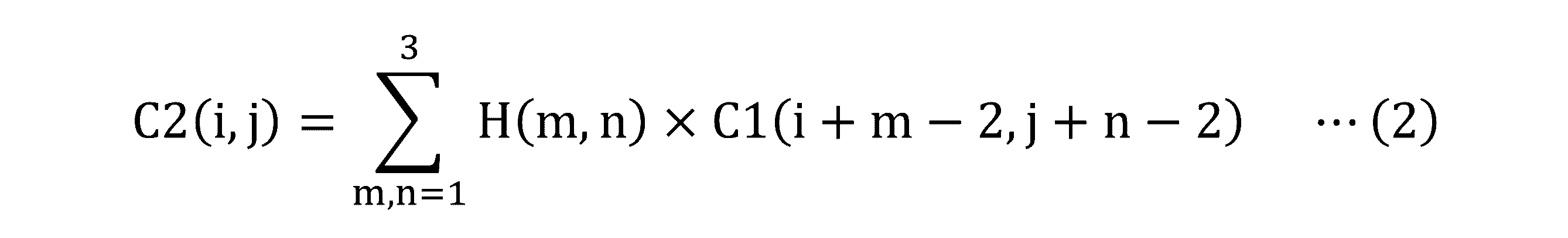
図6(b)は、図6(a)に示した静電容量C1を図5(a)又は図5(b)に示したハイパスフィルタで処理することによって得られる静電容量C2を示す模式図である。図6(b)と図3(b)及び図6(a)とを比較すると理解されるように、静電容量C2は、ハイパスフィルタによる処理の結果として、静電容量C,C1に比べてピークが強調されたものとなっている。 FIG. 6 (b) is a schematic showing the capacitance C2 obtained by treating the capacitance C1 shown in FIG. 6 (a) with the high-pass filter shown in FIG. 5 (a) or FIG. 5 (b). It is a figure. As can be understood by comparing FIG. 6 (b) with FIGS. 3 (b) and 6 (a), the capacitance C2 is higher than the capacitances C and C1 as a result of processing by the high-pass filter. The peak is emphasized.
図10(a)は、図9(a)に示した静電容量C1を図5(b)のハイパスフィルタで処理することによって得られる静電容量C2を示す図であり、図10(b)は、図10(a)に示した静電容量C2の分布を示す3D等高線図である。図10(a)(b)を図9(a)(b)と比較することによっても、ハイパスフィルタで処理することにより、静電容量C1に含まれるピークを強調できることが理解される。 10 (a) is a diagram showing the capacitance C2 obtained by processing the capacitance C1 shown in FIG. 9 (a) with the high-pass filter of FIG. 5 (b), and is a diagram showing FIG. 10 (b). Is a 3D contour diagram showing the distribution of the capacitance C2 shown in FIG. 10 (a). By comparing FIGS. 10 (a) and 10 (b) with those of FIGS. 9 (a) and 9 (b), it is understood that the peak contained in the capacitance C1 can be emphasized by processing with the high-pass filter.
図2に戻る。ステップS6,S7を実行したタッチ検出部15は次に、静電容量C2の最大値からスタイラスP検出用の閾値TH_P(第2の閾値)を導出する(ステップS8)。
Return to Fig. 2. Next, the
閾値TH_Pの導出について、再び図6(b)を参照して説明する。同図に示すように、タッチ検出部15は、検出されている静電容量C2の最大値MAXから所定値D_P(第1の値)を減算することにより、閾値TH_P=MAX-D_Pを導出する。所定値D_Pの値は、閾値TH_Pが閾値TH1よりも大きな値となるように予め決定される。なお、所定値D_Pは、上述した所定値D_Fに等しい値であるとすることも可能である。
The derivation of the threshold value TH_P will be described again with reference to FIG. 6 (b). As shown in the figure, the
図2に戻る。タッチ検出部15は、導出した閾値TH_Pを用いて、ローカルラベリングを実施する(ステップS9)。この場合のローカルラベリングは、静電容量C2が閾値TH_Pを上回るタッチ面内のエリア(第2のエリア)を特定する処理である。図6(b)に示したエリアLLPは、こうして特定される第2のエリアの例である。次いでタッチ検出部15は、ローカルラベリングの結果に基づき、スタイラスPの位置を示す座標を導出する(ステップS10)。具体的な例では、タッチ検出部15は、第2のエリアの重心を、スタイラスPの位置を示す座標として導出する。タッチ検出部15は、導出したスタイラスPの位置を示す座標をホストCPU(図2を参照)に出力し、処理を終了する。
Return to Fig. 2. The
以上説明したように、本実施の形態によるタッチ検出方法及びタッチ検出装置1によれば、指Fについては、第1の閾値より大きい第3の閾値を用いて検出を行うので、指Fの検出を好適に行うことができる。また、スタイラスPについては、フィルタによってピークを強調した後に第1の閾値より大きい第2の閾値を用いて検出を行うので、スタイラスPの検出も好適に行うことができる。したがって、本実施の形態によるタッチ検出方法及びタッチ検出装置1によれば、指F及びスタイラスPの検出を好適に行うことが可能になる。
As described above, according to the touch detection method and the
以上、本発明の好ましい実施の形態について説明したが、本発明はこうした実施の形態に何等限定されるものではなく、本発明が、その要旨を逸脱しない範囲において、種々なる態様で実施され得ることは勿論である。 Although the preferred embodiments of the present invention have been described above, the present invention is not limited to these embodiments, and the present invention can be implemented in various embodiments without departing from the gist thereof. Of course.
例えば、タッチ検出部15は、例えば特許5901870号公報に記載されているように、静電容量C(i,j)に代え、静電容量C(i,j)から交差位置(i,j)ごとの基準値を減じてなる値をフレームメモリFMに書き込むこととしてもよい。そして、フレームメモリFMに書き込んだこの値を用いて、上記実施の形態で説明したように、指F又はスタイラスPの検出と、検出した指F又はスタイラスPのタッチ面内における位置を示す座標の導出とを行うこととしてもよい。こうすることで、タッチ面の押下によって生ずる撓みの影響を低減することが可能になる。
For example, as described in Japanese Patent No. 5901870, for example, the
また、図4及び図5(a)(b)には3行3列の行列であるフィルタを示したが、他の種類のフィルタを用いることも可能である。さらに、図2には、ガウシアンフィルタとハイパスフィルタをこの順で適用する例を示したが、ハイパスフィルタを先に適用することとしてもよい。その他、ガウシアンフィルタによるノイズの低減は省略することとしてもよい。 Further, although the filters which are a matrix of 3 rows and 3 columns are shown in FIGS. 4 and 5 (a) and 5 (b), other types of filters can also be used. Further, although FIG. 2 shows an example in which the Gaussian filter and the high-pass filter are applied in this order, the high-pass filter may be applied first. In addition, noise reduction by the Gaussian filter may be omitted.
1 タッチ検出装置
2 タッチセンサ
2x,2y 電極
10 タッチセンサコントローラ
11 発振器
12,13 マルチプレクサ
14 アナログデジタル変換器(A/D)
15 タッチ検出部
20 記憶部
C,C1,C2 静電容量
D_F,D_P 所定値
F 指
FM フレームメモリ
GLF,GLP グローバルラベリングにより特定されるエリア
LLF,LLP ローカルラベリングにより特定されるエリア
P スタイラス
TH1,TH_F,TH_P 閾値
1
15
Claims (8)
それぞれ前記タッチ面内に含まれる複数の座標に対応する複数の第1の静電容量が第1の閾値を上回る前記タッチ面内の第1のエリアに基づき、検出されている指示体の種類を判定するステップと、
前記判定するステップにおいて前記指示体がスタイラスであると判定した場合に、前記複数の第1の静電容量を第1のフィルタによって処理することにより、前記複数の第1の静電容量に比べてピークが強調されてなる複数の第2の静電容量を取得するステップと、
前記複数の第2の静電容量が前記第1の閾値より大きい前記第2の閾値を上回る前記タッチ面内の第2のエリアに基づき、前記タッチ面内における前記スタイラスの位置を示す座標を導出するステップと、
前記判定するステップにおいて前記指示体が指であると判定した場合に、前記複数の第1の静電容量が前記第1の閾値より大きい第3の閾値を上回る前記タッチ面内の第3のエリアに基づき、前記タッチ面内における前記指の位置を示す座標を導出するステップと、
を含むタッチ検出方法。 A touch detection method executed by a touch detection device connected to a touch sensor that constitutes a touch surface.
Based on the first area in the touch surface where the plurality of first capacitances corresponding to the plurality of coordinates included in the touch surface exceed the first threshold value, the type of the indicator detected is determined. Judgment steps and
When it is determined that the indicator is a stylus in the determination step, the plurality of first capacitances are processed by the first filter, so that the plurality of first capacitances are compared with the plurality of first capacitances. The step of acquiring multiple second capacitances with emphasized peaks,
Based on the second area in the touch surface where the plurality of second capacitances are greater than the first threshold value and exceed the second threshold value, coordinates indicating the position of the stylus in the touch surface are derived. Steps to do and
When it is determined that the indicator is a finger in the determination step, the plurality of first capacitances exceed the third threshold value larger than the first threshold value, and the third area in the touch surface. Based on the step of deriving the coordinates indicating the position of the finger in the touch surface,
Touch detection methods including.
をさらに含む請求項1に記載のタッチ検出方法。 A step of deriving the second threshold value by subtracting a predetermined first value from the maximum value of the plurality of second capacitances in the first area.
The touch detection method according to claim 1, further comprising.
をさらに含む請求項2に記載のタッチ検出方法。 A step of deriving the third threshold value by subtracting a predetermined second value from the maximum value of the plurality of first capacitances in the first area.
The touch detection method according to claim 2, further comprising.
請求項3に記載のタッチ検出方法。 The first value is equal to the second value,
The touch detection method according to claim 3.
請求項1に記載のタッチ検出方法。 In the step of acquiring the plurality of second capacitances, the plurality of first capacitances are processed by each of the first and second filters to obtain the plurality of first capacitances. This is a step of acquiring the plurality of second capacitances in which the peak is emphasized and the noise noise is reduced as compared with the plurality of first capacitances.
The touch detection method according to claim 1.
前記第1のフィルタは、前記タッチ面内における前記複数の第1の静電容量の変化を強調するハイパスフィルタであり、
前記第2のフィルタは、前記第1のフィルタによる処理後の前記複数の第1の静電容量を平滑化するガウシアンフィルタである、
請求項5に記載のタッチ検出方法。 In the step of acquiring the plurality of second capacitances, the plurality of first capacitances are processed by the first filter, and the plurality of first static electricitys after the processing by the first filter are performed. This is a step of processing the capacitance by the second filter.
The first filter is a high-pass filter that emphasizes changes in the plurality of first capacitances in the touch surface.
The second filter is a Gaussian filter that smoothes the plurality of first capacitances after processing by the first filter.
The touch detection method according to claim 5.
前記第2のフィルタは、前記複数の第1の静電容量を平滑化するガウシアンフィルタであり、
前記第1のフィルタは、前記タッチ面内における前記第1のフィルタによる処理後の前記複数の第1の静電容量の変化を強調するハイパスフィルタである、
請求項5に記載のタッチ検出方法。 In the step of acquiring the plurality of second capacitances, the plurality of first capacitances are processed by the second filter, and the plurality of first static electricitys after the processing by the second filter are performed. This is a step of processing the capacitance by the first filter.
The second filter is a Gaussian filter that smoothes the plurality of first capacitances.
The first filter is a high-pass filter that emphasizes changes in the plurality of first capacitances in the touch surface after processing by the first filter.
The touch detection method according to claim 5.
それぞれ前記タッチ面内に含まれる複数の座標に対応する複数の第1の静電容量が第1の閾値を上回る前記タッチ面内の第1のエリアに基づき、検出されている指示体の種類を判定し、
前記指示体がスタイラスであると判定した場合に、前記複数の第1の静電容量を第1のフィルタによって処理することにより、前記複数の第1の静電容量に比べてピークが強調されてなる複数の第2の静電容量を取得し、
前記複数の第2の静電容量が前記第1の閾値より大きい第2の閾値を上回る前記タッチ面内の第2のエリアに基づき、前記タッチ面内における前記スタイラスの位置を示す座標を導出し、
前記指示体が指であると判定した場合に、前記複数の第1の静電容量が前記第1の閾値より大きい第3の閾値を上回る前記タッチ面内の第3のエリアに基づき、前記タッチ面内における前記指の位置を示す座標を導出する、
タッチ検出装置。 A touch detection device connected to a touch sensor that constitutes a touch surface.
Based on the first area in the touch surface where the plurality of first capacitances corresponding to the plurality of coordinates included in the touch surface exceed the first threshold value, the type of the indicator detected is determined. Judge,
When it is determined that the indicator is a stylus, the plurality of first capacitances are processed by the first filter, so that the peak is emphasized as compared with the plurality of first capacitances. To obtain multiple second capacitances,
Based on the second area in the touch plane where the plurality of second capacitances exceed the second threshold value larger than the first threshold value, coordinates indicating the position of the stylus in the touch plane are derived. ,
When it is determined that the indicator is a finger, the touch is based on a third area in the touch plane where the plurality of first capacitances exceed a third threshold that is greater than the first threshold. Derivation of coordinates indicating the position of the finger in the plane,
Touch detector.
Priority Applications (4)
| Application Number | Priority Date | Filing Date | Title |
|---|---|---|---|
| JP2021551030A JP7357999B2 (en) | 2019-10-10 | 2019-10-10 | Touch detection method and touch detection device |
| PCT/JP2019/039965 WO2021070313A1 (en) | 2019-10-10 | 2019-10-10 | Touch detection method and touch detection device |
| US17/694,193 US12019826B2 (en) | 2019-10-10 | 2022-03-14 | Touch detecting method and touch detecting device |
| US18/655,155 US12360631B2 (en) | 2019-10-10 | 2024-05-03 | Touch detecting method and touch detecting device |
Applications Claiming Priority (1)
| Application Number | Priority Date | Filing Date | Title |
|---|---|---|---|
| PCT/JP2019/039965 WO2021070313A1 (en) | 2019-10-10 | 2019-10-10 | Touch detection method and touch detection device |
Related Child Applications (1)
| Application Number | Title | Priority Date | Filing Date |
|---|---|---|---|
| US17/694,193 Continuation US12019826B2 (en) | 2019-10-10 | 2022-03-14 | Touch detecting method and touch detecting device |
Publications (1)
| Publication Number | Publication Date |
|---|---|
| WO2021070313A1 true WO2021070313A1 (en) | 2021-04-15 |
Family
ID=75438097
Family Applications (1)
| Application Number | Title | Priority Date | Filing Date |
|---|---|---|---|
| PCT/JP2019/039965 Ceased WO2021070313A1 (en) | 2019-10-10 | 2019-10-10 | Touch detection method and touch detection device |
Country Status (3)
| Country | Link |
|---|---|
| US (2) | US12019826B2 (en) |
| JP (1) | JP7357999B2 (en) |
| WO (1) | WO2021070313A1 (en) |
Families Citing this family (2)
| Publication number | Priority date | Publication date | Assignee | Title |
|---|---|---|---|---|
| WO2021070313A1 (en) * | 2019-10-10 | 2021-04-15 | 株式会社ワコム | Touch detection method and touch detection device |
| CN115701571A (en) * | 2021-08-02 | 2023-02-10 | 维沃移动通信有限公司 | Touch position determination method and device and electronic equipment |
Citations (6)
| Publication number | Priority date | Publication date | Assignee | Title |
|---|---|---|---|---|
| US20110074701A1 (en) * | 2009-09-30 | 2011-03-31 | Motorola, Inc. | Methods and apparatus for distinguishing between touch system manipulators |
| JP2013088982A (en) * | 2011-10-17 | 2013-05-13 | Rohm Co Ltd | Touch input device, controller and control method therefor, and electronic equipment |
| US20140111472A1 (en) * | 2012-10-18 | 2014-04-24 | Hideep Inc. | Touch screen controller and method for controlling the same |
| WO2014119347A1 (en) * | 2013-01-30 | 2014-08-07 | シャープ株式会社 | Touch panel device and touch panel device control method |
| WO2017046865A1 (en) * | 2015-09-15 | 2017-03-23 | 株式会社ワコム | Touch detection method, touch detection device, and touch sensor controller |
| JP2018147266A (en) * | 2017-03-06 | 2018-09-20 | シャープ株式会社 | Touch panel controller, touch panel system, and touch position detection method |
Family Cites Families (15)
| Publication number | Priority date | Publication date | Assignee | Title |
|---|---|---|---|---|
| US9024886B2 (en) * | 2009-04-14 | 2015-05-05 | Japan Display Inc. | Touch-panel device |
| US8451237B2 (en) * | 2009-07-06 | 2013-05-28 | Atmel Corporation | Sensitivity control as a function of touch shape |
| JP5423297B2 (en) * | 2009-09-30 | 2014-02-19 | 富士通株式会社 | Input device, input processing program, and input control method |
| JP4897983B1 (en) * | 2011-05-18 | 2012-03-14 | パナソニック株式会社 | Touch panel device and indicator distinguishing method |
| KR20130070893A (en) * | 2011-12-20 | 2013-06-28 | 삼성디스플레이 주식회사 | Touch detection system and driving method thereof |
| US9569045B2 (en) * | 2014-05-21 | 2017-02-14 | Apple Inc. | Stylus tilt and orientation estimation from touch sensor panel images |
| EP3151094B1 (en) * | 2014-05-27 | 2019-04-24 | Wacom Co., Ltd. | Indicator detection device and signal processing method thereof |
| US10437358B2 (en) * | 2014-06-27 | 2019-10-08 | 3M Innovative Properties Company | Touch systems stylus and methods |
| DE102015106101A1 (en) * | 2015-04-21 | 2016-10-27 | Preh Gmbh | Arrangement for spatially resolved projected-capacitive touch detection with improved locally deformed electrode structure |
| GB2547031B (en) * | 2016-02-05 | 2019-09-25 | Cambridge Touch Tech Ltd | Touchscreen panel signal processing |
| TWI606376B (en) * | 2016-08-08 | 2017-11-21 | 意象無限股份有限公司 | Touch Sensor Device And Touch-Sensing Method With Error-Touch Rejection |
| WO2018174109A1 (en) * | 2017-03-20 | 2018-09-27 | 株式会社I・Pソリューションズ | Sheet-shaped device |
| JP7011159B2 (en) * | 2018-01-12 | 2022-01-26 | Tianma Japan株式会社 | Capacitance detection circuit and capacitance sensor device |
| US11252322B2 (en) * | 2019-04-26 | 2022-02-15 | Canon Kabushiki Kaisha | Electronic device capable of performing control in accordance with a movement operation of an operating body and control method thereof |
| WO2021070313A1 (en) * | 2019-10-10 | 2021-04-15 | 株式会社ワコム | Touch detection method and touch detection device |
-
2019
- 2019-10-10 WO PCT/JP2019/039965 patent/WO2021070313A1/en not_active Ceased
- 2019-10-10 JP JP2021551030A patent/JP7357999B2/en active Active
-
2022
- 2022-03-14 US US17/694,193 patent/US12019826B2/en active Active
-
2024
- 2024-05-03 US US18/655,155 patent/US12360631B2/en active Active
Patent Citations (6)
| Publication number | Priority date | Publication date | Assignee | Title |
|---|---|---|---|---|
| US20110074701A1 (en) * | 2009-09-30 | 2011-03-31 | Motorola, Inc. | Methods and apparatus for distinguishing between touch system manipulators |
| JP2013088982A (en) * | 2011-10-17 | 2013-05-13 | Rohm Co Ltd | Touch input device, controller and control method therefor, and electronic equipment |
| US20140111472A1 (en) * | 2012-10-18 | 2014-04-24 | Hideep Inc. | Touch screen controller and method for controlling the same |
| WO2014119347A1 (en) * | 2013-01-30 | 2014-08-07 | シャープ株式会社 | Touch panel device and touch panel device control method |
| WO2017046865A1 (en) * | 2015-09-15 | 2017-03-23 | 株式会社ワコム | Touch detection method, touch detection device, and touch sensor controller |
| JP2018147266A (en) * | 2017-03-06 | 2018-09-20 | シャープ株式会社 | Touch panel controller, touch panel system, and touch position detection method |
Also Published As
| Publication number | Publication date |
|---|---|
| JP7357999B2 (en) | 2023-10-10 |
| JPWO2021070313A1 (en) | 2021-04-15 |
| US12019826B2 (en) | 2024-06-25 |
| US20240302920A1 (en) | 2024-09-12 |
| US12360631B2 (en) | 2025-07-15 |
| US20220197503A1 (en) | 2022-06-23 |
Similar Documents
| Publication | Publication Date | Title |
|---|---|---|
| US9569045B2 (en) | Stylus tilt and orientation estimation from touch sensor panel images | |
| TWI419025B (en) | A sensing device for detecting contact with or close to an object, and a display device for mounting the same | |
| KR102404549B1 (en) | Techniques for handling unintentional touch inputs on a touch-sensitive surface | |
| CN110447007B (en) | Projected capacitive touch systems, methods, and computer readable media with enhanced immunity to water contamination | |
| CN105045437B (en) | A kind of touch-control sensing electrode, sensing method of touch control and equipment | |
| US20110012855A1 (en) | Method and device for palm rejection | |
| US20150242009A1 (en) | Using Capacitive Images for Touch Type Classification | |
| CN109117023B (en) | Method and device for excluding line segment group corresponding to palm | |
| US12360631B2 (en) | Touch detecting method and touch detecting device | |
| US20130265258A1 (en) | Method for identifying touch on a touch screen | |
| CN107102785B (en) | Capacitive sensing device and update method for judging baseline value | |
| US12487692B2 (en) | Position detection circuit and position detection method | |
| WO2014131283A1 (en) | Touch recognition method and device | |
| US10990224B2 (en) | Touch detection method, touch detection apparatus, and touch sensor controller | |
| US9684407B2 (en) | Method and apparatus for determining shape and orientation of a touch object on handheld devices | |
| KR101580570B1 (en) | Control method and controller for touch sensor panel | |
| KR101143276B1 (en) | Adaptive type noise removing method for improving the accuracy of the position measurement of touch input | |
| JPWO2018168320A1 (en) | INPUT DEVICE, ITS CONTROL METHOD, AND PROGRAM | |
| CN113126802B (en) | Touch processing device for detecting liquid level of touch panel half immersed in conductive liquid | |
| US10599257B2 (en) | Touch screen device having improved floating mode entry conditions | |
| US10712883B2 (en) | Electronic device validating multiple finger touch detection through donut shaped touch islands, and related methods | |
| US20170024051A1 (en) | Multitouch frame matching with distance fields | |
| KR101822400B1 (en) | Optical touch screen apparatus and sensing method | |
| CN113126803B (en) | Touch processing device and method for touch panel half immersed in conductive liquid | |
| US20150301649A1 (en) | Touch sensing apparatus and touchscreen apparatus including the same |
Legal Events
| Date | Code | Title | Description |
|---|---|---|---|
| 121 | Ep: the epo has been informed by wipo that ep was designated in this application |
Ref document number: 19948384 Country of ref document: EP Kind code of ref document: A1 |
|
| ENP | Entry into the national phase |
Ref document number: 2021551030 Country of ref document: JP Kind code of ref document: A |
|
| NENP | Non-entry into the national phase |
Ref country code: DE |
|
| 122 | Ep: pct application non-entry in european phase |
Ref document number: 19948384 Country of ref document: EP Kind code of ref document: A1 |