WO2021053566A1 - Device for atraumatic removal of dental crowns and bridges - Google Patents
Device for atraumatic removal of dental crowns and bridges Download PDFInfo
- Publication number
- WO2021053566A1 WO2021053566A1 PCT/IB2020/058660 IB2020058660W WO2021053566A1 WO 2021053566 A1 WO2021053566 A1 WO 2021053566A1 IB 2020058660 W IB2020058660 W IB 2020058660W WO 2021053566 A1 WO2021053566 A1 WO 2021053566A1
- Authority
- WO
- WIPO (PCT)
- Prior art keywords
- length
- rest
- pliers
- removal
- width
- Prior art date
- Legal status (The legal status is an assumption and is not a legal conclusion. Google has not performed a legal analysis and makes no representation as to the accuracy of the status listed.)
- Ceased
Links
Classifications
-
- A—HUMAN NECESSITIES
- A61—MEDICAL OR VETERINARY SCIENCE; HYGIENE
- A61C—DENTISTRY; APPARATUS OR METHODS FOR ORAL OR DENTAL HYGIENE
- A61C3/00—Dental tools or instruments
- A61C3/16—Dentists' forceps or clamps for removing crowns
- A61C3/162—Dentists' forceps or clamps for removing crowns acting by leverage
Definitions
- This invention belongs to the field of dentistry and relates therein to pliers of the kind used for removal of dental crowns and / or bridges. More particularly, this invention concerns with the construction and operability of such pliers which make possible the removal of dental crowns and / or bridges without damage to said dental crowns and / or bridges and no trauma therein on part of the patient.
- the term “Pliers” generally refers a hand tool consisting of a pincer construct having gripping jaws which allow a user to hold and accurately manipulate an object (in this case, the Cover) in a precise manner.
- the Covers are placed into their positions over the prepared surfaces of the natural teeth by inserting them in a specific angle or a path.
- This specific angle or path of insertion is called as angle of insertion or path of insertion of those crowns or bridges.
- These angles or the paths of insertion are in line with their respective long axes of those natural teeth.
- This procedure also generates aerosols containing a wide spectrum of microorganisms which are highly infectious to the dentist / clinician, staff in the vicinity and also contaminates the air and the nearby area of 3 to 6 feet of the operatory room. Also the crown / bridge are removed in pieces and thus remain of no use. Also, the operation is made difficult to implement (especially for hard-to-reach teeth) in the limited workspace available within a human oral cavity. It is thus a pressing need of the art to have some means that allow efficient and quick removal of Covers while ensuring no trauma to the patient.
- Covers are prepared and / or subsequently replaced to restore the aesthetics, form and function of natural tooth / teeth. This can be achieved if the Covers maintain the same long axes of teeth.
- affixation and / or replacement of Covers requires their iterative removal, wherein it would be extremely desirable to have some means that facilitate removal of said Covers without damage to the Cover, nor trauma to the patient on whom the procedure is completed.
- the device for removal of Covers conforms to a pliers type construction which is presented in a meaningfully short plurality as a set, of which each member is devotedly localized to the group of tooth / teeth for which the Cover is designed, with specific consideration to its own long axis and the path of removal of said Cover.
- the device for removal of Covers negates the need for additional invasive procedures such as drilling or cutting of the Covers and thus prevents the generation of aerosols containing infectious microorganisms which can potentially infect the clinician / operator, staff and the air in the surrounding atmosphere.
- the device for removal of Covers makes it possible for the clinician to effectively apply controlled force, hence augmenting process control. It is another objective further to the aforesaid objective(s) that usage of the device for removal of Covers is easy to learn for any clinician.
- the device includes minimal consumables, and which are nonetheless capable of being changed via a quick, easy and tool less manner.
- the device for removal of Covers is easy and cost-effective to produce on a mass scale, and is characterised in having a long service life without any specific maintenance schedule.
- Figure 1 A illustrates the construction of the pliers for lower jaw incisors as per the present invention.
- Figure 1 B is a magnified isolated view of the rest (06) included in the pliers shown in Figure 1 A.
- Figure 1 C is a magnified isolated view of the rubber attachment (07) included in the pliers shown in Figure 1 A.
- Figure 1 D is a magnified isolated view of the active arm (08) included in the pliers shown in Figure 1 A.
- Figure 2A illustrates the construction of the pliers for lower jaw canines as per the present invention.
- Figure 2B is a magnified isolated view of the rest (06) included in the pliers shown in Figure 2k.
- Figure 2C is a magnified isolated view of the rubber attachment (07) included in the pliers shown in Figure 2k.
- Figure 2D is a magnified isolated view of the active arm (08) included in the pliers shown in Figure 2k.
- Figure 3A illustrates the construction of the pliers for lower jaw molars as per the present invention.
- Figure 3B is a magnified isolated view of the rest (06) included in the pliers shown in Figure 3A.
- Figure 3C is a magnified isolated view of the rubber attachment (07) included in the pliers shown in Figure 3A.
- Figure 3D is a magnified isolated view of the active arm (08) included in the pliers shown in Figure 3A.
- Figure 4A illustrates the construction of the pliers for lower jaw pre molars as per the present invention.
- Figure 4B is a magnified isolated view of the rest (06) included in the pliers shown in Figure 4A.
- Figure 4C is a magnified isolated view of the rubber attachment (07) included in the pliers shown in Figure 4A.
- Figure 4D is a magnified isolated view of the active arm (08) included in the pliers shown in Figure 4A.
- Figure 5A illustrates the construction of the pliers for upper jaw incisors as per the present invention.
- Figure 5B is a magnified isolated view of the rest (06) included in the pliers shown in Figure 5A.
- Figure 5C is a magnified isolated view of the rubber attachment (07) included in the pliers shown in Figure 5A.
- Figure 5D is a magnified isolated view of the active arm (08) included in the pliers shown in Figure 5A.
- Figure 6A illustrates the construction of the pliers for upper jaw canines as per the present invention.
- Figure 6B is a magnified isolated view of the rest (06) included in the pliers shown in Figure 6A.
- Figure 6C is a magnified isolated view of the rubber attachment (07) included in the pliers shown in Figure 6A.
- Figure 6D is a magnified isolated view of the active arm (08) included in the pliers shown in Figure 6A.
- Figure 7A illustrates the construction of the pliers for upper jaw molars as per the present invention.
- Figure 7B is a magnified isolated view of the rest (06) included in the pliers shown in Figure 7A.
- Figure 7C is a magnified isolated view of the rubber attachment (07) included in the pliers shown in Figure 7A.
- Figure 7D is a magnified isolated view of the active arm (08) included in the pliers shown in Figure 7A.
- Figure 8A illustrates construction of the pliers for upper jaw pre molars as per the present invention.
- Figure 8B is a magnified isolated view of the rest (06) included in the pliers shown in Figure 8A.
- Figure 8C is a magnified isolated view of the rubber attachment (07) included in the pliers shown in Figure 8A.
- Figure 8D is a magnified isolated view of the active arm (08) included in the pliers shown in Figure 8A.
- Figure 9A is a magnified view of an exemplary rubber attachment (07) as per the disclosures hereof.
- Figure 9B is a magnified view of an exemplary metal housing (12) as per the disclosures hereof.
- Figure 9C is a magnified view of an exemplary active arm (08) as per the disclosures hereof.
- Figure 10A illustrates construction of the pliers with angulated handles designed only for molars and for molar universal pliers as per the present invention.
- Figure 10B is a top view of the pliers shown in Figure 10A, with an inset showing a magnified view of the rest (06) in isolation.
- Figure 10C is a cross sectional view of the rest (06) included in the pliers shown in Figure 10A and also Figures 1 B, 2B, 3B, 4B, 5B, 6B, 7B, and 8B.
- Figure 10D is a top view of the the rest (06) as shown in the inset of Figure 10A and also Figures 1 B, 2B, 3B, 4B, 5B, 6B, 7B, and 8B.
- Figure 10E is a magnified isolated view of the rest (06) included in the pliers for only molars (occlusal), only premolars (occlusal), and posterior universal (occlusal) as shown in Figure 10A.
- Figure 10F is a magnified isolated view of the rubber attachment (07) included in the pliers only for molars, premolars and for posterior universal with convex adapting surface.
- Figure 10G is a magnified isolated view of the active arm (08) included in the pliers for only molars (occlusal), only premolars (occlusal), and posterior universal (occlusal) as shown in Figure 10A.
- Figure 11 A is a perspective view of the active arm (08) for pliers directed at removal of covers from molars, premolars and posterior universal, as per the disclosures hereof.
- Figure 11 B is a perspective view of the active arm (08) for pliers directed at removal of covers from anteriors, canines and anterior universal, as per the disclosures hereof.
- Figure 12A is a top view of the angulated handle of certain pliers, seen for the arm leading to the rest (06) as per the disclosures hereof.
- Figure 12B is a side view of the angulated handle of certain pliers, seen for the arm leading to the rest (06) as per the disclosures hereof.
- Figure 12C is a top view of the angulated handle of certain pliers, seen for the arm leading to the active arm (08) as per the disclosures hereof.
- Figure 12D is a side view of the angulated handle of certain pliers, seen for the arm leading to the active arm (08) as per the disclosures hereof.
- a set of pliers for atraumatic removal of a dental cover is proposed herein which characteristically has a modular construction a pair of opposing arms (01 and 02) connected along their lengths at a pivot (03) to end in a pair of jaw members (04 and 05) at other side of said pivot (03), wherein said jaw members (04 and 05) are arranged to receive a suitably shaped and sized rest (06) and active arm (08) respectively.
- This combination allows maximum vertical force / pressure to be transmitted and distributed equally along the length of the teeth and the cusps by the rest (06) and at the same time, an equal and opposite force is caused to be applied via the active arm (08) which results in controlled and balanced force which reduces the chances of injury to the underlying natural teeth structure such as to their cusps or to the incisal edges and also causing the dental cover to be removed in a quick, easy, and atraumatic manner.
- the disclosures herein are directed towards construction and operability of such pliers which make possible the removal of dental crowns and / or bridges without damage to said dental crowns and / or bridges and no trauma therein on part of the patient.
- the present invention is based on the innate understandings that:- a) Every tooth in the oral cavity is fixed in the alveolar bone of the maxillary and the mandibular jaws. An imaginary line passing through the center of the tooth and the center of the tip of the root is called as the long axis of the tooth which makes a specific acute / obtuse angle with the horizontal and the vertical planes. While preparing a tooth for crowns / bridges / covers, a clinician has to prepare the teeth by considering these long axes of the teeth.
- crowns / covers / bridges are constructed in the dental laboratories and are to be inserted and cemented over the teeth in a specific path called as path of insertion. So, if we want to remove these covers from the teeth, they have to be removed by the application of the force exactly in the opposite direction called as path of removal. If the force is applied in any other directions than their path of removal it may result into fracture of the underlying natural teeth structures; b) while applying the force along the direction of its path of removal, the force should be well controlled, balanced and should get distributed equally over the artificial crowns or bridges; and c) there should be sufficiently wider surface contact of the device at the level of application of force in order to get well controlled , wide spread and balanced distribution of the force applied. This also provides more firm and confident grip of the device over the crown to be removed.
- this invention contemplates a set of basic eight pliers each of which is customized for different teeth in the human jaw, as under-
- a second set of 4 pliers is also included, which conforms to-
- This arrangement makes it possible for the occlusal rests (06) and the active arms (08) to reach the first and second molar at right angle.
- a specially designed sit area (22) is seen in the horizontal arm (14) of occlusal rest (06) for locking of terminal ring (11) of the rubber attachment (07).
- Posterior Universal pliers which is derived from averaging out of the surface areas and the angles of the necks (13 - angles shown in Figure 10C) of the pliers for only molars, and only premolar crowns.
- the handle is designed in such a way that by turning the handle horizontally at 115 degree for a length of 25 mm and then turning again by the same 115 degrees, but in opposite direction, it becomes straight and exactly parallel with the arms (01 and 02), to allow ease of reach within the oral cavity for the clinician.
- This arrangement makes it possible for the occlusal rests (06) and the active arms (08) to reach the first and second molar at right angle.
- the occlusal rests are designed over the lingual cusps of the lower jaw molars and premolars and the palatal cusps of the upper jaw molars and premolars.
- the long axes are drawn along the centre of the lingual or the palatal cusps of molars and premolars.
- a third set of three pliers is also included.
- the occlusal rest (06) is designed over the complete occlusal surfaces of the molars and premolars of the lower and upper jaws.
- the long axes are drawn along the center of the occlusal surfaces of the molars and premolars.
- each among said set of pliers has a common construction consisting of a pair of opposing arm members (01 and 02) connected with each other about a pivot (03).
- the arm members (01 and 02) are made of medical grade stainless steel (SS304 or SS316L) and provided with non-slip materials / finishing or surface indentations to allow able firm grip of the clinician / user.
- a rest (06) is provided on the jaw (04). This rest (06) is arranged to removably receive a resilient deformable insert / rubber attachment (07) having an adapting surface (09) generally contoured to coincide with an incisal edge / occlusal and lingual / palatal cusp surfaces of the Cover to be removed.
- An active arm (08) is provided on the jaw (05). This active arm (08) is generally contoured and angled to coincide with base of the labial / buccal margin of the Cover to be removed.
- the arms (01 and 02) and jaws (04 and 05) are preferably casted one -piece individually in medical grade stainless steel of different hardness with respect to one another.
- the rest (06) is termed as the occlusal rest (06) in case of pliers designed for molars and premolars or as the incisal rest (06) (that is, by common numeral 06) respectively in case of canines and incisors.
- This rest (06) is made up of medical grade steel, and as the name suggests, the rest (06) is the component which rests on the occlusal surfaces of the molars and premolars and on the incisal edges of the canines and incisors.
- the rest (06) gets adopted over occlusal surfaces of the molars and premolars and on the incisal edges of the canines and incisors with the help of the aforementioned resilient deformable insert / rubber attachment (07), which is specially designed to complement the corresponding shapes of the occlusal surfaces and the incisal edges of the respective teeth, which helps in increasing the grip of the pliers (or allowing the clinician to hold the pliers) firmly over the Cover to be removed.
- the aforementioned resilient deformable insert / rubber attachment which is specially designed to complement the corresponding shapes of the occlusal surfaces and the incisal edges of the respective teeth, which helps in increasing the grip of the pliers (or allowing the clinician to hold the pliers) firmly over the Cover to be removed.
- each pliers mentioned above is cast in stainless steel of medical grade or equivalent.
- the arm members (01 and 02) bearing the opposed jaws (04 and 05) may be formed of different material, particularly having different hardness, than the occlusal rest (06) and active arm (08).
- the active arm (08) and occlusal rest (06) respectively are arranged to be received at the opposing jaws (05 and 04) respectively via means chosen among screw fitting or insertable pins that sit flush within body of said opposing jaws (05 and 04).
- the screw fitting or insertable pins are received through suitable orifices (such as 21 shown in Figure 9C) drilled and preferably tapped in bodies of said components.
- suitable orifices such as 21 shown in Figure 9C
- Other embodiments are intended wherein the rest (06) and active arm (08) may be cast in one piece with the opposing jaws (04 and 05).
- the arm members (04 and 05) have an offset area elliptical in shape, of dimensions of 7mm * 5.6 mm * 3 mm (length / depth, width and height / thickness respectively) with the draft of 1 % for receiving the fitment of the terminal parts (15 and 20) of the occlusal rest (06) and the active arm (08) respectively either by the press fit mechanism or with the help of a dowel pin tapping or affixed alternatively using metal to metal adhesives like Anabond (commercial name) or glue.
- the rest (06) consists of three components- )
- the metal housing (12) has a provision, a contoured recess in particular, for the fitment of rubber attachment (07) of corresponding shapes.
- Rubber attachments (07) of various shapes can be fitted into the corresponding metal housing (12), just by pressing them through the hollow space (23) specially designed in the angulated neck (13) of the occlusal rests (06) so that the stalk (10) of these rubber attachments along with the terminal locking ring (11), passes through that hollow space (23 as seen in Figure 10B and 10C) and when it protrudes out on the top surface, where it gets locked into the sit area (22) specially designed over the top surface of the metal housing (12) (For locking up of these rubber attachments);) Angulated neck (13) of the occlusal rest - Necks (13) of the occlusal rests (06) are designed by studying the average values of the angles (acute angles and the obtuse angles as shown in Figure 10C) formed between the long axes of the respective teeth with the horizontal plane. Same average values of these angulations are considered while designing the neck (13) of the occlusal rests (06) designed for the removal of the crowns / bridges / covers over those
- Angulated neck (13) is the narrow, slender, connecting part of 4.4 mm in diameter in between the dome shaped metal housing (12) and the horizontal arm (14) of the occlusal rest (06).
- An angle of neck corresponds to the angle of the long axis of tooth in case of the occlusal and incisal rests and to the long axis of the lingual / palatal cusps, in case of the lingual / palatal rests.
- the angulated neck (13) has a through and through hollow space (23) of 3 mm in diameter specially designed (as shown in the accompanying Figure 10C) and has an opening into the sit area (22) at its top surface in the horizontal arm (14) for getting the rubber attachment (07) locked.
- the sit area (22) in the horizontal arm (14) of the rest (6) is designed in such a way that it is having diameter of 3.4 mm and the depth of 1.4 mm to occupy the diameter of 3.4 mm of the terminal ring (11 ) of the resilient rubber attachment. (07).
- the diameter of the terminal ring (11) is 3.4 mm (more than the diameter of the stalk (10) (3 mm diameter) and that of the diameter of the hollow space (23) by 400 microns.
- Horizontal Arm (14) this is the part in between the angulated neck (13) and the arm member of jaw (04) of the pliers.
- the terminal part (15) of the horizontal arm is an elliptical in shape of dimensions of 7mm * 5.6 mm * 3 mm (length, width and height / thickness respectively) with the draft of 1 % (of 7 millimeter which goes inside into the specially designed offset area into the arm member of jaw (04) and gets fitted there with either dowel pin or press fit like arrangement or affixed with metal to metal adhesives like Anabond or glue.
- a through and through hole (21) of 2mm diameter is made exactly in the center of the terminal part (15) and into the arm member of the handle (04) through the offset area, coinciding with each other, for the fitment of the dowel pin.
- the active arm (08— particularly shown in Figure 9C) consists of three components-
- Blade (16) - this is the main active area of this device having chisel shaped edge (17), and said edge (17) of width of 700 microns and a 25 degree angle / taper in between the two edges which forms the shape of the chisel.
- Body (18) this is the area in between the blade (16) and the horizontal arm (19). Blade (16) continues forward and downward divergently to become the body (18) of the active arm (08) which is broader, bulkier, and sturdy and provides strength to the blade (16) as well as to the active arm (08);
- Horizontal arm (19) - this is the part between the body (18) and the terminal part (20) of the active arm (08).
- the terminal part (20) of the active arm (08) is an elliptical in shape of dimensions of 7mm * 5.6 mm * 3 mm (length, width and height / thickness respectively) with the draft of 1 % which goes inside into the specially designed offset area into the jaw member (05) and gets fitted there with either dowel pin or press fit like arrangement or affixed with metal to metal adhesives like Anabond or glue.
- a through and through hole (21) of 2mm diameter is made exactly in the center of the terminal part (20) and into the arm member of the handle (05) through the offset area, coinciding with each other, for the fitment of the dowel pin.
- the need to have separate design of the active arm (08) is eliminated by a common design, differing in dimensions alone (total length 11 mm Or 14 mm respectively as seen in the underlying tables) to conform to two variants, the first one being directed at removal of covers from molars (specifically shown in Figure 11 A) and the other being directed at removal of covers from anterior teeth (specifically shown in Figure 11 B).
- the resilient deformable insert / rubber attachment (07) consists of three components-
- An adapting surface (09) which gets adopted over the occlusal, lingual or palatal cusps or over the incisal surfaces of the teeth and are grossly of the corresponding shapes; and of around 2 mm thickness.
- the occlusal rest (06) is designed over the lingual cusps or the palatal cusps
- the form of the external surface of the rubber attachments (07) are concave, as these are getting adapted over the prominent, hill like convex surfaces of the cusps.
- a stalk (10) which is the middle part present between the adopting surface (09) and the terminal locking ring (11) having diameter of 3 mm.
- This part of the rubber attachment (07) along with the terminal locking ring (11) passes through the hollow space (23) designed especially for this stalk (10) in the angulated neck (13) of occlusal rest (06).
- a terminal locking ring (11) is the small ring like part admeasuring 3.4 mm in diameter (400 microns more in diameter than the 3 mm diameter of the stock (10), which being made up of compressible, resilient rubber like material, after application of little force / pressure, comes out through the hollow space (23) of the neck of the occlusal rest (06) and gets locked in the specially designed sit area (22), in the top surface of the horizontal arm (14) of the occlusal rest (06) for the fitment of this terminal locking ring (11). Because its diameter is 400 microns more than the diameter of the hollow space (23), once it goes and fits into the locking area in the horizontal arm (14) of the occlusal rest (06), it cannot come back again and gets locked.
- the resilient deformable insert / rubber attachment (07) is made up of medical grade silicone rubber or a thermoplastic silicone or such material of the required specific shore hardness, which can withstand to the multiple autoclave cycles, and has good wear and tear resistance (have specific thickness), in order to maintain the required resiliency for the said purpose, and so that it can get adopted well over the lingual or palatal cusps or over the occlusal surfaces or over the incisal edges of the Covers to be removed.
- Length of the Occlusal Rest means the total length from one end of the metal housing (12) for the rubber attachment (07) up to the terminal part (15) of the horizontal arm (14), which gets fitted into the offset area specially designed in to the handle of the pliers. (Up to its length of 7 millimeters) This is before assembly.
- Length of the Active Arm means the total length of the active arm (08) from tip of the blade (16) up to the terminal part (20) of the horizontal arm (19), which gets fitted into the offset area specially designed in to the handle of the pliers. (Up to its length of 7 millimeters). This is before assembly.
- Length of the Handle means total length of the two handle parts (assembled like a scissor). This is before assembly.
- Total length of the pliers / Device means length of the pliers from one end of the metal housing (12) for the rubber attachment (07) up to the distal end of the pliers handles. In this position, the terminal parts (15 and 20) of both occlusal rests (06) and the active arms (08) get fitted into the offset area specially designed in to the handle of the pliers. (Up to its length of 7 millimeters). ⁇ This is (C + A) -7 ⁇ This is after assembly of the device proposed herein.
- Lingual or palatal side means width of the metal housing (12) of occlusal rest (06) towards the tongue side which is in case of the mandibular teeth (lower jaw teeth).
- Palatal side means width of the metal housing (12) of occlusal rest (06) towards the palatal side, which is in the maxillary teeth (upper jaw teeth).
- Central or transverse means width of the metal housing (12) of the occlusal rests at their centre, where they are broader than the other two sides. This shape pertains only for the surfaces of the anterior pliers, the canines and for the anterior universal pliers. The shapes of the metal housing (12) for the pliers of premolar, molar and of posterior universal surfaces are more squarish.
- Labial or the buccal side means width of the metal housing (12) of occlusal rest (06) towards the lips, which is in case of the maxillary and mandibular anteriors, canines and anterior universal pliers.
- buccal means the width of the metal housing (12) of occlusal rest (06) towards the cheeks, which is in case of the maxillary and the mandibular premolars, molars and for the posterior universal pliers.
- J Obtuse Angles / Acute Angles of the long axes of Neck of the Occlusal Rests which are in line with the long axes of the respective teeth;
- K Length of Active Arm (“+7” refers length of the terminal part);
- L Width Of Blade;
- M Width of the Chisel edge;
- N Angle of the Edge.
- a) Obtuse angle and acute angle (as shown in Figure 10C). Every tooth is fixed into the socket of the jaw bones (maxilla and mandible) with some particular angulation in relation to the vertical and the horizontal planes. They are not at 90 degree in respect to both vertical and the horizontal planes. Every tooth has different angulations (its own long axis) in respect to the the vertical and the horizontal planes. Here the angulations of the long axes of teeth are measured in relation to the horizontal plane and the same angulations are applied for designing the neck (13) of the rest (06) and are noted down either as an obtuse angle or an acute angle and mentioned in the above table.
- Length of the Active arm (08) means the total length of the active arm (08) from tip of the blade up to the distal tip of the horizontal arm, which gets fitted into the offset area specially designed in to the jaw (05) of the pliers. (Up to its length of 7 millimeters) It’s before assembly. In this table, the lengths of the active arms are some figures + 7 (just like 11 +7 or 14+7). This distal / terminal part of 7 millimeter gets fitted in to the offset area specially designed in the handle and fixed with either dowel pin or with press fit like arrangement. c) Width of the blade (16).
- the working blade (16) which is the crux of the device mentioned herein, has width of either 3 millimeter and 4 millimeters for anterior teeth and the posterior teeth respectively.
- the width of the Chisel shaped edge is 700 microns in all active arm (08) tips. But may vary from 200 microns to 1200 microns.
- the applicant named herein has undertaken trials to determine the efficacy of the active arm (08) having different widths of the chisel shaped blades in the range of 200 microns to 1200 microns, with the gap of 100 microns each, e) The angle / taper of the chisel edge.
- the angle / taper in between the two edges / sides of the chisel edge is 25 degrees in all active arm (08) tips hereof. It may also vary. From 10 degree to 60 degree.
- the applicant named herein has undertaken trials to determine the efficacy of the active arm (08) having different angles of edge of the chisel shaped blades in the range of 10 degree to 60 degree, with the gap of 10 degree each.
- the device / each set of pliers mentioned above is characterized in having simple one-stroke operation that effectively results in removal of cemented dental crown intact (as it is) very easily in few seconds without cutting or perforating it, without causing any trauma or fracture to the underlying tooth or an implant while having application of controlled force with minimum psychological and mental stress to the patients as well as the clinician / staff.
- occlusal rest (06) is rested over the occlusal surface, lingual / palatal cusps, or over the incisal edge of the Cover to be removed a)
- the tip of the active arm (08) is adapting well with the cervical margin of the crown to be removed at its deepest curvature and its chisel shaped edge of the blade is going below the cervical margin of the crown generally having thickness of 500 microns to more than 1 mm, either completely or partially and getting engaged tightly in such position;
- the diagnostic probe which is a metallic instrument having a handle and a very sharp pointed end at its angulated tip.
- the active arm (08) may be engaged tightly against the cervical margin of the Cover by activating the pliers by applying little pressure over its handle c) If the crown margins are flushing with the root surface, then clinician can palpate the groove at the junction of crown margins and the root surface with the help of diagnostic probe, and feel it with the probe tip. The clinician may then make a marking at that level and make a small horizontal groove of half to one millimeter depth and 3 to 4 millimeter width using a slow speed motor just below that marked point. (Prior to this process, necessary local anesthesia is administered as a little laceration of the gingival margin is inevitable).
- the blade (16) of the pliers may be kept in that groove below the cervical margin of the crown and engaged tightly against the cervical margin of the crown by activating the pliers by applying little pressure over its handles )
- the clinician can feel a very firm, strong grip over the Cover to be removed with the plier / device proposed herein.
- a very little and gentle upward or the downward wrist movements are to be done in such a way that the- a) Occlusal rest (06) will get pressed over the crown to be removed. (It will deliver vertical force by pressing over the crown to be removed. This force will be passed on over the underlying natural tooth structure and will get distributed equally along its length).
- This active arm will be lifted up in an upward and a bit outward direction, (exactly in the opposite direction of the path of insertion of that crown or bridge and not in the vertical direction), so that the thin film or layer of the set cementing / bonding material of approximately 50 microns (plus or minus of 20 or 30 microns) thickness gets sheared off by cracking down the film / layer.
- the chisel shaped design of edge of the blade, specific angle of this chisel shaped edge, and the width of the edge works like a wedge and helps into the shearing off of the set cemental / bonded material which is present in between the natural crown (tooth) and the artificial crown.
- the Cover/s removed are preserved intact (perfectly conserved) and can be used again if no alterations are done by the clinician in the mesial, distal, buccal / labial, palatal / lingual sides of the underlying natural tooth / teeth or if the root canal treatment or re root canal treatment is being done in the underlying natural tooth and the occlusal form is maintained by proper filling of the access cavity with the help of proper filling materials. This saves the time of the patients and the doctors and avoids repetition in preparation of the Covers and costs for the patient;
- some hands- on training over models of cemented artificial crowns of the extracted natural teeth is sufficient to allow the clinician to get acquainted with the amount of force to be delivered while removing each group of tooth and the direction of the wrist movements to be done, because it differs from one group of tooth to the other.
- the crowns are bulkier and their heights are lesser than those of the anterior teeth which are slender and having more heights. Therefore the verticals movements required to be done in posterior teeth in order to lift the crown upward are lesser but with a bit more force than the vertical movements required to be done in the anterior teeth which requires application of gentle force.
- the rubber attachment (07) may get spoiled. At that time, that rubber attachment (07) has to be removed and then replaced with the new one, via a quick single press-fit motion which does not require any specific skills or tooling.
- all pliers mentioned above are designed to work in a position where the working field (here occlusal plane of the patient) is parallel to the floor.
- the main working unit of the device proposed herein is the chisel shaped edge of the blade of the active arm (08).
- the upward movements or downward movements of the device proposed herein in position refers to the upward movements or the downward movements of the active arm (08) in respect to the occlusal plane which is horizontal.
- the plier / device proposed herein should be moved in upward direction.
- the plier / device proposed herein should be moved in downward direction. In short, very small wrist movements are done in vertical directions to bring about these upward and the downward movements of the active arm (08) of the device proposed herein.
- the present invention does away with conventional practices of Cover removal, namely cutting (with dental diamond coated / carbide burs), Perforation (with specialized equipment), application of torque via uncontrolled, jerky movements (with spring loaded equipment available in the field), which many times results into fracture of the underlined tooth (specially root canal treated) and many times failure to remove the Cover without damage to said Covers.
Landscapes
- Health & Medical Sciences (AREA)
- Oral & Maxillofacial Surgery (AREA)
- Dentistry (AREA)
- Epidemiology (AREA)
- Life Sciences & Earth Sciences (AREA)
- Animal Behavior & Ethology (AREA)
- General Health & Medical Sciences (AREA)
- Public Health (AREA)
- Veterinary Medicine (AREA)
- Dental Tools And Instruments Or Auxiliary Dental Instruments (AREA)
Abstract
A set of pliers for atraumatic removal of a dental cover is proposed herein which characteristically has a modular construction comprising a pair of opposing arms (01 and 02) connected along their lengths at a pivot (03) to end a pair of jaw members (04 and 05) at other side of said pivot (03), wherein said jaw members (04 and 05) are arranged to received one each among a suitably shaped and sized occlusal rest (06) and active arm (08) which allow maximum vertical force / pressure to be transmitted and distributed equally along the length of the teeth and the cusps which will reduce the chances of injury to the underlying natural teeth structure such as to their cusps or to the incisal edges. At the same time, an equal and opposite force is caused to be applied via the active arm, therein causing the dental cover to be removed in a quick, easy, and atraumatic manner.
Description
Complete Specification
Device for atraumatic removal of dental crowns and bridges
Cross references to related applications: This international application is filed claiming priority from Indian patent application No. 201921033764 filed on 22/09/2019, the contents of which are incorporated herein in their entirety, by reference.
Field of the invention
This invention belongs to the field of dentistry and relates therein to pliers of the kind used for removal of dental crowns and / or bridges. More particularly, this invention concerns with the construction and operability of such pliers which make possible the removal of dental crowns and / or bridges without damage to said dental crowns and / or bridges and no trauma therein on part of the patient.
Definitions and interpretations
Before undertaking the detailed description of the invention below, it may be advantageous to set forth definitions of certain words or phrases used throughout this patent document: the terms “include” and “comprise,” as well as derivatives thereof, mean inclusion without limitation; the term “or” is inclusive, meaning and/or; the phrases “associated with” and “associated therewith,” as well as derivatives thereof, may mean to include, be included within, interconnect, with, contain, be contained within, connect to or with, couple to or with, be communicable with, cooperate with, interleave, juxtapose, be proximate to, be bound to or with, have, have a property of, or the like; and accordingly, the term “Cover” shall refer and include dental crowns, caps, bridges and their equivalents; the term “Pliers” generally refers a hand tool consisting of a pincer construct having gripping jaws which allow a user to hold and accurately manipulate an object (in this case, the Cover) in a precise manner.
Background of the invention and description of related art
On account of wearing out, cavities, infection, discoloration, chipping, or accidental breakage, or in order to replace a missing tooth / teeth, it sometimes becomes necessary to substitute the exterior portion of a tooth (or more) with an artificial prosthesis. For this, the Covers are placed into their positions over the prepared surfaces of the natural teeth by inserting them in a specific angle or a path. This specific angle or path of insertion is called as angle of insertion or path of insertion of those crowns or bridges. Mostly these angles or the paths of insertion are in line with their respective long axes of those natural teeth. These crowns and the bridges are cemented in these positions with the help of the luting cements or are bonded with the natural teeth structure with the help of appropriate bondable materials. These Covers themselves however are prone to wearing out, discoloration, chipping, or accidental breakage and hence may need to be replaced over time. Thus, the art is in need of some means of allowing effective removal of Covers.
Conventionally, removal of Covers is undertaken by dentists all over the world via hand-held instruments termed as crown removers. However, as the Covers are cemented or adhesively secured in place, their removal is not possible without application of large force which often results in injury to the underlying tooth structure / adjacent teeth / gums / lips which results in trauma to the patient, or by cutting down the cover / crown through and through practically with the diamond coated dental burs into many / multiple sections and then taking them out, which may cut down the underlying vital / non vital tooth / teeth structure. This procedure also generates aerosols containing a wide spectrum of microorganisms which are highly infectious to the dentist / clinician, staff in the vicinity and also contaminates the air and the nearby area of 3 to 6 feet of the operatory room. Also the crown / bridge are removed in pieces and thus remain of no use. Also, the operation is made difficult to implement (especially for hard-to-reach teeth) in the limited workspace available within a human oral cavity. It is thus a pressing need of the art to have some means that allow efficient and quick removal of Covers while ensuring no trauma to the patient.
A brief survey of prior art reveals attempts being made in this line, for example, USRE29889E (filed by Michael B. Klein), US4609353A (issued to Joseph M. Kline), US1216514A (issued to Samuel J Symmons), JP2005152173A (issued to Tadashi Tomii). There are some more, including Dental Automatic Single handed crown remover. (G.D.C.Company), Morrel crown remover set, WAMkey crown remover Dental USA Power crown remover, Safe Relax crown remover (Anthogear), Pneumatic crown removers, however, these solutions leave a lot to be desired, as particularly- a) The design of these tools has remained largely academic and not proven satisfactorily in actual use; b) The use of these tools has not been proven to avoid patient discomfort and damage to the crown and/or the tooth; c) The use of these tools has not been proven to result in removal of the Cover intact, hence fit to be reused; d) There is virtually no flexibility in design of these tools as required to suit differences in sizes and relationships between Covers and different teeth in a human jaw; and e) The design of these tools is not without sharp pointed ends and sharp edges which damage porcelain fused to metal Covers / adjoining tissue of the patient. f) Non predictable operation, generation of insufficient force, lack of control over the force, lack of patient comfort, potential of injuries to the nearby tissues and organs, fracture of part of the natural tooth structure, non-reusability of removed Covers, accidental removal of tooth etc. g) Many of them are not scientifically designed and in many cases, the path of insertion and the path of removal of the covers are not being considered.
Furthermore, it shall be appreciated that Covers are prepared and / or subsequently replaced to restore the aesthetics, form and function of natural tooth / teeth. This can be achieved if the Covers maintain the same long axes of teeth. Thus, affixation and / or replacement of Covers requires their iterative removal, wherein it would be extremely desirable to have some means that facilitate removal
of said Covers without damage to the Cover, nor trauma to the patient on whom the procedure is completed.
Prior art, therefore to the limited extent presently surveyed, does not list a single effective solution embracing all considerations mentioned hereinabove, thus preserving an acute necessity-to-invent for the present inventor who, as result of his focused research, has come up with novel solutions for resolving all needs of the art once and for all. Work of the presently named inventor, specifically directed against the technical problems recited hereinabove and currently part of the public domain including earlier filed patent applications, is neither expressly nor impliedly admitted as prior art against the present disclosures.
A better understanding of the objects, advantages, features, properties and relationships of the present invention will be obtained from the following detailed description which sets forth an illustrative yet-preferred embodiment.
Objectives of the present invention
The present invention is identified in addressing at least all major deficiencies of art discussed in the foregoing section by effectively addressing the objectives stated under, of which:
It is a primary objective to provide a device by the use of which Covers can be removed very smoothly, gently without damaging the underlying natural teeth structure.
It is another objective further to the aforesaid objective(s) that the device for removal of Covers conforms to a pliers type construction which is presented in a meaningfully short plurality as a set, of which each member is devotedly localized to the group of tooth / teeth for which the Cover is designed, with specific consideration to its own long axis and the path of removal of said Cover.
It is another objective further to the aforesaid objective(s) that usage of the device takes very less time compared to prior art for removal of Covers.
It is another objective further to the aforesaid objective(s) that the device for removal of Covers makes it possible to recover the removed Covers intact for reuse.
It is another objective further to the aforesaid objective(s) that the device for removal of Covers negates the need for additional invasive procedures such as drilling or cutting of the Covers and thus prevents the generation of aerosols containing infectious microorganisms which can potentially infect the clinician / operator, staff and the air in the surrounding atmosphere.
It is another objective further to the aforesaid objective(s) that the device for removal of Covers makes it possible for the clinician to effectively apply controlled force, hence augmenting process control.
It is another objective further to the aforesaid objective(s) that usage of the device for removal of Covers is easy to learn for any clinician.
It is another objective further to the aforesaid objective(s) that the device for removal of Covers conserves the surfaces of removed Covers, therein causing no spoilage of said surfaces.
It is another objective further to the aforesaid objective(s) that the device for removal of Covers is easy to use and does not mandate any specific skills other than those already had by a dentist / dental technician.
It is another objective further to the aforesaid objective(s) that the device includes minimal consumables, and which are nonetheless capable of being changed via a quick, easy and tool less manner.
It is another objective further to the aforesaid objective(s) that the device for removal of Covers is easy and cost-effective to produce on a mass scale, and is characterised in having a long service life without any specific maintenance schedule.
The manner in which the above objectives are achieved, together with other objects and advantages which will become subsequently apparent, reside in the detailed description set forth below in reference to the accompanying drawings and furthermore specifically outlined in the independent claim 1 . Other advantageous embodiments of the invention are specified in the dependent claims.
Brief description of drawings
The present invention is explained herein under with reference to the following drawings, in which:
Figure 1 A illustrates the construction of the pliers for lower jaw incisors as per the present invention.
Figure 1 B is a magnified isolated view of the rest (06) included in the pliers shown in Figure 1 A.
Figure 1 C is a magnified isolated view of the rubber attachment (07) included in the pliers shown in Figure 1 A.
Figure 1 D is a magnified isolated view of the active arm (08) included in the pliers shown in Figure 1 A. Figure 2A illustrates the construction of the pliers for lower jaw canines as per the present invention. Figure 2B is a magnified isolated view of the rest (06) included in the pliers shown in Figure 2k.
Figure 2C is a magnified isolated view of the rubber attachment (07) included in the pliers shown in Figure 2k.
Figure 2D is a magnified isolated view of the active arm (08) included in the pliers shown in Figure 2k.
Figure 3A illustrates the construction of the pliers for lower jaw molars as per the present invention.
Figure 3B is a magnified isolated view of the rest (06) included in the pliers shown in Figure 3A.
Figure 3C is a magnified isolated view of the rubber attachment (07) included in the pliers shown in Figure 3A.
Figure 3D is a magnified isolated view of the active arm (08) included in the pliers shown in Figure 3A.
Figure 4A illustrates the construction of the pliers for lower jaw pre molars as per the present invention.
Figure 4B is a magnified isolated view of the rest (06) included in the pliers shown in Figure 4A.
Figure 4C is a magnified isolated view of the rubber attachment (07) included in the pliers shown in Figure 4A.
Figure 4D is a magnified isolated view of the active arm (08) included in the pliers shown in Figure 4A.
Figure 5A illustrates the construction of the pliers for upper jaw incisors as per the present invention.
Figure 5B is a magnified isolated view of the rest (06) included in the pliers shown in Figure 5A.
Figure 5C is a magnified isolated view of the rubber attachment (07) included in the pliers shown in Figure 5A.
Figure 5D is a magnified isolated view of the active arm (08) included in the pliers shown in Figure 5A.
Figure 6A illustrates the construction of the pliers for upper jaw canines as per the present invention.
Figure 6B is a magnified isolated view of the rest (06) included in the pliers shown in Figure 6A.
Figure 6C is a magnified isolated view of the rubber attachment (07) included in the pliers shown in Figure 6A.
Figure 6D is a magnified isolated view of the active arm (08) included in the pliers shown in Figure 6A.
Figure 7A illustrates the construction of the pliers for upper jaw molars as per the present invention.
Figure 7B is a magnified isolated view of the rest (06) included in the pliers shown in Figure 7A.
Figure 7C is a magnified isolated view of the rubber attachment (07) included in the pliers shown in Figure 7A.
Figure 7D is a magnified isolated view of the active arm (08) included in the pliers shown in Figure 7A.
Figure 8A illustrates construction of the pliers for upper jaw pre molars as per the present invention.
Figure 8B is a magnified isolated view of the rest (06) included in the pliers shown in Figure 8A.
Figure 8C is a magnified isolated view of the rubber attachment (07) included in the pliers shown in Figure 8A.
Figure 8D is a magnified isolated view of the active arm (08) included in the pliers shown in Figure 8A.
Figure 9A is a magnified view of an exemplary rubber attachment (07) as per the disclosures hereof.
Figure 9B is a magnified view of an exemplary metal housing (12) as per the disclosures hereof.
Figure 9C is a magnified view of an exemplary active arm (08) as per the disclosures hereof.
Figure 10A illustrates construction of the pliers with angulated handles designed only for molars and for molar universal pliers as per the present invention.
Figure 10B is a top view of the pliers shown in Figure 10A, with an inset showing a magnified view of the rest (06) in isolation.
Figure 10C is a cross sectional view of the rest (06) included in the pliers shown in Figure 10A and also Figures 1 B, 2B, 3B, 4B, 5B, 6B, 7B, and 8B.
Figure 10D is a top view of the the rest (06) as shown in the inset of Figure 10A and also Figures 1 B, 2B, 3B, 4B, 5B, 6B, 7B, and 8B.
Figure 10E is a magnified isolated view of the rest (06) included in the pliers for only molars (occlusal), only premolars (occlusal), and posterior universal (occlusal) as shown in Figure 10A.
Figure 10F is a magnified isolated view of the rubber attachment (07) included in the pliers only for molars, premolars and for posterior universal with convex adapting surface.
Figure 10G is a magnified isolated view of the active arm (08) included in the pliers for only molars (occlusal), only premolars (occlusal), and posterior universal (occlusal) as shown in Figure 10A.
Figure 11 A is a perspective view of the active arm (08) for pliers directed at removal of covers from molars, premolars and posterior universal, as per the disclosures hereof.
Figure 11 B is a perspective view of the active arm (08) for pliers directed at removal of covers from anteriors, canines and anterior universal, as per the disclosures hereof.
Figure 12A is a top view of the angulated handle of certain pliers, seen for the arm leading to the rest (06) as per the disclosures hereof.
Figure 12B is a side view of the angulated handle of certain pliers, seen for the arm leading to the rest (06) as per the disclosures hereof.
Figure 12C is a top view of the angulated handle of certain pliers, seen for the arm leading to the active arm (08) as per the disclosures hereof.
Figure 12D is a side view of the angulated handle of certain pliers, seen for the arm leading to the active arm (08) as per the disclosures hereof.
The above drawings are illustrative of particular examples of the present invention but are not intended to limit the scope thereof. The drawings are not to scale (unless so stated) and are intended for use solely in conjunction with their explanations in the following detailed description. In above drawings, wherever possible, the same references and symbols have been used throughout to refer to the same or similar parts. Though numbering has been introduced to demarcate reference to specific components in relation to such references being made in different sections of this specification, all components are not shown or numbered in each drawing to avoid obscuring the invention proposed.
Attention of the reader is now requested to the detailed description to follow which narrates a preferred embodiment of the present invention and such other ways in which principles of the invention may be employed without parting from the essence of the invention claimed herein.
Summary / Statement of the invention
A set of pliers for atraumatic removal of a dental cover is proposed herein which characteristically has a modular construction a pair of opposing arms (01 and 02) connected along their lengths at a pivot
(03) to end in a pair of jaw members (04 and 05) at other side of said pivot (03), wherein said jaw members (04 and 05) are arranged to receive a suitably shaped and sized rest (06) and active arm (08) respectively. This combination allows maximum vertical force / pressure to be transmitted and distributed equally along the length of the teeth and the cusps by the rest (06) and at the same time, an equal and opposite force is caused to be applied via the active arm (08) which results in controlled and balanced force which reduces the chances of injury to the underlying natural teeth structure such as to their cusps or to the incisal edges and also causing the dental cover to be removed in a quick, easy, and atraumatic manner.
Detailed description
Principally, general purpose of the present invention is to assess disabilities and shortcomings inherent to known systems comprising state of the art and develop new systems incorporating all available advantages of known art and none of its disadvantages.
Accordingly, the disclosures herein are directed towards construction and operability of such pliers which make possible the removal of dental crowns and / or bridges without damage to said dental crowns and / or bridges and no trauma therein on part of the patient.
As per the Applicant named herein, the present invention is based on the innate understandings that:- a) Every tooth in the oral cavity is fixed in the alveolar bone of the maxillary and the mandibular jaws. An imaginary line passing through the center of the tooth and the center of the tip of the root is called as the long axis of the tooth which makes a specific acute / obtuse angle with the horizontal and the vertical planes. While preparing a tooth for crowns / bridges / covers, a clinician has to prepare the teeth by considering these long axes of the teeth. After making an impression of the prepared teeth, crowns / covers / bridges are constructed in the dental laboratories and are to be inserted and cemented over the teeth in a specific path called as path of insertion. So, if we want to remove these covers from the teeth, they have to be removed by the application of the force exactly in the opposite direction called as path of removal. If the force is applied in any other directions than their path of removal it may result into fracture of the underlying natural teeth structures; b) while applying the force along the direction of its path of removal, the force should be well controlled, balanced and should get distributed equally over the artificial crowns or bridges; and c) there should be sufficiently wider surface contact of the device at the level of application of force in order to get well controlled , wide spread and balanced distribution of the force applied. This also provides more firm and confident grip of the device over the crown to be removed.
At a block level, this invention contemplates a set of basic eight pliers each of which is customized for different teeth in the human jaw, as under-
1 ) A pliers for removal of maxillary molar crowns;
2) A pliers for removal of maxillary premolar crowns ;
3) A pliers for removal of maxillary canine crowns ;
4) A pliers for removal of maxillary incisor crowns ;
5) A pliers for removal of mandibular molar crowns ;
6) A pliers for removal of mandibular premolar crowns ;
7) A pliers for removal of mandibular canine crowns ; and
8) A pliers for removal of mandibular incisor crowns.
In addition to the first set of 8 pliers mentioned above, a second set of 4 pliers is also included, which conforms to-
1) Only molar pliers, which is derived from averaging out of the surface areas and the angles of the necks (13 - angles shown in Figure 10C) of the pliers for maxillary molar and mandibular molar crowns. As shown in fig. 10A and 10 B and furthermore the figures 12A, 12B, 12C, and 12D, the handle is designed in such a way that by turning the handle horizontally at 115 degree for a length of 25 mm and then turning again by the same 115 degrees, but in opposite direction, it becomes straight and exactly parallel with the arms (01 and 02), to allow ease of reach within the oral cavity for the clinician. This arrangement makes it possible for the occlusal rests (06) and the active arms (08) to reach the first and second molar at right angle. Here, a specially designed sit area (22) is seen in the horizontal arm (14) of occlusal rest (06) for locking of terminal ring (11) of the rubber attachment (07).
2) Only premolar pliers, which is derived from averaging out of the surface areas and the angles of the necks (13 - angles shown in Figure 10C) of the pliers for maxillary premolar and mandibular premolar crowns;
3) Anterior Universal pliers which is derived from averaging out of the surface areas and the angles of the necks (13 - angles shown in Figure 10C) of the pliers for maxillary canines, maxillary incisors, mandibular canines and mandibular incisor crowns;
4) Posterior Universal pliers which is derived from averaging out of the surface areas and the angles of the necks (13 - angles shown in Figure 10C) of the pliers for only molars, and only premolar crowns. As shown in fig. 10A and 10 B and furthermore the figures 12A, 12B, 12C, and 12D, the handle is designed in such a way that by turning the handle horizontally at 115 degree for a length of 25 mm and then turning again by the same 115 degrees, but in opposite direction, it becomes straight and exactly parallel with the arms (01 and 02), to allow ease of reach within the oral cavity for the clinician. This arrangement makes it possible for the occlusal rests (06) and the active arms (08) to reach the first and second molar at right angle.
In all of the above pliers, the occlusal rests are designed over the lingual cusps of the lower jaw molars and premolars and the palatal cusps of the upper jaw molars and premolars. The long axes are drawn along the centre of the lingual or the palatal cusps of molars and premolars.
In case of molars and pre molars, depending on the area based on which the occlusal rest is designed, there are additionally intended two types of pliers-
1) Pliers having an occlusal rest (06) designed over the linguo - occlusal surfaces of the lingual cusps of molars and premolars of mandibular teeth, and on palato- occlusal surfaces of the palatal cusps of molars and premolars of maxillary teeth; and
2) Having occlusal rest (06) designed over the complete occlusal surfaces of the molars and premolars.
So for premolars and molars, in addition to the first basic set of 8 pliers and second sets of 4 pliers mentioned above, a third set of three pliers is also included. In these three pliers, the occlusal rest (06) is designed over the complete occlusal surfaces of the molars and premolars of the lower and upper jaws. In these cases, the long axes are drawn along the center of the occlusal surfaces of the molars and premolars. These are as follows-
1) Only Molar pliers (Occlusal): which is derived from averaging out of the occlusal surface areas and the angles of the long axes passing through the center of maxillary molar and mandibular molar crowns (as seen in Figure 10C). As shown in fig. 10A and 10 B and furthermore the figures 12A, 12B, 12C, and 12D, the handle is designed in such a way that by turning the handle horizontally at 115 degree for a length of 25 mm and then turning again by the same 115 degrees, but in opposite direction, it becomes straight and exactly parallel with the arms (01 and 02), to allow ease of reach within the oral cavity for the clinician. This arrangement makes it possible for the occlusal rests (06) and the active arms (08) to reach the first and second molar at right angle.
2) Only Premolar Pliers (Occlusal): which is derived from averaging out of the occlusal surface areas and the angles of the long axes (as seen in Figure 10C) passing through the center of of maxillary premolar and mandibular premolar crowns;
3) Posterior Universal pliers (Occlusal) which is derived from averaging out the occlusal surface areas and the angles of the long axes (as seen in Figure 10C) passing through the center of maxillary and mandibular molars and premolar crowns. As shown in fig. 10A and 10 B and furthermore the figures 12A, 12B, 12C, and 12D, the handle is designed in such a way that by turning the handle horizontally at 115 degree for a length of 25 mm and then turning again by the same 115 degrees, but in opposite direction, it becomes straight and exactly parallel with the arms (01 and 02), to allow ease of reach within the oral cavity for the clinician. This arrangement makes it possible for the occlusal rests (06) and the active arms (08) to reach the first and second molar at right angle.
The design and customizations of said set of eight pliers is reflected in the accompanying Figures 1 A, 2A, 3A, 4A, 5A, 6A, 7A and 8A. As seen in these drawings, each among said set of pliers has a common construction consisting of a pair of opposing arm members (01 and 02) connected with each other about a pivot (03). The arm members (01 and 02) are made of medical grade stainless steel (SS304 or SS316L) and provided with non-slip materials / finishing or surface indentations to allow able firm grip of the clinician / user. This defines a handle of the pliers for the clinician to grip on one side of the pivot (03) which continues on other side of the pivot (03) to end in a pair of opposed jaws (04 and 05). A rest (06) is provided on the jaw (04). This rest (06) is arranged to removably receive a
resilient deformable insert / rubber attachment (07) having an adapting surface (09) generally contoured to coincide with an incisal edge / occlusal and lingual / palatal cusp surfaces of the Cover to be removed. An active arm (08) is provided on the jaw (05). This active arm (08) is generally contoured and angled to coincide with base of the labial / buccal margin of the Cover to be removed. The arms (01 and 02) and jaws (04 and 05) are preferably casted one -piece individually in medical grade stainless steel of different hardness with respect to one another.
The reader shall note that the rest (06) is termed as the occlusal rest (06) in case of pliers designed for molars and premolars or as the incisal rest (06) (that is, by common numeral 06) respectively in case of canines and incisors. This rest (06) is made up of medical grade steel, and as the name suggests, the rest (06) is the component which rests on the occlusal surfaces of the molars and premolars and on the incisal edges of the canines and incisors.
According to a related aspect hereof, the rest (06) gets adopted over occlusal surfaces of the molars and premolars and on the incisal edges of the canines and incisors with the help of the aforementioned resilient deformable insert / rubber attachment (07), which is specially designed to complement the corresponding shapes of the occlusal surfaces and the incisal edges of the respective teeth, which helps in increasing the grip of the pliers (or allowing the clinician to hold the pliers) firmly over the Cover to be removed.
According to a related aspect of the present invention, the entire assembly of each pliers mentioned above is cast in stainless steel of medical grade or equivalent. The arm members (01 and 02) bearing the opposed jaws (04 and 05) may be formed of different material, particularly having different hardness, than the occlusal rest (06) and active arm (08).
With reference to the Figures 9C and 10C, the active arm (08) and occlusal rest (06) respectively are arranged to be received at the opposing jaws (05 and 04) respectively via means chosen among screw fitting or insertable pins that sit flush within body of said opposing jaws (05 and 04). The screw fitting or insertable pins are received through suitable orifices (such as 21 shown in Figure 9C) drilled and preferably tapped in bodies of said components. Other embodiments are intended wherein the rest (06) and active arm (08) may be cast in one piece with the opposing jaws (04 and 05).
According to a related aspect hereof, the arm members (04 and 05) have an offset area elliptical in shape, of dimensions of 7mm * 5.6 mm * 3 mm (length / depth, width and height / thickness respectively) with the draft of 1 % for receiving the fitment of the terminal parts (15 and 20) of the occlusal rest (06) and the active arm (08) respectively either by the press fit mechanism or with the help of a dowel pin tapping or affixed alternatively using metal to metal adhesives like Anabond (commercial name) or glue.
As seen further in the accompanying Figures 1 B, 2B, 3B, 4B, 5B, 6B, 7B and 8B, 10B and 10C the rest (06) consists of three components-
) Metal housing (12 - particularly shown in Figure 9B) for the fitment of the rubber attachment (07) - this is the terminal part of the metal pliers which appears dome shaped externally and may be of various shapes and sizes for receiving and internal fitment of rubber attachment (07) of corresponding shapes. Internally, the metal housing (12) has a provision, a contoured recess in particular, for the fitment of rubber attachment (07) of corresponding shapes. Thus rubber attachments (07) of various shapes can be fitted into the corresponding metal housing (12), just by pressing them through the hollow space (23) specially designed in the angulated neck (13) of the occlusal rests (06) so that the stalk (10) of these rubber attachments along with the terminal locking ring (11), passes through that hollow space (23 as seen in Figure 10B and 10C) and when it protrudes out on the top surface, where it gets locked into the sit area (22) specially designed over the top surface of the metal housing (12) (For locking up of these rubber attachments);) Angulated neck (13) of the occlusal rest - Necks (13) of the occlusal rests (06) are designed by studying the average values of the angles (acute angles and the obtuse angles as shown in Figure 10C) formed between the long axes of the respective teeth with the horizontal plane. Same average values of these angulations are considered while designing the neck (13) of the occlusal rests (06) designed for the removal of the crowns / bridges / covers over those particular teeth.
Angulated neck (13) is the narrow, slender, connecting part of 4.4 mm in diameter in between the dome shaped metal housing (12) and the horizontal arm (14) of the occlusal rest (06). An angle of neck corresponds to the angle of the long axis of tooth in case of the occlusal and incisal rests and to the long axis of the lingual / palatal cusps, in case of the lingual / palatal rests.
The angulated neck (13) has a through and through hollow space (23) of 3 mm in diameter specially designed (as shown in the accompanying Figure 10C) and has an opening into the sit area (22) at its top surface in the horizontal arm (14) for getting the rubber attachment (07) locked.
When the grip over the Cover is along the long axes of the teeth or along the long axes of the lingual or palatal cusps, then on implementation of the pliers by the clinician, maximum vertical force / pressure will be transmitted and distributed equally along the length of the teeth and the cusps, which will reduce the chances of injury to the underlying natural teeth structure such as to their cusps or to the incisal edges.
The sit area (22) in the horizontal arm (14) of the rest (6) is designed in such a way that it is having diameter of 3.4 mm and the depth of 1.4 mm to occupy the diameter of 3.4 mm of the terminal ring (11 ) of the resilient rubber attachment. (07). The diameter of the terminal ring (11) is 3.4 mm (more than the diameter of the stalk (10) (3 mm diameter) and that of the diameter of the hollow space (23) by 400 microns. While passing this rubber attachment (07) through the opening of the hollow space (23) in the dome shaped metallic housing (12) in to the hollow space (23) in the neck having 3.00 mm diameter, little force or pressure has to be applied so that the rubber
portion of the terminal ring (11), being made up of resilient, compressible material (chosen from common art), gets compressed and gets passed through the hollow space (23) in the angulated neck (13) having diameter of 3 mm, and comes out from the another end of the hollow through the sit area (22) on the top surface of the horizontal arm (14) of the occlusal rest (06) into the sit area (22) of 3.4 mm diameter and 1.4 mm depth (as seen in Figure 10C), specially designed for the locking of the terminal ring (11 ) of the rubber attachment (07).
3) Horizontal Arm (14) this is the part in between the angulated neck (13) and the arm member of jaw (04) of the pliers. The terminal part (15) of the horizontal arm is an elliptical in shape of dimensions of 7mm * 5.6 mm * 3 mm (length, width and height / thickness respectively) with the draft of 1 % (of 7 millimeter which goes inside into the specially designed offset area into the arm member of jaw (04) and gets fitted there with either dowel pin or press fit like arrangement or affixed with metal to metal adhesives like Anabond or glue. A through and through hole (21) of 2mm diameter is made exactly in the center of the terminal part (15) and into the arm member of the handle (04) through the offset area, coinciding with each other, for the fitment of the dowel pin.
As seen further in the accompanying Figures 1 D, 2D, 3D, 4D, 5D, 6D, 7D and 8D, the active arm (08— particularly shown in Figure 9C) consists of three components-
1) Blade (16) - this is the main active area of this device having chisel shaped edge (17), and said edge (17) of width of 700 microns and a 25 degree angle / taper in between the two edges which forms the shape of the chisel.
2) Body (18) - this is the area in between the blade (16) and the horizontal arm (19). Blade (16) continues forward and downward divergently to become the body (18) of the active arm (08) which is broader, bulkier, and sturdy and provides strength to the blade (16) as well as to the active arm (08);
3) Horizontal arm (19) - this is the part between the body (18) and the terminal part (20) of the active arm (08). The terminal part (20) of the active arm (08) is an elliptical in shape of dimensions of 7mm * 5.6 mm * 3 mm (length, width and height / thickness respectively) with the draft of 1 % which goes inside into the specially designed offset area into the jaw member (05) and gets fitted there with either dowel pin or press fit like arrangement or affixed with metal to metal adhesives like Anabond or glue. A through and through hole (21) of 2mm diameter is made exactly in the center of the terminal part (20) and into the arm member of the handle (05) through the offset area, coinciding with each other, for the fitment of the dowel pin.
In another embodiment hereof explained with reference to the accompanying Figures 11 A and 11 B, the need to have separate design of the active arm (08) is eliminated by a common design, differing in dimensions alone (total length 11 mm Or 14 mm respectively as seen in the underlying tables) to conform to two variants, the first one being directed at removal of covers from molars (specifically shown in Figure 11 A) and the other being directed at removal of covers from anterior teeth (specifically shown in Figure 11 B).
Accordingly as seen from the accompanying Figures 1 C, 2C, 3C, 4C, 5C, 6C, 7C and 8C, and specifically 10C, the resilient deformable insert / rubber attachment (07) consists of three components-
1) An adapting surface (09) which gets adopted over the occlusal, lingual or palatal cusps or over the incisal surfaces of the teeth and are grossly of the corresponding shapes; and of around 2 mm thickness. In case of the pliers for molars, premolars, only molars, only premolars and posterior universal, where the occlusal rest (06) is designed over the lingual cusps or the palatal cusps, the form of the external surface of the rubber attachments (07) are concave, as these are getting adapted over the prominent, hill like convex surfaces of the cusps. In case of pliers for anteriors, canines and anterior universals, the form of external surface of the rubber attachment (07) are concave as they get adopted over the prominent incisal ridges. In case of the pliers for only premolar (occlusal), only molar (occlusal) and posterior universal (occlusal), the form of the external surfaces of the rubber attachments are convex, as they are getting adapted over the concave, valley like complete occlusal surfaces .
2) A stalk (10) which is the middle part present between the adopting surface (09) and the terminal locking ring (11) having diameter of 3 mm. This part of the rubber attachment (07) along with the terminal locking ring (11) passes through the hollow space (23) designed especially for this stalk (10) in the angulated neck (13) of occlusal rest (06).
3) A terminal locking ring (11) is the small ring like part admeasuring 3.4 mm in diameter (400 microns more in diameter than the 3 mm diameter of the stock (10), which being made up of compressible, resilient rubber like material, after application of little force / pressure, comes out through the hollow space (23) of the neck of the occlusal rest (06) and gets locked in the specially designed sit area (22), in the top surface of the horizontal arm (14) of the occlusal rest (06) for the fitment of this terminal locking ring (11). Because its diameter is 400 microns more than the diameter of the hollow space (23), once it goes and fits into the locking area in the horizontal arm (14) of the occlusal rest (06), it cannot come back again and gets locked.
The resilient deformable insert / rubber attachment (07) is made up of medical grade silicone rubber or a thermoplastic silicone or such material of the required specific shore hardness, which can withstand to the multiple autoclave cycles, and has good wear and tear resistance (have specific thickness), in order to maintain the required resiliency for the said purpose, and so that it can get adopted well over the lingual or palatal cusps or over the occlusal surfaces or over the incisal edges of the Covers to be removed.
The reader shall appreciate that due to this construction and resilient property of the attachment (07), it gets effectively adopted (after application of force while the pliers are being used by the clinician) over the maximum surface of the cusp or the teeth in order to provide maximum contact area to have maximum surface contact and firm grip and at the same time will not damage the surface of the Cover.
The set of 15 pliers mentioned above is dimensioned as per the values (in millimeters) provided in the table 1 below-
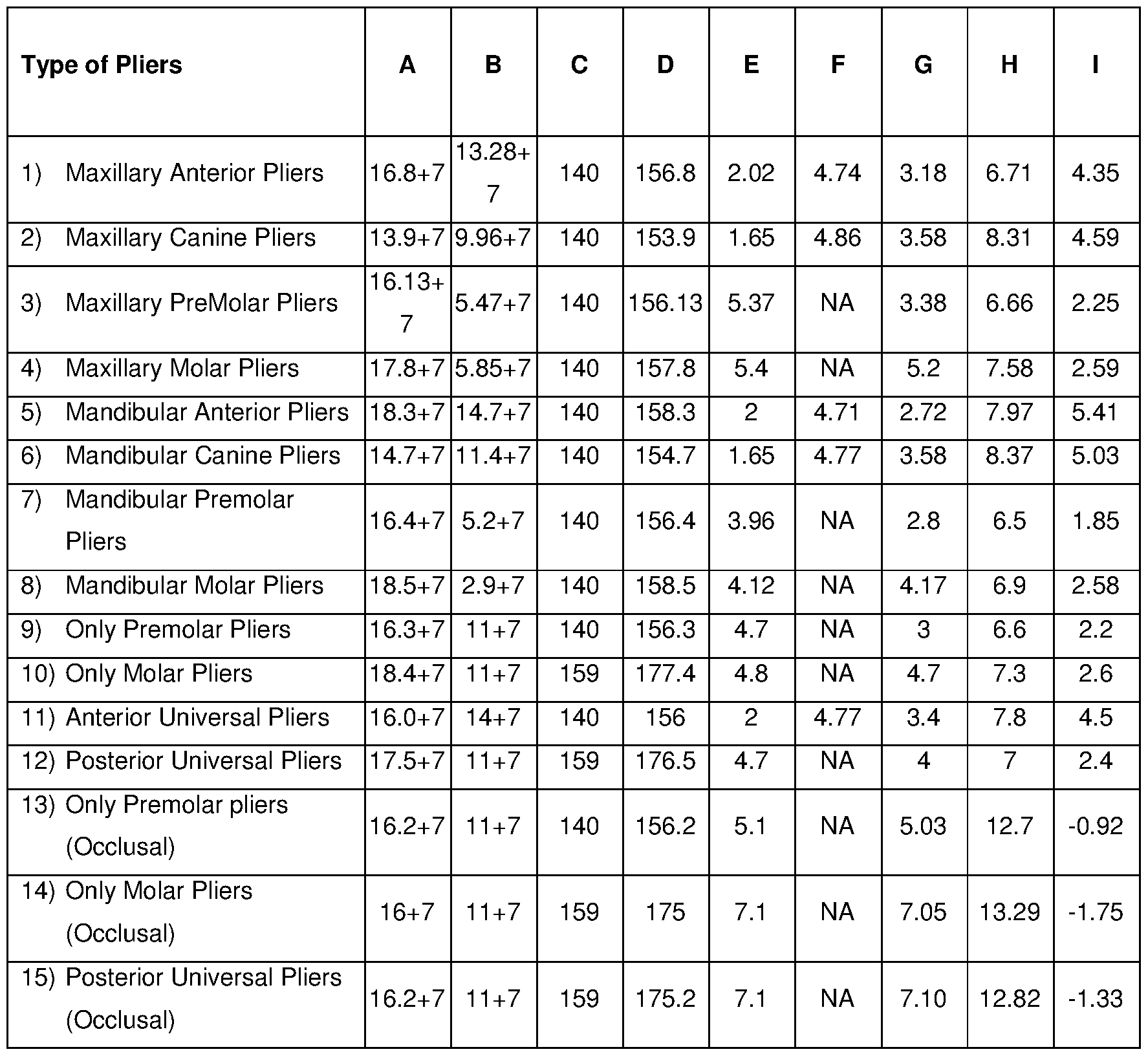
Table 1
Legend: A = Length of Occlusal Rest (“+7” refers length of the terminal part); B = Length of Active Arm (“+7” refers length of the terminal part); C = Length of Handle; D = Total Length of Pliers; E = Surface dimensions of the metal housing of occlusal rest on Lingual/Palatal side; F = Surface dimensions of the metal housing of occlusal rest on Central or Transverse; G = Surface dimensions of the metal housing of occlusal rest on Labial/Buccal side; H = Length of the Rubber Attachment; I = Depth of the Rubber Attachments (positive values indicate concavity and negative values denote convexity); NA = not applicable.
In the above table, a) Length of the Occlusal Rest (06) means the total length from one end of the metal housing (12) for the rubber attachment (07) up to the terminal part (15) of the horizontal arm (14), which gets fitted into the offset area specially designed in to the handle of the pliers. (Up to its length of 7 millimeters) This is before assembly. b) Length of the Active Arm (08) means the total length of the active arm (08) from tip of the blade (16) up to the terminal part (20) of the horizontal arm (19), which gets fitted into the offset area specially designed in to the handle of the pliers. (Up to its length of 7 millimeters). This is before assembly. c) Length of the Handle means total length of the two handle parts (assembled like a scissor). This is before assembly. d) Total length of the pliers / Device means length of the pliers from one end of the metal housing (12) for the rubber attachment (07) up to the distal end of the pliers handles. In this position, the terminal parts (15 and 20) of both occlusal rests (06) and the active arms (08) get fitted into the offset area specially designed in to the handle of the pliers. (Up to its length of 7 millimeters). { This is (C + A) -7 } This is after assembly of the device proposed herein. e) Lingual or palatal side means width of the metal housing (12) of occlusal rest (06) towards the tongue side which is in case of the mandibular teeth (lower jaw teeth). Palatal side means width of the metal housing (12) of occlusal rest (06) towards the palatal side, which is in the maxillary teeth (upper jaw teeth). f) Central or transverse means width of the metal housing (12) of the occlusal rests at their centre, where they are broader than the other two sides. This shape pertains only for the surfaces of the anterior pliers, the canines and for the anterior universal pliers. The shapes of the metal housing (12) for the pliers of premolar, molar and of posterior universal surfaces are more squarish. So, the dimensions of the surfaces of these pliers at their centre are not significantly different than the dimensions at their two sides. Hence not measured differently and not applicable for this region. g) Labial or the buccal side means width of the metal housing (12) of occlusal rest (06) towards the lips, which is in case of the maxillary and mandibular anteriors, canines and anterior universal pliers. Buccal means the width of the metal housing (12) of occlusal rest (06) towards the cheeks, which is in case of the maxillary and the mandibular premolars, molars and for the posterior universal pliers. h) Length of the rubber attachment (07): - It means the total length of the rubber attachment (07) from one side (lingual or palatal) to another side. (Labial or buccal.) i) Depth of the Rubber attachment (07): - As these rubber attachments will be getting adopted over the cuspal prominences or on the occlusal surfaces or over the incisal edges of the crowns, they are made up of the corresponding shapes. So the rubber attachments have a particular depth. That depth is measured and mentioned in the above table which is different for different pliers.
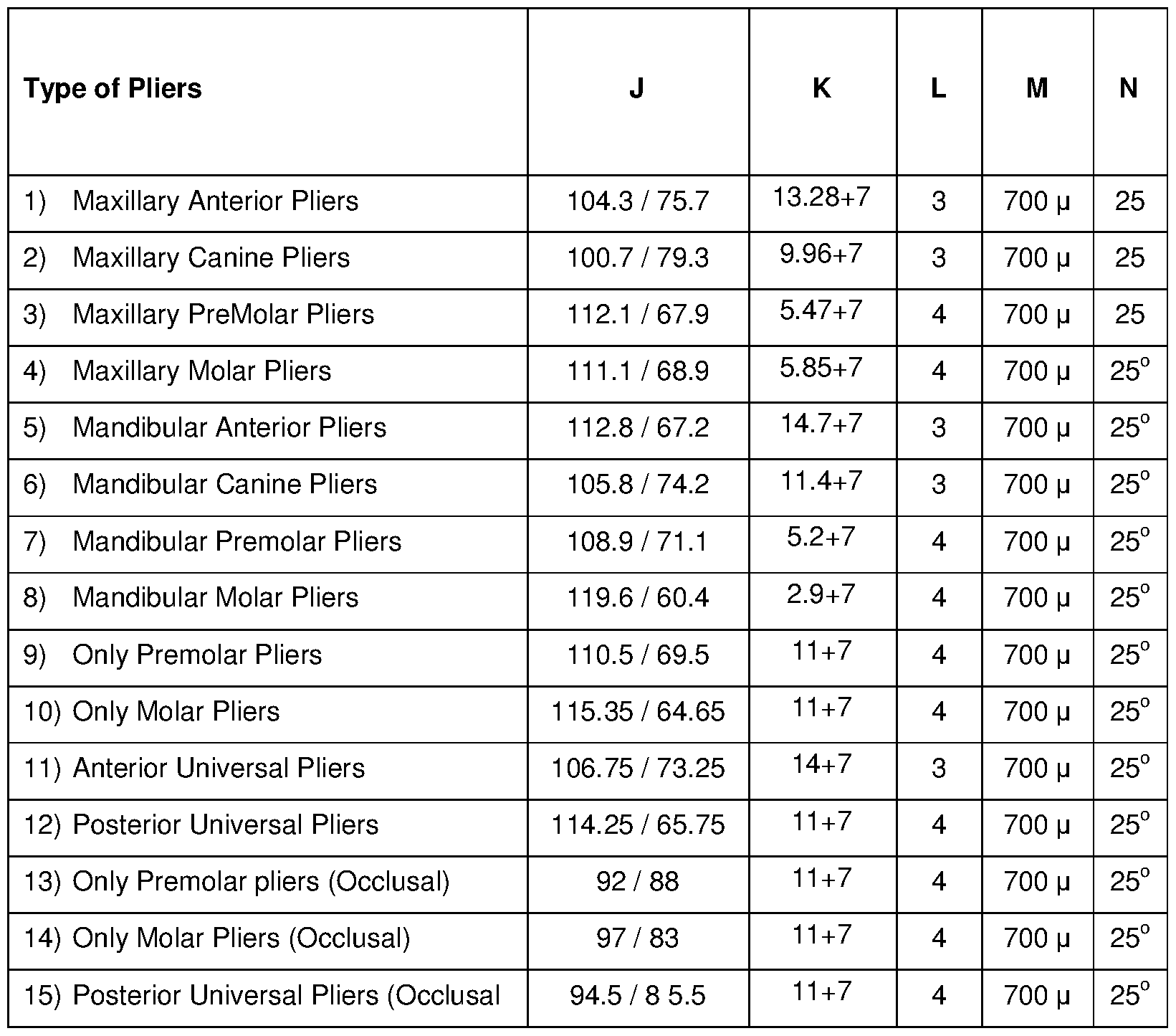
Table 2
Legend: J = Obtuse Angles / Acute Angles of the long axes of Neck of the Occlusal Rests which are in line with the long axes of the respective teeth; K = Length of Active Arm (“+7” refers length of the terminal part);; L = Width Of Blade; M = Width of the Chisel edge; N = Angle of the Edge.
In the above table, a) Obtuse angle and acute angle (as shown in Figure 10C). Every tooth is fixed into the socket of the jaw bones (maxilla and mandible) with some particular angulation in relation to the vertical and the horizontal planes. They are not at 90 degree in respect to both vertical and the horizontal planes. Every tooth has different angulations (its own long axis) in respect to the the vertical and the horizontal planes. Here the angulations of the long axes of teeth are measured in relation to the horizontal plane and the same angulations are applied for designing the neck (13) of the rest (06) and are noted down either as an obtuse angle or an acute angle and mentioned in the above table. b) Length of the Active arm (08) means the total length of the active arm (08) from tip of the blade up to the distal tip of the horizontal arm, which gets fitted into the offset area specially designed in to the jaw (05) of the pliers. (Up to its length of 7 millimeters) It’s before assembly. In this table, the
lengths of the active arms are some figures + 7 (just like 11 +7 or 14+7). This distal / terminal part of 7 millimeter gets fitted in to the offset area specially designed in the handle and fixed with either dowel pin or with press fit like arrangement. c) Width of the blade (16). The working blade (16), which is the crux of the device mentioned herein, has width of either 3 millimeter and 4 millimeters for anterior teeth and the posterior teeth respectively. d) Width of the Chisel shaped edge (17). The width of the Chisel shaped edge is 700 microns in all active arm (08) tips. But may vary from 200 microns to 1200 microns. The applicant named herein has undertaken trials to determine the efficacy of the active arm (08) having different widths of the chisel shaped blades in the range of 200 microns to 1200 microns, with the gap of 100 microns each, e) The angle / taper of the chisel edge. The angle / taper in between the two edges / sides of the chisel edge is 25 degrees in all active arm (08) tips hereof. It may also vary. From 10 degree to 60 degree. The applicant named herein has undertaken trials to determine the efficacy of the active arm (08) having different angles of edge of the chisel shaped blades in the range of 10 degree to 60 degree, with the gap of 10 degree each.
The device / each set of pliers mentioned above is characterized in having simple one-stroke operation that effectively results in removal of cemented dental crown intact (as it is) very easily in few seconds without cutting or perforating it, without causing any trauma or fracture to the underlying tooth or an implant while having application of controlled force with minimum psychological and mental stress to the patients as well as the clinician / staff.
A typical protocol of using the device / any single pliers of this invention is identified in the performance in serial of the steps comprising-
1 ) Select appropriate pliers among the set provided, as per Cover to be removed;
2) Autoclave the selected pliers before use;
3) Ensure that the occlusal rest (06) is rested over the occlusal surface, lingual / palatal cusps, or over the incisal edge of the Cover to be removed a) When the cervical margin of the crown is either at the gingival level or is supra-gingival, ensure that the tip of the active arm (08) is adapting well with the cervical margin of the crown to be removed at its deepest curvature and its chisel shaped edge of the blade is going below the cervical margin of the crown generally having thickness of 500 microns to more than 1 mm, either completely or partially and getting engaged tightly in such position; b) When the cervical margin of the crown is sub gingival, then the diagnostic probe (which is a metallic instrument having a handle and a very sharp pointed end at its angulated tip. It is very basic and the first instrument used in dentistry to identify any catch / very small cavities, irregularities present over the surface of the teeth. This is done by passing this probe over that surface, which may be visible or invisible) can be passed gently or pushed gently a bit downwards and inwards towards the crown root junction of the tooth, where the clinician can
palpate the cervical margin of the crown with the help of tip of the probe. Then said clinician can push the active arm (08) very gently towards the crown root junction so that the clinician can feel the cervical margin of the Cover with the edge (17) of the blade (16) of active arm (08). Then the active arm (08) may be engaged tightly against the cervical margin of the Cover by activating the pliers by applying little pressure over its handle c) If the crown margins are flushing with the root surface, then clinician can palpate the groove at the junction of crown margins and the root surface with the help of diagnostic probe, and feel it with the probe tip. The clinician may then make a marking at that level and make a small horizontal groove of half to one millimeter depth and 3 to 4 millimeter width using a slow speed motor just below that marked point. (Prior to this process, necessary local anesthesia is administered as a little laceration of the gingival margin is inevitable). Then, the blade (16) of the pliers may be kept in that groove below the cervical margin of the crown and engaged tightly against the cervical margin of the crown by activating the pliers by applying little pressure over its handles ) Once the pliers is activated / implemented, the clinician can feel a very firm, strong grip over the Cover to be removed with the plier / device proposed herein. Then a very little and gentle upward or the downward wrist movements are to be done in such a way that the- a) Occlusal rest (06) will get pressed over the crown to be removed. (It will deliver vertical force by pressing over the crown to be removed. This force will be passed on over the underlying natural tooth structure and will get distributed equally along its length). Application of downward vertical force over the crown will not allow any unwanted movements of the crown and will restrict its upward movement which may occur during its removal because of the application of equal and opposite force to the active arm (08), thereby holding the Cover to be removed very firmly and establishing a very good control over the device and limiting the chances of fracture of the underlying natural tooth structure over which it has been cemented b) Chisel shaped blade of the active arm (08) gets engaged below the cervical margin of the crown to be removed at its deepest curvature. This active arm will be lifted up in an upward and a bit outward direction, (exactly in the opposite direction of the path of insertion of that crown or bridge and not in the vertical direction), so that the thin film or layer of the set cementing / bonding material of approximately 50 microns (plus or minus of 20 or 30 microns) thickness gets sheared off by cracking down the film / layer. The chisel shaped design of edge of the blade, specific angle of this chisel shaped edge, and the width of the edge works like a wedge and helps into the shearing off of the set cemental / bonded material which is present in between the natural crown (tooth) and the artificial crown. Once this layer is broken at one place, it becomes very easy to lift up the crown with the same pliers because of its very firm grip over the crown c) After the Cover is removed, the pliers is to be cleaned and washed properly following standard cleaning protocol used for all other non consumable instruments used in dental clinics and autoclaved before the next use.
From the protocol mentioned above, it shall be clear that-
1) the complete process of Cover removal can be successfully undertaken within 20 seconds to a maximum of 2 minutes, once required expertise is acquired by the clinician to use the device proposed herein;
2) the Cover/s removed are preserved intact (perfectly conserved) and can be used again if no alterations are done by the clinician in the mesial, distal, buccal / labial, palatal / lingual sides of the underlying natural tooth / teeth or if the root canal treatment or re root canal treatment is being done in the underlying natural tooth and the occlusal form is maintained by proper filling of the access cavity with the help of proper filling materials. This saves the time of the patients and the doctors and avoids repetition in preparation of the Covers and costs for the patient;
3) There is virtually no need to drill or to cut down the Cover/s anywhere, thereby avoiding the cumbersome, time consuming process of cutting down the Covers made of metallic materials or metal. Cutting of the Covers also requires additional dental cutting burs and it may damages the cartridges of the dental hand pieces because of application of little pressure while cutting down those crowns, which is completely avoided in the use of the device proposed herein; Also, drilling or cutting with burs and the rotary instruments generates aerosol that contains wide range of infectious microorganisms which can potentially infect the operator, staff and the air in the surrounding atmosphere.
4) Because of the firm grip from resilient rubber attachments which gets well adapted over the occlusal surfaces of the crowns or over the lingual or palatal cusps or over the incisal edges, there are very less chances of the artificial crowns or their surfaces of getting spoiled while removing them safely with the device proposed herein;
5) Because of the controlled application of force, the procedure of removing the artificial crown is very much under control of the operator and the clinician can stop it in between if he anticipates any untoward episode or any problem in the continuation of the process; and
6) The process of removing Covers by using the device proposed herein is very easy to learn for any clinician because all clinicians are trained for handling various pliers for the extraction of teeth therein making controlled wrist movements, and the device and its protocol disclosed above makes no divergence from these already-taught skills.
In view of the application named herein, some hands- on training over models of cemented artificial crowns of the extracted natural teeth is sufficient to allow the clinician to get acquainted with the amount of force to be delivered while removing each group of tooth and the direction of the wrist movements to be done, because it differs from one group of tooth to the other. For example, in case of the posterior teeth, the crowns are bulkier and their heights are lesser than those of the anterior teeth which are slender and having more heights. Therefore the verticals movements required to be done in posterior teeth in order to lift the crown upward are lesser but with a bit more force than the vertical movements required to be done in the anterior teeth which requires application of gentle force.
It shall be understood that after some autoclave cycles or after some uses, the rubber attachment (07) may get spoiled. At that time, that rubber attachment (07) has to be removed and then replaced with the new one, via a quick single press-fit motion which does not require any specific skills or tooling.
Because of the unique design of the device proposed herein, replacement of the rubber attachment (07) is very easy task and takes less than a minute’s time. The stalk (10) of the rubber attachment (07) along with terminal ring (11) is to be passed through the hollow space (23) specially designed in the angulated neck (13) of the occlusal rest (06). With application of gentle pressure, it comes out through the opening over the top surface of the rest (06) and its area of terminal locking ring gets fitted and stuck over there, (because its diameter is 400 microns more than the diameter of the hollow space (23), Once it goes and fits into the locking area in the horizontal arm (14) of the occlusal rest (06), it cannot come back again) thereby completing replacement of the rubber attachment (07) in a quick, easy and tool less manner.
In the foregoing narration, all pliers mentioned above are designed to work in a position where the working field (here occlusal plane of the patient) is parallel to the floor. The main working unit of the device proposed herein is the chisel shaped edge of the blade of the active arm (08). When we say about the upward movements or downward movements of the device proposed herein in position refers to the upward movements or the downward movements of the active arm (08) in respect to the occlusal plane which is horizontal. For the removal of the Covers from the lower jaws (mandible), the plier / device proposed herein should be moved in upward direction. For the removal of Covers from the upper jaw (maxilla), the plier / device proposed herein should be moved in downward direction. In short, very small wrist movements are done in vertical directions to bring about these upward and the downward movements of the active arm (08) of the device proposed herein.
As will be realized, the present invention does away with conventional practices of Cover removal, namely cutting (with dental diamond coated / carbide burs), Perforation (with specialized equipment), application of torque via uncontrolled, jerky movements (with spring loaded equipment available in the field), which many times results into fracture of the underlined tooth (specially root canal treated) and many times failure to remove the Cover without damage to said Covers.
As will be realized further, the present invention is capable of various other embodiments and that its several components and related details are capable of various alterations, all without departing from the basic concept of the present invention. Accordingly, the foregoing description will be regarded as illustrative in nature and not as restrictive in any form whatsoever.
Modifications and variations of the system and apparatus described herein will be obvious to those skilled in the art. Such modifications and variations are intended to come within ambit of the present invention, which is limited only by the appended claims.
Claims
Claims
I claim,
1) A device, being a set of pliers in particular, for atraumatic removal of a dental cover, comprising- a) A pair of opposing arms (01 and 02) made of medical grade stainless steel, SS304 or SS316L in particular, and connected along their lengths at a pivot (03) to result in an arrangement characterized in forming a handle at one side of the pivot (03) and a pair of jaw members (04 and 05) having an offset area of elliptical shape on the other side of said pivot (03); b) An rest (06) made of medical grade steel and received at distal end of the jaw member (04) for resting on a surface chosen between the occlusal surfaces of molars and premolars and the incisal edges of canines and incisors, to thereby allow a clinician to have a firm grip over the dental cover being removed; and c) An active arm (08) made of medical grade steel and received at distal end of the jaw member (05), said active arm (08) being characterized in being contoured and angled to coincide with base of the labial and buccal margins of the Cover to be removed to thereby allow a clinician to apply controlled force for removal of the dental cover.
2) The device, being a set of pliers in particular, for atraumatic removal of a dental cover as claimed in claim 1 , wherein the rest (06) consists of- a) A terminal part (15) for allowing the rest (06) to be removably received at distal end of the jaw member (04); and b) A horizontal arm (14) in continuation to the distal end of the terminal part (15) for attachment of an angulated neck (13) and a dome shaped metal housing (12) to thereby receive a resilient and deformable rubber attachment (07).
3) The device, being a set of pliers in particular, for atraumatic removal of a dental cover as claimed in claim 2, wherein the resilient and deformable rubber attachment (07) is made of a material chosen among medical grade silicone rubber and thermoplastic silicone, and consists of- a) An adapting surface (09) of 2 mm thickness which is shaped and sized to complement and coincide with one among incisal edge, occlusal surface, and lingual and palatal cusp of the dental cover to be removed to thereby increase the grip of the pliers over the dental cover to be removed; b) a terminal locking ring (11 ) at a length from the adapting surface (09) for securely holding the resilient and deformable rubber attachment (07) within the metal housing (12); and c) a stalk (10) of diameter 3 mm for spanning the length between, and therein interconnecting, the adapting surface (09) and the terminal locking ring (11 ) with each other.
4) The device, being a set of pliers in particular, for atraumatic removal of a dental cover as claimed in claim 2, wherein the terminal part (15) is dimensioned to have a 7mm length, 5.6 mm breadth and 3 mm thickness and draft of 1 % for allowing the rest (06) to be received within an offset area of the jaw member (04).
5) The device, being a set of pliers in particular, for atraumatic removal of a dental cover as claimed in claim 2 and 3, wherein the horizontal arm (14) is provisioned on its top surface with an internal sit area (22) of diameter of 3.4 mm and depth of 1.4 mm for accommodating the terminal locking ring (11) of the deformable rubber attachment (07), whereby the deformable rubber attachment (07) is prevented from being released once the terminal locking ring (11) is locked within said sit area.
6) The device, being a set of pliers in particular, for atraumatic removal of a dental cover as claimed in claims 2, wherein the angulated neck (13) is a cylinder of 4.4 mm diameter enclosing a hollow space (23) of 3 mm diameter along its long axis, said angulated neck (13) is casted one piece with, and connected with the horizontal arm (14) at an angle which corresponds to- a) the angle of the long axis of a tooth in case of the occlusal and incisal rests; and b) the long axis of the lingual / palatal cusps, in case of the lingual and palatal rests.
7) The device, being a set of pliers in particular, for atraumatic removal of a dental cover as claimed in claim 2 and 3, wherein the metal housing (12) is shaped and sized as per the rubber attachment (07) to be received and characterized in being provisioned with an internal contoured recess which opens into the hollow space (23), provisioned into the angulated neck (13) for securely receiving the rubber attachment (07) in a releasable press-fit arrangement with help of the terminal locking ring (11 ).
8) The device, being a set of pliers in particular, for atraumatic removal of a dental cover as claimed in claim 1 , wherein the active arm (08) consists of- a) A terminal part (20) for allowing the active arm (08) to be removably received at distal end of the jaw member (05); and b) A horizontal arm (19) in continuation to the distal end of the terminal part (20) for attachment of a body (18) which in turn leads to an edge (17) and a blade (16).
9) The device, being a set of pliers in particular, for atraumatic removal of a dental cover as claimed in claim 8, wherein the terminal part (20) is elliptical in shape and dimensioned to have a 7mm length, 5.6 mm breadth and 3 mm thickness and draft of 1 % for allowing the active arm (08) to be received within an offset area of the jaw member (05).
10) The device, being a set of pliers in particular, for atraumatic removal of a dental cover as claimed in claim 8, wherein the body (18) is the broad area in between the blade (16) and the
horizontal arm (19) which continues forward and downward divergently, therein serving to provide strength to the blade (16) as well as to the active arm (08).
11) The device, being a set of pliers in particular, for atraumatic removal of a dental cover as claimed in claim 8, wherein the blade (16) is the main active area of the device, having a chisel shaped edge (17).
12) The device, being a set of pliers in particular, for atraumatic removal of a dental cover as claimed in claim 1 , wherein the arm members (01 and 02) are of different hardness to the rest (06) and active arm (08).
13) The device, being a set of pliers in particular, for atraumatic removal of a dental cover as claimed in claim 1 , wherein the rest (06) and active arm (08) are received at the the opposing jaws (04 and 05) respectively via releasable means chosen between screws and insertable pins that are received via coinciding orifices (21) of 2mm diameter drilled centrally through the bodies of said rest (06), active arm (08), terminal parts (15 and 20) and the opposing jaws (04 and 05) to thereby result in the rest (06), active arm (08) to sit flush within the bodies of the opposing jaws (04 and 05) respectively.
14) The device, being a set of pliers in particular, for atraumatic removal of a dental cover as claimed in claim 1 , wherein the rest (06) and active arm (08) are permanently associated via casting in one piece respectively with the opposing jaws (04 and 05) wherein material of the rest (06), active arm (08) and opposing jaws (04 and 05) is selected between the same or different grades of medical grade steel.
15) The device, being a set of pliers in particular, for atraumatic removal of a dental cover as claimed in claim 1 , wherein the rest (06) and active arm (08) are permanently associated by means of metal-to-metal bonding adhesive chosen among Anabond and its equivalents.
16) The device, being a set of pliers in particular, for atraumatic removal of a dental cover as claimed in claim 1 and any one of the preceding claims, characterized in having- a) a rest (06) of length 16.8 mm; an active Arm (8) of length 13.28 mm; length of handle made by arms (01 and 02) of 140 mm; total Length of Pliers 156.8 mm; Surface dimensions of the rest (06) on Lingual/Palatal side of 2.02 mm; Surface dimensions of the rest (06) on Central or Transverse of 4.74 mm; Surface dimensions of the rest (06) on Labial/Buccal side of 3.18 mm; Length of the Rubber Attachment (07) of 6.71 mm; Depth of the Rubber Attachment (07) of 4.35 mm; 104.3° obtuse and 75.7° acute angles of the long axes of Neck (13) of the Rests (06) which are in line with the long axes of the respective teeth; Width Of Blade 3 mm; Width of the Chisel edge (17) 700 m; and Angle of the Edge (17) 25° in the event said set of pliers is to be used for removal of dental covers affixed over maxillary anterior teeth;
b) a rest (06) of length 13.9 mm; an active Arm (8) of length 9.96 mm; length of handle made by arms (01 and 02) of 140 mm; total Length of Pliers 153.9 mm; Surface dimensions of the rest (06) on Lingual/Palatal side of 1.65 mm; Surface dimensions of the rest (06) on Central or Transverse of 4.86 mm; Surface dimensions of the rest (06) on Labial/Buccal side of 3.58 mm; Length of the Rubber Attachment (07) of 8.31 mm; Depth of the Rubber Attachment (07) of 4.59 mm; 100.7 0 obtuse and 79.3° acute angles of the long axes of Neck (13) of the Rests (06) which are in line with the long axes of the respective teeth; Width Of Blade 3 mm; Width of the Chisel edge (17) 700 m; and Angle of the Edge (17) 25° in the event said set of pliers is to be used for removal of dental covers affixed over Maxillary Canines; c) a rest (06) of length 16.13 mm; an active Arm (8) of length 5.47 mm; length of handle made by arms (01 and 02) of 140 mm; total Length of Pliers 156.13 mm; Surface dimensions of the rest (06) on Lingual/Palatal side of 5.37 mm; Surface dimensions of the rest (06) on Labial/Buccal side of 3.38 mm; Length of the Rubber Attachment (07) of 6.66 mm; Depth of the Rubber Attachment (07) of 2.25 mm; 112.1° obtuse and 67.9° acute angles of the long axes of Neck (13) of the Rests (06) which are in line with the long axes of the respective teeth passing through the lingual or palatal cusps in case of mandibular or maxillary jaw respectively; Width Of Blade 4 mm; Width of the Chisel edge (17) 700 m; and Angle of the Edge (17) 25° in the event said set of pliers is to be used for removal of dental covers affixed over Maxillary PreMolars; d) a rest (06) of length 17.8 mm; an active Arm (8) of length 5.85 mm; length of handle made by arms (01 and 02) of 140 mm; total Length of Pliers 157.8 mm; Surface dimensions of the rest (06) on Lingual/Palatal side of 5.4 mm; Surface dimensions of the rest (06) on Labial/Buccal side of 5.2 mm; Length of the Rubber Attachment (07) of 7.58 mm; Depth of the Rubber Attachment (07) of 2.59 mm; 111.1° obtuse and 68.9° acute angles of the long axes of Neck (13) of the Rests (06) which are in line with the long axes of the respective teeth passing through the lingual or palatal cusps in case of mandibular or maxillary jaw respectively; Width Of Blade 4 mm; Width of the Chisel edge (17) 700 m; and Angle of the Edge (17) 25° in the event said set of pliers is to be used for removal of dental covers affixed over Maxillary Molars; e) a rest (06) of length 18.3 mm; an active Arm (8) of length 14.7 mm; length of handle made by arms (01 and 02) of 140 mm; total Length of Pliers 158.3 mm; Surface dimensions of the rest (06) on Lingual/Palatal side of 2 mm; Surface dimensions of the rest (06) on Central or Transverse of 4.71 mm; Surface dimensions of the rest (06) on Labial/Buccal side of 2.72 mm; Length of the Rubber Attachment (07) of 7.97 mm; Depth of the Rubber Attachment (07) of 5.41 mm; 112.8° obtuse and 67.2° acute angles of the long axes of Neck (13) of the Rests (06) which are in line with the long axes of the respective teeth; Width Of Blade 3 mm; Width of the Chisel edge (17)
700 m; and Angle of the Edge (17) 25° in the event said set of pliers is to be used for removal of dental covers affixed over Mandibular Anterior teeth; f) a rest (06) of length 14.7 mm; an active Arm (8) of length 11 .4 mm; length of handle made by arms (01 and 02) of 140 mm; total Length of Pliers 154.7 mm; Surface dimensions of the rest (06) on Lingual/Palatal side of 1.65 mm; Surface dimensions of the rest (06) on Central or Transverse of 4.77 mm; Surface dimensions of the rest (06) on Labial/Buccal side of 3.58 mm; Length of the Rubber Attachment (07) of 8.37 mm; Depth of the Rubber Attachment (07) of 5.03 mm; 105.8° obtuse and 74.2° acute angles of the long axes of Neck (13) of the Rests (06) which are in line with the long axes of the respective teeth; Width Of Blade 3 mm; Width of the Chisel edge (17) 700 m; and Angle of the Edge (17) 25° in the event said set of pliers is to be used for removal of dental covers affixed over Mandibular Canines; g) a rest (06) of length 16.4 mm; an active Arm (8) of length 5.2 mm; length of handle made by arms (01 and 02) of 140 mm; total Length of Pliers 156.4 mm; Surface dimensions of the rest (06) on Lingual/Palatal side of 3.96 mm; Surface dimensions of the rest (06) on Labial/Buccal side of 2.8 mm; Length of the Rubber Attachment (07) of 6.5 mm; Depth of the Rubber Attachment (07) of 1.85 mm; 108.9° obtuse and 71.1° acute angles of the long axes of Neck (13) of the Rests (06) which are in line with the long axes of the respective teeth passing through the lingual or palatal cusps in case of mandibular or maxillary jaw respectively; Width Of Blade 4 mm; Width of the Chisel edge (17) 700 m; and Angle of the Edge (17) 25° in the event said set of pliers is to be used for removal of dental covers affixed over Mandibular Premolars; h) a rest (06) of length 18.5 mm; an active Arm (8) of length 2.9 mm; length of handle made by arms (01 and 02) of 140 mm; total Length of Pliers 158.5 mm; Surface dimensions of the rest (06) on Lingual/Palatal side of 4.12 mm; Surface dimensions of the rest (06) on Labial/Buccal side of 4.17 mm; Length of the Rubber Attachment (07) of 6.9 mm; Depth of the Rubber Attachment (07) of 2.58 mm; 119.6° obtuse and 60.4° acute angles of the long axes of Neck (13) of the Rests (06) which are in line with the long axes of the respective teeth passing through the lingual or palatal cusps in case of mandibular or maxillary jaw respectively; Width Of Blade 4 mm; Width of the Chisel edge (17) 700 m; and Angle of the Edge (17) 25° in the event said set of pliers is to be used for removal of dental covers affixed over Mandibular Molars; i) a rest (06) of length 16.3 mm; an active Arm (8) of length 11 mm; length of handle made by arms (01 and 02) of 140 mm; total Length of Pliers 156.3 mm; Surface dimensions of the rest (06) on Lingual/Palatal side of 4.7 mm; Surface dimensions of the rest (06) on Labial/Buccal side of 3 mm; Length of the Rubber Attachment (07) of 6.6 mm; Depth of the Rubber Attachment (07) of 2.2 mm; 110.5 ° obtuse and 69.5° acute angles of the long axes of Neck (13) of the Rests (06) which are in line with the long axes of the respective teeth passing through the lingual or palatal cusps in case of mandibular or maxillary jaw respectively; Width Of Blade 4 mm; Width of the Chisel
edge (17) 700 m; and Angle of the Edge (17) 25° in the event said set of pliers is to be used for removal of dental covers affixed exclusively over Premolars; j) a rest (06) of length 18.4 mm; an active Arm (8) of length 11 mm; length of handle made by arms (01 and 02) of 159 mm; total Length of Pliers 177.4 mm; Surface dimensions of the rest (06) on Lingual/Palatal side of 4.8mm; Surface dimensions of the rest (06) on Labial/Buccal side of 4.7 mm; Length of the Rubber Attachment (07) of 7.3 mm; Depth of the Rubber Attachment (07) of 2.6 mm; 115.35° obtuse and 64.65° acute angles of the long axes of Neck (13) of the Rests (06) which are in line with the long axes of the respective teeth passing through the lingual or palatal cusps in case of mandibular or maxillary jaw respectively; Width Of Blade 4 mm; Width of the Chisel edge (17) 700 m; and Angle of the Edge (17) 25° in the event said set of pliers is to be used for removal of dental covers affixed exclusively over molars; k) a rest (06) of length 16.0 mm; an active Arm (8) of length 14 mm; length of handle made by arms (01 and 02) of 140 mm; total Length of Pliers 156 mm; Surface dimensions of the rest (06) on Lingual/Palatal side of 2mm; Surface dimensions of the rest (06) on Central or Transverse of 4.77 mm; Surface dimensions of the rest (06) on Labial/Buccal side of 3.4 mm; Length of the Rubber Attachment (07) of 7.8 mm; Depth of the Rubber Attachment (07) of 4.5 mm; 106.75° obtuse and 73.25° acute angles of the long axes of Neck (13) of the Rests (06) which are in line with the long axes of the respective teeth; Width Of Blade 3 mm; Width of the Chisel edge (17) 700 m; and Angle of the Edge (17) 25° in the event said set of pliers is to be used for removal of dental covers affixed over any of the anterior teeth;
L) a rest (06) of length 17.5 mm; an active Arm (8) of length 11 mm; length of handle made by arms (01 and 02) of 159 mm; total Length of Pliers 176.5 mm; Surface dimensions of the rest (06) on Lingual/Palatal side of 4.7mm; Surface dimensions of the rest (06) on Labial/Buccal side of 4 mm; Length of the Rubber Attachment (07) of 7 mm; Depth of the Rubber Attachment (07) of 2.4 mm; 114.25° obtuse and 65.75° acute angles of the long axes of Neck (13) of the Rests (06) which are in line with the long axes of the respective teeth passing through the lingual or palatal cusps in case of mandibular or maxillary jaw respectively; Width Of Blade 4 mm; Width of the Chisel edge (17) 700 m; and Angle of the Edge (17) 25° in the event said set of pliers is to be used for removal of dental covers affixed over any of the Posterior teeth; m) a rest (06) of length 16.2 mm; an active Arm (8) of length 11 mm; length of handle made by arms (01 and 02) of 140 mm; total Length of Pliers 156.2 mm; Surface dimensions of the rest (06) on Lingual/Palatal side of 5.1 mm; Surface dimensions of the rest (06) on Labial/Buccal side of 5.03 mm; Length of the Rubber Attachment (07) of 12.7 mm; Depth of the Rubber Attachment (07) of -0.92 mm; 92° obtuse and 88° acute angles of the long axes of Neck (13) of the Rests (06) which are in line with the long axes drawn through the centre of the respective teeth; Width Of Blade 4 mm; Width of the Chisel edge (17) 700 m; and Angle of the Edge (17) 25° in the event said
set of pliers is to be used for removal of dental covers affixed exclusively over Occlusal Premolars; n) a rest (06) of length 16 mm; an active Arm (8) of length 11 mm; length of handle made by arms (01 and 02) of 159 mm; total Length of Pliers 175 mm; Surface dimensions of the rest (06) on Lingual/Palatal side of 7.1 mm; Surface dimensions of the rest (06) on Labial/Buccal side of 7.05 mm; Length of the Rubber Attachment (07) of 13.29 mm; Depth of the Rubber Attachment (07) of -1.75 mm; 97° obtuse and 83° acute angles of the long axes of Neck (13) of the Rests (06) which are in line with the long axes drawn through the centre of the respective teeth; Width Of Blade 4 mm; Width of the Chisel edge (17) 700 m; and Angle of the Edge (17) 25° in the event said set of pliers is to be used for removal of dental covers affixed exclusively over Occlusal Molars; o) a rest (06) of length 16.2 mm; an active Arm (8) of length 11 mm; length of handle made by arms (01 and 02) of 159 mm; total Length of Pliers 175.2 mm; Surface dimensions of the rest (06) on Lingual/Palatal side of 7.1 mm; Surface dimensions of the rest (06) on Labial/Buccal side of 7.10 mm; Length of the Rubber Attachment (07) of 12.82 mm; Depth of the Rubber Attachment (07) of -1.33 mm; 94.5° obtuse and 85.5° acute angles of the long axes of Neck (13) of the Rests (06) which are in line with the long axes drawn through the centre of the respective teeth; Width Of Blade 4 mm; Width of the Chisel edge (17) 700 m; and Angle of the Edge (17) 25° in the event said set of pliers is to be used for removal of dental covers affixed over Occlusal Posterior teeth.
17) The device, being a set of pliers in particular, for atraumatic removal of a dental cover as claimed in claim 1 , wherein the handle formed by arms (01 and 02) is angulated via two successive and opposing turns of 115° positioned at 119 mm along the lengths of both arms (01 and 02), said turns being separated by a distance of 25 mm, to thus allow arms (01 and 02) be parallel to the jaws (04 and 05) for ease of reach at 90° angle in the case of the set of pliers for molars and the molar universal pliers.
Applications Claiming Priority (2)
| Application Number | Priority Date | Filing Date | Title |
|---|---|---|---|
| IN201921033764 | 2019-09-22 | ||
| IN201921033764 | 2019-09-22 |
Publications (1)
| Publication Number | Publication Date |
|---|---|
| WO2021053566A1 true WO2021053566A1 (en) | 2021-03-25 |
Family
ID=74884604
Family Applications (1)
| Application Number | Title | Priority Date | Filing Date |
|---|---|---|---|
| PCT/IB2020/058660 Ceased WO2021053566A1 (en) | 2019-09-22 | 2020-09-17 | Device for atraumatic removal of dental crowns and bridges |
Country Status (1)
| Country | Link |
|---|---|
| WO (1) | WO2021053566A1 (en) |
Cited By (1)
| Publication number | Priority date | Publication date | Assignee | Title |
|---|---|---|---|---|
| US12496174B1 (en) * | 2025-04-23 | 2025-12-16 | King Saud University | Handheld vise for dental crowns |
Citations (2)
| Publication number | Priority date | Publication date | Assignee | Title |
|---|---|---|---|---|
| US1628499A (en) * | 1924-10-20 | 1927-05-10 | Joesch Bernhard | Dental appliance |
| US6280184B1 (en) * | 2000-03-16 | 2001-08-28 | David C. Hamilton | Method and apparatus for removing bonded dental appliances |
-
2020
- 2020-09-17 WO PCT/IB2020/058660 patent/WO2021053566A1/en not_active Ceased
Patent Citations (2)
| Publication number | Priority date | Publication date | Assignee | Title |
|---|---|---|---|---|
| US1628499A (en) * | 1924-10-20 | 1927-05-10 | Joesch Bernhard | Dental appliance |
| US6280184B1 (en) * | 2000-03-16 | 2001-08-28 | David C. Hamilton | Method and apparatus for removing bonded dental appliances |
Cited By (1)
| Publication number | Priority date | Publication date | Assignee | Title |
|---|---|---|---|---|
| US12496174B1 (en) * | 2025-04-23 | 2025-12-16 | King Saud University | Handheld vise for dental crowns |
Similar Documents
| Publication | Publication Date | Title |
|---|---|---|
| US6309219B1 (en) | Periotome | |
| ES2325478T3 (en) | PSEUDOGRABADO OF A DENTAL PREPARATION TOOL FOR THE CARBON COVERED OSTEOTOMY SIMILAR TO THE DIAMOND. | |
| JP6363155B2 (en) | Soft tissue preservation structure | |
| CN102316818B (en) | Systems, methods and devices for implementing dental implants | |
| US5915962A (en) | Dental implant and prosthesis positioning | |
| US7153132B2 (en) | Mini-dental implant surgical stent | |
| US6280184B1 (en) | Method and apparatus for removing bonded dental appliances | |
| US20160074135A1 (en) | Adjustable dental hand instrument | |
| US5538421A (en) | Dental instrument | |
| US11576749B2 (en) | Dental surgery method and device | |
| US20110045435A1 (en) | Dental pliers | |
| Johnson et al. | Basics of dental technology: a step by step approach | |
| EP3827782B1 (en) | Dental implantology tool for installing a prosthetic abutment | |
| US6626670B1 (en) | Powered periotome | |
| US20030186193A1 (en) | Hand-held medical/dental tool | |
| WO2021053566A1 (en) | Device for atraumatic removal of dental crowns and bridges | |
| AU2020217424B2 (en) | Dental retractor with micro mirror | |
| EP3752090B1 (en) | Dental surgery device | |
| AU2017348872B2 (en) | Surgical instrument | |
| CN109692049B (en) | A hand-held device for slicing sand strips | |
| CA2390165A1 (en) | Periotome | |
| US9326828B2 (en) | Dental device | |
| AU2020201283B2 (en) | Dental surgery method and device | |
| WO2025014509A1 (en) | Dental abutment insert extraction and insertion tool |
Legal Events
| Date | Code | Title | Description |
|---|---|---|---|
| 121 | Ep: the epo has been informed by wipo that ep was designated in this application |
Ref document number: 20866330 Country of ref document: EP Kind code of ref document: A1 |
|
| NENP | Non-entry into the national phase |
Ref country code: DE |
|
| 122 | Ep: pct application non-entry in european phase |
Ref document number: 20866330 Country of ref document: EP Kind code of ref document: A1 |