WO2021046743A1 - Systems and methods for smoke-reduction in images - Google Patents
Systems and methods for smoke-reduction in images Download PDFInfo
- Publication number
- WO2021046743A1 WO2021046743A1 PCT/CN2019/105311 CN2019105311W WO2021046743A1 WO 2021046743 A1 WO2021046743 A1 WO 2021046743A1 CN 2019105311 W CN2019105311 W CN 2019105311W WO 2021046743 A1 WO2021046743 A1 WO 2021046743A1
- Authority
- WO
- WIPO (PCT)
- Prior art keywords
- image
- pixel
- pixels
- value
- atmospheric light
- Prior art date
- Legal status (The legal status is an assumption and is not a legal conclusion. Google has not performed a legal analysis and makes no representation as to the accuracy of the status listed.)
- Ceased
Links
Images


Classifications
-
- G—PHYSICS
- G06—COMPUTING OR CALCULATING; COUNTING
- G06T—IMAGE DATA PROCESSING OR GENERATION, IN GENERAL
- G06T5/00—Image enhancement or restoration
- G06T5/73—Deblurring; Sharpening
-
- G—PHYSICS
- G06—COMPUTING OR CALCULATING; COUNTING
- G06T—IMAGE DATA PROCESSING OR GENERATION, IN GENERAL
- G06T7/00—Image analysis
- G06T7/90—Determination of colour characteristics
-
- G—PHYSICS
- G06—COMPUTING OR CALCULATING; COUNTING
- G06T—IMAGE DATA PROCESSING OR GENERATION, IN GENERAL
- G06T2207/00—Indexing scheme for image analysis or image enhancement
- G06T2207/10—Image acquisition modality
- G06T2207/10024—Color image
-
- G—PHYSICS
- G06—COMPUTING OR CALCULATING; COUNTING
- G06T—IMAGE DATA PROCESSING OR GENERATION, IN GENERAL
- G06T2207/00—Indexing scheme for image analysis or image enhancement
- G06T2207/10—Image acquisition modality
- G06T2207/10068—Endoscopic image
-
- H—ELECTRICITY
- H04—ELECTRIC COMMUNICATION TECHNIQUE
- H04N—PICTORIAL COMMUNICATION, e.g. TELEVISION
- H04N1/00—Scanning, transmission or reproduction of documents or the like, e.g. facsimile transmission; Details thereof
- H04N1/46—Colour picture communication systems
- H04N1/56—Processing of colour picture signals
- H04N1/60—Colour correction or control
Definitions
- the present disclosure relates to devices, systems and methods for smoke-reduction in images, and more particularly, to smoke-reduction in images during surgical procedures.
- Endoscopes are introduced through an incision or a natural body orifice to observe internal features of a body.
- Conventional endoscopes are used for visualization during endoscopic or laparoscopic surgical procedures.
- smoke it is possible for smoke to be generated when the energy surgical instrument is used, for example, to cut tissue with electrosurgical energy during the surgery.
- the image acquired by the endoscope may become blurry because of this smoke.
- the smoke may obscure features of the surgical site and delay the surgical procedure while surgeons wait for the smoke to clear.
- Other procedures may experience similar issues where smoke is present during the capture of an image. Accordingly, there is interest in improving imaging technology.
- a method for smoke reduction in images includes accessing an RGB image of an object obscured by smoke, determining a dark channel matrix of the RGB image, estimating an atmospheric light matrix for the RGB image based on the dark channel, determining a transmission map based on the atmospheric light matrix and the dark channel matrix, de-hazing the RGB image based on the transmission map to reduce the smoke in the RGB image, and displaying the de-hazed RGB image on a display device.
- the RGB image includes a plurality of pixels.
- the dark channel matrix includes, for each pixel of the plurality of pixels, a minimum color component intensity for a respective pixel area centered at the respective pixel.
- the atmospheric light matrix includes an atmospheric light component value for each of the plurality of pixels.
- the de-hazing the RGB image includes converting the RGB image to a YUV image, performing a de-hazing operation on the YUV image to provide a Y′UV image, and converting the Y′UV image to the de-hazed RGB image.
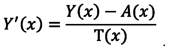
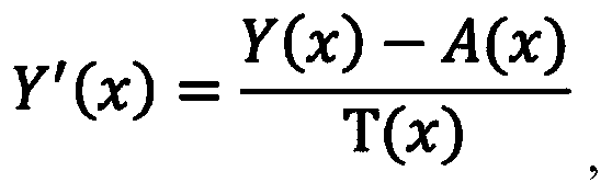
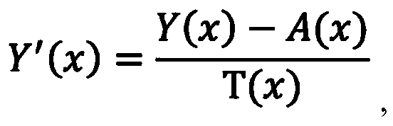
- the performing the de-hazing operation on the YUV image includes, for each pixel x of the plurality of pixels, determining Y′as T(x) is a transmission component for the pixel x.
- a (x) is the atmospheric light component value for the pixel x.
- the performing the de-hazing operation on the YUV image further includes replacing a Y channel of the YUV image with the determined Y′to provide a Y′UV image.
- the determining the transmission map includes determining, for each pixel x of the plurality of pixels, a transmission component as: Where ⁇ is a predetermined constant, I_DARK (x) is the dark channel matrix value for the pixel x, and A (x) is the atmospheric light component value for the pixel x.
- a method for smoke reduction in images includes accessing an image obscured by smoke, for each pixel of the plurality of pixels: (i) determining a dark channel matrix value for the respective pixel as a minimum color component intensity value for a respective pixel area centered at the respective pixel, and (ii) estimating an atmospheric light component value for the pixel x based on the minimum color component intensity value for each pixel of the pixel area, de-hazing the image based on the atmospheric light component values for the plurality of pixels, and displaying the de-hazed image on a display device.
- the image includes a plurality of pixels, where each pixel of the image includes a plurality of color components.
- the de-hazing the image includes determining a transmission map value for each pixel x of the plurality of pixels as: converting the image to a YUV image, determining Y′for each pixel x of the plurality of pixels as and replacing a Y channel of the YUV image with the determined Y′to provide a Y′UV image, where ⁇ is a predetermined constant, I_DARK (x) is the dark channel matrix value for the pixel x, and A (x) is the atmospheric light component value for the pixel x.
- the de-hazing the image further includes converting the Y′UV image to a de-hazed image.
- the image includes at least one of an RGB image, a CMYK image, a CIELAB image, or a CIEXYZ image.
- a system for smoke reduction in images may include a light source configured to provide light, an imaging device configured to acquire images, an imagining device control unit configured to control the imaging device.
- the image includes a plurality of pixels, where each pixel of the image may include a plurality of color components.
- the control unit may include a processor and a memory storing instructions.
- the instructions which, when executed by the processor, causes the system to access the image, for each of the pixels: determine a dark channel matrix value for the respective pixel as a minimum color component intensity value for a respective pixel area centered at the respective pixel, and estimate an atmospheric light component value for each pixel based on the minimum color component intensity value for each pixel of the pixel area, de-haze the image based on the atmospheric light component value for each of the pixels, and display the de-hazed image on a display device.
- the instructions when de-hazing the image may further cause the system to determine a transmission map value for each pixel x of the plurality of pixels as convert the image to a YUV image, determine Y′ as and replace a Y channel of the YUV image with the determined Y′ to provide a Y′UV image, where ⁇ is a predetermined constant, I_DARK (x) is the dark channel matrix value for the pixel x, and A (x) is the atmospheric light component value for the pixel x.
- the instructions when de-hazing the image may further cause the system to convert the Y′UV image to a de-hazed image.
- the image includes at least one of an RGB image, a CMYK image, a CIELAB image, or a CIEXYZ image.
- a (x) max (min (I c (y) ) * coef, for all y ⁇ ⁇ (x) .
- I c (y) is an intensity value of a color component c of the pixel y
- coef is a predetermined coefficient value.
- FIG. 1 is a diagram of an exemplary visualization or endoscope system in accordance with the present disclosure
- FIG. 2 is a schematic configuration of the visualization or endoscope system of FIG. 1;
- FIG. 3 is a diagram illustrating another schematic configuration of an optical system of the system of FIG. 1;
- FIG. 4 is a schematic configuration of the visualization or endoscope system in accordance with an embodiment of the present disclosure
- FIG. 5 is a flowchart of a method for smoke reduction in accordance with an exemplary embodiment of the disclosure
- FIG. 6 is an exemplary input image including an area of pixels in accordance with the present disclosure.
- FIG. 7 is a flowchart of a method for performing de-hazing in accordance with the disclosure.
- FIG. 8 is an exemplary image with smoke in accordance with the present disclosure.
- FIG. 9 is an exemplary de-hazed image with constant atmospheric light.
- FIG. 10 is an exemplary de-hazed image with atmospheric light calculated in accordance with the present disclosure.
- distal refers to that portion of a structure that is farther from a user
- proximal refers to that portion of a structure that is closer to the user.
- clinical practice refers to a doctor, nurse, or other care provider and may include support personnel.
- Endoscope systems are provided as an example, but it will be understood that such description is exemplary and does not limit the scope and applicability of the present disclosure to other systems and procedures.
- an endoscope system in accordance with the present disclosure, includes an endoscope 10, a light source 20, a video system 30, and a display device 40.
- the light source 20, such as an LED/Xenon light source is connected to the endoscope 10 via a fiber guide 22 that is operatively coupled to the light source 20 and to an endocoupler 16 disposed on, or adjacent to, a handle 18 of the endoscope 10.
- the fiber guide 22 includes, for example, fiber optic cable which extends through the elongated body 12 of the endoscope 10 and terminates at a distal end 14 of the endoscope 10.
- the fiber guide 22 may be about 1.0 m to about 1.5 m in length, only about 15% (or less) of the light flux emitted from the light source 20 is outputted from the distal end 14 of the endoscope 10.
- the video system 30 is operatively connected to an image sensor 32 mounted to, or disposed within, the handle 18 of the endoscope 10 via a data cable 34.
- An objective lens 36 is disposed at the distal end 14 of the elongated body 12 of the endoscope 10 and a series of spaced-apart, relay lenses 38, such as rod lenses, are positioned along the length of the elongated body 12 between the objective lens 36 and the image sensor 32. Images captured by the objective lens 36 are forwarded through the elongated body 12 of the endoscope 10 via the relay lenses 38 to the image sensor 32, which are then communicated to the video system 30 for processing and output to the display device 40 via cable 39.
- the image sensor 32 is located within, or mounted to, the handle 18 of the endoscope 10, which can be up to about 30 cm away from the distal end 14 of the endoscope 10.
- the flow diagrams include various blocks described in an ordered sequence. However, those skilled in the art will appreciate that one or more blocks of the flow diagram may be performed in a different order, repeated, and/or omitted without departing from the scope of the present disclosure.
- the below description of the flow diagram refers to various actions or tasks performed by one or more video system 30, but those skilled in the art will appreciate that the video system 30 is exemplary.
- the disclosed operations can be performed by another component, device, or system.
- the video system 30 or other component/device performs the actions or tasks via one or more software applications executing on a processor.
- at least some of the operations can be implemented by firmware, programmable logic devices, and/or hardware circuitry. Other implementations are contemplated to be within the scope of the present disclosure.
- FIG. 4 there is shown a schematic configuration of a system, which may be the endoscope system of FIG. 1 or may be a different type of system (e.g., visualization system, etc. ) .
- the system in accordance with the present disclosure, includes an imaging device 410, a light source 420, a video system 430, and a display device 440.
- the light source 420 is configured to provide light to a surgical site through the imaging device 410 via the fiber guide 422.
- the distal end 414 of the imaging device 410 includes an objective lens 436 for capturing the image at the surgical site.
- the objective lens 436 forwards the image to the image sensor 432.
- the image is then communicated to the video system 430 for processing.
- the video system 430 includes an imaging device controller 450 for controlling the endoscope and processing the images.
- the imaging device controller 450 includes processor 452 connected to a computer-readable storage medium or a memory 454 which may be a volatile type memory, such as RAM, or a non-volatile type memory, such as flash media, disk media, or other types of memory.
- the processor 452 may be another type of processor such as, without limitation, a digital signal processor, a microprocessor, an ASIC, a graphics processing unit (GPU) , field-programmable gate array (FPGA) , or a central processing unit (CPU) .
- the memory 454 can be random access memory, read only memory, magnetic disk memory, solid state memory, optical disc memory, and/or another type of memory. In various embodiments, the memory 454 can be separate from the imaging device controller 450 and can communicate with the processor 452 through communication buses of a circuit board and/or through communication cables such as serial ATA cables or other types of cables.
- the memory 454 includes computer-readable instructions that are executable by the processor 452 to operate the imaging device controller 450.
- the imaging device controller 450 may include a network interface 540 to communicate with other computers or a server.
- FIG. 5 there is shown an operation for smoke reduction in images.
- the operation of FIG. 5 can be performed by an endoscope system 1 described above herein.
- the operation of FIG. 5 can be performed by another type of system and/or during another type of procedure.
- the following description will refer to an endoscope system, but it will be understood that such description is exemplary and does not limit the scope and applicability of the present disclosure to other systems and procedures.
- the following description will refer to an RGB (Red, Green, Blue) image or RGB color model, but it will be understood that such description is exemplary and does not limit the scope and applicability of the present disclosure to other types of images or color models (for example, CMYK (Cyan, Magenta, Yellow, Key) , CIELAB, or CIEXYZ) .
- the image sensor 32 may capture raw data.
- the format of the raw data may be RGGB, RGBG, GRGB, or BGGR.
- the video system 30 may convert the raw data to RGB using a demosaicing algorithm.
- a demosaicing algorithm is a digital image process used to reconstruct a full-color image from the incomplete color samples output from an image sensor overlaid with a color filter array (CFA) . It is also known as CFA interpolation or color reconstruction.
- the RGB image may be further converted by the video system 30 to another color model, such as CMYK, CIELAB, or CIEXYZ.
- an image of a surgical site is captured via the objective lens 36 and forwarded to the image sensor 32 of endoscope system 1.
- image may include still images or moving images (for example, video) .
- the captured image is communicated to the video system 30 for processing.
- a surgeon may cut tissue with an electrosurgical instrument. During this cutting, smoke may be generated.
- smoke may be generated.
- the image may include the smoke.
- Smoke is generally a turbid medium (such as particles, water droplets) in the atmosphere.
- the irradiance received by the objective lens 36 from the scene point is attenuated by the line of sight. This incoming light is mixed with ambient light (air-light) reflected into the line of sight by atmospheric particles such as smoke. This smoke degrades the image, making it lose contrast and color fidelity.
- FIG. 6 shows an exemplary pixel representation of an image captured in step 502.
- the captured image may or may not have been processed during the capture process or after the capture process.
- an image 600 includes a number of pixels, and the dimensions of the image 600 are often represented as the amount of pixels in an X by Y format, such as 500 x 500 pixels, for example.
- each pixel of the image 600 may be processed based on a a pixel area 602, 610 centered at that pixel, which will also be referred to herein as a patch.
- each patch/pixel area of the image can have the same size.
- each pixel area or patch can have different sizes.
- Each pixel area or patch can be denoted as ⁇ (x) , which is a pixel area/patch having a particular pixel x as its center pixel.
- the pixel area 602 has a size of 3 x 3 pixels and is centered at a particular pixel x 1 606. If an image has 18 by 18 pixels, a patch size may be 3 x 3 pixels.
- the illustrated image size and patch size are exemplary and other image sizes and patch sizes are contemplated to be within the scope of the present disclosure.
- each pixel 601 in an image 600 may have combinations of color components 612, such as red, green, and blue, which are also referred to herein as color channels.
- I c (y) is used herein to denote the intensity value of a color component c of a particular pixel y in the image 600.
- each of the color components 612 has an intensity value representing the brightness intensity of that color component. For example, for a 24 bit RGB image, each of the color components 612 has 8 bits, which corresponds to each color component having 256 possible intensity values.
- the video system 30 determines a dark channel matrix for the image 600.
- the phrase “dark channel” of a pixel refers to the lowest color component intensity value among all pixels of a patch ⁇ (x) 602 centered at a particular pixel x.
- the term “dark channel matrix” of an image refers to a matrix of the dark channel of every pixel of the image.
- the dark channel of a pixel x will be denoted as I_DARK (x) .
- the video system 30 calculates the dark channel of a pixel as follows:
- I_DARK (x) min (min (I c (y) ) ) , , for all c ⁇ ⁇ r, g, b ⁇ y ⁇ (x)
- the dark channel of a pixel x is the outcome of two minimum operations across two variables c and y, which together determine the lowest color component intensity value among all pixels of a patch centered at pixel x.
- the video system 30 can calculate the dark channel of a pixel by acquiring the lowest color component intensity value for every pixel in the patch and then finding the minimum value among all those values. For cases where the center pixel of the patch is at or near the edge of the image, only the part of the patch in the image is used.
- the image 600 may have a height and width of 18 x 18 pixels, the pixel area (patch) size may be 3 x 3 pixels.
- the pixel area (patch) size may be 3 x 3 pixels.
- a 3 x 3 pixel area ⁇ (x 1 ) 602 centered at x 1 606 may have the following intensities for the R, G, and B channels for each of the 9 pixels in the patch:
- the R channel may have an intensity of 1
- the G channel may have an intensity of 3
- the B channel may have an intensity of 6.
- the R channel has the minimum intensity value (avalue of 1) of the RGB channels for that pixel.
- the minimum color component intensity value of each the pixels would be determined. For example, for the 3 x 3-pixel area ⁇ (x 1 ) 602 centered at x 1 the minimum color component intensity value for each of the pixels in the pixel area ⁇ (x 1 ) 602 are:
- the dark channel of the pixel would have an intensity value of 0 for this exemplary 3 x 3-pixel area ⁇ (x) 602 centered at x 1 .
- the video system 30 estimates an atmospheric light component for each pixel, and the atmospheric light components for all of the pixels are together referred to herein as a “atmospheric light matrix. ”
- the estimated atmospheric light component for a pixel x will be denoted herein as A (x) .
- a (x) can be determined based on the lowest color component intensity value for each pixel y 604 in a pixel area ⁇ (x) 602, which can be denoted as:
- A(x) f (min (I c (y) ) ) , for all c ⁇ ⁇ r, g, b ⁇ y ⁇ ⁇ (x) ,
- f () is an operation for estimating the atmospheric light component, based on the lowest color component intensity value for each pixel y 604 in the patch ⁇ (x 1 ) 602.
- the operation f () may determine the maximum value among min (I c (y) ) , for y ⁇ ⁇ (x) .
- the maximum value can be scaled by a coefficient “coef, ” which in various embodiments can have a value between 0 and 1, such as 0.85.
- the embodiment of atmospheric light component described above may be provided as follows:
- the video system 30 determines the atmospheric light component A (x 1 ) to be 9 *coef.
- the video system 30 determines what is referred to herein as a transmission map T.
- the transmission map T is determined based on the dark channel matrix and the atmospheric light matrix, which were determined in steps 504 and 506.
- the transmission map includes a transmission component T (x) for each pixel x.
- the transmission component can be determined as follows:
- ⁇ is a parameter having a value between 0 and 1, such as 0.85.
- the value of ⁇ can vary based on the particular application.
- the transmission map is equal to 1 minus ⁇ times the dark channel of a pixel (I-DARK (x) ) divided by the atmospheric light component of the pixel, A (x) .
- the video system 30 de-hazes the image based on the transmission map.
- FIG. 7 illustrates one way to perform the de-hazing operation.
- the illustrated operation assumes that the original image is an RGB image.
- the operation attempts to retain the color of the original RGB image 600 as much as possible in the de-haze process.
- the de-hazing operation converts the image 600 from the RGB color space to the YUV color space (Y is luminance, U and V are chrominance or color) , and applies dehazing on the Y (luma) channel, which is generally a weighted sum of the RGB color channels.
- the video system 30 converts the RGB image 600 to a YUV image denoted as I-YUV.
- the conversion of each pixel from RGB and YUV may be performed as follows:
- the video system 30 performs a de-hazing operation on the channel Y (luma) of the I-YUV image.
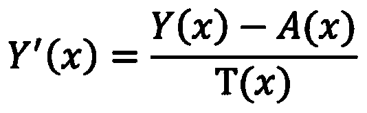
- the de-hazing operation is as following:
- Y′ (x) is the Y (luma) channel of de-hazed image I-Y′UV.
- a (x) is the estimated atmospheric light component for pixel x
- T (x) is the transmission map value for pixel x.
- the Y (luma) channel of de-hazed image I-Y′UV is equal to the difference of the Y (luma) channel of image I-YUV and the estimated atmospheric light component A (x) calculated in step 506, divided by the transmission map value T (x) which was determined in step 508.
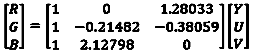
- step 706 the video system 30 converts the YUV image I-Y′UV to an de-hazed RGB image, the conversion from YUV to RGB is as follows:
- the video system 30 may communicate the resultant de-hazed RGB image on the display device 40 or save it to a memory or external storage device for later recall or further processing.
- FIG. 7 is described with respect to an RGB image, it will be understood that the disclosed operation can be applied to other color spaces as well.
- FIGS. 8–10 show an example result of the methods described in the previous sections.
- FIG. 8 shows an image 800 with smoke captured during a surgical procedure using the endoscope system 1. For example, during an endoscopic procedure a surgeon may cut tissue 804 with an electrosurgical instrument 802. During this cutting smoke 806 may be generated. This smoke 806 would be captured in the image 800.
- FIG. 9 shows a de-hazed image 900, where the image 800 from FIG. 8 was de-hazed was based on a constant atmospheric light value.
- the image 1000 still somewhat obscured by smoke 806, may include an electrosurgical instrument 802 and tissue 804.
- tissue 804. For example, in a case where a constant atmospheric light value A was used instead of the atmospheric light matrix A being estimated by the formula used in step 506.
- FIG. 10 shows a de-hazed RGB image 1000, de-hazed using the method of FIGS. 5 and 7, as described herein.
- the de-hazed RGB image 1000 may include an electrosurgical instrument 802 and tissue 804.
- the method may start with the capture of the image 800 of FIG. 8 during a surgical procedure, as in step 502 using the endoscopic system 1.
- the image may be approximately 20 x 20 pixels.
- the video system 30 determines the dark channel matrix of the image as in step 504.
- size of the pixel area ⁇ (x) may be set to approximately 3 x 3 pixels.
- the determined dark channel matrix of the image of FIG. 8 is used by the video system 30 to estimate the atmospheric light matrix by estimating a maximum value among the minimum color component intensities for each pixel in a pixel area, and multiplying this maximum value by a coefficient (e.g., 0.85) as in step 506.
- a coefficient e.g. 0.5
- the video system 30 calculates a transmission map (T) according to the dark channel matrix and the estimated atmospheric light matrix.
- the transmission map (T) is used in a de-hazing operation as described in FIG. 7.
- the video system 30 converts the RGB image I to a YUV image I-YUV.
- the video system 30 applies the de-hazing operation on channel Y (luma) of the I-YUV image by subtracting the estimated atmospheric light component A (x) from the Y (luma) channel and then dividing this difference by the determined transmission map, creating image I-Y′UV.
- the I-Y′UV image gets converted to a de-hazed RGB image 1000 (see FIG. 10) .
- a phrase in the form “A or B” means “ (A) , (B) , or (A and B) . ”
- a phrase in the form “at least one of A, B, or C” means “ (A) ; (B) ; (C) ; (A and B) ; (A and C) ; (B and C) ; or (A, B, and C) . ”
- the term “clinician” may refer to a clinician or any medical professional, such as a doctor, nurse, technician, medical assistant, or the like, performing a medical procedure.
- the systems described herein may also utilize one or more controllers to receive various information and transform the received information to generate an output.
- the controller may include any type of computing device, computational circuit, or any type of processor or processing circuit capable of executing a series of instructions that are stored in a memory.
- the controller may include multiple processors and/or multicore central processing units (CPUs) and may include any type of processor, such as a microprocessor, digital signal processor, microcontroller, programmable logic device (PLD) , field programmable gate array (FPGA) , or the like.
- the controller may also include a memory to store data and/or instructions that, when executed by the one or more processors, causes the one or more processors to perform one or more methods and/or algorithms.
- programming language and “computer program, ” as used herein, each include any language used to specify instructions to a computer, and include (but is not limited to) the following languages and their derivatives: Assembler, Basic, Batch files, BCPL, C, C+, C++, Delphi, Fortran, Java, JavaScript, machine code, operating system command languages, Pascal, Perl, PL1, scripting languages, Visual Basic, metalanguages which themselves specify programs, and all first, second, third, fourth, fifth, or further generation computer languages. Also included are database and other data schemas, and any other meta-languages.
- any of the herein described methods, programs, algorithms or codes may be contained on one or more machine-readable media or memory.
- the term “memory” may include a mechanism that provides (for example, stores and/or transmits) information in a form readable by a machine such a processor, computer, or a digital processing device.
- a memory may include a read only memory (ROM) , random access memory (RAM) , magnetic disk storage media, optical storage media, flash memory devices, or any other volatile or non-volatile memory storage device.
- ROM read only memory
- RAM random access memory
- Code or instructions contained thereon can be represented by carrier wave signals, infrared signals, digital signals, and by other like signals.
Landscapes
- Engineering & Computer Science (AREA)
- Physics & Mathematics (AREA)
- General Physics & Mathematics (AREA)
- Theoretical Computer Science (AREA)
- Computer Vision & Pattern Recognition (AREA)
- Image Processing (AREA)
Abstract
A method for smoke reduction in images includes accessing an RGB image of an object obscured by smoke, determining a dark channel matrix of the RGB image, estimating an atmospheric light matrix for the RGB image based on the dark channel, determining a transmission map based on to the atmospheric light matrix and the dark channel matrix, de-hazing the RGB image based on the transmission map to reduce the smoke in the RGB image, and displaying the de-hazed RGB image on a display device. The RGB image includes a plurality of pixels. The dark channel matrix includes, for each pixel of the plurality of pixels, a minimum color component intensity for a respective pixel area centered at the respective pixel. The atmospheric light matrix includes an atmospheric light component value for each of the plurality of pixels.
Description
The present disclosure relates to devices, systems and methods for smoke-reduction in images, and more particularly, to smoke-reduction in images during surgical procedures.
Endoscopes are introduced through an incision or a natural body orifice to observe internal features of a body. Conventional endoscopes are used for visualization during endoscopic or laparoscopic surgical procedures. During such surgical procedures, it is possible for smoke to be generated when the energy surgical instrument is used, for example, to cut tissue with electrosurgical energy during the surgery. Thus, the image acquired by the endoscope may become blurry because of this smoke. The smoke may obscure features of the surgical site and delay the surgical procedure while surgeons wait for the smoke to clear. Other procedures may experience similar issues where smoke is present during the capture of an image. Accordingly, there is interest in improving imaging technology.
SUMMARY
The present disclosure relates to devices, systems, and methods for smoke reduction in images. In accordance with aspects of the present disclosure, a method for smoke reduction in images includes accessing an RGB image of an object obscured by smoke, determining a dark channel matrix of the RGB image, estimating an atmospheric light matrix for the RGB image based on the dark channel, determining a transmission map based on the atmospheric light matrix and the dark channel matrix, de-hazing the RGB image based on the transmission map to reduce the smoke in the RGB image, and displaying the de-hazed RGB image on a display device. The RGB image includes a plurality of pixels. The dark channel matrix includes, for each pixel of the plurality of pixels, a minimum color component intensity for a respective pixel area centered at the respective pixel. The atmospheric light matrix includes an atmospheric light component value for each of the plurality of pixels.
In an aspect of the present disclosure, the de-hazing the RGB image includes converting the RGB image to a YUV image, performing a de-hazing operation on the YUV image to provide a Y′UV image, and converting the Y′UV image to the de-hazed RGB image.
In an aspect of the present disclosure, the performing the de-hazing operation on the YUV image includes, for each pixel x of the plurality of pixels, determining Y′as
 T(x) is a transmission component for the pixel x. A (x) is the atmospheric light component value for the pixel x.
In another aspect of the present disclosure, the performing the de-hazing operation on the YUV image further includes replacing a Y channel of the YUV image with the determined Y′to provide a Y′UV image.
In an aspect of the present disclosure, the estimating the atmospheric light matrix includes, for each pixel x of the plurality of pixels: determining an atmospheric light component value for the pixel x as: A (x) =max (min (I
c (y) ) ) *coef, for all y∈ Ω (x) , where Ω (x) is a pixel area centered at pixel x, y is a pixel of the pixel area Ω (x) , I
c (y) is an intensity value of a color component c of the pixel y, and coef is a predetermined coefficient value.
In an aspect of the present disclosure, the determining the transmission map includes determining, for each pixel x of the plurality of pixels, a transmission component as:
 Where ω is a predetermined constant, I_DARK (x) is the dark channel matrix value for the pixel x, and A (x) is the atmospheric light component value for the pixel x.
In accordance with aspects of the present disclosure, a method for smoke reduction in images is presented. The method includes accessing an image obscured by smoke, for each pixel of the plurality of pixels: (i) determining a dark channel matrix value for the respective pixel as a minimum color component intensity value for a respective pixel area centered at the respective pixel, and (ii) estimating an atmospheric light component value for the pixel x based on the minimum color component intensity value for each pixel of the pixel area, de-hazing the image based on the atmospheric light component values for the plurality of pixels, and displaying the de-hazed image on a display device. The image includes a plurality of pixels, where each pixel of the image includes a plurality of color components.
In a further aspect of the present disclosure, the de-hazing the image includes determining a transmission map value for each pixel x of the plurality of pixels as:
 converting the image to a YUV image, determining Y′for each pixel x of the plurality of pixels as
 and replacing a Y channel of the YUV image with the determined Y′to provide a Y′UV image, where ω is a predetermined constant, I_DARK (x) is the dark channel matrix value for the pixel x, and A (x) is the atmospheric light component value for the pixel x.
In an aspect of the present disclosure, the de-hazing the image further includes converting the Y′UV image to a de-hazed image.
In yet another aspect of the present disclosure, the image includes at least one of an RGB image, a CMYK image, a CIELAB image, or a CIEXYZ image.
In an aspect of the present disclosure, the estimating the atmospheric light matrix includes, for each pixel x of the plurality of pixels: determining an atmospheric light component value for the pixel x as A (x) =max (min (I
c (y) ) ) *coef, for all y∈ Ω (x) , where Ω (x) is a pixel area centered at pixel x, y is a pixel of the pixel area Ω (x) , I
c (y) is an intensity value of a color component c of the pixel y, and coef is a predetermined coefficient value.
In accordance with aspects of the present disclosure, a system for smoke reduction in images is presented. The system may include a light source configured to provide light, an imaging device configured to acquire images, an imagining device control unit configured to control the imaging device. The image includes a plurality of pixels, where each pixel of the image may include a plurality of color components. The control unit may include a processor and a memory storing instructions. The instructions which, when executed by the processor, causes the system to access the image, for each of the pixels: determine a dark channel matrix value for the respective pixel as a minimum color component intensity value for a respective pixel area centered at the respective pixel, and estimate an atmospheric light component value for each pixel based on the minimum color component intensity value for each pixel of the pixel area, de-haze the image based on the atmospheric light component value for each of the pixels, and display the de-hazed image on a display device.
In a further aspect of the present disclosure, the instructions when de-hazing the image, may further cause the system to determine a transmission map value for each pixel x of the plurality of pixels as
 convert the image to a YUV image, determine Y′ as
 and replace a Y channel of the YUV image with the determined Y′ to provide a Y′UV image, where ω is a predetermined constant, I_DARK (x) is the dark channel matrix value for the pixel x, and A (x) is the atmospheric light component value for the pixel x.
In yet a further aspect of the present disclosure, the instructions when de-hazing the image may further cause the system to convert the Y′UV image to a de-hazed image.
In yet another aspect of the present disclosure, the image includes at least one of an RGB image, a CMYK image, a CIELAB image, or a CIEXYZ image.
In an aspect of the present disclosure, the estimating the atmospheric light matrix includes determining an atmospheric light component value for the pixel x as A (x) =max (min (I
c (y) ) ) * coef, for all y∈ Ω (x) . Where y is a pixel, I
c (y) is an intensity value of a color component c of the pixel y, and coef is a predetermined coefficient value.
Further details and aspects of various embodiments of the present disclosure are described in more detail below with reference to the appended figures.
Embodiments of the present disclosure are described herein with reference to the accompanying drawings, wherein:
FIG. 1 is a diagram of an exemplary visualization or endoscope system in accordance with the present disclosure;
FIG. 2 is a schematic configuration of the visualization or endoscope system of FIG. 1;
FIG. 3 is a diagram illustrating another schematic configuration of an optical system of the system of FIG. 1;
FIG. 4 is a schematic configuration of the visualization or endoscope system in accordance with an embodiment of the present disclosure;
FIG. 5 is a flowchart of a method for smoke reduction in accordance with an exemplary embodiment of the disclosure;
FIG. 6 is an exemplary input image including an area of pixels in accordance with the present disclosure;
FIG. 7 is a flowchart of a method for performing de-hazing in accordance with the disclosure;
FIG. 8 is an exemplary image with smoke in accordance with the present disclosure;
FIG. 9 is an exemplary de-hazed image with constant atmospheric light; and
FIG. 10 is an exemplary de-hazed image with atmospheric light calculated in accordance with the present disclosure.
Further details and aspects of exemplary embodiments of the disclosure are described in more detail below with reference to the appended figures. Any of the above aspects and embodiments of the disclosure may be combined without departing from the scope of the disclosure.
DETAILED DESCRIPTION OF EMBODIMENTS
Embodiments of the presently disclosed devices, systems, and methods of treatment are described in detail with reference to the drawings, in which like reference numerals designate identical or corresponding elements in each of the several views. As used herein, the term “distal” refers to that portion of a structure that is farther from a user, while the term “proximal” refers to that portion of a structure that is closer to the user. The term “clinician” refers to a doctor, nurse, or other care provider and may include support personnel.
The present disclosure is applicable where images of a surgical site are captured. Endoscope systems are provided as an example, but it will be understood that such description is exemplary and does not limit the scope and applicability of the present disclosure to other systems and procedures.
Referring initially to FIGS. 1–3, an endoscope system 1, in accordance with the present disclosure, includes an endoscope 10, a light source 20, a video system 30, and a display device 40. With continued reference to FIG. 1, the light source 20, such as an LED/Xenon light source, is connected to the endoscope 10 via a fiber guide 22 that is operatively coupled to the light source 20 and to an endocoupler 16 disposed on, or adjacent to, a handle 18 of the endoscope 10. The fiber guide 22 includes, for example, fiber optic cable which extends through the elongated body 12 of the endoscope 10 and terminates at a distal end 14 of the endoscope 10. Accordingly, light is transmitted from the light source 20, through the fiber guide 22, and emitted out the distal end 14 of the endoscope 10 toward a targeted internal feature, such as tissue or an organ, of a body of a patient. As the light transmission pathway in such a configuration is relatively long, for example, the fiber guide 22 may be about 1.0 m to about 1.5 m in length, only about 15% (or less) of the light flux emitted from the light source 20 is outputted from the distal end 14 of the endoscope 10.
With reference to FIG. 2 and FIG. 3, the video system 30 is operatively connected to an image sensor 32 mounted to, or disposed within, the handle 18 of the endoscope 10 via a data cable 34. An objective lens 36 is disposed at the distal end 14 of the elongated body 12 of the endoscope 10 and a series of spaced-apart, relay lenses 38, such as rod lenses, are positioned along the length of the elongated body 12 between the objective lens 36 and the image sensor 32. Images captured by the objective lens 36 are forwarded through the elongated body 12 of the endoscope 10 via the relay lenses 38 to the image sensor 32, which are then communicated to the video system 30 for processing and output to the display device 40 via cable 39. The image sensor 32 is located within, or mounted to, the handle 18 of the endoscope 10, which can be up to about 30 cm away from the distal end 14 of the endoscope 10.
With reference to FIGS. 4–7, the flow diagrams include various blocks described in an ordered sequence. However, those skilled in the art will appreciate that one or more blocks of the flow diagram may be performed in a different order, repeated, and/or omitted without departing from the scope of the present disclosure. The below description of the flow diagram refers to various actions or tasks performed by one or more video system 30, but those skilled in the art will appreciate that the video system 30 is exemplary. In various embodiments, the disclosed operations can be performed by another component, device, or system. In various embodiments, the video system 30 or other component/device performs the actions or tasks via one or more software applications executing on a processor. In various embodiments, at least some of the operations can be implemented by firmware, programmable logic devices, and/or hardware circuitry. Other implementations are contemplated to be within the scope of the present disclosure.
Referring to FIG. 4, there is shown a schematic configuration of a system, which may be the endoscope system of FIG. 1 or may be a different type of system (e.g., visualization system, etc. ) . The system, in accordance with the present disclosure, includes an imaging device 410, a light source 420, a video system 430, and a display device 440. The light source 420 is configured to provide light to a surgical site through the imaging device 410 via the fiber guide 422. The distal end 414 of the imaging device 410 includes an objective lens 436 for capturing the image at the surgical site. The objective lens 436 forwards the image to the image sensor 432. The image is then communicated to the video system 430 for processing. The video system 430 includes an imaging device controller 450 for controlling the endoscope and processing the images. The imaging device controller 450 includes processor 452 connected to a computer-readable storage medium or a memory 454 which may be a volatile type memory, such as RAM, or a non-volatile type memory, such as flash media, disk media, or other types of memory. In various embodiments, the processor 452 may be another type of processor such as, without limitation, a digital signal processor, a microprocessor, an ASIC, a graphics processing unit (GPU) , field-programmable gate array (FPGA) , or a central processing unit (CPU) .
In various embodiments, the memory 454 can be random access memory, read only memory, magnetic disk memory, solid state memory, optical disc memory, and/or another type of memory. In various embodiments, the memory 454 can be separate from the imaging device controller 450 and can communicate with the processor 452 through communication buses of a circuit board and/or through communication cables such as serial ATA cables or other types of cables. The memory 454 includes computer-readable instructions that are executable by the processor 452 to operate the imaging device controller 450. In various embodiments, the imaging device controller 450 may include a network interface 540 to communicate with other computers or a server.
Referring now to FIG. 5, there is shown an operation for smoke reduction in images. In various embodiments, the operation of FIG. 5 can be performed by an endoscope system 1 described above herein. In various embodiments, the operation of FIG. 5 can be performed by another type of system and/or during another type of procedure. The following description will refer to an endoscope system, but it will be understood that such description is exemplary and does not limit the scope and applicability of the present disclosure to other systems and procedures. The following description will refer to an RGB (Red, Green, Blue) image or RGB color model, but it will be understood that such description is exemplary and does not limit the scope and applicability of the present disclosure to other types of images or color models (for example, CMYK (Cyan, Magenta, Yellow, Key) , CIELAB, or CIEXYZ) . The image sensor 32 may capture raw data. The format of the raw data may be RGGB, RGBG, GRGB, or BGGR. The video system 30 may convert the raw data to RGB using a demosaicing algorithm. A demosaicing algorithm is a digital image process used to reconstruct a full-color image from the incomplete color samples output from an image sensor overlaid with a color filter array (CFA) . It is also known as CFA interpolation or color reconstruction. The RGB image may be further converted by the video system 30 to another color model, such as CMYK, CIELAB, or CIEXYZ.
Initially, at step 502, an image of a surgical site is captured via the objective lens 36 and forwarded to the image sensor 32 of endoscope system 1. The term “image” as used herein may include still images or moving images (for example, video) . In various embodiments, the captured image is communicated to the video system 30 for processing. For example, during an endoscopic procedure, a surgeon may cut tissue with an electrosurgical instrument. During this cutting, smoke may be generated. When the image is captured, it may include the smoke. Smoke is generally a turbid medium (such as particles, water droplets) in the atmosphere. The irradiance received by the objective lens 36 from the scene point is attenuated by the line of sight. This incoming light is mixed with ambient light (air-light) reflected into the line of sight by atmospheric particles such as smoke. This smoke degrades the image, making it lose contrast and color fidelity.
FIG. 6 shows an exemplary pixel representation of an image captured in step 502. In various embodiments, the captured image may or may not have been processed during the capture process or after the capture process. In various embodiments, an image 600 includes a number of pixels, and the dimensions of the image 600 are often represented as the amount of pixels in an X by Y format, such as 500 x 500 pixels, for example. In accordance with aspects of the present disclosure, and as explained in more detail later herein, each pixel of the image 600 may be processed based on a a pixel area 602, 610 centered at that pixel, which will also be referred to herein as a patch. In various embodiments, each patch/pixel area of the image can have the same size. In various embodiments, different pixel areas or patches can have different sizes. Each pixel area or patch can be denoted as Ω (x) , which is a pixel area/patch having a particular pixel x as its center pixel. In the illustrative example of FIG. 6, the pixel area 602 has a size of 3 x 3 pixels and is centered at a particular pixel x
1 606. If an image has 18 by 18 pixels, a patch size may be 3 x 3 pixels. The illustrated image size and patch size are exemplary and other image sizes and patch sizes are contemplated to be within the scope of the present disclosure.
With continuing reference to FIG. 6, each pixel 601 in an image 600 may have combinations of color components 612, such as red, green, and blue, which are also referred to herein as color channels. I
c (y) is used herein to denote the intensity value of a color component c of a particular pixel y in the image 600. For a pixel 601, each of the color components 612 has an intensity value representing the brightness intensity of that color component. For example, for a 24 bit RGB image, each of the color components 612 has 8 bits, which corresponds to each color component having 256 possible intensity values.
Referring again to FIG. 5, at step 504, the video system 30 determines a dark channel matrix for the image 600. As used herein, the phrase “dark channel” of a pixel refers to the lowest color component intensity value among all pixels of a patch Ω (x) 602 centered at a particular pixel x. The term “dark channel matrix” of an image, as used herein, refers to a matrix of the dark channel of every pixel of the image. The dark channel of a pixel x will be denoted as I_DARK (x) . In various embodiments, the video system 30 calculates the dark channel of a pixel as follows:
I_DARK (x) =min (min (I
c (y) ) ) , , for all c∈ {r, g, b} y∈Ω (x)
where y denotes a pixel of the patch Ω (x) , c denotes a color component, and I
c (y) denotes the intensity value of the color component c of pixel y. Thus, the dark channel of a pixel x is the outcome of two minimum operations across two variables c and y, which together determine the lowest color component intensity value among all pixels of a patch centered at pixel x. In various embodiments, the video system 30 can calculate the dark channel of a pixel by acquiring the lowest color component intensity value for every pixel in the patch and then finding the minimum value among all those values. For cases where the center pixel of the patch is at or near the edge of the image, only the part of the patch in the image is used.
For example, with reference to FIG. 6, for an image 600 that was captured in step 502, the image 600 may have a height and width of 18 x 18 pixels, the pixel area (patch) size may be 3 x 3 pixels. For example a 3 x 3 pixel area Ω (x
1) 602 centered at x
1 606 may have the following intensities for the R, G, and B channels for each of the 9 pixels in the patch:
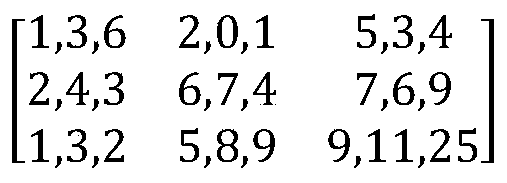
In this example, for the top-left pixel in the pixel area Ω (x
1) 602, the R channel may have an intensity of 1, the G channel may have an intensity of 3, and the B channel may have an intensity of 6. Here, the R channel has the minimum intensity value (avalue of 1) of the RGB channels for that pixel.
The minimum color component intensity value of each the pixels would be determined. For example, for the 3 x 3-pixel area Ω (x
1) 602 centered at x
1 the minimum color component intensity value for each of the pixels in the pixel area Ω (x
1) 602 are:

Thus, the dark channel of the pixel would have an intensity value of 0 for this exemplary 3 x 3-pixel area Ω (x) 602 centered at x
1.
Referring again to FIG. 5, at step 506, the video system 30 estimates an atmospheric light component for each pixel, and the atmospheric light components for all of the pixels are together referred to herein as a “atmospheric light matrix. ” The estimated atmospheric light component for a pixel x will be denoted herein as A (x) . In various embodiments, A (x) can be determined based on the lowest color component intensity value for each pixel y 604 in a pixel area Ω (x) 602, which can be denoted as:
A(x) = f (min (I
c (y) ) ) , for all c∈ {r, g, b} y∈ Ω (x) ,
where f () is an operation for estimating the atmospheric light component, based on the lowest color component intensity value for each pixel y 604 in the patch Ω (x
1) 602. In various embodiments, the operation f () may determine the maximum value among min (I
c (y) ) , for y∈ Ω (x) . In various embodiments, the maximum value can be scaled by a coefficient “coef, ” which in various embodiments can have a value between 0 and 1, such as 0.85. The embodiment of atmospheric light component described above may be provided as follows:
A(x) = f (min (I
c (y) ) ) =max (min (I
c (y) ) ) *coef, for all c∈ {r, g, b} y∈ Ω (x)
For example, using the same example above for intensity values in patch Ω (x
1) 602, the video system 30 determines the atmospheric light component A (x
1) to be 9 *coef.
At step 508, the video system 30 determines what is referred to herein as a transmission map T. The transmission map T is determined based on the dark channel matrix and the atmospheric light matrix, which were determined in steps 504 and 506. The transmission map includes a transmission component T (x) for each pixel x. In various embodiments, the transmission component can be determined as follows:
where ω is a parameter having a value between 0 and 1, such as 0.85. In practice, even in clear images, there are some particles. Thus, some haze exists when distant objects are observed. The presence of haze is a cue to human perception of depth. If all haze is removed, the perception of depth may be lost. Therefore, to retain some haze, the parameter ω (0< ω<=1) is introduced. In various embodiments, the value of ω can vary based on the particular application. Thus, the transmission map is equal to 1 minus ω times the dark channel of a pixel (I-DARK (x) ) divided by the atmospheric light component of the pixel, A (x) .
At step 510, the video system 30 de-hazes the image based on the transmission map. FIG. 7 illustrates one way to perform the de-hazing operation.
With reference to FIG. 7, the illustrated operation assumes that the original image is an RGB image. The operation attempts to retain the color of the original RGB image 600 as much as possible in the de-haze process. In various embodiments, the de-hazing operation converts the image 600 from the RGB color space to the YUV color space (Y is luminance, U and V are chrominance or color) , and applies dehazing on the Y (luma) channel, which is generally a weighted sum of the RGB color channels.
Initially, at step 702 the video system 30 converts the RGB image 600 to a YUV image denoted as I-YUV. The conversion of each pixel from RGB and YUV may be performed as follows:

Next, at step 704 the video system 30 performs a de-hazing operation on the channel Y (luma) of the I-YUV image. In accordance with aspects of the present disclosure, the de-hazing operation is as following:
where Y′ (x) is the Y (luma) channel of de-hazed image I-Y′UV. A (x) is the estimated atmospheric light component for pixel x, and T (x) is the transmission map value for pixel x. Thus, the Y (luma) channel of de-hazed image I-Y′UV is equal to the difference of the Y (luma) channel of image I-YUV and the estimated atmospheric light component A (x) calculated in step 506, divided by the transmission map value T (x) which was determined in step 508.
Finally, at step 706 the video system 30 converts the YUV image I-Y′UV to an de-hazed RGB image, the conversion from YUV to RGB is as follows:
In various embodiments, the video system 30 may communicate the resultant de-hazed RGB image on the display device 40 or save it to a memory or external storage device for later recall or further processing. Although the operation of FIG. 7 is described with respect to an RGB image, it will be understood that the disclosed operation can be applied to other color spaces as well.
FIGS. 8–10 show an example result of the methods described in the previous sections. FIG. 8 shows an image 800 with smoke captured during a surgical procedure using the endoscope system 1. For example, during an endoscopic procedure a surgeon may cut tissue 804 with an electrosurgical instrument 802. During this cutting smoke 806 may be generated. This smoke 806 would be captured in the image 800.
FIG. 9 shows a de-hazed image 900, where the image 800 from FIG. 8 was de-hazed was based on a constant atmospheric light value. The image 1000, still somewhat obscured by smoke 806, may include an electrosurgical instrument 802 and tissue 804. For example, in a case where a constant atmospheric light value A was used instead of the atmospheric light matrix A being estimated by the formula used in step 506.
FIG. 10 shows a de-hazed RGB image 1000, de-hazed using the method of FIGS. 5 and 7, as described herein. The de-hazed RGB image 1000 may include an electrosurgical instrument 802 and tissue 804. The method may start with the capture of the image 800 of FIG. 8 during a surgical procedure, as in step 502 using the endoscopic system 1. For example, the image may be approximately 20 x 20 pixels. Next, the video system 30 determines the dark channel matrix of the image as in step 504. For example, size of the pixel area Ω (x) may be set to approximately 3 x 3 pixels.
The determined dark channel matrix of the image of FIG. 8 is used by the video system 30 to estimate the atmospheric light matrix by estimating a maximum value among the minimum color component intensities for each pixel in a pixel area, and multiplying this maximum value by a coefficient (e.g., 0.85) as in step 506. Next, as in step 508 the video system 30 calculates a transmission map (T) according to the dark channel matrix and the estimated atmospheric light matrix.
The transmission map (T) is used in a de-hazing operation as described in FIG. 7. At step 702 the video system 30 converts the RGB image I to a YUV image I-YUV. Next, at step 704 the video system 30 applies the de-hazing operation on channel Y (luma) of the I-YUV image by subtracting the estimated atmospheric light component A (x) from the Y (luma) channel and then dividing this difference by the determined transmission map, creating image I-Y′UV. Finally in step 706, the I-Y′UV image gets converted to a de-hazed RGB image 1000 (see FIG. 10) .
The embodiments disclosed herein are examples of the present disclosure and may be embodied in various forms. For instance, although certain embodiments herein are described as separate embodiments, each of the embodiments herein may be combined with one or more of the other embodiments herein. Specific structural and functional details disclosed herein are not to be interpreted as limiting, but as a basis for the claims and as a representative basis for teaching one skilled in the art to variously employ the present disclosure in virtually any appropriately detailed structure. Like reference numerals may refer to similar or identical elements throughout the description of the figures.
The phrases “in an embodiment, ” “in embodiments, ” “in some embodiments, ” or “in other embodiments” may each refer to one or more of the same or different embodiments in accordance with the present disclosure. A phrase in the form “A or B” means “ (A) , (B) , or (A and B) . ” A phrase in the form “at least one of A, B, or C” means “ (A) ; (B) ; (C) ; (A and B) ; (A and C) ; (B and C) ; or (A, B, and C) . ” The term “clinician” may refer to a clinician or any medical professional, such as a doctor, nurse, technician, medical assistant, or the like, performing a medical procedure.
The systems described herein may also utilize one or more controllers to receive various information and transform the received information to generate an output. The controller may include any type of computing device, computational circuit, or any type of processor or processing circuit capable of executing a series of instructions that are stored in a memory. The controller may include multiple processors and/or multicore central processing units (CPUs) and may include any type of processor, such as a microprocessor, digital signal processor, microcontroller, programmable logic device (PLD) , field programmable gate array (FPGA) , or the like. The controller may also include a memory to store data and/or instructions that, when executed by the one or more processors, causes the one or more processors to perform one or more methods and/or algorithms.
Any of the herein described methods, programs, algorithms or codes may be converted to, or expressed in, a programming language or computer program. The terms “programming language” and “computer program, ” as used herein, each include any language used to specify instructions to a computer, and include (but is not limited to) the following languages and their derivatives: Assembler, Basic, Batch files, BCPL, C, C+, C++, Delphi, Fortran, Java, JavaScript, machine code, operating system command languages, Pascal, Perl, PL1, scripting languages, Visual Basic, metalanguages which themselves specify programs, and all first, second, third, fourth, fifth, or further generation computer languages. Also included are database and other data schemas, and any other meta-languages. No distinction is made between languages which are interpreted, compiled, or use both compiled and interpreted approaches. No distinction is made between compiled and source versions of a program. Thus, reference to a program, where the programming language could exist in more than one state (such as source, compiled, object, or linked) is a reference to any and all such states. Reference to a program may encompass the actual instructions and/or the intent of those instructions.
Any of the herein described methods, programs, algorithms or codes may be contained on one or more machine-readable media or memory. The term “memory” may include a mechanism that provides (for example, stores and/or transmits) information in a form readable by a machine such a processor, computer, or a digital processing device. For example, a memory may include a read only memory (ROM) , random access memory (RAM) , magnetic disk storage media, optical storage media, flash memory devices, or any other volatile or non-volatile memory storage device. Code or instructions contained thereon can be represented by carrier wave signals, infrared signals, digital signals, and by other like signals.
It should be understood that the foregoing description is only illustrative of the present disclosure. Various alternatives and modifications can be devised by those skilled in the art without departing from the present disclosure. Accordingly, the present disclosure is intended to embrace all such alternatives, modifications and variances. The embodiments described with reference to the attached drawing figures are presented only to demonstrate certain examples of the present disclosure. Other elements, steps, methods, and techniques that are insubstantially different from those described above and/or in the appended claims are also intended to be within the scope of the present disclosure.
Claims (16)
- A method for smoke reduction in images comprising:accessing an RGB image of an object obscured by smoke, the RGB image including a plurality of pixels;determining a dark channel matrix of the RGB image, where the dark channel matrix includes, for each pixel of the plurality of pixels, a minimum color component intensity for a respective pixel area centered at the respective pixel;estimating an atmospheric light matrix for the RGB image based on the dark channel matrix, wherein the atmospheric light matrix includes an atmospheric light component value for each of the plurality of pixels;determining a transmission map based on the atmospheric light matrix and the dark channel matrix;de-hazing the RGB image based on the transmission map to reduce the smoke in the RGB image; anddisplaying the de-hazed RGB image on a display device.
- The method of claim 1, wherein the de-hazing the RGB image includes:converting the RGB image to a YUV image;performing a de-hazing operation on the YUV image to provide a Y′UV image; andconverting the Y′UV image to the de-hazed RGB image.
- The method of claim 2, wherein the performing the de-hazing operation on the YUV image includes, for each pixel x of the plurality of pixels:determining Y′as
 wherein:T (x) is a transmission component for the pixel x, andA (x) is the atmospheric light component value for the pixel x.
 - The method of claim 3, wherein the performing the de-hazing operation on the YUV image further includes replacing a Y channel of the YUV image with the determined Y′to provide a Y′UV image.
- The method of claim 1, wherein the estimating the atmospheric light matrix includes, for each pixel x of the plurality of pixels:determining an atmospheric light component value for the pixel x as:A (x) =max (min (I c (y) ) ) *coef, for all y∈ Ω (x) ,wherein:Ω (x) is a pixel area centered at pixel x,y is a pixel of the pixel area Ω (x) ,I c (y) is an intensity value of a color component c of the pixel y, andcoef is a predetermined coefficient value.
- The method of claim 1, wherein the determining the transmission map includes determining, for each pixel x of the plurality of pixels, a transmission component value as:
 wherein:ω is a predetermined constant,I_DARK (x) is the dark channel matrix value for the pixel x, andA (x) is the atmospheric light component value for the pixel x.
 - A method for smoke reduction in images comprising:accessing an image obscured by smoke, the image including a plurality of pixels, where each pixel of the image includes a plurality of color components;for each pixel of the plurality of pixels:determining a dark matrix channel value for the respective pixel as a minimum color component intensity value for a respective pixel area centered at the respective pixel; andestimating an atmospheric light component value for the pixelx based on the minimum color component intensity value for each pixel of the pixel area;de-hazing the image based on the atmospheric light component value for each of the plurality of pixels; anddisplaying the de-hazed image on a display device.
- The method of claim 7, wherein the de-hazing the image includes:determining a transmission map, for each pixel x of the plurality of pixels as:
 wherein:ω is a predetermined constant,I_DARK (x) is the dark channel matrix value for the pixel x, andA (x) is the atmospheric light component value for the pixel x, converting the image to a YUV image;determining Y′, for each pixel x of the plurality of pixels asand
 replacing a Y channel of the YUV image with the determined Y′to provide a Y′UV image.
 - The method of claim 8, wherein the de-hazing the image further includes converting the Y′UV image to a de-hazed image.
- The method of claim 9, wherein the image includes at least one of an RGB image, a CMYK image, a CIELAB image, or a CIEXYZ image.
- The method of claim 7, wherein the estimating the atmospheric light component value includes, for each pixel x of the plurality of pixels:determining the atmospheric light component value for the pixel x as:A (x) =max (min (I c (y) ) ) *coef, for all y∈ Ω (x) ,wherein:Ω (x) is a pixel area centered at pixel x,y is a pixel of the pixel area Ω (x) ,I c (y) is an intensity value of a color component c of the pixel y, andcoef is a predetermined coefficient value.
- A system for smoke reduction in images comprising:a light source configured to provide light;an imaging device configured to acquire images;an imagining device control unit configured to control the imaging device, the control unit comprising:a processor; anda memory storing instructions which, when executed by the processor, cause the system to:capture an image of an object obscured by smoke, by the imaging device, the image including a plurality of pixels, where each pixel of the image includes a plurality of color components;access the image;for each of the pixels:determine a dark channel matrix value for the respective pixel as a minimum color component intensity value for a respective pixel area centered at the respective pixel; andestimate an atmospheric light component value for each pixel based on the minimum color component intensity value for each pixel of the pixel area;de-haze the image based on the atmospheric light component value for each of the pixels; anddisplay the de-hazed image on a display device.
- The system of claim 12, wherein the instructions when de-hazing the image, further cause the system to:determine a transmission map, for each pixel x of the plurality of pixels as:
 wherein:ω is a predetermined constant,I_DARK (x) is the dark channel matrix value for the pixel x, andA (x) is the atmospheric light component value for the pixel x,convert the image to a YUV image;determine Y′asand
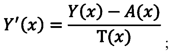 replace a Y channel of the YUV image with the determined Y′to provide a Y′UV image.
 - The system of claim 13, wherein the instructions when de-hazing the image, further cause the system to convert the Y′UV image to a de-hazed image.
- The system of claim 14, wherein the image includes at least one of an RGB image, a CMYK image, a CIELAB image, or a CIEXYZ image.
- The system of claim 12, wherein the instructions when estimating the atmospheric light component of the image, further cause the system to:determine the atmospheric light component value for the pixel xas:A (x) =max (min (I c (y) ) ) *coef,wherein:y is a pixel,I c is a color component of the pixel y, andcoef is a predetermined coefficient.
Priority Applications (4)
| Application Number | Priority Date | Filing Date | Title |
|---|---|---|---|
| EP19945282.2A EP4028986A4 (en) | 2019-09-11 | 2019-09-11 | Systems and methods for smoke-reduction in images |
| US17/641,452 US12223629B2 (en) | 2019-09-11 | 2019-09-11 | Systems and methods for smoke-reduction in images |
| PCT/CN2019/105311 WO2021046743A1 (en) | 2019-09-11 | 2019-09-11 | Systems and methods for smoke-reduction in images |
| CN202010950577.4A CN112488925A (en) | 2019-09-11 | 2020-09-11 | System and method for reducing smoke in an image |
Applications Claiming Priority (1)
| Application Number | Priority Date | Filing Date | Title |
|---|---|---|---|
| PCT/CN2019/105311 WO2021046743A1 (en) | 2019-09-11 | 2019-09-11 | Systems and methods for smoke-reduction in images |
Publications (1)
| Publication Number | Publication Date |
|---|---|
| WO2021046743A1 true WO2021046743A1 (en) | 2021-03-18 |
Family
ID=74867147
Family Applications (1)
| Application Number | Title | Priority Date | Filing Date |
|---|---|---|---|
| PCT/CN2019/105311 Ceased WO2021046743A1 (en) | 2019-09-11 | 2019-09-11 | Systems and methods for smoke-reduction in images |
Country Status (4)
| Country | Link |
|---|---|
| US (1) | US12223629B2 (en) |
| EP (1) | EP4028986A4 (en) |
| CN (1) | CN112488925A (en) |
| WO (1) | WO2021046743A1 (en) |
Families Citing this family (3)
| Publication number | Priority date | Publication date | Assignee | Title |
|---|---|---|---|---|
| WO2021126248A1 (en) * | 2019-12-20 | 2021-06-24 | Google Llc | Spatially varying reduction of haze in images |
| CN116647632A (en) * | 2023-05-24 | 2023-08-25 | 上海疆通科技有限公司 | AR glasses and method for recognizing endoscope and collecting video content through AR glasses |
| CN117078562B (en) * | 2023-10-16 | 2023-12-26 | 四川中科友成科技有限公司 | Video image defogging method, device, computer equipment and medium |
Citations (5)
| Publication number | Priority date | Publication date | Assignee | Title |
|---|---|---|---|---|
| CN102982513A (en) * | 2012-12-04 | 2013-03-20 | 电子科技大学 | Adaptive image defogging method based on textures |
| CN104392417A (en) * | 2014-11-28 | 2015-03-04 | 嘉应学院 | Image haze removal method based on pixel dark channel and anisotropic diffusion filtering |
| CN106023092A (en) * | 2016-05-04 | 2016-10-12 | 中国农业大学 | Image defogging method and device |
| US20180308225A1 (en) * | 2016-08-20 | 2018-10-25 | Adobe Systems Incorporated | Systems and techniques for automatic image haze removal across multiple video frames |
| CN109754372A (en) * | 2018-12-03 | 2019-05-14 | 浙江大华技术股份有限公司 | A kind of image defogging processing method and processing device |
Family Cites Families (224)
| Publication number | Priority date | Publication date | Assignee | Title |
|---|---|---|---|---|
| US5762458A (en) | 1996-02-20 | 1998-06-09 | Computer Motion, Inc. | Method and apparatus for performing minimally invasive cardiac procedures |
| US5855583A (en) | 1996-02-20 | 1999-01-05 | Computer Motion, Inc. | Method and apparatus for performing minimally invasive cardiac procedures |
| US5792135A (en) | 1996-05-20 | 1998-08-11 | Intuitive Surgical, Inc. | Articulated surgical instrument for performing minimally invasive surgery with enhanced dexterity and sensitivity |
| US6364888B1 (en) | 1996-09-09 | 2002-04-02 | Intuitive Surgical, Inc. | Alignment of master and slave in a minimally invasive surgical apparatus |
| US7666191B2 (en) | 1996-12-12 | 2010-02-23 | Intuitive Surgical, Inc. | Robotic surgical system with sterile surgical adaptor |
| US8182469B2 (en) | 1997-11-21 | 2012-05-22 | Intuitive Surgical Operations, Inc. | Surgical accessory clamp and method |
| US8206406B2 (en) | 1996-12-12 | 2012-06-26 | Intuitive Surgical Operations, Inc. | Disposable sterile surgical adaptor |
| US8529582B2 (en) | 1996-12-12 | 2013-09-10 | Intuitive Surgical Operations, Inc. | Instrument interface of a robotic surgical system |
| US7727244B2 (en) | 1997-11-21 | 2010-06-01 | Intuitive Surgical Operation, Inc. | Sterile surgical drape |
| US7699855B2 (en) | 1996-12-12 | 2010-04-20 | Intuitive Surgical Operations, Inc. | Sterile surgical adaptor |
| US6331181B1 (en) | 1998-12-08 | 2001-12-18 | Intuitive Surgical, Inc. | Surgical robotic tools, data architecture, and use |
| US6132368A (en) | 1996-12-12 | 2000-10-17 | Intuitive Surgical, Inc. | Multi-component telepresence system and method |
| US6714839B2 (en) | 1998-12-08 | 2004-03-30 | Intuitive Surgical, Inc. | Master having redundant degrees of freedom |
| US6246200B1 (en) | 1998-08-04 | 2001-06-12 | Intuitive Surgical, Inc. | Manipulator positioning linkage for robotic surgery |
| US8600551B2 (en) | 1998-11-20 | 2013-12-03 | Intuitive Surgical Operations, Inc. | Medical robotic system with operatively couplable simulator unit for surgeon training |
| US6459926B1 (en) | 1998-11-20 | 2002-10-01 | Intuitive Surgical, Inc. | Repositioning and reorientation of master/slave relationship in minimally invasive telesurgery |
| US6951535B2 (en) | 2002-01-16 | 2005-10-04 | Intuitive Surgical, Inc. | Tele-medicine system that transmits an entire state of a subsystem |
| US6659939B2 (en) | 1998-11-20 | 2003-12-09 | Intuitive Surgical, Inc. | Cooperative minimally invasive telesurgical system |
| US6799065B1 (en) | 1998-12-08 | 2004-09-28 | Intuitive Surgical, Inc. | Image shifting apparatus and method for a telerobotic system |
| US6493608B1 (en) | 1999-04-07 | 2002-12-10 | Intuitive Surgical, Inc. | Aspects of a control system of a minimally invasive surgical apparatus |
| US6770081B1 (en) | 2000-01-07 | 2004-08-03 | Intuitive Surgical, Inc. | In vivo accessories for minimally invasive robotic surgery and methods |
| US7125403B2 (en) | 1998-12-08 | 2006-10-24 | Intuitive Surgical | In vivo accessories for minimally invasive robotic surgery |
| US6394998B1 (en) | 1999-01-22 | 2002-05-28 | Intuitive Surgical, Inc. | Surgical tools for use in minimally invasive telesurgical applications |
| US6565554B1 (en) | 1999-04-07 | 2003-05-20 | Intuitive Surgical, Inc. | Friction compensation in a minimally invasive surgical apparatus |
| US6424885B1 (en) | 1999-04-07 | 2002-07-23 | Intuitive Surgical, Inc. | Camera referenced control in a minimally invasive surgical apparatus |
| US8944070B2 (en) | 1999-04-07 | 2015-02-03 | Intuitive Surgical Operations, Inc. | Non-force reflecting method for providing tool force information to a user of a telesurgical system |
| US6594552B1 (en) | 1999-04-07 | 2003-07-15 | Intuitive Surgical, Inc. | Grip strength with tactile feedback for robotic surgery |
| US6315184B1 (en) | 1999-06-02 | 2001-11-13 | Powermed, Inc. | Stapling device for use with an electromechanical driver device for use with anastomosing, stapling, and resecting instruments |
| US7695485B2 (en) | 2001-11-30 | 2010-04-13 | Power Medical Interventions, Llc | Surgical device |
| US6793652B1 (en) | 1999-06-02 | 2004-09-21 | Power Medical Interventions, Inc. | Electro-mechanical surgical device |
| US6716233B1 (en) | 1999-06-02 | 2004-04-06 | Power Medical Interventions, Inc. | Electromechanical driver and remote surgical instrument attachment having computer assisted control capabilities |
| US8768516B2 (en) | 2009-06-30 | 2014-07-01 | Intuitive Surgical Operations, Inc. | Control of medical robotic system manipulator about kinematic singularities |
| US7594912B2 (en) | 2004-09-30 | 2009-09-29 | Intuitive Surgical, Inc. | Offset remote center manipulator for robotic surgery |
| US8004229B2 (en) | 2005-05-19 | 2011-08-23 | Intuitive Surgical Operations, Inc. | Software center and highly configurable robotic systems for surgery and other uses |
| US10188471B2 (en) | 1999-09-17 | 2019-01-29 | Intuitive Surgical Operations, Inc. | Tele-operative surgical systems and methods of control at joint limits using inverse kinematics |
| US6312435B1 (en) | 1999-10-08 | 2001-11-06 | Intuitive Surgical, Inc. | Surgical instrument with extended reach for use in minimally invasive surgery |
| US6491691B1 (en) | 1999-10-08 | 2002-12-10 | Intuitive Surgical, Inc. | Minimally invasive surgical hook apparatus and method for using same |
| US6206903B1 (en) | 1999-10-08 | 2001-03-27 | Intuitive Surgical, Inc. | Surgical tool with mechanical advantage |
| US6645196B1 (en) | 2000-06-16 | 2003-11-11 | Intuitive Surgical, Inc. | Guided tool change |
| US6746443B1 (en) | 2000-07-27 | 2004-06-08 | Intuitive Surgical Inc. | Roll-pitch-roll surgical tool |
| US6902560B1 (en) | 2000-07-27 | 2005-06-07 | Intuitive Surgical, Inc. | Roll-pitch-roll surgical tool |
| US6840938B1 (en) | 2000-12-29 | 2005-01-11 | Intuitive Surgical, Inc. | Bipolar cauterizing instrument |
| US6994708B2 (en) | 2001-04-19 | 2006-02-07 | Intuitive Surgical | Robotic tool with monopolar electro-surgical scissors |
| US6783524B2 (en) | 2001-04-19 | 2004-08-31 | Intuitive Surgical, Inc. | Robotic surgical tool with ultrasound cauterizing and cutting instrument |
| US7824401B2 (en) | 2004-10-08 | 2010-11-02 | Intuitive Surgical Operations, Inc. | Robotic tool with wristed monopolar electrosurgical end effectors |
| US7607440B2 (en) | 2001-06-07 | 2009-10-27 | Intuitive Surgical, Inc. | Methods and apparatus for surgical planning |
| CA2451824C (en) | 2001-06-29 | 2015-02-24 | Intuitive Surgical, Inc. | Platform link wrist mechanism |
| US6817974B2 (en) | 2001-06-29 | 2004-11-16 | Intuitive Surgical, Inc. | Surgical tool having positively positionable tendon-actuated multi-disk wrist joint |
| US6676684B1 (en) | 2001-09-04 | 2004-01-13 | Intuitive Surgical, Inc. | Roll-pitch-roll-yaw surgical tool |
| US6728599B2 (en) | 2001-09-07 | 2004-04-27 | Computer Motion, Inc. | Modularity system for computer assisted surgery |
| CN100522096C (en) | 2001-12-04 | 2009-08-05 | 能量医学介入公司 | System and method for calibrating a surgical instrument |
| US6839612B2 (en) | 2001-12-07 | 2005-01-04 | Institute Surgical, Inc. | Microwrist system for surgical procedures |
| US6793653B2 (en) | 2001-12-08 | 2004-09-21 | Computer Motion, Inc. | Multifunctional handle for a medical robotic system |
| KR101026692B1 (en) | 2002-12-06 | 2011-04-07 | 인튜어티브 서지컬 인코포레이티드 | Device with long shaft |
| US7386365B2 (en) | 2004-05-04 | 2008-06-10 | Intuitive Surgical, Inc. | Tool grip calibration for robotic surgery |
| US8882657B2 (en) | 2003-03-07 | 2014-11-11 | Intuitive Surgical Operations, Inc. | Instrument having radio frequency identification systems and methods for use |
| US7410483B2 (en) | 2003-05-23 | 2008-08-12 | Novare Surgical Systems, Inc. | Hand-actuated device for remote manipulation of a grasping tool |
| US9002518B2 (en) | 2003-06-30 | 2015-04-07 | Intuitive Surgical Operations, Inc. | Maximum torque driving of robotic surgical tools in robotic surgical systems |
| US7379790B2 (en) | 2004-05-04 | 2008-05-27 | Intuitive Surgical, Inc. | Tool memory-based software upgrades for robotic surgery |
| WO2006015319A2 (en) | 2004-07-30 | 2006-02-09 | Power Medical Interventions, Inc. | Flexible shaft extender and method of using same |
| US9261172B2 (en) | 2004-09-30 | 2016-02-16 | Intuitive Surgical Operations, Inc. | Multi-ply strap drive trains for surgical robotic arms |
| US9700334B2 (en) | 2004-11-23 | 2017-07-11 | Intuitive Surgical Operations, Inc. | Articulating mechanisms and link systems with torque transmission in remote manipulation of instruments and tools |
| US8465474B2 (en) | 2009-05-19 | 2013-06-18 | Intuitive Surgical Operations, Inc. | Cleaning of a surgical instrument force sensor |
| US8496647B2 (en) | 2007-12-18 | 2013-07-30 | Intuitive Surgical Operations, Inc. | Ribbed force sensor |
| US8147503B2 (en) | 2007-09-30 | 2012-04-03 | Intuitive Surgical Operations Inc. | Methods of locating and tracking robotic instruments in robotic surgical systems |
| US10555775B2 (en) | 2005-05-16 | 2020-02-11 | Intuitive Surgical Operations, Inc. | Methods and system for performing 3-D tool tracking by fusion of sensor and/or camera derived data during minimally invasive robotic surgery |
| US8108072B2 (en) | 2007-09-30 | 2012-01-31 | Intuitive Surgical Operations, Inc. | Methods and systems for robotic instrument tool tracking with adaptive fusion of kinematics information and image information |
| US11259870B2 (en) | 2005-06-06 | 2022-03-01 | Intuitive Surgical Operations, Inc. | Interactive user interfaces for minimally invasive telesurgical systems |
| US8398541B2 (en) | 2006-06-06 | 2013-03-19 | Intuitive Surgical Operations, Inc. | Interactive user interfaces for robotic minimally invasive surgical systems |
| KR101332210B1 (en) | 2005-06-30 | 2013-11-25 | 인튜어티브 서지컬 인코포레이티드 | Indicator for tool state and communication in multiarm robotic telesurgery |
| US8273076B2 (en) | 2005-06-30 | 2012-09-25 | Intuitive Surgical Operations, Inc. | Indicator for tool state and communication in multi-arm robotic telesurgery |
| US8079950B2 (en) | 2005-09-29 | 2011-12-20 | Intuitive Surgical Operations, Inc. | Autofocus and/or autoscaling in telesurgery |
| US7453227B2 (en) | 2005-12-20 | 2008-11-18 | Intuitive Surgical, Inc. | Medical robotic system with sliding mode control |
| WO2007111749A2 (en) | 2005-12-20 | 2007-10-04 | Intuitive Surgical, Inc. | Method for handling an operator command exceeding a medical device state limitation in a medical robotic system |
| US7689320B2 (en) | 2005-12-20 | 2010-03-30 | Intuitive Surgical Operations, Inc. | Robotic surgical system with joint motion controller adapted to reduce instrument tip vibrations |
| US7762825B2 (en) | 2005-12-20 | 2010-07-27 | Intuitive Surgical Operations, Inc. | Electro-mechanical interfaces to mount robotic surgical arms |
| US8182470B2 (en) | 2005-12-20 | 2012-05-22 | Intuitive Surgical Operations, Inc. | Telescoping insertion axis of a robotic surgical system |
| ATE547059T1 (en) | 2005-12-20 | 2012-03-15 | Intuitive Surgical Operations | INSTRUMENT INTERFACE OF A ROBOTIC SURGERY SYSTEM |
| US7741802B2 (en) | 2005-12-20 | 2010-06-22 | Intuitive Surgical Operations, Inc. | Medical robotic system with programmably controlled constraints on error dynamics |
| US7819859B2 (en) | 2005-12-20 | 2010-10-26 | Intuitive Surgical Operations, Inc. | Control system for reducing internally generated frictional and inertial resistance to manual positioning of a surgical manipulator |
| US7757028B2 (en) | 2005-12-22 | 2010-07-13 | Intuitive Surgical Operations, Inc. | Multi-priority messaging |
| US7756036B2 (en) | 2005-12-22 | 2010-07-13 | Intuitive Surgical Operations, Inc. | Synchronous data communication |
| US8054752B2 (en) | 2005-12-22 | 2011-11-08 | Intuitive Surgical Operations, Inc. | Synchronous data communication |
| US7907166B2 (en) | 2005-12-30 | 2011-03-15 | Intuitive Surgical Operations, Inc. | Stereo telestration for robotic surgery |
| US7930065B2 (en) | 2005-12-30 | 2011-04-19 | Intuitive Surgical Operations, Inc. | Robotic surgery system including position sensors using fiber bragg gratings |
| US8628518B2 (en) | 2005-12-30 | 2014-01-14 | Intuitive Surgical Operations, Inc. | Wireless force sensor on a distal portion of a surgical instrument and method |
| US7835823B2 (en) | 2006-01-05 | 2010-11-16 | Intuitive Surgical Operations, Inc. | Method for tracking and reporting usage events to determine when preventive maintenance is due for a medical robotic system |
| US8597182B2 (en) | 2006-04-28 | 2013-12-03 | Intuitive Surgical Operations, Inc. | Robotic endoscopic retractor for use in minimally invasive surgery |
| WO2007146984A2 (en) | 2006-06-13 | 2007-12-21 | Intuitive Surgical, Inc. | Control system configured to compensate for non-ideal actuator-to-joint linkage characteristics in a medical robotic system |
| US8597280B2 (en) | 2006-06-13 | 2013-12-03 | Intuitive Surgical Operations, Inc. | Surgical instrument actuator |
| KR101477125B1 (en) | 2006-06-13 | 2014-12-29 | 인튜어티브 서지컬 인코포레이티드 | Minimally invasive surgical system |
| US10008017B2 (en) | 2006-06-29 | 2018-06-26 | Intuitive Surgical Operations, Inc. | Rendering tool information as graphic overlays on displayed images of tools |
| US9718190B2 (en) | 2006-06-29 | 2017-08-01 | Intuitive Surgical Operations, Inc. | Tool position and identification indicator displayed in a boundary area of a computer display screen |
| US20090192523A1 (en) | 2006-06-29 | 2009-07-30 | Intuitive Surgical, Inc. | Synthetic representation of a surgical instrument |
| US7391173B2 (en) | 2006-06-30 | 2008-06-24 | Intuitive Surgical, Inc | Mechanically decoupled capstan drive |
| US8151661B2 (en) | 2006-06-30 | 2012-04-10 | Intuituve Surgical Operations, Inc. | Compact capstan |
| US7736254B2 (en) | 2006-10-12 | 2010-06-15 | Intuitive Surgical Operations, Inc. | Compact cable tension tender device |
| US7935130B2 (en) | 2006-11-16 | 2011-05-03 | Intuitive Surgical Operations, Inc. | Two-piece end-effectors for robotic surgical tools |
| US8758229B2 (en) | 2006-12-21 | 2014-06-24 | Intuitive Surgical Operations, Inc. | Axial visualization systems |
| US9138129B2 (en) | 2007-06-13 | 2015-09-22 | Intuitive Surgical Operations, Inc. | Method and system for moving a plurality of articulated instruments in tandem back towards an entry guide |
| US8903546B2 (en) | 2009-08-15 | 2014-12-02 | Intuitive Surgical Operations, Inc. | Smooth control of an articulated instrument across areas with different work space conditions |
| US8620473B2 (en) | 2007-06-13 | 2013-12-31 | Intuitive Surgical Operations, Inc. | Medical robotic system with coupled control modes |
| US9096033B2 (en) | 2007-06-13 | 2015-08-04 | Intuitive Surgical Operations, Inc. | Surgical system instrument sterile adapter |
| US9084623B2 (en) | 2009-08-15 | 2015-07-21 | Intuitive Surgical Operations, Inc. | Controller assisted reconfiguration of an articulated instrument during movement into and out of an entry guide |
| US8224484B2 (en) | 2007-09-30 | 2012-07-17 | Intuitive Surgical Operations, Inc. | Methods of user interface with alternate tool mode for robotic surgical tools |
| US8012170B2 (en) | 2009-04-27 | 2011-09-06 | Tyco Healthcare Group Lp | Device and method for controlling compression of tissue |
| US8561473B2 (en) | 2007-12-18 | 2013-10-22 | Intuitive Surgical Operations, Inc. | Force sensor temperature compensation |
| US8155479B2 (en) | 2008-03-28 | 2012-04-10 | Intuitive Surgical Operations Inc. | Automated panning and digital zooming for robotic surgical systems |
| US8808164B2 (en) | 2008-03-28 | 2014-08-19 | Intuitive Surgical Operations, Inc. | Controlling a robotic surgical tool with a display monitor |
| US7843158B2 (en) | 2008-03-31 | 2010-11-30 | Intuitive Surgical Operations, Inc. | Medical robotic system adapted to inhibit motions resulting in excessive end effector forces |
| US7886743B2 (en) | 2008-03-31 | 2011-02-15 | Intuitive Surgical Operations, Inc. | Sterile drape interface for robotic surgical instrument |
| US9895813B2 (en) | 2008-03-31 | 2018-02-20 | Intuitive Surgical Operations, Inc. | Force and torque sensing in a surgical robot setup arm |
| US9265567B2 (en) | 2008-06-30 | 2016-02-23 | Intuitive Surgical Operations, Inc. | Vessel sealing instrument with stepped jaw |
| US8540748B2 (en) | 2008-07-07 | 2013-09-24 | Intuitive Surgical Operations, Inc. | Surgical instrument wrist |
| US8821480B2 (en) | 2008-07-16 | 2014-09-02 | Intuitive Surgical Operations, Inc. | Four-cable wrist with solid surface cable channels |
| US9204923B2 (en) | 2008-07-16 | 2015-12-08 | Intuitive Surgical Operations, Inc. | Medical instrument electronically energized using drive cables |
| US8315720B2 (en) | 2008-09-26 | 2012-11-20 | Intuitive Surgical Operations, Inc. | Method for graphically providing continuous change of state directions to a user of a medical robotic system |
| US9687986B2 (en) | 2008-11-11 | 2017-06-27 | Intuitive Surgical Operations, Inc. | Robotic linkage |
| US8161838B2 (en) | 2008-12-22 | 2012-04-24 | Intuitive Surgical Operations, Inc. | Method and apparatus for reducing at least one friction force opposing an axial force exerted through an actuator element |
| US8335590B2 (en) | 2008-12-23 | 2012-12-18 | Intuitive Surgical Operations, Inc. | System and method for adjusting an image capturing device attribute using an unused degree-of-freedom of a master control device |
| US8594841B2 (en) | 2008-12-31 | 2013-11-26 | Intuitive Surgical Operations, Inc. | Visual force feedback in a minimally invasive surgical procedure |
| US8374723B2 (en) | 2008-12-31 | 2013-02-12 | Intuitive Surgical Operations, Inc. | Obtaining force information in a minimally invasive surgical procedure |
| US8858547B2 (en) | 2009-03-05 | 2014-10-14 | Intuitive Surgical Operations, Inc. | Cut and seal instrument |
| US8423182B2 (en) | 2009-03-09 | 2013-04-16 | Intuitive Surgical Operations, Inc. | Adaptable integrated energy control system for electrosurgical tools in robotic surgical systems |
| US8120301B2 (en) | 2009-03-09 | 2012-02-21 | Intuitive Surgical Operations, Inc. | Ergonomic surgeon control console in robotic surgical systems |
| US8418073B2 (en) | 2009-03-09 | 2013-04-09 | Intuitive Surgical Operations, Inc. | User interfaces for electrosurgical tools in robotic surgical systems |
| US8423186B2 (en) | 2009-06-30 | 2013-04-16 | Intuitive Surgical Operations, Inc. | Ratcheting for master alignment of a teleoperated minimally-invasive surgical instrument |
| CN105193469B (en) | 2009-11-13 | 2018-12-04 | 直观外科手术操作公司 | End effector with redundant closing mechanisms |
| KR101767060B1 (en) | 2009-11-13 | 2017-08-10 | 인튜어티브 서지컬 오퍼레이션즈 인코포레이티드 | Surgical tool with a compact wrist |
| US20110118708A1 (en) | 2009-11-13 | 2011-05-19 | Intuitive Surgical Operations, Inc. | Double universal joint |
| US8340461B2 (en) * | 2010-02-01 | 2012-12-25 | Microsoft Corporation | Single image haze removal using dark channel priors |
| WO2011100110A1 (en) | 2010-02-11 | 2011-08-18 | Intuitive Surgical Operations, Inc. | Method and system for automatically maintaining an operator selected roll orientation at a distal tip of a robotic endoscope |
| US8644988B2 (en) | 2010-05-14 | 2014-02-04 | Intuitive Surgical Operations, Inc. | Drive force control in medical instrument providing position measurements |
| US9019345B2 (en) | 2010-07-02 | 2015-04-28 | Intuitive Surgical Operations, Inc. | Imaging mode blooming suppression |
| KR102215790B1 (en) | 2010-07-09 | 2021-02-16 | 인튜어티브 서지컬 오퍼레이션즈 인코포레이티드 | System Comprising Surgical Instrument and Instrument Cover |
| CN103209657B (en) | 2010-11-15 | 2016-03-23 | 直观外科手术操作公司 | Decoupling Instrument Shaft Rolling and End Effector Actuation in Surgical Instruments |
| US9241766B2 (en) | 2010-12-22 | 2016-01-26 | Intuitive Surgical Operations, Inc. | Alternate instrument removal |
| KR101964642B1 (en) | 2011-02-15 | 2019-04-02 | 인튜어티브 서지컬 오퍼레이션즈 인코포레이티드 | Seals and sealing methods for a surgical instrument having an articulated end effector actuated by a drive shaft |
| US9393017B2 (en) | 2011-02-15 | 2016-07-19 | Intuitive Surgical Operations, Inc. | Methods and systems for detecting staple cartridge misfire or failure |
| EP4364674A1 (en) | 2011-02-15 | 2024-05-08 | Intuitive Surgical Operations, Inc. | Indicator for knife location in a stapling or vessel sealing instrument |
| EP3308723B1 (en) | 2011-02-15 | 2021-03-10 | Intuitive Surgical Operations Inc. | Systems for indicating a clamping prediction |
| WO2012112249A1 (en) | 2011-02-15 | 2012-08-23 | Intuitive Surgical Operations, Inc. | Systems for detecting clamping or firing failure |
| EP2675383B1 (en) | 2011-02-18 | 2017-07-19 | Intuitive Surgical Operations, Inc. | Fusing and cutting surgical instrument |
| US9259277B2 (en) | 2011-05-13 | 2016-02-16 | Intuitive Surgical Operations, Inc. | Instrument actuation interface |
| CN103607968B (en) | 2011-05-31 | 2017-07-04 | 直观外科手术操作公司 | Active Control of End Effectors of Robotic Surgical Instruments |
| WO2012166817A2 (en) | 2011-05-31 | 2012-12-06 | Intuitive Surgical Operations, Inc. | Surgical instrument with single drive input for two end effector mechanisms |
| EP2768419B1 (en) | 2011-10-21 | 2020-05-13 | Intuitive Surgical Operations, Inc. | Grip force control for robotic surgical instrument end effector |
| WO2013063522A2 (en) | 2011-10-26 | 2013-05-02 | Reid Robert Cyrus | Surgical instrument motor pack latch |
| US9503713B2 (en) | 2011-11-02 | 2016-11-22 | Intuitive Surgical Operations, Inc. | Method and system for stereo gaze tracking |
| US9144456B2 (en) | 2012-04-09 | 2015-09-29 | Intuitive Surgical Operations, Inc. | Surgical instrument control |
| CN107961076B (en) | 2012-08-15 | 2020-07-07 | 直观外科手术操作公司 | User initiated breakaway clutching of surgical mounting platform |
| CN104736093B (en) | 2012-08-15 | 2018-06-05 | 直观外科手术操作公司 | Imaginary Degrees of Freedom in Joint Estimation and Control |
| CN119184863A (en) | 2012-08-15 | 2024-12-27 | 直观外科手术操作公司 | Movable surgical mounting platform controlled by manual movement of robotic arm |
| EP2895098B1 (en) | 2012-09-17 | 2022-08-10 | Intuitive Surgical Operations, Inc. | Methods and systems for assigning input devices to teleoperated surgical instrument functions |
| EP2928407B1 (en) | 2012-12-10 | 2021-09-29 | Intuitive Surgical Operations, Inc. | Collision avoidance during controlled movement of image capturing device and manipulatable device movable arms |
| EP2938273B1 (en) | 2012-12-31 | 2024-04-24 | Intuitive Surgical Operations, Inc. | Surgical staple cartridge with enhanced knife clearance |
| US10277097B2 (en) | 2013-01-14 | 2019-04-30 | Intuitive Surgical Operations, Inc. | Motor assembly |
| US10507066B2 (en) | 2013-02-15 | 2019-12-17 | Intuitive Surgical Operations, Inc. | Providing information of tools by filtering image areas adjacent to or on displayed images of the tools |
| US9424303B2 (en) | 2013-02-15 | 2016-08-23 | Intuitive Surgical Operations, Inc. | Systems and methods for synchronizing nodes of a robotic system |
| US9839481B2 (en) | 2013-03-07 | 2017-12-12 | Intuitive Surgical Operations, Inc. | Hybrid manual and robotic interventional instruments and methods of use |
| KR102255645B1 (en) | 2013-03-15 | 2021-05-25 | 인튜어티브 서지컬 오퍼레이션즈 인코포레이티드 | Surgical patient side cart with steering interface |
| US9948852B2 (en) | 2013-03-15 | 2018-04-17 | Intuitive Surgical Operations, Inc. | Intelligent manual adjustment of an image control element |
| CN105208963B (en) | 2013-05-15 | 2018-12-04 | 直观外科手术操作公司 | Surgical patient side trolley with suspension system |
| CN108095826B (en) | 2013-05-15 | 2021-04-30 | 直观外科手术操作公司 | Force transmission mechanism for teleoperated surgical system |
| KR102463600B1 (en) | 2013-08-09 | 2022-11-07 | 인튜어티브 서지컬 오퍼레이션즈 인코포레이티드 | Medical robotic system with remote current controller for controlling a plurality of distally housed motors |
| EP3730087A1 (en) | 2013-08-15 | 2020-10-28 | Intuitive Surgical Operations, Inc. | Robotic instrument driven element |
| CN109602495B (en) | 2013-08-15 | 2021-05-11 | 直观外科手术操作公司 | Instrument sterile adapter drive features |
| CN105637552B (en) | 2013-08-16 | 2019-06-14 | 直观外科手术操作公司 | System and method for recording and replaying among heterogeneous devices |
| US9446517B2 (en) | 2013-10-17 | 2016-09-20 | Intuitive Surgical Operations, Inc. | Fault reaction, fault isolation, and graceful degradation in a robotic system |
| EP3084747B1 (en) | 2013-12-20 | 2022-12-14 | Intuitive Surgical Operations, Inc. | Simulator system for medical procedure training |
| JP6599347B2 (en) | 2014-02-21 | 2019-10-30 | インテュイティブ サージカル オペレーションズ, インコーポレイテッド | Articulatable member with constrained motion, and associated apparatus and method |
| JP6664331B2 (en) | 2014-02-21 | 2020-03-13 | インテュイティブ サージカル オペレーションズ, インコーポレイテッド | Mechanical joints and related systems and methods |
| EP3119316B1 (en) | 2014-03-17 | 2020-05-27 | Intuitive Surgical Operations, Inc. | Sterile drape with sterile adapter comprising mounting datum for surgical instrument |
| EP3673859B1 (en) | 2014-03-17 | 2024-01-03 | Intuitive Surgical Operations, Inc. | Automatic push-out to avoid range of motion limits |
| US9918800B2 (en) | 2014-03-17 | 2018-03-20 | Intuitive Surgical Operations, Inc. | Surgical system with obstacle indication system |
| EP3119331B1 (en) | 2014-03-17 | 2022-05-04 | Intuitive Surgical Operations, Inc. | Surgical drape and systems including surgical drape and attachment sensor |
| KR102379335B1 (en) | 2014-03-17 | 2022-03-29 | 인튜어티브 서지컬 오퍼레이션즈 인코포레이티드 | Surgical cannula mounts and related systems and methods |
| JP6554113B2 (en) | 2014-03-17 | 2019-07-31 | インテュイティブ サージカル オペレーションズ, インコーポレイテッド | Wheeled cart including an antivibration device, and related systems and methods |
| KR102252641B1 (en) | 2014-03-17 | 2021-05-18 | 인튜어티브 서지컬 오퍼레이션즈 인코포레이티드 | Command shaping to dampen vibrations in mode transitions |
| US10085811B2 (en) | 2014-03-17 | 2018-10-02 | Intuitive Surgical Operations Inc. | Restoring instrument control input position/orientation during midprocedure restart |
| US10130436B2 (en) | 2014-03-17 | 2018-11-20 | Intuitive Surgical Operations, Inc. | Automated structure with pre-established arm positions in a teleoperated medical system |
| EP3119325B2 (en) | 2014-03-17 | 2022-04-13 | Intuitive Surgical Operations, Inc. | Systems and methods for control of imaging instrument orientation |
| JP6725424B2 (en) | 2014-03-17 | 2020-07-15 | インテュイティブ サージカル オペレーションズ, インコーポレイテッド | Guidance setup for teleoperated medical system |
| EP3119343A4 (en) | 2014-03-19 | 2017-12-20 | Intuitive Surgical Operations, Inc. | Medical devices, systems, and methods integrating eye gaze tracking for stereo viewer |
| KR102867231B1 (en) | 2014-03-19 | 2025-10-13 | 인튜어티브 서지컬 오퍼레이션즈 인코포레이티드 | Medical devices, systems, and methods using eye gaze tracking |
| EP3193768B1 (en) | 2014-09-17 | 2025-12-31 | Intuitive Surgical Operations, Inc. | SYSTEMS FOR THE USE OF ADVANCED JACOBIMATRIX TO CONTROL MANIPULATOR JOINT MOVEMENT |
| US10123846B2 (en) | 2014-11-13 | 2018-11-13 | Intuitive Surgical Operations, Inc. | User-interface control using master controller |
| EP3628264B1 (en) | 2015-03-17 | 2024-10-16 | Intuitive Surgical Operations, Inc. | Systems and methods for rendering onscreen identification of instruments in a teleoperational medical system |
| US10033308B2 (en) | 2015-03-17 | 2018-07-24 | Intuitive Surgical Operations, Inc. | Systems and methods for motor torque compensation |
| KR102673560B1 (en) | 2015-06-09 | 2024-06-12 | 인튜어티브 서지컬 오퍼레이션즈 인코포레이티드 | Configuring surgical system with surgical procedures atlas |
| KR102653344B1 (en) | 2015-06-10 | 2024-04-02 | 인튜어티브 서지컬 오퍼레이션즈 인코포레이티드 | Master-to-slave orientation mapping when misaligned |
| EP3307190B1 (en) | 2015-06-11 | 2023-05-17 | Intuitive Surgical Operations, Inc. | Systems and methods for instrument engagement |
| CN113456241B (en) | 2015-11-12 | 2025-04-25 | 直观外科手术操作公司 | Surgical systems with training or assistance functions |
| WO2017083125A1 (en) | 2015-11-13 | 2017-05-18 | Intuitive Surgical Operations, Inc. | Stapler with composite cardan and screw drive |
| EP3373831B1 (en) | 2015-11-13 | 2024-01-03 | Intuitive Surgical Operations, Inc. | Push-pull stapler with two degree of freedom wrist |
| US9949798B2 (en) | 2016-01-06 | 2018-04-24 | Ethicon Endo-Surgery, Llc | Methods, systems, and devices for controlling movement of a robotic surgical system |
| US11291442B2 (en) | 2016-01-29 | 2022-04-05 | Intuitive Surgical Operations, Inc. | System and method for variable velocity surgical instrument |
| US11013567B2 (en) | 2016-03-17 | 2021-05-25 | Intuitive Surgical Operations, Inc. | Systems and methods for instrument insertion control |
| KR102438357B1 (en) | 2016-07-01 | 2022-09-01 | 인튜어티브 서지컬 오퍼레이션즈 인코포레이티드 | Computer-assisted medical systems and methods |
| KR102533374B1 (en) | 2016-07-14 | 2023-05-26 | 인튜어티브 서지컬 오퍼레이션즈 인코포레이티드 | Automatic manipulator assembly deployment for draping |
| KR102437404B1 (en) | 2016-07-14 | 2022-08-30 | 인튜어티브 서지컬 오퍼레이션즈 인코포레이티드 | Systems and methods for controlling surgical instruments |
| EP3509511B1 (en) | 2016-09-09 | 2022-11-02 | Intuitive Surgical Operations, Inc. | Wrist architecture |
| EP4218653A1 (en) | 2016-09-09 | 2023-08-02 | Intuitive Surgical Operations, Inc. | Push-pull surgical instrument end effector actuation using flexible tension member |
| KR20240052889A (en) | 2016-09-09 | 2024-04-23 | 인튜어티브 서지컬 오퍼레이션즈 인코포레이티드 | Stapler beam architecture |
| WO2018052810A1 (en) | 2016-09-15 | 2018-03-22 | Intuitive Surgical Operations, Inc. | Medical device drive system |
| CN109310473B (en) | 2016-09-19 | 2023-02-17 | 直观外科手术操作公司 | Base positioning system for a steerable arm and related methods |
| US11076925B2 (en) | 2016-09-19 | 2021-08-03 | Intuitive Surgical Operations, Inc. | Positioning indicator system for a remotely controllable arm and related methods |
| WO2018067451A1 (en) | 2016-10-03 | 2018-04-12 | Intuitive Surgical Operations, Inc. | Surgical instrument with retaining feature for cutting element |
| KR102697593B1 (en) | 2016-10-11 | 2024-08-23 | 인튜어티브 서지컬 오퍼레이션즈 인코포레이티드 | Stapler cartridge with an integral knife |
| KR102780460B1 (en) | 2016-10-14 | 2025-03-14 | 인튜어티브 서지컬 오퍼레이션즈 인코포레이티드 | Systems to apply preload tension for surgical instruments and related methods |
| CN109890314B (en) | 2016-11-02 | 2021-11-16 | 直观外科手术操作公司 | Robotic surgical stapler assembly configured to be reloaded using a stapler |
| US11040189B2 (en) | 2016-11-04 | 2021-06-22 | Intuitive Surgical Operations, Inc. | Electrode assemblies with electrically insulative electrode spacers, and related devices, systems, and methods |
| US11241274B2 (en) | 2016-11-04 | 2022-02-08 | Intuitive Surgical Operations, Inc. | Electrically insulative electrode spacers, and related devices, systems, and methods |
| WO2018094191A1 (en) | 2016-11-21 | 2018-05-24 | Intuitive Surgical Operations, Inc. | Cable length conserving medical instrument |
| CN106846259A (en) * | 2016-12-15 | 2017-06-13 | 上海交通大学 | A kind of the real-time of laparoscopic surgery video frame rate self adaptation goes smog method |
| WO2018148030A1 (en) | 2017-02-08 | 2018-08-16 | Intuitive Surgical Operations, Inc. | Control of computer-assisted tele-operated systems |
| US10357321B2 (en) | 2017-02-24 | 2019-07-23 | Intuitive Surgical Operations, Inc. | Splayed cable guide for a medical instrument |
| WO2019023020A1 (en) | 2017-07-27 | 2019-01-31 | Intuitive Surgical Operations, Inc. | Association processes and related systems for manipulators |
| US11173597B2 (en) | 2017-11-10 | 2021-11-16 | Intuitive Surgical Operations, Inc. | Systems and methods for controlling a robotic manipulator or associated tool |
| US11161243B2 (en) | 2017-11-10 | 2021-11-02 | Intuitive Surgical Operations, Inc. | Systems and methods for controlling a robotic manipulator or associated tool |
| WO2019094794A2 (en) | 2017-11-10 | 2019-05-16 | Intuitive Surgical Operations, Inc. | Systems and methods for controlling a robotic manipulator or associated tool |
| US11191596B2 (en) | 2017-11-15 | 2021-12-07 | Intuitive Surgical Operations, Inc. | Foot controller |
| CN107862672B (en) * | 2017-12-20 | 2020-06-09 | 上海富瀚微电子股份有限公司 | Image defogging method and device |
| US10853921B2 (en) * | 2019-02-01 | 2020-12-01 | Samsung Electronics Co., Ltd | Method and apparatus for image sharpening using edge-preserving filters |
-
2019
- 2019-09-11 WO PCT/CN2019/105311 patent/WO2021046743A1/en not_active Ceased
- 2019-09-11 EP EP19945282.2A patent/EP4028986A4/en not_active Withdrawn
- 2019-09-11 US US17/641,452 patent/US12223629B2/en active Active
-
2020
- 2020-09-11 CN CN202010950577.4A patent/CN112488925A/en active Pending
Patent Citations (5)
| Publication number | Priority date | Publication date | Assignee | Title |
|---|---|---|---|---|
| CN102982513A (en) * | 2012-12-04 | 2013-03-20 | 电子科技大学 | Adaptive image defogging method based on textures |
| CN104392417A (en) * | 2014-11-28 | 2015-03-04 | 嘉应学院 | Image haze removal method based on pixel dark channel and anisotropic diffusion filtering |
| CN106023092A (en) * | 2016-05-04 | 2016-10-12 | 中国农业大学 | Image defogging method and device |
| US20180308225A1 (en) * | 2016-08-20 | 2018-10-25 | Adobe Systems Incorporated | Systems and techniques for automatic image haze removal across multiple video frames |
| CN109754372A (en) * | 2018-12-03 | 2019-05-14 | 浙江大华技术股份有限公司 | A kind of image defogging processing method and processing device |
Non-Patent Citations (1)
| Title |
|---|
| See also references of EP4028986A4 * |
Also Published As
| Publication number | Publication date |
|---|---|
| US20220392022A1 (en) | 2022-12-08 |
| CN112488925A (en) | 2021-03-12 |
| EP4028986A4 (en) | 2023-06-07 |
| US12223629B2 (en) | 2025-02-11 |
| EP4028986A1 (en) | 2022-07-20 |
Similar Documents
| Publication | Publication Date | Title |
|---|---|---|
| JP7166430B2 (en) | Medical image processing device, processor device, endoscope system, operating method and program for medical image processing device | |
| US10335014B2 (en) | Endoscope system, processor device, and method for operating endoscope system | |
| US20190139190A1 (en) | Efficient Image Demosaicing and Local Contrast Enhancement | |
| US12315109B2 (en) | Systems and methods for neural-network based color restoration | |
| CN107105987B (en) | Image processing device and method of operation thereof, recording medium, and endoscope device | |
| US12223629B2 (en) | Systems and methods for smoke-reduction in images | |
| JP7137629B2 (en) | Medical image processing device, processor device, operating method of medical image processing device, and program | |
| JP7600250B2 (en) | IMAGE PROCESSING SYSTEM, PROCESSOR DEVICE, ENDOSCOPIC SYSTEM, IMAGE PROCESSING METHOD, AND PROGRAM | |
| CN112788978A (en) | Processor for endoscope, information processing device, endoscope system, program, and information processing method | |
| WO2019138772A1 (en) | Image processing apparatus, processor apparatus, image processing method, and program | |
| US12362061B2 (en) | Medical image processing device, processor device, endoscope system, medical image processing method, and program | |
| WO2023070006A1 (en) | Methods and systems for generating clarified and enhanced intraoperative imaging data | |
| US20200121175A1 (en) | Image processing device, endoscope apparatus, and operating method of image processing device | |
| US11361406B2 (en) | Image processing apparatus, image processing method, and non-transitory computer readable recording medium | |
| US10694100B2 (en) | Image processing apparatus, image processing method, and computer readable recording medium | |
| CN112508797A (en) | System and method for real-time defogging in images | |
| US20190328218A1 (en) | Image processing device, image processing method, and computer-readable recording medium | |
| CN115797276A (en) | Method, device, electronic device and medium for processing focus image of endoscope | |
| WO2016114155A1 (en) | Image processing device, image processing method, program, and endoscope system | |
| US10863149B2 (en) | Image processing apparatus, image processing method, and computer readable recording medium | |
| JP7148625B2 (en) | Medical image processing device, processor device, operating method of medical image processing device, and program | |
| CN116402711A (en) | Image processing method, device and computer-readable storage medium | |
| CN119251123A (en) | Image processing method, device and apparatus for endoscopic images | |
| JP2011059408A (en) | Color filter and electronic endoscope system |
Legal Events
| Date | Code | Title | Description |
|---|---|---|---|
| 121 | Ep: the epo has been informed by wipo that ep was designated in this application |
Ref document number: 19945282 Country of ref document: EP Kind code of ref document: A1 |
|
| NENP | Non-entry into the national phase |
Ref country code: DE |
|
| ENP | Entry into the national phase |
Ref document number: 2019945282 Country of ref document: EP Effective date: 20220411 |