WO2021034888A1 - Mesoporous support-immobilized metal oxide-based nanoparticles - Google Patents
Mesoporous support-immobilized metal oxide-based nanoparticles Download PDFInfo
- Publication number
- WO2021034888A1 WO2021034888A1 PCT/US2020/046918 US2020046918W WO2021034888A1 WO 2021034888 A1 WO2021034888 A1 WO 2021034888A1 US 2020046918 W US2020046918 W US 2020046918W WO 2021034888 A1 WO2021034888 A1 WO 2021034888A1
- Authority
- WO
- WIPO (PCT)
- Prior art keywords
- metal oxide
- mesoporous
- based nanoparticles
- sba
- oxygen carrier
- Prior art date
- Legal status (The legal status is an assumption and is not a legal conclusion. Google has not performed a legal analysis and makes no representation as to the accuracy of the status listed.)
- Ceased
Links
Classifications
-
- B—PERFORMING OPERATIONS; TRANSPORTING
- B01—PHYSICAL OR CHEMICAL PROCESSES OR APPARATUS IN GENERAL
- B01J—CHEMICAL OR PHYSICAL PROCESSES, e.g. CATALYSIS OR COLLOID CHEMISTRY; THEIR RELEVANT APPARATUS
- B01J23/00—Catalysts comprising metals or metal oxides or hydroxides, not provided for in group B01J21/00
- B01J23/70—Catalysts comprising metals or metal oxides or hydroxides, not provided for in group B01J21/00 of the iron group metals or copper
- B01J23/74—Iron group metals
- B01J23/745—Iron
-
- C—CHEMISTRY; METALLURGY
- C01—INORGANIC CHEMISTRY
- C01B—NON-METALLIC ELEMENTS; COMPOUNDS THEREOF; METALLOIDS OR COMPOUNDS THEREOF NOT COVERED BY SUBCLASS C01C
- C01B3/00—Hydrogen; Gaseous mixtures containing hydrogen; Separation of hydrogen from mixtures containing it; Purification of hydrogen
- C01B3/02—Production of hydrogen or of gaseous mixtures containing a substantial proportion of hydrogen
- C01B3/32—Production of hydrogen or of gaseous mixtures containing a substantial proportion of hydrogen by reaction of gaseous or liquid organic compounds with gasifying agents, e.g. water, carbon dioxide, air
- C01B3/34—Production of hydrogen or of gaseous mixtures containing a substantial proportion of hydrogen by reaction of gaseous or liquid organic compounds with gasifying agents, e.g. water, carbon dioxide, air by reaction of hydrocarbons with gasifying agents
- C01B3/38—Production of hydrogen or of gaseous mixtures containing a substantial proportion of hydrogen by reaction of gaseous or liquid organic compounds with gasifying agents, e.g. water, carbon dioxide, air by reaction of hydrocarbons with gasifying agents using catalysts
- C01B3/42—Production of hydrogen or of gaseous mixtures containing a substantial proportion of hydrogen by reaction of gaseous or liquid organic compounds with gasifying agents, e.g. water, carbon dioxide, air by reaction of hydrocarbons with gasifying agents using catalysts using moving solid particles
-
- B—PERFORMING OPERATIONS; TRANSPORTING
- B01—PHYSICAL OR CHEMICAL PROCESSES OR APPARATUS IN GENERAL
- B01J—CHEMICAL OR PHYSICAL PROCESSES, e.g. CATALYSIS OR COLLOID CHEMISTRY; THEIR RELEVANT APPARATUS
- B01J21/00—Catalysts comprising the elements, oxides, or hydroxides of magnesium, boron, aluminium, carbon, silicon, titanium, zirconium, or hafnium
- B01J21/06—Silicon, titanium, zirconium or hafnium; Oxides or hydroxides thereof
- B01J21/08—Silica
-
- B—PERFORMING OPERATIONS; TRANSPORTING
- B01—PHYSICAL OR CHEMICAL PROCESSES OR APPARATUS IN GENERAL
- B01J—CHEMICAL OR PHYSICAL PROCESSES, e.g. CATALYSIS OR COLLOID CHEMISTRY; THEIR RELEVANT APPARATUS
- B01J29/00—Catalysts comprising molecular sieves
- B01J29/03—Catalysts comprising molecular sieves not having base-exchange properties
- B01J29/0308—Mesoporous materials not having base exchange properties, e.g. Si-MCM-41
- B01J29/0316—Mesoporous materials not having base exchange properties, e.g. Si-MCM-41 containing iron group metals, noble metals or copper
- B01J29/0333—Iron group metals or copper
-
- B—PERFORMING OPERATIONS; TRANSPORTING
- B01—PHYSICAL OR CHEMICAL PROCESSES OR APPARATUS IN GENERAL
- B01J—CHEMICAL OR PHYSICAL PROCESSES, e.g. CATALYSIS OR COLLOID CHEMISTRY; THEIR RELEVANT APPARATUS
- B01J35/00—Catalysts, in general, characterised by their form or physical properties
- B01J35/20—Catalysts, in general, characterised by their form or physical properties characterised by their non-solid state
- B01J35/23—Catalysts, in general, characterised by their form or physical properties characterised by their non-solid state in a colloidal state
-
- B—PERFORMING OPERATIONS; TRANSPORTING
- B01—PHYSICAL OR CHEMICAL PROCESSES OR APPARATUS IN GENERAL
- B01J—CHEMICAL OR PHYSICAL PROCESSES, e.g. CATALYSIS OR COLLOID CHEMISTRY; THEIR RELEVANT APPARATUS
- B01J35/00—Catalysts, in general, characterised by their form or physical properties
- B01J35/30—Catalysts, in general, characterised by their form or physical properties characterised by their physical properties
- B01J35/391—Physical properties of the active metal ingredient
- B01J35/393—Metal or metal oxide crystallite size
-
- B—PERFORMING OPERATIONS; TRANSPORTING
- B01—PHYSICAL OR CHEMICAL PROCESSES OR APPARATUS IN GENERAL
- B01J—CHEMICAL OR PHYSICAL PROCESSES, e.g. CATALYSIS OR COLLOID CHEMISTRY; THEIR RELEVANT APPARATUS
- B01J35/00—Catalysts, in general, characterised by their form or physical properties
- B01J35/40—Catalysts, in general, characterised by their form or physical properties characterised by dimensions, e.g. grain size
- B01J35/45—Nanoparticles
-
- B—PERFORMING OPERATIONS; TRANSPORTING
- B01—PHYSICAL OR CHEMICAL PROCESSES OR APPARATUS IN GENERAL
- B01J—CHEMICAL OR PHYSICAL PROCESSES, e.g. CATALYSIS OR COLLOID CHEMISTRY; THEIR RELEVANT APPARATUS
- B01J35/00—Catalysts, in general, characterised by their form or physical properties
- B01J35/60—Catalysts, in general, characterised by their form or physical properties characterised by their surface properties or porosity
- B01J35/64—Pore diameter
- B01J35/647—2-50 nm
-
- C—CHEMISTRY; METALLURGY
- C01—INORGANIC CHEMISTRY
- C01B—NON-METALLIC ELEMENTS; COMPOUNDS THEREOF; METALLOIDS OR COMPOUNDS THEREOF NOT COVERED BY SUBCLASS C01C
- C01B3/00—Hydrogen; Gaseous mixtures containing hydrogen; Separation of hydrogen from mixtures containing it; Purification of hydrogen
- C01B3/02—Production of hydrogen or of gaseous mixtures containing a substantial proportion of hydrogen
- C01B3/32—Production of hydrogen or of gaseous mixtures containing a substantial proportion of hydrogen by reaction of gaseous or liquid organic compounds with gasifying agents, e.g. water, carbon dioxide, air
- C01B3/34—Production of hydrogen or of gaseous mixtures containing a substantial proportion of hydrogen by reaction of gaseous or liquid organic compounds with gasifying agents, e.g. water, carbon dioxide, air by reaction of hydrocarbons with gasifying agents
- C01B3/38—Production of hydrogen or of gaseous mixtures containing a substantial proportion of hydrogen by reaction of gaseous or liquid organic compounds with gasifying agents, e.g. water, carbon dioxide, air by reaction of hydrocarbons with gasifying agents using catalysts
- C01B3/40—Production of hydrogen or of gaseous mixtures containing a substantial proportion of hydrogen by reaction of gaseous or liquid organic compounds with gasifying agents, e.g. water, carbon dioxide, air by reaction of hydrocarbons with gasifying agents using catalysts characterised by the catalyst
-
- C—CHEMISTRY; METALLURGY
- C01—INORGANIC CHEMISTRY
- C01B—NON-METALLIC ELEMENTS; COMPOUNDS THEREOF; METALLOIDS OR COMPOUNDS THEREOF NOT COVERED BY SUBCLASS C01C
- C01B32/00—Carbon; Compounds thereof
- C01B32/40—Carbon monoxide
-
- B—PERFORMING OPERATIONS; TRANSPORTING
- B01—PHYSICAL OR CHEMICAL PROCESSES OR APPARATUS IN GENERAL
- B01J—CHEMICAL OR PHYSICAL PROCESSES, e.g. CATALYSIS OR COLLOID CHEMISTRY; THEIR RELEVANT APPARATUS
- B01J2235/00—Indexing scheme associated with group B01J35/00, related to the analysis techniques used to determine the catalysts form or properties
- B01J2235/15—X-ray diffraction
-
- B—PERFORMING OPERATIONS; TRANSPORTING
- B01—PHYSICAL OR CHEMICAL PROCESSES OR APPARATUS IN GENERAL
- B01J—CHEMICAL OR PHYSICAL PROCESSES, e.g. CATALYSIS OR COLLOID CHEMISTRY; THEIR RELEVANT APPARATUS
- B01J2235/00—Indexing scheme associated with group B01J35/00, related to the analysis techniques used to determine the catalysts form or properties
- B01J2235/30—Scanning electron microscopy; Transmission electron microscopy
-
- B—PERFORMING OPERATIONS; TRANSPORTING
- B01—PHYSICAL OR CHEMICAL PROCESSES OR APPARATUS IN GENERAL
- B01J—CHEMICAL OR PHYSICAL PROCESSES, e.g. CATALYSIS OR COLLOID CHEMISTRY; THEIR RELEVANT APPARATUS
- B01J35/00—Catalysts, in general, characterised by their form or physical properties
- B01J35/40—Catalysts, in general, characterised by their form or physical properties characterised by dimensions, e.g. grain size
-
- C—CHEMISTRY; METALLURGY
- C01—INORGANIC CHEMISTRY
- C01B—NON-METALLIC ELEMENTS; COMPOUNDS THEREOF; METALLOIDS OR COMPOUNDS THEREOF NOT COVERED BY SUBCLASS C01C
- C01B2203/00—Integrated processes for the production of hydrogen or synthesis gas
- C01B2203/02—Processes for making hydrogen or synthesis gas
- C01B2203/0205—Processes for making hydrogen or synthesis gas containing a reforming step
- C01B2203/0227—Processes for making hydrogen or synthesis gas containing a reforming step containing a catalytic reforming step
- C01B2203/0238—Processes for making hydrogen or synthesis gas containing a reforming step containing a catalytic reforming step the reforming step being a carbon dioxide reforming step
-
- C—CHEMISTRY; METALLURGY
- C01—INORGANIC CHEMISTRY
- C01B—NON-METALLIC ELEMENTS; COMPOUNDS THEREOF; METALLOIDS OR COMPOUNDS THEREOF NOT COVERED BY SUBCLASS C01C
- C01B2203/00—Integrated processes for the production of hydrogen or synthesis gas
- C01B2203/02—Processes for making hydrogen or synthesis gas
- C01B2203/0283—Processes for making hydrogen or synthesis gas containing a CO-shift step, i.e. a water gas shift step
-
- C—CHEMISTRY; METALLURGY
- C01—INORGANIC CHEMISTRY
- C01B—NON-METALLIC ELEMENTS; COMPOUNDS THEREOF; METALLOIDS OR COMPOUNDS THEREOF NOT COVERED BY SUBCLASS C01C
- C01B2203/00—Integrated processes for the production of hydrogen or synthesis gas
- C01B2203/10—Catalysts for performing the hydrogen forming reactions
- C01B2203/1041—Composition of the catalyst
- C01B2203/1047—Group VIII metal catalysts
-
- C—CHEMISTRY; METALLURGY
- C01—INORGANIC CHEMISTRY
- C01B—NON-METALLIC ELEMENTS; COMPOUNDS THEREOF; METALLOIDS OR COMPOUNDS THEREOF NOT COVERED BY SUBCLASS C01C
- C01B2203/00—Integrated processes for the production of hydrogen or synthesis gas
- C01B2203/12—Feeding the process for making hydrogen or synthesis gas
- C01B2203/1205—Composition of the feed
- C01B2203/1211—Organic compounds or organic mixtures used in the process for making hydrogen or synthesis gas
- C01B2203/1235—Hydrocarbons
- C01B2203/1241—Natural gas or methane
-
- Y—GENERAL TAGGING OF NEW TECHNOLOGICAL DEVELOPMENTS; GENERAL TAGGING OF CROSS-SECTIONAL TECHNOLOGIES SPANNING OVER SEVERAL SECTIONS OF THE IPC; TECHNICAL SUBJECTS COVERED BY FORMER USPC CROSS-REFERENCE ART COLLECTIONS [XRACs] AND DIGESTS
- Y02—TECHNOLOGIES OR APPLICATIONS FOR MITIGATION OR ADAPTATION AGAINST CLIMATE CHANGE
- Y02P—CLIMATE CHANGE MITIGATION TECHNOLOGIES IN THE PRODUCTION OR PROCESSING OF GOODS
- Y02P20/00—Technologies relating to chemical industry
- Y02P20/50—Improvements relating to the production of bulk chemicals
- Y02P20/52—Improvements relating to the production of bulk chemicals using catalysts, e.g. selective catalysts
Definitions
- the present disclosure relates to oxygen carriers, including systems and methods for generating and using oxygen carriers.
- disclosed oxygen carriers comprise metal oxide-based nanoparticles immobilized on mesoporous support.
- Syngas is an important intermediate for methane conversion to high value chemicals such as gasoline, methanol, and dimethyl ether production.
- Conventional syngas generation is achieved through methane reforming with an oxidant over catalysts.
- the oxidants used are molecular oxygen, steam or CO 2 , where these can be used separately or as mixtures in a process.
- SMR steam methane reforming
- ATR autothermal reforming
- ATR is currently the preferred process for producing syngas in large-scale operations.
- ATR uses steam and oxygen to convert methane in a single reactor.
- the H 2 :CO ratio can be varied in ATR and the reaction is exothermic due to the oxidation.
- this process requires several auxiliary equipment, thus negatively affecting the overall economics of syngas generation.
- Chemical looping methane partial oxidation (CLPO) is an emerging approach that overcomes the above-mentioned shortcomings for syngas production.
- the CLPO process involves cyclic redox reactions taking place in two interconnected reactors: a reducer (fuel reactor) and an oxidizer (air reactor).
- FIG. 1 is a schematic diagram of an example chemical looping system with metal oxide (MeO x ) nanoparticles.
- the example system in FIG. 1 may be configured to process a gaseous reducing agent, such as methane, and a gaseous oxidizing agent, such as steam and/or CO 2 , to produce syngas in the presence of metal-oxide based nanoparticle oxygen carriers.
- a gaseous reducing agent such as methane
- a gaseous oxidizing agent such as steam and/or CO 2
- ReactionB MeO x-d (rNP) + CO 2 MeO x (NP) + CO where NP denotes nanoparticle and rNP denotes reduced nanoparticle.
- the gaseous reducing agent abstracts lattice oxygen from the metal oxide-based nanoparticles (as shown in Reaction A), while the oxidizing agents CO 2 replenish the depleted oxygen (as shown in Reaction B).
- an oxygen carrier may comprise a mesoporous support and a plurality of metal oxide-based nanoparticles immobilized on the mesoporous support.
- the plurality of metal oxide-based nanoparticles may comprise 10 volume percent to 80 volume percent of mesopores in the mesoporous support.
- a method of operating a reactor may comprise providing a carbonaceous feedstock to an inlet of the reactor, providing oxygen carrier particles within the reactor, and collecting a product stream from an outlet of the reactor, the product stream including at least one of: H 2 , carbon monoxide (CO), and C 2 + hydrocarbon.
- exemplary oxygen carrier particles may comprise a mesoporous support and a plurality of metal oxide-based nanoparticles immobilized on the mesoporous support.
- the plurality of metal oxide- based nanoparticles may comprise 10 volume percent to 80 volume percent of mesopores in the mesoporous support.
- a reactor in another aspect, may comprise a feedstock inlet in fluid communication with a carbonaceous feedstock source, a product stream outlet, and oxygen carrier particles.
- oxygen carrier particles may comprise a mesoporous support and a plurality of metal oxide-based nanoparticles immobilized on the mesoporous support.
- the plurality of metal oxide-based nanoparticles may comprise 10 volume percent to 80 volume percent of mesopores in the mesoporous support.
- FIG. 1 shows a schematic diagram of a chemical looping system configured for a partial oxidation process.
- FIG. 2A and FIG. 2B show syngas generation systems by using natural gas and steam or CO 2 as the feedstock.
- the reactor configuration in FIG. 2A has the metal oxide microparticles (MP) on the top of the reactor and the reduced metal oxide nanoparticles (rNP) on the bottom of the reactor.
- the metal oxide microparticles on the top of the reactor is substituted by metal oxide-based nanoparticles (NP).
- FIG. 3 shows a schematic diagram of metal oxide-based nanoparticles immobilized on mesoporous support.
- FIG. 4 shows a schematic configuration of a syngas generation and purification system.
- FIG. 5 A - FIG. 5D show a syngas generation system with four steps in a fixed bed, where valves indicated in white are open and valves indicated in gray are closed.
- FIG. 5 A shows a first step to produce high purity syngas from natural gas
- FIG. 5B shows a second step to produce pure hydrogen by natural gas cracking
- FIG. 5C shows a third step for CO 2 conversion to CO
- FIG. 5D shows a fourth step for the regeneration of metal oxide-based nanoparticles.
- red valves indicates close, green valves indicates open.
- red dot represents metal oxide-based NP
- grey dot indicates fully reduced metal oxide-based nanoparticles (frNP)
- yellow dot indicates the transition state
- black dot represents carbon deposition on the fully reduced nanoparticles.
- FIG. 6 is a TEM image of fresh Fe 2 O 3 @SBA-15 sample.
- FIG. 7 is an XRD pattern of mesoporous supported iron oxide nanoparticles.
- FIG. 8 is an SEM image of Fe 2 O 3 @SBA-15, where a thin layer of Au was sputtered on the surface for imaging purposes.
- FIG. 9A and FIG. 9B show temperature programmed reaction (TPR) results of (FIG. 9A) iron oxide nanoparticles and (FIG. 9B) copper doped iron oxide nanoparticles results.
- FIG. 10 shows results for an example syngas generation scheme in the simulated moving bed.
- FIG. 11 A and FIG. 1 IB show conversion of methane and selectivity of syngas under different WHSV. Fixed bed results for iron oxide microparticles (FIG. 11 A) and iron oxide nanoparticles (FIG. 11B).
- FIG. 12 shows calculated energies of CH 4 adsorption, End (open circles, kJ/mol), on Fe atop site and O atop site of ( Fe 2 O 3 ) n nanoparticles with one oxygen vacancy as a function of n.
- the adsorption trends are shown by the solid blue and red lines.
- the yellow circle denotes the oxygen vacancy.
- FIG. 13A and FIG. 13B show activation energies for CH 4 dissociation on Fe 2 O 3 based nanoparticle of different sizes (FIG. 13A: initial state; FIG. 13B: with 1% oxygen vacancy).
- FIG. 14 shows calculated energy barrier of CO formation, E a (kJ/mol) on (Fe 2 O 3 ) n nanoparticles as a function of n.
- DH rxn (T) is the reaction enthalpy at finite temperature, which is calculated from the individual enthalpies of the initial state and the final state for the constituent elementary reactions.
- DE rxn,DFT is the difference between the energies of final state and initial state at 0 K.
- FIG. 15 shows calculated CO 2 reduction barriers for ferrite nanoparticles (1 nm) and ferrite microparticle materials.
- FIG. 16 shows experimental results of the 5 atomic percent (at %) Ni-doped Fe 2 O 3 @SBA-15 sample in fixed bed as demonstrated in FIG. 2B.
- FIG. 18A is a TEM image of fresh Fe 2 O 3 @SBA-16.
- FIG. 18B is a TEM image of Fe 2 O 3 @SBA-16 after 100 redox cycles (inset scale 1 nm).
- FIG. 18C shows TPR results of Fe 2 O 3 @SBA-16 at 370-430°C.
- FIG. 18D shows TPR results of Fe 2 O 3 @SBA-16 at 650-850°C.
- FIG. 19 shows redox cycle results of Fe 2 O 3 @SBA-16.
- FIG. 20 shows unit cells and porous networks for SBA-15 and SBA-16. From left to right: unit cell for SBA-15, unit cell for SBA-16, porous network for SBA-15, and SBA-16.
- Oss denotes oxygen atom connecting with two silicon atoms
- Osh denotes oxygen atom in surface -
- FIG. 21A and FIG. 21B show illustrations of trajectories of methane in DMC simulations for Fe 2 O 3 @SBA-15 and Fe 2 O 3 @SBA-16, respectively.
- FIG. 22A and FIG. 22B show diffusivity values for Fe 2 O 3 @SBA-15 and Fe 2 O 3 @SBA-16.
- FIG. 22A shows diffusivity with uniform particle size.
- FIG. 22B shows diffusivity with varying particle size obeying the cut-off normal distribution in section [5 nm, 7.98nm] for SBA-15 and [3nm, 6nm] for SBA-16.
- FIG. 23 shows surface analysis results of SBA-15 and SBA-16, where isothermal curves for SBA-15 and SBA-16 are shown in A and C, respectively, and pore size distributions for SBA-15 and SBA-16 are shown in B and D, respectively.
- oxygen carriers as well as systems and methods for making and using oxygen carriers.
- disclosed oxygen carriers include metal oxide-based nanoparticles immobilized on mesoporous support.
- Exemplary oxygen carriers may be particularly suited for use in chemical looping systems, which may be configured for syngas generation.
- Syngas (CO+H 2 ) is an essential building block for synthesis of fuels or value-added chemicals.
- Methane (CH 4 ) to syngas production has been commercialized by steam reforming, auto-thermal reforming, and partial oxidation of methane for many decades. However, an improvement of its energy consumption, environmental impact, operation safety and associated production cost has always been desirable. Moreover, the highest syngas selectivity achieved in the state-of-the-art processes is only -90%. It is of particular interest to obtain higher selectivity.
- One challenge for nanoscale transition metal oxides is stability, which may impact the oxides’ ability to maintain high activity under chemical looping operations.
- One disclosed approach to stabilize nanoscale transition metal oxide nanoparticles is dispersing the transition metal oxide- based nanoparticles on mesoporous inert support.
- exemplary oxygen carrier particles include metal oxide-based nanoparticles immobilized on a mesoporous support.
- exemplary oxygen carrier particles include metal oxide-based nanoparticles immobilized on a mesoporous support.
- Various aspects of exemplary oxygen carrier particles are discussed below, such as chemical constituents, amounts of possible constituents, and physical properties of exemplary oxygen carrier particles.
- Exemplary mesoporous supports include structures that immobilize metal oxide- based nanoparticles.
- Various mesoporous materials such as mesoporous silica materials, may be used.
- example mesoporous support may be Santa Barbara Amorphous- 15 silica (SBA-15), Santa Barbara Amorphous- 16 silica (SBA-16), mesoporous silica MCM-41, mesoporous silica MCM-48, titanium oxide (TiO 2 ), Technische Universiteit Delft-1 (TUD-1), Hiroshima Mesoporous Material-33 (HMM-33), folded sheets mesoporous material 16 (FSM-16), zirconium oxide (ZrO 2 ), or aluminum oxide (AI2O3).
- more than one type of mesoporous support is used to immobilize metal oxide-based nanoparticles.
- Exemplary metal oxide-based nanoparticles may include one or more metal oxides.
- metal oxide-based nanoparticles may include iron oxide ( Fe 2 O 3 ), nickel oxide (NiO), copper oxide (CuO), ferrite, cobalt oxide and spinels, perovskites, or combinations thereof.
- exemplary metal oxide-based nanoparticles may include dopant.
- a catalytic aliovalent or isovalent metal dopant can provide extra reaction sites during CO 2 and CH 4 conversion in addition to the host transition metal oxide-based nanoparticles.
- exemplary metal oxide-based nanoparticles may include more than one dopant.
- Example dopants that may be incorporated into metal oxide-based nanoparticles include: iron (Fe), cobalt (Co), nickel (Ni), copper (Cu), scandium (Sc), titanium (Ti), vanadium (V), chromium (Cr), manganese (Mn), zinc (Zn), yttrium (Y), zirconium (Zr), niobium (Nb), molybdenum (Mo), technetium (Tc), ruthenium (Ru), rhodium (Rh), palladium (Pd), silver (Ag), cadmium (Cd), lutetium (Lu), hafnium (Hf), tantalum (Ta), tungsten (W), rhenium (Re), osmium (Os), iridium (Ir), platinum (Pt), gold (Au), and lanthanum (La).
- Metal oxide-based nanoparticles can lower a reaction energy barrier of CO 2 or CH 4 activation, and facilitate formation of carbon monoxide (CO).
- CO carbon monoxide
- the use of metal oxide-based nanoparticles immobilized on mesoporous support as oxygen carriers can achieve higher target product selectivity at lower temperatures in chemical looping redox reactions with carbonaceous fuels, such as partial oxidation of C m H n , combustion of C m H n , selective oxidation of C m H n , and carbon dioxide reforming of methane to produce power, fuels, chemicals (syngas, H 2 or value-added chemicals) and materials.
- Exemplary metal oxide-based nanoparticles may also be compatible with the design of existing reactors such as fixed bed, moving bed and fluidized bed.
- An amount of metal oxide-based nanoparticles immobilized on mesoporous support may be characterized in terms of a volume percent of mesopores in the mesoporous support.
- the pore volume of mesoporous material is determined by BET. The volume percent is determined by: where V metal oxide is the volume of metal oxide, and V mesoporous material is the pore volume of mesoporous support.
- Exemplary metal oxide-based nanoparticles may comprise 10 volume percent to 80 volume percent of the mesopores in the mesoporous support.
- metal oxide-based nanoparticles may comprise no less than 10 volume percent; no less than 20 volume percent; no less than 30 volume percent; no less than 40 volume percent; no less than 50 volume percent; no less than 60 volume percent; or no less than 70 volume percent of the mesopores in the mesoporous support.
- metal oxide-based nanoparticles may comprise 10 volume percent to 80 volume percent; 20 volume percent to 70 volume percent; 30 volume percent to 60 volume percent; 10 volume percent to 40 volume percent; 40 volume percent to 80 volume percent; 10 volume percent to 30 volume percent; 30 volume percent to 50 volume percent; or 50 volume percent to 80 volume percent of the mesopores in the mesoporous support.
- An amount of metal oxide-based nanoparticles immobilized on mesoporous supports may be characterized in terms of a weight percent of mesopores in the mesoporous support.
- metal oxide-based nanoparticles may comprise 22 weight percent to 86 weight percent of mesopores in the mesoporous support.
- metal oxide-based nanoparticles may comprise at least 22 weight percent; at least 30 weight percent; at least 40 weight percent; at least 50 weight percent; at least 60 weight percent; at least 70 weight percent; or at least 80 weight percent of mesopores in the mesoporous support.
- metal oxide-based nanoparticles may comprise 22 weight percent to 86 weight percent; 30 weight percent to 80 weight; 40 weight percent to 70 weight percent; 25 weight percent to 50 weight percent; 50 weight percent to 86 weight percent; 22 weight percent to 40 weight percent; 40 weight percent to 60 weight percent; or 60 weight percent to 86 weight percent of mesopores in the mesoporous support.
- dopant is an optional addition to exemplary metal oxide-based nanoparticles.
- dopant may be included at various amounts in exemplary metal oxide-based nanoparticles.
- exemplary metal oxide-based nanoparticles may comprise 0.5 atomic percent (at%) to 15 at% dopant.
- exemplary metal oxide-based nanoparticles may comprise 0.5 at% to 12 at% dopant; 3 at% to 15 at% dopant; 3 at% to 12 at% dopant; 0.5 at% to 8 at% dopant; 8 at% to 15 at% dopant; 0.5 at% to 10 at% dopant; 5 at% to 10 at% dopant; 0.5 at% to 4 at% dopant; 4 at% to 8 at% dopant; 8 at% to 12 at% dopant; or 12 at% to 15 at% dopant.
- Exemplary oxygen carrier particles have various physical characteristics, and selected physical characteristics are discussed below.
- Exemplary metal oxide-based nanoparticles may be sized based on pore size of the mesoporous support such that a maximum diameter is within the pore size of the mesoporous support.
- exemplary metal oxide-based nanoparticles may have an average diameter of 2 nm to 50 nm. In some instances, exemplary metal oxide-based nanoparticles may have an average diameter of no greater than 50 nm; no greater than 40 nm; no greater than 30 nm; no greater than 20 nm; or no greater than 10 nm.
- exemplary metal oxide-based nanoparticles may have an average diameter of 2 nm to 50 nm; 2 nm to 25 nm; 2 nm to 10 nm; 4 nm to 30 nm; 30 nm to 50 nm; 4 nm to 17 nm; 17 nm to 30 nm; 4 nm to 10 nm; 10 nm to 16 nm; 16 nm to 23 nm; 23 nm to 30 nm; 6 nm to 10 nm; 4 nm to 8 nm; 4 nm to 9 nm; 5 nm to 10 nm; or 7 nm to 10 nm.
- Exemplary mesoporous supports may have various sizes. For instance, exemplary mesoporous supports may have an average diameter of about 200 nm to about 150 mm. In various implementations exemplary mesoporous supports may have an average diameter of about 200 nm to 1 mm; 1 mm to 150 mm; 200 nm to 500 nm; 500 nm to 1 mm; 1 mm to 50 mm; 50 mm to 100 mm; or 100 mm to 150 mm.
- Exemplary mesoporous supports may have various pore diameters. For instance, exemplary mesoporous supports may have an average pore diameter of about 2 nm to about 50 nm. In some instances, exemplary mesoporous supports may have an average pore diameter of no greater than 50 nm; no greater than 40 nm; no greater than 30 nm; no greater than 20 nm; or no greater than 10 nm.
- exemplary mesoporous supports may have an average pore diameter an average diameter of 2 nm to 50 nm; 2 nm to 25 nm; 2 nm to 10 nm; 4 nm to 30 nm; 30 nm to 50 nm; 4 nm to 17 nm; 17 nm to 30 nm; 4 nm to 10 nm; 10 nm to 16 nm; 16 nm to 23 nm; 23 nm to 30 nm; 6 nm to 10 nm; 4 nm to 8 nm; 4 nm to 9 nm; 5 nm to 10 nm; or 7 nm to 10 nm.
- Exemplary oxygen carrier particles may be synthesized by any suitable method including, but not limited to, sonication, wet milling, extrusion, pelletizing, freeze granulation, co-precipitation, wet-impregnation, sol-gel, and mechanical compression.
- An example method may begin by dissolving metal oxide nanoparticles in ethanol. After dissolution, mesoporous support material may be added to the solution and the resulting mixture agitated for a predetermined period of time. As examples, the mixture may be agitated for 30 minutes; 45 minutes; 1 hour; 75 minutes; 90 minutes; 105 minutes; or 2 hours. In some implementations, mixing of the mixture may be accomplished using ultrasonic treatment.
- the resulting suspension may be vigorously stirred for a predetermined period of time.
- vigorous stirring may be performed for 1 hour; 2 hours; 4 hours; 6 hours; 8 hours; 10 hours; 12 hours; or 14 hours.
- a solid precursor product may be collected using a suitable method to remove a top solution, such as by pipette, and dried in air.
- air drying may occur at room temperature to 200°C.
- air drying may occur at 20°C to 200°C; 20°C to 100°C; 100°C to 200°C; 50°C to 125°C; 75°C to 200°C; 20°C to 40°C; 40°C to 80°C; 80°C to 120°C; 120°C to 160°C; or 160°C to 200°C.
- a duration of air drying may be selected based on a temperature during air drying. In some instances, air drying may occur for less than 2 hours; less than 90 minutes; less than 60 minutes; or less than 30 minutes. In various instances, air drying may occur for 30 to 120 minutes; 60 to 120 minutes; 90 to 120 minutes; or 105 to 120 minutes.
- the solid precursor product may be calcined to obtain the oxygen carrier particles.
- calcination may be conducted at 500°C to 800°C.
- calcination may be conducted at 500°C to 800°C; 500°C to 700°C; 500°C to 600°C; 600°C to 700°C; 700°C to 800°C; or 550°C to 750°C.
- a duration of calcination may be selected based on calcination temperature. For instance, calcination may be performed for 2 hours to 6 hours.
- calcination may be performed for 2 hours to 6 hours; 2 hours to 5 hours; 3 hours to 6 hours; 2 hours to 4 hours; 4 hours to 6 hours; 2 hours to 3 hours; 3 hours to 4 hours; 4 hours to 5 hours; or 5 hours to 6 hours.
- Exemplary oxygen carrier particles may be applied to a variety of techniques. For instance, exemplary oxygen carrier particles may be used during reactor operation.
- FIG. 2A and FIG. 2B show a schematic diagram of example embodiments of a reactor, which may comprise a feedstock inlet and a product stream outlet.
- the feedstock inlet may be in fluid communication with a carbonaceous feedstock source, such as natural gas.
- the feedstock inlet may also be in fluid communication with an oxidizing source, such as CO 2 and/or steam.
- the reactor may also comprise oxygen carrier particles as described herein.
- oxygen carrier particles may comprise a mesoporous support and a plurality of metal oxide-based nanoparticles immobilized on the mesoporous support.
- the plurality of metal oxide-based nanoparticles comprise 10 volume percent to 80 volume percent of mesopores in the mesoporous support.
- exemplary oxygen carrier particles may be positioned at the bottom of the reactor.
- Either metal oxide microparticles (MP) or metal oxide nanoparticles (NP) on mesoporous supports can be at the top of the reactor.
- CH 4 and CO 2 can be injected from top of the reducer with a desired ratio.
- the lattice oxygen from metal oxide macroparticles or metal oxide nanoparticles may be abstracted to oxidize the methane to CO 2 content syngas.
- the reduced metal oxide-based nanoparticles (rNP) can further reduce CO 2 to CO.
- An embodiment of an example method for operating a reactor may begin by providing a carbonaceous feedstock to an inlet of the reactor.
- a carbonaceous feedstock conversion may be greater than 95%; greater than 96%; greater than 97%; greater than 98%; or greater than 99%.
- Carbonaceous feedstock conversion may be defined as: where fuel,o is the total mole of fuel in outlet and n fuel.l is the total mole of fuel in inlet.
- the example method may also include providing oxygen carrier particles within the reactor.
- Exemplary oxygen carrier particles as described herein may be used, and may comprise a mesoporous support and a plurality of metal oxide-based nanoparticles immobilized on the mesoporous support.
- the plurality of metal oxide-based nanoparticles comprise 10 volume percent to 80 volume percent of mesopores in the mesoporous support.
- the example method may also include collecting a product stream from an outlet of the reactor, where the product stream may include one or more of H 2 , syngas and C 2 + hydrocarbon.
- the reactor may be arranged as a fixed bed, a moving bed, or a fluidized bed.
- the example method may additionally comprise providing the oxygen carrier particles to a second reactor where one or more oxidizing reactions may occur.
- the exemplary method may include, after collecting the product stream, providing an oxidizing agent to the inlet of the reactor.
- exemplary oxidizing agents may include steam, carbon dioxide (CO 2 ), air, and combinations thereof.
- the exemplary method may also include collecting a second product stream from the outlet of the reactor, the second product stream including carbon monoxide (CO).
- the second product stream may include one or more of: hydrogen (H 2 ), steam, carbon monoxide (CO), carbon dioxide (CO 2 ), nitrogen (N 2 ), and oxygen (O 2 ).
- Exemplary reactors may be operated at various temperatures, such as from room temperature to 1200°C.
- exemplary reactors may be operated at 200°C to 1200°C; 200°C to 600°C; 600°C to 1000°C; 800°C to 1200°C; 400°C to 800°C; 500°C to 900°C; 400°C to 600°C; 600° to 800° C; 500°C to 700°C; 400°C to 500°C; 500°C to 600°C; 600°C to 700°C; 700°C to 800°C; or 800°C to 900°C.
- Exemplary reactors may be operated at about atmospheric pressure. In some implementations, exemplary reactors may be operated at 1 bar.
- FIG. 4 shows a schematic configuration of the reactor system shown in FIG. 2 A with a syngas purification system added downstream of the syngas generation system. With the combination of these two systems, pure syngas can be generated from natural gas.
- FIG. 5 A-FIG. 5D show a schematic configuration for metal oxide-based nanoparticles utilization in a four-step syngas generation systems.
- the syngas generation includes four steps, which are shown in the following reactions (l)-(4):
- Iron oxide nanoparticles were synthesized by one-pot wet impregnation method. To prepare the solution for wet impregnation, Fe(NO 3 ) 3 -xH 2 O and surfactant were dissolved into ethanol. SBA-15 was stirred in the solution. The aforementioned solution was stirred for 20 ⁇ 28 hrs at room temperature, which was followed by a powderization at 80 ⁇ 200°C and calcination at 500 ⁇ 700°C. Transmission electron microscope was used to characterize the morphology of the sample. All the TEM images were obtained with FEI Tecnai G230.
- FIG. 5 shows the TEM images of iron oxide nanoparticles. The image in FIG. 5 indicates that ⁇ 10nm nanoparticles are embedded in SBA-15 nanochannels. FIG. 5 illustrates the success of iron oxide nanoparticles dispersion by aforementioned methods.
- the fabricated samples were also characterized using a Rigaku SmartLab X-ray Diffractometer (XRD) with eliminated fluorescence.
- XRD Rigaku SmartLab X-ray Diffractometer
- the analysis and identification of all XRD was accomplished with PDXL software and the JCPDS database.
- scans were conducted from 20 to 80 degrees, at a rate of 1° per minute with accelerating voltage and filament current of 40 kV and 44 mA, respectively.
- the XRD image of mesoporous supported iron oxide nanoparticles is shown in FIG. 7.
- the pattern of XRD indicates the rhombohedral Fe 2 O 3 structure. No other phases were detected due to the amorphous properties of SBA-15 and homogenous mixing and completion of wet impregnate method.
- FIG. 9(a) The reactivity test results are shown in FIG. 9.
- the iron oxide nanoparticles begin to react with methane at 500 °C, which is much lower than iron oxide microparticles.
- the copper doped iron oxide nanoparticles begin to react with methane at 470 °C (FIG. 9(b)).
- the TPR temperature reaches 900 °C
- copper doped iron oxide nanoparticles have 70% conversion, which is almost two times compared to iron oxide nanoparticles.
- FIG. 12 shows calculated energies of CH 4 adsorption on Fe atop site and O atop site of (Fe 2 O 3 ) n nanoparticles as a function of n. It can be seen that CH 4 adsorption energies dramatically decrease with increasing n when the sizes of Fe 2 O 3 nanoparticles are at a relatively small scale. However, they decrease slowly with increasing n when the sizes are at relatively large scale.
- the strongest adsorption on (Fe 2 O 3 ) 4 is CH 4 binding at the Fe atop site with an adsorption energy of 66.9 kJ/mol.
- the second stable configuration is CH 4 adsorption at the O atop site of (Fe 2 O 3 ) 4 with an adsorption energy of 35.7 kJ/mol .
- n increases from 4 to 70, the Fe atop adsorption becomes weaker with 46.3 kJ/mol lower adsorption energy.
- the adsorption at the Fe atop site and the O atop site of (Fe 2 O 3 ) 70 nanoparticles is still stronger than adsorption on Fe 2 O 3 (001) surface.
- the formed CO may further react with surface lattice O atoms to form CO2.
- the formation of CO 2 on Fe 40 O 60 nanoparticle needs to overcome a barrier of 148.9 kJ/mol, which is 30.4 kJ/mol higher than that of CO 2 formation on Fe 2 O 3 (001) surface.
- the high barrier with respect to CO 2 formation on Fe 40 O 60 is attributed to the surface stress of nanoparticles, induced by surface atoms with unsaturated coordination.
- reduced metal oxide-based nanoparticles can lower the CO 2 activation barrier.
- reduced ferrite nanoparticles exhibit high activity for CO 2 activation.
- Ferrites are metal oxides with spinel structure of general formula AB2O4, where A and B are metallic cations positioned at two different crystallographic sites: tetrahedral (A site) and octahedral (B site). The cations of both positions are tetrahedrally and octahedrally coordinated to lattice oxygen atoms.
- M Co, Ni, Cu, Mn and Zn
- ABO 3 perovskite materials such as LaFeO 3 .
- the calculated CO 2 reduction barriers for these ferrites nanoparticles (lnm in diameter) and microparticles (bulk material) are shown in Figure 15. It highlights the difference in reactivities of ferrites nanoparticles and microparticles, indicating the nanostructure of ferrite especially NiFe2C>4, CoFe2C>4 and ZnFe204, can significantly facilitate CO 2 activation and conversion.
- the dry reforming of methane can be represented by: CO 2 + CH 4 2H 2 + 2CO
- FIG. 17 shows the performance of 5 at% Co-doped sample in the same reactor configuration.
- the CO 2 conversion is 97% and CH 4 conversion is 55%.
- This sample also shows a high stability, no loss of activity is observed during the test at 800°C despite the carbon deposition.
- the conversion of both CH 4 and CO 2 are lower than 5 at% Ni-doped Fe 2 O 3 @SBA-15 sample, this is consistent with literature prediction thatNi has higher activity in dry forming compared with Co.
- Mesoporous support SBA-16 which has a 3-D interconnected mesopore structure, was tested as a support for iron oxide nanoparticles. Fe(NO 3 ) 3 -xH 2 O was first dissolved in ethanol. Mesoporous support SBA-16 was then added in the solution and the whole was subject to ultrasonic treatment for 1 hour. The suspension was mixed under vigorous stirring overnight. The solid precursor was collected and dried in air. The as-prepared precursor was calcined at 500-700°C to obtain the final product Fe 2 O 3 @SBA-16.
- TEM images were obtained on an FEI Tecnai G2 30 with working voltage at 200kV. High resolution TEM operation was performed on an FEI Image Corrected Titan3 G260-300 S/TEM with working voltage at 300kV.
- the temperature programmed reaction with methane was conducted in a SETARAM thermogravimetric analysis (TGA) device.
- TGA thermogravimetric analysis
- 20 mg sample was heated from 370°C to 430°C and 650°C-850°C with a heating ramp rate of 20°C/min.
- the reducing gas is composed of 20 mL/min of CH 4 balanced with 180 mL/min of He.
- Mass spectrometry (MS) was used to analyze the outlet gas composition.
- the reaction rate and stability of the samples were tested in TGA with 100 reduction- oxidation (redox) cycles at 800°C.
- each sample reacted with 40 mL/min of CH 4 balanced with 100 mL/min of N 2 and 50 mL/min of He carrier gas for 5 minutes.
- each sample was oxidized by 100 mL/min of air balanced with 100 mL/min of N 2 for 5 minutes.
- a buffering step between reduction and regeneration was also performed with 100 mL/min of N 2 as the flushing gas to prevent the mixing of air and methane.
- the conversion rate of the oxygen carrier is calculated by: where Am is the weight change during oxidation, m Fe2 is the weight of Fe 2 O 3 in the total sample, and 30% is the weight percentage of oxygen in Fe 2 O 3 .
- gas concentrations and dTG value are divided by the total mass of available oxygen in the sample, thus the unit of the gas concentration is “%/go”.
- the equation is shown below: where stands for gas mole fraction, m Fe2 is the weight of Fe 2 O 3 in the total sample, and 30% is the weight percentage of oxygen in Fe 2 O 3 .
- the selectivity is calculated by: where c co is the mole fraction of CO product, c CO2 is the mole fraction of CO 2 product.
- FIG. 18A-FIG. 18D shows the TEM and TPR result for Fe 2 O 3 @SBA-16.
- the structural features of freshly synthesized Fe 2 O 3 @SBA-16 is presented in FIG. 18 A.
- the Fe 2 O 3 nanoparticles are single crystalline (FIG. 18A inset) with sphere-like structures.
- No agglomeration of nanoparticles was observed on the surface of Fe 2 O 3 @SBA-16, suggesting that all the nanoparticles are embedded in the mesopores following the mesoporous support profile.
- the particle size remains unchanged with no sign of sintering after 100 redox cycles as shown in FIG. 18B, confirming the high stability of Fe 2 O 3 @SBA-16.
- FIG. 19 shows the conversion rates of Fe 2 O 3 @SBA-16 during the 100 redox cycles. Minimal fluctuation in conversion rates during 100 continuous cycles indicates high chemical and physical stability in Fe 2 O 3 @SBA-16.
- the average conversion rate for the sample was 26%, which is 660% higher than iron oxide microparticles (bulk Fe 2 O 3 ) reported in literature.
- DMC Dynamic Monte Carlo
- the nanoparticles were randomly placed in the mesopores of the porous network without overiapping with each other. A large enough computational domain was considered to eliminate the fluctuations due to the randomness of nanoparticle positions.
- 2 periodic nanochannels each with length of 10,240,000 nm and diameter of 8 nm were considered.
- a periodic domain of 1024 nm X 1024 nm X 1024 nm was considered with meso- and micro- pore diameters being 6 nm and 4 nm, respectively.
- FIG. 21 features the mesoporous networks of Fe 2 O 3 @SBA-15 and Fe 2 O 3 @SBA-16 adopted in the DMC simulations, and FIG. 21 illustrates the influence of nanoparticle size and loading on D CH4 .
- DMC simulations reveal the dependence of D CH4 on nanoparticle size is distinct between Fe 2 O 3 @SBA-15 and Fe 2 O 3 @SBA-16.
- D CH4 of Fe 2 O 3 @SBA-15 decreases significantly with increasing nanoparticle sizes
- D CH4 of Fe 2 O 3 @SBA-16 decreases significantly with increasing nanoparticle sizes
- D CH4 of Fe 2 O 3 @SBA-16 is nearly independent of nanoparticle size.
- a relative diameter between nanoparticles and mesopore is established to determine D CH4,Fe2 O3@SBA-15 and D CH4,Fe2 O3 @SBA-16 under different particle loadings.
- D CH4,Fe2 O3 @SBA-16 is higher than D CH4,Fe2 O3 @SBA-15 in the region above whereas D CH4,Fe2 O3@SBA-16 is lower than D CH4,Fe2 O3 @SBA-15 in the region below The is between 0.93 and 0.95 in this simulation when the nanoparticle loading is 0.10 and 0.04, respectively, indicating a high d r facilitates methane diffusion in Fe 2 O 3 @SBA-16.
- a congestion effect is defined as the phenomena that confines methane molecule diffusion in the space between Fe 2 O 3 nanoparticles and internal surface of silica wall.
- a trapping effect is defined as the phenomena that methane molecules are caged in the space created by neighbouring Fe 2 O 3 nanoparticles. Both effects are illustrated as in Figure 22.
- mesopores in Fe 2 O 3 @SBA-16 adopts a fully connected 3-D body centered cubic structure, which substantially mitigates the trapping effect with minimal congestion effect by allowing the molecules to bypass through the micropores that surrounds the mesopore cavity, as shown in FIG. 21B. Therefore D CH4.FC2O3@SBA-15 is found much higher than D CH4.FC2O3@SBA-15 when the relative diameter is above as presented in FIG. 22A.
- FIG. 22B further considers the cases where the size of dispersed nanoparticles follows the cut-off normal distribution, which matches the experimental observations from TEM and redox performance in the current study. It is also worth pointing out that D CH4.FC2O3@SBA-15 is higher than D CH4.FC2O3@SBA-16 when the relative diameter is below as indicated in
- FIG. 22A This can be explained by the fact that CH 4 diffuses faster in the framework of SBA-15 than SBA-16 without the presence of nanoparticles as shown in FIG. 22B.
- the congestion effect and trapping effect in SBA-15 framework can be overcome.
- the nanoparticle trapping effect is also reflected by the results in FIG. 22 that a higher loading leads to a lower D CH4 in both mesoporous networks.
- the DMC results demonstrate the necessity of considering the trapping effect and congestion effect of nanoparticles and mesoporous structures on diffusivity.
- N 2 physisorption was used to analyze solid surface and pore size distribution by a NOVA 4200 surface area analyzer. The surface areas were calculated adopting the Brunauer- Emmett-Teller (BET) method. Pore size distributions were calculated by Brunauer-Joyner- Halenda (BJH) method based on the adsorption of N 2 isotherm curve.
- BET Brunauer- Emmett-Teller
- BJH Brunauer-Joyner- Halenda
- FIG. 23 shows surface analysis results of SBA-15 and SBA-16, where (A) and (C) are isothermal curves of (A) SBA-15 and (C) SBA-16; Pore size distribution of (B) SBA-15 and (D) SBA-16.
- the mesoporous silica SBA-15 exhibited a uniform pore size of 8 nm, while SBA-16 had a wider pore size distribution with a peak at 6 nm.
- the comparable surface areas of for SBA- 15 and SBA-16 were 550 m 2 /g and 643 m 2 /g, respectively.
- the pore volume was 0.66 cm 3 /g for SBA-15 and 0.48 cm 3 /g for SBA-16.
- the modifier “about” used in connection with a quantity is inclusive of the stated value and has the meaning dictated by the context (for example, it includes at least the degree of error associated with the measurement of the particular quantity).
- the modifier “about” should also be considered as disclosing the range defined by the absolute values of the two endpoints. For example, the expression “from about 2 to about 4” also discloses the range “from 2 to 4.”
- the term “about” may refer to plus or minus 10% of the indicated number. For example, “about 10%” may indicate a range of 9% to 11%, and “about 1” may mean from 0.9-1.1. Other meanings of “about” may be apparent from the context, such as rounding off, so, for example “about 1” may also mean from 0.5 to 1.4.
Landscapes
- Chemical & Material Sciences (AREA)
- Chemical Kinetics & Catalysis (AREA)
- Organic Chemistry (AREA)
- Engineering & Computer Science (AREA)
- Materials Engineering (AREA)
- Inorganic Chemistry (AREA)
- Health & Medical Sciences (AREA)
- General Health & Medical Sciences (AREA)
- Combustion & Propulsion (AREA)
- Dispersion Chemistry (AREA)
- Catalysts (AREA)
- Crystallography & Structural Chemistry (AREA)
- Nanotechnology (AREA)
Abstract
Exemplary oxygen carrier particles may comprise a mesoporous support and a plurality of metal oxide-based nanoparticles immobilized on the mesoporous support. The plurality of metal oxide-based nanoparticles may comprise 10 volume percent to 80 volume percent of mesopores in the mesoporous support. A reactor may comprise a feedstock inlet in fluid communication with a carbonaceous feedstock source, a product stream outlet, and oxygen carrier particles. Exemplary reactors may be operated by providing a carbonaceous feedstock to an inlet of the reactor, providing oxygen carrier particles within the reactor, and collecting a product stream from an outlet of the reactor.
Description
MESOPOROUS SUPPORT-IMMOBILIZED METAL OXIDE-BASED
NANOPARTICLES
CROSS-REFERENCE TO RELATED APPLICATION
[0001] The present application is related to and claims the priority benefit of U.S. Provisional Patent Application No. 62/888,886, filed August 19, 2019, the entire contents of which are incorporated herein by reference.
TECHNICAL FIELD
[0002] The present disclosure relates to oxygen carriers, including systems and methods for generating and using oxygen carriers. In particular, disclosed oxygen carriers comprise metal oxide-based nanoparticles immobilized on mesoporous support.
INTRODUCTION
[0003] Syngas is an important intermediate for methane conversion to high value chemicals such as gasoline, methanol, and dimethyl ether production. Conventional syngas generation is achieved through methane reforming with an oxidant over catalysts. Typically, the oxidants used are molecular oxygen, steam or CO2, where these can be used separately or as mixtures in a process.
[0004] Among the syngas generation technologies, steam methane reforming (SMR) and autothermal reforming (ATR) are widely used for hydrogen production and liquid fuel production respectively. However, SMR requires excess amount of steam to attain high methane conversion and suppress coke deposition, leading to a hydrogen rich syngas stream. Thus, it requires additional reverse water-gas shift reactor and CO2 separator.
[0005] ATR is currently the preferred process for producing syngas in large-scale operations. ATR uses steam and oxygen to convert methane in a single reactor. The H2:CO ratio can be varied in ATR and the reaction is exothermic due to the oxidation. However, this process requires several auxiliary equipment, thus negatively affecting the overall economics of syngas generation.
[0006] Chemical looping methane partial oxidation (CLPO) is an emerging approach that overcomes the above-mentioned shortcomings for syngas production. The CLPO process involves cyclic redox reactions taking place in two interconnected reactors: a reducer (fuel reactor) and an oxidizer (air reactor).
[0007] FIG. 1 is a schematic diagram of an example chemical looping system with metal oxide (MeOx) nanoparticles. The example system in FIG. 1 may be configured to process a gaseous reducing agent, such as methane, and a gaseous oxidizing agent, such as steam and/or CO2, to produce syngas in the presence of metal-oxide based nanoparticle oxygen carriers. The global reaction stoichiometry is shown in Reactions A and B:
Reaction A: MeOx (NP) + CH4 MeOx-d (rNP) + CO + H2 + CO2
ReactionB: MeOx-d (rNP) + CO2 MeOx (NP) + CO where NP denotes nanoparticle and rNP denotes reduced nanoparticle. The gaseous reducing agent abstracts lattice oxygen from the metal oxide-based nanoparticles (as shown in Reaction A), while the oxidizing agents CO2 replenish the depleted oxygen (as shown in Reaction B). The mediation of these reactions by low-coordinated lattice oxygen from the metal oxide-based nanoparticles, influences the selectivity of CO that is produced in this system.
[0008] The variation of the CO selectivity due to the mediation by the low-coordinated lattice oxygen from the metal oxide-based nanoparticles differentiates this system from the redox process with metal oxide microparticles (MP). Due to CH4 and CO2, adsorption energies may decrease with increasing nanoparticles size as well as low-coordinated lattice oxygen atoms on the surface of nanoparticles significantly promote metal-oxygen bond cleavage and CO formation, the reactivity and selectively of methane (or CO2) to syngas production can be improved by using metal oxide-based nanoparticles. This process may eliminate the need for an air separation unit, water-gas shift reactor, and acid gas removal unit.
[0009] Extensive research has been conducted into the design and improvement of cost- effective, environmentally friendly, highly reactive, and recyclable oxygen carrier materials. Metal oxides particles containing first row transition metals such as Fe, Mn, Cu, Ni, and Co are the most extensively investigated oxygen carrying materials due to their relative abundance and suitable redox properties.
[0010] A factor recognized to influence the redox performance of oxygen carriers is particle size. However, the effect of particle size as a key operational variable on the activity and selectivity of oxygen carriers has not been closely examined, especially for nanoparticles below 10 nm in diameter. Recent investigations have revealed that nanoparticles exhibit superior redox performance at lower temperatures due to more facile lattice oxygen exchange, decreased mass resistance and increased surface area, compared to conventional micrometer-sized particles. However, the redox stress in chemical looping reactions can induce severe sintering and agglomeration.
[0011] A study on the redox reactions of Co3O4 nanoparticles (50±10 nm) reported that the surface area of the nanoparticle decreased from 26 m2/g to 0.6 m2/g and the average particle size increased from 50 nm to 500nm within 5 redox cycles during chemical looping combustion of methane at 600 °C. Therefore, nanoparticles without proper support or appropriate size cannot provide effective active sites and maintain their redox stabilities.
SUMMARY
[0012] In one aspect, an oxygen carrier is disclosed. The oxygen carrier may comprise a mesoporous support and a plurality of metal oxide-based nanoparticles immobilized on the mesoporous support. The plurality of metal oxide-based nanoparticles may comprise 10 volume percent to 80 volume percent of mesopores in the mesoporous support.
[0013] In another aspect, a method of operating a reactor is disclosed. The method may comprise providing a carbonaceous feedstock to an inlet of the reactor, providing oxygen carrier particles within the reactor, and collecting a product stream from an outlet of the reactor, the product stream including at least one of: H2, carbon monoxide (CO), and C2+ hydrocarbon. Exemplary oxygen carrier particles may comprise a mesoporous support and a plurality of metal oxide-based nanoparticles immobilized on the mesoporous support. The plurality of metal oxide- based nanoparticles may comprise 10 volume percent to 80 volume percent of mesopores in the mesoporous support.
[0014] In another aspect, a reactor is disclosed. The reactor may comprise a feedstock inlet in fluid communication with a carbonaceous feedstock source, a product stream outlet, and oxygen carrier particles. Exemplary oxygen carrier particles may comprise a mesoporous support and a
plurality of metal oxide-based nanoparticles immobilized on the mesoporous support. The plurality of metal oxide-based nanoparticles may comprise 10 volume percent to 80 volume percent of mesopores in the mesoporous support.
[0015] There is no specific requirement that a material, technique or method relating to oxygen carriers include all of the details characterized herein, in order to obtain some benefit according to the present disclosure. Thus, the specific examples characterized herein are meant to be exemplary applications of the techniques described, and alternatives are possible.
BRIEF DESCRIPTION OF THE DRAWINGS [0016] FIG. 1 shows a schematic diagram of a chemical looping system configured for a partial oxidation process.
[0017] FIG. 2A and FIG. 2B show syngas generation systems by using natural gas and steam or CO2 as the feedstock. The reactor configuration in FIG. 2A has the metal oxide microparticles (MP) on the top of the reactor and the reduced metal oxide nanoparticles (rNP) on the bottom of the reactor. In FIG. 2B, the metal oxide microparticles on the top of the reactor is substituted by metal oxide-based nanoparticles (NP).
[0018] FIG. 3 shows a schematic diagram of metal oxide-based nanoparticles immobilized on mesoporous support.
[0019] FIG. 4 shows a schematic configuration of a syngas generation and purification system.
[0020] FIG. 5 A - FIG. 5D show a syngas generation system with four steps in a fixed bed, where valves indicated in white are open and valves indicated in gray are closed. FIG. 5 A shows a first step to produce high purity syngas from natural gas; FIG. 5B shows a second step to produce pure hydrogen by natural gas cracking; FIG. 5C shows a third step for CO2 conversion to CO; FIG. 5D shows a fourth step for the regeneration of metal oxide-based nanoparticles.
(Red valves indicates close, green valves indicates open). In this diagram, red dot represents metal oxide-based NP, grey dot indicates fully reduced metal oxide-based nanoparticles (frNP), yellow dot indicates the transition state, and the black dot represents carbon deposition on the fully reduced nanoparticles.
[0021] FIG. 6 is a TEM image of fresh Fe2O3@SBA-15 sample.
[0022] FIG. 7 is an XRD pattern of mesoporous supported iron oxide nanoparticles.
[0023] FIG. 8 is an SEM image of Fe2O3@SBA-15, where a thin layer of Au was sputtered on the surface for imaging purposes.
[0024] FIG. 9A and FIG. 9B show temperature programmed reaction (TPR) results of (FIG. 9A) iron oxide nanoparticles and (FIG. 9B) copper doped iron oxide nanoparticles results.
[0025] FIG. 10 shows results for an example syngas generation scheme in the simulated moving bed.
[0026] FIG. 11 A and FIG. 1 IB show conversion of methane and selectivity of syngas under different WHSV. Fixed bed results for iron oxide microparticles (FIG. 11 A) and iron oxide nanoparticles (FIG. 11B).
[0027] FIG. 12 shows calculated energies of CH4 adsorption, End (open circles, kJ/mol), on Fe atop site and O atop site of ( Fe2O3)n nanoparticles with one oxygen vacancy as a function of n. The adsorption trends are shown by the solid blue and red lines. The yellow circle denotes the oxygen vacancy.
[0028] FIG. 13A and FIG. 13B show activation energies for CH4 dissociation on Fe2O3 based nanoparticle of different sizes (FIG. 13A: initial state; FIG. 13B: with 1% oxygen vacancy).
[0029] FIG. 14 shows calculated energy barrier of CO formation, Ea (kJ/mol) on (Fe2O3)n nanoparticles as a function of n. DHrxn(T) is the reaction enthalpy at finite temperature, which is calculated from the individual enthalpies of the initial state and the final state for the constituent elementary reactions. DErxn,DFT is the difference between the energies of final state and initial state at 0 K. The variable a denotes the relative position of the transition state compared to the initial (i.e., a = 0) or final (i.e., a = 1) state of the relevant elementary reaction.
[0030] FIG. 15 shows calculated CO2 reduction barriers for ferrite nanoparticles (1 nm) and ferrite microparticle materials.
[0031] FIG. 16 shows experimental results of the 5 atomic percent (at %) Ni-doped Fe2O3@SBA-15 sample in fixed bed as demonstrated in FIG. 2B.
[0032] Figure 17 shows experimental results of the 5 at% Co-doped Fe2O3@SBA-15 sample in fixed bed as demonstrated in FIG. 2B.
[0033] FIG. 18A is a TEM image of fresh Fe2O3@SBA-16. FIG. 18B is a TEM image of Fe2O3@SBA-16 after 100 redox cycles (inset scale 1 nm). FIG. 18C shows TPR results of Fe2O3@SBA-16 at 370-430°C. FIG. 18D shows TPR results of Fe2O3@SBA-16 at 650-850°C. [0034] FIG. 19 shows redox cycle results of Fe2O3@SBA-16.
[0035] FIG. 20 shows unit cells and porous networks for SBA-15 and SBA-16. From left to right: unit cell for SBA-15, unit cell for SBA-16, porous network for SBA-15, and SBA-16. Oss denotes oxygen atom connecting with two silicon atoms, Osh denotes oxygen atom in surface -
OH.
[0036] FIG. 21A and FIG. 21B show illustrations of trajectories of methane in DMC simulations for Fe2O3@SBA-15 and Fe2O3@SBA-16, respectively.
[0037] FIG. 22A and FIG. 22B show diffusivity values for Fe2O3@SBA-15 and Fe2O3@SBA-16. D0 = vave lunitcell, where vave is the average gas velocity and ZUnitcell =
10.24 nm, FIG. 22A shows diffusivity with uniform particle size. FIG. 22B
 shows diffusivity with varying particle size obeying the cut-off normal distribution in section [5 nm, 7.98nm] for SBA-15 and [3nm, 6nm] for SBA-16.
[0038] FIG. 23 shows surface analysis results of SBA-15 and SBA-16, where isothermal curves for SBA-15 and SBA-16 are shown in A and C, respectively, and pore size distributions for SBA-15 and SBA-16 are shown in B and D, respectively.
DETAILED DESCRIPTION
[0039] Broadly, the instant disclosure relates to oxygen carriers as well as systems and methods for making and using oxygen carriers. Generally, disclosed oxygen carriers include metal oxide-based nanoparticles immobilized on mesoporous support. Exemplary oxygen carriers may be particularly suited for use in chemical looping systems, which may be configured for syngas generation.
[0040] Syngas (CO+H2) is an essential building block for synthesis of fuels or value-added chemicals. Methane (CH4) to syngas production has been commercialized by steam reforming, auto-thermal reforming, and partial oxidation of methane for many decades. However, an improvement of its energy consumption, environmental impact, operation safety and associated
production cost has always been desirable. Moreover, the highest syngas selectivity achieved in the state-of-the-art processes is only -90%. It is of particular interest to obtain higher selectivity. One challenge for nanoscale transition metal oxides is stability, which may impact the oxides’ ability to maintain high activity under chemical looping operations. One disclosed approach to stabilize nanoscale transition metal oxide nanoparticles is dispersing the transition metal oxide- based nanoparticles on mesoporous inert support.
[0041] Combining the concept of chemical looping technology with metal oxide-based nanoparticles such as iron oxide nanoparticle can provide an alternative way for high purity syngas generation, which increases the economics of gaseous hydrocarbon to syngas generation by eliminating the post separation system. Exemplary oxygen carriers may inherently change the thermodynamic kinetics of a chemical looping system, allowing for higher syngas generation efficiencies.
[0042] Experimental results indicate that metal oxide-based nanoparticles immobilized on mesoporous support can be applied as highly active and stable oxygen carriers for syngas generation in chemical looping systems, and enable pure syngas selectivity in multiple reactor configurations, which is so far the highest value in syngas production directly from methane. Moreover, the effective temperature for syngas generation in chemical looping system with nanoparticles is lowered to 750°C to 935°C, which is over 100°C lower than current state-of-the- art processes. Nanostructured oxygen carriers are presented to exhibit little high-temperature reactivity property deterioration and adaptability to broader temperature operating windows for chemical looping operation conditions. These findings contribute to a nanoscale understanding of the metal oxide redox chemistry and provide potential systematic strategy towards the design of pure syngas generation systems with superior economics efficiency.
L Exemplary Oxygen Carrier Particles
[0043] Broadly, exemplary oxygen carrier particles include metal oxide-based nanoparticles immobilized on a mesoporous support. Various aspects of exemplary oxygen carrier particles are discussed below, such as chemical constituents, amounts of possible constituents, and physical properties of exemplary oxygen carrier particles.
A. Example Chemical Constituents and Amounts of Exemplary Oxygen Carrier Particles
[0044] Exemplary mesoporous supports include structures that immobilize metal oxide- based nanoparticles. Various mesoporous materials, such as mesoporous silica materials, may be used. In various implementations, example mesoporous support may be Santa Barbara Amorphous- 15 silica (SBA-15), Santa Barbara Amorphous- 16 silica (SBA-16), mesoporous silica MCM-41, mesoporous silica MCM-48, titanium oxide (TiO2), Technische Universiteit Delft-1 (TUD-1), Hiroshima Mesoporous Material-33 (HMM-33), folded sheets mesoporous material 16 (FSM-16), zirconium oxide (ZrO2), or aluminum oxide (AI2O3). In some instances, more than one type of mesoporous support is used to immobilize metal oxide-based nanoparticles.
[0045] Exemplary metal oxide-based nanoparticles may include one or more metal oxides. For instance, metal oxide-based nanoparticles may include iron oxide ( Fe2O3), nickel oxide (NiO), copper oxide (CuO), ferrite, cobalt oxide and spinels, perovskites, or combinations thereof.
[0046] In some instances, exemplary metal oxide-based nanoparticles may include dopant. A catalytic aliovalent or isovalent metal dopant can provide extra reaction sites during CO2 and CH4 conversion in addition to the host transition metal oxide-based nanoparticles. In some implementations, exemplary metal oxide-based nanoparticles may include more than one dopant. Example dopants that may be incorporated into metal oxide-based nanoparticles include: iron (Fe), cobalt (Co), nickel (Ni), copper (Cu), scandium (Sc), titanium (Ti), vanadium (V), chromium (Cr), manganese (Mn), zinc (Zn), yttrium (Y), zirconium (Zr), niobium (Nb), molybdenum (Mo), technetium (Tc), ruthenium (Ru), rhodium (Rh), palladium (Pd), silver (Ag), cadmium (Cd), lutetium (Lu), hafnium (Hf), tantalum (Ta), tungsten (W), rhenium (Re), osmium (Os), iridium (Ir), platinum (Pt), gold (Au), and lanthanum (La).
[0047] Active sites on metal oxide-based nanoparticles can lower a reaction energy barrier of CO2 or CH4 activation, and facilitate formation of carbon monoxide (CO). Thus, the use of metal oxide-based nanoparticles immobilized on mesoporous support as oxygen carriers can achieve higher target product selectivity at lower temperatures in chemical looping redox reactions with carbonaceous fuels, such as partial oxidation of CmHn, combustion of CmHn, selective oxidation
of CmHn, and carbon dioxide reforming of methane to produce power, fuels, chemicals (syngas, H2 or value-added chemicals) and materials. Exemplary metal oxide-based nanoparticles may also be compatible with the design of existing reactors such as fixed bed, moving bed and fluidized bed.
[0048] An amount of metal oxide-based nanoparticles immobilized on mesoporous support may be characterized in terms of a volume percent of mesopores in the mesoporous support. The pore volume of mesoporous material is determined by BET. The volume percent is determined by:
 where Vmetal oxide is the volume of metal oxide, and Vmesoporous material is the pore volume of mesoporous support.
[0049] Exemplary metal oxide-based nanoparticles may comprise 10 volume percent to 80 volume percent of the mesopores in the mesoporous support. In various implementations, metal oxide-based nanoparticles may comprise no less than 10 volume percent; no less than 20 volume percent; no less than 30 volume percent; no less than 40 volume percent; no less than 50 volume percent; no less than 60 volume percent; or no less than 70 volume percent of the mesopores in the mesoporous support. In various implementations, metal oxide-based nanoparticles may comprise 10 volume percent to 80 volume percent; 20 volume percent to 70 volume percent; 30 volume percent to 60 volume percent; 10 volume percent to 40 volume percent; 40 volume percent to 80 volume percent; 10 volume percent to 30 volume percent; 30 volume percent to 50 volume percent; or 50 volume percent to 80 volume percent of the mesopores in the mesoporous support.
[0050] An amount of metal oxide-based nanoparticles immobilized on mesoporous supports may be characterized in terms of a weight percent of mesopores in the mesoporous support. In these terms, metal oxide-based nanoparticles may comprise 22 weight percent to 86 weight percent of mesopores in the mesoporous support. In various implementations, metal oxide-based nanoparticles may comprise at least 22 weight percent; at least 30 weight percent; at least 40 weight percent; at least 50 weight percent; at least 60 weight percent; at least 70 weight percent; or at least 80 weight percent of mesopores in the mesoporous support. In various
implementations, metal oxide-based nanoparticles may comprise 22 weight percent to 86 weight percent; 30 weight percent to 80 weight; 40 weight percent to 70 weight percent; 25 weight percent to 50 weight percent; 50 weight percent to 86 weight percent; 22 weight percent to 40 weight percent; 40 weight percent to 60 weight percent; or 60 weight percent to 86 weight percent of mesopores in the mesoporous support.
[0051] As mentioned above, dopant is an optional addition to exemplary metal oxide-based nanoparticles. When present, dopant may be included at various amounts in exemplary metal oxide-based nanoparticles. For instance, exemplary metal oxide-based nanoparticles may comprise 0.5 atomic percent (at%) to 15 at% dopant. In various implementations, exemplary metal oxide-based nanoparticles may comprise 0.5 at% to 12 at% dopant; 3 at% to 15 at% dopant; 3 at% to 12 at% dopant; 0.5 at% to 8 at% dopant; 8 at% to 15 at% dopant; 0.5 at% to 10 at% dopant; 5 at% to 10 at% dopant; 0.5 at% to 4 at% dopant; 4 at% to 8 at% dopant; 8 at% to 12 at% dopant; or 12 at% to 15 at% dopant.
B. Example Physical Characteristics of Exemplary Oxygen Carrier Particles
[0052] Exemplary oxygen carrier particles have various physical characteristics, and selected physical characteristics are discussed below.
[0053] Exemplary metal oxide-based nanoparticles may be sized based on pore size of the mesoporous support such that a maximum diameter is within the pore size of the mesoporous support. In some implementations, exemplary metal oxide-based nanoparticles may have an average diameter of 2 nm to 50 nm. In some instances, exemplary metal oxide-based nanoparticles may have an average diameter of no greater than 50 nm; no greater than 40 nm; no greater than 30 nm; no greater than 20 nm; or no greater than 10 nm. In various implementations, exemplary metal oxide-based nanoparticles may have an average diameter of 2 nm to 50 nm; 2 nm to 25 nm; 2 nm to 10 nm; 4 nm to 30 nm; 30 nm to 50 nm; 4 nm to 17 nm; 17 nm to 30 nm; 4 nm to 10 nm; 10 nm to 16 nm; 16 nm to 23 nm; 23 nm to 30 nm; 6 nm to 10 nm; 4 nm to 8 nm; 4 nm to 9 nm; 5 nm to 10 nm; or 7 nm to 10 nm.
[0054] Exemplary mesoporous supports may have various sizes. For instance, exemplary mesoporous supports may have an average diameter of about 200 nm to about 150 mm. In various implementations exemplary mesoporous supports may have an average diameter of
about 200 nm to 1 mm; 1 mm to 150 mm; 200 nm to 500 nm; 500 nm to 1 mm; 1 mm to 50 mm; 50 mm to 100 mm; or 100 mm to 150 mm.
[0055] Exemplary mesoporous supports may have various pore diameters. For instance, exemplary mesoporous supports may have an average pore diameter of about 2 nm to about 50 nm. In some instances, exemplary mesoporous supports may have an average pore diameter of no greater than 50 nm; no greater than 40 nm; no greater than 30 nm; no greater than 20 nm; or no greater than 10 nm. In various implementations, exemplary mesoporous supports may have an average pore diameter an average diameter of 2 nm to 50 nm; 2 nm to 25 nm; 2 nm to 10 nm; 4 nm to 30 nm; 30 nm to 50 nm; 4 nm to 17 nm; 17 nm to 30 nm; 4 nm to 10 nm; 10 nm to 16 nm; 16 nm to 23 nm; 23 nm to 30 nm; 6 nm to 10 nm; 4 nm to 8 nm; 4 nm to 9 nm; 5 nm to 10 nm; or 7 nm to 10 nm.
P. Exemplary Methods of Making Oxygen Carrier Particles [0056] Exemplary oxygen carrier particles may be synthesized by any suitable method including, but not limited to, sonication, wet milling, extrusion, pelletizing, freeze granulation, co-precipitation, wet-impregnation, sol-gel, and mechanical compression.
[0057] An example method may begin by dissolving metal oxide nanoparticles in ethanol. After dissolution, mesoporous support material may be added to the solution and the resulting mixture agitated for a predetermined period of time. As examples, the mixture may be agitated for 30 minutes; 45 minutes; 1 hour; 75 minutes; 90 minutes; 105 minutes; or 2 hours. In some implementations, mixing of the mixture may be accomplished using ultrasonic treatment.
[0058] After agitation, the resulting suspension may be vigorously stirred for a predetermined period of time. As examples, vigorous stirring may be performed for 1 hour; 2 hours; 4 hours; 6 hours; 8 hours; 10 hours; 12 hours; or 14 hours.
[0059] Then a solid precursor product may be collected using a suitable method to remove a top solution, such as by pipette, and dried in air. In some instances, air drying may occur at room temperature to 200°C. In various implementations, air drying may occur at 20°C to 200°C; 20°C to 100°C; 100°C to 200°C; 50°C to 125°C; 75°C to 200°C; 20°C to 40°C; 40°C to 80°C; 80°C to 120°C; 120°C to 160°C; or 160°C to 200°C.
[0060] A duration of air drying may be selected based on a temperature during air drying. In some instances, air drying may occur for less than 2 hours; less than 90 minutes; less than 60 minutes; or less than 30 minutes. In various instances, air drying may occur for 30 to 120 minutes; 60 to 120 minutes; 90 to 120 minutes; or 105 to 120 minutes.
[0061] After drying, the solid precursor product may be calcined to obtain the oxygen carrier particles. In various implementations, calcination may be conducted at 500°C to 800°C. As examples, calcination may be conducted at 500°C to 800°C; 500°C to 700°C; 500°C to 600°C; 600°C to 700°C; 700°C to 800°C; or 550°C to 750°C. A duration of calcination may be selected based on calcination temperature. For instance, calcination may be performed for 2 hours to 6 hours. In various instances, calcination may be performed for 2 hours to 6 hours; 2 hours to 5 hours; 3 hours to 6 hours; 2 hours to 4 hours; 4 hours to 6 hours; 2 hours to 3 hours; 3 hours to 4 hours; 4 hours to 5 hours; or 5 hours to 6 hours.
PI. Exemplary Reactor Systems and Methods of Operation [0062] Exemplary oxygen carrier particles may be applied to a variety of techniques. For instance, exemplary oxygen carrier particles may be used during reactor operation.
[0063] FIG. 2A and FIG. 2B show a schematic diagram of example embodiments of a reactor, which may comprise a feedstock inlet and a product stream outlet. The feedstock inlet may be in fluid communication with a carbonaceous feedstock source, such as natural gas. The feedstock inlet may also be in fluid communication with an oxidizing source, such as CO2 and/or steam.
[0064] The reactor may also comprise oxygen carrier particles as described herein. For instance, oxygen carrier particles may comprise a mesoporous support and a plurality of metal oxide-based nanoparticles immobilized on the mesoporous support. In some instances, the plurality of metal oxide-based nanoparticles comprise 10 volume percent to 80 volume percent of mesopores in the mesoporous support.
[0065] In some instances, exemplary oxygen carrier particles may be positioned at the bottom of the reactor. Either metal oxide microparticles (MP) or metal oxide nanoparticles (NP) on mesoporous supports can be at the top of the reactor. CH4 and CO2 can be injected from top of the reducer with a desired ratio. As natural gas flows from the top of the reactor, the lattice
oxygen from metal oxide macroparticles or metal oxide nanoparticles may be abstracted to oxidize the methane to CO2 content syngas. Then, the reduced metal oxide-based nanoparticles (rNP) can further reduce CO2 to CO. These aspects are shown schematically in FIG. 3.
[0066] An embodiment of an example method for operating a reactor may begin by providing a carbonaceous feedstock to an inlet of the reactor. In various implementations, a carbonaceous feedstock conversion may be greater than 95%; greater than 96%; greater than 97%; greater than 98%; or greater than 99%. Carbonaceous feedstock conversion may be defined as:
 where fuel,o is the total mole of fuel in outlet and nfuel.l is the total mole of fuel in inlet.
[0067] The example method may also include providing oxygen carrier particles within the reactor. Exemplary oxygen carrier particles as described herein may be used, and may comprise a mesoporous support and a plurality of metal oxide-based nanoparticles immobilized on the mesoporous support. In some instances, the plurality of metal oxide-based nanoparticles comprise 10 volume percent to 80 volume percent of mesopores in the mesoporous support. The example method may also include collecting a product stream from an outlet of the reactor, where the product stream may include one or more of H2, syngas and C2+ hydrocarbon.
[0068] In various implementations, the reactor may be arranged as a fixed bed, a moving bed, or a fluidized bed. Depending on the configuration, the example method may additionally comprise providing the oxygen carrier particles to a second reactor where one or more oxidizing reactions may occur.
[0069] In some instances, the exemplary method may include, after collecting the product stream, providing an oxidizing agent to the inlet of the reactor. Exemplary oxidizing agents may include steam, carbon dioxide (CO2), air, and combinations thereof. The exemplary method may also include collecting a second product stream from the outlet of the reactor, the second product stream including carbon monoxide (CO). In some instances, the second product stream may include one or more of: hydrogen (H2), steam, carbon monoxide (CO), carbon dioxide (CO2), nitrogen (N2), and oxygen (O2).
[0070] Exemplary reactors may be operated at various temperatures, such as from room temperature to 1200°C. In various implementations, exemplary reactors may be operated at 200°C to 1200°C; 200°C to 600°C; 600°C to 1000°C; 800°C to 1200°C; 400°C to 800°C; 500°C to 900°C; 400°C to 600°C; 600° to 800° C; 500°C to 700°C; 400°C to 500°C; 500°C to 600°C; 600°C to 700°C; 700°C to 800°C; or 800°C to 900°C. Exemplary reactors may be operated at about atmospheric pressure. In some implementations, exemplary reactors may be operated at 1 bar.
[0071] FIG. 4 shows a schematic configuration of the reactor system shown in FIG. 2 A with a syngas purification system added downstream of the syngas generation system. With the combination of these two systems, pure syngas can be generated from natural gas.
[0072] FIG. 5 A-FIG. 5D show a schematic configuration for metal oxide-based nanoparticles utilization in a four-step syngas generation systems. In this system, the syngas generation includes four steps, which are shown in the following reactions (l)-(4):
MeOx(NP) + CH4 ® MeOx_d(rNP) + C0 + 2H2 (1) CH4 ® C + 2H2 (2)
MeOx_d(rNP) + CO2 + C ® MeOx_b(rNP) + CO (3) MeOx_b(rNP) + Air ® MeOx(NP) (4)
[0073] In the first step (Figure 5 A), natural gas (methane) will be injected from the top of the reactor. The metal oxide-based nanoparticles will provide the lattice oxygen for CH4 conversion to CO.
[0074] In the second step (Figure 5B), the metal oxide-based nanoparticles will be fully reduced, and natural gas will be cracked into H2 and carbon. The cracking results in carbon deposition on the nanoparticles where pure H2 can be obtained from the outlet of the reactor. When the conversion of the natural gas starts to decrease, indicating saturated carbon deposition on the nanoparticles, CO2 can be injected from bottom as the third step (Figure 5C). In this step, carbon will be converted to CO. Meanwhile, the fully reduced nanoparticles (frNP) will be partially oxidized. Finally (Figure 5D), the air will be injected from the bottom to fully oxidize
the metal oxide nanoparticles. Thus, this four-step configuration can be considered in a generalized form wherein metal oxide nanoparticles undergo redox cycles to produce syngas, pure H2 and pure CO together in one configuration.
IV. Experimental Examples
[0075] Experimental examples were conducted, and various aspects are discussed below.
A. Experimental oxygen carrier particles preparation and characterization [0076] Iron oxide nanoparticles were synthesized by one-pot wet impregnation method. To prepare the solution for wet impregnation, Fe(NO3)3-xH2O and surfactant were dissolved into ethanol. SBA-15 was stirred in the solution. The aforementioned solution was stirred for 20 ~ 28 hrs at room temperature, which was followed by a powderization at 80 ~ 200°C and calcination at 500 ~ 700°C. Transmission electron microscope was used to characterize the morphology of the sample. All the TEM images were obtained with FEI Tecnai G230. FIG. 5 shows the TEM images of iron oxide nanoparticles. The image in FIG. 5 indicates that ~10nm nanoparticles are embedded in SBA-15 nanochannels. FIG. 5 illustrates the success of iron oxide nanoparticles dispersion by aforementioned methods.
[0077] The fabricated samples were also characterized using a Rigaku SmartLab X-ray Diffractometer (XRD) with eliminated fluorescence. The analysis and identification of all XRD was accomplished with PDXL software and the JCPDS database. During the instrument characterization, scans were conducted from 20 to 80 degrees, at a rate of 1° per minute with accelerating voltage and filament current of 40 kV and 44 mA, respectively. The XRD image of mesoporous supported iron oxide nanoparticles is shown in FIG. 7. The pattern of XRD indicates the rhombohedral Fe2O3 structure. No other phases were detected due to the amorphous properties of SBA-15 and homogenous mixing and completion of wet impregnate method.
[0078] The morphology of experimental iron oxide nanoparticles were examined by a scanning electron microscope (SEM) with a 10 kV and 0.17 nA electron beam. Secondary electron images were obtained with a working distance around 4.1 mm. As shown in FIG. 8, silica bundles and were observed under SEM and minimal Fe2O3 nanoparticles can be seen on the surface
[0079] The reactivity of iron oxide nanoparticles and copper doped iron oxide nanoparticles were tested in a SETARAM thermogravimetric analysis (TGA) device. A 20 mg sample was mounted on the TGA, and heated from the room temperature to 900 °C with a ramping rate of 10 °C/min. 50 mL/min of CH4 balanced with 150 mL/min of Helium was used in the operation. The conversion of the iron oxide nanoparticles and doped iron oxide nanoparticles was calculated by equation as the following:
 where Dm is the weight change during redox cycle, mFe2O3 is the weight of Fe2O3 in the total sample, and 30% is the weight percentage of oxygen in Fe2O3. Differentiating thermo gravity (DTG) value are divided by the total mass of available oxygen in the experimental iron oxide nanoparticles to have better comparison for different samples.
[0080] The reactivity test results are shown in FIG. 9. As shown in FIG. 9(a), the iron oxide nanoparticles begin to react with methane at 500 °C, which is much lower than iron oxide microparticles. However, after adding copper dopant, the copper doped iron oxide nanoparticles begin to react with methane at 470 °C (FIG. 9(b)). In addition, when the TPR temperature reaches 900 °C, copper doped iron oxide nanoparticles have 70% conversion, which is almost two times compared to iron oxide nanoparticles. The highest DTG value of copper doped iron oxide nanoparticles strike -10 %Z(0 min), whereas, DTG value of iron oxide nanoparticles only have -2 %/(O min) at the highest value. Therefore, TGA test indicates that copper dopant increases conversion rates and reactivity of iron oxide nanoparticles.
B. Syngas Generation Results
[0081] The performance of the iron oxide nanoparticles utilizing in syngas generation scheme was tested in a simulated moving bed in a U-tube reactor. 270 mg reduced sample was mounted on the bottom of a U-tube reactor and 100 mg iron oxide nanoparticles was amounted on the top. Different flow rates of methane (0.5, 1, 2, 5 mL/min) were dosed into the reactor. The outlet was connected with the mass spectra to analyze the gas component. The results of conversion of methane and selectivity of syngas are shown in FIG. 10. The selectivity of methane is nearly 99% for the four different methane flow rates. The curve for iron oxide
microparticles is well below iron oxide nanoparticles, indicating iron oxide microparticles’ lower selectivity and conversion rate compared with iron oxide nanoparticles.
[0082] The fixed bed experiment was performed in a quartz U-tube reactor with an inner diameter of 1cm. For each sample, four weight hourly space velocity (WHSV) values of 17.8,
25, 30, 37.5 mL/(mgFe2O3 h) were applied, which were realized by varying the solid loading while maintaining the inlet flow rate of CH4 at 25 mL/min. In the experiment, the solids were amounted in the center of the reactor that is placed in a tube furnace and heated to 800°C. The outlet gas was analyzed with a mass spectrometry. The conversion of CH4 and selectivity of syngas were calculated by the following equations:

[0083] At tested WHSV values (17.8, 25, 30, 37.5 mL/(mgFe203 h)), conversion of CH4 for Fe2O3@SBA-15 is 131%, 60%, 76%, 92% higher than iron oxide microparticles. These values are shown in FIG. 11 A and FIG. 1 IB.
C. Simulations Results
[0084] To gain mechanistic insight into the role of the nanostructures in CO selectivity enhancement of iron oxide nanoparticles immobilized on SBA-15 mesoporous support and develop the nanoparticle screening strategy, the atomistic thermodynamics methods and density functional theory calculations are carried out to investigate the activity/structure relationship of nanoparticles. FIG. 12 shows calculated energies of CH4 adsorption on Fe atop site and O atop site of (Fe2O3)n nanoparticles as a function of n. It can be seen that CH4 adsorption energies dramatically decrease with increasing n when the sizes of Fe2O3 nanoparticles are at a relatively small scale. However, they decrease slowly with increasing n when the sizes are at relatively large scale. The strongest adsorption on (Fe2O3)4 is CH4 binding at the Fe atop site with an adsorption energy of 66.9 kJ/mol. The second stable configuration is CH4 adsorption at the O atop site of (Fe2O3)4 with an adsorption energy of 35.7 kJ/mol . When n increases from 4 to 70, the Fe atop adsorption becomes weaker with 46.3 kJ/mol lower adsorption energy. However, the
adsorption at the Fe atop site and the O atop site of (Fe2O3)70 nanoparticles is still stronger than adsorption on Fe2O3 (001) surface. This is because the average coordination number of surface Fe atoms in (Fe2O3)n nanoparticle is smaller than that on Fe2O3 (001) surface. The undercoordination results in an upward shift of the Fe d-band, yielding high binding energies. [0085] The energy barriers for methane dehydrogenation on 1nm nanoparticle is ~0.35 eV lower than the corresponding barriers on the 2nm nanoparticle (Figure 13). Thus, methane partial oxidation with 1nm NP is more favorable than that with 2nm NP. It proves that the barrier of methane activation may depend on the size and morphology of nanoparticle. [0086] After methane activation, C-H bonds are cleaved to generate a carbon atom and four hydrogen atoms. To determine the dominant pathway for converting the carbon atom to CO on (Fe2O3)n, a relatively small nanoparticle (n<70) was chosen as the models to calculate the reaction barriers. (Fe2O3)n has three chemically distinguishable types of lattice oxygen atoms: 2- fold coordinated lattice oxygen O2C, 3-fold coordinated lattice oxygen O3C, and 4-fold coordinated lattice oxygen Osub. As such, there are three reaction pathways for CO formation. [0087] The calculated CO formation barriers are shown in FIG.14. The plots indicate C binding to O2C is the most favorable path, compared to C binding to O3C and Osub because Fe-O bonds of low-coordinated lattice oxygen atoms are easier to break than high-coordinated lattice oxygen atoms. The formed CO may further react with surface lattice O atoms to form CO2. For example, the formation of CO2 on Fe40O60 nanoparticle needs to overcome a barrier of 148.9 kJ/mol, which is 30.4 kJ/mol higher than that of CO2 formation on Fe2O3 (001) surface. The high barrier with respect to CO2 formation on Fe40O60 is attributed to the surface stress of nanoparticles, induced by surface atoms with unsaturated coordination. The surface stress leads to shorter and thus stronger Fe-O3c bonds compared to Fe-O3c bonds of the Fe2O3 (001) surface. The formation of CO2 on Fe40O60 is endothermic, with the calculated reaction energy of 58.2 kJ/mol. These results indicate that the CO2 formation on Fe40O60 is both kinetically and thermochemically unfavorable. Therefore, iron oxide nanoparticles promote CO formation while inhibiting CO2 production. [0088] CO2 is a gaseous oxidizing agent which can be converted to CO via reacting with reduced oxygen carriers. It is widely believed that the first step in CO2 reduction is the activation of the C=O bond and charge transfer for the eventual formation of CO. Because CO2 is
thermodynamically stable, the activation is difficult on the surface of conventional oxygen carrier microparticles. However, the simulations show reduced metal oxide-based nanoparticles can lower the CO2 activation barrier. In particular, reduced ferrite nanoparticles (rFNP) exhibit high activity for CO2 activation. Ferrites are metal oxides with spinel structure of general formula AB2O4, where A and B are metallic cations positioned at two different crystallographic sites: tetrahedral (A site) and octahedral (B site). The cations of both positions are tetrahedrally and octahedrally coordinated to lattice oxygen atoms.
[0089] The common examples for ferrites are MFe2C>4 (where M = Co, Ni, Cu, Mn and Zn) as well as ABO3 perovskite materials, such as LaFeO3. The calculated CO2 reduction barriers for these ferrites nanoparticles (lnm in diameter) and microparticles (bulk material) are shown in Figure 15. It highlights the difference in reactivities of ferrites nanoparticles and microparticles, indicating the nanostructure of ferrite especially NiFe2C>4, CoFe2C>4 and ZnFe204, can significantly facilitate CO2 activation and conversion.
D. Experimental Doped Fe2O3@SBA-15 in dry reforming of methane
[0090] Doped Fe2O3@SBA-15 samples were all tested in a fixed bed reactor (Figure 2B). Each sample was composed of 200mg reduced Sat % metal-doped Fe2O3@SBA-15 at the bottom of the reactor, and less than lOmg of unreduced 5% metal-doped Fe2O3@SBA-15 on top of the reduced sample. The reactor was heated from room temperature to 800°C with a 40°C/min temperature ramp rate. Then the reactor was kept at 800°C for 1 hour to stabilize the temperature before reaction started. Afterwards, the mixture of 0.5 mL/min CH4 and 0.6 mL/min CO2 was injected to the reactor and reacted with the sample. CO2 flow rate is set to be 20% higher than CH4 flow rate in order to suppress the carbon deposition during the reaction. The steady products were analyzed by a mass spectrometer (MS).
[0091] The dry reforming of methane can be represented by: CO2+ CH4 2H2+ 2CO
1. Results of 5 at% Ni-doped Fe2O3@SBA-15 [0092] As shown in FIG. 16, the outlet gas contains less than 0.75% of CO2, and 6% of CH4, indicating a high CO2 conversion of over 98% and a CH4 conversion of 80%. This result shows that the 5 at% Ni-doped Fe2O3@SBA-15 is highly efficient in CO2 conversion and utilization it
also promotes high yield of pure syngas generation. The H2 to CO ratio is close to 1, higher than 0.8 which is the converting ratio of CH4:C02. This implies carbon deposition during the reaction. Nevertheless, no tendency of activity loss was observed during the 2-hour operating time, proving the high stability of the sample at temperatures as high as 800°C.
2. Results of 5 at% Co-doped Fe2O3@SBA-15 [0093] A similar test was conducted on 5 at% Co-doped Fe2O3@SBA-15. FIG. 17 shows the performance of 5 at% Co-doped sample in the same reactor configuration. For 5 at% Co-doped Fe2O3@SBA-15 sample, the CO2 conversion is 97% and CH4 conversion is 55%. This sample also shows a high stability, no loss of activity is observed during the test at 800°C despite the carbon deposition. The conversion of both CH4 and CO2 are lower than 5 at% Ni-doped Fe2O3@SBA-15 sample, this is consistent with literature prediction thatNi has higher activity in dry forming compared with Co.
E. Results of Fe2O3@SBA-16
[0094] Mesoporous support SBA-16, which has a 3-D interconnected mesopore structure, was tested as a support for iron oxide nanoparticles. Fe(NO3)3-xH2O was first dissolved in ethanol. Mesoporous support SBA-16 was then added in the solution and the whole was subject to ultrasonic treatment for 1 hour. The suspension was mixed under vigorous stirring overnight. The solid precursor was collected and dried in air. The as-prepared precursor was calcined at 500-700°C to obtain the final product Fe2O3@SBA-16.
[0095] TEM images were obtained on an FEI Tecnai G2 30 with working voltage at 200kV. High resolution TEM operation was performed on an FEI Image Corrected Titan3 G260-300 S/TEM with working voltage at 300kV.
[0096] The temperature programmed reaction with methane was conducted in a SETARAM thermogravimetric analysis (TGA) device. In each test 20 mg sample was heated from 370°C to 430°C and 650°C-850°C with a heating ramp rate of 20°C/min. The reducing gas is composed of 20 mL/min of CH4 balanced with 180 mL/min of He. Mass spectrometry (MS) was used to analyze the outlet gas composition.
[0097] The reaction rate and stability of the samples were tested in TGA with 100 reduction- oxidation (redox) cycles at 800°C. In a reduction step, each sample reacted with 40 mL/min of CH4 balanced with 100 mL/min of N2 and 50 mL/min of He carrier gas for 5 minutes. In a regeneration step, each sample was oxidized by 100 mL/min of air balanced with 100 mL/min of N2 for 5 minutes. A buffering step between reduction and regeneration was also performed with 100 mL/min of N2 as the flushing gas to prevent the mixing of air and methane. The conversion rate of the oxygen carrier is calculated by:
 where Am is the weight change during oxidation, mFe2 is the weight of Fe2O3 in the total sample, and 30% is the weight percentage of oxygen in Fe2O3.
[0098] For better comparison, gas concentrations and dTG value are divided by the total mass of available oxygen in the sample, thus the unit of the gas concentration is “%/go”. The equation is shown below:
 where stands for gas mole fraction, mFe2 is the weight of Fe2O3 in the total sample, and 30% is the weight percentage of oxygen in Fe2O3.
[0099] The selectivity is calculated by:
 where cco is the mole fraction of CO product, cCO2 is the mole fraction of CO2 product.
[00100] FIG. 18A-FIG. 18D shows the TEM and TPR result for Fe2O3@SBA-16. The structural features of freshly synthesized Fe2O3@SBA-16 is presented in FIG. 18 A. With Fe2O3 nanoparticle of 3-6 nm dispersed in a highly ordered 3-D cubic structure. The Fe2O3 nanoparticles are single crystalline (FIG. 18A inset) with sphere-like structures. No agglomeration of nanoparticles was observed on the surface of Fe2O3@SBA-16, suggesting that all the nanoparticles are embedded in the mesopores following the mesoporous support profile.
The particle size remains unchanged with no sign of sintering after 100 redox cycles as shown in FIG. 18B, confirming the high stability of Fe2O3@SBA-16.
[00101] The temperature programmed reduction (TPR) study with methane was carried out on Fe2O3@SBA-16 with an oxygen carrying capacity of 5.4%, and the results are shown in FIG.
18C and FIG. 18D. Minimal surface agglomeration was observed. Both lower temperature (370- 430°C) and higher temperatures (650-850°C) were applied to test the reactivity of Fe2O3@SBA- 16 in broad temperature windows (FIG. 18C and FIG. 18D). The onset reaction temperature was as low as around 400°C in Fe2O3@SBA-16. Increased reactivity was observed at higher temperatures due to the higher kinetic energy of molecules. The overall selectivity to syngas for Fe2O3@SBA-16 is higher than 95%. A ratio of H2:CO at 2: 1 indicates no carbon deposition during TPR test.
[00102] FIG. 19 shows the conversion rates of Fe2O3@SBA-16 during the 100 redox cycles. Minimal fluctuation in conversion rates during 100 continuous cycles indicates high chemical and physical stability in Fe2O3@SBA-16. The average conversion rate for the sample was 26%, which is 660% higher than iron oxide microparticles (bulk Fe2O3) reported in literature.
F. Result of Dynamic Monte Carlo (DMC) simulation [00103] Dynamic Monte Carlo (DMC) simulations were used to model the methane diffusion in Fe2O3@SBA-15 and Fe2O3@SBA-16. Periodic boundary conditions were applied in all three directions, the methane-methane collisions were neglected, and methane molecules were represented by material points with velocities. The simulations can be summarized as the following few steps.
[00104] (1) At the starting point of simulations, randomly generated methane molecules were placed inside the porous volume and were given randomly selected velocity directions. (2) The methane molecules moved forward until colliding with the wall of porous network, either with the surface of the placed-in nanoparticles or with the surface of SBA-15 or SBA-16. (3) After collision, methane molecules were bounce back, and new directions were randomly selected according to the cosine law. (4) Return to step (2).
[00105] After sufficient collisions, the self-diffusivity was estimated by Einstein’s equation:
 where a = 6 for 3-D simulations, L is the total trajectory length of the methane molecules and vave is the average gas velocity of methane by
 and M is the mass per mole of methane.
[00106] If the diffusion process is highly heterogenous, e.g., in the nanochannels of SBA-15, component-wise diffusivity can be expressed as:
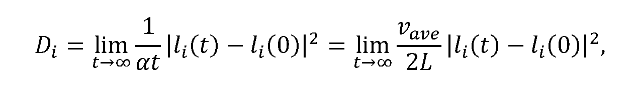 where i = x,y or z.
[00107] The nanoparticles were randomly placed in the mesopores of the porous network without overiapping with each other. A large enough computational domain was considered to eliminate the fluctuations due to the randomness of nanoparticle positions. For the SBA-15, 2 periodic nanochannels, each with length of 10,240,000 nm and diameter of 8 nm were considered. For the SBA-16, a periodic domain of 1024 nm X 1024 nm X 1024 nm was considered with meso- and micro- pore diameters being 6 nm and 4 nm, respectively.
[00108] The model configurations of SBA-15 and SBA-16 frameworks are shown in Figure 20, where the geometrical parameters are consistent with experimental results. Because the pore diameters are much smaller than the mean free path of the methane molecules, Knudsen diffusion of methane is considered as the dominating transport mechanism in both SBA-15 and SBA-16. This is confirmed by the GCMC simulations in the range of temperature from 600 °C to 800°C, where the calculated low methane loadings in SBA-15 (7-9 CH4 molecules/unit cell) and SBA-16 (4-5 CH4 molecules/unit cell) indicate that CH4-surface collisions is much more frequent than the intermolecular collisions.
[00109] DMC simulations discover varying morphological effects of the Fe2O3 nanoparticles supported by different mesoporous network on the CH4 diffusivity (DCH4). FIG. 21 features the mesoporous networks of Fe2O3@SBA-15 and Fe2O3@SBA-16 adopted in the DMC simulations, and FIG. 21 illustrates the influence of nanoparticle size and loading on DCH4. As shown in FIG. 22A, DMC simulations reveal the dependence of DCH4 on nanoparticle size is distinct between Fe2O3@SBA-15 and Fe2O3@SBA-16. DCH4 of Fe2O3@SBA-15 (DCH4,Fe2O3@SBA-15) decreases significantly with increasing nanoparticle sizes, whereas DCH4 of Fe2O3@SBA-16 (DCH4,Fe2 o3 @SBA-16) is nearly independent of nanoparticle size. A relative diameter between nanoparticles and mesopore is established to determine DCH4,Fe2 O3@SBA-15 and
 DCH4,Fe2 O3 @SBA-16 under different particle loadings. DCH4,Fe2 O3 @SBA-16 is higher than DCH4,Fe2 O3 @SBA-15 in the region above
 whereas DCH4,Fe2 O3@SBA-16 is lower than DCH4,Fe2 O3 @SBA-15 in the region below
 The
The
 is between 0.93 and 0.95 in this simulation when the nanoparticle loading is 0.10 and 0.04, respectively, indicating a high dr facilitates methane diffusion in Fe2O3@SBA-16.
[00110] Here we discover two distinct factors that appear to impact methane diffusivity. A congestion effect is defined as the phenomena that confines methane molecule diffusion in the space between Fe2O3 nanoparticles and internal surface of silica wall. A trapping effect is defined as the phenomena that methane molecules are caged in the space created by neighbouring Fe2O3 nanoparticles. Both effects are illustrated as in Figure 22.
[00111] The different sensitivity of DCH4 with respect to nanoparticle size between Fe2O3@SBA-15 and Fe2O3@SBA-16 can be attributed to their distinct flow patterns, which are dictated by the morphology of the mesoporous networks shown in FIG. 20 and FIG. 21. For Fe2O3@SBA-15, the mesopores are constructed by 2-D cylindrical channels; as a result, methane molecules would be trapped in the spaces between neighbouring nanoparticles by the narrow spaces between the nanoparticle and the silica wall when the nanoparticle size becomes considerable as shown in FIG. 21 A.
[00112] On the other hand, mesopores in Fe2O3@SBA-16 adopts a fully connected 3-D body centered cubic structure, which substantially mitigates the trapping effect with minimal
congestion effect by allowing the molecules to bypass through the micropores that surrounds the mesopore cavity, as shown in FIG. 21B. Therefore DCH4.FC2O3@SBA-15 is found much higher than DCH4.FC2O3@SBA-15 when the relative diameter is above
 as presented in FIG. 22A.
[00113] FIG. 22B further considers the cases where the size of dispersed nanoparticles follows the cut-off normal distribution, which matches the experimental observations from TEM and redox performance in the current study. It is also worth pointing out that DCH4.FC2O3@SBA-15 is higher than DCH4.FC2O3@SBA-16 when the relative diameter is below as indicated in

FIG. 22A. This can be explained by the fact that CH4 diffuses faster in the framework of SBA-15 than SBA-16 without the presence of nanoparticles as shown in FIG. 22B. Thus, when the loading particles possess small sizes, the congestion effect and trapping effect in SBA-15 framework can be overcome.
[00114] The nanoparticle trapping effect is also reflected by the results in FIG. 22 that a higher loading leads to a lower DCH4 in both mesoporous networks. In short, the DMC results demonstrate the necessity of considering the trapping effect and congestion effect of nanoparticles and mesoporous structures on diffusivity.
G. BET Surface Area for SBA-15 and SBA-16 [00115] N2 physisorption was used to analyze solid surface and pore size distribution by a NOVA 4200 surface area analyzer. The surface areas were calculated adopting the Brunauer- Emmett-Teller (BET) method. Pore size distributions were calculated by Brunauer-Joyner- Halenda (BJH) method based on the adsorption of N2 isotherm curve.
[00116] FIG. 23 shows surface analysis results of SBA-15 and SBA-16, where (A) and (C) are isothermal curves of (A) SBA-15 and (C) SBA-16; Pore size distribution of (B) SBA-15 and (D) SBA-16. The mesoporous silica SBA-15 exhibited a uniform pore size of 8 nm, while SBA-16 had a wider pore size distribution with a peak at 6 nm. The comparable surface areas of for SBA- 15 and SBA-16 were 550 m2/g and 643 m2/g, respectively. The pore volume was 0.66 cm3/g for SBA-15 and 0.48 cm3/g for SBA-16.
[00117] Unless otherwise defined, all technical and scientific terms used herein have the same meaning as commonly understood by one of ordinary skill in the art. In case of conflict, the present document, including definitions, will control. Example methods and materials are
described below, although methods and materials similar or equivalent to those described herein can be used in practice or testing of the present disclosure. The materials, methods, and examples disclosed herein are illustrative only and not intended to be limiting.
[00118] The terms “comprise(s),” “include(s),” “having,” “has,” “can,” “contain(s),” and variants thereof, as used herein, are intended to be open-ended transitional phrases, terms, or words that do not preclude the possibility of additional acts or structures. The singular forms “a,” “an” and “the” include plural references unless the context clearly dictates otherwise. The present disclosure also contemplates other embodiments “comprising,” “consisting of’ and “consisting essentially of,” the embodiments or elements presented herein, whether explicitly set forth or not.
[00119] The modifier “about” used in connection with a quantity is inclusive of the stated value and has the meaning dictated by the context (for example, it includes at least the degree of error associated with the measurement of the particular quantity). The modifier “about” should also be considered as disclosing the range defined by the absolute values of the two endpoints. For example, the expression “from about 2 to about 4” also discloses the range “from 2 to 4.”
The term “about” may refer to plus or minus 10% of the indicated number. For example, “about 10%” may indicate a range of 9% to 11%, and “about 1” may mean from 0.9-1.1. Other meanings of “about” may be apparent from the context, such as rounding off, so, for example “about 1” may also mean from 0.5 to 1.4.
[00120] Definitions of specific functional groups and chemical terms are described in more detail below. For purposes of this disclosure, the chemical elements are identified in accordance with the Periodic Table of the Elements, CAS version, Handbook of Chemistry and Physics, 75 th Ed., inside cover, and specific functional groups are generally defined as described therein. [00121] For the recitation of numeric ranges herein, each intervening number there between with the same degree of precision is explicitly contemplated. For example, for the range of 6-9, the numbers 7 and 8 are contemplated in addition to 6 and 9, and for the range 6.0-7.0, the number 6.0, 6.1, 6.2, 6.3, 6.4, 6.5, 6.6, 6.7, 6.8, 6.9, and 7.0 are explicitly contemplated. For example, when a pressure range is described as being between ambient pressure and another pressure, a pressure that is ambient pressure is expressly contemplated.
Claims
We claim:
1. An oxygen carrier, comprising: a mesoporous support; and a plurality of metal oxide-based nanoparticles immobilized on the mesoporous support, wherein the plurality of metal oxide-based nanoparticles comprise 10 volume percent to 80 volume percent of mesopores in the mesoporous support.
2. The oxygen carrier according to claim 1, wherein the plurality of metal oxide-based nanoparticles include Fe2O3, NiO, CuO, spinel, perovskite or combinations thereof.
3. The oxygen carrier according to claim 1, wherein the plurality of metal oxide-based nanoparticles include Fe2O3.
4. The oxygen carrier according to claim 3, wherein each of the plurality of metal oxide-based nanoparticles comprise 22 weight percent to 86 weight percent of mesopores in the mesoporous support.
5. The oxygen carrier according to any one of claims 1-4, wherein the mesoporous support is mesoporous silica, TiO2, ZrO2, or AI2O3.
6. The oxygen carrier according to claim 5, wherein the mesoporous support is Santa Barbara
Amorphous-15 silica (SBA-15), Santa Barbara Amorphous-16 silica (SB A- 16), mesoporous silica MCM-41, mesoporous silica MCM-48, titanium oxide (TiO2), Technische Universiteit Delft-1 (TUD-1), Hiroshima Mesoporous Material-33 (HMM-33), or folded sheets mesoporous material 16 (FSM-16).
7. The oxygen carrier according to any one of claims 1-4, wherein a portion of the plurality of metal oxide-based nanoparticles are immobilized on a first type of mesoporous support; wherein a remainder portion of the plurality of metal oxide-based nanoparticles are immobilized on a second type of mesoporous support, the second type being different from the first type; and wherein the first type and the second type are selected from: mesoporous silica, TiO2, ZrO2, and AI2O3.
8. The oxygen carrier according to any one of claims 1-7, wherein the volume of the plurality of metal oxide-based nanoparticles is 20 volume percent to 70 volume percent of mesopores in the mesoporous support.
9. The oxygen carrier according to any one of claims 1-8, wherein the metal oxide-based nanoparticles have an average diameter of 2 nm to 50 nm; wherein the mesoporous support has an average diameter of about 1 mm to about 4 mm; and wherein the mesoporous support has an average pore diameter of about 2 nm to about 50 nm.
10. The oxygen carrier according to any one of claims 1-9, wherein the metal oxide-based nanoparticles further comprise a dopant selected from: iron (Fe), cobalt (Co), nickel (Ni), copper (Cu), scandium (Sc), titanium (Ti), vanadium (V), chromium (Cr), manganese (Mn), zinc (Zn), yttrium (Y), zirconium (Zr), niobium (Nb), molybdenum (Mo), technetium (Tc), ruthenium (Ru), rhodium (Rh), palladium (Pd), silver (Ag), cadmium (Cd), lutetium (Lu), hafnium (Hf), tantalum (Ta), tungsten (W), rhenium (Re), osmium (Os), iridium (Ir), platinum (Pt), gold (Au), and lanthanum (La).
11. The oxygen carrier according to claim 10, wherein a dopant concentration is 0.5 atomic percent (at%) to 15 at%.
13. A method of operating a reactor, the method comprising: providing a carbonaceous feedstock to an inlet of the reactor; providing oxygen carrier particles within the reactor, wherein each of the oxygen carrier particles comprises: a mesoporous support; and a plurality of metal oxide-based nanoparticles immobilized on the mesoporous support, wherein the plurality of metal oxide-based nanoparticles comprise 10 volume percent to 80 volume percent of mesopores in the mesoporous support; and collecting a product stream from an outlet of the reactor, the product stream including at least one of: H2, carbon monoxide (CO), and C2+ hydrocarbon. 14. The method according to claim 13, further comprising arranging the reactor as a fixed bed, a moving bed, or a fluidized bed, wherein the carbonaceous feedstock includes at least one of methane (CH4), coal, carbon monoxide (CO), and carbon dioxide (CO2). 15. The method according to claim 13 or claim 14, further comprising: after collecting the product stream, providing an oxidizing agent to the inlet of the reactor; and collecting a second product stream from the outlet of the reactor, the second product stream including carbon monoxide (CO). 16. The method according to any one of claims 13-15, wherein the plurality of metal oxide- based nanoparticles include Fe2O3, NiO, CuO, ferrite, or combinations thereof; and wherein the mesoporous support is mesoporous silica SBA-15, mesoporous silica SBA-16, mesoporous silica MCM-41, TiO2, ZrO2, or Al2O3.
17. The method according to any one of claims 13-16, wherein the metal oxide-based nanoparticles further comprise a dopant selected from: Fe, Co, Ni, Cu, Sc, Ti, V, Cr, Mn, Zn, Y, Zr, Mb, Mo, Tc, Ru, Rh, Pd, Ag, Cd, Lu, Hf, Ta, W, Re, Os, Ir, Pt, Au, and La.
18. The method according to any one of claims 13-17, wherein a carbonaceous feedstock conversion rate is greater than 95%.
19. A reactor, comprising: a feedstock inlet in fluid communication with a carbonaceous feedstock source; a product stream outlet; and oxygen carrier particles, wherein each of the oxygen carrier particles comprise: a mesoporous support; and a plurality of metal oxide-based nanoparticles immobilized on the mesoporous support, wherein the plurality of metal oxide-based nanoparticles comprise 10 volume percent to 80 volume percent of mesopores in the mesoporous support.
20. The reactor according to claim 19, wherein the plurality of metal oxide-based nanoparticles include Fe2O3, NiO, CuO, ferrite, or combinations thereof; wherein the mesoporous support is mesoporous silica, TiO2, ZrO2, or AI2O3; wherein the metal oxide-based nanoparticles have an average diameter of 2 nm to 10 nm; wherein the mesoporous support has an average diameter of about 1 mm to about 4 mm; and wherein the mesoporous support has an average pore diameter of about 6 nm to about 11 nm.
Priority Applications (2)
| Application Number | Priority Date | Filing Date | Title |
|---|---|---|---|
| US17/636,160 US12350651B2 (en) | 2019-08-19 | 2020-08-19 | Mesoporous support-immobilized metal oxide-based nanoparticles |
| EP20855224.0A EP4010115A4 (en) | 2019-08-19 | 2020-08-19 | MESOPOROUS SUPPORT-IMMOBILIZED NANOPARTICLES BASED ON METAL OXIDE |
Applications Claiming Priority (2)
| Application Number | Priority Date | Filing Date | Title |
|---|---|---|---|
| US201962888886P | 2019-08-19 | 2019-08-19 | |
| US62/888,886 | 2019-08-19 |
Publications (1)
| Publication Number | Publication Date |
|---|---|
| WO2021034888A1 true WO2021034888A1 (en) | 2021-02-25 |
Family
ID=74659628
Family Applications (1)
| Application Number | Title | Priority Date | Filing Date |
|---|---|---|---|
| PCT/US2020/046918 Ceased WO2021034888A1 (en) | 2019-08-19 | 2020-08-19 | Mesoporous support-immobilized metal oxide-based nanoparticles |
Country Status (3)
| Country | Link |
|---|---|
| US (1) | US12350651B2 (en) |
| EP (1) | EP4010115A4 (en) |
| WO (1) | WO2021034888A1 (en) |
Cited By (2)
| Publication number | Priority date | Publication date | Assignee | Title |
|---|---|---|---|---|
| CN114410305A (en) * | 2022-01-13 | 2022-04-29 | 深圳市华星光电半导体显示技术有限公司 | Composite material film, preparation method thereof and display panel |
| CN116459835A (en) * | 2023-04-24 | 2023-07-21 | 华中科技大学 | A Co-Fe-based photothermal oxygen carrier and its preparation method and application |
Families Citing this family (4)
| Publication number | Priority date | Publication date | Assignee | Title |
|---|---|---|---|---|
| KR20220014120A (en) * | 2020-07-28 | 2022-02-04 | 현대자동차주식회사 | Catalyst for preparing synthesis gas, method for preparing the same, and method for preparing synthesis gas using the same |
| CN116351444B (en) * | 2023-03-31 | 2024-05-31 | 上海应用技术大学 | Preparation method and application of Cs2CuBr4 nanocrystals |
| WO2024258831A1 (en) * | 2023-06-12 | 2024-12-19 | Ohio State Innovation Foundation | Systems, methods and techniques for hydrogen production from chemical looping systems with particle heating |
| US12515203B1 (en) | 2025-06-16 | 2026-01-06 | King Fahd University Of Petroleum And Minerals | Oxygen carrier compositions |
Citations (2)
| Publication number | Priority date | Publication date | Assignee | Title |
|---|---|---|---|---|
| US20110024687A1 (en) * | 2006-09-21 | 2011-02-03 | Eltron Research & Development, Inc. | Cyclic catalytic upgrading of chemical species using metal oxide materials |
| US20180353933A1 (en) * | 2015-12-18 | 2018-12-13 | 3M Innovative Properties Company | Metal-containing sorbents for nitrogen-containing compounds |
Family Cites Families (277)
| Publication number | Priority date | Publication date | Assignee | Title |
|---|---|---|---|---|
| US1658939A (en) | 1928-02-14 | Chaeles e | ||
| US2899374A (en) | 1959-08-11 | Methods and apparatus for handling particulate solids | ||
| US971206A (en) | 1908-12-02 | 1910-09-27 | Corp Internationale Wasserstoff Ag | Process of producing hydrogen. |
| US1078686A (en) | 1910-07-16 | 1913-11-18 | Int Wasserstoff Ag | Process for the production of hydrogen. |
| US2182747A (en) | 1938-04-18 | 1939-12-05 | Kellogg M W Co | Production of hydrogen by the high pressure iron process |
| US2198560A (en) | 1938-04-18 | 1940-04-23 | Kellogg M W Co | Method for the production of hydrogen |
| US2449635A (en) | 1943-03-19 | 1948-09-21 | Standard Catalytic Co | Production of hydrogen |
| US2614067A (en) | 1948-07-02 | 1952-10-14 | Union Oil Co | Refining process and apparatus |
| US2635947A (en) | 1948-07-02 | 1953-04-21 | Union Oil Co | Hydrogen process |
| US2694622A (en) | 1948-07-02 | 1954-11-16 | Union Oil Co | Hydrocarbon refining apparatus |
| US2686819A (en) | 1949-09-01 | 1954-08-17 | Kellogg M W Co | Synthesis of methane |
| US2697686A (en) | 1951-04-26 | 1954-12-21 | Universal Oil Prod Co | Method for effecting the conversion of fluid reactant streams by contact with a moving bed of solid particles |
| US3031287A (en) | 1958-06-23 | 1962-04-24 | Homer E Benson | Process for manufacturing mixtures of hydrogen, carbon monoxide, and methane |
| US2979384A (en) | 1958-12-22 | 1961-04-11 | Parsons Co Ralph M | Process for production of hydrogen and sulfur |
| US3027238A (en) | 1959-12-07 | 1962-03-27 | Universal Oil Prod Co | Hydrogen manufacture |
| DE1248843B (en) | 1962-05-23 | |||
| FR1043603A (en) | 1963-02-20 | 1953-11-10 | Jumper in elastic material usable in files | |
| US3338667A (en) | 1963-12-02 | 1967-08-29 | Johns Manville | Recovery of silica, iron oxide and magnesium carbonate from the treatment of serpentine with ammonium bisulfate |
| US3421869A (en) | 1964-06-01 | 1969-01-14 | Con Gas Service Corp | Method for the production of a mixture of hydrogen and steam |
| US3442613A (en) | 1965-10-22 | 1969-05-06 | Braun & Co C F | Hydrocarbon reforming for production of a synthesis gas from which ammonia can be prepared |
| GB1150906A (en) | 1966-07-27 | 1969-05-07 | Mullard Ltd | Improvement relating to Screened Ferrite Elements |
| US3573224A (en) | 1967-11-14 | 1971-03-30 | Chemical Construction Corp | Production of hydrogen-rich synthesis gas |
| US3494858A (en) | 1967-11-17 | 1970-02-10 | Exxon Research Engineering Co | Two-stage countercurrent catalyst regenerator |
| US3442619A (en) | 1968-03-27 | 1969-05-06 | Consolidation Coal Co | Production of hydrogen via the steam-iron process utilizing dual solids recycle |
| US3442620A (en) | 1968-04-18 | 1969-05-06 | Consolidation Coal Co | Production of hydrogen via the steam-iron process |
| US3619142A (en) | 1969-02-11 | 1971-11-09 | Consolidation Coal Co | Continuous steam-iron process |
| US3726966A (en) | 1970-10-06 | 1973-04-10 | Phillips Petroleum Co | Barium promoted iron oxide for use as a catalyst in steam-iron process for producing hydrogen |
| NO127185B (en) | 1971-10-08 | 1973-05-21 | Elkem Spigerverket As | |
| US3801661A (en) | 1972-07-11 | 1974-04-02 | Dow Chemical Co | Selective process for the continuous dyhydrogenation of nonaromatic hydrocarbons |
| JPS5111032B2 (en) | 1973-10-29 | 1976-04-08 | ||
| US4017270A (en) | 1974-01-31 | 1977-04-12 | Kamyr, Inc. | Coal gasification process with improved procedures for continuously feeding lump coal under pressure |
| US4334959A (en) | 1974-03-07 | 1982-06-15 | Occidental Petroleum Corporation | Mixing method and apparatus |
| CA1050736A (en) | 1974-05-24 | 1979-03-20 | Occidental Petroleum Corporation | Mixing of particulate materials |
| US4075079A (en) | 1976-06-09 | 1978-02-21 | Exxon Research & Engineering Co. | Process for the production of hydrocarbons from coal |
| US4057402A (en) | 1976-06-28 | 1977-11-08 | Institute Of Gas Technology | Coal pretreatment and gasification process |
| US4151124A (en) | 1977-12-16 | 1979-04-24 | Institute Of Gas Technology | Sorbent composition and process for preparing it |
| US4155832A (en) | 1977-12-23 | 1979-05-22 | The United States Of America As Represented By The United States Department Of Energy | Hydrogenation process for solid carbonaceous materials |
| US4160663A (en) | 1978-02-21 | 1979-07-10 | Jack Hsieh | Method for the direct reduction of iron ore |
| US4212452A (en) | 1979-04-30 | 1980-07-15 | Jack Hsieh | Apparatus for the direct reduction of iron ore |
| US4272399A (en) | 1979-09-21 | 1981-06-09 | Monsanto Company | Conversion of carbon-containing materials to synthesis gas |
| US4343624A (en) | 1979-12-10 | 1982-08-10 | Caterpillar Tractor Co. | Rotating fluidized bed hydrogen production system |
| US4318711A (en) | 1979-12-28 | 1982-03-09 | Atlantic Richfield Company | Converting low BTU gas to high BTU gas |
| US4325833A (en) | 1980-06-27 | 1982-04-20 | Chevron Research Company | Three-stage catalyst regeneration |
| JPS5836034B2 (en) | 1980-12-22 | 1983-08-06 | 重質油対策技術研究組合 | Method for producing reduced iron through pyrolysis of heavy oil |
| CA1134596A (en) | 1981-07-06 | 1982-11-02 | Leo A. Behie | Process for producing hydrogen from hydrogen sulphide in a gas fluidized bed reactor |
| US4348487A (en) | 1981-11-02 | 1982-09-07 | Exxon Research And Engineering Co. | Production of methanol via catalytic coal gasification |
| US4404086A (en) | 1981-12-21 | 1983-09-13 | Standard Oil Company (Indiana) | Radial flow retorting process with trays and downcomers |
| NL190510C (en) | 1983-02-17 | 1994-04-05 | Hoogovens Groep Bv | Gas mixer. |
| US4778585A (en) | 1983-07-14 | 1988-10-18 | Research Foundation Of The City Univ. Of Ny | Two-stage pyrolysis of coal for producing liquid hydrocarbon fuels |
| US4594140A (en) | 1984-04-04 | 1986-06-10 | Cheng Shang I | Integrated coal liquefaction, gasification and electricity production process |
| FR2563118B1 (en) | 1984-04-20 | 1987-04-30 | Creusot Loire | PROCESS AND PLANT FOR TREATING FLUIDIZED BED MATERIAL |
| US4861165A (en) | 1986-08-20 | 1989-08-29 | Beloit Corporation | Method of and means for hydrodynamic mixing |
| US4869207A (en) | 1987-07-13 | 1989-09-26 | A. Ahlstrom Corporation | Circulating fluidized bed reactor |
| FR2619023B1 (en) | 1987-08-07 | 1991-04-12 | Lamort E & M | PRESSURE MIXER INJECTOR |
| DE3727119A1 (en) | 1987-08-14 | 1989-02-23 | Didier Werke Ag | METHOD FOR PRODUCING CATALYSTS FOR REDUCING NITROGEN OXIDES FROM EXHAUST GASES OR FOR CHEMICAL AIR PURIFYING METHODS AND CATALYSTS MANUFACTURED BY THE METHOD |
| US5130106A (en) | 1988-12-28 | 1992-07-14 | Uop | Moving bed radial flow reactor for high gas flow |
| US4957523A (en) | 1989-01-27 | 1990-09-18 | Pacific Consolidated Industries | High speed pressure swing adsorption liquid oxygen/liquid nitrogen generating plant |
| AU5635290A (en) | 1989-05-01 | 1990-11-29 | Ky Dangtran | Fluidized bed device for combustion of low-melting fuels |
| US5916529A (en) | 1989-07-19 | 1999-06-29 | Chevron U.S.A. Inc | Multistage moving-bed hydroprocessing reactor with separate catalyst addition and withdrawal systems for each stage, and method for hydroprocessing a hydrocarbon feed stream |
| JPH0368898A (en) | 1989-08-08 | 1991-03-25 | Nippon Nuclear Fuel Dev Co Ltd | Method of manufacturing nuclear fuel pellet |
| US4902586A (en) | 1989-08-28 | 1990-02-20 | International Fuel Cells Corporation | Once through molten carbonate fuel cell system |
| HU9201539D0 (en) | 1990-09-11 | 1992-08-28 | Kortec Ag | Method and device for gasifying gasifiable materials and/or transforming gas as well as heat exchanger of high temperature for executing said method |
| US5578498A (en) | 1991-05-22 | 1996-11-26 | Behringwerke Ag | Metal chelate containing compositions for use in chemiluminescent assays |
| US5365560A (en) | 1991-07-29 | 1994-11-15 | General Electric Company | Method and apparatus for acquiring a uniform distribution of radon data sufficiently dense to constitute a complete set for exact image reconstruction of an object irradiated by a cone beam source |
| JP3315719B2 (en) | 1992-06-03 | 2002-08-19 | 東京電力株式会社 | Chemical loop combustion power plant system |
| AU660852B2 (en) | 1992-11-25 | 1995-07-06 | Elan Pharma International Limited | Method of grinding pharmaceutical substances |
| US5827496A (en) | 1992-12-11 | 1998-10-27 | Energy And Environmental Research Corp. | Methods and systems for heat transfer by unmixed combustion |
| US5509362A (en) | 1992-12-11 | 1996-04-23 | Energy And Environmental Research Corporation | Method and apparatus for unmixed combustion as an alternative to fire |
| US5630368A (en) | 1993-05-24 | 1997-05-20 | The University Of Tennessee Research Corporation | Coal feed and injection system for a coal-fired firetube boiler |
| DE4326562C2 (en) | 1993-08-07 | 1995-06-22 | Gutehoffnungshuette Man | Method and device for the direct reduction of fine ores or fine ore concentrates |
| US5584615A (en) | 1993-12-27 | 1996-12-17 | Uop | Pneumatic particulate transport with gravity assisted flow |
| US5456807A (en) | 1994-03-09 | 1995-10-10 | Gas Research Institute | Method and apparatus for treating nitrogen oxide-containing gas streams using a combined electrochemical-sorbent approach |
| BR9506918A (en) | 1994-12-29 | 1997-09-09 | Pohang Iron & Steel Co Ltd Voe | Fluidized bed reproduction apparatus for iron ore and process for reducing iron ore using the apparatus |
| US5529599A (en) | 1995-01-20 | 1996-06-25 | Calderon; Albert | Method for co-producing fuel and iron |
| KR100249936B1 (en) | 1995-01-20 | 2000-03-15 | 제이. 에이치. 블롬 | Method for desulfurising gas stream and absorber suitable for this method |
| US5891415A (en) | 1995-05-17 | 1999-04-06 | Azerbaidzhanskaya Gosudarstvennaya Neftianaya Academiya | Process for selective oxidation of hydrogen sulfide to elemental sulfur |
| DE19546476A1 (en) | 1995-12-13 | 1997-06-19 | Daimler Benz Ag | Catalyst, process for its manufacture and use thereof |
| DE19606657C1 (en) | 1996-02-23 | 1997-07-10 | Basf Ag | Process and device for cleaning gases |
| JPH09272815A (en) | 1996-04-02 | 1997-10-21 | Merck Japan Kk | Metal oxide composite fine particles and method for producing the same |
| TW406055B (en) | 1996-04-08 | 2000-09-21 | Air Prod & Chem | Integrated steam methane reforming process for producing carbon monoxide and hydrogen |
| US5858210A (en) | 1996-05-20 | 1999-01-12 | Uop Llc | Method for regulating particle transfer rates |
| US6007699A (en) | 1996-08-21 | 1999-12-28 | Energy And Environmental Research Corporation | Autothermal methods and systems for fuels conversion |
| JP3094093B2 (en) | 1997-03-11 | 2000-10-03 | 科学技術庁無機材質研究所長 | Method for immobilizing CO2 with alkaline earth silicate |
| DE19724286A1 (en) | 1997-06-09 | 1998-12-10 | Linde Ag | Process for removing nitrogen oxides from gases |
| US6025403A (en) | 1997-07-07 | 2000-02-15 | Mobil Oil Corporation | Process for heat integration of an autothermal reformer and cogeneration power plant |
| US6361757B1 (en) | 1997-10-07 | 2002-03-26 | Nkk Corporation | Catalyst for manufacturing hydrogen or synthesis gas and manufacturing method of hydrogen or synthesis gas |
| WO2000022690A1 (en) | 1998-10-14 | 2000-04-20 | Northwest Power Systems, Llc | Fuel processing system |
| US6187465B1 (en) | 1997-11-07 | 2001-02-13 | Terry R. Galloway | Process and system for converting carbonaceous feedstocks into energy without greenhouse gas emissions |
| US5958222A (en) | 1997-11-17 | 1999-09-28 | Uop Llc | Standpipe distributor for short time contact of hydrocarbon compounds with particles |
| US6348278B1 (en) | 1998-06-09 | 2002-02-19 | Mobil Oil Corporation | Method and system for supplying hydrogen for use in fuel cells |
| US6334895B1 (en) | 1998-07-20 | 2002-01-01 | The University Of Wyoming Research Corporation | System for producing manufactured materials from coal combustion ash |
| GB9819645D0 (en) | 1998-09-10 | 1998-11-04 | Bp Chem Int Ltd | Process |
| US6258330B1 (en) | 1998-11-10 | 2001-07-10 | International Fuel Cells, Llc | Inhibition of carbon deposition on fuel gas steam reformer walls |
| US6534437B2 (en) | 1999-01-15 | 2003-03-18 | Akzo Nobel N.V. | Process for preparing a mixed metal catalyst composition |
| US6143203A (en) | 1999-04-13 | 2000-11-07 | The Boc Group, Inc. | Hydrocarbon partial oxidation process |
| AU4835800A (en) | 1999-05-07 | 2000-11-21 | Rentech, Inc. | Convertible methanol/fischer-tropsch plant and method |
| FI107758B (en) | 1999-11-10 | 2001-09-28 | Foster Wheeler Energia Oy | Reactor with circulating fluidized bed |
| US6790430B1 (en) | 1999-12-09 | 2004-09-14 | The Regents Of The University Of California | Hydrogen production from carbonaceous material |
| CA2340822C (en) | 2000-03-17 | 2010-08-03 | Snamprogetti S.P.A. | Process for the production of hydrogen |
| EP1136467A1 (en) | 2000-03-24 | 2001-09-26 | Aventis Animal Nutrition S.A. | Catalytic conversion of alkanes to alkenes |
| JP2001299744A (en) | 2000-04-18 | 2001-10-30 | Hitachi Medical Corp | Medical radiotomographic instrument |
| IL152455A0 (en) | 2000-04-24 | 2003-05-29 | Shell Int Research | In situ recovery of hydrocarbons from a kerogen-containing formation |
| AU2001281329A1 (en) | 2000-07-25 | 2002-02-05 | Apollo Energy Systems, Incorporated | Ammonia cracker for production of hydrogen |
| US7247279B2 (en) | 2000-08-01 | 2007-07-24 | Enviroscrub Technologies Corporation | System for removal of pollutants from a gas stream |
| US6506351B1 (en) | 2000-08-11 | 2003-01-14 | The Boc Group, Inc. | Removal of nitrogen oxides from gas streams |
| US6509000B1 (en) | 2000-08-31 | 2003-01-21 | Council Of Scientific And Industrial Research | Low temperature process for the production of hydrogen |
| DE10047642A1 (en) | 2000-09-26 | 2002-04-11 | Basf Ag | Process for the dehydrogenation of hydrocarbons |
| US6444712B1 (en) | 2000-09-28 | 2002-09-03 | Exxonmobil Chemical Patents, Inc. | Methanol, olefin, and hydrocarbon synthesis process |
| EP1379172A2 (en) | 2000-10-24 | 2004-01-14 | The Johns Hopkins University | Method and apparatus for multiple-projection, dual-energy x-ray absorptiometry scanning |
| US6412559B1 (en) | 2000-11-24 | 2002-07-02 | Alberta Research Council Inc. | Process for recovering methane and/or sequestering fluids |
| DE10063862A1 (en) | 2000-12-21 | 2002-07-11 | Solarworld Ag | Process for the production of high-purity, granular silicon |
| EP1372839A4 (en) | 2001-03-02 | 2006-11-29 | Mesofuel Inc | Ammonia-based hydrogen generation apparatus and method for using same |
| US6682714B2 (en) | 2001-03-06 | 2004-01-27 | Alchemix Corporation | Method for the production of hydrogen gas |
| US6685754B2 (en) | 2001-03-06 | 2004-02-03 | Alchemix Corporation | Method for the production of hydrogen-containing gaseous mixtures |
| US6663681B2 (en) | 2001-03-06 | 2003-12-16 | Alchemix Corporation | Method for the production of hydrogen and applications thereof |
| CA2444576A1 (en) | 2001-04-20 | 2002-10-31 | Shell Internationale Research Maatschappij B.V. | Process for mineral carbonation with carbon dioxide |
| US20020179887A1 (en) | 2001-05-01 | 2002-12-05 | Yongxian Zeng | Supported perovskite-type oxides and methods for preparation thereof |
| EP1262235A3 (en) | 2001-05-23 | 2003-04-16 | Rohm And Haas Company | Mixed-metal oxide catalysts containing molybdenum and vanadium and processes for preparing the same |
| JP4092090B2 (en) | 2001-06-26 | 2008-05-28 | 株式会社日本触媒 | Solid particle packed reactor and catalytic gas phase oxidation method using the reactor |
| US6568206B2 (en) | 2001-07-18 | 2003-05-27 | Air Products And Chemicals, Inc. | Cryogenic hydrogen and carbon monoxide production with membrane permeate expander |
| US6669917B2 (en) | 2001-07-31 | 2003-12-30 | General Electric Co. | Process for converting coal into fuel cell quality hydrogen and sequestration-ready carbon dioxide |
| US6494153B1 (en) | 2001-07-31 | 2002-12-17 | General Electric Co. | Unmixed combustion of coal with sulfur recycle |
| US6834623B2 (en) | 2001-08-07 | 2004-12-28 | Christopher T. Cheng | Portable hydrogen generation using metal emulsions |
| US6667022B2 (en) | 2001-08-14 | 2003-12-23 | General Electric Co. | Process for separating synthesis gas into fuel cell quality hydrogen and sequestration ready carbon dioxide |
| WO2003029390A1 (en) | 2001-09-28 | 2003-04-10 | Ebara Corporation | Process for reforming inflammable gas, apparatus for reforming inflammable gas and gasification apparatus |
| US6607704B2 (en) | 2001-10-18 | 2003-08-19 | Ford Global Technologies, Llc | Sulfur tolerant lean NOx trap |
| US6797253B2 (en) | 2001-11-26 | 2004-09-28 | General Electric Co. | Conversion of static sour natural gas to fuels and chemicals |
| FR2833005B1 (en) | 2001-11-30 | 2004-01-23 | Atofina | PROCESS FOR MANUFACTURING ACRYLIC ACID FROM PROPANE AND IN THE ABSENCE OF MOLECULAR OXYGEN |
| US6703343B2 (en) | 2001-12-18 | 2004-03-09 | Caterpillar Inc | Method of preparing doped oxide catalysts for lean NOx exhaust |
| US20030119658A1 (en) | 2001-12-21 | 2003-06-26 | Conocophillips Company | Recovery of rhenium from a spent catalyst via sublimation |
| DE10202127A1 (en) | 2002-01-22 | 2003-07-31 | Kataleuna Gmbh Catalysts | Spherical, highly active metal supported catalysts |
| US6747066B2 (en) | 2002-01-31 | 2004-06-08 | Conocophillips Company | Selective removal of oxygen from syngas |
| US20080031809A1 (en) | 2006-07-18 | 2008-02-07 | Norbeck Joseph M | Controlling the synthesis gas composition of a steam methane reformer |
| US20030162846A1 (en) | 2002-02-25 | 2003-08-28 | Wang Shoou-L | Process and apparatus for the production of synthesis gas |
| CA2478794A1 (en) | 2002-03-13 | 2003-09-25 | Conocophillips Company | Controlled-pore catalyst structures and process for producing synthesis gas |
| US7244399B2 (en) | 2002-04-26 | 2007-07-17 | Foster Wheeler Energia Oy | Grid construction for a fluidized bed reactor |
| US6919295B2 (en) | 2002-05-01 | 2005-07-19 | Rohm And Haas Company | Supported mixed metal oxide catalyst |
| AU2003231473A1 (en) | 2002-06-26 | 2004-01-19 | Kiyoshi Otsuka | Method for producing hydrogen and apparatus for supplying hydrogen |
| US7012104B2 (en) | 2002-10-16 | 2006-03-14 | Conocophillips Company | Fischer-Tropsch processes and catalysts made from a material comprising boehmite |
| JP5191626B2 (en) | 2002-10-17 | 2013-05-08 | インテグリス・インコーポレーテッド | Method for purifying carbon dioxide |
| US20040126293A1 (en) | 2002-10-23 | 2004-07-01 | Geerlings Jacobus Johannes Cornelis | Process for removal of carbon dioxide from flue gases |
| CA2448715C (en) | 2002-11-11 | 2011-07-05 | Nippon Telegraph And Telephone Corporation | Fuel cell power generating system with two fuel cells of different types and method of controlling the same |
| EP1569869A4 (en) | 2002-11-11 | 2008-11-19 | Conocophillips Co | STABILIZED ALUMINATING MATERIALS, CATALYSTS MADE THEREFROM, AND THEIR USE IN PARTIAL OXIDATION |
| US7945021B2 (en) | 2002-12-18 | 2011-05-17 | Varian Medical Systems, Inc. | Multi-mode cone beam CT radiotherapy simulator and treatment machine with a flat panel imager |
| ITMI20030192A1 (en) | 2003-02-05 | 2004-08-06 | Eni Spa | CATALYTIC SYSTEM AND PRODUCTION PROCESS |
| US7067456B2 (en) | 2003-02-06 | 2006-06-27 | The Ohio State University | Sorbent for separation of carbon dioxide (CO2) from gas mixtures |
| WO2004076017A2 (en) | 2003-02-26 | 2004-09-10 | Questair Technologies Inc. | Hydrogen recycle for high temperature fuel cells |
| US20040213705A1 (en) | 2003-04-23 | 2004-10-28 | Blencoe James G. | Carbonation of metal silicates for long-term CO2 sequestration |
| US7604787B2 (en) | 2003-05-02 | 2009-10-20 | The Penn State Research Foundation | Process for sequestering carbon dioxide and sulfur dioxide |
| US7075532B2 (en) | 2003-05-23 | 2006-07-11 | International Business Machines Corporation | Robust tetrahedralization and triangulation method with applications in VLSI layout design and manufacturability |
| US7255840B2 (en) | 2003-06-26 | 2007-08-14 | Praxair Technology, Inc. | Autothermal reactor and method for production of synthesis gas |
| TW200519073A (en) | 2003-08-21 | 2005-06-16 | Pearson Technologies Inc | Process and apparatus for the production of useful products from carbonaceous feedstock |
| AU2003256141A1 (en) | 2003-08-22 | 2005-03-10 | Instituto Mexicano Del Petroleo | Method of viewing multiphase flows using electrical capacitance tomography |
| US7767191B2 (en) | 2003-12-11 | 2010-08-03 | The Ohio State University | Combustion looping using composite oxygen carriers |
| US20070157517A1 (en) | 2004-02-06 | 2007-07-12 | David Tsay | Single stage membrane reactor for high purity hydrogen production |
| ITMI20040555A1 (en) | 2004-03-23 | 2004-06-23 | Eni Spa | PROCEDURE FOR THE PRODUCTION OF HYDROGEN AND THE CO-PRODUCTION OF CARBON DIOXIDE |
| US20050274648A1 (en) | 2004-04-21 | 2005-12-15 | Goldstein Stuart S | Method for revamping fixed-bed catalytic reformers |
| US7547419B2 (en) | 2004-06-16 | 2009-06-16 | United Technologies Corporation | Two phase injector for fluidized bed reactor |
| US20060021308A1 (en) | 2004-07-29 | 2006-02-02 | Merkel Gregory A | Mullite-aluminum titanate body and method for making same |
| US20060042565A1 (en) | 2004-08-26 | 2006-03-02 | Eaton Corporation | Integrated fuel injection system for on-board fuel reformer |
| US7223714B2 (en) | 2004-11-04 | 2007-05-29 | Exxonmobil Chemical Patents Inc. | Method of transferring catalyst in a reaction system |
| KR100655133B1 (en) | 2005-03-02 | 2006-12-08 | 아주대학교산학협력단 | Metal Oxide Catalyst for Nitric Oxide Removal |
| KR20070108269A (en) | 2005-03-29 | 2007-11-08 | 얀마 가부시키가이샤 | Exhaust gas purification device |
| US20110289845A1 (en) | 2005-04-12 | 2011-12-01 | Ze-Gen, Inc. | Method for controlling syngas production in a system with multiple feed materials using a molten metal bath |
| FR2889248B1 (en) | 2005-07-29 | 2007-09-07 | Inst Francais Du Petrole | NOVEL OXYDO-REDUCTIVE ACTIVE MASS FOR A LOOP OXYDO-REDUCTION PROCESS |
| US7842635B2 (en) | 2006-01-06 | 2010-11-30 | Headwaters Technology Innovation, Llc | Hydrocarbon-soluble, bimetallic catalyst precursors and methods for making same |
| CN104694169A (en) | 2006-01-12 | 2015-06-10 | 俄亥俄州立大学 | Systems and methods of converting fuel |
| CN101389734A (en) | 2006-01-12 | 2009-03-18 | 俄亥俄州立大学 | System and method for converting fuel |
| DE102006017614A1 (en) | 2006-04-12 | 2007-10-18 | J. Eberspächer GmbH & Co. KG | Fuel cell system and associated operating method |
| WO2007122498A2 (en) | 2006-04-24 | 2007-11-01 | University Of The Witwatersrand, Johannesburg | Improvement of carbon efficiencies in hydrocarbon production |
| NZ573217A (en) | 2006-05-05 | 2011-11-25 | Plascoenergy Ip Holdings S L Bilbao Schaffhausen Branch | A facility for conversion of carbonaceous feedstock into a reformulated syngas containing CO and H2 |
| WO2007134075A2 (en) | 2006-05-08 | 2007-11-22 | Alchemix Corporation | Method for the gasification of hydrocarbon feedstocks |
| WO2008019079A2 (en) | 2006-08-04 | 2008-02-14 | Zabolotny Ernest R | Gasification process |
| ES2822323T3 (en) | 2006-09-25 | 2021-04-30 | Ohio State Innovation Foundation | Calcium cycling process for the production of high purity hydrogen |
| US20080134666A1 (en) | 2006-12-11 | 2008-06-12 | Parag Prakash Kulkarni | Systems and Methods Using an Unmixed Fuel Processor |
| WO2008071215A1 (en) | 2006-12-14 | 2008-06-19 | Horst Grochowski | Method and device for scrubbing effluent gases from a sintering process for ores or other metal-containing materials in metal production |
| US7902416B2 (en) | 2006-12-28 | 2011-03-08 | Uop Llc | Fluidized bed reactor with back-mixing for dehydrogenation of light paraffins |
| WO2008082312A1 (en) | 2007-01-05 | 2008-07-10 | Sinvent As | Hydrogen production |
| NO328522B1 (en) | 2007-03-19 | 2010-03-08 | Statoil Asa | Hydrogen production process, hydrogen production plant, a water gas exchange reactor and a process for producing hydrogen from syngas. |
| US7840053B2 (en) | 2007-04-05 | 2010-11-23 | Liao Hstau Y | System and methods for tomography image reconstruction |
| US8017019B2 (en) | 2007-06-14 | 2011-09-13 | Kansas State University Research Foundation | Fluidized bed precipitator with optimized solids settling and solids handling features for use in recovering phosphorus from wastewater |
| DE102007031635A1 (en) | 2007-07-06 | 2009-01-15 | Evonik Degussa Gmbh | Process for the preparation of metal oxide granules |
| BRPI0812629A2 (en) | 2007-07-09 | 2019-09-24 | Range Fuels Inc | "Synthesis gas production method, Synthesis gas formation method, Product production method, Apparatus, Devaluation method of a carbon-containing starting material and Synthesis gas production apparatus" |
| KR100896455B1 (en) | 2007-07-09 | 2009-05-14 | 한국에너지기술연구원 | Pressure swing adsorption apparatus and method for hydrogen purification using the same |
| US8926717B2 (en) | 2007-07-27 | 2015-01-06 | The Trustees Of Columbia University In The City Of New York | Methods and systems for producing synthetic fuel |
| US20090042070A1 (en) | 2007-08-08 | 2009-02-12 | The University Corporation, Inc. At California State University, Northridge | Barometric thermal trap and collection apparatus and method thereof for combining multiple exhaust streams into one |
| WO2009023515A2 (en) | 2007-08-09 | 2009-02-19 | Eli Lilly And Company | Reactors and methods for processing reactants therein |
| AT505526B1 (en) | 2007-08-14 | 2010-09-15 | Univ Wien Tech | FLUID BED REACTOR SYSTEM |
| FR2923732B1 (en) | 2007-11-16 | 2011-03-04 | Nicolas Ugolin | METHOD USING PLASMA-COUPLED SOLAR THERMAL ENERGY TO PRODUCE LIQUID FUEL AND DIHYDROGEN FROM BIOMASS OR FOSSIL CHARCOAL (P-SL AND P-SH PROCESS) |
| FR2924035B1 (en) | 2007-11-23 | 2010-09-03 | Sebatien Roux | FORMULATION OF OXIDES, ITS OBTAINING AND ITS USE AS OXYGEN CARRIER IN A PROCESS FOR OXIDATION AND / OR DEOXIDATION OF A GASEOUS FLOW |
| US7880481B2 (en) | 2007-12-19 | 2011-02-01 | Infineon Technologies Ag | Capacitive sensor and measurement system |
| US9122260B2 (en) | 2008-03-03 | 2015-09-01 | Alstom Technology Ltd | Integrated controls design optimization |
| TWI461522B (en) | 2008-03-05 | 2014-11-21 | Thyssenkrupp Uhde Gmbh | Continuous fuel supply system for a coal gasification reactor |
| CN102065983A (en) | 2008-04-21 | 2011-05-18 | 斯瓦普索尔公司 | Hydrogen sulfide conversion to hydrogen |
| FR2930733B1 (en) | 2008-04-30 | 2014-04-11 | Inst Francais Du Petrole | ACTIVE OXYDO-REDUCTION MASS AND CHEMICAL LOOP COMBUSTION METHOD |
| AU2009262073B2 (en) | 2008-06-27 | 2012-09-06 | Greatpoint Energy, Inc. | Four-train catalytic gasification systems for SNG production |
| WO2010032790A1 (en) | 2008-09-17 | 2010-03-25 | 株式会社日本触媒 | Catalyst for ammonia decomposition, process for producing same, and method of treating ammonia |
| KR101290477B1 (en) | 2008-09-19 | 2013-07-29 | 그레이트포인트 에너지, 인크. | Processes for gasification of a carbonaceous feedstock |
| WO2010037011A2 (en) | 2008-09-26 | 2010-04-01 | The Ohio State University | Conversion of carbonaceous fuels into carbon free energy carriers |
| FR2937119B1 (en) | 2008-10-15 | 2010-12-17 | Air Liquide | METHOD FOR GENERATING ENERGY AND CAPTURING CO 2 |
| CN102209675B (en) | 2008-11-14 | 2014-07-23 | 电源开发工程技术株式会社 | Lock hopper |
| WO2010063923A2 (en) | 2008-12-02 | 2010-06-10 | Jean-Xavier Morin | Facility having thermochemical cycle for reactive fuel |
| US20100187159A1 (en) | 2009-01-28 | 2010-07-29 | Christopher Naunheimer | Moving Bed Hydrocarbon Conversion Process |
| CA2954374A1 (en) | 2009-01-21 | 2010-08-12 | Res Usa, Llc | System and method for dual fluidized bed gasification |
| JP2010167366A (en) | 2009-01-22 | 2010-08-05 | Ngk Insulators Ltd | Honeycomb catalytic article |
| FR2941689B1 (en) | 2009-01-30 | 2011-02-18 | Inst Francais Du Petrole | INTEGRATED OXIDATION, REDUCTION AND GASIFICATION PROCESS FOR THE PRODUCTION OF CHEMICAL LOOP SYNTHESIS GAS |
| GB0905222D0 (en) * | 2009-03-26 | 2009-05-13 | Johnson Matthey Plc | Method for producing a supported metal nitrate |
| US8461215B2 (en) | 2009-04-10 | 2013-06-11 | University Of Southern California | Rendering coal as an environmentally carbon dioxide neutral fuel and a regenerative carbon source |
| US20100275514A1 (en) | 2009-04-14 | 2010-11-04 | Packer Engineering, Inc. | Biomass gasification/pyrolysis system and process |
| FR2945034B1 (en) | 2009-04-29 | 2012-06-08 | Inst Francais Du Petrole | INTEGRATED METHOD OF GENERATING ENERGY AND / OR SYNTHESIS GAS BY IN SITU OXYGEN PRODUCTION, CHEMICAL LOOP COMBUSTION AND GASIFICATION |
| US8500868B2 (en) | 2009-05-01 | 2013-08-06 | Massachusetts Institute Of Technology | Systems and methods for the separation of carbon dioxide and water |
| US8202349B2 (en) | 2009-06-30 | 2012-06-19 | General Electric Company | Method and apparatus for removal of carbon dioxide from pre-combustion syngas |
| WO2011002793A1 (en) | 2009-06-30 | 2011-01-06 | The University Of Connecticut | Multiple excitation capacitance polling for enhanced electronic capacitance tomography |
| US8303696B2 (en) | 2009-07-10 | 2012-11-06 | Southern Company | Carbon dioxide absorber and regeneration assemblies useful for power plant flue gas |
| US8394240B2 (en) | 2009-07-14 | 2013-03-12 | C2O Technologies, Llc | Process for treating bituminous coal by removing volatile components |
| FR2948177B1 (en) | 2009-07-16 | 2011-08-05 | Inst Francais Du Petrole | CHEMICAL LOOP COMBUSTION PROCESS WITH INDEPENDENT CONTROL OF SOLIDS CIRCULATION |
| WO2011021161A2 (en) | 2009-08-18 | 2011-02-24 | Oron Zachar | Method and system for producing syngas |
| EP2475613B1 (en) | 2009-09-08 | 2017-05-03 | The Ohio State University Research Foundation | Integration of reforming/water splitting and electrochemical systems for power generation with integrated carbon capture |
| CA3011693C (en) | 2009-09-08 | 2021-03-09 | The Ohio State University Research Foundation | Synthetic fuels and chemicals production with in-situ co2 capture |
| US9873840B2 (en) | 2009-09-18 | 2018-01-23 | Wormser Energy Solutions, Inc. | Integrated gasification combined cycle plant with char preparation system |
| KR101029680B1 (en) | 2009-10-26 | 2011-04-15 | 상명대학교 산학협력단 | Storage and Decomposition of Dilute Nitrogen Oxides Using Mixed Metal Oxide Catalysts |
| US20110094226A1 (en) | 2009-10-28 | 2011-04-28 | Mchugh Lawrence F | Process and apparatus for high energy efficiency chemical looping combustion |
| US8356992B2 (en) | 2009-11-30 | 2013-01-22 | Chevron U.S.A. Inc. | Method and system for capturing carbon dioxide in an oxyfiring process where oxygen is supplied by regenerable metal oxide sorbents |
| US8961629B2 (en) | 2009-12-21 | 2015-02-24 | Southern Company Services, Inc. | Apparatus, components and operating methods for circulating fluidized bed transport gasifiers and reactors |
| US8761943B2 (en) | 2010-01-29 | 2014-06-24 | Alstom Technology Ltd | Control and optimization system and method for chemical looping processes |
| DE102010028816A1 (en) | 2010-05-10 | 2011-11-10 | Highterm Research Gmbh | Fluidized bed reactor useful for producing product gas from carbon-containing input materials via allothermal gasification comprises combustion chamber with first fluidized bed, reformer reactor with second fluidized bed and feeding device |
| EP2576041A1 (en) | 2010-05-28 | 2013-04-10 | ExxonMobil Chemical Patents Inc. | Reactor with reactor head and integrated valve |
| FR2960940B1 (en) | 2010-06-02 | 2015-08-07 | Inst Francais Du Petrole | CHEMICAL LOOP COMBUSTION PROCESS WITH A REACTION ZONE INTEGRATING A GAS-SOLID SEPARATION AREA AND INSTALLATION USING SUCH A METHOD |
| FR2960869B1 (en) | 2010-06-02 | 2014-08-08 | Inst Francais Du Petrole | PROCESS AND PLANT FOR PRODUCING OXYGEN BY FLUIDIZED BED CHEMICAL LOOP |
| AT509586B8 (en) | 2010-06-11 | 2011-12-15 | Univ Wien Tech | IMPROVED SWITCH LAYER REACTOR SYSTEM |
| EP2601443A1 (en) | 2010-08-02 | 2013-06-12 | Siemens Aktiengesellschaft | Chemical looping system |
| US8508238B2 (en) | 2010-08-12 | 2013-08-13 | General Electric Company | System and method for performing electrical impedance tomography |
| CA2754948A1 (en) | 2010-10-13 | 2012-04-13 | Song Sit | Chemical looping combustion |
| FR2966160B1 (en) | 2010-10-14 | 2013-11-15 | IFP Energies Nouvelles | CATALYTIC CRACKING METHOD FOR PROCESSING LOW CARBON CONRADSON LOADS COMPRISING THE RECYCLING OF A CUTTING CUTTING ACCORDING TO A NEW TECHNOLOGY |
| EP2450420A1 (en) | 2010-11-08 | 2012-05-09 | Shell Internationale Research Maatschappij B.V. | Multi stage process for producing hydrocarbons from syngas |
| WO2012064712A1 (en) | 2010-11-08 | 2012-05-18 | The Ohio State University | Circulating fluidized bed with moving bed downcomers and gas sealing between reactors |
| KR20120064030A (en) | 2010-12-08 | 2012-06-18 | 에스케이이노베이션 주식회사 | Carbon dioxide free gasification |
| EP2515038A1 (en) | 2011-04-21 | 2012-10-24 | Nederlandse Organisatie voor toegepast -natuurwetenschappelijk onderzoek TNO | Fixed bed chemical looping combustion |
| EP2514516A1 (en) | 2011-04-21 | 2012-10-24 | Nederlandse Organisatie voor toegepast -natuurwetenschappelijk onderzoek TNO | Fixed bed filling composition |
| CA2835148C (en) | 2011-05-06 | 2019-07-16 | Stamicarbon B.V. Acting Under The Name Of Mt Innovation Center | Zero emissions sulphur recovery process with concurrent hydrogen production |
| WO2012155054A1 (en) | 2011-05-11 | 2012-11-15 | The Ohio State University | Systems for converting fuel |
| EP3584426B1 (en) | 2011-05-11 | 2021-04-14 | Ohio State Innovation Foundation | Oxygen carrying materials |
| US9017627B2 (en) | 2011-09-21 | 2015-04-28 | Shell Oil Company | Process for removing hydrogen sulfide from very sour hydrocarbon gas streams using metal sulfide |
| US8562928B2 (en) | 2011-09-21 | 2013-10-22 | Shell Oil Company | Process for producing hydrogen, sulfur and sulfur dioxide from hydrogen sulfide-containing gas streams |
| EP3326966A1 (en) | 2011-09-23 | 2018-05-30 | Newcastle Innovation Limited | Integrated chemical looping air separation in large-scale oxy-fuel plants |
| US9259168B2 (en) | 2011-10-04 | 2016-02-16 | The Ohio State University | Adaptive electrical capacitance volume tomography |
| US20130261355A1 (en) | 2012-03-28 | 2013-10-03 | Kior, Inc. | Catalyst Compositions for Use in a Two-Stage Reactor Assembly Unit for the Thermolysis and Catalytic Conversion of Biomass |
| US20130255272A1 (en) | 2012-03-30 | 2013-10-03 | Alstom Technology Ltd. | Method for carbon capture in a gas turbine based power plant using chemical looping reactor system |
| CN104582829B (en) | 2012-08-29 | 2016-12-28 | 博里利斯股份公司 | Reactor assembly and method for olefinic polymerization |
| WO2014073965A1 (en) | 2012-11-08 | 2014-05-15 | Stamicarbon B.V. Acting Under The Name Of Mt Innovation Center | Process for sulphur recovery with concurrent hydrogen production from nh3 containing feed |
| PL2916947T3 (en) | 2012-11-08 | 2021-04-19 | Stamicarbon B.V. Acting Under The Name Of Mt Innovation Center | METHOD OF GENERATION OF HYDROGEN FROM A GAS STREAM CONTAINING H2S |
| JP6197044B2 (en) | 2012-11-30 | 2017-09-13 | サウジ アラビアン オイル カンパニー | Stepwise chemical looping process with integrated oxygen production |
| WO2014091024A1 (en) | 2012-12-13 | 2014-06-19 | Shell Internationale Research Maatschappij B.V. | Integrated recovery of hydrocarbons from a subsurface reservoir with nitrogen injection |
| CN109536210B (en) | 2013-02-05 | 2020-12-18 | 俄亥俄州国家创新基金会 | Method for conversion of carbonaceous fuels |
| US20160030904A1 (en) | 2013-03-13 | 2016-02-04 | Ohio State Innovation Foundation | Distributing secondary solids in packed moving bed reactors |
| WO2014160223A1 (en) | 2013-03-13 | 2014-10-02 | Ohio State Innovation Foundation | Oxygen carrying materials and methods for making the same |
| WO2014152814A1 (en) | 2013-03-14 | 2014-09-25 | Ohio State Innovation Foundation | Systems and devices for fuel conversion |
| US9616403B2 (en) | 2013-03-14 | 2017-04-11 | Ohio State Innovation Foundation | Systems and methods for converting carbonaceous fuels |
| US9481837B2 (en) | 2013-03-15 | 2016-11-01 | The Babcock & Wilcox Company | Chemical looping processes for partial oxidation of carbonaceous fuels |
| WO2014151138A1 (en) | 2013-03-15 | 2014-09-25 | Seerstone Llc | Reactors, systems, and methods for forming solid products |
| EP2810709A1 (en) | 2013-06-06 | 2014-12-10 | Saudi Basic Industries Corporation | Catalyst composition for the production of syngas |
| US9790605B2 (en) | 2013-06-27 | 2017-10-17 | Yale University | Iridium complexes for electrocatalysis |
| CN103468322B (en) | 2013-07-25 | 2015-08-12 | 易高环保能源研究院有限公司 | A method for producing hydrogen-rich gas by steam gasification of solid organic matter |
| US8877150B1 (en) | 2013-07-26 | 2014-11-04 | The Ohio State University | Single-step process for the simultaneous removal of CO2, SOx and NOx from a gas mixture |
| BR112016001590B1 (en) | 2013-07-31 | 2019-10-22 | Midrex Technologies, Inc. | method to reduce iron oxide to metallic iron |
| WO2015131117A1 (en) | 2014-02-27 | 2015-09-03 | Ohio State Innovation Foundation | Systems and methods for partial or complete oxidation of fuels |
| US20150343416A1 (en) | 2014-06-03 | 2015-12-03 | Saudi Arabian Oil Company | Activation of Waste Metal Oxide as an Oxygen Carrier for Chemical Looping Combustion Applications |
| EP3200908B1 (en) | 2014-10-01 | 2019-02-27 | Shell International Research Maatschappij B.V. | Systems and methods for providing feed material to a pressurized system |
| US9902615B2 (en) | 2015-07-14 | 2018-02-27 | The Babcock & Wilcox Company | Syngas production via cyclic reduction and oxidation of metal oxides |
| NO20151775A1 (en) | 2015-12-22 | 2017-06-23 | Inst Energiteknik | Sustainable oxygen carriers for chemical looping combustion with oxygen uncoupling and methods for their manufacture |
| RU2734917C2 (en) | 2016-03-22 | 2020-10-26 | Хальдор Топсёэ А/С | Sulphides based alkanes dehydrogenation catalysts |
| EP3429738B1 (en) | 2016-04-12 | 2024-07-17 | Ohio State Innovation Foundation | Chemical looping syngas production from carbonaceous fuels |
| WO2018166812A1 (en) | 2017-03-17 | 2018-09-20 | Haldor Topsøe A/S | A process for the dehydrogenation of alkanes to alkenes and iron-based catalysts for use in the process |
| US10434471B2 (en) | 2017-04-17 | 2019-10-08 | Toyota Motor Engineering & Manufacturing North America, Inc. | Copper oxides supported on spinel oxides as catalysts for low temperature direct NOx decomposition |
| CN111065459B (en) | 2017-07-31 | 2023-09-22 | 俄亥俄州立创新基金会 | Reactor systems with unequal reactor component operating pressures |
| US10549236B2 (en) | 2018-01-29 | 2020-02-04 | Ohio State Innovation Foundation | Systems, methods and materials for NOx decomposition with metal oxide materials |
| EP3956260A4 (en) | 2019-04-18 | 2023-01-11 | Commonwealth Scientific and Industrial Research Organisation | CHEMICAL LOOP PROCESS FOR HYDROGEN PRODUCTION |
-
2020
- 2020-08-19 WO PCT/US2020/046918 patent/WO2021034888A1/en not_active Ceased
- 2020-08-19 EP EP20855224.0A patent/EP4010115A4/en not_active Withdrawn
- 2020-08-19 US US17/636,160 patent/US12350651B2/en active Active
Patent Citations (2)
| Publication number | Priority date | Publication date | Assignee | Title |
|---|---|---|---|---|
| US20110024687A1 (en) * | 2006-09-21 | 2011-02-03 | Eltron Research & Development, Inc. | Cyclic catalytic upgrading of chemical species using metal oxide materials |
| US20180353933A1 (en) * | 2015-12-18 | 2018-12-13 | 3M Innovative Properties Company | Metal-containing sorbents for nitrogen-containing compounds |
Non-Patent Citations (2)
| Title |
|---|
| LIN HSING-AN, LIU CHUN-HSIA, HUANG WEI-CHIA, LIOU SZ-CHIAN, CHU MING-WEN, CHEN CHENG-HSUAN, LEE JYH-FU, YANG CHIA-MIN: "Novel Magnetically Separable Mesoporous Fe203@SBA-15 Nanocomposite with Fully Open Mesochannels for Protein Immobilization", CHEMISTRY OF MATERIALS, vol. 20, 2008, pages 6617 - 6622, XP055795074 * |
| See also references of EP4010115A4 * |
Cited By (2)
| Publication number | Priority date | Publication date | Assignee | Title |
|---|---|---|---|---|
| CN114410305A (en) * | 2022-01-13 | 2022-04-29 | 深圳市华星光电半导体显示技术有限公司 | Composite material film, preparation method thereof and display panel |
| CN116459835A (en) * | 2023-04-24 | 2023-07-21 | 华中科技大学 | A Co-Fe-based photothermal oxygen carrier and its preparation method and application |
Also Published As
| Publication number | Publication date |
|---|---|
| EP4010115A1 (en) | 2022-06-15 |
| US12350651B2 (en) | 2025-07-08 |
| US20220288568A1 (en) | 2022-09-15 |
| EP4010115A4 (en) | 2023-07-19 |
Similar Documents
| Publication | Publication Date | Title |
|---|---|---|
| US12350651B2 (en) | Mesoporous support-immobilized metal oxide-based nanoparticles | |
| Tahay et al. | Highly porous monolith/TiO2 supported Cu, Cu-Ni, Ru, and Pt catalysts in methanol steam reforming process for H2 generation | |
| Han et al. | Highly active and anticoke Ni/CeO2 with ultralow Ni loading in chemical looping dry reforming via the strong metal–support interaction | |
| Pu et al. | Core-shell nickel catalysts for the steam reforming of acetic acid | |
| EP2251080B1 (en) | A porous catalytic body that decomposes hydrocarbons and a manufacturing method thereof, a method for manufacturing mixed reformed gas that comprises hydrogen from hydrocarbon, and a fuel cell system | |
| Taherian et al. | Promoted nickel-based catalysts on modified mesoporous silica support: The role of yttria and magnesia on CO2 methanation | |
| KR101994152B1 (en) | A Reduced Carbon Poisoning Perovskite Catalyst Impregnated with Metal Ion, Preparation Method Thereof and Methane Reforming Method Threrewith | |
| US20100298131A1 (en) | Catalyst For Hydrogen Production By Autothermal Reforming, Method Of Making Same And Use Thereof | |
| Lim et al. | Porosity effect on ZrO 2 hollow shells and hydrothermal stability for catalytic steam reforming of methane | |
| Wu et al. | Surface Oxygen Vacancies Induced by Calcium Substitution in Macroporous La2Ce2–x Ca x O7− δ Catalysts for Boosting Low-Temperature Oxidative Coupling of Methane | |
| Lu et al. | Preparation of monodispersed NiO particles in SBA-15, and its enhanced selectivity for reverse water gas shift reaction | |
| Sajjadi et al. | Combustion vs. hybrid sol-gel-plasma surface design of coke-resistant Co-promoted Ni-spinel nanocatalyst used in combined reforming of CH4/CO2/O2 for hydrogen production | |
| EP2542338A1 (en) | Catalysts for feedstock-flexible and process-flexible hydrogen production | |
| Kosinski et al. | Methanol reforming by nanostructured Pd/Sm-doped ceria catalysts | |
| Jahangiri et al. | Syngas production via auto-thermal methane reforming using modified perovskite catalysts: performance evaluation of La1− xGdxNiO3-δ perovskite oxides | |
| US9168510B2 (en) | Nickel catalysts for reforming hydrocarbons | |
| Xue et al. | Constructing Ni-based confinement catalysts with advanced performances toward the CO 2 reforming of CH 4: state-of-the-art review and perspectives | |
| Sun et al. | Yolk-shell structured Pt-CeO2@ Ni-SiO2 as an efficient catalyst for enhanced hydrogen production from ethanol steam reforming | |
| Yuan et al. | Layered Mg-Al spinel supported Ce-Fe-Zr-O oxygen carriers for chemical looping reforming | |
| Mohammadi et al. | Single-step flame aerosol synthesis of active and stable nanocatalysts for the dry reforming of methane | |
| Ping et al. | Highly efficient Ru/TiO2‐NiAl mixed oxide catalysts for CO selective methanation in hydrogen‐rich gas | |
| Liu et al. | Highly Stable Bimetal Ni–Co on Alumina-Covered Spinel Oxide Derived from High Entropy Oxide for CO2 Methanation | |
| Mei et al. | Thermo-catalytic methane decomposition for hydrogen production: Effect of palladium promoter on Ni-based catalysts | |
| Lv et al. | Dry-gel synthesis of hierarchical Ni-La@ S-1 catalysts with stabilized Ni-La bimetals nanoparticles for dry reforming of methane | |
| US12134085B2 (en) | Steam reforming catalysts for sustainable hydrogen production from biobased materials |
Legal Events
| Date | Code | Title | Description |
|---|---|---|---|
| 121 | Ep: the epo has been informed by wipo that ep was designated in this application |
Ref document number: 20855224 Country of ref document: EP Kind code of ref document: A1 |
|
| NENP | Non-entry into the national phase |
Ref country code: DE |
|
| ENP | Entry into the national phase |
Ref document number: 2020855224 Country of ref document: EP Effective date: 20220309 |
|
| WWG | Wipo information: grant in national office |
Ref document number: 17636160 Country of ref document: US |