WO2020220236A1 - Multiplexing feedback responses - Google Patents
Multiplexing feedback responses Download PDFInfo
- Publication number
- WO2020220236A1 WO2020220236A1 PCT/CN2019/085093 CN2019085093W WO2020220236A1 WO 2020220236 A1 WO2020220236 A1 WO 2020220236A1 CN 2019085093 W CN2019085093 W CN 2019085093W WO 2020220236 A1 WO2020220236 A1 WO 2020220236A1
- Authority
- WO
- WIPO (PCT)
- Prior art keywords
- transmission reception
- reception point
- feedback response
- identifier
- uplink channel
- Prior art date
- Legal status (The legal status is an assumption and is not a legal conclusion. Google has not performed a legal analysis and makes no representation as to the accuracy of the status listed.)
- Ceased
Links
Images


Classifications
-
- H—ELECTRICITY
- H04—ELECTRIC COMMUNICATION TECHNIQUE
- H04L—TRANSMISSION OF DIGITAL INFORMATION, e.g. TELEGRAPHIC COMMUNICATION
- H04L1/00—Arrangements for detecting or preventing errors in the information received
- H04L1/12—Arrangements for detecting or preventing errors in the information received by using return channel
- H04L1/16—Arrangements for detecting or preventing errors in the information received by using return channel in which the return channel carries supervisory signals, e.g. repetition request signals
- H04L1/18—Automatic repetition systems, e.g. Van Duuren systems
- H04L1/1829—Arrangements specially adapted for the receiver end
- H04L1/1854—Scheduling and prioritising arrangements
-
- H—ELECTRICITY
- H04—ELECTRIC COMMUNICATION TECHNIQUE
- H04B—TRANSMISSION
- H04B7/00—Radio transmission systems, i.e. using radiation field
- H04B7/24—Radio transmission systems, i.e. using radiation field for communication between two or more posts
- H04B7/26—Radio transmission systems, i.e. using radiation field for communication between two or more posts at least one of which is mobile
- H04B7/2615—Radio transmission systems, i.e. using radiation field for communication between two or more posts at least one of which is mobile using hybrid frequency-time division multiple access [FDMA-TDMA]
Definitions
- the subject matter disclosed herein relates generally to wireless communications and more particularly relates to multiplexing feedback responses.
- HARQ-ACK may represent collectively the Positive Acknowledge ( “ACK” ) and the Negative Acknowledge ( “NAK” ) .
- ACK means that a TB is correctly received while NAK means a TB is erroneously received.
- multiple TRPs may be used.
- feedback may be provided for data sent by the TRPs.
- the method includes receiving first downlink data from a first transmission reception point. In certain embodiments, the method includes receiving second downlink data from a second transmission reception point. In some embodiments, the method includes multiplexing a first feedback response corresponding to the first downlink data with a second feedback response corresponding to the second downlink data into a message. In various embodiments, the method includes transmitting the message to the first transmission reception point or the second transmission reception point.
- An apparatus for multiplexing feedback responses includes a receiver that: receives first downlink data from a first transmission reception point; and receives second downlink data from a second transmission reception point.
- the apparatus includes a processor that multiplexes a first feedback response corresponding to the first downlink data with a second feedback response corresponding to the second downlink data into a message.
- the apparatus includes a transmitter that transmits the message to the first transmission reception point or the second transmission reception point.
- a method for receiving a message with multiple feedback responses includes transmitting first downlink data from a first transmission reception point.
- the method includes receiving a message from a user equipment, the message comprising a first feedback response corresponding to the first downlink data and a second feedback response corresponding to second downlink data transmitted from a second transmission reception point.
- the method includes transmitting the second feedback response to the second transmission reception point.
- An apparatus for receiving a message with multiple feedback responses includes a transmitter that transmits first downlink data from a first transmission reception point.
- the apparatus includes a receiver that receives a message from a user equipment, the message comprising a first feedback response corresponding to the first downlink data and a second feedback response corresponding to second downlink data transmitted from a second transmission reception point.
- the transmitter transmits the second feedback response to the second transmission reception point.
- Figure 1 is a schematic block diagram illustrating one embodiment of a wireless communication system for multiplexing and/or demultiplexing feedback responses
- Figure 2 is a schematic block diagram illustrating one embodiment of an apparatus that may be used for multiplexing feedback responses
- Figure 3 is a schematic block diagram illustrating one embodiment of an apparatus that may be used for receiving a message with multiple feedback responses
- Figure 4 is a schematic block diagram illustrating one embodiment of a system for multi TRP communication
- Figure 5 is a schematic block diagram illustrating one embodiment of a system having multiple TRPs
- Figure 6 is a schematic block diagram illustrating one embodiment of a first TRP having a first identifier
- Figure 7 is a schematic block diagram illustrating one embodiment of a message having multiple feedback responses
- Figure 8 is a schematic flow chart diagram illustrating one embodiment of a method for multiplexing feedback responses.
- Figure 9 is a schematic flow chart diagram illustrating one embodiment of a method for receiving a message with multiple feedback responses.
- embodiments may be embodied as a system, apparatus, method, or program product. Accordingly, embodiments may take the form of an entirely hardware embodiment, an entirely software embodiment (including firmware, resident software, micro-code, etc. ) or an embodiment combining software and hardware aspects that may all generally be referred to herein as a “circuit, ” “module” or “system. ” Furthermore, embodiments may take the form of a program product embodied in one or more computer readable storage devices storing machine readable code, computer readable code, and/or program code, referred hereafter as code. The storage devices may be tangible, non-transitory, and/or non-transmission. The storage devices may not embody signals. In a certain embodiment, the storage devices only employ signals for accessing code.
- modules may be implemented as a hardware circuit comprising custom very-large-scale integration ( “VLSI” ) circuits or gate arrays, off-the-shelf semiconductors such as logic chips, transistors, or other discrete components.
- VLSI very-large-scale integration
- a module may also be implemented in programmable hardware devices such as field programmable gate arrays, programmable array logic, programmable logic devices or the like.
- Modules may also be implemented in code and/or software for execution by various types of processors.
- An identified module of code may, for instance, include one or more physical or logical blocks of executable code which may, for instance, be organized as an object, procedure, or function. Nevertheless, the executables of an identified module need not be physically located together, but may include disparate instructions stored in different locations which, when joined logically together, include the module and achieve the stated purpose for the module.
- a module of code may be a single instruction, or many instructions, and may even be distributed over several different code segments, among different programs, and across several memory devices.
- operational data may be identified and illustrated herein within modules, and may be embodied in any suitable form and organized within any suitable type of data structure. The operational data may be collected as a single data set, or may be distributed over different locations including over different computer readable storage devices.
- the software portions are stored on one or more computer readable storage devices.
- the computer readable medium may be a computer readable storage medium.
- the computer readable storage medium may be a storage device storing the code.
- the storage device may be, for example, but not limited to, an electronic, magnetic, optical, electromagnetic, infrared, holographic, micromechanical, or semiconductor system, apparatus, or device, or any suitable combination of the foregoing.
- a storage device More specific examples (a non-exhaustive list) of the storage device would include the following: an electrical connection having one or more wires, a portable computer diskette, a hard disk, a random access memory ( “RAM” ) , a read-only memory ( “ROM” ) , an erasable programmable read-only memory ( “EPROM” or Flash memory) , a portable compact disc read-only memory (CD-ROM” ) , an optical storage device, a magnetic storage device, or any suitable combination of the foregoing.
- a computer readable storage medium may be any tangible medium that can contain, or store a program for use by or in connection with an instruction execution system, apparatus, or device.
- Code for carrying out operations for embodiments may be any number of lines and may be written in any combination of one or more programming languages including an object oriented programming language such as Python, Ruby, Java, Smalltalk, C++, or the like, and conventional procedural programming languages, such as the "C" programming language, or the like, and/or machine languages such as assembly languages.
- the code may execute entirely on the user's computer, partly on the user's computer, as a stand-alone software package, partly on the user's computer and partly on a remote computer or entirely on the remote computer or server.
- the remote computer may be connected to the user's computer through any type of network, including a local area network ( “LAN” ) or a wide area network ( “WAN” ) , or the connection may be made to an external computer (for example, through the Internet using an Internet Service Provider) .
- LAN local area network
- WAN wide area network
- the code may also be stored in a storage device that can direct a computer, other programmable data processing apparatus, or other devices to function in a particular manner, such that the instructions stored in the storage device produce an article of manufacture including instructions which implement the function/act specified in the schematic flowchart diagrams and/or schematic block diagrams block or blocks.
- the code may also be loaded onto a computer, other programmable data processing apparatus, or other devices to cause a series of operational steps to be performed on the computer, other programmable apparatus or other devices to produce a computer implemented process such that the code which execute on the computer or other programmable apparatus provide processes for implementing the functions/acts specified in the flowchart and/or block diagram block or blocks.
- each block in the schematic flowchart diagrams and/or schematic block diagrams may represent a module, segment, or portion of code, which includes one or more executable instructions of the code for implementing the specified logical function (s) .
- Figure 1 depicts an embodiment of a wireless communication system 100 for multiplexing and/or demultiplexing feedback responses.
- the wireless communication system 100 includes remote units 102 and network units 104. Even though a specific number of remote units 102 and network units 104 are depicted in Figure 1, one of skill in the art will recognize that any number of remote units 102 and network units 104 may be included in the wireless communication system 100.
- the remote units 102 may include computing devices, such as desktop computers, laptop computers, personal digital assistants ( “PDAs” ) , tablet computers, smart phones, smart televisions (e.g., televisions connected to the Internet) , set-top boxes, game consoles, security systems (including security cameras) , vehicle on-board computers, network devices (e.g., routers, switches, modems) , IoT devices, or the like.
- the remote units 102 include wearable devices, such as smart watches, fitness bands, optical head-mounted displays, or the like.
- the remote units 102 may be referred to as subscriber units, mobiles, mobile stations, users, terminals, mobile terminals, fixed terminals, subscriber stations, UE, user terminals, a device, or by other terminology used in the art.
- the remote units 102 may communicate directly with one or more of the network units 104 via UL communication signals and/or the remote units 102 may communicate directly with other remote units 102 via sidelink communication.
- the network units 104 may be distributed over a geographic region.
- a network unit 104 may also be referred to as an access point, an access terminal, a base, a base station, a Node-B, an eNB, a gNB, a Home Node-B, a RAN, a relay node, a device, a network device, an IAB node, a donor IAB node, or by any other terminology used in the art.
- the network units 104 are generally part of a radio access network that includes one or more controllers communicably coupled to one or more corresponding network units 104.
- the radio access network is generally communicably coupled to one or more core networks, which may be coupled to other networks, like the Internet and public switched telephone networks, among other networks.
- core networks like the Internet and public switched telephone networks, among other networks.
- the wireless communication system 100 is compliant with the 5G or NG (Next Generation) standard of the 3GPP protocol, wherein the network unit 104 transmits using NG RAN technology. More generally, however, the wireless communication system 100 may implement some other open or proprietary communication protocol, for example, WiMAX, among other protocols.
- the present disclosure is not intended to be limited to the implementation of any particular wireless communication system architecture or protocol.
- the network units 104 may serve a number of remote units 102 within a serving area, for example, a cell or a cell sector via a wireless communication link.
- the network units 104 transmit DL communication signals to serve the remote units 102 in the time, frequency, and/or spatial domain.
- a remote unit 102 may receive first downlink data from a first transmission reception point. In certain embodiments, the remote unit 102 may receive second downlink data from a second transmission reception point. In some embodiments, the remote unit 102 may multiplex a first feedback response corresponding to the first downlink data with a second feedback response corresponding to the second downlink data into a message. In various embodiments, the remote unit 102 may transmit the message to the first transmission reception point or the second transmission reception point. Accordingly, a remote unit 102 may be used for multiplexing feedback responses.
- a network unit 104 may transmit first downlink data from a first transmission reception point.
- the network unit 104 may receive a message from a user equipment, the message comprising a first feedback response corresponding to the first downlink data and a second feedback response corresponding to second downlink data transmitted from a second transmission reception point.
- the network unit 104 may transmit the second feedback response to the second transmission reception point. Accordingly, a network unit 104 may be used for receiving a message with multiple feedback responses.
- Figure 2 depicts one embodiment of an apparatus 200 that may be used for multiplexing feedback responses.
- the apparatus 200 includes one embodiment of the remote unit 102.
- the remote unit 102 may include a processor 202, a memory 204, an input device 206, a display 208, a transmitter 210, and a receiver 212.
- the input device 206 and the display 208 are combined into a single device, such as a touchscreen.
- the remote unit 102 may not include any input device 206 and/or display 208.
- the remote unit 102 may include one or more of the processor 202, the memory 204, the transmitter 210, and the receiver 212, and may not include the input device 206 and/or the display 208.
- the processor 202 may include any known controller capable of executing computer-readable instructions and/or capable of performing logical operations.
- the processor 202 may be a microcontroller, a microprocessor, a central processing unit ( “CPU” ) , a graphics processing unit ( “GPU” ) , an auxiliary processing unit, a field programmable gate array ( “FPGA” ) , or similar programmable controller.
- the processor 202 executes instructions stored in the memory 204 to perform the methods and routines described herein.
- the processor 202 may multiplex a first feedback response corresponding to first downlink data with a second feedback response corresponding to second downlink data into a message.
- the processor 202 is communicatively coupled to the memory 204, the input device 206, the display 208, the transmitter 210, and the receiver 212.
- the memory 204 in one embodiment, is a computer readable storage medium.
- the memory 204 includes volatile computer storage media.
- the memory 204 may include a RAM, including dynamic RAM ( “DRAM” ) , synchronous dynamic RAM ( “SDRAM” ) , and/or static RAM ( “SRAM” ) .
- the memory 204 includes non-volatile computer storage media.
- the memory 204 may include a hard disk drive, a flash memory, or any other suitable non-volatile computer storage device.
- the memory 204 includes both volatile and non-volatile computer storage media.
- the memory 204 also stores program code and related data, such as an operating system or other controller algorithms operating on the remote unit 102.
- the input device 206 may include any known computer input device including a touch panel, a button, a keyboard, a stylus, a microphone, or the like.
- the input device 206 may be integrated with the display 208, for example, as a touchscreen or similar touch-sensitive display.
- the input device 206 includes a touchscreen such that text may be input using a virtual keyboard displayed on the touchscreen and/or by handwriting on the touchscreen.
- the input device 206 includes two or more different devices, such as a keyboard and a touch panel.
- the display 208 may include any known electronically controllable display or display device.
- the display 208 may be designed to output visual, audible, and/or haptic signals.
- the display 208 includes an electronic display capable of outputting visual data to a user.
- the display 208 may include, but is not limited to, an LCD display, an LED display, an OLED display, a projector, or similar display device capable of outputting images, text, or the like to a user.
- the display 208 may include a wearable display such as a smart watch, smart glasses, a heads-up display, or the like.
- the display 208 may be a component of a smart phone, a personal digital assistant, a television, a table computer, a notebook (laptop) computer, a personal computer, a vehicle dashboard, or the like.
- the display 208 includes one or more speakers for producing sound.
- the display 208 may produce an audible alert or notification (e.g., a beep or chime) .
- the display 208 includes one or more haptic devices for producing vibrations, motion, or other haptic feedback.
- all or portions of the display 208 may be integrated with the input device 206.
- the input device 206 and display 208 may form a touchscreen or similar touch-sensitive display.
- the display 208 may be located near the input device 206.
- the transmitter 210 is used to provide UL communication signals to the network unit 104 and the receiver 212 is used to receive DL communication signals from the network unit 104.
- the receiver 212 receives first downlink data from a first transmission reception point; and receives second downlink data from a second transmission reception point.
- the transmitter 210 transmits a message to the first transmission reception point or the second transmission reception point.
- the remote unit 102 may have any suitable number of transmitters 210 and receivers 212.
- the transmitter 210 and the receiver 212 may be any suitable type of transmitters and receivers.
- the transmitter 210 and the receiver 212 may be part of a transceiver.
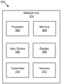
- Figure 3 depicts one embodiment of an apparatus 300 that may be used for receiving a message with multiple feedback responses.
- the apparatus 300 includes one embodiment of the network unit 104.
- the network unit 104 may include a processor 302, a memory 304, an input device 306, a display 308, a transmitter 310, and a receiver 312.
- the processor 302, the memory 304, the input device 306, the display 308, the transmitter 310, and the receiver 312 may be substantially similar to the processor 202, the memory 204, the input device 206, the display 208, the transmitter 210, and the receiver 212 of the remote unit 102, respectively.
- the transmitter 310 transmits first downlink data from a first transmission reception point.
- the receiver 312 receives a message from a user equipment, the message comprising a first feedback response corresponding to the first downlink data and a second feedback response corresponding to second downlink data transmitted from a second transmission reception point.
- the processor 302 may demultiplex the first feedback response and the second feedback response from the message.
- the transmitter 310 transmits the second feedback response to the second transmission reception point.
- the network unit 104 may have any suitable number of transmitters 310 and receivers 312.
- the transmitter 310 and the receiver 312 may be any suitable type of transmitters and receivers.
- the transmitter 310 and the receiver 312 may be part of a transceiver.
- FIG. 4 is a schematic block diagram illustrating one embodiment of a system 400 for multi TRP communication.
- the system 400 includes a first TRP 402 and a second TRP 404 that make concurrent (e.g., simultaneous, overlapping) transmissions to a UE 406 (e.g., having one or more panels) .
- the system 400 may include multiple PDCCHs that schedule multiple PDSCHs and/or PUSCHs from the first TRP 402 and the second TRP 404.
- communications between the first TRP 402 and the UE 406 may include communications 408, such as PDCCH (e.g., PDCCH1) , PDSCH (e.g., PDSCH1) , and PUSCH (e.g., PUSCH1)
- communications between the second TRP 404 and the UE 406 may include communications 410, such as PDCCH (e.g., PDCCH2) , PDSCH (e.g., PDSCH2) , and PUSCH (e.g., PUSCH2) .
- PDCCH e.g., PDCCH2
- PDSCH e.g., PDSCH2
- PUSCH e.g., PUSCH2
- the UE 406 may send ACK/NACK separately to each of the first TRP 402 and the second TRP 404.
- transmission delay may be reduced by sending ACK/NACK for both of the first TRP 402 and the second TRP 404 multiplexed together and transmitted to only the first TRP 402 (or the second TRP 404) .
- the first TRP 402 and the second TRP 404 are connected with ideal backhaul, the first TRP 402 may transmit the ACK/NACK corresponding to the second TRP 404 over the ideal backhaul channel.
- the UE 406 is configured with a set of CORESETs (e.g., one or more) for monitoring PDCCH.
- the network may configure the UE 406 with a set of TRPs (e.g., two or more) that the UE 406 may multiplex HARQ ACK/NACK feedback together for.
- the set of TRPs may be configured via RRC messaging.
- only TRPs that are within a configured set of TRPs can have ACK/NACK feedback corresponding to the TRPs multiplexed together and sent to one of the TRPs in the configured set of TRPs.
- the TRPs in a set of configured TRPs may communicate with one another to enable transmission of feedback data between the TRPs.
- the TRPs in a set of configured TRPs may communicate with one another using an ideal backhaul channel.
- FIG. 5 is a schematic block diagram illustrating one embodiment of a system 500 having multiple TRPs.
- the system 500 includes a first TRP 502 and a second TRP 504.
- the first TRP 502 has a first identifier 506 that identifies the first TRP 502, and the second TRP 504 has a second identifier 508 that identifiers the second TRP 504.
- FIG. 6 is a schematic block diagram illustrating one embodiment of the first TRP 502 having the first identifier 506.
- the embodiments described in relation to Figure 6 may apply to any TRP.
- the first identifier 506 may be defined as a first CORESET identifier 602. If the first TRP 502 includes multiple CORESETs, the first identifier 506 may select one of the CORESET identifiers as the first identifier 506. In the illustrated embodiment, the first TRP 502 includes two CORESETs and selects the first identifier 506 from the first CORESET identifier 602 and a second CORESET identifier 604.
- the first identifier 506 is a lowest CORESET ID from among the first CORESET identifier 602 and the second CORESET identifier 604. In various embodiments, the first identifier 506 is a highest CORESET ID from among the first CORESET identifier 602 and the second CORESET identifier 604.
- the UE 406 may determine which PUCCH resource for transmitting multiplexed HARQ ACK/NACK using any suitable method.
- the UE 406 determines the PUCCH resource for transmitting multiplexed HARQ ACK/NACK using the following rules: 1) if PUCCH resources for a TRP overlap in the time domain, determine a new PUCCH resource for the TRP using a predetermined procedure; 2) for PUCCH resources configured for transmitting to each TRP, determine whether each PUCCH resource for transmitting multiplexed HARQ ACK/NACK has sufficient resources to carry the multiplexed HARQ ACK/NACK (e.g., multiplexed HARQ ACK/NACK codebook) ; 3) only use PUCCH resources that have sufficient resources to carry the multiplexed HARQ ACK/NACK; 4) among the PUCCH resources that have sufficient resources to carry the multiplexed HARQ ACK/NACK, determine whether any of the PUCCH resources overlap in time and select one of
- Figure 7 is a schematic block diagram illustrating one embodiment of a message 700 (e.g., multiplexed HARQ ACK/NACK) having multiple feedback responses.
- the message 700 includes a first feedback response 702 (e.g., HARQ ACK/NACK corresponding to data transmitted from a first TRP) and a second feedback response 704 (e.g., HARQ ACK/NACK corresponding to data transmitted from a second TRP) .
- the message 700 may include any number of feedback responses.
- the first feedback response 702 may be the feedback response corresponding to a TRP having a lowest ID and the second feedback response 704 may be the feedback response corresponding to a TRP having a highest ID (e.g., the message 700 is arranged based on an ID corresponding to the TRP in ascending order) .
- the first feedback response 702 may be the feedback response corresponding to a TRP having a highest ID and the second feedback response 704 may be the feedback response corresponding to a TRP having a lowest ID (e.g., the message 700 is arranged based on an ID corresponding to the TRP in descending order) .
- each feedback response is generated using a predetermined procedure.
- the UE 406 transmits a multiplexed HARQ ACK/NACK using a PUCCH configuration parameter (e.g., spatial relationship information, PUCCH-spatialRelationInfo, etc. ) . In various embodiments, the UE 406 transmits the multiplexed HARQ ACK/NACK only once.
- a PUCCH configuration parameter e.g., spatial relationship information, PUCCH-spatialRelationInfo, etc.
- Figure 8 is a schematic flow chart diagram illustrating one embodiment of a method 800 for multiplexing feedback responses.
- the method 800 is performed by an apparatus, such as the remote unit 102.
- the method 800 may be performed by a processor executing program code, for example, a microcontroller, a microprocessor, a CPU, a GPU, an auxiliary processing unit, a FPGA, or the like.
- the method 800 may include receiving 802 first downlink data from a first transmission reception point. In certain embodiments, the method 800 includes receiving 804 second downlink data from a second transmission reception point. In some embodiments, the method 800 includes multiplexing 806 a first feedback response corresponding to the first downlink data with a second feedback response corresponding to the second downlink data into a message. In various embodiments, the method 800 includes transmitting 808 the message to the first transmission reception point or the second transmission reception point.
- the method 800 further comprises determining whether: to multiplex the first feedback response and the second feedback response before multiplexing the first feedback response and the second feedback response; or to transmit the first feedback response and the second feedback response separately. In some embodiments, the method 800 further comprises receiving information indicating whether the first feedback response can be multiplexed with the second feedback response. In various embodiments, the information comprises a group of transmission reception points.
- each transmission reception point of the group of transmission reception points is capable of communicating with other transmission reception points of the group of transmission reception points over a backhaul channel.
- the information is received in a radio resource control message.
- a first set of control resource sets corresponds to the first transmission reception point and a second set of control resource sets corresponds to the second transmission reception point.
- a control resource set or CORESET as used herein may refer to a set of physical resources and/or a set of parameters used to carry PDCCH and/or DCI.
- control resource sets may be defined by an RRC configuration.
- a first identifier corresponding to the first set of control resource sets identifies the first transmission reception point and a second identifier corresponding to the second set of control resource sets identifies the second transmission reception point.
- the first identifier is a lowest control resource set identifier corresponding to the first set of control resource sets and the second identifier is a lowest control resource set identifier corresponding to the second set of control resource sets.
- the method 800 further comprises selecting to transmit the message to the first transmission reception point or the second transmission reception point based on a first uplink channel configuration corresponding to the first transmission reception point and a second uplink channel configuration corresponding to the second transmission reception point.
- selecting to transmit the message to the first transmission reception point or the second transmission reception point comprises determining whether a first uplink channel corresponding to the first uplink channel configuration overlaps with a second uplink channel corresponding to the second uplink channel configuration.
- the method 800 further comprises, in response to the first uplink channel overlapping with the second uplink channel, selecting to transmit the message to the first transmission reception point or the second transmission reception point based on a first size of the first uplink channel and a second size of the second uplink channel, a first time to completion for the first uplink channel and a second time to completion for the second uplink channel, or a combination thereof.
- a time to completion may refer to a time at which a transmission (e.g., PUCCH transmission) is complete (e.g., a time at the end of a last symbol used for a transmission, such as a time at the end of a last OFDM symbol used for PUCCH) .
- the method 800 further comprises, in response to the first uplink channel overlapping with the second uplink channel, selecting to transmit the message to the first transmission reception point or the second transmission reception point based on a first size of the first uplink channel and a second size of the second uplink channel, a first identifier corresponding to the first uplink channel and a second identifier corresponding to the second uplink channel, or a combination thereof.
- the method 800 further comprises selecting to transmit the message to the first transmission reception point or the second transmission reception point based on first spatial relationship information in the first uplink channel configuration and second spatial relationship information in the second uplink channel configuration.
- multiplexing the first feedback response corresponding to the first downlink data with the second feedback response corresponding to the second downlink data into the message comprises generating the first feedback response based on a first downlink assignment index corresponding to the first transmission reception point and generating the second feedback response based on a second downlink assignment index corresponding to the second transmission reception point.
- the method 800 further comprises assigning a first identifier to the first transmission reception point and a second identifier to the second transmission reception point, wherein the first identifier corresponds to the first feedback response and the second identifier corresponds to the second feedback response.
- multiplexing the first feedback response corresponding to the first downlink data with the second feedback response corresponding to the second downlink data into the message comprises multiplexing the first feedback response and the second feedback response based on the first identifier and the second identifier.
- multiplexing the first feedback response corresponding to the first downlink data with the second feedback response corresponding to the second downlink data into the message comprises concatenating the first feedback response and the second feedback response into the message based on the first identifier and the second identifier.
- Figure 9 is a schematic flow chart diagram illustrating one embodiment of a method 900 for receiving a message with multiple feedback responses.
- the method 900 is performed by an apparatus, such as the network unit 104.
- the method 900 may be performed by a processor executing program code, for example, a microcontroller, a microprocessor, a CPU, a GPU, an auxiliary processing unit, a FPGA, or the like.
- the method 900 may include transmitting 902 first downlink data from a first transmission reception point.
- the method 900 includes receiving 904 a message from a user equipment, the message comprising a first feedback response corresponding to the first downlink data and a second feedback response corresponding to second downlink data transmitted from a second transmission reception point.
- the method 900 includes transmitting 906 the second feedback response to the second transmission reception point.
- the method 900 further comprises transmitting information indicating whether the first feedback response can be multiplexed with the second feedback response.
- the information may be transmitted from the network unit 104 to a remote unit 102 (e.g., UE) .
- the information comprises a group of transmission reception points.
- each transmission reception point of the group of transmission reception points is capable of communicating with other transmission reception points of the group of transmission reception points over a backhaul channel.
- the information is transmitted in a radio resource control message.
- a first set of control resource sets corresponds to the first transmission reception point and a second set of control resource sets corresponds to the second transmission reception point.
- a first identifier corresponding to the first set of control resource sets identifies the first transmission reception point and a second identifier corresponding to the second set of control resource sets identifies the second transmission reception point.
- the first identifier is a lowest control resource set identifier corresponding to the first set of control resource sets and the second identifier is a lowest control resource set identifier corresponding to the second set of control resource sets.
- the second feedback response is transmitted to the second transmission reception point over a backhaul channel.
- a method comprises: receiving first downlink data from a first transmission reception point; receiving second downlink data from a second transmission reception point; multiplexing a first feedback response corresponding to the first downlink data with a second feedback response corresponding to the second downlink data into a message; and transmitting the message to the first transmission reception point or the second transmission reception point.
- the method further comprises determining whether: to multiplex the first feedback response and the second feedback response before multiplexing the first feedback response and the second feedback response; or to transmit the first feedback response and the second feedback response separately.
- the method further comprises receiving information indicating whether the first feedback response can be multiplexed with the second feedback response.
- the information comprises a group of transmission reception points.
- each transmission reception point of the group of transmission reception points is capable of communicating with other transmission reception points of the group of transmission reception points over a backhaul channel.
- the information is received in a radio resource control message.
- a first set of control resource sets corresponds to the first transmission reception point and a second set of control resource sets corresponds to the second transmission reception point.
- a first identifier corresponding to the first set of control resource sets identifies the first transmission reception point and a second identifier corresponding to the second set of control resource sets identifies the second transmission reception point.
- the first identifier is a lowest control resource set identifier corresponding to the first set of control resource sets and the second identifier is a lowest control resource set identifier corresponding to the second set of control resource sets.
- the method further comprises selecting to transmit the message to the first transmission reception point or the second transmission reception point based on a first uplink channel configuration corresponding to the first transmission reception point and a second uplink channel configuration corresponding to the second transmission reception point.
- selecting to transmit the message to the first transmission reception point or the second transmission reception point comprises determining whether a first uplink channel corresponding to the first uplink channel configuration overlaps with a second uplink channel corresponding to the second uplink channel configuration.
- the method further comprises, in response to the first uplink channel overlapping with the second uplink channel, selecting to transmit the message to the first transmission reception point or the second transmission reception point based on a first size of the first uplink channel and a second size of the second uplink channel, a first time to completion for the first uplink channel and a second time to completion for the second uplink channel, or a combination thereof.
- the method further comprises, in response to the first uplink channel overlapping with the second uplink channel, selecting to transmit the message to the first transmission reception point or the second transmission reception point based on a first size of the first uplink channel and a second size of the second uplink channel, a first identifier corresponding to the first uplink channel and a second identifier corresponding to the second uplink channel, or a combination thereof.
- the method further comprises selecting to transmit the message to the first transmission reception point or the second transmission reception point based on first spatial relationship information in the first uplink channel configuration and second spatial relationship information in the second uplink channel configuration.
- multiplexing the first feedback response corresponding to the first downlink data with the second feedback response corresponding to the second downlink data into the message comprises generating the first feedback response based on a first downlink assignment index corresponding to the first transmission reception point and generating the second feedback response based on a second downlink assignment index corresponding to the second transmission reception point.
- the method further comprises assigning a first identifier to the first transmission reception point and a second identifier to the second transmission reception point, wherein the first identifier corresponds to the first feedback response and the second identifier corresponds to the second feedback response.
- multiplexing the first feedback response corresponding to the first downlink data with the second feedback response corresponding to the second downlink data into the message comprises multiplexing the first feedback response and the second feedback response based on the first identifier and the second identifier.
- the first feedback response may be positioned first in the message if the first identifier has a lower value than the second identifier
- the second feedback response may be positioned second in the message if the second identifier has a higher value than the first identifier.
- the first feedback response may be positioned first in the message if the first identifier has a higher value than the second identifier, and the second feedback response may be positioned second in the message if the second identifier has a lower value than the first identifier.
- multiplexing the first feedback response corresponding to the first downlink data with the second feedback response corresponding to the second downlink data into the message comprises concatenating the first feedback response and the second feedback response into the message based on the first identifier and the second identifier.
- the first feedback response may be inserted first in the message if the first identifier has a lower value than the second identifier, and the second feedback response may be appended after the first feedback message if the second identifier has a higher value than the first identifier.
- the first feedback response may be inserted first in the message if the first identifier has a higher value than the second identifier, and the second feedback response may be appended after the second feedback message if the second identifier has a lower value than the first identifier.
- an apparatus comprises: a receiver that: receives first downlink data from a first transmission reception point; and receives second downlink data from a second transmission reception point; a processor that multiplexes a first feedback response corresponding to the first downlink data with a second feedback response corresponding to the second downlink data into a message; and a transmitter that transmits the message to the first transmission reception point or the second transmission reception point.
- the processor determines whether: to multiplex the first feedback response and the second feedback response before multiplexing the first feedback response and the second feedback response; or to transmit the first feedback response and the second feedback response separately.
- the receiver receives information indicating whether the first feedback response can be multiplexed with the second feedback response.
- the information comprises a group of transmission reception points.
- each transmission reception point of the group of transmission reception points is capable of communicating with other transmission reception points of the group of transmission reception points over a backhaul channel.
- the information is received in a radio resource control message.
- a first set of control resource sets corresponds to the first transmission reception point and a second set of control resource sets corresponds to the second transmission reception point.
- a first identifier corresponding to the first set of control resource sets identifies the first transmission reception point and a second identifier corresponding to the second set of control resource sets identifies the second transmission reception point.
- the first identifier is a lowest control resource set identifier corresponding to the first set of control resource sets and the second identifier is a lowest control resource set identifier corresponding to the second set of control resource sets.
- the processor selects to transmit the message to the first transmission reception point or the second transmission reception point based on a first uplink channel configuration corresponding to the first transmission reception point and a second uplink channel configuration corresponding to the second transmission reception point.
- the processor selecting to transmit the message to the first transmission reception point or the second transmission reception point comprises the processor determining whether a first uplink channel corresponding to the first uplink channel configuration overlaps with a second uplink channel corresponding to the second uplink channel configuration.
- the processor in response to the first uplink channel overlapping with the second uplink channel, selects to transmit the message to the first transmission reception point or the second transmission reception point based on a first size of the first uplink channel and a second size of the second uplink channel, a first time to completion for the first uplink channel and a second time to completion for the second uplink channel, or a combination thereof.
- the processor in response to the first uplink channel overlapping with the second uplink channel, selects to transmit the message to the first transmission reception point or the second transmission reception point based on a first size of the first uplink channel and a second size of the second uplink channel, a first identifier corresponding to the first uplink channel and a second identifier corresponding to the second uplink channel, or a combination thereof.
- the processor selects to transmit the message to the first transmission reception point or the second transmission reception point based on first spatial relationship information in the first uplink channel configuration and second spatial relationship information in the second uplink channel configuration.
- the processor multiplexing the first feedback response corresponding to the first downlink data with the second feedback response corresponding to the second downlink data into the message comprises the processor generating the first feedback response based on a first downlink assignment index corresponding to the first transmission reception point and generating the second feedback response based on a second downlink assignment index corresponding to the second transmission reception point.
- the processor assigns a first identifier to the first transmission reception point and a second identifier to the second transmission reception point, and the first identifier corresponds to the first feedback response and the second identifier corresponds to the second feedback response.
- the processor multiplexing the first feedback response corresponding to the first downlink data with the second feedback response corresponding to the second downlink data into the message comprises the processor multiplexing the first feedback response and the second feedback response based on the first identifier and the second identifier.
- the processor multiplexing the first feedback response corresponding to the first downlink data with the second feedback response corresponding to the second downlink data into the message comprises the processor concatenating the first feedback response and the second feedback response into the message based on the first identifier and the second identifier.
- a method comprises: transmitting first downlink data from a first transmission reception point; receiving a message from a user equipment, the message comprising a first feedback response corresponding to the first downlink data and a second feedback response corresponding to second downlink data transmitted from a second transmission reception point; and transmitting the second feedback response to the second transmission reception point.
- the method further comprises transmitting information indicating whether the first feedback response can be multiplexed with the second feedback response.
- the information comprises a group of transmission reception points.
- each transmission reception point of the group of transmission reception points is capable of communicating with other transmission reception points of the group of transmission reception points over a backhaul channel.
- the information is transmitted in a radio resource control message.
- a first set of control resource sets corresponds to the first transmission reception point and a second set of control resource sets corresponds to the second transmission reception point.
- a first identifier corresponding to the first set of control resource sets identifies the first transmission reception point and a second identifier corresponding to the second set of control resource sets identifies the second transmission reception point.
- the first identifier is a lowest control resource set identifier corresponding to the first set of control resource sets and the second identifier is a lowest control resource set identifier corresponding to the second set of control resource sets.
- the second feedback response is transmitted to the second transmission reception point over a backhaul channel.
- an apparatus comprises: a transmitter that transmits first downlink data from a first transmission reception point; and a receiver that receives a message from a user equipment, the message comprising a first feedback response corresponding to the first downlink data and a second feedback response corresponding to second downlink data transmitted from a second transmission reception point; wherein the transmitter transmits the second feedback response to the second transmission reception point.
- the transmitter transmits information indicating whether the first feedback response can be multiplexed with the second feedback response.
- the information comprises a group of transmission reception points.
- each transmission reception point of the group of transmission reception points is capable of communicating with other transmission reception points of the group of transmission reception points over a backhaul channel.
- the information is transmitted in a radio resource control message.
- a first set of control resource sets corresponds to the first transmission reception point and a second set of control resource sets corresponds to the second transmission reception point.
- a first identifier corresponding to the first set of control resource sets identifies the first transmission reception point and a second identifier corresponding to the second set of control resource sets identifies the second transmission reception point.
- the first identifier is a lowest control resource set identifier corresponding to the first set of control resource sets and the second identifier is a lowest control resource set identifier corresponding to the second set of control resource sets.
- the second feedback response is transmitted to the second transmission reception point over a backhaul channel.
Landscapes
- Engineering & Computer Science (AREA)
- Computer Networks & Wireless Communication (AREA)
- Signal Processing (AREA)
- Mobile Radio Communication Systems (AREA)
Abstract
Apparatuses, methods, and systems are disclosed for multiplexing feedback responses. One method (800) includes receiving (802) first downlink data from a first transmission reception point. The method (800) includes receiving (804) second downlink data from a second transmission reception point. The method (800) includes multiplexing (806) a first feedback response corresponding to the first downlink data with a second feedback response corresponding to the second downlink data into a message. The method (800) includes transmitting (808) the message to the first transmission reception point or the second transmission reception point.
Description
The subject matter disclosed herein relates generally to wireless communications and more particularly relates to multiplexing feedback responses.
The following abbreviations are herewith defined, at least some of which are referred to within the following description: Third Generation Partnership Project ( “3GPP” ) , 5G QoS Indicator ( “5QI” ) , Acknowledge Mode ( “AM” ) , Backhaul ( “BH” ) , Broadcast Multicast ( “BM” ) , Buffer Occupancy ( “BO” ) , Base Station ( “BS” ) , Buffer Status Report ( “BSR” ) , Bandwidth ( “BW” ) , Bandwidth Part ( “BWP” ) , Component Carrier ( “CC” ) , Code Division Multiplexing ( “CDM” ) , Control Element ( “CE” ) , Coordinated Multipoint ( “CoMP” ) , Categories of Requirements ( “CoR” ) , Control Resource Set ( “CORESET” ) , Control Plane ( “CP” ) , CSI-RS Resource Indicator ( “CRI” ) , Cell RNTI ( “C-RNTI” ) , Channel State Information ( “CSI” ) , Channel Quality Indicator ( “CQI” ) , Central Unit ( “CU” ) , Codeword ( “CW” ) , Downlink Assignment Index ( “DAI” ) , Downlink Control Information ( “DCI” ) , Downlink ( “DL” ) , Demodulation Reference Signal ( “DMRS” or “DM-RS” ) , Data Radio Bearer ( “DRB” ) , Dedicated Short-Range Communications ( “DSRC” ) , Distributed Unit ( “DU” ) , Enhanced Mobile Broadband ( “eMBB” ) , Evolved Node B ( “eNB” ) , Enhanced Subscriber Identification Module ( “eSIM” ) , Enhanced ( “E” ) , Frequency Division Duplex ( “FDD” ) , Frequency Division Multiple Access ( “FDMA” ) , Frequency Range ( “FR” ) , 450 MHz –6000 MHz ( “FR1” ) , 24250 MHz –52600 MHz ( “FR2” ) , Hybrid Automatic Repeat Request ( “HARQ” ) , Integrated Access Backhaul ( “IAB” ) , Identity or Identifier or Identification ( “ID” ) , Interference Measurement ( “IM” ) , International Mobile Subscriber Identity ( “IMSI” ) , Internet-of-Things ( “IoT” ) , Internet Protocol ( “IP” ) , Joint Transmission ( “JT” ) , Level 1 ( “L1” ) , Logical Channel ( “LCH” ) , Logical Channel Group ( “LCG” ) , Logical Channel ID ( “LCID” ) , Logical Channel Prioritization ( “LCP” ) , Long Term Evolution ( “LTE” ) , Levels of Automation ( “LoA” ) , Medium Access Control ( “MAC” ) , Modulation Coding Scheme ( “MCS” ) , Multiple Input Multiple Output ( “MIMO” ) , Mobile-Termination ( “MT” ) , Machine Type Communication ( “MTC” ) , Multi-User ( “MU” ) , Multi-User MIMO ( “MU-MIMO” ) , Negative-Acknowledgment ( “NACK” ) or ( “NAK” ) , Next Generation ( “NG” ) , Next Generation Node B ( “gNB” ) , New Radio ( “NR” ) , Non-Zero Power ( “NZP” ) , Orthogonal Frequency Division Multiplexing ( “OFDM” ) , Peak-to-Average Power Ratio ( “PAPR” ) , Physical Broadcast Channel ( “PBCH” ) , Physical Downlink Control Channel ( “PDCCH” ) , Physical Downlink Shared Channel ( “PDSCH” ) , Policy Control Function ( “PCF” ) , Packet Data Convergence Protocol ( “PDCP” ) , Packet Data Network ( “PDN” ) , Protocol Data Unit ( “PDU” ) , Public Land Mobile Network ( “PLMN” ) , Precoding Matrix Indicator ( “PMI” ) , ProSe Per Packet Priority ( “PPPP” ) , ProSe Per Packet Reliability ( “PPPR” ) , Physical Resource Block ( “PRB” ) , Packet Switched ( “PS” ) , Physical Sidelink Control Channel ( “PSCCH” ) , Physical Sidelink Shared Channel ( “PSSCH” ) , Phase Tracking RS ( “PTRS” or “PT-RS” ) , Physical Uplink Shared Channel ( “PUSCH” ) , Quasi Co-Located ( “QCL” ) , Quality of Service ( “QoS” ) , Random Access Channel ( “RACH” ) , Radio Access Network ( “RAN” ) , Radio Access Technology ( “RAT” ) , Resource Element ( “RE” ) , Rank Indicator ( “RI” ) , Radio Link Control ( “RLC” ) , Radio Link Failure ( “RLF” ) , Radio Network Temporary Identifier ( “RNTI” ) , Resource Pool ( “RP” ) , Radio Resource Control ( “RRC” ) , Reference Signal ( “RS” ) , Reference Signal Received Power ( “RSRP” ) , Reference Signal Received Quality ( “RSRQ” ) , Receive ( “RX” ) , Secondary Cell ( “SCell” ) , Sub Carrier Spacing ( “SCS” ) , Service Data Unit ( “SDU” ) , Subscriber Identity Module ( “SIM” ) , Signal-to-Interference and Noise Ratio ( “SINR” ) , Sidelink ( “SL” ) , Sequence Number ( “SN” ) , Scheduling Request ( “SR” ) , SRS Resource Indicator ( “SRI” ) , Sounding Reference Signal ( “SRS” ) , Synchronization Signal ( “SS” ) , SS/PBCH Block ( “SSB” ) , Transmission Control Information ( “TCI” ) , Time Division Duplex ( “TDD” ) , Temporary Mobile Subscriber Identity ( “TMSI” ) , Transmitted Precoding Matrix Indicator ( “TPMI” ) , Transmission Reception Point ( “TRP” ) , Transmit ( “TX” ) , User Entity/Equipment (Mobile Terminal) ( “UE” ) , Universal Integrated Circuit Card ( “UICC” ) , Uplink ( “UL” ) , Unacknowledged Mode ( “UM” ) , Universal Mobile Telecommunications System ( “UMTS” ) , User Plane ( “UP” ) , Universal Subscriber Identity Module ( “USIM” ) , Universal Terrestrial Radio Access Network ( “UTRAN” ) , Vehicle to Everything ( “V2X” ) , Voice Over IP ( “VoIP” ) , Visited Public Land Mobile Network ( “VPLMN” ) , Vehicle RNTI ( “V-RNTI” ) , Worldwide Interoperability for Microwave Access ( “WiMAX” ) , and Zero Power ( “ZP” ) . As used herein, “HARQ-ACK” may represent collectively the Positive Acknowledge ( “ACK” ) and the Negative Acknowledge ( “NAK” ) . ACK means that a TB is correctly received while NAK means a TB is erroneously received.
In certain wireless communications networks, multiple TRPs may be used. In such networks, feedback may be provided for data sent by the TRPs.
BRIEF SUMMARY
Methods for multiplexing feedback responses are disclosed. Apparatuses and systems also perform the functions of the apparatus. In one embodiment, the method includes receiving first downlink data from a first transmission reception point. In certain embodiments, the method includes receiving second downlink data from a second transmission reception point. In some embodiments, the method includes multiplexing a first feedback response corresponding to the first downlink data with a second feedback response corresponding to the second downlink data into a message. In various embodiments, the method includes transmitting the message to the first transmission reception point or the second transmission reception point.
An apparatus for multiplexing feedback responses, in one embodiment, includes a receiver that: receives first downlink data from a first transmission reception point; and receives second downlink data from a second transmission reception point. In some embodiments, the apparatus includes a processor that multiplexes a first feedback response corresponding to the first downlink data with a second feedback response corresponding to the second downlink data into a message. In certain embodiments, the apparatus includes a transmitter that transmits the message to the first transmission reception point or the second transmission reception point.
In one embodiment, a method for receiving a message with multiple feedback responses includes transmitting first downlink data from a first transmission reception point. In certain embodiments, the method includes receiving a message from a user equipment, the message comprising a first feedback response corresponding to the first downlink data and a second feedback response corresponding to second downlink data transmitted from a second transmission reception point. In some embodiments, the method includes transmitting the second feedback response to the second transmission reception point.
An apparatus for receiving a message with multiple feedback responses, in one embodiment, includes a transmitter that transmits first downlink data from a first transmission reception point. In certain embodiments, the apparatus includes a receiver that receives a message from a user equipment, the message comprising a first feedback response corresponding to the first downlink data and a second feedback response corresponding to second downlink data transmitted from a second transmission reception point. In some embodiments, the transmitter transmits the second feedback response to the second transmission reception point.
A more particular description of the embodiments briefly described above will be rendered by reference to specific embodiments that are illustrated in the appended drawings. Understanding that these drawings depict only some embodiments and are not therefore to be considered to be limiting of scope, the embodiments will be described and explained with additional specificity and detail through the use of the accompanying drawings, in which:
Figure 1 is a schematic block diagram illustrating one embodiment of a wireless communication system for multiplexing and/or demultiplexing feedback responses;
Figure 2 is a schematic block diagram illustrating one embodiment of an apparatus that may be used for multiplexing feedback responses;
Figure 3 is a schematic block diagram illustrating one embodiment of an apparatus that may be used for receiving a message with multiple feedback responses;
Figure 4 is a schematic block diagram illustrating one embodiment of a system for multi TRP communication;
Figure 5 is a schematic block diagram illustrating one embodiment of a system having multiple TRPs;
Figure 6 is a schematic block diagram illustrating one embodiment of a first TRP having a first identifier;
Figure 7 is a schematic block diagram illustrating one embodiment of a message having multiple feedback responses;
Figure 8 is a schematic flow chart diagram illustrating one embodiment of a method for multiplexing feedback responses; and
Figure 9 is a schematic flow chart diagram illustrating one embodiment of a method for receiving a message with multiple feedback responses.
As will be appreciated by one skilled in the art, aspects of the embodiments may be embodied as a system, apparatus, method, or program product. Accordingly, embodiments may take the form of an entirely hardware embodiment, an entirely software embodiment (including firmware, resident software, micro-code, etc. ) or an embodiment combining software and hardware aspects that may all generally be referred to herein as a “circuit, ” “module” or “system. ” Furthermore, embodiments may take the form of a program product embodied in one or more computer readable storage devices storing machine readable code, computer readable code, and/or program code, referred hereafter as code. The storage devices may be tangible, non-transitory, and/or non-transmission. The storage devices may not embody signals. In a certain embodiment, the storage devices only employ signals for accessing code.
Certain of the functional units described in this specification may be labeled as modules, in order to more particularly emphasize their implementation independence. For example, a module may be implemented as a hardware circuit comprising custom very-large-scale integration ( “VLSI” ) circuits or gate arrays, off-the-shelf semiconductors such as logic chips, transistors, or other discrete components. A module may also be implemented in programmable hardware devices such as field programmable gate arrays, programmable array logic, programmable logic devices or the like.
Modules may also be implemented in code and/or software for execution by various types of processors. An identified module of code may, for instance, include one or more physical or logical blocks of executable code which may, for instance, be organized as an object, procedure, or function. Nevertheless, the executables of an identified module need not be physically located together, but may include disparate instructions stored in different locations which, when joined logically together, include the module and achieve the stated purpose for the module.
Indeed, a module of code may be a single instruction, or many instructions, and may even be distributed over several different code segments, among different programs, and across several memory devices. Similarly, operational data may be identified and illustrated herein within modules, and may be embodied in any suitable form and organized within any suitable type of data structure. The operational data may be collected as a single data set, or may be distributed over different locations including over different computer readable storage devices. Where a module or portions of a module are implemented in software, the software portions are stored on one or more computer readable storage devices.
Any combination of one or more computer readable medium may be utilized. The computer readable medium may be a computer readable storage medium. The computer readable storage medium may be a storage device storing the code. The storage device may be, for example, but not limited to, an electronic, magnetic, optical, electromagnetic, infrared, holographic, micromechanical, or semiconductor system, apparatus, or device, or any suitable combination of the foregoing.
More specific examples (a non-exhaustive list) of the storage device would include the following: an electrical connection having one or more wires, a portable computer diskette, a hard disk, a random access memory ( “RAM” ) , a read-only memory ( “ROM” ) , an erasable programmable read-only memory ( “EPROM” or Flash memory) , a portable compact disc read-only memory ( “CD-ROM” ) , an optical storage device, a magnetic storage device, or any suitable combination of the foregoing. In the context of this document, a computer readable storage medium may be any tangible medium that can contain, or store a program for use by or in connection with an instruction execution system, apparatus, or device.
Code for carrying out operations for embodiments may be any number of lines and may be written in any combination of one or more programming languages including an object oriented programming language such as Python, Ruby, Java, Smalltalk, C++, or the like, and conventional procedural programming languages, such as the "C" programming language, or the like, and/or machine languages such as assembly languages. The code may execute entirely on the user's computer, partly on the user's computer, as a stand-alone software package, partly on the user's computer and partly on a remote computer or entirely on the remote computer or server. In the latter scenario, the remote computer may be connected to the user's computer through any type of network, including a local area network ( “LAN” ) or a wide area network ( “WAN” ) , or the connection may be made to an external computer (for example, through the Internet using an Internet Service Provider) .
Reference throughout this specification to “one embodiment, ” “an embodiment, ” or similar language means that a particular feature, structure, or characteristic described in connection with the embodiment is included in at least one embodiment. Thus, appearances of the phrases “in one embodiment, ” “in an embodiment, ” and similar language throughout this specification may, but do not necessarily, all refer to the same embodiment, but mean “one or more but not all embodiments” unless expressly specified otherwise. The terms “including, ” “comprising, ” “having, ” and variations thereof mean “including but not limited to, ” unless expressly specified otherwise. An enumerated listing of items does not imply that any or all of the items are mutually exclusive, unless expressly specified otherwise. The terms “a, ” “an, ” and “the” also refer to “one or more” unless expressly specified otherwise.
Furthermore, the described features, structures, or characteristics of the embodiments may be combined in any suitable manner. In the following description, numerous specific details are provided, such as examples of programming, software modules, user selections, network transactions, database queries, database structures, hardware modules, hardware circuits, hardware chips, etc., to provide a thorough understanding of embodiments. One skilled in the relevant art will recognize, however, that embodiments may be practiced without one or more of the specific details, or with other methods, components, materials, and so forth. In other instances, well-known structures, materials, or operations are not shown or described in detail to avoid obscuring aspects of an embodiment.
Aspects of the embodiments are described below with reference to schematic flowchart diagrams and/or schematic block diagrams of methods, apparatuses, systems, and program products according to embodiments. It will be understood that each block of the schematic flowchart diagrams and/or schematic block diagrams, and combinations of blocks in the schematic flowchart diagrams and/or schematic block diagrams, can be implemented by code. The code may be provided to a processor of a general purpose computer, special purpose computer, or other programmable data processing apparatus to produce a machine, such that the instructions, which execute via the processor of the computer or other programmable data processing apparatus, create means for implementing the functions/acts specified in the schematic flowchart diagrams and/or schematic block diagrams block or blocks.
The code may also be stored in a storage device that can direct a computer, other programmable data processing apparatus, or other devices to function in a particular manner, such that the instructions stored in the storage device produce an article of manufacture including instructions which implement the function/act specified in the schematic flowchart diagrams and/or schematic block diagrams block or blocks.
The code may also be loaded onto a computer, other programmable data processing apparatus, or other devices to cause a series of operational steps to be performed on the computer, other programmable apparatus or other devices to produce a computer implemented process such that the code which execute on the computer or other programmable apparatus provide processes for implementing the functions/acts specified in the flowchart and/or block diagram block or blocks.
The schematic flowchart diagrams and/or schematic block diagrams in the Figures illustrate the architecture, functionality, and operation of possible implementations of apparatuses, systems, methods and program products according to various embodiments. In this regard, each block in the schematic flowchart diagrams and/or schematic block diagrams may represent a module, segment, or portion of code, which includes one or more executable instructions of the code for implementing the specified logical function (s) .
It should also be noted that, in some alternative implementations, the functions noted in the block may occur out of the order noted in the Figures. For example, two blocks shown in succession may, in fact, be executed substantially concurrently, or the blocks may sometimes be executed in the reverse order, depending upon the functionality involved. Other steps and methods may be conceived that are equivalent in function, logic, or effect to one or more blocks, or portions thereof, of the illustrated Figures.
Although various arrow types and line types may be employed in the flowchart and/or block diagrams, they are understood not to limit the scope of the corresponding embodiments. Indeed, some arrows or other connectors may be used to indicate only the logical flow of the depicted embodiment. For instance, an arrow may indicate a waiting or monitoring period of unspecified duration between enumerated steps of the depicted embodiment. It will also be noted that each block of the block diagrams and/or flowchart diagrams, and combinations of blocks in the block diagrams and/or flowchart diagrams, can be implemented by special purpose hardware-based systems that perform the specified functions or acts, or combinations of special purpose hardware and code.
The description of elements in each figure may refer to elements of proceeding figures. Like numbers refer to like elements in all figures, including alternate embodiments of like elements.
Figure 1 depicts an embodiment of a wireless communication system 100 for multiplexing and/or demultiplexing feedback responses. In one embodiment, the wireless communication system 100 includes remote units 102 and network units 104. Even though a specific number of remote units 102 and network units 104 are depicted in Figure 1, one of skill in the art will recognize that any number of remote units 102 and network units 104 may be included in the wireless communication system 100.
In one embodiment, the remote units 102 may include computing devices, such as desktop computers, laptop computers, personal digital assistants ( “PDAs” ) , tablet computers, smart phones, smart televisions (e.g., televisions connected to the Internet) , set-top boxes, game consoles, security systems (including security cameras) , vehicle on-board computers, network devices (e.g., routers, switches, modems) , IoT devices, or the like. In some embodiments, the remote units 102 include wearable devices, such as smart watches, fitness bands, optical head-mounted displays, or the like. Moreover, the remote units 102 may be referred to as subscriber units, mobiles, mobile stations, users, terminals, mobile terminals, fixed terminals, subscriber stations, UE, user terminals, a device, or by other terminology used in the art. The remote units 102 may communicate directly with one or more of the network units 104 via UL communication signals and/or the remote units 102 may communicate directly with other remote units 102 via sidelink communication.
The network units 104 may be distributed over a geographic region. In certain embodiments, a network unit 104 may also be referred to as an access point, an access terminal, a base, a base station, a Node-B, an eNB, a gNB, a Home Node-B, a RAN, a relay node, a device, a network device, an IAB node, a donor IAB node, or by any other terminology used in the art. The network units 104 are generally part of a radio access network that includes one or more controllers communicably coupled to one or more corresponding network units 104. The radio access network is generally communicably coupled to one or more core networks, which may be coupled to other networks, like the Internet and public switched telephone networks, among other networks. These and other elements of radio access and core networks are not illustrated but are well known generally by those having ordinary skill in the art.
In one implementation, the wireless communication system 100 is compliant with the 5G or NG (Next Generation) standard of the 3GPP protocol, wherein the network unit 104 transmits using NG RAN technology. More generally, however, the wireless communication system 100 may implement some other open or proprietary communication protocol, for example, WiMAX, among other protocols. The present disclosure is not intended to be limited to the implementation of any particular wireless communication system architecture or protocol.
The network units 104 may serve a number of remote units 102 within a serving area, for example, a cell or a cell sector via a wireless communication link. The network units 104 transmit DL communication signals to serve the remote units 102 in the time, frequency, and/or spatial domain.
In some embodiments, a remote unit 102 may receive first downlink data from a first transmission reception point. In certain embodiments, the remote unit 102 may receive second downlink data from a second transmission reception point. In some embodiments, the remote unit 102 may multiplex a first feedback response corresponding to the first downlink data with a second feedback response corresponding to the second downlink data into a message. In various embodiments, the remote unit 102 may transmit the message to the first transmission reception point or the second transmission reception point. Accordingly, a remote unit 102 may be used for multiplexing feedback responses.
In various embodiments, a network unit 104 may transmit first downlink data from a first transmission reception point. In certain embodiments, the network unit 104 may receive a message from a user equipment, the message comprising a first feedback response corresponding to the first downlink data and a second feedback response corresponding to second downlink data transmitted from a second transmission reception point. In some embodiments, the network unit 104 may transmit the second feedback response to the second transmission reception point. Accordingly, a network unit 104 may be used for receiving a message with multiple feedback responses.
Figure 2 depicts one embodiment of an apparatus 200 that may be used for multiplexing feedback responses. The apparatus 200 includes one embodiment of the remote unit 102. Furthermore, the remote unit 102 may include a processor 202, a memory 204, an input device 206, a display 208, a transmitter 210, and a receiver 212. In some embodiments, the input device 206 and the display 208 are combined into a single device, such as a touchscreen. In certain embodiments, the remote unit 102 may not include any input device 206 and/or display 208. In various embodiments, the remote unit 102 may include one or more of the processor 202, the memory 204, the transmitter 210, and the receiver 212, and may not include the input device 206 and/or the display 208.
The processor 202, in one embodiment, may include any known controller capable of executing computer-readable instructions and/or capable of performing logical operations. For example, the processor 202 may be a microcontroller, a microprocessor, a central processing unit ( “CPU” ) , a graphics processing unit ( “GPU” ) , an auxiliary processing unit, a field programmable gate array ( “FPGA” ) , or similar programmable controller. In some embodiments, the processor 202 executes instructions stored in the memory 204 to perform the methods and routines described herein. In some embodiments, the processor 202 may multiplex a first feedback response corresponding to first downlink data with a second feedback response corresponding to second downlink data into a message. The processor 202 is communicatively coupled to the memory 204, the input device 206, the display 208, the transmitter 210, and the receiver 212.
The memory 204, in one embodiment, is a computer readable storage medium. In some embodiments, the memory 204 includes volatile computer storage media. For example, the memory 204 may include a RAM, including dynamic RAM ( “DRAM” ) , synchronous dynamic RAM ( “SDRAM” ) , and/or static RAM ( “SRAM” ) . In some embodiments, the memory 204 includes non-volatile computer storage media. For example, the memory 204 may include a hard disk drive, a flash memory, or any other suitable non-volatile computer storage device. In some embodiments, the memory 204 includes both volatile and non-volatile computer storage media. In some embodiments, the memory 204 also stores program code and related data, such as an operating system or other controller algorithms operating on the remote unit 102.
The input device 206, in one embodiment, may include any known computer input device including a touch panel, a button, a keyboard, a stylus, a microphone, or the like. In some embodiments, the input device 206 may be integrated with the display 208, for example, as a touchscreen or similar touch-sensitive display. In some embodiments, the input device 206 includes a touchscreen such that text may be input using a virtual keyboard displayed on the touchscreen and/or by handwriting on the touchscreen. In some embodiments, the input device 206 includes two or more different devices, such as a keyboard and a touch panel.
The display 208, in one embodiment, may include any known electronically controllable display or display device. The display 208 may be designed to output visual, audible, and/or haptic signals. In some embodiments, the display 208 includes an electronic display capable of outputting visual data to a user. For example, the display 208 may include, but is not limited to, an LCD display, an LED display, an OLED display, a projector, or similar display device capable of outputting images, text, or the like to a user. As another, non-limiting, example, the display 208 may include a wearable display such as a smart watch, smart glasses, a heads-up display, or the like. Further, the display 208 may be a component of a smart phone, a personal digital assistant, a television, a table computer, a notebook (laptop) computer, a personal computer, a vehicle dashboard, or the like.
In certain embodiments, the display 208 includes one or more speakers for producing sound. For example, the display 208 may produce an audible alert or notification (e.g., a beep or chime) . In some embodiments, the display 208 includes one or more haptic devices for producing vibrations, motion, or other haptic feedback. In some embodiments, all or portions of the display 208 may be integrated with the input device 206. For example, the input device 206 and display 208 may form a touchscreen or similar touch-sensitive display. In other embodiments, the display 208 may be located near the input device 206.
The transmitter 210 is used to provide UL communication signals to the network unit 104 and the receiver 212 is used to receive DL communication signals from the network unit 104. In one embodiment, the receiver 212: receives first downlink data from a first transmission reception point; and receives second downlink data from a second transmission reception point. In certain embodiments, the transmitter 210 transmits a message to the first transmission reception point or the second transmission reception point.
Although only one transmitter 210 and one receiver 212 are illustrated, the remote unit 102 may have any suitable number of transmitters 210 and receivers 212. The transmitter 210 and the receiver 212 may be any suitable type of transmitters and receivers. In one embodiment, the transmitter 210 and the receiver 212 may be part of a transceiver.
Figure 3 depicts one embodiment of an apparatus 300 that may be used for receiving a message with multiple feedback responses. The apparatus 300 includes one embodiment of the network unit 104. Furthermore, the network unit 104 may include a processor 302, a memory 304, an input device 306, a display 308, a transmitter 310, and a receiver 312. As may be appreciated, the processor 302, the memory 304, the input device 306, the display 308, the transmitter 310, and the receiver 312 may be substantially similar to the processor 202, the memory 204, the input device 206, the display 208, the transmitter 210, and the receiver 212 of the remote unit 102, respectively.
In various embodiments, the transmitter 310 transmits first downlink data from a first transmission reception point. In certain embodiments, the receiver 312 receives a message from a user equipment, the message comprising a first feedback response corresponding to the first downlink data and a second feedback response corresponding to second downlink data transmitted from a second transmission reception point. In some embodiments, the processor 302 may demultiplex the first feedback response and the second feedback response from the message. In various embodiments, the transmitter 310 transmits the second feedback response to the second transmission reception point. Although only one transmitter 310 and one receiver 312 are illustrated, the network unit 104 may have any suitable number of transmitters 310 and receivers 312. The transmitter 310 and the receiver 312 may be any suitable type of transmitters and receivers. In one embodiment, the transmitter 310 and the receiver 312 may be part of a transceiver.
Figure 4 is a schematic block diagram illustrating one embodiment of a system 400 for multi TRP communication. The system 400 includes a first TRP 402 and a second TRP 404 that make concurrent (e.g., simultaneous, overlapping) transmissions to a UE 406 (e.g., having one or more panels) . In one embodiment, the system 400 may include multiple PDCCHs that schedule multiple PDSCHs and/or PUSCHs from the first TRP 402 and the second TRP 404. In such an embodiment, communications between the first TRP 402 and the UE 406 may include communications 408, such as PDCCH (e.g., PDCCH1) , PDSCH (e.g., PDSCH1) , and PUSCH (e.g., PUSCH1) , and communications between the second TRP 404 and the UE 406 may include communications 410, such as PDCCH (e.g., PDCCH2) , PDSCH (e.g., PDSCH2) , and PUSCH (e.g., PUSCH2) . It should be noted that while the system 400 includes only two TRPs, other embodiments of the system 400 may include any suitable number of TRPs.
As may be appreciated, in response to the first TRP 402 and the second TRP 404 transmitting PDCCH and PDSCH to the UE 406, the UE 406 may send ACK/NACK separately to each of the first TRP 402 and the second TRP 404. As described herein, transmission delay may be reduced by sending ACK/NACK for both of the first TRP 402 and the second TRP 404 multiplexed together and transmitted to only the first TRP 402 (or the second TRP 404) . Moreover, if the first TRP 402 and the second TRP 404 are connected with ideal backhaul, the first TRP 402 may transmit the ACK/NACK corresponding to the second TRP 404 over the ideal backhaul channel. In some embodiments, for each of the first TRP 402 and the second TRP 404, the UE 406 is configured with a set of CORESETs (e.g., one or more) for monitoring PDCCH.
In certain embodiments, the network (e.g., the network unit 104) may configure the UE 406 with a set of TRPs (e.g., two or more) that the UE 406 may multiplex HARQ ACK/NACK feedback together for. In such embodiments, the set of TRPs may be configured via RRC messaging. In various embodiments, only TRPs that are within a configured set of TRPs can have ACK/NACK feedback corresponding to the TRPs multiplexed together and sent to one of the TRPs in the configured set of TRPs. As may be appreciated, the TRPs in a set of configured TRPs may communicate with one another to enable transmission of feedback data between the TRPs. In some embodiments, the TRPs in a set of configured TRPs may communicate with one another using an ideal backhaul channel.
Figure 5 is a schematic block diagram illustrating one embodiment of a system 500 having multiple TRPs. The system 500 includes a first TRP 502 and a second TRP 504. The first TRP 502 has a first identifier 506 that identifies the first TRP 502, and the second TRP 504 has a second identifier 508 that identifiers the second TRP 504.
Figure 6 is a schematic block diagram illustrating one embodiment of the first TRP 502 having the first identifier 506. The embodiments described in relation to Figure 6 may apply to any TRP. The first identifier 506 may be defined as a first CORESET identifier 602. If the first TRP 502 includes multiple CORESETs, the first identifier 506 may select one of the CORESET identifiers as the first identifier 506. In the illustrated embodiment, the first TRP 502 includes two CORESETs and selects the first identifier 506 from the first CORESET identifier 602 and a second CORESET identifier 604. In some embodiments, the first identifier 506 is a lowest CORESET ID from among the first CORESET identifier 602 and the second CORESET identifier 604. In various embodiments, the first identifier 506 is a highest CORESET ID from among the first CORESET identifier 602 and the second CORESET identifier 604.
The UE 406 may determine which PUCCH resource for transmitting multiplexed HARQ ACK/NACK using any suitable method. In one embodiment, the UE 406 determines the PUCCH resource for transmitting multiplexed HARQ ACK/NACK using the following rules: 1) if PUCCH resources for a TRP overlap in the time domain, determine a new PUCCH resource for the TRP using a predetermined procedure; 2) for PUCCH resources configured for transmitting to each TRP, determine whether each PUCCH resource for transmitting multiplexed HARQ ACK/NACK has sufficient resources to carry the multiplexed HARQ ACK/NACK (e.g., multiplexed HARQ ACK/NACK codebook) ; 3) only use PUCCH resources that have sufficient resources to carry the multiplexed HARQ ACK/NACK; 4) among the PUCCH resources that have sufficient resources to carry the multiplexed HARQ ACK/NACK, determine whether any of the PUCCH resources overlap in time and select one of those PUCCH resources (the selected PUCCH resource may be the PUCCH resource that completes the earliest in time or the PUCCH resource having a lowest ID, for example) ; 5) if none of the PUCCH resources have sufficient resources to carry the multiplexed HARQ ACK/NACK, transmit the HARQ ACK/NACK for each TRP separately to each TRP. In certain embodiments, after HARQ ACK/NACK information for any of the TRPs is sent to a TRP, that HARQ ACK/NACK information is not sent to any other TRP.
Figure 7 is a schematic block diagram illustrating one embodiment of a message 700 (e.g., multiplexed HARQ ACK/NACK) having multiple feedback responses. Specifically, the message 700 includes a first feedback response 702 (e.g., HARQ ACK/NACK corresponding to data transmitted from a first TRP) and a second feedback response 704 (e.g., HARQ ACK/NACK corresponding to data transmitted from a second TRP) . As may be appreciated, the message 700 may include any number of feedback responses.
In one embodiment, the first feedback response 702 may be the feedback response corresponding to a TRP having a lowest ID and the second feedback response 704 may be the feedback response corresponding to a TRP having a highest ID (e.g., the message 700 is arranged based on an ID corresponding to the TRP in ascending order) . In another embodiment, the first feedback response 702 may be the feedback response corresponding to a TRP having a highest ID and the second feedback response 704 may be the feedback response corresponding to a TRP having a lowest ID (e.g., the message 700 is arranged based on an ID corresponding to the TRP in descending order) . In certain embodiments, each feedback response is generated using a predetermined procedure. For example, the message 700 may be generated as follows in which a separate DAI counter is used by each TRP, T is a total number of TRPs, and an order of TRPs is an ascending order based on a corresponding ID (e.g., based on a CORESET ID) : 1) set t=0; 2) while t < T; 2a) generate a dynamic HARQ ACK/NACK codebook for TRP t based on a predetermined procedure (e.g., such as defined in TS 38.213 Section 9.1.3.1) ; 2b) only include the counter DAI and total DAI from the PDCCH occasions that are associated with TRP t; 2c) if t > 0, append the HARQ ACK/NACK codebook for TRP t to the message 700 after the HARQ ACK/NACK codebook of TRP t-1; 2d) if t = 0 start the message 700 by putting the HARQ ACK/NACK codebook for TRP t in the message 700; 2e) t = t + 1; 2f) end while (t) .
In some embodiments, the UE 406 transmits a multiplexed HARQ ACK/NACK using a PUCCH configuration parameter (e.g., spatial relationship information, PUCCH-spatialRelationInfo, etc. ) . In various embodiments, the UE 406 transmits the multiplexed HARQ ACK/NACK only once.
Figure 8 is a schematic flow chart diagram illustrating one embodiment of a method 800 for multiplexing feedback responses. In some embodiments, the method 800 is performed by an apparatus, such as the remote unit 102. In certain embodiments, the method 800 may be performed by a processor executing program code, for example, a microcontroller, a microprocessor, a CPU, a GPU, an auxiliary processing unit, a FPGA, or the like.
The method 800 may include receiving 802 first downlink data from a first transmission reception point. In certain embodiments, the method 800 includes receiving 804 second downlink data from a second transmission reception point. In some embodiments, the method 800 includes multiplexing 806 a first feedback response corresponding to the first downlink data with a second feedback response corresponding to the second downlink data into a message. In various embodiments, the method 800 includes transmitting 808 the message to the first transmission reception point or the second transmission reception point.
In certain embodiments, the method 800 further comprises determining whether: to multiplex the first feedback response and the second feedback response before multiplexing the first feedback response and the second feedback response; or to transmit the first feedback response and the second feedback response separately. In some embodiments, the method 800 further comprises receiving information indicating whether the first feedback response can be multiplexed with the second feedback response. In various embodiments, the information comprises a group of transmission reception points.
In one embodiment, each transmission reception point of the group of transmission reception points is capable of communicating with other transmission reception points of the group of transmission reception points over a backhaul channel. In certain embodiments, the information is received in a radio resource control message. In some embodiments, a first set of control resource sets corresponds to the first transmission reception point and a second set of control resource sets corresponds to the second transmission reception point. As may be appreciated, a control resource set or CORESET as used herein may refer to a set of physical resources and/or a set of parameters used to carry PDCCH and/or DCI. In certain embodiments, control resource sets may be defined by an RRC configuration.
In various embodiments, a first identifier corresponding to the first set of control resource sets identifies the first transmission reception point and a second identifier corresponding to the second set of control resource sets identifies the second transmission reception point. In one embodiment, the first identifier is a lowest control resource set identifier corresponding to the first set of control resource sets and the second identifier is a lowest control resource set identifier corresponding to the second set of control resource sets.
In certain embodiments, the method 800 further comprises selecting to transmit the message to the first transmission reception point or the second transmission reception point based on a first uplink channel configuration corresponding to the first transmission reception point and a second uplink channel configuration corresponding to the second transmission reception point. In some embodiments, selecting to transmit the message to the first transmission reception point or the second transmission reception point comprises determining whether a first uplink channel corresponding to the first uplink channel configuration overlaps with a second uplink channel corresponding to the second uplink channel configuration.
In various embodiments, the method 800 further comprises, in response to the first uplink channel overlapping with the second uplink channel, selecting to transmit the message to the first transmission reception point or the second transmission reception point based on a first size of the first uplink channel and a second size of the second uplink channel, a first time to completion for the first uplink channel and a second time to completion for the second uplink channel, or a combination thereof. As used herein, a time to completion may refer to a time at which a transmission (e.g., PUCCH transmission) is complete (e.g., a time at the end of a last symbol used for a transmission, such as a time at the end of a last OFDM symbol used for PUCCH) .
In one embodiment, the method 800 further comprises, in response to the first uplink channel overlapping with the second uplink channel, selecting to transmit the message to the first transmission reception point or the second transmission reception point based on a first size of the first uplink channel and a second size of the second uplink channel, a first identifier corresponding to the first uplink channel and a second identifier corresponding to the second uplink channel, or a combination thereof.
In certain embodiments, the method 800 further comprises selecting to transmit the message to the first transmission reception point or the second transmission reception point based on first spatial relationship information in the first uplink channel configuration and second spatial relationship information in the second uplink channel configuration.
In some embodiments, multiplexing the first feedback response corresponding to the first downlink data with the second feedback response corresponding to the second downlink data into the message comprises generating the first feedback response based on a first downlink assignment index corresponding to the first transmission reception point and generating the second feedback response based on a second downlink assignment index corresponding to the second transmission reception point.
In various embodiments, the method 800 further comprises assigning a first identifier to the first transmission reception point and a second identifier to the second transmission reception point, wherein the first identifier corresponds to the first feedback response and the second identifier corresponds to the second feedback response. In one embodiment, multiplexing the first feedback response corresponding to the first downlink data with the second feedback response corresponding to the second downlink data into the message comprises multiplexing the first feedback response and the second feedback response based on the first identifier and the second identifier. In certain embodiments, multiplexing the first feedback response corresponding to the first downlink data with the second feedback response corresponding to the second downlink data into the message comprises concatenating the first feedback response and the second feedback response into the message based on the first identifier and the second identifier.
Figure 9 is a schematic flow chart diagram illustrating one embodiment of a method 900 for receiving a message with multiple feedback responses. In some embodiments, the method 900 is performed by an apparatus, such as the network unit 104. In certain embodiments, the method 900 may be performed by a processor executing program code, for example, a microcontroller, a microprocessor, a CPU, a GPU, an auxiliary processing unit, a FPGA, or the like.
The method 900 may include transmitting 902 first downlink data from a first transmission reception point. In certain embodiments, the method 900 includes receiving 904 a message from a user equipment, the message comprising a first feedback response corresponding to the first downlink data and a second feedback response corresponding to second downlink data transmitted from a second transmission reception point. In some embodiments, the method 900 includes transmitting 906 the second feedback response to the second transmission reception point.
In certain embodiments, the method 900 further comprises transmitting information indicating whether the first feedback response can be multiplexed with the second feedback response. The information may be transmitted from the network unit 104 to a remote unit 102 (e.g., UE) . In some embodiments, the information comprises a group of transmission reception points. In various embodiments, each transmission reception point of the group of transmission reception points is capable of communicating with other transmission reception points of the group of transmission reception points over a backhaul channel.
In one embodiment, the information is transmitted in a radio resource control message. In certain embodiments, a first set of control resource sets corresponds to the first transmission reception point and a second set of control resource sets corresponds to the second transmission reception point. In some embodiments, a first identifier corresponding to the first set of control resource sets identifies the first transmission reception point and a second identifier corresponding to the second set of control resource sets identifies the second transmission reception point.
In various embodiments, the first identifier is a lowest control resource set identifier corresponding to the first set of control resource sets and the second identifier is a lowest control resource set identifier corresponding to the second set of control resource sets. In one embodiment, the second feedback response is transmitted to the second transmission reception point over a backhaul channel.
In one embodiment, a method comprises: receiving first downlink data from a first transmission reception point; receiving second downlink data from a second transmission reception point; multiplexing a first feedback response corresponding to the first downlink data with a second feedback response corresponding to the second downlink data into a message; and transmitting the message to the first transmission reception point or the second transmission reception point.
In certain embodiments, the method further comprises determining whether: to multiplex the first feedback response and the second feedback response before multiplexing the first feedback response and the second feedback response; or to transmit the first feedback response and the second feedback response separately.
In some embodiments, the method further comprises receiving information indicating whether the first feedback response can be multiplexed with the second feedback response.
In various embodiments, the information comprises a group of transmission reception points.
In one embodiment, each transmission reception point of the group of transmission reception points is capable of communicating with other transmission reception points of the group of transmission reception points over a backhaul channel.
In certain embodiments, the information is received in a radio resource control message.
In some embodiments, a first set of control resource sets corresponds to the first transmission reception point and a second set of control resource sets corresponds to the second transmission reception point.
In various embodiments, a first identifier corresponding to the first set of control resource sets identifies the first transmission reception point and a second identifier corresponding to the second set of control resource sets identifies the second transmission reception point.
In one embodiment, the first identifier is a lowest control resource set identifier corresponding to the first set of control resource sets and the second identifier is a lowest control resource set identifier corresponding to the second set of control resource sets.
In certain embodiments, the method further comprises selecting to transmit the message to the first transmission reception point or the second transmission reception point based on a first uplink channel configuration corresponding to the first transmission reception point and a second uplink channel configuration corresponding to the second transmission reception point.
In some embodiments, selecting to transmit the message to the first transmission reception point or the second transmission reception point comprises determining whether a first uplink channel corresponding to the first uplink channel configuration overlaps with a second uplink channel corresponding to the second uplink channel configuration.
In various embodiments, the method further comprises, in response to the first uplink channel overlapping with the second uplink channel, selecting to transmit the message to the first transmission reception point or the second transmission reception point based on a first size of the first uplink channel and a second size of the second uplink channel, a first time to completion for the first uplink channel and a second time to completion for the second uplink channel, or a combination thereof.
In one embodiment, the method further comprises, in response to the first uplink channel overlapping with the second uplink channel, selecting to transmit the message to the first transmission reception point or the second transmission reception point based on a first size of the first uplink channel and a second size of the second uplink channel, a first identifier corresponding to the first uplink channel and a second identifier corresponding to the second uplink channel, or a combination thereof.
In certain embodiments, the method further comprises selecting to transmit the message to the first transmission reception point or the second transmission reception point based on first spatial relationship information in the first uplink channel configuration and second spatial relationship information in the second uplink channel configuration.
In some embodiments, multiplexing the first feedback response corresponding to the first downlink data with the second feedback response corresponding to the second downlink data into the message comprises generating the first feedback response based on a first downlink assignment index corresponding to the first transmission reception point and generating the second feedback response based on a second downlink assignment index corresponding to the second transmission reception point.
In various embodiments, the method further comprises assigning a first identifier to the first transmission reception point and a second identifier to the second transmission reception point, wherein the first identifier corresponds to the first feedback response and the second identifier corresponds to the second feedback response.
In one embodiment, multiplexing the first feedback response corresponding to the first downlink data with the second feedback response corresponding to the second downlink data into the message comprises multiplexing the first feedback response and the second feedback response based on the first identifier and the second identifier. For example, the first feedback response may be positioned first in the message if the first identifier has a lower value than the second identifier, and the second feedback response may be positioned second in the message if the second identifier has a higher value than the first identifier. As another example, the first feedback response may be positioned first in the message if the first identifier has a higher value than the second identifier, and the second feedback response may be positioned second in the message if the second identifier has a lower value than the first identifier.
In certain embodiments, multiplexing the first feedback response corresponding to the first downlink data with the second feedback response corresponding to the second downlink data into the message comprises concatenating the first feedback response and the second feedback response into the message based on the first identifier and the second identifier. For example, the first feedback response may be inserted first in the message if the first identifier has a lower value than the second identifier, and the second feedback response may be appended after the first feedback message if the second identifier has a higher value than the first identifier. As another example, the first feedback response may be inserted first in the message if the first identifier has a higher value than the second identifier, and the second feedback response may be appended after the second feedback message if the second identifier has a lower value than the first identifier.
In one embodiment, an apparatus comprises: a receiver that: receives first downlink data from a first transmission reception point; and receives second downlink data from a second transmission reception point; a processor that multiplexes a first feedback response corresponding to the first downlink data with a second feedback response corresponding to the second downlink data into a message; and a transmitter that transmits the message to the first transmission reception point or the second transmission reception point.
In certain embodiments, the processor determines whether: to multiplex the first feedback response and the second feedback response before multiplexing the first feedback response and the second feedback response; or to transmit the first feedback response and the second feedback response separately.
In some embodiments, the receiver receives information indicating whether the first feedback response can be multiplexed with the second feedback response.
In various embodiments, the information comprises a group of transmission reception points.
In one embodiment, each transmission reception point of the group of transmission reception points is capable of communicating with other transmission reception points of the group of transmission reception points over a backhaul channel.
In certain embodiments, the information is received in a radio resource control message.
In some embodiments, a first set of control resource sets corresponds to the first transmission reception point and a second set of control resource sets corresponds to the second transmission reception point.
In various embodiments, a first identifier corresponding to the first set of control resource sets identifies the first transmission reception point and a second identifier corresponding to the second set of control resource sets identifies the second transmission reception point.
In one embodiment, the first identifier is a lowest control resource set identifier corresponding to the first set of control resource sets and the second identifier is a lowest control resource set identifier corresponding to the second set of control resource sets.
In certain embodiments, the processor selects to transmit the message to the first transmission reception point or the second transmission reception point based on a first uplink channel configuration corresponding to the first transmission reception point and a second uplink channel configuration corresponding to the second transmission reception point.
In some embodiments, the processor selecting to transmit the message to the first transmission reception point or the second transmission reception point comprises the processor determining whether a first uplink channel corresponding to the first uplink channel configuration overlaps with a second uplink channel corresponding to the second uplink channel configuration.
In various embodiments, in response to the first uplink channel overlapping with the second uplink channel, the processor selects to transmit the message to the first transmission reception point or the second transmission reception point based on a first size of the first uplink channel and a second size of the second uplink channel, a first time to completion for the first uplink channel and a second time to completion for the second uplink channel, or a combination thereof.
In one embodiment, in response to the first uplink channel overlapping with the second uplink channel, the processor selects to transmit the message to the first transmission reception point or the second transmission reception point based on a first size of the first uplink channel and a second size of the second uplink channel, a first identifier corresponding to the first uplink channel and a second identifier corresponding to the second uplink channel, or a combination thereof.
In certain embodiments, the processor selects to transmit the message to the first transmission reception point or the second transmission reception point based on first spatial relationship information in the first uplink channel configuration and second spatial relationship information in the second uplink channel configuration.
In some embodiments, the processor multiplexing the first feedback response corresponding to the first downlink data with the second feedback response corresponding to the second downlink data into the message comprises the processor generating the first feedback response based on a first downlink assignment index corresponding to the first transmission reception point and generating the second feedback response based on a second downlink assignment index corresponding to the second transmission reception point.
In various embodiments, the processor assigns a first identifier to the first transmission reception point and a second identifier to the second transmission reception point, and the first identifier corresponds to the first feedback response and the second identifier corresponds to the second feedback response.
In one embodiment, the processor multiplexing the first feedback response corresponding to the first downlink data with the second feedback response corresponding to the second downlink data into the message comprises the processor multiplexing the first feedback response and the second feedback response based on the first identifier and the second identifier.
In certain embodiments, the processor multiplexing the first feedback response corresponding to the first downlink data with the second feedback response corresponding to the second downlink data into the message comprises the processor concatenating the first feedback response and the second feedback response into the message based on the first identifier and the second identifier.
In one embodiment, a method comprises: transmitting first downlink data from a first transmission reception point; receiving a message from a user equipment, the message comprising a first feedback response corresponding to the first downlink data and a second feedback response corresponding to second downlink data transmitted from a second transmission reception point; and transmitting the second feedback response to the second transmission reception point.
In certain embodiments, the method further comprises transmitting information indicating whether the first feedback response can be multiplexed with the second feedback response.
In some embodiments, the information comprises a group of transmission reception points.
In various embodiments, each transmission reception point of the group of transmission reception points is capable of communicating with other transmission reception points of the group of transmission reception points over a backhaul channel.
In one embodiment, the information is transmitted in a radio resource control message.
In certain embodiments, a first set of control resource sets corresponds to the first transmission reception point and a second set of control resource sets corresponds to the second transmission reception point.
In some embodiments, a first identifier corresponding to the first set of control resource sets identifies the first transmission reception point and a second identifier corresponding to the second set of control resource sets identifies the second transmission reception point.
In various embodiments, the first identifier is a lowest control resource set identifier corresponding to the first set of control resource sets and the second identifier is a lowest control resource set identifier corresponding to the second set of control resource sets.
In one embodiment, the second feedback response is transmitted to the second transmission reception point over a backhaul channel.
In one embodiment, an apparatus comprises: a transmitter that transmits first downlink data from a first transmission reception point; and a receiver that receives a message from a user equipment, the message comprising a first feedback response corresponding to the first downlink data and a second feedback response corresponding to second downlink data transmitted from a second transmission reception point; wherein the transmitter transmits the second feedback response to the second transmission reception point.
In certain embodiments, the transmitter transmits information indicating whether the first feedback response can be multiplexed with the second feedback response.
In some embodiments, the information comprises a group of transmission reception points.
In various embodiments, each transmission reception point of the group of transmission reception points is capable of communicating with other transmission reception points of the group of transmission reception points over a backhaul channel.
In one embodiment, the information is transmitted in a radio resource control message.
In certain embodiments, a first set of control resource sets corresponds to the first transmission reception point and a second set of control resource sets corresponds to the second transmission reception point.
In some embodiments, a first identifier corresponding to the first set of control resource sets identifies the first transmission reception point and a second identifier corresponding to the second set of control resource sets identifies the second transmission reception point.
In various embodiments, the first identifier is a lowest control resource set identifier corresponding to the first set of control resource sets and the second identifier is a lowest control resource set identifier corresponding to the second set of control resource sets.
In one embodiment, the second feedback response is transmitted to the second transmission reception point over a backhaul channel.
Embodiments may be practiced in other specific forms. The described embodiments are to be considered in all respects only as illustrative and not restrictive. The scope of the invention is, therefore, indicated by the appended claims rather than by the foregoing description. All changes which come within the meaning and range of equivalency of the claims are to be embraced within their scope.
Claims (54)
- A method comprising:receiving first downlink data from a first transmission reception point;receiving second downlink data from a second transmission reception point;multiplexing a first feedback response corresponding to the first downlink data with a second feedback response corresponding to the second downlink data into a message; andtransmitting the message to the first transmission reception point or the second transmission reception point.
- The method of claim 1, further comprising determining whether:to multiplex the first feedback response and the second feedback response before multiplexing the first feedback response and the second feedback response; orto transmit the first feedback response and the second feedback response separately.
- The method of claim 1, further comprising receiving information indicating whether the first feedback response can be multiplexed with the second feedback response.
- The method of claim 3, wherein the information comprises a group of transmission reception points.
- The method of claim 4, wherein each transmission reception point of the group of transmission reception points is capable of communicating with other transmission reception points of the group of transmission reception points over a backhaul channel.
- The method of claim 3, wherein the information is received in a radio resource control message.
- The method of claim 1, wherein a first set of control resource sets corresponds to the first transmission reception point and a second set of control resource sets corresponds to the second transmission reception point.
- The method of claim 7, wherein a first identifier corresponding to the first set of control resource sets identifies the first transmission reception point and a second identifier corresponding to the second set of control resource sets identifies the second transmission reception point.
- The method of claim 8, wherein the first identifier is a lowest control resource set identifier corresponding to the first set of control resource sets and the second identifier is a lowest control resource set identifier corresponding to the second set of control resource sets.
- The method of claim 1, further comprising selecting to transmit the message to the first transmission reception point or the second transmission reception point based on a first uplink channel configuration corresponding to the first transmission reception point and a second uplink channel configuration corresponding to the second transmission reception point.
- The method of claim 10, wherein selecting to transmit the message to the first transmission reception point or the second transmission reception point comprises determining whether a first uplink channel corresponding to the first uplink channel configuration overlaps with a second uplink channel corresponding to the second uplink channel configuration.
- The method of claim 11, further comprising, in response to the first uplink channel overlapping with the second uplink channel, selecting to transmit the message to the first transmission reception point or the second transmission reception point based on a first size of the first uplink channel and a second size of the second uplink channel, a first time to completion for the first uplink channel and a second time to completion for the second uplink channel, or a combination thereof.
- The method of claim 11, further comprising, in response to the first uplink channel overlapping with the second uplink channel, selecting to transmit the message to the first transmission reception point or the second transmission reception point based on a first size of the first uplink channel and a second size of the second uplink channel, a first identifier corresponding to the first uplink channel and a second identifier corresponding to the second uplink channel, or a combination thereof.
- The method of claim 10, further comprising selecting to transmit the message to the first transmission reception point or the second transmission reception point based on first spatial relationship information in the first uplink channel configuration and second spatial relationship information in the second uplink channel configuration.
- The method of claim 1, wherein multiplexing the first feedback response corresponding to the first downlink data with the second feedback response corresponding to the second downlink data into the message comprises generating the first feedback response based on a first downlink assignment index corresponding to the first transmission reception point and generating the second feedback response based on a second downlink assignment index corresponding to the second transmission reception point.
- The method of claim 1, further comprising assigning a first identifier to the first transmission reception point and a second identifier to the second transmission reception point, wherein the first identifier corresponds to the first feedback response and the second identifier corresponds to the second feedback response.
- The method of claim 15, wherein multiplexing the first feedback response corresponding to the first downlink data with the second feedback response corresponding to the second downlink data into the message comprises multiplexing the first feedback response and the second feedback response based on the first identifier and the second identifier.
- The method of claim 15, wherein multiplexing the first feedback response corresponding to the first downlink data with the second feedback response corresponding to the second downlink data into the message comprises concatenating the first feedback response and the second feedback response into the message based on the first identifier and the second identifier.
- An apparatus comprising:a receiver that:receives first downlink data from a first transmission reception point; andreceives second downlink data from a second transmission reception point;a processor that multiplexes a first feedback response corresponding to the first downlink data with a second feedback response corresponding to the second downlink data into a message; anda transmitter that transmits the message to the first transmission reception point or the second transmission reception point.
- The apparatus of claim 19, wherein the processor determines whether:to multiplex the first feedback response and the second feedback response before multiplexing the first feedback response and the second feedback response; orto transmit the first feedback response and the second feedback response separately.
- The apparatus of claim 19, wherein the receiver receives information indicating whether the first feedback response can be multiplexed with the second feedback response.
- The apparatus of claim 21, wherein the information comprises a group of transmission reception points.
- The apparatus of claim 22, wherein each transmission reception point of the group of transmission reception points is capable of communicating with other transmission reception points of the group of transmission reception points over a backhaul channel.
- The apparatus of claim 21, wherein the information is received in a radio resource control message.
- The apparatus of claim 19, wherein a first set of control resource sets corresponds to the first transmission reception point and a second set of control resource sets corresponds to the second transmission reception point.
- The apparatus of claim 25, wherein a first identifier corresponding to the first set of control resource sets identifies the first transmission reception point and a second identifier corresponding to the second set of control resource sets identifies the second transmission reception point.
- The apparatus of claim 26, wherein the first identifier is a lowest control resource set identifier corresponding to the first set of control resource sets and the second identifier is a lowest control resource set identifier corresponding to the second set of control resource sets.
- The apparatus of claim 19, wherein the processor selects to transmit the message to the first transmission reception point or the second transmission reception point based on a first uplink channel configuration corresponding to the first transmission reception point and a second uplink channel configuration corresponding to the second transmission reception point.
- The apparatus of claim 28, wherein the processor selecting to transmit the message to the first transmission reception point or the second transmission reception point comprises the processor determining whether a first uplink channel corresponding to the first uplink channel configuration overlaps with a second uplink channel corresponding to the second uplink channel configuration.
- The apparatus of claim 29, wherein, in response to the first uplink channel overlapping with the second uplink channel, the processor selects to transmit the message to the first transmission reception point or the second transmission reception point based on a first size of the first uplink channel and a second size of the second uplink channel, a for the first uplink channel and a second time to completion for the second uplink channel, or a combination thereof.
- The apparatus of claim 29, wherein, in response to the first uplink channel overlapping with the second uplink channel, the processor selects to transmit the message to the first transmission reception point or the second transmission reception point based on a first size of the first uplink channel and a second size of the second uplink channel, a first identifier corresponding to the first uplink channel and a second identifier corresponding to the second uplink channel, or a combination thereof.
- The apparatus of claim 28, wherein the processor selects to transmit the message to the first transmission reception point or the second transmission reception point based on first spatial relationship information in the first uplink channel configuration and second spatial relationship information in the second uplink channel configuration.
- The apparatus of claim 19, wherein the processor multiplexing the first feedback response corresponding to the first downlink data with the second feedback response corresponding to the second downlink data into the message comprises the processor generating the first feedback response based on a first downlink assignment index corresponding to the first transmission reception point and generating the second feedback response based on a second downlink assignment index corresponding to the second transmission reception point.
- The apparatus of claim 19, wherein the processor assigns a first identifier to the first transmission reception point and a second identifier to the second transmission reception point, and the first identifier corresponds to the first feedback response and the second identifier corresponds to the second feedback response.
- The apparatus of claim 34, wherein the processor multiplexing the first feedback response corresponding to the first downlink data with the second feedback response corresponding to the second downlink data into the message comprises the processor multiplexing the first feedback response and the second feedback response based on the first identifier and the second identifier.
- The apparatus of claim 34, wherein the processor multiplexing the first feedback response corresponding to the first downlink data with the second feedback response corresponding to the second downlink data into the message comprises the processor concatenating the first feedback response and the second feedback response into the message based on the first identifier and the second identifier.
- A method comprising:transmitting first downlink data from a first transmission reception point;receiving a message from a user equipment, the message comprising a first feedback response corresponding to the first downlink data and a second feedback response corresponding to second downlink data transmitted from a second transmission reception point; andtransmitting the second feedback response to the second transmission reception point.
- The method of claim 37, further comprising transmitting information indicating whether the first feedback response can be multiplexed with the second feedback response.
- The method of claim 38, wherein the information comprises a group of transmission reception points.
- The method of claim 39, wherein each transmission reception point of the group of transmission reception points is capable of communicating with other transmission reception points of the group of transmission reception points over a backhaul channel.
- The method of claim 39, wherein the information is transmitted in a radio resource control message.
- The method of claim 37, wherein a first set of control resource sets corresponds to the first transmission reception point and a second set of control resource sets corresponds to the second transmission reception point.
- The method of claim 42, wherein a first identifier corresponding to the first set of control resource sets identifies the first transmission reception point and a second identifier corresponding to the second set of control resource sets identifies the second transmission reception point.
- The method of claim 43, wherein the first identifier is a lowest control resource set identifier corresponding to the first set of control resource sets and the second identifier is a lowest control resource set identifier corresponding to the second set of control resource sets.
- The method of claim 37, wherein the second feedback response is transmitted to the second transmission reception point over a backhaul channel.
- An apparatus comprising:a transmitter that transmits first downlink data from a first transmission reception point; anda receiver that receives a message from a user equipment, the message comprising a first feedback response corresponding to the first downlink data and a second feedback response corresponding to second downlink data transmitted from a second transmission reception point;wherein the transmitter transmits the second feedback response to the second transmission reception point.
- The apparatus of claim 46, wherein the transmitter transmits information indicating whether the first feedback response can be multiplexed with the second feedback response.
- The apparatus of claim 47, wherein the information comprises a group of transmission reception points.
- The apparatus of claim 48, wherein each transmission reception point of the group of transmission reception points is capable of communicating with other transmission reception points of the group of transmission reception points over a backhaul channel.
- The apparatus of claim 48, wherein the information is transmitted in a radio resource control message.
- The apparatus of claim 46, wherein a first set of control resource sets corresponds to the first transmission reception point and a second set of control resource sets corresponds to the second transmission reception point.
- The apparatus of claim 51, wherein a first identifier corresponding to the first set of control resource sets identifies the first transmission reception point and a second identifier corresponding to the second set of control resource sets identifies the second transmission reception point.
- The apparatus of claim 52, wherein the first identifier is a lowest control resource set identifier corresponding to the first set of control resource sets and the second identifier is a lowest control resource set identifier corresponding to the second set of control resource sets.
- The apparatus of claim 46, wherein the second feedback response is transmitted to the second transmission reception point over a backhaul channel.
Priority Applications (1)
| Application Number | Priority Date | Filing Date | Title |
|---|---|---|---|
| PCT/CN2019/085093 WO2020220236A1 (en) | 2019-04-30 | 2019-04-30 | Multiplexing feedback responses |
Applications Claiming Priority (1)
| Application Number | Priority Date | Filing Date | Title |
|---|---|---|---|
| PCT/CN2019/085093 WO2020220236A1 (en) | 2019-04-30 | 2019-04-30 | Multiplexing feedback responses |
Publications (1)
| Publication Number | Publication Date |
|---|---|
| WO2020220236A1 true WO2020220236A1 (en) | 2020-11-05 |
Family
ID=73029604
Family Applications (1)
| Application Number | Title | Priority Date | Filing Date |
|---|---|---|---|
| PCT/CN2019/085093 Ceased WO2020220236A1 (en) | 2019-04-30 | 2019-04-30 | Multiplexing feedback responses |
Country Status (1)
| Country | Link |
|---|---|
| WO (1) | WO2020220236A1 (en) |
Citations (5)
| Publication number | Priority date | Publication date | Assignee | Title |
|---|---|---|---|---|
| CN103609187A (en) * | 2011-06-03 | 2014-02-26 | 诺基亚西门子网络公司 | Scheduling of downlink data resources |
| CN104584475A (en) * | 2012-09-28 | 2015-04-29 | 英特尔公司 | Transmission of uplink control information in inter-eNB carrier aggregation |
| CN104620517A (en) * | 2012-09-09 | 2015-05-13 | Lg电子株式会社 | Method and apparatus for transmitting and receiving data |
| WO2018155820A1 (en) * | 2017-02-24 | 2018-08-30 | 엘지전자 주식회사 | Method for processing data block and method for harq ack/nack feedback |
| CN109076537A (en) * | 2016-05-20 | 2018-12-21 | 松下电器(美国)知识产权公司 | Base station, terminal and communication method |
-
2019
- 2019-04-30 WO PCT/CN2019/085093 patent/WO2020220236A1/en not_active Ceased
Patent Citations (5)
| Publication number | Priority date | Publication date | Assignee | Title |
|---|---|---|---|---|
| CN103609187A (en) * | 2011-06-03 | 2014-02-26 | 诺基亚西门子网络公司 | Scheduling of downlink data resources |
| CN104620517A (en) * | 2012-09-09 | 2015-05-13 | Lg电子株式会社 | Method and apparatus for transmitting and receiving data |
| CN104584475A (en) * | 2012-09-28 | 2015-04-29 | 英特尔公司 | Transmission of uplink control information in inter-eNB carrier aggregation |
| CN109076537A (en) * | 2016-05-20 | 2018-12-21 | 松下电器(美国)知识产权公司 | Base station, terminal and communication method |
| WO2018155820A1 (en) * | 2017-02-24 | 2018-08-30 | 엘지전자 주식회사 | Method for processing data block and method for harq ack/nack feedback |
Similar Documents
| Publication | Publication Date | Title |
|---|---|---|
| US12335196B2 (en) | Data block transmissions | |
| US12500721B2 (en) | Configuring sounding reference signal resource sets | |
| WO2020164117A1 (en) | Indicating dmrs ports for codewords | |
| US12218880B2 (en) | Transmitting feedback for sidelink transmissions | |
| US12101800B2 (en) | Resource pool assignment | |
| US12500720B2 (en) | Transmission using DMRS from two code division multiplexing groups | |
| WO2022016441A1 (en) | Configuring uplink transmission configuration indication states | |
| US12003444B2 (en) | Determining resources for phase tracking reference signals | |
| WO2021146985A1 (en) | Updating sounding reference signal spatial relation information | |
| US12418818B2 (en) | Channel state information reference signal resource pairs | |
| WO2021179285A1 (en) | Channel state information report configuration | |
| WO2021056530A1 (en) | Information for physical downlink shared channel configuration | |
| WO2022061699A1 (en) | Downlink control information indicating transmission control indicator states | |
| WO2022027456A1 (en) | Configuring uplink transmission configuration indication power control parameters | |
| WO2020232627A1 (en) | Determining signal-to-interference ratios | |
| WO2020220236A1 (en) | Multiplexing feedback responses | |
| US12550068B2 (en) | Configuring uplink transmission configuration indication power control parameters | |
| WO2021142655A1 (en) | Determining a length of sounding reference signal symbols |
Legal Events
| Date | Code | Title | Description |
|---|---|---|---|
| 121 | Ep: the epo has been informed by wipo that ep was designated in this application |
Ref document number: 19926956 Country of ref document: EP Kind code of ref document: A1 |
|
| NENP | Non-entry into the national phase |
Ref country code: DE |
|
| 32PN | Ep: public notification in the ep bulletin as address of the adressee cannot be established |
Free format text: NOTING OF LOSS OF RIGHTS PURSUANT TO RULE 112(1) EPC (EPO FORM 1205A DATED 16/02/2022) |
|
| 122 | Ep: pct application non-entry in european phase |
Ref document number: 19926956 Country of ref document: EP Kind code of ref document: A1 |