WO2020206386A1 - Distributed optical fiber sensing for smart city applications - Google Patents
Distributed optical fiber sensing for smart city applications Download PDFInfo
- Publication number
- WO2020206386A1 WO2020206386A1 PCT/US2020/026760 US2020026760W WO2020206386A1 WO 2020206386 A1 WO2020206386 A1 WO 2020206386A1 US 2020026760 W US2020026760 W US 2020026760W WO 2020206386 A1 WO2020206386 A1 WO 2020206386A1
- Authority
- WO
- WIPO (PCT)
- Prior art keywords
- optical fiber
- sensing
- distributed
- length
- video surveillance
- Prior art date
- Legal status (The legal status is an assumption and is not a legal conclusion. Google has not performed a legal analysis and makes no representation as to the accuracy of the status listed.)
- Ceased
Links
Classifications
-
- G—PHYSICS
- G06—COMPUTING OR CALCULATING; COUNTING
- G06Q—INFORMATION AND COMMUNICATION TECHNOLOGY [ICT] SPECIALLY ADAPTED FOR ADMINISTRATIVE, COMMERCIAL, FINANCIAL, MANAGERIAL OR SUPERVISORY PURPOSES; SYSTEMS OR METHODS SPECIALLY ADAPTED FOR ADMINISTRATIVE, COMMERCIAL, FINANCIAL, MANAGERIAL OR SUPERVISORY PURPOSES, NOT OTHERWISE PROVIDED FOR
- G06Q50/00—Information and communication technology [ICT] specially adapted for implementation of business processes of specific business sectors, e.g. utilities or tourism
- G06Q50/10—Services
- G06Q50/26—Government or public services
-
- G—PHYSICS
- G01—MEASURING; TESTING
- G01H—MEASUREMENT OF MECHANICAL VIBRATIONS OR ULTRASONIC, SONIC OR INFRASONIC WAVES
- G01H9/00—Measuring mechanical vibrations or ultrasonic, sonic or infrasonic waves by using radiation-sensitive means, e.g. optical means
- G01H9/004—Measuring mechanical vibrations or ultrasonic, sonic or infrasonic waves by using radiation-sensitive means, e.g. optical means using fibre optic sensors
-
- G—PHYSICS
- G01—MEASURING; TESTING
- G01K—MEASURING TEMPERATURE; MEASURING QUANTITY OF HEAT; THERMALLY-SENSITIVE ELEMENTS NOT OTHERWISE PROVIDED FOR
- G01K11/00—Measuring temperature based upon physical or chemical changes not covered by groups G01K3/00, G01K5/00, G01K7/00 or G01K9/00
- G01K11/32—Measuring temperature based upon physical or chemical changes not covered by groups G01K3/00, G01K5/00, G01K7/00 or G01K9/00 using changes in transmittance, scattering or luminescence in optical fibres
-
- H—ELECTRICITY
- H04—ELECTRIC COMMUNICATION TECHNIQUE
- H04W—WIRELESS COMMUNICATION NETWORKS
- H04W4/00—Services specially adapted for wireless communication networks; Facilities therefor
- H04W4/70—Services for machine-to-machine communication [M2M] or machine type communication [MTC]
Definitions
- This disclosure relates generally to surveillance systems, method, and structures. More particularly, it describes contemporary video surveillance systems advantageously enhanced by distributed optical fiber sensing systems, methods, and structures and smart city applications developed therefrom.
- optical fiber cable as a transmission media to provide for long distance transmission of surveillance video signals/data over long distance(s) at high bandwidth(s).
- optical fiber cable advantageously permits long distance(s) between the camera, controller, and storage elements while providing substantially little to no delay in transmission.
- optical fiber cable While optical fiber cable has proven quite useful for such applications, its primary function remains transmission of video signals between camera(s) and controlled s) and or storage systems.
- FIG. 1 shows a schematic diagram of an illustrative architecture of optical fiber sensing arrangement operating as part of a smart city environment according to aspects of the present disclosure
- FIG. 2(A) and FIG. 2(B) are schematic diagrams of illustrative new cable(s) that may be employed in the architecture of FIG. 1 according to aspects of the present disclosure.
- FIG. 3 is a schematic diagram of the illustrative architecture of FIG. 1 as part of an educational/school application according to aspects of the present disclosure.
- FIGs comprising the drawing are not drawn to scale.
- FIG. 1 shows a schematic diagram of an illustrative architecture of optical fiber sensing arrangement operating as part of a smart city environment according to aspects of the present disclosure.
- this architecture includes aspects of current optical fiber-based surveillance system designs that include a point-to-point fiber link optically connecting a media converter 101 shown as located inside a control room 1.1 to a remote media converter 401 located in field.
- the fiber link may advantageously provide distributed optical fiber sensor functionality in addition to conventional video communications noted previously.
- the optical fiber operates as a distributed optical fiber sensor providing social sensing data and resulting information along entire fiber infrastructure.
- such infrastructure may include one or more optical switch 102, interrogator/integrator 103 which are shown as being positioned in a common control room 1.1.
- FIG. 2(A) and FIG. 2(B) are schematic diagrams of illustrative new cable(s) that may be employed in the architecture of FIG. 1 according to aspects of the present disclosure.
- a duplex single mode fiber (SMF) fiber cable As shown in FIG. 2(A) figure, a duplex single mode fiber (SMF) fiber cable
- 2.1 includes two single mode fiber(s) (SMF 201, 202) - one used for video transmission from surveillance camera, the other one used for distributed fiber sensing.
- SMF 201, 202 single mode fiber(s)
- FIG. 2(A), and FIG. 1 are identical with continued and simultaneous reference to FIG. 1, FIG. 2(A), and FIG.
- a sensing interrogation signal (pulse) is generated by fiber sensing integrator 103.
- the generated signal is directed through optical switch 102, duplex point- to-point fiber link 2.1, field optical switch SW 402, single mode fiber (SMF 201) positioned inside hybrid cable 3.1, light pole 404 and finally to surveillance camera 403.
- SMF 201 single mode fiber
- conditions of poles may also be detected by distributed optical fiber sensing for pole health monitoring applications.
- yet another variation to our architecture uses a daisy chained fiber link 4.1 to connect two converters in the field.
- such converters operate to convert electrical or other output signals from the cameras to optical signals for conveyance over the optical fiber.
- a road surface temperature may be determined by distributed temperature sensing to track pavement condition(s).
- such operation permits the determination of an actual pavement temperature instead of estimating such temperatures - thereby permitting better estimates of road surface temperatures and resulting pavement distress that results.
- FIG. 3 is a schematic diagram of the illustrative architecture of FIG. 1 as part of an educational/school application according to aspects of the present disclosure. With reference now to that figure, one may observe yet another application of our inventive disclosure wherein distributed optical fiber sensing and surveillance video share optical fiber links.
- a control room 1.1 which can be - for example - a police station or a monitoring office up to 20-km away from a school.
- hybrid cables (3.1) is employed for video transmission and sensing applications.
- the duplex point-to-point fiber link 2.1 can be located on walls, floors, ceilings, and can be used for person/intruder detection, temperature and structure monitoring, or safety/security considerations such as detecting unlawful violent events including shootings and/or bombings. Additionally, since our optical fiber sensing technology is integrated with surveillance systems, conveying triggered alarms to monitoring screens in real-time response to events is advantageously realized. In this illustrative example, the cameras can be controlled - or automatically zoom in to the targeted subjects and confirm events in real time.
- Table 1 One illustrative summary of applications is listed in Table 1.
Landscapes
- Business, Economics & Management (AREA)
- General Physics & Mathematics (AREA)
- Physics & Mathematics (AREA)
- Engineering & Computer Science (AREA)
- Tourism & Hospitality (AREA)
- Economics (AREA)
- Human Resources & Organizations (AREA)
- Educational Administration (AREA)
- Signal Processing (AREA)
- Health & Medical Sciences (AREA)
- Computer Networks & Wireless Communication (AREA)
- General Health & Medical Sciences (AREA)
- Development Economics (AREA)
- Marketing (AREA)
- Primary Health Care (AREA)
- Strategic Management (AREA)
- General Business, Economics & Management (AREA)
- Theoretical Computer Science (AREA)
- Closed-Circuit Television Systems (AREA)
- Alarm Systems (AREA)
- Studio Devices (AREA)
Abstract
Aspects of the present disclosure describe distributed optical fiber sensing for smart city applications in which distributed optical fiber sensing is integrated with a surveillance system into a single system such that the distributed sensing system may detect an event of interest and the surveillance system including cameras may be reoriented in response to verify and/or examine and/or acquire video of the event. Of particular advantage such distributed fiber sensing may include distributed acoustic sensing (DAS) for vibrational sensing and distributed temperature sensing (DTS) for temperature sensing. The integrated system employs shared optical fiber transport for the distributed sensing and the surveillance.
Description
DISTRIBUTED OPTICAL FIBER SENSING FOR SMART CITY
APPLICATIONS
CROSS REFERENCE
[0001] This disclosure claims the benefit of United States Provisional Patent
Application Serial No. 62/829,712 filed 04/05/2019 and United States Utility Patent Application Serial No. 16/839,686 filed 04/02/2020 the entire contents of which is incorporated by reference as if set forth at length herein.
TECHNICAL FIELD
[0002] This disclosure relates generally to surveillance systems, method, and structures. More particularly, it describes contemporary video surveillance systems advantageously enhanced by distributed optical fiber sensing systems, methods, and structures and smart city applications developed therefrom.
BACKGROUND
[0003] As is known in the surveillance arts, contemporary surveillance systems including cameras, controllers, and storage systems oftentimes employ optical fiber cable as a transmission media to provide for long distance transmission of surveillance video signals/data over long distance(s) at high bandwidth(s). Such optical fiber cable advantageously permits long distance(s) between the camera, controller, and storage elements while providing substantially little to no delay in transmission.
[0004] While optical fiber cable has proven quite useful for such applications, its primary function remains transmission of video signals between camera(s) and controlled s) and or storage systems.
SUMMARY
[0005] An advance in the art is made according to aspects of the present disclosure directed to systems, methods, and structures providing distributed fiber optic sensing over
optical fiber cable carrying surveillance video data thereby advantageously providing social sensing applications and the development of smart cities.
BRIEF DESCRIPTION OF THE DRAWING
[0006] A more complete understanding of the present disclosure may be realized by reference to the accompanying drawing in which:
[0007] FIG. 1 shows a schematic diagram of an illustrative architecture of optical fiber sensing arrangement operating as part of a smart city environment according to aspects of the present disclosure;
[0008] FIG. 2(A) and FIG. 2(B) are schematic diagrams of illustrative new cable(s) that may be employed in the architecture of FIG. 1 according to aspects of the present disclosure; and
[0009] FIG. 3 is a schematic diagram of the illustrative architecture of FIG. 1 as part of an educational/school application according to aspects of the present disclosure.
[0010] The illustrative embodiments are described more fully by the Figures and detailed description. Embodiments according to this disclosure may, however, be embodied in various forms and are not limited to specific or illustrative embodiments described in the drawing and detailed description.
DESCRIPTION
[0011] The following merely illustrates the principles of the disclosure. It will thus be appreciated that those skilled in the art will be able to devise various arrangements which, although not explicitly described or shown herein, embody the principles of the disclosure and are included within its spirit and scope.
[0012] Furthermore, all examples and conditional language recited herein are intended to be only for pedagogical purposes to aid the reader in understanding the
principles of the disclosure and the concepts contributed by the inventor(s) to furthering the art and are to be construed as being without limitation to such specifically recited examples and conditions.
[0013] Moreover, all statements herein reciting principles, aspects, and embodiments of the disclosure, as well as specific examples thereof, are intended to encompass both structural and functional equivalents thereof. Additionally, it is intended that such equivalents include both currently known equivalents as well as equivalents developed in the future, i.e., any elements developed that perform the same function, regardless of structure.
[0014] Thus, for example, it will be appreciated by those skilled in the art that any block diagrams herein represent conceptual views of illustrative circuitry embodying the principles of the disclosure.
[0015] Unless otherwise explicitly specified herein, the FIGs comprising the drawing are not drawn to scale.
[0016] FIG. 1 shows a schematic diagram of an illustrative architecture of optical fiber sensing arrangement operating as part of a smart city environment according to aspects of the present disclosure. Those skilled in the art will recognize that this architecture includes aspects of current optical fiber-based surveillance system designs that include a point-to-point fiber link optically connecting a media converter 101 shown as located inside a control room 1.1 to a remote media converter 401 located in field. We note that - according to aspects of the present disclosure - the fiber link may advantageously provide distributed optical fiber sensor functionality in addition to conventional video communications noted previously.
[0017] When so configured, the optical fiber operates as a distributed optical fiber sensor providing social sensing data and resulting information along entire fiber infrastructure. As schematically illustrated in the figure, such infrastructure according to
the present disclosure may include one or more optical switch 102, interrogator/integrator 103 which are shown as being positioned in a common control room 1.1.
[0018] While not explicit in FIG. 1, we note two key elements in this inventive architecture are SMF fiber cables 2.1 for point-to-point and daisy chained fiber link 4.1 and Hybrid cables 3.1 which are employed instead of a single fiber link and/or PoE (power over Ethernet) cables frequently used in current arrangements.
[0019] FIG. 2(A) and FIG. 2(B) are schematic diagrams of illustrative new cable(s) that may be employed in the architecture of FIG. 1 according to aspects of the present disclosure.
[0020] As shown in FIG. 2(A) figure, a duplex single mode fiber (SMF) fiber cable
2.1 includes two single mode fiber(s) (SMF 201, 202) - one used for video transmission from surveillance camera, the other one used for distributed fiber sensing.
[0021] Those skilled in the art will know and appreciate that typically, unshielded twisted pair, power-over-Ethemet type (PoE) cable are now widely used in the field to connect devices such as converters 401 and surveillance cameras 403, which provide video transmission bandwidth and electrical power to the cameras. In our inventive architecture, the hybrid cable 3.1 depicted in FIG. 2(B) - which includes one PoE 301 cable and one SMF 201 - is employed instead of the traditional PoE cable. As a result, video transmission, electrical power to the camera, and social sensing applications via distributed fiber sensing operation are all advantageously provided.
[0022] With continued and simultaneous reference to FIG. 1, FIG. 2(A), and FIG.
2(B), during operation, a sensing interrogation signal (pulse) is generated by fiber sensing integrator 103. The generated signal is directed through optical switch 102, duplex point- to-point fiber link 2.1, field optical switch SW 402, single mode fiber (SMF 201) positioned inside hybrid cable 3.1, light pole 404 and finally to surveillance camera 403.
[0023] Since, according to aspects of the present disclosure, the entire fiber length in the architecture operationally performs as sensing media which can advantageously be used for social sensing - or other - applications.
[0024] By way of an illustrative example, if light poles 404 - onto which are mounted surveillance cameras 403 - are located in a parking lot, car horns and car security alarms can be advantageously detected by distributed vibration sensing and acoustic sensing techniques for parking lot security applications. When the light poles 404 or traffic light poles 405 - onto which are mounted the surveillance cameras - are located instead on/near public roads, car crash events and other acoustic/vibratory events may likewise be detected by distributed optical fiber sensing technologies.
[0025] Still further, conditions of poles (such as light poles, traffic light poles, utility poles, etc., onto which surveillance cameras are mounted) may also be detected by distributed optical fiber sensing for pole health monitoring applications.
[0026] Finally, yet another variation to our architecture uses a daisy chained fiber link 4.1 to connect two converters in the field. As will be appreciated by those skilled in the art, such converters operate to convert electrical or other output signals from the cameras to optical signals for conveyance over the optical fiber. When so configured, a road surface temperature may be determined by distributed temperature sensing to track pavement condition(s). Advantageously, such operation permits the determination of an actual pavement temperature instead of estimating such temperatures - thereby permitting better estimates of road surface temperatures and resulting pavement distress that results.
[0027] FIG. 3 is a schematic diagram of the illustrative architecture of FIG. 1 as part of an educational/school application according to aspects of the present disclosure. With reference now to that figure, one may observe yet another application of our inventive disclosure wherein distributed optical fiber sensing and surveillance video share optical fiber links.
[0028] In an arrangement like that of FIG. 2, an entire control and monitoring operation including control and monitoring systems are shown located in a control room 1.1 which can be - for example - a police station or a monitoring office up to 20-km away from a school. Instead of PoE cables, hybrid cables (3.1) is employed for video transmission and sensing applications.
[0029] Advantageously, the duplex point-to-point fiber link 2.1 can be located on walls, floors, ceilings, and can be used for person/intruder detection, temperature and structure monitoring, or safety/security considerations such as detecting unlawful violent events including shootings and/or bombings. Additionally, since our optical fiber sensing technology is integrated with surveillance systems, conveying triggered alarms to monitoring screens in real-time response to events is advantageously realized. In this illustrative example, the cameras can be controlled - or automatically zoom in to the targeted subjects and confirm events in real time. One illustrative summary of applications is listed in Table 1.
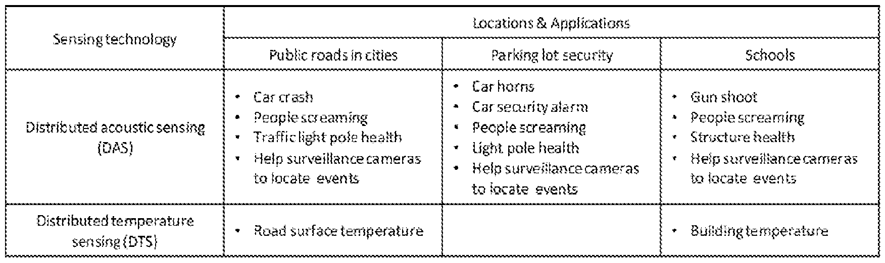
Table 1
[0030] While we have presented this disclosure using some specific examples, those skilled in the art will recognize that our teachings are not so limited. Accordingly, this disclosure should be only limited by the scope of the claims attached hereto.
Claims
1. An integrated distributed optical fiber sensing and video surveillance system comprising: a length of optical fiber;
a distributed optical fiber sensing interrogator in optical communication with the length of optical fiber; and
a video surveillance system in optical communication with the length of optical fiber, the video surveillance system including one or more media converters and one or more surveillance cameras in communication with the one or more converters.
2. The integrated system of claim 1 further comprising:
one or more optical switches in optical communication with the length of optical fiber.
3. The integrated system of claim 2 wherein at least one of the one or more surveillance cameras are in communication with a length of hybrid cable, said hybrid cable including a power-over-Ethemet (PoE) type cable and a single mode optical fiber (SMF) cable, said hybrid cable connecting the at least one surveillance camera to an optical switch and a media converter via the SMF and PoE cables, respectively.
4. The integrated system of claim 3 wherein the length of optical fiber comprises a length of duplex single mode fiber (SMF) cable, said duplex SMF cable including two, individual single mode optical fibers.
5. A method of operating an integrated distributed optical fiber sensing and video surveillance system, said system comprising:
a length of optical fiber;
a distributed optical fiber sensing interrogator in optical communication with the length of optical fiber; and
a video surveillance system in optical communication with the length of optical fiber;
said method comprising:
simultaneously operating the distributed optical fiber sensing interrogator and the video surveillance system;
detecting an event of interest via the distributed optical fiber sensing; and configuring the video surveillance system in response to the detected event.
6. The method of claim 5 wherein the video surveillance system includes one or more video surveillance cameras and the configuring of the video surveillance system in response to the detected event includes reorienting one or more of the video surveillance cameras.
7. The method of claim 6 wherein the distributed optical fiber sensing comprises sensing one or more characteristics selected from the group consisting of temperature (distributed temperature sensing - DTS) and mechanical vibrations (distributed acoustic sensing - DAS).
8. The method of claim 7 wherein the distributed optical fiber sensing senses infrastructure elements including one selected from the group consisting of buildings, roadways, and utility structures.
9. The method of claim 5 further comprising sending an alarm in response to the detected event.
10. The method of claim 9 wherein the interrogator generates optical pulses, introduces them into the optical fiber and receives reflected signals from the fiber, directs analysis of the reflected signals to determine sensing events.
Applications Claiming Priority (4)
| Application Number | Priority Date | Filing Date | Title |
|---|---|---|---|
| US201962829712P | 2019-04-05 | 2019-04-05 | |
| US62/829,712 | 2019-04-05 | ||
| US16/839,686 US20200319018A1 (en) | 2019-04-05 | 2020-04-03 | Distributed optical fiber sensing for smart city applications |
| US16/839,686 | 2020-04-03 |
Publications (1)
| Publication Number | Publication Date |
|---|---|
| WO2020206386A1 true WO2020206386A1 (en) | 2020-10-08 |
Family
ID=72663405
Family Applications (1)
| Application Number | Title | Priority Date | Filing Date |
|---|---|---|---|
| PCT/US2020/026760 Ceased WO2020206386A1 (en) | 2019-04-05 | 2020-04-04 | Distributed optical fiber sensing for smart city applications |
Country Status (2)
| Country | Link |
|---|---|
| US (1) | US20200319018A1 (en) |
| WO (1) | WO2020206386A1 (en) |
Families Citing this family (4)
| Publication number | Priority date | Publication date | Assignee | Title |
|---|---|---|---|---|
| US11733089B2 (en) * | 2020-12-22 | 2023-08-22 | Nec Corporation | Context encoder-based fiber sensing anomaly detection |
| US12106664B2 (en) * | 2021-10-22 | 2024-10-01 | Nec Corporation | Dynamic road traffic noise mapping using distributed fiber optic sensing (DFOS) over telecom network |
| JP7662045B2 (en) * | 2021-10-25 | 2025-04-15 | 日本電気株式会社 | Surveillance system and method |
| CN114495459A (en) * | 2022-01-14 | 2022-05-13 | 北京大学深圳研究生院 | A method, device, equipment and medium for real-time monitoring of structural health of high-rise buildings |
Citations (5)
| Publication number | Priority date | Publication date | Assignee | Title |
|---|---|---|---|---|
| US20120176496A1 (en) * | 2011-01-07 | 2012-07-12 | International Business Machines Corporation | Detecting and monitoring event occurences using fiber optic sensors |
| US20160171853A1 (en) * | 1999-07-20 | 2016-06-16 | Comcast Cable Communications, Llc | Video security systems and methods |
| KR101664313B1 (en) * | 2015-05-14 | 2016-10-10 | 에프엔엔(주) | video recoding system of big-data technology for mornitoring city |
| US20180219635A1 (en) * | 2013-09-19 | 2018-08-02 | Radius Universal Llc | Fiber optic communications and power network |
| WO2018227281A1 (en) * | 2017-06-12 | 2018-12-20 | Advanced Opto-Mechanical Systems And Technologies Inc. | Multi-parameter distributed fiber optic sensor system and methods of sensor manufacturing |
-
2020
- 2020-04-03 US US16/839,686 patent/US20200319018A1/en not_active Abandoned
- 2020-04-04 WO PCT/US2020/026760 patent/WO2020206386A1/en not_active Ceased
Patent Citations (5)
| Publication number | Priority date | Publication date | Assignee | Title |
|---|---|---|---|---|
| US20160171853A1 (en) * | 1999-07-20 | 2016-06-16 | Comcast Cable Communications, Llc | Video security systems and methods |
| US20120176496A1 (en) * | 2011-01-07 | 2012-07-12 | International Business Machines Corporation | Detecting and monitoring event occurences using fiber optic sensors |
| US20180219635A1 (en) * | 2013-09-19 | 2018-08-02 | Radius Universal Llc | Fiber optic communications and power network |
| KR101664313B1 (en) * | 2015-05-14 | 2016-10-10 | 에프엔엔(주) | video recoding system of big-data technology for mornitoring city |
| WO2018227281A1 (en) * | 2017-06-12 | 2018-12-20 | Advanced Opto-Mechanical Systems And Technologies Inc. | Multi-parameter distributed fiber optic sensor system and methods of sensor manufacturing |
Also Published As
| Publication number | Publication date |
|---|---|
| US20200319018A1 (en) | 2020-10-08 |
Similar Documents
| Publication | Publication Date | Title |
|---|---|---|
| WO2020206386A1 (en) | Distributed optical fiber sensing for smart city applications | |
| JP4805991B2 (en) | Security system using laser distance measuring device and intruder detection method using laser distance measuring device | |
| WO2020116030A1 (en) | Road monitoring system, road monitoring device, road monitoring method, and non-transitory computer-readable medium | |
| US20130093884A1 (en) | Manhole Security Device and Methods Thereof | |
| Wang et al. | EasiTia: A pervasive traffic information acquisition system based on wireless sensor networks | |
| CN103714702B (en) | Method for conducting vehicle overspeed warming through vehicle overspeed warming device | |
| US11885670B2 (en) | Smart stadium applications using fiber optic sensing | |
| US11686602B2 (en) | Method for providing a hybrid distributed fiber optic sensing system with improved connection to existing deployed fiber infrastructure | |
| CN108254022A (en) | Vessel traffic service and extra large cable the monitoring system of marine wind electric field | |
| US12460963B2 (en) | Gunshot detection via classification using deep learning and fiber sensing technologies | |
| Arjun et al. | PANCHENDRIYA: A multi-sensing framework through wireless sensor networks for advanced border surveillance and human intruder detection | |
| CN105321310B (en) | System and method for transmitting data from an alarm system to emergency service personnel | |
| CN102509404B (en) | Environment compensation type wild-area full-optical fiber disturbance sensing enclosure type security monitoring system | |
| JP2024544042A (en) | Distributed Acoustic Sensing Integrated Ultrasonic Device for Snow/Water Level Detection | |
| CN108416953B (en) | Intelligent optical fiber perimeter alarm system | |
| CN220474158U (en) | Intelligent traffic system for controlling vehicles in hydropower station construction period | |
| CN109685951B (en) | Optical fiber communication gateway controller | |
| CN202257823U (en) | Environment compensation device for wide-area all-fiber disturbing sensing system | |
| US11652552B2 (en) | Indoor disaster localization via hybrid ethernet/optical fiber cable | |
| CN213211233U (en) | Wisdom fence monitoring and early warning system based on distributed optical fiber vibration sensing | |
| KR102510022B1 (en) | Apparatus and method for recognizing situation in tunnel based on radar sensor | |
| CN116386374A (en) | Parking lot lane monitoring system, management system and management method | |
| Rahaman et al. | A low cost intelligent multi wireless sensor network perspective on real time traffic surveillance | |
| JP6046784B1 (en) | Information recording device for buildings | |
| KR102245387B1 (en) | Smart window alarm system, multi-purposes alarm device, window chassis module and window frame for the same |
Legal Events
| Date | Code | Title | Description |
|---|---|---|---|
| 121 | Ep: the epo has been informed by wipo that ep was designated in this application |
Ref document number: 20782774 Country of ref document: EP Kind code of ref document: A1 |
|
| NENP | Non-entry into the national phase |
Ref country code: DE |
|
| 122 | Ep: pct application non-entry in european phase |
Ref document number: 20782774 Country of ref document: EP Kind code of ref document: A1 |