WO2020186946A1 - 一种通信方法及设备 - Google Patents
一种通信方法及设备 Download PDFInfo
- Publication number
- WO2020186946A1 WO2020186946A1 PCT/CN2020/075145 CN2020075145W WO2020186946A1 WO 2020186946 A1 WO2020186946 A1 WO 2020186946A1 CN 2020075145 W CN2020075145 W CN 2020075145W WO 2020186946 A1 WO2020186946 A1 WO 2020186946A1
- Authority
- WO
- WIPO (PCT)
- Prior art keywords
- pbch
- information
- frequency domain
- terminal device
- synchronization
- Prior art date
Links
Images


Classifications
-
- H—ELECTRICITY
- H04—ELECTRIC COMMUNICATION TECHNIQUE
- H04W—WIRELESS COMMUNICATION NETWORKS
- H04W56/00—Synchronisation arrangements
- H04W56/001—Synchronization between nodes
-
- H—ELECTRICITY
- H04—ELECTRIC COMMUNICATION TECHNIQUE
- H04W—WIRELESS COMMUNICATION NETWORKS
- H04W48/00—Access restriction; Network selection; Access point selection
- H04W48/08—Access restriction or access information delivery, e.g. discovery data delivery
- H04W48/12—Access restriction or access information delivery, e.g. discovery data delivery using downlink control channel
-
- H—ELECTRICITY
- H04—ELECTRIC COMMUNICATION TECHNIQUE
- H04L—TRANSMISSION OF DIGITAL INFORMATION, e.g. TELEGRAPHIC COMMUNICATION
- H04L5/00—Arrangements affording multiple use of the transmission path
- H04L5/003—Arrangements for allocating sub-channels of the transmission path
- H04L5/0048—Allocation of pilot signals, i.e. of signals known to the receiver
- H04L5/005—Allocation of pilot signals, i.e. of signals known to the receiver of common pilots, i.e. pilots destined for multiple users or terminals
-
- H—ELECTRICITY
- H04—ELECTRIC COMMUNICATION TECHNIQUE
- H04L—TRANSMISSION OF DIGITAL INFORMATION, e.g. TELEGRAPHIC COMMUNICATION
- H04L5/00—Arrangements affording multiple use of the transmission path
- H04L5/003—Arrangements for allocating sub-channels of the transmission path
- H04L5/0053—Allocation of signalling, i.e. of overhead other than pilot signals
-
- H—ELECTRICITY
- H04—ELECTRIC COMMUNICATION TECHNIQUE
- H04L—TRANSMISSION OF DIGITAL INFORMATION, e.g. TELEGRAPHIC COMMUNICATION
- H04L5/00—Arrangements affording multiple use of the transmission path
- H04L5/0091—Signalling for the administration of the divided path, e.g. signalling of configuration information
- H04L5/0094—Indication of how sub-channels of the path are allocated
-
- H—ELECTRICITY
- H04—ELECTRIC COMMUNICATION TECHNIQUE
- H04W—WIRELESS COMMUNICATION NETWORKS
- H04W48/00—Access restriction; Network selection; Access point selection
- H04W48/08—Access restriction or access information delivery, e.g. discovery data delivery
- H04W48/10—Access restriction or access information delivery, e.g. discovery data delivery using broadcasted information
-
- H—ELECTRICITY
- H04—ELECTRIC COMMUNICATION TECHNIQUE
- H04W—WIRELESS COMMUNICATION NETWORKS
- H04W56/00—Synchronisation arrangements
-
- H—ELECTRICITY
- H04—ELECTRIC COMMUNICATION TECHNIQUE
- H04W—WIRELESS COMMUNICATION NETWORKS
- H04W72/00—Local resource management
- H04W72/04—Wireless resource allocation
-
- H—ELECTRICITY
- H04—ELECTRIC COMMUNICATION TECHNIQUE
- H04W—WIRELESS COMMUNICATION NETWORKS
- H04W72/00—Local resource management
- H04W72/04—Wireless resource allocation
- H04W72/044—Wireless resource allocation based on the type of the allocated resource
-
- H—ELECTRICITY
- H04—ELECTRIC COMMUNICATION TECHNIQUE
- H04W—WIRELESS COMMUNICATION NETWORKS
- H04W72/00—Local resource management
- H04W72/04—Wireless resource allocation
- H04W72/044—Wireless resource allocation based on the type of the allocated resource
- H04W72/0446—Resources in time domain, e.g. slots or frames
-
- H—ELECTRICITY
- H04—ELECTRIC COMMUNICATION TECHNIQUE
- H04W—WIRELESS COMMUNICATION NETWORKS
- H04W72/00—Local resource management
- H04W72/04—Wireless resource allocation
- H04W72/044—Wireless resource allocation based on the type of the allocated resource
- H04W72/0453—Resources in frequency domain, e.g. a carrier in FDMA
-
- H—ELECTRICITY
- H04—ELECTRIC COMMUNICATION TECHNIQUE
- H04W—WIRELESS COMMUNICATION NETWORKS
- H04W72/00—Local resource management
- H04W72/30—Resource management for broadcast services
-
- H—ELECTRICITY
- H04—ELECTRIC COMMUNICATION TECHNIQUE
- H04W—WIRELESS COMMUNICATION NETWORKS
- H04W24/00—Supervisory, monitoring or testing arrangements
- H04W24/02—Arrangements for optimising operational condition
Definitions
- This application relates to the field of communication technology, and in particular to a communication method and device.
- the 5 th generation, 5G a new air interface (new radio, NR) system
- 5G new radio
- NR new radio
- the synchronization signal is transmitted with a synchronization signal block (synchronization signal block, SSB) as the basic unit.
- the SSB includes a primary synchronization signal (PSS) and a secondary synchronization signal (SSS).
- PSS primary synchronization signal
- SSS secondary synchronization signal
- the SSB may also include a physical broadcasting channel (PBCH).
- PBCH physical broadcasting channel
- the bandwidth of the current PSS, SSS, and PBCH all occupy 6 resource blocks (RB).
- terminal devices of multiple bandwidth types have been introduced.
- the different bandwidth types mentioned here refer to different working bandwidths.
- there are terminal equipment with a working bandwidth of 12 RBs hereinafter also referred to as 12RB terminal equipment
- a working bandwidth of 6 RB terminal equipment hereinafter also referred to as 6RB terminal equipment
- a working bandwidth of 1 RB terminal equipment hereinafter also referred to as 1RB terminal device for short
- a 12RB terminal device is a broadband terminal device relative to a 6RB terminal device and a 1RB terminal device
- a 6RB terminal device is a narrowband terminal device relative to a 12RB terminal device
- a broadband terminal device relative to a 1RB terminal device.
- corresponding SSBs are currently designed for terminal devices of various bandwidth types.
- SSBs corresponding to terminal devices of different bandwidth types such as cell (identity, ID) and system frame number (SFN), etc.
- ID identity, ID
- SFN system frame number
- the present application provides a communication method and device, which are used to reduce the transmission resources occupied when sending the SSB.
- an embodiment of the present application provides a first communication method.
- the method includes: an access network device generates an SSB.
- the SSB includes a first physical broadcast channel PBCH and a second PBCH, and the first PBCH carries the first Time-frequency resource location information of the synchronization information, the second PBCH carries the time-frequency resource location information of the second synchronization information, and the time-frequency resource locations of the first synchronization information and the second synchronization information are different; the access The network equipment broadcasts the SSB.
- the communication method may be executed by a first communication device.
- the first communication device may be an access network device or a communication device capable of supporting the access network device to realize the functions required by the communication method. Of course, it may also be another communication device, such as a chip system. .
- the first communication device is an access network device, that is, the communication method is described from the perspective of the access network device.
- the SSB includes a first PBCH that carries time-frequency resource location information of the first synchronization information and a second PBCH that carries time-frequency resource location information of the second synchronization information.
- the first synchronization information can be used for terminal equipment of one bandwidth type to perform downlink synchronization
- the second synchronization information can be used for terminal equipment of another bandwidth type to perform downlink synchronization.
- the SSB can carry terminals of different bandwidth types.
- the access network only needs to send the same SSB, and information such as the cell ID and SFN in the SSB only needs to be sent once.
- the SSB provided by the embodiments of this application can satisfy both On the basis of various bandwidth types of terminal equipment, the transmission resources occupied by sending cell ID and SFN information are further reduced.
- the first PBCH may also carry third synchronization information, time-frequency resource location information of the first synchronization information and the third synchronization information
- the terminal equipment of the first type is used to perform downlink synchronization, and the time-frequency resource location information of the second synchronization information and the third synchronization information are used for the terminal equipment of the second type to perform downlink synchronization.
- the first PBCH may also carry third synchronization information, such as SFN in a master information block (Master Information Block, MIB), to serve as common information for terminal devices of different bandwidth types to perform downlink synchronization.
- third synchronization information such as SFN in a master information block (Master Information Block, MIB)
- MIB Master Information Block
- the first synchronization information is a first system information block type 1SIB1
- the second synchronization information is a second SIB1
- the second PBCH carries
- the time-frequency resource location information of the second synchronization information is the location information of the second SIB1 and/or the carrier resource block CRB offset, and the CRB offset is used to indicate the location information of the second SIB1.
- the time-frequency resource location information of the second synchronization information carried by the second PBCH may indicate the location information of the second SIB1.
- the time-frequency resource location information of the second synchronization information may include the location information of the second SIB1 and/or the Carry Resource Block (CRB) offset, where the CRB offset may be considered as the second SIB1
- CRB Carry Resource Block
- the difference between the frequency domain resource and the frequency domain resource of the SSB can thereby indicate where the terminal device obtains the second SIB1.
- the second PBCH provided by the embodiments of this application can reconfigure the location information of the second SIB1 for the second type of terminal equipment to meet the bandwidth receiving capability of the second type of terminal equipment, so that the second type of terminal equipment can receive The second SIB1.
- the first SIB1 and the second SIB1 contain the same or different information.
- the terminal device may perform subsequent procedures such as random access procedures based on the information contained in the SIB1, for example, bandwidth, cell access parameters, etc.
- terminal equipment of different bandwidth types can be configured with SIB1 containing the same information, which can reduce the burden on the access network equipment.
- access network devices can also be configured with SIBs containing different information, so that terminal devices of different bandwidth types only need to parse the information of their corresponding SIB1 instead of all SIB1, which can reduce terminal equipment Workload.
- the SSB may further include a third PBCH
- the frequency domain resource of the first PBCH is a first frequency domain resource
- the frequency domain resource of the third PBCH is a third frequency domain resource
- the first frequency domain resource is composed of a second frequency domain resource and the third frequency domain resource.
- the information carried by the third PBCH is the same as the information carried by the first PBCH on the second frequency domain resource, or the signal carried by the third PBCH is the same as that carried by the first PBCH.
- the signals carried on the second frequency domain resources are the same.
- the SSB may also include a third PBCH.
- the frequency domain resources of the third PBCH may consist of the frequency domain resources of the first PBCH and the second frequency domain resources.
- the PBCHs of terminal devices of different bandwidth types are in the frequency domain. Resources can be nested.
- the third PBCH belongs to the second type of terminal equipment
- the first PBCH belongs to the first type of terminal equipment.
- the SSB can nest the frequency domain resources occupied by the third PBCH in the frequency domain resources occupied by the first PBCH, for example, nesting Resources in the second frequency domain.
- the second type of terminal equipment can correctly demodulate the SSB of the first type of terminal equipment, while the first type of terminal equipment cannot feel the third PBCH that is additionally involved for the second type of terminal equipment, and can simultaneously satisfy the first type of terminal equipment.
- the downlink synchronization of the first type of terminal equipment and the second type of terminal equipment can correctly demodulate the SSB of the first type of terminal equipment, while the first type of terminal equipment cannot feel the third PBCH that is additionally involved for the second type of terminal equipment, and can simultaneously satisfy the first type of terminal equipment.
- the frequency domain resource of the third PBCH is a proper subset of the frequency domain resource of the first PBCH, and the information carried by the third PBCH is the frequency domain resource of the first PBCH Information on frequency domain resources other than the frequency domain resources of the second PBCH; or,
- the signal carried by the third PBCH is a signal on a frequency domain resource other than the frequency domain resource of the second PBCH in the frequency domain resource of the first PBCH.
- the SSB may also include a fourth PBCH, and the fourth PBCH is used for a third type of terminal device to change part of the information contained in the first PBCH, where the third The maximum bandwidth supported by the terminal device of the type is greater than or equal to the maximum bandwidth supported by the terminal device of the first type.
- the frequency domain resource of the fourth PBCH is located in the frequency domain resource of the first PBCH, or in other words, the frequency domain resource of the fourth PBCH is the frequency domain resource of the first PBCH.
- a subset of domain resources is provided.
- the frequency domain resource of the fourth PBCH is located outside the frequency domain resource of the first PBCH.
- the SSB provided in the embodiment of the present application may further include a fourth PBCH, where the terminal device of the third type may change part of the information in the first PBCH according to the fourth PBCH, such as the location information of SIB1.
- the terminal device of the third type can determine its own synchronization information, such as MIB information, according to the first PBCH and the fourth PBCH, so as to enhance the synchronization performance of the terminal device of the third type.
- the access network device when the access network device broadcasts the SSB, it may specifically broadcast the SSB on the same frequency domain resource within at least one time window .
- the SSB is located in a time window, and the time domain and/or frequency domain structure of the SSB is configured by the access network equipment, so the access network equipment can be in at least one time window in a terminal with a wider working bandwidth
- the SSB is broadcast on the frequency domain resources corresponding to the minimum bandwidth of the device, so that terminal devices with a narrow working bandwidth can receive the SSB, so as to ensure the correct rate of SSB reception as much as possible.
- the maximum bandwidth supported by the terminal device of the second type is less than or equal to the maximum bandwidth supported by the terminal device of the first type.
- the first type of terminal device may be a terminal device with a relatively wide working bandwidth
- the second type of terminal device may be a terminal device with a relatively narrow working bandwidth
- the PBCH included in the SSB may be a terminal device with a relatively narrow working bandwidth.
- the PBCH of the terminal device and the PBCH of the terminal device of the second type are nested together, so as to avoid the waste of system resources caused by separately designing the PBCH of terminal devices of different bandwidth types.
- the embodiments of the present application provide a second communication method.
- the method includes: a terminal device receives a first signal, where the first signal includes a physical broadcast channel PBCH; the terminal device acquires the PBCH;
- the PBCH is located in a synchronization signal block SSB, the SSB includes a first PBCH and a second PBCH, the first PBCH carries the time-frequency resource location information of the first synchronization information, and the second PBCH carries the time-frequency resource position information of the second synchronization information.
- Frequency resource location information, the time-frequency resource locations of the first synchronization information and the second synchronization information are different;
- the acquired PBCH is the first PBCH or the second PBCH.
- the communication method may be executed by a second communication device.
- the second communication device may be a terminal device or a communication device capable of supporting the terminal device to realize the functions required by the communication method, and of course, it may also be another communication device, such as a chip system.
- the second communication device is a terminal device, that is, the communication method is described from the perspective of the terminal device.
- the first PBCH may also carry third synchronization information; the terminal device may also obtain the third synchronization information in the first PBCH Information, further performing synchronization processing according to the third synchronization information and the acquired PBCH.
- the terminal device when the acquired PBCH is the first PBCH, the terminal device is a terminal device of the first type; and the acquired PBCH is the In the second PBCH, the terminal device is a second type of terminal device, wherein the maximum bandwidth of the second type of terminal device is less than or equal to the maximum bandwidth of the first type of terminal device.
- the first synchronization information is the first SIB1
- the second synchronization information is the second SIB1
- the time-frequency resource location information of the information is the location information and/or CRB offset of the second SIB1, and the CRB offset is used to indicate the location information of the second SIB1.
- the first SIB1 and the second SIB1 include the same or different information.
- the SSB further includes a third PBCH; the frequency domain resource of the first PBCH is the first frequency domain resource, and the frequency domain resource of the third PBCH is The frequency domain resource is a third frequency domain resource, and the first frequency domain resource is composed of a second frequency domain resource and the third frequency domain resource; wherein, the information carried by the third PBCH is the same as that of the first PBCH The information carried on the second frequency domain resource is the same, or the signal carried by the third PBCH is the same as the signal carried by the first PBCH on the second frequency domain resource.
- the frequency domain resource of the third PBCH is a proper subset of the frequency domain resource of the first PBCH, and the information carried by the third PBCH is the frequency domain resource of the first PBCH Information on frequency domain resources other than the frequency domain resources of the second PBCH; or,
- the signal carried by the third PBCH is a signal on a frequency domain resource other than the frequency domain resource of the second PBCH in the frequency domain resource of the first PBCH.
- the SSB may also include a fourth PBCH, and the fourth PBCH is used for a third type of terminal device to change part of the information contained in the first PBCH, where the third The maximum bandwidth supported by the terminal device of the type is greater than or equal to the maximum bandwidth supported by the terminal device of the first type.
- the frequency domain resource of the fourth PBCH is located within the frequency domain resource of the first PBCH.
- the frequency domain resource of the fourth PBCH is located outside the frequency domain resource of the first PBCH.
- one SSB may also include a fourth PBCH, where the fourth PBCH is received by a third type of terminal device, that is, a broadband terminal device, and is used to modify part of the information in the first PBCH, such as SIB1 location information.
- a third type of terminal device that is, a broadband terminal device
- the terminal device of the first type determines its own MIB information according to the first PBCH
- the terminal device of the third type determines its own MIB information according to the first PBCH and the fourth PBCH.
- the fourth PBCH can modify part of the information in the first PBCH. To enhance the synchronization performance of the third type of terminal equipment.
- the terminal device when the terminal device receives the first signal, it may specifically receive the first signal within at least one time window.
- a first communication device is provided, for example, the communication device is the first communication device as described above.
- the communication device is configured to execute the foregoing first aspect or the method in any possible implementation manner of the first aspect.
- the communication device may include a module for executing the method in the first aspect or any possible implementation of the first aspect, for example, including a processing module and a transceiver module that are coupled to each other.
- the communication device may be an access network device. among them,
- the processing module is configured to generate a synchronization signal block SSB.
- the SSB includes a first physical broadcast channel PBCH and a second PBCH.
- the first PBCH carries time-frequency resource location information of the first synchronization information
- the second The PBCH carries time-frequency resource location information of the second synchronization information, and the time-frequency resource locations of the first synchronization information and the second synchronization information are different;
- the transceiver module is used to broadcast the SSB.
- the first PBCH carries third synchronization information, and the time-frequency resource location information of the first synchronization information and the third synchronization information are used for
- the terminal device of the first type performs downlink synchronization
- the time-frequency resource location information of the second synchronization information and the third synchronization information are used for the terminal device of the second type to perform downlink synchronization.
- the first synchronization information is a first system information block type 1SIB1, and the second synchronization information is a second SIB1;
- the time-frequency resource location information of the second synchronization information carried by the second PBCH is the location information of the second SIB1 and/or the CRB offset of the bearer resource block, and the CRB offset is used to indicate the second Location information of SIB1.
- the first SIB1 and the second SIB1 contain the same or different information.
- the SSB further includes a third PBCH
- the frequency domain resource of the first PBCH is a first frequency domain resource
- the frequency domain resource of the third PBCH is a third frequency domain resource
- the first frequency domain resource is composed of a second frequency domain resource and the third frequency domain resource.
- the information carried by the third PBCH is the same as the information carried by the first PBCH on the second frequency domain resource, or the signal carried by the third PBCH is the same as the information carried by the first PBCH on the
- the signals carried on the second frequency domain resources are the same.
- the frequency domain resource of the third PBCH is a proper subset of the frequency domain resource of the first PBCH
- the information carried by the third PBCH is information on frequency domain resources other than the frequency domain resources of the second PBCH in the frequency domain resources of the first PBCH; or,
- the signal carried by the third PBCH is a signal on a frequency domain resource other than the frequency domain resource of the second PBCH in the frequency domain resource of the first PBCH.
- the SSB may also include a fourth PBCH, and the fourth PBCH is used for a third type of terminal device to change part of the information contained in the first PBCH, where the third The maximum bandwidth supported by the terminal device of the type is greater than or equal to the maximum bandwidth supported by the terminal device of the first type.
- the frequency domain resource of the fourth PBCH is located within the frequency domain resource of the first PBCH.
- the frequency domain resource of the fourth PBCH is located outside the frequency domain resource of the first PBCH.
- the transceiver module is specifically configured to: broadcast the SSB on the same frequency domain resource in at least one time window.
- the maximum bandwidth supported by the terminal device of the second type is less than or equal to the maximum bandwidth supported by the terminal device of the first type.
- a second communication device is provided, for example, the communication device is the second communication device as described above.
- the communication device is configured to execute the foregoing second aspect or any possible implementation method of the second aspect.
- the communication device may include a module for executing the method in the second aspect or any possible implementation of the second aspect, for example, including a processing module and a transceiver module that are coupled to each other.
- the communication device is a terminal device. among them,
- the transceiver module is configured to receive a first signal, where the first signal includes a physical broadcast channel PBCH;
- the processing module is used to obtain the PBCH
- the PBCH is located in a synchronization signal block SSB, the SSB includes a first PBCH and a second PBCH, the first PBCH carries the time-frequency resource position information of the first synchronization information, and the second PBCH carries the second synchronization
- the time-frequency resource location information of the information, the time-frequency resource location of the first synchronization information and the second synchronization information are different; the acquired PBCH is the first PBCH or the second PBCH.
- the first PBCH carries third synchronization information
- the processing module is further configured to: obtain the third synchronization in the first PBCH Information, and perform synchronization processing according to the third synchronization information and the acquired PBCH.
- the terminal device when the acquired PBCH is the first PBCH, the terminal device is a terminal device of the first type;
- the terminal device is a second type of terminal device
- the maximum bandwidth supported by the terminal device of the second type is less than or equal to the maximum bandwidth supported by the terminal device of the first type.
- the first synchronization information is a first SIB1
- the second synchronization information is a second SIB1
- the time-frequency resource location information of the second synchronization information carried by the second PBCH is the location information and/or CRB offset of the second SIB1, and the CRB offset is used to indicate the location of the second SIB1 information.
- the first SIB1 and the second SIB1 contain the same or different information.
- the SSB further includes a third PBCH
- the frequency domain resource of the first PBCH is a first frequency domain resource
- the frequency domain resource of the third PBCH is a third frequency domain resource
- the first frequency domain resource is composed of a second frequency domain resource and the third frequency domain resource.
- the information carried by the third PBCH is the same as the information carried by the first PBCH on the second frequency domain resource
- the signal carried by the third PBCH is the same as that carried by the first PBCH on the
- the signals carried on the second frequency domain resources are the same.
- the frequency domain resource of the third PBCH is a proper subset of the frequency domain resource of the first PBCH
- the information carried by the third PBCH is information on frequency domain resources other than the frequency domain resources of the second PBCH in the frequency domain resources of the first PBCH; or,
- the signal carried by the third PBCH is a signal on a frequency domain resource other than the frequency domain resource of the second PBCH in the frequency domain resource of the first PBCH.
- the SSB may also include a fourth PBCH, and the fourth PBCH is used for a third type of terminal device to change part of the information contained in the first PBCH, where the third The maximum bandwidth supported by the terminal device of the type is greater than or equal to the maximum bandwidth supported by the terminal device of the first type.
- the frequency domain resource of the fourth PBCH is located within the frequency domain resource of the first PBCH.
- the frequency domain resource of the fourth PBCH is located outside the frequency domain resource of the first PBCH.
- the transceiver module is specifically configured to: receive the first signal within at least one time window.
- a third communication device is provided.
- the communication device is, for example, the first communication device as described above.
- the communication device includes a processor and a transceiver, and is used to implement the foregoing first aspect or the methods described in various possible designs of the first aspect.
- the communication device is a chip provided in a communication device.
- the communication device is an access network device.
- the transceiver is realized by, for example, an antenna, a feeder, a codec in the communication device, or, if the communication device is a chip set in the communication device, the transceiver is, for example, a communication interface in the chip. Connect with the radio frequency transceiving component in the communication equipment, so as to realize the sending and receiving of information through the radio frequency transceiving component. among them,
- the processor is configured to generate a synchronization signal block SSB.
- the SSB includes a first physical broadcast channel PBCH and a second PBCH.
- the first PBCH carries time-frequency resource location information of the first synchronization information
- the second The PBCH carries time-frequency resource location information of the second synchronization information, and the time-frequency resource locations of the first synchronization information and the second synchronization information are different;
- the transceiver is used to broadcast the SSB.
- the first PBCH carries third synchronization information, and the time-frequency resource location information of the first synchronization information and the third synchronization information are used for
- the terminal device of the first type performs downlink synchronization
- the time-frequency resource location information of the second synchronization information and the third synchronization information are used for the terminal device of the second type to perform downlink synchronization.
- the first synchronization information is a first system information block type 1SIB1, and the second synchronization information is a second SIB1;
- the time-frequency resource location information of the second synchronization information carried by the second PBCH is the location information of the second SIB1 and/or the CRB offset of the bearer resource block, and the CRB offset is used to indicate the second Location information of SIB1.
- the first SIB1 and the second SIB1 contain the same or different information.
- the SSB further includes a third PBCH
- the frequency domain resource of the first PBCH is a first frequency domain resource
- the frequency domain resource of the third PBCH is a third frequency domain resource
- the first frequency domain resource is composed of a second frequency domain resource and the third frequency domain resource.
- the information carried by the third PBCH is the same as the information carried by the first PBCH on the second frequency domain resource
- the signal carried by the third PBCH is the same as that carried by the first PBCH on the
- the signals carried on the second frequency domain resources are the same.
- the frequency domain resource of the third PBCH is a proper subset of the frequency domain resource of the first PBCH
- the information carried by the third PBCH is information on frequency domain resources other than the frequency domain resources of the second PBCH in the frequency domain resources of the first PBCH; or,
- the signal carried by the third PBCH is a signal on a frequency domain resource other than the frequency domain resource of the second PBCH in the frequency domain resource of the first PBCH.
- the SSB may also include a fourth PBCH, and the fourth PBCH is used for a third type of terminal device to change part of the information contained in the first PBCH, where the third The maximum bandwidth supported by the terminal device of the type is greater than or equal to the maximum bandwidth supported by the terminal device of the first type.
- the frequency domain resource of the fourth PBCH is located within the frequency domain resource of the first PBCH.
- the frequency domain resource of the fourth PBCH is located outside the frequency domain resource of the first PBCH.
- the transceiver is specifically configured to broadcast the SSB on the same frequency domain resource in at least one time window.
- the maximum bandwidth supported by the terminal device of the second type is less than or equal to the maximum bandwidth supported by the terminal device of the first type.
- a fourth communication device is provided.
- the communication device is, for example, the second communication device as described above.
- the communication device includes a processor and a transceiver, and is used to implement the method described in the second aspect or various possible designs of the second aspect.
- the communication device is a chip provided in a communication device.
- the communication device is a terminal device.
- the transceiver is realized by, for example, an antenna, a feeder, a codec in the communication device, or, if the communication device is a chip set in the communication device, the transceiver is, for example, a communication interface in the chip. It is connected with the radio frequency transceiving component in the communication equipment to realize the information transmission and reception through the radio frequency transceiving component. among them,
- the transceiver is configured to receive a first signal, where the first signal includes a physical broadcast channel PBCH;
- the processor is configured to obtain the PBCH
- the PBCH is located in a synchronization signal block SSB, the SSB includes a first PBCH and a second PBCH, the first PBCH carries the time-frequency resource position information of the first synchronization information, and the second PBCH carries the second synchronization
- the time-frequency resource location information of the information, the time-frequency resource location of the first synchronization information and the second synchronization information are different; the acquired PBCH is the first PBCH or the second PBCH.
- the first PBCH carries third synchronization information
- the processor is further configured to: obtain the third synchronization in the first PBCH Information, and perform synchronization processing according to the third synchronization information and the acquired PBCH.
- the terminal device when the acquired PBCH is the first PBCH, the terminal device is a terminal device of the first type;
- the terminal device is a second type of terminal device
- the maximum bandwidth supported by the terminal device of the second type is less than or equal to the maximum bandwidth supported by the terminal device of the first type.
- the first synchronization information is a first SIB1
- the second synchronization information is a second SIB1
- the time-frequency resource location information of the second synchronization information carried by the second PBCH is the location information and/or CRB offset of the second SIB1, and the CRB offset is used to indicate the location of the second SIB1 information.
- the first SIB1 and the second SIB1 include the same or different information.
- the SSB further includes a third PBCH
- the frequency domain resource of the first PBCH is a first frequency domain resource
- the frequency domain resource of the third PBCH is a third frequency domain resource
- the first frequency domain resource is composed of a second frequency domain resource and the third frequency domain resource.
- the information carried by the third PBCH is the same as the information carried by the first PBCH on the second frequency domain resource
- the signal carried by the third PBCH is the same as that carried by the first PBCH on the
- the signals carried on the second frequency domain resources are the same.
- the frequency domain resource of the third PBCH is a proper subset of the frequency domain resource of the first PBCH
- the information carried by the third PBCH is information on frequency domain resources other than the frequency domain resources of the second PBCH in the frequency domain resources of the first PBCH; or,
- the signal carried by the third PBCH is a signal on a frequency domain resource other than the frequency domain resource of the second PBCH in the frequency domain resource of the first PBCH.
- the SSB may also include a fourth PBCH, and the fourth PBCH is used for a third type of terminal device to change part of the information contained in the first PBCH, where the third The maximum bandwidth supported by the terminal device of the type is greater than or equal to the maximum bandwidth supported by the terminal device of the first type.
- the frequency domain resource of the fourth PBCH is located within the frequency domain resource of the first PBCH.
- the frequency domain resource of the fourth PBCH is located outside the frequency domain resource of the first PBCH.
- the transceiver is specifically configured to receive the first signal within at least one time window.
- a fifth communication device is provided.
- the communication device may be the first communication device in the above method design.
- the communication device is a chip provided in a terminal device.
- the communication device includes: a memory for storing computer executable program codes; and a processor, which is coupled with the memory.
- the program code stored in the memory includes instructions, and when the processor executes the instructions, the fifth communication device executes the method in the first aspect or any one of the possible implementations of the first aspect.
- the fifth type of communication device may also include a communication interface.
- the communication interface may be a transceiver in an access network device, for example, implemented by the antenna, feeder, and codec in the communication device, or if the fifth If the communication device is a chip set in a terminal device, the communication interface may be an input/output interface of the chip, such as input/output pins.
- a sixth communication device is provided.
- the communication device may be the second communication device in the above method design.
- the communication device is a chip set in an access network device.
- the communication device includes: a memory for storing computer executable program codes; and a processor, which is coupled with the memory.
- the program code stored in the memory includes instructions, and when the processor executes the instructions, the sixth communication device executes the second aspect or the method in any one of the possible implementation manners of the second aspect.
- the sixth communication device may also include a communication interface, and the communication interface may be a transceiver in a terminal device, for example, implemented by the antenna, feeder, and codec in the communication device, or if the sixth communication
- the device is a chip set in an access network device, and the communication interface may be an input/output interface of the chip, such as input/output pins.
- a communication system which may include the first communication device described in the third aspect, the third communication device described in the fifth aspect, or the fifth communication device described in the seventh aspect , And including the second communication device described in the fourth aspect, the fourth communication device described in the sixth aspect, or the sixth communication device described in the eighth aspect.
- a computer storage medium stores instructions, which when run on a computer, cause the computer to execute the first aspect or any one of the possible designs of the first aspect The method described.
- a computer storage medium stores instructions that, when run on a computer, cause the computer to execute the second aspect or any one of the possible designs of the second aspect. The method described in.
- a computer program product containing instructions.
- the computer program product stores instructions that, when run on a computer, cause the computer to execute the first aspect or any one of the first aspects described above. The method described in the design.
- a computer program product containing instructions.
- the computer program product stores instructions that, when run on a computer, cause the computer to execute the second aspect or any one of the possibilities of the second aspect. The method described in the design.
- the SSB includes the first PBCH and the second PBCH.
- the synchronization information carried by the first PBCH and the second PBCH have different time-frequency resource positions, so the SSB can correspond to the synchronization information required by terminal devices of different bandwidth types , And the same synchronization information required by terminal devices of different bandwidth types, such as SFN and other information can be shared. Therefore, when the access network device sends SSB, it only needs to send the same information such as SFN once, which can satisfy various bandwidth types. On the basis of the terminal equipment, the waste of system resources caused by repeatedly sending the same information such as SFN can be further avoided.
- Figure 1 is a schematic diagram of time-frequency resources of an existing NR system
- Figure 2 is a schematic diagram of downlink synchronization
- Figure 3 is a schematic diagram of an existing SSB
- Figure 4 is a schematic diagram of SS burst set
- Figure 5 is a schematic diagram of the locations of two existing SSB time-frequency resources
- FIG. 6 is a schematic diagram of an application scenario of an embodiment of the application.
- FIG. 7 is a flowchart of a communication method provided by an embodiment of this application.
- FIG. 8 is a schematic diagram of a structure of an SSB provided by an embodiment of this application.
- FIG. 9 is a schematic diagram of a structure of an SSB provided by an embodiment of this application.
- FIG. 10 is a schematic diagram of a structure of an SSB provided by an embodiment of this application.
- FIG. 11 is a schematic diagram of a structure of the PBCH in the SSB provided by an embodiment of this application.
- FIG. 12 is a schematic diagram of a structure of the PBCH in the SSB provided by an embodiment of this application.
- FIG. 13 is a schematic diagram of a structure of an SSB provided by an embodiment of this application.
- FIG. 14 is a schematic diagram of a structure of an SSB provided by an embodiment of this application.
- 15 is a schematic diagram of a structure of an SSB provided by an embodiment of the application.
- 16 is a schematic diagram of a communication device capable of realizing the function of an access network device provided by an embodiment of the application;
- FIG. 17 is a schematic diagram of a communication device capable of realizing the functions of a terminal device provided by an embodiment of the application;
- 18A-18B are two schematic diagrams of a communication device provided by an embodiment of this application.
- Terminal devices including devices that provide users with voice and/or data connectivity, such as handheld devices with wireless connection functions, or processing devices connected to wireless modems.
- the terminal device can communicate with the core network via a radio access network (RAN), and exchange voice and/or data with the RAN.
- RAN radio access network
- the terminal equipment may include user equipment (UE), long term evolution (Long Term Evolution, LTE) terminal equipment, the fifth generation mobile communication network (The Fifith Generation Mobile Network, 5G) terminal equipment, wireless terminal equipment, and mobile terminal Equipment, device-to-device communication (device-to-device, D2D) terminal equipment, V2X terminal equipment, machine-to-machine/machine-type communications (machine-to-machine/machine-type communications, M2M/MTC) terminal equipment, Internet of Things (internet of things, IoT) terminal equipment, subscriber unit (subscriber unit), subscriber station (subscriber station), mobile station (mobile station), remote station (remote station), access point (access point, AP), remote terminal (remote terminal), access terminal (access terminal), user terminal (user terminal), user agent (user agent), or user equipment (user device), etc.
- IoT Internet of Things
- it may include mobile phones (or “cellular” phones), computers with mobile terminal equipment, portable, pocket-sized, handheld, and computer-built mobile devices.
- PCS personal communication service
- PCS personal communication service
- SIP session initiation protocol
- WLL wireless local loop
- PDA personal digital assistants
- restricted devices such as devices with low power consumption, or devices with limited storage capabilities, or devices with limited computing capabilities. Examples include barcodes, radio frequency identification (RFID), sensors, global positioning system (GPS), laser scanners and other information sensing equipment.
- RFID radio frequency identification
- GPS global positioning system
- laser scanners and other information sensing equipment.
- the terminal device may also be a wearable device.
- Wearable devices can also be called wearable smart devices or smart wearable devices, etc. It is a general term for using wearable technology to intelligently design daily wear and develop wearable devices, such as glasses, gloves, watches, clothing and shoes Wait.
- a wearable device is a portable device that is directly worn on the body or integrated into the user's clothes or accessories. Wearable devices are not only a hardware device, but also realize powerful functions through software support, data interaction, and cloud interaction.
- wearable smart devices include full-featured, large-sized, complete or partial functions that can be achieved without relying on smart phones, such as smart watches or smart glasses, and only focus on a certain type of application function, and need to cooperate with other devices such as smart phones.
- Use such as various smart bracelets, smart helmets, smart jewelry, etc. for physical sign monitoring.
- vehicle-mounted terminal equipment for example, the vehicle-mounted terminal equipment is also called on-board unit (OBU).
- OBU on-board unit
- the terminal device may also include a relay. Or it can be understood that everything that can communicate with the base station can be regarded as a terminal device.
- the embodiments of this application may involve two terminal devices with different maximum operating bandwidths: a first type of terminal device and a second type of terminal device.
- the first type of terminal device can be understood as a terminal device with a wider maximum operating bandwidth (hereinafter also referred to as broadband terminal equipment for short)
- the second type of terminal equipment can be understood as a terminal equipment with a relatively narrow maximum working bandwidth (hereinafter also referred to as narrowband terminal equipment for short).
- the conditions that broadband terminal equipment and narrowband terminal equipment need to meet include but are not limited to the following:
- the maximum bandwidth supported by the narrowband terminal device is less than the maximum bandwidth supported by the broadband terminal device.
- the narrowband terminal equipment is a narrowband internet of things (NB-IoT) terminal equipment and the broadband terminal equipment is an LTE terminal equipment.
- the data transmission bandwidth of NB-IoT terminal equipment is 1 RB, that is, 180kHz or 200kHz (including guard band), because the frequency resource occupied by PSS/SSS under the LTE system is 6 RBs, that is, 1.08MHz or 1.44MHz (including Guard band), so the maximum bandwidth supported by the broadband terminal device can be considered to be no less than 1.08MHz.
- the maximum bandwidth supported by the narrowband terminal device is less than the maximum bandwidth of the broadband terminal device.
- the narrowband terminal device is an NB-IoT terminal device
- the broadband terminal device is an NR terminal device.
- the data transmission bandwidth of the NR terminal device can be considered as 20 RBs, and each RB includes 12 subcarriers.
- narrowband terminal equipment can also be considered as low power wide coverage access (LPWA) terminal equipment
- broadband terminal equipment can be considered as enhanced mobile broadband (eMBB) ) Terminal equipment or ultra-reliability low-latency communication (URLLC) terminal equipment.
- LPWA low power wide coverage access
- eMBB enhanced mobile broadband
- URLLC ultra-reliability low-latency communication
- the same terminal device can have both narrowband and broadband capabilities, that is, the terminal device can be used as both a broadband terminal device and a narrowband terminal device.
- the terminal device can be used as both a broadband terminal device and a narrowband terminal device.
- a 6RB terminal device is compared with a 12RB terminal device.
- Narrowband terminal equipment is broadband terminal equipment compared to 1RB terminal equipment.
- Access network (AN) equipment for example, includes a base station (e.g., access point), which may refer to equipment that communicates with wireless terminal equipment through one or more cells at an air interface in the access network, or, for example,
- a base station e.g., access point
- the base station can be used to convert the received air frame and Internet Protocol (IP) packets to each other, as a router between the terminal device and the rest of the access network, where the rest of the access network may include an IP network.
- IP Internet Protocol
- the RSU can be a fixed infrastructure entity that supports V2X applications, and can exchange messages with other entities that support V2X applications.
- the access network equipment can also coordinate the attribute management of the air interface.
- the access network equipment may include the LTE system or the evolved base station (NodeB or eNB or e-NodeB, evolutional Node B) in the long term evolution-advanced (LTE-A), or may also include 5G NR
- the next generation node B (gNB) in the system may also include the centralized unit (CU) and distributed unit (CU) in the cloud radio access network (Cloud RAN) system.
- unit, DU the embodiment of this application is not limited.
- the downlink transmission of the NR system is based on orthogonal frequency division multiple access (OFDMA) technology, and the real-time frequency resources are divided into OFDM symbols in the time domain dimension (also called time domain symbols, or symbols for short) And subcarriers in the frequency domain dimension.
- the smallest resource granularity is called a resource element (resource element, RE), which represents a time-frequency grid point composed of a time-domain symbol in the time domain and a sub-carrier in the frequency domain.
- RE resource element
- the NR system supports multiple time-frequency resource structures. Please refer to Figure 1.
- Figure 1 shows the 15KHz subcarrier spacing, the time domain symbol duration of about 70 ⁇ s, and the cyclic prefix (CP) duration of about 4-6 ⁇ s.
- the time domain length of a slot is 1ms and contains 14 symbols. If the subcarrier spacing changes, the length of the corresponding time slot and the length of the symbols contained in the time slot will change accordingly. For example, if the subcarrier interval is 30KHz, the length of a corresponding slot is 0.5ms, and a slot still contains 14 symbols. Compared with the length of the symbol under the subcarrier interval of 15KHz, the symbol under the subcarrier interval of 30KHz The length will be reduced by half, for example, every 1ms will contain 28 symbols.
- every 12 subcarriers constitutes 1 RB, where every 12 subcarriers does not refer to any continuous 12 subcarriers, but the 12n+1 ⁇ 12(n+1)th subcarriers, where n is an integer.
- Each time-frequency grid point in FIG. 1 is an RE, and an RB includes 12 subcarriers.
- Figure 1 also shows the system bandwidth allocated by the system to the terminal equipment, which includes A downlink RB, among which, The possible values are 6, 12 or other possible values, so I won’t give more examples.
- At least one means one or more, and “plurality” means two or more.
- “And/or” describes the association relationship of the associated objects, indicating that there can be three relationships, for example, A and/or B, which can mean: A alone exists, A and B exist at the same time, and B exists alone, where A, B can be singular or plural.
- the character “/” generally indicates that the associated objects are in an “or” relationship.
- "The following at least one item (a)” or similar expressions refers to any combination of these items, including any combination of a single item (a) or plural items (a).
- at least one item (a) of a, b, or c can represent: a, b, c, ab, ac, bc, or abc, where a, b, and c can be single or multiple .
- first and second are used to distinguish multiple objects, and are not used to limit the order, timing, priority, or order of multiple objects. Importance.
- first synchronization information and the second synchronization information are only for distinguishing different synchronization information, but do not indicate the difference in content, priority, sending order, or importance of the two synchronization signals.
- the access network is divided into uplink access and downlink access.
- Uplink access is a process in which the terminal equipment informs the access network equipment of the existence of the terminal equipment, so that the access network equipment finally knows the existence of the terminal equipment and can receive the uplink data sent by the terminal equipment.
- downlink access is a process in which a terminal device searches for an access network device, and finally enables the terminal device to receive downlink signals sent by the access network device, and can receive downlink data sent by the access network device after downlink access.
- the terminal device accesses the network to implement the correct transmission or reception of data at the corresponding time-frequency resource location with the access network device, as shown in FIG. 2, which is a schematic diagram of downlink synchronization.
- the so-called aligned time-frequency resource here means that the terminal device aligns the RE boundary of the terminal device with the signal sent by the access network device to correctly receive the signal on each RE.
- the area on the left side of the arrow and the dotted line in Figure 2 is the signal sent by the access network device, and the left side of the arrow and the solid line is the RE boundary of the terminal device.
- the access network device can periodically send SSB.
- Each terminal device can synchronize with the access network device and obtain system messages by receiving SSB.
- FIG 3 is a schematic diagram of the structure of an SSB.
- PSS, SSS, and PBCH together form an SSB.
- 1 SSB occupies 4 OFDM symbols, which are marked as symbol 0 to symbol 3.
- 1 SSB occupies 20 RBs, that is, 240 subcarriers. Within each RB, the subcarrier numbers are 0 ⁇ 239.
- PSS is located on the middle 127 subcarriers of symbol 0
- SSS is located on the middle 127 subcarriers of symbol 2.
- the energy of different guard sub-carriers is set to 0, that is, there are guard sub-carriers that are not used to carry signals, and 8 sub-carriers and 9 sub-carriers are left as guard bands on both sides of SSS.
- Carriers such as the blank areas on the upper and lower sides of the SSS in Figure 3, are protection sub-carriers.
- PBCH occupies all the subcarriers of symbol 1 and symbol 3, and a part of the remaining subcarriers except the subcarrier occupied by SSS among all the subcarriers of symbol 2 (the remaining subcarriers except for the guard subcarrier Other subcarriers).
- the access network device periodically sends SSBs, and the set of all SSBs in one period sent is called a synchronization signal burst set (SS burst set).
- the period of the SS burst set can be configured as 5ms (milliseconds), 10ms, 20ms, 40ms, 80ms, or 160ms.
- 20ms is the default period, that is, the period assumed when the terminal device performs the initial cell search, as shown in Figure 4.
- L max 4 or 8 or 64.
- L max 4
- One SSB can support up to 4 beam scanning. Among them, each SS burst set is always located in a time interval of 5ms, which is the first half or the second half of a 10ms frame.
- Figure 4 takes 8 SSBs in an SS burst set period as an example. The 8 SSBs are located in the 1st to 4th time slots (within the first 4ms). Each time slot has 2 SSBs. No signal is sent for the next 16ms. Reduce the energy consumption of access network equipment. Due to the implementation of the access network equipment, for a certain terminal device, it is usually unable to receive all the SSBs in an SS burst set, but can only receive part of the SSBs in an SS burst set.
- the SSB received by the terminal device will carry the index of the SSB.
- the index of the SSB has a mapping relationship with the symbol position of the time slot in the SS burst set period. Therefore, the terminal device can know which segment of the SS burst set period the received SSB is located in. time. For example, in Figure 4, if the SSB index received by the terminal device is 0, the terminal device can determine that the SSB received by the terminal device is the 3rd to 6th symbols of the first time slot in the SS burst set period.
- access network equipment In order to reduce mutual interference between cells, access network equipment usually uses scrambling code technology when transmitting downlink signals.
- scrambling code technology In order to reduce mutual interference between cells, access network equipment usually uses scrambling code technology when transmitting downlink signals.
- access network equipment can calculate the scrambling code through SFN and cell ID, and use the scrambling code to transmit information Perform scrambling and transmit the scrambled information. Therefore, if the terminal equipment wants to demodulate the downlink signal, it also needs to know information such as SFN and cell ID.
- the cell ID is generally carried in PSS and SSS, for example, PSS and SSS respectively carry part of the cell ID information. Since the position of the PSS in the time domain is always located on the last symbol of the first time slot and the 11th time slot of each radio frame (refer to Figure 4), the terminal device can know the symbol where the PSS is located , Generally it is the third symbol or the ninth symbol of a certain time slot (the counting starts from 0 in Fig. 4, corresponding to symbol #2 and symbol #8). The terminal equipment can obtain the PSS in the corresponding symbol and demodulate the PSS to obtain the cell ID. PSS has a total of three possible sequences, which correspond to the three physical layer identifiers of each cell, which are recorded as formula (1).
- the terminal device can know the location of the SSS according to the location of the PSS, and thus can directly detect SSS.
- SSS has a total of 336 possible sequences, which are respectively marked as formula (2).
- Terminal equipment can be used with To calculate the complete cell ID, one calculation method can refer to formula (3).
- the method of obtaining the cell ID is described above, and the following describes how the terminal device obtains the SFN.
- the SFN is carried in the PBCH, and the terminal device can learn the time-frequency domain position of the PBCH according to the position of the PSS, and then demodulate the PBCH to obtain the SFN and SSB index.
- the position to the PSS is the ninth symbol of the first time slot of the system frame, and so on, on a carrier frequency below 6GHz, the SSB index is at most 7, which corresponds to the ninth symbol of the fourth time slot of the system frame symbol.
- the terminal equipment can detect the SSB shown in Figure 3 or Figure 4, and detect the PSS, SSS, and PBCH in the SSB. After the terminal device demodulates and receives the SSB, it can complete the downlink access according to the obtained cell ID and SFN information.
- the NR system can be oriented to eMBB, URLLC, and massive machine-type communication (mMTC), so that the design of the NR system can meet the requirements of different bandwidth types of terminal equipment.
- eMBB terminal equipment can access the NR system by acquiring the bandwidth information of the NR system
- some mMTC terminal equipment can access the NR system by acquiring the bandwidth information of the NR system due to considerations such as design cost or low power consumption.
- different terminal devices have different service rate requirements.
- mMTC terminal equipment for services such as meter reading, tracking and tracing, or on-demand payment, does not require high data transmission rates, but generally requires deep coverage, which can generally be accessed through narrowband; on the other hand, such as surveillance video return Such services require relatively high data transmission rates. Therefore, mMTC terminal devices that support this service can be regarded as terminal devices with medium and high-end capabilities, and generally can be accessed through broadband.
- narrowband terminal equipment such as NB-IoT terminal equipment
- the bandwidth of the existing network system is 20 RBs as shown in Figure 3
- the NB-IoT terminal equipment cannot receive the existing network system’s targeted broadband terminal equipment.
- SSB cannot use the SSB of the existing network system to access the network.
- separate synchronization signals are currently designed for LTE terminal equipment and NB-IoT terminal equipment.
- LTE's PSS, SSS, and PBCH bandwidths are all 6RB (there is no concept of SSB in LTE), while the bandwidth of NB-IoT is 1RB, in order to allow LTE terminal equipment and NB-IoT terminal equipment to access Network, LTE system has introduced two sets of access signals.
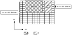
- One set is the wideband signal shown in shaded area 1 in Figure 5, occupying 6RB, including PSS, SSS, and PBCH; the other set is the narrowband signal shown in shaded area 2 in Figure 5, occupying 1RB, including the narrowband master sync Signals (Narrowband Primary Synchronization Signal, NPSS), Narrowband Synchronization Signals Block (NSSS), Narrowband Physical Broadcasting Channel (NPBCH), and there may be multiple types of bandwidth terminal equipment in the future, such as 12RB Terminal equipment, 6RB terminal equipment, 1RB terminal equipment, etc.
- NPSS narrowband Primary Synchronization Signal
- NSSS Narrowband Synchronization Signals Block
- NPBCH Narrowband Physical Broadcasting Channel
- the SSB corresponding to different bandwidth types of terminal equipment are generally the same, if the design concept of LTE is followed, that is, in the NR system, each type of bandwidth terminal equipment is used.
- the corresponding SSB is designed and sent, and the same information such as the cell ID and SFN is repeatedly sent, which requires more transmission resources.
- the embodiments of the present application provide a new SSB.
- This SSB may include a first PBCH carrying time-frequency resource location information of first synchronization information and a second PBCH carrying time-frequency resource location information of second synchronization information.
- One synchronization information may be used for downlink synchronization of broadband terminal equipment, and the second synchronization information may be used for downlink synchronization of narrowband terminal equipment. Therefore, for terminal devices of different bandwidth types, the access network device can send the same SSB, and one SSB can meet the synchronization requirements of terminal devices of various bandwidth types, simplifying the design of the system.
- information such as the cell ID and SFN only needs to be sent once, without repeated sending, thereby saving transmission resources.
- the technical solutions provided in the embodiments of the present application can be used in wireless communication systems, such as 4.5G systems or 5G systems, and further evolution systems based on LTE or NR, as well as future wireless communication systems or other similar communication systems.
- FIG. 6 is a network architecture applied in the embodiment of this application.
- Figure 6 includes access network equipment and six terminal equipment.
- the six terminal equipment can be cellular phones, smart phones, portable computers, handheld communication devices, handheld computing devices, satellite radio devices, global positioning systems, PDAs and/or Any other suitable equipment used for communication on the wireless communication system, and can be connected with the access network equipment.
- These six terminal devices can all communicate with the access network device.
- the terminal device may be a narrowband terminal device, such as a mMTC terminal device; the terminal device may be a broadband terminal device, such as an existing release 15 NR terminal device.
- the number of terminal devices in FIG. 6 is only an example, and it may be less or more.
- the access network device in Figure 6 may be a base station. Wherein the access network device in different systems corresponding to different devices, for example, in the fourth generation mobile communication technology (the 4 th generation, 4G) system, the eNB may correspond to, in the corresponding gNB 5G system.
- the fourth generation mobile communication technology the 4 th generation, 4G
- the eNB may correspond to, in the corresponding gNB 5G system.
- the network architecture applied in the embodiments of the present application may also be a public land mobile network (Public Land Mobile Network, PLMN) network, a device-to-device (D2D) network, and a machine-to-machine (M2M) network. , IoT network or other network.
- PLMN Public Land Mobile Network
- D2D device-to-device
- M2M machine-to-machine
- IoT IoT network or other network.
- the embodiment of the present application provides a communication method.
- the method is applied to the network architecture shown in FIG. 6 as an example.
- the method can be executed by two communication devices, for example, the first communication device and the second communication device.
- the first communication device may be an access network device or a communication device capable of supporting the access network device to implement the functions required by the method, or the first communication device may be a terminal device or a communication device capable of supporting the terminal device to implement the method required
- the functional communication device can of course also be other communication devices, such as a chip system.
- the second communication device may be an access network device or a communication device capable of supporting the access network device to implement the functions required by the method, or the second communication device may be a terminal device or a communication device capable of supporting the terminal device to implement the functions required by the method.
- the communication device can of course also be other communication devices, such as a chip system. And there are no restrictions on the implementation of the first communication device and the second communication device.
- the first communication device may be an access network device
- the second communication device is a terminal device
- the first communication device is an access network device
- the second communication device is a communication device that can support the terminal equipment to implement the functions required by the method
- the first communication device is a communication device that can support the access network equipment to implement the functions required by the method
- the second communication device is capable of supporting The terminal equipment implements the communication device required by the method, and so on.
- the method is executed by the access network device and the terminal device as an example, that is, the first communication device is the access network device and the second communication device is the terminal device as an example.
- the access network device in the following may be the access network device in FIG. 6, and the terminal device in the following may be any one of the terminal device 101 to the terminal device 106 in FIG. 6.
- the embodiment of the present application only takes execution through the access network device and the terminal device as an example, and is not limited to this scenario.
- Figure 7 is a flowchart of the method.
- the access network device generates an SSB.
- the SSB contains a first PBCH and a second PBCH.
- the first PBCH carries the time-frequency resource location information of the first synchronization information
- the second PBCH carries the time-frequency resource location information of the second synchronization information.
- the time-frequency resource positions of the first synchronization information and the second synchronization information are different.
- first PBCH and the second PBCH here may be one PBCH as a whole, or multiple PBCHs, and the embodiment of the present application is logically described as the first PBCH and the second PBCH.
- the SSB may include PSS, SSS, and PBCH.
- PBCH can include multiple parts.
- the PBCH includes 4 parts, namely the first part, the second part, the third part, and the fourth part.
- the first part occupies symbol 1 in the time domain and all subcarriers occupied by the SSB in the frequency domain.
- the second part occupies symbol 3 in the time domain, and all the SSB occupies in the frequency domain.
- the third part of the subcarriers occupies symbol 2 in the time domain, and occupies a part of the subcarriers in the remaining subcarriers other than the subcarriers occupied by the SSB in the frequency domain.
- the fourth part occupies symbol 2 in the time domain, and occupies another part of the subcarriers in the remaining RB except the subcarriers occupied by the SSB in the frequency domain.
- the SSB may include a first PBCH and a second PBCH.
- the first PBCH may be all of the four parts shown in FIG. 4, and the second PBCH may be a proper subset of the four parts shown in FIG. 4.
- the second PBCH may be the third part and the first Four parts.
- the embodiment of the application does not limit the composition of the first PBCH and the second PBCH.
- the first PBCH may carry the time-frequency resource location information of the first synchronization information
- the second PBCH may carry the time-frequency resource location information of the second synchronization information.
- both the first synchronization information and the second synchronization information can be used for synchronization between the terminal device and the access network device.
- the first synchronization information may be used for broadband terminal equipment to perform synchronization processing
- the second synchronization information may be used for narrowband terminal equipment to perform synchronization processing.
- the broadband terminal equipment and narrowband terminal equipment are relative, for example, if the broadband terminal equipment is a 12RB terminal equipment, the narrowband terminal equipment may be a 6RB terminal equipment, then the first synchronization information is used between the 12RB terminal equipment and the access network equipment For synchronization, the second synchronization information is used for synchronization between the 6RB terminal device and the access network device.
- the synchronization processing here may be a synchronization process or a part of the synchronization process, for example, the process of detecting the PBCH, the time synchronization process of the terminal equipment and the access network equipment. Of course, the synchronization processing here can also be other possible processes.
- the time-frequency resource location information of the first synchronization information is different from the time-frequency resource location information of the second synchronization information.
- the broadband terminal device and the narrowband terminal device can simultaneously obtain the first synchronization information and the second synchronization from different time-frequency resource locations.
- the SSB may include both the PBCH for broadband terminal equipment and the PBCH for narrowband terminal equipment. Therefore, the embodiment of the present application only needs to send one type of SSB to meet the requirements of the broadband terminal equipment and the narrowband terminal equipment for synchronization processing. demand.
- the access network device since the cell ID and SFN information included in the SSB are the same for terminal devices of different bandwidth types, in this embodiment of the application, the access network device only needs to send one type of SSB.
- the first synchronization information is SIB1, for example, called first SIB1
- the second synchronization information is also SIB1, for example, called second SIB1.
- the time-frequency resource location information of the first synchronization information may indicate the time-frequency resource location of the first SIB1.
- the time-frequency resource location information of the second synchronization information may indicate the time-frequency resource location of the second SIB1.
- the time-frequency resource location includes a time-domain resource location and/or a frequency-domain resource location, specifically, it includes a time-domain resource location or a frequency-domain resource location, or a time-domain resource location and a frequency-domain resource location.
- the time-frequency resource location information of the second synchronization information may be the location information of the second SIB1.
- the time-frequency resource location information of the second synchronization information may be a Carry Resource Block (CRB) offset.
- CRB Carry Resource Block
- the time-frequency resource location information of the second synchronization information may include the location information of the second SIB1 and the CRB offset.
- the CRB offset can be the offset between the frequency domain resource of the next piece of data sent by the access network device after the SSB is sent and the frequency domain resource of the narrowband terminal device receiving the SSB, to indicate where the terminal device receives the SSB The second SIB1.
- the frequency domain resource of the second SIB1 can be configured for the narrowband terminal device, so that the narrowband terminal device can receive the second SIB1, thereby performing downlink synchronization according to the second SIB1.
- Figure 8 is a schematic diagram of an SSB, which is applied to a communication system including broadband terminal equipment (taking legacy terminal equipment as an example) and narrowband terminal equipment (taking mMTC terminal equipment as an example).
- the SIB1 shown in Figure 8 is carried on the Physical Downlink Control Channel (PDCCH) with a bandwidth of 24RB
- the bandwidth of the mMTC terminal device is 25RB, so it can receive information within 25RB, so the mMTC terminal device can receive
- the SSB corresponding to the legacy terminal device further detects the time-frequency resource location information of the second SIB1 carried by the second PBCH in the SSB, so as to receive the first data from the access network device according to the time-frequency resource location indicated by the time-frequency resource location information Two SIB1.
- the SSB corresponding to the legacy terminal device can be received, so the first SIB1 can also be obtained from the received SSB.
- the time-frequency resource location of the first SIB1 and the time-frequency resource location of the second SIB1 are the same.
- the first PBCH and the second PBCH can be the same PBCH or different PBCHs.
- Fig. 9 is a schematic diagram of another SSB, which is also applied to a system including legacy terminal equipment and mMTC terminal equipment.
- the SIB1 shown in FIG. 9 is carried in the PDCCH control resource set CORESET with a bandwidth of 48 RB.
- Information such as the frequency band occupied in the frequency domain of the PDCCH and the number of OFDM symbols occupied in the time domain is encapsulated in CORESET.
- the access network device sends the PDCCH in the PDCCH CORESET. Under normal circumstances, the PDCCH will evenly occupy part of the resources in the PDCCH CORESET, and some of the resources can be divisible by 4.
- the bandwidth occupied by the PDCCH CORESET is 48 RB, and the PDCCH will evenly occupy part of the resources in the PDCCH CORESET, such as 24 RB. Since the mMTC terminal device has a bandwidth of 25RB, it cannot receive information with a bandwidth of 48RB, so the mMTC terminal device cannot detect the SSB corresponding to the legacy terminal device.
- the PDCCH (carrying SIB1) in Figure 9 exceeds the boundary of the frequency domain, that is, the boundary between the bandwidth of the narrowband terminal device and the bandwidth of the broadband terminal device (the boundary of the frequency domain is shown by the horizontal dashed line in Figure 8 and Figure 9). Therefore, the mMTC terminal device cannot receive the part of the SIB1 that exceeds the frequency domain boundary.
- the access network device needs to separately configure the time-frequency resource location information of the second SIB1 for the mMTC terminal device through the second PBCH to indicate the second SIB1
- the mMTC terminal device can receive the second SIB1 according to the indication of the second PBCH.
- the mMTC terminal device receives the second SIB1 in the NB-PDCCH (carrying SIB1) in FIG. 9.
- the second PBCH is represented as a narrowband physical broadcast channel (NB-PBCH).
- the PDCCH and CORESET bandwidth used to carry SIB1 is 24RB or 48RB, and the specific value may be indicated by the time-frequency resource location information of SIB1.
- the access network device is configured with a 48RB PDCCH CORESET, the mMTC terminal device cannot receive SIB1, and the access network device needs to use the second PBCH to indicate another PDCCH CORESET with a bandwidth of 24RB for the mMTC terminal device, so that the mMTC terminal device can receive The second SIB1.
- the information contained in the first SIB1 and the second SIB1 may be the same or different.
- the information contained in the first SIB1 and the second SIB1 can be the same. Whether it is a broadband terminal device or a narrowband terminal device, both SIB1 with the same information are configured, thereby reducing access The burden of network equipment. If the information contained in the first SIB1 and the second SIB1 are not the same, the narrowband terminal device obtains the first SIB1 and the second SIB1, and only needs to parse the second SIB1 that belongs to itself, and does not need to parse the first SIB1, which can reduce the workload of the terminal device .
- the first PBCH may also carry third synchronization information.
- the time-frequency resource location information of the first synchronization information and the third synchronization information are used for broadband terminal equipment to perform downlink synchronization, and the time of the second synchronization information
- the frequency resource location information and the third synchronization information are used for the narrowband terminal equipment to perform downlink synchronization.
- the third synchronization information may include synchronization information that can be shared by the broadband terminal device and the narrowband terminal device, such as SFN.
- the broadband terminal equipment and the narrowband terminal equipment can receive the SSB and obtain the first PBCH included in the SSB, thereby obtaining the third synchronization information. In this way, there is no need to separately design the PBCH carrying the third synchronization information for the broadband terminal equipment and the narrowband terminal equipment.
- the resource occupied by PBCH is the number of bits that carry two copies of third synchronization information, and the first PBCH only carries one copy of third synchronization information. , So the number of bits occupied, so resources are saved.
- the bandwidth of the PBCH included in the SSB corresponding to the broadband terminal equipment is relatively wide, such as 20 RBs.
- the bandwidth of the PBCH included in the SSB corresponding to the narrowband terminal equipment is relatively narrow, such as 12 RBs, so the narrowband terminal equipment cannot receive the bandwidth of the broadband terminal equipment.
- PBCH In order to enable the narrowband terminal equipment to receive the PBCH of the broadband terminal equipment, the access network equipment can send the PBCH for the broadband terminal equipment on a narrower bandwidth, so that the narrowband terminal equipment can receive the PBCH of the broadband terminal equipment.
- the SSB may also include a third PBCH, where the frequency domain resource of the first PBCH is called the first frequency domain resource, the frequency domain resource of the third PBCH is called the third frequency domain resource, and the frequency domain resource of the third PBCH is called the third frequency domain resource.
- the domain resources are composed of second frequency domain resources and third frequency domain resources.
- the information carried by the third PBCH is the same as the information carried by the first PBCH on the second frequency domain resource, or the signal carried by the third PBCH is the same as the signal carried by the first PBCH on the second frequency domain resource. It refers to the information carried on the second frequency domain resource after baseband processing and radio frequency processing.
- the baseband processing includes modulation and coding, and the radio frequency processing includes up-conversion.
- the PBCH used for broadband terminal equipment can be sent on a narrower bandwidth, that is, the information carried by the PBCH of the broadband terminal equipment is carried on the first PBCH and the third PBCH, and the total frequency domain resource occupied is the first A frequency domain resource, so that the bandwidth occupied by the PBCH of the broadband terminal device and the narrowband terminal device can be the same, so that the narrowband terminal device can receive the PBCH of the broadband terminal.
- each frame is composed of 10 subframes with a length of 1 ms, and each frame is divided into two half-frames of equal size, namely half-frame 0 and half-frame 1.
- Half frame 0 includes subframes 0 to 4
- half frame 1 includes subframes 5 to 9.
- Figure 10 takes an SSB in a half frame, that is, within a time window of 5 ms, as an example.
- the SSB is used for synchronization processing between broadband terminal equipment (such as legacy terminal equipment) and narrowband terminal equipment (such as 12RB terminal equipment).
- broadband terminal equipment such as legacy terminal equipment
- narrowband terminal equipment such as 12RB terminal equipment.
- the bandwidth of the PBCH included in the SSB corresponding to the broadband terminal device is 20 RBs
- the bandwidth of the PBCH included in the SSB corresponding to the narrowband terminal device is 12 RBs, so the narrowband terminal device cannot receive the PBCH of the broadband terminal device.
- the bandwidth of the PSS of the SSB and the bandwidth of the SSS corresponding to the legacy terminal device are both 12RB, so it can be received by the 12RB terminal device.
- the bandwidth of the PBCH of the SSB corresponding to the legacy terminal equipment is 20 RBs, so it is necessary to add the non-central 8 RBs (PSS/SSS/PBCH), that is, the 8 RBs outside the 12RB, and the 12RB ( PSS/SSS/PBCH) is sent again within the time after sending, so that the 12RB terminal device can receive all the information in the SSB of the legacy terminal device.
- the 8 non-central RBs may be PBCHs located on the upper and lower sides of the SSS as indicated by arrows in FIG. 10, that is, the PBCH shown in the shaded area in FIG. 10.
- the access network device can continue to send within the time after the third PBCH is sent. In this way, the SSB shown in FIG. 10 can be received by both the legacy terminal device and the 12RB terminal device.
- the 12RB terminal device After the 12RB terminal device receives the SSB, it can demodulate the PBCH of the legacy terminal device, for example, demodulate the PBCH (first PBCH) among the 12 RBs in the center in Figure 10 and the additional transmission of the access network device is suitable for the 12RB terminal device NB-PBCH.
- the legacy terminal device it is possible to receive only the PBCH applicable to the legacy terminal device, that is, only the first PBCH and the third PBCH, but not the NB-PBCH. In other words, the standard does not require legacy terminal equipment to read other PBCHs except the first PBCH and the third PBCH. At this time, the legacy terminal equipment will not know that the access network equipment transmits another bandwidth type on other time-frequency resources.
- the PBCH of the terminal device and it may be considered that other information of other terminal devices, such as data information, is transmitted on this resource.
- the SSB shown in Figure 10 can not only meet the requirements of legacy terminal equipment, but also meet the requirements of 12RB terminal equipment.
- Figure 10 illustrates the SSB when two 12RB terminal devices coexist with legacy terminal devices.
- Figure 10 shows two 12RB terminal devices with different shading patterns.
- the frequency domain resources of the third PBCH are a proper subset of the frequency domain resources of the first PBCH, that is, the frequency domain resources of the third PBCH are a subset of the frequency domain resources of the first PBCH, and The frequency domain resources of the first PBCH are not a subset of the frequency domain resources of the third PBCH. In this way, the frequency domain resources of the first PBCH and the third PBCH are partially multiplexed, so the transmission resources used by the access network device to send the SSB are saved.
- the information carried by the third PBCH may be information on frequency domain resources other than the frequency domain resources of the second PBCH in the frequency domain resources of the first PBCH.
- the information carried by the PBCH of the broadband terminal equipment is carried on the first PBCH and the third PBCH.
- the third PBCH and the second The frequency domain resources occupied by the PBCH are different, so that the broadband terminal device may not need to analyze the second PBCH.
- the broadband terminal device can receive the SSB of the narrowband terminal device, so the broadband terminal device can use the SSB of the narrowband terminal device for synchronization, so that the access network device can Only one set of SSB is designed to simplify the design of SSB.
- the broadband terminal device synchronizes according to the SSB of the narrowband terminal device, the synchronization performance may be poor. Therefore, the SSB provided in the embodiment of the present application may further include a fourth PBCH, so as to modify all or part of the information contained in the first PBCH, such as the location information of SIB1, for the terminal device of the third type.
- the terminal device of the third type can determine the synchronization information of the terminal device of the third type according to the first PBCH and the fourth PBCH, so as to improve the synchronization performance of the terminal device of the third type as much as possible.
- the maximum bandwidth supported by the terminal device of the third type is greater than or equal to the maximum bandwidth supported by the terminal device of the first type. It can be understood that the terminal device of the third type is a broadband terminal device relative to the terminal device of the first type. .
- FIG. 11 is a schematic diagram of a PBCH included in the SSB.
- Figure 11 takes the existence of two types of bandwidth types as an example.
- the bandwidths of the two types of bandwidth types are BWi and BWj, and BWi ⁇ BWj.
- a terminal device with a bandwidth of BWi is a terminal device of the second type, then a terminal device with a bandwidth of BWj is a terminal device of the first type or a terminal device of the third type; a terminal device with a bandwidth of BWi is a terminal of the first type Device, then the terminal device with the bandwidth of BWj is the third type of terminal device.
- a terminal device with a bandwidth of BWi is a narrowband terminal device
- a terminal device with a bandwidth of BWj is a broadband terminal device.
- FIG. 11 takes the BWi terminal device as a 6RB terminal device as an example, and the BWj terminal device as a 12RB terminal device as an example.
- the PBCH in the shaded area 1 in FIG. 11 is the PBCH of the 6RB terminal device, that is, the first PBCH, and the PBCH in the shaded area 2 is the fourth PBCH, and both the first PBCH and the fourth PBCH can be received by the 12RB terminal device.
- the fourth PBCH can be used to change part of the information in the first PBCH, for example, the time-frequency resource location information of the SIB1 carried by the first PBCH can be changed.
- the 6RB terminal device After the 6RB terminal device receives the SSB from the access network device, it only needs to obtain the required synchronization information such as the SIB from the first PBCH included in the SSB, and then perform synchronization processing.
- the 12RB terminal device After the 12RB terminal device receives the SSB, in addition to acquiring the first PBCH included in the SSB, it also needs to acquire the fourth PBCH, thereby obtaining required synchronization information such as SIB based on the acquired first PBCH and fourth PBCH, and then performing synchronization processing.
- the access network device sends the PBCH of the 6RB terminal device, and then sends the fourth PBCH for the 12RB terminal device, rather than resending a 12RB terminal device that carries all the information for the synchronization of the 12RB terminal device.
- the PBCH occupies less resources.
- the fourth PBCH carries the time-frequency resource location information and/or CRB offset of the SIB1 for the third type of terminal equipment to indicate that the third type of terminal equipment completes downlink access. , Where should the PDCCH be received.
- the fourth PBCH reconfigures the location information of SIB1 for the terminal equipment of the third type, which enables the terminal equipment of the third type to receive the PDCCH on a bandwidth greater than the maximum bandwidth supported by the terminal equipment of the first type, which is beneficial to improve the performance of the terminal equipment of the third type. PDCCH reception performance.
- the CRB offset can indicate the offset between the frequency domain resource of the next piece of data sent by the access network device after sending the SSB and the frequency domain resource of the terminal device receiving the SSB.
- the terminal device here may refer to the third type. To indicate where the third type of terminal device receives the second SIB1. That is, the fourth PBCH reconfigures the CRB offset for the terminal device, which can evacuate the data transmission of the terminal device of different bandwidth types on different frequency bands, so as to reduce the network congestion.
- the fourth PBCH and the first PBCH may be discontinuous in the time domain, and a corresponding time interval may be reserved in the middle as a guard interval.
- the frequency domain resources of the fourth PBCH may have the following situations.
- the frequency domain resources of the fourth PBCH are respectively introduced below.
- the frequency domain resources of the fourth PBCH are located within the frequency domain resources of the first PBCH.
- the frequency domain resources of the PBCH of the 6RB terminal equipment are within the frequency domain resources of the PBCH of the 12RB terminal equipment, that is, the frequency domain resources occupied by the PBCH of the narrowband terminal equipment are occupied by the PBCH of the broadband terminal equipment.
- the maximum frequency domain resource that the PBCH of the narrowband terminal device may occupy is the frequency domain resource occupied by the PBCH of the broadband terminal device, thereby saving frequency domain resources occupied by the PBCH of the broadband terminal device.
- the frequency domain resources of the fourth PBCH are located outside the frequency domain resources of the first PBCH.
- FIG. 12 is a schematic diagram of a PBCH included in the SSB.
- Figure 12 takes the existence of 6RB terminal equipment and 12RB terminal equipment as an example.
- the PBCH in shaded area 1 in FIG. 12 is the PBCH of a 6RB terminal device, that is, the first PBCH;
- the PBCH in shaded area 2 is a part of the PBCH of a 12RB terminal device, that is, the fourth PBCH.
- the frequency domain resources occupied by the fourth PBCH are within the frequency domain resources occupied by the PBCH of the 12RB terminal device, and are outside the frequency domain resources occupied by the PBCH of the 6RB terminal device.
- the fourth PBCH is information dedicated to broadband terminal equipment, so it is located within the frequency domain resources occupied by the PBCH of the 12RB terminal equipment and outside the frequency domain resources occupied by the PBCH of the 6RB terminal equipment, so the narrowband terminal equipment detects in the frequency band
- the information carried by the signal is for narrowband terminal equipment, and has nothing to do with broadband terminal equipment. There is no need to further determine from the acquired information that it does not belong to narrowband terminal equipment.
- PBCH adopts such a frequency domain structure, that is, the frequency band of the narrowband terminal equipment is only for the PBCH of the narrowband terminal equipment, and there is no PBCH of the broadband terminal equipment, which can make the signal of the frequency band of the narrowband terminal equipment more in the time domain.
- the PBCH adopts such a frequency domain structure.
- the first PBCH and the fourth PBCH occupy the same symbol for transmission, so that broadband terminal equipment and narrowband terminal equipment can quickly receive all PBCH signals, and increase the speed of access to the system.
- the access network device broadcasts the SSB.
- the access network device may broadcast the SSB on the same frequency domain resource in at least one time window.
- the SSB is within a period of time, and this period of time can be considered as a time window.
- the current SSB is within a time window of 5 ms, and the time window of 5 ms here may be the period of the SS burst set.
- the embodiment of the present application does not limit the length of the time window in which the SSB is located, and other lengths may be used besides 5 ms. It is just that the SSB in the embodiment of the present application is also located within the time window of 5 ms, which helps to be compatible with the existing system.
- the access network device can broadcast the SSB in at least one time window, then the SSB can be located in at least one discontinuous time window, where the access network device can broadcast one SSB or multiple SSBs in one time window .
- the PSS, SSS, and PBCH included in the SSB can be configured by the access network equipment or specified by agreement, in which time slots within the time window and which symbols in the corresponding time slots are located. .
- the access network device For at least two types of bandwidth types of terminal devices, the access network device generates an SSB.
- the PBCH included in the SSB broadcast by the access network device can be multiplexed in the frequency domain to minimize the use of broadcast SSB. Transmission resources.
- the frequency domain resources occupied by the SSB of the narrowband terminal device are within the frequency domain resources occupied by the SSB of the broadband terminal device.
- Figure 13 is a schematic diagram of SSB.
- FIG. 13 takes the existence of three bandwidth types of terminal devices as an example.
- the three bandwidth types of terminal devices are, for example, 12RB terminal devices, 6RB terminal devices, and 1RB terminal devices.
- the access network equipment broadcasts SSB, which is used for terminal equipment with bandwidths of BW 1 , BW 2 , and BW 3 to access the network.
- the terminal device with the bandwidth of BW 1 is a 1RB terminal device
- the terminal device with a bandwidth of BW 2 is a 6RB terminal device
- the terminal device with a bandwidth of BW 3 is a 12RB terminal device
- the SSB occupied The total bandwidth is BW 3 , which is 12RB.
- the frequency domain resources occupied by the SSB of a 1RB terminal device are within the frequency domain resources occupied by the SSB of a 12RB terminal device
- the frequency domain resources occupied by the SSB of a 6RB terminal device are also in the frequency domain of the 12RB terminal device.
- SSBs of terminal devices of multiple bandwidth types are multiplexed in frequency domain resources, which saves resources occupied by the SSB.
- the frequency domain resources occupied by the SSB of the terminal device with the first bandwidth are in the frequency domain occupied by the SSB of the terminal device with the second bandwidth.
- the frequency domain resources occupied by the SSB of the terminal device with the second bandwidth are within the frequency domain resources occupied by the SSB of the terminal device with the third bandwidth.
- the first bandwidth is smaller than the second bandwidth
- the second bandwidth is smaller than the third bandwidth.
- Fig. 14 is a schematic diagram of an SSB.
- Fig. 14 also takes a network system with three bandwidth types of terminal devices, including 12RB terminal devices, 6RB terminal devices, and 1RB terminal devices as an example.
- the access network device broadcasts the SSB for terminal devices with bandwidths of the first bandwidth (BW 1 ), the second bandwidth (BW 2 ), and the third bandwidth (BW 3 ) to access the network.
- BW 1 the first bandwidth
- BW 2 the second bandwidth
- BW 3 the third bandwidth
- a terminal device with a bandwidth of BW 1 is a 1RB terminal device
- a terminal device with a bandwidth of BW 2 is a 6RB terminal device
- a terminal device with a bandwidth of BW 3 is a 12RB terminal device.
- BW 1, BW 2, BW 3 between each level are in a nesting relationship, i.e. located. 1 BW band BW 2, BW 3 located BW 2, and so on.
- the frequency domain resources occupied by the SSB of a 1RB terminal device are within the frequency domain resources occupied by the SSB of a 6RB terminal device, and the frequency domain resources occupied by the SSB of a 6RB terminal device are occupied by the SSB of a 12RB terminal device. In the domain resources, to further save the resources occupied by the SSB.
- FIG. 15 is a schematic diagram of SSB.
- the SSB includes PSS, SSS and PBCH.
- the SSB shown in FIG. 15 occupies a total of 4 time slots in the time domain and a total of 12 RBs in the frequency domain.
- SSB only includes PBCH applicable to 1RB terminal equipment in the 3rd time slot and 4th time slot, so SSB only occupies 1 RB in the 3rd time slot and 4th time slot.
- Fig. 15 is an example of the embodiment of Fig. 13 and Fig. 14.
- the PSS and SSS hereinafter also referred to as SS
- the PSS and SSS included in the SSB of the 12RB terminal device occupy the third position in the time domain.
- the SS included in the SSB of a 6RB terminal device occupies the 3rd and 4th symbols in the time domain, and occupies 6RB in the frequency domain, represented by a solid box ;
- the SS included in the SSB of the 1RB terminal device occupies the 3rd to 14th symbols in the time domain, and 1RB in the frequency domain, which is represented by a solid line frame;
- the PBCH included in the SSB of the 12RB terminal device (the fourth PBCH above) Occupies the 5th and 6th symbols in the time domain, and occupies 6RB in the frequency domain, which is represented by a dashed box;
- the PBCH (the first PBCH above) included in the SSB of a 12RB terminal device or a 6RB terminal device is occupied in the time domain
- the 6th to 11th symbols occupy 4RB in the frequency domain and are represented by a dashed frame.
- the first two symbols of each time slot are reserved for broadband terminal equipment to send PDCCH, and the SS of narrowband terminal equipment starts from the third symbol.
- the SSs of terminal devices of different bandwidth types occupy different bandwidths, but the bearer sequences may be the same sequence.
- the frequency domain resources occupied by the PBCH of the 6RB terminal equipment are the same as the frequency domain resources occupied by the SS, and in order to avoid the 1RB SS, for example, the 1RB SS will interfere with the PBCH of the 6RB terminal equipment, a certain guard interval is reserved, such as reserved.
- a certain guard interval is reserved, such as reserved
- the 5th symbol between the 4th symbol and the 6th symbol in FIG. 15 serves as a guard interval.
- the frequency domain resource occupied by the fourth PBCH of the 12RB terminal device is within the frequency band of the 12RB terminal device and outside the frequency band of the 6RB terminal device.
- 1RB and 6RB terminal devices obtain synchronization information such as SIB by detecting their respective PBCHs
- 12RB terminal devices obtain synchronization information such as SIB by detecting the first PBCH of 6RB terminal devices and the fourth PBCH of 12RB terminal devices.
- the terminal device obtains the PBCH according to the received first signal, and performs synchronization processing, where the first signal includes PBCH, which is located in the synchronization signal block SSB, and the SSB includes the first PBCH and the second PBCH, and the first PBCH carries the first synchronization.
- the time-frequency resource location information of the information, the second PBCH carries the time-frequency resource location information of the second synchronization information, the time-frequency resource locations of the first synchronization information and the second synchronization information are different, and the acquired PBCH is the first PBCH or the second PBCH .
- the access network device For terminal devices of various bandwidth types, the access network device sends the same SSB.
- the terminal equipment of different bandwidth types obtains the corresponding PBCH according to the received SSB, and obtains synchronization information for synchronization according to the time-frequency resource location information of the synchronization information carried by the PBCH.
- Both the broadband terminal device and the narrowband terminal device receive the first signal from the access network device, where the first signal may be the SSB, or the signal from which the SSB can be obtained.
- the broadband terminal device and the narrowband terminal device obtain the SSB according to the first signal, and obtain the PBCH from the SSB for synchronization.
- the SSB may include a first PBCH and a second PBCH, where the first PBCH may carry first synchronization information, such as the time-frequency resource location information of the first SIB1, and the second PBCH may carry second synchronization information, For example, the time-frequency resource location information of the second SIB1.
- the first SIB1 may be used for synchronization of, for example, broadband terminal equipment
- the second SIB1 may be used for synchronization of, for example, narrowband terminal equipment. Therefore, the broadband terminal equipment and the narrowband terminal equipment can respectively obtain the corresponding PBCH from the SSB, and further obtain synchronization information for synchronization according to the obtained PBCH.
- the terminal equipment is a broadband terminal equipment and a narrowband terminal equipment as examples to introduce how the terminal equipment synchronizes according to the acquired SSB.
- the broadband terminal device obtains the SSB, can obtain the first PBCH from the SSB, parse the first PBCH, and obtain the time-frequency resource location information of the first SIB1, so as to obtain the time-frequency resource location information of the first SIB1.
- the frequency resource location information acquires the first SIB1 for synchronization.
- the narrowband terminal device obtains the SSB, and can obtain the second PBCH from the SSB.
- the second PBCH carries the time-frequency resource location information of the second SIB1, for example, the second PBCH carries the CRB offset of the second SIB, so that the narrowband terminal device analyzes the second PBCH and can learn where to receive the second SIB1, thereby Synchronize according to the second SIB1.
- the following describes the process of obtaining PBCH by broadband terminal equipment and narrowband terminal equipment and obtaining SIB according to PBCH with specific examples.
- the legacy terminal device can receive information within 24 RBs, so after receiving the SSB, the legacy terminal device can obtain the first PBCH from it, and then according to the first PBCH carried by the first PBCH.
- the first SIB1 is acquired by an indication of the time-frequency resource location information of the SIB1. Since the mMTC terminal device can receive information within 25 RBs, it can receive SIB1 from the PDCCH of 24 RBs.
- the time-frequency resource location of the second SIB1 and the time-frequency resource location of the first SIB1 may be the same.
- the mMTC terminal device receives the second SIB1 from the 24 RB PDCCH according to the indication of the time-frequency resource location information of the second SIB1 carried by the second PBCH in the SSB.
- the mMTC terminal device receives the second PBCH belonging to the mMTC terminal device in the SSB of the Legacy terminal device.
- the time-frequency resource location information of the second SIB1 carried by the second PBCH indicates the location where the mMTC terminal device can receive the second SIB1.
- Figure 9 belongs to the second PBCH of the mMTC terminal equipment, namely NB-PBCH.
- the NB-PBCH is used to update part of the information in the PBCH of the Legacy terminal device for the mMTC terminal device, such as the time-frequency resource location information of the second SIB.
- the time-frequency resource location information of the second SIB1 carried by the second PBCH indicates that the second SIB1 is transmitted on 24 RBs, so that the mMTC terminal device can obtain the second SIB1 on the 24 RBs according to the indication of the second PBCH.
- SIB1 to perform downlink synchronization.
- FIG. 16 shows a schematic structural diagram of a communication device 200.
- the communication device 200 can implement the functions of the access network device mentioned above.
- the communication apparatus 200 may be the access network device described above, or may be a chip set in the access network device described above.
- the communication device 200 may include a processor 201 and a transceiver 202.
- the processor 201 may be used to execute S701 in the embodiment shown in FIG. 7 and/or to support other processes of the technology described herein, for example, it may execute the steps performed by the access network device described above. All other processes or part of other processes except the sending and receiving process.
- the transceiver 202 can be used to perform S702 in the embodiment shown in FIG. 7 and/or to support other processes of the technology described herein. For example, it can perform all the operations performed by the access network device described above.
- the processor 201 is configured to generate a synchronization signal block SSB, where the SSB includes a first PBCH and a second PBCH, the first PBCH carries time-frequency resource location information of the first synchronization information, and the second PBCH carries Time-frequency resource location information of the second synchronization information, where the time-frequency resource locations of the first synchronization information and the second synchronization information are different;
- the transceiver 202 is used to broadcast the SSB.
- the first PBCH carries third synchronization information
- the time-frequency resource location information of the first synchronization information and the third synchronization information are used for the first type of terminal equipment to perform downlink synchronization
- the time-frequency resource location information of the second synchronization information and the third synchronization information are used for the second type of terminal equipment to perform downlink synchronization.
- the first synchronization information is a first system information block type 1 SIB1
- the second synchronization information is a second SIB1
- the time-frequency resource location information of the second synchronization information carried by the second PBCH is the location information of the second SIB1 and/or the CRB offset of the bearer resource block, and the CRB offset is used to indicate the second Location information of SIB1.
- the first SIB1 and the second SIB1 contain the same or different information.
- the SSB further includes a third PBCH
- the frequency domain resource of the first PBCH is a first frequency domain resource
- the frequency domain resource of the third PBCH is a third frequency domain resource
- the first frequency domain resource is composed of a second frequency domain resource and the third frequency domain resource.
- the information carried by the third PBCH is the same as the information carried by the first PBCH on the second frequency domain resource, or the signal carried by the third PBCH is the same as that carried by the first PBCH.
- the signals carried on the second frequency domain resources are the same.
- the transceiver 202 is specifically configured to broadcast the SSB on the same frequency domain resource in at least one time window.
- the maximum bandwidth of the terminal device of the second type is less than or equal to the maximum bandwidth of the terminal device of the first type.
- FIG. 17 shows a schematic structural diagram of a communication device 300.
- the communication device 300 can implement the functions of the terminal mentioned above.
- the communication apparatus 300 may be the terminal device described above, or may be a chip provided in the terminal device described above.
- the communication device 300 may include a processor 301 and a transceiver 302.
- the processor 301 may be used to execute S703 in the embodiment shown in FIG. 7 and/or to support other processes of the technology described herein.
- the processor 301 may be used to execute the above-mentioned terminal device except for receiving and sending. All other processes or part of other processes outside the process.
- the transceiver 302 can be used to perform S703 in the embodiment shown in FIG. 7 and/or to support other processes of the technology described herein, for example, it can perform all the transceiving processes performed by the terminal device described above. Or part of the sending and receiving process.
- the transceiver 302 is configured to receive a first signal, where the first signal includes PBCH;
- the processor 301 is configured to obtain the PBCH
- the PBCH is located in a synchronization signal block SSB, the SSB includes a first PBCH and a second PBCH, the first PBCH carries the time-frequency resource position information of the first synchronization information, and the second PBCH carries the second synchronization
- the time-frequency resource location information of the information, the time-frequency resource location of the first synchronization information and the second synchronization information are different; the acquired PBCH is the first PBCH or the second PBCH.
- the first PBCH carries third synchronization information
- the processor 301 is further configured to: obtain the third synchronization information in the first PBCH, and according to the third synchronization information And the acquired PBCH performs synchronization processing.
- the terminal device is a terminal device of the first type
- the terminal device is a second type of terminal device
- the maximum bandwidth of the terminal device of the second type is less than or equal to the maximum bandwidth of the terminal device of the first type.
- the first synchronization information is a first SIB1
- the second synchronization information is a second SIB1
- the time-frequency resource location information of the second synchronization information carried by the second PBCH is the location information and/or CRB offset of the second SIB1, and the CRB offset is used to indicate the location of the second SIB1 information.
- the first SIB1 and the second SIB1 contain the same or different information.
- the SSB further includes a third PBCH
- the frequency domain resource of the first PBCH is a first frequency domain resource
- the frequency domain resource of the third PBCH is a third frequency domain resource
- the first frequency domain resource is composed of a second frequency domain resource and the third frequency domain resource.
- the information carried by the third PBCH is the same as the information carried by the first PBCH on the second frequency domain resource, or the signal carried by the third PBCH is the same as that carried by the first PBCH.
- the signals carried on the second frequency domain resources are the same.
- the transceiver 302 is specifically configured to receive the first signal in at least one time window.
- the communication device 200 or the communication device 300 can also be implemented by the structure of the communication device 400 as shown in FIG. 18A.
- the communication apparatus 400 can implement the functions of the terminal equipment or access network equipment mentioned above.
- the communication device 400 may include a processor 401.
- the processor 401 may be used to execute S701 in the embodiment shown in FIG. 7 and/or to support the functions described herein.
- Other processes of the technology for example, all other processes or part of other processes performed by the access network equipment described above except for the transceiving process can be executed; or, the communication device 400 is used to implement the aforementioned processes
- the processor 401 can be used to execute S703 in the embodiment shown in FIG. 7 and/or other processes used to support the technology described herein, for example, it can execute the terminal device described in the foregoing. All other operations or part of other operations performed except for sending and receiving operations.
- the communication device 400 can use field-programmable gate array (FPGA), application specific integrated circuit (ASIC), system on chip (SoC), and central processor (central processor). unit, CPU), network processor (network processor, NP), digital signal processing circuit (digital signal processor, DSP), microcontroller (microcontroller unit, MCU), or programmable controller (programmable logic device, PLD) or other integrated chips, the communication device 400 can be set in the access network device or terminal device in the embodiment of the present application, so that the access network device or terminal device implements the method provided in the embodiment of the present application.
- FPGA field-programmable gate array
- ASIC application specific integrated circuit
- SoC system on chip
- central processor central processor
- unit CPU
- network processor network processor
- NP digital signal processing circuit
- DSP digital signal processor
- microcontroller microcontroller unit, MCU
- PLD programmable controller
- the communication device 400 may include a transceiver component for communicating with other devices.
- the transceiver component can be used to execute S702 in the embodiment shown in FIG. 7 and/or to support the functions described herein.
- a transceiver component is a communication interface. If the communication device 400 is an access network device or a terminal device, the communication interface may be a transceiver in the access network device or terminal device, such as the transceiver 202 or the transceiver 302.
- the device is, for example, a radio frequency transceiver component in an access network device or terminal device, or if the communication device 400 is a chip set in the access network device or terminal device, the communication interface may be the input/output interface of the chip, for example Input/output pins, etc.
- the communication device 400 may further include a memory 402, as shown in FIG. 18B, where the memory 402 is used to store computer programs or instructions, and the processor 401 is used to decode and execute these computer programs or instruction.
- these computer programs or instructions may include functional programs of the aforementioned access network devices or terminal devices.
- the functional program of the access network device is decoded and executed by the processor 401, the access network device can be made to realize the function of the access network device in the method provided in the embodiment shown in FIG. 7 of the embodiment of the present application.
- the terminal device can realize the function of the terminal device in the method provided in the embodiment shown in FIG. 7 of the embodiment of the present application.
- the functional programs of these access network devices or terminal devices are stored in a memory outside the communication device 400.
- the memory 402 temporarily stores part or all of the content of the function program of the access network device.
- the functional program of the terminal device is decoded and executed by the processor 401, the memory 402 temporarily stores part or all of the above-mentioned functional program of the terminal device.
- the functional programs of these access network devices or terminal devices are set in the memory 402 stored in the communication device 400.
- the communication device 400 may be set in the access network device in the embodiment of the present application.
- the functional program of the terminal device is stored in the memory 402 inside the communication device 400, the communication device 400 may be set in the terminal device in the embodiment of the present application.
- part of the content of the functional programs of these access network devices is stored in a memory outside the communication device 400, and other parts of the content of the functional programs of these access network devices are stored inside the communication device 400.
- part of the content of the functional programs of these terminal devices is stored in the memory outside the communication device 400, and other parts of the content of the functional programs of these terminal devices are stored in the memory 402 inside the communication device 400.
- the communication device 200, the communication device 300, and the communication device 400 are presented in the form of dividing each function module corresponding to each function, or may be presented in the form of dividing each function module in an integrated manner.
- the "module” here can refer to an ASIC, a processor and memory that executes one or more software or firmware programs, an integrated logic circuit, and/or other devices that can provide the above-mentioned functions.
- the communication device 200 provided by the embodiment shown in FIG. 16 may also be implemented in other forms.
- the communication device includes a processing module and a transceiver module.
- the processing module may be implemented by the processor 201, and the transceiver module may be implemented by the transceiver 202.
- the processing module can be used to execute S701 in the embodiment shown in FIG. 7 and/or to support other processes of the technology described in this article, for example, it can execute other processes performed by the access network device described above. All other processes or part of other processes other than the sending and receiving process.
- the transceiver module can be used to perform S702 in the embodiment shown in FIG. 7 and/or to support other processes of the technology described herein. For example, it can perform all the transceivers performed by the access network device described above. Process or part of the sending and receiving process.
- the processing module is configured to generate a synchronization signal block SSB, the SSB contains a first PBCH and a second PBCH, the first PBCH carries time-frequency resource location information of the first synchronization information, and the second PBCH carries the first synchronization information.
- Time-frequency resource location information of synchronization information where the time-frequency resource locations of the first synchronization information and the second synchronization information are different;
- the transceiver module is used to broadcast the SSB.
- the first PBCH carries third synchronization information
- the time-frequency resource location information of the first synchronization information and the third synchronization information are used for the first type of terminal equipment to perform downlink synchronization
- the time-frequency resource location information of the second synchronization information and the third synchronization information are used for the second type of terminal equipment to perform downlink synchronization.
- the first synchronization information is a first system information block type 1 SIB1
- the second synchronization information is a second SIB1
- the time-frequency resource location information of the second synchronization information carried by the second PBCH is the location information of the second SIB1 and/or the CRB offset of the bearer resource block, and the CRB offset is used to indicate the second Location information of SIB1.
- the first SIB1 and the second SIB1 contain the same or different information.
- the SSB further includes a third PBCH
- the frequency domain resource of the first PBCH is a first frequency domain resource
- the frequency domain resource of the third PBCH is a third frequency domain resource
- the first frequency domain resource is composed of a second frequency domain resource and the third frequency domain resource.
- the information carried by the third PBCH is the same as the information carried by the first PBCH on the second frequency domain resource, or the signal carried by the third PBCH is the same as that carried by the first PBCH.
- the signals carried on the second frequency domain resources are the same.
- the transceiver module is specifically configured to broadcast the SSB on the same frequency domain resource in at least one time window.
- the maximum bandwidth of the terminal device of the second type is less than or equal to the maximum bandwidth of the terminal device of the first type.
- the communication device 300 provided by the embodiment shown in FIG. 17 may also be implemented in other forms.
- the communication device includes a processing module and a transceiver module.
- the processing module may be implemented by the processor 301, and the transceiver module may be implemented by the transceiver 302.
- the processing module can be used to execute S703 in the embodiment shown in FIG. 7 and/or to support other processes of the technology described in this article, for example, can execute the above-mentioned terminal equipment except for the transceiving process. All other processes or part of other processes.
- the transceiving module can be used to perform S703 in the embodiment shown in FIG. 7 and/or to support other processes of the technology described herein, for example, it can perform all the transceiving processes or processes performed by the terminal device described above. Part of the sending and receiving process.
- the transceiver module is configured to receive a first signal, where the first signal includes a physical broadcast channel PBCH;
- the PBCH is located in a synchronization signal block SSB, the SSB includes a first PBCH and a second PBCH, the first PBCH carries the time-frequency resource position information of the first synchronization information, and the second PBCH carries the second synchronization
- the time-frequency resource location information of the information, the time-frequency resource location of the first synchronization information and the second synchronization information are different; the acquired PBCH is the first PBCH or the second PBCH.
- the first PBCH carries third synchronization information
- the processing module is further configured to: obtain the third synchronization information in the first PBCH, and according to the third synchronization Information and the acquired PBCH perform synchronization processing.
- the terminal device is a terminal device of the first type
- the terminal device is a second type of terminal device
- the maximum bandwidth of the terminal device of the second type is less than or equal to the maximum bandwidth of the terminal device of the first type.
- the first synchronization information is a first SIB1
- the second synchronization information is a second SIB1
- the time-frequency resource location information of the second synchronization information carried by the second PBCH is the location information and/or CRB offset of the second SIB1, and the CRB offset is used to indicate the location of the second SIB1 information.
- the first SIB1 and the second SIB1 contain the same or different information.
- the SSB further includes a third PBCH
- the frequency domain resource of the first PBCH is a first frequency domain resource
- the frequency domain resource of the third PBCH is a third frequency domain resource
- the first frequency domain resource is composed of a second frequency domain resource and the third frequency domain resource.
- the information carried by the third PBCH is the same as the information carried by the first PBCH on the second frequency domain resource, or the signal carried by the third PBCH is the same as that carried by the first PBCH.
- the signals carried on the second frequency domain resources are the same.
- the transceiver module is specifically configured to: receive the first signal within at least one time window.
- the communication device 200, the communication device 300, and the communication device 400 provided in the embodiments of the present application can be used to execute the method provided in the embodiment shown in FIG. 5, the technical effects that can be obtained can refer to the above method embodiments. No longer.
- the computer program product includes one or more computer instructions.
- the computer may be a general-purpose computer, a special-purpose computer, a computer network, or other programmable devices.
- the computer instructions may be stored in a computer-readable storage medium or transmitted from one computer-readable storage medium to another readable storage medium. For example, the computer instructions may be passed from a website, computer, server, or data center.
- Wired such as coaxial cable, optical fiber, digital subscriber line (DSL)
- wireless such as infrared, wireless, microwave, etc.
- the computer-readable storage medium may be any available medium that can be accessed by a computer or a data storage device such as a server or a data center integrated with one or more available media.
- the usable medium may be a magnetic medium (for example, a floppy disk, a hard disk, and a magnetic tape), an optical medium (for example, a digital versatile disc (DVD)), or a semiconductor medium (for example, a solid state disk (SSD)). ))Wait.
Landscapes
- Engineering & Computer Science (AREA)
- Signal Processing (AREA)
- Computer Networks & Wireless Communication (AREA)
- Computer Security & Cryptography (AREA)
- Mobile Radio Communication Systems (AREA)
Abstract
一种通信方法及设备,其中的通信方法包括:接入网设备生成同步信号块SSB,所述SSB中包含第一物理广播信道PBCH和第二PBCH,所述第一PBCH承载第一同步信息的时频资源位置信息,所述第二PBCH承载第二同步信息的时频资源位置信息,所述第一同步信息和所述第二同步信息的时频资源位置不同;所述接入网设备广播所述SSB。在本申请实施例中,SSB可以承载不同带宽类型终端设备对应的PBCH和/或不同带宽类型终端设备的同步信息,以满足多种带宽类型终端设备的处理需求。对于不同带宽类型终端设备所兼容的信息,接入网设备可以只发送一次,进一步提高了资源利用率。
Description
相关申请的交叉引用
本申请要求在2019年03月21日提交中国专利局、申请号为201910217449.6、申请名称为“一种通信方法及设备”的中国专利申请的优先权,其全部内容通过引用结合在本申请中。
本申请涉及通信技术领域,尤其涉及一种通信方法及设备。
第五代移动通信技术(the 5
th generation,5G)新空口(new radio,NR)系统,是基于正交频分复用(orthogonal frequency division multiplexing,OFDM)的全新空口设计的全球性5G标准,也是下一代非常重要的蜂窝移动技术基础。在NR系统中,同步信号是以同步信号块(synchronization signals block,SSB)为基本单位进行传输的。其中,SSB包括主同步信号(primary synchronization signal,PSS)和辅同步信号(secondary synchronization signal,SSS),可选地,SSB还可包括物理广播信道(physical broadcasting channel,PBCH)。
目前的PSS、SSS和PBCH的带宽均占用6个资源块(resource block,RB)。随着NR系统的发展,引入了多种带宽类型的终端设备,这里所述的不同的带宽类型,是指工作带宽不同。例如,有工作带宽为12个RB的终端设备(在下文中也简称为12RB终端设备)、工作带宽为6个RB终端设备(在下文中也简称为6RB终端设备)、工作带宽为1个RB终端设备(在下文中也简称为1RB终端设备)等。例如,12RB终端设备相对于6RB终端设备和1RB终端设备来说是宽带终端设备,6RB终端设备相对于12RB终端设备来说是窄带终端设备,相对于1RB终端设备来说又是宽带终端设备。为了保证各种带宽类型的终端设备都能够接收到SSB,目前为各种带宽类型的终端设备分别设计了对应的SSB。
不同带宽类型的终端设备对应的SSB所承载的一部分信息,例如小区(identity,ID)和系统帧号(system frame number,SFN)等,一般是相同的。按照目前的方式,为各种带宽类型的终端设备分别发送各自对应的SSB,就会导致小区ID和SFN等相同的信息被重复发送,需要占用较多的传输资源。
发明内容
本申请提供一种通信方法及设备,用于减少在发送SSB时所占用的传输资源。
第一方面,本申请实施例提供第一种通信方法,该方法包括:接入网设备生成SSB,所述SSB中包含第一物理广播信道PBCH和第二PBCH,所述第一PBCH承载第一同步信息的时频资源位置信息,所述第二PBCH承载第二同步信息的时频资源位置信息,所述第一同步信息和所述第二同步信息的时频资源位置不同;所述接入网设备广播所述SSB。
该通信方法可由第一通信装置执行,第一通信装置可以是接入网设备或能够支持接入网设备实现该通信方法所需的功能的通信装置,当然还可以是其他通信装置,例如芯片系 统。这里以第一通信装置是接入网设备为例,也就是该通信方法从接入网设备的角度进行描述。
在本申请实施例中,SSB包括承载第一同步信息的时频资源位置信息的第一PBCH和承载第二同步信息的时频资源位置信息的第二PBCH。其中,第一同步信息可以用于一种带宽类型的终端设备执行下行同步,第二同步信息可以用于另一种带宽类型的终端设备执行下行同步,这样,SSB可以承载属于不同带宽类型的终端设备各自对应的PBCH,以及不同带宽类型的终端设备公用的同步信息,例如,小区ID和SFN等信息。那么针对不同带宽类型的终端设备,接入网只需要发送相同的SSB,且SSB中的小区ID和SFN等信息只需要发送一次。相较于现有技术中,为各种带宽类型的终端设备分别设计并发送各自对应的SSB,导致小区ID和SFN等信息被重复发送来说,通过本申请实施例提供的SSB在既能满足各种带宽类型的终端设备的基础上,进一步减少了发送小区ID和SFN等信息占用的传输资源。
结合第一方面,在第一方面的一种可能的实施方式中,所述第一PBCH还可以承载第三同步信息,所述第一同步信息的时频资源位置信息和所述第三同步信息用于第一类型的终端设备执行下行同步,所述第二同步信息的时频资源位置信息和所述第三同步信息用于第二类型的终端设备执行下行同步。
本申请实施例中,第一PBCH还可以承载第三同步信息,例如主信息块(Master Information Block,MIB)中的SFN,以作为不同带宽类型的终端设备执行下行同步的公用信息。这样就不需要为不同带宽类型的终端设备分别单独设计PBCH,且,由于仅承载第三同步信息的PBCH所承载的比特数小于针对不同带宽类型的终端设备各自的PBCH所承载的比特数,所以可以节约传输资源。
结合第一方面,在第一方面的一种可能的实施方式中,所述第一同步信息为第一系统信息块类型1SIB1,所述第二同步信息为第二SIB1;所述第二PBCH承载的第二同步信息的时频资源位置信息为所述第二SIB1的位置信息和/或载体资源块CRB偏移量,所述CRB偏移量用于指示所述第二SIB1的位置信息。
在本申请实施例中,第二PBCH承载的第二同步信息的时频资源位置信息可以指示第二SIB1的位置信息。例如,第二同步信息的时频资源位置信息可以包括第二SIB1的位置信息和/或载体资源块(Carry Resource Block,CRB)偏移量,其中,CRB偏移量可以认为是第二SIB1的频域资源与SSB的频域资源的差值,从而可以指示终端设备在什么位置获取第二SIB1。通过本申请实施例提供的第二PBCH可以为第二类型的终端设备重新配置第二SIB1的位置信息,以符合第二类型的终端设备的带宽接收能力,使得第二类型的终端设备能够接收到第二SIB1。
结合第一方面,在第一方面的一种可能的实施方式中,所述第一SIB1与所述第二SIB1包含的信息相同或者不同。
终端设备可以基于SIB1包含的信息,例如,带宽、小区接入参数等执行例如随机接入过程等后续过程。接入网设备不需要区分终端设备的类型时,针对不同带宽类型的终端设备可以配置包含相同信息的SIB1,从而可以减轻接入网设备的负担。针对不同带宽类型的终端设备,接入网设备也可以配置包含不同信息的SIB,这样不同带宽类型的终端设备只需要解析各自对应的SIB1的信息,而不需要解析全部的SIB1,可以减少终端设备的工作量。
结合第一方面,在第一方面的一种可能的实施方式中,所述SSB中还可以包含第三 PBCH;
所述第一PBCH的频域资源为第一频域资源,所述第三PBCH的频域资源为第三频域资源,所述第一频域资源由第二频域资源以及所述第三频域资源组成;
其中,所述第三PBCH所承载的信息与所述第一PBCH在所述第二频域资源上所承载的信息相同,或,所述第三PBCH所承载的信号与所述第一PBCH在所述第二频域资源上所承载的信号相同。
本申请实施例中,SSB还可以包括第三PBCH,第三PBCH的频域资源可以由第一PBCH的频域资源和第二频域资源组成,那么不同带宽类型的终端设备的PBCH在频域资源上可以是嵌套的。例如,第三PBCH属于第二类型的终端设备,第一PBCH属于第一类型的终端设备。为了让第二类型的终端设备尽可能的利用第一类型的终端设备的SSB,SSB可以将第三PBCH所占的频域资源嵌套在第一PBCH所占的频域资源中,例如嵌套在第二频域资源。这样,第二类型的终端设备才可以正确解调第一类型的终端设备的SSB,而第一类型的终端设备感受不到为第二类型的终端设备额外涉及的第三PBCH,能够同时满足第一类型的终端设备和第二类型的终端设备的下行同步。
在一种可能的实施方式中,所述第三PBCH的频域资源为所述第一PBCH的频域资源的真子集,所述第三PBCH承载的信息为所述第一PBCH的频域资源中除所述第二PBCH的频域资源之外的频域资源上的信息;或,
所述第三PBCH承载的信号为所述第一PBCH的频域资源中除所述第二PBCH的频域资源之外的频域资源上的信号。
在一种可能的实施方式中,所述SSB中还可以包含第四PBCH,所述第四PBCH用于第三类型的终端设备更改所述第一PBCH包含的部分信息,其中,所述第三类型的终端设备支持的最大带宽大于或等于所述第一类型的终端设备支持的最大带宽。
在一种可能的实施方式中,所述第四PBCH的频域资源位于所述第一PBCH的频域资源中,或者说,所述第四PBCH的频域资源为所述第一PBCH的频域资源的子集。
在一种可能的实施方式中,所述第四PBCH的频域资源位于所述第一PBCH的频域资源之外。
考虑到工作带宽较宽的终端设备可以利用工作带宽较窄的终端设备的SSB进行同步,但是按照工作带宽较窄的终端设备进行同步的性能较差。本申请实施例提供的SSB还可以包括第四PBCH,其中,第三类型的终端设备可以根据第四PBCH更改第一PBCH中的部分信息,例如SIB1的位置信息。这样,第三类型的终端设备可以根据第一PBCH和第四PBCH确定自身的同步信息,例如MIB信息,以增强第三类型的终端设备的同步性能。
结合第一方面,在第一方面的一种可能的实施方式中,所述接入网设备广播所述SSB时,具体可以在至少一个时间窗内、在相同的频域资源上广播所述SSB。
本申请实施例中,SSB位于一个时间窗,SSB的时域和/或频域结构是接入网设备配置的,那么接入网设备可以在至少一个时间窗内,在工作带宽较宽的终端设备的最小带宽对应的频域资源上广播SSB,以使得工作带宽较窄的终端设备能够接收到SSB,以尽量保证SSB的接收正确率。
结合第一方面,在第一方面的一种可能的实施方式中,所述第二类型的终端设备支持的最大带宽小于或等于所述第一类型的终端设备支持的最大带宽。
本申请实施例中,第一类型的终端设备可以是工作带宽较宽的终端设备,第二类型的 终端设备相对来说是工作带宽较窄的终端设备,SSB包括的PBCH可以是将第一类型的终端设备的PBCH和第二类型的终端设备的PBCH嵌套在一起,以尽量避免单独设计不同带宽类型的终端设备的PBCH而造成系统资源的浪费。
第二方面,本申请实施例提供了第二种通信方法,该方法包括:终端设备接收第一信号,所述第一信号包括物理广播信道PBCH;所述终端设备获取所述PBCH;其中,所述PBCH位于同步信号块SSB中,所述SSB包含第一PBCH和第二PBCH,所述第一PBCH承载第一同步信息的时频资源位置信息,所述第二PBCH承载第二同步信息的时频资源位置信息,所述第一同步信息和所述第二同步信息的时频资源位置不同;所述获取的PBCH为所述第一PBCH或者所述第二PBCH。
该通信方法可由第二通信装置执行,第二通信装置可以是终端设备或能够支持终端设备实现该通信方法所需的功能的通信装置,当然还可以是其他通信装置,例如芯片系统。这里以第二通信装置是终端设备为例,也就是该通信方法从终端设备的角度进行描述。
结合第二方面,在第二方面的一种可能的实施方式中,所述第一PBCH还可以承载第三同步信息;所述终端设备还可以获取所述第一PBCH中的所述第三同步信息,进一步根据所述第三同步信息以及所述获取的PBCH执行同步处理。
结合第二方面,在第二方面的一种可能的实施方式中,所述获取的PBCH为所述第一PBCH时,所述终端设备为第一类型的终端设备;所述获取的PBCH为所述第二PBCH时,所述终端设备为第二类型的终端设备,其中,所述第二类型的终端设备的最大带宽小于或等于所述第一类型的终端设备的最大带宽。
结合第二方面,在第二方面的一种可能的实施方式中,所述第一同步信息为第一SIB1,所述第二同步信息为第二SIB1;所述第二PBCH承载的第二同步信息的时频资源位置信息为所述第二SIB1的位置信息和/或CRB偏移量,所述CRB偏移量用于指示所述第二SIB1的位置信息。
结合第二方面,在第二方面的一种可能的实施方式中,所述第一SIB1与所述第二SIB1包含的信息相同或者不同。
结合第二方面,在第二方面的一种可能的实施方式中,所述SSB中还包含第三PBCH;所述第一PBCH的频域资源为第一频域资源,所述第三PBCH的频域资源为第三频域资源,所述第一频域资源由第二频域资源以及所述第三频域资源组成;其中,所述第三PBCH所承载的信息与所述第一PBCH在所述第二频域资源上所承载的信息相同,或,所述第三PBCH所承载的信号与所述第一PBCH在所述第二频域资源上所承载的信号相同。
在一种可能的实施方式中,所述第三PBCH的频域资源为所述第一PBCH的频域资源的真子集,所述第三PBCH承载的信息为所述第一PBCH的频域资源中除所述第二PBCH的频域资源之外的频域资源上的信息;或,
所述第三PBCH承载的信号为所述第一PBCH的频域资源中除所述第二PBCH的频域资源之外的频域资源上的信号。
在一种可能的实施方式中,所述SSB中还可以包含第四PBCH,所述第四PBCH用于第三类型的终端设备更改所述第一PBCH包含的部分信息,其中,所述第三类型的终端设备支持的最大带宽大于或等于所述第一类型的终端设备支持的最大带宽。
在一种可能的实施方式中,所述第四PBCH的频域资源位于所述第一PBCH的频域资源以内。
在一种可能的实施方式中,所述第四PBCH的频域资源位于所述第一PBCH的频域资源以外。
本申请实施例中,一个SSB还可以包括第四PBCH,其中,第四PBCH被第三类型的终端设备,即宽带终端设备接收,用于更改第一PBCH中的部分信息,例如SIB1位置信息。这样,第一类型的终端设备根据第一PBCH确定自身MIB信息,第三类型的终端设备根据第一PBCH和第四PBCH确定自身的MIB信息,第四PBCH可以修改第一PBCH中的部分信息,以增强第三类型的终端设备的同步性能。
结合第二方面,在第二方面的一种可能的实施方式中,终端设备接收第一信号时,具体可以在至少一个时间窗内接收所述第一信号。
第三方面,提供第一种通信装置,例如该通信装置为如前所述的第一通信装置。所述通信装置用于执行上述第一方面或第一方面的任一可能的实现方式中的方法。具体地,所述通信装置可以包括用于执行第一方面或第一方面的任一可能的实现方式中的方法的模块,例如包括相互耦合的处理模块和收发模块。示例性地,所述通信装置可以为接入网设备。其中,
所述处理模块,用于生成同步信号块SSB,所述SSB中包含第一物理广播信道PBCH和第二PBCH,所述第一PBCH承载第一同步信息的时频资源位置信息,所述第二PBCH承载第二同步信息的时频资源位置信息,所述第一同步信息和所述第二同步信息的时频资源位置不同;
所述收发模块,用于广播所述SSB。
结合第三方面,在第三方面的一种可能的实施方式中,所述第一PBCH承载第三同步信息,所述第一同步信息的时频资源位置信息和所述第三同步信息用于第一类型的终端设备执行下行同步,所述第二同步信息的时频资源位置信息和所述第三同步信息用于第二类型的终端设备执行下行同步。
结合第三方面,在第三方面的一种可能的实施方式中,所述第一同步信息为第一系统信息块类型1SIB1,所述第二同步信息为第二SIB1;
所述第二PBCH承载的第二同步信息的时频资源位置信息为所述第二SIB1的位置信息和/或载体资源块CRB偏移量,所述CRB偏移量用于指示所述第二SIB1的位置信息。
结合第三方面,在第三方面的一种可能的实施方式中,所述第一SIB1与所述第二SIB1包含的信息相同或者不同。
结合第三方面,在第三方面的一种可能的实施方式中,所述SSB中还包含第三PBCH;
所述第一PBCH的频域资源为第一频域资源,所述第三PBCH的频域资源为第三频域资源,所述第一频域资源由第二频域资源以及所述第三频域资源组成;
其中,所述第三PBCH承载的信息与所述第一PBCH在所述第二频域资源上所承载的信息相同,或,所述第三PBCH承载的信号与所述第一PBCH在所述第二频域资源上所承载的信号相同。
在一种可能的实施方式中,所述第三PBCH的频域资源为所述第一PBCH的频域资源的真子集;
其中,所述第三PBCH所承载的信息为所述第一PBCH的频域资源中除所述第二PBCH的频域资源之外的频域资源上的信息;或,
所述第三PBCH所承载的信号为所述第一PBCH的频域资源中除所述第二PBCH的频域 资源之外的频域资源上的信号。
在一种可能的实施方式中,所述SSB中还可以包含第四PBCH,所述第四PBCH用于第三类型的终端设备更改所述第一PBCH包含的部分信息,其中,所述第三类型的终端设备支持的最大带宽大于或等于所述第一类型的终端设备支持的最大带宽。
在一种可能的实施方式中,所述第四PBCH的频域资源位于所述第一PBCH的频域资源以内。
在一种可能的实施方式中,所述第四PBCH的频域资源位于所述第一PBCH的频域资源以外。
结合第三方面,在第三方面的一种可能的实施方式中,所述收发模块具体用于:在至少一个时间窗内、在相同的频域资源上广播所述SSB。
结合第三方面,在第三方面的一种可能的实施方式中,所述第二类型的终端设备支持的最大带宽小于或等于所述第一类型的终端设备支持的最大带宽。
关于第三方面或第三方面的各种可能的实施方式所带来的技术效果,可以参考对第一方面或第一方面的各种可能的实施方式的技术效果的介绍。
第四方面,提供第二种通信装置,例如该通信装置为如前所述的第二通信装置。所述通信装置用于执行上述第二方面或第二方面的任一可能的实现方式中的方法。具体地,所述通信装置可以包括用于执行第二方面或第二方面的任一可能的实现方式中的方法的模块,例如包括相互耦合的处理模块和收发模块。示例性地,所述通信装置为终端设备。其中,
所述收发模块,用于接收第一信号,所述第一信号包括物理广播信道PBCH;
所述处理模块,用于获取所述PBCH;
其中,所述PBCH位于同步信号块SSB中,所述SSB包含第一PBCH和第二PBCH,所述第一PBCH承载第一同步信息的时频资源位置信息,所述第二PBCH承载第二同步信息的时频资源位置信息,所述第一同步信息和所述第二同步信息的时频资源位置不同;所述获取的PBCH为所述第一PBCH或者所述第二PBCH。
结合第四方面,在第四方面的一种可能的实施方式中,所述第一PBCH承载第三同步信息,所述处理模块还用于:获取所述第一PBCH中的所述第三同步信息,并根据所述第三同步信息以及所述获取的PBCH执行同步处理。
结合第四方面,在第四方面的一种可能的实施方式中,所述获取的PBCH为所述第一PBCH时,所述终端设备为第一类型的终端设备;
所述获取的PBCH为所述第二PBCH时,所述终端设备为第二类型的终端设备;
其中,所述第二类型的终端设备支持的最大带宽小于或等于所述第一类型的终端设备支持的最大带宽。
结合第四方面,在第四方面的一种可能的实施方式中,所述第一同步信息为第一SIB1,所述第二同步信息为第二SIB1;
所述第二PBCH承载的第二同步信息的时频资源位置信息为所述第二SIB1的位置信息和/或CRB偏移量,所述CRB偏移量用于指示所述第二SIB1的位置信息。
结合第四方面,在第四方面的一种可能的实施方式中,所述第一SIB1与所述第二SIB1包含的信息相同或者不同。
结合第四方面,在第四方面的一种可能的实施方式中,所述SSB中还包含第三PBCH;
所述第一PBCH的频域资源为第一频域资源,所述第三PBCH的频域资源为第三频域资源,所述第一频域资源由第二频域资源以及所述第三频域资源组成;
其中,所述第三PBCH所承载的信息与所述第一PBCH在所述第二频域资源上所承载的信息相同,所述第三PBCH所承载的信号与所述第一PBCH在所述第二频域资源上所承载的信号相同。
在一种可能的实施方式中,所述第三PBCH的频域资源为所述第一PBCH的频域资源的真子集;
其中,所述第三PBCH所承载的信息为所述第一PBCH的频域资源中除所述第二PBCH的频域资源之外的频域资源上的信息;或,
所述第三PBCH所承载的信号为所述第一PBCH的频域资源中除所述第二PBCH的频域资源之外的频域资源上的信号。
在一种可能的实施方式中,所述SSB中还可以包含第四PBCH,所述第四PBCH用于第三类型的终端设备更改所述第一PBCH包含的部分信息,其中,所述第三类型的终端设备支持的最大带宽大于或等于所述第一类型的终端设备支持的最大带宽。
在一种可能的实施方式中,所述第四PBCH的频域资源位于所述第一PBCH的频域资源以内。
在一种可能的实施方式中,所述第四PBCH的频域资源位于所述第一PBCH的频域资源以外。
结合第四方面,在第四方面的一种可能的实施方式中,所述收发模块具体用于:在至少一个时间窗内接收所述第一信号。
关于第四方面或第四方面的各种可能的实施方式所带来的技术效果,可以参考对第二方面或第二方面的各种可能的实施方式的技术效果的介绍。
第五方面,提供第三种通信装置,该通信装置例如为如前所述的第一通信装置。该通信装置包括处理器和收发器,用于实现上述第一方面或第一方面的各种可能的设计所描述的方法。示例性地,所述通信装置为设置在通信设备中的芯片。示例性的,所述通信设备为接入网设备。其中,收发器例如通过通信设备中的天线、馈线和编解码器等实现,或者,如果所述通信装置为设置在通信设备中的芯片,那么收发器例如为芯片中的通信接口,该通信接口与通信设备中的射频收发组件连接,以通过射频收发组件实现信息的收发。其中,
所述处理器,用于生成同步信号块SSB,所述SSB中包含第一物理广播信道PBCH和第二PBCH,所述第一PBCH承载第一同步信息的时频资源位置信息,所述第二PBCH承载第二同步信息的时频资源位置信息,所述第一同步信息和所述第二同步信息的时频资源位置不同;
所述收发器,用于广播所述SSB。
结合第五方面,在第五方面的一种可能的实施方式中,所述第一PBCH承载第三同步信息,所述第一同步信息的时频资源位置信息和所述第三同步信息用于第一类型的终端设备执行下行同步,所述第二同步信息的时频资源位置信息和所述第三同步信息用于第二类型的终端设备执行下行同步。
结合第五方面,在第五方面的一种可能的实施方式中,所述第一同步信息为第一系统信息块类型1SIB1,所述第二同步信息为第二SIB1;
所述第二PBCH承载的第二同步信息的时频资源位置信息为所述第二SIB1的位置信息 和/或载体资源块CRB偏移量,所述CRB偏移量用于指示所述第二SIB1的位置信息。
结合第五方面,在第五方面的一种可能的实施方式中,所述第一SIB1与所述第二SIB1包含的信息相同或者不同。
结合第五方面,在第五方面的一种可能的实施方式中,所述SSB中还包含第三PBCH;
所述第一PBCH的频域资源为第一频域资源,所述第三PBCH的频域资源为第三频域资源,所述第一频域资源由第二频域资源以及所述第三频域资源组成;
其中,所述第三PBCH所承载的信息与所述第一PBCH在所述第二频域资源上所承载的信息相同,所述第三PBCH所承载的信号与所述第一PBCH在所述第二频域资源上所承载的信号相同。
在一种可能的实施方式中,所述第三PBCH的频域资源为所述第一PBCH的频域资源的真子集;
其中,所述第三PBCH所承载的信息为所述第一PBCH的频域资源中除所述第二PBCH的频域资源之外的频域资源上的信息;或,
所述第三PBCH所承载的信号为所述第一PBCH的频域资源中除所述第二PBCH的频域资源之外的频域资源上的信号。
在一种可能的实施方式中,所述SSB中还可以包含第四PBCH,所述第四PBCH用于第三类型的终端设备更改所述第一PBCH包含的部分信息,其中,所述第三类型的终端设备支持的最大带宽大于或等于所述第一类型的终端设备支持的最大带宽。
在一种可能的实施方式中,所述第四PBCH的频域资源位于所述第一PBCH的频域资源以内。
在一种可能的实施方式中,所述第四PBCH的频域资源位于所述第一PBCH的频域资源以外。
结合第五方面,在第五方面的一种可能的实施方式中,所述收发器具体用于:在至少一个时间窗内、在相同的频域资源上广播所述SSB。
结合第五方面,在第五方面的一种可能的实施方式中,所述第二类型的终端设备支持的最大带宽小于或等于所述第一类型的终端设备支持的最大带宽。
关于第五方面或第五方面的各种可能的实施方式所带来的技术效果,可以参考对第一方面或第一方面的各种可能的实施方式的技术效果的介绍。
第六方面,提供第四种通信装置,该通信装置例如为如前所述的第二通信装置。该通信装置包括处理器和收发器,用于实现上述第二方面或第二方面的各种可能的设计所描述的方法。示例性地,所述通信装置为设置在通信设备中的芯片。示例性的,所述通信设备为终端设备。其中,收发器例如通过通信设备中的天线、馈线和编解码器等实现,或者,如果所述通信装置为设置在通信设备中的芯片,那么收发器例如为芯片中的通信接口,该通信接口与通信设备中的射频收发组件连接,以通过射频收发组件实现信息的收发。其中,
所述收发器,用于接收第一信号,所述第一信号包括物理广播信道PBCH;
所述处理器,用于获取所述PBCH;
其中,所述PBCH位于同步信号块SSB中,所述SSB包含第一PBCH和第二PBCH,所述第一PBCH承载第一同步信息的时频资源位置信息,所述第二PBCH承载第二同步信息的时频资源位置信息,所述第一同步信息和所述第二同步信息的时频资源位置不同;所述获取的PBCH为所述第一PBCH或者所述第二PBCH。
结合第六方面,在第六方面的一种可能的实施方式中,所述第一PBCH承载第三同步信息,所述处理器还用于:获取所述第一PBCH中的所述第三同步信息,并根据所述第三同步信息以及所述获取的PBCH执行同步处理。
结合第六方面,在第六方面的一种可能的实施方式中,所述获取的PBCH为所述第一PBCH时,所述终端设备为第一类型的终端设备;
所述获取的PBCH为所述第二PBCH时,所述终端设备为第二类型的终端设备;
其中,所述第二类型的终端设备支持的最大带宽小于或等于所述第一类型的终端设备支持的最大带宽。
结合第六方面,在第六方面的一种可能的实施方式中,所述第一同步信息为第一SIB1,所述第二同步信息为第二SIB1;
所述第二PBCH承载的第二同步信息的时频资源位置信息为所述第二SIB1的位置信息和/或CRB偏移量,所述CRB偏移量用于指示所述第二SIB1的位置信息。
结合第六方面,在第六方面的一种可能的实施方式中,所述第一SIB1与所述第二SIB1包含的信息相同或者不同。
结合第六方面,在第六方面的一种可能的实施方式中,所述SSB中还包含第三PBCH;
所述第一PBCH的频域资源为第一频域资源,所述第三PBCH的频域资源为第三频域资源,所述第一频域资源由第二频域资源以及所述第三频域资源组成;
其中,所述第三PBCH所承载的信息与所述第一PBCH在所述第二频域资源上所承载的信息相同,所述第三PBCH所承载的信号与所述第一PBCH在所述第二频域资源上所承载的信号相同。
在一种可能的实施方式中,所述第三PBCH的频域资源为所述第一PBCH的频域资源的真子集;
其中,所述第三PBCH所承载的信息为所述第一PBCH的频域资源中除所述第二PBCH的频域资源之外的频域资源上的信息;或,
所述第三PBCH所承载的信号为所述第一PBCH的频域资源中除所述第二PBCH的频域资源之外的频域资源上的信号。
在一种可能的实施方式中,所述SSB中还可以包含第四PBCH,所述第四PBCH用于第三类型的终端设备更改所述第一PBCH包含的部分信息,其中,所述第三类型的终端设备支持的最大带宽大于或等于所述第一类型的终端设备支持的最大带宽。
在一种可能的实施方式中,所述第四PBCH的频域资源位于所述第一PBCH的频域资源以内。
在一种可能的实施方式中,所述第四PBCH的频域资源位于所述第一PBCH的频域资源以外。
结合第六方面,在第六方面的一种可能的实施方式中,所述收发器具体用于:在至少一个时间窗内接收所述第一信号。
关于第六方面或第六方面的各种可能的实施方式所带来的技术效果,可以参考对第二方面或第二方面的各种可能的实施方式的技术效果的介绍。
第七方面,提供第五种通信装置。该通信装置可以为上述方法设计中的第一通信装置。示例性地,所述通信装置为设置在终端设备中的芯片。该通信装置包括:存储器,用于存储计算机可执行程序代码;以及处理器,处理器与存储器耦合。其中存储器所存储的程序 代码包括指令,当处理器执行所述指令时,使第五种通信装置执行上述第一方面或第一方面的任意一种可能的实施方式中的方法。
其中,第五种通信装置还可以包括通信接口,该通信接口可以是接入网设备中的收发器,例如通过所述通信装置中的天线、馈线和编解码器等实现,或者,如果第五种通信装置为设置在终端设备中的芯片,则通信接口可以是该芯片的输入/输出接口,例如输入/输出管脚等。
第八方面,提供第六种通信装置。该通信装置可以为上述方法设计中的第二通信装置。示例性地,所述通信装置为设置在接入网设备中的芯片。该通信装置包括:存储器,用于存储计算机可执行程序代码;以及处理器,处理器与存储器耦合。其中存储器所存储的程序代码包括指令,当处理器执行所述指令时,使第六种通信装置执行上述第二方面或第二方面的任意一种可能的实施方式中的方法。
其中,第六种通信装置还可以包括通信接口,该通信接口可以是终端设备中的收发器,例如通过所述通信装置中的天线、馈线和编解码器等实现,或者,如果第六种通信装置为设置在接入网设备中的芯片,则通信接口可以是该芯片的输入/输出接口,例如输入/输出管脚等。
第九方面,提供一种通信系统,该通信系统可以包括第三方面所述的第一种通信装置、第五方面所述的第三种通信装置或第七方面所述的第五种通信装置,以及包括第四方面所述的第二种通信装置、第六方面所述的第四种通信装置或第八方面所述的第六种通信装置。
第十方面,提供一种计算机存储介质,所述计算机可读存储介质中存储有指令,当其在计算机上运行时,使得计算机执行上述第一方面或第一方面的任意一种可能的设计中所述的方法。
第十一方面,提供一种计算机存储介质,所述计算机可读存储介质中存储有指令,当其在计算机上运行时,使得计算机执行上述第二方面或第二方面的任意一种可能的设计中所述的方法。
第十二方面,提供一种包含指令的计算机程序产品,所述计算机程序产品中存储有指令,当其在计算机上运行时,使得计算机执行上述第一方面或第一方面的任意一种可能的设计中所述的方法。
第十三方面,提供一种包含指令的计算机程序产品,所述计算机程序产品中存储有指令,当其在计算机上运行时,使得计算机执行上述第二方面或第二方面的任意一种可能的设计中所述的方法。
在本申请实施例中,SSB包括第一PBCH和第二PBCH,第一PBCH和第二PBCH承载的同步信息的时频资源位置不同,所以SSB可以对应不同带宽类型的终端设备所需要的同步信息,而对于不同带宽类型的终端设备所需要的相同的同步信息,例如SFN等信息可以共用,因此,接入网设备发送SSB,只需要发送一次SFN等相同信息,在既能满足各种带宽类型的终端设备的基础上,进一步可以避免因重复发送SFN等相同信息而造成的系统资源浪费。
图1为现有的NR系统的时频资源的示意图;
图2为下行同步的示意图;
图3为现有的一个SSB的示意图;
图4为SS burst set的示意图;
图5为现有的两套SSB时频资源位置示意图;
图6为本申请实施例的一种应用场景示意图;
图7为本申请实施例提供的一种通信方法的流程图;
图8为本申请实施例提供的SSB的一种结构的示意图;
图9为本申请实施例提供的SSB的一种结构的示意图;
图10为本申请实施例提供的SSB的一种结构的示意图;
图11为本申请实施例提供的SSB中PBCH的一种结构的示意图;
图12为本申请实施例提供的SSB中PBCH的一种结构的示意图;
图13为本申请实施例提供的SSB的一种结构的示意图;
图14为本申请实施例提供的SSB的一种结构的示意图;
图15为本申请实施例提供的SSB的一种结构的示意图;
图16为本申请实施例提供的能够实现接入网设备的功能的通信装置的一种示意图;
图17为本申请实施例提供的能够实现终端设备的功能的通信装置的一种示意图;
图18A-图18B为本申请实施例提供的一种通信装置的两种示意图。
为了使本申请实施例的目的、技术方案和优点更加清楚,下面将结合附图对本申请实施例作进一步地详细描述。
为了便于本领域技术人员理解,下面对本申请实施例中的部分用语进行解释说明。
1、终端设备,包括向用户提供语音和/或数据连通性的设备,例如可以包括具有无线连接功能的手持式设备、或连接到无线调制解调器的处理设备。该终端设备可以经无线接入网(radio access network,RAN)与核心网进行通信,与RAN交换语音和/或数据。该终端设备可以包括用户设备(user equipment,UE)、长期演进(Long Term Evolution,LTE)终端设备、第五代移动通信网络(The Fifith Generation Mobile Network,5G)终端设备、无线终端设备、移动终端设备、设备到设备通信(device-to-device,D2D)终端设备、V2X终端设备、机器到机器/机器类通信(machine-to-machine/machine-type communications,M2M/MTC)终端设备、物联网(internet of things,IoT)终端设备、订户单元(subscriber unit)、订户站(subscriber station),移动站(mobile station)、远程站(remote station)、接入点(access point,AP)、远程终端(remote terminal)、接入终端(access terminal)、用户终端(user terminal)、用户代理(user agent)、或用户装备(user device)等。例如,可以包括移动电话(或称为“蜂窝”电话),具有移动终端设备的计算机,便携式、袖珍式、手持式、计算机内置的移动装置等。例如,个人通信业务(personal communication service,PCS)电话、无绳电话、会话发起协议(session initiation protocol,SIP)话机、无线本地环路(wireless local loop,WLL)站、个人数字助理(personal digital assistant,PDA)、等设备。还包括受限设备,例如功耗较低的设备,或存储能力有限的设备,或计算能力有限的设备等。例如包括条码、射频识别(radio frequency identification,RFID)、传感器、全球定位系统(global positioning system,GPS)、激光扫描器等信息传感设备。
作为示例而非限定,在本申请实施例中,该终端设备还可以是可穿戴设备。可穿戴设 备也可以称为穿戴式智能设备或智能穿戴式设备等,是应用穿戴式技术对日常穿戴进行智能化设计、开发出可以穿戴的设备的总称,如眼镜、手套、手表、服饰及鞋等。可穿戴设备即直接穿在身上,或是整合到用户的衣服或配件的一种便携式设备。可穿戴设备不仅仅是一种硬件设备,更是通过软件支持以及数据交互、云端交互来实现强大的功能。广义穿戴式智能设备包括功能全、尺寸大、可不依赖智能手机实现完整或者部分的功能,例如:智能手表或智能眼镜等,以及只专注于某一类应用功能,需要和其它设备如智能手机配合使用,如各类进行体征监测的智能手环、智能头盔、智能首饰等。
而如上介绍的各种终端设备,如果位于车辆上(例如放置在车辆内或安装在车辆内),都可以认为是车载终端设备,车载终端设备例如也称为车载单元(on-board unit,OBU)。
本申请实施例中,终端设备还可以包括中继(relay)。或者理解为,能够与基站进行数据通信的都可以看作终端设备。
本申请实施例可能涉及最大工作带宽不同的两种终端设备:第一类型的终端设备和第二类型的终端设备,第一类型的终端设备可以理解为最大工作带宽较宽的终端设备(下文中也简称为宽带终端设备),第二类型的终端设备可以理解为最大工作带宽较窄的终端设备(下文中也简称为窄带终端设备)。其中,宽带终端设备和窄带终端设备需满足的条件,包括但不限于如下几种:
1)、在本申请实施例中,窄带终端设备支持的最大带宽小于宽带终端设备支持的最大带宽。以窄带终端设备是窄带物联网(narrow band internet of things,NB-IoT)终端设备、宽带终端设备是LTE终端设备为例。NB-IoT终端设备的数据传输带宽为1个RB,即180kHz或200kHz(包括保护频带),因为LTE系统下的PSS/SSS所占的频率资源为6个RB,即1.08MHz或1.44MHz(包括保护频带),所以宽带终端设备支持的最大带宽可以认为是不小于1.08MHz的,在这种情况下,可以认为窄带终端设备支持的最大带宽小于宽带终端设备的最大带宽。又例如,窄带终端设备是NB-IoT终端设备、宽带终端设备为NR终端设备,基于NR系统SSB的设计,NR终端设备的数据传输带宽可以认为是20个RB,其中每个RB包括12个子载波,在NR系统中,子载波间隔与NR系统部署的频带有关,不是固定值,以最小的子载波间隔15kHz为例,NR终端设备支持的最大带宽可以认为是大于或等于20*12*15=3.6MHz,大于窄带终端设备支持的最大带宽。
2)在本申请实施例中,窄带终端设备也可以认为是低功率广覆盖接入(low power wide coverage access,LPWA)终端设备,宽带终端设备可以认为是增强型移动宽带(enhanced mobile broadband,eMBB)终端设备或者超可靠低延时通信(ultra-reliability low-latency communication,URLLC)终端设备。
另外在本申请实施例中,同一个终端设备可以既具有窄带能力也具有宽带能力,也就是,该终端设备可以既作为宽带终端设备也作为窄带终端设备,例如6RB终端设备相对于12RB终端设备是窄带终端设备,相对于1RB终端设备是宽带终端设备。
2、接入网(access network,AN)设备,例如包括基站(例如,接入点),可以是指接入网中在空口通过一个或多个小区与无线终端设备通信的设备,或者例如,一种V2X技术中的接入网设备为路侧单元(road side unit,RSU)。基站可用于将收到的空中帧与网际协议(IP)分组进行相互转换,作为终端设备与接入网的其余部分之间的路由器,其中接入网的其余部分可包括IP网络。RSU可以是支持V2X应用的固定基础设施实体,可以与支持V2X应用的其他实体交换消息。接入网设备还可协调对空口的属性管理。例如,接入 网设备可以包括LTE系统或高级长期演进(long term evolution-advanced,LTE-A)中的演进型基站(NodeB或eNB或e-NodeB,evolutional Node B),或者也可以包括5G NR系统中的下一代节点B(next generation node B,gNB)或者也可以包括云接入网(cloud radio access network,Cloud RAN)系统中的集中式单元(centralized unit,CU)和分布式单元(distributed unit,DU),本申请实施例并不限定。
3、NR系统的下行传输基于正交频分多址接入(orthogonal frequency division multiple access,OFDMA)技术,即时频资源被划分成时间域维度上的OFDM符号(也称时域符号,简称符号)和频率域维度上的子载波。而最小的资源粒度叫做一个资源单元(resource element,RE),即表示时间域上的一个时域符号和频率域上的一个子载波组成的时频格点。NR系统中支持多种时频资源结构,请参见图1,图1所示的是15KHz的子载波间隔、大约70μs的时域符号时长以及4~6μs左右的循环前缀(cyclic prefix,CP)时长的时频资源结构,在15KHz的子载波间隔下,1个时隙(slot)的时域长度为1ms,包含14个符号。如果子载波间隔发生变化,则对应的时隙的长度以及时隙中包含的符号的长度等都会随之变化。例如,子载波间隔为30KHz,则对应的一个时隙的长度为0.5ms,一个时隙依然包含14个符号,相对于15KHz子载波间隔下的符号的长度来说,30KHz子载波间隔下的符号长度会缩短一半,例如,每1ms会包含28个符号。在频域上,每12个子载波构成1个RB,这里的每12个子载波指的不是任意连续的12个子载波,而是第12n+1~12(n+1)个子载波,n为整数。图1中的每个时频格点即为一个RE,一个RB包括12个子载波。图1还示意了包括系统为终端设备分配的系统带宽,即包括
 个下行RB,其中,
 可能的取值为6、12或者其他可能的值,就不再多举例了。
4、本申请实施例中的术语“系统”和“网络”可被互换使用。“至少一个”是指一个或者多个,“多个”是指两个或两个以上。“和/或”,描述关联对象的关联关系,表示可以存在三种关系,例如,A和/或B,可以表示:单独存在A,同时存在A和B,单独存在B的情况,其中A,B可以是单数或者复数。字符“/”一般表示前后关联对象是一种“或”的关系。“以下至少一项(个)”或其类似表达,是指的这些项中的任意组合,包括单项(个)或复数项(个)的任意组合。例如,a,b,或c中的至少一项(个),可以表示:a,b,c,a-b,a-c,b-c,或a-b-c,其中a,b,c可以是单个,也可以是多个。
以及,除非有相反的说明,本申请实施例提及“第一”、“第二”等序数词是用于对多个对象进行区分,不用于限定多个对象的顺序、时序、优先级或者重要程度。例如,第一同步信息和第二同步信息,只是为了区分不同的同步信息,而并不是表示这两个同步信号的内容、优先级、发送顺序或者重要程度等的不同。
如上介绍了本申请实施例涉及的一些概念,下面介绍本申请实施例的技术特征。
终端设备在启动之后,需要先接入网络。接入网络分为上行接入和下行接入。上行接入是终端设备告知接入网设备终端设备存在的过程,最终使得接入网设备获知有该终端设备的存在,并可以接收该终端设备发送的上行数据。对应地,下行接入是终端设备寻找接入网设备的过程,最终使得终端设备可以接收接入网设备发送的下行信号,并在下行接入后可以接收接入网设备发送的下行数据。
终端设备接入网络以实现与接入网设备在对应的时频资源位置上正确发送数据或接收数据,如图2所示,图2为下行同步示意图。这里所谓的对齐时频资源是指终端设备将终端设备的RE边界与接入网设备发送的信号对齐,以正确接收每个RE上的信号。图2 中箭头左侧且虚线所示区域为接入网设备发送的信号,箭头左侧且实线所示为终端设备的RE边界。
在现有的NR系统中,为了让每个终端设备都可以下行接入到网络,接入网设备可以周期性地发送SSB。每个终端设备可以通过接收SSB来实现与接入网设备的同步,以及获取系统消息等。请参见图3,为一个SSB的结构示意图,PSS、SSS和PBCH共同构成一个SSB。如图3所示,在时域上,1个SSB占用4个OFDM符号,记为符号0~符号3,在频域上,1个SSB占用20个RB,也就是240个子载波,在这20个RB内,子载波编号为0~239。PSS位于符号0的中间的127个子载波上,SSS位于符号2的中间的127个子载波上。为了保护PSS和SSS,分别有不同的保护子载波的能量被设为0,也就是有保护子载波不用于承载信号,在SSS两侧分别留了8个子载波和9个子载波用于作为保护带子载波,如图3中的SSS上下两侧的空白区域就是保护子载波。PBCH占用符号1和符号3的全部子载波,以及占用符号2的全部子载波中除了SSS所占用的子载波之外的剩余的子载波中的一部分子载波(剩余的子载波中除了保护子载波之外的子载波)。
接入网设备周期性地发送SSB,发送的一个周期内的所有SSB组成的集合称为一个同步突发集(synchronization signal burst set,SS burst set)。SS burst set的周期可以被配置为5ms(毫秒)、10ms、20ms、40ms、80ms或160ms等。其中,20ms是默认周期,即终端设备进行初始小区搜索时假设的周期,如图4所示。目前,一个SS burst set周期内最多有L
max个SSB,其中,L
max=4或8或64,当载频小于等于3GHz时,L
max=4,也就是一个SS burst set周期内最多有4个SSB,最多可以支持4个波束扫描。其中,每个SS burst set总是位于5ms的时间间隔内,为1个10ms的帧(frame)的前半部分或后半部分。图4以一个SS burst set周期内有8个SSB为例,8个SSB分别位于第1~4个时隙内(前4ms内),每时隙2个SSB,后面16ms不发送任何信号,以便降低接入网设备的能耗。由于接入网设备实现的原因,对于某个终端设备,通常是不能接收到一个SS burst set内所有SSB的,而只能接收一个SS burst set内的部分SSB。而终端设备接收的SSB会承载该SSB的index,SSB的index与SS burst set周期内的时隙的符号位置具有映射关系,因此终端设备能够知道,接收到SSB位于SS burst set周期内的哪段时间。例如在图4中,终端设备接收到的SSB index=0,终端设备就可以确定该终端设备所接收的SSB,是位于SS burst set周期内的第一个时隙的第3~6个符号。
为了降低小区间的相互干扰,接入网设备在传输下行信号时,通常会采用扰码技术,目前,接入网设备可以通过SFN和小区ID等计算出扰码,通过扰码对待传输的信息进行加扰,并传输加扰后的信息。所以,终端设备要解调下行信号,还需要知道SFN和小区ID等信息。
小区ID一般携带在PSS和SSS中,例如PSS和SSS中分别携带小区ID的部分信息。由于PSS在时域上的位置总是位于每个无线帧第1个时隙和第11个时隙的最后1个符号上,(可继续参考图4),因此终端设备可以知道PSS所在的符号,一般都是某一时隙的第3个符号或第9个符号(图4中从0开始计数,对应符号#2和符号#8)。终端设备可以在对应符号获取PSS,并解调PSS,以获得小区ID。PSS一共有三种可能的序列,对应每个小区的3个物理层标识,记为公式(1)。
公式(1)中,
 用于计算小区ID。终端设备通过每一种可能的序列解调PSS,直 到正确解调PSS为止。这样,终端设备就知道了该小区的
 以及终端设备的每个RE的边界。
由于SSS占用的频域资源与PSS占用的频域资源相同,时域上,位于PSS占用的符号之后的两个符号,所以终端设备根据PSS的位置就能够知道SSS所在的位置,从而可以直接检测SSS。SSS一共有336种可能的序列,分别对应记为公式(2)。
公式(2)中,
 也用于计算小区ID。终端设备解调SSS的每一种可能的序列,直到正确解调SSS为止。
终端设备可以利用
 和
和
 计算完整的小区ID,一种计算方式可参考公式(3)。
前面介绍了获得小区ID的方式,下面介绍终端设备如何获得SFN。
SFN携带在PBCH中,终端设备根据PSS的位置可以获知PBCH的时频域位置,进而解调PBCH,获取SFN和SSB index。例如,在图4中,若SSB index=0,则说明该终端设备检测到PSS的位置为系统帧的第一个时隙的第3个符号;若SSB index=1,则说明该终端设备检测到PSS的位置为系统帧的第一个时隙的第9个符号,以此类推,在6GHz以下的载频上,SSB index最多为7,对应系统帧的第4个时隙的第9个符号。终端设备可以检测如图3或图4所示的SSB,并检测SSB中的PSS,SSS,PBCH。终端设备解调接收SSB之后,根据获得的小区ID和SFN等信息可以完成下行接入。
随着NR系统支持的业务的多样化,例如,NR系统可以面向eMBB、URLLC以及大规模机器通信(massive machine-type communication,mMTC),使得NR系统的设计可以满足不同带宽类型的终端设备的接入需求。例如,eMBB终端设备可以通过获取NR系统的带宽信息,接入NR系统,而部分mMTC终端设备由于设计成本或低功耗等方面的考虑,可以通过获取NR系统的带宽信息,接入NR系统。又例如,即使针对同一种业务类型,不同的终端设备也有不同的业务速率要求。例如mMTC终端设备,对于抄电表、跟踪追查或按需支付等业务,对数据传输速率要求不高,但一般要求具有深度覆盖,则一般可以通过窄带接入;另一方面,例如监控视频回传等业务,对数据传输速率要求比较高,因此支持这种业务的mMTC终端设备可以看作是具有中高端能力的终端设备,一般可以通过宽带接入。
另一方面,随着NR系统业务的多样化,NR系统下的终端设备的能力也呈现多样化,可以在不同系统带宽下工作。
随着例如NB-IoT终端设备等窄带终端设备的出现,由于现有网络系统的带宽为如图3所示的20个RB,所以NB-IoT终端设备无法接收现有网络系统针对宽带终端设备的SSB,也就无法利用现有网络系统的SSB接入网络。为了保证LTE的向后兼容,目前分别为LTE终端设备和NB-IoT终端设备设计了各自的同步信号。如图5所示,LTE的PSS、SSS、PBCH带宽均为6RB(LTE里没有SSB的概念),而NB-IoT的带宽为1RB,为了让LTE终端设备和NB-IoT终端设备都可以接入网络,LTE系统引入了两套接入信号。一套是如图5中阴影区域1所示的宽带信号,占用6RB,包括PSS、SSS、PBCH;另一套是如图5中阴影区域2所示的窄带信号,占用1RB,包括窄带主同步信号(Narrowband Primary Synchronization Signal,NPSS),窄带辅同步信号(Narrowband synchronization signals block,NSSS)、窄带物理广播信道(Narrowband physical broadcasting channel,NPBCH。)而未来可能存在多种带宽类型的终端设备,例如12RB终端设备、6RB终端设备、1RB终端设备 等。由于不同带宽类型的终端设备对应的SSB所承载的部分信息,例如小区ID和SFN等,一般是相同的,如果沿用LTE的设计思路,即在NR系统中,为各种带宽类型的终端设备分别设计并发送对应的SSB,小区ID和SFN等相同的信息被重复发送,需要占用较多的传输资源。
鉴于此,提供本申请实施例的技术方案。本申请实施例提供了一种新的SSB,这种SSB可以包括承载第一同步信息的时频资源位置信息的第一PBCH和承载第二同步信息的时频资源位置信息的第二PBCH,第一同步信息可以用于宽带终端设备下行同步,第二同步信息可以用于窄带终端设备下行同步。所以针对不同带宽类型的终端设备,接入网设备可以发送相同的SSB,一种SSB就可以满足各种带宽类型的终端设备的同步需求,简化了系统的设计。且对于小区ID和SFN等信息也只需发送一次,无需重复发送,从而节约了传输资源。
本申请实施例提供的技术方案可以用于无线通信系统,例如4.5G系统或5G系统,以及基于LTE或者NR的进一步演进系统,以及未来的无线通信系统或其他类似的通信系统等。
请参考图6,为本申请实施例所应用的一种网络架构。
图6中包括接入网设备和6个终端设备,这六个终端设备可以是蜂窝电话、智能电话、便携式电脑、手持通信设备、手持计算设备、卫星无线电装置、全球定位系统、PDA和/或用于在无线通信系统上通信的任意其它适合设备,且均可以与接入网设备连接。这六个终端设备均能够与接入网设备通信。例如,终端设备可以为窄带终端设备,例如mMTC终端设备;终端设备可以为宽带终端设备,例如为现有版本(release)15的NR终端设备。当然图6中的终端设备的数量只是举例,还可以更少或更多。
图6中的接入网设备可以是基站。其中,接入网设备在不同的系统对应不同的设备,例如在第四代移动通信技术(the 4
th generation,4G)系统中可以对应eNB,在5G系统中对应gNB。
本申请实施例应用的网络架构还可以是公共陆地移动网(Public Land Mobile Network,PLMN)网络、设备到设备(device-to-device,D2D)网络、机器到机器(machine to machine,M2M)网络、IoT网络或者其他网络。
接下来结合附图介绍本申请实施例提供的技术方案。
本申请实施例提供一种通信方法,在下文的介绍过程中,以该方法应用于图6所示的网络架构为例。另外,该方法可由两个通信装置执行,这两个通信装置例如为第一通信装置和第二通信装置。其中,第一通信装置可以是接入网设备或能够支持接入网设备实现该方法所需的功能的通信装置,或者第一通信装置可以是终端设备或能够支持终端设备实现该方法所需的功能的通信装置,当然还可以是其他通信装置,例如芯片系统。第二通信装置可以是接入网设备或能够支持接入网设备实现该方法所需的功能的通信装置,或者第二通信装置可以是终端设备或能够支持终端设备实现该方法所需的功能的通信装置,当然还可以是其他通信装置,例如芯片系统。且对于第一通信装置和第二通信装置的实现方式均不做限制,例如第一通信装置可以是接入网设备,第二通信装置是终端设备,或者第一通信装置是接入网设备,第二通信装置是能够支持终端设备实现该方法所需的功能的通信装置,或者第一通信装置是能够支持接入网设备实现该方法所需的功能的通信装置,第二通信装置是能够支持终端设备实现该方法所需的功能的通信装置,等等。
为了便于介绍,在下文中,以该方法由接入网设备和终端设备执行为例,也就是,以第一通信装置是接入网设备、第二通信装置是终端设备为例。例如,下文中接入网设备可以是图6中的接入网设备,下文中终端设备可以是图6中的终端设备101~终端设备106中的任意一个终端设备。需要说明的是,本申请实施例只是以通过接入网设备和终端设备执行为例,并不限制于这种场景。
具体地,请参见图7,为该方法的流程图。
S701、接入网设备生成SSB,SSB中包含第一PBCH和第二PBCH,第一PBCH承载第一同步信息的时频资源位置信息,第二PBCH承载第二同步信息的时频资源位置信息,第一同步信息和第二同步信息的时频资源位置不同。
这里需要说明的是,这里的第一PBCH和第二PBCH可以整体上是一个PBCH,也可以是多个PBCH,本申请实施例在逻辑上以第一PBCH和第二PBCH阐述。
在本申请实施例中,SSB可以包括PSS、SSS和PBCH。其中,PBCH可以包括多个部分。例如,可继续参考图3,PBCH包括4个部分,分别为第一部分、第二部分、第三部分和第四部分。其中的第一部分在时域上占用符号1,在频域上占用该SSB所占用的全部子载波,其中的第二部分在时域上占用符号3,在频域上占用该SSB所占用的全部子载波,其中的第三部分在时域上占用符号2,在频域上占用该SSB所占用的子载波之外的剩余的子载波中的一部分子载波。其中的第四部分在时域上占用符号2,在频域上占用该SSB所占用的子载波之外的剩余的RB中的另一部分子载波。
SSB可以包括第一PBCH和第二PBCH。其中,第一PBCH可以是如图4所示的4个部分的全部部分,第二PBCH可以是如图4所示的4个部分的真子集,例如,第二PBCH可以是第三部分和第四部分。本申请实施例对第一PBCH和第二PBCH的构成不做限制。
第一PBCH可以承载第一同步信息的时频资源位置信息,第二PBCH可以承载第二同步信息的时频资源位置信息。其中,第一同步信息和第二同步信息均可以用于终端设备与接入网设备之间进行同步。例如,第一同步信息可以用于宽带终端设备执行同步处理,第二同步信息可以用于窄带终端设备执行同步处理。这里的宽带终端设备和窄带终端设备是相对的,例如,如果宽带终端设备为12RB终端设备,窄带终端设备可能是6RB终端设备,那么第一同步信息用于12RB终端设备与接入网设备之间进行同步,第二同步信息用于6RB终端设备与接入网设备之间进行同步。这里的同步处理可以是同步过程,也可以是同步过程中的部分过程,例如,检测PBCH的过程,终端设备和接入网设备的时间同步过程。当然,这里的同步处理也可以是其他可能的过程。
第一同步信息的时频资源位置信息和第二同步信息的时频资源位置信息不同,这样,宽带终端设备和窄带终端设备可以同时从不同的时频资源位置获取第一同步信息和第二同步信息。那么,SSB可以既包括用于宽带终端设备的PBCH,又包括用于窄带终端设备的PBCH,所以本申请实施例只需要发送一种SSB就可以同时满足宽带终端设备和窄带终端设备进行同步处理的需求。而且,由于对于不同带宽类型的终端设备来说,包括在SSB中的小区ID和SFN等信息是相同的,因此在本申请实施例中,接入网设备只需发送一种SSB,在该SSB中包括小区ID和SFN等信息即可,既无需针对不同带宽类型的终端设备分别发送SSB,也能够满足各种带宽类型的终端设备的需求。且,节省了传输资源,简化了对于SSB的设计,而且也减少了终端设备所接收的信息的冗余,提高了所传输的信息的有效性。
在一种可能的实施方式中,第一同步信息为SIB1,例如称为第一SIB1,第二同步信息也为SIB1,例如称为第二SIB1。
其中,第一同步信息的时频资源位置信息可以指示第一SIB1的时频资源位置。第二同步信息的时频资源位置信息可以指示第二SIB1的时频资源位置。在本申请实施例中,时频资源位置包括时域资源位置和/或频域资源位置,具体的,包括时域资源位置或频域资源位置,或时域资源位置和频域资源位置。例如,第二同步信息的时频资源位置信息可以为第二SIB1的位置信息。或者,第二同步信息的时频资源位置信息可以为载体资源块(Carry Resource Block,CRB)偏移量。又或者,第二同步信息的时频资源位置信息可以包括第二SIB1的位置信息和CRB偏移量。其中,CRB偏移量可以是接入网设备在发送SSB之后,所发送下一条数据的频域资源与窄带终端设备接收SSB的频域资源之间的偏移,以指示终端设备在什么位置接收第二SIB1。通过第二PBCH,可以为窄带终端设备配置第二SIB1的频域资源,以使得窄带终端设备能够接收第二SIB1,从而根据第二SIB1进行下行同步。
例如,请参见图8,是一个SSB的示意,应用于包括宽带终端设备(以legacy终端设备为例)和窄带终端设备(以mMTC终端设备为例)的通信系统。假设如图8所示的SIB1承载于带宽为24RB的物理下行控制信道(Physical Downlink Control Channel,PDCCH)上,mMTC终端设备的带宽为25RB,因此可以接收25RB以内的信息,所以mMTC终端设备可以接收legacy终端设备对应的SSB,进而检测该SSB中的第二PBCH承载的第二SIB1的时频资源位置信息,从而根据该时频资源位置信息指示的时频资源位置接收来自接入网设备的第二SIB1。而对于legacy终端设备来说,可以接收legacy终端设备对应的SSB,所以也可以从接收的SSB获取第一SIB1。在这种情况下,第一SIB1的时频资源位置和第二SIB1的时频资源位置相同。另外在这种情况下,第一PBCH和第二PBCH可以是同一个PBCH,也可以是不同的PBCH。
又例如,请参见图9,是另一个SSB的示意,同样应用于包括legacy终端设备和mMTC终端设备的系统。假设图9所示的SIB1承载于带宽为48RB的PDCCH控制资源集CORESET内。PDCCH频域上占据的频段和时域上占用的OFDM符号数等信息封装在CORESET。接入网设备在PDCCH CORESET内发送PDCCH,通常情况下,PDCCH会均匀占用PDCCH CORESET内的部分资源,部分资源是能被4整除的。例如,PDCCH CORESET占用的带宽为48RB,PDCCH会均匀占用PDCCH CORESET内的部分资源,例如24RB。由于mMTC终端设备的带宽为25RB,因此无法接收带宽为48RB的信息,所以mMTC终端设备无法检测legacy终端设备对应的SSB。
例如,图9中PDCCH(承载SIB1)超出了频域的分界线,也就是窄带终端设备的带宽和宽带终端设备的带宽的分界线(频域的分界线如图8和图9中横虚线所示),所以mMTC终端设备无法接收SIB1超出频域的分界线的部分,接入网设备就需要通过第二PBCH为mMTC终端设备单独配置第二SIB1的时频资源位置信息,以指示第二SIB1的时频资源位置,从而mMTC终端设备可以根据第二PBCH的指示接收第二SIB1,例如mMTC终端设备在图9中的NB-PDCCH(承载SIB1)接收第二SIB1。在图9中,第二PBCH表示为窄带物理广播信道(narrowband physical broadcast channel,NB-PBCH)。例如,用于承载SIB1的PDCCH CORESET带宽为24RB或48RB,具体数值可以由SIB1的时频资源位置信息指示。若接入网设备配置了48RB的PDCCH CORESET,则mMTC终端设备无法接收SIB1,需要接入网设备利用第二PBCH为mMTC终端设备指示另一个带宽为24RB的 PDCCH CORESET,以使得mMTC终端设备能够接收第二SIB1。
在本申请实施例中,第一SIB1与第二SIB1包含的信息可以相同,也可以不同。
如果接入网设备不需要区分终端设备的类型,那么第一SIB1与第二SIB1包含的信息可以相同,不管是宽带终端设备,还是窄带终端设备,均配置相同信息的SIB1,从而可以减轻接入网设备的负担。如果第一SIB1与第二SIB1包含的信息不相同,窄带终端设备获取到第一SIB1和第二SIB1,只需要解析属于自己的第二SIB1,无需解析第一SIB1,可以减少终端设备的工作量。
作为一种可选的实施方式,第一PBCH还可以承载第三同步信息,第一同步信息的时频资源位置信息和第三同步信息用于宽带终端设备执行下行同步,第二同步信息的时频资源位置信息和第三同步信息用于窄带终端设备执行下行同步。
例如,第三同步信息可以包括宽带终端设备和窄带终端设备可以公用的同步信息,例如SFN等。将第三同步信息包括在第一PBCH中,宽带终端设备和窄带终端设备均可以接收SSB,并获取SSB包括的第一PBCH,从而获取第三同步信息。这样就不需要分别为宽带终端设备和窄带终端设备设计承载第三同步信息的PBCH。相较于分别为宽带终端设备和窄带终端设备设计承载第三同步信息的PBCH,PBCH所占资源是承载两份第三同步信息所占的比特数,第一PBCH仅承载一份第三同步信息,所以所占用的比特数,所以节约了资源。
宽带终端设备对应的SSB包括的PBCH的带宽较宽,例如为20个RB,窄带终端设备对应的SSB包括的PBCH的带宽较窄,例如为12个RB,所以窄带终端设备无法接收宽带终端设备的PBCH。为了使得让窄带终端设备能够能接收宽带终端设备的PBCH,接入网设备可以将用于宽带终端设备的PBCH在更窄的带宽上发送,以使得窄带终端设备可以接收到宽带终端设备的PBCH。
在本申请实施例中,SSB还可以包括第三PBCH,其中,第一PBCH的频域资源称为第一频域资源,第三PBCH的频域资源称为第三频域资源,第一频域资源由第二频域资源以及第三频域资源组成。第三PBCH承载的信息与第一PBCH在第二频域资源上所承载的信息相同,或者,第三PBCH承载的信号与第一PBCH在第二频域资源上所承载的信号相同,这里信号是指经过基带处理,射频处理后的所述第二频域资源上所承载的信息,其中基带处理包括调制、编码等,射频处理包括上变频等。这样就可以将用于宽带终端设备的PBCH在更窄的带宽上发送,即将宽带终端设备的PBCH承载的信息,承载在第一PBCH和第三PBCH上发送,占用的总的频域资源为第一频域资源,以使得宽带终端设备和窄带终端设备的PBCH占用的带宽可以是相同的,从而窄带终端设备能够接收宽带终端的PBCH。
例如,请参见图10,是一个SSB的示意。在具体介绍图10之前,先介绍一下现有的NR系统的帧结构(frame structure),以便于理解本申请实施例的方案,但这并不意味着本申请实施例仅适用于NR系统。在NR系统中,每个帧由10个1ms长度的子帧(subframe)组成,每个帧分成2个等大小的半帧(half-frame),分别为半帧0和半帧1。其中的半帧0包含子帧0~4,其中的半帧1包含子帧5~9。图10以一个SSB位于半帧,也就是5ms的时间窗内为例。该SSB用于宽带终端设备(例如legacy终端设备)和窄带终端设备(例如12RB终端设备)的同步处理。宽带终端设备对应的SSB包括的PBCH的带宽为20个RB,窄带终端设备对应的SSB包括的PBCH的带宽为12个RB,所以窄带终端设备无法接收宽带终端设备的PBCH。
例如,请继续参见图10,legacy终端设备对应的SSB的PSS的带宽和SSS的带宽均 为12RB,所以可以被12RB终端设备接收。但legacy终端设备对应的SSB的PBCH的带宽为20个RB,所以需要将其中非中心的8个RB(PSS/SSS/PBCH),也就是位于12RB以外的8个RB,在位于中心的12RB(PSS/SSS/PBCH)发送之后的时间内重新发送,这样12RB终端设备才可以接收到legacy终端设备的SSB中的所有信息。其中,非中心的8个RB可以是图10中以箭头示意的位于SSS上下两侧的PBCH,也就是图10中阴影区域所示的PBCH。而针对12RB终端设备的PBCH,也就是第二PBCH,例如图10中的NB-PBCH,接入网设备可以继续在发送第三PBCH之后的时间内发送。这样,如图10所示的SSB既可以被legacy终端设备接收,又可以被12RB终端设备接收。12RB终端设备接收SSB之后,可以解调legacy终端设备的PBCH,例如,解调图10中位于中心的12个RB中的PBCH(第一PBCH)和接入网设备额外发送的适用于12RB终端设备的NB-PBCH。对于legacy终端设备来说,可以只接收适用于legacy终端设备的PBCH,也就是只接收第一PBCH和第三PBCH,而不接收NB-PBCH。或者说,标准不规定legacy终端设备要读取除第一PBCH和第三PBCH以外的其他PBCH,此时,legacy终端设备不会知道接入网设备在其他时频资源上传输了另一个带宽类型终端设备的PBCH,而可能认为该资源上传输了其他终端设备的其他信息,例如,数据信息。图10所示的SSB既能够满足legacy终端设备的需求,也能满足12RB终端设备的需求。图10示意了两个12RB终端设备与legacy终端设备共存情况下的SSB。图10通过不同阴影图案示意了两个12RB终端设备。
在一种可能的实施方式中,第三PBCH的频域资源为第一PBCH的频域资源的真子集,也就是第三PBCH的频域资源是第一PBCH的频域资源的子集,且第一PBCH的频域资源不是第三PBCH的频域资源的子集。这样,第一PBCH和第三PBCH的频域资源部分复用,所以节约了接入网设备发送SSB所使用的传输资源。
其中,第三PBCH承载的信息可以为第一PBCH的频域资源中除第二PBCH的频域资源之外的频域资源上的信息。正如上述提到的,宽带终端设备的PBCH承载的信息,承载在第一PBCH和第三PBCH上发送,为了便于宽带终端设备和窄带终端设备各自解析属于自己的PBCH,那么第三PBCH和第二PBCH所占用的频域资源不同,从而宽带终端设备可以不需要解析第二PBCH。
因为宽带终端设备支持的最大带宽大于窄带终端设备支持的最大带宽,所以宽带终端设备可以接收窄带终端设备的SSB,那么宽带终端设备可以利用窄带终端设备的SSB进行同步,这样接入网设备就可以只设计一套SSB,简化SSB的设计。但是如果宽带终端设备按照窄带终端设备的SSB进行同步,则可能同步的性能较差。因此,本申请实施例提供的SSB还可以包含第四PBCH,以为第三类型的终端设备更改第一PBCH包含的全部信息或部分信息,例如SIB1的位置信息。这样第三类型的终端设备可以根据第一PBCH和第四PBCH确定第三类型的终端设备的同步信息,以尽量提高第三类型的终端设备的同步性能。其中,第三类型的终端设备支持的最大带宽大于或等于第一类型的终端设备支持的最大带宽,可以理解为,第三类型的终端设备相对于第一类型的终端设备来说是宽带终端设备。
例如,请参见图11,是SSB包括的一种PBCH的示意。图11以存在两类带宽类型的终端设备为例,两类带宽类型的终端设备的带宽分别为BWi和BWj,且有BWi<BWj。例如,带宽为BWi的终端设备是第二类型的终端设备,那么带宽为BWj的终端设备为第一类型的终端设备或者第三类型的终端设备;带宽为BWi的终端设备是第一类型的终端设备,那么带宽为BWj的终端设备为第三类型的终端设备。可以理解为,带宽为BWi的终端设 备为窄带终端设备,带宽为BWj的终端设备为宽带终端设备。
图11以BWi的终端设备为6RB终端设备为例,BWj终端设备为12RB终端设备为例。图11中阴影区域1的PBCH是6RB终端设备的PBCH,即第一PBCH,阴影区域2的PBCH是第四PBCH,第一PBCH和第四PBCH均可以被12RB终端设备接收。第四PBCH可以用于更改第一PBCH中的部分信息,例如可以更改第一PBCH承载的SIB1的时频资源位置信息。这样,6RB终端设备接收来自接入网设备SSB后,只需要从SSB包括的第一PBCH中获得所需的SIB等同步信息,进而执行同步处理。12RB终端设备接收SSB之后,除了获取SSB包括的第一PBCH,还需要获取第四PBCH,从而基于获取的第一PBCH和第四PBCH获得所需的SIB等同步信息,进而执行同步处理。
由于第四PBCH只承载了12RB终端设备进行同步的部分信息,所以第四PBCH占用的比特数小于承载了12RB终端设备进行同步的全部信息的PBCH占用的比特数(通常为56bits),所以,在本申请实施例中,接入网设备发送6RB终端设备的PBCH,再另外发送用于12RB终端设备的第四PBCH,要比为12RB终端设备再次重新发送一个承载了12RB终端设备进行同步的全部信息的PBCH占用的资源少。
在一种可能的实施方式中,第四PBCH承载用于第三类型的终端设备的SIB1的时频资源位置信息和/或CRB偏移量,以指示第三类型的终端设备完成下行接入后,应该在什么位置接收PDCCH。第四PBCH为第三类型的终端设备重新配置SIB1的位置信息,可以使得第三类型的终端设备在大于第一类型终端设备支持的最大带宽上接收PDCCH,有利于提升第三类型的终端设备的PDCCH的接收性能。另外,CRB偏移量可以指示接入网设备在发送SSB之后,所发送下一条数据的频域资源与终端设备接收SSB的频域资源之间的偏移,这里的终端设备可以指第三类型的终端设备,以指示第三类型的终端设备在什么位置接收第二SIB1。也就是第四PBCH为终端设备重新配置CRB偏移量,可以将不同带宽类型的终端设备的数据传输疏散在不同的频带上,以降低网络的拥塞度。
在一种可能的实施方式中,第四PBCH与第一PBCH在时域上可以是不连续的,在中间可以预留相应的时间间隔,以作为保护间隔。
第四PBCH的频域资源可能有以下几种情况,下面分别介绍第四PBCH的频域资源。
第一种情况,第四PBCH的频域资源位于第一PBCH的频域资源以内。
从图11中可以看出,6RB终端设备的PBCH的频域资源在12RB终端设备的PBCH的频域资源内,也就是说,窄带终端设备的PBCH占用的频域资源在宽带终端设备的PBCH占用的频域资源内,所述窄带终端设备的PBCH可能占用的最大频域资源是宽带终端设备的PBCH所占用的频域资源,从而节约了为宽带终端设备单独设计PBCH占用的频域资源。
第二种情况,第四PBCH的频域资源位于第一PBCH的频域资源以外。
例如,请参见图12,是SSB包括的一种PBCH的示意。图12以存在6RB终端设备和12RB终端设备为例。图12中阴影区域1的PBCH是6RB终端设备的PBCH,也就是第一PBCH;阴影区域2的PBCH是12RB终端设备的部分PBCH,也就是第四PBCH。从图12中可以看出,第四PBCH占用的频域资源位于12RB终端设备的PBCH占用的频域资源之内,且位于6RB终端设备的PBCH占用的频域资源之外。
第四PBCH是宽带终端设备专用的信息,所以位于12RB终端设备的PBCH占用的频域资源之内,且位于6RB终端设备的PBCH占用的频域资源之外,所以窄带终端设备在频带内检测到的信号承载的信息是针对窄带终端设备的信息,而与宽带终端设备无关,不需 要另外从获取的信息中进一步判断不属于窄带终端设备的信息。另外,PBCH采用这样的频域结构,即窄带终端设备的所处频段只针对窄带终端设备的PBCH,没有宽带终端设备的PBCH,从而可以使得窄带终端设备的所处频段的信号在时域上更加松散,这样接入网设备重复发送SSB的次数可以更多,从而提升系统覆盖。另外,PBCH采用这样的频域结构,第一PBCH和第四PBCH占用同样的符号发送,所以可以使得宽带终端设备和窄带终端设备快速接收所有PBCH信号,提升接入系统的速度。
S702、接入网设备广播SSB。
本申请实施例中,接入网设备可以在至少一个时间窗内、在相同的频域资源上广播所述SSB。在本申请实施例中,SSB位于一段时长内,这段时长可以认为是一个时间窗。例如目前的SSB位于5ms的时间窗内,这里的5ms的时间窗可以是SS burst set的周期。当然本申请实施例不限制SSB所在的时间窗的长度,除了5ms之外,也可以是其他的长度。只是令本申请实施例中的SSB也位于5ms的时间窗内,有助于与现有系统的兼容。
接入网设备可以在至少一个时间窗内广播SSB,那么SSB可以位于至少一个不连续的时间窗内,其中,接入网设备在一个时间窗内可以广播一个SSB,或者也可以广播多个SSB。本申请实施例中,SSB所包括的PSS、SSS和PBCH,究竟位于时间窗内的哪些时隙中,以及究竟位于相应时隙的哪些符号中,可以由接入网设备配置,或者通过协议规定。
在本申请实施例中,针对至少两种带宽类型的终端设备,接入网设备生成一种SSB,接入网设备广播的SSB包括的PBCH可以在频域上复用,以尽量节约广播SSB使用的传输资源。
在一种可能的实施方式中,窄带终端设备的SSB占用的频域资源位于宽带终端设备的SSB占用的频域资源内。例如,请参见图13,是一种SSB的示意。图13以存在三种带宽类型的终端设备为例,三种带宽类型的终端设备例如为12RB终端设备、6RB终端设备和1RB终端设备。接入网设备广播SSB,用于带宽为BW
1,BW
2,BW
3的终端设备接入网络。假设BW
1<BW2<BW
3,即带宽为BW
1的终端设备为1RB终端设备,带宽为BW
2的终端设备为6RB终端设备,带宽为BW
3的终端设备为12RB终端设备,则SSB占用的总带宽为BW
3,也就是12RB。从图13中可以看出,1RB终端设备的SSB所占用的频域资源在12RB终端设备的SSB所占用的频域资源内,6RB终端设备的SSB所占的频域资源也在12RB终端设备的SSB所占用的频域资源内。相较于将12RB终端设备、6RB终端设备和1RB终端设备各自分别对应的SSB分别发送在不同的频带上,也就是12RB终端设备、6RB终端设备和1RB终端设备各自分别对应的SSB所占用的频域资源在频域上没有交集,本申请实施例中,多种带宽类型的终端设备的SSB在频域资源上存在复用,节约了SSB占用的资源。
在一种可能的实施方式中,存在至少三种宽带类型的终端设备时,带宽为第一带宽的终端设备的SSB占用的频域资源在带宽为第二带宽的终端设备的SSB占用的频域资源内,带宽为第二带宽的终端设备的SSB占用的频域资源在带宽为第三带宽的终端设备的SSB占用的频域资源内。其中,第一带宽小于第二带宽,第二带宽小于第三带宽。
例如,请参见图14,是一种SSB的示意,图14还是以存在三种带宽类型的终端设备,包括12RB终端设备、6RB终端设备和1RB终端设备的网络系统为例。接入网设备广播SSB,用于带宽为第一带宽(BW
1),第二带宽(BW
2),第三带宽(BW
3)的终端设备接入网络。例如,带宽为BW
1的终端设备为1RB终端设备,带宽为BW
2的终端设备为6RB 终端设备,带宽为BW
3的终端设备为12RB终端设备。BW
1,BW
2,BW
3之间的每一层级均有嵌套关系,即BW
1位于BW
2内带,BW
2位于BW
3内,以此类推。从图14中可以看出,1RB终端设备的SSB所占频域资源在6RB终端设备的SSB所占频域资源内,6RB终端设备的SSB所占频域资源在12RB终端设备的SSB所占频域资源内,以进一步节约SSB占用的资源。
为了便于理解,下面以存在1RB终端设备、6RB终端设备、12RB终端设备这3种终端设备的通信系统为例,举一个较为具体的例子来介绍如前的SSB的一种可能的结构。
例如,请参见图15,是一种SSB的示意。该SSB中包括PSS、SSS和PBCH。图15所示的SSB在时域上共占用4个时隙,频域上共占用12RB。其中,SSB在第3个时隙和4个时隙的部分只包括适用于1RB终端设备的PBCH,因此SSB在第3个时隙和第4个时隙只占用1个RB。
图15是对上述图13和图14的实施例的举例,在图15中,从左到右,12RB终端设备的SSB包括的PSS和SSS(下文中也称SS)在时域上占用第3个符号,在频域上占用12RB,用虚线框表示;6RB终端设备的SSB包括的SS在时域上占用第3个符号和第4个符号,在频域上占用6RB,用实线框表示;1RB终端设备的SSB包括的SS在时域上占用第3~14个符号,在频域上占用1RB,用实线框表示;12RB终端设备的SSB包括的PBCH(上文中的第四PBCH)在时域上占用第5和第6个符号,在频域上占用6RB,用虚线框表示;12RB终端设备或6RB终端设备的SSB包括的PBCH(上文中的第一PBCH)在时域上占用第6~11个符号,在频域上占用4RB,用虚线框表示。
在4个时隙中的前两个时隙中,每个时隙的前两个符号预留给宽带终端设备发送PDCCH,窄带终端设备的SS从第三个符号开始。不同带宽类型终端设备的SS占用不同的带宽,但承载的序列可以是相同的序列。
6RB终端设备的PBCH占用的频域资源与SS占用的频域资源相同,且为了回避1RB的SS,例如1RB的SS对6RB终端设备的PBCH造成干扰,预留了一定保护间隔,如预留了图15中的第4个符号和第6个符号之间的第5个符号作为保护间隔。
12RB终端设备的第四PBCH占用的频域资源在12RB终端设备的频带内,且位于6RB终端设备的频带外。此时1RB和6RB终端设备依靠检测各自的PBCH获得SIB等同步信息,12RB终端设备依靠检测6RB终端设备的第一PBCH和12RB终端设备的第四PBCH获得SIB等同步信息。
S703、终端设备根据接收的第一信号获取PBCH,进行同步处理,其中,第一信号包括PBCH,PBCH位于同步信号块SSB中,SSB包含第一PBCH和第二PBCH,第一PBCH承载第一同步信息的时频资源位置信息,第二PBCH承载第二同步信息的时频资源位置信息,第一同步信息和第二同步信息的时频资源位置不同,获取的PBCH为第一PBCH或者第二PBCH。
针对各种带宽类型的终端设备,接入网设备发送相同的SSB。而不同带宽类型的终端设备根据接收的SSB获取对应的PBCH,以根据PBCH承载的同步信息的时频资源位置信息获取同步信息进行同步。不管是宽带终端设备,还是窄带终端设备均接收来自接入网设备的第一信号,这里的第一信号可以是SSB,也可以是从中可以获得SSB的信号。宽带终端设备和窄带终端设备根据第一信号获取SSB,并从SSB中获取PBCH,以进行同步。
本申请实施例中,SSB可以包括第一PBCH和第二PBCH,其中,第一PBCH可以承 载第一同步信息,例如第一SIB1的时频资源位置信息,第二PBCH可以承载第二同步信息,例如第二SIB1的时频资源位置信息。第一SIB1可以用于例如宽带终端设备进行同步,第二SIB1可以用于例如窄带终端设备进行同步。所以宽带终端设备和窄带终端设备分别可以从SSB中获取对应的PBCH,并进一步根据获取的PBCH获取同步信息进行同步。下面分别以终端设备是宽带终端设备和窄带终端设备为例介绍终端设备如何根据获取的SSB进行同步。
以终端设备是宽带终端设备为例,宽带终端设备获取了SSB,可以从SSB中获取第一PBCH,并解析第一PBCH,获取第一SIB1的时频资源位置信息,从而根据第一SIB1的时频资源位置信息获取第一SIB1进行同步。
以终端设备是窄带终端设备为例,窄带终端设备获取了SSB,可以从SSB中获取第二PBCH。第二PBCH承载了第二SIB1的时频资源位置信息,例如第二PBCH承载了第二SIB的CRB偏移量,从而窄带终端设备解析第二PBCH,可以获知在什么位置接收第二SIB1,从而根据第二SIB1进行同步。
下面分别以具体实例介绍宽带终端设备和窄带终端设备获取PBCH以及根据PBCH获取SIB的过程。
请继续参见图8,以宽带终端设备是legacy终端设备,窄带终端设备是mMTC终端设备为例。如果SIB1的时频资源位置信息指示24个RB的PDCCH,legacy终端设备可以接收24个RB以内的信息,所以legacy终端设备接收SSB之后,可以从中获取第一PBCH,进而根据第一PBCH承载的第一SIB1的时频资源位置信息的指示获取第一SIB1。而mMTC终端设备由于可以接收25个RB以内的信息,所以可以从24个RB的PDCCH中接收SIB1。这种情况下,第二SIB1的时频资源位置和第一SIB1的时频资源位置可以是相同的。且mMTC终端设备根据SSB中的第二PBCH承载的第二SIB1的时频资源位置信息的指示从24个RB的PDCCH中接收第二SIB1。
而如果SIB的时频资源位置信息指示48个RB的PDCCH,那么mMTC终端设备接收Legacy终端设备的SSB中属于mMTC终端设备的第二PBCH。这种情况下,第二PBCH承载的第二SIB1的时频资源位置信息指示mMTC终端设备能够接收第二SIB1的位置。例如,请继续参见图9,属于mMTC终端设备的第二PBCH,即NB-PBCH。其中,NB-PBCH用于为mMTC终端设备更新Legacy终端设备的PBCH中的部分信息,例如第二SIB的时频资源位置信息。可能的实施方式中,第二PBCH承载的第二SIB1的时频资源位置信息指示第二SIB1在24个RB上传输,从而mMTC终端设备可以根据第二PBCH的指示在24个RB上获取第二SIB1,从而执行下行同步。
下面结合附图介绍本申请实施例中用来实现上述方法的装置。因此,上文中的内容均可以用于后续实施例中,重复的内容不再赘述。
请参见图16,图16示出了一种通信装置200的结构示意图。该通信装置200可以实现上文中涉及的接入网设备的功能。该通信装置200可以是上文中所述的接入网设备,或者可以是设置在上文中所述的接入网设备中的芯片。该通信装置200可以包括处理器201和收发器202。其中,处理器201可以用于执行图7所示的实施例中的S701,和/或用于支持本文所描述的技术的其他过程,例如可以执行前文中所述的接入网设备所执行的除了收发过程之外的全部的其他过程或部分的其他过程。收发器202可以用于执行图7所示的实施例中的S702,和/或用于支持本文所描述的技术的其它过程,例如可以执行前文中所述 的接入网设备所执行的全部的收发过程或部分的收发过程。
例如,处理器201,用于生成同步信号块SSB,所述SSB中包含第一PBCH和第二PBCH,所述第一PBCH承载第一同步信息的时频资源位置信息,所述第二PBCH承载第二同步信息的时频资源位置信息,所述第一同步信息和所述第二同步信息的时频资源位置不同;
收发器202,用于广播所述SSB。
在一种可能的实施方式中,所述第一PBCH承载第三同步信息,所述第一同步信息的时频资源位置信息和所述第三同步信息用于第一类型的终端设备执行下行同步,所述第二同步信息的时频资源位置信息和所述第三同步信息用于第二类型的终端设备执行下行同步。
在一种可能的实施方式中,所述第一同步信息为第一系统信息块类型1SIB1,所述第二同步信息为第二SIB1;
所述第二PBCH承载的第二同步信息的时频资源位置信息为所述第二SIB1的位置信息和/或载体资源块CRB偏移量,所述CRB偏移量用于指示所述第二SIB1的位置信息。
在一种可能的实施方式中,所述第一SIB1与所述第二SIB1包含的信息相同或者不同。
在一种可能的实施方式中,所述SSB中还包含第三PBCH;
所述第一PBCH的频域资源为第一频域资源,所述第三PBCH的频域资源为第三频域资源,所述第一频域资源由第二频域资源以及所述第三频域资源组成;
其中,所述第三PBCH所承载的信息与所述第一PBCH在所述第二频域资源上所承载的信息相同,或,所述第三PBCH所承载的信号与所述第一PBCH在所述第二频域资源上所承载的信号相同。
在一种可能的实施方式中,收发器202具体用于:在至少一个时间窗内、在相同的频域资源上广播所述SSB。
在一种可能的实施方式中,所述第二类型的终端设备的最大带宽小于或等于所述第一类型的终端设备的最大带宽。
其中,上述方法实施例涉及的各步骤的所有相关内容均可以援引到对应功能模块的功能描述,在此不再赘述。
请参见图17,图17示出了一种通信装置300的结构示意图。该通信装置300可以实现上文中涉及的终端的功能。该通信装置300可以是上文中所述的终端设备,或者可以是设置在上文中所述的终端设备中的芯片。该通信装置300可以包括处理器301和收发器302。其中,处理器301可以用于执行图7所示的实施例中的S703,和/或用于支持本文所描述的技术的其他过程,例如可以执行前文中所述的终端设备所执行的除了收发过程之外的全部的其他过程或部分的其他过程。收发器302可以用于执行图7所示的实施例中的S703,和/或用于支持本文所描述的技术的其它过程,例如可以执行前文中所述的终端设备所执行的全部的收发过程或部分的收发过程。
例如,收发器302,用于接收第一信号,所述第一信号包括PBCH;
处理器301,用于获取所述PBCH;
其中,所述PBCH位于同步信号块SSB中,所述SSB包含第一PBCH和第二PBCH,所述第一PBCH承载第一同步信息的时频资源位置信息,所述第二PBCH承载第二同步信息的时频资源位置信息,所述第一同步信息和所述第二同步信息的时频资源位置不同;所 述获取的PBCH为所述第一PBCH或者所述第二PBCH。
在一种可能的实施方式中,所述第一PBCH承载第三同步信息,处理器301还用于:获取所述第一PBCH中的所述第三同步信息,并根据所述第三同步信息以及所述获取的PBCH执行同步处理。
在一种可能的实施方式中,所述获取的PBCH为所述第一PBCH时,所述终端设备为第一类型的终端设备;
所述获取的PBCH为所述第二PBCH时,所述终端设备为第二类型的终端设备;
其中,所述第二类型的终端设备的最大带宽小于或等于所述第一类型的终端设备的最大带宽。
在一种可能的实施方式中,所述第一同步信息为第一SIB1,所述第二同步信息为第二SIB1;
所述第二PBCH承载的第二同步信息的时频资源位置信息为所述第二SIB1的位置信息和/或CRB偏移量,所述CRB偏移量用于指示所述第二SIB1的位置信息。
在一种可能的实施方式中,所述第一SIB1与所述第二SIB1包含的信息相同或者不同。
在一种可能的实施方式中,所述SSB中还包含第三PBCH;
所述第一PBCH的频域资源为第一频域资源,所述第三PBCH的频域资源为第三频域资源,所述第一频域资源由第二频域资源以及所述第三频域资源组成;
其中,所述第三PBCH所承载的信息与所述第一PBCH在所述第二频域资源上所承载的信息相同,或,所述第三PBCH所承载的信号与所述第一PBCH在所述第二频域资源上所承载的信号相同。
在一种可能的实施方式中,收发器302具体用于:在至少一个时间窗内接收所述第一信号。
其中,上述方法实施例涉及的各步骤的所有相关内容均可以援引到对应功能模块的功能描述,在此不再赘述。
在一个简单的实施例中,本领域的技术人员可以想到,还可以将通信装置200或通信装置300通过如图18A所示的通信装置400的结构实现。该通信装置400可以实现上文中涉及的终端设备或接入网设备的功能。该通信装置400可以包括处理器401。
其中,在该通信装置400用于实现上文中涉及的接入网设备的功能时,处理器401可以用于执行图7所示的实施例中的S701,和/或用于支持本文所描述的技术的其它过程,例如可以执行前文中所述的接入网设备所执行的除了收发过程之外的全部的其他过程或部分的其他过程;或者,在该通信装置400用于实现上文中涉及的终端设备的功能时,处理器401可以用于执行图7所示的实施例中的S703,和/或用于支持本文所描述的技术的其它过程,例如可以执行前文中所述的终端设备所执行的除了收发操作之外的全部的其他操作或部分的其他操作。
其中,通信装置400可以通过现场可编程门阵列(field-programmable gate array,FPGA),专用集成芯片(application specific integrated circuit,ASIC),系统芯片(system on chip,SoC),中央处理器(central processor unit,CPU),网络处理器(network processor,NP),数字信号处理电路(digital signal processor,DSP),微控制器(micro controller unit,MCU),还可以是可编程控制器(programmable logic device,PLD)或其他集成芯片实现,则通信装置400可被设置于本申请实施例的接入网设备或终端设备中,以使得接入网设备或终端 设备实现本申请实施例提供的方法。
在一种可选的实现方式中,该通信装置400可以包括收发组件,用于与其他设备进行通信。其中,在该通信装置400用于实现上文中涉及的接入网设备或终端设备的功能时,收发组件可以用于执行图7所示的实施例中的S702,和/或用于支持本文所描述的技术的其它过程。例如,一种收发组件为通信接口,如果通信装置400为接入网设备或终端设备,则通信接口可以是接入网设备或终端设备中的收发器,例如收发器202或收发器302,收发器例如为接入网设备或终端设备中的射频收发组件,或者,如果通信装置400为设置在接入网设备或终端设备中的芯片,则通信接口可以是该芯片的输入/输出接口,例如输入/输出管脚等。
在一种可选的实现方式中,该通信装置400还可以包括存储器402,可参考图18B,其中,存储器402用于存储计算机程序或指令,处理器401用于译码和执行这些计算机程序或指令。应理解,这些计算机程序或指令可包括上述接入网设备或终端设备的功能程序。当接入网设备的功能程序被处理器401译码并执行时,可使得接入网设备实现本申请实施例图7所示的实施例所提供的方法中接入网设备的功能。当终端设备的功能程序被处理器401译码并执行时,可使得终端设备实现本申请实施例图7所示的实施例所提供的方法中终端设备的功能。
在另一种可选的实现方式中,这些接入网设备或终端设备的功能程序存储在通信装置400外部的存储器中。当接入网设备的功能程序被处理器401译码并执行时,存储器402中临时存放上述接入网设备的功能程序的部分或全部内容。当终端设备的功能程序被处理器401译码并执行时,存储器402中临时存放上述终端设备的功能程序的部分或全部内容。
在另一种可选的实现方式中,这些接入网设备或终端设备的功能程序被设置于存储在通信装置400内部的存储器402中。当通信装置400内部的存储器402中存储有接入网设备的功能程序时,通信装置400可被设置在本申请实施例的接入网设备中。当通信装置400内部的存储器402中存储有终端设备的功能程序时,通信装置400可被设置在本申请实施例的终端设备中。
在又一种可选的实现方式中,这些接入网设备的功能程序的部分内容存储在通信装置400外部的存储器中,这些接入网设备的功能程序的其他部分内容存储在通信装置400内部的存储器402中。或,这些终端设备的功能程序的部分内容存储在通信装置400外部的存储器中,这些终端设备的功能程序的其他部分内容存储在通信装置400内部的存储器402中。
在本申请实施例中,通信装置200、通信装置300及通信装置400对应各个功能划分各个功能模块的形式来呈现,或者,可以采用集成的方式划分各个功能模块的形式来呈现。这里的“模块”可以指ASIC,执行一个或多个软件或固件程序的处理器和存储器,集成逻辑电路,和/或其他可以提供上述功能的器件。
另外,图16所示的实施例提供的通信装置200还可以通过其他形式实现。例如该通信装置包括处理模块和收发模块。例如处理模块可通过处理器201实现,收发模块可通过收发器202实现。其中,处理模块可以用于执行图7所示的实施例中的S701,和/或用于支持本文所描述的技术的其他过程,例如可以执行前文中所述的接入网设备所执行的除了收发过程之外的全部的其他过程或部分的其他过程。收发模块可以用于执行图7所示的实施例中的S702,和/或用于支持本文所描述的技术的其它过程,例如可以执行前文中所述 的接入网设备所执行的全部的收发过程或部分的收发过程。
例如,处理模块,用于生成同步信号块SSB,所述SSB中包含第一PBCH和第二PBCH,所述第一PBCH承载第一同步信息的时频资源位置信息,所述第二PBCH承载第二同步信息的时频资源位置信息,所述第一同步信息和所述第二同步信息的时频资源位置不同;
收发模块,用于广播所述SSB。
在一种可能的实施方式中,所述第一PBCH承载第三同步信息,所述第一同步信息的时频资源位置信息和所述第三同步信息用于第一类型的终端设备执行下行同步,所述第二同步信息的时频资源位置信息和所述第三同步信息用于第二类型的终端设备执行下行同步。
在一种可能的实施方式中,所述第一同步信息为第一系统信息块类型1SIB1,所述第二同步信息为第二SIB1;
所述第二PBCH承载的第二同步信息的时频资源位置信息为所述第二SIB1的位置信息和/或载体资源块CRB偏移量,所述CRB偏移量用于指示所述第二SIB1的位置信息。
在一种可能的实施方式中,所述第一SIB1与所述第二SIB1包含的信息相同或者不同。
在一种可能的实施方式中,所述SSB中还包含第三PBCH;
所述第一PBCH的频域资源为第一频域资源,所述第三PBCH的频域资源为第三频域资源,所述第一频域资源由第二频域资源以及所述第三频域资源组成;
其中,所述第三PBCH所承载的信息与所述第一PBCH在所述第二频域资源上所承载的信息相同,或,所述第三PBCH所承载的信号与所述第一PBCH在所述第二频域资源上所承载的信号相同。
在一种可能的实施方式中,所述收发模块具体用于:在至少一个时间窗内、在相同的频域资源上广播所述SSB。
在一种可能的实施方式中,所述第二类型的终端设备的最大带宽小于或等于所述第一类型的终端设备的最大带宽。
其中,上述方法实施例涉及的各步骤的所有相关内容均可以援引到对应功能模块的功能描述,在此不再赘述。
图17所示的实施例提供的通信装置300还可以通过其他形式实现。例如该通信装置包括处理模块和收发模块。例如处理模块可通过处理器301实现,收发模块可通过收发器302实现。其中,处理模块可以用于执行图7所示的实施例中的S703,和/或用于支持本文所描述的技术的其他过程,例如可以执行前文中所述的终端设备所执行的除了收发过程之外的全部的其他过程或部分的其他过程。收发模块可以用于执行图7所示的实施例中的S703,和/或用于支持本文所描述的技术的其它过程,例如可以执行前文中所述的终端设备所执行的全部的收发过程或部分的收发过程。
例如,收发模块,用于接收第一信号,所述第一信号包括物理广播信道PBCH;
处理模块,用于获取所述PBCH;
其中,所述PBCH位于同步信号块SSB中,所述SSB包含第一PBCH和第二PBCH,所述第一PBCH承载第一同步信息的时频资源位置信息,所述第二PBCH承载第二同步信息的时频资源位置信息,所述第一同步信息和所述第二同步信息的时频资源位置不同;所述获取的PBCH为所述第一PBCH或者所述第二PBCH。
在一种可能的实施方式中,所述第一PBCH承载第三同步信息,所述处理模块还用于: 获取所述第一PBCH中的所述第三同步信息,并根据所述第三同步信息以及所述获取的PBCH执行同步处理。
在一种可能的实施方式中,所述获取的PBCH为所述第一PBCH时,所述终端设备为第一类型的终端设备;
所述获取的PBCH为所述第二PBCH时,所述终端设备为第二类型的终端设备;
其中,所述第二类型的终端设备的最大带宽小于或等于所述第一类型的终端设备的最大带宽。
在一种可能的实施方式中,所述第一同步信息为第一SIB1,所述第二同步信息为第二SIB1;
所述第二PBCH承载的第二同步信息的时频资源位置信息为所述第二SIB1的位置信息和/或CRB偏移量,所述CRB偏移量用于指示所述第二SIB1的位置信息。
在一种可能的实施方式中,所述第一SIB1与所述第二SIB1包含的信息相同或者不同。
在一种可能的实施方式中,所述SSB中还包含第三PBCH;
所述第一PBCH的频域资源为第一频域资源,所述第三PBCH的频域资源为第三频域资源,所述第一频域资源由第二频域资源以及所述第三频域资源组成;
其中,所述第三PBCH所承载的信息与所述第一PBCH在所述第二频域资源上所承载的信息相同,或,所述第三PBCH所承载的信号与所述第一PBCH在所述第二频域资源上所承载的信号相同。
在一种可能的实施方式中,所述收发模块具体用于:在至少一个时间窗内接收所述第一信号。
其中,上述方法实施例涉及的各步骤的所有相关内容均可以援引到对应功能模块的功能描述,在此不再赘述。
由于本申请实施例提供的通信装置200、通信装置300及通信装置400可用于执行图5所示的实施例所提供的方法,因此其所能获得的技术效果可参考上述方法实施例,在此不再赘述。
本申请实施例是参照根据本申请实施例的方法、设备(系统)、和计算机程序产品的流程图和/或方框图来描述的。应理解可由计算机程序指令实现流程图和/或方框图中的每一流程和/或方框、以及流程图和/或方框图中的流程和/或方框的结合。可提供这些计算机程序指令到通用计算机、专用计算机、嵌入式处理机或其他可编程数据处理设备的处理器以产生一个机器,使得通过计算机或其他可编程数据处理设备的处理器执行的指令产生用于实现在流程图一个流程或多个流程和/或方框图一个方框或多个方框中指定的功能的装置。
在上述实施例中,可以全部或部分地通过软件、硬件、固件或者其任意组合来实现。当使用软件实现时,可以全部或部分地以计算机程序产品的形式实现。所述计算机程序产品包括一个或多个计算机指令。在计算机上加载和执行所述计算机程序指令时,全部或部分地产生按照本申请实施例所述的流程或功能。所述计算机可以是通用计算机、专用计算机、计算机网络、或者其他可编程装置。所述计算机指令可以存储在计算机可读存储介质中,或者从一个计算机可读存储介质向另一个可读存储介质传输,例如,所述计算机指令可以从一个网站站点、计算机、服务器或数据中心通过有线(例如同轴电缆、光纤、数字用户线(digital subscriber line,DSL))或无线(例如红外、无线、微波等)方式向另一个 网站站点、计算机、服务器或数据中心进行传输。所述计算机可读存储介质可以是计算机能够存取的任何可用介质或者是包含一个或多个可用介质集成的服务器、数据中心等数据存储设备。所述可用介质可以是磁性介质,(例如,软盘、硬盘、磁带)、光介质(例如,数字通用光盘(digital versatile disc,DVD))、或者半导体介质(例如,固态硬盘(solid state disk,SSD))等。
显然,本领域的技术人员可以对本申请实施例进行各种改动和变型而不脱离本申请的精神和范围。这样,倘若本申请实施例的这些修改和变型属于本申请权利要求及其等同技术的范围之内,则本申请也意图包含这些改动和变型在内。
Claims (29)
- 一种通信方法,其特征在于,所述方法包括:接入网设备生成同步信号块SSB,所述SSB中包含第一物理广播信道PBCH和第二PBCH,所述第一PBCH承载第一同步信息的时频资源位置信息,所述第二PBCH承载第二同步信息的时频资源位置信息,所述第一同步信息和所述第二同步信息的时频资源位置不同;所述接入网设备广播所述SSB。
- 如权利要求1所述的方法,其特征在于,所述第一PBCH承载第三同步信息,所述第一同步信息的时频资源位置信息和所述第三同步信息用于第一类型的终端设备下行同步,所述第二同步信息的时频资源位置信息和所述第三同步信息用于第二类型的终端设备下行同步。
- 如权利要求1或2所述的方法,其特征在于,所述第一同步信息为第一系统信息块类型1 SIB1,所述第二同步信息为第二SIB1;所述第二PBCH承载的第二同步信息的时频资源位置信息为所述第二SIB1的位置信息和/或载体资源块CRB偏移量,所述CRB偏移量用于指示所述第二SIB1的位置信息。
- 如权利要求1-3任一所述的方法,其特征在于,所述第一SIB1与所述第二SIB1包含的信息相同或者不同。
- 如权利要求1-4任一所述的方法,其特征在于,所述SSB中还包含第三PBCH;所述第一PBCH的频域资源为第一频域资源,所述第三PBCH的频域资源为第三频域资源,所述第一频域资源由第二频域资源以及所述第三频域资源组成;其中,所述第三PBCH承载的信息与所述第一PBCH在所述第二频域资源上所承载的信息相同,或,所述第三PBCH承载的信号与所述第一PBCH在所述第二频域资源上所承载的信号相同。
- 如权利要求1-5任一所述的方法,其特征在于,所述接入网设备广播所述SSB,包括:所述接入网设备在至少一个时间窗内、在相同的频域资源上广播所述SSB。
- 如权利要求2-6任一所述的方法,其特征在于,所述第二类型的终端设备支持的最大带宽小于或等于所述第一类型的终端设备支持的最大带宽。
- 一种通信方法,其特征在于,所述方法包括:终端设备接收第一信号,所述第一信号包括物理广播信道PBCH;所述终端设备获取所述PBCH;其中,所述PBCH位于同步信号块SSB中,所述SSB包含第一PBCH和第二PBCH,所述第一PBCH承载第一同步信息的时频资源位置信息,所述第二PBCH承载第二同步信息的时频资源位置信息,所述第一同步信息和所述第二同步信息的时频资源位置不同;所述获取的PBCH为所述第一PBCH或者所述第二PBCH。
- 如权利要求8所述的方法,其特征在于,所述第一PBCH承载第三同步信息,所述方法还包括:所述终端设备获取所述第一PBCH中的所述第三同步信息,并根据所述第三同步信息以及所述获取的PBCH执行同步处理。
- 如权利要求9所述的方法,其特征在于,所述获取的PBCH为所述第一PBCH时,所述终端设备为第一类型的终端设备;所述获取的PBCH为所述第二PBCH时,所述终端设备为第二类型的终端设备;其中,所述第二类型的终端设备支持的最大带宽小于或等于所述第一类型的终端设备支持的最大带宽。
- 如权利要求8-10任一所述的方法,其特征在于,所述第一同步信息为第一SIB1,所述第二同步信息为第二SIB1;所述第二PBCH承载的第二同步信息的时频资源位置信息为所述第二SIB1的位置信息和/或CRB偏移量,所述CRB偏移量用于指示所述第二SIB1的位置信息。
- 如权利要求8-11任一所述的方法,其特征在于,所述第一SIB1与所述第二SIB1包含的信息相同或者不同。
- 如权利要求8-12任一所述的方法,其特征在于,所述SSB中还包含第三PBCH;所述第一PBCH的频域资源为第一频域资源,所述第三PBCH的频域资源为第三频域资源,所述第一频域资源由第二频域资源以及所述第三频域资源组成;其中,所述第三PBCH承载的信息与所述第一PBCH在所述第二频域资源上所承载的信息相同,或,所述第三PBCH承载的信号与所述第一PBCH在所述第二频域资源上所承载的信号相同。
- 如权利要求8-13任一所述的方法,其特征在于,终端设备接收第一信号,包括:所述终端设备在至少一个时间窗内接收所述第一信号。
- 一种装置,其特征在于,包括:处理器,用于生成同步信号块SSB,所述SSB中包含第一PBCH和第二PBCH,所述第一PBCH承载第一同步信息的时频资源位置信息,所述第二PBCH承载第二同步信息的时频资源位置信息,所述第一同步信息和所述第二同步信息的时频资源位置不同;收发器,用于广播所述SSB。
- 如权利要求15所述的装置,其特征在于,所述第一PBCH承载第三同步信息,所述第一同步信息的时频资源位置信息和所述第三同步信息用于第一类型的终端设备执行下行同步,所述第二同步信息的时频资源位置信息和所述第三同步信息用于第二类型的终端设备执行下行同步。
- 如权利要求15或16所述的装置,其特征在于,所述第一同步信息为第一系统信息块类型1 SIB1,所述第二同步信息为第二SIB1;所述第二PBCH承载的第二同步信息的时频资源位置信息为所述第二SIB1的位置信息和/或载体资源块CRB偏移量,所述CRB偏移量用于指示所述第二SIB1的位置信息。
- 如权利要求15-17任一所述的装置,其特征在于,所述第一SIB1与所述第二SIB1包含的信息相同或者不同。
- 如权利要求15-18任一所述的装置,其特征在于,所述SSB中还包含第三PBCH;所述第一PBCH的频域资源为第一频域资源,所述第三PBCH的频域资源为第三频域资源,所述第一频域资源由第二频域资源以及所述第三频域资源组成;其中,所述第三PBCH承载的信息与所述第一PBCH在所述第二频域资源上所承载的信息相同,或,所述第三PBCH承载的信号与所述第一PBCH在所述第二频域资源上所承载的信号相同。
- 如权利要求15-19任一所述的装置,其特征在于,所述收发器具体用于:在至少一个时间窗内、在相同的频域资源上广播所述SSB。
- 如权利要求15-20任一所述的装置,其特征在于,所述第二类型的终端设备支持的最大带宽小于或等于所述第一类型的终端设备支持的最大带宽。
- 一种装置,其特征在于,包括:收发器,用于接收第一信号,所述第一信号包括物理广播信道PBCH;处理器,用于获取所述PBCH;其中,所述PBCH位于同步信号块SSB中,所述SSB包含第一PBCH和第二PBCH,所述第一PBCH承载第一同步信息的时频资源位置信息,所述第二PBCH承载第二同步信息的时频资源位置信息,所述第一同步信息和所述第二同步信息的时频资源位置不同;所述获取的PBCH为所述第一PBCH或者所述第二PBCH。
- 如权利要求22所述的装置,其特征在于,所述第一PBCH承载第三同步信息,所述处理器还用于:获取所述第一PBCH中的所述第三同步信息,并根据所述第三同步信息以及所述获取的PBCH执行同步处理。
- 如权利要求23所述的装置,其特征在于,所述获取的PBCH为所述第一PBCH时,所述终端设备为第一类型的终端设备;所述获取的PBCH为所述第二PBCH时,所述终端设备为第二类型的终端设备;其中,所述第二类型的终端设备支持的最大带宽小于或等于所述第一类型的终端设备支持的最大带宽。
- 如权利要求22-24任一所述的装置,其特征在于,所述第一同步信息为第一SIB1,所述第二同步信息为第二SIB1;所述第二PBCH承载的第二同步信息的时频资源位置信息为所述第二SIB1的位置信息和/或CRB偏移量,所述CRB偏移量用于指示所述第二SIB1的位置信息。
- 如权利要求22-25任一所述的装置,其特征在于,所述第一SIB1与所述第二SIB1包含的信息相同或者不同。
- 如权利要求22-26任一所述的装置,其特征在于,所述SSB中还包含第三PBCH;所述第一PBCH的频域资源为第一频域资源,所述第三PBCH的频域资源为第三频域资源,所述第一频域资源由第二频域资源以及所述第三频域资源组成;其中,所述第三PBCH承载的信息与所述第一PBCH在所述第二频域资源上所承载的信息相同,或,所述第三PBCH承载的信号与所述第一PBCH在所述第二频域资源上所承载的信号相同。
- 如权利要求22-27任一所述的装置,其特征在于,所述收发器具体用于:在至少一个时间窗内接收所述第一信号。
- 一种计算机可读存储介质,其特征在于,所述计算机可读存储介质存储有计算机程序,当所述计算机程序被计算机执行时,使所述计算机执行如权利要求1~7中任一项所述的方法,或者,执行如权利要求8-14中任一项所述的方法。
Priority Applications (2)
| Application Number | Priority Date | Filing Date | Title |
|---|---|---|---|
| EP20773841.0A EP3934329B1 (en) | 2019-03-21 | 2020-02-13 | Communication method and device |
| US17/480,590 US11950194B2 (en) | 2019-03-21 | 2021-09-21 | Communication method and device |
Applications Claiming Priority (2)
| Application Number | Priority Date | Filing Date | Title |
|---|---|---|---|
| CN201910217449.6A CN111726821B (zh) | 2019-03-21 | 2019-03-21 | 一种通信方法及设备 |
| CN201910217449.6 | 2019-03-21 |
Related Child Applications (1)
| Application Number | Title | Priority Date | Filing Date |
|---|---|---|---|
| US17/480,590 Continuation US11950194B2 (en) | 2019-03-21 | 2021-09-21 | Communication method and device |
Publications (1)
| Publication Number | Publication Date |
|---|---|
| WO2020186946A1 true WO2020186946A1 (zh) | 2020-09-24 |
Family
ID=72519632
Family Applications (1)
| Application Number | Title | Priority Date | Filing Date |
|---|---|---|---|
| PCT/CN2020/075145 WO2020186946A1 (zh) | 2019-03-21 | 2020-02-13 | 一种通信方法及设备 |
Country Status (4)
| Country | Link |
|---|---|
| US (1) | US11950194B2 (zh) |
| EP (1) | EP3934329B1 (zh) |
| CN (1) | CN111726821B (zh) |
| WO (1) | WO2020186946A1 (zh) |
Cited By (3)
| Publication number | Priority date | Publication date | Assignee | Title |
|---|---|---|---|---|
| CN114930767A (zh) * | 2020-12-09 | 2022-08-19 | 北京小米移动软件有限公司 | 接入控制方法、装置、通信设备和介质 |
| US11470564B2 (en) * | 2020-02-13 | 2022-10-11 | Qualcomm Incorporated | Lean synchronization signal blocks for reduced capability devices |
| EP4301070A4 (en) * | 2021-03-19 | 2024-08-21 | Huawei Technologies Co., Ltd. | COMMUNICATION METHOD AND COMMUNICATION APPARATUS |
Families Citing this family (6)
| Publication number | Priority date | Publication date | Assignee | Title |
|---|---|---|---|---|
| WO2022067780A1 (zh) * | 2020-09-30 | 2022-04-07 | 华为技术有限公司 | 一种接入信号的发送方法、接收方法及装置 |
| WO2022067723A1 (zh) * | 2020-09-30 | 2022-04-07 | 华为技术有限公司 | 信息发送和接收方法、装置及系统 |
| US20240357525A1 (en) * | 2021-07-23 | 2024-10-24 | Beijing Xiaomi Mobile Software Co., Ltd. | Information configuration method, information configuration apparatus, and storage medium |
| CN113965975B (zh) * | 2021-12-22 | 2022-03-15 | 中国移动通信有限公司研究院 | 信号处理方法、装置、通信设备及可读存储介质 |
| CN118055512A (zh) * | 2022-11-10 | 2024-05-17 | 华为技术有限公司 | 通信方法、终端设备及通信系统 |
| WO2025000295A1 (zh) * | 2023-06-28 | 2025-01-02 | 华为技术有限公司 | 小区同步方法、装置、设备及存储介质 |
Citations (3)
| Publication number | Priority date | Publication date | Assignee | Title |
|---|---|---|---|---|
| CN108282317A (zh) * | 2017-01-06 | 2018-07-13 | 展讯通信(上海)有限公司 | 同步信号块的传输方法、接收方法、基站及用户设备 |
| WO2018171924A1 (en) * | 2017-03-23 | 2018-09-27 | Telefonaktiebolaget Lm Ericsson (Publ) | Network node, wireless communication device, methods and computer programs |
| US20180324623A1 (en) * | 2017-05-05 | 2018-11-08 | Motorola Mobility Llc | Method and apparatus for transmitting a measurement report on a wireless network |
Family Cites Families (10)
| Publication number | Priority date | Publication date | Assignee | Title |
|---|---|---|---|---|
| CN107734596B (zh) * | 2016-08-12 | 2023-06-16 | 华为技术有限公司 | 一种物理广播信道发送和接收方法及装置 |
| CN108235435A (zh) * | 2016-12-15 | 2018-06-29 | 华为技术有限公司 | 一种资源指示方法及装置 |
| US10616847B2 (en) * | 2016-12-22 | 2020-04-07 | Qualcomm Incorporated | Techniques and apparatuses for multiple transmission of synchronization signal blocks in new radio |
| CN108366029A (zh) * | 2017-01-26 | 2018-08-03 | 中兴通讯股份有限公司 | 一种信息指示方法、装置及系统 |
| US10194410B2 (en) * | 2017-02-16 | 2019-01-29 | Qualcomm Incorporated | Synchronization signal blocks |
| BR112019022709B1 (pt) * | 2017-05-04 | 2023-11-07 | Sharp Kabushiki Kaisha | Equipamento de usuário, método em um equipamento de usuário, aparelho de estação-base e método de um aparelho de estação-base |
| WO2018231003A1 (ko) * | 2017-06-16 | 2018-12-20 | 주식회사 아이티엘 | 동기화 신호 블록 지시 방법 및 장치 |
| US11303494B2 (en) * | 2017-06-16 | 2022-04-12 | Sony Corporation | Wireless communications device, infrastructure equipment and methods |
| CN109150448B (zh) * | 2017-06-16 | 2023-04-18 | 华为技术有限公司 | 发送信号和接收信号的方法、网络设备和用户设备 |
| US10764851B2 (en) * | 2018-12-13 | 2020-09-01 | Nxp Usa, Inc. | Early detection of SSB index using prioritized candidate SSB index ordering |
-
2019
- 2019-03-21 CN CN201910217449.6A patent/CN111726821B/zh active Active
-
2020
- 2020-02-13 WO PCT/CN2020/075145 patent/WO2020186946A1/zh unknown
- 2020-02-13 EP EP20773841.0A patent/EP3934329B1/en active Active
-
2021
- 2021-09-21 US US17/480,590 patent/US11950194B2/en active Active
Patent Citations (3)
| Publication number | Priority date | Publication date | Assignee | Title |
|---|---|---|---|---|
| CN108282317A (zh) * | 2017-01-06 | 2018-07-13 | 展讯通信(上海)有限公司 | 同步信号块的传输方法、接收方法、基站及用户设备 |
| WO2018171924A1 (en) * | 2017-03-23 | 2018-09-27 | Telefonaktiebolaget Lm Ericsson (Publ) | Network node, wireless communication device, methods and computer programs |
| US20180324623A1 (en) * | 2017-05-05 | 2018-11-08 | Motorola Mobility Llc | Method and apparatus for transmitting a measurement report on a wireless network |
Non-Patent Citations (2)
| Title |
|---|
| ERICSSON: "Acquisition of Minimum SI", R2-1700477, 3GPP TSG-RAN WG2 NR AD HOC, 7 January 2017 (2017-01-07), XP051204025, DOI: 20200331143213A * |
| See also references of EP3934329A4 * |
Cited By (4)
| Publication number | Priority date | Publication date | Assignee | Title |
|---|---|---|---|---|
| US11470564B2 (en) * | 2020-02-13 | 2022-10-11 | Qualcomm Incorporated | Lean synchronization signal blocks for reduced capability devices |
| CN114930767A (zh) * | 2020-12-09 | 2022-08-19 | 北京小米移动软件有限公司 | 接入控制方法、装置、通信设备和介质 |
| CN114930767B (zh) * | 2020-12-09 | 2024-04-02 | 北京小米移动软件有限公司 | 接入控制方法、装置、通信设备和介质 |
| EP4301070A4 (en) * | 2021-03-19 | 2024-08-21 | Huawei Technologies Co., Ltd. | COMMUNICATION METHOD AND COMMUNICATION APPARATUS |
Also Published As
| Publication number | Publication date |
|---|---|
| CN111726821A (zh) | 2020-09-29 |
| US11950194B2 (en) | 2024-04-02 |
| US20220007315A1 (en) | 2022-01-06 |
| EP3934329B1 (en) | 2024-04-10 |
| CN111726821B (zh) | 2022-04-26 |
| EP3934329A1 (en) | 2022-01-05 |
| EP3934329A4 (en) | 2022-05-04 |
Similar Documents
| Publication | Publication Date | Title |
|---|---|---|
| WO2020186946A1 (zh) | 一种通信方法及设备 | |
| US11626947B2 (en) | Communication method and communications device | |
| US10652882B2 (en) | Data transmission method, wireless network device, and communications system | |
| CA3060399C (en) | Method for configuring transmission direction of time-frequency resource, and apparatus | |
| US20200120659A1 (en) | Information Transmission Method, Terminal Device, And Network Device | |
| US20210345269A1 (en) | Communication Method And Device | |
| CN111465022B (zh) | 一种信号发送、接收方法及设备 | |
| WO2021032017A1 (zh) | 通信方法和装置 | |
| WO2022194075A1 (zh) | 一种通信方法及通信装置 | |
| CN115767689A (zh) | 一种通信的方法和通信装置 | |
| EP3634033B1 (en) | Information transmission method and device and information receiving method and device | |
| US20220021509A1 (en) | Communication method and communications device | |
| WO2022067703A1 (zh) | 一种通信方法及装置 | |
| WO2018006741A1 (zh) | 传输信号的方法和装置 | |
| WO2024093972A1 (zh) | 通信方法和装置 | |
| WO2025025047A1 (zh) | 通信方法和装置 | |
| CN119138037A (zh) | 用于无线通信的方法和装置 | |
| CN117643171A (zh) | 多卡场景下的mg配置方法、装置、设备及存储介质 |
Legal Events
| Date | Code | Title | Description |
|---|---|---|---|
| 121 | Ep: the epo has been informed by wipo that ep was designated in this application |
Ref document number: 20773841 Country of ref document: EP Kind code of ref document: A1 |
|
| NENP | Non-entry into the national phase |
Ref country code: DE |
|
| ENP | Entry into the national phase |
Ref document number: 2020773841 Country of ref document: EP Effective date: 20211001 |