WO2020185005A1 - 변환에 기반한 영상 코딩 방법 및 그 장치 - Google Patents
변환에 기반한 영상 코딩 방법 및 그 장치 Download PDFInfo
- Publication number
- WO2020185005A1 WO2020185005A1 PCT/KR2020/003449 KR2020003449W WO2020185005A1 WO 2020185005 A1 WO2020185005 A1 WO 2020185005A1 KR 2020003449 W KR2020003449 W KR 2020003449W WO 2020185005 A1 WO2020185005 A1 WO 2020185005A1
- Authority
- WO
- WIPO (PCT)
- Prior art keywords
- block
- information
- transform
- current block
- height
- Prior art date
Links
Images


Classifications
-
- H—ELECTRICITY
- H04—ELECTRIC COMMUNICATION TECHNIQUE
- H04N—PICTORIAL COMMUNICATION, e.g. TELEVISION
- H04N19/00—Methods or arrangements for coding, decoding, compressing or decompressing digital video signals
- H04N19/70—Methods or arrangements for coding, decoding, compressing or decompressing digital video signals characterised by syntax aspects related to video coding, e.g. related to compression standards
-
- H—ELECTRICITY
- H04—ELECTRIC COMMUNICATION TECHNIQUE
- H04N—PICTORIAL COMMUNICATION, e.g. TELEVISION
- H04N19/00—Methods or arrangements for coding, decoding, compressing or decompressing digital video signals
- H04N19/10—Methods or arrangements for coding, decoding, compressing or decompressing digital video signals using adaptive coding
- H04N19/102—Methods or arrangements for coding, decoding, compressing or decompressing digital video signals using adaptive coding characterised by the element, parameter or selection affected or controlled by the adaptive coding
- H04N19/132—Sampling, masking or truncation of coding units, e.g. adaptive resampling, frame skipping, frame interpolation or high-frequency transform coefficient masking
-
- H—ELECTRICITY
- H04—ELECTRIC COMMUNICATION TECHNIQUE
- H04N—PICTORIAL COMMUNICATION, e.g. TELEVISION
- H04N19/00—Methods or arrangements for coding, decoding, compressing or decompressing digital video signals
- H04N19/10—Methods or arrangements for coding, decoding, compressing or decompressing digital video signals using adaptive coding
- H04N19/102—Methods or arrangements for coding, decoding, compressing or decompressing digital video signals using adaptive coding characterised by the element, parameter or selection affected or controlled by the adaptive coding
- H04N19/12—Selection from among a plurality of transforms or standards, e.g. selection between discrete cosine transform [DCT] and sub-band transform or selection between H.263 and H.264
-
- H—ELECTRICITY
- H04—ELECTRIC COMMUNICATION TECHNIQUE
- H04N—PICTORIAL COMMUNICATION, e.g. TELEVISION
- H04N19/00—Methods or arrangements for coding, decoding, compressing or decompressing digital video signals
- H04N19/10—Methods or arrangements for coding, decoding, compressing or decompressing digital video signals using adaptive coding
- H04N19/102—Methods or arrangements for coding, decoding, compressing or decompressing digital video signals using adaptive coding characterised by the element, parameter or selection affected or controlled by the adaptive coding
- H04N19/13—Adaptive entropy coding, e.g. adaptive variable length coding [AVLC] or context adaptive binary arithmetic coding [CABAC]
-
- H—ELECTRICITY
- H04—ELECTRIC COMMUNICATION TECHNIQUE
- H04N—PICTORIAL COMMUNICATION, e.g. TELEVISION
- H04N19/00—Methods or arrangements for coding, decoding, compressing or decompressing digital video signals
- H04N19/10—Methods or arrangements for coding, decoding, compressing or decompressing digital video signals using adaptive coding
- H04N19/134—Methods or arrangements for coding, decoding, compressing or decompressing digital video signals using adaptive coding characterised by the element, parameter or criterion affecting or controlling the adaptive coding
- H04N19/136—Incoming video signal characteristics or properties
- H04N19/137—Motion inside a coding unit, e.g. average field, frame or block difference
-
- H—ELECTRICITY
- H04—ELECTRIC COMMUNICATION TECHNIQUE
- H04N—PICTORIAL COMMUNICATION, e.g. TELEVISION
- H04N19/00—Methods or arrangements for coding, decoding, compressing or decompressing digital video signals
- H04N19/10—Methods or arrangements for coding, decoding, compressing or decompressing digital video signals using adaptive coding
- H04N19/134—Methods or arrangements for coding, decoding, compressing or decompressing digital video signals using adaptive coding characterised by the element, parameter or criterion affecting or controlling the adaptive coding
- H04N19/136—Incoming video signal characteristics or properties
- H04N19/14—Coding unit complexity, e.g. amount of activity or edge presence estimation
-
- H—ELECTRICITY
- H04—ELECTRIC COMMUNICATION TECHNIQUE
- H04N—PICTORIAL COMMUNICATION, e.g. TELEVISION
- H04N19/00—Methods or arrangements for coding, decoding, compressing or decompressing digital video signals
- H04N19/10—Methods or arrangements for coding, decoding, compressing or decompressing digital video signals using adaptive coding
- H04N19/134—Methods or arrangements for coding, decoding, compressing or decompressing digital video signals using adaptive coding characterised by the element, parameter or criterion affecting or controlling the adaptive coding
- H04N19/167—Position within a video image, e.g. region of interest [ROI]
-
- H—ELECTRICITY
- H04—ELECTRIC COMMUNICATION TECHNIQUE
- H04N—PICTORIAL COMMUNICATION, e.g. TELEVISION
- H04N19/00—Methods or arrangements for coding, decoding, compressing or decompressing digital video signals
- H04N19/10—Methods or arrangements for coding, decoding, compressing or decompressing digital video signals using adaptive coding
- H04N19/169—Methods or arrangements for coding, decoding, compressing or decompressing digital video signals using adaptive coding characterised by the coding unit, i.e. the structural portion or semantic portion of the video signal being the object or the subject of the adaptive coding
- H04N19/17—Methods or arrangements for coding, decoding, compressing or decompressing digital video signals using adaptive coding characterised by the coding unit, i.e. the structural portion or semantic portion of the video signal being the object or the subject of the adaptive coding the unit being an image region, e.g. an object
- H04N19/176—Methods or arrangements for coding, decoding, compressing or decompressing digital video signals using adaptive coding characterised by the coding unit, i.e. the structural portion or semantic portion of the video signal being the object or the subject of the adaptive coding the unit being an image region, e.g. an object the region being a block, e.g. a macroblock
-
- H—ELECTRICITY
- H04—ELECTRIC COMMUNICATION TECHNIQUE
- H04N—PICTORIAL COMMUNICATION, e.g. TELEVISION
- H04N19/00—Methods or arrangements for coding, decoding, compressing or decompressing digital video signals
- H04N19/10—Methods or arrangements for coding, decoding, compressing or decompressing digital video signals using adaptive coding
- H04N19/169—Methods or arrangements for coding, decoding, compressing or decompressing digital video signals using adaptive coding characterised by the coding unit, i.e. the structural portion or semantic portion of the video signal being the object or the subject of the adaptive coding
- H04N19/18—Methods or arrangements for coding, decoding, compressing or decompressing digital video signals using adaptive coding characterised by the coding unit, i.e. the structural portion or semantic portion of the video signal being the object or the subject of the adaptive coding the unit being a set of transform coefficients
-
- H—ELECTRICITY
- H04—ELECTRIC COMMUNICATION TECHNIQUE
- H04N—PICTORIAL COMMUNICATION, e.g. TELEVISION
- H04N19/00—Methods or arrangements for coding, decoding, compressing or decompressing digital video signals
- H04N19/10—Methods or arrangements for coding, decoding, compressing or decompressing digital video signals using adaptive coding
- H04N19/189—Methods or arrangements for coding, decoding, compressing or decompressing digital video signals using adaptive coding characterised by the adaptation method, adaptation tool or adaptation type used for the adaptive coding
- H04N19/196—Methods or arrangements for coding, decoding, compressing or decompressing digital video signals using adaptive coding characterised by the adaptation method, adaptation tool or adaptation type used for the adaptive coding being specially adapted for the computation of encoding parameters, e.g. by averaging previously computed encoding parameters
-
- H—ELECTRICITY
- H04—ELECTRIC COMMUNICATION TECHNIQUE
- H04N—PICTORIAL COMMUNICATION, e.g. TELEVISION
- H04N19/00—Methods or arrangements for coding, decoding, compressing or decompressing digital video signals
- H04N19/60—Methods or arrangements for coding, decoding, compressing or decompressing digital video signals using transform coding
- H04N19/625—Methods or arrangements for coding, decoding, compressing or decompressing digital video signals using transform coding using discrete cosine transform [DCT]
Definitions
- This document relates to an image coding technique, and more particularly, to a transform-based image coding method and apparatus thereof in an image coding system.
- VR Virtual Reality
- AR Artificial Realtiy
- high-efficiency video/video compression technology is required in order to effectively compress, transmit, store, and reproduce information of high-resolution, high-quality video/video having various characteristics as described above.
- the technical problem of this document is to provide a method and apparatus for increasing image coding efficiency.
- Another technical problem of this document is to provide a method and apparatus for increasing the efficiency of residual coding.
- Another technical problem of this document is to provide a method and apparatus for improving coding efficiency for the last non-zero transform coefficient position.
- Another technical problem of this document is to provide a method and apparatus for enhancing residual coding efficiency by coding a transform coefficient based on high frequency zeroing.
- Another technical problem of this document is to provide a method and apparatus for coding position information of a last significant coefficient in a current block (or a current transform block) based on high frequency zeroing.
- Another technical problem of this document is when coding transform coefficients for the current block (or current transform block) based on high frequency zeroing, the last effective transform based on the size of the region to which the high frequency zeroing is not applied in the current block. It is to provide a method and apparatus for deriving a maximum value of suffix information for a position of a coefficient.
- Another technical task of this document is to derive a context model for the position information of the last effective transform coefficient based on the current block size when coding transform coefficients for the current block (or current transform block) based on high frequency zeroing. It is to provide a method and apparatus.
- a video decoding method performed by a decoding apparatus includes deriving a residual sample, and the deriving the residual sample comprises: deriving a zero-out block for a current block; Deriving a context model for the position information of the last effective coefficient based on the width or height of the current block; Deriving a value of a last significant coefficient position based on the context model; And deriving a last significant coefficient position based on the value of the last significant coefficient position information and the width or height of the zero-out block.
- the width of the zero-out block may be smaller than the width of the current block.
- the height of the zero-out block may be smaller than the height of the current block.
- the last significant coefficient position information includes last significant coefficient prefix information and last significant coefficient suffix information
- the last significant coefficient prefix information includes x-axis prefix information and y It includes axis prefix information
- context increments for the x-axis prefix information and the y-axis prefix information may be derived based on the width or height of the current block.
- the maximum value that the last significant coefficient prefix information may have may be derived based on the size of the zero-out block.
- the width or height of the zero-out block may be derived based on the width or height of the current block.
- the width of the zero-out block is set to 16, and if the width of the current block is not 32 or the height of the current block is 64 or more, The width of the zero-out block may be set to a smaller value of 32 and the width of the current block.
- the height of the zero-out block is set to 16, and if the height of the current block is not 32 or the width of the current block is 64 or more, the The height of the zero-out block may be set to a smaller value among the height of the current block and 32.
- a video encoding method performed by an encoding device includes encoding residual information, the encoding step of deriving a zero-out block for a current block; Deriving a last significant coefficient position based on the width or height of the zero-out block; Deriving a context model for the location information of the last effective coefficient based on the width or height of the current block; It may include encoding the last significant coefficient position information based on the context model.
- a digital storage medium in which image data including a bitstream and encoded image information generated according to an image encoding method performed by an encoding apparatus is stored may be provided.
- a digital storage medium in which image data including encoded image information and a bitstream causing the decoding apparatus to perform the image decoding method are stored may be provided.
- a residual coding efficiency may be improved by coding a transform coefficient based on high frequency zeroing (or high frequency zero-out).
- image coding efficiency may be improved by coding position information of a last effective transform coefficient in a current block (or current transform block) based on high frequency zeroing.
- Another technical task of this document is when coding transform coefficients for the current block (or current transform block) based on high frequency zeroing, by deriving a context model for the position information of the last effective transform coefficient based on a predetermined block size. Image coding efficiency can be improved.
- FIG. 1 schematically shows an example of a video/video coding system to which this document can be applied.
- FIG. 2 is a diagram schematically illustrating a configuration of a video/video encoding apparatus to which this document can be applied.
- FIG. 3 is a diagram schematically illustrating a configuration of a video/video decoding apparatus to which the present document can be applied.
- 5 is a diagram for describing a 32-point zero-out according to an example of this document.
- FIG. 6 is a diagram illustrating division of a residual block according to an example of the present document.
- FIG. 7 is a flowchart illustrating an operation of a video decoding apparatus according to an embodiment of the present document.
- FIG. 8 is a block diagram showing the configuration of a decoding apparatus according to an embodiment of the present document.
- FIG. 9 is a flowchart illustrating a process of deriving a residual sample according to an embodiment of the present document.
- FIG. 10 is a flowchart illustrating an operation of a video encoding apparatus according to an embodiment of the present document.
- FIG. 11 is a block diagram showing the configuration of an encoding apparatus according to an embodiment of the present document.
- FIG. 12 is a flowchart illustrating a process of encoding residual information according to an embodiment of the present document.
- FIG. 13 exemplarily shows a structure diagram of a content streaming system to which this document is applied.
- each of the components in the drawings described in this document is independently illustrated for convenience of description of different characteristic functions, and does not mean that each component is implemented as separate hardware or separate software.
- two or more of the configurations may be combined to form one configuration, or one configuration may be divided into a plurality of configurations.
- Embodiments in which each configuration is integrated and/or separated are also included in the scope of the rights of this document, unless departing from the essence of this document.
- VVC Very Video Coding
- HEVC High Efficiency Video Coding
- EMC essential video coding
- video may mean a set of images over time.
- a picture generally refers to a unit representing one image in a specific time period, and a slice/tile is a unit constituting a part of a picture in coding.
- a slice/tile may include one or more coding tree units (CTU).
- CTU coding tree units
- One picture may be composed of one or more slices/tiles.
- One picture may consist of one or more tile groups.
- One tile group may include one or more tiles.
- a pixel or pel may mean a minimum unit constituting one picture (or image).
- sample' may be used as a term corresponding to a pixel.
- a sample may generally represent a pixel or a value of a pixel, may represent only a pixel/pixel value of a luma component, or may represent only a pixel/pixel value of a chroma component.
- the sample may mean a pixel value in the spatial domain, and when such a pixel value is converted to the frequency domain, it may mean a transform coefficient in the frequency domain.
- a unit may represent a basic unit of image processing.
- the unit may include at least one of a specific area of a picture and information related to the corresponding area.
- One unit may include one luma block and two chroma (ex. cb, cr) blocks.
- the unit may be used interchangeably with terms such as a block or an area depending on the case.
- the MxN block may include samples (or sample arrays) consisting of M columns and N rows, or a set (or array) of transform coefficients.
- A/B may mean “A and/or B.”
- A, B may mean “A and/or B.”
- A/B/C may mean “at least one of A, B, and/or C.”
- A/B/C may mean “ at least one of A, B, and/or C.”
- At least one of A and B may mean “only A”, “only B”, or “both A and B”.
- the expression “at least one of A or B” or “at least one of A and/or B” means “at least one It can be interpreted the same as "at least one of A and B”.
- At least one of A, B and C means “only A”, “only B”, “only C”, or “A, B and C Can mean any combination of A, B and C”.
- at least one of A, B or C or “at least one of A, B and/or C” means It can mean “at least one of A, B and C”.
- parentheses used in the present specification may mean "for example”. Specifically, when indicated as “prediction (intra prediction)”, “intra prediction” may be proposed as an example of “prediction”. In other words, “prediction” in the present specification is not limited to “intra prediction”, and “intra prediction” may be suggested as an example of “prediction”. In addition, even when displayed as “prediction (ie, intra prediction)”, “intra prediction” may be proposed as an example of “prediction”.
- FIG. 1 schematically shows an example of a video/video coding system to which this document can be applied.
- a video/image coding system may include a source device and a reception device.
- the source device may transmit the encoded video/image information or data in a file or streaming form to the receiving device through a digital storage medium or a network.
- the source device may include a video source, an encoding device, and a transmission unit.
- the receiving device may include a receiving unit, a decoding device, and a renderer.
- the encoding device may be referred to as a video/image encoding device, and the decoding device may be referred to as a video/image decoding device.
- the transmitter may be included in the encoding device.
- the receiver may be included in the decoding device.
- the renderer may include a display unit, and the display unit may be configured as a separate device or an external component.
- the video source may acquire a video/image through a process of capturing, synthesizing, or generating a video/image.
- the video source may include a video/image capturing device and/or a video/image generating device.
- the video/image capture device may include, for example, one or more cameras, a video/image archive including previously captured video/images, and the like.
- the video/image generating device may include, for example, a computer, a tablet and a smartphone, and may (electronically) generate a video/image.
- a virtual video/image may be generated through a computer or the like, and in this case, a video/image capturing process may be substituted as a process of generating related data.
- the encoding device may encode the input video/video.
- the encoding apparatus may perform a series of procedures such as prediction, transformation, and quantization for compression and coding efficiency.
- the encoded data (encoded video/video information) may be output in the form of a bitstream.
- the transmission unit may transmit the encoded video/video information or data output in the form of a bitstream to the reception unit of the receiving device through a digital storage medium or a network in a file or streaming form.
- Digital storage media may include various storage media such as USB, SD, CD, DVD, Blu-ray, HDD, and SSD.
- the transmission unit may include an element for generating a media file through a predetermined file format, and may include an element for transmission through a broadcast/communication network.
- the receiver may receive/extract the bitstream and transmit it to the decoding device.
- the decoding device may decode the video/image by performing a series of procedures such as inverse quantization, inverse transformation, and prediction corresponding to the operation of the encoding device.
- the renderer can render the decoded video/video.
- the rendered video/image may be displayed through the display unit.
- the video encoding device may include an image encoding device.
- the encoding device 200 includes an image partitioner 210, a predictor 220, a residual processor 230, an entropy encoder 240, and It may be configured to include an adder 250, a filter 260, and a memory 270.
- the prediction unit 220 may include an inter prediction unit 221 and an intra prediction unit 222.
- the residual processing unit 230 may include a transform unit 232, a quantizer 233, an inverse quantizer 234, and an inverse transformer 235.
- the residual processing unit 230 may further include a subtractor 231.
- the addition unit 250 may be referred to as a reconstructor or a recontructged block generator.
- the image segmentation unit 210, the prediction unit 220, the residual processing unit 230, the entropy encoding unit 240, the addition unit 250, and the filtering unit 260 described above may include one or more hardware components (for example, it may be configured by an encoder chipset or a processor).
- the memory 270 may include a decoded picture buffer (DPB), and may be configured by a digital storage medium.
- the hardware component may further include the memory 270 as an internal/external component.
- the image segmentation unit 210 may divide an input image (or picture, frame) input to the encoding apparatus 200 into one or more processing units.
- the processing unit may be referred to as a coding unit (CU).
- the coding unit is recursively divided according to the QTBTTT (Quad-tree binary-tree ternary-tree) structure from a coding tree unit (CTU) or a largest coding unit (LCU).
- QTBTTT Quad-tree binary-tree ternary-tree
- CTU coding tree unit
- LCU largest coding unit
- one coding unit may be divided into a plurality of coding units of a deeper depth based on a quad tree structure, a binary tree structure, and/or a ternary structure.
- a quad tree structure may be applied first, and a binary tree structure and/or a ternary structure may be applied later.
- the binary tree structure may be applied first.
- the coding procedure according to this document may be performed based on the final coding unit that is no longer divided. In this case, based on the coding efficiency according to the image characteristics, the maximum coding unit can be directly used as the final coding unit, or if necessary, the coding unit is recursively divided into coding units of lower depth to be optimal. A coding unit of the size of may be used as the final coding unit.
- the coding procedure may include a procedure such as prediction, transformation, and restoration described later.
- the processing unit may further include a prediction unit (PU) or a transform unit (TU).
- the prediction unit and the transform unit may be divided or partitioned from the above-described final coding unit, respectively.
- the prediction unit may be a unit of sample prediction
- the transform unit may be a unit for inducing a transform coefficient and/or a unit for inducing a residual signal from the transform coefficient.
- the unit may be used interchangeably with terms such as a block or an area depending on the case.
- the MxN block may represent a set of samples or transform coefficients consisting of M columns and N rows.
- a sample may represent a pixel or a value of a pixel, may represent only a pixel/pixel value of a luminance component, or may represent only a pixel/pixel value of a saturation component.
- a sample may be used as a term corresponding to one picture (or image) as a pixel or pel.
- the subtraction unit 231 subtracts the prediction signal (predicted block, prediction samples, or prediction sample array) output from the prediction unit 220 from the input image signal (original block, original samples, or original sample array) to make a residual.
- a signal residual block, residual samples, or residual sample array
- the prediction unit 220 may perform prediction on a block to be processed (hereinafter referred to as a current block) and generate a predicted block including prediction samples for the current block.
- the predictor 220 may determine whether intra prediction or inter prediction is applied in units of a current block or CU.
- the prediction unit may generate various information related to prediction, such as prediction mode information, as described later in the description of each prediction mode, and transmit it to the entropy encoding unit 240.
- the information on prediction may be encoded by the entropy encoding unit 240 and output in the form of a bitstream.
- the intra prediction unit 222 may predict the current block by referring to samples in the current picture.
- the referenced samples may be located in the vicinity of the current block or may be located apart according to the prediction mode.
- prediction modes may include a plurality of non-directional modes and a plurality of directional modes.
- the non-directional mode may include, for example, a DC mode and a planar mode (Planar mode).
- the directional mode may include, for example, 33 directional prediction modes or 65 directional prediction modes according to a detailed degree of the prediction direction. However, this is an example, and more or less directional prediction modes may be used depending on the setting.
- the intra prediction unit 222 may determine a prediction mode applied to the current block by using the prediction mode applied to the neighboring block.
- the inter prediction unit 221 may derive a predicted block for the current block based on a reference block (reference sample array) specified by a motion vector on the reference picture.
- motion information may be predicted in units of blocks, subblocks, or samples based on correlation between motion information between neighboring blocks and the current block.
- the motion information may include a motion vector and a reference picture index.
- the motion information may further include inter prediction direction (L0 prediction, L1 prediction, Bi prediction, etc.) information.
- the neighboring block may include a spatial neighboring block existing in the current picture and a temporal neighboring block existing in the reference picture.
- the reference picture including the reference block and the reference picture including the temporal neighboring block may be the same or different.
- the temporal neighboring block may be referred to by a name such as a collocated reference block, a colCU, or the like, and a reference picture including the temporal neighboring block may be referred to as a collocated picture (colPic).
- a collocated picture colPic
- the inter prediction unit 221 constructs a motion information candidate list based on neighboring blocks, and provides information indicating which candidate is used to derive a motion vector and/or a reference picture index of the current block. Can be generated. Inter prediction may be performed based on various prediction modes.
- the inter prediction unit 221 may use motion information of a neighboring block as motion information of a current block.
- a residual signal may not be transmitted.
- MVP motion vector prediction
- the motion vector of the current block is calculated by using the motion vector of the neighboring block as a motion vector predictor and signaling a motion vector difference. I can instruct.
- the prediction unit 220 may generate a prediction signal based on various prediction methods to be described later.
- the prediction unit may apply intra prediction or inter prediction for prediction of one block, as well as simultaneously apply intra prediction and inter prediction. This can be called combined inter and intra prediction (CIIP).
- the prediction unit may perform intra block copy (IBC) to predict a block.
- the intra block copy may be used for content image/video coding such as a game, for example, screen content coding (SCC).
- SCC screen content coding
- IBC basically performs prediction in the current picture, but can be performed similarly to inter prediction in that it derives a reference block in the current picture. That is, the IBC may use at least one of the inter prediction techniques described in this document.
- the prediction signal generated by the inter prediction unit 221 and/or the intra prediction unit 222 may be used to generate a reconstructed signal or may be used to generate a residual signal.
- the transform unit 232 may generate transform coefficients by applying a transform technique to the residual signal.
- the transformation technique may include Discrete Cosine Transform (DCT), Discrete Sine Transform (DST), Graph-Based Transform (GBT), or Conditionally Non-linear Transform (CNT).
- DCT Discrete Cosine Transform
- DST Discrete Sine Transform
- GBT Graph-Based Transform
- CNT Conditionally Non-linear Transform
- GBT refers to the transformation obtained from this graph when the relationship information between pixels is expressed in a graph.
- CNT refers to a transformation obtained based on generating a prediction signal using all previously reconstructed pixels.
- the conversion process may be applied to a pixel block having the same size of a square, or may be applied to a block having a variable size other
- the quantization unit 233 quantizes the transform coefficients and transmits it to the entropy encoding unit 240, and the entropy encoding unit 240 encodes the quantized signal (information on quantized transform coefficients) and outputs it as a bitstream. have.
- the information on the quantized transform coefficients may be called residual information.
- the quantization unit 233 may rearrange the quantized transform coefficients in the form of blocks into a one-dimensional vector form based on a coefficient scan order, and the quantized transform coefficients in the form of the one-dimensional vector It is also possible to generate information about transform coefficients.
- the entropy encoding unit 240 may perform various encoding methods such as exponential Golomb, context-adaptive variable length coding (CAVLC), and context-adaptive binary arithmetic coding (CABAC).
- the entropy encoding unit 240 may encode together or separately information necessary for video/image reconstruction (eg, values of syntax elements) in addition to quantized transform coefficients.
- the encoded information (eg, encoded video/video information) may be transmitted or stored in a bitstream format in units of network abstraction layer (NAL) units.
- the video/video information may further include information on various parameter sets, such as an adaptation parameter set (APS), a picture parameter set (PPS), a sequence parameter set (SPS), or a video parameter set (VPS).
- the video/video information may further include general constraint information.
- Signaling/transmitted information and/or syntax elements described later in this document may be encoded through the above-described encoding procedure and included in the bitstream.
- the bitstream may be transmitted through a network or may be stored in a digital storage medium.
- the network may include a broadcasting network and/or a communication network
- the digital storage medium may include various storage media such as USB, SD, CD, DVD, Blu-ray, HDD, and SSD.
- a transmission unit for transmitting and/or a storage unit (not shown) for storing may be configured as an internal/external element of the encoding apparatus 200, or the transmission unit It may be included in the entropy encoding unit 240.
- the quantized transform coefficients output from the quantization unit 233 may be used to generate a prediction signal.
- a residual signal residual block or residual samples
- the addition unit 250 may generate a reconstructed signal (a reconstructed picture, a reconstructed block, reconstructed samples, or a reconstructed sample array) by adding the reconstructed residual signal to the prediction signal output from the prediction unit 220 .
- the predicted block may be used as a reconstructed block.
- the generated reconstructed signal may be used for intra prediction of the next processing target block in the current picture, and may be used for inter prediction of the next picture through filtering as described later.
- LMCS luma mapping with chroma scaling
- the filtering unit 260 may improve subjective/objective image quality by applying filtering to the reconstructed signal.
- the filtering unit 260 may apply various filtering methods to the reconstructed picture to generate a modified reconstructed picture, and the modified reconstructed picture may be converted to the memory 270, specifically, the DPB of the memory 270. Can be saved on.
- the various filtering methods may include, for example, deblocking filtering, sample adaptive offset (SAO), adaptive loop filter, bilateral filter, and the like.
- the filtering unit 260 may generate a variety of filtering information and transmit it to the entropy encoding unit 290 as described later in the description of each filtering method.
- the filtering information may be encoded by the entropy encoding unit 290 and output in the form of a bitstream.
- the modified reconstructed picture transmitted to the memory 270 may be used as a reference picture in the inter prediction unit 280.
- the encoding device may avoid prediction mismatch between the encoding device 200 and the decoding device, and may improve encoding efficiency.
- the DPB of the memory 270 may store the modified reconstructed picture to be used as a reference picture in the inter prediction unit 221.
- the memory 270 may store motion information of a block from which motion information in a current picture is derived (or encoded) and/or motion information of blocks in a picture that have already been reconstructed.
- the stored motion information may be transferred to the inter prediction unit 221 in order to be used as motion information of spatial neighboring blocks or motion information of temporal neighboring blocks.
- the memory 270 may store reconstructed samples of reconstructed blocks in the current picture, and may be transmitted to the intra prediction unit 222.
- FIG. 3 is a diagram schematically illustrating a configuration of a video/video decoding apparatus to which the present document can be applied.
- the decoding apparatus 300 includes an entropy decoder 310, a residual processor 320, a predictor 330, an adder 340, and a filtering unit. It may be configured to include (filter, 350) and memory (memoery) 360.
- the prediction unit 330 may include an inter prediction unit 331 and an intra prediction unit 332.
- the residual processing unit 320 may include a dequantizer 321 and an inverse transformer 321.
- the entropy decoding unit 310, the residual processing unit 320, the prediction unit 330, the addition unit 340, and the filtering unit 350 described above are one hardware component (for example, a decoder chipset or a processor). ) Can be configured.
- the memory 360 may include a decoded picture buffer (DPB), and may be configured by a digital storage medium.
- the hardware component may further include the memory 360 as an internal/external component.
- the decoding apparatus 300 may reconstruct an image in response to a process in which the video/image information is processed by the encoding apparatus of FIG. 2. For example, the decoding apparatus 300 may derive units/blocks based on block division related information obtained from the bitstream.
- the decoding device 300 may perform decoding using a processing unit applied in the encoding device.
- the processing unit of decoding may be, for example, a coding unit, and the coding unit may be divided from a coding tree unit or a maximum coding unit along a quad tree structure, a binary tree structure and/or a ternary tree structure.
- One or more transform units may be derived from the coding unit.
- the reconstructed image signal decoded and output through the decoding device 300 may be reproduced through the playback device.
- the decoding apparatus 300 may receive a signal output from the encoding apparatus of FIG. 2 in the form of a bitstream, and the received signal may be decoded through the entropy decoding unit 310.
- the entropy decoding unit 310 may parse the bitstream to derive information (eg, video/video information) necessary for image restoration (or picture restoration).
- the video/video information may further include information on various parameter sets, such as an adaptation parameter set (APS), a picture parameter set (PPS), a sequence parameter set (SPS), or a video parameter set (VPS).
- the video/video information may further include general constraint information.
- the decoding apparatus may further decode the picture based on the information on the parameter set and/or the general restriction information.
- Signaled/received information and/or syntax elements described later in this document may be decoded through the decoding procedure and obtained from the bitstream.
- the entropy decoding unit 310 decodes information in the bitstream based on a coding method such as exponential Golomb coding, CAVLC, or CABAC, and a value of a syntax element required for image restoration, a quantized value of a transform coefficient related to a residual. Can be printed.
- the CABAC entropy decoding method receives a bin corresponding to each syntax element in a bitstream, and includes information on a syntax element to be decoded and information on a neighboring and decoding target block or information on a symbol/bin decoded in a previous step.
- a context model is determined using the context model, and a symbol corresponding to the value of each syntax element can be generated by performing arithmetic decoding of the bin by predicting the probability of occurrence of a bin according to the determined context model.
- the CABAC entropy decoding method may update the context model using information of the decoded symbol/bin for the context model of the next symbol/bin after the context model is determined.
- information on prediction is provided to the prediction unit 330, and information on the residual on which entropy decoding is performed by the entropy decoding unit 310, that is, quantized transform coefficients, and Related parameter information may be input to the inverse quantization unit 321.
- information about filtering among information decoded by the entropy decoding unit 310 may be provided to the filtering unit 350.
- a receiver (not shown) for receiving a signal output from the encoding device may be further configured as an inner/outer element of the decoding device 300, or the receiver may be a component of the entropy decoding unit 310.
- the decoding apparatus according to this document may be called a video/video/picture decoding apparatus, and the decoding apparatus can be divided into an information decoder (video/video/picture information decoder) and a sample decoder (video/video/picture sample decoder). May be.
- the information decoder may include the entropy decoding unit 310, and the sample decoder includes the inverse quantization unit 321, an inverse transform unit 322, a prediction unit 330, an addition unit 340, and a filtering unit ( 350) and at least one of the memory 360 may be included.
- the inverse quantization unit 321 may inverse quantize the quantized transform coefficients and output transform coefficients.
- the inverse quantization unit 321 may rearrange the quantized transform coefficients in a two-dimensional block shape. In this case, the rearrangement may be performed based on the coefficient scan order performed by the encoding device.
- the inverse quantization unit 321 may perform inverse quantization on quantized transform coefficients by using a quantization parameter (for example, quantization step size information) and obtain transform coefficients.
- a quantization parameter for example, quantization step size information
- the inverse transform unit 322 obtains a residual signal (residual block, residual sample array) by inverse transforming the transform coefficients.
- the prediction unit may perform prediction on the current block and generate a predicted block including prediction samples for the current block.
- the prediction unit may determine whether intra prediction or inter prediction is applied to the current block based on the information about the prediction output from the entropy decoding unit 310, and may determine a specific intra/inter prediction mode.
- the prediction unit may generate a prediction signal based on various prediction methods to be described later. For example, the prediction unit may apply intra prediction or inter prediction for prediction of one block, as well as simultaneously apply intra prediction and inter prediction. This can be called combined inter and intra prediction (CIIP).
- the prediction unit may perform intra block copy (IBC) to predict a block.
- the intra block copy may be used for content image/video coding such as a game, for example, screen content coding (SCC).
- SCC screen content coding
- IBC basically performs prediction in the current picture, but can be performed similarly to inter prediction in that it derives a reference block in the current picture. That is, the IBC may use at least one of the inter prediction techniques described in this document.
- the intra prediction unit 332 may predict the current block by referring to samples in the current picture.
- the referenced samples may be located in the vicinity of the current block or may be located apart according to the prediction mode.
- prediction modes may include a plurality of non-directional modes and a plurality of directional modes.
- the intra prediction unit 332 may determine a prediction mode applied to the current block by using the prediction mode applied to the neighboring block.
- the inter prediction unit 331 may derive a predicted block for the current block based on a reference block (reference sample array) specified by a motion vector on the reference picture.
- motion information may be predicted in units of blocks, subblocks, or samples based on correlation between motion information between neighboring blocks and the current block.
- the motion information may include a motion vector and a reference picture index.
- the motion information may further include inter prediction direction (L0 prediction, L1 prediction, Bi prediction, etc.) information.
- the neighboring block may include a spatial neighboring block existing in the current picture and a temporal neighboring block existing in the reference picture.
- the inter prediction unit 331 may construct a motion information candidate list based on neighboring blocks, and derive a motion vector and/or a reference picture index of the current block based on the received candidate selection information.
- Inter prediction may be performed based on various prediction modes, and the information about the prediction may include information indicating a mode of inter prediction for the current block.
- the addition unit 340 adds the obtained residual signal to the prediction signal (predicted block, prediction sample array) output from the prediction unit 330 to generate a reconstructed signal (restored picture, reconstructed block, reconstructed sample array). I can. When there is no residual for a block to be processed, such as when the skip mode is applied, the predicted block may be used as a reconstructed block.
- the addition unit 340 may be referred to as a restoration unit or a restoration block generation unit.
- the generated reconstructed signal may be used for intra prediction of the next processing target block in the current picture, may be output through filtering as described later, or may be used for inter prediction of the next picture.
- LMCS luma mapping with chroma scaling
- the filtering unit 350 may improve subjective/objective image quality by applying filtering to the reconstructed signal.
- the filtering unit 350 may apply various filtering methods to the reconstructed picture to generate a modified reconstructed picture, and the modified reconstructed picture may be converted to the memory 60, specifically, the DPB of the memory 360. Can be transferred to.
- the various filtering methods may include, for example, deblocking filtering, sample adaptive offset, adaptive loop filter, bilateral filter, and the like.
- the (modified) reconstructed picture stored in the DPB of the memory 360 may be used as a reference picture in the inter prediction unit 331.
- the memory 360 may store motion information of a block from which motion information in a current picture is derived (or decoded) and/or motion information of blocks in a picture that have already been reconstructed.
- the stored motion information may be transmitted to the inter prediction unit 331 to be used as motion information of spatial neighboring blocks or motion information of temporal neighboring blocks.
- the memory 360 may store reconstructed samples of reconstructed blocks in the current picture, and may be transmitted to the intra prediction unit 332.
- the embodiments described in the prediction unit 330, the inverse quantization unit 321, the inverse transform unit 322, and the filtering unit 350 of the decoding apparatus 300 are each a prediction unit ( 220), the inverse quantization unit 234, the inverse transform unit 235, and the filtering unit 260 may be applied in the same or corresponding manner.
- a predicted block including prediction samples for a current block as a coding target block may be generated.
- the predicted block includes prediction samples in the spatial domain (or pixel domain).
- the predicted block is derived equally from the encoding device and the decoding device, and the encoding device decodes information (residual information) about the residual between the original block and the predicted block, not the original sample value of the original block itself.
- Video coding efficiency can be improved by signaling to the device.
- the decoding apparatus may derive a residual block including residual samples based on the residual information, and generate a reconstructed block including reconstructed samples by summing the residual block and the predicted block. A reconstructed picture to be included can be generated.
- the residual information may be generated through transformation and quantization procedures.
- the encoding apparatus derives a residual block between the original block and the predicted block, and derives transform coefficients by performing a transformation procedure on residual samples (residual sample array) included in the residual block. And, by performing a quantization procedure on the transform coefficients, quantized transform coefficients may be derived, and related residual information may be signaled to a decoding apparatus (via a bitstream).
- the residual information may include information such as value information of the quantized transform coefficients, position information, a transform technique, a transform kernel, and a quantization parameter.
- the decoding apparatus may perform an inverse quantization/inverse transform procedure based on the residual information and derive residual samples (or residual blocks).
- the decoding apparatus may generate a reconstructed picture based on the predicted block and the residual block.
- the encoding apparatus may also inverse quantize/inverse transform quantized transform coefficients for reference for inter prediction of a picture to derive a residual block, and generate a reconstructed picture based on this.
- the transform unit may correspond to the transform unit in the encoding apparatus of FIG. 2 described above, and the inverse transform unit may correspond to the inverse transform unit in the encoding apparatus of FIG. 2 or the inverse transform unit in the decoding apparatus of FIG. 3. .
- the transform unit may derive (first-order) transform coefficients by performing first-order transform based on the residual samples (residual sample array) in the residual block (S410).
- This primary transform may be referred to as a core transform.
- the first-order transformation may be based on multiple transformation selection (MTS), and when multiple transformation is applied as the first-order transformation, it may be referred to as a multiple core transformation.
- MTS multiple transformation selection
- the multiple core transformation may indicate a method of additionally using Discrete Cosine Transform (DST) type 2, Discrete Sine Transform (DST) type 7, DCT type 8, and/or DST type 1. That is, the multi-core transform is based on a plurality of transform kernels selected from among the DCT type 2, the DST type 7, the DCT type 8, and the DST type 1, based on the residual signal (or residual block) in the spatial domain in the frequency domain.
- a transform method of transforming into transform coefficients (or first-order transform coefficients) of may be represented.
- the first-order transform coefficients may be referred to as temporary transform coefficients from the perspective of the transform unit.
- transformation coefficients can be generated by applying a transformation from a spatial domain to a frequency domain for a residual signal (or a residual block) based on DCT type 2.
- Transform to may be applied to generate transform coefficients (or first order transform coefficients).
- DCT type 2, DST type 7, DCT type 8, and DST type 1 may be referred to as a transform type, a transform kernel, or a transform core.
- a vertical transformation kernel and a horizontal transformation kernel for a target block may be selected from among the transformation kernels, and a vertical transformation for the target block is performed based on the vertical transformation kernel, and the Horizontal transformation may be performed on the target block based on the horizontal transformation kernel.
- the horizontal transformation may represent transformation of horizontal components of the target block
- the vertical transformation may represent transformation of vertical components of the target block.
- the vertical transform kernel/horizontal transform kernel may be adaptively determined based on a prediction mode and/or a transform index of a target block (CU or subblock) including a residual block.
- mapping relationship can be set. For example, if the horizontal direction conversion kernel is represented by trTypeHor and the vertical direction conversion kernel is represented by trTypeVer, the value of trTypeHor or trTypeVer is set to DCT2, the value of trTypeHor or trTypeVer is set to DST7, and the value of trTypeHor or trTypeVer is 2 May be set to DCT8.
- MTS index information may be encoded and signaled to a decoding device to indicate any one of a plurality of transform kernel sets. For example, if the MTS index is 0, it indicates that both trTypeHor and trTypeVer values are 0, if the MTS index is 1, it indicates that both trTypeHor and trTypeVer values are 1, and if the MTS index is 2, the trTypeHor value is 2 and the trTypeVer value Is 1, if the MTS index is 3, the trTypeHor value is 1 and the trTypeVer value is 2, and if the MTS index is 4, it may indicate that both trTypeHor and trTypeVer values are 2.
- a conversion kernel set according to MTS index information is shown in a table as follows.
- trTypeHor and trTypeVer when representing trTypeHor and trTypeVer according to MTS index information (mts_idx[ x ][ y ]) and a prediction mode (CuPredMode[ x ][ y ]) for a current block (eg, a current coding block) It is as follows.
- the transform unit may derive modified (second-order) transform coefficients by performing a second-order transform based on the (first-order) transform coefficients (S420).
- the first-order transform is a transform from a spatial domain to a frequency domain
- the second-order transform refers to transforming into a more compressive expression using a correlation existing between (first-order) transform coefficients.
- the second-order transform may include a non-separable transform.
- the second transform may be referred to as a non-separable secondary transform (NSST) or a mode-dependent non-separable secondary transform (MDNSST).
- the non-separated quadratic transform is a second-order transform of the (first-order) transform coefficients derived through the first-order transform based on a non-separable transform matrix, and modified transform coefficients for a residual signal. It may represent a transform that produces (or quadratic transform coefficients).
- the non-separated quadratic transform does not separate the vertical and horizontal components of the (first-order) transform coefficients, and for example, two-dimensional signals (transform coefficients) are in a specific direction (e.g., row-first). ) Direction or column-first direction), and then generating the modified transform coefficients (or quadratic transform coefficients) based on the non-separated transform matrix.
- the row priority order is to arrange the first row, the second row, ..., the Nth row for the MxN block in a row
- the column priority order is the first column, the second column for the MxN block. It is arranged in a row in the order of the column, ..., the Mth column.
- the non-separated quadratic transform may be applied to a top-left region of a block (hereinafter, referred to as a transform coefficient block) composed of (first-order) transform coefficients.
- a transform coefficient block composed of (first-order) transform coefficients.
- an 8 ⁇ 8 non-separated quadratic transform may be applied to the upper left 8 ⁇ 8 area of the transform coefficient block.
- both the width (W) and the height (H) of the transform coefficient block are 4 or more, and the width (W) or height (H) of the transform coefficient block is less than 8
- 4 ⁇ 4 non-separated secondary A transform may be applied to the upper left min(8,W) ⁇ min(8,H) area of the transform coefficient block.
- embodiments are not limited thereto, and for example, even if only the condition that the width (W) or the height (H) of the transform coefficient block is 4 or more is satisfied, the 4 ⁇ 4 non-separated quadratic transform is the upper left corner of the transform coefficient block. It can also be applied to the min(8,W) ⁇ min(8,H) area.
- the transform unit may perform the non-separated quadratic transform based on the selected transform kernels and obtain modified (quaternary) transform coefficients.
- the modified transform coefficients may be derived as quantized transform coefficients through a quantization unit as described above, and may be encoded and transmitted to a signaling and inverse quantization/inverse transform unit in an encoding device.
- the (first-order) transform coefficients which are the outputs of the first-order (separate) transform, can be derived as quantized transform coefficients through the quantization unit as described above, and are encoded. It may be transmitted to a decoding device to an inverse quantization/inverse transform unit in a signaling and encoding device.
- the inverse transform unit may perform a series of procedures in the reverse order of the procedure performed by the above-described transform unit.
- the inverse transform unit receives (inverse quantized) transform coefficients, performs a second-order (inverse) transform to derive (first-order) transform coefficients (S450), and performs a first-order (inverse) for the (first-order) transform coefficients.
- a residual block (residual samples) may be obtained by performing transformation (S460).
- the first-order transform coefficients may be referred to as modified transform coefficients from the standpoint of the inverse transform unit.
- the encoding apparatus and the decoding apparatus may generate a reconstructed block based on the residual block and the predicted block, and generate a reconstructed picture based on the residual block.
- the decoding apparatus may further include a second-order inverse transform determining unit (or an element determining whether to apply a second-order inverse transform) and a second-order inverse transform determining unit (or a second-order inverse transform determining element).
- Whether to apply the second-order inverse transform may determine whether to apply the second-order inverse transform.
- the second-order inverse transform may be NSST or RST, and the second-order inverse transform application determining unit may determine whether to apply the second-order inverse transform based on the second-order transform flag parsed from the bitstream.
- the determining unit whether to apply the second-order inverse transform may determine whether to apply the second-order inverse transform based on a transform coefficient of the residual block.
- the second-order inverse transform determiner may determine a second-order inverse transform.
- the second-order inverse transform determiner may determine a second-order inverse transform applied to the current block based on an NSST (or RST) transform set designated according to the intra prediction mode.
- a second-order transform determination method may be determined depending on a first-order transform determination method.
- Various combinations of the first-order transform and the second-order transform may be determined according to the intra prediction mode.
- the inverse quadratic transform determiner may determine a region to which the inverse quadratic transform is applied based on the size of the current block.
- a residual block (residual samples) may be obtained by receiving the (inverse quantized) transform coefficients and performing the first-order (separation) inverse transform.
- the encoding apparatus and the decoding apparatus may generate a reconstructed block based on the residual block and the predicted block, and generate a reconstructed picture based on the residual block.
- a reduced secondary transform (RST) with a reduced size of a transform matrix (kernel) can be applied from the concept of NSST in order to reduce the amount of computation and memory required for the non-separated quadratic transform.
- a transform kernel, a transform matrix, and a coefficient constituting the transform kernel matrix described in this document may be expressed in 8 bits. This may be a condition to be implemented in the decoding device and the encoding device, and it is possible to reduce the amount of memory required for storing the conversion kernel while accompanied by a performance degradation that can be reasonably accommodated compared to the existing 9-bit or 10-bit. .
- a small multiplier can be used, and it can be more suitable for a single instruction multiple data (SIMD) instruction used for optimal software implementation.
- RST may mean transformation performed on residual samples for a target block based on a transform matrix whose size is reduced according to a simplification factor.
- the amount of computation required for transformation may be reduced due to a reduction in the size of the transformation matrix. That is, the RST can be used to solve an issue of computational complexity that occurs when transforming a large block or non-separated transforming.
- RST may be referred to in various terms such as reduced transform, reduced transform, reduced transform, reduced secondary transform, reduction transform, simplified transform, simple transform, etc., and the name to which RST may be referred to is not limited to the listed examples.
- RST since RST is mainly performed in a low frequency region including a non-zero coefficient in a transform block, it may be referred to as a Low-Frequency Non-Separable Transform (LFNST).
- LNNST Low-Frequency Non-Separable Transform
- the inverse transform unit 235 of the encoding device 200 and the inverse transform unit 322 of the decoding device 300 are transformed based on the inverse RST of the transform coefficients.
- the inverse first-order transform means the inverse transform of the first-order transform applied to the residual.
- deriving a transform coefficient based on a transform may mean deriving a transform coefficient by applying a corresponding transform.
- RMTS reduced adaptive (or explicit) multiple transform selection (or set)
- a simplification factor may be determined based on the corresponding first-order transform.
- the first-order transform is DCT2
- the computational amount is relatively simple compared to other first-order transforms, so a reduced transform is not used for a small block, or a decrease in coding performance is minimized by using a relatively large R value. can do.
- different simplification factors can be used as follows.
- the transform size is not changed when the size of the block to be transformed is 8X8 or 16X16, and if it is 32X32 or more, the reduced transform size is limited to 32X32.
- the flag value indicating whether MTS is applied is 0 (that is, when DCT-2 conversion is applied for both the horizontal and vertical directions), in both directions (horizontal or vertical)
- the high-frequency component may be configured to be zero-out, that is, set to 0 (zero-out embodiment 1).
- the transform coefficient remains only in the upper left 32x32 region
- the transform coefficient remains only in the upper left 32x16 region
- the transform coefficient remains only in the upper left 8x32 region.
- the transform coefficients exist only up to a maximum length of 32 in both the width and the height.
- Such a zero-out method may be applied only to a residual signal to which intra prediction is applied, or to a residual signal to which inter prediction is applied. Alternatively, it may be applied to both a residual signal to which intra prediction is applied and a residual signal to which inter prediction is applied.
- the change in the size of the transform block which can be represented by zero out or high frequency zeroing described above, is a constant value in the (transform) block having the first horizontal size (or length) W1 and the first vertical size (or length) H1.
- This refers to a process of zeroing (ie, determining 0) the transform coefficients related to the high frequency.
- the transform coefficient values of the transform coefficients outside the low-frequency transform coefficient region configured based on the second horizontal size W2 and the second vertical size H2 among the transform coefficients in the (transform) block are all zeros.
- Can be determined (set). Outside of the low frequency transform coefficient region may be referred to as a high frequency transform coefficient region.
- the low frequency transform coefficient region may be a rectangular region positioned from the upper left of the (transform) block.
- high frequency zeroing is performed when the horizontal x coordinate value of the current TB (transform block) is set to 0 and the vertical y coordinate value is set to 0 (and the x coordinate increases from left to right and the y coordinate When is increasing from top to bottom), high-frequency zeroing may be defined as setting all values of the transform coefficients for locations where x coordinates are N or more or y coordinates are M or more to 0.
- the transform coefficients related to a frequency higher than a certain value are zeroed.
- the process is defined as “high frequency zeroing”, the region in which zeroing is performed through the high frequency zeroing is defined as a “high frequency transform coefficient region”, and the region in which zeroing is not performed is defined as a “low frequency transform coefficient region”.
- a second horizontal size (or length) W2 and a second vertical size (or length) H2 are used to indicate the size of the low frequency transform coefficient region.
- high frequency zeroing can be replaced with various terms such as high frequency zeroing, high frequency zeroing, high frequency zeroing, high frequency zero-out, and zero out
- the “high frequency conversion coefficient region” is a high frequency zeroing application region.
- a high frequency zeroing region, a high frequency region, a high frequency coefficient region, a high frequency zero out region, a zero out region, etc., and the “low frequency conversion coefficient region” refers to a region where high frequency zeroing is not applied, a low frequency region, and a low frequency coefficient region.
- the low-frequency transform coefficient region is a region remaining after high-frequency zeroing is performed, and an effective transform coefficient remains, and may be referred to as a zero out region or a zero out block.
- a flag value indicating whether MTS is applied is 1, that is, for a horizontal direction and a vertical direction
- other conversions DST-7 or DCT-8 other than DCT-2 are performed.
- the transform coefficient may be left only in the upper left area and the remaining areas may be zeroed out as follows (Zero-Out Embodiment 2).
- the transform coefficient can be left only for the length w/2 p from the left, and the remainder can be zero-out.
- the conversion factor can be left only for h/2 q length from the top and the rest can be zero-out.
- the m, n, p, and q values may be integers greater than or equal to 0, and specifically may be as follows.
- Such a zero-out method may be applied only to a residual signal to which intra prediction is applied, or to a residual signal to which inter prediction is applied. Alternatively, it may be applied to both a residual signal to which intra prediction is applied and a residual signal to which inter prediction is applied.
- the transform coefficient may be left only in the upper left area and the remaining area may be zeroed out as follows (Zero Out Embodiment 3).
- the vertical direction is reduced (h/2 p ), but the horizontal direction may be reduced (w/2 q ).
- the m, n, p, and q values may be integers greater than or equal to 0, and specifically may be as follows.
- Such a zero-out method may be applied only to a residual signal to which intra prediction is applied, or to a residual signal to which inter prediction is applied. Alternatively, it may be applied to both a residual signal to which intra prediction is applied and a residual signal to which inter prediction is applied.
- the transform coefficient region is limited when the flag value indicating whether the MTS is applied is 0 or the flag value indicating whether the MTS is applied is 1. According to one example, a combination of these is possible.
- the zero-out method may be applied only to a residual signal to which intra prediction is applied, or to a residual signal to which inter prediction is applied. Alternatively, it may be applied to both a residual signal to which intra prediction is applied and a residual signal to which inter prediction is applied. Accordingly, when the MTS flag is 1, the configuration as shown in the following table is possible (the zero-out embodiment 1 can be applied when the MTS flag is 0).
- a region bound to have a value of 0 in the TU is clearly defined. That is, the rest are zeroed out with a value of 0 except for the upper left area in which the existence of the transform coefficient is allowed. Accordingly, according to an embodiment, when entropy coding for a residual signal, a region in which a transform coefficient is certain to have a value of 0 may be configured to bypass without performing residual coding. For example, the following configuration is possible.
- subblock_flag a flag indicating whether a non-zero transform coefficient exists in one CG (it can be 4x4 or 2x2 blocks depending on the shape of the coefficient group, sub-block, TU block and luma component/chroma component) Coded (subblock_flag). As long as subblock_flag is 1, the inside of the CG is scanned and coefficient level values are coded. Accordingly, for CGs belonging to a region that is zeroed out with a value of 0, subblock_flag is not coded and may be set to a value of 0 by default.
- the position of the last coefficient in the forward scan order (last_coefficient_position_x in the X direction and last_coefficient_position_y in the Y direction) is first coded.
- the maximum values of the values that last_coefficient_position_x and last_coefficient_position_y can have are the (width-1) and (height-1) values of the TU, respectively, but when the area in which a non-zero coefficient can exist is limited by the zero-out, last_coefficient_position_x The maximum value of the values that and last_coefficient_position_y can have are also limited.
- last_coefficient_position_x and last_coefficient_position_y may be limited in consideration of zero-out and then coded. For example, if the binarization method applied to last_coefficient_position_x and last_coefficient_position_y is truncated unary, the maximum length of the truncated unary code (the code word length that last_coefficient_position_x and last_coefficient_position_y can have) is based on the adjusted maximum value. Can be reduced.
- the upper left 32x32 area is a low-frequency transform coefficient area (hereinafter, it may be referred to as 32 point Reduced MTS or RMTS32), not only the case where the MTS technique is applied, but also the 32-point area Applicable in all cases where DST-7 or 32-point DCT-8 is applied.
- 5 is a diagram for describing a 32-point zero-out according to an example of this document.
- DST-7 or DCT-8 may be applied to each side, and a transform pair applied to the horizontal and vertical directions Is not limited to the example shown in FIG. 5.
- the width and height of the entire block are represented by w and h, respectively, and the width and height of the block to which the actual separable transform is applied are (w1, h) when expressed as a pair of (width, height) or (w, h1).
- w1 may be 1/2 or 1/4 of w
- h1 may also be 1/2 or 1/4 of h.
- the block to which the transformation is applied may be located on the left or right side or above or below the entire block as shown in FIG. 5.
- the block of FIG. 5 may be a residual signal generated by inter prediction.
- a flag indicating whether to apply transformation to only one sub-block can be signaled by dividing the corresponding residual signal as shown in FIG. 5, and when the corresponding flag is 1, a flag indicating whether it is vertically divided or horizontally divided as shown in FIG. It can also be set through signaling.
- a flag indicating whether the block A to which the actual transformation is applied is located to the left or right within the entire block, or a flag indicating whether the block A is located above or below the entire block may also be signaled.
- each of the horizontal and vertical directions If the length of the side is 32, each of the RMTS32 proposed above can be applied. For example, in the case of vertical division in FIG. 5, if the height of the block A is 32, zero-out may be applied to the vertical direction. More specifically, when the A block is 16x32, the upper left 16x16 block becomes a zero-out block, so that an effective coefficient may exist only in a corresponding size area. In the case of the RMTS32, residual coding may be omitted for a region that is zero-out, or residual coding may be performed by scanning only a region that is not zero-out.
- FIG. 6 is a diagram illustrating division of a residual block according to an example of the present document.
- the partition for the residual block can be implemented as shown in FIG. 6, and the width and height of the block A to which the actual transformation is applied are w/4 and h respectively for the width (w) and height (h) of the original transform block.
- RMTS32 can be applied to any block to which the transformation is applied, if DST-7 or DCT-8 having a length of 32 for each of the horizontal and vertical directions is applicable. Whether DST-7 or DCT-8 of length 32 is applied may be determined through preset signaling or may be determined without signaling according to a predetermined coding condition.
- Spec text describing zero-out according to the embodiment of FIGS. 5 and 6 may be represented in a table below.
- the transform may be applied to a residual signal generated through inter prediction, and may be described as a Sub-Block Transform (SBT). Due to the SBT, the residual signal block is divided into two divided blocks, and a separate transform may be applied to only one of the divided blocks.
- SBT Sub-Block Transform
- Table 6 shows the syntax for a CU to which inter prediction is applied, and a split shape to which the SBT is applied may be determined by the four syntax elements of Table 6.
- cu_sbt_flag indicates whether SBT is applied to the corresponding CU
- the CU is horizontally partitioned, and if the cu_sbt_horizontal_flag value is 0, the CU is vertically partitioned.
- the following table shows trTypeHor and trTypeVer according to cu_sbt_horizontal_flag and cu_sbt_pos_flag.
- the trTypeHor or trTypeVer value 0 is set to DCT2
- trTypeHor or trTypeVer value 1 is set to DST7
- trTypeHor or trTypeVer value 2 can be set to DCT8. Therefore, when the length of at least one side of the corresponding partition to which the transform is applied is 64 or more, DCT-2 is applied in both the horizontal and vertical directions, otherwise DST-7 or DCT-8 may be applied.
- Table 8 shows a part of the TU syntax according to an example, and Table 9 shows a part of the residual coding syntax.
- tu_mts_idx[x0][y0] represents an MTS index applied to a transform block
- trTypeHor and trTypeVer may be determined according to the MTS index as shown in Table 1.
- last_sig_coeff_x_prefix, last_sig_coeff_y_prefix, last_sig_coeff_x_suffix, and last_sig_coeff_y_suffix of Table 9 indicate (x, y) position information of the last non-zero transform coefficient in the transform block.
- last_sig_coeff_x_prefix represents the prefix of the column position of the last significant coefficient in the scanning order in the transform block
- last_sig_coeff_y_prefix is the scan in the transform block
- last_sig_coeff_x_suffix is the last in the scanning order in the transform block.
- ) Represents the suffix of the column position of the significant coefficient
- last_sig_coeff_y_suffix is the row of the last significant coefficient in the scanning order in the transform block It represents the suffix of the row position.
- the effective coefficient may represent the non-zero coefficient.
- the scan order may be an upward-right diagonal scan order.
- the scan order may be a horizontal scan order or a vertical scan order.
- the scan order may be determined based on whether intra/inter prediction is applied to a target block (CB or CB including TB) and/or a specific intra/inter prediction mode.
- a zero-out area may be set in the residual coding of Table 9 based on tu_mts_idx[x0][y0] of Table 8.
- the width of the transform block may be set to a smaller value among the width and 32 of the transform block. That is, the maximum width of the transform block may be limited to 32 by zero out.
- the width of the transform block is greater than 32, or the height of the transform block is not 32, the height of the transform block may be set to a smaller value among the height and 32 of the transform block. That is, the maximum height of the transform block may be limited to 32 by zero out.
- DCT-2 when the length of at least one side of the divided block is 64 or more, DCT-2 is applied in both the horizontal and vertical directions, otherwise DST-7 or DCT-8 may be applied. Accordingly, when SBT is applied, zero-out may be performed by applying RMTS32 only when the lengths of both sides of the divided block to which the transformation is applied are 32 or less. That is, when the length is 32 in each direction of the block, only 16 transform coefficients may be left by applying DST-7 or DCT-8 of 32 length.
- the width x height of the original TU is 32 x 16
- a non-zero coefficient exists only in the upper left 16 x 16 area due to zero out.
- the width and height of the TU are set to 16 and 16, respectively, and coding for syntax elements (eg, last_sig_coeff_x_prefix, last_sig_coeff_y_prefix) can be performed afterwards.
- the actual width and height of the TU is changed by changing the log2TbWidth and log2TbHeight values, and subsequent syntax elements are coded according to the changed value.
- the range of last_sig_coeff_x_prefix and last_sig_coeff_y_prefix values is limited to a value between 0 and (log2TbWidth ⁇ 1)-1 or (log2TbHeight ⁇ 1)-1, and at this time, log2TbWidth or log2TbHeight is as shown in Table 9. , May be the width or height of the transform block whose size is reduced.
- the size of the transform block used for context selection of last_sig_coeff_x_prefix and last sig_coeff_y_prefix may also be changed.
- Table 11 shows the process of deriving ctxInc (context increment) for deriving last_sig_coeff_x_prefix and last sig_coeff_y_prefix
- Table 12 shows the binarization of last_sig_coeff_x_prefix and last sig_coeff_y_prefix considering the reduced TU. Since the context can be selected and classified by the context increment, the context model can be derived based on the context increment.
- variable log2TbSize for log2TbSize is set to log2TbWidth and log2TbHeight, respectively, when last_sig_coeff_x_prefix and last_sig_coeff_y_prefix are parsed, and at this time, log2TbWidth and log2TbHeight are reduced as the width and log2TbHeight of the low-frequency transform coefficient regions. Means.
- cMax log2TbWidth ⁇ 1)-1
- cMax log2TbHeight ⁇ ⁇ 1)-1).
- the maximum values (cMax) of last_sig_coeff_x_prefix and last_sig_coeff_y_prefix may be set equal to the maximum value of last_sig_coeff_x_prefix and the last_sig_prefix code used in the binary code. Accordingly, the maximum length of the prefix codeword indicating the last significant coefficient prefix information can be derived based on the size of the zero-out block.
- Table 13 shows syntax elements and corresponding semantics for residual coding according to the present embodiment.
- residual samples are derived based on the last significant coefficient position information, but the context model is derived based on the size of the original transform block whose size is not changed, and the last significant coefficient position is the zero-out block. It can be derived based on size. In this case, the size, specifically, the width or height of the zero-out block is smaller than the size, width, or height of the original transform block.
- log2TbWidth and log2TbHeight used in the process of deriving ctxInc (context increment) in Table 11 are the width and height of the original transform block. Can be interpreted.
- Table 12 derived based on the size of the zero-out block (log2ZoTbWidth and log2ZoTbHeight) in which the last significant coefficient position is determined may be changed as shown in Table 14.
- the maximum values (cMax) of last_sig_coeff_x_prefix and last_sig_coeff_y_prefix may be set equal to the maximum value of last_sig_coeff_x_prefix and the last_sig_prefix code used in the binary code. Accordingly, the maximum length of the prefix codeword indicating the last significant coefficient prefix information can be derived based on the size of the zero-out block.
- Table 15 shows a test result of performing context selection by applying a reduced TU size based on a test that performed context selection based on the size of the original TU.
- FIG. 7 is a flowchart illustrating an operation of a video decoding apparatus according to an embodiment of the present document.
- FIG. 7 is a flowchart illustrating an operation of a decoding apparatus according to an exemplary embodiment
- FIG. 8 is a block diagram illustrating a configuration of a decoding apparatus according to an exemplary embodiment.
- Each step disclosed in FIG. 7 may be performed by the decoding apparatus 300 disclosed in FIG. 3. More specifically, S700 and S710 may be performed by the entropy decoding unit 310 disclosed in FIG. 3, S720 may be performed by the inverse quantization unit 321 disclosed in FIG. 3, and S730 may be performed by the inverse quantization unit 321 disclosed in FIG. 3. It may be performed by the inverse transform unit 322, and S740 may be performed by the addition unit 340 disclosed in FIG. 3. In addition, operations according to S700 to S740 are based on some of the contents described above in FIGS. 4 to 6. Accordingly, detailed descriptions overlapping with those described above in FIGS. 3 to 6 will be omitted or simplified.
- the decoding apparatus may include an entropy decoding unit 310, an inverse quantization unit 321, an inverse transform unit 322, and an adder 340.
- an entropy decoding unit 310 may be included in the decoding device, and the decoding device may be implemented by more or less components than the components shown in FIG. 8.
- the entropy decoding unit 310, the inverse quantization unit 321, the inverse transform unit 322, and the addition unit 340 are each implemented as separate chips, or at least two or more components May be implemented through a single chip.
- the decoding apparatus may receive a bitstream including residual information (S700). More specifically, the entropy decoding unit 310 of the decoding apparatus may receive a bitstream including residual information.
- the decoding apparatus may derive quantized transform coefficients for a current block based on residual information included in a bitstream (S710). More specifically, the entropy decoding unit 310 of the decoding apparatus may derive a quantized transform coefficient for the current block based on residual information included in the bitstream.
- the decoding apparatus may derive transform coefficients from quantized transform coefficients based on an inverse quantization process (S720). More specifically, the inverse quantization unit 321 of the decoding apparatus may derive transform coefficients from quantized transform coefficients based on the inverse quantization process.
- the decoding apparatus may derive residual samples for a current block by applying an inverse transform to the derived transform coefficients (S720). More specifically, the inverse transform unit 322 of the decoding apparatus may derive residual samples for the current block by applying an inverse transform to the derived transform coefficients.
- the decoding apparatus may generate a reconstructed picture based on a residual sample for a current block (S740). More specifically, the adder 340 of the decoding apparatus may generate a reconstructed picture based on the residual sample for the current block.
- the unit of the current block may be a transform block (TB).
- each of the transform coefficients for the current block may be related to a high frequency transform coefficient region composed of zero transform coefficients or a low frequency transform coefficient region including at least one effective transform coefficient.
- the residual information includes last significant coefficient prefix information and last significant coefficient suffix information for a position of a last significant transform coefficient among the transform coefficients for the current block. coefficient suffix information).
- the maximum value that the last significant coefficient prefix information may have may be determined based on the size of the zero-out block.
- the position of the last significant transform coefficient may be determined based on a prefix codeword indicating the last significant coefficient prefix information and the last significant coefficient suffix information.
- the maximum length of the prefix codeword may be determined based on the size of the low-frequency transform coefficient region, that is, a zero-out block.
- the size of the zero-out block may be determined based on the width and height of the current block.
- the last significant coefficient prefix information includes x-axis prefix information and y-axis prefix information
- the prefix codeword is a codeword for the x-axis prefix information or a codeword for the y-axis prefix information. I can.
- the x-axis prefix information may be expressed as last_sig_coeff_x_prefix
- the y-axis prefix information may be expressed as last_sig_coeff_y_prefix
- the position of the last effective transform coefficient may be expressed as (LastSignificantCoeffX, LastSignificantCoeffY).
- the residual information may include information on the size of a zero-out block.
- FIG. 9 is a flowchart illustrating a process of deriving a residual sample according to an embodiment of the present document.
- Each step disclosed in FIG. 9 may be performed by the decoding apparatus 300 disclosed in FIG. 3. More specifically, S900 to S940 may be performed by the entropy decoding unit 310 disclosed in FIG. 3.
- a zero-out block for the current block may be derived (S900).
- the zero-out block refers to a low-frequency transform coefficient region including an effective transform coefficient other than zero, and the width or height of the zero-out block may be derived based on the width or height of the current block.
- the width or height of the zero-out block may be derived based on flag information indicating whether the current block is divided into sub-blocks and converted. For example, if the flag value indicating whether the current block is divided into sub-blocks and converted is 1, the width of the divided sub-block is 32, and the height of the sub-block is less than 64, the width of the sub-block is 16 Can be set to Alternatively, if the flag value indicating whether the current block is divided into sub-blocks and converted is 1, the height of the divided sub-block is 32, and the width of the sub-block is less than 64, the height of the sub-block may be set to 16. have.
- the width or height of the zero-out block may be derived based on information indicating whether the MTS index of the current block or whether MTS is applied to the transformation of the current block.
- the size of the zero-out block may be smaller than the size of the current block. Specifically, the width of the zero-out block may be smaller than the width of the current block, and the height of the zero-out block may be smaller than the height of the current block.
- the width of the zero-out block may be set to 16.
- the width of the zero-out block may be limited to a case in which the transform kernel used for the inverse first-order transform is not DCT-2 but DST-7 or DCT-8.
- the width of the zero-out block may be set to a smaller value of the width and 32 of the current block.
- the height of the zero-out block may be set to 16.
- the height of the zero-out block may be limited to a case in which the transform kernel used for the inverse first-order transform is not DCT-2 but DST-7 or DCT-8.
- the height of the zero-out block may be set to a smaller value among the height of the current block and 32.
- the size of the zero-out block may be one of 32x16, 16x32, 16x16, or 32x32.
- the size of the current block may be 64x64, and the size of the zero-out block may be 32x32.
- the decoding apparatus may derive a context model for the location information of the last effective coefficient based on the width or height of the current block (S910).
- the context model may be derived based on the size of the original transform block rather than the size of the zero-out block. More specifically, the context increment for the x-axis prefix information and the y-axis prefix information corresponding to the last significant coefficient prefix information may be derived based on the size of the original transform block.
- the decoding apparatus may derive the value of the last significant coefficient position based on the derived context model (S920).
- the last significant coefficient position information may include last significant coefficient prefix information and last significant coefficient suffix information, and is last valid based on the context model.
- the value of the count position can be derived.
- the decoding apparatus may derive the last significant coefficient position based on the derived value of the last significant coefficient position information and the width or height of the zero-out block (S930).
- the decoding apparatus may derive a position of a last significant coefficient within a size range of a zero-out block having a size smaller than the current block, not the original current block. That is, the transform coefficient to which the transform is to be applied may be derived within a size range of a zero-out block other than the current block.
- the maximum value that the last significant coefficient prefix information may have may be determined based on the size of the zero-out block.
- the last significant coefficient position is derived based on the prefix codeword indicating the last significant coefficient prefix information and the last significant coefficient suffix information, and the maximum length of the prefix codeword is derived based on the size of the zero-out block. Can be.
- the decoding apparatus may derive residual samples based on the position of the last significant coefficient derived based on the width or height of the zero-out block (S940).
- FIG. 10 is a flowchart illustrating an operation of a video encoding apparatus according to an embodiment of the present document.
- 11 is a block diagram illustrating a configuration of an encoding device according to an embodiment.
- the encoding apparatus according to FIGS. 10 and 11 may perform operations corresponding to the decoding apparatus according to FIGS. 7 and 8. Accordingly, the operations of the decoding apparatus described above in FIGS. 7 and 8 may be applied to the encoding apparatus according to FIGS. 10 and 11 as well.
- Each step disclosed in FIG. 10 may be performed by the encoding apparatus 200 disclosed in FIG. 2. More specifically, S1000 may be performed by the subtraction unit 231 disclosed in FIG. 2, S1010 may be performed by the transform unit 232 disclosed in FIG. 2, and S1020 may be performed by the quantization unit 233 disclosed in FIG. 2. ) May be performed, and S1030 may be performed by the entropy encoding unit 240 disclosed in FIG. 2. In addition, operations according to S1000 to S1030 are based on some of the contents described above in FIGS. 4 to 6. Accordingly, detailed descriptions overlapping with those described above in FIGS. 2 and 4 to 6 will be omitted or simplified.
- the encoding apparatus may include a subtraction unit 231, a transform unit 232, a quantization unit 233, and an entropy encoding unit 240.
- a subtraction unit 231 may be included in the encoding device, and the encoding device may be implemented by more or less components than the components shown in FIG. 11.
- the subtraction unit 231, the conversion unit 232, the quantization unit 233, and the entropy encoding unit 240 are each implemented as a separate chip, or at least two or more components are It can also be implemented through a single chip.
- the encoding apparatus may derive residual samples for a current block (S1000). More specifically, the subtraction unit 231 of the encoding device may derive residual samples for the current block.
- the encoding apparatus may derive transform coefficients for the current block by transforming the residual samples for the current block (S1010). More specifically, the transform unit 232 of the encoding device may derive transform coefficients for the current block by transforming the residual samples for the current block.
- the encoding apparatus may derive quantized transform coefficients from the transform coefficients based on a quantization process (S1020). More specifically, the quantization unit 233 of the encoding apparatus may derive quantized transform coefficients from the transform coefficients based on a quantization process.
- the encoding apparatus may encode residual information including information on the quantized transform coefficients (S1030). More specifically, the entropy encoding unit 240 of the encoding device may encode residual information including information on the quantized transform coefficients.
- each of the transform coefficients for the current block may be related to a high frequency transform coefficient region composed of zero transform coefficients or a low frequency transform coefficient region including at least one effective transform coefficient, that is, a zero-out block.
- the residual information may include last significant coefficient prefix information and last significant coefficient suffix information about a position of a last significant transform coefficient among the transform coefficients for the current block.
- the location of the last significant transform coefficient may be based on a prefix codeword indicating the last significant coefficient prefix information and the last significant coefficient suffix information.
- the maximum value that the last significant coefficient prefix information may have may be determined based on the size of the zero-out block.
- the maximum length of the prefix codeword may be determined based on the size of the zero-out block.
- the size of the zero-out block may be determined based on the width and height of the current block.
- the last significant coefficient prefix information includes x-axis prefix information and y-axis prefix information
- the prefix codeword is a codeword for the x-axis prefix information or a codeword for the y-axis prefix information. I can.
- the x-axis prefix information may be expressed as last_sig_coeff_x_prefix
- the y-axis prefix information may be expressed as last_sig_coeff_y_prefix
- the position of the last effective transform coefficient may be expressed as (LastSignificantCoeffX, LastSignificantCoeffY).
- the residual information may include information on the size of a zero-out block.
- FIG. 12 is a flowchart illustrating a process of encoding residual information according to an embodiment of the present document.
- Each step disclosed in FIG. 12 may be performed by the encoding apparatus 200 disclosed in FIG. 2. More specifically, S1200 to S1230 may be performed by the entropy encoding unit 240 disclosed in FIG. 3.
- a zero-out block for the current block may be derived (S1200).
- the zero-out block refers to a low-frequency transform coefficient region including an effective transform coefficient other than zero, and the width or height of the zero-out block may be derived based on the width or height of the current block.
- the width or height of the zero-out block may be derived based on flag information indicating whether the current block is divided into sub-blocks and converted. For example, if the flag value indicating whether the current block is divided into sub-blocks and converted is 1, the width of the divided sub-block is 32, and the height of the sub-block is less than 64, the width of the sub-block is 16 Can be set to Alternatively, if the flag value indicating whether the current block is divided into sub-blocks and converted is 1, the height of the divided sub-block is 32, and the width of the sub-block is less than 64, the height of the sub-block may be set to 16. have.
- the width or height of the zero-out block may be derived based on information indicating whether the MTS index of the current block or whether MTS is applied to the transformation of the current block.
- the size of the zero-out block may be smaller than the size of the current block. Specifically, the width of the zero-out block may be smaller than the width of the current block, and the height of the zero-out block may be smaller than the height of the current block.
- the width of the zero-out block may be set to 16.
- the width of the zero-out block may be limited to a case in which the conversion kernel used for the first-order conversion is DST-7 or DCT-8 instead of DCT-2.
- the width of the zero-out block may be set to a smaller value of the width and 32 of the current block.
- the height of the zero-out block may be set to 16.
- the height of the zero-out block may be limited to a case in which DST-7 or DCT-8 is applied instead of DCT-2 as a conversion kernel used for the first-order conversion.
- the height of the zero-out block may be set to a smaller value among the height of the current block and 32.
- the size of the zero-out block may be one of 32x16, 16x32, 16x16, or 32x32.
- the size of the current block may be 64x64, and the size of the zero-out block may be 32x32.
- the encoding apparatus may derive the last significant coefficient position based on the derived width or height of the zero-out block (S1210).
- the encoding apparatus may derive a position of the last significant coefficient within a size range of a zero-out block having a size smaller than or equal to a current block other than the original current block. That is, the transform coefficient to which the transform is to be applied may be derived within a size range of a zero-out block other than the current block.
- the last significant coefficient position is derived based on the prefix codeword indicating the last significant coefficient prefix information and the last significant coefficient suffix information, and the maximum length of the prefix codeword is derived based on the size of the zero-out block. Can be.
- the encoding device may derive a context model for the position information of the last effective coefficient based on the width or height of the current block (S1220).
- the context model may be derived based on the size of the original transform block rather than the size of the zero-out block. More specifically, the context increment for the x-axis prefix information and the y-axis prefix information corresponding to the last significant coefficient prefix information may be derived based on the size of the original transform block.
- the encoding device may encode location information on the value of the last significant coefficient location based on the derived context model (S1230).
- the last significant coefficient position information may include last significant coefficient prefix information and last significant coefficient suffix information, and is last valid based on the context model.
- the value of the coefficient position can be encoded.
- the quantized transform coefficient may be referred to as a transform coefficient.
- the transform coefficient may be called a coefficient or a residual coefficient, or may still be called a transform coefficient for uniformity of expression.
- the quantized transform coefficient and the transform coefficient may be referred to as a transform coefficient and a scaled transform coefficient, respectively.
- the residual information may include information about the transform coefficient(s), and the information about the transform coefficient(s) may be signaled through a residual coding syntax.
- Transform coefficients may be derived based on the residual information (or information about the transform coefficient(s)), and scaled transform coefficients may be derived through an inverse transform (scaling) of the transform coefficients. Residual samples may be derived based on the inverse transform (transform) of the scaled transform coefficients. This may be applied/expressed in other parts of this document as well.
- the above-described method according to this document may be implemented in a software form, and the encoding device and/or decoding device according to this document performs image processing such as a TV, computer, smartphone, set-top box, display device, etc. Can be included in the device.
- the above-described method may be implemented as a module (process, function, etc.) performing the above-described functions.
- the modules are stored in memory and can be executed by the processor.
- the memory may be inside or outside the processor, and may be connected to the processor by various well-known means.
- the processor may include an application-specific integrated circuit (ASIC), another chipset, a logic circuit, and/or a data processing device.
- the memory may include read-only memory (ROM), random access memory (RAM), flash memory, memory card, storage medium, and/or other storage device. That is, the embodiments described in this document may be implemented and performed on a processor, microprocessor, controller, or chip. For example, the functional units illustrated in each drawing may be implemented and executed on a computer, processor, microprocessor, controller, or chip.
- decoding devices and encoding devices to which this document is applied include multimedia broadcasting transmission/reception devices, mobile communication terminals, home cinema video devices, digital cinema video devices, surveillance cameras, video chat devices, real-time communication devices such as video communication, and mobile streaming.
- Devices storage media, camcorders, video-on-demand (VoD) service providers, OTT video (over the top video) devices, Internet streaming service providers, three-dimensional (3D) video devices, video telephony video devices, and medical video devices, etc. It may be included and may be used to process a video signal or a data signal.
- an OTT video (Over the top video) device may include a game console, a Blu-ray player, an Internet-connected TV, a home theater system, a smartphone, a tablet PC, and a digital video recorder (DVR).
- DVR digital video recorder
- the processing method to which the present document is applied may be produced in the form of a program executed by a computer, and may be stored in a computer-readable recording medium.
- Multimedia data having the data structure according to this document can also be stored in a computer-readable recording medium.
- the computer-readable recording medium includes all kinds of storage devices and distributed storage devices in which computer-readable data is stored.
- the computer-readable recording medium includes, for example, Blu-ray disk (BD), universal serial bus (USB), ROM, PROM, EPROM, EEPROM, RAM, CD-ROM, magnetic tape, floppy disk, and optical It may include a data storage device.
- the computer-readable recording medium includes media implemented in the form of a carrier wave (for example, transmission through the Internet).
- bitstream generated by the encoding method may be stored in a computer-readable recording medium or transmitted through a wired or wireless communication network.
- an embodiment of this document may be implemented as a computer program product using a program code, and the program code may be executed in a computer according to the embodiment of this document.
- the program code may be stored on a carrier readable by a computer.
- FIG. 13 exemplarily shows a structure diagram of a content streaming system to which this document is applied.
- the content streaming system to which this document is applied may largely include an encoding server, a streaming server, a web server, a media storage, a user device, and a multimedia input device.
- the encoding server serves to generate a bitstream by compressing content input from multimedia input devices such as smartphones, cameras, camcorders, etc. into digital data, and transmits it to the streaming server.
- multimedia input devices such as smartphones, cameras, camcorders, etc. directly generate bitstreams
- the encoding server may be omitted.
- the bitstream may be generated by an encoding method or a bitstream generation method to which this document is applied, and the streaming server may temporarily store the bitstream while transmitting or receiving the bitstream.
- the streaming server transmits multimedia data to a user device based on a user request through a web server, and the web server serves as an intermediary for notifying the user of a service.
- the web server transmits it to the streaming server, and the streaming server transmits multimedia data to the user.
- the content streaming system may include a separate control server, and in this case, the control server serves to control commands/responses between devices in the content streaming system.
- the streaming server may receive content from a media storage and/or encoding server. For example, when content is received from the encoding server, the content may be received in real time. In this case, in order to provide a smooth streaming service, the streaming server may store the bitstream for a predetermined time.
- Examples of the user device include a mobile phone, a smart phone, a laptop computer, a digital broadcasting terminal, a personal digital assistant (PDA), a portable multimedia player (PMP), a navigation system, a slate PC, and Tablet PC, ultrabook, wearable device, e.g., smartwatch, smart glass, head mounted display (HMD), digital TV, desktop computer , Digital signage, etc.
- PDA personal digital assistant
- PMP portable multimedia player
- Tablet PC tablet
- ultrabook ultrabook
- wearable device e.g., smartwatch, smart glass, head mounted display (HMD), digital TV, desktop computer , Digital signage, etc.
- HMD head mounted display
- Each server in the content streaming system may be operated as a distributed server, and in this case, data received from each server may be distributedly processed.
- the claims set forth herein may be combined in a variety of ways.
- the technical features of the method claims of the present specification may be combined to be implemented as a device, and the technical features of the device claims of the present specification may be combined to be implemented by a method.
- the technical characteristics of the method claim of the present specification and the technical characteristics of the device claim may be combined to be implemented as a device, and the technical characteristics of the method claim of the present specification and the technical characteristics of the device claim may be combined to be implemented by a method.
Landscapes
- Engineering & Computer Science (AREA)
- Multimedia (AREA)
- Signal Processing (AREA)
- Computing Systems (AREA)
- Theoretical Computer Science (AREA)
- Physics & Mathematics (AREA)
- Discrete Mathematics (AREA)
- General Physics & Mathematics (AREA)
- Compression Or Coding Systems Of Tv Signals (AREA)
- Compression Of Band Width Or Redundancy In Fax (AREA)
- Compression, Expansion, Code Conversion, And Decoders (AREA)
Abstract
Description


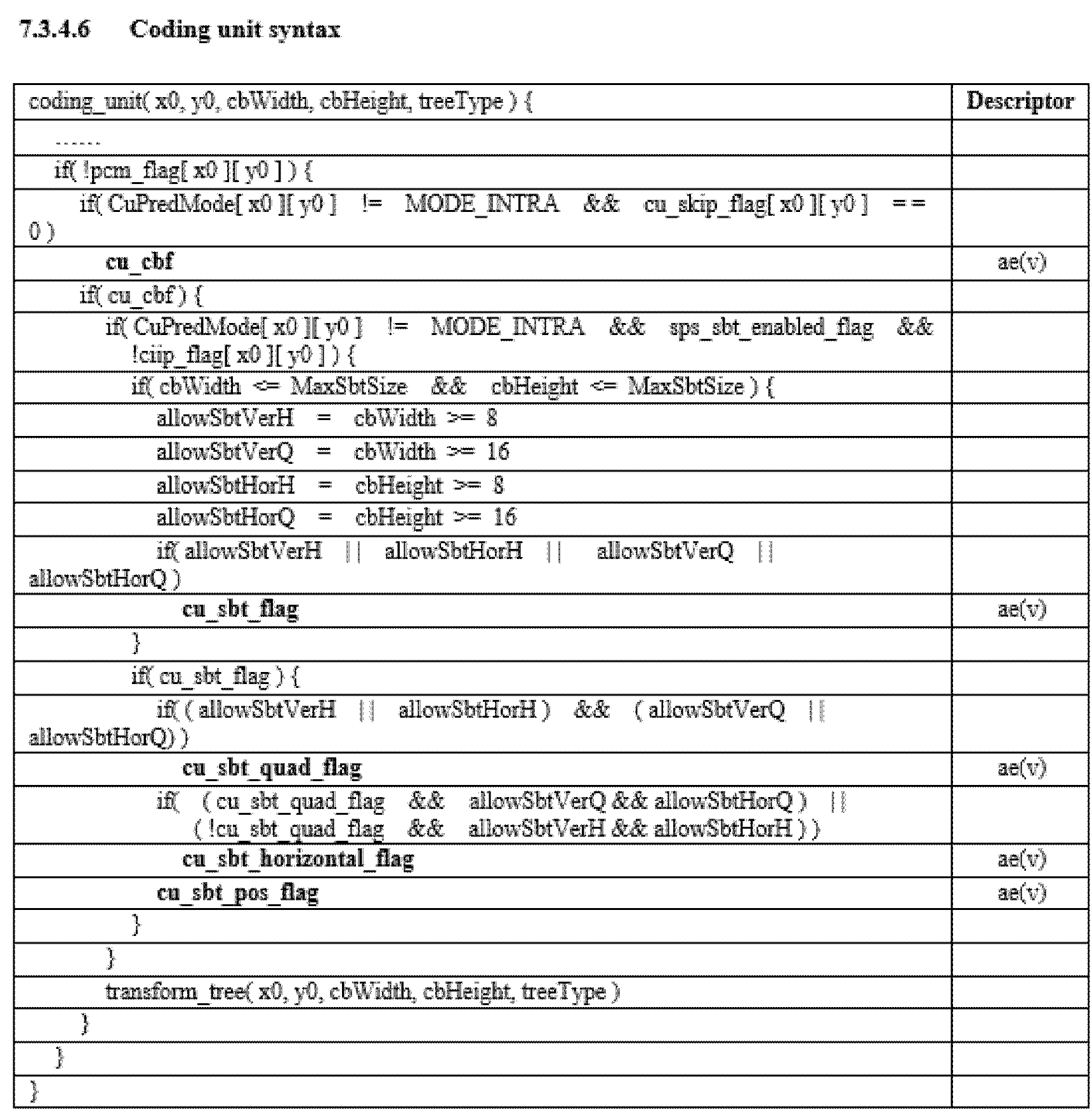
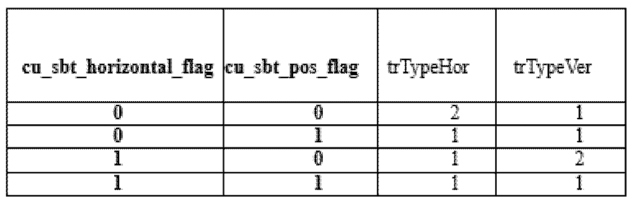


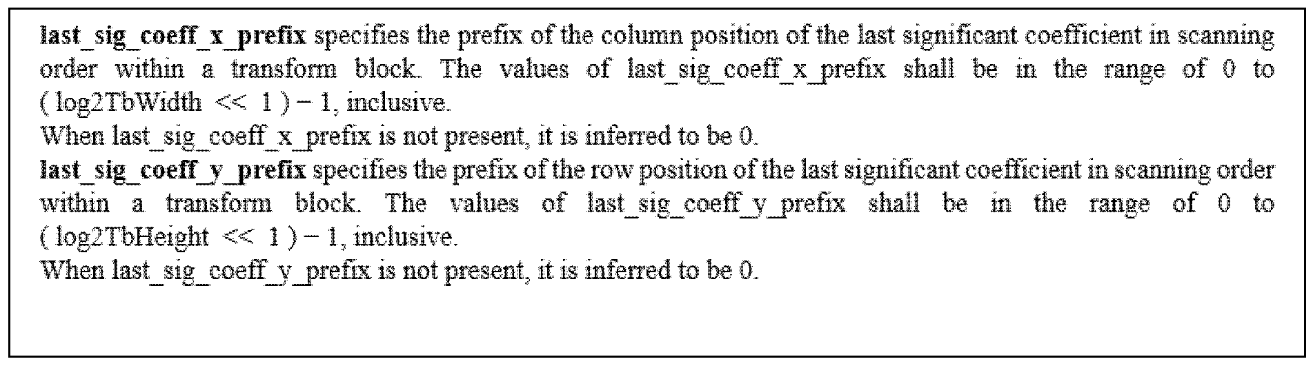
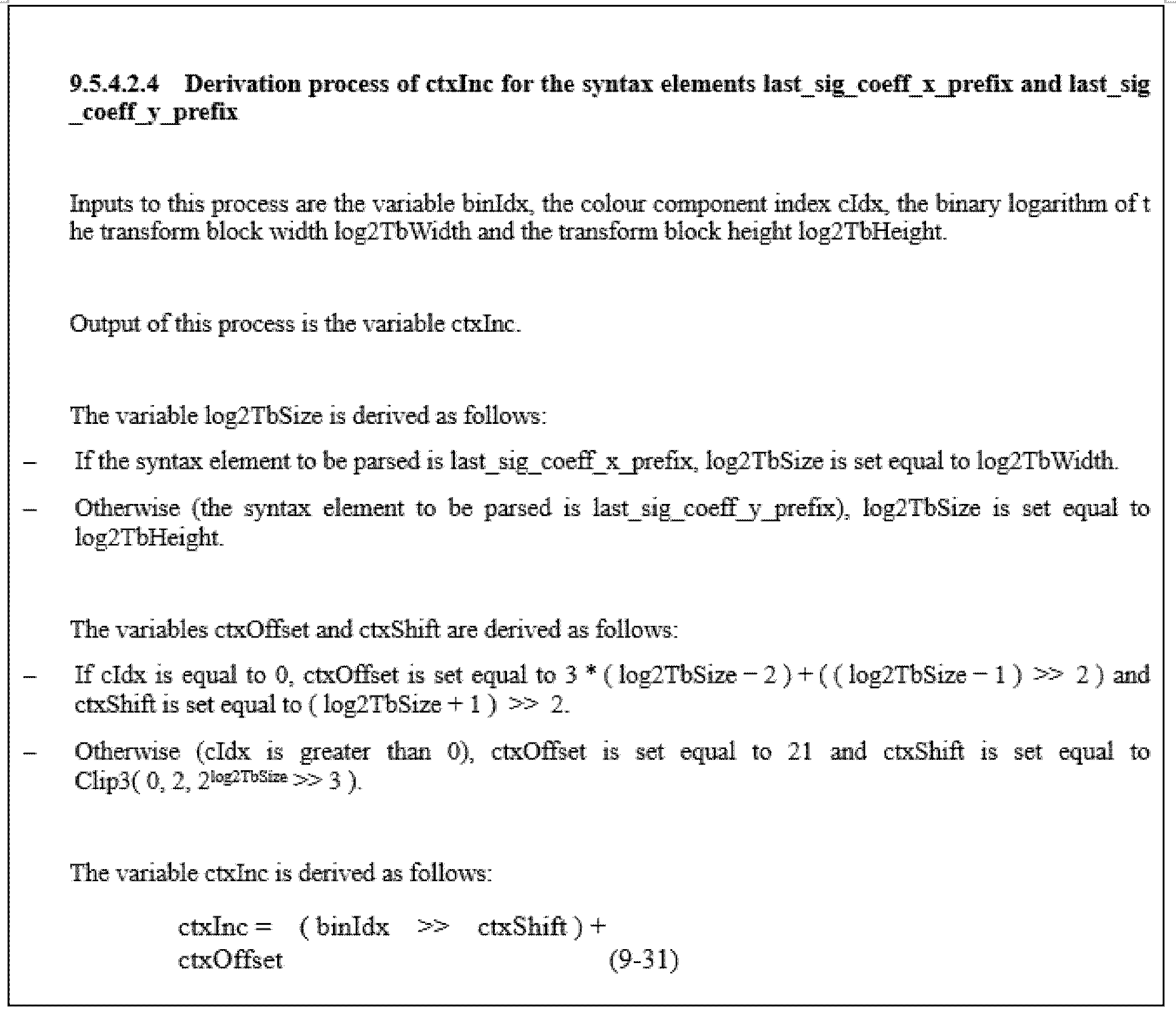
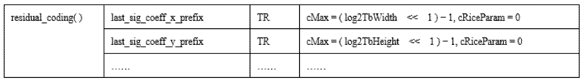
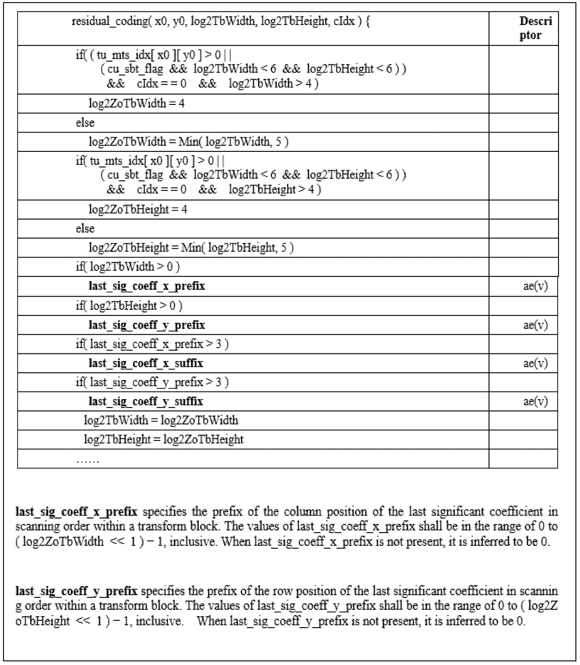


Claims (15)
- 디코딩 장치에 의하여 수행되는 영상 디코딩 방법에 있어서,레지듀얼 정보를 포함하는 비트스트림을 수신하는 단계;상기 레지듀얼 정보를 기반으로 현재 블록에 대한 변환 계수들을 도출하는 단계;상기 변환 계수를 기반으로 상기 현재 블록에 대한 레지듀얼 샘플을 도출하는 단계; 및상기 레지듀얼 샘플을 기반으로 복원 픽처를 생성하는 단계를 포함하되,상기 레지듀얼 정보는 마지막 유효 계수 위치 정보를 포함하고,상기 레지듀얼 샘플을 도출하는 단계는,상기 현재 블록에 대한 제로 아웃 블록을 도출하는 단계;상기 현재 블록의 폭 또는 높이를 기반으로 상기 마지막 유효 계수 위치 정보에 대한 컨텍스트 모델을 도출하는 단계;상기 컨텍스트 모델을 기반으로 마지막 유효 계수 위치 정보의 값을 도출하는 단계;상기 마지막 유효 계수 위치 정보의 값 및 상기 제로 아웃 블록의 폭 또는 높이를 기반으로 마지막 유효 계수 위치를 도출하는 단계를 포함하는 것을 특징으로 하는 영상 디코딩 방법.
- 제1항에 있어서,상기 제로 아웃 블록의 폭은 상기 현재 블록의 폭보다 작은 것을 특징으로 하는 영상 디코딩 방법.
- 제1항에 있어서,상기 제로 아웃 블록의 높이는 상기 현재 블록의 높이보다 작은 것을 특징으로 하는 영상 디코딩 방법.
- 제1항에 있어서,상기 마지막 유효 계수 위치 정보는 마지막 유효 계수 프리픽스 정보(last significant coefficient prefix information) 및 마지막 유효 계수 서픽스 정보(last significant coefficient suffix information)를 포함하고,상기 마지막 유효 계수 프리픽스 정보는 x축 프리픽스 정보 및 y축 프리픽스 정보를 포함하고,상기 현재 블록의 폭 또는 높이를 기반으로 상기 x축 프리픽스 정보 및 상기 y축 프리픽스 정보에 대한 컨텍스트 인크리먼트가 도출되는 것을 특징으로 하는 영상 디코딩 방법.
- 제4항에 있어서,상기 마지막 유효 계수 프리픽스 정보가 가질 수 있는 최대값은 상기 제로 아웃 블록의 크기에 기초하여 도출되는 것을 특징으로 하는 영상 디코딩 방법.
- 제1항에 있어서,상기 제로 아웃 블록의 폭 또는 높이는 상기 현재 블록의 폭 또는 높이를 기반으로 도출되는 것을 특징으로 하는 영상 디코딩 방법.
- 제6항에 있어서,상기 현재 블록의 폭이 32이고 상기 현재 블록의 높이가 32 이하이면, 상기 제로 아웃 블록의 폭은 16으로 설정되고,상기 현재 블록의 폭이 32가 아니거나 상기 현재 블록의 높이가 64 이상이면, 상기 제로 아웃 블록의 폭은 상기 현재 블록의 폭 및 32 중 작은 값으로 설정되는 것을 특징으로 하는 영상 디코딩 방법.
- 제6항에 있어서,상기 현재 블록의 높이가 32이고 상기 현재 블록의 폭이 32 이하이면, 상기 제로 아웃 블록의 높이는 16으로 설정되고,상기 현재 블록의 높이가 32가 아니거나 상기 현재 블록의 폭이 64 이상이면, 상기 제로 아웃 블록의 높이는 상기 현재 블록의 높이 및 32 중 작은 값으로 설정되는 것을 특징으로 하는 영상 디코딩 방법.
- 인코딩 장치에 의하여 수행되는 영상 인코딩 방법에 있어서,현재 블록에 대한 레지듀얼 샘플을 도출하는 단계;상기 현재 블록에 대한 상기 레지듀얼 샘플을 기반으로 양자화된 변환 계수를 도출하는 단계; 및상기 양자화된 변환 계수에 대한 정보를 포함하는 레지듀얼 정보를 인코딩하는 단계를 포함하되,상기 레지듀얼 정보는 마지막 유효 계수 위치 정보를 포함하고,상기 레지듀얼 정보를 인코딩하는 단계는,상기 현재 블록에 대한 제로 아웃 블록을 도출하는 단계;상기 제로 아웃 블록의 폭 또는 높이를 기반으로 마지막 유효 계수 위치를 도출하는 단계;상기 현재 블록의 폭 또는 높이를 기반으로 상기 마지막 유효 계수 위치 정보에 대한 컨텍스트 모델을 도출하는 단계;상기 컨텍스트 모델을 기반으로 마지막 유효 계수 위치 정보를 인코딩 하는 단계를 포함하는 것을 특징으로 하는 영상 인코딩 방법.
- 제9항에 있어서,상기 제로 아웃 블록의 폭은 상기 현재 블록의 폭보다 작은 것을 특징으로 하는 영상 인코딩 방법.
- 제9항에 있어서,상기 제로 아웃 블록의 높이는 상기 현재 블록의 높이보다 작은 것을 특징으로 하는 영상 인코딩 방법.
- 제9항에 있어서,상기 마지막 유효 계수 위치 정보는 마지막 유효 계수 프리픽스 정보(last significant coefficient prefix information) 및 마지막 유효 계수 서픽스 정보(last significant coefficient suffix information)를 포함하고,상기 마지막 유효 계수 프리픽스 정보는 x축 프리픽스 정보 및 y축 프리픽스 정보를 포함하고,상기 현재 블록의 폭 또는 높이를 기반으로 상기 x축 프리픽스 정보 및 상기 y축 프리픽스 정보에 대한 컨텍스트 인크리먼트가 도출되는 것을 특징으로 하는 영상 인코딩 방법.
- 제12항에 있어서,상기 마지막 유효 계수 프리픽스 정보가 가질 수 있는 최대값은 상기 제로 아웃 블록의 크기에 기초하여 도출되는 것을 특징으로 하는 영상 인코딩 방법.
- 제9항에 있어서,상기 제로 아웃 블록의 폭 또는 높이는 상기 현재 블록의 폭 또는 높이를 기반으로 도출되는 것을 특징으로 하는 영상 인코딩 방법.
- 영상 디코딩 방법을 수행하도록 야기하는 지시 정보가 저장된 컴퓨터 판독 가능한 디지털 저장 매체로서, 상기 영상 디코딩 방법은,레지듀얼 정보를 포함하는 비트스트림을 수신하는 단계;상기 레지듀얼 정보를 기반으로 현재 블록에 대한 양자화된 변환 계수들을 도출하는 단계;상기 양자화된 변환 계수를 기반으로 상기 현재 블록에 대한 레지듀얼 샘플을 도출하는 단계; 및상기 레지듀얼 샘플을 기반으로 복원 픽처를 생성하는 단계를 포함하되,상기 레지듀얼 정보는 마지막 유효 계수 위치 정보를 포함하고,상기 레지듀얼 샘플을 도출하는 단계는,상기 현재 블록에 대한 제로 아웃 블록을 도출하는 단계;상기 현재 블록의 폭 또는 높이를 기반으로 상기 마지막 유효 계수 위치 정보에 대한 컨텍스트 모델을 도출하는 단계;상기 컨텍스트 모델을 기반으로 마지막 유효 계수 위치의 값을 도출하는 단계;상기 마지막 유효 계수 위치 정보의 값 및 상기 제로 아웃 블록의 폭 또는 높이를 기반으로 마지막 유효 계수 위치를 도출하는 단계를 포함하는 것을 특징으로 하는 디지털 저장 매체.
Priority Applications (19)
| Application Number | Priority Date | Filing Date | Title |
|---|---|---|---|
| ES20770672T ES2953235T3 (es) | 2019-03-12 | 2020-03-12 | Codificación de imágenes basada en transformadas |
| AU2020234409A AU2020234409B2 (en) | 2019-03-12 | 2020-03-12 | Transform-based image coding method and device therefor |
| EP24186964.3A EP4418656A3 (en) | 2019-03-12 | 2020-03-12 | Transform-based image coding method and device therefor |
| EP23182212.3A EP4277278B1 (en) | 2019-03-12 | 2020-03-12 | Transform-based image coding |
| CN202311296871.8A CN117294848A (zh) | 2019-03-12 | 2020-03-12 | 基于变换的图像编译方法及其装置 |
| EP20770672.2A EP3910956B1 (en) | 2019-03-12 | 2020-03-12 | Transform-based image coding |
| KR1020227033086A KR20220133325A (ko) | 2019-03-12 | 2020-03-12 | 변환에 기반한 영상 코딩 방법 및 그 장치 |
| FIEP20770672.2T FI3910956T3 (fi) | 2019-03-12 | 2020-03-12 | Muunnospohjainen kuvankoodaus |
| PL20770672.2T PL3910956T3 (pl) | 2019-03-12 | 2020-03-12 | Sposób i urządzenie do kodowania obrazu opartego na transformacji |
| CN202080019440.5A CN113597770B (zh) | 2019-03-12 | 2020-03-12 | 基于变换的图像编译方法及其装置 |
| US17/431,908 US12041239B2 (en) | 2019-03-12 | 2020-03-12 | Transform-based image coding method and device therefor |
| HRP20231091TT HRP20231091T1 (hr) | 2019-03-12 | 2020-03-12 | Kodiranje slike temeljeno na transformaciji |
| CN202311289743.0A CN117278752A (zh) | 2019-03-12 | 2020-03-12 | 基于变换的图像编译方法及其装置 |
| SI202030252T SI3910956T1 (sl) | 2019-03-12 | 2020-03-12 | Kodiranje slik na podlagi transformacije |
| CN202311295012.7A CN117278753A (zh) | 2019-03-12 | 2020-03-12 | 基于变换的图像编译方法及其装置 |
| KR1020217024619A KR102456938B1 (ko) | 2019-03-12 | 2020-03-12 | 변환에 기반한 영상 코딩 방법 및 그 장치 |
| MX2021009649A MX2021009649A (es) | 2019-03-12 | 2020-03-12 | Metodo de codificacion de imagen basado en transformacion y dispositivo para el mismo. |
| AU2024200638A AU2024200638A1 (en) | 2019-03-12 | 2024-02-02 | Transform-based image coding method and device therefor |
| US18/438,023 US20240187601A1 (en) | 2019-03-12 | 2024-02-09 | Transform-based image coding method and device therefor |
Applications Claiming Priority (8)
| Application Number | Priority Date | Filing Date | Title |
|---|---|---|---|
| US201962817490P | 2019-03-12 | 2019-03-12 | |
| US201962817494P | 2019-03-12 | 2019-03-12 | |
| US62/817,490 | 2019-03-12 | ||
| US62/817,494 | 2019-03-12 | ||
| US201962822000P | 2019-03-21 | 2019-03-21 | |
| US62/822,000 | 2019-03-21 | ||
| US201962823571P | 2019-03-25 | 2019-03-25 | |
| US62/823,571 | 2019-03-25 |
Related Child Applications (2)
| Application Number | Title | Priority Date | Filing Date |
|---|---|---|---|
| US17/431,908 A-371-Of-International US12041239B2 (en) | 2019-03-12 | 2020-03-12 | Transform-based image coding method and device therefor |
| US18/438,023 Continuation US20240187601A1 (en) | 2019-03-12 | 2024-02-09 | Transform-based image coding method and device therefor |
Publications (1)
| Publication Number | Publication Date |
|---|---|
| WO2020185005A1 true WO2020185005A1 (ko) | 2020-09-17 |
Family
ID=72427588
Family Applications (1)
| Application Number | Title | Priority Date | Filing Date |
|---|---|---|---|
| PCT/KR2020/003449 WO2020185005A1 (ko) | 2019-03-12 | 2020-03-12 | 변환에 기반한 영상 코딩 방법 및 그 장치 |
Country Status (13)
| Country | Link |
|---|---|
| US (2) | US12041239B2 (ko) |
| EP (3) | EP4277278B1 (ko) |
| KR (2) | KR20220133325A (ko) |
| CN (4) | CN113597770B (ko) |
| AU (2) | AU2020234409B2 (ko) |
| ES (1) | ES2953235T3 (ko) |
| FI (1) | FI3910956T3 (ko) |
| HR (2) | HRP20231091T1 (ko) |
| HU (1) | HUE063009T2 (ko) |
| MX (1) | MX2021009649A (ko) |
| PL (1) | PL3910956T3 (ko) |
| SI (1) | SI3910956T1 (ko) |
| WO (1) | WO2020185005A1 (ko) |
Families Citing this family (1)
| Publication number | Priority date | Publication date | Assignee | Title |
|---|---|---|---|---|
| PL3989562T3 (pl) | 2019-06-19 | 2024-08-19 | Lg Electronics Inc. | Kodowanie informacji o zestawie jąder przekształcenia |
Citations (3)
| Publication number | Priority date | Publication date | Assignee | Title |
|---|---|---|---|---|
| KR20130140190A (ko) * | 2011-04-15 | 2013-12-23 | 블랙베리 리미티드 | 마지막 유효 계수의 위치를 코딩 및 디코딩하는 방법 및 장치 |
| KR20140029533A (ko) * | 2011-06-28 | 2014-03-10 | 퀄컴 인코포레이티드 | 비디오 코딩에서 최종 유의 변환 계수의 스캔 순서의 위치 도출 |
| US8902988B2 (en) * | 2010-10-01 | 2014-12-02 | Qualcomm Incorporated | Zero-out of high frequency coefficients and entropy coding retained coefficients using a joint context model |
Family Cites Families (15)
| Publication number | Priority date | Publication date | Assignee | Title |
|---|---|---|---|---|
| MY184097A (en) * | 2010-07-09 | 2021-03-17 | Samsung Electronics Co Ltd | Method and apparatus for entropy encoding/decoding a transform coefficient |
| US8976861B2 (en) | 2010-12-03 | 2015-03-10 | Qualcomm Incorporated | Separately coding the position of a last significant coefficient of a video block in video coding |
| US9042440B2 (en) | 2010-12-03 | 2015-05-26 | Qualcomm Incorporated | Coding the position of a last significant coefficient within a video block based on a scanning order for the block in video coding |
| MY160181A (en) * | 2011-06-28 | 2017-02-28 | Samsung Electronics Co Ltd | Method and apparatus for coding video and method and apparatus for decoding video accompanied with arithmetic coding |
| US20130003856A1 (en) | 2011-07-01 | 2013-01-03 | Samsung Electronics Co. Ltd. | Mode-dependent transforms for residual coding with low latency |
| US9392301B2 (en) * | 2011-07-01 | 2016-07-12 | Qualcomm Incorporated | Context adaptive entropy coding for non-square blocks in video coding |
| CN108377392A (zh) * | 2011-11-08 | 2018-08-07 | 三星电子株式会社 | 用于对视频进行解码的方法 |
| US10129548B2 (en) | 2011-12-28 | 2018-11-13 | Sharp Kabushiki Kaisha | Arithmetic decoding device, image decoding device, and arithmetic coding device |
| ES2967625T3 (es) * | 2012-04-15 | 2024-05-03 | Samsung Electronics Co Ltd | Aparato de decodificación de video que utiliza la actualización de parámetros para la desbinarización del coeficiente de transformación codificado por entropía, y el método de codificación que utiliza el mismo para la binarización |
| GB2519070A (en) | 2013-10-01 | 2015-04-15 | Sony Corp | Data encoding and decoding |
| US9432696B2 (en) | 2014-03-17 | 2016-08-30 | Qualcomm Incorporated | Systems and methods for low complexity forward transforms using zeroed-out coefficients |
| US10574993B2 (en) | 2015-05-29 | 2020-02-25 | Qualcomm Incorporated | Coding data using an enhanced context-adaptive binary arithmetic coding (CABAC) design |
| MX2019008023A (es) * | 2017-01-03 | 2019-11-12 | Lg Electronics Inc | Metodo de procesamiento de imagen, y aparato para el mismo. |
| US11134272B2 (en) | 2017-06-29 | 2021-09-28 | Qualcomm Incorporated | Memory reduction for non-separable transforms |
| US10812797B2 (en) * | 2018-02-05 | 2020-10-20 | Tencent America LLC | Method, apparatus and medium for decoding or encoding using a low-complexity transform |
-
2020
- 2020-03-12 MX MX2021009649A patent/MX2021009649A/es unknown
- 2020-03-12 CN CN202080019440.5A patent/CN113597770B/zh active Active
- 2020-03-12 EP EP23182212.3A patent/EP4277278B1/en active Active
- 2020-03-12 ES ES20770672T patent/ES2953235T3/es active Active
- 2020-03-12 FI FIEP20770672.2T patent/FI3910956T3/fi active
- 2020-03-12 KR KR1020227033086A patent/KR20220133325A/ko active Pending
- 2020-03-12 SI SI202030252T patent/SI3910956T1/sl unknown
- 2020-03-12 EP EP24186964.3A patent/EP4418656A3/en active Pending
- 2020-03-12 CN CN202311296871.8A patent/CN117294848A/zh active Pending
- 2020-03-12 EP EP20770672.2A patent/EP3910956B1/en active Active
- 2020-03-12 PL PL20770672.2T patent/PL3910956T3/pl unknown
- 2020-03-12 US US17/431,908 patent/US12041239B2/en active Active
- 2020-03-12 CN CN202311295012.7A patent/CN117278753A/zh active Pending
- 2020-03-12 KR KR1020217024619A patent/KR102456938B1/ko active Active
- 2020-03-12 CN CN202311289743.0A patent/CN117278752A/zh active Pending
- 2020-03-12 HR HRP20231091TT patent/HRP20231091T1/hr unknown
- 2020-03-12 WO PCT/KR2020/003449 patent/WO2020185005A1/ko unknown
- 2020-03-12 HU HUE20770672A patent/HUE063009T2/hu unknown
- 2020-03-12 AU AU2020234409A patent/AU2020234409B2/en active Active
- 2020-03-12 HR HRP20250243TT patent/HRP20250243T1/hr unknown
-
2024
- 2024-02-02 AU AU2024200638A patent/AU2024200638A1/en active Pending
- 2024-02-09 US US18/438,023 patent/US20240187601A1/en active Pending
Patent Citations (3)
| Publication number | Priority date | Publication date | Assignee | Title |
|---|---|---|---|---|
| US8902988B2 (en) * | 2010-10-01 | 2014-12-02 | Qualcomm Incorporated | Zero-out of high frequency coefficients and entropy coding retained coefficients using a joint context model |
| KR20130140190A (ko) * | 2011-04-15 | 2013-12-23 | 블랙베리 리미티드 | 마지막 유효 계수의 위치를 코딩 및 디코딩하는 방법 및 장치 |
| KR20140029533A (ko) * | 2011-06-28 | 2014-03-10 | 퀄컴 인코포레이티드 | 비디오 코딩에서 최종 유의 변환 계수의 스캔 순서의 위치 도출 |
Non-Patent Citations (2)
| Title |
|---|
| CHOI, JUNG-AH ET AL.: "Non-CE7: Last position coding for large block-size transforms", JVET-M0251-V6. JOINT VIDEO EXPERTS TEAM (JVET) OF ITU-T SG 16 WP 3 AND ISO/IEC JTC 1/SC 29/WG 11. 13TH MEETING, 16 January 2019 (2019-01-16), Marrakech, MA, pages 1 - 10, XP030202330 * |
| KOO, MOONMO ET AL.: "CE6-related: 32 point MTS based on skipping high frequency coefficients", JVET-M0297-V4. JOINT VIDEO EXPERTS TEAM (JVET) OF ITU-T SG 16 WP 3 AND ISO/EEC JTC 1/SC 29/WG 11. 13TH MEETING, 14 January 2019 (2019-01-14), Marrakech, MA, pages 1 - 10, XP030202100 * |
Also Published As
| Publication number | Publication date |
|---|---|
| KR20220133325A (ko) | 2022-10-04 |
| SI3910956T1 (sl) | 2023-11-30 |
| KR20210102463A (ko) | 2021-08-19 |
| AU2020234409B2 (en) | 2023-11-02 |
| EP4277278A1 (en) | 2023-11-15 |
| ES2953235T3 (es) | 2023-11-08 |
| AU2024200638A1 (en) | 2024-02-22 |
| EP3910956B1 (en) | 2023-08-09 |
| CN117278753A (zh) | 2023-12-22 |
| CN113597770B (zh) | 2023-10-27 |
| EP4277278B1 (en) | 2025-02-05 |
| US20240187601A1 (en) | 2024-06-06 |
| US20220046246A1 (en) | 2022-02-10 |
| EP4277278C0 (en) | 2025-02-05 |
| KR102456938B1 (ko) | 2022-10-20 |
| MX2021009649A (es) | 2021-12-10 |
| EP4418656A3 (en) | 2024-11-06 |
| AU2020234409A1 (en) | 2021-11-04 |
| CN113597770A (zh) | 2021-11-02 |
| HRP20231091T1 (hr) | 2023-12-22 |
| CN117294848A (zh) | 2023-12-26 |
| FI3910956T3 (fi) | 2023-09-01 |
| CN117278752A (zh) | 2023-12-22 |
| HRP20250243T1 (hr) | 2025-04-11 |
| EP4418656A2 (en) | 2024-08-21 |
| US12041239B2 (en) | 2024-07-16 |
| EP3910956A1 (en) | 2021-11-17 |
| HUE063009T2 (hu) | 2023-12-28 |
| EP3910956A4 (en) | 2022-06-08 |
| PL3910956T3 (pl) | 2023-09-25 |
Similar Documents
| Publication | Publication Date | Title |
|---|---|---|
| WO2020009556A1 (ko) | 변환에 기반한 영상 코딩 방법 및 그 장치 | |
| WO2020046091A1 (ko) | 다중 변환 선택에 기반한 영상 코딩 방법 및 그 장치 | |
| WO2020218793A1 (ko) | Bdpcm에 기반한 영상 코딩 방법 및 그 장치 | |
| WO2020213944A1 (ko) | 영상 코딩에서 매트릭스 기반의 인트라 예측을 위한 변환 | |
| WO2020256389A1 (ko) | Bdpcm 기반 영상 디코딩 방법 및 그 장치 | |
| WO2020116961A1 (ko) | 이차 변환에 기반한 영상 코딩 방법 및 그 장치 | |
| WO2019203610A1 (ko) | 영상의 처리 방법 및 이를 위한 장치 | |
| WO2020256391A1 (ko) | 영상 디코딩 방법 및 그 장치 | |
| WO2020213946A1 (ko) | 변환 인덱스를 이용하는 영상 코딩 | |
| WO2020242183A1 (ko) | 광각 인트라 예측 및 변환에 기반한 영상 코딩 방법 및 그 장치 | |
| WO2021025526A1 (ko) | 변환에 기반한 영상 코딩 방법 및 그 장치 | |
| WO2020130661A1 (ko) | 이차 변환에 기반한 영상 코딩 방법 및 그 장치 | |
| WO2020213945A1 (ko) | 인트라 예측 기반 영상 코딩에서의 변환 | |
| WO2021096172A1 (ko) | 변환에 기반한 영상 코딩 방법 및 그 장치 | |
| WO2021040319A1 (ko) | 비디오/영상 코딩 시스템에서 라이스 파라미터 도출 방법 및 장치 | |
| WO2023075353A1 (ko) | 비분리 1차 변환 설계 방법 및 장치 | |
| WO2020197274A1 (ko) | 변환에 기반한 영상 코딩 방법 및 그 장치 | |
| WO2021025530A1 (ko) | 변환에 기반한 영상 코딩 방법 및 그 장치 | |
| WO2020235960A1 (ko) | Bdpcm 에 대한 영상 디코딩 방법 및 그 장치 | |
| WO2020167097A1 (ko) | 영상 코딩 시스템에서 인터 예측을 위한 인터 예측 타입 도출 | |
| WO2020130581A1 (ko) | 이차 변환에 기반한 영상 코딩 방법 및 그 장치 | |
| WO2020180119A1 (ko) | Cclm 예측에 기반한 영상 디코딩 방법 및 그 장치 | |
| WO2021040398A1 (ko) | 팔레트 이스케이프 코딩 기반 영상 또는 비디오 코딩 | |
| WO2020256482A1 (ko) | 변환에 기반한 영상 코딩 방법 및 그 장치 | |
| WO2021040407A1 (ko) | 영상 코딩 시스템에서 단순화된 레지듀얼 데이터 코딩을 사용하는 영상 디코딩 방법 및 그 장치 |
Legal Events
| Date | Code | Title | Description |
|---|---|---|---|
| 121 | Ep: the epo has been informed by wipo that ep was designated in this application |
Ref document number: 20770672 Country of ref document: EP Kind code of ref document: A1 |
|
| ENP | Entry into the national phase |
Ref document number: 20217024619 Country of ref document: KR Kind code of ref document: A |
|
| ENP | Entry into the national phase |
Ref document number: 2020770672 Country of ref document: EP Effective date: 20210813 |
|
| NENP | Non-entry into the national phase |
Ref country code: DE |
|
| ENP | Entry into the national phase |
Ref document number: 2020234409 Country of ref document: AU Date of ref document: 20200312 Kind code of ref document: A |