WO2019197666A1 - Set of tiles adapted to cover a surface such as a floor. - Google Patents
Set of tiles adapted to cover a surface such as a floor. Download PDFInfo
- Publication number
- WO2019197666A1 WO2019197666A1 PCT/EP2019/059556 EP2019059556W WO2019197666A1 WO 2019197666 A1 WO2019197666 A1 WO 2019197666A1 EP 2019059556 W EP2019059556 W EP 2019059556W WO 2019197666 A1 WO2019197666 A1 WO 2019197666A1
- Authority
- WO
- WIPO (PCT)
- Prior art keywords
- tile
- edge
- rod
- contact surface
- locked configuration
- Prior art date
- Legal status (The legal status is an assumption and is not a legal conclusion. Google has not performed a legal analysis and makes no representation as to the accuracy of the status listed.)
- Ceased
Links
Classifications
-
- E—FIXED CONSTRUCTIONS
- E04—BUILDING
- E04F—FINISHING WORK ON BUILDINGS, e.g. STAIRS, FLOORS
- E04F13/00—Coverings or linings, e.g. for walls or ceilings
- E04F13/07—Coverings or linings, e.g. for walls or ceilings composed of covering or lining elements; Sub-structures therefor; Fastening means therefor
- E04F13/08—Coverings or linings, e.g. for walls or ceilings composed of covering or lining elements; Sub-structures therefor; Fastening means therefor composed of a plurality of similar covering or lining elements
- E04F13/18—Coverings or linings, e.g. for walls or ceilings composed of covering or lining elements; Sub-structures therefor; Fastening means therefor composed of a plurality of similar covering or lining elements of organic plastics with or without reinforcements or filling materials or with an outer layer of organic plastics with or without reinforcements or filling materials; plastic tiles
-
- E—FIXED CONSTRUCTIONS
- E04—BUILDING
- E04F—FINISHING WORK ON BUILDINGS, e.g. STAIRS, FLOORS
- E04F13/00—Coverings or linings, e.g. for walls or ceilings
- E04F13/07—Coverings or linings, e.g. for walls or ceilings composed of covering or lining elements; Sub-structures therefor; Fastening means therefor
- E04F13/08—Coverings or linings, e.g. for walls or ceilings composed of covering or lining elements; Sub-structures therefor; Fastening means therefor composed of a plurality of similar covering or lining elements
- E04F13/0889—Coverings or linings, e.g. for walls or ceilings composed of covering or lining elements; Sub-structures therefor; Fastening means therefor composed of a plurality of similar covering or lining elements characterised by the joints between neighbouring elements, e.g. with joint fillings or with tongue and groove connections
- E04F13/0894—Coverings or linings, e.g. for walls or ceilings composed of covering or lining elements; Sub-structures therefor; Fastening means therefor composed of a plurality of similar covering or lining elements characterised by the joints between neighbouring elements, e.g. with joint fillings or with tongue and groove connections with tongue and groove connections
-
- E—FIXED CONSTRUCTIONS
- E04—BUILDING
- E04F—FINISHING WORK ON BUILDINGS, e.g. STAIRS, FLOORS
- E04F13/00—Coverings or linings, e.g. for walls or ceilings
- E04F13/07—Coverings or linings, e.g. for walls or ceilings composed of covering or lining elements; Sub-structures therefor; Fastening means therefor
- E04F13/08—Coverings or linings, e.g. for walls or ceilings composed of covering or lining elements; Sub-structures therefor; Fastening means therefor composed of a plurality of similar covering or lining elements
- E04F13/0889—Coverings or linings, e.g. for walls or ceilings composed of covering or lining elements; Sub-structures therefor; Fastening means therefor composed of a plurality of similar covering or lining elements characterised by the joints between neighbouring elements, e.g. with joint fillings or with tongue and groove connections
- E04F13/0896—Coverings or linings, e.g. for walls or ceilings composed of covering or lining elements; Sub-structures therefor; Fastening means therefor composed of a plurality of similar covering or lining elements characterised by the joints between neighbouring elements, e.g. with joint fillings or with tongue and groove connections with adhesive joining strips
-
- E—FIXED CONSTRUCTIONS
- E04—BUILDING
- E04F—FINISHING WORK ON BUILDINGS, e.g. STAIRS, FLOORS
- E04F15/00—Flooring
- E04F15/02—Flooring or floor layers composed of a number of similar elements
- E04F15/02038—Flooring or floor layers composed of a number of similar elements characterised by tongue and groove connections between neighbouring flooring elements
-
- E—FIXED CONSTRUCTIONS
- E04—BUILDING
- E04F—FINISHING WORK ON BUILDINGS, e.g. STAIRS, FLOORS
- E04F15/00—Flooring
- E04F15/02—Flooring or floor layers composed of a number of similar elements
- E04F15/10—Flooring or floor layers composed of a number of similar elements of other materials, e.g. fibrous or chipped materials, organic plastics, magnesite tiles, hardboard, or with a top layer of other materials
- E04F15/105—Flooring or floor layers composed of a number of similar elements of other materials, e.g. fibrous or chipped materials, organic plastics, magnesite tiles, hardboard, or with a top layer of other materials of organic plastics with or without reinforcements or filling materials
-
- E—FIXED CONSTRUCTIONS
- E04—BUILDING
- E04F—FINISHING WORK ON BUILDINGS, e.g. STAIRS, FLOORS
- E04F15/00—Flooring
- E04F15/02—Flooring or floor layers composed of a number of similar elements
- E04F15/10—Flooring or floor layers composed of a number of similar elements of other materials, e.g. fibrous or chipped materials, organic plastics, magnesite tiles, hardboard, or with a top layer of other materials
- E04F15/107—Flooring or floor layers composed of a number of similar elements of other materials, e.g. fibrous or chipped materials, organic plastics, magnesite tiles, hardboard, or with a top layer of other materials composed of several layers, e.g. sandwich panels
-
- E—FIXED CONSTRUCTIONS
- E04—BUILDING
- E04F—FINISHING WORK ON BUILDINGS, e.g. STAIRS, FLOORS
- E04F2201/00—Joining sheets or plates or panels
- E04F2201/01—Joining sheets, plates or panels with edges in abutting relationship
- E04F2201/0107—Joining sheets, plates or panels with edges in abutting relationship by moving the sheets, plates or panels substantially in their own plane, perpendicular to the abutting edges
-
- E—FIXED CONSTRUCTIONS
- E04—BUILDING
- E04F—FINISHING WORK ON BUILDINGS, e.g. STAIRS, FLOORS
- E04F2201/00—Joining sheets or plates or panels
- E04F2201/01—Joining sheets, plates or panels with edges in abutting relationship
- E04F2201/0153—Joining sheets, plates or panels with edges in abutting relationship by rotating the sheets, plates or panels around an axis which is parallel to the abutting edges, possibly combined with a sliding movement
-
- E—FIXED CONSTRUCTIONS
- E04—BUILDING
- E04F—FINISHING WORK ON BUILDINGS, e.g. STAIRS, FLOORS
- E04F2201/00—Joining sheets or plates or panels
- E04F2201/02—Non-undercut connections, e.g. tongue and groove connections
- E04F2201/023—Non-undercut connections, e.g. tongue and groove connections with a continuous tongue or groove
-
- E—FIXED CONSTRUCTIONS
- E04—BUILDING
- E04F—FINISHING WORK ON BUILDINGS, e.g. STAIRS, FLOORS
- E04F2201/00—Joining sheets or plates or panels
- E04F2201/04—Other details of tongues or grooves
- E04F2201/043—Other details of tongues or grooves with tongues and grooves being formed by projecting or recessed parts of the panel layers
-
- E—FIXED CONSTRUCTIONS
- E04—BUILDING
- E04F—FINISHING WORK ON BUILDINGS, e.g. STAIRS, FLOORS
- E04F2201/00—Joining sheets or plates or panels
- E04F2201/04—Other details of tongues or grooves
- E04F2201/044—Other details of tongues or grooves with tongues or grooves comprising elements which are not manufactured in one piece with the sheets, plates or panels but which are permanently fixedly connected to the sheets, plates or panels, e.g. at the factory
- E04F2201/049—Other details of tongues or grooves with tongues or grooves comprising elements which are not manufactured in one piece with the sheets, plates or panels but which are permanently fixedly connected to the sheets, plates or panels, e.g. at the factory wherein the elements are made of organic plastics with or without reinforcements or filling materials
-
- E—FIXED CONSTRUCTIONS
- E04—BUILDING
- E04F—FINISHING WORK ON BUILDINGS, e.g. STAIRS, FLOORS
- E04F2201/00—Joining sheets or plates or panels
- E04F2201/07—Joining sheets or plates or panels with connections using a special adhesive material
Definitions
- Set of tiles adapted to cover a surface such as a floor.
- the present invention deals with a set of tiles adapted to cover a surface perpendicular to a thickness direction of the tiles, each of the tiles comprising a core layer comprising a thermoplastic material.
- Such a surface is for example a floor or a wall.
- the present invention also deals with a corresponding method of covering such a surface.
- Such tiles may have various shapes, such as rectangular or square. They are based on synthetic materials, with a rigid core layer supporting at least one upper layer, usually several ones, intended to be visible by users once the tiles are in place. Such tiles are known as vinyl tiles, also called LVT (Luxury Vinyl Tiles).
- the core layer brings rigidity to these tiles.
- the hooks of the first kind cooperate with those of the second kind in order to lock the tiles next to each other.
- tiles with a rigid core layer and hooks may be difficult to connect and disconnect, as the insertion and disconnection may require a huge effort.
- Example of what is considered as a tile with a rigid core layer in the sense of the present document are for example provided in WO 2017/133804.
- An aim of the invention is to provide a set of tiles that solves or reduces these problems, while remaining simple to produce, and cost effective.
- the invention proposes a set of tiles adapted to cover a surface perpendicular to a thickness direction of the tiles, each of the tiles comprising a core layer, the set comprising:
- first tile having a first edge extending in a longitudinal direction, the core layer of the first tile defining a connecting groove in the first edge;
- second tile having a second edge extending in the longitudinal direction, the core layer of second tile defining a connecting tongue protruding from the second edge, the connecting tongue being adapted to be received into the connecting groove in a locked configuration of the first tile and the second tile;
- the connecting groove being delimited in the thickness direction by an upper contact surface and a lower contact surface both configured to be at least partly in contact with a corresponding upper contact surface and a corresponding lower contact surface of the connecting tongue in the locked configuration, the lower contact surface being on the same side as the surface to be covered with respect to the connecting tongue in the thickness direction, and the upper contact surface being on the opposite side to the surface to be covered with respect to the connecting tongue in the thickness direction, wherein:
- the core layer of the first tile or the second tile defines at least one longitudinal recess in one of the upper contact surface, the lower contact surface, the corresponding upper contact surface, and the corresponding lower contact surface;
- the first tile or the second tile further comprises a rod fixed on a wall of the recess, the rod having a chemical composition distinct from a chemical composition of said wall, and
- the rod is configured to press on the connecting tongue or on the connecting groove in the locked configuration.
- the set of tiles comprises one or several of the following feature(s), taken in isolation or any technically feasible combination:
- the rod comprises at least one plastic material
- plastic material based on polyalkylene wherein the polyalkylene is preferably PVC, PE, or PP, or
- hot-melt adhesive or a hot sealing adhesive wherein the hot-melt adhesive or the hot sealing adhesive is preferably based on ethylene vinyl chloride, PA, PU or EVA;
- - the rod comprises one or several of:
- thermoplastic material preferably comprises a polyolefin, a vinyl polymer, a polyamide, a polyester, a polyurethane or a ionomer,
- thermoplastic elastomer preferably comprises TPE, TPR, TPO, SPS, TP-Q or TP-U;
- the connecting tongue is adapted to be snap-fit into the connecting groove in the locked configuration
- the rod is configured to latch the connecting tongue in a latching direction approximately perpendicular to the thickness direction and to the longitudinal direction;
- the rod is configured to latch the connecting tongue in the thickness direction with respect to the first tile
- the rod comprises an latent adhesive, preferably a polymer adhesive, adapted for adhering to the connecting tongue in the locked configuration after the latent adhesive has been moistened with water;
- the first tile has a thickness in the thickness direction, the rod having a substantially uniform thickness in the thickness direction, preferably comprised between 5% and 40% of the thickness of the first tile;
- said thickness of the rod is comprised between 0.3mm and 1 .5mm, preferably between 0.6mm and 0.8mm;
- the rod forms a bulge protruding from a mouth of the recess
- the first tile has a third edge extending in a transverse direction, the core layer of the first tile defining a connecting groove in the third edge, and at least the second tile has a fourth edge extending in the transverse direction, the core layer of second tile defining a connecting tongue protruding from the fourth edge, the connecting tongue being adapted to be received into the connecting groove in a locked configuration of the first tile and the second tile, wherein a locking strength between the third edge of the first tile and the fourth edge of the second tile in the locked configuration is lower than a locking strength between the first edge of the first tile and the second edge of the second tile in the locked configuration;
- the first tile is devoid of a rod located in a recess formed in the connecting groove in the third edge and the second tile is devoid of a rod located in a recess formed in the connecting tongue in the fourth edge;
- the recess is located in the lower contact surface of the connecting groove ;
- the core layer of the first tile includes a lower part defining the lower contact surface and a lower part of said first edge, and an upper part defining the upper contact surface and an upper part of said first edge, the lower part of the core layer of the first tile protruding more than the upper part of the core layer of the first tile from a bottom of the connecting groove in a latching direction approximately perpendicular to the thickness direction and to the longitudinal direction.
- the invention also deals with a method of covering a surface with tiles, the surface being perpendicular to a thickness direction of the tiles, comprising at least the following steps:
- the step of putting the first tile and the second tile in the locked configuration comprises:
- FIG. 1 is a schematic cross-sectional view of a set of tiles according to the invention
- FIG. 2 is another schematic cross-sectional view of the set of tiles shown in Figure 1 , along another side of the tiles, and
- FIG. 3 is an upper view of a set of tiles including the tiles shown in Figures 1 and
- the set 1 comprises a plurality of tiles 5, of which only two are partially shown in Figures 1 and 2, and only four are shown in Figure 3.
- the set 1 is for example adapted to cover a surface 10, such as a floor, which is approximately perpendicular to a thickness direction V of the tiles 5 and vertical in the example.
- the surface 10 is defined by a wall.
- the tiles 5 comprise a first tile 15 and a second tile 20 adapted to be connected to each other in a locked configuration (not shown).
- the first tile 15 and the second tile 20 are in an unlocked configuration.
- the tiles 5 also comprise a third tile 1 15, for example analogous to the first tile 15, and a fourth tile 120, for example analogous to the third tile 1 15.
- the tiles 5 have a same thickness E in the thickness direction V, advantageously comprised between 3.0mm and 8.0mm, for example approximately 5.5mm.
- Each of the tiles 5 comprises a core layer 22, and advantageously one a several upper layers 24 (represented as a group in the Figure), for example a decorative layer located on the core layer, and a wear layer located on the decorative layer.
- “Upper” and“lower” here respectively mean“towards the surface 10” and” opposite the surface 10” in the thickness direction V.
- the tiles 5, seen in the thickness direction V are for example rectangular or square, possibly with the same dimensions.
- the core layer 22, and the upper layers 24 are superimposed in the thickness direction V.
- these layers are laminated to each other.
- the core layer 22 is rigid.
- the core layer 22 comprises at least one thermoplastic material, advantageously PVC (polyvinyl chloride), of which content is for example between 15wt% and 40wt%.
- PVC polyvinyl chloride
- the core layer 22 does not contain PVC.
- the at least one thermoplastic material is chosen among PVB (Polyvinylbutyrate), polyolefins.
- the core layer 22 advantageously contains less than 5wt% of plasticizer, and for example no plasticizer at all.
- the skilled person knows how to adjust the rigidity of the core layer 22, by selecting its components, particularly the amount of plasticizer.
- the core layer 22 has a composition as specified in the below table 1.
- Table 1 composition of the core layer 22.
- the decorative layer for example comprises a printed decor (not shown).
- the decorative layer for example comprises 90wt% of a thermoplastic material, for example PVC, 10% of additive, and no plasticizer.
- the wear layer is adapted to protect the decorative layer.
- the wear layer for example comprises 80wt% of a thermoplastic material, for example PVC, 20% of additive, and no plasticizer.
- the tiles 5 are for example analogous to each other in terms of layers and composition of the layers, and for example in terms of dimensions.
- Each of the tiles 5 has a first edge 26 and a second edge 28 ( Figure 1 ), both extending in a longitudinal direction L perpendicular to the thickness direction V.
- Each of the tiles 5 has a third edge 126 and a fourth edge 128 (Figure 2), both extending in a transverse direction T perpendicular to the thickness direction V and for example perpendicular to the longitudinal direction L.
- the tiles 5 also have a lower surface S intended to be in contact with, and advantageously fixed to the surface 10 in the example.
- Each of the tiles 5 also comprises a rod 27.
- the core layer 22 defines a connecting groove 30 in the first edge 26, and a connecting tongue 34 protruding from the second edge 28 and adapted to be received into the connecting groove 30 of another of the tiles 5 in the locked configuration.
- the core layer 22 advantageously defines a connecting groove 130 in the third edge 126, and a connecting tongue 134 protruding from the fourth edge 128 and adapted to be received into the connecting groove 130 of another of the tiles 5 in the locked configuration.
- the first edge 26 comprises an upper part 36 locate above the connecting groove 30, for example parallel to the thickness direction V, and adapted to abut against an upper part 38 of the second edge 28 in the locked configuration.
- the first edge 26 also has a lower part 40 located under the connecting groove 30.
- the connecting tongue 34 comprises a distal part 42 forming a nose, for example with a triangular profile in the longitudinal direction L, and a proximal part 44.
- the connecting tongue 34 is adapted to be snap-fit into the connecting groove 30 in order to obtain the locked configuration.
- the snap-fit effect is advantageously light, in order not to increase the insertion effort.
- the connecting tongue 134 is adapted to be snap-fit into the connecting groove 130 in order to obtain the locked configuration.
- the snap-fit effect is advantageously light, in order not to increase the insertion effort.
- the locking strength (defined as the effort necessary to unlock the tiles par meter of of the edges locked to each other when the tile are parallel to each other) between the third edge 126 of one of the tiles 5 and the fourth edge 128 of another one of the tiles 5 in the locked configuration is advantageously lower than a locking strength between the first edge 26 and the second edge 28 in the locked configuration.
- the locking strength between the first edge 26 and the second edge 28 is greater than or equal to 20kN/m (kilonewton per meter of length of the edges locked to each other).
- the locking strength between the third edge 126 and the fourth edge 128 is lower than or equal to 2.0kN/m, preferably lower than 0.5kN/m.
- the locking strength between the third edge 126 and the fourth edge 128 is approximately OkN/m (no locking strength). This allows two tiles 5 connected by the third edge 126 and the fourth edge 128 to be translated one with respect to the other along the transverse direction T.
- the effort to make the third edge 126 of one of the tiles 5 slide in the fourth edge 128 of another one of the tiles in the locked configuration is lower than 1 5kN/m.
- the proximal part 44 defines an upper surface 46 and a lower surface 48 which are for example substantially perpendicular to the thickness direction V.
- the connecting groove 30 comprises a bottom 50.
- the connecting groove 30 is delimited in the thickness direction V by an upper contact surface 52 and a lower surface 54 configured to be at least partly in contact respectively with a corresponding upper contact surface 52A in the upper surface 46 and with a corresponding lower contact surface 54A in the lower surface 48 of the connecting tongue 34 in the locked configuration.
- the bottom 50 advantageously has a“U”-shaped profile in the longitudinal direction L, said“U” opening toward the first edge 26.
- the upper contact surface 52 is on the opposite side to the surface 10 with respect to the connecting tongue 34 in the thickness direction V.
- the upper contact surface 52 is for example substantially perpendicular to the thickness direction V.
- the lower contact surface 54 is on the same side as the surface 10 with respect to the connecting tongue 34 in the thickness direction V.
- the lower contact surface 54 comprises at least one longitudinal recess 56 defined by the core layer 22. Except for the recess 56, the lower contact surface 54 is adapted to be in contact with the lower surface 48 of the connecting tongue 34 and is for example substantially perpendicular to the thickness direction V.
- the recess 56 for example has a rectangular profile in the longitudinal direction L.
- the recess 56 has a bottom wall 58 on which the rod 27 is fixed.
- the recess 56 is not formed in the lower contact surface 54, but in one of the upper contact surface 52, the corresponding upper contact surface 52A, and the corresponding lower contact surface 54A.
- the recess 56 may be located on any side of the connecting groove 30 or on any side of the connecting tongue 34 in the thickness direction V.
- the core layer 22 includes a lower part 62 defining the lower contact surface 54 and the lower part 40 of the first edge 26.
- the core layer 22 further comprises an upper part 64 defining the upper contact surface 52 and the upper part 36 of the first edge 26.
- the lower part 62 protrudes more than the upper part 64 in a latching direction C approximately perpendicular to the thickness direction V and to the longitudinal direction L.
- the latching direction C the lower part 40 advantageously is farther from the bottom 50 than the upper part 36. This allows placing the rod 27 also farther from the bottom 50 than the upper part 36. As a result, it is possible to avoid the rod 27 when inserting the connecting tongue 34 in connecting groove 30.
- the connecting groove 130 is delimited in the thickness direction V by an upper contact surface 152 and a lower contact surface 154 both configured to be at least partly in contact with the connecting tongue 134 in the locked configuration.
- the tiles 5 are devoid of a rod that would be located in a recess formed in any of upper contact surface 152 and a lower contact surface 154 or formed in the connecting tongue 134. This allows a lower locking strength than when a rod, such as the trod 27, is present.
- connection direction C2 which is perpendicular to the thickness direction V and advantageously parallel to the longitudinal direction L.
- the connecting tongue 134 is adapted to be received in the connecting groove 130 in a connection direction C2’ which is parallel to the thickness direction V (that is to say vertical in the example).
- the rod 27 has a chemical composition distinct from the chemical composition of the wall 58, and in the example distinct from the composition of the whole core layer 22 which defines the recess.
- the rod 27 is configured to press on the connecting tongue 34 in the locked configuration in the thickness direction V.
- the rod 27 comprises at least one plastic material.
- the rod 27 comprises:
- plastic material based on polyalkylene wherein the polyalkylene is preferably PVC, PE, or PP, or
- hot-melt adhesive or a hot sealing adhesive wherein the hot-melt adhesive or the hot sealing adhesive is preferably based on ethylene vinyl chloride, PA, PU or EVA.
- Such plastics are deformable by heat or adhere by heat, and are advantageously selected to allow being extruded in rod form. They are able to solidify and adhere particularly firmly to the core layer 22. In use, they have an appropriate elasticity and viscosity in order to act as a locking element of the connecting tongue 34 in the connecting groove 30.
- the rod is viscoelastic or relative hard.
- the rod 27 comprises one or several of:
- thermoplastic material preferably comprises a polyolefin, a vinyl polymer, a polyamide, a polyester, a polyurethane or a ionomer,
- the elastomer preferably comprises a rubber
- thermoplastic elastomer preferably comprises TPE, TPR, TPO, SPS, TP-Q or TP-U.
- the plastic material comprised in the rod 27 may be present in the form of a polymer or copolymer.
- the plastic material present in the rod 27 may be present in a plasticized or non-plasticized formulation.
- the thermoplastic material used can advantageously be applied in the recess 56 with a nozzle (not shown).
- the rod 27 for example comprises a latent adhesive, preferably a polymer adhesive, adapted for adhering to the connecting tongue in the locked configuration after the latent adhesive has been moistened with water.
- a latent adhesive preferably a polymer adhesive
- the rod 27 is configured to latch the connecting tongue 34 of another one of the tiles 5 in the connecting groove 30 in a latching direction C approximately perpendicular to the thickness direction V and to the longitudinal direction L.
- relatively small quantities of thermoplastic material are sufficient.
- the effect of the rod 27 is obtained by contact with an area of the lower surface of the connecting tongue 34.
- the rod is adapted to latch the connecting groove 30 in the connecting direction C.
- the material of the rod is deposited in the recess 56 in a quantity sufficient to protrude from the mouth of the recess 56.
- the rod 27 is advantageously configured to also latch the connecting tongue 34 in the thickness direction V with respect to the connecting groove 30.
- the locking action is obtained when the rod 27 exerts a vertical pressure on the connecting tongue 34.
- upper surface 46 of the connecting tongue 34 is pressed against the upper contact surface 52 of the connecting groove 30.
- the rod 27 has a sufficient strength in order not to be removed or to be damaged, when the tongue is pushed into the groove.
- the rod 27 for example has a substantially uniform thickness E1 in the thickness direction V, preferably comprised between 5% and 40% of the thickness E of the tiles 5.
- the thickness E1 is larger than the thickness of the recess 56.
- the rod 27 for example forms a bulge 60 protruding from a mouth of the recess 56, that is to say protruding above the rest of the lower contact surface 54.
- the thickness E1 is for example comprised between 0.3mm and 1 5mm, preferably between 0.6mm and 0.8mm.
- the first tile 15 and the third tile 1 15 are first connected to each other in the connection direction C2.
- the connecting tongue 134 of the fourth edge 128 of the third tile 1 15 is introduced, advantageously without much effort, in the connecting groove 130 of the third edge 126 of the first tile 15. This is symbolized in Figure 3 by a sticker 1.
- first tile 15 and the second tile 20 are put in the locked configuration by introducing the connecting tongue 34 of the second tile into the connecting groove 30 of the first tile (sticker 2).
- the rod 27 of the first tile 15 then presses on the connecting tongue 34 of the second tile 20 in the locked configuration.
- the connecting tongue 34 is blocked by the upper contact surface 52 and the rod 27.
- the rod 27 provides a latching action on the connecting tongue 34 (or on the connecting groove 30 in embodiments wherein the rod is fixed on the connecting tongue 34).
- the rod 27 acts as a locking element when the tiles 15, 20 are joined.
- the step of putting the first tile 15 and the second tile 20 in the locked configuration comprises angling the second tile with respect to the first tile, and inserting the connecting tongue 34 in the connecting groove 30 in a connection direction C1 forming an angle a with the thickness direction V around the longitudinal direction L.
- This substep is symbolized with an arrow F1 in the Figure.
- the step also includes a substep of pivoting (arrow F2 in the Figure) the second tile 20 with respect to the first tile 15 around the longitudinal direction L, and further inserting the connecting tongue 34 in the connecting groove 30 (arrow F3) until the locked configuration is reached.
- the first tile 15 and the second tile are in contact with each other, but the locked configuration is not reached, so that the first tile 15 can still be moved along the edge of second tile 20.
- the locked configuration is reached only after the pivoting the second tile 20.
- This embodiment is particularly advantageous when the connecting tongue 134 formed in fourth edge 128 is adapted to be received along the thickness direction V in the connecting groove 130 formed in the third edge 126.
- the angle a is for example comprised between 15° and 70°, preferably between 30° and 60°.
- the fourth tile 120 is connected to the second tile 20 by introducing the connecting tongue 134 of the fourth tile into the connecting groove 130 of the second tile (sticker 3 in Figure 3).
- the fourth tile 120 is also connected to the third tile 1 15 by introducing the connecting tongue 34 of the fourth tile into the connecting groove 30 of the third tile 1 15 (sticker 3’) in a similar manner as the second tile 20 is connected to the first tile 15.
- the fourth tile 120 can be moved with respect to the second tile 20 during the connection of the fourth tile to the third tile 1 15, which makes this connection very easy to perform.
- the connecting tongue 34 of the fourth tile 120 is introduced into the connecting groove 30 of the third tile 1 15 (sticker 3’)
- the connecting tongue 134 of the fourth tile 120 may slide (sticker 3”) in the connecting groove 130 of the second tile 20 along the third edge 126 of the second tile. This also allows repositioning the fourth tile 120 with respect to the second tile 20 when connecting the fourth tile to the third tile 1 15.
- these tiles may be connected in such a way that the first tile 15 and the third tile 1 15 are offset with respect to the second tile 20 and the fourth tile 120 in the longitudinal direction L. This prevents the third tile 1 15 and the fourth tile 120 from sliding with respect to the first tile 15 and the second tile 20 along the transverse direction T once in the locked configuration.
- the other tiles 5 are connected to each other in the same manner, using connecting tongues and grooves.
- the connecting tongue 34 can be inserted in the connecting groove 30 with a reasonable insertion effort, despite the rigidity of the core layers 22. Then, in the locked configuration, the rod 27 acts as an efficient latching element.
- the set 1 is easy to use, while remaining simple to produce, and cost effective.
- the rod 27 is applied in the recess 56 during production of the tiles 5 in a simple and durable way.
- the set 1 is even easier to use.
Landscapes
- Engineering & Computer Science (AREA)
- Architecture (AREA)
- Civil Engineering (AREA)
- Structural Engineering (AREA)
- Finishing Walls (AREA)
- Floor Finish (AREA)
Abstract
A set (1) of tiles (5) adapted to cover a surface (10) perpendicular to a thickness direction (V), each of the tiles comprising a core layer (22), the set comprising: - at least one first tile (15) having a first edge (26) extending in a longitudinal direction (L), the core layer of the first tile defining a connecting groove (30) in the first edge, - at least one second tile (20) having a second edge (28) extending in the longitudinal direction (L), the core layer of second tile defining a connecting tongue (34) protruding from the second edge, the connecting tongue being adapted to be received into the connecting groove in a locked configuration. The connecting groove is delimited in the thickness direction by an upper contact surface (52) and a lower contact surface (54), the lower contact surface being on the same side as the surface to be covered, and the upper contact surface being on the opposite side to the surface with respect to the connecting tongue in the thickness direction. The core layer of the first tile defines at least one longitudinal recess (56) in one of the upper contact surface, the lower contact surface, or corresponding contact surfaces (52A, 4A) of the connecting tongue, and the first tile or the second tile further comprises a rod (27) fixed on a wall (58) of the recess, the rod having a chemical composition distinct from a chemical composition of said wall. The rod is configured to press on the connecting tongue or on the connecting groove in the locked configuration.
Description
Set of tiles adapted to cover a surface such as a floor.
The present invention deals with a set of tiles adapted to cover a surface perpendicular to a thickness direction of the tiles, each of the tiles comprising a core layer comprising a thermoplastic material.
Such a surface is for example a floor or a wall.
The present invention also deals with a corresponding method of covering such a surface.
Such tiles may have various shapes, such as rectangular or square. They are based on synthetic materials, with a rigid core layer supporting at least one upper layer, usually several ones, intended to be visible by users once the tiles are in place. Such tiles are known as vinyl tiles, also called LVT (Luxury Vinyl Tiles).
The core layer brings rigidity to these tiles. In order to interconnect the tiles, it is known to provide them with a first kind of hooks, for example located on two consecutive edges of a rectangular tile, and a second kind of hooks on the two remaining edges. The hooks of the first kind cooperate with those of the second kind in order to lock the tiles next to each other.
However, tiles with a rigid core layer and hooks may be difficult to connect and disconnect, as the insertion and disconnection may require a huge effort. Example of what is considered as a tile with a rigid core layer in the sense of the present document are for example provided in WO 2017/133804.
Relying on a snap-fit locking system between the tiles is not an option, as the core layer is actually too stiff to allow a reasonable insertion effort. In other words, due to the rigidity of the core layer of such tiles, it would be mechanically too difficult for a user to snap-fit one tile in another, or to separate them.
Using a core layer made of a softer material, or implementing shapes that would soften the snap-fit connection would also inevitably lower the strength of the connection. Tiles in the locked configuration may become too easy to separate.
An aim of the invention is to provide a set of tiles that solves or reduces these problems, while remaining simple to produce, and cost effective.
To this end, the invention proposes a set of tiles adapted to cover a surface perpendicular to a thickness direction of the tiles, each of the tiles comprising a core layer, the set comprising:
- at least one first tile having a first edge extending in a longitudinal direction, the core layer of the first tile defining a connecting groove in the first edge;
- at least one second tile having a second edge extending in the longitudinal direction, the core layer of second tile defining a connecting tongue protruding from the second edge, the connecting tongue being adapted to be received into the connecting groove in a locked configuration of the first tile and the second tile;
the connecting groove being delimited in the thickness direction by an upper contact surface and a lower contact surface both configured to be at least partly in contact with a corresponding upper contact surface and a corresponding lower contact surface of the connecting tongue in the locked configuration, the lower contact surface being on the same side as the surface to be covered with respect to the connecting tongue in the thickness direction, and the upper contact surface being on the opposite side to the surface to be covered with respect to the connecting tongue in the thickness direction, wherein:
- the core layer of the first tile or the second tile defines at least one longitudinal recess in one of the upper contact surface, the lower contact surface, the corresponding upper contact surface, and the corresponding lower contact surface;
- the first tile or the second tile further comprises a rod fixed on a wall of the recess, the rod having a chemical composition distinct from a chemical composition of said wall, and
- the rod is configured to press on the connecting tongue or on the connecting groove in the locked configuration.
In other embodiments, the set of tiles comprises one or several of the following feature(s), taken in isolation or any technically feasible combination:
- the rod comprises at least one plastic material;
- the rod comprises:
- a silicone plastic material,
- a plastic material based on polyalkylene, wherein the polyalkylene is preferably PVC, PE, or PP, or
- or a hot-melt adhesive or a hot sealing adhesive, wherein the hot-melt adhesive or the hot sealing adhesive is preferably based on ethylene vinyl chloride, PA, PU or EVA;
- the rod comprises one or several of:
- a thermoplastic material, wherein the thermoplastic material preferably comprises a polyolefin, a vinyl polymer, a polyamide, a polyester, a polyurethane or a ionomer,
- an elastomer, wherein the elastomer preferably comprises a rubber, or
- a thermoplastic elastomer, wherein the thermoplastic elastomer preferably comprises TPE, TPR, TPO, SPS, TP-Q or TP-U;
- the connecting tongue is adapted to be snap-fit into the connecting groove in the locked configuration;
- the rod is configured to latch the connecting tongue in a latching direction approximately perpendicular to the thickness direction and to the longitudinal direction;
- the rod is configured to latch the connecting tongue in the thickness direction with respect to the first tile;
- the rod comprises an latent adhesive, preferably a polymer adhesive, adapted for adhering to the connecting tongue in the locked configuration after the latent adhesive has been moistened with water;
- the first tile has a thickness in the thickness direction, the rod having a substantially uniform thickness in the thickness direction, preferably comprised between 5% and 40% of the thickness of the first tile;
- said thickness of the rod is comprised between 0.3mm and 1 .5mm, preferably between 0.6mm and 0.8mm;
- the rod forms a bulge protruding from a mouth of the recess;
- at least the first tile has a third edge extending in a transverse direction, the core layer of the first tile defining a connecting groove in the third edge, and at least the second tile has a fourth edge extending in the transverse direction, the core layer of second tile defining a connecting tongue protruding from the fourth edge, the connecting tongue being adapted to be received into the connecting groove in a locked configuration of the first tile and the second tile, wherein a locking strength between the third edge of the first tile and the fourth edge of the second tile in the locked configuration is lower than a locking strength between the first edge of the first tile and the second edge of the second tile in the locked configuration;
- the first tile is devoid of a rod located in a recess formed in the connecting groove in the third edge and the second tile is devoid of a rod located in a recess formed in the connecting tongue in the fourth edge;
- the recess is located in the lower contact surface of the connecting groove ; and
- the core layer of the first tile includes a lower part defining the lower contact surface and a lower part of said first edge, and an upper part defining the upper contact surface and an upper part of said first edge, the lower part of the core layer of the first tile protruding more than the upper part of the core layer of the first tile from a bottom of the connecting groove in a latching direction approximately perpendicular to the thickness direction and to the longitudinal direction.
The invention also deals with a method of covering a surface with tiles, the surface being perpendicular to a thickness direction of the tiles, comprising at least the following steps:
- providing a set as described above, and
- putting the first tile and the second tile in the locked configuration by introducing the connecting tongue into the connecting groove, wherein the rod presses on the connecting tongue or on the connecting groove in the locked configuration.
In a particular embodiment of the method, the step of putting the first tile and the second tile in the locked configuration comprises:
- angling the second tile with respect to the first tile, and inserting the connecting tongue in the connecting groove in a connection direction forming an angle with the thickness direction around the longitudinal direction, wherein the angle is comprised between 15° and 70°, preferably between 30° and 60°, and
- pivoting the second tile with respect to the first tile around the longitudinal direction, and further inserting the connecting tongue in the connecting groove until the locked configuration is reached.
The invention and its advantages will be better understood upon reading the following description, given solely by way of example and with reference to the appended drawings, in which:
- Figure 1 is a schematic cross-sectional view of a set of tiles according to the invention,
- Figure 2 is another schematic cross-sectional view of the set of tiles shown in Figure 1 , along another side of the tiles, and
- Figure 3 is an upper view of a set of tiles including the tiles shown in Figures 1 and
2.
A set 1 of tiles 5 according to the invention will now be described with reference to Figures 1 to 3.
The set 1 comprises a plurality of tiles 5, of which only two are partially shown in Figures 1 and 2, and only four are shown in Figure 3.
The set 1 is for example adapted to cover a surface 10, such as a floor, which is approximately perpendicular to a thickness direction V of the tiles 5 and vertical in the example.
In a variant (not shown), the surface 10 is defined by a wall.
The tiles 5 comprise a first tile 15 and a second tile 20 adapted to be connected to each other in a locked configuration (not shown). In the Figures, the first tile 15 and the second tile 20 are in an unlocked configuration.
As shown in Figure 3, the tiles 5 also comprise a third tile 1 15, for example analogous to the first tile 15, and a fourth tile 120, for example analogous to the third tile 1 15.
The tiles 5 have a same thickness E in the thickness direction V, advantageously comprised between 3.0mm and 8.0mm, for example approximately 5.5mm. Each of the tiles 5 comprises a core layer 22, and advantageously one a several upper layers 24 (represented as a group in the Figure), for example a decorative layer located on the core layer, and a wear layer located on the decorative layer.
“Upper” and“lower” here respectively mean“towards the surface 10” and” opposite the surface 10” in the thickness direction V.
The tiles 5, seen in the thickness direction V, are for example rectangular or square, possibly with the same dimensions.
The core layer 22, and the upper layers 24 are superimposed in the thickness direction V. Advantageously these layers are laminated to each other.
The core layer 22 is rigid.
The core layer 22 comprises at least one thermoplastic material, advantageously PVC (polyvinyl chloride), of which content is for example between 15wt% and 40wt%.
As an alternative, the core layer 22 does not contain PVC. In this case the at least one thermoplastic material is chosen among PVB (Polyvinylbutyrate), polyolefins.
The core layer 22 advantageously contains less than 5wt% of plasticizer, and for example no plasticizer at all.
The skilled person knows how to adjust the rigidity of the core layer 22, by selecting its components, particularly the amount of plasticizer.
For example, the core layer 22 has a composition as specified in the below table 1.
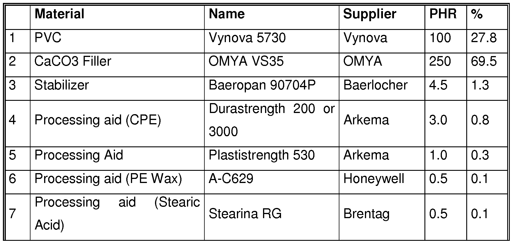
Table 1 : composition of the core layer 22.
The decorative layer for example comprises a printed decor (not shown). The decorative layer for example comprises 90wt% of a thermoplastic material, for example PVC, 10% of additive, and no plasticizer.
The wear layer is adapted to protect the decorative layer. The wear layer for example comprises 80wt% of a thermoplastic material, for example PVC, 20% of additive, and no plasticizer.
The tiles 5 are for example analogous to each other in terms of layers and composition of the layers, and for example in terms of dimensions.
Each of the tiles 5 has a first edge 26 and a second edge 28 (Figure 1 ), both extending in a longitudinal direction L perpendicular to the thickness direction V.
Each of the tiles 5 has a third edge 126 and a fourth edge 128 (Figure 2), both extending in a transverse direction T perpendicular to the thickness direction V and for example perpendicular to the longitudinal direction L.
The tiles 5 also have a lower surface S intended to be in contact with, and advantageously fixed to the surface 10 in the example. Each of the tiles 5 also comprises a rod 27.
The core layer 22 defines a connecting groove 30 in the first edge 26, and a connecting tongue 34 protruding from the second edge 28 and adapted to be received into the connecting groove 30 of another of the tiles 5 in the locked configuration.
The core layer 22 advantageously defines a connecting groove 130 in the third edge 126, and a connecting tongue 134 protruding from the fourth edge 128 and adapted to be received into the connecting groove 130 of another of the tiles 5 in the locked configuration.
The first edge 26 comprises an upper part 36 locate above the connecting groove 30, for example parallel to the thickness direction V, and adapted to abut against an upper part 38 of the second edge 28 in the locked configuration. The first edge 26 also has a lower part 40 located under the connecting groove 30.
With respect to the second edge 28, the connecting tongue 34 comprises a distal part 42 forming a nose, for example with a triangular profile in the longitudinal direction L, and a proximal part 44.
In a variant (not shown), the connecting tongue 34 is adapted to be snap-fit into the connecting groove 30 in order to obtain the locked configuration. The snap-fit effect is advantageously light, in order not to increase the insertion effort.
In a variant (not shown), the connecting tongue 134 is adapted to be snap-fit into the connecting groove 130 in order to obtain the locked configuration. The snap-fit effect is advantageously light, in order not to increase the insertion effort.
The locking strength (defined as the effort necessary to unlock the tiles par meter of of the edges locked to each other when the tile are parallel to each other) between the third edge 126 of one of the tiles 5 and the fourth edge 128 of another one of the tiles 5 in the locked configuration is advantageously lower than a locking strength between the first edge 26 and the second edge 28 in the locked configuration.
For example, the locking strength between the first edge 26 and the second edge 28 is greater than or equal to 20kN/m (kilonewton per meter of length of the edges locked to each other).
For example, the locking strength between the third edge 126 and the fourth edge 128 is lower than or equal to 2.0kN/m, preferably lower than 0.5kN/m. According to a particular embodiment, the locking strength between the third edge 126 and the fourth edge 128 is approximately OkN/m (no locking strength). This allows two tiles 5 connected by the third edge 126 and the fourth edge 128 to be translated one with respect to the other along the transverse direction T.
Advantageously, the effort to make the third edge 126 of one of the tiles 5 slide in the fourth edge 128 of another one of the tiles in the locked configuration is lower than 1 5kN/m.
The proximal part 44 defines an upper surface 46 and a lower surface 48 which are for example substantially perpendicular to the thickness direction V.
The connecting groove 30 comprises a bottom 50. The connecting groove 30 is delimited in the thickness direction V by an upper contact surface 52 and a lower surface 54 configured to be at least partly in contact respectively with a corresponding upper contact surface 52A in the upper surface 46 and with a corresponding lower contact surface 54A in the lower surface 48 of the connecting tongue 34 in the locked configuration.
The bottom 50 advantageously has a“U”-shaped profile in the longitudinal direction L, said“U” opening toward the first edge 26.
The upper contact surface 52 is on the opposite side to the surface 10 with respect to the connecting tongue 34 in the thickness direction V. The upper contact surface 52 is for example substantially perpendicular to the thickness direction V.
The lower contact surface 54 is on the same side as the surface 10 with respect to the connecting tongue 34 in the thickness direction V. The lower contact surface 54 comprises at least one longitudinal recess 56 defined by the core layer 22. Except for the recess 56, the lower contact surface 54 is adapted to be in contact with the lower surface 48 of the connecting tongue 34 and is for example substantially perpendicular to the thickness direction V.
The recess 56 for example has a rectangular profile in the longitudinal direction L. The recess 56 has a bottom wall 58 on which the rod 27 is fixed.
In other embodiments (not shown), the recess 56 is not formed in the lower contact surface 54, but in one of the upper contact surface 52, the corresponding upper contact surface 52A, and the corresponding lower contact surface 54A. In other words, the recess 56 may be located on any side of the connecting groove 30 or on any side of the connecting tongue 34 in the thickness direction V.
The core layer 22 includes a lower part 62 defining the lower contact surface 54 and the lower part 40 of the first edge 26. The core layer 22 further comprises an upper part 64 defining the upper contact surface 52 and the upper part 36 of the first edge 26. Advantageously, the lower part 62 protrudes more than the upper part 64 in a latching direction C approximately perpendicular to the thickness direction V and to the longitudinal direction L. In the latching direction C, the lower part 40 advantageously is farther from the bottom 50 than the upper part 36. This allows placing the rod 27 also farther from the bottom 50 than the upper part 36. As a result, it is possible to avoid the rod 27 when inserting the connecting tongue 34 in connecting groove 30.
As shown in Figure 2, the connecting groove 130 is delimited in the thickness direction V by an upper contact surface 152 and a lower contact surface 154 both configured to be at least partly in contact with the connecting tongue 134 in the locked configuration.
Advantageously, the tiles 5 are devoid of a rod that would be located in a recess formed in any of upper contact surface 152 and a lower contact surface 154 or formed in the connecting tongue 134. This allows a lower locking strength than when a rod, such as the trod 27, is present.
In Figure 2, the connecting tongue 134 is adapted to be received in the connecting groove 130 in a connection direction C2 which is perpendicular to the thickness direction V and advantageously parallel to the longitudinal direction L.
As a variant (not shown), the connecting tongue 134 is adapted to be received in the connecting groove 130 in a connection direction C2’ which is parallel to the thickness direction V (that is to say vertical in the example).
The rod 27 has a chemical composition distinct from the chemical composition of the wall 58, and in the example distinct from the composition of the whole core layer 22 which defines the recess.
The rod 27 is configured to press on the connecting tongue 34 in the locked configuration in the thickness direction V.
The rod 27 comprises at least one plastic material.
In particular embodiments, the rod 27 comprises:
- a silicone plastic material,
- a plastic material based on polyalkylene, wherein the polyalkylene is preferably PVC, PE, or PP, or
- or a hot-melt adhesive or a hot sealing adhesive, wherein the hot-melt adhesive or the hot sealing adhesive is preferably based on ethylene vinyl chloride, PA, PU or EVA.
Such plastics are deformable by heat or adhere by heat, and are advantageously selected to allow being extruded in rod form. They are able to solidify and adhere particularly firmly to the core layer 22. In use, they have an appropriate elasticity and viscosity in order to act as a locking element of the connecting tongue 34 in the connecting groove 30. The rod is viscoelastic or relative hard.
In particular embodiments, the rod 27 comprises one or several of:
- a thermoplastic material, wherein the thermoplastic material preferably comprises a polyolefin, a vinyl polymer, a polyamide, a polyester, a polyurethane or a ionomer,
- an elastomer, wherein the elastomer preferably comprises a rubber, or
- a thermoplastic elastomer, wherein the thermoplastic elastomer preferably comprises TPE, TPR, TPO, SPS, TP-Q or TP-U.
The plastic material comprised in the rod 27 may be present in the form of a polymer or copolymer. The plastic material present in the rod 27 may be present in a plasticized or non-plasticized formulation. The thermoplastic material used can advantageously be applied in the recess 56 with a nozzle (not shown).
The rod 27 for example comprises a latent adhesive, preferably a polymer adhesive, adapted for adhering to the connecting tongue in the locked configuration after the latent adhesive has been moistened with water.
The rod 27 is configured to latch the connecting tongue 34 of another one of the tiles 5 in the connecting groove 30 in a latching direction C approximately perpendicular to the thickness direction V and to the longitudinal direction L. For obtaining the latching, relatively small quantities of thermoplastic material are sufficient. The effect of the rod 27 is obtained by contact with an area of the lower surface of the connecting tongue 34.
In embodiments wherein the rod is fixed on the connecting tongue 34, the rod is adapted to latch the connecting groove 30 in the connecting direction C.
For obtaining the latching effect, the material of the rod is deposited in the recess 56 in a quantity sufficient to protrude from the mouth of the recess 56.
The rod 27 is advantageously configured to also latch the connecting tongue 34 in the thickness direction V with respect to the connecting groove 30. The locking action is obtained when the rod 27 exerts a vertical pressure on the connecting tongue 34. When this pressure occurs, upper surface 46 of the connecting tongue 34 is pressed against the upper contact surface 52 of the connecting groove 30.
The rod 27 has a sufficient strength in order not to be removed or to be damaged, when the tongue is pushed into the groove.
The rod 27 for example has a substantially uniform thickness E1 in the thickness direction V, preferably comprised between 5% and 40% of the thickness E of the tiles 5.
The thickness E1 is larger than the thickness of the recess 56. The rod 27 for example forms a bulge 60 protruding from a mouth of the recess 56, that is to say protruding above the rest of the lower contact surface 54.
The thickness E1 is for example comprised between 0.3mm and 1 5mm, preferably between 0.6mm and 0.8mm.
In order to use the set 1 for covering the surface 10, for example, the first tile 15 and the third tile 1 15 are first connected to each other in the connection direction C2. The connecting tongue 134 of the fourth edge 128 of the third tile 1 15 is introduced, advantageously without much effort, in the connecting groove 130 of the third edge 126 of the first tile 15. This is symbolized in Figure 3 by a sticker 1.
Then the first tile 15 and the second tile 20 are put in the locked configuration by introducing the connecting tongue 34 of the second tile into the connecting groove 30 of the first tile (sticker 2).
The rod 27 of the first tile 15 then presses on the connecting tongue 34 of the second tile 20 in the locked configuration. The connecting tongue 34 is blocked by the upper contact surface 52 and the rod 27.
The rod 27 provides a latching action on the connecting tongue 34 (or on the connecting groove 30 in embodiments wherein the rod is fixed on the connecting tongue 34). The rod 27 acts as a locking element when the tiles 15, 20 are joined.
Advantageously the step of putting the first tile 15 and the second tile 20 in the locked configuration comprises angling the second tile with respect to the first tile, and inserting the connecting tongue 34 in the connecting groove 30 in a connection direction
C1 forming an angle a with the thickness direction V around the longitudinal direction L. This substep is symbolized with an arrow F1 in the Figure.
The step also includes a substep of pivoting (arrow F2 in the Figure) the second tile 20 with respect to the first tile 15 around the longitudinal direction L, and further inserting the connecting tongue 34 in the connecting groove 30 (arrow F3) until the locked configuration is reached.
After angling the second tile 20, the first tile 15 and the second tile are in contact with each other, but the locked configuration is not reached, so that the first tile 15 can still be moved along the edge of second tile 20. The locked configuration is reached only after the pivoting the second tile 20. This embodiment is particularly advantageous when the connecting tongue 134 formed in fourth edge 128 is adapted to be received along the thickness direction V in the connecting groove 130 formed in the third edge 126.
The angle a is for example comprised between 15° and 70°, preferably between 30° and 60°.
Afterwards, the fourth tile 120 is connected to the second tile 20 by introducing the connecting tongue 134 of the fourth tile into the connecting groove 130 of the second tile (sticker 3 in Figure 3).
The fourth tile 120 is also connected to the third tile 1 15 by introducing the connecting tongue 34 of the fourth tile into the connecting groove 30 of the third tile 1 15 (sticker 3’) in a similar manner as the second tile 20 is connected to the first tile 15.
As the connection of the fourth tile 120 with the second tile 20 is not strong, the fourth tile 120 can be moved with respect to the second tile 20 during the connection of the fourth tile to the third tile 1 15, which makes this connection very easy to perform. In other words, while the connecting tongue 34 of the fourth tile 120 is introduced into the connecting groove 30 of the third tile 1 15 (sticker 3’), the connecting tongue 134 of the fourth tile 120 may slide (sticker 3”) in the connecting groove 130 of the second tile 20 along the third edge 126 of the second tile. This also allows repositioning the fourth tile 120 with respect to the second tile 20 when connecting the fourth tile to the third tile 1 15.
After that, the four tiles 5 represented in Figure 3 are in a locked configuration with each other.
As a variant (not shown), these tiles may be connected in such a way that the first tile 15 and the third tile 1 15 are offset with respect to the second tile 20 and the fourth tile 120 in the longitudinal direction L. This prevents the third tile 1 15 and the fourth tile 120 from sliding with respect to the first tile 15 and the second tile 20 along the transverse direction T once in the locked configuration.
The other tiles 5 (not shown) are connected to each other in the same manner, using connecting tongues and grooves.
Thanks to the above features, the connecting tongue 34 can be inserted in the connecting groove 30 with a reasonable insertion effort, despite the rigidity of the core layers 22. Then, in the locked configuration, the rod 27 acts as an efficient latching element. The set 1 is easy to use, while remaining simple to produce, and cost effective.
Advantageously, the rod 27 is applied in the recess 56 during production of the tiles 5 in a simple and durable way.
Thanks to the optional features according to which the tiles 5 are adapted for having a weaker connection between the third edged 126 and the fourth edge 128, the set 1 is even easier to use.
Claims
1.- A set (1 ) of tiles (5) adapted to cover a surface (10) perpendicular to a thickness direction (V) of the tiles (5), each of the tiles (5) comprising a core layer (22), the set (1 ) comprising:
- at least one first tile (15) having a first edge (26) extending in a longitudinal direction (L), the core layer (22) of the first tile (15) defining a connecting groove (30) in the first edge (26),
- at least one second tile (20) having a second edge (28) extending in the longitudinal direction (L), the core layer (22) of second tile (20) defining a connecting tongue (34) protruding from the second edge (28), the connecting tongue (34) being adapted to be received into the connecting groove (30) in a locked configuration of the first tile (15) and the second tile (20),
the connecting groove (30) being delimited in the thickness direction (V) by an upper contact surface (52) and a lower contact surface (54) both configured to be at least partly in contact with a corresponding upper contact surface (52A) and a corresponding lower contact surface (54A) of the connecting tongue (34) in the locked configuration, the lower contact surface (54) being on the same side as the surface (10) to be covered with respect to the connecting tongue (34) in the thickness direction (V), and the upper contact surface (52) being on the opposite side to the surface (10) to be covered with respect to the connecting tongue (34) in the thickness direction (V),
wherein:
- the core layer (22) of the first tile (15) or the second tile (20) defines at least one longitudinal recess (56) in one of the upper contact surface (52), the lower contact surface (54), the corresponding upper contact surface (52A), and the corresponding lower contact surface (54A),
- the first tile (15) or the second tile (20) further comprises a rod (27) fixed on a wall (58) of the recess (56), the rod (27) having a chemical composition distinct from a chemical composition of said wall (58), and
- the rod (27) is configured to press on the connecting tongue (34) or on the connecting groove (30) in the locked configuration.
2.- The set (1 ) according to claim 1 , wherein the rod (27) comprises at least one plastic material.
3.- The set (1 ) according to claim 1 or 2, wherein the rod (27) comprises:
- a silicone plastic material,
- a plastic material based on polyalkylene, wherein the polyalkylene is preferably PVC, PE, or PP, or
- or a hot-melt adhesive or a hot sealing adhesive, wherein the hot-melt adhesive or the hot sealing adhesive is preferably based on ethylene vinyl chloride, PA, PU or EVA.
4.- The set (1 ) according to claim 1 or 2, wherein the rod (27) comprises one or several of:
- a thermoplastic material, wherein the thermoplastic material preferably comprises a polyolefin, a vinyl polymer, a polyamide, a polyester, a polyurethane or a ionomer,
- an elastomer, wherein the elastomer preferably comprises a rubber, or
- a thermoplastic elastomer, wherein the thermoplastic elastomer preferably comprises TPE, TPR, TPO, SPS, TP-Q or TP-U.
5.- The set (1 ) according to any of claims 1 to 4, wherein the connecting tongue (34) is adapted to be snap-fit into the connecting groove (30) in the locked configuration.
6.- The set (1 ) according to any of claims 1 to 5, wherein the rod (27) is configured to latch the connecting tongue (34) in a latching direction (C) approximately perpendicular to the thickness direction (V) and to the longitudinal direction (L).
7.- The set (1 ) according to any of claims 1 to 6, wherein the rod (27) is configured to latch the connecting tongue (34) in the thickness direction (V) with respect to the first tile (15).
8.- The set (1 ) according to any of claims 1 to 7, wherein the rod (27) comprises an latent adhesive, preferably a polymer adhesive, adapted for adhering to the connecting tongue (34) in the locked configuration after the latent adhesive has been moistened with water.
9.- The set (1 ) according to any of claims 1 to 8, wherein the first tile (15) has a thickness (E) in the thickness direction (V), the rod (27) having a substantially uniform thickness (E1 ) in the thickness direction (V), preferably comprised between 5% and 40% of the thickness (E) of the first tile.
10.- The set (1 ) according to claim 9, wherein said thickness (E1 ) of the rod (27) is comprised between 0.3mm and 1.5mm, preferably between 0.6mm and 0.8mm.
1 1.- The set (1 ) according to any of claims 1 to 10, wherein the rod (27) forms a bulge (60) protruding from a mouth of the recess (56).
12.- The set (1 ) according to any of claims 1 to 1 1 , wherein :
- at least the first tile (15) has a third edge (126) extending in a transverse direction (T), the core layer (22) of the first tile (15) defining a connecting groove (130) in the third edge (126), and
- at least the second tile (20) has a fourth edge (128) extending in the transverse direction (T), the core layer (22) of second tile (20) defining a connecting tongue (134) protruding from the fourth edge (128), the connecting tongue (34) being adapted to be received into the connecting groove (130) in a locked configuration of the first tile (15) and the second tile (20),
wherein a locking strength between the third edge (126) of the first tile (15) and the fourth edge (128) of the second tile (20) in the locked configuration is lower than a locking strength between the first edge (26) of the first tile (15) and the second edge (28) of the second tile (20) in the locked configuration.
13.- The set (1 ) according to claim 12, wherein the first tile (15) is devoid of a rod located in a recess formed in the connecting groove (130) in the third edge (126) and the second tile (20) is devoid of a rod located in a recess formed in the connecting tongue (134) in the fourth edge (128).
14.- A method of covering a surface (10) with tiles (5), the surface (10) being perpendicular to a thickness direction (V) of the tiles (5), comprising at least the following steps:
- providing a set (1 ) according to anyone of claims 1 to 13, and
- putting the first tile (15) and the second tile (20) in the locked configuration by introducing the connecting tongue (34) into the connecting groove (30), wherein the rod (27) presses on the connecting tongue (34) or on the connecting groove (30) in the locked configuration.
15.- The method according to claim 14, wherein the step of putting the first tile (15) and the second tile (20) in the locked configuration comprises:
- angling the second tile (20) with respect to the first tile (15), and inserting the connecting tongue (34) in the connecting groove (30) in a connection direction (C1 ) forming an angle (a) with the thickness direction (V) around the longitudinal direction (L), wherein the angle (a) is comprised between 15° and 70°, preferably between 30° and 60°, and
- pivoting the second tile (20) with respect to the first tile (15) around the longitudinal direction (L), and further inserting the connecting tongue (34) in the connecting groove (30) until the locked configuration is reached.
Priority Applications (3)
| Application Number | Priority Date | Filing Date | Title |
|---|---|---|---|
| PL19717890.8T PL3775431T3 (en) | 2018-04-13 | 2019-04-12 | Set of tiles adapted to cover a surface such as a floor |
| ES19717890T ES2972755T3 (en) | 2018-04-13 | 2019-04-12 | Set of tiles adapted to cover a surface such as a floor |
| EP19717890.8A EP3775431B1 (en) | 2018-04-13 | 2019-04-12 | Set of tiles adapted to cover a surface such as a floor |
Applications Claiming Priority (2)
| Application Number | Priority Date | Filing Date | Title |
|---|---|---|---|
| EP18167351.8 | 2018-04-13 | ||
| EP18167351.8A EP3553248A1 (en) | 2018-04-13 | 2018-04-13 | Set of tiles adapted to cover a surface such as a floor |
Publications (1)
| Publication Number | Publication Date |
|---|---|
| WO2019197666A1 true WO2019197666A1 (en) | 2019-10-17 |
Family
ID=62002022
Family Applications (1)
| Application Number | Title | Priority Date | Filing Date |
|---|---|---|---|
| PCT/EP2019/059556 Ceased WO2019197666A1 (en) | 2018-04-13 | 2019-04-12 | Set of tiles adapted to cover a surface such as a floor. |
Country Status (4)
| Country | Link |
|---|---|
| EP (2) | EP3553248A1 (en) |
| ES (1) | ES2972755T3 (en) |
| PL (1) | PL3775431T3 (en) |
| WO (1) | WO2019197666A1 (en) |
Citations (8)
| Publication number | Priority date | Publication date | Assignee | Title |
|---|---|---|---|---|
| DE20219110U1 (en) * | 2002-12-09 | 2003-03-13 | Kronospan Technical Company Ltd., Engomi, Nikosia | Panels with cable duct |
| EP1367194A2 (en) * | 2002-05-31 | 2003-12-03 | Kronotec Ag | Flooring panel and method of laying such a panel |
| US20040031227A1 (en) * | 2002-08-19 | 2004-02-19 | M. Kaindl | Cladding panel |
| DE20319121U1 (en) * | 2003-01-23 | 2004-06-03 | E.F.P. Floor Products Fussböden GmbH | Panel, in particular floor panel |
| WO2005090707A1 (en) * | 2004-03-23 | 2005-09-29 | Kaindl Flooring Gmbh | Joining panel |
| WO2006032378A1 (en) * | 2004-09-17 | 2006-03-30 | Hdm Gmbh | Panel in particular floor panel |
| WO2006104436A1 (en) * | 2005-03-30 | 2006-10-05 | Välinge Innovation AB | Mechanical locking system for floor panels and a method to disconnect floor panels |
| WO2017133804A1 (en) | 2016-02-04 | 2017-08-10 | Champion Link International Corporation | Waterproof panel, process for producing a panel, and panel obtainable by said process |
Family Cites Families (1)
| Publication number | Priority date | Publication date | Assignee | Title |
|---|---|---|---|---|
| BE1010487A6 (en) * | 1996-06-11 | 1998-10-06 | Unilin Beheer Bv | FLOOR COATING CONSISTING OF HARD FLOOR PANELS AND METHOD FOR MANUFACTURING SUCH FLOOR PANELS. |
-
2018
- 2018-04-13 EP EP18167351.8A patent/EP3553248A1/en not_active Withdrawn
-
2019
- 2019-04-12 EP EP19717890.8A patent/EP3775431B1/en active Active
- 2019-04-12 WO PCT/EP2019/059556 patent/WO2019197666A1/en not_active Ceased
- 2019-04-12 ES ES19717890T patent/ES2972755T3/en active Active
- 2019-04-12 PL PL19717890.8T patent/PL3775431T3/en unknown
Patent Citations (8)
| Publication number | Priority date | Publication date | Assignee | Title |
|---|---|---|---|---|
| EP1367194A2 (en) * | 2002-05-31 | 2003-12-03 | Kronotec Ag | Flooring panel and method of laying such a panel |
| US20040031227A1 (en) * | 2002-08-19 | 2004-02-19 | M. Kaindl | Cladding panel |
| DE20219110U1 (en) * | 2002-12-09 | 2003-03-13 | Kronospan Technical Company Ltd., Engomi, Nikosia | Panels with cable duct |
| DE20319121U1 (en) * | 2003-01-23 | 2004-06-03 | E.F.P. Floor Products Fussböden GmbH | Panel, in particular floor panel |
| WO2005090707A1 (en) * | 2004-03-23 | 2005-09-29 | Kaindl Flooring Gmbh | Joining panel |
| WO2006032378A1 (en) * | 2004-09-17 | 2006-03-30 | Hdm Gmbh | Panel in particular floor panel |
| WO2006104436A1 (en) * | 2005-03-30 | 2006-10-05 | Välinge Innovation AB | Mechanical locking system for floor panels and a method to disconnect floor panels |
| WO2017133804A1 (en) | 2016-02-04 | 2017-08-10 | Champion Link International Corporation | Waterproof panel, process for producing a panel, and panel obtainable by said process |
Also Published As
| Publication number | Publication date |
|---|---|
| EP3553248A1 (en) | 2019-10-16 |
| EP3775431A1 (en) | 2021-02-17 |
| PL3775431T3 (en) | 2024-05-06 |
| EP3775431B1 (en) | 2024-02-07 |
| ES2972755T3 (en) | 2024-06-14 |
| EP3775431C0 (en) | 2024-02-07 |
Similar Documents
| Publication | Publication Date | Title |
|---|---|---|
| US11898356B2 (en) | Floorboards provided with a mechanical locking system | |
| US10612249B2 (en) | Floor panel for forming a floor covering, floor covering formed from such floor panels and method for manufacturing such floor panels | |
| WO2019170605A1 (en) | Set of tiles adapted to cover a surface such as a floor. | |
| JP6900313B2 (en) | Mechanical locking system for floor panels | |
| US9771722B2 (en) | Floor tile | |
| US9890541B2 (en) | Floor board, in particular for flooring | |
| US20190017278A1 (en) | Floor panel for forming a floor covering | |
| AU2016282948B2 (en) | A floor tile | |
| US10400457B2 (en) | Synthetic multilayer floor covering | |
| EP3194684B1 (en) | Thin decorative surface covering | |
| CA2824926A1 (en) | Panel | |
| WO2007141605A2 (en) | Floor covering, floor element and method for manufacturing floor elements | |
| AU2020295642B2 (en) | Floor tile with waterproof connection | |
| EP3775431A1 (en) | Set of tiles adapted to cover a surface such as a floor | |
| JP6229253B2 (en) | Floor panel material | |
| CN110788956A (en) | Method for manufacturing composite solid wood floor | |
| LU92866B1 (en) | Synthetic multilayer floor covering | |
| HK40064663A (en) | Floor tile with waterproof connection | |
| HK40064663B (en) | Floor tile with waterproof connection | |
| KR20160120014A (en) | Method for manufacturing one body type hot water mat |
Legal Events
| Date | Code | Title | Description |
|---|---|---|---|
| 121 | Ep: the epo has been informed by wipo that ep was designated in this application |
Ref document number: 19717890 Country of ref document: EP Kind code of ref document: A1 |
|
| NENP | Non-entry into the national phase |
Ref country code: DE |
|
| WWE | Wipo information: entry into national phase |
Ref document number: 2019717890 Country of ref document: EP |