WO2019116658A1 - Information processing device, information processing method, and program - Google Patents
Information processing device, information processing method, and program Download PDFInfo
- Publication number
- WO2019116658A1 WO2019116658A1 PCT/JP2018/034375 JP2018034375W WO2019116658A1 WO 2019116658 A1 WO2019116658 A1 WO 2019116658A1 JP 2018034375 W JP2018034375 W JP 2018034375W WO 2019116658 A1 WO2019116658 A1 WO 2019116658A1
- Authority
- WO
- WIPO (PCT)
- Prior art keywords
- evaluation
- information
- information processing
- evaluator
- processing apparatus
- Prior art date
Links
Images


Classifications
-
- G—PHYSICS
- G06—COMPUTING; CALCULATING OR COUNTING
- G06Q—INFORMATION AND COMMUNICATION TECHNOLOGY [ICT] SPECIALLY ADAPTED FOR ADMINISTRATIVE, COMMERCIAL, FINANCIAL, MANAGERIAL OR SUPERVISORY PURPOSES; SYSTEMS OR METHODS SPECIALLY ADAPTED FOR ADMINISTRATIVE, COMMERCIAL, FINANCIAL, MANAGERIAL OR SUPERVISORY PURPOSES, NOT OTHERWISE PROVIDED FOR
- G06Q30/00—Commerce
- G06Q30/02—Marketing; Price estimation or determination; Fundraising
-
- G—PHYSICS
- G06—COMPUTING; CALCULATING OR COUNTING
- G06F—ELECTRIC DIGITAL DATA PROCESSING
- G06F18/00—Pattern recognition
- G06F18/20—Analysing
- G06F18/21—Design or setup of recognition systems or techniques; Extraction of features in feature space; Blind source separation
- G06F18/217—Validation; Performance evaluation; Active pattern learning techniques
-
- G—PHYSICS
- G06—COMPUTING; CALCULATING OR COUNTING
- G06N—COMPUTING ARRANGEMENTS BASED ON SPECIFIC COMPUTATIONAL MODELS
- G06N20/00—Machine learning
-
- G—PHYSICS
- G06—COMPUTING; CALCULATING OR COUNTING
- G06V—IMAGE OR VIDEO RECOGNITION OR UNDERSTANDING
- G06V40/00—Recognition of biometric, human-related or animal-related patterns in image or video data
- G06V40/10—Human or animal bodies, e.g. vehicle occupants or pedestrians; Body parts, e.g. hands
-
- G—PHYSICS
- G06—COMPUTING; CALCULATING OR COUNTING
- G06N—COMPUTING ARRANGEMENTS BASED ON SPECIFIC COMPUTATIONAL MODELS
- G06N3/00—Computing arrangements based on biological models
- G06N3/02—Neural networks
- G06N3/08—Learning methods
- G06N3/084—Backpropagation, e.g. using gradient descent
Definitions
- the present disclosure relates to an information processing device, an information processing method, and a program.
- Patent Document 1 discloses a technique for generating a ranking of entities using the calculated reputation or score of degree of influence.
- the present disclosure proposes an information processing apparatus, an information processing method, and a program capable of estimating the reliability of an evaluator and improving the accuracy of an evaluation value.
- An information processing apparatus comprising: a control unit that performs processing of estimating the reliability of the evaluation by the evaluator based on sensing data.
- the processor acquires evaluation information on the evaluation target person of the evaluator and sensing data of the evaluation target person, the evaluation information on the evaluation target person of the evaluator, and the evaluation.
- An information processing method is proposed, which includes estimating the reliability of evaluation by the evaluator based on sensing data of a target person.
- the computer is a process of acquiring evaluation information of the evaluator for the evaluation subject, sensing data of the evaluation subject, the evaluation information of the evaluator for the evaluation subject, and the evaluation.
- a program is proposed to function as a control unit that performs a process of estimating the reliability of evaluation by the evaluator based on sensing data of a target person.
- FIG. 1 is a block diagram illustrating an example of an overall configuration of an embodiment of the present disclosure.
- FIG. 7 is a block diagram illustrating another example of an overall configuration of an embodiment of the present disclosure.
- FIG. 7 is a block diagram illustrating another example of an overall configuration of an embodiment of the present disclosure.
- FIG. 7 is a block diagram illustrating another example of an overall configuration of an embodiment of the present disclosure. It is a block diagram showing an example of functional composition of a treating part concerning one embodiment of this indication. It is a figure showing an example of the evaluation input screen concerning one embodiment of this indication. It is a figure explaining an example of acquisition of evaluation information from sensing data of an evaluator concerning one embodiment of this indication.
- this indication it is a flow chart which shows an example of the 2nd analysis processing which calculates an evaluation value with reference to a degree of reliability of an evaluator, and updates a degree of reliability.
- it is a flow chart which shows an example of processing which presumes a degree of reliability of an evaluator based on sensing data of a candidate for evaluation.
- it is a flow chart which shows an example of the 3rd analysis processing which computes an evaluation value based on relative evaluation.
- it is a flow chart showing an example of integrated processing of evaluation values analyzed.
- it is a flowchart which shows the flow of a process of causal analysis. It is a flowchart which shows the flow of the discretization process of a continuous value variable regarding the data used for the causal analysis which concerns on the application example of this embodiment.
- it is a flowchart which shows the flow of a presentation process of a causal-analysis result.
- It is a figure which shows an example of the display screen of the analysis result which concerns on the application example of this embodiment.
- it is a block diagram which shows the function structural example of the process part which performs time-sequential causal analysis of evaluation.
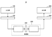
- FIG. 1 is a block diagram illustrating an example of the overall configuration of an embodiment of the present disclosure.
- the system 10 includes an input unit 100, a processing unit 200, and an output unit 300.
- the input unit 100, the processing unit 200, and the output unit 300 are realized by one or more information processing apparatuses, as shown in the configuration example of the system 10 described later.
- the input unit 100 includes, for example, an operation input device, a sensor, or software for acquiring information from an external service, and receives an input of various information from a user, a peripheral environment, or another service.
- the operation input device includes, for example, a hardware button, a keyboard, a mouse, a touch panel, a touch sensor, a proximity sensor, an acceleration sensor, an angular velocity sensor, a temperature sensor, and the like, and receives an operation input by a user.
- the operation input device may include a camera (imaging element), a microphone, or the like that receives an operation input represented by a user's gesture or voice.
- the input unit 100 may include a processor or processing circuit that converts a signal or data acquired by the operation input device into an operation command.
- the input unit 100 may output the signal or data acquired by the operation input device to the interface 150 without converting it into an operation command. In that case, the signal or data acquired by the operation input device is converted into an operation command by the processing unit 200, for example.
- the sensor includes an acceleration sensor, an angular velocity sensor, a geomagnetic sensor, an illuminance sensor, a temperature sensor, or an atmospheric pressure sensor, and detects acceleration, angular velocity, azimuth, illuminance, temperature, atmospheric pressure, and the like applied to the device.
- the various sensors described above can detect various information as information on the user, such as information indicating the user's exercise or direction.
- the sensors may also include other sensors that detect user's biological information such as pulse, sweating, brain waves, touch, smell and taste.
- the input unit 100 includes a processing circuit that acquires information indicating the user's emotion by analyzing information detected by these sensors and / or image or voice data detected by a camera or a microphone described later. It may be Alternatively, the above information and / or data may be output to the interface 150 without analysis, and the analysis may be performed in the processing unit 200, for example.
- the senor may acquire an image or sound in the vicinity of the user or the device as data by a camera, a microphone, the various sensors described above, and the like.
- the sensor may also include position detection means for detecting the indoor or outdoor position.
- the position detection means is a GNSS (Global Navigation Satellite System) receiver, for example, a GPS (Global Positioning System) receiver, GLONASS (Global Navigation Satellite) System) receiver, BDS (BeiDou Navigation Satellite System) receiver and / or communication device, etc. may be included.
- GNSS Global Navigation Satellite System
- GPS Global Positioning System
- GLONASS Global Navigation Satellite
- BDS BeiDou Navigation Satellite System
- the communication device is, for example, Wi-Fi (registered trademark), MIMO (Multi-Input Multi-Output), cellular communication (for example, position detection using a mobile base station, femtocell), or near field communication (for example, BLE (Bluetooth)
- Wi-Fi registered trademark
- MIMO Multi-Input Multi-Output
- cellular communication for example, position detection using a mobile base station, femtocell
- near field communication for example, BLE (Bluetooth)
- BLE Bluetooth
- the position is detected using technology such as Low Energy), Bluetooth (registered trademark), and Low Power Wide Area (LPWA).
- LPWA Low Power Wide Area
- the device including the sensor When the sensor as described above detects the position or condition (including biological information) of the user, the device including the sensor is carried or worn by the user, for example. Alternatively, even when the device including the sensor is installed in the living environment of the user, it may be possible to detect the position and the situation (including the biological information) of the user. For example, the user's pulse can be detected by analyzing an image including the user's face acquired by a camera fixedly installed in a room or the like.
- the input unit 100 is a processor or process that converts signals or data acquired by the sensor into a predetermined format (for example, converts an analog signal into a digital signal or encodes image or audio data)
- a circuit may be included.
- the input unit 100 may output the acquired signal or data to the interface 150 without converting it into a predetermined format.
- the processing unit 200 converts the signal or data acquired by the sensor into an operation command.
- Software that acquires information from an external service uses, for example, an API (Application Program Interface) of the external service to acquire various types of information provided by the external service.
- the software may, for example, obtain information from the server of the external service, or may obtain information from application software of the service being executed on the client device.
- the software may, for example, obtain information such as text or images posted by the user or another user to an external service such as social media.
- the acquired information does not necessarily have to be posted intentionally by the user or another user, and may be, for example, a log of an operation performed by the user or the other user.
- the information to be acquired is not limited to personal information of the user or other users, and, for example, an unspecified number of unspecified information such as news, weather forecast, traffic information, POI (Point Of Interest), or advertisement. It may be information distributed to the user.
- an unspecified number of unspecified information such as news, weather forecast, traffic information, POI (Point Of Interest), or advertisement. It may be information distributed to the user.
- the information acquired from the external service includes information acquired by the various sensors described above, such as acceleration, angular velocity, azimuth, altitude, illuminance, temperature, barometric pressure, pulse, sweating, brain waves, touch, smell, taste, etc.
- Biological information, emotions, location information, etc. may be detected by a sensor included in another system that cooperates with the external service, and information generated by being posted to the external service may be included.
- the interface 150 is an interface between the input unit 100 and the processing unit 200.
- the interface 150 may include a wired or wireless communication interface.
- the Internet may be interposed between the input unit 100 and the processing unit 200.
- the wired or wireless communication interface may be cellular communication such as 3G / LTE / 5G, wireless LAN (Local Area Network) communication such as Wi-Fi (registered trademark), wireless such as Bluetooth (registered trademark) It may include PAN (Personal Area Network) communication, NFC (Near Field Communication), Ethernet (registered trademark), HDMI (registered trademark) (High-Definition Multimedia Interface), USB (Universal Serial Bus), and the like.
- the interface 150 may include a bus in the device, data reference in a program module, etc. Also called interface in the device). Also, when the input unit 100 is implemented in a plurality of devices, the interface 150 may include different types of interfaces for the respective devices. For example, interface 150 may include both a communication interface and an interface within the device.
- the processing unit 200 executes various processes based on the information acquired by the input unit 100. More specifically, for example, the processing unit 200 may be a central processing unit (CPU), a graphics processing unit (GPU), a digital signal processor (DSP), an application specific integrated circuit (ASIC), or a field-programmable gate array (FPGA). Etc.) or processors or processing circuits.
- the processing unit 200 may also include a memory or a storage device that temporarily or permanently stores a program executed in a processor or processing circuit, and data read and written in processing.
- the processing unit 200 may be realized by a single processor or processing circuit in a single device, or may be realized by being distributed to a plurality of devices or a plurality of processors or processing circuits in the same device. May be When the processing units 200 are implemented in a distributed manner, the interface 250 intervenes between the divided portions of the processing units 200 as in the examples shown in FIGS. 2 and 3.
- the interface 250 may include a communication interface or an interface within a device, similar to the interface 150 described above.
- the individual functional blocks constituting the processing unit 200 are illustrated, but the interface 250 may be interposed between any functional blocks. That is, when the processing unit 200 is realized by being distributed to a plurality of devices or a plurality of processors or processing circuits, it is separately described how to distribute the functional block to each device, each processor or each processing circuit. It is optional unless it is.
- FIG. 4 shows an example of a functional block diagram of the processing unit 200.
- the processing unit 200 includes a learning unit 210 and an identification unit 220.
- the learning unit 210 performs machine learning based on the input information (learning data), and outputs a learning result.
- the identification unit 220 also identifies (determines, predicts, etc.) the input information based on the input information and the learning result.
- a neural network is a model that mimics human brain neural circuits, and consists of three types of layers: an input layer, an intermediate layer (hidden layer), and an output layer.
- deep learning is a model using a multi-layered neural network, and it is possible to repeat characteristic learning in each layer and learn complex patterns hidden in a large amount of data. Deep learning is used, for example, to identify objects in images and words in speech.
- a neurochip / neuromorphic chip incorporating the concept of neural network may be used.
- supervised learning learns feature quantities based on given labeled learning data (teacher data). This makes it possible to derive labels for unknown data.
- semi-teaching learning is a mixture of supervised learning and unsupervised learning, and after having a feature amount learned in supervised learning, a large amount of training data is given by unsupervised learning, and features are automatically made. It is a method of repeating learning while calculating the amount.
- Reinforcement learning deals with the problem of determining the action to be taken by an agent in an environment by observing the current state.
- the agent learns the reward from the environment by selecting an action, and learns the method that can obtain the most reward through a series of actions.
- the optimal solution in a certain environment it is possible to reproduce human judgment and to allow a computer to acquire judgment beyond human.
- the processing unit 200 can also generate virtual sensing data by machine learning as described above. For example, the processing unit 200 can predict other sensing data from certain sensing data and use it as input information, such as generating position information from input image information. Moreover, the processing unit 200 can also generate another sensing data from a plurality of sensing data. The processing unit 200 can also predict necessary information and generate predetermined information from sensing data.
- the output unit 300 outputs the information provided from the processing unit 200 to a user (may be the same user as the user of the input unit 100 or may be a different user), an external device, or another service. Do.
- the output unit 300 may include an output device, a controller, or software for providing information to an external service.
- the output device may use the information provided by the processing unit 200 as the visual or auditory sense, tactile sense, olfactory sense, taste, etc. of the user (may be the same user as the user of the input unit 100 or may be a different user).
- the output device is a display, which outputs information as an image.
- the display is not limited to a reflective or self-luminous display such as an LCD (Liquid Crystal Display) or an organic EL (Electro-Luminescence) display, and an image is displayed on the eyes of the user as used in wearable devices etc. It also includes a combination of a light guide member for guiding light and a light source.
- the output device may include a speaker and output information by voice.
- the output device may include a projector, a vibrator and the like.
- the control device controls the device based on the information provided from the processing unit 200.
- the device to be controlled may be included in the device that realizes the output unit 300 or may be an external device. More specifically, for example, the controller includes a processor or processing circuit that generates control commands.
- the output unit 300 may further include a communication device that transmits a control command to the external device.
- the control device controls, for example, a printer that outputs the information provided from the processing unit 200 as a printed matter.
- the control device may include a driver for controlling the writing of the information provided from the processing unit 200 to the storage device or the removable recording medium.
- the control device may control a device other than the device that outputs or records the information provided from the processing unit 200.
- the control device controls the illumination device to turn on the illumination, controls the television to turn off the image, controls the audio device to adjust the volume, controls the robot to control the movement, etc. You may
- control device may control the input device included in the input unit 100. That is, the control device can control to obtain predetermined information by the input device. Also, the control device may be realized by the same device as the input device. This also allows the input device to control other input devices. For example, when there are a plurality of camera devices, usually only one is activated for the purpose of power saving, but when a person is recognized, another camera that is activated is connected to another camera Control to start the device.
- the software for providing information to the external service provides, for example, the information provided from the processing unit 200 to the external service using an API of the external service.
- the software may, for example, provide information to the server of the external service or may provide information to application software of the service being executed on the client device.
- the provided information may not necessarily be reflected immediately on the external service, and may be provided as a candidate for the user to post or transmit to the external service, for example.
- the software may provide a search keyword input by the user or text used as a candidate for a Uniform Resource Locator (URL) in browser software executed on the client device.
- the software may post text, images, videos, sounds, etc. to an external service such as social media on behalf of the user.
- the interface 350 is an interface between the processing unit 200 and the output unit 300.
- the interface 350 may include a wired or wireless communication interface.
- the interface 350 may include the interface in the device described above.
- the interface 350 may include different types of interfaces for the respective devices.
- interface 350 may include both a communication interface and an interface within the device.
- FIG. 5 is a block diagram showing an example of a functional configuration of a processing unit according to an embodiment of the present disclosure.
- the processing unit 200 (control unit) includes an evaluation unit 201, an evaluation analysis unit 205, and an analysis result output unit 211. Each functional configuration will be further described below.
- the evaluation unit 201 acquires various types of information indicating the evaluation of the evaluation target person from the input unit 100 via the interface 150. More specifically, for example, the evaluation unit 201 acquires information from the operation input device included in the input unit 100.
- the information acquired from the operation input device is, for example, evaluation information manually input by the evaluator on the evaluation input screen.
- the manually input evaluation information includes an absolute evaluation in which the predetermined skill of the evaluation subject is evaluated with a predetermined numerical value, and a relative evaluation in which the evaluation is performed in comparison with other evaluation subjects.
- Skills are not particularly limited, but, for example, sports (soccer, baseball, tennis, etc.), games, fashion, cooking, good singing, foot speed, kindness, tenderness, etc. are assumed.
- the numerical value to be input may be one obtained by converting the number of stars indicating evaluation and words (such as “wow / very great / superwow”) selected by the evaluator.
- An example of the evaluation input screen which can input such evaluation information is shown in FIG.
- the evaluation input screen 30 the input of the evaluation of each skill is performed by the selection of the number of stars per evaluation subject.
- the evaluation input screen 31 in the skill unit, the input of evaluation of each evaluation target person is performed by selection of the number of stars or selection of words.
- a relative evaluation is performed in which a plurality of evaluation target persons are compared with each other on a skill basis to select the superior one.
- the evaluation unit 201 acquires information from a sensor included in the input unit 100.
- the information acquired from the sensor is, for example, sensing data of the evaluator.
- IoT Internet of Things
- various devices are connected to the Internet, and it is possible to acquire a large amount of sensing data on a daily basis.
- the evaluation by the evaluator can be obtained from other than manual input. For example, from the user's telephone conversation, information about evaluations such as "You are good at basketball is good for Mr. ⁇ ", "You are very friendly for Mr. ⁇ ", and "Good at cooking by ⁇ for Mr. ⁇ ", etc. It can be extracted and acquired as evaluation information.
- the evaluation unit 201 acquires and analyzes, for example, voice, writing to SNS, etc., mail contents etc. as sensing data, specifies a person to be evaluated (who to whom evaluation is made) and evaluation contents (skill, strength), and evaluates Get information.
- An example is shown in FIG. 7 about acquisition of evaluation information from such sensing data.
- voice data when the evaluator is speaking with someone or contents written by the evaluator in SNS etc. are acquired from various sensors as sensing data, as shown in the left of FIG. , Identify the person to be evaluated and the character string corresponding to the content of the evaluation by speech recognition or text analysis.
- the character string corresponding to the person to be evaluated and the content of the evaluation may be identified using, for example, a recognizer obtained by machine learning.
- evaluation information is acquired from the specified character string (the person to be evaluated and the content of the evaluation). For example, from a character string such as "Taro you are super interesting", the person to be evaluated: Taro, skill: speech, strength: very great, certainty: medium is obtained as evaluation information. "Strength” corresponds to an evaluation indicating the level of ability of the skill.
- the evaluation unit 201 extracts a word indicating "strength" from the character string using, for example, dictionary data registered in advance, and determines which evaluation of "w / w / w / w" corresponds to.
- “super interesting” is judged to correspond to the evaluation of "very great” as an example.
- “certainty” is the certainty of the acquired evaluation.
- the evaluation unit 201 has high certainty when it is evaluated by a presupposed expression ("it is very interesting! Etc.), and when it is evaluated by an unpredicted expression ("it seems to be interesting, , Etc.) are judged to be low in certainty.
- the evaluation unit 201 accumulates the acquired evaluation information in the evaluation information DB (database) 203.
- the evaluation analysis unit 205 may analyze the evaluation information accumulated in the evaluation information DB 203 to calculate an evaluation value or estimate the reliability.
- the evaluation analysis unit 205 calculates a more accurate evaluation value by propagating an evaluation between all users including the evaluator and the evaluation target person. That is, it can be said that the evaluation of the skill by a person with high evaluation of a certain skill is more accurate (reliable) than the evaluation by a person with low evaluation of the skill. Therefore, the evaluation performed by another evaluator who has a high evaluation on a certain skill may be calculated by adding the evaluator's own evaluation.
- an example of calculation of an evaluation value based on propagation of evaluation will be described with reference to FIG.
- the evaluation analysis unit 205 can also calculate the evaluation value of each evaluation target person after weighting with reference to the reliability of each evaluator stored in the reliability DB 207. As a result, it is possible to make the evaluation value (analytical result) more reflected as the evaluation of the user with higher reliability degree, and to improve the accuracy of the evaluation value.
- the evaluation analysis unit 205 can also update the reliability of each evaluator stored in the reliability DB 207. For example, the evaluation analysis unit 205 compares the calculated evaluation value of the evaluation target person (the evaluation value calculated by analyzing the evaluation information by a large number of evaluators) with the evaluation information of the evaluator, The reliability of the evaluator is updated according to the height.
- the evaluation analysis unit 205 can calculate a more accurate evaluation value by alternately repeating the update of the reliability and the calculation of the evaluation value with reference to the reliability.
- the evaluation analysis unit 205 can also estimate the reliability of the evaluation of the evaluator based on the sensing data of the evaluation target person.
- the sensor information DB 208 includes various sensing data of each user (including the person to be evaluated and the evaluator who may be the evaluator or the person to be evaluated) acquired from the input unit 100. Is accumulated.
- the various sensing data of the user are, for example, a captured image of the user, voice, position information, biological information (such as sweat and pulse), environmental information (such as temperature and humidity), and movement.
- sensing data are, for example, a wearable terminal (for example, a head mounted display (HMD), a smart eyeglass, a smart watch, a smart band, a smart earphone, etc.) worn by the user, Telephone terminals, music players, game machines, etc., PCs (Personal Computers), environment sensors (cameras, microphones, acceleration sensors, etc.) around the user, various electronic devices around the user (TVs, in-vehicle devices, digital cameras, CE (Consumer Electronics) device or the like) and stored in the sensor information DB 208 from the input unit 100.
- HMD head mounted display
- smart eyeglass for example, a smart eyeglass, a smart watch, a smart band, a smart earphone, etc.
- Telephone terminals music players, game machines, etc.
- PCs Personal Computers
- environment sensors cameras, microphones, acceleration sensors, etc.
- various electronic devices around the user TVs, in-vehicle devices, digital cameras, CE (Consumer Electronics) device
- Recent IoT Internet of Things
- the sensor information DB 208 stores the user sensing data acquired in this manner.
- sensing data may include items such as test scores, school performance, sports event performance, individual sales performance, sales, and target achievement rates.
- the evaluation analysis unit 205 estimates the reliability of the evaluation by the evaluator using a large amount of various sensing data accumulated daily as described above. Specifically, the evaluation analysis unit 205 compares the evaluation information of the evaluation target person by the evaluator with the sensing data of the evaluation target person accumulated in the sensor information DB 208 to estimate the reliability of the evaluation by the evaluator. .
- the reliability of evaluation is estimated for each evaluation item (the evaluation items are also referred to as “skill” and “field” in this specification), and is stored in the reliability DB 207.
- the evaluation analysis unit 205 determines whether the evaluation information on the person to be evaluated by the evaluator matches the corresponding sensing data, the height of the degree of coincidence between the two, etc.
- the reliability may be estimated.
- the user A evaluates that "M's foot is fast”
- the user B's foot is compared with the actual time of 50 m or 100 m of the user B (an example of sensing data) Determine if it is really fast.
- the judgment of "foot fast" may be judged by the national average according to the age and gender based on the rank in the school, etc., and such judgment criteria are set in advance.
- sensing data used for estimation of reliability may be prioritized using timing close to the timing of evaluation by the evaluator (for example, three months after the timing of evaluation, etc.). Depending on which type of sensing data to use, it may be determined appropriately. Also, instead of using sensing data as it is, processing results obtained by performing some processing on one or more sensing data may be used. Thus, it becomes possible to grasp an incorrect evaluation by comparing the actual data with the evaluation to estimate the reliability of the evaluation. In addition, by not using evaluation information of evaluators with low reliability (lower than a predetermined value) for analysis of evaluations, it is possible to eliminate fraudulent evaluations and output more accurate evaluation values. Become.
- the evaluation analysis unit 205 may calculate an overall evaluation value by integrating the evaluation values calculated by the above-described methods. Specifically, the evaluation analysis unit 205 may calculate a deviation value for each skill of each evaluation target person as a comprehensive evaluation value.
- the evaluation information used to calculate the evaluation value may be further multiplied by the certainty of the evaluation described with reference to FIG.
- the evaluation analysis unit 205 normalizes evaluation information obtained by various expressions such as the number of stars, words, and the like to calculate an evaluation value.
- the evaluation analysis unit 205 can convert the relative evaluation into an absolute evaluation by sorting the persons to be evaluated such that all relative evaluations match as much as possible.
- the evaluation analysis unit 205 accumulates the evaluation value thus calculated (analyzed) in the analysis result DB 209 as an analysis result.
- the analysis result output unit 211 performs control to output the analysis result (evaluation value) of each evaluation target person accumulated in the analysis result DB 209.
- the analysis result is provided to the output unit 300 via the interface 350 and output by the output unit 300.
- the analysis result output unit 211 may display information indicating the reliability of the evaluator on an evaluation input screen or the like. For example, the motivation of the evaluator's evaluation input can be enhanced by presenting the evaluator with a comment such as “You have eyes to look at this evaluation item” when the degree of reliability exceeds a predetermined value.
- the analysis result output unit 211 may generate a screen indicating the analysis result and output the generated screen information.
- FIG. 9 shows an example of a display screen of the analysis result.
- the evaluation value of each skill is presented by, for example, a deviation value for each evaluation target person.
- the evaluation value of each person to be evaluated is presented as a deviation value on a skill basis.
- the time series of the evaluation value of the skill of the person to be evaluated is presented by the time series of the deviation value.
- the information generated by the analysis result output unit 211 may be output as an image or sound from an output device such as a display or a speaker included in the output unit 300.
- the information generated by the analysis result output unit 211 may be output as a printed matter from a printer controlled by the control device included in the output unit 300 or may be recorded as electronic data in a storage device or a removable recording medium. Good.
- the information generated by the analysis result output unit 211 may be used to control the device by the control device included in the output unit 300.
- the information generated by the analysis result output unit 211 may be provided to the external service via the software included in the output unit 300 for providing the information to the external service.
- FIG. 10 is a flowchart illustrating the flow of the entire processing of the information processing system (evaluation visualization system) according to an embodiment of the present disclosure.
- the evaluation unit 201 acquires evaluation information (step S100).
- the evaluation unit 201 acquires evaluation information from an input unit such as a sensor, an input device, or software included in the input unit 100.
- the acquired evaluation information is accumulated in the evaluation information DB 203.
- the evaluation analysis unit 205 analyzes the evaluation information (step S300). As described above, the evaluation analysis unit 205 analyzes the evaluation of each skill of the evaluation subject based on the large number of evaluation information accumulated in the evaluation information DB 203, and outputs an evaluation value. At this time, the evaluation analysis unit 205 can also estimate and update the evaluator's reliability. Further, the evaluation analysis unit 205 can calculate a more accurate evaluation value with reference to the reliability of the evaluator.
- the analysis result output unit 211 outputs the analysis result (step S500). As described above, the analysis result output unit 211 presents the user with the evaluation value obtained by analyzing the evaluation information of all the users, not the evaluation by each user as it is.
- FIG. 11 is a flow chart showing an example of acquisition processing of evaluation information from sensing data of an evaluator. As shown in FIG. 11, first, when the evaluation unit 201 acquires sensing data (voice information, image information, text information, etc.) of the evaluator (step S103), it is related to the evaluation of another user from the sensing data. Extraction of a part and identification of a person to be evaluated are performed (step S106).
- the evaluation unit 201 analyzes the part related to the evaluation, and acquires the skill (evaluation item), the strength (evaluation), and the certainty (step S109).
- the evaluation unit 201 stores the acquired evaluation information in the evaluation information DB 203 (step S112).
- FIG. 12 is a flowchart illustrating an example of acquisition processing of evaluation information from sensing data of an evaluation target person.
- the evaluation unit 201 acquires sensing data of the evaluation target person (step S115)
- the evaluation unit 201 evaluates the skill of the evaluation target person based on the sensing data (step S118). For example, when the result of a sports test or the result of a sports event is acquired as sensing data, the evaluation unit 201 has a quicker foot and has endurance compared to the average value and the variance value of the same sex of the person to be evaluated. , It is possible to obtain evaluation information such as good soccer.
- the evaluation unit 201 can determine the skill (capability) based on whether sensing data, which is an objective actual measurement value of the person to be evaluated, satisfies a predetermined condition.
- the evaluation unit 201 stores the acquired evaluation information in the evaluation information DB 203 (step S121).
- FIG. 13 is a flowchart illustrating an example of a first analysis process of calculating an evaluation value based on propagation of evaluation between users.
- the evaluation analysis unit 205 selects one evaluation axis k (step S303).
- the evaluation axis k corresponds to the above "skill”.
- the evaluation analysis unit 205 acquires evaluation information of all users (all evaluation target persons) regarding the selected evaluation axis k from the evaluation information DB 203 (step S306).
- the evaluation analysis unit 205 calculates an evaluation value when the evaluation is propagated among the users (step S309). For example, as described with reference to FIG. 8, the evaluation analysis unit 205 adds the evaluation value of the evaluation axis k of the evaluator who made the evaluation, and calculates the evaluation value of the evaluation target person.
- the specific algorithm of evaluation value calculation based on the propagation between such users is not particularly limited, it is also possible to calculate using, for example, a page rank algorithm.
- the evaluation analysis unit 205 stores the calculated evaluation value in the analysis result DB 209 (step S209).
- steps S303 to S312 are performed on all the evaluation axes (step S315). Thereby, the evaluation value of each skill of a certain user (evaluator subject person) can be calculated.
- FIG. 14 is a flowchart illustrating an example of a second analysis process of calculating the evaluation value with reference to the reliability of the evaluator and updating the reliability.
- the evaluation analysis unit 205 selects one evaluation axis k (step S323).
- the evaluation analysis unit 205 initializes reads the reliability R i of each evaluation (user i) from the reliability DB 207 (step S326).
- Reliability R i of each evaluation (user i) may be provided for each evaluation axis k, assay portion 205, reads the reliability R i of each evaluator's evaluation axes k selected (the user i) Initialize with.
- the evaluation analysis unit 205 obtains the distribution (average ⁇ i, k and variance ⁇ i, k ) of the evaluation value for the evaluation axis k of the evaluation subject (user j) (step S 329).
- the evaluation analysis unit 205 may obtain the distribution of the evaluation value based on the result of the first analysis process.
- assay portion 205 on was weighted evaluation evaluator evaluator in accordance with the reliability R i (user i) (user i), obtains the distribution of the evaluation value.
- the evaluation analysis unit 205 calculates an average likelihood L i for each evaluation axis k of each evaluation (user i) is evaluated who made (user j) (step S332).
- evaluation analysis unit 205 determines the reliability R i evaluators (user i) from the average likelihood L i (step S335). That is, the evaluation analysis unit 205 increases the reliability of the evaluators who performed the evaluation matched with the evaluation by all the evaluators, and reduces the reliability of the evaluators who performed the evaluation out of the evaluation by all the evaluators. Do (update reliability).
- the reliability may be, for example, a correlation coefficient of “ ⁇ 1 to 1”.
- the evaluation analysis unit 205 repeats the processes of steps S329 to S335 until the distribution of evaluation values converges (step S338). That is, in the repeated step S329, the weighting of the evaluation according to the reliability updated in the step S335 is performed again, the distribution of the evaluation value is determined (analytical processing), and the distribution converges until the distribution converges. Repeat the analysis process of updating and evaluation value alternately.
- the evaluation analysis unit 205 outputs the average evaluation value ⁇ i, k of the evaluation axis k of the evaluation target person (user j) to the analysis result DB 209 (Step S341).
- evaluation analysis unit 205 outputs the reliability R i evaluators (user i) the reliability DB 209 (step S344).
- the evaluation analysis unit 205 repeats the processing of steps S323 to S344 for all evaluation axes (step S347).
- the estimation process of the reliability in an embodiment of the present disclosure is not limited to the example described with reference to FIG. 14, and may be estimated, for example, in comparison with sensing data of an evaluation target person. This will be described below with reference to FIG.
- FIG. 15 is a flowchart showing an example of a process of estimating the degree of reliability of the evaluator based on the sensing data of the person to be evaluated.
- the evaluation analysis unit 205 acquires evaluation information of the evaluator (step S353).
- the evaluation analysis unit 205 acquires sensing information of the evaluation target person (step S356).
- the evaluation analysis unit 205 compares the evaluation information of the evaluator on the evaluation axis k with the sensing information of the person to be evaluated to estimate the reliability (step S359). Specifically, the evaluation analysis unit 205 determines whether the evaluation information of the evaluator matches the processing result of the sensing data of the evaluation target person, or the evaluation axis of the evaluator depending on the degree of coincidence, etc. Estimate the reliability at k. That is, when the evaluation information of the evaluator matches the processing result of the sensing data, the evaluation analysis unit 205 determines the reliability when the matching degree is high or when the sensing data satisfies a predetermined condition corresponding to the evaluation information. Estimate high.
- the evaluation analysis unit 205 stores the calculation result in the reliability degree DB 207 (step S362).
- FIG. 16 is a flowchart showing an example of a third analysis process for calculating an evaluation value based on relative evaluation.
- the evaluation analysis unit 205 selects one evaluation axis k (step S373).
- the evaluation analysis unit 205 sorts the persons to be evaluated in ascending order based on the evaluation value (relative evaluation) for the evaluation axis k (step S376).
- the evaluation analysis unit 205 normalizes the order of each evaluation target person after sorting, and sets it as an evaluation value (absolute evaluation value) (step S379).
- the evaluation analysis unit 205 stores the calculated evaluation value (absolute evaluation value) in the analysis result DB 209 (step S382).
- the evaluation analysis unit 205 repeats the process of steps S373 to S382 for all evaluation axes (step S385).
- the evaluation analysis unit 205 can also be put together into one absolute evaluation by simply averaging the analysis result obtained from the relative evaluation and the analysis result obtained from the absolute evaluation.
- FIG. 17 is a flowchart showing an example of integration processing of the analyzed evaluation values.
- the evaluation analysis unit 205 calculates an evaluation value based on evaluation propagation between users (step S403).
- the evaluation analysis unit 205 calculates an evaluation value with reference to the reliability of the evaluator (step S406).
- the evaluation analysis unit 205 calculates an evaluation value based on the relative evaluation (step S409).
- the evaluation analysis unit 205 extracts, for each user j, the three types of evaluation values calculated in the above steps S403 to S409 from the analysis result DB 209 and adds them (step S412).
- the evaluation analysis unit 205 calculates the deviation value of the evaluation axis for each user (step S415).
- the evaluation analysis unit 205 stores the deviation value as a final evaluation value in the analysis result DB 209 (step S418).
- the evaluation visualization system realizes automatic evaluation by learning a recognizer from evaluation information and sensing data. Thereby, for example, an evaluation value can be calculated for an item that has not been evaluated by another person.
- FIG. 18 is a block diagram showing an example of a functional configuration of the processing unit 200A that performs evaluation learning and automatic evaluation.
- the processing unit 200A includes an evaluation unit 201A, an evaluation analysis unit 205, an analysis result output unit 211, an automatic evaluation learning unit 213, and an automatic evaluation unit 217.
- Each functional configuration will be further described below. The detailed description of the functional configuration having the same reference numeral as the functional configuration described with reference to FIG. 5 is omitted here.
- the evaluation unit 201A can acquire evaluation information from the input sensing data of the person to be evaluated, and store the acquired evaluation information in the evaluation information DB 203A.
- the sensing data is an objective fact such as a test result or a sports event score, evaluation information can be acquired more reliably.
- the sensing data is biological information, position information, etc. and it is difficult to obtain evaluation information from the sensing data, perform automatic evaluation by using an automatic evaluator obtained by machine learning. Make it possible. Specifically, it may be performed by the automatic evaluation learning unit 213 and the automatic evaluation unit 217 described below.
- the automatic evaluation unit 217 stores the obtained evaluation information Y in the evaluation information DB 203A.
- the automatic evaluation machine DB 215 may store an automatic evaluation machine designed in advance.
- FIG. 19 shows a diagram for explaining a specific example of the automatic evaluation.
- the evaluation visualization system of the present embodiment can acquire evaluation information even for an item that has not been evaluated by another person by using a learning device.
- the evaluation visualization system of the present embodiment can acquire subjective evaluations such as “friendly”, “kind”, “good looking” and the like from the sensing data of the evaluation target person by using a learning device. It becomes.
- a causal analysis between sensing data of a person to be evaluated and evaluation information is used to acquire a factor when evaluation changes in time series.
- the configuration and processing flow of an evaluation visualization system that performs such causal analysis will be described using the drawings.
- FIG. 20 is a block diagram showing an example of a functional configuration of the processing unit 200B that performs causal analysis.
- the processing unit 200B includes an evaluation unit 201, an evaluation analysis unit 205, an analysis result output unit 211, and a causal analysis unit 219.
- the detailed description of the functional configuration having the same reference numeral as the functional configuration described with reference to FIG. 5 is omitted here.
- the causal analysis unit 219 performs causal analysis between the sensing data of the evaluation target person acquired from the sensor information DB 208 and the evaluation information of the evaluation target person acquired from the evaluation information DB 203, and stores the analysis result in the analysis result DB 209B. .
- Causal analysis is an analysis technique that outputs causal relationships between variables in the form of a directed graph when given observation results of multiple variables. For example, as shown in FIG. 20, a data set for causal analysis is prepared, and the result of the causal analysis is output. Data used in causal analysis can be created for each user, at each evaluated timing. For example, data 1 of the causal analysis data set shown in FIG. 20 is data when user A is evaluated for the first time, and data 2 is data when user A is evaluated for the second time, Data 3 is data when the user B is evaluated for the first time. Also, variables include sensing results and evaluation results. For example, a variable A shown in FIG. 10 is a soccer practice amount, a variable B is a sleep time, and a variable C is evaluation information for soccer.
- FIG. 22 is a flowchart showing the flow of causal analysis processing. As shown in FIG. 22, first, a data set to be subjected to causal analysis is input (step S513).
- the causal analysis unit 219 performs discretization processing of continuous value variables (step S516).
- the causal analysis processing by the causal analysis unit 219 for example, when using the Max-min hill climbing method, only discretized variables can be handled, and continuous values can not be handled, so discretization processing is performed.
- the range from the minimum value to the maximum value is uniformly discretized into a predetermined number.
- the continuous value is discretized into eight stages (0, 1, 2,..., 7), and the continuous value is divided by dividing the range from the minimum value to the maximum value into eight. Convert to discrete values.
- the causal analysis unit 219 estimates DAG (directed graph) by Max-min hill climbing (step S519). Specifically, the causal analysis unit 219 obtains, for each variable included in the data set, an estimation result as to which other variable is the cause.
- FIG. 24 shows an example of causal analysis of sensing data and evaluation information. As shown in FIG. 24, causality is estimated between sensing data such as soccer practice time, overall activity, and sleep time, and variables of evaluation information such as soccer evaluation, for example. Arrows in the figure indicate that there is causality between variables.
- the causal analysis unit 219 stores the estimation result obtained by the causal analysis in the analysis result DB 209B.
- FIG. 25 is a flowchart showing the flow of the process of presenting causal analysis results. As shown in FIG. 25, first, the analysis result output unit 211 sorts each evaluation item of the person to be evaluated in the descending order of the recent change in evaluation (step S523).
- the analysis result output unit 211 presents a causal analysis result as a factor of change in evaluation in each evaluation item (step S526). Specifically, the analysis result output unit 211 indicates sensing data whose causality with the latest evaluation is estimated based on the estimation result.
- FIG. 26 shows an example of the display screen of the analysis result. As shown in FIG. 26, for example, the time series of evaluation values are displayed in the order of evaluation items in which the change in the recent evaluation is large, and further “increase in practice amount”, “the amount of practice” as a factor of recent evaluation in each evaluation item. Display the result of causal analysis such as "increase of activity amount". As a result, the person to be evaluated can know the reason why his / her evaluation has changed.
- evaluation of the evaluators and the analysis results of the evaluations of all the evaluators are subjected to time series analysis, and when the whole evaluation catches up with the evaluators evaluation, the evaluators are foresighted It is also possible to give feedback to the evaluator that there is a light.
- evaluation values (analysis results) calculated by analyzing evaluation information (for example, all evaluators) of a large number of evaluators and evaluation information of a certain evaluator are Comparison is made and the reliability of the evaluator is estimated according to the degree of coincidence, but in this case minority is excluded.
- the time-series relationship of evaluation by evaluators is analyzed, and a prospective evaluator is extracted. Based on the extraction result, the accuracy of the evaluation value (analysis result) can be improved by increasing the reliability of the evaluator who is judged to have the foresight and giving priority to the evaluation value. it can. Also, by feedback to the evaluator that there is an eye to look at (foresight), the evaluator can know in which field he / she has foresight, and the user experience is enhanced.
- FIG. 27 is a block diagram illustrating an example of a functional configuration of a processing unit 200C that performs time-series causal analysis of evaluation.
- the processing unit 200C includes an evaluation unit 201, an evaluation analysis unit 205, an analysis result output unit 211, and an evaluation time series analysis unit 221.
- the detailed description of the functional configuration having the same reference numeral as the functional configuration described with reference to FIG. 5 is omitted here.
- the evaluation time-series analysis unit 221 acquires evaluation information by the evaluator from the evaluation information DB 203, and performs time-series causal analysis of the evaluation information performed by a certain evaluator and the evaluation information of all the evaluators. Specifically, the evaluation time series analysis unit 221 compares the time series of evaluation values obtained by analyzing the evaluation information of all the evaluators with the evaluation information performed by a certain evaluator, and the overall evaluation value is If the evaluator is approaching the evaluation of the evaluator, the evaluator determines that the foresight is clear, and processing to increase the reliability (processing to update the reliability of the evaluator stored in the reliability DB 207 C) I do.
- the evaluation time series analysis unit 221 analyzes the evaluation value of the whole by preferentially reflecting (for example, weighting) the evaluation information of the evaluator who has determined that there is a foresight, and analyzes the analysis result DB 209 C Save to
- the evaluation time series analysis unit 221 can output a more accurate evaluation value by performing time series causal analysis of the evaluation value and updating the reliability and re-analyzing the entire evaluation value. It becomes.
- the analysis result output unit 211C generates and outputs a display screen for performing feedback to the evaluator with high reliability based on the result of the evaluation time-series causal analysis.
- the “high reliability” is, for example, a reliability that exceeds a predetermined value.
- the threshold may be appropriately set in a fluid manner in accordance with the result of time-series causal analysis (for example, the magnitude of change in evaluation time series, elapsed time, and the like) for each evaluation item or for each evaluation item.
- FIG. 28 is a diagram showing an example of a display screen for feeding back the result of evaluation time-series causal analysis.
- an evaluation item that can be expected to have a high degree of reliability may be presented to the person to be evaluated on the profile screen of the evaluator.
- An evaluation item that can be expected to have high reliability is, for example, an evaluation item whose reliability of the evaluator exceeds a predetermined value.
- an evaluation item 471 that can be expected to have a high degree of reliability may be displayed at the top on the evaluation input screen.
- the evaluation item 471 that can be expected to have a high degree of reliability may be highlighted by coloring it.
- the present embodiment is not limited to this, and as described above, the evaluation analysis unit 205 When the estimated reliability exceeds a predetermined value, it may be used in feedback to the evaluator.
- FIG. 29 is a block diagram showing an example of a functional configuration of a processing unit 200D that performs automatic reliability estimation.
- the processing unit 200D includes an evaluation unit 201, an evaluation analysis unit 205, an analysis result output unit 211, a reliability automatic estimation learning unit 224, and a reliability automatic estimation unit 228.
- Each functional configuration will be further described below. The detailed description of the functional configuration having the same reference numeral as the functional configuration described with reference to FIG. 5 is omitted here.
- the reliability automatic estimation learning unit 224 stores the generated reliability automatic estimator in the reliability automatic estimator DB 226.
- the system 10 includes the input unit 100, the processing unit 200, and the output unit 300, and these components are realized by one or more information processing apparatuses.
- achieves the system 10 is demonstrated with a more specific example.
- FIG. 30 is a block diagram showing a first example of a system configuration according to an embodiment of the present disclosure.
- the system 10 includes an information processing apparatus 11.
- the input unit 100, the processing unit 200, and the output unit 300 are all realized in the information processing apparatus 11.
- the information processing device 11 may be a terminal device or a server as described below.
- the information processing device 11 may be a stand-alone device that does not communicate with an external device via a network to realize the function according to the embodiment of the present disclosure.
- the information processing device 11 may communicate with an external device for other functions, and thus may not necessarily be a stand-alone device.
- the interface 150a between the input unit 100 and the processing unit 200, and the interface 350a between the processing unit 200 and the output unit 300 may all be interfaces in the apparatus.
- the information processing device 11 may be, for example, a terminal device.
- the input unit 100 may include an input device, a sensor, software for acquiring information from an external service, and the like.
- the software that acquires information from an external service acquires data from, for example, application software of a service that is being executed by a terminal device.
- the processing unit 200 is realized by a processor or processing circuit included in the terminal device operating according to a program stored in a memory or a storage device.
- the output unit 300 may include an output device, a controller, software for providing information to an external service, and the like.
- Software that provides information to an external service may, for example, provide information to application software of a service that is being executed on a terminal device.
- the information processing apparatus 11 may be a server.
- the input unit 100 may include software for acquiring information from an external service.
- Software that acquires information from an external service acquires data from, for example, a server of the external service (which may be the information processing apparatus 11 itself).
- the processing unit 200 is realized by a processor included in the terminal device operating according to a program stored in a memory or a storage device.
- the output unit 300 may include software for providing information to an external service. Software that provides information to an external service, for example, provides information to a server of the external service (which may be the information processing apparatus 11 itself).
- FIG. 31 is a block diagram illustrating a second example of a system configuration according to an embodiment of the present disclosure.
- the system 10 includes information processing apparatuses 11 and 13.
- the input unit 100 and the output unit 300 are realized in the information processing apparatus 11.
- the processing unit 200 is realized in the information processing device 13.
- the information processing device 11 and the information processing device 13 communicate via a network in order to realize the function according to the embodiment of the present disclosure.
- the interface 150 b between the input unit 100 and the processing unit 200 and the interface 350 b between the processing unit 200 and the output unit 300 may be communication interfaces between devices.
- the information processing device 11 may be, for example, a terminal device.
- the input unit 100 may include an input device, a sensor, software for acquiring information from an external service, and the like, as in the first example described above.
- the output unit 300 may also include an output device, a control device, software for providing information to an external service, and the like, as in the first example described above.
- the information processing apparatus 11 may be a server for exchanging information with an external service.
- the input unit 100 may include software for acquiring information from an external service.
- the output unit 300 may include software for providing information to an external service.
- the information processing device 13 may be a server or a terminal device.
- the processing unit 200 is realized by a processor or processing circuit included in the information processing apparatus 13 operating according to a program stored in a memory or a storage device.
- the information processing device 13 may be, for example, a device dedicated as a server. In this case, the information processing device 13 may be installed in a data center or the like, or may be installed in a home. Alternatively, the information processing device 13 may be a device that can use other functions as a terminal device, but does not implement the input unit 100 and the output unit 300 with respect to the function according to the embodiment of the present disclosure. In the following example, the information processing device 13 may be a server or a terminal device in the above sense.
- the information processing apparatus 11 is a wearable device and the information processing apparatus 13 is a mobile device connected to the wearable device by Bluetooth (registered trademark) or the like.
- the wearable device receives an operation input by the user (input unit 100), the mobile device executes processing based on the request transmitted based on the operation input (processing unit 200), and outputs the result of the processing from the wearable device In such a case (the output unit 300), it can be said that the wearable device functions as the information processing apparatus 11 in the second example and the mobile device functions as the information processing apparatus 13.
- FIG. 32 is a block diagram illustrating a third example of a system configuration according to an embodiment of the present disclosure.
- the system 10 includes information processing devices 11 a, 11 b and 13.
- the input unit 100 is realized in the information processing apparatus 11a.
- the output unit 300 is implemented in the information processing apparatus 11b.
- the processing unit 200 is realized in the information processing device 13.
- the information processing apparatuses 11a and 11b and the information processing apparatus 13 communicate with one another via a network in order to realize the function according to the embodiment of the present disclosure.
- the interface 150 b between the input unit 100 and the processing unit 200 and the interface 350 b between the processing unit 200 and the output unit 300 may be communication interfaces between devices.
- the interfaces 150b and 350b may include different types of interfaces.
- the information processing devices 11a and 11b may be, for example, terminal devices.
- the input unit 100 may include an input device, a sensor, software for acquiring information from an external service, and the like, as in the first example described above.
- the output unit 300 may also include an output device, a control device, software for providing information to an external service, and the like, as in the first example described above.
- one or both of the information processing apparatuses 11a and 11b may be servers for acquiring information from an external service and providing information to the external service.
- the input unit 100 may include software for acquiring information from an external service.
- the output unit 300 may include software for providing information to an external service.
- the information processing device 13 may be a server or a terminal device, as in the above-described second example.
- the processing unit 200 is realized by a processor or processing circuit included in the information processing apparatus 13 operating according to a program stored in a memory or a storage device.
- the information processing apparatus 11 a that implements the input unit 100 and the information processing apparatus 11 b that implements the output unit 300 are separate apparatuses. Therefore, for example, a terminal owned or used by a second user different from the first user, the result of the process based on the input acquired by the information processing apparatus 11a which is a terminal apparatus owned or used by the first user A function such as output from the information processing apparatus 11b which is an apparatus can be realized.
- both the information processing apparatus 11a and the information processing apparatus 11b may be terminal devices owned or used by the same user.
- the information processing apparatuses 11a and 11b are wearable devices attached to different parts of the user or when the information processing apparatuses 11a and 11b are a combination of wearable devices and mobile devices, Can be provided.
- FIG. 33 is a block diagram illustrating a fourth example of a system configuration according to an embodiment of the present disclosure.
- system 10 includes information processing devices 11 and 13.
- the input unit 100 and the output unit 300 are realized in the information processing apparatus 11.
- the processing unit 200 is realized by being distributed to the information processing device 11 and the information processing device 13.
- the information processing device 11 and the information processing device 13 communicate via a network in order to realize the function according to the embodiment of the present disclosure.
- the processing unit 200 is realized by being distributed between the information processing device 11 and the information processing device 13. More specifically, the processing unit 200 includes processing units 200 a and 200 c realized by the information processing device 11 and a processing unit 200 b realized by the information processing device 13.
- the processing unit 200a executes processing based on the information provided from the input unit 100 via the interface 150a, and provides the processing result to the processing unit 200b. In this sense, it can be said that the processing unit 200a executes pre-processing.
- the processing unit 200c performs processing based on the information provided from the processing unit 200b, and provides the result of the processing to the output unit 300 via the interface 350a. In this sense, it can be said that the processing unit 200c performs post-processing.
- both of the processing unit 200a for performing pre-processing and the processing unit 200c for performing post-processing are shown, but in actuality, only one of these may be present.
- the information processing apparatus 11 realizes the processing unit 200a that executes pre-processing, but does not realize the processing unit 200c that executes post-processing, and provides the information provided from the processing unit 200b to the output unit 300 as it is. It may be done.
- the information processing apparatus 11 implements the processing unit 200c that performs post-processing, the information processing apparatus 11 may not implement the processing unit 200a that performs pre-processing.
- An interface 250 b intervenes between the processing unit 200 a and the processing unit 200 b and between the processing unit 200 b and the processing unit 200 c.
- the interface 250 b is a communication interface between devices.
- the interface 150a is an interface in the apparatus.
- the interface 350a is an interface in the apparatus.
- the fourth example described above is the second example described above except that one or both of the processing unit 200 a and the processing unit 200 c are realized by a processor or processing circuit included in the information processing apparatus 11.
- the information processing apparatus 11 can be a server for exchanging information with a terminal device or an external service.
- the information processing device 13 may be a server or a terminal device.
- FIG. 34 is a block diagram showing a fifth example of a system configuration according to an embodiment of the present disclosure.
- the system 10 includes information processing devices 11 a, 11 b and 13.
- the input unit 100 is realized in the information processing apparatus 11a.
- the output unit 300 is implemented in the information processing apparatus 11b.
- the processing unit 200 is realized by being distributed to the information processing devices 11 a and 11 b and the information processing device 13.
- the information processing apparatuses 11a and 11b and the information processing apparatus 13 communicate with one another via a network in order to realize the function according to the embodiment of the present disclosure.
- the processing unit 200 is realized by being distributed between the information processing devices 11 a and 11 b and the information processing device 13. More specifically, the processing unit 200 includes a processing unit 200a realized by the information processing apparatus 11a, a processing unit 200b realized by the information processing apparatus 13, and a processing unit 200c realized by the information processing apparatus 11b. Including. The dispersion of such processing units 200 is similar to that of the fourth example described above. However, in the fifth example, since the information processing apparatus 11a and the information processing apparatus 11b are separate apparatuses, the interfaces 250b1 and 250b2 may include different types of interfaces.
- the processing unit 200a and the processing unit 200c are realized by the processor described above except that the information processing apparatus 11a or the information processing apparatus 11b includes a processor or processing circuit. It is similar to the third example. That is, the information processing apparatuses 11a and 11b can be servers for exchanging information with the terminal device or the external service. Further, the information processing device 13 may be a server or a terminal device. In the following examples, processing units in a terminal or server having an input unit and an output unit are omitted and described, but any or all of the devices may have a processing unit in any of the examples. .
- FIG. 35 is a diagram showing a client-server system as one of more specific examples of the system configuration according to the embodiment of the present disclosure.
- the information processing device 11 (or the information processing devices 11a and 11b) is a terminal device, and the information processing device 13 is a server.
- the terminal device includes, for example, a mobile device 11-1 such as a smartphone, a tablet, or a notebook personal computer (PC), an eyewear or contact lens type terminal, a wristwatch type terminal, a bracelet type terminal, Wearable devices such as ring-type terminals, headsets, clothes-mounted or integrated-garment terminals, shoe-mounted or integrated shoes-type terminals, or necklace-type terminals, on-vehicle devices such as car navigation systems and rear seat entertainment systems 11-3, a television 11-4, a digital camera 11-5, a recorder, a game machine, an air conditioner, a refrigerator, a washing machine, or a CE (Consumer Electronics) device 11-6 such as a desktop PC, a robot device, equipment Will be installed Digital signboard installed device or on the street, and the like can be included, such as (digital signage) 11-7.
- a mobile device 11-1 such as a smartphone, a tablet, or a notebook personal computer (PC)
- an eyewear or contact lens type terminal such as ring-
- the information processing devices 11 communicate with the information processing device 13 (server) via a network.
- the network between the terminal and the server corresponds to interface 150b, interface 250b or interface 350b in the above example.
- these devices may operate in cooperation with each other individually, or a system in which all the devices can operate in cooperation may be constructed.
- both of the information processing apparatuses 11 and 13 may be terminal devices, and both of the information processing apparatuses 11 and 13 may be servers.
- the information processing device 11 includes the information processing devices 11a and 11b, one of the information processing devices 11a and 11b may be a terminal device, and the other may be a server.
- examples of the terminal device are not limited to the above-described terminal devices 11-1 to 11-7, and other types of terminal devices may be included.
- FIG. 36 is a diagram showing a distributed system as another specific example of the system configuration according to the embodiment of the present disclosure.
- the information processing apparatuses 11 (or the information processing apparatuses 11a and 11b) are nodes, and these information processing apparatuses 11 are connected to each other via a network.
- a distributed system can also perform machine learning in a distributed and coordinated manner, and can process a large amount of data.
- each information processing apparatus 11 can share the transaction information (ledger) and maintain the legitimacy strictly (so-called block chain).
- ledger transaction information
- block chain since it is substantially impossible to falsify all the ledgers of all the participants, credibility can be ensured more reliably.
- block chain when falsifying data included in the past block, it is necessary to recalculate all the hash values included in the block and subsequent blocks, so the processing load is high and substantially impossible. It will be possible to ensure credibility more reliably.
- FIG. 37 is a block diagram illustrating a sixth example of a system configuration according to an embodiment of the present disclosure.
- the system 10 includes information processing devices 11, 12, and 13.
- the input unit 100 and the output unit 300 are realized in the information processing apparatus 11.
- the processing unit 200 is realized by being distributed to the information processing device 12 and the information processing device 13.
- the information processing apparatus 11 and the information processing apparatus 12, and the information processing apparatus 12 and the information processing apparatus 13 communicate with one another via a network in order to realize the function according to the embodiment of the present disclosure.
- the processing unit 200 is realized in a distributed manner between the information processing device 12 and the information processing device 13. More specifically, it includes processing units 200 a and 200 c implemented by the information processing device 12 and a processing unit 200 b implemented by the information processing device 13.
- the processing unit 200a executes processing based on the information provided from the input unit 100 via the interface 150b, and provides the processing result to the processing unit 200b via the interface 250b.
- the processing unit 200c executes processing based on the information provided from the processing unit 200b via the interface 250b, and provides the result of the processing to the output unit 300 via the interface 350b.
- both of the processing unit 200a for performing pre-processing and the processing unit 200c for performing post-processing are shown, but in actuality, only one of these may be present. .
- the information processing device 12 intervenes between the information processing device 11 and the information processing device 13. More specifically, for example, the information processing device 12 may be a terminal device or a server interposed between the information processing device 11 which is a terminal device and the information processing device 13 which is a server. As an example in which the information processing device 12 is a terminal device, the information processing device 11 is a wearable device, and the information processing device 12 is a mobile device connected to the wearable device by Bluetooth (registered trademark) or the like. May be the server connected to the mobile device and the Internet.
- Bluetooth registered trademark
- the information processing apparatus 12 is a server
- the information processing apparatus 11 is various terminal devices
- the information processing apparatus 12 is an intermediate server connected to the terminal apparatus via a network
- the information processing apparatus 13 is intermediate It may be a server connected to a server via a network.
- FIG. 38 is a block diagram illustrating a seventh example of a system configuration according to an embodiment of the present disclosure.
- the system 10 includes information processing apparatuses 11a, 11b, 12, 13.
- the input unit 100 is realized in the information processing device 11a.
- the output unit 300 is implemented in the information processing apparatus 11b.
- the processing unit 200 is realized by being distributed to the information processing device 12 and the information processing device 13.
- the information processing devices 11a and 11b and the information processing device 12, and the information processing device 12 and the information processing device 13 communicate with one another via a network in order to realize the function according to the embodiment of the present disclosure.
- the seventh example is an example in which the third and sixth examples described above are combined. That is, in the seventh example, the information processing apparatus 11 a that implements the input unit 100 and the information processing apparatus 11 b that implements the output unit 300 are separate apparatuses. More specifically, in the seventh example, the information processing apparatuses 11a and 11b are wearable devices attached to different parts of the user, and the information processing apparatus 12 performs Bluetooth (registered trademark) with these wearable devices And the like, and the case where the information processing apparatus 13 is a server connected to the mobile device via the Internet is included.
- the information processing apparatuses 11a and 11b are a plurality of terminal devices (may be owned or used by the same user or may be owned or used by different users), and the information processing This also includes the case where the device 12 is an intermediate server connected to each terminal device via a network, and the information processing device 13 is a server connected to the intermediate server via a network.
- FIG. 39 is a block diagram illustrating an eighth example of a system configuration according to an embodiment of the present disclosure.
- the system 10 includes the information processing devices 11, 12a, 12b, and 13.
- the input unit 100 and the output unit 300 are realized in the information processing apparatus 11.
- the processing unit 200 is realized by being distributed to the information processing devices 12 a and 12 b and the information processing device 13.
- the information processing apparatus 11 and the information processing apparatuses 12a and 12b, and the information processing apparatuses 12a and 12b and the information processing apparatus 13 communicate with one another via a network in order to realize the function according to the embodiment of the present disclosure.
- the processing unit 200a for executing pre-processing and the processing unit 200c for executing post-processing are realized by separate information processing devices 12a and 12b.
- the information processing apparatus 11 and the information processing apparatus 13 are the same as the above-described sixth example.
- each of the information processing devices 12a and 12b may be a server or a terminal device.
- the processing unit 200 is realized by being distributed to three servers (the information processing apparatuses 12a, 12b, and 13).
- the number of servers for realizing the processing unit 200 in a distributed manner is not limited to three, and may be two or four or more. Since these examples can be understood from, for example, the eighth example or the ninth example to be described next, the illustration is omitted.
- FIG. 40 is a block diagram showing a ninth example of a system configuration according to an embodiment of the present disclosure.
- the system 10 includes information processing apparatuses 11a, 11b, 12a, 12b, and 13.
- the input unit 100 is realized in the information processing device 11a.
- the output unit 300 is implemented in the information processing apparatus 11b.
- the processing unit 200 is realized by being distributed to the information processing devices 12 a and 12 b and the information processing device 13.
- the information processing apparatus 11a and the information processing apparatus 12a, the information processing apparatus 11b and the information processing apparatus 12b, and the information processing apparatuses 12a and 12b and the information processing apparatus 13 are networks in order to realize the function according to the embodiment of the present disclosure. Communicate with each other.
- the ninth example is an example in which the seventh and eighth examples described above are combined. That is, in the ninth example, the information processing apparatus 11 a that implements the input unit 100 and the information processing apparatus 11 b that implements the output unit 300 are separate apparatuses. The information processing apparatuses 11a and 11b communicate with separate intermediate nodes (information processing apparatuses 12a and 12b). Therefore, in the ninth example, the processing unit 200 is realized by being distributed to three servers (the information processing apparatuses 12a, 12b, 13) as in the above eighth example, and possessed or used by the same user.
- the functions according to the embodiment of the present disclosure can be realized using the information processing apparatuses 11a and 11b which may be terminal devices owned or used by different users.
- FIG. 41 is a diagram illustrating an example of a system including an intermediate server as one of more specific examples of the system configuration according to the embodiment of the present disclosure.
- the information processing device 11 (or the information processing devices 11a and 11b) is a terminal device
- the information processing device 12 is an intermediate server
- the information processing device 13 is a server.
- the terminal device includes the mobile device 11-1, wearable device 11-2, in-vehicle device 11-3, television 11-4, digital camera 11-5, CE.
- a device 11-6, a robot device, or a sign board 11-7 may be included.
- These information processing apparatuses 11 communicate with the information processing apparatus 12 (intermediate server) via a network.
- the network between the terminal and the intermediate server corresponds to the interfaces 150 b and 350 b in the above example.
- the information processing apparatus 12 (intermediate server) communicates with the information processing apparatus 13 (server) via the network.
- the network between the intermediate server and the server corresponds to interface 250b in the above example.
- FIG. 41 The example shown in FIG. 41 is shown to facilitate understanding of an example in which the system 10 is implemented in a system including an intermediate server, and the system 10 is not limited to such a system. It is as having demonstrated in each above-mentioned example.
- FIG. 42 is a diagram illustrating an example of a system including a terminal device functioning as a host, as one of more specific examples of the system configuration according to an embodiment of the present disclosure.
- the information processing device 11 (or the information processing devices 11a and 11b) is a terminal device
- the information processing device 12 is a terminal device that functions as a host
- the information processing device 13 is a server.
- the terminal device includes, for example, a device including a wearable device 11-2, an in-vehicle device 11-3, a digital camera 11-5, a robot device, a sensor attached to equipment, and the like, and a CE Device 11-6 may be included.
- These information processing apparatuses 11 communicate with the information processing apparatus 12 via a network such as Bluetooth (registered trademark) or Wi-Fi, for example.
- a mobile device 12-1 is illustrated as a terminal device that functions as a host.
- the network between the terminal and the mobile device corresponds to the interfaces 150b, 350b in the above example.
- the information processing apparatus 12 (mobile device) communicates with the information processing apparatus 13 (server) via a network such as the Internet, for example.
- the network between the mobile device and the server corresponds to interface 250b in the above example.
- FIG. 42 The example shown in FIG. 42 is shown to facilitate understanding of an example implemented in a system including a terminal device in which system 10 functions as a host, and system 10 is limited to such a system. What is not done is as described in the respective examples above.
- the terminal device functioning as a host is not limited to the mobile device 12-1 in the illustrated example, and various terminal devices having appropriate communication functions and processing functions can function as a host.
- the wearable device 11-2, the in-vehicle device 11-3, the digital camera 11-5, and the CE device 11-6 illustrated as an example of a terminal device exclude terminal devices other than these devices from this example. Instead, it only shows an example of a typical terminal apparatus that can be used as the information processing apparatus 11 when the information processing apparatus 12 is the mobile device 12-1.
- FIG. 43 is a diagram illustrating an example of a system including an edge server as one of more specific examples of a system configuration according to an embodiment of the present disclosure.
- the information processing device 11 (or the information processing devices 11a and 11b) is a terminal device
- the information processing device 12 is an edge server
- the information processing device 13 is a server.
- the terminal device includes the mobile device 11-1, wearable device 11-2, in-vehicle device 11-3, television 11-4, digital camera 11-5, CE.
- a device 11-6, a robot device, or a sign board 11-7 may be included.
- These information processing apparatuses 11 communicate with the information processing apparatus 12 (edge server 12-2) via a network.
- the network between the terminal device and the edge server corresponds to the interfaces 150 b and 350 b in the above example.
- the information processing apparatus 12 (edge server) communicates with the information processing apparatus 13 (server) via a network such as the Internet, for example.
- the network between the edge server and the server corresponds to the interface 250b in the above example.
- the communication delay is shortened by distributing the edge servers 12-2 (for example, the edge servers 12-2a to 12-2d) closer to the terminal device (the information processing apparatus 11) than the server 13. , Processing speed, and real time improvement can be realized.
- the edge servers 12-2 for example, the edge servers 12-2a to 12-2d
- FIG. 43 The example shown in FIG. 43 is shown to facilitate understanding of an example in which the system 10 is implemented in a system including an edge server, and the system 10 is not limited to such a system. It is as having demonstrated in each above-mentioned example.
- FIG. 44 is a diagram illustrating an example of a system including fog computing as one of more specific examples of a system configuration according to an embodiment of the present disclosure.
- the information processing device 11 (or the information processing devices 11a and 11b) is a terminal device, the information processing device 12 is fog computing, and the information processing device 13 is a server.
- the terminal device includes the mobile device 11-1, wearable device 11-2, in-vehicle device 11-3, television 11-4, digital camera 11-5, CE.
- a device 11-6, a robot device, or a sign board 11-7 may be included.
- the information processing apparatuses 11 communicate with the information processing apparatus 12 (fog computing 12-3) via a network.
- the network between the terminal and fog computing corresponds to the interfaces 150b, 350b in the above example.
- the information processing apparatus 12 (fog computing) communicates with the information processing apparatus 13 (server) via a network such as the Internet, for example.
- the network between fog computing and the server corresponds to interface 250b in the above example.
- the fog computing 12-3 is a distributed processing environment between the cloud and the device, and is widely dispersed at a position closer to the device (the information processing apparatus 11) than the cloud (server 13).
- the fog computing 12-3 has a system configuration that includes edge computing by a mechanism for optimally distributing computing resources for processing by field or region.
- fog computing 12-3, mobility fog 12-3a performing data management and processing of mobile terminal 11-1 and wearable fog performing data management and processing of wearable device 11-2 12-3b
- an in-vehicle device fog 12-3c performing data management and processing of the in-vehicle device 11-3
- a television terminal fog 12-3d performing data management and processing of the television 11-4
- data management of the digital camera 11-5 The camera terminal fog 12-3e performing processing, the CE fog 12-3f performing data management and processing of the CE device 11-6, and the signboard fog 12-3g performing data management and processing of the signboard 11-7 are assumed .
- Data can also be distributed between fogs.
- computing resources can be distributed at a position close to the device, and various processing such as data management, storage, conversion, etc. can be performed, shortening communication delay, speeding up processing, and improving real-time performance It can.
- FIG. 44 The example shown in FIG. 44 is shown to facilitate understanding of an example in which system 10 is implemented in a system including fog computing, and system 10 is not limited to such a system. , As described in the respective examples above.
- FIG. 45 is a block diagram illustrating a tenth example of a system configuration according to an embodiment of the present disclosure.
- the system 10 includes information processing devices 11a, 12a, and 13.
- the input unit 100 is realized in the information processing device 11a.
- the processing unit 200 is realized by being distributed to the information processing device 12 a and the information processing device 13.
- the output unit 300 is implemented in the information processing device 13.
- the information processing apparatus 11a and the information processing apparatus 12a, and the information processing apparatus 12a and the information processing apparatus 13 communicate with one another via a network in order to realize the function according to the embodiment of the present disclosure.
- the tenth example is an example in which the information processing apparatuses 11 b and 12 b are taken into the information processing apparatus 13 in the above-described ninth example. That is, in the tenth example, the information processing apparatus 11a that implements the input unit 100 and the information processing apparatus 12a that implements the processing unit 200a are independent devices, but the processing unit 200b and the output unit 300 It is realized by the same information processing device 13.
- the information acquired by the input unit 100 in the information processing apparatus 11a which is a terminal apparatus is processed by the processing unit 200a in the information processing apparatus 12a which is an intermediate terminal apparatus or a server
- a configuration is provided that is provided to the information processing apparatus 13 which is a server or a terminal, and output from the output unit 300 after being processed by the processing unit 200 b.
- intermediate processing by the information processing device 12a may be omitted.
- Such a configuration is, for example, a service in which the server or the terminal 13 executes a predetermined process based on the information provided from the terminal device 11 a and then stores or outputs the process result in the server or the terminal 13 Can be adopted.
- the accumulated processing results can be used, for example, by another service.
- FIG. 46 is a block diagram illustrating an eleventh example of a system configuration according to an embodiment of the present disclosure.
- the system 10 includes the information processing devices 11b, 12b, and 13.
- the input unit 100 is realized by the information processing device 13.
- the processing unit 200 is realized by being distributed to the information processing device 13 and the information processing device 12 b.
- the output unit 300 is implemented in the information processing apparatus 11b.
- the information processing device 13 and the information processing device 12 b, and the information processing device 12 b and the information processing device 11 b communicate with one another via a network in order to realize the function according to the embodiment of the present disclosure.
- the eleventh example is an example in which the information processing apparatuses 11 a and 12 a are taken into the information processing apparatus 13 in the above-described ninth example. That is, in the eleventh example, the information processing apparatus 11 b for realizing the output unit 300 and the information processing apparatus 12 b for realizing the processing unit 200 c are independent devices, but the input unit 100 and the processing unit 200 b are It is realized by the same information processing device 13.
- the information acquired by the input unit 100 in the information processing apparatus 13 which is a server or a terminal device passes through the processing by the processing unit 200 b, and the information processing apparatus 12 b which is an intermediate terminal device or a server
- the configuration is implemented such that the information processing apparatus 11b, which is a terminal apparatus, outputs the information from the output unit 300 after being processed by the processing unit 200c. Intermediate processing by the information processing apparatus 12b may be omitted.
- Such a configuration is adopted, for example, in a service that provides the processing result to the terminal device 11b after executing predetermined processing in the server or the terminal 13 based on information acquired in the server or the terminal 13. It can be done.
- the acquired information can be provided, for example, by another service.
- FIG. 47 is a block diagram illustrating an exemplary hardware configuration of an information processing apparatus according to an embodiment of the present disclosure.
- the information processing apparatus 900 includes a central processing unit (CPU) 901, a read only memory (ROM) 903, and a random access memory (RAM) 905.
- the information processing apparatus 900 may also include a host bus 907, a bridge 909, an external bus 911, an interface 913, an input device 915, an output device 917, a storage device 919, a drive 921, a connection port 923, and a communication device 925.
- the information processing device 900 may include an imaging device 933 and a sensor 935 as necessary.
- the information processing apparatus 900 may have a processing circuit such as a digital signal processor (DSP), an application specific integrated circuit (ASIC), or a field-programmable gate array (FPGA) instead of or in addition to the CPU 901.
- DSP digital signal processor
- ASIC application specific integrated circuit
- FPGA field-programmable gate array
- the CPU 901 functions as an arithmetic processing unit and a control unit, and controls the overall operation or a part of the information processing apparatus 900 according to various programs recorded in the ROM 903, the RAM 905, the storage unit 919, or the removable recording medium 927.
- the ROM 903 stores programs used by the CPU 901, calculation parameters, and the like.
- the RAM 905 primarily stores programs used in the execution of the CPU 901, parameters that appropriately change in the execution, and the like.
- the CPU 901, the ROM 903 and the RAM 905 are mutually connected by a host bus 907 configured by an internal bus such as a CPU bus. Furthermore, the host bus 907 is connected to an external bus 911 such as a peripheral component interconnect / interface (PCI) bus via the bridge 909.
- PCI peripheral component interconnect / interface
- the input device 915 is, for example, a device operated by the user, such as a mouse, a keyboard, a touch panel, a button, a switch, and a lever.
- the input device 915 may be, for example, a remote control device using infrared rays or other radio waves, or may be an external connection device 929 such as a mobile phone corresponding to the operation of the information processing apparatus 900.
- the input device 915 includes an input control circuit that generates an input signal based on information input by the user and outputs the generated signal to the CPU 901. The user operates the input device 915 to input various data to the information processing apparatus 900 and instruct processing operation.
- the output device 917 is configured of a device capable of notifying the user of the acquired information using senses such as sight, hearing, and touch.
- the output device 917 may be, for example, a display device such as an LCD (Liquid Crystal Display) or an organic EL (Electro-Luminescence) display, an audio output device such as a speaker or a headphone, or a vibrator.
- the output device 917 outputs the result obtained by the process of the information processing apparatus 900 as video such as text or image, voice such as audio or sound, or vibration.
- the storage device 919 is a device for data storage configured as an example of a storage unit of the information processing device 900.
- the storage device 919 is configured of, for example, a magnetic storage unit device such as a hard disk drive (HDD), a semiconductor storage device, an optical storage device, or a magneto-optical storage device.
- the storage device 919 stores, for example, programs executed by the CPU 901, various data, various data acquired from the outside, and the like.
- the drive 921 is a reader / writer for a removable recording medium 927 such as a magnetic disk, an optical disk, a magneto-optical disk, or a semiconductor memory, and is built in or externally attached to the information processing apparatus 900.
- the drive 921 reads out the information recorded in the mounted removable recording medium 927 and outputs it to the RAM 905.
- the drive 921 also writes a record on the attached removable recording medium 927.
- the connection port 923 is a port for connecting a device to the information processing apparatus 900.
- the connection port 923 may be, for example, a Universal Serial Bus (USB) port, an IEEE 1394 port, a Small Computer System Interface (SCSI) port, or the like.
- the connection port 923 may be an RS-232C port, an optical audio terminal, a high-definition multimedia interface (HDMI (registered trademark)) port, or the like.
- HDMI registered trademark
- the communication device 925 is, for example, a communication interface configured of a communication device or the like for connecting to the communication network 931.
- the communication device 925 may be, for example, a communication card for LAN (Local Area Network), Bluetooth (registered trademark), Wi-Fi, or WUSB (Wireless USB).
- the communication device 925 may be a router for optical communication, a router for Asymmetric Digital Subscriber Line (ADSL), or a modem for various types of communication.
- the communication device 925 transmits and receives signals and the like to and from the Internet or another communication device using a predetermined protocol such as TCP / IP.
- the communication network 931 connected to the communication device 925 is a wired or wirelessly connected network, and may include, for example, the Internet, a home LAN, infrared communication, radio wave communication, or satellite communication.
- the imaging device 933 uses, for example, various members such as an imaging element such as a complementary metal oxide semiconductor (CMOS) or a charge coupled device (CCD), and a lens for controlling the formation of an object image on the imaging element. It is an apparatus which images real space and generates a captured image.
- the imaging device 933 may capture a still image, or may capture a moving image.
- the sensor 935 is, for example, various sensors such as an acceleration sensor, an angular velocity sensor, a geomagnetic sensor, an illuminance sensor, a temperature sensor, an atmospheric pressure sensor, or a sound sensor (microphone).
- the sensor 935 acquires information related to the environment of the information processing apparatus 900, such as information on the state of the information processing apparatus 900 itself, such as the posture of the housing of the information processing apparatus 900, and brightness and noise around the information processing apparatus 900. Do.
- the sensor 935 may include a GPS receiver that receives a Global Positioning System (GPS) signal to measure the latitude, longitude and altitude of the device.
- GPS Global Positioning System
- an information processing apparatus as described above, a system, an information processing method executed by the information processing apparatus or system, a program for causing the information processing apparatus to function, and a program are recorded. It may include tangible media that are not temporary.
- the information processing system mainly targets the evaluation between users, that is, the evaluation of a person viewed from the person
- the evaluation target is not limited to a person, and may be objects, contents, organizations, places, etc. It may be.
- the evaluation information of a person with high confidence in each field may be more strongly reflected in the evaluation value.
- the hardware such as a CPU, a ROM, and a RAM incorporated in the input unit 100, the processing unit 200, or the output unit 300 described above causes the function of the input unit 100, the processing unit 200, or the output unit 300 to be exhibited. It is also possible to create a computer program for A computer readable storage medium storing the computer program is also provided.
- a process of acquiring evaluation information on an evaluation subject of an evaluator and sensing data of the evaluation subject comprising: a control unit that performs processing of estimating reliability of evaluation by the evaluator based on the evaluation information on the evaluation target of the evaluator and sensing data of the evaluation target.
- the control unit estimates the reliability in accordance with a degree of coincidence between the evaluation information and a processing result of the sensing data.
- the control unit performs control to notify the evaluator of information indicating the reliability.
- the control unit Generating a screen including the information indicating the reliability, The information processing apparatus according to (3), which performs control of transmitting the generated screen to the evaluator.
- the control unit The reliability is estimated for each evaluation item, Generating an evaluation input screen in which evaluation items are arranged according to the degree of reliability;
- the information processing apparatus according to (1) or (2) which performs control of transmitting the generated evaluation input screen to the evaluator.
- (6) The information processing apparatus according to any one of (1) to (5), wherein the control unit estimates the reliability based on sensing data of the evaluator.
- the control unit The reliability evaluation process is performed based on the sensing data of the evaluator using the stored sensing data of the multiple evaluators and machine-learned information generated based on the respective reliabilities of the multiple evaluators.
- the information processing apparatus according to (6).
- the control unit Comparing the evaluation information of the evaluator and the evaluation value of the analysis result of the accumulated evaluation information of multiple evaluators, The information processing apparatus according to any one of (1) to (7), wherein the reliability of the evaluator is estimated based on a comparison result.
- the control unit Comparing a time-series change of evaluation values of analysis results of evaluation information of the accumulated plural evaluators with the evaluation information of the evaluators, Any one of the above (1) to (8), wherein, when the evaluation value approximates to the evaluation information by the evaluator, control is performed to feed back to the evaluator that the reliability of the evaluator is high.
- the information processing apparatus described in the item.
- the control unit The information processing apparatus according to any one of (1) to (9), which analyzes the evaluation information on the person to be evaluated by the accumulated plurality of evaluators and calculates an evaluation value of the person to be evaluated.
- the control unit The information processing apparatus according to (10), wherein the evaluation value is calculated after the evaluation information by the plurality of evaluators is weighted according to the reliability of the plurality of evaluators. (12) The control unit Comparing the calculated evaluation value with the evaluation information of the person to be evaluated; Updating the reliability of the evaluator according to the closeness of the evaluation information to the evaluation value; The information processing apparatus according to (11), wherein the evaluation value is calculated again after weighting according to the updated degree of reliability is applied to the evaluation information by the plurality of evaluators.
- the control unit The evaluation value of the person to be evaluated is calculated based on the evaluation information on the person to be evaluated by the evaluator and the evaluation value of the analysis result of the evaluation information on which the evaluator has been evaluated by other evaluators.
- the information processing apparatus according to (10).
- the control unit When the evaluation information by the plurality of evaluators is a relative evaluation comparing a plurality of persons, the plurality of persons to be evaluated are sorted based on all of the relative evaluations by the plurality of evaluators and converted into an absolute evaluation.
- the information processing apparatus according to (10), wherein the evaluation value of the person to be evaluated is calculated.
- the control unit The first evaluation value of the person to be evaluated is calculated after weighting the evaluation information by the plurality of evaluators according to the reliability of the plurality of evaluators, The second evaluation value of the person to be evaluated is determined based on the evaluation information on the person to be evaluated by the evaluator and the evaluation value of the analysis result of the evaluation information on which the evaluator is evaluated by another evaluator. Calculate When the evaluation information by the plurality of evaluators is a relative evaluation comparing a plurality of persons, the plurality of persons to be evaluated are sorted based on all of the relative evaluations by the plurality of evaluators and converted into an absolute evaluation.
- Calculating a third evaluation value of the person to be evaluated Any of the above (10) to (14), wherein the final evaluation value of the person to be evaluated is calculated based on the first evaluation value, the second evaluation value, and the third evaluation value.
- An information processing apparatus according to any one of the preceding items. (16)
- the control unit The evaluation information is acquired from at least one of the input content of the evaluation input screen input by the evaluator, the text analysis result of the message input by the evaluator, or the analysis result of the voice uttered by the evaluator.
- the information processing apparatus according to any one of (1) to (15), which performs control of accumulating in a storage unit.
- the control unit Using the machine-learned information generated based on the accumulated sensing data of multiple evaluation subjects and the evaluation value of the analysis result of each evaluation information of the multiple evaluation subjects, the newly acquired evaluation subject's Acquire the evaluation information from sensing data, The information processing apparatus according to any one of (1) to (16), which performs control of accumulating the acquired evaluation information in a storage unit. (18) The control unit Performing control to present the evaluation subject the evaluation value of the analysis result of the evaluation information of the evaluation subject, and information indicating a factor of change when the evaluation value changes in time series; An information processing apparatus according to any one of (17) to (17).
- Processor is Obtaining evaluation information on an evaluation target person of the evaluator and sensing data of the evaluation target person; And estimating the reliability of evaluation by the evaluator based on the evaluation information of the evaluator for the evaluation subject and sensing data of the evaluation subject.
- Computer A process of acquiring evaluation information on an evaluation subject of an evaluator and sensing data of the evaluation subject; A program for functioning as a control unit that performs processing of estimating reliability of evaluation by the evaluator based on the evaluation information of the evaluator for the evaluation target and sensing data of the evaluation target.
Landscapes
- Engineering & Computer Science (AREA)
- Theoretical Computer Science (AREA)
- Business, Economics & Management (AREA)
- General Physics & Mathematics (AREA)
- Physics & Mathematics (AREA)
- Accounting & Taxation (AREA)
- Development Economics (AREA)
- Finance (AREA)
- Strategic Management (AREA)
- Data Mining & Analysis (AREA)
- Software Systems (AREA)
- General Engineering & Computer Science (AREA)
- Computer Vision & Pattern Recognition (AREA)
- Evolutionary Computation (AREA)
- Artificial Intelligence (AREA)
- Economics (AREA)
- General Business, Economics & Management (AREA)
- Entrepreneurship & Innovation (AREA)
- Marketing (AREA)
- Game Theory and Decision Science (AREA)
- Medical Informatics (AREA)
- Mathematical Physics (AREA)
- Computing Systems (AREA)
- Evolutionary Biology (AREA)
- Multimedia (AREA)
- Human Computer Interaction (AREA)
- Life Sciences & Earth Sciences (AREA)
- Bioinformatics & Computational Biology (AREA)
- Bioinformatics & Cheminformatics (AREA)
- Information Retrieval, Db Structures And Fs Structures Therefor (AREA)
- User Interface Of Digital Computer (AREA)
- Management, Administration, Business Operations System, And Electronic Commerce (AREA)
Abstract
[Problem] To provide an information processing device, information processing method, and program that are capable of enhancing evaluation value accuracy through evaluator reliability estimation. [Solution] This information processing device comprises a control part for carrying out: a process for acquiring evaluation information relating to an evaluated subject, who is being evaluated by an evaluator, and sensing data relating to said evaluated subject; and a process for estimating the reliability of the evaluator's evaluation on the basis of said evaluation information and sensing data relating to the evaluated subject.
Description
本開示は、情報処理装置、情報処理方法、およびプログラムに関する。
The present disclosure relates to an information processing device, an information processing method, and a program.
従来から、他人から見た自分自身の評価は自分自身を客観的に把握する重要な材料となるものであった。また、各人物に対する他人からの客観的な評価は、職場での人事評価や仕事のアサイン、SNS(Social Networking Service)で繋がる人物やインターネット上で商取引を行う際の相手を判断する際にも重要な材料となっていた。
Traditionally, one's own evaluation from the perspective of others has been an important source of objectively grasping oneself. In addition, objective evaluation from others by each person is also important when determining personnel evaluations at work, assignment of work, persons connected via SNS (Social Networking Service), and persons involved in commerce on the Internet. It was a good material.
人物や店舗等の実体の評価に関し、例えば下記特許文献1には、算出された評判又は影響度のスコアを用いてエンティティのランキングを生成する技術が開示されている。
Regarding evaluation of entities such as persons and stores, for example, Patent Document 1 below discloses a technique for generating a ranking of entities using the calculated reputation or score of degree of influence.
しかしながら、評価者による評価能力には個人差があり、全ての評価をそのまま利用すると正確な評価値が得られない場合がある。
However, there are individual differences in evaluation ability by evaluators, and when all evaluations are used as they are, accurate evaluation values may not be obtained.
そこで、本開示では、評価者の信頼度を推定して評価値の正確性を向上させることが可能な情報処理装置、情報処理方法、およびプログラムを提案する。
Therefore, the present disclosure proposes an information processing apparatus, an information processing method, and a program capable of estimating the reliability of an evaluator and improving the accuracy of an evaluation value.
本開示によれば、評価者の評価対象者に対する評価情報と、前記評価対象者のセンシングデータとを取得する処理と、前記評価者の前記評価対象者に対する前記評価情報と、前記評価対象者のセンシングデータとに基づいて、前記評価者による評価の信頼度を推定する処理とを行う制御部を備える、情報処理装置を提案する。
According to the present disclosure, a process of acquiring evaluation information of the evaluator for the evaluation subject, sensing data of the evaluation subject, the evaluation information of the evaluator for the evaluation subject, and the evaluation information of the evaluation subject An information processing apparatus is proposed, comprising: a control unit that performs processing of estimating the reliability of the evaluation by the evaluator based on sensing data.
本開示によれば、プロセッサが、評価者の評価対象者に対する評価情報と、前記評価対象者のセンシングデータとを取得することと、前記評価者の前記評価対象者に対する前記評価情報と、前記評価対象者のセンシングデータとに基づいて、前記評価者による評価の信頼度を推定することとを含む、情報処理方法を提案する。
According to the present disclosure, the processor acquires evaluation information on the evaluation target person of the evaluator and sensing data of the evaluation target person, the evaluation information on the evaluation target person of the evaluator, and the evaluation. An information processing method is proposed, which includes estimating the reliability of evaluation by the evaluator based on sensing data of a target person.
本開示によれば、コンピータを、評価者の評価対象者に対する評価情報と、前記評価対象者のセンシングデータとを取得する処理と、前記評価者の前記評価対象者に対する前記評価情報と、前記評価対象者のセンシングデータとに基づいて、前記評価者による評価の信頼度を推定する処理とを行う制御部として機能させるための、プログラムを提案する。
According to the present disclosure, the computer is a process of acquiring evaluation information of the evaluator for the evaluation subject, sensing data of the evaluation subject, the evaluation information of the evaluator for the evaluation subject, and the evaluation. A program is proposed to function as a control unit that performs a process of estimating the reliability of evaluation by the evaluator based on sensing data of a target person.
以上説明したように本開示によれば、評価者の信頼度を推定して評価値の正確性を向上させることが可能となる。
As described above, according to the present disclosure, it is possible to estimate the reliability of the evaluator and improve the accuracy of the evaluation value.
なお、上記の効果は必ずしも限定的なものではなく、上記の効果とともに、または上記の効果に代えて、本明細書に示されたいずれかの効果、または本明細書から把握され得る他の効果が奏されてもよい。
Note that the above-mentioned effects are not necessarily limited, and, along with or in place of the above-mentioned effects, any of the effects shown in the present specification, or other effects that can be grasped from the present specification May be played.
以下に添付図面を参照しながら、本開示の好適な実施の形態について詳細に説明する。なお、本明細書及び図面において、実質的に同一の機能構成を有する構成要素については、同一の符号を付することにより重複説明を省略する。
Hereinafter, preferred embodiments of the present disclosure will be described in detail with reference to the accompanying drawings. In the present specification and the drawings, components having substantially the same functional configuration will be assigned the same reference numerals and redundant description will be omitted.
また、説明は以下の順序で行うものとする。
1.全体的な構成
1-1.入力部
1-2.処理部
1-3.出力部
2.処理部の機能構成
2-1.全体的な機能構成
3.処理フロー
3-1.全体の処理の流れ
3-2.評価情報の取得
3-3.評価情報の分析
(3-3-1.第1の分析処理)
(3-3-2.第2の分析処理)
(3-3-3.第3の分析処理)
(3-3-4.評価値(分析結果)の統合処理)
4.応用例
4-1.自動評価
4-2.因果分析
4-3.時系列分析
4-4.信頼度自動推定
5.システム構成
6.ハードウェア構成
7.補足 The description will be made in the following order.
1. Overall configuration 1-1. Input section 1-2. Processing unit 1-3.Output unit 2. Functional configuration of processing unit 2-1. Overall functional configuration 3. Processing flow 3-1. Flow of Overall Processing 3-2. Acquisition of evaluation information 3-3. Analysis of evaluation information (3-3-1. First analysis process)
(3-3-2. Second analysis process)
(3-3-3. Third analysis process)
(3-3-4. Integrated processing of evaluation value (analysis result))
4. Application example 4-1. Automatic evaluation 4-2. Causal analysis 4-3. Time series analysis 4-4. Confidenceautomatic estimation 5. System configuration 6. Hardware configuration 7. Supplement
1.全体的な構成
1-1.入力部
1-2.処理部
1-3.出力部
2.処理部の機能構成
2-1.全体的な機能構成
3.処理フロー
3-1.全体の処理の流れ
3-2.評価情報の取得
3-3.評価情報の分析
(3-3-1.第1の分析処理)
(3-3-2.第2の分析処理)
(3-3-3.第3の分析処理)
(3-3-4.評価値(分析結果)の統合処理)
4.応用例
4-1.自動評価
4-2.因果分析
4-3.時系列分析
4-4.信頼度自動推定
5.システム構成
6.ハードウェア構成
7.補足 The description will be made in the following order.
1. Overall configuration 1-1. Input section 1-2. Processing unit 1-3.
(3-3-2. Second analysis process)
(3-3-3. Third analysis process)
(3-3-4. Integrated processing of evaluation value (analysis result))
4. Application example 4-1. Automatic evaluation 4-2. Causal analysis 4-3. Time series analysis 4-4. Confidence
(1.全体的な構成)
図1は、本開示の一実施形態の全体的な構成の例を示すブロック図である。図1を参照すると、システム10は、入力部100と、処理部200と、出力部300とを含む。入力部100、処理部200、および出力部300は、後述するシステム10の構成例に示されるように、1または複数の情報処理装置によって実現される。 (1. Overall configuration)
FIG. 1 is a block diagram illustrating an example of the overall configuration of an embodiment of the present disclosure. Referring to FIG. 1, thesystem 10 includes an input unit 100, a processing unit 200, and an output unit 300. The input unit 100, the processing unit 200, and the output unit 300 are realized by one or more information processing apparatuses, as shown in the configuration example of the system 10 described later.
図1は、本開示の一実施形態の全体的な構成の例を示すブロック図である。図1を参照すると、システム10は、入力部100と、処理部200と、出力部300とを含む。入力部100、処理部200、および出力部300は、後述するシステム10の構成例に示されるように、1または複数の情報処理装置によって実現される。 (1. Overall configuration)
FIG. 1 is a block diagram illustrating an example of the overall configuration of an embodiment of the present disclosure. Referring to FIG. 1, the
(1-1.入力部)
入力部100は、例えば、操作入力装置、センサ、または外部サービスから情報を取得するソフトウェアなどを含み、ユーザ、周辺環境、または他のサービスから、さまざまな情報の入力を受け付ける。 (1-1. Input section)
Theinput unit 100 includes, for example, an operation input device, a sensor, or software for acquiring information from an external service, and receives an input of various information from a user, a peripheral environment, or another service.
入力部100は、例えば、操作入力装置、センサ、または外部サービスから情報を取得するソフトウェアなどを含み、ユーザ、周辺環境、または他のサービスから、さまざまな情報の入力を受け付ける。 (1-1. Input section)
The
操作入力装置は、例えば、ハードウェアボタン、キーボード、マウス、タッチパネル、タッチセンサ、近接センサ、加速度センサ、角速度センサ、温度センサなどを含み、ユーザによる操作入力を受け付ける。また、操作入力装置は、ユーザのジェスチャまたは音声によって表現される操作入力を受け付ける、カメラ(撮像素子)またはマイクロフォンなどを含んでもよい。
The operation input device includes, for example, a hardware button, a keyboard, a mouse, a touch panel, a touch sensor, a proximity sensor, an acceleration sensor, an angular velocity sensor, a temperature sensor, and the like, and receives an operation input by a user. In addition, the operation input device may include a camera (imaging element), a microphone, or the like that receives an operation input represented by a user's gesture or voice.
なお、入力部100には、操作入力装置によって取得される信号またはデータを操作コマンドに変換するプロセッサまたは処理回路が含まれてもよい。あるいは、入力部100は、操作入力装置が取得した信号またはデータを、操作コマンドに変換することなくインターフェース150に出力してもよい。その場合、操作入力装置が取得した信号またはデータは、例えば処理部200で操作コマンドに変換される。
The input unit 100 may include a processor or processing circuit that converts a signal or data acquired by the operation input device into an operation command. Alternatively, the input unit 100 may output the signal or data acquired by the operation input device to the interface 150 without converting it into an operation command. In that case, the signal or data acquired by the operation input device is converted into an operation command by the processing unit 200, for example.
センサは、加速度センサ、角速度センサ、地磁気センサ、照度センサ、温度センサ、または気圧センサなどを含み、装置にかかる加速度や角速度、方位、照度、温度、気圧などを検出する。上記の各種センサは、例えばセンサを含む装置がユーザによって携帯または装着されている場合に、各種情報をユーザに関する情報、例えばユーザの運動や向きなどを示す情報として検出することができる。また、センサは、他にも、脈拍、発汗、脳波、触覚、嗅覚、味覚など、ユーザの生体情報を検出するセンサを含んでもよい。入力部100には、これらのセンサによって検出された情報、および/または後述するカメラやマイクによって検出された画像または音声のデータを解析することによってユーザの感情を示す情報を取得する処理回路が含まれてもよい。あるいは、上記の情報および/またはデータは解析を経ずにインターフェース150に出力され、例えば処理部200において解析が実行されてもよい。
The sensor includes an acceleration sensor, an angular velocity sensor, a geomagnetic sensor, an illuminance sensor, a temperature sensor, or an atmospheric pressure sensor, and detects acceleration, angular velocity, azimuth, illuminance, temperature, atmospheric pressure, and the like applied to the device. For example, when the device including the sensor is carried or worn by the user, the various sensors described above can detect various information as information on the user, such as information indicating the user's exercise or direction. The sensors may also include other sensors that detect user's biological information such as pulse, sweating, brain waves, touch, smell and taste. The input unit 100 includes a processing circuit that acquires information indicating the user's emotion by analyzing information detected by these sensors and / or image or voice data detected by a camera or a microphone described later. It may be Alternatively, the above information and / or data may be output to the interface 150 without analysis, and the analysis may be performed in the processing unit 200, for example.
さらに、センサは、カメラ、マイク、上述した各種センサなどにより、ユーザまたは装置の近傍の画像または音声をデータとして取得してもよい。また、センサは、屋内または屋外の位置を検出する位置検出手段を含んでもよい。位置検出手段は、具体的には、GNSS(Global Navigation Satellite System)受信機、例えばGPS(Global Positioning System)受信機、GLONASS(Global Navigation Satellite
System)受信機、BDS(BeiDou Navigation Satellite System)受信機および/または通信装置などを含みうる。通信装置は、例えばWi-fi(登録商標)、MIMO(Multi-Input Multi-Output)、セルラー通信(例えば携帯基地局を使った位置検出、フェムトセル)、または近距離無線通信(例えばBLE(Bluetooth Low Energy)、Bluetooth(登録商標))、LPWA(Low Power Wide Area)などの技術を利用して位置を検出する。 Furthermore, the sensor may acquire an image or sound in the vicinity of the user or the device as data by a camera, a microphone, the various sensors described above, and the like. The sensor may also include position detection means for detecting the indoor or outdoor position. Specifically, the position detection means is a GNSS (Global Navigation Satellite System) receiver, for example, a GPS (Global Positioning System) receiver, GLONASS (Global Navigation Satellite)
System) receiver, BDS (BeiDou Navigation Satellite System) receiver and / or communication device, etc. may be included. The communication device is, for example, Wi-Fi (registered trademark), MIMO (Multi-Input Multi-Output), cellular communication (for example, position detection using a mobile base station, femtocell), or near field communication (for example, BLE (Bluetooth) The position is detected using technology such as Low Energy), Bluetooth (registered trademark), and Low Power Wide Area (LPWA).
上記のようなセンサがユーザの位置や状況(生体情報を含む)を検出する場合、センサを含む装置は、例えばユーザによって携帯または装着されている。あるいは、センサを含む装置がユーザの生活環境に設置されているような場合にも、ユーザの位置や状況(生体情報を含む)を検出することが可能でありうる。例えば、室内などに固定して設置されたカメラによって取得されたユーザの顔を含む画像を解析することによって、ユーザの脈拍を検出することができる。
When the sensor as described above detects the position or condition (including biological information) of the user, the device including the sensor is carried or worn by the user, for example. Alternatively, even when the device including the sensor is installed in the living environment of the user, it may be possible to detect the position and the situation (including the biological information) of the user. For example, the user's pulse can be detected by analyzing an image including the user's face acquired by a camera fixedly installed in a room or the like.
なお、入力部100には、センサによって取得される信号またはデータを所定の形式に変換する(例えば、アナログ信号をデジタル信号に変換したり、画像または音声のデータをエンコードしたりする)プロセッサまたは処理回路が含まれてもよい。あるいは、入力部100は、取得された信号またはデータを、所定の形式に変換することなくインターフェース150に出力してもよい。その場合、センサが取得した信号またはデータは、処理部200で操作コマンドに変換される。
Note that the input unit 100 is a processor or process that converts signals or data acquired by the sensor into a predetermined format (for example, converts an analog signal into a digital signal or encodes image or audio data) A circuit may be included. Alternatively, the input unit 100 may output the acquired signal or data to the interface 150 without converting it into a predetermined format. In that case, the processing unit 200 converts the signal or data acquired by the sensor into an operation command.
外部サービスから情報を取得するソフトウェアは、例えば、外部サービスのAPI(Application Program Interface)を利用して、外部サービスによって提供される各種の情報を取得する。ソフトウェアは、例えば外部サービスのサーバから情報を取得してもよいし、クライアント装置で実行されているサービスのアプリケーションソフトウェアから情報を取得してもよい。ソフトウェアによって、例えば、ユーザまたは他のユーザがソーシャルメディアなどの外部サービスに投稿したテキストや画像などの情報が取得されうる。取得される情報は、必ずしもユーザまたは他のユーザによって意図的に投稿されたものでなくてもよく、例えばユーザまたは他のユーザが実行した操作のログなどであってもよい。また、取得される情報は、ユーザまたは他のユーザの個人的な情報には限らず、例えばニュース、天気予報、交通情報、POI(Point Of Interest)、または広告などのように、不特定多数のユーザに向けて配信される情報であってもよい。
Software that acquires information from an external service uses, for example, an API (Application Program Interface) of the external service to acquire various types of information provided by the external service. The software may, for example, obtain information from the server of the external service, or may obtain information from application software of the service being executed on the client device. The software may, for example, obtain information such as text or images posted by the user or another user to an external service such as social media. The acquired information does not necessarily have to be posted intentionally by the user or another user, and may be, for example, a log of an operation performed by the user or the other user. Also, the information to be acquired is not limited to personal information of the user or other users, and, for example, an unspecified number of unspecified information such as news, weather forecast, traffic information, POI (Point Of Interest), or advertisement. It may be information distributed to the user.
また、外部サービスから取得される情報には、上述した各種センサによって取得された情報、例えば加速度、角速度、方位、高度、照度、温度、気圧、脈拍、発汗、脳波、触覚、嗅覚、味覚、その他の生体情報、感情、位置情報などが、外部サービスと連携する他のシステムに含まれるセンサによって検出され、外部サービスに投稿されることによって生成された情報が含まれてもよい。
Further, the information acquired from the external service includes information acquired by the various sensors described above, such as acceleration, angular velocity, azimuth, altitude, illuminance, temperature, barometric pressure, pulse, sweating, brain waves, touch, smell, taste, etc. Biological information, emotions, location information, etc. may be detected by a sensor included in another system that cooperates with the external service, and information generated by being posted to the external service may be included.
インターフェース150は、入力部100と処理部200との間のインターフェースである。例えば、入力部100と処理部200とが別個の装置で実現される場合、インターフェース150は、有線または無線の通信インターフェースを含みうる。また、インターネットが入力部100と処理部200の間に介在することもありうる。より具体的には、有線または無線の通信インターフェースは、3G/LTE/5Gなどのセルラー通信、Wi-Fi(登録商標)などの無線LAN(Local Area Network)通信、Bluetooth(登録商標)などの無線PAN(Personal Area Network)通信、NFC(Near Field Communication)、イーサネット(登録商標)、HDMI(登録商標)(High-Definition Multimedia Interface)、USB(Universal Serial Bus)などを含みうる。また、入力部100と処理部200の少なくとも一部とが同一の装置で実現される場合、インターフェース150は、装置内のバスや、プログラムモジュール内でのデータ参照などを含みうる(以下、これらを装置内のインターフェースともいう)。また、入力部100が複数の装置に分散して実現される場合、インターフェース150は、それぞれの装置のための異なる種類のインターフェースを含みうる。例えば、インターフェース150は、通信インターフェースと装置内のインターフェースとの両方を含んでもよい。
The interface 150 is an interface between the input unit 100 and the processing unit 200. For example, when the input unit 100 and the processing unit 200 are realized by separate devices, the interface 150 may include a wired or wireless communication interface. In addition, the Internet may be interposed between the input unit 100 and the processing unit 200. More specifically, the wired or wireless communication interface may be cellular communication such as 3G / LTE / 5G, wireless LAN (Local Area Network) communication such as Wi-Fi (registered trademark), wireless such as Bluetooth (registered trademark) It may include PAN (Personal Area Network) communication, NFC (Near Field Communication), Ethernet (registered trademark), HDMI (registered trademark) (High-Definition Multimedia Interface), USB (Universal Serial Bus), and the like. Further, when the input unit 100 and at least a part of the processing unit 200 are realized by the same device, the interface 150 may include a bus in the device, data reference in a program module, etc. Also called interface in the device). Also, when the input unit 100 is implemented in a plurality of devices, the interface 150 may include different types of interfaces for the respective devices. For example, interface 150 may include both a communication interface and an interface within the device.
(1-2.処理部)
処理部200は、入力部100によって取得された情報に基づいてさまざまな処理を実行する。より具体的には、例えば、処理部200は、CPU(Central Processing Unit)、GPU(Graphics processing unit)、DSP(Digital Signal Processor)、ASIC(Application Specific Integrated Circuit)、またはFPGA(Field-Programmable Gate Array)などのプロセッサまたは処理回路を含む。また、処理部200は、プロセッサまたは処理回路において実行されるプログラム、および処理において読み書きされるデータを一時的または永続的に格納するメモリまたはストレージ装置を含んでもよい。 (1-2. Processing unit)
Theprocessing unit 200 executes various processes based on the information acquired by the input unit 100. More specifically, for example, the processing unit 200 may be a central processing unit (CPU), a graphics processing unit (GPU), a digital signal processor (DSP), an application specific integrated circuit (ASIC), or a field-programmable gate array (FPGA). Etc.) or processors or processing circuits. The processing unit 200 may also include a memory or a storage device that temporarily or permanently stores a program executed in a processor or processing circuit, and data read and written in processing.
処理部200は、入力部100によって取得された情報に基づいてさまざまな処理を実行する。より具体的には、例えば、処理部200は、CPU(Central Processing Unit)、GPU(Graphics processing unit)、DSP(Digital Signal Processor)、ASIC(Application Specific Integrated Circuit)、またはFPGA(Field-Programmable Gate Array)などのプロセッサまたは処理回路を含む。また、処理部200は、プロセッサまたは処理回路において実行されるプログラム、および処理において読み書きされるデータを一時的または永続的に格納するメモリまたはストレージ装置を含んでもよい。 (1-2. Processing unit)
The
なお、処理部200は、単一の装置内の単一のプロセッサまたは処理回路によって実現されてもよいし、複数の装置、または同一の装置内の複数のプロセッサもしくは処理回路に分散して実現されてもよい。処理部200が分散して実現される場合、図2および図3に示す例のように、処理部200の分割された部分の間にはインターフェース250が介在する。インターフェース250は、上記のインターフェース150と同様に、通信インターフェース、または装置内のインターフェースを含みうる。なお、後述する処理部200の詳細な説明では、処理部200を構成する個々の機能ブロックを例示するが、インターフェース250は、任意の機能ブロックの間に介在しうる。つまり、処理部200が複数の装置、または複数のプロセッサもしくは処理回路に分散して実現される場合、機能ブロックをどのように各装置、各プロセッサまたは各処理回路に振り分けるかは、別途の記載がない限り任意である。
The processing unit 200 may be realized by a single processor or processing circuit in a single device, or may be realized by being distributed to a plurality of devices or a plurality of processors or processing circuits in the same device. May be When the processing units 200 are implemented in a distributed manner, the interface 250 intervenes between the divided portions of the processing units 200 as in the examples shown in FIGS. 2 and 3. The interface 250 may include a communication interface or an interface within a device, similar to the interface 150 described above. In the detailed description of the processing unit 200 described later, the individual functional blocks constituting the processing unit 200 are illustrated, but the interface 250 may be interposed between any functional blocks. That is, when the processing unit 200 is realized by being distributed to a plurality of devices or a plurality of processors or processing circuits, it is separately described how to distribute the functional block to each device, each processor or each processing circuit. It is optional unless it is.
このような処理部200により行われる処理の一例として、例えば機械学習が挙げられる。図4に、処理部200の機能ブロック図の一例を示す。図4に示すように、処理部200は、学習部210および識別部220を備える。学習部210は、入力された情報(学習データ)に基づいて機械学習を行い、学習結果を出力する。また、識別部220は、入力された情報と学習結果に基づいて、当該入力された情報の識別(判断や予測等)を行う。
As an example of the process performed by the processing unit 200, for example, machine learning may be mentioned. FIG. 4 shows an example of a functional block diagram of the processing unit 200. As shown in FIG. 4, the processing unit 200 includes a learning unit 210 and an identification unit 220. The learning unit 210 performs machine learning based on the input information (learning data), and outputs a learning result. The identification unit 220 also identifies (determines, predicts, etc.) the input information based on the input information and the learning result.
学習部210における学習手法には、例えばニューラルネットワークやディープラーニングが用いられる。ニューラルネットワークとは、人間の脳神経回路を模倣したモデルであって、入力層、中間層(隠れ層)、出力層の3種類の層から成る。また、ディープラーニングとは、多層構造のニューラルネットワークを用いたモデルであって、各層で特徴的な学習を繰り返し、大量データの中に潜んでいる複雑なパターンを学習することができる。ディープラーニングは、例えば画像内のオブジェクトや音声内の単語を識別する用途として用いられる。
As a learning method in the learning unit 210, for example, a neural network or deep learning is used. A neural network is a model that mimics human brain neural circuits, and consists of three types of layers: an input layer, an intermediate layer (hidden layer), and an output layer. Further, deep learning is a model using a multi-layered neural network, and it is possible to repeat characteristic learning in each layer and learn complex patterns hidden in a large amount of data. Deep learning is used, for example, to identify objects in images and words in speech.
また、このような機械学習を実現するハードウェア構造としては、ニューラルネットワークの概念を組み込まれたニューロチップ/ニューロモーフィック・チップが用いられ得る。
Also, as a hardware structure for realizing such machine learning, a neurochip / neuromorphic chip incorporating the concept of neural network may be used.
また、機械学習の問題設定には、教師あり学習、教師なし学習、半教師学習、強化学習、逆強化学習、能動学習、転移学習等がある。例えば教師あり学習は、与えられたラベル付きの学習データ(教師データ)に基づいて特徴量を学習する。これにより、未知のデータのラベルを導くことが可能となる。
Moreover, there are supervised learning, unsupervised learning, semi-supervised learning, reinforcement learning, reverse reinforcement learning, active learning, transfer learning and the like in the problem setting of machine learning. For example, supervised learning learns feature quantities based on given labeled learning data (teacher data). This makes it possible to derive labels for unknown data.
また、教師なし学習は、ラベルが付いていない学習データを大量に分析して特徴量を抽出し、抽出した特徴量に基づいてクラスタリングを行う。これにより、膨大な未知のデータに基づいて傾向の分析や未来予測を行うことが可能となる。
In the case of unsupervised learning, a large amount of unlabeled learning data is analyzed to extract feature quantities, and clustering is performed based on the extracted feature quantities. This makes it possible to analyze trends and predict the future based on a large amount of unknown data.
また、半教師学習は、教師あり学習と教師なし学習を混在させたものであって、教師あり学習で特徴量を学ばせた後、教師なし学習で膨大な訓練データを与え、自動的に特徴量を算出させながら繰り返し学習を行う方法である。
In addition, semi-teaching learning is a mixture of supervised learning and unsupervised learning, and after having a feature amount learned in supervised learning, a large amount of training data is given by unsupervised learning, and features are automatically made. It is a method of repeating learning while calculating the amount.
また、強化学習は、ある環境内におけるエージェントが現在の状態を観測して取るべき行動を決定する問題を扱うものである。エージェントは、行動を選択することで環境から報酬を習得し、一連の行動を通じて報酬が最も多く得られるような方策を学習する。このように、ある環境における最適解を学習することで、人間の判断力を再現し、また、人間を超える判断力をコンピュータに習得させることが可能となる。
Reinforcement learning deals with the problem of determining the action to be taken by an agent in an environment by observing the current state. The agent learns the reward from the environment by selecting an action, and learns the method that can obtain the most reward through a series of actions. Thus, by learning the optimal solution in a certain environment, it is possible to reproduce human judgment and to allow a computer to acquire judgment beyond human.
以上説明したような機械学習によって、処理部200は、仮想的なセンシングデータを生成することも可能である。例えば、処理部200は、入力された画像情報から位置情報を生成するなど、あるセンシングデータから別のセンシングデータを予測して入力情報として使用することが可能である。また、処理部200は、複数のセンシングデータから別のセンシングデータを生成することも可能である。また、処理部200は、必要な情報を予測し、センシングデータから所定の情報を生成することも可能である。
The processing unit 200 can also generate virtual sensing data by machine learning as described above. For example, the processing unit 200 can predict other sensing data from certain sensing data and use it as input information, such as generating position information from input image information. Moreover, the processing unit 200 can also generate another sensing data from a plurality of sensing data. The processing unit 200 can also predict necessary information and generate predetermined information from sensing data.
(1-3.出力部)
出力部300は、処理部200から提供された情報を、ユーザ(入力部100のユーザと同じユーザであってもよいし、異なるユーザであってもよい)、外部装置、または他のサービスに出力する。例えば、出力部300は、出力装置、制御装置、または外部サービスに情報を提供するソフトウェアなどを含みうる。 (1-3. Output part)
Theoutput unit 300 outputs the information provided from the processing unit 200 to a user (may be the same user as the user of the input unit 100 or may be a different user), an external device, or another service. Do. For example, the output unit 300 may include an output device, a controller, or software for providing information to an external service.
出力部300は、処理部200から提供された情報を、ユーザ(入力部100のユーザと同じユーザであってもよいし、異なるユーザであってもよい)、外部装置、または他のサービスに出力する。例えば、出力部300は、出力装置、制御装置、または外部サービスに情報を提供するソフトウェアなどを含みうる。 (1-3. Output part)
The
出力装置は、処理部200から提供された情報を、ユーザ(入力部100のユーザと同じユーザであってもよいし、異なるユーザであってもよい)の視覚や聴覚、触覚、嗅覚、味覚などの感覚によって知覚される形式で出力する。例えば、出力装置はディスプレイであり、情報を画像によって出力する。なお、ディスプレイは、LCD(Liquid Crystal Display)や有機EL(Electro-Luminescence)ディスプレイなどの反射型または自発光型のディスプレイには限らず、ウェアラブル装置などで用いられるような、ユーザの眼に画像表示光を導光する導光部材と光源との組み合わせをも含む。また、出力装置はスピーカを含み、情報を音声によって出力してもよい。その他にも、出力装置は、プロジェクタやバイブレータなどを含んでもよい。
The output device may use the information provided by the processing unit 200 as the visual or auditory sense, tactile sense, olfactory sense, taste, etc. of the user (may be the same user as the user of the input unit 100 or may be a different user). Output in a form perceived by the sense of For example, the output device is a display, which outputs information as an image. The display is not limited to a reflective or self-luminous display such as an LCD (Liquid Crystal Display) or an organic EL (Electro-Luminescence) display, and an image is displayed on the eyes of the user as used in wearable devices etc. It also includes a combination of a light guide member for guiding light and a light source. In addition, the output device may include a speaker and output information by voice. Besides, the output device may include a projector, a vibrator and the like.
制御装置は、処理部200から提供された情報に基づいて装置を制御する。制御される装置は、出力部300を実現する装置に含まれてもよいし、外部装置であってもよい。より具体的には、例えば、制御装置は制御コマンドを生成するプロセッサまたは処理回路を含む。外部装置が制御される場合、出力部300は、さらに、制御コマンドを外部装置に送信する通信装置を含みうる。制御装置は、例えば、処理部200から提供された情報を印刷物として出力するプリンタを制御する。制御装置は、処理部200から提供された情報の、ストレージ装置またはリムーバブル記録媒体への書き込みを制御するドライバを含んでもよい。あるいは、制御装置は、処理部200から提供された情報を出力または記録する装置以外の装置を制御してもよい。例えば、制御装置は、照明装置を制御して照明を点灯させたり、テレビを制御して画像を消したり、オーディオ装置を制御して音量を調節したり、ロボットを制御してその動き等を制御したりしてもよい。
The control device controls the device based on the information provided from the processing unit 200. The device to be controlled may be included in the device that realizes the output unit 300 or may be an external device. More specifically, for example, the controller includes a processor or processing circuit that generates control commands. When the external device is controlled, the output unit 300 may further include a communication device that transmits a control command to the external device. The control device controls, for example, a printer that outputs the information provided from the processing unit 200 as a printed matter. The control device may include a driver for controlling the writing of the information provided from the processing unit 200 to the storage device or the removable recording medium. Alternatively, the control device may control a device other than the device that outputs or records the information provided from the processing unit 200. For example, the control device controls the illumination device to turn on the illumination, controls the television to turn off the image, controls the audio device to adjust the volume, controls the robot to control the movement, etc. You may
また、制御装置は、入力部100に含まれる入力装置を制御してもよい。すなわち、制御装置は、入力装置により所定の情報を取得するよう制御することができる。また、制御装置が入力装置と同一の装置で実現されてもよい。これにより、入力装置が、他の入力装置を制御することも可能となる。例えば、複数台のカメラ装置がある場合に、通常は省電力目的で一つだけ起動しているが、人物を認識した際には、起動している一つのカメラ装置が、接続する他のカメラ装置を起動するよう制御する。
Also, the control device may control the input device included in the input unit 100. That is, the control device can control to obtain predetermined information by the input device. Also, the control device may be realized by the same device as the input device. This also allows the input device to control other input devices. For example, when there are a plurality of camera devices, usually only one is activated for the purpose of power saving, but when a person is recognized, another camera that is activated is connected to another camera Control to start the device.
外部サービスに情報を提供するソフトウェアは、例えば、外部サービスのAPIを利用して、処理部200から提供された情報を外部サービスに提供する。ソフトウェアは、例えば外部サービスのサーバに情報を提供してもよいし、クライアント装置で実行されているサービスのアプリケーションソフトウェアに情報を提供してもよい。提供される情報は、必ずしもすぐに外部サービスに反映されるものでなくてよく、例えばユーザが外部サービスに投稿または送信するための候補として提供されてもよい。より具体的には、例えば、ソフトウェアは、クライアント装置で実行されているブラウザソフトウェアにおいて、ユーザが入力する検索キーワードやURL(Uniform Resource Locator)の候補として用いられるテキストを提供してもよい。また、例えば、ソフトウェアは、ユーザに代わって、ソーシャルメディアなどの外部サービスに、テキスト、画像、動画、音声などを投稿してもよい。
The software for providing information to the external service provides, for example, the information provided from the processing unit 200 to the external service using an API of the external service. The software may, for example, provide information to the server of the external service or may provide information to application software of the service being executed on the client device. The provided information may not necessarily be reflected immediately on the external service, and may be provided as a candidate for the user to post or transmit to the external service, for example. More specifically, for example, the software may provide a search keyword input by the user or text used as a candidate for a Uniform Resource Locator (URL) in browser software executed on the client device. Also, for example, the software may post text, images, videos, sounds, etc. to an external service such as social media on behalf of the user.
インターフェース350は、処理部200と出力部300との間のインターフェースである。例えば、処理部200と出力部300とが別個の装置で実現される場合、インターフェース350は、有線または無線の通信インターフェースを含みうる。また、処理部200の少なくとも一部と出力部300とが同一の装置で実現される場合、インターフェース350は、上述した装置内のインターフェースを含みうる。また、出力部300が複数の装置に分散して実現される場合、インターフェース350は、それぞれの装置のための異なる種類のインターフェースを含みうる。例えば、インターフェース350は、通信インターフェースと装置内のインターフェースとの両方を含んでもよい。
The interface 350 is an interface between the processing unit 200 and the output unit 300. For example, when the processing unit 200 and the output unit 300 are implemented as separate devices, the interface 350 may include a wired or wireless communication interface. Further, when at least a part of the processing unit 200 and the output unit 300 are realized by the same device, the interface 350 may include the interface in the device described above. Also, when the output unit 300 is implemented by being distributed to a plurality of devices, the interface 350 may include different types of interfaces for the respective devices. For example, interface 350 may include both a communication interface and an interface within the device.
(2.処理部の機能構成)
(2-1.全体的な機能構成)
図5は、本開示の一実施形態に係る処理部の機能構成例を示すブロック図である。図5を参照すると、処理部200(制御部)は、評価部201と、評価分析部205と、分析結果出力部211とを含む。以下、それぞれの機能構成についてさらに説明する。 (2. Functional configuration of processing unit)
(2-1. Overall functional configuration)
FIG. 5 is a block diagram showing an example of a functional configuration of a processing unit according to an embodiment of the present disclosure. Referring to FIG. 5, the processing unit 200 (control unit) includes anevaluation unit 201, an evaluation analysis unit 205, and an analysis result output unit 211. Each functional configuration will be further described below.
(2-1.全体的な機能構成)
図5は、本開示の一実施形態に係る処理部の機能構成例を示すブロック図である。図5を参照すると、処理部200(制御部)は、評価部201と、評価分析部205と、分析結果出力部211とを含む。以下、それぞれの機能構成についてさらに説明する。 (2. Functional configuration of processing unit)
(2-1. Overall functional configuration)
FIG. 5 is a block diagram showing an example of a functional configuration of a processing unit according to an embodiment of the present disclosure. Referring to FIG. 5, the processing unit 200 (control unit) includes an
評価部201は、入力部100からインターフェース150を介して、評価対象者の評価を示す各種の情報を取得する。より具体的には、例えば、評価部201は、入力部100に含まれる操作入力装置から情報を取得する。操作入力装置から取得される情報は、例えば評価者が評価入力画面でマニュアル入力した評価情報である。マニュアル入力された評価情報は、評価対象者の所定のスキルについて所定の数値により評価を行う絶対評価と、他の評価対象者と比較して評価を行う相対評価とが含まれる。スキル(評価項目)は特に限定しないが、例えば、スポーツ(サッカー、野球、テニス等)、ゲーム、ファッション、料理、歌の上手さ、足の速さ、親切さ、優しさ等が想定される。また、入力される数値は、評価者が選択した、評価を示す星の数や言葉(「すごい/とてもすごい/超すごい」など)が変換されたものであってもよい。このような評価情報の入力を行い得る評価入力画面の一例を、図6に示す。図6に示すように、例えば評価入力画面30では、評価対象者単位で、各スキルの評価の入力が星の数の選択により行われる。また、評価入力画面31では、スキル単位で、各評価対象者の評価の入力が星の数の選択または言葉の選択により行われる。また、評価入力画面32では、スキル単位で複数の評価対象者をそれぞれ比較して優れている方を選択する相対的な評価が行われる。
The evaluation unit 201 acquires various types of information indicating the evaluation of the evaluation target person from the input unit 100 via the interface 150. More specifically, for example, the evaluation unit 201 acquires information from the operation input device included in the input unit 100. The information acquired from the operation input device is, for example, evaluation information manually input by the evaluator on the evaluation input screen. The manually input evaluation information includes an absolute evaluation in which the predetermined skill of the evaluation subject is evaluated with a predetermined numerical value, and a relative evaluation in which the evaluation is performed in comparison with other evaluation subjects. Skills (evaluation items) are not particularly limited, but, for example, sports (soccer, baseball, tennis, etc.), games, fashion, cooking, good singing, foot speed, kindness, tenderness, etc. are assumed. In addition, the numerical value to be input may be one obtained by converting the number of stars indicating evaluation and words (such as “wow / very great / superwow”) selected by the evaluator. An example of the evaluation input screen which can input such evaluation information is shown in FIG. As shown in FIG. 6, for example, in the evaluation input screen 30, the input of the evaluation of each skill is performed by the selection of the number of stars per evaluation subject. Further, on the evaluation input screen 31, in the skill unit, the input of evaluation of each evaluation target person is performed by selection of the number of stars or selection of words. In addition, in the evaluation input screen 32, a relative evaluation is performed in which a plurality of evaluation target persons are compared with each other on a skill basis to select the superior one.
また、例えば、評価部201は、入力部100に含まれるセンサから情報を取得する。センサから取得される情報は、例えば、評価者のセンシングデータである。近年のIoT(Internet of Things)の技術により、様々なデバイスがインターネットに接続され、日常的に大量のセンシングデータを取得することが可能となっている。これにより、マニュアル入力以外から評価者による評価を取得することができる。例えば、ユーザの電話の会話から、「○○さんはバスケが得意だよね」、「○○さんはとても優しいよね」、「○○さんは□□さんより料理が上手い」等、評価に関する情報を抽出し、評価情報として取得することができる。評価部201は、センシングデータとして、例えば音声、SNS等への書き込み、メール内容等を取得して解析し、評価対象者(誰に対する評価か)および評価内容(スキル、強度)を特定し、評価情報を取得する。このようなセンシングデータからの評価情報の取得について図7に一例を示す。図7左に示すように、センシングデータとして、評価者が誰かと話している際の音声情報や、評価者がSNS等へ書き込んだ内容等を各種センサから取得すると、図7中央に示すように、音声認識やテキスト解析により、評価対象者および評価内容に相当する文字列を特定する。評価対象者および評価内容に相当する文字列の特定は、例えば機械学習により得た認識機を用いて行ってもよい。次いで、図7右に示すように、特定した文字列(評価対象者および評価内容)から、評価情報を取得する。例えば「太郎君って超面白いよね」といった文字列からは、評価対象者:太郎、スキル:話術、強度:とてもすごい、確実性:中が評価情報として取得される。「強度」とは、そのスキルの能力の高さを示す評価に相当する。評価部201は、例えば予め登録された辞書データを用いて、文字列の中から「強度」を示す言葉を抽出し、「すごい/とてもすごい/超すごい」のいずれの評価に該当するかを判断してもよい。例えば一例として、「超面白い」は、『とてもすごい』の評価に相当すると判断される。また、「確実性」とは、取得した評価の確からしさである。評価部201は、例えば断定した表現により評価されている場合(「絶対にすごく面白いよ!」等)は確実性が高く、断定しない表現により評価されている場合(「面白いような気がする、、、」等)は確実性が低いと判断する。
Also, for example, the evaluation unit 201 acquires information from a sensor included in the input unit 100. The information acquired from the sensor is, for example, sensing data of the evaluator. With recent IoT (Internet of Things) technology, various devices are connected to the Internet, and it is possible to acquire a large amount of sensing data on a daily basis. Thereby, the evaluation by the evaluator can be obtained from other than manual input. For example, from the user's telephone conversation, information about evaluations such as "You are good at basketball is good for Mr. ○○", "You are very friendly for Mr. ○○", and "Good at cooking by ○○ for Mr. □□", etc. It can be extracted and acquired as evaluation information. The evaluation unit 201 acquires and analyzes, for example, voice, writing to SNS, etc., mail contents etc. as sensing data, specifies a person to be evaluated (who to whom evaluation is made) and evaluation contents (skill, strength), and evaluates Get information. An example is shown in FIG. 7 about acquisition of evaluation information from such sensing data. As shown in the center of FIG. 7, when voice data when the evaluator is speaking with someone or contents written by the evaluator in SNS etc. are acquired from various sensors as sensing data, as shown in the left of FIG. , Identify the person to be evaluated and the character string corresponding to the content of the evaluation by speech recognition or text analysis. The character string corresponding to the person to be evaluated and the content of the evaluation may be identified using, for example, a recognizer obtained by machine learning. Next, as shown on the right of FIG. 7, evaluation information is acquired from the specified character string (the person to be evaluated and the content of the evaluation). For example, from a character string such as "Taro you are super interesting", the person to be evaluated: Taro, skill: speech, strength: very great, certainty: medium is obtained as evaluation information. "Strength" corresponds to an evaluation indicating the level of ability of the skill. The evaluation unit 201 extracts a word indicating "strength" from the character string using, for example, dictionary data registered in advance, and determines which evaluation of "w / w / w / w" corresponds to. You may For example, "super interesting" is judged to correspond to the evaluation of "very great" as an example. Also, “certainty” is the certainty of the acquired evaluation. For example, the evaluation unit 201 has high certainty when it is evaluated by a presupposed expression ("it is very interesting!" Etc.), and when it is evaluated by an unpredicted expression ("it seems to be interesting, , Etc.) are judged to be low in certainty.
評価部201は、取得した評価情報を評価情報DB(データベース)203に蓄積する。
The evaluation unit 201 accumulates the acquired evaluation information in the evaluation information DB (database) 203.
評価分析部205は、評価情報DB203に蓄積された評価情報を分析し、評価値の算出や、信頼度の推定を行い得る。
The evaluation analysis unit 205 may analyze the evaluation information accumulated in the evaluation information DB 203 to calculate an evaluation value or estimate the reliability.
例えば、評価分析部205は、評価者および評価対象者を含む全ユーザ間で評価を伝搬させることで、より正確な評価値を算出する。すなわち、あるスキルの評価が高い人物による、そのスキルの評価は、そのスキルの評価が低い人物による評価よりも正確である(信頼できる)と言える。従って、あるスキルについて評価の高い評価者が他者に対して行った評価は、評価者自身の評価を上乗せして算出するようにしてもよい。ここで、図8を参照して、評価の伝搬に基づく評価値の算出の一例について説明する。
For example, the evaluation analysis unit 205 calculates a more accurate evaluation value by propagating an evaluation between all users including the evaluator and the evaluation target person. That is, it can be said that the evaluation of the skill by a person with high evaluation of a certain skill is more accurate (reliable) than the evaluation by a person with low evaluation of the skill. Therefore, the evaluation performed by another evaluator who has a high evaluation on a certain skill may be calculated by adding the evaluator's own evaluation. Here, an example of calculation of an evaluation value based on propagation of evaluation will be described with reference to FIG.
図8に示す例では、あるユーザが他のユーザに対して評価(星の数で表現)を行った際、評価した者自身の評価を加算して評価値とする。このような評価の加算を繰り返す(伝搬)することで、より評価の高い者が行った例えば星1個の評価が、評価の低い者が行った星1個の評価よりも高く算出され得る。具体的には、図8に示すユーザA(評価:星0個)が、ユーザBに対して「すごい(評価:星1個)」の評価を行った場合、ユーザBには、評価:星1個が付与される。次いで、ユーザB(評価:星1個)が、ユーザCに対して「超すごい(評価:星3個)」の評価を行った場合、ユーザCには、ユーザBが行った評価にユーザB自身の評価を加算して、評価:星4個が付与される。また、ユーザC(評価:星4個)が、ユーザDに対して「すごい(評価:星1個)」の評価を行った場合、ユーザDには、ユーザCが行った評価にユーザC自身の評価を加算して、評価:星5個が付与される。なおユーザDに対しては、ユーザE(評価:星5個)からも「すごい(評価:星1個)」の評価が行われており、ユーザEに基づく評価(評価:星6個)も付与される。これにより、ユーザDの評価は、星11個となる。このように、同じ「すごい(評価:星1個)」の評価を行った場合でも、評価を行ったユーザ自身の評価を加算することで、より正確な評価値を算出することが可能となる。
In the example shown in FIG. 8, when a certain user performs an evaluation (represented by the number of stars) with respect to another user, an evaluation of the evaluated person is added to obtain an evaluation value. By repeating (propagating) addition of such evaluations, an evaluation of, for example, one star performed by a higher evaluation person can be calculated higher than an evaluation of one star performed by a low evaluation person. Specifically, when the user A (rating: 0 stars) shown in FIG. 8 evaluates "wow (rating: 1 star)" to the user B, the rating to the user B is: star One is given. Next, when the user B (evaluation: one star) evaluates the user C as "super-waste (three stars)", the user C receives the user B's evaluation. Add your own ratings and give them 4 stars. Also, when the user C (evaluation: four stars) evaluates "wow (evaluation: one star)" to the user D, the user D is evaluated by the user C in the evaluation performed by the user C. The rating is added and the rating: 5 stars are given. In addition, for user D, user E (evaluation: five stars) also carries out an evaluation of “wow (evaluation: one star)”, and evaluation based on user E (evaluation: six stars) Granted. Thereby, the evaluation of the user D is 11 stars. As described above, even when the same "very good (evaluation: 1 star)" is evaluated, it is possible to calculate a more accurate evaluation value by adding the evaluation of the user who has made the evaluation. .
また、評価分析部205は、信頼度DB207に蓄積されている各評価者の信頼度を参照して重み付けを行った上で、各評価対象者の評価値を算出することも可能である。これにより、信頼度の高いユーザの評価ほど大きく評価値(分析結果)に反映させ、評価値の正確性を向上させることができる。
The evaluation analysis unit 205 can also calculate the evaluation value of each evaluation target person after weighting with reference to the reliability of each evaluator stored in the reliability DB 207. As a result, it is possible to make the evaluation value (analytical result) more reflected as the evaluation of the user with higher reliability degree, and to improve the accuracy of the evaluation value.
また、評価分析部205は、信頼度DB207に蓄積されている各評価者の信頼度を更新することも可能である。例えば、評価分析部205は、算出された評価対象者の評価値(多数の評価者による評価情報を分析して算出された評価値)と、評価者の評価情報とを比較し、一致度の高さに応じて当該評価者の信頼度を更新する。
The evaluation analysis unit 205 can also update the reliability of each evaluator stored in the reliability DB 207. For example, the evaluation analysis unit 205 compares the calculated evaluation value of the evaluation target person (the evaluation value calculated by analyzing the evaluation information by a large number of evaluators) with the evaluation information of the evaluator, The reliability of the evaluator is updated according to the height.
また、評価分析部205は、信頼度の更新と、信頼度を参照した評価値の算出とを繰り返し交互に行うことで、より正確な評価値を算出することが可能である。
Further, the evaluation analysis unit 205 can calculate a more accurate evaluation value by alternately repeating the update of the reliability and the calculation of the evaluation value with reference to the reliability.
また、評価分析部205は、評価対象者のセンシングデータに基づいて、評価者の評価の信頼度を推定することも可能である。センサ情報DB208には、入力部100から取得された各ユーザ(評価対象者および評価者を含む。同じ人物が評価者となることもあれば、評価対象者となることもある)の各種センシングデータが蓄積されている。ユーザの各種センシングデータは、例えば、ユーザの撮像画像、音声、位置情報、生体情報(発汗や脈拍等)、環境情報(気温や湿度等)、および動き等である。これらのセンシングデータは、例えばユーザが身に着けるウェアラブル端末(例えばHMD(Head Mounted Display)、スマートアイグラス、スマートウォッチ、スマートバンド、スマートイヤホン等)、評価対象者が所有するモバイル端末(スマートフォン、携帯電話端末、音楽プレーヤー、ゲーム機等)、PC(Personal Computer)、ユーザ周辺の環境センサ(カメラ、マイクロホン、加速度センサ等)、ユーザ周辺の様々な電子機器(テレビ、車載デバイス、デジタルカメラ、CE(Consumer Electronics)デバイス等)により取得され、入力部100からセンサ情報DB208に蓄積される。近年のIoT(Internet of Things)の技術により、日常生活で利用する様々な物にセンサが設けられ、また、インターネットに接続され、大量の様々なセンシングデータを日常的に取得することが可能となっている。センサ情報DB208には、このように取得されたユーザのセンシングデータが蓄積されている。本実施形態では、このようなIoTセンシング結果を利用することで、得られる評価値を精緻化することが出来る。また、センシングデータには、テストの点数や学校の成績、スポーツ大会の実績、また、個人の販売実績、売り上げ、目標達成率といった事項も含まれ得る。
Further, the evaluation analysis unit 205 can also estimate the reliability of the evaluation of the evaluator based on the sensing data of the evaluation target person. The sensor information DB 208 includes various sensing data of each user (including the person to be evaluated and the evaluator who may be the evaluator or the person to be evaluated) acquired from the input unit 100. Is accumulated. The various sensing data of the user are, for example, a captured image of the user, voice, position information, biological information (such as sweat and pulse), environmental information (such as temperature and humidity), and movement. These sensing data are, for example, a wearable terminal (for example, a head mounted display (HMD), a smart eyeglass, a smart watch, a smart band, a smart earphone, etc.) worn by the user, Telephone terminals, music players, game machines, etc., PCs (Personal Computers), environment sensors (cameras, microphones, acceleration sensors, etc.) around the user, various electronic devices around the user (TVs, in-vehicle devices, digital cameras, CE (Consumer Electronics) device or the like) and stored in the sensor information DB 208 from the input unit 100. Recent IoT (Internet of Things) technology enables sensors to be installed on various objects used in daily life and connected to the Internet, making it possible to acquire a large amount of various sensing data on a daily basis ing. The sensor information DB 208 stores the user sensing data acquired in this manner. In the present embodiment, it is possible to refine the obtained evaluation value by using such an IoT sensing result. In addition, sensing data may include items such as test scores, school performance, sports event performance, individual sales performance, sales, and target achievement rates.
このように日常的に蓄積される大量の様々なセンシングデータを用いて、評価分析部205は、評価者による評価の信頼度を推定する。具体的には、評価分析部205は、評価者による評価対象者に対する評価情報と、センサ情報DB208に蓄積された当該評価対象者のセンシングデータを比較し、評価者による評価の信頼度を推定する。評価の信頼度は、評価項目毎(評価項目とは、本明細書において、「スキル」、「分野」とも称す)に推定され、信頼度DB207に保存される。推定アルゴリズムについては特に限定しないが、例えば、評価分析部205は、評価者による評価対象者に対する評価情報と、対応するセンシングデータが一致するか否か、両者の一致度の高さ等に基づいて、信頼度を推定してもよい。具体例としては、例えばユーザAが「Bさんは足が速い」と評価した場合に、ユーザBの50m走や100m走の実際のタイム(センシングデータの一例)と比較し、ユーザBの足が本当に速いのか否かを判断する。「足が速い」の判断は、年齢や性別に応じた全国平均が校内の順位等により判断してもよく、このような判断基準は予め設定される。また、信頼度の推定に用いるセンシングデータは、評価者による評価のタイミングと時期的に近いもの(例えば評価のタイミングの前後3カ月等)を優先的に用いるようにしてもよいし、評価項目に応じてどのようなセンシングデータを用いるか適宜判断してもよい。また、センシングデータをそのまま用いるのではなく、1以上のセンシングデータに対して何らかの処理を行って得た処理結果を用いるようにしてもよい。このように、実際のデータと評価とを比較して評価の信頼度を推定することで、不正な評価を把握することが可能となる。また、信頼度の低い(所定値より低い)評価者の評価情報は評価の分析に用いないようにすることで、不正な評価を排除し、より正確性な評価値を出力することが可能となる。
The evaluation analysis unit 205 estimates the reliability of the evaluation by the evaluator using a large amount of various sensing data accumulated daily as described above. Specifically, the evaluation analysis unit 205 compares the evaluation information of the evaluation target person by the evaluator with the sensing data of the evaluation target person accumulated in the sensor information DB 208 to estimate the reliability of the evaluation by the evaluator. . The reliability of evaluation is estimated for each evaluation item (the evaluation items are also referred to as “skill” and “field” in this specification), and is stored in the reliability DB 207. Although the estimation algorithm is not particularly limited, for example, the evaluation analysis unit 205 determines whether the evaluation information on the person to be evaluated by the evaluator matches the corresponding sensing data, the height of the degree of coincidence between the two, etc. The reliability may be estimated. As a specific example, when, for example, the user A evaluates that "M's foot is fast", the user B's foot is compared with the actual time of 50 m or 100 m of the user B (an example of sensing data) Determine if it is really fast. The judgment of "foot fast" may be judged by the national average according to the age and gender based on the rank in the school, etc., and such judgment criteria are set in advance. In addition, sensing data used for estimation of reliability may be prioritized using timing close to the timing of evaluation by the evaluator (for example, three months after the timing of evaluation, etc.). Depending on which type of sensing data to use, it may be determined appropriately. Also, instead of using sensing data as it is, processing results obtained by performing some processing on one or more sensing data may be used. Thus, it becomes possible to grasp an incorrect evaluation by comparing the actual data with the evaluation to estimate the reliability of the evaluation. In addition, by not using evaluation information of evaluators with low reliability (lower than a predetermined value) for analysis of evaluations, it is possible to eliminate fraudulent evaluations and output more accurate evaluation values. Become.
また、評価分析部205は、上述した各手法により算出した評価値を統合して総合的な評価値を算出してもよい。具体的には、評価分析部205は、総合的な評価値として、各評価対象者のスキル毎の偏差値を算出してもよい。
In addition, the evaluation analysis unit 205 may calculate an overall evaluation value by integrating the evaluation values calculated by the above-described methods. Specifically, the evaluation analysis unit 205 may calculate a deviation value for each skill of each evaluation target person as a comprehensive evaluation value.
以上、評価分析部205による評価分析の一例について説明した。なお、評価値の算出に用いる評価情報は、図7を参照して説明したその評価の確実性をさらに掛けたものであってもよい。また、評価分析部205は、星の数や言葉等、様々な表現により行われた評価情報をそれぞれ正規化して評価値を算出する。この際、評価分析部205は、相対評価に関しては、全ての相対評価が出来るだけ整合するよう評価対象者をソートすることで、相対評価を絶対評価に換算することが可能である。評価分析部205は、このように算出(分析)した評価値を、分析結果として分析結果DB209に蓄積する。
Heretofore, an example of the evaluation analysis by the evaluation analysis unit 205 has been described. The evaluation information used to calculate the evaluation value may be further multiplied by the certainty of the evaluation described with reference to FIG. In addition, the evaluation analysis unit 205 normalizes evaluation information obtained by various expressions such as the number of stars, words, and the like to calculate an evaluation value. At this time, the evaluation analysis unit 205 can convert the relative evaluation into an absolute evaluation by sorting the persons to be evaluated such that all relative evaluations match as much as possible. The evaluation analysis unit 205 accumulates the evaluation value thus calculated (analyzed) in the analysis result DB 209 as an analysis result.
分析結果出力部211は、分析結果DB209に蓄積された各評価対象者の分析結果(評価値)を出力する制御を行う。分析結果は、インターフェース350を介して出力部300に提供され、出力部300によって出力される。また、分析結果出力部211は、評価者の信頼度を示す情報を、評価入力画面等に表示してもよい。例えば、所定値を上回る信頼度の場合に評価者に「あなたはこの評価項目について見る目があります」といったコメントと共に提示することで、評価者の評価入力のモチベーションを高めることができる。
The analysis result output unit 211 performs control to output the analysis result (evaluation value) of each evaluation target person accumulated in the analysis result DB 209. The analysis result is provided to the output unit 300 via the interface 350 and output by the output unit 300. In addition, the analysis result output unit 211 may display information indicating the reliability of the evaluator on an evaluation input screen or the like. For example, the motivation of the evaluator's evaluation input can be enhanced by presenting the evaluator with a comment such as “You have eyes to look at this evaluation item” when the degree of reliability exceeds a predetermined value.
本実施形態では、各ユーザが個別に付けた評価そのままではなく、多数の評価者の総意としての分析結果のみを評価対象者に表示することで、評価を提示された側の納得感を高めると共に、評価者個人への攻撃を防止することが可能となる。また、各ユーザが個別に付けた評価がそのまま提示されることがないので、評価者側の心理的障壁を下げ、人の評価をエンターテイメント化することができる。また、他人から見た自分の評価が可視化されることで、自分を客観視することができる。また、様々な能力についての分析結果の評価値が、成績表や偏差値で生涯において可視化されるようにすることで、個人の成長を促進することが可能となる。また、各ユーザの評価の可視化により、仕事のアサインなどにおけるミスマッチを防止することができる。
In the present embodiment, not only the evaluations individually assigned by each user but the analysis results as the consensus of a large number of evaluators are displayed on the evaluation target person, thereby enhancing the persuasiveness of the side on which the evaluation is presented. It is possible to prevent attacks on individual assessors. In addition, since evaluations individually assigned to each user are not presented as they are, it is possible to lower psychological barriers on the evaluator side and to make people's evaluations into entertainment. In addition, it is possible to objectively view oneself by visualizing one's own evaluation viewed from another person. In addition, it is possible to promote personal growth by making evaluation values of analysis results of various abilities be visualized in a lifetime by means of a scorecard or deviation value. Also, by visualizing the evaluation of each user, it is possible to prevent mismatch in assignment of work and the like.
分析結果出力部211は、分析結果を示す画面を生成し、生成した画面情報を出力してもよい。ここで、図9に、分析結果の表示画面の一例を示す。図9に示すように、例えば分析結果画面40では、評価対象者単位で各スキルの評価値が例えば偏差値により提示されている。また、分析結果画面41では、スキル単位で、各評価対象者の評価値が偏差値により提示されている。また、分析結果画面42では、評価対象者のスキルの評価値の時系列が偏差値の時系列により提示されている。
The analysis result output unit 211 may generate a screen indicating the analysis result and output the generated screen information. Here, FIG. 9 shows an example of a display screen of the analysis result. As shown in FIG. 9, for example, in the analysis result screen 40, the evaluation value of each skill is presented by, for example, a deviation value for each evaluation target person. Further, on the analysis result screen 41, the evaluation value of each person to be evaluated is presented as a deviation value on a skill basis. Further, on the analysis result screen 42, the time series of the evaluation value of the skill of the person to be evaluated is presented by the time series of the deviation value.
より具体的には、例えば、分析結果出力部211によって生成された情報は、出力部300に含まれるディスプレイ、またはスピーカなどの出力装置から、画像、または音声などによって出力されてもよい。また、分析結果出力部211によって生成された情報は、出力部300に含まれる制御装置によって制御されたプリンタから印刷物として出力されたり、ストレージ装置またはリムーバブル記録媒体に電子データとして記録されたりしてもよい。あるいは、分析結果出力部211によって生成された情報は、出力部300に含まれる制御装置よる装置の制御に利用されてもよい。また、分析結果出力部211によって生成された情報は、出力部300に含まれる、外部サービスに情報を提供するソフトウェアを介して、外部サービスに提供されてもよい。
More specifically, for example, the information generated by the analysis result output unit 211 may be output as an image or sound from an output device such as a display or a speaker included in the output unit 300. Also, the information generated by the analysis result output unit 211 may be output as a printed matter from a printer controlled by the control device included in the output unit 300 or may be recorded as electronic data in a storage device or a removable recording medium. Good. Alternatively, the information generated by the analysis result output unit 211 may be used to control the device by the control device included in the output unit 300. Further, the information generated by the analysis result output unit 211 may be provided to the external service via the software included in the output unit 300 for providing the information to the external service.
(3.処理フロー)
(3-1.全体の処理の流れ)
図10は、本開示の一実施形態に係る情報処理システム(評価可視化システム)の全体の処理の流れを示すフローチャートである。図10を参照すると、まず、評価部201が、評価情報を取得する(ステップS100)。上記のように、評価部201は、入力部100に含まれるセンサ、入力装置、またはソフトウェアなどの入力手段から評価情報を取得する。取得した評価情報は評価情報DB203に蓄積される。 (3. Processing flow)
(3-1. Flow of overall processing)
FIG. 10 is a flowchart illustrating the flow of the entire processing of the information processing system (evaluation visualization system) according to an embodiment of the present disclosure. Referring to FIG. 10, first, theevaluation unit 201 acquires evaluation information (step S100). As described above, the evaluation unit 201 acquires evaluation information from an input unit such as a sensor, an input device, or software included in the input unit 100. The acquired evaluation information is accumulated in the evaluation information DB 203.
(3-1.全体の処理の流れ)
図10は、本開示の一実施形態に係る情報処理システム(評価可視化システム)の全体の処理の流れを示すフローチャートである。図10を参照すると、まず、評価部201が、評価情報を取得する(ステップS100)。上記のように、評価部201は、入力部100に含まれるセンサ、入力装置、またはソフトウェアなどの入力手段から評価情報を取得する。取得した評価情報は評価情報DB203に蓄積される。 (3. Processing flow)
(3-1. Flow of overall processing)
FIG. 10 is a flowchart illustrating the flow of the entire processing of the information processing system (evaluation visualization system) according to an embodiment of the present disclosure. Referring to FIG. 10, first, the
次に、評価分析部205が、評価情報を分析する(ステップS300)。上記のように、評価分析部205は、評価情報DB203に蓄積された多数の評価情報に基づいて、評価対象者のスキル毎の評価を分析し、評価値を出力する。この際、評価分析部205は、評価者の信頼度を推定、更新することも可能である。また、評価分析部205は、評価者の信頼度を参照してより正確な評価値を算出し得る。
Next, the evaluation analysis unit 205 analyzes the evaluation information (step S300). As described above, the evaluation analysis unit 205 analyzes the evaluation of each skill of the evaluation subject based on the large number of evaluation information accumulated in the evaluation information DB 203, and outputs an evaluation value. At this time, the evaluation analysis unit 205 can also estimate and update the evaluator's reliability. Further, the evaluation analysis unit 205 can calculate a more accurate evaluation value with reference to the reliability of the evaluator.
次いで、分析結果出力部211が、分析結果を出力する(ステップS500)。上記のように、分析結果出力部211は、各ユーザによる評価そのままではなく、全ユーザの評価情報を分析して得た評価値をユーザに提示する。
Next, the analysis result output unit 211 outputs the analysis result (step S500). As described above, the analysis result output unit 211 presents the user with the evaluation value obtained by analyzing the evaluation information of all the users, not the evaluation by each user as it is.
(3-2.評価情報の取得)
図11は、評価者のセンシングデータからの評価情報の取得処理の一例を示すフローチャートである。図11に示すように、まず、評価部201は、評価者のセンシングデータ(音声情報、画像情報、テキスト情報等)を取得すると(ステップS103)、センシングデータから、他のユーザの評価に関連する箇所の抽出、および評価対象者の特定を行う(ステップS106)。 (3-2. Acquisition of evaluation information)
FIG. 11 is a flow chart showing an example of acquisition processing of evaluation information from sensing data of an evaluator. As shown in FIG. 11, first, when theevaluation unit 201 acquires sensing data (voice information, image information, text information, etc.) of the evaluator (step S103), it is related to the evaluation of another user from the sensing data. Extraction of a part and identification of a person to be evaluated are performed (step S106).
図11は、評価者のセンシングデータからの評価情報の取得処理の一例を示すフローチャートである。図11に示すように、まず、評価部201は、評価者のセンシングデータ(音声情報、画像情報、テキスト情報等)を取得すると(ステップS103)、センシングデータから、他のユーザの評価に関連する箇所の抽出、および評価対象者の特定を行う(ステップS106)。 (3-2. Acquisition of evaluation information)
FIG. 11 is a flow chart showing an example of acquisition processing of evaluation information from sensing data of an evaluator. As shown in FIG. 11, first, when the
次に、評価部201は、評価に関連する箇所を解析し、スキル(評価項目)、強度(評価)、および確実性を取得する(ステップS109)。
Next, the evaluation unit 201 analyzes the part related to the evaluation, and acquires the skill (evaluation item), the strength (evaluation), and the certainty (step S109).
そして、評価部201は、取得した評価情報を、評価情報DB203に保存する(ステップS112)。
Then, the evaluation unit 201 stores the acquired evaluation information in the evaluation information DB 203 (step S112).
図12は、評価対象者のセンシングデータからの評価情報の取得処理の一例を示すフローチャートである。図12に示すように、まず、評価部201は、評価対象者のセンシングデータを取得すると(ステップS115)、センシングデータに基づいて、評価対象者のスキルを評価する(ステップS118)。例えば、評価部201は、センシングデータとしてスポーツテストの結果やスポーツ大会の成績が取得された場合、評価対象者の同性代の平均値や分散値と比較して、足が速い、持久力がある、サッカーが上手い等の評価情報を取得することが可能である。評価部201は、評価対象者の客観的な実測値であるセンシングデータが所定の条件を満たすか否か等に基づいて、スキル(能力)を判断することが可能となる。
FIG. 12 is a flowchart illustrating an example of acquisition processing of evaluation information from sensing data of an evaluation target person. As shown in FIG. 12, first, when the evaluation unit 201 acquires sensing data of the evaluation target person (step S115), the evaluation unit 201 evaluates the skill of the evaluation target person based on the sensing data (step S118). For example, when the result of a sports test or the result of a sports event is acquired as sensing data, the evaluation unit 201 has a quicker foot and has endurance compared to the average value and the variance value of the same sex of the person to be evaluated. , It is possible to obtain evaluation information such as good soccer. The evaluation unit 201 can determine the skill (capability) based on whether sensing data, which is an objective actual measurement value of the person to be evaluated, satisfies a predetermined condition.
そして、評価部201は、取得した評価情報を、評価情報DB203に保存する(ステップS121)。
Then, the evaluation unit 201 stores the acquired evaluation information in the evaluation information DB 203 (step S121).
(3-3.評価情報の分析)
続いて、図13~図17を参照して本実施形態による評価情報の分析処理について具体的に説明する。 (3-3. Analysis of evaluation information)
Subsequently, analysis processing of evaluation information according to the present embodiment will be specifically described with reference to FIGS. 13 to 17. FIG.
続いて、図13~図17を参照して本実施形態による評価情報の分析処理について具体的に説明する。 (3-3. Analysis of evaluation information)
Subsequently, analysis processing of evaluation information according to the present embodiment will be specifically described with reference to FIGS. 13 to 17. FIG.
(3-3-1.第1の分析処理)
図13は、ユーザ間の評価の伝搬に基づいて評価値を算出する第1の分析処理の一例を示すフローチャートである。 (3-3-1. First analysis process)
FIG. 13 is a flowchart illustrating an example of a first analysis process of calculating an evaluation value based on propagation of evaluation between users.
図13は、ユーザ間の評価の伝搬に基づいて評価値を算出する第1の分析処理の一例を示すフローチャートである。 (3-3-1. First analysis process)
FIG. 13 is a flowchart illustrating an example of a first analysis process of calculating an evaluation value based on propagation of evaluation between users.
図13に示すように、まず、評価分析部205は、評価軸kを1つ選択する(ステップS303)。評価軸kとは、上記「スキル」に相当する。
As shown in FIG. 13, first, the evaluation analysis unit 205 selects one evaluation axis k (step S303). The evaluation axis k corresponds to the above "skill".
次に、評価分析部205は、選択した評価軸kに関する全ユーザ(全ての評価対象者)の評価情報を評価情報DB203から取得する(ステップS306)。
Next, the evaluation analysis unit 205 acquires evaluation information of all users (all evaluation target persons) regarding the selected evaluation axis k from the evaluation information DB 203 (step S306).
次いで、評価分析部205は、ユーザ間で評価を伝播させた場合の評価値を算出する(ステップS309)。例えば、評価分析部205は、上記図8を参照したように、評価を行った評価者自身の当該評価軸kの評価値を加算して評価対象者の評価値を算出する。かかるユーザ間の伝搬に基づく評価値算出の具体的なアルゴリズムは特に限定しないが、例えばページランクアルゴリズムを用いて算出することも可能である。
Next, the evaluation analysis unit 205 calculates an evaluation value when the evaluation is propagated among the users (step S309). For example, as described with reference to FIG. 8, the evaluation analysis unit 205 adds the evaluation value of the evaluation axis k of the evaluator who made the evaluation, and calculates the evaluation value of the evaluation target person. Although the specific algorithm of evaluation value calculation based on the propagation between such users is not particularly limited, it is also possible to calculate using, for example, a page rank algorithm.
次に、評価分析部205は、算出した評価値を分析結果DB209に保存する(ステップS209)。
Next, the evaluation analysis unit 205 stores the calculated evaluation value in the analysis result DB 209 (step S209).
以上説明したステップS303~S312を、全ての評価軸に対して行う(ステップS315)。これにより、あるユーザ(評価者対象者)の各スキルの評価値を算出し得る。
The above-described steps S303 to S312 are performed on all the evaluation axes (step S315). Thereby, the evaluation value of each skill of a certain user (evaluator subject person) can be calculated.
(3-3-2.第2の分析処理)
図14は、評価者の信頼度を参照して評価値を算出すると共に信頼度の更新を行う第2の分析処理の一例を示すフローチャートである。 (3-3-2. Second analysis process)
FIG. 14 is a flowchart illustrating an example of a second analysis process of calculating the evaluation value with reference to the reliability of the evaluator and updating the reliability.
図14は、評価者の信頼度を参照して評価値を算出すると共に信頼度の更新を行う第2の分析処理の一例を示すフローチャートである。 (3-3-2. Second analysis process)
FIG. 14 is a flowchart illustrating an example of a second analysis process of calculating the evaluation value with reference to the reliability of the evaluator and updating the reliability.
図14に示すように、まず、評価分析部205は、評価軸kを1つ選択する(ステップS323)。
As shown in FIG. 14, first, the evaluation analysis unit 205 selects one evaluation axis k (step S323).
次に、評価分析部205は、信頼度DB207から各評価者(ユーザi)の信頼度Riを読み込んで初期化する(ステップS326)。各評価者(ユーザi)の信頼度Riは評価軸k毎に設けられてもよく、評価分析部205は、選択した評価軸kの各評価者(ユーザi)の信頼度Riを読み込んで初期化する。
Next, the evaluation analysis unit 205 initializes reads the reliability R i of each evaluation (user i) from the reliability DB 207 (step S326). Reliability R i of each evaluation (user i) may be provided for each evaluation axis k, assay portion 205, reads the reliability R i of each evaluator's evaluation axes k selected (the user i) Initialize with.
次いで、評価分析部205は、評価対象者(ユーザj)の評価軸kについて、評価値の分布(平均μi,kと分散σi,k)を求める(ステップS329)。評価分析部205は、上記第1の分析処理の結果に基づいて評価値の分布を求めてもよい。この際、評価分析部205は、評価者(ユーザi)の信頼度Riに応じて評価者(ユーザi)の評価を重み付けた上で、評価値の分布を求める。
Next, the evaluation analysis unit 205 obtains the distribution (average μ i, k and variance σ i, k ) of the evaluation value for the evaluation axis k of the evaluation subject (user j) (step S 329). The evaluation analysis unit 205 may obtain the distribution of the evaluation value based on the result of the first analysis process. At this time, assay portion 205, on was weighted evaluation evaluator evaluator in accordance with the reliability R i (user i) (user i), obtains the distribution of the evaluation value.
次に、評価分析部205は、各評価者(ユーザi)が行った評価対象者(ユーザj)の各評価軸kについての平均尤度Liを求める(ステップS332)。
Next, the evaluation analysis unit 205 calculates an average likelihood L i for each evaluation axis k of each evaluation (user i) is evaluated who made (user j) (step S332).
次いで、評価分析部205は、平均尤度Liから評価者(ユーザi)の信頼度Riを決定する(ステップS335)。すなわち、評価分析部205は、全評価者による評価と合った評価を行った評価者の信頼度を上げて、全評価者による評価から外れた評価を行った評価者の信頼度を下げる処理を行う(信頼度の更新)。信頼度は、例えば「‐1~1」の相関係数であってもよい。
Then, evaluation analysis unit 205 determines the reliability R i evaluators (user i) from the average likelihood L i (step S335). That is, the evaluation analysis unit 205 increases the reliability of the evaluators who performed the evaluation matched with the evaluation by all the evaluators, and reduces the reliability of the evaluators who performed the evaluation out of the evaluation by all the evaluators. Do (update reliability). The reliability may be, for example, a correlation coefficient of “−1 to 1”.
続いて、評価分析部205は、評価値の分布が収束するまで上記ステップS329~ステップS335の処理を繰り返す(ステップS338)。すなわち、繰り返しの上記ステップS329では、上記ステップS335で更新した信頼度に応じた評価の重み付けを再度行った上で評価値の分布を求め(分析処理)、かかる分布が収束するまで、信頼度の更新と評価値の分析処理を交互に繰り返す。
Subsequently, the evaluation analysis unit 205 repeats the processes of steps S329 to S335 until the distribution of evaluation values converges (step S338). That is, in the repeated step S329, the weighting of the evaluation according to the reliability updated in the step S335 is performed again, the distribution of the evaluation value is determined (analytical processing), and the distribution converges until the distribution converges. Repeat the analysis process of updating and evaluation value alternately.
次に、評価値の分布が収束した場合(ステップS338/Yes)、評価分析部205は、評価対象者(ユーザj)の評価軸kの平均評価値μi,kを分析結果DB209に出力する(ステップS341)。
Next, when the distribution of evaluation values converges (step S338 / Yes), the evaluation analysis unit 205 outputs the average evaluation value μ i, k of the evaluation axis k of the evaluation target person (user j) to the analysis result DB 209 (Step S341).
次いで、評価分析部205は、評価者(ユーザi)の信頼度Riを信頼度DB209に出力する(ステップS344)。
Then, evaluation analysis unit 205 outputs the reliability R i evaluators (user i) the reliability DB 209 (step S344).
そして、評価分析部205は、全ての評価軸について上記ステップS323~S344の処理を繰り返す(ステップS347)。
Then, the evaluation analysis unit 205 repeats the processing of steps S323 to S344 for all evaluation axes (step S347).
(信頼度の推定処理)
本開示の一実施形態における信頼度の推定処理は図14を参照して説明した例に限定されず、例えば、評価対象者のセンシングデータと比較して推定することも可能である。以下、図15を参照して説明する。 (Process of estimating reliability)
The estimation process of the reliability in an embodiment of the present disclosure is not limited to the example described with reference to FIG. 14, and may be estimated, for example, in comparison with sensing data of an evaluation target person. This will be described below with reference to FIG.
図15は、評価対象者のセンシングデータに基づいて評価者の信頼度を推定する処理の一例を示すフローチャートである。
FIG. 15 is a flowchart showing an example of a process of estimating the degree of reliability of the evaluator based on the sensing data of the person to be evaluated.
図15に示すように、まず、評価分析部205は、評価者の評価情報を取得する(ステップS353)。
As shown in FIG. 15, first, the evaluation analysis unit 205 acquires evaluation information of the evaluator (step S353).
次に、評価分析部205は、評価対象者のセンシング情報を取得する(ステップS356)。
Next, the evaluation analysis unit 205 acquires sensing information of the evaluation target person (step S356).
次いで、評価分析部205は、評価軸kに対する評価者の評価情報と、評価対象者のセンシング情報とを比較し、信頼度を推定する(ステップS359)。具体的には、評価分析部205は、評価者の評価情報と評価対象者のセンシングデータの処理結果が一致するか否か、または一致度の高さ等に応じて、当該評価者の評価軸kにおける信頼度を推定する。すなわち、評価分析部205は、評価者の評価情報がセンシングデータの処理結果と一致する場合、一致度が高い場合、若しくは、評価情報に対応する所定の条件をセンシングデータが満たす場合、信頼度を高く推定する。
Next, the evaluation analysis unit 205 compares the evaluation information of the evaluator on the evaluation axis k with the sensing information of the person to be evaluated to estimate the reliability (step S359). Specifically, the evaluation analysis unit 205 determines whether the evaluation information of the evaluator matches the processing result of the sensing data of the evaluation target person, or the evaluation axis of the evaluator depending on the degree of coincidence, etc. Estimate the reliability at k. That is, when the evaluation information of the evaluator matches the processing result of the sensing data, the evaluation analysis unit 205 determines the reliability when the matching degree is high or when the sensing data satisfies a predetermined condition corresponding to the evaluation information. Estimate high.
次に、評価分析部205は、算出結果を信頼度DB207に保存する(ステップS362)。
Next, the evaluation analysis unit 205 stores the calculation result in the reliability degree DB 207 (step S362).
(3-3-3.第3の分析処理)
続いて、相対評価に基づいて評価値を算出する場合について図16を参照して説明する。図16は、相対評価に基づいて評価値を算出する第3の分析処理の一例を示すフローチャートである。 (3-3-3. Third analysis process)
Subsequently, the case where the evaluation value is calculated based on the relative evaluation will be described with reference to FIG. FIG. 16 is a flowchart showing an example of a third analysis process for calculating an evaluation value based on relative evaluation.
図16に示すように、まず、評価分析部205は、評価軸kを1つ選択する(ステップS373)。
As shown in FIG. 16, first, the evaluation analysis unit 205 selects one evaluation axis k (step S373).
次に、評価分析部205は、評価軸kに対する評価値(相対評価)に基づいて各評価対象者を昇順ソートする(ステップS376)。
Next, the evaluation analysis unit 205 sorts the persons to be evaluated in ascending order based on the evaluation value (relative evaluation) for the evaluation axis k (step S376).
次いで、評価分析部205は、ソート後の各評価対象者の順位を正規化し、評価値(絶対評価値)とする(ステップS379)。
Next, the evaluation analysis unit 205 normalizes the order of each evaluation target person after sorting, and sets it as an evaluation value (absolute evaluation value) (step S379).
次に、評価分析部205は、算出した評価値(絶対評価値)を分析結果DB209に保存する(ステップS382)。
Next, the evaluation analysis unit 205 stores the calculated evaluation value (absolute evaluation value) in the analysis result DB 209 (step S382).
そして、評価分析部205は、全ての評価軸について上記ステップS373~S382の処理を繰り返す(ステップS385)。
Then, the evaluation analysis unit 205 repeats the process of steps S373 to S382 for all evaluation axes (step S385).
このように、相対評価を絶対評価に変換して分析結果として出力することが可能である。また、評価分析部205は、相対評価から得た分析結果と、絶対評価から得た分析結果を単純に平均する等して1つの絶対評価にまとめることも可能である。
Thus, it is possible to convert the relative evaluation into an absolute evaluation and output it as an analysis result. In addition, the evaluation analysis unit 205 can also be put together into one absolute evaluation by simply averaging the analysis result obtained from the relative evaluation and the analysis result obtained from the absolute evaluation.
(3-3-4.評価値(分析結果)の統合処理)
以上、本実施形態による評価情報の分析による評価値の出力について複数の手法により行われ得ることを説明した。なお本実施形態では、これら複数の手法により算出された評価値を統合して総合的な評価値として出力するようにしてもよい。以下、図17を参照して説明する。 (3-3-4. Integrated processing of evaluation value (analysis result))
In the above, it has been described that output of evaluation values by analysis of evaluation information according to the present embodiment can be performed by a plurality of techniques. In the present embodiment, the evaluation values calculated by the plurality of methods may be integrated and output as a comprehensive evaluation value. This will be described below with reference to FIG.
図17は、分析した評価値の統合処理の一例を示すフローチャートである。
FIG. 17 is a flowchart showing an example of integration processing of the analyzed evaluation values.
図17に示すように、評価分析部205は、ユーザ間の評価伝播に基づく評価値の算出を行う(ステップS403)。
As shown in FIG. 17, the evaluation analysis unit 205 calculates an evaluation value based on evaluation propagation between users (step S403).
次に、評価分析部205は、評価者の信頼度を参照した評価値の算出を行う(ステップS406)。
Next, the evaluation analysis unit 205 calculates an evaluation value with reference to the reliability of the evaluator (step S406).
次いで、評価分析部205は、相対評価に基づく評価値の算出を行う(ステップS409)。
Next, the evaluation analysis unit 205 calculates an evaluation value based on the relative evaluation (step S409).
次に、評価分析部205は、各ユーザjについて、上記ステップS403~S409で算出した3種類の評価値を分析結果DB209から抽出し、加算する(ステップS412)。
Next, the evaluation analysis unit 205 extracts, for each user j, the three types of evaluation values calculated in the above steps S403 to S409 from the analysis result DB 209 and adds them (step S412).
次いで、評価分析部205は、各ユーザについて、評価軸の偏差値を算出する(ステップS415)。
Next, the evaluation analysis unit 205 calculates the deviation value of the evaluation axis for each user (step S415).
そして、評価分析部205は、偏差値を最終的な評価値として分析結果DB209に保存する(ステップS418)。
Then, the evaluation analysis unit 205 stores the deviation value as a final evaluation value in the analysis result DB 209 (step S418).
(4.応用例)
続いて、本実施形態の応用例について説明する。 (4. Application example)
Subsequently, an application example of the present embodiment will be described.
続いて、本実施形態の応用例について説明する。 (4. Application example)
Subsequently, an application example of the present embodiment will be described.
(4-1.自動評価)
本実施形態による評価可視化システムでは、評価情報とセンシングデータから認識機を学習することで、自動評価を行うことを実現する。これにより、例えば他者から一度も評価されていない項目についても評価値を算出することができる。 (4-1. Automatic evaluation)
The evaluation visualization system according to the present embodiment realizes automatic evaluation by learning a recognizer from evaluation information and sensing data. Thereby, for example, an evaluation value can be calculated for an item that has not been evaluated by another person.
図18は、評価学習および自動評価を行う処理部200Aの機能構成例を示すブロック図である。図18に示すように、処理部200Aは、評価部201Aと、評価分析部205と、分析結果出力部211と、自動評価学習部213と、自動評価部217とを含む。以下、それぞれの機能構成についてさらに説明する。なお、図5を参照して説明した機能構成と同符号の機能構成については、ここでの詳細な説明は省略する。
FIG. 18 is a block diagram showing an example of a functional configuration of the processing unit 200A that performs evaluation learning and automatic evaluation. As shown in FIG. 18, the processing unit 200A includes an evaluation unit 201A, an evaluation analysis unit 205, an analysis result output unit 211, an automatic evaluation learning unit 213, and an automatic evaluation unit 217. Each functional configuration will be further described below. The detailed description of the functional configuration having the same reference numeral as the functional configuration described with reference to FIG. 5 is omitted here.
評価部201Aは、図12を参照して上述した評価部201と同様に、入力された評価対象者のセンシングデータから評価情報を取得し、評価情報DB203Aに保存することが可能である。特にセンシングデータがテストの結果やスポーツ大会の成績等の客観的事実である場合、評価情報をより確実に取得し得る。
As in the evaluation unit 201 described above with reference to FIG. 12, the evaluation unit 201A can acquire evaluation information from the input sensing data of the person to be evaluated, and store the acquired evaluation information in the evaluation information DB 203A. In particular, if the sensing data is an objective fact such as a test result or a sports event score, evaluation information can be acquired more reliably.
一方で、センシングデータが生体情報や位置情報等であって、センシングデータからの評価情報の取得が難しい場合であっても、機械学習により取得した自動評価機を用いることで、自動評価を行うことを可能とする。具体的には、次に説明する自動評価学習部213および自動評価部217により行われ得る。
On the other hand, even if the sensing data is biological information, position information, etc. and it is difficult to obtain evaluation information from the sensing data, perform automatic evaluation by using an automatic evaluator obtained by machine learning. Make it possible. Specifically, it may be performed by the automatic evaluation learning unit 213 and the automatic evaluation unit 217 described below.
自動評価学習部213は、センサ情報DB208に保存された評価対象者のセンシングデータと、当該評価対象者に対して行われた評価者による評価情報に基づいて、自動評価機の学習を行う。具体的には、自動評価学習部213は、評価情報DB203Aから、ある項目に関する評価情報Yを、センサ情報DB208から同項目について評価のある評価対象者に関するセンシングデータXを取得する。次いで、自動評価学習部213は、センシングデータXから評価情報Yを推定する機械学習を行い、自動評価機Y=F(X)を生成する。自動評価学習部213は、生成した自動評価機を、自動評価機DB215に保存する。
The automatic evaluation learning unit 213 performs learning of the automatic evaluator based on the sensing data of the evaluation target person stored in the sensor information DB 208 and the evaluation information by the evaluator performed on the evaluation target person. Specifically, the automatic evaluation learning unit 213 acquires, from the evaluation information DB 203A, the evaluation information Y related to a certain item and the sensor data X related to an evaluation target person who has an evaluation related to the same item from the sensor information DB 208. Next, the automatic evaluation learning unit 213 performs machine learning to estimate the evaluation information Y from the sensing data X, and generates an automatic evaluation machine Y = F (X). The automatic evaluation learning unit 213 stores the generated automatic evaluator in the automatic evaluator DB 215.
自動評価部217は、センサ情報DB208から評価対象者に関するセンシングデータXを、自動評価機DB215から評価機F(X)をそれぞれ取得し、評価対象者の自動評価を行う。すなわち、自動評価部217は、Y=F(X)を評価し、評価対象者の評価情報Yを求める。自動評価部217は、求めた評価情報Yを、評価情報DB203Aに保存する。なお、自動評価機DB215には、予め設計された自動評価機が保存されていてもよい。
The automatic evaluation unit 217 acquires the sensing data X related to the person to be evaluated from the sensor information DB 208 and the evaluation machine F (X) from the automatic evaluator DB 215, and performs the automatic evaluation of the person to be evaluated. That is, the automatic evaluation unit 217 evaluates Y = F (X) to obtain evaluation information Y of the person to be evaluated. The automatic evaluation unit 217 stores the obtained evaluation information Y in the evaluation information DB 203A. In addition, the automatic evaluation machine DB 215 may store an automatic evaluation machine designed in advance.
ここで図19に、自動評価の具体例について説明する図を示す。図19に示すように、例えば自動評価部217は、ある評価対象者がサッカーを行っている際のセンシングデータX(位置情報や心拍等)と、当該評価対象者に対するサッカーの評価情報Yに基づいて、自動評価機Y=F(X)を学習する。次いで、自動評価部217は、サッカーについての評価が入力されていない評価対象者のサッカー中のセンシングデータXを取得した場合、自動評価機Y=F(X)を用いて評価を行い、当該評価対象者についてのサッカーの自動評価を取得する。
Here, FIG. 19 shows a diagram for explaining a specific example of the automatic evaluation. As shown in FIG. 19, for example, the automatic evaluation unit 217 is based on sensing data X (position information, heart rate, etc.) when a certain evaluation target person is playing soccer, and evaluation information Y on soccer for the evaluation target person. And learn the automatic evaluator Y = F (X). Next, when the automatic evaluation unit 217 acquires the sensing data X during the soccer of the evaluation target person who has not received the evaluation for the soccer, the evaluation is performed using the automatic evaluation machine Y = F (X), and the evaluation is performed. Obtain an automatic evaluation of football for the subject.
このように、本実施形態の評価可視化システムは、学習機を用いることで他者から一度も評価されていない項目についても評価情報を取得することができる。
Thus, the evaluation visualization system of the present embodiment can acquire evaluation information even for an item that has not been evaluated by another person by using a learning device.
また、本実施形態の評価可視化システムは、学習機を用いることで、「優しい」、「親切」、「格好良い」等の主観的な評価も、評価対象者のセンシングデータから取得することが可能となる。
In addition, the evaluation visualization system of the present embodiment can acquire subjective evaluations such as “friendly”, “kind”, “good looking” and the like from the sensing data of the evaluation target person by using a learning device. It becomes.
(4-2.因果分析)
また、本実施形態による評価可視化システムでは、評価結果の出力において、評価が時系列的に変化した場合にその要因も提示することが可能である。これにより、評価対象者は、なぜ自分の評価が変化したかを知ることができるため、より好ましい変化を強化したり、好ましくない変化を抑制したりするための行動をとることができる。 (4-2. Causal analysis)
Further, in the evaluation visualization system according to the present embodiment, when the evaluation changes in time series in the output of the evaluation result, it is possible to present the factor as well. As a result, the person to be evaluated can know why his / her evaluation has changed, and therefore can take action to intensify more preferable changes or to suppress undesirable changes.
評価が時系列的に変化した場合の要因の取得には、例えば評価対象者のセンシングデータと評価情報の間の因果分析を用いる。かかる因果分析を行う評価可視化システムの構成および処理フローについて、図面を用いて説明する。
For example, a causal analysis between sensing data of a person to be evaluated and evaluation information is used to acquire a factor when evaluation changes in time series. The configuration and processing flow of an evaluation visualization system that performs such causal analysis will be described using the drawings.
(構成)
図20は、因果分析を行う処理部200Bの機能構成例を示すブロック図である。図20に示すように、処理部200Bは、評価部201と、評価分析部205と、分析結果出力部211と、因果分析部219とを含む。なお、図5を参照して説明した機能構成と同符号の機能構成については、ここでの詳細な説明は省略する。 (Constitution)
FIG. 20 is a block diagram showing an example of a functional configuration of the processing unit 200B that performs causal analysis. As shown in FIG. 20, the processing unit 200B includes anevaluation unit 201, an evaluation analysis unit 205, an analysis result output unit 211, and a causal analysis unit 219. The detailed description of the functional configuration having the same reference numeral as the functional configuration described with reference to FIG. 5 is omitted here.
図20は、因果分析を行う処理部200Bの機能構成例を示すブロック図である。図20に示すように、処理部200Bは、評価部201と、評価分析部205と、分析結果出力部211と、因果分析部219とを含む。なお、図5を参照して説明した機能構成と同符号の機能構成については、ここでの詳細な説明は省略する。 (Constitution)
FIG. 20 is a block diagram showing an example of a functional configuration of the processing unit 200B that performs causal analysis. As shown in FIG. 20, the processing unit 200B includes an
因果分析部219は、センサ情報DB208から取得した評価対象者のセンシングデータと、評価情報DB203から取得した評価対象者の評価情報との間の因果分析を行い、分析結果を分析結果DB209Bに保存する。
The causal analysis unit 219 performs causal analysis between the sensing data of the evaluation target person acquired from the sensor information DB 208 and the evaluation information of the evaluation target person acquired from the evaluation information DB 203, and stores the analysis result in the analysis result DB 209B. .
因果分析は、複数の変数の観測結果が与えられたときに、変数間の因果関係を有向グラフの形で出力する分析技術である。例えば、図20に示すように、因果分析用データセットを用意し、因果分析結果を出力する。因果分析で用いるデータはユーザ毎に、評価されたタイミング毎で作成され得る。例えば、図20に示す因果分析用データセットのデータ1はユーザAが1回目に評価された時のデータであって、データ2はユーザAが2回目に評価された時のデータであって、データ3はユーザBが1回目に評価された時のデータである。また、変数はセンシング結果と評価結果を含む。例えば、図10に示す変数Aはサッカーの練習量、変数Bは睡眠時間、変数Cはサッカーに対する評価情報である。
Causal analysis is an analysis technique that outputs causal relationships between variables in the form of a directed graph when given observation results of multiple variables. For example, as shown in FIG. 20, a data set for causal analysis is prepared, and the result of the causal analysis is output. Data used in causal analysis can be created for each user, at each evaluated timing. For example, data 1 of the causal analysis data set shown in FIG. 20 is data when user A is evaluated for the first time, and data 2 is data when user A is evaluated for the second time, Data 3 is data when the user B is evaluated for the first time. Also, variables include sensing results and evaluation results. For example, a variable A shown in FIG. 10 is a soccer practice amount, a variable B is a sleep time, and a variable C is evaluation information for soccer.
(処理フロー)
図22は、因果分析部219は、因果分析の処理の流れを示すフローチャートである。図22に示すように、まず、因果分析対象のデータセットを入力する(ステップS513)。 (Processing flow)
FIG. 22 is a flowchart showing the flow of causal analysis processing. As shown in FIG. 22, first, a data set to be subjected to causal analysis is input (step S513).
図22は、因果分析部219は、因果分析の処理の流れを示すフローチャートである。図22に示すように、まず、因果分析対象のデータセットを入力する(ステップS513)。 (Processing flow)
FIG. 22 is a flowchart showing the flow of causal analysis processing. As shown in FIG. 22, first, a data set to be subjected to causal analysis is input (step S513).
次に、因果分析部219は、連続値変数の離散化処理を行う(ステップS516)。因果分析部219による因果分析処理において、例えばMax-min hill climbing法を用いる場合、扱えるのは離散化された変数のみであり、連続値は扱えないため、離散化処理を行う。本実施例では、例えば図23に示すように、最小値から最大値の間を予め決めた数に均等に離散化する。図23に示す例では、例えば連続値を8段階(0,1,2,…,7)に離散化する場合であって、最小値から最大値の間を8つに区切ることで、連続値を離散値に変換する。
Next, the causal analysis unit 219 performs discretization processing of continuous value variables (step S516). In the causal analysis processing by the causal analysis unit 219, for example, when using the Max-min hill climbing method, only discretized variables can be handled, and continuous values can not be handled, so discretization processing is performed. In this embodiment, for example, as shown in FIG. 23, the range from the minimum value to the maximum value is uniformly discretized into a predetermined number. In the example shown in FIG. 23, for example, the continuous value is discretized into eight stages (0, 1, 2,..., 7), and the continuous value is divided by dividing the range from the minimum value to the maximum value into eight. Convert to discrete values.
次いで、因果分析部219は、Max-min hill climbingによるDAG(有向グラフ)の推定を行う(ステップS519)。具体的には、因果分析部219は、データセットの持つ各変数について、他のどの変数が原因になっているのかについての推定結果が得る。ここで、図24に、センシングデータと評価情報の因果分析例を示す。図24に示すように、因果分析により、例えばサッカーの練習時間、活動量全体、および睡眠時間といったセンシングデータと、サッカーの評価という評価情報の変数間における因果が推定される。図中の矢印は変数間に因果があることを示すものである。因果分析部219は、因果分析により得た推定結果を分析結果DB209Bに保存する。
Next, the causal analysis unit 219 estimates DAG (directed graph) by Max-min hill climbing (step S519). Specifically, the causal analysis unit 219 obtains, for each variable included in the data set, an estimation result as to which other variable is the cause. Here, FIG. 24 shows an example of causal analysis of sensing data and evaluation information. As shown in FIG. 24, causality is estimated between sensing data such as soccer practice time, overall activity, and sleep time, and variables of evaluation information such as soccer evaluation, for example. Arrows in the figure indicate that there is causality between variables. The causal analysis unit 219 stores the estimation result obtained by the causal analysis in the analysis result DB 209B.
図25は、因果分析結果の提示処理の流れを示すフローチャートである。図25に示すように、まず、分析結果出力部211は、評価対象者の各評価項目を、最近の評価の変化が大きかった順にソートする(ステップS523)。
FIG. 25 is a flowchart showing the flow of the process of presenting causal analysis results. As shown in FIG. 25, first, the analysis result output unit 211 sorts each evaluation item of the person to be evaluated in the descending order of the recent change in evaluation (step S523).
次に、分析結果出力部211は、各評価項目における評価の変化の要因として因果分析結果を提示する(ステップS526)。具体的には、分析結果出力部211は、推定結果に基づいて、最近の評価との因果が推定されるセンシングデータを示す。ここで、図26に、分析結果の表示画面の一例を示す。図26に示すように、例えば最近の評価の変化が大きかった評価項目の順に、評価値の時系列を表示し、さらに各評価項目における最近の評価の要因として、「練習量の増加」、「活動量の増加」等の因果分析結果を表示する。これにより、評価対象者は、自分の評価が変化した理由を知ることができる。
Next, the analysis result output unit 211 presents a causal analysis result as a factor of change in evaluation in each evaluation item (step S526). Specifically, the analysis result output unit 211 indicates sensing data whose causality with the latest evaluation is estimated based on the estimation result. Here, FIG. 26 shows an example of the display screen of the analysis result. As shown in FIG. 26, for example, the time series of evaluation values are displayed in the order of evaluation items in which the change in the recent evaluation is large, and further “increase in practice amount”, “the amount of practice” as a factor of recent evaluation in each evaluation item. Display the result of causal analysis such as "increase of activity amount". As a result, the person to be evaluated can know the reason why his / her evaluation has changed.
(4-3.時系列分析)
また、本実施形態による評価可視化システムでは、評価者の評価と、全評価者の評価の分析結果とを時系列分析し、評価者の評価に全体の評価が追い付いた場合、評価者に先見の明があることを評価者にフィードバックすることも可能である。
上述した評価者の信頼度の推定の一例では、多数の評価者の(例えば全ての評価者の)評価情報を分析して算出した評価値(分析結果)と、ある評価者の評価情報とを比較し、一致度の高さに応じて当該評価者の信頼度を推定しているが、この場合、マイノリティが排除される。しかし、人の能力を見出すことに長けた評価ユーザAがいた場合に、そのユーザAの評価が他の一般的な評価ユーザの評価と異なると、評価ユーザAの信頼度が低くなってしまうことがある。そこで、本応用例では、評価者による評価の時系列関係を分析し、先見の明がある評価者を抽出する。抽出結果を元に、先見の明があると判定された評価者ほど信頼度を高くし、優先的に評価値に反映するようにすることで、評価値(分析結果)の精度を高めることができる。また、見る目(先見の明)があることを評価者にフィードバックすることで、評価者は、自分がどの分野で先見の明があるかを知ることができ、ユーザ体験が高まる。 (4-3. Time-series analysis)
In addition, in the evaluation visualization system according to the present embodiment, the evaluation of the evaluators and the analysis results of the evaluations of all the evaluators are subjected to time series analysis, and when the whole evaluation catches up with the evaluators evaluation, the evaluators are foresighted It is also possible to give feedback to the evaluator that there is a light.
In one example of estimation of the reliability of evaluators described above, evaluation values (analysis results) calculated by analyzing evaluation information (for example, all evaluators) of a large number of evaluators and evaluation information of a certain evaluator are Comparison is made and the reliability of the evaluator is estimated according to the degree of coincidence, but in this case minority is excluded. However, if there is an evaluation user A who is good at finding a person's ability, if the evaluation of the user A is different from the evaluation of other general evaluation users, the reliability of the evaluation user A will be low. There is. Therefore, in this application example, the time-series relationship of evaluation by evaluators is analyzed, and a prospective evaluator is extracted. Based on the extraction result, the accuracy of the evaluation value (analysis result) can be improved by increasing the reliability of the evaluator who is judged to have the foresight and giving priority to the evaluation value. it can. Also, by feedback to the evaluator that there is an eye to look at (foresight), the evaluator can know in which field he / she has foresight, and the user experience is enhanced.
このような時系列分析を行う評価可視化システムの構成および処理フローについて、図面を用いて説明する。
The configuration and processing flow of an evaluation visualization system that performs such time series analysis will be described using the drawings.
(構成)
図27は、評価の時系列因果分析を行う処理部200Cの機能構成例を示すブロック図である。図27に示すように、処理部200Cは、評価部201と、評価分析部205と、分析結果出力部211と、評価時系列分析部221とを含む。なお、図5を参照して説明した機能構成と同符号の機能構成については、ここでの詳細な説明は省略する。 (Constitution)
FIG. 27 is a block diagram illustrating an example of a functional configuration of aprocessing unit 200C that performs time-series causal analysis of evaluation. As shown in FIG. 27, the processing unit 200C includes an evaluation unit 201, an evaluation analysis unit 205, an analysis result output unit 211, and an evaluation time series analysis unit 221. The detailed description of the functional configuration having the same reference numeral as the functional configuration described with reference to FIG. 5 is omitted here.
図27は、評価の時系列因果分析を行う処理部200Cの機能構成例を示すブロック図である。図27に示すように、処理部200Cは、評価部201と、評価分析部205と、分析結果出力部211と、評価時系列分析部221とを含む。なお、図5を参照して説明した機能構成と同符号の機能構成については、ここでの詳細な説明は省略する。 (Constitution)
FIG. 27 is a block diagram illustrating an example of a functional configuration of a
評価時系列分析部221は、評価情報DB203から評価者による評価情報を取得し、ある評価者の行った評価情報と、全評価者の評価情報との時系列因果分析を行う。具体的には、評価時系列分析部221は、全評価者の評価情報を分析して得た評価値の時系列と、ある評価者の行った評価情報とを比較し、全体の評価値が当該評価者の評価に近付いている場合、当該評価者は先見の明があると判断し、信頼度を高くする処理(信頼度DB207Cに保存されている当該評価者の信頼度を更新する処理)を行う。また、評価時系列分析部221は、先見の明があると判断した評価者の評価情報を優先的に反映させて(例えば重み付けを行い)全体の評価値を分析し、分析結果を分析結果DB209Cに保存する。
The evaluation time-series analysis unit 221 acquires evaluation information by the evaluator from the evaluation information DB 203, and performs time-series causal analysis of the evaluation information performed by a certain evaluator and the evaluation information of all the evaluators. Specifically, the evaluation time series analysis unit 221 compares the time series of evaluation values obtained by analyzing the evaluation information of all the evaluators with the evaluation information performed by a certain evaluator, and the overall evaluation value is If the evaluator is approaching the evaluation of the evaluator, the evaluator determines that the foresight is clear, and processing to increase the reliability (processing to update the reliability of the evaluator stored in the reliability DB 207 C) I do. In addition, the evaluation time series analysis unit 221 analyzes the evaluation value of the whole by preferentially reflecting (for example, weighting) the evaluation information of the evaluator who has determined that there is a foresight, and analyzes the analysis result DB 209 C Save to
このように、評価時系列分析部221は、評価値の時系列因果分析を行い、信頼度の更新および全体の評価値の再分析を行うことで、より正確な評価値を出力することが可能となる。
As described above, the evaluation time series analysis unit 221 can output a more accurate evaluation value by performing time series causal analysis of the evaluation value and updating the reliability and re-analyzing the entire evaluation value. It becomes.
分析結果出力部211Cは、評価時系列因果分析の結果に基づいて、高い信頼度を持つ評価者に対してフィードバックを行う表示画面を生成し、出力する。これにより、評価者は、自分がどの分野で先見の明があるかを知ることができ、ユーザ体験が高まる。「高い信頼度」とは、例えば所定値を超える信頼度である。閾値は評価項目毎、または評価項目毎の時系列因果分析結果(例えば、評価時系列の変化の大きさや経過時間等)に応じて適宜流動的に設定されてもよい。
The analysis result output unit 211C generates and outputs a display screen for performing feedback to the evaluator with high reliability based on the result of the evaluation time-series causal analysis. As a result, the evaluator can know in what field he / she is visionary, and the user experience is enhanced. The “high reliability” is, for example, a reliability that exceeds a predetermined value. The threshold may be appropriately set in a fluid manner in accordance with the result of time-series causal analysis (for example, the magnitude of change in evaluation time series, elapsed time, and the like) for each evaluation item or for each evaluation item.
(表示画面例)
図28は、評価時系列因果分析の結果をフィードバックする表示画面の一例を示す図である。例えば図28の表示画面45に示すように、評価者のプロフィール画面において、高い信頼度が期待できる評価項目を評価対象者に提示してもよい。高い信頼度が期待できる評価項目とは、例えばその評価者の信頼度が所定値を上回る評価項目である。また、図28の表示画面47に示すように、評価入力画面において、高い信頼度が期待できる評価項目471を上位に表示するようにしてもよい。また、高い信頼度が期待できる評価項目471に色を付ける等して強調表示してもよい。なお、図28に示す表示画面例は、評価時系列因果分析の結果をフィードバックする表示画面の一例として用いたが、本実施形態はこれに限定されず、上述したように、評価分析部205により推定された信頼度が所定値を上回る場合に、評価者にフィードバックする際に用いてもよい。 (Display screen example)
FIG. 28 is a diagram showing an example of a display screen for feeding back the result of evaluation time-series causal analysis. For example, as shown on thedisplay screen 45 of FIG. 28, an evaluation item that can be expected to have a high degree of reliability may be presented to the person to be evaluated on the profile screen of the evaluator. An evaluation item that can be expected to have high reliability is, for example, an evaluation item whose reliability of the evaluator exceeds a predetermined value. Further, as shown on the display screen 47 of FIG. 28, an evaluation item 471 that can be expected to have a high degree of reliability may be displayed at the top on the evaluation input screen. In addition, the evaluation item 471 that can be expected to have a high degree of reliability may be highlighted by coloring it. Although the display screen example shown in FIG. 28 is used as an example of a display screen for feeding back the result of evaluation time-series causal analysis, the present embodiment is not limited to this, and as described above, the evaluation analysis unit 205 When the estimated reliability exceeds a predetermined value, it may be used in feedback to the evaluator.
図28は、評価時系列因果分析の結果をフィードバックする表示画面の一例を示す図である。例えば図28の表示画面45に示すように、評価者のプロフィール画面において、高い信頼度が期待できる評価項目を評価対象者に提示してもよい。高い信頼度が期待できる評価項目とは、例えばその評価者の信頼度が所定値を上回る評価項目である。また、図28の表示画面47に示すように、評価入力画面において、高い信頼度が期待できる評価項目471を上位に表示するようにしてもよい。また、高い信頼度が期待できる評価項目471に色を付ける等して強調表示してもよい。なお、図28に示す表示画面例は、評価時系列因果分析の結果をフィードバックする表示画面の一例として用いたが、本実施形態はこれに限定されず、上述したように、評価分析部205により推定された信頼度が所定値を上回る場合に、評価者にフィードバックする際に用いてもよい。 (Display screen example)
FIG. 28 is a diagram showing an example of a display screen for feeding back the result of evaluation time-series causal analysis. For example, as shown on the
(4-4.信頼度自動推定)
また、本実施形態による評価可視化システムでは、信頼度とセンシングデータから推定機を学習することで、信頼度を自動推定することを実現する。これにより、例えば一度も他者を評価したことがないユーザについても信頼度を推定することができる。 (4-4. Automatic estimation of reliability)
Moreover, in the evaluation visualization system according to the present embodiment, it is possible to automatically estimate the reliability by learning the estimator from the reliability and the sensing data. Thus, for example, the reliability can be estimated for a user who has never evaluated another person.
図29は、信頼度自動推定を行う処理部200Dの機能構成例を示すブロック図である。図29に示すように、処理部200Dは、評価部201と、評価分析部205と、分析結果出力部211と、信頼度自動推定学習部224と、信頼度自動推定部228とを含む。以下、それぞれの機能構成についてさらに説明する。なお、図5を参照して説明した機能構成と同符号の機能構成については、ここでの詳細な説明は省略する。
FIG. 29 is a block diagram showing an example of a functional configuration of a processing unit 200D that performs automatic reliability estimation. As shown in FIG. 29, the processing unit 200D includes an evaluation unit 201, an evaluation analysis unit 205, an analysis result output unit 211, a reliability automatic estimation learning unit 224, and a reliability automatic estimation unit 228. Each functional configuration will be further described below. The detailed description of the functional configuration having the same reference numeral as the functional configuration described with reference to FIG. 5 is omitted here.
信頼度自動推定機学習部224は、信頼度DB207Dから評価者の信頼度Yを、センサ情報DB208から評価者のセンシングデータXを取得し、センシングデータXから信頼度Yを推定する機械学習を行い、信頼度自動推定機Y=F(X)を生成する。信頼度自動推定学習部224は、生成した信頼度自動推定機を信頼度自動推定機DB226に保存する。
The reliability automatic estimation machine learning unit 224 performs machine learning to acquire the evaluator's reliability Y from the reliability DB 207D, acquire the evaluator's sensing data X from the sensor information DB 208, and estimate the reliability Y from the sensing data X , Reliability automatic estimator Y = F (X) is generated. The reliability automatic estimation learning unit 224 stores the generated reliability automatic estimator in the reliability automatic estimator DB 226.
信頼度自動推定部228は、センサ情報DB208から評価者に関するセンシングデータXを、信頼度自動推定機DB226から信頼度自動推定機を取得し、評価者の信頼度の自動推定を行う。具体的には、信頼度自動推定部228は、Y=F(X)を評価し、評価者の信頼度Yを求める。そして、信頼度自動推定部228は、求めた信頼度Yを信頼度DB207Dに保存する。なお、信頼度自動推定機DB226には、予め設計された自動推定機が保存されていてもよい。
The reliability automatic estimation unit 228 acquires the sensing data X related to the evaluator from the sensor information DB 208 and the reliability automatic estimator from the reliability automatic estimator DB 226, and performs automatic estimation of the evaluator reliability. Specifically, the reliability automatic estimation unit 228 evaluates Y = F (X) to obtain the reliability Y of the evaluator. Then, the reliability degree automatic estimation unit 228 stores the obtained reliability degree Y in the reliability degree DB 207D. Note that an automatic estimator designed in advance may be stored in the reliability degree automatic estimator DB 226.
(5.システム構成)
以上、本開示の一実施形態について説明した。上述したように、本実施形態に係るシステム10は、入力部100と、処理部200と、出力部300とを含み、これらの構成要素は、1または複数の情報処理装置によって実現される。以下では、システム10を実現する情報処理装置の組み合わせの例について、より具体的な例とともに説明する。 (5. System configuration)
Hereinabove, one embodiment of the present disclosure has been described. As described above, thesystem 10 according to the present embodiment includes the input unit 100, the processing unit 200, and the output unit 300, and these components are realized by one or more information processing apparatuses. Below, the example of the combination of the information processing apparatus which implement | achieves the system 10 is demonstrated with a more specific example.
以上、本開示の一実施形態について説明した。上述したように、本実施形態に係るシステム10は、入力部100と、処理部200と、出力部300とを含み、これらの構成要素は、1または複数の情報処理装置によって実現される。以下では、システム10を実現する情報処理装置の組み合わせの例について、より具体的な例とともに説明する。 (5. System configuration)
Hereinabove, one embodiment of the present disclosure has been described. As described above, the
(第1の例)
図30は、本開示の実施形態に係るシステム構成の第1の例を示すブロック図である。図30を参照すると、システム10は、情報処理装置11を含む。入力部100、処理部200、および出力部300は、いずれも情報処理装置11において実現される。情報処理装置11は、以下で説明するように端末装置またはサーバでありうる。この第1の例において、情報処理装置11は、本開示の実施形態に係る機能の実現のためにネットワークを介して外部装置と通信しない、スタンドアロンの装置であってもよい。なお、情報処理装置11は、他の機能のために外部装置と通信してもよく、従って必ずしもスタンドアロンの装置でなくてもよい。入力部100と処理部200との間のインターフェース150a、および処理部200と出力部300との間のインターフェース350aは、いずれも装置内のインターフェースでありうる。 (First example)
FIG. 30 is a block diagram showing a first example of a system configuration according to an embodiment of the present disclosure. Referring to FIG. 30, thesystem 10 includes an information processing apparatus 11. The input unit 100, the processing unit 200, and the output unit 300 are all realized in the information processing apparatus 11. The information processing device 11 may be a terminal device or a server as described below. In the first example, the information processing device 11 may be a stand-alone device that does not communicate with an external device via a network to realize the function according to the embodiment of the present disclosure. Note that the information processing device 11 may communicate with an external device for other functions, and thus may not necessarily be a stand-alone device. The interface 150a between the input unit 100 and the processing unit 200, and the interface 350a between the processing unit 200 and the output unit 300 may all be interfaces in the apparatus.
図30は、本開示の実施形態に係るシステム構成の第1の例を示すブロック図である。図30を参照すると、システム10は、情報処理装置11を含む。入力部100、処理部200、および出力部300は、いずれも情報処理装置11において実現される。情報処理装置11は、以下で説明するように端末装置またはサーバでありうる。この第1の例において、情報処理装置11は、本開示の実施形態に係る機能の実現のためにネットワークを介して外部装置と通信しない、スタンドアロンの装置であってもよい。なお、情報処理装置11は、他の機能のために外部装置と通信してもよく、従って必ずしもスタンドアロンの装置でなくてもよい。入力部100と処理部200との間のインターフェース150a、および処理部200と出力部300との間のインターフェース350aは、いずれも装置内のインターフェースでありうる。 (First example)
FIG. 30 is a block diagram showing a first example of a system configuration according to an embodiment of the present disclosure. Referring to FIG. 30, the
第1の例において、情報処理装置11は、例えば端末装置でありうる。この場合、入力部100は、入力装置、センサ、外部サービスから情報を取得するソフトウェアなどを含みうる。外部サービスから情報を取得するソフトウェアは、例えば、端末装置で実行されているサービスのアプリケーションソフトウェアからデータを取得する。処理部200は、端末装置が備えるプロセッサまたは処理回路がメモリまたはストレージ装置に格納されたプログラムに従って動作することによって実現される。出力部300は、出力装置、制御装置、外部サービスに情報を提供するソフトウェアなどを含みうる。外部サービスに情報を提供するソフトウェアは、例えば、端末装置で実行されているサービスのアプリケーションソフトウェアに情報を提供しうる。
In the first example, the information processing device 11 may be, for example, a terminal device. In this case, the input unit 100 may include an input device, a sensor, software for acquiring information from an external service, and the like. The software that acquires information from an external service acquires data from, for example, application software of a service that is being executed by a terminal device. The processing unit 200 is realized by a processor or processing circuit included in the terminal device operating according to a program stored in a memory or a storage device. The output unit 300 may include an output device, a controller, software for providing information to an external service, and the like. Software that provides information to an external service may, for example, provide information to application software of a service that is being executed on a terminal device.
あるいは、第1の例において、情報処理装置11は、サーバであってもよい。この場合、入力部100は、外部サービスから情報を取得するソフトウェアを含みうる。外部サービスから情報を取得するソフトウェアは、例えば、外部サービスのサーバ(情報処理装置11自身であってもよい)からデータを取得する。処理部200は、端末装置が備えるプロセッサがメモリまたはストレージ装置に格納されたプログラムに従って動作することによって実現される。出力部300は、外部サービスに情報を提供するソフトウェアなどを含みうる。外部サービスに情報を提供するソフトウェアは、例えば、外部サービスのサーバ(情報処理装置11自身であってもよい)に情報を提供する。
Alternatively, in the first example, the information processing apparatus 11 may be a server. In this case, the input unit 100 may include software for acquiring information from an external service. Software that acquires information from an external service acquires data from, for example, a server of the external service (which may be the information processing apparatus 11 itself). The processing unit 200 is realized by a processor included in the terminal device operating according to a program stored in a memory or a storage device. The output unit 300 may include software for providing information to an external service. Software that provides information to an external service, for example, provides information to a server of the external service (which may be the information processing apparatus 11 itself).
(第2の例)
図31は、本開示の実施形態に係るシステム構成の第2の例を示すブロック図である。図31を参照すると、システム10は、情報処理装置11,13を含む。入力部100および出力部300は、情報処理装置11において実現される。一方、処理部200は、情報処理装置13において実現される。情報処理装置11と情報処理装置13とは、本開示の実施形態に係る機能を実現するために、ネットワークを介して通信する。入力部100と処理部200との間のインターフェース150bおよび処理部200と出力部300との間のインターフェース350bは、いずれも装置間の通信インターフェースでありうる。 (Second example)
FIG. 31 is a block diagram illustrating a second example of a system configuration according to an embodiment of the present disclosure. Referring to FIG. 31, thesystem 10 includes information processing apparatuses 11 and 13. The input unit 100 and the output unit 300 are realized in the information processing apparatus 11. On the other hand, the processing unit 200 is realized in the information processing device 13. The information processing device 11 and the information processing device 13 communicate via a network in order to realize the function according to the embodiment of the present disclosure. The interface 150 b between the input unit 100 and the processing unit 200 and the interface 350 b between the processing unit 200 and the output unit 300 may be communication interfaces between devices.
図31は、本開示の実施形態に係るシステム構成の第2の例を示すブロック図である。図31を参照すると、システム10は、情報処理装置11,13を含む。入力部100および出力部300は、情報処理装置11において実現される。一方、処理部200は、情報処理装置13において実現される。情報処理装置11と情報処理装置13とは、本開示の実施形態に係る機能を実現するために、ネットワークを介して通信する。入力部100と処理部200との間のインターフェース150bおよび処理部200と出力部300との間のインターフェース350bは、いずれも装置間の通信インターフェースでありうる。 (Second example)
FIG. 31 is a block diagram illustrating a second example of a system configuration according to an embodiment of the present disclosure. Referring to FIG. 31, the
第2の例において、情報処理装置11は、例えば端末装置でありうる。この場合、入力部100は、上記の第1の例と同様に、入力装置、センサ、外部サービスから情報を取得するソフトウェアなどを含みうる。出力部300も、上記の第1の例と同様に、出力装置、制御装置、外部サービスに情報を提供するソフトウェアなどを含みうる。あるいは、情報処理装置11は、外部サービスとの間で情報をやりとりするためのサーバであってもよい。この場合、入力部100は、外部サービスから情報を取得するソフトウェアを含みうる。また、出力部300は、外部サービスに情報を提供するソフトウェアを含みうる。
In the second example, the information processing device 11 may be, for example, a terminal device. In this case, the input unit 100 may include an input device, a sensor, software for acquiring information from an external service, and the like, as in the first example described above. The output unit 300 may also include an output device, a control device, software for providing information to an external service, and the like, as in the first example described above. Alternatively, the information processing apparatus 11 may be a server for exchanging information with an external service. In this case, the input unit 100 may include software for acquiring information from an external service. Also, the output unit 300 may include software for providing information to an external service.
また、第2の例において、情報処理装置13は、サーバまたは端末装置でありうる。処理部200は、情報処理装置13が備えるプロセッサまたは処理回路がメモリまたはストレージ装置に格納されたプログラムに従って動作することによって実現される。情報処理装置13は、例えばサーバとして専用される装置であってもよい。この場合、情報処理装置13は、データセンタなどに設置されてもよいし、家庭内に設置されてもよい。あるいは、情報処理装置13は、他の機能については端末装置として利用可能であるが、本開示の実施形態に係る機能に関しては入力部100および出力部300を実現しない装置であってもよい。以下の例において、情報処理装置13は、上記のような意味において、サーバであってもよいし、端末装置であってもよい。
In the second example, the information processing device 13 may be a server or a terminal device. The processing unit 200 is realized by a processor or processing circuit included in the information processing apparatus 13 operating according to a program stored in a memory or a storage device. The information processing device 13 may be, for example, a device dedicated as a server. In this case, the information processing device 13 may be installed in a data center or the like, or may be installed in a home. Alternatively, the information processing device 13 may be a device that can use other functions as a terminal device, but does not implement the input unit 100 and the output unit 300 with respect to the function according to the embodiment of the present disclosure. In the following example, the information processing device 13 may be a server or a terminal device in the above sense.
一例として、情報処理装置11がウェアラブルデバイスであり、情報処理装置13がウェアラブルデバイスにBluetooth(登録商標)などで接続されたモバイルデバイスであるような場合を考える。ウェアラブルデバイスがユーザによる操作入力を受け付け(入力部100)、当該操作入力に基づいて送信されたリクエストに基づいてモバイルデバイスが処理を実行し(処理部200)、処理の結果をウェアラブルデバイスから出力する(出力部300)ような場合、ウェアラブルデバイスは上記の第2の例における情報処理装置11として、モバイルデバイスは情報処理装置13として、それぞれ機能しているといえる。
As an example, it is assumed that the information processing apparatus 11 is a wearable device and the information processing apparatus 13 is a mobile device connected to the wearable device by Bluetooth (registered trademark) or the like. The wearable device receives an operation input by the user (input unit 100), the mobile device executes processing based on the request transmitted based on the operation input (processing unit 200), and outputs the result of the processing from the wearable device In such a case (the output unit 300), it can be said that the wearable device functions as the information processing apparatus 11 in the second example and the mobile device functions as the information processing apparatus 13.
(第3の例)
図32は、本開示の実施形態に係るシステム構成の第3の例を示すブロック図である。図32を参照すると、システム10は、情報処理装置11a,11b,13を含む。入力部100は、情報処理装置11aにおいて実現される。出力部300は、情報処理装置11bにおいて実現される。また、処理部200は、情報処理装置13において実現される。情報処理装置11a,11bと情報処理装置13とは、本開示の実施形態に係る機能を実現するために、ネットワークを介してそれぞれ通信する。入力部100と処理部200との間のインターフェース150bおよび処理部200と出力部300との間のインターフェース350bは、いずれも装置間の通信インターフェースでありうる。ただし、第3の例では、情報処理装置11aと情報処理装置11bとが別個の装置であるために、インターフェース150b,350bは、それぞれ異なる種類のインターフェースを含みうる。 (Third example)
FIG. 32 is a block diagram illustrating a third example of a system configuration according to an embodiment of the present disclosure. Referring to FIG. 32, thesystem 10 includes information processing devices 11 a, 11 b and 13. The input unit 100 is realized in the information processing apparatus 11a. The output unit 300 is implemented in the information processing apparatus 11b. Also, the processing unit 200 is realized in the information processing device 13. The information processing apparatuses 11a and 11b and the information processing apparatus 13 communicate with one another via a network in order to realize the function according to the embodiment of the present disclosure. The interface 150 b between the input unit 100 and the processing unit 200 and the interface 350 b between the processing unit 200 and the output unit 300 may be communication interfaces between devices. However, in the third example, since the information processing apparatus 11a and the information processing apparatus 11b are separate apparatuses, the interfaces 150b and 350b may include different types of interfaces.
図32は、本開示の実施形態に係るシステム構成の第3の例を示すブロック図である。図32を参照すると、システム10は、情報処理装置11a,11b,13を含む。入力部100は、情報処理装置11aにおいて実現される。出力部300は、情報処理装置11bにおいて実現される。また、処理部200は、情報処理装置13において実現される。情報処理装置11a,11bと情報処理装置13とは、本開示の実施形態に係る機能を実現するために、ネットワークを介してそれぞれ通信する。入力部100と処理部200との間のインターフェース150bおよび処理部200と出力部300との間のインターフェース350bは、いずれも装置間の通信インターフェースでありうる。ただし、第3の例では、情報処理装置11aと情報処理装置11bとが別個の装置であるために、インターフェース150b,350bは、それぞれ異なる種類のインターフェースを含みうる。 (Third example)
FIG. 32 is a block diagram illustrating a third example of a system configuration according to an embodiment of the present disclosure. Referring to FIG. 32, the
第3の例において、情報処理装置11a,11bは、例えば端末装置でありうる。この場合、入力部100は、上記の第1の例と同様に、入力装置、センサ、外部サービスから情報を取得するソフトウェアなどを含みうる。出力部300も、上記の第1の例と同様に、出力装置、制御装置、外部サービスに情報を提供するソフトウェアなどを含みうる。あるいは、情報処理装置11a,11bのうちの一方または両方は、外部サービスからの情報の取得、および外部サービスへの情報の提供のためのサーバであってもよい。この場合、入力部100は、外部サービスから情報を取得するソフトウェアを含みうる。また、出力部300は、外部サービスに情報を提供するソフトウェアを含みうる。
In the third example, the information processing devices 11a and 11b may be, for example, terminal devices. In this case, the input unit 100 may include an input device, a sensor, software for acquiring information from an external service, and the like, as in the first example described above. The output unit 300 may also include an output device, a control device, software for providing information to an external service, and the like, as in the first example described above. Alternatively, one or both of the information processing apparatuses 11a and 11b may be servers for acquiring information from an external service and providing information to the external service. In this case, the input unit 100 may include software for acquiring information from an external service. Also, the output unit 300 may include software for providing information to an external service.
また、第3の例において、情報処理装置13は、上記の第2の例と同様に、サーバまたは端末装置でありうる。処理部200は、情報処理装置13が備えるプロセッサまたは処理回路がメモリまたはストレージ装置に格納されたプログラムに従って動作することによって実現される。
Further, in the third example, the information processing device 13 may be a server or a terminal device, as in the above-described second example. The processing unit 200 is realized by a processor or processing circuit included in the information processing apparatus 13 operating according to a program stored in a memory or a storage device.
上記の第2の例では、入力部100を実現する情報処理装置11aと、出力部300を実現する情報処理装置11bとが別個の装置である。従って、例えば、第1のユーザが所持または使用する端末装置である情報処理装置11aによって取得された入力に基づく処理の結果を、第1のユーザとは異なる第2のユーザが所持または使用する端末装置である情報処理装置11bから出力するといったような機能が実現できる。また、第1のユーザが所持または使用する端末装置である情報処理装置11aによって取得された入力に基づく処理の結果を、その時点では第1のユーザの手元にない(例えば留守中の自宅に設置されている)端末装置である情報処理装置11bから出力するといったような機能も実現できる。あるいは、情報処理装置11aと情報処理装置11bは、いずれも同じユーザによって所持または使用される端末装置であってもよい。例えば、情報処理装置11a,11bが、ユーザの異なる部位に装着されるウェアラブルデバイスである場合や、ウェアラブルデバイスとモバイルデバイスとの組み合わせであるような場合、これらのデバイスを連携させた機能をユーザに提供することができる。
In the second example described above, the information processing apparatus 11 a that implements the input unit 100 and the information processing apparatus 11 b that implements the output unit 300 are separate apparatuses. Therefore, for example, a terminal owned or used by a second user different from the first user, the result of the process based on the input acquired by the information processing apparatus 11a which is a terminal apparatus owned or used by the first user A function such as output from the information processing apparatus 11b which is an apparatus can be realized. In addition, the result of the process based on the input acquired by the information processing apparatus 11a, which is a terminal device possessed or used by the first user, is not at hand of the first user at that time (for example, installed at home away from home It is also possible to realize a function such as outputting from the information processing apparatus 11 b which is a terminal device). Alternatively, both the information processing apparatus 11a and the information processing apparatus 11b may be terminal devices owned or used by the same user. For example, in the case where the information processing apparatuses 11a and 11b are wearable devices attached to different parts of the user or when the information processing apparatuses 11a and 11b are a combination of wearable devices and mobile devices, Can be provided.
(第4の例)
図33は、本開示の実施形態に係るシステム構成の第4の例を示すブロック図である。図33を参照すると、システム10は、情報処理装置11,13を含む。第4の例において、入力部100および出力部300は、情報処理装置11において実現される。一方、処理部200は、情報処理装置11および情報処理装置13に分散して実現される。情報処理装置11と情報処理装置13とは、本開示の実施形態に係る機能を実現するために、ネットワークを介して通信する。 (4th example)
FIG. 33 is a block diagram illustrating a fourth example of a system configuration according to an embodiment of the present disclosure. Referring to FIG. 33,system 10 includes information processing devices 11 and 13. In the fourth example, the input unit 100 and the output unit 300 are realized in the information processing apparatus 11. On the other hand, the processing unit 200 is realized by being distributed to the information processing device 11 and the information processing device 13. The information processing device 11 and the information processing device 13 communicate via a network in order to realize the function according to the embodiment of the present disclosure.
図33は、本開示の実施形態に係るシステム構成の第4の例を示すブロック図である。図33を参照すると、システム10は、情報処理装置11,13を含む。第4の例において、入力部100および出力部300は、情報処理装置11において実現される。一方、処理部200は、情報処理装置11および情報処理装置13に分散して実現される。情報処理装置11と情報処理装置13とは、本開示の実施形態に係る機能を実現するために、ネットワークを介して通信する。 (4th example)
FIG. 33 is a block diagram illustrating a fourth example of a system configuration according to an embodiment of the present disclosure. Referring to FIG. 33,
上記のように、この第4の例では、処理部200が、情報処理装置11と情報処理装置13との間で分散して実現される。より具体的には、処理部200は、情報処理装置11で実現される処理部200a,200cと、情報処理装置13で実現される処理部200bとを含む。処理部200aは、入力部100からインターフェース150aを介して提供される情報に基づいて処理を実行し、処理の結果を処理部200bに提供する。この意味において、処理部200aは、前処理を実行するともいえる。一方、処理部200cは、処理部200bから提供される情報に基づいて処理を実行し、処理の結果をインターフェース350aを介して出力部300に提供する。この意味において、処理部200cは、後処理を実行するともいえる。
As described above, in the fourth example, the processing unit 200 is realized by being distributed between the information processing device 11 and the information processing device 13. More specifically, the processing unit 200 includes processing units 200 a and 200 c realized by the information processing device 11 and a processing unit 200 b realized by the information processing device 13. The processing unit 200a executes processing based on the information provided from the input unit 100 via the interface 150a, and provides the processing result to the processing unit 200b. In this sense, it can be said that the processing unit 200a executes pre-processing. On the other hand, the processing unit 200c performs processing based on the information provided from the processing unit 200b, and provides the result of the processing to the output unit 300 via the interface 350a. In this sense, it can be said that the processing unit 200c performs post-processing.
なお、図示された例では、前処理を実行する処理部200aと後処理を実行する処理部200cとが両方示されているが、実際にはこのうちのいずれか一方だけが存在してもよい。つまり、情報処理装置11は、前処理を実行する処理部200aを実現するが、後処理を実行する処理部200cを実現せず、処理部200bから提供される情報は、そのまま出力部300に提供されてもよい。同様に、情報処理装置11は、後処理を実行する処理部200cを実現するが、前処理を実行する処理部200aを実現しなくてもよい。
In the illustrated example, both of the processing unit 200a for performing pre-processing and the processing unit 200c for performing post-processing are shown, but in actuality, only one of these may be present. . That is, the information processing apparatus 11 realizes the processing unit 200a that executes pre-processing, but does not realize the processing unit 200c that executes post-processing, and provides the information provided from the processing unit 200b to the output unit 300 as it is. It may be done. Similarly, although the information processing apparatus 11 implements the processing unit 200c that performs post-processing, the information processing apparatus 11 may not implement the processing unit 200a that performs pre-processing.
処理部200aと処理部200bとの間、および処理部200bと処理部200cとの間には、それぞれインターフェース250bが介在する。インターフェース250bは、装置間の通信インターフェースである。一方、情報処理装置11が処理部200aを実現する場合、インターフェース150aは、装置内のインターフェースである。同様に、情報処理装置11が処理部200cを実現する場合、インターフェース350aは、装置内のインターフェースである。
An interface 250 b intervenes between the processing unit 200 a and the processing unit 200 b and between the processing unit 200 b and the processing unit 200 c. The interface 250 b is a communication interface between devices. On the other hand, when the information processing apparatus 11 implements the processing unit 200a, the interface 150a is an interface in the apparatus. Similarly, when the information processing apparatus 11 implements the processing unit 200c, the interface 350a is an interface in the apparatus.
なお、上述した第4の例は、処理部200aまたは処理部200cのうちの一方または両方が情報処理装置11が備えるプロセッサまたは処理回路によって実現される点を除いては、上記の第2の例と同様である。つまり、情報処理装置11は、端末装置、または外部サービスとの間で情報をやり取りするためのサーバでありうる。また、情報処理装置13は、サーバまたは端末装置でありうる。
Note that the fourth example described above is the second example described above except that one or both of the processing unit 200 a and the processing unit 200 c are realized by a processor or processing circuit included in the information processing apparatus 11. Is the same as That is, the information processing apparatus 11 can be a server for exchanging information with a terminal device or an external service. Further, the information processing device 13 may be a server or a terminal device.
(第5の例)
図34は、本開示の実施形態に係るシステム構成の第5の例を示すブロック図である。図34を参照すると、システム10は、情報処理装置11a,11b,13を含む。入力部100は、情報処理装置11aにおいて実現される。出力部300は、情報処理装置11bにおいて実現される。また、処理部200は、情報処理装置11a,11bおよび情報処理装置13に分散して実現される。情報処理装置11a,11bと情報処理装置13とは、本開示の実施形態に係る機能を実現するために、ネットワークを介してそれぞれ通信する。 (Fifth example)
FIG. 34 is a block diagram showing a fifth example of a system configuration according to an embodiment of the present disclosure. Referring to FIG. 34, thesystem 10 includes information processing devices 11 a, 11 b and 13. The input unit 100 is realized in the information processing apparatus 11a. The output unit 300 is implemented in the information processing apparatus 11b. Also, the processing unit 200 is realized by being distributed to the information processing devices 11 a and 11 b and the information processing device 13. The information processing apparatuses 11a and 11b and the information processing apparatus 13 communicate with one another via a network in order to realize the function according to the embodiment of the present disclosure.
図34は、本開示の実施形態に係るシステム構成の第5の例を示すブロック図である。図34を参照すると、システム10は、情報処理装置11a,11b,13を含む。入力部100は、情報処理装置11aにおいて実現される。出力部300は、情報処理装置11bにおいて実現される。また、処理部200は、情報処理装置11a,11bおよび情報処理装置13に分散して実現される。情報処理装置11a,11bと情報処理装置13とは、本開示の実施形態に係る機能を実現するために、ネットワークを介してそれぞれ通信する。 (Fifth example)
FIG. 34 is a block diagram showing a fifth example of a system configuration according to an embodiment of the present disclosure. Referring to FIG. 34, the
図示されているように、この第5の例では、処理部200が、情報処理装置11a,11bと情報処理装置13との間で分散して実現される。より具体的には、処理部200は、情報処理装置11aで実現される処理部200aと、情報処理装置13で実現される処理部200bと、情報処理装置11bで実現される処理部200cとを含む。このような処理部200の分散については、上記の第4の例と同様である。ただし、この第5の例では、情報処理装置11aと情報処理装置11bとが別個の装置であるために、インターフェース250b1,250b2は、それぞれ異なる種類のインターフェースを含みうる。
As illustrated, in the fifth example, the processing unit 200 is realized by being distributed between the information processing devices 11 a and 11 b and the information processing device 13. More specifically, the processing unit 200 includes a processing unit 200a realized by the information processing apparatus 11a, a processing unit 200b realized by the information processing apparatus 13, and a processing unit 200c realized by the information processing apparatus 11b. Including. The dispersion of such processing units 200 is similar to that of the fourth example described above. However, in the fifth example, since the information processing apparatus 11a and the information processing apparatus 11b are separate apparatuses, the interfaces 250b1 and 250b2 may include different types of interfaces.
なお、第5の例は、処理部200aまたは処理部200cのうちの一方または両方が情報処理装置11aまたは情報処理装置11bが備えるプロセッサまたは処理回路によって実現される点を除いては、上記の第3の例と同様である。つまり、情報処理装置11a,11bは、端末装置、または外部サービスとの間で情報をやり取りするためのサーバでありうる。また、情報処理装置13は、サーバまたは端末装置でありうる。また、以降の例では、入力部と出力部を有する端末またはサーバにおける処理部は省略して記載するが、いずれの例においても、いずれかまたは全ての装置が処理部を有していてもよい。
In the fifth example, one or both of the processing unit 200a and the processing unit 200c are realized by the processor described above except that the information processing apparatus 11a or the information processing apparatus 11b includes a processor or processing circuit. It is similar to the third example. That is, the information processing apparatuses 11a and 11b can be servers for exchanging information with the terminal device or the external service. Further, the information processing device 13 may be a server or a terminal device. In the following examples, processing units in a terminal or server having an input unit and an output unit are omitted and described, but any or all of the devices may have a processing unit in any of the examples. .
(クライアント-サーバシステムの例)
図35は、本開示の実施形態に係るシステム構成のより具体的な例の一つとして、クライアント-サーバシステムを示す図である。図示された例では、情報処理装置11(または情報処理装置11a,11b)が端末装置であり、情報処理装置13がサーバである。 (Example of client-server system)
FIG. 35 is a diagram showing a client-server system as one of more specific examples of the system configuration according to the embodiment of the present disclosure. In the illustrated example, the information processing device 11 (or the information processing devices 11a and 11b) is a terminal device, and the information processing device 13 is a server.
図35は、本開示の実施形態に係るシステム構成のより具体的な例の一つとして、クライアント-サーバシステムを示す図である。図示された例では、情報処理装置11(または情報処理装置11a,11b)が端末装置であり、情報処理装置13がサーバである。 (Example of client-server system)
FIG. 35 is a diagram showing a client-server system as one of more specific examples of the system configuration according to the embodiment of the present disclosure. In the illustrated example, the information processing device 11 (or the
図示されているように、端末装置には、例えば、スマートフォン、タブレット、もしくはノートPC(Personal Computer)のようなモバイルデバイス11-1、アイウェアまたはコンタクトレンズ型端末、腕時計型端末、腕輪型端末、指輪型端末、ヘッドセット、衣服取付型または衣服一体型端末、靴取付型または靴一体型端末、もしくはネックレス型端末のようなウェアラブルデバイス11-2、カーナビゲーションシステムやリアシートエンターテインメントシステムのような車載デバイス11-3、テレビ11-4、デジタルカメラ11-5、レコーダ、ゲーム機、エアコンディショナー、冷蔵庫、洗濯機、もしくはデスクトップPCのようなCE(Consumer Electronics)デバイス11-6、ロボット装置、設備に付帯して設置されるセンサなどを含むデバイス、または街頭に設置されるデジタルサインボード(デジタルサイネージ)11-7などが含まれうる。これらの情報処理装置11(端末装置)は、ネットワークを介して情報処理装置13(サーバ)と通信する。端末装置とサーバとの間のネットワークは、上記の例におけるインターフェース150b、インターフェース250b、またはインターフェース350bにあたる。さらに、これらの装置は、装置相互間で個別に連係動作してもよいし、すべての装置が連係動作可能なシステムが構築されていてもよい。
As illustrated, the terminal device includes, for example, a mobile device 11-1 such as a smartphone, a tablet, or a notebook personal computer (PC), an eyewear or contact lens type terminal, a wristwatch type terminal, a bracelet type terminal, Wearable devices such as ring-type terminals, headsets, clothes-mounted or integrated-garment terminals, shoe-mounted or integrated shoes-type terminals, or necklace-type terminals, on-vehicle devices such as car navigation systems and rear seat entertainment systems 11-3, a television 11-4, a digital camera 11-5, a recorder, a game machine, an air conditioner, a refrigerator, a washing machine, or a CE (Consumer Electronics) device 11-6 such as a desktop PC, a robot device, equipment Will be installed Digital signboard installed device or on the street, and the like can be included, such as (digital signage) 11-7. The information processing devices 11 (terminal devices) communicate with the information processing device 13 (server) via a network. The network between the terminal and the server corresponds to interface 150b, interface 250b or interface 350b in the above example. Furthermore, these devices may operate in cooperation with each other individually, or a system in which all the devices can operate in cooperation may be constructed.
なお、図35に示した例は、システム10がクライアント-サーバシステムにおいて実現される例を理解しやすくするために示されたものであり、システム10がこのようなクライアント-サーバシステムに限定されないのは、上記のそれぞれの例で説明された通りである。つまり、例えば、情報処理装置11,13の両方が端末装置であってもよいし、情報処理装置11,13の両方がサーバであってもよい。情報処理装置11が情報処理装置11a,11bを含む場合、情報処理装置11a,11bのうちの一方が端末装置であり、他方がサーバであってもよい。また、情報処理装置11が端末装置である場合も、端末装置の例は、上記の端末装置11-1~11-7には限られず、他の種類の端末装置が含まれてもよい。
The example shown in FIG. 35 is shown to facilitate understanding of an example in which the system 10 is implemented in a client-server system, and the system 10 is not limited to such a client-server system. Are as described in the respective examples above. That is, for example, both of the information processing apparatuses 11 and 13 may be terminal devices, and both of the information processing apparatuses 11 and 13 may be servers. When the information processing device 11 includes the information processing devices 11a and 11b, one of the information processing devices 11a and 11b may be a terminal device, and the other may be a server. Further, even when the information processing apparatus 11 is a terminal device, examples of the terminal device are not limited to the above-described terminal devices 11-1 to 11-7, and other types of terminal devices may be included.
(分散型システムの例)
システム10の他の構成例について、図36を参照して説明する。図36は、本開示の実施形態に係るシステム構成の他の具体的な例の一つとして、分散型システムを示す図である。図示された例では、情報処理装置11(または、情報処理装置11a、11b)がノードであって、これらの情報処理装置11は、ネットワークを介して互いに接続している。 (Example of distributed system)
Another configuration example of thesystem 10 will be described with reference to FIG. FIG. 36 is a diagram showing a distributed system as another specific example of the system configuration according to the embodiment of the present disclosure. In the illustrated example, the information processing apparatuses 11 (or the information processing apparatuses 11a and 11b) are nodes, and these information processing apparatuses 11 are connected to each other via a network.
システム10の他の構成例について、図36を参照して説明する。図36は、本開示の実施形態に係るシステム構成の他の具体的な例の一つとして、分散型システムを示す図である。図示された例では、情報処理装置11(または、情報処理装置11a、11b)がノードであって、これらの情報処理装置11は、ネットワークを介して互いに接続している。 (Example of distributed system)
Another configuration example of the
図36に示す分散型システムでは、装置相互間で個別に連携動作したり、データを分散管理したり、処理を分散したりすることが可能である。これにより、処理負担の軽減、リアルタイム性の向上(応答時間や処理速度の向上)、セキュリティの担保を実現することが可能となる。
In the distributed system shown in FIG. 36, it is possible to cooperate with devices individually, to perform distributed management of data, and to disperse processing. This makes it possible to reduce the processing load, to improve the real-time performance (i.e., to improve the response time and the processing speed), and to secure security.
また、分散型システムは、分散協調的に機械学習を行うことも可能であって、大量のデータを処理することができる。
A distributed system can also perform machine learning in a distributed and coordinated manner, and can process a large amount of data.
また、図36に示す分散型システムでは、集中型システムにおけるサーバを必要とせず、互いにデータの監視を行ってその信憑性を確保することも可能である。具体的には、例えば、取引情報(台帳)を参加者全員(各情報処理装置11)で共有して正当性を厳密に維持することができる(所謂ブロックチェーン)。ブロックチェーンにおいては、参加者全員の台帳を全て改ざんすることは実質的に不可能なため、より確実に信憑性を確保可能となる。また、ブロックチェーンにおいて、過去のブロックに含まれるデータを改ざんする場合、そのブロック以降のブロックに含まれるハッシュ値を全て再計算する必要があるため、処理負荷が高く実質的に不可能であるため、より確実に信憑性を確保可能となる。
Further, in the distributed system shown in FIG. 36, it is also possible to monitor data mutually to ensure the credibility without requiring a server in the centralized system. Specifically, for example, all the participants (each information processing apparatus 11) can share the transaction information (ledger) and maintain the legitimacy strictly (so-called block chain). In the block chain, since it is substantially impossible to falsify all the ledgers of all the participants, credibility can be ensured more reliably. In addition, in the block chain, when falsifying data included in the past block, it is necessary to recalculate all the hash values included in the block and subsequent blocks, so the processing load is high and substantially impossible. It will be possible to ensure credibility more reliably.
また、ブロックチェーンでは、参加者全員が取引情報を共有し(分散データベース)、かかる分散データベースへの書き込みを特定の合意形成により行うため、特定の参加者による不正を防ぎ、公平性が保たれる。
In addition, in the block chain, all participants share transaction information (distributed database), and writing to such a distributed database is performed by forming a specific agreement, thereby preventing fraud by a specific participant and maintaining fairness. .
(第6の例)
図37は、本開示の実施形態に係るシステム構成の第6の例を示すブロック図である。図37を参照すると、システム10は、情報処理装置11,12,13を含む。入力部100および出力部300は、情報処理装置11において実現される。一方、処理部200は、情報処理装置12および情報処理装置13に分散して実現される。情報処理装置11と情報処理装置12、および情報処理装置12と情報処理装置13とは、本開示の実施形態に係る機能を実現するために、ネットワークを介してそれぞれ通信する。 (Sixth example)
FIG. 37 is a block diagram illustrating a sixth example of a system configuration according to an embodiment of the present disclosure. Referring to FIG. 37, thesystem 10 includes information processing devices 11, 12, and 13. The input unit 100 and the output unit 300 are realized in the information processing apparatus 11. On the other hand, the processing unit 200 is realized by being distributed to the information processing device 12 and the information processing device 13. The information processing apparatus 11 and the information processing apparatus 12, and the information processing apparatus 12 and the information processing apparatus 13 communicate with one another via a network in order to realize the function according to the embodiment of the present disclosure.
図37は、本開示の実施形態に係るシステム構成の第6の例を示すブロック図である。図37を参照すると、システム10は、情報処理装置11,12,13を含む。入力部100および出力部300は、情報処理装置11において実現される。一方、処理部200は、情報処理装置12および情報処理装置13に分散して実現される。情報処理装置11と情報処理装置12、および情報処理装置12と情報処理装置13とは、本開示の実施形態に係る機能を実現するために、ネットワークを介してそれぞれ通信する。 (Sixth example)
FIG. 37 is a block diagram illustrating a sixth example of a system configuration according to an embodiment of the present disclosure. Referring to FIG. 37, the
上記のように、この第6の例では、処理部200が、情報処理装置12と情報処理装置13との間で分散して実現される。より具体的には、情報処理装置12で実現される処理部200a,200cと、情報処理装置13で実現される処理部200bとを含む。処理部200aは、入力部100からインターフェース150bを介して提供される情報に基づいて処理を実行し、処理の結果をインターフェース250bを介して処理部200bに提供する。一方、処理部200cは、処理部200bからインターフェース250bを介して提供される情報に基づいて処理を実行し、処理の結果をインターフェース350bを介して出力部300に提供する。なお、図示された例では、前処理を実行する処理部200aと後処理を実行する処理部200cとが両方示されているが、実際にはこのうちのいずれか一方だけが存在してもよい。
As described above, in the sixth example, the processing unit 200 is realized in a distributed manner between the information processing device 12 and the information processing device 13. More specifically, it includes processing units 200 a and 200 c implemented by the information processing device 12 and a processing unit 200 b implemented by the information processing device 13. The processing unit 200a executes processing based on the information provided from the input unit 100 via the interface 150b, and provides the processing result to the processing unit 200b via the interface 250b. On the other hand, the processing unit 200c executes processing based on the information provided from the processing unit 200b via the interface 250b, and provides the result of the processing to the output unit 300 via the interface 350b. In the illustrated example, both of the processing unit 200a for performing pre-processing and the processing unit 200c for performing post-processing are shown, but in actuality, only one of these may be present. .
第6の例において、情報処理装置12は、情報処理装置11と情報処理装置13との間に介在する。より具体的には、例えば、情報処理装置12は、端末装置である情報処理装置11と、サーバである情報処理装置13との間に介在する端末装置またはサーバでありうる。情報処理装置12が端末装置である例としては、情報処理装置11がウェアラブルデバイスであり、情報処理装置12がウェアラブルデバイスとBluetooth(登録商標)などで接続されたモバイルデバイスであり、情報処理装置13がモバイルデバイスとインターネットで接続されたサーバであるような場合がある。また、情報処理装置12がサーバである例としては、情報処理装置11が各種の端末装置であり、情報処理装置12が端末装置とネットワークで接続された中間サーバであり、情報処理装置13が中間サーバとネットワークで接続されたサーバであるような場合がある。
In the sixth example, the information processing device 12 intervenes between the information processing device 11 and the information processing device 13. More specifically, for example, the information processing device 12 may be a terminal device or a server interposed between the information processing device 11 which is a terminal device and the information processing device 13 which is a server. As an example in which the information processing device 12 is a terminal device, the information processing device 11 is a wearable device, and the information processing device 12 is a mobile device connected to the wearable device by Bluetooth (registered trademark) or the like. May be the server connected to the mobile device and the Internet. Further, as an example in which the information processing apparatus 12 is a server, the information processing apparatus 11 is various terminal devices, the information processing apparatus 12 is an intermediate server connected to the terminal apparatus via a network, and the information processing apparatus 13 is intermediate It may be a server connected to a server via a network.
(第7の例)
図38は、本開示の実施形態に係るシステム構成の第7の例を示すブロック図である。図38を参照すると、システム10は、情報処理装置11a,11b,12,13を含む。図示された例において、入力部100は、情報処理装置11aにおいて実現される。出力部300は、情報処理装置11bにおいて実現される。一方、処理部200は、情報処理装置12および情報処理装置13に分散して実現される。情報処理装置11a,11bと情報処理装置12、および情報処理装置12と情報処理装置13とは、本開示の実施形態に係る機能を実現するために、ネットワークを介してそれぞれ通信する。 (Seventh example)
FIG. 38 is a block diagram illustrating a seventh example of a system configuration according to an embodiment of the present disclosure. Referring to FIG. 38, thesystem 10 includes information processing apparatuses 11a, 11b, 12, 13. In the illustrated example, the input unit 100 is realized in the information processing device 11a. The output unit 300 is implemented in the information processing apparatus 11b. On the other hand, the processing unit 200 is realized by being distributed to the information processing device 12 and the information processing device 13. The information processing devices 11a and 11b and the information processing device 12, and the information processing device 12 and the information processing device 13 communicate with one another via a network in order to realize the function according to the embodiment of the present disclosure.
図38は、本開示の実施形態に係るシステム構成の第7の例を示すブロック図である。図38を参照すると、システム10は、情報処理装置11a,11b,12,13を含む。図示された例において、入力部100は、情報処理装置11aにおいて実現される。出力部300は、情報処理装置11bにおいて実現される。一方、処理部200は、情報処理装置12および情報処理装置13に分散して実現される。情報処理装置11a,11bと情報処理装置12、および情報処理装置12と情報処理装置13とは、本開示の実施形態に係る機能を実現するために、ネットワークを介してそれぞれ通信する。 (Seventh example)
FIG. 38 is a block diagram illustrating a seventh example of a system configuration according to an embodiment of the present disclosure. Referring to FIG. 38, the
この第7の例は、上記の第3の例と第6の例とを組み合わせた例である。つまり、第7の例では、入力部100を実現する情報処理装置11aと、出力部300を実現する情報処理装置11bとが別個の装置である。より具体的には、この第7の例には、情報処理装置11a,11bが、ユーザの異なる部位に装着されるウェアラブルデバイスであり、情報処理装置12がこれらのウェアラブルデバイスとBluetooth(登録商標)などで接続されたモバイルデバイスであり、情報処理装置13がモバイルデバイスとインターネットで接続されたサーバであるような場合が含まれる。また、この第7の例には、情報処理装置11a,11bが複数の端末装置(同じユーザによって所持または使用されてもよいし、異なるユーザによって所持または使用されてもよい)であり、情報処理装置12がそれぞれの端末装置とネットワークで接続された中間サーバであり、情報処理装置13が中間サーバとネットワークで接続されたサーバであるような場合も含まれる。
The seventh example is an example in which the third and sixth examples described above are combined. That is, in the seventh example, the information processing apparatus 11 a that implements the input unit 100 and the information processing apparatus 11 b that implements the output unit 300 are separate apparatuses. More specifically, in the seventh example, the information processing apparatuses 11a and 11b are wearable devices attached to different parts of the user, and the information processing apparatus 12 performs Bluetooth (registered trademark) with these wearable devices And the like, and the case where the information processing apparatus 13 is a server connected to the mobile device via the Internet is included. In the seventh example, the information processing apparatuses 11a and 11b are a plurality of terminal devices (may be owned or used by the same user or may be owned or used by different users), and the information processing This also includes the case where the device 12 is an intermediate server connected to each terminal device via a network, and the information processing device 13 is a server connected to the intermediate server via a network.
(第8の例)
図39は、本開示の実施形態に係るシステム構成の第8の例を示すブロック図である。図39を参照すると、システム10は、情報処理装置11,12a,12b,13を含む。入力部100および出力部300は、情報処理装置11において実現される。一方、処理部200は、情報処理装置12a,12bおよび情報処理装置13に分散して実現される。情報処理装置11と情報処理装置12a,12b、および情報処理装置12a,12bと情報処理装置13とは、本開示の実施形態に係る機能を実現するために、ネットワークを介してそれぞれ通信する。 (Eighth example)
FIG. 39 is a block diagram illustrating an eighth example of a system configuration according to an embodiment of the present disclosure. Referring to FIG. 39, thesystem 10 includes the information processing devices 11, 12a, 12b, and 13. The input unit 100 and the output unit 300 are realized in the information processing apparatus 11. On the other hand, the processing unit 200 is realized by being distributed to the information processing devices 12 a and 12 b and the information processing device 13. The information processing apparatus 11 and the information processing apparatuses 12a and 12b, and the information processing apparatuses 12a and 12b and the information processing apparatus 13 communicate with one another via a network in order to realize the function according to the embodiment of the present disclosure.
図39は、本開示の実施形態に係るシステム構成の第8の例を示すブロック図である。図39を参照すると、システム10は、情報処理装置11,12a,12b,13を含む。入力部100および出力部300は、情報処理装置11において実現される。一方、処理部200は、情報処理装置12a,12bおよび情報処理装置13に分散して実現される。情報処理装置11と情報処理装置12a,12b、および情報処理装置12a,12bと情報処理装置13とは、本開示の実施形態に係る機能を実現するために、ネットワークを介してそれぞれ通信する。 (Eighth example)
FIG. 39 is a block diagram illustrating an eighth example of a system configuration according to an embodiment of the present disclosure. Referring to FIG. 39, the
この第8の例は、上記の第6の例において、前処理を実行する処理部200aと、後処理を実行する処理部200cとが、別個の情報処理装置12a,12bによってそれぞれ実現されるようにした例である。従って、情報処理装置11および情報処理装置13については、上記の第6の例と同様である。また、情報処理装置12a,12bは、それぞれ、サーバであってもよいし、端末装置であってもよい。例えば、情報処理装置12a,12bがいずれもサーバである場合、システム10では、処理部200が、3つのサーバ(情報処理装置12a,12b,13)に分散して実現されているともいえる。なお、処理部200を分散的に実現するサーバの数は、3つには限らず、2つであってもよいし、4つ以上であってもよい。これらの例については、例えばこの第8の例、または次に説明する第9の例から理解することが可能であるため、図示は省略する。
In the eighth example, in the sixth example described above, the processing unit 200a for executing pre-processing and the processing unit 200c for executing post-processing are realized by separate information processing devices 12a and 12b. Here is an example. Therefore, the information processing apparatus 11 and the information processing apparatus 13 are the same as the above-described sixth example. Further, each of the information processing devices 12a and 12b may be a server or a terminal device. For example, when both the information processing apparatuses 12a and 12b are servers, it can be said that in the system 10, the processing unit 200 is realized by being distributed to three servers (the information processing apparatuses 12a, 12b, and 13). The number of servers for realizing the processing unit 200 in a distributed manner is not limited to three, and may be two or four or more. Since these examples can be understood from, for example, the eighth example or the ninth example to be described next, the illustration is omitted.
(第9の例)
図40は、本開示の実施形態に係るシステム構成の第9の例を示すブロック図である。図40を参照すると、システム10は、情報処理装置11a,11b,12a,12b,13を含む。この第9の例において、入力部100は、情報処理装置11aにおいて実現される。出力部300は、情報処理装置11bにおいて実現される。一方、処理部200は、情報処理装置12a,12bおよび情報処理装置13に分散して実現される。情報処理装置11aと情報処理装置12a、情報処理装置11bと情報処理装置12b、および情報処理装置12a,12bと情報処理装置13とは、本開示の実施形態に係る機能を実現するために、ネットワークを介してそれぞれ通信する。 (The ninth example)
FIG. 40 is a block diagram showing a ninth example of a system configuration according to an embodiment of the present disclosure. Referring to FIG. 40, thesystem 10 includes information processing apparatuses 11a, 11b, 12a, 12b, and 13. In the ninth example, the input unit 100 is realized in the information processing device 11a. The output unit 300 is implemented in the information processing apparatus 11b. On the other hand, the processing unit 200 is realized by being distributed to the information processing devices 12 a and 12 b and the information processing device 13. The information processing apparatus 11a and the information processing apparatus 12a, the information processing apparatus 11b and the information processing apparatus 12b, and the information processing apparatuses 12a and 12b and the information processing apparatus 13 are networks in order to realize the function according to the embodiment of the present disclosure. Communicate with each other.
図40は、本開示の実施形態に係るシステム構成の第9の例を示すブロック図である。図40を参照すると、システム10は、情報処理装置11a,11b,12a,12b,13を含む。この第9の例において、入力部100は、情報処理装置11aにおいて実現される。出力部300は、情報処理装置11bにおいて実現される。一方、処理部200は、情報処理装置12a,12bおよび情報処理装置13に分散して実現される。情報処理装置11aと情報処理装置12a、情報処理装置11bと情報処理装置12b、および情報処理装置12a,12bと情報処理装置13とは、本開示の実施形態に係る機能を実現するために、ネットワークを介してそれぞれ通信する。 (The ninth example)
FIG. 40 is a block diagram showing a ninth example of a system configuration according to an embodiment of the present disclosure. Referring to FIG. 40, the
この第9の例は、上記の第7の例と第8の例とを組み合わせた例である。つまり、第9の例では、入力部100を実現する情報処理装置11aと、出力部300を実現する情報処理装置11bとが別個の装置である。情報処理装置11a,11bは、それぞれ別個の中間ノード(情報処理装置12a,12b)と通信する。従って、この第9の例では、上記の第8の例と同様に処理部200が3つのサーバ(情報処理装置12a,12b,13)に分散して実現されるとともに、同じユーザによって所持または使用される、または異なるユーザによって所持または使用される端末装置でありうる情報処理装置11a,11bを利用して、本開示の実施形態に係る機能を実現することができる。
The ninth example is an example in which the seventh and eighth examples described above are combined. That is, in the ninth example, the information processing apparatus 11 a that implements the input unit 100 and the information processing apparatus 11 b that implements the output unit 300 are separate apparatuses. The information processing apparatuses 11a and 11b communicate with separate intermediate nodes ( information processing apparatuses 12a and 12b). Therefore, in the ninth example, the processing unit 200 is realized by being distributed to three servers (the information processing apparatuses 12a, 12b, 13) as in the above eighth example, and possessed or used by the same user. The functions according to the embodiment of the present disclosure can be realized using the information processing apparatuses 11a and 11b which may be terminal devices owned or used by different users.
(中間サーバを含むシステムの例)
図41は、本開示の実施形態に係るシステム構成のより具体的な例の一つとして、中間サーバを含むシステムの例を示す図である。図示された例では、情報処理装置11(または情報処理装置11a,11b)が端末装置であり、情報処理装置12が中間サーバであり、情報処理装置13がサーバである。 (Example of a system including an intermediate server)
FIG. 41 is a diagram illustrating an example of a system including an intermediate server as one of more specific examples of the system configuration according to the embodiment of the present disclosure. In the illustrated example, the information processing device 11 (or the information processing devices 11a and 11b) is a terminal device, the information processing device 12 is an intermediate server, and the information processing device 13 is a server.
図41は、本開示の実施形態に係るシステム構成のより具体的な例の一つとして、中間サーバを含むシステムの例を示す図である。図示された例では、情報処理装置11(または情報処理装置11a,11b)が端末装置であり、情報処理装置12が中間サーバであり、情報処理装置13がサーバである。 (Example of a system including an intermediate server)
FIG. 41 is a diagram illustrating an example of a system including an intermediate server as one of more specific examples of the system configuration according to the embodiment of the present disclosure. In the illustrated example, the information processing device 11 (or the
上記で図35を参照して説明した例と同様に、端末装置には、モバイルデバイス11-1、ウェアラブルデバイス11-2、車載デバイス11-3、テレビ11-4、デジタルカメラ11-5、CEデバイス11-6、ロボットデバイス、またはサインボード11-7などが含まれうる。これらの情報処理装置11(端末装置)は、ネットワークを介して情報処理装置12(中間サーバ)と通信する。端末装置と中間サーバとの間のネットワークは、上記の例におけるインターフェース150b,350bにあたる。また、情報処理装置12(中間サーバ)は、ネットワークを介して情報処理装置13(サーバ)と通信する。中間サーバとサーバとの間のネットワークは、上記の例におけるインターフェース250bにあたる。
Similar to the example described above with reference to FIG. 35, the terminal device includes the mobile device 11-1, wearable device 11-2, in-vehicle device 11-3, television 11-4, digital camera 11-5, CE. A device 11-6, a robot device, or a sign board 11-7 may be included. These information processing apparatuses 11 (terminal apparatuses) communicate with the information processing apparatus 12 (intermediate server) via a network. The network between the terminal and the intermediate server corresponds to the interfaces 150 b and 350 b in the above example. Further, the information processing apparatus 12 (intermediate server) communicates with the information processing apparatus 13 (server) via the network. The network between the intermediate server and the server corresponds to interface 250b in the above example.
なお、図41に示した例は、システム10が中間サーバを含むシステムにおいて実現される例を理解しやすくするために示されたものであり、システム10がこのようなシステムに限定されないのは、上記のそれぞれの例で説明された通りである。
The example shown in FIG. 41 is shown to facilitate understanding of an example in which the system 10 is implemented in a system including an intermediate server, and the system 10 is not limited to such a system. It is as having demonstrated in each above-mentioned example.
(ホストとして機能する端末装置を含むシステムの例)
図42は、本開示の実施形態に係るシステム構成のより具体的な例の一つとして、ホストとして機能する端末装置を含むシステムの例を示す図である。図示された例では、情報処理装置11(または情報処理装置11a,11b)が端末装置であり、情報処理装置12がホストとして機能する端末装置であり、情報処理装置13がサーバである。 (Example of a system including a terminal device functioning as a host)
FIG. 42 is a diagram illustrating an example of a system including a terminal device functioning as a host, as one of more specific examples of the system configuration according to an embodiment of the present disclosure. In the illustrated example, the information processing device 11 (or the information processing devices 11a and 11b) is a terminal device, the information processing device 12 is a terminal device that functions as a host, and the information processing device 13 is a server.
図42は、本開示の実施形態に係るシステム構成のより具体的な例の一つとして、ホストとして機能する端末装置を含むシステムの例を示す図である。図示された例では、情報処理装置11(または情報処理装置11a,11b)が端末装置であり、情報処理装置12がホストとして機能する端末装置であり、情報処理装置13がサーバである。 (Example of a system including a terminal device functioning as a host)
FIG. 42 is a diagram illustrating an example of a system including a terminal device functioning as a host, as one of more specific examples of the system configuration according to an embodiment of the present disclosure. In the illustrated example, the information processing device 11 (or the
図示された例において、端末装置には、例えば、ウェアラブルデバイス11-2、車載デバイス11-3、デジタルカメラ11-5、ロボットデバイス、設備に付帯して設置されるセンサなどを含むデバイス、およびCEデバイス11-6が含まれうる。これらの情報処理装置11(端末装置)は、例えばBluetooth(登録商標)やWi-Fiのようなネットワークを介して情報処理装置12と通信する。図では、ホストとして機能する端末装置として、モバイルデバイス12-1を例示している。端末装置とモバイルデバイスとの間のネットワークは、上記の例におけるインターフェース150b,350bにあたる。情報処理装置12(モバイルデバイス)は、例えばインターネットなどのネットワークを介して情報処理装置13(サーバ)と通信する。モバイルデバイスとサーバとの間のネットワークは、上記の例におけるインターフェース250bにあたる。
In the illustrated example, the terminal device includes, for example, a device including a wearable device 11-2, an in-vehicle device 11-3, a digital camera 11-5, a robot device, a sensor attached to equipment, and the like, and a CE Device 11-6 may be included. These information processing apparatuses 11 (terminal apparatuses) communicate with the information processing apparatus 12 via a network such as Bluetooth (registered trademark) or Wi-Fi, for example. In the figure, a mobile device 12-1 is illustrated as a terminal device that functions as a host. The network between the terminal and the mobile device corresponds to the interfaces 150b, 350b in the above example. The information processing apparatus 12 (mobile device) communicates with the information processing apparatus 13 (server) via a network such as the Internet, for example. The network between the mobile device and the server corresponds to interface 250b in the above example.
なお、図42に示した例は、システム10がホストとして機能する端末装置を含むシステムにおいて実現される例を理解しやすくするために示されたものであり、システム10がこのようなシステムに限定されないのは、上記のそれぞれの例で説明された通りである。また、ホストとして機能する端末装置は、図示された例におけるモバイルデバイス12-1には限られず、適切な通信機能および処理機能を有する各種の端末装置が、ホストとして機能しうる。また、端末装置の例として図示したウェアラブルデバイス11-2、車載デバイス11-3、デジタルカメラ11-5、およびCEデバイス11-6は、これらの装置以外の端末装置をこの例から除外するものではなく、情報処理装置12がモバイルデバイス12-1である場合の情報処理装置11としてありうる典型的な端末装置の例を示しているにすぎない。
The example shown in FIG. 42 is shown to facilitate understanding of an example implemented in a system including a terminal device in which system 10 functions as a host, and system 10 is limited to such a system. What is not done is as described in the respective examples above. Further, the terminal device functioning as a host is not limited to the mobile device 12-1 in the illustrated example, and various terminal devices having appropriate communication functions and processing functions can function as a host. In addition, the wearable device 11-2, the in-vehicle device 11-3, the digital camera 11-5, and the CE device 11-6 illustrated as an example of a terminal device exclude terminal devices other than these devices from this example. Instead, it only shows an example of a typical terminal apparatus that can be used as the information processing apparatus 11 when the information processing apparatus 12 is the mobile device 12-1.
(エッジサーバを含むシステムの例)
図43は、本開示の実施形態に係るシステム構成のより具体的な例の一つとして、エッジサーバを含むシステムの例を示す図である。図示された例では、情報処理装置11(または情報処理装置11a、11b)が端末装置であり、情報処理装置12がエッジサーバであり、情報処理装置13がサーバである。 (Example of system including edge server)
FIG. 43 is a diagram illustrating an example of a system including an edge server as one of more specific examples of a system configuration according to an embodiment of the present disclosure. In the illustrated example, the information processing device 11 (or the information processing devices 11a and 11b) is a terminal device, the information processing device 12 is an edge server, and the information processing device 13 is a server.
図43は、本開示の実施形態に係るシステム構成のより具体的な例の一つとして、エッジサーバを含むシステムの例を示す図である。図示された例では、情報処理装置11(または情報処理装置11a、11b)が端末装置であり、情報処理装置12がエッジサーバであり、情報処理装置13がサーバである。 (Example of system including edge server)
FIG. 43 is a diagram illustrating an example of a system including an edge server as one of more specific examples of a system configuration according to an embodiment of the present disclosure. In the illustrated example, the information processing device 11 (or the
上記で図35を参照して説明した例と同様に、端末装置には、モバイルデバイス11-1、ウェアラブルデバイス11-2、車載デバイス11-3、テレビ11-4、デジタルカメラ11-5、CEデバイス11-6、ロボットデバイス、またはサインボード11-7などが含まれうる。これらの情報処理装置11(端末装置)は、ネットワークを介して情報処理装置12(エッジサーバ12-2)と通信する。端末装置とエッジサーバとの間のネットワークは、上記の例におけるインターフェース150b,350bにあたる。情報処理装置12(エッジサーバ)は、例えばインターネットなどのネットワークを介して情報処理装置13(サーバ)と通信する。エッジサーバとサーバとの間のネットワークは、上記の例におけるインターフェース250bにあたる。
Similar to the example described above with reference to FIG. 35, the terminal device includes the mobile device 11-1, wearable device 11-2, in-vehicle device 11-3, television 11-4, digital camera 11-5, CE. A device 11-6, a robot device, or a sign board 11-7 may be included. These information processing apparatuses 11 (terminal apparatuses) communicate with the information processing apparatus 12 (edge server 12-2) via a network. The network between the terminal device and the edge server corresponds to the interfaces 150 b and 350 b in the above example. The information processing apparatus 12 (edge server) communicates with the information processing apparatus 13 (server) via a network such as the Internet, for example. The network between the edge server and the server corresponds to the interface 250b in the above example.
図43に示す例では、サーバ13よりも端末装置(情報処理装置11)の近くにエッジサーバ12-2(例えば、エッジサーバ12-2a~12-2d)を分散させることで、通信遅延の短縮、処理の高速化、およびリアルタイム性の向上を実現し得る。
In the example shown in FIG. 43, the communication delay is shortened by distributing the edge servers 12-2 (for example, the edge servers 12-2a to 12-2d) closer to the terminal device (the information processing apparatus 11) than the server 13. , Processing speed, and real time improvement can be realized.
なお、図43に示した例は、システム10がエッジサーバを含むシステムにおいて実現される例を理解しやすくするために示されたものであり、システム10がこのようなシステムに限定されないのは、上記のそれぞれの例で説明された通りである。
The example shown in FIG. 43 is shown to facilitate understanding of an example in which the system 10 is implemented in a system including an edge server, and the system 10 is not limited to such a system. It is as having demonstrated in each above-mentioned example.
(フォグコンピューティングを含むシステムの例)
図44は、本開示の実施形態に係るシステム構成のより具体的な例の一つとして、フォグコンピューティングを含むシステムの例を示す図である。図示された例では、情報処理装置11(または情報処理装置11a、11b)が端末装置であり、情報処理装置12がフォグコンピューティングであり、情報処理装置13がサーバである。 (Example of system including fog computing)
FIG. 44 is a diagram illustrating an example of a system including fog computing as one of more specific examples of a system configuration according to an embodiment of the present disclosure. In the illustrated example, the information processing device 11 (or the information processing devices 11a and 11b) is a terminal device, the information processing device 12 is fog computing, and the information processing device 13 is a server.
図44は、本開示の実施形態に係るシステム構成のより具体的な例の一つとして、フォグコンピューティングを含むシステムの例を示す図である。図示された例では、情報処理装置11(または情報処理装置11a、11b)が端末装置であり、情報処理装置12がフォグコンピューティングであり、情報処理装置13がサーバである。 (Example of system including fog computing)
FIG. 44 is a diagram illustrating an example of a system including fog computing as one of more specific examples of a system configuration according to an embodiment of the present disclosure. In the illustrated example, the information processing device 11 (or the
上記で図35を参照して説明した例と同様に、端末装置には、モバイルデバイス11-1、ウェアラブルデバイス11-2、車載デバイス11-3、テレビ11-4、デジタルカメラ11-5、CEデバイス11-6、ロボットデバイス、またはサインボード11-7などが含まれうる。これらの情報処理装置11(端末装置)は、ネットワークを介して情報処理装置12(フォグコンピューティング12-3)と通信する。端末装置とフォグコンピューティングとの間のネットワークは、上記の例におけるインターフェース150b,350bにあたる。情報処理装置12(フォグコンピューティング)は、例えばインターネットなどのネットワークを介して情報処理装置13(サーバ)と通信する。フォグコンピューティングとサーバとの間のネットワークは、上記の例におけるインターフェース250bにあたる。
Similar to the example described above with reference to FIG. 35, the terminal device includes the mobile device 11-1, wearable device 11-2, in-vehicle device 11-3, television 11-4, digital camera 11-5, CE. A device 11-6, a robot device, or a sign board 11-7 may be included. The information processing apparatuses 11 (terminal apparatuses) communicate with the information processing apparatus 12 (fog computing 12-3) via a network. The network between the terminal and fog computing corresponds to the interfaces 150b, 350b in the above example. The information processing apparatus 12 (fog computing) communicates with the information processing apparatus 13 (server) via a network such as the Internet, for example. The network between fog computing and the server corresponds to interface 250b in the above example.
フォグコンピューティング12-3は、クラウドとデバイスの間にある分散処理環境で、クラウド(サーバ13)よりデバイス(情報処理装置11)に近い位置に広く分散している。具体的には、フォグコンピューティング12-3は、処理のためのコンピューティングリソースを分野別や地域別に分散化して最適に配置する仕組みによりエッジコンピューティングを包含したシステム構成となる。
The fog computing 12-3 is a distributed processing environment between the cloud and the device, and is widely dispersed at a position closer to the device (the information processing apparatus 11) than the cloud (server 13). Specifically, the fog computing 12-3 has a system configuration that includes edge computing by a mechanism for optimally distributing computing resources for processing by field or region.
図44に示す例では、一例として、フォグコンピューティング12-3として、モバイル端末11-1のデータ管理および処理を行うモビリティフォグ12-3a、ウェアラブルデバイス11-2のデータ管理および処理を行うウェアラブルフォグ12-3b、車載デバイス11-3のデータ管理および処理を行う車載デバイスフォグ12-3c、テレビ11-4のデータ管理および処理を行うテレビ端末フォグ12-3d、デジタルカメラ11-5のデータ管理および処理を行うカメラ端末フォグ12-3e、CEデバイス11-6のデータ管理および処理を行うCEフォグ12-3f、サインボード11-7のデータ管理および処理を行うサインボードフォグ12-3gが想定される。各フォグ同士でのデータ流通も行われ得る。
In the example shown in FIG. 44, as an example, as fog computing 12-3, mobility fog 12-3a performing data management and processing of mobile terminal 11-1 and wearable fog performing data management and processing of wearable device 11-2 12-3b, an in-vehicle device fog 12-3c performing data management and processing of the in-vehicle device 11-3, a television terminal fog 12-3d performing data management and processing of the television 11-4, data management of the digital camera 11-5 The camera terminal fog 12-3e performing processing, the CE fog 12-3f performing data management and processing of the CE device 11-6, and the signboard fog 12-3g performing data management and processing of the signboard 11-7 are assumed . Data can also be distributed between fogs.
フォグコンピューティングでは、コンピューティングリソースをデバイスに近い位置で分散し、データ管理や蓄積、変換等の各種処理を行うことができ、通信遅延の短縮、処理の高速化、およびリアルタイム性の向上を実現し得る。
In fog computing, computing resources can be distributed at a position close to the device, and various processing such as data management, storage, conversion, etc. can be performed, shortening communication delay, speeding up processing, and improving real-time performance It can.
なお、図44に示した例は、システム10がフォグコンピューティングを含むシステムにおいて実現される例を理解しやすくするために示されたものであり、システム10がこのようなシステムに限定されないのは、上記のそれぞれの例で説明された通りである。
The example shown in FIG. 44 is shown to facilitate understanding of an example in which system 10 is implemented in a system including fog computing, and system 10 is not limited to such a system. , As described in the respective examples above.
(第10の例)
図45は、本開示の実施形態に係るシステム構成の第10の例を示すブロック図である。図45を参照すると、システム10は、情報処理装置11a,12a,13を含む。この第10の例において、入力部100は、情報処理装置11aにおいて実現される。また、処理部200は、情報処理装置12aおよび情報処理装置13に分散して実現される。出力部300は、情報処理装置13において実現される。情報処理装置11aと情報処理装置12a、および情報処理装置12aと情報処理装置13とは、本開示の実施形態に係る機能を実現するために、ネットワークを介してそれぞれ通信する。 (Tenth example)
FIG. 45 is a block diagram illustrating a tenth example of a system configuration according to an embodiment of the present disclosure. Referring to FIG. 45, thesystem 10 includes information processing devices 11a, 12a, and 13. In the tenth example, the input unit 100 is realized in the information processing device 11a. Further, the processing unit 200 is realized by being distributed to the information processing device 12 a and the information processing device 13. The output unit 300 is implemented in the information processing device 13. The information processing apparatus 11a and the information processing apparatus 12a, and the information processing apparatus 12a and the information processing apparatus 13 communicate with one another via a network in order to realize the function according to the embodiment of the present disclosure.
図45は、本開示の実施形態に係るシステム構成の第10の例を示すブロック図である。図45を参照すると、システム10は、情報処理装置11a,12a,13を含む。この第10の例において、入力部100は、情報処理装置11aにおいて実現される。また、処理部200は、情報処理装置12aおよび情報処理装置13に分散して実現される。出力部300は、情報処理装置13において実現される。情報処理装置11aと情報処理装置12a、および情報処理装置12aと情報処理装置13とは、本開示の実施形態に係る機能を実現するために、ネットワークを介してそれぞれ通信する。 (Tenth example)
FIG. 45 is a block diagram illustrating a tenth example of a system configuration according to an embodiment of the present disclosure. Referring to FIG. 45, the
この第10の例は、上記の第9の例において、情報処理装置11b,12bが情報処理装置13に取り込まれた例である。つまり、第10の例では、入力部100を実現する情報処理装置11a、および処理部200aを実現する情報処理装置12aはそれぞれが独立した装置であるが、処理部200bと出力部300とは、同じ情報処理装置13によって実現される。
The tenth example is an example in which the information processing apparatuses 11 b and 12 b are taken into the information processing apparatus 13 in the above-described ninth example. That is, in the tenth example, the information processing apparatus 11a that implements the input unit 100 and the information processing apparatus 12a that implements the processing unit 200a are independent devices, but the processing unit 200b and the output unit 300 It is realized by the same information processing device 13.
第10の例によって、例えば、端末装置である情報処理装置11aにおいて入力部100によって取得された情報が、中間的な端末装置またはサーバである情報処理装置12aでの処理部200aによる処理を経て、サーバまたは端末である情報処理装置13に提供され、処理部200bによる処理を経て出力部300から出力される、といったような構成が実現される。なお、情報処理装置12aによる中間的な処理は、省略されてもよい。このような構成は、例えば、端末装置11aから提供される情報に基づいて、サーバまたは端末13にて所定の処理を実行した上で、処理結果をサーバまたは端末13において蓄積または出力するようなサービスにおいて採用されうる。蓄積された処理結果は、例えば別のサービスによって利用されうる。
According to the tenth example, for example, the information acquired by the input unit 100 in the information processing apparatus 11a which is a terminal apparatus is processed by the processing unit 200a in the information processing apparatus 12a which is an intermediate terminal apparatus or a server, A configuration is provided that is provided to the information processing apparatus 13 which is a server or a terminal, and output from the output unit 300 after being processed by the processing unit 200 b. Note that intermediate processing by the information processing device 12a may be omitted. Such a configuration is, for example, a service in which the server or the terminal 13 executes a predetermined process based on the information provided from the terminal device 11 a and then stores or outputs the process result in the server or the terminal 13 Can be adopted. The accumulated processing results can be used, for example, by another service.
(第11の例)
図46は、本開示の実施形態に係るシステム構成の第11の例を示すブロック図である。図46を参照すると、システム10は、情報処理装置11b,12b,13を含む。この第11の例において、入力部100は、情報処理装置13において実現される。また、処理部200は、情報処理装置13および情報処理装置12bに分散して実現される。出力部300は、情報処理装置11bにおいて実現される。情報処理装置13と情報処理装置12b、および情報処理装置12bと情報処理装置11bとは、本開示の実施形態に係る機能を実現するために、ネットワークを介してそれぞれ通信する。 (Eleventh example)
FIG. 46 is a block diagram illustrating an eleventh example of a system configuration according to an embodiment of the present disclosure. Referring to FIG. 46, thesystem 10 includes the information processing devices 11b, 12b, and 13. In the eleventh example, the input unit 100 is realized by the information processing device 13. Further, the processing unit 200 is realized by being distributed to the information processing device 13 and the information processing device 12 b. The output unit 300 is implemented in the information processing apparatus 11b. The information processing device 13 and the information processing device 12 b, and the information processing device 12 b and the information processing device 11 b communicate with one another via a network in order to realize the function according to the embodiment of the present disclosure.
図46は、本開示の実施形態に係るシステム構成の第11の例を示すブロック図である。図46を参照すると、システム10は、情報処理装置11b,12b,13を含む。この第11の例において、入力部100は、情報処理装置13において実現される。また、処理部200は、情報処理装置13および情報処理装置12bに分散して実現される。出力部300は、情報処理装置11bにおいて実現される。情報処理装置13と情報処理装置12b、および情報処理装置12bと情報処理装置11bとは、本開示の実施形態に係る機能を実現するために、ネットワークを介してそれぞれ通信する。 (Eleventh example)
FIG. 46 is a block diagram illustrating an eleventh example of a system configuration according to an embodiment of the present disclosure. Referring to FIG. 46, the
この第11の例は、上記の第9の例において、情報処理装置11a,12aが情報処理装置13に取り込まれた例である。つまり、第11の例では、出力部300を実現する情報処理装置11b、および処理部200cを実現する情報処理装置12bはそれぞれが独立した装置であるが、入力部100と処理部200bとは、同じ情報処理装置13によって実現される。
The eleventh example is an example in which the information processing apparatuses 11 a and 12 a are taken into the information processing apparatus 13 in the above-described ninth example. That is, in the eleventh example, the information processing apparatus 11 b for realizing the output unit 300 and the information processing apparatus 12 b for realizing the processing unit 200 c are independent devices, but the input unit 100 and the processing unit 200 b are It is realized by the same information processing device 13.
第11の例によって、例えば、サーバまたは端末装置である情報処理装置13において入力部100によって取得された情報が、処理部200bによる処理を経て、中間的な端末装置またはサーバである情報処理装置12bに提供され、処理部200cによる処理を経て、端末装置である情報処理装置11bにおいて出力部300から出力される、といったような構成が実現される。なお、情報処理装置12bによる中間的な処理は、省略されてもよい。このような構成は、例えば、サーバまたは端末13において取得された情報に基づいて、サーバまたは端末13にて所定の処理を実行した上で、処理結果を端末装置11bに提供するようなサービスにおいて採用されうる。取得される情報は、例えば別のサービスによって提供されうる。
According to the eleventh example, for example, the information acquired by the input unit 100 in the information processing apparatus 13 which is a server or a terminal device passes through the processing by the processing unit 200 b, and the information processing apparatus 12 b which is an intermediate terminal device or a server The configuration is implemented such that the information processing apparatus 11b, which is a terminal apparatus, outputs the information from the output unit 300 after being processed by the processing unit 200c. Intermediate processing by the information processing apparatus 12b may be omitted. Such a configuration is adopted, for example, in a service that provides the processing result to the terminal device 11b after executing predetermined processing in the server or the terminal 13 based on information acquired in the server or the terminal 13. It can be done. The acquired information can be provided, for example, by another service.
(6.ハードウェア構成)
次に、図47を参照して、本開示の実施形態に係る情報処理装置のハードウェア構成について説明する。図47は、本開示の実施形態に係る情報処理装置のハードウェア構成例を示すブロック図である。 (6. Hardware configuration)
Next, the hardware configuration of the information processing apparatus according to the embodiment of the present disclosure will be described with reference to FIG. FIG. 47 is a block diagram illustrating an exemplary hardware configuration of an information processing apparatus according to an embodiment of the present disclosure.
情報処理装置900は、CPU(Central Processing unit)901、ROM(Read Only Memory)903、およびRAM(Random Access Memory)905を含む。また、情報処理装置900は、ホストバス907、ブリッジ909、外部バス911、インターフェース913、入力装置915、出力装置917、ストレージ装置919、ドライブ921、接続ポート923、通信装置925を含んでもよい。さらに、情報処理装置900は、必要に応じて、撮像装置933、およびセンサ935を含んでもよい。情報処理装置900は、CPU901に代えて、またはこれとともに、DSP(Digital Signal Processor)、ASIC(Application Specific Integrated Circuit)、またはFPGA(Field-Programmable Gate Array)などの処理回路を有してもよい。
The information processing apparatus 900 includes a central processing unit (CPU) 901, a read only memory (ROM) 903, and a random access memory (RAM) 905. The information processing apparatus 900 may also include a host bus 907, a bridge 909, an external bus 911, an interface 913, an input device 915, an output device 917, a storage device 919, a drive 921, a connection port 923, and a communication device 925. Furthermore, the information processing device 900 may include an imaging device 933 and a sensor 935 as necessary. The information processing apparatus 900 may have a processing circuit such as a digital signal processor (DSP), an application specific integrated circuit (ASIC), or a field-programmable gate array (FPGA) instead of or in addition to the CPU 901.
CPU901は、演算処理装置および制御装置として機能し、ROM903、RAM905、ストレージ装置919、またはリムーバブル記録媒体927に記録された各種プログラムに従って、情報処理装置900内の動作全般またはその一部を制御する。ROM903は、CPU901が使用するプログラムや演算パラメータなどを記憶する。RAM905は、CPU901の実行において使用するプログラムや、その実行において適宜変化するパラメータなどを一次記憶する。CPU901、ROM903、およびRAM905は、CPUバスなどの内部バスにより構成されるホストバス907により相互に接続されている。さらに、ホストバス907は、ブリッジ909を介して、PCI(Peripheral Component Interconnect/Interface)バスなどの外部バス911に接続されている。
The CPU 901 functions as an arithmetic processing unit and a control unit, and controls the overall operation or a part of the information processing apparatus 900 according to various programs recorded in the ROM 903, the RAM 905, the storage unit 919, or the removable recording medium 927. The ROM 903 stores programs used by the CPU 901, calculation parameters, and the like. The RAM 905 primarily stores programs used in the execution of the CPU 901, parameters that appropriately change in the execution, and the like. The CPU 901, the ROM 903 and the RAM 905 are mutually connected by a host bus 907 configured by an internal bus such as a CPU bus. Furthermore, the host bus 907 is connected to an external bus 911 such as a peripheral component interconnect / interface (PCI) bus via the bridge 909.
入力装置915は、例えば、マウス、キーボード、タッチパネル、ボタン、スイッチおよびレバーなど、ユーザによって操作される装置である。入力装置915は、例えば、赤外線やその他の電波を利用したリモートコントロール装置であってもよいし、情報処理装置900の操作に対応した携帯電話などの外部接続機器929であってもよい。入力装置915は、ユーザが入力した情報に基づいて入力信号を生成してCPU901に出力する入力制御回路を含む。ユーザは、この入力装置915を操作することによって、情報処理装置900に対して各種のデータを入力したり処理動作を指示したりする。
The input device 915 is, for example, a device operated by the user, such as a mouse, a keyboard, a touch panel, a button, a switch, and a lever. The input device 915 may be, for example, a remote control device using infrared rays or other radio waves, or may be an external connection device 929 such as a mobile phone corresponding to the operation of the information processing apparatus 900. The input device 915 includes an input control circuit that generates an input signal based on information input by the user and outputs the generated signal to the CPU 901. The user operates the input device 915 to input various data to the information processing apparatus 900 and instruct processing operation.
出力装置917は、取得した情報をユーザに対して視覚や聴覚、触覚などの感覚を用いて通知することが可能な装置で構成される。出力装置917は、例えば、LCD(Liquid Crystal Display)または有機EL(Electro-Luminescence)ディスプレイなどの表示装置、スピーカまたはヘッドフォンなどの音声出力装置、もしくはバイブレータなどでありうる。出力装置917は、情報処理装置900の処理により得られた結果を、テキストもしくは画像などの映像、音声もしくは音響などの音声、またはバイブレーションなどとして出力する。
The output device 917 is configured of a device capable of notifying the user of the acquired information using senses such as sight, hearing, and touch. The output device 917 may be, for example, a display device such as an LCD (Liquid Crystal Display) or an organic EL (Electro-Luminescence) display, an audio output device such as a speaker or a headphone, or a vibrator. The output device 917 outputs the result obtained by the process of the information processing apparatus 900 as video such as text or image, voice such as audio or sound, or vibration.
ストレージ装置919は、情報処理装置900の記憶部の一例として構成されたデータ格納用の装置である。ストレージ装置919は、例えば、HDD(Hard Disk Drive)などの磁気記憶部デバイス、半導体記憶デバイス、光記憶デバイス、または光磁気記憶デバイスなどにより構成される。ストレージ装置919は、例えばCPU901が実行するプログラムや各種データ、および外部から取得した各種のデータなどを格納する。
The storage device 919 is a device for data storage configured as an example of a storage unit of the information processing device 900. The storage device 919 is configured of, for example, a magnetic storage unit device such as a hard disk drive (HDD), a semiconductor storage device, an optical storage device, or a magneto-optical storage device. The storage device 919 stores, for example, programs executed by the CPU 901, various data, various data acquired from the outside, and the like.
ドライブ921は、磁気ディスク、光ディスク、光磁気ディスク、または半導体メモリなどのリムーバブル記録媒体927のためのリーダライタであり、情報処理装置900に内蔵、あるいは外付けされる。ドライブ921は、装着されているリムーバブル記録媒体927に記録されている情報を読み出して、RAM905に出力する。また、ドライブ921は、装着されているリムーバブル記録媒体927に記録を書き込む。
The drive 921 is a reader / writer for a removable recording medium 927 such as a magnetic disk, an optical disk, a magneto-optical disk, or a semiconductor memory, and is built in or externally attached to the information processing apparatus 900. The drive 921 reads out the information recorded in the mounted removable recording medium 927 and outputs it to the RAM 905. The drive 921 also writes a record on the attached removable recording medium 927.
接続ポート923は、機器を情報処理装置900に接続するためのポートである。接続ポート923は、例えば、USB(Universal Serial Bus)ポート、IEEE1394ポート、SCSI(Small Computer System Interface)ポートなどでありうる。また、接続ポート923は、RS-232Cポート、光オーディオ端子、HDMI(登録商標)(High-Definition Multimedia Interface)ポートなどであってもよい。接続ポート923に外部接続機器929を接続することで、情報処理装置900と外部接続機器929との間で各種のデータが交換されうる。
The connection port 923 is a port for connecting a device to the information processing apparatus 900. The connection port 923 may be, for example, a Universal Serial Bus (USB) port, an IEEE 1394 port, a Small Computer System Interface (SCSI) port, or the like. In addition, the connection port 923 may be an RS-232C port, an optical audio terminal, a high-definition multimedia interface (HDMI (registered trademark)) port, or the like. By connecting the external connection device 929 to the connection port 923, various data can be exchanged between the information processing device 900 and the external connection device 929.
通信装置925は、例えば、通信ネットワーク931に接続するための通信デバイスなどで構成された通信インターフェースである。通信装置925は、例えば、LAN(Local Area Network)、Bluetooth(登録商標)、Wi-Fi、またはWUSB(Wireless USB)用の通信カードなどでありうる。また、通信装置925は、光通信用のルータ、ADSL(Asymmetric Digital Subscriber Line)用のルータ、または、各種通信用のモデムなどであってもよい。通信装置925は、例えば、インターネットや他の通信機器との間で、TCP/IPなどの所定のプロトコルを用いて信号などを送受信する。また、通信装置925に接続される通信ネットワーク931は、有線または無線によって接続されたネットワークであり、例えば、インターネット、家庭内LAN、赤外線通信、ラジオ波通信または衛星通信などを含みうる。
The communication device 925 is, for example, a communication interface configured of a communication device or the like for connecting to the communication network 931. The communication device 925 may be, for example, a communication card for LAN (Local Area Network), Bluetooth (registered trademark), Wi-Fi, or WUSB (Wireless USB). The communication device 925 may be a router for optical communication, a router for Asymmetric Digital Subscriber Line (ADSL), or a modem for various types of communication. The communication device 925 transmits and receives signals and the like to and from the Internet or another communication device using a predetermined protocol such as TCP / IP. The communication network 931 connected to the communication device 925 is a wired or wirelessly connected network, and may include, for example, the Internet, a home LAN, infrared communication, radio wave communication, or satellite communication.
撮像装置933は、例えば、CMOS(Complementary Metal Oxide Semiconductor)またはCCD(Charge Coupled Device)などの撮像素子、および撮像素子への被写体像の結像を制御するためのレンズなどの各種の部材を用いて実空間を撮像し、撮像画像を生成する装置である。撮像装置933は、静止画を撮像するものであってもよいし、また動画を撮像するものであってもよい。
The imaging device 933 uses, for example, various members such as an imaging element such as a complementary metal oxide semiconductor (CMOS) or a charge coupled device (CCD), and a lens for controlling the formation of an object image on the imaging element. It is an apparatus which images real space and generates a captured image. The imaging device 933 may capture a still image, or may capture a moving image.
センサ935は、例えば、加速度センサ、角速度センサ、地磁気センサ、照度センサ、温度センサ、気圧センサ、または音センサ(マイクロフォン)などの各種のセンサである。センサ935は、例えば情報処理装置900の筐体の姿勢など、情報処理装置900自体の状態に関する情報や、情報処理装置900の周辺の明るさや騒音など、情報処理装置900の周辺環境に関する情報を取得する。また、センサ935は、GPS(Global Positioning System)信号を受信して装置の緯度、経度および高度を測定するGPS受信機を含んでもよい。
The sensor 935 is, for example, various sensors such as an acceleration sensor, an angular velocity sensor, a geomagnetic sensor, an illuminance sensor, a temperature sensor, an atmospheric pressure sensor, or a sound sensor (microphone). The sensor 935 acquires information related to the environment of the information processing apparatus 900, such as information on the state of the information processing apparatus 900 itself, such as the posture of the housing of the information processing apparatus 900, and brightness and noise around the information processing apparatus 900. Do. Also, the sensor 935 may include a GPS receiver that receives a Global Positioning System (GPS) signal to measure the latitude, longitude and altitude of the device.
以上、情報処理装置900のハードウェア構成の一例を示した。上記の各構成要素は、汎用的な部材を用いて構成されていてもよいし、各構成要素の機能に特化したハードウェアにより構成されていてもよい。かかる構成は、実施する時々の技術レベルに応じて適宜変更されうる。
The example of the hardware configuration of the information processing apparatus 900 has been described above. Each of the components described above may be configured using a general-purpose member, or may be configured by hardware specialized for the function of each component. Such configuration may be changed as appropriate depending on the level of technology to be implemented.
(7.補足)
本開示の実施形態は、例えば、上記で説明したような情報処理装置、システム、情報処理装置またはシステムで実行される情報処理方法、情報処理装置を機能させるためのプログラム、およびプログラムが記録された一時的でない有形の媒体を含みうる。 (7. Supplement)
In the embodiment of the present disclosure, for example, an information processing apparatus as described above, a system, an information processing method executed by the information processing apparatus or system, a program for causing the information processing apparatus to function, and a program are recorded. It may include tangible media that are not temporary.
また、本実施形態による情報処理システムは、主にユーザ間の評価、すなわち人から見た人の評価を対象としているが、評価対象は人に限定されず、モノ、コンテンツ、組織、場所等であってもよい。また、この場合、各分野への目利きの信頼度の高い人(上述した見る目のある人物)の評価情報がより強く評価値に反映されるようにしてもよい。
In addition, although the information processing system according to the present embodiment mainly targets the evaluation between users, that is, the evaluation of a person viewed from the person, the evaluation target is not limited to a person, and may be objects, contents, organizations, places, etc. It may be. Moreover, in this case, the evaluation information of a person with high confidence in each field (a person with the above-mentioned eyesight) may be more strongly reflected in the evaluation value.
以上、添付図面を参照しながら本開示の好適な実施形態について詳細に説明したが、本技術はかかる例に限定されない。本開示の技術分野における通常の知識を有する者であれば、特許請求の範囲に記載された技術的思想の範疇内において、各種の変更例または修正例に想到し得ることは明らかであり、これらについても、当然に本開示の技術的範囲に属するものと了解される。
The preferred embodiments of the present disclosure have been described above in detail with reference to the accompanying drawings, but the present technology is not limited to such examples. It is obvious that those skilled in the art of the present disclosure can conceive of various modifications or alterations within the scope of the technical idea described in the claims. It is understood that also of course falls within the technical scope of the present disclosure.
例えば、上述した入力部100、処理部200、または出力部300に内蔵されるCPU、ROM、およびRAM等のハードウェアに、・入力部100、処理部200、または出力部300の機能を発揮させるためのコンピュータプログラムも作成可能である。また、当該コンピュータプログラムを記憶させたコンピュータ読み取り可能な記憶媒体も提供される。
For example, the hardware such as a CPU, a ROM, and a RAM incorporated in the input unit 100, the processing unit 200, or the output unit 300 described above causes the function of the input unit 100, the processing unit 200, or the output unit 300 to be exhibited. It is also possible to create a computer program for A computer readable storage medium storing the computer program is also provided.
また、本明細書に記載された効果は、あくまで説明的または例示的なものであって限定的ではない。つまり、本開示に係る技術は、上記の効果とともに、または上記の効果に代えて、本明細書の記載から当業者には明らかな他の効果を奏しうる。
In addition, the effects described in the present specification are merely illustrative or exemplary, and not limiting. That is, the technology according to the present disclosure can exhibit other effects apparent to those skilled in the art from the description of the present specification, in addition to or instead of the effects described above.
なお、本技術は以下のような構成も取ることができる。
(1)
評価者の評価対象者に対する評価情報と、前記評価対象者のセンシングデータとを取得する処理と、
前記評価者の前記評価対象者に対する前記評価情報と、前記評価対象者のセンシングデータとに基づいて、前記評価者による評価の信頼度を推定する処理とを行う制御部を備える、情報処理装置。
(2)
前記制御部は、前記評価情報と前記センシングデータの処理結果の一致度に応じて、前記信頼度を推定する、前記(1)に記載の情報処理装置。
(3)
前記制御部は、前記信頼度を示す情報を前記評価者に通知する制御を行う、前記(1)または(2)に記載の情報処理装置。
(4)
前記制御部は、
前記信頼度を示す前記情報を含む画面を生成し、
生成した前記画面を前記評価者に送信する制御を行う、前記(3)に記載の情報処理装置。
(5)
前記制御部は、
前記信頼度を評価項目毎に推定し、
前記信頼度の高さに応じて評価項目を配置した評価入力画面を生成し、
生成した前記評価入力画面を前記評価者に送信する制御を行う、前記(1)または(2)に記載の情報処理装置。
(6)
前記制御部は、前記評価者のセンシングデータに基づいて前記信頼度を推定する、前記(1)~(5)のいずれか1項に記載の情報処理装置。
(7)
前記制御部は、
蓄積された複数評価者のセンシングデータおよび前記複数評価者の各信頼度に基づいて生成された機械学習済の情報を用いて、前記評価者の前記センシングデータに基づく前記信頼度の推定処理を行う、前記(6)に記載の情報処理装置。
(8)
前記制御部は、
前記評価者の前記評価情報と、蓄積された複数評価者の評価情報の分析結果の評価値とを比較し、
比較結果に基づいて前記評価者の前記信頼度を推定する、前記(1)~(7)のいずれか1項に記載の情報処理装置。
(9)
前記制御部は、
蓄積された複数評価者の評価情報の分析結果の評価値の時系列変化と、前記評価者の前記評価情報とを比較し、
前記評価値が、前記評価者による前記評価情報に近似した場合、前記評価者の前記信頼度が高いことを前記評価者にフィードバックする制御を行う、前記(1)~(8)のいずれか1項に記載の情報処理装置。
(10)
前記制御部は、
蓄積された複数評価者による前記評価対象者に対する前記評価情報を分析し、前記評価対象者の評価値を算出する、前記(1)~(9)のいずれか1項に記載の情報処理装置。
(11)
前記制御部は、
前記複数評価者による前記評価情報に、前記複数評価者の前記信頼度に応じた重み付けを行った上で、前記評価値を算出する、前記(10)に記載の情報処理装置。
(12)
前記制御部は、
前記算出した前記評価値と、前記評価対象者の前記評価情報とを比較し、
前記評価情報の前記評価値との近さに応じて前記評価者の前記信頼度を更新し、
前記複数評価者による前記評価情報に、前記更新した前記信頼度に応じた重み付けを行った上で、再度、前記評価値を算出する、前記(11)に記載の情報処理装置。
(13)
前記制御部は、
前記評価者による前記評価対象者に対する前記評価情報と、前記評価者が他の評価者から評価された評価情報の分析結果の評価値とに基づいて、前記評価対象者の前記評価値を算出する、前記(10)に記載の情報処理装置。
(14)
前記制御部は、
前記複数評価者による前記評価情報が、複数の人物を比較した相対評価の場合、前記複数評価者による全ての相対評価に基づいて複数の前記評価対象者をソートして絶対評価に換算した上で、前記評価対象者の前記評価値を算出する、前記(10)に記載の情報処理装置。
(15)
前記制御部は、
前記複数評価者による前記評価情報に、前記複数評価者の前記信頼度に応じた重み付けを行った上で、前記評価対象者の第1の評価値を算出し、
前記評価者による前記評価対象者に対する前記評価情報と、前記評価者が他の評価者から評価された評価情報の分析結果の評価値とに基づいて、前記評価対象者の第2の評価値を算出し、
前記複数評価者による前記評価情報が、複数の人物を比較した相対評価の場合、前記複数評価者による全ての相対評価に基づいて複数の前記評価対象者をソートして絶対評価に換算した上で、前記評価対象者の第3の評価値を算出し、
前記第1の評価値、前記第2の評価値、および前記第3の評価値に基づいて、前記評価対象者の最終的な前記評価値を算出する、前記(10)~(14)のいずれか1項に記載の情報処理装置。
(16)
前記制御部は、
前記評価者により入力された評価入力画面の入力内容、前記評価者が入力したメッセージのテキスト解析結果、または前記評価者が発話した音声の解析結果の少なくともいずれかから、前記評価情報を取得し、記憶部に蓄積する制御を行う、前記(1)~(15)のいずれか1項に記載の情報処理装置。
(17)
前記制御部は、
蓄積された複数評価対象者のセンシングデータおよび前記複数評価対象者の各評価情報の分析結果の評価値に基づいて生成された機械学習済の情報を用いて、新たに取得した前記評価対象者のセンシングデータから前記評価情報を取得し、
取得した前記評価情報を記憶部に蓄積する制御を行う、前記(1)~(16)のいずれか1項に記載の情報処理装置。
(18)
前記制御部は、
前記評価対象者の前記評価情報の分析結果の評価値と、前記評価値が時系列変化した場合は変化の要因を示す情報とを、前記評価対象者に提示する制御を行う、前記(1)~(17)のいずれか1項に記載の情報処理装置。
(19)
プロセッサが、
評価者の評価対象者に対する評価情報と、前記評価対象者のセンシングデータとを取得することと、
前記評価者の前記評価対象者に対する前記評価情報と、前記評価対象者のセンシングデータとに基づいて、前記評価者による評価の信頼度を推定することとを含む、情報処理方法。
(20)
コンピータを、
評価者の評価対象者に対する評価情報と、前記評価対象者のセンシングデータとを取得する処理と、
前記評価者の前記評価対象者に対する前記評価情報と、前記評価対象者のセンシングデータとに基づいて、前記評価者による評価の信頼度を推定する処理とを行う制御部として機能させるための、プログラム。 Note that the present technology can also have the following configurations.
(1)
A process of acquiring evaluation information on an evaluation subject of an evaluator and sensing data of the evaluation subject;
An information processing apparatus, comprising: a control unit that performs processing of estimating reliability of evaluation by the evaluator based on the evaluation information on the evaluation target of the evaluator and sensing data of the evaluation target.
(2)
The information processing apparatus according to (1), wherein the control unit estimates the reliability in accordance with a degree of coincidence between the evaluation information and a processing result of the sensing data.
(3)
The information processing apparatus according to (1) or (2), wherein the control unit performs control to notify the evaluator of information indicating the reliability.
(4)
The control unit
Generating a screen including the information indicating the reliability,
The information processing apparatus according to (3), which performs control of transmitting the generated screen to the evaluator.
(5)
The control unit
The reliability is estimated for each evaluation item,
Generating an evaluation input screen in which evaluation items are arranged according to the degree of reliability;
The information processing apparatus according to (1) or (2), which performs control of transmitting the generated evaluation input screen to the evaluator.
(6)
The information processing apparatus according to any one of (1) to (5), wherein the control unit estimates the reliability based on sensing data of the evaluator.
(7)
The control unit
The reliability evaluation process is performed based on the sensing data of the evaluator using the stored sensing data of the multiple evaluators and machine-learned information generated based on the respective reliabilities of the multiple evaluators. The information processing apparatus according to (6).
(8)
The control unit
Comparing the evaluation information of the evaluator and the evaluation value of the analysis result of the accumulated evaluation information of multiple evaluators,
The information processing apparatus according to any one of (1) to (7), wherein the reliability of the evaluator is estimated based on a comparison result.
(9)
The control unit
Comparing a time-series change of evaluation values of analysis results of evaluation information of the accumulated plural evaluators with the evaluation information of the evaluators,
Any one of the above (1) to (8), wherein, when the evaluation value approximates to the evaluation information by the evaluator, control is performed to feed back to the evaluator that the reliability of the evaluator is high. The information processing apparatus described in the item.
(10)
The control unit
The information processing apparatus according to any one of (1) to (9), which analyzes the evaluation information on the person to be evaluated by the accumulated plurality of evaluators and calculates an evaluation value of the person to be evaluated.
(11)
The control unit
The information processing apparatus according to (10), wherein the evaluation value is calculated after the evaluation information by the plurality of evaluators is weighted according to the reliability of the plurality of evaluators.
(12)
The control unit
Comparing the calculated evaluation value with the evaluation information of the person to be evaluated;
Updating the reliability of the evaluator according to the closeness of the evaluation information to the evaluation value;
The information processing apparatus according to (11), wherein the evaluation value is calculated again after weighting according to the updated degree of reliability is applied to the evaluation information by the plurality of evaluators.
(13)
The control unit
The evaluation value of the person to be evaluated is calculated based on the evaluation information on the person to be evaluated by the evaluator and the evaluation value of the analysis result of the evaluation information on which the evaluator has been evaluated by other evaluators. The information processing apparatus according to (10).
(14)
The control unit
When the evaluation information by the plurality of evaluators is a relative evaluation comparing a plurality of persons, the plurality of persons to be evaluated are sorted based on all of the relative evaluations by the plurality of evaluators and converted into an absolute evaluation. The information processing apparatus according to (10), wherein the evaluation value of the person to be evaluated is calculated.
(15)
The control unit
The first evaluation value of the person to be evaluated is calculated after weighting the evaluation information by the plurality of evaluators according to the reliability of the plurality of evaluators,
The second evaluation value of the person to be evaluated is determined based on the evaluation information on the person to be evaluated by the evaluator and the evaluation value of the analysis result of the evaluation information on which the evaluator is evaluated by another evaluator. Calculate
When the evaluation information by the plurality of evaluators is a relative evaluation comparing a plurality of persons, the plurality of persons to be evaluated are sorted based on all of the relative evaluations by the plurality of evaluators and converted into an absolute evaluation. Calculating a third evaluation value of the person to be evaluated,
Any of the above (10) to (14), wherein the final evaluation value of the person to be evaluated is calculated based on the first evaluation value, the second evaluation value, and the third evaluation value. An information processing apparatus according to any one of the preceding items.
(16)
The control unit
The evaluation information is acquired from at least one of the input content of the evaluation input screen input by the evaluator, the text analysis result of the message input by the evaluator, or the analysis result of the voice uttered by the evaluator. The information processing apparatus according to any one of (1) to (15), which performs control of accumulating in a storage unit.
(17)
The control unit
Using the machine-learned information generated based on the accumulated sensing data of multiple evaluation subjects and the evaluation value of the analysis result of each evaluation information of the multiple evaluation subjects, the newly acquired evaluation subject's Acquire the evaluation information from sensing data,
The information processing apparatus according to any one of (1) to (16), which performs control of accumulating the acquired evaluation information in a storage unit.
(18)
The control unit
Performing control to present the evaluation subject the evaluation value of the analysis result of the evaluation information of the evaluation subject, and information indicating a factor of change when the evaluation value changes in time series; An information processing apparatus according to any one of (17) to (17).
(19)
Processor is
Obtaining evaluation information on an evaluation target person of the evaluator and sensing data of the evaluation target person;
And estimating the reliability of evaluation by the evaluator based on the evaluation information of the evaluator for the evaluation subject and sensing data of the evaluation subject.
(20)
Computer,
A process of acquiring evaluation information on an evaluation subject of an evaluator and sensing data of the evaluation subject;
A program for functioning as a control unit that performs processing of estimating reliability of evaluation by the evaluator based on the evaluation information of the evaluator for the evaluation target and sensing data of the evaluation target. .
(1)
評価者の評価対象者に対する評価情報と、前記評価対象者のセンシングデータとを取得する処理と、
前記評価者の前記評価対象者に対する前記評価情報と、前記評価対象者のセンシングデータとに基づいて、前記評価者による評価の信頼度を推定する処理とを行う制御部を備える、情報処理装置。
(2)
前記制御部は、前記評価情報と前記センシングデータの処理結果の一致度に応じて、前記信頼度を推定する、前記(1)に記載の情報処理装置。
(3)
前記制御部は、前記信頼度を示す情報を前記評価者に通知する制御を行う、前記(1)または(2)に記載の情報処理装置。
(4)
前記制御部は、
前記信頼度を示す前記情報を含む画面を生成し、
生成した前記画面を前記評価者に送信する制御を行う、前記(3)に記載の情報処理装置。
(5)
前記制御部は、
前記信頼度を評価項目毎に推定し、
前記信頼度の高さに応じて評価項目を配置した評価入力画面を生成し、
生成した前記評価入力画面を前記評価者に送信する制御を行う、前記(1)または(2)に記載の情報処理装置。
(6)
前記制御部は、前記評価者のセンシングデータに基づいて前記信頼度を推定する、前記(1)~(5)のいずれか1項に記載の情報処理装置。
(7)
前記制御部は、
蓄積された複数評価者のセンシングデータおよび前記複数評価者の各信頼度に基づいて生成された機械学習済の情報を用いて、前記評価者の前記センシングデータに基づく前記信頼度の推定処理を行う、前記(6)に記載の情報処理装置。
(8)
前記制御部は、
前記評価者の前記評価情報と、蓄積された複数評価者の評価情報の分析結果の評価値とを比較し、
比較結果に基づいて前記評価者の前記信頼度を推定する、前記(1)~(7)のいずれか1項に記載の情報処理装置。
(9)
前記制御部は、
蓄積された複数評価者の評価情報の分析結果の評価値の時系列変化と、前記評価者の前記評価情報とを比較し、
前記評価値が、前記評価者による前記評価情報に近似した場合、前記評価者の前記信頼度が高いことを前記評価者にフィードバックする制御を行う、前記(1)~(8)のいずれか1項に記載の情報処理装置。
(10)
前記制御部は、
蓄積された複数評価者による前記評価対象者に対する前記評価情報を分析し、前記評価対象者の評価値を算出する、前記(1)~(9)のいずれか1項に記載の情報処理装置。
(11)
前記制御部は、
前記複数評価者による前記評価情報に、前記複数評価者の前記信頼度に応じた重み付けを行った上で、前記評価値を算出する、前記(10)に記載の情報処理装置。
(12)
前記制御部は、
前記算出した前記評価値と、前記評価対象者の前記評価情報とを比較し、
前記評価情報の前記評価値との近さに応じて前記評価者の前記信頼度を更新し、
前記複数評価者による前記評価情報に、前記更新した前記信頼度に応じた重み付けを行った上で、再度、前記評価値を算出する、前記(11)に記載の情報処理装置。
(13)
前記制御部は、
前記評価者による前記評価対象者に対する前記評価情報と、前記評価者が他の評価者から評価された評価情報の分析結果の評価値とに基づいて、前記評価対象者の前記評価値を算出する、前記(10)に記載の情報処理装置。
(14)
前記制御部は、
前記複数評価者による前記評価情報が、複数の人物を比較した相対評価の場合、前記複数評価者による全ての相対評価に基づいて複数の前記評価対象者をソートして絶対評価に換算した上で、前記評価対象者の前記評価値を算出する、前記(10)に記載の情報処理装置。
(15)
前記制御部は、
前記複数評価者による前記評価情報に、前記複数評価者の前記信頼度に応じた重み付けを行った上で、前記評価対象者の第1の評価値を算出し、
前記評価者による前記評価対象者に対する前記評価情報と、前記評価者が他の評価者から評価された評価情報の分析結果の評価値とに基づいて、前記評価対象者の第2の評価値を算出し、
前記複数評価者による前記評価情報が、複数の人物を比較した相対評価の場合、前記複数評価者による全ての相対評価に基づいて複数の前記評価対象者をソートして絶対評価に換算した上で、前記評価対象者の第3の評価値を算出し、
前記第1の評価値、前記第2の評価値、および前記第3の評価値に基づいて、前記評価対象者の最終的な前記評価値を算出する、前記(10)~(14)のいずれか1項に記載の情報処理装置。
(16)
前記制御部は、
前記評価者により入力された評価入力画面の入力内容、前記評価者が入力したメッセージのテキスト解析結果、または前記評価者が発話した音声の解析結果の少なくともいずれかから、前記評価情報を取得し、記憶部に蓄積する制御を行う、前記(1)~(15)のいずれか1項に記載の情報処理装置。
(17)
前記制御部は、
蓄積された複数評価対象者のセンシングデータおよび前記複数評価対象者の各評価情報の分析結果の評価値に基づいて生成された機械学習済の情報を用いて、新たに取得した前記評価対象者のセンシングデータから前記評価情報を取得し、
取得した前記評価情報を記憶部に蓄積する制御を行う、前記(1)~(16)のいずれか1項に記載の情報処理装置。
(18)
前記制御部は、
前記評価対象者の前記評価情報の分析結果の評価値と、前記評価値が時系列変化した場合は変化の要因を示す情報とを、前記評価対象者に提示する制御を行う、前記(1)~(17)のいずれか1項に記載の情報処理装置。
(19)
プロセッサが、
評価者の評価対象者に対する評価情報と、前記評価対象者のセンシングデータとを取得することと、
前記評価者の前記評価対象者に対する前記評価情報と、前記評価対象者のセンシングデータとに基づいて、前記評価者による評価の信頼度を推定することとを含む、情報処理方法。
(20)
コンピータを、
評価者の評価対象者に対する評価情報と、前記評価対象者のセンシングデータとを取得する処理と、
前記評価者の前記評価対象者に対する前記評価情報と、前記評価対象者のセンシングデータとに基づいて、前記評価者による評価の信頼度を推定する処理とを行う制御部として機能させるための、プログラム。 Note that the present technology can also have the following configurations.
(1)
A process of acquiring evaluation information on an evaluation subject of an evaluator and sensing data of the evaluation subject;
An information processing apparatus, comprising: a control unit that performs processing of estimating reliability of evaluation by the evaluator based on the evaluation information on the evaluation target of the evaluator and sensing data of the evaluation target.
(2)
The information processing apparatus according to (1), wherein the control unit estimates the reliability in accordance with a degree of coincidence between the evaluation information and a processing result of the sensing data.
(3)
The information processing apparatus according to (1) or (2), wherein the control unit performs control to notify the evaluator of information indicating the reliability.
(4)
The control unit
Generating a screen including the information indicating the reliability,
The information processing apparatus according to (3), which performs control of transmitting the generated screen to the evaluator.
(5)
The control unit
The reliability is estimated for each evaluation item,
Generating an evaluation input screen in which evaluation items are arranged according to the degree of reliability;
The information processing apparatus according to (1) or (2), which performs control of transmitting the generated evaluation input screen to the evaluator.
(6)
The information processing apparatus according to any one of (1) to (5), wherein the control unit estimates the reliability based on sensing data of the evaluator.
(7)
The control unit
The reliability evaluation process is performed based on the sensing data of the evaluator using the stored sensing data of the multiple evaluators and machine-learned information generated based on the respective reliabilities of the multiple evaluators. The information processing apparatus according to (6).
(8)
The control unit
Comparing the evaluation information of the evaluator and the evaluation value of the analysis result of the accumulated evaluation information of multiple evaluators,
The information processing apparatus according to any one of (1) to (7), wherein the reliability of the evaluator is estimated based on a comparison result.
(9)
The control unit
Comparing a time-series change of evaluation values of analysis results of evaluation information of the accumulated plural evaluators with the evaluation information of the evaluators,
Any one of the above (1) to (8), wherein, when the evaluation value approximates to the evaluation information by the evaluator, control is performed to feed back to the evaluator that the reliability of the evaluator is high. The information processing apparatus described in the item.
(10)
The control unit
The information processing apparatus according to any one of (1) to (9), which analyzes the evaluation information on the person to be evaluated by the accumulated plurality of evaluators and calculates an evaluation value of the person to be evaluated.
(11)
The control unit
The information processing apparatus according to (10), wherein the evaluation value is calculated after the evaluation information by the plurality of evaluators is weighted according to the reliability of the plurality of evaluators.
(12)
The control unit
Comparing the calculated evaluation value with the evaluation information of the person to be evaluated;
Updating the reliability of the evaluator according to the closeness of the evaluation information to the evaluation value;
The information processing apparatus according to (11), wherein the evaluation value is calculated again after weighting according to the updated degree of reliability is applied to the evaluation information by the plurality of evaluators.
(13)
The control unit
The evaluation value of the person to be evaluated is calculated based on the evaluation information on the person to be evaluated by the evaluator and the evaluation value of the analysis result of the evaluation information on which the evaluator has been evaluated by other evaluators. The information processing apparatus according to (10).
(14)
The control unit
When the evaluation information by the plurality of evaluators is a relative evaluation comparing a plurality of persons, the plurality of persons to be evaluated are sorted based on all of the relative evaluations by the plurality of evaluators and converted into an absolute evaluation. The information processing apparatus according to (10), wherein the evaluation value of the person to be evaluated is calculated.
(15)
The control unit
The first evaluation value of the person to be evaluated is calculated after weighting the evaluation information by the plurality of evaluators according to the reliability of the plurality of evaluators,
The second evaluation value of the person to be evaluated is determined based on the evaluation information on the person to be evaluated by the evaluator and the evaluation value of the analysis result of the evaluation information on which the evaluator is evaluated by another evaluator. Calculate
When the evaluation information by the plurality of evaluators is a relative evaluation comparing a plurality of persons, the plurality of persons to be evaluated are sorted based on all of the relative evaluations by the plurality of evaluators and converted into an absolute evaluation. Calculating a third evaluation value of the person to be evaluated,
Any of the above (10) to (14), wherein the final evaluation value of the person to be evaluated is calculated based on the first evaluation value, the second evaluation value, and the third evaluation value. An information processing apparatus according to any one of the preceding items.
(16)
The control unit
The evaluation information is acquired from at least one of the input content of the evaluation input screen input by the evaluator, the text analysis result of the message input by the evaluator, or the analysis result of the voice uttered by the evaluator. The information processing apparatus according to any one of (1) to (15), which performs control of accumulating in a storage unit.
(17)
The control unit
Using the machine-learned information generated based on the accumulated sensing data of multiple evaluation subjects and the evaluation value of the analysis result of each evaluation information of the multiple evaluation subjects, the newly acquired evaluation subject's Acquire the evaluation information from sensing data,
The information processing apparatus according to any one of (1) to (16), which performs control of accumulating the acquired evaluation information in a storage unit.
(18)
The control unit
Performing control to present the evaluation subject the evaluation value of the analysis result of the evaluation information of the evaluation subject, and information indicating a factor of change when the evaluation value changes in time series; An information processing apparatus according to any one of (17) to (17).
(19)
Processor is
Obtaining evaluation information on an evaluation target person of the evaluator and sensing data of the evaluation target person;
And estimating the reliability of evaluation by the evaluator based on the evaluation information of the evaluator for the evaluation subject and sensing data of the evaluation subject.
(20)
Computer,
A process of acquiring evaluation information on an evaluation subject of an evaluator and sensing data of the evaluation subject;
A program for functioning as a control unit that performs processing of estimating reliability of evaluation by the evaluator based on the evaluation information of the evaluator for the evaluation target and sensing data of the evaluation target. .
10 システム
11,12,13 情報処理装置
100 入力部
150,250,350 インターフェース
200、200A、200B、200C、200D 処理部
201 評価部
203 評価情報DB
205 評価分析部
207 信頼度DB
208 センサ情報DB
209 分析結果DB
211 分析結果出力部
213 自動評価学習部
215 自動評価機DB
217 自動評価部
219 因果分析部
221 評価時系列分析部
224 信頼度自動推定学習部
226 信頼度自動推定機DB
228 信頼度自動推定部
300 出力部 DESCRIPTION OFSYMBOLS 10 systems 11, 12, 13 Information processing apparatus 100 Input part 150, 250, 350 Interface 200, 200A, 200B, 200C, 200D Processing part 201 Evaluation part 203 Evaluation information DB
205 Evaluation andAnalysis Unit 207 Reliability DB
208 Sensor Information DB
209 Analysis Result DB
211 Analysisresult output unit 213 Automatic evaluation learning unit 215 Automatic evaluation machine DB
217automatic evaluation unit 219 causal analysis unit 221 evaluation time series analysis unit 224 reliability automatic estimation learning unit 226 reliability automatic estimator DB
228 Reliabilityautomatic estimation unit 300 Output unit
11,12,13 情報処理装置
100 入力部
150,250,350 インターフェース
200、200A、200B、200C、200D 処理部
201 評価部
203 評価情報DB
205 評価分析部
207 信頼度DB
208 センサ情報DB
209 分析結果DB
211 分析結果出力部
213 自動評価学習部
215 自動評価機DB
217 自動評価部
219 因果分析部
221 評価時系列分析部
224 信頼度自動推定学習部
226 信頼度自動推定機DB
228 信頼度自動推定部
300 出力部 DESCRIPTION OF
205 Evaluation and
208 Sensor Information DB
209 Analysis Result DB
211 Analysis
217
228 Reliability
Claims (20)
- 評価者の評価対象者に対する評価情報と、前記評価対象者のセンシングデータとを取得する処理と、
前記評価者の前記評価対象者に対する前記評価情報と、前記評価対象者のセンシングデータとに基づいて、前記評価者による評価の信頼度を推定する処理とを行う制御部を備える、情報処理装置。 A process of acquiring evaluation information on an evaluation subject of an evaluator and sensing data of the evaluation subject;
An information processing apparatus, comprising: a control unit that performs processing of estimating reliability of evaluation by the evaluator based on the evaluation information on the evaluation target of the evaluator and sensing data of the evaluation target. - 前記制御部は、前記評価情報と前記センシングデータの処理結果の一致度に応じて、前記信頼度を推定する、請求項1に記載の情報処理装置。 The information processing apparatus according to claim 1, wherein the control unit estimates the reliability in accordance with a degree of coincidence between the evaluation information and a processing result of the sensing data.
- 前記制御部は、前記信頼度を示す情報を前記評価者に通知する制御を行う、請求項1または2に記載の情報処理装置。 The information processing apparatus according to claim 1, wherein the control unit performs control to notify the evaluator of information indicating the reliability.
- 前記制御部は、
前記信頼度を示す前記情報を含む画面を生成し、
生成した前記画面を前記評価者に送信する制御を行う、請求項3に記載の情報処理装置。 The control unit
Generating a screen including the information indicating the reliability,
The information processing apparatus according to claim 3, wherein control is performed to transmit the generated screen to the evaluator. - 前記制御部は、
前記信頼度を評価項目毎に推定し、
前記信頼度の高さに応じて評価項目を配置した評価入力画面を生成し、
生成した前記評価入力画面を前記評価者に送信する制御を行う、請求項1または2に記載の情報処理装置。 The control unit
The reliability is estimated for each evaluation item,
Generating an evaluation input screen in which evaluation items are arranged according to the degree of reliability;
The information processing apparatus according to claim 1, wherein control to transmit the generated evaluation input screen to the evaluator is performed. - 前記制御部は、前記評価者のセンシングデータに基づいて前記信頼度を推定する、請求項1に記載の情報処理装置。 The information processing apparatus according to claim 1, wherein the control unit estimates the reliability based on sensing data of the evaluator.
- 前記制御部は、
蓄積された複数評価者のセンシングデータおよび前記複数評価者の各信頼度に基づいて生成された機械学習済の情報を用いて、前記評価者の前記センシングデータに基づく前記信頼度の推定処理を行う、請求項6に記載の情報処理装置。 The control unit
The reliability evaluation process is performed based on the sensing data of the evaluator using the stored sensing data of the multiple evaluators and machine-learned information generated based on the respective reliabilities of the multiple evaluators. The information processing apparatus according to claim 6. - 前記制御部は、
前記評価者の前記評価情報と、蓄積された複数評価者の評価情報の分析結果の評価値とを比較し、
比較結果に基づいて前記評価者の前記信頼度を推定する、請求項1に記載の情報処理装置。 The control unit
Comparing the evaluation information of the evaluator and the evaluation value of the analysis result of the accumulated evaluation information of multiple evaluators,
The information processing apparatus according to claim 1, wherein the reliability of the evaluator is estimated based on a comparison result. - 前記制御部は、
蓄積された複数評価者の評価情報の分析結果の評価値の時系列変化と、前記評価者の前記評価情報とを比較し、
前記評価値が、前記評価者による前記評価情報に近似した場合、前記評価者の前記信頼度が高いことを前記評価者にフィードバックする制御を行う、請求項1に記載の情報処理装置。 The control unit
Comparing a time-series change of evaluation values of analysis results of evaluation information of the accumulated plural evaluators with the evaluation information of the evaluators,
The information processing apparatus according to claim 1, wherein, when the evaluation value approximates to the evaluation information by the evaluator, control is performed to feedback to the evaluator that the reliability of the evaluator is high. - 前記制御部は、
蓄積された複数評価者による前記評価対象者に対する前記評価情報を分析し、前記評価対象者の評価値を算出する、請求項1に記載の情報処理装置。 The control unit
The information processing apparatus according to claim 1, wherein the evaluation information on the person to be evaluated by the accumulated plural evaluators is analyzed to calculate an evaluation value of the person to be evaluated. - 前記制御部は、
前記複数評価者による前記評価情報に、前記複数評価者の前記信頼度に応じた重み付けを行った上で、前記評価値を算出する、請求項10に記載の情報処理装置。 The control unit
The information processing apparatus according to claim 10, wherein the evaluation value is calculated after weighting the evaluation information by the plurality of evaluators according to the reliability of the plurality of evaluators. - 前記制御部は、
前記算出した前記評価値と、前記評価対象者の前記評価情報とを比較し、
前記評価情報の前記評価値との近さに応じて前記評価者の前記信頼度を更新し、
前記複数評価者による前記評価情報に、前記更新した前記信頼度に応じた重み付けを行った上で、再度、前記評価値を算出する、請求項11に記載の情報処理装置。 The control unit
Comparing the calculated evaluation value with the evaluation information of the person to be evaluated;
Updating the reliability of the evaluator according to the closeness of the evaluation information to the evaluation value;
The information processing apparatus according to claim 11, wherein the evaluation value is calculated again after weighting according to the updated degree of reliability is performed on the evaluation information by the plurality of evaluators. - 前記制御部は、
前記評価者による前記評価対象者に対する前記評価情報と、前記評価者が他の評価者から評価された評価情報の分析結果の評価値とに基づいて、前記評価対象者の前記評価値を算出する、請求項10に記載の情報処理装置。 The control unit
The evaluation value of the person to be evaluated is calculated based on the evaluation information on the person to be evaluated by the evaluator and the evaluation value of the analysis result of the evaluation information on which the evaluator has been evaluated by other evaluators. The information processing apparatus according to claim 10. - 前記制御部は、
前記複数評価者による前記評価情報が、複数の人物を比較した相対評価の場合、前記複数評価者による全ての相対評価に基づいて複数の前記評価対象者をソートして絶対評価に換算した上で、前記評価対象者の前記評価値を算出する、請求項10に記載の情報処理装置。 The control unit
When the evaluation information by the plurality of evaluators is a relative evaluation comparing a plurality of persons, the plurality of persons to be evaluated are sorted based on all of the relative evaluations by the plurality of evaluators and converted into an absolute evaluation. The information processing apparatus according to claim 10, wherein the evaluation value of the person to be evaluated is calculated. - 前記制御部は、
前記複数評価者による前記評価情報に、前記複数評価者の前記信頼度に応じた重み付けを行った上で、前記評価対象者の第1の評価値を算出し、
前記評価者による前記評価対象者に対する前記評価情報と、前記評価者が他の評価者から評価された評価情報の分析結果の評価値とに基づいて、前記評価対象者の第2の評価値を算出し、
前記複数評価者による前記評価情報が、複数の人物を比較した相対評価の場合、前記複数評価者による全ての相対評価に基づいて複数の前記評価対象者をソートして絶対評価に換算した上で、前記評価対象者の第3の評価値を算出し、
前記第1の評価値、前記第2の評価値、および前記第3の評価値に基づいて、前記評価対象者の最終的な前記評価値を算出する、請求項10に記載の情報処理装置。 The control unit
The first evaluation value of the person to be evaluated is calculated after weighting the evaluation information by the plurality of evaluators according to the reliability of the plurality of evaluators,
The second evaluation value of the person to be evaluated is determined based on the evaluation information on the person to be evaluated by the evaluator and the evaluation value of the analysis result of the evaluation information on which the evaluator is evaluated by another evaluator. Calculate
When the evaluation information by the plurality of evaluators is a relative evaluation comparing a plurality of persons, the plurality of persons to be evaluated are sorted based on all of the relative evaluations by the plurality of evaluators and converted into an absolute evaluation. Calculating a third evaluation value of the person to be evaluated,
The information processing apparatus according to claim 10, wherein the final evaluation value of the person to be evaluated is calculated based on the first evaluation value, the second evaluation value, and the third evaluation value. - 前記制御部は、
前記評価者により入力された評価入力画面の入力内容、前記評価者が入力したメッセージのテキスト解析結果、または前記評価者が発話した音声の解析結果の少なくともいずれかから、前記評価情報を取得し、記憶部に蓄積する制御を行う、請求項1に記載の情報処理装置。 The control unit
The evaluation information is acquired from at least one of the input content of the evaluation input screen input by the evaluator, the text analysis result of the message input by the evaluator, or the analysis result of the voice uttered by the evaluator. The information processing apparatus according to claim 1, which performs control of accumulating in a storage unit. - 前記制御部は、
蓄積された複数評価対象者のセンシングデータおよび前記複数評価対象者の各評価情報の分析結果の評価値に基づいて生成された機械学習済の情報を用いて、新たに取得した前記評価対象者のセンシングデータから前記評価情報を取得し、
取得した前記評価情報を記憶部に蓄積する制御を行う、請求項1に記載の情報処理装置。 The control unit
Using the machine-learned information generated based on the accumulated sensing data of multiple evaluation subjects and the evaluation value of the analysis result of each evaluation information of the multiple evaluation subjects, the newly acquired evaluation subject's Acquire the evaluation information from sensing data,
The information processing apparatus according to claim 1, wherein control to accumulate the acquired evaluation information in a storage unit is performed. - 前記制御部は、
前記評価対象者の前記評価情報の分析結果の評価値と、前記評価値が時系列変化した場合は変化の要因を示す情報とを、前記評価対象者に提示する制御を行う、請求項1に記載の情報処理装置。 The control unit
The control of presenting the evaluation subject with the evaluation value of the analysis result of the evaluation information of the evaluation subject and information indicating the factor of the change when the evaluation value changes with time series is performed. Information processor as described. - プロセッサが、
評価者の評価対象者に対する評価情報と、前記評価対象者のセンシングデータとを取得することと、
前記評価者の前記評価対象者に対する前記評価情報と、前記評価対象者のセンシングデータとに基づいて、前記評価者による評価の信頼度を推定することとを含む、情報処理方法。 Processor is
Obtaining evaluation information on an evaluation target person of the evaluator and sensing data of the evaluation target person;
And estimating the reliability of evaluation by the evaluator based on the evaluation information of the evaluator for the evaluation subject and sensing data of the evaluation subject. - コンピータを、
評価者の評価対象者に対する評価情報と、前記評価対象者のセンシングデータとを取得する処理と、
前記評価者の前記評価対象者に対する前記評価情報と、前記評価対象者のセンシングデータとに基づいて、前記評価者による評価の信頼度を推定する処理とを行う制御部として機能させるための、プログラム。 Computer,
A process of acquiring evaluation information on an evaluation subject of an evaluator and sensing data of the evaluation subject;
A program for functioning as a control unit that performs processing of estimating reliability of evaluation by the evaluator based on the evaluation information of the evaluator for the evaluation target and sensing data of the evaluation target. .
Priority Applications (4)
| Application Number | Priority Date | Filing Date | Title |
|---|---|---|---|
| CN201880078969.7A CN111465949A (en) | 2017-12-13 | 2018-09-18 | Information processing apparatus, information processing method, and program |
| JP2019558911A JPWO2019116658A1 (en) | 2017-12-13 | 2018-09-18 | Information processing equipment, information processing methods, and programs |
| US16/770,369 US20200387758A1 (en) | 2017-12-13 | 2018-09-18 | Information processing apparatus, information processing method, and program |
| EP18887400.2A EP3726453A4 (en) | 2017-12-13 | 2018-09-18 | Information processing device, information processing method, and program |
Applications Claiming Priority (2)
| Application Number | Priority Date | Filing Date | Title |
|---|---|---|---|
| JP2017-238529 | 2017-12-13 | ||
| JP2017238529 | 2017-12-13 |
Publications (1)
| Publication Number | Publication Date |
|---|---|
| WO2019116658A1 true WO2019116658A1 (en) | 2019-06-20 |
Family
ID=66820117
Family Applications (1)
| Application Number | Title | Priority Date | Filing Date |
|---|---|---|---|
| PCT/JP2018/034375 WO2019116658A1 (en) | 2017-12-13 | 2018-09-18 | Information processing device, information processing method, and program |
Country Status (5)
| Country | Link |
|---|---|
| US (1) | US20200387758A1 (en) |
| EP (1) | EP3726453A4 (en) |
| JP (1) | JPWO2019116658A1 (en) |
| CN (1) | CN111465949A (en) |
| WO (1) | WO2019116658A1 (en) |
Cited By (4)
| Publication number | Priority date | Publication date | Assignee | Title |
|---|---|---|---|---|
| JP2021089590A (en) * | 2019-12-04 | 2021-06-10 | Tis株式会社 | Project evaluation system, project evaluation method, and program |
| EP4020367A4 (en) * | 2019-10-11 | 2022-09-21 | Sony Group Corporation | Information processing device and method, and program |
| WO2024127776A1 (en) * | 2022-12-13 | 2024-06-20 | パナソニックIpマネジメント株式会社 | Information processing method, information processing system, and program |
| WO2024161648A1 (en) * | 2023-02-03 | 2024-08-08 | 日本電信電話株式会社 | Evaluation device, evaluation method, and program |
Families Citing this family (4)
| Publication number | Priority date | Publication date | Assignee | Title |
|---|---|---|---|---|
| JP7020345B2 (en) * | 2018-08-27 | 2022-02-16 | 日本電信電話株式会社 | Evaluation equipment, methods, and programs |
| CN110708427B (en) * | 2019-10-22 | 2023-07-18 | 北京小米移动软件有限公司 | Information processing method, device and storage medium |
| JP2021071747A (en) * | 2019-10-29 | 2021-05-06 | 日本電気株式会社 | Information processing system, information processing method, and program |
| US11656966B2 (en) * | 2020-04-06 | 2023-05-23 | Computime Ltd. | Local computing cloud that is interactive with a public computing cloud |
Citations (6)
| Publication number | Priority date | Publication date | Assignee | Title |
|---|---|---|---|---|
| JP2003288305A (en) * | 2002-03-28 | 2003-10-10 | Just Syst Corp | Guidance information providing device, guidance information providing method, and program for causing computer to execute the method |
| JP2004227354A (en) * | 2003-01-23 | 2004-08-12 | Nippon Telegr & Teleph Corp <Ntt> | Information recommending device, information recommending method, program, and recording medium |
| JP2006350870A (en) * | 2005-06-17 | 2006-12-28 | Nippon Telegr & Teleph Corp <Ntt> | Method for generating reputation information, device for managing reputation information, receipt device, communication system, and program for managing reputation informaiton |
| JP2008033468A (en) * | 2006-07-27 | 2008-02-14 | Hitachi Ltd | Creditability evaluation method, evaluation ability calculation method, execution device for them, and program for executing them |
| JP2014026462A (en) * | 2012-07-26 | 2014-02-06 | Kddi Corp | User reliability estimation apparatus, method, program and recording medium in social media |
| JP2015057718A (en) | 2008-12-01 | 2015-03-26 | トプシー ラブズ インコーポレイテッド | Ranking and selection entities based on calculated reputation or impact scores |
Family Cites Families (3)
| Publication number | Priority date | Publication date | Assignee | Title |
|---|---|---|---|---|
| JP5556262B2 (en) * | 2010-03-15 | 2014-07-23 | オムロン株式会社 | Image attribute discrimination device, attribute discrimination support device, image attribute discrimination method, control method for attribute discrimination support device, and control program |
| JP2016006611A (en) * | 2014-06-20 | 2016-01-14 | ソニー株式会社 | Information processing device, information processing method, and program |
| KR102354943B1 (en) * | 2015-05-20 | 2022-01-25 | 삼성전자주식회사 | A method for controlling an external device by an electronic device and the electronic device |
-
2018
- 2018-09-18 JP JP2019558911A patent/JPWO2019116658A1/en active Pending
- 2018-09-18 EP EP18887400.2A patent/EP3726453A4/en not_active Withdrawn
- 2018-09-18 US US16/770,369 patent/US20200387758A1/en not_active Abandoned
- 2018-09-18 CN CN201880078969.7A patent/CN111465949A/en not_active Withdrawn
- 2018-09-18 WO PCT/JP2018/034375 patent/WO2019116658A1/en unknown
Patent Citations (6)
| Publication number | Priority date | Publication date | Assignee | Title |
|---|---|---|---|---|
| JP2003288305A (en) * | 2002-03-28 | 2003-10-10 | Just Syst Corp | Guidance information providing device, guidance information providing method, and program for causing computer to execute the method |
| JP2004227354A (en) * | 2003-01-23 | 2004-08-12 | Nippon Telegr & Teleph Corp <Ntt> | Information recommending device, information recommending method, program, and recording medium |
| JP2006350870A (en) * | 2005-06-17 | 2006-12-28 | Nippon Telegr & Teleph Corp <Ntt> | Method for generating reputation information, device for managing reputation information, receipt device, communication system, and program for managing reputation informaiton |
| JP2008033468A (en) * | 2006-07-27 | 2008-02-14 | Hitachi Ltd | Creditability evaluation method, evaluation ability calculation method, execution device for them, and program for executing them |
| JP2015057718A (en) | 2008-12-01 | 2015-03-26 | トプシー ラブズ インコーポレイテッド | Ranking and selection entities based on calculated reputation or impact scores |
| JP2014026462A (en) * | 2012-07-26 | 2014-02-06 | Kddi Corp | User reliability estimation apparatus, method, program and recording medium in social media |
Non-Patent Citations (1)
| Title |
|---|
| See also references of EP3726453A4 |
Cited By (5)
| Publication number | Priority date | Publication date | Assignee | Title |
|---|---|---|---|---|
| EP4020367A4 (en) * | 2019-10-11 | 2022-09-21 | Sony Group Corporation | Information processing device and method, and program |
| JP2021089590A (en) * | 2019-12-04 | 2021-06-10 | Tis株式会社 | Project evaluation system, project evaluation method, and program |
| JP7240306B2 (en) | 2019-12-04 | 2023-03-15 | Tis株式会社 | PROJECT EVALUATION SYSTEM, PROJECT EVALUATION METHOD AND PROGRAM |
| WO2024127776A1 (en) * | 2022-12-13 | 2024-06-20 | パナソニックIpマネジメント株式会社 | Information processing method, information processing system, and program |
| WO2024161648A1 (en) * | 2023-02-03 | 2024-08-08 | 日本電信電話株式会社 | Evaluation device, evaluation method, and program |
Also Published As
| Publication number | Publication date |
|---|---|
| EP3726453A1 (en) | 2020-10-21 |
| JPWO2019116658A1 (en) | 2020-12-17 |
| EP3726453A4 (en) | 2020-12-09 |
| CN111465949A (en) | 2020-07-28 |
| US20200387758A1 (en) | 2020-12-10 |
Similar Documents
| Publication | Publication Date | Title |
|---|---|---|
| WO2019116658A1 (en) | Information processing device, information processing method, and program | |
| US11938393B2 (en) | Devices, systems, and their methods of use for desktop evaluation | |
| US10595072B2 (en) | Systems and methods for recognizing faces using non-facial information | |
| WO2019116679A1 (en) | Information processing device, information processing method, and program | |
| US20220296966A1 (en) | Cross-Platform and Connected Digital Fitness System | |
| US20210005224A1 (en) | System and Method for Determining a State of a User | |
| WO2018171223A1 (en) | Data processing method and nursing robot device | |
| US20230336694A1 (en) | Tagging Characteristics of an Interpersonal Encounter Based on Vocal Features | |
| US20180314915A1 (en) | Image based prediction of user demographics | |
| KR20190047648A (en) | Method and wearable device for providing feedback on action | |
| CN117940941A (en) | Conference session control based on attention determination | |
| KR20160000446A (en) | System for identifying human relationships around users and coaching based on identified human relationships | |
| WO2015190141A1 (en) | Information processing device, information processing method, and program | |
| WO2023018562A1 (en) | Evolution of topics in a messaging system | |
| KR102766466B1 (en) | A system and method for monitoring autism based on artificial intelligence | |
| Hattingh | Antecedents of wrist-based fitness tracker usage amongst members of the South African Generation Y cohort | |
| US20210124980A1 (en) | Augmented group experience event correlation | |
| Hossain | Activity Recognition and Quantifying Data Scarcity in Modeling Human Behavior for Healthcare Analysis | |
| US20190095956A1 (en) | Information control apparatus, information control system and information control method | |
| CN110598087A (en) | Searching method and system based on environmental information and user preference |
Legal Events
| Date | Code | Title | Description |
|---|---|---|---|
| 121 | Ep: the epo has been informed by wipo that ep was designated in this application |
Ref document number: 18887400 Country of ref document: EP Kind code of ref document: A1 |
|
| ENP | Entry into the national phase |
Ref document number: 2019558911 Country of ref document: JP Kind code of ref document: A |
|
| NENP | Non-entry into the national phase |
Ref country code: DE |
|
| ENP | Entry into the national phase |
Ref document number: 2018887400 Country of ref document: EP Effective date: 20200713 |