WO2019066051A1 - Interior ct phase imaging x-ray microscope apparatus - Google Patents
Interior ct phase imaging x-ray microscope apparatus Download PDFInfo
- Publication number
- WO2019066051A1 WO2019066051A1 PCT/JP2018/036520 JP2018036520W WO2019066051A1 WO 2019066051 A1 WO2019066051 A1 WO 2019066051A1 JP 2018036520 W JP2018036520 W JP 2018036520W WO 2019066051 A1 WO2019066051 A1 WO 2019066051A1
- Authority
- WO
- WIPO (PCT)
- Prior art keywords
- image
- interior
- sample
- ray
- reconstruction
- Prior art date
- Legal status (The legal status is an assumption and is not a legal conclusion. Google has not performed a legal analysis and makes no representation as to the accuracy of the status listed.)
- Ceased
Links
Images


Classifications
-
- G—PHYSICS
- G01—MEASURING; TESTING
- G01N—INVESTIGATING OR ANALYSING MATERIALS BY DETERMINING THEIR CHEMICAL OR PHYSICAL PROPERTIES
- G01N23/00—Investigating or analysing materials by the use of wave or particle radiation, e.g. X-rays or neutrons, not covered by groups G01N3/00 – G01N17/00, G01N21/00 or G01N22/00
- G01N23/02—Investigating or analysing materials by the use of wave or particle radiation, e.g. X-rays or neutrons, not covered by groups G01N3/00 – G01N17/00, G01N21/00 or G01N22/00 by transmitting the radiation through the material
- G01N23/04—Investigating or analysing materials by the use of wave or particle radiation, e.g. X-rays or neutrons, not covered by groups G01N3/00 – G01N17/00, G01N21/00 or G01N22/00 by transmitting the radiation through the material and forming images of the material
- G01N23/041—Phase-contrast imaging, e.g. using grating interferometers
-
- G—PHYSICS
- G21—NUCLEAR PHYSICS; NUCLEAR ENGINEERING
- G21K—TECHNIQUES FOR HANDLING PARTICLES OR IONISING RADIATION NOT OTHERWISE PROVIDED FOR; IRRADIATION DEVICES; GAMMA RAY OR X-RAY MICROSCOPES
- G21K7/00—Gamma- or X-ray microscopes
Definitions
- the present invention relates to an X-ray microscope (XRM), and more particularly to a phase difference X-ray microscope which converts the phase of X-rays into contrast to measure the structure of a sample.
- XRM X-ray microscope
- XRM is widely used to observe the submicron level structure of a sample. This is a method of irradiating the sample with X-rays, projecting the X-rays transmitted through the sample on an enlarged scale on the detector, watermarking the structure inside the sample, and reflecting the degree of absorption of the X-ray inside the sample object A projected image is obtained, which is known, for example, from the following non-patent document 1.
- Non-Patent Document 2 already discloses a method for acquiring a phase image obtained by imaging the phase of X-rays that is changed by passing a substance rather than the absorption of X-rays. Further, a Talbot interferometer-XRM for obtaining an enlarged image of a sample using a phase image acquisition method using a phase grating and a magnifying optical system with a Fresnel zone plate (FZP) is already known from Non-Patent Document 3.
- FZP Fresnel zone plate
- a method of constructing a three-dimensional image is to irradiate X-rays completely covering the cross section of the sample, measure projection data on all straight lines passing through the sample cross section, and use the data to reconstruct an image. It is supposed to Such an approach is known from [4]. However, even if a tomographic image of only a small region of interest (ROI: Region of Interest) in the object (sample) is desired, the projection data on all the straight lines passing through the sample cross section is generally not only the ROI. It was necessary.
- ROI Region of Interest
- the projected image when imaging at high resolution and spatial resolution, the projected image often measures the ROI portion of the sample at high magnification, and conventional CT methods can not always produce high-precision three-dimensional image reconstruction due to lack of surrounding data
- FBP Filtered Back Projection
- projection data on a straight line that does not pass through the ROI is also required to generate the ROI image.
- projection data on a straight line not passing through the ROI does not contain any information of the ROI.
- projection data on a straight line which does not pass through the ROI is not measured, so a method for performing image reconstruction from incomplete projection data in which a part is missing is required.
- projection data p (r, ⁇ ) (r is the radius, ⁇ ) where a straight line passes the object f (x, y) and the ROI to be imaged (see Figure 1) (Angle) can only be measured.
- the projection data of each angle ⁇ is truncated due to truncation on the left and right. It is necessary to correctly reconstruct the image f (x, y) in the ROI from such truncated projection data.
- Non-Patent Document 5 the reconstruction of the image of the interior CT is that the solution is uniquely determined from the projection data and is not determined as the mathematically correct image reconstruction. Is mathematically proven. Because of this non-uniqueness, many approximate image reconstruction methods have been studied.
- Non-Patent Document 7 a method has been devised that enables accurate image reconstruction using another a priori knowledge (Non-Patent Document 7), and performs signal reconstruction with high accuracy from insufficient measurement data called compressed sensing. Based on the method, it has been shown that if the image f (x, y) is piecewise uniform throughout the ROI, then the solution for image reconstruction of the interior CT is uniquely determined.
- piecewise uniform means that the image is composed of a finite number of regions having a completely constant value, as in a numerical phantom (see FIG. 3 (b)). This result is known as Patent Document 2.
- Inverse Problems 26: Article ID 35013, 2010 Courdurier M, Noo F, Defrise M, Kudo H: Solving the interior problems of computed tomography using a priori knowledge.
- phase difference XRM which is converted to contrast and observed is used. Since the present invention can construct high-resolution images even when X-rays are irradiated around the ROI of the sample among the phase differences XRM described above, the interior CT phase is particularly advantageous for reducing the X-ray exposure of the sample. It relates to imaging XRM.
- phase difference XRM Even in the phase difference XRM to which the present invention relates, the principle of absorption contrast is that the heavier the element is present at a higher density in the sample object, the larger the scattering of X-rays and the clear contrast can be obtained. Image contrast occurs. However, in the case of a non-stained biological tissue mainly composed of the same light element, or a structure in which a thin film of resin or similar composition is laminated, it is difficult to obtain contrast in the image. As the X-ray grating, phase imaging XRM is used, in which the phase of X-rays transmitted through a sample object is converted into contrast and observed.
- phase difference X-ray image data for using the CT method can not be acquired in a state where such phase difference X-ray CT data of the whole sample can not be acquired, the image reconstruction of the desired system can not be performed.
- high spatial resolution CT data can not be acquired.
- the present invention improves the image contrast and improves operability even in the case where a non-stained biological tissue mainly composed of the same light element, and a structure in which a thin film of resin or similar composition is laminated are targeted.
- Another object of the present invention is to provide an interior CT phase imaging XRM capable of measuring a high spatial resolution three-dimensional tomogram of a desired region of a sample by the superior and more practical interior CT image reconstruction method.
- phase imaging XRM provided with an optical system for measuring phase difference image data capable of easily exchanging two or more kinds of image recording ranges was devised.
- the phase difference XRM image of the entire sample is photographed at a low magnification with a large image recording range, and the interest of the sample photographed at high magnification and high spatial resolution based on the low magnification phase difference XRM image
- the region ROI was determined and changed to a high magnification X-ray optical system to obtain high magnification and high spatial resolution data.
- optical elements such as X-ray gratings of X-ray optical systems having different magnifications and Fresnel zone plate (FZP) are optimum for each optical system having different magnifications.
- a mechanism is provided which is installed in a jig capable of adjusting the position and inclination so as to be able to be used and which can easily switch these optical systems by operations such as translation and rotation.
- Some optical systems do not have an FZP attached for maximum field of view, and they also include non-magnifying 1 ⁇ optical systems.
- the position change of the optical element is slightly changed, and a plurality of images are acquired to detect phase change, amplitude change, or scattering by the sample as an image. Is preferred.
- projection data is acquired by X-rays passing through the sample under conditions that all projection images of the cross-section perpendicular to one axis at least for sample rotation can be imaged for cross-sectional imaging.
- the first stage approximate reconstruction is performed by the CT image reconstruction method using the projection data.
- the projection data is measured at the maximum magnification at which the projection image of all the ROIs can be measured, and the image numerical value representing the physical quantity in the ROI is at least piecewise uniform or based on the reconstructed CT image.
- the reconstruction of the first step It is an image reconstruction method for interior CT that performs high-precision second-stage reconstruction.
- the numerical value of the projection data representing the physical quantity may include the absorption of the X-ray by the imaging target, or the value by the imaging target It may include a phase shift of x-rays, or may include diffraction of the x-rays by the subject, or may include scattering of the electron beam by the subject.
- the at least piecewise uniform or piecewise polynomial region identified in the ROI is obtained using a CT image obtained by the first-step reconstruction. It may be set manually by a human or may be set by image processing using a CT image obtained by the first stage reconstruction. Alternatively, it may be preset by at least one of the specification from the previously acquired CT image of the imaging target, the model representing the structure of the imaging target, and the specification from the a priori information in the ROI. Note that the at least piecewise uniformly or piecewise polynomial region identified in the ROI using a CT image obtained by the approximate reconstruction in the first step is the boundary of the ROI. It may be formed including a part.
- the CT image reconstruction method according to the first step includes a filtered back projection (FBP) method, a successive approximation method, and a statistical reconstruction method.
- the second stage of reconstruction may be performed by CT including the differential backprojection Hilbert transform, constrained successive approximation, and constrained statistical reconstruction. It may be performed by at least one of the image reconstruction methods.
- the phase difference of X-rays passing through the sample object is imaged, the distribution of the phase difference of X-rays is quantitatively measured, and strictness is achieved with much less a priori knowledge than the prior art. It is possible to provide an interior CT phase imaging XRM equipped with a more practical interior CT image reconstruction method capable of image reconstruction.
- an apparatus was configured by adding an optical system switching mechanism to a commercially available XRM apparatus.
- the X-ray source, the sample mounting mechanism, and the X-ray detector were fixed in terms of size and weight. It is also possible for these devices to be position changeable optical systems.
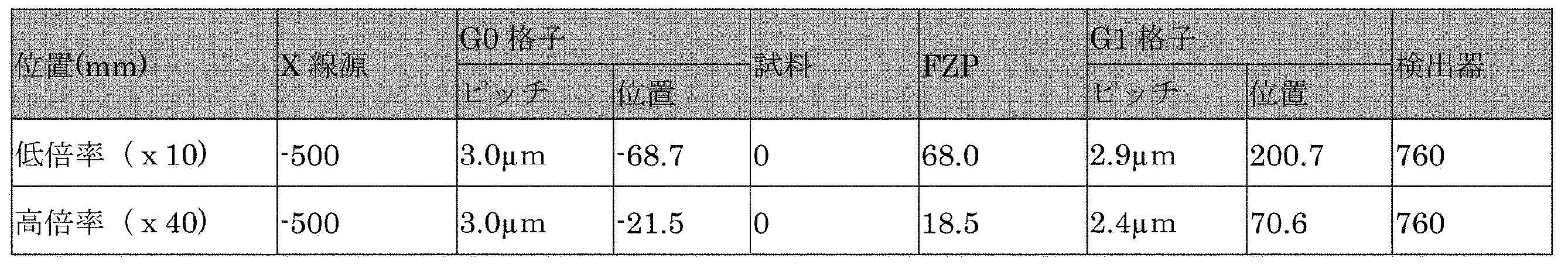
- an optical system with two magnifications is incorporated, with the distance between the X-ray source and the sample center being 500 mm and the distance between the sample center and the X-ray detector and element surface being 760 mm.
- each optical element of the Talbot-Lau interferometer having a magnifying optical system to which the FZP adopted in the present invention is added is described in FIG. 4 (a).
- the condensing mirror 2 is formed on a spheroid surface in which one of the two focal points is the X-ray source 1 and the other is the sample 4 so that X-rays can be totally reflected on the inner surface of the hollow glass tube There is.
- a single layer film of a metal film or a multilayer film of two or more types of films different in density may be formed inside the hollow glass tube.
- the X-rays transmitted through the G0 grating 3 and the sample 4 are transmitted through the Fresnel zone plate (FZP) 5 and the G1 grating 6 to be incident on the X-ray detector 7 and recorded as an image.
- the FZP 5 is prepared to obtain 10 ⁇ and 40 ⁇ magnifications, and the entire optical system is switched.
- the G0 grating 3 has a virtual X-ray source in the X-ray transmitting part of the grating, and the Talbot-Lau interferometer has an optical system in which many thin X-ray sources are superimposed.
- the X-ray source 1 is not a microfocus X-ray source, and functions as a high spatial resolution microscope even if there is a certain area. Since X-ray source with high X-ray intensity has a finite area, G0 grating 3 is required to obtain high spatial resolution, but even when X-ray source size is 10 ⁇ m or less, G0 grating is not used is there. In the present embodiment, the X-ray source having a diameter of 70 ⁇ m was used.
- the distances from sample positions of G0 gratings 3-1 and 3-2, FZPs 5-1 and 5-2, and G1 gratings 6-1 and 6-2 used in this embodiment are shown in FIG.
- the instructor pitch of the G0 grid 3 was 3.0 ⁇ m for both low magnification and high magnification.
- the low magnification FZP5-1 is ⁇ 10
- the high magnification FZP5-2 is ⁇ 40
- the pitch of the low magnification G1 grating 6-1 is 2.9 ⁇ m
- the pitch of the high magnification G1 grating 6-2 is 2.4 ⁇ m.
- Table 1 collectively shows the installation positions of the optical elements of the present embodiment. The method of determining the position of these optical elements is described in detail in Non-Patent Document 10.
- a 1024-ch ⁇ 1024-ch two-dimensional detector with a pixel size of 0.65 ⁇ m ⁇ 0.65 ⁇ m is used as the X-ray detector.
- the detection area is 16.4 ⁇ m (corner) and the detection pixel size is 16.3 nm.
- the actual spatial resolution was affected by the accuracy of completion of each optical element, etc., and it was about 150 nm at low magnification and about 50 nm at high magnification from the measurement of the standard sample.
- FIG. 6 The configuration of the magnification changing mechanism of the optical system in this embodiment is shown in FIG. In FIG. 6, the X-rays passing through the G0 grating 3 pass through the sample 4 and then pass through the FZP 5-1 and the G1 grating 6-1, or pass through the FZP 5-2 and the G1 grating 6-2.
- Table 1 the magnification as a microscope is determined by FZP, and a G1 lattice suitable for that is used in combination. Therefore, in the present invention, the FZP 5-1 and the G1 grating 6-1, and the FZP 5-2 and the G1 grating 6-2 are used in their respective combinations, and the magnification of the microscope is changed by moving the optical element mounting table 8 There is.
- the G0 grating 3 is fixed to the mounting jig 31 and the position of the swivel 32, the rotatable mechanism 33, and the G0 grating can be adjusted in the X vertical plane around the X-ray optical path X near the center of the G0 grating.
- the X-ray beam path X and its vertically movable movement mechanism 34 can adjust its position and mounting state.
- the movement in the X-ray optical path X direction is provided with a movement mechanism that can be externally controlled.
- the sample 4 is fixed to a sample mounting jig 41 and fixed to a sample XY moving table 42.
- the sample XY moving table 42 is fixed to a sample rotating table 43.
- the sample rotation table 43 can be rotated about an axis perpendicular to the X-ray optical path X at an externally controllable rotation angle ⁇ . Further, the sample rotation table 43 is structured to be capable of performing Z parallel movement in the direction of the rotation axis.
- the sample XY movement table 42 and the Z translation function of the sample rotation table move the position of the sample to view the desired specific region (Region of Interest, ROI) of the sample. It is possible to adjust to the center.
- the FZPs 5-1 and 5-2 are fixed to the mounting jig 51 capable of adjusting the height Z, fixed to the FZP XY moving base 52, and then mounted on the optical system switching base 8.
- FZP 5-1 and FZP 5-2 can be independently adjusted on the optical system switching base with respect to the X-ray optical path X direction and two axes YZ perpendicular thereto.
- the G1 grids 6-1 and 6-2 are respectively fixed to a mounting jig 61 capable of height adjustment Z, and can be swivel-adjustable in an X vertical plane around an X-ray optical path X near the center of the G1 grid, After being fixed to the rotatable rotation mechanism 63 and the G1 grating XY moving base 64, it is mounted on the X-ray optical system switching base 8.
- the G1 grating 6-1 and the G1 grating 6-2 independently of each other on the X-ray optical system switching table 8, the X-ray optical path X direction and the perpendicular plane to the X-ray grating of the two axes YZ and G1 grating perpendicular thereto. It is adjustable for internal rotation and rotation about an axis perpendicular to the x-ray path X.
- the adjustment items of the FZPs 5-1 and 5-2 and the G1 gratings 6-1 and 6-2 are adjusted respectively with respect to the X-ray optical paths of two kinds of microscope magnifications. Although some of these adjustments can be performed manually, it is desirable to be able to adjust by external control.
- the vertical Y movement of the G1 gratings 6-1 and 6-2 with respect to the X-ray optical path must be able to be moved by external control for measurement to obtain phase image information.
- the FZPs 5-1 and 5-2, and the G1 gratings 6-1 and 6-2 configured on the X-ray optical system switching stand 8 as described above constitute X-ray optical paths of two different magnifications
- By moving the entire optical system switching base 8 relative to the X-ray optical path X it is possible to easily switch the XRM magnification.
- two types of XRM magnifications are switched.
- two or more types of optical systems can be switched.
- the magnification is 1 ⁇ , no FZP is installed in the X-ray optical path X.
- FIG. 7 shows a configuration diagram including the device control system of this embodiment.
- the X-ray source 1 uses the X-ray source controller 93 to control the G0 lattice adjustment mechanism, the sample position adjustment mechanism, the FZP position adjustment mechanism, the G1 position adjustment mechanism, and the X-ray optical system switching stand 8 as illustrated. Further, the X-ray detector 9 is connected to the XRM controller 91 via the X-ray detector controller 95 via the device 94. These adjustment parameters and X-ray detector measurement data are stored in the data storage device 92.
- the block diagram of the whole microscope apparatus of a present Example is shown in FIG.
- the devices shown in FIG. 7 are installed on an optical bench 103 installed on a task 104 waiting for an isolation function to prevent vibration from the floor, and constitute an XRM.
- the XRM is installed in an X-ray shielding and apparatus outer panel 101 provided with a temperature control apparatus 102 for controlling the temperature strictly.
- the internal temperature control can be controlled to 0.1 ° C. (How to acquire phase CT image data)
- a transmission X-ray image of the sample 4 is obtained on the X-ray detector 8 by the phase difference XRM apparatus of the present embodiment described above.
- a direction perpendicular to the X-ray optical path X and perpendicular to the stripe of the grating at a moving pitch of 1/3 or less of the grating pitch of the G1 grating 6-1 or 6-2 used for imaging A transmission image is obtained by imaging every time when the minute amount ⁇ Y is moved (in this case, the Y direction).
- G1 is moved by ⁇ Y every time the rotation axis of the sample rotation table 43 shown in FIG. 6 is rotated by ⁇ using the imaging method of the transmission X-ray image described above. Are imaged, and CT data of a phase image for each sample rotation angle is recorded in the data storage device 92. At this time, it is possible to simultaneously record as CT data for each sample rotation angle of absorption and scattering images.
- This measurement method makes ⁇ Y constant and moves angularly every ⁇ to record a transmission image, measures transmission image data every ⁇ every time ⁇ Y is moved, records it in a data storage device, and measures all data It is also possible to carry out data processing after completion to obtain CT data of a phase image, an absorption image, and a scatter image. (How to acquire phase interior CT image data)
- Some of the samples 4 may need to perform particularly high spatial resolution data measurements.
- the detection pixel size of For example, the case where the sample size is 50 ⁇ m in diameter and it is desired to measure the 10 ⁇ m portion of the sample with the highest spatial resolution CT corresponds to this example.
- the sample size is 50 ⁇ m in diameter, it will be measured at a low magnification setting of low magnification XRM, and CT images will be acquired at a 65 nm detection pixel size. At high magnification settings, strict CT image reconstruction can not be performed.
- the interior CT image reconstruction method of the present invention is capable of image reconstruction with high accuracy, and a data acquisition method for performing phase interior CT image reconstruction will be described.
- a method of identifying a priori knowledge from measured projection data (a priori knowledge identification type image reconstruction method) and a method of identifying a priori knowledge on the periphery of an image without identification (approximately applies to any image).
- a method to fix (a priori knowledge non-identification type image reconstruction method).
- FIG. 10 shows the process flow of the two-stage image reconstruction method of the present invention.
- an incomplete image including an artifact is generated using a conventional FBP method, successive approximation image reconstruction method, statistical image reconstruction method or the like without a priori knowledge.
- this incomplete image includes artifacts, the artifacts generated in the interior CT are low frequency components, and therefore, information on boundaries such as tissues and structures is generated accurately in most cases.
- the region B which is an arbitrary small region in the ROI that can be used as a priori knowledge is specified by image analysis (processing) by the user manually or using software. (S62).
- the region B obtained in the first step is used for a priori knowledge, as shown in FIG. 11 (b), by the strict image reconstruction method (ie, the first stage reconstruction Image reconstruction (with higher accuracy) is performed (S63). It is determined according to what kind of prior information area B could be extracted by the first step.
- the strict image reconstruction method ie, the first stage reconstruction Image reconstruction (with higher accuracy) is performed (S63). It is determined according to what kind of prior information area B could be extracted by the first step.
- the piecewise uniform means that B is composed of a finite number (L) of areas D 1 , D 2 ,..., D L , and constant values C 1 and C 2 are used in each area. , ..., it is that it is C L.
- the number of regions L and the values of the fixed values C 1 , C 2 ,..., C L may be unknown in advance, and [Result 3] is a reduction of a priori knowledge of [Result 1].
- Non-Patent Document 5 uses piecewise uniform type a priori knowledge, it is necessary to make an impossible assumption that piecewise uniformity is uniform throughout the ROI, not arbitrary small region B in the ROI. It is different.
- FIGS. 14 (a) to (c) show an example of actual reconstruction when using the a priori knowledge of the above [Result 1] to [Result 3]. In any case, it can be seen that a little prior knowledge has achieved a large artifact reduction.
- Example 2
- the a priori knowledge required for the exact image reconstruction of the interior CT can be much less.
- the region B which is an arbitrary small region in the ROI that can be used as a priori knowledge in step S62 is automatically identified.
- the automatic identification of the a priori information area can be realized, for example, by using an image analysis (processing) technique.
- the success or failure of the a priori knowledge automatic estimation type image reconstruction method of the above-mentioned first embodiment depends on whether or not the identification of the a priori knowledge (area B) in the first step is successful. Therefore, in the third embodiment, the “prior knowledge non-identifying image reconstruction method” in which the image reconstruction is performed without identifying the region B is described.
- the method remains an approximate image reconstruction method, but in the context of many CT imaging As [Finding 3] holds, by fixing and arranging at the part of the edge that is the periphery of the ROI, as shown in FIGS. 14 (a) to (c), another approximation that does not use a priori knowledge Image reconstruction can be performed with much higher accuracy compared to conventional image reconstruction methods.
- 15 (a) to 15 (f) show specific simulation experiments of the a priori knowledge identification type image reconstruction method (Example 1) and the a priori knowledge non-identification type image reconstruction method (Example 3). An example is shown by comparison with the prior art. Chest CT images were used for the experiment, and image reconstruction was performed with the heart portion located at the center as ROIS (see FIG. 15 (a)).
- the user looks at the reconstructed image by the FBP method in the first step, and the a priori information region B is specified in the ROI S, and the strict image reconstruction in the second step is performed (note that The a priori knowledge that we have is piecewise uniform at B corresponding to [Result 3]).
- the result is shown in FIG.
- the a priori information area B is fixed to the peripheral portion of the ROI S (the frame type in FIG. 14C) to perform image reconstruction (note that the a priori knowledge used is [Result 3) piecewise uniform at B).
- the result is shown in FIG.
- FIG.15 (d) a result of the local FBP method of applying the FBP method by extrapolating the lost portion of the projection data in a smooth function in FIG. 15 (b), the image f (x in the same priori information area B, y
- the result by the method (nonpatent literature 5, 6) which used the true value of) for a priori knowledge is shown in FIG.15 (c) not only small a priori information area B but piecewise uniform over the whole ROI S.
- the result by the compression sensing method (nonpatent literature 5) which applies the total variation (TV: Total variation) which is restraint of is each shown in FIG.15 (d).
- x ⁇ C represents a constraint known in advance with respect to an image, and the following are often used.
- A (Support constraint) The image f becomes zero outside the support area ⁇ OBJ where it is known in advance.
- B non-negative condition
- the components of the image f do not take negative values.
- F (x) is a function that does not have a local minimum called a convex function
- an iterative solution or non-iterative solution that solves the above-mentioned problems is numerous in the field of mathematical optimization and image reconstruction. It is known and all these approaches are available. For example, a constrained statistical image reconstruction method or a constrained conditional successive approximation method can be used. In addition, as another class of image reconstruction methods, it is possible to construct an image reconstruction method based on a later-described framework called differential back projection (DBP).
- DBP differential back projection
- the image reconstruction method of the present invention A constraint condition is imposed only on the prior information area B which is an arbitrary small area in the above.
- the norm of the first derivative of f (x, y) in B is minimized Or dispersion of the concentration change in B may be minimized.
- Examples of typical F (x) are shown in Table 2.
- the parameter p is the order of the norm, and its value may be 0 ⁇ p ⁇ 2 in [Result 1] and [Result 2], but it is uniform or M in [Result 3] and [Result 4]. It is necessary to use 0 ⁇ p ⁇ 1 in order to avoid that the influence of the boundary of the finite number (L) of partial regions having the density change of the next polynomial is evaluated too large.
- the thing by which there were a plurality of candidates with F (x) shown in Table 2 was tested by numerical experiment, all worked well generally and no big difference was seen.
- the uniqueness of the solution (in which the solution of the image reconstruction problem is settled into one) is established in the interior CT, and in order to enable the exact image reconstruction, some additional information in addition to the interior CT projection data is necessary.
- the interior CT measures projection data which is not usually measured, that is, extra projection data which does not pass through the region ROI ⁇ where the image is desired to be obtained, and utilizes this supplementary data. That is, an important feature of the exact solution of the fourth embodiment of the present invention is to measure the minimum necessary extra projection data not passing through the ROI ⁇ .
- the above method has generality that can be applied to various optical systems of microscopic CT such as electron beam, X-ray, neutron beam etc.
- the electron beam source is relatively in circular orbit by rotating the sample
- the principle of the 360-degree moving fan beam CT will be described.
- FIG. 16A consider the situation of interior CT where projection data is measured by irradiating only the electron beam passing through the ROI ⁇ in the 360-degree circular orbit fan beam CT.
- the arc segment E of a part of the circular orbit is used as additional information.
- the entire projection data is measured by irradiating an electron beam covering the entire object.
- this partial whole projection data (hereinafter, also simply referred to as “whole projection data”) is added to the interior CT projection data to enable strict ROI ⁇ reconstruction, arbitrary arc segment E, It has been mathematically proved that accurate ROI ⁇ image reconstruction is possible if the whole projection data is small arc segments which are not one point.
- the differential back projection (DBP) method used as a tool to show the uniqueness of the solution in the study of the interior CT exact solution method using the a priori information on the past objects
- DBP differential back projection
- the length of the small arc segment E is a segment corresponding to a certain circle including the object inside, and may be anywhere as short as possible, if it is not one point.
- the meaning of the two geometric conditions described above is shown in FIG.
- This uniqueness can be interpreted as the limit in which the radius of the circular orbit is infinite in the uniqueness of the solution in the case of the 360-degree circular orbit fan beam CT, and the 360-degree circular orbit fan also in the 180-degree parallel beam scan
- the uniqueness of the solution similar to the beam CT is established. This result can be proved for the first time by using uniqueness generalized to arbitrary geometric systems.
- the ROI can be obtained by measuring the total projection data in an arbitrary small angle range E (which may be small).
- the image f (x, y) is uniquely determined by ⁇ , and strict reconstruction of ⁇ is possible.
- (B) Use Scout-View scan projection data for alignment as whole projection data For the purpose of positioning the ROI ⁇ that you want to see before shooting well within the field of view, such a low magnification that all objects are within the field of view Scout-View scan is performed.
- the projection data with low magnification can be used as total projection data of the partial trajectory E by using the function of this Scout-View scan.
Landscapes
- Physics & Mathematics (AREA)
- Health & Medical Sciences (AREA)
- General Health & Medical Sciences (AREA)
- General Physics & Mathematics (AREA)
- Life Sciences & Earth Sciences (AREA)
- Chemical & Material Sciences (AREA)
- Analytical Chemistry (AREA)
- Biochemistry (AREA)
- Nuclear Medicine, Radiotherapy & Molecular Imaging (AREA)
- Radiology & Medical Imaging (AREA)
- Immunology (AREA)
- Pathology (AREA)
- Engineering & Computer Science (AREA)
- General Engineering & Computer Science (AREA)
- High Energy & Nuclear Physics (AREA)
- Analysing Materials By The Use Of Radiation (AREA)
Abstract
【課題】 同種の軽元素を主成分とする無染色の生体組織、樹脂や似通った組成の薄膜を積層した構造体を対象とする場合でも、像のコントラストを向上し、操作性にも優れかつ、より実用的なインテリアCTの画像再構成方法により試料一部の所望領域の高空間分解能3次元断層像を計測可能なインテリアCT位相イメージングX線顕微鏡装置を提供する。 【解決手段】 複数の画像記録範囲をもつ光学系を容易に交換できる位相差画像データ計測用光学系を備えた位相差XRM装置により、まず、画像記録範囲が大きな低倍率で試料全体の位相差X線顕微像を撮影し、その低倍率位相差X線顕微像をもとに高倍率・高空間分解能で撮影する試料の関心領域(ROI)を決め、高倍率X線光学系に変更して高倍率・高空間分解能データを取るようにした。こうすることにより、低倍率測定時の位相差X線顕微再構成像のうち、所望の高倍率測定するROIの内部にある測定点の再構成データを用いることにより、高空間分解能インテリアCT画像再構成を行うことが出来るインテリアCT位相イメージングXRM装置を提供する。PROBLEM TO BE SOLVED: To improve the contrast of an image and to be excellent in operability even in the case of using a non-stained biological tissue mainly composed of light elements of the same kind, a structure in which resin and thin films of similar composition are laminated An interior CT phase imaging X-ray microscope apparatus capable of measuring a high spatial resolution three-dimensional tomogram of a desired region of a part of a sample by a more practical interior CT image reconstruction method. SOLUTION: A phase difference XRM apparatus provided with a phase difference image data measuring optical system capable of easily exchanging an optical system having a plurality of image recording ranges, firstly, the phase difference of the whole sample at a low magnification with a large image recording range. An X-ray microscopic image is taken, and a region of interest (ROI) of a sample to be imaged with high magnification and high spatial resolution is determined based on the low magnification phase difference X-ray microscopic image, and changed to a high magnification X-ray optical system It was made to take high magnification and high spatial resolution data. By doing this, high spatial resolution interior CT image reconstruction can be performed by using the reconstruction data of the measurement point inside the desired high magnification measurement ROI among the phase difference X-ray microscopic reconstruction images at the low magnification measurement. Provided is an interior CT phase imaging XRM device that can be configured.
Description
本発明は、X線顕微鏡装置(X-ray Microscope:XRM)に関し、特に、X線の位相をコントラストに変換して試料の構造を計測する位相差式のX線顕微鏡装置に関する。 The present invention relates to an X-ray microscope (XRM), and more particularly to a phase difference X-ray microscope which converts the phase of X-rays into contrast to measure the structure of a sample.
XRMは、試料のサブミクロンレベルの構造を観察する等に広く用いられている。これは、試料にX線を照射し、当該試料を透過したX線を、検出器上に拡大投影し、試料内部の構造を透かし観る手法であり、試料物体内部のX線の吸収度を反映した投影像が得られるものであり、例えば、以下の非特許文献1により既に知られている。
XRM is widely used to observe the submicron level structure of a sample. This is a method of irradiating the sample with X-rays, projecting the X-rays transmitted through the sample on an enlarged scale on the detector, watermarking the structure inside the sample, and reflecting the degree of absorption of the X-ray inside the sample object A projected image is obtained, which is known, for example, from the following
更に、X線の吸収度ではなく物質を通過することにより変化するX線の位相を画像化した位相画像を取得する手法については非特許文献2により既に知られている。また位相格子を用いた位相画像取得方法とフレネルゾーンプレート(FZP)による拡大光学系を用いて、試料の拡大像を得るTalbot干渉計―XRMについても非特許文献3によって既に知られている。
Furthermore, Non-Patent
次に、3次元像を構成する手法は、試料の断面を完全に覆うX線を照射して、試料断面を通過する全ての直線上の投影データを測定し、そのデータを用いて画像再構成するものになっている。このような手法は非特許文献4によって知られている。しかし、対象物(試料)内の小さな関心領域(ROI:Region of Interest)だけの断層画像が欲しい場合でも、一般的にはROIのみではなく、試料断面を通過する全ての直線上の投影データを必要であった。 Next, a method of constructing a three-dimensional image is to irradiate X-rays completely covering the cross section of the sample, measure projection data on all straight lines passing through the sample cross section, and use the data to reconstruct an image. It is supposed to Such an approach is known from [4]. However, even if a tomographic image of only a small region of interest (ROI: Region of Interest) in the object (sample) is desired, the projection data on all the straight lines passing through the sample cross section is generally not only the ROI. It was necessary.
一般に高倍率で空間分解能高く撮像する場合、投影像は高倍率で試料のROI部分を測定することが多く、従来のCT手法では周囲のデータ欠落により必ずしも精度の高い3次元像再構成が出来なかった。これは、CTの画像再構成に用いられる計算手順であるフィルタ補正逆投影(FBP:Filtered Back Projection)法において、ROI画像を生成するのにROIを通過しない直線上の投影データも必要なことによる。しかし、ROIを通過しない直線上の投影データはROIの情報を全く含んでいない。そこで、X線CTの分野ではROIだけにX線を照射して、ROIを通過する(全ての)直線上の投影データのみを測定してROIの画像のみを生成するCT撮影の方法が、インテリアCTとして開発されてきた。 Generally, when imaging at high resolution and spatial resolution, the projected image often measures the ROI portion of the sample at high magnification, and conventional CT methods can not always produce high-precision three-dimensional image reconstruction due to lack of surrounding data The This is because, in the Filtered Back Projection (FBP) method, which is a calculation procedure used for CT image reconstruction, projection data on a straight line that does not pass through the ROI is also required to generate the ROI image. . However, projection data on a straight line not passing through the ROI does not contain any information of the ROI. Therefore, in the field of X-ray CT, a method of CT imaging in which only the ROI is irradiated with X-rays and only projection data on a (all) straight line passing through the ROI is measured to generate only an image of the ROI It has been developed as a CT.
このインテリアCTには、不必要な投影データをも測定する従来のX線CTと比較して、(1)ROI外部の被曝量(試料損傷)の大幅な低減、(2)検出器サイズやX線ビーム幅の削減、(3)視野に収まらない大きい物体の撮影が可能になること、(4)物体の小視野だけにX線を照射して拡大撮影する高分解能CTが可能になること等が挙げられる。 In this interior CT, (1) significant reduction of exposure dose (sample damage) outside the ROI, (2) detector size and X compared with conventional X-ray CT which also measures unnecessary projection data Reduction of line beam width, (3) enabling imaging of large objects that do not fit within the field of view, and (4) enabling high resolution CT that irradiates X-rays only to the small field of the object for magnified imaging, etc. Can be mentioned.
インテリアCTでは、ROIを通過しない直線上の投影データは測定されないため、一部が欠損した不完全投影データから画像再構成を行う手法が必要となる。平行ビームによる投影データ収集では、対象物f(x,y)と画像化の対象となるROIを(図1を参照)直線が通過する投影データp(r,θ)(rは動径、θは角度)のみが測定可能である。この場合、直線がROIを通過しないp(r,θ)は測定されないため、各角度θの投影データは、左右がトランケーションされて欠損することになる。このようなトランケーションされた投影データからROIにおいて画像f(x,y)を正しく再構成する必要がある。 In the interior CT, projection data on a straight line which does not pass through the ROI is not measured, so a method for performing image reconstruction from incomplete projection data in which a part is missing is required. In parallel beam projection data collection, projection data p (r, θ) (r is the radius, θ) where a straight line passes the object f (x, y) and the ROI to be imaged (see Figure 1) (Angle) can only be measured. In this case, since p (r, θ) where the straight line does not pass the ROI is not measured, the projection data of each angle θ is truncated due to truncation on the left and right. It is necessary to correctly reconstruct the image f (x, y) in the ROI from such truncated projection data.
このインテリアCTの再構成は長年多くの研究が行われてきており、非特許文献5では、インテリアCTの画像再構成は解が投影データから唯一に決まり数学的に正しい画像再構成として定まらないことが数学的に証明されている。この非一意性が知られていたため、多くの近似的な画像再構成法が研究されてきた。
In this reconstruction of the interior CT, many studies have been conducted for many years, and in Non-Patent
その代表的な手法として、(1)各方向投影データ左右の欠損部分を滑らかな関数で外挿してから画像再構成する手法、(2)不完全な投影データのまま逐次近似法により画像再構成を行う手法などが研究されたが、近似誤差によるアーティファクトが発生して実用に至らなかった(非特許文献6、7、8)。このインテリアCTにおいて発生する典型的なアーティファクトの例を示すと、画像低周波成分に歪みが発生するシェーディングアーティファクト(図2(a)を参照)やROI周辺部で値が増大するカッピング効果(図2(b)を参照)が発生し、画像の値が安定に定まらないことが知られている。
As a representative method, (1) a method of extrapolating the missing part on the right and left of each direction projection data with a smooth function and then reconstructing the image, and (2) image reconstruction by the successive approximation method with the incomplete projection data remaining Although the method etc. of doing were researched, the artifact by the approximation error generate | occur | produced and it did not reach practical use (
これらの先行研究に対し、インテリアCTの厳密な画像再構成法が案出され(非特許文献8、9)、ROIの内部にある任意の小さな領域B(即ち、図3(a)においてROIの内部にある丸印の領域)において画像f(x,y)の値が事前に既知であるという先験的知識があれば、インテリアCTの画像再構成の解は一意に定まることを証明した。解の一意性を保証するための領域Bは複数あれば小さくともROI S内のどの場所にあっても良い。この成果は、特許文献1として知られている。
For these previous studies, a rigorous image reconstruction method for interior CT was devised (8, 9), and any small area B inside the ROI (ie, in Figure 3 (a) It is proved that the solution for image reconstruction of the interior CT is uniquely determined if there is a priori knowledge that the value of the image f (x, y) is known in advance in the circle region inside). If there are a plurality of regions B for guaranteeing the uniqueness of the solution, they may be small or anywhere in the ROIS. This result is known as
一方、別の先験的知識を用いて厳密な画像再構成を可能にする手法も案出されており(非特許文献7)、圧縮センシングと呼ばれる不足した測定データから高精度で信号復元を行う手法に基づき、画像f(x,y)がROIの全体で区分的一様であれば、インテリアCTの画像再構成の解は一意に定まることが示された。ここで、区分的一様とは、数値ファントムのように、画像が完全な一定値を持つ有限個の領域で構成されていることを指す(図3(b)を参照)。この成果は、特許文献2として知られている。
On the other hand, a method has been devised that enables accurate image reconstruction using another a priori knowledge (Non-Patent Document 7), and performs signal reconstruction with high accuracy from insufficient measurement data called compressed sensing. Based on the method, it has been shown that if the image f (x, y) is piecewise uniform throughout the ROI, then the solution for image reconstruction of the interior CT is uniquely determined. Here, piecewise uniform means that the image is composed of a finite number of regions having a completely constant value, as in a numerical phantom (see FIG. 3 (b)). This result is known as
XRMにおいて、X線の吸収が少なくコントラストの着きにくい無染色の生体軟組織、樹脂や似通った組成の薄膜を積層した構造体などを対象とする場合には、試料物体を透過する電子線の位相をコントラストに変換して観察する、所謂、位相差XRMが用いられる。本発明は、上述した位相差XRMのうち、試料のROIを中心にX線の照射を行っても高分解能の画像が構築できるため、特に、試料のX線被曝の低減に有利なインテリアCT位相イメージングXRMに関する。 In XRM, when the target is an unstained biological soft tissue with low X-ray absorption and low contrast and a laminated structure of resin and thin film of similar composition, the phase of the electron beam transmitted through the sample object is A so-called phase difference XRM which is converted to contrast and observed is used. Since the present invention can construct high-resolution images even when X-rays are irradiated around the ROI of the sample among the phase differences XRM described above, the interior CT phase is particularly advantageous for reducing the X-ray exposure of the sample. It relates to imaging XRM.
本発明の関わる位相差XRMにおいても、なお、試料物体中においてより重い元素がより高い密度で存在している程、大きなX線の散乱があり、明瞭なコントラストが得られるという吸収コントラストの原理による画像のコントラストは生ずる。しかしながら、同種の軽元素を主成分とする無染色の生体組織、樹脂や似通った組成の薄膜を積層した構造体を対象とする場合には、像にコントラストが着きにくいため、これを解決する手法として、X線格子を用いて試料物体を透過するX線の位相をコントラストに変換して観察する、位相イメージングXRMを用いる。 Even in the phase difference XRM to which the present invention relates, the principle of absorption contrast is that the heavier the element is present at a higher density in the sample object, the larger the scattering of X-rays and the clear contrast can be obtained. Image contrast occurs. However, in the case of a non-stained biological tissue mainly composed of the same light element, or a structure in which a thin film of resin or similar composition is laminated, it is difficult to obtain contrast in the image. As the X-ray grating, phase imaging XRM is used, in which the phase of X-rays transmitted through a sample object is converted into contrast and observed.
しかし、従来型の位相差XRMで、空間分解能を高くとって画像を得ようとすると、光学系や画像検出器のサイズの限界から、画像記録範囲が狭くなる。このような試料全体の位相差X線CTデータが取得できない状態でCT法を用いるための位相差X線画像データを取得しても、所望の制度の画像再構成が出来ないため、かならずしもROIの高空間分解能CTデータの取得が出来ないという欠点があった。 However, when attempting to obtain an image with high spatial resolution with the conventional phase difference XRM, the image recording range becomes narrow due to the limit of the size of the optical system and the image detector. Even if phase difference X-ray image data for using the CT method can not be acquired in a state where such phase difference X-ray CT data of the whole sample can not be acquired, the image reconstruction of the desired system can not be performed. There is a drawback that high spatial resolution CT data can not be acquired.
上記した欠点を克服するためにはインテリアCT画像解析手法が用いられるが、前記非特許文献7と非特許文献8により知られた厳密解法を適用するには、撮像前に、物体に関する先験的知識(図3aにおけるROI内部の小さな領域Bにおける画像の値)が分かっている必要があるが、撮像前に画像の値が既知という状況はごく希である。また、前記非特許文献7の厳密解法では、画像のROIの一部が区分的一様という仮定をするため、この手法では滑らかな濃度変化が失われてしまう。
Although the interior CT image analysis method is used to overcome the above-mentioned drawbacks, in order to apply the exact solution method known by the above-mentioned
そこで、本発明は、同種の軽元素を主成分とする無染色の生体組織、樹脂や似通った組成の薄膜を積層した構造体を対象とする場合でも、像のコントラストを向上し、操作性にも優れかつ、より実用的なインテリアCTの画像再構成方法により試料一部の所望領域の高空間分解能3次元断層像を計測可能なインテリアCT位相イメージングXRMを提供することを目的とする。 Therefore, the present invention improves the image contrast and improves operability even in the case where a non-stained biological tissue mainly composed of the same light element, and a structure in which a thin film of resin or similar composition is laminated are targeted. Another object of the present invention is to provide an interior CT phase imaging XRM capable of measuring a high spatial resolution three-dimensional tomogram of a desired region of a sample by the superior and more practical interior CT image reconstruction method.
上述した目的を達成するため、画像記録範囲を2種以上、複数の容易に交換できる位相差画像データ計測用光学を備えた位相イメージングXRMを考案した。本発明によれば、まず、画像記録範囲が大きな低倍率で試料全体の位相差XRM像を撮影し、その低倍率位相差XRM像をもとに高倍率・高空間分解能で撮影する試料の関心領域ROIを決め、高倍率X線光学系に変更して高倍率・高空間分解能データを取るようにした。こうすることにより、低倍率測定時の位相差XRM再構成像のうち、所望の高倍率測定するROIの内部にある測定点の再構成データを用いることにより、インテリアCT画像再構成を行うことが出来るインテリアCT位相イメージングXRMを構築することが可能である。 In order to achieve the above-mentioned object, a phase imaging XRM provided with an optical system for measuring phase difference image data capable of easily exchanging two or more kinds of image recording ranges was devised. According to the present invention, first, the phase difference XRM image of the entire sample is photographed at a low magnification with a large image recording range, and the interest of the sample photographed at high magnification and high spatial resolution based on the low magnification phase difference XRM image The region ROI was determined and changed to a high magnification X-ray optical system to obtain high magnification and high spatial resolution data. By doing this, it is possible to perform interior CT image reconstruction by using, among the phase difference XRM reconstruction images at the time of low magnification measurement, reconstruction data of measurement points inside the desired high magnification measurement ROI. It is possible to construct a capable interior CT phase imaging XRM.
また、本発明では、上記に記載したインテリアCT位相イメージングXRMにおいて、倍率の異なるX線光学系のX線格子、フレネルゾーンプレート(FZP)等の光学素子はそれぞれの倍率の異なる光学系毎に最適化できるよう位置及び傾きの調整ができる冶具に設置され、これらの光学系を併進や回転等の操作で容易に切り替えられる機構を備えていることが、前記インテリアCT位相イメージングXRMの使い勝手上好ましい。最大の視野を得るためにはFZPを取り付けない光学系もあり、拡大しない等倍光学系も含まれる。 Further, in the present invention, in the interior CT phase imaging XRM described above, optical elements such as X-ray gratings of X-ray optical systems having different magnifications and Fresnel zone plate (FZP) are optimum for each optical system having different magnifications. It is preferable from the viewpoint of usability of the interior CT phase imaging XRM that a mechanism is provided which is installed in a jig capable of adjusting the position and inclination so as to be able to be used and which can easily switch these optical systems by operations such as translation and rotation. Some optical systems do not have an FZP attached for maximum field of view, and they also include non-magnifying 1 × optical systems.
さらに、上記に記載のインテリアCT位相イメージングXRMでは、前期光学素子の位置を微小量変化させ、複数の画像を取得することにより、前記試料による位相変化、振幅変化、もしくは、散乱を画像として検出することが好ましい。 Furthermore, in the interior CT phase imaging XRM described above, the position change of the optical element is slightly changed, and a plurality of images are acquired to detect phase change, amplitude change, or scattering by the sample as an image. Is preferred.
撮像された低倍率画像データについては、断面撮像のため少なくとも試料回転を行う1軸に垂直な断面の投影像全てが撮像できる条件で試料を通過するX線により投影データを取得し、前記で得られた投影データを用いてCTの画像再構成法により第1段階の近似的な再構成を行う。次に、ROI全ての投影像が測定可能な最大の倍率で、投影データを測定し、前記で再構成したCT画像に基づいて前記ROI内において物理量を表す画像数値が少なくとも区分的に一様または区分的に多項式で表される領域を特定し、前記特定した領域の位置とその内部で前記物理量が区分的に一様または区分的に多項式で表すことにより、前記第1段階の再構成よりも精度の高い第2段階の再構成を行うインテリアCTの画像再構成方法とする。 For low-magnification image data captured, projection data is acquired by X-rays passing through the sample under conditions that all projection images of the cross-section perpendicular to one axis at least for sample rotation can be imaged for cross-sectional imaging. The first stage approximate reconstruction is performed by the CT image reconstruction method using the projection data. Next, the projection data is measured at the maximum magnification at which the projection image of all the ROIs can be measured, and the image numerical value representing the physical quantity in the ROI is at least piecewise uniform or based on the reconstructed CT image. It is possible to specify a region which is piecewise represented by a polynomial, and by representing the physical quantity in a piecewise uniform or piecewise polynomial form in the position of the specified region and the inside thereof, the reconstruction of the first step It is an image reconstruction method for interior CT that performs high-precision second-stage reconstruction.
なお、本発明では、前記に記載したインテリアCTの画像再構成方法において、前記物理量を表す投影データの数値は、当該撮影対象による前記X線の吸収を含んでもよく、或いは、当該撮影対象による前記X線の位相シフトを含んでもよく、或いは、当該撮影対象による前記X線の回折を含んでもよく、或いは、当該撮影対象による前記電子ビームの散乱を含んでもよい。 In the present invention, in the image reconstruction method for interior CT described above, the numerical value of the projection data representing the physical quantity may include the absorption of the X-ray by the imaging target, or the value by the imaging target It may include a phase shift of x-rays, or may include diffraction of the x-rays by the subject, or may include scattering of the electron beam by the subject.
前記インテリアCTの画像再構成方法において、前記ROI内において特定される前記少なくとも区分的に一様または区分的に多項式な領域は、前記第1段階の再構成により得られたCT画像を使用して人間が手動で設定してもよく、或いは、前記第1段階の再構成により得られたCT画像を使用して画像処理により設定してもよい。或いは、前記ROI内で、前記撮影対象の以前に取得したCT画像からの特定、前記撮影対象の構造を表すモデルや先験情報からの特定の少なくとも一つにより予め設定されていてもよい。なお、前記第1段階の近似的な再構成により得られたCT画像を使用して前記ROI内で特定される前記少なくとも区分的に一様または区分的に多項式な領域は、前記ROIの境界の一部を含んで形成されてもよい。 In the image reconstruction method of the interior CT, the at least piecewise uniform or piecewise polynomial region identified in the ROI is obtained using a CT image obtained by the first-step reconstruction. It may be set manually by a human or may be set by image processing using a CT image obtained by the first stage reconstruction. Alternatively, it may be preset by at least one of the specification from the previously acquired CT image of the imaging target, the model representing the structure of the imaging target, and the specification from the a priori information in the ROI. Note that the at least piecewise uniformly or piecewise polynomial region identified in the ROI using a CT image obtained by the approximate reconstruction in the first step is the boundary of the ROI. It may be formed including a part.
前記インテリアCTの画像再構成方法において、前記第1段階の近似的な再構成を、フィルタ補正逆投影(FBP)法、逐次近似法、統計的再構成法を含む従来のCTの画像再構成法の少なくとも一つにより実行してもよく、或いは、前記第2段階の再構成を、微分逆投影ヒルベルト変換法、拘束条件付き逐次近似法、及び、拘束条件付き統計的再構成法を含むCTの画像再構成法の少なくとも一つにより実行してもよい。 In the image reconstruction method for the interior CT, the CT image reconstruction method according to the first step includes a filtered back projection (FBP) method, a successive approximation method, and a statistical reconstruction method. The second stage of reconstruction may be performed by CT including the differential backprojection Hilbert transform, constrained successive approximation, and constrained statistical reconstruction. It may be performed by at least one of the image reconstruction methods.
上述した本発明によれば、試料物体を通過するX線の位相差を画像化し、X線の位相差の分布を定量的に計測し、従来技術よりも、はるかに少ない先験的知識で厳密な画像再構成が可能な、より実用的なインテリアCTの画像再構成方法を備えたインテリアCT位相イメージングXRMを提供することが可能となる。 According to the present invention described above, the phase difference of X-rays passing through the sample object is imaged, the distribution of the phase difference of X-rays is quantitatively measured, and strictness is achieved with much less a priori knowledge than the prior art. It is possible to provide an interior CT phase imaging XRM equipped with a more practical interior CT image reconstruction method capable of image reconstruction.
以下、添付の図面を参照しながら本発明を実施するための形態について詳細に説明する。
<実施例1>
Hereinafter, embodiments of the present invention will be described in detail with reference to the accompanying drawings.
Example 1
まず、本発明の基本的な考え方として、市販のXRM装置に光学系切替機構を付加する形で、装置を構成した。装置のうちX線源、試料載置機構、X線検出器は大きさと重量の観点から固定することとした。これらの機器が位置変更可能な光学系とすることも可能である。本実施例ではX線源-試料中心間距離を500mm、試料中心-X線検出器・素子面間距離を760mmとして、2種類の倍率の光学系を組み込んだ。 First, as a basic idea of the present invention, an apparatus was configured by adding an optical system switching mechanism to a commercially available XRM apparatus. Among the devices, the X-ray source, the sample mounting mechanism, and the X-ray detector were fixed in terms of size and weight. It is also possible for these devices to be position changeable optical systems. In this embodiment, an optical system with two magnifications is incorporated, with the distance between the X-ray source and the sample center being 500 mm and the distance between the sample center and the X-ray detector and element surface being 760 mm.
図4(a)に本発明で採用したFZPを加えた拡大光学系をもつTalbot-Lau干渉計の各光学素子の配置を記載する。ここで集光鏡2は中空ガラス管の内面の形状を2つの焦点の一方がX線源1、他方が試料4となる回転楕円面に形成され内面でX線を全反射できるようになっている。中空ガラス管の内側は金属膜の単層膜や、2種類以上の密度の異なる膜の多層膜が形成してあっても良い。G0格子3と試料4を透過したX線はフレネルゾーンプレート(FZP)5とG1格子6を透過してX線検出器7に入射し、像として記録される。本発明ではFZP5に10倍と40倍の拡大倍率が得られるものを用意し、全体の光学系が切り替えられるようにした。
The arrangement of each optical element of the Talbot-Lau interferometer having a magnifying optical system to which the FZP adopted in the present invention is added is described in FIG. 4 (a). Here, the condensing
図4(b)で、G0格子3は格子のX線を透過する部分が仮想X線源となり、Talbot-Lau干渉計は多くの細いX線源を重ね合わせるような光学系となっている。その結果、X線源1が微小焦点X線源ではなく、ある程度の面積があっても高空間分解能顕微鏡として機能する。X線強度が大きなX線源は有限な面積をもつため、空間分解能を高くとるためにはG0格子3が必要であるが、X線源サイズが10μm以下のときはG0格子を使わない場合もある。本実施例ではX線源の直径が70μmのものを用いた。
In FIG. 4B, the
本実施例で用いた、G0格子3-1及び3-2、FZP5-1及び5-2、G1格子6-1及び6-2の試料位置からの距離を図5に表す。G0格子3の講師ピッチは低倍率・高倍率ともに3.0μmとした。低倍率FZP5-1は×10倍、高倍率FZP5-2は×40倍、低倍率G1格子6-1のピッチは2.9μm、高倍率G1格子6-2のピッチは2.4μmとした。表1に本実施例光学素子の設置位置を纏めて表示する。これらの光学素子の位置の決定方法については非特許文献10に詳細が述べられている。
本実施例ではX線検出器にピクセルサイズ0.65μm×0.65μmで1024ch×1024chの2次元検出器を用いた。本実施例の撮像領域サイズと空間分解能はこの検出器の検出エリアとピクセルサイズで決まり、低倍率(×10倍)では0.65μm×1024×1/10=66μm(角)の検出エリアと0.65μm/10=65nmの検出ピクセルサイズとなる。同様に高倍率(×40倍)では、16.4μm(角)の検出エリアと16.3nmの検出ピクセルサイズとなる。実際の空間分解能については、各光学素子の出来上がり精度等の影響を受け、標準試料の測定から低倍率で約150nm、高倍率で約50nmであった。 In this embodiment, a 1024-ch × 1024-ch two-dimensional detector with a pixel size of 0.65 μm × 0.65 μm is used as the X-ray detector. The imaging area size and spatial resolution of this embodiment are determined by the detection area and pixel size of this detector, and at a low magnification (× 10 times), the detection area of 0.65 μm × 1024 × 1/10 = 66 μm (angle) and 0 It becomes a detection pixel size of .65 μm / 10 = 65 nm. Similarly, at high magnification (× 40), the detection area is 16.4 μm (corner) and the detection pixel size is 16.3 nm. The actual spatial resolution was affected by the accuracy of completion of each optical element, etc., and it was about 150 nm at low magnification and about 50 nm at high magnification from the measurement of the standard sample.
本実施例での光学系の倍率交換機構の構成を図6に示す。図6においてG0格子3を通過したX線は試料4を通過後FZP5-1及びG1格子6-1を通過、あるいはFZP5-2及びG1格子6-2を通過する。上記表1に示したように、FZPで顕微鏡としての倍率を決め、それに合うようなG1格子を組み合わせて用いている。従って、本発明ではFZP5-1とG1格子6-1、FZP5-2とG1格子6-2はそれぞれの組み合わせで用いられ、光学素子載置台8を動かすことにより、顕微鏡としての倍率を変更している。
The configuration of the magnification changing mechanism of the optical system in this embodiment is shown in FIG. In FIG. 6, the X-rays passing through the G0 grating 3 pass through the
図6においてG0格子3は取り付け冶具31に固定され、G0格子の中心付近でX線光路Xを中心にX垂直面内で回転調整可能なスィーベル32、回転可能な回転機構33、G0格子の位置をX線光路Xとその垂直方向に移動可能な移動機構34によりその位置及び取り付け状態を調整可能である。なお、X線光路X方向への移動は外部制御可能な移動機構を備えている。試料4は試料取り付け冶具41に固定され、試料XY移動台42に固定される。該試料XY移動台42は試料回転台43に固定されている。試料回転台43はX線光路Xに対して垂直な軸の周りに外部制御可能な回転角θで回転できるようになっている。また、試料回転台43は回転軸に方向に対してZ併進可能な構造となっている。
In FIG. 6, the
低倍率で試料全体像の撮像を行った後に、試料XY移動台42と試料回転台のZ併進機能により、試料の位置を移動し、試料の所望の特定部位(Region of Interest、ROI)を視野中心に合わせることが可能となっている。 After imaging the entire image of the sample at low magnification, the sample XY movement table 42 and the Z translation function of the sample rotation table move the position of the sample to view the desired specific region (Region of Interest, ROI) of the sample. It is possible to adjust to the center.
FZP5-1及び5-2はそれぞれ高さ調整Zが可能な取り付け冶具51に固定され、FZP XY移動台52に固定されたうえで光学系切替台8に搭載される。これにより、FZP5-1及びFZP5-2は独立に光学系切替台の上で、X線光路X方向とそれに垂直な2軸YZに対して調整可能となっている。
The FZPs 5-1 and 5-2 are fixed to the mounting
G1格子6-1及び6-2はそれぞれ高さ調整Zが可能な取り付け冶具61に固定され、G1格子の中心付近でX線光路Xを中心にX垂直面内で回転調整可能なスィーベル62、回転可能な回転機構63、G1格子XY移動台64に固定されたうえでX線光学系切替台8に搭載される。これにより、G1格子6-1及びG1格子6-2は独立にX線光学系切替台8の上で、X線光路X方向とそれに垂直な2軸YZ及びG1格子のX線格子に対する垂直面内での回転及びX線経路Xに垂直な軸での回転に対して調整可能となっている。
The G1 grids 6-1 and 6-2 are respectively fixed to a mounting
FZP5-1及び5-2またG1格子6-1及び6-2の各調整項目は2通りの顕微鏡倍率のX線光路に対してそれぞれ調整される。これらの調整については手動が可能な調整もあるが、外部制御で調整できるようにすることが望ましい。なお、G1格子6-1及び6-2のX線光路に対する垂直なY移動に関しては、位相画像情報を取得する測定のため、必ず外部制御で移動できるようにしておく必要がある。 The adjustment items of the FZPs 5-1 and 5-2 and the G1 gratings 6-1 and 6-2 are adjusted respectively with respect to the X-ray optical paths of two kinds of microscope magnifications. Although some of these adjustments can be performed manually, it is desirable to be able to adjust by external control. The vertical Y movement of the G1 gratings 6-1 and 6-2 with respect to the X-ray optical path must be able to be moved by external control for measurement to obtain phase image information.
上記のようにX線光学系切替台8上に構成したFZP5-1及び5-2、G1格子6-1及び6-2により2通りの顕微鏡倍率のX線光路が構成されるが、X線光学系切替台8全体をX線光路Xに対し移動することで、XRM倍率を容易に切り替えることが可能である。本実施例では、XRM倍率を2種類切り替える構造としたが、2種類以上複数の光学系が切り替えられるようにすることも可能である。なお、倍率を1Xとする場合は、X線光路XにFZPを設置しない構成となる。
Although the FZPs 5-1 and 5-2, and the G1 gratings 6-1 and 6-2 configured on the X-ray optical
図7に本実施例の装置制御系を含む構成図を示す。X線源1はX線源制御装置93を介して、G0格子調整機構、試料位置調整機構、FZP位置調整機構、G1位置調整機構及びX線光学系切替台8は図示したごとく位置調整用制御装置94を介して、さらにX線検出器9はX線検出器制御装置95を介してXRM制御装置91に接続される。これらの調整パラメータ及びX線検出器測定データはデータ蓄積装置92に蓄積される。
FIG. 7 shows a configuration diagram including the device control system of this embodiment. The
図8に本実施例の顕微鏡装置全体のブロック図を示す。図7に示した機器類は床からの振動を防ぐ除振機能を待つ課題104の上に設置された光学ベンチ103の上に設置されXRMを構成する。該XRMは温度を厳密に制御する温度制御装置102を設置した防X線シールド兼装置外部パネル101の中に設置される。内部温度制御は0.1℃に制御できるようにした。
(位相CT像データの取得方法)
The block diagram of the whole microscope apparatus of a present Example is shown in FIG. The devices shown in FIG. 7 are installed on an
(How to acquire phase CT image data)
上述した本実施例の位相差XRM装置によりX線検出器8に試料4の透過X線像が得られる。位相像を撮像するためには、撮像に供しているG1格子6-1或いは6-2をその格子ピッチの1/3以下の移動ピッチでX線光路Xに垂直かつ格子のストライプに垂直な方向(この場合はY方向)に微小量ΔY移動する毎に透過像を撮像して得る。試料の構造により僅かに屈折したX線がG1格子を通過することにより格子の像を歪めX線検出器8で画像データとして測定しデータ蓄積装置92に記録される。本実施例の低倍率(X10)X線顕微像を撮像する場合、G1格子のピッチ(2.9μm)の1/4の0.725μmをΔYとして、0、0.725μm、1.45μm、2.175μmの移動量で4枚の透過像を撮像する。この4枚の画像から、非特許文献11で解説されている方法を用いて位相像を取得する。このとき位相像だけでなく、吸収像、散乱像が取得できる。
A transmission X-ray image of the
CT像を取得するためには、上記した透過X線像の撮像方法を用い、図6に示した試料回転台43の回転軸をΔθずつ回転させる毎にG1をΔY移動させて複数の透過像を撮像し、試料回転角毎の位相像のCTデータをデータ蓄積装置92に記録する。なお、このとき同時に同様に吸収像、散乱像の試料回転角度毎のCTデータとして記録することが出来る。この測定方法はΔYを一定にして、Δθ毎に角度移動させて透過像を記録し、ΔYを移動する毎にΔθ毎の透過像データを測定、データ蓄積装置に記録し、全データを測定し終えてからデータ処理し、位相像、吸収像、散乱像のCTデータとすることも可能である。
(位相インテリアCT像データの取得方法)
In order to acquire a CT image, G1 is moved by ΔY every time the rotation axis of the sample rotation table 43 shown in FIG. 6 is rotated by Δθ using the imaging method of the transmission X-ray image described above. Are imaged, and CT data of a phase image for each sample rotation angle is recorded in the
(How to acquire phase interior CT image data)
試料4の中には特に高空間分解能データ測定を行う必要が含まれる場合がある。本実施例装置の場合、低倍率(×10倍)で66μm(角)の検出エリアと65nmの検出ピクセルサイズ、高倍率(×40倍)で16.4μm(角)の検出エリアと16.3nmの検出ピクセルサイズとなる。例えば、試料サイズが直径50μmで、その中の10μm部分を最高空間分解能CTで測定したい場合がこの例に相当する。試料サイズが直径50μmあるとすれば、低倍率XRMの低倍率の設定で測定し、65nm検出ピクセルサイズでCT画像取得をすることになる。高倍率設定では厳密なCT画像再構成をすることが出来ない。
Some of the
本発明のインテリアCT画像再構成方法はこのような場合でも、精度の高い画像再構成が可能であり、位相インテリアCT画像再構成を行うためのデータの取得方法について説明する。 Even in such a case, the interior CT image reconstruction method of the present invention is capable of image reconstruction with high accuracy, and a data acquisition method for performing phase interior CT image reconstruction will be described.
低倍率で測定する場合、図9(a)にあるように試料4全体にX線が照射されそのX線はFZP5―1及びG1格子6-1を通過してX線検出器8に入射する。この条件でCTデータを取得し、厳密なCT画像再構成を行うことが可能である。一方、同一の試料を高倍率設定のXRMで撮像するとFZP5-2の拡大倍率とX線検出器8の大きさの関係から図9(b)に示すような状態となり、試料の41部分のみがCT画像再構成に必要な全方位のX線透過が行われる条件になるが、その他の部分は不充分な測定データとなり、試料41部分を含めて厳密なCT画像再構成を行うことが出来ない。そこで、本発明では図9(a)に示される低倍率測定で得られた厳密CT画像再構成可能なデータを用いて、図9(b)の試料41部分の精密CT画像再構成を行う方法を開発した。低倍率測定で得られた測定データ或いは再構成したCT画像は構造未知の試料4の先験情報として用いることが可能である。
When measuring at low magnification, as shown in FIG. 9A, the
更に、この方法によれば、図9(a)で全体のCT画像データを取得した後は図9(b)に示される設定で測定することになる。図9(a)及び図9(b)において、X線源1に付属しているX線シャッター11により、データを取得する必要があるときのみX線光路XからX線シャッター11を移動させ、試料4にX線が照射されるようにする。更に、高倍率の設定で試料の一部のみのデータ取得を行うときは4象限X線スリット12或いはX線ピンホールを用いて必要とされる部分にのみX線を照射することになり、試料全体のX線被曝を著しく減少させることが可能となるメリットが得られる。
(インテリアCTの画像再構成法)
Furthermore, according to this method, after acquiring the entire CT image data in FIG. 9A, measurement is performed with the setting shown in FIG. 9B. In FIGS. 9A and 9B, the
(Image reconstruction method for interior CT)
本発明では、測定した投影データから先験的知識を同定する手法(先験的知識同定型画像再構成法)と、同定せずに(どんな画像でも概ね近似的に当てはまる)画像の周辺部に固定する手法(先験的知識非同定型画像再構成法)を開発した。 In the present invention, a method of identifying a priori knowledge from measured projection data (a priori knowledge identification type image reconstruction method) and a method of identifying a priori knowledge on the periphery of an image without identification (approximately applies to any image). We developed a method to fix (a priori knowledge non-identification type image reconstruction method).
図10は、本発明の2段階画像再構成法の処理の流れを示す。第1ステップ(S61)では、先験的知識なしで従来のFBP法、逐次近似画像再構成法、統計的画像再構成法などを用いて、アーティファクトを含む不完全画像を生成する。この不完全画像はアーティファクトを含むが、インテリアCTで発生するアーティファクトは低周波成分であるため、組織や構造物などの境界の情報はほとんどの場合、正確に生成されている。図11(a)にも示す上記の不完全画像から、ユーザが手動やソフトウェアを用いた画像解析(処理)により、先験的知識として使用できるROI 内の任意小領域である領域Bを特定する(S62)。 FIG. 10 shows the process flow of the two-stage image reconstruction method of the present invention. In the first step (S61), an incomplete image including an artifact is generated using a conventional FBP method, successive approximation image reconstruction method, statistical image reconstruction method or the like without a priori knowledge. Although this incomplete image includes artifacts, the artifacts generated in the interior CT are low frequency components, and therefore, information on boundaries such as tissues and structures is generated accurately in most cases. From the above-described incomplete image shown also in FIG. 11A, the region B which is an arbitrary small region in the ROI that can be used as a priori knowledge is specified by image analysis (processing) by the user manually or using software. (S62).
第2ステップでは、第1ステップで得られた領域Bを先験的知識に使用して、図11(b)に示すように、厳密な画像再構成法により(即ち、第1段階の再構成よりも精度の高い)画像再構成を行う(S63)。なお、第1ステップによりどのような先験情報領域Bが抽出できたかにより決定する。 In the second step, the region B obtained in the first step is used for a priori knowledge, as shown in FIG. 11 (b), by the strict image reconstruction method (ie, the first stage reconstruction Image reconstruction (with higher accuracy) is performed (S63). It is determined according to what kind of prior information area B could be extracted by the first step.
ここで、上記の不完全画像から得られた結果は、以下の[結果1]~[結果4]の4つに要約される。例えば、一定値のBであれば[結果1]を、一定値とは言えないが多項式の濃度変化に近いBであれば[結果2]を、区分的一様のBであれば[結果3]を、そして、区分的多項式の濃度変化に近いBであれば[結果4]を選択して用いる。 Here, the results obtained from the above incomplete image are summarized in the following [Result 1] to [Result 4]. For example, if B is a constant value, [Result 1], if it is not a constant value but B is close to the density change of the polynomial, [Result 2], if it is a piecewise uniform B [Result 3 ] And, if it is B close to the density change of the piecewise polynomial, select and use [Result 4].
[結果1(一定値先験的知識)]
図12(a)に示すように、ROI の内部に任意の小さな先験情報領域Bが存在し、Bにおいて前記の画像f(x,y)が一定値C(constant)であることが既知であれば、インテリアCTの画像再構成の解は一意に定まる。この結果1は非特許文献5、6の厳密解法の先験的知識を少なくしたものとなっている。
[Result 1 (constant value a priori knowledge)]
As shown in FIG. 12 (a), it is known that an arbitrary small a priori information region B exists inside the ROI, and the image f (x, y) in B has a constant value C (constant). If there is, the solution of the image reconstruction of the interior CT is uniquely determined. As a result, 1 reduces the a priori knowledge of the exact solution in
[結果2(多項式先験的知識)]
図12(a)に示すように、ROI の内部に任意の小さな先験情報領域Bが存在し、Bにおいて前記画像f(x,y)がM次の多項式(polynomial)であることが既知であれば、インテリアCTの画像再構成の解は一意に定まる。ここで、多項式とは、前記画像f(x,y)の濃度変化が以下の形をしていることである。
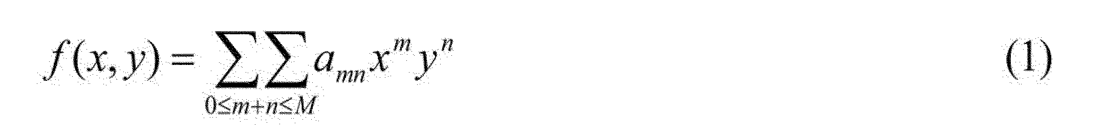
As shown in FIG. 12 (a), it is known that an arbitrary small a priori information region B exists inside the ROI, and in B, the image f (x, y) is an M-order polynomial. If there is, the solution of the image reconstruction of the interior CT is uniquely determined. Here, the polynomial means that the density change of the image f (x, y) has the following form.
ただし,多項式の次数Mは既知である必要があり,多項式の係数amnは未知で良い。[結果1]は、[結果2]において多項式の次数をM=0に設定した関数の形の制限を強くしたものであり、即ち、[結果2]は[結果1]の先験的知識を少なくしたものになっている。 However, the degree M of the polynomial needs to be known, and the coefficients a mn of the polynomial may be unknown. [Result 1] strengthens the restriction of the form of the function in which the degree of the polynomial is set to M = 0 in [Result 2], that is, [Result 2] gives a priori knowledge of [Result 1] It has been reduced.
[結果3(区分的一様先験的知識)]
図12(a)に示すように、ROI の内部に任意の小さな領域Bが存在し、Bにおいて前記画像f(x,y)が区分的一様(piecewise constant)であることが既知であれば、インテリアCTの画像再構成の解は一意に定まる。ここで、区分的一様とは、図13に示すように、Bが有限個(L個)の領域D1,D2, …,DLから構成され各領域で一定値C1,C2, …,CLであることである。ただし、領域数Lと一定値C1,C2, …,CLの値は事前に未知で良く、[結果3]は[結果1]の先験的知識を少なくしたものとなっている。
[Result 3 (piecewise uniform a priori knowledge)]
As shown in FIG. 12 (a), if an arbitrary small region B exists inside the ROI, and it is known that the image f (x, y) is piecewise constant in B. , The solution of image reconstruction of interior CT is decided uniquely. Here, as shown in FIG. 13, the piecewise uniform means that B is composed of a finite number (L) of areas D 1 , D 2 ,..., D L , and constant values C 1 and C 2 are used in each area. , ..., it is that it is C L. However, the number of regions L and the values of the fixed values C 1 , C 2 ,..., C L may be unknown in advance, and [Result 3] is a reduction of a priori knowledge of [Result 1].
[結果4(区分的多項式先験的知識)]
図12(a)に示すように、ROI の内部に任意の小さな領域Bが存在し、Bにおいて前記画像f(x,y)がM次の区分的多項式(piecewise polynomial)であることが既知であれば、インテリアCTの画像再構成の解は一意に定まる。ここで、区分的多項式とは、図13に示すようにBが有限個(L個)の領域D1,D2,…,DLから構成されl番目の領域の画像fl(x,y)の濃度変化が以下の形をしていることである。

As shown in FIG. 12 (a), it is known that an arbitrary small region B exists inside the ROI, and in B, the image f (x, y) is an M-order piecewise polynomial. If there is, the solution of the image reconstruction of the interior CT is uniquely determined. Here, the piecewise polynomial, region D 1, D 2 of a finite number in the B as shown in FIG. 13 (L number), ..., is composed of D L l th region image f l (x in, y The concentration change of) is in the following form.
ただし、多項式の次数Mは既知である必要があり、領域数Lと多項式係数amn (l)は未知で良く、[結果4]は、[結果2]と[結果3]の先験的知識を少なくしたものとなっている。 However, the degree M of the polynomial needs to be known, the number of regions L and the polynomial coefficients a mn (l) may be unknown, and [Result 4] is a priori knowledge of [Result 2] and [Result 3] Has been reduced.
このように、厳密な画像再構成を行うために必要な物体に関する先験的知識を理論的に考察して、上記従来技術(非特許文献5と6、特許文献1)に述べられている先験的知識より、はるかに少ない先験的知識で厳密な画像再構成を可能とした。
Thus, theoretically considering the a priori knowledge of the object necessary for performing the exact image reconstruction, the destination described in the above-mentioned prior art (
上記非特許文献5と6では、[結果1]~[結果4]と同じROI 内の任意小領域Bの先験的知識を用いているが、画像f(x,y)の値そのものが必要であるのに対し、本発明では、[結果1]~[結果4]では画像f(x,y)の値が(区分的)一様または(区分的)多項式など、はるかに少ない先験的知識だけで良い点で大きく異なる。また、非特許文献5では、区分的一様タイプの先験的知識を用いているが、ROI 内の任意小領域Bではなく、ROI 全体で区分的一様という無理な仮定が必要な点で異なる。
Although the above
また、図14(a)~(c)には、上記[結果1]~[結果3]の先験的知識を用いた場合の実際の再構成例を示す。どの場合も、少しの先験的知識により大きなアーティファクトの低減が達成できていることがわかる。
<実施例2>
Further, FIGS. 14 (a) to (c) show an example of actual reconstruction when using the a priori knowledge of the above [Result 1] to [Result 3]. In any case, it can be seen that a little prior knowledge has achieved a large artifact reduction.
Example 2
上記の実施例で説明した発明により、インテリアCTの厳密な画像再構成に必要な先験的知識ははるかに少なくできた。しかしながら、実際のCTイメージングにおいては、撮影前に対象とする物体に関する先験的知識が分かっている場合は比較的少ない。そこで、実施例2では、上記の図13に示した処理の流れにおいて、ステップS62で先験的知識として使用できるROI 内の任意小領域である領域Bを自動的に同定するものである。この先験情報領域の自動的同定は、例えば、画像解析(処理)技術を利用することによって実現可能である。
<実施例3>
According to the invention described in the above embodiment, the a priori knowledge required for the exact image reconstruction of the interior CT can be much less. However, in actual CT imaging, there are relatively few cases where prior knowledge of an object of interest is known before imaging. Therefore, in the second embodiment, in the process flow shown in FIG. 13 described above, the region B which is an arbitrary small region in the ROI that can be used as a priori knowledge in step S62 is automatically identified. The automatic identification of the a priori information area can be realized, for example, by using an image analysis (processing) technique.
Example 3
上記の実施例1の先験的知識自動推定型画像再構成法の成否は、第1ステップにおける先験的知識(領域B)の同定が上手くできるか否かに依存する。そこで、更に実施例3では、領域Bを同定しないで画像再構成を行う「先験的知識非同定型画像再構成法」である。ROI 周囲の縁の部分が区分的一様または区分的多項式であるという仮定は厳密には正しくないため、本手法は近似的な画像再構成法に止まるが、しかし、多くのCTイメージングの状況では[知見3]が成立するため、ROI の周囲である縁の部分に固定して配置することにより、図14(a)~(c)に示すように、先験的知識を利用しない他の近似的画像再構成法と比較して、はるかに精度高く画像再構成できる。 The success or failure of the a priori knowledge automatic estimation type image reconstruction method of the above-mentioned first embodiment depends on whether or not the identification of the a priori knowledge (area B) in the first step is successful. Therefore, in the third embodiment, the “prior knowledge non-identifying image reconstruction method” in which the image reconstruction is performed without identifying the region B is described. Although the assumption that the portion of the edge around the ROI is piecewise uniform or piecewise polynomial is not strictly correct, the method remains an approximate image reconstruction method, but in the context of many CT imaging As [Finding 3] holds, by fixing and arranging at the part of the edge that is the periphery of the ROI, as shown in FIGS. 14 (a) to (c), another approximation that does not use a priori knowledge Image reconstruction can be performed with much higher accuracy compared to conventional image reconstruction methods.
図15(a)~(f)には、先験的知識同定型画像再構成法(実施例1)と先験的知識非同定型画像再構成法(実施例3)の具体的なシミュレーション実験例を、従来技術との比較により示す。実験には胸部CT画像を用い、中央に位置する心臓部分がROI Sとして画像再構成を行った(図15(a)参照)。 15 (a) to 15 (f) show specific simulation experiments of the a priori knowledge identification type image reconstruction method (Example 1) and the a priori knowledge non-identification type image reconstruction method (Example 3). An example is shown by comparison with the prior art. Chest CT images were used for the experiment, and image reconstruction was performed with the heart portion located at the center as ROIS (see FIG. 15 (a)).
実施例1では、第1ステップのFBP法による再構成画像をユーザが見て先験情報領域BをROI S内に指定して、第2ステップの厳密な画像再構成を行った(なお、用いた先験的知識は[結果3]に対応するBで区分的一様である)。その結果を図15(e)に示す。また、実施例3では、ROI Sの周辺部(図14(c)の額縁型)に先験情報領域Bを固定して画像再構成を行った(なお、用いた先験的知識は[結果3]に対応するBで区分的一様である)。その結果を図15(f)に示す。 In the first embodiment, the user looks at the reconstructed image by the FBP method in the first step, and the a priori information region B is specified in the ROI S, and the strict image reconstruction in the second step is performed (note that The a priori knowledge that we have is piecewise uniform at B corresponding to [Result 3]). The result is shown in FIG. Further, in the third embodiment, the a priori information area B is fixed to the peripheral portion of the ROI S (the frame type in FIG. 14C) to perform image reconstruction (note that the a priori knowledge used is [Result 3) piecewise uniform at B). The result is shown in FIG.
また、比較例として、投影データの欠損部分を滑らかな関数で外挿してFBP法を適用するローカルFBP法による結果を図15(b)に、同じ先験情報領域Bにおける画像f(x,y)の真値を先験的知識に用いた手法(非特許文献5、6)による結果を図15(c)に、小さな先験情報領域BのみではなくROI S全体に対して区分的一様の拘束であるトータリバリエーション(TV:Total Variation)をかける圧縮センシング法(非特許文献5)による結果を図15(d)に、それぞれ、示す。
Further, as a comparative example, a result of the local FBP method of applying the FBP method by extrapolating the lost portion of the projection data in a smooth function in FIG. 15 (b), the image f (x in the same priori information area B, y The result by the method (
これらの結果から明らかなように、ローカルFBP法では強いカッピング効果が発生して画像劣化が著しく、圧縮センシング法ではTVの影響により細部や滑らかな濃度変化がかなり失われている。これに対して、本発明の実施例1及び3の手法では、いずれもアーティファクトを削減してかなり上手く画像再構成できていることがわかる。
As apparent from these results, in the local FBP method, a strong cupping effect occurs and image degradation is remarkable, and in the compressed sensing method, details and smooth density changes are considerably lost due to the influence of TV. On the other hand, it can be seen that in the methods of
[画像再構成法]
上述した[結果1]~[結果4]の解の一意性に基づいて投影データから画像を生成する画像再構成法について説明する。まず、画像f(x,y)と投影データp(r,θ)を離散化したベクトルを、各々、f,bで表し、画像に投影データを対応づける投影演算行列をAで表す。ただし、画像fはROI S内の画素のみではなく、断面内の物体存在領域に属する全ての画素を含め(注意が必要)、投影データベクトルbは全ての測定値を一列に並べて作成する。また、先験情報領域Bにおいて先験的知識が満足されているかどうかを評価する評価関数をF(x)で表す。このとき、画像再構成は以下の3つの最適化問題のいずれかとして定式化できる。
[Image reconstruction method]
An image reconstruction method for generating an image from projection data based on the uniqueness of the solutions of [Result 1] to [Result 4] described above will be described. First, vectors obtained by discretizing the image f (x, y) and the projection data p (r, θ) are represented by f and b, respectively, and a projection operation matrix that associates projection data with the image is represented by A. However, the image f includes not only the pixels in the ROI S but all the pixels belonging to the object existing area in the cross section (note that it is necessary), and the projection data vector b is created by arranging all the measured values in a line. Also, an evaluation function for evaluating whether a priori knowledge is satisfied in the a priori information area B is represented by F (x). At this time, image reconstruction can be formulated as any of the following three optimization problems.
[定式化1]
![]()
![]()
[定式化2]
![]()
![]()
[定式化3]
![]()
![]()
ただし、x∈Cは画像に関して事前に分かる拘束条件を表し、以下のものが良く用いられる。
(a)(サポート拘束)画像fが事前に既知であるサポート領域ΩOBJの外側でゼロになる。
(b)(非負条件)画像fの成分は負の値を取らない。
(c)(ヒルベルト直線上の投影データ値)後述するヒルベルト変換を用いた画像再構成法では、Af=bをHf=cに書き換える際の情報のロスを補うため、後述するヒルベルト直線L(u)上の投影データ値が用いられる。
However, x∈C represents a constraint known in advance with respect to an image, and the following are often used.
(A) (Support constraint) The image f becomes zero outside the support area Ω OBJ where it is known in advance.
(B) (non-negative condition) The components of the image f do not take negative values.
(C) (Projected data value on Hilbert straight line) In the image reconstruction method using Hilbert transform described later, the Hilbert straight line L (u) described later is used to compensate for the loss of information when Af = b is rewritten as Hf = c. ) Projection data values are used.
もしもF(x)が凸関数と呼ばれる局所的最適解(local minimum)が存在しない関数であれば、上述の問題を解く反復解法または非反復解法は、数理最適化分野や画像再構成分野で多数知られており、これらの手法が全て利用可能である。例えば、拘束条件付統計的画像再構成法や拘束条件付逐次近似法などが利用できる。また,別のクラスの画像再構成法として、微分逆投影(DBP:Differentiated Back Projection)と呼ばれる後述する枠組みに基づき、画像再構成法を構築することが可能である。DBP法の詳細は後述するが、DBP法ではAf=bで表される画像fと投影データbの関係式をそのまま用いるのではなく、一旦、DBPと呼ばれる手法により画像fとヒルベルト画像(Hilbert image)と呼ばれる不完全な画像cの関係式Hf=cに変換して、以下のように定式化して画像再構成を行う。このクラスの手法は、微分逆投影+トランケーションヒルベルト変換法などの名称で呼ばれる(非特許文献5と6、特許文献1)。
If F (x) is a function that does not have a local minimum called a convex function, an iterative solution or non-iterative solution that solves the above-mentioned problems is numerous in the field of mathematical optimization and image reconstruction. It is known and all these approaches are available. For example, a constrained statistical image reconstruction method or a constrained conditional successive approximation method can be used. In addition, as another class of image reconstruction methods, it is possible to construct an image reconstruction method based on a later-described framework called differential back projection (DBP). Although the details of the DBP method will be described later, in the DBP method, the relational expression between the image f and the projection data b represented by Af = b is not used as it is, but the image f and Hilbert image (Hilbert image) are temporarily obtained by a method called DBP. The image reconstruction is performed by converting the incomplete image c called H) into the relational expression Hf = c, and formulating it as follows. Methods of this class are referred to by the names such as differential backprojection + truncation Hilbert transform (
[定式化4]
![]()
![]()
[定式化5]
![]()
![]()
[定式化6]
![]()
![]()
もちろん、上述のように定式化した問題は反復解法または非反復解法を用いて解く。 Of course, the problem formulated as described above is solved using an iterative or non-iterative solution.
次に,本発明において厳密または正確な画像再構成を行うキーである先験情報領域Bにおける先験的知識を評価する評価関数F(x)について説明する。 Next, an evaluation function F (x) for evaluating a priori knowledge in the a priori information area B, which is a key for performing exact or accurate image reconstruction in the present invention, will be described.
まず、F(x)を設計するにあたって、ROI S全体に対して先験的知識に基づく拘束条件をかける非特許文献5や非特許文献6の手法と異なり、本発明の画像再構成法ではS内の任意小領域である先験情報領域Bのみに拘束条件を課す。[結果1]の場合はf(x,y)の一回導関数がB内でゼロになる先験的知識であるから、Bにおけるf(x,y)の一回導関数のノルムを最小化するか、または、B内の濃度変化のばらつき(分散)を最小化すれば良い。[結果2]の場合は、f(x,y)のM+1回導関数がB内でゼロになる先験的知識であるから、M+1回導関数のノルムを最小化するか、f(x,y)とf(x,y)((x,y)∈B)にM次の多項式を当てはめた関数との誤差を最小化すれば良い。[結果3]の場合は、f(x,y)がB内で区分的一様になる先験的知識であるから、B内におけるL0ノルムまたはL1ノルムに基づくトータルバリエーション(TV:Total Variation)ノルムを最小化すれば良い。[結果4]の場合は、f(x,y)のM回導関数がB内で区分的一様になる先験的知識であるから、M+1回の導関数に基づき定義されたTVノルムを最小化すれば良い。
First, unlike the methods of
典型的なF(x)の例を表2に示す。ただし、表2においてパラメータpはノルムの次数であり、その値は[結果1]と[結果2]では0≦p≦2で良いが、[結果3]と[結果4]では一様またはM次の多項式の濃度変化を持つ有限個(L個)の部分領域の境界の影響が過度に大きく評価されるのを避けるため、0≦p≦1を用いる必要がある。ただし、0≦p<1の場合には、F(x)は凸関数にならないため、反復解法や非反復解法に工夫が必要であり、p=1を用いるのが良いと言える。なお,表2に示したF(x)で複数の候補があるものは数値実験によるテストを行ったが、どれも概ね良好に動作して大きな差は見られなかった。
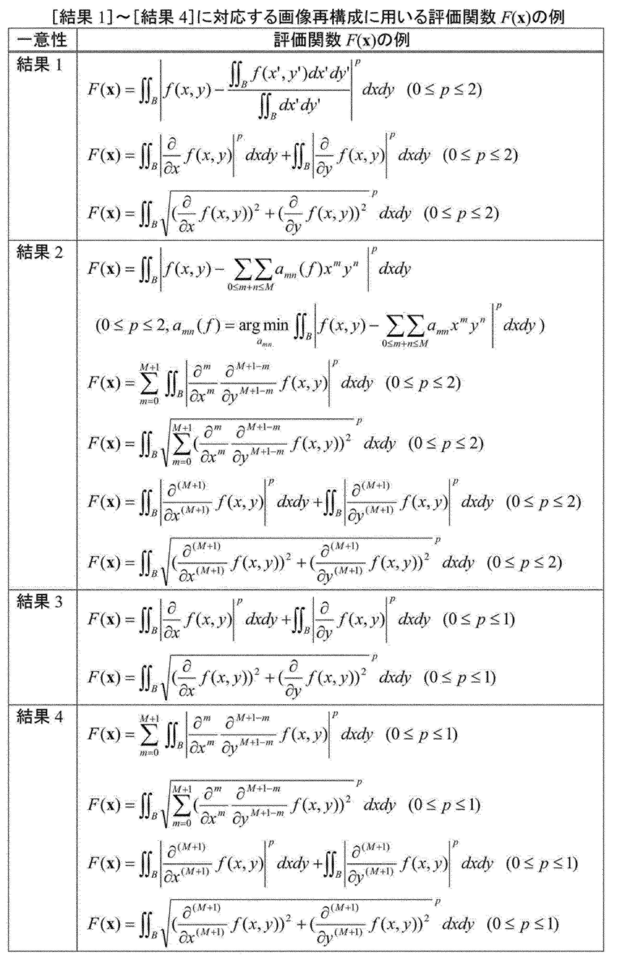
更に、上述したように従来技術における対象物に関する先験情報を利用することなく、低倍率による全体画像データを用いたインテリアCTの数学的に厳密な画像再構成を実現する手法について、以下に詳述する。
<実施例4>
Furthermore, as described above, a method for realizing mathematically exact image reconstruction of interior CT using low-magnification overall image data without using prior information on objects in the prior art as described above will be described in detail below. Describe.
Example 4
インテリアCTにおいて解の一意性(画像再構成問題の解が一つに定まること)が成り立ち、厳密な画像再構成を可能にするためには、インテリアCT投影データに加えて、何らかの付加的な情報が必要である。実施例4ではこれに代わるものとして、インテリアCTでは通常は測定しない投影データ、即ち、画像を得たい領域ROIΩを通らない余分な投影データを測定して、この補足データを利用する。即ち、本発明実施例4の厳密解法の重要な特徴は、ROIΩを通らない必要最小限の余分な投影データを測定することにある。 The uniqueness of the solution (in which the solution of the image reconstruction problem is settled into one) is established in the interior CT, and in order to enable the exact image reconstruction, some additional information in addition to the interior CT projection data is necessary. In the fourth embodiment, as an alternative, the interior CT measures projection data which is not usually measured, that is, extra projection data which does not pass through the region ROI Ω where the image is desired to be obtained, and utilizes this supplementary data. That is, an important feature of the exact solution of the fourth embodiment of the present invention is to measure the minimum necessary extra projection data not passing through the ROI Ω.
特に試料撮像の倍率を変更可能な撮像光学系をもつことにより、試料全体像を撮像し、その一部がROIΩを通らない余分な投影データとて、補足データを利用することが有効な方法となる。 In particular, by having an imaging optical system capable of changing the magnification of sample imaging, it is effective to use supplementary data as extra projection data, a part of which captures an entire image of the sample and does not pass through the ROI Ω. Become.
上記の手法は電子線、X線、中性子線等の顕微CTの多様な光学系にも適用できる一般性を有するが、まず、試料が回転することにより相対的に電子線源が円軌道上を360度動くファンビームCTについてその原理を説明する。図16(a)に示すように、360度の円軌道のファンビームCTにおいて、ROIΩを通過する電子線のみを照射して投影データを測定するインテリアCTの状況を考える。もちろん、インテリアCT投影データだけでは数学的に厳密なROI Ωの画像再構成は不可能であり、図16(b)に示すように、付加的な情報として、円軌道の一部の円弧セグメントEから対象物全体をカバーする電子線を照射して、全体の投影データを測定する。この部分的な全体投影データ(以下、単に「全体投影データ」とも言う)をインテリアCT投影データに加味して、厳密なROI Ωの再構成ができるようにしたところ、円弧セグメントEの任意の、一点ではない小さな円弧セグメントで全体投影データがあれば、厳密なROI Ωの画像再構成が可能であることが数学的に証明できた。 The above method has generality that can be applied to various optical systems of microscopic CT such as electron beam, X-ray, neutron beam etc. First, the electron beam source is relatively in circular orbit by rotating the sample The principle of the 360-degree moving fan beam CT will be described. As shown in FIG. 16A, consider the situation of interior CT where projection data is measured by irradiating only the electron beam passing through the ROI Ω in the 360-degree circular orbit fan beam CT. Of course, it is impossible to reconstruct mathematically exact ROI Ω image only by the interior CT projection data, and as shown in FIG. 16 (b), the arc segment E of a part of the circular orbit is used as additional information. The entire projection data is measured by irradiating an electron beam covering the entire object. When this partial whole projection data (hereinafter, also simply referred to as “whole projection data”) is added to the interior CT projection data to enable strict ROI Ω reconstruction, arbitrary arc segment E, It has been mathematically proved that accurate ROI Ω image reconstruction is possible if the whole projection data is small arc segments which are not one point.
また、上記の問題に対しては、過去の対象物に関する先験情報を用いたインテリアCT厳密解法の研究で解の一意性を示すツールとして使用された微分逆投影(DBP: Differentiated Back Projection)法とトランケーションヒルベルト変換を組み合わせた画像再構成法(非特許文献[5]-[9])では証明できないが、FBP法におけるフィルタリング処理にトランケーションヒルベルト変換を導入した新しい画像再構成法を用いることで証明した。ここで、本発明で明らかになった360度円軌道ファンビームCTにおけるインテリアCT画像再構成問題の解の一意性をまとめると、次のようになる。 In addition, for the above problems, the differential back projection (DBP) method used as a tool to show the uniqueness of the solution in the study of the interior CT exact solution method using the a priori information on the past objects Although it can not be proved by the image reconstruction method (nonpatent literature [5]-[9]) which combined with the pruning Hilbert transform, it proves by using the new image reconstruction method which introduced the truncation Hilbert transform for filtering processing in FBP method did. Here, the uniqueness of the solution of the interior CT image reconstruction problem in the 360-degree circular orbit fan beam CT revealed by the present invention is summarized as follows.
[解の一意性]
インテリアCT投影データに加えて任意の円弧セグメントE(いくら小さくともよい)の全体スキャン(左右のトランケーションなし)投影データがあれば、インテリアCTの画像再構成の解は一意である。
[Uniqueness of solution]
If there is a full scan (without left and right truncation) projection data of an arbitrary arc segment E (which may be small) in addition to the interior CT projection data, the solution for the image reconstruction of the interior CT is unique.
<得られたインテリアCTにおける解の一意性>
ここでは、後に説明するFBP法のフィルタリング処理にトランケーションヒルベルト変換を導入した新しい画像再構成法に基づき証明することに成功した、インテリアCT画像再構成における解の一意性の結果をまとめて述べる。なお、記号の定義として、対象画像(物体)をf(x,y)、ROIをΩで表す。
<Uniqueness of Solution in Obtained Interior CT>
Here, the results of the uniqueness of the solution in the interior CT image reconstruction, which were successfully proved based on the new image reconstruction method in which the truncation Hilbert transform is introduced into the filtering processing of the FBP method described later, are described collectively. In addition, as a definition of a symbol, an object image (object) is represented by f (x, y), and ROI is represented by Ω.
まず、図17に基づいて、一般化する際の考え方を述べる。任意の幾何学系を用いた場合において、物体の直線上の線積分値の集合を測定している点は共通であり、両者の投影データの間には座標変換の関係が成立する。そこで、任意の幾何学系で測定した投影データを、一旦、図17(a)に示すように、仮想的な360度円軌道ファンビームCTの投影データに座標変換して、そのデータが360度円軌道ファンビームCTの場合における一意性の条件を満足しているか調べ、任意の幾何学系で測定した投影データに適用可能な解の一意性を導出すると、最終的に、次の結論が得られる。 First, based on FIG. 17, the way of thinking upon generalization will be described. When an arbitrary geometric system is used, it is common to measure a set of line integral values on a straight line of the object, and a coordinate conversion relationship holds between the two projection data. Therefore, as shown in FIG. 17A, the projection data measured by an arbitrary geometric system is temporarily transformed into projection data of a virtual 360 degree circular orbit fan beam CT, and the data is 360 degrees. Investigate whether the condition of uniqueness in the case of circular orbit fan beam CT is satisfied and derive the uniqueness of the solution applicable to projection data measured in any geometric system, the following conclusion is finally obtained Be
[解の一意性(任意の幾何学系)]
以下の2つの両方の条件が満足されるように投影データが測定されていれば、ROI Ωで画像f(x,y)は一意に定まり、Ωの厳密な再構成が可能である。
[Uniqueness of solution (arbitrary geometric system)]
If the projection data is measured such that both of the following two conditions are satisfied, the image f (x, y) is uniquely determined in the ROI Ω, and an exact reconstruction of Ω is possible.
(条件1)ROI Ωを通る全ての投影データが測定されていること(インテリアCTの測定条件)。 (Condition 1) All projection data passing through the ROI Ω have been measured (measurement conditions of interior CT).
(条件2)物体外部にある任意の(物体を内部に含むある円に対応する)小円弧セグメントEを通る全ての直線上の投影データ(部分的な全体投影データ)が測定されていること(解を一意に定めるために余分に測定する投影データの条件)。 (Condition 2) Projection data (partial whole projection data) on all straight lines passing an arbitrary small arc segment E (corresponding to a certain circle including the object) existing outside the object is measured (partial whole projection data) Conditions of projection data to be measured extra to define the solution uniquely).
ただし、小円弧セグメントEの長さは、物体を内部に含むある円に対応するセグメントであり、一点ではないならばいくら短くともよく、どの場所にあってもよい。上述した2つの幾何学的条件の意味を、図17(b)に示す。 However, the length of the small arc segment E is a segment corresponding to a certain circle including the object inside, and may be anywhere as short as possible, if it is not one point. The meaning of the two geometric conditions described above is shown in FIG.
更に、上述の一般化した解の一意性が有効な3つの事例を以下に述べる。 In addition, three cases in which the uniqueness of the above generalized solution is valid are described below.
(a)180度平行ビームスキャンの場合
CTのデータ収集法の中で、電子線撮像では最も基本的な180度平行ビームスキャンでインテリアCTを実施する場合を考える。動径をr、角度をθとして投影データをp(r,θ)(投影角度範囲-π/2≦θ<π/2)で表す。いま、-ε≦θ≦ε(εは小角度)の角度範囲では(トランケーションなしの)全体投影データが測定され、それ以外ではインテリアCT投影データしか測定されないとする。このとき、小円弧セグメントEを図18(a)に示すようにとれば上述の解の一意性の条件を満足していることが分かり、ROI再構成の解は一意である。
(A) In the case of 180 degree parallel beam scan In the data acquisition method of CT, consider the case where the interior CT is carried out with the 180 degree parallel beam scan which is the most basic in electron beam imaging. The projection data is represented by p (r, θ) (projection angle range −π / 2 ≦ θ <π / 2), where r is a radius and θ is an angle. Now, it is assumed that overall projection data (without truncation) is measured in an angular range of −ε ≦ θ ≦ ε (ε is a small angle), and only interior CT projection data is measured otherwise. At this time, if the small circular arc segment E is as shown in FIG. 18A, it is understood that the condition of uniqueness of the above solution is satisfied, and the solution of the ROI reconstruction is unique.
[解の一意性(180度平行ビーム)]
-π/2≦θ<π/2の角度範囲のインテリアCT投影データに加え任意の小角度範囲E(いくら小さくともよい)で全体投影データを測定すれば、ROI Ωで画像f(x,y)は一意に定まり、Ωの厳密な再構成が可能である。
[Uniqueness of solution (180 degree parallel beam)]
If the total projection data is measured in an arbitrary small angle range E (how small it may be) in addition to the interior CT projection data in the angle range of −π / 2 ≦ θ <π / 2, the image f (x, y in ROI Ω ) Is uniquely determined, and strict reconstruction of Ω is possible.
なお、この一意性は、360度円軌道ファンビームCTの場合の解の一意性において円軌道の半径を無限にした極限と解釈することができ、180度平行ビームスキャンにおいても360度円軌道ファンビームCTと同様な解の一意性が成立する。なお、この結果は任意の幾何学系に一般化した一意性を用いて初めて証明できる。 This uniqueness can be interpreted as the limit in which the radius of the circular orbit is infinite in the uniqueness of the solution in the case of the 360-degree circular orbit fan beam CT, and the 360-degree circular orbit fan also in the 180-degree parallel beam scan The uniqueness of the solution similar to the beam CT is established. This result can be proved for the first time by using uniqueness generalized to arbitrary geometric systems.
(b)ファンビームショートスキャンの場合
図18(b)に示すファンビームショートスキャンの場合を考える。円軌道上のX線源の位置をβ∈[-π/2-αmax,π/2+αmax)(αmaxはショートスキャンの条件から決まるオーバースキャン角度、非特許文献[7])、直線検出器上の座標をuとしてファンビーム投影データをg(u,β)で表す。いま、-ε≦β≦ε(εは小角度)の角度範囲で(トランケーションなしの)全体投影データが測定され、それ以外ではインテリアCT投影データしか測定されないとする。このとき、小円弧セグメントEを図21(b)に示すようにとれば、上述の解の一意性の条件を満足していることが分かり、ROI再構成の解は一意である。
(B) In the case of fan beam short scan Consider the case of fan beam short scan shown in FIG. The position of the X-ray source on the circular orbit is β∈ [−π / 2−α max , π / 2 + α max ) (α max is an overscan angle determined from the condition of the short scan, Non Patent Literature [7]), The fan beam projection data is represented by g (u, β), where u is the coordinates on the straight line detector. Now, it is assumed that overall projection data (without truncation) is measured in an angular range of −ε ≦ β ≦ ε (ε is a small angle), and only interior CT projection data is measured otherwise. At this time, if the small circular arc segment E is as shown in FIG. 21 (b), it is understood that the condition of uniqueness of the above-mentioned solution is satisfied, and the solution of the ROI reconstruction is unique.
[解の一意性(ファンビームショートスキャン)]
-π/2-αmax≦β<π/2+αmaxの角度範囲のインテリアCT投影データに加えて、任意の小角度範囲E(いくら小さくともよい)で全体投影データを測定すれば、ROI Ωで画像f(x,y)は一意に定まり、Ωの厳密な再構成が可能である。
[Uniqueness of solution (fan beam short scan)]
In addition to the interior CT projection data of the angle range of -π / 2-α max β β <π / 2 + α max , the ROI can be obtained by measuring the total projection data in an arbitrary small angle range E (which may be small). The image f (x, y) is uniquely determined by Ω, and strict reconstruction of Ω is possible.
(c)多角形軌道を用いたファンビームスキャン:
図18(c)に示す正五角形軌道を用いたファンビームスキャンを考える。正五角形軌道上のX線源の位置をβ∈[-π,π)(βは正五角形の中心から軌道上の点を見た方位角)、直線検出器上の座標をuとしてファンビーム投影データをg(u,β)で表す。今、-ε≦β≦ε(εは小角度で正五角形軌道の一辺がEになるように決定)の角度範囲では(トランケーションなしの)全体投影データが測定され、それ以外ではインテリアCT投影データしか測定されないとする。
(C) Fan beam scan using polygonal trajectory:
Consider a fan beam scan using a regular pentagonal trajectory shown in FIG. 18 (c). The position of the X-ray source on the regular pentagonal orbit is β∈ [-π, π) (β is the azimuth angle seen from the center of the regular pentagon to the point on the orbit), fan beam projection with u on the linear detector Data are expressed as g (u, β). Now, the entire projection data (without truncation) is measured in the angle range of -ε ≦ β ≦ ε (ε is determined so that one side of the regular pentagonal trajectory is E with a small angle), otherwise the interior CT projection data Can only be measured.
このとき、小円弧セグメントEを図18(c)に示すようにとれば、上述の解の一意性の条件を満足していることが分かり、ROI再構成の解は一意である。 At this time, if the small circular arc segment E is as shown in FIG. 18C, it can be understood that the condition of uniqueness of the above solution is satisfied, and the solution of the ROI reconstruction is unique.
[解の一意性(多角形軌道を用いたファンビームスキャン)]
-π≦β<πの角度範囲のインテリアCT投影データに加えて、任意の小角度範囲E(いくら小さくともよい)で全体投影データを測定すれば、ROI Ωで画像f(x,y)は一意に定まり、Ωの厳密な再構成が可能である。
[Uniqueness of solution (fan beam scan using polygonal trajectory)]
If the total projection data is measured in an arbitrary small angle range E (how small it may be) in addition to the interior CT projection data in the angle range of −π ≦ β <π, the image f (x, y) is ROI Ω It is uniquely determined, and strict reconstruction of Ω is possible.
(b)位置合わせのScout-Viewスキャン投影データを全体投影データに利用する
撮影を行う前に見たいROIΩを上手く視野内に収める位置決めの目的で、物体全てが視野内に入るような低倍率のScout-Viewスキャンが行われる。このScout-Viewスキャンの機能を利用して、低倍率の投影データを、部分軌道Eの全体投影データとして利用することができる。
(B) Use Scout-View scan projection data for alignment as whole projection data For the purpose of positioning the ROI Ω that you want to see before shooting well within the field of view, such a low magnification that all objects are within the field of view Scout-View scan is performed. The projection data with low magnification can be used as total projection data of the partial trajectory E by using the function of this Scout-View scan.
次にScout-Viewスキャンにより特定したROIΩに対して2回目の測定が行われ、Ry軸の回転により、ROIを通過する電子線のみを照射してインテリアCT投影データ全てが測定され、画像情報データ蓄積装置61に保存される。これにより、インテリアCT画像を再構築するためのデータ取得が行える。
Next, a second measurement is performed on the ROI Ω specified by the Scout-View scan, and only the electron beam passing through the ROI is irradiated by rotation of the Ry axis to measure all interior CT projection data, and image information data It is stored in the
画像情報データ蓄積装置61に保存された1回目測定の試料全体投影の部分データ及びROIΩに対して行う2回目のインテリアCT投影データ全ての測定データを用いて記述の画像再構築方法を用いて、インテリアCT画像を再構築する。
Using the measurement data of all of the internal CT projection data of the second time performed on partial data of the whole sample projection of the first measurement stored in the image information
1…X線源、2…X線集光鏡、3…G0格子、4…試料、5-1、5-2…FZP、6-1、6-2…G1格子、7…X線検出器、8…光学素子載置台、11…X線シャッター、12…4象限X線スリット、31…G0格子取り付け冶具、32…G0格子スィーベル、33…G0格子回転機構、34…G0格子移動機構、41…試料取り付け冶具、42…試料XY移動台、43…試料回転台、51…FZP取り付け冶具、52…FZP XY移動台、61…G1格子取り付け冶具、62…G1格子スィーベル、63…G1格子回転機構、64…G1格子XY移動台、91…XRM制御装置、92…データ蓄積装置、93…X線源制御装置、94…位置調整用制御装置、95…X線検出器制御装置、101…防X線シールド兼装置外部パネル、102…温度制御装置、103…光学ベンチ、104…架台。
DESCRIPTION OF
Claims (9)
前記X線源と試料の間に配置され、前記X線源を格子状に成形するための第一の格子と、
前記試料を回転保持するための試料台と、
前記試料の後方に配置されたX線結像光学系と、
前記試料の後方に配置された第二の格子と、
前記試料のX線像を強度分布として検出するための手段とを備えたX線顕微鏡装置であって、
前記X線結像光学系と第二の格子を二組以上複数の組み合わせで同時に交換できる機構を備えていることを特徴とするインテリアCT位相イメージングX線顕微鏡装置。 An x-ray source that emits x-rays;
A first grid disposed between the x-ray source and the sample for shaping the x-ray source into a grid;
A sample stage for holding the sample in rotation;
An X-ray imaging optical system disposed behind the sample;
A second grid disposed behind the sample;
Means for detecting the X-ray image of the sample as an intensity distribution, the X-ray microscope apparatus comprising:
An interior CT phase imaging X-ray microscope apparatus comprising a mechanism capable of simultaneously exchanging the X-ray imaging optical system and the second grating in a combination of two or more sets.
Priority Applications (1)
| Application Number | Priority Date | Filing Date | Title |
|---|---|---|---|
| JP2019545185A JP7198457B2 (en) | 2017-09-29 | 2018-09-28 | Interior CT phase imaging X-ray microscope equipment |
Applications Claiming Priority (2)
| Application Number | Priority Date | Filing Date | Title |
|---|---|---|---|
| JP2017189610 | 2017-09-29 | ||
| JP2017-189610 | 2017-09-29 |
Publications (1)
| Publication Number | Publication Date |
|---|---|
| WO2019066051A1 true WO2019066051A1 (en) | 2019-04-04 |
Family
ID=65903045
Family Applications (1)
| Application Number | Title | Priority Date | Filing Date |
|---|---|---|---|
| PCT/JP2018/036520 Ceased WO2019066051A1 (en) | 2017-09-29 | 2018-09-28 | Interior ct phase imaging x-ray microscope apparatus |
Country Status (2)
| Country | Link |
|---|---|
| JP (1) | JP7198457B2 (en) |
| WO (1) | WO2019066051A1 (en) |
Cited By (7)
| Publication number | Priority date | Publication date | Assignee | Title |
|---|---|---|---|---|
| CN111474190A (en) * | 2020-05-21 | 2020-07-31 | 中国科学院上海光学精密机械研究所 | Three-dimensional full-shape detection device and method for silicon dioxide microspheres |
| JPWO2020166304A1 (en) * | 2019-02-15 | 2020-08-20 | ||
| WO2020246220A1 (en) * | 2019-06-04 | 2020-12-10 | コニカミノルタ株式会社 | Radiography system and enlarged absorption contrast image generation method |
| CN114034385A (en) * | 2021-10-20 | 2022-02-11 | 山东师范大学 | Spectral measurement method and system based on compressed sensing and dynamic local high resolution |
| WO2023121414A1 (en) * | 2021-12-24 | 2023-06-29 | 주식회사 자비스옵틱스 | Dual-mode resolution conversion device for three-dimensional x-ray microscope |
| KR20230097970A (en) * | 2021-12-24 | 2023-07-03 | 주식회사 자비스옵틱스 | A resolution dual-mode conversion apparatus of 3D X-ray microscope |
| WO2023171726A1 (en) * | 2022-03-10 | 2023-09-14 | コニカミノルタ株式会社 | Evaluation method, evaluation device, and program |
Families Citing this family (1)
| Publication number | Priority date | Publication date | Assignee | Title |
|---|---|---|---|---|
| JP7605503B2 (en) * | 2019-10-11 | 2024-12-24 | ボード オブ リージェンツ,ザ ユニバーシティ オブ テキサス システム | Variable zoom x-ray computed tomography method for composite materials - Patents.com |
Citations (3)
| Publication number | Priority date | Publication date | Assignee | Title |
|---|---|---|---|---|
| JP2008528096A (en) * | 2005-01-21 | 2008-07-31 | ミン ヒョン チョ | X-ray tomographic image reconstruction method and apparatus |
| JP2012135612A (en) * | 2010-12-07 | 2012-07-19 | Fujifilm Corp | Radiation phase image photographing method and apparatus |
| US20160066873A1 (en) * | 2013-05-22 | 2016-03-10 | Siemens Aktiengesellschaft | Phase-contrast x-ray imaging device |
Family Cites Families (1)
| Publication number | Priority date | Publication date | Assignee | Title |
|---|---|---|---|---|
| JP2011220982A (en) | 2010-04-02 | 2011-11-04 | Toshiba It & Control Systems Corp | Ct device |
-
2018
- 2018-09-28 JP JP2019545185A patent/JP7198457B2/en active Active
- 2018-09-28 WO PCT/JP2018/036520 patent/WO2019066051A1/en not_active Ceased
Patent Citations (3)
| Publication number | Priority date | Publication date | Assignee | Title |
|---|---|---|---|---|
| JP2008528096A (en) * | 2005-01-21 | 2008-07-31 | ミン ヒョン チョ | X-ray tomographic image reconstruction method and apparatus |
| JP2012135612A (en) * | 2010-12-07 | 2012-07-19 | Fujifilm Corp | Radiation phase image photographing method and apparatus |
| US20160066873A1 (en) * | 2013-05-22 | 2016-03-10 | Siemens Aktiengesellschaft | Phase-contrast x-ray imaging device |
Cited By (8)
| Publication number | Priority date | Publication date | Assignee | Title |
|---|---|---|---|---|
| JPWO2020166304A1 (en) * | 2019-02-15 | 2020-08-20 | ||
| WO2020246220A1 (en) * | 2019-06-04 | 2020-12-10 | コニカミノルタ株式会社 | Radiography system and enlarged absorption contrast image generation method |
| CN111474190A (en) * | 2020-05-21 | 2020-07-31 | 中国科学院上海光学精密机械研究所 | Three-dimensional full-shape detection device and method for silicon dioxide microspheres |
| CN114034385A (en) * | 2021-10-20 | 2022-02-11 | 山东师范大学 | Spectral measurement method and system based on compressed sensing and dynamic local high resolution |
| WO2023121414A1 (en) * | 2021-12-24 | 2023-06-29 | 주식회사 자비스옵틱스 | Dual-mode resolution conversion device for three-dimensional x-ray microscope |
| KR20230097970A (en) * | 2021-12-24 | 2023-07-03 | 주식회사 자비스옵틱스 | A resolution dual-mode conversion apparatus of 3D X-ray microscope |
| KR102777155B1 (en) * | 2021-12-24 | 2025-03-07 | 주식회사 자비스옵틱스 | A resolution dual-mode conversion apparatus of 3D X-ray microscope |
| WO2023171726A1 (en) * | 2022-03-10 | 2023-09-14 | コニカミノルタ株式会社 | Evaluation method, evaluation device, and program |
Also Published As
| Publication number | Publication date |
|---|---|
| JPWO2019066051A1 (en) | 2021-01-14 |
| JP7198457B2 (en) | 2023-01-04 |
Similar Documents
| Publication | Publication Date | Title |
|---|---|---|
| JP7198457B2 (en) | Interior CT phase imaging X-ray microscope equipment | |
| CN102781327B (en) | Phase contrast imaging | |
| US7186023B2 (en) | Slice image and/or dimensional image creating method | |
| JP4415762B2 (en) | Tomography equipment | |
| JP2008012319A (en) | Method and system for reducing artifacts in tomosynthesis imaging systems | |
| JP7750078B2 (en) | Radiography apparatus, image generation method, radiation photography system, and program | |
| US20080089466A1 (en) | X-ray CT examination installation and CT methods of examining objects | |
| CN112189134B (en) | X-ray imaging device | |
| CN101111192A (en) | X-ray tomography apparatus with variable image geometry | |
| JPH119583A (en) | X-ray ct scanner | |
| WO2020246220A1 (en) | Radiography system and enlarged absorption contrast image generation method | |
| CA2850845A1 (en) | A computed tomography imaging process and system | |
| Dreier et al. | Laboratory x-ray nano-computed tomography for biomedical research | |
| JPH06181918A (en) | Transmission type three-dimenisonal tomograph | |
| JP2019067555A (en) | Phase difference transmission electron microscope device | |
| US12133748B2 (en) | Radiologic biopsy system and method | |
| WO2017169232A1 (en) | Image reconstruction method for interior ct | |
| WO2024206092A1 (en) | Scintillator defect correction in x-ray microscopy | |
| JP2019067554A (en) | Phase difference sweep transmission electron microscope device | |
| Cai et al. | Simplified method of scatter correction using a beam-stop-array algorithm for cone-beam computed tomography breast imaging | |
| US9633423B2 (en) | Method of reduction of septal shadows for thick septa collimators | |
| KR102596189B1 (en) | Ct apparatus | |
| EP4095521A1 (en) | Improved sparse image reconstruction from neighboring tomography tilt images | |
| Wang et al. | X-ray projection microscopy and cone-beam microtomography | |
| GR1010793B (en) | Automated radiographic imaging system and method for multimodal imaging protocols with motion correction system |
Legal Events
| Date | Code | Title | Description |
|---|---|---|---|
| 121 | Ep: the epo has been informed by wipo that ep was designated in this application |
Ref document number: 18862249 Country of ref document: EP Kind code of ref document: A1 |
|
| WWE | Wipo information: entry into national phase |
Ref document number: 2019545185 Country of ref document: JP |
|
| NENP | Non-entry into the national phase |
Ref country code: DE |
|
| 122 | Ep: pct application non-entry in european phase |
Ref document number: 18862249 Country of ref document: EP Kind code of ref document: A1 |