WO2018119889A1 - Three-dimensional scene positioning method and device - Google Patents
Three-dimensional scene positioning method and device Download PDFInfo
- Publication number
- WO2018119889A1 WO2018119889A1 PCT/CN2016/113060 CN2016113060W WO2018119889A1 WO 2018119889 A1 WO2018119889 A1 WO 2018119889A1 CN 2016113060 W CN2016113060 W CN 2016113060W WO 2018119889 A1 WO2018119889 A1 WO 2018119889A1
- Authority
- WO
- WIPO (PCT)
- Prior art keywords
- visual
- dimensional
- feature
- point cloud
- visual information
- Prior art date
- Legal status (The legal status is an assumption and is not a legal conclusion. Google has not performed a legal analysis and makes no representation as to the accuracy of the status listed.)
- Ceased
Links
Images


Classifications
-
- G—PHYSICS
- G06—COMPUTING OR CALCULATING; COUNTING
- G06T—IMAGE DATA PROCESSING OR GENERATION, IN GENERAL
- G06T19/00—Manipulating 3D models or images for computer graphics
- G06T19/003—Navigation within 3D models or images
-
- G—PHYSICS
- G06—COMPUTING OR CALCULATING; COUNTING
- G06T—IMAGE DATA PROCESSING OR GENERATION, IN GENERAL
- G06T17/00—Three dimensional [3D] modelling, e.g. data description of 3D objects
- G06T17/05—Geographic models
Definitions
- the present application relates to the field of mixed reality technologies, and in particular, to a method and an apparatus for positioning a three-dimensional scene.
- Microsoft's HoloLens uses four cameras, two sets of binocular cameras as sensors, and combines the TOF (time of flight) sensor in the center of the helmet to achieve three-dimensional reconstruction of the current scene.
- Intel's Alloy works similarly to HoloLens, but it uses the RealSense 3D structured real-life camera developed by Intel itself as a sensor.
- two sets of structured light depth cameras are built in, which can directly capture depth images to restore 3D scenes.
- Embodiments of the present application provide a three-dimensional scene positioning method and apparatus for sharing three-dimensional map data.
- a method for positioning a three-dimensional scene including:
- a three-dimensional scene positioning apparatus including:
- a generating unit configured to generate three-dimensional map data according to the first visual information of the current scene and the depth information corresponding to the first visual information, where the three-dimensional map data includes a three-dimensional scene model;
- a positioning unit configured to load a corresponding three-dimensional scene model on the second visual information according to a mapping relationship between the second visual feature and the three-dimensional map data, to implement the second visual information in the three-dimensional scene model Positioning in .
- a computer storage medium for storing computer software instructions for use in a three-dimensional scene location device, comprising program code designed to perform the three-dimensional scene location method of the first aspect.
- a computer program product can be directly loaded into an internal memory of a computer and includes software code, and the computer program can be loaded and executed by a computer to implement the three-dimensional scene positioning method according to the first aspect.
- the method and device for positioning a three-dimensional scene provided by the embodiment of the present application generates three-dimensional map data according to the first visual information and depth information corresponding to the first visual information, and performs feature extraction on the second visual information to obtain a second visual feature.
- the corresponding three-dimensional scene model is loaded on the second visual information to realize the positioning of the second visual information in the three-dimensional scene model.
- the three-dimensional map data generated according to the first visual information and the corresponding depth information can be used for the positioning of the second visual information, and the sharing of the three-dimensional map data is realized.
- FIG. 1 is a schematic structural diagram of a three-dimensional scene positioning system according to an embodiment of the present application
- FIG. 2 is a schematic structural diagram of a first visual collection device according to an embodiment of the present application.
- FIG. 6 is a schematic flowchart diagram of another method for positioning a three-dimensional scene according to an embodiment of the present disclosure
- FIG. 7 is a schematic flowchart of updating a visual feature database and performing a three-dimensional scene reconstruction to obtain a three-dimensional scene model according to an embodiment of the present application;
- FIG. 8 is a schematic diagram of a result of a three-dimensional scene model according to an embodiment of the present application.
- FIG. 11 is a schematic diagram of a result of performing feature matching on an overall grayscale distribution feature according to an embodiment of the present application.
- FIG. 12 is a schematic diagram of a result of performing three-dimensional scene positioning on an ORB feature according to an embodiment of the present application.
- FIG. 13 is a schematic diagram of a result of performing three-dimensional scene positioning on an overall grayscale distribution feature according to an embodiment of the present disclosure
- FIG. 14 is a schematic flowchart diagram of another method for positioning a three-dimensional scene according to an embodiment of the present disclosure.
- FIG. 15 is a schematic flowchart diagram of aligning a three-dimensional dense point cloud with a vSLAM sparse point cloud registration to reconstruct a three-dimensional scene model according to an embodiment of the present application;
- FIG. 17 is a schematic diagram of positioning a second visual collection device according to a real-time pose and a three-dimensional scene model according to an embodiment of the present application;
- FIG. 18 is a schematic structural diagram of a three-dimensional scene positioning apparatus according to an embodiment of the present disclosure.
- FIG. 19 is a schematic structural diagram of still another three-dimensional scene positioning apparatus according to an embodiment of the present application.
- FIG. 20 is a schematic structural diagram of another three-dimensional scene positioning apparatus according to an embodiment of the present disclosure.
- the server 12 is configured to store a three-dimensional scene model to implement a shared three-dimensional scene model between different devices.
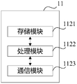
- the server 12 includes a processor 1202, a memory 1203, and a communication interface 1204, which are connected by a bus.
- the memory 1203 is configured to store code and data and the like for execution by the processor 1202, and the communication interface 1204 is configured to communicate with the first visual collection device 11 and the second visual collection device 13 in a wired or wireless manner.
- the second visual collection device 13 includes any mobile device with a common visual sensor, such as a mobile phone with a common monocular or binocular camera, a tablet computer, AR/MR glasses, etc., and can collect visual information of the current scene.
- the second visual acquisition device 13 can include a visual sensor 1301, a processor 1302, a memory 1303, and a communication interface 1304 that are connected by a bus.
- the memory 1303 is configured to store code and data and the like for execution by the processor 1302, and the processor 1302 controls the visual sensor 1101 to collect visual information of the current location, and controls to receive the three-dimensional scene from the server 12 by the communication interface 1104 in a wired or wireless manner. model.
- the visual information described in the embodiment of the present application includes an RGB image frame or a gray scale image frame of the current image frame, and the depth information includes a depth of field.
- the pose described in the embodiment of the present application refers to the position and posture of the visual acquisition device.
- the three-dimensional scene model described in the embodiments of the present application includes a point cloud having three-dimensional coordinate points.
- the point cloud described in the embodiment of the present application refers to a point data set of an object surface in a current scene obtained by a measuring instrument.
- a point cloud having a relatively small number of points and a large point-to-point spacing is called a sparse point cloud.
- a relatively large and dense point cloud is called a dense point cloud.
- the embodiment of the present application provides a three-dimensional scene positioning method, which is referred to in FIG. 5 .
- the indication includes: steps S101-S103.
- the process of generating the three-dimensional map data may be implemented on the first visual collection device or the server.
- the embodiment of the present application is not limited herein.
- the three-dimensional map data can be stored on the server such that other devices for positioning can share the three-dimensional map data.
- the device for acquiring the second visual information may be different from the device for acquiring the first visual information. Since the first visual information is used to generate three-dimensional map data, the accuracy requirement thereof is high, and may be performed by a dedicated visual acquisition device, for example, as described above. A visual acquisition device to obtain. The second visual information is only used for positioning according to the above three-dimensional map data, so the accuracy requirement is low, and can be acquired by the second visual collection device as described above.
- a variety of feature extractions can be performed on the visual information, such as extracting corner features, line features, shape features, or vSLAM features.
- the process of performing feature extraction on the second visual information may be implemented on the second visual collection device or the server.
- the embodiment of the present application is not limited herein.
- the second visual feature may be mapped and matched with different three-dimensional scene models in the three-dimensional map data, and the corresponding three-dimensional scene model is simultaneously displayed when the second visual information is displayed, the mixed reality is realized, and the second visual information is realized in the three-dimensional scene model. Positioning.
- the first visual collection device collects first visual information and corresponding depth information of the current scene.
- the first visual acquisition device acquires the current frame image
- the corresponding depth information that is, the depth of field
- the first visual collection device performs feature extraction on the first visual information to obtain a first visual feature.
- the visual feature library may include a feature binary robust independent elementary feature (ORB) feature library, and the first visual acquisition device extracts the ORB feature from the first visual information.
- ORB feature binary robust independent elementary feature
- the overall gray scale distribution information can be extracted for the first visual information
- the commonly used feature extraction and positioning methods include LSD-SLAM (large scale direct simultaneous localization and mapping). The embodiments of the present application are not described herein.
- the first visual acquiring device performs feature matching on the first visual feature and the visual feature database to obtain a rotation matrix and a displacement matrix of the first visual information, and calculates the first visual information according to the rotation matrix and the displacement matrix of the first visual information. Real-time pose, And updating the visual feature library with the first visual feature.
- the ORB feature of the first visual information is matched with the existing key frame ORB feature library, and the rotation matrix and the displacement matrix of the first visual information are calculated, thereby calculating the first vision according to the rotation matrix and the displacement matrix of the first visual information.
- the real-time pose of the acquisition device when acquiring the first visual information it is determined whether the key frame ORB feature database needs to be updated with the first visual information. That is, whether the first visual information is added to the key frame ORB feature library, or whether the first visual information is replaced with a certain frame in the key frame ORB feature library. For example, whether the number of common feature points of the first visual information and the key frame ORB feature database can be compared is less than a preset threshold, and if not, the first visual information is added to the key frame ORB feature library.
- S2041 Perform three-dimensional scene reconstruction using the calculated real-time pose and the collected depth information to generate a three-dimensional point cloud of the first visual information.
- S2042 Perform a fusion, denoising, and deleting a repeated point on the three-dimensional point cloud of the first visual information to finally obtain a three-dimensional scene model.
- the three-dimensional map data includes a visual feature library and a three-dimensional scene model.
- the server receives the visual feature library and the three-dimensional scene model from the first visual collection device.
- the server sends the visual feature database and the three-dimensional scene model to the second visual collection device.
- the second visual collection device collects second visual image information of the current scene.
- the second visual collection device performs feature extraction on the second visual image information to obtain a second visual feature.
- the ORB feature is extracted for the second visual information to obtain the ORB feature of the second visual information as the second visual feature.
- the overall grayscale distribution information is extracted for the second visual information to obtain the overall grayscale distribution feature of the second visual information as the second visual feature.
- Step S211 corresponds to step S102.
- step S212 specifically includes:
- the ORB feature of the second visual information is feature-matched according to the key frame ORB feature library.
- Figure 10 An example of feature matching for an ORB feature is shown, where the small box is an ORB feature point.
- An example of feature matching for the overall grayscale distribution feature is shown in FIG.
- the PnP pose calculation is performed on the ORB feature of the feature-matched second visual information to obtain the real-time pose of the second visual acquisition device.
- FIG. 12 is a schematic diagram showing the result of performing three-dimensional scene positioning on the ORB feature, and the star symbol in the figure indicates the positioning position.
- Fig. 13 there is shown a schematic diagram of the result of three-dimensional scene localization of the overall grayscale distribution feature, the white arrows in the figure indicating the positioning position and direction. Steps S212-S213 correspond to step S103.
- the first visual collection device updates the visual feature database with the first visual information of the current scene and acquires the real-time pose of the first visual acquisition device, and the real-time pose of the first visual acquisition device.
- the second visual acquiring device acquires the visual feature database and the three-dimensional scene model from the server, and then The second visual information extracts the visual feature information, obtains the real-time pose according to the visual feature information and the visual feature database, realizes the positioning according to the real-time pose and the three-dimensional scene model, and realizes sharing the three-dimensional between the first visual acquiring device and the second visual collecting device.
- the scene model and visual feature library achieve the purpose of sharing 3D map data.
- the embodiment of the present application can realize high-precision three-dimensional map data sharing, and realizes dense three-dimensional reconstruction by using a visual acquisition device with dedicated color and depth sensors in an offline three-dimensional scene reconstruction stage, and even can be performed by a high-speed computing unit. Intelligently combine, denoise, and remove duplicate points to optimize the number of generated 3D point clouds, making the 3D reconstruction point cloud more accurate to meet the graphics rendering requirements in MR applications. At the same time, the visual feature information of these high-precision point clouds is extracted as shared data.
- the embodiment of the present application provides another three-dimensional scene positioning. Referring to FIG. 14 , the method includes:
- the first visual collection device collects third visual information and corresponding depth information of the current scene.
- the first visual collection device performs three-dimensional scene reconstruction on the third visual information and the corresponding depth information to generate a three-dimensional dense point cloud, or performs three-dimensional scene reconstruction on the depth information to generate the three-dimensional dense point cloud.
- indoors can use a mobile device with dedicated color and depth sensor devices (such as RGB-D, Microsoft's Kinect or Intel's RealSense) to capture RGB images and their corresponding depth image data to form a three-dimensional dense point cloud (x, y, z) RGBD , which can use 3D lidar to scan depth information to form a 3D dense point cloud (x, y, z) Radar .
- dedicated color and depth sensor devices such as RGB-D, Microsoft's Kinect or Intel's RealSense
- the first visual collection device sends the three-dimensional dense point cloud to the server.
- the server receives the three-dimensional dense point cloud from the first visual collection device.
- the second visual collection device collects fourth visual information of the current scene.
- the second visual collection device performs a three-dimensional scene reconstruction on the fourth visual information of the current scene to generate a vSLAM (visual simultaneous localization and mapping) sparse point cloud.
- vSLAM visual simultaneous localization and mapping
- the fourth visual information may also be the third visual information.
- the third visual information is reconstructed by the first visual acquisition device to generate a vSLAM sparse point cloud.
- Each three-dimensional point (x, y, z) vSLAM in the vSLAM sparse point cloud corresponds to the feature information F vSLAM of the visual information (eg, corner feature, line feature or shape feature, etc.).
- the second visual collection device sends the vSLAM sparse point cloud to the server.
- the server receives the vSLAM sparse point cloud from the second visual collection device.
- the server aligns the three-dimensional dense point cloud with the vSLAM sparse point cloud to reconstruct the three-dimensional scene model.
- steps S3091-S3093 are included:
- the vSLAM sparse point cloud extracts the point cloud feature to obtain the vSLAM sparse point cloud feature
- the three-dimensional dense point cloud extracts the point cloud feature to obtain the three-dimensional dense point cloud feature.
- the point cloud feature can adopt the common point feature histograms (PFH), fast point feature histograms (FPFH), and viewpoint feature histogram (VFH). Signature of histograms of orientations (SHOT) and so on.
- S3092 Performing a three-dimensional point cloud registration calculation on the vSLAM sparse point cloud feature and the three-dimensional dense point cloud feature to obtain a conversion relationship RT between the vSLAM sparse point cloud and the three-dimensional dense point cloud.
- S3093 Align the vSLAM sparse point cloud with the three-dimensional dense point cloud three-dimensional dense point registration according to the conversion relationship between the vSLAM sparse point cloud and the three-dimensional dense point cloud to reconstruct the three-dimensional scene model.
- the three-dimensional map data is a three-dimensional scene model.
- Steps S302, S306, and S309 correspond to step S101.
- the server sends the three-dimensional scene model to the second visual collection device.
- the second visual collection device collects second visual information.
- the second visual acquisition device is based on the real-time pose and the three-dimensional of the second visual information.
- the mapping relationship of the corresponding three-dimensional scene model in the map data loads the three-dimensional scene model on the second visual information to realize the positioning of the second visual information in the three-dimensional scene model.
- the perspective of the current device is mapped into the three-dimensional scene model, and the high-precision three-dimensional map environment information can be presented on the second visual acquisition device.
- the fifth visual information 1701 collected in real time may be displayed in the same interface as the corresponding virtual three-dimensional scene model 1702.
- Step S314 corresponds to step S103.
- the first visual acquiring device performs three-dimensional scene reconstruction on the third visual information and the corresponding depth information to generate a three-dimensional dense point cloud, and sends the three-dimensional dense point cloud to the server;
- the acquiring device performs three-dimensional scene reconstruction on the fourth visual information to generate a vSLAM sparse point cloud, and sends the vSLAM sparse point cloud to the server;
- the server aligns the three-dimensional dense point cloud with the vSLAM sparse point cloud to reconstruct the three-dimensional scene model;
- the second visual acquisition device acquires a three-dimensional scene model from the server, extracts a vSLAM visual feature from the fifth visual information, and the vSLAM visual feature includes a real-time pose of the second visual acquisition device, and then according to the real-time pose and the three-dimensional scene of the second visual acquisition device.
- the model locates the second visual acquisition device, realizes sharing a three-dimensional scene model between the first visual acquisition device and the second visual acquisition device,
- the embodiments of the present application may divide the functional modules of each device according to the foregoing method example.
- each functional module may be divided according to each function, or two or more functions may be integrated into one processing module.
- the above integrated modules can be implemented in the form of hardware or in the form of software functional modules. It should be noted that the division of the module in the embodiment of the present application is schematic, and is only a logical function division, and the actual implementation may have another division manner.
- FIG. 18 is a schematic diagram showing a possible structure of the three-dimensional scene locating device involved in the above embodiment.
- the three-dimensional scene locating device 10 includes: a generating unit 1011 and an extracting unit. 1012.
- the generating unit 1011 is configured to support a three-dimensional scene
- the positioning device performs the process S101 in FIG. 5, the processes S202-S204 in FIG. 6, the processes S2041 and S2042 in FIG. 7, the processes S302, S306, S309 in FIG. 14, the processes S3091-S3093 in FIG. 15, and the extraction unit 1012 is used to support the three-dimensional scene locating device to perform the process S102 in FIG. 5, the process S211 in FIG. 6, the process S313 in FIG.
- the positioning unit 1013 is configured to support the three-dimensional scene locating device to execute the process S103 in FIG. 5, FIG. Processes S212 and S213, processes S2121 and S2122 in FIG. 9, process S314 in FIG. 14; calibration unit 1014 is configured to support the three-dimensional scene location device to perform process S207 in FIG. All the related content of the steps involved in the foregoing method embodiments may be referred to the functional descriptions of the corresponding functional modules, and details are not described herein again.
- FIG. 19 shows a possible structural diagram of the three-dimensional scene locating device involved in the above embodiment.
- the three-dimensional scene positioning device 10 includes a processing module 1022 and a communication module 1023.
- the processing module 1022 is configured to control and manage the actions of the three-dimensional scene positioning device.
- the processing module 1022 is configured to support the three-dimensional scene positioning device to perform the processes S101-S103 in FIG. 5.
- the communication module 1013 is for supporting communication of the three-dimensional scene location device with other entities, such as communication with the functional modules or network entities shown in FIG.
- the three-dimensional scene location device 10 may further include a storage module 1021 for storing program codes and data of the three-dimensional scene location device.
- the three-dimensional scene positioning device When the processing module 1022 is a processor, the communication module 1023 is a transceiver, and the storage module 1021 is a memory, the three-dimensional scene positioning device according to the embodiment of the present application may be the three-dimensional scene positioning device shown in FIG.
- the steps of a method or algorithm described in connection with the present disclosure may be implemented in a hardware or may be implemented by a processor executing software instructions.
- the embodiment of the present application further provides a storage medium, which may include a memory 1031 for storing computer software instructions used by the three-dimensional scene location device, including program code designed to execute a three-dimensional scene location method.
- the software instructions may be composed of corresponding software modules, and the software modules may be stored in a random access memory (RAM), a flash memory, a read only memory (ROM), and an erasable programmable only.
- RAM random access memory
- ROM read only memory
- EEPROM electrically erasable programmable read only memory
- An exemplary storage medium is coupled to the processor to enable the processor to read information from, and write information to, the storage medium.
- the storage medium can also be an integral part of the processor.
- the processor and the storage medium can be located in an ASIC. Additionally, the ASIC can be located in a three dimensional scene location device.
- the processor and the storage medium can also exist as discrete components in the three-dimensional scene location device.
- the embodiment of the present application further provides a computer program, which can be directly loaded into the memory 1031 and contains software code, and the computer program can be loaded and executed by a computer to implement the above-described three-dimensional scene localization method.
Landscapes
- Engineering & Computer Science (AREA)
- Software Systems (AREA)
- Physics & Mathematics (AREA)
- Theoretical Computer Science (AREA)
- Computer Graphics (AREA)
- Remote Sensing (AREA)
- General Physics & Mathematics (AREA)
- Geometry (AREA)
- Computer Hardware Design (AREA)
- General Engineering & Computer Science (AREA)
- Radar, Positioning & Navigation (AREA)
- Processing Or Creating Images (AREA)
- Length Measuring Devices By Optical Means (AREA)
Abstract
Description
本申请涉及混合现实技术领域,尤其涉及一种三维场景定位方法和装置。The present application relates to the field of mixed reality technologies, and in particular, to a method and an apparatus for positioning a three-dimensional scene.
混合现实技术(mixed reality,MR)是一种实时地计算摄影机影像的位置及角度并在影像上叠加图像、视频、3D模型的技术,这种技术的目标是在屏幕上把虚拟世界叠加在现实世界并进行互动。目前市场上已经比较成熟的MR技术产品包括微软的全息眼镜HoloLens,因特尔的VR(virtual reality,虚拟现实)/AR(augmented reality,增强现实)一体头显Alloy等。Mixed reality (MR) is a technique for calculating the position and angle of a camera image in real time and superimposing images, videos, and 3D models on the image. The goal of this technology is to superimpose the virtual world on the screen. The world interacts. At present, the mature MR technology products on the market include Microsoft's holographic glasses HoloLens, Intel's VR (virtual reality) / AR (augmented reality), and the like.
微软的HoloLens采用了四颗摄像头即两组双目摄像头作为传感器,结合头盔正中央的TOF(time of flight,飞行时间)传感器实现当前场景的三维重建。因特尔的Alloy工作原理与HoloLens类似,不过它采用因特尔自己开发的RealSense 3D结构光实感摄像头作为传感器。除了一对双目摄像头以外还内置了两套结构光深度摄像头,能够直接采集深度图像恢复三维场景。Microsoft's HoloLens uses four cameras, two sets of binocular cameras as sensors, and combines the TOF (time of flight) sensor in the center of the helmet to achieve three-dimensional reconstruction of the current scene. Intel's Alloy works similarly to HoloLens, but it uses the RealSense 3D structured real-life camera developed by Intel itself as a sensor. In addition to a pair of binocular cameras, two sets of structured light depth cameras are built in, which can directly capture depth images to restore 3D scenes.
上述MR头显设备,均是由头盔上集成的专用彩色和深度传感器采集真实世界的图像和深度数据,而没有采用集成度更高的单目,双目视觉传感器,其原因是现有的单目和双目传感器无法实现密集和高精度的三维重建,而且对于计算资源要求很高,无法集成在移动终端设备上。此外,上述两款设备之间无法共享三维地图数据,也就是说HoloLens构建的三维场景无法用Alloy设备体验,反之亦然。另外,在高精度3D地图导航应用领域,往往高精度3D地图街景扫描设备复杂,体积庞大和昂贵,普通消费者不便携带这些专业的设备去定位和导航。The above-mentioned MR head-display devices capture real-world image and depth data by dedicated color and depth sensors integrated on the helmet, without the use of a more integrated monocular, binocular vision sensor due to the existing single Mesh and binocular sensors are not capable of dense and high-precision 3D reconstruction, and are computationally resource intensive and cannot be integrated into mobile devices. In addition, the three-dimensional map data cannot be shared between the above two devices, which means that the 3D scene built by HoloLens cannot be experienced by the Alloy device, and vice versa. In addition, in the field of high-precision 3D map navigation applications, high-precision 3D map street view scanning devices are often complicated, bulky and expensive, and ordinary consumers do not carry these professional devices to locate and navigate.
申请内容 Application content
本申请的实施例提供一种三维场景定位方法和装置,用于共享三维地图数据。Embodiments of the present application provide a three-dimensional scene positioning method and apparatus for sharing three-dimensional map data.
为达到上述目的,本申请的实施例采用如下技术方案:To achieve the above objective, the embodiment of the present application adopts the following technical solutions:
第一方面,提供了一种三维场景定位方法,包括:In a first aspect, a method for positioning a three-dimensional scene is provided, including:
根据当前场景的第一视觉信息以及与所述第一视觉信息对应的深度信息生成三维地图数据,所述三维地图数据中包括三维场景模型;对当前场景的第二视觉信息进行特征提取得到第二视觉特征;根据所述第二视觉特征与所述三维地图数据的映射关系,在所述第二视觉信息上加载对应的三维场景模型,实现所述第二视觉信息在所述三维场景模型中的定位。Generating three-dimensional map data according to the first visual information of the current scene and the depth information corresponding to the first visual information, where the three-dimensional map data includes a three-dimensional scene model; and extracting the second visual information of the current scene to obtain a second feature a visual feature; loading a corresponding three-dimensional scene model on the second visual information according to the mapping relationship between the second visual feature and the three-dimensional map data, and implementing the second visual information in the three-dimensional scene model Positioning.
第二方面,提供了一种三维场景定位装置,包括:In a second aspect, a three-dimensional scene positioning apparatus is provided, including:
生成单元,用于根据当前场景的第一视觉信息以及与所述第一视觉信息对应的深度信息生成三维地图数据,所述三维地图数据中包括三维场景模型;a generating unit, configured to generate three-dimensional map data according to the first visual information of the current scene and the depth information corresponding to the first visual information, where the three-dimensional map data includes a three-dimensional scene model;
提取单元,用于对当前场景的第二视觉信息进行特征提取得到第二视觉特征;An extracting unit, configured to perform feature extraction on the second visual information of the current scene to obtain a second visual feature;
定位单元,用于根据所述第二视觉特征与所述三维地图数据的映射关系,在所述第二视觉信息上加载对应的三维场景模型,实现所述第二视觉信息在所述三维场景模型中的定位。a positioning unit, configured to load a corresponding three-dimensional scene model on the second visual information according to a mapping relationship between the second visual feature and the three-dimensional map data, to implement the second visual information in the three-dimensional scene model Positioning in .
第三方面,提供了一种计算机存储介质,用于储存为三维场景定位装置所用的计算机软件指令,其包含执行第一方面所述的三维场景定位方法所设计的程序代码。In a third aspect, a computer storage medium is provided for storing computer software instructions for use in a three-dimensional scene location device, comprising program code designed to perform the three-dimensional scene location method of the first aspect.
第四方面,提供了一种计算机程序产品,可直接加载到计算机的内部存储器中,并含有软件代码,所述计算机程序经由计算机载入并执行后能够实现第一方面所述的三维场景定位方法。In a fourth aspect, a computer program product is provided that can be directly loaded into an internal memory of a computer and includes software code, and the computer program can be loaded and executed by a computer to implement the three-dimensional scene positioning method according to the first aspect. .
第五方面,提供了一种三维场景定位装置,包括:存储器、通信接口和处理器,所述存储器用于存储计算机执行代码,所述处理器用于执行所述计算机执行代码控制执行第一方面所述三维场景定位方法,所述通信接口用于所述三维场景定位装置与外部设备的数 据传输。A fifth aspect provides a three-dimensional scene positioning apparatus, including: a memory, a communication interface, and a processor, the memory is configured to store computer execution code, and the processor is configured to execute the computer to perform code control execution. The three-dimensional scene positioning method, the communication interface is used for the number of the three-dimensional scene positioning device and the external device According to transmission.
本申请实施例提供的三维场景定位方法和装置,通过根据第一视觉信息以及与所述第一视觉信息对应的深度信息生成三维地图数据;对第二视觉信息进行特征提取得到第二视觉特征;根据第二视觉特征与三维地图数据的映射关系,在第二视觉信息上加载对应的三维场景模型,实现第二视觉信息在三维场景模型中的定位。使得根据第一视觉信息和对应深度信息生成的三维地图数据可以用于第二视觉信息的定位,实现了三维地图数据的共享。The method and device for positioning a three-dimensional scene provided by the embodiment of the present application generates three-dimensional map data according to the first visual information and depth information corresponding to the first visual information, and performs feature extraction on the second visual information to obtain a second visual feature. According to the mapping relationship between the second visual feature and the three-dimensional map data, the corresponding three-dimensional scene model is loaded on the second visual information to realize the positioning of the second visual information in the three-dimensional scene model. The three-dimensional map data generated according to the first visual information and the corresponding depth information can be used for the positioning of the second visual information, and the sharing of the three-dimensional map data is realized.
为了更清楚地说明本申请实施例或现有技术中的技术方案,下面将对实施例或现有技术描述中所需要使用的附图作简单地介绍,显而易见地,下面描述中的附图仅仅是本申请的一些实施例,对于本领域普通技术人员来讲,在不付出创造性劳动的前提下,还可以根据这些附图获得其他的附图。In order to more clearly illustrate the embodiments of the present application or the technical solutions in the prior art, the drawings to be used in the embodiments or the prior art description will be briefly described below. Obviously, the drawings in the following description are only It is a certain embodiment of the present application, and other drawings can be obtained according to the drawings without any creative work for those skilled in the art.
图1为本申请实施例提供的三维场景定位系统的结构示意图;FIG. 1 is a schematic structural diagram of a three-dimensional scene positioning system according to an embodiment of the present application;
图2为本申请实施例提供的第一视觉采集设备的结构示意图;2 is a schematic structural diagram of a first visual collection device according to an embodiment of the present application;
图3为本申请实施例提供的服务器的结构示意图;FIG. 3 is a schematic structural diagram of a server according to an embodiment of the present application;
图4为本申请实施例提供的第二视觉采集设备的结构示意图;4 is a schematic structural diagram of a second visual collection device according to an embodiment of the present application;
图5为本申请实施例提供的一种三维场景定位方法的流程示意图;FIG. 5 is a schematic flowchart of a method for positioning a three-dimensional scene according to an embodiment of the present disclosure;
图6为本申请实施例提供的另一种三维场景定位方法的流程示意图;FIG. 6 is a schematic flowchart diagram of another method for positioning a three-dimensional scene according to an embodiment of the present disclosure;
图7为本申请实施例提供的更新视觉特征库以及进行三维场景重建得到三维场景模型的流程示意图;FIG. 7 is a schematic flowchart of updating a visual feature database and performing a three-dimensional scene reconstruction to obtain a three-dimensional scene model according to an embodiment of the present application;
图8为本申请实施例提供的一种三维场景模型结果的示意图;FIG. 8 is a schematic diagram of a result of a three-dimensional scene model according to an embodiment of the present application;
图9为本申请实施例提供的得到第二视觉采集设备的实时位姿的流程示意图;FIG. 9 is a schematic flowchart of obtaining a real-time pose of a second visual collection device according to an embodiment of the present application;
图10为本申请实施例提供的对ORB特征进行特征匹配的结果的示意图; FIG. 10 is a schematic diagram of a result of performing feature matching on an ORB feature according to an embodiment of the present application; FIG.
图11为本申请实施例提供的对整体灰度分布特征进行特征匹配的结果的示意图;FIG. 11 is a schematic diagram of a result of performing feature matching on an overall grayscale distribution feature according to an embodiment of the present application; FIG.
图12为本申请实施例提供的对ORB特征进行三维场景定位的结果的示意图;FIG. 12 is a schematic diagram of a result of performing three-dimensional scene positioning on an ORB feature according to an embodiment of the present application;
图13为本申请实施例提供的对整体灰度分布特征进行三维场景定位的结果的示意图;FIG. 13 is a schematic diagram of a result of performing three-dimensional scene positioning on an overall grayscale distribution feature according to an embodiment of the present disclosure;
图14为本申请实施例提供的另一种三维场景定位方法的流程示意图;FIG. 14 is a schematic flowchart diagram of another method for positioning a three-dimensional scene according to an embodiment of the present disclosure;
图15为本申请实施例提供的对三维密集点云与vSLAM稀疏点云配准对齐以重建三维场景模型的流程示意图;FIG. 15 is a schematic flowchart diagram of aligning a three-dimensional dense point cloud with a vSLAM sparse point cloud registration to reconstruct a three-dimensional scene model according to an embodiment of the present application;
图16为本申请实施例提供的vSLAM稀疏点云和三维密集点云融合形成三维点云的示意图;16 is a schematic diagram of a vSLAM sparse point cloud and a three-dimensional dense point cloud fused to form a three-dimensional point cloud according to an embodiment of the present disclosure;
图17为本申请实施例提供的根据实时位姿和三维场景模型对第二视觉采集设备进行定位的示意图;FIG. 17 is a schematic diagram of positioning a second visual collection device according to a real-time pose and a three-dimensional scene model according to an embodiment of the present application;
图18为本申请实施例提供的一种三维场景定位装置的结构示意图;FIG. 18 is a schematic structural diagram of a three-dimensional scene positioning apparatus according to an embodiment of the present disclosure;
图19为本申请实施例提供的又一种三维场景定位装置的结构示意图;FIG. 19 is a schematic structural diagram of still another three-dimensional scene positioning apparatus according to an embodiment of the present application;
图20为本申请实施例提供的另一种三维场景定位装置的结构示意图。FIG. 20 is a schematic structural diagram of another three-dimensional scene positioning apparatus according to an embodiment of the present disclosure.
下面结合附图,对本申请的实施例进行描述。Embodiments of the present application will be described below with reference to the accompanying drawings.
本申请实施例提供了一种三维场景定位系统,参照图1中所示,包括:第一视觉采集设备11、服务器12、第二视觉采集设备13。The embodiment of the present application provides a three-dimensional scene positioning system, as shown in FIG. 1, comprising: a first
第一视觉采集设备11包括具有专用的彩色和深度传感器器件的移动设备,例如RGB-D(red green blue-depth,红绿蓝——深度)设备、RGB-TOF(red green blue-time of flight,红绿蓝——飞行时间)设备、微软的Kinect或者因特尔的RealSense、三维激光雷达设备等,可以同时采集当前场景的视觉信息和深度信息。参照图2中
所示,该第一视觉采集设备11可以包括彩色和深度传感器1101、处理器1102、存储器1103和通信接口1104,它们通过总线方式进行连接。其中,存储器1103用于存储供处理器1102执行的代码以及数据等,由处理器1102控制彩色和深度传感器1101采集当前位置的视觉信息和深度信息后经过初步处理,然后通过通信接口1104以有线或无线方式发送给服务器12。The first
服务器12用于存储三维场景模型,以实现不同设备之间共享三维场景模型。参照图3中所示,服务器12包括:处理器1202、存储器1203和通信接口1204,它们通过总线方式进行连接。其中,存储器1203用于存储供处理器1202执行的代码以及数据等,通信接口1204用于以有线或无线方式与第一视觉采集设备11和第二视觉采集设备13进行通信。The
第二视觉采集设备13包括任意带有普通视觉传感器的移动设备,例如具有普通单目或者双目摄像头的手机、平板电脑、AR/MR眼镜等设备,可以采集当前场景的视觉信息。参照图4中所示,该第二视觉采集设备13可以包括视觉传感器1301、处理器1302、存储器1303和通信接口1304,它们通过总线方式进行连接。其中,存储器1303用于存储供处理器1302执行的代码以及数据等,由处理器1302控制视觉传感器1101采集当前位置的视觉信息,并且控制通过通信接口1104以有线或无线方式从服务器12接收三维场景模型。The second
本申请实施例所述的视觉信息包括当前图像帧的RGB图像帧或灰度色阶图像帧,深度信息包括景深。本申请实施例所述的位姿指视觉采集设备的位置和姿态。本申请实施例所述的三维场景模型包括具有三维坐标点的点云。本申请实施例所述的点云是指通过测量仪器得到的当前场景中物体表面的点数据集合,对于点数量比较少并且点与点的间距比较大的点云称为稀疏点云,对于点数量比较大并且比较密集的点云称为密集点云。The visual information described in the embodiment of the present application includes an RGB image frame or a gray scale image frame of the current image frame, and the depth information includes a depth of field. The pose described in the embodiment of the present application refers to the position and posture of the visual acquisition device. The three-dimensional scene model described in the embodiments of the present application includes a point cloud having three-dimensional coordinate points. The point cloud described in the embodiment of the present application refers to a point data set of an object surface in a current scene obtained by a measuring instrument. A point cloud having a relatively small number of points and a large point-to-point spacing is called a sparse point cloud. A relatively large and dense point cloud is called a dense point cloud.
本申请实施例提供了一种三维场景定位方法,参照图5中所 示,包括:步骤S101-S103。The embodiment of the present application provides a three-dimensional scene positioning method, which is referred to in FIG. 5 . The indication includes: steps S101-S103.
S101、根据当前场景的第一视觉信息以及与所述第一视觉信息对应的深度信息生成三维地图数据,三维地图数据中包括三维场景模型。S101. Generate three-dimensional map data according to first visual information of the current scene and depth information corresponding to the first visual information, where the three-dimensional map data includes a three-dimensional scene model.
第一视觉信息以及对应的深度信息可以在一个设备上获取,也可以在不同设备上获取,但要保证数据的一一对应关系,优选的采用如上所述的第一视觉采集设备来获取,以便根据视觉信息和深度信息形成三维地图数据。The first visual information and the corresponding depth information may be acquired on one device or may be acquired on different devices, but to ensure a one-to-one correspondence of the data, it is preferably obtained by using the first visual collection device as described above, so that The three-dimensional map data is formed based on the visual information and the depth information.
生成三维地图数据的过程可以直接在上述第一视觉采集设备上实现也可以由服务器来实现,本申请实施例在此不做限定。The process of generating the three-dimensional map data may be implemented on the first visual collection device or the server. The embodiment of the present application is not limited herein.
三维地图数据可以存储于服务器上,使得其他用于定位的设备可以共享该三维地图数据。The three-dimensional map data can be stored on the server such that other devices for positioning can share the three-dimensional map data.
S102、对当前场景的第二视觉信息进行特征提取得到第二视觉特征。S102. Perform feature extraction on the second visual information of the current scene to obtain a second visual feature.
获取第二视觉信息的设备可以与获取第一视觉信息的设备不同,由于第一视觉信息用于生成三维地图数据,因此其精度要求较高,可以由专用的视觉采集设备例如如上所述的第一视觉采集设备来获取。而第二视觉信息仅用于根据上述三维地图数据进行定位,因此其精度要求较低,可以为如上所述的第二视觉采集设备来获取。The device for acquiring the second visual information may be different from the device for acquiring the first visual information. Since the first visual information is used to generate three-dimensional map data, the accuracy requirement thereof is high, and may be performed by a dedicated visual acquisition device, for example, as described above. A visual acquisition device to obtain. The second visual information is only used for positioning according to the above three-dimensional map data, so the accuracy requirement is low, and can be acquired by the second visual collection device as described above.
对视觉信息可以进行多种特征提取,例如提取角点特征、直线特征、形状特征或vSLAM特征等。对第二视觉信息进行特征提取的过程可以直接在上述第二视觉采集设备上实现也可以由服务器来实现,本申请实施例在此不做限定。A variety of feature extractions can be performed on the visual information, such as extracting corner features, line features, shape features, or vSLAM features. The process of performing feature extraction on the second visual information may be implemented on the second visual collection device or the server. The embodiment of the present application is not limited herein.
S103、根据第二视觉特征与三维地图数据的映射关系,在第二视觉信息上加载对应的三维场景模型,实现第二视觉信息在三维场景模型中的定位。S103. Load a corresponding three-dimensional scene model on the second visual information according to the mapping relationship between the second visual feature and the three-dimensional map data, and implement positioning of the second visual information in the three-dimensional scene model.
可以将第二视觉特征与三维地图数据中不同三维场景模型进行映射匹配,在显示第二视觉信息时同时显示对应的三维场景模型,实现混合现实,同时实现第二视觉信息在三维场景模型中的定位。 The second visual feature may be mapped and matched with different three-dimensional scene models in the three-dimensional map data, and the corresponding three-dimensional scene model is simultaneously displayed when the second visual information is displayed, the mixed reality is realized, and the second visual information is realized in the three-dimensional scene model. Positioning.
本申请实施例提供的三维场景定位方法,通过根据第一视觉信息以及与所述第一视觉信息对应的深度信息生成三维地图数据;对第二视觉信息进行特征提取得到第二视觉特征;根据第二视觉特征与三维地图数据的映射关系,在第二视觉信息上加载对应的三维场景模型,实现第二视觉信息在三维场景模型中的定位。使得第二视觉信息根据第一视觉信息和对应深度信息生成的三维地图数据可以用于第二视觉信息的定位,实现了三维地图数据的共享。The three-dimensional scene positioning method provided by the embodiment of the present application generates three-dimensional map data according to the first visual information and the depth information corresponding to the first visual information, and performs feature extraction on the second visual information to obtain a second visual feature; The mapping relationship between the second visual feature and the three-dimensional map data loads the corresponding three-dimensional scene model on the second visual information to realize the positioning of the second visual information in the three-dimensional scene model. The three-dimensional map data generated by the second visual information according to the first visual information and the corresponding depth information may be used for positioning of the second visual information, and the sharing of the three-dimensional map data is realized.
本申请实施例提供了另一种三维场景定位方法,参照图6中所示,该方法包括:步骤S201-S114。An embodiment of the present application provides another method for positioning a three-dimensional scene. Referring to FIG. 6, the method includes: steps S201-S114.
S201、第一视觉采集设备采集当前场景的第一视觉信息和对应的深度信息。S201. The first visual collection device collects first visual information and corresponding depth information of the current scene.
第一视觉采集设备每次采集当前帧图像时会同时获取对应的深度信息即景深。Each time the first visual acquisition device acquires the current frame image, the corresponding depth information, that is, the depth of field, is simultaneously acquired.
S202、第一视觉采集设备对第一视觉信息进行特征提取得到第一视觉特征。S202. The first visual collection device performs feature extraction on the first visual information to obtain a first visual feature.
根据图像特征的描述方式不同,可以选择不同方式提取视觉特征后汇集为视觉特征库。视觉特征库可以包括角点特征、直线特征、形状特征等。Depending on how the image features are described, different methods can be selected to extract the visual features and then aggregated into a visual feature library. The visual feature library can include corner features, line features, shape features, and the like.
对于角点特征描述方式来说,视觉特征库可以包括关键帧ORB(oriented binary robust independent elementary features,面向二进制鲁棒独立基本特征)特征库,第一视觉采集设备对第一视觉信息提取ORB特征得到第一视觉信息的ORB特征。For the feature description of the corner feature, the visual feature library may include a feature binary robust independent elementary feature (ORB) feature library, and the first visual acquisition device extracts the ORB feature from the first visual information. The ORB feature of the first visual information.
对于线性描述方式来说,可以对第一视觉信息提取整体灰度分布信息,比较常用的特征提取和定位方法包括LSD-SLAM(large scale direct simultaneous localization and mapping,大尺度直接即时定位与地图构建),本申请实施例在此不赘述。For the linear description method, the overall gray scale distribution information can be extracted for the first visual information, and the commonly used feature extraction and positioning methods include LSD-SLAM (large scale direct simultaneous localization and mapping). The embodiments of the present application are not described herein.
S203、第一视觉采集设备将第一视觉特征与视觉特征库进行特征匹配计算得到第一视觉信息的旋转矩阵和位移矩阵,根据第一视觉信息的旋转矩阵和位移矩阵计算得到第一视觉信息的实时位姿, 并且用第一视觉特征更新视觉特征库。S203. The first visual acquiring device performs feature matching on the first visual feature and the visual feature database to obtain a rotation matrix and a displacement matrix of the first visual information, and calculates the first visual information according to the rotation matrix and the displacement matrix of the first visual information. Real-time pose, And updating the visual feature library with the first visual feature.
将第一视觉信息的ORB特征与现有的关键帧ORB特征库进行匹配,计算得到第一视觉信息的旋转矩阵和位移矩阵,从而根据第一视觉信息的旋转矩阵和位移矩阵计算得到第一视觉采集设备采集第一视觉信息时的实时位姿。同时判定是否需要用第一视觉信息对关键帧ORB特征数据库进行更新。即是否将第一视觉信息加入关键帧ORB特征库,或者是否将第一视觉信息替换关键帧ORB特征库中的某一帧。例如,可以比较第一视觉信息与关键帧ORB特征数据库的公共特征点数目是否小于预设门限,如果小于则将第一视觉信息加入关键帧ORB特征库。The ORB feature of the first visual information is matched with the existing key frame ORB feature library, and the rotation matrix and the displacement matrix of the first visual information are calculated, thereby calculating the first vision according to the rotation matrix and the displacement matrix of the first visual information. The real-time pose of the acquisition device when acquiring the first visual information. At the same time, it is determined whether the key frame ORB feature database needs to be updated with the first visual information. That is, whether the first visual information is added to the key frame ORB feature library, or whether the first visual information is replaced with a certain frame in the key frame ORB feature library. For example, whether the number of common feature points of the first visual information and the key frame ORB feature database can be compared is less than a preset threshold, and if not, the first visual information is added to the key frame ORB feature library.
S204、根据深度信息以及第一视觉信息的实时位姿进行三维场景重建得到三维场景模型。S204. Perform a three-dimensional scene reconstruction according to the depth information and the real-time pose of the first visual information to obtain a three-dimensional scene model.
对于角点特征描述方式来说,参照图7中所示,对第一视觉采集设备的实时位姿和深度信息进行三维场景重建得到三维场景模型具体包括:For the description of the corner feature, referring to FIG. 7, the three-dimensional scene reconstruction of the real-time pose and depth information of the first visual acquisition device to obtain the three-dimensional scene model specifically includes:
S2041、利用计算的实时位姿以及采集的深度信息进行三维场景重建以生成第一视觉信息的三维点云。S2041: Perform three-dimensional scene reconstruction using the calculated real-time pose and the collected depth information to generate a three-dimensional point cloud of the first visual information.
三维场景重建得到的三维点云效果如图8中所示(图中去除了颜色信息)。The 3D point cloud effect obtained from the 3D scene reconstruction is shown in Figure 8 (the color information is removed in the figure).
S2042、对第一视觉信息的三维点云进行融合、去噪、删除重复点等运算最终得到三维场景模型。S2042: Perform a fusion, denoising, and deleting a repeated point on the three-dimensional point cloud of the first visual information to finally obtain a three-dimensional scene model.
步骤S202-S204对应于步骤S101。Steps S202-S204 correspond to step S101.
S205、第一视觉采集设备将更新的视觉特征库和三维场景模型发送给服务器进行存储。S205. The first visual collection device sends the updated visual feature database and the three-dimensional scene model to the server for storage.
此时三维地图数据包括视觉特征库和三维场景模型。At this time, the three-dimensional map data includes a visual feature library and a three-dimensional scene model.
S206、服务器从第一视觉采集设备接收视觉特征库和三维场景模型。S206. The server receives the visual feature library and the three-dimensional scene model from the first visual collection device.
S207、第二视觉采集设备对第二视觉采集设备的视觉传感器进行标定以得到第二视觉采集设备的视觉传感器的相机参数,并根据 相机参数对第二视觉采集设备的视觉传感器进行矫正。S207. The second visual acquisition device calibrates the visual sensor of the second visual acquisition device to obtain a camera parameter of the visual sensor of the second visual acquisition device, and according to The camera parameters correct the visual sensor of the second visual acquisition device.
用户在使用第二视觉采集设备采集视觉信息之前,需要对该设备进行标定以确定视觉传感器的相机参数,相机参数包括主点、焦距和畸变校正参数等参数信息,其中畸变校正参数用于标识第二视觉采集设备的视觉传感器拍摄图像时产生的图像畸变。主点、焦距等参数用于对相机进行对焦。首先选定第二视觉采集设备的摄像头类型(深度、双目或单目),然后用第二视觉采集设备对摄像头标定图案拍摄多张(例如20至30张)不同角度的照片。通过对标定图案的检测和配准,计算出该第二视觉采集设备所采用视觉传感器的相机参数,然后用该相机参数对应视觉传感器进行矫正即得到经矫正的第二视觉采集设备。Before using the second visual acquisition device to collect visual information, the user needs to calibrate the device to determine camera parameters of the visual sensor. The camera parameters include parameter information such as a principal point, a focal length, and a distortion correction parameter, where the distortion correction parameter is used to identify the The visual sensor of the second visual acquisition device is distorted when the image is taken. Parameters such as the main point and focal length are used to focus the camera. First select the camera type (depth, binocular or monocular) of the second visual acquisition device, and then use the second visual acquisition device to take multiple (eg 20 to 30) different angle photos of the camera calibration pattern. By detecting and registering the calibration pattern, the camera parameters of the vision sensor used by the second vision acquisition device are calculated, and then the camera parameters are corrected corresponding to the vision sensor to obtain the corrected second vision acquisition device.
S208、服务器将视觉特征库和三维场景模型发送给第二视觉采集设备。S208. The server sends the visual feature database and the three-dimensional scene model to the second visual collection device.
S209、第二视觉采集设备从服务器接收视觉特征库和三维场景模型。S209. The second visual collection device receives the visual feature library and the three-dimensional scene model from the server.
S210、第二视觉采集设备采集当前场景的第二视觉图像信息。S210. The second visual collection device collects second visual image information of the current scene.
S211、第二视觉采集设备对第二视觉图像信息进行特征提取得到第二视觉特征。S211. The second visual collection device performs feature extraction on the second visual image information to obtain a second visual feature.
对于角点特征描述方式来说,对第二视觉信息提取ORB特征得到第二视觉信息的ORB特征作为第二视觉特征。对于直线特征描述方式来说,对第二视觉信息提取整体灰度分布信息得到第二视觉信息的整体灰度分布特征作为第二视觉特征。For the corner feature description manner, the ORB feature is extracted for the second visual information to obtain the ORB feature of the second visual information as the second visual feature. For the linear feature description mode, the overall grayscale distribution information is extracted for the second visual information to obtain the overall grayscale distribution feature of the second visual information as the second visual feature.
步骤S211对应于步骤S102。Step S211 corresponds to step S102.
S212、根据第二视觉特征、视觉特征库得到第二视觉采集设备采集第二视觉信息时的实时位姿。S212. Obtain a real-time pose when the second visual information collection device acquires the second visual information according to the second visual feature and the visual feature database.
参照图9中所示,步骤S212具体包括:Referring to FIG. 9, step S212 specifically includes:
S2121、根据视觉特征库对第二视觉特征进行特征匹配。S2121. Perform feature matching on the second visual feature according to the visual feature library.
示例性的,对于角点特征描述方式来说,根据关键帧ORB特征库对第二视觉信息的ORB特征进行特征匹配。示例性的,参照图10 中所示为ORB特征进行特征匹配的一种示例,其中的小方框为ORB特征点。参照图11中所示为整体灰度分布特征进行特征匹配的一种示例。Exemplarily, for the corner feature description manner, the ORB feature of the second visual information is feature-matched according to the key frame ORB feature library. Exemplarily, referring to Figure 10 An example of feature matching for an ORB feature is shown, where the small box is an ORB feature point. An example of feature matching for the overall grayscale distribution feature is shown in FIG.
S2122、对经特征匹配的第二视觉特征进行PnP(perspective n point problem,透视N点问题)位姿计算得到第二视觉信息的实时位姿。S2122: performing a PnP (perspective n point problem) pose calculation on the feature-matched second visual feature to obtain a real-time pose of the second visual information.
示例性的,对于角点特征描述方式来说,对经特征匹配的第二视觉信息的ORB特征进行PnP位姿计算得到第二视觉采集设备的实时位姿。Exemplarily, for the corner feature description manner, the PnP pose calculation is performed on the ORB feature of the feature-matched second visual information to obtain the real-time pose of the second visual acquisition device.
S213、根据第二视觉信息的实时位姿与三维地图数据中对应的三维场景模型的映射关系,在第二视觉信息上加载三维场景模型,以实现第二视觉信息在三维场景模型中的定位。S213. Load a three-dimensional scene model on the second visual information according to a mapping relationship between the real-time pose of the second visual information and the corresponding three-dimensional scene model in the three-dimensional map data, so as to realize positioning of the second visual information in the three-dimensional scene model.
示例性的,参照图12中所示为对ORB特征进行三维场景定位的结果的示意图,图中的星型符号表示定位位置。参照图13中所示为对整体灰度分布特征进行三维场景定位的结果的示意图,图中的白色箭头表示定位位置和方向。步骤S212-S213对应于步骤S103。Exemplarily, referring to FIG. 12 is a schematic diagram showing the result of performing three-dimensional scene positioning on the ORB feature, and the star symbol in the figure indicates the positioning position. Referring to Fig. 13, there is shown a schematic diagram of the result of three-dimensional scene localization of the overall grayscale distribution feature, the white arrows in the figure indicating the positioning position and direction. Steps S212-S213 correspond to step S103.
本申请实施例提供的三维场景定位方法,第一视觉采集设备用当前场景的第一视觉信息更新视觉特征库并获取第一视觉采集设备的实时位姿,对第一视觉采集设备的实时位姿和与第一视觉信息对应的深度信息进行三维场景重建得到三维场景模型,然后将视觉特征库和三维场景模型发送给服务器;第二视觉采集设备从服务器获取视觉特征库和三维场景模型,然后对第二视觉信息提取视觉特征信息,根据视觉特征信息和视觉特征库得到实时位姿,根据实时位姿和三维场景模型实现定位,实现了第一视觉采集设备与第二视觉采集设备之间共享三维场景模型和视觉特征库,达到了共享三维地图数据的目的。In the three-dimensional scene positioning method provided by the embodiment of the present application, the first visual collection device updates the visual feature database with the first visual information of the current scene and acquires the real-time pose of the first visual acquisition device, and the real-time pose of the first visual acquisition device. And reconstructing the three-dimensional scene with the depth information corresponding to the first visual information to obtain a three-dimensional scene model, and then transmitting the visual feature database and the three-dimensional scene model to the server; the second visual acquiring device acquires the visual feature database and the three-dimensional scene model from the server, and then The second visual information extracts the visual feature information, obtains the real-time pose according to the visual feature information and the visual feature database, realizes the positioning according to the real-time pose and the three-dimensional scene model, and realizes sharing the three-dimensional between the first visual acquiring device and the second visual collecting device. The scene model and visual feature library achieve the purpose of sharing 3D map data.
并且,本申请实施例可以实现高精度的三维地图数据共享,在离线的三维场景重建阶段,利用具有专用的彩色和深度传感器的视觉采集设备实现密集的三维重建,甚至可以通过高速计算单元进行 智能地融合、去噪、删除重复点等运算,优化生成的三维点云数量,使得三维重建点云精度更高,以满足MR应用中的图形渲染要求。同时,将提取出这些高精度点云的视觉特征信息做为共享数据。在在线视觉采集设备定位阶段,可以使用任意视觉采集设备的视觉传感器(包括单目,双目摄像头等)进行定位,极大地拓展了MR的应用平台,成本大为降低,更易普及。Moreover, the embodiment of the present application can realize high-precision three-dimensional map data sharing, and realizes dense three-dimensional reconstruction by using a visual acquisition device with dedicated color and depth sensors in an offline three-dimensional scene reconstruction stage, and even can be performed by a high-speed computing unit. Intelligently combine, denoise, and remove duplicate points to optimize the number of generated 3D point clouds, making the 3D reconstruction point cloud more accurate to meet the graphics rendering requirements in MR applications. At the same time, the visual feature information of these high-precision point clouds is extracted as shared data. In the positioning stage of the online visual acquisition device, the visual sensor (including monocular, binocular camera, etc.) of any visual acquisition device can be used for positioning, which greatly expands the application platform of the MR, and the cost is greatly reduced, and the popularity is more popular.
对于第一视觉信息包括第三视觉信息和第四视觉信息时,本申请实施例提供了又一种三维场景定位,参照图14中所示,包括:When the first visual information includes the third visual information and the fourth visual information, the embodiment of the present application provides another three-dimensional scene positioning. Referring to FIG. 14 , the method includes:
S301、第一视觉采集设备采集当前场景的第三视觉信息和对应的深度信息。S301. The first visual collection device collects third visual information and corresponding depth information of the current scene.
S302、第一视觉采集设备对第三视觉信息和对应的深度信息进行三维场景重建以生成三维密集点云,或者对深度信息进行三维场景重建以生成所述三维密集点云。S302. The first visual collection device performs three-dimensional scene reconstruction on the third visual information and the corresponding depth information to generate a three-dimensional dense point cloud, or performs three-dimensional scene reconstruction on the depth information to generate the three-dimensional dense point cloud.
例如在室内可以采用具有专用的彩色和深度传感器器件的移动设备(例如RGB-D,微软的Kinect或者因特尔的RealSense)采集RGB图像和其对应的深度图像数据形成三维密集点云(x,y,z)RGBD,在室外可利用三维激光雷达扫描深度信息形成三维密集点云(x,y,z)Radar。For example, indoors can use a mobile device with dedicated color and depth sensor devices (such as RGB-D, Microsoft's Kinect or Intel's RealSense) to capture RGB images and their corresponding depth image data to form a three-dimensional dense point cloud (x, y, z) RGBD , which can use 3D lidar to scan depth information to form a 3D dense point cloud (x, y, z) Radar .
S303、第一视觉采集设备将三维密集点云发送给服务器。S303. The first visual collection device sends the three-dimensional dense point cloud to the server.
S304、服务器从第一视觉采集设备接收三维密集点云。S304. The server receives the three-dimensional dense point cloud from the first visual collection device.
S305、第二视觉采集设备采集当前场景的第四视觉信息。S305. The second visual collection device collects fourth visual information of the current scene.
S306、第二视觉采集设备对当前场景的第四视觉信息进行三维场景重建以生成vSLAM(visual simultaneous localization and mapping,视觉即时定位与地图构建)稀疏点云。S306. The second visual collection device performs a three-dimensional scene reconstruction on the fourth visual information of the current scene to generate a vSLAM (visual simultaneous localization and mapping) sparse point cloud.
需要说明的是,第四视觉信息也可以为第三视觉信息,此时,由第一视觉采集设备对第三视觉信息进行三维场景重建以生成vSLAM稀疏点云。It should be noted that the fourth visual information may also be the third visual information. At this time, the third visual information is reconstructed by the first visual acquisition device to generate a vSLAM sparse point cloud.
vSLAM稀疏点云中的每个三维点(x,y,z)vSLAM对应视觉信息的特征信息FvSLAM(例如角点特征、直线特征或者形状特征等)。 Each three-dimensional point (x, y, z) vSLAM in the vSLAM sparse point cloud corresponds to the feature information F vSLAM of the visual information (eg, corner feature, line feature or shape feature, etc.).
S307、第二视觉采集设备将vSLAM稀疏点云发送给服务器。S307. The second visual collection device sends the vSLAM sparse point cloud to the server.
S308、服务器从第二视觉采集设备接收vSLAM稀疏点云。S308. The server receives the vSLAM sparse point cloud from the second visual collection device.
S309、服务器对三维密集点云与vSLAM稀疏点云配准对齐以重建三维场景模型。参照图15中所示,具体包括步骤S3091-S3093:S309. The server aligns the three-dimensional dense point cloud with the vSLAM sparse point cloud to reconstruct the three-dimensional scene model. Referring to FIG. 15, specifically, steps S3091-S3093 are included:
S3091、对vSLAM稀疏点云提取点云特征得到vSLAM稀疏点云特征,对三维密集点云提取点云特征得到三维密集点云特征。S3091, the vSLAM sparse point cloud extracts the point cloud feature to obtain the vSLAM sparse point cloud feature, and the three-dimensional dense point cloud extracts the point cloud feature to obtain the three-dimensional dense point cloud feature.
示例性的,点云特征可以采用常见的点特征直方图(point feature histograms,PFH)、快速点特征直方图(fast point feature histograms,FPFH)、视点特征直方图(viewpoint feature histogram,VFH),方向直方图签名(signature of histograms of orientations,SHOT)等等。Exemplarily, the point cloud feature can adopt the common point feature histograms (PFH), fast point feature histograms (FPFH), and viewpoint feature histogram (VFH). Signature of histograms of orientations (SHOT) and so on.
S3092、对vSLAM稀疏点云特征和三维密集点云特征进行三维点云配准计算得到vSLAM稀疏点云与三维密集点云之间的转换关系RT。S3092: Performing a three-dimensional point cloud registration calculation on the vSLAM sparse point cloud feature and the three-dimensional dense point cloud feature to obtain a conversion relationship RT between the vSLAM sparse point cloud and the three-dimensional dense point cloud.
S3093、根据vSLAM稀疏点云与三维密集点云之间的转换关系将vSLAM稀疏点云与三维密集点云三维密集点配准对齐以重建三维场景模型。此时三维地图数据为三维场景模型。S3093: Align the vSLAM sparse point cloud with the three-dimensional dense point cloud three-dimensional dense point registration according to the conversion relationship between the vSLAM sparse point cloud and the three-dimensional dense point cloud to reconstruct the three-dimensional scene model. At this time, the three-dimensional map data is a three-dimensional scene model.
最终,位于不同坐标系下的vSLAM稀疏点云和三维密集点云最终融合在一起形成一个三维点云,示例性的如图16中所示,vSLAM稀疏点云1601与三维密集点云1602融合成新的三维点云1603。步骤S302、S306、S309对应于步骤S101。Finally, the vSLAM sparse point cloud and the three-dimensional dense point cloud in different coordinate systems are finally merged to form a three-dimensional point cloud. As shown in Fig. 16, the vSLAM
S310、服务器将三维场景模型发送给第二视觉采集设备。S310. The server sends the three-dimensional scene model to the second visual collection device.
S311、第二视觉采集设备从服务器接收三维场景模型。S311. The second visual collection device receives the three-dimensional scene model from the server.
S312、第二视觉采集设备采集第二视觉信息。S312. The second visual collection device collects second visual information.
S313、第二视觉采集设备对第二视觉信息提取vSLAM视觉特征,vSLAM视觉特征中包含第二视觉采集设备采集第二视觉信息时的实时位姿。步骤S313对应于步骤S102。S313. The second visual collection device extracts a vSLAM visual feature for the second visual information, where the vSLAM visual feature includes a real-time pose when the second visual acquisition device acquires the second visual information. Step S313 corresponds to step S102.
S314、第二视觉采集设备根据第二视觉信息的实时位姿与三维 地图数据中对应的三维场景模型的映射关系,在第二视觉信息上加载三维场景模型,以实现第二视觉信息在三维场景模型中的定位。S314. The second visual acquisition device is based on the real-time pose and the three-dimensional of the second visual information. The mapping relationship of the corresponding three-dimensional scene model in the map data loads the three-dimensional scene model on the second visual information to realize the positioning of the second visual information in the three-dimensional scene model.
例如将当前设备的视角映射到三维场景模型中,在第二视觉采集设备上即可呈现高精度的三维地图环境信息。示例性的,参照图17中所示,可以将实时采集的第五视觉信息1701与对应的虚拟的三维场景模型1702显示在同一界面中。For example, the perspective of the current device is mapped into the three-dimensional scene model, and the high-precision three-dimensional map environment information can be presented on the second visual acquisition device. Exemplarily, referring to FIG. 17, the fifth
另外,根据定位的结果,还可以进行路径规划和3D导航应用,最终呈现给用户或者客服。步骤S314对应于步骤S103。In addition, according to the result of the positioning, path planning and 3D navigation applications can also be performed, and finally presented to the user or the customer service. Step S314 corresponds to step S103.
本申请实施例提供的三维场景定位方法,第一视觉采集设备对第三视觉信息和对应的深度信息进行三维场景重建以生成三维密集点云,并将三维密集点云发送给服务器;第二视觉采集设备对第四视觉信息进行三维场景重建以生成vSLAM稀疏点云,并将vSLAM稀疏点云发送给服务器;由服务器对三维密集点云与vSLAM稀疏点云配准对齐以重建三维场景模型;第二视觉采集设备从服务器获取三维场景模型,对第五视觉信息提取vSLAM视觉特征,vSLAM视觉特征中包含第二视觉采集设备的实时位姿,然后根据第二视觉采集设备的实时位姿和三维场景模型对第二视觉采集设备进行定位,实现了第一视觉采集设备与第二视觉采集设备之间共享三维场景模型,达到了共享三维地图数据的目的。In the three-dimensional scene positioning method provided by the embodiment of the present application, the first visual acquiring device performs three-dimensional scene reconstruction on the third visual information and the corresponding depth information to generate a three-dimensional dense point cloud, and sends the three-dimensional dense point cloud to the server; The acquiring device performs three-dimensional scene reconstruction on the fourth visual information to generate a vSLAM sparse point cloud, and sends the vSLAM sparse point cloud to the server; the server aligns the three-dimensional dense point cloud with the vSLAM sparse point cloud to reconstruct the three-dimensional scene model; The second visual acquisition device acquires a three-dimensional scene model from the server, extracts a vSLAM visual feature from the fifth visual information, and the vSLAM visual feature includes a real-time pose of the second visual acquisition device, and then according to the real-time pose and the three-dimensional scene of the second visual acquisition device. The model locates the second visual acquisition device, realizes sharing a three-dimensional scene model between the first visual acquisition device and the second visual acquisition device, and achieves the purpose of sharing the three-dimensional map data.
本申请实施例可以根据上述方法示例对各设备进行功能模块的划分,例如,可以对应各个功能划分各个功能模块,也可以将两个或两个以上的功能集成在一个处理模块中。上述集成的模块既可以采用硬件的形式实现,也可以采用软件功能模块的形式实现。需要说明的是,本申请实施例中对模块的划分是示意性的,仅仅为一种逻辑功能划分,实际实现时可以有另外的划分方式。The embodiments of the present application may divide the functional modules of each device according to the foregoing method example. For example, each functional module may be divided according to each function, or two or more functions may be integrated into one processing module. The above integrated modules can be implemented in the form of hardware or in the form of software functional modules. It should be noted that the division of the module in the embodiment of the present application is schematic, and is only a logical function division, and the actual implementation may have another division manner.
在采用对应各个功能划分各个功能模块的情况下,图18示出了上述实施例中所涉及的三维场景定位装置的一种可能的结构示意图,三维场景定位装置10包括:生成单元1011、提取单元1012、定位单元1013、标定单元1014。生成单元1011用于支持三维场景
定位装置执行图5中的过程S101,图6中的过程S202-S204,图7中的过程S2041和S2042,图14中的过程S302、S306、S309,图15中的过程S3091-S3093;提取单元1012用于支持三维场景定位装置执行图5中的过程S102,图6中的过程S211,图14中的过程S313;定位单元1013用于支持三维场景定位装置执行图5中的过程S103,图6中的过程S212和S213,图9中的过程S2121和S2122,图14中的过程S314;标定单元1014用于支持三维场景定位装置执行图6中的过程S207。其中,上述方法实施例涉及的各步骤的所有相关内容均可以援引到对应功能模块的功能描述,在此不再赘述。FIG. 18 is a schematic diagram showing a possible structure of the three-dimensional scene locating device involved in the above embodiment. The three-dimensional
在采用集成的单元的情况下,图19示出了上述实施例中所涉及的三维场景定位装置的一种可能的结构示意图。三维场景定位装置10包括:处理模块1022和通信模块1023。处理模块1022用于对三维场景定位装置的动作进行控制管理,例如,处理模块1022用于支持三维场景定位装置执行图5中的过程S101-S103。通信模块1013用于支持三维场景定位装置与其他实体的通信,例如与图1中示出的功能模块或网络实体之间的通信。三维场景定位装置10还可以包括存储模块1021,用于存储三维场景定位装置的程序代码和数据。In the case of employing an integrated unit, FIG. 19 shows a possible structural diagram of the three-dimensional scene locating device involved in the above embodiment. The three-dimensional
其中,处理模块1022可以是处理器或控制器,例如可以是中央处理器(central processing unit,CPU),通用处理器,数字信号处理器(digital signal processor,DSP),专用集成电路(application-specific integrated circuit,ASIC),现场可编程门阵列(field programmable gate array,FPGA)或者其他可编程逻辑器件、晶体管逻辑器件、硬件部件或者其任意组合。其可以实现或执行结合本申请公开内容所描述的各种示例性的逻辑方框,模块和电路。所述处理器也可以是实现计算功能的组合,例如包含一个或多个微处理器组合,DSP和微处理器的组合等等。通信模块1023可以是收发器、收发电路或通信接口等。存储模块1021可以是存储器。 The processing module 1022 can be a processor or a controller, for example, a central processing unit (CPU), a general-purpose processor, a digital signal processor (DSP), and an application-specific integrated circuit (application-specific). Integrated circuit (ASIC), field programmable gate array (FPGA) or other programmable logic device, transistor logic device, hardware component, or any combination thereof. It is possible to implement or carry out the various illustrative logical blocks, modules and circuits described in connection with the present disclosure. The processor may also be a combination of computing functions, for example, including one or more microprocessor combinations, a combination of a DSP and a microprocessor, and the like. The communication module 1023 may be a transceiver, a transceiver circuit, a communication interface, or the like. The storage module 1021 can be a memory.
当处理模块1022为处理器,通信模块1023为收发器,存储模块1021为存储器时,本申请实施例所涉及的三维场景定位装置可以为图20所示的三维场景定位装置。When the processing module 1022 is a processor, the communication module 1023 is a transceiver, and the storage module 1021 is a memory, the three-dimensional scene positioning device according to the embodiment of the present application may be the three-dimensional scene positioning device shown in FIG.
参阅图20所示,该三维场景定位装置10包括:处理器1032、收发器1033、存储器1031、总线1034。其中,收发器1033、处理器1032、存储器1031通过总线1034相互连接;总线1034可以是外设部件互连标准(peripheral component interconnect,PCI)总线或扩展工业标准结构(extended industry standard architecture,EISA)总线等。所述总线可以分为地址总线、数据总线、控制总线等。为便于表示,图中仅用一条粗线表示,但并不表示仅有一根总线或一种类型的总线。Referring to FIG. 20, the three-dimensional
结合本申请公开内容所描述的方法或者算法的步骤可以硬件的方式来实现,也可以是由处理器执行软件指令的方式来实现。本申请实施例还提供一种存储介质,该存储介质可以包括存储器1031,用于储存为三维场景定位装置所用的计算机软件指令,其包含执行三维场景定位方法所设计的程序代码。具体的,软件指令可以由相应的软件模块组成,软件模块可以被存放于随机存取存储器(random access memory,RAM)、闪存、只读存储器(read only memory,ROM)、可擦除可编程只读存储器(erasable programmable ROM,EPROM)、电可擦可编程只读存储器(electrically EPROM,EEPROM)或者本领域熟知的任何其它形式的存储介质中。一种示例性的存储介质耦合至处理器,从而使处理器能够从该存储介质读取信息,且可向该存储介质写入信息。当然,存储介质也可以是处理器的组成部分。处理器和存储介质可以位于ASIC中。另外,该ASIC可以位于三维场景定位装置中。当然,处理器和存储介质也可以作为分立组件存在于三维场景定位装置中。The steps of a method or algorithm described in connection with the present disclosure may be implemented in a hardware or may be implemented by a processor executing software instructions. The embodiment of the present application further provides a storage medium, which may include a
本申请实施例还提供一种计算机程序,该计算机程序可直接加载到存储器1031中,并含有软件代码,该计算机程序经由计算机载入并执行后能够实现上述的三维场景定位方法。
The embodiment of the present application further provides a computer program, which can be directly loaded into the
Claims (23)
Priority Applications (2)
| Application Number | Priority Date | Filing Date | Title |
|---|---|---|---|
| CN201680006928.8A CN107223269B (en) | 2016-12-29 | 2016-12-29 | Three-dimensional scene positioning method and device |
| PCT/CN2016/113060 WO2018119889A1 (en) | 2016-12-29 | 2016-12-29 | Three-dimensional scene positioning method and device |
Applications Claiming Priority (1)
| Application Number | Priority Date | Filing Date | Title |
|---|---|---|---|
| PCT/CN2016/113060 WO2018119889A1 (en) | 2016-12-29 | 2016-12-29 | Three-dimensional scene positioning method and device |
Publications (1)
| Publication Number | Publication Date |
|---|---|
| WO2018119889A1 true WO2018119889A1 (en) | 2018-07-05 |
Family
ID=59928231
Family Applications (1)
| Application Number | Title | Priority Date | Filing Date |
|---|---|---|---|
| PCT/CN2016/113060 Ceased WO2018119889A1 (en) | 2016-12-29 | 2016-12-29 | Three-dimensional scene positioning method and device |
Country Status (2)
| Country | Link |
|---|---|
| CN (1) | CN107223269B (en) |
| WO (1) | WO2018119889A1 (en) |
Cited By (29)
| Publication number | Priority date | Publication date | Assignee | Title |
|---|---|---|---|---|
| CN110070617A (en) * | 2018-11-02 | 2019-07-30 | 北京微播视界科技有限公司 | Method of data synchronization, device, hardware device |
| CN110298912A (en) * | 2019-05-13 | 2019-10-01 | 深圳市易恬技术有限公司 | Reproducing method, system, electronic device and the storage medium of three-dimensional scenic |
| CN110930456A (en) * | 2019-12-11 | 2020-03-27 | 北京工业大学 | Three-dimensional recognition and positioning method of sheet metal parts based on PCL point cloud library |
| CN110940316A (en) * | 2019-12-09 | 2020-03-31 | 国网山东省电力公司 | Navigation method and system for fire-fighting robot of transformer substation in complex environment |
| CN110989599A (en) * | 2019-12-09 | 2020-04-10 | 国网智能科技股份有限公司 | Autonomous operation control method and system for fire-fighting robot of transformer substation |
| CN111260789A (en) * | 2020-01-07 | 2020-06-09 | 青岛小鸟看看科技有限公司 | Obstacle avoidance method, virtual reality headset, and storage medium |
| CN111311742A (en) * | 2020-03-27 | 2020-06-19 | 北京百度网讯科技有限公司 | Three-dimensional reconstruction method, three-dimensional reconstruction device and electronic equipment |
| CN111415388A (en) * | 2020-03-17 | 2020-07-14 | Oppo广东移动通信有限公司 | A visual positioning method and terminal |
| CN111553844A (en) * | 2020-04-29 | 2020-08-18 | 北京百度网讯科技有限公司 | Method and device for updating point cloud |
| CN111652929A (en) * | 2020-06-03 | 2020-09-11 | 全球能源互联网研究院有限公司 | A method and system for identifying and locating visual features |
| CN111815709A (en) * | 2019-04-10 | 2020-10-23 | 四川大学 | A 3D Reconstruction Method of Unit Pose Multi-image Surface Based on Common Digital Camera |
| CN111862205A (en) * | 2019-12-18 | 2020-10-30 | 北京嘀嘀无限科技发展有限公司 | Visual positioning method, device, equipment and storage medium |
| CN111862337A (en) * | 2019-12-18 | 2020-10-30 | 北京嘀嘀无限科技发展有限公司 | Visual positioning method and device, electronic equipment and computer readable storage medium |
| CN112348885A (en) * | 2019-08-09 | 2021-02-09 | 华为技术有限公司 | Visual feature library construction method, visual positioning method, device and storage medium |
| CN112907659A (en) * | 2019-11-19 | 2021-06-04 | 阿里巴巴集团控股有限公司 | Mobile device positioning system, method and device |
| CN113487732A (en) * | 2021-04-21 | 2021-10-08 | 中国地质大学(武汉) | Indoor underground emergency scene three-dimensional modeling method based on mobile phone crowdsourcing imaging terminal |
| CN113643431A (en) * | 2021-08-06 | 2021-11-12 | 舵敏智能科技(苏州)有限公司 | System and method for iterative optimization of visual algorithm |
| CN113643422A (en) * | 2021-07-09 | 2021-11-12 | 北京三快在线科技有限公司 | Information display method and device |
| CN113902802A (en) * | 2021-09-29 | 2022-01-07 | 浙江商汤科技开发有限公司 | Visual positioning method and related device, electronic equipment and storage medium |
| CN114332341A (en) * | 2020-09-30 | 2022-04-12 | 华为技术有限公司 | Point cloud reconstruction method, device and system |
| CN114399597A (en) * | 2022-01-12 | 2022-04-26 | 贝壳找房(北京)科技有限公司 | Method and device for constructing scene space model and storage medium |
| CN114494594A (en) * | 2022-01-18 | 2022-05-13 | 中国人民解放军63919部队 | Astronaut operating equipment state identification method based on deep learning |
| CN114739411A (en) * | 2022-04-07 | 2022-07-12 | 合肥智行者科技有限公司 | Indoor positioning method and system and mobile tool |
| CN114822026A (en) * | 2022-04-22 | 2022-07-29 | 南京泛在地理信息产业研究院有限公司 | Intelligent fusion method for acquiring scene data of holographic map |
| CN115100813A (en) * | 2022-06-07 | 2022-09-23 | 慧之安信息技术股份有限公司 | Intelligent community system based on digital twins |
| CN115690215A (en) * | 2022-11-04 | 2023-02-03 | 上海市特种设备监督检验技术研究院 | Dynamic measurement helmet based on vision and pose fusion |
| CN116580099A (en) * | 2023-07-14 | 2023-08-11 | 山东艺术学院 | A woodland target location method based on the fusion of video and 3D model |
| CN117437290A (en) * | 2023-12-20 | 2024-01-23 | 深圳市森歌数据技术有限公司 | A multi-sensor fusion three-dimensional spatial positioning method for UAVs in nature reserves |
| US12260585B2 (en) | 2019-12-18 | 2025-03-25 | Beijing Didi Infinity Technology And Development Co., Ltd. | Systems and methods for visual positioning |
Families Citing this family (22)
| Publication number | Priority date | Publication date | Assignee | Title |
|---|---|---|---|---|
| CN107767450B (en) * | 2017-10-31 | 2021-05-28 | 南京维睛视空信息科技有限公司 | Spark-slam-based real-time graph establishing method |
| CN108320334B (en) * | 2018-01-30 | 2021-08-17 | 公安部物证鉴定中心 | A method for establishing a 3D scene roaming system based on point cloud |
| WO2019148311A1 (en) * | 2018-01-30 | 2019-08-08 | 深圳前海达闼云端智能科技有限公司 | Information processing method and system, cloud processing device and computer program product |
| CN108389264B (en) * | 2018-02-07 | 2022-03-29 | 杭州易现先进科技有限公司 | Coordinate system determination method and device, storage medium and electronic equipment |
| CN109102533A (en) * | 2018-06-19 | 2018-12-28 | 黑龙江拓盟科技有限公司 | A kind of characteristic point positioning method based on mixed reality |
| CN109117718B (en) * | 2018-07-02 | 2021-11-26 | 东南大学 | Three-dimensional semantic map construction and storage method for road scene |
| WO2020006685A1 (en) * | 2018-07-03 | 2020-01-09 | 深圳前海达闼云端智能科技有限公司 | Method for establishing map, and terminal and computer readable storage medium |
| CN112530024B (en) | 2018-10-15 | 2024-09-17 | 华为技术有限公司 | Data processing method and device for virtual scene |
| CN109636917B (en) * | 2018-11-02 | 2023-07-18 | 北京微播视界科技有限公司 | Three-dimensional model generation method, device and hardware device |
| CN109857111B (en) * | 2019-02-18 | 2020-11-13 | 广州小鹏汽车科技有限公司 | High-precision positioning method and system based on shared SLAM map |
| WO2020223975A1 (en) * | 2019-05-09 | 2020-11-12 | 珊口(深圳)智能科技有限公司 | Method of locating device on map, server, and mobile robot |
| CN110221276B (en) * | 2019-05-31 | 2023-09-29 | 文远知行有限公司 | Laser radar calibration method, device, computer equipment and storage medium |
| CN112146645B (en) * | 2019-06-28 | 2022-07-22 | 浙江商汤科技开发有限公司 | Method and device for aligning coordinate system, electronic equipment and storage medium |
| CN110389348B (en) * | 2019-07-30 | 2020-06-23 | 四川大学 | Positioning and Navigation Method and Device Based on LiDAR and Binocular Camera |
| CN111559314B (en) * | 2020-04-27 | 2021-08-24 | 长沙立中汽车设计开发股份有限公司 | 3D Enhanced Panoramic Surround View System and Implementation Method Based on Fusion of Depth and Image Information |
| CN111882590A (en) * | 2020-06-24 | 2020-11-03 | 广州万维创新科技有限公司 | AR scene application method based on single picture positioning |
| CN111784754B (en) * | 2020-07-06 | 2024-01-12 | 浙江得图网络有限公司 | Orthodontic methods, devices, equipment and storage media based on computer vision |
| CN112135091A (en) * | 2020-08-27 | 2020-12-25 | 杭州张量科技有限公司 | Monitoring scene marking method and device, computer equipment and storage medium |
| CN113820697B (en) * | 2021-09-09 | 2024-03-26 | 中国电子科技集团公司第五十四研究所 | Visual positioning method based on city building features and three-dimensional map |
| CN114509782A (en) * | 2022-02-17 | 2022-05-17 | 广州大学 | A Method for Realizing Mixed Reality Based on 3D Laser SLAM |
| CN117274378A (en) * | 2023-09-15 | 2023-12-22 | 东北电力大学 | Indoor positioning system and method based on AI vision fusion of three-dimensional scenes |
| CN118113149A (en) * | 2024-01-25 | 2024-05-31 | 影育(上海)科技有限公司 | Cloud-based persistent space anchoring mode |
Citations (4)
| Publication number | Priority date | Publication date | Assignee | Title |
|---|---|---|---|---|
| CN103177475A (en) * | 2013-03-04 | 2013-06-26 | 腾讯科技(深圳)有限公司 | Method and system for showing streetscape maps |
| CN103716586A (en) * | 2013-12-12 | 2014-04-09 | 中国科学院深圳先进技术研究院 | Monitoring video fusion system and monitoring video fusion method based on three-dimension space scene |
| CN104504671A (en) * | 2014-12-12 | 2015-04-08 | 浙江大学 | Method for generating virtual-real fusion image for stereo display |
| CN106097243A (en) * | 2016-05-31 | 2016-11-09 | 上海美迪索科电子科技有限公司 | A kind of 3D map quick molding method utilizing camera to shoot |
Family Cites Families (5)
| Publication number | Priority date | Publication date | Assignee | Title |
|---|---|---|---|---|
| US6084592A (en) * | 1998-06-18 | 2000-07-04 | Microsoft Corporation | Interactive construction of 3D models from panoramic images |
| CN101441769A (en) * | 2008-12-11 | 2009-05-27 | 上海交通大学 | Real time vision positioning method of monocular camera |
| US9405972B2 (en) * | 2013-09-27 | 2016-08-02 | Qualcomm Incorporated | Exterior hybrid photo mapping |
| CN104574386B (en) * | 2014-12-26 | 2017-05-17 | 速感科技(北京)有限公司 | Indoor positioning method based on three-dimensional environment model matching |
| CN106127739B (en) * | 2016-06-16 | 2021-04-27 | 华东交通大学 | An RGB-D SLAM Method Combined with Monocular Vision |
-
2016
- 2016-12-29 WO PCT/CN2016/113060 patent/WO2018119889A1/en not_active Ceased
- 2016-12-29 CN CN201680006928.8A patent/CN107223269B/en active Active
Patent Citations (4)
| Publication number | Priority date | Publication date | Assignee | Title |
|---|---|---|---|---|
| CN103177475A (en) * | 2013-03-04 | 2013-06-26 | 腾讯科技(深圳)有限公司 | Method and system for showing streetscape maps |
| CN103716586A (en) * | 2013-12-12 | 2014-04-09 | 中国科学院深圳先进技术研究院 | Monitoring video fusion system and monitoring video fusion method based on three-dimension space scene |
| CN104504671A (en) * | 2014-12-12 | 2015-04-08 | 浙江大学 | Method for generating virtual-real fusion image for stereo display |
| CN106097243A (en) * | 2016-05-31 | 2016-11-09 | 上海美迪索科电子科技有限公司 | A kind of 3D map quick molding method utilizing camera to shoot |
Cited By (43)
| Publication number | Priority date | Publication date | Assignee | Title |
|---|---|---|---|---|
| CN110070617A (en) * | 2018-11-02 | 2019-07-30 | 北京微播视界科技有限公司 | Method of data synchronization, device, hardware device |
| CN111815709A (en) * | 2019-04-10 | 2020-10-23 | 四川大学 | A 3D Reconstruction Method of Unit Pose Multi-image Surface Based on Common Digital Camera |
| CN111815709B (en) * | 2019-04-10 | 2023-04-21 | 四川大学 | Single-pose multi-image-plane three-dimensional reconstruction method based on common digital camera |
| CN110298912B (en) * | 2019-05-13 | 2023-06-27 | 深圳市易恬技术有限公司 | Reproduction method, reproduction system, electronic device and storage medium for three-dimensional scene |
| CN110298912A (en) * | 2019-05-13 | 2019-10-01 | 深圳市易恬技术有限公司 | Reproducing method, system, electronic device and the storage medium of three-dimensional scenic |
| CN112348885A (en) * | 2019-08-09 | 2021-02-09 | 华为技术有限公司 | Visual feature library construction method, visual positioning method, device and storage medium |
| CN112907659A (en) * | 2019-11-19 | 2021-06-04 | 阿里巴巴集团控股有限公司 | Mobile device positioning system, method and device |
| CN110940316A (en) * | 2019-12-09 | 2020-03-31 | 国网山东省电力公司 | Navigation method and system for fire-fighting robot of transformer substation in complex environment |
| CN110989599A (en) * | 2019-12-09 | 2020-04-10 | 国网智能科技股份有限公司 | Autonomous operation control method and system for fire-fighting robot of transformer substation |
| CN110930456A (en) * | 2019-12-11 | 2020-03-27 | 北京工业大学 | Three-dimensional recognition and positioning method of sheet metal parts based on PCL point cloud library |
| US12260585B2 (en) | 2019-12-18 | 2025-03-25 | Beijing Didi Infinity Technology And Development Co., Ltd. | Systems and methods for visual positioning |
| CN111862205A (en) * | 2019-12-18 | 2020-10-30 | 北京嘀嘀无限科技发展有限公司 | Visual positioning method, device, equipment and storage medium |
| CN111862337A (en) * | 2019-12-18 | 2020-10-30 | 北京嘀嘀无限科技发展有限公司 | Visual positioning method and device, electronic equipment and computer readable storage medium |
| CN111862205B (en) * | 2019-12-18 | 2024-06-21 | 北京嘀嘀无限科技发展有限公司 | Visual positioning method, device, equipment and storage medium |
| CN111862337B (en) * | 2019-12-18 | 2024-05-10 | 北京嘀嘀无限科技发展有限公司 | Visual positioning method, visual positioning device, electronic equipment and computer readable storage medium |
| CN111260789B (en) * | 2020-01-07 | 2024-01-16 | 青岛小鸟看看科技有限公司 | Obstacle avoidance method, virtual reality headset and storage medium |
| CN111260789A (en) * | 2020-01-07 | 2020-06-09 | 青岛小鸟看看科技有限公司 | Obstacle avoidance method, virtual reality headset, and storage medium |
| CN111415388A (en) * | 2020-03-17 | 2020-07-14 | Oppo广东移动通信有限公司 | A visual positioning method and terminal |
| CN111415388B (en) * | 2020-03-17 | 2023-10-24 | Oppo广东移动通信有限公司 | Visual positioning method and terminal |
| CN111311742A (en) * | 2020-03-27 | 2020-06-19 | 北京百度网讯科技有限公司 | Three-dimensional reconstruction method, three-dimensional reconstruction device and electronic equipment |
| CN111553844A (en) * | 2020-04-29 | 2020-08-18 | 北京百度网讯科技有限公司 | Method and device for updating point cloud |
| CN111553844B (en) * | 2020-04-29 | 2023-08-29 | 阿波罗智能技术(北京)有限公司 | Method and device for updating point cloud |
| US11828606B2 (en) | 2020-04-29 | 2023-11-28 | Beijing Baidu Netcom Science And Technology Co., Ltd. | Method and apparatus for updating point cloud |
| CN111652929A (en) * | 2020-06-03 | 2020-09-11 | 全球能源互联网研究院有限公司 | A method and system for identifying and locating visual features |
| CN114332341A (en) * | 2020-09-30 | 2022-04-12 | 华为技术有限公司 | Point cloud reconstruction method, device and system |
| CN113487732A (en) * | 2021-04-21 | 2021-10-08 | 中国地质大学(武汉) | Indoor underground emergency scene three-dimensional modeling method based on mobile phone crowdsourcing imaging terminal |
| CN113643422A (en) * | 2021-07-09 | 2021-11-12 | 北京三快在线科技有限公司 | Information display method and device |
| CN113643422B (en) * | 2021-07-09 | 2023-02-03 | 北京三快在线科技有限公司 | Information display method and device |
| CN113643431A (en) * | 2021-08-06 | 2021-11-12 | 舵敏智能科技(苏州)有限公司 | System and method for iterative optimization of visual algorithm |
| CN113902802A (en) * | 2021-09-29 | 2022-01-07 | 浙江商汤科技开发有限公司 | Visual positioning method and related device, electronic equipment and storage medium |
| CN114399597B (en) * | 2022-01-12 | 2022-10-28 | 贝壳找房(北京)科技有限公司 | Method and device for constructing scene space model and storage medium |
| CN114399597A (en) * | 2022-01-12 | 2022-04-26 | 贝壳找房(北京)科技有限公司 | Method and device for constructing scene space model and storage medium |
| CN114494594A (en) * | 2022-01-18 | 2022-05-13 | 中国人民解放军63919部队 | Astronaut operating equipment state identification method based on deep learning |
| CN114494594B (en) * | 2022-01-18 | 2023-11-28 | 中国人民解放军63919部队 | Deep learning-based astronaut operation equipment state identification method |
| CN114739411A (en) * | 2022-04-07 | 2022-07-12 | 合肥智行者科技有限公司 | Indoor positioning method and system and mobile tool |
| CN114822026A (en) * | 2022-04-22 | 2022-07-29 | 南京泛在地理信息产业研究院有限公司 | Intelligent fusion method for acquiring scene data of holographic map |
| CN115100813B (en) * | 2022-06-07 | 2023-02-17 | 慧之安信息技术股份有限公司 | Intelligent community system based on digital twins |
| CN115100813A (en) * | 2022-06-07 | 2022-09-23 | 慧之安信息技术股份有限公司 | Intelligent community system based on digital twins |
| CN115690215A (en) * | 2022-11-04 | 2023-02-03 | 上海市特种设备监督检验技术研究院 | Dynamic measurement helmet based on vision and pose fusion |
| CN115690215B (en) * | 2022-11-04 | 2025-08-12 | 上海市特种设备监督检验技术研究院 | Dynamic measurement helmet based on vision and pose fusion |
| CN116580099A (en) * | 2023-07-14 | 2023-08-11 | 山东艺术学院 | A woodland target location method based on the fusion of video and 3D model |
| CN117437290A (en) * | 2023-12-20 | 2024-01-23 | 深圳市森歌数据技术有限公司 | A multi-sensor fusion three-dimensional spatial positioning method for UAVs in nature reserves |
| CN117437290B (en) * | 2023-12-20 | 2024-02-23 | 深圳市森歌数据技术有限公司 | Multi-sensor fusion type three-dimensional space positioning method for unmanned aerial vehicle in natural protection area |
Also Published As
| Publication number | Publication date |
|---|---|
| CN107223269A (en) | 2017-09-29 |
| CN107223269B (en) | 2021-09-28 |
Similar Documents
| Publication | Publication Date | Title |
|---|---|---|
| CN107223269B (en) | Three-dimensional scene positioning method and device | |
| CN107820593B (en) | Virtual reality interaction method, device and system | |
| CN108765498B (en) | Monocular vision tracking, device and storage medium | |
| US9269003B2 (en) | Diminished and mediated reality effects from reconstruction | |
| CN108401461A (en) | Three-dimensional mapping method, device and system, cloud platform, electronic equipment and computer program product | |
| CN108288292A (en) | A kind of three-dimensional rebuilding method, device and equipment | |
| CN114219855A (en) | Point cloud normal vector estimation method and device, computer equipment and storage medium | |
| CN109754464B (en) | Method and apparatus for generating information | |
| CN113361365B (en) | Positioning method and device, equipment and storage medium | |
| CN114494388B (en) | Three-dimensional image reconstruction method, device, equipment and medium in large-view-field environment | |
| CN115035235B (en) | Three-dimensional reconstruction method and device | |
| WO2023093739A1 (en) | Multi-view three-dimensional reconstruction method | |
| CN113470112B (en) | Image processing method, device, storage medium and terminal | |
| CN113177975A (en) | Depth calculation method and three-dimensional modeling method based on dome camera and laser radar | |
| CN111080776A (en) | Processing method and system for collecting and reproducing 3D data of human motion | |
| CN109658497B (en) | A three-dimensional model reconstruction method and device | |
| CN116228974A (en) | Three-dimensional model construction method, device, computer equipment and storage medium | |
| CN117689826A (en) | Three-dimensional model construction and rendering methods, devices, equipment and media | |
| CN111161398B (en) | Image generation method, device, equipment and storage medium | |
| CN114049403B (en) | Multi-angle three-dimensional face reconstruction method, device and storage medium | |
| WO2025077567A1 (en) | Three-dimensional model output method, apparatus and device, and computer readable storage medium | |
| CN114882106A (en) | Pose determination method and device, equipment and medium | |
| CN115830135B (en) | An image processing method, apparatus and electronic device | |
| CN113160405B (en) | Point cloud map generation method, device, computer equipment and storage medium | |
| CN114882194A (en) | Method and device for processing room point cloud data, electronic equipment and storage medium |
Legal Events
| Date | Code | Title | Description |
|---|---|---|---|
| 121 | Ep: the epo has been informed by wipo that ep was designated in this application |
Ref document number: 16925035 Country of ref document: EP Kind code of ref document: A1 |
|
| NENP | Non-entry into the national phase |
Ref country code: DE |
|
| 32PN | Ep: public notification in the ep bulletin as address of the adressee cannot be established |
Free format text: NOTING OF LOSS OF RIGHTS PURSUANT TO RULE 112(1) EPC (EPO FORM 1205A DATED 24.10.2019) |
|
| 122 | Ep: pct application non-entry in european phase |
Ref document number: 16925035 Country of ref document: EP Kind code of ref document: A1 |