WO2017194278A1 - Method for ascertaining a physical parameter of a liquid charged with gas - Google Patents
Method for ascertaining a physical parameter of a liquid charged with gas Download PDFInfo
- Publication number
- WO2017194278A1 WO2017194278A1 PCT/EP2017/059260 EP2017059260W WO2017194278A1 WO 2017194278 A1 WO2017194278 A1 WO 2017194278A1 EP 2017059260 W EP2017059260 W EP 2017059260W WO 2017194278 A1 WO2017194278 A1 WO 2017194278A1
- Authority
- WO
- WIPO (PCT)
- Prior art keywords
- mode
- density
- natural frequency
- preliminary
- gas
- Prior art date
- Legal status (The legal status is an assumption and is not a legal conclusion. Google has not performed a legal analysis and makes no representation as to the accuracy of the status listed.)
- Ceased
Links
Classifications
-
- G—PHYSICS
- G01—MEASURING; TESTING
- G01F—MEASURING VOLUME, VOLUME FLOW, MASS FLOW OR LIQUID LEVEL; METERING BY VOLUME
- G01F1/00—Measuring the volume flow or mass flow of fluid or fluent solid material wherein the fluid passes through a meter in a continuous flow
- G01F1/74—Devices for measuring flow of a fluid or flow of a fluent solid material in suspension in another fluid
-
- G—PHYSICS
- G01—MEASURING; TESTING
- G01F—MEASURING VOLUME, VOLUME FLOW, MASS FLOW OR LIQUID LEVEL; METERING BY VOLUME
- G01F1/00—Measuring the volume flow or mass flow of fluid or fluent solid material wherein the fluid passes through a meter in a continuous flow
- G01F1/76—Devices for measuring mass flow of a fluid or a fluent solid material
- G01F1/78—Direct mass flowmeters
- G01F1/80—Direct mass flowmeters operating by measuring pressure, force, momentum, or frequency of a fluid flow to which a rotational movement has been imparted
- G01F1/84—Coriolis or gyroscopic mass flowmeters
- G01F1/8409—Coriolis or gyroscopic mass flowmeters constructional details
- G01F1/8436—Coriolis or gyroscopic mass flowmeters constructional details signal processing
-
- G—PHYSICS
- G01—MEASURING; TESTING
- G01F—MEASURING VOLUME, VOLUME FLOW, MASS FLOW OR LIQUID LEVEL; METERING BY VOLUME
- G01F15/00—Details of, or accessories for, apparatus of groups G01F1/00 - G01F13/00 insofar as such details or appliances are not adapted to particular types of such apparatus
- G01F15/02—Compensating or correcting for variations in pressure, density or temperature
- G01F15/022—Compensating or correcting for variations in pressure, density or temperature using electrical means
-
- G—PHYSICS
- G01—MEASURING; TESTING
- G01N—INVESTIGATING OR ANALYSING MATERIALS BY DETERMINING THEIR CHEMICAL OR PHYSICAL PROPERTIES
- G01N29/00—Investigating or analysing materials by the use of ultrasonic, sonic or infrasonic waves; Visualisation of the interior of objects by transmitting ultrasonic or sonic waves through the object
- G01N29/02—Analysing fluids
- G01N29/024—Analysing fluids by measuring propagation velocity or propagation time of acoustic waves
-
- G—PHYSICS
- G01—MEASURING; TESTING
- G01N—INVESTIGATING OR ANALYSING MATERIALS BY DETERMINING THEIR CHEMICAL OR PHYSICAL PROPERTIES
- G01N29/00—Investigating or analysing materials by the use of ultrasonic, sonic or infrasonic waves; Visualisation of the interior of objects by transmitting ultrasonic or sonic waves through the object
- G01N29/02—Analysing fluids
- G01N29/036—Analysing fluids by measuring frequency or resonance of acoustic waves
-
- G—PHYSICS
- G01—MEASURING; TESTING
- G01N—INVESTIGATING OR ANALYSING MATERIALS BY DETERMINING THEIR CHEMICAL OR PHYSICAL PROPERTIES
- G01N29/00—Investigating or analysing materials by the use of ultrasonic, sonic or infrasonic waves; Visualisation of the interior of objects by transmitting ultrasonic or sonic waves through the object
- G01N29/22—Details, e.g. general constructional or apparatus details
-
- G—PHYSICS
- G01—MEASURING; TESTING
- G01N—INVESTIGATING OR ANALYSING MATERIALS BY DETERMINING THEIR CHEMICAL OR PHYSICAL PROPERTIES
- G01N9/00—Investigating density or specific gravity of materials; Analysing materials by determining density or specific gravity
-
- G—PHYSICS
- G01—MEASURING; TESTING
- G01N—INVESTIGATING OR ANALYSING MATERIALS BY DETERMINING THEIR CHEMICAL OR PHYSICAL PROPERTIES
- G01N9/00—Investigating density or specific gravity of materials; Analysing materials by determining density or specific gravity
- G01N9/002—Investigating density or specific gravity of materials; Analysing materials by determining density or specific gravity using variation of the resonant frequency of an element vibrating in contact with the material submitted to analysis
-
- G—PHYSICS
- G01—MEASURING; TESTING
- G01N—INVESTIGATING OR ANALYSING MATERIALS BY DETERMINING THEIR CHEMICAL OR PHYSICAL PROPERTIES
- G01N2291/00—Indexing codes associated with group G01N29/00
- G01N2291/02—Indexing codes associated with the analysed material
- G01N2291/024—Mixtures
- G01N2291/02433—Gases in liquids, e.g. bubbles, foams
Definitions
- the present invention relates to a method for determining a physical parameter of a gas-laden liquid by means of a measuring sensor with at least one measuring tube for guiding the gas-laden liquid, wherein the measuring tube has an inlet-side end portion and an outlet-side end portion, wherein the sensor at least one On the inlet side fixing device and an outlet side fixing device, with which the measuring tube is fixed in each case in one of the end portions, wherein the measuring tube between the two fixing devices can be excited to oscillations, from the vibration behavior of the measuring tube mass flow and density of the gas-laden liquid can be determined.
- mass flow and density measurements have cross-sensitivities to the sonic velocity or compressibility of the gas-laden liquid, which increases with increasing gas loading. Compensation of these cross-sensitivities is therefore desirable.
- one mass flow measurement is carried out in each case in two different modes, one of which is a bending vibration mode and another is a radial mode. From the comparison of the mass flow values which are determined by means of these two modes.
- this is a problematic approach insofar as the radial mode vibrations have significant dependence on the airfoil and atatic pressure, more sensors than the usual two are required to detect both flexural and radial mode vibrations. Likewise, a more complex pathogen structure is required.
- Bending vibration mode is, the stronger is the influence on the natural frequency. Since usually above the natural frequency of the measuring tubes, the influence on the f3 bending mode is greater than the influence on the f1 bending mode. This results in different tentative mode-specific density values, the ratio between the preliminary density values providing the opportunity to determine and correct the influence of the oscillating gas-laden liquid. This is described in the still unpublished German patent application with the file reference DE 102015122661.8.
- the method according to the invention is used for determining a physical parameter of a liquid which has a gas loading, the gas being present in particular in the form of suspended bubbles in the liquid, by means of a measuring transducer with at least one measuring tube for guiding the medium, wherein the at least one measuring tube is an inlet side End section and an outlet-side end portion, wherein the sensor has at least one inlet-side fixing device and an outlet-side fixing device, with which the measuring tube is fixed in each case in one of the end portions, wherein the measuring tube between the two
- Fixing devices can be excited to bending vibrations of different modes with different natural frequencies, of which an f1 mode has no node between the fixing devices, and wherein an f3 mode has two nodes between the fixing devices, the method (100) comprising the following steps: Exciting the f1 mode and the f3 mode;
- Mass flow correction terms as a function of the resonant frequency for correcting a preliminary mass flow measurement, and / or determining the speed of sound of the gas-laden liquid in the measuring tube as a function of the resonant frequency.
- Suspended bladders are, in particular, those bladders whose size is not more than three times a penetration depth, which depends on the kinematic viscosity of the fluid and the natural frequency of the f1 mode.
- the expected value of the natural frequency of the suppressed Bieschwwingungsmodes is determined as a function of the natural frequency of at least one not suppressed Bieschwwingungsmodes.
- Natural frequency of the suppressed Bieschwwingungsmodes determined by multiplying the natural frequency of a non-suppressed Bieschwwingungsmodes with a factor.
- the appropriate factor may be determined experimentally by varying the gas loading of a liquid until a flexural vibration mode is suppressed.
- the factor can be determined from the ratio of the last measured natural frequency of the flexural vibration mode before its suppression and the natural frequency of the unenstressed flexural vibration modulus under these conditions.
- the factor is stored as a constant parameter.
- the factor is continuously updated during operation by the ratio of the natural frequencies of two
- Expectation value for the f3 mode is to be calculated on the basis of the f1 mode.
- the reverse case, however, is expressly encompassed by the invention.
- the method further comprises:
- Flexural vibration modes are where the preliminary density reading and / or the preliminary mass flow rate reading was or were determined.
- the density correction term K for a preliminary density value and / or the mass flow correction term is or are a function of a quotient of the resonance frequency of the gas-laden liquid and the natural frequency of the unconfirmed bending mode Modes the preliminary density reading and / or
- the density correction term K for the provisional density values p, has the following form on the basis of the natural frequency of the / j mode: in which
- Bend vibration mode is, p co pi öie corrected and the provisional density, and b is a scaling constant.
- r / b ⁇ 1 in particular r / b ⁇ 0.9.
- b 1.
- g is a proportionality factor, dependent on the diameter of the measuring tube, between a resonance frequency f res of the gas-laden liquid and the speed of sound of the gas-laden liquid, wherein and a value of the speed of sound determined according to the equation is output.
- the provisional density measurement based on the natural frequency of the f-mode is determined by means of a polynomial in 1 // j, in particular in ( 1/2 , where the coefficients of the polynomial are mode-dependent.
- a density error E 1 of a preliminary density value based on the natural frequency of the fi mode is valid:
- a mass flow error E m of a preliminary mass flow value is proportional to the density error E p1 of the first provisional density value, that is: p - k ⁇ F where the proportionality factor k is not less than 1.5, for example not less than 1, 8 and in particular not less than 1, 9, wherein the proportionality factor k is not more than 3, for example not more than 2.25 and in particular not more than 2, 1, wherein for the mass flow correction term K m for the mass flow rate:
- the method further includes when neither the f1 mode nor the f3 mode are suppressed:
- the correction term for a preliminary density value is a function of a quotient of the speed of sound of the gas-laden liquid and the natural frequency of the mode with which the preliminary density measured value was determined.
- the sound velocity c of the gas-laden liquid is determined by searching the sound velocity value at which the quotient of the first correction term for the first provisional density value divided by the second correction term for the second provisional density value, the quotient of the first preliminary density value divided by the second preliminary density value.
- the correction term K for the preliminary density values p, has the following form on the basis of the natural frequency of the / i mode: in which
- the penetration depth ⁇ describes the range of a flow field due to relative movements of a suspended bubble relative to the liquid surrounding it.
- suspended bubbles essentially affect the compressibility, while for radii which significantly exceed the penetration depth, additional effects occur which impair the accuracy of the corrections according to the invention.
- FIG. 1 shows a flow chart for an embodiment of the first alternative of the method according to the invention
- FIG. 2 shows a flow chart for a detail of the exemplary embodiment of the first alternative of the method according to the invention
- FIG. 3 shows a flow chart for an exemplary embodiment of the second alternative of the method according to the invention.
- Fig. 4 is a flowchart for a detail of the embodiment of the second embodiment
- the exemplary embodiment of a method 100 for determining a density value shown in FIG. 1 begins in a step 110 with the statement that a bending oscillation mode is suppressed, for example the f3 mode.
- the determination of the natural frequency of the non-suppressed flexural vibration mode for example of the f1 mode, for example, by maximizing the ratio of the vibration amplitude to the mode-specific excitation power by varying the excitation frequencies, the sought natural frequencies can be determined.
- a preliminary density measured value p- is then determined in a step 120 as
- HH where Co ,, C ⁇ , and c 2 i, are mode dependent coefficients.
- a density correction term for the density measurement takes place.
- a corrected density value is determined by means of the correction term.
- step 130 to determine the density correction term, first comprises, in step 132, calculating an expected natural frequency of the suppressed flexural vibration mode based on the natural frequency of the unmanifested flexural vibration modulus, for example by multiplication by a factor.
- the determined expected value for the natural frequency of the suppressed Bieschwwingungsmodes is of interest insofar as preferably on this frequency an excitation of the Bieschwwingungsmodes should be tried to bring it to swing again when the resonance frequency is removed again.
- the determined expected value for the natural frequency of the suppressed bending vibration mode is used according to step 132 as the value for the resonance frequency f res .
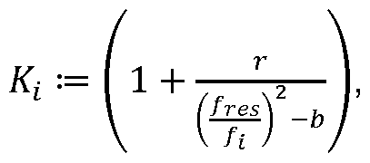
- a density correction term K is thus calculated according to: where the natural frequency is the un-suppressed bending vibration mode with which the preliminary p, density measurement was determined. And where r is one
- Constant is, which has the value 0.84 here.
- the corrected density reading / is finally determined in step 140 of FIG.
- the exemplary embodiment of a method 200 for determining a density value illustrated in FIG. 3 begins in a step 210 the determination of the natural frequencies of the f1 bending mode and of the f3 bending mode.
- the f1 bending mode and the f3 bending mode can be excited in particular simultaneously.
- Excitation power by varying the excitation frequencies the sought natural frequencies can be determined.
- provisional density values i and p 3 are determined in a step 220 as: i, i
- step 230 which will be explained in more detail below with reference to FIG. 4, the determination of a correction term for the density measurement takes place.
- step 240 a corrected density value is determined by means of the correction term.
- step 230 includes determining the
- the sound velocity c is determined, which at the measured natural frequencies of the bending vibration modes leads to the calculated ratio V of the preliminary density values:
- r is about 0.84
- b 1
- g is a meter tube dependent proportionality factor between the speed of sound and the resonant frequency, which may for example have a value of 10 / m.
- a mode-specific correction term K is then calculated in step 233 of the method in FIG. 4 in accordance with:
- the preliminary density value p i is finally calculated in step 240 of the method in FIG. 1 according to:
- the provisional density value # is thus divided by the correction term K, to obtain the corrected density value /.
Landscapes
- Physics & Mathematics (AREA)
- General Physics & Mathematics (AREA)
- Chemical & Material Sciences (AREA)
- Immunology (AREA)
- Health & Medical Sciences (AREA)
- Analytical Chemistry (AREA)
- Biochemistry (AREA)
- General Health & Medical Sciences (AREA)
- Pathology (AREA)
- Life Sciences & Earth Sciences (AREA)
- Fluid Mechanics (AREA)
- Acoustics & Sound (AREA)
- Engineering & Computer Science (AREA)
- Signal Processing (AREA)
- Measuring Volume Flow (AREA)
- Measurement Of Mechanical Vibrations Or Ultrasonic Waves (AREA)
Abstract
Description
Verfahren zum Ermitteln eines physikalischen Parameters einer mit Gas beladenen Flüssigkeit Method for determining a physical parameter of a gas-laden liquid
Die vorliegende Erfindung betrifft ein Verfahren zum Ermitteln eines physikalischen Parameters einer mit Gas beladenen Flüssigkeit mittels eines Mess- aufnehmers mit mindestens einem Messrohr zum Führen der mit Gas beladenen Flüssigkeit, wobei das Messrohr einen einlassseitigen Endabschnitt und einen auslassseitigen Endabschnitt aufweist, wobei der Messaufnehmer mindestens eine einlassseitige Fixiervorrichtung und eine auslasseitige Fixiervorrichtung aufweist, mit denen das Messrohr jeweils in einen der Endabschnitte fixiert ist, wobei das Messrohr zwischen den beiden Fixiervorrichtungen zu Schwingungen anregbar ist, wobei aus dem Schwingungsverhalten des Messrohrs Massedurchfluss und Dichte der mit Gas beladenen Flüssigkeit bestimmbar sind. Die Messwerte für Massedurchfluss und Dichte weisen jedoch Querempfindlichkeiten zur Schallgeschwindigkeit bzw. Kompressibilität der mit Gas beladenen Flüssigkeit auf, welche mit zunehmender Gasbeladung steigt. Eine Kompensation dieser Querempfindlichkeiten ist daher erwünscht. The present invention relates to a method for determining a physical parameter of a gas-laden liquid by means of a measuring sensor with at least one measuring tube for guiding the gas-laden liquid, wherein the measuring tube has an inlet-side end portion and an outlet-side end portion, wherein the sensor at least one On the inlet side fixing device and an outlet side fixing device, with which the measuring tube is fixed in each case in one of the end portions, wherein the measuring tube between the two fixing devices can be excited to oscillations, from the vibration behavior of the measuring tube mass flow and density of the gas-laden liquid can be determined. However, mass flow and density measurements have cross-sensitivities to the sonic velocity or compressibility of the gas-laden liquid, which increases with increasing gas loading. Compensation of these cross-sensitivities is therefore desirable.
Aus der Veröffentlichung WO 01/01086 A1 ein Verfahren zur Kompressibilitätskompensation bei der Massedurchflussmessung in einem Coriolis From the publication WO 01/01086 A1 a method for compressibility compensation in the mass flow measurement in a Coriolis
Massedurchflussmesser offenbart, Dabei wird eine jeweils eine Massedurchflussmessung bei zwei unterschiedlichen Moden durchgeführt, von denen einer ein Biegeschwingungsmode und ein anderer ein Radialmode ist. Aus dem Vergleich der Massedurchflusswerte die mittels dieser beiden Moden ermittelt werden. Dies ist jedoch insofern ein problematischer Ansatz, als die Radialmodeschwingungen erhebliche Abhängigkeit vom Strömungsprofil und vom atatischen Druck aufweisen zudem sind mehr Sensoren als die üblichen zwei erforderlich, um sowohl Biegeschwingungen als auch Radialmodeschwingungen erfassen zu können. Gleichermaßen ist eine komplexere Erregerstruktur erforderlich. In this case, one mass flow measurement is carried out in each case in two different modes, one of which is a bending vibration mode and another is a radial mode. From the comparison of the mass flow values which are determined by means of these two modes. However, this is a problematic approach insofar as the radial mode vibrations have significant dependence on the airfoil and atatic pressure, more sensors than the usual two are required to detect both flexural and radial mode vibrations. Likewise, a more complex pathogen structure is required.
In erster Näherung kann der Zusammenhang eines vorläufigen Dichtewerts p, einer mit Gas beladenen Flüssigkeit auf Basis der Eigenfrequenz f eines fi-Modes beschrieben werden als: As a first approximation, the relationship of a preliminary density value p, of a gas-laden liquid based on the natural frequency f of a fi-mode can be described as:
_ , 1 , 1 _, 1, 1
Pi— c0i + cli f2 + c2i ft Pi- c 0i + c li f 2 + c 2 i f t
H H wobei Co,, Cü, und c2i, modenabhängige Koeffizienten sind. Die obige Näherung berücksichtigt jedoch nicht die Einflüsse der schwingenden mit Gas beladenen Flüssigkeit im Messrohr. Je näher die Resonanzfrequenz der schwingenden mit Gas beladenen Flüssigkeit an der Eigenfrequenz eines HH where Co ,, Cμ, and c 2 i, are mode dependent coefficients. However, the above approximation does not take into account the effects of vibrating gas-laden liquid in the measuring tube. The closer the resonant frequency of the vibrating gas-laden liquid to the natural frequency of a
Biegeschwingungsmodes liegt, desto stärker ist die Beeinflussung der Eigenfrequenz. Da gewöhnlich oberhalb der Eigenfrequenz der Messrohre liegt, ist der Einfluss auf den f3-Biegeschwingungsmode größer als der Einfluss auf den f1-Biegeschwingungsmode. Dies führt zu unterschiedlichen vorläufigen modenspezifischen Dichtewerten, wobei das Verhältnis zwischen den vorläufigen Dichtewerten die Möglichkeit eröffnet, den Einfluss der schwingenden mit Gas beladenen Flüssigkeit zu ermitteln und zu korrigieren. Dies ist in der noch unveröffentlichten deutschen Patentanmeldung mit dem Aktenzeichen DE 102015122661.8 beschrieben. Bending vibration mode is, the stronger is the influence on the natural frequency. Since usually above the natural frequency of the measuring tubes, the influence on the f3 bending mode is greater than the influence on the f1 bending mode. This results in different tentative mode-specific density values, the ratio between the preliminary density values providing the opportunity to determine and correct the influence of the oscillating gas-laden liquid. This is described in the still unpublished German patent application with the file reference DE 102015122661.8.
Wenn jedoch die Resonanzfrequenz der mit Gas beladenen Flüssigkeit mit einer Eigenfrequenz eines Biegeschwingungsmodes übereinstimmt wird dieser vollständig unterdrückt. Damit kann in diesen Situation mit dem zuvor beschriebenen Ansatz nicht gearbeitet werden. Es ist daher die Aufgabe der vorliegenden Erfindung, für diese Situation eine Lösung anzugeben. However, when the resonance frequency of the gas-laden liquid coincides with a natural frequency of a bending vibration mode, it is completely suppressed. This can not be used in this situation with the approach described above. It is therefore the object of the present invention to provide a solution for this situation.
Die Aufgabe wird erfindungsgemäß gelöst durch das Verfahren gemäß dem unabhängigen Patentanspruch 1. The object is achieved by the method according to the independent claim. 1
Das erfindungsgemäße Verfahren dient zum Ermitteln eines physikalischen Parameters einer Flüssigkeit, welche eine Gasbeladung aufweist, wobei das Gas insbesondere in Form von suspendierten Blasen in der Flüssigkeit vorliegt, mittels eines Messaufnehmers mit mindestens einem Messrohr zum Führen des Mediums, wobei das mindestens eine Messrohr ein einlassseitigen Endabschnitt und einen auslassseitigen Endabschnitt aufweist, wobei der Messaufnehmer mindestens eine einlasseitige Fixiervorrichtung und eine auslasseitige Fixiervorrichtung aufweist, mit denen das Messrohr jeweils in einen der Endabschnitte fixiert ist, wobei das Messrohr zwischen den beiden The method according to the invention is used for determining a physical parameter of a liquid which has a gas loading, the gas being present in particular in the form of suspended bubbles in the liquid, by means of a measuring transducer with at least one measuring tube for guiding the medium, wherein the at least one measuring tube is an inlet side End section and an outlet-side end portion, wherein the sensor has at least one inlet-side fixing device and an outlet-side fixing device, with which the measuring tube is fixed in each case in one of the end portions, wherein the measuring tube between the two
Fixiervorrichtungen zu Biegeschwingungen verschiedener Moden mit unterschiedlichen Eigenfrequenzen anregbar ist, von denen ein f1-Mode keinen Schwingungsknoten zwischen den Fixiervorrichtungen aufweist, und wobei ein f3-Mode zwei Schwingungsknoten zwischen den Fixiervorrichtungen aufweist, wobei das Verfahren (100) die folgenden Schritte umfasst: Anregen des f1-Modes und des f3-Modes; Fixing devices can be excited to bending vibrations of different modes with different natural frequencies, of which an f1 mode has no node between the fixing devices, and wherein an f3 mode has two nodes between the fixing devices, the method (100) comprising the following steps: Exciting the f1 mode and the f3 mode;
Prüfen ob der f1-Mode oder der f3-Mode unterdrückt sind; wenn entweder der f 1 -Mode oder der f3-Mode aufgrund einer Resonanzschwingung der mit Gas beladenen Flüssigkeit bezüglich des Messrohrs unterdrückt wird, Verwenden eines Erwartungswerts für die Eigenfrequenz des unterdrückten Biegeschwingungsmodes als Wert für die Resonanzfrequenz der mit Gas beladenen Check if the f1-mode or the f3-mode are suppressed; when either the f 1 mode or the f3 mode is suppressed due to resonance vibration of the gas-laden liquid with respect to the measuring tube, using an expected value for the natural frequency of the suppressed bending vibration mode as the value of the resonant frequency of the gas-loaded one
Flüssigkeit; Liquid;
Ermitteln eines Dichtekorrekturterms als Funktion der Resonanzfrequenz zur Korrektur eines vorläufigen Dichtemesswerts und/oder eines Determining a density correction term as a function of the resonant frequency for correcting a preliminary density reading and / or a
Massedurchflusskorrekturterms als Funktion der Resonanzfrequenz zur Korrektur eines vorläufigen Massedurchflussmesswerts, und/oder Ermitteln der Schallgeschwindigkeit der mit Gas beladenen Flüssigkeit im Messrohr als Funktion der Resonanzfrequenz. Mass flow correction terms as a function of the resonant frequency for correcting a preliminary mass flow measurement, and / or determining the speed of sound of the gas-laden liquid in the measuring tube as a function of the resonant frequency.
Suspendierte Blasen sind insbesondere solche Blasen deren Größe nicht mehr als das dreifache einer Eindringtiefe beträgt, welche von der kinematischen Viskosität der Flüssigkeit und der Eigenfrequenz des f1-Modes abhängt. Suspended bladders are, in particular, those bladders whose size is not more than three times a penetration depth, which depends on the kinematic viscosity of the fluid and the natural frequency of the f1 mode.
In einer Weiterbildung der Erfindung wird der Erwartungswert der Eigenfrequenz des unterdrückten Biegeschwingungsmodes als Funktion der Eigenfrequenz mindestens eines nicht unterdrückten Biegeschwingungsmodes ermittelt wird. In an embodiment of the invention, the expected value of the natural frequency of the suppressed Bieschwwingungsmodes is determined as a function of the natural frequency of at least one not suppressed Bieschwwingungsmodes.
In einer Weiterbildung der Erfindung wird der Erwartungswert für die In one embodiment of the invention, the expected value for the
Eigenfrequenz des unterdrückten Biegeschwingungsmodes durch Multiplikation der Eigenfrequenz eines nicht unterdrückten Biegeschwingungsmodes mit einem Faktor ermittelt. Natural frequency of the suppressed Bieschwwingungsmodes determined by multiplying the natural frequency of a non-suppressed Bieschwwingungsmodes with a factor.
Der passende Faktor kann beispielsweise experimentell ermittelt werden, indem die Gasbeladung einer Flüssigkeit variiert wird, bis ein Biegeschwingungsmode unterdrückt wird. Der Faktor kann bestimmt werden aus dem Verhältnis der zuletzt gemessenen Eigenfrequenz des Biegeschwingungsmodes vor dessen Unterdrückung und der Eigenfrequenz des nicht unterdrückten Biegeschwingungsmodes unter diesen Bedingungen. For example, the appropriate factor may be determined experimentally by varying the gas loading of a liquid until a flexural vibration mode is suppressed. The factor can be determined from the ratio of the last measured natural frequency of the flexural vibration mode before its suppression and the natural frequency of the unenstressed flexural vibration modulus under these conditions.
In einer Weiterbildung der Erfindung ist der Faktor als konstanter Parameter abgespeichert. In einer Weiterbildung der Erfindung wird der Faktor im laufenden Betrieb fortlaufend aktualisiert, indem das Verhältnis der Eigenfrequenzen zweier In a development of the invention, the factor is stored as a constant parameter. In one embodiment of the invention, the factor is continuously updated during operation by the ratio of the natural frequencies of two
Biegeschwingungsmoden regelmäßig bestimmt und aufgezeichnet wird. Bending vibration modes regularly determined and recorded.
In den meisten Fällen wird der f3-Mode unterdrückt sein, so dass ein In most cases, the f3 mode will be suppressed, leaving a
Erwartungswert für den f3-Mode auf Basis des f1- Modes zu berechnen ist. Der umgekehrte Fall ist aber ausdrücklich von der Erfindung umfasst. Expectation value for the f3 mode is to be calculated on the basis of the f1 mode. The reverse case, however, is expressly encompassed by the invention.
In einer Weiterbildung der Erfindung umfasst das Verfahren weiterhin: In a further development of the invention, the method further comprises:
Ermitteln eines vorläufigen Dichtemesswerts und/oder eines vorläufigen Massedurchflussmesswerts bei einer Eigenfrequenz des nicht unterdrückten Biege- schwingungsmodes, und Ermitteln eines korrigierten Dichtemesswerts und/oder eines korrigierten Massedurchflussmesswerts unter Verwendung des Dichtekorrekturterms und/oder des Massedurchflusskorrekurterms, wobei der Dichtekorrekturterm und/oder der Massed urchflusskorrekurterm eine Funktion der Resonanzfrequenz und Eigenfrequenz des nicht unterdrückten Determining a preliminary density measured value and / or a preliminary mass flow measured value at a natural frequency of the un-suppressed bending vibration mode, and determining a corrected density measured value and / or a corrected mass flow measured value using the density correction term and / or the mass flow correction term, wherein the density correction term and / or the mass flow correction term m a function of the resonant frequency and natural frequency of the non-suppressed
Biegeschwingungsmodes sind bzw. ist, bei welcher der vorläufige Dichtemesswert und/oder der vorläufige Massedurchflussmesswert ermittelt wurden bzw. wurde. Flexural vibration modes are where the preliminary density reading and / or the preliminary mass flow rate reading was or were determined.
In einer Weiterbildung der Erfindung werden bzw. wird wobei der Dichtekorrekturterm K, für einen vorläufigen Dichtewert und/oder der Massedurchflusskorrekturterm eine Funktion eines Quotienten aus der Resonanzfrequenz der mit Gas beladenen Flüssigkeit und der Eigenfrequenz des nicht unterdrückten biegeschwingungsmodes Modes sind bzw. ist, bei welcher der vorläufige Dichtemesswert und/oder In a further development of the invention, the density correction term K, for a preliminary density value and / or the mass flow correction term is or are a function of a quotient of the resonance frequency of the gas-laden liquid and the natural frequency of the unconfirmed bending mode Modes the preliminary density reading and / or
Massedurchflussmesswert ermittelt wurden bzw. wurde. Mass flow measured value were determined or was.
In einer Weiterbildung der Erfindung weist der Dichtekorrekturterm K, für die vorläufigen Dichtewerte p, auf Basis der Eigenfrequenz des /j-Modes folgende Form auf:

Pi pi
Pc corr wobei r eine medienunabhängige Konstante ist, /jes die Resonanzfrequenz der mit Gas beladenen Flüssigkeit ist, /jdie Eigenfrequenz des nicht unterdrückten Pc corr where r is a media-independent constant / jes is the resonant frequency of the gas-laden liquid, / j is the natural frequency of the un-suppressed
Biegeschwingungsmodes ist, pco pi öie korrigierte und die vorläufige Dichte sind, und b eine Skalierungskonstante ist. Bend vibration mode is, p co pi öie corrected and the provisional density, and b is a scaling constant.
In einer Weiterbildung der Erfindung gilt: r/b < 1 , insbesondere r/b < 0,9. In a development of the invention, r / b <1, in particular r / b <0.9.
In einer Weiterbildung der Erfindung ist b = 1. In one embodiment of the invention, b = 1.
In einer Weiterbildung der Erfindung ist g ein vom Durchmesser des Messrohrs abhängiger Proportionalitätsfaktor zwischen einer Resonanzfrequenz fres der mit Gas beladenen Flüssigkeit und der Schallgeschwindigkeit der mit Gas beladenen Flüssigkeit ist, wobei gilt,
![]()
![]()
In einer Weiterbildung der Erfindung wird der vorläufige Dichtemess auf Basis der Eigenfrequenz des des f-Modes mittels eines Polynoms in 1//j , insbesondere in (1/ 2 bestimmt werden, wobei die Koeffizienten des Polynoms modenabhängig sind. In a further development of the invention, the provisional density measurement based on the natural frequency of the f-mode is determined by means of a polynomial in 1 // j, in particular in ( 1/2 , where the coefficients of the polynomial are mode-dependent.
In einer Weiterbildung der Erfindung gilt für einen Dichtefehler E^ eines vorläufigen Dichtewerts auf Basis der Eigenfrequenz des fi-Modes: In a development of the invention, a density error E 1 of a preliminary density value based on the natural frequency of the fi mode is valid:
Epi '■= Ki - 1> wobei ein Massedurchflussfehler Em eines vorläufigen Massedurchflusswerts proportional zu dem Dichtefehler Ep1 des ersten vorläufigen Dichtewerts ist, also: p — k■ F wobei der Proportionalitätsfaktor k nicht weniger als 1 ,5, beispielsweise nicht weniger als 1 ,8 und insbesondere nicht weniger als 1 ,9 beträgt, wobei der Proportionalitätsfaktor k nicht mehr als 3, beispielsweise nicht mehr als 2,25 und insbesondere nicht mehr als 2, 1 beträgt, wobei für den Massedurchflusskorrekturterm Km für den Massendurchfluss gilt: Epi '■ = Ki - 1> where a mass flow error E m of a preliminary mass flow value is proportional to the density error E p1 of the first provisional density value, that is: p - k ■ F where the proportionality factor k is not less than 1.5, for example not less than 1, 8 and in particular not less than 1, 9, wherein the proportionality factor k is not more than 3, for example not more than 2.25 and in particular not more than 2, 1, wherein for the mass flow correction term K m for the mass flow rate:
Km— 1 + Em, wobei der korrigierte Massendurchfluss rhcorr ermittelt wird als m, wobei rhv der vorläufige Massedurchflusswert ist. K m - 1 + E m , where the corrected mass flow rh corr is determined as m, where rh v is the preliminary mass flow value.
In einer Weiterbildung der Erfindung umfasst das Verfahren weiterin, wenn weder der f1 -Mode noch der f3-Mode unterdrückt sind: In a development of the invention, the method further includes when neither the f1 mode nor the f3 mode are suppressed:
Ermitteln der Eigenfrequenz des f1 -Modes und des f3-Modes (1 10); Determining the natural frequency of the f1-mode and the f3-mode (1 10);
Ermitteln eines ersten vorläufigen Dichtewerts für die im Messrohr geführte gasbeladene Flüssigkeit auf Basis der Eigenfrequenz des f1 -Modes (120); Determining a first preliminary density value for the gas-laden liquid carried in the measuring tube based on the natural frequency of the f1 mode (120);
Ermitteln eines zweiten vorläufigen Dichtewerts für die im Messrohr geführte gasbeladene Flüssigkeit auf Basis der Eigenfrequenz des f3-Modes (120); Determining a second preliminary density value for the gas-laden liquid carried in the measuring tube based on the natural frequency of the f3 mode (120);
Ermitteln eines Werts für die Schallgeschwindigkeit der im Messrohr lüssigkeit, und/oder zumindest eines von der Schallgeschwindigkeit und der Eigenfrequenz eines Modes abhängigen Korrekturterms (130) und/oder Dichtefehlers für den vorläufigen Dichtewert, der auf Basis der Eigenfrequenz des Modes ermittelt wurde, zum Bestimmen eines korrigierten Dichtemesswerts (140); und/oder eines Korrekturterms für einen vorläufigen Massedurchflusswert zum Bestimmen eines korrigierten Massedurch- flussmesswerts auf Basis des ersten vorläufigen Dichtewerts, des zweiten vorläufigen Dichtewerts, der Eigenfrequenz des f1 -Modes und der Eigenfrequenz des f3-Modes. Determining a value for the speed of sound of the liquid in the measuring tube, and / or at least one of the speed of sound and the natural frequency of a mode dependent correction term (130) and / or density error for the preliminary density value, which was determined based on the natural frequency of the mode for determining a corrected density reading (140); and / or a preliminary mass flow rate correction term for determining a corrected mass flow measurement value based on the first preliminary density value, the second provisional density value, the natural frequency of the f1 mode, and the natural frequency of the f3 mode.
In einer Weiterbildung der Erfindung ist der Korrekturterm ,- für einen vorläufigen Dichtewert eine Funktion eines Quotienten aus der Schallgeschwindigkeit der mit Gas beladenen Flüssigkeit und der Eigenfrequenz des Modes, mit dem der vorläufige Dichtemesswert ermittelt wurde. In einer Weiterbildung der Erfindung wird die Schallgeschwindigkeit c der mit Gas beladenen Flüssigkeit bestimmt wird, indem der Schallgeschwindigkeitswert gesucht wird, bei dem der Quotient des ersten Korrekturterms für den ersten vorläufigen Dichtewert geteilt durch den zweiten Korrekturterm für den zweiten vorläufigen Dichte- wert, dem Quotienten des ersten vorläufigen Dichtewerts geteilt durch den zweiten vorläufigen Dichtewert entspricht. In a development of the invention, the correction term for a preliminary density value is a function of a quotient of the speed of sound of the gas-laden liquid and the natural frequency of the mode with which the preliminary density measured value was determined. In a further development of the invention, the sound velocity c of the gas-laden liquid is determined by searching the sound velocity value at which the quotient of the first correction term for the first provisional density value divided by the second correction term for the second provisional density value, the quotient of the first preliminary density value divided by the second preliminary density value.
In einer Weiterbildung der Erfindung wird weist der Korrekturterm K, für die vorläufigen Dichtewerte p, auf Basis des der Eigenfrequenz des /i-Modes folgende Form auf:

.= Ei . = Egg
Pcorr [ζ. wobei r und g gasunabängige Konstanten sind, c die Schallgeschwindigkeit der mit Gas beladenen Flüssigkeit ist, /jdie Eigenfrequenz des /j-Modes ist, / die korrigierte Dichte ist, und b eine Skalierungskonstante ist. Pcorr [ζ . where r and g are gas-independent constants, c is the sonic velocity of the gas-laden liquid, / j is the natural frequency of the / j mode, / is the corrected density, and b is a scaling constant.
In einer Weiterbildung der Erfindung wird das Verfahren dann eingesetzt, wenn die suspendierten Blasen einen Radius r aufweisen, der nicht mehr als das Fünffache, insbesondere nicht mehr als das Dreifache einer Eindringtiefe δ beträgt, welche gegeben ist als δ = (ν/(^)) 2, wobei v die kinematische Viskosität der Flüssigkeit und f1 die Eigenfrequenz des f1-Modes ist. In a further development of the invention, the method is used when the suspended bubbles have a radius r, which is not more than five times, in particular not more than three times a penetration depth δ, which is given as δ = (ν / (^) ) 2 , where v is the kinematic viscosity of the fluid and f1 is the natural frequency of the f1 mode.
Die Eindringtiefe δ beschreibt die Reichweite eines Strömungsfeldes aufgrund von Relativbewegungen einer suspendierten Blase gegenüber der sie umgebenden Flüssigkeit. Bei kleinen Radien wirken sich suspendierte Blasen im Wesentlichen auf die Kompressibilität aus, während bei Radien, welche die Eindringtiefe deutlich übersteigen, zusätzliche Effekte auftreten, welche die Genauigkeit der erfindungsgmäßen Korrekturen beeinträchtigen. Die Erfindung wird nun anhand des in den Zeichnungen beschriebenen The penetration depth δ describes the range of a flow field due to relative movements of a suspended bubble relative to the liquid surrounding it. For small radii, suspended bubbles essentially affect the compressibility, while for radii which significantly exceed the penetration depth, additional effects occur which impair the accuracy of the corrections according to the invention. The invention will now be described with reference to the drawings
Ausführungsbeispiels näher erläutert. Embodiment explained in more detail.
Es zeigt: It shows:
Fig. 1 : Ein Flussdiagramm für ein Ausführungsbeispiel der ersten Alternative des erfindungsgemäßen Verfahrens; 1 shows a flow chart for an embodiment of the first alternative of the method according to the invention;
Fig. 2: Ein Flussdiagramm für ein Detail des Ausführungsbeispiels der ersten Alternative des erfindungsgemäßen Verfahrens; 2 shows a flow chart for a detail of the exemplary embodiment of the first alternative of the method according to the invention;
Fig. 3: Ein Flussdiagramm für ein Ausführungsbeispiel der zweiten Alternative des erfindungsgemäßen Verfahrens; und Fig. 4: Ein Flussdiagramm für ein Detail des Ausführungsbeispiels der zweiten3 shows a flow chart for an exemplary embodiment of the second alternative of the method according to the invention; and Fig. 4 is a flowchart for a detail of the embodiment of the second embodiment
Alternative des erfindungsgemäßen Verfahrens. Alternative of the method according to the invention.
Das in Fig. 1 dargestellte Ausführungsbeispiel eines erfindungsgemäßen Verfahren 100 zum Bestimmen eines Dichtewertes beginnt in einem Schritt 110 mit der Feststellung, dass ein Biegeschwingungsmode unterdrückt ist, beispielsweise des f3- Modes. The exemplary embodiment of a method 100 for determining a density value shown in FIG. 1 begins in a step 110 with the statement that a bending oscillation mode is suppressed, for example the f3 mode.
Dann erfolgt die Bestimmung der Eigenfrequenz des nicht unterdrückten Biege- schwingungsmodes, beispielsweise des f1-Modes, beispielsweise durch Maximieren des Verhältnisses von der Schwingungsamplitude zur modenspezifischen Erregerleistung durch Variieren der Anregungsfrequenzen können die gesuchten Eigenfrequenzen ermittelt werden. Then, the determination of the natural frequency of the non-suppressed flexural vibration mode, for example of the f1 mode, for example, by maximizing the ratio of the vibration amplitude to the mode-specific excitation power by varying the excitation frequencies, the sought natural frequencies can be determined.
Anhand der ermittelten Eigenfrequenz fi wird dann in einem Schritt 120 ein vorläufiger Dichtemesswert p-, bestimmt als: On the basis of the determined natural frequency fi, a preliminary density measured value p- is then determined in a step 120 as
_ , 1 , 1 _, 1, 1
Pi — cOi + cli 2 + C2i ~μ , Pi - c Oi + c li 2 + C 2 i ~ μ,
H H wobei Co,, Cü,und c2i, modenabhängige Koeffizienten sind. In einem Schritt 130, der weiter unten anhand von Fig. 2 näher erläutert wird, erfolgt die Bestimmung eines Dichtekorrekturterms für die Dichtemessung. Schließlich wird in einem Schritt 140 mittels des Korrekturterms ein Korrigierter Dichtewert bestimmt. HH where Co ,, Cμ, and c 2 i, are mode dependent coefficients. In a step 130, which will be explained in more detail below with reference to FIG. 2, the determination of a density correction term for the density measurement takes place. Finally, in a step 140, a corrected density value is determined by means of the correction term.
Wie in Fig. 2 dargestellt, umfasst der Schritt 130 zum Bestimmen des Dichte- korrekturterms zunächst in einem Schritt 132 das Berechnen eines Erwartungswertes der Eigenfrequenz des unterdrückten Biegeschwingungsmodes auf Basis der Eigenfrequenz des nicht unterdrückten Biegeschwingungsmodes, beispielsweise durch multiplikation mit einem Faktor. As shown in FIG. 2, step 130, to determine the density correction term, first comprises, in step 132, calculating an expected natural frequency of the suppressed flexural vibration mode based on the natural frequency of the unmanifested flexural vibration modulus, for example by multiplication by a factor.
Bei einem Durchflussmessgerät, das in den Untersuchungen zur Vorliegenden Erfindung verwendet wurde, sind mit einem konstanten Faktor von 5,5 zwischen der Eigenfrequenz des f1-Modes und der Eigenfrequenz des f3-Modes gute Ergebnisse erzielt worden. Wenn mit einem konstanten Faktor gearbeitet werden soll, ist dieser sicherlich in einer Typ- bzw. Stückprüfung zu ermitteln. In a flow meter used in the studies of the present invention, good results have been obtained with a constant factor of 5.5 between the natural frequency of the f1 mode and the natural frequency of the f3 mode. If you want to work with a constant factor, this is certainly to be determined in a type or routine test.
Der ermittelte Erwartungswert für die Eigenfrequenz des unterdrückten Biegeschwingungsmodes ist insofern von Interesse, als vorzugsweise auf dieser Frequenz eine Anregung des Biegeschwingungsmodes probiert werden sollte, um ihn wieder zum Schwingen zu bringen, wenn sich die Resonanzfrequenz wieder entfernt. The determined expected value for the natural frequency of the suppressed Bieschwwingungsmodes is of interest insofar as preferably on this frequency an excitation of the Bieschwwingungsmodes should be tried to bring it to swing again when the resonance frequency is removed again.
Der ermittelte Erwartungswert für die Eigenfrequenz des unterdrückten Biegeschwingungsmodes wird gemäß Schritt 132 als Wert für die Resonanzfrequenz fres verwendet. In einem Schritt 133 wird damit ein Dichtekorrekturterm K, berechnet gemäß:

Konstante ist, die hier den Wert 0,84 aufweist. Constant is, which has the value 0.84 here.
Der korrigierte Dichtemesswert / wird schließlich im Schritt 140 des The corrected density reading / is finally determined in step 140 of FIG
Verfahrens in Fig. 1 berechnet gemäß: Method calculated in FIG. 1 according to:
Pi pi
Pc corr Der vorläufige Dichtewert p, wird also durch den Korrekturterm K geteilt, korrigierten Dichtewert / zu erhalten. Pc corr The provisional density value p, is thus divided by the correction term K to obtain the corrected density value /.
Das in Fig. 3 dargestellte Ausführungsbeispiel eines erfindungsgemäßen Verfahren 200 zum Bestimmen eines Dichtewertes beginnt in einem Schritt 210 die Bestimmung der Eigenfrequenzen des f1 -Biegeschwingungsmodes und des f3- Biegeschwingungsmodes. Hierzu können der f1-Biegeschwingungsmode und der f3- Biegeschwingungsmode insbesondere gleichzeitig angeregt werden. Durch Maximieren des Verhältnisses von der Schwingungsamplitude zur modenspezifischen The exemplary embodiment of a method 200 for determining a density value illustrated in FIG. 3 begins in a step 210 the determination of the natural frequencies of the f1 bending mode and of the f3 bending mode. For this purpose, the f1 bending mode and the f3 bending mode can be excited in particular simultaneously. By maximizing the ratio of the vibration amplitude to the mode specific
Erregerleistung durch Variieren der Anregungsfrequenzen können die gesuchten Eigenfrequenzen ermittelt werden. Excitation power by varying the excitation frequencies, the sought natural frequencies can be determined.
Anhand der ermittelten Eigenfrequenzen fi werden in einem Schritt 220 vorläufige Dichtewerte i und p3 bestimmt als: i , i On the basis of the determined eigenfrequencies fi, provisional density values i and p 3 are determined in a step 220 as: i, i
Pi— c0i + cli + c2i wobei Co,, Cü,und c2i, modenabhängige Koeffizienten sind. Pi- c 0i + c + c 2 i li ,, wherein Co Cii, and c 2 i, are mode-dependent coefficients.
In einem Schritt 230, der weiter unten anhand von Fig. 4 näher erläutert wird, erfolgt die Bestimmung eines Korrekturterms für die Dichtemessung. In a step 230, which will be explained in more detail below with reference to FIG. 4, the determination of a correction term for the density measurement takes place.
Schließlich wird in einem Schritt 240 mittels des Korrekturterms ein Korrigierter Dichtewert bestimmt. Wie in Fig. 2 dargestellt umfasst der Schritt 230 zum Bestimmen des Finally, in a step 240, a corrected density value is determined by means of the correction term. As shown in FIG. 2, step 230 includes determining the
Korrekturterms zunächst in einem Schritt 232 das Berechnen des Verhältnisses V der vorläufigen Dichtewerte, also beispielsweise die Division der vorläufigen Dichtewerte p-i und p3 zu V:= p-t I p3. Correction term first, in a step 232, calculating the ratio V of the provisional density values, ie for example the division of the preliminary density values pi and p 3 to V: I pt = p. 3
Anschließend wird in einem Schritt 232 die Schallgeschwindigkeit c bestimmt, welche bei den gemessenen Eigenfrequenzen der Biegeschwingungsmoden zu dem berechneten Verhältnis V der vorläufigen Dichtewerte führt: Subsequently, in a step 232, the sound velocity c is determined, which at the measured natural frequencies of the bending vibration modes leads to the calculated ratio V of the preliminary density values:

Anhand der ermittelten Schallgeschwindigkeit wird dann im Schritt 233 des Verfahrens in Fig. 4 ein modenspezifischer Korrekturterm K berechnet gemäß:

Der vorläufige Dichtewert p, wird schließlich im Schritt 240 des Verfahrens in Fig. 1 berechnet gemäß: The preliminary density value p i is finally calculated in step 240 of the method in FIG. 1 according to:
.= Ei . = Egg
Pcorr [ζ. Pcorr [ζ .
Der vorläufige Dichtewert # wird also durch den Korrekturterm K, geteilt, um den korrigierten Dichtewert / zu erhalten. The provisional density value # is thus divided by the correction term K, to obtain the corrected density value /.
Claims

Applications Claiming Priority (2)
| Application Number | Priority Date | Filing Date | Title |
|---|---|---|---|
| DE102016005547.2A DE102016005547B4 (en) | 2016-05-09 | 2016-05-09 | Method for determining a physical parameter of a gas-laden liquid |
| DE102016005547.2 | 2016-05-09 |
Publications (1)
| Publication Number | Publication Date |
|---|---|
| WO2017194278A1 true WO2017194278A1 (en) | 2017-11-16 |
Family
ID=58549156
Family Applications (1)
| Application Number | Title | Priority Date | Filing Date |
|---|---|---|---|
| PCT/EP2017/059260 Ceased WO2017194278A1 (en) | 2016-05-09 | 2017-04-19 | Method for ascertaining a physical parameter of a liquid charged with gas |
Country Status (2)
| Country | Link |
|---|---|
| DE (1) | DE102016005547B4 (en) |
| WO (1) | WO2017194278A1 (en) |
Cited By (3)
| Publication number | Priority date | Publication date | Assignee | Title |
|---|---|---|---|---|
| CN113260834A (en) * | 2018-12-21 | 2021-08-13 | 恩德斯+豪斯流量技术股份有限公司 | Method for determining physical parameters of carrier gas liquid |
| DE102020131649A1 (en) | 2020-09-03 | 2022-03-03 | Endress + Hauser Flowtec Ag | Vibronic measuring system |
| CN114787620A (en) * | 2019-12-19 | 2022-07-22 | 恩德斯+豪斯流量技术股份有限公司 | Method for characterizing the gas load of a medium and densitometer therefor |
Families Citing this family (6)
| Publication number | Priority date | Publication date | Assignee | Title |
|---|---|---|---|---|
| DE102016114974A1 (en) | 2016-08-11 | 2018-02-15 | Endress+Hauser Flowtec Ag | Method for determining a gas volume fraction of a gas-laden medium |
| DE102016114972A1 (en) | 2016-08-11 | 2018-02-15 | Endress+Hauser Flowtec Ag | Method for determining a gas volume fraction of a gas-laden liquid medium |
| DE102017131267A1 (en) | 2017-12-22 | 2019-06-27 | Endress+Hauser Flowtec Ag | Method for determining a gas volume fraction of a gas-laden medium |
| DE102019117101A1 (en) | 2019-06-25 | 2020-12-31 | Endress+Hauser Flowtec Ag | Method for determining a physical parameter of a loaded liquid |
| DE102020110575A1 (en) | 2020-04-17 | 2021-10-21 | Endress+Hauser Flowtec Ag | Method for determining a flow rate of a liquid medium flowing through a pipe |
| DE102021133150A1 (en) | 2021-12-14 | 2023-06-15 | Endress + Hauser Flowtec Ag | contraption |
Citations (5)
| Publication number | Priority date | Publication date | Assignee | Title |
|---|---|---|---|---|
| WO2001001086A1 (en) | 1999-06-29 | 2001-01-04 | Direct Measurement Corporation | Compressibility compensation in a coriolis mass flow meter |
| US6347293B1 (en) * | 1999-07-09 | 2002-02-12 | Micro Motion, Inc. | Self-characterizing vibrating conduit parameter sensors and methods of operation therefor |
| CN1853088A (en) * | 2003-07-15 | 2006-10-25 | 塞德拉公司 | Apparatus and method for compensating a coriolis meter |
| EP2026042A1 (en) * | 2005-12-27 | 2009-02-18 | Endress+Hauser Flowtec AG | In-line measuring devices and method for compensating measurement errors in in-line measuring devices |
| US20110023626A1 (en) * | 2008-05-01 | 2011-02-03 | Joel Weinstein | Vibratory flow meter for determining one or more flow fluid characteristics of a multi-phase flow fluid |
Family Cites Families (2)
| Publication number | Priority date | Publication date | Assignee | Title |
|---|---|---|---|---|
| DE19652002C2 (en) | 1995-12-15 | 2003-03-27 | Flowtec Ag | Vibration meter |
| DE102015122661A1 (en) | 2015-12-23 | 2017-06-29 | Endress + Hauser Flowtec Ag | Method for determining a physical parameter of a gas-laden liquid |
-
2016
- 2016-05-09 DE DE102016005547.2A patent/DE102016005547B4/en active Active
-
2017
- 2017-04-19 WO PCT/EP2017/059260 patent/WO2017194278A1/en not_active Ceased
Patent Citations (5)
| Publication number | Priority date | Publication date | Assignee | Title |
|---|---|---|---|---|
| WO2001001086A1 (en) | 1999-06-29 | 2001-01-04 | Direct Measurement Corporation | Compressibility compensation in a coriolis mass flow meter |
| US6347293B1 (en) * | 1999-07-09 | 2002-02-12 | Micro Motion, Inc. | Self-characterizing vibrating conduit parameter sensors and methods of operation therefor |
| CN1853088A (en) * | 2003-07-15 | 2006-10-25 | 塞德拉公司 | Apparatus and method for compensating a coriolis meter |
| EP2026042A1 (en) * | 2005-12-27 | 2009-02-18 | Endress+Hauser Flowtec AG | In-line measuring devices and method for compensating measurement errors in in-line measuring devices |
| US20110023626A1 (en) * | 2008-05-01 | 2011-02-03 | Joel Weinstein | Vibratory flow meter for determining one or more flow fluid characteristics of a multi-phase flow fluid |
Cited By (7)
| Publication number | Priority date | Publication date | Assignee | Title |
|---|---|---|---|---|
| CN113260834A (en) * | 2018-12-21 | 2021-08-13 | 恩德斯+豪斯流量技术股份有限公司 | Method for determining physical parameters of carrier gas liquid |
| CN113260834B (en) * | 2018-12-21 | 2024-06-04 | 恩德斯+豪斯流量技术股份有限公司 | Method for learning physical parameters of carrier gas liquid |
| US12055423B2 (en) | 2018-12-21 | 2024-08-06 | Endress+Hauser Flowtec Ag | Method for ascertaining a physical parameter of a gas-charged liquid |
| CN114787620A (en) * | 2019-12-19 | 2022-07-22 | 恩德斯+豪斯流量技术股份有限公司 | Method for characterizing the gas load of a medium and densitometer therefor |
| DE102020131649A1 (en) | 2020-09-03 | 2022-03-03 | Endress + Hauser Flowtec Ag | Vibronic measuring system |
| WO2022048888A1 (en) | 2020-09-03 | 2022-03-10 | Endress+Hauser Flowtec Ag | Vibronic measuring system |
| US12442675B2 (en) | 2020-09-03 | 2025-10-14 | Endress+Hauser Flowtec Ag | Vibronic measuring system |
Also Published As
| Publication number | Publication date |
|---|---|
| DE102016005547B4 (en) | 2023-06-01 |
| DE102016005547A1 (en) | 2017-11-09 |
Similar Documents
| Publication | Publication Date | Title |
|---|---|---|
| WO2017194278A1 (en) | Method for ascertaining a physical parameter of a liquid charged with gas | |
| EP3394575B1 (en) | Method for determining a physcal parameter of a liquid charged with gas | |
| DE60009065T2 (en) | MEASURING DEVICE WITH SWING TUBE | |
| DE102016112002A1 (en) | Method for determining a physical parameter of a compressible medium with a vibration-type sensor and sensor for carrying out such a method | |
| WO2018114402A1 (en) | Mass flow meter according to the coriolis principle and method for determining a mass flow | |
| WO2018001635A1 (en) | Method for operating a vibration-type measuring sensor | |
| DE102010035341B4 (en) | Method for determining the viscosity of a medium with a Coriolis mass flowmeter | |
| WO2001075399A2 (en) | Mass flow rate measuring device | |
| EP3332228B1 (en) | Method for ascertaining a physical parameter of a gas | |
| WO2008077574A2 (en) | Method for operating a vibratory measuring instrument, and corresponding instrument | |
| DE102016114972A1 (en) | Method for determining a gas volume fraction of a gas-laden liquid medium | |
| DE102016114974A1 (en) | Method for determining a gas volume fraction of a gas-laden medium | |
| EP3899446B1 (en) | Method for ascertaining a physical parameter of a gas-charged liquid | |
| EP4323747B1 (en) | Density measuring device with at least one measuring tube as well as method for operating and method for adjusting such a density measuring device | |
| AT516302B1 (en) | Method and device for determining the filling quality of a bending vibrator | |
| WO2019015913A1 (en) | DEVICE FOR MEASURING VISCOSITIES | |
| EP4251969B1 (en) | Method and measuring device for determining a viscosity measurement value, and method and measuring assembly for determining a flow measurement value | |
| EP3714253B1 (en) | Method for calculating the density of a medium which is conducted in at least one vibratable measuring tube of a density meter | |
| DE102017131267A1 (en) | Method for determining a gas volume fraction of a gas-laden medium | |
| WO2020259940A1 (en) | Method for ascertaining a physical parameter of a charged liquid | |
| EP4341650B1 (en) | Coriolis mass flow meter and method of monitoring a coriolis mass flow meter | |
| EP4256303B1 (en) | Method of determining a density value and coriolis mass flow transducer for carrying out the method | |
| DE102022134790A1 (en) | Procedure for cleaning a flow meter |
Legal Events
| Date | Code | Title | Description |
|---|---|---|---|
| NENP | Non-entry into the national phase |
Ref country code: DE |
|
| 121 | Ep: the epo has been informed by wipo that ep was designated in this application |
Ref document number: 17718087 Country of ref document: EP Kind code of ref document: A1 |
|
| 122 | Ep: pct application non-entry in european phase |
Ref document number: 17718087 Country of ref document: EP Kind code of ref document: A1 |