WO2017175362A1 - Plate-shaped assembled battery - Google Patents
Plate-shaped assembled battery Download PDFInfo
- Publication number
- WO2017175362A1 WO2017175362A1 PCT/JP2016/061447 JP2016061447W WO2017175362A1 WO 2017175362 A1 WO2017175362 A1 WO 2017175362A1 JP 2016061447 W JP2016061447 W JP 2016061447W WO 2017175362 A1 WO2017175362 A1 WO 2017175362A1
- Authority
- WO
- WIPO (PCT)
- Prior art keywords
- negative electrode
- bus bar
- positive electrode
- assembled battery
- plate
- Prior art date
- Legal status (The legal status is an assumption and is not a legal conclusion. Google has not performed a legal analysis and makes no representation as to the accuracy of the status listed.)
- Ceased
Links
Images


Classifications
-
- H—ELECTRICITY
- H01—ELECTRIC ELEMENTS
- H01M—PROCESSES OR MEANS, e.g. BATTERIES, FOR THE DIRECT CONVERSION OF CHEMICAL ENERGY INTO ELECTRICAL ENERGY
- H01M50/00—Constructional details or processes of manufacture of the non-active parts of electrochemical cells other than fuel cells, e.g. hybrid cells
- H01M50/20—Mountings; Secondary casings or frames; Racks, modules or packs; Suspension devices; Shock absorbers; Transport or carrying devices; Holders
- H01M50/218—Mountings; Secondary casings or frames; Racks, modules or packs; Suspension devices; Shock absorbers; Transport or carrying devices; Holders characterised by the material
- H01M50/22—Mountings; Secondary casings or frames; Racks, modules or packs; Suspension devices; Shock absorbers; Transport or carrying devices; Holders characterised by the material of the casings or racks
- H01M50/231—Mountings; Secondary casings or frames; Racks, modules or packs; Suspension devices; Shock absorbers; Transport or carrying devices; Holders characterised by the material of the casings or racks having a layered structure
-
- H—ELECTRICITY
- H01—ELECTRIC ELEMENTS
- H01M—PROCESSES OR MEANS, e.g. BATTERIES, FOR THE DIRECT CONVERSION OF CHEMICAL ENERGY INTO ELECTRICAL ENERGY
- H01M50/00—Constructional details or processes of manufacture of the non-active parts of electrochemical cells other than fuel cells, e.g. hybrid cells
- H01M50/10—Primary casings; Jackets or wrappings
- H01M50/102—Primary casings; Jackets or wrappings characterised by their shape or physical structure
- H01M50/103—Primary casings; Jackets or wrappings characterised by their shape or physical structure prismatic or rectangular
-
- H—ELECTRICITY
- H01—ELECTRIC ELEMENTS
- H01M—PROCESSES OR MEANS, e.g. BATTERIES, FOR THE DIRECT CONVERSION OF CHEMICAL ENERGY INTO ELECTRICAL ENERGY
- H01M50/00—Constructional details or processes of manufacture of the non-active parts of electrochemical cells other than fuel cells, e.g. hybrid cells
- H01M50/20—Mountings; Secondary casings or frames; Racks, modules or packs; Suspension devices; Shock absorbers; Transport or carrying devices; Holders
- H01M50/204—Racks, modules or packs for multiple batteries or multiple cells
- H01M50/207—Racks, modules or packs for multiple batteries or multiple cells characterised by their shape
- H01M50/209—Racks, modules or packs for multiple batteries or multiple cells characterised by their shape adapted for prismatic or rectangular cells
-
- H—ELECTRICITY
- H01—ELECTRIC ELEMENTS
- H01M—PROCESSES OR MEANS, e.g. BATTERIES, FOR THE DIRECT CONVERSION OF CHEMICAL ENERGY INTO ELECTRICAL ENERGY
- H01M50/00—Constructional details or processes of manufacture of the non-active parts of electrochemical cells other than fuel cells, e.g. hybrid cells
- H01M50/20—Mountings; Secondary casings or frames; Racks, modules or packs; Suspension devices; Shock absorbers; Transport or carrying devices; Holders
- H01M50/218—Mountings; Secondary casings or frames; Racks, modules or packs; Suspension devices; Shock absorbers; Transport or carrying devices; Holders characterised by the material
- H01M50/22—Mountings; Secondary casings or frames; Racks, modules or packs; Suspension devices; Shock absorbers; Transport or carrying devices; Holders characterised by the material of the casings or racks
- H01M50/222—Inorganic material
- H01M50/224—Metals
-
- H—ELECTRICITY
- H01—ELECTRIC ELEMENTS
- H01M—PROCESSES OR MEANS, e.g. BATTERIES, FOR THE DIRECT CONVERSION OF CHEMICAL ENERGY INTO ELECTRICAL ENERGY
- H01M50/00—Constructional details or processes of manufacture of the non-active parts of electrochemical cells other than fuel cells, e.g. hybrid cells
- H01M50/20—Mountings; Secondary casings or frames; Racks, modules or packs; Suspension devices; Shock absorbers; Transport or carrying devices; Holders
- H01M50/218—Mountings; Secondary casings or frames; Racks, modules or packs; Suspension devices; Shock absorbers; Transport or carrying devices; Holders characterised by the material
- H01M50/22—Mountings; Secondary casings or frames; Racks, modules or packs; Suspension devices; Shock absorbers; Transport or carrying devices; Holders characterised by the material of the casings or racks
- H01M50/227—Organic material
-
- H—ELECTRICITY
- H01—ELECTRIC ELEMENTS
- H01M—PROCESSES OR MEANS, e.g. BATTERIES, FOR THE DIRECT CONVERSION OF CHEMICAL ENERGY INTO ELECTRICAL ENERGY
- H01M50/00—Constructional details or processes of manufacture of the non-active parts of electrochemical cells other than fuel cells, e.g. hybrid cells
- H01M50/20—Mountings; Secondary casings or frames; Racks, modules or packs; Suspension devices; Shock absorbers; Transport or carrying devices; Holders
- H01M50/262—Mountings; Secondary casings or frames; Racks, modules or packs; Suspension devices; Shock absorbers; Transport or carrying devices; Holders with fastening means, e.g. locks
-
- H—ELECTRICITY
- H01—ELECTRIC ELEMENTS
- H01M—PROCESSES OR MEANS, e.g. BATTERIES, FOR THE DIRECT CONVERSION OF CHEMICAL ENERGY INTO ELECTRICAL ENERGY
- H01M50/00—Constructional details or processes of manufacture of the non-active parts of electrochemical cells other than fuel cells, e.g. hybrid cells
- H01M50/50—Current conducting connections for cells or batteries
-
- Y—GENERAL TAGGING OF NEW TECHNOLOGICAL DEVELOPMENTS; GENERAL TAGGING OF CROSS-SECTIONAL TECHNOLOGIES SPANNING OVER SEVERAL SECTIONS OF THE IPC; TECHNICAL SUBJECTS COVERED BY FORMER USPC CROSS-REFERENCE ART COLLECTIONS [XRACs] AND DIGESTS
- Y02—TECHNOLOGIES OR APPLICATIONS FOR MITIGATION OR ADAPTATION AGAINST CLIMATE CHANGE
- Y02E—REDUCTION OF GREENHOUSE GAS [GHG] EMISSIONS, RELATED TO ENERGY GENERATION, TRANSMISSION OR DISTRIBUTION
- Y02E60/00—Enabling technologies; Technologies with a potential or indirect contribution to GHG emissions mitigation
- Y02E60/10—Energy storage using batteries
Definitions
- the present invention relates to an assembled battery formed by combining a plurality of single-cell secondary batteries.
- Patent Document 1 a plurality of battery power generation elements each configured by stacking a positive electrode, a negative electrode, and a separator are respectively stored in a plurality of battery power generation element storage portions of a battery case, and these battery power generation elements are connected to a bus bar. After that, an assembled battery configured by a simple manufacturing process of sealing a battery case with a cover plate is described.
- the material of the bus bar of the assembled battery of Patent Document 1 is a conductive metal such as aluminum or nickel
- the material of the terminal portion of the positive electrode is a conductive metal such as aluminum, aluminum alloy, SUS, or titanium.
- the material of the negative electrode terminal portion is a conductive metal such as copper, nickel, silver, or SUS, different types of materials are used unless the bus bar, the positive electrode terminal portion, and the negative electrode terminal portion are all made of the same material. There has been a problem that, when metals are connected to each other, electric corrosion (electrochemical corrosion) due to moisture in the air occurs.
- Patent Document 2 discloses a bus bar for terminal connection used for a battery in which a plus terminal and a minus terminal are formed of different metals, and the same metal as the plus terminal of the battery.
- a positive electrode connecting portion formed and connectable to the positive terminal; and a negative electrode connecting portion formed of the same metal as the negative terminal of the battery and connectable to the negative terminal.
- a bus bar is described in which and are integrated by a metallic bond. This “metallic bond” forms a bonded interface in which different kinds of metals to be bonded are in close contact with each other at the metal structure level.
- the conductivity and mechanical bond strength are set to “values suitable for practical use as a bus bar”. It is described as saying that it has been raised.
- the present invention has been made in view of such conventional problems, and an object of the present invention is a plate that can be easily manufactured without using a large-scale facility and that prevents electric corrosion. It is to provide a battery pack. In addition to the above object, another object of the present invention is to provide a plate-shaped assembled battery that can be easily assembled equal to or more than the conventional one and that maintains high quality.
- the present inventor first electrically connected a copper negative electrode bus bar and an aluminum positive electrode bus bar to each other by caulking or bolt fastening.
- At least a part of the connection surface is configured to be disposed outside the plurality of storage portions, and at least a part of the connection part of the negative electrode bus bar and the connection part of the positive electrode bus bar in the direction along the connection surface.
- the outer periphery is seamlessly covered with the inner wall of the battery pack case over the entire circumference, and it is easy to manufacture without using large-scale equipment by blocking the inflow of moisture in the air to the connection surface. And it discovered that electric corrosion could be prevented.
- the present inventor attaches a caulking nut to at least one of the negative electrode bus bar and the positive electrode bus bar, injects the electrolytic solution from the hole, and then seals the hole with a screw, so that it is as easy as or more than the conventional one.
- the present inventors have found that they can be assembled and can maintain high quality, and have arrived at the present invention.
- the present invention electrically insulates a negative electrode element having a negative electrode battery active material and a negative electrode current collector, a positive electrode element having a positive electrode battery active material and a positive electrode current collector, and the negative electrode element and the positive electrode element.
- a plurality of unit cell elements each having a separator, and a flat plate assembly made of an insulating material, each having a same number of storage units as the plurality of unit cell elements, each storing a plurality of unit cell elements in each storage unit.
- a battery case a long negative electrode bus bar made of a conductive material, integrated with the assembled battery case to connect a plurality of single cell elements in series, and an integrated battery case integrally connected to the negative electrode bus bar
- a long positive electrode bus bar made of a conductive material different from the negative electrode bus bar
- a sealing plate for hermetically sealing a plurality of storage portions of the assembled battery case into which the electrolyte solution has been injected.
- Each of the cell elements of At least a part is in a state exposed in each storage portion, and the negative electrode bus bar is disposed in one end portion, and the unit cell in the storage portion in which one unit cell element connected in series is stored.
- the negative electrode current collector connected to the element is electrically connected to the negative electrode stacking connection part, and the negative electrode connecting part is arranged at the other end, and the positive electrode bus bar is arranged at one end and in series
- a positive electrode stacking connection part electrically connected to a positive electrode current collecting part provided in the single cell element in a storage part in which the other single battery element to be connected to is connected, and a positive electrode connection disposed at the other end part
- the negative electrode connecting portion and the positive electrode connecting portion are electrically connected to each other by caulking or bolt fastening, and at least a part of the electrical connection surface between the negative electrode connecting portion and the positive electrode connecting portion is any It is configured to be arranged outside the plurality of storage units There is provided a Jo battery pack.
- the assembled battery case covers the entire circumference of at least a part of the whole of the negative electrode connecting portion and the positive electrode connecting portion that are electrically connected to each other in the direction along the connection surface. It is preferable to have a connecting part fixing wall. Furthermore, it is preferable to include a sealant applied to the interface between the negative electrode bus bar and the connecting portion fixing wall and the interface between the positive electrode bus bar and the connecting portion fixing wall.
- a negative electrode terminal plate and a positive electrode terminal plate configured integrally with an assembled battery case for taking out electric power from the plate-shaped assembled battery, the negative electrode bus bar or the negative electrode terminal plate and the positive electrode bus bar arranged in the same storage unit, At least one of the positive electrode terminal plates preferably has a liquid injection hole for injecting an electrolytic solution.
- the liquid injection hole preferably has a liquid injection auxiliary member fixed to the liquid injection hole by caulking in order to assist sealing of the liquid injection hole. It is preferable that the negative electrode bus bar and the positive electrode bus bar have a plate shape bent stepwise. It is preferable that the negative electrode bus bar and the positive electrode bus bar have a plate shape bent in a U shape.
- the width of the bent portion of the negative electrode bus bar and the positive electrode bus bar is preferably equal to or less than the straight portion.
- the assembled battery case has a negative electrode bus bar protection part for covering one surface of a part of the negative electrode bus bar, and a positive electrode bus bar protection part for covering a part of one surface of the positive electrode bus bar.
- the thickness of the part and the positive electrode bus bar protection part is preferably 5 mm or less.
- the present invention can be easily manufactured without using a large-scale facility, and electric corrosion can be prevented. Further, according to the present invention, in addition to the above effects, it can be easily assembled equal to or higher than the conventional one and high quality can be maintained.
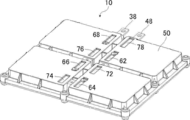
- FIG. 1 is a perspective view showing a plate-shaped assembled battery according to a first embodiment of the present invention from the sealing plate side.
- FIG. 2 is a perspective view showing the plate assembled battery of FIG. 1 from the opposite side of the sealing plate.
- FIG. 3 is a perspective view showing a state where the sealing plate and the single cell element are removed from the plate-shaped assembled battery of FIG.
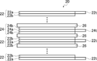
- FIG. 4 is a side view schematically showing a stacked state of unit cell elements of the plate-like assembled battery of FIG.
- FIG. 5 is a plan view showing a state in which the sealing plate is removed from the plate-shaped assembled battery of FIG. 6 is a cross-sectional view of the plate assembled battery of FIG. 1 cut along line A of FIG. FIG.
- FIG. 7 is a partially enlarged cross-sectional view showing the bus bar before caulking used in the plate-shaped assembled battery of FIG.
- FIG. 8 is a partial enlarged cross-sectional view showing the bus bar after caulking used in the plate-shaped assembled battery of FIG.
- FIG. 9 is a partially enlarged cross-sectional view showing a plate-shaped assembled battery of Modification 1 of the first embodiment of the present invention.
- FIG. 10 is a top view which shows the state which removed the sealing plate from the plate-shaped assembled battery of the modification 2 of the 1st Embodiment of this invention.
- FIG. 11 is a cross-sectional view of the plate assembled battery of FIG. 10 cut along line B of FIG.
- FIG. 12 is a cross-sectional view of a plate-shaped assembled battery according to Modification 3 of the first embodiment of the present invention.
- FIG. 13 is a cross-sectional view of the plate assembled battery according to the second embodiment of the present invention.
- FIG. 1 is a perspective view showing a plate-like assembled battery according to a first embodiment of the present invention from the sealing plate side
- FIG. 2 is a perspective view showing the plate-like assembled battery of FIG. 1 from the opposite side of the sealing plate.
- FIG. 3 is a perspective view showing a state in which the sealing plate and the single battery element are removed from the plate-like assembled battery of FIG.
- the plate-shaped assembled battery 10 of the present invention includes a plurality of single battery elements 20, a long negative electrode bus bar 30, a long positive electrode bus bar 40, a plate-shaped assembled battery case 50, and a sealing plate 80.
- the long negative electrode bus bar 30 is made of a conductive material, and is configured integrally with the assembled battery case 50 in order to connect the plurality of unit cell elements 20 in series.
- the elongated positive electrode bus bar 40 is made of a conductive material different from that of the negative electrode bus bar 30, and is configured integrally with the assembled battery case 50 while being connected to the negative electrode bus bar 30.
- the flat assembled battery case 50 is made of an insulating material, has the same number of storage parts 52 as the plurality of single battery elements 20, and stores the plurality of single battery elements 20 in each storage part 52.
- the sealing plate 80 hermetically seals the plurality of storage portions 52 of the assembled battery case 50 into which the electrolytic solution has been injected.
- this preferred embodiment demonstrates the number of the several cell elements 20 accommodated in the assembled battery case 50 as four, this invention is not limited to this.
- the storage portion 52 of the plate-shaped assembled battery 10 according to the first embodiment of the present invention is a recess composed of storage portions 52a to 52d, and the sealing plate 80 is screwed to the surface of the assembled battery case 50 where the recess is present.
- the sealing plate 80 is fixed to the upper surface of the assembled battery case 50 with screws. A fixing method other than screw fixing and a sealing method other than O-ring incorporation will be described later.
- each storage portion 52 of the assembled battery case 50 may be coated by, for example, aluminum vapor deposition in order to suppress the penetration of the electrolyte into the assembled battery case 50 and the intrusion of moisture in the outside air and the outside air. It may be covered with, for example, LCP (liquid crystal polymer), polyimide, aluminum foil, or aluminum laminate.
- LCP liquid crystal polymer
- polyimide polyimide
- aluminum foil aluminum laminate
- the material of the negative electrode bus bar 30 of the plate assembled battery 10 of the present invention is, for example, copper, nickel, SUS, etc., and is not particularly limited, but is preferably copper.
- the material of the positive electrode bus bar 40 is, for example, aluminum or SUS, and is not particularly limited, but is preferably aluminum.
- the material of the assembled battery case 50 is not particularly limited, but may be PPS (polyphenylene sulfide) resin, PES (polyethersulfone) resin, PEEK (polyetheretherketone) resin, PPSU (polyphenylsulfone) resin. preferable.
- the material of the sealing plate 80 is not particularly limited, but PPS (polyphenylene sulfide) resin, PES (polyethersulfone) resin, PEEK (polyetheretherketone) resin, PPSU (polyphenylsulfone) resin, aluminum, SUS Is preferred.
- PPS polyphenylene sulfide
- PES polyethersulfone
- PEEK polyetheretherketone
- PPSU polyphenylsulfone
- aluminum SUS Is preferred.
- resin you may use resin which added the composite material of a metal and ceramics and improved thermal conductivity.
- FIG. 4 is a side view schematically showing a stacked state of unit cell elements of the plate-like assembled battery of FIG.
- the plurality of single cell elements 20 includes a plurality of negative electrode elements 22, a plurality of positive electrode elements 24, and a plurality of separators 26, respectively.
- the negative electrode element 22 has a negative electrode battery active material 22b and a negative electrode current collector 22t.
- the positive electrode element 24 has a positive electrode battery active material 24b and a positive electrode current collector 24t. It electrically insulates from the positive electrode element 24.
- the negative electrode element 22 includes a negative electrode current collector 22t that is a part of the negative electrode foil 22a, and a negative electrode battery active material 22b formed on both sides of the negative electrode foil 22a other than the negative electrode current collector 22t.
- the positive electrode element 24 includes a positive electrode current collector 24t that is a part of the positive electrode foil 24a, and a positive battery active material 24b formed on both sides of the positive electrode foil 24a other than the positive electrode current collector 24t.
- the negative electrode element 22 and the positive electrode element 24 are alternately stacked via the separator 26, and the negative electrode element 22 having the negative electrode active material 22b formed on one side or both sides of the negative electrode foil 22a is disposed at both ends in the stacking direction. .
- the positive electrode element 24 in which the positive electrode battery active material 24b is formed on one side or both sides of the positive electrode foil 24a may be disposed at one end in the stacking direction.
- the unit cell element 20 may have a structure in which a negative electrode element 22 having a large aspect ratio, a separator 26, and a positive electrode element 24 are stacked in this order and wound in a roll shape.
- the plurality of negative electrode current collectors 22t that protrude with a gap from one of the long sides of the negative electrode element 22 and the gap that protrudes from one of the long sides of the positive electrode element 24
- the plurality of positive electrode current collectors 24t may be configured to overlap each other.
- the separator 26 may be integrated with one of the negative electrode element 22 or the positive electrode element 24 by, for example, applying to one of the negative electrode battery active material 22b or the positive electrode battery active material 24b. Can do.
- each of the plurality of unit cell elements 20 is exposed in each storage portion 52. That is, since each cell element 20 is not housed in a separate container, the negative foil 22a, the negative battery active material 22b, the negative current collector 22t, the positive foil 24a, the positive battery active material 24b, and the positive current collector 24t. For example, the side surface of the separator 26 is exposed in each storage portion 52.
- the material of the negative electrode foil 22a and the negative electrode current collector 22t of the plate assembled battery 10 of the present invention is, for example, copper, nickel and the like, and is not particularly limited, but is preferably copper.
- the material of the negative electrode battery active material 22b is not particularly limited, and examples thereof include carbon materials such as natural graphite, artificial graphite, amorphous carbon, coke and mesophase pitch carbon fiber, graphite, and hard carbon which is amorphous carbon.
- the main material is at least one selected.
- the material of the positive electrode foil 24a and the positive electrode current collector 24t is, for example, aluminum or SUS, and is not particularly limited, but is preferably aluminum.
- the material of the positive electrode battery active material 24b is not particularly limited, but for example, lithium-manganese composite oxide, lithium-nickel composite oxide, lithium-cobalt composite oxide, lithium-iron composite oxide, lithium-nickel- Cobalt composite oxide, lithium-manganese-cobalt composite oxide, lithium-nickel-manganese-cobalt composite oxide, lithium-metal phosphate compound, lithium-manganese phosphate, lithium-nickel phosphate, lithium-cobalt phosphorus Examples thereof include oxides, lithium-iron phosphorus oxides, and lithium-transition metal sulfate compounds.
- the material of the separator is not particularly limited, but as the material of the porous separator, for example, polyethylene (PE), polypropylene (PP), PP / PE / PP three-layer structure, polyimide, etc.
- a material for the separator for example, polyolefin such as cotton, rayon, acetate, nylon, polyester, polypropylene, polyethylene, polyimide, aramid, or the like can be used.
- Examples of the material of the separator 26 that can be integrated by coating are silica, alumina, titania, talc, diatomaceous earth, mica, vermiculite, and the like.
- the electrolytic solution is not particularly limited.
- an electrolyte using at least one lithium salt such as LiPF 6 , LiBF 4 , LiClO 4 , LiAsF 6 , ethylene carbonate (EC), ethyl methyl carbonate (EMC) is used.
- EC ethylene carbonate
- EMC ethyl methyl carbonate
- PC Propylene carbonate
- DEC diethyl carbonate
- FIG. 5 is a plan view showing a state in which the sealing plate is removed from the plate-like assembled battery of FIG. 1
- FIG. 6 is a cross-sectional view of the plate-like assembled battery of FIG. 1 cut along line A in FIG. .
- the single cell element 20 includes single cell elements 20a to 20d
- the negative electrode bus bar 30 includes negative electrode bus bars 32, 34, and 36
- the positive electrode bus bar 40 includes positive electrode bus bars 42, 44, and 46.
- the negative electrode bus bar 32 has negative electrode laminate connection portions 32a and 32b.
- the negative electrode stacking connection portions 32a and 32b are arranged at one end of the negative electrode bus bar 32 and are arranged in one end portion of the negative electrode bus bar 32.
- the electric part 22t is electrically connected. Since the negative electrode bus bars 34 and 36 are the same, the description thereof is omitted.
- the negative electrode bus bar 30 may have a shape on a flat plate without bending. In that case, you may provide the connection position of the negative electrode current collection part 22t of the cell element 20a in one place.
- the positive electrode bus bar 42 has positive electrode laminated connection portions 42a and 42b.
- the positive electrode stacking connection portions 42a and 42b are arranged at one end of the positive electrode bus bar 42, and the positive electrode assembly provided in the unit cell element 20b in the storage unit 52b in which the other unit cell element 20b connected in series is stored.
- the electric part 24t is electrically connected. Since the positive electrode bus bars 44 and 46 are the same, the description thereof is omitted.
- the positive electrode bus bar 40 may have a shape on a flat plate without bending. In that case, you may provide the connection position of the positive electrode current collection part 24t of the cell element 20a in one place.
- the negative electrode terminal plate 38 and the positive electrode terminal plate 48 are configured integrally with the assembled battery case 50.
- the negative electrode terminal plate 38 has negative electrode laminate connection portions 38a and 38b.
- the negative electrode stacking connection portions 38a and 38b are disposed at one end of the negative electrode terminal plate 38, and the negative electrode current collector 22t included in the unit cell element 20d is electrically connected to the storage unit 52d in which the unit cell element 20d is stored.
- the positive electrode terminal plate 48 has positive electrode laminated connection portions 48a and 48b.
- the positive electrode stacking connection portions 48a and 48b are disposed at one end of the positive electrode terminal plate 48, and the positive electrode current collector 24t included in the unit cell element 20a is electrically connected to the storage unit 52a in which the unit cell element 20a is stored.
- the assembled battery case 50 of the plate-like assembled battery 10 includes a terminal plate fixing wall 56d that seamlessly covers the outer periphery of the negative electrode terminal plate 38 over the entire circumference, and a terminal plate fixing wall 56a that seamlessly covers the outer periphery of the positive electrode terminal plate 48 over the entire circumference. And having.
- the negative electrode bus bar 30 and the positive electrode bus bar 40 of the plate-shaped assembled battery 10 of the present invention may have a plate shape bent in a U shape. That is, the shape of the negative electrode bus bar 32 is a plate shape bent in a U shape, and the purpose thereof is to connect the connection position of the negative electrode current collector 22t of the single cell element 20a to the negative electrode laminated connection portion 32a on the lower side of the U shape. This is for preventing the disconnection and poor connection of the negative electrode current collector 22t by reducing the number of connections per one point by halving the number of connections per one part.
- the shape of the positive electrode bus bar 42 is a plate shape bent into a U shape, and the purpose of the positive electrode bus bar 42 is also the same as that of the positive electrode current collector 24t of the unit cell element 20a.
- the reason is to prevent tearing and poor connection of the positive electrode current collector 24t by providing the stacked connection part 42a and the upper positive electrode stacked connection part 42b in two places and reducing the number of connections per one place by half.
- the remaining half of the positive electrode current collector parts 24t are ultrasonically welded. Since the positive electrode bus bars 44 and 46 and the positive electrode terminal plate 48 are the same, description thereof is omitted. Ultrasonic welding for the U-shaped lower negative electrode connecting portion 32a and the lower positive electrode connecting portion 42a, and ultrasonic welding for the U-shaped upper negative electrode connecting portion 32b and the upper positive electrode connecting portion 42b, Each may be executed simultaneously.
- the plate-like assembled battery of the present invention can maintain high quality as easily as or more than the conventional one.
- the width of the bent portion of the negative electrode bus bar 30 and the positive electrode bus bar 40 of the plate-like assembled battery 10 of the present invention may be equal to or less than the straight portion. That is, the width of the bent portion of the negative electrode bus bar 32 and the positive electrode bus bar 42 is narrower than the width of the straight portion, and the purpose thereof is to reduce the width of the bent portion in advance by processing the width of the bent portion in advance. This is to prevent excess dimensions. Since the negative electrode bus bars 34 and 36 and the positive electrode bus bars 44 and 46 are the same, the description thereof is omitted.
- the plate-like assembled battery of the present invention can be easily assembled to the same level as or higher than the conventional one.
- FIG. 7 is a partial enlarged cross-sectional view showing the bus bar before caulking used in the plate assembled battery of FIG. 1, and FIG. 8 shows the bus bar after caulking used in the plate assembled battery of FIG. It is an expanded sectional view and shows the bus bar of the part C in FIG.
- the negative electrode bus bar 32 further includes a negative electrode connecting portion 32c disposed at the other end, and the positive electrode bus bar 42 further includes a positive electrode connecting portion 42c disposed at the other end, and the negative electrode connecting portion 32c.
- the positive electrode coupling portion 42c are electrically connected to each other by caulking or bolt fastening.
- the negative electrode bus bar 32 has a negative electrode connecting portion 32c at the end opposite to the negative electrode stacked connection portions 32a and 32b
- the positive electrode bus bar 42 has a positive electrode at the end opposite to the positive electrode stacked connection portions 42a and 42b.
- There is a connecting portion 42c, and the negative electrode connecting portion 32c and the positive electrode connecting portion 42c are electrically connected to each other by caulking or bolt fastening which can be connected more easily than the conventional “metallic coupling”.
- the negative electrode bus bar 34 further includes a negative electrode connecting portion 34c (not shown) disposed at the other end, and the positive electrode bus bar 44 further includes a positive electrode connecting portion 44c (not illustrated) disposed at the other end.
- the negative electrode connecting portion 34c and the positive electrode connecting portion 44c are electrically connected to each other in the same manner.
- the negative electrode bus bar 36 is the same as the negative electrode bus bars 32, 34, and the positive electrode bus bar 46 is the same as the positive electrode bus bars 42, 44, and thus the description thereof is omitted.
- caulking in this specification means not only that the rivets fitted to a plurality of parts are plastically deformed and joined, but also a part of a plurality of parts is plastically processed and joined together. To do.
- the electrical connection surfaces of the negative electrode coupling portions 32c, 34c, and 36c and the positive electrode coupling portions 42c, 44c, and 46c of the plate assembled battery 10 of the present invention are the longitudinal direction of the negative electrode bus bars 32, 34, and 36, and the positive electrode bus bar 42, They may be arranged so as to extend in the longitudinal direction of 44 and 46 and to face each other. That is, as shown in FIGS. 7 and 8, the side surface of the negative electrode connecting portion 32 c extending in the longitudinal direction of the negative electrode bus bar 32 and the side surface of the positive electrode connecting portion 42 c extending in the longitudinal direction of the positive electrode bus bar 42 are arranged to face each other. And an electrical connection surface is formed between them.
- a cylindrical member made of copper is attached to the negative electrode connecting portion 32c, and a through hole is provided in the positive electrode connecting portion 42c. After the cylindrical member and the through hole are fitted, the cylindrical member is crushed while opening the tip.
- the negative electrode coupling part 32c and the positive electrode coupling part 42c are electrically connected by plastic deformation.
- the negative electrode coupling part 32c and the positive electrode coupling part 42c may be electrically connected by bolt fastening. Since the negative electrode connecting portion 34c and the positive electrode connecting portion 44c, and the negative electrode connecting portion 36c and the positive electrode connecting portion 46c are the same, description thereof will be omitted.
- the electrical connection surfaces of the negative electrode coupling portions 32c, 34c, and 36c and the positive electrode coupling portions 42c, 44c, and 46c of the plate assembled battery 10 of the present invention are the longitudinal direction of the negative electrode bus bars 32, 34, and 36, and the positive electrode bus bar 42, They may be arranged so as to extend perpendicularly to the longitudinal direction of 44 and 46 and to face each other. That is, although not shown, the end surface of the negative electrode coupling portion 32c extending perpendicularly to the longitudinal direction of the negative electrode bus bar 32 and the end surface of the positive electrode coupling portion 42c extending perpendicularly to the longitudinal direction of the positive electrode bus bar 42 face each other. And an electrical connection surface is formed between them. Since the negative electrode connecting portion 34c and the positive electrode connecting portion 44c, and the negative electrode connecting portion 36c and the positive electrode connecting portion 46c are the same, description thereof will be omitted.
- the plate-like assembled battery of the present invention can be easily assembled equal to or higher than the conventional one and can maintain high quality.
- At least a part of the electrical connection surface between the negative electrode coupling portion 32c and the positive electrode coupling portion 42c is configured to be disposed outside any of the plurality of storage portions 52a to 52d. That is, at least a part of the electrical connection surface between the negative electrode coupling part 32 c and the positive electrode coupling part 42 c is arranged outside the storage part 52 so as not to touch the electrolyte injected into the storage part 52. .
- At least a part of the electrical connection surface between the negative electrode connecting portion 34c and the positive electrode connecting portion 44c is configured to be disposed outside any of the plurality of storage portions 52a to 52d.
- the electrical connection surface between the negative electrode coupling portion 36c (not shown) and the positive electrode coupling portion 46c (not shown) is the electrical connection surface between the negative electrode coupling portion 32c and the positive electrode coupling portion 42c, and the negative electrode coupling portion 34c. Since this is the same as the electrical connection surface of the positive electrode connecting portion 44c, description thereof is omitted.
- the assembled battery case 50 of the plate-shaped assembled battery 10 of the present invention may have connecting portion fixing walls 56ab, 56bc, 56cd.
- the connecting portion fixing walls 56ab, 56bc, 56cd are at least a part of the whole of the negative electrode connecting portions 32c, 34c, 36c and the positive electrode connecting portions 42c, 44c, 46c electrically connected to each other in the direction along the connecting surface.
- the outer circumference is seamlessly covered over the entire circumference. That is, the connecting portion fixing wall 56ab covers the entire circumference of the negative electrode connecting portion 32c and the positive electrode connecting portion 42c, which are electrically connected to each other, at least partially in the direction along the connecting surface. is there.
- the connecting portion fixing wall 56ab seamlessly covers the entire outer periphery of the negative electrode connecting portion 32c and the positive electrode connecting portion 42c over the entire circumference because of the shrinkage of the material after the battery pack case 50 is injection molded, This is because pressure is applied to the electrical connection surface with the connecting portion 42c to block inflow of moisture and electrolyte in the air to the connection surface.
- an inspection port for directly measuring the negative electrode connecting portion 32c and the positive electrode connecting portion 42c and measuring the voltage can be provided in a part of the connecting portion fixing wall 56ab in the direction along the connecting surface.
- the connecting portion fixing wall 56bc similarly covers the negative electrode connecting portion 34c and the positive electrode connecting portion 44c
- the connecting portion fixing wall 56cd similarly covers the negative electrode connecting portion 36c and the positive electrode connecting portion 46c. The description is omitted.
- the plate-like assembled battery of the present invention can be easily manufactured without using a large-scale facility and can prevent electric corrosion. As a result, it can be easily assembled and high quality can be maintained.
- the plate assembled battery 10 of the present invention may further include a sealant.
- the sealant is applied to the interface between the negative electrode bus bar 30 and the connecting portion fixing walls 56ab, 56bc, 56cd and the interface between the positive electrode bus bar 40 and the connecting portion fixing walls 56ab, 56bc, 56cd. That is, a sealant is applied to the interface between the negative electrode bus bar 32 and the connecting portion fixing wall 56ab and the interface between the positive electrode bus bar 42 and the connecting portion fixing wall 56ab.
- the purpose is to improve the adhesion of each interface. This is to block the inflow of moisture and electrolyte in the air to each interface.
- a sealing agent may be applied to the negative electrode bus bar 32 and the positive electrode bus bar 42 and then heated.
- the sealant is not particularly limited, but is preferably a thermoplastic polyester elastomer.
- the sealant is used for the interface between the negative electrode bus bar 34 and the connecting portion fixing wall 56bc, the interface between the positive electrode bus bar 44 and the connecting portion fixing wall 56bc, the interface between the negative electrode bus bar 36 and the connecting portion fixing wall 56cd, and the positive electrode bus bar 46.
- the connection portion fixing wall 56cd are applied in the same manner, and the description thereof is omitted.
- the plate-like assembled battery of the present invention can be easily manufactured without using a large-scale facility and can prevent electric corrosion. As a result, it can be easily assembled and high quality can be maintained.
- the assembled battery case 50 of the plate-like assembled battery 10 of the present invention includes a negative electrode bus bar protection part 62, 64, 66 for covering one surface of a part of the negative electrode bus bar 30, and a part of one surface of the positive electrode bus bar 40. And positive electrode bus bar protection portions 72, 74, and 76.
- the thickness of the negative electrode bus bar protection parts 62, 64, 66 and the positive electrode bus bar protection parts 72, 74, 76 is 5 mm or less.
- the thickness of the negative electrode bus bar protection part 62 for covering a part of the lower surface of the negative electrode bus bar 32 and the thickness of the positive electrode bus bar protection part 72 for covering a part of the lower surface of the positive electrode bus bar 42 are: The purpose is to enhance the heat dissipation of the negative electrode bus bar 32 during preliminary charging. Note that the negative electrode bus bar protection units 64 and 66 and the positive electrode bus bar protection units 74 and 76 are the same, and thus the description thereof is omitted.
- the assembled battery case 50 of the plate-like assembled battery 10 includes a terminal plate protection unit 68 for covering a part of one surface of the negative electrode terminal plate 38 and a terminal for covering a part of one surface of the positive electrode terminal plate 48. And a plate protection part 78. Since the thicknesses of the terminal plate protection part 68 and the terminal plate protection part 78 are the same as those of the negative electrode bus bar protection parts 62, 64, 66 and the positive electrode bus bar protection parts 72, 74, 76, the description thereof is omitted.
- the plate-like assembled battery of the present invention can maintain high quality as easily as or more than the conventional one.
- the plate-like assembled battery 10 of the present invention further includes a negative electrode terminal plate 38 and a positive electrode terminal plate 48 that are integrally formed with the assembled battery case 50 in order to extract power from the plate-like assembled battery 10.
- At least one of the negative electrode bus bar 30 or the negative electrode terminal plate 38 and the positive electrode bus bar 40 or the positive electrode terminal plate 48 disposed therein is an injection hole portion 32d, 34d, an injection hole portion 36d, 38d for injecting an electrolytic solution ( (Not shown).
- the liquid injection hole portion 32d is provided in one or both of the negative electrode bus bar 32 and the positive electrode terminal plate 48 disposed in the storage portion 52a, and the purpose thereof is that the wall surface of each storage portion 52a is made of synthetic resin or the like. This is because the liquid injection hole is easily and surely sealed by providing the liquid injection hole in a metal bus bar having a strength higher than that of the assembled battery case 50 made of an insulating material.
- a hole is provided at a position corresponding to the liquid injection hole 32d of the assembled battery case 50, and the electrolytic solution is injected from the liquid injection hole 32d exposed from the hole. In the case where there is no liquid injection hole 32d, it is necessary to inject the electrolyte before the sealing plate 80 is screwed.
- the plate-like assembled battery of the present invention can be easily assembled equal to or higher than the conventional one and can maintain high quality.
- the liquid injection holes 32d, 34d, 36d, and 38d of the plate assembled battery 10 of the present invention are fixed to the liquid injection holes 32d, 34d, 36d, and 38d by caulking to assist sealing of the liquid injection holes.
- a liquid filling auxiliary member may be included. That is, a caulking nut for assisting the sealing of the liquid injection hole is fixed to the liquid injection hole portion 32d, and the hole is sealed with a screw. This is because the plate-shaped bus bar is formed with higher strength than the direct processing.
- an O-ring integrated type may be used in order to improve the sealing performance.
- the liquid injection hole portions 34d, 36d, and 38d are the same, and thus the description thereof is omitted.
- the plate-like assembled battery of the present invention can be easily assembled equal to or higher than the conventional one and can maintain high quality.
- FIG. 9 is a partially enlarged cross-sectional view showing a plate-shaped assembled battery of Modification 1 of the first embodiment of the present invention.
- the plate-like assembled battery 110 of Modification 1 is the same as the plate-like assembled battery 10 of the present invention except that the O-ring grooves 54a to 54d are not provided and the film 184 is provided instead of the O-rings 82a to 82d. Since it has a structure, description of the same component is abbreviate
- a film 184 for hermetically sealing each storage portion 52 may be mounted between the assembled battery case 150 and the sealing plate 80 of the plate-shaped assembled battery 110 of the present invention. That is, in order to hermetically seal each storage portion 52, a film 184 is mounted between the assembled battery case 150 and the sealing plate 80, and a surface having a concave portion of the assembled battery case 150 using a heat sealer or the like.
- the film 184 of the part M around each storage part 52 is thermally welded to the assembled battery case 150, and the sealing plate 80 is screw-fixed thereon, the purpose of which is more than when an O-ring is used. This is because the deflection due to the reaction force is small, so that the sealing plate 80 is made thin and the heat dissipation and assembling properties are improved.
- ultrasonic welding, adhesion or caulking may be used, and a gasket may be incorporated instead of the film 184.
- the plate-like assembled battery of the present invention can be easily assembled equal to or higher than the conventional one and can maintain high quality.
- FIG. 10 is a plan view showing a state in which the sealing plate is removed from the plate-shaped assembled battery of Modification 2 of the first embodiment of the present invention
- FIG. 11 shows the plate-shaped assembled battery of FIG. It is sectional drawing cut
- the plate-like assembled battery 210 of Modification 2 is different from the plate-like assembled battery 10 of the present invention in that the arrangement of the negative electrode current collectors 22t and the positive electrode current collectors 24t of the unit cell elements 20a to 20d is different. Since the bus bars 32, 34, and 36 and the positive electrode bus bars 42, 44, and 46 have the same configuration except that they have different shapes, description of the same components is omitted.
- the single cell element 220 includes single cell elements 220a to 220d, the negative electrode bus bar 230 includes negative electrode bus bars 232, 234, and 236, and the positive electrode bus bar 240 includes positive electrode bus bars 242, 244, and 246.
- the negative electrode bus bar 230 and the positive electrode bus bar 240 of the plate-shaped assembled battery 210 of the present invention may have a plate shape bent stepwise. That is, the shape of the negative electrode bus bar 232 is a plate bent in a staircase shape. The purpose of the negative electrode bus bar 232 is to connect the negative electrode current collector 222t of the unit cell element 220 to the lower layer negative electrode stack connection portion 232a and the upper step.
- the negative electrode current collector 222t is prevented from being broken and poorly connected, and the lower layer negative electrode stacking connection portion 232a and the upper negative electrode This is because the simultaneous assembly to the stacked connection portion 232b improves productivity as compared with the case where a bus bar bent in a U-shape is used.
- Half of the negative electrode current collectors 222t can be ultrasonically welded to the lower layer negative electrode connector 232a of the stairs, and at the same time, half of the negative electrode current collectors 222t can be ultrasonically welded to the upper electrode negative electrode layer connector 232b. . Since the negative electrode bus bars 234 and 236 and the negative electrode terminal plate 238 are the same, description thereof is omitted.
- the shape of the positive electrode bus bar 242 is also a plate shape bent in a staircase shape, and the purpose of the positive electrode bus bar 242 is also the same as that of the positive electrode stacking connection portion at the lower stage of the staircase.
- 242a and the upper positive electrode stacking connection part 242b are provided at two locations, and the number of connections per one point is halved to prevent tearing of the positive current collector 224t and poor connection, and at the lower step of the positive electrode stacking connection part 242a. This is because the simultaneous assembly into the upper positive electrode stacking connection portion 242b improves productivity more than when using a U-shaped bent bus bar.
- Half of the positive electrode current collectors 224t can be ultrasonically welded to the lower positive electrode layered connection 242a of the staircase, and half of the positive electrode current collectors 224t can be ultrasonically welded to the upper positive electrode layered connection 242b.
- the positive bus bars 244 and 246 and the positive terminal plate 248 are the same and will not be described. Ultrasonic welding of the lower layer negative electrode connection 232a and the upper negative electrode layer connection 232b and the ultrasonic welding of the lower layer positive electrode layer connection 242a and upper step positive electrode layer connection 242b are all performed simultaneously. May be.
- the plate-like assembled battery of the present invention can maintain high quality as easily as or more than the conventional one.
- FIG. 12 is a cross-sectional view of a plate-shaped assembled battery according to Modification 3 of the first embodiment of the present invention.
- the plate-like assembled battery 310 of Modification 3 is different from the plate-like assembled battery 210 of the present invention in that the upper negative electrode laminated connection portions 232b, 234b, 236b and the upper positive electrode laminated connection portions 242b, 244b of the positive electrode bus bar. Since the assembled battery case 250 has the same configuration except that the portions of the battery pack case 250 adjacent to the H.246b have different thicknesses, the description of the same components will be omitted.
- the thickness of the assembled battery case 350 at the portion adjacent to the upper negative electrode stacked connection portions 232b, 234b, 236b and the upper positive electrode stacked connection portions 242b, 244b, 246b of the negative electrode bus bar of the plate-shaped assembled battery 310 of the present invention Is approximately the same as the thickness of the assembled battery case 350 in the portion adjacent to the lower layer negative electrode stacking connections 232a, 234a, 236a and the lower layer positive electrode stacking connections 242a, 244a, 246a, respectively.
- concave portions 358a to 358d are provided from the lower side to the upper side of the assembled battery case 350.
- the purpose of the concave portions 358a to 358d is to reduce the weight of the assembled battery case and to the negative electrode laminated connection portions 232b, 234b, 236b, 238b in the upper stage.
- the negative electrode current collector 222t is ultrasonically welded, and the upper positive electrode laminate connection part 24 b, 244b, 246b, in order to prevent the attenuation of ultrasonic waves at the time of ultrasonic welding the positive electrode current collecting portion 224t to 248 b.
- the plate-like assembled battery of the present invention can maintain high quality as easily as or more than the conventional one.
- FIG. 13 is a cross-sectional view of the plate assembled battery according to the second embodiment of the present invention.
- the plate-like assembled battery 410 according to the second embodiment is different from the plate-like assembled battery 10 of the present invention in that it has storage portions 452a to 452d that penetrate therethrough instead of the storage portions 52a to 52d that have bottoms. Except for the point having 486, the point having O-ring grooves 458a to 458h on the lower surface of the assembled battery case 450, and the point having O-rings 488a to 488h, the description of the same components is omitted. To do.
- the storage portions 452a to 452d of the plate-like assembled battery 410 according to the second embodiment of the present invention may be through holes.
- the sealing plates 80 and 486 may be screwed to a pair of opposed surfaces having through holes of the assembled battery case 450. That is, the storage portions 452a to 452d are through holes in which the bottom surface of the storage portion 52 of the plate-like battery pack 10 according to the first embodiment of the present invention is removed.
- O-ring grooves 458a to 458d are formed around the storage portions 452a to 452d on the lower surface of the assembled battery case 450, and O-rings 488a to 488d are formed therein.
- the O-ring groove 458e is formed around the holes provided at the positions corresponding to the liquid injection holes 32d, 34d, 36d, and 38d on the lower surface.
- the material and shape of the sealing plate 486 may be the same as that of the sealing plate 80. Further, when there is no liquid injection hole portion 32d, 34d, 36d, 38d, it is necessary to inject the electrolytic solution after screwing one of the sealing plates 80, 486 and before screwing the other. Further, instead of screwing the sealing plates 80 and 486 to the assembled battery case 450, ultrasonic welding or adhesion or caulking may be used, or the film or gasket of the first modification may be used instead of the O-ring. good.
- the plate assembled battery of the present invention is basically configured as described above.
- the plate-like assembled battery of the present invention can be easily manufactured without using a large-scale facility and can prevent electric corrosion, it can be easily assembled to be equal to or more than conventional. Can be maintained and high quality can be maintained, which is industrially useful.
Landscapes
- Chemical & Material Sciences (AREA)
- Chemical Kinetics & Catalysis (AREA)
- Electrochemistry (AREA)
- General Chemical & Material Sciences (AREA)
- Inorganic Chemistry (AREA)
- Connection Of Batteries Or Terminals (AREA)
Abstract
Description
本発明は、単セルの二次電池を複数個組み合わせてできる組電池に関するものである。 The present invention relates to an assembled battery formed by combining a plurality of single-cell secondary batteries.
従来から、大容量の二次電池を構成するために複数個の単セルを直列もしくは並列または直並列に接続することで構成される組電池が知られている。また、近年、電気自動車やハイブリッド自動車の普及に伴い、これら組電池の重要性が再認識されている。このような組電池が特許文献1に開示されている。 Conventionally, an assembled battery configured by connecting a plurality of single cells in series, parallel, or series-parallel in order to configure a large-capacity secondary battery is known. In recent years, with the popularization of electric vehicles and hybrid vehicles, the importance of these assembled batteries has been recognized again. Such an assembled battery is disclosed in Patent Document 1.
特許文献1には、正極と負極とセパレータを積層してそれぞれ構成される複数の電池発電要素を、電池ケースの複数の電池発電要素格納部にそれぞれ格納し、これらの電池発電要素をバスバーに接続した後、蓋板で電池ケースを封止するというシンプルな製造工程で構成された組電池が記載されている。 In Patent Document 1, a plurality of battery power generation elements each configured by stacking a positive electrode, a negative electrode, and a separator are respectively stored in a plurality of battery power generation element storage portions of a battery case, and these battery power generation elements are connected to a bus bar. After that, an assembled battery configured by a simple manufacturing process of sealing a battery case with a cover plate is described.
しかしながら、特許文献1の組電池のバスバーの材料は、アルミニウムやニッケルなどの導電性金属であるのに対して、正極の端子部の材料は、アルミニウム、アルミニウム合金、SUS、チタンなどの導電性金属であり、負極の端子部の材料は、銅、ニッケル、銀、SUSなどの導電性金属であるため、バスバーと正極の端子部と負極の端子部とを全て同一材料で構成しない限り、異種の金属同士を接続したときに空気中の水分による電気腐食(電気化学的腐食)が起こるという問題があった。 However, the material of the bus bar of the assembled battery of Patent Document 1 is a conductive metal such as aluminum or nickel, while the material of the terminal portion of the positive electrode is a conductive metal such as aluminum, aluminum alloy, SUS, or titanium. Since the material of the negative electrode terminal portion is a conductive metal such as copper, nickel, silver, or SUS, different types of materials are used unless the bus bar, the positive electrode terminal portion, and the negative electrode terminal portion are all made of the same material. There has been a problem that, when metals are connected to each other, electric corrosion (electrochemical corrosion) due to moisture in the air occurs.
この問題を解消する技術として、特許文献2には、プラス端子とマイナス端子とが互いに異種金属で形成されたバッテリに対して用いる端子接続用のバスバーであって、バッテリのプラス端子と同一金属で形成され且つプラス端子と接続可能とされた正極接続部と、バッテリのマイナス端子と同一金属で形成され且つマイナス端子と接続可能とされた負極接続部とを有し、正極接続部と負極接続部とが金属的結合により一体化されたバスバーが記載されている。そして、この「金属的結合」は、結合しようとする異種金属間が金属組織レベルで密着した結合界面を形成させ、その結果として導電性及び機械的結合強度を「バスバーとして実用に適する値」にまで高めた状態を言うと記載されている。 As a technique for solving this problem, Patent Document 2 discloses a bus bar for terminal connection used for a battery in which a plus terminal and a minus terminal are formed of different metals, and the same metal as the plus terminal of the battery. A positive electrode connecting portion formed and connectable to the positive terminal; and a negative electrode connecting portion formed of the same metal as the negative terminal of the battery and connectable to the negative terminal. A bus bar is described in which and are integrated by a metallic bond. This “metallic bond” forms a bonded interface in which different kinds of metals to be bonded are in close contact with each other at the metal structure level. As a result, the conductivity and mechanical bond strength are set to “values suitable for practical use as a bus bar”. It is described as saying that it has been raised.
しかしながら、特許文献2のバスバーは、正極用元材及び負極用元材を長手方向に沿って張り合わせて形成した丸棒状のビレットを、正極用元材と負極用元材とが互いに並行して押し出されるように押出装置へ装填し、この状態で、押出装置を超高圧の等方圧環境下にて作動させ、押出加工又は引抜作業を行い、正極用元材と負極用元材とが金属的結合して一体となった成形体を成形するという手順で製造されるので、押出装置のような大規模な設備を要するという問題があった。 However, in the bus bar of Patent Document 2, a round bar-shaped billet formed by bonding a positive electrode base material and a negative electrode base material along the longitudinal direction is extruded in parallel with each other. In this state, the extrusion apparatus is operated in an isotropic pressure environment of ultra high pressure to perform extrusion processing or drawing work, and the positive electrode base material and the negative electrode base material are metallic. Since it is manufactured by the procedure of forming a molded body which is united by joining, there is a problem that a large-scale facility such as an extrusion apparatus is required.
本発明は、従来のこのような問題点に鑑みてなされたものであり、本発明の目的は、大規模な設備を使用せずに容易に製造することができかつ電気腐食が防止された板状組電池を提供することにある。
また、本発明の他の目的は、上記目的に加え、従来と同等かそれ以上に容易に組み立てることができかつ高品質が維持された板状組電池を提供することにある。
The present invention has been made in view of such conventional problems, and an object of the present invention is a plate that can be easily manufactured without using a large-scale facility and that prevents electric corrosion. It is to provide a battery pack.
In addition to the above object, another object of the present invention is to provide a plate-shaped assembled battery that can be easily assembled equal to or more than the conventional one and that maintains high quality.
本発明者は、上記目的を達成するために、鋭意研究を重ねた結果、まず、銅製の負極バスバーとアルミニウム製の正極バスバーとをかしめまたはボルト締結によって互いに電気的に接続し、その電気的な接続面の少なくとも一部を、複数の収納部の外側に配置するように構成し、さらに、負極バスバーの接続部分と正極バスバーの接続部分の全体の、接続面に沿った方向の少なくとも一部の外周を、組電池ケースの内部の壁で全周にわたって継ぎ目なく覆い、接続面への空気中の水分の流入を遮断することによって、大規模な設備を使用せずに容易に製造することができかつ電気腐食を防止することができることを見出した。 As a result of intensive studies to achieve the above object, the present inventor first electrically connected a copper negative electrode bus bar and an aluminum positive electrode bus bar to each other by caulking or bolt fastening. At least a part of the connection surface is configured to be disposed outside the plurality of storage portions, and at least a part of the connection part of the negative electrode bus bar and the connection part of the positive electrode bus bar in the direction along the connection surface. The outer periphery is seamlessly covered with the inner wall of the battery pack case over the entire circumference, and it is easy to manufacture without using large-scale equipment by blocking the inflow of moisture in the air to the connection surface. And it discovered that electric corrosion could be prevented.
また、本発明者は、負極バスバーおよび正極バスバーの少なくとも一方にかしめナットを取り付け、その孔から電解液を注入後、その孔をねじで封止することによって、従来と同等かそれ以上に容易に組み立てることができかつ高品質を維持することができることを見出し、本発明に至ったものである。 In addition, the present inventor attaches a caulking nut to at least one of the negative electrode bus bar and the positive electrode bus bar, injects the electrolytic solution from the hole, and then seals the hole with a screw, so that it is as easy as or more than the conventional one. The present inventors have found that they can be assembled and can maintain high quality, and have arrived at the present invention.
即ち、本発明は、負極電池活物質と負極集電部とを有する負極要素と、正極電池活物質と正極集電部とを有する正極要素と、負極要素と正極要素とを電気的に絶縁するセパレータと、をそれぞれ備えた複数の単電池要素と、複数の単電池要素と同数の収納部を有し、各収納部に複数の単電池要素をそれぞれ収納する、絶縁材料から成る平板状の組電池ケースと、複数の単電池要素を直列に接続するために組電池ケースと一体に構成される、導電材料から成る長尺な負極バスバーと、負極バスバーに接続された状態で組電池ケースと一体に構成される、負極バスバーと異なる導電材料から成る長尺な正極バスバーと、電解液が注入された組電池ケースの複数の収納部をそれぞれ気密に封止する封止板と、を備え、複数の単電池要素のそれぞれの少なくとも一部は、各収納部の中に露出した状態であり、負極バスバーは、一方の端部に配置されかつ直列に接続する一方の単電池要素が収納された収納部の中でその単電池要素に備わる負極集電部が電気的に接続される負極積層接続部と、他方の端部に配置される負極連結部と、を有し、正極バスバーは、一方の端部に配置されかつ直列に接続する他方の単電池要素が収納された収納部の中でその単電池要素に備わる正極集電部が電気的に接続される正極積層接続部と、他方の端部に配置される正極連結部と、を有し、負極連結部と正極連結部とは、かしめまたはボルト締結によって互いに電気的に接続され、負極連結部と正極連結部との電気的な接続面の少なくとも一部は、あらゆる複数の収納部の外側に配置されるように構成される板状組電池を提供するものである。 That is, the present invention electrically insulates a negative electrode element having a negative electrode battery active material and a negative electrode current collector, a positive electrode element having a positive electrode battery active material and a positive electrode current collector, and the negative electrode element and the positive electrode element. A plurality of unit cell elements each having a separator, and a flat plate assembly made of an insulating material, each having a same number of storage units as the plurality of unit cell elements, each storing a plurality of unit cell elements in each storage unit. A battery case, a long negative electrode bus bar made of a conductive material, integrated with the assembled battery case to connect a plurality of single cell elements in series, and an integrated battery case integrally connected to the negative electrode bus bar Comprising a long positive electrode bus bar made of a conductive material different from the negative electrode bus bar, and a sealing plate for hermetically sealing a plurality of storage portions of the assembled battery case into which the electrolyte solution has been injected. Each of the cell elements of At least a part is in a state exposed in each storage portion, and the negative electrode bus bar is disposed in one end portion, and the unit cell in the storage portion in which one unit cell element connected in series is stored. The negative electrode current collector connected to the element is electrically connected to the negative electrode stacking connection part, and the negative electrode connecting part is arranged at the other end, and the positive electrode bus bar is arranged at one end and in series A positive electrode stacking connection part electrically connected to a positive electrode current collecting part provided in the single cell element in a storage part in which the other single battery element to be connected to is connected, and a positive electrode connection disposed at the other end part The negative electrode connecting portion and the positive electrode connecting portion are electrically connected to each other by caulking or bolt fastening, and at least a part of the electrical connection surface between the negative electrode connecting portion and the positive electrode connecting portion is any It is configured to be arranged outside the plurality of storage units There is provided a Jo battery pack.
ここで、上記においては、組電池ケースは、互いに電気的に接続された負極連結部と正極連結部の全体の、接続面に沿った方向の少なくとも一部の外周を全周にわたって継ぎ目なく覆うための連結部固定壁を有するのが好ましい。
さらに、負極バスバーと連結部固定壁との界面ならびに正極バスバーと連結部固定壁との界面に塗布された封止剤を備えるのが好ましい。
さらに、板状組電池から電力を取り出すために組電池ケースと一体に構成される負極端子板および正極端子板を備え、同じ収納部の中に配置された負極バスバーまたは負極端子板および正極バスバーまたは正極端子板の少なくとも一方は、電解液を注入するための注液孔部を有するのが好ましい。
注液孔部は、注液孔の封止を補助するために、かしめによって注液孔部に固定された注液補助部材を有するのが好ましい。
負極バスバーおよび正極バスバーは、階段状に曲げられた板状の形状であるのが好ましい。
負極バスバーおよび正極バスバーは、U字状に曲げられた板状の形状であるのが好ましい。
負極バスバーおよび正極バスバーの曲げ部分の幅は、直線部分以下であるのが好ましい。
組電池ケースは、負極バスバーの一部の一方の表面を覆うための負極バスバー保護部と、正極バスバーの一部の一方の表面を覆うための正極バスバー保護部と、を有し、負極バスバー保護部および正極バスバー保護部の厚さは、5mm以下であるのが好ましい。
Here, in the above, the assembled battery case covers the entire circumference of at least a part of the whole of the negative electrode connecting portion and the positive electrode connecting portion that are electrically connected to each other in the direction along the connection surface. It is preferable to have a connecting part fixing wall.
Furthermore, it is preferable to include a sealant applied to the interface between the negative electrode bus bar and the connecting portion fixing wall and the interface between the positive electrode bus bar and the connecting portion fixing wall.
Furthermore, a negative electrode terminal plate and a positive electrode terminal plate configured integrally with an assembled battery case for taking out electric power from the plate-shaped assembled battery, the negative electrode bus bar or the negative electrode terminal plate and the positive electrode bus bar arranged in the same storage unit, At least one of the positive electrode terminal plates preferably has a liquid injection hole for injecting an electrolytic solution.
The liquid injection hole preferably has a liquid injection auxiliary member fixed to the liquid injection hole by caulking in order to assist sealing of the liquid injection hole.
It is preferable that the negative electrode bus bar and the positive electrode bus bar have a plate shape bent stepwise.
It is preferable that the negative electrode bus bar and the positive electrode bus bar have a plate shape bent in a U shape.
The width of the bent portion of the negative electrode bus bar and the positive electrode bus bar is preferably equal to or less than the straight portion.
The assembled battery case has a negative electrode bus bar protection part for covering one surface of a part of the negative electrode bus bar, and a positive electrode bus bar protection part for covering a part of one surface of the positive electrode bus bar. The thickness of the part and the positive electrode bus bar protection part is preferably 5 mm or less.
本発明によれば、大規模な設備を使用せずに容易に製造することができかつ電気腐食を防止することができる。
また、本発明によれば、上記効果に加え、従来と同等かそれ以上に容易に組み立てることができかつ高品質を維持することができる。
According to the present invention, it can be easily manufactured without using a large-scale facility, and electric corrosion can be prevented.
Further, according to the present invention, in addition to the above effects, it can be easily assembled equal to or higher than the conventional one and high quality can be maintained.
以下に、本発明の板状組電池を添付の図面に示す好適実施形態に基づいて詳細に説明する。
まず、本発明の第1の実施形態の板状組電池について説明する。図1は、本発明の第1の実施形態の板状組電池を封止板側から示す斜視図であり、図2は、図1の板状組電池を封止板の反対側から示す斜視図であり、図3は、図1の板状組電池から封止板および単電池要素を取り外した状態を示す斜視図である。
Below, the plate-shaped assembled battery of this invention is demonstrated in detail based on suitable embodiment shown to an accompanying drawing.
First, the plate assembled battery according to the first embodiment of the present invention will be described. FIG. 1 is a perspective view showing a plate-like assembled battery according to a first embodiment of the present invention from the sealing plate side, and FIG. 2 is a perspective view showing the plate-like assembled battery of FIG. 1 from the opposite side of the sealing plate. FIG. 3 is a perspective view showing a state in which the sealing plate and the single battery element are removed from the plate-like assembled battery of FIG.
本発明の板状組電池10は、複数の単電池要素20と、長尺な負極バスバー30と、長尺な正極バスバー40と、平板状の組電池ケース50と、封止板80と、を備える。長尺な負極バスバー30は、導電材料から成り、複数の単電池要素20を直列に接続するために組電池ケース50と一体に構成されるものである。長尺な正極バスバー40は、負極バスバー30と異なる導電材料から成り、負極バスバー30に接続された状態で組電池ケース50と一体に構成されるものである。平板状の組電池ケース50は、絶縁材料から成り、複数の単電池要素20と同数の収納部52を有し、各収納部52に複数の単電池要素20をそれぞれ収納するものである。封止板80は、電解液が注入された組電池ケース50の複数の収納部52をそれぞれ気密に封止するものである。なお、本好適実施形態では、組電池ケース50に収納される複数の単電池要素20の個数を4つとして説明するが、本発明はこれに限定されるものではない。
The plate-shaped assembled
本発明の第1の実施形態の板状組電池10の収納部52は、収納部52a~52dから成る凹部であり、封止板80は、組電池ケース50の凹部がある面にねじ固定される。即ち、その凹部を気密に封止するために、組電池ケース50の上面の各収納部52a~52dのまわりにOリング溝54a~54dを形成し、その中にOリング82a~82dを組み込み、組電池ケース50の上面に封止板80をねじ固定するものである。なお、ねじ固定以外の固定方法およびOリング組み込み以外の封止方法については後述する。
The
組電池ケース50の各収納部52の表面は、組電池ケース50の内部への電解液の滲み込み、ならびに外気と外気中の水分の侵入を抑制するために、例えばアルミ蒸着によってコーティングされても良く、また、例えばLCP(液晶ポリマ)、ポリイミド、アルミ箔、アルミラミネートで覆われても良い。
The surface of each
本発明の板状組電池10の負極バスバー30の材料は、例えば銅、ニッケル、SUSなどであり、特に限定的ではないが、銅であるのが好ましい。正極バスバー40の材料は、例えばアルミニウム、SUSなどであり、特に限定的ではないが、アルミニウムであるのが好ましい。組電池ケース50の材料は、特に限定的ではないが、PPS(ポリフェニレンサルファイド)樹脂、PES(ポリエーテルスルホン)樹脂、PEEK(ポリエーテルエーテルケトン)樹脂、PPSU(ポリフェニルスルホン)樹脂であるのが好ましい。封止板80の材料は、特に限定的ではないが、PPS(ポリフェニレンサルファイド)樹脂、PES(ポリエーテルスルホン)樹脂、PEEK(ポリエーテルエーテルケトン)樹脂、PPSU(ポリフェニルスルホン)樹脂、アルミニウム、SUSであるのが好ましい。樹脂を用いる場合には、金属とセラミックスの複合材料を添加して熱伝導性を高めた樹脂を用いても良い。
The material of the negative
次に、単電池要素の構成について説明する。図4は、図1の板状組電池の単電池要素の積層状態を模式的に示す側面図である。
複数の単電池要素20は、複数の負極要素22と、複数の正極要素24と、複数のセパレータ26と、をそれぞれ備える。負極要素22は、負極電池活物質22bと負極集電部22tとを有し、正極要素24は、正極電池活物質24bと正極集電部24tとを有し、セパレータ26は、負極要素22と正極要素24とを電気的に絶縁するものである。即ち、負極要素22は、負極箔22aの一部である負極集電部22tと、負極箔22aの負極集電部22t以外の部分の両側に形成された負極電池活物質22bと、を有し、正極要素24は、正極箔24aの一部である正極集電部24tと、正極箔24aの正極集電部24t以外の部分の両側に形成された正極電池活物質24bと、を有する。
Next, the configuration of the single cell element will be described. FIG. 4 is a side view schematically showing a stacked state of unit cell elements of the plate-like assembled battery of FIG.
The plurality of
負極要素22および正極要素24は、セパレータ26を介して交互に積層され、積層方向の両端には、負極箔22aの片側または両側に負極電池活物質22bが形成された負極要素22が配置される。積層方向の一方の端には、正極箔24aの片側または両側に正極電池活物質24bが形成された正極要素24が配置されても良い。単電池要素20は、アスペクト比の大きな負極要素22、セパレータ26、正極要素24をこの順に重ね、ロール状に捲回した構造でも良い。その場合、ロール状に捲回した際に、負極要素22の長辺の一方から間隔を開けて突出した複数の負極集電部22t、および正極要素24の長辺の一方から間隔を開けて突出した複数の正極集電部24tが、それぞれ重なり合うように構成されても良い。また、セパレータ26は、材料によっては、例えば、負極電池活物質22bまたは正極電池活物質24bの内の一方に塗工することによって、負極要素22または正極要素24の内の一方に一体化することができる。
The
複数の単電池要素20のそれぞれの少なくとも一部は、各収納部52の中に露出した状態である。即ち、各単電池要素20は、個別の容器に収納されていないので、負極箔22a、負極電池活物質22b、負極集電部22t、正極箔24a、正極電池活物質24b、正極集電部24t、セパレータ26の例えば側面は、各収納部52の中に露出した状態である。
At least a part of each of the plurality of
本発明の板状組電池10の負極箔22aおよび負極集電部22tの材料は、例えば銅、ニッケルなどであり、特に限定的ではないが、銅であるのが好ましい。負極電池活物質22bの材料は、特に限定的ではないが、例えば、天然黒鉛、人造黒鉛、アモルファスカーボン、コークスおよびメソフェーズピッチ系炭素繊維、グラファイト、非晶質炭素であるハードカーボンなどの炭素材料から選ばれてなる少なくとも1種を主材料とするものである。
The material of the
正極箔24aおよび正極集電部24tの材料は、例えばアルミニウム、SUSなどであり、特に限定的ではないが、アルミニウムであるのが好ましい。正極電池活物質24bの材料は、特に限定的ではないが、例えば、リチウム-マンガン複合酸化物、リチウム-ニッケル複合酸化物、リチウム-コバルト複合酸化物、リチウム-鉄複合酸化物、リチウム-ニッケル-コバルト複合酸化物、リチウム-マンガン-コバルト複合酸化物、リチウム-ニッケル-マンガン-コバルト複合酸化物、リチウム-金属リン酸化合物、リチウム-マンガンリン酸化物、リチウム-ニッケルリン酸化物、リチウム-コバルトリン酸化物、リチウム-鉄リン酸化物、およびリチウム-遷移金属硫酸化合物などが例示される。
The material of the
セパレータの材料は、特に限定的ではないが、多孔性セパレータの材質としては、例えば、ポリエチレン(PE)、ポリプロピレン(PP)、PP/PE/PPの3層構造をした構造、ポリイミドなどを、不織布セパレータの材質としては、例えば、綿、レーヨン、アセテート、ナイロン、ポリエステル、ポリプロピレン、ポリエチレンなどのポリオレフィン、ポリイミド、アラミドなどを用いることができる。塗工によって一体化可能なセパレータ26の材料は、例えばシリカ、アルミナ、チタニア、タルク、珪藻土、マイカ、バーミキュライトなどである。電解液は、特に限定的ではないが、例えば、LiPF6、LiBF4、LiClO4、LiAsF6などのリチウム塩の少なくとも1種類を用いた電解質を、エチレンカーボネート(EC)、エチルメチルカーボネート(EMC)、プロピレンカーボネート(PC)、ジエチルカーボネート(DEC)などの少なくとも1種類を用いた溶媒に溶解させたものである。
The material of the separator is not particularly limited, but as the material of the porous separator, for example, polyethylene (PE), polypropylene (PP), PP / PE / PP three-layer structure, polyimide, etc. As a material for the separator, for example, polyolefin such as cotton, rayon, acetate, nylon, polyester, polypropylene, polyethylene, polyimide, aramid, or the like can be used. Examples of the material of the
次に、単電池要素と負極バスバーとの電気的な接続方法および単電池要素と正極バスバーとの電気的な接続方法について説明する。図5は、図1の板状組電池から封止板を取り外した状態を示す平面図であり、図6は、図1の板状組電池を図5の線Aで切断した断面図である。 Next, an electrical connection method between the single cell element and the negative electrode bus bar and an electrical connection method between the single cell element and the positive electrode bus bar will be described. 5 is a plan view showing a state in which the sealing plate is removed from the plate-like assembled battery of FIG. 1, and FIG. 6 is a cross-sectional view of the plate-like assembled battery of FIG. 1 cut along line A in FIG. .
単電池要素20は、単電池要素20a~20dから成り、負極バスバー30は、負極バスバー32、34、36から成り、正極バスバー40は、正極バスバー42、44、46から成る。負極バスバー32は、負極積層接続部32a、32bを有する。負極積層接続部32a、32bは、負極バスバー32の一方の端部に配置されかつ直列に接続する一方の単電池要素20aが収納された収納部52aの中でその単電池要素20aに備わる負極集電部22tが電気的に接続されるものである。負極バスバー34、36も同様であるので、説明を省略する。負極バスバー30は、曲げがない平板上の形状であっても良い。その場合、単電池要素20aの負極集電部22tの接続位置を1箇所に設けても良い。
The
正極バスバー42は、正極積層接続部42a、42bを有する。正極積層接続部42a、42bは、正極バスバー42の一方の端部に配置されかつ直列に接続する他方の単電池要素20bが収納された収納部52bの中でその単電池要素20bに備わる正極集電部24tが電気的に接続されるものである。正極バスバー44、46も同様であるので、説明を省略する。正極バスバー40は、曲げがない平板上の形状であっても良い。その場合、単電池要素20aの正極集電部24tの接続位置を1箇所に設けても良い。
The positive
板状組電池10から電力を取り出すために、負極端子板38および正極端子板48が組電池ケース50と一体に構成される。負極端子板38は、負極積層接続部38a、38bを有する。負極積層接続部38a、38bは、負極端子板38の一方の端部に配置されかつ単電池要素20dが収納された収納部52dの中でその単電池要素20dに備わる負極集電部22tが電気的に接続されるものである。正極端子板48は、正極積層接続部48a、48bを有する。正極積層接続部48a、48bは、正極端子板48の一方の端部に配置されかつ単電池要素20aが収納された収納部52aの中でその単電池要素20aに備わる正極集電部24tが電気的に接続されるものである。板状組電池10の組電池ケース50は、負極端子板38の外周を全周にわたって継ぎ目なく覆う端子板固定壁56dと、正極端子板48の外周を全周にわたって継ぎ目なく覆う端子板固定壁56aと、を有する。
In order to extract electric power from the plate-shaped assembled
本発明の板状組電池10の負極バスバー30および正極バスバー40は、U字状に曲げられた板状の形状であっても良い。即ち、負極バスバー32の形状は、U字状に曲げられた板状であり、その目的は、単電池要素20aの負極集電部22tの接続位置をU字の下側の負極積層接続部32aと上側の負極積層接続部32bの2箇所に設け、1箇所あたりの接続枚数を半減させることによって、負極集電部22tのちぎれや接続不良を防ぐためである。U字の下側の負極積層接続部32aに半数の負極集電部22tを超音波溶接した後、上側の負極積層接続部32bに残る半数の負極集電部22tを超音波溶接する。なお、負極バスバー34、36、負極端子板38も同様であるので、説明を省略する。
The negative
また、正極バスバー42の形状も同様に、U字状に曲げられた板状であり、その目的も同様に、単電池要素20aの正極集電部24tの接続位置をU字の下側の正極積層接続部42aと上側の正極積層接続部42bの2箇所に設け、1箇所あたりの接続枚数を半減させることによって、正極集電部24tのちぎれや接続不良を防ぐためである。U字の下側の正極積層接続部42aに半数の正極集電部24tを超音波溶接した後、上側の正極積層接続部42bに残る半数の正極集電部24tを超音波溶接する。なお、正極バスバー44、46、正極端子板48も同様であるので、説明を省略する。U字の下側の負極積層接続部32aと下側の正極積層接続部42aに対する超音波溶接、ならびにU字の上側の負極積層接続部32bと上側の正極積層接続部42bに対する超音波溶接は、それぞれ同時に実行しても良い。
Similarly, the shape of the positive
このような構成とすることで、本発明の板状組電池は、従来と同等かそれ以上に容易に高品質を維持することができる。 By adopting such a configuration, the plate-like assembled battery of the present invention can maintain high quality as easily as or more than the conventional one.
本発明の板状組電池10の負極バスバー30および正極バスバー40の曲げ部分の幅は、直線部分以下であっても良い。即ち、負極バスバー32および正極バスバー42の曲げ部分の幅は、直線部分の幅よりも狭く、その目的は、曲げ部分の幅を予め狭く加工しておくことによって、曲げた時の曲げ部分の幅寸法の超過を防ぐためである。なお、負極バスバー34、36および正極バスバー44、46も同様であるので、説明を省略する。
The width of the bent portion of the negative
このような構成とすることで、本発明の板状組電池は、従来と同等かそれ以上に容易に組み立てることができる。 By adopting such a configuration, the plate-like assembled battery of the present invention can be easily assembled to the same level as or higher than the conventional one.
次に、負極バスバーと正極バスバーとの電気的な接続方法について説明する。図7は、図1の板状組電池に使用されるかしめ前のバスバーを示す部分拡大断面図であり、図8は、図1の板状組電池に使用されるかしめ後のバスバーを示す部分拡大断面図であり、図6の中の部分Cのバスバーを示すものである。 Next, an electrical connection method between the negative electrode bus bar and the positive electrode bus bar will be described. 7 is a partial enlarged cross-sectional view showing the bus bar before caulking used in the plate assembled battery of FIG. 1, and FIG. 8 shows the bus bar after caulking used in the plate assembled battery of FIG. It is an expanded sectional view and shows the bus bar of the part C in FIG.
負極バスバー32は、さらに、他方の端部に配置された負極連結部32cを有し、正極バスバー42は、さらに、他方の端部に配置された正極連結部42cを有し、負極連結部32cと正極連結部42cとは、かしめまたはボルト締結によって互いに電気的に接続される。即ち、負極バスバー32の負極積層接続部32a、32bの反対側の端部には、負極連結部32cがあり、正極バスバー42の正極積層接続部42a、42bの反対側に端部には、正極連結部42cがあり、負極連結部32cと正極連結部42cとは、従来の「金属的結合」よりも容易に接続可能なかしめまたはボルト締結によって互いに電気的に接続される。
The negative
負極バスバー34は、さらに、他方の端部に配置された負極連結部34c(図示せず)を有し、正極バスバー44は、さらに、他方の端部に配置された正極連結部44c(図示せず)を有し、負極連結部34cと正極連結部44cとは、同様に互いに電気的に接続される。なお、負極バスバー36は、負極バスバー32、34と同様であり、正極バスバー46は、正極バスバー42、44と同様であるので、説明を省略する。
The negative
ここで、本明細書における「かしめ」は、単に複数の部品に嵌合したリベットを塑性変形させて接合するだけでなく、広く複数の部品の一部を塑性加工して互いに接合することを意味する。 Here, “caulking” in this specification means not only that the rivets fitted to a plurality of parts are plastically deformed and joined, but also a part of a plurality of parts is plastically processed and joined together. To do.
本発明の板状組電池10の負極連結部32c、34c、36cと正極連結部42c、44c、46cとの電気的な接続面は、負極バスバー32、34、36の長手方向と正極バスバー42、44、46の長手方向にそれぞれ伸びかつ互いに対向するように配置されても良い。即ち、図7、図8のように、負極バスバー32の長手方向に伸びた負極連結部32cの側面および正極バスバー42の長手方向に伸びた正極連結部42cの側面は、互いに対向するように配置され、それらの間に電気的な接続面が形成される。負極連結部32cに材料が銅の円筒形部材を装着し、正極連結部42cに貫通孔を設け、その円筒形部材とその貫通孔とを嵌合後、円筒形部材の先端を開きながら押し潰すように塑性変形させることによって、負極連結部32cと正極連結部42cを電気的に接続する。また、別の方法として、ボルト締結によって、負極連結部32cと正極連結部42cを電気的に接続しても良い。負極連結部34cおよび正極連結部44c、ならびに負極連結部36cおよび正極連結部46cも同様であるので、説明を省略する。
The electrical connection surfaces of the negative
本発明の板状組電池10の負極連結部32c、34c、36cと正極連結部42c、44c、46cとの電気的な接続面は、負極バスバー32、34、36の長手方向と正極バスバー42、44、46の長手方向に対してそれぞれ垂直に伸びかつ互いに対向するように配置されても良い。即ち、図示しないが、負極バスバー32の長手方向に対して垂直に伸びた負極連結部32cの端面および正極バスバー42の長手方向に対して垂直に伸びた正極連結部42cの端面は、互いに対向するように配置され、それらの間に電気的な接続面が形成される。負極連結部34cおよび正極連結部44c、ならびに負極連結部36cおよび正極連結部46cも同様であるので、説明を省略する。
The electrical connection surfaces of the negative
このような構成とすることで、本発明の板状組電池は、従来と同等かそれ以上に容易に組み立てることができかつ高品質を維持することができる。 By adopting such a configuration, the plate-like assembled battery of the present invention can be easily assembled equal to or higher than the conventional one and can maintain high quality.
次に、再度図6、図8を参照して、組電池ケースと負極バスバーとの構造的関係および組電池ケースと正極バスバーとの構造的関係について説明する。
負極連結部32cと正極連結部42cとの電気的な接続面の少なくとも一部は、あらゆる複数の収納部52a~52dの外側に配置されるように構成される。即ち、負極連結部32cと正極連結部42cとの電気的な接続面の少なくとも一部は、各収納部52に注入された電解液に触れないように、各収納部52の外側に配置される。
Next, referring to FIGS. 6 and 8 again, the structural relationship between the assembled battery case and the negative electrode bus bar and the structural relationship between the assembled battery case and the positive electrode bus bar will be described.
At least a part of the electrical connection surface between the negative
負極連結部34cと正極連結部44cとの電気的な接続面の少なくとも一部は、あらゆる複数の収納部52a~52dの外側に配置されるように構成される。なお、負極連結部36c(図示せず)と正極連結部46c(図示せず)との電気的な接続面は、負極連結部32cと正極連結部42cの電気的な接続面、負極連結部34cと正極連結部44cの電気的な接続面と同様であるので、説明を省略する。
At least a part of the electrical connection surface between the negative
本発明の板状組電池10の組電池ケース50は、連結部固定壁56ab、56bc、56cdを有しても良い。連結部固定壁56ab、56bc、56cdは、互いに電気的に接続された負極連結部32c、34c、36cと正極連結部42c、44c、46cの全体の、接続面に沿った方向の少なくとも一部の外周を全周にわたって継ぎ目なく覆うものである。即ち、連結部固定壁56abは、互いに電気的に接続された負極連結部32cと正極連結部42cの全体の、接続面に沿った方向の少なくとも一部の外周を全周にわたって継ぎ目なく覆うものである。
The assembled
連結部固定壁56abが負極連結部32cと正極連結部42cの全体の外周を全周にわたって継ぎ目なく覆うのは、組電池ケース50を射出成型した後の材料の収縮によって、負極連結部32cと正極連結部42cとの電気的な接続面に圧力を加え、接続面への空気中の水分および電解液の流入を遮断するためである。また、連結部固定壁56abの、接続面に沿った方向の一部には、負極連結部32cと正極連結部42cとをそれぞれ直接目視すると共に電圧測定するための点検口を設けることができる。なお、連結部固定壁56bcは、負極連結部34cと正極連結部44cを同様に覆うものであり、連結部固定壁56cdは、負極連結部36cと正極連結部46cを同様に覆うものであるので、説明を省略する。
The connecting portion fixing wall 56ab seamlessly covers the entire outer periphery of the negative
このような構成とすることで、本発明の板状組電池は、大規模な設備を使用せずに容易に製造することができかつ電気腐食を防止することができ、しかも従来と同等かそれ以上に容易に組み立てることができかつ高品質を維持することができる。 By adopting such a configuration, the plate-like assembled battery of the present invention can be easily manufactured without using a large-scale facility and can prevent electric corrosion. As a result, it can be easily assembled and high quality can be maintained.
本発明の板状組電池10は、さらに、封止剤を備えても良い。封止剤は、負極バスバー30と連結部固定壁56ab、56bc、56cdとの界面ならびに正極バスバー40と連結部固定壁56ab、56bc、56cdとの界面に塗布されるものである。即ち、負極バスバー32と連結部固定壁56abとの界面ならびに正極バスバー42と連結部固定壁56abとの界面に封止剤を塗布するものであり、その目的は、各界面の密着性を向上させ、各界面への空気中の水分および電解液の流入を遮断するためである。また、その密着性をさらに向上させるために、負極バスバー32および正極バスバー42に封止剤を塗布後、加熱しても良い。
The plate assembled
封止剤は、特に限定的ではないが、熱可塑性ポリエステルエラストマであるのが好ましい。なお、封止剤は、負極バスバー34と連結部固定壁56bcとの界面ならびに正極バスバー44と連結部固定壁56bcとの界面、および負極バスバー36と連結部固定壁56cdとの界面ならびに正極バスバー46と連結部固定壁56cdとの界面にも同様に塗布されるものであるので、説明を省略する。
The sealant is not particularly limited, but is preferably a thermoplastic polyester elastomer. The sealant is used for the interface between the negative
このような構成とすることで、本発明の板状組電池は、大規模な設備を使用せずに容易に製造することができかつ電気腐食を防止することができ、しかも従来と同等かそれ以上に容易に組み立てることができかつ高品質を維持することができる。 By adopting such a configuration, the plate-like assembled battery of the present invention can be easily manufactured without using a large-scale facility and can prevent electric corrosion. As a result, it can be easily assembled and high quality can be maintained.
本発明の板状組電池10の組電池ケース50は、負極バスバー30の一部の一方の表面を覆うための負極バスバー保護部62、64、66と、正極バスバー40の一部の一方の表面を覆うための正極バスバー保護部72、74、76と、を有しても良い。負極バスバー保護部62、64、66および正極バスバー保護部72、74、76の厚さは、5mm以下である。即ち、負極バスバー32の一部の下側の表面を覆うための負極バスバー保護部62の厚さおよび正極バスバー42の一部の下側の表面を覆うための正極バスバー保護部72の厚さは、5mm以下であり、その目的は、予備充電中の負極バスバー32の放熱性を高めるためである。なお、負極バスバー保護部64、66および正極バスバー保護部74、76も同様であるので、説明を省略する。
The assembled
板状組電池10の組電池ケース50は、負極端子板38の一部の一方の表面を覆うための端子板保護部68と、正極端子板48の一部の一方の表面を覆うための端子板保護部78と、を有しても良い。端子板保護部68および端子板保護部78の厚さは、負極バスバー保護部62、64、66および正極バスバー保護部72、74、76と同様であるので、説明を省略する。
The assembled
このような構成とすることで、本発明の板状組電池は、従来と同等かそれ以上に容易に高品質を維持することができる。 By adopting such a configuration, the plate-like assembled battery of the present invention can maintain high quality as easily as or more than the conventional one.
次に、再度図2、図6を参照して、電解液を注入するための注液孔について説明する。
本発明の板状組電池10は、さらに、板状組電池10から電力を取り出すために組電池ケース50と一体に構成される負極端子板38および正極端子板48を備え、同じ収納部52の中に配置された負極バスバー30または負極端子板38および正極バスバー40または正極端子板48の少なくとも一方は、電解液を注入するための注液孔部32d、34d、注液孔部36d、38d(図示せず)を有しても良い。即ち、収納部52aの中に配置された負極バスバー32および正極端子板48の一方または両方に注液孔部32dを設けるものであり、その目的は、各収納部52aの壁面が合成樹脂などの絶縁材料製の組電池ケース50よりも高強度の金属製のバスバーに注液孔部を設けることによって、容易かつ確実に注液孔部を封止するためである。組電池ケース50の注液孔部32dに対応する位置に孔が設けられ、その孔から露出している注液孔部32dから電解液を注入する。注液孔部32dがない場合には、封止板80をねじ固定する前に電解液を注入する必要がある。なお、収納部52bの中に配置された負極バスバー34および正極バスバー42、収納部52cの中に配置された負極バスバー36および正極バスバー44、収納部52dの中に配置された負極端子板38および正極バスバー46も同様であるので、説明を省略する。
Next, with reference to FIG. 2 and FIG. 6 again, the liquid injection hole for injecting the electrolytic solution will be described.
The plate-like assembled
このような構成とすることで、本発明の板状組電池は、従来と同等かそれ以上に容易に組み立てることができかつ高品質を維持することができる。 By adopting such a configuration, the plate-like assembled battery of the present invention can be easily assembled equal to or higher than the conventional one and can maintain high quality.
本発明の板状組電池10の注液孔部32d、34d、36d、38dは、注液孔の封止を補助するために、かしめによって注液孔部32d、34d、36d、38dに固定された注液補助部材を有しても良い。即ち、注液孔部32dに注液孔の封止を補助するためのかしめナットを固定し、その孔をねじで封止するものであり、その目的は、封止用のねじ孔を容易かつ板状のバスバーに直接加工するよりも高強度に形成するためである。封止用のねじは、その封止性能を向上させるために、Oリング一体型のものを使用しても良い。なお、注液孔部34d、36d、38dも同様であるので、説明を省略する。
The
このような構成とすることで、本発明の板状組電池は、従来と同等かそれ以上に容易に組み立てることができかつ高品質を維持することができる。 By adopting such a configuration, the plate-like assembled battery of the present invention can be easily assembled equal to or higher than the conventional one and can maintain high quality.
次に、本発明の第1の実施形態の変形例1の板状組電池について説明する。図9は、本発明の第1の実施形態の変形例1の板状組電池を示す部分拡大断面図である。
変形例1の板状組電池110は、本発明の板状組電池10に対して、Oリング溝54a~54dがない点、Oリング82a~82dの代わりにフィルム184を有する点以外は同一の構成を有するものであるので、同一の構成要素の説明を省略する。
Next, a plate-like assembled battery according to Modification 1 of the first embodiment of the present invention will be described. FIG. 9 is a partially enlarged cross-sectional view showing a plate-shaped assembled battery of Modification 1 of the first embodiment of the present invention.
The plate-like assembled
本発明の板状組電池110の組電池ケース150と封止板80との間には、各収納部52を気密に封止するためのフィルム184が装着されても良い。即ち、各収納部52を気密に封止するために、組電池ケース150と封止板80との間にフィルム184を装着し、ヒートシーラなどを使用して、組電池ケース150の凹部がある面の各収納部52のまわりの部分Mのフィルム184を組電池ケース150に熱溶着し、その上に封止板80をねじ固定するものであり、その目的は、Oリングを使用した場合よりも反力によるたわみが少ないので、封止板80を薄くすると共に、放熱性と組立性を向上させるためである。なお、組電池ケース150に封止板80をねじ固定する代わりに、超音波溶接または接着またはかしめ固定しても良く、フィルム184の代わりにガスケットを組み込んでも良い。
A
このような構成とすることで、本発明の板状組電池は、従来と同等かそれ以上に容易に組み立てることができかつ高品質を維持することができる。 By adopting such a configuration, the plate-like assembled battery of the present invention can be easily assembled equal to or higher than the conventional one and can maintain high quality.
次に、本発明の第1の実施形態の変形例2の板状組電池について説明する。図10は、本発明の第1の実施形態の変形例2の板状組電池から封止板を取り外した状態を示す平面図であり、図11は、図10の板状組電池を図10の線Bで切断した断面図である。
変形例2の板状組電池210は、本発明の板状組電池10に対して、単電池要素20a~20dの各負極集電部22tおよび各正極集電部24tの配置が異なる点、負極バスバー32、34、36および正極バスバー42、44、46の形状が異なる点以外は同一の構成を有するものであるので、同一の構成要素の説明を省略する。
Next, a plate-like assembled battery according to Modification 2 of the first embodiment of the present invention will be described. FIG. 10 is a plan view showing a state in which the sealing plate is removed from the plate-shaped assembled battery of Modification 2 of the first embodiment of the present invention, and FIG. 11 shows the plate-shaped assembled battery of FIG. It is sectional drawing cut | disconnected by line B.
The plate-like assembled
単電池要素220は、単電池要素220a~220dから成り、負極バスバー230は、負極バスバー232、234、236から成り、正極バスバー240は、正極バスバー242、244、246から成る。
The
本発明の板状組電池210の負極バスバー230および正極バスバー240は、階段状に曲げられた板状の形状であっても良い。即ち、負極バスバー232の形状は、階段状に曲げられた板状であり、その目的は、単電池要素220の負極集電部222tの接続位置を階段の下段の負極積層接続部232aと上段の負極積層接続部232bの2箇所に設け、1箇所あたりの接続枚数を半減させることによって、負極集電部222tのちぎれや接続不良を防ぐと共に、階段の下段の負極積層接続部232aと上段の負極積層接続部232bへの同時組立によって、U字状に曲げられたバスバーを使用した場合よりも生産性を向上させるためである。階段の下段の負極積層接続部232aに半数の負極集電部222tを超音波溶接すると同時に、上段の負極積層接続部232bに位置が異なる半数の負極集電部222tを超音波溶接することができる。なお、負極バスバー234、236、負極端子板238も同様であるので、説明を省略する。
The negative
また、正極バスバー242の形状も同様に、階段状に曲げられた板状であり、その目的も同様に、単電池要素220の正極集電部224tの接続位置を階段の下段の正極積層接続部242aと上段の正極積層接続部242bの2箇所に設け、1箇所あたりの接続枚数を半減させることによって、正極集電部224tのちぎれや接続不良を防ぐと共に、階段の下段の正極積層接続部242aと上段の正極積層接続部242bへの同時組立によって、U字状に曲げられたバスバーを使用した場合よりも生産性を向上させるためである。階段の下段の正極積層接続部242aに半数の正極集電部224tを超音波溶接すると同時に、上段の正極積層接続部242bに位置が異なる半数の正極集電部224tを超音波溶接することができる。なお、正極バスバー244、246、正極端子板248も同様であるので、説明を省略する。階段の下段の負極積層接続部232aと上段の負極積層接続部232bに対する超音波溶接、ならびに階段の下段の正極積層接続部242aと上段の正極積層接続部242bに対する超音波溶接は、全て同時に実行しても良い。
Similarly, the shape of the positive
このような構成とすることで、本発明の板状組電池は、従来と同等かそれ以上に容易に高品質を維持することができる。 By adopting such a configuration, the plate-like assembled battery of the present invention can maintain high quality as easily as or more than the conventional one.
次に、本発明の第1の実施形態の変形例3の板状組電池について説明する。図12は、本発明の第1の実施形態の変形例3の板状組電池の断面図である。
変形例3の板状組電池310は、本発明の板状組電池210に対して、負極バスバーの上段の負極積層接続部232b、234b、236bおよび正極バスバーの上段の正極積層接続部242b、244b、246bにそれぞれ隣接する部分の組電池ケース250の厚さが異なる点以外は同一の構成を有するものであるので、同一の構成要素の説明を省略する。
Next, a plate-like assembled battery according to Modification 3 of the first embodiment of the present invention will be described. FIG. 12 is a cross-sectional view of a plate-shaped assembled battery according to Modification 3 of the first embodiment of the present invention.
The plate-like assembled
本発明の板状組電池310の負極バスバーの上段の負極積層接続部232b、234b、236bおよび正極バスバーの上段の正極積層接続部242b、244b、246bにそれぞれ隣接する部分の組電池ケース350の厚さが、負極バスバーの下段の負極積層接続部232a、234a、236aおよび正極バスバーの下段の正極積層接続部242a、244a、246aにそれぞれ隣接する部分の組電池ケース350の厚さとほぼ同じになるように、組電池ケース350の下側から上側に向かって凹部358a~358dを設けるものであり、その目的は、組電池ケースの軽量化、ならびに上段の負極積層接続部232b、234b、236b、238bに負極集電部222tを超音波溶接する時、および上段の正極積層接続部242b、244b、246b、248bに正極集電部224tを超音波溶接する時の超音波の減衰を防止するためである。
The thickness of the assembled
このような構成とすることで、本発明の板状組電池は、従来と同等かそれ以上に容易に高品質を維持することができる。 By adopting such a configuration, the plate-like assembled battery of the present invention can maintain high quality as easily as or more than the conventional one.
次に、本発明の第2の実施形態の板状組電池について説明する。図13は、本発明の第2の実施形態の板状組電池の断面図である。
第2の実施形態の板状組電池410は、本発明の板状組電池10に対して、底がある収納部52a~52dの代わりに貫通した収納部452a~452dを有する点、封止板486を有する点、組電池ケース450の下面にOリング溝458a~458hを有する点、Oリング488a~488hを有する点以外は同一の構成を有するものであるので、同一の構成要素の説明を省略する。
Next, the plate assembled battery of the 2nd Embodiment of this invention is demonstrated. FIG. 13 is a cross-sectional view of the plate assembled battery according to the second embodiment of the present invention.
The plate-like assembled
本発明の第2の実施形態の板状組電池410の収納部452a~452dは、貫通孔であっても良い。その場合、封止板80、486は、組電池ケース450の貫通孔がある対向した一対の面にねじ固定されても良い。即ち、収納部452a~452dは、本発明の第1の実施形態の板状組電池10の収納部52の底面を取り除いた貫通孔である。
The
その貫通孔の下側を気密に封止するために、組電池ケース450の下面の各収納部452a~452dのまわりにOリング溝458a~458dを形成し、その中にOリング488a~488dを組み込むと共に、注液孔部32d、34d、36d、38dがある場合には、下面の各注液孔部32d、34d、36d、38dに対応する位置に設けられた孔のまわりにOリング溝458e~458hを形成し、その中にOリング488e~488hを組み込み、組電池ケース450の下面に封止板486をねじ固定するものであり、その目的は、底がある収納部を使用した場合よりも集積性を向上させ、必要に応じて組電池ケース450を直接積層できるようにするためである。なお、ねじ固定以外の固定方法およびOリング組み込み以外の封止方法については後述する。
In order to hermetically seal the lower side of the through hole, O-
封止板486の材料および形状は、封止板80と同じでも良い。また、注液孔部32d、34d、36d、38dがない場合には、封止板80、486の一方をねじ固定した後、他方をねじ固定する前に電解液を注入する必要がある。また、組電池ケース450に封止板80、486をねじ固定する代わりに、超音波溶接または接着またはかしめ固定しても良く、Oリングの代わりに変形例1のフィルムまたはガスケットを使用しても良い。
本発明の板状組電池は、基本的に以上のように構成される。
The material and shape of the sealing
The plate assembled battery of the present invention is basically configured as described above.
以上、本発明の板状組電池について詳細に説明したが、本発明は上記記載に限定されず、本発明の主旨を逸脱しない範囲において、種々の改良や変更をしても良いのはもちろんである。 As mentioned above, although the plate-shaped assembled battery of this invention was demonstrated in detail, this invention is not limited to the said description, Of course, in the range which does not deviate from the main point of this invention, a various improvement and a change may be carried out. is there.
本発明の板状組電池は、大規模な設備を使用せずに容易に製造することができかつ電気腐食を防止することができるという効果に加え、従来と同等かそれ以上に容易に組み立てることができかつ高品質を維持することができるという効果もあるので、産業上有用である。 In addition to the effect that the plate-like assembled battery of the present invention can be easily manufactured without using a large-scale facility and can prevent electric corrosion, it can be easily assembled to be equal to or more than conventional. Can be maintained and high quality can be maintained, which is industrially useful.
10、110、210、310、410 板状組電池
20、20a~20d、220、220a~220d 単電池要素
22 負極要素
22a 負極板
22b 負極電池活物質
22t、222t 負極集電部
24 正極要素
24a 正極板
24b 正極電池活物質
24t、224t 正極集電部
26 セパレータ
30、32、34、36、230、232、234、236 負極バスバー
32a、34a、36a、38a、232a、234a、236a、238a 負極積層接続部(下側、下段)
32b、34b、36b、38b、232b、234b、236b、238b 負極積層接続部(上側、上段)
32c、34c、36c 負極連結部
32d、34d、36d、38d 注液孔部
38、238 負極端子板
40、42、44、46、240、242、244、246 正極バスバー
42a、44a、46a、48a、242a、244a、246a、248a 正極積層接続部(下側、下段)
42b、44b、46b、48b、242b、244b、246b、248b 正極積層接続部(上側、上段)
42c、44c、46c 正極連結部
48、248 正極端子板
50、150、250、350、450 組電池ケース
52、52a~52d、452a~452d 収納部
54a~54d、458a~458h Oリング溝
56ab、56bc、56cd 連結部固定壁
56a、56d 端子板固定壁
62、64、66 負極バスバー保護部
68、78 端子板保護部
72、74、76 正極バスバー保護部
80、486 封止板
82a~82d、488a~488h Oリング
184 フィルム
358a~358d 凹部
10, 110, 210, 310, 410 Plate-like assembled
32b, 34b, 36b, 38b, 232b, 234b, 236b, 238b Negative electrode stacking connection (upper, upper)
32c, 34c, 36c Negative
42b, 44b, 46b, 48b, 242b, 244b, 246b, 248b Positive electrode stacking connection (upper, upper)
42c, 44c, 46c Positive
Claims (9)
前記複数の単電池要素と同数の収納部を有し、各収納部に前記複数の単電池要素をそれぞれ収納する、絶縁材料から成る平板状の組電池ケースと、
前記複数の単電池要素を直列に接続するために前記組電池ケースと一体に構成される、導電材料から成る長尺な負極バスバーと、
前記負極バスバーに接続された状態で前記組電池ケースと一体に構成される、前記負極バスバーと異なる導電材料から成る長尺な正極バスバーと、
電解液が注入された前記組電池ケースの複数の前記収納部をそれぞれ気密に封止する封止板と、を備え、
前記複数の単電池要素のそれぞれの少なくとも一部は、各収納部の中に露出した状態であり、
前記負極バスバーは、一方の端部に配置されかつ直列に接続する一方の単電池要素が収納された収納部の中でその単電池要素に備わる負極集電部が電気的に接続される負極積層接続部と、他方の端部に配置される負極連結部と、を有し、
前記正極バスバーは、一方の端部に配置されかつ直列に接続する他方の単電池要素が収納された収納部の中でその単電池要素に備わる正極集電部が電気的に接続される正極積層接続部と、他方の端部に配置される正極連結部と、を有し、
前記負極連結部と前記正極連結部とは、かしめまたはボルト締結によって互いに電気的に接続され、
前記負極連結部と前記正極連結部との電気的な接続面の少なくとも一部は、あらゆる複数の前記収納部の外側に配置されるように構成される板状組電池。 A negative electrode element having a negative electrode battery active material and a negative electrode current collector, a positive electrode element having a positive electrode battery active material and a positive electrode current collector, and a separator for electrically insulating the negative electrode element and the positive electrode element; A plurality of unit cell elements each provided,
A plate-like battery case made of an insulating material, having the same number of storage portions as the plurality of unit cell elements, and storing the plurality of unit cell elements in each storage unit;
A long negative electrode bus bar made of a conductive material, which is integrally formed with the assembled battery case in order to connect the plurality of unit cell elements in series;
A long positive bus bar made of a conductive material different from the negative electrode bus bar, which is integrally formed with the assembled battery case in a state of being connected to the negative electrode bus bar;
A sealing plate that hermetically seals each of the plurality of storage portions of the assembled battery case into which the electrolytic solution has been injected, and
At least a part of each of the plurality of single cell elements is in a state of being exposed in each storage unit,
The negative electrode bus bar is disposed at one end portion, and a negative electrode stack in which a negative electrode current collector provided in the unit cell element is electrically connected in a storage unit in which one unit cell element connected in series is stored. A connecting portion, and a negative electrode connecting portion disposed at the other end,
The positive electrode bus bar is a positive electrode stack in which a positive electrode current collector provided in a unit cell element is electrically connected in a storage unit in which the other unit cell element connected in series is disposed at one end. A connecting portion, and a positive electrode connecting portion disposed at the other end,
The negative electrode connecting portion and the positive electrode connecting portion are electrically connected to each other by caulking or bolt fastening,
At least a part of an electrical connection surface between the negative electrode connecting portion and the positive electrode connecting portion is a plate-shaped assembled battery configured to be disposed outside any of the plurality of storage portions.
Priority Applications (1)
| Application Number | Priority Date | Filing Date | Title |
|---|---|---|---|
| PCT/JP2016/061447 WO2017175362A1 (en) | 2016-04-07 | 2016-04-07 | Plate-shaped assembled battery |
Applications Claiming Priority (1)
| Application Number | Priority Date | Filing Date | Title |
|---|---|---|---|
| PCT/JP2016/061447 WO2017175362A1 (en) | 2016-04-07 | 2016-04-07 | Plate-shaped assembled battery |
Publications (1)
| Publication Number | Publication Date |
|---|---|
| WO2017175362A1 true WO2017175362A1 (en) | 2017-10-12 |
Family
ID=60001095
Family Applications (1)
| Application Number | Title | Priority Date | Filing Date |
|---|---|---|---|
| PCT/JP2016/061447 Ceased WO2017175362A1 (en) | 2016-04-07 | 2016-04-07 | Plate-shaped assembled battery |
Country Status (1)
| Country | Link |
|---|---|
| WO (1) | WO2017175362A1 (en) |
Cited By (2)
| Publication number | Priority date | Publication date | Assignee | Title |
|---|---|---|---|---|
| CN108461802A (en) * | 2018-04-09 | 2018-08-28 | 江西恒动新能源有限公司 | A kind of energy-storage module battery core puts structure and puts method |
| JP2023550165A (en) * | 2021-08-23 | 2023-11-30 | 寧徳時代新能源科技股▲分▼有限公司 | Battery cells, batteries and power consumption devices |
Citations (4)
| Publication number | Priority date | Publication date | Assignee | Title |
|---|---|---|---|---|
| JP2005116457A (en) * | 2003-10-10 | 2005-04-28 | Nissan Motor Co Ltd | Battery pack and manufacturing method thereof |
| JP2006128009A (en) * | 2004-10-29 | 2006-05-18 | Toyota Motor Corp | Power storage module and module frame |
| WO2010087472A1 (en) * | 2009-02-02 | 2010-08-05 | 株式会社Gsユアサ | Conductor for connecting terminals, assembled battery, and method for producing assembled battery |
| JP2015005488A (en) * | 2013-05-23 | 2015-01-08 | Connexx Systems株式会社 | Planar battery pack and planar battery pack group constituted by combining a plurality of them |
-
2016
- 2016-04-07 WO PCT/JP2016/061447 patent/WO2017175362A1/en not_active Ceased
Patent Citations (4)
| Publication number | Priority date | Publication date | Assignee | Title |
|---|---|---|---|---|
| JP2005116457A (en) * | 2003-10-10 | 2005-04-28 | Nissan Motor Co Ltd | Battery pack and manufacturing method thereof |
| JP2006128009A (en) * | 2004-10-29 | 2006-05-18 | Toyota Motor Corp | Power storage module and module frame |
| WO2010087472A1 (en) * | 2009-02-02 | 2010-08-05 | 株式会社Gsユアサ | Conductor for connecting terminals, assembled battery, and method for producing assembled battery |
| JP2015005488A (en) * | 2013-05-23 | 2015-01-08 | Connexx Systems株式会社 | Planar battery pack and planar battery pack group constituted by combining a plurality of them |
Cited By (3)
| Publication number | Priority date | Publication date | Assignee | Title |
|---|---|---|---|---|
| CN108461802A (en) * | 2018-04-09 | 2018-08-28 | 江西恒动新能源有限公司 | A kind of energy-storage module battery core puts structure and puts method |
| JP2023550165A (en) * | 2021-08-23 | 2023-11-30 | 寧徳時代新能源科技股▲分▼有限公司 | Battery cells, batteries and power consumption devices |
| JP7689574B2 (en) | 2021-08-23 | 2025-06-06 | 香港時代新能源科技有限公司 | Battery cells, batteries and power consuming devices |
Similar Documents
| Publication | Publication Date | Title |
|---|---|---|
| JP6315269B2 (en) | Sealed battery module and manufacturing method thereof | |
| CN103180996B (en) | The manufacture method of the battery cover of belt electrode terminal, the battery cover of belt electrode terminal and enclosed-type battery | |
| CN106575721B (en) | Square secondary battery | |
| JP6363893B2 (en) | Secondary battery | |
| US20170125778A1 (en) | Rectangular Secondary Battery | |
| US9698408B2 (en) | Secondary battery | |
| KR101675623B1 (en) | Secondary battery and manufacturing method thereof | |
| US20190319301A1 (en) | Nonaqueous electrolyte secondary battery and method of manufacturing the same | |
| WO2011125812A1 (en) | Cell module | |
| US10158107B2 (en) | Battery comprising insulative films | |
| EP3509126B1 (en) | Prismatic secondary battery | |
| KR20190060779A (en) | battery | |
| US7754379B2 (en) | Secondary battery | |
| JP5679271B2 (en) | Battery cover with electrode terminal, method for manufacturing battery cover with electrode terminal, and sealed battery | |
| WO2017175362A1 (en) | Plate-shaped assembled battery | |
| JP5470603B2 (en) | Sealed battery | |
| JP3608047B2 (en) | Bipolar type secondary battery manufacturing method and bipolar type secondary battery | |
| JP2022014715A (en) | Secondary battery | |
| US20130266850A1 (en) | Electrochemical cell and method for manufacturing same | |
| JP2020149935A (en) | Battery module | |
| KR20170006046A (en) | Pouch type secondary cell | |
| JP2022026712A (en) | Power storage cell and power storage device |
Legal Events
| Date | Code | Title | Description |
|---|---|---|---|
| NENP | Non-entry into the national phase |
Ref country code: DE |
|
| 121 | Ep: the epo has been informed by wipo that ep was designated in this application |
Ref document number: 16897919 Country of ref document: EP Kind code of ref document: A1 |
|
| 122 | Ep: pct application non-entry in european phase |
Ref document number: 16897919 Country of ref document: EP Kind code of ref document: A1 |
|
| NENP | Non-entry into the national phase |
Ref country code: JP |