WO2017163427A1 - Microscopic observation system, microscopic observation method, and microscopic observation program - Google Patents
Microscopic observation system, microscopic observation method, and microscopic observation program Download PDFInfo
- Publication number
- WO2017163427A1 WO2017163427A1 PCT/JP2016/059761 JP2016059761W WO2017163427A1 WO 2017163427 A1 WO2017163427 A1 WO 2017163427A1 JP 2016059761 W JP2016059761 W JP 2016059761W WO 2017163427 A1 WO2017163427 A1 WO 2017163427A1
- Authority
- WO
- WIPO (PCT)
- Prior art keywords
- shooting
- image
- imaging
- unit
- main
- Prior art date
- Legal status (The legal status is an assumption and is not a legal conclusion. Google has not performed a legal analysis and makes no representation as to the accuracy of the status listed.)
- Ceased
Links
Images


Classifications
-
- G—PHYSICS
- G01—MEASURING; TESTING
- G01N—INVESTIGATING OR ANALYSING MATERIALS BY DETERMINING THEIR CHEMICAL OR PHYSICAL PROPERTIES
- G01N21/00—Investigating or analysing materials by the use of optical means, i.e. using sub-millimetre waves, infrared, visible or ultraviolet light
- G01N21/62—Systems in which the material investigated is excited whereby it emits light or causes a change in wavelength of the incident light
- G01N21/63—Systems in which the material investigated is excited whereby it emits light or causes a change in wavelength of the incident light optically excited
- G01N21/64—Fluorescence; Phosphorescence
- G01N21/645—Specially adapted constructive features of fluorimeters
- G01N21/6456—Spatial resolved fluorescence measurements; Imaging
- G01N21/6458—Fluorescence microscopy
-
- G—PHYSICS
- G02—OPTICS
- G02B—OPTICAL ELEMENTS, SYSTEMS OR APPARATUS
- G02B21/00—Microscopes
- G02B21/36—Microscopes arranged for photographic purposes or projection purposes or digital imaging or video purposes including associated control and data processing arrangements
- G02B21/365—Control or image processing arrangements for digital or video microscopes
- G02B21/367—Control or image processing arrangements for digital or video microscopes providing an output produced by processing a plurality of individual source images, e.g. image tiling, montage, composite images, depth sectioning, image comparison
-
- G—PHYSICS
- G02—OPTICS
- G02B—OPTICAL ELEMENTS, SYSTEMS OR APPARATUS
- G02B21/00—Microscopes
- G02B21/0004—Microscopes specially adapted for specific applications
- G02B21/002—Scanning microscopes
- G02B21/0024—Confocal scanning microscopes (CSOMs) or confocal "macroscopes"; Accessories which are not restricted to use with CSOMs, e.g. sample holders
- G02B21/0052—Optical details of the image generation
- G02B21/0076—Optical details of the image generation arrangements using fluorescence or luminescence
Definitions
- the present invention relates to a microscope observation system, a microscope observation method, and a microscope observation program for observing a subject through an image acquired in a microscope apparatus.
- sweep imaging is known in which an object or an imaging device is moved in the Z direction during exposure (see, for example, Patent Documents 1 and 2). Since the structure existing in the Z direction is superimposed on the sweep image, the user can know the presence of the depth structure on the two-dimensional plane orthogonal to the Z direction from the sweep image. Furthermore, it is possible to acquire an omnifocal image by performing restoration processing on this sweep image, and it is possible to shorten the photographing time compared with a method of acquiring an omnifocal image from a Z stack image.
- Patent Document 2 discloses a configuration in which this sweep photographing is applied to a microscope.
- Patent Documents 1 and 2 do not disclose a method for setting the exposure time, and there are cases in which a light-emitting image with high visibility cannot be obtained even if sweep imaging is performed in light-emission observation.
- the present invention has been made in view of the above, and a microscope observation system, a microscope observation method, and a microscope observation program capable of acquiring an image with high visibility when performing sweep photographing in light emission observation using a microscope.
- the purpose is to provide.
- a microscope observation system includes an imaging unit that captures a subject image generated by an observation optical system of a microscope and generates the subject image, and the imaging unit A control unit configured to acquire the main image of the subject image, and an imaging control unit configured to control the imaging unit based on the imaging condition set by the control unit, the control unit comprising: A first pre-shooting condition setting unit that sets shooting conditions for first pre-shooting for acquiring a pre-image for generating the main image, and the first pre-shooting is performed on the subject. Sweep shooting is performed while changing the position of the focal plane, and the control unit sets a shooting condition in which the pre-image obtained by the sweep shooting does not saturate, and acquires the main image based on the pre-image. ,thing And features.
- control unit further includes a main photographing condition setting unit that sets photographing conditions for main photographing for acquiring the main image, and the main photographing determines a focal plane position with respect to the subject. Sweep shooting is performed while changing, and the main shooting condition setting unit sets shooting conditions for the main shooting based on the preliminary image acquired by the first preliminary shooting, and the imaging control unit The imaging unit controls the imaging of the subject image based on the imaging conditions of the actual imaging set by the actual imaging condition setting unit.
- control unit further includes a main image acquisition unit that generates a main image based on the prior image.
- control unit determines whether to perform acquisition of the main image by sweep shooting based on the main image generated based on the preliminary image.
- the main shooting condition setting unit sets shooting conditions for the main image when the main shooting execution determination unit determines to acquire the main image by sweep shooting. To do.
- control unit further includes an omnifocal image acquisition unit that acquires an omnifocal image based on the main image and blur information of the main image.
- the blur information includes information generated using a point spread function representing blur of the main image in the imaging range of the sweep imaging.
- the control unit further includes a second pre-shooting condition setting unit that sets shooting conditions for second pre-shooting performed before the first pre-shooting,
- the shooting is a still image shooting for shooting a still subject image at a shooting start position or a shooting end position in the shooting range of the sweep shooting, and the second pre-shooting condition setting unit sets an exposure time of the still subject image.
- the first pre-shooting condition setting unit obtains the first pre-shooting condition
- the first pre-shooting condition setting unit captures the first pre-shooting based on the exposure time obtained by the second pre-shooting.
- a condition is set.
- the imaging condition that does not saturate the brightness includes an exposure time when performing the sweep imaging.
- the microscope observation method is set in a pre-shooting condition setting step for setting pre-shooting shooting conditions for generating a pre-image for generating a main image based on a subject image, and the pre-shooting condition setting step.
- An imaging control step for causing the imaging unit to capture the preliminary image in accordance with imaging conditions for preliminary imaging, and an image acquisition step for acquiring the main image based on the preliminary image generated by the preliminary imaging.
- the pre-shooting is sweep shooting in which the position of the focal plane is changed with respect to the subject, and the pre-shooting condition setting step sets shooting conditions in which the pre-image obtained by the sweep shooting does not saturate in brightness.
- the image pickup unit picks up a subject image generated by an observation optical system of a microscope and generates a subject image.
- a pre-shooting condition setting procedure for setting a pre-shooting shooting condition for generating a pre-image for generating a main image based on a subject image
- the pre-shooting condition setting procedure are set.
- An imaging control procedure for causing the imaging unit to capture the preliminary image in accordance with imaging conditions for preliminary imaging, and an image acquisition procedure for acquiring the main image based on the preliminary image generated by the preliminary imaging.
- the pre-shooting is executed by a computer, and the pre-shooting is a sweep shooting in which the position of the focal plane is changed with respect to the subject, and the pre-shooting condition setting procedure is a shooting condition in which the pre-image obtained by the sweep shooting does not become saturated in luminance.
- the imaging unit captures a subject image generated by an observation optical system of a microscope and generates a subject image.
- FIG. 1 is a block diagram showing a configuration example of a microscope observation system according to Embodiment 1 of the present invention.
- FIG. 2 is a schematic diagram illustrating a configuration example of the microscope apparatus illustrated in FIG. 1.
- FIG. 3 is a flowchart showing the operation of the microscope observation system shown in FIG.
- FIG. 4 is a flowchart for explaining the imaging condition acquisition process of the first pre-imaging shown in FIG.
- FIG. 5 is a schematic diagram for explaining the setting process of the shooting conditions of the first preliminary shooting.
- FIG. 6 is a diagram illustrating an example of information stored in the parameter storage unit.
- FIG. 7 is a schematic diagram for explaining the processing for setting the shooting conditions for the first preliminary shooting.
- FIG. 8 is a diagram illustrating an example of the relationship between the reagent and the exposure coefficient.
- FIG. 9 is a diagram illustrating an example of a preliminary image obtained by the first preliminary shooting.
- FIG. 10 is a flowchart for explaining the photographing condition acquisition process of the main photographing shown in FIG.
- FIG. 11 is a diagram illustrating an example of a histogram generated based on the prior image.
- FIG. 12 is a diagram illustrating an example of a main image obtained by sweep imaging.
- FIG. 13 is a block diagram illustrating a configuration example of a microscope observation system according to a modification of the first embodiment of the present invention.
- FIG. 14 is a flowchart showing the operation of the microscope observation system shown in FIG.
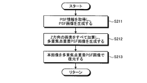
- FIG. 15 is a flowchart illustrating the omnifocal image acquisition process shown in FIG. FIG.
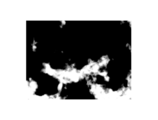
- FIG. 16 is a diagram illustrating an example of the omnifocal image acquired based on the main image obtained by the sweep shooting.
- FIG. 17 is a block diagram showing a configuration example of a microscope observation system according to Embodiment 2 of the present invention.
- FIG. 18 is a flowchart showing the operation of the microscope observation system shown in FIG.
- FIG. 19 is a diagram illustrating an example of the second pre-image obtained by the second pre-photographing illustrated in FIG.
- FIG. 20 is a flowchart for describing the imaging condition acquisition process of the first preliminary imaging shown in FIG.
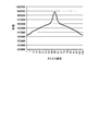
- FIG. 21 is a diagram illustrating the luminance distribution information at each Z position obtained from the PFS information.
- FIG. 22 is a block diagram illustrating a configuration example of the microscope observation system according to the first modification of the second embodiment of the present invention.
- FIG. 23 is a flowchart showing the operation of the microscope observation system shown in FIG.
- FIG. 24 is a flowchart illustrating the main image acquisition process shown in FIG.
- FIG. 25 is a diagram illustrating an example of a histogram generated based on a prior image.
- FIG. 26 is a diagram for explaining a tone curve for calculating a luminance gain from a prior image.
- FIG. 27 is a diagram illustrating an example of a main image obtained by gain adjustment of a prior image.
- FIG. 28 is a block diagram illustrating a configuration example of a microscope observation system according to the second modification of the second embodiment of the present invention.
- FIG. 29 is a flowchart showing the operation of the microscope observation system shown in FIG.
- FIG. 1 is a block diagram showing a configuration example of a microscope observation system according to Embodiment 1 of the present invention.
- a microscope observation system 1 according to Embodiment 1 includes a microscope device 10 that generates a subject image, and an imaging device 20 that acquires and processes the image of the subject image generated by the microscope device 10. And a display device 30 for displaying an image processed by the imaging device 20.
- the microscope observation system 1 receives light emitted from a subject as observation light, and acquires a subject image using an image based on the received light as a subject image.
- the luminescence according to the embodiment of the present invention reacts with, for example, fluorescence emitted by cells excited by introducing a fluorescent gene into a subject cell and irradiating the cell with excitation light, a reagent, or the like. Including luminescence, where photoproteins shine by themselves.
- any object can be applied as long as it receives light from a subject with weak light intensity such as a dark part of the subject to acquire a subject image.
- fluorescence observation for observing fluorescence from a subject will be described as an example of light emission observation.
- FIG. 2 is a schematic diagram illustrating a configuration example of the microscope apparatus 10.
- the microscope apparatus 10 includes a substantially C-shaped arm 100, a lens barrel 102 and an eyepiece unit 103 supported on the arm 100 via a trinocular tube unit 101, and the arm 100.
- an objective lens 140 that forms an image of observation light from the subject S.
- the objective lens 140, the lens barrel 102 connected via the trinocular tube unit 101, and an imaging unit 211 (described later) provided on the other end side of the lens barrel 102 are an observation optical system (imaging optical system). ) 104 is configured.
- the trinocular tube unit 101 branches the observation light incident from the objective lens 140 in the direction of an eyepiece unit 103 for the user to directly observe the subject S and an imaging unit 211 described later.
- the epi-illumination unit 110 includes an epi-illumination light source 111 and an epi-illumination optical system 112 and irradiates the subject S with epi-illumination light.
- the epi-illumination optical system 112 condenses the illumination light emitted from the epi-illumination light source 111 and guides it in the direction of the optical axis L of the observation optical system 104, specifically, the excitation wavelength of the fluorescence.
- a cube, a shutter, a field stop, an aperture stop, and the like including a filter that reflects light and transmits fluorescence generated by excitation with light having the excitation wavelength are included.
- the transmitted illumination unit 120 includes a transmitted illumination light source 121 and a transmitted illumination optical system 122 and irradiates the subject S with transmitted illumination light.
- the transmission illumination optical system 122 includes various optical members that condense the illumination light emitted from the transmission illumination light source 121 and guide it in the direction of the optical axis L, specifically, a filter unit, a shutter, a field stop, an aperture stop, and the like. Including.
- any one of these epi-illumination units 110 and transmission illumination units 120 is selected and used according to the spectroscopic method. Note that only one of the epi-illumination unit 110 and the transmission illumination unit 120 may be provided in the microscope apparatus 10.
- the electric stage unit 130 includes a stage 131, a stage drive unit 132 that moves the stage 131, and a position detection unit 133.
- the stage drive unit 132 is configured by a motor, for example.
- a subject placement surface 131 a of the stage 131 is provided so as to be orthogonal to the optical axis of the objective lens 140.
- the subject placement surface 131a is the XY plane, and the normal direction of the XY plane, that is, the direction parallel to the optical axis is the Z direction.
- the downward direction in the figure that is, the direction in which the stage 131 (subject placement surface 131a) is separated from the objective lens 140 is defined as the plus direction.
- the position of the field of view of the objective lens 140 can be moved by moving the stage 131 in the XY plane. Further, the focal plane of the objective lens 140 can be moved along the optical axis L by moving the stage 131 in the Z direction. That is, the electric stage unit 130 is a moving unit that moves the position of the focal plane and the visual field by moving the stage 131 under the control of the imaging control unit 22 described later.
- the position of the observation optical system 104 including the lens barrel 102 to the objective lens 140 is fixed and the stage 131 is moved. May be fixed and the observation optical system 104 side may be moved. Alternatively, both the stage 131 and the observation optical system 104 may be moved in opposite directions. That is, any configuration may be used as long as the observation optical system 104 and the subject S are relatively movable. Further, the focal plane may be moved by moving the observation optical system 104 in the Z direction, and the visual field position may be moved by moving the stage 131 in the XY plane.
- the position detection unit 133 is configured by an encoder that detects the amount of rotation of the stage drive unit 132 made of a motor, for example, and detects the position of the stage 131 and outputs a detection signal.
- a pulse generation unit and a stepping motor that generate pulses in accordance with the control of the imaging control unit 22 described later may be provided.
- the objective lens 140 is attached to a revolver 142 that can hold a plurality of objective lenses having different magnifications (for example, the objective lenses 140 and 141).
- the imaging magnification can be changed by rotating the revolver 142 and changing the objective lenses 140 and 141 facing the stage 131.
- FIG. 2 shows a state in which the objective lens 140 faces the stage 131.
- the imaging device 20 acquires an image by capturing a subject image generated by the observation optical system 104 of the microscope device 10, and performs an imaging operation of the image acquisition unit 21.
- the image capturing control unit 22 to be controlled, the various operations in the image capturing apparatus 20, the control unit 23 that processes the image acquired by the image acquiring unit 21, and the image data and control program of the image acquired by the image acquiring unit 21
- a storage unit 24 for storing various information such as, an input unit 25 for inputting instructions and information to the imaging device 20, and an image based on the image data stored in the storage unit 24 and other various types of information to an external device.
- an output unit 26 for outputting.
- the image acquisition unit 21 includes an imaging unit 211 and a memory 212.
- the image pickup unit 211 includes an image pickup device (imager) 211a made of, for example, a CCD or a CMOS, and pixel levels (R (red), G (green), and B (blue)) in each pixel included in the image pickup device 211a ( It is configured using a camera capable of capturing a color image having a pixel value. Or you may comprise the imaging part 211 using the camera which can image the monochrome image which outputs the luminance value Y as a pixel level (pixel value) in each pixel.
- the imaging unit 211 is provided at one end of the lens barrel 102 so that the optical axis L passes through the center of the light receiving surface of the imaging element 211a, and includes an observation optical system including the objective lens 140 to the lens barrel 102.
- the observation light incident on the light receiving surface via 104 is photoelectrically converted to generate image data of the subject image that enters the field of view of the objective lens 140.
- the memory 212 includes a recording device such as a flash memory that can be updated and recorded, a semiconductor memory such as a RAM, and a ROM, and temporarily stores the image data generated by the imaging unit 211.
- a recording device such as a flash memory that can be updated and recorded
- a semiconductor memory such as a RAM, and a ROM
- the imaging control unit 22 Under the control of the control unit 23, the imaging control unit 22 outputs a control signal to the microscope apparatus 10 and moves the stage 131 during one exposure period of the imaging unit 211, thereby moving the focal plane with respect to the subject. Sweep shooting is performed while changing the position of the image, and control for acquiring a sweep image including image information on a plurality of surfaces in the optical axis L direction of the observation optical system 104 and still image shooting at a predetermined position in the Z direction are performed. Control to acquire a still image. Note that the position of the field of view can be moved by moving the stage 131 on the XY plane under the control of the imaging control unit 22.
- the control unit 23 is configured by hardware such as a CPU, for example, and by reading a program stored in the storage unit 24, based on various parameters stored in the storage unit 24, information input from the input unit 25, and the like, The overall operation of the imaging device 20 and the microscope observation system 1 is controlled. In addition, the control unit 23 performs a process of setting an acquisition condition for an image acquired by the image acquisition unit 21 and performs control for causing the display device 30 to display the image acquired by the image acquisition unit 21.
- the control unit 23 sets the first pre-shooting condition setting unit 231 that sets pre-shooting shooting conditions that are performed using the microscope apparatus 10 and the shooting conditions of the main shooting that is performed using the microscope apparatus 10.
- the pre-photographing here is a first pre-photographing that obtains a pre-image for generating a main image, and is a sweep photographing that shoots while changing the position of the focal plane with respect to the subject.
- the main shooting is shooting in which shooting conditions are set based on a prior image, and is sweep shooting in which shooting is performed while changing the position of the focal plane with respect to the subject.
- the storage unit 24 includes a recording device such as a flash memory, RAM, and ROM that can be updated and recorded, a recording medium such as a hard disk, MO, CD-R, and DVD-R that is built-in or connected by a data communication terminal, and the like.
- a writing / reading apparatus that writes information to a recording medium and reads information recorded on the recording medium.
- the storage unit 24 includes a parameter storage unit 241 that stores parameters used for calculation in the control unit 23 and a program storage unit 242 that stores various programs.
- the parameter storage unit 241 is a parameter table that associates a fluorescent reagent (hereinafter also simply referred to as a reagent) and an exposure coefficient as a parameter for setting imaging conditions when imaging fluorescence, and a reagent or objective lens and a cube. Are stored as parameters such as a relationship table.
- the program storage unit 242 stores a control program for causing the imaging device 20 to execute a predetermined operation, an image processing program, and the like.
- the input unit 25 includes an input device such as a keyboard, various buttons, and various switches, a pointing device such as a mouse and a touch panel, and the like, and inputs signals corresponding to operations performed on these devices to the control unit 23. .
- the output unit 26 outputs an image based on the image data acquired by the image acquisition unit 21, an omnifocal image generated by the control unit 23, and other various information to an external device such as the display device 30, and a predetermined format This is an external interface to be displayed with.
- Such an imaging device 20 can be configured by combining a general-purpose digital camera via an external interface with a general-purpose device such as a personal computer or a workstation.
- the display device 30 is configured by, for example, an LCD, an EL display, a CRT display, or the like, and displays an image and related information output from the output unit 26.
- the display device 30 is provided outside the imaging device 20, but may be provided inside the imaging device 20.
- FIG. 3 is a flowchart showing the operation of the microscope observation system 1. The following operations will be described assuming that each unit operates under the control of the control unit 23.
- the first pre-shooting condition setting unit 231 sets the first pre-shooting shooting condition for acquiring a pre-image. Specifically, the first pre-shooting condition setting processing unit 231 acquires the shooting condition of the sweep shooting that is the first pre-shooting for acquiring the pre-image based on the set information.
- FIG. 4 is a flowchart for explaining the imaging condition acquisition process of the first pre-imaging shown in FIG.
- the first pre-imaging condition setting unit 231 acquires subject information including the subject thickness corresponding to the reagent to be used, the excitation wavelength, and the sweep distance (step S111).
- FIG. 5 is a schematic diagram for explaining the imaging condition setting process of the first pre-imaging and shows a user interface displayed on the display device 30.
- a user interface may be displayed on the display device 30 so that the user can input settings.
- the input screen W 1 shown in FIG. 5 includes a pull-down Pd 1 for setting a reagent, a pull-down Pd 2 for setting an excitation wavelength, an input box C 1 for setting and inputting a subject thickness, and an OK for confirming the setting input.
- a button B 1 and a cancel button B 2 for canceling the setting input are displayed. The user can select the items displayed in the pull-down through the input unit 25, or entered in the input box C 1, by or to select the OK button B 1 or the cancel button B 2, the subject information Set and confirm settings.
- the relationship between the reagent and the excitation wavelength may be stored in the parameter storage unit 241 in advance, and the excitation wavelength may be automatically selected by selecting the reagent.
- FIG. 6 is a diagram illustrating an example of information stored in the parameter storage unit, and is a diagram illustrating a relation table in which a reagent, an excitation wavelength, a fluorescence wavelength, and a cube are associated with each other. As shown in FIG. 6, by storing a relation table in which the reagent and the wavelength band of the excitation light are associated with each other in advance in the parameter storage unit 241, as described above, by selecting one of the reagent and the excitation wavelength. The other can be selected automatically.
- step S112 following step S111 the first pre-imaging condition setting unit 231 acquires observation information including the magnification of the objective lens, the imaging range, and the cube.
- FIG. 7 is a schematic diagram for explaining the imaging condition setting process of the first pre-imaging and shows a user interface displayed on the display device 30. As shown in FIG. 7, a user interface may be displayed on the display device 30 so that the user can input settings.
- a pull-down Pd 3 for setting the magnification of the objective lens
- an input box C 2 for setting and inputting a position near the subject in the shooting range
- An input box C 3 in which a position far from the subject (Far) can be set and input
- a pull-down Pd 4 for setting a cube to be used
- an OK button B 1 for confirming the setting input
- a cancel button B 2 for canceling the setting input Is displayed.
- the user selects an item displayed in the pull-down via the input unit 25, inputs the input box C 2 or C 3 , or selects the OK button B 1 or the cancel button B 2 .
- get buttons B 31 and B 41 are input buttons for acquiring the current position of the objective lens 140 or the stage 131, and the set buttons B 32 and B 42 are obtained by the get buttons B 31 and B 41 .
- the first pre-shooting condition setting unit 231 acquires the first pre-shooting shooting conditions based on the subject information and the observation information (step S113).
- the first pre-imaging condition setting unit 231 first acquires an exposure coefficient P ⁇ determined by the reagent from the subject information, and acquires an exposure time Pex calculated by multiplying the reference exposure time Bex by the acquired exposure coefficient P ⁇ .
- the luminance I, the molar absorption coefficient ( ⁇ (M ⁇ 1 cm ⁇ 1 )), and the quantum yield ( ⁇ ) have a relationship of I ⁇ ⁇ ⁇ .
- the quantum yield ( ⁇ ) is the number of emitted photons / the number of absorbed photons, and can be measured using the peak wavelength of the absorption spectrum of each fluorescent dye.
- the luminance I is proportional to the light amount of a specific wavelength absorbed by the fluorescent material and the conversion efficiency (quantum yield) of excitation light and fluorescence.
- the luminance I can be calculated (or measured or recorded) depending on the type of reagent.
- the exposure coefficient of each reagent can be determined by determining the luminance ratio with FITC by using the extremely bright FITC luminance as the reference luminance.
- the exposure time Pex is calculated based on the following equation (1).
- P ⁇ is reference luminance / reagent luminance.
- the exposure time Pex described above may be calculated in consideration of the fading of the reagent.
- k is a correction coefficient for setting the exposure time so as not to be surely saturated, and is a coefficient that can be set according to the discoloration of the reagent.
- a short exposure time corresponding to the reagent can be set by the exposure coefficient P ⁇ , and luminance saturation of the prior image can be prevented.
- FIG. 8 is a diagram illustrating an example of the relationship between the reagent and the exposure coefficient. As shown in FIG. 8, by storing the reagent and the exposure coefficient in association with each other, it is possible to acquire the exposure coefficient when setting the reagent.
- the first preliminary imaging condition setting unit 231 sets the imaging condition based on the exposure coefficient P ⁇ determined by the reagent and the preset reference exposure time Bex, thereby acquiring the preliminary image acquired by the first preliminary imaging.
- the shooting conditions that can suppress the luminance saturation are set.
- each reference reference excitation intensity, A setting value corrected by each coefficient may be calculated with respect to the (reference aperture value).
- the first pre-imaging condition setting unit 231 calculates the exposure time Pex from the set value, acquires the imaging range D 1 from the observation information, and calculates the moving speed Sp based on the distance and the exposure time Pex.
- the exposure time is set according to the type of photoprotein.
- the control unit 23 returns to the flowchart of FIG.
- the control unit 23 performs the first pre-shooting sweep shooting according to the exposure time Pex and the moving speed Sp acquired in step S101, and causes the pre-image to be shot (step S102).
- the imaging control unit 22 performs control for causing the imaging unit 211 to perform sweep imaging according to the exposure time Pex and the moving speed Sp, and acquires a subject image.
- the control unit 23 acquires a subject image obtained by the sweep shooting as a prior image.
- FIG. 9 is a diagram illustrating an example of a pre-image obtained by pre-sweep shooting. A pre-image as shown in FIG. 9 can be obtained by performing sweep imaging according to the exposure time Pex and the moving speed Sp acquired in step S101.
- step S103 the control unit 23 acquires shooting conditions for main shooting for acquiring the main image from the prior image.
- FIG. 10 is a flowchart for explaining the photographing condition acquisition process of the main photographing shown in FIG.
- the imaging condition setting unit 232 acquires the luminance information of the previous image acquired in step S102 (step S121). Specifically, the main photographing condition setting unit 232 generates a histogram as luminance information of the previous image for the luminance values of all the pixels of the previous image.
- FIG. 11 is a diagram showing an example of a histogram generated based on a prior image. As shown in FIG. 11, the minimum luminance value (Min), the maximum luminance value (Max), and the average (Mean) can be obtained by generating a histogram based on the luminance value of the prior image.
- Min minimum luminance value
- Max maximum luminance value
- Mean average
- the photographing condition setting unit 232 acquires the maximum luminance from the generated histogram, and the reference maximum luminance (for example, luminance value 255) and the maximum luminance of the previous image (for example, the maximum luminance value 54 of the histogram shown in FIG. 11). ) And the luminance ratio are calculated (step S122).
- the control unit 23 performs the sweep photographing that is the main photographing according to the sweep range in the first preliminary photographing acquired in step S101 and the exposure time Rex and the moving speed Sr acquired in step S103. This image is photographed (step S104).
- the imaging control unit 22 controls the imaging unit 211 to perform sweep imaging according to the exposure time Rex and the moving speed Sr, and acquires a subject image.
- the control unit 23 acquires a subject image obtained by the sweep shooting as a main image.
- FIG. 12 is a diagram illustrating an example of a main image obtained by sweep imaging. By performing sweep imaging according to the exposure time Rex and the moving speed Sr acquired in step S103, a main image as shown in FIG. 12 can be obtained.
- control unit 23 terminates the processing related to image acquisition.
- the control unit 23 may display the acquired main image on the display device 30, may store the main image in the storage unit 24, or displays the main image on the display device 30, You may make it memorize
- the pre-image is obtained by performing the sweep imaging under the imaging conditions set based on the reagent or the like as the preliminary imaging. Since the shooting conditions for the sweep shooting, which is the main shooting for acquiring the main image, are set based on the brightness value of the previous image, the sweep shooting is performed once in advance and the main shooting is performed.
- an optimal exposure time can be set with a small number of shootings (shooting time), and a book (sweep) image in which luminance saturation is suppressed can be acquired.
- it is possible to obtain an image in which the existence of the depth structure can be known on the two-dimensional plane that is the XY plane in a state where the fluorescent color of the subject is small.
- a Z stack image is acquired by a plurality of capturing operations, and this Z stack image is Compared with the case of obtaining a multifocal superimposed image by averaging, it is possible to perform imaging in a short time, and to significantly reduce the amount of data and the amount of calculation in image processing.
- FIG. 13 is a block diagram illustrating a configuration example of a microscope observation system according to a modification of the first embodiment of the present invention.
- the microscope observation system 2 according to this modification includes a microscope apparatus 10, an imaging apparatus 40 that acquires and processes an image of a subject image generated by the microscope apparatus 10, and an imaging apparatus 40 that performs processing.
- a display device 30 for displaying the images and the like for displaying the images and the like.
- the configurations and operations of the microscope apparatus 10 and the display apparatus 30 are the same as those in the first embodiment.
- the imaging device 40 includes a control unit 41 instead of the control unit 23 shown in FIG.
- the control unit 41 further includes an omnifocal image acquisition unit 411 that generates an omnifocal image based on the acquired main image with respect to the control unit 23.
- the operations of the first pre-shooting condition setting unit 231 and the main shooting condition setting unit 232 are the same as those in the first embodiment.
- FIG. 14 is a flowchart showing the operation of the microscope observation system 2. The following operations will be described assuming that each unit operates under the control of the control unit 41.
- step S ⁇ b> 201 the first pre-shooting condition setting unit 231 acquires the shooting condition of the sweep shooting that is the first pre-shooting. Thereafter, the control unit 41 performs sweep imaging according to the imaging conditions acquired in step S201 to capture a pre-image (step S202).
- step S203 the control unit 41 acquires the shooting conditions (exposure time Rex and moving speed Sr) of the main shooting from the preliminary image. Thereafter, the control unit 41 captures the main image by performing the sweep photographing that is the main photographing according to the exposure time Rex and the moving speed Sr acquired in step S203 (step S204).
- FIG. 15 is a flowchart illustrating the omnifocal image acquisition process shown in FIG.
- the omnifocal image acquisition unit 411 performs point spread function (PSF) information indicating image blur at each Z position in the imaging range set in the observation information (the imaging range of the sweep shooting in the Z direction).
- PSF point spread function
- Several slices are acquired, and a PSF image based on the PSF information is generated (step S211).
- the PSF information is stored in the parameter storage unit 241 in advance in association with the imaging position based on the imaging conditions such as the excitation wavelength and the observation magnification.
- the omnifocal image acquisition unit 411 generates a multifocal superimposed PSF image by calculating an average value of pixel values of pixels corresponding to positions among the PSF images at each Z position (step S212). ). In this way, the omnifocal image acquisition unit 411 acquires a multifocal superimposed PSF image as PSF information in the sweep range of the main photographing.
- the omnifocal image acquisition unit 411 acquires an omnifocal image based on the main image and the multifocal superimposed PSF image (step S213). Specifically, the omnifocal image acquisition unit 411 acquires an omnifocal image by restoring the main image as a multifocal superimposed PSF image.
- a known restoration technique can be used as an image restoration processing method.
- FIG. 16 is a diagram illustrating an example of the omnifocal image acquired based on the main image obtained by the sweep shooting. By performing sweep imaging according to the exposure time Rex and the moving speed Sr acquired in step S203, for example, a main image as shown in FIG. 12 can be obtained. Furthermore, this main image, a multi-focus superimposed PSF image, Based on the above, an omnifocal image can be generated.
- control unit 41 After that, the control unit 41 returns to FIG. 14 and ends the processing related to image acquisition.
- the control unit 41 may display the acquired omnifocal image on the display device 30, may store the omnifocal image in the storage unit 24, or displays the omnifocal image on the display device 30. And may be stored in the storage unit 24.
- the sweep imaging is performed under the imaging conditions set based on the reagent or the like, Since the pre-image was acquired and the shooting conditions for the main shooting were set based on the brightness value of the pre-image, it was less necessary to set the exposure time for the main shooting by performing a sweep shooting only once in advance.
- An optimum exposure time can be set by the number of times of photographing (photographing time), and a real (sweep) image can be acquired.
- an omnifocal image with high visibility in which luminance saturation is suppressed can be generated based on the main (sweep) image and the multifocal superimposed PSF image. As a result, it is possible to obtain an image in which the existence of the depth structure can be known on the two-dimensional plane that is the XY plane in a state where the fluorescent color of the subject is small.
- FIG. 17 is a block diagram showing a configuration example of a microscope observation system according to Embodiment 2 of the present invention.
- the microscope observation system 3 according to the second embodiment includes a microscope device 10, an imaging device 50 that acquires and processes an image of a subject image generated by the microscope device 10, and the imaging device 50.
- a display device 30 for displaying an image processed by the computer the configurations and operations of the microscope apparatus 10 and the display apparatus 30 are the same as those in the first embodiment.
- the imaging device 50 includes a control unit 51 instead of the control unit 41 shown in FIG.
- the control unit 51 further includes a second pre-shooting condition setting unit 511 for setting the shooting conditions for the second pre-shooting performed before the first pre-shooting with respect to the control unit 41.
- the second preliminary shooting in the second embodiment is a still image shooting that takes a still subject image at a shooting start position or a shooting end position within the shooting range of the sweep shooting in the first preliminary shooting.
- FIG. 18 is a flowchart showing the operation of the microscope observation system 3. The following operations will be described assuming that each unit operates under the control of the control unit 51.
- the second pre-shooting condition setting unit 511 acquires the shooting conditions of the second pre-shooting (step S301).
- the second pre-shooting condition setting unit 511 sets the exposure time Pex_n acquired by performing the automatic exposure process using the near position as the shooting position in the shooting range set on the input screen or the like shown in FIG. Acquired as shooting conditions.
- the automatic exposure process may be a known method.For example, as described in Japanese Patent No. 338477, a histogram of an image taken with an arbitrary exposure time is acquired, and an area having a luminance greater than a threshold is set as a processing target.
- the exposure time Pex_n is acquired using the average value of the luminance of the area.
- FIG. 19 is a diagram illustrating an example of a still subject image obtained by the second pre-shooting illustrated in FIG. According to the exposure time Pex_n acquired in step S301, a still subject image as shown in FIG. 19 can be obtained by photographing the subject at the Near position, for example.
- step S303 following step S302 the first pre-shooting condition setting unit 231 acquires shooting conditions for the first pre-shooting.
- the first pre-shooting condition setting unit 231 acquires the first pre-shooting shooting condition based on the exposure time Pex_n acquired in step S301.
- FIG. 20 is a flowchart for describing the imaging condition acquisition process of the first preliminary imaging shown in FIG.
- the first pre-imaging condition setting unit 231 acquires observation information including the magnification of the objective lens, the imaging range, and the cube (step S311). For example, the observation information set using the user interface shown in FIG. 7 is acquired.
- the first pre-imaging condition setting unit 231 acquires PSF information including slices photographed at a plurality of Z positions previously stored in the parameter storage unit 241 in the imaging range of the observation information. Obtain (step S312).
- the first pre-shooting condition setting unit 231 acquires the shooting conditions for the first pre-shooting from the exposure time Pex_n at the shooting start position acquired in Step S311 and the PSF information acquired in Step S312 (Step S311). S313).
- the first pre-shooting condition setting unit 231 acquires luminance distribution information at each Z position from the PSF information.
- FIG. 21 is a diagram illustrating luminance distribution information at each Z position obtained from PFS information, and is a graph illustrating an example of a relationship between a slice (number) and luminance.
- the first pre-imaging condition setting unit 231 acquires luminance distribution information generated by plotting the luminance sum of each slice as shown in FIG. In FIG. 21, for example, the slice on the near position side is number 1 and the slice on the far side is number 109.
- the control unit 51 returns to the flowchart of FIG.
- step S304 the control unit 51 captures a pre-image by performing the sweep pre-shooting according to the exposure time Pex and the moving speed Sp acquired in step S303.
- step S305 the control unit 51 acquires an exposure time Rex and a moving speed Sr, which are shooting conditions for main shooting for acquiring the main image from the prior image.
- the control unit 51 performs sweep imaging according to the exposure time Rex and the moving speed Sr acquired in step S305 to capture the main image (step S306).
- control unit 51 After acquiring the main image, the control unit 51 generates and acquires an omnifocal image by restoring the main image as a multi-focus superimposed PSF image (step S307). Thereafter, the control unit 51 returns to FIG. 18 and ends the processing related to image acquisition.
- the control unit 51 may display the acquired omnifocal image on the display device 30, may store the omnifocal image in the storage unit 24, or displays the omnifocal image on the display device 30. And may be stored in the storage unit 24.
- the automatic exposure process is performed to obtain the exposure time Pex_n, which is stored in the parameter storage unit 241. Since the first pre-shooting shooting conditions are set from the exposure time Pex_n and the PSF information, the first pre-shooting is performed only once in advance. The exposure time for shooting can be set appropriately. As compared with the case of acquiring the main image by performing only the first pre-photographing without performing the second pre-photographing as in the first embodiment, the number of times of photographing (photographing time) and the optimum exposure time are reduced. It is possible to obtain a book (sweep) image with a certain setting.
- an omnifocal image with high visibility in which luminance saturation is suppressed can be generated based on the main (sweep) image and the multifocal superimposed PSF image.
- the main (sweep) image and the multifocal superimposed PSF image can be generated based on the main (sweep) image and the multifocal superimposed PSF image.
- the second pre-shooting condition setting unit 511 has been described as performing the automatic exposure process with the Near position in the shooting range as the shooting position, and acquiring the exposure time Pex_n.
- the exposure time Pex_f may be acquired by performing an automatic exposure process with the Far position as the imaging position.
- FIG. 22 is a block diagram illustrating a configuration example of the microscope observation system according to the first modification of the second embodiment of the present invention.
- the microscope observation system 4 according to the first modification includes a microscope apparatus 10, an imaging apparatus 60 that acquires and processes an image of a subject image generated by the microscope apparatus 10, and an imaging apparatus 60. And a display device 30 that displays the processed image and the like.
- the configurations and operations of the microscope apparatus 10 and the display apparatus 30 are the same as those in the first and second embodiments.
- the imaging device 60 includes a control unit 61 instead of the control unit 51 shown in FIG.
- the control unit 61 includes a main image acquisition unit 611 that generates a main image based on a prior image instead of the main photographing condition setting unit 232 with respect to the control unit 51.
- the operations of the first pre-shooting condition setting unit 231, the omnifocal image acquisition unit 411, and the second pre-shooting condition setting unit 511 are the same as those in the second embodiment.
- the main image is acquired by acquiring the shooting conditions of the main shooting based on the previous image and performing the main shooting. However, in the first modification, the previous image is also acquired. And the main image is generated.
- FIG. 23 is a flowchart showing the operation of the microscope observation system 4. The following operations will be described assuming that each unit operates under the control of the control unit 61.
- the process from the second pre-shooting shooting condition setting process to the pre-image shooting process is the same as steps S301 to S304 in FIG. 18 described above (steps S401 to S404).
- the second pre-shooting condition setting unit 511 acquires the shooting condition of the second pre-shooting (Step S401).
- the control unit 61 captures a still subject image according to the capturing conditions acquired in step S401 (step S402).
- the first pre-shooting condition setting unit 231 acquires the shooting conditions of the first pre-shooting.
- the first pre-shooting condition setting unit 231 Based on the exposure time Pex_n acquired in step S401, the first pre-shooting condition setting unit 231 specifically uses the brightness of the still subject image acquired in step S402 to perform the first pre-shooting shooting.
- the conditions (exposure time Pex and moving speed Sp) are acquired.
- the control unit 61 captures a preliminary image by performing sweep imaging according to the exposure time Pex and the moving speed Sp acquired in step S403.
- step S405 the main image acquisition unit 611 generates and acquires a main image based on the previous image acquired in step S404.
- FIG. 24 is a flowchart illustrating the main image acquisition process shown in FIG. First, the main image acquisition unit 611 acquires luminance information of a prior image (step S411). The main image acquisition unit 611 generates a histogram as luminance information of the previous image.
- FIG. 25 is a diagram illustrating an example of a histogram generated based on a prior image. As shown in FIG. 25, the minimum luminance value (Min), the maximum luminance value (Max), and the average (Mean) can be obtained by generating a histogram based on the luminance value of the prior image.
- Min minimum luminance value
- Max maximum luminance value
- Mean average
- FIG. 26 is a diagram for explaining a tone curve for calculating a luminance gain from a prior image.
- the main image acquisition unit 611 has a tone curve L 1 as shown in FIG. 26, and performs gain adjustment based on the relationship between the input level and the output level based on the tone curve L 1 set based on the luminance information.
- the luminance gain at each gradation is acquired.
- the main image acquisition unit 611 may acquire the luminance gain using an automatic adjustment algorithm for brightness and contrast.
- FIG. 27 is a diagram illustrating an example of a main image obtained by gain adjustment of a prior image.
- control unit 61 After acquiring the main image, the control unit 61 returns to the flowchart of FIG. 23 to generate an omnifocal image by restoring the main image as a multi-focus superimposed PSF image, as in step S307 of FIG. Obtain (step S406). Then, the control part 61 complete
- the control unit 61 may display the acquired omnifocal image on the display device 30, may store the omnifocal image in the storage unit 24, or displays the omnifocal image on the display device 30. And may be stored in the storage unit 24.
- the luminance gain is calculated from the previous image, and the main image is generated based on the luminance gain. Therefore, still image shooting and sweep shooting are performed only once in advance.
- an optimum exposure time can be set with a small number of times of photographing (shooting time), and a main image can be generated based on a prior image acquired with the optimum exposure time.
- it is possible to obtain an image in which the existence of the depth structure can be known on the two-dimensional plane that is the XY plane in a state where the fluorescent color of the subject is small.
- FIG. 28 is a block diagram illustrating a configuration example of a microscope observation system according to the second modification of the second embodiment of the present invention.
- the microscope observation system 5 according to the second modification includes a microscope device 10, an imaging device 70 that acquires and processes an image of a subject image generated by the microscope device 10, and an imaging device 70.
- a display device 30 that displays the processed image and the like.
- the configurations and operations of the microscope apparatus 10 and the display apparatus 30 are the same as those in the first and second embodiments.
- the imaging device 70 includes a control unit 71 instead of the control unit 61 shown in FIG.
- the control unit 71 instructs the control unit 61 to determine whether to perform main shooting based on the main image generated based on the previous image, and the main shooting conditions described above.
- a setting unit 232 The operations of the first pre-imaging condition setting unit 231, the omnifocal image acquisition unit 411, the second pre-image capture setting unit 511, and the main image acquisition unit 611 are the same as in the first modification of the second embodiment. .
- the main image is acquired based on the previous image.
- the second modification based on the information of the main image generated based on the previous image.
- the main shooting is performed, and it is determined whether or not the main image is acquired by the sweep shooting.
- FIG. 29 is a flowchart showing the operation of the microscope observation system 5. The following operations will be described assuming that each unit operates under the control of the control unit 71.
- step S501 From the shooting condition setting process of the second preliminary shooting to the acquisition process of the main image based on the preliminary image is the same as steps S401 to S405 in FIG. 23 described above (steps S501 to S505).
- the second pre-shooting condition setting unit 511 acquires the shooting condition of the second pre-shooting (Step S501). Thereafter, the control unit 71 captures a still subject image according to the capturing condition acquired in step S501 (step S502).
- step S503 following step S502, the first pre-shooting condition setting unit 231 acquires shooting conditions for the first pre-shooting.
- the first pre-imaging condition setting unit 231 acquires the pre-image shooting conditions (exposure time Pex and moving speed Sp) based on the exposure time Pex_n acquired in step S501.
- the control unit 51 captures a preliminary image by performing sweep imaging according to the exposure time Pex and the moving speed Sp acquired in step S503.
- step S505 the main image acquisition unit 611 calculates a luminance gain from the prior image acquired in step S504, and generates and acquires a main image based on the luminance gain (step S505).
- the main shooting execution determination unit 711 performs the main sweep shooting to determine whether to acquire a new main image. For this image, a signal-to-noise ratio (Signal Noise Ratio: SNR) in an arbitrary region is acquired (step S506).
- SNR Signal-to-noise ratio
- the actual image capturing determination unit 711 may divide the image into a plurality of regions and obtain the average SNR of the entire image from the SNR of each region.
- the actual photographing execution determining unit 711 determines whether or not to perform the main photographing and newly acquire the main image (step S507).
- the actual shooting execution determination unit 711 compares the SNR acquired in step S506 with the threshold value, and determines that the actual shooting is not performed when the SNR is larger than the threshold value (step S507: No), and proceeds to step S509. To do.
- the main shooting execution determination unit 711 determines that the main shooting is performed and the main image is reacquired because the ratio of noise to the signal in the image is large ( Step S507: Yes), the process proceeds to Step S508.
- the control unit 71 may perform image processing such as noise reduction processing on the main image based on the prior image.
- step S508 the control unit 71 acquires the shooting conditions (exposure time Rex and moving speed Sr) of the main shooting from the previous image, and performs the sweep shooting according to the acquired exposure time Rex and moving speed Sr to shoot the main image.
- the main photographing condition setting unit 232 acquires the exposure time Rex and the moving speed Sr based on the flow of FIG. 10 described above, and performs the sweep photographing according to the acquired exposure time Rex and the moving speed Sr to perform the main image. To get.
- control unit 71 uses the main image acquired in step S505 or the main image acquired in step S508 to restore the main image as a multi-focus superimposed PSF image in the same manner as in step S406 of FIG. 23 described above.
- an omnifocal image is generated and acquired (step S509).
- control unit 71 ends the process related to image acquisition.
- the control unit 71 may display the acquired omnifocal image on the display device 30, may store the omnifocal image in the storage unit 24, or displays the omnifocal image on the display device 30. And may be stored in the storage unit 24.
- the second modification whether or not the main photographing is necessary is determined based on the main image generated based on the previous image, and a new (sweep) image is newly determined according to the determination result. Since the image is noisy like the main image generated based on the previous image by re-taking it according to the image quality of the main image generated by adjusting the gain of the previous image In order to prevent discoloration of the image, it is possible to selectively perform a case where the main image is acquired by one sweep shooting and a case where the image quality is more important than the number of shootings, and a subject image desired by the user is provided. Can do.
- the omnifocal image is generated based on the main image.
- the control unit does not generate the omnifocal image and performs the main photographing.
- the acquired main image or the main image generated based on the previous image may be acquired as the final image.
- the second pre-shooting is performed and the first pre-shooting shooting condition is set.
- the first pre-shooting is set. It is also possible to acquire the main image by performing only prior shooting.
- the first and second embodiments and the modifications described above are not limited as they are, and various inventions are formed by appropriately combining a plurality of constituent elements disclosed in the embodiments and the modifications. be able to. For example, some components may be excluded from all the components shown in the embodiment. Or you may form combining the component shown in different embodiment suitably.
- the image acquisition unit 611 and the main photographing execution determination unit 711 have been described as being provided in the control unit, each unit may be provided as a separate block from the control unit.
- the present invention can include various embodiments and the like not described herein, and appropriate design changes and the like can be made without departing from the technical idea described in the claims. Is possible.
- Microscope observation system 10 Microscope device 20, 40, 50, 60, 70 Imaging device 21 Image acquisition unit 22 Imaging control unit 23, 41, 51, 61, 71 Control unit 24 Storage unit 25 Input Unit 26 output unit 30 display device 100 arm 101 trinocular tube unit 102 lens tube 103 eyepiece unit 104 observation optical system 110 epi-illumination unit 111 epi-illumination light source 112 epi-illumination optical system 120 transmission illumination unit 121 transmission illumination light source 122 transmission Illumination optical system 130 Electric stage unit 131 Stage 132 Stage drive unit 133 Position detection unit 140, 141 Objective lens 142 Revolver 211 Imaging unit 212 Memory 231 First pre-imaging condition setting unit 232 Main imaging condition setting unit 411 All-focus image acquisition unit 511 second Before capturing condition setting unit 611 present the image acquisition unit 711 present imaging implementation determining unit
Landscapes
- Physics & Mathematics (AREA)
- General Physics & Mathematics (AREA)
- Health & Medical Sciences (AREA)
- Chemical & Material Sciences (AREA)
- Analytical Chemistry (AREA)
- Multimedia (AREA)
- Engineering & Computer Science (AREA)
- Biochemistry (AREA)
- General Health & Medical Sciences (AREA)
- Nuclear Medicine, Radiotherapy & Molecular Imaging (AREA)
- Immunology (AREA)
- Pathology (AREA)
- Life Sciences & Earth Sciences (AREA)
- Optics & Photonics (AREA)
- Computer Vision & Pattern Recognition (AREA)
- Microscoopes, Condenser (AREA)
- Investigating, Analyzing Materials By Fluorescence Or Luminescence (AREA)
- Investigating Or Analysing Materials By Optical Means (AREA)
- Studio Devices (AREA)
Abstract
Description
本発明は、顕微鏡装置において取得された画像を介して被写体を観察する顕微鏡観察システム、顕微鏡観察方法、及び顕微鏡観察プログラムに関する。 The present invention relates to a microscope observation system, a microscope observation method, and a microscope observation program for observing a subject through an image acquired in a microscope apparatus.
焦点深度が数十μmレベルの生物顕微鏡を用いて細胞核や幹細胞等の厚みのある被写体を観察する際、観察光学系の光軸に沿った奥行き方向(Z方向)に存在する注目部位を速やかに特定したいというユーザのニーズがある。このようなニーズに対し、観察光学系の焦点面を光軸に沿ってずらしながら順次撮像を行うことにより焦点面が異なる複数の画像を取得し、観察する方法がある。このように取得された焦点面が異なる複数の画像をまとめて、Zスタック画像ともいう。 When observing thick subjects such as cell nuclei and stem cells using a biological microscope with a depth of focus of several tens of μm, quickly locate the region of interest in the depth direction (Z direction) along the optical axis of the observation optical system. There is a user's need to specify. To meet such needs, there is a method of acquiring and observing a plurality of images having different focal planes by sequentially capturing images while shifting the focal plane of the observation optical system along the optical axis. A plurality of images having different focal planes acquired in this way are collectively referred to as a Z stack image.
Zスタック画像の撮影は、複数の画像を取得する必要があるために時間を要する。一方で、蛍光観察においては、被写体に励起光を照射し続けることにより、蛍光強度が弱まってしまう「褪色」が起こるため、できるだけ短い時間、少ない回数で所望の撮影を行うことが望ましい。さらに、蛍光観察は、明視野観察と比較して露光時間が長いことが多いため、Zスタック画像を取得するにあたり、被写体に励起光が照射される時間が必然的に長くなってしまう。 撮 影 Shooting Z stack images takes time because it is necessary to acquire multiple images. On the other hand, in fluorescence observation, since the subject will continue to be irradiated with excitation light, a “fading” occurs in which the fluorescence intensity weakens. Therefore, it is desirable to perform desired imaging in as short a time as possible. Furthermore, since the fluorescence observation is often longer in exposure time than the bright field observation, the time for which the subject is irradiated with the excitation light is inevitably longer when acquiring the Z stack image.
そこで、焦点面が異なる画像を取得する技術として、露光中に被写体または撮像装置をZ方向に移動させて撮影するスイープ撮影が知られている(例えば、特許文献1、2を参照)。スイープ画像はZ方向に存在する構造が重畳されるため、ユーザが、スイープ画像からZ方向と直交する二次元平面上で奥行き構造の存在を知ることが可能である。さらに、このスイープ画像に対し復元処理を施すことにより全焦点画像を取得することが可能であり、Zスタック画像から全焦点画像を取得する方法と比較して撮影時間を短縮することができる。また、特許文献2では、このスイープ撮影を顕微鏡に適用させた構成が開示されている。
Therefore, as a technique for acquiring images with different focal planes, sweep imaging is known in which an object or an imaging device is moved in the Z direction during exposure (see, for example,
ところで、顕微鏡を用いた被写体が発する光を観察する発光観察においてスイープ撮影を行う場合、合焦/非合焦領域または背景や構造物によって明るさが大きく異なるために露光時間の設定が難しいという課題がある。しかしながら、特許文献1,2には、露光時間の設定方法についての開示がなく、発光観察においてスイープ撮影を行っても視認性の高い発光画像を取得できない場合があった。
By the way, when performing sweep photography in light emission observation for observing light emitted from a subject using a microscope, it is difficult to set an exposure time because the brightness varies greatly depending on the in-focus / non-focus area or the background or structure. There is. However,
本発明は上記に鑑みてなされたものであり、顕微鏡を用いた発光観察においてスイープ撮影を行う際に、視認性の高い画像を取得することができる顕微鏡観察システム、顕微鏡観察方法、及び顕微鏡観察プログラムを提供することを目的とする。 The present invention has been made in view of the above, and a microscope observation system, a microscope observation method, and a microscope observation program capable of acquiring an image with high visibility when performing sweep photographing in light emission observation using a microscope. The purpose is to provide.
上述した課題を解決し、目的を達成するために、本発明に係る顕微鏡観察システムは、顕微鏡の観察光学系により生成される被写体像を撮像して被写体画像を生成する撮像部と、前記撮像部の撮影条件を設定し、前記被写体像の本画像を取得する制御部と、前記制御部が設定した前記撮影条件に基づいて前記撮像部を制御する撮像制御部と、を備え、前記制御部は、前記本画像を生成するための事前画像を取得する第1の事前撮影の撮影条件を設定する第1の事前撮影条件設定部を有し、前記第1の事前撮影は、前記被写体に対して焦点面の位置を変えながら撮影するスイープ撮影であり、前記制御部は、前記スイープ撮影により得られる事前画像が輝度飽和しない撮影条件を設定し、前記事前画像に基づいて前記本画像を取得する、ことを特徴とする。 In order to solve the above-described problems and achieve the object, a microscope observation system according to the present invention includes an imaging unit that captures a subject image generated by an observation optical system of a microscope and generates the subject image, and the imaging unit A control unit configured to acquire the main image of the subject image, and an imaging control unit configured to control the imaging unit based on the imaging condition set by the control unit, the control unit comprising: A first pre-shooting condition setting unit that sets shooting conditions for first pre-shooting for acquiring a pre-image for generating the main image, and the first pre-shooting is performed on the subject. Sweep shooting is performed while changing the position of the focal plane, and the control unit sets a shooting condition in which the pre-image obtained by the sweep shooting does not saturate, and acquires the main image based on the pre-image. ,thing And features.
上記顕微鏡観察システムにおいて、前記制御部は、前記本画像を取得する本撮影の撮影条件を設定する本撮影条件設定部をさらに有し、前記本撮影は、前記被写体に対して焦点面の位置を変えながら撮影するスイープ撮影であり、前記本撮影条件設定部は、前記第1の事前撮影によって取得した前記事前画像をもとに、前記本撮影の撮影条件を設定し、前記撮像制御部は、前記本撮影条件設定部が設定した前記本撮影の撮影条件に基づいて、前記撮像部が前記被写体画像を撮像するように制御する、ことを特徴とする。 In the microscope observation system, the control unit further includes a main photographing condition setting unit that sets photographing conditions for main photographing for acquiring the main image, and the main photographing determines a focal plane position with respect to the subject. Sweep shooting is performed while changing, and the main shooting condition setting unit sets shooting conditions for the main shooting based on the preliminary image acquired by the first preliminary shooting, and the imaging control unit The imaging unit controls the imaging of the subject image based on the imaging conditions of the actual imaging set by the actual imaging condition setting unit.
上記顕微鏡観察システムにおいて、前記制御部は、前記事前画像をもとに本画像を生成する本画像取得部、をさらに備えることを特徴とする。 In the microscope observation system, the control unit further includes a main image acquisition unit that generates a main image based on the prior image.
上記顕微鏡観察システムにおいて、前記制御部は、前記事前画像をもとに生成された前記本画像に基づいて、スイープ撮影による本画像の取得を実施するか否かを判断する本撮影実施判断部、をさらに有し、前記本撮影条件設定部は、前記本撮影実施判断部がスイープ撮影により本画像の取得を実施すると判断した場合に、前記本画像の撮影条件を設定する、ことを特徴とする。 In the microscope observation system, the control unit determines whether to perform acquisition of the main image by sweep shooting based on the main image generated based on the preliminary image. The main shooting condition setting unit sets shooting conditions for the main image when the main shooting execution determination unit determines to acquire the main image by sweep shooting. To do.
上記顕微鏡観察システムにおいて、前記制御部は、前記本画像、及び該本画像のボケ情報をもとに、全焦点画像を取得する全焦点画像取得部をさらに有することを特徴とする。 In the microscope observation system, the control unit further includes an omnifocal image acquisition unit that acquires an omnifocal image based on the main image and blur information of the main image.
上記顕微鏡観察システムにおいて、前記ボケ情報は、前記スイープ撮影の撮影範囲における前記本画像のボケを表す点拡がり関数とを用いて生成された情報を含む、ことを特徴とする。 In the microscope observation system, the blur information includes information generated using a point spread function representing blur of the main image in the imaging range of the sweep imaging.
上記顕微鏡観察システムにおいて、前記制御部は、前記第1の事前撮影の前に行う第2の事前撮影の撮影条件を設定する第2の事前撮影条件設定部をさらに有し、前記第2の事前撮影は、前記スイープ撮影の撮影範囲のうちの撮影開始位置又は撮影終了位置における静止被写体画像を撮影する静止画撮影であり、前記第2の事前撮影条件設定部は、前記静止被写体画像の露光時間を取得する第2の事前撮影の撮影条件を設定し、前記第1の事前撮影条件設定部は、前記第2の事前撮影により得られる露光時間をもとに、前記第1の事前撮影の撮影条件を設定する、ことを特徴とする。 In the microscope observation system, the control unit further includes a second pre-shooting condition setting unit that sets shooting conditions for second pre-shooting performed before the first pre-shooting, The shooting is a still image shooting for shooting a still subject image at a shooting start position or a shooting end position in the shooting range of the sweep shooting, and the second pre-shooting condition setting unit sets an exposure time of the still subject image. The first pre-shooting condition setting unit obtains the first pre-shooting condition, and the first pre-shooting condition setting unit captures the first pre-shooting based on the exposure time obtained by the second pre-shooting. A condition is set.
上記顕微鏡観察システムにおいて、前記輝度飽和しない撮影条件は、前記スイープ撮影を行う際の露光時間を含む、ことを特徴とする。 In the microscope observation system, the imaging condition that does not saturate the brightness includes an exposure time when performing the sweep imaging.
本発明に係る顕微鏡観察方法は、被写体像に基づく本画像を生成するための事前画像を生成する事前撮影の撮影条件を設定する事前撮影条件設定ステップと、前記事前撮影条件設定ステップで設定した事前撮影の撮影条件にしたがって撮像部に前記事前画像を撮像させる撮像制御ステップと、前記事前撮影によって生成された前記事前画像をもとに前記本画像を取得する画像取得ステップと、を含み、前記事前撮影は、被写体に対して焦点面の位置を変えながら撮影するスイープ撮影であり、事前撮影条件設定ステップは、該スイープ撮影により得られる事前画像が輝度飽和しない撮影条件を設定し、前記撮像部は、顕微鏡の観察光学系により生成される被写体像を撮像して被写体画像を生成する、ことを特徴とする。 The microscope observation method according to the present invention is set in a pre-shooting condition setting step for setting pre-shooting shooting conditions for generating a pre-image for generating a main image based on a subject image, and the pre-shooting condition setting step. An imaging control step for causing the imaging unit to capture the preliminary image in accordance with imaging conditions for preliminary imaging, and an image acquisition step for acquiring the main image based on the preliminary image generated by the preliminary imaging. The pre-shooting is sweep shooting in which the position of the focal plane is changed with respect to the subject, and the pre-shooting condition setting step sets shooting conditions in which the pre-image obtained by the sweep shooting does not saturate in brightness. The image pickup unit picks up a subject image generated by an observation optical system of a microscope and generates a subject image.
本発明に係る顕微鏡観察プログラムは、被写体像に基づく本画像を生成するための事前画像を生成する事前撮影の撮影条件を設定する事前撮影条件設定手順と、前記事前撮影条件設定手順が設定した事前撮影の撮影条件にしたがって撮像部に前記事前画像を撮像させる撮像制御手順と、前記事前撮影によって生成された前記事前画像をもとに前記本画像を取得する画像取得手順と、をコンピュータに実行させ、前記事前撮影は、被写体に対して焦点面の位置を変えながら撮影するスイープ撮影であり、事前撮影条件設定手順は、該スイープ撮影により得られる事前画像が輝度飽和しない撮影条件を設定し、前記撮像部は、顕微鏡の観察光学系により生成される被写体像を撮像して被写体画像を生成する、ことを特徴とする。 In the microscope observation program according to the present invention, a pre-shooting condition setting procedure for setting a pre-shooting shooting condition for generating a pre-image for generating a main image based on a subject image, and the pre-shooting condition setting procedure are set. An imaging control procedure for causing the imaging unit to capture the preliminary image in accordance with imaging conditions for preliminary imaging, and an image acquisition procedure for acquiring the main image based on the preliminary image generated by the preliminary imaging. The pre-shooting is executed by a computer, and the pre-shooting is a sweep shooting in which the position of the focal plane is changed with respect to the subject, and the pre-shooting condition setting procedure is a shooting condition in which the pre-image obtained by the sweep shooting does not become saturated in luminance. And the imaging unit captures a subject image generated by an observation optical system of a microscope and generates a subject image.
本発明によれば、顕微鏡を用いた発光観察においてスイープ撮影を行う際に、視認性の高い画像を取得することができるという効果を奏する。 According to the present invention, it is possible to obtain an image with high visibility when performing sweep photographing in light emission observation using a microscope.
以下、本発明に係る顕微鏡観察システム、顕微鏡観察方法、及び顕微鏡観察プログラムの実施の形態について、図面を参照しながら詳細に説明する。なお、これらの実施の形態により本発明が限定されるものではない。また、各図面の記載において、同一部分には同一の符号を付して示している。 Hereinafter, embodiments of a microscope observation system, a microscope observation method, and a microscope observation program according to the present invention will be described in detail with reference to the drawings. Note that the present invention is not limited to these embodiments. Moreover, in description of each drawing, the same code | symbol is attached | subjected and shown to the same part.
(実施の形態1)
図1は、本発明の実施の形態1に係る顕微鏡観察システムの構成例を示すブロック図である。図1に示すように、実施の形態1に係る顕微鏡観察システム1は、被写体像を生成する顕微鏡装置10と、該顕微鏡装置10が生成した被写体像の画像を取得して処理する撮像装置20と、撮像装置20が処理した画像を表示する表示装置30とを備える。顕微鏡観察システム1では、被写体が発する発光を観察光として受光して、該受光した光に基づく像を被写体像として被写体画像を取得する。本発明の実施の形態に係る発光は、例えば蛍光を発する遺伝子を被写体である細胞に導入し、該細胞に励起光を照射することによって励起された細胞が発する蛍光や、試薬などと反応して発光タンパク質が自ら光る発光などを含む。なお、上述した蛍光及び発光のほか、被写体の暗部などの光強度が微弱な被写体からの光を受光して被写体画像を取得するものであれば適用可能である。以下、本実施の形態では、発光観察の一例として、被写体からの蛍光を観察する蛍光観察について説明する。
(Embodiment 1)
FIG. 1 is a block diagram showing a configuration example of a microscope observation system according to
図2は、顕微鏡装置10の構成例を示す模式図である。図2に示すように、顕微鏡装置10は、略C字形のアーム100と、該アーム100上に三眼鏡筒ユニット101を介して支持された鏡筒102及び接眼レンズユニット103と、アーム100に設けられた落射照明ユニット110及び透過照明ユニット120と、被写体Sが載置されるステージ131を含む電動ステージユニット130と、鏡筒102の一端側に三眼鏡筒ユニット101を介してステージ131と対向するように設けられ、被写体Sからの観察光を結像する対物レンズ140とを備える。この対物レンズ140と、三眼鏡筒ユニット101を介して接続された鏡筒102と、該鏡筒102の他端側に設けられた撮像部211(後述)とが、観察光学系(撮像光学系)104を構成する。
FIG. 2 is a schematic diagram illustrating a configuration example of the
三眼鏡筒ユニット101は、対物レンズ140から入射した観察光を、ユーザが被写体Sを直接観察するための接眼レンズユニット103と、後述する撮像部211との方向に分岐する。
The
落射照明ユニット110は、落射照明用光源111及び落射照明光学系112を備え、被写体Sに対して落射照明光を照射する。落射照明光学系112は、落射照明用光源111から出射した照明光を集光して、観察光学系104の光軸Lの方向に導く種々の光学部材、具体的には、蛍光の励起波長の光を反射するとともに、該励起波長の光により励起されて生じた蛍光を透過するフィルタを含むキューブ、シャッタ、視野絞り、開口絞り等を含む。
The epi-
透過照明ユニット120は、透過照明用光源121及び透過照明光学系122を備え、被写体Sに対して透過照明光を照射する。透過照明光学系122は、透過照明用光源121から出射した照明光を集光して光軸Lの方向に導く種々の光学部材、具体的にはフィルタユニット、シャッタ、視野絞り、開口絞り等を含む。
The transmitted
これらの落射照明ユニット110及び透過照明ユニット120は、検鏡法に応じていずれかが選択されて使用される。なお、顕微鏡装置10に、落射照明ユニット110と透過照明ユニット120とのいずれか一方のみを設けることとしてもよい。
Any one of these epi-
電動ステージユニット130は、ステージ131と、該ステージ131を移動させるステージ駆動部132と、位置検出部133とを備える。ステージ駆動部132は、例えばモータによって構成される。ステージ131の被写体載置面131aは、対物レンズ140の光軸と直交するように設けられている。以下においては、被写体載置面131aをXY平面とし、該XY平面の法線方向、即ち光軸と平行な方向をZ方向とする。Z方向においては、図の下方向、即ちステージ131(被写体載置面131a)が対物レンズ140から離れる方向をプラス方向とする。
The
ステージ131をXY平面内で移動させることにより、対物レンズ140の視野の位置を移動させることができる。また、ステージ131をZ方向に移動させることにより、対物レンズ140の焦点面を光軸Lに沿って移動させることができる。即ち、電動ステージユニット130は、後述する撮像制御部22の制御のもとでステージ131を移動させることにより焦点面や視野の位置を移動させる移動手段である。
The position of the field of view of the
なお、図2においては、焦点面及び視野の位置を移動させる際、鏡筒102~対物レンズ140を含む観察光学系104の位置を固定し、ステージ131側を移動させる構成としているが、ステージ131の位置を固定し、観察光学系104側を移動させてもよい。或いは、ステージ131と観察光学系104との双方を互いに反対方向に移動させてもよい。つまり、観察光学系104と被写体Sとが相対的に移動可能な構成であれば、どのような構成であっても構わない。また、焦点面の移動は観察光学系104のZ方向における移動により行い、視野の位置の移動はステージ131のXY平面における移動により行うこととしてもよい。
In FIG. 2, when the focal plane and the field of view are moved, the position of the observation
位置検出部133は、例えばモータからなるステージ駆動部132の回転量を検出するエンコーダによって構成され、ステージ131の位置を検出して検出信号を出力する。なお、ステージ駆動部132及び位置検出部133の代わりに、後述する撮像制御部22の制御に従ってパルスを発生するパルス発生部及びステッピングモータを設けてもよい。
The
対物レンズ140は、倍率が互いに異なる複数の対物レンズ(例えば、対物レンズ140、141)を保持可能なレボルバ142に取り付けられている。レボルバ142を回転させ、ステージ131と対向する対物レンズ140、141を変更することにより、撮像倍率を変化させることができる。なお、図2は、対物レンズ140がステージ131と対向している状態を示している。
The
再び図1を参照すると、撮像装置20は、顕微鏡装置10の観察光学系104により生成された被写体像を撮像することにより画像を取得する画像取得部21と、該画像取得部21の撮像動作を制御する撮像制御部22と、当該撮像装置20における各種動作を制御すると共に、画像取得部21が取得した画像を処理する制御部23と、画像取得部21が取得した画像の画像データや制御プログラム等の各種情報を記憶する記憶部24と、当該撮像装置20に対する指示や情報を入力するための入力部25と、記憶部24に記憶された画像データに基づく画像やその他各種情報を外部機器に出力する出力部26とを備える。
Referring to FIG. 1 again, the
画像取得部21は、撮像部211及びメモリ212を備える。撮像部211は、例えばCCDやCMOS等からなる撮像素子(イメージャ)211aを備え、撮像素子211aが備える各画素においてR(赤)、G(緑)、B(青)の各バンドにおける画素レベル(画素値)を持つカラー画像を撮像可能なカメラを用いて構成される。或いは、各画素における画素レベル(画素値)として輝度値Yを出力するモノクロ画像を撮像可能なカメラを用いて撮像部211を構成してもよい。
The
図2に示すように、撮像部211は、光軸Lが撮像素子211aの受光面の中心を通るように、鏡筒102の一端に設けられ、対物レンズ140~鏡筒102を含む観察光学系104を介して受光面に入射した観察光を光電変換することにより、対物レンズ140の視野に入った被写体像の画像データを生成する。
As shown in FIG. 2, the
メモリ212は、例えば更新記録可能なフラッシュメモリ、RAM、ROMといった半導体メモリ等の記録装置からなり、撮像部211が生成した画像データを一時的に記憶する。
The
撮像制御部22は、制御部23の制御のもと、撮像部211の1露光期間中に、顕微鏡装置10に制御信号を出力してステージ131を移動させることにより、被写体に対して、焦点面の位置を変えながら撮影するスイープ撮影を行い、観察光学系104の光軸L方向の複数の面における画像情報を含むスイープ画像を取得する制御や、Z方向の所定の位置において静止画撮影を行い静止画像を取得する制御を行う。なお、撮像制御部22による制御のもと、ステージ131をXY平面上で移動させて、視野の位置を移動させることも可能である。
Under the control of the
制御部23は、例えばCPU等のハードウェアによって構成され、記憶部24に記憶されたプログラムを読み込むことにより、記憶部24に記憶された各種パラメータや入力部25から入力される情報等に基づき、撮像装置20及び顕微鏡観察システム1全体の動作を統括的に制御する。また、制御部23は、画像取得部21が取得する画像の取得条件を設定する処理を実行するとともに、画像取得部21が取得した画像を表示装置30に表示させる制御を行う。
The
詳細には、制御部23は、顕微鏡装置10を用いて行う事前撮影の撮影条件を設定する第1の事前撮影条件設定部231と、顕微鏡装置10を用いて行う本撮影の撮影条件を設定する本撮影条件設定部232とを備える。ここでいう事前撮影とは、本画像を生成するための事前画像を取得する第1の事前撮影であり、被写体に対して焦点面の位置を変えながら撮影するスイープ撮影のことである。また、本撮影とは、事前画像に基づいて撮影条件が設定される撮影であり、被写体に対して焦点面の位置を変えながら撮影するスイープ撮影のことである。
Specifically, the
記憶部24は、更新記録可能なフラッシュメモリ、RAM、ROMといった半導体メモリ等の記録装置や、内蔵若しくはデータ通信端子で接続されたハードディスク、MO、CD-R、DVD-R等の記録媒体と該記録媒体に対して情報を書き込むと共に該記録媒体に記録された情報を読み取る書込読取装置とによって構成される。記憶部24は、制御部23における演算に使用されるパラメータを記憶するパラメータ記憶部241と、各種プログラムを記憶するプログラム記憶部242とを備える。このうち、パラメータ記憶部241は、蛍光を撮影する際の撮影条件を設定するパラメータとして、蛍光試薬(以下、単に試薬ともいう)と露光係数とを関連付けた係数テーブルや、試薬または対物レンズとキューブとを関連付けた関係テーブル等のパラメータを記憶する。また、プログラム記憶部242は、当該撮像装置20に所定の動作を実行させるための制御プログラムや、画像処理プログラム等を記憶する。
The
入力部25は、キーボード、各種ボタン、各種スイッチ等の入力デバイスや、マウスやタッチパネル等のポインティングデバイス等により構成され、これらのデバイスに対してなされる操作に応じた信号を制御部23に入力する。
The
出力部26は、画像取得部21により取得された画像データに基づく画像や、制御部23において生成された全焦点画像や、その他各種情報を表示装置30等の外部機器に出力し、所定の形式で表示させる外部インタフェースである。
The
このような撮像装置20は、例えば、パーソナルコンピュータやワークステーション等の汎用の装置に、外部インタフェースを介して汎用のデジタルカメラを組み合わせることにより構成することができる。
Such an
表示装置30は、例えばLCD、ELディスプレイ又はCRTディスプレイ等によって構成され、出力部26から出力された画像や関連情報を表示する。なお、実施の形態1においては、表示装置30を撮像装置20の外部に設けているが、撮像装置20の内部に設けてもよい。
The
次に、顕微鏡観察システム1の動作について説明する。図3は、顕微鏡観察システム1の動作を示すフローチャートである。以下の動作は、制御部23の制御のもとで、各部が動作するものとして説明する。
Next, the operation of the
まず、ステップS101において、第1の事前撮影条件設定部231は、事前画像を取得するための第1の事前撮影の撮影条件を設定する。具体的に、第1の事前撮影条件設定処部231は、設定された情報をもとに、事前画像を取得するための第1の事前撮影であるスイープ撮影の撮影条件を取得する。
First, in step S101, the first pre-shooting
図4は、図3に示す第1の事前撮影の撮影条件取得処理を説明するフローチャートである。まず、第1の事前撮影条件設定部231は、使用する試薬、励起波長、及びスイープ距離に応じた被写体の厚さを含む被写体情報を取得する(ステップS111)。
FIG. 4 is a flowchart for explaining the imaging condition acquisition process of the first pre-imaging shown in FIG. First, the first pre-imaging
図5は、第1の事前撮影の撮影条件の設定処理を説明するための模式図であって、表示装置30に表示するユーザインターフェースを示す図である。図5に示すように、表示装置30にユーザインターフェースを表示して、ユーザが設定入力するようにしてもよい。図5に示す入力画面W1には、試薬を設定するプルダウンPd1や、励起波長を設定するプルダウンンPd2、被写体の厚さを設定入力可能な入力ボックスC1、設定入力を確定するOKボタンB1、設定入力をキャンセルするキャンセルボタンB2が表示されている。ユーザは、入力部25を介してプルダウンに表示されている項目を選択したり、入力ボックスC1に入力したり、OKボタンB1またはキャンセルボタンB2を選択したりすることによって、被写体情報の設定、及び設定の確定を行う。
FIG. 5 is a schematic diagram for explaining the imaging condition setting process of the first pre-imaging and shows a user interface displayed on the
なお、試薬と励起波長との関係を予めパラメータ記憶部241に記憶させておき、試薬の選択によって、自動的に励起波長が選択されるようにしてもよい。図6は、パラメータ記憶部に記憶される情報の一例を示す図であって、試薬、励起波長、蛍光波長及びキューブを関連付けた関係テーブルを示す図である。図6に示すように、試薬と励起光の波長帯域とを関連付けた関係テーブルを予めパラメータ記憶部241に記憶させておくことによって、上述したように、試薬及び励起波長の一方を選択することによって他方を自動的に選択することができる。
The relationship between the reagent and the excitation wavelength may be stored in the
ステップS111に続くステップS112では、第1の事前撮影条件設定部231は、対物レンズの倍率、撮影範囲、及びキューブを含む観察情報を取得する。図7は、第1の事前撮影の撮影条件の設定処理を説明するための模式図であって、表示装置30に表示するユーザインターフェースを示す図である。図7に示すように、表示装置30にユーザインターフェースを表示して、ユーザが設定入力するようにしてもよい。図7に示す入力画面W2には、対物レンズの倍率を設定するプルダウンPd3や、撮影範囲のうちの被写体と近い側(Near)の位置を設定入力可能な入力ボックスC2、撮影範囲のうちの被写体と遠い側(Far)の位置を設定入力可能な入力ボックスC3、使用するキューブを設定するプルダウンPd4、設定入力を確定するOKボタンB1、設定入力をキャンセルするキャンセルボタンB2が表示されている。ユーザは、入力部25を介してプルダウンに表示されている項目を選択したり、入力ボックスC2、C3に入力したり、OKボタンB1またはキャンセルボタンB2を選択したりすることによって、観察情報の設定、及び設定の確定を行う。
In step S112 following step S111, the first pre-imaging
なお、入力画面W2において、getボタンB31、B41は現在の対物レンズ140又はステージ131の位置を取得する入力ボタンであり、setボタンB32、B42はgetボタンB31、B41によって取得した位置に設定する入力ボタンである。例えば、ユーザが、ステージ131を所望の位置に移動させた後、入力部25を介してgetボタンB31を押下すると、現在のステージ131の位置をNear位置として取得する。その後、入力部25を介してsetボタンB32を押下すると、取得したステージ131の位置をNear位置として設定する。
In the input screen W 2 , get buttons B 31 and B 41 are input buttons for acquiring the current position of the
ステップS111及びS112において被写体情報及び観察情報を取得すると、第1の事前撮影条件設定部231は、被写体情報及び観察情報に基づいて第1の事前撮影の撮影条件を取得する(ステップS113)。第1の事前撮影条件設定部231は、まず、被写体情報から試薬によって決まる露光係数Pαを取得し、基準露光時間Bexに対して取得した露光係数Pαを乗じて算出した露光時間Pexを取得する。
When the subject information and the observation information are acquired in steps S111 and S112, the first pre-shooting
ここで、露光係数Pαについて説明する。輝度Iと、モル吸収係数(ε(M-1cm-1))と、量子収率(φ)とは、I∝ε×φの関係を有している。M(molar)は、単位体積の溶液中の溶質の物質量を表す単位である(mol/L=10-3M)。量子収率(φ)は、放出された光子数/吸収された光子数で、各蛍光色素の吸収スペクトルのピーク波長を用いて測定できる。 Here, the exposure coefficient Pα will be described. The luminance I, the molar absorption coefficient (ε (M −1 cm −1 )), and the quantum yield (φ) have a relationship of I∝ε × φ. M (molar) is a unit representing the amount of a solute substance in a unit volume of solution (mol / L = 10 −3 M). The quantum yield (φ) is the number of emitted photons / the number of absorbed photons, and can be measured using the peak wavelength of the absorption spectrum of each fluorescent dye.
輝度Iは、蛍光物質に吸収される特定波長の光量と励起光と蛍光の変換効率(量子収率)に比例することが知られている。輝度Iは、試薬の種類によって算出(または計測、記録)可能である。例えば、フルオレセイン(FITC)はε=70,000、φ=0.9であり、Cy5(サイファイブ)はε=200,000、φ=0.3である。このように試薬によって得られる輝度情報に対し、例えば、非常に明るいFITCの輝度を基準輝度とし、FITCとの輝度比率を求めることによって、各試薬の露光係数を決めることができる。例えば、使用する試薬の中で最も輝度の高いFITCの輝度を基準輝度、FITCの露光時間を基準露光時間Bexに設定した場合は、下式(1)に基づいて、露光時間Pexを算出することができる。
Pex=Bex×Pα ・・・(1)
ここで、Pαは基準輝度/試薬輝度である。
It is known that the luminance I is proportional to the light amount of a specific wavelength absorbed by the fluorescent material and the conversion efficiency (quantum yield) of excitation light and fluorescence. The luminance I can be calculated (or measured or recorded) depending on the type of reagent. For example, fluorescein (FITC) has ε = 70,000 and φ = 0.9, and Cy5 (ciive) has ε = 200,000 and φ = 0.3. For the luminance information obtained by the reagent in this way, for example, the exposure coefficient of each reagent can be determined by determining the luminance ratio with FITC by using the extremely bright FITC luminance as the reference luminance. For example, when the FITC luminance with the highest luminance among the reagents used is set as the reference luminance and the FITC exposure time is set as the reference exposure time Bex, the exposure time Pex is calculated based on the following equation (1). Can do.
Pex = Bex × Pα (1)
Here, Pα is reference luminance / reagent luminance.
また、上述した露光時間Pexを試薬の褪色を考慮して算出してもよい。この場合、基準露光時間Bexは、FITCを褪色前に観察する際の露光時間をFex(例えば0.1ms=100ns)としたとき、Fex×k(≦1.0)とする。kは確実に飽和しない程度の露光時間に設定するための補正係数であり、試薬の褪色具合に応じて設定可能な係数である。露光係数Pαにより試薬に応じた短い露光時間を設定することができ、事前画像の輝度飽和を防ぐことができる。 Further, the exposure time Pex described above may be calculated in consideration of the fading of the reagent. In this case, the reference exposure time Bex is set to Fex × k (≦ 1.0) when the exposure time when observing FITC before fading is Fex (for example, 0.1 ms = 100 ns). k is a correction coefficient for setting the exposure time so as not to be surely saturated, and is a coefficient that can be set according to the discoloration of the reagent. A short exposure time corresponding to the reagent can be set by the exposure coefficient Pα, and luminance saturation of the prior image can be prevented.
さらに、ユーザによって使用試薬が決まっている場合は、試薬と露光係数とを関連付けた関係テーブルをパラメータ記憶部241に予め記憶しておき、試薬が指定された時点で係数Tableから露光係数を取得してもよい。図8は、試薬と露光係数との関係の一例を示す図である。図8に示すように、試薬と露光係数とを関連づけて記憶しておくことで、試薬の設定時に露光係数を取得することが可能である。
Further, when the reagent to be used is determined by the user, a relationship table in which the reagent and the exposure coefficient are associated with each other is stored in advance in the
その後、第1の事前撮影条件設定部231は、観察情報の撮影範囲D1(D1=Near-Far)を取得して、算出した露光時間Pexと、取得した撮影範囲とに基づいてZ方向の移動速度Sp(Sp=D1/Pex)を算出する。第1の事前撮影条件設定部231は、試薬によって決まる露光係数Pα、及び予め設定されている基準露光時間Bexに基づいて撮影条件を設定することにより、第1の事前撮影によって取得される事前画像の輝度飽和を抑制することができる撮影条件を設定する。
Thereafter, the first pre-imaging
なお、露光係数を用いて露光時間を算出するものとして説明したが、励起強度係数や、絞り係数を基準とし、励起強度係数や、絞り係数の関係テーブルを用いて、各基準(基準励起強度、基準絞り値)に対して、各係数で補正した設定値を算出するようにしてもよい。第1の事前撮影条件設定部231は、その後、設定値から露光時間Pexを算出し、観察情報から撮影範囲D1を取得して、距離と露光時間Pexとに基づき移動速度Spを算出する。また、蛍光のほか、発光タンパク質など自ら発光する被写体の観察を行なう場合は、発光タンパク質の種別などに応じて露光時間を設定する。
Although the description has been given on the assumption that the exposure time is calculated using the exposure coefficient, each reference (reference excitation intensity, A setting value corrected by each coefficient may be calculated with respect to the (reference aperture value). The first pre-imaging
このようにして、制御部23は、第1の事前撮影条件設定部231が第1の事前撮影の撮影条件である露光時間Pex及び移動速度Spを算出すると、図3のフローチャートに戻る。
In this way, when the first pre-shooting
図3に戻り、制御部23は、ステップS101で取得された露光時間Pex及び移動速度Spにしたがって第1の事前撮影であるスイープ撮影を行って事前画像を撮影させる(ステップS102)。この際、撮像制御部22は、露光時間Pex及び移動速度Spにしたがって撮像部211にスイープ撮影させる制御を行って、被写体画像を取得させる。制御部23は、スイープ撮影により得られた被写体画像を事前画像として取得する。図9は、事前スイープ撮影により得られた事前画像の一例を示す図である。ステップS101で取得された露光時間Pex及び移動速度Spにしたがってスイープ撮影を行うことにより、図9に示すような事前画像を得ることができる。
Referring back to FIG. 3, the
ステップS102に続くステップS103では、制御部23は、事前画像から本画像を取得するための本撮影の撮影条件を取得する。図10は、図3に示す本撮影の撮影条件取得処理を説明するフローチャートである。まず、本撮影条件設定部232は、ステップS102で取得した事前画像の輝度情報を取得する(ステップS121)。具体的に、本撮影条件設定部232は、事前画像の全画素の輝度値についてヒストグラムを事前画像の輝度情報として生成する。
In step S103 following step S102, the
図11は、事前画像に基づき生成したヒストグラムの一例を示す図である。図11に示すように、事前画像の輝度値をもとにヒストグラムを生成することによって、最小輝度値(Min)、最大輝度値(Max)及び平均(Mean)を取得することができる。 FIG. 11 is a diagram showing an example of a histogram generated based on a prior image. As shown in FIG. 11, the minimum luminance value (Min), the maximum luminance value (Max), and the average (Mean) can be obtained by generating a histogram based on the luminance value of the prior image.
その後、本撮影条件設定部232は、生成したヒストグラムから最大輝度を取得して、基準最大輝度(例えば、輝度値255)と事前画像の最大輝度(例えば、図11に示すヒストグラムの最大輝度値54)との輝度比を算出する(ステップS122)。本撮影条件設定部232は、輝度比をEgとしたとき、輝度比Eg=基準最大輝度値(例えば255)/事前画像最大輝度値(例えば54)により輝度比Egを算出する。
Thereafter, the photographing
ステップS122に続くステップS123では、本撮影条件設定部232は、輝度比Egから本撮影における露光時間を算出する。具体的に、本撮影条件設定部232は、本画像撮影の露光時間をRexとすると、事前画像の露光時間Pexと輝度比Egとを用いて、下式(2)より、露光時間Rexを算出する。
Rex=Pex×Eg ・・・(2)
In step S123 following step S122, the main photographing
Rex = Pex × Eg (2)
ステップS123に続くステップS124では、本撮影条件設定部232は、観察情報の撮影範囲D1(D1=Near-Far)を取得して、算出した露光時間Rexと、取得した撮影範囲(D1)とに基づいてZ方向の移動速度Sr(Sr=D1/Rex)を算出する。
In step S124 following step S123, the imaging
このようにして、制御部23は、本撮影条件設定部232が本撮影の撮影条件である露光時間Rex及び移動速度Srを算出すると、図3のフローチャートに戻る。
In this way, when the main photographing
図3に戻り、制御部23は、ステップS101で取得された第1の事前撮影におけるスイープ範囲と、ステップS103で取得された露光時間Rex及び移動速度Srとにしたがって本撮影であるスイープ撮影を行って本画像を撮影させる(ステップS104)。この際、撮像制御部22は、露光時間Rex及び移動速度Srにしたがって撮像部211にスイープ撮影させる制御を行って、被写体画像を取得させる。制御部23は、スイープ撮影により得られた被写体画像を本画像として取得する。図12は、スイープ撮影により得られた本画像の一例を示す図である。ステップS103で取得された露光時間Rex及び移動速度Srにしたがってスイープ撮影を行うことにより、図12に示すような本画像を得ることができる。
Returning to FIG. 3, the
その後、制御部23は、画像取得にかかる処理を終了する。制御部23は、取得した本画像を表示装置30に表示させるようにしてもよいし、本画像を記憶部24に記憶させるようにしてもよいし、本画像を表示装置30に表示させるとともに、記憶部24に記憶させるようにしてもよい。
Thereafter, the
以上説明したように、本発明の実施の形態1においては、本画像を撮像する前に、事前撮影として、試薬等に基づき設定された撮影条件のもとでスイープ撮影を行って、事前画像を取得し、この事前画像の輝度値をもとに、本画像を取得するための本撮影であるスイープ撮影の撮影条件を設定するようにしたので、事前に1度だけスイープ撮影し、本撮影の露光時間を設定することで、少ない撮影回数(撮影時間)で最適な露光時間を設定して、輝度飽和を抑制した本(スイープ)画像を取得することができる。これにより被写体の蛍光の褪色が少ない状態でXY平面である二次元平面上で奥行き構造の存在を知ることが可能な画像を取得することができる。 As described above, in the first embodiment of the present invention, before the main image is captured, the pre-image is obtained by performing the sweep imaging under the imaging conditions set based on the reagent or the like as the preliminary imaging. Since the shooting conditions for the sweep shooting, which is the main shooting for acquiring the main image, are set based on the brightness value of the previous image, the sweep shooting is performed once in advance and the main shooting is performed. By setting the exposure time, an optimal exposure time can be set with a small number of shootings (shooting time), and a book (sweep) image in which luminance saturation is suppressed can be acquired. As a result, it is possible to obtain an image in which the existence of the depth structure can be known on the two-dimensional plane that is the XY plane in a state where the fluorescent color of the subject is small.
また、上記実施の形態1によれば、1露光期間中に焦点面を移動させて撮像を行うことにより画像を取得するので、複数回の撮像によりZスタック画像を取得し、このZスタック画像を加算平均して多重焦点重畳画像を取得する場合と比較して、撮像を短時間で行うことができるとともに、データ量や画像処理における演算量を大幅に抑制することが可能となる。 Further, according to the first embodiment, since an image is acquired by moving the focal plane during one exposure period and capturing an image, a Z stack image is acquired by a plurality of capturing operations, and this Z stack image is Compared with the case of obtaining a multifocal superimposed image by averaging, it is possible to perform imaging in a short time, and to significantly reduce the amount of data and the amount of calculation in image processing.
(実施の形態1の変形例)
次に、本発明の実施の形態1の変形例について説明する。図13は、本発明の実施の形態1の変形例に係る顕微鏡観察システムの構成例を示すブロック図である。図13に示すように、本変形例に係る顕微鏡観察システム2は、顕微鏡装置10と、該顕微鏡装置10が生成した被写体像の画像を取得して処理する撮像装置40と、撮像装置40が処理した画像等を表示する表示装置30とを備える。このうち、顕微鏡装置10及び表示装置30の構成及び動作は実施の形態1と同様である。
(Modification of Embodiment 1)
Next, a modification of the first embodiment of the present invention will be described. FIG. 13 is a block diagram illustrating a configuration example of a microscope observation system according to a modification of the first embodiment of the present invention. As illustrated in FIG. 13, the
撮像装置40は、図1に示す制御部23の代わりに制御部41を備える。制御部41は、制御部23に対して、取得した本画像をもとに、全焦点画像を生成する全焦点画像取得部411をさらに備える。なお、第1の事前撮影条件設定部231及び本撮影条件設定部232の動作は、実施の形態1と同様である。
The
次に、顕微鏡観察システム2の動作について説明する。図14は、顕微鏡観察システム2の動作を示すフローチャートである。以下の動作は、制御部41の制御のもとで、各部が動作するものとして説明する。
Next, the operation of the
第1の事前撮影の撮影条件の設定から、本画像の取得処理までは、上述した実施の形態1にかかるステップS101~S104と同様である(ステップS201~S204)。まず、ステップS201において、第1の事前撮影条件設定部231は、第1の事前撮影であるスイープ撮影の撮影条件を取得する。その後、制御部41は、ステップS201で取得された撮影条件にしたがってスイープ撮影を行って事前画像を撮影させる(ステップS202)。
From the setting of the shooting conditions for the first pre-shooting to the acquisition processing of the main image are the same as steps S101 to S104 according to the first embodiment described above (steps S201 to S204). First, in step S <b> 201, the first pre-shooting
ステップS202に続くステップS203では、制御部41は、事前画像から本撮影の撮影条件(露光時間Rex及び移動速度Sr)を取得する。その後、制御部41は、ステップS203で取得された露光時間Rex及び移動速度Srにしたがって本撮影であるスイープ撮影を行って本画像を撮影する(ステップS204)。
In step S203 following step S202, the
制御部41は、本画像を取得後、この本画像から全焦点画像を生成して取得する(ステップS205)。図15は、図14に示す全焦点画像取得処理を説明するフローチャートである。まず、全焦点画像取得部411は、観察情報で設定されている撮影範囲(Z方向のスイープ撮影の撮影範囲)において、各Z位置における画像ボケを表す点拡がり関数(Point Spread Function:PSF)情報(複数のスライス)を取得し、このPSF情報に基づくPSF画像を生成する(ステップS211)。ここで、PSF情報は、励起波長や観察倍率等の撮影条件から撮影位置と関連づけられて予めパラメータ記憶部241に記憶されている。その後、全焦点画像取得部411は、各Z位置でのPSF画像間で、位置が対応する画素同士の画素値の加算平均値を算出することにより、多重焦点重畳PSF画像を生成する(ステップS212)。このようにして、全焦点画像取得部411は、本撮影のスイープ範囲におけるPSF情報として多重焦点重畳PSF画像を取得する。
After acquiring the main image, the
その後、全焦点画像取得部411は、本画像と多重焦点重畳PSF画像とをもとに全焦点画像を取得する(ステップS213)。具体的に、全焦点画像取得部411は、本画像を多重焦点重畳PSF画像で復元することにより全焦点画像を取得する。なお、画像の復元処理方法は公知の復元技術を用いることができる。図16は、スイープ撮影により得られた本画像に基づいて取得した全焦点画像の一例を示す図である。ステップS203で取得された露光時間Rex及び移動速度Srにしたがってスイープ撮影を行うことにより、例えば図12に示すような本画像を得ることができ、さらに、この本画像と、多重焦点重畳PSF画像とをもとに、全焦点画像を生成することができる。
Thereafter, the omnifocal
その後、制御部41は、図14に戻り、画像取得にかかる処理を終了する。制御部41は、取得した全焦点画像を表示装置30に表示させるようにしてもよいし、全焦点画像を記憶部24に記憶させるようにしてもよいし、全焦点画像を表示装置30に表示させるとともに、記憶部24に記憶させるようにしてもよい。
After that, the
以上説明したように、本発明の実施の形態1の変形例においては、本画像を撮像する前に、事前撮影として、試薬等に基づき設定された撮影条件のもとでスイープ撮影を行って、事前画像を取得し、この事前画像の輝度値をもとに、本撮影の撮影条件を設定するようにしたので、事前に1度だけスイープ撮影し、本撮影の露光時間設定することで、少ない撮影回数(撮影時間)で、最適な露光時間を設定して本(スイープ)画像を取得することができる。さらに、本(スイープ)画像と、多重焦点重畳PSF画像とをもとに、輝度飽和を抑制した視認性の高い全焦点画像を生成することができる。これにより被写体の蛍光の褪色が少ない状態でXY平面である二次元平面上で奥行き構造の存在を知ることが可能な画像を取得することができる。 As described above, in the modification of the first embodiment of the present invention, before capturing the main image, as the preliminary imaging, the sweep imaging is performed under the imaging conditions set based on the reagent or the like, Since the pre-image was acquired and the shooting conditions for the main shooting were set based on the brightness value of the pre-image, it was less necessary to set the exposure time for the main shooting by performing a sweep shooting only once in advance. An optimum exposure time can be set by the number of times of photographing (photographing time), and a real (sweep) image can be acquired. Furthermore, an omnifocal image with high visibility in which luminance saturation is suppressed can be generated based on the main (sweep) image and the multifocal superimposed PSF image. As a result, it is possible to obtain an image in which the existence of the depth structure can be known on the two-dimensional plane that is the XY plane in a state where the fluorescent color of the subject is small.
(実施の形態2)
次に、本発明の実施の形態2について説明する。図17は、本発明の実施の形態2に係る顕微鏡観察システムの構成例を示すブロック図である。図17に示すように、本実施の形態2に係る顕微鏡観察システム3は、顕微鏡装置10と、該顕微鏡装置10が生成した被写体像の画像を取得して処理する撮像装置50と、撮像装置50が処理した画像等を表示する表示装置30とを備える。このうち、顕微鏡装置10及び表示装置30の構成及び動作は実施の形態1と同様である。
(Embodiment 2)
Next, a second embodiment of the present invention will be described. FIG. 17 is a block diagram showing a configuration example of a microscope observation system according to
撮像装置50は、図13に示す制御部41の代わりに制御部51を備える。制御部51は、制御部41に対して、第1の事前撮影の前に行う第2の事前撮影の撮影条件の設定を行う第2の事前撮影条件設定部511をさらに備える。なお、第1の事前撮影条件設定部231、本撮影条件設定部232及び全焦点画像取得部411の動作は、実施の形態1及び変形例と同様である。本実施の形態2における第2の事前撮影とは、第1の事前撮影におけるスイープ撮影の撮影範囲のうちの撮影開始位置又は撮影終了位置における静止被写体画像を撮影する静止画撮影である。
The imaging device 50 includes a
次に、顕微鏡観察システム3の動作について説明する。図18は、顕微鏡観察システム3の動作を示すフローチャートである。以下の動作は、制御部51の制御のもとで、各部が動作するものとして説明する。
Next, the operation of the
まず、第2の事前撮影条件設定部511が、第2の事前撮影の撮影条件を取得する(ステップS301)。第2の事前撮影条件設定部511は、図7に示す入力画面等において設定される撮影範囲のうちNear位置を撮影位置として、自動露光処理を行って取得した露光時間Pex_nを第2の事前撮影の撮影条件として取得する。自動露光処理は公知の方法でよく、例えば、特許第3384577号公報に記載のように、任意の露光時間で撮影した画像のヒストグラムを取得し、閾値より大きい輝度を持つ領域を処理対象として、該領域の輝度の平均値を用いて露光時間Pex_nを取得する。
First, the second pre-shooting
その後、制御部51は、ステップS301で取得された撮影条件にしたがって静止被写体画像を撮影する(ステップS302)。図19は、図18に示す第2の事前撮影により得られた静止被写体画像の一例を示す図である。ステップS301で取得された露光時間Pex_nにしたがって、Near位置において被写体の撮影を行うことにより、例えば図19に示すような静止被写体画像を得ることができる。
Thereafter, the
ステップS302に続くステップS303では、第1の事前撮影条件設定部231が、第1の事前撮影の撮影条件を取得する。第1の事前撮影条件設定部231は、ステップS301で取得された露光時間Pex_nをもとに、第1の事前撮影の撮影条件を取得する。図20は、図18に示す第1の事前撮影の撮影条件取得処理を説明するフローチャートである。まず、第1の事前撮影条件設定部231は、対物レンズの倍率、撮影範囲、及びキューブを含む観察情報を取得する(ステップS311)。例えば、図7に示すユーザインターフェースを用いて設定された観察情報を取得する。
In step S303 following step S302, the first pre-shooting
ステップS311において観察情報を取得すると、第1の事前撮影条件設定部231は、観察情報の撮影範囲において、予めパラメータ記憶部241に記憶されている複数のZ位置で撮影したスライスを含むPSF情報を取得する(ステップS312)。
When the observation information is acquired in step S311, the first pre-imaging
その後、第1の事前撮影条件設定部231は、ステップS311で取得した撮影開始位置における露光時間Pex_nと、ステップS312で取得したPSF情報とから、第1の事前撮影の撮影条件を取得する(ステップS313)。
Thereafter, the first pre-shooting
ステップS313において、第1の事前撮影条件設定部231は、PSF情報から各Z位置での輝度分布情報を取得する。図21は、PFS情報から得られる、各Z位置における輝度分布情報を説明する図であって、スライス(番号)と輝度との関係の一例を示すグラフである。第1の事前撮影条件設定部231は、図21に示すような、各スライスの輝度総和をプロットして生成される輝度分布情報を取得する。図21では、例えば、Near位置側のスライスを1番、Far側のスライスを109番としている。
In step S313, the first pre-shooting
第1の事前撮影条件設定部231は、輝度分布情報を取得後、撮影開始位置画像(Near位置で取得した静止被写体画像)を「最も合焦位置から外れている状態で撮影した画像」と仮定し、最も合焦位置から外れている状態で撮影した画像の輝度、すなわちスライス1の輝度と、合焦している位置の輝度、例えばスライス55の輝度との比率を求める。ここで取得した比率をゲインKとすると、第1の事前撮影条件設定部231は、ステップS301で取得した露光時間Pex_nと、上述したゲインKとから、下式より露光時間Pexを設定する。
K=スライス1の輝度総和/スライス55の輝度総和
Pex=Pex_n×K
After acquiring the luminance distribution information, the first pre-shooting
K = total luminance of
さらに、第1の事前撮影条件設定部231は、観察情報から撮影範囲D1(D1=Near-Far)を取得し、距離(D1)と露光時間Pexとから移動速度Sp(Sp=D1/Pex)を算出する。
Further, the first pre-shooting
このようにして、制御部51は、第1の事前撮影条件設定部231が第1の事前撮影の撮影条件である露光時間Pex及び移動速度Spを算出すると、図18のフローチャートに戻る。
In this way, when the first pre-shooting
事前画像の撮影処理から全焦点画像の取得処理までは、上述した実施の形態1の変形例にかかるステップS202~S205と同様である(ステップS304~S307)。まず、ステップS304において、制御部51は、ステップS303で取得された露光時間Pex及び移動速度Spにしたがって第1の事前撮影であるスイープ撮影を行って事前画像を撮影する。ステップS304に続くステップS305では、制御部51は、事前画像から本画像を取得するための本撮影の撮影条件である露光時間Rex及び移動速度Srを取得する。その後、制御部51は、ステップS305で取得された露光時間Rex及び移動速度Srにしたがってスイープ撮影を行って本画像を撮影する(ステップS306)。
The process from the pre-image shooting process to the omnifocal image acquisition process is the same as steps S202 to S205 according to the modification of the first embodiment described above (steps S304 to S307). First, in step S304, the
制御部51は、本画像を取得後、この本画像を多重焦点重畳PSF画像で復元することにより全焦点画像を生成して取得する(ステップS307)。その後、制御部51は、図18に戻り、画像取得にかかる処理を終了する。制御部51は、取得した全焦点画像を表示装置30に表示させるようにしてもよいし、全焦点画像を記憶部24に記憶させるようにしてもよいし、全焦点画像を表示装置30に表示させるとともに、記憶部24に記憶させるようにしてもよい。
After acquiring the main image, the
以上説明したように、本発明の実施の形態2においては、事前画像を撮像する前に、第2の事前撮影として、自動露光処理を行って露光時間Pex_nを取得し、パラメータ記憶部241に記憶されているPSF情報を取得して、露光時間Pex_nとPSF情報とから第1の事前撮影の撮影条件を設定するようにしたので、事前に1度だけ静止画撮影するのみで、第1の事前撮影の露光時間を適切に設定することができる。実施の形態1のように、第2の事前撮影を行わずに第1の事前撮影のみを行って本画像を取得する場合と比して、少ない撮影回数(撮影時間)、かつ最適な露光時間を確実に設定して本(スイープ)画像を取得することができる。さらに、本(スイープ)画像と、多重焦点重畳PSF画像とをもとに、輝度飽和を抑制した視認性の高い全焦点画像を生成することができる。これにより被写体の蛍光の褪色が少ない状態でXY平面である二次元平面上で奥行き構造の存在を知ることが可能な画像を取得することができる。
As described above, in the second embodiment of the present invention, before the pre-image is taken, as the second pre-photographing, the automatic exposure process is performed to obtain the exposure time Pex_n, which is stored in the
なお、上述した実施の形態2では、第2の事前撮影条件設定部511が、撮影範囲のうちNear位置を撮影位置として、自動露光処理を行って露光時間Pex_nを取得するものとして説明したが、Far位置を撮影位置として、自動露光処理を行って露光時間Pex_fを取得するものであってもよい。
In the second embodiment described above, the second pre-shooting
(実施の形態2の変形例1)
次に、本発明の実施の形態2の変形例1について説明する。図22は、本発明の実施の形態2の変形例1に係る顕微鏡観察システムの構成例を示すブロック図である。図22に示すように、本変形例1に係る顕微鏡観察システム4は、顕微鏡装置10と、該顕微鏡装置10が生成した被写体像の画像を取得して処理する撮像装置60と、撮像装置60が処理した画像等を表示する表示装置30とを備える。このうち、顕微鏡装置10及び表示装置30の構成及び動作は実施の形態1、2と同様である。
(
Next,
撮像装置60は、図17に示す制御部51の代わりに制御部61を備える。制御部61は、制御部51に対して、本撮影条件設定部232に代えて、事前画像をもとに本画像を生成する本画像取得部611を備える。なお、第1の事前撮影条件設定部231、全焦点画像取得部411及び第2の事前撮影条件設定部511の動作は、実施の形態2と同様である。上述した実施の形態2では、事前画像をもとに本撮影の撮影条件を取得して本撮影を行うことで本画像を取得するものとして説明したが、本変形例1では、事前画像をもとに本画像を生成する。
The imaging device 60 includes a
続いて、本変形例1に係る顕微鏡観察システム4の動作について説明する。図23は、顕微鏡観察システム4の動作を示すフローチャートである。以下の動作は、制御部61の制御のもとで、各部が動作するものとして説明する。
Subsequently, the operation of the
第2の事前撮影の撮影条件設定処理から事前画像の撮影処理までは、上述した図18のステップS301~S304と同様である(ステップS401~S404)。第2の事前撮影条件設定部511が、第2の事前撮影の撮影条件を取得する(ステップS401)。その後、制御部61は、ステップS401で取得された撮影条件にしたがって静止被写体画像を撮影する(ステップS402)。ステップS402に続くステップS403では、第1の事前撮影条件設定部231が、第1の事前撮影の撮影条件を取得する。第1の事前撮影条件設定部231は、ステップS401で取得された露光時間Pex_nをもとに、具体的にはステップS402で取得された静止被写体画像の輝度を用いて第1の事前撮影の撮影条件(露光時間Pex及び移動速度Sp)を取得する。ステップS403に続くステップS404では、制御部61が、ステップS403で取得された露光時間Pex及び移動速度Spにしたがってスイープ撮影を行って事前画像を撮影する。
The process from the second pre-shooting shooting condition setting process to the pre-image shooting process is the same as steps S301 to S304 in FIG. 18 described above (steps S401 to S404). The second pre-shooting
ステップS404に続くステップS405では、本画像取得部611が、ステップS404で取得した事前画像をもとに本画像を生成して取得する。図24は、図23に示す本画像の取得処理を説明するフローチャートである。まず、本画像取得部611は、事前画像の輝度情報を取得する(ステップS411)。本画像取得部611は、事前画像の輝度情報として、ヒストグラムを生成する。
In step S405 following step S404, the main
図25は、事前画像に基づき生成したヒストグラムの一例を示す図である。図25に示すように、事前画像の輝度値をもとにヒストグラムを生成することによって、最小輝度値(Min)、最大輝度値(Max)及び平均(Mean)を取得することができる。 FIG. 25 is a diagram illustrating an example of a histogram generated based on a prior image. As shown in FIG. 25, the minimum luminance value (Min), the maximum luminance value (Max), and the average (Mean) can be obtained by generating a histogram based on the luminance value of the prior image.
事前画像の輝度情報を取得すると、本画像取得部611は、公知のゲイン調整方法を用いて、事前画像から輝度ゲインを算出する(ステップS412)。図26は、事前画像から輝度ゲインを算出するためのトーンカーブを説明する図である。本画像取得部611は、例えば、図26に示すようなトーンカーブL1であって、輝度情報に基づき設定されるトーンカーブL1による入力レベルと出力レベルの関係に基づきゲイン調整を行うことにより各階調での輝度ゲインを取得する。なお、本画像取得部611が、明るさやコントラストの自動調整アルゴリズムを用いて輝度ゲインを取得するようにしてもよい。
When acquiring the luminance information of the previous image, the main
本画像取得部611は、輝度ゲインを算出後、該輝度ゲインを用いて、事前画像のゲイン調整を行って本画像を生成して取得する(ステップS413)。図27は、事前画像のゲイン調整により得られた本画像の一例を示す図である。ステップS412で取得された輝度ゲインにしたがって事前画像(例えば、図9を参照)のゲイン調整を行うことにより、例えば図27に示すような本画像を得ることができる。
After calculating the luminance gain, the main
制御部61は、本画像を取得後、図23のフローチャートに戻り、上述した図18のステップS307と同様に、この本画像を多重焦点重畳PSF画像で復元することにより全焦点画像を生成して取得する(ステップS406)。その後、制御部61は、画像取得にかかる処理を終了する。制御部61は、取得した全焦点画像を表示装置30に表示させるようにしてもよいし、全焦点画像を記憶部24に記憶させるようにしてもよいし、全焦点画像を表示装置30に表示させるとともに、記憶部24に記憶させるようにしてもよい。
After acquiring the main image, the
以上説明したように、本変形例1においては、事前画像から輝度ゲインを算出し、該輝度ゲインに基づいて本画像を生成するようにしたので、事前に1度だけ静止画撮影及びスイープ撮影することで、少ない撮影回数(撮影時間)で最適な露光時間を設定し、この最適な露光時間で取得した事前画像に基づいて本画像を生成することができる。さらに、本画像と、多重焦点重畳PSF画像とをもとに、輝度飽和を抑制した視認性の高い全焦点画像を生成することができる。これにより被写体の蛍光の褪色が少ない状態でXY平面である二次元平面上で奥行き構造の存在を知ることが可能な画像を取得することができる。 As described above, in the first modification, the luminance gain is calculated from the previous image, and the main image is generated based on the luminance gain. Therefore, still image shooting and sweep shooting are performed only once in advance. Thus, an optimum exposure time can be set with a small number of times of photographing (shooting time), and a main image can be generated based on a prior image acquired with the optimum exposure time. Furthermore, it is possible to generate an omnifocal image with high visibility in which luminance saturation is suppressed based on the main image and the multifocal superimposed PSF image. As a result, it is possible to obtain an image in which the existence of the depth structure can be known on the two-dimensional plane that is the XY plane in a state where the fluorescent color of the subject is small.
(実施の形態2の変形例2)
次に、本発明の実施の形態2の変形例2について説明する。図28は、本発明の実施の形態2の変形例2に係る顕微鏡観察システムの構成例を示すブロック図である。図28に示すように、本変形例2に係る顕微鏡観察システム5は、顕微鏡装置10と、該顕微鏡装置10が生成した被写体像の画像を取得して処理する撮像装置70と、撮像装置70が処理した画像等を表示する表示装置30とを備える。このうち、顕微鏡装置10及び表示装置30の構成及び動作は実施の形態1、2と同様である。
(
Next, a second modification of the second embodiment of the present invention will be described. FIG. 28 is a block diagram illustrating a configuration example of a microscope observation system according to the second modification of the second embodiment of the present invention. As illustrated in FIG. 28, the
撮像装置70は、図22に示す制御部61の代わりに制御部71を備える。制御部71は、制御部61に対して、事前画像をもとに生成された本画像に基づき、本撮影を実施するか否かを判断する本撮影実施判断部711と、上述した本撮影条件設定部232とをさらに備える。なお、第1の事前撮影条件設定部231、全焦点画像取得部411、第2の事前画像撮影設定部511及び本画像取得部611の動作は、実施の形態2の変形例1と同様である。上述した実施の形態2の変形例1では、事前画像をもとに本画像を取得するものとして説明したが、本変形例2では、事前画像をもとに生成した本画像の情報に基づいて本撮影を実施して、スイープ撮影により本画像を取得するか否かを判断する。
The imaging device 70 includes a
続いて、本変形例2に係る顕微鏡観察システム5の動作について説明する。図29は、顕微鏡観察システム5の動作を示すフローチャートである。以下の動作は、制御部71の制御のもとで、各部が動作するものとして説明する。
Subsequently, the operation of the
第2の事前撮影の撮影条件設定処理から事前画像に基づく本画像の取得処理までは、上述した図23のステップS401~S405と同様である(ステップS501~S505)。第2の事前撮影条件設定部511が、第2の事前撮影の撮影条件を取得する(ステップS501)。その後、制御部71は、ステップS501で取得された撮影条件にしたがって静止被写体画像を撮影する(ステップS502)。ステップS502に続くステップS503では、第1の事前撮影条件設定部231が、第1の事前撮影の撮影条件を取得する。第1の事前撮影条件設定部231は、ステップS501で取得された露光時間Pex_nをもとに、事前画像の撮影条件(露光時間Pex及び移動速度Sp)を取得する。ステップS503に続くステップS504では、制御部51が、ステップS503で取得された露光時間Pex及び移動速度Spにしたがってスイープ撮影を行って事前画像を撮影する。
From the shooting condition setting process of the second preliminary shooting to the acquisition process of the main image based on the preliminary image is the same as steps S401 to S405 in FIG. 23 described above (steps S501 to S505). The second pre-shooting
ステップS504に続くステップS505では、本画像取得部611が、ステップS504で取得した事前画像から輝度ゲインを算出し、該輝度ゲインに基づいて本画像を生成して取得する(ステップS505)。
In step S505 following step S504, the main
本画像取得部611が事前画像をもとに本画像を生成後、本撮影実施判断部711は、本スイープ撮影を実施して本画像を新たに取得するか否かを判断するために、この本画像に対し、任意領域におけるシグナル-ノイズ比(Signal Noise Ratio:SNR)を取得する(ステップS506)。なお、本撮影実施判断部711は、画像を複数領域に分割し、各領域のSNRから画像全体の平均SNRを求めるようにしてもよい。
After the main
本撮影実施判断部711は、本撮影を実施して本画像を新たに取得するか否かを判断する(ステップS507)。本撮影実施判断部711は、ステップS506で取得したSNRと閾値とを比較して、SNRが閾値よりも大きい場合は、本撮影を実施しないと判断し(ステップS507:No)、ステップS509に移行する。これに対し、本撮影実施判断部711は、SNRが閾値以下の場合は、画像中のシグナルに対してノイズの割合が多いため、本撮影を実施して、本画像を再取得すると判断し(ステップS507:Yes)、ステップS508に移行する。なお、制御部71は、本撮影を実施しないと判断した場合(ステップS507:No)、事前画像に基づく本画像に対してノイズ低減処理などの画像処理を施してもよい。
The actual photographing
ステップS508では、制御部71は、事前画像から本撮影の撮影条件(露光時間Rex及び移動速度Sr)を取得し、取得した露光時間Rex及び移動速度Srにしたがってスイープ撮影を行って本画像を撮影する。例えば、本撮影条件設定部232が、上述した図10のフローに基づいて、露光時間Rex及び移動速度Srを取得して、取得した露光時間Rex及び移動速度Srにしたがってスイープ撮影を行って本画像を取得する。
In step S508, the
その後、制御部71は、ステップS505で取得した本画像、又はステップS508で取得した本画像を用いて、上述した図23のステップS406と同様に、この本画像を多重焦点重畳PSF画像で復元することにより全焦点画像を生成して取得する(ステップS509)。その後、制御部71は、画像取得にかかる処理を終了する。制御部71は、取得した全焦点画像を表示装置30に表示させるようにしてもよいし、全焦点画像を記憶部24に記憶させるようにしてもよいし、全焦点画像を表示装置30に表示させるとともに、記憶部24に記憶させるようにしてもよい。
Thereafter, the
以上説明したように、本変形例2においては、事前画像をもとに生成した本画像に基づいて本撮影の要否を判断するようにし、判断結果に応じて新たに本(スイープ)画像を取得するようにしたので、事前画像にゲイン調整を行って生成した本画像の画質に応じて撮り直すことによって、事前画像をもとに生成した本画像のようにノイズが多いものの、撮影による被写体の褪色を防ぐために、1回のスイープ撮影で本画像を取得する場合と、撮影回数よりも画質を重視する場合とを選択的に行うことが可能であり、ユーザが求める被写体画像を提供することができる。 As described above, in the second modification, whether or not the main photographing is necessary is determined based on the main image generated based on the previous image, and a new (sweep) image is newly determined according to the determination result. Since the image is noisy like the main image generated based on the previous image by re-taking it according to the image quality of the main image generated by adjusting the gain of the previous image In order to prevent discoloration of the image, it is possible to selectively perform a case where the main image is acquired by one sweep shooting and a case where the image quality is more important than the number of shootings, and a subject image desired by the user is provided. Can do.
なお、上述した実施の形態2及び変形例1、2では、本画像をもとに全焦点画像を生成するものとして説明したが、制御部が、全焦点画像を生成せずに、本撮影により取得した本画像、又は事前画像に基づいて生成された本画像を最終画像として取得するものであってもよい。また、上述した実施の形態2及び変形例1、2では、第2の事前撮影を行って第1の事前撮影の撮影条件を設定するものとして説明したが、実施の形態1のように第1の事前撮影のみを行って本画像を取得するようにしてもよい。
In
以上説明した実施の形態1、2及び変形例はそのままに限定されるものではなく、各実施の形態及び変形例に開示されている複数の構成要素を適宜組み合わせることによって、種々の発明を形成することができる。例えば、実施の形態に示される全構成要素からいくつかの構成要素を除外して形成してもよい。あるいは、異なる実施の形態に示した構成要素を適宜組み合わせて形成してもよい。 The first and second embodiments and the modifications described above are not limited as they are, and various inventions are formed by appropriately combining a plurality of constituent elements disclosed in the embodiments and the modifications. be able to. For example, some components may be excluded from all the components shown in the embodiment. Or you may form combining the component shown in different embodiment suitably.
また、上述した実施の形態1、2及び変形例では、第1の事前撮影条件設定部231、本撮影条件設定部232、全焦点画像取得部411、第2の事前撮影条件設定部511、本画像取得部611及び本撮影実施判断部711が、制御部に設けられているものとして説明したが、各部が制御部とは別のブロックとして設けられてもよい。
In the first and second embodiments and the modifications described above, the first pre-shooting
このように、本発明は、ここでは記載していない様々な実施の形態等を含み得るものであり、請求の範囲に記載した技術的思想を逸脱しない範囲内において適宜設計変更等を行うことが可能である。 As described above, the present invention can include various embodiments and the like not described herein, and appropriate design changes and the like can be made without departing from the technical idea described in the claims. Is possible.
1、2、3、4、5 顕微鏡観察システム
10 顕微鏡装置
20、40、50、60、70 撮像装置
21 画像取得部
22 撮像制御部
23、41、51、61、71 制御部
24 記憶部
25 入力部
26 出力部
30 表示装置
100 アーム
101 三眼鏡筒ユニット
102 鏡筒
103 接眼レンズユニット
104 観察光学系
110 落射照明ユニット
111 落射照明用光源
112 落射照明光学系
120 透過照明ユニット
121 透過照明用光源
122 透過照明光学系
130 電動ステージユニット
131 ステージ
132 ステージ駆動部
133 位置検出部
140、141 対物レンズ
142 レボルバ
211 撮像部
212 メモリ
231 第1の事前撮影条件設定部
232 本撮影条件設定部
411 全焦点画像取得部
511 第2の事前撮影条件設定部
611 本画像取得部
711 本撮影実施判断部
1, 2, 3, 4, 5
Claims (10)
前記撮像部の撮影条件を設定し、前記被写体像の本画像を取得する制御部と、
前記制御部が設定した前記撮影条件に基づいて前記撮像部を制御する撮像制御部と、
を備え、
前記制御部は、前記本画像を生成するための事前画像を取得する第1の事前撮影の撮影条件を設定する第1の事前撮影条件設定部を有し、
前記第1の事前撮影は、前記被写体に対して焦点面の位置を変えながら撮影するスイープ撮影であり、
前記制御部は、
前記スイープ撮影により得られる事前画像が輝度飽和しない撮影条件を設定し、
前記事前画像に基づいて前記本画像を取得する、
ことを特徴とする顕微鏡観察システム。 An imaging unit that captures a subject image generated by an observation optical system of a microscope and generates a subject image;
A control unit that sets shooting conditions of the imaging unit and acquires a main image of the subject image;
An imaging control unit that controls the imaging unit based on the imaging conditions set by the control unit;
With
The control unit includes a first pre-shooting condition setting unit that sets shooting conditions for first pre-shooting for acquiring a pre-image for generating the main image,
The first pre-shooting is a sweep shooting for shooting while changing the position of the focal plane with respect to the subject,
The controller is
Set the shooting condition that the pre-image obtained by the sweep shooting does not saturate the brightness,
Obtaining the main image based on the prior image;
A microscope observation system characterized by this.
前記本撮影は、前記被写体に対して焦点面の位置を変えながら撮影するスイープ撮影であり、
前記本撮影条件設定部は、前記第1の事前撮影によって取得した前記事前画像をもとに、前記本撮影の撮影条件を設定し、
前記撮像制御部は、前記本撮影条件設定部が設定した前記本撮影の撮影条件に基づいて、前記撮像部が前記被写体画像を撮像するように制御する、
ことを特徴とする請求項1に記載の顕微鏡観察システム。 The control unit further includes a main shooting condition setting unit that sets shooting conditions for main shooting for acquiring the main image,
The main shooting is a sweep shooting for shooting while changing the position of the focal plane with respect to the subject,
The main shooting condition setting unit sets shooting conditions for the main shooting based on the preliminary image acquired by the first preliminary shooting,
The imaging control unit controls the imaging unit to capture the subject image based on the imaging condition of the actual imaging set by the actual imaging condition setting unit;
The microscope observation system according to claim 1.
前記事前画像をもとに本画像を生成する本画像取得部、
をさらに備えることを特徴とする請求項1に記載の顕微鏡観察システム。 The controller is
A main image acquisition unit for generating a main image based on the prior image;
The microscope observation system according to claim 1, further comprising:
前記事前画像をもとに生成された前記本画像に基づいて、スイープ撮影による本画像の取得を実施するか否かを判断する本撮影実施判断部、
をさらに有し、
前記本撮影条件設定部は、
前記本撮影実施判断部がスイープ撮影により本画像の取得を実施すると判断した場合に、前記本画像の撮影条件を設定する、
ことを特徴とする請求項2に記載の顕微鏡観察システム。 The controller is
Based on the main image generated based on the prior image, a main shooting execution determination unit that determines whether or not to acquire the main image by sweep shooting,
Further comprising
The main shooting condition setting unit
When the main shooting execution determination unit determines to acquire the main image by sweep shooting, the shooting condition of the main image is set.
The microscope observation system according to claim 2.
前記本画像、及び該本画像のボケ情報をもとに、全焦点画像を取得する全焦点画像取得部
をさらに有することを特徴とする請求項1~4のいずれか一つに記載の顕微鏡観察システム。 The controller is
The microscopic observation according to any one of claims 1 to 4, further comprising an omnifocal image acquisition unit that acquires an omnifocal image based on the main image and blur information of the main image. system.
ことを特徴とする請求項5に記載の顕微鏡観察システム。 The blur information includes information generated using a point spread function representing blur of the main image in the imaging range of the sweep shooting.
The microscope observation system according to claim 5.
前記第2の事前撮影は、前記スイープ撮影の撮影範囲のうちの撮影開始位置又は撮影終了位置における静止被写体画像を撮影する静止画撮影であり、
前記第2の事前撮影条件設定部は、前記静止被写体画像の露光時間を取得する第2の事前撮影の撮影条件を設定し、
前記第1の事前撮影条件設定部は、前記第2の事前撮影により得られる露光時間をもとに、前記第1の事前撮影の撮影条件を設定する、
ことを特徴とする請求項1~6のいずれか一つに記載の顕微鏡観察システム。 The control unit further includes a second pre-shooting condition setting unit that sets shooting conditions for second pre-shooting performed before the first pre-shooting,
The second pre-shooting is a still image shooting for shooting a still subject image at a shooting start position or a shooting end position in the shooting range of the sweep shooting,
The second pre-shooting condition setting unit sets shooting conditions for second pre-shooting for acquiring an exposure time of the still subject image;
The first pre-shooting condition setting unit sets shooting conditions for the first pre-shooting based on an exposure time obtained by the second pre-shooting.
The microscope observation system according to any one of claims 1 to 6, wherein:
ことを特徴とする請求項1に記載の顕微鏡観察システム。 The photographing condition that does not saturate the brightness includes an exposure time when performing the sweep photographing.
The microscope observation system according to claim 1.
前記事前撮影条件設定ステップで設定した事前撮影の撮影条件にしたがって撮像部に前記事前画像を撮像させる撮像制御ステップと、
前記事前撮影によって生成された前記事前画像をもとに前記本画像を取得する画像取得ステップと、
を含み、
前記事前撮影は、被写体に対して焦点面の位置を変えながら撮影するスイープ撮影であり、
事前撮影条件設定ステップは、該スイープ撮影により得られる事前画像が輝度飽和しない撮影条件を設定し、
前記撮像部は、顕微鏡の観察光学系により生成される被写体像を撮像して被写体画像を生成する、
ことを特徴とする顕微鏡観察方法。 A pre-shooting condition setting step for setting pre-shooting shooting conditions for generating a pre-image for generating a main image based on a subject image;
An imaging control step for causing the imaging unit to capture the preliminary image in accordance with the preliminary imaging conditions set in the preliminary imaging condition setting step;
An image acquisition step of acquiring the main image based on the preliminary image generated by the preliminary shooting;
Including
The pre-shooting is a sweep shooting in which the shooting is performed while changing the position of the focal plane with respect to the subject,
The pre-shooting condition setting step sets shooting conditions in which the pre-image obtained by the sweep shooting does not saturate the brightness,
The imaging unit captures a subject image generated by an observation optical system of a microscope and generates a subject image.
A microscope observation method characterized by the above.
前記事前撮影条件設定手順が設定した事前撮影の撮影条件にしたがって撮像部に前記事前画像を撮像させる撮像制御手順と、
前記事前撮影によって生成された前記事前画像をもとに前記本画像を取得する画像取得手順と、
をコンピュータに実行させ、
前記事前撮影は、被写体に対して焦点面の位置を変えながら撮影するスイープ撮影であり、
事前撮影条件設定手順は、該スイープ撮影により得られる事前画像が輝度飽和しない撮影条件を設定し、
前記撮像部は、顕微鏡の観察光学系により生成される被写体像を撮像して被写体画像を生成する、
ことを特徴とする顕微鏡観察プログラム。 A pre-shooting condition setting procedure for setting pre-shooting shooting conditions for generating a pre-image for generating a main image based on a subject image;
An imaging control procedure for causing the imaging unit to capture the prior image according to the imaging conditions of the preliminary imaging set by the preliminary imaging condition setting procedure;
An image acquisition procedure for acquiring the main image based on the preliminary image generated by the preliminary shooting;
To the computer,
The pre-shooting is a sweep shooting in which the shooting is performed while changing the position of the focal plane with respect to the subject,
The pre-shooting condition setting procedure sets shooting conditions in which the pre-image obtained by the sweep shooting does not saturate,
The imaging unit captures a subject image generated by an observation optical system of a microscope and generates a subject image.
A microscope observation program characterized by that.
Priority Applications (3)
| Application Number | Priority Date | Filing Date | Title |
|---|---|---|---|
| PCT/JP2016/059761 WO2017163427A1 (en) | 2016-03-25 | 2016-03-25 | Microscopic observation system, microscopic observation method, and microscopic observation program |
| JP2018506744A JP6654688B2 (en) | 2016-03-25 | 2016-03-25 | Microscope observation system, microscope observation method, and microscope observation program |
| US16/133,766 US10718715B2 (en) | 2016-03-25 | 2018-09-18 | Microscopy system, microscopy method, and computer-readable storage medium |
Applications Claiming Priority (1)
| Application Number | Priority Date | Filing Date | Title |
|---|---|---|---|
| PCT/JP2016/059761 WO2017163427A1 (en) | 2016-03-25 | 2016-03-25 | Microscopic observation system, microscopic observation method, and microscopic observation program |
Related Child Applications (1)
| Application Number | Title | Priority Date | Filing Date |
|---|---|---|---|
| US16/133,766 Continuation US10718715B2 (en) | 2016-03-25 | 2018-09-18 | Microscopy system, microscopy method, and computer-readable storage medium |
Publications (1)
| Publication Number | Publication Date |
|---|---|
| WO2017163427A1 true WO2017163427A1 (en) | 2017-09-28 |
Family
ID=59900990
Family Applications (1)
| Application Number | Title | Priority Date | Filing Date |
|---|---|---|---|
| PCT/JP2016/059761 Ceased WO2017163427A1 (en) | 2016-03-25 | 2016-03-25 | Microscopic observation system, microscopic observation method, and microscopic observation program |
Country Status (3)
| Country | Link |
|---|---|
| US (1) | US10718715B2 (en) |
| JP (1) | JP6654688B2 (en) |
| WO (1) | WO2017163427A1 (en) |
Cited By (5)
| Publication number | Priority date | Publication date | Assignee | Title |
|---|---|---|---|---|
| WO2020022038A1 (en) * | 2018-07-24 | 2020-01-30 | ソニー株式会社 | Information processing device, information processing method, information processing system, and program |
| JP2023534366A (en) * | 2020-07-22 | 2023-08-09 | ザルトリウス バイオアナリティカル インストゥルメンツ, インコーポレイテッド | Method and system for acquisition of fluorescence images of live cell biological samples |
| WO2023248954A1 (en) * | 2022-06-24 | 2023-12-28 | ソニーグループ株式会社 | Biological specimen observation system, biological specimen observation method, and dataset creation method |
| JP2024542827A (en) * | 2021-12-06 | 2024-11-15 | ライカ マイクロシステムズ シーエムエス ゲゼルシャフト ミット ベシュレンクテル ハフツング | Microscope control device, microscope system, method for controlling a microscope, and computer program |
| JP2025510585A (en) * | 2022-03-09 | 2025-04-15 | 北京字跳▲網▼絡技▲術▼有限公司 | Exposure imaging method, device, equipment, storage medium, and program product |
Families Citing this family (3)
| Publication number | Priority date | Publication date | Assignee | Title |
|---|---|---|---|---|
| CN109417602B (en) * | 2016-07-13 | 2020-12-22 | 株式会社斯库林集团 | Image processing method, image processing apparatus, image capturing apparatus, and image capturing method |
| DE102019102231A1 (en) * | 2019-01-29 | 2020-08-13 | Senswork Gmbh | Device for detecting a three-dimensional structure |
| GB202001902D0 (en) | 2020-02-12 | 2020-03-25 | Univ Oslo | Microscope apparatus |
Citations (2)
| Publication number | Priority date | Publication date | Assignee | Title |
|---|---|---|---|---|
| JP2014021487A (en) * | 2012-07-19 | 2014-02-03 | Sony Corp | Method and apparatus for simulating depth of field (dof) in microscopy |
| JP2014142637A (en) * | 2012-12-27 | 2014-08-07 | Nitto Denko Corp | Privacy filter |
Family Cites Families (9)
| Publication number | Priority date | Publication date | Assignee | Title |
|---|---|---|---|---|
| JP3678397B2 (en) | 1998-12-15 | 2005-08-03 | 富士写真フイルム株式会社 | Shooting system |
| US6689998B1 (en) * | 2000-07-05 | 2004-02-10 | Psc Scanning, Inc. | Apparatus for optical distancing autofocus and imaging and method of using the same |
| JP4496463B2 (en) * | 2004-03-29 | 2010-07-07 | ソニー株式会社 | Imaging apparatus and method, recording medium, and program |
| JP2005284136A (en) | 2004-03-30 | 2005-10-13 | Olympus Corp | Observation device and focusing method for observation device |
| JP5643210B2 (en) * | 2008-10-24 | 2014-12-17 | アペリオ・テクノロジーズ・インコーポレイテッドAperio Technologies, Inc. | Whole slide fluorescent scanner |
| JP2012013804A (en) | 2010-06-29 | 2012-01-19 | Sony Corp | Image processing apparatus, image processing system and image processing method, and program |
| WO2012105222A1 (en) | 2011-01-31 | 2012-08-09 | パナソニック株式会社 | Image restoration device, imaging device, and image restoration method |
| JP6042043B2 (en) * | 2014-09-30 | 2016-12-14 | 富士フイルム株式会社 | Image processing apparatus, image processing method, program, and recording medium |
| WO2017006416A1 (en) * | 2015-07-06 | 2017-01-12 | 富士機械製造株式会社 | Mounting device, photographic processing method, and photographic unit |
-
2016
- 2016-03-25 WO PCT/JP2016/059761 patent/WO2017163427A1/en not_active Ceased
- 2016-03-25 JP JP2018506744A patent/JP6654688B2/en active Active
-
2018
- 2018-09-18 US US16/133,766 patent/US10718715B2/en active Active
Patent Citations (2)
| Publication number | Priority date | Publication date | Assignee | Title |
|---|---|---|---|---|
| JP2014021487A (en) * | 2012-07-19 | 2014-02-03 | Sony Corp | Method and apparatus for simulating depth of field (dof) in microscopy |
| JP2014142637A (en) * | 2012-12-27 | 2014-08-07 | Nitto Denko Corp | Privacy filter |
Cited By (10)
| Publication number | Priority date | Publication date | Assignee | Title |
|---|---|---|---|---|
| WO2020022038A1 (en) * | 2018-07-24 | 2020-01-30 | ソニー株式会社 | Information processing device, information processing method, information processing system, and program |
| JPWO2020022038A1 (en) * | 2018-07-24 | 2021-09-09 | ソニーグループ株式会社 | Information processing equipment, information processing methods, information processing systems, and programs |
| US11579090B2 (en) | 2018-07-24 | 2023-02-14 | Sony Corporation | Information processing apparatus, information processing method, information processing system, and computer program |
| JP7424289B2 (en) | 2018-07-24 | 2024-01-30 | ソニーグループ株式会社 | Information processing device, information processing method, information processing system, and program |
| US12163886B2 (en) | 2018-07-24 | 2024-12-10 | Sony Group Corporation | Information processing apparatus, information processing method, information processing system, and computer program |
| JP2023534366A (en) * | 2020-07-22 | 2023-08-09 | ザルトリウス バイオアナリティカル インストゥルメンツ, インコーポレイテッド | Method and system for acquisition of fluorescence images of live cell biological samples |
| JP2024542827A (en) * | 2021-12-06 | 2024-11-15 | ライカ マイクロシステムズ シーエムエス ゲゼルシャフト ミット ベシュレンクテル ハフツング | Microscope control device, microscope system, method for controlling a microscope, and computer program |
| JP7781282B2 (en) | 2021-12-06 | 2025-12-05 | ライカ マイクロシステムズ シーエムエス ゲゼルシャフト ミット ベシュレンクテル ハフツング | Microscope control device, microscope system, microscope control method and computer program |
| JP2025510585A (en) * | 2022-03-09 | 2025-04-15 | 北京字跳▲網▼絡技▲術▼有限公司 | Exposure imaging method, device, equipment, storage medium, and program product |
| WO2023248954A1 (en) * | 2022-06-24 | 2023-12-28 | ソニーグループ株式会社 | Biological specimen observation system, biological specimen observation method, and dataset creation method |
Also Published As
| Publication number | Publication date |
|---|---|
| US10718715B2 (en) | 2020-07-21 |
| JP6654688B2 (en) | 2020-02-26 |
| US20190025213A1 (en) | 2019-01-24 |
| JPWO2017163427A1 (en) | 2019-02-28 |
Similar Documents
| Publication | Publication Date | Title |
|---|---|---|
| JP6654688B2 (en) | Microscope observation system, microscope observation method, and microscope observation program | |
| JP5856733B2 (en) | Imaging device | |
| TWI482996B (en) | The focus depth of the microscope device and the microscope device is enlarged | |
| JP5188101B2 (en) | Magnification observation apparatus, magnified image photographing method, magnified image photographing program, and computer-readable recording medium | |
| EP2573607B1 (en) | Image processing apparatus, fluorescence microscope apparatus, and image processing program | |
| JP5188100B2 (en) | Magnification observation apparatus, magnification image observation method, magnification image observation program, and computer-readable recording medium | |
| JP2005284136A (en) | Observation device and focusing method for observation device | |
| JP2012237693A (en) | Image processing device, image processing method and image processing program | |
| US10613313B2 (en) | Microscopy system, microscopy method, and computer-readable recording medium | |
| JP2015082088A (en) | Laser scanning microscope system and laser light intensity setting method | |
| JP6270388B2 (en) | Imaging apparatus, microscope system, imaging method, and imaging program | |
| US10721413B2 (en) | Microscopy system, microscopy method, and computer readable recording medium | |
| JP5953373B2 (en) | Endoscope device | |
| US10089768B2 (en) | Image processing device, image processing method, image processing program, and imaging system | |
| JP2005070537A (en) | Microscopic imaging apparatus and method | |
| JP6238574B2 (en) | Observation device | |
| JP2013229706A (en) | Image acquisition apparatus, image acquisition method, and image acquisition program | |
| JP5241944B2 (en) | Magnification observation apparatus, magnified image photographing method, magnified image photographing program, and computer-readable recording medium | |
| JP5298229B2 (en) | Magnification observation apparatus, magnified image photographing method, magnified image photographing program, and computer-readable recording medium | |
| JP2013148856A (en) | Imaging device, display screen generation device, imaging system, and control method of the same | |
| JP6346455B2 (en) | Image processing apparatus and microscope system | |
| JP2010121955A (en) | Height information acquisition device, height information acquisition method, and program | |
| JP2004343358A (en) | Image processing system, image processing control method, and program | |
| WO2023276326A1 (en) | Optical image processing method, machine learning method, trained model, machine learning preprocessing method, optical image processing module, optical image processing program, and optical image processing system | |
| JP2009047735A (en) | Imaging apparatus and image processing program |
Legal Events
| Date | Code | Title | Description |
|---|---|---|---|
| WWE | Wipo information: entry into national phase |
Ref document number: 2018506744 Country of ref document: JP |
|
| NENP | Non-entry into the national phase |
Ref country code: DE |
|
| 121 | Ep: the epo has been informed by wipo that ep was designated in this application |
Ref document number: 16895458 Country of ref document: EP Kind code of ref document: A1 |
|
| 122 | Ep: pct application non-entry in european phase |
Ref document number: 16895458 Country of ref document: EP Kind code of ref document: A1 |