WO2017110618A1 - Resin sheet, method for manufacturing resin sheet, and method for manufacturing multilayer resin substrate - Google Patents
Resin sheet, method for manufacturing resin sheet, and method for manufacturing multilayer resin substrate Download PDFInfo
- Publication number
- WO2017110618A1 WO2017110618A1 PCT/JP2016/087226 JP2016087226W WO2017110618A1 WO 2017110618 A1 WO2017110618 A1 WO 2017110618A1 JP 2016087226 W JP2016087226 W JP 2016087226W WO 2017110618 A1 WO2017110618 A1 WO 2017110618A1
- Authority
- WO
- WIPO (PCT)
- Prior art keywords
- region
- resin sheet
- coating layer
- porosity
- substrate
- Prior art date
- Legal status (The legal status is an assumption and is not a legal conclusion. Google has not performed a legal analysis and makes no representation as to the accuracy of the status listed.)
- Ceased
Links
Images


Classifications
-
- B—PERFORMING OPERATIONS; TRANSPORTING
- B32—LAYERED PRODUCTS
- B32B—LAYERED PRODUCTS, i.e. PRODUCTS BUILT-UP OF STRATA OF FLAT OR NON-FLAT, e.g. CELLULAR OR HONEYCOMB, FORM
- B32B27/00—Layered products comprising a layer of synthetic resin
- B32B27/14—Layered products comprising a layer of synthetic resin next to a particulate layer
-
- B—PERFORMING OPERATIONS; TRANSPORTING
- B32—LAYERED PRODUCTS
- B32B—LAYERED PRODUCTS, i.e. PRODUCTS BUILT-UP OF STRATA OF FLAT OR NON-FLAT, e.g. CELLULAR OR HONEYCOMB, FORM
- B32B27/00—Layered products comprising a layer of synthetic resin
- B32B27/16—Layered products comprising a layer of synthetic resin specially treated, e.g. irradiated
-
- H—ELECTRICITY
- H05—ELECTRIC TECHNIQUES NOT OTHERWISE PROVIDED FOR
- H05K—PRINTED CIRCUITS; CASINGS OR CONSTRUCTIONAL DETAILS OF ELECTRIC APPARATUS; MANUFACTURE OF ASSEMBLAGES OF ELECTRICAL COMPONENTS
- H05K1/00—Printed circuits
- H05K1/02—Details
- H05K1/03—Use of materials for the substrate
-
- H—ELECTRICITY
- H05—ELECTRIC TECHNIQUES NOT OTHERWISE PROVIDED FOR
- H05K—PRINTED CIRCUITS; CASINGS OR CONSTRUCTIONAL DETAILS OF ELECTRIC APPARATUS; MANUFACTURE OF ASSEMBLAGES OF ELECTRICAL COMPONENTS
- H05K3/00—Apparatus or processes for manufacturing printed circuits
- H05K3/46—Manufacturing multilayer circuits
Definitions
- the present invention relates to a resin sheet, a resin sheet manufacturing method, and a resin multilayer substrate manufacturing method.
- Patent Document 1 A technique relating to a method for producing a yarn composed of polymer nanofibers is described in JP-A-2011-214170 (Patent Document 1).
- a polymer material solution that is a raw material for polymer nanofibers is ejected from a nozzle, and a high voltage is applied between the nozzle and the collector. Thereby, polymer nanofiber accumulates on a collector and a sheet-like nonwoven fabric is obtained.
- the sheet-like nonwoven fabric which consists of polymer nanofiber is manufactured in this way, and the strip
- polymer nanofibers are fused and bonded only in a limited region of the yarn by irradiating a laser beam in the middle of the yarn made of the polymer nanofiber thus manufactured. A dot is formed.
- Patent Document 2 JP-A-2007-268717 (Patent Document 2) describes that a thermoplastic polyimide resin film is obtained by melt extrusion molding of a thermoplastic polyimide resin.
- Patent Document 1 In order to carry out the technique of Patent Document 1, it is necessary to produce a sheet-like nonwoven fabric having self-supporting properties with polymer nanofibers. For this purpose, it is first necessary to prepare polymer nanofibers. Since the material of the fiber is ejected from the nozzle to be a fiber, it must be dissolved in a solvent. Further, the conditions for forming the fibers and the sheets are complicated and cannot be realized easily.
- the obtained film was a solid body, and a film having a high specific surface area could not be obtained.
- the present invention does not require the solubility of the material in a solvent, does not require prior self-supporting ability, can be produced by a simple method, and can have a higher specific surface area than a resin sheet or surface.
- An object of the present invention is to provide a resin sheet having a high internal porosity and a method for producing them. Moreover, it aims at providing the manufacturing method of the resin multilayer substrate which can reduce the level
- a resin sheet according to the present invention is a resin sheet having a first surface and a second surface that are opposite to each other, and a thermoplastic resin as a main material, and is 2 etc. in the thickness direction.
- the porosity of the first region is greater than 0, The porosity of the two regions is larger than the porosity of the first region.
- a resin sheet having a high specific surface area or a resin sheet having a higher internal void ratio than the surface can be obtained, and this resin sheet does not require solubility in a solvent of the material, and is a thermoplastic resin. It can be easily produced using the powder or fibrillated product.
- FIG. 1 shows a flowchart of a method for manufacturing a resin sheet in the present embodiment.
- step S4 is not shown, but steps S1, S2, S3, and S5 are shown.
- the method for producing a resin sheet in the present embodiment includes a step S1 of preparing a base material having a main surface, a step S2 of applying a thermoplastic resin powder to the main surface to form an application layer, and the application Irradiating a flash lamp from the opposite side of the substrate toward the layer to fuse a part of the coating layer including the surface on the side far from the substrate;
- the step S3 of fusing including the step S5 of separating from the material and taking it out alone, the coating layer is equally divided into two in the thickness direction, and the region far from the main surface is defined as the first region, When the region closer to the surface is the second region, the porosity of the first region is greater than 0, the porosity of the second region is greater than the porosity of the first region, and the application
- the powder is at least partially in the form of the powder Fusing enough to integrate the whole of the coating layer while leaving.
- a base material 1 having a main surface 1u is prepared as shown in FIG.
- the substrate 1 may be made of, for example, PET (polyethylene terephthalate).
- a powder of thermoplastic resin is applied to the main surface 1u to form the coating layer 10.
- the application is preferably performed by applying a paste-like resin dispersion obtained by dispersing thermoplastic resin powder in a dispersion medium. This is because a stable coating film can be obtained. The same applies to the other embodiments described below.
- step S3 As shown in FIG. 4, a part of the coating layer 10 including the surface far from the substrate 1 by irradiating the flash lamp 4 from the side opposite to the substrate 1 toward the coating layer 10 To fuse.
- the flash lamp 4 emits light 4a with a high light amount over a very short time.
- step S3 the state shown in FIG. 5 is obtained.
- the coating layer 20 is formed. Part of the coating layer 20 including the surface on the side far from the substrate 1 has already been fused, so that the original shape of the powder is somewhat broken, and it is difficult to understand the original shape as the powder. There are also parts.
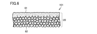
- step S5 as shown in FIG. 6, the coating layer 20 is separated from the substrate 1 and taken out alone.
- Step S5 may be performed by peeling off the coating layer 20 from the substrate 1.
- Step S5 may be performed by removing the substrate 1 by some means while leaving the coating layer 20.
- the resin sheet 101 can be obtained.
- the resin sheet 101 has a first surface 81 and a second surface 82 that face opposite sides.
- the first surface 81 is a surface fused by irradiation of the flash lamp 4.
- the second surface 82 is a surface that is in contact with the main surface 1 u of the substrate 1.
- FIG. 7 and FIG. 8 show SEM (Scanning Electron Microscope) photographs of the surface of the resin sheet 101 produced by the inventors as prototypes.
- FIG. 7 is a view of the second surface 82
- FIG. 8 is a view of the first surface 81.
- fine particles of the powder can be seen, but in FIG. 8, the particles are fused to form a large shape.
- the coating layer 20 is equally divided into two in the thickness direction, and the region far from the substrate 1 is defined as the first region 20a.
- the region closer to 1 is the second region 20b
- the porosity of the first region 20a is greater than 0
- the porosity of the second region 20b is greater than the porosity of the first region 20a
- the application The layer 20 is fused so as to be integrated as a whole of the coating layer 20 while leaving at least a part of the powder form.
- thermoplastic resin the example using the powder of the thermoplastic resin has been described.
- a fibrillated product of the thermoplastic resin may be used instead of the powder of the thermoplastic resin.
- fine particles or nanofibers can be fused together by flash lamp irradiation and handled as an independent sheet. be able to. By fusing only the vicinity of the outermost surface with a flash lamp, the adhesion between the base material and the material does not increase and can be easily peeled off.
- the resin sheet having a high specific surface area can be obtained by a simple method without requiring the solubility of the material in the solvent and without requiring prior self-supporting property.
- the flash lamp irradiation surface can be fused and formed into a sheet, and the back surface can leave the fine particle shape. is there.
- a resin sheet as a high specific surface area film can be obtained from a desired material, and the properties of the material can be utilized to the maximum.
- FIG. 6 shows a schematic cross-sectional view of the resin sheet in the present embodiment.
- the photograph of the 2nd surface of the resin sheet in this Embodiment is shown in FIG. 7, and the photograph of the 1st surface is shown in FIG.
- the resin sheet 101 in the present embodiment is a resin sheet having a first surface 81 and a second surface 82 that are opposite to each other and mainly made of a thermoplastic resin.
- the region closer to the first surface 81 divided into two in the thickness direction is the first region 20 a and the region closer to the second surface 82 is the second region 20 b
- region 20a is larger than 0, and the porosity of the 2nd area
- the resin sheet 101 in the present embodiment has a high specific surface area, and can be easily manufactured by using the thermoplastic resin powder by the manufacturing method described in the first embodiment. In carrying out the production method, the solubility of the material in the solvent is not necessary.
- FIG. 10 shows a flowchart of the resin sheet manufacturing method in the present embodiment.
- the resin sheet manufacturing method in the present embodiment has many steps in common with the resin sheet manufacturing method in the first embodiment, but unlike the resin sheet manufacturing method in the first embodiment, the process before step S5 is performed. Includes S4.
- the substrate 1 has translucency.
- a PET film is used as the substrate 1.
- the light 4a is transmitted through the base material 1 and enters the coating layer 20 as shown in FIG.
- the process S4 which fuse
- FIG. 12 shows a state after both steps S3 and S4 are completed regardless of which of steps S3 and S4 is performed first.
- the coating layer 21 is formed.
- a part including the surface on the side far from the base material 1 and a part including the surface on the side close to the base material 1 are fused together, and the original shape of the powder is destroyed.
- the middle part the original shape of the powder is relatively maintained.
- step S5 as shown in FIG. 13, the coating layer 21 is separated from the substrate 1 and taken out alone. In this way, the resin sheet 102 can be obtained.
- the resin sheet 102 has a first surface 81 and a second surface 82 that face opposite sides.
- fine particles or nanofibers can be fused together by flash lamp irradiation and handled as an independent sheet. be able to. By fusing only the vicinity of the outermost surface with a flash lamp, the adhesion between the base material and the material does not increase and can be easily peeled off.
- the upper and lower surfaces of the coating layer are fused by flash lamp irradiation, so that the state as a single resin sheet after separation from the substrate 1 can be further stabilized.
- a resin sheet having a higher internal porosity than the surface can be easily obtained.
- FIG. 13 shows a schematic cross-sectional view of the resin sheet in the present embodiment.
- the resin sheet 102 in the present embodiment is a resin sheet having a first surface 81 and a second surface 82 that are opposite to each other and mainly made of a thermoplastic resin.
- the region closest to the first surface 81 divided into three equal parts in the thickness direction is defined as a first region 21a
- the region closest to the second surface 82 is defined as a second region 21b
- the first region 21a and the first region When the region sandwiched between the two regions 21b is the third region 21c, the porosity of the first region 21a is greater than 0, and the porosity of the third region 21c is greater than the porosity of the first region 21a.
- the resin sheet 101 shown in FIG. 6 also satisfies this condition.
- the same effect as in the second embodiment can be obtained.
- it since it is a resin sheet having a higher internal porosity than the surface, it can be a resin sheet that can be significantly compressed in the thickness direction as necessary. Therefore, this resin sheet can be used, for example, as a so-called step absorption sheet.
- the porosity of the third region 21c is preferably larger than the porosity of the second region 21b.
- the resin sheet 102 shown in FIGS. 13 to 14 satisfies this condition.
- the manufacturing method of the resin sheet in the present embodiment includes a step S1 of preparing a base material having a main surface, a step S2 of forming a coating layer by applying a fibrillated product of a thermoplastic resin to the main surface, and the coating Irradiating a flash lamp from the opposite side of the substrate toward the layer to fuse a part of the coating layer including the surface on the side far from the substrate; And step S4 of separating from the material and taking it out alone.
- a region far from the main surface is defined as a first region
- a region near the main surface is defined as a second region.
- the porosity of the first region is greater than 0, the porosity of the second region is greater than the porosity of the first region, and the coating layer remains at least partially in the form of the fibrillated product.
- the coating layer is fused so as to be integrated as a whole.
- Step S1 is the same as that described in the first embodiment.
- step S2 as shown in FIG. 15, a fibrillated product of a thermoplastic resin is applied to the main surface 1u to form a coating layer 30.
- step S3 As shown in FIG. 16, a part of the coating layer 30 including the surface far from the substrate 1 by irradiating the flash lamp 4 from the side opposite to the substrate 1 toward the coating layer 30. To fuse. The flash lamp 4 emits light 4a with a high light amount over a very short time.
- step S3 the state shown in FIG. 17 is obtained.
- the coating layer 40 is formed. A part of the coating layer 40 including the surface on the side far from the base material 1 is fused, so that the original form of the fibrillated product is somewhat broken, and the original form as the fibrillated product is difficult to understand. There is also a part.
- step S5 as shown in FIG. 18, the coating layer 40 is separated from the substrate 1 and taken out alone.
- Step S5 may be performed by peeling the coating layer 40 from the substrate 1.
- Step S5 may be performed by removing the substrate 1 by some means while leaving the coating layer 40.
- the resin sheet 103 has a first surface 81 and a second surface 82 that face opposite sides.
- the first surface 81 is a surface fused by irradiation of the flash lamp 4.
- the second surface 82 is a surface that is in contact with the main surface 1 u of the substrate 1.
- FIG. 19 to 21 show SEM photographs of the resin sheet 103 prototyped by the inventors.
- FIG. 19 shows the end of the resin sheet 103 as viewed from the side.
- the white arrow points to the fused surface, that is, the first surface 81.
- FIG. 19 it is shown upside down compared to FIG. In FIG. 19, the upper side is the second surface 82 and the lower side is the first surface 81.
- FIG. 20 shows the second surface 82 as seen.
- FIG. 21 shows the first surface 81 as viewed.
- a fine fibrous shape of the fibrillated product can be seen, but in FIG. 21, the fibrillated products are fused to form a large-sized shape.
- FIG. 22 shows a state in which the resin sheet 103 prototyped by the inventor is embedded with another resin so that the gap is filled with the other resin, and then the section is exposed by cutting and observed with an SEM. .
- the upper and lower sides of the coating layer 40 are shown upside down as compared with FIG.
- the upper surface of the coating layer 40 is a surface in contact with the main surface 1 u of the substrate 1.
- the coating layer 40 is equally divided into two in the thickness direction, and a region far from the substrate 1 is defined as a first region 40a.
- the porosity of the first region 40a is greater than 0
- the porosity of the second region 40b is greater than the porosity of the first region 40a
- the application The layer 40 is fused so as to be integrated as a whole of the coating layer 40 while leaving the form of the fibrillated product at least partially.
- the same effect as in the first embodiment can be obtained.
- the fibrillated product is used instead of the powder used in Embodiment 1, the specific surface area can be made extremely high. Since the fibrillated product is intertwined with each other even before the surface is fused, the fibrillated product is less likely to scatter than the powder and is easy to handle. The fibrillated product has a smaller true volume than the apparent volume and, as a result, a smaller heat capacity. Therefore, even when the same amount of energy is applied for fusing, the fibrillated product is fused compared to the powder. It's easy to do.
- FIG. 6 A schematic cross-sectional view of the resin sheet in the present embodiment is shown in FIG.
- a photograph of the cross section of the resin sheet in the present embodiment is shown in FIG.
- the photograph of the 2nd surface of the resin sheet in this Embodiment is shown in FIG. 20, and the photograph of the 1st surface is shown in FIG.
- the resin sheet 103 in the present embodiment is a resin sheet having a first surface 81 and a second surface 82 that are opposite to each other and mainly made of a thermoplastic resin. 22 when the region closer to the first surface 81 divided into two in the thickness direction is the first region 40a, and the region closer to the second surface 82 is the second region 40b, The porosity of the 1st area
- the resin sheet 103 in the present embodiment has a high specific surface area, and can be easily produced using a fibrillated product of a thermoplastic resin by the manufacturing method described in the fifth embodiment. In carrying out the production method, the solubility of the material in the solvent is not necessary.
- FIG. 23 is obtained by changing the region dividing method in FIG. Therefore, in FIG. 23, the top and bottom of the coating layer 40 are shown upside down compared to FIG.
- the resin sheet 103 in the present embodiment is a resin sheet having a first surface 81 and a second surface 82 that are opposite to each other and mainly made of a thermoplastic resin.
- the region closest to the first surface 81 divided into three in the thickness direction is defined as a first region 40ax
- the region closest to the second surface 82 is defined as a second region 40bx
- the first region 40ax and the first region When the region sandwiched between the two regions 40bx is the third region 40cx, the porosity of the first region 40ax is greater than 0, and the porosity of the third region 40cx is greater than the porosity of the first region 40ax.
- the porosity of the third region 40cx is preferably larger than the porosity of the second region 40bx.
- Embodiment 8 With reference to FIGS. 24 to 26, a resin sheet manufacturing method according to Embodiment 8 of the present invention will be described. Although this embodiment has many steps that are common to the resin sheet manufacturing method of the fifth embodiment, unlike the resin sheet manufacturing method of the first embodiment, step S4 is included before step S5. The flowchart of the resin sheet manufacturing method in the present embodiment is the same as that shown in FIG.
- the substrate 1 has translucency. Further, in this manufacturing method, before the step S5 of separating the coating layer from the base material 1 and taking it out alone, the light 4a is transmitted through the base material 1 and enters the coating layer 40 as shown in FIG. Step S4 is included in which a part of the coating layer 40 including the surface close to the substrate 1 is fused by irradiating the flash lamp 4.
- FIG. 25 shows a state after both steps S3 and S4 are completed regardless of which of steps S3 and S4 is performed first.
- the coating layer 41 is formed.
- a part including the surface far from the base material 1 and a part including the surface near the base material 1 are fused together, and the original form of the fibrillated product is destroyed.
- the middle part the original shape of the fibrillated product is relatively maintained.
- the coating layer 41 is separated from the substrate 1 and taken out alone.
- the resin sheet 104 can be obtained.
- the resin sheet 104 has a first surface 81 and a second surface 82 that face opposite sides.
- a resin sheet having a higher internal porosity than the surface can be obtained using the fibrillated product. Since fibrillated material is used in place of the powder, the internal porosity can be made extremely high. Since such a sheet can be greatly compressed in the thickness direction as necessary, it can be used, for example, as a so-called step absorbing sheet.
- FIG. 26 shows a schematic cross-sectional view of the resin sheet in the present embodiment.
- the resin sheet 104 in the present embodiment is a resin sheet having a first surface 81 and a second surface 82 that are opposite to each other and mainly made of a thermoplastic resin, and has a thickness.
- a region that is equally divided into three in the direction and is closest to the first surface 81 is a first region
- a region that is closest to the second surface 82 is a second region
- a region sandwiched between the first region 21a and the second region 21b is When the third region is used, the porosity of the first region is greater than 0, and the porosity of the third region is greater than the porosity of the first region.
- the resin sheet since the resin sheet has a higher internal porosity than the surface, the resin sheet can be compressed significantly in the thickness direction as necessary. Therefore, this resin sheet can be used, for example, as a so-called step absorption sheet.
- the porosity of the third region is preferably larger than the porosity of the second region.
- the resin sheet 104 shown in FIG. 26 satisfies this condition.
- FIG. 27 shows a flowchart of a method for manufacturing a resin sheet in the present embodiment.
- the method for producing a resin sheet in the present embodiment includes a step S1 of preparing a base material having a main surface, a step S2 of forming a coating layer by applying a thermoplastic resin powder to the main surface, Irradiating a flash lamp so as to pass through the base material and enter the coating layer, thereby fusing a part of the coating layer including a surface close to the base material, and the coating layer; And step S5 for separating the substrate from the substrate and taking it out alone.
- the coating layer is equally divided into two in the thickness direction, a region far from the main surface is defined as a first region, and a region near the main surface is defined as a second region.
- the porosity of the second region is greater than 0, the porosity of the first region is greater than the porosity of the second region, and the coating layer leaves the powder form at least partially.
- the coating layer is fused so as to be integrated as a whole.
- steps S1 and S2 are the same as those described in the first embodiment, description thereof will not be repeated.
- step S4 as shown in FIG. 28, a part of the coating layer 10 including the surface near the substrate 1 is melted by irradiating the flash lamp 4 toward the coating layer 10 from the substrate 1 side. Put on. In other words, by irradiating the flash lamp 4 so that the light 4a passes through the substrate 1 and enters the coating layer 10, a part of the coating layer 10 including the surface close to the substrate 1 is fused. .
- step S4 the state shown in FIG. 29 is obtained.
- the coating layer 22 is formed. Part of the coating layer 22 including the surface on the side close to the base material 1 is fused, so that the original shape of the powder is somewhat collapsed, and the original shape as the powder becomes difficult to understand. There is also a part.
- step S5 is the same as that described in the first embodiment, description thereof will not be repeated.
- step S5 By completing step S5 in this way, a resin sheet in which the resin sheet 101 shown in FIG. 6 is turned upside down is obtained.
- the method for producing a resin sheet in the present embodiment includes a step S1 for preparing a base material having a main surface, a step S2 for forming a coating layer by applying a fibrillated thermoplastic resin to the main surface, Irradiating a flash lamp so as to pass through the base material and enter the coating layer, thereby fusing a part of the coating layer including a surface close to the base material, and the coating layer;
- step S4 for separating and separating the substrate from the base material and in the step S4 for fusing, the coating layer is divided into two equal parts in the thickness direction, and the region far from the main surface is defined as the first region.
- the porosity of the second region is greater than 0
- the porosity of the first region is greater than the porosity of the second region
- the coating layer is at least partially Fusing enough to integrate the whole of the coating layer while leaving the form of the fibril product.
- steps S1 and S2 are the same as those described in the fifth embodiment, description thereof will not be repeated.
- step S4 as shown in FIG. 30, a part of the coating layer 30 including the surface near the substrate 1 is melted by irradiating the flash lamp 4 from the substrate 1 side toward the coating layer 30. Put on. In other words, by irradiating the flash lamp 4 so that the light 4a passes through the substrate 1 and enters the coating layer 30, a part of the coating layer 30 including the surface close to the substrate 1 is fused. .
- step S4 the state shown in FIG. 31 is obtained.
- the coating layer 32 is formed. Part of the coating layer 32 including the surface on the side close to the base material 1 is fused, so that the original shape of the powder is somewhat collapsed, and the original shape as the powder becomes difficult to understand. There is also a part.
- step S5 is the same as that described in the first embodiment, description thereof will not be repeated.
- step S5 By completing step S5 in this way, a resin sheet in which the resin sheet 103 shown in FIG. 18 is turned upside down is obtained.
- the same effect as in the fifth embodiment can be obtained.
- the method for producing a resin sheet has been described.
- the thermoplastic resin preferably contains a liquid crystal polymer.
- thermoplastic resin preferably includes a liquid crystal polymer.
- this sheet can be used as a step absorption sheet.
- materials such as LCP, polyimide, PEEK, etc. according to the material of the multilayer substrate and the press temperature as the step absorption sheet of the multilayer substrate, without impairing the heat resistance and electrical characteristics of the finished substrate, A flat multilayer substrate can be manufactured by filling the step portion of the circuit.
- the sheet obtained by performing irradiation with a flash lamp only on one side maintains a high specific surface area on the surface opposite to the irradiated surface, so that a polymer alloy substrate sheet, a step absorption sheet, When used for applications such as super water-repellent sheets, good performance is easily obtained.
- a sheet obtained by irradiating both sides with a flash lamp is easy to obtain a self-supporting property even if the film thickness is large, and is suitable for an application requiring a large film thickness.
- a heat insulating sheet containing an air layer, or a low dielectric sheet good performance is easily obtained.
- FIG. 32 shows a flowchart of the method for manufacturing the resin multilayer substrate in the present embodiment.
- the manufacturing method of the resin multilayer substrate in the present embodiment includes a step S101 for preparing a first thermoplastic resin layer having a conductor pattern disposed on the surface, a step S102 for preparing a second thermoplastic resin layer, and so far.
- Step S103 of preparing the resin sheet described in any of the embodiments the resin sheet is in contact with the conductor pattern, and the resin sheet is the first thermoplastic resin layer and the second thermoplastic resin.
- step S101 for preparing a first thermoplastic resin layer is performed.
- a resin sheet 12 with a conductor film is prepared.
- the resin sheet with a conductor film 12 includes a resin layer 2 and a conductor layer 17.
- the conductor layer 17 is disposed so as to cover one surface of the resin layer 2.
- the conductor layer 17 is, for example, a metal layer.
- the metal layer here may be, for example, a copper layer.
- a resist pattern 13 is formed on one surface of the resin sheet 12 with a conductor film. By etching the conductor layer 17 using the resist pattern 13 as a mask, the conductor pattern 7 is formed as shown in FIG. By removing the resist pattern 13, a first thermoplastic resin layer 51 is obtained as shown in FIG. This is step S101.
- Step S102 for preparing the second thermoplastic resin layer is performed.
- the second thermoplastic resin layer 52 may have the same conductor pattern 7 as the first thermoplastic resin layer 51.
- the second thermoplastic resin layer 52 may have a conductor pattern 7 different from that of the first thermoplastic resin layer 51.
- the second thermoplastic resin layer 52 may have no conductor pattern at all.
- Step S103 for preparing the resin sheet described in any of the above embodiments is performed.
- Step S103 may be performed by the resin sheet manufacturing method described above.
- a resin sheet 103 is prepared as shown in FIG.
- the resin sheet 103 has been described in the sixth embodiment with reference to FIG. In FIG. 38, the resin sheet 103 is simplified and displayed.
- the first surface 81 of the resin sheet 103 may face either up or down.
- Processes S101, S102, and S103 may be performed in any order, and may be performed in parallel. After all of steps S101, S102, and S103 are completed, step S104 for obtaining a laminate is performed.
- step S104 as shown in FIG. 39, the resin sheet 103 abuts on the conductor pattern 7, and the resin sheet 103 is sandwiched between the first thermoplastic resin layer 51 and the second thermoplastic resin layer 52. At least the first thermoplastic resin layer 51, the second thermoplastic resin layer 52, and the resin sheet 103 are stacked to obtain a laminate 85.
- the laminated body 85 is obtained by combining and stacking sheets in addition to the above-described three sheets.
- step S105 for integrating the laminate is performed.
- the laminated body 85 is integrated by applying heat and pressure to the laminated body 85.
- a gap portion is formed in the portion overlapping the conductor pattern 7 in the resin sheet 103 (the lower resin sheet 103 in FIG. 39) sandwiched between the first thermoplastic resin layer 51 and the second thermoplastic resin layer 52 through the step S105.
- the material of the resin sheet 103 is accommodated in a portion where the conductor pattern 7 is not present. That is, the resin sheet 103 functions as a step absorption sheet. In this way, the resin multilayer substrate 201 can be obtained as shown in FIG.
- a resin sheet produced using a thermoplastic resin powder or fibrillated product is sandwiched between thermoplastic resin layers as a step-absorbing sheet to form a laminate, thereby producing a resin multilayer substrate. Therefore, it is possible to obtain a resin multilayer substrate in which the step on the outermost surface is reduced.
- LCP powder was used as the powder.
- a LCP biaxially stretched film having a thickness of 125 ⁇ m was prepared as a raw material of LCP powder. This film was primarily ground using a rotary cutter mill. In the primary pulverization, only those pulverized to such an extent that they passed through a 3 mm diameter sieve were collected. The primary pulverized film piece was subjected to secondary pulverization using a freeze pulverizer to obtain LCP powder. Of the obtained LCP powder, only those passing through 40 mesh were collected. The LCP powder thus obtained was hereinafter referred to as “LCP1”. LCP1 was added to butanediol at a weight ratio of 25% and stirred to obtain a paste-like LCP dispersion. This was called “LCP dispersion 1”.
- a PET substrate was prepared.
- LCP dispersion 1 was applied on a PET substrate by a screen printing method to form a coating film.
- a screen mesh of 70 lines / inch and an opening of 263 ⁇ m was used.
- the coating film having a thickness of about 30 ⁇ m corresponds to the coating layer 10 in FIG.
- step S3 a flash lamp irradiation treatment was performed on the side of the sheet having the coating film using PulseForge (R) 1300 manufactured by NovaCentrix with a pulse width of 0.5 milliseconds and an output of 300V. Thus, at least a part of the coating film was fused.
- step S5 the coating film was peeled off from the PET substrate to obtain an LCP sheet having a film thickness of 25 ⁇ m. As a result of observing the LCP sheet with SEM, it was found that the surface irradiated with the flash lamp was fused and integrated, and the surface peeled from the PET base material was fused while maintaining the powder shape. It was.
- the specific surface area of the LCP sheet thus obtained was measured using Macsorb (R) HM manufactured by Mountec Co., Ltd. As a result, the specific surface area was 2 g / m 2 .
- the surface of the coating layer formed thereby can be fused to give the whole layer self-supporting properties while leaving a part of the shape of the powder. It was confirmed that the sheet obtained by peeling off the coating layer can be handled as an independent sheet. In this method, it is possible to form a sheet while partially leaving the powder shape, so that a resin sheet as a high specific surface area sheet can be obtained.
- the material to be used as the high specific surface area sheet does not need to be completely dissolved in the solvent, and may be simply applied as a dispersion. Therefore, a resin having high solvent resistance can be used as the material.
- the LCP sheet obtained from LCP1 in Experiment 1 was embedded with Stricus Specifix-20, cut so that the cross-section was exposed, and then observed with SEM (VE7800 manufactured by Keyence Corporation).
- the ratio of voids (embedded resin) to the ratio of LCP resin in the image obtained by observation was determined.
- the porosity (void area / viewing area) was 33% on the irradiated surface side when the total film thickness was divided into two equal parts, and 69% on the non-irradiated surface side.
- the porosity ratio was 0.48.
- the measurement results are shown in Tables 1 to 3.
- the second pulverization is performed using a freeze pulverizer to obtain LCP powder, which is the same as described in Experiment 1.
- LCP powder obtained by secondary pulverization, those passing through 150 mesh were collected.
- the LCP powder thus obtained was fibrillated with a high-pressure wet crusher.
- LCP2 a fibrillated product of LCP was obtained.
- LCP2 was added to butanediol (viscosity: about 90 mPa ⁇ s) at a weight ratio of 5% and stirred to obtain a paste-like LCP dispersion. This was called “LCP dispersion 2”.
- Steps S1 and S2 were performed as in Experiment 1. However, in Step S2, coating was performed using the LCP dispersion 2 instead of the LCP dispersion 1 of Experiment 1.
- the obtained sheet corresponds to that shown in FIG.
- the coating film corresponds to the coating layer 30 in FIG.
- the resin sheet was manufactured by performing process S3, S5 similarly to the experiment 1.
- FIG. About the obtained resin sheet, the specific surface area and the porosity were measured. The measurement results are shown in Tables 1 to 3.
- thermoplastic polyimide resin powder (hereinafter referred to as “PI powder”) was used.
- PI powder pellets of Aurum (R) (AURUM) PL450C manufactured by Mitsui Chemicals were prepared, and the pellets were pulverized using a freeze pulverizer. In this way, PI powder was obtained.
- R Aurum
- AURUM Aurum
- PL450C PL450C manufactured by Mitsui Chemicals
- a powder passing through 40 mesh was added to butanediol at a weight ratio of 30% and stirred to obtain a paste-like PI dispersion.
- a resin sheet was obtained by the production method shown in the first embodiment. About the obtained resin sheet, the specific surface area and the porosity were measured. The measurement results are shown in Tables 1 to 3.
- PEEK powder a PEEK resin powder (hereinafter referred to as “PEEK powder”) was used.
- PEEK 150XF (powder) manufactured by Victrex was used as the PEEK powder, and 25% by weight was added to butanediol, followed by stirring to obtain a paste-like PEEK dispersion.
- a resin sheet was obtained by the production method shown in the first embodiment. About the obtained resin sheet, the specific surface area and the porosity were measured. The measurement results are shown in Tables 1 to 3.
- COP powder cyclic olefin polymer (COP) resin powder (hereinafter referred to as “COP powder”) was used.
- ZEONEX (R) RS420 made by Nippon Zeon was pulverized using a freeze pulverizer to obtain COP powder.
- those passing through 40 mesh were added to butanediol in a weight ratio of 30% and stirred to obtain a paste-like COP dispersion.
- a resin sheet was obtained by the production method shown in the first embodiment. About the obtained resin sheet, the specific surface area and the porosity were measured. The measurement results are shown in Tables 1 to 3.
- the LCP dispersion 1 was applied onto a PET substrate using a doctor blade to form a coating film. Then, it dried on 130 degreeC * 10 minute conditions on the hotplate, and obtained the sheet
- the coating surface of this sheet was subjected to flash lamp irradiation treatment using PulseForge (R) 1300 manufactured by NovaCentrix with a pulse width of 1 millisecond and an output of 380V. Subsequently, a flash lamp irradiation process was performed from the PET substrate side with a pulse width of 1 millisecond and an output of 390V.
- the coating film was peeled off from the PET substrate to obtain an LCP sheet having a thickness of about 80 ⁇ m.
- LCP sheet having a thickness of about 80 ⁇ m.
- SEM surface on the side in contact with the substrate and the surface on the opposite side were fused and integrated.
- the specific surface area of the LCP sheet thus obtained was measured using Macsorb (R) HM manufactured by Mountec Co., Ltd. As a result, the specific surface area was 2.4 g / m 2 .
- Table 1 shows the results obtained by dividing the resin sheet obtained in each of Experiments 1 to 5 into two portions in the thickness direction in the manner shown in FIG. 9 and measuring the porosity for each of these two regions.
- Tables 2 to 3 show the results of measuring the porosity of each of these three regions by dividing the resin sheets obtained in Experiments 1 to 7 into three equal parts in the thickness direction in the manner shown in FIG.
- Tables 2 and 3 are the contents that should originally be one table connected in the left-right direction, but are divided into two tables for the convenience of display space.
- the material of the substrate 1 used in the resin sheet manufacturing method is not particularly limited. However, when the manufacturing method includes a step of irradiating a flash lamp so that light passes through the base material 1 and enters the coating layer, the base material 1 needs to have translucency. In other cases, the substrate 1 may be formed of a material that does not have translucency.
Landscapes
- Engineering & Computer Science (AREA)
- Microelectronics & Electronic Packaging (AREA)
- Manufacturing & Machinery (AREA)
- Laminated Bodies (AREA)
Abstract
Description
本発明は、樹脂シート、樹脂シートの製造方法および樹脂多層基板の製造方法に関するものである。 The present invention relates to a resin sheet, a resin sheet manufacturing method, and a resin multilayer substrate manufacturing method.
高分子ナノ繊維からなる糸の製造方法に関する技術が特開2011-214170号公報(特許文献1)に記載されている。特許文献1では、高分子ナノ繊維の原料となる高分子材料溶液をノズルから噴出させ、ノズルとコレクタとの間に高電圧を印加している。これにより、高分子ナノ繊維がコレクタ上に堆積し、シート状不織布が得られる。特許文献1では、このように高分子ナノ繊維からなるシート状不織布を製造し、これを切断することによって帯状不織布を製造している。この帯状不織布を一連の装置に通すことによって高分子ナノ繊維からなる糸を連続的に製造している。特許文献1においては、このように製造される高分子ナノ繊維からなる糸の途中にレーザ光を照射することによって、糸のうち限られた領域のみにおいて高分子ナノ繊維同士を融着させ、結合点を形成している。
A technique relating to a method for producing a yarn composed of polymer nanofibers is described in JP-A-2011-214170 (Patent Document 1). In
熱可塑性ポリイミド樹脂を溶融押出成形して熱可塑性ポリイミド樹脂フィルムを得ることが、特開2007-268917号公報(特許文献2)に記載されている。 JP-A-2007-268717 (Patent Document 2) describes that a thermoplastic polyimide resin film is obtained by melt extrusion molding of a thermoplastic polyimide resin.
特許文献1の技術を実施するためには、自己支持性を有するシート状不織布を高分子ナノ繊維で作製する必要がある。そのためには、まず高分子ナノ繊維を作製する必要がある。この繊維の材料は、ノズルから噴出して繊維とするものであるので、溶剤に溶解するものでなければならない。また、繊維を形成する際およびシートを形成する際の条件は複雑であり、簡便には実現できなかった。
In order to carry out the technique of
特許文献2の製造方法を実施した場合には、得られるフィルムは充実体となり、比表面積が高いフィルムを得ることはできなかった。
When the production method of
そこで、本発明は、材料の溶剤への溶解性を必要とせず、事前の自己支持性も必要とせず、簡便な方法で作製可能で、比表面積を高くすることができる樹脂シートまたは表面よりも内部の空隙率が高い樹脂シートおよびこれらの製造方法を提供することを目的とする。また、最表面の段差を軽減することができる樹脂多層基板の製造方法を提供することを目的とする。 Therefore, the present invention does not require the solubility of the material in a solvent, does not require prior self-supporting ability, can be produced by a simple method, and can have a higher specific surface area than a resin sheet or surface. An object of the present invention is to provide a resin sheet having a high internal porosity and a method for producing them. Moreover, it aims at providing the manufacturing method of the resin multilayer substrate which can reduce the level | step difference of an outermost surface.
上記目的を達成するため、本発明に基づく樹脂シートは、互いに逆の面である第1面および第2面を有し、熱可塑性樹脂を主材料とする樹脂シートであり、厚み方向に2等分して上記第1面に近い側の領域を第1領域とし、上記第2面に近い側の領域を第2領域としたときに、上記第1領域の空隙率が0より大きく、上記第2領域の空隙率が上記第1領域の空隙率より大きい。 In order to achieve the above object, a resin sheet according to the present invention is a resin sheet having a first surface and a second surface that are opposite to each other, and a thermoplastic resin as a main material, and is 2 etc. in the thickness direction. When the region closer to the first surface is the first region and the region closer to the second surface is the second region, the porosity of the first region is greater than 0, The porosity of the two regions is larger than the porosity of the first region.
本発明によれば、比表面積が高い樹脂シートまたは表面よりも内部の空隙率が高い樹脂シートとすることができ、この樹脂シートは、材料の溶剤への溶解性を必要とせず、熱可塑性樹脂の粉体またはフィブリル化物を用いて簡便に作製することができる。 According to the present invention, a resin sheet having a high specific surface area or a resin sheet having a higher internal void ratio than the surface can be obtained, and this resin sheet does not require solubility in a solvent of the material, and is a thermoplastic resin. It can be easily produced using the powder or fibrillated product.
図面において示す寸法比は、必ずしも忠実に現実のとおりを表しているとは限らず、説明の便宜のために寸法比を誇張して示している場合がある。以下の説明において、上または下の概念に言及する際には、絶対的な上または下を意味するものではなく、図示された姿勢の中での相対的な上または下を意味するものである。 The dimensional ratios shown in the drawings do not always faithfully represent the actual ones, and the dimensional ratios may be exaggerated for convenience of explanation. In the following description, when referring to a concept above or below, it does not mean absolute above or below, but rather relative above or below in the illustrated posture. .
(実施の形態1)
図1~図8を参照して、本発明に基づく実施の形態1における樹脂シートの製造方法について説明する。本実施の形態における樹脂シートの製造方法のフローチャートを図1に示す。図1のフローチャートには、工程S4は示されておらず、工程S1,S2,S3,S5が示されている。
(Embodiment 1)
With reference to FIGS. 1 to 8, a method for producing a resin sheet in the first embodiment based on the present invention will be described. FIG. 1 shows a flowchart of a method for manufacturing a resin sheet in the present embodiment. In the flowchart of FIG. 1, step S4 is not shown, but steps S1, S2, S3, and S5 are shown.
本実施の形態における樹脂シートの製造方法は、主表面を有する基材を用意する工程S1と、熱可塑性樹脂の粉体を前記主表面に塗布して塗布層を形成する工程S2と、前記塗布層に向けて前記基材とは反対側からフラッシュランプを照射することによって前記塗布層のうち前記基材から遠い側の表面を含む一部を融着させる工程S3と、前記塗布層を前記基材から分離して単独で取り出す工程S5とを含む、前記融着させる工程S3では、前記塗布層を厚み方向に2等分して前記主表面から遠い側の領域を第1領域とし、前記主表面に近い側の領域を第2領域としたときに、前記第1領域の空隙率が0より大きく、前記第2領域の空隙率が前記第1領域の空隙率より大きくなり、なおかつ、前記塗布層が少なくとも一部に前記粉体の形態を残しつつ前記塗布層の全体として一体化する程度に融着させる。 The method for producing a resin sheet in the present embodiment includes a step S1 of preparing a base material having a main surface, a step S2 of applying a thermoplastic resin powder to the main surface to form an application layer, and the application Irradiating a flash lamp from the opposite side of the substrate toward the layer to fuse a part of the coating layer including the surface on the side far from the substrate; In the step S3 of fusing, including the step S5 of separating from the material and taking it out alone, the coating layer is equally divided into two in the thickness direction, and the region far from the main surface is defined as the first region, When the region closer to the surface is the second region, the porosity of the first region is greater than 0, the porosity of the second region is greater than the porosity of the first region, and the application The powder is at least partially in the form of the powder Fusing enough to integrate the whole of the coating layer while leaving.
本実施の形態における樹脂シートの製造方法に含まれる各工程について、図面を参照しながらより詳しく説明する。 Each step included in the resin sheet manufacturing method in the present embodiment will be described in more detail with reference to the drawings.
まず、工程S1として、図2に示すように、主表面1uを有する基材1を用意する。基材1は、たとえばPET(ポリエチレンテレフタレート:polyethylene terephthalate)からなるものであってもよい。次に工程S2として、図3に示すように、熱可塑性樹脂の粉体を主表面1uに塗布して塗布層10を形成する。なお、この塗布は、熱可塑性樹脂の粉体を分散媒に分散して得たペースト状の樹脂分散液を塗布することによって行なうことが好ましい。そのようにすれば、安定した塗膜を得ることができるからである。以下に述べる他の実施の形態においてもそれぞれ同様である。
First, as step S1, a
工程S3として、図4に示すように、塗布層10に向けて基材1とは反対側からフラッシュランプ4を照射することによって塗布層10のうち基材1から遠い側の表面を含む一部を融着させる。フラッシュランプ4からは光4aがきわめて短い時間に渡って高い光量で発せられる。工程S3を行なったことで、図5に示すような状態になる。図5では、塗布層20が形成されている。塗布層20のうち基材1から遠い側の表面を含む一部は既に融着したことにより、粉体の元の姿が多少崩れており、中には粉体としての元の姿がわかりにくくなっている部分もある。
As step S3, as shown in FIG. 4, a part of the
工程S5として、図6に示すように、塗布層20を基材1から分離して単独で取り出す。工程S5は、塗布層20を基材1から引き剥がすことによって行なってもよい。工程S5は、塗布層20を残しつつ基材1を何らかの手段で除去することによって行なってもよい。こうして、樹脂シート101を得ることができる。樹脂シート101は、互いに逆の側を向く第1面81と第2面82とを有する。第1面81はフラッシュランプ4の照射によって融着した面である。第2面82は、基材1の主表面1uに接していた面である。
As step S5, as shown in FIG. 6, the
発明者が試作した樹脂シート101の表面のSEM(走査型電子顕微鏡:Scanning Electron Microscope)写真を図7および図8に示す。図7は第2面82を見たところであり、図8は第1面81を見たところである。図7では粉体の細かい粒が見えているが、図8では粒同士が融着して大ぶりな形状となっている。
FIG. 7 and FIG. 8 show SEM (Scanning Electron Microscope) photographs of the surface of the
図4~図5を参照して説明した工程3では、図9に示すように塗布層20を厚み方向に2等分して基材1から遠い側の領域を第1領域20aとし、基材1に近い側の領域を第2領域20bとしたときに、第1領域20aの空隙率が0より大きく、第2領域20bの空隙率が第1領域20aの空隙率より大きくなり、なおかつ、塗布層20が少なくとも一部に粉体の形態を残しつつ塗布層20の全体として一体化する程度に融着させる。
In
本実施の形態では、熱可塑性樹脂の粉体を用いる例を説明したが、実施の形態5で後述するように、熱可塑性樹脂の粉体に代えて熱可塑性樹脂のフィブリル化物を用いてもよい。 In this embodiment, the example using the powder of the thermoplastic resin has been described. However, as described later in the fifth embodiment, a fibrillated product of the thermoplastic resin may be used instead of the powder of the thermoplastic resin. .
本実施の形態では、素材に自己支持性がなく、単体ではフィルムまたはシートとして取り扱えない微粒子やナノファイバーであっても、フラッシュランプ照射によって素材間を融着し、独立したシートとしてハンドリング可能とすることができる。フラッシュランプにより最表面近傍のみを融着させることで、基材と素材との間の密着性は上がらず、容易に剥離することができる。 In this embodiment, even if the material has no self-supporting property and can not be handled as a film or sheet by itself, fine particles or nanofibers can be fused together by flash lamp irradiation and handled as an independent sheet. be able to. By fusing only the vicinity of the outermost surface with a flash lamp, the adhesion between the base material and the material does not increase and can be easily peeled off.
本実施の形態では、材料の溶剤への溶解性を必要とせず、事前の自己支持性も必要とせず、簡便な方法で、比表面積が高い樹脂シートを得ることができる。 In the present embodiment, the resin sheet having a high specific surface area can be obtained by a simple method without requiring the solubility of the material in the solvent and without requiring prior self-supporting property.
本実施の形態では、微粒子の塗布厚みに対して、融着させる部分の深さを制御することで、フラッシュランプ照射面は融着させてシート化し、裏面は微粒子の形状を残すことが可能である。所望の素材から高比表面積フィルムとしての樹脂シートを得ることができ、素材の性質を最大限に活用することができる。 In this embodiment, by controlling the depth of the portion to be fused with respect to the coating thickness of the fine particles, the flash lamp irradiation surface can be fused and formed into a sheet, and the back surface can leave the fine particle shape. is there. A resin sheet as a high specific surface area film can be obtained from a desired material, and the properties of the material can be utilized to the maximum.
(実施の形態2)
図6~図9を参照して、本発明に基づく実施の形態2における樹脂シートについて説明する。本実施の形態における樹脂シートの模式的な断面図を図6に示す。本実施の形態における樹脂シートの第2面の写真を図7に示し、第1面の写真を図8に示す。
(Embodiment 2)
With reference to FIG. 6 to FIG. 9, a resin sheet according to the second embodiment of the present invention will be described. FIG. 6 shows a schematic cross-sectional view of the resin sheet in the present embodiment. The photograph of the 2nd surface of the resin sheet in this Embodiment is shown in FIG. 7, and the photograph of the 1st surface is shown in FIG.
図6に示すように、本実施の形態における樹脂シート101は、互いに逆の面である第1面81および第2面82を有し、熱可塑性樹脂を主材料とする樹脂シートであり、図9に示すように、厚み方向に2等分して第1面81に近い側の領域を第1領域20aとし、第2面82に近い側の領域を第2領域20bとしたときに、第1領域20aの空隙率が0より大きく、第2領域20bの空隙率が第1領域20aの空隙率より大きい。
As shown in FIG. 6, the
本実施の形態における樹脂シート101は、比表面積が高く、実施の形態1で説明した製造方法により熱可塑性樹脂の粉体を用いて簡便に作製することができる。製造方法を実施する上で、材料の溶剤への溶解性は不要である。
The
(実施の形態3)
図10~図13を参照して、本発明に基づく実施の形態3における樹脂シートの製造方法について説明する。本実施の形態における樹脂シートの製造方法のフローチャートを図10に示す。
(Embodiment 3)
With reference to FIGS. 10 to 13, a method for manufacturing a resin sheet according to the third embodiment of the present invention will be described. FIG. 10 shows a flowchart of the resin sheet manufacturing method in the present embodiment.
本実施の形態における樹脂シートの製造方法は、実施の形態1における樹脂シートの製造方法と共通する工程が多いが、実施の形態1における樹脂シートの製造方法とは異なり、工程S5の前に工程S4を含む。 The resin sheet manufacturing method in the present embodiment has many steps in common with the resin sheet manufacturing method in the first embodiment, but unlike the resin sheet manufacturing method in the first embodiment, the process before step S5 is performed. Includes S4.
本実施の形態における樹脂シートの製造方法においては、基材1は透光性を有する。基材1としては、たとえばPETフィルムが用いられる。さらにこの製造方法は、塗布層を基材1から分離して単独で取り出す工程S5の前に、図11に示すように、光4aが基材1を透過して塗布層20に入射するようにフラッシュランプ4を照射することによって塗布層20のうち基材1に近い側の表面を含む一部を融着させる工程S4を含む。
In the method for producing a resin sheet in the present embodiment, the
図10~図11では、工程S3を行なってから工程S4を行なうこととして説明したが、実際には、工程S3と工程S4とは同時に並行して行なってもよい。あるいは、工程S4を行なってから工程S3を行なうこととしてもよい。その場合、工程S4,S3,S5の順に行なわれることとなる。 10 to 11, it has been described that the process S4 is performed after the process S3 is performed, but actually, the process S3 and the process S4 may be performed in parallel. Or it is good also as performing process S3 after performing process S4. In that case, it will be performed in order of process S4, S3, S5.
工程S3,S4のいずれを先に行なうかにかかわらず、工程S3,S4の両方が完了した後の状態を図12に示す。図12では、塗布層21が形成されている。塗布層21のうち、基材1から遠い側の表面を含む一部と、基材1から近い側の表面を含む一部とがそれぞれ融着して粉体の元の姿が崩れている。一方、中間部分においては、粉体の元の姿が比較的維持されている。
FIG. 12 shows a state after both steps S3 and S4 are completed regardless of which of steps S3 and S4 is performed first. In FIG. 12, the
工程S5として、図13に示すように、塗布層21を基材1から分離して単独で取り出す。こうして、樹脂シート102を得ることができる。樹脂シート102は、互いに逆の側を向く第1面81と第2面82とを有する。
As step S5, as shown in FIG. 13, the
本実施の形態では、素材に自己支持性がなく、単体ではフィルムまたはシートとして取り扱えない微粒子やナノファイバーであっても、フラッシュランプ照射によって素材間を融着し、独立したシートとしてハンドリング可能とすることができる。フラッシュランプにより最表面近傍のみを融着させることで、基材と素材との間の密着性は上がらず、容易に剥離することができる。 In this embodiment, even if the material has no self-supporting property and can not be handled as a film or sheet by itself, fine particles or nanofibers can be fused together by flash lamp irradiation and handled as an independent sheet. be able to. By fusing only the vicinity of the outermost surface with a flash lamp, the adhesion between the base material and the material does not increase and can be easily peeled off.
本実施の形態では、塗布層の上下両面においてフラッシュランプ照射により融着させているので、基材1から分離した後の単独の樹脂シートとしての状態をより安定させることができる。本実施の形態によれば、表面より内部の空隙率が高い樹脂シートを簡便に得ることができる。
In the present embodiment, the upper and lower surfaces of the coating layer are fused by flash lamp irradiation, so that the state as a single resin sheet after separation from the
(実施の形態4)
図13~図14を参照して、本発明に基づく実施の形態4における樹脂シートについて説明する。本実施の形態における樹脂シートの模式的な断面図を図13に示す。
(Embodiment 4)
With reference to FIGS. 13 to 14, a resin sheet according to
図13に示すように、本実施の形態における樹脂シート102は、互いに逆の面である第1面81および第2面82を有し、熱可塑性樹脂を主材料とする樹脂シートであり、図14に示すように、厚み方向に3等分して第1面81に最も近い領域を第1領域21aとし、第2面82に最も近い領域を第2領域21bとし、第1領域21aと第2領域21bとに挟まれる領域を第3領域21cとしたときに、第1領域21aの空隙率が0より大きく、第3領域21cの空隙率が第1領域21aの空隙率より大きい。図13~図14に示す樹脂シート102の他に、図6に示した樹脂シート101も、この条件を満たしている。
As shown in FIG. 13, the
本実施の形態においても、実施の形態2と同様の効果を得ることができる。本実施の形態によれば、表面より内部の空隙率が高い樹脂シートとなっているので、必要に応じて厚み方向に大幅に圧縮されうる樹脂シートとすることができる。したがって、この樹脂シートは、たとえばいわゆる段差吸収シートとして使用することができる。 Also in the present embodiment, the same effect as in the second embodiment can be obtained. According to the present embodiment, since it is a resin sheet having a higher internal porosity than the surface, it can be a resin sheet that can be significantly compressed in the thickness direction as necessary. Therefore, this resin sheet can be used, for example, as a so-called step absorption sheet.
なお、第3領域21cの空隙率が第2領域21bの空隙率より大きいことが好ましい。図13~図14に示す樹脂シート102は、この条件を満たしている。
Note that the porosity of the third region 21c is preferably larger than the porosity of the
(実施の形態5)
図15~図22を参照して、本発明に基づく実施の形態5における樹脂シートの製造方法について説明する。実施の形態1では熱可塑性樹脂の粉体を用いた樹脂シートの製造方法について各工程を図示して説明したが、本実施の形態では、熱可塑性樹脂の粉体に代えて、熱可塑性樹脂のフィブリル化物を用いた樹脂シートの製造方法について各工程を図示して説明する。本実施の形態における樹脂シートの製造方法のフローチャートは、図1に示したものと同じである。
(Embodiment 5)
With reference to FIGS. 15 to 22, a method for producing a resin sheet in the fifth embodiment according to the present invention will be described. In the first embodiment, each process is illustrated and described for a method of manufacturing a resin sheet using a thermoplastic resin powder. In the present embodiment, instead of the thermoplastic resin powder, a thermoplastic resin powder is used. Each process is illustrated and demonstrated about the manufacturing method of the resin sheet using a fibrillation thing. The flowchart of the resin sheet manufacturing method in the present embodiment is the same as that shown in FIG.
本実施の形態における樹脂シートの製造方法は、主表面を有する基材を用意する工程S1と、熱可塑性樹脂のフィブリル化物を前記主表面に塗布して塗布層を形成する工程S2と、前記塗布層に向けて前記基材とは反対側からフラッシュランプを照射することによって前記塗布層のうち前記基材から遠い側の表面を含む一部を融着させる工程S3と、前記塗布層を前記基材から分離して単独で取り出す工程S4とを含む。前記融着させる工程S3では、前記塗布層を厚み方向に2等分して前記主表面から遠い側の領域を第1領域とし、前記主表面に近い側の領域を第2領域としたときに、前記第1領域の空隙率が0より大きく、前記第2領域の空隙率が前記第1領域の空隙率より大きくなり、なおかつ、前記塗布層が少なくとも一部に前記フィブリル化物の形態を残しつつ前記塗布層の全体として一体化する程度に融着させる。 The manufacturing method of the resin sheet in the present embodiment includes a step S1 of preparing a base material having a main surface, a step S2 of forming a coating layer by applying a fibrillated product of a thermoplastic resin to the main surface, and the coating Irradiating a flash lamp from the opposite side of the substrate toward the layer to fuse a part of the coating layer including the surface on the side far from the substrate; And step S4 of separating from the material and taking it out alone. In the fusion bonding step S3, when the coating layer is equally divided into two in the thickness direction, a region far from the main surface is defined as a first region, and a region near the main surface is defined as a second region. The porosity of the first region is greater than 0, the porosity of the second region is greater than the porosity of the first region, and the coating layer remains at least partially in the form of the fibrillated product. The coating layer is fused so as to be integrated as a whole.
本実施の形態における樹脂シートの製造方法に含まれる各工程について、図面を参照しながらより詳しく説明する。 Each step included in the resin sheet manufacturing method in the present embodiment will be described in more detail with reference to the drawings.
工程S1は、実施の形態1で説明したものと同じである。
工程S2として、図15に示すように、熱可塑性樹脂のフィブリル化物を主表面1uに塗布して塗布層30を形成する。
Step S1 is the same as that described in the first embodiment.
As step S2, as shown in FIG. 15, a fibrillated product of a thermoplastic resin is applied to the
工程S3として、図16に示すように、塗布層30に向けて基材1とは反対側からフラッシュランプ4を照射することによって塗布層30のうち基材1から遠い側の表面を含む一部を融着させる。フラッシュランプ4からは光4aがきわめて短い時間に渡って高い光量で発せられる。工程S3を行なったことで、図17に示すような状態になる。図17では、塗布層40が形成されている。塗布層40のうち基材1から遠い側の表面を含む一部は融着したことによりフィブリル化物の元の姿が多少崩れており、中にはフィブリル化物としての元の姿がわかりにくくなっている部分もある。
As step S3, as shown in FIG. 16, a part of the
工程S5として、図18に示すように、塗布層40を基材1から分離して単独で取り出す。工程S5は、塗布層40を基材1から引き剥がすことによって行なってもよい。工程S5は、塗布層40を残しつつ基材1を何らかの手段で除去することによって行なってもよい。こうして、樹脂シート103を得ることができる。樹脂シート103は、互いに逆の側を向く第1面81と第2面82とを有する。第1面81はフラッシュランプ4の照射によって融着した面である。第2面82は、基材1の主表面1uに接していた面である。
As step S5, as shown in FIG. 18, the
発明者が試作した樹脂シート103のSEM写真を図19~図21に示す。図19は樹脂シート103の端を側方から見たところである。図19において白い矢印が指しているのは、融着した面すなわち第1面81である。図19においては、図18に比べて上下が逆になって示されている。図19では、上側が第2面82であり、下側が第1面81である。図20は第2面82を見たところである。図21は第1面81を見たところである。図20ではフィブリル化物の細かい繊維状の姿が見えているが、図21ではフィブリル化物同士が融着して大ぶりな状となっている。
19 to 21 show SEM photographs of the
図22は、発明者が試作した樹脂シート103を他の樹脂で包埋し、空隙が他の樹脂で満たされるような状態としてから、切削加工によって断面を露出させてSEMで観察したものである。図22では、図18に比べて塗布層40の上下が逆に示されている。図22においては、塗布層40の上側の面が基材1の主表面1uに接していた面である。図16~図17を参照して説明した工程3では、図22に示すように塗布層40を厚み方向に2等分して基材1から遠い側の領域を第1領域40aとし、基材1に近い側の領域を第2領域40bとしたときに、第1領域40aの空隙率が0より大きく、第2領域40bの空隙率が第1領域40aの空隙率より大きくなり、なおかつ、塗布層40が少なくとも一部にフィブリル化物の形態を残しつつ塗布層40の全体として一体化する程度に融着させる。
FIG. 22 shows a state in which the
本実施の形態においても、実施の形態1と同様の効果を得ることができる。本実施の形態では、実施の形態1で用いていた粉体に代えてフィブリル化物を用いているので、比表面積をきわめて高くすることができる。フィブリル化物は、たとえ表面を融着させる前の段階であっても互いに絡み合っているので、粉体に比べて飛散しにくく、ハンドリングが容易となる。フィブリル化物は、見かけ上の体積に比べて真の体積が小さく、その結果、熱容量が小さいので、融着のために同じ量のエネルギーを与えた場合であっても、粉体に比べて融着しやすい。
Also in the present embodiment, the same effect as in the first embodiment can be obtained. In this embodiment, since the fibrillated product is used instead of the powder used in
(実施の形態6)
図18~図22を参照して、本発明に基づく実施の形態6における樹脂シートについて説明する。本実施の形態における樹脂シートの模式的な断面図を図18に示す。本実施の形態における樹脂シートの断面の写真を図19に示す。本実施の形態における樹脂シートの第2面の写真を図20に示し、第1面の写真を図21に示す。
(Embodiment 6)
With reference to FIGS. 18 to 22, a resin sheet according to the sixth embodiment of the present invention will be described. A schematic cross-sectional view of the resin sheet in the present embodiment is shown in FIG. A photograph of the cross section of the resin sheet in the present embodiment is shown in FIG. The photograph of the 2nd surface of the resin sheet in this Embodiment is shown in FIG. 20, and the photograph of the 1st surface is shown in FIG.
図18に示すように、本実施の形態における樹脂シート103は、互いに逆の面である第1面81および第2面82を有し、熱可塑性樹脂を主材料とする樹脂シートであり、図22に示すように、厚み方向に2等分して第1面81に近い側の領域を第1領域40aとし、第2面82に近い側の領域を第2領域40bとしたときに、第1領域40aの空隙率が0より大きく、第2領域40bの空隙率が第1領域40aの空隙率より大きい。
As shown in FIG. 18, the
本実施の形態における樹脂シート103は、比表面積が高く、実施の形態5で説明した製造方法により熱可塑性樹脂のフィブリル化物を用いて簡便に作製することができる。製造方法を実施する上で、材料の溶剤への溶解性は不要である。
The
(実施の形態7)
図18および図23を参照して、本発明に基づく実施の形態7における樹脂シートについて説明する。図23は、図22において領域の分割方法を変更したものである。したがって、図23では、図18に比べて塗布層40の上下が逆に示されている。
(Embodiment 7)
With reference to FIG. 18 and FIG. 23, the resin sheet in
図18に示すように、本実施の形態における樹脂シート103は、互いに逆の面である第1面81および第2面82を有し、熱可塑性樹脂を主材料とする樹脂シートであり、図23に示すように、厚み方向に3等分して第1面81に最も近い領域を第1領域40axとし、第2面82に最も近い領域を第2領域40bxとし、第1領域40axと第2領域40bxとに挟まれる領域を第3領域40cxとしたときに、第1領域40axの空隙率が0より大きく、第3領域40cxの空隙率が第1領域40axの空隙率より大きい。
As shown in FIG. 18, the
本実施の形態においても、実施の形態6で説明したのと同様の効果を得ることができる。 Also in the present embodiment, the same effect as described in the sixth embodiment can be obtained.
なお、第3領域40cxの空隙率が第2領域40bxの空隙率より大きいことが好ましい。 Note that the porosity of the third region 40cx is preferably larger than the porosity of the second region 40bx.
(実施の形態8)
図24~図26を参照して、本発明に基づく実施の形態8における樹脂シートの製造方法について説明する。本実施の形態は、実施の形態5における樹脂シートの製造方法と共通する工程が多いが、実施の形態1における樹脂シートの製造方法とは異なり、工程S5の前に工程S4を含む。本実施の形態における樹脂シートの製造方法のフローチャートは、図10に示したものと同じである。
(Embodiment 8)
With reference to FIGS. 24 to 26, a resin sheet manufacturing method according to Embodiment 8 of the present invention will be described. Although this embodiment has many steps that are common to the resin sheet manufacturing method of the fifth embodiment, unlike the resin sheet manufacturing method of the first embodiment, step S4 is included before step S5. The flowchart of the resin sheet manufacturing method in the present embodiment is the same as that shown in FIG.
本実施の形態における樹脂シートの製造方法においては、基材1は透光性を有する。さらにこの製造方法は、塗布層を基材1から分離して単独で取り出す工程S5の前に、図24に示すように、光4aが基材1を透過して塗布層40に入射するようにフラッシュランプ4を照射することによって塗布層40のうち基材1に近い側の表面を含む一部を融着させる工程S4を含む。
In the method for producing a resin sheet in the present embodiment, the
図10および図24では、工程S3を行なってから工程S4を行なうこととして説明したが、実際には、工程S3と工程S4とは同時に並行して行なってもよい。あるいは、工程S4を行なってから工程S3を行なうこととしてもよい。その場合、工程S4,S3,S5の順に行なわれることとなる。 10 and 24, it has been described that the process S4 is performed after the process S3 is performed, but actually, the process S3 and the process S4 may be performed in parallel. Or it is good also as performing process S3 after performing process S4. In that case, it will be performed in order of process S4, S3, S5.
工程S3,S4のいずれを先に行なうかにかかわらず、工程S3,S4の両方が完了した後の状態を図25に示す。図25では、塗布層41が形成されている。塗布層41のうち、基材1から遠い側の表面を含む一部と、基材1から近い側の表面を含む一部とがそれぞれ融着してフィブリル化物の元の姿が崩れている。一方、中間部分においては、フィブリル化物の元の姿が比較的維持されている。
FIG. 25 shows a state after both steps S3 and S4 are completed regardless of which of steps S3 and S4 is performed first. In FIG. 25, the
工程S5として、図26に示すように、塗布層41を基材1から分離して単独で取り出す。こうして、樹脂シート104を得ることができる。樹脂シート104は、互いに逆の側を向く第1面81と第2面82とを有する。
As step S5, as shown in FIG. 26, the
本実施の形態によれば、フィブリル化物を用いて、表面より内部の空隙率が高い樹脂シートを得ることができる。粉体に代えてフィブリル化物を用いているので、内部の空隙率をきわめて高くすることも可能である。このようなシートは、必要に応じて厚み方向に大幅に圧縮されうるので、たとえばいわゆる段差吸収シートとして使用することができる。 According to the present embodiment, a resin sheet having a higher internal porosity than the surface can be obtained using the fibrillated product. Since fibrillated material is used in place of the powder, the internal porosity can be made extremely high. Since such a sheet can be greatly compressed in the thickness direction as necessary, it can be used, for example, as a so-called step absorbing sheet.
(実施の形態9)
図26を参照して、本発明に基づく実施の形態9における樹脂シートについて説明する。本実施の形態における樹脂シートの模式的な断面図を図26に示す。
(Embodiment 9)
With reference to FIG. 26, the resin sheet in Embodiment 9 based on this invention is demonstrated. FIG. 26 shows a schematic cross-sectional view of the resin sheet in the present embodiment.
図26に示すように、本実施の形態における樹脂シート104は、互いに逆の面である第1面81および第2面82を有し、熱可塑性樹脂を主材料とする樹脂シートであり、厚み方向に3等分して第1面81に最も近い領域を第1領域とし、第2面82に最も近い領域を第2領域とし、第1領域21aと第2領域21bとに挟まれる領域を第3領域としたときに、第1領域の空隙率が0より大きく、第3領域の空隙率が第1領域の空隙率より大きい。
As shown in FIG. 26, the
本実施の形態によれば、表面より内部の空隙率が高い樹脂シートとなっているので、必要に応じて厚み方向に大幅に圧縮されうる樹脂シートとすることができる。したがって、この樹脂シートは、たとえばいわゆる段差吸収シートとして使用することができる。 According to the present embodiment, since the resin sheet has a higher internal porosity than the surface, the resin sheet can be compressed significantly in the thickness direction as necessary. Therefore, this resin sheet can be used, for example, as a so-called step absorption sheet.
なお、第3領域の空隙率が第2領域の空隙率より大きいことが好ましい。図26に示した樹脂シート104は、この条件を満たしている。
Note that the porosity of the third region is preferably larger than the porosity of the second region. The
(実施の形態10)
図27~図29を参照して、本発明に基づく実施の形態10における樹脂シートの製造方法について説明する。本実施の形態における樹脂シートの製造方法のフローチャートを図27に示す。
(Embodiment 10)
With reference to FIGS. 27 to 29, a resin sheet manufacturing method according to the tenth embodiment of the present invention will be described. FIG. 27 shows a flowchart of a method for manufacturing a resin sheet in the present embodiment.
本実施の形態における樹脂シートの製造方法は、主表面を有する基材を用意する工程S1と、熱可塑性樹脂の粉体を前記主表面に塗布して塗布層を形成する工程S2と、光が前記基材を透過して前記塗布層に入射するようにフラッシュランプを照射することによって前記塗布層のうち前記基材に近い側の表面を含む一部を融着させる工程S4と、前記塗布層を前記基材から分離して単独で取り出す工程S5とを含む。前記融着させる工程S4では、前記塗布層を厚み方向に2等分して前記主表面から遠い側の領域を第1領域とし、前記主表面に近い側の領域を第2領域としたときに、前記第2領域の空隙率が0より大きく、前記第1領域の空隙率が前記第2領域の空隙率より大きくなり、なおかつ、前記塗布層が少なくとも一部に前記粉体の形態を残しつつ前記塗布層の全体として一体化する程度に融着させる。 The method for producing a resin sheet in the present embodiment includes a step S1 of preparing a base material having a main surface, a step S2 of forming a coating layer by applying a thermoplastic resin powder to the main surface, Irradiating a flash lamp so as to pass through the base material and enter the coating layer, thereby fusing a part of the coating layer including a surface close to the base material, and the coating layer; And step S5 for separating the substrate from the substrate and taking it out alone. In the fusion bonding step S4, when the coating layer is equally divided into two in the thickness direction, a region far from the main surface is defined as a first region, and a region near the main surface is defined as a second region. The porosity of the second region is greater than 0, the porosity of the first region is greater than the porosity of the second region, and the coating layer leaves the powder form at least partially. The coating layer is fused so as to be integrated as a whole.
本実施の形態における樹脂シートの製造方法に含まれる各工程について、図面を参照しながらより詳しく説明する。 Each step included in the resin sheet manufacturing method in the present embodiment will be described in more detail with reference to the drawings.
工程S1,S2は、実施の形態1で説明したものと同じであるので、説明を繰り返さない。 Since steps S1 and S2 are the same as those described in the first embodiment, description thereof will not be repeated.
工程S4として、図28に示すように、塗布層10に向けて基材1の側からフラッシュランプ4を照射することによって塗布層10のうち基材1から近い側の表面を含む一部を融着させる。言い換えれば、光4aが基材1を透過して塗布層10に入射するようにフラッシュランプ4を照射することによって塗布層10のうち基材1に近い側の表面を含む一部を融着させる。工程S4を行なったことで、図29に示すような状態になる。図29では、塗布層22が形成されている。塗布層22のうち基材1から近い側の表面を含む一部は融着したことにより粉体の元の姿が多少崩れており、中には粉体としての元の姿がわかりにくくなっている部分もある。
As step S4, as shown in FIG. 28, a part of the
工程S5は、実施の形態1で説明したものと同じであるので、説明を繰り返さない。こうして工程S5を終えることにより、図6に示した樹脂シート101の上下を逆にしたような樹脂シートが得られる。
Since step S5 is the same as that described in the first embodiment, description thereof will not be repeated. By completing step S5 in this way, a resin sheet in which the
本実施の形態においても、実施の形態1と同様の効果を得ることができる。
(実施の形態11)
図30~図31を参照して、本発明に基づく実施の形態11における樹脂シートの製造方法について説明する。本実施の形態における樹脂シートの製造方法のフローチャートは図27に示したものと同じである。
Also in the present embodiment, the same effect as in the first embodiment can be obtained.
(Embodiment 11)
With reference to FIG. 30 to FIG. 31, a method for manufacturing a resin sheet according to the eleventh embodiment of the present invention will be described. The flowchart of the resin sheet manufacturing method in the present embodiment is the same as that shown in FIG.
本実施の形態における樹脂シートの製造方法は、主表面を有する基材を用意する工程S1と、熱可塑性樹脂のフィブリル化物を前記主表面に塗布して塗布層を形成する工程S2と、光が前記基材を透過して前記塗布層に入射するようにフラッシュランプを照射することによって前記塗布層のうち前記基材に近い側の表面を含む一部を融着させる工程S4と、前記塗布層を前記基材から分離して単独で取り出す工程S5とを含み、前記融着させる工程S4では、前記塗布層を厚み方向に2等分して前記主表面から遠い側の領域を第1領域とし、前記主表面に近い側の領域を第2領域としたときに、前記第2領域の空隙率が0より大きく、前記第1領域の空隙率が前記第2領域の空隙率より大きくなり、なおかつ、前記塗布層が少なくとも一部に前記フィブリル化物の形態を残しつつ前記塗布層の全体として一体化する程度に融着させる。 The method for producing a resin sheet in the present embodiment includes a step S1 for preparing a base material having a main surface, a step S2 for forming a coating layer by applying a fibrillated thermoplastic resin to the main surface, Irradiating a flash lamp so as to pass through the base material and enter the coating layer, thereby fusing a part of the coating layer including a surface close to the base material, and the coating layer; In step S4 for separating and separating the substrate from the base material, and in the step S4 for fusing, the coating layer is divided into two equal parts in the thickness direction, and the region far from the main surface is defined as the first region. When the region closer to the main surface is the second region, the porosity of the second region is greater than 0, the porosity of the first region is greater than the porosity of the second region, and The coating layer is at least partially Fusing enough to integrate the whole of the coating layer while leaving the form of the fibril product.
本実施の形態における樹脂シートの製造方法に含まれる各工程について、図面を参照しながらより詳しく説明する。 Each step included in the resin sheet manufacturing method in the present embodiment will be described in more detail with reference to the drawings.
工程S1,S2は、実施の形態5で説明したものと同じであるので、説明を繰り返さない。 Since steps S1 and S2 are the same as those described in the fifth embodiment, description thereof will not be repeated.
工程S4として、図30に示すように、塗布層30に向けて基材1の側からフラッシュランプ4を照射することによって塗布層30のうち基材1から近い側の表面を含む一部を融着させる。言い換えれば、光4aが基材1を透過して塗布層30に入射するようにフラッシュランプ4を照射することによって塗布層30のうち基材1に近い側の表面を含む一部を融着させる。工程S4を行なったことで、図31に示すような状態になる。図31では、塗布層32が形成されている。塗布層32のうち基材1から近い側の表面を含む一部は融着したことにより粉体の元の姿が多少崩れており、中には粉体としての元の姿がわかりにくくなっている部分もある。
As step S4, as shown in FIG. 30, a part of the
工程S5は、実施の形態1で説明したものと同じであるので、説明を繰り返さない。こうして工程S5を終えることにより、図18に示した樹脂シート103の上下を逆にしたような樹脂シートが得られる。
Since step S5 is the same as that described in the first embodiment, description thereof will not be repeated. By completing step S5 in this way, a resin sheet in which the
本実施の形態においても、実施の形態5と同様の効果を得ることができる。
これまでのいくつかの実施の形態では、樹脂シートの製造方法について説明したが、これらの樹脂シートの製造方法において、前記熱可塑性樹脂は液晶ポリマーを含むことが好ましい。
Also in the present embodiment, the same effect as in the fifth embodiment can be obtained.
In some of the embodiments described so far, the method for producing a resin sheet has been described. In these resin sheet producing methods, the thermoplastic resin preferably contains a liquid crystal polymer.
これまでのいくつかの実施の形態では、樹脂シートについて説明したが、これらの樹脂シートにおいて、前記熱可塑性樹脂は液晶ポリマーを含むことが好ましい。 In some embodiments so far, resin sheets have been described, but in these resin sheets, the thermoplastic resin preferably includes a liquid crystal polymer.
これまで説明してきた樹脂シートおよびその製造方法の具体的な応用例を以下に示す。
(応用例1) 素材の種類によらず、上述の高比表面積な樹脂シートに他の種類の樹脂を含侵させることで、アンカー効果によるポリマーアロイを容易に作製することができる。また、接触面積が大きいため、界面密着力も優れた複合材料を得られる。素材としてLCPやポリイミドを用いることで、高耐熱、低誘電率で高強度、高密着な基板を作製することができる。
Specific application examples of the resin sheet and the manufacturing method thereof described so far are shown below.
(Application example 1) Regardless of the type of material, by impregnating the above-mentioned resin sheet having a high specific surface area with another type of resin, a polymer alloy with an anchor effect can be easily produced. Moreover, since the contact area is large, a composite material having excellent interfacial adhesion can be obtained. By using LCP or polyimide as a material, a substrate having high heat resistance, low dielectric constant, high strength, and high adhesion can be manufactured.
(応用例2) 空気層を含む低密度シートが得られるので、このシートを段差吸収シートとして利用することができる。多層基板の段差吸収シートとして、多層基板の素材やプレス温度に合わせて、LCP、ポリイミド、PEEKなどの素材を適宜選択して用いることで、完成基板の耐熱性、電気特性を阻害することなく、回路の段差部を埋め、フラットな多層基板を作製することができる。 (Application example 2) Since a low-density sheet including an air layer is obtained, this sheet can be used as a step absorption sheet. By appropriately selecting and using materials such as LCP, polyimide, PEEK, etc. according to the material of the multilayer substrate and the press temperature as the step absorption sheet of the multilayer substrate, without impairing the heat resistance and electrical characteristics of the finished substrate, A flat multilayer substrate can be manufactured by filling the step portion of the circuit.
(応用例3) 空気層を多く含む低密度シートを得ることができるので、素材としてLCPなどの低誘電率素材を用いることで、空気層も含めたさらに誘電率の低いシートを得ることができる。 (Application Example 3) Since a low density sheet containing a large amount of air layer can be obtained, a sheet having a lower dielectric constant including the air layer can be obtained by using a low dielectric constant material such as LCP as the material. .
(応用例4) 素材としてフッ素系樹脂などの表面張力の小さい樹脂を用いることで、表面の凹凸によるロータス効果により、超撥水表面を有する樹脂シートとすることができる。 (Application Example 4) By using a resin having a small surface tension such as a fluorine resin as a material, a resin sheet having a super water-repellent surface can be obtained due to a lotus effect due to surface irregularities.
フラッシュランプによる照射を片面に対してのみ行なって得られたシートは、照射された面とは反対側の面が高比表面積な状態を保っているので、ポリマーアロイの基板シート、段差吸収シート、超撥水シートなどの用途に用いると良好な性能が得られやすい。一方、フラッシュランプによる照射を両面に対して行なって得られたシートは膜厚が厚くても自己支持性を得やすいので、厚い膜厚が必要な用途に適している。段差吸収シートや空気層を含有する断熱シート、低誘電シートに用いると良好な性能が得られやすい。 The sheet obtained by performing irradiation with a flash lamp only on one side maintains a high specific surface area on the surface opposite to the irradiated surface, so that a polymer alloy substrate sheet, a step absorption sheet, When used for applications such as super water-repellent sheets, good performance is easily obtained. On the other hand, a sheet obtained by irradiating both sides with a flash lamp is easy to obtain a self-supporting property even if the film thickness is large, and is suitable for an application requiring a large film thickness. When used for a step-absorbing sheet, a heat insulating sheet containing an air layer, or a low dielectric sheet, good performance is easily obtained.
(実施の形態12)
図32~図40を参照して、本発明に基づく実施の形態12における樹脂多層基板の製造方法について説明する。本実施の形態における樹脂多層基板の製造方法のフローチャートを図32に示す。
(Embodiment 12)
With reference to FIGS. 32 to 40, a method for manufacturing a resin multilayer substrate in accordance with the twelfth embodiment of the present invention will be described. FIG. 32 shows a flowchart of the method for manufacturing the resin multilayer substrate in the present embodiment.
本実施の形態における樹脂多層基板の製造方法は、表面に導体パターンが配置されている第1熱可塑性樹脂層を用意する工程S101と、第2熱可塑性樹脂層を用意する工程S102と、これまでの実施の形態のいずれかで説明した樹脂シートを用意する工程S103と、前記樹脂シートが前記導体パターンに当接し、かつ、前記樹脂シートが前記第1熱可塑性樹脂層と前記第2熱可塑性樹脂層とに挟まれるように、少なくとも前記第1熱可塑性樹脂層、前記第2熱可塑性樹脂層および前記樹脂シートを積み重ねて積層体を得る工程S104と、前記積層体に熱および圧力を加えて前記積層体を一体化する工程S105とを含む。 The manufacturing method of the resin multilayer substrate in the present embodiment includes a step S101 for preparing a first thermoplastic resin layer having a conductor pattern disposed on the surface, a step S102 for preparing a second thermoplastic resin layer, and so far. Step S103 of preparing the resin sheet described in any of the embodiments, the resin sheet is in contact with the conductor pattern, and the resin sheet is the first thermoplastic resin layer and the second thermoplastic resin. Step S104 for obtaining a laminate by stacking at least the first thermoplastic resin layer, the second thermoplastic resin layer, and the resin sheet so as to be sandwiched between layers, and applying heat and pressure to the laminate, Step S105 for integrating the laminated body.
本実施の形態における樹脂多層基板の製造方法に含まれる各工程について、図面を参照しながらより詳しく説明する。 Each step included in the method for manufacturing a resin multilayer substrate in the present embodiment will be described in more detail with reference to the drawings.
まず、第1熱可塑性樹脂層を用意する工程S101を行なう。そのためにはまず図33に示すように、導体膜付き樹脂シート12を用意する。導体膜付き樹脂シート12は、樹脂層2と導体層17とを含む。導体層17は樹脂層2の一方の表面を覆うように配置されている。導体層17は、たとえば金属層である。ここでいう金属層は、たとえば銅層であってよい。図34に示すように、導体膜付き樹脂シート12の一方の面にレジストパターン13を形成する。レジストパターン13をマスクとして導体層17をエッチングすることにより、図35に示すように、導体パターン7を形成する。レジストパターン13を除去することにより、図36に示すように、第1熱可塑性樹脂層51を得る。ここまでが工程S101である。
First, step S101 for preparing a first thermoplastic resin layer is performed. For this purpose, first, as shown in FIG. 33, a
第2熱可塑性樹脂層を用意する工程S102を行なう。図37に示すように、第2熱可塑性樹脂層52は、第1熱可塑性樹脂層51と同じ導体パターン7を有していてもよい。第2熱可塑性樹脂層52は、第1熱可塑性樹脂層51と異なる導体パターン7を有していてもよい。第2熱可塑性樹脂層52は、導体パターンを全く有していないものであってもよい。第2熱可塑性樹脂層52が何らかの導体パターンを有するものである場合には、工程S101と同様の作業を行なうことにより、所望の構造の第2熱可塑性樹脂層52を得ることとしてもよい。
Step S102 for preparing the second thermoplastic resin layer is performed. As shown in FIG. 37, the second
これまでの実施の形態のいずれかで説明した樹脂シートを用意する工程S103を行なう。工程S103は、これまでに説明した樹脂シートの製造方法によって行なうこととしてもよい。ここでは一例として、図38に示すように樹脂シート103を用意している。樹脂シート103は、図18を参照して実施の形態6で説明したものである。図38においては、樹脂シート103は単純化して表示している。樹脂シート103は第1面81が上下いずれを向いていてもよい。
Step S103 for preparing the resin sheet described in any of the above embodiments is performed. Step S103 may be performed by the resin sheet manufacturing method described above. Here, as an example, a
工程S101,S102,S103はいずれの順で行なってよく、同時に並行して行なってもよい。工程S101,S102,S103の全てを終えた後で、積層体を得る工程S104を行なう。工程S104では、図39に示すように、樹脂シート103が導体パターン7に当接し、かつ、樹脂シート103が第1熱可塑性樹脂層51と第2熱可塑性樹脂層52とに挟まれるように、少なくとも第1熱可塑性樹脂層51、第2熱可塑性樹脂層52および樹脂シート103を積み重ねて積層体85を得る。図39では、上述の3枚のシートの他にさらにシートを組み合わせて積み重ねることによって積層体85を得ている。
Processes S101, S102, and S103 may be performed in any order, and may be performed in parallel. After all of steps S101, S102, and S103 are completed, step S104 for obtaining a laminate is performed. In step S104, as shown in FIG. 39, the
工程S104の後で、積層体を一体化する工程S105を行なう。工程S105では、積層体85に熱および圧力を加えて積層体85を一体化する。工程S105を通じて、第1熱可塑性樹脂層51と第2熱可塑性樹脂層52とに挟まれていた樹脂シート103(図39における下側の樹脂シート103)のうち導体パターン7に重なる部分では空隙部分が潰れ、樹脂シート103の材料は導体パターン7がない部分に収まることとなる。すなわち、樹脂シート103は、段差吸収シートとして働く。こうして、図40に示すように、樹脂多層基板201を得ることができる。
After step S104, step S105 for integrating the laminate is performed. In step S105, the
本実施の形態では、熱可塑性樹脂の粉体またはフィブリル化物を用いて作製された樹脂シートを段差吸収シートとして熱可塑性樹脂層同士の間に挟み込んで積層体を形成し、樹脂多層基板を作製するので、最表面の段差を軽減した樹脂多層基板を得ることができる。また、表面に導体パターンを形成した樹脂層と、段差吸収シートとしての樹脂シートとを同じ材料とすれば、互いの材料特性が等しくなるので、より好ましい。 In the present embodiment, a resin sheet produced using a thermoplastic resin powder or fibrillated product is sandwiched between thermoplastic resin layers as a step-absorbing sheet to form a laminate, thereby producing a resin multilayer substrate. Therefore, it is possible to obtain a resin multilayer substrate in which the step on the outermost surface is reduced. In addition, it is more preferable to use the same material for the resin layer having a conductor pattern formed on the surface and the resin sheet as the step absorption sheet, since the material characteristics of each other are equal.
(実験結果)
以下に、発明者が実際に実験した結果について説明する。
(Experimental result)
Hereinafter, the results of actual experiments by the inventors will be described.
(実験1)
実験1として、実施の形態1で説明した製造方法により樹脂シートを試作した。
(Experiment 1)
As
粉体としてLCPパウダーを用いることとした。まずLCPパウダーを得るために、LCPパウダーの原料として厚み125μmのLCPの2軸延伸フィルムを用意した。回転式カッターミルを用いてこのフィルムの一次粉砕を行なった。一次粉砕では、3mm径のふるいを通過する程度にまで粉砕されたもののみを回収した。一次粉砕したフィルム断片に対して、凍結粉砕機を用いて二次粉砕を行ない、LCPパウダーを得た。得られたLCPパウダーのうち、40メッシュを通過するもののみを回収した。こうして得られたLCPパウダーを、以下「LCP1」と呼ぶこととした。LCP1をブタンジオールに重量比で25%添加し、攪拌してペースト状のLCP分散液を得た。これを「LCP分散液1」と呼ぶこととした。
LCP powder was used as the powder. First, in order to obtain LCP powder, a LCP biaxially stretched film having a thickness of 125 μm was prepared as a raw material of LCP powder. This film was primarily ground using a rotary cutter mill. In the primary pulverization, only those pulverized to such an extent that they passed through a 3 mm diameter sieve were collected. The primary pulverized film piece was subjected to secondary pulverization using a freeze pulverizer to obtain LCP powder. Of the obtained LCP powder, only those passing through 40 mesh were collected. The LCP powder thus obtained was hereinafter referred to as “LCP1”. LCP1 was added to butanediol at a weight ratio of 25% and stirred to obtain a paste-like LCP dispersion. This was called “
工程S1として、PET基材を用意した。工程S2として、LCP分散液1を、PET基材上に、スクリーン印刷法で塗布し、塗膜を形成した。このスクリーン印刷には、70本/インチ、開口263μmのスクリーンメッシュを用いた。さらにホットプレート上で130℃、3分間の条件で乾燥を行なうことによって、LCP粉体(LCP1)からなる厚み約30μmの塗膜を形成したシートを得た。このシートは、図3に示したものに相当する。厚み約30μmの塗膜は図3における塗布層10に相当する。工程S3として、このシートの塗膜がある側の面に、NovaCentrix社製PulseForge(R) 1300を用いて、パルス幅0.5ミリ秒、出力300Vでフラッシュランプ照射処理を行なった。こうして塗膜の少なくとも一部が融着した。工程S5として、PET基材上から塗膜を剥離し、膜厚25μmのLCPシートを得た。LCPシートをSEMで観察した結果、フラッシュランプを照射した側の面は融着して一体化しており、PET基材から剥離した側の面はパウダー形状を保ちつつ融着していることが分かった。こうして得たLCPシートの比表面積を、株式会社マウンテック社製Macsorb(R) HMを用いて測定した。その結果、比表面積は2g/m2であった。
As step S1, a PET substrate was prepared. As Step S2,
この実験から、自己保持性がない粉体であっても、これにより形成した塗布層の表面を融着させることで粉体の形状は部分的に残しつつ層全体に自己支持性を付与することができ、塗布層を剥離して得たシートは独立したシートとして扱えることが確認できた。この方法では粉体形状を部分的に残しつつシート化することができるので、高比表面積シートとしての樹脂シートを得ることができる。高比表面積シートとすべき素材は、溶剤に完全に溶解させる必要はなく、分散液として塗布するだけでもよいので、素材として耐溶剤性が高い樹脂などを用いることも可能である。 From this experiment, even if it is a powder that does not have self-holding properties, the surface of the coating layer formed thereby can be fused to give the whole layer self-supporting properties while leaving a part of the shape of the powder. It was confirmed that the sheet obtained by peeling off the coating layer can be handled as an independent sheet. In this method, it is possible to form a sheet while partially leaving the powder shape, so that a resin sheet as a high specific surface area sheet can be obtained. The material to be used as the high specific surface area sheet does not need to be completely dissolved in the solvent, and may be simply applied as a dispersion. Therefore, a resin having high solvent resistance can be used as the material.
実験1でLCP1から得られたLCPシートを、ストルアス社のスペシフィックス-20により包埋し、断面が露出するように切削した後で、SEM(キーエンス社製VE7800)により観察を行なった。観察して得られる画像中のLCP樹脂の割合に対する空隙(包埋樹脂)の割合を求めた。空隙率(空隙面積/視野面積)は全膜厚を2等分にした照射面側が33%に対して、非照射面側は69%と大きかった。照射面空隙率/非照射面空隙率を空隙率比と定義すると、空隙率比は0.48であった。測定結果を表1~表3に示す。
The LCP sheet obtained from LCP1 in
(実験2)
実験2として、実施の形態5で説明した製造方法により樹脂シートを試作した。
(Experiment 2)
As
凍結粉砕機を用いて二次粉砕を行ない、LCPパウダーを得るところまでは、実験1で説明したものと同じである。二次粉砕で得られたLCPパウダーのうち、150メッシュを通過するものを回収した。こうして得られたLCPパウダーに対して、高圧湿式破砕装置によりフィブリル化を施した。こうしてLCPのフィブリル化物が得られた。これを以下「LCP2」と呼ぶこととした。LCP2をブタンジオール(粘度 約90mPa・s)に重量比で5%添加し、攪拌してペースト状のLCP分散液を得た。これを「LCP分散液2」と呼ぶこととした。
The second pulverization is performed using a freeze pulverizer to obtain LCP powder, which is the same as described in
実験1と同様に、工程S1,S2を行なった。ただし、工程S2では、実験1のLCP分散液1に代えてLCP分散液2を用いて塗布を行なった。得られたシートは、図15に示したものに相当する。塗膜は図15における塗布層30に相当する。さらに、実験1と同様に、工程S3,S5を行なうことによって、樹脂シートを製造した。得られた樹脂シートについて、比表面積、空隙率を測定した。測定結果を表1~表3に示す。
Steps S1 and S2 were performed as in
(実験3)
実験3として、実験1の粉体の材料を他の種類に置き換えて樹脂シートを試作した。
(Experiment 3)
As
粉体として熱可塑性ポリイミド樹脂のパウダー(以下「PIパウダー」という。)を用いることとした。PIパウダーを得るために、三井化学製オーラム(R)(AURUM) PL450Cのペレットを用意し、凍結粉砕機を用いてこのペレットの粉砕を行なった。こうしてPIパウダーを得た。得られたPIパウダーのうち、40メッシュを通過するものをブタンジオールに重量比で30%添加し、攪拌してペースト状のPI分散液を得た。このPI分散液を用いて実施の形態1で示した製造方法で樹脂シートを得た。得られた樹脂シートについて、比表面積、空隙率を測定した。測定結果を表1~表3に示す。 As the powder, a thermoplastic polyimide resin powder (hereinafter referred to as “PI powder”) was used. In order to obtain PI powder, pellets of Aurum (R) (AURUM) PL450C manufactured by Mitsui Chemicals were prepared, and the pellets were pulverized using a freeze pulverizer. In this way, PI powder was obtained. Of the obtained PI powder, a powder passing through 40 mesh was added to butanediol at a weight ratio of 30% and stirred to obtain a paste-like PI dispersion. Using this PI dispersion, a resin sheet was obtained by the production method shown in the first embodiment. About the obtained resin sheet, the specific surface area and the porosity were measured. The measurement results are shown in Tables 1 to 3.
(実験4)
実験4として、実験例1の粉体の材料をさらに他の種類に置き換えて樹脂シートを試作した。
(Experiment 4)
In
粉体としてPEEK樹脂のパウダー(以下「PEEKパウダー」という。)を用いることとした。PEEKパウダーとしてビクトレックス社製PEEK 150XF(パウダー)を用い、ブタンジオールに重量比で25%添加し、攪拌してペースト状のPEEK分散液を得た。このPEEK分散液を用いて実施の形態1で示した製造方法で樹脂シートを得た。得られた樹脂シートについて、比表面積、空隙率を測定した。測定結果を表1~表3に示す。 As the powder, a PEEK resin powder (hereinafter referred to as “PEEK powder”) was used. PEEK 150XF (powder) manufactured by Victrex was used as the PEEK powder, and 25% by weight was added to butanediol, followed by stirring to obtain a paste-like PEEK dispersion. Using this PEEK dispersion, a resin sheet was obtained by the production method shown in the first embodiment. About the obtained resin sheet, the specific surface area and the porosity were measured. The measurement results are shown in Tables 1 to 3.
(実験5)
実験5として、実験1の粉体の材料をさらに他の種類に置き換えて樹脂シートを試作した。
(Experiment 5)
In Experiment 5, a resin sheet was made by replacing the powder material of
粉体として環状オレフィンポリマー(COP)樹脂のパウダー(以下「COPパウダー」という。)を用いることとした。日本ゼオン製ZEONEX(R) RS420を凍結粉砕機を用いて粉砕を行ない、COPパウダーを得た。得られたCOPパウダーのうち、40メッシュを通過するものをブタンジオールに重量比で30%添加し、攪拌してペースト状のCOP分散液を得た。この分散液を用いて実施の形態1で示した製造方法で樹脂シートを得た。得られた樹脂シートについて、比表面積、空隙率を測定した。測定結果を表1~表3に示す。 As the powder, cyclic olefin polymer (COP) resin powder (hereinafter referred to as “COP powder”) was used. ZEONEX (R) RS420 made by Nippon Zeon was pulverized using a freeze pulverizer to obtain COP powder. Among the obtained COP powders, those passing through 40 mesh were added to butanediol in a weight ratio of 30% and stirred to obtain a paste-like COP dispersion. Using this dispersion, a resin sheet was obtained by the production method shown in the first embodiment. About the obtained resin sheet, the specific surface area and the porosity were measured. The measurement results are shown in Tables 1 to 3.
(実験6)
実験6として、実験1のLCP分散液1を用いつつ、実施の形態3で説明した製造方法により樹脂シートを試作した。
(Experiment 6)
As
LCP分散液1を、PET基材上に、ドクターブレードを用いて塗布し、塗膜を形成した。その後、ホットプレート上で130℃×10分間の条件で乾燥を行ない、LCP粉体からなる厚み約100μmの塗膜を形成したシートを得た。このシートの塗膜面に、NovaCentrix社製PulseForge(R) 1300を用いて、パルス幅1ミリ秒、出力380Vでフラッシュランプ照射処理を行なった。続いて、PET基材側からパルス幅1ミリ秒、出力390Vでフラッシュランプ照射処理を行なった。PET基材上から塗膜を剥離し、膜厚約80μmのLCPシートを得た。LCPシートをSEMで観察した結果、基材に接していた側の面もその逆の側の面もそれぞれ融着して一体化していることが分かった。こうして得たLCPシートの比表面積を、株式会社マウンテック社製Macsorb(R) HMを用いて測定した。その結果、比表面積は2.4g/m2であった。
The
得られた樹脂シートについて、空隙率を測定した。測定結果を表2~表3に示す。
(実験7)
実験7として、実験3のPI分散液を用いつつ、実施の形態3で説明した製造方法により樹脂シートを試作した。得られた樹脂シートについて、比表面積、空隙率を測定した。測定結果を表2~表3に示す。
About the obtained resin sheet, the porosity was measured. The measurement results are shown in Tables 2 to 3.
(Experiment 7)
As
実験1~5によってそれぞれ得られた樹脂シートにおいて、図9に示した要領で厚み方向に2等分してこれら2つの領域ごとに空隙率を測定した結果を表1に示す。
Table 1 shows the results obtained by dividing the resin sheet obtained in each of

実験1~7によってそれぞれ得られた樹脂シートにおいて、図14に示した要領で厚み方向に3等分してこれら3つの領域ごとに空隙率を測定した結果を表2~表3に示す。表2および表3は、本来左右方向につながった1つの表とすべき内容であるが、表示スペースの都合から2つの表に分割して表示している。
Tables 2 to 3 show the results of measuring the porosity of each of these three regions by dividing the resin sheets obtained in

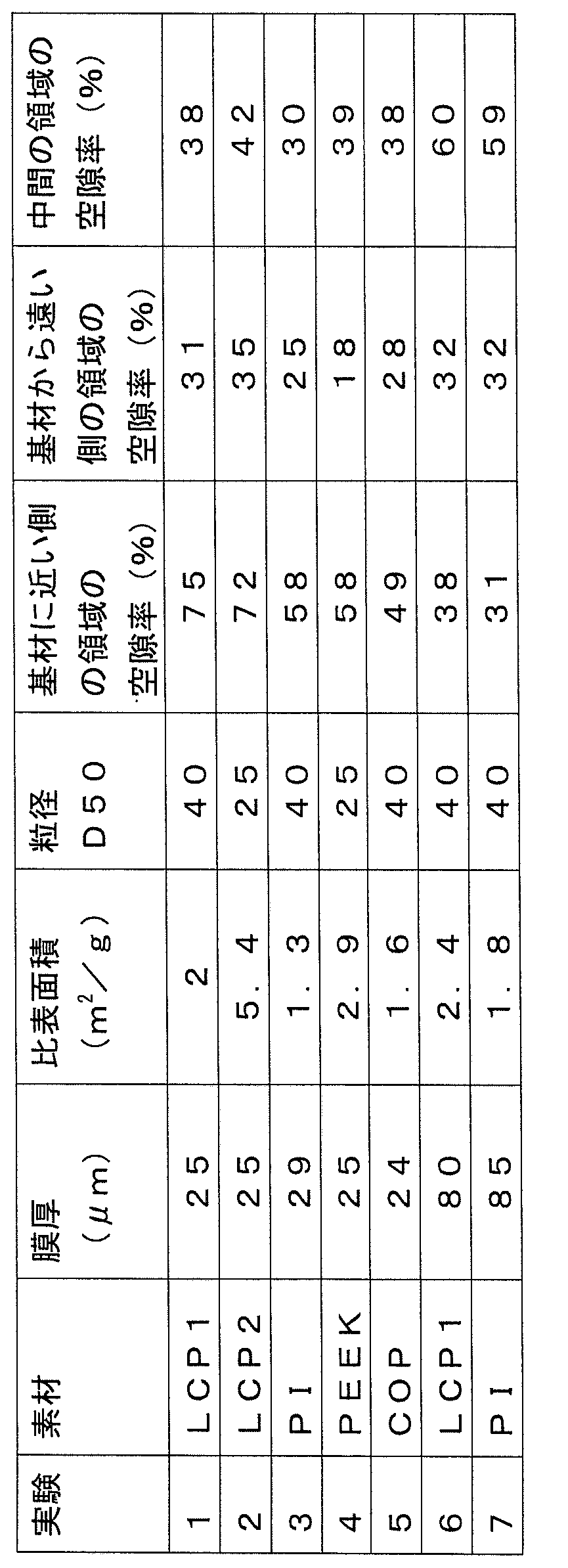
樹脂シートの製造方法において用いる基材1の材料は、特に限定されない。ただし、製造方法が、光が基材1を透過して塗布層に入射するようにフラッシュランプを照射する工程を含む場合には、基材1は透光性を有することが必要である。それ以外の場合には、基材1は透光性を有していない材料で形成されていてもよい。
The material of the
なお、上記実施の形態のうち複数を適宜組み合わせて採用してもよい。
なお、今回開示した上記実施の形態はすべての点で例示であって制限的なものではない。本発明の範囲は上記した説明ではなくて請求の範囲によって示され、請求の範囲と均等の意味および範囲内でのすべての変更を含むものである。
In addition, you may employ | adopt combining suitably two or more among the said embodiment.
In addition, the said embodiment disclosed this time is an illustration in all the points, Comprising: It is not restrictive. The scope of the present invention is defined by the terms of the claims, rather than the description above, and is intended to include any modifications within the scope and meaning equivalent to the terms of the claims.
1 基材、1u 主表面、2 樹脂層、3 粉体、3e フィブリル化物、4 フラッシュランプ、4a 光、7 導体パターン、10 (粉体の)塗布層、12 導体膜付き樹脂シート、13 レジストパターン、17 導体層、20 (粉体由来で上面が融着した)塗布層、20a,21a,40a,40ax 第1領域、20b,21b,40b,40bx 第2領域、21c,40cx 第3領域、21 (粉体由来で両面が融着した)塗布層、22 (粉体由来で下面が融着した)塗布層、30 (フィブリル化物の)塗布層、32 (フィブリル化物由来で下面が融着した)塗布層、40 (フィブリル化物由来で上面が融着した)塗布層、41 (フィブリル化物由来で両面が融着した)塗布層、51 第1熱可塑性樹脂層、52 第2熱可塑性樹脂層、81 第1面、82 第2面、85 積層体、101,102,103,104 樹脂シート、201 樹脂多層基板。
1 substrate, 1u main surface, 2 resin layer, 3 powder, 3e fibrillated product, 4 flash lamp, 4a light, 7 conductor pattern, 10 (powder) coating layer, 12 resin sheet with conductor film, 13 resist pattern , 17 conductor layer, 20 coating layer (derived from powder and fused on top), 20a, 21a, 40a, 40ax first region, 20b, 21b, 40b, 40bx second region, 21c, 40cx third region, 21 Coating layer (derived from powder and fused on both sides), 22 coating layer (derived from powder and fused on lower surface), coating layer (30 of fibrillated material), 32 (derived from fibrillated material and fused on lower surface) Coating layer, 40 (derived from fibrillated product and fused on top) 41, coated layer (derived from fibrillated and fused on both sides), 51 first
Claims (9)
熱可塑性樹脂の粉体またはフィブリル化物を前記主表面に塗布して塗布層を形成する工程と、
前記塗布層に向けて前記基材とは反対側からフラッシュランプを照射することによって前記塗布層のうち前記基材から遠い側の表面を含む一部を融着させる工程と、
前記塗布層を前記基材から分離して単独で取り出す工程とを含み、
前記融着させる工程では、前記塗布層を厚み方向に2等分して前記主表面から遠い側の領域を第1領域とし、前記主表面に近い側の領域を第2領域としたときに、前記第1領域の空隙率が0より大きく、前記第2領域の空隙率が前記第1領域の空隙率より大きくなり、なおかつ、前記塗布層が少なくとも一部に前記粉体または前記フィブリル化物の形態を残しつつ前記塗布層の全体として一体化する程度に融着させる、樹脂シートの製造方法。 Preparing a base material having a main surface;
Applying a thermoplastic resin powder or fibrillated product to the main surface to form a coating layer;
Fusing a part of the coating layer including a surface far from the substrate by irradiating a flash lamp from the opposite side of the substrate toward the coating layer;
Separating the coating layer from the substrate and taking it out alone,
In the step of fusing, when the coating layer is equally divided into two in the thickness direction, a region far from the main surface is a first region, and a region near the main surface is a second region, The porosity of the first region is greater than 0, the porosity of the second region is greater than the porosity of the first region, and the coating layer is at least partially in the form of the powder or the fibrillated product. The manufacturing method of the resin sheet | seat which is made to fuse | melt so that it may integrate as the whole of the said application layer, leaving behind.
前記製造方法は、
前記塗布層を基材から分離して単独で取り出す工程の前に、
光が前記基材を透過して前記塗布層に入射するようにフラッシュランプを照射することによって前記塗布層のうち前記基材に近い側の表面を含む一部を融着させる工程を含む、請求項5に記載の樹脂シートの製造方法。 The substrate has translucency,
The manufacturing method includes:
Before the step of separating the coating layer from the substrate and taking it out alone,
Irradiating a flash lamp so that light is transmitted through the substrate and incident on the coating layer, thereby fusing a part of the coating layer including a surface closer to the substrate. Item 6. A method for producing a resin sheet according to Item 5.
熱可塑性樹脂の粉体またはフィブリル化物を前記主表面に塗布して塗布層を形成する工程と、
光が前記基材を透過して前記塗布層に入射するようにフラッシュランプを照射することによって前記塗布層のうち前記基材に近い側の表面を含む一部を融着させる工程と、
前記塗布層を前記基材から分離して単独で取り出す工程とを含み、
前記融着させる工程では、前記塗布層を厚み方向に2等分して前記主表面から遠い側の領域を第1領域とし、前記主表面に近い側の領域を第2領域としたときに、前記第2領域の空隙率が0より大きく、前記第1領域の空隙率が前記第2領域の空隙率より大きくなり、なおかつ、前記塗布層が少なくとも一部に前記粉体または前記フィブリル化物の形態を残しつつ前記塗布層の全体として一体化する程度に融着させる、樹脂シートの製造方法。 Preparing a base material having a main surface;
Applying a thermoplastic resin powder or fibrillated product to the main surface to form a coating layer;
Irradiating a flash lamp so that light is transmitted through the substrate and incident on the coating layer, thereby fusing a part of the coating layer including a surface close to the substrate;
Separating the coating layer from the substrate and taking it out alone,
In the step of fusing, when the coating layer is equally divided into two in the thickness direction, a region far from the main surface is a first region, and a region near the main surface is a second region, The porosity of the second region is greater than 0, the porosity of the first region is greater than the porosity of the second region, and the coating layer is at least partially in the form of the powder or the fibrillated product. The manufacturing method of the resin sheet | seat which is made to fuse | melt so that it may integrate as the whole of the said application layer, leaving behind.
第2熱可塑性樹脂層を用意する工程と、
請求項1から4のいずれかに記載の樹脂シートを用意する工程と、
前記樹脂シートが前記導体パターンに当接し、かつ、前記樹脂シートが前記第1熱可塑性樹脂層と前記第2熱可塑性樹脂層とに挟まれるように、少なくとも前記第1熱可塑性樹脂層、前記第2熱可塑性樹脂層および前記樹脂シートを積み重ねて積層体を得る工程と、
前記積層体に熱および圧力を加えて前記積層体を一体化する工程とを含む、樹脂多層基板の製造方法。 Preparing a first thermoplastic resin layer having a conductor pattern disposed on the surface;
Preparing a second thermoplastic resin layer;
Preparing the resin sheet according to any one of claims 1 to 4,
At least the first thermoplastic resin layer, the first thermoplastic resin layer, and the second thermoplastic resin layer so that the resin sheet is in contact with the conductor pattern and the resin sheet is sandwiched between the first thermoplastic resin layer and the second thermoplastic resin layer. 2 stacking the thermoplastic resin layer and the resin sheet to obtain a laminate;
And a step of applying heat and pressure to the laminate to integrate the laminate.
Priority Applications (1)
| Application Number | Priority Date | Filing Date | Title |
|---|---|---|---|
| CN201690001324.XU CN209440968U (en) | 2015-12-24 | 2016-12-14 | Resin sheet |
Applications Claiming Priority (2)
| Application Number | Priority Date | Filing Date | Title |
|---|---|---|---|
| JP2015252397 | 2015-12-24 | ||
| JP2015-252397 | 2015-12-24 |
Publications (1)
| Publication Number | Publication Date |
|---|---|
| WO2017110618A1 true WO2017110618A1 (en) | 2017-06-29 |
Family
ID=59090200
Family Applications (1)
| Application Number | Title | Priority Date | Filing Date |
|---|---|---|---|
| PCT/JP2016/087226 Ceased WO2017110618A1 (en) | 2015-12-24 | 2016-12-14 | Resin sheet, method for manufacturing resin sheet, and method for manufacturing multilayer resin substrate |
Country Status (2)
| Country | Link |
|---|---|
| CN (1) | CN209440968U (en) |
| WO (1) | WO2017110618A1 (en) |
Cited By (1)
| Publication number | Priority date | Publication date | Assignee | Title |
|---|---|---|---|---|
| JPWO2022260094A1 (en) * | 2021-06-09 | 2022-12-15 |
Citations (14)
| Publication number | Priority date | Publication date | Assignee | Title |
|---|---|---|---|---|
| JPS5262658A (en) * | 1975-11-20 | 1977-05-24 | Asahi Chemical Ind | Printed circuit board blank and method of producing printed circuit board using same |
| JPS63132048A (en) * | 1986-08-29 | 1988-06-04 | モ−ビル・オイル・コ−ポレ−ション | Improved opaque film composition |
| JP2003015286A (en) * | 2001-06-28 | 2003-01-15 | Tdk Corp | Substrate where functional layer pattern is formed and method for forming functional layer pattern |
| JP2005040992A (en) * | 2003-07-23 | 2005-02-17 | Sumitomo Chemical Co Ltd | Thermoplastic foam |
| JP2010146757A (en) * | 2008-12-16 | 2010-07-01 | Hitachi Maxell Ltd | Manufacturing method of transparent conductive sheet |
| JP2012086477A (en) * | 2010-10-20 | 2012-05-10 | Hitachi Chemical Co Ltd | Thin-film transfer material, method for manufacturing the same, molding with thin film, and method for manufacturing the same |
| JP2012126045A (en) * | 2010-12-16 | 2012-07-05 | Sekisui Chem Co Ltd | Resin molding and method of manufacturing the same |
| JP2013223962A (en) * | 2012-04-20 | 2013-10-31 | Du Pont Teijin Advanced Paper Kk | Aramid-resin film laminate and method for manufacturing same |
| JP2014079920A (en) * | 2012-10-15 | 2014-05-08 | Asahi Glass Co Ltd | Article and production method of the same |
| JP2014087999A (en) * | 2012-10-31 | 2014-05-15 | Yamauchi Corp | Cushoning material for hot press |
| JP2015116772A (en) * | 2013-12-19 | 2015-06-25 | コニカミノルタ株式会社 | Method of producing water-repellent film, and water-repellent film |
| JP2015528753A (en) * | 2012-06-05 | 2015-10-01 | 昭和電工株式会社 | Base film and heating and baking method |
| WO2016190146A1 (en) * | 2015-05-27 | 2016-12-01 | 東レ株式会社 | Film for solar-cell back sheet, solar-cell back sheet including same, and solar cell |
| JP2017015205A (en) * | 2015-07-03 | 2017-01-19 | パナソニックIpマネジメント株式会社 | Heat insulation material, manufacturing method therefor, and electronic equipment using heat insulation material |
-
2016
- 2016-12-14 WO PCT/JP2016/087226 patent/WO2017110618A1/en not_active Ceased
- 2016-12-14 CN CN201690001324.XU patent/CN209440968U/en active Active
Patent Citations (14)
| Publication number | Priority date | Publication date | Assignee | Title |
|---|---|---|---|---|
| JPS5262658A (en) * | 1975-11-20 | 1977-05-24 | Asahi Chemical Ind | Printed circuit board blank and method of producing printed circuit board using same |
| JPS63132048A (en) * | 1986-08-29 | 1988-06-04 | モ−ビル・オイル・コ−ポレ−ション | Improved opaque film composition |
| JP2003015286A (en) * | 2001-06-28 | 2003-01-15 | Tdk Corp | Substrate where functional layer pattern is formed and method for forming functional layer pattern |
| JP2005040992A (en) * | 2003-07-23 | 2005-02-17 | Sumitomo Chemical Co Ltd | Thermoplastic foam |
| JP2010146757A (en) * | 2008-12-16 | 2010-07-01 | Hitachi Maxell Ltd | Manufacturing method of transparent conductive sheet |
| JP2012086477A (en) * | 2010-10-20 | 2012-05-10 | Hitachi Chemical Co Ltd | Thin-film transfer material, method for manufacturing the same, molding with thin film, and method for manufacturing the same |
| JP2012126045A (en) * | 2010-12-16 | 2012-07-05 | Sekisui Chem Co Ltd | Resin molding and method of manufacturing the same |
| JP2013223962A (en) * | 2012-04-20 | 2013-10-31 | Du Pont Teijin Advanced Paper Kk | Aramid-resin film laminate and method for manufacturing same |
| JP2015528753A (en) * | 2012-06-05 | 2015-10-01 | 昭和電工株式会社 | Base film and heating and baking method |
| JP2014079920A (en) * | 2012-10-15 | 2014-05-08 | Asahi Glass Co Ltd | Article and production method of the same |
| JP2014087999A (en) * | 2012-10-31 | 2014-05-15 | Yamauchi Corp | Cushoning material for hot press |
| JP2015116772A (en) * | 2013-12-19 | 2015-06-25 | コニカミノルタ株式会社 | Method of producing water-repellent film, and water-repellent film |
| WO2016190146A1 (en) * | 2015-05-27 | 2016-12-01 | 東レ株式会社 | Film for solar-cell back sheet, solar-cell back sheet including same, and solar cell |
| JP2017015205A (en) * | 2015-07-03 | 2017-01-19 | パナソニックIpマネジメント株式会社 | Heat insulation material, manufacturing method therefor, and electronic equipment using heat insulation material |
Cited By (5)
| Publication number | Priority date | Publication date | Assignee | Title |
|---|---|---|---|---|
| JPWO2022260094A1 (en) * | 2021-06-09 | 2022-12-15 | ||
| WO2022260094A1 (en) * | 2021-06-09 | 2022-12-15 | 株式会社村田製作所 | Conductor-layer-coated resin film, layered substrate, and method for producing conductor-layer-coated resin film |
| US12330392B2 (en) | 2021-06-09 | 2025-06-17 | Murata Manufacturing Co., Ltd. | Liquid crystal polymer film, liquid crystal polymer film with conductor layer, and multilayer substrate |
| JP7722451B2 (en) | 2021-06-09 | 2025-08-13 | 株式会社村田製作所 | Resin film with conductor layer, laminated substrate, and method for manufacturing resin film with conductor layer |
| US12507340B2 (en) | 2021-06-09 | 2025-12-23 | Murata Manufacturing Co., Ltd. | Resin film with conductor layer, multilayer substrate, and method for producing resin film with conductor layer |
Also Published As
| Publication number | Publication date |
|---|---|
| CN209440968U (en) | 2019-09-27 |
Similar Documents
| Publication | Publication Date | Title |
|---|---|---|
| JP7200197B2 (en) | Insulating resin material, insulating resin material with metal layer and wiring substrate using the same | |
| US8895139B2 (en) | Isotropic nano crystallites of polytetrafluoroethylene (PTFE) resin and products thereof that are biaxially planar oriented and form stable | |
| WO2013118598A1 (en) | Piezoelectric element including fluororesin film | |
| KR100875807B1 (en) | Separator and battery for placement inside battery | |
| WO2010007917A1 (en) | Heat resistant cushion material for molding press | |
| CN110892551B (en) | Separator for electrochemical element | |
| CN104968713A (en) | Processed liquid crystal polymer powder, paste including same, and liquid crystal polymer sheet using said powder and paste, laminated body, and method for producing processed liquid crystal polymer powder | |
| JP6365760B2 (en) | COMPOSITE SHEET, ITS MANUFACTURING METHOD, RESIN MULTILAYER SUBSTRATE AND ITS MANUFACTURING METHOD | |
| CA2857064A1 (en) | Structural core | |
| DE112020005956T5 (en) | EXTENDED POROUS POLYTETRAFLUORETHYLENE MEMBRANE, AIR PERMEABLE MEDIUM USING SAME AND FILTER ELEMENT USING SAME | |
| DE112020005959T5 (en) | EXTENDED POROUS POLYTETRAFLUORETHYLENE MEMBRANE, AIR PERMEABLE MEDIUM USING SAME AND FILTER ELEMENT USING SAME | |
| CN108781517B (en) | Multilayer laminated board and method for manufacturing multilayer printed wiring board using same | |
| WO2017110618A1 (en) | Resin sheet, method for manufacturing resin sheet, and method for manufacturing multilayer resin substrate | |
| KR101685289B1 (en) | Multilayer wiring board and manufacturing method for the multilayer wiring board | |
| US20180186138A1 (en) | Method of manufacturing treated sheet and method of manufacturing resin multilayer substrate | |
| KR102375660B1 (en) | Insulating resin material, insulating resin material with metal layer using same, and wiring board | |
| JP3954570B2 (en) | Dielectric-forming sheet material for plasma display panels | |
| CN110816020B (en) | Composite material screen printing plate and manufacturing method thereof | |
| CN105751659A (en) | Method Of Fabricating Composite Laminate And Article Used For Fabricating Composite Laminate | |
| US20180056220A1 (en) | Tailored multilayered nano-fibrous filtration media and method of making | |
| WO2023007847A1 (en) | Method for manufacturing fiber mat and fiber mat | |
| WO2021020147A1 (en) | Press-adrhered body and production method therefor | |
| WO2013131716A1 (en) | Perforated polymer films having improved tolerance to tensile stress | |
| DE112024001645T5 (en) | Three-layer polymer adhesive film, method for joining structured substrates, multilayer conductor and method for forming a multilayer conductor | |
| KR20250130605A (en) | Description and its manufacturing method, and wiring board using the same |
Legal Events
| Date | Code | Title | Description |
|---|---|---|---|
| 121 | Ep: the epo has been informed by wipo that ep was designated in this application |
Ref document number: 16878509 Country of ref document: EP Kind code of ref document: A1 |
|
| NENP | Non-entry into the national phase |
Ref country code: DE |
|
| 122 | Ep: pct application non-entry in european phase |
Ref document number: 16878509 Country of ref document: EP Kind code of ref document: A1 |
|
| NENP | Non-entry into the national phase |
Ref country code: JP |