WO2017077261A1 - A monocular camera cognitive imaging system for a vehicle - Google Patents
A monocular camera cognitive imaging system for a vehicle Download PDFInfo
- Publication number
- WO2017077261A1 WO2017077261A1 PCT/GB2015/053359 GB2015053359W WO2017077261A1 WO 2017077261 A1 WO2017077261 A1 WO 2017077261A1 GB 2015053359 W GB2015053359 W GB 2015053359W WO 2017077261 A1 WO2017077261 A1 WO 2017077261A1
- Authority
- WO
- WIPO (PCT)
- Prior art keywords
- frame
- environment
- sub
- vehicle
- hazard
- Prior art date
- Legal status (The legal status is an assumption and is not a legal conclusion. Google has not performed a legal analysis and makes no representation as to the accuracy of the status listed.)
- Ceased
Links
Classifications
-
- G—PHYSICS
- G06—COMPUTING OR CALCULATING; COUNTING
- G06V—IMAGE OR VIDEO RECOGNITION OR UNDERSTANDING
- G06V20/00—Scenes; Scene-specific elements
- G06V20/50—Context or environment of the image
- G06V20/56—Context or environment of the image exterior to a vehicle by using sensors mounted on the vehicle
- G06V20/58—Recognition of moving objects or obstacles, e.g. vehicles or pedestrians; Recognition of traffic objects, e.g. traffic signs, traffic lights or roads
Definitions
- the present invention concerns a system for cognitive imaging in a vehicle using a monocular camera to capture image data.
- the field of cognitive imaging generally requires one or a sequence of image frames to be captured and analysed to deduce useful information from the image. For example in the field of vehicle control, an image of a forward field of view may be captured and analysed to determine if a hazard appears ahead of the vehicle. The resulting information may be used to steer the vehicle.
- Such systems are commonly stereoscopic in order to exploit parallax for ranging and sizing. Such systems are therefore complex and expensive.
- CN101303732A discloses an imaging system using a vehicle mounted on-board
- the system of CN101303732A provides a warning alarm if another hazard target vehicle is detected ahead of the camera vehicle.
- the hazard target vehicle is detected using feature point extraction and feature point matching.
- the system of CN101303732A is therefore unable to identify and detect stationary target hazards.
- EP0671706A2 presents an image processing method and system, which makes use of background reconstruction, partial region updating and background differentiation. It realizes the moving target detection by gradually extracting the moving objects from multiple continuous image. As the vehicle mounted camera keeps moving each of the background and the target hazard keep changing, simultaneously in each frame captured. Therefore, the system of EP0671706A2 cannot extract a moving object accurately in the dynamic changing background.
- CN102542571 A presents a moving objects detection method and equipment. It uses continuous multi-frame imaging and dissembles the video into several video segment.
- the background feature matrix of each video chunk is constructed based on the corresponding structure and texture feature. Based on an obtained matrix, the feature vector of each video chunk to be detected will be represented linearly.
- the detector makes a decision whether a moving target is present. This decision is made based on residual and sparseness of a minimum residual solution.
- the system is poor at training itself to identify particular hazard targets, especially where there are multiple targets within the field of view.
- the system cannot be applied efficiently where the camera is moving as well as the target hazard because of the poor correlation between the background of sequential frames. This prior art system cannot recognize different types of object.
- CN102915545A must obtain multi-parameters during the hazard target tracking
- CN102915545A uses a Kalman filter for dynamic position estimation and detection template updating. This is poor for tracking target hazards moving non-linearly.
- US2013243322A1 discloses a system which requires the camera to be fixed in a
- JP201 1 154634A1 is unable to detect a target hazard from other than the grey
- a cognitive imaging system for a vehicle comprising:
- a monocular camera arranged to focus an image of a field of view onto an image sensor, said image sensor processing the image into image data
- a processor device responsive to machine readable code stored in a memory to be capable of driving the camera to capture a sequence of images to implement an image processing method in order to process the image data and identify a hazard in the field of view;
- the processor is responsive to capture a time sequence of images from the camera, the processor is responsive to scan pixel image data of a first captured image in a sequence and applies a series of filters to identify a sub frame in which a vehicular hazard may exist and to distinguish the background environment from the foreground vehicle hazard;
- the processor is responsive to calculate a fast environment classification criterion for the each sub frame in the current frame
- the processor is responsive to add each fast environment classification to a fast environment identification queue of a predetermined length to form an environment analysing vector
- the processor responding to analyse the pixel image data of a subsequent captured image to add fast environment classification data to the fast environment identification queue;
- a slow environment result is updated according to the fast environment analysing vector calculated from the preceding sequence of captured frames.
- fast environment addresses the problem of a fast changing environment when the environment (background) changes fast.
- the slow environment loop seeks to reduce processing required to track a target first identified in the fast environment loop by identifying and exploiting a situation where the environment, and therefore the background is changing slowly.
- the "slow environment loop" is a faster process and is liable to reduce the burden on hardware assets.
- figure 1 is an isometric view of a user vehicle travelling on a road approaching a tunnel following a target vehicle
- figure 2 is a diagram of the field of view of a system camera from a system equipped user vehicle
- figure 3 is a diagram of the bottom shadow of each target vehicle in figure 2;
- figure 4a is a side elevation of the scene in figure 1 ;
- figure 4b is a plan of the scene in figure 1 ;
- figure 5 is a side elevation of the user vehicle illustrating aspects of the system installation
- figure 6 is a high level chart of the system operation:
- Figure 1 illustrates a user vehicle 1 equipped with the system traveling on a road
- a target vehicle T1 is leading the user vehicle 1 into the tunnel, while a second target vehicle T2 is exiting the tunnel towards the user vehicle 1 .
- the target vehicles T1 and T2 form the foreground against a background environment which is moving relative to the user vehicle 1 .
- the user or camera vehicle is fitted with a system camera 2 mounted to have a field of view (FOV) in the forward direction.
- the camera is mounted to have a lens axis at a height h-camera above the ground.
- To calibrate the system it is necessary to load the system with the height of the vehicle h-car.
- the system may be interfaced with the user vehicle management systems in order to read the vehicle speed, indicator condition and steering angle.
- the camera is installed in a host vehicle preferably behind the windscreen as shown in figure 5, where it will not obscure the drivers view and has a field of view looking horizontally forwards through the windscreen.
- the camera forms part of a cognitive imaging system (CIS) shown diagrammatically in figure 8 including memory and a processor running machine readable code to implement an image recognition process and to intelligently output alerts to the vehicle driver via a vehicle management system (VMS) of the vehicle. Alerts may be via visual and or audible means.
- the output means may be integral with the CIS or may interface to output via a VDU or loudspeaker integral with the vehicle.
- the CIS will preferably have an interface for communication with the output of the
- Vehicle management sensors may be hardwired or wireless and may be via ports in the vehicle management system or direct to the sensors.
- Vehicle sensor data captured by the CIS will preferably include: vehicle speed, accelerometer data, steering angle, accelerator angle, brake sensor and indicator actuation.
- the interface may also be installed to be capable of driving the vehicle management system to actuate the vehicle brake or other systems.
- step 0.1 initialises a frame counter to a fixed initial value such as 1 .
- S-1 the first process step, S-1 , is to capture a first real time image frame (FR1 ) and subject it to the fast environment process loop (FEPL).
- FEPL fast environment process loop
- the frame may be subject to image pre-processing steps such as
- ROI region of interest
- An ROI is any portion of FR1 which contains image data suspected of indicating a potential hazard.
- An example of a potential hazard is a vehicle moving relative to the host vehicle, and not part of the background which could adopt a vector resulting in a collision.
- ROI are identified by thresholding and boundary detection techniques.
- ROI are identified in the captured image by inspecting the pixels along a search path which starts at the middle of the bottom of the frame and proceeds towards the top; and progresses from the middle to each of the two sides, either sequentially or simultaneously.
- search path which starts at the middle of the bottom of the frame and proceeds towards the top; and progresses from the middle to each of the two sides, either sequentially or simultaneously.
- the target vehicle height up_car is determined according to the position where the vehicle bottom appears in the row of the search point in the image.
- mrow is the frame row in which the stationary point for the ROI lies
- irow is the row in which the point at infinity lies
- h camera is the vertical height from the ground to the camera in the host vehicle
- h ear is the a priori height of the target vehicle.
- step S-2.1 the system determines if the count of ROI exceeds zero, in other words if ROIn is the number of regions of interest is ROIn>0. If so it goes to step S3 and if not to step S1 where the next real time image is captured.
- Each ROI is uniquely identifiable in a frame by a "stationary point".
- the stationary point is a coordinate, common to any frame, that is to say that in a sequence of frames the stationary point will not move from one frame to another.
- the stationary point is established in the middle of the bottom row of each ROI from which the examination of the ROI ordinarily commences.
- the apparent depth or height of the bottom shadow is an indication of the distance of the target from the host vehicle.
- the depth of the bottom shadow is compared to a threshold value, if the threshold value is exceeded at step 3.2 the target is close enough to the host vehicle to be a hazard.
- the above mean grey level is obtained by calculating the weighted average of a grey value of the corresponding region. The weight is based on the distance of the potential hazard object from the camera.
- Detection of a hazard target is determined at step 3.1 if:
- step 3.3 If the threshold is not exceeded the process goes to step 3.3 where the ROI is tagged as examined and if there are any remaining ROI unexamined the step 3.4 returns the process to step 3 and if there are no remaining unexamined ROI the process steps to S1 to capture a new frame.
- AEDD comprises the steps of determining the vertical edge accumulative decision area of the left side as follows:
- the system seeks edges in each are using a Sobel operator and conducts 2- dimensional convolution, to obtain the left and right vertical edge image
- Sobel_2 by utilizing binarization dynamic threshold and accumulate downward.
- the units of accumulated values could be obtained after accumulating left and right vertical edges sub-frame.
- the search point goes to next stationary point along the search path, updates the interesting sub-frame and goes into the next dynamic bottom shadow decision state, goes back to step S3.
- the ROI fails step 4.1 and goes to step 3.3.
- SVM dynamic support vector machine
- the captured and pre-processed sub- frames are regularized to the same size and normalized, preferably to 64 * 64 pixels.
- a gradient histogram is established for the ROI.
- the system adopts block units with size of 8 * 8 pixels, cell unit with size of 4 * 4 , smooth step size of 8 and a histogram bin number of 9.
- the normalized 64 * 64 ROI with a potential vehicle object is transformed to 1 * 1764 feature vector with feature vector dimension of 1764 and each of dimension value represents statistics accumulated value along the certain direction of gradient in the specific sub area.
- the ROI is regularized and normalised the ROI is compared with a database of templates of potential target road vehicles, such as cars, vans, lorries, coaches etc.
- the templates are sampled not only for a range of vehicles but each vehicle before a range of backgrounds and conditions such as weather and/or daylight and/or night. Comparison may be via adding the ROI to the negative template and examining the output result. If the result is zero or near zero the target vehicle in the ROI is deemed a match with the template.
- the output from the SVM is one of three SVM classifiers.
- the steps to generate classifiers are to obtain the histogram of orientated gradients (HOG) feature vector matrix of the block unit and cell unit gradient histogram after regularizing. Construct an augmented feature matrix based on the feature vector matrix by utilizing the feature vector matrix and combining the class samples and then find a hyper classification plane that can distinguish positive templates and negative templates through SVM.
- HOG histogram of orientated gradients
- Identifying process Based on the three SVM classifiers corresponding to different scenarios choose the corresponding SVM according to the slow environment identifying result and match it with the current identified slow environment.
- the SVM classifies the interesting sub-frame into a
- step 3 there is no hazard target vehicle present in the ROI and the process goes to step 3 to examine a new unexamined ROI or step 1 to capture a new frame where step 3.4 finds no unexamined ROI.
- the step of tagging may be achieved in any suitable way, for example by setting a flag against the stationary point of the ROI.
- the process goes to step 5.2 and records the stationary point to track the target vehicle in subsequent cycles.
- the stationary point of the ROI is associated with a recording of the background of the of the ROI.
- the system may advantageously record only the ROI background
- the system obtains grey level information of every pixel of the backgrounds in sub regions to the left and right of the vehicle and within the ROI where the left region may be defined by:
- the system extracts the maximum and minimum values of row mean vectors which correspond to the left and right background sub-frame of the ROI respectively. Based on the maximum and minimum values, the system constructs a feature matrix
- the fast environment classification criterion for the current single frame is as follows.
- the system updates the parameters as following at step 6.2, as single frame dynamic decision system parameter update based on the fast environment detection results.
- step 7 the system selects one of the recorded stationary points identifying an ROI which has passed each of steps 3 to 5. It is now desirable to determine if the background exhibits a high level of complexity or a low level of complexity (the background is simple). To determine the complexity of the background each ROI is scanned backwards at step 7.1 as compared to step 3, thus the search pattern is from top to bottom and from the edges towards the centre. However, at step 7.2 the bottom shadow is determined from the backscan results and again compared to the bottom shadow threshold mentioned at step 3 above.
- Step 7.3 indicates that there are some (one or more) approximate false-alarm stationary points and the background environment is therefore determined to be complex at step 7.4 so that the process can advance directly to step 7.7.
- step 7.4 If the decision at step 7.4 is that the environment is simple 7.5, the process advances to step 7.6. In this case, if the result of the fast environment decision is "1", it requires rectification for the current fast environment identification result into "2". The system will re-identify the fast environment around the target and rectify the fast environment error at step 7.6. The dynamic decision parameter of the next frame will be based on the rectified fast environment decision.
- a fast environment identification que is formed with a length of 100. This is the fast environment identification queue for the purpose of slow environment identification (SEI).
- SEI slow environment identification
- the SEI is outer loop of the faster environment loop. Every output of the environment identification result will be pushed into the queue. If the current queue stores 100 statistic results, then the first statistic I that is pushed in the queue will be squeezed out of the queue and keeps the "first in, first out” rule.
- the push strategies are:
- S3 dynamic bottom shadow decision
- S4 dynamic edge accumulative decision
- S5 dynamic support vector machine (SVM) decision
- the fast environment decision of current sub-frame is "2" or "3” or "4"
- the fast environment decision result of current sub-frame will be pushed into the queue. If there is an interest sub-frame that passes the S3, S4 and S5, the rectified fast environment decision results "0” "1” "2” "3” "4" will be pushed into the queue sequentially.
- step 7.8 the system then utilizes the 100 statistic fast environment decision result to update the slow environment result according to the following strategies:
- the slow environment will be set to 2 (the normal condition).
- step 8.0 the fast environment identification according to the slow environment result is set at a certain interval.
- the fast environment identification will be set to "3, nightfall”.
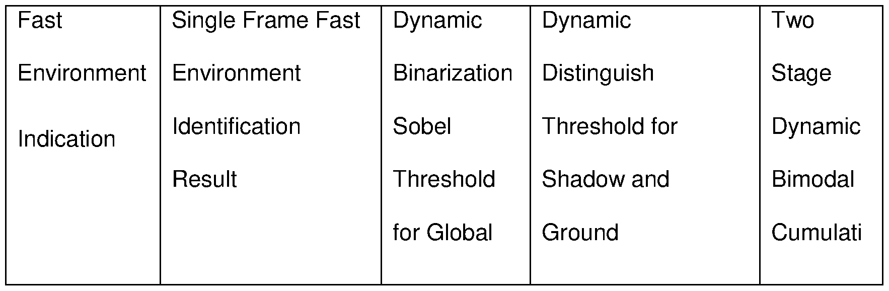
- the fast environment related parameters including "Dynamic Binarization Sobel Threshold for Global Gradient Image”, “Dynamic Distinguish Threshold for Shadow and Ground” and "Two Stage Dynamic Bimodal vertical direction Cumulative Threshold” will change according to the reset of fast environment, from 1 to 3, for the next frame.
- the fast environment identification result is "2" or "3"
- the fast environment identification will be forced to "4, dusk”.
- the fast environment related parameters including "Dynamic Binarization Sobel Threshold for Global Gradient Image”, “Dynamic Distinguish Threshold for Shadow and Ground” and “Two Stage Dynamic Bimodal vertical direction Cumulative Threshold” will change according to the reset of fast environment for the next frame.
- sub-frames (ROI) pass S3, S4 and S5 in several consecutive frames, it can be concluded that a vehicle object exists in the sub-frame (ROI) of the corresponding stationary point.
- Each sub-frames of interest will be marked as a sub-frame of object tracking. The detailed process is described below:
- the environment identification result is complex. If there still is an interested sub-frame in the current and previous four frames that can pass the 3 stage dynamic decision under the condition that the stationary point of these 5 interested frames is close to each other, then it can be regarded that there exists a object and the object is marked as the final object detection result.
- the object feature is weakened. Therefore, if there still exists an interested sub-frame in the current and previous three image frames that can pass the three stage dynamic decision under the condition that the stationary point of these interested sub-frames is close to each other, it can be regarded that an object exists and the object is marked as the final object detection result. [097] Referring again to step 5.3, where each ROI has been scanned so that there are no
- step 5.3.1 a frame counter is incremented from N to N+1 .
- step 5.3.2 the frame count is compared to a predetermined frame count number "X".
- X may be five but might be set to a higher or lower value. This ensures that a sequence of five captured frames must be inspected with the corresponding ROI exhibiting the presence of a potential hazard target before target tracking is confirmed.
- step 5.3.3 the frame count is reset to 1 . From step 5.3.3 the system advances to step 9.1 where the target data is output for subsequent processing.
- step 9.1 the method advances to step 1 where a new frame is captured for examination.
- step 1 If the frame count number is not exceeded at step 5.3.2 the method advances directly to step 1 to capture a new frame for examination.
- the cognitive imaging system having confirmed the presence of a foreground object which may prove to be a hazard is able to track the hazard with a high degree of confidence against even fast changing background environments. The tracking of any hazard target is achieved across several sequentially captured frames, which facilitates the step of calculating a vector for the target and hence a plot of the position of the target vehicle against time which can be compared to the current vector of the host vehicle.
- Integral warning system may, for example, include a screen, warning lights or an acoustic warning from a loudspeaker. Alternatively the warning may be transferred over the interface to drive the warning indicators of the vehicle.
- a feature of the system is an ability to correlate the lateral movement of the vehicle with the operation of the vehicle indicators in order to warn the driver of changing lane without indicating or otherwise driving erratically.
Landscapes
- Engineering & Computer Science (AREA)
- Physics & Mathematics (AREA)
- General Physics & Mathematics (AREA)
- Multimedia (AREA)
- Theoretical Computer Science (AREA)
- Traffic Control Systems (AREA)
- Image Analysis (AREA)
Abstract
A cognitive imaging system and a method of cognitive imaging are disclosed including a step of classifying the complexity of a background environment in a segment, sub-frame or region of interest (ROI) of a frame captured by a monocular camera. The monocular camera being installed in a vehicle (vessel or craft) in order to have a field of view in the normal direction of motion of the vehicle. The classification is added to a queue of predetermined length and updated by adding a new classification every time a sub-frame is scanned in a subsequent new captured frame during target hazard tracking. The sequence of classifications form an environment analysing vector. The environment analysing vector is used to determine if the environment background for the sub-frame can be reused in a subsequent background subtraction to track the target in a subsequently captured frame. The resulting tracking data can be used to determine if a hazardous situation is imminent and to alert the vehicle driver or to control the vehicle to avoid the hazard.
Description
A MONOCULAR CAMERA COGNITIVE IMAGING SYSTEM FOR A VEHICLE
Technical field
[001] The present invention concerns a system for cognitive imaging in a vehicle using a monocular camera to capture image data.
Prior Art
[002] The field of cognitive imaging generally requires one or a sequence of image frames to be captured and analysed to deduce useful information from the image. For example in the field of vehicle control, an image of a forward field of view may be captured and analysed to determine if a hazard appears ahead of the vehicle. The resulting information may be used to steer the vehicle. Such systems are commonly stereoscopic in order to exploit parallax for ranging and sizing. Such systems are therefore complex and expensive.
[003] Systems using a monocular camera to capture an image are relatively less complex and expensive and occupy less space within the vehicle. However, reliably distinguishing a foreground hazard from a background has presented significant problems to monocular cognitive imaging systems. Such systems generally use a variety of techniques to identify a foreground hazard such as another road vehicle, of which image subtraction is one. Where an environment or background is relatively unchanging it is possible to implement image subtraction as between two sequential image frames. In this case the relatively unchanging background image will be subtracted substantially completely leaving an image relating to a moving foreground hazard or target. For this process to be applied to a moving hazard it is necessary to analyse the complexity of the environment in two or more captured frames in order to
determine if it can be subtracted with any confidence that the target will be all that is left. This problem is further complicated where the imaging device is actually moving in relation to each of a moving hazard target and a stationary background.
[004] CN101303732A discloses an imaging system using a vehicle mounted on-board
monocular camera to assist the vehicle driver. The system of CN101303732A provides a warning alarm if another hazard target vehicle is detected ahead of the camera vehicle. The hazard target vehicle is detected using feature point extraction and feature point matching. The system of CN101303732A is therefore unable to identify and detect stationary target hazards.
[005] EP0671706A2 presents an image processing method and system, which makes use of background reconstruction, partial region updating and background differentiation. It realizes the moving target detection by gradually extracting the moving objects from multiple continuous image. As the vehicle mounted camera keeps moving each of the background and the target hazard keep changing, simultaneously in each frame captured. Therefore, the system of EP0671706A2 cannot extract a moving object accurately in the dynamic changing background.
[006] CN102542571 A] presents a moving objects detection method and equipment. It uses continuous multi-frame imaging and dissembles the video into several video segment. The background feature matrix of each video chunk is constructed based on the corresponding structure and texture feature. Based on an obtained matrix, the feature vector of each video chunk to be detected will be represented linearly. The detector makes a decision whether a moving target is present. This decision is made based on residual and sparseness of a minimum residual solution. However, the system is poor at training itself to identify particular hazard targets, especially where there are multiple
targets within the field of view. The system cannot be applied efficiently where the camera is moving as well as the target hazard because of the poor correlation between the background of sequential frames. This prior art system cannot recognize different types of object.
[007] CN102915545A must obtain multi-parameters during the hazard target tracking
process determined by a dynamically updating template. CN102915545A uses a Kalman filter for dynamic position estimation and detection template updating. This is poor for tracking target hazards moving non-linearly.
[008] US2013243322A1 discloses a system which requires the camera to be fixed in a
confined space with a predetermined attitude to facilitate background modelling using a Gaussian model. It is ill suited to an application where both the camera and target are commonly moving relative to a static background.
[009] JP201 1 154634A1 is unable to detect a target hazard from other than the grey
information captured from sequential frames and cannot classify and recognise targets.
Statement of Invention
[010] Accordingly there is provided a cognitive imaging system for a vehicle comprising:
a monocular camera arranged to focus an image of a field of view onto an image sensor, said image sensor processing the image into image data, and
a processor device responsive to machine readable code stored in a memory to be capable of driving the camera to capture a sequence of images to implement an image processing method in order to process the image data and identify a hazard in the field of view; wherein:
the processor is responsive to capture a time sequence of images from the camera,
the processor is responsive to scan pixel image data of a first captured image in a sequence and applies a series of filters to identify a sub frame in which a vehicular hazard may exist and to distinguish the background environment from the foreground vehicle hazard;
the processor is responsive to calculate a fast environment classification criterion for the each sub frame in the current frame;
the processor is responsive to add each fast environment classification to a fast environment identification queue of a predetermined length to form an environment analysing vector;
the processor responding to analyse the pixel image data of a subsequent captured image to add fast environment classification data to the fast environment identification queue; whereby
a slow environment result is updated according to the fast environment analysing vector calculated from the preceding sequence of captured frames.
[011] The process of target recognition and tracking is divided into two loops referred to as fast environment and slow environment. Fast environment addresses the problem of a fast changing environment when the environment (background) changes fast.
[012] The slow environment loop seeks to reduce processing required to track a target first identified in the fast environment loop by identifying and exploiting a situation where the environment, and therefore the background is changing slowly. In general the "slow environment loop" is a faster process and is liable to reduce the burden on hardware assets.
Brief Description of Drawings
[013] An embodiment of a cognitive imaging system according to the present invention will now be described, by way of example only, with reference to the accompanying illustrative figures, in which:
figure 1 is an isometric view of a user vehicle travelling on a road approaching a tunnel following a target vehicle,
figure 2 is a diagram of the field of view of a system camera from a system equipped user vehicle,
figure 3 is a diagram of the bottom shadow of each target vehicle in figure 2; figure 4a is a side elevation of the scene in figure 1 ;
figure 4b is a plan of the scene in figure 1 ;
figure 5 is a side elevation of the user vehicle illustrating aspects of the system installation;
figure 6 is a high level chart of the system operation:
figures 7 A & 7B combine to form a detailed flowchart of the system operation. Detailed Description
[014] Figure 1 illustrates a user vehicle 1 equipped with the system traveling on a road
approaching a tunnel. As shown in figures 1 , 4a and 4b a target vehicle T1 is leading the user vehicle 1 into the tunnel, while a second target vehicle T2 is exiting the tunnel towards the user vehicle 1 . The target vehicles T1 and T2 form the foreground against a background environment which is moving relative to the user vehicle 1 . As shown in figure 5, the user or camera vehicle is fitted with a system camera 2 mounted to have a field of view (FOV) in the forward direction. The camera is mounted to have a lens axis at a height h-camera above the ground. To calibrate the system it is necessary to load the system with the height of the vehicle h-car.
[015] The system may be interfaced with the user vehicle management systems in order to read the vehicle speed, indicator condition and steering angle.
[016] Referring to figure 7, at step S-0 the camera is installed in a host vehicle preferably behind the windscreen as shown in figure 5, where it will not obscure the drivers view and has a field of view looking horizontally forwards through the windscreen. The camera forms part of a cognitive imaging system (CIS) shown diagrammatically in figure 8 including memory and a processor running machine readable code to implement an image recognition process and to intelligently output alerts to the vehicle driver via a vehicle management system (VMS) of the vehicle. Alerts may be via visual and or audible means. The output means may be integral with the CIS or may interface to output via a VDU or loudspeaker integral with the vehicle.
[017] The CIS will preferably have an interface for communication with the output of the
vehicle management sensors. The interface may be hardwired or wireless and may be via ports in the vehicle management system or direct to the sensors. Vehicle sensor data captured by the CIS will preferably include: vehicle speed, accelerometer data, steering angle, accelerator angle, brake sensor and indicator actuation. The interface may also be installed to be capable of driving the vehicle management system to actuate the vehicle brake or other systems.
[018] When the CIS is first actuated it may go through a calibration procedure to install
according to the particular height above ground, and other factors which are
characteristic of the particular vehicle installation in order to determine the values of h ear and h camera shown in figure 5.
[019] As part of the initiation process, whenever the CIA system starts up step 0.1 initialises a frame counter to a fixed initial value such as 1 .
[020] In normal operation the first process step, S-1 , is to capture a first real time image frame (FR1 ) and subject it to the fast environment process loop (FEPL). The FEPL is so named because the environment or background is either completely new due to the start-up condition or changing fast and is therefore unknown for the initial frame FR1 .
[021] After capture the frame may be subject to image pre-processing steps such as
re-sampling, noise reduction contrast enhancement or scale space representation.
[022] In the first pass of the fast environment process loop FR1 is scanned at S-2 to identify any region of interest (ROI). An ROI (sometimes known as a sub-frame) is any portion of FR1 which contains image data suspected of indicating a potential hazard. An example of a potential hazard is a vehicle moving relative to the host vehicle, and not part of the background which could adopt a vector resulting in a collision. ROI are identified by thresholding and boundary detection techniques.
[023] ROI are identified in the captured image by inspecting the pixels along a search path which starts at the middle of the bottom of the frame and proceeds towards the top; and progresses from the middle to each of the two sides, either sequentially or simultaneously. The process of defining an ROI is described in greater detail below.
[024] The target vehicle height up_car is determined according to the position where the vehicle bottom appears in the row of the search point in the image. Thus:

where mrow is the frame row in which the stationary point for the ROI lies, irow is the row in which the point at infinity lies, h camera is the vertical height from the ground to the camera in the host vehicle and h ear is the a priori height of the target vehicle.
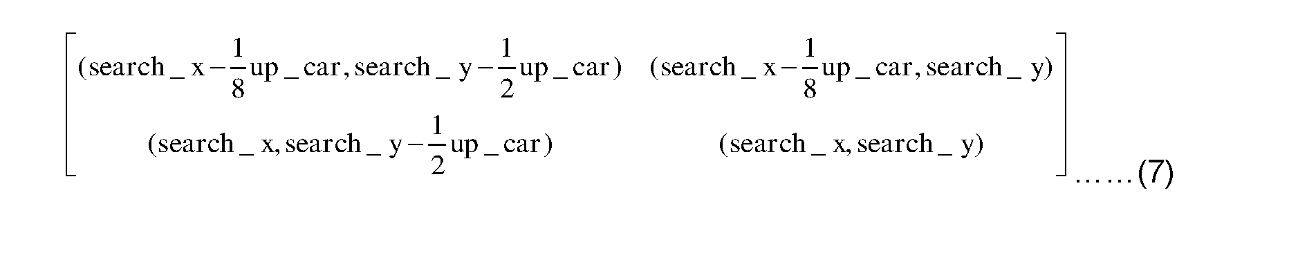
[027] Based on the stationary point (search x, search_y) where every search point passes over the height (up_car) of the target vehicle which locates on this stationary point, the system constructs an ROI corresponding to this stationary point that is the region of the frame suspected to contain a hazard object image where the stationary point appears in the bottom centre of the image. The ROI is then defined by the following coordinate points of the frame:

[029] At step S-2.1 the system determines if the count of ROI exceeds zero, in other words if ROIn is the number of regions of interest is ROIn>0. If so it goes to step S3 and if not to step S1 where the next real time image is captured. Each ROI is uniquely identifiable in a frame by a "stationary point". The stationary point is a coordinate, common to any frame, that is to say that in a sequence of frames the stationary point will not move from one frame to another. Preferably the stationary point is established in the middle of the bottom row of each ROI from which the examination of the ROI ordinarily commences.
[030] There may be no, one or several ROI in FR1 . In the case where there are no ROI the system goes to step S1 to capture a new (n+1 th) frame. If there are any unexamined ROI At step S-3 a first one of the ROI of FR1 is selected for examination.
[031] Examination comprises a number of technical tests the first of which starts at step S-3.0.1 where the bottom shadow of the selected ROI is determined. The bottom shadow area of the suspected hazard vehicle is extracted based on the ROI at (2) using equation (3) below to generate a left hand bottom shadow and equation (4) for
the right hand bottom shadow:

[032] The potential ground area to the left and right of the ROI is determined according to (5) and (6) below:

[033] When the ROI is produced be a vehicle which is far distant from the host vehicle, the bottom shadow will tend to resemble a horizontal line. This effect will become progressively more pronounced the further the target vehicle is from the host vehicle and the bottom shadow will become progressively less like a horizontal line the closer the target is to the host vehicle. In this case the potential left and right bottom shadow update to (7) and (8) below:

and the potential left and right ground area updates to (9) and (10):

[034] The apparent depth or height of the bottom shadow is an indication of the distance of the target from the host vehicle. Thus at S-3.1 the depth of the bottom shadow is compared to a threshold value, if the threshold value is exceeded at step 3.2 the target is close enough to the host vehicle to be a hazard.
[035] The system calculates the mean grey level (Mean_S1 ) of the potential left bottom
shadow area and the mean grey level (Mean_S2) of the potential right shadow area, respectively. At the system calculate the mean grey level of the potential left and right ground area (Mean_G1 ) and the mean grey level of the potential right ground area (Mean_G2). The above mean grey level is obtained by calculating the weighted average of a grey value of the corresponding region. The weight is based on the distance of the potential hazard object from the camera.
[036] Detection of a hazard target is determined at step 3.1 if:

[038] If the threshold is not exceeded the process goes to step 3.3 where the ROI is tagged as examined and if there are any remaining ROI unexamined the step 3.4 returns the process to step 3 and if there are no remaining unexamined ROI the process steps to S1 to capture a new frame.
[039] If the threshold is exceeded the process steps to S4 to implement a dynamic edge accumulative decision (AEDD). AEDD comprises the steps of determining the vertical edge accumulative decision area of the left side as follows:

and similarly a right side accumulative edge decision area for the right side:

[040] The system seeks edges in each are using a Sobel operator and conducts 2- dimensional convolution, to obtain the left and right vertical edge image
Sobel_2 respectively. Conduct binarization to the left and right edge image
Sobel_2 by utilizing binarization dynamic threshold and accumulate downward. The units of accumulated values could be obtained after accumulating left and right vertical edges sub-frame. Then, compare the maximum value of aforementioned left and right accumulated values with the pre-defined two stage dynamic bimodal cumulative
threshold Double Edge Threshold. If both of the maximum left or right values exceed a Double Edge Threshold, the system allows the current dynamic edge accumulative decision to pass. Otherwise the possibility that vehicles exist in the ROI of the current stationary point equals zero. Then the search point goes to next stationary point along the search path, updates the interesting sub-frame and goes into the next dynamic bottom shadow decision state, goes back to step S3.
[041] If the double edge threshold is passed the process goes to step 5 from decision step
4.1 to apply a dynamic support vector machine (SVM) decision step, otherwise the ROI fails step 4.1 and goes to step 3.3. In the SVM the captured and pre-processed sub- frames are regularized to the same size and normalized, preferably to 64*64 pixels. A gradient histogram is established for the ROI. According to the gradient histogram of the sub-frame, the system adopts block units with size of 8*8 pixels, cell unit with size of 4*4 , smooth step size of 8 and a histogram bin number of 9. Then the normalized 64*64 ROI with a potential vehicle object is transformed to 1 *1764 feature vector with feature vector dimension of 1764 and each of dimension value represents statistics accumulated value along the certain direction of gradient in the specific sub area.
[042] Once the ROI is regularized and normalised the ROI is compared with a database of templates of potential target road vehicles, such as cars, vans, lorries, coaches etc. The templates are sampled not only for a range of vehicles but each vehicle before a range of backgrounds and conditions such as weather and/or daylight and/or night. Comparison may be via adding the ROI to the negative template and examining the output result. If the result is zero or near zero the target vehicle in the ROI is deemed a match with the template. The output from the SVM is one of three SVM classifiers.
[043] In more detail, the steps to generate classifiers are to obtain the histogram of orientated gradients (HOG) feature vector matrix of the block unit and cell unit gradient histogram after regularizing. Construct an augmented feature matrix based on the feature vector matrix by utilizing the feature vector matrix and combining the class samples and then find a hyper classification plane that can distinguish positive templates and negative templates through SVM.
[044] Identifying process: Based on the three SVM classifiers corresponding to different scenarios choose the corresponding SVM according to the slow environment identifying result and match it with the current identified slow environment.
[045] Then make the final decision at step 5.1 by utilizing the following formula:

Where indicates that: the SVM classifies the interesting sub-frame into a

positive template space; a hazard target vehicle is present in the ROI; the system directly outputs the ROI.
Where the SVM step classifies the ROI to the negative template space. If

there is no hazard target vehicle present in the ROI and the process goes to step 3 to examine a new unexamined ROI or step 1 to capture a new frame where step 3.4 finds no unexamined ROI.
[046] The step of tagging may be achieved in any suitable way, for example by setting a flag against the stationary point of the ROI.
[047] If the output of step 5.1 is 1 , that is to say, positive, the process goes to step 5.2 and records the stationary point to track the target vehicle in subsequent cycles. The stationary point of the ROI is associated with a recording of the background of the of the ROI.
[048] To record the ROI background the system may advantageously record only the
backgrounds to the left (BackgroundJ.) and right (Background_R) of the target vehicle. To do this the system obtains grey level information of every pixel of the backgrounds in sub regions to the left and right of the vehicle and within the ROI where the left region may be defined by:
[049]

and the right as:

[050] In each of BackgroundJ. and Background_R the grey level information of every pixel is determined on a row by row basis to construct a left/right background grey level matrix. Based on the background grey level matrix, the system calculates the mean value of each row. From the mean value on each row the system constructs a row mean vector MeanGBi for the left and MeanGBr for the right:

Then the system extracts the maximum and minimum values of row mean vectors which correspond to the left and right background sub-frame of the ROI respectively. Based on the maximum and minimum values, the system constructs a feature matrix

[052] where represent the maximum and minimum of the row

mean vectors in the left background sub-frame;
represent the maximum and minimum the row mean vector in the right background sub-frame.
[053] Then the system applies a space coordinate transformation to the feature matrix (19) and obtains a new profile feature matrix

[054] Based on the profile feature matrix, the fast environment classification criterion for the current single frame is as follows.
The environment is "1 , Sunny" when:


The environment is "0, Uphold" otherwise,
where:
&& is logical AND operation,
II is logical OR operation;
represents the entry in the 1 st row and 1 st column of represents the entry in the 2nd row and 1 st column of represents the entry in the 1 st row and 2nd column of represents the entry in the 2nd row and 2nd column of

According to the above results, the system updates the parameters as following at step 6.2, as single frame dynamic decision system parameter update based on the fast environment detection results.

At step 7 the system selects one of the recorded stationary points identifying an ROI which has passed each of steps 3 to 5. It is now desirable to determine if the background exhibits a high level of complexity or a low level of complexity (the background is simple). To determine the complexity of the background each ROI is
scanned backwards at step 7.1 as compared to step 3, thus the search pattern is from top to bottom and from the edges towards the centre. However, at step 7.2 the bottom shadow is determined from the backscan results and again compared to the bottom shadow threshold mentioned at step 3 above.
[089] The system will uphold the current environment results if some ROI passes step S3 after the backtracking search point has reached the start point searching along the opposite direction of the search path. Step 7.3 indicates that there are some (one or more) approximate false-alarm stationary points and the background environment is therefore determined to be complex at step 7.4 so that the process can advance directly to step 7.7.
[090] If the decision at step 7.4 is that the environment is simple 7.5, the process advances to step 7.6. In this case, if the result of the fast environment decision is "1", it requires rectification for the current fast environment identification result into "2". The system will re-identify the fast environment around the target and rectify the fast environment error at step 7.6. The dynamic decision parameter of the next frame will be based on the rectified fast environment decision.
[091] At step 7.7 a fast environment identification que is formed with a length of 100. This is the fast environment identification queue for the purpose of slow environment identification (SEI). The SEI is outer loop of the faster environment loop. Every output of the environment identification result will be pushed into the queue. If the current queue stores 100 statistic results, then the first statistic I that is pushed in the queue will be squeezed out of the queue and keeps the "first in, first out" rule. The push strategies are:
If none of interested sub-frame passes S3 (dynamic bottom shadow decision), S4
(dynamic edge accumulative decision) and S5 (dynamic support vector machine (SVM) decision), that is, the system cannot find the "object stationary point", "0" will be pushed to queue.
If the fast environment decision of current sub-frame is "1" and the system finds approximate false-alarm stationary point during the backtracking search process, "1" will be pushed into the queue.
If the fast environment decision of current sub-frame is "1" and system cannot find approximate false-alarm stationary point during the backtracking search process, "2" will be pushed into the queue.
If the fast environment decision of current sub-frame is "2" or "3" or "4", the fast environment decision result of current sub-frame will be pushed into the queue. If there is an interest sub-frame that passes the S3, S4 and S5, the rectified fast environment decision results "0" "1" "2" "3" "4" will be pushed into the queue sequentially.
Therefore, it forms an environment analysing vector with a range from 0 to 4.
[092] At step 7.8 the system then utilizes the 100 statistic fast environment decision result to update the slow environment result according to the following strategies:
If the number of "1" is larger than 30, the slow environment will be set to "1" (the complicated condition);
If the number of "3" and "4" is larger than 30, the slow environment will be set to 3 (the weak light condition);
As to the other situations, the slow environment will be set to 2 (the normal condition).
[093] The process then goes to step 8.0 where the fast environment identification according to the slow environment result is set at a certain interval.
[094] If the slow environment result is "1", the fast environment identification will be set to "3, nightfall". Sequentially, the fast environment related parameters, including "Dynamic Binarization Sobel Threshold for Global Gradient Image", "Dynamic Distinguish Threshold for Shadow and Ground" and "Two Stage Dynamic Bimodal vertical direction Cumulative Threshold" will change according to the reset of fast environment, from 1 to 3, for the next frame.
[095] If the slow environment identification result is "2" or "3", then the fast environment identification will be forced to "4, dusk". Sequentially, the fast environment related parameters, including "Dynamic Binarization Sobel Threshold for Global Gradient Image", "Dynamic Distinguish Threshold for Shadow and Ground" and "Two Stage Dynamic Bimodal vertical direction Cumulative Threshold" will change according to the reset of fast environment for the next frame. When sub-frames (ROI) pass S3, S4 and S5 in several consecutive frames, it can be concluded that a vehicle object exists in the sub-frame (ROI) of the corresponding stationary point. Each sub-frames of interest will be marked as a sub-frame of object tracking. The detailed process is described below:
Taking the frame as a unit and the current frame as the base point, continuously obtain the frames which start from current frame to the previous several frames. Then analyse the existence and location of these interested sub-frames which pass the S3, S4 and S5.
If the slow environment identification output is "1", the environment identification result is complex. If there still is an interested sub-frame in the current and previous four frames that can pass the 3 stage dynamic decision under the condition that the stationary point of these 5 interested frames is close to each
other, then it can be regarded that there exists a object and the object is marked as the final object detection result.
If the slow environment identification output is "2" or "3", the object feature is weakened. Therefore, if there still exists an interested sub-frame in the current and previous three image frames that can pass the three stage dynamic decision under the condition that the stationary point of these interested sub-frames is close to each other, it can be regarded that an object exists and the object is marked as the final object detection result. [097] Referring again to step 5.3, where each ROI has been scanned so that there are no
ROI in the Nth captured frame which have not been subject to at least step 3, the system outputs to step 5.3.1 where a frame counter is incremented from N to N+1 . The process advances to step 5.3.2 where the frame count is compared to a predetermined frame count number "X". In the example X may be five but might be set to a higher or lower value. This ensures that a sequence of five captured frames must be inspected with the corresponding ROI exhibiting the presence of a potential hazard target before target tracking is confirmed. When the frame count N equals the frame count number 5, the system advances to step 5.3.3 where the frame count is reset to 1 . From step 5.3.3 the system advances to step 9.1 where the target data is output for subsequent processing. After step 9.1 the method advances to step 1 where a new frame is captured for examination. [098] If the frame count number is not exceeded at step 5.3.2 the method advances directly to step 1 to capture a new frame for examination. [099] The cognitive imaging system having confirmed the presence of a foreground object which may prove to be a hazard is able to track the hazard with a high degree of
confidence against even fast changing background environments. The tracking of any hazard target is achieved across several sequentially captured frames, which facilitates the step of calculating a vector for the target and hence a plot of the position of the target vehicle against time which can be compared to the current vector of the host vehicle. As a result the system is able to identify objects on a potential collision course with the user vehicle and issue a hazard warning to the driver by way of integral warning systems. Integral warning system may, for example, include a screen, warning lights or an acoustic warning from a loudspeaker. Alternatively the warning may be transferred over the interface to drive the warning indicators of the vehicle.
A feature of the system is an ability to correlate the lateral movement of the vehicle with the operation of the vehicle indicators in order to warn the driver of changing lane without indicating or otherwise driving erratically.
Claims
1 . A cognitive imaging system for a moving vehicle comprising:
a monocular camera adapted to be mounted into a vehicle in order to focus an image of a field of view onto an image sensor, said image sensor capable of processing the image into image data, and a processor device responsive to machine readable code stored in a memory to be capable of driving the camera to capture a sequence of image frames to implement an image processing method in order to process the image frame data and identify a hazard in the field of view; wherein: the processor is responsive to capture a time sequence of images from the camera, the processor is responsive to scan pixel image data of a first captured frame from a sequence of frames and applies a series of filters to identify a sub-frame in which a vehicular hazard target may exist and to distinguish the background environment from the foreground vehicle hazard target when each of the vehicle and the hazard target are moving relative to a background; the processor is responsive to calculate an environment classification criterion which is either one of a fast environment or a slow environment for each sub frame in the current frame; the processor is responsive to add each fast environment classification to a fast environment identification queue of a predetermined length to form an environment analysing vector;
the processor responding to analyse the pixel image data of a subsequent captured image to add fast environment classification data to the fast environment identification queue; whereby a slow environment result is updated according to the fast environment analysing vector calculated from the preceding sequence of captured frames.
2. A system according to claim 1 wherein the filters comprise at least a bottom shadow filter, wherein the processor calculates a bottom shadow of a suspected hazard and compares the bottom shadow to a threshold value.
3. A system according to claim 2 wherein the filters include a dynamic edge filter.
4. A system according to claim 3 wherein the processor is responsive to the output of the dynamic edge filter to apply a support vector machine (SVM) filter, wherein each sub-frame is regularized, normalised and compared to a database of templates to generate one of a plurality of classifiers, of which classifiers at least one indicates a match with a template.
5. A system according to claim 4 wherein the processor is responsive to the sub- frame passing each filter to back-scan the ROI suspected to contain a hazard.
6. A system according to claim 5 wherein the processor is responsive to apply the bottom shadow filter to the output of the back-scanned ROI.
7. A system according to claim 5 or 6 wherein the processor responds to the output of the back-scan bottom shadow filter to determine if the background
environment of the sub-frame is simple or complex.
8. A system according to claim 7 wherein the processor calibrates the simplicity or complexity of the background environment of a sub-frame to determine if the
background can be reused to track the target hazard in the sub-frame in one or more subsequent captured frames.
9. A system according to any one of the preceding claims wherein the processor calculates a vector of an identified target hazard and a vector of the system and calculates a probability of the vectors coinciding to output a first alarm warning of the risk of a collision.
10. A system according to claim 9 wherein the system includes an interface for communication of data with an inboard vehicle management system whereby the system can capture data determined from any of the vehicle:
I. steering angle sensor,
II. accelerator/throttle angle sensor ,
III. direction indicator state,
IV. brake operation sensor.
1 1 . A system according to claim 10 wherein the system interface is capable of driving the inboard vehicle management system to actuate any of the vehicle: brakes, steering or accelerator.
12. A method of cognitive imaging in a cognitive imaging system comprising: capturing a sequence of frames of monocular images of a single field of view from a moving vehicle; scanning a temporal first of the frames to identify sub-frames (ROI) which are most likely to contain a foreground object constituting a potential hazard; scanning each sub-frame to calculate an environment classification sub-frame;
adding each environment classification to an environment classification queue of a predetermined length to form an environment analysing vector; scanning a subsequent one of the sequence of captured frames to generate sub-frame environment classifications and adding the environment classifications to the environment classification queue to update the environment analysing vector; whereby a slow environment result is updated according to the fast environment analysing vector calculated from the preceding sequence of captured frames.
13. A method according to claim 12 wherein a first of the filters is a bottom shadow filter which calculates the bottom shadow of a sub-frame and compares the bottom shadow to a threshold value.
14. A method according to claim 12 or 13 wherein a one of the filters is a dynamic edge filter.
15. A method according to claim 12, 13 or 14 wherein a one of the filters is a support vector machine (SVM) filter wherein each sub-frame is regularised and normalised and compared to a database of templates to generate one of a plurality of classifiers, of which classifiers at least one indicates a match with a template.
16. A method according to any one of claims 12 to 15 in which any sub-frame which passes each of the filters is subject to a back-scan where the pixel data is recovered in reverse order from the sub-frame and the bottom shadow is recalculated from the back-scan data to be subject to the bottom shadow threshold test.
17. A method according to claims 16 wherein the output of the back scan bottom shadow filter is used to determine if the background environment of the sub-frame is simple or complex.
18. A method according to claim 17, wherein the complexity classification of the sub-frame is used to determine if the background of the sub-frame can be used in the identification of target by sub-frame subtraction in a subsequent frame.
19. A method according to any one of claims 12 to 18 wherein the vehicle:
I. steering angle,
II. accelerator/throttle angle
III. direction indicator state, or
IV. brake operation state is integrated with a hazard target vector determined by the method to generate a hazard warning if there is a significant risk of collision.
20. A method according to claim 19 wherein, in response to a calculated high risk of collision one or more of the vehicle, brakes, steering or accelerator are actuated to alleviate the risk of collision.
21 . A road vehicle in combination with a system according to any one of claims 1 to 1 1 .
22. Machine readable code packaged and encoded to be communicated for execution in a system to implement a method according to any one of claims 12 to 20.
Priority Applications (1)
| Application Number | Priority Date | Filing Date | Title |
|---|---|---|---|
| PCT/GB2015/053359 WO2017077261A1 (en) | 2015-11-05 | 2015-11-05 | A monocular camera cognitive imaging system for a vehicle |
Applications Claiming Priority (1)
| Application Number | Priority Date | Filing Date | Title |
|---|---|---|---|
| PCT/GB2015/053359 WO2017077261A1 (en) | 2015-11-05 | 2015-11-05 | A monocular camera cognitive imaging system for a vehicle |
Publications (1)
| Publication Number | Publication Date |
|---|---|
| WO2017077261A1 true WO2017077261A1 (en) | 2017-05-11 |
Family
ID=54754687
Family Applications (1)
| Application Number | Title | Priority Date | Filing Date |
|---|---|---|---|
| PCT/GB2015/053359 Ceased WO2017077261A1 (en) | 2015-11-05 | 2015-11-05 | A monocular camera cognitive imaging system for a vehicle |
Country Status (1)
| Country | Link |
|---|---|
| WO (1) | WO2017077261A1 (en) |
Cited By (3)
| Publication number | Priority date | Publication date | Assignee | Title |
|---|---|---|---|---|
| US20190012549A1 (en) * | 2017-07-10 | 2019-01-10 | Nanjing Yuanjue Information and Technology Company | Scene analysis method and visual navigation device |
| US11024042B2 (en) * | 2018-08-24 | 2021-06-01 | Incorporated National University Iwate University; | Moving object detection apparatus and moving object detection method |
| CN110458885B (en) * | 2019-08-27 | 2024-04-19 | 纵目科技(上海)股份有限公司 | Positioning system and mobile terminal based on stroke perception and vision fusion |
Citations (6)
| Publication number | Priority date | Publication date | Assignee | Title |
|---|---|---|---|---|
| EP0671706A2 (en) | 1994-03-09 | 1995-09-13 | Nippon Telegraph And Telephone Corporation | Method and apparatus for moving object extraction based on background subtraction |
| CN101303732A (en) | 2008-04-11 | 2008-11-12 | 西安交通大学 | Moving target perception and warning method based on vehicle-mounted monocular camera |
| JP2011154634A (en) | 2010-01-28 | 2011-08-11 | Toshiba Information Systems (Japan) Corp | Image processing apparatus, method and program |
| CN102542571A (en) | 2010-12-17 | 2012-07-04 | 中国移动通信集团广东有限公司 | Moving target detecting method and device |
| CN102915545A (en) | 2012-09-20 | 2013-02-06 | 华东师范大学 | OpenCV(open source computer vision library)-based video target tracking algorithm |
| US20130243322A1 (en) | 2012-03-13 | 2013-09-19 | Korea University Research And Business Foundation | Image processing method |
-
2015
- 2015-11-05 WO PCT/GB2015/053359 patent/WO2017077261A1/en not_active Ceased
Patent Citations (6)
| Publication number | Priority date | Publication date | Assignee | Title |
|---|---|---|---|---|
| EP0671706A2 (en) | 1994-03-09 | 1995-09-13 | Nippon Telegraph And Telephone Corporation | Method and apparatus for moving object extraction based on background subtraction |
| CN101303732A (en) | 2008-04-11 | 2008-11-12 | 西安交通大学 | Moving target perception and warning method based on vehicle-mounted monocular camera |
| JP2011154634A (en) | 2010-01-28 | 2011-08-11 | Toshiba Information Systems (Japan) Corp | Image processing apparatus, method and program |
| CN102542571A (en) | 2010-12-17 | 2012-07-04 | 中国移动通信集团广东有限公司 | Moving target detecting method and device |
| US20130243322A1 (en) | 2012-03-13 | 2013-09-19 | Korea University Research And Business Foundation | Image processing method |
| CN102915545A (en) | 2012-09-20 | 2013-02-06 | 华东师范大学 | OpenCV(open source computer vision library)-based video target tracking algorithm |
Non-Patent Citations (6)
| Title |
|---|
| BING-FEI WU ET AL: "Embedded weather adaptive lane and vehicle detection system", INDUSTRIAL ELECTRONICS, 2008. ISIE 2008. IEEE INTERNATIONAL SYMPOSIUM ON, 1 January 2008 (2008-01-01), Piscataway, NJ, USA, pages 1255 - 1260, XP055286344, ISBN: 978-1-4244-1665-3, DOI: 10.1109/ISIE.2008.4677194 * |
| EN-FONG CHOU ET AL: "Weather-adapted Vehicle Detection for Forward Collision Warning System", LECTURE NOTES IN ENGINEERING AND COMPUTER SCIENCE, 1 July 2011 (2011-07-01), pages 1294 - 1299, XP055282726, Retrieved from the Internet <URL:http://www.iaeng.org/publication/WCE2011/WCE2011_pp1294-1299.pdf> [retrieved on 20160706] * |
| Jà CR Rà CR MIE BOSSU ET AL: "Rain or Snow Detection in Image Sequences Through Use of a Histogram of Orientation of Streaks", INTERNATIONAL JOURNAL OF COMPUTER VISION, KLUWER ACADEMIC PUBLISHERS, BO, vol. 93, no. 3, 29 January 2011 (2011-01-29), pages 348 - 367, XP019894573, ISSN: 1573-1405, DOI: 10.1007/S11263-011-0421-7 * |
| TAE HUNG KIM ET AL: "Road Sign Detection with Weather/Illumination Classifications and Adaptive Color Models in Various Road Images", KIPS TRANSACTIONS ON SOFTWARE AND DATA ENGINEERING, vol. 4, no. 11, 1 November 2015 (2015-11-01), pages 521 - 528, XP055286279, ISSN: 2287-5905, DOI: 10.3745/KTSDE.2015.4.11.521 * |
| WENG T L ET AL: "Weather-adaptive flying target detection and tracking from infrared video sequences", EXPERT SYSTEMS WITH APPLICATIONS, OXFORD, GB, vol. 37, no. 2, 1 March 2010 (2010-03-01), pages 1666 - 1675, XP026736226, ISSN: 0957-4174, [retrieved on 20090705], DOI: 10.1016/J.ESWA.2009.06.092 * |
| XUDONG ZHAO ET AL: "A time, space and color-based classification of different weather conditions", VISUAL COMMUNICATIONS AND IMAGE PROCESSING (VCIP), 2011 IEEE, IEEE, 6 November 2011 (2011-11-06), pages 1 - 4, XP032081366, ISBN: 978-1-4577-1321-7, DOI: 10.1109/VCIP.2011.6115972 * |
Cited By (4)
| Publication number | Priority date | Publication date | Assignee | Title |
|---|---|---|---|---|
| US20190012549A1 (en) * | 2017-07-10 | 2019-01-10 | Nanjing Yuanjue Information and Technology Company | Scene analysis method and visual navigation device |
| US10614323B2 (en) * | 2017-07-10 | 2020-04-07 | Nanjing Yuanjue Information and Technology Company | Scene analysis method and visual navigation device |
| US11024042B2 (en) * | 2018-08-24 | 2021-06-01 | Incorporated National University Iwate University; | Moving object detection apparatus and moving object detection method |
| CN110458885B (en) * | 2019-08-27 | 2024-04-19 | 纵目科技(上海)股份有限公司 | Positioning system and mobile terminal based on stroke perception and vision fusion |
Similar Documents
| Publication | Publication Date | Title |
|---|---|---|
| JP5297078B2 (en) | Method for detecting moving object in blind spot of vehicle, and blind spot detection device | |
| US11170272B2 (en) | Object detection device, object detection method, and computer program for object detection | |
| Wu et al. | Lane-mark extraction for automobiles under complex conditions | |
| US20180150704A1 (en) | Method of detecting pedestrian and vehicle based on convolutional neural network by using stereo camera | |
| US10867403B2 (en) | Vehicle external recognition apparatus | |
| KR101912914B1 (en) | Method and system for recognition of speed limit sign using front camera | |
| US9626599B2 (en) | Reconfigurable clear path detection system | |
| CN107667378B (en) | Method and apparatus for identifying and evaluating road surface reflections | |
| CN107463890B (en) | A kind of Foregut fermenters and tracking based on monocular forward sight camera | |
| US8452054B2 (en) | Obstacle detection procedure for motor vehicle | |
| US8879786B2 (en) | Method for detecting and/or tracking objects in motion in a scene under surveillance that has interfering factors; apparatus; and computer program | |
| US20160104047A1 (en) | Image recognition system for a vehicle and corresponding method | |
| US20170032676A1 (en) | System for detecting pedestrians by fusing color and depth information | |
| US20130208945A1 (en) | Method for the detection and tracking of lane markings | |
| Ciberlin et al. | Object detection and object tracking in front of the vehicle using front view camera | |
| WO2011067790A2 (en) | Cost-effective system and method for detecting, classifying and tracking the pedestrian using near infrared camera | |
| EP2741234B1 (en) | Object localization using vertical symmetry | |
| CN111626170A (en) | Image identification method for railway slope rockfall invasion limit detection | |
| Romera et al. | A Real-Time Multi-scale Vehicle Detection and Tracking Approach for Smartphones. | |
| WO2016059643A1 (en) | System and method for pedestrian detection | |
| CN107506739B (en) | Night forward vehicle detection and distance measurement method | |
| CN108629225B (en) | Vehicle detection method based on multiple sub-images and image significance analysis | |
| WO2017077261A1 (en) | A monocular camera cognitive imaging system for a vehicle | |
| KR20150002040A (en) | The way of Real-time Pedestrian Recognition and Tracking using Kalman Filter and Clustering Algorithm based on Cascade Method by HOG | |
| CN107256382A (en) | Virtual bumper control method and system based on image recognition |
Legal Events
| Date | Code | Title | Description |
|---|---|---|---|
| 121 | Ep: the epo has been informed by wipo that ep was designated in this application |
Ref document number: 15802183 Country of ref document: EP Kind code of ref document: A1 |
|
| NENP | Non-entry into the national phase |
Ref country code: DE |
|
| 32PN | Ep: public notification in the ep bulletin as address of the adressee cannot be established |
Free format text: NOTING OF LOSS OF RIGHTS PURSUANT TO RULE 112(1) EPC (EPO FORM 1205A DATED 03/09/2018) |
|
| 122 | Ep: pct application non-entry in european phase |
Ref document number: 15802183 Country of ref document: EP Kind code of ref document: A1 |