WO2016208166A1 - Applicator for medical-use liquids - Google Patents
Applicator for medical-use liquids Download PDFInfo
- Publication number
- WO2016208166A1 WO2016208166A1 PCT/JP2016/002924 JP2016002924W WO2016208166A1 WO 2016208166 A1 WO2016208166 A1 WO 2016208166A1 JP 2016002924 W JP2016002924 W JP 2016002924W WO 2016208166 A1 WO2016208166 A1 WO 2016208166A1
- Authority
- WO
- WIPO (PCT)
- Prior art keywords
- mounting plate
- liquid
- applicator
- cylindrical member
- base
- Prior art date
- Legal status (The legal status is an assumption and is not a legal conclusion. Google has not performed a legal analysis and makes no representation as to the accuracy of the status listed.)
- Ceased
Links
Images


Classifications
-
- A—HUMAN NECESSITIES
- A61—MEDICAL OR VETERINARY SCIENCE; HYGIENE
- A61M—DEVICES FOR INTRODUCING MEDIA INTO, OR ONTO, THE BODY; DEVICES FOR TRANSDUCING BODY MEDIA OR FOR TAKING MEDIA FROM THE BODY; DEVICES FOR PRODUCING OR ENDING SLEEP OR STUPOR
- A61M35/00—Devices for applying media, e.g. remedies, on the human body
- A61M35/003—Portable hand-held applicators having means for dispensing or spreading integral media
- A61M35/006—Portable hand-held applicators having means for dispensing or spreading integral media using sponges, foams, absorbent pads or swabs as spreading means
-
- A—HUMAN NECESSITIES
- A61—MEDICAL OR VETERINARY SCIENCE; HYGIENE
- A61K—PREPARATIONS FOR MEDICAL, DENTAL OR TOILETRY PURPOSES
- A61K31/00—Medicinal preparations containing organic active ingredients
- A61K31/13—Amines
- A61K31/155—Amidines (), e.g. guanidine (H2N—C(=NH)—NH2), isourea (N=C(OH)—NH2), isothiourea (—N=C(SH)—NH2)
-
- A—HUMAN NECESSITIES
- A61—MEDICAL OR VETERINARY SCIENCE; HYGIENE
- A61K—PREPARATIONS FOR MEDICAL, DENTAL OR TOILETRY PURPOSES
- A61K31/00—Medicinal preparations containing organic active ingredients
- A61K31/74—Synthetic polymeric materials
- A61K31/785—Polymers containing nitrogen
- A61K31/787—Polymers containing nitrogen containing heterocyclic rings having nitrogen as a ring hetero atom
- A61K31/79—Polymers of vinyl pyrrolidone
-
- A—HUMAN NECESSITIES
- A61—MEDICAL OR VETERINARY SCIENCE; HYGIENE
- A61K—PREPARATIONS FOR MEDICAL, DENTAL OR TOILETRY PURPOSES
- A61K33/00—Medicinal preparations containing inorganic active ingredients
- A61K33/18—Iodine; Compounds thereof
Definitions
- the present invention relates to an applicator for applying a medical liquid such as a disinfecting liquid to the skin, which is particularly useful in the field of surgery.
- a breakable tank container that is particularly useful for applying pre-surgical surgical cleaning or application to the skin as an applicator for applying pre-surgical surgical cleaning or disinfecting liquid to the skin It has a liquid applicator (Patent Document 1) equipped with a delivery device for applying the liquid contained in the surface to the surface, and a flexible elongated hollow cylindrical body that accepts a glass-filled glass ampoule, and discharges the liquid in small portions.
- Patent Document 1 a liquid applicator equipped with a delivery device for applying the liquid contained in the surface to the surface, and a flexible elongated hollow cylindrical body that accepts a glass-filled glass ampoule, and discharges the liquid in small portions.
- a portable liquid applicator having an ampoule crushing mechanism, a hollow elongated member having a container, a flange extending radially outward from the hollow elongated member, and attached to the flange
- An applicator for applying or delivering fluid, the distributor element comprising at least two orifices and And projecting elements for separating at least two orifices, including an absorbent pad attached to the first side of the distributor element, the applicator (Patent Document 3) are known.
- Patent Document 4 for applying a disinfectant to a desired surface and selectively removing undesirable by-products derived from the disinfectant, a packet for containing fluid, and a packet
- An applicator device US Pat. No.
- a porous body impregnated with a liquid a cap having a slit fitted to the other end, an outer container, an inner container sealed with a lid member having a knob and sealed with the chemical liquid;
- a liquid applicator comprising: the inner container is housed in the main body, the knob is folded in the direction of the cap, and protrudes to the outside of the outer container through the slit.
- a liquid applicator Patent Document 7 is known.
- the main body extended in a cylindrical shape having an opening at one end and a porous body having an impregnating property at the other end, and a mouth filled with a chemical solution and sealed with a sealing material
- a liquid applicator comprising a sealed bottle, and a substantially cylindrical connecting body for connecting the main body and the bottle, wherein the connecting body is screwed onto an inner surface of the bottle mouth.
- a screw-shaped part and a convex rib that moves in cooperation with the opening are formed on the outer surface, and a substantially S-shaped guide groove that guides the convex rib is formed on a side wall of the opening.
- An inner shelf is formed on the inner surface, and an inner cylinder having a sharp tip with a hole for breaking the sealing material on the inner surface of the intermediate shelf is formed in the direction of the mouth along the axis.
- a liquid applicator (Patent Document 8) characterized by having a hollow book suitable for receiving a liquid-filled ampoule
- a lever having a hinge, a grip and a foot, formed integrally with the foot, the foot is positioned adjacent to the ampoule, and when the lever is depressed, the applicator crushes the ampoule to release liquid ( Patent document 9) is known.
- An object of the present invention is to provide a medical liquid applicator capable of uniformly exuding an appropriate amount of medical liquid such as a disinfectant from an application pad and applying a predetermined amount accurately.
- a container containing a liquid such as a disinfectant contained in a hollow cylindrical member having an application pad at the lower end is cleaved to release and release the liquid into the cylindrical member, and the liquid is released from the hole at the bottom of the cylindrical member.
- the liquid that has flowed out is allowed to permeate the application pad and is applied to the skin, the liquid suddenly and unidirectionally flows immediately after the liquid container is opened, and unevenly penetrates the application pad.
- liquid may drip or leak from the application pad before or during application, or on the contrary, the amount of penetration of the liquid into the application pad may be partially reduced, and smooth application with the application pad is not possible. There was a problem that there was something.
- the inventors of the present invention have applied the shape of the coating pad, the surface state of the coating pad, the material of the coating pad, the volume of the recess surrounded by the peripheral bank portion of the mounting pad mounting plate,
- the flow rate and flow direction cannot be adjusted by providing a weir in the course of various investigations regarding the size of the inclined outflow hole that is inclined and opened to the base, the method of cleaving the container, the type of disinfectant, etc. I came up with the idea.
- a handle portion including a hollow cylindrical member, a liquid container built in the cylindrical member, and a means for cleaving the liquid container; and a lower end of the cylindrical member having an inclined cross section
- a medical liquid applicator comprising: an application pad attachment plate fixed to the application plate; and an application part comprising an application pad attached to the attachment plate;
- the mounting plate includes a bank portion having a thick peripheral edge, a base portion formed in a concave portion in the center, and a solution released and released from the liquid container in the vicinity of the center of the base portion flows toward the tip end of the mounting plate.
- Inclined outflow holes that are inclined to the base, and weirs in the shape of an arc or crescent with the inclined outflow holes extending from the inclined outflow holes to the base in the tip direction of the mounting plate.
- An applicator for medical liquid characterized in that is provided.
- the weir provided in an arc shape or a crescent shape is inclined by 40 to 50 ° in a direction away from the center side of the arc toward the upper end with respect to the base surface.
- an appropriate amount of medical liquid such as a disinfectant liquid oozes uniformly from the application pad without dripping or dropping the disinfectant liquid from the application pad, and a predetermined amount is accurately applied to the skin. Can be applied.
- FIG. 5 is an enlarged view of a portion AA in FIG.
- FIG. 6 is a cross-sectional view taken along a line BB in FIG. It is a front view of the attachment board of the application pad of the applicator (10 mL) of this invention of another aspect.
- upper and lower means “upper” on the right side in FIGS. 1 to 4 and “lower” on the left side
- tip means an upper left side in FIGS. 5 and 7 and an upper left side in FIG.
- the medical liquid applicator according to the present invention includes a hollow cylindrical member, a liquid container built in the cylindrical member, and a handle portion provided with means for cleaving the liquid container; and the cylindrical member
- a coating portion provided with a coating plate attached to the lower end of the coating pad so as to have an inclined cross section and a coating pad attached to the mounting plate
- the technique is characterized by the structure of the plate, and the techniques disclosed in Patent Documents 1 to 9 described above can be basically applied to the handle portion and the coating pad.
- the liquid container contained in the cylindrical member is cleaved by the cleaving means, and the liquid is released / released from the liquid container. It is sufficient that the discharged liquid does not flow out from the upper part of the cylindrical member and flows out from the inclined outflow hole provided in the base portion of the mounting plate.
- the length is 10 to 20 cm and the diameter is
- An elongated hollow cylindrical member having a long side of 2 to 4 cm in cross section, an ellipse, a rectangle or the like can be mentioned, and a tapered cylindrical shape whose diameter is reduced downward can be preferably exemplified.
- a mounting plate for the application pad is integrally fixed to the lower end of the cylindrical container so as to have an inclined cross section. If the upper surface of the mounting plate is the horizontal reference, the central axis of the cylindrical member is erected with an inclination of 30 to 60 °, preferably 40 to 50 ° with respect to the upper surface of the mounting plate.
- the cylindrical member is made of plastic and is made of olefin resin such as polyethylene and polypropylene; polyethylene terephthalate resin; polyamide resin; MBS resin such as methyl methacrylate butadiene styrene and methyl methacrylate butadiene styrene n-butyl acrylate, etc.
- the resin may be selected and the thickness may be set as appropriate based on rigidity and the like, and examples of the molding method include injection molding and extrusion molding.
- the liquid container contains a liquid for medical use such as a disinfectant liquid and a cleaning liquid, and can be built in a cylindrical member.
- the liquid is released / released by the cleaving means, and the released / released liquid is cylindrical. It is only necessary to be able to flow out from the inclined outflow hole provided in the base portion of the mounting plate without flowing out from the upper part of the member.
- a brittle ampoule, a collapsible container, a pierceable container, a container from which a cap is removed, etc. Can be mentioned.
- the liquid container built in the cylindrical member can be cleaved, and the liquid can be released / released from the liquid container, so that the released / released liquid does not flow out from the upper part of the cylindrical member.
- Any means can be used as long as it can flow out from the inclined outflow hole provided in the base portion of the mounting plate.
- ampule breaking means such as a lever for a brittle ampule built in a cylindrical member having a cap at the upper end ( Patent Documents 1 to 4 and 9), an external pressure applying means for compressing a bucket containing liquid (Patent Document 5), and an actuator sleeve for removing the lid of the liquid container by pushing down the inside of the cylindrical member (Patent Document) 6), seal peeling means for opening the liquid container (Patent Documents 7 and 8) and the like, but an actuator sleeve for removing the lid of the liquid container is preferable. It can be exemplified.
- Examples of the shape of the application pad include a substantially mussel shape, a rectangular shape, an oval shape, a circular shape, a triangular shape, and an elliptical shape in a plan view having a thickness of about 1.5 to 2 mm. In view of smooth application and ease of handling, it is preferable to have a substantially mussel shape.
- the porous material which has the property which osmose-impregnates liquids, such as disinfection liquid can be illustrated suitably, However, Other textiles, a nonwoven fabric, etc. can also be used.
- Examples of the raw material for the porous material include polyolefin-based, polyurethane-based, polyethylene terephthalate-based resins, and cellulose-based fibers.
- Such a coating pad can be attached to the top surface of the bank portion formed on the mounting plate by heat fusion or an adhesive.
- the mounting plate has a bank portion with a thick peripheral edge and a flat top surface, a base portion with a concave center and a flat bottom surface, and the solution near the center of the base portion toward the tip of the mounting plate.
- the shape of the mounting plate is preferably the same shape as the coating pad.
- the shape of the base portion is also a substantially mussel shape, and an inclined outflow hole is provided near the center portion. .
- the inclined outflow hole opens in the shape of an ellipse that is long in the front-rear direction on the surface of the base, and the size of the hole depends on the size of the applicator, but usually the major axis is about 4 to 6.5 mm and the minor axis is about 3 to 5 mm. It is.
- the weir is provided in an arc shape or crescent shape with an inclined outflow hole at the center side of the arc at the base, but the position of the inclined outflow hole with respect to the weir is from the arc between the arc and the string from the arc string. It is preferable that the shortest distance from the tip of the inclined outflow hole (oval) to the weir is 2 to 3 mm.
- the weir provided in an arc shape or a crescent shape is inclined by 40 to 50 ° in a direction concentrically away from the center side of the arc as it goes to the upper end with respect to the base surface. .
- the flow of the liquid blocked by the weir can be efficiently reversed and reversed, and as a result, the flow of the solution toward the one-side tip direction can be performed.
- the solution can be uniformly permeated into the coating pad by regulating.
- the weir is higher than the bank at a height in a direction perpendicular to the upper surface of the mounting plate with respect to the upper surface of the mounting plate, and the high portion (hereinafter sometimes referred to as “protruding portion”) is, for example, 0 It is preferably 1 to 1 mm, particularly preferably 0.25 to 0.75 mm. Since the dam is higher than the bank portion, the top of the dam bites into the coating pad, so that the liquid flow can be prevented from getting over the dam, and the reverse flow can be reliably reversed. In particular, when the weir has an inclined curved surface, the liquid flow easily gets over the weir. Therefore, it is preferable that the weir is made higher than the bank and the top of the weir is bitten into the coating pad so that the reverse flow is surely reversed.
- the medical liquid examples include a disinfectant solution and a cleaning solution, and more specifically, povidone iodine solution, ethanol solution, isopropanol solution, potassium iodide solution, benzalkonium chloride solution, benzethonium chloride solution, chlorhexidine gluconate.
- Such medical liquid can be applied to a local area immediately before surgery.
- the medical liquid is not particularly limited as long as it is obtained by liquefying an active ingredient such as a disinfecting ingredient or a cleaning ingredient.
- the medical liquid may be an aqueous preparation in which the active ingredient is diluted with purified water, or ethanol, isopropanol, etc. It may be an alcohol preparation diluted with purified alcohol or an aqueous solution thereof.
- the concentration of the active ingredient is also arbitrary.
- the alcohol concentration in the case of an alcohol preparation is also arbitrary.
- additives usually used as aqueous preparations and alcohol preparations such as preservatives, moisturizers, thickeners, nonionic surfactants, cationic surfactants, Antioxidants, fragrances, colorants and the like can also be used.
- the viscosity of the liquid is not limited as long as it does not impede practical use for application using an application pad, but is preferably 0.5 to 15.0 mPa ⁇ s.
- the applicator of the present invention is also preferably used for a low-viscosity liquid that easily leaks, that is, a liquid having a viscosity of 0.5 to 4.0 mPa ⁇ s, particularly 0.5 to 2.5 mPa ⁇ s. it can.
- the above viscosity is a numerical value measured according to a viscosity measuring method using a JIS Z8803 liquid viscosity measuring method, a cone-plate rotational viscometer, and a measurement temperature is 20 ° C.
- the applicator according to the present invention is applied to a target local region immediately before surgery.
- the liquid container is crushed, removed, and uncapped using a cleaving means of the handle, and the liquid is discharged from the liquid container into the cylindrical member.
- Most of the liquid that flows out from the inclined outflow hole flows toward the mounting plate tip, but it is blocked by the weir and once reverses and backflows so that it goes around from the left and right gaps between the bank and the weir.
- the liquid flows in the direction toward the tip of the base, and the flow of the liquid is adjusted.
- the liquid is applied to the skin after sufficiently penetrating the application pad.
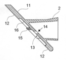
- the applicator 1 shown in FIGS. 1 to 6 includes a hollow cylindrical member 2, a liquid container 3 built in the cylindrical member 2, and an actuator sleeve 4 inserted into the cylindrical member 2. And a mounting plate 10 of the application pad 5 fixed to the lower end of the cylindrical member 2 so as to have an inclined cross section, and a substantially mussel-shaped application pad 5 attached to the mounting plate 10 It is comprised from the application part provided with.
- the cylindrical member 2 and the mounting plate 10 are integrally formed of methyl methacrylate butadiene styrene resin, and the coating pad 5 is made of polyethylene having a porosity of 87%.
- the cylindrical tubular member 2 having a taper that narrows downward has a maximum outer diameter of about 28 mm and a length (center axis) of about 18.5 cm.
- the cylindrical member 2 is based on the upper surface 11 of the mounting plate.
- the central axis 2 is inclined by approximately 45 ° with respect to the upper surface 11 of the mounting plate.
- the shape of the mounting plate 10 is also a substantially mussel shape that is a little smaller than the application pad 5, and has a front-rear direction length of about 6 cm and a rear portion width of about 4.5 cm.
- the mounting plate 10 has a bank portion 12 with a thick peripheral edge, a base portion 13 formed with a recess in the center, and the solution flows out toward the tip of the mounting plate near the center of the base portion.
- An inclined outflow hole 14 inclined to the base portion 13, and a weir 15 in an arc shape with the inclined outflow hole 14 at the center side of the arc from the inclined outflow hole 14 to the base portion 13 in the mounting plate distal direction. Is provided.
- the depth of the base portion 13 with respect to the bank portion 12 is about 2 mm, and the diameter (intermediate value of the major axis and the minor axis) of the inclined outflow hole 14 is about 3.5 mm (25 mL) or about 4.5 mm (10 mL).
- the inclined outflow hole 14 is provided more than the arc between the arc and the string.
- the weir 15 is 0.5 mm higher than the bank 12 in the vertical direction with respect to the mounting plate upper surface 11 with respect to the mounting plate upper surface 11 (projecting portion 0.5 mm), and is provided in an arc shape.
- the weir 15 is provided with an inclination of 45 ° in a direction away from the center of the arc concentrically from the base side toward the upper end of the base surface 16.
- the thickness of the weir 15 is about 1.5 mm.
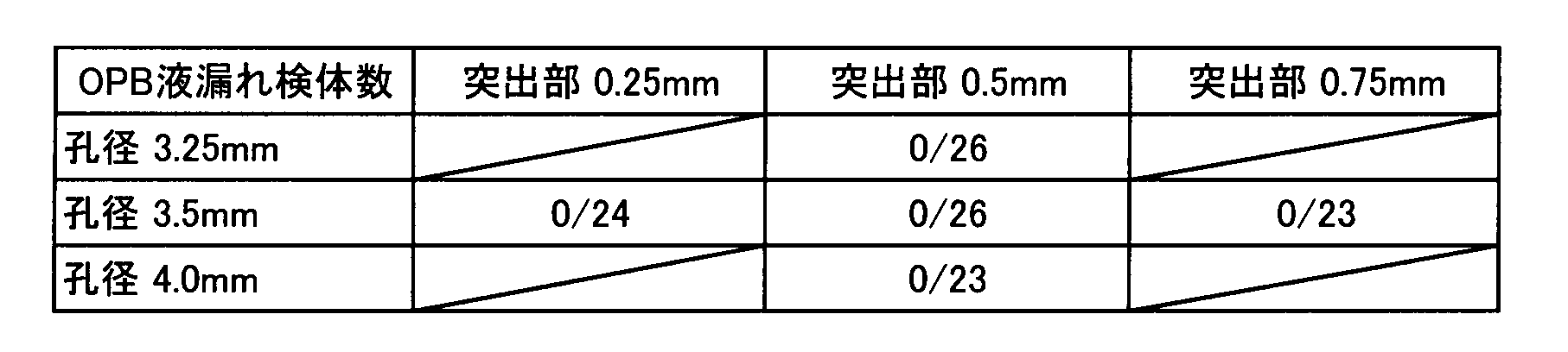
- Example 1 Using an applicator (25 mL) of the present invention provided with a polyethylene coating pad having a porosity of 87% and a weir having a protrusion, a liquid leakage test of oranexidine liquid (OPB) was performed.
- the diameter of the inclined outflow hole (the intermediate value between the major axis and the minor axis) was 3.25 mm, 3.5 mm, or 4.0 mm, and the protrusion was 0.25 mm, 0.5 mm, or 0.75 mm.
- the results are shown in Table 1.
- the fractional denominator represents the total number of samples, and the numerator represents the number of leaked samples. As can be seen from Table 1, there was no liquid leakage when the diameter of the inclined outflow hole was 3.25 to 4.0 mm.
- Example 2 Using the applicator (10 mL) of the present invention provided with a polyethylene coating pad having a porosity of 87% and a weir with protrusions, a liquid leak test of olanexidine liquid (OPB) and popidone iodine liquid (PVI) was performed.
- OLB olanexidine liquid
- PV popidone iodine liquid
- the diameter of the inclined outflow hole (intermediate value between the major axis and the minor axis) was set to 4.25 mm or 4.5 mm, which was slightly larger than that of Example 1, and the protrusion was 0.25 mm or 0.5 mm.
- Tables 2 and 3 As a result, it was found that even if the hole diameter was increased, liquid leakage hardly occurred.
- the olanexidine liquid used in Examples 1 and 2 and the comparative example was an aqueous solution containing gluconic acid and polyalkylene glycol having a concentration of olanexidine of 1.5%, and its viscosity was 1.2 mPa ⁇ s.
- the popidone iodine solution used in Example 2 and Comparative Example is a 10% popidone iodine preparation, which contains glycerin, potassium iodide, lauromacrogol, anhydrous sodium hydrogen phosphate, citrate hydrate and sodium hydroxide.
- the viscosity was 4.5 mPa ⁇ s.
- the viscosity was measured at a temperature of 20 ° C. in accordance with a viscosity measuring method using a cone-plate rotational viscometer according to JIS Z8803 liquid viscosity measuring method.
- the medical liquid applicator of the present invention is useful in medical fields such as surgery.
Landscapes
- Health & Medical Sciences (AREA)
- Life Sciences & Earth Sciences (AREA)
- Veterinary Medicine (AREA)
- Public Health (AREA)
- General Health & Medical Sciences (AREA)
- Animal Behavior & Ethology (AREA)
- Medicinal Chemistry (AREA)
- Chemical & Material Sciences (AREA)
- Pharmacology & Pharmacy (AREA)
- Epidemiology (AREA)
- Hematology (AREA)
- Heart & Thoracic Surgery (AREA)
- Biomedical Technology (AREA)
- Anesthesiology (AREA)
- Engineering & Computer Science (AREA)
- Inorganic Chemistry (AREA)
- Media Introduction/Drainage Providing Device (AREA)
- Coating Apparatus (AREA)
Abstract
Description
本発明は、外科手術の分野で特に有用な、消毒液等の医療用液体を皮膚に塗布するためのアプリケータに関する。 The present invention relates to an applicator for applying a medical liquid such as a disinfecting liquid to the skin, which is particularly useful in the field of surgery.
従来、手術前の外科用洗浄剤や消毒液を皮膚に塗布するためのアプリケータとしては、手術前の外科用洗浄又は塗布剤を皮膚に塗布するのに特に有用である、破断可能なタンク容器内に収納された液体を表面に塗布するための送り出し装置を備えた液体アプリケータ(特許文献1)や、液体入りガラス・アンプルを受け入れる柔軟な細長い中空円筒体を有するとともに、液体を小分け排出するためにアンプルの破砕機構を備えた携帯型液体アプリケータ(特許文献2)や、容器を備える中空の細長い部材と、前記中空の細長い部材から半径方向に外側に延びるフランジと、前記フランジに取り付けられている分配器要素とを有する、流体を塗布又は供給するためのアプリケータであって、前記分配器要素は、少なくとも2つのオリフィスと、少なくとも2つのオリフィスを分離する突出要素と、前記分配器要素の前記第1の側に取り付けられている吸収パッドとを含む、アプリケータ(特許文献3)が知られている。 Conventionally, a breakable tank container that is particularly useful for applying pre-surgical surgical cleaning or application to the skin as an applicator for applying pre-surgical surgical cleaning or disinfecting liquid to the skin It has a liquid applicator (Patent Document 1) equipped with a delivery device for applying the liquid contained in the surface to the surface, and a flexible elongated hollow cylindrical body that accepts a glass-filled glass ampoule, and discharges the liquid in small portions. For this purpose, a portable liquid applicator (Patent Document 2) having an ampoule crushing mechanism, a hollow elongated member having a container, a flange extending radially outward from the hollow elongated member, and attached to the flange An applicator for applying or delivering fluid, the distributor element comprising at least two orifices and And projecting elements for separating at least two orifices, including an absorbent pad attached to the first side of the distributor element, the applicator (Patent Document 3) are known.
また、所望の表面に消毒剤を塗布するための、並びに消毒剤に由来する望ましくない副産物を選択的に除去するためのアプリケータ(特許文献4)、流体を収容するためのパケットと、パケットに外部圧力を印加してパケットを圧縮し、流体をパケットから解放することを可能にするように構成された可撓性の蓋を有するハンドルを備えたアプリケータ・デバイス(特許文献5)や、細長い中空体と塗布パッドと中空体内に挿入されるアクチュエータ・スリーブを有し、長手方向突出部を有するアクチュエータ・スリーブが中空体内を移動するとき、中空体の中の液体容器の蓋部に対して作用して開放し、液体容器から塗布パッドに液体を放出する塗布具(特許文献6)や、筒状に形成された本体部と、該本体部の一方の端部に装着された薬液を含浸する多孔質体と、他方の端部に嵌合されたスリットを有するキャップと、からなる外容器と、摘み部を有する蓋材にてシールされ前記薬液が封入された内容器と、からなる液体塗布具であって、前記内容器が、前記本体部に収納され、前記摘み部が前記キャップの方向に折り返され、前記スリットを通して前記外容器の外側に飛び出していることを特徴とする液体塗布具(特許文献7)が知られている。 In addition, an applicator (Patent Document 4) for applying a disinfectant to a desired surface and selectively removing undesirable by-products derived from the disinfectant, a packet for containing fluid, and a packet An applicator device (US Pat. No. 6,099,049) with a handle having a flexible lid configured to apply external pressure to compress the packet and release fluid from the packet; An actuator sleeve having a hollow body, an application pad, and an actuator sleeve inserted into the hollow body, and the actuator sleeve having a longitudinal protruding portion acts on the lid of the liquid container in the hollow body when moving in the hollow body And is applied to the applicator (Patent Document 6) that releases the liquid from the liquid container to the applicator pad, the cylindrical main body, and one end of the main body. A porous body impregnated with a liquid, a cap having a slit fitted to the other end, an outer container, an inner container sealed with a lid member having a knob and sealed with the chemical liquid; A liquid applicator comprising: the inner container is housed in the main body, the knob is folded in the direction of the cap, and protrudes to the outside of the outer container through the slit. A liquid applicator (Patent Document 7) is known.
そしてまた、一方の端部に開口口を有し、他方の端部に含浸性を有する多孔質体が装着された、筒状に延長された本体と、薬液が充填され口部をシール材で封止されたボトルと、前記本体と前記ボトルとを連結する略筒状の接続体と、からなる液体塗布具であって、前記接続体は、内面に前記ボトルの口元と螺合するためのネジ状部と、外面に前記開口口に連携して可動する凸状リブと、が形成され、前記開口口は、側壁に、前記凸状リブをガイドする略S字状のガイド溝が形成され、内面に、中間棚が形成され、該中間棚の内面に前記シール材を破材するための穴を有した先端が鋭角な内筒が、軸線に沿って前記口部の方向に形成されていることを特徴とする液体塗布具(特許文献8)や、液体充填アンプルを受容するのに好適な中空本体と一体的に形成された、ヒンジ、握り部および足部を有するレバーを備え、足部はアンプルに隣接して位置付けられ、かつレバーが押し下げられるとアンプルを破砕して液体を放出するアプリケータ(特許文献9)が知られている。 In addition, the main body extended in a cylindrical shape having an opening at one end and a porous body having an impregnating property at the other end, and a mouth filled with a chemical solution and sealed with a sealing material A liquid applicator comprising a sealed bottle, and a substantially cylindrical connecting body for connecting the main body and the bottle, wherein the connecting body is screwed onto an inner surface of the bottle mouth. A screw-shaped part and a convex rib that moves in cooperation with the opening are formed on the outer surface, and a substantially S-shaped guide groove that guides the convex rib is formed on a side wall of the opening. An inner shelf is formed on the inner surface, and an inner cylinder having a sharp tip with a hole for breaking the sealing material on the inner surface of the intermediate shelf is formed in the direction of the mouth along the axis. A liquid applicator (Patent Document 8) characterized by having a hollow book suitable for receiving a liquid-filled ampoule A lever having a hinge, a grip and a foot, formed integrally with the foot, the foot is positioned adjacent to the ampoule, and when the lever is depressed, the applicator crushes the ampoule to release liquid ( Patent document 9) is known.
本発明の課題は、塗布パッドから適量の消毒液等の医療用液体が均一に滲出し、所定量を正確に塗布することができる医療用液体のアプリケータを提供することにある。 An object of the present invention is to provide a medical liquid applicator capable of uniformly exuding an appropriate amount of medical liquid such as a disinfectant from an application pad and applying a predetermined amount accurately.
従来、下端に塗布パッドを有する中空の筒状部材に内蔵した消毒液等の液体を収容した容器を開裂させて、液体を筒状部材内に解放放出し、筒状部材の底部の孔から液体を流出させ、流出した液体を塗布パッドに浸透させ、皮膚に塗布するタイプのアプリケータにおいては、液体容器の開裂直後に液体が急激且つ一方向的に流出し、不均一に塗布パッドに浸透した結果、塗布する前や塗布中に液体が塗布パッドから滴下・液漏れすることがあったり、逆に液体の塗布パッドへの浸透量が部分的に少なくなり、スムーズに塗布パッドで均一に塗布できないことがあるという問題があった。 Conventionally, a container containing a liquid such as a disinfectant contained in a hollow cylindrical member having an application pad at the lower end is cleaved to release and release the liquid into the cylindrical member, and the liquid is released from the hole at the bottom of the cylindrical member. In a type of applicator in which the liquid that has flowed out is allowed to permeate the application pad and is applied to the skin, the liquid suddenly and unidirectionally flows immediately after the liquid container is opened, and unevenly penetrates the application pad. As a result, liquid may drip or leak from the application pad before or during application, or on the contrary, the amount of penetration of the liquid into the application pad may be partially reduced, and smooth application with the application pad is not possible. There was a problem that there was something.
そこで、本発明者らは上記課題を解決すべく、塗布パッドの形状、塗布パッドの表面状態、塗布パッドの材質、塗布パッドの取付板における周縁土手部に囲まれた凹部の容積、取付板の基底部に傾斜して開口している傾斜流出孔の大きさ、容器の開裂の仕方、消毒薬の種類等について種々検討する過程で、堰を設けることで流量や流れ方向を調節することができないかとの考えに至った。そして堰の形状や高さ・傾きについて試行錯誤を繰り返した結果、傾斜流出孔を円弧の中心側とする円弧状や三日月状の堰を設ける、とりわけ取付板周縁の土手部より僅かに高い堰を設けることにより、上記課題が解決できることを見いだした。 Therefore, in order to solve the above problems, the inventors of the present invention have applied the shape of the coating pad, the surface state of the coating pad, the material of the coating pad, the volume of the recess surrounded by the peripheral bank portion of the mounting pad mounting plate, The flow rate and flow direction cannot be adjusted by providing a weir in the course of various investigations regarding the size of the inclined outflow hole that is inclined and opened to the base, the method of cleaving the container, the type of disinfectant, etc. I came up with the idea. As a result of repeated trial and error on the shape, height, and inclination of the weir, an arc-shaped or crescent-shaped weir with an inclined outflow hole as the center side of the arc is provided, and a weir that is slightly higher than the bank at the periphery of the mounting plate. It was found that the above-mentioned problems can be solved by providing them.
すなわち本発明は以下のとおりである。
[1]中空の筒状部材と、該筒状部材に内蔵されている液体容器と、該液体容器の開裂手段とを備えたハンドル部;及び、前記筒状部材の下端に傾斜断面となるように固着されている塗布パッドの取付板と、該取付板に付着された塗布パッドとを備えた塗布部;を有する医療用液体のアプリケータであって、
前記取付板には、周縁が肉厚に形成された土手部、中央が凹部に形成された基底部、基底部中央付近に前記液体容器から解放放出された溶液が取付板先端方向に向かって流出するように、基底部に対して傾斜開口している傾斜流出孔、及び、該傾斜流出孔から取付板先端方向の基底部に傾斜流出孔を円弧の中心側とする円弧状又は三日月状に堰が設けられていることを特徴とする医療用液体のアプリケータ。
[2]筒状部材が、下方に向かって細くなるテーパーを有する円筒形状であることを特徴とする上記[1]記載のアプリケータ。
[3]液体容器の開裂手段が、筒状部材に挿入されているアクチュエータ・スリーブであることを特徴とする上記[1]又は[2]記載のアプリケータ。
[4]塗布パッドと取付板が略オムスビ形状であることを特徴とする上記[1]~[3]のいずれか記載のアプリケータ。
[5]取付板上面を基準として、筒状部材の中心軸が取付板上面に対して、40~50°傾斜していることを特徴とする上記[1]~[4]のいずれか記載のアプリケータ。
[6]取付板上面を基準として、取付板上面に対して垂直方向の高さにおいて堰が土手部よりも0.1~1mm高いことを特徴とする上記[1]~[5]のいずれか記載のアプリケータ。
[7]堰が土手部よりも0.25~0.75mm高いことを特徴とする上記[6]記載のアプリケータ。
[8]円弧状又は三日月状に設けられている堰が、基底部表面を基準として、円弧の中心側からしてその上端に行くにしたがって遠ざかる方向に40~50°傾斜していることを特徴とする上記[1]~[7]のいずれか記載のアプリケータ。
That is, the present invention is as follows.
[1] A handle portion including a hollow cylindrical member, a liquid container built in the cylindrical member, and a means for cleaving the liquid container; and a lower end of the cylindrical member having an inclined cross section A medical liquid applicator comprising: an application pad attachment plate fixed to the application plate; and an application part comprising an application pad attached to the attachment plate;
The mounting plate includes a bank portion having a thick peripheral edge, a base portion formed in a concave portion in the center, and a solution released and released from the liquid container in the vicinity of the center of the base portion flows toward the tip end of the mounting plate. Inclined outflow holes that are inclined to the base, and weirs in the shape of an arc or crescent with the inclined outflow holes extending from the inclined outflow holes to the base in the tip direction of the mounting plate. An applicator for medical liquid, characterized in that is provided.
[2] The applicator according to the above [1], wherein the cylindrical member has a cylindrical shape having a taper that narrows downward.
[3] The applicator as described in [1] or [2] above, wherein the means for cleaving the liquid container is an actuator sleeve inserted into a cylindrical member.
[4] The applicator according to any one of the above [1] to [3], wherein the coating pad and the mounting plate have a substantially mussel shape.
[5] Any one of the above [1] to [4], wherein the central axis of the cylindrical member is inclined by 40 to 50 ° with respect to the upper surface of the mounting plate with reference to the upper surface of the mounting plate. applicator.
[6] Any one of the above [1] to [5], wherein the weir is 0.1 to 1 mm higher than the bank at a height in a direction perpendicular to the top surface of the mounting plate with respect to the top surface of the mounting plate The applicator described.
[7] The applicator according to the above [6], wherein the weir is 0.25 to 0.75 mm higher than the bank portion.
[8] The weir provided in an arc shape or a crescent shape is inclined by 40 to 50 ° in a direction away from the center side of the arc toward the upper end with respect to the base surface. The applicator according to any one of [1] to [7] above.
本発明のアプリケータによると、塗布パッドから消毒液等の医療用液体がしたたり落ちることなく、塗布パッドから適量の消毒液等の医療用液体が均一に滲出し、皮膚に所定量を正確に塗布することができる。 According to the applicator of the present invention, an appropriate amount of medical liquid such as a disinfectant liquid oozes uniformly from the application pad without dripping or dropping the disinfectant liquid from the application pad, and a predetermined amount is accurately applied to the skin. Can be applied.
以下の説明において、上下とは、図1~4における右側を「上」、左側を「下」といい、先端とは、図5及び7における左側、図6における左斜め上をいう。 In the following description, “upper and lower” means “upper” on the right side in FIGS. 1 to 4 and “lower” on the left side, and “tip” means an upper left side in FIGS. 5 and 7 and an upper left side in FIG.
本発明の医療用液体のアプリケータは、中空の筒状部材と、該筒状部材に内蔵されている液体容器と、該液体容器の開裂手段とを備えたハンドル部;及び、前記筒状部材の下端に傾斜断面となるように固着されている塗布パッドの取付板と、該取付板に付着された塗布パッドとを備えた塗布部を有していれば特に制限されないが、塗布パッドの取付板の構造に特徴を有するものであり、ハンドル部や塗布パッドについては、前述の特許文献1~9に開示された技術を基本的に適用することができる。
The medical liquid applicator according to the present invention includes a hollow cylindrical member, a liquid container built in the cylindrical member, and a handle portion provided with means for cleaving the liquid container; and the cylindrical member Although there is no particular limitation as long as it has a coating portion provided with a coating plate attached to the lower end of the coating pad so as to have an inclined cross section and a coating pad attached to the mounting plate, The technique is characterized by the structure of the plate, and the techniques disclosed in
本発明のアプリケータのハンドル部を形成する中空の細長い筒状部材としては、開裂手段により、筒状部材に内蔵されている液体容器が開裂され、液体容器から液体が解放・放出され、解放・放出された液体が筒状部材の上部から流失することなく、取付板の基底部に設けられた傾斜流出孔から流出する構造を有しておればよく、例えば、長さが10~20cm、直径や長辺が2~4cmの断面円形、楕円、矩形等の細長い中空筒状部材を挙げることができるが、下方に向かって縮径するテーパー状の円筒形状を好適に例示することができる。筒状容器の下端には、傾斜断面となるように塗布パッドの取付板が一体的に固着されている。また、取付板上面を水平基準とすると、筒状部材の中心軸は取付板上面に対して、30~60°、好ましくは40~50°傾斜して立設されている。筒状部材はプラスティック製で、ポリエチレン、ポリプロピレンなどのオレフィン系樹脂;ポリエチレンテレフタレート樹脂;ポリアミド樹脂;メチルメタクリレートブタジエンスチレン、メチルメタクリレートブタジエンスチレンn-ブチルアクリレートなどのMBS樹脂等で作製されるが、成型性、剛性などから適宜樹脂の選定、厚みの設定をすればよく、成型方法としては、射出成形、押出成形等を挙げることができる。 As the hollow elongated cylindrical member forming the handle portion of the applicator of the present invention, the liquid container contained in the cylindrical member is cleaved by the cleaving means, and the liquid is released / released from the liquid container. It is sufficient that the discharged liquid does not flow out from the upper part of the cylindrical member and flows out from the inclined outflow hole provided in the base portion of the mounting plate. For example, the length is 10 to 20 cm and the diameter is An elongated hollow cylindrical member having a long side of 2 to 4 cm in cross section, an ellipse, a rectangle or the like can be mentioned, and a tapered cylindrical shape whose diameter is reduced downward can be preferably exemplified. A mounting plate for the application pad is integrally fixed to the lower end of the cylindrical container so as to have an inclined cross section. If the upper surface of the mounting plate is the horizontal reference, the central axis of the cylindrical member is erected with an inclination of 30 to 60 °, preferably 40 to 50 ° with respect to the upper surface of the mounting plate. The cylindrical member is made of plastic and is made of olefin resin such as polyethylene and polypropylene; polyethylene terephthalate resin; polyamide resin; MBS resin such as methyl methacrylate butadiene styrene and methyl methacrylate butadiene styrene n-butyl acrylate, etc. The resin may be selected and the thickness may be set as appropriate based on rigidity and the like, and examples of the molding method include injection molding and extrusion molding.
上記液体容器としては、消毒液、洗浄液等の医薬用液体が収容されており、筒状部材に内蔵することができ、開裂手段により液体が解放・放出され、解放・放出された液体が筒状部材の上部から流失することなく、取付板の基底部に設けられた傾斜流出孔から流出することができればよく、例えば、脆性アンプル、圧潰可能な容器、穿孔可能な容器、キャップが外れる容器などを挙げることができる。 The liquid container contains a liquid for medical use such as a disinfectant liquid and a cleaning liquid, and can be built in a cylindrical member. The liquid is released / released by the cleaving means, and the released / released liquid is cylindrical. It is only necessary to be able to flow out from the inclined outflow hole provided in the base portion of the mounting plate without flowing out from the upper part of the member.For example, a brittle ampoule, a collapsible container, a pierceable container, a container from which a cap is removed, etc. Can be mentioned.
上記開裂手段としては、筒状部材に内蔵されている液体容器を開裂し、液体容器から液体を解放・放出することができ、解放・放出された液体が筒状部材の上部から流失することなく、取付板の基底部に設けられた傾斜流出孔から流出させることができる手段であればよく、例えば、上端にキャップのある筒状部材に内蔵された脆性アンプルに対するレバー等のアンプル破壊用手段(特許文献1~4及び9)、液体を収容するバケットを圧縮させる外部圧力印加手段(特許文献5)、筒状部材中を下方に押し下げることにより、液体容器の蓋を外すアクチュエータ・スリーブ(特許文献6)、液体容器を開封するためのシール剥がし手段(特許文献7及び8)等を挙げることができるが、液体容器の蓋を外すアクチュエータ・スリーブを好適に例示することができる。
As the above-mentioned cleaving means, the liquid container built in the cylindrical member can be cleaved, and the liquid can be released / released from the liquid container, so that the released / released liquid does not flow out from the upper part of the cylindrical member. Any means can be used as long as it can flow out from the inclined outflow hole provided in the base portion of the mounting plate. For example, ampule breaking means such as a lever for a brittle ampule built in a cylindrical member having a cap at the upper end (
上記塗布パッドの形状としては、例えば、1.5~2mm程度の厚みを有する平面視が略オムスビ形状、長方形状、長円形状、円形状、三角形状、楕円形状等を挙げることができるが、塗布のスムーズさや取り扱いやすさの点で略オムスビ形状とすることが好ましい。また、塗布パッドの材質としては、消毒液等の液体を浸透含浸する性質を有する多孔質材料を好適に例示することができるが、その他の織物、不織布なども使用することができる。かかる多孔質材料等の原料としては、ポリオレフィン系、ポリウレタン系、ポリエチレテレフタレート系などの樹脂やセルロース系の線維を挙げることができる。かかる塗布パッドは、取付板に形成された土手部の頂面に熱融着又は接着剤により装着することができる。 Examples of the shape of the application pad include a substantially mussel shape, a rectangular shape, an oval shape, a circular shape, a triangular shape, and an elliptical shape in a plan view having a thickness of about 1.5 to 2 mm. In view of smooth application and ease of handling, it is preferable to have a substantially mussel shape. Moreover, as a material of an application pad, the porous material which has the property which osmose-impregnates liquids, such as disinfection liquid, can be illustrated suitably, However, Other textiles, a nonwoven fabric, etc. can also be used. Examples of the raw material for the porous material include polyolefin-based, polyurethane-based, polyethylene terephthalate-based resins, and cellulose-based fibers. Such a coating pad can be attached to the top surface of the bank portion formed on the mounting plate by heat fusion or an adhesive.
上記取付板には、周縁が肉厚で頂面が平坦に形成された土手部、中央が凹部で底面が平坦に形成された基底部、基底部中央付近に前記溶液が取付板先端方向に向かって流出するように、基底部に対して傾斜開口している傾斜流出孔、及び、該傾斜流出孔から取付板先端方向の基底部に傾斜流出孔を円弧の中心側とする円弧状又は三日月状に堰が設けられている。また、上記取付板の形状としては、上記塗布パッドと同形状が好ましく、例えば略オムスビ形状の場合、基底部の形状も略オムスビ形状となり、その中心部附近に傾斜流出孔が設けられることになる。 The mounting plate has a bank portion with a thick peripheral edge and a flat top surface, a base portion with a concave center and a flat bottom surface, and the solution near the center of the base portion toward the tip of the mounting plate. A slanted outflow hole that is inclined with respect to the base part, and an arcuate or crescent shape with the slanted outflow hole extending from the slanted outflow hole to the base part in the tip end direction of the mounting plate. There is a weir. In addition, the shape of the mounting plate is preferably the same shape as the coating pad. For example, in the case of a substantially mussel shape, the shape of the base portion is also a substantially mussel shape, and an inclined outflow hole is provided near the center portion. .
傾斜流出孔は、基底部表面では先後方向に長い長円形状で開口し、孔の大きさはアプリケータの大きさにもよるが、通常長径が4~6.5mm、短径3~5mm程度である。また、堰は、基底部に傾斜流出孔を円弧の中心側とする円弧状又は三日月状に設けられるが、堰に対する傾斜流出孔の位置は、円弧の弦上から円弧と弦の間の円弧よりまで基底部の大きさにより適宜位置決めすることができ、傾斜流出孔(長円)先端から堰までの最短距離は2~3mmとすることが好ましい。 The inclined outflow hole opens in the shape of an ellipse that is long in the front-rear direction on the surface of the base, and the size of the hole depends on the size of the applicator, but usually the major axis is about 4 to 6.5 mm and the minor axis is about 3 to 5 mm. It is. In addition, the weir is provided in an arc shape or crescent shape with an inclined outflow hole at the center side of the arc at the base, but the position of the inclined outflow hole with respect to the weir is from the arc between the arc and the string from the arc string. It is preferable that the shortest distance from the tip of the inclined outflow hole (oval) to the weir is 2 to 3 mm.
円弧状又は三日月状に設けられている堰が、基底部表面を基準として、その上端に行くにしたがって円弧の中心側からして同心円状に遠ざかる方向に40~50°傾斜していることが好ましい。このように基底部表面に対して傾斜曲面として形成されていることにより、堰により阻まれた液体の流れを効率よく反転逆流させることができ、その結果溶液の一方的な先端方向への流れを規制して、塗布パッドに溶液を均一に浸透させることができる。 It is preferable that the weir provided in an arc shape or a crescent shape is inclined by 40 to 50 ° in a direction concentrically away from the center side of the arc as it goes to the upper end with respect to the base surface. . By forming the inclined curved surface with respect to the base surface in this way, the flow of the liquid blocked by the weir can be efficiently reversed and reversed, and as a result, the flow of the solution toward the one-side tip direction can be performed. The solution can be uniformly permeated into the coating pad by regulating.
また、取付板上面を基準として、取付板上面に対して垂直方向の高さにおいて堰が土手部よりも高くすることが好ましく、高い部分(以下「突出部」ということもある)が、例えば0.1~1mm、とりわけ0.25~0.75mmであることが好ましい。土手部よりも堰が高いことにより、堰の頂上部が塗布パットに食い込むことによって、液流が堰を乗り越えることを防止し、確実に反転逆流させることができる。特に、堰が傾斜曲面状の場合は液流が堰を乗り越えやすくなるので、堰を土手部よりも高くして堰の頂上部を塗布パットに食い込ませて、確実に反転逆流させることが好ましい。 Further, it is preferable that the weir is higher than the bank at a height in a direction perpendicular to the upper surface of the mounting plate with respect to the upper surface of the mounting plate, and the high portion (hereinafter sometimes referred to as “protruding portion”) is, for example, 0 It is preferably 1 to 1 mm, particularly preferably 0.25 to 0.75 mm. Since the dam is higher than the bank portion, the top of the dam bites into the coating pad, so that the liquid flow can be prevented from getting over the dam, and the reverse flow can be reliably reversed. In particular, when the weir has an inclined curved surface, the liquid flow easily gets over the weir. Therefore, it is preferable that the weir is made higher than the bank and the top of the weir is bitten into the coating pad so that the reverse flow is surely reversed.
上記医療用液体としては、消毒液や洗浄液を挙げることができ、より具体的には、ポビドンヨード液、エタノール液、イソプロパノール液、ヨウ化カリウム液、塩化ベンザルコニウム液、塩化ベンゼトニウム液、グルコン酸クロルヘキシジン液、グルタルアルデヒド液、オラネキシジン[1-(3,4-ジクロロベンジル)-5-オクチルビグアニド]液等を挙げることができ、これらは二種以上混合して用いることもできる。かかる医療用液体は、手術の直前に局所領域に塗布して用いることができる。 Examples of the medical liquid include a disinfectant solution and a cleaning solution, and more specifically, povidone iodine solution, ethanol solution, isopropanol solution, potassium iodide solution, benzalkonium chloride solution, benzethonium chloride solution, chlorhexidine gluconate. Liquid, glutaraldehyde liquid, olanexidine [1- (3,4-dichlorobenzyl) -5-octyl biguanide] liquid, and the like. These may be used in a mixture of two or more. Such medical liquid can be applied to a local area immediately before surgery.
上記医療用液体は消毒成分や洗浄成分などの有効成分を液剤化したものであれば特に限定されず、例えば有効成分を精製水で希釈した水性製剤であってもよいし、エタノールやイソプロパノールなどの精製アルコールやこれらの水溶液で希釈したアルコール製剤であってもよい。有効成分の濃度も任意である。またアルコール製剤の場合のアルコール濃度も任意である。本医療用液体には有効成分の他、通常水性製剤やアルコール製剤として用いられている添加剤、例えば防腐剤、保湿剤、増粘剤、非イオン性界面活性剤、陽イオン性界面活性剤、抗酸化剤、香料、着色剤等も使用できる。液剤の粘度は塗布パッドを使用して塗布するのに実用上の支障がない範囲であれば限定されるものではないが、0.5~15.0mPa・sが好ましい。また、本発明のアプリケータは液漏れしやすい低粘度の液剤、即ち粘度が0.5~4.0mPa・s、特に0.5~2.5mPa・sである液剤にも好適に用いることができる。ここで上記粘度はJIS Z8803 液体の粘度測定方法 円すい-平板形回転粘度計による粘度測定方法に準拠して測定される数値であり、測定温度は20℃である。 The medical liquid is not particularly limited as long as it is obtained by liquefying an active ingredient such as a disinfecting ingredient or a cleaning ingredient. For example, the medical liquid may be an aqueous preparation in which the active ingredient is diluted with purified water, or ethanol, isopropanol, etc. It may be an alcohol preparation diluted with purified alcohol or an aqueous solution thereof. The concentration of the active ingredient is also arbitrary. Moreover, the alcohol concentration in the case of an alcohol preparation is also arbitrary. In addition to the active ingredients in this medical liquid, additives usually used as aqueous preparations and alcohol preparations, such as preservatives, moisturizers, thickeners, nonionic surfactants, cationic surfactants, Antioxidants, fragrances, colorants and the like can also be used. The viscosity of the liquid is not limited as long as it does not impede practical use for application using an application pad, but is preferably 0.5 to 15.0 mPa · s. The applicator of the present invention is also preferably used for a low-viscosity liquid that easily leaks, that is, a liquid having a viscosity of 0.5 to 4.0 mPa · s, particularly 0.5 to 2.5 mPa · s. it can. Here, the above viscosity is a numerical value measured according to a viscosity measuring method using a JIS Z8803 liquid viscosity measuring method, a cone-plate rotational viscometer, and a measurement temperature is 20 ° C.
本発明のアプリケータは、手術の直前に対象の局所領域に適用され、まず、ハンドル部の開裂手段を用いて液体容器を破砕、脱シール、脱蓋等により液体容器から液体を筒状部材内に解放・放出させ、傾斜流出孔から塗布部へと流出させる。傾斜流出孔から流出した液体の殆どは、取付板先端方向に向かって流れるが、堰により阻まれて一度後方へ反転・逆流し、土手部と堰の間の左右2つの隙間から回り込むようにして基底部先端方向へ流れ込むことになり、液体の流れが調節される。そして、液体が塗布パッドに十分浸透した後に皮膚に塗布される。 The applicator according to the present invention is applied to a target local region immediately before surgery. First, the liquid container is crushed, removed, and uncapped using a cleaving means of the handle, and the liquid is discharged from the liquid container into the cylindrical member. To release and discharge to the application part from the inclined outflow hole. Most of the liquid that flows out from the inclined outflow hole flows toward the mounting plate tip, but it is blocked by the weir and once reverses and backflows so that it goes around from the left and right gaps between the bank and the weir. The liquid flows in the direction toward the tip of the base, and the flow of the liquid is adjusted. The liquid is applied to the skin after sufficiently penetrating the application pad.
以下、本発明の医療用液体のアプリケータの実施態様を図面により説明する。図1~6に示されているアプリケータ1は、中空の筒状部材2と、該筒状部材2に内蔵されている液体容器3と、筒状部材2に挿入されているアクチュエータ・スリーブ4とを備えたハンドル部、及び、筒状部材2の下端に傾斜断面となるように固着されている塗布パッド5の取付板10と、該取付板10に付着された略オムスビ形状の塗布パッド5とを備えた塗布部から構成されている。筒状部材2と取付板10とはメチルメタクリレートブタジエンスチレン樹脂製で一体成形されており、塗布パッド5は空隙率87%のポリエチレン製である。
Hereinafter, embodiments of the medical liquid applicator of the present invention will be described with reference to the drawings. The
下方に向かって細くなるテーパーを有する円筒形状の筒状部材2は、その最大外径約28mmで長さ(中心軸)が約18.5cmであり、取付板上面11を基準として、筒状部材2の中心軸が取付板上面11に対して、略45°傾斜している。取付板10の形状も塗布パッド5より少し小さめの相似形である略オムスビ形状をしており、先後方向の長さ約6cm、後方部の幅が約4.5cmである。
The cylindrical
上記取付板10には、周縁が肉厚に形成された土手部12、中央が凹部に形成された基底部13、基底部中央付近に前記溶液が取付板先端方向に向かって流出するように、基底部13に対して傾斜開口している傾斜流出孔14、及び、該傾斜流出孔14から取付板先端方向の基底部13に傾斜流出孔14を円弧の中心側とする円弧状に堰15が設けられている。土手部12に対する基底部13の深さは約2mmであり、また傾斜流出孔14の径(長径と短径の中間値)は約3.5mm(25mL)又は約4.5mm(10mL)であり、円弧と弦の間の円弧よりに傾斜流出孔14が設けられている。
The mounting
堰15は、取付板上面11を基準として、取付板上面11に対して垂直方向の高さにおいて土手部12よりも0.5mm高く(突出部0.5mm)、また、円弧状に設けられている堰15は、基底部表面16を基準として、その上端に行くにしたがって円弧の中心側からして同心円状に遠ざかる方向に45°傾斜して設けられている。堰15の厚みは約1.5mmである。
The
[実施例1]
空隙率87%のポリエチレン製塗布パッドと突出部を有する堰を備えた本発明のアプリケータ(25mL)を用いて、オラネキシジン液(OPB)の液漏れ試験を実施した。傾斜流出孔の孔径(長径と短径の中間値)は、3.25mm、3.5mm、又は4.0mmとし、突出部は0.25mm、0.5mm、又は0.75mmとした。結果を表1に示す。表中の分数表記の分母は総サンプル数、分子は液漏れサンプル数を表す。表1からわかるように、傾斜流出孔の孔径が3.25~4.0mmでは液漏れはなかった。
[Example 1]
Using an applicator (25 mL) of the present invention provided with a polyethylene coating pad having a porosity of 87% and a weir having a protrusion, a liquid leakage test of oranexidine liquid (OPB) was performed. The diameter of the inclined outflow hole (the intermediate value between the major axis and the minor axis) was 3.25 mm, 3.5 mm, or 4.0 mm, and the protrusion was 0.25 mm, 0.5 mm, or 0.75 mm. The results are shown in Table 1. In the table, the fractional denominator represents the total number of samples, and the numerator represents the number of leaked samples. As can be seen from Table 1, there was no liquid leakage when the diameter of the inclined outflow hole was 3.25 to 4.0 mm.
[実施例2]
空隙率87%のポリエチレン製塗布パッドと突出部を有する堰を備えた本発明のアプリケータ(10mL)を用いて、オラネキシジン液(OPB)とポピドンヨード液(PVI)の液漏れ試験を実施した。傾斜流出孔の孔径(長径と短径の中間値)は、実施例1より少し大きく4.25mm又は4.5mmとし、突出部は0.25mm又は0.5mmとした。結果を表2と表3に示す。その結果、孔径を大きくしても、ほとんど液漏れしないことがわかった。
[Example 2]
Using the applicator (10 mL) of the present invention provided with a polyethylene coating pad having a porosity of 87% and a weir with protrusions, a liquid leak test of olanexidine liquid (OPB) and popidone iodine liquid (PVI) was performed. The diameter of the inclined outflow hole (intermediate value between the major axis and the minor axis) was set to 4.25 mm or 4.5 mm, which was slightly larger than that of Example 1, and the protrusion was 0.25 mm or 0.5 mm. The results are shown in Tables 2 and 3. As a result, it was found that even if the hole diameter was increased, liquid leakage hardly occurred.


[比較例]
空隙率87%のポリエチレン製塗布パッドを備え、堰を備えていない、傾斜流出孔の孔径(長径と短径の中間値)2.5mmの従来のアプリケータ(10mL)及びアプリケータ(25mL)を用いて、オラネキシジン液(OPB)とポピドンヨード液(PVI)のそれぞれ液漏れ試験を実施した。PVIについては、アプリケータ(10mL)及びアプリケータ(25mL)の両方とも液漏れが認められなかったが、OPBについては、孔径2.5mmにもかかわらず、アプリケータ(10mL)及びアプリケータ(25mL)の両方ともかなりの液漏れが認められた。
[Comparative example]
A conventional applicator (10 mL) and an applicator (25 mL) with a diameter of the outflow hole (intermediate value of major axis and minor axis) of 2.5 mm, which is provided with a polyethylene coating pad with a porosity of 87% and no weir. Using this, each of the olenexidine liquid (OPB) and the popidone iodine liquid (PVI) was subjected to a liquid leakage test. For PVI, neither applicator (10 mL) nor applicator (25 mL) leaked, but for OPB, applicator (10 mL) and applicator (25 mL) despite a 2.5 mm pore size. In both cases, considerable leakage was observed.
上記実施例1、2及び比較例で用いたオラネキシジン液は、オラネキシジンの濃度が1.5%であるグルコン酸とポリアルキレングリコールを含む水溶液であり、その粘度は1.2mPa・sであった。また、実施例2、及び比較例で用いたポピドンヨード液は10%ポピドンヨード製剤であり、グリセリン、ヨウ化カリウム、ラウロマクロゴール、無水リン酸一水素ナトリウム、クエン酸水和物及び水酸化ナトリウムを含む水溶液であり、その粘度は4.5mPa・sであった。粘度はJIS Z8803 液体の粘度測定方法 円すい-平板形回転粘度計による粘度測定方法に準拠し、温度20℃で測定された。 The olanexidine liquid used in Examples 1 and 2 and the comparative example was an aqueous solution containing gluconic acid and polyalkylene glycol having a concentration of olanexidine of 1.5%, and its viscosity was 1.2 mPa · s. Moreover, the popidone iodine solution used in Example 2 and Comparative Example is a 10% popidone iodine preparation, which contains glycerin, potassium iodide, lauromacrogol, anhydrous sodium hydrogen phosphate, citrate hydrate and sodium hydroxide. The viscosity was 4.5 mPa · s. The viscosity was measured at a temperature of 20 ° C. in accordance with a viscosity measuring method using a cone-plate rotational viscometer according to JIS Z8803 liquid viscosity measuring method.
本発明の医療用液体のアプリケータは、外科手術等の医療分野で有用である。 The medical liquid applicator of the present invention is useful in medical fields such as surgery.
1 アプリケータ
2 筒状部材
3 液体容器
4 アクチュエータ・スリーブ
5 塗布パッド
10 取付板
11 取付板上面
12 土手部
13 基底部
14 傾斜流出孔
15 堰
16 基底部表面
DESCRIPTION OF
Claims (8)
前記取付板には、周縁が肉厚に形成された土手部、中央が凹部に形成された基底部、基底部中央付近に前記液体容器から解放放出された溶液が取付板先端方向に向かって流出するように、基底部に対して傾斜開口している傾斜流出孔、及び、該傾斜流出孔から取付板先端方向の基底部に傾斜流出孔を円弧の中心側とする円弧状又は三日月状に堰が設けられていることを特徴とする医療用液体のアプリケータ。 A handle having a hollow cylindrical member, a liquid container built in the cylindrical member, and a means for cleaving the liquid container; and a lower end of the cylindrical member fixed to the inclined section so as to have an inclined cross section. A medical liquid applicator comprising: a coating pad mounting plate; and a coating portion comprising a coating pad attached to the mounting plate;
The mounting plate includes a bank portion having a thick peripheral edge, a base portion formed in a concave portion in the center, and a solution released and released from the liquid container in the vicinity of the center of the base portion flows toward the tip end of the mounting plate. Inclined outflow holes that are inclined to the base, and weirs in the shape of an arc or crescent with the inclined outflow holes extending from the inclined outflow holes to the base in the tip direction of the mounting plate. An applicator for medical liquid, characterized in that is provided.
Priority Applications (18)
| Application Number | Priority Date | Filing Date | Title |
|---|---|---|---|
| SG11201709819XA SG11201709819XA (en) | 2015-06-25 | 2016-06-17 | Applicator for medical-use liquids |
| MX2017016659A MX2017016659A (en) | 2015-06-25 | 2016-06-17 | Applicator for medical-use liquids. |
| AU2016283630A AU2016283630B2 (en) | 2015-06-25 | 2016-06-17 | Applicator for medical-use liquids |
| CN201680036023.5A CN107735141B (en) | 2015-06-25 | 2016-06-17 | Applicator for medical liquids |
| JP2017524625A JP6343399B2 (en) | 2015-06-25 | 2016-06-17 | Medical liquid applicator |
| PL16813938.4T PL3315164T3 (en) | 2015-06-25 | 2016-06-17 | Applicator for medical-use liquids |
| HK18105789.4A HK1246222B (en) | 2015-06-25 | 2016-06-17 | Applicator for medical-use liquids |
| SI201631763T SI3315164T1 (en) | 2015-06-25 | 2016-06-17 | Applicator for medical-use liquids |
| ES16813938T ES2966963T3 (en) | 2015-06-25 | 2016-06-17 | Applicator for medical liquids |
| EP16813938.4A EP3315164B1 (en) | 2015-06-25 | 2016-06-17 | Applicator for medical-use liquids |
| CA2987027A CA2987027C (en) | 2015-06-25 | 2016-06-17 | Applicator for medical-use liquids |
| RU2017144789A RU2681063C1 (en) | 2015-06-25 | 2016-06-17 | Applicator for liquids of medical use |
| KR1020177036262A KR102028061B1 (en) | 2015-06-25 | 2016-06-17 | Applicator of Medical Liquid |
| BR112017025680-0A BR112017025680B1 (en) | 2015-06-25 | 2016-06-17 | APPLICATOR FOR MEDICAL USE LIQUIDS |
| US15/580,872 US11305101B2 (en) | 2015-06-25 | 2016-06-17 | Applicator for medical-use liquids |
| FIEP16813938.4T FI3315164T3 (en) | 2015-06-25 | 2016-06-17 | Applicator for medical-use liquids |
| DK16813938.4T DK3315164T3 (en) | 2015-06-25 | 2016-06-17 | Applicator for medical-use liquids |
| PH12017550144A PH12017550144A1 (en) | 2015-06-25 | 2017-12-18 | Applicator for medical-use liquids |
Applications Claiming Priority (4)
| Application Number | Priority Date | Filing Date | Title |
|---|---|---|---|
| JP2015128033 | 2015-06-25 | ||
| JP2015-128033 | 2015-06-25 | ||
| JP2015-172589 | 2015-09-02 | ||
| JP2015172589 | 2015-09-02 |
Publications (1)
| Publication Number | Publication Date |
|---|---|
| WO2016208166A1 true WO2016208166A1 (en) | 2016-12-29 |
Family
ID=57586212
Family Applications (1)
| Application Number | Title | Priority Date | Filing Date |
|---|---|---|---|
| PCT/JP2016/002924 Ceased WO2016208166A1 (en) | 2015-06-25 | 2016-06-17 | Applicator for medical-use liquids |
Country Status (22)
| Country | Link |
|---|---|
| US (1) | US11305101B2 (en) |
| EP (1) | EP3315164B1 (en) |
| JP (1) | JP6343399B2 (en) |
| KR (1) | KR102028061B1 (en) |
| CN (1) | CN107735141B (en) |
| AU (1) | AU2016283630B2 (en) |
| BR (1) | BR112017025680B1 (en) |
| CA (1) | CA2987027C (en) |
| DK (1) | DK3315164T3 (en) |
| ES (1) | ES2966963T3 (en) |
| FI (1) | FI3315164T3 (en) |
| HU (1) | HUE064658T2 (en) |
| MX (1) | MX2017016659A (en) |
| MY (1) | MY179694A (en) |
| PH (1) | PH12017550144A1 (en) |
| PL (1) | PL3315164T3 (en) |
| PT (1) | PT3315164T (en) |
| RU (1) | RU2681063C1 (en) |
| SG (1) | SG11201709819XA (en) |
| SI (1) | SI3315164T1 (en) |
| TW (1) | TWI678216B (en) |
| WO (1) | WO2016208166A1 (en) |
Families Citing this family (1)
| Publication number | Priority date | Publication date | Assignee | Title |
|---|---|---|---|---|
| WO2018156363A1 (en) * | 2017-02-21 | 2018-08-30 | Entrotech Life Sciences, Inc. | Composition applicator with integrated light source |
Citations (3)
| Publication number | Priority date | Publication date | Assignee | Title |
|---|---|---|---|---|
| WO2013163552A2 (en) * | 2012-04-27 | 2013-10-31 | Ecolab Usa Inc. | Skin disinfectant applicator |
| US20140234004A1 (en) * | 2013-02-19 | 2014-08-21 | Hct Asia Ltd. | Applicator device or dispenser with applicator tip assembly |
| US20140316352A1 (en) * | 2013-04-19 | 2014-10-23 | Zurex Pharma, Inc. | Medical skin applicator apparatus |
Family Cites Families (24)
| Publication number | Priority date | Publication date | Assignee | Title |
|---|---|---|---|---|
| US5288159A (en) | 1992-12-04 | 1994-02-22 | Minnesota Mining And Manufacturing Company | Liquid applicator with frangible ampoule and support |
| US6099184A (en) | 1997-05-14 | 2000-08-08 | Painter's Products, Inc. | Dispenser-applicator assembly |
| US6422778B2 (en) * | 2000-04-03 | 2002-07-23 | 3M Innovative Properties Company | Surgical prep solution applicator system and methods |
| US6536975B1 (en) | 2000-11-10 | 2003-03-25 | Mediflex Hospital Products, Inc. | Liquid applicator with opposed wings |
| US20020076255A1 (en) * | 2000-12-20 | 2002-06-20 | Hoang Minh Q. | Skin disinfectant applicator |
| US6916133B2 (en) * | 2003-06-02 | 2005-07-12 | Becton, Dickinson And Company | Patient preparatory applicator with a back plug activator |
| US7540681B2 (en) | 2004-10-04 | 2009-06-02 | 3M Innovative Properties Company | Surgical prep solution applicator |
| US20070147946A1 (en) * | 2005-12-23 | 2007-06-28 | 3M Innovative Properties Cornpany | Surgical prep solution applicator |
| US8319894B2 (en) * | 2006-02-09 | 2012-11-27 | Canon Kabushiki Kaisha | Display apparatus capable of discriminating the type of input signal from different signals |
| EP1986790B1 (en) | 2006-02-14 | 2021-05-19 | Allegiance Corporation | Liquid applicator and method for reducing the concentration of by-products from antiseptic |
| CN101455876B (en) | 2007-12-12 | 2012-02-01 | 3M创新有限公司 | Painting device |
| TWI556845B (en) | 2008-12-30 | 2016-11-11 | 大塚美國製藥股份有限公司 | Apparatus and method for applying fluid |
| TWI524875B (en) * | 2008-12-30 | 2016-03-11 | 大塚製藥工場股份有限公司 | Applicator device and system for applying a fluid, and fluid containing container disposed in the applicatior device |
| GB0913973D0 (en) * | 2009-08-10 | 2009-09-16 | Rieke Corp | Dispensers |
| GB0913972D0 (en) * | 2009-08-10 | 2009-09-16 | Rieke Corp | Dispensers |
| US8708983B2 (en) * | 2010-06-29 | 2014-04-29 | Carefusion 2200, Inc. | Antiseptic applicator |
| JP5140744B2 (en) | 2011-03-01 | 2013-02-13 | タイコ ヘルスケアー グループ リミテッド パートナーシップ | Medical skin applicator device |
| JP5909908B2 (en) | 2011-07-25 | 2016-04-27 | 凸版印刷株式会社 | Liquid applicator |
| JP5846541B2 (en) | 2011-07-26 | 2016-01-20 | 凸版印刷株式会社 | Liquid applicator |
| US8956065B2 (en) * | 2011-08-10 | 2015-02-17 | The Cleveland Clinic Foundation | Applicator for dispensing a surgical prep solution |
| CN104379206B (en) | 2012-04-25 | 2016-08-24 | 3M创新有限公司 | liquid applicator |
| GB201209880D0 (en) * | 2012-05-31 | 2012-07-18 | Rieke Corp | Applicators |
| AU2013308838B2 (en) * | 2012-08-31 | 2017-11-30 | Biomed Packaging Systems Inc. | Dispensing applicator for fluids |
| CN103438753A (en) * | 2013-09-11 | 2013-12-11 | 天津知顺科技有限公司 | Novel baffle plate |
-
2016
- 2016-06-17 CN CN201680036023.5A patent/CN107735141B/en active Active
- 2016-06-17 PT PT168139384T patent/PT3315164T/en unknown
- 2016-06-17 DK DK16813938.4T patent/DK3315164T3/en active
- 2016-06-17 WO PCT/JP2016/002924 patent/WO2016208166A1/en not_active Ceased
- 2016-06-17 FI FIEP16813938.4T patent/FI3315164T3/en active
- 2016-06-17 BR BR112017025680-0A patent/BR112017025680B1/en active IP Right Grant
- 2016-06-17 JP JP2017524625A patent/JP6343399B2/en active Active
- 2016-06-17 HU HUE16813938A patent/HUE064658T2/en unknown
- 2016-06-17 AU AU2016283630A patent/AU2016283630B2/en active Active
- 2016-06-17 MY MYPI2017704744A patent/MY179694A/en unknown
- 2016-06-17 US US15/580,872 patent/US11305101B2/en active Active
- 2016-06-17 RU RU2017144789A patent/RU2681063C1/en active
- 2016-06-17 EP EP16813938.4A patent/EP3315164B1/en active Active
- 2016-06-17 CA CA2987027A patent/CA2987027C/en active Active
- 2016-06-17 SG SG11201709819XA patent/SG11201709819XA/en unknown
- 2016-06-17 PL PL16813938.4T patent/PL3315164T3/en unknown
- 2016-06-17 MX MX2017016659A patent/MX2017016659A/en unknown
- 2016-06-17 SI SI201631763T patent/SI3315164T1/en unknown
- 2016-06-17 KR KR1020177036262A patent/KR102028061B1/en active Active
- 2016-06-17 ES ES16813938T patent/ES2966963T3/en active Active
- 2016-06-20 TW TW105119323A patent/TWI678216B/en active
-
2017
- 2017-12-18 PH PH12017550144A patent/PH12017550144A1/en unknown
Patent Citations (3)
| Publication number | Priority date | Publication date | Assignee | Title |
|---|---|---|---|---|
| WO2013163552A2 (en) * | 2012-04-27 | 2013-10-31 | Ecolab Usa Inc. | Skin disinfectant applicator |
| US20140234004A1 (en) * | 2013-02-19 | 2014-08-21 | Hct Asia Ltd. | Applicator device or dispenser with applicator tip assembly |
| US20140316352A1 (en) * | 2013-04-19 | 2014-10-23 | Zurex Pharma, Inc. | Medical skin applicator apparatus |
Also Published As
Similar Documents
| Publication | Publication Date | Title |
|---|---|---|
| ES2601493T3 (en) | Liquid applicator for coloring a liquid and method of obtaining | |
| CN107207122B (en) | Individually sealed antiseptic applicator | |
| US10974037B2 (en) | Device for the preparation and application of a medical substance | |
| MXPA06011639A (en) | ANTISEPTIC COMPOSITION DISTRIBUTOR FOR SKIN AND METHODS TO USE IT. | |
| JP2006527047A (en) | Improved disposable applicator for topical compositions | |
| RU2695306C2 (en) | Tube with tip applicator | |
| JP6343399B2 (en) | Medical liquid applicator | |
| CN112601574B (en) | Flexible applicator handle region | |
| JP5846541B2 (en) | Liquid applicator | |
| CN204275278U (en) | Hand-held pesticide applicator | |
| CN113490473B (en) | Systems and methods for preparing liquids | |
| ITBO980633A1 (en) | DISPOSABLE SYRINGE FOR THE AUTOMATIC MIXING OF A FIRST AND A SECOND COMPONENT. | |
| HK1246221B (en) | Applicator for medical-use liquids | |
| HK1246221A1 (en) | Applicator for medical-use liquids | |
| HK1246222B (en) | Applicator for medical-use liquids | |
| CN206454111U (en) | A kind of disposable erasing device | |
| JP2011172849A (en) | Container-cum-syringe | |
| CN119894470A (en) | Liquid dispenser with point-by-point opening mechanism for preservative-free type bottles made by blowing, filling and sealing | |
| HK1245205A1 (en) | Individually sealed antiseptic applicators | |
| MX2007001483A (en) | Medical skin applicator apparatus | |
| JP2011098163A (en) | Syringe serving also as container |
Legal Events
| Date | Code | Title | Description |
|---|---|---|---|
| 121 | Ep: the epo has been informed by wipo that ep was designated in this application |
Ref document number: 16813938 Country of ref document: EP Kind code of ref document: A1 |
|
| ENP | Entry into the national phase |
Ref document number: 2017524625 Country of ref document: JP Kind code of ref document: A |
|
| ENP | Entry into the national phase |
Ref document number: 2987027 Country of ref document: CA |
|
| ENP | Entry into the national phase |
Ref document number: 2016283630 Country of ref document: AU Date of ref document: 20160617 Kind code of ref document: A |
|
| WWE | Wipo information: entry into national phase |
Ref document number: 15580872 Country of ref document: US |
|
| WWE | Wipo information: entry into national phase |
Ref document number: 11201709819X Country of ref document: SG |
|
| ENP | Entry into the national phase |
Ref document number: 20177036262 Country of ref document: KR Kind code of ref document: A |
|
| WWE | Wipo information: entry into national phase |
Ref document number: 12017550144 Country of ref document: PH Ref document number: MX/A/2017/016659 Country of ref document: MX |
|
| NENP | Non-entry into the national phase |
Ref country code: DE |
|
| WWE | Wipo information: entry into national phase |
Ref document number: 2017144789 Country of ref document: RU |
|
| REG | Reference to national code |
Ref country code: BR Ref legal event code: B01A Ref document number: 112017025680 Country of ref document: BR |
|
| ENP | Entry into the national phase |
Ref document number: 112017025680 Country of ref document: BR Kind code of ref document: A2 Effective date: 20171129 |