WO2016182294A1 - Method and device for transmitting and receiving discovery signal of device-to-device communication terminal in wireless communication system - Google Patents
Method and device for transmitting and receiving discovery signal of device-to-device communication terminal in wireless communication system Download PDFInfo
- Publication number
- WO2016182294A1 WO2016182294A1 PCT/KR2016/004831 KR2016004831W WO2016182294A1 WO 2016182294 A1 WO2016182294 A1 WO 2016182294A1 KR 2016004831 W KR2016004831 W KR 2016004831W WO 2016182294 A1 WO2016182294 A1 WO 2016182294A1
- Authority
- WO
- WIPO (PCT)
- Prior art keywords
- transmitted
- bits
- signal
- terminal
- transmission
- Prior art date
- Legal status (The legal status is an assumption and is not a legal conclusion. Google has not performed a legal analysis and makes no representation as to the accuracy of the status listed.)
- Ceased
Links
Images


Classifications
-
- H—ELECTRICITY
- H04—ELECTRIC COMMUNICATION TECHNIQUE
- H04W—WIRELESS COMMUNICATION NETWORKS
- H04W48/00—Access restriction; Network selection; Access point selection
- H04W48/08—Access restriction or access information delivery, e.g. discovery data delivery
-
- H—ELECTRICITY
- H04—ELECTRIC COMMUNICATION TECHNIQUE
- H04L—TRANSMISSION OF DIGITAL INFORMATION, e.g. TELEGRAPHIC COMMUNICATION
- H04L1/00—Arrangements for detecting or preventing errors in the information received
-
- H—ELECTRICITY
- H04—ELECTRIC COMMUNICATION TECHNIQUE
- H04L—TRANSMISSION OF DIGITAL INFORMATION, e.g. TELEGRAPHIC COMMUNICATION
- H04L1/00—Arrangements for detecting or preventing errors in the information received
- H04L1/12—Arrangements for detecting or preventing errors in the information received by using return channel
- H04L1/16—Arrangements for detecting or preventing errors in the information received by using return channel in which the return channel carries supervisory signals, e.g. repetition request signals
- H04L1/18—Automatic repetition systems, e.g. Van Duuren systems
- H04L1/1867—Arrangements specially adapted for the transmitter end
- H04L1/1887—Scheduling and prioritising arrangements
-
- H—ELECTRICITY
- H04—ELECTRIC COMMUNICATION TECHNIQUE
- H04L—TRANSMISSION OF DIGITAL INFORMATION, e.g. TELEGRAPHIC COMMUNICATION
- H04L5/00—Arrangements affording multiple use of the transmission path
- H04L5/003—Arrangements for allocating sub-channels of the transmission path
- H04L5/0032—Distributed allocation, i.e. involving a plurality of allocating devices, each making partial allocation
- H04L5/0033—Distributed allocation, i.e. involving a plurality of allocating devices, each making partial allocation each allocating device acting autonomously, i.e. without negotiation with other allocating devices
-
- H—ELECTRICITY
- H04—ELECTRIC COMMUNICATION TECHNIQUE
- H04L—TRANSMISSION OF DIGITAL INFORMATION, e.g. TELEGRAPHIC COMMUNICATION
- H04L5/00—Arrangements affording multiple use of the transmission path
- H04L5/003—Arrangements for allocating sub-channels of the transmission path
- H04L5/0078—Timing of allocation
- H04L5/0082—Timing of allocation at predetermined intervals
-
- H—ELECTRICITY
- H04—ELECTRIC COMMUNICATION TECHNIQUE
- H04L—TRANSMISSION OF DIGITAL INFORMATION, e.g. TELEGRAPHIC COMMUNICATION
- H04L5/00—Arrangements affording multiple use of the transmission path
- H04L5/0091—Signalling for the administration of the divided path, e.g. signalling of configuration information
-
- H—ELECTRICITY
- H04—ELECTRIC COMMUNICATION TECHNIQUE
- H04W—WIRELESS COMMUNICATION NETWORKS
- H04W72/00—Local resource management
- H04W72/04—Wireless resource allocation
- H04W72/044—Wireless resource allocation based on the type of the allocated resource
- H04W72/0446—Resources in time domain, e.g. slots or frames
-
- H—ELECTRICITY
- H04—ELECTRIC COMMUNICATION TECHNIQUE
- H04W—WIRELESS COMMUNICATION NETWORKS
- H04W76/00—Connection management
- H04W76/10—Connection setup
- H04W76/14—Direct-mode setup
-
- H—ELECTRICITY
- H04—ELECTRIC COMMUNICATION TECHNIQUE
- H04W—WIRELESS COMMUNICATION NETWORKS
- H04W8/00—Network data management
- H04W8/005—Discovery of network devices, e.g. terminals
-
- H—ELECTRICITY
- H04—ELECTRIC COMMUNICATION TECHNIQUE
- H04L—TRANSMISSION OF DIGITAL INFORMATION, e.g. TELEGRAPHIC COMMUNICATION
- H04L5/00—Arrangements affording multiple use of the transmission path
- H04L5/0001—Arrangements for dividing the transmission path
- H04L5/0003—Two-dimensional division
- H04L5/0005—Time-frequency
- H04L5/0007—Time-frequency the frequencies being orthogonal, e.g. OFDM(A) or DMT
- H04L5/001—Time-frequency the frequencies being orthogonal, e.g. OFDM(A) or DMT the frequencies being arranged in component carriers
-
- H—ELECTRICITY
- H04—ELECTRIC COMMUNICATION TECHNIQUE
- H04L—TRANSMISSION OF DIGITAL INFORMATION, e.g. TELEGRAPHIC COMMUNICATION
- H04L5/00—Arrangements affording multiple use of the transmission path
- H04L5/0001—Arrangements for dividing the transmission path
- H04L5/0014—Three-dimensional division
- H04L5/0023—Time-frequency-space
-
- H—ELECTRICITY
- H04—ELECTRIC COMMUNICATION TECHNIQUE
- H04L—TRANSMISSION OF DIGITAL INFORMATION, e.g. TELEGRAPHIC COMMUNICATION
- H04L5/00—Arrangements affording multiple use of the transmission path
- H04L5/003—Arrangements for allocating sub-channels of the transmission path
- H04L5/0048—Allocation of pilot signals, i.e. of signals known to the receiver
-
- H—ELECTRICITY
- H04—ELECTRIC COMMUNICATION TECHNIQUE
- H04W—WIRELESS COMMUNICATION NETWORKS
- H04W48/00—Access restriction; Network selection; Access point selection
- H04W48/16—Discovering, processing access restriction or access information
-
- H—ELECTRICITY
- H04—ELECTRIC COMMUNICATION TECHNIQUE
- H04W—WIRELESS COMMUNICATION NETWORKS
- H04W56/00—Synchronisation arrangements
- H04W56/001—Synchronization between nodes
- H04W56/0015—Synchronization between nodes one node acting as a reference for the others
Definitions
- the following description relates to a wireless communication system, and more particularly, to a method and apparatus for transmitting and receiving an extended discovery signal in D2D communication.
- Wireless communication systems are widely deployed to provide various kinds of communication services such as voice and data.
- a wireless communication system is a multiple access system capable of supporting communication with multiple users by sharing available system resources (bandwidth, transmission power, etc.).
- multiple access systems include code division multiple access (CDMA) systems, frequency division multiple access (FDMA) systems, time division multiple access (TDMA) systems, orthogonal frequency division multiple access (OFDMA) systems, and single carrier frequency (SC-FDMA).
- CDMA code division multiple access
- FDMA frequency division multiple access
- TDMA time division multiple access
- OFDMA orthogonal frequency division multiple access
- SC-FDMA single carrier frequency division multiple access
- MCD division multiple access
- MCDMA multi-carrier frequency division multiple access
- MC-FDMA multi-carrier frequency division multiple access
- D2D communication establishes a direct link between user equipments (UEs), and directly communicates voice and data between terminals without passing through an evolved NodeB (eNB).
- UEs user equipments
- eNB evolved NodeB
- the D2D communication may include a scheme such as UE-to-UE communication, Peer-to-Peer communication, and the like.
- the D2D communication scheme may be applied to machine-to-machine (M2M) communication, machine type communication (MTC), and the like.
- M2M machine-to-machine
- MTC machine type communication
- D2D communication has been considered as a way to solve the burden on the base station due to the rapidly increasing data traffic.
- the D2D communication unlike the conventional wireless communication system, since the data is exchanged between devices without passing through a base station, the network can be overloaded.
- the D2D communication it is possible to expect the effect of reducing the procedure of the base station, the power consumption of the devices participating in the D2D, increase the data transmission speed, increase the capacity of the network, load balancing, cell coverage expansion.
- the present invention provides a method for transmitting a discovery signal of a variety of information than the conventional discovery signal in the D2D communication as a technical problem.
- a method for transmitting a discovery signal by a terminal in a wireless communication system comprising: determining a subframe pool for data transmission; Determining a set of subframes for transmitting a D2D signal by applying a time resource pattern (TRP) bitmap to the subframe pool for data transmission; And transmitting a discovery message in a subframe corresponding to n bits of the TRP bitmap.
- TRP time resource pattern
- the CRC mask used in the D2D control channel may be different from each other. Can be.
- DMRS sequences transmitted in subframes corresponding to may be different from each other.
- a discovery signal may be transmitted only in an RB of a predetermined size.
- the position of the n bits in the TRP bitmap may be determined by one of an ID, an L2 scheduling assignment (SA) ID, or a discovery ID.
- SA L2 scheduling assignment
- the location of the n bits in the TRP bitmap may be randomly determined by the terminal from a positive integer less than or equal to the quotient of 4 divided by the TRP bitmap.
- a subframe to receive a D2D signal by applying a time resource pattern (TRP) bitmap to a subframe pool for data transmission Determining a set of; And receiving a discovery message in a subframe corresponding to n bits of the TRP bitmap.
- TRP time resource pattern
- the terminal may recognize that a discovery signal is transmitted in a subframe corresponding to the n bits by checking the CRC of the D2D control channel.
- the terminal may recognize that a discovery signal is transmitted in a subframe corresponding to the n bits through a DMRS sequence of a D2D control channel.
- a discovery signal may be transmitted only in an RB of a predetermined size.
- the terminal may determine the positions of the n bits using one of an ID, an L2 SA (scheduling assignment) ID, or a discovery ID in the TRP bitmap.
- the location of the n bits in the TRP bitmap may be randomly determined by the terminal from a positive integer less than or equal to the quotient of 4 divided by the TRP bitmap.
- the extended discovery signal can be transmitted while reducing the blind decoding burden of the UE.
- 1 is a diagram illustrating a structure of a radio frame.
- FIG. 2 is a diagram illustrating a resource grid in a downlink slot.
- 3 is a diagram illustrating a structure of a downlink subframe.
- FIG. 4 is a diagram illustrating a structure of an uplink subframe.
- FIG. 5 is a configuration diagram of a wireless communication system having multiple antennas.
- FIG. 6 shows a subframe in which the D2D synchronization signal is transmitted.
- FIG. 7 is a diagram for explaining a relay of a D2D signal.
- FIG. 8 shows an example of a D2D resource pool for D2D communication.
- FIG. 10 is a diagram illustrating a configuration of a transmitting and receiving device.
- each component or feature may be considered to be optional unless otherwise stated.
- Each component or feature may be embodied in a form that is not combined with other components or features.
- some components and / or features may be combined to form an embodiment of the present invention.
- the order of the operations described in the embodiments of the present invention may be changed. Some components or features of one embodiment may be included in another embodiment or may be replaced with corresponding components or features of another embodiment.
- the base station has a meaning as a terminal node of the network that directly communicates with the terminal.
- the specific operation described as performed by the base station in this document may be performed by an upper node of the base station in some cases.
- a 'base station (BS)' may be replaced by terms such as a fixed station, a Node B, an eNode B (eNB), an access point (AP), and the like.
- the repeater may be replaced by terms such as relay node (RN) and relay station (RS).
- the term “terminal” may be replaced with terms such as a user equipment (UE), a mobile station (MS), a mobile subscriber station (MSS), a subscriber station (SS), and the like.
- a base station may also be used as a meaning of a scheduling node or a cluster header. If the base station or the relay also transmits a signal transmitted by the terminal, it can be regarded as a kind of terminal.
- the cell names described below are applied to transmission and reception points such as a base station (eNB), a sector, a remote radio head (RRH), a relay, and the like. It may be used as a generic term for identifying a component carrier.
- eNB base station
- RRH remote radio head
- Embodiments of the present invention may be supported by standard documents disclosed in at least one of the wireless access systems IEEE 802 system, 3GPP system, 3GPP LTE and LTE-Advanced (LTE-A) system and 3GPP2 system. That is, steps or parts which are not described to clearly reveal the technical spirit of the present invention among the embodiments of the present invention may be supported by the above documents. In addition, all terms disclosed in the present document can be described by the above standard document.
- CDMA code division multiple access
- FDMA frequency division multiple access
- TDMA time division multiple access
- OFDMA orthogonal frequency division multiple access
- SC-FDMA single carrier frequency division multiple access
- CDMA may be implemented with a radio technology such as Universal Terrestrial Radio Access (UTRA) or CDMA2000.
- TDMA may be implemented with wireless technologies such as Global System for Mobile communications (GSM) / General Packet Radio Service (GPRS) / Enhanced Data Rates for GSM Evolution (EDGE).
- GSM Global System for Mobile communications
- GPRS General Packet Radio Service
- EDGE Enhanced Data Rates for GSM Evolution
- OFDMA may be implemented in a wireless technology such as IEEE 802.11 (Wi-Fi), IEEE 802.16 (WiMAX), IEEE 802-20, Evolved UTRA (E-UTRA).
- UTRA is part of the Universal Mobile Telecommunications System (UMTS).
- 3rd Generation Partnership Project (3GPP) long term evolution (LTE) is part of an Evolved UMTS (E-UMTS) using E-UTRA, and employs OFDMA in downlink and SC-FDMA in uplink.
- LTE-A Advanced
- WiMAX can be described by the IEEE 802.16e standard (WirelessMAN-OFDMA Reference System) and the advanced IEEE 802.16m standard (WirelessMAN-OFDMA Advanced system). For clarity, the following description focuses on 3GPP LTE and 3GPP LTE-A systems, but the technical spirit of the present invention is not limited thereto.
- a structure of a radio frame will be described with reference to FIG. 1.
- uplink / downlink data packet transmission is performed in units of subframes, and one subframe is defined as a predetermined time interval including a plurality of OFDM symbols.
- the 3GPP LTE standard supports a type 1 radio frame structure applicable to frequency division duplex (FDD) and a type 2 radio frame structure applicable to time division duplex (TDD).
- the downlink radio frame consists of 10 subframes, and one subframe consists of two slots in the time domain.
- the time it takes for one subframe to be transmitted is called a transmission time interval (TTI).
- TTI transmission time interval
- one subframe may have a length of 1 ms and one slot may have a length of 0.5 ms.
- One slot includes a plurality of OFDM symbols in the time domain and a plurality of resource blocks (RBs) in the frequency domain.
- RBs resource blocks
- a resource block (RB) is a resource allocation unit and may include a plurality of consecutive subcarriers in one block.
- the number of OFDM symbols included in one slot may vary depending on the configuration of a cyclic prefix (CP).
- CP has an extended CP (normal CP) and a normal CP (normal CP).
- normal CP normal CP
- the number of OFDM symbols included in one slot may be seven.
- the OFDM symbol is configured by an extended CP, since the length of one OFDM symbol is increased, the number of OFDM symbols included in one slot is smaller than that of the normal CP.
- the number of OFDM symbols included in one slot may be six. If the channel state is unstable, such as when the terminal moves at a high speed, an extended CP may be used to further reduce intersymbol interference.
- one subframe includes 14 OFDM symbols.
- the first two or three OFDM symbols of each subframe may be allocated to a physical downlink control channel (PDCCH), and the remaining OFDM symbols may be allocated to a physical downlink shared channel (PDSCH).
- PDCCH physical downlink control channel
- PDSCH physical downlink shared channel
- Type 2 radio frames consist of two half frames, each of which has five subframes, a downlink pilot time slot (DwPTS), a guard period (GP), and an uplink pilot time slot (UpPTS).
- DwPTS downlink pilot time slot
- GP guard period
- UpPTS uplink pilot time slot
- One subframe consists of two slots.
- DwPTS is used for initial cell search, synchronization or channel estimation at the terminal.
- UpPTS is used for channel estimation at the base station and synchronization of uplink transmission of the terminal.
- the guard period is a period for removing interference generated in the uplink due to the multipath delay of the downlink signal between the uplink and the downlink.
- one subframe consists of two slots regardless of the radio frame type.
- the structure of the radio frame is only an example, and the number of subframes included in the radio frame or the number of slots included in the subframe and the number of symbols included in the slot may be variously changed.
- FIG. 2 is a diagram illustrating a resource grid in a downlink slot.
- One downlink slot includes seven OFDM symbols in the time domain and one resource block (RB) is shown to include 12 subcarriers in the frequency domain, but the present invention is not limited thereto.
- one slot includes 7 OFDM symbols in the case of a general cyclic prefix (CP), but one slot may include 6 OFDM symbols in the case of an extended-CP (CP).
- Each element on the resource grid is called a resource element.
- One resource block includes 12 ⁇ 7 resource elements.
- the number N DL of resource blocks included in the downlink slot depends on the downlink transmission bandwidth.
- the structure of the uplink slot may be the same as the structure of the downlink slot.
- FIG. 3 is a diagram illustrating a structure of a downlink subframe.
- Up to three OFDM symbols at the front of the first slot in one subframe correspond to a control region to which a control channel is allocated.
- the remaining OFDM symbols correspond to data regions to which a Physical Downlink Shared Channel (PDSCH) is allocated.
- Downlink control channels used in the 3GPP LTE / LTE-A system include, for example, a Physical Control Format Indicator Channel (PCFICH), a Physical Downlink Control Channel (PDCCH), Physical Hybrid Automatic Repeat Request Indicator Channel (PHICH).
- PCFICH Physical Control Format Indicator Channel
- PDCH Physical Downlink Control Channel
- PHICH Physical Hybrid Automatic Repeat Request Indicator Channel
- the PHICH includes a HARQ ACK / NACK signal as a response of uplink transmission.
- Control information transmitted through the PDCCH is referred to as downlink control information (DCI).
- the DCI includes uplink or downlink scheduling information or an uplink transmit power control command for a certain terminal group.
- the PDCCH is a resource allocation and transmission format of the downlink shared channel (DL-SCH), resource allocation information of the uplink shared channel (UL-SCH), paging information of the paging channel (PCH), system information on the DL-SCH, on the PDSCH Resource allocation of upper layer control messages such as random access responses transmitted to the network, a set of transmit power control commands for individual terminals in an arbitrary terminal group, transmission power control information, and activation of voice over IP (VoIP) And the like.
- a plurality of PDCCHs may be transmitted in the control region.
- the terminal may monitor the plurality of PDCCHs.
- the PDCCH is transmitted in an aggregation of one or more consecutive Control Channel Elements (CCEs).
- CCEs Control Channel Elements
- CCE is a logical allocation unit used to provide a PDCCH at a coding rate based on the state of a radio channel.
- the CCE corresponds to a plurality of resource element groups.
- the number of CCEs required for the PDCCH may vary depending on the size and coding rate of the DCI. For example, any one of 1, 2, 4, and 8 CCEs (corresponding to PDCCH formats 0, 1, 2, and 3, respectively) may be used for PDCCH transmission, and when the size of DCI is large and / or channel state If a low coding rate is required due to poor quality, a relatively large number of CCEs may be used for one PDCCH transmission.
- the base station determines the PDCCH format in consideration of the size of the DCI transmitted to the terminal, the cell bandwidth, the number of downlink antenna ports, the PHICH resource amount, and adds a cyclic redundancy check (CRC) to the control information.
- the CRC is masked with an identifier called a Radio Network Temporary Identifier (RNTI) according to the owner or purpose of the PDCCH.
- RNTI Radio Network Temporary Identifier
- the PDCCH is for a specific terminal, the cell-RNTI (C-RNTI) identifier of the terminal may be masked to the CRC.
- a paging indicator identifier P-RNTI
- SI-RNTI system information identifier and system information RNTI
- RA-RNTI Random Access-RNTI
- the uplink subframe may be divided into a control region and a data region in the frequency domain.
- a physical uplink control channel (PUCCH) including uplink control information is allocated to the control region.
- a physical uplink shared channel (PUSCH) including user data is allocated.
- PUCCH physical uplink control channel
- PUSCH physical uplink shared channel
- one UE does not simultaneously transmit a PUCCH and a PUSCH.
- PUCCH for one UE is allocated to an RB pair in a subframe. Resource blocks belonging to a resource block pair occupy different subcarriers for two slots. This is called a resource block pair allocated to the PUCCH is frequency-hopped at the slot boundary.
- the transmitted packet is transmitted through a wireless channel
- signal distortion may occur during the transmission process.
- the distortion In order to correctly receive the distorted signal at the receiving end, the distortion must be corrected in the received signal using the channel information.
- a method of transmitting the signal known to both the transmitting side and the receiving side and finding the channel information with the distortion degree when the signal is received through the channel is mainly used.
- the signal is called a pilot signal or a reference signal.
- the reference signal may be divided into an uplink reference signal and a downlink reference signal.
- an uplink reference signal as an uplink reference signal,
- DM-RS Demodulation-Reference Signal
- SRS sounding reference signal
- DM-RS Demodulation-Reference Signal
- CSI-RS Channel State Information Reference Signal
- MBSFN Multimedia Broadcast Single Frequency Network
- Reference signals can be classified into two types according to their purpose. There is a reference signal for obtaining channel information and a reference signal used for data demodulation. Since the former has a purpose for the UE to acquire channel information on the downlink, the UE should be transmitted over a wide band, and the UE should receive the reference signal even if the UE does not receive the downlink data in a specific subframe. It is also used in situations such as handover.
- the latter is a reference signal transmitted together with a corresponding resource when the base station transmits a downlink, and the terminal can demodulate data by performing channel measurement by receiving the reference signal. This reference signal should be transmitted in the area where data is transmitted.
- FIG. 5 is a configuration diagram of a wireless communication system having multiple antennas.
- the transmission rate can be improved and the frequency efficiency can be significantly improved.
- the transmission rate may theoretically increase as the rate of increase rate Ri multiplied by the maximum transmission rate Ro when using a single antenna.
- a transmission rate four times higher than a single antenna system may be theoretically obtained. Since the theoretical capacity increase of multi-antenna systems was proved in the mid 90's, various techniques to actively lead to the actual data rate improvement have been actively studied. In addition, some technologies are already being reflected in various wireless communication standards such as 3G mobile communication and next generation WLAN.
- the research trends related to multi-antennas to date include the study of information theory aspects related to the calculation of multi-antenna communication capacity in various channel environments and multi-access environments, the study of wireless channel measurement and model derivation of multi-antenna systems, improvement of transmission reliability, and improvement of transmission rate. Research is being actively conducted from various viewpoints, such as research on space-time signal processing technology.
- the communication method in a multi-antenna system will be described in more detail using mathematical modeling. It is assumed that there are Nt transmit antennas and Nt receive antennas in the system.
- the transmission signal when there are Nt transmit antennas, the maximum information that can be transmitted is NT.
- the transmission information may be expressed as follows.
- Each transmission information The transmit power may be different.
- Each transmit power In this case, the transmission information whose transmission power is adjusted may be expressed as follows.
- Weighting matrix Nt transmitted signals actually applied by applying Consider the case where is configured.
- Weighting matrix Plays a role in properly distributing transmission information to each antenna according to a transmission channel situation.
- Vector It can be expressed as follows.
- Received signal is received signal of each antenna when there are Nr receiving antennas Can be expressed as a vector as
- channels may be divided according to transmit / receive antenna indexes. From the transmit antenna j to the channel through the receive antenna i It is indicated by. Note that in the order of the index, the receiving antenna index is first, and the index of the transmitting antenna is later.
- FIG. 5 (b) shows a channel from NR transmit antennas to receive antenna i .
- the channels may be bundled and displayed in vector and matrix form.
- a channel arriving from a total of NT transmit antennas to a receive antenna i may be represented as follows.
- AWGN Additive White Gaussian Noise
- the received signal may be expressed as follows through the above-described mathematical modeling.
- the channel matrix indicating the channel state The number of rows and columns of is determined by the number of transmit and receive antennas.
- Channel matrix The number of rows is equal to the number of receiving antennas NR, and the number of columns is equal to the number of transmitting antennas Nt. That is, the channel matrix The matrix is NR ⁇ Nt.
- the rank of a matrix is defined as the minimum number of rows or columns that are independent of each other. Thus, the rank of the matrix cannot be greater than the number of rows or columns.
- Channel matrix Rank of ( ) Is limited to
- rank may be defined as the number of nonzero eigenvalues when the matrix is eigenvalue decomposition.
- another definition of rank may be defined as the number of nonzero singular values when singular value decomposition is performed.
- rank in the channel matrix The physical meaning of is the maximum number of different information that can be sent on a given channel.
- 'rank' for MIMO transmission refers to the number of paths that can independently transmit signals at specific time points and specific frequency resources, and 'number of layers' denotes each path. It indicates the number of signal streams transmitted through the system. In general, since the transmitting end transmits the number of layers corresponding to the number of ranks used for signal transmission, unless otherwise specified, the rank has the same meaning as the number of layers.
- some nodes may transmit a D2D signal (where the node may be referred to as an eNB, a UE, a synchronization reference node or a synchronization source), and transmit a D2D synchronization signal (D2DSS, D2D Synchronization Signal).
- a method of transmitting and receiving signals in synchronization with the remaining terminals may be used.
- the D2D synchronization signal may be a primary synchronization signal (Primary D2DSS or Primary Sidelink synchronization signal (PSSS)) or a secondary synchronization signal (SD2DSS (Secondary D2DSS or Secondary Sidelink synchronization signal)). It may be a Zadoff-chu sequence or a similar / modified / repeated structure to the PSS, etc. It is also possible to use other Zadoff Chu root indices (eg, 26, 37) unlike the DL PSS. May be a similar / modified / repeated structure to M-sequence or SSS, etc.
- PD2DSS Physical D2D synchronization channel
- SRN becomes eNB
- D2DSS becomes PSS / SSS
- PD2DSS The / SD2DSS follows the UL subcarrier mapping scheme, and the subframe through which the D2D synchronization signal is transmitted is shown in Fig. 6.
- the PD2DSCH Physical D2D synchronization channel
- the PD2DSCH may be transmitted on the same subframe as the D2DSS or on a subsequent subframe DMRS may be used for demodulation of the PD2DSCH.
- the SRN may be a node transmitting a D2DSS and a Physical D2D Synchronization Channel (PD2DSCH).
- the D2DSS may be in the form of a specific sequence
- the PD2DSCH may be in the form of a sequence representing specific information or a code word after a predetermined channel coding.
- the SRN may be an eNB or a specific D2D terminal.
- the UE may be an SRN.
- the D2DSS may be relayed for D2D communication with an out of coverage terminal.
- the D2DSS can be relayed over multiple hops.
- relaying a synchronization signal is a concept including not only directly relaying a synchronization signal of a base station, but also transmitting a D2D synchronization signal of a separate format in accordance with the timing of receiving the synchronization signal. As such, since the D2D synchronization signal is relayed, the in-coverage terminal and the out-of-coverage terminal can directly perform communication.
- a UE refers to a network equipment such as a base station for transmitting and receiving a signal according to a terminal or a D2D communication scheme.
- the terminal may select a resource unit corresponding to a specific resource in a resource pool representing a set of resources and transmit a D2D signal using the corresponding resource unit.
- the receiving terminal UE2 may be configured with a resource pool in which UE1 can transmit a signal, and detect a signal of UE1 in the corresponding pool.
- the resource pool may be notified by the base station when UE1 is in the connection range of the base station.
- a resource pool is composed of a plurality of resource units, each terminal may select one or a plurality of resource units and use them for transmitting their D2D signals.
- the resource unit may be as illustrated in FIG. 8 (b). Referring to FIG. 8 (b), it can be seen that total frequency resources are divided into NFs and total time resources are divided into NTs so that a total of NF * NT resource units are defined.
- the resource pool may be repeated every NT subframe. In particular, one resource unit may appear periodically and repeatedly as shown.
- a resource pool may mean a set of resource units that can be used for transmission by a terminal that wants to transmit a D2D signal.
- Resource pools can be divided into several types. First, they may be classified according to contents of D2D signals transmitted from each resource pool. For example, the contents of the D2D signal may be divided, and a separate resource pool may be configured for each.
- As the content of the D2D signal there may be a scheduling assignment (SA), a D2D data channel, and a discovery channel (SA), where the location of a resource used for transmission of a subsequent D2D data channel by a transmitting terminal and others It may be a signal including information such as a modulation and coding scheme (MCS), a MIMO transmission scheme, a timing advance (TA), etc. required for demodulation of a data channel, which may be multiplexed and transmitted together with D2D data on the same resource unit.
- MCS modulation and coding scheme
- TA timing advance
- the SA resource pool may mean a pool of resources in which the SA is multiplexed with the D2D data and transmitted, or may be referred to as a D2D control channel or a physical sidelink control channel (PSCCH).
- the D2D data channel (or physical sidelink shared channel (PSSCH)) may be a pool of resources used by a transmitting terminal to transmit user data. If the SA is multiplexed and transmitted together with the D2D data on the same resource unit, only the D2D data channel except for the SA information may be transmitted in the resource pool for the D2D data channel, that is, individual resource units in the SA resource pool.
- the REs used to transmit SA information on the D2D data channel resource pool can still be used to transmit D2D data in the discovery channel, where a transmitting terminal transmits information such as its own ID and the like so that a neighboring terminal can discover itself. It can be a resource pool for messages to be made.
- the transmission timing determination method of the D2D signal for example, is it transmitted at the time of reception of a synchronization reference signal or is transmitted by applying a constant TA there
- a resource allocation method for example, For example, whether an eNB assigns transmission resources of an individual signal to an individual transmitting UE or whether an individual transmitting UE selects an individual signaling resource on its own in a pool, and a signal format (for example, each D2D signal occupies one subframe).
- the number of symbols, the number of subframes used for transmission of one D2D signal), the signal strength from the eNB, and the transmission power strength of the D2D UE may be further divided into different resource pools.
- Mode 1 a transmission resource region is set in advance, or the eNB designates a transmission resource region, and the UE directly selects a transmission resource in a method of directly instructing the eNB to transmit resources of the D2D transmitting UE in D2D communication.
- Mode 2 In the case of D2D discovery, when the eNB directly indicates a resource, a type 2 when a UE directly selects a transmission resource in a preset resource region or a resource region indicated by the eNB is called Type 1.
- the mode 1 terminal may transmit an SA (or a D2D control signal, Sidelink Control Information (SCI)) through a resource configured from the base station.
- SA or a D2D control signal, Sidelink Control Information (SCI)
- SCI Sidelink Control Information
- the mode 2 terminal is configured with a resource to be used for D2D transmission from the base station.
- the SA may be transmitted by selecting a time frequency resource from the configured resource.
- the first SA period may be started in a subframe away from a specific system frame by a predetermined offset SAOffsetIndicator indicated by higher layer signaling.
- Each SA period may include a SA resource pool and a subframe pool for D2D data transmission.
- the SA resource pool may include the last subframe of the subframes indicated by which the SA is transmitted in the subframe bitmap (saSubframeBitmap) from the first subframe of the SA period.
- a subframe used for actual data transmission may be determined by applying a time-resource pattern for transmission or a time-resource pattern (TRP).
- the T-RPT may be repeatedly applied, and the last applied T-RPT is the number of remaining subframes. As many as truncated can be applied.
- the discovery message has a length of 232 bits excluding the CRC. In the case of relay or out coverage discovery, more bits may be required for discovery.
- the discovery format may be newly defined, or a discovery message may be transmitted (hereinafter, referred to as DTC) through a communication channel (PSSCH, PSCCH).
- DTC discovery message
- PSSCH communication channel
- PSCCH communication channel
- each of the DTC embodiments may be used independently, but at least two embodiments may be used in a combined form.
- a PSCCH format defined for DTC may be transmitted in a separate resource pool defined for DTC.
- the discovery signal (the MAC PDU of the discovery message) may be transmitted only at some transmission opportunity within the SA period.
- the UE transmits the D2D data (PSSCH) by applying the TRP a part may be used for discovery transmission.
- some bits of the TRP use the indication differently for discovery.
- the terminal determines a subframe pool for data transmission and applies a time resource pattern (TRP) bitmap to the subframe pool for data transmission to determine a set of subframes for transmitting the D2D signal.
- TRP time resource pattern
- the discovery message may be transmitted in a subframe corresponding to n bits of the TRP bitmap, and no signal may be transmitted or a D2D data may be transmitted in a subframe corresponding to the remaining bits except n bits in the TRP bitmap. have.
- the CRC mask of the PSCCH is set differently when transmitting a discovery message and when transmitting data (only).
- the receiving terminal may recognize that the discovery message is transmitted in a subframe corresponding to n bits (of the subframe in which data is transmitted) of the PSSCH through the CRC check of the PSCCH.
- the DMRS and / or scrambling sequence of the PSCCH may be set differently when transmitting a discovery message and when transmitting data (only).
- the DMRS and / or scrambling sequence of the PSCCH for transmitting the discovery message and the DMRS and / or scrambling sequence of the PSCCH for transmitting the data may be different from each other.
- the receiving terminal may distinguish whether the corresponding PSCCH is for transmitting a discovery message or for transmitting data through each DMRS and / or scrambling sequence.
- a predetermined MCS or RB size may be used.
- a discovery signal is transmitted only in a predetermined size RB.
- the discovery signal may be transmitted in some n subframes of the PSSCH by using a state in which MCS or RB size is not used in communication.
- the CRC mask used for the subframe corresponding to n bits and the CRC mask used for the subframe corresponding to the remaining bits may be different from each other. That is, the CRC mask of the PSSCH is set differently when transmitting a discovery message and when transmitting data. In this case, the receiving terminal may distinguish between a subframe corresponding to n bits and a subframe corresponding to the remaining bits through the CRC check.
- the DMRS and / or scrambling sequence of the PSCCH may be set differently when transmitting a discovery message and when transmitting data.
- a DMRS sequence transmitted in a subframe corresponding to n bits and a DMRS sequence transmitted in a subframe corresponding to the remaining bits may be different from each other.
- the receiving terminal may distinguish between a subframe corresponding to n bits and a subframe corresponding to the remaining bits through a DMRS sequence.
- a predetermined MCS or RB size may be used. In a subframe corresponding to n bits, a discovery signal is transmitted only in a predetermined size RB.
- the discovery signal may only be transmitted in the initial N transmission opportunities within the SA period.
- a subframe in which the discovery signal is transmitted may be distinguished to be UE-specific in time.
- a transmission opportunity for transmitting a discovery message is set to different locations between UEs.
- the receiving UE may be freed from the constraint that the UE cannot receive all discovery signals.
- the discovery messages can be received between the terminals.
- the terminal A transmitting the discovery message may transmit the discovery message from the first to the Nth transmission opportunity among the transmission opportunities in the SA period, and the terminal B transmits 2N at the N + 1th transmission opportunity in the SA period.
- the opportunity may send a discovery message.
- the UE-specific or UE group-specific ID such as the ID of the UE, the L2 SA ID, or the discovery ID, may be used to determine the transmission location for each terminal. That is, the position of the n bits in the TRP bitmap may be determined by one, or a combination of two or more of ID, L2 SA (Scheduling assignment) ID, or Discovery ID. Alternatively, the UE may determine the location where the discovery message is randomly transmitted within the SA period.
- a rule may be set to send a discovery message at a transmission opportunity of a corresponding location by extracting a random number within a quotient divided by four transmission opportunities in an SA period. That is, the position of n bits in the TRP bitmap may be randomly determined by the terminal from a positive integer less than or equal to the quotient of 4 divided by the TRP bitmap.
- different PSCCH (destination) IDs may be allocated between the terminals. That is, after assigning a plurality of PSCCH IDs for the DTC, a discovery signal is set to be transmitted at a different PSSCH subframe position for each ID.
- the ID included in the PSCCH can be set to be received by all UEs or a plurality of destination groups, or a separate PSCCH format can be defined and transmitted with new information. That is, the ID included in the PSCCH is set to the group common. In this case, the existing 1RB PSCCH format 0 may be maintained. Or, if the ID is a specific state (for example, all zero / all one), a rule may be determined such that all UEs receive the PSSCH indicated by the corresponding PSCCH.
- an existing field may be fixed to a specific state or used for indicating other information.
- the MCS or frequency resource size is fixed to a specific number so that the MCS and / or frequency resource field is not used and may indicate other information or may be fixed to a specific state.
- the receiving terminal may confirm that the MCS and / or frequency resource field is fixed to a specific state, and may recognize that the PSCCH is a DTC. And, even if the ID included in the PSCCH is not its destination group ID, packet reception may be performed for discovery reception.
- the TA field is always fixed to 0 and can be used for virtual CRC.
- the RB size may be determined from N candidates having a limited size. In this case, a considerable part of the frequency resource indication field may not be used and may be used for other purposes.
- modulation is fixed by QPSK, so that the MCS field can be used for indicating other information.
- 64QAM is currently 3GPP Rel. It is not used for 12/13 D2D, but it can be used to indicate that it is a DTC using some of the 64 QAM states.
- a combination of several fields may indicate that the corresponding PSCCH is for DTC use.
- the MCS may use one of a state corresponding to 64 QAM or a reserved state, and may indicate that the corresponding PSCCH is for DTC by using some state of the frequency resource indication field.
- a separate PSCCH resource pool for DTC may be defined.
- the PSSCH pool may be defined separately for the DTC. Since the receiving terminal can know whether or not the DTC through the resource pool, the burden of blind decoding the PSCCH of several different formats in one pool can be reduced.
- the network may transmit, to the terminal, a signal indicating the purpose of the corresponding PSCCH and / or PSSCH pool to the terminal as a physical layer or higher layer signal. Alternatively, this information may be predetermined for each resource pool.
- a new PSCCH format for the DTC may be defined.
- the bandwidth is too narrow (1RB) so that the measurement accuracy may be lowered. Therefore, the PSSCH format transmitted through the wideband may be defined.
- the new PSCCH format may be defined such that the RSC size is the same as that of the existing 1RB but the field configuration is different. That is, the PSCCH format having a higher coding rate may be defined by removing some fields from the existing PSSCH format or adding new fields.
- the MCS may be fixed and used and the MCS field may be removed and / or the ID field may be removed or may be fixed to a specific state.
- the TA field can be subtracted or fixed to a specific state (all zero). In particular, since the TA field is 11 bits long, significant coding gain can be obtained when it is removed.
- the length of the existing PSSCH format 0 may be kept the same and the field configuration may be different. Zero padding may be used to maintain length.
- field interpretation may be performed differently by setting the CRC for PSSCH format 0 and the format for DTC differently.
- a new PSCCH format may be defined for the DTC. For example, 2 RB or 4 RB PSCCH may be introduced. By adding multiple ID fields, multiple group destination IDs can be configured to receive the corresponding PSSCH.
- the number of samples increases in the frequency domain, thereby obtaining the measurement result in a shorter time interval.
- PSCCH for DTC may introduce CRC masking different from PSCCH format 0 regardless of format length or field configuration.
- the receiving terminal may distinguish the PSCCH format 0 and the PSCCH for the DTC by checking the CRC. This can be distinguished without additional blind decoding, especially when the PSCCH format for the DTC is the same as the existing PSSCH format.
- the existing PSCCH format 0 does not perform separate CRC masking, but the newly defined PSCCH format for DTC sets CRC masking to a specific bit state, for example, (1,0,1,0,?., 1 , 0,1,0).
- two different CRC maskings may use the PSCCH format for the DTC in the existing PSSCH format.
- the DMSC or scrambling sequence generation of the PSCCH for the DTC may be set differently from the PSCCH format 0. For example, assuming that the pool of PSCCH format 0 and the pool in which the PSCCH format for DTC is transmitted overlap partially, PSCCH for discovery and PSCCH for communication are used because the same DMRS is used to decode the same size PSCCH.
- the DMRS of a single frequency network (SFN) transmission (in other words, if the DMRS sequences for different purpose signals are transmitted in the same overlap if the DMRS is not distinguished phenomenon), any signal may not be properly decoded.
- the DMRS sequence or the scrambling sequence may be divided according to the purpose, and the channel may be separated and the decoding may be performed separately.
- Table 1 shows the factors used to generate a DMRS and scrambling sequence of an existing PSCCH / PSSCH.
- the terminal transmitting the PSCCH / PSSCH for the DTC using the cell ID portion of the DMRS and the scrambling may use a value other than 510 (for example, 511).
- a DMRS sequence is generated using an SA ID, and this part may use a predetermined ID or an ID for a DTC.
- the CS / OCC of the PSSCH may be a separate ID for the DTC, not the group destination ID.
- Each of the above-described embodiments may be used when a separate PSCCH resource pool is configured, but may be used together with a pool of an existing PSCCH format 0.
- one PSCCH resource pool may be divided into several sub pools, for example, some resources in the frequency domain, some resources in the time domain, or some resource region of the time frequency combination.
- a resource for transmitting a new PSCCH format may be set.
- frequency resources may be divided into N regions, and M ( ⁇ N) regions may be set to regions in which a PSCCH for transmitting and transmitting DTCs is transmitted.
- some of the subframes may be configured as subframes for PSCCH transmission for the DTC.
- a part of a combination of a subframe (time) and a subband (frequency) may be configured as a resource for PSCCH transmission for DTC.
- some of the SA resources may be configured as resources for transmitting the DTC.
- the PSSCH (data) region may also be configured in one of the above schemes (time, freuqnecy, time + freuqnecy).
- PSCCH is configured so that all UEs use the same DMRS. Therefore, when performing DMRS averaging between UEs, it is preferable to perform averaging only DMRSs having the same L2 ID or only the DMRSs having the same source ID in the PSCCH. If a separate PSCCH pool or sub-pool for the DTC is configured and the PSCCH ID includes some or all of the source ID components in the corresponding region, measurement averaging can be performed between DMRSs having the same source ID.
- the receiving UE can know the transmission position of the PSSCH.
- the reception power of the DMRS at the position where the PSSCH is transmitted may be measured.
- the bandwidth of the PSCCH may change every SA period, and this measurement may need to be averaged only within one SA period.
- the averaging may be performed by normalizing the RB size. For example, when 4RB PSSCH is transmitted in SA period #n and 6RB PSSCH is transmitted in SA period # n + 1, the measured value normalized to 1 RB may be summed. This is to normalize the measurement to the number of samples used for the measurement and average the average measurement per sample. The latter method is to average the measurement regardless of the number of samples. (Or simply, you can average the measurement results without normalizing them.)
- the transmission is too narrow band may result in inaccurate measurement results, can be measured only when the RB size is within a certain range. For example, the measurement is performed only when A RB or more and B RB or less. Otherwise, the measurement is not performed.
- the Tx power may be changed for each SA period. In this case, averaging may be performed for different powers, but the Tx power is included in the MAC header of the packet to allow the UE to measure pure channels except for the transmission power value. Only can be done. Alternatively, measurement averaging may be performed irrespective of the transmission power, in order to perform discovery measurement in consideration of the case where the transmitting terminal increases the transmission power for a wider discovery range. When the measurement is performed except for the transmit power, there is an advantage of measuring pure channel state between D2D UEs.
- a TX UE which can be measured for stable measurement, may be defined to perform PSSCH TX of N RBs at a predetermined number of times for at least a predetermined time (for example, X transmission opportunities).
- UE complexity can be reduced in that it can take the same structure as PSBCH measurement.
- the PSSCH transmission BW is set to 4 RBs in the PSCCH, the DTC message is transmitted when the DTC message is transmitted or the PSSCH transmission BW is transmitted in 6 RBs, and the remaining PSSCHs are transmitted in the 4 RBs.
- the starting point of the frequency resource allocation is the same as indicated by the PSCCH, but the ending point is extended to the 6RB region when transmitting to the 6RB.
- the corresponding subframe may be transmitted in 4RB as before.
- an area (X transmission opportunities) determined to be transmitted to N RB may be previously determined in common for the UE, or a rule may be determined to transmit at different locations for each UE.
- X transmissions are transmitted to N RBs at positions linked to UE IDs among transmission opportunities within an SA period.
- the X value may be determined as a multiple of the number of repetitions so as not to change the RB size during the MAC PDU transmission.
- the position at which X transmission starts may be determined in units of multiples of the repetition number. All X transmissions may be consecutive transmission opportunities, but may be determined in a predetermined pattern discontinuously. In this case, the transmission may be continuous in units of repetition number so as not to change the RB size during one MAC PDU transmission.
- the method may be a method applied selectively only when transmitted below N RB. Since the above methods are used to ensure measurement accuracy for a certain period of time because the measurement accuracy may be lowered when transmitting with too small RB size, the additional additional operation may be performed because sufficient measurement accuracy may be secured when the RB size originally allocated is large. It may not be necessary.
- DMRS Downlink Reference Signal
- the region in which the DMRS is transmitted may be aligned based on a start point, an end point, or a center RB of frequency resource allocation in which data is transmitted.
- only DMRS used for measurement is transmitted in a certain size to ensure measurement accuracy, and the codeword of the actual data is fixed to the size indicated by the PSCCH, thereby preventing the encoding from being performed for various sizes.
- a rule may be determined to perform N RB transmission in all transmissions in the SA period.
- the RB size may be different between the DTC packet and the data packet.
- the measurement averaging may be performed for all packets, or the averaging may be performed only for the DTC packets. . If averaging is performed on the measurement of all packets, the aforementioned normalization for each RB size may be applied.
- different UEs perform DTC. If the receiving UE performs averaging without distinguishing between UEs, relay UE selection cannot be performed. Therefore, separate averaging should be performed for each UE, and the following methods may be used to perform measurement by dividing the UE.
- averaging may be performed only for PSSCHs having the same ID in the PSCCH. This method is applicable when the source UE-specific ID can be set in the PSCCH. As described above, when a separate resource pool for the DTC is defined, the ID included in the PSCCH is set as the source ID. All UEs receiving this can perform measurement averaging only for PSSCH / PSCCH having the same source ID.
- the source ID may be checked through a higher layer signal, and measurement averaging may be performed only for the DMRS of the PSSCH / PSCCH of the same ID. If the destination ID is continuously used for the PSCCH or the UE group common ID is used, it may be difficult to distinguish the source UE through the PSCCH ID. In this case, a method of acquiring a source ID in the upper layer and then performing measurement averaging only for the DMRS of the PSCCH / PSSCH transmitted by the UE having the same source ID may be considered.
- actual PSCCH / PSSCH transmission may not occur with WAN or SLSS transmission.
- an incorrect measurement result may be generated.
- averaging may be performed only when the RSRP is above a certain threshold, or a method of measuring (averaging) only the DMRS included in the CRC pass packet may be considered.
- a rule may be determined to perform averaging only when the CRC is a CRC transmitting a discovery message among the CRC pass packets.
- the memory to perform the measurement may be excessively increased.
- the number storing the maximum measured value may be limited within a certain number (predetermined by the UE as a specific value or may have different capabilities for each UE), in which case FIFO (first input first The output method can be used to discard the measurement results in the oldest order.
- the rule may be determined to store the measured value in the case of DTC of the relay UE.
- examples of the proposed scheme described above may also be regarded as a kind of proposed schemes as they may be included as one of the implementation methods of the present invention.
- the above-described proposed schemes may be independently implemented, some proposed schemes may be implemented in a combination (or merge) form.
- Information on whether the proposed methods are applied may be defined so that the base station notifies the terminal through a predefined signal (eg, a physical layer signal or a higher layer signal). Can be.
- FIG. 10 is a diagram illustrating the configuration of a transmission point apparatus and a terminal apparatus according to an embodiment of the present invention.
- the transmission point apparatus 10 may include a receiver 11, a transmitter 12, a processor 13, a memory 14, and a plurality of antennas 15. .
- the plurality of antennas 15 refers to a transmission point apparatus that supports MIMO transmission and reception.
- the reception device 11 may receive various signals, data, and information on the uplink from the terminal.
- the transmitter 12 may transmit various signals, data, and information on downlink to the terminal.
- the processor 13 may control the overall operation of the transmission point apparatus 10.
- the processor 13 of the transmission point apparatus 10 may process matters necessary in the above-described embodiments.
- the processor 13 of the transmission point apparatus 10 performs a function of processing the information received by the transmission point apparatus 10, information to be transmitted to the outside, and the memory 14 stores the calculated information and the like. It may be stored for a predetermined time and may be replaced by a component such as a buffer (not shown).
- the terminal device 20 may include a receiver 21, a transmitter 22, a processor 23, a memory 24, and a plurality of antennas 25.
- the plurality of antennas 25 refers to a terminal device that supports MIMO transmission and reception.
- the receiving device 21 may receive various signals, data, and information on downlink from the base station.
- the transmitter 22 may transmit various signals, data, and information on the uplink to the base station.
- the processor 23 may control operations of the entire terminal device 20.
- the processor 23 of the terminal device 20 may process matters necessary in the above-described embodiments.
- the processor 23 of the terminal device 20 performs a function of processing the information received by the terminal device 20, information to be transmitted to the outside, etc., and the memory 24 stores the calculated information and the like for a predetermined time. And may be replaced by a component such as a buffer (not shown).
- the description of the transmission point apparatus 10 may be equally applicable to a relay apparatus as a downlink transmission entity or an uplink reception entity, and the description of the terminal device 20 is a downlink. The same may be applied to a relay apparatus as a receiving subject or an uplink transmitting subject.
- Embodiments of the present invention described above may be implemented through various means.
- embodiments of the present invention may be implemented by hardware, firmware, software, or a combination thereof.
- a method according to embodiments of the present invention may include one or more Application Specific Integrated Circuits (ASICs), Digital Signal Processors (DSPs), Digital Signal Processing Devices (DSPDs), and Programmable Logic Devices (PLDs). It may be implemented by field programmable gate arrays (FPGAs), processors, controllers, microcontrollers, microprocessors, and the like.
- ASICs Application Specific Integrated Circuits
- DSPs Digital Signal Processors
- DSPDs Digital Signal Processing Devices
- PLDs Programmable Logic Devices
- FPGAs field programmable gate arrays
- processors controllers, microcontrollers, microprocessors, and the like.
- the method according to the embodiments of the present invention may be implemented in the form of an apparatus, procedure, or function for performing the above-described functions or operations.
- the software code may be stored in a memory unit and driven by a processor.
- the memory unit may be located inside or outside the processor, and may exchange data with the processor by various known means.
- Embodiments of the present invention as described above may be applied to various mobile communication systems.
Landscapes
- Engineering & Computer Science (AREA)
- Signal Processing (AREA)
- Computer Networks & Wireless Communication (AREA)
- Databases & Information Systems (AREA)
- Computer Security & Cryptography (AREA)
- Mobile Radio Communication Systems (AREA)
Abstract
Description
이하의 설명은 무선 통신 시스템에 대한 것으로, 보다 상세하게는 D2D 통신에서 확장된 디스커버리 신호의 송수신 방법 및 장치에 대한 것이다.The following description relates to a wireless communication system, and more particularly, to a method and apparatus for transmitting and receiving an extended discovery signal in D2D communication.
무선 통신 시스템이 음성이나 데이터 등과 같은 다양한 종류의 통신 서비스를 제공하기 위해 광범위하게 전개되고 있다. 일반적으로 무선 통신 시스템은 가용한 시스템 자원(대역폭, 전송 파워 등)을 공유하여 다중 사용자와의 통신을 지원할 수 있는 다중 접속(multiple access) 시스템이다. 다중 접속 시스템의 예들로는 CDMA(code division multiple access) 시스템, FDMA(frequency division multiple access) 시스템, TDMA(time division multiple access) 시스템, OFDMA(orthogonal frequency division multiple access) 시스템, SC-FDMA(single carrier frequency division multiple access) 시스템, MC-FDMA(multi carrier frequency division multiple access) 시스템 등이 있다.Wireless communication systems are widely deployed to provide various kinds of communication services such as voice and data. In general, a wireless communication system is a multiple access system capable of supporting communication with multiple users by sharing available system resources (bandwidth, transmission power, etc.). Examples of multiple access systems include code division multiple access (CDMA) systems, frequency division multiple access (FDMA) systems, time division multiple access (TDMA) systems, orthogonal frequency division multiple access (OFDMA) systems, and single carrier frequency (SC-FDMA). division multiple access (MCD) systems and multi-carrier frequency division multiple access (MC-FDMA) systems.
장치 대 장치(Device-to-Device; D2D) 통신이란 단말(User Equipment; UE)들 간에 직접적인 링크를 설정하여, 기지국(evolved NodeB; eNB)을 거치지 않고 단말 간에 음성, 데이터 등을 직접 주고 받는 통신 방식을 말한다. D2D 통신은 단말-대-단말(UE-to-UE) 통신, 피어-대-피어(Peer-to-Peer) 통신 등의 방식을 포함할 수 있다. 또한, D2D 통신 방식은 M2M(Machine-to-Machine) 통신, MTC(Machine Type Communication) 등에 응용될 수 있다. Device-to-Device (D2D) communication establishes a direct link between user equipments (UEs), and directly communicates voice and data between terminals without passing through an evolved NodeB (eNB). Say the way. The D2D communication may include a scheme such as UE-to-UE communication, Peer-to-Peer communication, and the like. In addition, the D2D communication scheme may be applied to machine-to-machine (M2M) communication, machine type communication (MTC), and the like.
D2D 통신은 급속도로 증가하는 데이터 트래픽에 따른 기지국의 부담을 해결할 수 있는 하나의 방안으로서 고려되고 있다. 예를 들어, D2D 통신에 의하면 기존의 무선 통신 시스템과 달리 기지국을 거치지 않고 장치 간에 데이터를 주고 받기 때문에 네트워크의 과부하를 줄일 수 있게 된다. 또한, D2D 통신을 도입함으로써, 기지국의 절차 감소, D2D에 참여하는 장치들의 소비 전력 감소, 데이터 전송 속도 증가, 네트워크의 수용 능력 증가, 부하 분산, 셀 커버리지 확대 등의 효과를 기대할 수 있다.D2D communication has been considered as a way to solve the burden on the base station due to the rapidly increasing data traffic. For example, according to the D2D communication, unlike the conventional wireless communication system, since the data is exchanged between devices without passing through a base station, the network can be overloaded. In addition, by introducing the D2D communication, it is possible to expect the effect of reducing the procedure of the base station, the power consumption of the devices participating in the D2D, increase the data transmission speed, increase the capacity of the network, load balancing, cell coverage expansion.
본 발명은 D2D 통신에서 종래 디스커버리 신호보다 다양한 정보의 디스커버리 신호를 전송하는 방법 등을 기술적 과제로 한다.The present invention provides a method for transmitting a discovery signal of a variety of information than the conventional discovery signal in the D2D communication as a technical problem.
본 발명에서 이루고자 하는 기술적 과제들은 이상에서 언급한 기술적 과제들로 제한되지 않으며, 언급하지 않은 또 다른 기술적 과제들은 아래의 기재로부터 본 발명이 속하는 기술분야에서 통상의 지식을 가진 자에게 명확하게 이해될 수 있을 것이다.The technical problems to be achieved in the present invention are not limited to the technical problems mentioned above, and other technical problems not mentioned above will be clearly understood by those skilled in the art from the following description. Could be.
본 발명의 일 실시예는, 무선통신시스템에서 단말이 디스커버리 신호를 전송하는 방법에 있어서, 데이터 전송을 위한 서브프레임 풀을 결정하는 단계; 상기 데이터 전송을 위한 서브프레임 풀에 TRP(Time resource pattern) 비트맵을 적용하여, D2D 신호를 전송할 서브프레임의 세트를 결정하는 단계; 및 상기 TRP 비트맵 중 n개의 비트에 해당하는 서브프레임에서 디스커버리 메시지를 전송하는 단계를 포함하는, 디스커버리 신호 전송 방법이다.According to an embodiment of the present invention, a method for transmitting a discovery signal by a terminal in a wireless communication system, the method comprising: determining a subframe pool for data transmission; Determining a set of subframes for transmitting a D2D signal by applying a time resource pattern (TRP) bitmap to the subframe pool for data transmission; And transmitting a discovery message in a subframe corresponding to n bits of the TRP bitmap.
상기 n개의 비트에 해당하는 서브프레임에 디스커버리 신호가 전송될 때 D2D 제어 채널에 사용되는 상기 n개의 비트에 해당하는 서브프레임에 데이터만 전송될 때 상기 D2D 제어 채널에 사용되는 CRC 매스크는 서로 상이할 수 있다.When only a data is transmitted in the subframe corresponding to the n bits used for the D2D control channel when a discovery signal is transmitted in the subframe corresponding to the n bits, the CRC mask used in the D2D control channel may be different from each other. Can be.
상기 n개의 비트에 해당하는 서브프레임에 디스커버리 신호가 전송될 때 D2D 제어 채널에 사용되는 상기 n개의 비트에 해당하는 서브프레임에 데이터만 전송될 때 상기 D2D 제어 채널에 사용되는 DMRS 시퀀스와 상기 나머지 비트에 해당하는 서브프레임에서 전송되는 DMRS 시퀀스는 서로 상이할 수 있다.The DMRS sequence used for the D2D control channel and the remaining bits when only data is transmitted in the subframe corresponding to the n bits used for the D2D control channel when a discovery signal is transmitted in the subframe corresponding to the n bits. DMRS sequences transmitted in subframes corresponding to may be different from each other.
상기 n개의 비트에 해당하는 서브프레임에서는 미리 정해진 크기의 RB에서만 디스커버리 신호가 전송될 수 있다.In a subframe corresponding to the n bits, a discovery signal may be transmitted only in an RB of a predetermined size.
상기 TRP 비트맵에서 상기 n개의 비트의 위치는 ID, L2 SA(Scheduling assignment) ID, 또는 디스커버리 ID 중 하나에 의해 결정될 수 있다.The position of the n bits in the TRP bitmap may be determined by one of an ID, an L2 scheduling assignment (SA) ID, or a discovery ID.
상기 TRP 비트맵에서 상기 n개의 비트의 위치는 상기 TRP 비트맵을 4로 나눈 몫 이하의 양의 정수 중에서 상기 단말이 랜덤하게 결정한 것일 수 있다.The location of the n bits in the TRP bitmap may be randomly determined by the terminal from a positive integer less than or equal to the quotient of 4 divided by the TRP bitmap.
본 발명의 일 실시예는, 무선통신시스템에서 단말이 디스커버리 신호를 수신하는 방법에 있어서, 데이터 전송을 위한 서브프레임 풀에 TRP(Time resource pattern) 비트맵을 적용하여, D2D 신호를 수신할 서브프레임의 세트를 결정하는 단계; 및 상기 TRP 비트맵 중 n개의 비트에 해당하는 서브프레임에서 디스커버리 메시지를 수신하는 단계를 포함하는, 디스커버리 신호 수신 방법이다.According to an embodiment of the present invention, in a method of receiving a discovery signal by a terminal in a wireless communication system, a subframe to receive a D2D signal by applying a time resource pattern (TRP) bitmap to a subframe pool for data transmission Determining a set of; And receiving a discovery message in a subframe corresponding to n bits of the TRP bitmap.
상기 단말은 D2D 제어 채널의 CRC 확인을 통해 상기 n개의 비트에 해당하는 서브프레임에 디스커버리 신호가 전송됨을 인식할 수 있다.The terminal may recognize that a discovery signal is transmitted in a subframe corresponding to the n bits by checking the CRC of the D2D control channel.
상기 단말은 D2D 제어 채널의 DMRS 시퀀스를 통해 상기 n개의 비트에 해당하는 서브프레임에 디스커버리 신호가 전송됨을 인식할 수 있다.The terminal may recognize that a discovery signal is transmitted in a subframe corresponding to the n bits through a DMRS sequence of a D2D control channel.
상기 n개의 비트에 해당하는 서브프레임에서는 미리 정해진 크기의 RB에서만 디스커버리 신호가 전송될 수 있다.In a subframe corresponding to the n bits, a discovery signal may be transmitted only in an RB of a predetermined size.
상기 단말은 상기 TRP 비트맵에서 ID, L2 SA(Scheduling assignment) ID, 또는 디스커버리 ID 중 하나를 사용하여 상기 n개의 비트의 위치를 결정할 수 있다.The terminal may determine the positions of the n bits using one of an ID, an L2 SA (scheduling assignment) ID, or a discovery ID in the TRP bitmap.
상기 TRP 비트맵에서 상기 n개의 비트의 위치는 상기 TRP 비트맵을 4로 나눈 몫 이하의 양의 정수 중에서 상기 단말이 랜덤하게 결정한 것일 수 있다.The location of the n bits in the TRP bitmap may be randomly determined by the terminal from a positive integer less than or equal to the quotient of 4 divided by the TRP bitmap.
본 발명에 따르면 단말의 블라인드 디코딩 부담을 줄이면서 확장된 디스커버리 신호를 전송할 수 있다.According to the present invention, the extended discovery signal can be transmitted while reducing the blind decoding burden of the UE.
본 발명에서 얻을 수 있는 효과는 이상에서 언급한 효과들로 제한되지 않으며, 언급하지 않은 또 다른 효과들은 아래의 기재로부터 본 발명이 속하는 기술분야에서 통상의 지식을 가진 자에게 명확하게 이해될 수 있을 것이다.The effects obtainable in the present invention are not limited to the above-mentioned effects, and other effects not mentioned above may be clearly understood by those skilled in the art from the following description. will be.
본 명세서에 첨부되는 도면은 본 발명에 대한 이해를 제공하기 위한 것으로서 본 발명의 다양한 실시형태들을 나타내고 명세서의 기재와 함께 본 발명의 원리를 설명하기 위한 것이다. BRIEF DESCRIPTION OF THE DRAWINGS The drawings appended hereto are for the purpose of providing an understanding of the present invention and for illustrating various embodiments of the present invention and for describing the principles of the present invention together with the description of the specification.
도 1은 무선 프레임의 구조를 나타내는 도면이다.1 is a diagram illustrating a structure of a radio frame.
도 2는 하향링크 슬롯에서의 자원 그리드(resource grid)를 나타내는 도면이다. FIG. 2 is a diagram illustrating a resource grid in a downlink slot.
도 3은 하향링크 서브프레임의 구조를 나타내는 도면이다. 3 is a diagram illustrating a structure of a downlink subframe.
도 4는 상향링크 서브프레임의 구조를 나타내는 도면이다. 4 is a diagram illustrating a structure of an uplink subframe.
도 5는 다중안테나를 갖는 무선 통신 시스템의 구성도이다.5 is a configuration diagram of a wireless communication system having multiple antennas.
도 6에는 D2D동기 신호가 전송되는 서브프레임이 도시되어 있다.6 shows a subframe in which the D2D synchronization signal is transmitted.
도 7은 D2D 신호의 릴레이를 설명하기 위한 도면이다.7 is a diagram for explaining a relay of a D2D signal.
도 8에는 D2D 통신을 위한 D2D 리소스 풀의 예가 도시되어 있다.8 shows an example of a D2D resource pool for D2D communication.
도 9은 SA 주기를 설명하기 위한 도면이다. 9 is a diagram for explaining an SA period.
도 10은 송수신 장치의 구성을 도시한 도면이다.10 is a diagram illustrating a configuration of a transmitting and receiving device.
이하의 실시예들은 본 발명의 구성요소들과 특징들을 소정 형태로 결합한 것들이다. 각 구성요소 또는 특징은 별도의 명시적 언급이 없는 한 선택적인 것으로 고려될 수 있다. 각 구성요소 또는 특징은 다른 구성요소나 특징과 결합되지 않은 형태로 실시될 수 있다. 또한, 일부 구성요소들 및/또는 특징들을 결합하여 본 발명의 실시예를 구성할 수도 있다. 본 발명의 실시예들에서 설명되는 동작들의 순서는 변경될 수 있다. 어느 실시예의 일부 구성이나 특징은 다른 실시예에 포함될 수 있고, 또는 다른 실시예의 대응하는 구성 또는 특징과 교체될 수 있다.The following embodiments combine the components and features of the present invention in a predetermined form. Each component or feature may be considered to be optional unless otherwise stated. Each component or feature may be embodied in a form that is not combined with other components or features. In addition, some components and / or features may be combined to form an embodiment of the present invention. The order of the operations described in the embodiments of the present invention may be changed. Some components or features of one embodiment may be included in another embodiment or may be replaced with corresponding components or features of another embodiment.
본 명세서에서 본 발명의 실시예들을 기지국과 단말 간의 데이터 송신 및 수신의 관계를 중심으로 설명한다. 여기서, 기지국은 단말과 직접적으로 통신을 수행하는 네트워크의 종단 노드(terminal node)로서의 의미를 갖는다. 본 문서에서 기지국에 의해 수행되는 것으로 설명된 특정 동작은 경우에 따라서는 기지국의 상위 노드(upper node)에 의해 수행될 수도 있다. In the present specification, embodiments of the present invention will be described based on a relationship between data transmission and reception between a base station and a terminal. Here, the base station has a meaning as a terminal node of the network that directly communicates with the terminal. The specific operation described as performed by the base station in this document may be performed by an upper node of the base station in some cases.
즉, 기지국을 포함하는 다수의 네트워크 노드들(network nodes)로 이루어지는 네트워크에서 단말과의 통신을 위해 수행되는 다양한 동작들은 기지국 또는 기지국 이외의 다른 네트워크 노드들에 의해 수행될 수 있음은 자명하다. '기지국(BS: Base Station)'은 고정국(fixed station), Node B, eNode B(eNB), 액세스 포인트(AP: Access Point) 등의 용어에 의해 대체될 수 있다. 중계기는 Relay Node(RN), Relay Station(RS) 등의 용어에 의해 대체될 수 있다. 또한, '단말(Terminal)'은 UE(User Equipment), MS(Mobile Station), MSS(Mobile Subscriber Station), SS(Subscriber Station) 등의 용어로 대체될 수 있다. 또한, 이하의 설명에서 기지국이라 함은 스케줄링 수행 노드, 클러스터 헤더(cluster header) 등을 장치를 지칭하는 의미로써도 사용될 수 있다. 만약 기지국이나 릴레이도 단말이 전송하는 신호를 전송한다면, 일종의 단말로 간주할 수 있다. That is, it is obvious that various operations performed for communication with a terminal in a network composed of a plurality of network nodes including a base station may be performed by the base station or other network nodes other than the base station. A 'base station (BS)' may be replaced by terms such as a fixed station, a Node B, an eNode B (eNB), an access point (AP), and the like. The repeater may be replaced by terms such as relay node (RN) and relay station (RS). In addition, the term “terminal” may be replaced with terms such as a user equipment (UE), a mobile station (MS), a mobile subscriber station (MSS), a subscriber station (SS), and the like. In addition, in the following description, a base station may also be used as a meaning of a scheduling node or a cluster header. If the base station or the relay also transmits a signal transmitted by the terminal, it can be regarded as a kind of terminal.
이하에서 기술되는 셀의 명칭은 기지국(base station, eNB), 섹터(sector), 리모트라디오헤드(remote radio head, RRH), 릴레이(relay)등의 송수신 포인트에 적용되며, 또한 특정 송수신 포인트에서 구성 반송파(component carrier)를 구분하기 위한 포괄적인 용어로 사용되는 것일 수 있다.The cell names described below are applied to transmission and reception points such as a base station (eNB), a sector, a remote radio head (RRH), a relay, and the like. It may be used as a generic term for identifying a component carrier.
이하의 설명에서 사용되는 특정 용어들은 본 발명의 이해를 돕기 위해서 제공된 것이며, 이러한 특정 용어의 사용은 본 발명의 기술적 사상을 벗어나지 않는 범위에서 다른 형태로 변경될 수 있다.Specific terms used in the following description are provided to help the understanding of the present invention, and the use of such specific terms may be changed to other forms without departing from the technical spirit of the present invention.
몇몇 경우, 본 발명의 개념이 모호해지는 것을 피하기 위하여 공지의 구조 및 장치는 생략되거나, 각 구조 및 장치의 핵심기능을 중심으로 한 블록도 형식으로 도시될 수 있다. 또한, 본 명세서 전체에서 동일한 구성요소에 대해서는 동일한 도면 부호를 사용하여 설명한다.In some instances, well-known structures and devices may be omitted or shown in block diagram form centering on the core functions of the structures and devices in order to avoid obscuring the concepts of the present invention. In addition, the same components will be described with the same reference numerals throughout the present specification.
본 발명의 실시예들은 무선 접속 시스템들인 IEEE 802 시스템, 3GPP 시스템, 3GPP LTE 및 LTE-A(LTE-Advanced)시스템 및 3GPP2 시스템 중 적어도 하나에 개시된 표준 문서들에 의해 뒷받침될 수 있다. 즉, 본 발명의 실시예들 중 본 발명의 기술적 사상을 명확히 드러내기 위해 설명하지 않은 단계들 또는 부분들은 상기 문서들에 의해 뒷받침될 수 있다. 또한, 본 문서에서 개시하고 있는 모든 용어들은 상기 표준 문서에 의해 설명될 수 있다. Embodiments of the present invention may be supported by standard documents disclosed in at least one of the wireless access systems IEEE 802 system, 3GPP system, 3GPP LTE and LTE-Advanced (LTE-A) system and 3GPP2 system. That is, steps or parts which are not described to clearly reveal the technical spirit of the present invention among the embodiments of the present invention may be supported by the above documents. In addition, all terms disclosed in the present document can be described by the above standard document.
이하의 기술은 CDMA(Code Division Multiple Access), FDMA(Frequency Division Multiple Access), TDMA(Time Division Multiple Access), OFDMA(Orthogonal Frequency Division Multiple Access), SC-FDMA(Single Carrier Frequency Division Multiple Access) 등과 같은 다양한 무선 접속 시스템에 사용될 수 있다. CDMA는 UTRA(Universal Terrestrial Radio Access)나 CDMA2000과 같은 무선 기술(radio technology)로 구현될 수 있다. TDMA는 GSM(Global System for Mobile communications)/GPRS(General Packet Radio Service)/EDGE(Enhanced Data Rates for GSM Evolution)와 같은 무선 기술로 구현될 수 있다. OFDMA는 IEEE 802.11 (Wi-Fi), IEEE 802.16 (WiMAX), IEEE 802-20, E-UTRA(Evolved UTRA) 등과 같은 무선 기술로 구현될 수 있다. UTRA는 UMTS(Universal Mobile Telecommunications System)의 일부이다. 3GPP(3rd Generation Partnership Project) LTE(long term evolution)는 E-UTRA를 사용하는 E-UMTS(Evolved UMTS)의 일부로써, 하향링크에서 OFDMA를 채용하고 상향링크에서 SC-FDMA를 채용한다. LTE-A(Advanced)는 3GPP LTE의 진화이다. WiMAX는 IEEE 802.16e 규격(WirelessMAN-OFDMA Reference System) 및 발전된 IEEE 802.16m 규격(WirelessMAN-OFDMA Advanced system)에 의하여 설명될 수 있다. 명확성을 위하여 이하에서는 3GPP LTE 및 3GPP LTE-A 시스템을 위주로 설명하지만 본 발명의 기술적 사상이 이에 제한되는 것은 아니다.The following techniques include code division multiple access (CDMA), frequency division multiple access (FDMA), time division multiple access (TDMA), orthogonal frequency division multiple access (OFDMA), single carrier frequency division multiple access (SC-FDMA), and the like. It can be used in various radio access systems. CDMA may be implemented with a radio technology such as Universal Terrestrial Radio Access (UTRA) or CDMA2000. TDMA may be implemented with wireless technologies such as Global System for Mobile communications (GSM) / General Packet Radio Service (GPRS) / Enhanced Data Rates for GSM Evolution (EDGE). OFDMA may be implemented in a wireless technology such as IEEE 802.11 (Wi-Fi), IEEE 802.16 (WiMAX), IEEE 802-20, Evolved UTRA (E-UTRA). UTRA is part of the Universal Mobile Telecommunications System (UMTS). 3rd Generation Partnership Project (3GPP) long term evolution (LTE) is part of an Evolved UMTS (E-UMTS) using E-UTRA, and employs OFDMA in downlink and SC-FDMA in uplink. LTE-A (Advanced) is the evolution of 3GPP LTE. WiMAX can be described by the IEEE 802.16e standard (WirelessMAN-OFDMA Reference System) and the advanced IEEE 802.16m standard (WirelessMAN-OFDMA Advanced system). For clarity, the following description focuses on 3GPP LTE and 3GPP LTE-A systems, but the technical spirit of the present invention is not limited thereto.
LTE/LTE-A 자원 구조/채널LTE / LTE-A Resource Structure / Channel
도 1을 참조하여 무선 프레임의 구조에 대하여 설명한다. A structure of a radio frame will be described with reference to FIG. 1.
셀룰라 OFDM 무선 패킷 통신 시스템에서, 상/하향링크 데이터 패킷 전송은 서브프레임 (subframe) 단위로 이루어지며, 한 서브프레임은 다수의 OFDM 심볼을 포함하는 일정 시간 구간으로 정의된다. 3GPP LTE 표준에서는 FDD(Frequency Division Duplex)에 적용 가능한 타입 1 무선 프레임(radio frame) 구조와 TDD(Time Division Duplex)에 적용 가능한 타입 2의 무선 프레임 구조를 지원한다. In a cellular OFDM wireless packet communication system, uplink / downlink data packet transmission is performed in units of subframes, and one subframe is defined as a predetermined time interval including a plurality of OFDM symbols. The 3GPP LTE standard supports a
도 1(a)는 타입 1 무선 프레임의 구조를 나타내는 도면이다. 하향링크 무선 프레임(radio frame)은 10개의 서브프레임(subframe)으로 구성되고, 하나의 서브프레임은 시간 영역(time domain)에서 2개의 슬롯(slot)으로 구성된다. 하나의 서브프레임이 전송되는 데 걸리는 시간을 TTI(transmission time interval)이라 하고, 예를 들어 하나의 서브프레임의 길이는 1ms이고, 하나의 슬롯의 길이는 0.5ms 일 수 있다. 하나의 슬롯은 시간 영역에서 복수의 OFDM 심볼을 포함하고, 주파수 영역에서 다수의 자원블록(Resource Block; RB)을 포함한다. 3GPP LTE/LTE-A 시스템에서는 하향링크에서 OFDMA 를 사용하므로, OFDM 심볼이 하나의 심볼 구간을 나타낸다. OFDM 심볼은 또한 SC-FDMA 심볼 또는 심볼 구간으로 칭하여질 수도 있다. 자원 블록(Resource Block; RB)은 자원 할당 단위이고, 하나의 블록에서 복수개의 연속적인 부반송파(subcarrier)를 포함할 수 있다. 1 (a) is a diagram showing the structure of a
하나의 슬롯에 포함되는 OFDM 심볼의 수는 CP(Cyclic Prefix)의 구성(configuration)에 따라 달라질 수 있다. CP에는 확장된 CP(extended CP)와 일반 CP(normal CP)가 있다. 예를 들어, OFDM 심볼이 일반 CP에 의해 구성된 경우, 하나의 슬롯에 포함되는 OFDM 심볼의 수는 7개일 수 있다. OFDM 심볼이 확장된 CP에 의해 구성된 경우, 한 OFDM 심볼의 길이가 늘어나므로, 한 슬롯에 포함되는 OFDM 심볼의 수는 일반 CP인 경우보다 적다. 확장된 CP의 경우에, 예를 들어, 하나의 슬롯에 포함되는 OFDM 심볼의 수는 6개일 수 있다. 단말이 빠른 속도로 이동하는 등의 경우와 같이 채널상태가 불안정한 경우, 심볼간 간섭을 더욱 줄이기 위해 확장된 CP가 사용될 수 있다.The number of OFDM symbols included in one slot may vary depending on the configuration of a cyclic prefix (CP). CP has an extended CP (normal CP) and a normal CP (normal CP). For example, when an OFDM symbol is configured by a general CP, the number of OFDM symbols included in one slot may be seven. When the OFDM symbol is configured by an extended CP, since the length of one OFDM symbol is increased, the number of OFDM symbols included in one slot is smaller than that of the normal CP. In the case of an extended CP, for example, the number of OFDM symbols included in one slot may be six. If the channel state is unstable, such as when the terminal moves at a high speed, an extended CP may be used to further reduce intersymbol interference.
일반 CP가 사용되는 경우 하나의 슬롯은 7개의 OFDM 심볼을 포함하므로, 하나의 서브프레임은 14개의 OFDM 심볼을 포함한다. 이때, 각 서브프레임의 처음 2개 또는 3개의 OFDM 심볼은 PDCCH(physical downlink control channel)에 할당되고, 나머지 OFDM 심볼은 PDSCH(physical downlink shared channel)에 할당될 수 있다.When a general CP is used, since one slot includes 7 OFDM symbols, one subframe includes 14 OFDM symbols. In this case, the first two or three OFDM symbols of each subframe may be allocated to a physical downlink control channel (PDCCH), and the remaining OFDM symbols may be allocated to a physical downlink shared channel (PDSCH).
도 1(b)는 타입 2 무선 프레임의 구조를 나타내는 도면이다. 타입 2 무선 프레임은 2개의 해프 프레임 (half frame)으로 구성되며, 각 해프 프레임은 5개의 서브프레임과 DwPTS (Downlink Pilot Time Slot), 보호구간(Guard Period; GP), UpPTS (Uplink Pilot Time Slot)로 구성되며, 이 중 1개의 서브프레임은 2개의 슬롯으로 구성된다. DwPTS는 단말에서의 초기 셀 탐색, 동기화 또는 채널 추정에 사용된다. UpPTS는 기지국에서의 채널 추정과 단말의 상향 전송 동기를 맞추는 데 사용된다. 보호구간은 상향링크와 하향링크 사이에 하향링크 신호의 다중경로 지연으로 인해 상향링크에서 생기는 간섭을 제거하기 위한 구간이다. 한편, 무선 프레임의 타입에 관계 없이 1개의 서브프레임은 2개의 슬롯으로 구성된다.1 (b) is a diagram showing the structure of a
무선 프레임의 구조는 예시에 불과하고, 무선 프레임에 포함되는 서브프레임의 수 또는 서브프레임에 포함되는 슬롯의 수, 슬롯에 포함되는 심볼의 수는 다양하게 변경될 수 있다.The structure of the radio frame is only an example, and the number of subframes included in the radio frame or the number of slots included in the subframe and the number of symbols included in the slot may be variously changed.
도 2는 하향링크 슬롯에서의 자원 그리드(resource grid)를 나타내는 도면이다. 하나의 하향링크 슬롯은 시간 영역에서 7 개의 OFDM 심볼을 포함하고, 하나의 자원블록(RB)은 주파수 영역에서 12 개의 부반송파를 포함하는 것으로 도시되어 있지만, 본 발명이 이에 제한되는 것은 아니다. 예를 들어, 일반 CP(Cyclic Prefix)의 경우에는 하나의 슬롯이 7 OFDM 심볼을 포함하지만, 확장된 CP(extended-CP)의 경우에는 하나의 슬롯이 6 OFDM 심볼을 포함할 수 있다. 자원 그리드 상의 각각의 요소는 자원 요소(resource element)라 한다. 하나의 자원블록은 12×7 자원 요소를 포함한다. 하향링크 슬롯에 포함되는 자원블록들의 개수(NDL)는 하향링크 전송 대역폭에 따른다. 상향링크 슬롯의 구조는 하향링크 슬롯의 구조와 동일할 수 있다. FIG. 2 is a diagram illustrating a resource grid in a downlink slot. One downlink slot includes seven OFDM symbols in the time domain and one resource block (RB) is shown to include 12 subcarriers in the frequency domain, but the present invention is not limited thereto. For example, one slot includes 7 OFDM symbols in the case of a general cyclic prefix (CP), but one slot may include 6 OFDM symbols in the case of an extended-CP (CP). Each element on the resource grid is called a resource element. One resource block includes 12 × 7 resource elements. The number N DL of resource blocks included in the downlink slot depends on the downlink transmission bandwidth. The structure of the uplink slot may be the same as the structure of the downlink slot.
도 3은 하향링크 서브프레임의 구조를 나타내는 도면이다. 하나의 서브프레임 내에서 첫 번째 슬롯의 앞 부분의 최대 3 개의 OFDM 심볼은 제어 채널이 할당되는 제어 영역에 해당한다. 나머지 OFDM 심볼들은 물리하향링크공유채널(Physical Downlink Shared Channel; PDSCH)이 할당되는 데이터 영역에 해당한다. 3GPP LTE/LTE-A 시스템에서 사용되는 하향링크 제어 채널들에는, 예를 들어, 물리제어포맷지시자채널(Physical Control Format Indicator Channel; PCFICH), 물리하향링크제어채널(Physical Downlink Control Channel; PDCCH), 물리HARQ지시자채널(Physical Hybrid automatic repeat request Indicator Channel; PHICH) 등이 있다. PCFICH는 서브프레임의 첫 번째 OFDM 심볼에서 전송되고 서브프레임 내의 제어 채널 전송에 사용되는 OFDM 심볼의 개수에 대한 정보를 포함한다. PHICH는 상향링크 전송의 응답으로서 HARQ ACK/NACK 신호를 포함한다. PDCCH를 통하여 전송되는 제어 정보를 하향링크제어정보(Downlink Control Information; DCI)라 한다. DCI는 상향링크 또는 하향링크 스케듈링 정보를 포함하거나 임의의 단말 그룹에 대한 상향링크 전송 전력 제어 명령을 포함한다. PDCCH는 하향링크공유채널(DL-SCH)의 자원 할당 및 전송 포맷, 상향링크공유채널(UL-SCH)의 자원 할당 정보, 페이징채널(PCH)의 페이징 정보, DL-SCH 상의 시스템 정보, PDSCH 상으로 전송되는 임의접속응답(Random Access Response)과 같은 상위계층 제어 메시지의 자원 할당, 임의의 단말 그룹 내의 개별 단말에 대한 전송 전력 제어 명령의 세트, 전송 전력 제어 정보, VoIP(Voice over IP)의 활성화 등을 포함할 수 있다. 복수의 PDCCH가 제어 영역 내에서 전송될 수 있다. 단말은 복수의 PDCCH를 모니터링할 수 있다. PDCCH는 하나 이상의 연속하는 제어채널요소(Control Channel Element; CCE)의 조합(aggregation)으로 전송된다. CCE는 무선 채널의 상태에 기초한 코딩 레이트로 PDCCH를 제공하기 위해 사용되는 논리 할당 단위이다. CCE는 복수개의 자원 요소 그룹에 대응한다. PDCCH를 위해 필요한 CCE의 개수는 DCI의 크기와 코딩 레이트 등에 따라 달라질 수 있다. 예를 들어, PDCCH 전송에는 CCE 개수 1, 2, 4, 8(각각 PDCCH 포맷 0, 1, 2, 3에 대응)개 중 어느 하나가 사용될 수 있으며, DCI의 크기가 큰 경우 및/또는 채널 상태가 좋지 않아 낮은 코딩 레이트가 필요한 경우 상대적으로 많은 개수의 CCE가 하나의 PDCCH 전송을 위해 사용될 수 있다. 기지국은 단말에게 전송되는 DCI의 크기, 셀 대역폭, 하향링크 안테나 포트의 개수, PHICH 자원 양 등을 고려하여 PDCCH 포맷을 결정하고, 제어 정보에 순환잉여검사(Cyclic Redundancy Check; CRC)를 부가한다. CRC는 PDCCH의 소유자 또는 용도에 따라 무선 네트워크 임시 식별자(Radio Network Temporary Identifier; RNTI)라 하는 식별자로 마스킹된다. PDCCH가 특정 단말에 대한 것이면, 단말의 cell-RNTI(C-RNTI) 식별자가 CRC에 마스킹될 수 있다. 또는, PDCCH가 페이징 메시지에 대한 것이면, 페이징 지시자 식별자(Paging Indicator Identifier; P-RNTI)가 CRC에 마스킹될 수 있다. PDCCH가 시스템 정보(보다 구체적으로, 시스템 정보 블록(SIB))에 대한 것이면, 시스템 정보 식별자 및 시스템 정보 RNTI(SI-RNTI)가 CRC에 마스킹될 수 있다. 단말의 임의 접속 프리앰블의 전송에 대한 응답인 임의접속응답을 나타내기 위해, 임의접속-RNTI(RA-RNTI)가 CRC에 마스킹될 수 있다. 3 is a diagram illustrating a structure of a downlink subframe. Up to three OFDM symbols at the front of the first slot in one subframe correspond to a control region to which a control channel is allocated. The remaining OFDM symbols correspond to data regions to which a Physical Downlink Shared Channel (PDSCH) is allocated. Downlink control channels used in the 3GPP LTE / LTE-A system include, for example, a Physical Control Format Indicator Channel (PCFICH), a Physical Downlink Control Channel (PDCCH), Physical Hybrid Automatic Repeat Request Indicator Channel (PHICH). The PCFICH is transmitted in the first OFDM symbol of a subframe and includes information on the number of OFDM symbols used for control channel transmission in the subframe. The PHICH includes a HARQ ACK / NACK signal as a response of uplink transmission. Control information transmitted through the PDCCH is referred to as downlink control information (DCI). The DCI includes uplink or downlink scheduling information or an uplink transmit power control command for a certain terminal group. The PDCCH is a resource allocation and transmission format of the downlink shared channel (DL-SCH), resource allocation information of the uplink shared channel (UL-SCH), paging information of the paging channel (PCH), system information on the DL-SCH, on the PDSCH Resource allocation of upper layer control messages such as random access responses transmitted to the network, a set of transmit power control commands for individual terminals in an arbitrary terminal group, transmission power control information, and activation of voice over IP (VoIP) And the like. A plurality of PDCCHs may be transmitted in the control region. The terminal may monitor the plurality of PDCCHs. The PDCCH is transmitted in an aggregation of one or more consecutive Control Channel Elements (CCEs). CCE is a logical allocation unit used to provide a PDCCH at a coding rate based on the state of a radio channel. The CCE corresponds to a plurality of resource element groups. The number of CCEs required for the PDCCH may vary depending on the size and coding rate of the DCI. For example, any one of 1, 2, 4, and 8 CCEs (corresponding to PDCCH formats 0, 1, 2, and 3, respectively) may be used for PDCCH transmission, and when the size of DCI is large and / or channel state If a low coding rate is required due to poor quality, a relatively large number of CCEs may be used for one PDCCH transmission. The base station determines the PDCCH format in consideration of the size of the DCI transmitted to the terminal, the cell bandwidth, the number of downlink antenna ports, the PHICH resource amount, and adds a cyclic redundancy check (CRC) to the control information. The CRC is masked with an identifier called a Radio Network Temporary Identifier (RNTI) according to the owner or purpose of the PDCCH. If the PDCCH is for a specific terminal, the cell-RNTI (C-RNTI) identifier of the terminal may be masked to the CRC. Or, if the PDCCH is for a paging message, a paging indicator identifier (P-RNTI) may be masked to the CRC. If the PDCCH is for system information (more specifically, system information block (SIB)), the system information identifier and system information RNTI (SI-RNTI) may be masked to the CRC. Random Access-RNTI (RA-RNTI) may be masked to the CRC to indicate a random access response that is a response to the transmission of the random access preamble of the terminal.
도 4는 상향링크 서브프레임의 구조를 나타내는 도면이다. 상향링크 서브프레임은 주파수 영역에서 제어 영역과 데이터 영역으로 분할될 수 있다. 제어 영역에는 상향링크 제어 정보를 포함하는 물리상향링크제어채널(Physical Uplink Control Channel; PUCCH)이 할당된다. 데이터 영역에는 사용자 데이터를 포함하는 물리상향링크공유채널(Physical Uplink Shared Channel; PUSCH)이 할당된다. 단일 반송파 특성을 유지하기 위해서, 하나의 단말은 PUCCH와 PUSCH를 동시에 전송하지 않는다. 하나의 단말에 대한 PUCCH는 서브프레임에서 자원블록 쌍(RB pair)에 할당된다. 자원블록 쌍에 속하는 자원블록들은 2 슬롯에 대하여 상이한 부반송파를 차지한다. 이를 PUCCH에 할당되는 자원블록 쌍이 슬롯 경계에서 주파수-호핑(frequency-hopped)된다고 한다.4 is a diagram illustrating a structure of an uplink subframe. The uplink subframe may be divided into a control region and a data region in the frequency domain. A physical uplink control channel (PUCCH) including uplink control information is allocated to the control region. In the data area, a physical uplink shared channel (PUSCH) including user data is allocated. In order to maintain a single carrier characteristic, one UE does not simultaneously transmit a PUCCH and a PUSCH. PUCCH for one UE is allocated to an RB pair in a subframe. Resource blocks belonging to a resource block pair occupy different subcarriers for two slots. This is called a resource block pair allocated to the PUCCH is frequency-hopped at the slot boundary.
참조 신호 (Reference Signal; RS)Reference Signal (RS)
무선 통신 시스템에서 패킷을 전송할 때, 전송되는 패킷은 무선 채널을 통해서 전송되기 때문에 전송과정에서 신호의 왜곡이 발생할 수 있다. 왜곡된 신호를 수신측에서 올바로 수신하기 위해서는 채널 정보를 이용하여 수신 신호에서 왜곡을 보정하여야 한다. 채널 정보를 알아내기 위해서, 송신측과 수신측에서 모두 알고 있는 신호를 전송하여, 상기 신호가 채널을 통해 수신될 때의 왜곡 정도를 가지고 채널 정보를 알아내는 방법을 주로 사용한다. 상기 신호를 파일럿 신호(Pilot Signal) 또는 참조신호(Reference Signal)라고 한다.When transmitting a packet in a wireless communication system, since the transmitted packet is transmitted through a wireless channel, signal distortion may occur during the transmission process. In order to correctly receive the distorted signal at the receiving end, the distortion must be corrected in the received signal using the channel information. In order to find out the channel information, a method of transmitting the signal known to both the transmitting side and the receiving side and finding the channel information with the distortion degree when the signal is received through the channel is mainly used. The signal is called a pilot signal or a reference signal.
다중안테나를 사용하여 데이터를 송수신하는 경우에는 각 송신 안테나와 수신 안테나 사이의 채널 상황을 알아야 올바른 신호를 수신할 수 있다. 따라서, 각 송신 안테나 별로, 좀더 자세하게는 안테나 포트(port)별로 별도의 참조신호가 존재하여야 한다.When transmitting and receiving data using multiple antennas, it is necessary to know the channel condition between each transmitting antenna and the receiving antenna to receive the correct signal. Therefore, a separate reference signal should exist for each transmit antenna, more specifically, for each antenna port.
참조신호는 상향링크 참조신호와 하향링크 참조신호로 구분될 수 있다. 현재 LTE 시스템에는 상향링크 참조신호로써,The reference signal may be divided into an uplink reference signal and a downlink reference signal. In the current LTE system, as an uplink reference signal,
i) PUSCH 및 PUCCH를 통해 전송된 정보의 코히런트(coherent)한 복조를 위한 채널 추정을 위한 복조 참조신호(DeModulation-Reference Signal, DM-RS)i) Demodulation-Reference Signal (DM-RS) for Channel Estimation for Coherent Demodulation of Information Transmitted over PUSCH and PUCCH
ii) 기지국이, 네트워크가 다른 주파수에서의 상향링크 채널 품질을 측정하기 위한 사운딩 참조신호(Sounding Reference Signal, SRS)가 있다. ii) There is a sounding reference signal (SRS) for the base station to measure uplink channel quality at different frequencies.
한편, 하향링크 참조신호에는,Meanwhile, in the downlink reference signal,
i) 셀 내의 모든 단말이 공유하는 셀-특정 참조신호(Cell-specific Reference Signal, CRS)i) Cell-specific reference signal (CRS) shared by all terminals in the cell
ii) 특정 단말만을 위한 단말-특정 참조신호(UE-specific Reference Signal)ii) UE-specific reference signal for specific UE only
iii) PDSCH가 전송되는 경우 코히런트한 복조를 위해 전송되는 (DeModulation-Reference Signal, DM-RS)iii) when PDSCH is transmitted, it is transmitted for coherent demodulation (DeModulation-Reference Signal, DM-RS)
iv) 하향링크 DMRS가 전송되는 경우 채널 상태 정보(Channel State Information; CSI)를 전달하기 위한 채널상태정보 참조신호(Channel State Information- Reference Signal, CSI-RS)iv) Channel State Information Reference Signal (CSI-RS) for transmitting Channel State Information (CSI) when downlink DMRS is transmitted;
v) MBSFN(Multimedia Broadcast Single Frequency Network) 모드로 전송되는 신호에 대한 코히런트한 복조를 위해 전송되는 MBSFN 참조신호(MBSFN Reference Signal)v) MBSFN Reference Signal, which is transmitted for coherent demodulation of the signal transmitted in Multimedia Broadcast Single Frequency Network (MBSFN) mode.
vi) 단말의 지리적 위치 정보를 추정하는데 사용되는 위치 참조신호(Positioning Reference Signal)가 있다.vi) There is a Positioning Reference Signal used to estimate the geographical location information of the terminal.
참조신호는 그 목적에 따라 크게 두 가지로 구분될 수 있다. 채널 정보 획득을 위한 목적의 참조신호와 데이터 복조를 위해 사용되는 참조신호가 있다. 전자는 UE가 하향 링크로의 채널 정보를 획득하는데 그 목적이 있으므로 광대역으로 전송되어야 하고, 특정 서브 프레임에서 하향 링크 데이터를 수신하지 않는 단말이라도 그 참조신호를 수신하여야 한다. 또한 이는 핸드오버 등의 상황에서도 사용된다. 후자는 기지국이 하향링크를 보낼 때 해당 리소스에 함께 보내는 참조신호로서, 단말은 해당 참조신호를 수신함으로써 채널 측정을 하여 데이터를 복조할 수 있게 된다. 이 참조신호는 데이터가 전송되는 영역에 전송되어야 한다. Reference signals can be classified into two types according to their purpose. There is a reference signal for obtaining channel information and a reference signal used for data demodulation. Since the former has a purpose for the UE to acquire channel information on the downlink, the UE should be transmitted over a wide band, and the UE should receive the reference signal even if the UE does not receive the downlink data in a specific subframe. It is also used in situations such as handover. The latter is a reference signal transmitted together with a corresponding resource when the base station transmits a downlink, and the terminal can demodulate data by performing channel measurement by receiving the reference signal. This reference signal should be transmitted in the area where data is transmitted.
다중안테나(MIMO) 시스템의 모델링Modeling of Multiple Antenna (MIMO) Systems
도 5는 다중안테나를 갖는 무선 통신 시스템의 구성도이다.5 is a configuration diagram of a wireless communication system having multiple antennas.
도 5(a)에 도시된 바와 같이 송신 안테나의 수를 Nt 개로, 수신 안테나의 수를 NR 개로 늘리면, 송신기나 수신기에서만 다수의 안테나를 사용하게 되는 경우와 달리 안테나 수에 비례하여 이론적인 채널 전송 용량이 증가한다. 따라서, 전송 레이트를 향상시키고 주파수 효율을 획기적으로 향상시킬 수 있다. 채널 전송 용량이 증가함에 따라, 전송 레이트는 이론적으로 단일 안테나 이용시의 최대 전송 레이트(Ro)에 레이트 증가율(Ri)이 곱해진 만큼 증가할 수 있다.As shown in FIG. 5A, when the number of transmitting antennas is increased to Nt and the number of receiving antennas is increased to NR, theoretical channel transmission is proportional to the number of antennas, unlike when the transmitter or the receiver uses multiple antennas only. Dose is increased. Therefore, the transmission rate can be improved and the frequency efficiency can be significantly improved. As the channel transmission capacity is increased, the transmission rate may theoretically increase as the rate of increase rate Ri multiplied by the maximum transmission rate Ro when using a single antenna.
![]()
![]()
예를 들어, 4개의 송신 안테나와 4개의 수신 안테나를 이용하는 MIMO 통신 시스템에서는 단일 안테나 시스템에 비해 이론상 4배의 전송 레이트를 획득할 수 있다. 다중안테나 시스템의 이론적 용량 증가가 90 년대 중반에 증명된 이후 이를 실질적인 데이터 전송률 향상으로 이끌어 내기 위한 다양한 기술들이 현재까지 활발히 연구되고 있다. 또한, 몇몇 기술들은 이미 3 세대 이동 통신과 차세대 무선랜 등의 다양한 무선 통신의 표준에 반영되고 있다.For example, in a MIMO communication system using four transmit antennas and four receive antennas, a transmission rate four times higher than a single antenna system may be theoretically obtained. Since the theoretical capacity increase of multi-antenna systems was proved in the mid 90's, various techniques to actively lead to the actual data rate improvement have been actively studied. In addition, some technologies are already being reflected in various wireless communication standards such as 3G mobile communication and next generation WLAN.
현재까지의 다중안테나 관련 연구 동향을 살펴보면 다양한 채널 환경 및 다중접속 환경에서의 다중안테나 통신 용량 계산 등과 관련된 정보 이론 측면 연구, 다중안테나 시스템의 무선 채널 측정 및 모형 도출 연구, 전송 신뢰도 향상 및 전송률 향상을 위한 시공간 신호 처리 기술 연구 등 다양한 관점에서 활발히 연구가 진행되고 있다.The research trends related to multi-antennas to date include the study of information theory aspects related to the calculation of multi-antenna communication capacity in various channel environments and multi-access environments, the study of wireless channel measurement and model derivation of multi-antenna systems, improvement of transmission reliability, and improvement of transmission rate. Research is being actively conducted from various viewpoints, such as research on space-time signal processing technology.
다중안테나 시스템에서의 통신 방법을 수학적 모델링을 이용하여 보다 구체적으로 설명한다. 상기 시스템에는 Nt개의 송신 안테나와 Nt개의 수신 안테나가 존재한다고 가정한다.The communication method in a multi-antenna system will be described in more detail using mathematical modeling. It is assumed that there are Nt transmit antennas and Nt receive antennas in the system.
송신 신호를 살펴보면, Nt개의 송신 안테나가 있는 경우 전송 가능한 최대 정보는 NT개이다. 전송 정보는 다음과 같이 표현될 수 있다.Looking at the transmission signal, when there are Nt transmit antennas, the maximum information that can be transmitted is NT. The transmission information may be expressed as follows.
![]()
![]()
각각의 전송 정보 ![]()
![]()
![]()
![]()
![]()
![]()
또한, ![]()
![]()
![]()
![]()
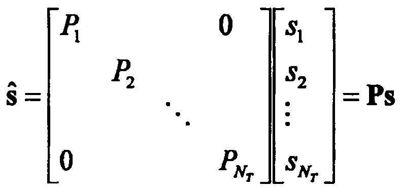
전송전력이 조정된 정보 벡터 ![]()
![]()
![]()
![]()
![]()
![]()
![]()
![]()
![]()
![]()
![]()
![]()
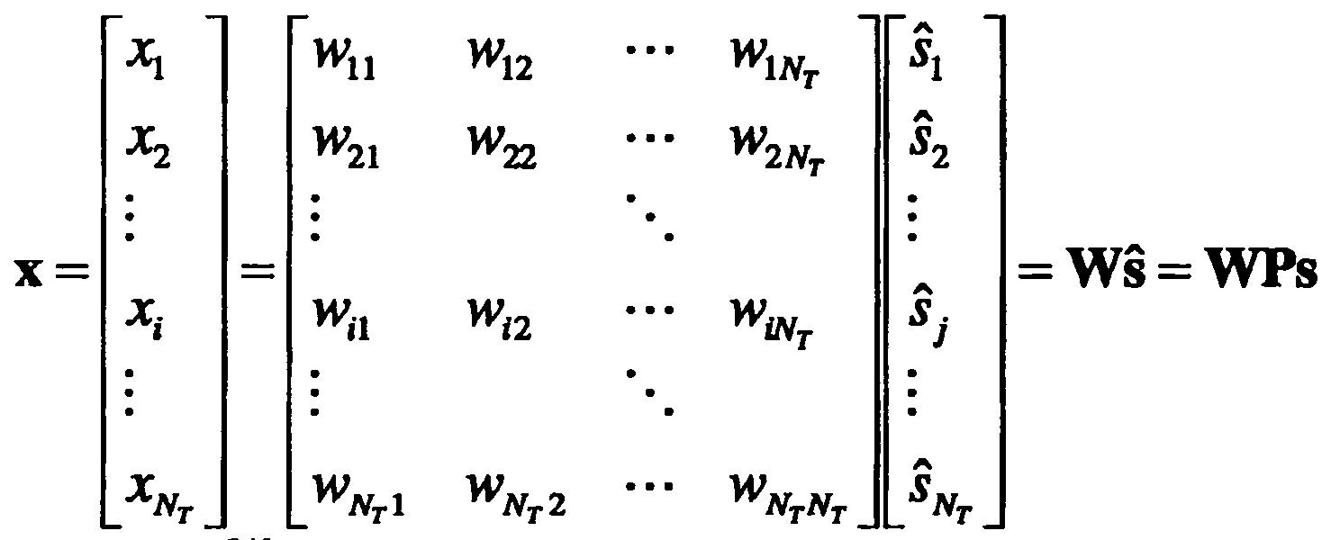
여기에서, ![]()
![]()
![]()
![]()
수신신호는 Nr개의 수신 안테나가 있는 경우 각 안테나의 수신신호 ![]()
![]()
![]()
![]()
다중안테나 무선 통신 시스템에서 채널을 모델링하는 경우, 채널은 송수신 안테나 인덱스에 따라 구분될 수 있다. 송신 안테나 j로부터 수신 안테나 i를 거치는 채널을 ![]()
![]()
![]()
![]()
한편, 도 5(b)은 NR개의 송신 안테나에서 수신 안테나 i로의 채널을 도시한 도면이다. 상기 채널을 묶어서 벡터 및 행렬 형태로 표시할 수 있다. 도 5(b)에서, 총 NT개의 송신 안테나로부터 수신 안테나 i로 도착하는 채널은 다음과 같이 나타낼 수 있다.5 (b) shows a channel from NR transmit antennas to receive antenna i . The channels may be bundled and displayed in vector and matrix form. In FIG. 5 (b), a channel arriving from a total of NT transmit antennas to a receive antenna i may be represented as follows.
![]()
![]()
따라서, Nt개의 송신 안테나로부터 Nr개의 수신 안테나로 도착하는 모든 채널은 다음과 같이 표현될 수 있다.Therefore, all channels arriving from Nt transmit antennas to Nr receive antennas can be expressed as follows.
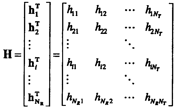
실제 채널에는 채널 행렬 ![]()
![]()
![]()
![]()
![]()
![]()
상술한 수식 모델링을 통해 수신신호는 다음과 같이 표현될 수 있다.The received signal may be expressed as follows through the above-described mathematical modeling.

한편, 채널 상태를 나타내는 채널 행렬 ![]()
![]()
![]()
![]()
![]()
![]()
행렬의 랭크(rank)는 서로 독립인(independent) 행 또는 열의 개수 중에서 최소 개수로 정의된다. 따라서, 행렬의 랭크는 행 또는 열의 개수 보다 클 수 없다. 채널 행렬 ![]()
![]()
![]()
![]()
![]()
![]()
랭크의 다른 정의는 행렬을 고유치 분해(Eigen value decomposition) 하였을 때, 0이 아닌 고유치들의 개수로 정의할 수 있다. 유사하게, 랭크의 또 다른 정의는 특이치 분해(singular value decomposition) 하였을 때, 0이 아닌 특이치들의 개수로 정의할 수 있다. 따라서, 채널 행렬에서 랭크. 의 물리적인 의미는 주어진 채널에서 서로 다른 정보를 보낼 수 있는 최대 수라고 할 수 있다.Another definition of rank may be defined as the number of nonzero eigenvalues when the matrix is eigenvalue decomposition. Similarly, another definition of rank may be defined as the number of nonzero singular values when singular value decomposition is performed. Thus, rank in the channel matrix. The physical meaning of is the maximum number of different information that can be sent on a given channel.
본 문서의 설명에 있어서, MIMO 전송에 대한 '랭크(Rank)' 는 특정 시점 및 특정 주파수 자원에서 독립적으로 신호를 전송할 수 있는 경로의 수를 나타내며, '레이어(layer)의 개수' 는 각 경로를 통해 전송되는 신호 스트림의 개수를 나타낸다. 일반적으로 송신단은 신호 전송에 이용되는 랭크 수에 대응하는 개수의 레이어를 전송하기 때문에 특별한 언급이 없는 한 랭크는 레이어 개수와 동일한 의미를 가진다.In the description of this document, 'rank' for MIMO transmission refers to the number of paths that can independently transmit signals at specific time points and specific frequency resources, and 'number of layers' denotes each path. It indicates the number of signal streams transmitted through the system. In general, since the transmitting end transmits the number of layers corresponding to the number of ranks used for signal transmission, unless otherwise specified, the rank has the same meaning as the number of layers.
D2DD2D 단말의 동기 획득 Synchronous acquisition of terminal
이하에서는 상술한 설명 및 기존 LTE/LTE-A 시스템에 기초하여, D2D 통신에서 단말간 동기 획득에 대해 설명한다. OFDM 시스템에서는 시간/주파수 동기가 맞지 않을 경우 셀 간 간섭(Inter-Cell Interference)로 인해 OFDM 신호에서 서로 다른 단말 간에 멀티플렉싱이 불가능질 수 있다. 동기를 맞추기 위해 D2D 단말들이 직접 동기 신호를 송수신하여 모든 단말이 개별적으로 동기를 맞추는 것은 비효율적이다. 따라서, D2D와 같은 분산 노드 시스템에서는 특정 노드가 대표 동기 신호를 전송해주고 나머지 UE들이 이에 동기를 맞출 수 있다. 다시 말해, D2D 신호 송수신을 위해 일부 노드들이 (이때 노드는 eNB, UE, SRN(synchronization reference node 또는 synchronization source로 불릴 수도 있다) 일 수도 있다.) D2D 동기 신호(D2DSS, D2D Synchronization Signal)를 전송하고, 나머지 단말들이 이에 동기를 맞추어 신호를 송수신하는 방식이 사용될 수 있다. Hereinafter, on the basis of the above description and the existing LTE / LTE-A system, it will be described for the synchronization between terminals in the D2D communication. In an OFDM system, when time / frequency synchronization is not correct, multiplexing between different terminals in the OFDM signal may be impossible due to inter-cell interference. In order to synchronize, it is inefficient to synchronize all terminals individually by transmitting and receiving synchronization signals directly by D2D terminals. Therefore, in a distributed node system such as D2D, a specific node may transmit a representative synchronization signal and the remaining UEs may synchronize with it. In other words, some nodes may transmit a D2D signal (where the node may be referred to as an eNB, a UE, a synchronization reference node or a synchronization source), and transmit a D2D synchronization signal (D2DSS, D2D Synchronization Signal). For example, a method of transmitting and receiving signals in synchronization with the remaining terminals may be used.
D2D 동기신호에는 프라이머리 동기 신호(PD2DSS(Primary D2DSS 또는 PSSS(Primary Sidelink synchronization signal)), 세컨더리 동기 신호(SD2DSS(Secondary D2DSS 또는 SSSS(Secondary Sidelink synchronization signal))가 있을 수 있다. PD2DSS는 소정 길이의 자도프 추 시퀀스(Zadoff-chu 시퀀스) 또는 PSS와 유사/변형/반복된 구조 등일 수 있다. 또한 DL PSS와 달리 다른 자도프 추 루트 인덱스(예를 들어, 26, 37)를 사용할 수 있다. SD2DSS는 M-시퀀스 또는 SSS와 유사/변형/반복된 구조 등일 수 있다. 만약 단말들이 eNB로부터 동기를 맞출 경우, SRN은 eNB가 되며, D2DSS는 PSS/SSS가 된다. DL의 PSS/SSS와 달리 PD2DSS/SD2DSS는 UL 서브캐리어 매핑 방식을 따른다. 도 6에는 D2D동기 신호가 전송되는 서브프레임이 도시되어 있다. PD2DSCH(Physical D2D synchronization channel)는 D2D 신호 송수신 전에 단말이 가장 먼저 알아야 하는 기본이 되는 (시스템) 정보(예를 들어, D2DSS에 관련된 정보, 듀플렉스 모드(Duplex Mode, DM), TDD UL/DL 구성, 리소스 풀 관련 정보, D2DSS에 관련된 애플리케이션의 종류, subframe offset, 브로드캐스트 정보 등)가 전송되는 (방송) 채널일 수 있다. PD2DSCH는 D2DSS와 동일한 서브프레임 상에서 또는 후행하는 서브프레임 상에서 전송될 수 있다. DMRS는 PD2DSCH의 복조를 위해 사용될 수 있다.The D2D synchronization signal may be a primary synchronization signal (Primary D2DSS or Primary Sidelink synchronization signal (PSSS)) or a secondary synchronization signal (SD2DSS (Secondary D2DSS or Secondary Sidelink synchronization signal)). It may be a Zadoff-chu sequence or a similar / modified / repeated structure to the PSS, etc. It is also possible to use other Zadoff Chu root indices (eg, 26, 37) unlike the DL PSS. May be a similar / modified / repeated structure to M-sequence or SSS, etc. If UEs synchronize from eNB, SRN becomes eNB and D2DSS becomes PSS / SSS Unlike PD's PSS / SSS, PD2DSS The / SD2DSS follows the UL subcarrier mapping scheme, and the subframe through which the D2D synchronization signal is transmitted is shown in Fig. 6. The PD2DSCH (Physical D2D synchronization channel) has a basic requirement that the UE first needs to know before transmitting and receiving the D2D signal. (System) information (e.g., information related to D2DSS, duplex mode (DM), TDD UL / DL configuration, resource pool related information, type of application related to D2DSS, subframe offset, broadcast information, etc.) The PD2DSCH may be transmitted on the same subframe as the D2DSS or on a subsequent subframe DMRS may be used for demodulation of the PD2DSCH.
SRN은 D2DSS, PD2DSCH(Physical D2D synchronization channel)를 전송하는 노드일 수 있다. D2DSS는 특정 시퀀스 형태일 수 있고, PD2DSCH는 특정 정보를 나타내는 시퀀스거나 사전에 정해진 채널 코딩을 거친 후의 코드 워드 형태일 수 있다. 여기서, SRN은 eNB 또는 특정 D2D 단말이 될 수 있다. 부분 네트워크 커버리지(partial network coverage) 또는 커버리지 바깥(out of network coverage)의 경우에는 단말이 SRN이 될 수 있다.The SRN may be a node transmitting a D2DSS and a Physical D2D Synchronization Channel (PD2DSCH). The D2DSS may be in the form of a specific sequence, and the PD2DSCH may be in the form of a sequence representing specific information or a code word after a predetermined channel coding. Here, the SRN may be an eNB or a specific D2D terminal. In the case of partial network coverage or out of network coverage, the UE may be an SRN.
도 7과 같은 상황에서 커버리지 밖(out of coverage) 단말과의 D2D 통신을 위해 D2DSS는 릴레이 될 수 있다. 또한, D2DSS는 다중 홉을 통해 릴레이될 수 있다. 이하의 설명에서 동기 신호를 릴레이 한다는 것은 직접 기지국의 동기신호를 AF 릴레이하는 것뿐만 아니라, 동기 신호 수신 시점에 맞추어 별도의 포맷의 D2D 동기신호를 전송하는 것도 포함하는 개념이다. 이와 같이, D2D 동기 신호가 릴레이 됨으로써 커버리지 안 단말과 커버리지 밖 단말이 직접 통신을 수행할 수 있다. In the situation as shown in FIG. 7, the D2DSS may be relayed for D2D communication with an out of coverage terminal. In addition, the D2DSS can be relayed over multiple hops. In the following description, relaying a synchronization signal is a concept including not only directly relaying a synchronization signal of a base station, but also transmitting a D2D synchronization signal of a separate format in accordance with the timing of receiving the synchronization signal. As such, since the D2D synchronization signal is relayed, the in-coverage terminal and the out-of-coverage terminal can directly perform communication.
D2DD2D 리소스resource 풀 pool
도 8에는 D2D 통신을 수행하는 UE1, UE2 및 이들이 사용하는 D2D 리소스 풀의 예가 도시되어 있다. 도 8(a)에서 UE는 단말 또는 D2D 통신 방식에 따라 신호를 송수신하는 기지국 등의 네트워크 장비를 의미한다. 단말은 일련의 자원의 집합을 의미하는 리소스 풀 내에서 특정한 자원에 해당하는 리소스 유닛을 선택하고 해당 리소스 유닛을 사용하여 D2D 신호를 송신할 수 있다. 수신 단말(UE2)는 UE1이 신호를 전송할 수 있는 리소스 풀을 구성(configured) 받고 해당 pool내에서 UE1의 신호를 검출할 수 있다. 여기서 리소스 풀은 UE1이 기지국의 연결 범위에 있는 경우 기지국이 알려줄 수 있으며, 기지국의 연결 범위 밖에 있는 경우에는 다른 단말이 알려주거나 또는 사전에 정해진 자원으로 결정될 수도 있다. 일반적으로 리소스 풀은 복수의 리소스 유닛으로 구성되며 각 단말은 하나 또는 복수의 리소스 유닛을 선정하여 자신의 D2D 신호 송신에 사용할 수 있다. 리소스 유닛은 도 8(b)에 예시된 것과 같을 수 있다. 도 8(b)를 참조하면, 전체 주파수 자원이 NF개로 분할되고 전체 시간 자원이 NT개로 분할되어 총 NF*NT개의 리소스 유닛이 정의되는 것을 알 수 있다. 여기서는 해당 리소스 풀이 NT 서브프레임을 주기로 반복된다고 할 수 있다. 특히, 하나의 리소스 유닛이 도시된 바와 같이 주기적으로 반복하여 나타날 수 있다. 또는, 시간이나 주파수 차원에서의 다이버시티 효과를 얻기 위해, 하나의 논리적인 리소스 유닛이 매핑되는 물리적 리소스 유닛의 인댁스가 시간에 따라서 사전에 정해진 패턴으로 변화할 수도 있다. 이러한 리소스 유닛 구조에 있어서 리소스 풀이란 D2D 신호를 송신하고자 하는 단말이 송신에 사용할 수 있는 리소스 유닛의 집합을 의미할 수 있다. 8 shows an example of UE1, UE2 performing D2D communication, and a D2D resource pool used by them. In FIG. 8 (a), a UE refers to a network equipment such as a base station for transmitting and receiving a signal according to a terminal or a D2D communication scheme. The terminal may select a resource unit corresponding to a specific resource in a resource pool representing a set of resources and transmit a D2D signal using the corresponding resource unit. The receiving terminal UE2 may be configured with a resource pool in which UE1 can transmit a signal, and detect a signal of UE1 in the corresponding pool. Here, the resource pool may be notified by the base station when UE1 is in the connection range of the base station. When the UE1 is outside the connection range of the base station, another UE may notify or may be determined as a predetermined resource. In general, a resource pool is composed of a plurality of resource units, each terminal may select one or a plurality of resource units and use them for transmitting their D2D signals. The resource unit may be as illustrated in FIG. 8 (b). Referring to FIG. 8 (b), it can be seen that total frequency resources are divided into NFs and total time resources are divided into NTs so that a total of NF * NT resource units are defined. In this case, the resource pool may be repeated every NT subframe. In particular, one resource unit may appear periodically and repeatedly as shown. Alternatively, in order to obtain a diversity effect in the time or frequency dimension, the inductance of a physical resource unit to which one logical resource unit is mapped may change in a predetermined pattern over time. In this resource unit structure, a resource pool may mean a set of resource units that can be used for transmission by a terminal that wants to transmit a D2D signal.
리소스 풀은 여러 종류로 세분화될 수 있다. 먼저 각 리소스 풀에서 전송되는 D2D 신호의 컨텐츠(contents)에 따라서 구분될 수 있다. 예를 들어, D2D 신호의 컨텐츠는 구분될 수 있으며, 각각에 대하여 별도의 리소스 풀이 구성될 수 있다. D2D 신호의 컨텐츠로서, SA(Scheduling assignment (SA), D2D 데이터 채널, 디스커버리 채널(Discovery channel)이 있을 수 있다. SA는 송신 단말이 후행하는 D2D 데이터 채널의 전송으로 사용하는 리소스의 위치 및 그 외 데이터 채널의 복조를 위해서 필요한 MCS(modulation and coding scheme)나 MIMO 전송 방식, TA(timing advance)등의 정보를 포함하는 신호일 수 있다. 이 신호는 동일 리소스 유닛 상에서 D2D 데이터와 함께 멀티플렉싱되어 전송되는 것도 가능하며, 이 경우 SA 리소스 풀이란 SA가 D2D 데이터와 멀티플렉싱되어 전송되는 리소스의 풀을 의미할 수 있다. 다른 이름으로 D2D 제어 채널(control channel), PSCCH(physical sidelink control channel)로 불릴 수도 있다. D2D 데이터 채널(또는, PSSCH(Physical sidelink shared channel))은, 송신 단말이 사용자 데이터를 전송하는데 사용하는 리소스의 pool일 수 있다. 만일 동일 리소스 유닛 상에서 D2D 데이터와 함께 SA가 멀티플렉싱되어 전송되는 경우 D2D 데이터 채널을 위한 리소스 풀에서는 SA 정보를 제외한 형태의 D2D 데이터 채널만이 전송 될 수 있다. 다시 말하면 SA 리소스 풀 내의 개별 리소스 유닛 상에서 SA 정보를 전송하는데 사용되었던 REs를 D2D 데이터 채널 리소스 풀에서는 여전히 D2D 데이터를 전송하는데 사용할 수 있다. 디스커버리 채널은 송신 단말이 자신의 ID 등의 정보를 전송하여 인접 단말로 하여금 자신을 발견할 수 있도록 하는 메시지를 위한 리소스 풀일 수 있다.Resource pools can be divided into several types. First, they may be classified according to contents of D2D signals transmitted from each resource pool. For example, the contents of the D2D signal may be divided, and a separate resource pool may be configured for each. As the content of the D2D signal, there may be a scheduling assignment (SA), a D2D data channel, and a discovery channel (SA), where the location of a resource used for transmission of a subsequent D2D data channel by a transmitting terminal and others It may be a signal including information such as a modulation and coding scheme (MCS), a MIMO transmission scheme, a timing advance (TA), etc. required for demodulation of a data channel, which may be multiplexed and transmitted together with D2D data on the same resource unit. In this case, the SA resource pool may mean a pool of resources in which the SA is multiplexed with the D2D data and transmitted, or may be referred to as a D2D control channel or a physical sidelink control channel (PSCCH). The D2D data channel (or physical sidelink shared channel (PSSCH)) may be a pool of resources used by a transmitting terminal to transmit user data. If the SA is multiplexed and transmitted together with the D2D data on the same resource unit, only the D2D data channel except for the SA information may be transmitted in the resource pool for the D2D data channel, that is, individual resource units in the SA resource pool. The REs used to transmit SA information on the D2D data channel resource pool can still be used to transmit D2D data in the discovery channel, where a transmitting terminal transmits information such as its own ID and the like so that a neighboring terminal can discover itself. It can be a resource pool for messages to be made.
D2D 신호의 컨텐츠가 동일한 경우에도 D2D 신호의 송수신 속성에 따라서 상이한 리소스 풀을 사용할 수 있다. 예를 들어, 동일한 D2D 데이터 채널이나 디스커버리 메시지라 하더라도 D2D 신호의 송신 타이밍 결정 방식(예를 들어 동기 기준 신호의 수신 시점에서 송신되는지 아니면 거기에서 일정한 TA를 적용하여 전송되는지)이나 자원 할당 방식(예를 들어 개별 신호의 전송 자원을 eNB가 개별 송신 UE에게 지정해주는지 아니면 개별 송신 UE가 pool 내에서 자체적으로 개별 신호 전송 자원을 선택하는지), 신호 포맷(예를 들어 각 D2D 신호가 한 서브프레임에서 차지하는 심볼의 개수나, 한 D2D 신호의 전송에 사용되는 서브프레임의 개수), eNB로부터의 신호 세기, D2D UE의 송신 전력 세기 등에 따라서 다시 상이한 리소스 풀로 구분될 수 있다. 설명의 편의상 D2D 커뮤니케이션에서 eNB가 D2D 송신 UE의 송신 자원을 직접 지시하는 방법을 Mode 1, 전송 자원 영역이 사전에 설정되어 있거나, eNB가 전송 자원 영역을 지정하고, UE가 직접 송신 자원을 선택하는 방법을 Mode 2라 부르기로 한다. D2D discovery의 경우에는 eNB가 직접 자원을 지시하는 경우에는 Type 2, 사전에 설정된 자원영역 또는 eNB가 지시한 자원 영역에서 UE가 직접 전송 자원을 선택하는 경우는 Type 1이라 부르기로 한다.Even when the contents of the D2D signal are the same, different resource pools may be used according to the transmission / reception attributes of the D2D signal. For example, even when the same D2D data channel or discovery message is used, the transmission timing determination method of the D2D signal (for example, is it transmitted at the time of reception of a synchronization reference signal or is transmitted by applying a constant TA there) or a resource allocation method (for example, For example, whether an eNB assigns transmission resources of an individual signal to an individual transmitting UE or whether an individual transmitting UE selects an individual signaling resource on its own in a pool, and a signal format (for example, each D2D signal occupies one subframe). The number of symbols, the number of subframes used for transmission of one D2D signal), the signal strength from the eNB, and the transmission power strength of the D2D UE may be further divided into different resource pools. For convenience of explanation,
SA의 송수신SA transmission and reception
모드 1 단말은 기지국으로부터 구성 받은 자원을 통해 SA(또는, D2D 제어 신호, SCI(Sidelink Control Information))을 전송할 수 있다. 모드 2 단말은 기지국으로부터 D2D 송신에 사용할 리소스를 구성 받는(configured)다. 그리고, 구성 받은 그 리소스에서 시간 주파수 자원을 선택하여 SA를 전송할 수 있다. The
SA 주기는 도 9에 도시된 바와 같이 정의된 것일 수 있다. 도 9을 참조하면, 첫 번째 SA 주기는 특정 시스템 프레임으로부터 상위계층시그널링에 의해 지시된 소정 오프셋(SAOffsetIndicator)만큼 떨어진 서브프레임에서 시작될 수 있다. 각 SA 주기는 SA 리소스 풀과 D2D 데이터 전송을 위한 서브프레임 풀을 포함할 수 있다. SA 리소스 풀은 SA 주기의 첫 번째 서브프레임부터 서브프레임 비트맵(saSubframeBitmap)에서 SA가 전송되는 것으로 지시된 서브프레임 중 마지막 서브프레임을 포함할 수 있다. D2D 데이터 전송을 위한 리소스 풀은, 모드 1의 경우, T-RPT(Time-resource pattern for transmission 또는 TRP(Time-resource pattern))가 적용됨으로써 실제 데이터 전송에 사용되는 서브프레임이 결정될 수 있다. 도시된 바와 같이, SA 리소스 풀을 제외한 SA 주기에 포함된 서브프레임의 개수가 T-RPT 비트 개수보다 많은 경우 T-RPT는 반복하여 적용될 수 있으며, 마지막으로 적용되는 T-RPT는 남은 서브프레임 개수만큼 truncated되어 적용될 수 있다.SA period may be defined as shown in FIG. Referring to FIG. 9, the first SA period may be started in a subframe away from a specific system frame by a predetermined offset SAOffsetIndicator indicated by higher layer signaling. Each SA period may include a SA resource pool and a subframe pool for D2D data transmission. The SA resource pool may include the last subframe of the subframes indicated by which the SA is transmitted in the subframe bitmap (saSubframeBitmap) from the first subframe of the SA period. In the resource pool for D2D data transmission, in case of
이하에서는 상술한 설명 및 종래 LTE 표준 문서 및 알려진 기술에 기초하여, 본 발명의 일 실시예에 의한 디스커버리 신호의 전송 방법에 대해 설명한다. 기존 D2D 통신에서 디스커버리 메시지의 길이는 CRC 를 제외하고 232비트인데, 릴레이나 커버리지 밖(out coverage) 디스커버리의 경우 이보다 많은 비트가 디스커버리를 위해 필요할 수 있다. 이를 위해, 디스커버리 포맷을 새로이 정의할 수도 있고, 또는 커뮤니케이션 채널(PSSCH, PSCCH)을 통해 디스커버리 메시지를 전송(이하에서는 이를 DTC라 칭한다)할 수도 있다. 이하, 각 DTC 실시예들은 어느 하나가 독립적으로 사용될 수도 있지만, 적어도 두 개의 실시예가 조합된 형태로써 사용될 수도 있다. 예를 들어, DTC 실시예 2와 3의 조합된 형태로써, DTC를 위해 정의된 별도의 리소스 풀에서, DTC 를 위해 정의된 PSCCH 포맷이 전송될 수도 있다.Hereinafter, a method for transmitting a discovery signal according to an embodiment of the present invention will be described based on the above description and the conventional LTE standard document and known technology. In a conventional D2D communication, the discovery message has a length of 232 bits excluding the CRC. In the case of relay or out coverage discovery, more bits may be required for discovery. To this end, the discovery format may be newly defined, or a discovery message may be transmitted (hereinafter, referred to as DTC) through a communication channel (PSSCH, PSCCH). Hereinafter, each of the DTC embodiments may be used independently, but at least two embodiments may be used in a combined form. For example, in a combined form of
DTCDTC 실시예Example 1 One
DTC의 일 실시예로써, SA 주기 내에서 일부 전송 기회(transmission opportunity)에서만 디스커버리 신호(디스커버리 메시지의 MAC PDU)를 전송할 수 있다. 다시 말해, 단말이 TRP를 적용하여 D2D 데이터(PSSCH)를 전송할 때, 일부를 디스커버리 전송에 사용할 수 있다. 즉, TRP의 일부 비트들을 디스커버리를 위해 그 지시하는 바를 달리 사용하는 것이다.As an embodiment of the DTC, the discovery signal (the MAC PDU of the discovery message) may be transmitted only at some transmission opportunity within the SA period. In other words, when the UE transmits the D2D data (PSSCH) by applying the TRP, a part may be used for discovery transmission. In other words, some bits of the TRP use the indication differently for discovery.
구체적으로, 단말은 데이터 전송을 위한 서브프레임 풀을 결정하고, 데이터 전송을 위한 서브프레임 풀에 TRP(Time resource pattern) 비트맵을 적용하여, D2D 신호를 전송할 서브프레임의 세트를 결정한다. 그리고, TRP 비트맵의 n개의 비트에 해당하는 서브프레임에서 디스커버리 메시지를 전송하고, TRP 비트맵에서 n개의 비트를 제외한 나머지 비트에 해당하는 서브프레임에서 아무 신호도 전송하지 않거나, D2D 데이터를 전송할 수 있다.In detail, the terminal determines a subframe pool for data transmission and applies a time resource pattern (TRP) bitmap to the subframe pool for data transmission to determine a set of subframes for transmitting the D2D signal. In addition, the discovery message may be transmitted in a subframe corresponding to n bits of the TRP bitmap, and no signal may be transmitted or a D2D data may be transmitted in a subframe corresponding to the remaining bits except n bits in the TRP bitmap. have.
이와 같이, TRP 비트맵에 의해 지시되는 서브프레임들에 디스커버리 신호와 D2D 데이터를 함께 전송될 수 있는 경우, 수신 단말에게 PSSCH에서 디스커버리 신호가 전송되는 것을 구분하기 위한 방법이 필요할 수 있다. 구체적으로PSCCH의 CRC mask를 디스커버리 메시지를 전송할 때와 데이터(만)을 전송할 때 다르게 설정하는 것이다. 이 경우, 수신 단말은 PSCCH의 CRC 확인을 통해 PSSCH의 (data가 전송되는 서브프레임의) n개의 비트에 해당하는 서브프레임에 디스커버리 메시지가 전송된다는 것을 인지할 수 있다. 또는, PSCCH의 DMRS 및/또는 스크램블링 시퀀스를 디스커버리 메시지를 전송할 때와, 데이터(만)을 전송할 때 다르게 설정할 수 있다. 즉, 디스커버리 메시지를 전송하기 위한 PSCCH의 DMRS 그리고/또는 스크램블링 시퀀스와 데이터를 전송하기 위한 PSCCH의 DMRS 그리고/또는 스크램블링 시퀀스는 서로 상이할 수 있다. 이 경우, 수신 단말은 각 DMRS 그리고/또는 스크램블링 시퀀스를 통해 해당 PSCCH가 디스커버리 메시지를 전송하기 위한 것인지, 데이터를 전송하기 위한 것인지 구분할 수 있다. 또 다른 예로써, 디스커버리 메시지를 전송할 경우에는 사전에 정해진 MCS나 RB 크기를 사용할 수 있다. n개의 비트에 해당하는 서브프레임에서는 미리 정해진 크기의 RB에서만 디스커버리 신호가 전송되는 것이다. 혹은 MCS나 RB크기를 커뮤니테이션에서 사용하지 않는 state를 활용하여 디스커버리 신호가 PSSCH의 일부 n개 서브프레임에서 전송됨을 지시할 수 있다. As such, when the discovery signal and the D2D data may be transmitted together in subframes indicated by the TRP bitmap, a method for distinguishing that the discovery signal is transmitted from the PSSCH may be required. Specifically, the CRC mask of the PSCCH is set differently when transmitting a discovery message and when transmitting data (only). In this case, the receiving terminal may recognize that the discovery message is transmitted in a subframe corresponding to n bits (of the subframe in which data is transmitted) of the PSSCH through the CRC check of the PSCCH. Alternatively, the DMRS and / or scrambling sequence of the PSCCH may be set differently when transmitting a discovery message and when transmitting data (only). That is, the DMRS and / or scrambling sequence of the PSCCH for transmitting the discovery message and the DMRS and / or scrambling sequence of the PSCCH for transmitting the data may be different from each other. In this case, the receiving terminal may distinguish whether the corresponding PSCCH is for transmitting a discovery message or for transmitting data through each DMRS and / or scrambling sequence. As another example, when transmitting a discovery message, a predetermined MCS or RB size may be used. In a subframe corresponding to n bits, a discovery signal is transmitted only in a predetermined size RB. Alternatively, the discovery signal may be transmitted in some n subframes of the PSSCH by using a state in which MCS or RB size is not used in communication.
또는, TRP 비트맵에 의해 지시되는 서브프레임들에 디스커버리 신호와 D2D 데이터를 함께 전송하는 경우, 디스커버리 신호와 D2D 데이터를 구분하기 위한 방법이 필요할 수 있다. 구체적으로, n개의 비트에 해당하는 서브프레임에 사용된 CRC 매스크와 나머지 비트에 해당하는 서브프레임에 사용된 CRC 매스크는 서로 상이할 수 있다. 즉, PSSCH의 CRC mask를 디스커버리 메시지를 전송할 때와 데이터를 전송할 때 다르게 설정하는 것이다. 이 경우, 수신 단말은 CRC 확인을 통해 n개의 비트에 해당하는 서브프레임과 나머지 비트에 해당하는 서브프레임을 구분할 수 있다. 또는, PSCCH의 DMRS 및/또는 스크램블링 시퀀스를 디스커버리 메시지를 전송할 때와, 데이터를 전송할 때 다르게 설정할 수 있다. 즉, n개의 비트에 해당하는 서브프레임에서 전송되는 DMRS 시퀀스와 나머지 비트에 해당하는 서브프레임에서 전송되는 DMRS 시퀀스는 서로 상이할 수 있다. 이 경우, 수신 단말은 DMRS 시퀀스를 통해 n개의 비트에 해당하는 서브프레임과 나머지 비트에 해당하는 서브프레임을 구분할 수 있다. 또 다른 예로써, 디스커버리 메시지를 전송할 경우에는 사전에 정해진 MCS나 RB 크기를 사용할 수 있다. n개의 비트에 해당하는 서브프레임에서는 미리 정해진 크기의 RB에서만 디스커버리 신호가 전송되는 것이다. Alternatively, when the discovery signal and the D2D data are transmitted together in subframes indicated by the TRP bitmap, a method for distinguishing the discovery signal and the D2D data may be needed. Specifically, the CRC mask used for the subframe corresponding to n bits and the CRC mask used for the subframe corresponding to the remaining bits may be different from each other. That is, the CRC mask of the PSSCH is set differently when transmitting a discovery message and when transmitting data. In this case, the receiving terminal may distinguish between a subframe corresponding to n bits and a subframe corresponding to the remaining bits through the CRC check. Alternatively, the DMRS and / or scrambling sequence of the PSCCH may be set differently when transmitting a discovery message and when transmitting data. That is, a DMRS sequence transmitted in a subframe corresponding to n bits and a DMRS sequence transmitted in a subframe corresponding to the remaining bits may be different from each other. In this case, the receiving terminal may distinguish between a subframe corresponding to n bits and a subframe corresponding to the remaining bits through a DMRS sequence. As another example, when transmitting a discovery message, a predetermined MCS or RB size may be used. In a subframe corresponding to n bits, a discovery signal is transmitted only in a predetermined size RB.
디스커버리 신호는 SA 주기내에서 초기 N개의 전송 기회에서만 전송될 수 있다. 또는, 디스커버리 신호가 전송되는 서브프레임을 시간 상에서 단말 특정하도록 구분해 줄 도 있다. 즉, 디스커버리 메시지를 전송하는 전송 기회는 UE간에 서로 다른 위치로 설정해 주는 것이다. 이 경우, SA 주기 내에서 모든 단말이 공통된 위치에서 디스커버리 메시지를 전송할 경우 수신 단말이 모든 디스커버리 신호를 수신할 수 없는 제약에서 벗어날 수 있다. 또한 단말사이에 디스커버리 메시지가 전송되는 서브프레임 (시간 자원)을 분산시켜서 단말들 사이에 서로의 디스커버리 메시지를 수신할 수 있게 한다. 이를 위한 구체적인 예로써, 디스커버리 메시지를 전송하는 단말 A는 SA 주기내의 전송 기회 중에서 첫 번째부터 N번째 전송 기회까지 디스커버리 메시지를 전송할 수 있고, 단말 B는 SA 주기내의 N+1번째 전송 기회에서 2N 전송 기회에서 디스커버리 메시지를 전송할 수 있다. 각 단말 별 전송 위치의 결정에는, UE의 ID, L2 SA ID, 또는 디스커버리 ID 등과 같은 UE-특정한 또는 UE 그룹-특정한 ID가 사용될 수 있다. 즉, TRP 비트맵에서 n개의 비트의 위치는 ID, L2 SA(Scheduling assignment) ID, 또는 디스커버리 ID 중 하나혹은 두개이상의 조합에 의해 결정될 수 있다. 또는 UE가 SA 주기내에서 랜덤하게 디스커버리 메시지를 전송하는 위치를 결정할 수 있다. 예를 들어 SA 주기내의 전송 기회를 4로 나눈 몫 이내의 랜덤한 숫자를 뽑아서 해당 위치의 전송 기회에서 디스커버리 메시지를 전송하도록 규칙이 정해질 수 있다. 즉, TRP 비트맵에서 n개의 비트의 위치는 TRP 비트맵을 4로 나눈 몫 이하의 양의 정수 중에서 단말이 랜덤하게 결정한 것일 수 있다. 이때 수신단말이 특정 단말의 디스커버리 메시지를 전송하는 서브프레임 위치를 명확히 알게 하기 위해서 단말들 사이에 서로 다른 PSCCH (destination) ID를 할당할 수 있다. 즉 DTC를 위해서 다수개의 PSCCH ID를 할당한 다음, 각 ID에 대해서 서로 다른 PSSCH 서브프레임 위치에서 디스커버리 신호가 전송되게 설정하는 것이다. The discovery signal may only be transmitted in the initial N transmission opportunities within the SA period. Alternatively, a subframe in which the discovery signal is transmitted may be distinguished to be UE-specific in time. In other words, a transmission opportunity for transmitting a discovery message is set to different locations between UEs. In this case, when all the UEs transmit discovery messages at a common location within the SA period, the receiving UE may be freed from the constraint that the UE cannot receive all discovery signals. In addition, by distributing subframes (time resources) in which discovery messages are transmitted between terminals, the discovery messages can be received between the terminals. As a specific example for this, the terminal A transmitting the discovery message may transmit the discovery message from the first to the Nth transmission opportunity among the transmission opportunities in the SA period, and the terminal B transmits 2N at the N + 1th transmission opportunity in the SA period. The opportunity may send a discovery message. The UE-specific or UE group-specific ID, such as the ID of the UE, the L2 SA ID, or the discovery ID, may be used to determine the transmission location for each terminal. That is, the position of the n bits in the TRP bitmap may be determined by one, or a combination of two or more of ID, L2 SA (Scheduling assignment) ID, or Discovery ID. Alternatively, the UE may determine the location where the discovery message is randomly transmitted within the SA period. For example, a rule may be set to send a discovery message at a transmission opportunity of a corresponding location by extracting a random number within a quotient divided by four transmission opportunities in an SA period. That is, the position of n bits in the TRP bitmap may be randomly determined by the terminal from a positive integer less than or equal to the quotient of 4 divided by the TRP bitmap. In this case, in order for the receiving terminal to clearly know the location of the subframe transmitting the discovery message of the specific terminal, different PSCCH (destination) IDs may be allocated between the terminals. That is, after assigning a plurality of PSCCH IDs for the DTC, a discovery signal is set to be transmitted at a different PSSCH subframe position for each ID.
DTCDTC 실시예Example 2 2
현재 PSCCH 에는 PSSCH 를 수신할 destination (그룹)ID (L2 ID)가 포함되어 전송되므로 해당 ID를 가진 destination UE 그룹만 해당 패킷을 decoding할 수 있다. 따라서, 디스커버리 신호를 PSSCH 를 통해 전송하는 경우 PSCCH에 포함되는 ID를 모든 UE 또는 다수의 destination 그룹이 수신할 수 있도록 설정하거나, 별도의 PSCCH 포맷을 정의하여 새로운 정보를 포함하여 전송할 수 있다. 즉, PSCCH에 포함되는 ID를 그룹 common하게 설정하는 것이다. 이 경우, 기존 1RB PSCCH 포맷 0은 유지될 수 있다. 또는, 또는 ID가 특정 state (예를 들어 all zero / all one) 인 경우 모든 단말이 해당 PSCCH가 지시하는 PSSCH를 수신하도록 규칙이 정해질 수 있다. Since the current PSCCH includes a destination (group) ID (L2 ID) for receiving the PSSCH, only the destination UE group having the corresponding ID can decode the packet. Therefore, when transmitting a discovery signal through the PSSCH, the ID included in the PSCCH can be set to be received by all UEs or a plurality of destination groups, or a separate PSCCH format can be defined and transmitted with new information. That is, the ID included in the PSCCH is set to the group common. In this case, the existing
또는, 기존 필드(예를 들어, MCS 필드 및/또는 주파수 자원 지시 필드)가 특정 state로 고정되거나, 다른 정보를 지시하는 용도로 사용될 수 있다. 예를 들어 DTC를 위해 전송되는 PSSCH의 경우에는 MCS나 주파수 자원 크기가 특정 숫자로 고정되어서 MCS 및/또는 주파수 자원 필드가 사용되지 않고 다른 정보를 지시하거나, 특정 state로 고정될 수 있다. 수신 단말은 MCS 및/또는 주파수 자원 필드가 특정 state로 고정되었음을 확인하고, PSCCH가 DTC 임을 파악할 수 있다. 그리고, PSCCH에 포함된 ID가 자신의 destination 그룹 ID가 아니더라도, 디스커버리 수신을 위해 패킷 수신을 수행할 수 있다. 또는 DTC가 mode 1으로 동작하지 않는 경우 TA 필드가 항상 0으로 고정하여 virtual CRC용도로 사용할 수 있다. 주파수 자원 지시 필드설정의 구체적인 일례로, DTC를 수행하는 경우에는 RB 크기가 한정된 N개의 candidate중에서 결정될 수 있고, 그 경우에는 주파수 자원 지시 필드중에 상당부분은 사용되지 않고 다른 용도로 사용될 수 있다. DTC를 수행하는 경우 QPSK로 modulation이 고정되어 MCS 필드를 다른 정보를 지시하는 용도로 사용할 수 있다. 일례로 64QAM이 현재 3GPP Rel. 12/13 D2D에는 사용되지 않는데, 64 QAM state중에 일부를 사용하여 DTC임을 지시하는 용도로 사용할 수 있다. 여러 필드들의 조합을 통해 해당 PSCCH가 DTC 용도임을 지시할 수 있다. 예를 들어 MCS는 64 QAM에 해당하는 state나, reserved state중 하나를 사용하고, 주파수 자원 지시 필드 중 일부 state를 이용하여 해당 PSCCH가 DTC 용도 임을 지시할 수 있다.Alternatively, an existing field (eg, MCS field and / or frequency resource indication field) may be fixed to a specific state or used for indicating other information. For example, in the case of the PSSCH transmitted for DTC, the MCS or frequency resource size is fixed to a specific number so that the MCS and / or frequency resource field is not used and may indicate other information or may be fixed to a specific state. The receiving terminal may confirm that the MCS and / or frequency resource field is fixed to a specific state, and may recognize that the PSCCH is a DTC. And, even if the ID included in the PSCCH is not its destination group ID, packet reception may be performed for discovery reception. Alternatively, if the DTC does not operate in
DTCDTC 실시예Example 3 3
DTC를 위한 별도의 PSCCH 자원 pool이 정의될 수 있다. 또한 PSSCH pool도 DTC를 위해 별도로 정의될 수도 있다. 수신 단말은 리소스 풀을 통해 DTC 인지 여부를 알 수 있으므로, 하나의 pool에서 여러 개의 서로 다른 포맷의 PSCCH를 blind 디코딩하는 부담을 줄일 수 있다. 이를 위해 네트웍은 물리계층 혹은 상위계층 신호로 단말에게 해당 PSCCH and/or PSSCH pool이 어떠한 용도인지 지시하는 시그널을 단말에게 전송할 수 있다. 혹은 이러한 정보는 각 resource pool별로 사전에 정해져 있을 수 있다. A separate PSCCH resource pool for DTC may be defined. In addition, the PSSCH pool may be defined separately for the DTC. Since the receiving terminal can know whether or not the DTC through the resource pool, the burden of blind decoding the PSCCH of several different formats in one pool can be reduced. To this end, the network may transmit, to the terminal, a signal indicating the purpose of the corresponding PSCCH and / or PSSCH pool to the terminal as a physical layer or higher layer signal. Alternatively, this information may be predetermined for each resource pool.
DTCDTC 실시예Example 4 4
DTC를 위한 새로운 PSCCH 포맷이 정의될 수도 있다. PSCCH 포맷 0의 DMRS를 측정에 사용할 경우 대역폭이 너무 좁아서 (1RB) 측정 (measurement) 정확도가 떨어질 수 있기 때문에 wideband로 전송하는 PSSCH 포맷이 정의될 수 있다. A new PSCCH format for the DTC may be defined. When the DMRS of
구체적으로, 새로운 PSCCH 포맷은 기존 1RB의 PSCCH 포맷과 RB 크기는 같지만 필드 구성이 상이하도록 정의될 수 있다. 즉, 기존 PSSCH 포맷에서 일부 필드를 제거하거나 또는 새로운 필드를 추가하여, coding rate를 높인 형태의 PSCCH 포맷이 정의될 수 있다. 예를 들어, DTC의 경우에는 MCS를 고정하여 사용하고 MCS 필드를 제거 및/또는 ID 필드를 제거하거나 특정 state로 고정할 수 있다. Type 1 디스커버리와 유사하게, DL timing을 사용하는 경우 TA 필드를 빼거나 특정 state (all zero)로 고정할 수 있다. 특히 TA 필드는 11bit로 길기 때문에 제거할 경우 상당한 coding gain을 얻을 수 있다.Specifically, the new PSCCH format may be defined such that the RSC size is the same as that of the existing 1RB but the field configuration is different. That is, the PSCCH format having a higher coding rate may be defined by removing some fields from the existing PSSCH format or adding new fields. For example, in the case of DTC, the MCS may be fixed and used and the MCS field may be removed and / or the ID field may be removed or may be fixed to a specific state. Similar to
또 다른 예로써, 기존 PSSCH 포맷 0의 length 는 동일하게 유지하면서 필드 구성을 상이하게 할 수 있다. 길이 유지를 위해 zero padding이 사용될 수도 있다. 이러한 경우, CRC를 PSSCH 포맷 0와 DTC를 위한 포맷은 다르게 설정하여 필드 해석을 다르게 수행할 수 있다.As another example, the length of the existing
DTC를 위해 새로이 PSCCH 포맷을 정의할 수도 있다. 예를 들어 2 RB 또는 4 RB의 PSCCH가 도입될 수도 있다. 여러 개의 ID 필드를 추가하여 여러 그룹 destination ID가 해당 PSSCH를 수신할 수 있도록 설정할 수 있다. 이와 같이 길어진 RB에 대한 DMRS 측정을 수행할 경우 주파수 영역에서 샘플 수가 많아져서 보다 짧은 시간 구간에서 측정결과를 얻을 수 있다.A new PSCCH format may be defined for the DTC. For example, 2 RB or 4 RB PSCCH may be introduced. By adding multiple ID fields, multiple group destination IDs can be configured to receive the corresponding PSSCH. When performing the DMRS measurement on the longer RB as described above, the number of samples increases in the frequency domain, thereby obtaining the measurement result in a shorter time interval.
DTCDTC 실시예Example 5 5
DTC를 위한 PSCCH는 포맷의 길이나 필드 구성과 관계 없이 PSCCH 포맷 0과 상이한 CRC 매스킹을 도입할 수 있다. 수신 단말은 CRC 확인을 통해 PSCCH format 0와 DTC를 위한 PSCCH를 구분할 수 있다. 이는 특히 DTC를 위한 PSCCH 포맷이 기존 PSSCH 포맷과 동일한 경우, 추가적인 blind 디코딩없이 포맷을 구분할 수 있다. 예를 들어 기존 PSCCH 포맷 0는 별도의 CRC 매스킹을 수행하지 않으나, DTC를 위하여 새로 정의되는 PSCCH 포맷은 CRC 매스킹을 특정 bit state 예를 들어 (1,0,1,0,?.,1,0,1,0)으로 설정할 수 있다. 또는, 서로 상이한 두 개의 CRC 매스킹을 DTC를 위한 PSCCH 포맷이 기존 PSSCH 포맷에 사용할 수 있다. PSCCH for DTC may introduce CRC masking different from
DTCDTC 실시예Example 6 6
DTC를 위한 PSCCH의 DMRS나 스크램블링 시퀀스생성을 PSCCH 포맷 0와 달리 설정할 수 있다. 예를 들어 PSCCH 포맷 0의 pool과 DTC를 위한 PSCCH 포맷이 전송되는 pool이 partially overlap된 경우를 가정하면, 같은 크기의 PSCCH를 디코딩할 경우 같은 DMRS를 사용하기 때문에 디스커버리를 위한 PSCCH와 커뮤니케이션을 위한 PSCCH의 DMRS가 SFN (single frequency network) 전송 (달리 말해 서로 다른 목적의 신호를 위한 DMRS시퀀스가 같아서 겹쳐서 전송될 경우 DMRS가 구분이 되지 않는 현상) 되어서 어떤 신호도 제대로 디코딩이 되지 않을 수 있다. 이 경우 DMRS 시퀀스나 스크램블링 시퀀스를 목적에 따라 구분하여 채널을 분리해내어 별도로 디코딩을 수행할 수 있을 것이다. The DMSC or scrambling sequence generation of the PSCCH for the DTC may be set differently from the
다음 표 1은 기존 PSCCH/PSSCH의 DMRS, 스크램블링 시퀀스 생성에 사용되는 인자들이다.Table 1 below shows the factors used to generate a DMRS and scrambling sequence of an existing PSCCH / PSSCH.
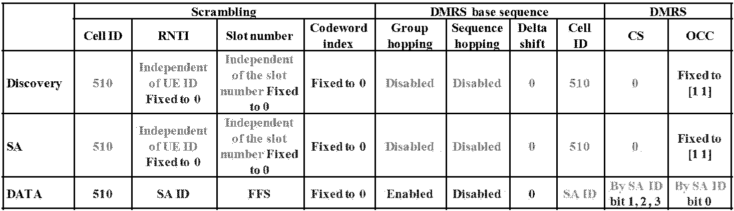
여기서 DMRS와 scrambling의 cell ID부분을 DTC를 위한 PSCCH/PSSCH를 전송하는 단말은 510이 아닌 다른 값(예를 들어 511)을 사용할 수 있다. PSSCH에는 SA ID를 이용하여 DMRS 시퀀스가 생성되는데 이 부분이 사전에 정해진 ID를 사용하거나, DTC를 위한 ID를 사용할 수 있다. 마찬가지로 PSSCH의 CS/OCC도 그룹 destination ID가 아니라, DTC를 위한 별도의 ID가 사용될 수 있다. In this case, the terminal transmitting the PSCCH / PSSCH for the DTC using the cell ID portion of the DMRS and the scrambling may use a value other than 510 (for example, 511). In the PSSCH, a DMRS sequence is generated using an SA ID, and this part may use a predetermined ID or an ID for a DTC. Similarly, the CS / OCC of the PSSCH may be a separate ID for the DTC, not the group destination ID.
DTCDTC 실시예Example 7 7
상술한 각 실시예들은 별도의 PSCCH 자원 pool이 구성되는 경우에 사용될 수 있지만 기존의 PSCCH 포맷 0의 pool에 함께 사용될 수도 있다. 이 경우 단말의 blind 디코딩 복잡도를 낮추기 위하여, 하나의 PSCCH 자원 pool이 여러 개의 sub pool로 나뉠 수 있는데, 일례로 주파수 영역에서 일부 자원, 또는 time 영역에서 일부 자원, 또는 time 주파수 조합의 일부 자원 영역에서 새로운 PSCCH 포맷을 전송하기 위한 자원이 설정될 수 있다. Each of the above-described embodiments may be used when a separate PSCCH resource pool is configured, but may be used together with a pool of an existing
구체적인 방법으로 주파수 자원이 N개의 영역으로 나뉘고, 이중 M(<N)개의 영역은 DTC를 전송 전송하기 위한 PSCCH가 전송되는 영역으로 설정될 수 있다. 또는 서브프레임중 일부는 DTC를 위한 PSCCH 전송용도의 서브프레임으로 구성될 수 있다. 또는 서브프레임 (time)과 subband (주파수)의 조합으로 일부는 DTC를 위한 PSCCH전송 용도의 자원으로 구성될 수 있다. 이 방식의 구현 일례로 SA 자원 중 일부는 DTC를 전송하기 위한 자원으로 구성될 수 있다. 이때, PSSCH (데이터)영역 또한 상기 방식 (time, freuqnecy, time+freuqnecy)중 하나로 구성될 수 있다. As a specific method, frequency resources may be divided into N regions, and M (<N) regions may be set to regions in which a PSCCH for transmitting and transmitting DTCs is transmitted. Alternatively, some of the subframes may be configured as subframes for PSCCH transmission for the DTC. Alternatively, a part of a combination of a subframe (time) and a subband (frequency) may be configured as a resource for PSCCH transmission for DTC. As an example of implementation of this scheme, some of the SA resources may be configured as resources for transmitting the DTC. In this case, the PSSCH (data) region may also be configured in one of the above schemes (time, freuqnecy, time + freuqnecy).
이하에서는 상술한 설명에 기초하여, 본 발명의 실시예에 의한 DTC에서 릴레이 UE의 측정에 대해 살펴본다.Hereinafter, based on the above description, it looks at the measurement of the relay UE in the DTC according to an embodiment of the present invention.
측정 Measure 실시예Example 1 - One - PSCCH의Of PSCCH DMRS에To DMRS 인가된 수신 전력을 측정 Measure the received received power
PSCCH 포맷 0은 1RB를 통해, SA 주기당 2번의 PSCCH만 전송되기 때문에 측정 정확도를 확보하기 위해서 상당 시간 동안 PSCCH를 측정해야 할 필요가 있다. 따라서, 안정적인 측정을 위해서 최소 X번의 SA 주기 동안 PSCCH의 DMRS를 측정해야 한다는 규칙이 정해질 수 있다. 따라서 만약 DTC를 위한 별도의 PSCCH pool이 설정될 경우 repetition횟수가 기존 2회보다 큰 값 예를 들면 4회로 증가할 수 있다. 만약, 새로운 PSCCH 포맷이 정의될 경우 RB 크기가 기존 1RB가 아닌 안정 적인 측정을 수행하기 위한 RB 크기(>=N RB, 예를 들어, N=4 or 6)가 사용될 수 있다.Since
현재 PSCCH는 모든 단말이 같은 DMRS를 사용하도록 되어있다. 따라서 UE 간에 DMRS 평균화를 수행할 때에는 PSCCH에 L2 ID가 같은 DMRS만 또는 소스 ID가 같은 DMRS만 평균화를 수행하는 것이 바람직하다. 만약 DTC를 위한 별도의 PSCCH pool또는 sub-pool이 구성되고, 해당 영역에서 PSCCH의 ID는 소스 ID 성분을 일부 또는 전체 포함할 경우 소스 ID가 같은 DMRS간에 측정 평균화를 수행할 수 있다. Currently, PSCCH is configured so that all UEs use the same DMRS. Therefore, when performing DMRS averaging between UEs, it is preferable to perform averaging only DMRSs having the same L2 ID or only the DMRSs having the same source ID in the PSCCH. If a separate PSCCH pool or sub-pool for the DTC is configured and the PSCCH ID includes some or all of the source ID components in the corresponding region, measurement averaging can be performed between DMRSs having the same source ID.
측정 Measure 실시예Example 2 - 2 - PSSCH의PSSCH DMRS에To DMRS 인가된 수신 전력을 측정 Measure the received received power
앞서 언급하였듯이 PSCCH에서 지시한 TRP를 이용하여, 수신 UE는 PSSCH의 전송 위치를 알 수 있다. 이때, PSSCH가 전송되는 위치의 DMRS의 수신 전력을 측정할 수 있다. 하지만 PSCCH의 대역폭은 매 SA 주기마다 바뀔 수 있는데, 이 측정은 한 SA 주기 내에서만 평균화를 수행해야 할 수 있다. 또는 SA 주기간에 평균화를 수행할 경우 RB 크기를 normalize하여 평균화를 수행할 수 있다. 예를 들어 SA 주기 #n에서는 4RB PSSCH가 전송되고, SA 주기 #n+1에서는 6RB PSSCH가 전송되는 경우, 1 RB로 normalize된 측정 값을 합할 수 있다. 이는 측정에 사용되는 샘플수로 측정을 normalized하여 샘플당 평균 측정을 평균화하는 것이고, 후자의 방법은 샘플 수에 관계없이 측정을 평균화하는 것이다. (또는 단순히, 별도의 normalize없이 측정결과를 평균할 수도 있다.)As mentioned above, using the TRP indicated by the PSCCH, the receiving UE can know the transmission position of the PSSCH. In this case, the reception power of the DMRS at the position where the PSSCH is transmitted may be measured. However, the bandwidth of the PSCCH may change every SA period, and this measurement may need to be averaged only within one SA period. Alternatively, when averaging is performed in the SA main period, the averaging may be performed by normalizing the RB size. For example, when 4RB PSSCH is transmitted in SA period #n and 6RB PSSCH is transmitted in SA period # n + 1, the measured value normalized to 1 RB may be summed. This is to normalize the measurement to the number of samples used for the measurement and average the average measurement per sample. The latter method is to average the measurement regardless of the number of samples. (Or simply, you can average the measurement results without normalizing them.)
한편, 너무 좁은 대역으로 전송되는 경우에는 부정확한 측정결과가 나올 수 있으므로, RB 크기가 일정 레인지에 들어오는 경우에만 측정할 수 있다. 예를 들어 A RB 이상 B RB이하인 경우에만 측정을 수행하고, 이외의 경우에는 측정을 수행하지 않는 것이다. 한편 Mode 1에서는 SA 주기마다 Tx 전력이 바뀔 수 있는데, 이 경우 서로 다른 전력에 대해서 평균화를 수행할 수도 있겠지만, Tx 전력을 패킷의 MAC 헤더에 포함하여 단말이 송신 전력 값을 제외하고 순수 채널의 측정만을 수행할 수 있다. 또는 송신 전력에 관계없이 측정 평균화를 수행할 수도 있는데 이는 송신 단말이 더 넓은 디스커버리 레인지를 위해 송신 전력을 높였을 경우 이를 감안하여 디스커버리 측정을 수행하기 위함이다. 전송 전력을 제외하고 측정을 수행하는 경우에는 D2D UE사이의 순수한 채널 상태를 측정할 수 있는 장점이 있다. On the other hand, if the transmission is too narrow band may result in inaccurate measurement results, can be measured only when the RB size is within a certain range. For example, the measurement is performed only when A RB or more and B RB or less. Otherwise, the measurement is not performed. On the other hand, in
안정적인 측정을 위해서 측정 대상이 될 수 있는 TX UE는 적어도 일정 시간 동안 (예를 들어 X번의 전송 기회) 정해진 횟수로는 N RB의 PSSCH TX를 수행하도록 규정될 수 있다. 실시예로 N=6 RB인 경우를 고려할 수 있다. N=6으로 정할 경우, PSBCH 측정과 동일 구조를 취할 수 있다는 측면에서 UE 복잡도를 줄일 수 있다. 일예로, PSCCH에서 PSSCH 전송 BW를 4 RB로 설정한 경우 DTC 메시지를 전송할 때나, 일정 횟수의 PSSCH 전송에서는 6RB로 전송하고, 나머지 PSSCH는 4RB로 전송하는 것이다. 이때 주파수 자원 allocation의 시작점은 PSCCH에서 지시한 곳과 같지만, 끝나는 점은 6RB로 전송할 때에, 6RB영역까지 확장된다. 이때 D2D 자원 pool의 주파수 영역을 벗어나는 경우에는 전송이 불가능할 수 있기 때문에 해당 서브프레임에서는 기존과 같이 4RB로 전송할 수 있다. A TX UE, which can be measured for stable measurement, may be defined to perform PSSCH TX of N RBs at a predetermined number of times for at least a predetermined time (for example, X transmission opportunities). As an example, the case of N = 6 RB may be considered. If N = 6, UE complexity can be reduced in that it can take the same structure as PSBCH measurement. For example, when the PSSCH transmission BW is set to 4 RBs in the PSCCH, the DTC message is transmitted when the DTC message is transmitted or the PSSCH transmission BW is transmitted in 6 RBs, and the remaining PSSCHs are transmitted in the 4 RBs. At this time, the starting point of the frequency resource allocation is the same as indicated by the PSCCH, but the ending point is extended to the 6RB region when transmitting to the 6RB. In this case, since the transmission may be impossible when the D2D resource pool is out of the frequency domain, the corresponding subframe may be transmitted in 4RB as before.
한편 N RB로 전송하도록 정해진 영역 (X 번의 전송 기회)는 UE 공통으로 사전에 정해져 있을 수 있고, 또는 UE마다 서로 다른 위치에서 전송하도록 규칙이 정해질 수 있다. 예를 들어 SA 주기내의 전송 기회 중에서 UE ID에 연동된 위치에서 X번의 전송을 N RB로 전송하는 것이다. 여기서 X값은 MAC PDU 전송 도중에 RB 크기를 바꾸지 않도록 반복 횟수의 배수로 결정될 수 있다. 또한 X번의 전송이 시작하는 위치는 반복 횟수의 배수 단위로 결정될 수 있다. X번의 전송이 모두 연속된 전송 기회일 수도 있지만 불연속하게 사전에 정해진 패턴으로 결정될 수도 있는데, 이때, 하나의 MAC PDU전송도중 RB 크기를 바꾸지 않도록 반복 횟수 단위로는 연속된 형태일 수 있다. Meanwhile, an area (X transmission opportunities) determined to be transmitted to N RB may be previously determined in common for the UE, or a rule may be determined to transmit at different locations for each UE. For example, X transmissions are transmitted to N RBs at positions linked to UE IDs among transmission opportunities within an SA period. Here, the X value may be determined as a multiple of the number of repetitions so as not to change the RB size during the MAC PDU transmission. In addition, the position at which X transmission starts may be determined in units of multiples of the repetition number. All X transmissions may be consecutive transmission opportunities, but may be determined in a predetermined pattern discontinuously. In this case, the transmission may be continuous in units of repetition number so as not to change the RB size during one MAC PDU transmission.
상기 방법은 N RB이하로 전송될 때에만 선택적으로 적용되는 방식일 수 있다. 상기 방법들은 너무 작은 RB 크기로 전송할 경우 측정 정확도가 떨어질 수 있어서 일정 구간 동안 측정 정확도를 확보하기 위한 것이므로, 애초에 할당한 RB 크기가 큰 경우에는 충분한 측정 정확도를 확보할 수 있기 때문에 별도의 추가 동작이 필요 없을 수 있다. The method may be a method applied selectively only when transmitted below N RB. Since the above methods are used to ensure measurement accuracy for a certain period of time because the measurement accuracy may be lowered when transmitting with too small RB size, the additional additional operation may be performed because sufficient measurement accuracy may be secured when the RB size originally allocated is large. It may not be necessary.
한편 너무 광대역으로 전송되어서 전송에 사용되는 전력이 제한되어서 RE 별 quality가 현저히 떨어지는 경우에도 마찬가지로 상기 원리를 적용하여 일부 PSSCH 전송에는 N RB로 전송할 수 있다. On the other hand, if the transmission power is too wide, the power used for transmission is limited, so that the quality of each RE is significantly lowered, similarly by applying the above principle can be transmitted to the N RB for some PSSCH transmission.
한편 상기 방식을 변형하여, 일정 PSSCH 전송에 패킷을 다르게 설정하는 것이 아니라, DMRS만 N RB로 전송할 수 있다. 이때 DMRS가 전송되는 영역은 데이터가 전송되는 주파수 자원 allocation의 시작점, 끝나는 점 또는 중심 RB를 기준으로 정렬될 수 있다. 이 방식은 측정에 사용되는 DMRS만 측정 정확도를 확보할 수 있도록 일정 크기로 전송하고, 실제 데이터의 codeword는 PSCCH에서 지시한 크기를 고정함으로써, 인코딩을 여러 크기에 대해서 수행하는 것을 방지할 수 있다. On the other hand, by modifying the above scheme, instead of setting packets differently for constant PSSCH transmission, only DMRS can be transmitted to N RB. In this case, the region in which the DMRS is transmitted may be aligned based on a start point, an end point, or a center RB of frequency resource allocation in which data is transmitted. In this method, only DMRS used for measurement is transmitted in a certain size to ensure measurement accuracy, and the codeword of the actual data is fixed to the size indicated by the PSCCH, thereby preventing the encoding from being performed for various sizes.
PSSCH에 SA 주기내의 일정 구간 동안 RB 크기를 N (예를 들어, N=6) RB로 전송하는 방법을 극단적으로 확장하면 SA 주기내의 모든 전송에서 N RB전송을 하도록 규칙이 정해질 수 있다. 달리 표현하여, DTC로 PSSCH를 전송할 경우에는 최소 RB 크기가 N (예를 들어, N=6) RB이거나, DTC로 전송하는 경우 항상 N RB로 고정하는 방법이 고려될 수 있다. 이 방법은 앞서 언급하였듯이 PSBCH DMRS 측정과 공통성을 유지하여 단말의 구현을 단순하게 할 수 있는 장점이 있다. Extremely extending the method of transmitting the RB size to the N (for example, N = 6) RB in the PSSCH for a certain period in the SA period, a rule may be determined to perform N RB transmission in all transmissions in the SA period. In other words, when transmitting the PSSCH through the DTC, the minimum RB size is N (for example, N = 6) RB, or when transmitting through the DTC may be considered to always be fixed to N RB. This method has an advantage of simplifying the implementation of the terminal by maintaining commonality with the PSBCH DMRS measurement as mentioned above.
한편 모든 PSSCH가 전송되는 패킷에 대해서만 측정을 수행할 경우 DTC 패킷과 데이터 패킷간에 RB 크기가 달라질 수도 있는데 이 경우 모든 패킷에 대해서 측정 평균화를 수행할 수도 있고, DTC 패킷에 대해서만 평균화를 수행할 수도 있다. 만약 모든 패킷의 측정에 대해서 평균화를 수행할 경우 앞서 언급한 RB 크기별 normalization이 적용될 수도 있다. On the other hand, if the measurement is performed only for the packets for which all PSSCHs are transmitted, the RB size may be different between the DTC packet and the data packet. In this case, the measurement averaging may be performed for all packets, or the averaging may be performed only for the DTC packets. . If averaging is performed on the measurement of all packets, the aforementioned normalization for each RB size may be applied.
측정 Measure 실시예Example 3 - 같은 소스 ID에 대해서만 평균화를 수행 3-average only for the same source ID
한편 서로 다른 UE들이 DTC를 수행하는데, 수신 UE가 UE의 구분 없이 평균화를 수행 하게 되면 릴레이 UE selection을 수행할 수 없게 된다. 따라서 UE 별로 별도의 평균화를 수행해야 하는데 UE를 구분하여 측정을 수행하기 위해서는 다음과 같은 방법들이 사용될 수 있다.On the other hand, different UEs perform DTC. If the receiving UE performs averaging without distinguishing between UEs, relay UE selection cannot be performed. Therefore, separate averaging should be performed for each UE, and the following methods may be used to perform measurement by dividing the UE.
첫 번째로, PSCCH에 같은 ID인 PSSCH에 대해서만 평균화를 수행할 수 있다. 이 방법은 PSCCH에 소스 UE-특정한 ID를 설정 가능한 경우에 적용할 수 있는 방법인데, 앞서 설명된 바와 같이 DTC를 위한 별도의 자원 pool이 정의될 경우 PSCCH에 포함되는 ID를 소스 ID로 설정하고, 이를 수신하는 모든 UE들은 소스 ID가 같은 PSSCH/PSCCH에 대해서만 측정 평균화를 수행할 수 있다. First, averaging may be performed only for PSSCHs having the same ID in the PSCCH. This method is applicable when the source UE-specific ID can be set in the PSCCH. As described above, when a separate resource pool for the DTC is defined, the ID included in the PSCCH is set as the source ID. All UEs receiving this can perform measurement averaging only for PSSCH / PSCCH having the same source ID.
두 번째로, 소스 ID를 상위계층 신호를 통해 확인해보고, 같은 ID의 PSSCH/PSCCH의 DMRS에 대해서만 측정 평균화를 수행할 수 있다. 만약 PSCCH에 ID를 destination ID를 계속 사용하거나, UE 그룹 common ID를 사용할 경우 PSCCH ID를 통해 소스 UE를 구분하는 것이 어려울 수 있다. 이 경우에는 상위계층에서 소스 ID를 획득한 다음, 같은 소스 ID를 가진 UE가 전송한 PSCCH/PSSCH의 DMRS에 대해서만 측정 평균화를 수행하는 방법을 고려할 수 있다. Second, the source ID may be checked through a higher layer signal, and measurement averaging may be performed only for the DMRS of the PSSCH / PSCCH of the same ID. If the destination ID is continuously used for the PSCCH or the UE group common ID is used, it may be difficult to distinguish the source UE through the PSCCH ID. In this case, a method of acquiring a source ID in the upper layer and then performing measurement averaging only for the DMRS of the PSCCH / PSSCH transmitted by the UE having the same source ID may be considered.
한편 상기 설명에서, WAN 또는 SLSS 전송으로 실제 PSCCH/PSSCH 전송이 일어나지 않을 수도 있다. 이 경우 전송되지 않은 PSCCH/PSSCH의 DMRS를 측정할 경우 부정확한 측정결과가 나올 수 있다. 이를 방지하기 위하여 RSRP가 일정 임계 이상인 경우에만 평균화를 수행한다거나, CRC pass한 패킷에 포함된 DMRS만 측정 (평균화)를 수행하는 방법이 고려될 수 있다. 이 때, CRC pass한 패킷 중에서 CRC가 디스커버리 메시지를 전송하는 CRC인 경우에만 평균화를 수행하도록 규칙이 정해질 수 있다. Meanwhile, in the above description, actual PSCCH / PSSCH transmission may not occur with WAN or SLSS transmission. In this case, when measuring the DMRS of the PSCCH / PSSCH not transmitted, an incorrect measurement result may be generated. In order to prevent this, averaging may be performed only when the RSRP is above a certain threshold, or a method of measuring (averaging) only the DMRS included in the CRC pass packet may be considered. In this case, a rule may be determined to perform averaging only when the CRC is a CRC transmitting a discovery message among the CRC pass packets.
한편, 모든 UE의 DTC에 대해서 별도의 측정을 수행할 경우 UE 숫자가 많아지면 측정을 수행 해야 하는 (또는 측정 값을 저장해야 하는) 메모리가 과도하게 늘어날 수 있다. 과도한 UE implementation을 방지하기 위하여 최대한 측정 값을 저장 하는 숫자가 일정 숫자 (사전에 특정 값으로 UE 공통으로 정해지거나 UE마다 다른 capability를 가질 수 있다)이내로 제한될 수 있으며, 이 경우 FIFO (first input first output)방식으로 최초 측정이 오래된 순서로 측정 결과 값을 버릴 수 있다. 또는 단말이 측정을 수행할 때, 릴레이 UE의 DTC인 경우 우선적으로 측정값을 저장하고 있도록 규칙이 정해질 수도 있다. 만약 릴레이 UE와 다른 목적의 DTC가 혼재할 때, 릴레이 UE의 측정 값을 우선 저장하여 이후 릴레이 path selection에 도움을 주기 위함이다. On the other hand, when performing a separate measurement for the DTC of all UEs, when the number of UEs increases, the memory to perform the measurement (or to store the measurement value) may be excessively increased. In order to prevent excessive UE implementation, the number storing the maximum measured value may be limited within a certain number (predetermined by the UE as a specific value or may have different capabilities for each UE), in which case FIFO (first input first The output method can be used to discard the measurement results in the oldest order. Alternatively, when the UE performs the measurement, the rule may be determined to store the measured value in the case of DTC of the relay UE. When the relay UE and the other DTCs are mixed, the measurement values of the relay UE are stored first to assist in later relay path selection.
상기 설명한 제안 방식에 대한 일례들 또한 본 발명의 구현 방법들 중 하나로 포함될 수 있으므로, 일종의 제안 방식들로 간주될 수 있음은 명백한 사실이다. 또한, 상기 설명한 제안 방식들은 독립적으로 구현될 수 도 있지만, 일부 제안 방식들의 조합 (또는 병합) 형태로 구현될 수 도 있다. 상기 제안 방법들의 적용 여부 정보 (또는 상기 제안 방법들의 규칙들에 대한 정보)는 기지국이 단말에게 사전에 정의된 시그널 (예를 들어, 물리 계층 시그널 또는 상위 계층 시그널)을 통해서 알려주도록 규칙이 정의될 수 가 있다.It is obvious that examples of the proposed scheme described above may also be regarded as a kind of proposed schemes as they may be included as one of the implementation methods of the present invention. In addition, although the above-described proposed schemes may be independently implemented, some proposed schemes may be implemented in a combination (or merge) form. Information on whether the proposed methods are applied (or information on rules of the proposed methods) may be defined so that the base station notifies the terminal through a predefined signal (eg, a physical layer signal or a higher layer signal). Can be.
본 발명의 Of the present invention 실시예에Example 의한 장치 구성 Device configuration by
도 10은 본 발명의 실시 형태에 따른 전송포인트 장치 및 단말 장치의 구성을 도시한 도면이다. 10 is a diagram illustrating the configuration of a transmission point apparatus and a terminal apparatus according to an embodiment of the present invention.
도 10을 참조하여 본 발명에 따른 전송포인트 장치(10)는, 수신장치(11), 전송장치(12), 프로세서(13), 메모리(14) 및 복수개의 안테나(15)를 포함할 수 있다. 복수개의 안테나(15)는 MIMO 송수신을 지원하는 전송포인트 장치를 의미한다. 수신장치(11)은 단말로부터의 상향링크 상의 각종 신호, 데이터 및 정보를 수신할 수 있다. 전송장치(12)은 단말로의 하향링크 상의 각종 신호, 데이터 및 정보를 전송할 수 있다. 프로세서(13)는 전송포인트 장치(10) 전반의 동작을 제어할 수 있다. Referring to FIG. 10, the
본 발명의 일 실시예에 따른 전송포인트 장치(10)의 프로세서(13)는, 앞서 설명된 각 실시예들에서 필요한 사항들을 처리할 수 있다.The
전송포인트 장치(10)의 프로세서(13)는 그 외에도 전송포인트 장치(10)가 수신한 정보, 외부로 전송할 정보 등을 연산 처리하는 기능을 수행하며, 메모리(14)는 연산 처리된 정보 등을 소정시간 동안 저장할 수 있으며, 버퍼(미도시) 등의 구성요소로 대체될 수 있다. In addition, the
계속해서 도 10을 참조하면 본 발명에 따른 단말 장치(20)는, 수신장치(21), 전송장치(22), 프로세서(23), 메모리(24) 및 복수개의 안테나(25)를 포함할 수 있다. 복수개의 안테나(25)는 MIMO 송수신을 지원하는 단말 장치를 의미한다. 수신장치(21)은 기지국으로부터의 하향링크 상의 각종 신호, 데이터 및 정보를 수신할 수 있다. 전송장치(22)은 기지국으로의 상향링크 상의 각종 신호, 데이터 및 정보를 전송할 수 있다. 프로세서(23)는 단말 장치(20) 전반의 동작을 제어할 수 있다. 10, the
본 발명의 일 실시예에 따른 단말 장치(20)의 프로세서(23)는 앞서 설명된 각 실시예들에서 필요한 사항들을 처리할 수 있다.The
단말 장치(20)의 프로세서(23)는 그 외에도 단말 장치(20)가 수신한 정보, 외부로 전송할 정보 등을 연산 처리하는 기능을 수행하며, 메모리(24)는 연산 처리된 정보 등을 소정시간 동안 저장할 수 있으며, 버퍼(미도시) 등의 구성요소로 대체될 수 있다. In addition, the
위와 같은 전송포인트 장치 및 단말 장치의 구체적인 구성은, 전술한 본 발명의 다양한 실시예에서 설명한 사항들이 독립적으로 적용되거나 또는 2 이상의 실시예가 동시에 적용되도록 구현될 수 있으며, 중복되는 내용은 명확성을 위하여 설명을 생략한다. Specific configurations of the above-described transmission point apparatus and the terminal apparatus may be implemented so that the above-described matters described in various embodiments of the present invention may be independently applied or two or more embodiments may be applied at the same time. Omit.
또한, 도 10에 대한 설명에 있어서 전송포인트 장치(10)에 대한 설명은 하향링크 전송 주체 또는 상향링크 수신 주체로서의 중계기 장치에 대해서도 동일하게 적용될 수 있고, 단말 장치(20)에 대한 설명은 하향링크 수신 주체 또는 상향링크 전송 주체로서의 중계기 장치에 대해서도 동일하게 적용될 수 있다.In addition, in the description of FIG. 10, the description of the
상술한 본 발명의 실시예들은 다양한 수단을 통해 구현될 수 있다. 예를 들어, 본 발명의 실시예들은 하드웨어, 펌웨어(firmware), 소프트웨어 또는 그것들의 결합 등에 의해 구현될 수 있다. Embodiments of the present invention described above may be implemented through various means. For example, embodiments of the present invention may be implemented by hardware, firmware, software, or a combination thereof.
하드웨어에 의한 구현의 경우, 본 발명의 실시예들에 따른 방법은 하나 또는 그 이상의 ASICs(Application Specific Integrated Circuits), DSPs(Digital Signal Processors), DSPDs(Digital Signal Processing Devices), PLDs(Programmable Logic Devices), FPGAs(Field Programmable Gate Arrays), 프로세서, 컨트롤러, 마이크로 컨트롤러, 마이크로 프로세서 등에 의해 구현될 수 있다.For implementation in hardware, a method according to embodiments of the present invention may include one or more Application Specific Integrated Circuits (ASICs), Digital Signal Processors (DSPs), Digital Signal Processing Devices (DSPDs), and Programmable Logic Devices (PLDs). It may be implemented by field programmable gate arrays (FPGAs), processors, controllers, microcontrollers, microprocessors, and the like.
펌웨어나 소프트웨어에 의한 구현의 경우, 본 발명의 실시예들에 따른 방법은 이상에서 설명된 기능 또는 동작들을 수행하는 장치, 절차 또는 함수 등의 형태로 구현될 수 있다. 소프트웨어 코드는 메모리 유닛에 저장되어 프로세서에 의해 구동될 수 있다. 상기 메모리 유닛은 상기 프로세서 내부 또는 외부에 위치하여, 이미 공지된 다양한 수단에 의해 상기 프로세서와 데이터를 주고 받을 수 있다.In the case of an implementation by firmware or software, the method according to the embodiments of the present invention may be implemented in the form of an apparatus, procedure, or function for performing the above-described functions or operations. The software code may be stored in a memory unit and driven by a processor. The memory unit may be located inside or outside the processor, and may exchange data with the processor by various known means.
상술한 바와 같이 개시된 본 발명의 바람직한 실시예들에 대한 상세한 설명은 당업자가 본 발명을 구현하고 실시할 수 있도록 제공되었다. 상기에서는 본 발명의 바람직한 실시예들을 참조하여 설명하였지만, 해당 기술 분야의 숙련된 당업자는 본 발명의 영역으로부터 벗어나지 않는 범위 내에서 본 발명을 다양하게 수정 및 변경시킬 수 있음을 이해할 수 있을 것이다. 예를 들어, 당업자는 상술한 실시예들에 기재된 각 구성을 서로 조합하는 방식으로 이용할 수 있다. 따라서, 본 발명은 여기에 나타난 실시형태들에 제한되려는 것이 아니라, 여기서 개시된 원리들 및 신규한 특징들과 일치하는 최광의 범위를 부여하려는 것이다.The detailed description of the preferred embodiments of the invention disclosed as described above is provided to enable those skilled in the art to implement and practice the invention. Although the above has been described with reference to preferred embodiments of the present invention, those skilled in the art will understand that various modifications and changes can be made without departing from the scope of the present invention. For example, those skilled in the art can use each of the configurations described in the above-described embodiments in combination with each other. Thus, the present invention is not intended to be limited to the embodiments shown herein but is to be accorded the widest scope consistent with the principles and novel features disclosed herein.
본 발명은 본 발명의 정신 및 필수적 특징을 벗어나지 않는 범위에서 다른 특정한 형태로 구체화될 수 있다. 따라서, 상기의 상세한 설명은 모든 면에서 제한적으로 해석되어서는 아니 되고 예시적인 것으로 고려되어야 한다. 본 발명의 범위는 첨부된 청구항의 합리적 해석에 의해 결정되어야 하고, 본 발명의 등가적 범위 내에서의 모든 변경은 본 발명의 범위에 포함된다. 본 발명은 여기에 나타난 실시형태들에 제한되려는 것이 아니라, 여기서 개시된 원리들 및 신규한 특징들과 일치하는 최광의 범위를 부여하려는 것이다. 또한, 특허청구범위에서 명시적인 인용 관계가 있지 않은 청구항들을 결합하여 실시예를 구성하거나 출원 후의 보정에 의해 새로운 청구항으로 포함할 수 있다.The invention can be embodied in other specific forms without departing from the spirit and essential features of the invention. Accordingly, the above detailed description should not be construed as limiting in all aspects and should be considered as illustrative. The scope of the invention should be determined by reasonable interpretation of the appended claims, and all changes within the equivalent scope of the invention are included in the scope of the invention. The present invention is not intended to be limited to the embodiments shown herein but is to be accorded the widest scope consistent with the principles and novel features disclosed herein. In addition, the claims may be combined to form an embodiment by combining claims that do not have an explicit citation relationship or may be incorporated as new claims by post-application correction.
상술한 바와 같은 본 발명의 실시형태들은 다양한 이동통신 시스템에 적용될 수 있다.Embodiments of the present invention as described above may be applied to various mobile communication systems.
Claims (12)
Priority Applications (2)
| Application Number | Priority Date | Filing Date | Title |
|---|---|---|---|
| EP16792940.5A EP3297204B1 (en) | 2015-05-08 | 2016-05-09 | Method and device for transmitting and receiving discovery signal of device-to-device communication terminal in wireless communication system |
| US15/572,262 US10455481B2 (en) | 2015-05-08 | 2016-05-09 | Method and device for transmitting and receiving discovery signal of device-to-device communication terminal in wireless communication system |
Applications Claiming Priority (2)
| Application Number | Priority Date | Filing Date | Title |
|---|---|---|---|
| US201562158554P | 2015-05-08 | 2015-05-08 | |
| US62/158,554 | 2015-05-08 |
Publications (1)
| Publication Number | Publication Date |
|---|---|
| WO2016182294A1 true WO2016182294A1 (en) | 2016-11-17 |
Family
ID=57249296
Family Applications (1)
| Application Number | Title | Priority Date | Filing Date |
|---|---|---|---|
| PCT/KR2016/004831 Ceased WO2016182294A1 (en) | 2015-05-08 | 2016-05-09 | Method and device for transmitting and receiving discovery signal of device-to-device communication terminal in wireless communication system |
Country Status (3)
| Country | Link |
|---|---|
| US (1) | US10455481B2 (en) |
| EP (1) | EP3297204B1 (en) |
| WO (1) | WO2016182294A1 (en) |
Cited By (4)
| Publication number | Priority date | Publication date | Assignee | Title |
|---|---|---|---|---|
| WO2018135913A1 (en) * | 2017-01-20 | 2018-07-26 | 엘지전자 주식회사 | Method and device for performing relay d2d communication in wireless communication system |
| CN108882314A (en) * | 2017-05-12 | 2018-11-23 | 北京三星通信技术研究有限公司 | The method and apparatus of Multi-ported Data transmission |
| JP2020519166A (en) * | 2017-05-01 | 2020-06-25 | エルジー エレクトロニクス インコーポレイティド | Method of D2D operation of terminal in wireless communication system and terminal using the method |
| US11917561B2 (en) | 2017-03-24 | 2024-02-27 | Samsung Electronics Co., Ltd. | Method and apparatus for performing data transmission based on multiple transmission time intervals, for transmitting control information, and for transmitting data by employing multiple ports |
Families Citing this family (12)
| Publication number | Priority date | Publication date | Assignee | Title |
|---|---|---|---|---|
| KR102512634B1 (en) * | 2015-06-10 | 2023-03-23 | 삼성전자주식회사 | Method and apparatus for device to device communication |
| EP3352405B1 (en) * | 2015-09-14 | 2023-01-11 | LG Electronics Inc. | Method and apparatus for transceiving messages from v2x terminal in wireless communication system |
| CN116506962A (en) | 2015-11-05 | 2023-07-28 | 松下电器(美国)知识产权公司 | Wireless device and wireless communication method |
| CN109478964B (en) * | 2016-08-11 | 2022-04-29 | 华为技术有限公司 | A method, device and system for transmitting scheduling allocation information |
| CN109391921A (en) * | 2017-08-11 | 2019-02-26 | 财团法人工业技术研究院 | Feedback control method for border connection communication, transmitting node and receiving node |
| CN110798297A (en) * | 2018-08-03 | 2020-02-14 | 维沃移动通信有限公司 | A kind of side link information transmission method and terminal |
| EP3675529B1 (en) * | 2018-10-31 | 2021-04-07 | LG Electronics Inc. -1- | Method and device for transmitting and receiving location information in nr v2x |
| CN118972029A (en) * | 2018-11-01 | 2024-11-15 | 松下电器(美国)知识产权公司 | Transmitting device, receiving device and method thereof |
| EP4654516A2 (en) | 2019-02-22 | 2025-11-26 | InterDigital Patent Holdings, Inc. | Methods for nr sl multi-sub-channel pscch transmission |
| KR102720442B1 (en) * | 2019-05-03 | 2024-10-23 | 엘지전자 주식회사 | Method and device for transmitting sidelink reference signal in NR V2X |
| CN112737742B (en) * | 2019-10-14 | 2023-04-25 | 维沃移动通信有限公司 | A Demodulation Reference Signal Configuration Indication Method and Terminal |
| US11805471B2 (en) | 2020-11-18 | 2023-10-31 | Qualcomm Incorporated | Discovery indication for sidelink |
Citations (2)
| Publication number | Priority date | Publication date | Assignee | Title |
|---|---|---|---|---|
| US20130223353A1 (en) * | 2012-02-27 | 2013-08-29 | Futurewei Technologies, Inc. | System and Method for Time Resource Allocation for Device-to-Device Communication Overlaid on a Cellular Network |
| WO2015065015A1 (en) * | 2013-10-28 | 2015-05-07 | 엘지전자 주식회사 | Method and apparatus for transmitting and receiving signal for device-to-device terminal in wireless communication system |
Family Cites Families (14)
| Publication number | Priority date | Publication date | Assignee | Title |
|---|---|---|---|---|
| CN104938021B (en) * | 2013-01-16 | 2019-01-08 | 交互数字专利控股公司 | Discovery signal generation and reception |
| US9967727B2 (en) * | 2013-02-22 | 2018-05-08 | Intel IP Corporation | Systems and methods for access network selection and traffic routing |
| US9706481B2 (en) * | 2013-03-15 | 2017-07-11 | Futurewei Technologies, Inc. | System and method for time-power frequency hopping for D2D discovery |
| CN104113851B (en) * | 2013-04-16 | 2019-04-16 | 中兴通讯股份有限公司 | A D2D discovery method, base station, and user equipment |
| CN110177358B (en) * | 2013-05-01 | 2022-06-14 | 三星电子株式会社 | Method and apparatus for device-to-device communication system |
| CA2920638C (en) * | 2013-08-07 | 2022-01-04 | Samsung Electronics Co., Ltd. | Method and apparatus for transmitting and receiving resource allocation information in a wireless communication system |
| US9326122B2 (en) * | 2013-08-08 | 2016-04-26 | Intel IP Corporation | User equipment and method for packet based device-to-device (D2D) discovery in an LTE network |
| US20150089382A1 (en) * | 2013-09-26 | 2015-03-26 | Wu-chi Feng | Application context migration framework and protocol |
| KR102236020B1 (en) * | 2013-10-08 | 2021-04-05 | 삼성전자 주식회사 | Method and apparatus for power control and multiplexing of discovery resource in a wireless communication system |
| WO2015068145A1 (en) * | 2013-11-10 | 2015-05-14 | Telefonaktiebolaget L M Ericsson (Publ) | Triggering of direct discovery signals |
| US20150264588A1 (en) * | 2014-03-14 | 2015-09-17 | Samsung Electronics Co., Ltd. | Methods and apparatus for synchronization in device-to-device communication networks |
| WO2016008149A1 (en) * | 2014-07-18 | 2016-01-21 | Sony Corporation | Title of the invention |
| DE102014111254B4 (en) | 2014-08-07 | 2018-04-26 | Pierburg Gmbh | For different mounting positions of suitable range extenders |
| US9942742B2 (en) * | 2014-09-26 | 2018-04-10 | Nokia Solutions And Networks Oy | Signal transmission for proximity-based services wireless communications |
-
2016
- 2016-05-09 WO PCT/KR2016/004831 patent/WO2016182294A1/en not_active Ceased
- 2016-05-09 EP EP16792940.5A patent/EP3297204B1/en active Active
- 2016-05-09 US US15/572,262 patent/US10455481B2/en active Active
Patent Citations (2)
| Publication number | Priority date | Publication date | Assignee | Title |
|---|---|---|---|---|
| US20130223353A1 (en) * | 2012-02-27 | 2013-08-29 | Futurewei Technologies, Inc. | System and Method for Time Resource Allocation for Device-to-Device Communication Overlaid on a Cellular Network |
| WO2015065015A1 (en) * | 2013-10-28 | 2015-05-07 | 엘지전자 주식회사 | Method and apparatus for transmitting and receiving signal for device-to-device terminal in wireless communication system |
Non-Patent Citations (3)
| Title |
|---|
| HUAWEI ET AL.: "UE-to-Network Relay Discovery", R1-151865, 3GPP TSG RAN WG1 MEETING #80BIS, 10 April 2015 (2015-04-10), Belgrade, Serbia, XP050934723 * |
| INTEL CORPORATION: "Type-1 Discovery Support in Partial and Out of Coverage Scenarios", R1-151440, 3GPP TSG RAN WG1 MEETING #80BIS, 11 April 2015 (2015-04-11), Belgrade, Serbia, XP050934315 * |
| QUALCOMM INCORPORATED ET AL.: "Out-of-Coverage Discovery for Public Safety", R1-151398, 3GPP TSG RAN WG1 MEETING #80BIS, 10 April 2015 (2015-04-10), Belgrade, Serbia, XP050934273 * |
Cited By (7)
| Publication number | Priority date | Publication date | Assignee | Title |
|---|---|---|---|---|
| WO2018135913A1 (en) * | 2017-01-20 | 2018-07-26 | 엘지전자 주식회사 | Method and device for performing relay d2d communication in wireless communication system |
| US11025334B2 (en) | 2017-01-20 | 2021-06-01 | Lg Electronics Inc. | Method and device for performing relay D2D communication in wireless communication system |
| US11917561B2 (en) | 2017-03-24 | 2024-02-27 | Samsung Electronics Co., Ltd. | Method and apparatus for performing data transmission based on multiple transmission time intervals, for transmitting control information, and for transmitting data by employing multiple ports |
| JP2020519166A (en) * | 2017-05-01 | 2020-06-25 | エルジー エレクトロニクス インコーポレイティド | Method of D2D operation of terminal in wireless communication system and terminal using the method |
| US11716786B2 (en) | 2017-05-01 | 2023-08-01 | Lg Electronics Inc. | D2D operation method of terminal in wireless communication system and terminal using method |
| CN108882314A (en) * | 2017-05-12 | 2018-11-23 | 北京三星通信技术研究有限公司 | The method and apparatus of Multi-ported Data transmission |
| CN108882314B (en) * | 2017-05-12 | 2023-12-01 | 北京三星通信技术研究有限公司 | Multi-port data transmission method and equipment |
Also Published As
| Publication number | Publication date |
|---|---|
| US20180124682A1 (en) | 2018-05-03 |
| EP3297204B1 (en) | 2020-12-16 |
| US10455481B2 (en) | 2019-10-22 |
| EP3297204A1 (en) | 2018-03-21 |
| EP3297204A4 (en) | 2019-01-02 |
Similar Documents
| Publication | Publication Date | Title |
|---|---|---|
| WO2016182294A1 (en) | Method and device for transmitting and receiving discovery signal of device-to-device communication terminal in wireless communication system | |
| WO2018038525A1 (en) | Method and device for transmitting and receiving pscch and pssch by terminal in wireless communication system | |
| WO2017048099A1 (en) | Method and apparatus for transceiving messages from v2x terminal in wireless communication system | |
| WO2016159716A1 (en) | Method for performing ranging related operation in wireless communication system | |
| WO2016209056A1 (en) | Method and apparatus for transceiving signal of device-to-device communication terminal in wireless communication system | |
| WO2016171495A1 (en) | Method and apparatus for selecting relay by device-to-device communication terminal and transmitting or receiving signal in wireless communication system | |
| WO2016163848A1 (en) | Method and device for transmitting/receiving d2d signal considering priority in wireless communication system | |
| WO2018199652A1 (en) | Method and apparatus for receiving wake-up signal in wireless communication system | |
| WO2016163814A1 (en) | Method and device for transmitting and receiving plurality of d2d signals in wireless communication system | |
| WO2017196129A1 (en) | Sidelink signal transmission/reception method of ue in wireless communication system | |
| WO2018030791A1 (en) | Method and apparatus for terminal to transmit d2d data in wireless communication system | |
| WO2017111466A1 (en) | Method and apparatus for generating and transmitting reference signal and data in wireless communication system | |
| WO2018062846A1 (en) | Method and device for selecting resource and transmitting pssch in wireless communication system | |
| WO2017171447A2 (en) | Method for transmitting and receiving sidelink signal of ue using gnss timing in wireless communication system | |
| WO2017095095A1 (en) | Method and apparatus for transmitting and receiving signal related to qcl of device-to-device communication terminal in wireless communication system | |
| WO2016167635A1 (en) | Method and apparatus for measuring d2d signal or selecting relay in wireless communication system | |
| WO2016093547A1 (en) | Method for performing device to device communication in wireless communication system and device performing same | |
| WO2016117982A2 (en) | Method and apparatus for generating signal by device-to-device communication terminal in wireless communication system | |
| WO2017034265A1 (en) | Method and device for transmitting/receiving signal of v2x terminal in wireless communication system | |
| WO2014116039A1 (en) | Method and device for measuring channel between base stations in wireless communication system | |
| WO2016032202A2 (en) | Method for transmitting and receiving synchronization signal in wireless communication system and device for performing same | |
| WO2016117983A1 (en) | Method and apparatus for transmitting/receiving signal of device-to-device communication terminal in wireless communication system | |
| WO2018084570A1 (en) | Method and apparatus for transmitting a d2d signal by applying offset in wireless communication system | |
| WO2016159738A1 (en) | Method and device for transmitting and receiving signal in wireless communication system | |
| WO2018030788A1 (en) | Method whereby terminal transmits and receives sidelink signals in wireless communication system |
Legal Events
| Date | Code | Title | Description |
|---|---|---|---|
| 121 | Ep: the epo has been informed by wipo that ep was designated in this application |
Ref document number: 16792940 Country of ref document: EP Kind code of ref document: A1 |
|
| WWE | Wipo information: entry into national phase |
Ref document number: 15572262 Country of ref document: US |
|
| NENP | Non-entry into the national phase |
Ref country code: DE |