WO2014113382A1 - Implantable transient nerve stimulation device - Google Patents
Implantable transient nerve stimulation device Download PDFInfo
- Publication number
- WO2014113382A1 WO2014113382A1 PCT/US2014/011470 US2014011470W WO2014113382A1 WO 2014113382 A1 WO2014113382 A1 WO 2014113382A1 US 2014011470 W US2014011470 W US 2014011470W WO 2014113382 A1 WO2014113382 A1 WO 2014113382A1
- Authority
- WO
- WIPO (PCT)
- Prior art keywords
- medical device
- circuit
- implantable medical
- tissue
- substrate
- Prior art date
- Legal status (The legal status is an assumption and is not a legal conclusion. Google has not performed a legal analysis and makes no representation as to the accuracy of the status listed.)
- Ceased
Links
Classifications
-
- A—HUMAN NECESSITIES
- A61—MEDICAL OR VETERINARY SCIENCE; HYGIENE
- A61N—ELECTROTHERAPY; MAGNETOTHERAPY; RADIATION THERAPY; ULTRASOUND THERAPY
- A61N1/00—Electrotherapy; Circuits therefor
- A61N1/18—Applying electric currents by contact electrodes
- A61N1/32—Applying electric currents by contact electrodes alternating or intermittent currents
- A61N1/36—Applying electric currents by contact electrodes alternating or intermittent currents for stimulation
- A61N1/372—Arrangements in connection with the implantation of stimulators
- A61N1/375—Constructional arrangements, e.g. casings
-
- A—HUMAN NECESSITIES
- A61—MEDICAL OR VETERINARY SCIENCE; HYGIENE
- A61N—ELECTROTHERAPY; MAGNETOTHERAPY; RADIATION THERAPY; ULTRASOUND THERAPY
- A61N1/00—Electrotherapy; Circuits therefor
- A61N1/18—Applying electric currents by contact electrodes
- A61N1/32—Applying electric currents by contact electrodes alternating or intermittent currents
- A61N1/36—Applying electric currents by contact electrodes alternating or intermittent currents for stimulation
- A61N1/3605—Implantable neurostimulators for stimulating central or peripheral nerve system
- A61N1/3606—Implantable neurostimulators for stimulating central or peripheral nerve system adapted for a particular treatment
- A61N1/36071—Pain
-
- A—HUMAN NECESSITIES
- A61—MEDICAL OR VETERINARY SCIENCE; HYGIENE
- A61N—ELECTROTHERAPY; MAGNETOTHERAPY; RADIATION THERAPY; ULTRASOUND THERAPY
- A61N1/00—Electrotherapy; Circuits therefor
- A61N1/18—Applying electric currents by contact electrodes
- A61N1/32—Applying electric currents by contact electrodes alternating or intermittent currents
- A61N1/36—Applying electric currents by contact electrodes alternating or intermittent currents for stimulation
- A61N1/3605—Implantable neurostimulators for stimulating central or peripheral nerve system
- A61N1/36128—Control systems
- A61N1/36146—Control systems specified by the stimulation parameters
- A61N1/3615—Intensity
- A61N1/36157—Current
-
- A—HUMAN NECESSITIES
- A61—MEDICAL OR VETERINARY SCIENCE; HYGIENE
- A61N—ELECTROTHERAPY; MAGNETOTHERAPY; RADIATION THERAPY; ULTRASOUND THERAPY
- A61N1/00—Electrotherapy; Circuits therefor
- A61N1/18—Applying electric currents by contact electrodes
- A61N1/32—Applying electric currents by contact electrodes alternating or intermittent currents
- A61N1/36—Applying electric currents by contact electrodes alternating or intermittent currents for stimulation
- A61N1/372—Arrangements in connection with the implantation of stimulators
- A61N1/37211—Means for communicating with stimulators
- A61N1/37217—Means for communicating with stimulators characterised by the communication link, e.g. acoustic or tactile
- A61N1/37223—Circuits for electromagnetic coupling
-
- A—HUMAN NECESSITIES
- A61—MEDICAL OR VETERINARY SCIENCE; HYGIENE
- A61N—ELECTROTHERAPY; MAGNETOTHERAPY; RADIATION THERAPY; ULTRASOUND THERAPY
- A61N1/00—Electrotherapy; Circuits therefor
- A61N1/18—Applying electric currents by contact electrodes
- A61N1/32—Applying electric currents by contact electrodes alternating or intermittent currents
- A61N1/36—Applying electric currents by contact electrodes alternating or intermittent currents for stimulation
- A61N1/372—Arrangements in connection with the implantation of stimulators
- A61N1/375—Constructional arrangements, e.g. casings
- A61N1/37512—Pacemakers
-
- A—HUMAN NECESSITIES
- A61—MEDICAL OR VETERINARY SCIENCE; HYGIENE
- A61N—ELECTROTHERAPY; MAGNETOTHERAPY; RADIATION THERAPY; ULTRASOUND THERAPY
- A61N1/00—Electrotherapy; Circuits therefor
- A61N1/18—Applying electric currents by contact electrodes
- A61N1/32—Applying electric currents by contact electrodes alternating or intermittent currents
- A61N1/36—Applying electric currents by contact electrodes alternating or intermittent currents for stimulation
- A61N1/372—Arrangements in connection with the implantation of stimulators
- A61N1/375—Constructional arrangements, e.g. casings
- A61N1/37514—Brain implants
-
- A—HUMAN NECESSITIES
- A61—MEDICAL OR VETERINARY SCIENCE; HYGIENE
- A61N—ELECTROTHERAPY; MAGNETOTHERAPY; RADIATION THERAPY; ULTRASOUND THERAPY
- A61N1/00—Electrotherapy; Circuits therefor
- A61N1/18—Applying electric currents by contact electrodes
- A61N1/32—Applying electric currents by contact electrodes alternating or intermittent currents
- A61N1/36—Applying electric currents by contact electrodes alternating or intermittent currents for stimulation
- A61N1/372—Arrangements in connection with the implantation of stimulators
- A61N1/375—Constructional arrangements, e.g. casings
- A61N1/37516—Intravascular implants
-
- A—HUMAN NECESSITIES
- A61—MEDICAL OR VETERINARY SCIENCE; HYGIENE
- A61N—ELECTROTHERAPY; MAGNETOTHERAPY; RADIATION THERAPY; ULTRASOUND THERAPY
- A61N1/00—Electrotherapy; Circuits therefor
- A61N1/18—Applying electric currents by contact electrodes
- A61N1/32—Applying electric currents by contact electrodes alternating or intermittent currents
- A61N1/36—Applying electric currents by contact electrodes alternating or intermittent currents for stimulation
- A61N1/3605—Implantable neurostimulators for stimulating central or peripheral nerve system
- A61N1/36128—Control systems
- A61N1/36146—Control systems specified by the stimulation parameters
- A61N1/36167—Timing, e.g. stimulation onset
- A61N1/36171—Frequency
-
- A—HUMAN NECESSITIES
- A61—MEDICAL OR VETERINARY SCIENCE; HYGIENE
- A61N—ELECTROTHERAPY; MAGNETOTHERAPY; RADIATION THERAPY; ULTRASOUND THERAPY
- A61N1/00—Electrotherapy; Circuits therefor
- A61N1/18—Applying electric currents by contact electrodes
- A61N1/32—Applying electric currents by contact electrodes alternating or intermittent currents
- A61N1/36—Applying electric currents by contact electrodes alternating or intermittent currents for stimulation
- A61N1/3605—Implantable neurostimulators for stimulating central or peripheral nerve system
- A61N1/36128—Control systems
- A61N1/36146—Control systems specified by the stimulation parameters
- A61N1/36167—Timing, e.g. stimulation onset
- A61N1/36175—Pulse width or duty cycle
-
- A—HUMAN NECESSITIES
- A61—MEDICAL OR VETERINARY SCIENCE; HYGIENE
- A61N—ELECTROTHERAPY; MAGNETOTHERAPY; RADIATION THERAPY; ULTRASOUND THERAPY
- A61N1/00—Electrotherapy; Circuits therefor
- A61N1/18—Applying electric currents by contact electrodes
- A61N1/32—Applying electric currents by contact electrodes alternating or intermittent currents
- A61N1/36—Applying electric currents by contact electrodes alternating or intermittent currents for stimulation
- A61N1/372—Arrangements in connection with the implantation of stimulators
- A61N1/37211—Means for communicating with stimulators
- A61N1/37217—Means for communicating with stimulators characterised by the communication link, e.g. acoustic or tactile
- A61N1/37223—Circuits for electromagnetic coupling
- A61N1/37229—Shape or location of the implanted or external antenna
-
- A—HUMAN NECESSITIES
- A61—MEDICAL OR VETERINARY SCIENCE; HYGIENE
- A61N—ELECTROTHERAPY; MAGNETOTHERAPY; RADIATION THERAPY; ULTRASOUND THERAPY
- A61N1/00—Electrotherapy; Circuits therefor
- A61N1/18—Applying electric currents by contact electrodes
- A61N1/32—Applying electric currents by contact electrodes alternating or intermittent currents
- A61N1/36—Applying electric currents by contact electrodes alternating or intermittent currents for stimulation
- A61N1/372—Arrangements in connection with the implantation of stimulators
- A61N1/375—Constructional arrangements, e.g. casings
- A61N1/3758—Packaging of the components within the casing
Definitions
- the present disclosure relates generally to transient devices, and, more particularly, to an implantable, tunable, and bioresorbable medical device for nerve stimulation within a body of a patient for pain management.
- Pain management is widely recognized as a major medical challenge. This is particularly true in the military field, where chronic neuropathic pain management persists as one of the most ongoing and significant medical challenges, impacting the full spectrum of military personnel, including in the active duty, Wounded Warrior, Warrior in Transition (WIT), and Veteran populations. Pain is the single most prevalent driver for current and former military personnel to seek medical attention. In fact, the majority of the 42,000 daily MEDCOM visits and the 5.8 million annual VHA visits involve a pain assessment, wherein pain is often referred to among medical staff as the "5 th Vital Sign".
- Chronic pain is typically classified as pain lasting more than 6 months and generally divided into three main types: nociceptive, psychogenic or neuropathic (e.g., due to nerve injury) although the distinction between these types can be blurred.
- Current approaches to the management of chronic pain include pharmacological and Complementary Alternative Medicine (CAM) strategies.
- Opiates and analgesics are the most often prescribed pharmacological agents, and while they are usually effective at relieving pain symptoms, the use of these agents is fraught with problematic side effects and drawbacks including addiction and/or motor function and gastrointestinal side effects. Such side effects can hamper soldier recovery and rehabilitation and can promote "passive patient mentality" in which the soldier becomes focused primarily on receiving treatment for pain and less on being an active participant in their own recovery.
- CAM techniques include acupuncture, yoga, massage, and the use of electrical nerve stimulation. Currently, these techniques are used to augment or supplement the use of opiates and analgesics, and have yet to emerge as primary pain treatment methods.
- TENS is a non-invasive technique in which all components are external with the electrodes placed on the skin of the patient. Applied current ranges from ⁇ 2 mA (low-intensity) to ⁇ 15 mA (high-intensity) delivered at either low frequency ( ⁇ 10 Hz) or high frequency (50 - 150 Hz).
- the "high-frequency" signals of the TENS technique fall well-short of the 1000 Hz frequency generally required for deep tissue penetration, resulting in the applied current traveling between the electrodes along the surface of or just beneath the skin.
- TENS is thought to work through stimulation of small-diameter cutaneous nerve fibers at the site of application, leading to the common practice of placing external electrodes at or near the site of injury.
- PENS is an invasive technique in which the stimulating electrodes are implanted near the affected site or the spinal cord.
- the applied electrical signal is generated either by an implanted power source or via epidermal capacitive coupling or non-contact microwave transmission to create an electrical field that stimulates afferent neurons or the spinal cord directly.
- the correct stimulatory signal is generated in the correct dimension at the correct position, the result is paresthesia, a sensation of tingling, tickling, prickling, pricking, or burning that may mask the pain.
- PENS is considered by some to be the most promising paradigm for clinically relevant nerve stimulation or percutaneous neuromodulation to treat a variety of pain-related indications.
- lead breakage and migration are major complications with PENS devices. Up to 30% of patients experience treatment disruptions or suboptimal device function.
- PENS devices are associated with increased risk of infection and require repeated surgeries to retrieve or replace the electrodes. Improper placement of electrodes can lead to perineural scarring and fibrosis, which can lead to restricted nerve function when administered over long treatment periods. The need for subsequent surgeries to repair, replace or remove PENS devices is a major drawback.
- a system includes an implantable, biocompatible, tunable, and bioresorbable medical device for peripheral nerve stimulation for the management of pain.
- the medical device includes a substrate, a circuit configured to provide stimulation to one or more nerve fibers, and a material surrounding the substrate and the circuit.
- the system further includes a controller configured to be disposed external to the patient's body and wirelessly communicate with the medical device to provide stimulation to the target tissue when the device is implanted within the patient's body.
- the circuit of the medical device includes electronic components, which may form an integrated circuit, including, but not limited to, conducting electrodes and interconnects, dielectrics, and semiconductor material, all supported by the substrate.
- electronic components may form an integrated circuit, including, but not limited to, conducting electrodes and interconnects, dielectrics, and semiconductor material, all supported by the substrate.
- one or more of the electronic components of circuit and the supporting substrate are bioresorbable (e.g., able to degrade and break down when implanted into the body of a patient) and are also biocompatible, such that degraded components do not cause toxicity and/or inflammation.
- the circuit and substrate are further encapsulated by a protective bioresorbable layer so as to enable implantation within the patient.
- the substrate, circuit, and encapsulation layer may each include materials and/or have specific dimensions or geometries resulting in predictable and controllable resorption rates, such that the medical device may cease to function and completely dissipate within a medically relevant timescale (e.g., after completion of treatment).
- the medical device may be implanted subcutaneously at or in close proximity to a trauma site, such that a stimulatory signal from the medical device will reach and address the relevant afferent neurons of a nerve fiber of interest, although direct contact between the electrodes and a nerve fiber is not necessary.
- the medical device may be immobilized at the time of
- the fixtures are configured to degrade at the same rate as the implanted medical device.
- the fixtures may provide temporary immobilization until the medical device is fixed within the implant site via immunologically-driven encapsulation by fibrous extracellular matrix material.
- the circuit and substrate may be sufficiently flexible such that the medical device may be configured to physically conform to the implant site and/or target nerves, thus precluding the requirement for immobilization.
- Nerve stimulation to relieve pain is achieved by wirelessly transmitting high frequency signals from the external controller to the medical device.
- a current flows between the electrodes of the circuit, wherein the electrodes are configured to deliver electrical energy to the one or more nerve fibers to stimulate paresthesia, thereby masking associated pain.
- the electrodes are configured to generate an electric field that penetrates surrounding tissue containing the affected sensory or peripheral nerves.
- the electrodes are configured to deliver a variety of different stimulation patterns based on wireless input from the external controller.
- the external controller may operate in a variety of different modes, each mode resulting in the delivery of a different stimulation pattern from the electrodes.
- the system allows the tuning of stimulation patterns on a patient-by-patient basis for frequency, amplitude and duration so as to inhibit the transmission of pain signals along the nerve fibers, thereby providing pain relief.
- the implantable transient nerve stimulation device of the present invention provides numerous benefits. For example, most, if not all, of the components of the implantable medical device are composed of materials having predictable and controllable resorption within a patient upon implantation. The bioresorbable characteristics of the medical device circumvent the technical limitations of current nerve stimulation devices and methods, such as TENS and PENS devices.
- the target duration of operation of the device may be a function of the expected period of treatment. The transience of function may be controlled either by
- the medical device of the present invention may degrade after a desired period of time (e.g., upon completion of treatment), further eliminating the need for repeated surgeries and risk of infection or inconvenience to the patient.
- the medical device has wireless capabilities, such that an external controller may be used to both wirelessly transmit power to and control output (e.g., stimulation) from the device.
- an external controller may be used to both wirelessly transmit power to and control output (e.g., stimulation) from the device.
- the use of wireless communication overcomes the drawbacks associated with devices having wired connections. For example, some implantable devices must be directly connected to an external power source or controller in order to function, wherein, in addition to being inconvenient to a patient, the wire connecting the external power source or controller and the device must be constantly cleaned and monitored to avoid infection.
- the ability to wirelessly control of the medical device of the present invention overcomes the drawbacks associated with wired connections, thus improving patient treatment and compliance.
- the transient medical device includes optimal bioresorbable materials and manufacturing processes, allowing the medical device to achieve electronic performance profiles closely comparable to those of non-transient or resorbable implantable devices based on conventional silicon-on-insulator (SOI) electronics.
- SOI-based flexible electronic devices consistently have shown superior reliability, durability and performance versus organic material- based microelectronic devices.
- Silicon based approaches, unlike organics, are well-aligned with a large, existing industry and benefit, as a result, from an established base of engineering and technical knowledge in device and circuit design for reliability and performance.
- Modern silicon electronics, such as SOI electronics do not provide transient capabilities. Accordingly, the transient medical device is configured to provide comparable SOI-like electronic performance, while still being bioresorbable on a medically relevant timescale, thus exploiting the benefits of modern silicon electronics and the benefits of transient technology.
- the devices specifically proposed herein are intended to treat subjects suffering from sub-chronic and chronic pain.
- the devices are configured to be used to treat military personnel, for example, such that the devise may be utilized by forward surgical teams or aid stations and in combat support hospitals.
- the following description focuses on a device for the treatment of somatic and visceral nociceptive pain associated with battlefield polytrauma, burns, lacerations and post-surgical pain.
- systems and methods described herein may be used for treating and managing other types of pain and/or in connection with the general population (i.e. civilians).
- FIG. 1 is a block diagram illustrating one embodiment of an exemplary system for stimulating a target tissue within a body of a patient consistent with the present disclosure.
- FIG. 2 is a top plan view of one embodiment of an implantable transient medical device of the system of FIG. 1.
- FIG. 3 is a cross-sectional view of the implantable transient medical device of FIG. 2.
- FIG. 4 is a top plan view of a patterned trace material for use in an implantable transient medical device consistent with the present disclosure.
- FIG. 5 is a perspective view of the patterned trace material of FIG. 4 disposed on a substrate and coupling one or more components to one another to form the circuit of the medical device.
- FIG. 6 is an image depicting a completed circuit, including components coupled to one another by the trace material and disposed on the substrate of FIG. 5.
- FIGS. 7 A and 7B are graphs illustrating dissolution properties of one exemplary bioresorbable substrate material.
- FIGS. 8A-8C are images depicting the appearance of the exemplary bioresorbable substrate material of FIGS. 7 A and 7B upon wetting.
- FIGS. 9 A and 9B are graphs illustrating dissolution properties of the exemplary bioresorbable substrate material of FIGS. 7 A and 7B.
- FIGS. 10A and 10B are graphs illustrating degradation and water adsorption profiles of another exemplary bioresorbable substrate material.
- FIGS. 11A and 11B are graphs illustrating dissolution properties and degradation/water adsorption profiles of another exemplary bioresorbable substrate material.
- FIGS. 12A-12F are graphs illustrating resistance changes during the dissolution of different exemplary bioresorbable metals for use as one or more components in the circuit of a transient medical device consistent with the present disclosure.
- FIG. 13 illustrates one embodiment of a circuit of the transient medical device of the system of FIG. 1 consistent with the present disclosure.
- FIG. 14 is a graph illustrating exemplary circuit input and circuit output for peripheral nerve stimulation.
- FIG. 15 illustrates another embodiment of a circuit of the external controller and transient medical device of the system of FIG. 1 consistent with the present disclosure.
- FIG. 16 illustrates another embodiment of a circuit of the external controller and transient medical device of the system of FIG. 1 consistent with the present disclosure.
- FIG. 17 is a graph illustrating different voltages observed in the circuit of FIG. 16 upon simulation of the circuit.
- FIGS. 18A and 18B are perspective views of an exemplary external controller (e.g., transmitter) wirelessly communicating with an exemplary transient medical device (e.g., receiver) through different mediums (air in FIG. 18A and saline solution in FIG. 18B).
- an exemplary external controller e.g., transmitter
- an exemplary transient medical device e.g., receiver
- FIG. 19 is a graph illustrating different voltages observed during operation of the systems of FIGS. 18A and 18B.
- FIG. 20 illustrates another embodiment of a circuit of the external controller and transient medical device of the system of FIG. 1 consistent with the present disclosure.
- FIG. 21 is a graph illustrating a range of tolerant stimulation levels configured to be delivered by the circuitry of the transient medical device of FIG. 20.
- FIG. 22 is a sectional anterior view of a portion of a patient's torso, illustrating the implantation of a transient medical device consistent with the present disclosure adjacent to the rectus femoris muscle of the leg.
- FIG. 23 is an enlarged view, partly in section, of the rectus femoris muscle including a bundle of peripheral nerves targeted with the electrical field generated and delivered from the transient medical device.
- FIG. 24 is a flow diagram illustrating one embodiment of a method for stimulating a target tissue within a body of a patient.
- the present disclosure is generally directed to systems and method for treating pain.
- the following description focuses on systems and methods for treating sub-chronic and/or chronic pain in military personnel, particularly treatment of somatic and visceral nociceptive pain associated with battlefield polytrauma, burns, lacerations and post-surgical pain.
- systems and methods described herein may be used for pain treatment and management in general population (i.e. civilians).
- a system includes an implantable, biocompatible, tunable, and
- the medical device includes a substrate, a circuit configured to provide stimulation to one or more nerve fibers, and a material surrounding the substrate and the circuit.
- the system further includes a controller configured to be disposed external to the patient's body and wirelessly communicate with the medical device to provide stimulation to the target tissue when the device is implanted within the patient's body.
- the circuit of the medical device includes electronic components, which may form an integrated circuit, including, but not limited to, conducting electrodes and interconnects, dielectrics, and semiconductor material, all supported by the substrate.
- electronic components which may form an integrated circuit, including, but not limited to, conducting electrodes and interconnects, dielectrics, and semiconductor material, all supported by the substrate.
- one or more of the electronic components of circuit and the supporting substrate are configured to form an integrated circuit, including, but not limited to, conducting electrodes and interconnects, dielectrics, and semiconductor material, all supported by the substrate.
- bioresorbable e.g., able to degrade and break down when implanted into the body of a patient
- the circuit and substrate are further encapsulated by a protective bioresorbable layer so as to enable implantation within the patient.
- the substrate, circuit, and encapsulation layer may each include materials and/or have specific dimensions resulting in predictable and controllable resorption rates, such that the medical device may cease to function and completely dissipate within a medically relevant timescale (e.g., after completion of treatment).
- Nerve stimulation to relieve pain is achieved by wirelessly transmitting high frequency signals from the external controller to the implanted medical device. Upon receiving high frequency signals, a current flows between the electrodes of the circuit, wherein the electrodes are configured to deliver electrical energy to the one or more nerve fibers to stimulate paresthesia, thereby masking associated pain.
- the system further provides tuning of stimulation patterns, such as adjustment of frequency, amplitude, and/or duration, thereby allowing customization of pain treatment on a patient-by-patient basis.
- the target duration of the function life of the device may be a function of the expected period of treatment.
- the transience of function may be controlled either by incorporating one or more bioresorbable components within the circuit of the device itself or by including a bioresorbable protective encapsulation coating configured to degrade over a programmed period of time, after which the circuit is compromised and ceases function.
- the functional phase of the device is terminated, the remnants of the implanted device may be resorbed naturally over a much longer time period.
- the medical device of the present invention may degrade after a desired period of time (e.g., upon completion of treatment), further eliminating the need for repeated surgeries and risk of infection or inconvenience to the patient.
- the system 100 includes a medical device 102 implanted within a patient's body 110 (e.g., internally) and a controller 104 disposed external to the patient's body 110 and configured to wirelessly communicate with the medical device 102.
- the medical device 102 Upon to receiving wireless input from the controller 104, the medical device 102 is configured to provide stimulation to a target tissue 106.
- the target tissue 106 may include, but is not limited to, heart tissue, brain tissue, muscle tissue, epithelial tissue, nerve tissue, and vascular tissue.
- the stimulation delivered from the medical device 102 is configured to penetrate surrounding tissue 108 and reach the target tissue 106.
- the target tissue includes one or more nerve fibers 106 surrounded by muscle tissue 108.
- the stimulation provided by the medical device 102 includes electrical energy configured to stimulate paresthesia, for example, within the one or more nerve fibers 106 so as to treat and manage pain associated with the nerve fibers 106, as described in greater detail herein.
- FIG. 2 is a top plan view of one embodiment of an implantable transient medical device - 202 of the system 100 of FIG. 1 and FIG. 3 is a cross-sectional view of the implantable transient medical device 202.
- the medical device 202 generally includes a substrate, a circuit configured to provide stimulation to one or more nerve fibers, and a material surrounding the substrate and the circuit (e.g., encapsulation layer).
- the circuit of the medical device 202 includes electronic components, including, but not limited to, conducting electrodes and interconnects, dielectrics, and semiconductor components, all supported by the substrate.
- one or more of the electronic components of circuit and the supporting substrate are biodegradable and/or bioresorbable, as well as biocompatible, such that degraded components do not cause toxicity and/or inflammation if degraded within a patient's body.
- the circuit and substrate are further encapsulated by a protective bioresorbable layer so as to enable implantation within the patient.
- biodegradable generally refers to a material that has a chemical structure that may be altered and is susceptible to being chemically broken down into lower molecular weight chemical moieties by common environmental chemistries (e.g., enzymes, pH, and naturally- occurring compounds) to yield elements or simple chemical structures that may be resorbed by the environment.
- bioresorbable generally refers to a material that is susceptible to being chemically broken down into lower molecular weight chemical moieties by chemical and/or physical process upon interaction with one or more components (e.g., reagents) in a physiological environment, such as a within the body of a human or animal. The material may be broken down into components that are metabolizable or excretable.
- the chemical moieties may be assimilated into human or animal tissue.
- biocompatible refers to a material that does not elicit an immunological rejection or detrimental effect when it is disposed within an in-vivo biological environment.
- a biological marker indicative of an immune response changes less than 10%, or less than 20%, or less than 25%, or less than 40%, or less than 50% from a baseline value when a biocompatible material is implanted into a human or animal.
- the circuit of the medical device 202 includes a trace pattern forming an inductive coil, one or more capacitors, one or more resistors, and contact pads for connecting semiconductor devices, as well as electrodes, to the circuit.
- the medical device 202 is configured to wirelessly receive input from the external controller 104 via the inductive coil of the circuit, and, in turn, the electrodes are configured to output electrical energy.
- the particular arrangement and configuration of the circuit is configured to adjust one or more properties of electrical energy delivered from the electrodes to the target tissue, as described in greater detail herein.
- the overall dimensions of the medical device 202 are 5 cm or less, thereby allowing the medical device 202 to be easily implanted and positioned within a variety of different target sites.
- the substrate, circuit, and encapsulation layer may each include materials and/or have specific dimensions resulting in predictable and controllable resorption rates, such that the medical device 202 may cease to function and completely dissipate within a medically relevant timescale (e.g., after completion of treatment).
- one or more components of the circuit comprises a material selected from the group consisting of magnesium (Mg), Mg alloys, magnesium oxide (MgO), zinc (Zn), tungsten (W), iron (Fe), silicon (Si), silicon oxide (Si0 2 ), and combinations thereof.
- Mg is used to fabricate coils, contact pads, capacitors, and resistors, while diodes are fabricated with silicon derived from a silicon-on-insulator (SOI).
- SOI silicon-on-insulator
- Mg foils are patterned using a laser-cutting method and transfer printed from adhesive tape to the substrate.
- ultrathin single crystalline silicon nanomembranes may serve as the semiconductor material for proposed transient electronic devices.
- SOT level carrier mobility e.g. 560 cm 2/V-s (saturation mobility), 660 cm 2/V-s (linear regime mobility) for proof of concept n-channel devices
- practical fabrication via photolithography and reactive-ion etching (SF 6 gas) of SOI wafers followed by a wet etch release of the SiNMs and finally transfer printing onto the device substrate, and a controlled aqueous dissolution profile on the time scale of weeks based on the SiNM thickness, a period consistent with the target transience period.
- Silicon oxide (Si0 2 ) and magnesium oxide (MgO) may further be used as interlayer dielectrics in the circuit of the medical device 202. While Si0 2 may be a preferred material for use in integrated circuits (lCs) due to their performance, versatility and reliability, both metal oxides are compatible with conventional fabrication conditions and techniques, including the temperature and pressure extremes of e-beam and CVD, which can produce high-purity, high performance, homogeneous interlayer dielectrics. These materials also may be deposited on virtually any type of underlying substrate material. Notably, MgO also has the benefit of acting as an adhesion promoter for metal conductors. Furthermore, ultrathin Si0 2 and MgO dissolve in aqueous solution on a time scale similar to that of SiNMs.
- Si0 2 may be deposited as a dielectric material that is sandwiched between the parallel capacitive plates and the crossover regions of the coil.
- SiNM doped monocrystalline silicon nanomembrane
- Isolation of the SiNMs can be achieved by reactive-ion etching (RIE) using sulfur hexafluoride (SF 6 ) gas.
- RIE reactive-ion etching
- SF 6 sulfur hexafluoride
- the SiNMs are released from the wafer by wet etching with aqueous HF, and transfer printed onto a substrate material.
- Stencil masks are used to enable patterned deposition of the metal electrodes, dielectrics and interconnects (if needed), for example via e-beam evaporation or chemical vapor deposition.
- the cathodes consist of arrays on electrodes that are distributed equidistant along affected nerve sites, while the anode usually contains one electrode that is posited on the surrounding soft tissues or the adjacent area of the cathodes.
- the electrodes and interconnects are made of conductive materials, such as Mg, Mg alloys, and W, in this particular example.
- FIG. 4 is a top plan view of a patterned trace material for use in an implantable transient medical device 302 consistent with the present disclosure.
- FIG. 5 is a perspective view of the patterned trace material of FIG. 4 disposed on a substrate and coupling one or more components to one another to form the circuit of the medical device 302.
- FIG. 6 is an image depicting a completed circuit, including components coupled to one another by the trace material and disposed on the substrate of FIG. 5.
- the medical device 302 of FIGS. 4-6 was fabricated similarly of the device 202 of FIGS. 3 and 4, including similar materials.
- fabrication of the medical device 302 requires three fabrication steps: patterning of the magnesium traces, transfer printing of the magnesium to the transient substrate, and bonding of the components to the magnesium traces.
- the Mg foils can be used to form inductive coils, capacitors, and traces connecting semiconductor devices on transient substrates.
- the Mg foils have a thickness of 60 ⁇ .
- the Mg foils may have a greater or lesser thickness depending on the desired AC resistance characteristics. As such, the Mg foils may have a thickness ranging between 10 and 100 ⁇ , 1 and 1000 ⁇ , etc.
- Mg foils were patterned and transfer printed from adhesive tape to a degradable substrate.
- a thin surface layer of the substrate was dissolved in chloroform to adhere the Mg traces to the substrate. Once the solvent fully evaporated, the adhesive tape was peeled away leaving the Mg pattern behind.
- a bridge structure was formed using insulated Mg foil to connect the inner terminal of the receiver coil to the common ground node of the receiver.
- the bridge structure may comprise one or more flexible and/or stretchable electrical interconnections providing electrical communication between elements.
- surface- mount components were then bonded to the traces using conductive silver paint, rendering these circuits partially transient.
- the substrate and/or encapsulation layer comprises a biodegradable and/or bioresorbable material selected from the group consisting of polyanhydrides, polyortho-esters, polyesters, polyphosphazenes, and combinations thereof.
- the circuit and substrate are then encapsulated with a thin insulating layer of transient material to allow time-controlled interface with interstitial fluids upon implantation.
- substrate and/or encapsulation materials having certain properties, so as to allow predictable degradation in a medical relevant timescale, while still providing sufficient support and function for circuitry of the transient medical device.
- Substrate materials must retain sufficient robustness and mechanical stability (e.g. modulus > 10 MPa) to support the electronics and accommodate the device fabrication sequences; however, they must also be flexible enough (modulus ⁇ 10 GPa) to enable casting of films and coatings for integration into biological tissues. Good tensile strength is required to withstand fabrication processes and the physical assaults on the device post- implantation.
- T g glass transition temperature
- T m high melt temperature
- T g e.g., T g below 4° C
- the transience profile of a device is heavily influenced by the hydrophilic/hydrophobic nature and intrinsic solubility of its component materials.
- Hydrophilic materials of low crystallinity e.g. PEG
- PEG polyethylene glycol
- Swelling may be reduced by increasing the hydrophobicity and/or the crystallinity of the material, leading to more stable devices; however, some degree of water solubility is often desirable if control of the transience profiled is desired.
- the most important properties for transient electronic devices are the chemical and enzymatic stability of the substrate and encapsulation materials under physiological conditions and the mechanisms of degradation. The ability to optimize and control these properties dictates the functional time course and ultimately the success or failure of a particular device.
- the rate of material dissolution is a function of both the intrinsic chemical or enzymatic reaction rates and the interfacial surface area between the device material and its corrosive surroundings.
- degradation may occur either by bulk erosion, or surface erosion.
- bulk erosion the rate of covalent bond scission through hydrolytic or enzymatic processes is slower that the rate at which the aqueous medium penetrates the material matrix.
- swelling occurs faster than the degradation process, and as described above, can lead to premature failure of a device.
- any substrate material be chemically modifiable to ensure good bonding to deposited or transfer printed materials (e.g. semiconductor or conductive material), thereby enabling fabrication of stable, functional devices.
- substrate and/or encapsulation materials should not invoke a strong inflammatory or toxic response upon implantation or upon degradation/resorption.
- Degradation products whether resulting from hydrolysis or metabolism should either be completely metabolized or excreted via normal pathways in the body.
- the mechanical, physicochemical, chemical and biological properties of substrate and/or encapsulation materials were studied and considered for their impact on functional potential, transience potential and compatibility with foundry fabrication sequences of the implantable transient medical device of the present invention.
- Four classes of materials were investigated due to their widely understood hydrolytic properties, and biocompatibility: poly(anhydrides), poly(ortho-esters), poly(esters) and poly(phosphazenes).
- PTE Poly(thiol- ene)
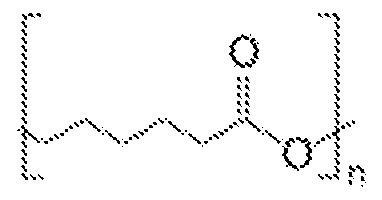
- PCL Poly(caprolactone)
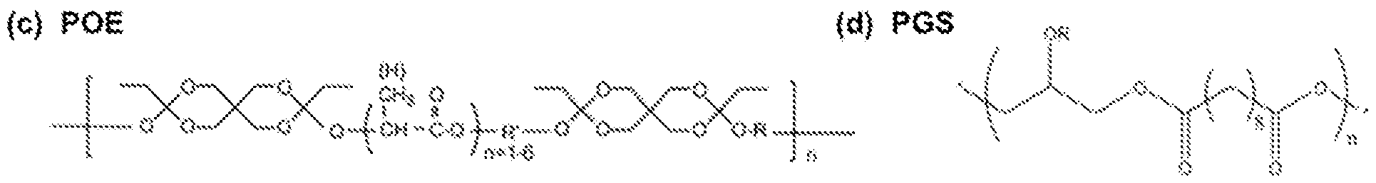
- POE Poly(ortho-ester)
- PES Poly(glycerol-sebacate)
- Poly(anhydrides), synthesized via thiol-ene chemistry, are easily prepared in a solvent- free system via UV polymerization, enabling facile synthesis and 3-D polymer structure flexibility.
- the wide range of commercially available monomers facilitates the simple tunability of material properties and degradation.
- Many PTE materials have been studied in drug delivery applications.
- PCL is a polyester material that has been heavily studied in implantable devices, and approved by the FDA. It has been fully characterized in the literature, and many forms are commercially available in large quantities.
- a class of POE was selected based on their widely published surface erosion characteristics and biocompatibility.
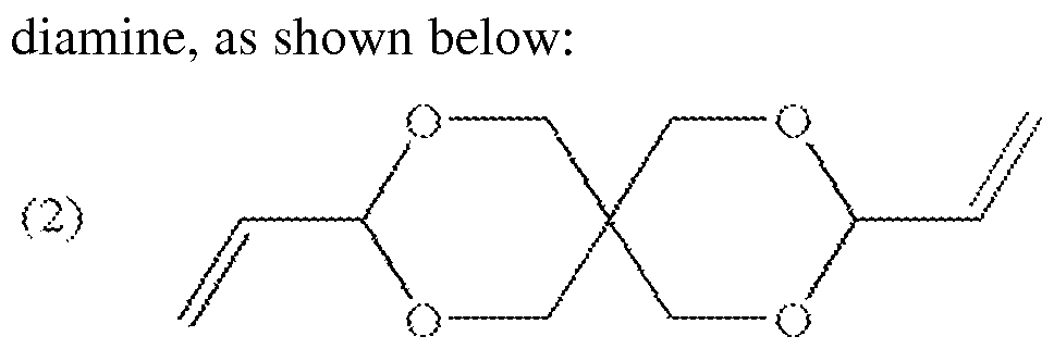
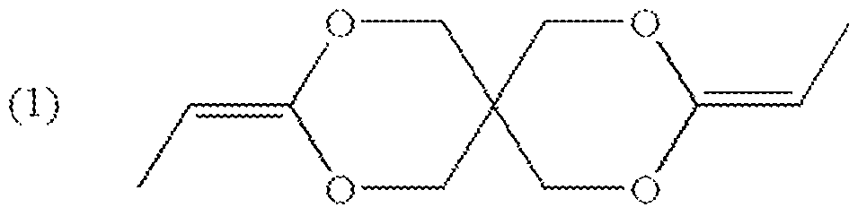
- the material is based on the monomer "DETOSU” (3,9 diethylidene-2,4,8,10-tetraoxaspiro [5.5]undecane) and two linker molecules (trans cyclohexanedimethanol (tCHD) and hexanediol (HD)).
- the POE formulation of poly(DETOSU-tCHD-HD) (100:50:50) was selected as the benchmark material of this class, because of its well-reported and promising properties.
- PGS has well reported biocompatibility and elastomeric properties.
- PGS a thermoset polyester, has been used extensively in implantable applications such as drug delivery and artificial tissue applications.
- the benchmark formulation was poly(glycerol-sebacic acid) (50:50), as it has been well studied and reported in the literature.
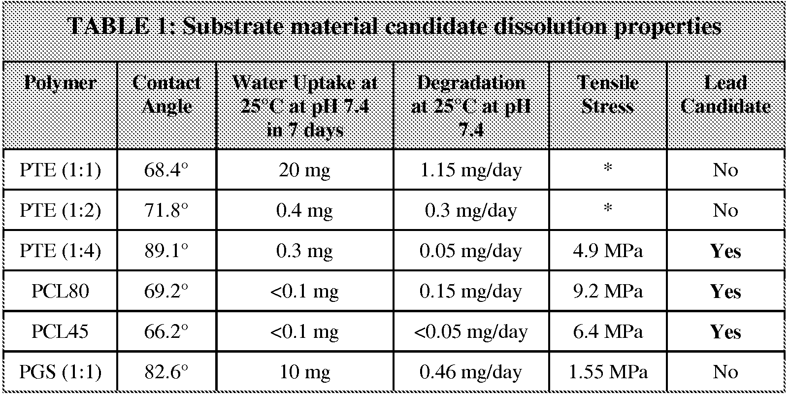
- the four candidate materials (PTE, PCL, POE, and PGS) were prepared and analyzed to determine their suitability as substrate materials for the transient medical device of the present invention.
- Table 1 shown below, provides the experimental analysis of material dissolution and physical properties, thereby leading to at least three candidate substrate materials.
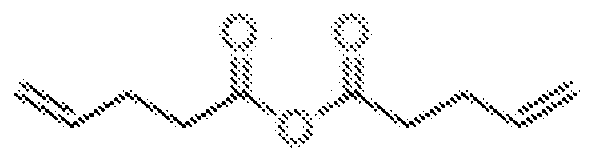
- Polyanhydrides were synthesized through thiol-ene chemistry by simple mixing of commercially available monomers, followed by UV polymerization. The properties were easily tailored by modifying the type of linker molecules and their relative ratios, and were rendered degradable by using a linker molecule possessing a hydrolysable anhydride functional group. PTE's were synthesized using various multi-armed divinyl linkers, different lengths of linear dithiols and the 4-pentenoic-anhydride (the degradable group), then screened for transience potential (water penetration and dissolution profiles) and suitability of physical properties. The best linker combination was selected for further investigation.
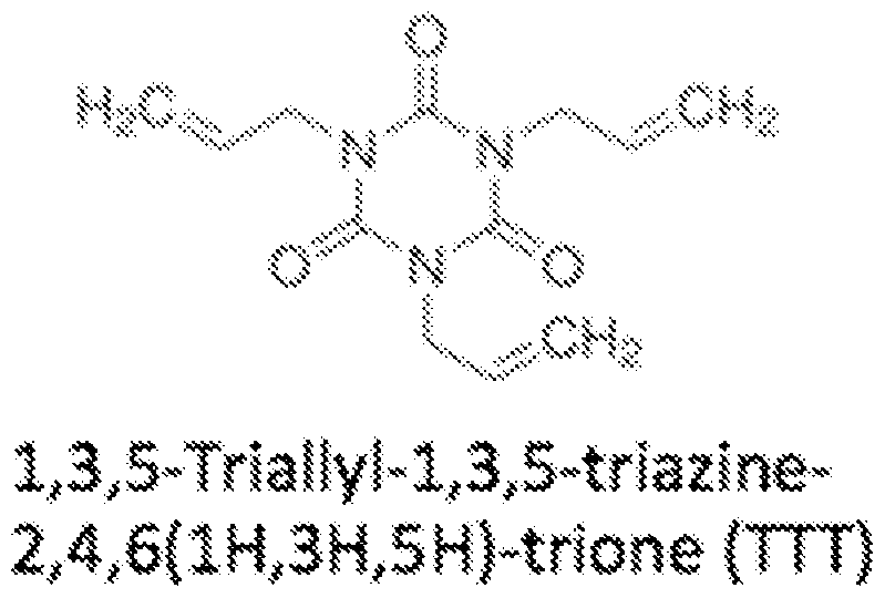
- the PTE selected was synthesized from 4-pentenoic-anhydride (4PA), a branched linker l,3,5-Triallyl-l,3,5-triazine-2,4,6(lH,3H,5H)-trione (TTT) and a linear dithiol 1,4 butanedithiol (BDT).
- 4PA 4-pentenoic-anhydride
- TTT branched linker l,3,5-Triallyl-l,3,5-triazine-2,4,6(lH,3H,5H)-trione
- BDT linear dithiol 1,4 butanedithiol
- FIGS. 7A and 7B are graphs illustrating dissolution properties of PTE films.
- the dissolution properties of PTE's were studied by soaking bulk PTE films in 0.1 M sodium phosphate buffer at room temperature.
- the effect of pH on film degradation was examined by utilizing sodium phosphate buffer at pH 5.7, pH 7.4 and pH 8.
- the rate of polymer weight loss decreased with decreasing 4PA content.
- the sample with no 4PA initially degraded more rapidly than PTE 1:2 and PTE 1:4 samples it is believed that this degradation is a physical change in the polymer, rather than a chemical degradation.
- FIGS. 8A-8C are images depicting the appearance of the PTE films of FIGS. 7 A and 7B upon wetting. Over a 16-day period the films lost less than 1 mg of dry weight and absorbed less than 1 mg of water. Additionally, the appearance of PTE 1:4 remained unchanged after 16 days, whereas PTE 1: 1 and PTE 1:2 became white, sticky and in some instances gel like after extended incubation.
- FIGS. 9A and 9B based on the promising characteristics of PTE 1:4, the dissolution of PTE 1:4 was studied at 37° C to understand material changes at physiological temperature.
- FIG. 9A is a graph illustrating polymer weight loss of PTE 1:4 at room temperature
- FIG. 9B is a graph illustrating polymer weight loss of PTE 1:4 at 37° C.
- the dissolution and water uptake of PTE 1:4 were accelerated by 10-fold at 37° C as compared to room temperature.
- further work completed in the Rogers lab showed that PTE 1:4 was able to protect a patterned Mg resistor for 5 days; however upon addition of three Si0 2 /SiN layers, the lifetime was extended to 27 days. Based on this data, it can be concluded that PTE serves as a lead candidate material for the substrate and/or encapsulation material of the medical device.
- PCL is a relatively simple polyester that is available commercially in many different molecular weight formulations, from which we selected Mn 14,000 (PCL14), Mn 45,000 (PCL45) and Mn 80,000 (PCL80) to cover a wide range of properties.
- Solvent cast films of PCL14 did not have any structural integrity and demonstrated significant cracking and flaking, and was not evaluated further.
- PCL80 formed robust and controllable thin films via solvent casting and spin coating. PCL film thickness was easily controlled by spin coating speed.
- the dissolution properties of PCL were studied via a polymer weight loss test in 0.1 M sodium phosphate buffer, as described above. As shown in FIGS. 10A and 10B, the degradation of both types of PCL is slow, and occurs with low water uptake. Specifically, PCL80 lost approximately 2 mg of polymer (equating to 2% of the original weight) in 13 days, while PCL45 lost less than 1 mg of polymer (equating to less than 1% of the original weight) in 24 days.
- Type IV POE's provide an orthogonally reactive option for substrate and encapsulation materials by virtue of their sensitivity to lower pH versus the high pH sensitivity observed for PTE, PCL and other ester-containing polymers. While this class remains of interest, the exothermic acid-catalysed polymerization raised significant concerns regarding future manufacturing at scale.
- PGS is an elastomeric polyester formed through polycondensation of glycerol and sebacic acid at a mole ratio of 1: 1 or 2:3.
- PGS films were fabricated via drop casting and spin casting of hot PGS prepolymer, followed by curing at 120° C under vacuum.
- R H, polymer chain
- Film thickness has proven difficult to control due to frequent irregularities in curing, which in turn cause a dewetting effect in the material. Thicker cast films have been more consistent from batch to batch.
- FIGS. 11A and 1 IB are graphs illustrating dry polymer eight loss and water uptake for PGS (1: 1), respectively.
- FIG. 11A shows the weight loss of PGS (1: 1) over 24 days.
- PGS (1: 1) lost 6-10 mg of weight over the course of 24 days (0.46 mg/day), with no apparent effect from buffer pH, analogous to the results obtained for PCL films.
- FIG. 1 IB PGS (1: 1) showed a significantly higher water uptake than PCL and PTE' s, with 10 mg of water uptake after only 3 days.
- solvent cast films are typically amorphous as opposed to heat processed films, in which crystallinity is typically more controllable.
- the thermal stability of substrate films influences the processes selected for the assembly of electronics.
- the thermoplastic characteristics of PCL, and its moderately low melting point (59 - 64° C), enable the facile melt processing of PCL, but limit the high temperature electronics deposition processes.
- Low temperature deposition of electronics, such as transfer printing, will be required for this material.
- the PTE materials, resistant to at least 150° C will be stable in higher temperature thermal/E-beam metal deposition techniques. A more thorough evaluation of deposition and circuit fabrication techniques will be undertaken during Phase II.
- the long-term stability of all materials must be improved for their use as substrates and encapsulants in implantable devices. This can be achieved via copolymerization, blending of polymers and material layering. Advanced polymer processing, such as hot pressing to form more crystalline films, may also improve material stability.
- one or more components of the circuit of the medical device may include materials and/or have specific dimensions resulting in predictable and controllable resorption rates, such that the medical device 202 may cease to function and completely dissipate within a medically relevant timescale (e.g., after completion of treatment).
- one or more of the components of the circuit include a material selected from the group consisting of Mg, Mg alloys, MgO, Zn, W, Fe, Mo, Si, Si0 2 , and combinations thereof.
- FIGS. 12A-12F are graphs illustrating resistance changes during the dissolution of different exemplary bioresorbable metals for use as one or more components in the circuit of a transient medical device consistent with the present disclosure. As shown, the degradation profiles of different metal materials are under evaluation with the intent to identify metals that could be implemented in transient electronic systems.
- Six metals that are degradable, bioresorbable and compatible with silicon devices were evaluated in dissolution studies: Mg, Mg alloy AZ31B (with 3 wt % aluminum (Al), and 1 wt % Zn), W, Zn, and molybdenum (Mo).
- Mg, Mg alloy and Zn dissolve at much faster rates versus Fe and W
- Mg, Mg alloy and Zn dissolve at faster rates in HBSS versus DI water
- dissolution rates are nearly pH independent
- sputtered W degrades slower in DI water and pH 5 Hank's solution due to its acidic dissolution products.
- the rates of dissolution appear faster for Mg, Mg alloy and Zn than that for Mo and W, and salt solutions significantly enhance the degradation rates compared to DI water, except that the rates for Mo and W in pH 5 solution.
- Dissolution rates of W can also be modified by a factor of ten through different deposition methods.
- FIG. 13 illustrates one embodiment of a circuit of the transient medical device of the system of FIG. 1 consistent with the present disclosure.
- the implantable circuit for providing electrical stimulation to management pain includes inductive coil L2 configured to wirelessly communicate with an inductive coil LI of the external controller, a rectification circuit (formed by capacitors CI and C2, diodes Dl and D2), PIN diodes (Zl), current limiting resistors (Rl), cathodes, and an anode.
- the coil LI of the external controller can operate in two different modes, in which a constant sinusoidal wave or a modulated sinusoidal wave can be generated, resulting in different outputs from the implanted circuit.
- the implanted coil L2 communicates with external coil LI through the skin and/or tissue via resonant inductive coupling, for example.
- CI, C2, Dl, and D2 combine to form a voltage doubler that changes the input alternating current (AC) to a direct current (DC) output voltage whose amplitude is twice as large as the input voltage.
- the PIN diode Zl is configured to regulate the DC voltage to be approximately 5.1 V, while resistor Rl limits the output current to a level tolerable by human tissue.
- the electrodes are configured to generate and deliver an electric field having a frequency in the range of 6 to 14 MHz.
- the frequency of the electric field is 6.78 MHz, which is comparable to the ISM standard for implantable medical devices while maintaining a large quality factor for inductive coupling through inhomogeneous human tissue.
- the theoretical skin penetration depth of the electromagnetic field at 6.78 MHz is approximately 0.97 m, thus ensuring consistent inductive coupling to the implanted circuits regardless of its placement locale within the patient.
- the electrodes are configured to deliver between 1 to 10 mA of current in monophasic square- wave pulses having durations between 10 to 200 ⁇ 8 to provide between 10 to 2000 nC of charge to one or more nerve fibers.
- the pulses may be delivered to the one or more nerve fibers have a frequency in the range of 40 to 200 Hz.
- the electrodes are configured to deliver a variety of different stimulation patterns (e.g., different electrical fields) based on wireless input from the external controller.
- the external controller may operate in a variety of different modes, each mode resulting in the delivery of a different stimulation pattern from the electrodes.
- the circuit is configured to allow adjustment, or tuning, of the stimulation patterns on a patient-by-patient basis for frequency, amplitude and duration so as to inhibit the transmission of pain signals along the nerve fibers, thereby providing pain relief.
- the external controller electronics and coil LI may include standard, non-transient technologies, ultimately assembled in compact enclosures with user friendly interface. For the purposes of present disclosure, off-the-shelf function generators, amplifiers, coils and associated control equipment were used.
- FIG. 14 is a graph illustrating exemplary circuit input and circuit output for peripheral nerve stimulation. It has been demonstrated that electrical nerve stimulation with a median pulse width of 300 us and a current level of 2.5 mA can generate effective parasthesias. Accordingly, the electrodes are configured to deliver monophasic, sinusoidal capacitively-coupled output pulses to the one or more nerve fibers based on wirelessly received input from the controller.
- FIG. 15 illustrates another embodiment of a circuit of the external controller and transient medical device of the system of FIG. 1 consistent with the present disclosure.
- the circuit of FIG. 15 is a demonstration circuit designed to deliver 200 ⁇ sec-long monophasic pulses of 5 mA of current to a fixed 500 ⁇ resistive load with a frequency of 100 Hz.
- a circuit capable of delivering stimulation with these parameters can stimulate the sciatic nerve of a rat and will provide a basis for testing of the entire transient stimulation system in an in vivo experiment.
- the proof-of-concept nerve stimulator system was designed to receive wireless power via resonant inductive coupling from an external controller 104 in the form of a PCB-based transmitter operating at a transmission frequency within the 13.56 MHz ISM band.
- Planar rectangular spiral inductors were used as transmitting and receiving antennae; the transmitter was designed to be positioned on the exterior surface of the tissue while the receiver was designed to be implanted 10 mm below the skin surface.
- the coupling frequency of the two spiral coils was chosen based on the allowable size of the implantable receiver coil (10 mm outer diameter), the separation between the transmitter and receivers, and ISM regulations for radiation absorption in tissue.
- Resonant coupling between the primary and secondary coils can greatly improve the power transmission efficiency for near-field inductively coupled systems.
- Capacitors are added in series or parallel with each coil to create two resonant tanks with equivalent resonant frequencies.
- the receiver circuit rectifies the coupled power using a half- wave rectifier and delivers it to a 500 ⁇ resistive load.
- An indicator LED placed in series with the resistive load provides visual confirmation of the power delivered to the load.
- controller also referred to herein as "transmitter”
- medical device also referred to herein as “receiver”
- FIG. 16 illustrates another embodiment of a circuit of the external controller and transient medical device of the system of FIG. 1 consistent with the present disclosure.
- the circuit of FIG. 16 was simulated using circuit simulation software, specifically LTSPICE IV, a SPICE simulator, commercially available from Linear Technology Corporation.
- the circuit was simulated using detailed models of the parasitic resistance and capacitance of each component.
- FIG. 17 is a graph illustrating different voltages observed in the circuit of FIG. 16 upon simulation of the circuit.
- the stimulating voltage has an average value of 2.5 V, which corresponds to an output current of 5 mA through the load.
- the predicted capacitance values required to resonate the secondary coil and to smooth the output to provide monophasic stimulation represent a 50-fold increase in energy storage capacity over the state-of-the-art capacitors currently developed.
- FIGS. 18A and 18B are perspective views of an exemplary external controller (e.g., transmitter) wirelessly communicating with an exemplary transient medical device (e.g., receiver) through different mediums (air in FIG. 18A and saline solution in FIG. 18B).
- the functionality of a transient medical device of the present disclosure was demonstrated by transmitting wireless power to a medical device (e.g., receiver) circuit and illuminating an indicator LED with 2 mA of current.
- Wireless function was established with two different experimental configurations: a first configuration with 1 cm of air separating the transmitter and receiver (shown in FIG. 18 A, and second configuration with 1 cm of saline solution separating the two circuits (shown in FIG. 18B).
- the indicator LED which was connected in series with a 500 ⁇ output resistor, was illuminated for both conditions, confirming that sufficient voltage was received by the stimulator circuit in both cases.
- FIG. 19 is a graph illustrating different voltages observed during operation of the systems of FIGS. 18A and 18B.
- the transmitter and receiver coils were resonated at 13.56 MHz to boost the voltage at the receiver unit.
- a signal generator provided a 5 V peak-to-peak sinusoidal signal to the transmitter PCB. This waveform was generated in "burst mode" with a 10 msec period and 200 ⁇ 8 ⁇ pulse width to satisfy the requirements of the nerve stimulator.
- a rectified voltage of 1 V was provided to the output resistor, as shown in FIG. 19, thereby illuminating the LED with 2 mA of current.
- FIG. 20 illustrates another embodiment of a circuit of the external controller and transient medical device of the system of FIG. 1 consistent with the present disclosure.
- a battery- powered class-E amplifier will generate a 13.56 MHz sinusoidal wave form whose amplitude is modulated by a controller.
- the peak voltage of the transmitted waveform will be limited to a safe value to prevent excessive power from being delivered to the nerve tissue.
- the sinusoidal waveform generated by the amplifier will be wirelessly transmitted in pulses whose width is set by the control circuitry.
- the transmitted waveform will be coupled through tissue using resonant inductive coupling to maximize the power transferred to the implanted circuit.
- Impedance matching circuits on the transmitter and receiver will be used to tune the load impedance to maximize the power transfer from the amplifier to the transmitter antenna and from the receiver antenna to the tissue.
- the impedance matching network on the transmitter will be used to match the output impedance of the class-E amplifier to the impedance of the resonant transmitter coil.
- the impedance matching network will be used to match to impedance of the receiver coil to that of the tissue (nominally 500 ⁇ ).
- the matching networks shown in FIG. 20 are L-match networks that are used when the load impedance is larger than the source impedance.
- the source and load impedance on the transmitter and receiver sides will both be measured experimentally to optimize the impedance match structure and component values to maximize the power-transfer efficiency.
- a half- wave rectifier will convert the ac voltage waveform to dc to drive the nerve tissue with monophasic square wave pulses.
- a filter capacitor with sufficient capacitance will be used to smooth the voltage to within a 10% peak-to-peak voltage ripple on the output. Simulations of this circuit predict that capacitance values between 200 and 500 pF will be needed to smooth the output voltage of the circuit and to resonate the secondary coil at 13.56 MHz.
- Monophasic stimulation of nerve tissue has been shown to be safe and effective when implemented at charge densities below 0.2 ⁇ / ⁇ per pulse.
- the circuit of the present device is designed to operate below this safety threshold to mitigate tissue damage associated with Faradaic charge delivery and tissue electrolysis.
- the circuit will deliver 1-10 mA of current in monophasic square- wave pulses with durations of 10-200 ⁇ 8 ⁇ to peripheral nerve tissue. This charge will be delivered to the tissue over short pulses with a frequency between 40 and 200 Hz to stimulate paresthesia in the patient. These requirements have been demonstrated to be effective in mediating pain both in animal and human studies. Monophasic stimulation that delivers charge at a density of 0.2 ⁇ / ⁇ per pulse resulted in no tissue damage in previous studies. The largest charge per phase that our stimulator will be able to deliver will be 2 ⁇ ⁇ . Given a 10 mm electrode area, the charge density per phase would be at most 20 ⁇ ⁇ /phase, which is well within the levels of safe stimulation.
- FIG. 21 is a graph illustrating a range of tolerant stimulation levels configured to be delivered by the circuitry of the transient medical device of FIG. 20.
- the highest allowable stimulation provided by the circuit of FIG. 20, as indicated by arrow 1000, is still within the safety limits demonstrated in previous experiments.
- the transmitted pulse width, amplitude, and frequency will be set by external control circuitry on the transmitter PCB.
- the controller will be able to adjust the transmitted waveform parameters over the following ranges: pulse widths between 10-200 ⁇ 8 ⁇ , transmitted voltage amplitudes between 5 and 15 V, pulse frequencies between 40-200 Hz.
- the implantable transient medical device of the present invention is configured to operate without direct feedback, such that unidirectional power for stimulation will be the only wireless signal transmitted in the system. Accordingly, the output voltage from the medical device can be regulated by limiting the peak voltage delivered from the external controller. Simulations and lab tests will be done to determine at which level to set this peak threshold voltage considering the range of possible coupling factors between the primary and secondary coils. An additional level of control can be added, if deemed necessary after this testing, which would limit the peak voltage of the stimulating waveform using a Zener diode. A Zener diode would serve as over- voltage protection and would provide a fixed voltage output for coupling factors and transmitted voltages greater than chosen values. The complexity of the control and regulation circuits will be determined in part by the patient condition that our stimulator serves to treat and the precise location in the body in which we intend to implant the device. Additional levels of control can be added to ensure tighter regulation of the electrical stimulus provided by our implant.
- an implanted transient stimulator circuit consistent with the present invention may have a total device surface area of no more than 5 cm and will deliver 1-10 mA of current in monophasic square- wave pulses with durations of 10-200 ⁇ 8 ⁇ to provide between 10 and 2000 nC of charge to peripheral nerve tissue. These charge pulses will be delivered to the tissue with a frequency between 40 and 200 Hz to stimulate continuous paresthesia within the nervous system to mask sensations of pain. These stimulation requirements have been demonstrated to be effective in mediating pain both in animal and human studies.
- the stimulator will be wirelessly powered by an external power supply circuit. The frequency and peak current amplitude of the stimulus pulses will be tunable based on the transmitted voltage waveform from the external circuit.
- components may be positioned on the exterior surface of the tissue (positioned directly over the implant) and provide wireless power to the implant via near- field inductive coupling at a desired frequency, such as, for example, 13.56 MHz.
- Resonant inductive coupling between an external coil and an implanted coil will be used to deliver power to the stimulator circuit.
- the transmitter and receiver coils will each be connected to capacitors to form resonant tanks that oscillate at 13.56 MHz to maximize the transfer of power through the tissue.
- the external controller and implanted medical device may be loosely coupled through tissue at a nominal distance of 10 mm, for example.
- the external controller is configured to wirelessly deliver unidirectional electrical power from a class E amplifier to the implanted medical device.
- the transmitted power will be limited such that the power delivered to the target tissue does not exceed safety thresholds.
- FIG. 22 is a sectional anterior view of a portion of a patient's torso, illustrating the implantation of a transient medical device 102 consistent with the present disclosure adjacent to the rectus femoris muscle of the leg.
- FIG. 23 is an enlarged view, partly in section, of the rectus femoris muscle 108 including a bundle of peripheral nerves 106 targeted with the electrical field generated and delivered from the transient medical device 102.
- the medical device 102 may be implanted subcutaneously at or in close proximity to a trauma site, such as a bundle of nerve fibers 106 in the rectus femoris 108 of a patient's leg.
- the controller 104 is disposed externally to the patient's leg in close proximity to the medical device 102.
- the medical device 102 may be immobilized at the time of
- the fixtures are configured to degrade at the same rate as the implanted medical device.
- the fixtures may provide temporary immobilization until the medical device is fixed within the implant site via immunologically-driven encapsulation by fibrous extracellular matrix material.
- the circuit and substrate of the medical device 102 may be sufficiently flexible such that the medical device may be configured to physically conform to the implant site and/or target nerves, thus precluding the requirement for immobilization.
- Nerve stimulation to relieve pain is achieved by wirelessly transmitting high frequency signals from the external controller 104 to the medical device 102, via inductive resonance coupling, for example.
- a current flows between the electrodes of the circuit of the medical device 102, wherein the electrodes are configured to deliver electrical energy to the one or more nerve fibers to stimulate paresthesia, thereby masking associated pain.
- the electrodes are configured to generate an electric field that penetrates surrounding tissue containing the affected sensory or peripheral nerves.
- the electrodes are configured to deliver a variety of different stimulation patterns based on wireless input from the external controller.
- the external controller 104 may operate in a variety of different modes, each mode resulting in the delivery of a different stimulation pattern from the electrodes. Accordingly, the system allows the tuning of stimulation patterns on a patient-by-patient basis for frequency, amplitude and duration so as to inhibit the transmission of pain signals along the nerve fibers, thereby providing pain relief.
- the wireless capabilities of the external controller 104 and implanted device 102 allow improved treatment.
- the external controller 104 need only be placed adjacent to the implanted device 102 so as to provide power to and stimulation from the device 102, without requiring a directly wired connections.
- some implantable devices must be directly connected to an external power source or controller in order to function, wherein, in addition to being inconvenient to a patient, the wire connecting the external power source or controller and the device must be constantly cleaned and monitored to avoid infection.
- the ability to wirelessly control of the medical device 102 of the present invention overcomes the drawbacks associated with wired connections, thus improving patient treatment and compliance.
- the substrate and one or more of the electronic components of the circuit of the medical device 102 are bioresorbable and biocompatible.
- the substrate and most, if not all, of the components of the circuit have specific dimensions or geometries resulting in predictable and controllable resorption rates, such that the medical device 102 may cease to function and completely dissipate within a medically relevant timescale (e.g., after completion of treatment). Accordingly, once the functional phase of the device 102 is terminated, the remnants of the implanted device 102 may be resorbed naturally over a much longer time period without requiring surgery on the patient's leg to remove the device 102.
- FIG. 24 is a flow diagram illustrating one embodiment of a method 2400 for stimulating a target tissue within a body of a patient.
- the method includes implanting a medical device with the patient's body (operation 2410). Implantation may occur at or near a site of trauma or the target tissue, such that a stimulatory signal from the medical device will reach and address the relevant target, although direct contact between the electrodes and the target tissue itself is not necessary.
- the method 2400 further includes wirelessly transmitting input to the implanted medical device from a controller disposed external to the patient's body (operation 2420).
- the wireless transmission may include transmitting power from the controller to the implantable medical device via resonant inductive coupling.
- the method 2400 further includes stimulating the target tissue based on the wirelessly transmitted input (operation 2430). In some embodiment of a method 2400 for stimulating a target tissue within a body of a patient.
- the method includes implanting a medical device with the patient's body (operation 2410). Implantation may occur at or near a
- the stimulation may be in the form of an electrical field, wherein, in the event the target tissue is a nerve fiber, the electrical field is configured to stimulate paresthesia within the nerve fiber to mask pain.
- FIG. 24 illustrates method operations according various embodiments, it is to be understood that in any embodiment not all of these operations are necessary. Indeed, it is fully contemplated herein that in other embodiments of the present disclosure, the operations depicted in FIG. 24 may be combined in a manner not specifically shown in any of the drawings, but still fully consistent with the present disclosure. Thus, claims directed to features and/or operations that are not exactly shown in one drawing are deemed within the scope and content of the present disclosure.
Landscapes
- Health & Medical Sciences (AREA)
- Life Sciences & Earth Sciences (AREA)
- Engineering & Computer Science (AREA)
- Biomedical Technology (AREA)
- Nuclear Medicine, Radiotherapy & Molecular Imaging (AREA)
- Radiology & Medical Imaging (AREA)
- Animal Behavior & Ethology (AREA)
- General Health & Medical Sciences (AREA)
- Public Health (AREA)
- Veterinary Medicine (AREA)
- Neurosurgery (AREA)
- Neurology (AREA)
- Physics & Mathematics (AREA)
- Pain & Pain Management (AREA)
- Electromagnetism (AREA)
- Acoustics & Sound (AREA)
- Vascular Medicine (AREA)
- Biophysics (AREA)
- Heart & Thoracic Surgery (AREA)
- Electrotherapy Devices (AREA)
Abstract
Description

Claims
Priority Applications (5)
| Application Number | Priority Date | Filing Date | Title |
|---|---|---|---|
| CA2898196A CA2898196A1 (en) | 2013-01-15 | 2014-01-14 | Implantable transient nerve stimulation device |
| JP2015552893A JP6412507B2 (en) | 2013-01-15 | 2014-01-14 | Implantable temporary neurostimulation device |
| EP14740135.0A EP2945699A4 (en) | 2013-01-15 | 2014-01-14 | IMPLANTABLE NERVOUS STIMULATION EPHEMER DEVICE |
| AU2014207685A AU2014207685B2 (en) | 2013-01-15 | 2014-01-14 | Implantable transient nerve stimulation device |
| AU2018206723A AU2018206723A1 (en) | 2013-01-15 | 2018-07-17 | Implantable transient nerve stimulation device |
Applications Claiming Priority (6)
| Application Number | Priority Date | Filing Date | Title |
|---|---|---|---|
| US201361752717P | 2013-01-15 | 2013-01-15 | |
| US61/752,717 | 2013-01-15 | ||
| US201361753122P | 2013-01-16 | 2013-01-16 | |
| US61/753,122 | 2013-01-16 | ||
| US201361912731P | 2013-12-06 | 2013-12-06 | |
| US61/912,731 | 2013-12-06 |
Publications (1)
| Publication Number | Publication Date |
|---|---|
| WO2014113382A1 true WO2014113382A1 (en) | 2014-07-24 |
Family
ID=51165728
Family Applications (1)
| Application Number | Title | Priority Date | Filing Date |
|---|---|---|---|
| PCT/US2014/011470 Ceased WO2014113382A1 (en) | 2013-01-15 | 2014-01-14 | Implantable transient nerve stimulation device |
Country Status (6)
| Country | Link |
|---|---|
| US (1) | US20140200626A1 (en) |
| EP (1) | EP2945699A4 (en) |
| JP (1) | JP6412507B2 (en) |
| AU (2) | AU2014207685B2 (en) |
| CA (1) | CA2898196A1 (en) |
| WO (1) | WO2014113382A1 (en) |
Cited By (1)
| Publication number | Priority date | Publication date | Assignee | Title |
|---|---|---|---|---|
| WO2022203157A1 (en) * | 2021-03-24 | 2022-09-29 | 포항공과대학교 산학협력단 | Composite for controlling degradation of transient electronics |
Families Citing this family (18)
| Publication number | Priority date | Publication date | Assignee | Title |
|---|---|---|---|---|
| CN205304411U (en) * | 2013-06-05 | 2016-06-08 | 株式会社村田制作所 | Electron device and wireless electric power transmission system |
| WO2016168485A1 (en) * | 2015-04-17 | 2016-10-20 | David Robinson | An implantable neuro-stimulation device |
| US11291847B2 (en) * | 2015-06-16 | 2022-04-05 | The Regents Of The University Of Colorado, A Body Corporate | Systems and methods for preventing, diagnosing, and/or treating one or more medical conditions via neuromodulation |
| WO2017004531A1 (en) * | 2015-07-02 | 2017-01-05 | The Board Of Trustees Of The University Of Illinois | Fully implantable soft medical devices for interfacing with biological tissue |
| US10603500B2 (en) * | 2016-01-29 | 2020-03-31 | Axonics Modulation Technologies, Inc. | Methods and systems for frequency adjustment to optimize charging of implantable neurostimulator |
| US11298544B2 (en) * | 2016-02-17 | 2022-04-12 | Galvani Bioelectronics Limited | Nerve stimulation systems and methods using an external wireless power source |
| US10707531B1 (en) | 2016-09-27 | 2020-07-07 | New Dominion Enterprises Inc. | All-inorganic solvents for electrolytes |
| CN110248601A (en) * | 2016-12-21 | 2019-09-17 | 埃尔瓦有限公司 | Body kinematics or situation are monitored according to motion scheme using conformal electronic device |
| US11179564B2 (en) | 2017-04-25 | 2021-11-23 | Washington University | Resorbable implant for stimulating tissue, systems including such implant, and methods of using |
| KR102318885B1 (en) | 2018-11-13 | 2021-11-02 | 단국대학교 천안캠퍼스 산학협력단 | Electrode For Stimulating Spinal Cord |
| US11617536B1 (en) * | 2019-01-31 | 2023-04-04 | Dartmouth-Hitchcock Clinic | System and method to measure pain levels of patients following surgery |
| US12082916B2 (en) * | 2020-03-02 | 2024-09-10 | Vanderbilt University | Bioresorbable RF coils for post-surgical monitoring by MRI |
| CN113949145B (en) * | 2020-07-17 | 2024-02-06 | 深圳先进技术研究院 | Degradable rectifying device and manufacturing method thereof |
| WO2023178224A1 (en) * | 2022-03-17 | 2023-09-21 | Northwestern University | Transient closed-loop system and applications of same |
| WO2022272164A1 (en) * | 2021-06-25 | 2022-12-29 | Northwestern University | Bioresorbable cardiovascular instruments, and operation and fabrication methods of same |
| US20250312591A1 (en) * | 2022-05-18 | 2025-10-09 | Northwestern University | Electrotherapy system and applications of same |
| CN115177865B (en) * | 2022-07-22 | 2023-05-30 | 北京品驰医疗设备有限公司 | Spinal cord electric stimulation system |
| DE102023104119A1 (en) * | 2023-02-20 | 2024-08-22 | Neuroloop GmbH | Electrical circuit arrangement for a biomedical interface |
Citations (6)
| Publication number | Priority date | Publication date | Assignee | Title |
|---|---|---|---|---|
| US20020198582A1 (en) * | 2001-05-30 | 2002-12-26 | Edell David J. | Implantable devices having a liquid crystal polymer substrate |
| US7236821B2 (en) * | 2002-02-19 | 2007-06-26 | Cardiac Pacemakers, Inc. | Chronically-implanted device for sensing and therapy |
| US20070156179A1 (en) * | 2003-03-06 | 2007-07-05 | S E Karashurov | Multi-channel and multi dimensional system and method |
| US20090157147A1 (en) * | 2007-11-26 | 2009-06-18 | Microtransponder, Inc., | Implantable Transponder Systems and Methods |
| US20100076536A1 (en) * | 2006-09-22 | 2010-03-25 | Koninklijke Philips Electronics N.V. | Implantable multi-electrode device |
| US20110004269A1 (en) * | 2004-06-10 | 2011-01-06 | Medtronic Urinary Solutions, Inc. | Implantable pulse generator for providing functional and/or therapeutic stimulation of muscles and/or nerves and/or central nervous system tissue |
Family Cites Families (10)
| Publication number | Priority date | Publication date | Assignee | Title |
|---|---|---|---|---|
| US7277749B2 (en) * | 2003-01-15 | 2007-10-02 | Alfred E. Mann Institute For Biomedical Engineering At The University Of Southern California | Treatments for snoring using injectable neuromuscular stimulators |
| US20080063866A1 (en) * | 2006-05-26 | 2008-03-13 | Georgia Tech Research Corporation | Method for Making Electrically Conductive Three-Dimensional Structures |
| MX2009004819A (en) * | 2006-11-06 | 2009-11-23 | Tyrx Pharma Inc | Resorbable pouches for implantable medical devices. |
| US9023114B2 (en) * | 2006-11-06 | 2015-05-05 | Tyrx, Inc. | Resorbable pouches for implantable medical devices |
| CA2695760C (en) * | 2007-08-10 | 2014-02-04 | Med-El Elektromedizinische Geraete Gmbh | Pulse width adaptation for inductive links |
| US8951546B2 (en) * | 2008-12-23 | 2015-02-10 | Surmodics Pharmaceuticals, Inc. | Flexible implantable composites and implants comprising same |
| US8666471B2 (en) * | 2010-03-17 | 2014-03-04 | The Board Of Trustees Of The University Of Illinois | Implantable biomedical devices on bioresorbable substrates |
| CA2816343C (en) * | 2010-11-12 | 2017-01-17 | Tyrx, Inc. | Anchorage devices comprising an active pharmaceutical ingredient |
| EP2760537A4 (en) * | 2011-09-30 | 2015-06-03 | Adi Mashiach | Device and method for modulating nerves using parallel electric fields |
| US9582465B2 (en) * | 2012-11-15 | 2017-02-28 | Elwha Llc | Flexible processors and flexible memory |
-
2014
- 2014-01-14 WO PCT/US2014/011470 patent/WO2014113382A1/en not_active Ceased
- 2014-01-14 CA CA2898196A patent/CA2898196A1/en not_active Abandoned
- 2014-01-14 JP JP2015552893A patent/JP6412507B2/en not_active Expired - Fee Related
- 2014-01-14 AU AU2014207685A patent/AU2014207685B2/en not_active Ceased
- 2014-01-14 EP EP14740135.0A patent/EP2945699A4/en not_active Withdrawn
- 2014-01-14 US US14/154,938 patent/US20140200626A1/en not_active Abandoned
-
2018
- 2018-07-17 AU AU2018206723A patent/AU2018206723A1/en not_active Abandoned
Patent Citations (6)
| Publication number | Priority date | Publication date | Assignee | Title |
|---|---|---|---|---|
| US20020198582A1 (en) * | 2001-05-30 | 2002-12-26 | Edell David J. | Implantable devices having a liquid crystal polymer substrate |
| US7236821B2 (en) * | 2002-02-19 | 2007-06-26 | Cardiac Pacemakers, Inc. | Chronically-implanted device for sensing and therapy |
| US20070156179A1 (en) * | 2003-03-06 | 2007-07-05 | S E Karashurov | Multi-channel and multi dimensional system and method |
| US20110004269A1 (en) * | 2004-06-10 | 2011-01-06 | Medtronic Urinary Solutions, Inc. | Implantable pulse generator for providing functional and/or therapeutic stimulation of muscles and/or nerves and/or central nervous system tissue |
| US20100076536A1 (en) * | 2006-09-22 | 2010-03-25 | Koninklijke Philips Electronics N.V. | Implantable multi-electrode device |
| US20090157147A1 (en) * | 2007-11-26 | 2009-06-18 | Microtransponder, Inc., | Implantable Transponder Systems and Methods |
Cited By (1)
| Publication number | Priority date | Publication date | Assignee | Title |
|---|---|---|---|---|
| WO2022203157A1 (en) * | 2021-03-24 | 2022-09-29 | 포항공과대학교 산학협력단 | Composite for controlling degradation of transient electronics |
Also Published As
| Publication number | Publication date |
|---|---|
| AU2014207685A1 (en) | 2015-07-30 |
| EP2945699A1 (en) | 2015-11-25 |
| AU2014207685B2 (en) | 2018-04-19 |
| EP2945699A4 (en) | 2016-01-27 |
| JP2016502924A (en) | 2016-02-01 |
| US20140200626A1 (en) | 2014-07-17 |
| AU2018206723A1 (en) | 2018-08-09 |
| CA2898196A1 (en) | 2014-07-24 |
| JP6412507B2 (en) | 2018-10-24 |
Similar Documents
| Publication | Publication Date | Title |
|---|---|---|
| AU2014207685B2 (en) | Implantable transient nerve stimulation device | |
| Cha et al. | Bioresorbable electronic implants: history, materials, fabrication, devices, and clinical applications | |
| JP7190545B2 (en) | Devices, systems and methods for stimulation therapy | |
| AU2008352005B2 (en) | Array of joined microtransponders for implantation | |
| US9061134B2 (en) | Systems and methods for flexible electrodes | |
| AU2008329716B2 (en) | Implantable transponder systems and methods | |
| US7330756B2 (en) | Implantable microstimulator with conductive plastic electrode and methods of manufacture and use | |
| US7840279B2 (en) | Implantable microstimulator having a separate battery unit and methods of use thereof | |
| US20120296399A1 (en) | Array of Joined Microtransponders for Implantation | |
| Cho et al. | A SU-8-based fully integrated biocompatible inductively powered wireless neurostimulator | |
| WO2009070705A2 (en) | Transfer coil architecture | |
| JP2010536507A (en) | System for transmitting current to body tissue | |
| JP2016502924A5 (en) | ||
| US11458309B2 (en) | Flexible implantable tissue stimulator and methods of making and using same | |
| US20110307042A1 (en) | Electrode arrays based on polyetherketoneketone | |
| WO2013106884A1 (en) | An apparatus and method for facilitating treatment of tissue | |
| CN104107507A (en) | Passive minimally-invasive subcutaneous nerve interventional chip based on RFID radio frequency technology | |
| CN115136500B (en) | Wireless trigger device | |
| US20060259090A1 (en) | Implantable medical device with polymer-polymer interfaces and methods of manufacture and use | |
| US20130166039A1 (en) | Osseous implant and methods of its making and use | |
| Cho et al. | A MEMS-based fully-integrated wireless neurostimulator | |
| CN110464983A (en) | Degradable flexible nerve bundle repair device | |
| Cho et al. | Biodegradable Implantable Electronics with Wireless Technology for Real‐Time Clinical Applications | |
| Cheng et al. | Bioresorbable Electrically‐Active Neuromodulation Materials & Devices | |
| EP4626544A1 (en) | Brain implant devices and methods |
Legal Events
| Date | Code | Title | Description |
|---|---|---|---|
| 121 | Ep: the epo has been informed by wipo that ep was designated in this application |
Ref document number: 14740135 Country of ref document: EP Kind code of ref document: A1 |
|
| ENP | Entry into the national phase |
Ref document number: 2015552893 Country of ref document: JP Kind code of ref document: A |
|
| ENP | Entry into the national phase |
Ref document number: 2898196 Country of ref document: CA |
|
| NENP | Non-entry into the national phase |
Ref country code: DE |
|
| WWE | Wipo information: entry into national phase |
Ref document number: 2014740135 Country of ref document: EP |
|
| ENP | Entry into the national phase |
Ref document number: 2014207685 Country of ref document: AU Date of ref document: 20140114 Kind code of ref document: A |