WO2013154076A1 - Composition for organic electroluminescent elements, and organic electroluminescent element - Google Patents
Composition for organic electroluminescent elements, and organic electroluminescent element Download PDFInfo
- Publication number
- WO2013154076A1 WO2013154076A1 PCT/JP2013/060654 JP2013060654W WO2013154076A1 WO 2013154076 A1 WO2013154076 A1 WO 2013154076A1 JP 2013060654 W JP2013060654 W JP 2013060654W WO 2013154076 A1 WO2013154076 A1 WO 2013154076A1
- Authority
- WO
- WIPO (PCT)
- Prior art keywords
- group
- composition
- organic electroluminescent
- substituent
- ring
- Prior art date
Links
- 239000000203 mixture Substances 0.000 title claims abstract description 366
- 229920000642 polymer Polymers 0.000 claims abstract description 195
- 239000003960 organic solvent Substances 0.000 claims abstract description 184
- 150000004982 aromatic amines Chemical class 0.000 claims abstract description 134
- 238000002347 injection Methods 0.000 claims abstract description 81
- 239000007924 injection Substances 0.000 claims abstract description 81
- 230000005525 hole transport Effects 0.000 claims abstract description 71
- 238000000034 method Methods 0.000 claims description 191
- 125000001424 substituent group Chemical group 0.000 claims description 134
- 150000001875 compounds Chemical class 0.000 claims description 118
- 239000011521 glass Substances 0.000 claims description 95
- 239000007788 liquid Substances 0.000 claims description 70
- 125000006615 aromatic heterocyclic group Chemical group 0.000 claims description 43
- 239000000758 substrate Substances 0.000 claims description 40
- 125000003118 aryl group Chemical group 0.000 claims description 27
- 125000005647 linker group Chemical group 0.000 claims description 22
- 125000000217 alkyl group Chemical group 0.000 claims description 20
- 125000003545 alkoxy group Chemical group 0.000 claims description 15
- 125000004435 hydrogen atom Chemical group [H]* 0.000 claims description 12
- 125000004433 nitrogen atom Chemical group N* 0.000 claims description 8
- 239000008393 encapsulating agent Substances 0.000 claims description 6
- 150000002894 organic compounds Chemical class 0.000 claims description 5
- 238000005286 illumination Methods 0.000 claims description 4
- 210000003000 inclusion body Anatomy 0.000 claims description 3
- 125000002029 aromatic hydrocarbon group Chemical group 0.000 claims 5
- 230000000994 depressogenic effect Effects 0.000 claims 1
- 239000000463 material Substances 0.000 abstract description 147
- 239000010410 layer Substances 0.000 description 289
- -1 metal ions Chemical class 0.000 description 116
- 239000010408 film Substances 0.000 description 113
- 230000015572 biosynthetic process Effects 0.000 description 104
- 239000011701 zinc Substances 0.000 description 92
- 125000004432 carbon atom Chemical group C* 0.000 description 70
- 238000010438 heat treatment Methods 0.000 description 54
- 229910052751 metal Inorganic materials 0.000 description 52
- 239000002184 metal Substances 0.000 description 52
- 239000000243 solution Substances 0.000 description 52
- 239000000126 substance Substances 0.000 description 51
- 150000002500 ions Chemical class 0.000 description 50
- 150000004945 aromatic hydrocarbons Chemical group 0.000 description 49
- 238000005401 electroluminescence Methods 0.000 description 48
- YXFVVABEGXRONW-UHFFFAOYSA-N Toluene Chemical compound CC1=CC=CC=C1 YXFVVABEGXRONW-UHFFFAOYSA-N 0.000 description 43
- 230000002378 acidificating effect Effects 0.000 description 40
- 238000003786 synthesis reaction Methods 0.000 description 40
- 238000005342 ion exchange Methods 0.000 description 38
- NWUYHJFMYQTDRP-UHFFFAOYSA-N 1,2-bis(ethenyl)benzene;1-ethenyl-2-ethylbenzene;styrene Chemical group C=CC1=CC=CC=C1.CCC1=CC=CC=C1C=C.C=CC1=CC=CC=C1C=C NWUYHJFMYQTDRP-UHFFFAOYSA-N 0.000 description 36
- MTZQAGJQAFMTAQ-UHFFFAOYSA-N ethyl benzoate Chemical compound CCOC(=O)C1=CC=CC=C1 MTZQAGJQAFMTAQ-UHFFFAOYSA-N 0.000 description 36
- 230000000694 effects Effects 0.000 description 35
- 238000007740 vapor deposition Methods 0.000 description 35
- OKKJLVBELUTLKV-UHFFFAOYSA-N Methanol Chemical compound OC OKKJLVBELUTLKV-UHFFFAOYSA-N 0.000 description 33
- 239000003729 cation exchange resin Substances 0.000 description 33
- 238000005259 measurement Methods 0.000 description 29
- 150000001450 anions Chemical class 0.000 description 27
- 238000003860 storage Methods 0.000 description 27
- XLYOFNOQVPJJNP-UHFFFAOYSA-N water Substances O XLYOFNOQVPJJNP-UHFFFAOYSA-N 0.000 description 27
- 239000003957 anion exchange resin Substances 0.000 description 24
- 238000000746 purification Methods 0.000 description 24
- 239000012298 atmosphere Substances 0.000 description 23
- 239000003795 chemical substances by application Substances 0.000 description 23
- 238000000151 deposition Methods 0.000 description 23
- 230000008021 deposition Effects 0.000 description 23
- 230000001771 impaired effect Effects 0.000 description 23
- 238000002360 preparation method Methods 0.000 description 23
- 239000007864 aqueous solution Substances 0.000 description 22
- 238000000576 coating method Methods 0.000 description 22
- QAOWNCQODCNURD-UHFFFAOYSA-N Sulfuric acid Chemical compound OS(O)(=O)=O QAOWNCQODCNURD-UHFFFAOYSA-N 0.000 description 21
- 230000000903 blocking effect Effects 0.000 description 21
- 238000001914 filtration Methods 0.000 description 21
- PPBRXRYQALVLMV-UHFFFAOYSA-N Styrene Chemical compound C=CC1=CC=CC=C1 PPBRXRYQALVLMV-UHFFFAOYSA-N 0.000 description 20
- 239000002253 acid Substances 0.000 description 19
- 238000006243 chemical reaction Methods 0.000 description 18
- 125000000524 functional group Chemical group 0.000 description 18
- 239000002585 base Substances 0.000 description 17
- 239000011248 coating agent Substances 0.000 description 17
- 239000012535 impurity Substances 0.000 description 17
- WYURNTSHIVDZCO-UHFFFAOYSA-N Tetrahydrofuran Chemical compound C1CCOC1 WYURNTSHIVDZCO-UHFFFAOYSA-N 0.000 description 16
- 229920000547 conjugated polymer Polymers 0.000 description 16
- 238000002156 mixing Methods 0.000 description 16
- 239000000523 sample Substances 0.000 description 16
- OKTJSMMVPCPJKN-UHFFFAOYSA-N Carbon Chemical class [C] OKTJSMMVPCPJKN-UHFFFAOYSA-N 0.000 description 15
- XAGFODPZIPBFFR-UHFFFAOYSA-N aluminium Chemical group [Al] XAGFODPZIPBFFR-UHFFFAOYSA-N 0.000 description 15
- 150000001768 cations Chemical class 0.000 description 15
- 229920001940 conductive polymer Polymers 0.000 description 15
- 239000012044 organic layer Substances 0.000 description 15
- 230000002829 reductive effect Effects 0.000 description 15
- 229910052782 aluminium Inorganic materials 0.000 description 14
- 238000004519 manufacturing process Methods 0.000 description 14
- 239000011347 resin Substances 0.000 description 14
- 229920005989 resin Polymers 0.000 description 14
- 238000003756 stirring Methods 0.000 description 14
- IJGRMHOSHXDMSA-UHFFFAOYSA-N Atomic nitrogen Chemical compound N#N IJGRMHOSHXDMSA-UHFFFAOYSA-N 0.000 description 13
- VYPSYNLAJGMNEJ-UHFFFAOYSA-N Silicium dioxide Chemical compound O=[Si]=O VYPSYNLAJGMNEJ-UHFFFAOYSA-N 0.000 description 13
- 238000009835 boiling Methods 0.000 description 13
- 230000006870 function Effects 0.000 description 13
- 125000001997 phenyl group Chemical group [H]C1=C([H])C([H])=C(*)C([H])=C1[H] 0.000 description 13
- 229920001343 polytetrafluoroethylene Polymers 0.000 description 13
- 239000004810 polytetrafluoroethylene Substances 0.000 description 13
- 230000008569 process Effects 0.000 description 13
- 239000007787 solid Substances 0.000 description 13
- RTZKZFJDLAIYFH-UHFFFAOYSA-N Diethyl ether Chemical compound CCOCC RTZKZFJDLAIYFH-UHFFFAOYSA-N 0.000 description 12
- 229910052799 carbon Inorganic materials 0.000 description 12
- 239000003456 ion exchange resin Substances 0.000 description 12
- 229920003303 ion-exchange polymer Polymers 0.000 description 12
- 229910021645 metal ion Inorganic materials 0.000 description 12
- 229910052757 nitrogen Inorganic materials 0.000 description 12
- 230000000737 periodic effect Effects 0.000 description 12
- 239000002904 solvent Substances 0.000 description 12
- 238000005406 washing Methods 0.000 description 12
- JUJWROOIHBZHMG-UHFFFAOYSA-N Pyridine Chemical group C1=CC=NC=C1 JUJWROOIHBZHMG-UHFFFAOYSA-N 0.000 description 11
- 238000004090 dissolution Methods 0.000 description 11
- 125000001624 naphthyl group Chemical group 0.000 description 11
- 239000011148 porous material Substances 0.000 description 11
- 230000001603 reducing effect Effects 0.000 description 11
- 230000002441 reversible effect Effects 0.000 description 11
- YLQBMQCUIZJEEH-UHFFFAOYSA-N tetrahydrofuran Natural products C=1C=COC=1 YLQBMQCUIZJEEH-UHFFFAOYSA-N 0.000 description 11
- 125000003342 alkenyl group Chemical group 0.000 description 10
- 125000000304 alkynyl group Chemical group 0.000 description 10
- 238000004132 cross linking Methods 0.000 description 10
- 238000001035 drying Methods 0.000 description 10
- 239000007850 fluorescent dye Substances 0.000 description 10
- 229910001410 inorganic ion Inorganic materials 0.000 description 10
- 239000000178 monomer Substances 0.000 description 10
- KDLHZDBZIXYQEI-UHFFFAOYSA-N palladium Substances [Pd] KDLHZDBZIXYQEI-UHFFFAOYSA-N 0.000 description 10
- FNJSWIPFHMKRAT-UHFFFAOYSA-N Monomethyl phthalate Chemical compound COC(=O)C1=CC=CC=C1C(O)=O FNJSWIPFHMKRAT-UHFFFAOYSA-N 0.000 description 9
- 229940023913 cation exchange resins Drugs 0.000 description 9
- 238000011156 evaluation Methods 0.000 description 9
- QSHDDOUJBYECFT-UHFFFAOYSA-N mercury Chemical compound [Hg] QSHDDOUJBYECFT-UHFFFAOYSA-N 0.000 description 9
- 229910052753 mercury Inorganic materials 0.000 description 9
- 229910052573 porcelain Inorganic materials 0.000 description 9
- 239000002994 raw material Substances 0.000 description 9
- 239000005394 sealing glass Substances 0.000 description 9
- 238000004528 spin coating Methods 0.000 description 9
- LFQSCWFLJHTTHZ-UHFFFAOYSA-N Ethanol Chemical compound CCO LFQSCWFLJHTTHZ-UHFFFAOYSA-N 0.000 description 8
- VEXZGXHMUGYJMC-UHFFFAOYSA-N Hydrochloric acid Chemical compound Cl VEXZGXHMUGYJMC-UHFFFAOYSA-N 0.000 description 8
- QAOWNCQODCNURD-UHFFFAOYSA-L Sulfate Chemical compound [O-]S([O-])(=O)=O QAOWNCQODCNURD-UHFFFAOYSA-L 0.000 description 8
- 125000002252 acyl group Chemical group 0.000 description 8
- 239000000470 constituent Substances 0.000 description 8
- 125000001153 fluoro group Chemical group F* 0.000 description 8
- 150000002430 hydrocarbons Chemical class 0.000 description 8
- YNPNZTXNASCQKK-UHFFFAOYSA-N phenanthrene Chemical group C1=CC=C2C3=CC=CC=C3C=CC2=C1 YNPNZTXNASCQKK-UHFFFAOYSA-N 0.000 description 8
- 150000003839 salts Chemical class 0.000 description 8
- 238000001771 vacuum deposition Methods 0.000 description 8
- UHOVQNZJYSORNB-UHFFFAOYSA-N Benzene Chemical compound C1=CC=CC=C1 UHOVQNZJYSORNB-UHFFFAOYSA-N 0.000 description 7
- 102100039201 Constitutive coactivator of peroxisome proliferator-activated receptor gamma Human genes 0.000 description 7
- 101000813317 Homo sapiens Constitutive coactivator of peroxisome proliferator-activated receptor gamma Proteins 0.000 description 7
- NIXOWILDQLNWCW-UHFFFAOYSA-N acrylic acid group Chemical group C(C=C)(=O)O NIXOWILDQLNWCW-UHFFFAOYSA-N 0.000 description 7
- 125000004104 aryloxy group Chemical group 0.000 description 7
- 125000001309 chloro group Chemical group Cl* 0.000 description 7
- 238000010828 elution Methods 0.000 description 7
- 239000003446 ligand Substances 0.000 description 7
- 230000000670 limiting effect Effects 0.000 description 7
- 229910052763 palladium Inorganic materials 0.000 description 7
- BASFCYQUMIYNBI-UHFFFAOYSA-N platinum Chemical compound [Pt] BASFCYQUMIYNBI-UHFFFAOYSA-N 0.000 description 7
- 239000002244 precipitate Substances 0.000 description 7
- 238000000926 separation method Methods 0.000 description 7
- 238000001542 size-exclusion chromatography Methods 0.000 description 7
- 125000005580 triphenylene group Chemical group 0.000 description 7
- 239000005725 8-Hydroxyquinoline Substances 0.000 description 6
- XEKOWRVHYACXOJ-UHFFFAOYSA-N Ethyl acetate Chemical compound CCOC(C)=O XEKOWRVHYACXOJ-UHFFFAOYSA-N 0.000 description 6
- ZOKXTWBITQBERF-UHFFFAOYSA-N Molybdenum Chemical compound [Mo] ZOKXTWBITQBERF-UHFFFAOYSA-N 0.000 description 6
- IMNFDUFMRHMDMM-UHFFFAOYSA-N N-Heptane Chemical compound CCCCCCC IMNFDUFMRHMDMM-UHFFFAOYSA-N 0.000 description 6
- UFWIBTONFRDIAS-UHFFFAOYSA-N Naphthalene Chemical compound C1=CC=CC2=CC=CC=C21 UFWIBTONFRDIAS-UHFFFAOYSA-N 0.000 description 6
- 125000004442 acylamino group Chemical group 0.000 description 6
- 239000000654 additive Substances 0.000 description 6
- 238000004458 analytical method Methods 0.000 description 6
- 125000001769 aryl amino group Chemical group 0.000 description 6
- 238000004140 cleaning Methods 0.000 description 6
- 230000000052 comparative effect Effects 0.000 description 6
- 230000007547 defect Effects 0.000 description 6
- 229910001873 dinitrogen Inorganic materials 0.000 description 6
- 230000005684 electric field Effects 0.000 description 6
- 150000002148 esters Chemical class 0.000 description 6
- 125000001495 ethyl group Chemical group [H]C([H])([H])C([H])([H])* 0.000 description 6
- 239000007789 gas Substances 0.000 description 6
- 229910052736 halogen Inorganic materials 0.000 description 6
- 150000002367 halogens Chemical class 0.000 description 6
- 229910052750 molybdenum Inorganic materials 0.000 description 6
- 239000011733 molybdenum Substances 0.000 description 6
- 229960003540 oxyquinoline Drugs 0.000 description 6
- 239000002245 particle Substances 0.000 description 6
- MCJGNVYPOGVAJF-UHFFFAOYSA-N quinolin-8-ol Chemical compound C1=CN=C2C(O)=CC=CC2=C1 MCJGNVYPOGVAJF-UHFFFAOYSA-N 0.000 description 6
- 238000001226 reprecipitation Methods 0.000 description 6
- 239000011343 solid material Substances 0.000 description 6
- 238000013112 stability test Methods 0.000 description 6
- 229910052717 sulfur Inorganic materials 0.000 description 6
- 150000003512 tertiary amines Chemical class 0.000 description 6
- 238000009210 therapy by ultrasound Methods 0.000 description 6
- 239000010409 thin film Substances 0.000 description 6
- KFZMGEQAYNKOFK-UHFFFAOYSA-N Isopropanol Chemical compound CC(C)O KFZMGEQAYNKOFK-UHFFFAOYSA-N 0.000 description 5
- BQCADISMDOOEFD-UHFFFAOYSA-N Silver Chemical compound [Ag] BQCADISMDOOEFD-UHFFFAOYSA-N 0.000 description 5
- YTPLMLYBLZKORZ-UHFFFAOYSA-N Thiophene Chemical group C=1C=CSC=1 YTPLMLYBLZKORZ-UHFFFAOYSA-N 0.000 description 5
- 230000002776 aggregation Effects 0.000 description 5
- 125000004453 alkoxycarbonyl group Chemical group 0.000 description 5
- 150000001412 amines Chemical group 0.000 description 5
- 125000005577 anthracene group Chemical group 0.000 description 5
- 125000004429 atom Chemical group 0.000 description 5
- 125000003785 benzimidazolyl group Chemical group N1=C(NC2=C1C=CC=C2)* 0.000 description 5
- UMIVXZPTRXBADB-UHFFFAOYSA-N benzocyclobutene Chemical group C1=CC=C2CCC2=C1 UMIVXZPTRXBADB-UHFFFAOYSA-N 0.000 description 5
- 150000001721 carbon Chemical group 0.000 description 5
- 229910052801 chlorine Inorganic materials 0.000 description 5
- 238000011109 contamination Methods 0.000 description 5
- 238000001816 cooling Methods 0.000 description 5
- 239000010949 copper Substances 0.000 description 5
- 238000010908 decantation Methods 0.000 description 5
- 238000002149 energy-dispersive X-ray emission spectroscopy Methods 0.000 description 5
- 125000003983 fluorenyl group Chemical group C1(=CC=CC=2C3=CC=CC=C3CC12)* 0.000 description 5
- 229910052731 fluorine Inorganic materials 0.000 description 5
- 125000005843 halogen group Chemical group 0.000 description 5
- 125000005842 heteroatom Chemical group 0.000 description 5
- 150000002739 metals Chemical class 0.000 description 5
- 125000002496 methyl group Chemical group [H]C([H])([H])* 0.000 description 5
- 125000002950 monocyclic group Chemical group 0.000 description 5
- VLKZOEOYAKHREP-UHFFFAOYSA-N n-Hexane Chemical compound CCCCCC VLKZOEOYAKHREP-UHFFFAOYSA-N 0.000 description 5
- 125000000962 organic group Chemical group 0.000 description 5
- 125000002080 perylenyl group Chemical group C1(=CC=C2C=CC=C3C4=CC=CC5=CC=CC(C1=C23)=C45)* 0.000 description 5
- 229910052698 phosphorus Inorganic materials 0.000 description 5
- 230000000704 physical effect Effects 0.000 description 5
- 239000000377 silicon dioxide Substances 0.000 description 5
- 229910052709 silver Inorganic materials 0.000 description 5
- 239000004332 silver Substances 0.000 description 5
- 239000011734 sodium Substances 0.000 description 5
- 238000012360 testing method Methods 0.000 description 5
- 125000000391 vinyl group Chemical group [H]C([*])=C([H])[H] 0.000 description 5
- FYGHSUNMUKGBRK-UHFFFAOYSA-N 1,2,3-trimethylbenzene Chemical compound CC1=CC=CC(C)=C1C FYGHSUNMUKGBRK-UHFFFAOYSA-N 0.000 description 4
- JNFNEKBFTQJGGE-UHFFFAOYSA-N 4-(n-[4-(n-(4-hydroxyphenyl)anilino)phenyl]anilino)phenol Chemical compound C1=CC(O)=CC=C1N(C=1C=CC(=CC=1)N(C=1C=CC=CC=1)C=1C=CC(O)=CC=1)C1=CC=CC=C1 JNFNEKBFTQJGGE-UHFFFAOYSA-N 0.000 description 4
- QTBSBXVTEAMEQO-UHFFFAOYSA-M Acetate Chemical compound CC([O-])=O QTBSBXVTEAMEQO-UHFFFAOYSA-M 0.000 description 4
- XKRFYHLGVUSROY-UHFFFAOYSA-N Argon Chemical compound [Ar] XKRFYHLGVUSROY-UHFFFAOYSA-N 0.000 description 4
- WKBOTKDWSSQWDR-UHFFFAOYSA-N Bromine atom Chemical group [Br] WKBOTKDWSSQWDR-UHFFFAOYSA-N 0.000 description 4
- FERIUCNNQQJTOY-UHFFFAOYSA-N Butyric acid Chemical compound CCCC(O)=O FERIUCNNQQJTOY-UHFFFAOYSA-N 0.000 description 4
- VZCYOOQTPOCHFL-OWOJBTEDSA-N Fumaric acid Chemical compound OC(=O)\C=C\C(O)=O VZCYOOQTPOCHFL-OWOJBTEDSA-N 0.000 description 4
- PXHVJJICTQNCMI-UHFFFAOYSA-N Nickel Chemical compound [Ni] PXHVJJICTQNCMI-UHFFFAOYSA-N 0.000 description 4
- OFBQJSOFQDEBGM-UHFFFAOYSA-N Pentane Chemical compound CCCCC OFBQJSOFQDEBGM-UHFFFAOYSA-N 0.000 description 4
- OFOBLEOULBTSOW-UHFFFAOYSA-N Propanedioic acid Natural products OC(=O)CC(O)=O OFOBLEOULBTSOW-UHFFFAOYSA-N 0.000 description 4
- NINIDFKCEFEMDL-UHFFFAOYSA-N Sulfur Chemical compound [S] NINIDFKCEFEMDL-UHFFFAOYSA-N 0.000 description 4
- 239000004809 Teflon Substances 0.000 description 4
- 229920006362 Teflon® Polymers 0.000 description 4
- 238000010306 acid treatment Methods 0.000 description 4
- 125000004423 acyloxy group Chemical group 0.000 description 4
- 125000004414 alkyl thio group Chemical group 0.000 description 4
- 125000003277 amino group Chemical group 0.000 description 4
- LJCFOYOSGPHIOO-UHFFFAOYSA-N antimony pentoxide Chemical compound O=[Sb](=O)O[Sb](=O)=O LJCFOYOSGPHIOO-UHFFFAOYSA-N 0.000 description 4
- 125000005110 aryl thio group Chemical group 0.000 description 4
- 230000004888 barrier function Effects 0.000 description 4
- 229910000416 bismuth oxide Inorganic materials 0.000 description 4
- DKPFZGUDAPQIHT-UHFFFAOYSA-N butyl acetate Chemical compound CCCCOC(C)=O DKPFZGUDAPQIHT-UHFFFAOYSA-N 0.000 description 4
- XSIFPSYPOVKYCO-UHFFFAOYSA-N butyl benzoate Chemical compound CCCCOC(=O)C1=CC=CC=C1 XSIFPSYPOVKYCO-UHFFFAOYSA-N 0.000 description 4
- 229910052791 calcium Inorganic materials 0.000 description 4
- 239000011575 calcium Substances 0.000 description 4
- WDECIBYCCFPHNR-UHFFFAOYSA-N chrysene Chemical compound C1=CC=CC2=CC=C3C4=CC=CC=C4C=CC3=C21 WDECIBYCCFPHNR-UHFFFAOYSA-N 0.000 description 4
- 125000004093 cyano group Chemical group *C#N 0.000 description 4
- 125000004122 cyclic group Chemical group 0.000 description 4
- TYIXMATWDRGMPF-UHFFFAOYSA-N dibismuth;oxygen(2-) Chemical compound [O-2].[O-2].[O-2].[Bi+3].[Bi+3] TYIXMATWDRGMPF-UHFFFAOYSA-N 0.000 description 4
- 238000010494 dissociation reaction Methods 0.000 description 4
- 230000005593 dissociations Effects 0.000 description 4
- 125000001301 ethoxy group Chemical group [H]C([H])([H])C([H])([H])O* 0.000 description 4
- LZCLXQDLBQLTDK-UHFFFAOYSA-N ethyl 2-hydroxypropanoate Chemical compound CCOC(=O)C(C)O LZCLXQDLBQLTDK-UHFFFAOYSA-N 0.000 description 4
- 125000002534 ethynyl group Chemical group [H]C#C* 0.000 description 4
- 238000000605 extraction Methods 0.000 description 4
- 125000002887 hydroxy group Chemical group [H]O* 0.000 description 4
- 125000002183 isoquinolinyl group Chemical group C1(=NC=CC2=CC=CC=C12)* 0.000 description 4
- 238000000622 liquid--liquid extraction Methods 0.000 description 4
- PQXKHYXIUOZZFA-UHFFFAOYSA-M lithium fluoride Chemical compound [Li+].[F-] PQXKHYXIUOZZFA-UHFFFAOYSA-M 0.000 description 4
- 229910001507 metal halide Inorganic materials 0.000 description 4
- 150000005309 metal halides Chemical class 0.000 description 4
- 229910044991 metal oxide Inorganic materials 0.000 description 4
- 150000004706 metal oxides Chemical class 0.000 description 4
- 125000005395 methacrylic acid group Chemical group 0.000 description 4
- 238000005192 partition Methods 0.000 description 4
- 150000005041 phenanthrolines Chemical class 0.000 description 4
- 229910052697 platinum Inorganic materials 0.000 description 4
- 229920000058 polyacrylate Polymers 0.000 description 4
- 229920000768 polyamine Polymers 0.000 description 4
- 125000003373 pyrazinyl group Chemical group 0.000 description 4
- BBEAQIROQSPTKN-UHFFFAOYSA-N pyrene Chemical compound C1=CC=C2C=CC3=CC=CC4=CC=C1C2=C43 BBEAQIROQSPTKN-UHFFFAOYSA-N 0.000 description 4
- 125000005581 pyrene group Chemical group 0.000 description 4
- PBMFSQRYOILNGV-UHFFFAOYSA-N pyridazine Chemical group C1=CC=NN=C1 PBMFSQRYOILNGV-UHFFFAOYSA-N 0.000 description 4
- 125000000714 pyrimidinyl group Chemical group 0.000 description 4
- 125000001453 quaternary ammonium group Chemical group 0.000 description 4
- 125000002943 quinolinyl group Chemical group N1=C(C=CC2=CC=CC=C12)* 0.000 description 4
- 125000001567 quinoxalinyl group Chemical group N1=C(C=NC2=CC=CC=C12)* 0.000 description 4
- 230000009467 reduction Effects 0.000 description 4
- 238000007789 sealing Methods 0.000 description 4
- 125000003808 silyl group Chemical group [H][Si]([H])([H])[*] 0.000 description 4
- 229910052708 sodium Inorganic materials 0.000 description 4
- 238000000638 solvent extraction Methods 0.000 description 4
- 239000011593 sulfur Substances 0.000 description 4
- 125000005579 tetracene group Chemical group 0.000 description 4
- VZCYOOQTPOCHFL-UHFFFAOYSA-N trans-butenedioic acid Natural products OC(=O)C=CC(O)=O VZCYOOQTPOCHFL-UHFFFAOYSA-N 0.000 description 4
- ODHXBMXNKOYIBV-UHFFFAOYSA-N triphenylamine Chemical compound C1=CC=CC=C1N(C=1C=CC=CC=1)C1=CC=CC=C1 ODHXBMXNKOYIBV-UHFFFAOYSA-N 0.000 description 4
- JYEUMXHLPRZUAT-UHFFFAOYSA-N 1,2,3-triazine Chemical group C1=CN=NN=C1 JYEUMXHLPRZUAT-UHFFFAOYSA-N 0.000 description 3
- CSNIZNHTOVFARY-UHFFFAOYSA-N 1,2-benzothiazole Chemical group C1=CC=C2C=NSC2=C1 CSNIZNHTOVFARY-UHFFFAOYSA-N 0.000 description 3
- KTZQTRPPVKQPFO-UHFFFAOYSA-N 1,2-benzoxazole Chemical group C1=CC=C2C=NOC2=C1 KTZQTRPPVKQPFO-UHFFFAOYSA-N 0.000 description 3
- IANQTJSKSUMEQM-UHFFFAOYSA-N 1-benzofuran Chemical group C1=CC=C2OC=CC2=C1 IANQTJSKSUMEQM-UHFFFAOYSA-N 0.000 description 3
- FCEHBMOGCRZNNI-UHFFFAOYSA-N 1-benzothiophene Chemical group C1=CC=C2SC=CC2=C1 FCEHBMOGCRZNNI-UHFFFAOYSA-N 0.000 description 3
- 125000004973 1-butenyl group Chemical group C(=CCC)* 0.000 description 3
- AVRPFRMDMNDIDH-UHFFFAOYSA-N 1h-quinazolin-2-one Chemical group C1=CC=CC2=NC(O)=NC=C21 AVRPFRMDMNDIDH-UHFFFAOYSA-N 0.000 description 3
- STTGYIUESPWXOW-UHFFFAOYSA-N 2,9-dimethyl-4,7-diphenyl-1,10-phenanthroline Chemical compound C=12C=CC3=C(C=4C=CC=CC=4)C=C(C)N=C3C2=NC(C)=CC=1C1=CC=CC=C1 STTGYIUESPWXOW-UHFFFAOYSA-N 0.000 description 3
- 125000003903 2-propenyl group Chemical group [H]C([*])([H])C([H])=C([H])[H] 0.000 description 3
- 125000001494 2-propynyl group Chemical group [H]C#CC([H])([H])* 0.000 description 3
- DHDHJYNTEFLIHY-UHFFFAOYSA-N 4,7-diphenyl-1,10-phenanthroline Chemical compound C1=CC=CC=C1C1=CC=NC2=C1C=CC1=C(C=3C=CC=CC=3)C=CN=C21 DHDHJYNTEFLIHY-UHFFFAOYSA-N 0.000 description 3
- ZCYVEMRRCGMTRW-UHFFFAOYSA-N 7553-56-2 Chemical group [I] ZCYVEMRRCGMTRW-UHFFFAOYSA-N 0.000 description 3
- QTBSBXVTEAMEQO-UHFFFAOYSA-N Acetic acid Chemical compound CC(O)=O QTBSBXVTEAMEQO-UHFFFAOYSA-N 0.000 description 3
- 0 C*C(C[C@]1C2(C)C=CC[C@@]1C=C2)N(B1C*CC1)C Chemical compound C*C(C[C@]1C2(C)C=CC[C@@]1C=C2)N(B1C*CC1)C 0.000 description 3
- ZMXDDKWLCZADIW-UHFFFAOYSA-N N,N-Dimethylformamide Chemical compound CN(C)C=O ZMXDDKWLCZADIW-UHFFFAOYSA-N 0.000 description 3
- MUBZPKHOEPUJKR-UHFFFAOYSA-N Oxalic acid Chemical compound OC(=O)C(O)=O MUBZPKHOEPUJKR-UHFFFAOYSA-N 0.000 description 3
- 101100083855 Rattus norvegicus Pou2f3 gene Proteins 0.000 description 3
- 239000007983 Tris buffer Substances 0.000 description 3
- 125000000738 acetamido group Chemical group [H]C([H])([H])C(=O)N([H])[*] 0.000 description 3
- 125000002777 acetyl group Chemical group [H]C([H])([H])C(*)=O 0.000 description 3
- 238000005054 agglomeration Methods 0.000 description 3
- 125000001931 aliphatic group Chemical group 0.000 description 3
- 125000003282 alkyl amino group Chemical group 0.000 description 3
- 125000005196 alkyl carbonyloxy group Chemical group 0.000 description 3
- 125000004390 alkyl sulfonyl group Chemical group 0.000 description 3
- AZDRQVAHHNSJOQ-UHFFFAOYSA-N alumane Chemical class [AlH3] AZDRQVAHHNSJOQ-UHFFFAOYSA-N 0.000 description 3
- 238000005349 anion exchange Methods 0.000 description 3
- 125000000129 anionic group Chemical group 0.000 description 3
- 125000003710 aryl alkyl group Chemical group 0.000 description 3
- 125000005161 aryl oxy carbonyl group Chemical group 0.000 description 3
- 125000004391 aryl sulfonyl group Chemical group 0.000 description 3
- 238000000089 atomic force micrograph Methods 0.000 description 3
- 125000000043 benzamido group Chemical group [H]N([*])C(=O)C1=C([H])C([H])=C([H])C([H])=C1[H] 0.000 description 3
- TXVHTIQJNYSSKO-UHFFFAOYSA-N benzo[e]pyrene Chemical group C1=CC=C2C3=CC=CC=C3C3=CC=CC4=CC=C1C2=C34 TXVHTIQJNYSSKO-UHFFFAOYSA-N 0.000 description 3
- 125000003236 benzoyl group Chemical group [H]C1=C([H])C([H])=C(C([H])=C1[H])C(*)=O 0.000 description 3
- 239000011230 binding agent Substances 0.000 description 3
- 239000005388 borosilicate glass Substances 0.000 description 3
- 125000004106 butoxy group Chemical group [*]OC([H])([H])C([H])([H])C(C([H])([H])[H])([H])[H] 0.000 description 3
- 150000001716 carbazoles Chemical class 0.000 description 3
- 125000000609 carbazolyl group Chemical group C1(=CC=CC=2C3=CC=CC=C3NC12)* 0.000 description 3
- 238000010538 cationic polymerization reaction Methods 0.000 description 3
- 229910052804 chromium Inorganic materials 0.000 description 3
- 239000011651 chromium Substances 0.000 description 3
- 125000005578 chrysene group Chemical group 0.000 description 3
- KRKNYBCHXYNGOX-UHFFFAOYSA-N citric acid Chemical compound OC(=O)CC(O)(C(O)=O)CC(O)=O KRKNYBCHXYNGOX-UHFFFAOYSA-N 0.000 description 3
- DENRZWYUOJLTMF-UHFFFAOYSA-N diethyl sulfate Chemical compound CCOS(=O)(=O)OCC DENRZWYUOJLTMF-UHFFFAOYSA-N 0.000 description 3
- 229940008406 diethyl sulfate Drugs 0.000 description 3
- 238000004821 distillation Methods 0.000 description 3
- 125000003754 ethoxycarbonyl group Chemical group C(=O)(OCC)* 0.000 description 3
- 125000000816 ethylene group Chemical group [H]C([H])([*:1])C([H])([H])[*:2] 0.000 description 3
- 238000001704 evaporation Methods 0.000 description 3
- 230000008020 evaporation Effects 0.000 description 3
- 239000010419 fine particle Substances 0.000 description 3
- ZTYYDUBWJTUMHW-UHFFFAOYSA-N furo[3,2-b]furan Chemical group O1C=CC2=C1C=CO2 ZTYYDUBWJTUMHW-UHFFFAOYSA-N 0.000 description 3
- 230000009477 glass transition Effects 0.000 description 3
- PCHJSUWPFVWCPO-UHFFFAOYSA-N gold Chemical compound [Au] PCHJSUWPFVWCPO-UHFFFAOYSA-N 0.000 description 3
- 229910052737 gold Inorganic materials 0.000 description 3
- 239000010931 gold Substances 0.000 description 3
- 125000005241 heteroarylamino group Chemical group 0.000 description 3
- 229930195733 hydrocarbon Natural products 0.000 description 3
- 125000002883 imidazolyl group Chemical group 0.000 description 3
- 125000001041 indolyl group Chemical group 0.000 description 3
- 229910052740 iodine Inorganic materials 0.000 description 3
- 230000001678 irradiating effect Effects 0.000 description 3
- 125000000959 isobutyl group Chemical group [H]C([H])([H])C([H])(C([H])([H])[H])C([H])([H])* 0.000 description 3
- 125000001449 isopropyl group Chemical group [H]C([H])([H])C([H])(*)C([H])([H])[H] 0.000 description 3
- 239000011777 magnesium Substances 0.000 description 3
- 229910052749 magnesium Inorganic materials 0.000 description 3
- 239000000155 melt Substances 0.000 description 3
- 125000000956 methoxy group Chemical group [H]C([H])([H])O* 0.000 description 3
- 125000001160 methoxycarbonyl group Chemical group [H]C([H])([H])OC(*)=O 0.000 description 3
- LBFXFIPIIMAZPK-UHFFFAOYSA-N n-[4-[4-(n-phenanthren-9-ylanilino)phenyl]phenyl]-n-phenylphenanthren-9-amine Chemical group C1=CC=CC=C1N(C=1C2=CC=CC=C2C2=CC=CC=C2C=1)C1=CC=C(C=2C=CC(=CC=2)N(C=2C=CC=CC=2)C=2C3=CC=CC=C3C3=CC=CC=C3C=2)C=C1 LBFXFIPIIMAZPK-UHFFFAOYSA-N 0.000 description 3
- 125000004108 n-butyl group Chemical group [H]C([H])([H])C([H])([H])C([H])([H])C([H])([H])* 0.000 description 3
- 125000004123 n-propyl group Chemical group [H]C([H])([H])C([H])([H])C([H])([H])* 0.000 description 3
- 150000007524 organic acids Chemical class 0.000 description 3
- 235000005985 organic acids Nutrition 0.000 description 3
- 239000012074 organic phase Substances 0.000 description 3
- WCPAKWJPBJAGKN-UHFFFAOYSA-N oxadiazole Chemical group C1=CON=N1 WCPAKWJPBJAGKN-UHFFFAOYSA-N 0.000 description 3
- 125000003566 oxetanyl group Chemical group 0.000 description 3
- 230000036961 partial effect Effects 0.000 description 3
- PGMYKACGEOXYJE-UHFFFAOYSA-N pentyl acetate Chemical compound CCCCCOC(C)=O PGMYKACGEOXYJE-UHFFFAOYSA-N 0.000 description 3
- 125000005327 perimidinyl group Chemical group N1C(=NC2=CC=CC3=CC=CC1=C23)* 0.000 description 3
- 125000004437 phosphorous atom Chemical group 0.000 description 3
- 229910052700 potassium Inorganic materials 0.000 description 3
- 238000007639 printing Methods 0.000 description 3
- 125000003226 pyrazolyl group Chemical group 0.000 description 3
- MHOZZUICEDXVGD-UHFFFAOYSA-N pyrrolo[2,3-d]imidazole Chemical group C1=NC2=CC=NC2=N1 MHOZZUICEDXVGD-UHFFFAOYSA-N 0.000 description 3
- RQGPLDBZHMVWCH-UHFFFAOYSA-N pyrrolo[3,2-b]pyrrole Chemical group C1=NC2=CC=NC2=C1 RQGPLDBZHMVWCH-UHFFFAOYSA-N 0.000 description 3
- GZTPJDLYPMPRDF-UHFFFAOYSA-N pyrrolo[3,2-c]pyrazole Chemical group N1=NC2=CC=NC2=C1 GZTPJDLYPMPRDF-UHFFFAOYSA-N 0.000 description 3
- 125000000168 pyrrolyl group Chemical group 0.000 description 3
- 125000002294 quinazolinyl group Chemical group N1=C(N=CC2=CC=CC=C12)* 0.000 description 3
- 101150040893 skn-1 gene Proteins 0.000 description 3
- 239000002002 slurry Substances 0.000 description 3
- 239000000057 synthetic resin Substances 0.000 description 3
- 229920003002 synthetic resin Polymers 0.000 description 3
- 125000000999 tert-butyl group Chemical group [H]C([H])([H])C(*)(C([H])([H])[H])C([H])([H])[H] 0.000 description 3
- ONCNIMLKGZSAJT-UHFFFAOYSA-N thieno[3,2-b]furan Chemical group S1C=CC2=C1C=CO2 ONCNIMLKGZSAJT-UHFFFAOYSA-N 0.000 description 3
- VJYJJHQEVLEOFL-UHFFFAOYSA-N thieno[3,2-b]thiophene Chemical group S1C=CC2=C1C=CS2 VJYJJHQEVLEOFL-UHFFFAOYSA-N 0.000 description 3
- 238000002042 time-of-flight secondary ion mass spectrometry Methods 0.000 description 3
- TVIVIEFSHFOWTE-UHFFFAOYSA-K tri(quinolin-8-yloxy)alumane Chemical compound [Al+3].C1=CN=C2C([O-])=CC=CC2=C1.C1=CN=C2C([O-])=CC=CC2=C1.C1=CN=C2C([O-])=CC=CC2=C1 TVIVIEFSHFOWTE-UHFFFAOYSA-K 0.000 description 3
- RFFLAFLAYFXFSW-UHFFFAOYSA-N 1,2-dichlorobenzene Chemical compound ClC1=CC=CC=C1Cl RFFLAFLAYFXFSW-UHFFFAOYSA-N 0.000 description 2
- KVNYFPKFSJIPBJ-UHFFFAOYSA-N 1,2-diethylbenzene Chemical compound CCC1=CC=CC=C1CC KVNYFPKFSJIPBJ-UHFFFAOYSA-N 0.000 description 2
- DPZNOMCNRMUKPS-UHFFFAOYSA-N 1,3-Dimethoxybenzene Chemical compound COC1=CC=CC(OC)=C1 DPZNOMCNRMUKPS-UHFFFAOYSA-N 0.000 description 2
- YJTKZCDBKVTVBY-UHFFFAOYSA-N 1,3-Diphenylbenzene Chemical group C1=CC=CC=C1C1=CC=CC(C=2C=CC=CC=2)=C1 YJTKZCDBKVTVBY-UHFFFAOYSA-N 0.000 description 2
- ZMLPKJYZRQZLDA-UHFFFAOYSA-N 1-(2-phenylethenyl)-4-[4-(2-phenylethenyl)phenyl]benzene Chemical group C=1C=CC=CC=1C=CC(C=C1)=CC=C1C(C=C1)=CC=C1C=CC1=CC=CC=C1 ZMLPKJYZRQZLDA-UHFFFAOYSA-N 0.000 description 2
- CHLICZRVGGXEOD-UHFFFAOYSA-N 1-Methoxy-4-methylbenzene Chemical compound COC1=CC=C(C)C=C1 CHLICZRVGGXEOD-UHFFFAOYSA-N 0.000 description 2
- 125000005978 1-naphthyloxy group Chemical group 0.000 description 2
- ISZWRZGKEWQACU-UHFFFAOYSA-N 2-(3-hydroxyphenyl)chromen-4-one Chemical compound OC1=CC=CC(C=2OC3=CC=CC=C3C(=O)C=2)=C1 ISZWRZGKEWQACU-UHFFFAOYSA-N 0.000 description 2
- AFABGHUZZDYHJO-UHFFFAOYSA-N 2-Methylpentane Chemical compound CCCC(C)C AFABGHUZZDYHJO-UHFFFAOYSA-N 0.000 description 2
- QQZOPKMRPOGIEB-UHFFFAOYSA-N 2-Oxohexane Chemical compound CCCCC(C)=O QQZOPKMRPOGIEB-UHFFFAOYSA-N 0.000 description 2
- MTUBTKOZCCGPSU-UHFFFAOYSA-N 2-n-naphthalen-1-yl-1-n,1-n,2-n-triphenylbenzene-1,2-diamine Chemical compound C1=CC=CC=C1N(C=1C(=CC=CC=1)N(C=1C=CC=CC=1)C=1C2=CC=CC=C2C=CC=1)C1=CC=CC=C1 MTUBTKOZCCGPSU-UHFFFAOYSA-N 0.000 description 2
- 125000005979 2-naphthyloxy group Chemical group 0.000 description 2
- VQGHOUODWALEFC-UHFFFAOYSA-N 2-phenylpyridine Chemical compound C1=CC=CC=C1C1=CC=CC=N1 VQGHOUODWALEFC-UHFFFAOYSA-N 0.000 description 2
- QENGPZGAWFQWCZ-UHFFFAOYSA-N 3-Methylthiophene Chemical compound CC=1C=CSC=1 QENGPZGAWFQWCZ-UHFFFAOYSA-N 0.000 description 2
- LSQARZALBDFYQZ-UHFFFAOYSA-N 4,4'-difluorobenzophenone Chemical compound C1=CC(F)=CC=C1C(=O)C1=CC=C(F)C=C1 LSQARZALBDFYQZ-UHFFFAOYSA-N 0.000 description 2
- ALYNCZNDIQEVRV-UHFFFAOYSA-N 4-aminobenzoic acid Chemical compound NC1=CC=C(C(O)=O)C=C1 ALYNCZNDIQEVRV-UHFFFAOYSA-N 0.000 description 2
- UJOBWOGCFQCDNV-UHFFFAOYSA-N 9H-carbazole Chemical compound C1=CC=C2C3=CC=CC=C3NC2=C1 UJOBWOGCFQCDNV-UHFFFAOYSA-N 0.000 description 2
- ZOXJGFHDIHLPTG-UHFFFAOYSA-N Boron Chemical group [B] ZOXJGFHDIHLPTG-UHFFFAOYSA-N 0.000 description 2
- MRABAEUHTLLEML-UHFFFAOYSA-N Butyl lactate Chemical compound CCCCOC(=O)C(C)O MRABAEUHTLLEML-UHFFFAOYSA-N 0.000 description 2
- OYPRJOBELJOOCE-UHFFFAOYSA-N Calcium Chemical compound [Ca] OYPRJOBELJOOCE-UHFFFAOYSA-N 0.000 description 2
- 239000004215 Carbon black (E152) Substances 0.000 description 2
- 241000284156 Clerodendrum quadriloculare Species 0.000 description 2
- XTHFKEDIFFGKHM-UHFFFAOYSA-N Dimethoxyethane Chemical compound COCCOC XTHFKEDIFFGKHM-UHFFFAOYSA-N 0.000 description 2
- NIQCNGHVCWTJSM-UHFFFAOYSA-N Dimethyl phthalate Chemical compound COC(=O)C1=CC=CC=C1C(=O)OC NIQCNGHVCWTJSM-UHFFFAOYSA-N 0.000 description 2
- IAZDPXIOMUYVGZ-UHFFFAOYSA-N Dimethylsulphoxide Chemical compound CS(C)=O IAZDPXIOMUYVGZ-UHFFFAOYSA-N 0.000 description 2
- YNQLUTRBYVCPMQ-UHFFFAOYSA-N Ethylbenzene Chemical compound CCC1=CC=CC=C1 YNQLUTRBYVCPMQ-UHFFFAOYSA-N 0.000 description 2
- KRHYYFGTRYWZRS-UHFFFAOYSA-N Fluorane Chemical compound F KRHYYFGTRYWZRS-UHFFFAOYSA-N 0.000 description 2
- DGAQECJNVWCQMB-PUAWFVPOSA-M Ilexoside XXIX Chemical compound C[C@@H]1CC[C@@]2(CC[C@@]3(C(=CC[C@H]4[C@]3(CC[C@@H]5[C@@]4(CC[C@@H](C5(C)C)OS(=O)(=O)[O-])C)C)[C@@H]2[C@]1(C)O)C)C(=O)O[C@H]6[C@@H]([C@H]([C@@H]([C@H](O6)CO)O)O)O.[Na+] DGAQECJNVWCQMB-PUAWFVPOSA-M 0.000 description 2
- NHTMVDHEPJAVLT-UHFFFAOYSA-N Isooctane Chemical compound CC(C)CC(C)(C)C NHTMVDHEPJAVLT-UHFFFAOYSA-N 0.000 description 2
- 239000002841 Lewis acid Substances 0.000 description 2
- CERQOIWHTDAKMF-UHFFFAOYSA-N Methacrylic acid Chemical compound CC(=C)C(O)=O CERQOIWHTDAKMF-UHFFFAOYSA-N 0.000 description 2
- AFVFQIVMOAPDHO-UHFFFAOYSA-N Methanesulfonic acid Chemical compound CS(O)(=O)=O AFVFQIVMOAPDHO-UHFFFAOYSA-N 0.000 description 2
- LRHPLDYGYMQRHN-UHFFFAOYSA-N N-Butanol Chemical compound CCCCO LRHPLDYGYMQRHN-UHFFFAOYSA-N 0.000 description 2
- CTQNGGLPUBDAKN-UHFFFAOYSA-N O-Xylene Chemical compound CC1=CC=CC=C1C CTQNGGLPUBDAKN-UHFFFAOYSA-N 0.000 description 2
- NBIIXXVUZAFLBC-UHFFFAOYSA-N Phosphoric acid Chemical compound OP(O)(O)=O NBIIXXVUZAFLBC-UHFFFAOYSA-N 0.000 description 2
- 229920001609 Poly(3,4-ethylenedioxythiophene) Polymers 0.000 description 2
- 239000004793 Polystyrene Substances 0.000 description 2
- BUGBHKTXTAQXES-UHFFFAOYSA-N Selenium Chemical group [Se] BUGBHKTXTAQXES-UHFFFAOYSA-N 0.000 description 2
- CDBYLPFSWZWCQE-UHFFFAOYSA-L Sodium Carbonate Chemical compound [Na+].[Na+].[O-]C([O-])=O CDBYLPFSWZWCQE-UHFFFAOYSA-L 0.000 description 2
- ATJFFYVFTNAWJD-UHFFFAOYSA-N Tin Chemical compound [Sn] ATJFFYVFTNAWJD-UHFFFAOYSA-N 0.000 description 2
- DTQVDTLACAAQTR-UHFFFAOYSA-N Trifluoroacetic acid Chemical compound OC(=O)C(F)(F)F DTQVDTLACAAQTR-UHFFFAOYSA-N 0.000 description 2
- SLGBZMMZGDRARJ-UHFFFAOYSA-N Triphenylene Natural products C1=CC=C2C3=CC=CC=C3C3=CC=CC=C3C2=C1 SLGBZMMZGDRARJ-UHFFFAOYSA-N 0.000 description 2
- QYKIQEUNHZKYBP-UHFFFAOYSA-N Vinyl ether Chemical group C=COC=C QYKIQEUNHZKYBP-UHFFFAOYSA-N 0.000 description 2
- 125000004062 acenaphthenyl group Chemical group C1(CC2=CC=CC3=CC=CC1=C23)* 0.000 description 2
- 235000011054 acetic acid Nutrition 0.000 description 2
- 230000000996 additive effect Effects 0.000 description 2
- WNLRTRBMVRJNCN-UHFFFAOYSA-N adipic acid Chemical compound OC(=O)CCCCC(O)=O WNLRTRBMVRJNCN-UHFFFAOYSA-N 0.000 description 2
- 238000004220 aggregation Methods 0.000 description 2
- 229910052783 alkali metal Inorganic materials 0.000 description 2
- 150000001340 alkali metals Chemical class 0.000 description 2
- 229910045601 alloy Inorganic materials 0.000 description 2
- 239000000956 alloy Substances 0.000 description 2
- 125000002490 anilino group Chemical group [H]N(*)C1=C([H])C([H])=C([H])C([H])=C1[H] 0.000 description 2
- RDOXTESZEPMUJZ-UHFFFAOYSA-N anisole Chemical compound COC1=CC=CC=C1 RDOXTESZEPMUJZ-UHFFFAOYSA-N 0.000 description 2
- MWPLVEDNUUSJAV-UHFFFAOYSA-N anthracene Chemical compound C1=CC=CC2=CC3=CC=CC=C3C=C21 MWPLVEDNUUSJAV-UHFFFAOYSA-N 0.000 description 2
- 239000002518 antifoaming agent Substances 0.000 description 2
- 229910052787 antimony Inorganic materials 0.000 description 2
- WATWJIUSRGPENY-UHFFFAOYSA-N antimony atom Chemical group [Sb] WATWJIUSRGPENY-UHFFFAOYSA-N 0.000 description 2
- 229940027991 antiseptic and disinfectant quinoline derivative Drugs 0.000 description 2
- YZXBAPSDXZZRGB-DOFZRALJSA-N arachidonic acid Chemical compound CCCCC\C=C/C\C=C/C\C=C/C\C=C/CCCC(O)=O YZXBAPSDXZZRGB-DOFZRALJSA-N 0.000 description 2
- 229910052786 argon Inorganic materials 0.000 description 2
- 239000002635 aromatic organic solvent Substances 0.000 description 2
- 229910052785 arsenic Inorganic materials 0.000 description 2
- RQNWIZPPADIBDY-UHFFFAOYSA-N arsenic atom Chemical group [As] RQNWIZPPADIBDY-UHFFFAOYSA-N 0.000 description 2
- 125000003828 azulenyl group Chemical group 0.000 description 2
- 230000008901 benefit Effects 0.000 description 2
- WPYMKLBDIGXBTP-UHFFFAOYSA-N benzoic acid Chemical compound OC(=O)C1=CC=CC=C1 WPYMKLBDIGXBTP-UHFFFAOYSA-N 0.000 description 2
- IOJUPLGTWVMSFF-UHFFFAOYSA-N benzothiazole Chemical compound C1=CC=C2SC=NC2=C1 IOJUPLGTWVMSFF-UHFFFAOYSA-N 0.000 description 2
- QUKGYYKBILRGFE-UHFFFAOYSA-N benzyl acetate Chemical compound CC(=O)OCC1=CC=CC=C1 QUKGYYKBILRGFE-UHFFFAOYSA-N 0.000 description 2
- 125000001797 benzyl group Chemical group [H]C1=C([H])C([H])=C(C([H])=C1[H])C([H])([H])* 0.000 description 2
- 239000004305 biphenyl Substances 0.000 description 2
- 125000006267 biphenyl group Chemical group 0.000 description 2
- 229910052796 boron Inorganic materials 0.000 description 2
- 229910052792 caesium Inorganic materials 0.000 description 2
- TVFDJXOCXUVLDH-UHFFFAOYSA-N caesium atom Chemical compound [Cs] TVFDJXOCXUVLDH-UHFFFAOYSA-N 0.000 description 2
- FJDQFPXHSGXQBY-UHFFFAOYSA-L caesium carbonate Chemical compound [Cs+].[Cs+].[O-]C([O-])=O FJDQFPXHSGXQBY-UHFFFAOYSA-L 0.000 description 2
- 239000006229 carbon black Substances 0.000 description 2
- 150000001732 carboxylic acid derivatives Chemical class 0.000 description 2
- 239000003054 catalyst Substances 0.000 description 2
- 230000008859 change Effects 0.000 description 2
- 239000000460 chlorine Substances 0.000 description 2
- MVPPADPHJFYWMZ-UHFFFAOYSA-N chlorobenzene Chemical compound ClC1=CC=CC=C1 MVPPADPHJFYWMZ-UHFFFAOYSA-N 0.000 description 2
- 238000004440 column chromatography Methods 0.000 description 2
- 238000012790 confirmation Methods 0.000 description 2
- 230000021615 conjugation Effects 0.000 description 2
- 239000000356 contaminant Substances 0.000 description 2
- 238000007796 conventional method Methods 0.000 description 2
- GBRBMTNGQBKBQE-UHFFFAOYSA-L copper;diiodide Chemical compound I[Cu]I GBRBMTNGQBKBQE-UHFFFAOYSA-L 0.000 description 2
- RWGFKTVRMDUZSP-UHFFFAOYSA-N cumene Chemical compound CC(C)C1=CC=CC=C1 RWGFKTVRMDUZSP-UHFFFAOYSA-N 0.000 description 2
- 125000006165 cyclic alkyl group Chemical group 0.000 description 2
- 150000004292 cyclic ethers Chemical group 0.000 description 2
- JHIVVAPYMSGYDF-UHFFFAOYSA-N cyclohexanone Chemical compound O=C1CCCCC1 JHIVVAPYMSGYDF-UHFFFAOYSA-N 0.000 description 2
- BGTOWKSIORTVQH-UHFFFAOYSA-N cyclopentanone Chemical compound O=C1CCCC1 BGTOWKSIORTVQH-UHFFFAOYSA-N 0.000 description 2
- 238000001514 detection method Methods 0.000 description 2
- 230000006866 deterioration Effects 0.000 description 2
- 150000004985 diamines Chemical class 0.000 description 2
- 125000004986 diarylamino group Chemical group 0.000 description 2
- JXTHNDFMNIQAHM-UHFFFAOYSA-N dichloroacetic acid Chemical compound OC(=O)C(Cl)Cl JXTHNDFMNIQAHM-UHFFFAOYSA-N 0.000 description 2
- 238000007607 die coating method Methods 0.000 description 2
- FLKPEMZONWLCSK-UHFFFAOYSA-N diethyl phthalate Chemical compound CCOC(=O)C1=CC=CC=C1C(=O)OCC FLKPEMZONWLCSK-UHFFFAOYSA-N 0.000 description 2
- 125000001664 diethylamino group Chemical group [H]C([H])([H])C([H])([H])N(*)C([H])([H])C([H])([H])[H] 0.000 description 2
- 125000002147 dimethylamino group Chemical group [H]C([H])([H])N(*)C([H])([H])[H] 0.000 description 2
- XBDQKXXYIPTUBI-UHFFFAOYSA-N dimethylselenoniopropionate Natural products CCC(O)=O XBDQKXXYIPTUBI-UHFFFAOYSA-N 0.000 description 2
- 238000003618 dip coating Methods 0.000 description 2
- ZUOUZKKEUPVFJK-UHFFFAOYSA-N diphenyl Chemical compound C1=CC=CC=C1C1=CC=CC=C1 ZUOUZKKEUPVFJK-UHFFFAOYSA-N 0.000 description 2
- USIUVYZYUHIAEV-UHFFFAOYSA-N diphenyl ether Chemical compound C=1C=CC=CC=1OC1=CC=CC=C1 USIUVYZYUHIAEV-UHFFFAOYSA-N 0.000 description 2
- 239000012153 distilled water Substances 0.000 description 2
- GNTDGMZSJNCJKK-UHFFFAOYSA-N divanadium pentaoxide Chemical compound O=[V](=O)O[V](=O)=O GNTDGMZSJNCJKK-UHFFFAOYSA-N 0.000 description 2
- 230000003670 easy-to-clean Effects 0.000 description 2
- 125000006575 electron-withdrawing group Chemical group 0.000 description 2
- 125000003700 epoxy group Chemical group 0.000 description 2
- 229940116333 ethyl lactate Drugs 0.000 description 2
- FKRCODPIKNYEAC-UHFFFAOYSA-N ethyl propionate Chemical compound CCOC(=O)CC FKRCODPIKNYEAC-UHFFFAOYSA-N 0.000 description 2
- 125000004705 ethylthio group Chemical group C(C)S* 0.000 description 2
- 230000002349 favourable effect Effects 0.000 description 2
- 239000000835 fiber Substances 0.000 description 2
- HVQAJTFOCKOKIN-UHFFFAOYSA-N flavonol Chemical compound O1C2=CC=CC=C2C(=O)C(O)=C1C1=CC=CC=C1 HVQAJTFOCKOKIN-UHFFFAOYSA-N 0.000 description 2
- 238000007667 floating Methods 0.000 description 2
- 125000003914 fluoranthenyl group Chemical group C1(=CC=C2C=CC=C3C4=CC=CC=C4C1=C23)* 0.000 description 2
- GVEPBJHOBDJJJI-UHFFFAOYSA-N fluoranthrene Natural products C1=CC(C2=CC=CC=C22)=C3C2=CC=CC3=C1 GVEPBJHOBDJJJI-UHFFFAOYSA-N 0.000 description 2
- 125000002485 formyl group Chemical group [H]C(*)=O 0.000 description 2
- 239000001530 fumaric acid Substances 0.000 description 2
- LNTHITQWFMADLM-UHFFFAOYSA-N gallic acid Chemical compound OC(=O)C1=CC(O)=C(O)C(O)=C1 LNTHITQWFMADLM-UHFFFAOYSA-N 0.000 description 2
- JEGUKCSWCFPDGT-UHFFFAOYSA-N h2o hydrate Chemical compound O.O JEGUKCSWCFPDGT-UHFFFAOYSA-N 0.000 description 2
- 125000001188 haloalkyl group Chemical group 0.000 description 2
- CATSNJVOTSVZJV-UHFFFAOYSA-N heptan-2-one Chemical compound CCCCCC(C)=O CATSNJVOTSVZJV-UHFFFAOYSA-N 0.000 description 2
- 238000004770 highest occupied molecular orbital Methods 0.000 description 2
- 150000004677 hydrates Chemical class 0.000 description 2
- 230000007062 hydrolysis Effects 0.000 description 2
- 238000006460 hydrolysis reaction Methods 0.000 description 2
- 229910052738 indium Inorganic materials 0.000 description 2
- APFVFJFRJDLVQX-UHFFFAOYSA-N indium atom Chemical compound [In] APFVFJFRJDLVQX-UHFFFAOYSA-N 0.000 description 2
- 239000011261 inert gas Substances 0.000 description 2
- 150000008040 ionic compounds Chemical class 0.000 description 2
- 229910052742 iron Inorganic materials 0.000 description 2
- XEEYBQQBJWHFJM-UHFFFAOYSA-N iron Substances [Fe] XEEYBQQBJWHFJM-UHFFFAOYSA-N 0.000 description 2
- GJRQTCIYDGXPES-UHFFFAOYSA-N isobutyl acetate Chemical compound CC(C)COC(C)=O GJRQTCIYDGXPES-UHFFFAOYSA-N 0.000 description 2
- JMMWKPVZQRWMSS-UHFFFAOYSA-N isopropyl acetate Chemical compound CC(C)OC(C)=O JMMWKPVZQRWMSS-UHFFFAOYSA-N 0.000 description 2
- 238000010030 laminating Methods 0.000 description 2
- 238000003475 lamination Methods 0.000 description 2
- RVSFRSNANSEBKV-UHFFFAOYSA-J lead(2+);hydroxide;phosphate Chemical compound [OH-].[Pb+2].[Pb+2].[O-]P([O-])([O-])=O RVSFRSNANSEBKV-UHFFFAOYSA-J 0.000 description 2
- 150000007517 lewis acids Chemical class 0.000 description 2
- 239000004973 liquid crystal related substance Substances 0.000 description 2
- 238000004768 lowest unoccupied molecular orbital Methods 0.000 description 2
- VZCYOOQTPOCHFL-UPHRSURJSA-N maleic acid Chemical compound OC(=O)\C=C/C(O)=O VZCYOOQTPOCHFL-UPHRSURJSA-N 0.000 description 2
- 239000011976 maleic acid Substances 0.000 description 2
- YDSWCNNOKPMOTP-UHFFFAOYSA-N mellitic acid Chemical compound OC(=O)C1=C(C(O)=O)C(C(O)=O)=C(C(O)=O)C(C(O)=O)=C1C(O)=O YDSWCNNOKPMOTP-UHFFFAOYSA-N 0.000 description 2
- BDAGIHXWWSANSR-UHFFFAOYSA-N methanoic acid Natural products OC=O BDAGIHXWWSANSR-UHFFFAOYSA-N 0.000 description 2
- QPJVMBTYPHYUOC-UHFFFAOYSA-N methyl benzoate Chemical compound COC(=O)C1=CC=CC=C1 QPJVMBTYPHYUOC-UHFFFAOYSA-N 0.000 description 2
- UAEPNZWRGJTJPN-UHFFFAOYSA-N methylcyclohexane Chemical compound CC1CCCCC1 UAEPNZWRGJTJPN-UHFFFAOYSA-N 0.000 description 2
- 125000002816 methylsulfanyl group Chemical group [H]C([H])([H])S[*] 0.000 description 2
- 150000007522 mineralic acids Chemical class 0.000 description 2
- IBHBKWKFFTZAHE-UHFFFAOYSA-N n-[4-[4-(n-naphthalen-1-ylanilino)phenyl]phenyl]-n-phenylnaphthalen-1-amine Chemical group C1=CC=CC=C1N(C=1C2=CC=CC=C2C=CC=1)C1=CC=C(C=2C=CC(=CC=2)N(C=2C=CC=CC=2)C=2C3=CC=CC=C3C=CC=2)C=C1 IBHBKWKFFTZAHE-UHFFFAOYSA-N 0.000 description 2
- 229940017144 n-butyl lactate Drugs 0.000 description 2
- 125000005029 naphthylthio group Chemical group C1(=CC=CC2=CC=CC=C12)S* 0.000 description 2
- 229910052759 nickel Inorganic materials 0.000 description 2
- 125000000449 nitro group Chemical group [O-][N+](*)=O 0.000 description 2
- 239000004745 nonwoven fabric Substances 0.000 description 2
- GJQIMXVRFNLMTB-UHFFFAOYSA-N nonyl acetate Chemical compound CCCCCCCCCOC(C)=O GJQIMXVRFNLMTB-UHFFFAOYSA-N 0.000 description 2
- TVMXDCGIABBOFY-UHFFFAOYSA-N octane Chemical compound CCCCCCCC TVMXDCGIABBOFY-UHFFFAOYSA-N 0.000 description 2
- CSHWQDPOILHKBI-UHFFFAOYSA-N peryrene Natural products C1=CC(C2=CC=CC=3C2=C2C=CC=3)=C3C2=CC=CC3=C1 CSHWQDPOILHKBI-UHFFFAOYSA-N 0.000 description 2
- RDOWQLZANAYVLL-UHFFFAOYSA-N phenanthridine Chemical group C1=CC=C2C3=CC=CC=C3C=NC2=C1 RDOWQLZANAYVLL-UHFFFAOYSA-N 0.000 description 2
- 125000006678 phenoxycarbonyl group Chemical group 0.000 description 2
- 125000003356 phenylsulfanyl group Chemical group [*]SC1=C([H])C([H])=C([H])C([H])=C1[H] 0.000 description 2
- XNGIFLGASWRNHJ-UHFFFAOYSA-N phthalic acid Chemical compound OC(=O)C1=CC=CC=C1C(O)=O XNGIFLGASWRNHJ-UHFFFAOYSA-N 0.000 description 2
- 239000002985 plastic film Substances 0.000 description 2
- 229920000172 poly(styrenesulfonic acid) Polymers 0.000 description 2
- 229920002223 polystyrene Polymers 0.000 description 2
- 229940005642 polystyrene sulfonic acid Drugs 0.000 description 2
- BWHMMNNQKKPAPP-UHFFFAOYSA-L potassium carbonate Chemical compound [K+].[K+].[O-]C([O-])=O BWHMMNNQKKPAPP-UHFFFAOYSA-L 0.000 description 2
- 239000000843 powder Substances 0.000 description 2
- YKYONYBAUNKHLG-UHFFFAOYSA-N propyl acetate Chemical compound CCCOC(C)=O YKYONYBAUNKHLG-UHFFFAOYSA-N 0.000 description 2
- ODLMAHJVESYWTB-UHFFFAOYSA-N propylbenzene Chemical compound CCCC1=CC=CC=C1 ODLMAHJVESYWTB-UHFFFAOYSA-N 0.000 description 2
- 239000013014 purified material Substances 0.000 description 2
- 150000003216 pyrazines Chemical class 0.000 description 2
- UMJSCPRVCHMLSP-UHFFFAOYSA-N pyridine Natural products COC1=CC=CN=C1 UMJSCPRVCHMLSP-UHFFFAOYSA-N 0.000 description 2
- 150000003222 pyridines Chemical class 0.000 description 2
- 125000005554 pyridyloxy group Chemical group 0.000 description 2
- 125000005030 pyridylthio group Chemical group N1=C(C=CC=C1)S* 0.000 description 2
- 229940083082 pyrimidine derivative acting on arteriolar smooth muscle Drugs 0.000 description 2
- 150000003230 pyrimidines Chemical class 0.000 description 2
- 150000003248 quinolines Chemical class 0.000 description 2
- 230000009257 reactivity Effects 0.000 description 2
- 230000006798 recombination Effects 0.000 description 2
- 238000005215 recombination Methods 0.000 description 2
- YGSDEFSMJLZEOE-UHFFFAOYSA-N salicylic acid Chemical compound OC(=O)C1=CC=CC=C1O YGSDEFSMJLZEOE-UHFFFAOYSA-N 0.000 description 2
- CXMXRPHRNRROMY-UHFFFAOYSA-N sebacic acid Chemical compound OC(=O)CCCCCCCCC(O)=O CXMXRPHRNRROMY-UHFFFAOYSA-N 0.000 description 2
- 229910052711 selenium Inorganic materials 0.000 description 2
- 125000005372 silanol group Chemical group 0.000 description 2
- 229910052710 silicon Inorganic materials 0.000 description 2
- 150000003967 siloles Chemical class 0.000 description 2
- 125000004469 siloxy group Chemical group [SiH3]O* 0.000 description 2
- 239000002356 single layer Substances 0.000 description 2
- 238000001179 sorption measurement Methods 0.000 description 2
- 238000010183 spectrum analysis Methods 0.000 description 2
- 238000005507 spraying Methods 0.000 description 2
- 125000005504 styryl group Chemical group 0.000 description 2
- 238000000859 sublimation Methods 0.000 description 2
- 230000008022 sublimation Effects 0.000 description 2
- 125000000542 sulfonic acid group Chemical group 0.000 description 2
- 125000000472 sulfonyl group Chemical group *S(*)(=O)=O 0.000 description 2
- 125000004434 sulfur atom Chemical group 0.000 description 2
- 150000003467 sulfuric acid derivatives Chemical class 0.000 description 2
- 229920001187 thermosetting polymer Polymers 0.000 description 2
- 125000005031 thiocyano group Chemical group S(C#N)* 0.000 description 2
- 238000005011 time of flight secondary ion mass spectroscopy Methods 0.000 description 2
- 229910052718 tin Inorganic materials 0.000 description 2
- JUWGUJSXVOBPHP-UHFFFAOYSA-B titanium(4+);tetraphosphate Chemical compound [Ti+4].[Ti+4].[Ti+4].[O-]P([O-])([O-])=O.[O-]P([O-])([O-])=O.[O-]P([O-])([O-])=O.[O-]P([O-])([O-])=O JUWGUJSXVOBPHP-UHFFFAOYSA-B 0.000 description 2
- JOXIMZWYDAKGHI-UHFFFAOYSA-N toluene-4-sulfonic acid Chemical compound CC1=CC=C(S(O)(=O)=O)C=C1 JOXIMZWYDAKGHI-UHFFFAOYSA-N 0.000 description 2
- 125000002088 tosyl group Chemical group [H]C1=C([H])C(=C([H])C([H])=C1C([H])([H])[H])S(*)(=O)=O 0.000 description 2
- 150000003918 triazines Chemical class 0.000 description 2
- 125000002023 trifluoromethyl group Chemical group FC(F)(F)* 0.000 description 2
- 125000000026 trimethylsilyl group Chemical group [H]C([H])([H])[Si]([*])(C([H])([H])[H])C([H])([H])[H] 0.000 description 2
- 150000001651 triphenylamine derivatives Chemical class 0.000 description 2
- 229910021642 ultra pure water Inorganic materials 0.000 description 2
- 239000012498 ultrapure water Substances 0.000 description 2
- NQPDZGIKBAWPEJ-UHFFFAOYSA-N valeric acid Chemical compound CCCCC(O)=O NQPDZGIKBAWPEJ-UHFFFAOYSA-N 0.000 description 2
- ABDKAPXRBAPSQN-UHFFFAOYSA-N veratrole Chemical compound COC1=CC=CC=C1OC ABDKAPXRBAPSQN-UHFFFAOYSA-N 0.000 description 2
- 239000002759 woven fabric Substances 0.000 description 2
- 239000008096 xylene Substances 0.000 description 2
- 229910000166 zirconium phosphate Inorganic materials 0.000 description 2
- LEHFSLREWWMLPU-UHFFFAOYSA-B zirconium(4+);tetraphosphate Chemical compound [Zr+4].[Zr+4].[Zr+4].[O-]P([O-])([O-])=O.[O-]P([O-])([O-])=O.[O-]P([O-])([O-])=O.[O-]P([O-])([O-])=O LEHFSLREWWMLPU-UHFFFAOYSA-B 0.000 description 2
- OBETXYAYXDNJHR-SSDOTTSWSA-M (2r)-2-ethylhexanoate Chemical compound CCCC[C@@H](CC)C([O-])=O OBETXYAYXDNJHR-SSDOTTSWSA-M 0.000 description 1
- WRIDQFICGBMAFQ-UHFFFAOYSA-N (E)-8-Octadecenoic acid Natural products CCCCCCCCCC=CCCCCCCC(O)=O WRIDQFICGBMAFQ-UHFFFAOYSA-N 0.000 description 1
- BJEPYKJPYRNKOW-REOHCLBHSA-N (S)-malic acid Chemical compound OC(=O)[C@@H](O)CC(O)=O BJEPYKJPYRNKOW-REOHCLBHSA-N 0.000 description 1
- PFNQVRZLDWYSCW-UHFFFAOYSA-N (fluoren-9-ylideneamino) n-naphthalen-1-ylcarbamate Chemical compound C12=CC=CC=C2C2=CC=CC=C2C1=NOC(=O)NC1=CC=CC2=CC=CC=C12 PFNQVRZLDWYSCW-UHFFFAOYSA-N 0.000 description 1
- ZRQUIRABLIQJRI-UHFFFAOYSA-N 1,2,3,4,5-pentafluoro-6-methoxybenzene Chemical compound COC1=C(F)C(F)=C(F)C(F)=C1F ZRQUIRABLIQJRI-UHFFFAOYSA-N 0.000 description 1
- VIDOPANCAUPXNH-UHFFFAOYSA-N 1,2,3-triethylbenzene Chemical compound CCC1=CC=CC(CC)=C1CC VIDOPANCAUPXNH-UHFFFAOYSA-N 0.000 description 1
- WSLDOOZREJYCGB-UHFFFAOYSA-N 1,2-Dichloroethane Chemical compound ClCCCl WSLDOOZREJYCGB-UHFFFAOYSA-N 0.000 description 1
- LZDKZFUFMNSQCJ-UHFFFAOYSA-N 1,2-diethoxyethane Chemical compound CCOCCOCC LZDKZFUFMNSQCJ-UHFFFAOYSA-N 0.000 description 1
- PZWLRLIAVLSBQU-UHFFFAOYSA-N 1,2-dioctyl-9h-fluorene Chemical compound C1=CC=C2C3=CC=C(CCCCCCCC)C(CCCCCCCC)=C3CC2=C1 PZWLRLIAVLSBQU-UHFFFAOYSA-N 0.000 description 1
- BCMCBBGGLRIHSE-UHFFFAOYSA-N 1,3-benzoxazole Chemical compound C1=CC=C2OC=NC2=C1 BCMCBBGGLRIHSE-UHFFFAOYSA-N 0.000 description 1
- NKEWBOPVULFSFJ-UHFFFAOYSA-N 1,3-dihydroperimidin-2-one Chemical class C1=CC(NC(O)=N2)=C3C2=CC=CC3=C1 NKEWBOPVULFSFJ-UHFFFAOYSA-N 0.000 description 1
- IJAAWBHHXIWAHM-UHFFFAOYSA-N 1,4-bis(2-phenylethenyl)benzene Chemical compound C=1C=CC=CC=1C=CC(C=C1)=CC=C1C=CC1=CC=CC=C1 IJAAWBHHXIWAHM-UHFFFAOYSA-N 0.000 description 1
- OSIGJGFTADMDOB-UHFFFAOYSA-N 1-Methoxy-3-methylbenzene Chemical compound COC1=CC=CC(C)=C1 OSIGJGFTADMDOB-UHFFFAOYSA-N 0.000 description 1
- ARGUYEMAEBVPBD-UHFFFAOYSA-N 1-N',1-N',2-N',2-N',3-N',3-N',4-N',4-N'-octakis-phenyl-9,9'-spirobi[fluorene]-1',2',3',4'-tetramine Chemical compound C1=CC=CC=C1N(C=1C(=C(N(C=2C=CC=CC=2)C=2C=CC=CC=2)C(N(C=2C=CC=CC=2)C=2C=CC=CC=2)=C2C3(C4=CC=CC=C4C4=CC=CC=C43)C3=CC=CC=C3C2=1)N(C=1C=CC=CC=1)C=1C=CC=CC=1)C1=CC=CC=C1 ARGUYEMAEBVPBD-UHFFFAOYSA-N 0.000 description 1
- GYSCBCSGKXNZRH-UHFFFAOYSA-N 1-benzothiophene-2-carboxamide Chemical compound C1=CC=C2SC(C(=O)N)=CC2=C1 GYSCBCSGKXNZRH-UHFFFAOYSA-N 0.000 description 1
- RWNUSVWFHDHRCJ-UHFFFAOYSA-N 1-butoxypropan-2-ol Chemical compound CCCCOCC(C)O RWNUSVWFHDHRCJ-UHFFFAOYSA-N 0.000 description 1
- HYFLWBNQFMXCPA-UHFFFAOYSA-N 1-ethyl-2-methylbenzene Chemical compound CCC1=CC=CC=C1C HYFLWBNQFMXCPA-UHFFFAOYSA-N 0.000 description 1
- BLMBNEVGYRXFNA-UHFFFAOYSA-N 1-methoxy-2,3-dimethylbenzene Chemical compound COC1=CC=CC(C)=C1C BLMBNEVGYRXFNA-UHFFFAOYSA-N 0.000 description 1
- ARXJGSRGQADJSQ-UHFFFAOYSA-N 1-methoxypropan-2-ol Chemical compound COCC(C)O ARXJGSRGQADJSQ-UHFFFAOYSA-N 0.000 description 1
- RTBFRGCFXZNCOE-UHFFFAOYSA-N 1-methylsulfonylpiperidin-4-one Chemical compound CS(=O)(=O)N1CCC(=O)CC1 RTBFRGCFXZNCOE-UHFFFAOYSA-N 0.000 description 1
- YEBQUUKDSJCPIX-UHFFFAOYSA-N 12h-benzo[a]thioxanthene Chemical class C1=CC=CC2=C3CC4=CC=CC=C4SC3=CC=C21 YEBQUUKDSJCPIX-UHFFFAOYSA-N 0.000 description 1
- MQRCTQVBZYBPQE-UHFFFAOYSA-N 189363-47-1 Chemical compound C1=CC=CC=C1N(C=1C=C2C3(C4=CC(=CC=C4C2=CC=1)N(C=1C=CC=CC=1)C=1C=CC=CC=1)C1=CC(=CC=C1C1=CC=C(C=C13)N(C=1C=CC=CC=1)C=1C=CC=CC=1)N(C=1C=CC=CC=1)C=1C=CC=CC=1)C1=CC=CC=C1 MQRCTQVBZYBPQE-UHFFFAOYSA-N 0.000 description 1
- ZVFJWYZMQAEBMO-UHFFFAOYSA-N 1h-benzo[h]quinolin-10-one Chemical compound C1=CNC2=C3C(=O)C=CC=C3C=CC2=C1 ZVFJWYZMQAEBMO-UHFFFAOYSA-N 0.000 description 1
- LTMRRSWNXVJMBA-UHFFFAOYSA-L 2,2-diethylpropanedioate Chemical compound CCC(CC)(C([O-])=O)C([O-])=O LTMRRSWNXVJMBA-UHFFFAOYSA-L 0.000 description 1
- UJCFZCTTZWHRNL-UHFFFAOYSA-N 2,4-Dimethylanisole Chemical compound COC1=CC=C(C)C=C1C UJCFZCTTZWHRNL-UHFFFAOYSA-N 0.000 description 1
- MUNFOTHAFHGRIM-UHFFFAOYSA-N 2,5-dinaphthalen-1-yl-1,3,4-oxadiazole Chemical compound C1=CC=C2C(C3=NN=C(O3)C=3C4=CC=CC=C4C=CC=3)=CC=CC2=C1 MUNFOTHAFHGRIM-UHFFFAOYSA-N 0.000 description 1
- JAHNSTQSQJOJLO-UHFFFAOYSA-N 2-(3-fluorophenyl)-1h-imidazole Chemical compound FC1=CC=CC(C=2NC=CN=2)=C1 JAHNSTQSQJOJLO-UHFFFAOYSA-N 0.000 description 1
- GQKZRWSUJHVIPE-UHFFFAOYSA-N 2-Pentanol acetate Chemical compound CCCC(C)OC(C)=O GQKZRWSUJHVIPE-UHFFFAOYSA-N 0.000 description 1
- YLYPIBBGWLKELC-RMKNXTFCSA-N 2-[2-[(e)-2-[4-(dimethylamino)phenyl]ethenyl]-6-methylpyran-4-ylidene]propanedinitrile Chemical compound C1=CC(N(C)C)=CC=C1\C=C\C1=CC(=C(C#N)C#N)C=C(C)O1 YLYPIBBGWLKELC-RMKNXTFCSA-N 0.000 description 1
- POXIZPBFFUKMEQ-UHFFFAOYSA-N 2-cyanoethenylideneazanide Chemical group [N-]=C=[C+]C#N POXIZPBFFUKMEQ-UHFFFAOYSA-N 0.000 description 1
- WOYWLLHHWAMFCB-UHFFFAOYSA-N 2-ethylhexyl acetate Chemical compound CCCCC(CC)COC(C)=O WOYWLLHHWAMFCB-UHFFFAOYSA-N 0.000 description 1
- DTFKRVXLBCAIOZ-UHFFFAOYSA-N 2-methylanisole Chemical compound COC1=CC=CC=C1C DTFKRVXLBCAIOZ-UHFFFAOYSA-N 0.000 description 1
- FWPFFKQILIFMAD-UHFFFAOYSA-N 2-phenylpyridine;platinum Chemical compound [Pt].C1=CC=CC=C1C1=CC=CC=N1.C1=CC=CC=C1C1=CC=CC=N1 FWPFFKQILIFMAD-UHFFFAOYSA-N 0.000 description 1
- FLEKYFPINOSNRF-UHFFFAOYSA-N 2-phenylpyridine;rhenium Chemical compound [Re].C1=CC=CC=C1C1=CC=CC=N1.C1=CC=CC=C1C1=CC=CC=N1.C1=CC=CC=C1C1=CC=CC=N1 FLEKYFPINOSNRF-UHFFFAOYSA-N 0.000 description 1
- LQJBNNIYVWPHFW-UHFFFAOYSA-N 20:1omega9c fatty acid Natural products CCCCCCCCCCC=CCCCCCCCC(O)=O LQJBNNIYVWPHFW-UHFFFAOYSA-N 0.000 description 1
- GOLORTLGFDVFDW-UHFFFAOYSA-N 3-(1h-benzimidazol-2-yl)-7-(diethylamino)chromen-2-one Chemical compound C1=CC=C2NC(C3=CC4=CC=C(C=C4OC3=O)N(CC)CC)=NC2=C1 GOLORTLGFDVFDW-UHFFFAOYSA-N 0.000 description 1
- XMTQQYYKAHVGBJ-UHFFFAOYSA-N 3-(3,4-DICHLOROPHENYL)-1,1-DIMETHYLUREA Chemical compound CN(C)C(=O)NC1=CC=C(Cl)C(Cl)=C1 XMTQQYYKAHVGBJ-UHFFFAOYSA-N 0.000 description 1
- ZVFQEOPUXVPSLB-UHFFFAOYSA-N 3-(4-tert-butylphenyl)-4-phenyl-5-(4-phenylphenyl)-1,2,4-triazole Chemical compound C1=CC(C(C)(C)C)=CC=C1C(N1C=2C=CC=CC=2)=NN=C1C1=CC=C(C=2C=CC=CC=2)C=C1 ZVFQEOPUXVPSLB-UHFFFAOYSA-N 0.000 description 1
- QMYGFTJCQFEDST-UHFFFAOYSA-N 3-methoxybutyl acetate Chemical compound COC(C)CCOC(C)=O QMYGFTJCQFEDST-UHFFFAOYSA-N 0.000 description 1
- OSWFIVFLDKOXQC-UHFFFAOYSA-N 4-(3-methoxyphenyl)aniline Chemical compound COC1=CC=CC(C=2C=CC(N)=CC=2)=C1 OSWFIVFLDKOXQC-UHFFFAOYSA-N 0.000 description 1
- VGVHNLRUAMRIEW-UHFFFAOYSA-N 4-methylcyclohexan-1-one Chemical compound CC1CCC(=O)CC1 VGVHNLRUAMRIEW-UHFFFAOYSA-N 0.000 description 1
- AWQSAIIDOMEEOD-UHFFFAOYSA-N 5,5-Dimethyl-4-(3-oxobutyl)dihydro-2(3H)-furanone Chemical compound CC(=O)CCC1CC(=O)OC1(C)C AWQSAIIDOMEEOD-UHFFFAOYSA-N 0.000 description 1
- IYBLVRRCNVHZQJ-UHFFFAOYSA-N 5-Hydroxyflavone Chemical compound C=1C(=O)C=2C(O)=CC=CC=2OC=1C1=CC=CC=C1 IYBLVRRCNVHZQJ-UHFFFAOYSA-N 0.000 description 1
- OEDUIFSDODUDRK-UHFFFAOYSA-N 5-phenyl-1h-pyrazole Chemical compound N1N=CC=C1C1=CC=CC=C1 OEDUIFSDODUDRK-UHFFFAOYSA-N 0.000 description 1
- LPEKGGXMPWTOCB-UHFFFAOYSA-N 8beta-(2,3-epoxy-2-methylbutyryloxy)-14-acetoxytithifolin Natural products COC(=O)C(C)O LPEKGGXMPWTOCB-UHFFFAOYSA-N 0.000 description 1
- QSBYPNXLFMSGKH-UHFFFAOYSA-N 9-Heptadecensaeure Natural products CCCCCCCC=CCCCCCCCC(O)=O QSBYPNXLFMSGKH-UHFFFAOYSA-N 0.000 description 1
- 229910001316 Ag alloy Inorganic materials 0.000 description 1
- 229910001148 Al-Li alloy Inorganic materials 0.000 description 1
- 108010017443 B 43 Proteins 0.000 description 1
- 239000005711 Benzoic acid Substances 0.000 description 1
- LSNNMFCWUKXFEE-UHFFFAOYSA-M Bisulfite Chemical compound OS([O-])=O LSNNMFCWUKXFEE-UHFFFAOYSA-M 0.000 description 1
- BTBUEUYNUDRHOZ-UHFFFAOYSA-N Borate Chemical compound [O-]B([O-])[O-] BTBUEUYNUDRHOZ-UHFFFAOYSA-N 0.000 description 1
- CPELXLSAUQHCOX-UHFFFAOYSA-M Bromide Chemical compound [Br-] CPELXLSAUQHCOX-UHFFFAOYSA-M 0.000 description 1
- WWZKQHOCKIZLMA-UHFFFAOYSA-N Caprylic acid Natural products CCCCCCCC(O)=O WWZKQHOCKIZLMA-UHFFFAOYSA-N 0.000 description 1
- XTEGARKTQYYJKE-UHFFFAOYSA-M Chlorate Chemical compound [O-]Cl(=O)=O XTEGARKTQYYJKE-UHFFFAOYSA-M 0.000 description 1
- VEXZGXHMUGYJMC-UHFFFAOYSA-M Chloride anion Chemical compound [Cl-] VEXZGXHMUGYJMC-UHFFFAOYSA-M 0.000 description 1
- VYZAMTAEIAYCRO-UHFFFAOYSA-N Chromium Chemical compound [Cr] VYZAMTAEIAYCRO-UHFFFAOYSA-N 0.000 description 1
- RYGMFSIKBFXOCR-UHFFFAOYSA-N Copper Chemical compound [Cu] RYGMFSIKBFXOCR-UHFFFAOYSA-N 0.000 description 1
- XFXPMWWXUTWYJX-UHFFFAOYSA-N Cyanide Chemical compound N#[C-] XFXPMWWXUTWYJX-UHFFFAOYSA-N 0.000 description 1
- XDTMQSROBMDMFD-UHFFFAOYSA-N Cyclohexane Chemical compound C1CCCCC1 XDTMQSROBMDMFD-UHFFFAOYSA-N 0.000 description 1
- YYLLIJHXUHJATK-UHFFFAOYSA-N Cyclohexyl acetate Chemical compound CC(=O)OC1CCCCC1 YYLLIJHXUHJATK-UHFFFAOYSA-N 0.000 description 1
- GHVNFZFCNZKVNT-UHFFFAOYSA-N Decanoic acid Natural products CCCCCCCCCC(O)=O GHVNFZFCNZKVNT-UHFFFAOYSA-N 0.000 description 1
- FEWJPZIEWOKRBE-JCYAYHJZSA-N Dextrotartaric acid Chemical compound OC(=O)[C@H](O)[C@@H](O)C(O)=O FEWJPZIEWOKRBE-JCYAYHJZSA-N 0.000 description 1
- 238000005698 Diels-Alder reaction Methods 0.000 description 1
- 229910001111 Fine metal Inorganic materials 0.000 description 1
- BDAGIHXWWSANSR-UHFFFAOYSA-M Formate Chemical compound [O-]C=O BDAGIHXWWSANSR-UHFFFAOYSA-M 0.000 description 1
- GYHNNYVSQQEPJS-UHFFFAOYSA-N Gallium Chemical group [Ga] GYHNNYVSQQEPJS-UHFFFAOYSA-N 0.000 description 1
- 108010043121 Green Fluorescent Proteins Proteins 0.000 description 1
- 229910000846 In alloy Inorganic materials 0.000 description 1
- WHXSMMKQMYFTQS-UHFFFAOYSA-N Lithium Chemical compound [Li] WHXSMMKQMYFTQS-UHFFFAOYSA-N 0.000 description 1
- FYYHWMGAXLPEAU-UHFFFAOYSA-N Magnesium Chemical compound [Mg] FYYHWMGAXLPEAU-UHFFFAOYSA-N 0.000 description 1
- WRQNANDWMGAFTP-UHFFFAOYSA-N Methylacetoacetic acid Chemical compound COC(=O)CC(C)=O WRQNANDWMGAFTP-UHFFFAOYSA-N 0.000 description 1
- FXHOOIRPVKKKFG-UHFFFAOYSA-N N,N-Dimethylacetamide Chemical compound CN(C)C(C)=O FXHOOIRPVKKKFG-UHFFFAOYSA-N 0.000 description 1
- SECXISVLQFMRJM-UHFFFAOYSA-N N-Methylpyrrolidone Chemical compound CN1CCCC1=O SECXISVLQFMRJM-UHFFFAOYSA-N 0.000 description 1
- 229910002651 NO3 Inorganic materials 0.000 description 1
- GRYLNZFGIOXLOG-UHFFFAOYSA-N Nitric acid Chemical compound O[N+]([O-])=O GRYLNZFGIOXLOG-UHFFFAOYSA-N 0.000 description 1
- 239000005642 Oleic acid Substances 0.000 description 1
- ZQPPMHVWECSIRJ-UHFFFAOYSA-N Oleic acid Natural products CCCCCCCCC=CCCCCCCCC(O)=O ZQPPMHVWECSIRJ-UHFFFAOYSA-N 0.000 description 1
- MUBZPKHOEPUJKR-UHFFFAOYSA-L Oxalate Chemical compound [O-]C(=O)C([O-])=O MUBZPKHOEPUJKR-UHFFFAOYSA-L 0.000 description 1
- JKRZOJADNVOXPM-UHFFFAOYSA-N Oxalic acid dibutyl ester Chemical compound CCCCOC(=O)C(=O)OCCCC JKRZOJADNVOXPM-UHFFFAOYSA-N 0.000 description 1
- CBENFWSGALASAD-UHFFFAOYSA-N Ozone Chemical compound [O-][O+]=O CBENFWSGALASAD-UHFFFAOYSA-N 0.000 description 1
- LGRFSURHDFAFJT-UHFFFAOYSA-N Phthalic anhydride Natural products C1=CC=C2C(=O)OC(=O)C2=C1 LGRFSURHDFAFJT-UHFFFAOYSA-N 0.000 description 1
- ZLMJMSJWJFRBEC-UHFFFAOYSA-N Potassium Chemical compound [K] ZLMJMSJWJFRBEC-UHFFFAOYSA-N 0.000 description 1
- XBDQKXXYIPTUBI-UHFFFAOYSA-M Propionate Chemical compound CCC([O-])=O XBDQKXXYIPTUBI-UHFFFAOYSA-M 0.000 description 1
- WTKZEGDFNFYCGP-UHFFFAOYSA-N Pyrazole Chemical compound C=1C=NNC=1 WTKZEGDFNFYCGP-UHFFFAOYSA-N 0.000 description 1
- 206010037660 Pyrexia Diseases 0.000 description 1
- NRCMAYZCPIVABH-UHFFFAOYSA-N Quinacridone Chemical class N1C2=CC=CC=C2C(=O)C2=C1C=C1C(=O)C3=CC=CC=C3NC1=C2 NRCMAYZCPIVABH-UHFFFAOYSA-N 0.000 description 1
- KJTLSVCANCCWHF-UHFFFAOYSA-N Ruthenium Chemical compound [Ru] KJTLSVCANCCWHF-UHFFFAOYSA-N 0.000 description 1
- 235000021355 Stearic acid Nutrition 0.000 description 1
- KDYFGRWQOYBRFD-UHFFFAOYSA-N Succinic acid Natural products OC(=O)CCC(O)=O KDYFGRWQOYBRFD-UHFFFAOYSA-N 0.000 description 1
- FEWJPZIEWOKRBE-UHFFFAOYSA-N Tartaric acid Natural products [H+].[H+].[O-]C(=O)C(O)C(O)C([O-])=O FEWJPZIEWOKRBE-UHFFFAOYSA-N 0.000 description 1
- XBDYBAVJXHJMNQ-UHFFFAOYSA-N Tetrahydroanthracene Natural products C1=CC=C2C=C(CCCC3)C3=CC2=C1 XBDYBAVJXHJMNQ-UHFFFAOYSA-N 0.000 description 1
- 238000005411 Van der Waals force Methods 0.000 description 1
- 235000010724 Wisteria floribunda Nutrition 0.000 description 1
- DGEZNRSVGBDHLK-UHFFFAOYSA-N [1,10]phenanthroline Chemical compound C1=CN=C2C3=NC=CC=C3C=CC2=C1 DGEZNRSVGBDHLK-UHFFFAOYSA-N 0.000 description 1
- JFBZPFYRPYOZCQ-UHFFFAOYSA-N [Li].[Al] Chemical compound [Li].[Al] JFBZPFYRPYOZCQ-UHFFFAOYSA-N 0.000 description 1
- JHYLKGDXMUDNEO-UHFFFAOYSA-N [Mg].[In] Chemical compound [Mg].[In] JHYLKGDXMUDNEO-UHFFFAOYSA-N 0.000 description 1
- NPRDEIDCAUHOJU-UHFFFAOYSA-N [Pt].N1C(C=C2N=C(C=C3NC(=C4)C=C3)C=C2)=CC=C1C=C1C=CC4=N1 Chemical compound [Pt].N1C(C=C2N=C(C=C3NC(=C4)C=C3)C=C2)=CC=C1C=C1C=CC4=N1 NPRDEIDCAUHOJU-UHFFFAOYSA-N 0.000 description 1
- BWZNMFIGGHVLSV-UHFFFAOYSA-N [Ru].C1=CC=CC=C1C1=CC=CC=N1.C1=CC=CC=C1C1=CC=CC=N1.C1=CC=CC=C1C1=CC=CC=N1 Chemical compound [Ru].C1=CC=CC=C1C1=CC=CC=N1.C1=CC=CC=C1C1=CC=CC=N1.C1=CC=CC=C1C1=CC=CC=N1 BWZNMFIGGHVLSV-UHFFFAOYSA-N 0.000 description 1
- 230000001133 acceleration Effects 0.000 description 1
- 229940022663 acetate Drugs 0.000 description 1
- IPBVNPXQWQGGJP-UHFFFAOYSA-N acetic acid phenyl ester Natural products CC(=O)OC1=CC=CC=C1 IPBVNPXQWQGGJP-UHFFFAOYSA-N 0.000 description 1
- KXKVLQRXCPHEJC-UHFFFAOYSA-N acetic acid trimethyl ester Natural products COC(C)=O KXKVLQRXCPHEJC-UHFFFAOYSA-N 0.000 description 1
- 150000001243 acetic acids Chemical class 0.000 description 1
- 125000003668 acetyloxy group Chemical group [H]C([H])([H])C(=O)O[*] 0.000 description 1
- 150000007513 acids Chemical class 0.000 description 1
- 230000009471 action Effects 0.000 description 1
- 239000001361 adipic acid Substances 0.000 description 1
- 235000011037 adipic acid Nutrition 0.000 description 1
- 230000002411 adverse Effects 0.000 description 1
- 150000001338 aliphatic hydrocarbons Chemical class 0.000 description 1
- 229910052784 alkaline earth metal Inorganic materials 0.000 description 1
- 150000001342 alkaline earth metals Chemical class 0.000 description 1
- 125000002947 alkylene group Chemical group 0.000 description 1
- 125000001118 alkylidene group Chemical group 0.000 description 1
- OBETXYAYXDNJHR-UHFFFAOYSA-N alpha-ethylcaproic acid Natural products CCCCC(CC)C(O)=O OBETXYAYXDNJHR-UHFFFAOYSA-N 0.000 description 1
- BJEPYKJPYRNKOW-UHFFFAOYSA-N alpha-hydroxysuccinic acid Natural products OC(=O)C(O)CC(O)=O BJEPYKJPYRNKOW-UHFFFAOYSA-N 0.000 description 1
- DTOSIQBPPRVQHS-PDBXOOCHSA-N alpha-linolenic acid Chemical compound CC\C=C/C\C=C/C\C=C/CCCCCCCC(O)=O DTOSIQBPPRVQHS-PDBXOOCHSA-N 0.000 description 1
- 235000020661 alpha-linolenic acid Nutrition 0.000 description 1
- 229910000147 aluminium phosphate Inorganic materials 0.000 description 1
- 150000001408 amides Chemical class 0.000 description 1
- 229960004050 aminobenzoic acid Drugs 0.000 description 1
- 125000004397 aminosulfonyl group Chemical group NS(=O)(=O)* 0.000 description 1
- 229910021417 amorphous silicon Inorganic materials 0.000 description 1
- JFCQEDHGNNZCLN-UHFFFAOYSA-N anhydrous glutaric acid Natural products OC(=O)CCCC(O)=O JFCQEDHGNNZCLN-UHFFFAOYSA-N 0.000 description 1
- 229940114079 arachidonic acid Drugs 0.000 description 1
- 235000021342 arachidonic acid Nutrition 0.000 description 1
- 150000004984 aromatic diamines Chemical class 0.000 description 1
- 239000003849 aromatic solvent Substances 0.000 description 1
- 125000001691 aryl alkyl amino group Chemical group 0.000 description 1
- 150000008378 aryl ethers Chemical class 0.000 description 1
- QVGXLLKOCUKJST-UHFFFAOYSA-N atomic oxygen Chemical compound [O] QVGXLLKOCUKJST-UHFFFAOYSA-N 0.000 description 1
- 238000007611 bar coating method Methods 0.000 description 1
- 229910052788 barium Inorganic materials 0.000 description 1
- DSAJWYNOEDNPEQ-UHFFFAOYSA-N barium atom Chemical compound [Ba] DSAJWYNOEDNPEQ-UHFFFAOYSA-N 0.000 description 1
- 239000011324 bead Substances 0.000 description 1
- SRSXLGNVWSONIS-UHFFFAOYSA-N benzenesulfonic acid Chemical compound OS(=O)(=O)C1=CC=CC=C1 SRSXLGNVWSONIS-UHFFFAOYSA-N 0.000 description 1
- 229940092714 benzenesulfonic acid Drugs 0.000 description 1
- JZOIZKBKSZMVRV-UHFFFAOYSA-N benzo(a)triphenylene Chemical group C1=CC=CC2=C3C4=CC=CC=C4C=CC3=C(C=CC=C3)C3=C21 JZOIZKBKSZMVRV-UHFFFAOYSA-N 0.000 description 1
- 235000010233 benzoic acid Nutrition 0.000 description 1
- 229960004365 benzoic acid Drugs 0.000 description 1
- UDEWPOVQBGFNGE-UHFFFAOYSA-N benzoic acid n-propyl ester Natural products CCCOC(=O)C1=CC=CC=C1 UDEWPOVQBGFNGE-UHFFFAOYSA-N 0.000 description 1
- 150000001562 benzopyrans Chemical class 0.000 description 1
- 229940007550 benzyl acetate Drugs 0.000 description 1
- GONOPSZTUGRENK-UHFFFAOYSA-N benzyl(trichloro)silane Chemical compound Cl[Si](Cl)(Cl)CC1=CC=CC=C1 GONOPSZTUGRENK-UHFFFAOYSA-N 0.000 description 1
- 235000010290 biphenyl Nutrition 0.000 description 1
- 125000002529 biphenylenyl group Chemical group C1(=CC=CC=2C3=CC=CC=C3C12)* 0.000 description 1
- 229940063013 borate ion Drugs 0.000 description 1
- KGBXLFKZBHKPEV-UHFFFAOYSA-N boric acid Chemical compound OB(O)O KGBXLFKZBHKPEV-UHFFFAOYSA-N 0.000 description 1
- 239000004327 boric acid Substances 0.000 description 1
- KDYFGRWQOYBRFD-NUQCWPJISA-N butanedioic acid Chemical compound O[14C](=O)CC[14C](O)=O KDYFGRWQOYBRFD-NUQCWPJISA-N 0.000 description 1
- JHIWVOJDXOSYLW-UHFFFAOYSA-N butyl 2,2-difluorocyclopropane-1-carboxylate Chemical compound CCCCOC(=O)C1CC1(F)F JHIWVOJDXOSYLW-UHFFFAOYSA-N 0.000 description 1
- XZCJVWCMJYNSQO-UHFFFAOYSA-N butyl pbd Chemical compound C1=CC(C(C)(C)C)=CC=C1C1=NN=C(C=2C=CC(=CC=2)C=2C=CC=CC=2)O1 XZCJVWCMJYNSQO-UHFFFAOYSA-N 0.000 description 1
- BTMVHUNTONAYDX-UHFFFAOYSA-N butyl propionate Chemical compound CCCCOC(=O)CC BTMVHUNTONAYDX-UHFFFAOYSA-N 0.000 description 1
- 229910000024 caesium carbonate Inorganic materials 0.000 description 1
- 238000011088 calibration curve Methods 0.000 description 1
- 230000003197 catalytic effect Effects 0.000 description 1
- 125000002091 cationic group Chemical group 0.000 description 1
- 230000002925 chemical effect Effects 0.000 description 1
- 239000003153 chemical reaction reagent Substances 0.000 description 1
- 229940005989 chlorate ion Drugs 0.000 description 1
- QBWCMBCROVPCKQ-UHFFFAOYSA-M chlorite Chemical compound [O-]Cl=O QBWCMBCROVPCKQ-UHFFFAOYSA-M 0.000 description 1
- 229940005993 chlorite ion Drugs 0.000 description 1
- FOCAUTSVDIKZOP-UHFFFAOYSA-N chloroacetic acid Chemical compound OC(=O)CCl FOCAUTSVDIKZOP-UHFFFAOYSA-N 0.000 description 1
- HNEGQIOMVPPMNR-IHWYPQMZSA-N citraconic acid Chemical compound OC(=O)C(/C)=C\C(O)=O HNEGQIOMVPPMNR-IHWYPQMZSA-N 0.000 description 1
- 229940018557 citraconic acid Drugs 0.000 description 1
- 239000004927 clay Substances 0.000 description 1
- 229910052570 clay Inorganic materials 0.000 description 1
- 230000009918 complex formation Effects 0.000 description 1
- 239000004020 conductor Substances 0.000 description 1
- 150000004696 coordination complex Chemical class 0.000 description 1
- 229920001577 copolymer Polymers 0.000 description 1
- 229910052802 copper Inorganic materials 0.000 description 1
- 150000004775 coumarins Chemical class 0.000 description 1
- 239000013078 crystal Substances 0.000 description 1
- 238000006352 cycloaddition reaction Methods 0.000 description 1
- 125000000113 cyclohexyl group Chemical group [H]C1([H])C([H])([H])C([H])([H])C([H])(*)C([H])([H])C1([H])[H] 0.000 description 1
- HHNHBFLGXIUXCM-GFCCVEGCSA-N cyclohexylbenzene Chemical compound [CH]1CCCC[C@@H]1C1=CC=CC=C1 HHNHBFLGXIUXCM-GFCCVEGCSA-N 0.000 description 1
- 230000020335 dealkylation Effects 0.000 description 1
- 238000006900 dealkylation reaction Methods 0.000 description 1
- 238000000354 decomposition reaction Methods 0.000 description 1
- 239000003599 detergent Substances 0.000 description 1
- 125000004663 dialkyl amino group Chemical group 0.000 description 1
- RAABOESOVLLHRU-UHFFFAOYSA-N diazene Chemical compound N=N RAABOESOVLLHRU-UHFFFAOYSA-N 0.000 description 1
- 229910000071 diazene Inorganic materials 0.000 description 1
- LMEDOLJKVASKTP-UHFFFAOYSA-N dibutyl sulfate Chemical compound CCCCOS(=O)(=O)OCCCC LMEDOLJKVASKTP-UHFFFAOYSA-N 0.000 description 1
- 229960005215 dichloroacetic acid Drugs 0.000 description 1
- WYACBZDAHNBPPB-UHFFFAOYSA-N diethyl oxalate Chemical compound CCOC(=O)C(=O)OCC WYACBZDAHNBPPB-UHFFFAOYSA-N 0.000 description 1
- XUCJHNOBJLKZNU-UHFFFAOYSA-M dilithium;hydroxide Chemical compound [Li+].[Li+].[OH-] XUCJHNOBJLKZNU-UHFFFAOYSA-M 0.000 description 1
- FBSAITBEAPNWJG-UHFFFAOYSA-N dimethyl phthalate Natural products CC(=O)OC1=CC=CC=C1OC(C)=O FBSAITBEAPNWJG-UHFFFAOYSA-N 0.000 description 1
- VAYGXNSJCAHWJZ-UHFFFAOYSA-N dimethyl sulfate Chemical compound COS(=O)(=O)OC VAYGXNSJCAHWJZ-UHFFFAOYSA-N 0.000 description 1
- 229960001826 dimethylphthalate Drugs 0.000 description 1
- 239000006185 dispersion Substances 0.000 description 1
- ODQWQRRAPPTVAG-GZTJUZNOSA-N doxepin Chemical compound C1OC2=CC=CC=C2C(=C/CCN(C)C)/C2=CC=CC=C21 ODQWQRRAPPTVAG-GZTJUZNOSA-N 0.000 description 1
- 239000005293 duran Substances 0.000 description 1
- 238000005516 engineering process Methods 0.000 description 1
- XYIBRDXRRQCHLP-UHFFFAOYSA-N ethyl acetoacetate Chemical compound CCOC(=O)CC(C)=O XYIBRDXRRQCHLP-UHFFFAOYSA-N 0.000 description 1
- 230000001747 exhibiting effect Effects 0.000 description 1
- 239000000706 filtrate Substances 0.000 description 1
- RMBPEFMHABBEKP-UHFFFAOYSA-N fluorene Chemical compound C1=CC=C2C3=C[CH]C=CC3=CC2=C1 RMBPEFMHABBEKP-UHFFFAOYSA-N 0.000 description 1
- 239000011888 foil Substances 0.000 description 1
- 235000019253 formic acid Nutrition 0.000 description 1
- 229940074391 gallic acid Drugs 0.000 description 1
- 235000004515 gallic acid Nutrition 0.000 description 1
- 229910052733 gallium Inorganic materials 0.000 description 1
- 238000007429 general method Methods 0.000 description 1
- 238000007646 gravure printing Methods 0.000 description 1
- 125000001072 heteroaryl group Chemical group 0.000 description 1
- 238000005984 hydrogenation reaction Methods 0.000 description 1
- RWSOTUBLDIXVET-UHFFFAOYSA-M hydrosulfide Chemical compound [SH-] RWSOTUBLDIXVET-UHFFFAOYSA-M 0.000 description 1
- GQZXNSPRSGFJLY-UHFFFAOYSA-N hydroxyphosphanone Chemical compound OP=O GQZXNSPRSGFJLY-UHFFFAOYSA-N 0.000 description 1
- WQYVRQLZKVEZGA-UHFFFAOYSA-N hypochlorite Chemical compound Cl[O-] WQYVRQLZKVEZGA-UHFFFAOYSA-N 0.000 description 1
- 229940005631 hypophosphite ion Drugs 0.000 description 1
- 230000005764 inhibitory process Effects 0.000 description 1
- 239000003999 initiator Substances 0.000 description 1
- 230000010354 integration Effects 0.000 description 1
- 230000003993 interaction Effects 0.000 description 1
- 230000009878 intermolecular interaction Effects 0.000 description 1
- 238000004255 ion exchange chromatography Methods 0.000 description 1
- 229910052741 iridium Inorganic materials 0.000 description 1
- GKOZUEZYRPOHIO-UHFFFAOYSA-N iridium atom Chemical compound [Ir] GKOZUEZYRPOHIO-UHFFFAOYSA-N 0.000 description 1
- UEEXRMUCXBPYOV-UHFFFAOYSA-N iridium;2-phenylpyridine Chemical compound [Ir].C1=CC=CC=C1C1=CC=CC=N1.C1=CC=CC=C1C1=CC=CC=N1.C1=CC=CC=C1C1=CC=CC=N1 UEEXRMUCXBPYOV-UHFFFAOYSA-N 0.000 description 1
- KXUHSQYYJYAXGZ-UHFFFAOYSA-N isobutylbenzene Chemical compound CC(C)CC1=CC=CC=C1 KXUHSQYYJYAXGZ-UHFFFAOYSA-N 0.000 description 1
- 239000012948 isocyanate Substances 0.000 description 1
- QXJSBBXBKPUZAA-UHFFFAOYSA-N isooleic acid Natural products CCCCCCCC=CCCCCCCCCC(O)=O QXJSBBXBKPUZAA-UHFFFAOYSA-N 0.000 description 1
- 150000002576 ketones Chemical class 0.000 description 1
- KQQKGWQCNNTQJW-UHFFFAOYSA-N linolenic acid Natural products CC=CCCC=CCC=CCCCCCCCC(O)=O KQQKGWQCNNTQJW-UHFFFAOYSA-N 0.000 description 1
- 229960004488 linolenic acid Drugs 0.000 description 1
- 229910052744 lithium Inorganic materials 0.000 description 1
- 239000001989 lithium alloy Substances 0.000 description 1
- 230000004807 localization Effects 0.000 description 1
- 230000007774 longterm Effects 0.000 description 1
- 238000004020 luminiscence type Methods 0.000 description 1
- ORUIBWPALBXDOA-UHFFFAOYSA-L magnesium fluoride Chemical compound [F-].[F-].[Mg+2] ORUIBWPALBXDOA-UHFFFAOYSA-L 0.000 description 1
- SJCKRGFTWFGHGZ-UHFFFAOYSA-N magnesium silver Chemical compound [Mg].[Ag] SJCKRGFTWFGHGZ-UHFFFAOYSA-N 0.000 description 1
- 239000001630 malic acid Substances 0.000 description 1
- 235000011090 malic acid Nutrition 0.000 description 1
- 239000003550 marker Substances 0.000 description 1
- 239000011159 matrix material Substances 0.000 description 1
- 238000002844 melting Methods 0.000 description 1
- 230000008018 melting Effects 0.000 description 1
- HNEGQIOMVPPMNR-NSCUHMNNSA-N mesaconic acid Chemical compound OC(=O)C(/C)=C/C(O)=O HNEGQIOMVPPMNR-NSCUHMNNSA-N 0.000 description 1
- 125000005905 mesyloxy group Chemical group 0.000 description 1
- 239000002923 metal particle Substances 0.000 description 1
- 229940098779 methanesulfonic acid Drugs 0.000 description 1
- UZKWTJUDCOPSNM-UHFFFAOYSA-N methoxybenzene Substances CCCCOC=C UZKWTJUDCOPSNM-UHFFFAOYSA-N 0.000 description 1
- IMXBRVLCKXGWSS-UHFFFAOYSA-N methyl 2-cyclohexylacetate Chemical compound COC(=O)CC1CCCCC1 IMXBRVLCKXGWSS-UHFFFAOYSA-N 0.000 description 1
- 229940095102 methyl benzoate Drugs 0.000 description 1
- 229940057867 methyl lactate Drugs 0.000 description 1
- OLXYLDUSSBULGU-UHFFFAOYSA-N methyl pyridine-4-carboxylate Chemical compound COC(=O)C1=CC=NC=C1 OLXYLDUSSBULGU-UHFFFAOYSA-N 0.000 description 1
- GYNNXHKOJHMOHS-UHFFFAOYSA-N methyl-cycloheptane Natural products CC1CCCCCC1 GYNNXHKOJHMOHS-UHFFFAOYSA-N 0.000 description 1
- 125000000250 methylamino group Chemical group [H]N(*)C([H])([H])[H] 0.000 description 1
- LVHBHZANLOWSRM-UHFFFAOYSA-N methylenebutanedioic acid Natural products OC(=O)CC(=C)C(O)=O LVHBHZANLOWSRM-UHFFFAOYSA-N 0.000 description 1
- HNEGQIOMVPPMNR-UHFFFAOYSA-N methylfumaric acid Natural products OC(=O)C(C)=CC(O)=O HNEGQIOMVPPMNR-UHFFFAOYSA-N 0.000 description 1
- ZIYVHBGGAOATLY-UHFFFAOYSA-N methylmalonic acid Chemical compound OC(=O)C(C)C(O)=O ZIYVHBGGAOATLY-UHFFFAOYSA-N 0.000 description 1
- 125000004170 methylsulfonyl group Chemical group [H]C([H])([H])S(*)(=O)=O 0.000 description 1
- 230000005012 migration Effects 0.000 description 1
- 238000013508 migration Methods 0.000 description 1
- 239000012046 mixed solvent Substances 0.000 description 1
- 230000004048 modification Effects 0.000 description 1
- 238000012986 modification Methods 0.000 description 1
- NMVZHJHQIMLNBM-UHFFFAOYSA-N n,n-dimethyl-4-[2-(6-methyl-4h-pyran-2-yl)ethenyl]aniline Chemical class C1=CC(N(C)C)=CC=C1C=CC1=CCC=C(C)O1 NMVZHJHQIMLNBM-UHFFFAOYSA-N 0.000 description 1
- DCZNSJVFOQPSRV-UHFFFAOYSA-N n,n-diphenyl-4-[4-(n-phenylanilino)phenyl]aniline Chemical compound C1=CC=CC=C1N(C=1C=CC(=CC=1)C=1C=CC(=CC=1)N(C=1C=CC=CC=1)C=1C=CC=CC=1)C1=CC=CC=C1 DCZNSJVFOQPSRV-UHFFFAOYSA-N 0.000 description 1
- FUZZWVXGSFPDMH-UHFFFAOYSA-N n-hexanoic acid Natural products CCCCCC(O)=O FUZZWVXGSFPDMH-UHFFFAOYSA-N 0.000 description 1
- 125000004957 naphthylene group Chemical group 0.000 description 1
- 125000005186 naphthyloxy group Chemical group C1(=CC=CC2=CC=CC=C12)O* 0.000 description 1
- 230000007935 neutral effect Effects 0.000 description 1
- 229910017604 nitric acid Inorganic materials 0.000 description 1
- QJGQUHMNIGDVPM-UHFFFAOYSA-N nitrogen group Chemical group [N] QJGQUHMNIGDVPM-UHFFFAOYSA-N 0.000 description 1
- DBVFFJULYPMFJD-UHFFFAOYSA-N nonanoic acid;octanoic acid Chemical compound CCCCCCCC(O)=O.CCCCCCCCC(O)=O DBVFFJULYPMFJD-UHFFFAOYSA-N 0.000 description 1
- NIHNNTQXNPWCJQ-UHFFFAOYSA-N o-biphenylenemethane Natural products C1=CC=C2CC3=CC=CC=C3C2=C1 NIHNNTQXNPWCJQ-UHFFFAOYSA-N 0.000 description 1
- QIQXTHQIDYTFRH-UHFFFAOYSA-N octadecanoic acid Chemical compound CCCCCCCCCCCCCCCCCC(O)=O QIQXTHQIDYTFRH-UHFFFAOYSA-N 0.000 description 1
- OQCDKBAXFALNLD-UHFFFAOYSA-N octadecanoic acid Natural products CCCCCCCC(C)CCCCCCCCC(O)=O OQCDKBAXFALNLD-UHFFFAOYSA-N 0.000 description 1
- 238000007645 offset printing Methods 0.000 description 1
- 239000003921 oil Substances 0.000 description 1
- ZQPPMHVWECSIRJ-KTKRTIGZSA-N oleic acid Chemical compound CCCCCCCC\C=C/CCCCCCCC(O)=O ZQPPMHVWECSIRJ-KTKRTIGZSA-N 0.000 description 1
- 239000011368 organic material Substances 0.000 description 1
- 239000005416 organic matter Substances 0.000 description 1
- 125000002524 organometallic group Chemical group 0.000 description 1
- 229910052762 osmium Inorganic materials 0.000 description 1
- UPIUNSCEIALIPL-UHFFFAOYSA-N osmium 2-phenylpyridine Chemical compound [Os].C1=CC=CC=C1C1=CC=CC=N1.C1=CC=CC=C1C1=CC=CC=N1.C1=CC=CC=C1C1=CC=CC=N1 UPIUNSCEIALIPL-UHFFFAOYSA-N 0.000 description 1
- SYQBFIAQOQZEGI-UHFFFAOYSA-N osmium atom Chemical compound [Os] SYQBFIAQOQZEGI-UHFFFAOYSA-N 0.000 description 1
- 150000004866 oxadiazoles Chemical class 0.000 description 1
- 235000006408 oxalic acid Nutrition 0.000 description 1
- 230000001590 oxidative effect Effects 0.000 description 1
- 125000001820 oxy group Chemical group [*:1]O[*:2] 0.000 description 1
- 229910052760 oxygen Inorganic materials 0.000 description 1
- 239000001301 oxygen Substances 0.000 description 1
- 125000004430 oxygen atom Chemical group O* 0.000 description 1
- 239000003973 paint Substances 0.000 description 1
- FJKROLUGYXJWQN-UHFFFAOYSA-N papa-hydroxy-benzoic acid Natural products OC(=O)C1=CC=C(O)C=C1 FJKROLUGYXJWQN-UHFFFAOYSA-N 0.000 description 1
- 238000000059 patterning Methods 0.000 description 1
- 125000006340 pentafluoro ethyl group Chemical group FC(F)(F)C(F)(F)* 0.000 description 1
- YZERDTREOUSUHF-UHFFFAOYSA-N pentafluorobenzoic acid Chemical compound OC(=O)C1=C(F)C(F)=C(F)C(F)=C1F YZERDTREOUSUHF-UHFFFAOYSA-N 0.000 description 1
- 125000000538 pentafluorophenyl group Chemical group FC1=C(F)C(F)=C(*)C(F)=C1F 0.000 description 1
- GXOHBWLPQHTYPF-UHFFFAOYSA-N pentyl 2-hydroxypropanoate Chemical compound CCCCCOC(=O)C(C)O GXOHBWLPQHTYPF-UHFFFAOYSA-N 0.000 description 1
- QKNZNUNCDJZTCH-UHFFFAOYSA-N pentyl benzoate Chemical compound CCCCCOC(=O)C1=CC=CC=C1 QKNZNUNCDJZTCH-UHFFFAOYSA-N 0.000 description 1
- LLYCMZGLHLKPPU-UHFFFAOYSA-M perbromate Chemical compound [O-]Br(=O)(=O)=O LLYCMZGLHLKPPU-UHFFFAOYSA-M 0.000 description 1
- VLTRZXGMWDSKGL-UHFFFAOYSA-M perchlorate Chemical compound [O-]Cl(=O)(=O)=O VLTRZXGMWDSKGL-UHFFFAOYSA-M 0.000 description 1
- KHIWWQKSHDUIBK-UHFFFAOYSA-M periodate Chemical compound [O-]I(=O)(=O)=O KHIWWQKSHDUIBK-UHFFFAOYSA-M 0.000 description 1
- DLRJIFUOBPOJNS-UHFFFAOYSA-N phenetole Chemical compound CCOC1=CC=CC=C1 DLRJIFUOBPOJNS-UHFFFAOYSA-N 0.000 description 1
- 125000000951 phenoxy group Chemical group [H]C1=C([H])C([H])=C(O*)C([H])=C1[H] 0.000 description 1
- DYUMLJSJISTVPV-UHFFFAOYSA-N phenyl propanoate Chemical compound CCC(=O)OC1=CC=CC=C1 DYUMLJSJISTVPV-UHFFFAOYSA-N 0.000 description 1
- 229940049953 phenylacetate Drugs 0.000 description 1
- WLJVXDMOQOGPHL-UHFFFAOYSA-N phenylacetic acid Chemical compound OC(=O)CC1=CC=CC=C1 WLJVXDMOQOGPHL-UHFFFAOYSA-N 0.000 description 1
- 125000000843 phenylene group Chemical group C1(=C(C=CC=C1)*)* 0.000 description 1
- NBIIXXVUZAFLBC-UHFFFAOYSA-K phosphate Chemical compound [O-]P([O-])([O-])=O NBIIXXVUZAFLBC-UHFFFAOYSA-K 0.000 description 1
- 229940085991 phosphate ion Drugs 0.000 description 1
- AQSJGOWTSHOLKH-UHFFFAOYSA-N phosphite(3-) Chemical compound [O-]P([O-])[O-] AQSJGOWTSHOLKH-UHFFFAOYSA-N 0.000 description 1
- 239000003504 photosensitizing agent Substances 0.000 description 1
- IEQIEDJGQAUEQZ-UHFFFAOYSA-N phthalocyanine Chemical class N1C(N=C2C3=CC=CC=C3C(N=C3C4=CC=CC=C4C(=N4)N3)=N2)=C(C=CC=C2)C2=C1N=C1C2=CC=CC=C2C4=N1 IEQIEDJGQAUEQZ-UHFFFAOYSA-N 0.000 description 1
- 238000009832 plasma treatment Methods 0.000 description 1
- 229920006255 plastic film Polymers 0.000 description 1
- 230000010287 polarization Effects 0.000 description 1
- 229920003227 poly(N-vinyl carbazole) Polymers 0.000 description 1
- 229920002492 poly(sulfone) Polymers 0.000 description 1
- 229920000767 polyaniline Polymers 0.000 description 1
- 229920000412 polyarylene Polymers 0.000 description 1
- 239000004417 polycarbonate Substances 0.000 description 1
- 229920000515 polycarbonate Polymers 0.000 description 1
- 125000003367 polycyclic group Chemical group 0.000 description 1
- 229920000728 polyester Polymers 0.000 description 1
- 238000006116 polymerization reaction Methods 0.000 description 1
- 229920000193 polymethacrylate Polymers 0.000 description 1
- 229920000128 polypyrrole Polymers 0.000 description 1
- 150000004033 porphyrin derivatives Chemical class 0.000 description 1
- 239000011591 potassium Substances 0.000 description 1
- 229910000027 potassium carbonate Inorganic materials 0.000 description 1
- 230000001376 precipitating effect Effects 0.000 description 1
- 238000012545 processing Methods 0.000 description 1
- 239000000047 product Substances 0.000 description 1
- 235000019260 propionic acid Nutrition 0.000 description 1
- 238000010298 pulverizing process Methods 0.000 description 1
- 125000004076 pyridyl group Chemical group 0.000 description 1
- 239000010453 quartz Substances 0.000 description 1
- 238000010791 quenching Methods 0.000 description 1
- IUVKMZGDUIUOCP-BTNSXGMBSA-N quinbolone Chemical compound O([C@H]1CC[C@H]2[C@H]3[C@@H]([C@]4(C=CC(=O)C=C4CC3)C)CC[C@@]21C)C1=CCCC1 IUVKMZGDUIUOCP-BTNSXGMBSA-N 0.000 description 1
- 230000005855 radiation Effects 0.000 description 1
- 239000011541 reaction mixture Substances 0.000 description 1
- 238000001953 recrystallisation Methods 0.000 description 1
- 238000011160 research Methods 0.000 description 1
- 229910052702 rhenium Inorganic materials 0.000 description 1
- WUAPFZMCVAUBPE-UHFFFAOYSA-N rhenium atom Chemical compound [Re] WUAPFZMCVAUBPE-UHFFFAOYSA-N 0.000 description 1
- PYWVYCXTNDRMGF-UHFFFAOYSA-N rhodamine B Chemical class [Cl-].C=12C=CC(=[N+](CC)CC)C=C2OC2=CC(N(CC)CC)=CC=C2C=1C1=CC=CC=C1C(O)=O PYWVYCXTNDRMGF-UHFFFAOYSA-N 0.000 description 1
- 229910052703 rhodium Inorganic materials 0.000 description 1
- 239000010948 rhodium Substances 0.000 description 1
- MHOVAHRLVXNVSD-UHFFFAOYSA-N rhodium atom Chemical compound [Rh] MHOVAHRLVXNVSD-UHFFFAOYSA-N 0.000 description 1
- 238000007788 roughening Methods 0.000 description 1
- 229910052701 rubidium Inorganic materials 0.000 description 1
- IGLNJRXAVVLDKE-UHFFFAOYSA-N rubidium atom Chemical compound [Rb] IGLNJRXAVVLDKE-UHFFFAOYSA-N 0.000 description 1
- YYMBJDOZVAITBP-UHFFFAOYSA-N rubrene Chemical compound C1=CC=CC=C1C(C1=C(C=2C=CC=CC=2)C2=CC=CC=C2C(C=2C=CC=CC=2)=C11)=C(C=CC=C2)C2=C1C1=CC=CC=C1 YYMBJDOZVAITBP-UHFFFAOYSA-N 0.000 description 1
- 229910052707 ruthenium Inorganic materials 0.000 description 1
- 229960004889 salicylic acid Drugs 0.000 description 1
- 238000005070 sampling Methods 0.000 description 1
- 238000005488 sandblasting Methods 0.000 description 1
- 238000000550 scanning electron microscopy energy dispersive X-ray spectroscopy Methods 0.000 description 1
- 238000007650 screen-printing Methods 0.000 description 1
- DCKVNWZUADLDEH-UHFFFAOYSA-N sec-butyl acetate Chemical compound CCC(C)OC(C)=O DCKVNWZUADLDEH-UHFFFAOYSA-N 0.000 description 1
- JXOHGGNKMLTUBP-HSUXUTPPSA-N shikimic acid Chemical compound O[C@@H]1CC(C(O)=O)=C[C@@H](O)[C@H]1O JXOHGGNKMLTUBP-HSUXUTPPSA-N 0.000 description 1
- JXOHGGNKMLTUBP-JKUQZMGJSA-N shikimic acid Natural products O[C@@H]1CC(C(O)=O)=C[C@H](O)[C@@H]1O JXOHGGNKMLTUBP-JKUQZMGJSA-N 0.000 description 1
- 229910002027 silica gel Inorganic materials 0.000 description 1
- 239000000741 silica gel Substances 0.000 description 1
- HBMJWWWQQXIZIP-UHFFFAOYSA-N silicon carbide Chemical compound [Si+]#[C-] HBMJWWWQQXIZIP-UHFFFAOYSA-N 0.000 description 1
- 229910052814 silicon oxide Inorganic materials 0.000 description 1
- 238000000527 sonication Methods 0.000 description 1
- 238000001228 spectrum Methods 0.000 description 1
- 150000003413 spiro compounds Chemical class 0.000 description 1
- 239000007921 spray Substances 0.000 description 1
- 238000004544 sputter deposition Methods 0.000 description 1
- 239000008117 stearic acid Substances 0.000 description 1
- 125000005017 substituted alkenyl group Chemical group 0.000 description 1
- 125000004426 substituted alkynyl group Chemical group 0.000 description 1
- LSNNMFCWUKXFEE-UHFFFAOYSA-L sulfite Chemical compound [O-]S([O-])=O LSNNMFCWUKXFEE-UHFFFAOYSA-L 0.000 description 1
- 239000006228 supernatant Substances 0.000 description 1
- 230000002195 synergetic effect Effects 0.000 description 1
- 229940042055 systemic antimycotics triazole derivative Drugs 0.000 description 1
- 235000002906 tartaric acid Nutrition 0.000 description 1
- 239000011975 tartaric acid Substances 0.000 description 1
- 229910052714 tellurium Inorganic materials 0.000 description 1
- PORWMNRCUJJQNO-UHFFFAOYSA-N tellurium atom Chemical group [Te] PORWMNRCUJJQNO-UHFFFAOYSA-N 0.000 description 1
- IFLREYGFSNHWGE-UHFFFAOYSA-N tetracene Chemical compound C1=CC=CC2=CC3=CC4=CC=CC=C4C=C3C=C21 IFLREYGFSNHWGE-UHFFFAOYSA-N 0.000 description 1
- 125000001544 thienyl group Chemical group 0.000 description 1
- 125000005297 thienyloxy group Chemical group S1C(=CC=C1)O* 0.000 description 1
- 125000003396 thiol group Chemical group [H]S* 0.000 description 1
- 125000005424 tosyloxy group Chemical group S(=O)(=O)(C1=CC=C(C)C=C1)O* 0.000 description 1
- 230000001988 toxicity Effects 0.000 description 1
- 231100000419 toxicity Toxicity 0.000 description 1
- 238000002834 transmittance Methods 0.000 description 1
- 125000005259 triarylamine group Chemical group 0.000 description 1
- 150000003852 triazoles Chemical group 0.000 description 1
- YNJBWRMUSHSURL-UHFFFAOYSA-N trichloroacetic acid Chemical compound OC(=O)C(Cl)(Cl)Cl YNJBWRMUSHSURL-UHFFFAOYSA-N 0.000 description 1
- 238000004506 ultrasonic cleaning Methods 0.000 description 1
- 238000001132 ultrasonic dispersion Methods 0.000 description 1
- 238000009281 ultraviolet germicidal irradiation Methods 0.000 description 1
- 238000009834 vaporization Methods 0.000 description 1
- 230000008016 vaporization Effects 0.000 description 1
- 229920002554 vinyl polymer Polymers 0.000 description 1
- 229910052724 xenon Inorganic materials 0.000 description 1
- FHNFHKCVQCLJFQ-UHFFFAOYSA-N xenon atom Chemical compound [Xe] FHNFHKCVQCLJFQ-UHFFFAOYSA-N 0.000 description 1
Images

Classifications
-
- H—ELECTRICITY
- H10—SEMICONDUCTOR DEVICES; ELECTRIC SOLID-STATE DEVICES NOT OTHERWISE PROVIDED FOR
- H10K—ORGANIC ELECTRIC SOLID-STATE DEVICES
- H10K85/00—Organic materials used in the body or electrodes of devices covered by this subclass
- H10K85/10—Organic polymers or oligomers
- H10K85/111—Organic polymers or oligomers comprising aromatic, heteroaromatic, or aryl chains, e.g. polyaniline, polyphenylene or polyphenylene vinylene
-
- H—ELECTRICITY
- H10—SEMICONDUCTOR DEVICES; ELECTRIC SOLID-STATE DEVICES NOT OTHERWISE PROVIDED FOR
- H10K—ORGANIC ELECTRIC SOLID-STATE DEVICES
- H10K50/00—Organic light-emitting devices
- H10K50/10—OLEDs or polymer light-emitting diodes [PLED]
- H10K50/11—OLEDs or polymer light-emitting diodes [PLED] characterised by the electroluminescent [EL] layers
-
- C—CHEMISTRY; METALLURGY
- C08—ORGANIC MACROMOLECULAR COMPOUNDS; THEIR PREPARATION OR CHEMICAL WORKING-UP; COMPOSITIONS BASED THEREON
- C08G—MACROMOLECULAR COMPOUNDS OBTAINED OTHERWISE THAN BY REACTIONS ONLY INVOLVING UNSATURATED CARBON-TO-CARBON BONDS
- C08G73/00—Macromolecular compounds obtained by reactions forming a linkage containing nitrogen with or without oxygen or carbon in the main chain of the macromolecule, not provided for in groups C08G12/00 - C08G71/00
- C08G73/02—Polyamines
- C08G73/024—Polyamines containing oxygen in the form of ether bonds in the main chain
-
- C—CHEMISTRY; METALLURGY
- C08—ORGANIC MACROMOLECULAR COMPOUNDS; THEIR PREPARATION OR CHEMICAL WORKING-UP; COMPOSITIONS BASED THEREON
- C08G—MACROMOLECULAR COMPOUNDS OBTAINED OTHERWISE THAN BY REACTIONS ONLY INVOLVING UNSATURATED CARBON-TO-CARBON BONDS
- C08G73/00—Macromolecular compounds obtained by reactions forming a linkage containing nitrogen with or without oxygen or carbon in the main chain of the macromolecule, not provided for in groups C08G12/00 - C08G71/00
- C08G73/02—Polyamines
- C08G73/026—Wholly aromatic polyamines
-
- C—CHEMISTRY; METALLURGY
- C09—DYES; PAINTS; POLISHES; NATURAL RESINS; ADHESIVES; COMPOSITIONS NOT OTHERWISE PROVIDED FOR; APPLICATIONS OF MATERIALS NOT OTHERWISE PROVIDED FOR
- C09D—COATING COMPOSITIONS, e.g. PAINTS, VARNISHES OR LACQUERS; FILLING PASTES; CHEMICAL PAINT OR INK REMOVERS; INKS; CORRECTING FLUIDS; WOODSTAINS; PASTES OR SOLIDS FOR COLOURING OR PRINTING; USE OF MATERIALS THEREFOR
- C09D179/00—Coating compositions based on macromolecular compounds obtained by reactions forming in the main chain of the macromolecule a linkage containing nitrogen, with or without oxygen, or carbon only, not provided for in groups C09D161/00 - C09D177/00
- C09D179/02—Polyamines
-
- C—CHEMISTRY; METALLURGY
- C09—DYES; PAINTS; POLISHES; NATURAL RESINS; ADHESIVES; COMPOSITIONS NOT OTHERWISE PROVIDED FOR; APPLICATIONS OF MATERIALS NOT OTHERWISE PROVIDED FOR
- C09K—MATERIALS FOR MISCELLANEOUS APPLICATIONS, NOT PROVIDED FOR ELSEWHERE
- C09K11/00—Luminescent, e.g. electroluminescent, chemiluminescent materials
- C09K11/06—Luminescent, e.g. electroluminescent, chemiluminescent materials containing organic luminescent materials
-
- H—ELECTRICITY
- H10—SEMICONDUCTOR DEVICES; ELECTRIC SOLID-STATE DEVICES NOT OTHERWISE PROVIDED FOR
- H10K—ORGANIC ELECTRIC SOLID-STATE DEVICES
- H10K50/00—Organic light-emitting devices
- H10K50/10—OLEDs or polymer light-emitting diodes [PLED]
- H10K50/14—Carrier transporting layers
- H10K50/15—Hole transporting layers
-
- H—ELECTRICITY
- H10—SEMICONDUCTOR DEVICES; ELECTRIC SOLID-STATE DEVICES NOT OTHERWISE PROVIDED FOR
- H10K—ORGANIC ELECTRIC SOLID-STATE DEVICES
- H10K85/00—Organic materials used in the body or electrodes of devices covered by this subclass
- H10K85/10—Organic polymers or oligomers
- H10K85/111—Organic polymers or oligomers comprising aromatic, heteroaromatic, or aryl chains, e.g. polyaniline, polyphenylene or polyphenylene vinylene
- H10K85/115—Polyfluorene; Derivatives thereof
-
- H—ELECTRICITY
- H10—SEMICONDUCTOR DEVICES; ELECTRIC SOLID-STATE DEVICES NOT OTHERWISE PROVIDED FOR
- H10K—ORGANIC ELECTRIC SOLID-STATE DEVICES
- H10K85/00—Organic materials used in the body or electrodes of devices covered by this subclass
- H10K85/10—Organic polymers or oligomers
- H10K85/151—Copolymers
-
- H—ELECTRICITY
- H10—SEMICONDUCTOR DEVICES; ELECTRIC SOLID-STATE DEVICES NOT OTHERWISE PROVIDED FOR
- H10K—ORGANIC ELECTRIC SOLID-STATE DEVICES
- H10K85/00—Organic materials used in the body or electrodes of devices covered by this subclass
- H10K85/30—Coordination compounds
- H10K85/321—Metal complexes comprising a group IIIA element, e.g. Tris (8-hydroxyquinoline) gallium [Gaq3]
- H10K85/322—Metal complexes comprising a group IIIA element, e.g. Tris (8-hydroxyquinoline) gallium [Gaq3] comprising boron
-
- H—ELECTRICITY
- H10—SEMICONDUCTOR DEVICES; ELECTRIC SOLID-STATE DEVICES NOT OTHERWISE PROVIDED FOR
- H10K—ORGANIC ELECTRIC SOLID-STATE DEVICES
- H10K50/00—Organic light-emitting devices
- H10K50/10—OLEDs or polymer light-emitting diodes [PLED]
- H10K50/17—Carrier injection layers
-
- H—ELECTRICITY
- H10—SEMICONDUCTOR DEVICES; ELECTRIC SOLID-STATE DEVICES NOT OTHERWISE PROVIDED FOR
- H10K—ORGANIC ELECTRIC SOLID-STATE DEVICES
- H10K85/00—Organic materials used in the body or electrodes of devices covered by this subclass
- H10K85/30—Coordination compounds
- H10K85/321—Metal complexes comprising a group IIIA element, e.g. Tris (8-hydroxyquinoline) gallium [Gaq3]
- H10K85/324—Metal complexes comprising a group IIIA element, e.g. Tris (8-hydroxyquinoline) gallium [Gaq3] comprising aluminium, e.g. Alq3
-
- H—ELECTRICITY
- H10—SEMICONDUCTOR DEVICES; ELECTRIC SOLID-STATE DEVICES NOT OTHERWISE PROVIDED FOR
- H10K—ORGANIC ELECTRIC SOLID-STATE DEVICES
- H10K85/00—Organic materials used in the body or electrodes of devices covered by this subclass
- H10K85/60—Organic compounds having low molecular weight
- H10K85/631—Amine compounds having at least two aryl rest on at least one amine-nitrogen atom, e.g. triphenylamine
- H10K85/633—Amine compounds having at least two aryl rest on at least one amine-nitrogen atom, e.g. triphenylamine comprising polycyclic condensed aromatic hydrocarbons as substituents on the nitrogen atom
-
- Y—GENERAL TAGGING OF NEW TECHNOLOGICAL DEVELOPMENTS; GENERAL TAGGING OF CROSS-SECTIONAL TECHNOLOGIES SPANNING OVER SEVERAL SECTIONS OF THE IPC; TECHNICAL SUBJECTS COVERED BY FORMER USPC CROSS-REFERENCE ART COLLECTIONS [XRACs] AND DIGESTS
- Y10—TECHNICAL SUBJECTS COVERED BY FORMER USPC
- Y10T—TECHNICAL SUBJECTS COVERED BY FORMER US CLASSIFICATION
- Y10T428/00—Stock material or miscellaneous articles
- Y10T428/13—Hollow or container type article [e.g., tube, vase, etc.]
- Y10T428/131—Glass, ceramic, or sintered, fused, fired, or calcined metal oxide or metal carbide containing [e.g., porcelain, brick, cement, etc.]
Definitions
- the present invention relates to a composition for an organic electroluminescence device used for forming a hole injection layer and / or a hole transport layer of an organic electroluminescence device.
- the present invention also relates to an organic electroluminescence device having a hole injection layer and / or a hole transport layer formed by a wet film forming method using the composition for organic electroluminescence device.
- organic electroluminescent devices using organic thin films
- examples of the method for forming the organic thin film in the organic electroluminescence device include a vacuum deposition method and a wet film formation method.
- the vacuum deposition method can be laminated, it has an advantage that the charge injection from the anode and / or the cathode is improved and the exciton light-emitting layer is easily contained.
- Patent Document 1 discloses various solvents used for a charge transporting composition and a composition for a hole injection layer using ethyl benzoate as a solvent. ing.
- Patent Documents 2 to 4 disclose that PEDOT (polyethylenedioxythiophene) -PSS (polystyrene sulfonic acid) resin-based hole injection material uses water as a coating solvent. The technology about is described.
- Japanese Unexamined Patent Publication No. 2010-98306 Japanese Laid-Open Patent Publication No. 2005-276749 Japanese Unexamined Patent Publication No. 2006-5144 Japan Special Table 2008-515194
- an organic electric field containing a hole injecting / transporting material and an organic solvent used for forming a hole injecting layer and / or a hole transporting layer of an organic electroluminescent element It is an object of the present invention to provide a composition for a light-emitting element, which has a low content of foreign matter and less trouble during film formation.
- the inventors of the present invention can suppress the generation of foreign substances caused by Zn and solve the above problems by setting the Zn content (Zn concentration) in the composition to less than 0.5 ppm. As a result, the present invention has been completed.
- the gist of the present invention resides in the following ⁇ 1> to ⁇ 22>.
- ⁇ 1> A composition for an organic electroluminescence device for forming at least one layer selected from the group consisting of a light emitting layer, a hole injection layer and a hole transport layer of an organic electroluminescence device, wherein the composition has a weight average molecular weight of 3,
- composition for an organic electroluminescent element is a composition for forming at least one of a hole injection layer and a hole transport layer of the organic electroluminescent element.
- Composition for light emitting device ⁇ 3> The composition for organic electroluminescent elements according to ⁇ 1> or ⁇ 2>, wherein the Zn concentration is less than 0.1 ppm.
- S concentration in the composition is less than 5 ppm.
- ⁇ 8> The composition for organic electroluminescent elements according to any one of ⁇ 1> to ⁇ 7>, wherein the aromatic amine-based polymer has a repeating unit represented by the following formula (2). .
- m represents an integer of 0 to 3
- Ar 31 and Ar 32 are each independently a direct bond, a divalent aromatic hydrocarbon ring group or substituent which may have a substituent.
- Each of Ar 33 to Ar 35 independently has an aromatic hydrocarbon ring group or a substituent which may have a substituent. Represents an aromatic heterocyclic group which may be substituted.
- Ar 33 and Ar 35 represent a monovalent group, and Ar 34 represents a divalent group.
- Ar 31 and Ar 32 are not both a direct bond.
- Ar 51 to Ar 53 each independently represent a divalent aromatic group which may have a substituent
- Ar 54 and Ar 55 each independently have a substituent
- Ar 56 and Ar 57 each independently represent a divalent aromatic group which may have a direct bond or a substituent, and R 11 and R 12.
- Ar 1 and Ar 2 each independently represent an aromatic hydrocarbon ring group which may have a substituent or an aromatic heterocyclic group which may have a substituent.
- Ar 3 to Ar 5 each independently represents a divalent aromatic hydrocarbon ring group which may have a substituent, or a divalent aromatic heterocyclic group which may have a substituent.
- X is one linking group selected from the following linking group group X ′. Represents a group.
- Ar 11 to Ar 28 each independently represents an aromatic hydrocarbon ring group which may have a substituent or an aromatic heterocyclic group which may have a substituent.
- R 41 and R 42 each independently represents a hydrogen atom or an arbitrary substituent.
- R 1 to R 5 each independently represents an arbitrary substituent.
- P and q each independently represents an integer of 0 to 5.
- r, s and t are each independently Represents an integer of 0 to 4.
- X has the same meaning as X in formula (1).
- ⁇ 12> The composition for organic electroluminescent elements according to any one of ⁇ 8> to ⁇ 11>, wherein the aromatic amine-based polymer has an insolubilizing group.
- ⁇ 13> The composition for organic electroluminescent elements according to any one of ⁇ 1> to ⁇ 12>, further comprising an electron-accepting compound.
- composition for organic electroluminescent elements according to any one of ⁇ 1> to ⁇ 13>, wherein the composition for organic electroluminescent elements is enclosed in a glass container having the following characteristics.
- a glass container which is a liquid contact surface of the inner surface of the container with the composition for an organic electroluminescent element, and is obtained from a projected area, and has a convex region protruding from the reference surface by 0.8 nm or more, and a reference surface
- the area ratio of the surface irregularities which is the sum of the concave regions recessed by 0.8 nm or more, is 0.2% or more.
- composition for organic electroluminescent elements according to any one of ⁇ 1> to ⁇ 13>, wherein the composition for organic electroluminescent elements is enclosed in a glass container having the following characteristics.
- (Feature) A glass container, and a surface recess portion which is a recess region which is recessed from a reference plane by 0.8 nm or more, which is obtained from a projected area, on the liquid contact surface of the inner surface of the container with the composition for organic electroluminescent elements The area ratio is 0.1% or more.
- the sum of the number of regions and the number of recessed regions recessed by 0.8 nm or more from the reference surface is 5 or more.
- An organic electroluminescence device comprising at least an anode, a hole injection layer, a hole transport layer, a light emitting layer and a cathode laminated on a substrate, wherein the light emitting layer, the hole injection layer and the hole transport layer are stacked.
- An organic electroluminescent device wherein at least one layer selected from the group consisting of is formed by a wet film-forming method using the composition for organic electroluminescent devices according to any one of ⁇ 1> to ⁇ 16>.
- Organic electroluminescent illumination including the organic electroluminescent element according to ⁇ 17>.
- An organic electroluminescent display device comprising the organic electroluminescent element according to ⁇ 17>.
- organic electroluminescence element of the present invention Since the composition for organic electroluminescence (hereinafter also referred to as “organic EL”) element of the present invention is a uniform solution and the Zn concentration causing the generation of foreign matter is reduced, Uniform film formation is possible. Therefore, the organic electroluminescence device manufactured using the composition for organic electroluminescence device of the present invention does not cause short circuit or dark spot, and has a long driving life.
- the organic electroluminescent device of the present invention obtained using the composition for organic electroluminescent device of the present invention is a light source (for example, a flat panel display (for example, for OA computers or wall-mounted televisions) or a surface light emitter). It can be applied to light sources for copying machines, backlight sources for liquid crystal displays and instruments), display panels, and marker lamps, and its technical value is high.
- a light source for example, a flat panel display (for example, for OA computers or wall-mounted televisions) or a surface light emitter. It can be applied to light sources for copying machines, backlight sources for liquid crystal displays and instruments), display panels, and marker lamps, and its technical value is high.
- FIG. 1 is a cross-sectional view schematically showing an example of the structure of the organic electroluminescent element according to the present invention.
- composition for organic electroluminescent elements of the present invention is from the group consisting of a light emitting layer, a hole injection layer, and a hole transport layer of an organic electroluminescent element.
- a composition for an organic electroluminescent device for forming at least one selected layer comprising an aromatic amine polymer having a weight average molecular weight of 3,000 to 1,000,000 and an organic solvent, wherein The Zn concentration is less than 0.5 ppm.
- the aromatic amine polymer of the present invention is a polymer having an aromatic amino group in the main chain. Details will be described later.
- the composition for organic electroluminescent elements of this invention is a composition for organic electroluminescent elements for forming at least 1 layer of the positive hole injection layer of an organic electroluminescent element, and a positive hole transport layer. Moreover, it is preferable from the point of the voltage reduction of an organic electroluminescent element that the composition for organic electroluminescent elements of this invention contains an electron-accepting compound further.
- the composition of the present invention is characterized in that the Zn content in the composition, that is, the Zn concentration is less than 0.5 ppm. The reason is described below.
- Zn atoms When Zn atoms are present in the composition according to the present invention, it is considered that these Zn atoms gradually react with the anion component contained in the composition over time to form an insoluble precipitate (foreign matter). . Such a precipitate can cause a short circuit or a dark spot in an organic electroluminescence device containing the composition.
- the anion component include an anion component containing sulfur (S), and the anion component will be described later. Since Zn has a large atomic radius and a large van der Waals force, it has a strong interaction with organic matter. Therefore, it is easy to be taken into the polymer that forms the hole injection layer and / or the hole transport layer. Therefore, when Zn atoms are present in the composition, the function of the organic electroluminescent device may be hindered due to unintended complex formation, polarization action, inhibition of intermolecular interaction, and the like.
- Zn in the composition may be mixed from various routes.
- Specific examples of the route include mixing from a solid material such as an aromatic amine-based polymer or an organic solvent constituting the composition; mixing from a container in which the material is mixed; used when preparing the composition; Mixing from the surrounding environment when preparing a composition by mixing; mixing from a container in which the composition is filled and stored; and the like.
- the container In order to prevent Zn contamination from the container, it is necessary to sufficiently wash the container to be used. For example, it is preferable that the container is repeatedly rinsed and dried in a clean oven using ultrapure water with a small amount of particles in an environment with few particles (fine particles) such as a clean room. Before washing with ultrapure water, it is also preferable to wash and remove organic or inorganic substances attached to the inner wall of the container using an organic solvent or an alkaline, acidic or neutral detergent as necessary. .
- the constituent materials of the composition In order to reduce the Zn content in the composition, it is particularly important to sufficiently purify the constituent materials of the composition. For example, it is effective to purify liquids such as organic solvents by applying a purification method utilizing distillation, ion chromatography, column chromatography, various metal removal agents, etc. prior to the preparation of the composition.
- liquids such as organic solvents
- solid materials it is necessary to pay close attention to Zn contamination in reaction raw materials such as raw materials, catalysts, and organic solvents at the stage of producing the compound so as not to mix Zn as much as possible.
- Zn is prevented from being mixed into the composition at each stage, such as from the production of the constituent material of the composition, during the preparation of the composition, and during its storage.
- the Zn concentration in the composition of the present invention is made less than 0.5 ppm.
- the Zn concentration in the composition of the present invention is preferably as low as possible, more preferably less than 0.1 ppm, but more preferably below the detection limit in the analysis of Zn concentration described below.
- the Zn concentration in the composition is 0.5 ppm or more, the formation of foreign matters due to Zn does not allow uniform film formation, and the organic electroluminescence device manufactured using this composition is short-circuited or dark. Since spots, reverse voltage leakage currents, and the like occur, it is not possible to obtain an organic electroluminescent element having a long driving life.
- the Zn concentration in the composition can be measured by ICP (spectral analysis) method so that it may describe in the term of the below-mentioned Example.
- the composition of the present invention is also characterized in that since the Zn concentration is low as described above, there are few foreign substances generated by the reaction between Zn and an anionic component in the composition.
- the number of Zn-containing foreign matters having a major axis of 0.1 ⁇ m or more contained in 1 ml of the composition of the present invention is preferably 50,000 or less, more preferably 20,000 or less, and even more preferably 10,000. It can be as follows.
- the smaller the number of Zn-containing foreign matters having a major axis of 0.1 ⁇ m or more in the composition the better, and it is particularly preferable that there are no Zn-containing foreign matters having a major axis of 0.1 ⁇ m or more in the composition.
- Examples of the method for measuring the number of Zn-containing foreign substances in the composition include a method of observing and measuring a unit area with a scanning electron microscope (SEM).
- SEM scanning electron microscope
- the element contained in a foreign material can be specified by EDX or EDS (energy dispersive X-ray analyzer).
- EDX energy dispersive X-ray analyzer
- EDX energy dispersive X-ray analyzer
- 1 ml of the composition is filtered through a filter having an Acm 2 filtration area, and an arbitrary Bcm 2 range of the filter is observed, and one Zn-containing foreign matter is detected by SEM-EDX
- the number of Zn-containing foreign matters in 1 ml can be calculated as 1 ⁇ A / B.
- the aromatic amine polymer of the hole injection / transport material used for the preparation of the composition of the present invention In order to prepare the composition of the present invention having a Zn content of less than 0.5 ppm, the aromatic amine polymer of the hole injection / transport material used for the preparation of the composition of the present invention, other solid materials and organic materials As a method of reducing the Zn content contained in the solvent or the prepared composition, an acid treatment method, a method using an ion removing agent, other methods (for example, reprecipitation method, organic solvent washing method), and A known method such as a combination of these is used.
- Acid treatment method As an acid treatment method, after purifying a material to be purified such as an aromatic amine-based polymer in an organic solvent, it is brought into a liquid state, and then contacted with an acidic aqueous solution to extract impurities to the aqueous solution side by liquid extraction.
- the method of removing is mentioned. Specifically, for example, methods described in Japanese Unexamined Patent Publication No. 2004-2627 and Japanese Unexamined Patent Publication No. 2011-42745 can be mentioned.
- purification can be performed by dissolving a material to be purified such as an aromatic amine-based polymer in an organic solvent, and bringing the solution into contact with an acidic aqueous solution for liquid-liquid extraction.
- a material to be purified such as an aromatic amine-based polymer
- the organic solvent for dissolving the material to be purified will be described later.
- the amount of the organic solvent used when dissolving the material to be purified in the organic solvent is not particularly limited as long as it is an amount capable of dissolving the material to be purified, but when an excessive amount of the organic solvent is used, There are cases where the total liquid amount increases and the operability is lowered.
- the preferred amount of the organic solvent used is 50 to 5000 parts by weight, more preferably 100 to 4000 parts by weight with respect to 100 parts by weight of the material to be purified.
- the material to be purified dissolved in the organic solvent is extracted liquid-liquid by contact treatment with an acidic aqueous solution.
- an acidic aqueous solution for example, an acid added to water to adjust the pH to 5 or less is preferable. If the acidity of the aqueous solution is excessively increased, it may affect the physical properties and structure of the material to be purified.
- an acidic aqueous solution having a pH of about 0 or more is preferable, and a more preferable pH range is 1 to 5.
- Examples of the acid used for the acidic aqueous solution include inorganic acids such as hydrochloric acid, nitric acid, sulfuric acid, hydrofluoric acid, phosphoric acid, and boric acid; acetic acid, propionic acid, butanoic acid, pentanoic acid, hexanoic acid, heptanoic acid, octanoic acid Nonanoic acid, Decanoic acid, Oxalic acid, Maleic acid, Methylmalonic acid, Adipic acid, Sebacic acid, Gallic acid, Butyric acid, Mellitic acid, Arachidonic acid, Shikimic acid, 2-ethylhexanoic acid, Oleic acid, Stearic acid, Linol Acid, linolenic acid, salicylic acid, benzoic acid, p-aminobenzoic acid, p-toluenesulfonic acid, benzenesulfonic acid, monochloroacetic acid, dichlor
- the water used for the preparation of the acidic aqueous solution is preferably one having a low metal content in accordance with the object of the present invention, such as ion exchange water or distilled water having an electric resistance of 10 M ⁇ / cm or more.
- ion-exchanged water or water that has a low metal content and is made weakly acidic by adding an acid can be preferably used.
- a suitable amount of the acidic aqueous solution is 100 to 3000 parts by weight, more preferably 150 to 2500 parts by weight with respect to 100 parts by weight of the material to be purified.
- an organic solvent solution in which a material to be purified is dissolved and an acidic aqueous solution as an extractant are sufficiently mixed by stirring or the like at a temperature of 5 to 60 ° C., more preferably at a temperature of 10 to 50 ° C. After that, it is done by standing. Thereby, the to-be-purified material solution layer and the aqueous layer are separated into two layers, and Zn ions contained in the to-be-purified material solution move to the aqueous layer. In this case, the separation property of the material layer to be purified and the water layer can be improved by using a centrifuge.
- the Zn content in the material solution to be purified can be reduced.
- the obtained material solution layer to be purified is further poured into water or an acidic aqueous solution, in the same manner as the liquid-liquid extraction treatment. It is desirable to further reduce the Zn content by repeating the operations of mixing by stirring, standing, and liquid separation several times.
- the water used in this case is also preferably ion-exchanged water or distilled water having a low metal content, similar to the water used for the preparation of the acidic aqueous solution.
- Method using ion remover As a preferred embodiment of the method for reducing the Zn content using an ion removing agent, a method of bringing the material to be purified into a liquid state by dissolving it in an organic solvent to be described later, and then bringing it into contact with the ion removing agent can be mentioned. It is done. As a method of contacting with the ion removing agent, the ion removing agent is added to the solution of the material to be purified and mixed sufficiently, and then the ion removing agent is removed by filtration, or the column is filled with the ion removing agent. Examples include a method of passing the material solution to be purified.
- a suitable ion removing agent is an ion exchange resin.
- an ion exchange resin an acidic cation exchange resin or a basic anion exchange resin is used. Of these, acidic cation exchange resins are preferably used to remove metal ions such as Zn.
- the acidic cation exchange resin includes, for example, various polymers such as styrene, acrylic, and methacrylic bases, and has —SO 3 M (—SO 3 H), —COOM, —N ⁇ (CH 2 COOM) in the main chain.
- Various ion exchange groups (functional groups) such as 2 are introduced, that is, the ion exchange groups are modified.
- M in the ion exchange group (functional group) represents a metal element.
- the acidic cation exchange resin includes a strong acid cation exchange resin and a weak acid cation exchange resin.
- Strong acid cation exchange resins for example, based on styrene polymers and having sulfonic acid groups (—SO 3 H) as ion exchange groups (functional groups), have better cations (cations) as impurities It can be ion-exchanged to capture it and removed from the liquid to be treated.
- examples of the cation as an impurity to be removed include those made of various metal ions, P, and Si in addition to Zn.
- metal ions include ions of metals belonging to groups Ia, IIa, VIa, VIIa, and IIb of the periodic table, and more specifically, Ca, Cr, Fe, Pd, Na, Mg, Ni , Sn, K and the like.
- strongly acidic cation exchange resins include “Diaion (registered trademark) SK110” (trade name) manufactured by Mitsubishi Chemical Corporation.
- Weakly acidic cation exchange resins have an acrylic polymer as a base and an acrylic acid group as an ion exchange group (functional group), or a methacrylic polymer as a base and methacrylic acid as an ion exchange group (functional group). The thing with group is mentioned. Similar to the strong acid cation exchange resin, the weak acid cation exchange resin can better ion-exchange cations such as metal ions, capture them, and remove them from the liquid to be treated. In addition, this weakly acidic cation exchange resin is used in an excessive amount with respect to the donor polymer in the liquid to be treated, and when it is used for contact, the donor polymer is similar to the strong acid cation exchange resin.
- an ion exchange resin the form thereof is not particularly limited, and various forms can be used. For example, granular or fibrous forms, or woven or non-woven fabrics made of the fibers, and molded articles formed into various shapes can be used.
- the organic electroluminescent device produced using the composition of the present invention can also be used. It is preferable for improving the life.
- the basic anion exchange resin is based on, for example, various polymers such as styrene and acrylic, and has a main chain of various polymers such as a quaternary ammonium base (quaternary amine), a tertiary amine, and a primary or secondary polyamine.
- quaternary amine quaternary ammonium base
- tertiary amine a tertiary amine
- primary or secondary polyamine An ion exchange group (functional group) is introduced, that is, the ion exchange group is modified.
- the basic anion exchange resin includes a strong basic anion exchange resin and a weak basic anion exchange resin.
- Strongly basic anion exchange resins are based on, for example, a styrene-based polymer and have a quaternary ammonium base (quaternary amine) as an ion exchange group (functional group), and more anions (anions) as impurities. It can be successfully ion-exchanged and captured and removed from the liquid to be treated.
- Anions as impurities to be removed include sulfate ion (SO 4 2 ⁇ ), formate ion (HCO 2 ⁇ ), oxalate ion (C 2 O 4 2 ⁇ ), acetate ion (CH 3 COO ⁇ ), F - ions, Cl - ions, Br - ions, NO 3 - and inorganic ions and organic ions such as ions.
- strong base anion exchange resins include “Diaion (registered trademark) NSA100” (trade name) and “Diaion (registered trademark) SAN1” (trade name) manufactured by Mitsubishi Chemical Corporation. Etc.
- the weakly basic anion exchange resin has a styrene polymer as a base and has a tertiary amine as an ion exchange group (functional group), or an acrylic polymer as a base and has an ion exchange group (functional group) of 1 or It has a secondary polyamine and, like the above strongly basic anion exchange resin, it is possible to better ion-exchange and capture anions such as sulfate ions (sulfonate ions) and remove them from the liquid to be treated. it can.
- Specific examples of such weakly basic anion exchange resins include “Diaion (registered trademark) WA20” (trade name) manufactured by Mitsubishi Chemical Corporation.
- inorganic ion exchange materials are also preferably used as the ion removing agent.
- Inorganic ion exchange materials are composed of metal salts such as metal oxides, which adsorb and exchange ions by cations; types that adsorb ions by exchanging anions; and types that exchange ions by adsorbing both cations and anions. There is.
- Examples of the inorganic ion exchange material that exchanges cations include hydrates of antimony pentoxide (Sb 2 O 5 ) (for example, “IXE (registered trademark) -300” (trade name) manufactured by Toa Gosei Co., Ltd.), Titanium phosphate (for example, “IXE (registered trademark) -400” (trade name) manufactured by Toagosei Co., Ltd.), zirconium phosphate (for example, “IXE (registered trademark) -100 manufactured by Toagosei Co., Ltd.) (trade name) )and so on.
- SB 2 O 5 antimony pentoxide
- titanium phosphate for example, “IXE (registered trademark) -400” (trade name) manufactured by Toagosei Co., Ltd.
- zirconium phosphate for example, “IXE (registered trademark) -100 manufactured by Toagosei Co., Ltd.) (trade
- Examples of the inorganic ion exchange material that exchanges anions include hydrous bismuth oxide (for example, “IXE (registered trademark) -500” (trade name) manufactured by Toa Gosei Co., Ltd.) and lead hydroxide phosphate (for example, There is “IXE (registered trademark) -1000” (trade name) manufactured by Toa Gosei Co., Ltd.). Hydrous bismuth oxide in particular has high adsorption selectivity for sulfate ions (SO 4 2 ⁇ ).
- activated carbon activated carbon
- activated clay activated clay
- silica silica gel and the like
- ion exchanger As the ion removing agent, activated carbon, activated clay, silica, silica gel and the like can be used in addition to the above ion exchanger.
- the reprecipitation method used to reduce the Zn content is dissolved in an appropriate organic solvent (good solvent) that can dissolve the material to be purified, and a poor solvent is added to this solution to precipitate the material to be purified as a solid. It is the method of refine
- the amount of good solvent used in this reprecipitation method is usually 5 times by weight or more, preferably 5 parts by weight or more with respect to the material to be purified in order to completely dissolve the material to be purified such as the aromatic amine polymer to be purified. Is preferably 10 times by weight or more.
- the organic solvent to be used is an organic organic solvent such as methanol or ethanol, an aliphatic organic solvent such as pentane, hexane or heptane, or an aromatic solvent such as benzene or toluene.
- organic organic solvents Preferred are organic organic solvents.
- it is preferable that the amount of impurities in the organic solvent used is small.
- Organic solvent cleaning method used for reducing the Zn content is a method of cleaning the material to be purified by selecting an appropriate organic solvent that can disperse the material to be purified and has appropriate volatility. .
- the organic solvent used in this organic solvent cleaning method may dissolve a material to be purified such as an aromatic amine polymer to some extent.
- alcohol-based organic solvents such as methanol, ethanol, isopropanol and butanol are preferably used.
- a mixture of a material to be purified and an organic solvent is usually mixed for 1 minute using a mixing apparatus such as a dissolver, a homomixer, a homogenizer, a paint shaker, a three roll, a two roll, or a bead mill.
- a mixing apparatus such as a dissolver, a homomixer, a homogenizer, a paint shaker, a three roll, a two roll, or a bead mill.
- the mixture is usually irradiated with ultrasonic waves having a frequency of 1 to 300 KHz, preferably 2 to 100 KHz, and usually 30 seconds to 10 hours, preferably 1 Irradiation for minutes to 5 hours, and then separating the organic solvent by filtration, decantation, etc., followed by drying Ultrasonic cleaning operation;
- the mixture with the solvent is stirred with a bladed stirrer at a rotation speed of usually 50 to 15,000 rpm, preferably 100 to 2,000 rpm, usually 5 minutes to 10 hours, preferably 10 minutes to 5 hours, and then Examples thereof include a stirring and washing operation of drying after separating the organic solvent by filtration, decantation, or the like.
- Organic solvent for purification As the organic solvent used in the above purification method, the same organic solvent as used in the preparation of the composition of the present invention can be used. From the viewpoint of Zn removability, for example, the following organic solvents are used. Is preferably used.
- the purification method of the organic solvent used for preparing the composition of the present invention is the same as the purification method of the material to be purified, except that the organic solvent to be purified is used instead of the material solution to be purified. Can do.
- the organic electroluminescence device of the present invention is produced by using the composition for organic electroluminescence device which is sealed and stored in a specific glass container. No spots are generated and the driving life is long.
- the composition for organic electroluminescent elements of the present invention as an enclosure formed by encapsulating in a specific glass container.
- the glass container is 0 from the reference plane obtained from the projected area on the contact surface of the inner surface of the glass container with the organic electroluminescent element composition (hereinafter sometimes referred to as “liquid contact surface”).
- the glass container has an area ratio of 0.2% or more of the surface unevenness portion obtained by adding up the convex region protruding 8 nm or more and the concave region recessed 0.8 nm or more from the surface.
- the glass container has an area ratio of 0.1% of the surface concave portion which is a concave region lower than the reference plane by 0.8 nm or more with respect to the liquid contact surface of the glass container. The above is preferable.
- the glass container has an area of 10 ⁇ m ⁇ 10 ⁇ m arbitrarily selected with respect to the liquid contact surface of the glass container, and the number of convex regions protruding 0.8 nm or more from the reference surface and 0.8 nm from the reference surface. More preferably, the sum of the number of recessed regions recessed above is 5 or more.
- the projected area of the liquid contact surface on the inner surface of the container is an area when an arbitrary region of the liquid contact surface on the inner surface of the container as an observation sample is viewed from a direction perpendicular to the liquid contact surface of the inner surface of the container.
- an arbitrary 10 ⁇ m ⁇ 10 ⁇ m wetted surface can be set as an area when viewed from a direction perpendicular to the wetted surface.
- the inner surface of the container is often a curved surface when viewed macroscopically, but the micro area of 10 ⁇ m ⁇ 10 ⁇ m can be regarded as an approximate plane, and the vertical direction of the 10 ⁇ m ⁇ 10 ⁇ m area with respect to the liquid contact surface is unambiguous. To be determined.
- the convex region on the liquid contact surface of the container inner surface that protrudes 0.8 nm or more from the reference surface obtained from the projected area is 0. 0 mm from the container inner surface reference surface when viewed from the direction perpendicular to the container inner surface.
- the projected area of the protruding part protruding 8 nm or more, and the recessed area recessed 0.8 nm or more from the reference surface obtained from the projected area on the liquid contact surface of the inner surface of the container, when viewed from the direction perpendicular to the inner surface of the container Further, the projected area of the concave portion recessed by 0.8 nm or more from the container inner surface reference surface.
- the area ratio of the surface irregularities obtained by adding up the regions is 0.2% or more with respect to the liquid contact surface of the inner surface of the container with the composition for organic electroluminescent elements (i) It is preferable to obtain the area ratio of the surface irregularities shown in (ii) below by performing the AFM measurement shown in FIG.
- the area ratio of the surface concave portion which is a concave region that is recessed by 0.8 nm or more from the reference plane, obtained from the projected area, Specifically, it is preferable to obtain the area ratio of 0.1% or more as the area ratio of the surface concave portion shown in the following (iii) by performing the AFM measurement shown in the following (i).
- the AFM measurement shown in the following (i) is performed, and the following (iv) is shown. It is preferable to obtain the surface unevenness density.
- the convex region that is higher than the reference surface by 0.8 nm or more is a set of convex portions that are connected by one or more convex portions that are higher by 0.8 nm or more than the reference surface.
- a recess region that is 0.8 nm lower than the reference plane is a set of recess sections in which one or a plurality of recess sections that are 0.8 nm or more lower than the reference plane are connected, and the periphery thereof is a recess that is lower than 0.8 nm.
- a surface of a flat region or a surface defined by an average of unevenness of a measurement region can be used as the reference surface.
- the surface defined by the average of the irregularities in the measurement region is preferable because it is simple and reproducible.
- the AFM measurement is preferable because the liquid contact surface is highly reproducible.
- the thickness of the organic layer is several nanometers to several tens of nanometers or several hundred nanometers. This may affect the electrical properties of the film, cause an electrical short circuit, and form display defects.
- the glass container according to the present invention is a metal that suppresses agglomeration by capturing the impurities with the surface irregularities of the wetted surface during storage when such a trace amount of metal impurities is present in the composition of the present invention. Functions as a carrying container. In order for the glass container according to the present invention to sufficiently exhibit the metal capturing function, it is preferable that there is an optimum unevenness on the liquid contact surface of the glass container, and that the liquid contact surface has polarity is preferable. .
- the area ratio of the surface unevenness portion of the liquid contact surface of the glass container according to the present invention is 0.2% or more, the effect of capturing foreign matters in the composition by the surface unevenness can be sufficiently obtained.
- the area ratio of the surface irregularities is preferably as large as 0.5% or more, particularly preferably 0.7% or more. If dirt or the like is attached to the container, it is easy to wash and remove, and when using the solution in the container, the solution is less likely to adhere to the wall surface of the container, and the use efficiency of the solution in the container is increased. Since the container components are difficult to elute, the area ratio of the surface irregularities of the glass container is usually 20% or less.
- the area ratio of the surface concave portion indicating the abundance of the concave portion that captures and captures foreign matters in the concave portion is particularly 0.1%. It is preferable that it is above, and it is more preferable that it is 0.3% or more. If dirt is attached to the container, it is easy to clean and remove, and when using the solution in the container, the solution is less likely to adhere to the wall surface of the container, and the use efficiency of the solution in the container is increased. Since the container components are difficult to elute, the area ratio of the surface concave portion of the liquid contact surface of the glass container is usually 30% or less.
- the surface unevenness density representing the number of surface unevenness per unit area is preferably large, and is preferably 5 or more, particularly 7 or more, especially 10 or more. Is preferred. If dirt is attached to the container, it is easy to clean and remove, and when using the solution in the container, the solution is less likely to adhere to the wall surface of the container, and the use efficiency of the solution in the container is increased. Since the components of the container are difficult to elute, the surface unevenness density of the liquid contact surface of the glass container is usually 80 or less, preferably 50 or less.
- the upper limit of the height of the convex portion and the upper limit of the depth of the concave portion are not particularly limited, but the upper limit of the height of the convex portion from the reference surface is usually 7 nm or less, and the upper limit of the depth of the concave portion from the reference surface is usually 7 nm or less.
- the diameter (of the portion where the distance between the parallel lines becomes the longest when the projection surface of the unevenness is sandwiched between two parallel lines) It is preferably a protrusion (protrusion) or a fine hole (recess) having a length of 0.05 to 3 ⁇ m.
- the uneven diameter is preferably 0.1 ⁇ m or more, and more preferably 0.5 ⁇ m or more.
- the diameter is the partition (one partition is approximately 0.039 ⁇ m).
- ⁇ The length of the portion where the distance between the parallel lines is the longest when sandwiched between two parallel lines in contact with the sides or vertices of the convex region or concave region represented by a set of about 0.039 ⁇ m square) Define. Since the surface area of the liquid contact surface is smaller as the unevenness diameter is smaller, the metal capturing effect is lower. Therefore, the metal capturing effect is enhanced by increasing the surface area of the liquid contacting surface.
- the probability of foreign matter in the composition entering the fine hole is reduced, and the metal capture efficiency may be reduced.
- the film thickness of the layer formed by the composition the foreign matter present in the composition and causing a problem is considered to have a size of 0.01 ⁇ m or more.
- the surface irregularities of the glass container are preferably large enough to effectively capture such foreign matter even if such foreign matter is formed in the composition being stored.
- the entire surface of the liquid contact surface satisfies the area ratio of the surface uneven portion, and preferably further satisfies the area ratio and surface uneven density of the surface recess portion. If at least 30% or more, particularly 50% or more, of the wetted surface satisfies the area ratio of the surface irregularities, and preferably further satisfies the area ratio and surface irregularity density of the surface irregularities, the foreign matter according to the present invention A capturing effect can be obtained.
- the composition of the present invention is sealed in the glass container according to the present invention for 16 hours or more, It is particularly preferable to store for one day or longer. If the storage period is too short, in the case of a highly purified composition, the possibility of metal agglomeration is low enough to become a foreign substance. Accordingly, the effect of capturing foreign matter by the glass container cannot be obtained. Further, if the storage period is too long, the composition may be deteriorated such as agglomeration or decomposition when the stability of the composition is low.
- Examples of the material of a general container for storing the composition for an organic electroluminescence device include a poly container (resin container), a glass container, and a metal container.
- the metal container may cause further metal elution from the metal surface, and the poly container may have poor heat resistance, chemical resistance, and the like.
- it is preferable to use a glass container because there is no such a case, the contents can be easily confirmed, and the contents are robust.
- borosilicate glass is preferably used from the viewpoint of low elution of various ions into the composition of the present invention. Soda glass or the like can be used as the glass material of the glass container, but borosilicate glass is preferable because soda glass has a large amount of elution of Na and the like from the glass.
- the surface irregularities of the glass container are mainly covered with silanol groups.
- the glass container satisfying the area ratio of the surface irregularities, the area ratio of the surface depressions, and the surface irregularity density increases the chemical effect of capturing the metal by increasing the surface area of the silanol group.
- the surface irregularities form a pocket for capturing three-dimensional ions and foreign matters, and metal ions are captured on the liquid contact surface of the container by a synergistic effect due to physical bonding force.
- it can prevent forming an aggregate in a composition and becoming a foreign material.
- the foreign material can be prevented from freely floating in the composition.
- foreign substances can be prevented from being mixed into the formed film.
- heating during the production stage of the glass dough tube can form by adjusting the temperature rise in a cooling step, or a cooling rate, respectively.
- a method of roughening the surface of the finished glass container using particles such as sandblasting is also effective.
- the above-described AFM measurement is performed on a commercially available glass container, and the surface irregularities as described above are selected, and the surface irregularities satisfying the area ratio and surface irregularity density of the surface irregularities are selected. It can also be used as a glass container according to the invention.
- ⁇ Anion component> As described above, the presence of Zn in the composition may form an insoluble precipitate with the anionic component.
- salts formed by ionic bonds are usually insoluble in organic solvents and precipitate in organic solvents. Therefore, it is preferable to reduce an anion component, especially an anion component containing sulfur (S) as a constituent component.
- S sulfur
- the S content (S concentration) in the composition is preferably less than 20 ppm, more preferably less than 5 ppm, and still more preferably less than 1 ppm.
- S contained in the composition of the present invention is usually derived from an organic compound, and generally, an S component contained in an organic solvent used when preparing the composition is brought into the composition.
- the reason why S in the composition is brought into the organic solvent is as follows.
- the composition of the present invention is obtained by dissolving an aromatic amine polymer in an organic solvent.
- an aromatic amine-based polymer In order to dissolve such an aromatic amine-based polymer, it is desired to have a certain polarity as a required physical property as an organic solvent used in the composition of the present invention.
- a catalyst using sulfuric acid or a sulfuric acid derivative or a reagent for introducing a polar group is used.
- the ester organic solvent is synthesized using an acid such as alcohol and a catalytic amount of sulfuric acid with respect to the carboxylic acid as a raw material.
- the raw material carboxylic acid is synthesized by reacting sulfate esters such as dimethyl sulfate, diethyl sulfate, and dibutyl sulfate.
- sulfuric acid or sulfate ester remains in the synthesized organic solvent.
- S is contained in the composition, and in the case of sulfuric acid, a complex is formed directly with the metal ion in the composition, In the case of diethyl sulfate, it gradually decomposes to form sulfuric acid to form a complex with metal ions. The formed complex is precipitated as a foreign substance in the composition.
- sulfuric acid and sulfuric acid ester are compared, usually sulfuric acid can be easily removed by washing and other steps, while sulfuric acid ester is difficult to remove by washing and cannot be removed by separation and purification by distillation. There is. Although these may not be a problem immediately after the preparation of the composition, they may become a problem with the passage of time. In particular, the content of S derived from an organic compound such as a sulfate such as diethyl sulfate is reduced. It is preferable to use the organic solvent prepared.
- the composition of the present invention prevents the metal contained in the composition from precipitating to form foreign matter, and the content of foreign matter is low, so that during film formation It can be set as a composition with few troubles.
- the smaller the foreign matter formed by S and the metal component in the composition the better.
- a filter having a pore size of 0.1 ⁇ m particles having a major axis of 0.5 ⁇ m or more are seen on the filter.
- the metal component in the composition that forms a complex that becomes a foreign substance is from a solid material such as an aromatic amine polymer or an organic solvent that constitutes the composition; these are mixed at the time of preparing the composition. From the container; from the surrounding environment when the composition is prepared by mixing the materials; and from the container in which the composition is filled and stored, inevitably mixed into the composition.
- the composition of the present invention preferably has a low Zn content, and the Zn content is preferably less than 0.5 ppm.
- the S content in the composition according to the present invention is preferably less than 20 ppm, more preferably less than 5 ppm, and even more preferably less than 1 ppm.
- examples of a method for reducing the S content of the organic solvent used for preparing the composition include a water washing method and a method using an ion removing agent.
- Examples of a method for reducing the S concentration using an ion removing agent include a method of contacting with an ion exchange resin.
- an ion exchange resin an acidic cation exchange resin or a basic anion exchange resin is used.
- a basic anion exchange resin is preferably used to remove S components such as SO 4 2- .
- the basic anion exchange resin is based on, for example, various polymers such as styrene and acrylic, and has a main chain of various polymers such as a quaternary ammonium base (quaternary amine), a tertiary amine, and a primary or secondary polyamine.
- quaternary amine quaternary ammonium base
- tertiary amine a tertiary amine
- primary or secondary polyamine An ion exchange group (functional group) is introduced, that is, the ion exchange group is modified.
- Basic anion exchange resins include strong basic anion exchange resins and weak basic anion exchange resins. Strongly basic anion exchange resins are based on, for example, a styrene-based polymer and have a quaternary ammonium base (quaternary amine) as an ion exchange group (functional group), and more anions (anions) as impurities. It can be successfully ion-exchanged and captured and removed from the liquid to be treated.
- quaternary ammonium base quaternary amine
- anions anions
- sulfate ions SO 4 2 ⁇
- formate ions HCO 2 ⁇
- oxalate ions C 2 O 4 2 ⁇
- acetate ions CH 3 COO ⁇
- F - ions F - ions
- Cl - ions Cl - ions
- Br - ions NO 3 - and inorganic ions
- organic ions such as ions.
- strong base anion exchange resins include “Diaion (registered trademark) NSA100” (trade name) and “Diaion (registered trademark) SAN1” (trade name) manufactured by Mitsubishi Chemical Corporation. Etc.
- the weakly basic anion exchange resin has a styrene polymer as a base and has a tertiary amine as an ion exchange group (functional group), or an acrylic polymer as a base and has an ion exchange group (functional group) of 1 or It has a secondary polyamine and, like the above strongly basic anion exchange resin, it is possible to better ion-exchange and capture anions such as sulfate ions (sulfonate ions) and remove them from the liquid to be treated. it can.
- Specific examples of such weakly basic anion exchange resins include “Diaion (registered trademark) WA20” (trade name) manufactured by Mitsubishi Chemical Corporation.
- the organic electroluminescent element produced using the composition of this invention is also good. It is preferable for improving the life.
- the acidic cation exchange resin includes, for example, various polymers such as styrene, acrylic, and methacrylic bases, and has —SO 3 M (—SO 3 H), —COOM, —N ⁇ (CH 2 COOM) in the main chain.
- Various ion exchange groups (functional groups) such as 2 are introduced, that is, the ion exchange groups are modified.
- M in the ion exchange group (functional group) represents a metal element.
- the acidic cation exchange resin includes a strong acid cation exchange resin and a weak acid cation exchange resin.
- Strong acid cation exchange resins for example, based on styrene polymers and having sulfonic acid groups (—SO 3 H) as ion exchange groups (functional groups), have better cations (cations) as impurities It can be ion-exchanged to capture it and removed from the liquid to be treated.
- examples of the cation as an impurity to be removed include those made of various metal ions, P, and Si in addition to Zn.
- metal ions include ions of metals belonging to groups Ia, IIa, VIa, VIIa, and IIb of the periodic table, and more specifically, Ca, Cr, Fe, Pd, Na, Mg, Ni , Sn, K and the like.
- Specific examples of such strongly acidic cation exchange resins include “Diaion (registered trademark) SK110” (trade name) and “Diaion (registered trademark) SKN1” (trade name) manufactured by Mitsubishi Chemical Corporation. Etc.
- Weakly acidic cation exchange resins have an acrylic polymer as a base and an acrylic acid group as an ion exchange group (functional group), or a methacrylic polymer as a base and methacrylic acid as an ion exchange group (functional group). The thing with group is mentioned. Similar to the strong acid cation exchange resin, the weak acid cation exchange resin can better ion-exchange cations such as metal ions, capture them, and remove them from the liquid to be treated. In addition, this weakly acidic cation exchange resin is used in an excessive amount with respect to the donor polymer in the liquid to be treated, and when it is used for contact, the donor polymer is similar to the strong acid cation exchange resin.
- an ion exchange resin the form thereof is not particularly limited, and various forms can be used. For example, granular or fibrous forms, or woven or non-woven fabrics made of the fibers, and molded articles formed into various shapes can be used.
- inorganic ion exchange materials are also preferably used as the ion removing agent.
- Inorganic ion exchange materials are composed of metal salts such as metal oxides, which adsorb and exchange ions by cations; types that adsorb ions by exchanging anions; and types that exchange ions by adsorbing both cations and anions. There is.
- Examples of the inorganic ion exchange material that exchanges cations include hydrates of antimony pentoxide (Sb 2 O 5 ) (for example, “IXE (registered trademark) -300” (trade name) manufactured by Toa Gosei Co., Ltd.), Titanium phosphate (for example, “IXE (registered trademark) -400 (trade name)” manufactured by Toagosei Co., Ltd.), zirconium phosphate (for example, “IXE (registered trademark) -100 manufactured by Toagosei Co., Ltd.) (trade name) )and so on.
- SB 2 O 5 antimony pentoxide
- titanium phosphate for example, “IXE (registered trademark) -400 (trade name)” manufactured by Toagosei Co., Ltd.
- zirconium phosphate for example, “IXE (registered trademark) -100 manufactured by Toagosei Co., Ltd.) (trade
- Examples of the inorganic ion exchange material that exchanges anions include hydrous bismuth oxide (for example, “IXE (registered trademark) -500” (trade name) manufactured by Toa Gosei Co., Ltd.) and lead hydroxide phosphate (for example, There is “IXE (registered trademark) -1000” (trade name) manufactured by Toa Gosei Co., Ltd.). Hydrous bismuth oxide in particular has high adsorption selectivity for sulfate ions (SO 4 2 ⁇ ).
- an ion removing agent is added to an organic solvent to be purified and mixed sufficiently, and then the ion removing agent is removed by filtration, or an ion removing agent is used. Examples include a method of passing an organic solvent to be purified through a packed column.
- the organic solvent can also be purified by careful washing with water.
- the organic solvent and other materials used are organic S. It is preferable not to perform the treatment using the containing compound.
- the organic solvent used for the preparation of the composition is purified to prevent S from being mixed into the composition, and the S concentration in the composition of the present invention is less than 20 ppm, preferably It can be less than 5 ppm, more preferably less than 1 ppm.
- the S concentration in the composition of the present invention is preferably as low as possible, and is preferably below the detection limit in the analysis of S concentration described below.
- the S concentration in the composition of the present invention can be measured by an ICP (spectral analysis) method as described in the Examples section below.
- composition of the present invention is an ester organic solvent such as ethyl benzoate, amyl benzoate, butyl benzoate, etc., which is easily mixed with S as an organic solvent, in order to obtain such an S concentration reducing effect remarkably. This is particularly effective when using.
- the aromatic amine polymer contained in the composition for organic electroluminescence device of the present invention is a polymer compound having a weight average molecular weight of 3,000 to 1,000,000 and having at least an aromatic amino group in a repeating unit.
- the aromatic amine polymer contained in the composition for organic electroluminescence device of the present invention is a polymer compound having a weight average molecular weight of 3,000 to 1,000,000 having at least a triarylamino group as a repeating unit. Preferably there is.
- the aromatic amine polymer in the present invention has a weight average molecular weight (Mw) of 3,000 or more and 1,000,000 or less, which is suitable for use in an organic electroluminescence device.
- the weight average molecular weight of the aromatic amine polymer is within the above range, the solubility of the aromatic amine polymer in an organic solvent is good during wet film formation, and a uniform film can be easily formed. Since it is difficult to increase the molecular weight, it is easy to purify and industrial disadvantages are less likely to occur. On the other hand, when the weight average molecular weight is less than the lower limit, the glass transition temperature, melting point and vaporization temperature are lowered, so that the heat resistance may be significantly impaired.
- the weight average molecular weight is preferably 100,000 or less, and preferably 60,000 or less from the viewpoint of solubility, film forming property, and heat resistance. Is more preferable.
- the lower limit is preferably 5,000 or more, and more preferably 10,000 or more.
- the number average molecular weight (Mn) of the aromatic amine polymer in the present invention is usually 2,500,000 or less, preferably 750,000 or less, more preferably 400,000 or less, and usually 500 or more, preferably Is 1,500 or more, more preferably 3,000 or more.
- the dispersity (Mw / Mn) of the aromatic amine polymer in the present invention is usually 10 or less, preferably 2.5 or less, more preferably 2.0 or less, preferably 1.0 or more, more preferably Is 1.1 or more, particularly preferably 1.2 or more. Within the above range, it is preferable because purification is easy and the solubility of the aromatic amine polymer in an organic solvent and the charge transporting ability are good.
- the weight average molecular weight (and number average molecular weight) in the present invention is determined by SEC (size exclusion chromatography) measurement.
- SEC size exclusion chromatography
- the elution time is shorter for higher molecular weight components and the elution time is longer for lower molecular weight components, but using the calibration curve calculated from the elution time of polystyrene (standard sample) with a known molecular weight, the elution time of the sample is changed to the molecular weight. By converting, the weight average molecular weight (and number average molecular weight) is calculated.
- the aromatic amine polymer contained in the composition for organic electroluminescent elements of the present invention is preferably a polymer containing a repeating unit represented by the following formula (2).
- m represents an integer of 0 to 3
- Ar 31 and Ar 32 are each independently a direct bond, a divalent aromatic hydrocarbon ring group or substituent which may have a substituent.
- Each of Ar 33 to Ar 35 independently has an aromatic hydrocarbon ring group or a substituent which may have a substituent.
- Ar 33 and Ar 35 each represent a monovalent group, and Ar 34 represents a divalent group, provided that both Ar 31 and Ar 32 are directly bonded to each other.
- Examples of the aromatic hydrocarbon ring group which may have a substituent include, for example, a benzene ring, naphthalene ring, anthracene ring, phenanthrene ring, perylene ring, tetracene ring having one or two free valences, Examples include a 6-membered monocyclic ring or a 2-5 condensed ring having one or two free valences such as a pyrene ring, a benzpyrene ring, a chrysene ring, a triphenylene ring, an acenaphthene ring, a fluoranthene ring, and a fluorene ring.
- free valence can form bonds with other free valences as described in Organic Chemistry / Biochemical Nomenclature (above) (Revised 2nd edition, Nankodo, 1992). Say things.
- aromatic heterocyclic group which may have a substituent, for example, a furan ring, a benzofuran ring, a thiophene ring, a benzothiophene ring, a pyrrole ring, a pyrazole ring having one or two free valences, Imidazole ring, oxadiazole ring, indole ring, carbazole ring, pyrroloimidazole ring, pyrrolopyrazole ring, pyrrolopyrrole ring, thienopyrrole ring, thienothiophene ring, furopyrrole ring, furofuran ring, thienofuran ring, benzoisoxazole ring, benzoisothiazole Ring, benzimidazole ring, pyridine ring, pyrazine ring, pyridazine ring, pyrimidine ring, triazine ring, quino
- Ar 31 to Ar 35 may each independently have a substituent, a benzene ring, naphthalene having one or two free valences.
- a substituent a benzene ring, naphthalene having one or two free valences.
- Ar 31 to Ar 35 a group in which one or two or more rings selected from the above group are directly bonded or connected by a —CH ⁇ CH— group is preferable, and a biphenyl group, a terphenyl group, and the like are further included. preferable. Further, a benzene ring, a fluorene ring, a biphenyl group, and a terphenyl group having one or two free valences are more preferable from the viewpoint of stability as an organic electroluminescence device.
- Examples of the substituent that the aromatic hydrocarbon ring group that may have a substituent and the aromatic heterocyclic group that may have a substituent may have the following (substituent group Z ).
- Each of the above substituents may further have a substituent, and examples of the substituent which may be included include the same groups as those exemplified in the substituent group Z.
- the molecular weight of the substituent that the aromatic hydrocarbon ring group and aromatic heterocyclic group in Ar 31 to Ar 35 may have is preferably 500 or less, more preferably 250 or less, including the substituted group.
- the substituents that the aromatic hydrocarbon ring group and aromatic heterocyclic group in Ar 31 to Ar 35 may have are each independently an alkyl group having 1 to 12 carbon atoms. And an alkoxy group having 1 to 12 carbon atoms, an aromatic hydrocarbon ring group having 6 to 24 carbon atoms, and an aromatic heterocyclic group having 4 to 24 carbon atoms, and further, a methyl group, an ethyl group, a phenyl group, A naphthyl group is preferable, and a phenyl group and a naphthyl group are particularly preferable from the viewpoint of stability as an organic electroluminescent device.
- the repeating unit represented by the formula (2) has two or more Ar 34 and Ar 35 .
- a plurality of Ar 34 and Ar 35 may be the same or different.
- Ar 34 and Ar 35 may be bonded to each other directly or via a linking group to form a cyclic structure.
- M in Formula (2) represents an integer of 0 or more and 3 or less.
- m 0, it is preferable in that the solubility of the aromatic amine polymer in the organic solvent and the film formability are improved.
- m 1 or more and 3 or less, it is preferable in that the hole transport ability of the aromatic amine polymer is improved.
- a compound in which the value of m is changed according to the use and situation can be used.
- the aromatic amine-based polymer in the present invention is composed of repeating units having a conjugated structure
- the aromatic amine-based polymer is a conjugated polymer from the viewpoint of having sufficient charge transporting ability and sufficient solubility in an organic solvent.
- it is preferably a polymer composed of a repeating unit represented by the formula (2).
- the aromatic amine polymer in the present invention is also preferably a polymer containing a repeating unit represented by the following formula (3).
- Ar 51 to Ar 53 each independently represent a divalent aromatic group which may have a substituent
- Ar 54 and Ar 55 each independently have a substituent
- Ar 56 and Ar 57 each independently represent a divalent aromatic group which may have a direct bond or a substituent
- m ′ represents an integer of 0 to 5, and R 11 and R 12 may be bonded to each other to form a ring structure.
- Ar 51 , Ar 52 , Ar 53 , Ar 56 in the case of a divalent aromatic group which may have a substituent, and divalent aroma which may have a substituent Ar 57 in the case of a group is the same group as the groups described for Ar 31 and Ar 32 .
- Ar 54 , Ar 55 , R 11 in the case of an aromatic group and R 12 in the case of an aromatic group are the same groups as the groups described for Ar 33 and Ar 35 .
- the substituents that Ar 51 to Ar 57 , R 11 and R 12 may have are the same as those in the substituent group Z.
- R 11 and R 12 are aromatic groups that may have a substituent
- R 11 and R 12 are the same groups as the groups described for Ar 33 and Ar 35 .
- R 11 and R 12 are preferably an alkyl group having 1 to 12 carbon atoms and an alkoxy group having 1 to 12 carbon atoms, and more preferably an alkyl group having 1 to 12 carbon atoms from the viewpoint of solubility.
- the aromatic amine polymer in the present invention is a conjugated polymer, it is preferable to further have an insolubilizing group from the viewpoint of easy lamination and excellent surface flatness during film formation. That is, the aromatic amine polymer in the present invention is preferably a conjugated polymer having an insolubilizing group.
- the insolubilizing group is a group that reacts by irradiation with active energy rays such as heat and / or light, and is a group having an effect of lowering solubility in an organic solvent or water after the reaction than before the reaction.
- the insolubilizing group is preferably a dissociable group or a crosslinkable group.
- the aromatic amine polymer has a group containing an insolubilizing group as a substituent, but the position having the insolubilizing group may be in the repeating unit represented by the formula (2). You may have in parts other than the repeating unit represented, for example, a terminal group.
- an aromatic amine polymer having a dissociable group may be referred to as a “dissociable polymer”, and an aromatic amine polymer having a crosslinkable group may be referred to as a “crosslinkable polymer”.
- the dissociable group is a group that is soluble in an organic solvent, and represents a group that is thermally dissociated from a bonded group (for example, a hydrocarbon ring) at 70 ° C. or higher. Further, the dissociation of the dissociable group reduces the solubility of the polymer in the organic solvent. However, after dissociation, a reaction in which other atoms are bonded, for example, a group dissociated by hydrolysis is not included in the dissociable group.
- the group that dissociates by hydrolysis has an active proton in the molecule after dissociation. If this active proton is present in the device, the device characteristics may be affected.
- Such a dissociable group is preferably bonded to a hydrocarbon ring, and the hydrocarbon ring is preferably condensed to an aromatic hydrocarbon ring having no polar group.
- the group is thermally dissociated by a reverse Diels-Alder reaction. More preferably.
- the temperature at which heat dissociates is preferably 100 ° C. or higher, more preferably 120 ° C. or higher, and preferably 300 ° C. or lower, more preferably 240 ° C. or lower.
- the synthesis of the polymer is easy, and the compound does not easily decompose during film formation.
- a group having a three-dimensional structure that suppresses intermolecular stacking is preferable because it is excellent in solubility.
- An example of a reaction in which a dissociable group dissociates from a compound is shown below.
- the dissociable group is a portion surrounded by a round frame having the structure shown below.
- dissociable group dissociation examples include, for example, desulfinylacetamide (see JACS, V124, No. 30, 2002, 8813), deolefination, dealcoholization, dealkylation (H. Kwart and K. King, Department). of Chemistry, University of Delaware, Newware, Delaware, 19771, p415-447 (1967), O. Diels and K. Alder, Ber., 62, 554 (1929) and MC KlotetelOrtg. (See 1948)), de-1,3-dioxole (see ND Field, J. Am. Chem. Soc., 83, 3504 (1961)), dediene (R. Huis). en, M. Seidel, G. Wallbilrich, and H.
- the hydrocarbon ring to which the dissociable group is bonded is preferably an etheno group or a ring containing an ethano group from the viewpoint that the dissociable group is more stable and easy to synthesize.
- a dissociable group can prevent stacking between molecules due to its bulky molecular structure before heat treatment, or the polymer can have good solubility in an organic solvent.
- the dissociable group is dissociated from the polymer by the heat treatment, the solubility of the heated compound in an organic solvent can be remarkably suppressed, and the organic layer containing the compound is imparted with an organic solvent resistance. I can do it. Therefore, it becomes easy to further form an organic thin film on the organic layer formed using the dissociable polymer in the present invention by a wet film forming method.
- group containing a dissociable group examples are as follows, but the present invention is not limited thereto.
- a specific example in the case where the group containing a dissociable group is a divalent group is as shown in ⁇ Group group A containing a divalent dissociable group> below.
- the structure of the repeating unit and the like is not particularly limited.
- the dissociative group is preferably bonded to a hydrocarbon ring condensed with the ring.
- a conjugated polymer having a dissociable group containing a repeating unit having a partial structure to which a dissociative group containing an etheno group or an ethano group is bonded is preferable from the viewpoint of excellent film formability.
- the etheno group or ethano group is preferably contained in a hydrocarbon ring, and the hydrocarbon ring is preferably a 6-membered ring.
- the conjugated polymer having a dissociable group in the present invention includes a repeating unit having a partial structure represented by the following chemical formula (U3) or (U4) as a repeating unit having a partial structure to which the dissociable group is bonded. Is preferred.
- the content of the repeating unit (U3) or (U4) in the polymer chain is preferably 10 mol% or more, more preferably 30 mol% or more.
- Ring A 1 represents an aromatic ring which may have a substituent, and the substituents may form a ring directly or via a divalent linking group.
- S 21 , S 22 and R 21 to R 26 are each independently a hydrogen atom, a hydroxyl group, an alkyl group which may have a substituent, or an aromatic hydrocarbon ring group which may have a substituent.
- An oxy group, an optionally substituted acyl group, an optionally substituted alkenyl group, an optionally substituted alkynyl group, an optionally substituted acyloxy group Represents an arylamino group which may have a substituent, a heteroarylamino group which may have a substituent, or an acylamino group which may have a substituent.
- X 1 and X 2 are each independently a divalent aromatic hydrocarbon ring group having 6 to 50 carbon atoms which may have a substituent, or a carbon number which may have a substituent. Represents a divalent aromatic heterocyclic group of 5 or more and 50 or less. n 1 and n 2 each independently represents an integer of 0 to 5. )
- Ring B 1 represents an aromatic ring which may have a substituent, and the substituents may form a ring directly or via a divalent linking group.
- S 31 to S 34 and R 31 to R 36 are each independently the same as S 21 in Formula (U3).
- X 3 and X 4 are each independently the same as X 1 in Formula (U3).
- n 3 and n 4 each independently represents an integer of 0 to 5.
- Ring A 1 and ring B 1 in chemical formulas (U3) and (U4) each represent an aromatic ring to which a dissociable group is bonded, and may be an aromatic hydrocarbon ring or an aromatic heterocyclic ring. However, it is preferably an aromatic hydrocarbon ring because it has excellent electrochemical stability and is difficult to localize charges.
- the number of nuclear carbons of the aromatic hydrocarbon ring is usually 6 or more. Moreover, it is 40 or less normally, Preferably it is 30 or less, More preferably, it is 20 or less.
- the number of nuclear carbons of the aromatic heterocycle is usually 3 or more, preferably 4 or more, more preferably 5 or more. Moreover, it is 50 or less normally, Preferably it is 30 or less, More preferably, it is 20 or less.
- the aromatic hydrocarbon ring examples include a benzene ring, naphthalene ring, anthracene ring, phenanthrene ring, perylene ring, tetracene ring, pyrene ring, benzopyrene ring, chrysene ring, benzochrysene ring, triphenylene ring, fluoranthene ring, and fluorene ring.
- the ring A 1 and the ring B 1 are independently selected from the group consisting of a benzene ring, a naphthalene ring, an anthracene ring, and a tetracene ring.
- the aromatic heterocycle includes furan ring, benzofuran ring, thiophene ring, benzothiophene ring, pyrrole ring, pyrazole ring, imidazole ring, oxadiazole ring, indole ring, carbazole ring, pyrroloimidazole ring, pyrrolopyrazole ring, pyrrolo Pyrrole ring, thienopyrrole ring, thienothiophene ring, furopyrrole ring, furofuran ring, thienofuran ring, benzisoxazole ring, benzisothiazole ring, benzimidazole ring, pyridine ring, pyrazine ring, pyridazine ring, pyrimidine ring, quinoline ring, isoquinoline ring Quinoxaline ring, perimidine ring, quinazoline ring, quinazolinone ring
- the ring A 1 and the ring B 2 have the same or different two or more types of ring structural units of 1 or more and 10 or less, directly or oxygen atom, nitrogen atom, sulfur atom, nucleus A chain structure which may contain a hetero atom having 1 to 20 carbon atoms and one or more divalent linking groups selected from aliphatic groups having 1 to 20 carbon atoms are used. It is also possible.
- the linked structural unit may be the same as the above aromatic hydrocarbon ring or aromatic heterocyclic ring, or may be a different aromatic hydrocarbon ring or aromatic heterocyclic ring.
- these aromatic hydrocarbon rings and aromatic heterocycles may have a substituent.
- Examples of the substituent for ring A 1 or ring B 1 include a methyl group, an ethyl group, an n-propyl group, a 2-propyl group, an n-butyl group, an isobutyl group, and a tert-butyl group having 1 to 10 carbon atoms.
- alkenyl group having 1 to 8 carbon atoms such as vinyl group, allyl group and 1-butenyl group; alkynyl group having 1 to 8 carbon atoms such as ethynyl group and propargyl group; benzyl An aralkyl group having 2 to 8 carbon atoms such as a group; an arylamino group such as a phenylamino group, a diphenylamino group or a ditolylamino group; a heteroarylamino group such as a pyridylamino group, a thienylamino group or a dithienylamino group; an acetylamino group An acylamino group such as benzoylamino group; an alkoxy group having 1 to 8 carbon atoms such as methoxy group, ethoxy group, and butoxy group; An acyloxyl group having 1 to 15 carbon atoms, such as
- substituents may be either directly or —O—, —S—,>CO,> SO 2 , — (C ⁇ H 2 ⁇ ) —, —O— (C ⁇ H 2 ⁇ ) —, substituted or unsubstituted. Bonding via a divalent linking group such as an alkylidene group having 2 to 20 carbon atoms or an alkylene group having 2 to 20 carbon atoms which may have a substituent may form a cyclic structure. Good.
- ⁇ and ⁇ each represent an integer of 1 or more and 20 or less.
- substituents may be used alone or in any combination of two or more, and one or more groups may be substituted on ring A 1 or ring B 1 .
- S 21 , S 22 , R 21 to R 26 , S 31 to S 34 and R 31 to R 36 are each independently a hydrogen atom; a hydroxyl group; a methyl group, an ethyl group Group, n-propyl group, 2-propyl group, n-butyl group, isobutyl group, tert-butyl group and the like, the carbon number which may have a substituent is usually 1 or more, usually 50 or less, preferably 10 or less.
- an alkenyl group having 1 to 8 carbon atoms which may have a substituent such as vinyl group, allyl group or 1-butenyl group; may have a substituent such as ethynyl group or propargyl group
- An alkynyl group usually having 1 to 8 carbon atoms; acryloyloxyl group, methylcarbonyloxyl group, ethylcarbonyloxyl group, hydroxycarbonylmethylcarbonyloxyl group, hydroxycarbonyl group;
- An acyloxy group having usually 2 or more, usually 50 or less, preferably 15 or less of an acyloxy group which may have a substituent such as a sulfonylethylcarbonyloxyl group, a hydroxyphenylcarbonyloxyl group;
- An arylamino group having usually 6 to 50 nuclear carbon atoms which may have a substituent such as a ditolylamino group; a nucleus which may have a substituent such as
- the dissociable group may be contained in a portion other than the repeating unit of the dissociative polymer.
- the average number of dissociable groups contained in the dissociable polymer chain is preferably 5 or more, more preferably 10 or more, and more preferably 50 or more on average. Within the above range, it is preferable in that the solubility of the organic layer formed using the dissociative polymer in the organic solvent is sufficiently lowered.
- the aromatic amine polymer in the present invention when it is a conjugated polymer, it has a crosslinkable group as an insolubilizing group, which is a reaction (crosslinking reaction) caused by heat and / or active energy ray irradiation. Before and after, it is preferable at the point which can make a big difference in the solubility with respect to an organic solvent.
- the crosslinkable group refers to a group that reacts with the same or different groups of other molecules located nearby by irradiation with heat and / or active energy rays to form a new chemical bond.
- Examples of the crosslinkable group include groups shown in the crosslinkable group group T in that crosslinking is easy.
- R 81 to R 85 each independently represents a hydrogen atom or an alkyl group.
- Ar 41 may have an aromatic hydrocarbon ring group or a substituent which may have a substituent. Represents a good aromatic heterocyclic group, and the benzocyclobutene ring may have a substituent, and the substituents may be bonded to each other to form a ring.
- the crosslinkable group is preferably a group that undergoes insolubilization by cationic polymerization such as a cyclic ether group such as an epoxy group or an oxetane group, or a vinyl ether group in terms of high reactivity and easy insolubilization.
- a cyclic ether group such as an epoxy group or an oxetane group
- a vinyl ether group in terms of high reactivity and easy insolubilization.
- an oxetane group is particularly preferable from the viewpoint that the rate of cationic polymerization can be easily controlled
- a vinyl ether group is preferable from the viewpoint that a hydroxyl group that may cause deterioration of the device during the cationic polymerization is hardly generated.
- the crosslinkable group is preferably an arylvinylcarbonyl group such as a cinnamoyl group or a group that undergoes a cycloaddition reaction such as a benzocyclobutene ring having one free valence from the viewpoint of further improving electrochemical stability.
- a benzocyclobutene ring having one free valence is particularly preferable in that the structure after insolubilization is particularly stable.
- a group represented by the following formula (5) is preferable.
- the benzocyclobutene ring in formula (5) may have a substituent.
- the substituents may be bonded to each other to form a ring.
- the crosslinkable group may be directly bonded to an aromatic hydrocarbon ring group or an aromatic heterocyclic group in the molecule, or may be bonded via a divalent group.
- a divalent group a group selected from an —O— group, a —C ( ⁇ O) — group, or an (optionally substituted) —CH 2 — group may be selected from 1 to 30 in any order. It is preferable to bind to an aromatic hydrocarbon ring group or an aromatic heterocyclic group via a divalent group formed by individual linking.
- crosslinkable group via these divalent groups that is, a group containing a crosslinkable group
- a group containing a crosslinkable group are as shown in ⁇ Group group T ′ containing a crosslinkable group> below, but the present invention is not limited thereto. It is not something.
- the number of crosslinkable groups possessed by the crosslinkable polymer in the present invention can be represented by a number per 1,000 molecular weights.
- the number of crosslinkable groups possessed by the crosslinkable polymer is usually 3.0 or less, preferably 2.0 or less, more preferably 1 per 1,000 molecular weight.
- 0.0 or less usually 0.01 or more, and preferably 0.05 or more.
- the number of crosslinkable groups per 1,000 molecular weight of the crosslinkable polymer is calculated from the molar ratio of the charged monomers at the time of synthesis and the structural formula, excluding the end groups from the crosslinkable polymer. For example, the case of the following compound will be described.
- the average molecular weight of the repeating unit excluding the terminal group is 362.33, and the average number of crosslinkable groups is 0.05 per repeating unit.
- the number of crosslinkable groups per 1,000 molecular weight is calculated to be 0.138.
- the crosslinkable polymer in the present invention is a conjugated polymer having at least one repeating unit selected from the group consisting of the following repeating unit group C and at least one repeating unit selected from the group consisting of the following repeating unit group D. Is particularly preferable in terms of high charge transporting ability and excellent redox stability.
- the glass transition temperature of the crosslinkable polymer in the present invention is usually 50 ° C. or higher, preferably 80 ° C. or higher, more preferably 100 ° C. or higher, and usually 300 ° C. from the viewpoint of driving stability including the heat resistance of the organic electroluminescent element. It is below °C.
- the ionization potential of the conjugated polymer is usually 4.5 eV or more, preferably 4.8 eV or more, and usually 6.0 eV or less, preferably 5.7 eV or less, from the viewpoint of excellent charge transport ability.
- crosslinkable groups do not always exist close to each other because the molecular motion of the crosslinkable polymer molecule itself is large, so the solution state below the heating temperature for insolubilization described later Then there is almost no possibility of crosslinking.
- a non-conjugated polymer is also preferably used.
- the reason for this is that when the amine site becomes a cation radical due to the electron-accepting compound, the main chain is not conjugated, so that the cation radical is difficult to move in the absence of voltage application.
- the cation radicals are preferably uniformly distributed in the polymer chain, and the cation radicals propagate through the polymer chain and are not easily aggregated due to the localization of the polymer.
- non-conjugated polymers it is preferable to include a repeating unit represented by the formula (2) and / or a repeating unit represented by the formula (3). Further, the non-conjugated polymer is more preferably a polymer containing a repeating unit represented by the following formula (1) because of its high hole injection / transport property.
- Ar 1 and Ar 2 are each independently an aromatic hydrocarbon ring group which may have a substituent, or an aromatic heterocyclic group which may have a substituent.
- Ar 3 to Ar 5 each independently represents a divalent aromatic hydrocarbon ring group which may have a substituent, or a divalent aromatic heterocycle which may have a substituent. And represents a cyclic group, and among Ar 1 to Ar 5 , two groups bonded to the same N atom may be bonded to each other to form a ring, and X represents a divalent linking group.
- Ar 1 and Ar 2 may each independently have a substituent from the viewpoint of solubility, heat resistance, hole injection / transport properties of the aromatic amine polymer, and one free valence
- a benzene ring, a naphthalene ring, a phenanthrene ring, a thiophene ring, and a pyridine ring are preferable, and a phenyl group and a naphthyl group are also preferable.
- Ar 3 to Ar 5 are each independently a benzene ring, naphthalene ring, triphenylene ring having two free valences from the viewpoints of heat resistance and hole injection / transport properties including redox potential.
- a phenanthrene ring is preferable, and a phenylene group, a biphenylene group, and a naphthylene group are also preferable.
- the substituent that the aromatic hydrocarbon ring group and the aromatic heterocyclic group in Ar 1 to Ar 5 may have has the same meaning as the above (Substituent Group Z). The same applies to preferred groups among these.
- the molecular weight of the substituent is usually 400 or less, preferably about 250 or less.
- linking group X is preferably a divalent linking group selected from the linking group group X ′.
- Ar 11 to Ar 28 each independently represents an aromatic hydrocarbon ring group which may have a substituent or an aromatic heterocyclic group which may have a substituent.
- R 41 and R 42 each independently represents a hydrogen atom or an arbitrary substituent.
- Ar 16 , Ar 21, and Ar 26 are each independently the same group as Ar 1 in the above formula (1).
- Ar 11 to Ar 15 , Ar 17 to Ar 20 , Ar 22 to Ar 25 , Ar 27 and Ar 28 are each independently the same groups as Ar 3 in the formula (1).
- R 41 and R 42 are each independently a hydrogen atom or a substituent.
- substituents include an alkyl group, an alkenyl group, an alkynyl group, an alkoxy group, a silyl group, a siloxy group, an aromatic hydrocarbon ring group, an aromatic heterocyclic group, and the like, and specific examples and preferred examples thereof. Include those exemplified in the above-mentioned (Substituent group Z).
- the aromatic amine polymer used in the present invention is a repeating unit represented by the following formula (1-1) because the hole injection / transport property is very high.
- it is a repeating unit represented by the following formula (1-2).
- R 1 to R 5 each independently represents an arbitrary substituent.
- P and q each independently represents an integer of 0 to 5.
- r, s and t are each independently Represents an integer of 0 to 4.
- X has the same meaning as X in formula (1).
- R 1 to R 5 are examples of the substituents that Ar 1 to Ar 5 may have, ie, the above (Substituent group Z). Applicable.
- Ar 11 ⁇ Ar 17 are the respectively the Ar 11 ⁇ Ar 17 in ⁇ linking Group X '> interchangeably. Also, and preferred examples are also the same.
- the aromatic amine polymer in the present invention may be a polymer containing two or more different repeating units.
- Ar 1 to Ar 5 or the linking group X in the repeating unit represented by the formula (1) may be different to form different repeating units.
- the polymer containing the repeating unit represented by Formula (1) may further have an insolubilizing group from the viewpoint of easy lamination and excellent surface flatness during film formation.
- the insolubilizing group is the same as described above.
- the content of the aromatic amine polymer in the composition for organic electroluminescence device of the present invention is usually 1% by weight or more, preferably 2% by weight or more, and usually 6% by weight or less, preferably 5% by weight or less. It is. If the content of the aromatic amine polymer is too small, the charge transport ability may be insufficient. Moreover, when there is too much, the solubility with respect to the organic solvent of an aromatic amine polymer may fall. In the case where two or more different aromatic amine polymers are used in combination, the total content thereof is included in the above range.
- the electron-accepting compound is preferably a compound having an oxidizing power and the ability to accept one electron from the above-described hole-transporting compound. Specifically, a compound having an electron affinity of 4 eV or more is preferable, and 5 eV. The compound which is the above compound is further more preferable.
- Examples of such electron-accepting compounds include triarylboron compounds, metal halides, Lewis acids, organic acids, onium salts, salts of arylamines and metal halides, and salts of arylamines and Lewis acids. Examples thereof include one or more compounds selected from the group.
- the electron-accepting compound contained in the composition for organic electroluminescent elements of the present invention is a long-period periodic table (hereinafter referred to as a “periodic table” unless otherwise specified).
- an element belonging to Groups 15 to 17 is preferably an ionic compound having a structure in which at least one organic group is bonded with a carbon atom, and further includes the following formulas (I-1) to (I- It is preferable that it is a compound represented by either of 3).
- R 51 , R 61 and R 71 each independently represents an organic group bonded to D 1 to D 3 via a carbon atom
- R 52 , R 62 , R 63 and R 72 to R 74 each independently represent a substituent. Two or more adjacent groups of R 51 to R 74 may be bonded to each other to form a ring.
- R 51 , R 61 and R 71 is not particularly limited as long as it does not impair the effects of the present invention as long as it is an organic group having a carbon atom at the bonding portion with D 1 to D 3 .
- the organic group in the present invention is a group containing at least one carbon atom.
- the molecular weights of R 51 , R 61 and R 71 are each a value including the substituent, and are usually 1,000 or less, preferably 500 or less.
- Preferable examples of R 51 , R 61 and R 71 include an alkyl group, an alkenyl group, an alkynyl group, an aromatic hydrocarbon ring group and an aromatic heterocyclic group from the viewpoint of delocalizing the positive charge.
- an aromatic hydrocarbon ring group or an aromatic heterocyclic group is preferable because it delocalizes positive charges and is thermally stable.
- the aromatic hydrocarbon ring group is a 5- or 6-membered monocyclic ring or a 2-5 condensed ring having one free valence, and a group that can delocalize a positive charge on the group.
- a group that can delocalize a positive charge on the group can be mentioned.
- Specific examples include a benzene ring, naphthalene ring, anthracene ring, phenanthrene ring, perylene ring, tetracene ring, pyrene ring, benzpyrene ring, chrysene ring, triphenylene ring, acenaphthene ring, fluorene ring, etc. having one free valence. Is mentioned.
- aromatic heterocyclic group examples include a group having a single free valence, which is a 5- or 6-membered monocyclic ring or a 2-4 condensed ring, and a positive charge can be delocalized on the group. It is done.
- a furan ring benzofuran ring, thiophene ring, benzothiophene ring, pyrrole ring, pyrazole ring, triazole ring, imidazole ring, oxadiazole ring, indole ring, carbazole ring having one free valence, Pyrroloimidazole ring, pyrrolopyrazole ring, pyrrolopyrrole ring, thienopyrrole ring, thienothiophene ring, furopyrrole ring, furofuran ring, thienofuran ring, benzoisoxazole ring, benzoisothiazole ring, benzimidazole ring, pyridine ring, pyrazine ring, pyridazine ring , Pyrimidine ring, triazine ring, quinoline ring, isoquinoline ring, sinoline ring, quinoxaline
- alkyl group examples include linear, branched, or cyclic alkyl groups having a carbon number of usually 1 or more and usually 12 or less, preferably 6 or less. Specific examples include methyl group, ethyl group, n-propyl group, 2-propyl group, n-butyl group, isobutyl group, tert-butyl group, cyclohexyl group and the like.
- alkenyl group examples include those having usually 2 or more, usually 12 or less, preferably 6 or less. Specific examples include vinyl group, allyl group, 1-butenyl group and the like.
- alkynyl group examples include those having usually 2 or more, usually 12 or less, preferably 6 or less. Specific examples include ethynyl group and propargyl group.
- R 52 , R 62 , R 63 and R 72 to R 74 are not particularly limited as long as the effects of the present invention are not impaired.
- the molecular weights of R 52 , R 62 , R 63 and R 72 to R 74 are each a value including the substituent, and are usually 1,000 or less, preferably 500 or less.
- R 52 , R 62 , R 63 and R 72 to R 74 include a hydrogen atom, an alkyl group, an alkenyl group, an alkynyl group, an aromatic hydrocarbon ring group, an aromatic heterocyclic group, an amino group, an alkoxy group, Aryloxy group, acyl group, alkoxycarbonyl group, aryloxycarbonyl group, alkylcarbonyloxy group, alkylthio group, arylthio group, sulfonyl group, alkylsulfonyl group, arylsulfonyl group, sulfonyloxy group, cyano group, hydroxyl group, thiol group, A silyl group etc. are mentioned.
- an organic group having a carbon atom at the bond portion with D 1 to D 3 is preferable from the viewpoint of high electron acceptability.
- examples thereof include an alkyl group, an alkenyl group, Alkynyl groups, aromatic hydrocarbon ring groups, and aromatic heterocyclic groups are preferably used.
- an aromatic hydrocarbon ring group or an aromatic heterocyclic group is preferable because it has a large electron accepting property and is thermally stable.
- Examples of the alkyl group, alkenyl group, alkynyl group, aromatic hydrocarbon ring group and aromatic heterocyclic group are the same as those described above for R 51 , R 61 and R 71 .
- Examples of the amino group include an alkylamino group, an arylamino group, and an acylamino group.
- Examples of the alkylamino group include alkylamino groups having one or more alkyl groups usually having 1 or more carbon atoms and usually 12 or less, preferably 6 or less carbon atoms. Specific examples include methylamino group, dimethylamino group, diethylamino group, dibenzylamino group and the like.
- arylamino group an arylamino group having at least one aromatic hydrocarbon ring group or aromatic heterocyclic group having usually 3 or more, preferably 4 or more, and usually 25 or less, preferably 15 or less is used.
- arylamino group includes an acylamino group having one or more acyl groups having usually 2 or more carbon atoms and usually 25 or less, preferably 15 or less carbon atoms.
- acetylamino group and a benzoylamino group include an acetylamino group and a benzoylamino group.
- the alkoxy group includes an alkoxy group having usually 1 or more carbon atoms and usually 12 or less, preferably 6 or less. Specific examples include a methoxy group, an ethoxy group, and a butoxy group.
- the aryloxy group include an aryloxy group having an aromatic hydrocarbon ring group or an aromatic heterocyclic group having usually 3 or more, preferably 4 or more, and usually 25 or less, preferably 15 or less. Specific examples include phenyloxy group, naphthyloxy group, pyridyloxy group, thienyloxy group and the like.
- acyl group examples include acyl groups having usually 1 or more carbon atoms and usually 25 or less, preferably 15 or less. Specific examples include formyl group, acetyl group, benzoyl group and the like.
- the alkoxycarbonyl group includes an alkoxycarbonyl group having usually 2 or more carbon atoms and usually 10 or less, preferably 7 or less. Specific examples include a methoxycarbonyl group and an ethoxycarbonyl group.
- Examples of the aryloxycarbonyl group include those having an aromatic hydrocarbon ring group or an aromatic heterocyclic group having usually 3 or more, preferably 4 or more, and usually 25 or less, preferably 15 or less. Specific examples include a phenoxycarbonyl group and a pyridyloxycarbonyl group.
- Examples of the alkylcarbonyloxy group include alkylcarbonyloxy groups having usually 2 or more carbon atoms and usually 10 or less, preferably 7 or less. Specific examples include an acetoxy group and a trifluoroacetoxy group.
- the alkylthio group includes an alkylthio group having usually 1 or more carbon atoms and usually 12 or less, preferably 6 or less. Specific examples include a methylthio group and an ethylthio group.
- the arylthio group includes an arylthio group having usually 3 or more, preferably 4 or more, and usually 25 or less, preferably 14 or less. Specific examples include a phenylthio group, a naphthylthio group, and a pyridylthio group.
- alkylsulfonyl group and the arylsulfonyl group include a mesyl group and a tosyl group.
- Specific examples of the sulfonyloxy group include a mesyloxy group and a tosyloxy group.
- Specific examples of the silyl group include a trimethylsilyl group and a triphenylsilyl group.
- R 51 , R 61 and R 71 and R 52 , R 62 , R 63 and R 72 to R 74 are further substituted with other substituents unless they are contrary to the gist of the present invention. May be.
- the type of the substituent is not particularly limited, and examples thereof include R 51 , R 61 and R 71 , R 52 , R 62 , R 63 and R 72 to R 74, as well as the halogen atom, cyano Group, thiocyano group, nitro group and the like.
- an alkyl group an alkenyl group, an alkynyl group, an alkoxy group, an aryloxy group, an aromatic hydrocarbon ring group, an aromatic complex A cyclic group is preferred.
- D 1 and D 2 are elements from the third period on the periodic table (third to sixth periods), and D 3 is the second period on the periodic table (second To 6th period), D 1 represents an element belonging to Group 17 of the long-period periodic table, D 2 represents an element belonging to Group 16, and D 3 represents Group 15 Represents an element belonging to Among these, from the viewpoint of electron acceptability and availability, all of D 1 to D 3 are preferably elements before the fifth period of the periodic table.
- D 1 is preferably an iodine atom, bromine atom or chlorine atom
- D 2 is preferably a tellurium atom, selenium atom or sulfur atom
- D 3 is preferably an antimony atom, arsenic atom, phosphorus atom or nitrogen atom.
- D 1 in the formula (I-1) is a bromine atom or iodine atom
- D 2 in the formula (I-2) is a selenium atom or sulfur.
- An electron-accepting compound that is an atom, and an electron-accepting compound in which D 3 in the formula (I-3) is a nitrogen atom are preferable.
- an electron-accepting compound in which D 1 in the formula (I-1) is an iodine atom
- Most preferred are electron-accepting compounds in which D 3 in formula (I-3) is a nitrogen atom.
- Z 1 n1 to Z 3 n3 each independently represent a counter anion.
- the type of the counter anion is not particularly limited, and may be a monoatomic ion or a complex ion.
- the larger the size of the counter anion the more the negative charge is delocalized, and the positive charge is also delocalized thereby increasing the electron accepting ability. Therefore, the complex ion is preferable to the monoatomic ion.
- n 1 to n 3 are each independently an arbitrary positive integer corresponding to the ionic value of the counter anion Z 1 n1 to Z 3 n3 .
- the values of n 1 to n 3 are not particularly limited, but all are preferably 1 or 2, and most preferably 1.
- Z 1 n1- to Z 3 n3- include hydroxide ions, fluoride ions, chloride ions, bromide ions, iodide ions, cyanide ions, nitrate ions, nitrite ions, sulfate ions, sulfite ions.
- the counter anions Z 1 n1 to Z 3 n3 are represented by any of the following formulas (I-4) to (I-6) from the viewpoint of the stability of the compound and the solubility in organic solvents.
- the complex ions represented by formula (I-6) are preferable because the negative charges are delocalized and the positive charges are delocalized to increase the electron accepting ability. Ions are more preferred.
- E 1 and E 3 each independently represent an element belonging to Group 13 of the long-period periodic table.
- a boron atom, an aluminum atom, or a gallium atom is preferable, and a boron atom is preferable from the viewpoint of stability of the compound and ease of synthesis and purification.
- E 2 represents an element belonging to Group 15 of the long-period periodic table.
- a phosphorus atom, an arsenic atom or an antimony atom is preferable, and a phosphorus atom is preferable from the viewpoint of stability, synthesis and purification of the compound and toxicity.
- Q 4 and Q 6 each independently represent a halogen atom such as a fluorine atom, a chlorine atom, or a bromine atom, and the stability, synthesis and purification of the compound From the viewpoint of ease, it is preferably a fluorine atom or a chlorine atom, and most preferably a fluorine atom.
- Ar 61 to Ar 64 each independently represents an aromatic hydrocarbon ring group or an aromatic heterocyclic group.
- the aromatic hydrocarbon ring group and aromatic heterocyclic group are the same as those exemplified above for R 51 , a 5- or 6-membered monocyclic ring having 2 free valences, or 2 to 4 A condensed ring is mentioned.
- a benzene ring, naphthalene ring, pyridine ring, pyrazine ring, pyridazine ring, pyrimidine ring, triazine ring, quinoline ring and isoquinoline ring having one free valence are preferable from the viewpoint of stability and heat resistance of the compound. .
- the aromatic hydrocarbon ring group or aromatic heterocyclic group exemplified as Ar 61 to Ar 64 may be further substituted with another substituent unless it is contrary to the gist of the present invention.
- the type of the substituent is not particularly limited, and any substituent can be applied, but an electron-withdrawing group is preferable.
- Examples of preferable electron-withdrawing groups as the substituent that Ar 61 to Ar 64 may have include halogen atoms such as fluorine atom, chlorine atom and bromine atom; cyano group; thiocyano group; nitro group; Alkylsulfonyl group; arylsulfonyl group such as tosyl group; acyl group such as formyl group, acetyl group, benzoyl group and the like, usually having 1 or more, usually 12 or less, preferably 6 or less; methoxycarbonyl group, ethoxycarbonyl group, etc.
- a haloalkyl group substituted with a halogen atom such as a chlorine atom.
- At least one group out of Ar 61 to Ar 64 has one or two or more fluorine atoms or chlorine atoms as substituents.
- it is most preferably a perfluoroaryl group in which all of the hydrogen atoms of Ar 61 to Ar 64 are substituted with fluorine atoms from the viewpoint of efficiently delocalizing negative charges and having an appropriate sublimation property.
- the perfluoroaryl group include a pentafluorophenyl group, a heptafluoro-2-naphthyl group, and a tetrafluoro-4-pyridyl group.
- the molecular weight of the electron-accepting compound in the present invention is usually 100 or more, preferably 300 or more, more preferably 400 or more, and usually 5,000 or less, preferably 3,000 or less, more preferably 2,000 or less. It is. If the molecular weight of the electron-accepting compound is too small, delocalization of the positive charge and negative charge is insufficient, which may reduce the electron accepting ability. If the molecular weight of the electron-accepting compound is too large, the electron accepting compound The active compound itself may interfere with charge transport.
- A-1 to A-48, A-54, A-55, A-60 to A-62, A are preferable in terms of electron acceptability, heat resistance, and solubility in organic solvents.
- the method for producing the electron-accepting compound described above is not particularly limited, and can be produced using various methods. As an example, Chem. Rev. 66, 243, 1966, and J. Am. Org. Chem. 53, page 5571, 1988, and the like.
- composition for an organic electroluminescent element of the present invention may contain any one of the above-described electron-accepting compounds alone, or may contain two or more kinds in any combination and ratio. Further, two or more electron-accepting compounds corresponding to any one of formulas (I-1) to (I-3) may be combined, and two or more electron-accepting compounds each corresponding to a different formula You may combine a compound.
- the content of the above-described electron-accepting compound in the composition for organic electroluminescent elements of the present invention is usually 0.1% by weight or more, preferably 1% by weight or more, based on the above-mentioned aromatic amine-based polymer. Usually, it is 100% by weight or less, preferably 40% by weight or less. If the content of the electron-accepting compound is too small, the driving voltage may increase. If the content of the electron-accepting compound is too large, the film forming property may be deteriorated. When two or more kinds of electron-accepting compounds are used in combination, the total content is included in the above range.
- the aromatic amine polymer in the present invention is usually 0.05% by weight or more, preferably 0.5% by weight or more, and more preferably 1%.
- An organic solvent that dissolves by weight% or more is preferable.
- organic solvent examples include aromatic organic solvents, halogen-containing organic solvents, ether organic solvents, and ester organic solvents.
- aromatic organic solvent examples include toluene, xylene, methicylene, cyclohexylbenzene, pentafluoromethoxybenzene, ethyl (pentafluorobenzoate), etc.
- halogen-containing organic solvent examples include 1,2-dichloroethane, chlorobenzene, o-dichlorobenzene, etc.
- ether organic solvent examples include aliphatic ethers such as ethylene glycol dimethyl ether, ethylene glycol diethyl ether, propylene glycol-1-monomethyl ether acetate (PGMEA); 1,2-dimethoxybenzene, 1,3-dimethoxybenzene , Aromatic ethers such as anisole, phenetole, 2-methoxytoluene, 3-methoxytoluene, 4-methoxytoluene, 2,3-dimethylanisole, 2,4-dimethylanisole, diphenyl ether, etc.
- aliphatic ethers such as ethylene glycol dimethyl ether, ethylene glycol diethyl ether, propylene glycol-1-monomethyl ether acetate (PGMEA); 1,2-dimethoxybenzene, 1,3-dimethoxybenzene , Aromatic ethers such as anisole, phenetole, 2-methoxytoluene, 3-methoxyto
- ester organic solvent examples include aliphatic esters such as ethyl acetate, n-butyl acetate, ethyl lactate and n-butyl lactate; phenyl acetate, phenyl propionate, methyl benzoate, ethyl benzoate, propyl benzoate, And aromatic esters such as n-butyl benzoate.
- an ether organic solvent and an ester organic solvent are preferable. These may be used alone or as a mixed organic solvent of two or more.
- Examples of the organic solvent contained in the composition for organic electroluminescent elements of the present invention include organic solvents having a vapor pressure at 25 ° C. of 10 mmHg or less, preferably 5 mmHg or less, and usually 0.1 mmHg or more.
- the concentration of these organic solvents contained in the organic electroluminescent element composition of the present invention in the composition is usually 10% by weight or more, preferably 50% by weight or more, more preferably 80% by weight or more.
- organic solvents described above various other organic solvents may be included as necessary as the organic solvent.
- examples of such other organic solvents include amide organic solvents such as N, N-dimethylformamide and N, N-dimethylacetamide, and dimethyl sulfoxide.
- various additives such as a leveling agent and an antifoamer, may be included.
- the organic solvent whose surface tension in 20 degreeC is usually less than 40 dyn / cm, Preferably it is 36 dyn / cm or less, More preferably, it is 33 dyn / cm or less.
- the organic solvent may be a mixed solvent, and an organic solvent having a vapor pressure at 25 ° C. of 2 mmHg or higher, preferably 3 mmHg or higher, more preferably 4 mmHg or higher (however, the upper limit is preferably 10 mmHg or lower). And a mixed organic solvent with an organic solvent having a vapor pressure at 25 ° C. of less than 2 mmHg, preferably 1 mmHg or less, more preferably 0.5 mmHg or less.
- an organic solvent it is possible to prepare a composition suitable for a process for producing an organic electroluminescent element by a wet film forming method and suitable for the properties of an aromatic amine polymer.
- the viscosity of the composition for organic electroluminescent elements of the present invention depends on the solid content, but is usually 15 mPas or less, preferably 10 mPas or less, more preferably 8 mPas or less, and usually 2 mPas or more, preferably 3 mPas or more, more preferably. Is 5 mPas or more. If this upper limit is exceeded, uniform film formation may not be possible when forming a film by a wet film formation method. Further, if the lower limit is not reached, film formation may not be possible.
- the measuring method of a viscosity is measured using a rotational viscometer.
- the viscosity depends on the temperature and the measurement rotation speed, but the above value is a measurement value when measured under a constant condition of a measurement temperature of 23 ° C. and a measurement rotation speed of 20 rotations.
- the composition for organic electroluminescent elements of the present invention may contain various additives such as coating improvers such as a leveling agent and an antifoaming agent, if necessary.
- an organic solvent that dissolves both the aromatic amine polymer and the additive at 0.05% by weight or more, preferably 0.5% by weight or more, more preferably 1% by weight or more is used as the organic solvent. It is preferable.
- the composition for organic electroluminescence device of the present invention has no problem of foreign matter generation, and can be uniformly formed when a hole injection layer and / or a hole transport layer is formed by a wet film formation method.
- the wet film forming method in the present invention is a spin coating method, dip coating method, die coating method, bar coating method, blade coating method, roll coating method, spray coating method, capillary coating method, composition jet method, screen printing.
- the method of forming into a film using the composition containing organic solvents such as a method, a gravure printing method, a flexographic printing method, and offset printing. From the viewpoint of easy patterning, a die coating method, a roll coating method, a spray coating method, a composition jet method, and a flexographic printing method are preferable.
- composition for organic electroluminescent elements ⁇ The manufacturing method of the composition for organic electroluminescent elements> Although an example of the manufacturing method of the composition for organic electroluminescent elements of this invention is shown below, this invention is not limited to these. In particular, the composition for organic electroluminescent elements of the present invention can be produced by combining the methods described below and particularly preferable methods.
- each of the sex compounds may independently be a solid or a solution. It is preferable to mix the aromatic amine polymer and the electron-accepting compound together in a solution state. Alternatively, it is preferable that either one of the aromatic amine polymer and the electron accepting compound is mixed in a solid state and one of them is mixed in a solution state. In this case, it is preferable to add the solid to the solution in that it can be added while confirming the dissolution of the solid.
- the aromatic amine polymer and the electron accepting compound are both solid and are dissolved in an organic solvent after being pulverized and mixed.
- the particle size is usually 5 cm or less, preferably 1 cm or less, more preferably 5 mm or less, and usually 0.5 mm or more.
- Dissolution Step In a preferred method for producing the composition for organic electroluminescent elements of the present invention, it usually has a dissolution step.
- the dissolution step refers to a step of stirring a solid in an organic solvent so that it cannot be visually confirmed that the solid is floating.
- the temperature in the dissolving step is usually 20 ° C. or higher, preferably 40 ° C. or higher, and usually lower than the boiling point of the organic solvent, preferably 10 ° C. lower than the boiling point of the organic solvent. If the upper limit is exceeded, the organic solvent may partially evaporate and the concentration may change. If the lower limit is not reached, the organic solvent to be used is solidified or its solubility is lowered, so the desired concentration cannot be obtained. There is a fear.
- the atmosphere in the dissolution step is not particularly limited as long as the effects of the present invention are not impaired, but an inert gas may be mentioned.
- the inert gas include nitrogen gas and argon gas, and nitrogen gas is preferable in terms of easy handling.
- Ultrasonic treatment / light irradiation treatment / heat treatment As a production method for obtaining the composition for an organic electroluminescence device of the present invention, at least one of ultrasonic treatment, light irradiation treatment, and heat treatment is particularly performed. It is preferable to include. Moreover, there is no restriction
- the ultrasonic time in the ultrasonic treatment is usually 5 minutes or longer, preferably 10 minutes or longer, and usually 2 hours or shorter, preferably 1 hour or shorter. If the upper limit is exceeded, the polymer may be decomposed, and if the lower limit is not reached, dissolution may be insufficient.
- the high-pressure mercury lamp is a greenish bluish white (5,700 K) light source consisting of 404.7 nm, 435.8 nm, 546.1 nm, 577.0 nm, and 579.1 nm emission line spectra, 253.7 nm, 365.0 nm. Accompanying UV irradiation.
- the container may be irradiated with ultraviolet rays, and when the container shields the ultraviolet rays, for example, the lid may be opened and the ultraviolet rays may be irradiated from the opening.
- the apparatus used for ultraviolet irradiation is not particularly limited, and xenon lamps, mercury lamps, high pressure mercury lamps, ultrahigh pressure mercury lamps, metal halide lamps, ultraviolet fluorescent lamps, D2 lamps, carbon arc lamps, LEDs, and the like are used.
- liquid temperature of the composition when the composition contains an organic solvent is not particularly limited, but is usually room temperature, but may be further cooled or heated.
- the dose of the ultraviolet radiation is typically 10 mJ / cm 2 or more, preferably 100 mJ / cm 2 or more, more preferably 600 mJ / cm 2 or more, usually 50,000mJ / cm 2 or less, preferably 10,000 / cm 2 or less More preferably, it is 5,000 mJ / cm 2 or less.
- the electron mobility from the aromatic amine polymer to the electron-accepting compound is sufficient, and the aromatic amine polymer is less likely to deteriorate, which is preferable.
- ultraviolet rays are absorbed on the surface of the composition. Therefore, it is preferable to stir the composition uniformly after irradiation with ultraviolet rays, or to irradiate ultraviolet rays while stirring.
- the irradiation area of the ultraviolet rays it is preferable that the entire container containing the composition is irradiated with ultraviolet rays, but a part of the composition may be irradiated. In that case, it is preferable to stir the composition after ultraviolet irradiation, and it is also preferable to irradiate the composition while stirring.
- Heating treatment As the heating means in the heat treatment, a known technique can be used as long as the effects of the present invention are not impaired. Specifically, a method in which an aromatic amine-based polymer, an electron-accepting compound and an organic solvent are placed in a heatable container, the temperature is adjusted with a heating bath while stirring, and the mixture is heated and stirred. A water bath, an oil bath, etc. are used as a heating bath.
- the aromatic amine polymer, the electron accepting compound and the organic solvent can be heat-treated by placing them in a heating container and stirring them, and then placing them in a constant temperature controllable thermostat. From the viewpoint of safety, a method by heating and stirring using a heating bath is preferable.
- the heating temperature in the heat treatment is usually 40 ° C. or higher, preferably 80 ° C. or higher, and usually lower than the boiling point of the organic solvent, preferably 10 ° C. lower than the boiling point of the organic solvent.
- the boiling point as the upper limit is based on the boiling point in the organic solvent having the lowest boiling point among the two or more organic solvents. If this upper limit is exceeded, there is a risk that the organic solvent will bump, and the concentration of the organic solvent will change due to evaporation of the organic solvent. On the other hand, if the lower limit is not reached, there is no possibility of heat treatment and there is a risk of insufficient dissolution.
- the heating time in the heat treatment is usually 1 hour or longer, preferably 5 hours or longer, and usually 36 hours or shorter, preferably 24 hours or shorter. If the upper limit is exceeded, the organic solvent may evaporate, and if the lower limit is not reached, dissolution may be insufficient.
- composition for an organic electroluminescence device of the present invention can be produced by performing at least one of ultrasonic treatment, light irradiation treatment, and heat treatment is presumed as follows.
- the aggregation state of the aromatic amine polymer is relaxed, and the aromatic amine polymer and the electron-accepting compound are easily brought close to each other. Due to this proximity, the aromatic amine-based polymer becomes a cation radical state in the molecule, becomes an ion pair state with the electron accepting compound that is an anion radical, and the aggregation of the polymer and the electron accepting compound are less likely to occur. It is possible to produce a charge transport film composition having a small proportion containing large aggregates having a particle size of the order of microns.
- [4] Filtration process In the manufacturing method of the composition for organic electroluminescent elements of this invention, it is preferable that a filtration process is included. Moreover, it is preferable to perform the filtration process in this invention after a melt
- the pores of the filter used in the filtration step are usually 5 ⁇ m or less, preferably 0.5 ⁇ m or less, and usually 0.02 ⁇ m or more, preferably 0.1 ⁇ m or more. If the upper limit is exceeded, insolubles may be mixed in, and if the lower limit is not reached, filtration may not be possible and clogging may occur.
- ⁇ Film formation method> As described above, since the organic electroluminescent element is formed by laminating a plurality of layers made of organic compounds, it is very important that the film quality is uniform.
- a layer is formed by a wet film formation method, a known film formation method such as a coating method such as a spin coating method or a spray method, or a printing method such as an ink jet method or a screen method can be adopted depending on the material and properties of the base. .
- the organic electroluminescent element composition of the present invention is applied onto a layer corresponding to the lower layer of the layer to be formed by a technique such as spin coating or dip coating, and dried to form a layer.
- a technique such as spin coating or dip coating
- the film of the composition for organic electroluminescent elements is dried by heating or the like after application. As a method for drying, a heating step is usually performed.
- heating means used in the heating process include clean ovens, hot plates, infrared rays, halogen heaters, microwave irradiation, and the like. Among them, a clean oven and a hot plate are preferable in order to uniformly apply heat to the entire film.
- the heating temperature in the heating step is preferably heated at a temperature equal to or higher than the boiling point of the organic solvent used in the composition for organic electroluminescent elements, unless the effects of the present invention are significantly impaired.
- the dissociative polymer mentioned above contains in a layer, it is preferable to heat at the temperature more than the temperature which a dissociative group dissociates.
- the heating step is preferably performed at 120 ° C. or higher, preferably 410 ° C. or lower.
- a method of irradiating directly using an ultraviolet / visible / infrared light source such as an ultrahigh pressure mercury lamp, a high pressure mercury lamp, a halogen lamp, an infrared lamp, Or the mask aligner which incorporates the above-mentioned light source, the method of irradiating using a conveyor type
- active energy irradiation other than light for example, there is a method of irradiation using a so-called microwave oven that irradiates a microwave generated by a magnetron.
- irradiation time it is preferable to set conditions necessary for sufficient insolubilization reaction to occur, but irradiation is usually performed for 0.1 second or longer, preferably 10 hours or shorter.
- the irradiation of active energy such as heating and light may be performed alone or in combination. When combined, the order of implementation is not particularly limited.
- the irradiation of active energy such as heating and light is preferably performed in an atmosphere containing no moisture such as a nitrogen gas atmosphere in order to reduce the amount of moisture contained in the layer and / or moisture adsorbed on the surface after implementation.
- active energy such as heating and light
- the organic electroluminescent device of the present invention is an organic electroluminescent device in which at least an anode, a hole injection layer, a hole transport layer, a light emitting layer and a cathode are laminated on a substrate. At least one of these layers is formed by a wet film-forming method using the composition for organic electroluminescent elements of the present invention.
- the organic electroluminescent device in which the layer formed of the composition for organic electroluminescent device of the present invention is a layer adjacent to the anode has an effect that neither a short circuit nor a dark spot occurs. Therefore, the layer formed by the composition for organic electroluminescent elements of the present invention is preferably a hole injection layer. Moreover, it is preferable that all of a positive hole injection layer, a positive hole transport layer, and a light emitting layer are formed by the wet film-forming method. Moreover, the organic electroluminescent element of this invention may have an inorganic layer.
- FIG. 1 is a schematic cross-sectional view showing a structural example of an organic electroluminescent device of the present invention.
- 1 is a substrate
- 2 is an anode
- 3 is a hole injection layer
- 4 is a hole transport layer
- 6 represents a hole blocking layer
- 7 represents an electron transport layer
- 8 represents an electron injection layer
- 9 represents a cathode.
- the material of each layer described below is dispersed or dissolved in an organic solvent to form a wet film.
- a composition for a film may be prepared and formed using the wet film-forming composition.
- the substrate serves as a support for the organic electroluminescence device, and quartz or glass plates, metal plates or metal foils, plastic films, sheets, or the like are used.
- a glass plate or a transparent synthetic resin plate such as polyester, polymethacrylate, polycarbonate, polysulfone or the like is preferable.
- a method of securing a gas barrier property by providing a dense silicon oxide film or the like on at least one surface of the synthetic resin substrate is also one of preferable methods.
- the anode plays a role of hole injection into the layer on the light emitting layer side.
- This anode is usually a metal such as aluminum, gold, silver, nickel, palladium, or platinum, a metal oxide such as an oxide of indium and / or tin, a metal halide such as copper iodide, carbon black, or poly ( 3-methylthiophene), polypyrrole, polyaniline and other conductive polymers.
- the anode is usually formed by sputtering or vacuum deposition.
- an appropriate binder resin solution is used.
- the anode can also be formed by dispersing and coating the substrate.
- a conductive polymer a thin film can be directly formed on a substrate by electrolytic polymerization, or an anode can be formed by applying a conductive polymer on a substrate (Appl. Phys. Lett. , 60, 2711, 1992).
- the anode usually has a single-layer structure, but it can also have a laminated structure composed of a plurality of materials if desired.
- the thickness of the anode varies depending on the required transparency. When transparency is required, the visible light transmittance is usually 60% or more, preferably 80% or more. In this case, the thickness of the anode is usually 5 nm or more, preferably 10 nm or more, and is usually 1000 nm or less, preferably about 500 nm or less. When opaqueness is acceptable, the thickness of the anode is arbitrary, and the anode may be the same as the substrate. Furthermore, it is also possible to laminate different conductive materials on the anode.
- the anode surface is subjected to ultraviolet (UV) / ozone treatment, oxygen plasma or argon plasma treatment. Is preferred.
- the hole injection layer is a layer having a function of transporting holes from the anode to the light emitting layer, and is usually formed on the anode. In order to exhibit this function, the hole injection layer is preferably a layer formed of the composition for organic electroluminescent elements of the present invention.
- this composition After preparing the composition for organic electroluminescent elements of the present invention, this composition is wet-formed on a layer (usually an anode) corresponding to the lower layer of the hole injection layer, and dried. A hole injection layer is formed.
- the temperature in the wet film formation is preferably 10 ° C. or higher, and preferably 50 ° C. or lower, in order to prevent film defects due to the formation of crystals in the composition.
- the relative humidity in the wet film formation is not limited as long as the effect of the present invention is not significantly impaired, but is usually 0.01 ppm or more and usually 80% or less.
- the film of the composition for organic electroluminescence elements of the present invention is dried by heating or the like.
- the heating means is not particularly limited, and examples thereof include a clean oven, a hot plate, an infrared ray, a halogen heater, and microwave irradiation. Among them, a clean oven and a hot plate are preferable in order to uniformly apply heat to the entire film.
- the heating temperature is a temperature at least one of the organic solvents used in the composition for organic electroluminescent elements of the present invention is at or near the boiling point of the organic solvent unless the effects of the present invention are significantly impaired. It is preferable to be heated at. In consideration of an increase in the boiling point of the organic solvent, it is preferable to heat at 200 ° C. or higher, more preferably 220 ° C. or higher, preferably 410 ° C. or lower in the heating step.
- the heating time is not particularly limited as long as the heating temperature is equal to or higher than the boiling point of the organic solvent of the composition for organic electroluminescent elements of the present invention, and the film formed by wet film formation is sufficiently insolubilized, but preferably 10 More than a second and usually less than 180 minutes. Within the above range, a uniform film tends to be formed, which is preferable. Heating may be performed in two steps.
- the film thickness formed by the above method is usually 1 nm or more, preferably 5 nm or more, and usually 1,000 nm or less, preferably 500 nm or less.
- the organic electroluminescent element of the present invention usually has a hole transport layer.
- the method for forming the hole transport layer according to the present invention is not particularly limited, but the hole transport layer is preferably formed by wet film formation from the viewpoint of reducing dark spots.
- the hole transport layer can be formed on the hole injection layer.
- the material that can be used for the hole transport layer is preferably a material that has a high hole transport property and can efficiently transport the injected holes. Therefore, it is preferable that the ionization potential is small, the transparency to visible light is high, the hole mobility is large, the stability is high, and impurities that become traps are not easily generated during manufacturing or use. In many cases, it is in contact with the light-emitting layer, so it is preferable not to quench the light emitted from the light-emitting layer or reduce the efficiency by forming an exciplex with the light-emitting layer.
- any material that has been conventionally used as a material for a hole transport layer may be used.
- a hole transportable compound contained in the composition for organic electroluminescent elements of this invention is mentioned.
- two or more condensed aromatic rings including two or more tertiary amines represented by 4,4′-bis [N- (1-naphthyl) -N-phenylamino] biphenyl are substituted with nitrogen atoms.
- Aromatic amine compounds having a starburst structure J. Lumin, such as aromatic diamine (Japanese Patent Application Laid-Open No.
- polyvinyl carbazole polyvinyl triphenylamine (Japanese Unexamined Patent Publication No. 7-53953), polyarylene ether sulfone containing tetraphenylbenzidine (Polym. Adv. Tech., 7, 33, 1996). Etc.
- a composition for forming a hole transport layer is prepared, followed by film formation and heat drying.
- the composition for forming a hole transport layer contains an organic solvent in addition to the hole transport compound.
- the organic solvent is the same as that used in the composition for an organic electroluminescent element of the present invention, and the film forming conditions, the heat drying conditions, and the like are the same as in forming the hole injection layer.
- the film formation conditions and the like for forming the hole transport layer by vacuum deposition are as follows.
- one or more of the constituent materials of the hole transport layer (the aforementioned hole transport compound, electron accepting compound, etc.) are placed in a vacuum container.
- Place in crucibles (in case of using two or more materials, put in each crucible), evacuate the inside of the vacuum vessel to about 10 ⁇ 4 Pa with a suitable vacuum pump, then heat the crucible (two or more types)
- heat each crucible and evaporate by controlling the amount of evaporation (when using two or more materials, evaporate by independently controlling the amount of evaporation) and place it facing the crucible.
- a hole transport layer is formed on the anode of the substrate.
- those hole mixtures can also be put into a crucible, and it can heat and evaporate and can form a positive hole transport layer.
- the degree of vacuum at the time of vapor deposition is not limited as long as the effect of the present invention is not significantly impaired, but is usually 0.1 ⁇ 10 ⁇ 6 Torr (0.13 ⁇ 10 ⁇ 4 Pa) or more, usually 9.0 ⁇ 10 ⁇ 6 Torr. (12.0 ⁇ 10 ⁇ 4 Pa) or less.
- the deposition rate is not limited as long as the effect of the present invention is not significantly impaired, but is usually 0.1 ⁇ / second or more and usually 5.0 ⁇ / second or less.
- the film forming temperature at the time of vapor deposition is not limited as long as the effect of the present invention is not significantly impaired, but is preferably 10 ° C. or higher, preferably 50 ° C. or lower.
- the hole transport layer may contain various light emitting materials, electron transport compounds, binder resins, coatability improvers, and the like in addition to the hole transport compound.
- the hole transport layer may be a layer formed by crosslinking a crosslinkable compound.
- the crosslinkable compound is a compound having a crosslinkable group, which will be described later, and forms a network-like aromatic amine-based polymer by crosslinking.
- the crosslinkable compound may be any of a monomer, an oligomer, and a polymer, and among them, an aromatic amine-based polymer is preferable.
- the crosslinkable compound may have only 1 type, and may have 2 or more types by arbitrary combinations and ratios.
- a crosslinkable group means the group which reacts with the same or different group of the other molecule
- generates a novel chemical bond is mentioned.
- crosslinkable groups include cyclic ethers such as oxetane groups and epoxy groups; unsaturated double bonds such as vinyl groups, trifluorovinyl groups, styryl groups, acrylic groups, methacryloyl groups, cinnamoyl groups; benzocyclobutane groups, etc. Is mentioned.
- crosslinkable groups there is no particular limitation on the number of crosslinkable groups that the monomer, oligomer or polymer having a crosslinkable group has, but it is usually less than 2.0, preferably 0.8 or less, more preferably 0.5 or less per charge transport unit. Number is preferred. This is to keep the relative dielectric constant of the crosslinkable compound within a suitable range. Further, when the number of crosslinkable groups is too large, reactive species are generated, which may adversely affect other materials.
- the charge transport unit is a monomer itself, and indicates a skeleton excluding a crosslinkable group (main skeleton). Even when other types of monomers are mixed, the main skeleton of each monomer is shown.
- the material forming the network polymer is an aromatic amine-based polymer, in the case of a structure in which conjugation is broken organically, the repeated structure is used as a charge transport unit. In the case of a structure in which conjugation is widely linked, the minimum repeating structure exhibiting charge transporting properties is a monomer structure.
- Examples include polycyclic aromatics such as naphthalene, triphenylene, phenanthrene, tetracene, chrysene, pyrene, perylene, fluorene, triphenylene, carbazole, triarylamine, tetraarylbenzidine, 1,4-bis (diarylamino) benzene, etc. It is done.
- polycyclic aromatics such as naphthalene, triphenylene, phenanthrene, tetracene, chrysene, pyrene, perylene, fluorene, triphenylene, carbazole, triarylamine, tetraarylbenzidine, 1,4-bis (diarylamino) benzene, etc. It is done.
- hole transporting compounds include nitrogen-containing aromatic compound derivatives such as pyridine derivatives, pyrazine derivatives, pyrimidine derivatives, triazine derivatives, quinoline derivatives, phenanthroline derivatives, carbazole derivatives, phthalocyanine derivatives, porphyrin derivatives; triphenylamine derivatives Silole derivatives; oligothiophene derivatives, condensed polycyclic aromatic derivatives, metal complexes and the like.
- nitrogen-containing aromatic compound derivatives such as pyridine derivatives, pyrazine derivatives, pyrimidine derivatives, triazine derivatives, quinoline derivatives, phenanthroline derivatives, carbazole derivatives, phthalocyanine derivatives, porphyrin derivatives; triphenylamine derivatives Silole derivatives; oligothiophene derivatives, condensed polycyclic aromatic derivatives, metal complexes and the like.
- nitrogen-containing aromatic derivatives such as pyridine derivatives, pyrazine derivatives, pyrimidine derivatives, triazine derivatives, quinoline derivatives, phenanthroline derivatives, carbazole derivatives; triphenylamine derivatives, silole derivatives, condensed polycyclic aromatic derivatives, metal complexes, etc.
- triphenylamine derivatives particularly preferred are triphenylamine derivatives.
- the molecular weight of the crosslinkable compound is usually 5,000 or less, preferably 2,500 or less, preferably 300 or more, more preferably 500 or more.
- a coating liquid composition for forming a hole transport layer
- a crosslinkable compound in which a crosslinkable compound is dissolved or dispersed in an organic solvent is usually prepared, and wet film formation is performed. Form a film and crosslink.
- the coating solution may contain an additive that accelerates the crosslinking reaction.
- additives that accelerate the crosslinking reaction include: crosslinking initiators and crosslinking accelerators such as alkylphenone compounds, acylphosphine oxide compounds, metallocene compounds, oxime ester compounds, azo compounds, onium salts; condensed polycyclic hydrocarbons; And photosensitizers such as porphyrin compounds and diaryl ketone compounds. Further, it may contain a coating property improving agent such as a leveling agent and an antifoaming agent; an electron accepting compound: a binder resin, and the like.
- crosslinking initiators and crosslinking accelerators such as alkylphenone compounds, acylphosphine oxide compounds, metallocene compounds, oxime ester compounds, azo compounds, onium salts; condensed polycyclic hydrocarbons; And photosensitizers such as porphyrin compounds and diaryl ketone compounds. Further, it may contain a coating property improving agent such as a leveling agent and an antifoaming agent; an electron accepting compound
- the organic solvent used in the coating solution is a composition for forming the hole transport layer of Patent Document 1 when the composition for organic electroluminescent elements of the present invention is used to form a hole injection layer.
- the crosslinkable compound is usually 0.01% by weight or more, preferably 0.05% by weight or more, more preferably 0.1% by weight or more, usually 50% by weight or less, preferably 20% by weight or less, more preferably. Contains 10% by weight or less.
- the organic solvent of the present invention is suitably used for the hole transport layer.
- the crosslinkable compound After forming the coating solution on the lower layer, the crosslinkable compound is crosslinked to form a network polymer by heating and / or irradiation with active energy rays.
- the heating method after film formation is not particularly limited, and examples thereof include heat drying and reduced pressure drying.
- the layer formed at 120 ° C. or higher, preferably 400 ° C. or lower is heated.
- the heating time is usually 1 minute or longer, preferably 24 hours or shorter.
- the heating means is not particularly limited, and means such as placing a laminated body having a deposited layer on a hot plate or heating in an oven is used. For example, conditions such as heating on a hot plate at 120 ° C. or more for 1 minute or more can be used.
- active energy ray irradiation a method of direct irradiation using an ultraviolet, visible, or infrared light source such as an ultra-high pressure mercury lamp, a high pressure mercury lamp, a halogen lamp, or an infrared lamp, or a mask aligner incorporating the aforementioned light source And a method of irradiating using a conveyor type light irradiation device.
- an ultraviolet, visible, or infrared light source such as an ultra-high pressure mercury lamp, a high pressure mercury lamp, a halogen lamp, or an infrared lamp, or a mask aligner incorporating the aforementioned light source
- a method of irradiating using a conveyor type light irradiation device In active energy ray irradiation other than light, for example, there is a method of irradiation using a device that irradiates a microwave generated by a magnetron, a so-called microwave oven.
- the irradiation time it is preferable
- Heating and active energy ray irradiation may be performed alone or in combination. When combined, the order of implementation is not particularly limited. Heating and active energy ray irradiation are preferably performed in an atmosphere that does not contain moisture, such as a nitrogen gas atmosphere, in order to reduce the amount of moisture contained in the layer and / or the amount of moisture adsorbed on the surface after implementation. For the same purpose, when combined with heating and / or active energy ray irradiation, it is particularly preferable to perform at least the process immediately before the formation of the light emitting layer in an atmosphere containing no moisture such as a nitrogen gas atmosphere.
- the film thickness of the hole transport layer is usually 5 nm or more, preferably 10 nm or more, and usually 300 nm or less, preferably 100 nm or less.
- a light emitting layer is provided on the hole transport layer.
- the light emitting layer is a layer which is excited by recombination of holes injected from the anode and electrons injected from the cathode between the electrodes to which an electric field is applied, and becomes a main light emitting source.
- the light emitting layer contains at least a material having a light emitting property (light emitting material) as a constituent material thereof, and preferably a compound having a hole moving property (hole transporting material) or an electron moving property.
- the compound (electron transport material) which has this.
- the light-emitting material there is no particular limitation on the light-emitting material, and a material that emits light at a desired light emission wavelength and has favorable light emission efficiency may be used. Moreover, it is preferable to contain two or more charge transport materials. Furthermore, the light emitting layer may contain other components as long as the effects of the present invention are not significantly impaired. In addition, when forming a light emitting layer with a wet film-forming method, it is preferable to use the material of a monomer amount in any case.
- Luminescent material Any known material can be applied as the light emitting material.
- a fluorescent material or a phosphorescent material may be used, but a phosphorescent material is preferable from the viewpoint of internal quantum efficiency.
- a phosphorescent material is preferable from the viewpoint of internal quantum efficiency.
- fluorescent dyes that give blue light emission (blue fluorescent dyes) include naphthalene, perylene, pyrene, anthracene, coumarin, chrysene, p-bis (2-phenylethenyl) benzene, and derivatives thereof.
- fluorescent dyes that give green light emission include quinacridone derivatives, coumarin derivatives, and aluminum complexes such as Al (C 9 H 6 NO) 3 .
- fluorescent dyes that give yellow light include rubrene and perimidone derivatives.
- red fluorescent dye for example, DCM (4- (dicyanomethylene) -2-methyl-6- (p-dimethylaminostyryl) -4H-pyran) (4- (dicyanomethylene) -2- And methyl-6- (p-dimethylaminostyryl) -4H-pyran) compounds, benzopyran derivatives, rhodamine derivatives, benzothioxanthene derivatives, azabenzothioxanthene and the like.
- Examples of the phosphorescent material include organometallic complexes containing a metal selected from Groups 7 to 11 of the long-period periodic table.
- Preferred examples of the metal selected from Groups 7 to 11 of the periodic table include ruthenium, rhodium, palladium, silver, rhenium, osmium, iridium, platinum, and gold.
- a ligand in which a (hetero) aryl group such as a (hetero) arylpyridine ligand or a (hetero) arylpyrazole ligand and a pyridine, pyrazole, phenanthroline, or the like is connected is preferable.
- a pyridine ligand and a phenylpyrazole ligand are preferable.
- (hetero) aryl represents an aryl group or a heteroaryl group.
- phosphorescent materials include tris (2-phenylpyridine) iridium, tris (2-phenylpyridine) ruthenium, tris (2-phenylpyridine) palladium, bis (2-phenylpyridine) platinum, tris (2- Phenylpyridine) osmium, tris (2-phenylpyridine) rhenium, octaethyl platinum porphyrin, octaphenyl platinum porphyrin, octaethyl palladium porphyrin, octaphenyl palladium porphyrin, and the like.
- the molecular weight of the compound used as the light emitting material is arbitrary as long as the effect of the present invention is not significantly impaired, but is usually 10,000 or less, preferably 5,000 or less, more preferably 4,000 or less, and still more preferably 3,000. Hereinafter, it is usually in the range of 100 or more, preferably 200 or more, more preferably 300 or more, and still more preferably 400 or more. If the molecular weight of the luminescent material is too small, the heat resistance will be significantly reduced, gas generation will be caused, the film quality will be reduced when the film is formed, or the morphology of the organic electroluminescent element will be changed due to migration, etc. Sometimes come.
- any 1 type may be used for the luminescent material mentioned above, and 2 or more types may be used together by arbitrary combinations and a ratio.
- the proportion of the light emitting material in the light emitting layer is arbitrary as long as the effect of the present invention is not significantly impaired, but is usually 0.05% by weight or more, preferably 0.3% by weight or more, more preferably 0.5% by weight or more, Moreover, it is 35 weight% or less normally, Preferably it is 25 weight% or less, More preferably, it is 20 weight% or less. If the amount of the light emitting material is too small, uneven light emission may occur. If the amount is too large, the light emission efficiency may be reduced. In addition, when using together 2 or more types of luminescent material, it is made for the total content of these to be contained in the said range.
- the light emitting layer may contain a hole transport material as a constituent material thereof.
- examples of the monomer-amount hole transport material include various compounds exemplified as (monomer-amount hole transport material) in the above-described hole injection layer, for example, 4 , 4′-bis [N- (1-naphthyl) -N-phenylamino] biphenyl, which includes two or more tertiary amines and two or more condensed aromatic rings substituted with nitrogen atoms Aromatic amine compounds having a starburst structure (Journal of Luminescence, 1997) such as diamine (Japanese Patent Laid-Open No.
- the ratio of the hole transport material in the light emitting layer is arbitrary as long as the effect of the present invention is not significantly impaired, but is usually 0.1% by weight or more, preferably 0.5% by weight or more, more preferably 1% by weight or more, Moreover, it is 65 weight% or less normally, Preferably it is 50 weight% or less, More preferably, it is 40 weight% or less. If the amount of the hole transport material is too small, it may be easily affected by a short circuit, and if it is too large, the film thickness may be uneven. In addition, when using together 2 or more types of hole transport materials, it is made for the total content of these to be contained in the said range.
- the light emitting layer may contain an electron transport material as a constituent material thereof.
- the monomer amount electron transport material include 2,5-bis (1-naphthyl) -1,3,4-oxadiazole (BND), 2,5-bis (6 ′-(2 ′, 2 ′′ -bipyridyl))-1,1-dimethyl-3,4-diphenylsilole (PyPySPyPy), bathophenanthroline (BPhen), 2,9-dimethyl-4,7- Diphenyl-1,10-phenanthroline (BCP, bathocuproin), 2- (4-biphenylyl) -5- (p-tertiarybutylphenyl) -1,3,4-oxadiazole (tBu-PBD), And 4′-bis (9-carbazole) -biphenyl (CBP).
- BND 2,5-bis (1-naphthyl) -1,3,4-oxadiazole
- the ratio of the electron transport material in the light emitting layer is arbitrary as long as the effect of the present invention is not significantly impaired, but is usually 0.1% by weight or more, preferably 0.5% by weight or more, more preferably 1% by weight or more, The amount is usually 65% by weight or less, preferably 50% by weight or less, and more preferably 40% by weight or less. If the amount of the electron transporting material is too small, it may be easily affected by a short circuit, and if it is too large, the film thickness may be uneven. In addition, when using together 2 or more types of electron transport materials, it is made for the total content of these to be contained in the said range.
- a composition for wet film formation is prepared by dissolving the above materials in an appropriate organic solvent, and the film formation process, preferably drying is performed using the composition. It is formed through a process. Details of these steps are the same as those described above.
- the suitable example of the organic solvent for light emitting layers is the same as the organic solvent for light emitting layers of the said patent document 1.
- FIG. The ratio of the organic solvent for the light emitting layer to the wet film-forming composition for forming the light emitting layer is arbitrary as long as the effect of the present invention is not significantly impaired, but is usually 0.01% by weight or more, preferably 0.1%. % By weight or more, more preferably 0.5% by weight or more, and usually 70% by weight or less, preferably 60% by weight or less, more preferably 50% by weight or less.
- the obtained coating film is dried and the organic solvent for the light emitting layer is removed to form the light emitting layer.
- the method of the wet film forming method is not limited as long as the effect of the present invention is not significantly impaired, and any of the methods described above can be used.
- the thickness of the light emitting layer is arbitrary as long as the effect of the present invention is not significantly impaired, but is usually 3 nm or more, preferably 5 nm or more, and usually 200 nm or less, preferably 100 nm or less. If the light emitting layer is too thin, defects may occur in the film, and if it is too thick, the driving voltage may increase.
- a hole blocking layer may be provided between the light emitting layer and an electron injection layer described later.
- the hole blocking layer is a layer stacked on the light emitting layer so as to be in contact with the cathode side interface of the light emitting layer.
- the hole blocking layer has a role of blocking holes moving from the anode from reaching the cathode and a role of efficiently transporting electrons injected from the cathode toward the light emitting layer.
- the physical properties required for the material constituting the hole blocking layer include high electron mobility, low hole mobility, large energy gap (difference between HOMO and LUMO), and excited triplet level (T1). It is expensive.
- Examples of the hole blocking layer material satisfying such conditions include bis (2-methyl-8-quinolinolato) (phenolato) aluminum, bis (2-methyl-8-quinolinolato) (triphenylsilanolato) aluminum, and the like.
- Triazole derivatives such as styryl compounds (Japanese Patent Laid-Open No. 11-242996), 3- (4-biphenylyl) -4-phenyl-5 (4-tert-butylphenyl) -1,2,4-triazole (Japan) Japanese Patent Laid-Open No. 7-41759), phenanthroline derivatives such as bathocuproine (Japanese Patent Laid-Open No. 10-79297) Broadcast), and the like. Furthermore, a compound having at least one pyridine ring substituted at the 2,4,6-position described in International Publication No. 2005/022962 is also preferable as a material for the hole blocking layer.
- the material of a hole-blocking layer may use only 1 type, and may use 2 or more types together by arbitrary combinations and ratios.
- a hole-blocking layer There is no restriction
- the thickness of the hole blocking layer is arbitrary as long as the effect of the present invention is not significantly impaired, but is usually 0.3 nm or more, preferably 0.5 nm or more, and usually 100 nm or less, preferably 50 nm or less.
- An electron transport layer is usually provided between the light emitting layer and the cathode described later.
- the electron transport layer is provided for the purpose of further improving the light emission efficiency of the device, and can efficiently transport electrons injected from the cathode between the electrodes to which an electric field is applied in the direction of the light emitting layer. Is formed.
- the electron transporting compound used for the electron transporting layer a compound that has high electron injection efficiency from the cathode or the electron injection layer and has high electron mobility and can efficiently transport the injected electrons.
- the compound satisfying such conditions include metal complexes such as aluminum complexes of 8-hydroxyquinoline (Japanese Patent Laid-Open No.
- an electron carrying layer there is no restriction
- the thickness of the electron transport layer is arbitrary as long as the effect of the present invention is not significantly impaired, but is usually 1 nm or more, preferably 5 nm or more, and usually 300 nm or less, preferably 100 nm or less.
- the light emitting layer and the electron transport layer may be a single layer. In that case, the above-described light emitting material and electron transport material are contained in one layer.
- the light emitting material and the electron transporting material different compounds can be used, but a compound having both a light emitting function and an electron transporting function (for example, an aluminum complex of 8-hydroxyquinoline represented by the formula (C3) described later) Can also be used.
- the material for forming the electron injection layer is preferably a metal having a low work function. Examples include alkali metals such as sodium and cesium, alkaline earth metals such as barium and calcium, and the film thickness is preferably from 0.1 nm to 5 nm.
- an organic electron transport compound represented by a metal complex such as a nitrogen-containing heterocyclic compound such as bathophenanthroline or an aluminum complex of 8-hydroxyquinoline is doped with an alkali metal such as sodium, potassium, cesium, lithium or rubidium ( Described in Japanese Laid-Open Patent Publication No. 10-270171, Japanese Laid-Open Patent Publication No. 2002-1000047, Japanese Laid-Open Patent Publication No. 2002-1000048, and the like, thereby improving electron injection / transport properties and achieving excellent film quality. It is preferable because it becomes possible.
- the film thickness is usually 5 nm or more, preferably 10 nm or more, and is usually 200 nm or less, preferably 100 nm or less.
- the cathode plays a role of injecting electrons into a layer (such as an electron injection layer or a light emitting layer) on the light emitting layer side.
- a metal having a low work function is preferable, for example, tin, magnesium, indium, calcium,
- a suitable metal such as aluminum or silver or an alloy thereof is used.
- Specific examples include low work function alloy electrodes such as magnesium-silver alloy, magnesium-indium alloy, and aluminum-lithium alloy.
- only 1 type may be used for the material of a cathode, and 2 or more types may be used together by arbitrary combinations and a ratio.
- the thickness of the cathode is usually the same as that of the anode. Further, for the purpose of protecting the cathode made of a low work function metal, it is preferable to further stack a metal layer having a high work function and stable to the atmosphere because the stability of the device is increased.
- metals such as aluminum, silver, copper, nickel, chromium, gold and platinum are used. In addition, these materials may be used only by 1 type and may use 2 or more types together by arbitrary combinations and a ratio.
- the organic electroluminescent element according to the present invention may have another configuration without departing from the gist thereof.
- an arbitrary layer may be provided between the anode and the cathode in addition to the layers described above, and an arbitrary layer may be omitted.
- Electrode blocking layer examples include an electron blocking layer.
- the electron blocking layer is provided between the hole injecting layer or the hole transporting layer and the light emitting layer, and prevents electrons moving from the light emitting layer from reaching the hole injecting layer.
- a phosphorescent material or a blue light emitting material is used as the light emitting material, it is effective to provide an electron blocking layer.
- the characteristics required for the electron blocking layer include high hole transportability, a large energy gap (difference between HOMO and LUMO), and a high excited triplet level (T1). Furthermore, in the present invention, when the light emitting layer is produced by a wet film formation method, the electron blocking layer is also required to be compatible with the wet film formation.
- Examples of the material used for such an electron blocking layer include a copolymer of dioctylfluorene and triphenylamine typified by F8-TFB (International Publication No. 2004/084260).
- the material of an electron blocking layer may use only 1 type, and may use 2 or more types together by arbitrary combinations and a ratio. There is no restriction
- the interface between the cathode and the light emitting layer or the electron transport layer for example, formed with lithium fluoride (LiF), magnesium fluoride (MgF 2 ), lithium oxide (Li 2 O), cesium carbonate (II) (CsCO 3 ), or the like. It is also an effective method to improve the efficiency of the device by inserting an ultrathin insulating film (0.1 to 5 nm) (Applied Physics Letters, 1997, Vol. 70, pp. 152; No. 10-74586; see IEEE Transactions on Electron Devices, 1997, Vol. 44, pp. 1245; SID 04 Digest, pp. 154, etc.).
- the layer structure demonstrated above it is also possible to laminate
- the other components on the substrate are in the order of cathode, electron injection layer, electron transport layer, hole blocking layer, light emitting layer, hole transport layer, hole injection layer, and anode. It may be provided.
- a structure in which a plurality of components (light emitting units) other than the substrate are stacked in a plurality of layers may be employed.
- a structure in which a plurality of light emitting units are stacked instead of the interface layer between the steps (between the light emitting units) (in the case where the anode is ITO and the cathode is Al, these two layers), for example, a charge made of vanadium pentoxide (V 2 O 5 ) or the like.
- a generation layer Carrier Generation Layer: CGL
- a barrier between steps is reduced, which is more preferable from the viewpoint of light emission efficiency and driving voltage.
- the organic electroluminescent device according to the present invention may be configured as a single organic electroluminescent device, or may be applied to a configuration in which a plurality of organic electroluminescent devices are arranged in an array. You may apply to the structure by which the cathode is arrange
- Each layer described above may contain components other than those described as materials unless the effects of the present invention are significantly impaired.
- Organic electroluminescence display uses the above-described organic electroluminescent element of the present invention.
- organic electroluminescent display apparatus of this invention It can assemble in accordance with a conventional method using the organic electroluminescent element of this invention.
- an organic EL display can be formed by a method as described in “Organic EL display” (Ohm, published on August 20, 2004, by Shizushi Tokito, Chiba Adachi, and Hideyuki Murata). it can.
- Organic electroluminescence (organic EL) lighting uses the above-described organic electroluminescent element of the present invention.
- the type and structure of the organic EL lighting of the present invention to which the organic electroluminescent element of the present invention is applied are not particularly limited, and can be assembled according to a conventional method using the organic electroluminescent element of the present invention.
- the crude composition 1-1 was dissolved in tetrahydrofuran, normal heptane was added to this solution, and the mixture was stirred at 20 ⁇ 5 ° C. for 30 minutes to obtain a precipitate. The supernatant was removed by decantation to obtain a precipitate. Further, the same reprecipitation operation was repeated to obtain a crude composition 1-2.
- the crude composition 1-2 was dissolved in toluene, 2-propanol and demineralized water were added to the toluene solution, and the mixture was stirred at 50 ⁇ 5 ° C. for 30 minutes.
- the organic layer obtained by liquid separation after standing was further washed twice by the same operation to remove inorganic components.
- the obtained organic layer was concentrated under reduced pressure, the residue was extracted with tetrahydrofuran, this solution was added to methanol and precipitated, and then collected by filtration and dried under reduced pressure at 60 ° C. for 8 hours to obtain the desired aromatic amine.
- Polymer (P1-1) (0.81 parts by weight, yield 59%) was obtained.
- the weight-average molecular weight (Mw) of the obtained aromatic amine polymer (P1-1) was 24,000.
- toluene To the separated organic layer was added 630 parts by weight of toluene, and 167 parts by weight of a strongly acidic cation exchange resin (trade name “Diaion (registered trademark) WK11” (trade name) manufactured by Mitsubishi Chemical Corporation) and strong basic anion exchange.
- a toluene solution of the organic layer is passed through a mixed bed ion exchange resin layer prepared by mixing 83 parts by weight of a resin (trade name “Diaion (registered trademark) SAN1” (trade name) manufactured by Mitsubishi Chemical Corporation). Liquid.
- the eluate was filtered through a polytetrafluoroethylene filter having a pore size of 0.1 ⁇ m (hereinafter referred to as “0.1 ⁇ m PTFE filter”), then released into 3,500 parts by weight of methanol to prepare a polymer slurry, and filtered.
- the solid content was washed with 350 parts by weight of methanol and dried at 60 ° C. for 8 hours to obtain a purified aromatic amine polymer (P1-3).
- toluene To the separated organic layer was added 630 parts by weight of toluene, and 134 parts by weight of a strongly acidic cation exchange resin (trade name “Diaion (registered trademark) WK11” (trade name) manufactured by Mitsubishi Chemical Corporation) and strong basic anion exchange.
- a toluene solution of the above organic layer is passed through a mixed bed ion exchange resin layer prepared by mixing 66 parts by weight of a resin (trade name “Diaion (registered trademark) SAN1” (trade name) manufactured by Mitsubishi Chemical Corporation). Liquid.
- the eluate was filtered through a 0.1 ⁇ m PTFE filter, then released into 2800 parts by weight of methanol to prepare a polymer slurry, filtered, washed with 280 parts by weight of methanol, and dried at 60 ° C. for 8 hours. In this way, a purified aromatic amine polymer (P1-4) was obtained.
- composition 1 for organic electroluminescent elements The composition 1 for an organic electroluminescent device containing the aromatic amine polymer (P1-3), the electron accepting compound (A1) represented by the following structural formula, and the organic solvent obtained in Synthesis Example 3 is shown below.
- Solute component Compound (P1-3) 3.0 parts by weight
- Compound (A1) 0.3 parts by weight
- Organic solvent Ethyl benzoate 96.7 parts by weight
- the compound (P1-3), the compound (A1), and an organic solvent were mixed and heated and stirred at 140 ° C. for 3 hours. After standing to cool, after visually confirming that the dissolved residue was not precipitated, filtration treatment was performed with a 0.1 ⁇ m PTFE filter to obtain a composition 1 for an organic electroluminescent element. It was 0.03 ppm when Zn density
- an organic electroluminescent element was produced by the following method.
- the composition for organic electroluminescence device 1 was applied by a spin coating method, dried and baked to form a hole injection layer.
- Spin coating was performed in an air atmosphere at a temperature of 23 ° C. and a relative humidity of 50%, the spinner rotation speed was 2750 rpm, and the spinner time was 30 seconds.
- the film was heated and dried on a hot plate at 80 ° C. for 1 minute, and then baked in an oven atmosphere at 230 ° C. for 15 minutes to form a hole injection layer having a thickness of 35 nm.
- the ITO substrate on which this hole injection layer was formed was placed in the chamber of a vacuum deposition apparatus.
- the chamber was roughed with a rotary pump and then depressurized with a cryopump.
- the degree of vacuum was 2.0 ⁇ 10 ⁇ 4 Pa.
- a vapor deposition mask was placed in a predetermined area on the substrate, and necessary vapor deposition materials were placed in separate porcelain crucibles in the chamber in advance.
- a porcelain crucible containing 4,4′-bis [N- (9-phenanthryl) -N-phenyl-amino] biphenyl (PPD) represented by the following structural formula is heated by current application and deposited on the hole injection layer. did.
- the degree of vacuum during vapor deposition was 1.8 ⁇ 10 ⁇ 4 Pa, the vapor deposition rate was 0.8 ⁇ / s to 1.3 ⁇ / s, and the hole transport layer was formed with a film thickness of 45 nm.
- the substrate on which the light emitting / electron transport layer is formed is once taken out into the atmosphere, and a 7 mm wide striped shadow mask is arranged as a mask for cathode vapor deposition so as to be orthogonal to the ITO stripe of the anode, and vapor deposition is performed quickly.
- the chamber was roughed with a rotary pump and then depressurized with a cryopump.
- the degree of vacuum was 3.4 ⁇ 10 ⁇ 6 Torr.
- a molybdenum boat containing lithium fluoride (LiF) was energized and heated and deposited on the electron transport layer.
- Deposition conditions were such that the degree of vacuum during deposition was 3.6 ⁇ 10 ⁇ 6 Torr, the deposition rate was 0.16 ⁇ / s to 0.20 ⁇ / s, and the film thickness was 0.5 nm.
- a molybdenum boat containing aluminum was heated by energization to deposit a cathode.
- Deposition conditions were such that the degree of vacuum during deposition was 6.0 ⁇ 10 ⁇ 6 Torr to 12.0 ⁇ 10 ⁇ 6 Torr, the deposition rate was 2.6 ⁇ / s to 5.6 ⁇ / s, and the film was formed to a thickness of 80 nm.
- NG frequency the ratio of NG to be tightened to 8 data series. That is, an NG frequency of 0% indicates a very favorable state in which a reverse leakage current does not flow even when a reverse voltage is applied, and an NG frequency of 100% indicates a reverse direction with a probability of 100% with respect to the application of the reverse voltage. This indicates a very inappropriate state in which leakage current flows.
- Example 1 An organic electric field was obtained in the same manner as in Example 1 except that the aromatic amine polymer (P1-1) produced in Synthesis Example 1 was used instead of the aromatic amine polymer (P1-3).
- a composition x for a light emitting device was prepared. When the Zn concentration of the composition x was quantified by the ICP method, it was 0.7 ppm, which was higher than that of the composition 1 for an organic electroluminescent element used in Example 1.
- An organic electroluminescent element was produced in the same manner as in Example 1 using the above-described composition x for organic electroluminescent element instead of the composition 1 for organic electroluminescent element, and the reverse voltage leakage current test was similarly conducted. However, an undesirable result of NG frequency of 88% was obtained.
- Example 2 In Example 1, instead of the aromatic amine polymer (P1-3), 0.5 part by weight of the aromatic amine polymer (P1-2) produced in Synthesis Example 2 and the aromatic amine polymer (P1- 3) The composition 2 for organic electroluminescent elements was prepared like Example 1 except having mixed and using 2.5 weight part. When the Zn concentration of the composition 2 was quantified by the ICP method, it was 0.2 ppm, which was lower than that of the composition x for organic electroluminescent elements in Comparative Example 1.
- An organic electroluminescent element was produced in the same manner as in Example 1 using the above-described organic electroluminescent element composition 2 instead of the organic electroluminescent element composition 1, and the reverse voltage leakage current test was similarly conducted.
- the NG frequency was 50%, and a better result than Comparative Example 1 was obtained.
- Example 3 ⁇ Preparation of the composition 3 for organic electroluminescent elements>
- an organic electroluminescence device was prepared by performing the same operation as in Example 1 except that the aromatic amine polymer (P1-4) was used instead of the aromatic amine polymer (P1-3).
- Composition 3 was prepared. The Zn concentration of this product was determined by ICP method and found to be 0.01 ppm.
- Example 3 In Example 3, instead of the organic electroluminescent element composition 3, the organic electroluminescent element composition x prepared in Comparative Example 1 was used to confirm the storage stability. Twenty foreign substances were confirmed, and it was estimated that there were a total of about 56,000 to 112,000 foreign substances on the entire surface of the filter. As a result of EDX analysis, the foreign matter was found to contain Zn. That is, there are about 56,000 to 112,000 Zn-containing foreign matters having a major axis of 0.1 ⁇ m or more in 1 ml of the composition for organic electroluminescent elements.
- Example 4 In Example 3, instead of the organic electroluminescent device composition 3, using the organic electroluminescent device composition 2 prepared in Example 2, the storage stability was confirmed in the same manner. One foreign substance was confirmed, and it was estimated that there were about 5,600 or less total foreign substances on the entire surface of the filter. As a result of EDX analysis, the foreign matter was found to contain Zn. In this composition 2 for organic electroluminescent elements, 5,600 or less Zn-containing foreign matters having a major axis of 0.1 ⁇ m or more are present in 1 ml of the composition. Compared with the element composition x, it was greatly improved.
- Zn removal operation of aromatic amine polymer As a method for reducing the Zn concentration of the aromatic amine polymer used in the present invention, a known method is used in addition to the acid treatment method, ion exchange method, and combinations thereof exemplified in the above examples. That is, there is, for example, a method of bringing activated carbon or silica into contact with an organic solvent solution of an aromatic amine polymer as an ion removing agent. Below, the removal effect of Zn using activated carbon and silica is shown.
- toluene To the separated organic layer was added 630 parts by weight of toluene, and 167 parts by weight of a strongly acidic cation exchange resin (trade name “Diaion (registered trademark) WK11” (trade name) manufactured by Mitsubishi Chemical Corporation) and strong basic anion exchange.
- a toluene solution of the organic layer is passed through a mixed bed ion exchange resin layer prepared by mixing 83 parts by weight of a resin (trade name “Diaion (registered trademark) SAN1” (trade name) manufactured by Mitsubishi Chemical Corporation). Liquid.
- the eluate was filtered through a polytetrafluoroethylene filter having a pore size of 0.1 ⁇ m (hereinafter referred to as “0.1 ⁇ m PTFE filter”), then released into 3,500 parts by weight of methanol to prepare a polymer slurry, and filtered.
- EB-1 ethyl benzoate
- EB-2 ethyl benzoate
- Compound (P1-5), compound (A1) and organic solvent (EB-2) were mixed and stirred with heating at 140 ° C. for 3 hours. After standing to cool, after visually confirming that the dissolved residue was not precipitated, filtration treatment was performed with a PTFE filter having a pore size of 0.1 ⁇ m to obtain a composition 4 for an organic electroluminescent element.
- the S concentration of this composition 4 for organic electroluminescent elements was quantified by ICP method and found to be 2 ppm. The Zn concentration was 0.2 ppm.
- Example 6 ⁇ Preparation of the composition 5 for organic electroluminescent elements> A composition 5 for an organic electroluminescent device was prepared in the same manner as in Example 5 except that 3 parts by weight of the polymer (P1-6) produced in Synthesis Example 6 was used instead of the polymer (P1-5) in Example 5. did. When analyzed by the ICP method, the composition 5 for an organic electroluminescent element 5 had a Zn concentration of less than 0.1 ppm and an S concentration of 2 ppm.
- an organic electroluminescent element was produced by the following method.
- the organic electroluminescent element composition 5 was applied onto the cleaned ITO substrate by a spin coating method, dried and fired to form a hole injection layer.
- Spin coating was performed in an air atmosphere at a temperature of 23 ° C. and a relative humidity of 50%, the spinner rotation speed was 2750 rpm, and the spinner time was 30 seconds.
- the film was heated and dried on a hot plate at 80 ° C. for 1 minute, and then baked in an oven atmosphere at 230 ° C. for 15 minutes to form a hole injection layer having a thickness of 35 nm.
- the ITO substrate on which this hole injection layer was formed was placed in the chamber of a vacuum deposition apparatus.
- the chamber was roughed with a rotary pump and then depressurized with a cryopump.
- the degree of vacuum was 0.8 ⁇ 10 ⁇ 6 Torr.
- a vapor deposition mask was placed in a predetermined area on the substrate, and necessary vapor deposition materials were placed in separate porcelain crucibles in the chamber in advance.
- a porcelain crucible containing 4,4′-bis [N- (9-phenanthryl) -N-phenyl-amino] biphenyl (PPD) was energized and heated and deposited on the hole injection layer.
- the degree of vacuum during vapor deposition was 0.8 ⁇ 10 ⁇ 6 Torr, the vapor deposition rate was 0.9 to 1.1 ⁇ / s, and the hole transport layer was formed with a film thickness of 45 nm.
- a molybdenum boat containing lithium fluoride (LiF) was energized and heated and deposited on the electron transport layer.
- Deposition conditions were such that the degree of vacuum during deposition was 1.7 ⁇ 10 ⁇ 4 to 1.9 ⁇ 10 ⁇ 4 Pa, the deposition rate was 0.12 to 0.13 ⁇ / s, and the film thickness was 0.5 nm. .
- a molybdenum boat containing aluminum was heated by energization for vapor deposition.
- Deposition conditions were such that the degree of vacuum during deposition was 2.2 ⁇ 10 ⁇ 4 to 2.5 ⁇ 10 ⁇ 4 Pa, the deposition rate was 1.2 to 5.5 ⁇ / s, and the film was formed with a film thickness of 80 nm.
- the measurement surface was made into 2 places which extracted the location of the bottom face randomly among the liquid-contact surfaces of a glass container.
- the liquid contact surface is a uniform surface, and there is almost no difference in surface irregularities depending on the measurement location.
- Device Asylum Research MFP-3D Probe: AC240TS-C3 made by Olympus Spring constant ⁇ 2N / m
- the number of convex portions and concave portions of 0.8 nm or more was calculated in the same manner as the surface unevenness density.
- the area ratio of the recesses of 0.8 nm or more corresponds to the area ratio of the surface recesses, and the area ratio of the protrusions of 0.8 nm or more was obtained in the same manner as the area ratio of the surface recesses.
- Table 14 The results are shown in Table 14 below.
- the glass container 3 has almost no surface unevenness on the liquid contact surface, whereas the glass containers 1 and 2 have surface unevenness on the liquid contact surface.
- the resulting aromatic amine polymer (P1-7) had a weight average molecular weight (Mw) of 29,000.
- Mw weight average molecular weight
- the aromatic amine polymer (P1-7) was measured for inorganic content by ICP method. As a result, the Zn content was 6,600 ppb and the Cu content was less than 1,000 ppb.
- composition 6 for organic electroluminescent elements The composition 6 for an organic electroluminescent element containing the aromatic amine polymer (P1-7), the electron-accepting compound (A1), and ethyl benzoate as the organic solvent obtained in Synthesis Example 7 was blended as follows. Prepared. Solute component Compound (P1-7) 3.0 parts by weight Compound (A1) 0.3 parts by weight Organic solvent Ethyl benzoate 96.7 parts by weight
- Compound (P1-7), compound (A1) and an organic solvent were mixed and stirred under heating at 140 ° C. for 3 hours. After standing to cool, after visually confirming that the dissolved residue was not precipitated, filtration treatment was performed with a PTFE filter having a pore diameter of 0.1 ⁇ m to obtain a composition 6 for an organic electroluminescent element. The obtained composition 6 for organic electroluminescent elements was enclosed in the glass container 1 and stored, and the following evaluation was performed.
- Time-of-flight secondary ion mass spectrometer (abbreviated toF-SIMS) Model name: ION-TOF TOF-SIMS IV Primary ion: Bi 3 ++ , acceleration voltage 25 kV, irradiation current 0.1 pA, 200 ⁇ m scan Secondary ion: positive ion collection, 30 scan integration
- Table 15 shows the following.
- Zn in the composition was captured by the glass container 1, and the Zn count number increased on the container surface.
- Teflon (registered trademark) container when stored in a glass container 3 or a Teflon (registered trademark) container, the increase in the Zn count is small. From this, the glass container according to the present invention has a large surface area due to the presence of many irregularities on the liquid contact surface, and mechanical and chemical bonds are easily formed mechanically and chemically. It can be seen that these metal ions inside can be easily captured on the surface.
- Example 8 ⁇ Preparation of the composition 7 for organic electroluminescent elements> Organic electroluminescence of Example 7 except that the aromatic amine polymer (P1-8) was used instead of the aromatic amine polymer (P1-7), and the heating temperature during mixing was changed from 140 ° C. to 110 ° C. In the same manner as in the preparation of the element composition 6, an organic electroluminescent element composition 7 was obtained. The obtained composition 7 for organic electroluminescent elements was enclosed in the glass container 1 and stored, and the following evaluation was performed.
- Example 9 ⁇ Preparation of the composition 8 for organic electroluminescent elements> Organic electroluminescence was carried out in the same manner as in the preparation of the organic electroluminescent element composition 6 of Example 7, except that the aromatic amine polymer (P1-9) was used instead of the aromatic amine polymer (P1-7). A device composition 8 was obtained. The obtained composition 8 for organic electroluminescent elements was enclosed and stored in the glass container 2, and the following evaluation was performed.
- Example 8 an organic electroluminescent element was produced by the following method using the composition 7 for an organic electroluminescent element after being sealed in a glass container 1 and stored at 23 ° C. for 1 week.
- the organic electroluminescent element composition 2 after storage was applied, dried and fired by a spin coating method to form a hole injection layer.
- Spin coating was performed in an air atmosphere at a temperature of 23 ° C. and a relative humidity of 50%, the spinner rotation speed was 2750 rpm, and the spinner time was 30 seconds.
- the film was heated and dried on a hot plate at 80 ° C. for 1 minute, and then baked in an oven atmosphere at 230 ° C. for 15 minutes to form a hole injection layer having a thickness of 35 nm.
- the ITO substrate on which this hole injection layer was formed was placed in the chamber of a vacuum deposition apparatus.
- the chamber was roughed with a rotary pump and then depressurized with a cryopump.
- the degree of vacuum was 2.0 ⁇ 10 ⁇ 4 Pa.
- a vapor deposition mask was placed in a predetermined area on the substrate, and necessary vapor deposition materials were placed in separate porcelain crucibles in the chamber in advance.
- a porcelain crucible containing 4,4′-bis [N- (9-phenanthryl) -N-phenyl-amino] biphenyl (PPD) was energized and heated and deposited on the hole injection layer.
- the degree of vacuum during the deposition was 1.8 ⁇ 10 ⁇ 4 Pa, the deposition rate was 0.8 to 1.3 ⁇ / s, and the hole transport layer was formed with a film thickness of 45 nm.
- a molybdenum boat containing lithium fluoride (LiF) was energized and heated and deposited on the electron transport layer.
- the deposition conditions were as follows: the degree of vacuum during deposition was 4.8 ⁇ 10 ⁇ 4 Pa, the deposition rate was 0.16 to 0.20 ⁇ / s, and the film thickness was 0.5 nm.
- a molybdenum boat containing aluminum was heated by energization for vapor deposition. Deposition conditions were such that the degree of vacuum during deposition was 8.0 ⁇ 10 ⁇ 4 to 16.0 ⁇ 10 ⁇ 4 Pa, the deposition rate was 2.6 to 5.6 ⁇ / s, and the film thickness was 80 nm.
- the composition for organic electroluminescence device of the present invention has no problem of foreign matter generation, and can be uniformly formed when a hole injection layer and / or a hole transport layer is formed by a wet film formation method. Does not cause any disadvantage from an industrial point of view.
- an organic electroluminescence device having a hole injection layer and / or a hole transport layer formed by a wet film formation method using the composition for an organic electroluminescence device of the present invention causes a short circuit or a dark spot. In addition, the drive life is long.
- the present invention provides a light source (for example, a copier) utilizing characteristics of various fields in which an organic electroluminescent element is used, for example, a flat panel display (for example, for an OA computer or a wall-mounted television) or a surface emitter.
- a light source for example, a copier
- an organic electroluminescent element for example, a flat panel display (for example, for an OA computer or a wall-mounted television) or a surface emitter.
- illumination light sources for general lighting devices such as ceiling lights and stand lights
- lighting light sources for production lighting devices such as display shelves
- display boards for indicator lights, etc.
- indicator lights can be preferably used.
Landscapes
- Chemical & Material Sciences (AREA)
- Engineering & Computer Science (AREA)
- Materials Engineering (AREA)
- Organic Chemistry (AREA)
- Chemical Kinetics & Catalysis (AREA)
- Health & Medical Sciences (AREA)
- Medicinal Chemistry (AREA)
- Polymers & Plastics (AREA)
- Inorganic Chemistry (AREA)
- Physics & Mathematics (AREA)
- Optics & Photonics (AREA)
- Wood Science & Technology (AREA)
- Life Sciences & Earth Sciences (AREA)
- Electroluminescent Light Sources (AREA)
- Polyethers (AREA)
- Compositions Of Macromolecular Compounds (AREA)
Abstract
Description
本発明はまた、前記有機電界発光素子用組成物を用いて湿式成膜法により形成された正孔注入層及び/又は正孔輸送層を有する有機電界発光素子に関する。 The present invention relates to a composition for an organic electroluminescence device used for forming a hole injection layer and / or a hole transport layer of an organic electroluminescence device.
The present invention also relates to an organic electroluminescence device having a hole injection layer and / or a hole transport layer formed by a wet film forming method using the composition for organic electroluminescence device.
このうち、真空蒸着法は積層化が可能であるため、陽極及び/又は陰極からの電荷注入の改善、励起子の発光層封じ込めが容易であるという利点を有する。 In recent years, electroluminescent devices using organic thin films (hereinafter referred to as “organic electroluminescent devices”) have been developed. Examples of the method for forming the organic thin film in the organic electroluminescence device include a vacuum deposition method and a wet film formation method.
Among these, since the vacuum deposition method can be laminated, it has an advantage that the charge injection from the anode and / or the cathode is improved and the exciton light-emitting layer is easily contained.
湿式成膜法で有機層を形成した例として、特許文献1には、電荷輸送用組成物に用いられる各種の溶媒や、安息香酸エチルを溶媒として用いた正孔注入層用組成物が開示されている。 On the other hand, the wet film formation method does not require a vacuum process, is easy to increase in area, and can be easily mixed with a plurality of materials having various functions in one layer (coating liquid). There is.
As an example of forming an organic layer by a wet film formation method, Patent Document 1 discloses various solvents used for a charge transporting composition and a composition for a hole injection layer using ethyl benzoate as a solvent. ing.
特に有機溶剤を塗布溶媒として用いる場合は、イオン結合によって形成される塩が有機溶剤に対して不溶であることから、水系の溶媒では析出しない微量の不純物によって塩が異物として析出し、成膜時のトラブルや、有機電界発光素子の不良の原因となることがある。 However, in the wet film forming method, when a foreign substance is mixed in, a coating defect may occur, and particularly in an organic electroluminescent element using an organic thin film, it is required to form a very thin film. Therefore, it has been required to suppress the mixing of foreign matters and the generation of foreign matters in the composition.
In particular, when an organic solvent is used as a coating solvent, the salt formed by ionic bonds is insoluble in the organic solvent. Or troubles in organic electroluminescent elements.
そこで本発明では、上記実情に鑑み、有機電界発光素子の正孔注入層及び/又は正孔輸送層を形成するために用いられる、正孔注入・輸送性材料と有機溶剤とを含有する有機電界発光素子用組成物であって、異物の含有量が少なく成膜時のトラブルの少ない組成物を提供することを課題とする。 However, the above technique is different in a solvent system called an aqueous system. In addition, since it is water-based, the amount of metal components mixed in is large, and the amount of metal mixed in is very high at a contamination level of several tens of ppm or more as the concentration in the solution.
Therefore, in the present invention, in view of the above circumstances, an organic electric field containing a hole injecting / transporting material and an organic solvent used for forming a hole injecting layer and / or a hole transporting layer of an organic electroluminescent element. It is an object of the present invention to provide a composition for a light-emitting element, which has a low content of foreign matter and less trouble during film formation.
<1>有機電界発光素子の発光層、正孔注入層及び正孔輸送層からなる群より選ばれる少なくとも1層を形成するための有機電界発光素子用組成物であって、重量平均分子量3,000~1,000,000の芳香族アミン系ポリマーと有機溶剤とを含み、前記組成物中のZn濃度が0.5ppm未満である、有機電界発光素子用組成物。
<2>前記有機電界発光素子用組成物が、有機電界発光素子の正孔注入層及び正孔輸送層の少なくとも1層を形成するための組成物である、前記<1>に記載の有機電界発光素子用組成物。
<3>前記Zn濃度が0.1ppm未満である、前記<1>又は<2>に記載の有機電界発光素子用組成物。
<4>前記組成物1ml中に含まれる長径0.1μm以上のZn含有異物の数が50,000個以下である、前記<1>乃至<3>のいずれか1に記載の有機電界発光素子用組成物。
<5>前記組成物中のS濃度が20ppm未満である、前記<1>乃至<4>のいずれか1に記載の有機電界発光素子用組成物。
<6>前記組成物中のS濃度が5ppm未満である、前記<1>乃至<4>のいずれか1に記載の有機電界発光素子用組成物。
<7>前記組成物中に存在するSが有機化合物由来のものである、前記<5>又は<6>に記載の有機電界発光素子用組成物。
<8>前記芳香族アミン系ポリマーが、下記式(2)で表される繰り返し単位を有するものである、前記<1>乃至<7>のいずれか1に記載の有機電界発光素子用組成物。 That is, the gist of the present invention resides in the following <1> to <22>.
<1> A composition for an organic electroluminescence device for forming at least one layer selected from the group consisting of a light emitting layer, a hole injection layer and a hole transport layer of an organic electroluminescence device, wherein the composition has a weight average molecular weight of 3, A composition for an organic electroluminescent device, comprising an aromatic amine polymer of 000 to 1,000,000 and an organic solvent, wherein the Zn concentration in the composition is less than 0.5 ppm.
<2> The organic electric field according to <1>, wherein the composition for an organic electroluminescent element is a composition for forming at least one of a hole injection layer and a hole transport layer of the organic electroluminescent element. Composition for light emitting device.
<3> The composition for organic electroluminescent elements according to <1> or <2>, wherein the Zn concentration is less than 0.1 ppm.
<4> The organic electroluminescence device according to any one of <1> to <3>, wherein the number of Zn-containing foreign matters having a major axis of 0.1 μm or more contained in 1 ml of the composition is 50,000 or less. Composition.
<5> The composition for organic electroluminescent elements according to any one of <1> to <4>, wherein the S concentration in the composition is less than 20 ppm.
<6> The composition for organic electroluminescent elements according to any one of <1> to <4>, wherein the S concentration in the composition is less than 5 ppm.
<7> The composition for organic electroluminescent elements according to <5> or <6>, wherein S present in the composition is derived from an organic compound.
<8> The composition for organic electroluminescent elements according to any one of <1> to <7>, wherein the aromatic amine-based polymer has a repeating unit represented by the following formula (2). .

なお、Ar33及びAr35は1価の基を示し、Ar34は2価の基を示す。但し、Ar31及びAr32が共に、直接結合であることはない。)
<9>前記芳香族アミン系ポリマーが、下記式(3)で表される繰り返し単位を有するものである、前記<1>乃至<7>のいずれか1に記載の有機電界発光素子用組成物。 (In the formula, m represents an integer of 0 to 3, and Ar 31 and Ar 32 are each independently a direct bond, a divalent aromatic hydrocarbon ring group or substituent which may have a substituent. Each of Ar 33 to Ar 35 independently has an aromatic hydrocarbon ring group or a substituent which may have a substituent. Represents an aromatic heterocyclic group which may be substituted.
Ar 33 and Ar 35 represent a monovalent group, and Ar 34 represents a divalent group. However, Ar 31 and Ar 32 are not both a direct bond. )
<9> The composition for organic electroluminescent elements according to any one of <1> to <7>, wherein the aromatic amine-based polymer has a repeating unit represented by the following formula (3): .

<10>前記芳香族アミン系ポリマーが、下記式(1)で表される繰り返し単位を有する、前記<1>乃至<9>のいずれか1に記載の有機電界発光素子用組成物。 (In the formula, Ar 51 to Ar 53 each independently represent a divalent aromatic group which may have a substituent, and Ar 54 and Ar 55 each independently have a substituent. Ar 56 and Ar 57 each independently represent a divalent aromatic group which may have a direct bond or a substituent, and R 11 and R 12. Each independently represents a hydrogen atom, an alkyl group which may have a substituent, an alkoxy group which may have a substituent, or an aromatic group which may have a substituent; m ′ represents an integer of 0 to 5, and R 11 and R 12 may be bonded to each other to form a ring structure.)
<10> The composition for organic electroluminescent elements according to any one of <1> to <9>, wherein the aromatic amine polymer has a repeating unit represented by the following formula (1).

<連結基群X’> (In the formula, Ar 1 and Ar 2 each independently represent an aromatic hydrocarbon ring group which may have a substituent or an aromatic heterocyclic group which may have a substituent. Ar 3 to Ar 5 each independently represents a divalent aromatic hydrocarbon ring group which may have a substituent, or a divalent aromatic heterocyclic group which may have a substituent. Of Ar 1 to Ar 5 , two groups bonded to the same N atom may be bonded to each other to form a ring, and X is one linking group selected from the following linking group group X ′. Represents a group.)
<Linking group X '>

<11>前記式(1)が下記式(1-1)で表される繰返し単位である、前記<10>に記載の有機電界発光素子用組成物。 (In the formula, Ar 11 to Ar 28 each independently represents an aromatic hydrocarbon ring group which may have a substituent or an aromatic heterocyclic group which may have a substituent. R 41 and R 42 each independently represents a hydrogen atom or an arbitrary substituent.)
<11> The composition for organic electroluminescent elements according to <10>, wherein the formula (1) is a repeating unit represented by the following formula (1-1).

<12>前記芳香族アミン系ポリマーが、不溶化基を有するものである、前記<8>乃至<11>のいずれか1に記載の有機電界発光素子用組成物。
<13>更に、電子受容性化合物を含有する、前記<1>乃至<12>のいずれか1に記載の有機電界発光素子用組成物。
<14>前記有機電界発光素子用組成物が下記特徴を有するガラス容器に封入されてなる、前記<1>乃至<13>のいずれか1に記載の有機電界発光素子用組成物。
(特徴)ガラス容器であって、前記容器内面の前記有機電界発光素子用組成物との接液面において、投影面積から求めた、基準面から0.8nm以上突出した凸部領域と、基準面から0.8nm以上窪んだ凹部領域とを合計した表面凹凸部分の面積率が、0.2%以上である。
<15>前記有機電界発光素子用組成物が下記特徴を有するガラス容器に封入されてなる、前記<1>乃至<13>のいずれか1に記載の有機電界発光素子用組成物。
(特徴)ガラス容器であって、前記容器内面の前記有機電界発光素子用組成物との接液面において、投影面積から求めた、基準面から0.8nm以上窪んだ凹部領域である表面凹部分の面積率が、0.1%以上である。
<16>前記有機電界発光素子用組成物が下記特徴を有するガラス容器に封入されてなる、前記<1>乃至<13>のいずれか1に記載の有機電界発光素子用組成物。
(特徴)ガラス容器であって、前記容器内面の前記有機電界発光素子用組成物との接液面において、任意に選択した10μm×10μmの領域における、基準面から0.8nm以上突出した凸部領域の数と、基準面から0.8nm以上窪んだ凹部領域の数との合計が、5以上である。
<17>基板上に、少なくとも陽極、正孔注入層、正孔輸送層、発光層及び陰極を積層してなる有機電界発光素子であって、前記発光層、正孔注入層及び正孔輸送層からなる群より選ばれる少なくとも1層が、前記<1>乃至<16>のいずれか1に記載の有機電界発光素子用組成物を用いて湿式成膜法により形成された、有機電界発光素子。
<18>前記<17>に記載の有機電界発光素子を含む、有機電界発光照明。
<19>前記<17>に記載の有機電界発光素子を含む、有機電界発光表示装置。
<20>前記<1>乃至<13>のいずれか1に記載の有機電界発光素子用組成物をガラス容器に封入してなる封入体であって、前記ガラス容器が、前記容器内面の前記有機電界発光素子用組成物との接液面において、投影面積から求めた、基準面から0.8nm以上突出した凸部領域と、基準面から0.8nm以上窪んだ凹部領域とを合計した表面凹凸部分の面積率が、0.2%以上である封入体。
<21>前記<1>乃至<13>のいずれか1に記載の有機電界発光素子用組成物をガラス容器に封入してなる封入体であって、前記ガラス容器が、前記容器内面の前記有機電界発光素子用組成物との接液面において、投影面積から求めた、基準面から0.8nm以上窪んだ凹部領域である表面凹部分の面積率が、0.1%以上である封入体。
<22>前記<1>乃至<13>のいずれか1に記載の有機電界発光素子用組成物をガラス容器に封入してなる封入体であって、前記ガラス容器が、前記容器内面の前記有機電界発光素子用組成物との接液面において、任意に選択した10μm×10μmの領域における、基準面から0.8nm以上突出した凸部領域の数と、基準面から0.8nm以上窪んだ凹部領域の数との合計が、5以上である封入体。 (Wherein R 1 to R 5 each independently represents an arbitrary substituent. P and q each independently represents an integer of 0 to 5. r, s and t are each independently Represents an integer of 0 to 4. X has the same meaning as X in formula (1).
<12> The composition for organic electroluminescent elements according to any one of <8> to <11>, wherein the aromatic amine-based polymer has an insolubilizing group.
<13> The composition for organic electroluminescent elements according to any one of <1> to <12>, further comprising an electron-accepting compound.
<14> The composition for organic electroluminescent elements according to any one of <1> to <13>, wherein the composition for organic electroluminescent elements is enclosed in a glass container having the following characteristics.
(Characteristics) A glass container, which is a liquid contact surface of the inner surface of the container with the composition for an organic electroluminescent element, and is obtained from a projected area, and has a convex region protruding from the reference surface by 0.8 nm or more, and a reference surface The area ratio of the surface irregularities, which is the sum of the concave regions recessed by 0.8 nm or more, is 0.2% or more.
<15> The composition for organic electroluminescent elements according to any one of <1> to <13>, wherein the composition for organic electroluminescent elements is enclosed in a glass container having the following characteristics.
(Feature) A glass container, and a surface recess portion which is a recess region which is recessed from a reference plane by 0.8 nm or more, which is obtained from a projected area, on the liquid contact surface of the inner surface of the container with the composition for organic electroluminescent elements The area ratio is 0.1% or more.
<16> The composition for organic electroluminescent elements according to any one of <1> to <13>, wherein the composition for organic electroluminescent elements is enclosed in a glass container having the following characteristics.
(Feature) A glass container, and a convex part protruding from the reference surface by 0.8 nm or more in an arbitrarily selected region of 10 μm × 10 μm on the liquid contact surface of the inner surface of the container with the organic electroluminescent element composition The sum of the number of regions and the number of recessed regions recessed by 0.8 nm or more from the reference surface is 5 or more.
<17> An organic electroluminescence device comprising at least an anode, a hole injection layer, a hole transport layer, a light emitting layer and a cathode laminated on a substrate, wherein the light emitting layer, the hole injection layer and the hole transport layer are stacked. An organic electroluminescent device, wherein at least one layer selected from the group consisting of is formed by a wet film-forming method using the composition for organic electroluminescent devices according to any one of <1> to <16>.
<18> Organic electroluminescent illumination including the organic electroluminescent element according to <17>.
<19> An organic electroluminescent display device comprising the organic electroluminescent element according to <17>.
<20> An encapsulant formed by encapsulating the organic electroluminescent element composition according to any one of <1> to <13> in a glass container, wherein the glass container is the organic on the inner surface of the container. Surface unevenness obtained by summing a convex region protruding from the reference surface by 0.8 nm or more and a concave region recessed by 0.8 nm or more from the reference surface, obtained from the projected area, on the liquid contact surface with the composition for an electroluminescent element An enclosure in which the area ratio of the portion is 0.2% or more.
<21> An encapsulant formed by encapsulating the organic electroluminescent element composition according to any one of <1> to <13> in a glass container, wherein the glass container is the organic on the inner surface of the container. An enclosure in which the area ratio of a surface concave portion, which is a concave region that is recessed by 0.8 nm or more from a reference surface, obtained from a projected area on a liquid contact surface with the composition for an electroluminescent element is 0.1% or more.
<22> An encapsulant formed by encapsulating the organic electroluminescent element composition according to any one of <1> to <13> in a glass container, wherein the glass container is the organic on the inner surface of the container. On the liquid contact surface with the composition for an electroluminescence device, in the arbitrarily selected 10 μm × 10 μm region, the number of convex regions protruding from the reference surface by 0.8 nm or more and the concave portions recessed by 0.8 nm or more from the reference surface Inclusion body whose sum total with the number of regions is 5 or more.
ここで、単に“ppm”と記載した場合は、“重量ppm”のことを示す。 Embodiments of the composition for organic electroluminescent elements and the organic electroluminescent element of the present invention will be described in detail below, but the description of the constituent elements described below is an example (representative example) of the embodiment of the present invention. The present invention is not limited to these contents unless it exceeds the gist.
Here, simply “ppm” indicates “weight ppm”.
本発明の有機電界発光素子用組成物(以下、「本発明の組成物」と称す場合がある。)は、有機電界発光素子の発光層、正孔注入層及び正孔輸送層からなる群より選ばれる少なくとも1層を形成するための有機電界発光素子用組成物であって、重量平均分子量3,000~1,000,000の芳香族アミン系ポリマーと有機溶剤とを含み、前記組成物中のZn濃度が0.5ppm未満であることを特徴とする。なお、本発明の芳香族アミン系ポリマーとは、主鎖に芳香族アミノ基を有するポリマーである。詳細は後述する。
中でも、本発明の有機電界発光素子用組成物は、有機電界発光素子の正孔注入層及び正孔輸送層の少なくとも1層を形成するための有機電界発光素子用組成物であることが好ましい。
また、本発明の有機電界発光素子用組成物は、更に電子受容性化合物を含有することが有機電界発光素子の低電圧化の点から好ましい。 [Composition for organic electroluminescence device]
The composition for organic electroluminescent elements of the present invention (hereinafter sometimes referred to as “the composition of the present invention”) is from the group consisting of a light emitting layer, a hole injection layer, and a hole transport layer of an organic electroluminescent element. A composition for an organic electroluminescent device for forming at least one selected layer, comprising an aromatic amine polymer having a weight average molecular weight of 3,000 to 1,000,000 and an organic solvent, wherein The Zn concentration is less than 0.5 ppm. The aromatic amine polymer of the present invention is a polymer having an aromatic amino group in the main chain. Details will be described later.
Especially, it is preferable that the composition for organic electroluminescent elements of this invention is a composition for organic electroluminescent elements for forming at least 1 layer of the positive hole injection layer of an organic electroluminescent element, and a positive hole transport layer.
Moreover, it is preferable from the point of the voltage reduction of an organic electroluminescent element that the composition for organic electroluminescent elements of this invention contains an electron-accepting compound further.
本発明の組成物は、組成物中のZnの含有量、すなわちZn濃度が0.5ppm未満であることを特徴とする。理由を以下に述べる。 <Explanation about Zn>
The composition of the present invention is characterized in that the Zn content in the composition, that is, the Zn concentration is less than 0.5 ppm. The reason is described below.
前記陰イオン成分としては、とりわけ硫黄(S)を含む陰イオン成分が挙げられるが、陰イオン成分については後述する。
Znは原子半径が大きく、ファンデルワールス力が大きいため、有機物との相互作用が強い。そのため、正孔注入層及び/又は正孔輸送層を形成するポリマー中に取り込まれやすい。よって、組成物中にZn原子が存在すると、意図しない錯体形成や分極化作用、分子間相互作用の阻害等により有機電界発光素子の機能を妨害するおそれがある。 When Zn atoms are present in the composition according to the present invention, it is considered that these Zn atoms gradually react with the anion component contained in the composition over time to form an insoluble precipitate (foreign matter). . Such a precipitate can cause a short circuit or a dark spot in an organic electroluminescence device containing the composition.
Examples of the anion component include an anion component containing sulfur (S), and the anion component will be described later.
Since Zn has a large atomic radius and a large van der Waals force, it has a strong interaction with organic matter. Therefore, it is easy to be taken into the polymer that forms the hole injection layer and / or the hole transport layer. Therefore, when Zn atoms are present in the composition, the function of the organic electroluminescent device may be hindered due to unintended complex formation, polarization action, inhibition of intermolecular interaction, and the like.
その経路の具体例としては、組成物を構成する芳香族アミン系ポリマー等の固形材料や有機溶剤などの材料からの混入;組成物の調製時に使用する、材料を混合する容器からの混入;材料を混合して組成物を調製する際の周囲環境からの混入;組成物を充填して保存する容器からの混入;などが挙げられる。 Zn in the composition may be mixed from various routes.
Specific examples of the route include mixing from a solid material such as an aromatic amine-based polymer or an organic solvent constituting the composition; mixing from a container in which the material is mixed; used when preparing the composition; Mixing from the surrounding environment when preparing a composition by mixing; mixing from a container in which the composition is filled and stored; and the like.
超純水による上記洗浄の前に、必要に応じて、有機溶剤やアルカリ性、酸性又は中性の洗剤を用いて、容器内壁等に付着した有機物質又は無機物質を洗浄除去しておくことも好ましい。 In order to prevent Zn contamination from the container, it is necessary to sufficiently wash the container to be used. For example, it is preferable that the container is repeatedly rinsed and dried in a clean oven using ultrapure water with a small amount of particles in an environment with few particles (fine particles) such as a clean room.
Before washing with ultrapure water, it is also preferable to wash and remove organic or inorganic substances attached to the inner wall of the container using an organic solvent or an alkaline, acidic or neutral detergent as necessary. .
例えば、仕切りやフードなどで、外部環境と仕切られた清浄な環境を整え、流入してくる気体についてはヘパフィルターなどの各種のフィルターを用いて清浄化することが好ましい。 In order to prevent Zn contamination from the surrounding environment during the preparation of the composition, it is necessary to confirm that there are no contaminants that can be a source of contamination in the surrounding area, and to eliminate any contaminants. is important.
For example, it is preferable to prepare a clean environment partitioned from the external environment by a partition or a hood, and to clean the inflowing gas using various filters such as a hepa filter.
例えば、有機溶剤などの液体に関しては、組成物の調製に先立ち、蒸留やイオンクロマトグラフィー、カラムクロマトグラフィー、各種金属除去剤などを活用した精製手法を適用して精製することが有効である。また、固形材料に関しては、その化合物を製造する段階での原料や触媒、有機溶剤等の反応原材料中のZn混入に十分に注意し、極力Znを混入させないようにする必要がある。 In order to reduce the Zn content in the composition, it is particularly important to sufficiently purify the constituent materials of the composition.
For example, it is effective to purify liquids such as organic solvents by applying a purification method utilizing distillation, ion chromatography, column chromatography, various metal removal agents, etc. prior to the preparation of the composition. In addition, regarding solid materials, it is necessary to pay close attention to Zn contamination in reaction raw materials such as raw materials, catalysts, and organic solvents at the stage of producing the compound so as not to mix Zn as much as possible.
調製された組成物に混入してしまったZnを除去する方法としては、カラムクロマトグラフィー法や晶析-濾過法、デカンテーション、水洗法、フィルターで濾過する方法等が挙げられる。 In the production stage, it is also effective to purify by combining a washing process using an acidic aqueous solution, an alkaline aqueous solution, an organic solvent, etc., a reprecipitation method, a recrystallization method, distillation, a sublimation purification method, or the like. Further, for these solid materials having low solubility in aqueous solutions and organic solvents, it is preferable to wash them with an acidic aqueous solution, an alkaline aqueous solution, an organic solvent or the like while finely pulverizing the solid material using a ball mill or the like.
Examples of a method for removing Zn mixed in the prepared composition include a column chromatography method, a crystallization-filtration method, a decantation method, a water washing method, and a filtration method using a filter.
本発明の組成物中のZn濃度は低い程好ましく、より好ましくは0.1ppm未満であるが、後述のZn濃度の分析における検出限界以下であることがより好ましい。 In the present invention, as described above, Zn is prevented from being mixed into the composition at each stage, such as from the production of the constituent material of the composition, during the preparation of the composition, and during its storage. By removing Zn, the Zn concentration in the composition of the present invention is made less than 0.5 ppm.
The Zn concentration in the composition of the present invention is preferably as low as possible, more preferably less than 0.1 ppm, but more preferably below the detection limit in the analysis of Zn concentration described below.
本発明においては、組成物中のZn濃度を0.5ppm未満とすることで、Znに起因する異物の生成を抑制し、均一な成膜が行え、この組成物を用いて製造される有機電界発光素子に、短絡やダークスポット、逆電圧漏れ電流などの問題が生じにくく、駆動寿命の長い有機電界発光素子を得ることができる。
なお、本発明の組成物中のZn濃度は後述の実施例の項に記載されるように、ICP(分光分析)法で測定することができる。 When the Zn concentration in the composition is 0.5 ppm or more, the formation of foreign matters due to Zn does not allow uniform film formation, and the organic electroluminescence device manufactured using this composition is short-circuited or dark. Since spots, reverse voltage leakage currents, and the like occur, it is not possible to obtain an organic electroluminescent element having a long driving life.
In the present invention, by setting the Zn concentration in the composition to less than 0.5 ppm, it is possible to suppress the generation of foreign substances caused by Zn, perform uniform film formation, and an organic electric field produced using this composition. Problems such as short circuits, dark spots, and reverse voltage leakage current hardly occur in the light emitting element, and an organic electroluminescent element having a long driving life can be obtained.
In addition, Zn density | concentration in the composition of this invention can be measured by ICP (spectral analysis) method so that it may describe in the term of the below-mentioned Example.
ここで、組成物中の長径が0.1μm以上のZn含有異物の個数は、少ない程好ましく、組成物中に長径が0.1μm以上のZn含有異物が存在しないことが特に好ましい。 In addition, the composition of the present invention is also characterized in that since the Zn concentration is low as described above, there are few foreign substances generated by the reaction between Zn and an anionic component in the composition. For example, the number of Zn-containing foreign matters having a major axis of 0.1 μm or more contained in 1 ml of the composition of the present invention is preferably 50,000 or less, more preferably 20,000 or less, and even more preferably 10,000. It can be as follows.
Here, the smaller the number of Zn-containing foreign matters having a major axis of 0.1 μm or more in the composition, the better, and it is particularly preferable that there are no Zn-containing foreign matters having a major axis of 0.1 μm or more in the composition.
具体的には、例えば1mlの組成物をAcm2の濾過面積のフィルターにて濾過し、フィルターの任意のBcm2の範囲を観察して、1個のZn含有異物をSEM-EDXにより検出した場合、1ml中のZn含有異物の個数は1×A/B個と算出できる。 Examples of the method for measuring the number of Zn-containing foreign substances in the composition include a method of observing and measuring a unit area with a scanning electron microscope (SEM). In that case, the element contained in a foreign material can be specified by EDX or EDS (energy dispersive X-ray analyzer).
Specifically, for example, when 1 ml of the composition is filtered through a filter having an Acm 2 filtration area, and an arbitrary Bcm 2 range of the filter is observed, and one Zn-containing foreign matter is detected by SEM-EDX The number of Zn-containing foreign matters in 1 ml can be calculated as 1 × A / B.
以下に、Zn含有量が0.5ppm未満の本発明の組成物を調製するための精製方法について説明する。 <Zn reduction method>
Below, the purification method for preparing the composition of this invention whose Zn content is less than 0.5 ppm is demonstrated.
酸処理法としては、芳香族アミン系ポリマー等の被精製材料を有機溶剤に溶解するなどして液体の状態にした後に、酸性水溶液と接触させて液々抽出により不純物を水溶液側に抽出して除去する方法が挙げられる。
具体的には、例えば、日本国特開2004-2627号公報や日本国特開2011-42745号公報に記載されるような方法が挙げられる。 (Acid treatment method)
As an acid treatment method, after purifying a material to be purified such as an aromatic amine-based polymer in an organic solvent, it is brought into a liquid state, and then contacted with an acidic aqueous solution to extract impurities to the aqueous solution side by liquid extraction. The method of removing is mentioned.
Specifically, for example, methods described in Japanese Unexamined Patent Publication No. 2004-2627 and Japanese Unexamined Patent Publication No. 2011-42745 can be mentioned.
被精製材料を有機溶剤に溶解する際の有機溶剤の使用量は被精製材料を溶解することができる量であればよく、特に制限されるものではないが、有機溶剤を過度に多く用いると、全体の液量が多くなって操作性が低下する場合がある。また有機溶剤の量が過度に少ないと、酸性水溶液で処理した後の水層との分離性が悪くなることがある。
このため、好適な有機溶剤使用量は、被精製材料100重量部に対して50~5000重量部、より好ましくは100~4000重量部である。 Specifically, purification can be performed by dissolving a material to be purified such as an aromatic amine-based polymer in an organic solvent, and bringing the solution into contact with an acidic aqueous solution for liquid-liquid extraction. Here, the organic solvent for dissolving the material to be purified will be described later.
The amount of the organic solvent used when dissolving the material to be purified in the organic solvent is not particularly limited as long as it is an amount capable of dissolving the material to be purified, but when an excessive amount of the organic solvent is used, There are cases where the total liquid amount increases and the operability is lowered. On the other hand, if the amount of the organic solvent is excessively small, the separation from the aqueous layer after treatment with an acidic aqueous solution may be deteriorated.
For this reason, the preferred amount of the organic solvent used is 50 to 5000 parts by weight, more preferably 100 to 4000 parts by weight with respect to 100 parts by weight of the material to be purified.
中でもコストや除去性、反応性などの面から無機酸や酢酸などの低級の有機酸が好ましい例として挙げることができる。これらの酸は、1種を用いてもよく、2種以上を混合して使用してもよい。 Examples of the acid used for the acidic aqueous solution include inorganic acids such as hydrochloric acid, nitric acid, sulfuric acid, hydrofluoric acid, phosphoric acid, and boric acid; acetic acid, propionic acid, butanoic acid, pentanoic acid, hexanoic acid, heptanoic acid, octanoic acid Nonanoic acid, Decanoic acid, Oxalic acid, Maleic acid, Methylmalonic acid, Adipic acid, Sebacic acid, Gallic acid, Butyric acid, Mellitic acid, Arachidonic acid, Shikimic acid, 2-ethylhexanoic acid, Oleic acid, Stearic acid, Linol Acid, linolenic acid, salicylic acid, benzoic acid, p-aminobenzoic acid, p-toluenesulfonic acid, benzenesulfonic acid, monochloroacetic acid, dichloroacetic acid, trichloroacetic acid, trifluoroacetic acid, formic acid, malonic acid, sulfonic acid, phthalic acid, Fumaric acid, citric acid, tartaric acid, succinic acid, fumaric acid, itaconic acid, mesaconic acid, citraconic acid, malic acid Hydrolyzate of glutaric acid, hydrolyzate of maleic acid, and organic acids such as hydrolyzate of phthalic anhydride.
Among these, lower organic acids such as inorganic acids and acetic acids can be mentioned as preferable examples in terms of cost, removability, reactivity, and the like. These acids may be used alone or in combination of two or more.
酸性水溶液の好適な使用量は、被精製材料100重量部に対して100~3000重量部、より好ましくは150~2500重量部である。 Although there is no special restriction | limiting in the usage-amount of the acidic aqueous solution in liquid-liquid extraction, When the quantity is too small, it is necessary to increase the frequency | count of extraction for Zn removal. On the other hand, if the amount of the acidic aqueous solution is excessively large, the total amount of liquid may increase and the operability may deteriorate.
A suitable amount of the acidic aqueous solution is 100 to 3000 parts by weight, more preferably 150 to 2500 parts by weight with respect to 100 parts by weight of the material to be purified.
これにより、被精製材料溶液層と水層が二層に分離し、被精製材料溶液中に含まれていたZnイオンが水層に移行する。この際、遠心分離器などを用いて被精製材料溶液層と水層と分離性を向上させることもできる。 In the liquid-liquid extraction treatment, an organic solvent solution in which a material to be purified is dissolved and an acidic aqueous solution as an extractant are sufficiently mixed by stirring or the like at a temperature of 5 to 60 ° C., more preferably at a temperature of 10 to 50 ° C. After that, it is done by standing.
Thereby, the to-be-purified material solution layer and the aqueous layer are separated into two layers, and Zn ions contained in the to-be-purified material solution move to the aqueous layer. In this case, the separation property of the material layer to be purified and the water layer can be improved by using a centrifuge.
イオン除去剤を用いてZn含有量を低減する方法として好ましい実施形態としては、被精製材料を後述の有機溶剤に溶解するなどして液体の状態にした後に、イオン除去剤と接触させる方法が挙げられる。
イオン除去剤との接触方法としては、イオン除去剤を被精製材料の溶液に添加混合して十分に攪拌し、その後、濾過によりイオン除去剤を取り除く方法や、イオン除去剤を充填したカラム内に被精製材料溶液を通液させる方法などが挙げられる。 (Method using ion remover)
As a preferred embodiment of the method for reducing the Zn content using an ion removing agent, a method of bringing the material to be purified into a liquid state by dissolving it in an organic solvent to be described later, and then bringing it into contact with the ion removing agent can be mentioned. It is done.
As a method of contacting with the ion removing agent, the ion removing agent is added to the solution of the material to be purified and mixed sufficiently, and then the ion removing agent is removed by filtration, or the column is filled with the ion removing agent. Examples include a method of passing the material solution to be purified.
ここで、除去対象となる不純物としてのカチオンとしては、Znの他、各種の金属イオンやP、Siからなるものが挙げられる。金属イオンとしては、周期律表Ia族、IIa族、VIa族、VIIa族、及びIIb族に属する金属のイオンが挙げられ、より具体的にはCa、Cr、Fe、Pd、Na、Mg、Ni、Sn、K等が挙げられる。なお、このような強酸性カチオン交換樹脂の具体例としては、三菱化学(株)製の「ダイヤイオン(登録商標)SK110」(商品名)等を挙げることができる。 The acidic cation exchange resin includes a strong acid cation exchange resin and a weak acid cation exchange resin. Strong acid cation exchange resins, for example, based on styrene polymers and having sulfonic acid groups (—SO 3 H) as ion exchange groups (functional groups), have better cations (cations) as impurities It can be ion-exchanged to capture it and removed from the liquid to be treated.
Here, examples of the cation as an impurity to be removed include those made of various metal ions, P, and Si in addition to Zn. Examples of metal ions include ions of metals belonging to groups Ia, IIa, VIa, VIIa, and IIb of the periodic table, and more specifically, Ca, Cr, Fe, Pd, Na, Mg, Ni , Sn, K and the like. Specific examples of such strongly acidic cation exchange resins include “Diaion (registered trademark) SK110” (trade name) manufactured by Mitsubishi Chemical Corporation.
また、この弱酸性カチオン交換樹脂は、特に被処理液中のドナー性高分子に対して過剰に用いられ、接触に供された場合に、前記強酸性カチオン交換樹脂と同様に、ドナー性高分子の低分子側の成分を選択的に吸着(イオン交換)して、被処理液から除去することもできる。なお、このような強酸性カチオン交換樹脂の具体例としては、三菱化学(株)製の「ダイヤイオン(登録商標)WK100」(商品名)、「ダイヤイオン(登録商標)WK11」(商品名)等を挙げることができる。 Weakly acidic cation exchange resins have an acrylic polymer as a base and an acrylic acid group as an ion exchange group (functional group), or a methacrylic polymer as a base and methacrylic acid as an ion exchange group (functional group). The thing with group is mentioned. Similar to the strong acid cation exchange resin, the weak acid cation exchange resin can better ion-exchange cations such as metal ions, capture them, and remove them from the liquid to be treated.
In addition, this weakly acidic cation exchange resin is used in an excessive amount with respect to the donor polymer in the liquid to be treated, and when it is used for contact, the donor polymer is similar to the strong acid cation exchange resin. It is also possible to selectively adsorb (ion exchange) the components on the low molecular weight side and remove them from the liquid to be treated. Specific examples of such strongly acidic cation exchange resins include “Diaion (registered trademark) WK100” (trade name) and “Diaion (registered trademark) WK11” (trade name) manufactured by Mitsubishi Chemical Corporation. Etc.
強塩基性アニオン交換樹脂は、例えばスチレン系のポリマーを基体とし、イオン交換基(官能基)として第4級アンモニウム塩基(4級アミン)を有するもので、不純物としてのアニオン(陰イオン)をより良好にイオン交換してこれを捕捉し、被処理液から除去することができる。
除去対象となる不純物としてのアニオンとしては、硫酸イオン(SO4 2-)、ギ酸イオン(HCO2 -)、シュウ酸イオン(C2O4 2-)、酢酸イオン(CH3COO-)、F-イオン、Cl-イオン、Br-イオン、NO3 -イオン等の無機イオン及び有機イオンが挙げられる。
なお、このような強塩基アニオン交換樹脂の具体例としては、三菱化学(株)製の「ダイヤイオン(登録商標)NSA100」(商品名)、「ダイヤイオン(登録商標)SAN1」(商品名)等を挙げることができる。 The basic anion exchange resin includes a strong basic anion exchange resin and a weak basic anion exchange resin.
Strongly basic anion exchange resins are based on, for example, a styrene-based polymer and have a quaternary ammonium base (quaternary amine) as an ion exchange group (functional group), and more anions (anions) as impurities. It can be successfully ion-exchanged and captured and removed from the liquid to be treated.
Anions as impurities to be removed include sulfate ion (SO 4 2− ), formate ion (HCO 2 − ), oxalate ion (C 2 O 4 2− ), acetate ion (CH 3 COO − ), F - ions, Cl - ions, Br - ions, NO 3 - and inorganic ions and organic ions such as ions.
Specific examples of such strong base anion exchange resins include “Diaion (registered trademark) NSA100” (trade name) and “Diaion (registered trademark) SAN1” (trade name) manufactured by Mitsubishi Chemical Corporation. Etc.
なお、このような弱塩基性アニオン交換樹脂の具体例としては、三菱化学(株)製の「ダイヤイオン(登録商標)WA20」(商品名)等を挙げることができる。 The weakly basic anion exchange resin has a styrene polymer as a base and has a tertiary amine as an ion exchange group (functional group), or an acrylic polymer as a base and has an ion exchange group (functional group) of 1 or It has a secondary polyamine and, like the above strongly basic anion exchange resin, it is possible to better ion-exchange and capture anions such as sulfate ions (sulfonate ions) and remove them from the liquid to be treated. it can.
Specific examples of such weakly basic anion exchange resins include “Diaion (registered trademark) WA20” (trade name) manufactured by Mitsubishi Chemical Corporation.
また、アニオンをイオン交換するタイプの無機イオン交換材料としては、含水酸化ビスマス(例えば、東亜合成株式会社製「IXE(登録商標)-500」(商品名))や水酸化リン酸鉛(例えば、東亜合成株式会社製「IXE(登録商標)-1000」(商品名))などがある。特に含水酸化ビスマスは、硫酸イオン(SO4 2-)に対する吸着選択性が高い。 Examples of the inorganic ion exchange material that exchanges cations include hydrates of antimony pentoxide (Sb 2 O 5 ) (for example, “IXE (registered trademark) -300” (trade name) manufactured by Toa Gosei Co., Ltd.), Titanium phosphate (for example, “IXE (registered trademark) -400” (trade name) manufactured by Toagosei Co., Ltd.), zirconium phosphate (for example, “IXE (registered trademark) -100 manufactured by Toagosei Co., Ltd.) (trade name) )and so on.
Examples of the inorganic ion exchange material that exchanges anions include hydrous bismuth oxide (for example, “IXE (registered trademark) -500” (trade name) manufactured by Toa Gosei Co., Ltd.) and lead hydroxide phosphate (for example, There is “IXE (registered trademark) -1000” (trade name) manufactured by Toa Gosei Co., Ltd.). Hydrous bismuth oxide in particular has high adsorption selectivity for sulfate ions (SO 4 2− ).
Zn含有量を低減するために用いる再沈殿法は、被精製材料を溶解できる適当な有機溶剤(良溶媒)に溶解し、この溶液に貧溶媒を添加して、被精製材料を固体として析出させることにより精製する方法である。この再沈殿法に使用される良溶媒の使用量は、精製される芳香族アミン系ポリマー等の被精製材料を完全に溶解するために、通常被精製材料に対して5倍重量部以上、好ましくは10倍重量部以上とすることが望ましい。
ここで、用いる有機溶剤としては、後述の精製用有機溶剤のうち、特にメタノール、エタノールなどのアルコール系有機溶剤や、ペンタン、ヘキサン、ヘプタンなどの脂肪族系有機溶剤、ベンゼン、トルエンなどの芳香族系有機溶剤等が好ましい。当然のことながら使用する有機溶剤の不純物量が少ないことが好ましい。 (Reprecipitation method)
The reprecipitation method used to reduce the Zn content is dissolved in an appropriate organic solvent (good solvent) that can dissolve the material to be purified, and a poor solvent is added to this solution to precipitate the material to be purified as a solid. It is the method of refine | purifying by this. The amount of good solvent used in this reprecipitation method is usually 5 times by weight or more, preferably 5 parts by weight or more with respect to the material to be purified in order to completely dissolve the material to be purified such as the aromatic amine polymer to be purified. Is preferably 10 times by weight or more.
Here, the organic solvent to be used is an organic organic solvent such as methanol or ethanol, an aliphatic organic solvent such as pentane, hexane or heptane, or an aromatic solvent such as benzene or toluene. Preferred are organic organic solvents. As a matter of course, it is preferable that the amount of impurities in the organic solvent used is small.
Zn含有量を低減するために用いる有機溶剤洗浄法は、被精製材料を分散することができ、かつ適度な揮発性を有する適当な有機溶剤を選択して、被精製材料を洗浄する方法である。この有機溶剤洗浄法に使用される有機溶剤は、芳香族アミン系ポリマー等の被精製材料をある程度溶解するものであってもよい。
有機溶剤洗浄法に使用される有機溶剤としては、メタノール、エタノール、イソプロパノール、ブタノールなどのアルコール系有機溶剤が好ましく用いられる。 (Organic solvent cleaning method)
The organic solvent cleaning method used for reducing the Zn content is a method of cleaning the material to be purified by selecting an appropriate organic solvent that can disperse the material to be purified and has appropriate volatility. . The organic solvent used in this organic solvent cleaning method may dissolve a material to be purified such as an aromatic amine polymer to some extent.
As the organic solvent used in the organic solvent cleaning method, alcohol-based organic solvents such as methanol, ethanol, isopropanol and butanol are preferably used.
これらの操作は、個別に実施しても何れか2つ以上を組み合わせて実施してもよい。これらの操作を行う際の被精製材料の濃度は、通常0.1~70重量%、好ましくは1~50重量%である。 As an operation method of the organic solvent cleaning method, a mixture of a material to be purified and an organic solvent is usually mixed for 1 minute using a mixing apparatus such as a dissolver, a homomixer, a homogenizer, a paint shaker, a three roll, a two roll, or a bead mill. 70 hours, preferably 5 minutes to 24 hours, more preferably 10 minutes to 6 hours, followed by dispersion and washing operation after separating the organic solvent by filtration, decantation, etc .; and the material to be purified and the organic solvent In the ultrasonic mixing apparatus such as an ultrasonic dispersion homogenizer or an ultrasonic cleaner, the mixture is usually irradiated with ultrasonic waves having a frequency of 1 to 300 KHz, preferably 2 to 100 KHz, and usually 30 seconds to 10 hours, preferably 1 Irradiation for minutes to 5 hours, and then separating the organic solvent by filtration, decantation, etc., followed by drying Ultrasonic cleaning operation; The mixture with the solvent is stirred with a bladed stirrer at a rotation speed of usually 50 to 15,000 rpm, preferably 100 to 2,000 rpm, usually 5 minutes to 10 hours, preferably 10 minutes to 5 hours, and then Examples thereof include a stirring and washing operation of drying after separating the organic solvent by filtration, decantation, or the like.
These operations may be performed individually or in combination of any two or more. The concentration of the material to be purified when performing these operations is usually 0.1 to 70% by weight, preferably 1 to 50% by weight.
以上の精製法において用いる有機溶剤としては、本発明の組成物調製の際に用いられる有機溶剤と同様のものを用いることができるが、Zn除去性などの観点から例えば、以下のような有機溶剤を用いることが好ましい。
酢酸メチル、酢酸エチル、酢酸n-プロピル、酢酸i-プロピル、酢酸n-ブチル、酢酸i-ブチル、酢酸sec-ブチル、酢酸n-ペンチル、酢酸sec-ペンチル、酢酸3-メトキシブチル、酢酸メチルペンチル、酢酸2-エチルブチル、酢酸2-エチルヘキシル、酢酸ベンジル、酢酸シクロヘキシル、酢酸メチルシクロヘキシル、酢酸n-ノニル、アセト酢酸メチル、アセト酢酸エチル、酢酸プロピレングリコールモノブチルエーテル、プロピオン酸エチル、プロピオン酸n-ブチル、プロピオン酸i-アミル、シュウ酸ジエチル、シュウ酸ジ-n-ブチル、乳酸メチル、乳酸エチル、乳酸n-ブチル、乳酸n-アミル、マロン酸ジエチル、フタル酸ジメチル、フタル酸ジエチルなどのエステル系有機溶剤;n-ペンタン、i-ペンタン、n-ヘキサン、i-ヘキサン、n-ヘプタン、i-ヘプタン、2,2,4-トリメチルペンタン、n-オクタン、i-オクタン、シクロヘキサン、メチルシクロヘキサンなどの脂肪族炭化水素系有機溶剤;ベンゼン、トルエン、キシレン、エチルベンゼン、トリメチルベンゼン、メチルエチルベンゼン、n-プロピルベンセン、i-プロピルベンセン、ジエチルベンゼン、i-ブチルベンゼン、トリエチルベンゼン、ジ-i-プロピルベンセン、n-アミルナフタレン、トリメチルベンゼンなどの芳香族炭化水素系有機溶剤;シクロペンタノン、シクロヘキサノン、2-ヘキサノン、2-ヘプタノン、メチルシクロヘキサノン等のケトン系有機溶剤;ジエチルエーテル、テトラヒドロフラン等のエーテル系有機溶剤などを挙げることができる。
これら有機溶剤は2種以上を同時に使用しても良い。 (Organic solvent for purification)
As the organic solvent used in the above purification method, the same organic solvent as used in the preparation of the composition of the present invention can be used. From the viewpoint of Zn removability, for example, the following organic solvents are used. Is preferably used.
Methyl acetate, ethyl acetate, n-propyl acetate, i-propyl acetate, n-butyl acetate, i-butyl acetate, sec-butyl acetate, n-pentyl acetate, sec-pentyl acetate, 3-methoxybutyl acetate, methyl pentyl acetate 2-ethylbutyl acetate, 2-ethylhexyl acetate, benzyl acetate, cyclohexyl acetate, methyl cyclohexyl acetate, n-nonyl acetate, methyl acetoacetate, ethyl acetoacetate, propylene glycol monobutyl ether, ethyl propionate, n-butyl propionate, Esters such as i-amyl propionate, diethyl oxalate, di-n-butyl oxalate, methyl lactate, ethyl lactate, n-butyl lactate, n-amyl lactate, diethyl malonate, dimethyl phthalate, diethyl phthalate Solvent; n-pentane, i-penta Aliphatic hydrocarbon organic solvents such as n-hexane, i-hexane, n-heptane, i-heptane, 2,2,4-trimethylpentane, n-octane, i-octane, cyclohexane, and methylcyclohexane; Aromatics such as toluene, xylene, ethylbenzene, trimethylbenzene, methylethylbenzene, n-propyl benzene, i-propyl benzene, diethylbenzene, i-butylbenzene, triethylbenzene, di-i-propyl benzene, n-amylnaphthalene, trimethylbenzene Examples include hydrocarbon organic solvents; ketone organic solvents such as cyclopentanone, cyclohexanone, 2-hexanone, 2-heptanone, and methylcyclohexanone; ether organic solvents such as diethyl ether and tetrahydrofuran. That.
Two or more of these organic solvents may be used simultaneously.
本発明の組成物を調製するために用いられる有機溶剤の精製方法としては、上述の被精製材料の精製方法において、被精製材料溶液の代りに被精製有機溶剤を用いて、同様に実施することができる。 (Purification method of organic solvent)
The purification method of the organic solvent used for preparing the composition of the present invention is the same as the purification method of the material to be purified, except that the organic solvent to be purified is used instead of the material solution to be purified. Can do.
本発明の組成物は、特定のガラス容器に封入、保管することにより、組成物中の異物生成の要因となる金属が、保管中にガラス容器の壁面に捕捉され、均一な溶液状態を保持することができる。よって、組成物中に異物が生成せず、安定して均一な成膜が可能である。このため、本発明の有機電界発光素子用組成物を特定のガラス容器に封入、保管された有機電界発光素子用組成物を用いて製造することによって本発明の有機電界発光素子は、短絡やダークスポットが生じず、駆動寿命が長いものとなる。 <Storage of composition>
By sealing and storing the composition of the present invention in a specific glass container, the metal that causes the generation of foreign matter in the composition is captured on the wall surface of the glass container during storage, and maintains a uniform solution state. be able to. Therefore, no foreign matter is generated in the composition, and stable and uniform film formation is possible. For this reason, the organic electroluminescence device of the present invention is produced by using the composition for organic electroluminescence device which is sealed and stored in a specific glass container. No spots are generated and the driving life is long.
前記ガラス容器は、前記ガラス容器の容器内面の該有機電界発光素子用組成物との接触面(以下「接液面」と称することがある。)において、投影面積から求めた、基準面から0.8nm以上突出した凸部領域と、表面から0.8nm以上窪んだ凹部領域とを合計した表面凹凸部分の面積率が、0.2%以上であるガラス容器である。 That is, it is preferable to store the composition for organic electroluminescent elements of the present invention as an enclosure formed by encapsulating in a specific glass container.
The glass container is 0 from the reference plane obtained from the projected area on the contact surface of the inner surface of the glass container with the organic electroluminescent element composition (hereinafter sometimes referred to as “liquid contact surface”). The glass container has an area ratio of 0.2% or more of the surface unevenness portion obtained by adding up the convex region protruding 8 nm or more and the concave region recessed 0.8 nm or more from the surface.
容器内面は巨視的には曲面形状の場合が多いが、前記10μm×10μmという微小領域では近似的に平面と見なすことができ、10μm×10μmの領域の容器内面の接液面に対する垂直方向は一義的に決定される。 The projected area of the liquid contact surface on the inner surface of the container is an area when an arbitrary region of the liquid contact surface on the inner surface of the container as an observation sample is viewed from a direction perpendicular to the liquid contact surface of the inner surface of the container. Specifically, an arbitrary 10 μm × 10 μm wetted surface can be set as an area when viewed from a direction perpendicular to the wetted surface.
The inner surface of the container is often a curved surface when viewed macroscopically, but the micro area of 10 μm × 10 μm can be regarded as an approximate plane, and the vertical direction of the 10 μm × 10 μm area with respect to the liquid contact surface is unambiguous. To be determined.
また、ガラス容器の容器内面の該有機電界発光素子用組成物との接液面において、投影面積から求めた、基準面から0.8nm以上窪んだ凹部領域である表面凹部分の面積率が、0.1%以上であることは、具体的には、下記(i)に示したAFM測定を行い、下記(iii)に示した表面凹部分の面積率として求めることが好ましい。 On the contact surface of the inner surface of the glass container with the composition for an organic electroluminescent device, a convex region protruding from the reference surface by 0.8 nm or more and a concave portion recessed by 0.8 nm or more from the reference surface were obtained from the projected area. More specifically, the area ratio of the surface irregularities obtained by adding up the regions is 0.2% or more with respect to the liquid contact surface of the inner surface of the container with the composition for organic electroluminescent elements (i) It is preferable to obtain the area ratio of the surface irregularities shown in (ii) below by performing the AFM measurement shown in FIG.
Further, in the liquid contact surface of the inner surface of the glass container with the organic electroluminescent element composition, the area ratio of the surface concave portion, which is a concave region that is recessed by 0.8 nm or more from the reference plane, obtained from the projected area, Specifically, it is preferable to obtain the area ratio of 0.1% or more as the area ratio of the surface concave portion shown in the following (iii) by performing the AFM measurement shown in the following (i).
(ii) 1サンプル当たりに検出された、基準面に対して0.8nm以上高い凸部区画と0.8nm以上低い凹部区画の面積の合計を、1サンプルの面積(10μm×10μm)に対する百分率として算出し、全サンプルの平均値を求めて表面凹凸部分の面積率とする。
(iii) 1サンプル当たりに検出された、基準面に対して0.8nm以上低い凹部区画の面積の合計を、1サンプルの面積(10μm×10μm)に対する百分率として算出し、全サンプルの平均値を求めて表面凹部分の面積率とする。
(iv) 1サンプル(10μm×10μm)当たりに検出された、基準面に対して0.8nm以上高い凸部領域の数と0.8nm以上低い凹部領域の数を合計し、全サンプルの平均値を求めて表面凹凸密度とする。 (I) At any two locations on the wetted surface of the glass container, an arbitrarily selected 10 μm × 10 μm AFM image is taken as one sample, and one sample is partitioned into 256 × 256 regions, Measure height information data.
(Ii) The total of the areas of the convex section higher than 0.8 nm and the concave section lower than 0.8 nm detected per sample as a percentage of the area of one sample (10 μm × 10 μm) The average value of all the samples is calculated and used as the area ratio of the surface uneven portion.
(Iii) The sum of the areas of the recessed sections detected per sample, which is lower than the reference plane by 0.8 nm or more, is calculated as a percentage of the area of one sample (10 μm × 10 μm), and the average value of all samples is calculated. Determine the area ratio of the surface recess.
(Iv) The average value of all samples is obtained by adding up the number of convex regions higher than 0.8 nm and the number of concave regions lower than 0.8 nm relative to the reference surface, detected per sample (10 μm × 10 μm). Is determined as the surface unevenness density.
基準面に対して0.8nm低い凹部領域とは、基準面に対して0.8nm以上低い凹部区画が1つまたは複数つながった凹部区画の集合であって、その周囲は0.8nm以上低い凹部区画ではない領域のことを言う。
基準面とは、平坦領域の面、または、測定領域の凹凸の平均で定義される面を用いることができる。測定領域の凹凸の平均で定義される面が簡便で再現性があり、好ましい。
なお、前記接液面の観察は、再現性が高いため、AFM測定が好ましい。 Here, the convex region that is higher than the reference surface by 0.8 nm or more is a set of convex portions that are connected by one or more convex portions that are higher by 0.8 nm or more than the reference surface. Means a region that is not a convex section higher than 0.8 nm.
A recess region that is 0.8 nm lower than the reference plane is a set of recess sections in which one or a plurality of recess sections that are 0.8 nm or more lower than the reference plane are connected, and the periphery thereof is a recess that is lower than 0.8 nm. An area that is not a compartment.
As the reference surface, a surface of a flat region or a surface defined by an average of unevenness of a measurement region can be used. The surface defined by the average of the irregularities in the measurement region is preferable because it is simple and reproducible.
Note that the AFM measurement is preferable because the liquid contact surface is highly reproducible.
本発明に係るガラス容器が金属捕捉機能を十分に発揮するために、ガラス容器の接液面に最適な凹凸が存在するものが好ましく、また、接液面に極性を有しているものが好ましい。 The glass container according to the present invention is a metal that suppresses agglomeration by capturing the impurities with the surface irregularities of the wetted surface during storage when such a trace amount of metal impurities is present in the composition of the present invention. Functions as a carrying container.
In order for the glass container according to the present invention to sufficiently exhibit the metal capturing function, it is preferable that there is an optimum unevenness on the liquid contact surface of the glass container, and that the liquid contact surface has polarity is preferable. .
容器に汚れ等が付着していた場合、洗浄して取り除きやすいこと、容器内の溶液を使用する際に容器壁面に溶液が付着残留しにくいため容器内の溶液の利用効率が高くなること、および、容器成分が溶出しにくいことから、ガラス容器の表面凹凸部分の面積率は通常20%以下である。 When the area ratio of the surface unevenness portion of the liquid contact surface of the glass container according to the present invention is 0.2% or more, the effect of capturing foreign matters in the composition by the surface unevenness can be sufficiently obtained. In terms of the foreign matter capturing effect, the area ratio of the surface irregularities is preferably as large as 0.5% or more, particularly preferably 0.7% or more.
If dirt or the like is attached to the container, it is easy to wash and remove, and when using the solution in the container, the solution is less likely to adhere to the wall surface of the container, and the use efficiency of the solution in the container is increased. Since the container components are difficult to elute, the area ratio of the surface irregularities of the glass container is usually 20% or less.
容器に汚れ等が付着していた場合、洗浄して取り除きやすいこと、容器内の溶液を使用する際、容器壁面に溶液が付着残留しにくいため容器内の溶液の利用効率が高くなること、および、容器成分が溶出しにくいことから、ガラス容器の接液面の表面凹部分の面積率は通常30%以下である。 Further, in order to more reliably obtain the effect of capturing foreign matter in the composition due to surface irregularities, the area ratio of the surface concave portion indicating the abundance of the concave portion that captures and captures foreign matters in the concave portion is particularly 0.1%. It is preferable that it is above, and it is more preferable that it is 0.3% or more.
If dirt is attached to the container, it is easy to clean and remove, and when using the solution in the container, the solution is less likely to adhere to the wall surface of the container, and the use efficiency of the solution in the container is increased. Since the container components are difficult to elute, the area ratio of the surface concave portion of the liquid contact surface of the glass container is usually 30% or less.
容器に汚れ等が付着していた場合、洗浄して取り除きやすいこと、容器内の溶液を使用する際、容器壁面に溶液が付着残留しにくいため容器内の溶液の利用効率が高くなること、および、容器成分が溶出しにくいことから、ガラス容器の接液面の表面凹凸密度は通常80以下であり、好ましくは50以下である。 Further, in terms of the effect of capturing foreign matter in the composition due to the surface unevenness, the surface unevenness density representing the number of surface unevenness per unit area is preferably large, and is preferably 5 or more, particularly 7 or more, especially 10 or more. Is preferred.
If dirt is attached to the container, it is easy to clean and remove, and when using the solution in the container, the solution is less likely to adhere to the wall surface of the container, and the use efficiency of the solution in the container is increased. Since the components of the container are difficult to elute, the surface unevenness density of the liquid contact surface of the glass container is usually 80 or less, preferably 50 or less.
凹凸の径が小さいほど接液面の表面積が小さいため金属捕捉効果が低いので、接液面の表面積を大きくすることで、金属捕捉効果が高まる。 When a 10 μm × 10 μm AFM image is taken as one sample and one sample is partitioned into 256 × 256 regions and height information data is measured for each partition, the diameter is the partition (one partition is approximately 0.039 μm). × The length of the portion where the distance between the parallel lines is the longest when sandwiched between two parallel lines in contact with the sides or vertices of the convex region or concave region represented by a set of about 0.039 μm square) Define.
Since the surface area of the liquid contact surface is smaller as the unevenness diameter is smaller, the metal capturing effect is lower. Therefore, the metal capturing effect is enhanced by increasing the surface area of the liquid contacting surface.
ガラス容器の表面凹凸は、保管中の組成物にこのような異物が形成されてしまってもこれを効果的に捕捉できる大きさが好ましい。 In the case of a fine hole, if the diameter is too small, the probability of foreign matter in the composition entering the fine hole is reduced, and the metal capture efficiency may be reduced. Considering the film thickness of the layer formed by the composition, the foreign matter present in the composition and causing a problem is considered to have a size of 0.01 μm or more.
The surface irregularities of the glass container are preferably large enough to effectively capture such foreign matter even if such foreign matter is formed in the composition being stored.
少なくとも接液面の30%以上、特に50%以上が上記表面凹凸部分の面積率を満たし、好ましくは更に上記表面凹部分の面積率及び表面凹凸密度をも満たすものであれば、本発明による異物捕捉効果を得ることができる。 In the glass container according to the present invention, the entire surface of the liquid contact surface satisfies the area ratio of the surface uneven portion, and preferably further satisfies the area ratio and surface uneven density of the surface recess portion.
If at least 30% or more, particularly 50% or more, of the wetted surface satisfies the area ratio of the surface irregularities, and preferably further satisfies the area ratio and surface irregularity density of the surface irregularities, the foreign matter according to the present invention A capturing effect can be obtained.
この保管期間が短過ぎると、高度に精製した組成物の場合、異物となるほどに金属の凝集が起こる可能性が低い。従って、ガラス容器による異物捕捉効果も得られない。また保管期間が長過ぎると組成物の安定性が低い場合には、組成物の凝集または分解などの劣化が進行する恐れがある。 In addition, during the storage of the composition of the present invention, in order to sufficiently obtain the foreign matter capturing effect by the glass container according to the present invention, the composition of the present invention is sealed in the glass container according to the present invention for 16 hours or more, It is particularly preferable to store for one day or longer.
If the storage period is too short, in the case of a highly purified composition, the possibility of metal agglomeration is low enough to become a foreign substance. Accordingly, the effect of capturing foreign matter by the glass container cannot be obtained. Further, if the storage period is too long, the composition may be deteriorated such as agglomeration or decomposition when the stability of the composition is low.
金属容器は、金属表面から更なる金属溶出を起こす場合があり、ポリ容器は、耐熱性、耐薬品性等が劣る場合がある。このような場合がなく、また、内容物を確認しやすく、堅牢である点などから、本発明においてはガラス容器を用いることが好ましい。 Examples of the material of a general container for storing the composition for an organic electroluminescence device include a poly container (resin container), a glass container, and a metal container.
The metal container may cause further metal elution from the metal surface, and the poly container may have poor heat resistance, chemical resistance, and the like. In the present invention, it is preferable to use a glass container because there is no such a case, the contents can be easily confirmed, and the contents are robust.
また仮に異物が生成しても容器の接液面で捕捉され、異物が組成物内に自由に浮遊することを防ぐことができる。このような組成物を膜形成に使用する際に、形成される膜中に異物が混入することを防ぐことができる。 Further, the surface irregularities form a pocket for capturing three-dimensional ions and foreign matters, and metal ions are captured on the liquid contact surface of the container by a synergistic effect due to physical bonding force. Thereby, it can prevent forming an aggregate in a composition and becoming a foreign material.
Moreover, even if a foreign material is generated, it is captured on the liquid contact surface of the container, and the foreign material can be prevented from freely floating in the composition. When such a composition is used for film formation, foreign substances can be prevented from being mixed into the formed film.
前述の通り、組成物中にZnが存在すると、陰イオン成分と不溶性の析出物を形成する可能性がある。特に、イオン結合によって形成される塩は有機溶剤に対して通常不溶性であり、有機溶剤中で析出する。よって、陰イオン成分、とりわけ硫黄(S)を構成成分として含む陰イオン成分も低減しておくことが好ましい。以下、硫黄(S)の低減に関して説明する。 <Anion component>
As described above, the presence of Zn in the composition may form an insoluble precipitate with the anionic component. In particular, salts formed by ionic bonds are usually insoluble in organic solvents and precipitate in organic solvents. Therefore, it is preferable to reduce an anion component, especially an anion component containing sulfur (S) as a constituent component. Hereinafter, the reduction of sulfur (S) will be described.
本発明の組成物は、組成物中のSの含有量(S濃度)が20ppm未満であることが好ましく、より好ましくは5ppm未満、更に好ましくは1ppm未満に低減されたものが好ましい。
本発明の組成物に含まれるSは、通常、有機化合物由来のものであり、一般に、組成物を調製する際に用いる有機溶剤に含まれているS成分が、組成物内に持ち込まれる。 <Explanation regarding S>
In the composition of the present invention, the S content (S concentration) in the composition is preferably less than 20 ppm, more preferably less than 5 ppm, and still more preferably less than 1 ppm.
S contained in the composition of the present invention is usually derived from an organic compound, and generally, an S component contained in an organic solvent used when preparing the composition is brought into the composition.
例えば、エステル系有機溶剤は、原料のカルボン酸に対して、アルコール及び触媒量の硫酸などの酸を用いて合成される。原料のカルボン酸に、ジメチル硫酸、ジエチル硫酸、ジブチル硫酸などの硫酸エステル類を反応させることにより合成される場合もある。 In producing an organic solvent having a polar group, a catalyst using sulfuric acid or a sulfuric acid derivative or a reagent for introducing a polar group is used.
For example, the ester organic solvent is synthesized using an acid such as alcohol and a catalytic amount of sulfuric acid with respect to the carboxylic acid as a raw material. In some cases, the raw material carboxylic acid is synthesized by reacting sulfate esters such as dimethyl sulfate, diethyl sulfate, and dibutyl sulfate.
このような残存硫酸や残存硫酸エステルを含む有機溶剤を用いて組成物を調製すると、組成物中にSが含まれるものとなり、硫酸の場合は組成物中の金属イオンと直接錯体を形成し、ジエチル硫酸エステルの場合は徐々に分解して硫酸となって金属イオンと錯体を形成する。形成された錯体は組成物中に異物として析出する。 If the purification is inadequate after such a reaction, sulfuric acid or sulfate ester remains in the synthesized organic solvent.
When a composition is prepared using an organic solvent containing such residual sulfuric acid or residual sulfuric acid ester, S is contained in the composition, and in the case of sulfuric acid, a complex is formed directly with the metal ion in the composition, In the case of diethyl sulfate, it gradually decomposes to form sulfuric acid to form a complex with metal ions. The formed complex is precipitated as a foreign substance in the composition.
これらは、組成物の調製直後には問題とならなくても、時間の経過と共に問題となる場合もあるため、特に、ジエチル硫酸等の硫酸エステルのような有機化合物由来のSの含有量を低減した有機溶剤を用いることが好ましい。 When sulfuric acid and sulfuric acid ester are compared, usually sulfuric acid can be easily removed by washing and other steps, while sulfuric acid ester is difficult to remove by washing and cannot be removed by separation and purification by distillation. There is.
Although these may not be a problem immediately after the preparation of the composition, they may become a problem with the passage of time. In particular, the content of S derived from an organic compound such as a sulfate such as diethyl sulfate is reduced. It is preferable to use the organic solvent prepared.
なお、異物となる錯体を形成する組成物中の金属成分とは、組成物を構成する芳香族アミン系ポリマー等の固形材料や有機溶剤などの材料から;組成物の調製時におけるこれらを混合する容器から;材料を混合して組成物を調製する際の周囲環境から;更には組成物を充填して保存する容器などから不可避的に組成物中に混入してくるものである。これらのうち、特にZnは、異物を形成し易いことから、本発明の組成物はZn含有量も少ないことが好ましく、Zn含有量は0.5ppm未満であることが好ましい。 In the composition of the present invention, the smaller the foreign matter formed by S and the metal component in the composition, the better. When filtered with a filter having a pore size of 0.1 μm, particles having a major axis of 0.5 μm or more are seen on the filter. Preferably not.
In addition, the metal component in the composition that forms a complex that becomes a foreign substance is from a solid material such as an aromatic amine polymer or an organic solvent that constitutes the composition; these are mixed at the time of preparing the composition. From the container; from the surrounding environment when the composition is prepared by mixing the materials; and from the container in which the composition is filled and stored, inevitably mixed into the composition. Among these, since Zn easily forms foreign matters, the composition of the present invention preferably has a low Zn content, and the Zn content is preferably less than 0.5 ppm.
以下に、本発明の組成物においてS含有量を20ppm未満とするための有機溶剤の精製方法について説明する。 <Method for reducing S>
Below, the purification method of the organic solvent for making S content less than 20 ppm in the composition of this invention is demonstrated.
イオン除去剤を用いてS濃度を低減する方法としては、イオン交換樹脂と接触させる方法が挙げられる。
イオン交換樹脂としては、酸性カチオン交換樹脂又は塩基性アニオン交換樹脂が用いられる。このうち、SO4 2-などのS成分を除去するには塩基性アニオン交換樹脂が好適に用いられる。 (Method using ion remover)
Examples of a method for reducing the S concentration using an ion removing agent include a method of contacting with an ion exchange resin.
As the ion exchange resin, an acidic cation exchange resin or a basic anion exchange resin is used. Of these, a basic anion exchange resin is preferably used to remove S components such as SO 4 2- .
強塩基性アニオン交換樹脂は、例えばスチレン系のポリマーを基体とし、イオン交換基(官能基)として第4級アンモニウム塩基(4級アミン)を有するもので、不純物としてのアニオン(陰イオン)をより良好にイオン交換してこれを捕捉し、被処理液から除去することができる。
ここで、除去対象となる不純物としてのアニオンとしては、硫酸イオン(SO4 2-)、ギ酸イオン(HCO2 -)、シュウ酸イオン(C2O4 2-)、酢酸イオン(CH3COO-)、F-イオン、Cl-イオン、Br-イオン、NO3 -イオン等の無機イオン及び有機イオンが挙げられる。
なお、このような強塩基アニオン交換樹脂の具体例としては、三菱化学(株)製の「ダイヤイオン(登録商標)NSA100」(商品名)、「ダイヤイオン(登録商標)SAN1」(商品名)等を挙げることができる。 Basic anion exchange resins include strong basic anion exchange resins and weak basic anion exchange resins.
Strongly basic anion exchange resins are based on, for example, a styrene-based polymer and have a quaternary ammonium base (quaternary amine) as an ion exchange group (functional group), and more anions (anions) as impurities. It can be successfully ion-exchanged and captured and removed from the liquid to be treated.
Here, as anions as impurities to be removed, sulfate ions (SO 4 2− ), formate ions (HCO 2 − ), oxalate ions (C 2 O 4 2− ), acetate ions (CH 3 COO −) ), F - ions, Cl - ions, Br - ions, NO 3 - and inorganic ions and organic ions such as ions.
Specific examples of such strong base anion exchange resins include “Diaion (registered trademark) NSA100” (trade name) and “Diaion (registered trademark) SAN1” (trade name) manufactured by Mitsubishi Chemical Corporation. Etc.
なお、このような弱塩基性アニオン交換樹脂の具体例としては、三菱化学(株)製の「ダイヤイオン(登録商標)WA20」(商品名)等を挙げることができる。 The weakly basic anion exchange resin has a styrene polymer as a base and has a tertiary amine as an ion exchange group (functional group), or an acrylic polymer as a base and has an ion exchange group (functional group) of 1 or It has a secondary polyamine and, like the above strongly basic anion exchange resin, it is possible to better ion-exchange and capture anions such as sulfate ions (sulfonate ions) and remove them from the liquid to be treated. it can.
Specific examples of such weakly basic anion exchange resins include “Diaion (registered trademark) WA20” (trade name) manufactured by Mitsubishi Chemical Corporation.
ここで、除去対象となる不純物としてのカチオンとしては、Znの他、各種の金属イオンやP、Siからなるものが挙げられる。金属イオンとしては、周期律表Ia族、IIa族、VIa族、VIIa族、及びIIb族に属する金属のイオンが挙げられ、より具体的にはCa、Cr、Fe、Pd、Na、Mg、Ni、Sn、K等が挙げられる。なお、このような強酸性カチオン交換樹脂の具体例としては、三菱化学(株)製の「ダイヤイオン(登録商標)SK110」(商品名)、「ダイヤイオン(登録商標)SKN1」(商品名)等を挙げることができる。 The acidic cation exchange resin includes a strong acid cation exchange resin and a weak acid cation exchange resin. Strong acid cation exchange resins, for example, based on styrene polymers and having sulfonic acid groups (—SO 3 H) as ion exchange groups (functional groups), have better cations (cations) as impurities It can be ion-exchanged to capture it and removed from the liquid to be treated.
Here, examples of the cation as an impurity to be removed include those made of various metal ions, P, and Si in addition to Zn. Examples of metal ions include ions of metals belonging to groups Ia, IIa, VIa, VIIa, and IIb of the periodic table, and more specifically, Ca, Cr, Fe, Pd, Na, Mg, Ni , Sn, K and the like. Specific examples of such strongly acidic cation exchange resins include “Diaion (registered trademark) SK110” (trade name) and “Diaion (registered trademark) SKN1” (trade name) manufactured by Mitsubishi Chemical Corporation. Etc.
また、この弱酸性カチオン交換樹脂は、特に被処理液中のドナー性高分子に対して過剰に用いられ、接触に供された場合に、前記強酸性カチオン交換樹脂と同様に、ドナー性高分子の低分子側の成分を選択的に吸着(イオン交換)して、被処理液から除去することもできる。なお、このような弱酸性カチオン交換樹脂の具体例としては、三菱化学(株)製の「ダイヤイオン(登録商標)WK100」(商品名)等を挙げることができる。 Weakly acidic cation exchange resins have an acrylic polymer as a base and an acrylic acid group as an ion exchange group (functional group), or a methacrylic polymer as a base and methacrylic acid as an ion exchange group (functional group). The thing with group is mentioned. Similar to the strong acid cation exchange resin, the weak acid cation exchange resin can better ion-exchange cations such as metal ions, capture them, and remove them from the liquid to be treated.
In addition, this weakly acidic cation exchange resin is used in an excessive amount with respect to the donor polymer in the liquid to be treated, and when it is used for contact, the donor polymer is similar to the strong acid cation exchange resin. It is also possible to selectively adsorb (ion exchange) the components on the low molecular weight side and remove them from the liquid to be treated. Specific examples of such weakly acidic cation exchange resins include “Diaion (registered trademark) WK100” (trade name) manufactured by Mitsubishi Chemical Corporation.
また、アニオンをイオン交換するタイプの無機イオン交換材料としては、含水酸化ビスマス(例えば、東亜合成株式会社製「IXE(登録商標)-500」(商品名))や水酸化リン酸鉛(例えば、東亜合成株式会社製「IXE(登録商標)-1000」(商品名))などがある。特に含水酸化ビスマスは、硫酸イオン(SO4 2-)に対する吸着選択性が高い。 Examples of the inorganic ion exchange material that exchanges cations include hydrates of antimony pentoxide (Sb 2 O 5 ) (for example, “IXE (registered trademark) -300” (trade name) manufactured by Toa Gosei Co., Ltd.), Titanium phosphate (for example, “IXE (registered trademark) -400 (trade name)” manufactured by Toagosei Co., Ltd.), zirconium phosphate (for example, “IXE (registered trademark) -100 manufactured by Toagosei Co., Ltd.) (trade name) )and so on.
Examples of the inorganic ion exchange material that exchanges anions include hydrous bismuth oxide (for example, “IXE (registered trademark) -500” (trade name) manufactured by Toa Gosei Co., Ltd.) and lead hydroxide phosphate (for example, There is “IXE (registered trademark) -1000” (trade name) manufactured by Toa Gosei Co., Ltd.). Hydrous bismuth oxide in particular has high adsorption selectivity for sulfate ions (SO 4 2− ).
有機溶剤は、水洗を念入りに行うことにより精製することもできる。 (Method by washing with water)
The organic solvent can also be purified by careful washing with water.
なお、本発明の組成物中のS濃度は後述の実施例の項に記載されるように、ICP(分光分析)法で測定することができる。 When the S concentration in the composition is 20 ppm or more, it is impossible to form a uniform film due to the generation of foreign matters due to S, and the organic electroluminescence device manufactured using this composition has short circuits, dark spots, etc. Thus, an organic electroluminescent element having a long driving life cannot be obtained.
The S concentration in the composition of the present invention can be measured by an ICP (spectral analysis) method as described in the Examples section below.
以下に、本発明の有機電界発光素子用組成物に用いられる芳香族アミン系ポリマーについて説明する。
本発明の有機電界発光素子用組成物に含まれる芳香族アミン系ポリマーは、繰り返し単位に少なくとも芳香族アミノ基を有する、重量平均分子量3,000~1,000,000の高分子化合物である。
また、本発明の有機電界発光素子用組成物に含まれる芳香族アミン系ポリマーは、繰り返し単位に少なくともトリアリールアミノ基を有する、重量平均分子量3,000~1,000,000の高分子化合物であることが好ましい。 <Aromatic amine polymer>
Below, the aromatic amine type polymer used for the composition for organic electroluminescent elements of this invention is demonstrated.
The aromatic amine polymer contained in the composition for organic electroluminescence device of the present invention is a polymer compound having a weight average molecular weight of 3,000 to 1,000,000 and having at least an aromatic amino group in a repeating unit.
The aromatic amine polymer contained in the composition for organic electroluminescence device of the present invention is a polymer compound having a weight average molecular weight of 3,000 to 1,000,000 having at least a triarylamino group as a repeating unit. Preferably there is.
本発明における芳香族アミン系ポリマーの重量平均分子量(Mw)は、3,000以上、また、1,000,000以下であり、有機電界発光素子への使用に好適である。 (About molecular weight)
The aromatic amine polymer in the present invention has a weight average molecular weight (Mw) of 3,000 or more and 1,000,000 or less, which is suitable for use in an organic electroluminescence device.
また重量平均分子量がこの下限値を下回ると、ガラス転移温度、融点及び気化温度が低下するため、耐熱性が著しく損なわれるおそれがある。 When the weight average molecular weight of the aromatic amine polymer is within the above range, the solubility of the aromatic amine polymer in an organic solvent is good during wet film formation, and a uniform film can be easily formed. Since it is difficult to increase the molecular weight, it is easy to purify and industrial disadvantages are less likely to occur.
On the other hand, when the weight average molecular weight is less than the lower limit, the glass transition temperature, melting point and vaporization temperature are lowered, so that the heat resistance may be significantly impaired.
上記範囲内であると、精製が容易であり、また芳香族アミン系ポリマーの有機溶剤に対する溶解性や電荷輸送能が良好であるため好ましい。 Furthermore, the dispersity (Mw / Mn) of the aromatic amine polymer in the present invention is usually 10 or less, preferably 2.5 or less, more preferably 2.0 or less, preferably 1.0 or more, more preferably Is 1.1 or more, particularly preferably 1.2 or more.
Within the above range, it is preferable because purification is easy and the solubility of the aromatic amine polymer in an organic solvent and the charge transporting ability are good.
本発明の有機電界発光素子用組成物に含有される芳香族アミン系ポリマーは、下記式(2)で表される繰り返し単位を含むポリマーであることが好ましい。 (About suitable repeating units)
The aromatic amine polymer contained in the composition for organic electroluminescent elements of the present invention is preferably a polymer containing a repeating unit represented by the following formula (2).

ここで、本発明において、遊離原子価とは、有機化学・生化学命名法(上)(改定第2版、南江堂、1992年発行)に記載のとおり、他の遊離原子価と結合を形成できるものを言う。 Examples of the aromatic hydrocarbon ring group which may have a substituent include, for example, a benzene ring, naphthalene ring, anthracene ring, phenanthrene ring, perylene ring, tetracene ring having one or two free valences, Examples include a 6-membered monocyclic ring or a 2-5 condensed ring having one or two free valences such as a pyrene ring, a benzpyrene ring, a chrysene ring, a triphenylene ring, an acenaphthene ring, a fluoranthene ring, and a fluorene ring. .
Here, in the present invention, free valence can form bonds with other free valences as described in Organic Chemistry / Biochemical Nomenclature (above) (Revised 2nd edition, Nankodo, 1992). Say things.
また、Ar31~Ar35としては、前記群から選ばれる1種又は2種以上の環を直接結合、又は-CH=CH-基により連結した基も好ましく、ビフェニル基及びターフェニル基などがさらに好ましい。
また、有機電界発光素子としての安定性から、1個又は2個の遊離原子価を有する、ベンゼン環、フルオレン環、ビフェニル基、ターフェニル基がさらに好ましい。 From the viewpoint of solubility in organic solvents and heat resistance, Ar 31 to Ar 35 may each independently have a substituent, a benzene ring, naphthalene having one or two free valences. One ring selected from the group consisting of a ring, anthracene ring, phenanthrene ring, triphenylene ring, pyrene ring, thiophene ring, pyridine ring and fluorene ring is preferred.
In addition, as Ar 31 to Ar 35 , a group in which one or two or more rings selected from the above group are directly bonded or connected by a —CH═CH— group is preferable, and a biphenyl group, a terphenyl group, and the like are further included. preferable.
Further, a benzene ring, a fluorene ring, a biphenyl group, and a terphenyl group having one or two free valences are more preferable from the viewpoint of stability as an organic electroluminescence device.
メチル基、エチル基等の好ましくは炭素数1~24、更に好ましくは炭素数1~12のアルキル基;
ビニル基等の好ましくは炭素数2~24、更に好ましくは炭素数2~12のアルケニル基;
エチニル基等の好ましくは炭素数2~24、更に好ましくは炭素数2~12のアルキニル基;
メトキシ基、エトキシ基等の好ましくは炭素数1~24、更に好ましくは炭素数1~12のアルコキシ基;
フェノキシ基、ナフトキシ基、ピリジルオキシ基等の好ましくは炭素数4~36、更に好ましくは炭素数5~24のアリールオキシ基;
メトキシカルボニル基、エトキシカルボニル基等の好ましくは炭素数2~24、更に好ましくは炭素数2~12のアルコキシカルボニル基;
ジメチルアミノ基、ジエチルアミノ基等の好ましくは炭素数2~24、更に好ましくは炭素数2~12のジアルキルアミノ基;
ジフェニルアミノ基、ジトリルアミノ基、N-カルバゾリル基等の好ましくは炭素数10~36、更に好ましくは炭素数12~24のジアリールアミノ基;
フェニルメチルアミノ基等の好ましくは炭素数6~36、更に好ましくは炭素数7~24のアリールアルキルアミノ基;
アセチル基、ベンゾイル基等の好ましくは炭素数2~24、好ましくは炭素数2~12のアシル基;
フッ素原子、塩素原子等のハロゲン原子;
トリフルオロメチル基等の好ましくは炭素数1~12、更に好ましくは炭素数1~6のハロアルキル基;
メチルチオ基、エチルチオ基等の好ましくは炭素数1~24、更に好ましくは炭素数1~12のアルキルチオ基;
フェニルチオ基、ナフチルチオ基、ピリジルチオ基等の好ましくは炭素数4~36、更に好ましくは炭素数5~24のアリールチオ基;
トリメチルシリル基、トリフェニルシリル基等の好ましくは炭素数2~36、更に好ましくは炭素数3~24のシリル基;
トリメチルシロキシ基、トリフェニルシロキシ基等の好ましくは炭素数2~36、更に好ましくは炭素数3~24のシロキシ基;
シアノ基;
フェニル基、ナフチル基等の好ましくは炭素数6~36、更に好ましくは炭素数6~24の芳香族炭化水素環基;
チエニル基、ピリジル基等の好ましくは炭素数3~36、更に好ましくは炭素数4~24の芳香族複素環基。 <Substituent group Z>
An alkyl group having preferably 1 to 24 carbon atoms, more preferably 1 to 12 carbon atoms, such as a methyl group or an ethyl group;
An alkenyl group having preferably 2 to 24 carbon atoms, more preferably 2 to 12 carbon atoms, such as a vinyl group;
An alkynyl group having preferably 2 to 24 carbon atoms, more preferably 2 to 12 carbon atoms, such as an ethynyl group;
An alkoxy group having preferably 1 to 24 carbon atoms, more preferably 1 to 12 carbon atoms, such as a methoxy group or an ethoxy group;
An aryloxy group having preferably 4 to 36 carbon atoms, more preferably 5 to 24 carbon atoms, such as a phenoxy group, a naphthoxy group, and a pyridyloxy group;
An alkoxycarbonyl group having preferably 2 to 24 carbon atoms, more preferably 2 to 12 carbon atoms, such as a methoxycarbonyl group and an ethoxycarbonyl group;
A dialkylamino group having preferably 2 to 24 carbon atoms, more preferably 2 to 12 carbon atoms, such as a dimethylamino group and a diethylamino group;
A diarylamino group having preferably 10 to 36 carbon atoms, more preferably 12 to 24 carbon atoms, such as a diphenylamino group, a ditolylamino group, or an N-carbazolyl group;
An arylalkylamino group having preferably 6 to 36 carbon atoms, more preferably 7 to 24 carbon atoms, such as a phenylmethylamino group;
An acyl group having preferably 2 to 24 carbon atoms, preferably 2 to 12 carbon atoms, such as an acetyl group or a benzoyl group;
Halogen atoms such as fluorine atoms and chlorine atoms;
A haloalkyl group having preferably 1 to 12 carbon atoms, more preferably 1 to 6 carbon atoms, such as a trifluoromethyl group;
An alkylthio group having preferably 1 to 24 carbon atoms, more preferably 1 to 12 carbon atoms, such as a methylthio group and an ethylthio group;
A phenylthio group, a naphthylthio group, a pyridylthio group and the like, preferably an arylthio group having 4 to 36 carbon atoms, more preferably 5 to 24 carbon atoms;
A silyl group having preferably 2 to 36 carbon atoms, more preferably 3 to 24 carbon atoms, such as a trimethylsilyl group or a triphenylsilyl group;
A siloxy group having preferably 2 to 36 carbon atoms, more preferably 3 to 24 carbon atoms, such as a trimethylsiloxy group and a triphenylsiloxy group;
A cyano group;
An aromatic hydrocarbon ring group having preferably 6 to 36 carbon atoms, more preferably 6 to 24 carbon atoms, such as a phenyl group and a naphthyl group;
An aromatic heterocyclic group having preferably 3 to 36 carbon atoms, more preferably 4 to 24 carbon atoms, such as thienyl group and pyridyl group.
Ar31~Ar35における芳香族炭化水素環基及び芳香族複素環基が有してもよい置換基の分子量としては、さらに置換した基を含めて500以下が好ましく、250以下がさらに好ましい。 Each of the above substituents may further have a substituent, and examples of the substituent which may be included include the same groups as those exemplified in the substituent group Z.
The molecular weight of the substituent that the aromatic hydrocarbon ring group and aromatic heterocyclic group in Ar 31 to Ar 35 may have is preferably 500 or less, more preferably 250 or less, including the substituted group.
なお、mが2以上である場合、前記式(2)で表される繰り返し単位は、2個以上のAr34及びAr35を有することになる。その場合、複数存在するAr34同士及びAr35同士は、各々、同じでもよく、異なっていてもよい。さらに、Ar34同士、Ar35同士は、各々互いに直接又は連結基を介して結合して環状構造を形成していてもよい。 From the viewpoint of solubility in organic solvents, the substituents that the aromatic hydrocarbon ring group and aromatic heterocyclic group in Ar 31 to Ar 35 may have are each independently an alkyl group having 1 to 12 carbon atoms. And an alkoxy group having 1 to 12 carbon atoms, an aromatic hydrocarbon ring group having 6 to 24 carbon atoms, and an aromatic heterocyclic group having 4 to 24 carbon atoms, and further, a methyl group, an ethyl group, a phenyl group, A naphthyl group is preferable, and a phenyl group and a naphthyl group are particularly preferable from the viewpoint of stability as an organic electroluminescent device.
When m is 2 or more, the repeating unit represented by the formula (2) has two or more Ar 34 and Ar 35 . In that case, a plurality of Ar 34 and Ar 35 may be the same or different. Further, Ar 34 and Ar 35 may be bonded to each other directly or via a linking group to form a cyclic structure.
mは0である場合には、芳香族アミン系ポリマーの、有機溶剤に対する溶解性及び成膜性が高められる点で好ましい。
また、mは1以上、3以下である場合には、芳香族アミン系ポリマーの正孔輸送能が向上する点で好ましい。
用途や状況に応じてmの値を変えた化合物を用いることができる。 M in Formula (2) represents an integer of 0 or more and 3 or less.
When m is 0, it is preferable in that the solubility of the aromatic amine polymer in the organic solvent and the film formability are improved.
Moreover, when m is 1 or more and 3 or less, it is preferable in that the hole transport ability of the aromatic amine polymer is improved.
A compound in which the value of m is changed according to the use and situation can be used.
本発明における芳香族アミン系ポリマーは、共役系の構造を有する繰り返し単位からなるため、十分な電荷輸送能を有し、また有機溶剤に対する十分な溶解性を有する点から、共役ポリマーであることが好ましい。
より具体的には、前記式(2)で表される繰り返し単位からなるポリマーであることが好ましい。 (Conjugated polymer)
Since the aromatic amine-based polymer in the present invention is composed of repeating units having a conjugated structure, the aromatic amine-based polymer is a conjugated polymer from the viewpoint of having sufficient charge transporting ability and sufficient solubility in an organic solvent. preferable.
More specifically, it is preferably a polymer composed of a repeating unit represented by the formula (2).
本発明における芳香族アミン系ポリマーは、下記式(3)で表される繰り返し単位を含むポリマーであることも好ましい。 (Non-conjugated group)
The aromatic amine polymer in the present invention is also preferably a polymer containing a repeating unit represented by the following formula (3).

Ar54、Ar55、芳香族基である場合のR11及び芳香族基である場合のR12は、前記Ar33及びAr35で記した基と同様の基である。
Ar51~Ar57、R11及びR12が有していてもよい置換基は前記置換基群Zと同様である。
R11及びR12が置換基を有していてもよい芳香族基である場合は、R11及びR12は前記Ar33及びAr35で記した基と同様の基である。
R11及びR12は、溶解性の点から、炭素数1~12のアルキル基及び炭素数1~12のアルコキシ基が好ましく、炭素数1~12のアルキル基がより好ましい。 Specifically, Ar 51 , Ar 52 , Ar 53 , Ar 56 in the case of a divalent aromatic group which may have a substituent, and divalent aroma which may have a substituent Ar 57 in the case of a group is the same group as the groups described for Ar 31 and Ar 32 .
Ar 54 , Ar 55 , R 11 in the case of an aromatic group and R 12 in the case of an aromatic group are the same groups as the groups described for Ar 33 and Ar 35 .
The substituents that Ar 51 to Ar 57 , R 11 and R 12 may have are the same as those in the substituent group Z.
When R 11 and R 12 are aromatic groups that may have a substituent, R 11 and R 12 are the same groups as the groups described for Ar 33 and Ar 35 .
R 11 and R 12 are preferably an alkyl group having 1 to 12 carbon atoms and an alkoxy group having 1 to 12 carbon atoms, and more preferably an alkyl group having 1 to 12 carbon atoms from the viewpoint of solubility.
また、本発明における芳香族アミン系ポリマーが共役ポリマーである場合、積層が容易であり、また成膜時の表面平坦性に優れる点で、さらに不溶化基を有することが好ましい。つまり、本発明における芳香族アミン系ポリマーは、不溶化基を有する共役ポリマーであることが好ましい。 (Insolubilized group)
In addition, when the aromatic amine polymer in the present invention is a conjugated polymer, it is preferable to further have an insolubilizing group from the viewpoint of easy lamination and excellent surface flatness during film formation. That is, the aromatic amine polymer in the present invention is preferably a conjugated polymer having an insolubilizing group.
本発明においては、不溶化基は、解離性基又は架橋性基であることが好ましい。
芳香族アミン系ポリマーは、置換基として不溶化基を含む基を有するが、不溶化基を有する位置は、前記式(2)で表される繰り返し単位中にあってもよく、また式(2)で表される繰り返し単位以外の部分、例えば、末端基に有していてもよい。 The insolubilizing group is a group that reacts by irradiation with active energy rays such as heat and / or light, and is a group having an effect of lowering solubility in an organic solvent or water after the reaction than before the reaction.
In the present invention, the insolubilizing group is preferably a dissociable group or a crosslinkable group.
The aromatic amine polymer has a group containing an insolubilizing group as a substituent, but the position having the insolubilizing group may be in the repeating unit represented by the formula (2). You may have in parts other than the repeating unit represented, for example, a terminal group.
解離性基とは、有機溶剤に対して可溶性を示す基であり、結合している基(例えば、炭化水素環)から70℃以上で熱解離する基を表す。また、解離性基が解離することにより、ポリマーの有機溶剤への溶解度は低下する。
但し、解離後に、他の原子が結合する反応、例えば加水分解で解離する基などは解離性基には含まない。加水分解で解離する基は、解離後、分子内に活性プロトンを有することになる。この活性プロトンが素子中に存在すると、素子特性に影響する場合がある。
このような解離性基は、炭化水素環に結合し、該炭化水素環は極性基を有さない芳香族炭化水素環に縮合していることが好ましく、逆ディールスアルダー反応により熱解離する基であることがより好ましい。 <Dissociable group>
The dissociable group is a group that is soluble in an organic solvent, and represents a group that is thermally dissociated from a bonded group (for example, a hydrocarbon ring) at 70 ° C. or higher. Further, the dissociation of the dissociable group reduces the solubility of the polymer in the organic solvent.
However, after dissociation, a reaction in which other atoms are bonded, for example, a group dissociated by hydrolysis is not included in the dissociable group. The group that dissociates by hydrolysis has an active proton in the molecule after dissociation. If this active proton is present in the device, the device characteristics may be affected.
Such a dissociable group is preferably bonded to a hydrocarbon ring, and the hydrocarbon ring is preferably condensed to an aromatic hydrocarbon ring having no polar group. The group is thermally dissociated by a reverse Diels-Alder reaction. More preferably.
上記範囲内であると、ポリマーの合成が容易であり、また成膜時に化合物が分解するなどが起きにくい。
また特に、分子間のスタッキングを抑制する立体構造を有する基が可溶性に優れるため好ましい。化合物から解離性基が解離する反応の一例を下記に示す。 The temperature at which heat dissociates is preferably 100 ° C. or higher, more preferably 120 ° C. or higher, and preferably 300 ° C. or lower, more preferably 240 ° C. or lower.
Within the above range, the synthesis of the polymer is easy, and the compound does not easily decompose during film formation.
In particular, a group having a three-dimensional structure that suppresses intermolecular stacking is preferable because it is excellent in solubility. An example of a reaction in which a dissociable group dissociates from a compound is shown below.


このような解離性基は、加熱処理前において、その嵩高い分子構造から、分子間のスタッキングを防止したり、有機溶剤に対して該ポリマーが良好な溶解性を有するものとすることができる。 Among the above, the hydrocarbon ring to which the dissociable group is bonded is preferably an etheno group or a ring containing an ethano group from the viewpoint that the dissociable group is more stable and easy to synthesize.
Such a dissociable group can prevent stacking between molecules due to its bulky molecular structure before heat treatment, or the polymer can have good solubility in an organic solvent.
したがって、本発明における解離性ポリマーを用いて形成された有機層上に、さらに湿式成膜法によって有機薄膜を積層して形成することが容易となる。 Further, since the dissociable group is dissociated from the polymer by the heat treatment, the solubility of the heated compound in an organic solvent can be remarkably suppressed, and the organic layer containing the compound is imparted with an organic solvent resistance. I can do it.
Therefore, it becomes easy to further form an organic thin film on the organic layer formed using the dissociable polymer in the present invention by a wet film forming method.
解離性基を含む基が2価の基である場合の具体例は、以下の<2価の解離性基を含む基群A>の通りである。 Specific examples of the group containing a dissociable group are as follows, but the present invention is not limited thereto.
A specific example in the case where the group containing a dissociable group is a divalent group is as shown in <Group group A containing a divalent dissociable group> below.


解離性基を有する共役ポリマーは、その構造中に解離性基を有するものであれば、その繰り返し単位等の構造は特に制限はないが、繰り返し単位内に芳香族環を有し、この芳香族環に縮合した炭化水素環に上記解離性基が結合していることが好ましい。 <Repetition unit arrangement and ratio, etc.>
As long as the conjugated polymer having a dissociable group has a dissociable group in its structure, the structure of the repeating unit and the like is not particularly limited. The dissociative group is preferably bonded to a hydrocarbon ring condensed with the ring.
尚、エテノ基又はエタノ基は、炭化水素環に含まれていることが好ましく、該炭化水素環はさらに6員環であることが好ましい。 Among them, a conjugated polymer having a dissociable group containing a repeating unit having a partial structure to which a dissociative group containing an etheno group or an ethano group is bonded is preferable from the viewpoint of excellent film formability.
The etheno group or ethano group is preferably contained in a hydrocarbon ring, and the hydrocarbon ring is preferably a 6-membered ring.

S21、S22及びR21~R26は、各々独立して、水素原子、水酸基、置換基を有していてもよいアルキル基、置換基を有していてもよい芳香族炭化水素環基、置換基を有していてもよい芳香族複素環基、置換基を有していてもよいアラルキル基、置換基を有していてもよいアルコキシ基、置換基を有していてもよいアリールオキシ基、置換基を有していてもよいアシル基、置換基を有していてもよいアルケニル基、置換基を有していてもよいアルキニル基、置換基を有していてもよいアシルオキシ基、置換基を有していてもよいアリールアミノ基、置換基を有していてもよいへテロアリールアミノ基又は置換基を有していてもよいアシルアミノ基を表す。
X1及びX2は、各々独立して、置換基を有していてもよい炭素数6以上50以下の2価の芳香族炭化水素環基、又は置換基を有していてもよい炭素数5以上50以下の2価の芳香族複素環基を表す。
n1及びn2は、各々独立して、0~5の整数を表す。) (In Formula (U3), Ring A 1 represents an aromatic ring which may have a substituent, and the substituents may form a ring directly or via a divalent linking group.
S 21 , S 22 and R 21 to R 26 are each independently a hydrogen atom, a hydroxyl group, an alkyl group which may have a substituent, or an aromatic hydrocarbon ring group which may have a substituent. , An aromatic heterocyclic group which may have a substituent, an aralkyl group which may have a substituent, an alkoxy group which may have a substituent, an aryl which may have a substituent An oxy group, an optionally substituted acyl group, an optionally substituted alkenyl group, an optionally substituted alkynyl group, an optionally substituted acyloxy group Represents an arylamino group which may have a substituent, a heteroarylamino group which may have a substituent, or an acylamino group which may have a substituent.
X 1 and X 2 are each independently a divalent aromatic hydrocarbon ring group having 6 to 50 carbon atoms which may have a substituent, or a carbon number which may have a substituent. Represents a divalent aromatic heterocyclic group of 5 or more and 50 or less.
n 1 and n 2 each independently represents an integer of 0 to 5. )
S31~S34及びR31~R36は各々独立して、式(U3)におけるS21と同様である。
X3及びX4は、各々独立して、式(U3)におけるX1と同様である。
n3及びn4は、各々独立して、0~5の整数を表す。) (In Formula (U4), Ring B 1 represents an aromatic ring which may have a substituent, and the substituents may form a ring directly or via a divalent linking group.
S 31 to S 34 and R 31 to R 36 are each independently the same as S 21 in Formula (U3).
X 3 and X 4 are each independently the same as X 1 in Formula (U3).
n 3 and n 4 each independently represents an integer of 0 to 5. )
また、環A1及びB1が、芳香族複素環である場合、該芳香族複素環の核炭素数は、通常3以上、好ましくは4以上、より好ましくは5以上である。また通常50以下であり、好ましくは30以下、より好ましくは20以下である。 When the rings A 1 and B 1 are aromatic hydrocarbon rings, the number of nuclear carbons of the aromatic hydrocarbon ring is usually 6 or more. Moreover, it is 40 or less normally, Preferably it is 30 or less, More preferably, it is 20 or less.
When rings A 1 and B 1 are aromatic heterocycles, the number of nuclear carbons of the aromatic heterocycle is usually 3 or more, preferably 4 or more, more preferably 5 or more. Moreover, it is 50 or less normally, Preferably it is 30 or less, More preferably, it is 20 or less.
上記の中でも環A1及び環B1が、それぞれ独立に、ベンゼン環、ナフタレン環、アントラセン環及びテトラセン環からなる群から選ばれることが好ましい。 Examples of the aromatic hydrocarbon ring include a benzene ring, naphthalene ring, anthracene ring, phenanthrene ring, perylene ring, tetracene ring, pyrene ring, benzopyrene ring, chrysene ring, benzochrysene ring, triphenylene ring, fluoranthene ring, and fluorene ring. Is mentioned.
Among the above, it is preferable that the ring A 1 and the ring B 1 are independently selected from the group consisting of a benzene ring, a naphthalene ring, an anthracene ring, and a tetracene ring.
なお連結される環構造単位としては、上記芳香族炭化水素環や芳香族複素環と同様のものでも、異なる芳香族炭化水素環や芳香族複素環でもよい。またこれらの芳香族炭化水素環及び芳香族複素環は置換基を有していてもよい。 In addition, in the chemical formulas (U3) and (U4), the ring A 1 and the ring B 2 have the same or different two or more types of ring structural units of 1 or more and 10 or less, directly or oxygen atom, nitrogen atom, sulfur atom, nucleus A chain structure which may contain a hetero atom having 1 to 20 carbon atoms and one or more divalent linking groups selected from aliphatic groups having 1 to 20 carbon atoms are used. It is also possible.
The linked structural unit may be the same as the above aromatic hydrocarbon ring or aromatic heterocyclic ring, or may be a different aromatic hydrocarbon ring or aromatic heterocyclic ring. Moreover, these aromatic hydrocarbon rings and aromatic heterocycles may have a substituent.
解離性基は、上記解離性ポリマーの繰り返し単位以外の部分に含まれていてもよい。解離性ポリマー鎖の中に含まれる解離性基は、好ましくは平均5以上、より好ましくは平均10以上、より好ましくは平均50以上である。
上記範囲内であると、解離性ポリマーを用いて形成した有機層の有機溶剤に対する溶解性の低下が十分である点で好ましい。 (Percentage of thermally dissociable soluble groups)
The dissociable group may be contained in a portion other than the repeating unit of the dissociative polymer. The average number of dissociable groups contained in the dissociable polymer chain is preferably 5 or more, more preferably 10 or more, and more preferably 50 or more on average.
Within the above range, it is preferable in that the solubility of the organic layer formed using the dissociative polymer in the organic solvent is sufficiently lowered.

また、本発明における芳香族アミン系ポリマーは、共役ポリマーである場合、不溶化基として、架橋性基を有していることが、熱及び/又は活性エネルギー線の照射により起こる反応(架橋反応)の前後で、有機溶剤に対する溶解性に大きな差を生じさせることができる点で好ましい。 (Crosslinkable group)
In addition, when the aromatic amine polymer in the present invention is a conjugated polymer, it has a crosslinkable group as an insolubilizing group, which is a reaction (crosslinking reaction) caused by heat and / or active energy ray irradiation. Before and after, it is preferable at the point which can make a big difference in the solubility with respect to an organic solvent.
架橋性基としては、架橋がしやすいという点で、例えば、架橋性基群Tに示す基が挙げられる。 Here, the crosslinkable group refers to a group that reacts with the same or different groups of other molecules located nearby by irradiation with heat and / or active energy rays to form a new chemical bond.
Examples of the crosslinkable group include groups shown in the crosslinkable group group T in that crosslinking is easy.

また、架橋性基の中でも、不溶化後の構造が特に安定な点で、1個の遊離原子価を有するベンゾシクロブテン環が特に好ましい。
具体的には、下記式(5)で表される基であることが好ましい。 In addition, the crosslinkable group is preferably an arylvinylcarbonyl group such as a cinnamoyl group or a group that undergoes a cycloaddition reaction such as a benzocyclobutene ring having one free valence from the viewpoint of further improving electrochemical stability.
Further, among the crosslinkable groups, a benzocyclobutene ring having one free valence is particularly preferable in that the structure after insolubilization is particularly stable.
Specifically, a group represented by the following formula (5) is preferable.

これら2価の基を介する架橋性基、すなわち、架橋性基を含む基の具体例は以下の<架橋性基を含む基群T’>に示す通りであるが、本発明はこれらに限定されるものではない。 The crosslinkable group may be directly bonded to an aromatic hydrocarbon ring group or an aromatic heterocyclic group in the molecule, or may be bonded via a divalent group. As the divalent group, a group selected from an —O— group, a —C (═O) — group, or an (optionally substituted) —CH 2 — group may be selected from 1 to 30 in any order. It is preferable to bind to an aromatic hydrocarbon ring group or an aromatic heterocyclic group via a divalent group formed by individual linking.
Specific examples of the crosslinkable group via these divalent groups, that is, a group containing a crosslinkable group, are as shown in <Group group T ′ containing a crosslinkable group> below, but the present invention is not limited thereto. It is not something.


本発明における架橋性ポリマーが有する架橋性基の数は、分子量1,000あたりの数で表すことができる。
上記架橋性ポリマーが有する架橋性基の数を、分子量1,000あたりの数で表した場合、分子量1,000あたり、通常3.0個以下、好ましくは2.0個以下、さらに好ましくは1.0以下、また通常0.01以上、好ましくは0.05以上である。 (Ratio of crosslinkable groups)
The number of crosslinkable groups possessed by the crosslinkable polymer in the present invention can be represented by a number per 1,000 molecular weights.
When the number of crosslinkable groups possessed by the crosslinkable polymer is expressed by the number per 1,000 molecular weight, it is usually 3.0 or less, preferably 2.0 or less, more preferably 1 per 1,000 molecular weight. 0.0 or less, usually 0.01 or more, and preferably 0.05 or more.
ここで、架橋性ポリマーの分子量1,000あたりの架橋性基の数は、架橋性ポリマーからその末端基を除いて、合成時の仕込みモノマーのモル比と、構造式から算出する。
例えば、下記化合物の場合で説明する。 Within the above range, a flatter film can be obtained, and the number of unreacted crosslinkable groups after forming the film is less likely to affect the drive life, which is preferable.
Here, the number of crosslinkable groups per 1,000 molecular weight of the crosslinkable polymer is calculated from the molar ratio of the charged monomers at the time of synthesis and the structural formula, excluding the end groups from the crosslinkable polymer.
For example, the case of the following compound will be described.

[具体例] Specific preferred examples of the crosslinkable polymer in the present invention are shown below, but the present invention is not limited thereto.
[Concrete example]


本発明における架橋性ポリマーは、下記の繰り返し単位群Cからなる群より選ばれる少なくとも一つの繰り返し単位、及び下記の繰り返し単位群Dからなる群より選ばれる少なくとも一つの繰り返し単位を有する共役ポリマーであることが、電荷輸送能が高く、酸化還元安定性に優れる点で特に好ましい。 (Conjugated polymer having particularly preferred crosslinkable group)
The crosslinkable polymer in the present invention is a conjugated polymer having at least one repeating unit selected from the group consisting of the following repeating unit group C and at least one repeating unit selected from the group consisting of the following repeating unit group D. Is particularly preferable in terms of high charge transporting ability and excellent redox stability.


本発明における架橋性ポリマーのガラス転移温度は、通常50℃以上、有機電界発光素子の耐熱性を含めた駆動安定性の点で好ましくは80℃以上、より好ましくは100℃以上、また、通常300℃以下である。
また、上記共役ポリマーのイオン化ポテンシャルは、電荷輸送能が優れる点で、通常4.5eV以上、好ましくは4.8eV以上、また、通常6.0eV以下、好ましくは5.7eV以下である。 (Glass transition temperature, other physical properties)
The glass transition temperature of the crosslinkable polymer in the present invention is usually 50 ° C. or higher, preferably 80 ° C. or higher, more preferably 100 ° C. or higher, and usually 300 ° C. from the viewpoint of driving stability including the heat resistance of the organic electroluminescent element. It is below ℃.
The ionization potential of the conjugated polymer is usually 4.5 eV or more, preferably 4.8 eV or more, and usually 6.0 eV or less, preferably 5.7 eV or less, from the viewpoint of excellent charge transport ability.
溶液状態の電荷輸送膜用組成物の場合、溶液であるために架橋性基の分子運動が固体状態よりも大きくなる。このとき、架橋性ポリマーの凝集状態において、架橋性基同士が常に近くに存在し続けた場合、適度な分子運動のために、後述の不溶化のための加熱温度以下であっても凝集状態で架橋してしまう確率が高くなると推測される。
凝集状態でない均一な溶液の場合は、架橋性ポリマー分子そのものの分子運動が大きいために架橋性基同士が常に近くに存在し続けることはないため、後述の不溶化のための加熱温度以下の溶液状態では架橋する可能性はほとんどない。 (Advantage of being a conjugated polymer having a crosslinkable group)
In the case of a solution state charge transport film composition, since it is a solution, the molecular motion of the crosslinkable group becomes larger than that in the solid state. At this time, in the aggregated state of the crosslinkable polymer, when the crosslinkable groups are always present close to each other, the polymer is crosslinked in the aggregated state even for a temperature below the heating temperature for insolubilization described later for appropriate molecular motion. It is estimated that the probability of doing so increases.
In the case of a uniform solution that is not in an aggregated state, the crosslinkable groups do not always exist close to each other because the molecular motion of the crosslinkable polymer molecule itself is large, so the solution state below the heating temperature for insolubilization described later Then there is almost no possibility of crosslinking.
本発明における芳香族アミン系ポリマーは、非共役ポリマーも好ましく用いられる。この理由としては、電子受容性化合物により、アミン部位がカチオンラジカルになった場合、主鎖が共役していないことから、電圧の印加がない状態ではカチオンラジカルが移動し難い。つまり、カチオンラジカルが、ポリマー鎖中に均一に分布しており、カチオンラジカルがポリマー鎖中を伝播して、ポリマーが局在化してしまうことによる凝集が置きにくいため好ましい。 (About non-conjugated polymers)
As the aromatic amine polymer in the present invention, a non-conjugated polymer is also preferably used. The reason for this is that when the amine site becomes a cation radical due to the electron-accepting compound, the main chain is not conjugated, so that the cation radical is difficult to move in the absence of voltage application. In other words, the cation radicals are preferably uniformly distributed in the polymer chain, and the cation radicals propagate through the polymer chain and are not easily aggregated due to the localization of the polymer.

また、Ar3~Ar5としては、耐熱性、酸化還元電位を含めた正孔注入・輸送性の点から、各々独立に、2個の遊離原子価を有する、ベンゼン環、ナフタレン環、トリフェニレン環、フェナントレン環が好ましく、フェニレン基、ビフェニレン基、ナフチレン基も好ましい。 Ar 1 and Ar 2 may each independently have a substituent from the viewpoint of solubility, heat resistance, hole injection / transport properties of the aromatic amine polymer, and one free valence A benzene ring, a naphthalene ring, a phenanthrene ring, a thiophene ring, and a pyridine ring are preferable, and a phenyl group and a naphthyl group are also preferable.
Ar 3 to Ar 5 are each independently a benzene ring, naphthalene ring, triphenylene ring having two free valences from the viewpoints of heat resistance and hole injection / transport properties including redox potential. A phenanthrene ring is preferable, and a phenylene group, a biphenylene group, and a naphthylene group are also preferable.
置換基の分子量としては、通常400以下、中でも250以下程度が好ましい。 The substituent that the aromatic hydrocarbon ring group and the aromatic heterocyclic group in Ar 1 to Ar 5 may have has the same meaning as the above (Substituent Group Z). The same applies to preferred groups among these.
The molecular weight of the substituent is usually 400 or less, preferably about 250 or less.
さらに、前記式(1)で表される繰り返し単位において、連結基Xが、連結基群X’から選ばれた2価の連結基であることが好ましい。 (Linking group X)
Furthermore, in the repeating unit represented by the formula (1), the linking group X is preferably a divalent linking group selected from the linking group group X ′.


以下、本発明における芳香族アミン系ポリマーを構成する繰り返し単位の好ましい例について例示するが、本発明はこれらに限定されるものではない。 (Specific examples of repeating units of aromatic amine polymers)
Hereinafter, although the preferable example of the repeating unit which comprises the aromatic amine polymer in this invention is illustrated, this invention is not limited to these.


また、式(1)で表される繰り返し単位中のAr1~Ar5又は連結基Xが異なることで、異なる繰り返し単位になっていてもよい。
(不溶化基)
また、式(1)で表される繰り返し単位を含むポリマーは、積層が容易であり、また成膜時の表面平坦性に優れる点で、さらに不溶化基を有してもよい。不溶化基は、前記と同様である。 The aromatic amine polymer in the present invention may be a polymer containing two or more different repeating units.
In addition, Ar 1 to Ar 5 or the linking group X in the repeating unit represented by the formula (1) may be different to form different repeating units.
(Insolubilized group)
Moreover, the polymer containing the repeating unit represented by Formula (1) may further have an insolubilizing group from the viewpoint of easy lamination and excellent surface flatness during film formation. The insolubilizing group is the same as described above.
芳香族アミン系ポリマーの含有量が少なすぎると電荷輸送能が不足する場合がある。また、多すぎると芳香族アミン系ポリマーの有機溶剤に対する溶解性が低下する場合がある。異なる二種以上の芳香族アミン系ポリマーを併用する場合は、これらの合計の含有量が上記範囲に含まれるようにする。 The content of the aromatic amine polymer in the composition for organic electroluminescence device of the present invention is usually 1% by weight or more, preferably 2% by weight or more, and usually 6% by weight or less, preferably 5% by weight or less. It is.
If the content of the aromatic amine polymer is too small, the charge transport ability may be insufficient. Moreover, when there is too much, the solubility with respect to the organic solvent of an aromatic amine polymer may fall. In the case where two or more different aromatic amine polymers are used in combination, the total content thereof is included in the above range.
電子受容性化合物とは、酸化力を有し、上述の正孔輸送性化合物から一電子を受容する能力を有する化合物が好ましく、具体的には、電子親和力が4eV以上である化合物が好ましく、5eV以上の化合物である化合物がさらに好ましい。
このような電子受容性化合物としては、例えば、トリアリールホウ素化合物、ハロゲン化金属、ルイス酸、有機酸、オニウム塩、アリールアミンとハロゲン化金属との塩及びアリールアミンとルイス酸との塩よりなる群から選ばれる1種又は2種以上の化合物等が挙げられる。 <Electron-accepting compound>
The electron-accepting compound is preferably a compound having an oxidizing power and the ability to accept one electron from the above-described hole-transporting compound. Specifically, a compound having an electron affinity of 4 eV or more is preferable, and 5 eV. The compound which is the above compound is further more preferable.
Examples of such electron-accepting compounds include triarylboron compounds, metal halides, Lewis acids, organic acids, onium salts, salts of arylamines and metal halides, and salts of arylamines and Lewis acids. Examples thereof include one or more compounds selected from the group.

R51、R61及びR71の好ましい例としては、正電荷を非局在化させる点から、アルキル基、アルケニル基、アルキニル基、芳香族炭化水素環基、芳香族複素環基が挙げられる。中でも、正電荷を非局在化させるとともに熱的に安定であることから、芳香族炭化水素環基又は芳香族複素環基が好ましい。 The molecular weights of R 51 , R 61 and R 71 are each a value including the substituent, and are usually 1,000 or less, preferably 500 or less.
Preferable examples of R 51 , R 61 and R 71 include an alkyl group, an alkenyl group, an alkynyl group, an aromatic hydrocarbon ring group and an aromatic heterocyclic group from the viewpoint of delocalizing the positive charge. Among them, an aromatic hydrocarbon ring group or an aromatic heterocyclic group is preferable because it delocalizes positive charges and is thermally stable.
具体例としては、1個の遊離原子価を有する、ベンゼン環、ナフタレン環、アントラセン環、フェナントレン環、ペリレン環、テトラセン環、ピレン環、ベンズピレン環、クリセン環、トリフェニレン環、アセナフテン環、フルオレン環等が挙げられる。 The aromatic hydrocarbon ring group is a 5- or 6-membered monocyclic ring or a 2-5 condensed ring having one free valence, and a group that can delocalize a positive charge on the group. Can be mentioned.
Specific examples include a benzene ring, naphthalene ring, anthracene ring, phenanthrene ring, perylene ring, tetracene ring, pyrene ring, benzpyrene ring, chrysene ring, triphenylene ring, acenaphthene ring, fluorene ring, etc. having one free valence. Is mentioned.
具体例としては、1個の遊離原子価を有する、フラン環、ベンゾフラン環、チオフェン環、ベンゾチオフェン環、ピロール環、ピラゾール環、トリアゾール環、イミダゾール環、オキサジアゾール環、インドール環、カルバゾール環、ピロロイミダゾール環、ピロロピラゾール環、ピロロピロール環、チエノピロール環、チエノチオフェン環、フロピロール環、フロフラン環、チエノフラン環、ベンゾイソオキサゾール環、ベンゾイソチアゾール環、ベンゾイミダゾール環、ピリジン環、ピラジン環、ピリダジン環、ピリミジン環、トリアジン環、キノリン環、イソキノリン環、シノリン環、キノキサリン環、フェナントリジン環、ベンゾイミダゾール環、ペリミジン環、キナゾリン環、キナゾリノン環、アズレン環等が挙げられる。 Examples of the aromatic heterocyclic group include a group having a single free valence, which is a 5- or 6-membered monocyclic ring or a 2-4 condensed ring, and a positive charge can be delocalized on the group. It is done.
Specific examples include a furan ring, benzofuran ring, thiophene ring, benzothiophene ring, pyrrole ring, pyrazole ring, triazole ring, imidazole ring, oxadiazole ring, indole ring, carbazole ring having one free valence, Pyrroloimidazole ring, pyrrolopyrazole ring, pyrrolopyrrole ring, thienopyrrole ring, thienothiophene ring, furopyrrole ring, furofuran ring, thienofuran ring, benzoisoxazole ring, benzoisothiazole ring, benzimidazole ring, pyridine ring, pyrazine ring, pyridazine ring , Pyrimidine ring, triazine ring, quinoline ring, isoquinoline ring, sinoline ring, quinoxaline ring, phenanthridine ring, benzimidazole ring, perimidine ring, quinazoline ring, quinazolinone ring, azulene ring and the like.
具体例としては、メチル基、エチル基、n-プロピル基、2-プロピル基、n-ブチル基、イソブチル基、tert-ブチル基、シクロヘキシル基等が挙げられる。 Examples of the alkyl group include linear, branched, or cyclic alkyl groups having a carbon number of usually 1 or more and usually 12 or less, preferably 6 or less.
Specific examples include methyl group, ethyl group, n-propyl group, 2-propyl group, n-butyl group, isobutyl group, tert-butyl group, cyclohexyl group and the like.
アルキニル基としては、炭素数が通常2以上、通常12以下、好ましくは6以下のものが挙げられる。具体例としては、エチニル基、プロパルギル基等が挙げられる。 Examples of the alkenyl group include those having usually 2 or more, usually 12 or less, preferably 6 or less. Specific examples include vinyl group, allyl group, 1-butenyl group and the like.
Examples of the alkynyl group include those having usually 2 or more, usually 12 or less, preferably 6 or less. Specific examples include ethynyl group and propargyl group.
R52、R62、R63及びR72~R74の分子量は、各々、その置換基を含めた値で、通常1,000以下、好ましくは500以下の範囲である。 The types of R 52 , R 62 , R 63 and R 72 to R 74 are not particularly limited as long as the effects of the present invention are not impaired.
The molecular weights of R 52 , R 62 , R 63 and R 72 to R 74 are each a value including the substituent, and are usually 1,000 or less, preferably 500 or less.
中でも、R51、R61及びR71と同様、電子受容性が大きい点から、D1~D3との結合部分に炭素原子を有する有機基が好ましく、例としては、アルキル基、アルケニル基、アルキニル基、芳香族炭化水素環基、芳香族複素環基が好ましく用いられる。特に、電子受容性が大きいとともに熱的に安定であることから、芳香族炭化水素環基又は芳香族複素環基が好ましい。 Examples of R 52 , R 62 , R 63 and R 72 to R 74 include a hydrogen atom, an alkyl group, an alkenyl group, an alkynyl group, an aromatic hydrocarbon ring group, an aromatic heterocyclic group, an amino group, an alkoxy group, Aryloxy group, acyl group, alkoxycarbonyl group, aryloxycarbonyl group, alkylcarbonyloxy group, alkylthio group, arylthio group, sulfonyl group, alkylsulfonyl group, arylsulfonyl group, sulfonyloxy group, cyano group, hydroxyl group, thiol group, A silyl group etc. are mentioned.
Among them, like R 51 , R 61 and R 71 , an organic group having a carbon atom at the bond portion with D 1 to D 3 is preferable from the viewpoint of high electron acceptability. Examples thereof include an alkyl group, an alkenyl group, Alkynyl groups, aromatic hydrocarbon ring groups, and aromatic heterocyclic groups are preferably used. In particular, an aromatic hydrocarbon ring group or an aromatic heterocyclic group is preferable because it has a large electron accepting property and is thermally stable.
アルキルアミノ基としては、炭素数が通常1以上、また、通常12以下、好ましくは6以下のアルキル基を1つ以上有するアルキルアミノ基が挙げられる。具体例としては、メチルアミノ基、ジメチルアミノ基、ジエチルアミノ基、ジベンジルアミノ基等が挙げられる。 Examples of the alkyl group, alkenyl group, alkynyl group, aromatic hydrocarbon ring group and aromatic heterocyclic group are the same as those described above for R 51 , R 61 and R 71 . Examples of the amino group include an alkylamino group, an arylamino group, and an acylamino group.
Examples of the alkylamino group include alkylamino groups having one or more alkyl groups usually having 1 or more carbon atoms and usually 12 or less, preferably 6 or less carbon atoms. Specific examples include methylamino group, dimethylamino group, diethylamino group, dibenzylamino group and the like.
アシルアミノ基としては、炭素数が通常2以上、また、通常25以下、好ましくは15以下のアシル基を1つ以上有するアシルアミノ基が挙げられる。具体例としては、アセチルアミノ基、ベンゾイルアミノ基等が挙げられる。 As the arylamino group, an arylamino group having at least one aromatic hydrocarbon ring group or aromatic heterocyclic group having usually 3 or more, preferably 4 or more, and usually 25 or less, preferably 15 or less is used. Can be mentioned. Specific examples include phenylamino group, diphenylamino group, tolylamino group, pyridylamino group, thienylamino group and the like.
The acylamino group includes an acylamino group having one or more acyl groups having usually 2 or more carbon atoms and usually 25 or less, preferably 15 or less carbon atoms. Specific examples include an acetylamino group and a benzoylamino group.
アリールオキシ基としては、炭素数が通常3以上、好ましくは4以上、また、通常25以下、好ましくは15以下の芳香族炭化水素環基又は芳香族複素環基を有するアリールオキシ基が挙げられる。具体例としては、フェニルオキシ基、ナフチルオキシ基、ピリジルオキシ基、チエニルオキシ基等が挙げられる。 The alkoxy group includes an alkoxy group having usually 1 or more carbon atoms and usually 12 or less, preferably 6 or less. Specific examples include a methoxy group, an ethoxy group, and a butoxy group.
Examples of the aryloxy group include an aryloxy group having an aromatic hydrocarbon ring group or an aromatic heterocyclic group having usually 3 or more, preferably 4 or more, and usually 25 or less, preferably 15 or less. Specific examples include phenyloxy group, naphthyloxy group, pyridyloxy group, thienyloxy group and the like.
アルコキシカルボニル基としては、炭素数が通常2以上、また、通常10以下、好ましくは7以下のアルコキシカルボニル基が挙げられる。具体例としては、メトキシカルボニル基、エトキシカルボニル基等が挙げられる。 Examples of the acyl group include acyl groups having usually 1 or more carbon atoms and usually 25 or less, preferably 15 or less. Specific examples include formyl group, acetyl group, benzoyl group and the like.
The alkoxycarbonyl group includes an alkoxycarbonyl group having usually 2 or more carbon atoms and usually 10 or less, preferably 7 or less. Specific examples include a methoxycarbonyl group and an ethoxycarbonyl group.
アルキルカルボニルオキシ基としては、炭素数が通常2以上、また、通常10以下、好ましくは7以下のアルキルカルボニルオキシ基が挙げられる。具体例としては、アセトキシ基、トリフルオロアセトキシ基等が挙げられる。 Examples of the aryloxycarbonyl group include those having an aromatic hydrocarbon ring group or an aromatic heterocyclic group having usually 3 or more, preferably 4 or more, and usually 25 or less, preferably 15 or less. Specific examples include a phenoxycarbonyl group and a pyridyloxycarbonyl group.
Examples of the alkylcarbonyloxy group include alkylcarbonyloxy groups having usually 2 or more carbon atoms and usually 10 or less, preferably 7 or less. Specific examples include an acetoxy group and a trifluoroacetoxy group.
アリールチオ基としては、炭素数が通常3以上、好ましくは4以上、また、通常25以下、好ましくは14以下のアリールチオ基が挙げられる。具体例としては、フェニルチオ基、ナフチルチオ基、ピリジルチオ基等が挙げられる。 The alkylthio group includes an alkylthio group having usually 1 or more carbon atoms and usually 12 or less, preferably 6 or less. Specific examples include a methylthio group and an ethylthio group.
The arylthio group includes an arylthio group having usually 3 or more, preferably 4 or more, and usually 25 or less, preferably 14 or less. Specific examples include a phenylthio group, a naphthylthio group, and a pyridylthio group.
スルホニルオキシ基の具体例としては、メシルオキシ基、トシルオキシ基等が挙げられる。
シリル基の具体例としては、トリメチルシリル基、トリフェニルシリル基など挙げられる。 Specific examples of the alkylsulfonyl group and the arylsulfonyl group include a mesyl group and a tosyl group.
Specific examples of the sulfonyloxy group include a mesyloxy group and a tosyloxy group.
Specific examples of the silyl group include a trimethylsilyl group and a triphenylsilyl group.
置換基の種類は特に制限されないが、例としては、上記R51、R61及びR71並びにR52、R62、R63及びR72~R74として各々例示した基の他、ハロゲン原子、シアノ基、チオシアノ基、ニトロ基等が挙げられる。中でも、イオン化合物(電子受容性化合物)の耐熱性及び電子受容性の妨げにならない観点から、アルキル基、アルケニル基、アルキニル基、アルコキシ基、アリールオキシ基、芳香族炭化水素環基、芳香族複素環基が好ましい。 As mentioned above, the groups exemplified as R 51 , R 61 and R 71 and R 52 , R 62 , R 63 and R 72 to R 74 are further substituted with other substituents unless they are contrary to the gist of the present invention. May be.
The type of the substituent is not particularly limited, and examples thereof include R 51 , R 61 and R 71 , R 52 , R 62 , R 63 and R 72 to R 74, as well as the halogen atom, cyano Group, thiocyano group, nitro group and the like. Among them, from the viewpoint of not hindering the heat resistance and electron acceptability of the ionic compound (electron-accepting compound), an alkyl group, an alkenyl group, an alkynyl group, an alkoxy group, an aryloxy group, an aromatic hydrocarbon ring group, an aromatic complex A cyclic group is preferred.
中でも、電子受容性及び入手容易性の観点から、D1~D3はいずれも周期表の第5周期以前の元素が好ましい。 In the formulas (I-1) to (I-3), D 1 and D 2 are elements from the third period on the periodic table (third to sixth periods), and D 3 is the second period on the periodic table (second To 6th period), D 1 represents an element belonging to Group 17 of the long-period periodic table, D 2 represents an element belonging to Group 16, and D 3 represents Group 15 Represents an element belonging to
Among these, from the viewpoint of electron acceptability and availability, all of D 1 to D 3 are preferably elements before the fifth period of the periodic table.
特に、電子受容性、化合物の安定性の面から、式(I-1)におけるD1が臭素原子又はヨウ素原子である電子受容性化合物、式(I-2)におけるD2がセレン原子又は硫黄原子である電子受容性化合物、式(I-3)におけるD3が窒素原子である電子受容性化合物が好ましく、中でも、式(I-1)におけるD1がヨウ素原子である電子受容性化合物、式(I-3)におけるD3が窒素原子である電子受容性化合物が最も好ましい。 That is, D 1 is preferably an iodine atom, bromine atom or chlorine atom, D 2 is preferably a tellurium atom, selenium atom or sulfur atom, and D 3 is preferably an antimony atom, arsenic atom, phosphorus atom or nitrogen atom.
In particular, from the viewpoint of electron acceptability and stability of the compound, D 1 in the formula (I-1) is a bromine atom or iodine atom, and D 2 in the formula (I-2) is a selenium atom or sulfur. An electron-accepting compound that is an atom, and an electron-accepting compound in which D 3 in the formula (I-3) is a nitrogen atom are preferable. Among them, an electron-accepting compound in which D 1 in the formula (I-1) is an iodine atom, Most preferred are electron-accepting compounds in which D 3 in formula (I-3) is a nitrogen atom.
対アニオンの種類は特に制限されず、単原子イオンであっても錯イオンであってもよい。但し、対アニオンのサイズが大きいほど負電荷が非局在化し、それに伴い正電荷も非局在化して電子受容能が大きくなるため、単原子イオンよりも錯イオンの方が好ましい。 In formulas (I-1) to (I-3), Z 1 n1 to Z 3 n3 each independently represent a counter anion.
The type of the counter anion is not particularly limited, and may be a monoatomic ion or a complex ion. However, the larger the size of the counter anion, the more the negative charge is delocalized, and the positive charge is also delocalized thereby increasing the electron accepting ability. Therefore, the complex ion is preferable to the monoatomic ion.

式(I-5)中、E2は、長周期型周期表の第15族に属する元素を表す。中でもリン原子、ヒ素原子又はアンチモン原子が好ましく、化合物の安定性、合成及び精製が容易である点及び毒性の点から、リン原子が好ましい。 In formulas (I-4) and (I-6), E 1 and E 3 each independently represent an element belonging to Group 13 of the long-period periodic table. Among these, a boron atom, an aluminum atom, or a gallium atom is preferable, and a boron atom is preferable from the viewpoint of stability of the compound and ease of synthesis and purification.
In formula (I-5), E 2 represents an element belonging to Group 15 of the long-period periodic table. Among them, a phosphorus atom, an arsenic atom or an antimony atom is preferable, and a phosphorus atom is preferable from the viewpoint of stability, synthesis and purification of the compound and toxicity.
中でも、化合物の安定性、耐熱性の点から、1個の遊離原子価を有する、ベンゼン環、ナフタレン環、ピリジン環、ピラジン環、ピリダジン環、ピリミジン環、トリアジン環、キノリン環、イソキノリン環が好ましい。 In the formula (I-6), Ar 61 to Ar 64 each independently represents an aromatic hydrocarbon ring group or an aromatic heterocyclic group. Examples of the aromatic hydrocarbon ring group and aromatic heterocyclic group are the same as those exemplified above for R 51 , a 5- or 6-membered monocyclic ring having 2 free valences, or 2 to 4 A condensed ring is mentioned.
Among them, a benzene ring, naphthalene ring, pyridine ring, pyrazine ring, pyridazine ring, pyrimidine ring, triazine ring, quinoline ring and isoquinoline ring having one free valence are preferable from the viewpoint of stability and heat resistance of the compound. .
特に、負電荷を効率よく非局在化する点、及び、適度な昇華性を有する点から、Ar61~Ar64の水素原子がすべてフッ素原子で置換されたパーフルオロアリール基であることが最も好ましい。パーフルオロアリール基の具体例としては、ペンタフルオロフェニル基、ヘプタフルオロ-2-ナフチル基、テトラフルオロ-4-ピリジル基等が挙げられる。 In particular, it is more preferable that at least one group out of Ar 61 to Ar 64 has one or two or more fluorine atoms or chlorine atoms as substituents.
In particular, it is most preferably a perfluoroaryl group in which all of the hydrogen atoms of Ar 61 to Ar 64 are substituted with fluorine atoms from the viewpoint of efficiently delocalizing negative charges and having an appropriate sublimation property. preferable. Specific examples of the perfluoroaryl group include a pentafluorophenyl group, a heptafluoro-2-naphthyl group, and a tetrafluoro-4-pyridyl group.
電子受容性化合物の分子量が小さすぎると、正電荷及び負電荷の非局在化が不十分なため、電子受容能が低下するおそれがあり、電子受容性化合物の分子量が大きすぎると、電子受容性化合物自体が電荷輸送の妨げとなるおそれがある。 The molecular weight of the electron-accepting compound in the present invention is usually 100 or more, preferably 300 or more, more preferably 400 or more, and usually 5,000 or less, preferably 3,000 or less, more preferably 2,000 or less. It is.
If the molecular weight of the electron-accepting compound is too small, delocalization of the positive charge and negative charge is insufficient, which may reduce the electron accepting ability. If the molecular weight of the electron-accepting compound is too large, the electron accepting compound The active compound itself may interfere with charge transport.


電子受容性化合物の含有率が少な過ぎると駆動電圧が上昇するおそれがあり、また電子受容性化合物の含有率が多過ぎると成膜性が低下するおそれがある。二種以上の電子受容性化合物を併用する場合には、これらの合計の含有量が上記範囲に含まれるようにする。 The content of the above-described electron-accepting compound in the composition for organic electroluminescent elements of the present invention is usually 0.1% by weight or more, preferably 1% by weight or more, based on the above-mentioned aromatic amine-based polymer. Usually, it is 100% by weight or less, preferably 40% by weight or less.
If the content of the electron-accepting compound is too small, the driving voltage may increase. If the content of the electron-accepting compound is too large, the film forming property may be deteriorated. When two or more kinds of electron-accepting compounds are used in combination, the total content is included in the above range.
本発明の有機電界発光素子用組成物に含有される有機溶剤としては、本発明における芳香族アミン系ポリマーを、通常0.05重量%以上、好ましくは0.5重量%以上、さらに好ましくは1重量%以上溶解する有機溶剤であることが好ましい。
また、電子受容性化合物を0.005重量%以上溶解することが好ましく、0.05重量%以上溶解することがより好ましく、0.5重量%以上溶解することがさらに好ましい。 <Organic solvent>
As an organic solvent contained in the composition for organic electroluminescent elements of the present invention, the aromatic amine polymer in the present invention is usually 0.05% by weight or more, preferably 0.5% by weight or more, and more preferably 1%. An organic solvent that dissolves by weight% or more is preferable.
In addition, it is preferable to dissolve 0.005% by weight or more of the electron-accepting compound, more preferably 0.05% by weight or more, and even more preferably 0.5% by weight or more.
含ハロゲン有機溶剤の具体例としては、1,2-ジクロロエタン、クロロベンゼン、o-ジクロロベンゼン等、
エーテル系有機溶剤の具体例としては、エチレングリコールジメチルエーテル、エチレングリコールジエチルエーテル、プロピレングリコール-1-モノメチルエーテルアセタート(PGMEA)等の脂肪族エーテル;1,2-ジメトキシベンゼン,1,3-ジメトキシベンゼン、アニソール、フェネトール、2-メトキシトルエン、3-メトキシトルエン,4-メトキシトルエン、2,3-ジメチルアニソール,2,4-ジメチルアニソール、ジフェニルエーテル等の芳香族エーテル等、
エステル系有機溶剤の具体例としては、酢酸エチル、酢酸n―ブチル、乳酸エチル、乳酸n-ブチル等の脂肪族エステル;酢酸フェニル、プロピオン酸フェニル、安息香酸メチル、安息香酸エチル、安息香酸プロピル、安息香酸n-ブチル等の芳香族エステル等が挙げられる。 Specific examples of the aromatic organic solvent include toluene, xylene, methicylene, cyclohexylbenzene, pentafluoromethoxybenzene, ethyl (pentafluorobenzoate), etc.
Specific examples of the halogen-containing organic solvent include 1,2-dichloroethane, chlorobenzene, o-dichlorobenzene, etc.
Specific examples of the ether organic solvent include aliphatic ethers such as ethylene glycol dimethyl ether, ethylene glycol diethyl ether, propylene glycol-1-monomethyl ether acetate (PGMEA); 1,2-dimethoxybenzene, 1,3-dimethoxybenzene , Aromatic ethers such as anisole, phenetole, 2-methoxytoluene, 3-methoxytoluene, 4-methoxytoluene, 2,3-dimethylanisole, 2,4-dimethylanisole, diphenyl ether, etc.
Specific examples of the ester organic solvent include aliphatic esters such as ethyl acetate, n-butyl acetate, ethyl lactate and n-butyl lactate; phenyl acetate, phenyl propionate, methyl benzoate, ethyl benzoate, propyl benzoate, And aromatic esters such as n-butyl benzoate.
これらは1種で用いてもよく、2種以上の混合有機溶剤としてもよい。 The ability to dissolve aromatic amine polymers and the ability to dissolve cation radicals of hole injection / transport materials resulting from mixing electron transport compounds with hole transport materials such as aromatic amine polymers Since it is high, an ether organic solvent and an ester organic solvent are preferable.
These may be used alone or as a mixed organic solvent of two or more.
また、有機溶剤として、20℃における表面張力が、通常40dyn/cm未満、好ましくは36dyn/cm以下、より好ましくは33dyn/cm以下である有機溶剤が挙げられる。 In addition, it is widely known that moisture may promote deterioration of the performance of the organic electroluminescent element, particularly brightness reduction during continuous driving, in order to reduce moisture remaining in the coating film as much as possible. Among these organic solvents, those having a water solubility at 25 ° C. of 1% by weight or less are preferable, and organic solvents having a solubility of 0.1% by weight or less are more preferable.
Moreover, as an organic solvent, the organic solvent whose surface tension in 20 degreeC is usually less than 40 dyn / cm, Preferably it is 36 dyn / cm or less, More preferably, it is 33 dyn / cm or less.
本発明の有機電界発光素子用組成物の粘度は、固形分の濃度に依存するが、通常15mPas以下、好ましくは10mPas以下、さらに好ましくは8mPas以下、また通常2mPas以上、好ましくは3mPas以上、さらに好ましくは5mPas以上である。
この上限値を超えると、湿式成膜法にて膜形成時、均一な成膜ができないおそれがある。また、この下限値を下回ると成膜できないおそれがある。 <About the physical property of the composition for organic electroluminescent elements>
The viscosity of the composition for organic electroluminescent elements of the present invention depends on the solid content, but is usually 15 mPas or less, preferably 10 mPas or less, more preferably 8 mPas or less, and usually 2 mPas or more, preferably 3 mPas or more, more preferably. Is 5 mPas or more.
If this upper limit is exceeded, uniform film formation may not be possible when forming a film by a wet film formation method. Further, if the lower limit is not reached, film formation may not be possible.
本発明の有機電界発光素子用組成物は、必要に応じ、レベリング剤や消泡剤等の塗布性改良剤などの各種添加剤等を含んでいてもよい。この場合は、有機溶剤としては、芳香族アミン系ポリマーと添加剤の双方を0.05重量%以上、好ましくは0.5重量%以上、さらに好ましくは1重量%以上溶解する有機溶剤を使用することが好ましい。 <Additives>
The composition for organic electroluminescent elements of the present invention may contain various additives such as coating improvers such as a leveling agent and an antifoaming agent, if necessary. In this case, an organic solvent that dissolves both the aromatic amine polymer and the additive at 0.05% by weight or more, preferably 0.5% by weight or more, more preferably 1% by weight or more is used as the organic solvent. It is preferable.
本発明の有機電界発光素子用組成物は、異物生成の問題がなく、湿式成膜法で正孔注入層及び/又は正孔輸送層を形成する場合において、均一に成膜可能であることから好ましい。
また、本発明における湿式成膜法とは、スピンコート法、ディップコート法、ダイコート法、バーコート法、ブレードコート法、ロールコート法、スプレーコート法、キャピラリーコート法、組成物ジェット法、スクリーン印刷法、グラビア印刷法、フレキソ印刷法、オフセット印刷等の有機溶剤を含有する組成物を用いて成膜する方法をいう。
パターニングのし易さという点で、ダイコート法、ロールコート法、スプレーコート法、組成物ジェット法、フレキソ印刷法が好ましい。 <Application>
The composition for organic electroluminescence device of the present invention has no problem of foreign matter generation, and can be uniformly formed when a hole injection layer and / or a hole transport layer is formed by a wet film formation method. preferable.
In addition, the wet film forming method in the present invention is a spin coating method, dip coating method, die coating method, bar coating method, blade coating method, roll coating method, spray coating method, capillary coating method, composition jet method, screen printing. The method of forming into a film using the composition containing organic solvents, such as a method, a gravure printing method, a flexographic printing method, and offset printing.
From the viewpoint of easy patterning, a die coating method, a roll coating method, a spray coating method, a composition jet method, and a flexographic printing method are preferable.
本発明の有機電界発光素子用組成物の製造方法の一例を以下に示すが、本発明はこれらに限定されるものではない。
特に、本発明の有機電界発光素子用組成物は、以下に記載する方法や特に好ましい方法を組み合わせるなどして製造することができる。 <The manufacturing method of the composition for organic electroluminescent elements>
Although an example of the manufacturing method of the composition for organic electroluminescent elements of this invention is shown below, this invention is not limited to these.
In particular, the composition for organic electroluminescent elements of the present invention can be produced by combining the methods described below and particularly preferable methods.
本発明の有機電界発光素子用組成物に含有される、芳香族アミン系ポリマー、電子受容性化合物及び有機溶剤を混合する場合、混合する芳香族アミン系ポリマー及び電子受容性化合物は、各々独立に、固体であってもよく、また溶液であってもよい。
芳香族アミン系ポリマー及び電子受容性化合物を共に溶液状態で混合することが好ましい。或いは、芳香族アミン系ポリマー及び電子受容性化合物の何れか一方が固体状態で、何れか一方が溶液状態で混合することが好ましい。この場合、固体の溶解を確認しながら添加できる点で溶液に、固体を入れることが好ましい。 [1] Addition Form / Method When the aromatic amine polymer, the electron accepting compound and the organic solvent contained in the organic electroluminescent device composition of the present invention are mixed, the aromatic amine polymer to be mixed and the electron accepting are mixed. Each of the sex compounds may independently be a solid or a solution.
It is preferable to mix the aromatic amine polymer and the electron-accepting compound together in a solution state. Alternatively, it is preferable that either one of the aromatic amine polymer and the electron accepting compound is mixed in a solid state and one of them is mixed in a solution state. In this case, it is preferable to add the solid to the solution in that it can be added while confirming the dissolution of the solid.
上記の通り固体で混合する場合、粒径は、通常5cm以下、好ましくは1cm以下、より好ましくは5mm以下、また通常0.5mm以上である。 Further, it is preferable that the aromatic amine polymer and the electron accepting compound are both solid and are dissolved in an organic solvent after being pulverized and mixed.
When mixed as a solid as described above, the particle size is usually 5 cm or less, preferably 1 cm or less, more preferably 5 mm or less, and usually 0.5 mm or more.
本発明の有機電界発光素子用組成物の好ましい製造方法においては、通常溶解工程を有する。
溶解工程は、固体を有機溶剤に攪拌し、固体が浮遊していることが目視で確認できなくなるようにする工程をいう。 [2] Dissolution Step In a preferred method for producing the composition for organic electroluminescent elements of the present invention, it usually has a dissolution step.
The dissolution step refers to a step of stirring a solid in an organic solvent so that it cannot be visually confirmed that the solid is floating.
この上限値を上回ると、有機溶剤が一部蒸発し濃度が変化するおそれがあり、またこの下限値を下回ると使用する有機溶剤が固化、あるいは溶解度が低下するために所望の濃度が得られないおそれがある。 The temperature in the dissolving step is usually 20 ° C. or higher, preferably 40 ° C. or higher, and usually lower than the boiling point of the organic solvent, preferably 10 ° C. lower than the boiling point of the organic solvent.
If the upper limit is exceeded, the organic solvent may partially evaporate and the concentration may change. If the lower limit is not reached, the organic solvent to be used is solidified or its solubility is lowered, so the desired concentration cannot be obtained. There is a fear.
本発明の有機電界発光素子用組成物を得るための製造方法としては、特に、超音波処理、光照射処理、加熱処理の少なくとも一つの処理を含むことが好ましい。
また、処理を行う時期は、本発明の効果を損なわない限り特に制限はなく、溶解工程で行ってもよく、また溶解工程の後に行ってもよい。
尚、これらの処理は、いずれか一種の処理を単独で行ってもよく、また併用して処理を行ってもよい。 [3] Ultrasonic treatment / light irradiation treatment / heat treatment As a production method for obtaining the composition for an organic electroluminescence device of the present invention, at least one of ultrasonic treatment, light irradiation treatment, and heat treatment is particularly performed. It is preferable to include.
Moreover, there is no restriction | limiting in particular unless the effect of this invention is impaired, the time which performs a process may be performed in a melt | dissolution process, and may be performed after a melt | dissolution process.
In addition, these processes may perform any one kind of process independently, and may perform a process in combination.
超音波処理を行う場合、振動子28kHzを用いることが好ましい。
超音波処理における超音波時間は、通常5分以上、好ましくは10分以上、また通常2時間以下、好ましくは1時間以下である。
この上限値を上回ると、ポリマーが分解するおそれがあり、またこの下限値を下回ると溶解が不十分となるおそれがある。 (Sonication)
When performing ultrasonic treatment, it is preferable to use a vibrator of 28 kHz.
The ultrasonic time in the ultrasonic treatment is usually 5 minutes or longer, preferably 10 minutes or longer, and usually 2 hours or shorter, preferably 1 hour or shorter.
If the upper limit is exceeded, the polymer may be decomposed, and if the lower limit is not reached, dissolution may be insufficient.
光照射処理を行う場合、高圧水銀灯を用いることが好ましい。高圧水銀灯は404.7nm、435.8nm、546.1nm、577.0nm、及び579.1nmの輝線スペクトルからなる緑がかった青白色(5,700K)の光源で、253.7nm、365.0nmの紫外線照射を伴う。 (Light irradiation treatment)
When performing the light irradiation treatment, it is preferable to use a high-pressure mercury lamp. The high-pressure mercury lamp is a greenish bluish white (5,700 K) light source consisting of 404.7 nm, 435.8 nm, 546.1 nm, 577.0 nm, and 579.1 nm emission line spectra, 253.7 nm, 365.0 nm. Accompanying UV irradiation.
容器が紫外線を透過する場合は容器を密閉した状態で紫外線を照射してもよいし、容器が紫外線を遮蔽する場合は、例えば蓋を開封し、開口部から紫外線を照射してもよい。 Although it does not specifically limit as an ultraviolet irradiation method, You may irradiate directly to the prepared composition, and you may irradiate an ultraviolet ray in a suitable container.
When the container transmits ultraviolet rays, the container may be irradiated with ultraviolet rays, and when the container shields the ultraviolet rays, for example, the lid may be opened and the ultraviolet rays may be irradiated from the opening.
上記範囲内であると、芳香族アミン系ポリマーから電子受容性化合物への電子移動度が十分であり、また芳香族アミン系ポリマーが劣化しにくくなるため好ましい。 The dose of the ultraviolet radiation is typically 10 mJ / cm 2 or more, preferably 100 mJ / cm 2 or more, more preferably 600 mJ / cm 2 or more, usually 50,000mJ / cm 2 or less, preferably 10,000 / cm 2 or less More preferably, it is 5,000 mJ / cm 2 or less.
Within the above range, the electron mobility from the aromatic amine polymer to the electron-accepting compound is sufficient, and the aromatic amine polymer is less likely to deteriorate, which is preferable.
紫外線の照射面積としては、組成物の入った容器全体に紫外線が照射されることが好ましいが、組成物の一部を照射してもよい。その場合は、紫外線照射後に組成物を攪拌することが好ましく、組成物を撹拌しながら照射することも好ましい。 Usually, ultraviolet rays are absorbed on the surface of the composition. Therefore, it is preferable to stir the composition uniformly after irradiation with ultraviolet rays, or to irradiate ultraviolet rays while stirring.
As the irradiation area of the ultraviolet rays, it is preferable that the entire container containing the composition is irradiated with ultraviolet rays, but a part of the composition may be irradiated. In that case, it is preferable to stir the composition after ultraviolet irradiation, and it is also preferable to irradiate the composition while stirring.
加熱処理における加熱手段は、本発明の効果を損なわない限り、公知の技術を用いることができる。
具体的には、芳香族アミン系ポリマー、電子受容性化合物及び有機溶剤を加熱可能な容器に入れ、攪拌しながら、加熱バスにより温度を調節し、加熱攪拌する方法が挙げられる。
加熱バスとしては、水バス、オイルバス等が用いられる。 (Heat treatment)
As the heating means in the heat treatment, a known technique can be used as long as the effects of the present invention are not impaired.
Specifically, a method in which an aromatic amine-based polymer, an electron-accepting compound and an organic solvent are placed in a heatable container, the temperature is adjusted with a heating bath while stirring, and the mixture is heated and stirred.
A water bath, an oil bath, etc. are used as a heating bath.
安全を考慮した観点から、加熱バスを用いた加熱攪拌による方法が好ましい。 In addition, the aromatic amine polymer, the electron accepting compound and the organic solvent can be heat-treated by placing them in a heating container and stirring them, and then placing them in a constant temperature controllable thermostat.
From the viewpoint of safety, a method by heating and stirring using a heating bath is preferable.
ここで上限値である沸点は、2種以上の有機溶剤のうちの最も低い沸点の有機溶剤における沸点が基準となる。
この上限値を上回ると、有機溶剤が突沸するおそれがありかつ有機溶剤の蒸発により仕込み時の濃度変化をきたす。またこの下限値を下回ると加熱処理の効果がなく、溶解不十分になるおそれがある。 The heating temperature in the heat treatment is usually 40 ° C. or higher, preferably 80 ° C. or higher, and usually lower than the boiling point of the organic solvent, preferably 10 ° C. lower than the boiling point of the organic solvent.
Here, the boiling point as the upper limit is based on the boiling point in the organic solvent having the lowest boiling point among the two or more organic solvents.
If this upper limit is exceeded, there is a risk that the organic solvent will bump, and the concentration of the organic solvent will change due to evaporation of the organic solvent. On the other hand, if the lower limit is not reached, there is no possibility of heat treatment and there is a risk of insufficient dissolution.
この近接により、芳香族アミン系ポリマーは分子内でカチオンラジカル状態となり、アニオンラジカルである電子受容性化合物とイオン対状態となり、ポリマーの凝集や、電子受容性化合物の凝集が生じにくくなることから、粒径がミクロンオーダである大きな凝集体を含む割合が小さい電荷輸送膜用組成物が製造できる。 By performing any one of ultrasonic treatment, light irradiation treatment, and heat treatment, the aggregation state of the aromatic amine polymer is relaxed, and the aromatic amine polymer and the electron-accepting compound are easily brought close to each other.
Due to this proximity, the aromatic amine-based polymer becomes a cation radical state in the molecule, becomes an ion pair state with the electron accepting compound that is an anion radical, and the aggregation of the polymer and the electron accepting compound are less likely to occur. It is possible to produce a charge transport film composition having a small proportion containing large aggregates having a particle size of the order of microns.
本発明の有機電界発光素子用組成物の製造方法においては、濾過工程を含むことが好ましい。また、本発明における濾過工程は、溶解工程の後に行うことが好ましい。
濾過工程に用いるフィルターの孔は、通常5μm以下、好ましくは0.5μm以下、また通常0.02μm以上、好ましくは0.1μm以上である。
この上限値を上回ると、不溶物が混入するおそれがあり、また、この下限値を下回ると濾過ができず目詰まりするおそれがある。 [4] Filtration process In the manufacturing method of the composition for organic electroluminescent elements of this invention, it is preferable that a filtration process is included. Moreover, it is preferable to perform the filtration process in this invention after a melt | dissolution process.
The pores of the filter used in the filtration step are usually 5 μm or less, preferably 0.5 μm or less, and usually 0.02 μm or more, preferably 0.1 μm or more.
If the upper limit is exceeded, insolubles may be mixed in, and if the lower limit is not reached, filtration may not be possible and clogging may occur.
前述の如く、有機電界発光素子は、多数の有機化合物からなる層を積層して形成するため、膜質が均一であることが非常に重要である。湿式成膜法で層形成する場合、その材料や、下地の性質によって、スピンコート法、スプレー法などの塗布法や、インクジェット法、スクリーン法などの印刷法等、公知の成膜方法が採用できる。 <Film formation method>
As described above, since the organic electroluminescent element is formed by laminating a plurality of layers made of organic compounds, it is very important that the film quality is uniform. When a layer is formed by a wet film formation method, a known film formation method such as a coating method such as a spin coating method or a spray method, or a printing method such as an ink jet method or a screen method can be adopted depending on the material and properties of the base. .
本発明における芳香族アミン系ポリマーが、不溶化基を有さない場合は、塗布後、通常加熱等により有機電界発光素子用組成物の膜を乾燥させる。乾燥させる方法としては、通常加熱工程が行なわれる。 When the wet film forming method is used, the organic electroluminescent element composition of the present invention is applied onto a layer corresponding to the lower layer of the layer to be formed by a technique such as spin coating or dip coating, and dried to form a layer. Form.
When the aromatic amine polymer in the present invention does not have an insolubilizing group, the film of the composition for organic electroluminescent elements is dried by heating or the like after application. As a method for drying, a heating step is usually performed.
また、有機電界発光素子用組成物には有機溶剤が2種類以上含まれている場合、少なくとも1種類がその有機溶剤の沸点以上の温度で加熱されるのが好ましい。
有機溶剤の沸点上昇を考慮すると、加熱工程においては、好ましくは120℃以上、好ましくは410℃以下で加熱することが好ましい。 The heating temperature in the heating step is preferably heated at a temperature equal to or higher than the boiling point of the organic solvent used in the composition for organic electroluminescent elements, unless the effects of the present invention are significantly impaired. Moreover, when the dissociative polymer mentioned above contains in a layer, it is preferable to heat at the temperature more than the temperature which a dissociative group dissociates.
Moreover, when two or more types of organic solvents are contained in the composition for organic electroluminescent elements, it is preferable that at least one type is heated at a temperature equal to or higher than the boiling point of the organic solvent.
In consideration of an increase in the boiling point of the organic solvent, the heating step is preferably performed at 120 ° C. or higher, preferably 410 ° C. or lower.
光以外の活性エネルギー照射では、例えばマグネトロンにより発生させたマイクロ波を照射する装置、いわゆる電子レンジを用いて照射する方法が挙げられる。 In addition to heating, in the case of irradiation with active energy such as light, a method of irradiating directly using an ultraviolet / visible / infrared light source such as an ultrahigh pressure mercury lamp, a high pressure mercury lamp, a halogen lamp, an infrared lamp, Or the mask aligner which incorporates the above-mentioned light source, the method of irradiating using a conveyor type | mold light irradiation apparatus, etc. are mentioned.
In active energy irradiation other than light, for example, there is a method of irradiation using a so-called microwave oven that irradiates a microwave generated by a magnetron.
加熱及び光などの活性エネルギー照射は、それぞれ単独、あるいは組み合わせて行ってもよい。組み合わせる場合、実施する順序は特に限定されない。 As the irradiation time, it is preferable to set conditions necessary for sufficient insolubilization reaction to occur, but irradiation is usually performed for 0.1 second or longer, preferably 10 hours or shorter.
The irradiation of active energy such as heating and light may be performed alone or in combination. When combined, the order of implementation is not particularly limited.
本発明の有機電界発光素子は、基板上に、少なくとも陽極、正孔注入層、正孔輸送層、発光層及び陰極を積層した有機電界発光素子において、前記正孔注入層及び正孔輸送層のうちの少なくとも1層が、本発明の有機電界発光素子用組成物を用いて湿式成膜法により形成されたことを特徴とする。 [Organic electroluminescence device]
The organic electroluminescent device of the present invention is an organic electroluminescent device in which at least an anode, a hole injection layer, a hole transport layer, a light emitting layer and a cathode are laminated on a substrate. At least one of these layers is formed by a wet film-forming method using the composition for organic electroluminescent elements of the present invention.
また、正孔注入層、正孔輸送層、及び発光層の全てが湿式成膜法で形成されることが好ましい。また、本発明の有機電界発光素子は、無機層を有していてもよい。 The organic electroluminescent device in which the layer formed of the composition for organic electroluminescent device of the present invention is a layer adjacent to the anode has an effect that neither a short circuit nor a dark spot occurs. Therefore, the layer formed by the composition for organic electroluminescent elements of the present invention is preferably a hole injection layer.
Moreover, it is preferable that all of a positive hole injection layer, a positive hole transport layer, and a light emitting layer are formed by the wet film-forming method. Moreover, the organic electroluminescent element of this invention may have an inorganic layer.
図1は本発明の有機電界発光素子の構造例を示す断面の模式図であり、図1において、1は基板、2は陽極、3は正孔注入層、4は正孔輸送層、5は発光層、6は正孔阻止層、7は電子輸送層、8は電子注入層、9は陰極を各々表す。 Hereinafter, an example of the layer structure of the organic electroluminescence device of the present invention and a general method for forming the layer will be described with reference to FIG.
FIG. 1 is a schematic cross-sectional view showing a structural example of an organic electroluminescent device of the present invention. In FIG. 1, 1 is a substrate, 2 is an anode, 3 is a hole injection layer, 4 is a hole transport layer, The light emitting layer, 6 represents a hole blocking layer, 7 represents an electron transport layer, 8 represents an electron injection layer, and 9 represents a cathode.
基板は有機電界発光素子の支持体となるものであり、石英やガラスの板、金属板や金属箔、プラスチックフィルムやシート等が用いられる。特にガラス板や、ポリエステル、ポリメタクリレート、ポリカーボネート、ポリスルホン等の透明な合成樹脂の板が好ましい。
合成樹脂基板を使用する場合にはガスバリア性に留意する必要がある。基板のガスバリア性が小さすぎると、基板を通過した外気により有機電界発光素子が劣化することがあるので好ましくない。このため、合成樹脂基板の少なくとも片面に緻密なシリコン酸化膜等を設けてガスバリア性を確保する方法も好ましい方法の一つである。 {substrate}
The substrate serves as a support for the organic electroluminescence device, and quartz or glass plates, metal plates or metal foils, plastic films, sheets, or the like are used. In particular, a glass plate or a transparent synthetic resin plate such as polyester, polymethacrylate, polycarbonate, polysulfone or the like is preferable.
When using a synthetic resin substrate, it is necessary to pay attention to gas barrier properties. If the gas barrier property of the substrate is too small, the organic electroluminescent element may be deteriorated by the outside air that has passed through the substrate, which is not preferable. For this reason, a method of securing a gas barrier property by providing a dense silicon oxide film or the like on at least one surface of the synthetic resin substrate is also one of preferable methods.
陽極は発光層側の層への正孔注入の役割を果たすものである。
この陽極は、通常アルミニウム、金、銀、ニッケル、パラジウム、白金等の金属、インジウム及び/又はスズの酸化物等の金属酸化物、ヨウ化銅等のハロゲン化金属、カーボンブラック、或いは、ポリ(3-メチルチオフェン)、ポリピロール、ポリアニリン等の導電性高分子等により構成される。 {anode}
The anode plays a role of hole injection into the layer on the light emitting layer side.
This anode is usually a metal such as aluminum, gold, silver, nickel, palladium, or platinum, a metal oxide such as an oxide of indium and / or tin, a metal halide such as copper iodide, carbon black, or poly ( 3-methylthiophene), polypyrrole, polyaniline and other conductive polymers.
さらに、導電性高分子の場合は、電解重合により直接基板上に薄膜を形成したり、基板上に導電性高分子を塗布して陽極を形成したりすることもできる(Appl.Phys.Lett.,60巻,2711頁,1992年)。 The anode is usually formed by sputtering or vacuum deposition. In addition, when forming an anode using fine metal particles such as silver, fine particles such as copper iodide, carbon black, conductive metal oxide fine particles, and conductive polymer fine powder, an appropriate binder resin solution is used. The anode can also be formed by dispersing and coating the substrate.
Further, in the case of a conductive polymer, a thin film can be directly formed on a substrate by electrolytic polymerization, or an anode can be formed by applying a conductive polymer on a substrate (Appl. Phys. Lett. , 60, 2711, 1992).
陽極の厚みは、必要とする透明性により異なる。透明性が必要とされる場合は、可視光の透過率を、通常60%以上、好ましくは80%以上とすることが好ましい。この場合、陽極の厚みは通常5nm以上、好ましくは10nm以上であり、また、通常1000nm以下、好ましくは500nm以下程度である。
不透明でよい場合は陽極の厚みは任意であり、陽極は基板と同一でもよい。
また、さらには、上記の陽極の上に異なる導電材料を積層することも可能である。 The anode usually has a single-layer structure, but it can also have a laminated structure composed of a plurality of materials if desired.
The thickness of the anode varies depending on the required transparency. When transparency is required, the visible light transmittance is usually 60% or more, preferably 80% or more. In this case, the thickness of the anode is usually 5 nm or more, preferably 10 nm or more, and is usually 1000 nm or less, preferably about 500 nm or less.
When opaqueness is acceptable, the thickness of the anode is arbitrary, and the anode may be the same as the substrate.
Furthermore, it is also possible to laminate different conductive materials on the anode.
正孔注入層は、陽極から発光層へ正孔を輸送する機能を有する層であり、通常陽極上に形成される。
この機能を発現するため、正孔注入層は、本発明の有機電界発光素子用組成物により形成された層であることが好ましい。 {Hole injection layer}
The hole injection layer is a layer having a function of transporting holes from the anode to the light emitting layer, and is usually formed on the anode.
In order to exhibit this function, the hole injection layer is preferably a layer formed of the composition for organic electroluminescent elements of the present invention.
本発明の有機電界発光素子用組成物を調製後、この組成物を湿式成膜により、正孔注入層の下層に該当する層(通常は、陽極)上に湿式成膜し、乾燥することにより正孔注入層を形成する。 (Film formation method)
After preparing the composition for organic electroluminescent elements of the present invention, this composition is wet-formed on a layer (usually an anode) corresponding to the lower layer of the hole injection layer, and dried. A hole injection layer is formed.
湿式成膜における相対湿度は、本発明の効果を著しく損なわない限り限定されないが、通常0.01ppm以上、また通常80%以下である。 The temperature in the wet film formation is preferably 10 ° C. or higher, and preferably 50 ° C. or lower, in order to prevent film defects due to the formation of crystals in the composition.
The relative humidity in the wet film formation is not limited as long as the effect of the present invention is not significantly impaired, but is usually 0.01 ppm or more and usually 80% or less.
有機溶剤の沸点上昇を考慮すると、加熱工程においては、好ましくは200℃以上、より好ましくは220℃以上、好ましくは410℃以下で加熱することが好ましい。 The heating temperature is a temperature at least one of the organic solvents used in the composition for organic electroluminescent elements of the present invention is at or near the boiling point of the organic solvent unless the effects of the present invention are significantly impaired. It is preferable to be heated at.
In consideration of an increase in the boiling point of the organic solvent, it is preferable to heat at 200 ° C. or higher, more preferably 220 ° C. or higher, preferably 410 ° C. or lower in the heating step.
上記の方法で形成した膜厚は、通常1nm以上、好ましくは5nm以上、また、通常1,000nm以下、好ましくは500nm以下である。 The heating time is not particularly limited as long as the heating temperature is equal to or higher than the boiling point of the organic solvent of the composition for organic electroluminescent elements of the present invention, and the film formed by wet film formation is sufficiently insolubilized, but preferably 10 More than a second and usually less than 180 minutes. Within the above range, a uniform film tends to be formed, which is preferable. Heating may be performed in two steps.
The film thickness formed by the above method is usually 1 nm or more, preferably 5 nm or more, and usually 1,000 nm or less, preferably 500 nm or less.
本発明の有機電界発光素子は通常正孔輸送層を有する。
本発明に係る正孔輸送層の形成方法は特に制限はないが、ダークスポット低減の観点から正孔輸送層を湿式成膜により形成することが好ましい。
正孔輸送層は、図1に示す構成の有機電界発光素子の場合は正孔注入層の上に形成することができる。 {Hole transport layer}
The organic electroluminescent element of the present invention usually has a hole transport layer.
The method for forming the hole transport layer according to the present invention is not particularly limited, but the hole transport layer is preferably formed by wet film formation from the viewpoint of reducing dark spots.
In the case of the organic electroluminescence device having the configuration shown in FIG. 1, the hole transport layer can be formed on the hole injection layer.
また、多くの場合発光層に接するため、発光層からの発光を消光したり、発光層との間でエキサイプレックスを形成して効率を低下させたりしないことが好ましい。 The material that can be used for the hole transport layer is preferably a material that has a high hole transport property and can efficiently transport the injected holes. Therefore, it is preferable that the ionization potential is small, the transparency to visible light is high, the hole mobility is large, the stability is high, and impurities that become traps are not easily generated during manufacturing or use.
In many cases, it is in contact with the light-emitting layer, so it is preferable not to quench the light emitted from the light-emitting layer or reduce the efficiency by forming an exciplex with the light-emitting layer.
また、4,4’-ビス[N-(1-ナフチル)-N-フェニルアミノ]ビフェニルで代表される2個以上の3級アミンを含み2個以上の縮合芳香族環が窒素原子に置換した芳香族ジアミン(日本国特開平5-234681号公報)、4,4’,4’’-トリス(1-ナフチルフェニルアミノ)トリフェニルアミン等のスターバースト構造を有する芳香族アミン化合物(J.Lumin.,72-74巻、985頁、1997年)、トリフェニルアミンの四量体から成る芳香族アミン化合物(Chem.Commun.,2175頁、1996年)、2,2’,7,7’-テトラキス-(ジフェニルアミノ)-9,9’-スピロビフルオレン等のスピロ化合物(Synth.Metals,91巻、209頁、1997年)、4,4’-N,N’-ジカルバゾールビフェニルなどのカルバゾール誘導体などが挙げられる。
また、例えばポリビニルカルバゾール、ポリビニルトリフェニルアミン(日本国特開平7-53953号公報)、テトラフェニルベンジジンを含有するポリアリーレンエーテルサルホン(Polym.Adv.Tech.,7巻、33頁、1996年)等が挙げられる。 As a material for such a hole transport layer, any material that has been conventionally used as a material for a hole transport layer may be used. For example, what was illustrated as a hole transportable compound contained in the composition for organic electroluminescent elements of this invention is mentioned.
In addition, two or more condensed aromatic rings including two or more tertiary amines represented by 4,4′-bis [N- (1-naphthyl) -N-phenylamino] biphenyl are substituted with nitrogen atoms. Aromatic amine compounds having a starburst structure (J. Lumin, such as aromatic diamine (Japanese Patent Application Laid-Open No. 5-234681), 4,4 ′, 4 ″ -tris (1-naphthylphenylamino) triphenylamine) , 72-74, 985, 1997), an aromatic amine compound comprising a tetramer of triphenylamine (Chem. Commun., 2175, 1996), 2, 2 ', 7, 7'- Spiro compounds such as tetrakis- (diphenylamino) -9,9'-spirobifluorene (Synth. Metals, 91, 209, 1997), 4,4'-N, N'-dicarba Carbazole derivatives such Lumpur biphenyl.
Also, for example, polyvinyl carbazole, polyvinyl triphenylamine (Japanese Unexamined Patent Publication No. 7-53953), polyarylene ether sulfone containing tetraphenylbenzidine (Polym. Adv. Tech., 7, 33, 1996). Etc.
正孔輸送層形成用組成物には、正孔輸送性化合物の他、有機溶剤を含有する。有機溶剤は本発明の有機電界発光素子用組成物に用いたものと同様であり、成膜条件、加熱乾燥条件等も正孔注入層形成時と同様である。 In the case of forming a hole transport layer by a wet film formation method, a composition for forming a hole transport layer is prepared, followed by film formation and heat drying.
The composition for forming a hole transport layer contains an organic solvent in addition to the hole transport compound. The organic solvent is the same as that used in the composition for an organic electroluminescent element of the present invention, and the film forming conditions, the heat drying conditions, and the like are the same as in forming the hole injection layer.
真空蒸着により正孔輸送層を形成する場合には、正孔輸送層の構成材料(前述の正孔輸送性化合物、電子受容性化合物等)の1種又は2種以上を真空容器内に設置されたるつぼに入れ(2種以上の材料を用いる場合は各々のるつぼに入れ)、真空容器内を適当な真空ポンプで10-4Pa程度まで排気した後、るつぼを加熱して(2種以上の材料を用いる場合は各々のるつぼを加熱して)、蒸発量を制御して蒸発させ(2種以上の材料を用いる場合は各々独立に蒸発量を制御して蒸発させ)、るつぼと向き合って置かれた基板の陽極上に正孔輸送層を形成させる。
なお、2種以上の材料を用いる場合は、それらの混合物をるつぼに入れ、加熱、蒸発させて正孔輸送層を形成することもできる。 The film formation conditions and the like for forming the hole transport layer by vacuum deposition are as follows.
When forming the hole transport layer by vacuum deposition, one or more of the constituent materials of the hole transport layer (the aforementioned hole transport compound, electron accepting compound, etc.) are placed in a vacuum container. Place in crucibles (in case of using two or more materials, put in each crucible), evacuate the inside of the vacuum vessel to about 10 −4 Pa with a suitable vacuum pump, then heat the crucible (two or more types) When using materials, heat each crucible) and evaporate by controlling the amount of evaporation (when using two or more materials, evaporate by independently controlling the amount of evaporation) and place it facing the crucible. A hole transport layer is formed on the anode of the substrate.
In addition, when using 2 or more types of materials, those hole mixtures can also be put into a crucible, and it can heat and evaporate and can form a positive hole transport layer.
蒸着速度は、本発明の効果を著しく損なわない限り限定されないが、通常0.1Å/秒以上、通常5.0Å/秒以下である。
蒸着時の成膜温度は、本発明の効果を著しく損なわない限り限定されないが、好ましくは10℃以上で、好ましくは50℃以下で行われる。 The degree of vacuum at the time of vapor deposition is not limited as long as the effect of the present invention is not significantly impaired, but is usually 0.1 × 10 −6 Torr (0.13 × 10 −4 Pa) or more, usually 9.0 × 10 −6 Torr. (12.0 × 10 −4 Pa) or less.
The deposition rate is not limited as long as the effect of the present invention is not significantly impaired, but is usually 0.1 Å / second or more and usually 5.0 Å / second or less.
The film forming temperature at the time of vapor deposition is not limited as long as the effect of the present invention is not significantly impaired, but is preferably 10 ° C. or higher, preferably 50 ° C. or lower.
正孔輸送層は架橋性化合物を架橋して形成される層であってもよい。 The hole transport layer may contain various light emitting materials, electron transport compounds, binder resins, coatability improvers, and the like in addition to the hole transport compound.
The hole transport layer may be a layer formed by crosslinking a crosslinkable compound.
架橋性化合物は1種のみを有していてもよく、2種以上を任意の組み合わせ及び比率で有していてもよい。 The crosslinkable compound is a compound having a crosslinkable group, which will be described later, and forms a network-like aromatic amine-based polymer by crosslinking. The crosslinkable compound may be any of a monomer, an oligomer, and a polymer, and among them, an aromatic amine-based polymer is preferable.
The crosslinkable compound may have only 1 type, and may have 2 or more types by arbitrary combinations and ratios.
例えば、熱及び/又は活性エネルギー線の照射により、近傍に位置する他の分子の同一又は異なる基と反応して、新規な化学結合を生成する基が挙げられる。 Moreover, a crosslinkable group means the group which reacts with the same or different group of the other molecule | numerator located in the vicinity, and produces | generates a novel chemical bond.
For example, the group which reacts with the same or different group of the other molecule | numerator located in the vicinity by irradiation of a heat | fever and / or active energy ray, and produces | generates a novel chemical bond is mentioned.
また、架橋性基の数が多すぎると、反応活性種が発生し、他の材料に悪影響を与える可能性がある。 There is no particular limitation on the number of crosslinkable groups that the monomer, oligomer or polymer having a crosslinkable group has, but it is usually less than 2.0, preferably 0.8 or less, more preferably 0.5 or less per charge transport unit. Number is preferred. This is to keep the relative dielectric constant of the crosslinkable compound within a suitable range.
Further, when the number of crosslinkable groups is too large, reactive species are generated, which may adversely affect other materials.
網目状ポリマーを形成する材料が芳香族アミン系ポリマーの場合、有機化学的に共役がとぎれる構造の場合は、その繰り返しの構造を電荷輸送ユニットとする。また、広く共役が連なっている構造の場合には、電荷輸送性を示す最小繰り返し構造は、モノマーの構造である。
例えば、ナフタレン、トリフェニレン、フェナントレン、テトラセン、クリセン、ピレン、ペリレンなどの多環系芳香族、フルオレン、トリフェニレン、カルバゾール、トリアリールアミン、テトラアリールベンジジン、1,4-ビス(ジアリールアミノ)ベンゼンなどが挙げられる。 Here, when the material forming the network-like aromatic amine polymer is a monomer, the charge transport unit is a monomer itself, and indicates a skeleton excluding a crosslinkable group (main skeleton). Even when other types of monomers are mixed, the main skeleton of each monomer is shown.
When the material forming the network polymer is an aromatic amine-based polymer, in the case of a structure in which conjugation is broken organically, the repeated structure is used as a charge transport unit. In the case of a structure in which conjugation is widely linked, the minimum repeating structure exhibiting charge transporting properties is a monomer structure.
Examples include polycyclic aromatics such as naphthalene, triphenylene, phenanthrene, tetracene, chrysene, pyrene, perylene, fluorene, triphenylene, carbazole, triarylamine, tetraarylbenzidine, 1,4-bis (diarylamino) benzene, etc. It is done.
正孔輸送性化合物の例を挙げると、ピリジン誘導体、ピラジン誘導体、ピリミジン誘導体、トリアジン誘導体、キノリン誘導体、フェナントロリン誘導体、カルバゾール誘導体、フタロシアニン誘導体、ポルフィリン誘導体等の含窒素芳香族化合物誘導体;トリフェニルアミン誘導体;シロール誘導体;オリゴチオフェン誘導体、縮合多環芳香族誘導体、金属錯体などが挙げられる。 Furthermore, it is preferable to use a hole transporting compound having a crosslinkable group as the crosslinkable compound.
Examples of hole transporting compounds include nitrogen-containing aromatic compound derivatives such as pyridine derivatives, pyrazine derivatives, pyrimidine derivatives, triazine derivatives, quinoline derivatives, phenanthroline derivatives, carbazole derivatives, phthalocyanine derivatives, porphyrin derivatives; triphenylamine derivatives Silole derivatives; oligothiophene derivatives, condensed polycyclic aromatic derivatives, metal complexes and the like.
架橋性化合物の分子量は、通常5,000以下、好ましくは2,500以下であり、また好ましくは300以上、さらに好ましくは500以上である。 Among them, nitrogen-containing aromatic derivatives such as pyridine derivatives, pyrazine derivatives, pyrimidine derivatives, triazine derivatives, quinoline derivatives, phenanthroline derivatives, carbazole derivatives; triphenylamine derivatives, silole derivatives, condensed polycyclic aromatic derivatives, metal complexes, etc. Particularly preferred are triphenylamine derivatives.
The molecular weight of the crosslinkable compound is usually 5,000 or less, preferably 2,500 or less, preferably 300 or more, more preferably 500 or more.
塗布液には、架橋性化合物の他、架橋反応を促進する添加物を含んでいてもよい。 In order to form a hole transport layer by crosslinking a crosslinkable compound, a coating liquid (composition for forming a hole transport layer) in which a crosslinkable compound is dissolved or dispersed in an organic solvent is usually prepared, and wet film formation is performed. Form a film and crosslink.
In addition to the crosslinkable compound, the coating solution may contain an additive that accelerates the crosslinking reaction.
また、さらに、レベリング剤、消泡剤等の塗布性改良剤;電子受容性化合物:バインダー樹脂、などを含有していてもよい。 Examples of additives that accelerate the crosslinking reaction include: crosslinking initiators and crosslinking accelerators such as alkylphenone compounds, acylphosphine oxide compounds, metallocene compounds, oxime ester compounds, azo compounds, onium salts; condensed polycyclic hydrocarbons; And photosensitizers such as porphyrin compounds and diaryl ketone compounds.
Further, it may contain a coating property improving agent such as a leveling agent and an antifoaming agent; an electron accepting compound: a binder resin, and the like.
塗布液は、架橋性化合物を通常0.01重量%以上、好ましくは0.05重量%以上、さらに好ましくは0.1重量%以上、通常50重量%以下、好ましくは20重量%以下、さらに好ましくは10重量%以下含有する。
正孔注入層を形成するために本発明の有機電界発光素子用組成物が用いられない場合は、正孔輸送層には本発明の有機溶剤が好適に用いられる。 The organic solvent used in the coating solution is a composition for forming the hole transport layer of Patent Document 1 when the composition for organic electroluminescent elements of the present invention is used to form a hole injection layer. The same as those exemplified as the organic solvent.
In the coating solution, the crosslinkable compound is usually 0.01% by weight or more, preferably 0.05% by weight or more, more preferably 0.1% by weight or more, usually 50% by weight or less, preferably 20% by weight or less, more preferably. Contains 10% by weight or less.
When the organic electroluminescent composition of the present invention is not used for forming the hole injection layer, the organic solvent of the present invention is suitably used for the hole transport layer.
加熱手段としては特に限定されないが、成膜された層を有する積層体をホットプレート上に載せたり、オーブン内で加熱するなどの手段が用いられる。例えば、ホットプレート上で120℃以上、1分間以上加熱する等の条件を用いることができる。 As conditions for the heat drying, the layer formed at 120 ° C. or higher, preferably 400 ° C. or lower is heated. The heating time is usually 1 minute or longer, preferably 24 hours or shorter.
The heating means is not particularly limited, and means such as placing a laminated body having a deposited layer on a hot plate or heating in an oven is used. For example, conditions such as heating on a hot plate at 120 ° C. or more for 1 minute or more can be used.
光以外の活性エネルギー線照射では、例えばマグネトロンにより発生させたマイクロ波を照射する装置、いわゆる電子レンジを用いて照射する方法が挙げられる。
照射時間としては、膜の溶解性を低下させるために必要な条件を設定することが好ましいが、通常0.1秒以上、好ましくは10時間以下照射される。 In the case of active energy ray irradiation, a method of direct irradiation using an ultraviolet, visible, or infrared light source such as an ultra-high pressure mercury lamp, a high pressure mercury lamp, a halogen lamp, or an infrared lamp, or a mask aligner incorporating the aforementioned light source And a method of irradiating using a conveyor type light irradiation device.
In active energy ray irradiation other than light, for example, there is a method of irradiation using a device that irradiates a microwave generated by a magnetron, a so-called microwave oven.
As the irradiation time, it is preferable to set conditions necessary for reducing the solubility of the film, but irradiation is usually performed for 0.1 seconds or longer, preferably 10 hours or shorter.
加熱及び活性エネルギー線照射は、実施後に層に含有する水分及び/又は表面に吸着する水分の量を低減するために、窒素ガス雰囲気等の水分を含まない雰囲気で行うことが好ましい。同様の目的で、加熱及び/又は活性エネルギー線照射を組み合わせて行う場合には、少なくとも発光層の形成直前の工程を窒素ガス雰囲気等の水分を含まない雰囲気で行うことが特に好ましい。 Heating and active energy ray irradiation may be performed alone or in combination. When combined, the order of implementation is not particularly limited.
Heating and active energy ray irradiation are preferably performed in an atmosphere that does not contain moisture, such as a nitrogen gas atmosphere, in order to reduce the amount of moisture contained in the layer and / or the amount of moisture adsorbed on the surface after implementation. For the same purpose, when combined with heating and / or active energy ray irradiation, it is particularly preferable to perform at least the process immediately before the formation of the light emitting layer in an atmosphere containing no moisture such as a nitrogen gas atmosphere.
正孔注入層の上、又は正孔輸送層を設けた場合には正孔輸送層の上には発光層が設けられる。発光層は、電界を与えられた電極間において、陽極から注入された正孔と、陰極から注入された電子との再結合により励起されて、主たる発光源となる層である。 {Light emitting layer}
When a hole injection layer is provided on the hole injection layer or a hole transport layer, a light emitting layer is provided on the hole transport layer. The light emitting layer is a layer which is excited by recombination of holes injected from the anode and electrons injected from the cathode between the electrodes to which an electric field is applied, and becomes a main light emitting source.
発光層は、その構成材料として、少なくとも、発光の性質を有する材料(発光材料)を含有するとともに、好ましくは、正孔移動の性質を有する化合物(正孔輸送材料)、あるいは、電子移動の性質を有する化合物(電子輸送材料)を含有する。 <Light emitting layer material>
The light emitting layer contains at least a material having a light emitting property (light emitting material) as a constituent material thereof, and preferably a compound having a hole moving property (hole transporting material) or an electron moving property. The compound (electron transport material) which has this.
なお、湿式成膜法で発光層を形成する場合は、何れもモノマー量の材料を使用することが好ましい。 There is no particular limitation on the light-emitting material, and a material that emits light at a desired light emission wavelength and has favorable light emission efficiency may be used. Moreover, it is preferable to contain two or more charge transport materials. Furthermore, the light emitting layer may contain other components as long as the effects of the present invention are not significantly impaired.
In addition, when forming a light emitting layer with a wet film-forming method, it is preferable to use the material of a monomer amount in any case.
発光材料としては、任意の公知の材料を適用可能である。例えば、蛍光発光材料であってもよく、燐光発光材料であってもよいが、内部量子効率の観点から、好ましくは燐光発光材料である。
なお、有機溶剤への溶解性を向上させる目的で、発光材料の分子の対称性や剛性を低下させたり、或いはアルキル基などの親油性置換基を導入したりすることが好ましい。 (Luminescent material)
Any known material can be applied as the light emitting material. For example, a fluorescent material or a phosphorescent material may be used, but a phosphorescent material is preferable from the viewpoint of internal quantum efficiency.
For the purpose of improving the solubility in an organic solvent, it is preferable to reduce the symmetry and rigidity of the molecules of the luminescent material, or to introduce a lipophilic substituent such as an alkyl group.
青色発光を与える蛍光色素(青色蛍光色素)としては、例えば、ナフタレン、ペリレン、ピレン、アントラセン、クマリン、クリセン、p-ビス(2-フェニルエテニル)ベンゼン及びそれらの誘導体等が挙げられる。 Hereinafter, although the example of a fluorescent dye is mentioned among light emitting materials, a fluorescent dye is not limited to the following illustrations.
Examples of fluorescent dyes that give blue light emission (blue fluorescent dyes) include naphthalene, perylene, pyrene, anthracene, coumarin, chrysene, p-bis (2-phenylethenyl) benzene, and derivatives thereof.
黄色発光を与える蛍光色素(黄色蛍光色素)としては、例えば、ルブレン、ペリミドン誘導体等が挙げられる。
赤色発光を与える蛍光色素(赤色蛍光色素)としては、例えば、DCM(4-(dicyanomethylene)-2-methyl-6-(p-dimethylaminostyryl)-4H-pyran)(4-(ジシアノメチレン)-2-メチル-6-(p-ジメチルアミノスチリル)-4H-ピラン)系化合物、ベンゾピラン誘導体、ローダミン誘導体、ベンゾチオキサンテン誘導体、アザベンゾチオキサンテン等が挙げられる。 Examples of fluorescent dyes that give green light emission (green fluorescent dyes) include quinacridone derivatives, coumarin derivatives, and aluminum complexes such as Al (C 9 H 6 NO) 3 .
Examples of fluorescent dyes that give yellow light (yellow fluorescent dyes) include rubrene and perimidone derivatives.
As a fluorescent dye that gives red light (red fluorescent dye), for example, DCM (4- (dicyanomethylene) -2-methyl-6- (p-dimethylaminostyryl) -4H-pyran) (4- (dicyanomethylene) -2- And methyl-6- (p-dimethylaminostyryl) -4H-pyran) compounds, benzopyran derivatives, rhodamine derivatives, benzothioxanthene derivatives, azabenzothioxanthene and the like.
周期表第7~11族から選ばれる金属として、好ましくは、ルテニウム、ロジウム、パラジウム、銀、レニウム、オスミウム、イリジウム、白金、金等が挙げられる。 Examples of the phosphorescent material include organometallic complexes containing a metal selected from Groups 7 to 11 of the long-period periodic table.
Preferred examples of the metal selected from Groups 7 to 11 of the periodic table include ruthenium, rhodium, palladium, silver, rhenium, osmium, iridium, platinum, and gold.
ここで、(ヘテロ)アリールとは、アリール基又はヘテロアリール基を表す。 As the ligand of the complex, a ligand in which a (hetero) aryl group such as a (hetero) arylpyridine ligand or a (hetero) arylpyrazole ligand and a pyridine, pyrazole, phenanthroline, or the like is connected is preferable. A pyridine ligand and a phenylpyrazole ligand are preferable.
Here, (hetero) aryl represents an aryl group or a heteroaryl group.
発光材料の分子量が小さ過ぎると、耐熱性が著しく低下したり、ガス発生の原因となったり、膜を形成した際の膜質の低下を招いたり、或いはマイグレーションなどによる有機電界発光素子のモルフォロジー変化を来したりする場合がある。一方、発光材料の分子量が大き過ぎると、発光材料の精製が困難となってしまったり、有機溶剤に溶解させる際に時間を要したりする傾向がある。
なお、上述した発光材料は、いずれか1種のみを用いてもよく、2種以上を任意の組み合わせ及び比率で併用してもよい。 The molecular weight of the compound used as the light emitting material is arbitrary as long as the effect of the present invention is not significantly impaired, but is usually 10,000 or less, preferably 5,000 or less, more preferably 4,000 or less, and still more preferably 3,000. Hereinafter, it is usually in the range of 100 or more, preferably 200 or more, more preferably 300 or more, and still more preferably 400 or more.
If the molecular weight of the luminescent material is too small, the heat resistance will be significantly reduced, gas generation will be caused, the film quality will be reduced when the film is formed, or the morphology of the organic electroluminescent element will be changed due to migration, etc. Sometimes come. On the other hand, if the molecular weight of the light emitting material is too large, it tends to be difficult to purify the light emitting material, or it may take time to dissolve in the organic solvent.
In addition, any 1 type may be used for the luminescent material mentioned above, and 2 or more types may be used together by arbitrary combinations and a ratio.
発光材料が少なすぎると発光ムラを生じる可能性があり、多すぎると発光効率が低下する可能性がある。
なお、2種以上の発光材料を併用する場合には、これらの合計の含有量が上記範囲に含まれるようにする。 The proportion of the light emitting material in the light emitting layer is arbitrary as long as the effect of the present invention is not significantly impaired, but is usually 0.05% by weight or more, preferably 0.3% by weight or more, more preferably 0.5% by weight or more, Moreover, it is 35 weight% or less normally, Preferably it is 25 weight% or less, More preferably, it is 20 weight% or less.
If the amount of the light emitting material is too small, uneven light emission may occur. If the amount is too large, the light emission efficiency may be reduced.
In addition, when using together 2 or more types of luminescent material, it is made for the total content of these to be contained in the said range.
発光層には、その構成材料として、正孔輸送材料を含有させてもよい。ここで、正孔輸送材料のうち、モノマー量の正孔輸送材料の例としては、前述の正孔注入層における(モノマー量の正孔輸送材料)として例示した各種の化合物のほか、例えば、4,4’-ビス[N-(1-ナフチル)-N-フェニルアミノ]ビフェニルに代表される、2個以上の3級アミンを含み2個以上の縮合芳香族環が窒素原子に置換した芳香族ジアミン(日本国特開平5-234681号公報)、4,4’,4’’-トリス(1-ナフチルフェニルアミノ)トリフェニルアミン等のスターバースト構造を有する芳香族アミン化合物(Journal of Luminescence,1997年,Vol.72-74, pp.985)、トリフェニルアミンの四量体から成る芳香族アミン化合物(Chemical Communications,1996年,pp.2175)、2,2’,7,7’-テトラキス-(ジフェニルアミノ)-9,9’-スピロビフルオレン等のスピロ化合物(Synthetic Metals,1997年,Vol.91,pp.209)等が挙げられる。 (Hole transport material)
The light emitting layer may contain a hole transport material as a constituent material thereof. Here, among the hole transport materials, examples of the monomer-amount hole transport material include various compounds exemplified as (monomer-amount hole transport material) in the above-described hole injection layer, for example, 4 , 4′-bis [N- (1-naphthyl) -N-phenylamino] biphenyl, which includes two or more tertiary amines and two or more condensed aromatic rings substituted with nitrogen atoms Aromatic amine compounds having a starburst structure (Journal of Luminescence, 1997) such as diamine (Japanese Patent Laid-Open No. 5-234811), 4,4 ′, 4 ″ -tris (1-naphthylphenylamino) triphenylamine , Vol.72-74, pp.985), an aromatic amine compound comprising a tetramer of triphenylamine (Chemical Communicat). ons, 1996, pp. 2175), spiro compounds such as 2,2 ′, 7,7′-tetrakis- (diphenylamino) -9,9′-spirobifluorene (Synthetic Metals, 1997, Vol. 91, pp. 209) and the like.
発光層における正孔輸送材料の割合は、本発明の効果を著しく損なわない限り任意であるが、通常0.1重量%以上、好ましくは0.5重量%以上、より好ましくは1重量%以上、また、通常65重量%以下、好ましくは50重量%以下、更に好ましくは40重量%以下である。
正孔輸送材料が少なすぎると短絡の影響を受けやすくなる可能性があり、多すぎると膜厚ムラを生じる可能性がある。
なお、2種以上の正孔輸送材料を併用する場合には、これらの合計の含有量が上記範囲に含まれるようにする。 In the light emitting layer, only one type of hole transport material may be used, or two or more types may be used in any combination and ratio.
The ratio of the hole transport material in the light emitting layer is arbitrary as long as the effect of the present invention is not significantly impaired, but is usually 0.1% by weight or more, preferably 0.5% by weight or more, more preferably 1% by weight or more, Moreover, it is 65 weight% or less normally, Preferably it is 50 weight% or less, More preferably, it is 40 weight% or less.
If the amount of the hole transport material is too small, it may be easily affected by a short circuit, and if it is too large, the film thickness may be uneven.
In addition, when using together 2 or more types of hole transport materials, it is made for the total content of these to be contained in the said range.
発光層には、その構成材料として、電子輸送材料を含有させてもよい。ここで、電子輸送材料のうち、モノマー量の電子輸送材料の例としては、2,5-ビス(1-ナフチル)-1,3,4-オキサジアゾール(BND)や、2,5-ビス(6’-(2’,2’’-ビピリジル))-1,1-ジメチル-3,4-ジフェニルシロール(PyPySPyPy)や、バソフェナントロリン(BPhen)や、2,9-ジメチル-4,7-ジフェニル-1,10-フェナントロリン(BCP、バソクプロイン)、2-(4-ビフェニリル)-5-(p-ターシャルブチルフェニル)-1,3,4-オキサジアゾール(tBu-PBD)や、4,4’-ビス(9-カルバゾール)-ビフェニル(CBP)等が挙げられる。
なお、発光層において、電子輸送材料は、1種のみを用いてもよく、2種以上を任意の組み合わせ及び比率で併用してもよい。 (Electron transport material)
The light emitting layer may contain an electron transport material as a constituent material thereof. Here, among the electron transport materials, examples of the monomer amount electron transport material include 2,5-bis (1-naphthyl) -1,3,4-oxadiazole (BND), 2,5-bis (6 ′-(2 ′, 2 ″ -bipyridyl))-1,1-dimethyl-3,4-diphenylsilole (PyPySPyPy), bathophenanthroline (BPhen), 2,9-dimethyl-4,7- Diphenyl-1,10-phenanthroline (BCP, bathocuproin), 2- (4-biphenylyl) -5- (p-tertiarybutylphenyl) -1,3,4-oxadiazole (tBu-PBD), And 4′-bis (9-carbazole) -biphenyl (CBP).
In the light emitting layer, only one type of electron transport material may be used, or two or more types may be used in any combination and ratio.
電子輸送材料が少なすぎると短絡の影響を受けやすくなる可能性があり、多すぎると膜厚ムラを生じる可能性がある。なお、2種以上の電子輸送材料を併用する場合には、これらの合計の含有量が上記範囲に含まれるようにする。 The ratio of the electron transport material in the light emitting layer is arbitrary as long as the effect of the present invention is not significantly impaired, but is usually 0.1% by weight or more, preferably 0.5% by weight or more, more preferably 1% by weight or more, The amount is usually 65% by weight or less, preferably 50% by weight or less, and more preferably 40% by weight or less.
If the amount of the electron transporting material is too small, it may be easily affected by a short circuit, and if it is too large, the film thickness may be uneven. In addition, when using together 2 or more types of electron transport materials, it is made for the total content of these to be contained in the said range.
本発明に係る湿式成膜法により発光層を形成する場合は、上述の材料を適切な有機溶剤に溶解させて湿式成膜用組成物を調製し、それを用いて成膜工程、好ましくは乾燥工程を介して形成する。
これらの工程の詳細は、先に説明した内容と同様である。なお、他の有機層を本発明に係る湿式成膜法で形成する場合は、発光層の形成に蒸着法、又はその他の方法を用いてもよい。 <Formation of light emitting layer>
When the light emitting layer is formed by the wet film formation method according to the present invention, a composition for wet film formation is prepared by dissolving the above materials in an appropriate organic solvent, and the film formation process, preferably drying is performed using the composition. It is formed through a process.
Details of these steps are the same as those described above. In addition, when forming another organic layer with the wet film-forming method based on this invention, you may use a vapor deposition method or another method for formation of a light emitting layer.
発光層を形成するための湿式成膜用組成物に対する発光層用有機溶剤の比率は、本発明の効果を著しく損なわない限り任意であるが、通常0.01重量%以上、好ましくは0.1重量%以上、より好ましくは0.5重量%以上、また、通常70重量%以下、好ましくは60重量%以下、更に好ましくは50重量%以下の範囲である。
なお、発光層用有機溶剤として2種以上の有機溶剤を混合して用いる場合には、これらの有機溶剤の合計がこの範囲を満たすようにする。 The suitable example of the organic solvent for light emitting layers is the same as the organic solvent for light emitting layers of the said patent document 1. FIG.
The ratio of the organic solvent for the light emitting layer to the wet film-forming composition for forming the light emitting layer is arbitrary as long as the effect of the present invention is not significantly impaired, but is usually 0.01% by weight or more, preferably 0.1%. % By weight or more, more preferably 0.5% by weight or more, and usually 70% by weight or less, preferably 60% by weight or less, more preferably 50% by weight or less.
In addition, when mixing and using 2 or more types of organic solvents as an organic solvent for light emitting layers, it is made for the sum total of these organic solvents to satisfy | fill this range.
湿式成膜法の方式は、本発明の効果を著しく損なわない限り限定されず、前述のいかなる方式も用いることができる。 After the wet film formation of the composition for wet film formation for forming the light emitting layer, the obtained coating film is dried and the organic solvent for the light emitting layer is removed to form the light emitting layer.
The method of the wet film forming method is not limited as long as the effect of the present invention is not significantly impaired, and any of the methods described above can be used.
発光層の膜厚が、薄すぎると膜に欠陥が生じる可能性があり、厚すぎると駆動電圧が上昇する可能性がある。 The thickness of the light emitting layer is arbitrary as long as the effect of the present invention is not significantly impaired, but is usually 3 nm or more, preferably 5 nm or more, and usually 200 nm or less, preferably 100 nm or less.
If the light emitting layer is too thin, defects may occur in the film, and if it is too thick, the driving voltage may increase.
発光層と後述の電子注入層との間に、正孔阻止層を設けてもよい。正孔阻止層は、発光層の上に、発光層の陰極側の界面に接するように積層される層である。
この正孔阻止層は、陽極から移動してくる正孔を陰極に到達するのを阻止する役割と、陰極から注入された電子を効率よく発光層の方向に輸送する役割とを有する。 {Hole blocking layer}
A hole blocking layer may be provided between the light emitting layer and an electron injection layer described later. The hole blocking layer is a layer stacked on the light emitting layer so as to be in contact with the cathode side interface of the light emitting layer.
The hole blocking layer has a role of blocking holes moving from the anode from reaching the cathode and a role of efficiently transporting electrons injected from the cathode toward the light emitting layer.
このような条件を満たす正孔阻止層の材料としては、例えば、ビス(2-メチル-8-キノリノラト)(フェノラト)アルミニウム、ビス(2-メチル-8-キノリノラト)(トリフェニルシラノラト)アルミニウム等の混合配位子錯体、ビス(2-メチル-8-キノラト)アルミニウム-μ-オキソ-ビス-(2-メチル-8-キノリラト)アルミニウム二核金属錯体等の金属錯体、ジスチリルビフェニル誘導体等のスチリル化合物(日本国特開平11-242996号公報)、3-(4-ビフェニルイル)-4-フェニル-5(4-tert-ブチルフェニル)-1,2,4-トリアゾール等のトリアゾール誘導体(日本国特開平7-41759号公報)、バソクプロイン等のフェナントロリン誘導体(日本国特開平10-79297号公報)などが挙げられる。
更に、国際公開第2005/022962号に記載の2,4,6位が置換されたピリジン環を少なくとも1個有する化合物も、正孔阻止層の材料として好ましい。 The physical properties required for the material constituting the hole blocking layer include high electron mobility, low hole mobility, large energy gap (difference between HOMO and LUMO), and excited triplet level (T1). It is expensive.
Examples of the hole blocking layer material satisfying such conditions include bis (2-methyl-8-quinolinolato) (phenolato) aluminum, bis (2-methyl-8-quinolinolato) (triphenylsilanolato) aluminum, and the like. Mixed ligand complexes of, such as metal complexes such as bis (2-methyl-8-quinolato) aluminum-μ-oxo-bis- (2-methyl-8-quinolinato) aluminum binuclear metal complexes, distyryl biphenyl derivatives, etc. Triazole derivatives such as styryl compounds (Japanese Patent Laid-Open No. 11-242996), 3- (4-biphenylyl) -4-phenyl-5 (4-tert-butylphenyl) -1,2,4-triazole (Japan) Japanese Patent Laid-Open No. 7-41759), phenanthroline derivatives such as bathocuproine (Japanese Patent Laid-Open No. 10-79297) Broadcast), and the like.
Furthermore, a compound having at least one pyridine ring substituted at the 2,4,6-position described in International Publication No. 2005/022962 is also preferable as a material for the hole blocking layer.
正孔阻止層の形成方法に制限はない。従って、湿式成膜法、蒸着法や、その他の方法で形成できる。
正孔阻止層の膜厚は、本発明の効果を著しく損なわない限り任意であるが、通常0.3nm以上、好ましくは0.5nm以上、また、通常100nm以下、好ましくは50nm以下である。 In addition, the material of a hole-blocking layer may use only 1 type, and may use 2 or more types together by arbitrary combinations and ratios.
There is no restriction | limiting in the formation method of a hole-blocking layer. Therefore, it can be formed by a wet film forming method, a vapor deposition method, or other methods.
The thickness of the hole blocking layer is arbitrary as long as the effect of the present invention is not significantly impaired, but is usually 0.3 nm or more, preferably 0.5 nm or more, and usually 100 nm or less, preferably 50 nm or less.
発光層と後述の陰極の間には、通常電子輸送層を設ける。
電子輸送層は、素子の発光効率を更に向上させることを目的として設けられるもので、電界を与えられた電極間において陰極から注入された電子を効率よく発光層の方向に輸送することができる化合物より形成される。 {Electron transport layer}
An electron transport layer is usually provided between the light emitting layer and the cathode described later.
The electron transport layer is provided for the purpose of further improving the light emission efficiency of the device, and can efficiently transport electrons injected from the cathode between the electrodes to which an electric field is applied in the direction of the light emitting layer. Is formed.
このような条件を満たす化合物としては、例えば、8-ヒドロキシキノリンのアルミニウム錯体などの金属錯体(日本国特開昭59-194393号公報)、10-ヒドロキシベンゾ[h]キノリンの金属錯体、オキサジアゾール誘導体、ジスチリルビフェニル誘導体、シロール誘導体、3-ヒドロキシフラボン金属錯体、5-ヒドロキシフラボン金属錯体、ベンズオキサゾール金属錯体、ベンゾチアゾール金属錯体、トリスベンズイミダゾリルベンゼン(米国特許第5645948号公報)、キノキサリン化合物(日本国特開平6-207169号公報)、フェナントロリン誘導体(日本国特開平5-331459号公報)、2-t-ブチル-9,10-N,N’-ジシアノアントラキノンジイミン、n型水素化非晶質炭化シリコン、n型硫化亜鉛、n型セレン化亜鉛などが挙げられる。
なお、電子輸送層の材料は、1種のみを用いてもよく、2種以上を任意の組み合わせ及び比率で併用してもよい。 As the electron transporting compound used for the electron transporting layer, a compound that has high electron injection efficiency from the cathode or the electron injection layer and has high electron mobility and can efficiently transport the injected electrons. Use.
Examples of the compound satisfying such conditions include metal complexes such as aluminum complexes of 8-hydroxyquinoline (Japanese Patent Laid-Open No. 59-194393), metal complexes of 10-hydroxybenzo [h] quinoline, oxadi Azole derivatives, distyrylbiphenyl derivatives, silole derivatives, 3-hydroxyflavone metal complexes, 5-hydroxyflavone metal complexes, benzoxazole metal complexes, benzothiazole metal complexes, trisbenzimidazolylbenzene (US Pat. No. 5,645,948), quinoxaline compounds (Japanese Laid-Open Patent Publication No. 6-207169), phenanthroline derivatives (Japanese Laid-Open Patent Publication No. 5-331459), 2-t-butyl-9,10-N, N′-dicyanoanthraquinone diimine, n-type hydrogenation Amorphous silicon carbide, n-type sulfur Zinc halide, n-type zinc selenide, etc. are mentioned.
In addition, only 1 type may be used for the material of an electron carrying layer, and 2 or more types may be used together by arbitrary combinations and a ratio.
電子輸送層の膜厚は、本発明の効果を著しく損なわない限り任意であるが、通常1nm以上、好ましくは5nm以上、また、通常300nm以下、好ましくは100nm以下の範囲である。 There is no restriction | limiting in the formation method of an electron carrying layer. Therefore, it can be formed by a wet film forming method, a vapor deposition method, or other methods.
The thickness of the electron transport layer is arbitrary as long as the effect of the present invention is not significantly impaired, but is usually 1 nm or more, preferably 5 nm or more, and usually 300 nm or less, preferably 100 nm or less.
発光材料、電子輸送材料としては、別々の化合物を使用することもできるが、発光機能と電子輸送機能を併せ持つ化合物(例えば、後述の式(C3)で表される8-ヒドロキシキノリンのアルミニウム錯体)を1種使用することもできる。 The light emitting layer and the electron transport layer may be a single layer. In that case, the above-described light emitting material and electron transport material are contained in one layer.
As the light emitting material and the electron transporting material, different compounds can be used, but a compound having both a light emitting function and an electron transporting function (for example, an aluminum complex of 8-hydroxyquinoline represented by the formula (C3) described later) Can also be used.
電子輸送層と陰極の間に、電子注入層を設けることが好ましい。
電子注入層は、陰極から注入された電子を効率よく発光層へ注入する役割を果たす。電子注入を効率よく行なうには、電子注入層を形成する材料は、仕事関数の低い金属が好ましい。
例としては、ナトリウムやセシウム等のアルカリ金属、バリウムやカルシウムなどのアルカリ土類金属等が用いられ、その膜厚は通常0.1nm以上、5nm以下が好ましい。 {Electron injection layer}
It is preferable to provide an electron injection layer between the electron transport layer and the cathode.
The electron injection layer plays a role of efficiently injecting electrons injected from the cathode into the light emitting layer. In order to perform electron injection efficiently, the material for forming the electron injection layer is preferably a metal having a low work function.
Examples include alkali metals such as sodium and cesium, alkaline earth metals such as barium and calcium, and the film thickness is preferably from 0.1 nm to 5 nm.
この場合の膜厚は、通常5nm以上、中でも10nm以上が好ましく、また、通常200nm以下、中でも100nm以下が好ましい。 Furthermore, an organic electron transport compound represented by a metal complex such as a nitrogen-containing heterocyclic compound such as bathophenanthroline or an aluminum complex of 8-hydroxyquinoline is doped with an alkali metal such as sodium, potassium, cesium, lithium or rubidium ( Described in Japanese Laid-Open Patent Publication No. 10-270171, Japanese Laid-Open Patent Publication No. 2002-1000047, Japanese Laid-Open Patent Publication No. 2002-1000048, and the like, thereby improving electron injection / transport properties and achieving excellent film quality. It is preferable because it becomes possible.
In this case, the film thickness is usually 5 nm or more, preferably 10 nm or more, and is usually 200 nm or less, preferably 100 nm or less.
電子注入層の形成方法に制限はない。従って、湿式成膜法、蒸着法や、その他の方法で形成することができる。 In addition, only 1 type may be used for the material of an electron injection layer, and 2 or more types may be used together by arbitrary combinations and a ratio.
There is no restriction | limiting in the formation method of an electron injection layer. Therefore, it can be formed by a wet film forming method, a vapor deposition method, or other methods.
陰極は、発光層側の層(電子注入層又は発光層など)に電子を注入する役割を果たすものである。
陰極の材料としては、前記の陽極に使用される材料を用いることが可能であるが、効率よく電子注入を行なうには、仕事関数の低い金属が好ましく、例えば、スズ、マグネシウム、インジウム、カルシウム、アルミニウム、銀等の適当な金属又はそれらの合金が用いられる。
具体例としては、マグネシウム-銀合金、マグネシウム-インジウム合金、アルミニウム-リチウム合金等の低仕事関数合金電極が挙げられる。
なお、陰極の材料は、1種のみを用いてもよく、2種以上を任意の組み合わせ及び比率で併用してもよい。 {cathode}
The cathode plays a role of injecting electrons into a layer (such as an electron injection layer or a light emitting layer) on the light emitting layer side.
As the material of the cathode, it is possible to use the material used for the anode, but in order to perform electron injection efficiently, a metal having a low work function is preferable, for example, tin, magnesium, indium, calcium, A suitable metal such as aluminum or silver or an alloy thereof is used.
Specific examples include low work function alloy electrodes such as magnesium-silver alloy, magnesium-indium alloy, and aluminum-lithium alloy.
In addition, only 1 type may be used for the material of a cathode, and 2 or more types may be used together by arbitrary combinations and a ratio.
さらに、低仕事関数金属から成る陰極を保護する目的で、この上に更に、仕事関数が高く大気に対して安定な金属層を積層すると、素子の安定性が増すので好ましい。この目的のために、例えば、アルミニウム、銀、銅、ニッケル、クロム、金、白金等の金属が使われる。
なお、これらの材料は、1種のみで用いてもよく、2種以上を任意の組み合わせ及び比率で併用してもよい。 The thickness of the cathode is usually the same as that of the anode.
Further, for the purpose of protecting the cathode made of a low work function metal, it is preferable to further stack a metal layer having a high work function and stable to the atmosphere because the stability of the device is increased. For this purpose, for example, metals such as aluminum, silver, copper, nickel, chromium, gold and platinum are used.
In addition, these materials may be used only by 1 type and may use 2 or more types together by arbitrary combinations and a ratio.
本発明に係る有機電界発光素子は、その趣旨を逸脱しない範囲において、別の構成を有していてもよい。例えば、その性能を損なわない限り、陽極と陰極との間に、上記説明にある層の他に任意の層を有していてもよく、また、任意の層が省略されていてもよい。 {Other layers}
The organic electroluminescent element according to the present invention may have another configuration without departing from the gist thereof. For example, as long as the performance is not impaired, an arbitrary layer may be provided between the anode and the cathode in addition to the layers described above, and an arbitrary layer may be omitted.
有していてもよいその他の層としては、電子阻止層が挙げられる。
電子阻止層は、正孔注入層又は正孔輸送層と発光層との間に設けられ、発光層から移動してくる電子が正孔注入層に到達するのを阻止することで、発光層内での正孔と電子との再結合確率を増やし、生成した励起子を発光層内に閉じこめる役割と、正孔注入層から注入された正孔を効率よく発光層の方向に輸送する役割とを担う。特に、発光材料として燐光材料を用いたり、青色発光材料を用いたりする場合は電子阻止層を設けることが効果的である。 <Electron blocking layer>
Examples of other layers that may be included include an electron blocking layer.
The electron blocking layer is provided between the hole injecting layer or the hole transporting layer and the light emitting layer, and prevents electrons moving from the light emitting layer from reaching the hole injecting layer. The role of increasing the recombination probability of holes and electrons in the substrate, confining the generated excitons in the light emitting layer, and the role of efficiently transporting holes injected from the hole injection layer in the direction of the light emitting layer. Bear. In particular, when a phosphorescent material or a blue light emitting material is used as the light emitting material, it is effective to provide an electron blocking layer.
更に、本発明においては、発光層を湿式成膜法で作製する場合には、電子阻止層にも湿式成膜の適合性が求められる。このような電子阻止層に用いられる材料としては、F8-TFBに代表されるジオクチルフルオレンとトリフェニルアミンの共重合体(国際公開第2004/084260号)等が挙げられる。
なお、電子阻止層の材料は、1種のみを用いてもよく、2種以上を任意の組み合わせ及び比率で併用してもよい。
電子阻止層の形成方法に制限はない。従って、湿式成膜法、蒸着法や、その他の方法で形成することができる。 The characteristics required for the electron blocking layer include high hole transportability, a large energy gap (difference between HOMO and LUMO), and a high excited triplet level (T1).
Furthermore, in the present invention, when the light emitting layer is produced by a wet film formation method, the electron blocking layer is also required to be compatible with the wet film formation. Examples of the material used for such an electron blocking layer include a copolymer of dioctylfluorene and triphenylamine typified by F8-TFB (International Publication No. 2004/084260).
In addition, the material of an electron blocking layer may use only 1 type, and may use 2 or more types together by arbitrary combinations and a ratio.
There is no restriction | limiting in the formation method of an electron blocking layer. Therefore, it can be formed by a wet film forming method, a vapor deposition method, or other methods.
例えば、図1の層構成であれば、基板上に他の構成要素を陰極、電子注入層、電子輸送層、正孔阻止層、発光層、正孔輸送層、正孔注入層、陽極の順に設けてもよい。更には、少なくとも一方が透明性を有する2枚の基板の間に、基板以外の構成要素を積層することにより、本発明に係る有機電界発光素子を構成することも可能である。 Moreover, in the layer structure demonstrated above, it is also possible to laminate | stack components other than a board | substrate in reverse order.
For example, in the case of the layer configuration of FIG. 1, the other components on the substrate are in the order of cathode, electron injection layer, electron transport layer, hole blocking layer, light emitting layer, hole transport layer, hole injection layer, and anode. It may be provided. Furthermore, it is also possible to constitute the organic electroluminescent element according to the present invention by laminating components other than the substrate between two substrates, at least one of which is transparent.
また、上述した各層には、本発明の効果を著しく損なわない限り、材料として説明した以外の成分が含まれていてもよい。 Furthermore, the organic electroluminescent device according to the present invention may be configured as a single organic electroluminescent device, or may be applied to a configuration in which a plurality of organic electroluminescent devices are arranged in an array. You may apply to the structure by which the cathode is arrange | positioned at XY matrix form.
Each layer described above may contain components other than those described as materials unless the effects of the present invention are significantly impaired.
本発明の有機EL表示装置は、上述の本発明の有機電界発光素子を用いたものである。本発明の有機EL表示装置の型式や構造については特に制限はなく、本発明の有機電界発光素子を用いて常法に従って組み立てることができる。
例えば、「有機ELディスプレイ」(オーム社、平成16年8月20日発行、時任静士、安達千波矢、村田英幸著)に記載されているような方法で、有機ELディスプレイを形成することができる。 [Organic electroluminescence display]
The organic EL display device of the present invention uses the above-described organic electroluminescent element of the present invention. There is no restriction | limiting in particular about the model and structure of the organic electroluminescent display apparatus of this invention, It can assemble in accordance with a conventional method using the organic electroluminescent element of this invention.
For example, an organic EL display can be formed by a method as described in “Organic EL display” (Ohm, published on August 20, 2004, by Shizushi Tokito, Chiba Adachi, and Hideyuki Murata). it can.
本発明の有機EL照明は、上述の本発明の有機電界発光素子を用いたものである。本発明の有機電界発光素子が適用される本発明の有機EL照明の型式や構造については特に制限はなく、本発明の有機電界発光素子を用いて常法に従って組み立てることができる。 [Organic electroluminescence (organic EL) lighting]
The organic EL illumination of the present invention uses the above-described organic electroluminescent element of the present invention. The type and structure of the organic EL lighting of the present invention to which the organic electroluminescent element of the present invention is applied are not particularly limited, and can be assembled according to a conventional method using the organic electroluminescent element of the present invention.
[合成例1:芳香族アミン系ポリマー(P1-1)の合成]
下記反応式に従って反応を行って、芳香族アミン系ポリマー(P1-1)を合成した。 [Synthesis and purification of aromatic amine polymers]
[Synthesis Example 1: Synthesis of aromatic amine polymer (P1-1)]
Reaction was performed according to the following reaction formula to synthesize an aromatic amine-based polymer (P1-1).

得られた反応混合物を冷却後、中間濾過により不溶物を除いた濾液を、メタノールに添加して沈殿を得た。これを濾取し、60℃で6時間減圧乾燥することによって粗組成物1-1を得た。 N, N'-bis (4-hydroxyphenyl) -N, N'-diphenyl-p-phenylenediamine (1.00 parts by weight), 4,4'-difluorobenzophenone (0.49 parts by weight) under a nitrogen stream Potassium carbonate (1.87 parts by weight) and 1-methyl-2-pyrrolidone (23.13 parts by weight) were stirred at 131 ° C. for 9 hours.
After cooling the obtained reaction mixture, the filtrate from which insolubles were removed by intermediate filtration was added to methanol to obtain a precipitate. This was collected by filtration and dried under reduced pressure at 60 ° C. for 6 hours to obtain a crude composition 1-1.
得られた有機層を減圧濃縮し、残渣をテトラヒドロフランで抽出し、この溶液をメタノールに添加して沈殿させた後に濾取し、60℃で8時間減圧乾燥することによって、目的とする芳香族アミン系ポリマー(P1-1)(0.81重量部、収率59%)を得た。 The crude composition 1-2 was dissolved in toluene, 2-propanol and demineralized water were added to the toluene solution, and the mixture was stirred at 50 ± 5 ° C. for 30 minutes. The organic layer obtained by liquid separation after standing was further washed twice by the same operation to remove inorganic components.
The obtained organic layer was concentrated under reduced pressure, the residue was extracted with tetrahydrofuran, this solution was added to methanol and precipitated, and then collected by filtration and dried under reduced pressure at 60 ° C. for 8 hours to obtain the desired aromatic amine. Polymer (P1-1) (0.81 parts by weight, yield 59%) was obtained.
得られた芳香族アミン系ポリマー(P1-1)のSEC(サイズ排除クロマトグラフィー)測定を下記の条件で行い、分子量を測定した。
<SEC測定条件>
装置:東ソー社製HLC8020
カラム:東ソー社製TSKgel GMHxL(カラムサイズ30cm×2本)
カラム温度:40℃
移動層:テトラヒドロフラン
流量:1.0ml/分
インジェクション濃度:0.1重量%
インジェクション量:0.10ml
検出器:RI
換算法:ポリスチレン換算
近似式:3次式 (SEC measurement of aromatic amine polymer (P1-1))
The SEC (size exclusion chromatography) measurement of the obtained aromatic amine polymer (P1-1) was performed under the following conditions to measure the molecular weight.
<SEC measurement conditions>
Apparatus: HLC8020 manufactured by Tosoh Corporation
Column: TSKgel GMHxL manufactured by Tosoh Corporation (column size: 30 cm x 2)
Column temperature: 40 ° C
Moving bed: Tetrahydrofuran Flow rate: 1.0 ml / min Injection concentration: 0.1% by weight
Injection volume: 0.10ml
Detector: RI
Conversion method: Polystyrene conversion Approximation formula: Tertiary formula
合成例1において、原料であるN,N’-ビス(4-ヒドロキシフェニル)-N,N’-ジフェニル-p-フェニレンジアミン、4,4’-ジフルオロベンゾフェノンの原料ロットを変更した以外は同様にして、芳香族アミン系ポリマー(P1-1)と同一の芳香族アミン系ポリマー(P1-2)(重量平均分子量(Mw)=24,000)を製造した。 [Synthesis Example 2: Synthesis of aromatic amine polymer (P1-2)]
The same procedure as in Synthesis Example 1 was performed except that the raw material lots of N, N′-bis (4-hydroxyphenyl) -N, N′-diphenyl-p-phenylenediamine and 4,4′-difluorobenzophenone were changed. Thus, the same aromatic amine polymer (P1-2) (weight average molecular weight (Mw) = 24,000) as the aromatic amine polymer (P1-1) was produced.
合成例2で製造した芳香族アミン系ポリマー(P1-2)50重量部に、テトラヒドロフラン105重量部とトルエン345重量部を加え、均一な溶液を得た。この溶液に、更に1N塩酸500重量部を加え、攪拌の後、分液した。
得られた有機相を500重量部の水で3度洗浄した。分離した有機層にトルエン630重量部を加え、強酸性カチオン交換樹脂(三菱化学(株)製商品名「ダイヤイオン(登録商標)WK11」(商品名))167重量部と、強塩基性アニオン交換樹脂(三菱化学(株)製商品名「ダイヤイオン(登録商標)SAN1」(商品名))83重量部を混合して作製した混床イオン交換樹脂層に、上記の有機層のトルエン溶液を通液した。 [Synthesis Example 3: Purification of aromatic amine polymer (P1-2)]
To 50 parts by weight of the aromatic amine polymer (P1-2) produced in Synthesis Example 2, 105 parts by weight of tetrahydrofuran and 345 parts by weight of toluene were added to obtain a uniform solution. To this solution, 500 parts by weight of 1N hydrochloric acid was further added, followed by liquid separation after stirring.
The resulting organic phase was washed 3 times with 500 parts by weight of water. To the separated organic layer was added 630 parts by weight of toluene, and 167 parts by weight of a strongly acidic cation exchange resin (trade name “Diaion (registered trademark) WK11” (trade name) manufactured by Mitsubishi Chemical Corporation) and strong basic anion exchange. A toluene solution of the organic layer is passed through a mixed bed ion exchange resin layer prepared by mixing 83 parts by weight of a resin (trade name “Diaion (registered trademark) SAN1” (trade name) manufactured by Mitsubishi Chemical Corporation). Liquid.
合成例3と同様に、合成例2で製造した芳香族アミン系ポリマー(P1-2)を精製した。
合成例2で製造した芳香族アミン系ポリマー(P1-2)40重量部に、テトラヒドロフラン84重量部とトルエン276重量部を加え、均一な溶液を得た。この溶液に、更に1N塩酸400重量部を加え、攪拌の後、分液した。
得られた有機相を400重量部の水で3度洗浄した。分離した有機層にトルエン630重量部を加え、強酸性カチオン交換樹脂(三菱化学(株)製商品名「ダイヤイオン(登録商標)WK11」(商品名))134重量部と、強塩基性アニオン交換樹脂(三菱化学(株)製商品名「ダイヤイオン(登録商標)SAN1」(商品名))66重量部を混合して作製した混床イオン交換樹脂層に、上記の有機層のトルエン溶液を通液した。 [Synthesis Example 4: Purification of aromatic amine polymer (P1-2)]
In the same manner as in Synthesis Example 3, the aromatic amine polymer (P1-2) produced in Synthesis Example 2 was purified.
To 40 parts by weight of the aromatic amine polymer (P1-2) produced in Synthesis Example 2, 84 parts by weight of tetrahydrofuran and 276 parts by weight of toluene were added to obtain a uniform solution. To this solution was further added 400 parts by weight of 1N hydrochloric acid, and after stirring, the solution was separated.
The resulting organic phase was washed 3 times with 400 parts by weight of water. To the separated organic layer was added 630 parts by weight of toluene, and 134 parts by weight of a strongly acidic cation exchange resin (trade name “Diaion (registered trademark) WK11” (trade name) manufactured by Mitsubishi Chemical Corporation) and strong basic anion exchange. A toluene solution of the above organic layer is passed through a mixed bed ion exchange resin layer prepared by mixing 66 parts by weight of a resin (trade name “Diaion (registered trademark) SAN1” (trade name) manufactured by Mitsubishi Chemical Corporation). Liquid.
[実施例1]
<有機電界発光素子用組成物1の調製>
合成例3で得られた、芳香族アミン系ポリマー(P1-3)、下記構造式で表される電子受容性化合物(A1)、及び有機溶剤を含有する有機電界発光素子用組成物1を下記の配合で調製した。
溶質成分 化合物(P1-3) 3.0重量部
化合物(A1) 0.3重量部
有機溶剤 安息香酸エチル 96.7重量部 [Preparation and Evaluation of Composition for Organic Electroluminescence Device]
[Example 1]
<Preparation of the composition 1 for organic electroluminescent elements>
The composition 1 for an organic electroluminescent device containing the aromatic amine polymer (P1-3), the electron accepting compound (A1) represented by the following structural formula, and the organic solvent obtained in Synthesis Example 3 is shown below. Was prepared.
Solute component Compound (P1-3) 3.0 parts by weight Compound (A1) 0.3 parts by weight Organic solvent Ethyl benzoate 96.7 parts by weight

ICP法にて、この有機電界発光素子用組成物1のZn濃度を定量したところ、0.03ppmであった。 The compound (P1-3), the compound (A1), and an organic solvent were mixed and heated and stirred at 140 ° C. for 3 hours. After standing to cool, after visually confirming that the dissolved residue was not precipitated, filtration treatment was performed with a 0.1 μm PTFE filter to obtain a composition 1 for an organic electroluminescent element.
It was 0.03 ppm when Zn density | concentration of this composition 1 for organic electroluminescent elements was quantified by ICP method.
得られた有機電界発光素子用組成物1を用いて、以下の方法で有機電界発光素子を作製した。 <Production of organic electroluminescence device>
Using the obtained composition 1 for organic electroluminescent elements, an organic electroluminescent element was produced by the following method.
洗浄処理したITO基板上に、上記有機電界発光素子用組成物1を、スピンコート法にて塗布、乾燥、焼成して正孔注入層を形成した。スピンコートは気温23℃、相対湿度50%の大気中で行ない、スピナ回転数は2750rpm、スピナ時間は30秒とした。
塗布後、ホットプレート上で80℃にて1分間加熱乾燥した後、オーブン大気中で230℃で15分間ベークし、膜厚35nmの正孔注入層を形成した。 (Formation of hole injection layer)
On the cleaned ITO substrate, the composition for organic electroluminescence device 1 was applied by a spin coating method, dried and baked to form a hole injection layer. Spin coating was performed in an air atmosphere at a temperature of 23 ° C. and a relative humidity of 50%, the spinner rotation speed was 2750 rpm, and the spinner time was 30 seconds.
After coating, the film was heated and dried on a hot plate at 80 ° C. for 1 minute, and then baked in an oven atmosphere at 230 ° C. for 15 minutes to form a hole injection layer having a thickness of 35 nm.
この正孔注入層を形成したITO基板を真空蒸着装置のチャンバー内に設置した。チャンバーはロータリーポンプで粗引きした後、クライオポンプにて減圧した。真空度は2.0×10⁻⁴Paであった。基板には、所定の領域に、蒸着用マスクを配置し、チャンバーには予め必要な蒸着材料をそれぞれ別の磁器製坩堝に入れて配置しておいた。 (Formation of hole transport layer)
The ITO substrate on which this hole injection layer was formed was placed in the chamber of a vacuum deposition apparatus. The chamber was roughed with a rotary pump and then depressurized with a cryopump. The degree of vacuum was 2.0 × 10 −4 Pa. A vapor deposition mask was placed in a predetermined area on the substrate, and necessary vapor deposition materials were placed in separate porcelain crucibles in the chamber in advance.

次に、下記式(C3)で表される8-ヒドロキシキノリンのアルミニウム錯体(Alq3)を入れた磁器製坩堝を通電加熱し、正孔輸送層の上に蒸着した。蒸着時の真空度は1.8×10⁻⁴Pa、蒸着速度は1.0Å/s~1.4Å/sとし、発光層を兼ねた電子輸送層を膜厚60nmで形成した。 (Formation of light-emitting / electron transport layer)
Next, a porcelain crucible containing an aluminum complex (Alq3) of 8-hydroxyquinoline represented by the following formula (C3) was heated by heating and deposited on the hole transport layer. The degree of vacuum during vapor deposition was 1.8 × 10 −4 Pa, the vapor deposition rate was 1.0 Å / s to 1.4 Å / s, and an electron transport layer serving as a light emitting layer was formed to a thickness of 60 nm.

次に、発光・電子輸送層までを形成した基板を一旦大気中に取り出し、陰極蒸着用のマスクとして7mm幅のストライプ状シャドーマスクを、陽極のITOストライプと直交するように配置し、速やかに蒸着装置に設置した。チャンバーはロータリーポンプで粗引きした後、クライオポンプにて減圧した。真空度は3.4×10⁻⁶Torrであった。 (Cathode formation)
Next, the substrate on which the light emitting / electron transport layer is formed is once taken out into the atmosphere, and a 7 mm wide striped shadow mask is arranged as a mask for cathode vapor deposition so as to be orthogonal to the ITO stripe of the anode, and vapor deposition is performed quickly. Installed in the device. The chamber was roughed with a rotary pump and then depressurized with a cryopump. The degree of vacuum was 3.4 × 10 −6 Torr.
最後に、アルミニウムを入れたモリブデン製ボートを通電加熱して陰極を蒸着した。蒸着条件は、蒸着時の真空度6.0×10⁻⁶Torr~12.0×10⁻⁶Torr、蒸着速度2.6Å/s~5.6Å/sとし、膜厚80nmに成膜した。 As a cathode, first, a molybdenum boat containing lithium fluoride (LiF) was energized and heated and deposited on the electron transport layer. Deposition conditions were such that the degree of vacuum during deposition was 3.6 × 10 −6 Torr, the deposition rate was 0.16 Å / s to 0.20 Å / s, and the film thickness was 0.5 nm.
Finally, a molybdenum boat containing aluminum was heated by energization to deposit a cathode. Deposition conditions were such that the degree of vacuum during deposition was 6.0 × 10 −6 Torr to 12.0 × 10 −6 Torr, the deposition rate was 2.6 Å / s to 5.6 Å / s, and the film was formed to a thickness of 80 nm.
次に、陰極を形成した基板を一旦大気中に取り出し、速やかに窒素置換されたグローブボックスに移した。窒素置換されたグローブボックス中では封止ガラス板の凹部に吸湿剤シートを貼り付け、封止ガラス板の凹部の周囲にUV硬化性樹脂をディスペンサーにて塗布し、蒸着を行なった基板の蒸着領域を封止ガラス板で密封するように密着させ、UVランプにてUV光を照射してUV硬化性樹脂を硬化させた。
以上の様にして、有機電界発光素子を得た。 (Sealing)
Next, the substrate on which the cathode was formed was once taken out into the atmosphere and immediately transferred to a glove box where nitrogen was substituted. In a nitrogen-substituted glove box, a hygroscopic sheet is attached to the concave portion of the sealing glass plate, a UV curable resin is applied around the concave portion of the sealing glass plate with a dispenser, and the vapor deposition region of the substrate on which vapor deposition has been performed Was tightly sealed with a sealing glass plate, and UV light was irradiated with a UV lamp to cure the UV curable resin.
As described above, an organic electroluminescent element was obtained.
(評価方法)
得られた素子について、直流2端子法を用いて電流電圧特性を測定した。測定にはKEYTHLEY社製2400型汎用ソースメーターを使用した。電圧2.0V/secで0.0V~-16.0Vまで掃引し、0.2V毎に電流値を取得した。
評価は有機電界発光素子用組成物1を用いて形成した4個のピクセルに対し上記の掃引を2度行い、8個のデータシリーズの形式で得た。 <Reverse voltage leakage current test>
(Evaluation methods)
About the obtained element, the current-voltage characteristic was measured using DC 2 terminal method. For the measurement, a 2400 type general-purpose source meter manufactured by KEYTHLEY was used. The voltage was swept from 0.0 V to -16.0 V at a voltage of 2.0 V / sec, and current values were acquired every 0.2 V.
The evaluation was performed in the form of eight data series by performing the above sweep twice for four pixels formed using the composition 1 for organic electroluminescent elements.
すなわち、NG度数0%は、逆方向電圧を印加しても逆方向漏れ電流が流れないという極めて好適な状態を示し、NG度数100%は逆方向電圧の印加に対し100%の確率で逆方向漏れ電流が流れるという極めて不適切な状態を示す。 When a current of 1 × 10 −7 A or more flows in the range of −15.0 V to −16.0 V, it is judged as NG, and the ratio of NG to be tightened to 8 data series is expressed as “NG frequency” as a percentage expressed.
That is, an NG frequency of 0% indicates a very favorable state in which a reverse leakage current does not flow even when a reverse voltage is applied, and an NG frequency of 100% indicates a reverse direction with a probability of 100% with respect to the application of the reverse voltage. This indicates a very inappropriate state in which leakage current flows.
芳香族アミン系ポリマー(P1-3)を用いて調製した有機電界発光素子用組成物1を用いた素子については、NG度数25%の好適な結果を得た。 (Evaluation results)
With respect to the device using the composition 1 for an organic electroluminescent device prepared using the aromatic amine polymer (P1-3), a suitable result with an NG frequency of 25% was obtained.
実施例1において、芳香族アミン系ポリマー(P1-3)の代わりに、合成例1で製造した芳香族アミン系ポリマー(P1-1)を用いた以外は、実施例1と同様にして有機電界発光素子用組成物xを調製した。
ICP法にて、当該組成物xのZn濃度を定量したところ、0.7ppmであり、実施例1で用いた有機電界発光素子用組成物1に比べ、Zn濃度が高かった。 [Comparative Example 1]
In Example 1, an organic electric field was obtained in the same manner as in Example 1 except that the aromatic amine polymer (P1-1) produced in Synthesis Example 1 was used instead of the aromatic amine polymer (P1-3). A composition x for a light emitting device was prepared.
When the Zn concentration of the composition x was quantified by the ICP method, it was 0.7 ppm, which was higher than that of the composition 1 for an organic electroluminescent element used in Example 1.
実施例1において、芳香族アミン系ポリマー(P1-3)の代わりに、合成例2で製造した芳香族アミン系ポリマー(P1-2)を0.5重量部と芳香族アミン系ポリマー(P1-3)2.5重量部とを混合して用いた以外は、実施例1と同様に有機電界発光素子用組成物2を調製した。
ICP法にて、当該組成物2のZn濃度を定量したところ、0.2ppmであり、比較例1における有機電界発光素子用組成物xに比べ、Zn濃度が低かった。 [Example 2]
In Example 1, instead of the aromatic amine polymer (P1-3), 0.5 part by weight of the aromatic amine polymer (P1-2) produced in Synthesis Example 2 and the aromatic amine polymer (P1- 3) The composition 2 for organic electroluminescent elements was prepared like Example 1 except having mixed and using 2.5 weight part.
When the Zn concentration of the composition 2 was quantified by the ICP method, it was 0.2 ppm, which was lower than that of the composition x for organic electroluminescent elements in Comparative Example 1.
<有機電界発光素子用組成物3の調製>
実施例1において、芳香族アミン系ポリマー(P1-3)の代わりに、芳香族アミン系ポリマー(P1-4)を用いたこと以外は、実施例1と同様の操作を行い、有機電界発光素子用組成物3を調製した。
ICP法にて、このもののZn濃度を定量したところ、0.01ppmであった。 [Example 3]
<Preparation of the composition 3 for organic electroluminescent elements>
In Example 1, an organic electroluminescence device was prepared by performing the same operation as in Example 1 except that the aromatic amine polymer (P1-4) was used instead of the aromatic amine polymer (P1-3). Composition 3 was prepared.
The Zn concentration of this product was determined by ICP method and found to be 0.01 ppm.
この有機電界発光素子用組成物3の保存安定性について、以下の方法で、Zn含有異物の生成の有無を確認した。
即ち、室温にて3週間保存した有機電界発光素子用組成物3を1ml採取し、直径1.3cmの0.1μmPTFEフィルターに通液させ、通液後のフィルターを室温で3時間乾燥させ、このフィルターを走査型電子顕微鏡(倍率:1000倍)で観察した。
即ち、有機電界発光素子用組成物の1mlを、孔径0.1μmのフィルターで濾過するため、この濾過により、フィルター上に異物が残留していれば、この異物が、有機電界発光素子用組成物の1ml中に含まれる長径0.1μm以上の異物であり、その数を数えることにより、組成物1ml中の長径0.1μm以上の異物の数を求めることができる。 <Storage stability test method>
About the storage stability of this composition 3 for organic electroluminescent elements, the presence or absence of the production | generation of Zn containing foreign material was confirmed with the following method.
That is, 1 ml of the composition 3 for an organic electroluminescent device, which was stored at room temperature for 3 weeks, was collected and passed through a 0.1 μm PTFE filter having a diameter of 1.3 cm, and the filtered filter was dried at room temperature for 3 hours. The filter was observed with a scanning electron microscope (magnification: 1000 times).
That is, since 1 ml of the composition for organic electroluminescent elements is filtered with a filter having a pore size of 0.1 μm, if foreign matter remains on the filter by this filtration, the foreign matter is removed from the composition for organic electroluminescent elements. By counting the number of foreign substances having a major axis of 0.1 μm or more contained in 1 ml, the number of foreign substances having a major axis of 0.1 μm or more in 1 ml of the composition can be determined.
フィルターを観察して異物を探したが、異物は確認されなかった。 <Storage stability test results>
The filter was observed to look for foreign material, but no foreign material was found.
実施例3において、有機電界発光素子用組成物3の代わりに、比較例1で調製した有機電界発光素子用組成物xを用いて、同様に保存安定性を確認したところ、1視野あたり10~20個の異物が確認されフィルターの全面で合計約56,000~112,000個の異物があると推定された。
EDX分析の結果、その異物はZnを含有していることが判明した。即ち、有機電界発光素子用組成物x 1ml中の長径0.1μm以上のZn含有異物は約56,000~112,000個である。 [Comparative Example 2]
In Example 3, instead of the organic electroluminescent element composition 3, the organic electroluminescent element composition x prepared in Comparative Example 1 was used to confirm the storage stability. Twenty foreign substances were confirmed, and it was estimated that there were a total of about 56,000 to 112,000 foreign substances on the entire surface of the filter.
As a result of EDX analysis, the foreign matter was found to contain Zn. That is, there are about 56,000 to 112,000 Zn-containing foreign matters having a major axis of 0.1 μm or more in 1 ml of the composition for organic electroluminescent elements.
実施例3において、有機電界発光素子用組成物3の代わりに、実施例2で調製した有機電界発光素子用組成物2を用いて、同様に保存安定性を確認したところ、1視野あたり0~1個の異物が確認され、フィルターの全面で合計約5,600個以下の異物があると推定された。
EDX分析の結果、その異物はZnを含有していることが判明した。この有機電界発光素子用組成物2では、組成物1ml中に長径0.1μm以上のZn含有異物が5,600個以下存在することになるが、Zn異物析出挙動は、比較例の有機電界発光素子用組成物xに比べて、大幅に改善されていた。 [Example 4]
In Example 3, instead of the organic electroluminescent device composition 3, using the organic electroluminescent device composition 2 prepared in Example 2, the storage stability was confirmed in the same manner. One foreign substance was confirmed, and it was estimated that there were about 5,600 or less total foreign substances on the entire surface of the filter.
As a result of EDX analysis, the foreign matter was found to contain Zn. In this composition 2 for organic electroluminescent elements, 5,600 or less Zn-containing foreign matters having a major axis of 0.1 μm or more are present in 1 ml of the composition. Compared with the element composition x, it was greatly improved.
本発明で用いられる芳香族アミン系ポリマーのZn濃度を低減する方法としては、上記の実施例に例示した酸処理法、イオン交換法、その組み合わせ以外にも公知の方法が用いられる。
即ち、芳香族アミン系ポリマーの有機溶剤溶液に、例えば、イオン除去剤として活性炭や、シリカを接触させる方法などがある。以下に、活性炭とシリカを用いたZnの除去効果を示す。 [Zn removal operation of aromatic amine polymer]
As a method for reducing the Zn concentration of the aromatic amine polymer used in the present invention, a known method is used in addition to the acid treatment method, ion exchange method, and combinations thereof exemplified in the above examples.
That is, there is, for example, a method of bringing activated carbon or silica into contact with an organic solvent solution of an aromatic amine polymer as an ion removing agent. Below, the removal effect of Zn using activated carbon and silica is shown.
合成例1で得られた芳香族アミン系ポリマー(P1-1)2重量部を、テトラヒドロフラン18重量部に溶解させた。この溶液のZn濃度は3ppmであった。 [Reference Example 1]
2 parts by weight of the aromatic amine polymer (P1-1) obtained in Synthesis Example 1 was dissolved in 18 parts by weight of tetrahydrofuran. The Zn concentration of this solution was 3 ppm.
参考例1で得られた芳香族アミン系ポリマー溶液20重量部に、富士シリシア化学(株)製ジアミンシリカ2重量部を加え、3時間室温で攪拌した後にシリカを濾別し、液相部のZn濃度を定量したところ、Zn濃度は1ppmであり、Zn濃度が低減された。 [Reference Example 2]
To 20 parts by weight of the aromatic amine polymer solution obtained in Reference Example 2, 2 parts by weight of diamine silica manufactured by Fuji Silysia Chemical Co., Ltd. was added, stirred for 3 hours at room temperature, and then the silica was filtered off. When the Zn concentration was quantified, the Zn concentration was 1 ppm, and the Zn concentration was reduced.
参考例1で得られた芳香族アミン系ポリマー溶液20重量部に、関東化学(株)製活性炭(粉末)2重量部を加え、3時間室温で攪拌した後に活性炭を濾別し、液相部のZn濃度を定量したところ、Zn濃度は0.1ppmであり、Zn濃度が低減された。 [Reference Example 3]
2 parts by weight of activated carbon (powder) manufactured by Kanto Chemical Co., Inc. was added to 20 parts by weight of the aromatic amine polymer solution obtained in Reference Example 1, and the mixture was stirred at room temperature for 3 hours. As a result of quantitative determination of the Zn concentration, the Zn concentration was 0.1 ppm, and the Zn concentration was reduced.
合成例1と同じ方法で芳香族アミン系ポリマー(P1-5)(重量平均分子量(Mw)=24,000)を再度合成した。 [Synthesis Example 5: Synthesis of aromatic amine polymer (P1-5)]
An aromatic amine polymer (P1-5) (weight average molecular weight (Mw) = 24,000) was synthesized again by the same method as in Synthesis Example 1.
合成例5で製造した芳香族アミン系ポリマー(P1-5)50重量部に、テトラヒドロフラン105重量部とトルエン345重量部を加え、均一な溶液を得た。この溶液に、更に1N塩酸500重量部を加え、攪拌の後、分液した。
得られた有機相を500重量部の水で3度洗浄した。分離した有機層にトルエン630重量部を加え、強酸性カチオン交換樹脂(三菱化学(株)製商品名「ダイヤイオン(登録商標)WK11」(商品名))167重量部と、強塩基性アニオン交換樹脂(三菱化学(株)製商品名「ダイヤイオン(登録商標)SAN1」(商品名))83重量部を混合して作製した混床イオン交換樹脂層に、上記の有機層のトルエン溶液を通液した。 [Synthesis Example 6: Synthesis of aromatic amine-based polymer (P1-6)]
To 50 parts by weight of the aromatic amine polymer (P1-5) produced in Synthesis Example 5, 105 parts by weight of tetrahydrofuran and 345 parts by weight of toluene were added to obtain a uniform solution. To this solution, 500 parts by weight of 1N hydrochloric acid was further added, followed by liquid separation after stirring.
The resulting organic phase was washed 3 times with 500 parts by weight of water. To the separated organic layer was added 630 parts by weight of toluene, and 167 parts by weight of a strongly acidic cation exchange resin (trade name “Diaion (registered trademark) WK11” (trade name) manufactured by Mitsubishi Chemical Corporation) and strong basic anion exchange. A toluene solution of the organic layer is passed through a mixed bed ion exchange resin layer prepared by mixing 83 parts by weight of a resin (trade name “Diaion (registered trademark) SAN1” (trade name) manufactured by Mitsubishi Chemical Corporation). Liquid.
[精製例1:安息香酸エチルの精製]
三菱化学(株)製強塩基性アニオン交換樹脂(ダイヤイオン(登録商標)SAN1(商品名))30mLと三菱化学(株)製強酸性カチオン交換樹脂(ダイヤイオン(登録商標)SKN1(商品名))30mLを、それぞれメタノール500mLと混合攪拌し、濾過で固液分離した。得られた「SAN1」24mLと「SKN1」12mLを混合し、100mLの滴下ロートに充填して、混床イオン交換樹脂層を形成した。 [Purification of organic solvents]
[Purification Example 1: Purification of ethyl benzoate]
30 mL of strongly basic anion exchange resin (Diaion (registered trademark) SAN1 (trade name)) manufactured by Mitsubishi Chemical Corporation and strongly acidic cation exchange resin (Diaion (registered trademark) SKN1 (trade name)) manufactured by Mitsubishi Chemical Corporation ) 30 mL each was mixed and stirred with 500 mL of methanol, and solid-liquid separated by filtration. 24 mL of the obtained “SAN1” and 12 mL of “SKN1” were mixed and filled in a 100 mL dropping funnel to form a mixed bed ion exchange resin layer.
EB-1及びEB-2について、ICP法にてS濃度を分析したところ、EB-1のS濃度は33ppmであったのに対して、EB-2のS濃度は4ppmであった。 Through this mixed bed ion exchange resin layer, 400 mL of ethyl benzoate (manufactured by Kishida Chemical Co., Ltd., hereinafter referred to as “EB-1”) was passed to replace the solvent, and then EB-1 was further passed. EB-1 that passed through the mixed bed ion exchange resin layer was filtered through a PTFE filter having a pore diameter of 0.2 μm. This purified ethyl benzoate was designated as “EB-2”.
When EB-1 and EB-2 were analyzed for S concentration by the ICP method, the S concentration of EB-1 was 33 ppm, whereas the S concentration of EB-2 was 4 ppm.
[実施例5]
<有機電界発光素子用組成物4の調製>
合成例5で得られた、芳香族アミン系ポリマー(P1-5)、電子受容性化合物(A1)、及び有機溶剤として精製例1で精製した安息香酸エチルEB-2を含有する有機電界発光素子用組成物4を下記の配合で調製した。
溶質成分 化合物(P1-5) 3.0重量部
化合物(A1) 0.3重量部
有機溶剤 安息香酸エチル(EB-2) 96.7重量部 [Preparation and Evaluation of Composition for Organic Electroluminescence Device]
[Example 5]
<Preparation of Composition 4 for Organic Electroluminescent Device>
Organic electroluminescent device comprising aromatic amine polymer (P1-5), electron accepting compound (A1) obtained in Synthesis Example 5 and ethyl benzoate EB-2 purified in Purification Example 1 as an organic solvent Composition 4 for use was prepared with the following composition.
Solute component Compound (P1-5) 3.0 parts by weight Compound (A1) 0.3 parts by weight Organic solvent Ethyl benzoate (EB-2) 96.7 parts by weight
ICP法にて、この有機電界発光素子用組成物4のS濃度を定量したところ、2ppmであった。また、Zn濃度は0.2ppmであった。 Compound (P1-5), compound (A1) and organic solvent (EB-2) were mixed and stirred with heating at 140 ° C. for 3 hours. After standing to cool, after visually confirming that the dissolved residue was not precipitated, filtration treatment was performed with a PTFE filter having a pore size of 0.1 μm to obtain a composition 4 for an organic electroluminescent element.
The S concentration of this composition 4 for organic electroluminescent elements was quantified by ICP method and found to be 2 ppm. The Zn concentration was 0.2 ppm.
この有機電界発光素子用組成物4の保存安定性について、実施例3に記載の方法に従い、異物の生成の有無を確認して評価した。 <Storage stability test method>
According to the method described in Example 3, the storage stability of this composition 4 for organic electroluminescent elements was evaluated by confirming the presence or absence of foreign matter.
フィルターを観察して異物を探したが、長径0.5μm以上の異物は確認されなかった。このように冷却条件下での保管試験においても異物を形成することがないことから、実用上の問題も少なく、有機電界発光素子用組成物4を用いて品質の安定した素子を得ることができることが分かる。 <Storage stability test results>
The filter was observed to find foreign matter, but no foreign matter having a major axis of 0.5 μm or more was confirmed. Since no foreign matter is formed even in a storage test under cooling conditions as described above, there are few practical problems, and an element having stable quality can be obtained using the composition 4 for organic electroluminescent elements. I understand.
<有機電界発光素子用組成物5の調製>
実施例5におけるポリマー(P1-5)の代わりに、合成例6で製造したポリマー(P1-6)を3重量部用いた以外は実施例5と同様に有機電界発光素子用組成物5を調製した。
ICP法にて分析したところ、有機電界発光素子用組成物5のZn濃度は0.1ppm未満で、S濃度は2ppmであった。 [Example 6]
<Preparation of the composition 5 for organic electroluminescent elements>
A composition 5 for an organic electroluminescent device was prepared in the same manner as in Example 5 except that 3 parts by weight of the polymer (P1-6) produced in Synthesis Example 6 was used instead of the polymer (P1-5) in Example 5. did.
When analyzed by the ICP method, the composition 5 for an organic electroluminescent element 5 had a Zn concentration of less than 0.1 ppm and an S concentration of 2 ppm.
有機電界発光素子用組成物5について、実施例3と同様に保存安定性試験を行い、フィルター上の異物を探したが、長径0.5μm以上の異物は確認されなかった。
このように冷却条件下での保管試験においても異物を形成することがないことから、実用上も問題も少なく、有機電界発光素子用組成物5を用いて品質の安定した素子を得ることができることが分かる。 <Storage stability test results>
The composition 5 for an organic electroluminescent element was subjected to a storage stability test in the same manner as in Example 3 to find foreign matters on the filter, but no foreign matters having a major axis of 0.5 μm or more were confirmed.
Since no foreign matter is formed even in a storage test under cooling conditions as described above, there are few problems in practical use, and an element having stable quality can be obtained using the composition 5 for an organic electroluminescent element. I understand.
保管後の有機電界発光素子用組成物5を用いて、以下の方法で有機電界発光素子を作製した。
(正孔注入層の形成)
洗浄処理したITO基板上に、上記有機電界発光素子用組成物5を、スピンコート法にて塗布、乾燥、焼成して正孔注入層を形成した。スピンコートは気温23℃、相対湿度50%の大気中で行ない、スピナ回転数は2750rpm、スピナ時間は30秒とした。塗布後、ホットプレート上で80℃にて1分間加熱乾燥した後、オーブン大気中で230℃で15分間ベークし、膜厚35nmの正孔注入層を形成した。 <Production of organic electroluminescence device>
Using the composition 5 for organic electroluminescent elements after storage, an organic electroluminescent element was produced by the following method.
(Formation of hole injection layer)
The organic electroluminescent element composition 5 was applied onto the cleaned ITO substrate by a spin coating method, dried and fired to form a hole injection layer. Spin coating was performed in an air atmosphere at a temperature of 23 ° C. and a relative humidity of 50%, the spinner rotation speed was 2750 rpm, and the spinner time was 30 seconds. After coating, the film was heated and dried on a hot plate at 80 ° C. for 1 minute, and then baked in an oven atmosphere at 230 ° C. for 15 minutes to form a hole injection layer having a thickness of 35 nm.
この正孔注入層を形成したITO基板を真空蒸着装置のチャンバー内に設置した。チャンバーはロータリーポンプで粗引きした後、クライオポンプにて減圧した。真空度は0.8×10⁻⁶Torrであった。基板には、所定の領域に、蒸着用マスクを配置し、チャンバーには予め必要な蒸着材料をそれぞれ別の磁器製坩堝に入れて配置しておいた。 (Formation of hole transport layer)
The ITO substrate on which this hole injection layer was formed was placed in the chamber of a vacuum deposition apparatus. The chamber was roughed with a rotary pump and then depressurized with a cryopump. The degree of vacuum was 0.8 × 10 −6 Torr. A vapor deposition mask was placed in a predetermined area on the substrate, and necessary vapor deposition materials were placed in separate porcelain crucibles in the chamber in advance.
次に、8-ヒドロキシキノリンのアルミニウム錯体(Alq3)を入れた磁器製坩堝を通電加熱し、正孔輸送層の上に蒸着した。蒸着時の真空度は0.7×10⁻⁶~0.8×10⁻⁶Torr、蒸着速度は1.1~1.4Å/sとし、発光層を兼ねた電子輸送層を膜厚60nmで形成した。 (Formation of light-emitting / electron transport layer)
Next, a porcelain crucible containing an aluminum complex of 8-hydroxyquinoline (Alq3) was heated by current application and deposited on the hole transport layer. The degree of vacuum during the deposition is 0.7 × 10 −6 to 0.8 × 10 −6 Torr, the deposition rate is 1.1 to 1.4 1.1 / s, and the electron transporting layer that also serves as the light emitting layer has a film thickness of 60 nm. Formed.
次に、基板を一旦大気中に取り出し、陰極蒸着用のマスクとして2mm幅のストライプ状シャドーマスクを、陽極のITOストライプと直交するように配置し、速やかに蒸着装置に設置した。チャンバーはロータリーポンプで粗引きした後、クライオポンプにて減圧した。真空度は1.5×10⁻⁴Paであった。 (Cathode formation)
Next, the substrate was once taken out into the atmosphere, and a 2 mm wide striped shadow mask as a mask for cathode vapor deposition was arranged so as to be orthogonal to the ITO ITO stripe of the anode, and immediately placed in the vapor deposition apparatus. The chamber was roughed with a rotary pump and then depressurized with a cryopump. The degree of vacuum was 1.5 × 10 −4 Pa.
最後に、アルミニウムを入れたモリブデン製ボートを通電加熱して蒸着した。蒸着条件は、蒸着時の真空度は2.2×10⁻⁴~2.5×10⁻⁴Pa、蒸着速度は1.2~5.5Å/sとし、膜厚80nmで成膜した。 As a cathode, first, a molybdenum boat containing lithium fluoride (LiF) was energized and heated and deposited on the electron transport layer. Deposition conditions were such that the degree of vacuum during deposition was 1.7 × 10 −4 to 1.9 × 10 −4 Pa, the deposition rate was 0.12 to 0.13 Å / s, and the film thickness was 0.5 nm. .
Finally, a molybdenum boat containing aluminum was heated by energization for vapor deposition. Deposition conditions were such that the degree of vacuum during deposition was 2.2 × 10 −4 to 2.5 × 10 −4 Pa, the deposition rate was 1.2 to 5.5 Å / s, and the film was formed with a film thickness of 80 nm.
次に、基板を一旦大気中に取り出し、速やかに窒素置換されたグローブボックスに移した。窒素置換されたグローブボックス中では封止ガラス板の凹部に吸湿剤シートを貼り付け、封止ガラス板の凹部の周囲にUV硬化性樹脂をディスペンサーにて塗布し、蒸着を行なった基板の蒸着領域を封止ガラス板で密封するように密着させ、UVランプにてUV光を照射してUV硬化性樹脂を硬化させた。
以上の様にして、有機電界発光素子を得た。 (Sealing)
Next, the substrate was once taken out into the atmosphere and immediately transferred to a glove box substituted with nitrogen. In a nitrogen-substituted glove box, a hygroscopic sheet is attached to the concave portion of the sealing glass plate, a UV curable resin is applied around the concave portion of the sealing glass plate with a dispenser, and the vapor deposition region of the substrate on which vapor deposition has been performed Was tightly sealed with a sealing glass plate, and UV light was irradiated with a UV lamp to cure the UV curable resin.
As described above, an organic electroluminescent element was obtained.
この素子に通電したところ、発光欠陥の無い均一な発光面の緑色発光が得られた。 <Light emission performance confirmation>
When this element was energized, green light emission with a uniform light emitting surface free from light emitting defects was obtained.
〔ガラス容器の接液面のAFM測定〕
ガラス容器として、以下の3種類のほう珪酸ガラス製容器を準備した。
ガラス容器1:スクリュー管瓶褐色(販売元;マルエム社)
ガラス容器2:スクリュー管瓶褐色100ml(販売元;株式会社アルファパーチェス)
ガラス容器3:ねじ口瓶丸型茶褐色(ShottDuran社製「デュラン(登録商標)」)
上記3種類のガラス容器について、容器の内側の接液する部分の表面の凹凸を以下の方法でAFM測定を行った。 [Reference Example 4]
[AFM measurement of wetted surface of glass container]
The following three types of borosilicate glass containers were prepared as glass containers.
Glass container 1: Brown screw tube bottle (Distributor: Maruemu)
Glass container 2: Screw tube bottle 100ml brown (Distributor; Alpha Purchase Co., Ltd.)
Glass container 3: round screw brown bottle ("Duran (registered trademark)" manufactured by Shot Duran)
With respect to the above three types of glass containers, AFM measurement was performed on the surface irregularities of the wetted part inside the container by the following method.
装置:Asylum Reserch社 MFP-3D
プローブ:Olympus社製AC240TS-C3 バネ定数 ~2N/m
測定環境:実験室雰囲気 室温
1サンプルの測定領域:10μm角(=10μm×10μm)
データサンプリング数:256×256 The measurement surface was made into 2 places which extracted the location of the bottom face randomly among the liquid-contact surfaces of a glass container. In any of the above glass containers, the liquid contact surface is a uniform surface, and there is almost no difference in surface irregularities depending on the measurement location.
Device: Asylum Research MFP-3D
Probe: AC240TS-C3 made by Olympus Spring constant ~ 2N / m
Measurement environment: laboratory atmosphere Room temperature 1 sample measurement area: 10 μm square (= 10 μm × 10 μm)
Number of data sampling: 256 × 256
得られたAFM画像10μm角について、AFMで観察した高さ画像を画像処理プログラムで操作するため、-6.4nmから6.4nmを0~255階調に変換し(0.05nm/濃度)、画像処理プログラム(Media Cybernetics社製ImageProPlus)を使用し、メディアンフィルタ(フィルタ領域5×5、回数1)を用い画像のノイズ処理を行なった。
画像処理プログラムを使用し、面積10画素以下をノイズとしてカットし、個数、面積の計測を行って、0.8nm以上の凸部の個数及び面積率と、0.8nm以上の凹部の個数と面積率を求めた。
なお、0.8nm以上の凸部、凹部の個数は、表面凹凸密度と同様に算出した、基準面に対して0.8nm以上高い凸部の1サンプル当りの数、基準面に対して0.8nm以上低い凹部の1サンプル当りの数である。
また、0.8nm以上の凹部の面積率は表面凹部分の面積率に該当し、0.8nm以上の凸部の面積率は表面凹部分の面積率と同様に求めた。
結果を下記表14に示す。 (analysis method)
For the obtained AFM image 10 μm square, in order to manipulate the height image observed by AFM with an image processing program, −6.4 nm to 6.4 nm were converted from 0 to 255 gradations (0.05 nm / density), An image processing program (ImageProPlus manufactured by Media Cybernetics) was used to perform image noise processing using a median filter (filter area 5 × 5, number of times 1).
Using an image processing program, the area of 10 pixels or less is cut as noise, and the number and area are measured. The number and area ratio of protrusions of 0.8 nm or more and the number and area of recesses of 0.8 nm or more are measured. The rate was determined.
The number of convex portions and concave portions of 0.8 nm or more was calculated in the same manner as the surface unevenness density. The number of convex portions higher than the reference surface by 0.8 nm or more per sample and 0. 0 relative to the reference surface. This is the number of recesses per sample that is 8 nm or more lower.
In addition, the area ratio of the recesses of 0.8 nm or more corresponds to the area ratio of the surface recesses, and the area ratio of the protrusions of 0.8 nm or more was obtained in the same manner as the area ratio of the surface recesses.
The results are shown in Table 14 below.

[合成例7:芳香族アミン系ポリマー(P1-7)の合成]
合成例1と同様に再度反応を行って、芳香族アミン系ポリマー(P1-7)を合成した。 [Synthesis and purification of aromatic amine polymers]
[Synthesis Example 7: Synthesis of aromatic amine polymer (P1-7)]
The reaction was carried out again in the same manner as in Synthesis Example 1 to synthesize an aromatic amine polymer (P1-7).
芳香族アミン系ポリマー(P1-7)について、ICP法により無機分の測定を行ったところ、Zn含有量は6,600ppb、Cu含有量は1,000ppb未満であった。 The resulting aromatic amine polymer (P1-7) had a weight average molecular weight (Mw) of 29,000.
The aromatic amine polymer (P1-7) was measured for inorganic content by ICP method. As a result, the Zn content was 6,600 ppb and the Cu content was less than 1,000 ppb.
原料のN,N’-ビス(4-ヒドロキシフェニル)-N,N’-ジフェニル-p-フェニレンジアミンとして、異なる原料ロットのものを用いた以外は合成例7と同様にして芳香族アミン系ポリマー(P1-8)を合成し、同様に分析を行った。
得られた芳香族アミン系ポリマー(P1-8)の重量平均分子量(Mw)は24,000で、Zn含有量は270ppb、Cu含有量は2,000ppbであった。 [Synthesis Example 8: Synthesis of aromatic amine polymer (P1-8)]
Aromatic amine-based polymer in the same manner as in Synthesis Example 7 except that the raw material N, N′-bis (4-hydroxyphenyl) -N, N′-diphenyl-p-phenylenediamine was used in a different raw material lot (P1-8) was synthesized and analyzed in the same manner.
The resulting aromatic amine polymer (P1-8) had a weight average molecular weight (Mw) of 24,000, a Zn content of 270 ppb, and a Cu content of 2,000 ppb.
原料のN,N’-ビス(4-ヒドロキシフェニル)-N,N’-ジフェニル-p-フェニレンジアミンとして、異なる原料ロットのものを用いた以外は合成例7と同様にして芳香族アミン系ポリマー(P1-9)を合成し、同様に分析を行った。
得られた芳香族アミン系ポリマー(P1-9)の重量平均分子量(Mw)は29,000で、Zn含有量は220ppb、Cu含有量は1,400ppbであった。 [Synthesis Example 9: Synthesis of aromatic amine-based polymer (P1-9)]
Aromatic amine-based polymer in the same manner as in Synthesis Example 7 except that the raw material N, N′-bis (4-hydroxyphenyl) -N, N′-diphenyl-p-phenylenediamine was used in a different raw material lot (P1-9) was synthesized and analyzed in the same manner.
The resulting aromatic amine polymer (P1-9) had a weight average molecular weight (Mw) of 29,000, a Zn content of 220 ppb, and a Cu content of 1,400 ppb.
[実施例7]
<有機電界発光素子用組成物6の調製>
合成例7で得られた、芳香族アミン系ポリマー(P1-7)、電子受容性化合物(A1)、及び有機溶剤として安息香酸エチルを含有する有機電界発光素子用組成物6を下記の配合で調製した。
溶質成分 化合物(P1-7) 3.0重量部
化合物(A1) 0.3重量部
有機溶剤 安息香酸エチル 96.7重量部 [Preparation and Evaluation of Composition for Organic Electroluminescence Device]
[Example 7]
<Preparation of the composition 6 for organic electroluminescent elements>
The composition 6 for an organic electroluminescent element containing the aromatic amine polymer (P1-7), the electron-accepting compound (A1), and ethyl benzoate as the organic solvent obtained in Synthesis Example 7 was blended as follows. Prepared.
Solute component Compound (P1-7) 3.0 parts by weight Compound (A1) 0.3 parts by weight Organic solvent Ethyl benzoate 96.7 parts by weight
得られた有機電界発光素子用組成物6をガラス容器1に封入して保管し、以下の評価を行った。 Compound (P1-7), compound (A1) and an organic solvent were mixed and stirred under heating at 140 ° C. for 3 hours. After standing to cool, after visually confirming that the dissolved residue was not precipitated, filtration treatment was performed with a PTFE filter having a pore diameter of 0.1 μm to obtain a composition 6 for an organic electroluminescent element.
The obtained composition 6 for organic electroluminescent elements was enclosed in the glass container 1 and stored, and the following evaluation was performed.
ガラス容器1内に封入して5℃にて1週間保存した有機電界発光素子用組成物6を2ml採取し、直径1.3cm、孔径0.1μmのPTFE製フィルターに通液させ、通液後のフィルターを室温で3時間乾燥させ、このフィルターを走査型電子顕微鏡(倍率:1000倍)で観察した。
フィルターを9視野以上観察して異物を探したが、異物は確認されなかった。 <Storage stability test-1>
2 ml of the organic electroluminescent element composition 6 sealed in the glass container 1 and stored at 5 ° C. for 1 week is sampled and passed through a PTFE filter having a diameter of 1.3 cm and a pore diameter of 0.1 μm. The filter was dried at room temperature for 3 hours, and this filter was observed with a scanning electron microscope (magnification: 1000 times).
The filter was observed over 9 fields of view to find foreign matter, but no foreign matter was confirmed.
ガラス容器1内に封入して、室温で3日間保管した後の有機電界発光素子用組成物6について、ICP法により組成物中のZn濃度を測定した。結果を表15に示す。 <Measurement of Zn concentration>
About the composition 6 for organic electroluminescent elements after enclosing in the glass container 1 and storing at room temperature for 3 days, the Zn density | concentration in a composition was measured by ICP method. The results are shown in Table 15.
Zn濃度の測定において、ガラス容器1より組成物を除去した後、安息香酸エチルにて容器内壁を洗浄し、2日間風乾した後、接液面を以下の測定条件でToF-SIMSにてZnカウント数(質量63.93)を測定した。結果を表15に示す。
分析手法;飛行時間型二次イオン質量分析計(略称ToF-SIMS)
機種名:ION-TOF社製TOF-SIMS IV
一次イオン:Bi3 ++、加速電圧25kV、照射電流0.1pA、200μm走査
二次イオン:正イオン収集、30scan積算 <Measurement of ToF-SIMS>
In the measurement of Zn concentration, after removing the composition from the glass container 1, the inner wall of the container was washed with ethyl benzoate, air-dried for 2 days, and the wetted surface was counted with ToF-SIMS under the following measurement conditions. The number (mass 63.93) was measured. The results are shown in Table 15.
Analysis method: Time-of-flight secondary ion mass spectrometer (abbreviated toF-SIMS)
Model name: ION-TOF TOF-SIMS IV
Primary ion: Bi 3 ++ , acceleration voltage 25 kV, irradiation current 0.1 pA, 200 μm scan Secondary ion: positive ion collection, 30 scan integration
有機電界発光素子用組成物6をガラス容器3に封入して保管したこと以外は実施例7と同様にして保存安定性試験-1を行い、フィルターを観察して異物を探したところ、球状の異物が1視野あたり5個以上確認されフィルターの全面で合計28,000個以上の異物があると推定された。この異物は主成分がZnであることが、走査型電子顕微鏡(Kvex製S-4100)を用いた観察、および付属のX線解析装置、EDXによる解析により確認された。
また、実施例7と同様にZn濃度の測定とToF-SIMSの測定を行って、結果を表15に示した。 [Reference Example 5]
Except that the organic electroluminescent element composition 6 was stored in a glass container 3 and stored, the storage stability test-1 was conducted in the same manner as in Example 7, and the filter was observed to find a foreign substance. 5 or more foreign substances were confirmed per field of view, and it was estimated that there were a total of 28,000 or more foreign substances on the entire surface of the filter. It was confirmed by observation using a scanning electron microscope (K-4x S-4100) and analysis by the attached X-ray analyzer, EDX that the main component of this foreign substance was Zn.
Further, measurement of Zn concentration and measurement of ToF-SIMS were performed in the same manner as in Example 7, and the results are shown in Table 15.
有機電界発光素子用組成物6を、テフロン(登録商標)容器(ビッグボーイSCC(テフロン(登録商標))PFA製、販売元;株式会社アルファパーチェス)に封入したこと以外は実施例7と同様にしてZn濃度の測定を行って、結果を表15に示した。尚、テフロン(登録商標)は非極性であり、容器接液面で異物や金属イオンを補足することができない。したがって、組成物中に多数の異物を生成しやすい。 [Reference Example 6]
Except that the composition 6 for an organic electroluminescent element was sealed in a Teflon (registered trademark) container (Big Boy SCC (Teflon (registered trademark)) PFA, sold by Alphapurchase Co., Ltd.) The Zn concentration was measured and the results are shown in Table 15. Note that Teflon (registered trademark) is nonpolar and cannot capture foreign substances and metal ions on the liquid contact surface of the container. Accordingly, a large number of foreign substances are easily generated in the composition.

実施例7では、ガラス容器1により組成物中のZnが捕捉され、容器表面においてはZnのカウント数が増加している。
これに対して、ガラス容器3やテフロン(登録商標)容器で保管した場合、Znカウント数の増加も小さい。
このことより、本発明に係るガラス容器は、接液面に凹凸が多く存在することにより、その凹凸により表面積が大きくなり、機械的・化学的に金属イオンとの結合が形成されやすく、組成物中のこれらの金属イオンを表面で捕捉しやすくなっていることが分かる。 Table 15 shows the following.
In Example 7, Zn in the composition was captured by the glass container 1, and the Zn count number increased on the container surface.
On the other hand, when stored in a glass container 3 or a Teflon (registered trademark) container, the increase in the Zn count is small.
From this, the glass container according to the present invention has a large surface area due to the presence of many irregularities on the liquid contact surface, and mechanical and chemical bonds are easily formed mechanically and chemically. It can be seen that these metal ions inside can be easily captured on the surface.
<有機電界発光素子用組成物7の調製>
芳香族アミン系ポリマー(P1-7)の代わりに芳香族アミン系ポリマー(P1-8)を用い、混合時の加熱温度を140℃から110℃に変更したこと以外は実施例7の有機電界発光素子用組成物6の調製と同様にして有機電界発光素子用組成物7を得た。
得られた有機電界発光素子用組成物7をガラス容器1に封入して保管し、以下の評価を行った。 [Example 8]
<Preparation of the composition 7 for organic electroluminescent elements>
Organic electroluminescence of Example 7 except that the aromatic amine polymer (P1-8) was used instead of the aromatic amine polymer (P1-7), and the heating temperature during mixing was changed from 140 ° C. to 110 ° C. In the same manner as in the preparation of the element composition 6, an organic electroluminescent element composition 7 was obtained.
The obtained composition 7 for organic electroluminescent elements was enclosed in the glass container 1 and stored, and the following evaluation was performed.
ガラス容器1内に封入して23℃にて1週間保存した有機電界発光素子用組成物7を2ml採取し、直径1.3cm、孔径0.1μmのPTFE製フィルターに通液させ、通液後のフィルターを室温で3時間乾燥させ、このフィルターを走査型電子顕微鏡(倍率:1000倍)で観察した。
フィルターを9視野以上観察して異物を探したが、異物は確認されなかった。 <Storage stability test-2>
2 ml of the organic electroluminescent element composition 7 sealed in the glass container 1 and stored at 23 ° C. for 1 week was collected and passed through a PTFE filter having a diameter of 1.3 cm and a pore diameter of 0.1 μm. The filter was dried at room temperature for 3 hours, and this filter was observed with a scanning electron microscope (magnification: 1000 times).
The filter was observed over 9 fields of view to find foreign matter, but no foreign matter was confirmed.
有機電界発光素子用組成物7をガラス容器3に封入して保管したこと以外は、実施例7と同様にして保管安定性試験-2を行い、フィルターを観察して異物を探したところ、球状の異物が1視野あたり5個以上確認されフィルターの全面で合計約28,000個以上の異物があると推定された。この異物は主成分がCuであることが走査型電子顕微鏡(Kvex製S-4100)を用いた観察、および付属のX線解析装置、EDXによる解析により確認された。 [Comparative Example 3]
Except that the organic electroluminescent element composition 7 was stored in a glass container 3 and stored, a storage stability test-2 was conducted in the same manner as in Example 7, and the filter was observed to find a foreign substance. 5 or more foreign substances were confirmed per field of view, and it was estimated that there were about 28,000 or more in total on the entire surface of the filter. This foreign substance was confirmed to be mainly composed of Cu by observation using a scanning electron microscope (S-4100 manufactured by Kvex) and analysis using an attached X-ray analyzer and EDX.
<有機電界発光素子用組成物8の調製>
芳香族アミン系ポリマー(P1-7)の代りに芳香族アミン系ポリマー(P1-9)を用いたこと以外は実施例7の有機電界発光素子用組成物6の調製と同様にして有機電界発光素子用組成物8を得た。
得られた有機電界発光素子用組成物8をガラス容器2に封入して保管し、以下の評価を行った。 [Example 9]
<Preparation of the composition 8 for organic electroluminescent elements>
Organic electroluminescence was carried out in the same manner as in the preparation of the organic electroluminescent element composition 6 of Example 7, except that the aromatic amine polymer (P1-9) was used instead of the aromatic amine polymer (P1-7). A device composition 8 was obtained.
The obtained composition 8 for organic electroluminescent elements was enclosed and stored in the glass container 2, and the following evaluation was performed.
ガラス容器2内に封入して室温で3ヶ月保存した有機電界発光素子用組成物8を2ml採取し、直径1.3cm、孔径0.1μmのPTFE製フィルターに通液させ、通液後のフィルターを室温で3時間乾燥させ、このフィルターを走査型電子顕微鏡(倍率:1000倍)で観察した。
フィルターを9視野以上観察して異物を探したが、異物は確認されなかった。 <Storage stability test-3>
2 ml of the organic electroluminescent element composition 8 sealed in the glass container 2 and stored at room temperature for 3 months is collected and passed through a PTFE filter having a diameter of 1.3 cm and a pore diameter of 0.1 μm. Was dried at room temperature for 3 hours, and this filter was observed with a scanning electron microscope (magnification: 1000 times).
The filter was observed over 9 fields of view to find foreign matter, but no foreign matter was confirmed.
[実施例10]
実施例8において、ガラス容器1に封入して23℃で1週間保管した後の有機電界発光素子用組成物7を用いて、以下の方法で有機電界発光素子を作製した。 [Preparation of organic electroluminescence device]
[Example 10]
In Example 8, an organic electroluminescent element was produced by the following method using the composition 7 for an organic electroluminescent element after being sealed in a glass container 1 and stored at 23 ° C. for 1 week.
洗浄処理したITO基板上に、上記保管後の有機電界発光素子用組成物2を、スピンコート法にて塗布、乾燥、焼成して正孔注入層を形成した。スピンコートは気温23℃、相対湿度50%の大気中で行ない、スピナ回転数は2750rpm、スピナ時間は30秒とした。
塗布後、ホットプレート上で80℃にて1分間加熱乾燥した後、オーブン大気中で230℃で15分間ベークし、膜厚35nmの正孔注入層を形成した。 (Formation of hole injection layer)
On the cleaned ITO substrate, the organic electroluminescent element composition 2 after storage was applied, dried and fired by a spin coating method to form a hole injection layer. Spin coating was performed in an air atmosphere at a temperature of 23 ° C. and a relative humidity of 50%, the spinner rotation speed was 2750 rpm, and the spinner time was 30 seconds.
After coating, the film was heated and dried on a hot plate at 80 ° C. for 1 minute, and then baked in an oven atmosphere at 230 ° C. for 15 minutes to form a hole injection layer having a thickness of 35 nm.
この正孔注入層を形成したITO基板を真空蒸着装置のチャンバー内に設置した。チャンバーはロータリーポンプで粗引きした後、クライオポンプにて減圧した。真空度は2.0×10⁻⁴Paであった。基板には、所定の領域に、蒸着用マスクを配置し、チャンバーには予め必要な蒸着材料をそれぞれ別の磁器製坩堝に入れて配置しておいた。 (Formation of hole transport layer)
The ITO substrate on which this hole injection layer was formed was placed in the chamber of a vacuum deposition apparatus. The chamber was roughed with a rotary pump and then depressurized with a cryopump. The degree of vacuum was 2.0 × 10 −4 Pa. A vapor deposition mask was placed in a predetermined area on the substrate, and necessary vapor deposition materials were placed in separate porcelain crucibles in the chamber in advance.
次に、8-ヒドロキシキノリンのアルミニウム錯体(Alq3)を入れた磁器製坩堝を通電加熱し、正孔輸送層の上に蒸着した。蒸着時の真空度は1.8×10⁻⁴Pa、蒸着速度は1.0~1.4Å/sとし、発光層を兼ねた電子輸送層を膜厚60nmで形成した。 (Formation of light-emitting / electron transport layer)
Next, a porcelain crucible containing an aluminum complex of 8-hydroxyquinoline (Alq3) was heated by current application and deposited on the hole transport layer. The degree of vacuum at the time of vapor deposition was 1.8 × 10 −4 Pa, the vapor deposition rate was 1.0 to 1.4 電子 / s, and an electron transport layer serving also as a light emitting layer was formed with a film thickness of 60 nm.
次に、基板を一旦大気中に取り出し、陰極蒸着用のマスクとして7mm幅のストライプ状シャドーマスクを、陽極のITOストライプと直交するように配置し、速やかに蒸着装置に設置した。チャンバーはロータリーポンプで粗引きした後、クライオポンプにて減圧した。真空度は4.5×10⁻⁴Paであった。 (Cathode formation)
Next, the substrate was once taken out into the atmosphere, and a 7 mm wide stripe-shaped shadow mask as a mask for cathode vapor deposition was arranged so as to be orthogonal to the ITO stripe of the anode, and immediately placed in the vapor deposition apparatus. The chamber was roughed with a rotary pump and then depressurized with a cryopump. The degree of vacuum was 4.5 × 10 −4 Pa.
最後に、アルミニウムを入れたモリブデン製ボートを通電加熱して蒸着した。蒸着条件は、蒸着時の真空度は8.0×10⁻⁴~16.0×10⁻⁴Pa、蒸着速度は2.6~5.6Å/sとし、膜厚80nmで成膜した。 As a cathode, first, a molybdenum boat containing lithium fluoride (LiF) was energized and heated and deposited on the electron transport layer. The deposition conditions were as follows: the degree of vacuum during deposition was 4.8 × 10 −4 Pa, the deposition rate was 0.16 to 0.20 Å / s, and the film thickness was 0.5 nm.
Finally, a molybdenum boat containing aluminum was heated by energization for vapor deposition. Deposition conditions were such that the degree of vacuum during deposition was 8.0 × 10 −4 to 16.0 × 10 −4 Pa, the deposition rate was 2.6 to 5.6 Å / s, and the film thickness was 80 nm.
次に、陰極を形成した基板を一旦大気中に取り出し、速やかに窒素置換されたグローブボックスに移した。窒素置換されたグローブボックス中では封止ガラス板の凹部に吸湿剤シートを貼り付け、封止ガラス板の凹部の周囲にUV硬化性樹脂をディスペンサーにて塗布し、蒸着を行なった基板の蒸着領域を封止ガラス板で密封するように密着させ、UVランプにてUV光を照射してUV硬化性樹脂を硬化させた。
以上の様にして、有機電界発光素子を得た。 (Sealing)
Next, the substrate on which the cathode was formed was once taken out into the atmosphere and immediately transferred to a glove box where nitrogen was substituted. In a nitrogen-substituted glove box, a hygroscopic sheet is attached to the concave portion of the sealing glass plate, a UV curable resin is applied around the concave portion of the sealing glass plate with a dispenser, and the vapor deposition region of the substrate on which vapor deposition has been performed Was tightly sealed with a sealing glass plate, and UV light was irradiated with a UV lamp to cure the UV curable resin.
As described above, an organic electroluminescent element was obtained.
この素子に通電したところ、発光欠陥の無い均一な発光面の緑色発光が得られた。 <Light emission performance confirmation>
When this element was energized, green light emission with a uniform light emitting surface free from light emitting defects was obtained.
本出願は2012年4月9日出願の日本特許出願(特願2012-088476)、2012年4月9日出願の日本特許出願(特願2012-088477)、および、2013年3月12日出願の日本特許出願(特願2013-049291)に基づくものであり、その内容はここに参照として取り込まれる。 Although the present invention has been described in detail and with reference to specific embodiments, it will be apparent to those skilled in the art that various changes and modifications can be made without departing from the spirit and scope of the invention.
This application is a Japanese patent application filed on April 9, 2012 (Japanese Patent Application No. 2012-088476), a Japanese patent application filed on April 9, 2012 (Japanese Patent Application No. 2012-088477), and an application filed on March 12, 2013 Japanese patent application (Japanese Patent Application No. 2013-042991), the contents of which are incorporated herein by reference.
また、本発明の有機電界発光素子用組成物を用いて、湿式成膜法により形成された正孔注入層及び/又は正孔輸送層を有する有機電界発光素子は、短絡やダークスポットを生じさせず、また駆動寿命が長い。
これより、本発明は、有機電界発光素子が使用される各種の分野、例えば、フラットパネル・ディスプレイ(例えばOAコンピュータ用や壁掛けテレビ)や面発光体としての特徴を生かした光源(例えば、複写機の光源、液晶ディスプレイや計器類のバックライト光源、例えば、シーリングライトやスタンドライトなどの一般照明装置の照明光源、展示棚などの演出照明装置の照明光源)、表示板、標識灯等の分野において、好適に使用することが出来る。 The composition for organic electroluminescence device of the present invention has no problem of foreign matter generation, and can be uniformly formed when a hole injection layer and / or a hole transport layer is formed by a wet film formation method. Does not cause any disadvantage from an industrial point of view.
In addition, an organic electroluminescence device having a hole injection layer and / or a hole transport layer formed by a wet film formation method using the composition for an organic electroluminescence device of the present invention causes a short circuit or a dark spot. In addition, the drive life is long.
Thus, the present invention provides a light source (for example, a copier) utilizing characteristics of various fields in which an organic electroluminescent element is used, for example, a flat panel display (for example, for an OA computer or a wall-mounted television) or a surface emitter. In the fields of backlights for liquid crystal displays and instruments, for example, illumination light sources for general lighting devices such as ceiling lights and stand lights, lighting light sources for production lighting devices such as display shelves), display boards, indicator lights, etc. , Can be preferably used.
2 陽極
3 正孔注入層
4 正孔輸送層
5 発光層
6 正孔阻止層
7 電子輸送層
8 電子注入層
9 陰極 DESCRIPTION OF SYMBOLS 1 Substrate 2 Anode 3 Hole injection layer 4 Hole transport layer 5 Light emitting layer 6 Hole blocking layer 7 Electron transport layer 8 Electron injection layer 9 Cathode
Claims (22)
- 有機電界発光素子の発光層、正孔注入層及び正孔輸送層からなる群より選ばれる少なくとも1層を形成するための有機電界発光素子用組成物であって、
重量平均分子量3,000~1,000,000の芳香族アミン系ポリマーと有機溶剤とを含み、
前記組成物中のZn濃度が0.5ppm未満である、有機電界発光素子用組成物。 A composition for an organic electroluminescent device for forming at least one layer selected from the group consisting of a light emitting layer, a hole injection layer and a hole transport layer of an organic electroluminescent device,
An aromatic amine polymer having a weight average molecular weight of 3,000 to 1,000,000 and an organic solvent,
The composition for organic electroluminescent elements whose Zn density | concentration in the said composition is less than 0.5 ppm. - 前記有機電界発光素子用組成物が、有機電界発光素子の正孔注入層及び正孔輸送層の少なくとも1層を形成するための組成物である、請求項1に記載の有機電界発光素子用組成物。 The composition for organic electroluminescent elements according to claim 1, wherein the composition for organic electroluminescent elements is a composition for forming at least one of a hole injection layer and a hole transport layer of the organic electroluminescent element. object.
- 前記Zn濃度が0.1ppm未満である、請求項1又は2に記載の有機電界発光素子用組成物。 The composition for organic electroluminescent elements according to claim 1 or 2, wherein the Zn concentration is less than 0.1 ppm.
- 前記組成物1ml中に含まれる長径0.1μm以上のZn含有異物の数が50,000個以下である、請求項1乃至3のいずれか1項に記載の有機電界発光素子用組成物。 The composition for organic electroluminescent elements according to any one of claims 1 to 3, wherein the number of Zn-containing foreign matters having a major axis of 0.1 µm or more contained in 1 ml of the composition is 50,000 or less.
- 前記組成物中のS濃度が20ppm未満である、請求項1乃至4のいずれか1項に記載の有機電界発光素子用組成物。 The composition for organic electroluminescent elements according to any one of claims 1 to 4, wherein the S concentration in the composition is less than 20 ppm.
- 前記組成物中のS濃度が5ppm未満である、請求項1乃至4のいずれか1項に記載の有機電界発光素子用組成物。 The composition for organic electroluminescent elements according to any one of claims 1 to 4, wherein the S concentration in the composition is less than 5 ppm.
- 前記組成物中に存在するSが有機化合物由来のものである、請求項5又は6に記載の有機電界発光素子用組成物。 The composition for organic electroluminescent elements according to claim 5 or 6, wherein S present in the composition is derived from an organic compound.
- 前記芳香族アミン系ポリマーが、下記式(2)で表される繰り返し単位を有するものである、請求項1乃至7のいずれか1項に記載の有機電界発光素子用組成物。

Ar31及びAr32は、各々独立して、直接結合、置換基を有していてもよい2価の芳香族炭化水素環基又は置換基を有していてもよい2価の芳香族複素環基を表し、
Ar33~Ar35は、各々独立して、置換基を有していてもよい芳香族炭化水素環基又は置換基を有していてもよい芳香族複素環基を表す。
なお、Ar33及びAr35は1価の基を示し、Ar34は2価の基を示す。但し、Ar31及びAr32が共に、直接結合であることはない。) The composition for organic electroluminescent elements according to any one of claims 1 to 7, wherein the aromatic amine-based polymer has a repeating unit represented by the following formula (2).
Ar 31 and Ar 32 are each independently a direct bond, a divalent aromatic hydrocarbon ring group which may have a substituent, or a divalent aromatic heterocyclic ring which may have a substituent. Represents a group,
Ar 33 to Ar 35 each independently represents an aromatic hydrocarbon ring group which may have a substituent or an aromatic heterocyclic group which may have a substituent.
Ar 33 and Ar 35 represent a monovalent group, and Ar 34 represents a divalent group. However, Ar 31 and Ar 32 are not both a direct bond. ) - 前記芳香族アミン系ポリマーが、下記式(3)で表される繰り返し単位を有するものである、請求項1乃至7のいずれか1項に記載の有機電界発光素子用組成物。

Ar54及びAr55は、各々独立して、置換基を有していてもよい芳香族基を示し、
Ar56及びAr57は、各々独立して、直接結合、又は置換基を有していてもよい2価の芳香族基を示し、
R11及びR12は、各々独立して、水素原子、置換基を有していてもよいアルキル基、置換基を有していてもよいアルコキシ基、又は置換基を有していてもよい芳香族基を示し、
m’は0~5の整数を表し、
R11及びR12は互いに結合して環構造を形成していてもよい。) The composition for organic electroluminescent elements according to any one of claims 1 to 7, wherein the aromatic amine-based polymer has a repeating unit represented by the following formula (3).
Ar 54 and Ar 55 each independently represent an aromatic group which may have a substituent,
Ar 56 and Ar 57 each independently represent a direct bond or a divalent aromatic group which may have a substituent,
R 11 and R 12 are each independently a hydrogen atom, an alkyl group that may have a substituent, an alkoxy group that may have a substituent, or an aromatic that may have a substituent. Indicates a group,
m ′ represents an integer of 0 to 5,
R 11 and R 12 may be bonded to each other to form a ring structure. ) - 前記芳香族アミン系ポリマーが、下記式(1)で表される繰り返し単位を有する、請求項1乃至9のいずれか1項に記載の有機電界発光素子用組成物。

<連結基群X’>
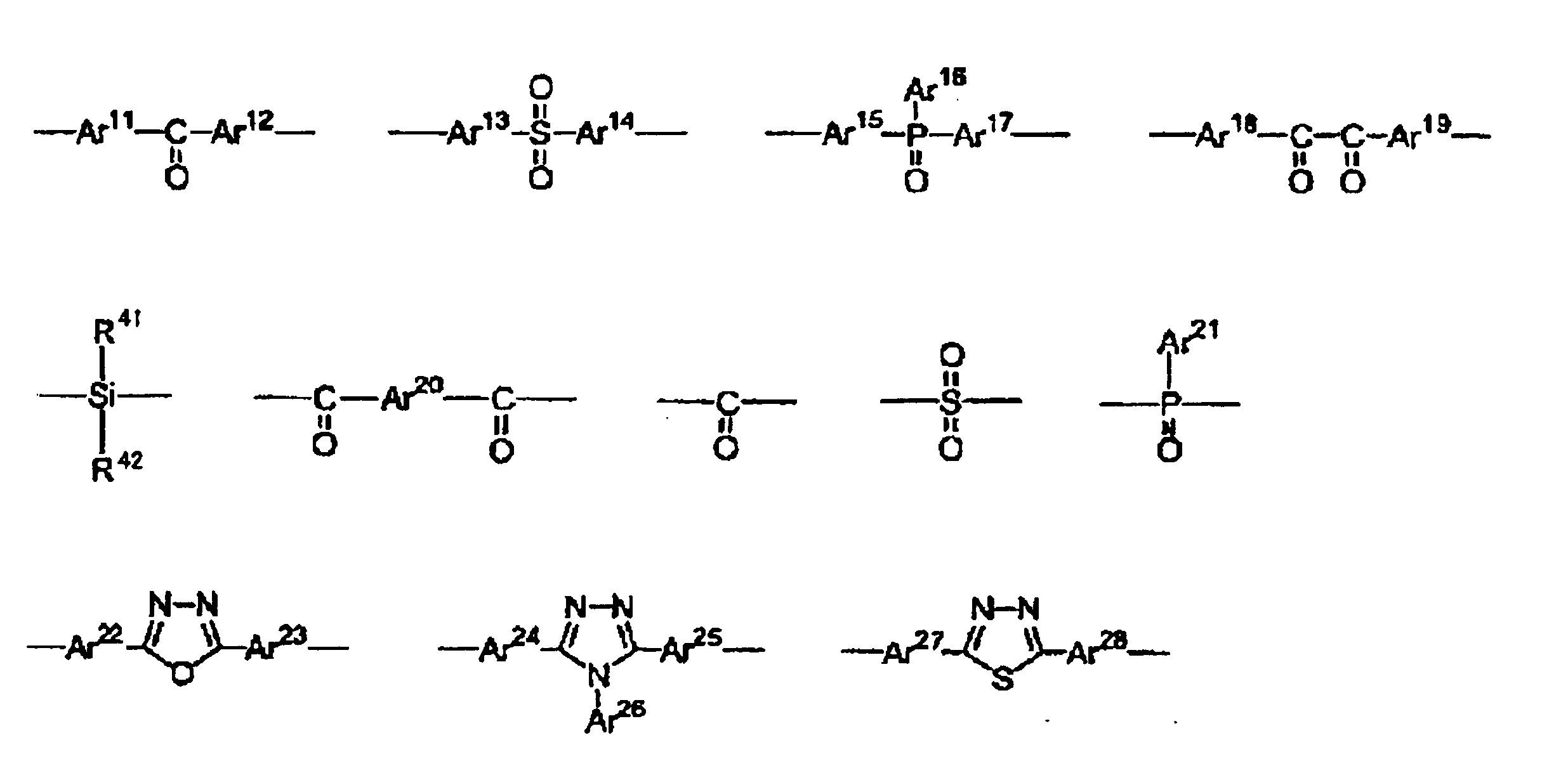
<Linking group X '>
- 前記式(1)が下記式(1-1)で表される繰返し単位である、請求項10に記載の有機電界発光素子用組成物。

- 前記芳香族アミン系ポリマーが、不溶化基を有するものである、請求項8乃至11のいずれか1項に記載の有機電界発光素子用組成物。 The composition for organic electroluminescent elements according to any one of claims 8 to 11, wherein the aromatic amine-based polymer has an insolubilizing group.
- 更に、電子受容性化合物を含有する、請求項1乃至12のいずれか1項に記載の有機電界発光素子用組成物。 Furthermore, the composition for organic electroluminescent elements of any one of Claims 1 thru | or 12 containing an electron-accepting compound.
- 前記有機電界発光素子用組成物が下記特徴を有するガラス容器に封入されてなる、請求項1乃至13のいずれか1項に記載の有機電界発光素子用組成物。
(特徴)ガラス容器であって、前記容器内面の前記有機電界発光素子用組成物との接液面において、投影面積から求めた、基準面から0.8nm以上突出した凸部領域と、基準面から0.8nm以上窪んだ凹部領域とを合計した表面凹凸部分の面積率が、0.2%以上である。 The composition for organic electroluminescent elements according to any one of claims 1 to 13, wherein the composition for organic electroluminescent elements is enclosed in a glass container having the following characteristics.
(Characteristics) A glass container, which is a liquid contact surface of the inner surface of the container with the composition for an organic electroluminescent element, and is obtained from a projected area, and has a convex region protruding from the reference surface by 0.8 nm or more, and a reference surface The area ratio of the surface irregularities, which is the sum of the concave regions recessed by 0.8 nm or more, is 0.2% or more. - 前記有機電界発光素子用組成物が下記特徴を有するガラス容器に封入されてなる、請求項1乃至13のいずれか1項に記載の有機電界発光素子用組成物。
(特徴)ガラス容器であって、前記容器内面の前記有機電界発光素子用組成物との接液面において、投影面積から求めた、基準面から0.8nm以上窪んだ凹部領域である表面凹部分の面積率が、0.1%以上である。 The composition for organic electroluminescent elements according to any one of claims 1 to 13, wherein the composition for organic electroluminescent elements is enclosed in a glass container having the following characteristics.
(Feature) A glass container, and a surface recess portion which is a recess region which is recessed from a reference plane by 0.8 nm or more, which is obtained from a projected area, on the liquid contact surface of the inner surface of the container with the composition for organic electroluminescent elements The area ratio is 0.1% or more. - 前記有機電界発光素子用組成物が下記特徴を有するガラス容器に封入されてなる、請求項1乃至13のいずれか1項に記載の有機電界発光素子用組成物。
(特徴)ガラス容器であって、前記容器内面の前記有機電界発光素子用組成物との接液面において、任意に選択した10μm×10μmの領域における、基準面から0.8nm以上突出した凸部領域の数と、基準面から0.8nm以上窪んだ凹部領域の数との合計が、5以上である。 The composition for organic electroluminescent elements according to any one of claims 1 to 13, wherein the composition for organic electroluminescent elements is enclosed in a glass container having the following characteristics.
(Feature) A glass container, and a convex part protruding from the reference surface by 0.8 nm or more in an arbitrarily selected region of 10 μm × 10 μm on the liquid contact surface of the inner surface of the container with the organic electroluminescent element composition The sum of the number of regions and the number of recessed regions recessed by 0.8 nm or more from the reference surface is 5 or more. - 基板上に、少なくとも陽極、正孔注入層、正孔輸送層、発光層及び陰極を積層してなる有機電界発光素子であって、前記発光層、正孔注入層及び正孔輸送層からなる群より選ばれる少なくとも1層が、請求項1乃至16のいずれか1項に記載の有機電界発光素子用組成物を用いて湿式成膜法により形成された、有機電界発光素子。 An organic electroluminescent device in which at least an anode, a hole injection layer, a hole transport layer, a light emitting layer and a cathode are laminated on a substrate, the group comprising the light emitting layer, the hole injection layer and the hole transport layer The organic electroluminescent element in which at least 1 layer chosen from was formed with the wet film-forming method using the composition for organic electroluminescent elements of any one of Claims 1 thru | or 16.
- 請求項17に記載の有機電界発光素子を含む、有機電界発光照明。 An organic electroluminescent illumination comprising the organic electroluminescent element according to claim 17.
- 請求項17に記載の有機電界発光素子を含む、有機電界発光表示装置。 An organic electroluminescent display device comprising the organic electroluminescent element according to claim 17.
- 請求項1乃至13のいずれか1項に記載の有機電界発光素子用組成物をガラス容器に封入してなる封入体であって、
前記ガラス容器が、前記容器内面の前記有機電界発光素子用組成物との接液面において、投影面積から求めた、基準面から0.8nm以上突出した凸部領域と、基準面から0.8nm以上窪んだ凹部領域とを合計した表面凹凸部分の面積率が、0.2%以上である封入体。 An encapsulant comprising the organic electroluminescent element composition according to any one of claims 1 to 13 encapsulated in a glass container,
The glass container has a convex region that protrudes 0.8 nm or more from the reference surface and is 0.8 nm from the reference surface, which is obtained from the projected area, on the liquid contact surface of the inner surface of the container with the composition for organic electroluminescent elements. An enclosure in which the area ratio of the surface irregularities, which is the sum of the concave areas that have been depressed, is 0.2% or more. - 請求項1乃至13のいずれか1項に記載の有機電界発光素子用組成物をガラス容器に封入してなる封入体であって、
前記ガラス容器が、前記容器内面の前記有機電界発光素子用組成物との接液面において、投影面積から求めた、基準面から0.8nm以上窪んだ凹部領域である表面凹部分の面積率が、0.1%以上である封入体。 An encapsulant comprising the organic electroluminescent element composition according to any one of claims 1 to 13 encapsulated in a glass container,
In the liquid contact surface of the inner surface of the container with the composition for organic electroluminescent elements, the glass container has an area ratio of a surface concave portion that is a concave region that is recessed by 0.8 nm or more from a reference plane, obtained from a projected area. Inclusion bodies that are 0.1% or more. - 請求項1乃至13のいずれか1項に記載の有機電界発光素子用組成物をガラス容器に封入してなる封入体であって、
前記ガラス容器が、前記容器内面の前記有機電界発光素子用組成物との接液面において、任意に選択した10μm×10μmの領域における、基準面から0.8nm以上突出した凸部領域の数と、基準面から0.8nm以上窪んだ凹部領域の数との合計が、5以上である封入体。 An encapsulant comprising the organic electroluminescent element composition according to any one of claims 1 to 13 encapsulated in a glass container,
The number of convex regions protruding from the reference surface by 0.8 nm or more in an arbitrarily selected region of 10 μm × 10 μm on the surface of the glass container in contact with the organic electroluminescent element composition on the inner surface of the container An inclusion body in which the total of the number of recessed regions recessed by 0.8 nm or more from the reference surface is 5 or more.
Priority Applications (8)
| Application Number | Priority Date | Filing Date | Title |
|---|---|---|---|
| JP2013549458A JP5494899B2 (en) | 2012-04-09 | 2013-04-08 | Composition for organic electroluminescent device and organic electroluminescent device |
| EP13776357.9A EP2838129A4 (en) | 2012-04-09 | 2013-04-08 | Composition for organic electroluminescent elements, and organic electroluminescent element |
| KR1020147028139A KR102123784B1 (en) | 2012-04-09 | 2013-04-08 | Composition for organic electroluminescent elements, and organic electroluminescent element |
| KR1020207016555A KR102374181B1 (en) | 2012-04-09 | 2013-04-08 | Composition for organic electroluminescent elements, and organic electroluminescent element |
| KR1020227007670A KR102610365B1 (en) | 2012-04-09 | 2013-04-08 | Composition for organic electroluminescent elements, and organic electroluminescent element |
| CN201380018895.5A CN104254930B (en) | 2012-04-09 | 2013-04-08 | Composition for organic electroluminescent element and organic electroluminescent device |
| KR1020237040594A KR20230165369A (en) | 2012-04-09 | 2013-04-08 | Composition for organic electroluminescent elements, and organic electroluminescent element |
| US14/510,542 US20150021587A1 (en) | 2012-04-09 | 2014-10-09 | Composition for organic electroluminescent elements and organic electroluminescent element |
Applications Claiming Priority (6)
| Application Number | Priority Date | Filing Date | Title |
|---|---|---|---|
| JP2012-088477 | 2012-04-09 | ||
| JP2012088476 | 2012-04-09 | ||
| JP2012088477 | 2012-04-09 | ||
| JP2012-088476 | 2012-04-09 | ||
| JP2013049291 | 2013-03-12 | ||
| JP2013-049291 | 2013-03-12 |
Related Child Applications (1)
| Application Number | Title | Priority Date | Filing Date |
|---|---|---|---|
| US14/510,542 Continuation US20150021587A1 (en) | 2012-04-09 | 2014-10-09 | Composition for organic electroluminescent elements and organic electroluminescent element |
Publications (1)
| Publication Number | Publication Date |
|---|---|
| WO2013154076A1 true WO2013154076A1 (en) | 2013-10-17 |
Family
ID=49327639
Family Applications (1)
| Application Number | Title | Priority Date | Filing Date |
|---|---|---|---|
| PCT/JP2013/060654 WO2013154076A1 (en) | 2012-04-09 | 2013-04-08 | Composition for organic electroluminescent elements, and organic electroluminescent element |
Country Status (7)
| Country | Link |
|---|---|
| US (1) | US20150021587A1 (en) |
| EP (1) | EP2838129A4 (en) |
| JP (2) | JP5494899B2 (en) |
| KR (4) | KR20230165369A (en) |
| CN (2) | CN108615824B (en) |
| TW (1) | TWI648894B (en) |
| WO (1) | WO2013154076A1 (en) |
Cited By (9)
| Publication number | Priority date | Publication date | Assignee | Title |
|---|---|---|---|---|
| KR20150057960A (en) * | 2013-11-19 | 2015-05-28 | 세이코 엡슨 가부시키가이샤 | Ink for forming functional layer, method of manufacturing ink for forming functional layer, and methdo of manufacturing organic electro-luminescence element |
| EP2887417A3 (en) * | 2013-12-17 | 2015-07-08 | The Regents Of The University Of Michigan | Extended OLED operational lifetime through phosphorescent dopant profile mangement |
| JP5799181B1 (en) * | 2015-01-07 | 2015-10-21 | 住友化学株式会社 | Method for manufacturing organic electronic device |
| WO2016107668A1 (en) * | 2014-12-30 | 2016-07-07 | Merck Patent Gmbh | Compositions comprising at least one polymer and at least one salt, and electroluminescent devices containing said compositions |
| JP2018511929A (en) * | 2015-01-30 | 2018-04-26 | メルク パテント ゲーエムベーハー | Formulation with low particle content |
| JP2018147888A (en) * | 2018-05-01 | 2018-09-20 | セイコーエプソン株式会社 | Ink for forming functional layer, method of manufacturing ink for forming functional layer, and method of manufacturing organic electroluminescent element |
| CN108886103A (en) * | 2016-03-03 | 2018-11-23 | 日产化学株式会社 | Charge-transporting varnish |
| CN109256034A (en) * | 2017-07-13 | 2019-01-22 | 乐金显示有限公司 | Display device and its manufacturing method with frame pattern |
| TWI700845B (en) * | 2014-08-21 | 2020-08-01 | 南韓商三星顯示器有限公司 | Organic light emitting display including organic light emitting element |
Families Citing this family (11)
| Publication number | Priority date | Publication date | Assignee | Title |
|---|---|---|---|---|
| US9978812B2 (en) * | 2014-01-14 | 2018-05-22 | Sharp Kabushiki Kaisha | Organic electroluminescent display panel |
| JP6623562B2 (en) * | 2015-05-29 | 2019-12-25 | 三菱ケミカル株式会社 | Method for producing lithographic material, method for producing lithographic composition, and method for producing substrate on which pattern is formed |
| CA3047693C (en) | 2016-12-19 | 2020-06-16 | Perkinelmer Health Sciences Canada, Inc. | Inorganic and organic mass spectrometry systems and methods of using them |
| JP6834533B2 (en) * | 2017-01-27 | 2021-02-24 | 住友化学株式会社 | Method for Producing Liquid Composition for Organic Electroluminescent Device |
| US11175586B2 (en) * | 2017-05-26 | 2021-11-16 | Nsx Managemen T Group, Llc | Platewash composition |
| CN111051470B (en) * | 2017-09-14 | 2020-11-10 | 住友化学株式会社 | Process for preparing liquid composition |
| US20190269589A1 (en) * | 2018-03-01 | 2019-09-05 | Gojo Industries, Inc. | Alcohol-based hand conditioners for repeated use |
| KR102550692B1 (en) | 2018-04-24 | 2023-07-04 | 삼성디스플레이 주식회사 | Organic light emitting device and method manufacturing the same |
| KR20220024468A (en) * | 2019-06-14 | 2022-03-03 | 가꼬우 호징 관세이 가쿠잉 | polyaromatic compounds |
| CN113493564B (en) * | 2020-04-07 | 2023-05-02 | 中国科学院长春应用化学研究所 | Organic polymer luminescent material with D-sigma-A structure, and preparation method and application thereof |
| CN115536835A (en) * | 2022-10-25 | 2022-12-30 | 吉林大学 | Polyarylether polymer based on triphenylamine and derivatives thereof, and preparation method and application thereof |
Citations (29)
| Publication number | Priority date | Publication date | Assignee | Title |
|---|---|---|---|---|
| JPS59194393A (en) | 1983-03-25 | 1984-11-05 | イ−ストマン コダツク カンパニ− | Organic electroluminescent device having inproved power conversion efficiency |
| JPH05234681A (en) | 1990-07-26 | 1993-09-10 | Eastman Kodak Co | Electroluminescent device having organic electroluminescent medium |
| JPH05331459A (en) | 1992-04-03 | 1993-12-14 | Pioneer Electron Corp | Organic electroluminescent element |
| JPH06207169A (en) | 1992-11-17 | 1994-07-26 | Idemitsu Kosan Co Ltd | Organic electroluminescence element |
| JPH0741759A (en) | 1993-03-26 | 1995-02-10 | Sumitomo Electric Ind Ltd | Organic electroluminescent device |
| JPH0753953A (en) | 1993-08-19 | 1995-02-28 | Mitsubishi Chem Corp | Organic electroluminescent element |
| US5645948A (en) | 1996-08-20 | 1997-07-08 | Eastman Kodak Company | Blue organic electroluminescent devices |
| JPH1074586A (en) | 1996-07-29 | 1998-03-17 | Eastman Kodak Co | Two layer electron injection electrode used in electroluminescence device |
| JPH1079297A (en) | 1996-07-09 | 1998-03-24 | Sony Corp | Electroluminescent element |
| JPH10270171A (en) | 1997-01-27 | 1998-10-09 | Junji Kido | Organic electroluminescent element |
| JPH11242996A (en) | 1998-02-25 | 1999-09-07 | Mitsubishi Chemical Corp | Organic electroluminescent element |
| WO2000041443A1 (en) * | 1998-12-28 | 2000-07-13 | Idemitsu Kosan Co., Ltd. | Organic electroluminescence device |
| JP2002100478A (en) | 2000-09-20 | 2002-04-05 | Mitsubishi Chemicals Corp | Organic electroluminescence element and its method of manufacture |
| JP2002100482A (en) | 2000-09-20 | 2002-04-05 | Mitsubishi Chemicals Corp | Organic electroluminescence element |
| JP2003347624A (en) * | 2002-05-27 | 2003-12-05 | Konica Minolta Holdings Inc | Method of refining organic semiconductor material, organic semiconductor material obtained by this refining method, and semiconductor device using the same |
| JP2004002627A (en) | 2002-03-25 | 2004-01-08 | Jsr Corp | Method for producing aromatic polymer, composition for film formation, method for film formation and organic film |
| JP2004083650A (en) * | 2002-08-23 | 2004-03-18 | Konica Minolta Holdings Inc | Organic semiconductor material and thin film transistor element using the same |
| WO2004084260A2 (en) | 2003-03-20 | 2004-09-30 | Cambridge Display Technology Limited | Electroluminescent device |
| WO2005022962A1 (en) | 2003-07-31 | 2005-03-10 | Mitsubishi Chemical Corporation | Compound, charge transport material and organic electroluminescent device |
| JP2005209626A (en) * | 2003-12-22 | 2005-08-04 | Mitsubishi Chemicals Corp | Composition, charge transportation material, organic electroluminescent element, and its manufacturing method |
| JP2005276749A (en) | 2004-03-26 | 2005-10-06 | Sanyo Electric Co Ltd | Organic electroluminescent element |
| JP2006005144A (en) | 2004-06-17 | 2006-01-05 | Seiko Epson Corp | Conductive polymer purification method, hole injection layer forming material, and organic EL device manufacturing method |
| JP2007324233A (en) * | 2006-05-30 | 2007-12-13 | Canon Inc | Organic electroluminescence element and manufacturing method therefor |
| JP2008515194A (en) | 2004-09-24 | 2008-05-08 | プレックストロニクス インコーポレーティッド | Heteroatom regioregular poly (3-substituted thiophene) in electroluminescent devices |
| JP2008516421A (en) * | 2004-10-01 | 2008-05-15 | メルク パテント ゲーエムベーハー | Electronic devices including organic semiconductors |
| JP2009114380A (en) * | 2007-11-08 | 2009-05-28 | Mitsubishi Chemicals Corp | High polymer compound, polymer composition, and organic electroluminescent element |
| JP2010098306A (en) | 2008-09-18 | 2010-04-30 | Mitsubishi Chemicals Corp | Composition for charge transport film, organic electroluminescent element, organic el display, and organic el illumination |
| WO2010140187A1 (en) * | 2009-06-02 | 2010-12-09 | パイオニア株式会社 | Photoelectric conversion element and method for manufacturing the same |
| JP2011042745A (en) | 2009-08-21 | 2011-03-03 | Sumitomo Chemical Co Ltd | Method for producing purified polyarylene |
Family Cites Families (12)
| Publication number | Priority date | Publication date | Assignee | Title |
|---|---|---|---|---|
| JPH0455313A (en) * | 1990-06-22 | 1992-02-24 | Mitsui Toatsu Chem Inc | Method of removing sulfuric acid ion |
| JP2000340366A (en) * | 1999-05-27 | 2000-12-08 | Tdk Corp | Light emitting diode |
| JP4281442B2 (en) * | 2003-05-29 | 2009-06-17 | セイコーエプソン株式会社 | Hole transport material |
| US7615921B2 (en) * | 2003-06-13 | 2009-11-10 | Fuji Electric Holdings Co., Ltd. | Organic EL device and organic EL panel |
| KR101463271B1 (en) * | 2006-09-14 | 2014-11-18 | 스미또모 가가꾸 가부시키가이샤 | Organic electroluminescent device |
| US7851112B2 (en) * | 2006-11-28 | 2010-12-14 | Xerox Corporation | Thiophosphate containing photoconductors |
| KR100922761B1 (en) * | 2008-03-04 | 2009-10-21 | 삼성모바일디스플레이주식회사 | Organic light emitting device |
| TWI443127B (en) * | 2008-08-07 | 2014-07-01 | Mitsubishi Chem Corp | Polymer, composition for organic electroluminescence element, and organic electroluminescence element, solar cell element organic el display and organic el lighting, useing the same |
| KR101708064B1 (en) * | 2008-08-13 | 2017-02-17 | 미쓰비시 가가꾸 가부시키가이샤 | Organic electroluminescent element, organic el display device and organic el illuminating device |
| JP5793878B2 (en) * | 2010-02-10 | 2015-10-14 | 三菱化学株式会社 | Polymer, organic electroluminescent element material, composition for organic electroluminescent element, organic electroluminescent element, display device and lighting device |
| CN102394278B (en) * | 2011-11-12 | 2013-10-30 | 太原理工大学 | Preparation method of phosphorescent diode with electronic transmission layer doped with lithium fluoride |
| WO2013096543A1 (en) * | 2011-12-20 | 2013-06-27 | E. I. Du Pont De Nemours And Company | Process and materials for making contained layers and devices made with same |
-
2013
- 2013-04-08 CN CN201810039186.XA patent/CN108615824B/en active Active
- 2013-04-08 EP EP13776357.9A patent/EP2838129A4/en active Pending
- 2013-04-08 KR KR1020237040594A patent/KR20230165369A/en not_active Application Discontinuation
- 2013-04-08 JP JP2013549458A patent/JP5494899B2/en active Active
- 2013-04-08 WO PCT/JP2013/060654 patent/WO2013154076A1/en active Application Filing
- 2013-04-08 KR KR1020227007670A patent/KR102610365B1/en active IP Right Grant
- 2013-04-08 KR KR1020207016555A patent/KR102374181B1/en active IP Right Grant
- 2013-04-08 CN CN201380018895.5A patent/CN104254930B/en active Active
- 2013-04-08 KR KR1020147028139A patent/KR102123784B1/en active IP Right Grant
- 2013-04-09 TW TW102112475A patent/TWI648894B/en active
-
2014
- 2014-03-06 JP JP2014043940A patent/JP2014199922A/en not_active Withdrawn
- 2014-10-09 US US14/510,542 patent/US20150021587A1/en not_active Abandoned
Patent Citations (29)
| Publication number | Priority date | Publication date | Assignee | Title |
|---|---|---|---|---|
| JPS59194393A (en) | 1983-03-25 | 1984-11-05 | イ−ストマン コダツク カンパニ− | Organic electroluminescent device having inproved power conversion efficiency |
| JPH05234681A (en) | 1990-07-26 | 1993-09-10 | Eastman Kodak Co | Electroluminescent device having organic electroluminescent medium |
| JPH05331459A (en) | 1992-04-03 | 1993-12-14 | Pioneer Electron Corp | Organic electroluminescent element |
| JPH06207169A (en) | 1992-11-17 | 1994-07-26 | Idemitsu Kosan Co Ltd | Organic electroluminescence element |
| JPH0741759A (en) | 1993-03-26 | 1995-02-10 | Sumitomo Electric Ind Ltd | Organic electroluminescent device |
| JPH0753953A (en) | 1993-08-19 | 1995-02-28 | Mitsubishi Chem Corp | Organic electroluminescent element |
| JPH1079297A (en) | 1996-07-09 | 1998-03-24 | Sony Corp | Electroluminescent element |
| JPH1074586A (en) | 1996-07-29 | 1998-03-17 | Eastman Kodak Co | Two layer electron injection electrode used in electroluminescence device |
| US5645948A (en) | 1996-08-20 | 1997-07-08 | Eastman Kodak Company | Blue organic electroluminescent devices |
| JPH10270171A (en) | 1997-01-27 | 1998-10-09 | Junji Kido | Organic electroluminescent element |
| JPH11242996A (en) | 1998-02-25 | 1999-09-07 | Mitsubishi Chemical Corp | Organic electroluminescent element |
| WO2000041443A1 (en) * | 1998-12-28 | 2000-07-13 | Idemitsu Kosan Co., Ltd. | Organic electroluminescence device |
| JP2002100478A (en) | 2000-09-20 | 2002-04-05 | Mitsubishi Chemicals Corp | Organic electroluminescence element and its method of manufacture |
| JP2002100482A (en) | 2000-09-20 | 2002-04-05 | Mitsubishi Chemicals Corp | Organic electroluminescence element |
| JP2004002627A (en) | 2002-03-25 | 2004-01-08 | Jsr Corp | Method for producing aromatic polymer, composition for film formation, method for film formation and organic film |
| JP2003347624A (en) * | 2002-05-27 | 2003-12-05 | Konica Minolta Holdings Inc | Method of refining organic semiconductor material, organic semiconductor material obtained by this refining method, and semiconductor device using the same |
| JP2004083650A (en) * | 2002-08-23 | 2004-03-18 | Konica Minolta Holdings Inc | Organic semiconductor material and thin film transistor element using the same |
| WO2004084260A2 (en) | 2003-03-20 | 2004-09-30 | Cambridge Display Technology Limited | Electroluminescent device |
| WO2005022962A1 (en) | 2003-07-31 | 2005-03-10 | Mitsubishi Chemical Corporation | Compound, charge transport material and organic electroluminescent device |
| JP2005209626A (en) * | 2003-12-22 | 2005-08-04 | Mitsubishi Chemicals Corp | Composition, charge transportation material, organic electroluminescent element, and its manufacturing method |
| JP2005276749A (en) | 2004-03-26 | 2005-10-06 | Sanyo Electric Co Ltd | Organic electroluminescent element |
| JP2006005144A (en) | 2004-06-17 | 2006-01-05 | Seiko Epson Corp | Conductive polymer purification method, hole injection layer forming material, and organic EL device manufacturing method |
| JP2008515194A (en) | 2004-09-24 | 2008-05-08 | プレックストロニクス インコーポレーティッド | Heteroatom regioregular poly (3-substituted thiophene) in electroluminescent devices |
| JP2008516421A (en) * | 2004-10-01 | 2008-05-15 | メルク パテント ゲーエムベーハー | Electronic devices including organic semiconductors |
| JP2007324233A (en) * | 2006-05-30 | 2007-12-13 | Canon Inc | Organic electroluminescence element and manufacturing method therefor |
| JP2009114380A (en) * | 2007-11-08 | 2009-05-28 | Mitsubishi Chemicals Corp | High polymer compound, polymer composition, and organic electroluminescent element |
| JP2010098306A (en) | 2008-09-18 | 2010-04-30 | Mitsubishi Chemicals Corp | Composition for charge transport film, organic electroluminescent element, organic el display, and organic el illumination |
| WO2010140187A1 (en) * | 2009-06-02 | 2010-12-09 | パイオニア株式会社 | Photoelectric conversion element and method for manufacturing the same |
| JP2011042745A (en) | 2009-08-21 | 2011-03-03 | Sumitomo Chemical Co Ltd | Method for producing purified polyarylene |
Non-Patent Citations (24)
| Title |
|---|
| "Organic Chemistry, Biochemical Nomenclature", vol. 1, 1992, NANKO-DO |
| APPL. PHYS. LETT., vol. 60, 1992, pages 2711 |
| APPLIED PHYSICS LETTERS, vol. 70, 1997, pages 152 |
| CHEM. COMMUN., 1996, pages 2175 |
| CHEM. REV., vol. 66, 1966, pages 243 |
| CHEMICAL COMMUNICATIONS, 1996, pages 2175 |
| H. KWART; K. KING, DEPARTMENT OF CHEMISTRY, UNIVERSITY OF DELAWARE, NEW YORK, DELAWARE, vol. 19771, 1967, pages 415 - 447 |
| IEEE TRANSACTIONS ON ELECTRON DEVICES, vol. 44, 1997, pages 1245 |
| J. LUMIN., vol. 72-74, 1997, pages 985 |
| J. ORG. CHEM., vol. 53, 1988, pages 5571 |
| JACS, vol. 124, no. 30, pages 2022,8813 |
| JOURNAL OF LUMINESCENCE, vol. 72-74, 1997, pages 985 |
| M. C. KLOETZEL, ORG. REACTIONS, vol. 4, 1948, pages 6 |
| N. D. FIELD, J. AM. CHEM. SOC., vol. 83, 1961, pages 3504 |
| O. DIELS; K. ALDER, BER., vol. 62, 1929, pages 554 |
| POLYM. ADV. TECH., vol. 7, 1996, pages 33 |
| R. HUISGEN; M. CHRISTI, ANGEW. CHEM. INTERN. ED. ENGL., vol. 5, 1967, pages 456 |
| R. HUISGEN; M. SEIDEL; G. WALLBILLICH; H, KNUPFER, TETRAHEDRON, vol. 17, 1962, pages 3 |
| R. KREHER; J. SEUBERT, Z. NATURFORACH., vol. 20B, 1965, pages 75 |
| See also references of EP2838129A4 |
| SHIZUO TOKITO; CHIHAYA ADACHI; HIDEYUKI MURATA, ORGANIC EL DISPLAY, 20 August 2004 (2004-08-20) |
| SID 04 DIGEST, pages 154 |
| SYNTH. METALS, vol. 91, 1997, pages 209 |
| SYNTHETIC METALS, vol. 91, 1997, pages 209 |
Cited By (23)
| Publication number | Priority date | Publication date | Assignee | Title |
|---|---|---|---|---|
| US10522758B2 (en) | 2013-11-19 | 2019-12-31 | Seiko Epson Corporation | Ink for forming functional layer, method of manufacturing ink for forming functional layer, and method of manufacturing organic electro-luminescence element |
| JP2015099679A (en) * | 2013-11-19 | 2015-05-28 | セイコーエプソン株式会社 | Functional layer forming ink, method for producing functional layer forming ink, and method for producing organic electroluminescence element |
| KR102215302B1 (en) | 2013-11-19 | 2021-02-10 | 세이코 엡슨 가부시키가이샤 | Ink for forming functional layer, method of manufacturing ink for forming functional layer, and methdo of manufacturing organic electro-luminescence element |
| KR20150057960A (en) * | 2013-11-19 | 2015-05-28 | 세이코 엡슨 가부시키가이샤 | Ink for forming functional layer, method of manufacturing ink for forming functional layer, and methdo of manufacturing organic electro-luminescence element |
| US9825225B2 (en) | 2013-11-19 | 2017-11-21 | Seiko Epson Corporation | Ink for forming functional layer, method of manufacturing ink for forming functional layer, and method of manufacturing organic electro-luminescence element |
| EP2887417A3 (en) * | 2013-12-17 | 2015-07-08 | The Regents Of The University Of Michigan | Extended OLED operational lifetime through phosphorescent dopant profile mangement |
| EP3690972A1 (en) * | 2013-12-17 | 2020-08-05 | The Regents Of The University Of Michigan | Extended oled operational lifetime through phosphorescent dopant profile management |
| TWI700845B (en) * | 2014-08-21 | 2020-08-01 | 南韓商三星顯示器有限公司 | Organic light emitting display including organic light emitting element |
| US10862038B2 (en) | 2014-12-30 | 2020-12-08 | Merck Patent Gmbh | Compositions comprising at least one polymer and at least one salt, and electroluminescent devices containing said compositions |
| CN107112426A (en) * | 2014-12-30 | 2017-08-29 | 默克专利有限公司 | Composition comprising at least one polymer and at least one salt and the electroluminescent device for including the composition |
| CN112341761A (en) * | 2014-12-30 | 2021-02-09 | 默克专利有限公司 | Composition comprising at least one polymer and at least one salt and electroluminescent device comprising said composition |
| WO2016107668A1 (en) * | 2014-12-30 | 2016-07-07 | Merck Patent Gmbh | Compositions comprising at least one polymer and at least one salt, and electroluminescent devices containing said compositions |
| JP5799181B1 (en) * | 2015-01-07 | 2015-10-21 | 住友化学株式会社 | Method for manufacturing organic electronic device |
| US10319909B2 (en) | 2015-01-07 | 2019-06-11 | Sumitomo Chemical Company, Limited | Method for manufacturing organic electronic element |
| US10916705B2 (en) | 2015-01-30 | 2021-02-09 | Merck Patent Gmbh | Formulations with a low particle content |
| JP2018511929A (en) * | 2015-01-30 | 2018-04-26 | メルク パテント ゲーエムベーハー | Formulation with low particle content |
| JP2021108375A (en) * | 2015-01-30 | 2021-07-29 | メルク パテント ゲーエムベーハー | Formulation with low particle content |
| JP7030519B2 (en) | 2015-01-30 | 2022-03-07 | メルク パテント ゲーエムベーハー | Formulations with low particle content |
| US11309493B2 (en) | 2015-01-30 | 2022-04-19 | Merck Patent Gmbh | Formulations with a low particle content |
| CN108886103B (en) * | 2016-03-03 | 2020-12-18 | 日产化学株式会社 | Charge-transporting varnish |
| CN108886103A (en) * | 2016-03-03 | 2018-11-23 | 日产化学株式会社 | Charge-transporting varnish |
| CN109256034A (en) * | 2017-07-13 | 2019-01-22 | 乐金显示有限公司 | Display device and its manufacturing method with frame pattern |
| JP2018147888A (en) * | 2018-05-01 | 2018-09-20 | セイコーエプソン株式会社 | Ink for forming functional layer, method of manufacturing ink for forming functional layer, and method of manufacturing organic electroluminescent element |
Also Published As
| Publication number | Publication date |
|---|---|
| EP2838129A4 (en) | 2015-11-18 |
| JPWO2013154076A1 (en) | 2015-12-17 |
| KR20230165369A (en) | 2023-12-05 |
| JP2014199922A (en) | 2014-10-23 |
| KR20200071148A (en) | 2020-06-18 |
| JP5494899B2 (en) | 2014-05-21 |
| EP2838129A1 (en) | 2015-02-18 |
| KR102123784B1 (en) | 2020-06-17 |
| KR20150002651A (en) | 2015-01-07 |
| CN104254930A (en) | 2014-12-31 |
| KR20220034934A (en) | 2022-03-18 |
| CN108615824B (en) | 2021-09-28 |
| CN104254930B (en) | 2018-02-16 |
| CN108615824A (en) | 2018-10-02 |
| TWI648894B (en) | 2019-01-21 |
| US20150021587A1 (en) | 2015-01-22 |
| TW201351744A (en) | 2013-12-16 |
| KR102610365B1 (en) | 2023-12-05 |
| KR102374181B1 (en) | 2022-03-15 |
Similar Documents
| Publication | Publication Date | Title |
|---|---|---|
| JP5494899B2 (en) | Composition for organic electroluminescent device and organic electroluminescent device | |
| JP5880654B2 (en) | Luminescent layer material, composition for organic electroluminescent element, organic electroluminescent element using these, organic EL display device, and organic EL lighting | |
| JP5088097B2 (en) | Organic electroluminescent material, organic electroluminescent device composition, organic electroluminescent device, organic EL display and color display device | |
| JP5768860B2 (en) | Organic electroluminescent device, organic EL display device, and organic EL lighting | |
| JP5857743B2 (en) | Polymer, electronic device material, composition for electronic device, organic electroluminescent device, organic solar cell device, display device and lighting device | |
| JP2007067383A (en) | Charge transport material, organic electroluminescent element, and composition thereof | |
| JP6540771B2 (en) | Iridium complex compound, organic electroluminescent device, display device and lighting device | |
| JP5672681B2 (en) | Composition for charge transport film, organic electroluminescence device, organic EL display and organic EL lighting | |
| JP5353069B2 (en) | Triphenylene compound, organic electroluminescence device containing triphenylene compound, and organic EL display | |
| JP5703859B2 (en) | Composition for organic electroluminescent device and method for producing organic electroluminescent device | |
| JP5194623B2 (en) | Tetraarylpyrene compound, charge transport material, material for organic electroluminescence device, composition for organic electroluminescence device, and organic electroluminescence device | |
| JP5549051B2 (en) | Anthracene compound, charge transport material for wet film formation, charge transport material composition for wet film formation, and organic electroluminescence device | |
| JP2010239134A (en) | Organic electroluminescent element, organic el display and organic el illumination | |
| JP5685826B2 (en) | Composition for charge transport film, organic electroluminescence device, organic EL display and organic EL lighting |
Legal Events
| Date | Code | Title | Description |
|---|---|---|---|
| ENP | Entry into the national phase |
Ref document number: 2013549458 Country of ref document: JP Kind code of ref document: A |
|
| 121 | Ep: the epo has been informed by wipo that ep was designated in this application |
Ref document number: 13776357 Country of ref document: EP Kind code of ref document: A1 |
|
| ENP | Entry into the national phase |
Ref document number: 20147028139 Country of ref document: KR Kind code of ref document: A |
|
| NENP | Non-entry into the national phase |
Ref country code: DE |
|
| WWE | Wipo information: entry into national phase |
Ref document number: 2013776357 Country of ref document: EP |