WO2013001268A2 - Optical fibre sensor interrogation system - Google Patents
Optical fibre sensor interrogation system Download PDFInfo
- Publication number
- WO2013001268A2 WO2013001268A2 PCT/GB2012/000556 GB2012000556W WO2013001268A2 WO 2013001268 A2 WO2013001268 A2 WO 2013001268A2 GB 2012000556 W GB2012000556 W GB 2012000556W WO 2013001268 A2 WO2013001268 A2 WO 2013001268A2
- Authority
- WO
- WIPO (PCT)
- Prior art keywords
- interferometer
- optical
- fibre
- wavelength
- light
- Prior art date
- Legal status (The legal status is an assumption and is not a legal conclusion. Google has not performed a legal analysis and makes no representation as to the accuracy of the status listed.)
- Ceased
Links
Classifications
-
- G—PHYSICS
- G01—MEASURING; TESTING
- G01M—TESTING STATIC OR DYNAMIC BALANCE OF MACHINES OR STRUCTURES; TESTING OF STRUCTURES OR APPARATUS, NOT OTHERWISE PROVIDED FOR
- G01M11/00—Testing of optical apparatus; Testing structures by optical methods not otherwise provided for
- G01M11/30—Testing of optical devices, constituted by fibre optics or optical waveguides
-
- G—PHYSICS
- G01—MEASURING; TESTING
- G01D—MEASURING NOT SPECIALLY ADAPTED FOR A SPECIFIC VARIABLE; ARRANGEMENTS FOR MEASURING TWO OR MORE VARIABLES NOT COVERED IN A SINGLE OTHER SUBCLASS; TARIFF METERING APPARATUS; MEASURING OR TESTING NOT OTHERWISE PROVIDED FOR
- G01D5/00—Mechanical means for transferring the output of a sensing member; Means for converting the output of a sensing member to another variable where the form or nature of the sensing member does not constrain the means for converting; Transducers not specially adapted for a specific variable
- G01D5/26—Mechanical means for transferring the output of a sensing member; Means for converting the output of a sensing member to another variable where the form or nature of the sensing member does not constrain the means for converting; Transducers not specially adapted for a specific variable characterised by optical transfer means, i.e. using infrared, visible, or ultraviolet light
- G01D5/32—Mechanical means for transferring the output of a sensing member; Means for converting the output of a sensing member to another variable where the form or nature of the sensing member does not constrain the means for converting; Transducers not specially adapted for a specific variable characterised by optical transfer means, i.e. using infrared, visible, or ultraviolet light with attenuation or whole or partial obturation of beams of light
- G01D5/34—Mechanical means for transferring the output of a sensing member; Means for converting the output of a sensing member to another variable where the form or nature of the sensing member does not constrain the means for converting; Transducers not specially adapted for a specific variable characterised by optical transfer means, i.e. using infrared, visible, or ultraviolet light with attenuation or whole or partial obturation of beams of light the beams of light being detected by photocells
- G01D5/353—Mechanical means for transferring the output of a sensing member; Means for converting the output of a sensing member to another variable where the form or nature of the sensing member does not constrain the means for converting; Transducers not specially adapted for a specific variable characterised by optical transfer means, i.e. using infrared, visible, or ultraviolet light with attenuation or whole or partial obturation of beams of light the beams of light being detected by photocells influencing the transmission properties of an optical fibre
- G01D5/35306—Mechanical means for transferring the output of a sensing member; Means for converting the output of a sensing member to another variable where the form or nature of the sensing member does not constrain the means for converting; Transducers not specially adapted for a specific variable characterised by optical transfer means, i.e. using infrared, visible, or ultraviolet light with attenuation or whole or partial obturation of beams of light the beams of light being detected by photocells influencing the transmission properties of an optical fibre using an interferometer arrangement
- G01D5/35309—Mechanical means for transferring the output of a sensing member; Means for converting the output of a sensing member to another variable where the form or nature of the sensing member does not constrain the means for converting; Transducers not specially adapted for a specific variable characterised by optical transfer means, i.e. using infrared, visible, or ultraviolet light with attenuation or whole or partial obturation of beams of light the beams of light being detected by photocells influencing the transmission properties of an optical fibre using an interferometer arrangement using multiple waves interferometer
- G01D5/35316—Mechanical means for transferring the output of a sensing member; Means for converting the output of a sensing member to another variable where the form or nature of the sensing member does not constrain the means for converting; Transducers not specially adapted for a specific variable characterised by optical transfer means, i.e. using infrared, visible, or ultraviolet light with attenuation or whole or partial obturation of beams of light the beams of light being detected by photocells influencing the transmission properties of an optical fibre using an interferometer arrangement using multiple waves interferometer using a Bragg gratings
-
- G—PHYSICS
- G01—MEASURING; TESTING
- G01D—MEASURING NOT SPECIALLY ADAPTED FOR A SPECIFIC VARIABLE; ARRANGEMENTS FOR MEASURING TWO OR MORE VARIABLES NOT COVERED IN A SINGLE OTHER SUBCLASS; TARIFF METERING APPARATUS; MEASURING OR TESTING NOT OTHERWISE PROVIDED FOR
- G01D5/00—Mechanical means for transferring the output of a sensing member; Means for converting the output of a sensing member to another variable where the form or nature of the sensing member does not constrain the means for converting; Transducers not specially adapted for a specific variable
- G01D5/26—Mechanical means for transferring the output of a sensing member; Means for converting the output of a sensing member to another variable where the form or nature of the sensing member does not constrain the means for converting; Transducers not specially adapted for a specific variable characterised by optical transfer means, i.e. using infrared, visible, or ultraviolet light
- G01D5/32—Mechanical means for transferring the output of a sensing member; Means for converting the output of a sensing member to another variable where the form or nature of the sensing member does not constrain the means for converting; Transducers not specially adapted for a specific variable characterised by optical transfer means, i.e. using infrared, visible, or ultraviolet light with attenuation or whole or partial obturation of beams of light
- G01D5/34—Mechanical means for transferring the output of a sensing member; Means for converting the output of a sensing member to another variable where the form or nature of the sensing member does not constrain the means for converting; Transducers not specially adapted for a specific variable characterised by optical transfer means, i.e. using infrared, visible, or ultraviolet light with attenuation or whole or partial obturation of beams of light the beams of light being detected by photocells
- G01D5/353—Mechanical means for transferring the output of a sensing member; Means for converting the output of a sensing member to another variable where the form or nature of the sensing member does not constrain the means for converting; Transducers not specially adapted for a specific variable characterised by optical transfer means, i.e. using infrared, visible, or ultraviolet light with attenuation or whole or partial obturation of beams of light the beams of light being detected by photocells influencing the transmission properties of an optical fibre
- G01D5/35306—Mechanical means for transferring the output of a sensing member; Means for converting the output of a sensing member to another variable where the form or nature of the sensing member does not constrain the means for converting; Transducers not specially adapted for a specific variable characterised by optical transfer means, i.e. using infrared, visible, or ultraviolet light with attenuation or whole or partial obturation of beams of light the beams of light being detected by photocells influencing the transmission properties of an optical fibre using an interferometer arrangement
- G01D5/35335—Aspects of emitters or receivers used by an interferometer in an optical fibre sensor arrangement
-
- G—PHYSICS
- G01—MEASURING; TESTING
- G01D—MEASURING NOT SPECIALLY ADAPTED FOR A SPECIFIC VARIABLE; ARRANGEMENTS FOR MEASURING TWO OR MORE VARIABLES NOT COVERED IN A SINGLE OTHER SUBCLASS; TARIFF METERING APPARATUS; MEASURING OR TESTING NOT OTHERWISE PROVIDED FOR
- G01D5/00—Mechanical means for transferring the output of a sensing member; Means for converting the output of a sensing member to another variable where the form or nature of the sensing member does not constrain the means for converting; Transducers not specially adapted for a specific variable
- G01D5/26—Mechanical means for transferring the output of a sensing member; Means for converting the output of a sensing member to another variable where the form or nature of the sensing member does not constrain the means for converting; Transducers not specially adapted for a specific variable characterised by optical transfer means, i.e. using infrared, visible, or ultraviolet light
- G01D5/32—Mechanical means for transferring the output of a sensing member; Means for converting the output of a sensing member to another variable where the form or nature of the sensing member does not constrain the means for converting; Transducers not specially adapted for a specific variable characterised by optical transfer means, i.e. using infrared, visible, or ultraviolet light with attenuation or whole or partial obturation of beams of light
- G01D5/34—Mechanical means for transferring the output of a sensing member; Means for converting the output of a sensing member to another variable where the form or nature of the sensing member does not constrain the means for converting; Transducers not specially adapted for a specific variable characterised by optical transfer means, i.e. using infrared, visible, or ultraviolet light with attenuation or whole or partial obturation of beams of light the beams of light being detected by photocells
- G01D5/353—Mechanical means for transferring the output of a sensing member; Means for converting the output of a sensing member to another variable where the form or nature of the sensing member does not constrain the means for converting; Transducers not specially adapted for a specific variable characterised by optical transfer means, i.e. using infrared, visible, or ultraviolet light with attenuation or whole or partial obturation of beams of light the beams of light being detected by photocells influencing the transmission properties of an optical fibre
- G01D5/35383—Mechanical means for transferring the output of a sensing member; Means for converting the output of a sensing member to another variable where the form or nature of the sensing member does not constrain the means for converting; Transducers not specially adapted for a specific variable characterised by optical transfer means, i.e. using infrared, visible, or ultraviolet light with attenuation or whole or partial obturation of beams of light the beams of light being detected by photocells influencing the transmission properties of an optical fibre using multiple sensor devices using multiplexing techniques
- G01D5/35387—Mechanical means for transferring the output of a sensing member; Means for converting the output of a sensing member to another variable where the form or nature of the sensing member does not constrain the means for converting; Transducers not specially adapted for a specific variable characterised by optical transfer means, i.e. using infrared, visible, or ultraviolet light with attenuation or whole or partial obturation of beams of light the beams of light being detected by photocells influencing the transmission properties of an optical fibre using multiple sensor devices using multiplexing techniques using wavelength division multiplexing
-
- G—PHYSICS
- G01—MEASURING; TESTING
- G01D—MEASURING NOT SPECIALLY ADAPTED FOR A SPECIFIC VARIABLE; ARRANGEMENTS FOR MEASURING TWO OR MORE VARIABLES NOT COVERED IN A SINGLE OTHER SUBCLASS; TARIFF METERING APPARATUS; MEASURING OR TESTING NOT OTHERWISE PROVIDED FOR
- G01D5/00—Mechanical means for transferring the output of a sensing member; Means for converting the output of a sensing member to another variable where the form or nature of the sensing member does not constrain the means for converting; Transducers not specially adapted for a specific variable
- G01D5/26—Mechanical means for transferring the output of a sensing member; Means for converting the output of a sensing member to another variable where the form or nature of the sensing member does not constrain the means for converting; Transducers not specially adapted for a specific variable characterised by optical transfer means, i.e. using infrared, visible, or ultraviolet light
- G01D5/32—Mechanical means for transferring the output of a sensing member; Means for converting the output of a sensing member to another variable where the form or nature of the sensing member does not constrain the means for converting; Transducers not specially adapted for a specific variable characterised by optical transfer means, i.e. using infrared, visible, or ultraviolet light with attenuation or whole or partial obturation of beams of light
- G01D5/34—Mechanical means for transferring the output of a sensing member; Means for converting the output of a sensing member to another variable where the form or nature of the sensing member does not constrain the means for converting; Transducers not specially adapted for a specific variable characterised by optical transfer means, i.e. using infrared, visible, or ultraviolet light with attenuation or whole or partial obturation of beams of light the beams of light being detected by photocells
- G01D5/353—Mechanical means for transferring the output of a sensing member; Means for converting the output of a sensing member to another variable where the form or nature of the sensing member does not constrain the means for converting; Transducers not specially adapted for a specific variable characterised by optical transfer means, i.e. using infrared, visible, or ultraviolet light with attenuation or whole or partial obturation of beams of light the beams of light being detected by photocells influencing the transmission properties of an optical fibre
- G01D5/35383—Mechanical means for transferring the output of a sensing member; Means for converting the output of a sensing member to another variable where the form or nature of the sensing member does not constrain the means for converting; Transducers not specially adapted for a specific variable characterised by optical transfer means, i.e. using infrared, visible, or ultraviolet light with attenuation or whole or partial obturation of beams of light the beams of light being detected by photocells influencing the transmission properties of an optical fibre using multiple sensor devices using multiplexing techniques
- G01D5/3539—Mechanical means for transferring the output of a sensing member; Means for converting the output of a sensing member to another variable where the form or nature of the sensing member does not constrain the means for converting; Transducers not specially adapted for a specific variable characterised by optical transfer means, i.e. using infrared, visible, or ultraviolet light with attenuation or whole or partial obturation of beams of light the beams of light being detected by photocells influencing the transmission properties of an optical fibre using multiple sensor devices using multiplexing techniques using time division multiplexing
Definitions
- the present invention relates to an optical fibre interrogation system and in particular an optical fibre interrogation system for condition monitoring.
- FBGs fibre Bragg gratings
- a scanning laser can be employed instead of the broadband source and tunable filter to provide identical functionality.
- US 5,680, 489 describes an optical interrogation system that uses fibre Bragg gratings, at least one interferometer and optical multiplexing techniques, such as differentiate- cross-multiplying and time-division multiplexing.
- the system uses a conventional interferometer to interrogate each sensor in parallel.
- Signal processing and control systems are used to modulate one arm of the interferometer to apply a periodic phase signal at the output.
- a problem with the system of US 5,680, 489 is that the speed of multiplexing and the measurement bandwidth are limited by the requirement for active interferometer path modulation.
- US 2002/0041722 describes an optical sensing device containing fiber Bragg gratings, a scanning Fabry-Perot bandpass filter, an interferometer and multiple photodetectors.
- the scanning Fabry-Perot (SFP) bandpass filter is used to wavelength-multiplex multiple gratings in a single fiber, and an unbalanced Mach-Zehnder fibre interferometer made with a 3x3 coupler is used to detect strain-induced wavelength shifts.
- SFP scanning Fabry-Perot
- the use of a tunable filter limits the achievable interrogation rate and wastes valuable time during the scanning operation.
- the present invention relates to a multiplexing optical sensor interrogation system that allows for very high resolution measurements to be achieved at high speeds and for a large number of sensors simultaneously.
- a monitoring system for monitoring a plurality of fibre Bragg gratings in an optical fibre, each fibre Bragg grating being sensitive to a different wavelength of light
- the system comprising: a broadband source for illuminating the optical fibre; at least one optical interferometer; light feeding means for feeding to an input of the interferometer light reflected from the fibre Bragg gratings, and a processor for processing the output from the interferometer to determine the wavelength of the reflected light
- the light feeding means comprise a wavelength division multiplexer operable to separate light received from the optical fibre into a plurality of wavelengths, each associated with one of the fibre Bragg gratings and/or a time division mulitplexer operable to separate light received from the optical fibre into a time separated series.
- a single optical interferometer may be provided and an output of the wavelength division multiplexer is connected to a switch that is operable to selectively switch light from each of the fibre Bragg gratings into the single interferometer in a time separated series.
- Mulitple optical interferometers may be provided, one for every fibre Bragg grating, and the wavelength division multiplexer may have multiple channels, one for every fibre Bragg grating, wherein each output of the wavelength division multiplexer is connected to a corresponding one of the interferometers.
- the time division mulitplexer may comprise one or more delay lines located between each fibre Bragg grating or between groups of fibre Bragg gratings.
- the optical interferometer may have two arms; and a three-by-three coupler forming the point of interference, replicating the interference pattern on all three outputs with a mutual phase difference.
- the optical interferometer may be an unbalanced ach- Zehnder interferometer terminating in a three by three coupler.
- the optical interferometer may be a Michelson interferometer terminating in a three by three coupler.
- Each interferometer may be calibrated to measure the absolute wavelength of the received light.
- the processor may operable to use the measured wavelengths to determine a measure of one or more of: strain, temperature, voltage, current, and electric magnetic fields.
- the invention allows a large array of sensors to be interrogated in any sequence, at high measurement rates, and with a resolution much greater than present multiplexing schemes.
- a method for measuring absolute wavelength in a system having at least one fibre Bragg grating in an optical fibre, each fibre Bragg grating being sensitive to a different wavelength of light comprising: illuminating the optical fibre with a broadband source; inputting light reflected from the at least one fibre Bragg grating to at least one optical interferometer that has two input arms; varying the optical path difference between the interferometer arms; and determining the wavelength using any change of phase caused by the change of optical path difference.
- the method may involve feeding to the input of the interferometer in a time separeated series light reflected from multiple fibre Bragg gratings; varying the optical path difference between the interferometer arms for light from each fibre Bragg grating; and determining the wavelength associated with each of the fibre Bragg gratings in turn using any change of phase caused by the change of optical path difference.
- the method may involve using multiple interferometers, each one associated with one of the fibre Bragg gratings; feeding to the input of each interferometer light reflected from its associated fibre Bragg grating; varying the optical path difference between the interferometer arms; and determining the wavelength associated with each of the fibre Bragg gratings using any change of phase caused by the change of optical path difference.
- Varying the optical path difference may involve heating or straining at least one arm of the interferometer.
- the interferometer may be a two by three unbalanced Mach-Zehnder interferometer or a two by three ichelson interferometer.
- the method may involve using a.stable reference wavelength to determine the change in optical path difference.
- Figure 1 is a schematic representation of a 2x3 unbalanced Mach-Zehnder interferometer (2x3 UMZI);
- Figure 2 is a block diagram of a first interrogation/condition monitoring system, in which in fibre Bragg gratings are being monitored;
- Figure 3 is a block diagram similar to that of Figure 2, in which three fibre Bragg gratings are monitored;
- Figure 4 shows the results of simultaneous interrogation of three FBG sensors ((a) 1535 nm, (b) 1545 nm, (c) 1555 nm) indirectly measuring 3-phase ac 50 Hz voltage using the system of Figure 3;
- Figures 5 (a) - (c) show the frequency domain transform of the signals of Figure 4 after phase to strain conversion
- Figures 6 (a) - (c) demonstrate the lack of cross-sensitivity when a signal is applied only to oneof the three FBG sensors of Figure 4;
- Figure 7 is a block diagram of a second interrogation/condition monitoring system
- Figure 8 is a block diagram of a third interrogation/condition monitoring system
- Figure 9 is a block diagram of a fourth interrogation/condition monitoring system
- Figure 10 is a block diagram of a fifth interrogation/condition monitoring system
- Figure 11 is a block diagram of a sixth interrogation/condition monitoring system
- Figure 2(a) shows a schematic representation of an unbalanced ichelson interferometer that can be used in place of the interferometer of Figure 1 , and
- Figure 12(b) shows a schematic representation of another unbalanced Michelson interferometer that can be used in place of the interferometer of Figure
- the condition monitoring system of the present invention is designed for interrogation of fibre Bragg grating (FBG) sensors, which operate by strongly reflecting a single optical wavelength, known as the Bragg wavelength, and allowing all other wavelengths to pass unaffected.
- the reflected wavelength can be tuned, for example by stretching or heating the fibre, allowing FBGs to operate very well as sensors.
- various transducer arrangements have been developed for sensitising Bragg gratings to many more exotic measurands such as pressure, radiation, electromagnetic fields, voltage, current, acceleration or liquid level. Interrogation of FBG sensors, therefore, relies on detecting and monitoring the shift in the reflected wavelengths from each sensor, since this provides the information on the change in the measured parameter.
- An accurate method for determining and tracking the change in reflected wavelength is optical interferometry.
- a two-path interferometer is used. This may be constructed in a Mach-Zehnder format between a 2"2 coupler and a 3x3 coupler realised as fused optical fibre couplers or planar waveguides. This approach is described in M. D. Todd, M. Seaver, and F. Bucholtz, "Improved, operationally-passive interferometric demodulation method using 3x3 coupler," Elec. Lett. 38 (15), 784-786 (2002), the contents of which are incorporated herein by reference. The optical arrangement is shown in Figure 1.
- Light is input via a fibre optic or planar waveguide to a 2x2 coupler, where its wavelength is converted to a phase difference within the unbalanced MZI (UMZI).
- UZI unbalanced MZI
- the outputs of the 3*3 coupler can be used to determine this phase difference by the ratio of their optical powers (voltages after photodetection), and hence track the wavelength of an optical input.
- 2x3 UMZI + PDs The contents of this Figure are referred to hereafter as "2x3 UMZI + PDs”.
- the 3*3 coupler is the point of interference of the two optical paths. Due to the physical characteristics of single fusion 3*3 couplers, the optical power at the three MZI outputs represents the same interference pattern spaced by 20° from each other. After photodetection, the corresponding voltage outputs can be described most concisely as
- ⁇ ⁇ + 6, cos ( ⁇ + 0 radical) (1)
- a n and b n are the amplitudes of the dc and ac components of the interference fringes respectively
- FIG 2 shows a sensor interrogation system for interrogating a plurality of fibre Bragg gratings (FBGs), n, each responsive to different wavelengths.
- the FBGs are provided on an optical fibre.
- a continuous wave broadband source is provided to inject an interrogation signal into the fibre.
- a coupler is provided to couple light from the source into the fibre, and to couple light reflected from the plurality of FBGs to a detector.
- the detector has a course wavelength division multiplexer (CWDM) unit connected to a fast optical path switch, which is in turn connected to the input of a demodulator of the type shown in Figure 1.
- CWDM course wavelength division multiplexer
- the FBG wavelengths and CWDM channel centre wavelengths are matched, so that each channel of the CWDM is associated with a particular FBG. Therefore, every FBG wavelength must be unique and must correspond to a single CWDM channel.
- Light from the demodulator is input to an analogue to digital converter and processor unit, where it is analysed to determine the wavelength of the light, thereby to allow an assessment of the condition of the system being monitored. This exploits the immediacy of the phase demodulation technique by selecting, at rates limited only by switching speeds and processing capability, which sensor reflection is guided to the interferometer for detection.
- the continuous wave broadband source illuminates a wavelength range covering the reflection wavelengths of all sensors within the sensor array. Reflected wavelengths from all sensors return simultaneously and continuously to the CWDM unit, which separates off signals from each sensor onto independent output fibres.
- An optical path switch driven by the ADC/Processor unit, is used to guide the reflected signal of each sensor in turn to the demodulation platform where the voltages Vi. n are immediately sampled by the ADC unit and thereafter processed to determine the FBG wavelength.
- the wavelength switch can select between sensor signals in any order.
- the ADC sampling rate may be set to any integer multiple of the switching rate to enable oversampling for the purposes of electronic noise filtering and hence further improved measurement resolution.
- the system of Figure 2 has been tested using three sensors, as shown in Figure 3.
- the three CWD and FBG centre wavelengths were matched (1535 nm, 1545 nm, 1555 nm).
- Each FBG was bonded to a piezoelectric stack to allow straining of the FBGs by application of voltages. This allows the simulation of straining caused by changes in environmental conditions, which would be experienced in a real monitoring situation.
- a three-phase voltage transformer was then used to drive all sensors simultaneously.
- the ADC/Processor unit was configured for 3 kHz switching/sampling rate, allowing for 1 kHz acquisition rate per sensor. The results of various tests are shown in Figures 4 to 6.
- Figures 4 (a) - (c) show the signals of each sensor ((a) 1535 nm, (b) 1545 nm, (c) 555 nm) during 50 Hz ac voltage application. The 120° shift between voltage phasors can be clearly seen. The difference in signal amplitudes is due to difference in piezoelectric stack characteristics.
- Figures 5 (a) - (c) show the frequency domain transform of the signals after phase to strain conversion. This illustrates the excellent signal-to-noise ratio achievable even without anti-alias filtering or sample averaging.
- Figures 6 (a) - (c) were recorded during application of a single voltage signal at one sensor ( Figure 6(a)). This illustrates the independence of measurements and lack of cross-talk while using this scheme. It can be clearly seen that there is no trace of cross-talk between sensors on the spectra of either other sensor ( Figures 6 (b) and (c)).
- Figure 7 shows another sensor interrogation system. This is related to the system of Figure 2, in that a CWDM module is used to separate reflected signals from each sensor. However, instead of using a single demodulator, multiple demodulators are provided one for each FBG, so that multiple signals from the CWDM can be simultaneously passed to the demodulators. Hence, instead of selecting and guiding to the demodulation platform each sensor reflection in turn, in Figure 7 all sensor reflections are demodulated and processed in parallel by the ADC/Processor unit. In this case, the measurement rate is limited only by the capability of the ADC/Processor stage.
- Figure 8 shows another interrogation system. This is based on a time division multiplexing scheme that is similar to Figure 2, in that one sensor reflection is guided at a time to the demodulation platform.
- This system has a pulsed broadband source (PBS) and a plurality of FBGs. Between each FBG is a delay line. The delay lines ensure that after pulsing the source the sensor reflections return in temporal series to the demodulation platform in the order that they are illuminated.
- a coupler is provided to couple light from the source into the fibre, and to couple light reflected from the plurality of FBGs to a detector.
- the detector has a demodulator of the type shown in Figure 1 and a threshold detector and ADC, which is connected at its output to a processor.
- the processor is connected to the pulsed broadband source and the threshold detector and ADC and each of these can be controlled by processing.
- the processor sends a signal to the source to cause pulses to be emitted.
- the pulses travel out towards the FBG sensors, so that each is illuminated and in turn produces a sensor reflection.
- the delay lines ensure that the time difference between the arrivals of consecutive sensor signals at the demodulation platform is sufficient for one to be recorded and processed before the next arrives.
- the ADC unit and threshold detector are used. Depending on the sampling speed of the ADC unit, several samples can be acquired per single pulse to enable signal averaging for noise reduction.
- the Bragg wavelengths of each sensor are not required to be unique or specified accurately since the system is not multiplexing by way of wavelength division. This allows greater freedom during system design.
- the sensors can be fabricated to be absolutely identical, simplifying manufacturing, replacements, and the modular nature of installations. Also, the number of sensors can be very large (100s), owing to the TDM nature of the system. This is, in contrast, to the systems of Figures 2 and 7, where WDM limits sensors to the number that can fit within the bandwidth of the source.
- Figure 9 shows yet another interrogation system. This uses some of the features of the systems of Figures 2 and 8 by combining TDM and WDM elements to produce a system that is capable of interrogating multiple sensor arrays.
- a pulsed broadband source PBS
- arrays of FBGs are separated by delay lines such that a sei of reflections from arrays return simultaneously, with a time difference between the arrivals of array reflections.
- a WDM module is used to split sensor wavelengths - ⁇ ⁇ onto individual output fibres for selection by the optical path switch, as done in Figure 2.
- the delay between the arrivals of sensor array reflections should be long enough to allow interrogation of all sensors within the array using the switching technique of Figure 2 before the arrival of reflections from the next array.
- the processor may wait for illumination at ⁇ ⁇ before proceeding to interrogate other wavelengths.
- the fast WDM switching interrogation technique may be implemented over not only one but multiple identical sensor arrays, each of which are illuminated in turn by the travelling broadband pulse. In this way, a very large number of sensors may be interrogated. Additionally, each array of wavelength multiplexed sensors, ⁇ ⁇ - ⁇ ⁇ may be used for monitoring of smaller components of a larger system or plant where the mounting of additional delay lines between individual sensors may be restrictive but placing delay lines between the arrays that are spaced farther apart may not pose the same restriction.
- Figure 10 shows a system that is similar to that of Figure 9, but in which the switch is removed and demodulator is provided for every sensor in order to process all sensor array reflections in parallel.
- the WDM unit separates the reflections of individual sensors within the array onto separate output fibres. Then, before the reflection from the next sensor array arrives, the processor must interrogate all sensors ⁇ , - ⁇ roy.
- FIG 11 shows a system similar to that of Figure 8, except that the wavelength switch (comprised of the combination of WDM module and optical path switch) is replaced by a tunable optical filter (commonly a scanning Fabry-Perot filter (SFP)) that is switched or stepped between different wavelengths, the switched/stepped filter wavelengths corresponding to the wavelengths of the Bragg gratings.
- a tunable optical filter commonly a scanning Fabry-Perot filter (SFP)
- SFP scanning Fabry-Perot filter
- Such wavelength filters can be tuned, for example by application of a driving voltage, allowing the filter to replace the wavelength switch of Figure 2.
- a step change in the filter centre wavelength may be produced by a stepping, calibrated control voltage signal.
- the tunable filter may move swiftly to centre wavelengths ⁇ - ⁇ ⁇ .
- the filter is a broadband filter and is tuned using discrete voltage steps.
- the stability of its centre wavelength can be relaxed compared to conventional narrowband filters used for reconstruction of detailed FBG reflection spectra.
- the same functionality as the CWDIWSwitch combination selection of sensor reflection for guidance to the demodulation platform
- the transfer function, i.e. wavelength to phase conversion, of the unbalanced ach- Zehnder interferometer of Figure 1 drifts slowly over time with changes in the environmental temperature. Such drift alters the sensitivity of the sensors to changes in measurands.
- the device picks up unwanted acoustic noise and vibrations which contribute to the noise level of all sensor signals. In practice, therefore, the interferometer module must be made robust to the external influence of both temperature and vibration.
- the device After fabrication of the interferometer (either in fibre or planar form) the device must be calibrated to determine the constants required for deployment of Equation (2). To do so, the phase difference ⁇ must be modulated by at least 2 ⁇ radians, thus driving the interference patterns on all three outputs through at least one maximum and minimum. Then using a straightforward procedure for determining the optical power splitting ratio and the phase angles between 3x3 outputs, such as that described by Schleip ef al, see “Phase sensitive investigations of 3x3 singlemode fibre directional couplers", Elec. Lett. 29, 68-70 (1993), the required parameters a north, b n , and ⁇ ⁇ as discussed above may be recorded.
- the 2 ⁇ phase modulation required for this calibration procedure can be achieved either by stretching one or both arms of the interferometer, which is feasible for both fibre and planar embodiments of the interferometer.
- a piezoelectric stretcher can be employed to stretch the interferometer arms; in the planar construction, a suitable modulation technique can be used, e.g., utilising electro- or thermo-optic effects or MEMS (micro-electromechanical systems) actuation.
- Planar MZI modulators are commercially available, e.g., from JDSU, and similar techniques could potentially be adopted in this application.
- calibration can be achieved through the modulation of the input wavelength. Input wavelength modulation does not require manipulation of the interferometer itself in any way.
- a temperature-controlled athermal FBG can be used as a stable wavelength reference (connected in series or in parallel with the sensor gratings) that can be checked periodically to ensure long-term accuracy of the measurements. Adjustment for changes in sensor signal offsets over long periods of time as determined by these periodic checks can easily be automated and would form a component of the processor platform. In many measurement applications, it is desirable not only to know the change in a measurand but also to know its absolute value at some point in time. The scheme described above enables fast, accurate measurement of changes in sensor responses, including both dynamic and quasi-static responses. However, measurements are referenced to the initial state acquired at the 'switch on' time of the system, and are taken relative to this point in time.
- a procedure may be implemented during the 'switch on' initialisation phase which calculates the absolute reflected wavelengths of each sensor, and stores these starting values for use as references during normal operation. In this way, after initialisation, changes in the sensor responses can be tracked continually to enable measurement of absolute wavelength in all sensors with speed and accuracy.
- phase and wavelength are related by the value of OPD.
- OPD may be changed in order to determine the wavelength in absolute terms from the induced change in phase.
- phase changes may be acquired from all sensors simultaneously using the multiplexing techniques described previously. Using the recorded phase changes, the absolute value of each individual sensor wavelength may then be found from the formula:
- the required sweeping or stepping of the interferometer OPD during initialisation can be achieved by a variety of mechanisms.
- the OPD is a function of both the fibre refractive index and the physical path difference between arms. Heating or stretching of one or both arms may therefore be used to tune the OPD. This is commonly achieved using piezoelectric elements to apply strain to one of the fibre arms, or by active temperature control of the ZI unit.
- piezoelectric elements to apply strain to one of the fibre arms, or by active temperature control of the ZI unit.
- Equation (4) may be used to determine input wavelength as previously described. Where accurate knowledge of the change in OPD during the initialization sweep is not known through calibration or other means, a stable reference wavelength may be used to determine, from the change in phase, the magnitude of the OPD sweep. This value of OPD change may then be used in Equation (4) to calculate initially unknown sensor wavelengths as described. Thus, accurate control of the OPD scan rate or magnitude is not a requirement of this procedure.
- the present invention can be used in many different sensing and condition monitoring applications. For example, wind farms require large-scale health monitoring of the mechanical structures and performance monitoring of the associated plant.
- the present invention could be used for simultaneous measurement of strain, temperature, voltage, current, electric/magnetic fields, and numerous other effects that have to be monitored in wind farms.
- the invention could be used for protection and security of transmission systems for electrical power delivery, as it is electrically-isolated and can provide immediate knowledge of voltage and current at a number of distributed points along a power line.
- the present invention could be used for all of these applications.
- the requirements for this stage are a two-path interferometer that converts the optical wavelength into a phase difference, and a 3x3 coupler that acts as the point of interference and produces the critical mutual phase difference between the three output fibres.
- a 3x3 coupler must form the point of interference, and it must be two paths experiencing the same input optical wavelength that are brought to interference.
- a Mach-Zehnder architecture may be the simplest implementation, the function of this stage could be achieved by other architectures.
- Figure 12(a) shows an optical fibre based Michelson interferometer implementation of the same functionality. This has two mirrors separated by a known optical path difference.
- each mirror Light reflected from each mirror is directed into one of two optical fibres and guided to a 3x3 coupler, where it interferes and is split into three different phase components.
- 3x3 coupler At the output of the 3x3 coupler are three optical fibres that are coupled to one or three detectors. Each phase component is converted to a voltage at one of the detectors. This phase/voltage measurement is used as before to determine the wavelength of the light.
- light is input via a light circulator that is coupled with one of the output fibres from the 3x3 coupler.
- Figure 12(b) shows another Michelson interferometer, in which the circulator is replaced by a second coupler, in this case a 2x1 coupler.
Landscapes
- Physics & Mathematics (AREA)
- General Physics & Mathematics (AREA)
- Optics & Photonics (AREA)
- Chemical & Material Sciences (AREA)
- Analytical Chemistry (AREA)
- Optical Transform (AREA)
Abstract
A monitoring system for monitoring a plurality of fibre Bragg gratings in an optical fibre, each fibre Bragg grating being sensitive to a different wavelength of light. The system comprises a broadband source for illuminating the optical fibre; at least one optical interferometer; light feeding means for feeding to an input of the interferometer light reflected from the fibre Bragg gratings, and a processor for processing the output from the interferometer to determine the wavelength of the reflected light. The light feeding means comprise a wavelength division multiplexer operable to separate light received from the optical fibre into a plurality of wavelengths, each associated with one of the fibre Bragg gratings and/or a time division mulitplexer operable to separate light received from the optical fibre into in a time separated series.
Description
Optical Fibre Sensor Interrogation System Field of the Invention
The present invention relates to an optical fibre interrogation system and in particular an optical fibre interrogation system for condition monitoring.
Background
Interrogation schemes for the most common type of optical fibre transducers, fibre Bragg gratings (FBGs), require precise detection and location of the FBG centre wavelength. This can be realised using a number of methods, but the most common uses a combination of a broadband light source, tunable filter and photodetector, so that wavelength division multiplexing of serially arranged gratings can be achieved, see A. D. Kersey, T. A. Berkoff, and W. W. Morey, "Multiplexed fiber Bragg grating strain- sensor system with a fiber Fabry-Perot wavelength filter," Opt. Lett. 18, 1370-1372 (1993). Alternatively, a scanning laser can be employed instead of the broadband source and tunable filter to provide identical functionality. These schemes require precise control of the tunable spectral components to achieve satisfactory peak detection resolution and accuracy. However, high levels of performance are difficult to achieve in practical systems due to inherent nonlinearities, drifts, and electronic noise. These effects are particularly difficult to control at higher scanning frequencies. Therefore, conventional interrogation systems possess a trade-off between their extensibility (number of sensors the scheme can interrogate) and the quality of the measurement (accuracy, resolution, and rate of measurement). An alternative, highly precise peak detection technique employing interferometry can be used, as described by A. D. Kersey, T. A. Berkoff, and W. W. Morey, in "High- resolution fibre-grating based strain sensor with interferometric wavelength-shift detection," Elec. Lett. 28 (3), 236-238 (1992). However, this technique is difficult to combine with existing multiplexing methods. One example of such a combined system is reported by Todd et al in "A novel Bragg grating sensor interrogation system utilizing a scanning filter, a Mach-Zehnder interferometer and a 3x3 coupler," eas. Sci. Technol. 12, 771-777 (2001 ). However, this has a limitation of the interrogation speed due to the use of a tunable filter. Additionally, the high cost of tunable filters prevents this technology from being widely adopted.
US 5,680, 489 describes an optical interrogation system that uses fibre Bragg gratings, at least one interferometer and optical multiplexing techniques, such as differentiate- cross-multiplying and time-division multiplexing. The system uses a conventional interferometer to interrogate each sensor in parallel. Signal processing and control systems are used to modulate one arm of the interferometer to apply a periodic phase signal at the output. A problem with the system of US 5,680, 489 is that the speed of multiplexing and the measurement bandwidth are limited by the requirement for active interferometer path modulation.
US 2002/0041722 describes an optical sensing device containing fiber Bragg gratings, a scanning Fabry-Perot bandpass filter, an interferometer and multiple photodetectors. The scanning Fabry-Perot (SFP) bandpass filter is used to wavelength-multiplex multiple gratings in a single fiber, and an unbalanced Mach-Zehnder fibre interferometer made with a 3x3 coupler is used to detect strain-induced wavelength shifts. The use of a tunable filter limits the achievable interrogation rate and wastes valuable time during the scanning operation.
Summary of the Invention
The present invention relates to a multiplexing optical sensor interrogation system that allows for very high resolution measurements to be achieved at high speeds and for a large number of sensors simultaneously.
According to the present invention, there is provided a monitoring system for monitoring a plurality of fibre Bragg gratings in an optical fibre, each fibre Bragg grating being sensitive to a different wavelength of light, the system comprising: a broadband source for illuminating the optical fibre; at least one optical interferometer; light feeding means for feeding to an input of the interferometer light reflected from the fibre Bragg gratings, and a processor for processing the output from the interferometer to determine the wavelength of the reflected light, wherein the light feeding means comprise a wavelength division multiplexer operable to separate light received from the optical fibre into a plurality of wavelengths, each associated with one of the fibre Bragg gratings and/or a time division mulitplexer operable to separate light received from the optical fibre into a time separated series.
A single optical interferometer may be provided and an output of the wavelength division multiplexer is connected to a switch that is operable to selectively switch light
from each of the fibre Bragg gratings into the single interferometer in a time separated series.
Mulitple optical interferometers may be provided, one for every fibre Bragg grating, and the wavelength division multiplexer may have multiple channels, one for every fibre Bragg grating, wherein each output of the wavelength division multiplexer is connected to a corresponding one of the interferometers.
The time division mulitplexer may comprise one or more delay lines located between each fibre Bragg grating or between groups of fibre Bragg gratings.
The optical interferometer may have two arms; and a three-by-three coupler forming the point of interference, replicating the interference pattern on all three outputs with a mutual phase difference. The optical interferometer may be an unbalanced ach- Zehnder interferometer terminating in a three by three coupler. The optical interferometer may be a Michelson interferometer terminating in a three by three coupler.
Each interferometer may be calibrated to measure the absolute wavelength of the received light.
The processor may operable to use the measured wavelengths to determine a measure of one or more of: strain, temperature, voltage, current, and electric magnetic fields.
The invention allows a large array of sensors to be interrogated in any sequence, at high measurement rates, and with a resolution much greater than present multiplexing schemes. According to another aspect of the invention, there is provided a method for measuring absolute wavelength in a system having at least one fibre Bragg grating in an optical fibre, each fibre Bragg grating being sensitive to a different wavelength of light, the method comprising: illuminating the optical fibre with a broadband source; inputting light reflected from the at least one fibre Bragg grating to at least one optical interferometer that has two input arms; varying the optical path difference between the
interferometer arms; and determining the wavelength using any change of phase caused by the change of optical path difference.
The method may involve feeding to the input of the interferometer in a time separeated series light reflected from multiple fibre Bragg gratings; varying the optical path difference between the interferometer arms for light from each fibre Bragg grating; and determining the wavelength associated with each of the fibre Bragg gratings in turn using any change of phase caused by the change of optical path difference. The method may involve using multiple interferometers, each one associated with one of the fibre Bragg gratings; feeding to the input of each interferometer light reflected from its associated fibre Bragg grating; varying the optical path difference between the interferometer arms; and determining the wavelength associated with each of the fibre Bragg gratings using any change of phase caused by the change of optical path difference.
Varying the optical path difference may involve heating or straining at least one arm of the interferometer. The interferometer may be a two by three unbalanced Mach-Zehnder interferometer or a two by three ichelson interferometer.
The method may involve using a.stable reference wavelength to determine the change in optical path difference.
Brief Description of the Drawings
Various aspects of the invention will now be described by way of example only and with reference to the accompanying drawings, of which:
Figure 1 is a schematic representation of a 2x3 unbalanced Mach-Zehnder interferometer (2x3 UMZI);
Figure 2 is a block diagram of a first interrogation/condition monitoring system, in which in fibre Bragg gratings are being monitored;
Figure 3 is a block diagram similar to that of Figure 2, in which three fibre Bragg gratings are monitored;
Figure 4 shows the results of simultaneous interrogation of three FBG sensors ((a) 1535 nm, (b) 1545 nm, (c) 1555 nm) indirectly measuring 3-phase ac 50 Hz voltage using the system of Figure 3;
Figures 5 (a) - (c) show the frequency domain transform of the signals of Figure 4 after phase to strain conversion;
Figures 6 (a) - (c) demonstrate the lack of cross-sensitivity when a signal is applied only to oneof the three FBG sensors of Figure 4;
Figure 7 is a block diagram of a second interrogation/condition monitoring system;
Figure 8 is a block diagram of a third interrogation/condition monitoring system;
Figure 9 is a block diagram of a fourth interrogation/condition monitoring system;
Figure 10 is a block diagram of a fifth interrogation/condition monitoring system; Figure 11 is a block diagram of a sixth interrogation/condition monitoring system;
Figure 2(a) shows a schematic representation of an unbalanced ichelson interferometer that can be used in place of the interferometer of Figure 1 , and
Figure 12(b) shows a schematic representation of another unbalanced Michelson interferometer that can be used in place of the interferometer of Figure
Detailed description of the Drawings
The condition monitoring system of the present invention is designed for interrogation of fibre Bragg grating (FBG) sensors, which operate by strongly reflecting a single optical wavelength, known as the Bragg wavelength, and allowing all other wavelengths to pass unaffected. The reflected wavelength (Bragg wavelength) can be tuned, for example by stretching or heating the fibre, allowing FBGs to operate very well as sensors. In addition to strain and heat, various transducer arrangements have been developed for sensitising Bragg gratings to many more exotic measurands such as pressure, radiation, electromagnetic fields, voltage, current, acceleration or liquid level. Interrogation of FBG sensors, therefore, relies on detecting and monitoring the shift in the reflected wavelengths from each sensor, since this provides the information on the change in the measured parameter.
An accurate method for determining and tracking the change in reflected wavelength is optical interferometry. In one known technique, a two-path interferometer is used. This
may be constructed in a Mach-Zehnder format between a 2"2 coupler and a 3x3 coupler realised as fused optical fibre couplers or planar waveguides. This approach is described in M. D. Todd, M. Seaver, and F. Bucholtz, "Improved, operationally-passive interferometric demodulation method using 3x3 coupler," Elec. Lett. 38 (15), 784-786 (2002), the contents of which are incorporated herein by reference. The optical arrangement is shown in Figure 1. Light is input via a fibre optic or planar waveguide to a 2x2 coupler, where its wavelength is converted to a phase difference within the unbalanced MZI (UMZI). The outputs of the 3*3 coupler can be used to determine this phase difference by the ratio of their optical powers (voltages after photodetection), and hence track the wavelength of an optical input. The contents of this Figure are referred to hereafter as "2x3 UMZI + PDs".
In Figure 1 , the 3*3 coupler is the point of interference of the two optical paths. Due to the physical characteristics of single fusion 3*3 couplers, the optical power at the three MZI outputs represents the same interference pattern spaced by 20° from each other. After photodetection, the corresponding voltage outputs can be described most concisely as
Κ„= βη + 6, cos (ø + 0„) (1) where an and bn are the amplitudes of the dc and ac components of the interference fringes respectively, and θη is the initial phase (nominally 0°, 120°, -120° for n = 1, 2,
3). By modulating the interferometer by at least 2ττ during system calibration (see later), the above values can be determined for each of the three output channels. If normalised constants are prepared ( n - an l a and fi„= bn ib ), the phase can then be calculated using the equation
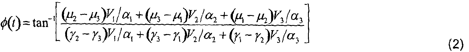 where yn = βη sin (0„ / αη ) and μη = β„ cos (θ„ I „ ) .
Using this technique, an optical wavelength guided to the input of the ZI determined immediately from a single sample on each V^.3
where yn = βη sin (0„ / αη ) and μη = β„ cos (θ„ I „ ) .
Using this technique, an optical wavelength guided to the input of the ZI determined immediately from a single sample on each V^.3
Figure 2 shows a sensor interrogation system for interrogating a plurality of fibre Bragg gratings (FBGs), n, each responsive to different wavelengths. The FBGs are provided on an optical fibre. At one end of the fibre a continuous wave broadband source is provided to inject an interrogation signal into the fibre. A coupler is provided to couple light from the source into the fibre, and to couple light reflected from the plurality of FBGs to a detector. The detector has a course wavelength division multiplexer (CWDM) unit connected to a fast optical path switch, which is in turn connected to the input of a demodulator of the type shown in Figure 1.
The FBG wavelengths and CWDM channel centre wavelengths are matched, so that each channel of the CWDM is associated with a particular FBG. Therefore, every FBG wavelength must be unique and must correspond to a single CWDM channel. Light from the demodulator is input to an analogue to digital converter and processor unit, where it is analysed to determine the wavelength of the light, thereby to allow an assessment of the condition of the system being monitored. This exploits the immediacy of the phase demodulation technique by selecting, at rates limited only by switching speeds and processing capability, which sensor reflection is guided to the interferometer for detection.
In use, the continuous wave broadband source illuminates a wavelength range covering the reflection wavelengths of all sensors within the sensor array. Reflected wavelengths from all sensors return simultaneously and continuously to the CWDM unit, which separates off signals from each sensor onto independent output fibres. An optical path switch, driven by the ADC/Processor unit, is used to guide the reflected signal of each sensor in turn to the demodulation platform where the voltages Vi.n are immediately sampled by the ADC unit and thereafter processed to determine the FBG wavelength. The wavelength switch can select between sensor signals in any order. In addition, the ADC sampling rate may be set to any integer multiple of the switching rate to enable oversampling for the purposes of electronic noise filtering and hence further improved measurement resolution.
The system of Figure 2 has been tested using three sensors, as shown in Figure 3. The three CWD and FBG centre wavelengths were matched (1535 nm, 1545 nm, 1555 nm). Each FBG was bonded to a piezoelectric stack to allow straining of the FBGs by application of voltages. This allows the simulation of straining caused by changes in environmental conditions, which would be experienced in a real monitoring situation. A three-phase voltage transformer was then used to drive all sensors simultaneously. The ADC/Processor unit was configured for 3 kHz switching/sampling rate, allowing for 1 kHz acquisition rate per sensor. The results of various tests are shown in Figures 4 to 6.
Figures 4 (a) - (c) show the signals of each sensor ((a) 1535 nm, (b) 1545 nm, (c) 555 nm) during 50 Hz ac voltage application. The 120° shift between voltage phasors can be clearly seen. The difference in signal amplitudes is due to difference in piezoelectric stack characteristics. Figures 5 (a) - (c) show the frequency domain transform of the signals after phase to strain conversion. This illustrates the excellent signal-to-noise ratio achievable even without anti-alias filtering or sample averaging. Figures 6 (a) - (c) were recorded during application of a single voltage signal at one sensor (Figure 6(a)). This illustrates the independence of measurements and lack of cross-talk while using this scheme. It can be clearly seen that there is no trace of cross-talk between sensors on the spectra of either other sensor (Figures 6 (b) and (c)).
From Figures 5 and 6 the resolution of the interferometric technique is demonstrated to be approximately 10 nanostrains rms before filtering or sample averaging. This contrasts with a 1 microstrain resolution of higher end commercially available interrogation systems, demonstrating a two orders of magnitude improvement. With sample averaging or filtering, this result can be improved by a further order of magnitude.
Figure 7 shows another sensor interrogation system. This is related to the system of Figure 2, in that a CWDM module is used to separate reflected signals from each sensor. However, instead of using a single demodulator, multiple demodulators are provided one for each FBG, so that multiple signals from the CWDM can be simultaneously passed to the demodulators. Hence, instead of selecting and guiding to the demodulation platform each sensor reflection in turn, in Figure 7 all sensor reflections are demodulated and processed in parallel by the ADC/Processor unit. In
this case, the measurement rate is limited only by the capability of the ADC/Processor stage.
Figure 8 shows another interrogation system. This is based on a time division multiplexing scheme that is similar to Figure 2, in that one sensor reflection is guided at a time to the demodulation platform. This system has a pulsed broadband source (PBS) and a plurality of FBGs. Between each FBG is a delay line. The delay lines ensure that after pulsing the source the sensor reflections return in temporal series to the demodulation platform in the order that they are illuminated. A coupler is provided to couple light from the source into the fibre, and to couple light reflected from the plurality of FBGs to a detector. The detector has a demodulator of the type shown in Figure 1 and a threshold detector and ADC, which is connected at its output to a processor. The processor is connected to the pulsed broadband source and the threshold detector and ADC and each of these can be controlled by processing.
In use, the processor sends a signal to the source to cause pulses to be emitted. The pulses travel out towards the FBG sensors, so that each is illuminated and in turn produces a sensor reflection. The delay lines ensure that the time difference between the arrivals of consecutive sensor signals at the demodulation platform is sufficient for one to be recorded and processed before the next arrives. In order to capture the voltage levels V .n as they briefly arrive, the ADC unit and threshold detector are used. Depending on the sampling speed of the ADC unit, several samples can be acquired per single pulse to enable signal averaging for noise reduction. For the time division multiplexing system of Figure 8, the Bragg wavelengths of each sensor are not required to be unique or specified accurately since the system is not multiplexing by way of wavelength division. This allows greater freedom during system design. This is because the sensors can be fabricated to be absolutely identical, simplifying manufacturing, replacements, and the modular nature of installations. Also, the number of sensors can be very large (100s), owing to the TDM nature of the system. This is, in contrast, to the systems of Figures 2 and 7, where WDM limits sensors to the number that can fit within the bandwidth of the source.
Figure 9 shows yet another interrogation system. This uses some of the features of the systems of Figures 2 and 8 by combining TDM and WDM elements to produce a
system that is capable of interrogating multiple sensor arrays. Here, a pulsed broadband source (PBS) is used. At the sensors, arrays of FBGs are separated by delay lines such that a sei of reflections from arrays return simultaneously, with a time difference between the arrivals of array reflections. Upon arrival of the sensor array reflections, a WDM module is used to split sensor wavelengths - λη onto individual output fibres for selection by the optical path switch, as done in Figure 2. The delay between the arrivals of sensor array reflections should be long enough to allow interrogation of all sensors within the array using the switching technique of Figure 2 before the arrival of reflections from the next array. In order to synchronize switching WDM with the arrival of TDM reflections, the processor may wait for illumination at λΊ before proceeding to interrogate other wavelengths.
With this technique, there is a merging of the benefits of both the TDM and WDM techniques. The fast WDM switching interrogation technique may be implemented over not only one but multiple identical sensor arrays, each of which are illuminated in turn by the travelling broadband pulse. In this way, a very large number of sensors may be interrogated. Additionally, each array of wavelength multiplexed sensors, λ\ - λη may be used for monitoring of smaller components of a larger system or plant where the mounting of additional delay lines between individual sensors may be restrictive but placing delay lines between the arrays that are spaced farther apart may not pose the same restriction.
Figure 10 shows a system that is similar to that of Figure 9, but in which the switch is removed and demodulator is provided for every sensor in order to process all sensor array reflections in parallel. As sensor array reflections return during illumination from the pulsed source, the WDM unit separates the reflections of individual sensors within the array onto separate output fibres. Then, before the reflection from the next sensor array arrives, the processor must interrogate all sensors λ, - λ„. Figure 11 shows a system similar to that of Figure 8, except that the wavelength switch (comprised of the combination of WDM module and optical path switch) is replaced by a tunable optical filter (commonly a scanning Fabry-Perot filter (SFP)) that is switched or stepped between different wavelengths, the switched/stepped filter wavelengths corresponding to the wavelengths of the Bragg gratings. Such wavelength filters can be tuned, for example by application of a driving voltage, allowing the filter to replace
the wavelength switch of Figure 2. A step change in the filter centre wavelength may be produced by a stepping, calibrated control voltage signal. In this case, the tunable filter may move swiftly to centre wavelengths ΑΊ - λη. The filter is a broadband filter and is tuned using discrete voltage steps. The stability of its centre wavelength can be relaxed compared to conventional narrowband filters used for reconstruction of detailed FBG reflection spectra. Thus, the same functionality as the CWDIWSwitch combination (selection of sensor reflection for guidance to the demodulation platform) may be achieved by a calibrated SFP module. The transfer function, i.e. wavelength to phase conversion, of the unbalanced ach- Zehnder interferometer of Figure 1 drifts slowly over time with changes in the environmental temperature. Such drift alters the sensitivity of the sensors to changes in measurands. In addition, the device picks up unwanted acoustic noise and vibrations which contribute to the noise level of all sensor signals. In practice, therefore, the interferometer module must be made robust to the external influence of both temperature and vibration. This can be most easily achieved by miniaturisation of the interferometer, for example by fabrication of the device in a compact, monolithic, planar form rather than using fibre couplers. Fabrication of the device in planar form would allow it to be easily potted in vibration-dampening gel, and mounted on a thermoelectrically cooled platform, thus ensuring the robustness of the device to both forms of interference.
After fabrication of the interferometer (either in fibre or planar form) the device must be calibrated to determine the constants required for deployment of Equation (2). To do so, the phase difference φ must be modulated by at least 2π radians, thus driving the interference patterns on all three outputs through at least one maximum and minimum. Then using a straightforward procedure for determining the optical power splitting ratio and the phase angles between 3x3 outputs, such as that described by Schleip ef al, see "Phase sensitive investigations of 3x3 singlemode fibre directional couplers", Elec. Lett. 29, 68-70 (1993), the required parameters a„, bn, and θη as discussed above may be recorded.
The 2π phase modulation required for this calibration procedure can be achieved either by stretching one or both arms of the interferometer, which is feasible for both fibre and planar embodiments of the interferometer. In the fibre embodiment, a piezoelectric
stretcher can be employed to stretch the interferometer arms; in the planar construction, a suitable modulation technique can be used, e.g., utilising electro- or thermo-optic effects or MEMS (micro-electromechanical systems) actuation. Planar MZI modulators are commercially available, e.g., from JDSU, and similar techniques could potentially be adopted in this application. Alternatively, calibration can be achieved through the modulation of the input wavelength. Input wavelength modulation does not require manipulation of the interferometer itself in any way. There are a number of ways by which this may be achieved, the simplest of which may be to guide a strain-modulated FBG reflection through the interferometer temporarily. In general, system calibration would be required infrequently, and could be automated to perform during system 'start up' or when demanded by the user.
To improve stability, a temperature-controlled athermal FBG can be used as a stable wavelength reference (connected in series or in parallel with the sensor gratings) that can be checked periodically to ensure long-term accuracy of the measurements. Adjustment for changes in sensor signal offsets over long periods of time as determined by these periodic checks can easily be automated and would form a component of the processor platform. In many measurement applications, it is desirable not only to know the change in a measurand but also to know its absolute value at some point in time. The scheme described above enables fast, accurate measurement of changes in sensor responses, including both dynamic and quasi-static responses. However, measurements are referenced to the initial state acquired at the 'switch on' time of the system, and are taken relative to this point in time.
To enable absolute measurements, a procedure may be implemented during the 'switch on' initialisation phase which calculates the absolute reflected wavelengths of each sensor, and stores these starting values for use as references during normal operation. In this way, after initialisation, changes in the sensor responses can be tracked continually to enable measurement of absolute wavelength in all sensors with speed and accuracy.
The wavelength-to-phase relationship in the unbalanced Mach-Zehnder interferometer illustrated in Fig. 1 may be described by
2n∞d
φ =
λΒ (3) whereg? is the phase difference at the point of interference, As is the sensor reflected wavelength, and nd is the optical path difference (OPD) between interferometer arms.
As exploited for measurement of the change in sensor response, the phase and wavelength are related by the value of OPD. This invites a reciprocal use of the relationship during initialisation where, instead of a changing sensor wavelength, the OPD may be changed in order to determine the wavelength in absolute terms from the induced change in phase. During the OPD change, phase changes may be acquired from all sensors simultaneously using the multiplexing techniques described previously. Using the recorded phase changes, the absolute value of each individual sensor wavelength may then be found from the formula:
<K)PD
δ (4)
The required sweeping or stepping of the interferometer OPD during initialisation can be achieved by a variety of mechanisms. Fundamentally, the OPD is a function of both the fibre refractive index and the physical path difference between arms. Heating or stretching of one or both arms may therefore be used to tune the OPD. This is commonly achieved using piezoelectric elements to apply strain to one of the fibre arms, or by active temperature control of the ZI unit. However, it will be understood by one versed in the field that a variety of alternative techniques exist to provide this functionality.
As an alternative to continuous scanning of the OPD between two values, it may be preferable to instantaneously step or switch the OPD in order to detect the corresponding step in sensor phases. This could be implemented in a number of ways, including switching the optical path between two ZIs with differing OPDs, or by applying a stepping voltage to a piezoelectric actuator on one MZI arm. After calculating the relationship between OPD step and phase step, Equation (4) may be used to determine input wavelength as previously described.
Where accurate knowledge of the change in OPD during the initialization sweep is not known through calibration or other means, a stable reference wavelength may be used to determine, from the change in phase, the magnitude of the OPD sweep. This value of OPD change may then be used in Equation (4) to calculate initially unknown sensor wavelengths as described. Thus, accurate control of the OPD scan rate or magnitude is not a requirement of this procedure.
The present invention can be used in many different sensing and condition monitoring applications. For example, wind farms require large-scale health monitoring of the mechanical structures and performance monitoring of the associated plant. The present invention could be used for simultaneous measurement of strain, temperature, voltage, current, electric/magnetic fields, and numerous other effects that have to be monitored in wind farms. Also, the invention could be used for protection and security of transmission systems for electrical power delivery, as it is electrically-isolated and can provide immediate knowledge of voltage and current at a number of distributed points along a power line. Furthermore, within the oil and gas sector there is a need to measure pressure at a very high resolution and accuracy. The present invention could be used for all of these applications.
A skilled person will appreciate that variations of the disclosed arrangements are possible without departing from the invention. For example, although the various embodiments of the invention are described as including a 2x3 unbalanced ach- Zehnder, as shown in Figure 1, other interferometer arrangements cound be used to provide the same function, i.e. to convert an input optical wavelength into an optical phase difference and subsequently into three optical intensities. The ratio of these intensities (which may be expressed as the ratio of three voltages after the light is photodetected) may be related back to the phase difference, and finally back to the input optical wavelength. The requirements for this stage are a two-path interferometer that converts the optical wavelength into a phase difference, and a 3x3 coupler that acts as the point of interference and produces the critical mutual phase difference between the three output fibres. Thus, a 3x3 coupler must form the point of interference, and it must be two paths experiencing the same input optical wavelength that are brought to interference.
Although a Mach-Zehnder architecture may be the simplest implementation, the function of this stage could be achieved by other architectures. As an example, Figure 12(a) shows an optical fibre based Michelson interferometer implementation of the same functionality. This has two mirrors separated by a known optical path difference. Light reflected from each mirror is directed into one of two optical fibres and guided to a 3x3 coupler, where it interferes and is split into three different phase components. At the output of the 3x3 coupler are three optical fibres that are coupled to one or three detectors. Each phase component is converted to a voltage at one of the detectors. This phase/voltage measurement is used as before to determine the wavelength of the light. In the arrangement of Figure 12(a) light is input via a light circulator that is coupled with one of the output fibres from the 3x3 coupler. Figure 12(b) shows another Michelson interferometer, in which the circulator is replaced by a second coupler, in this case a 2x1 coupler. Accordingly the above description of the specific embodiment is made by way of example only and not for the purposes of limitation. It will be clear to the skilled person that minor modifications may be made without significant changes to the operation described.
Claims
1. A monitoring system for monitoring a plurality of fibre Bragg gratings in an optical fibre, each fibre Bragg grating being sensitive to a different wavelength of light, the system comprising:
a broadband source for illuminating the optical fibre;
at least one optical interferometer;
light feeding means for feeding to an input of the interferometer light reflected from the fibre Bragg gratings, and
a processor for processing the output from the interferometer to determine the wavelength of the reflected light,
wherein the light feeding means comprise a wavelength division multiplexer operable to separate light received from the optical fibre into a plurality of wavelengths, each associated with one of the fibre Bragg gratings andlor a time division mulitplexer operable to separate light received from the optical fibre into in a time separated series.
2. A monitoring system as claimed in claim 1 , wherein a single optical interferometer is provided and an output of the wavelength division multiplexer is connected to a switch that is operable to selectively switch light from each of the fibre Bragg gratings into the single interferometer in a time separated series.
3. A monitoring system as claimed in claim 1 , wherein multiple optical interferometers are provided, one for every fibre Bragg grating, and the the wavelength division multiplexer has multiple channels, one for every fibre Bragg grating, wherein each output of the wavelength division multiplexer is connected to a corresponding one of the interferometers.
4. A monitoring system as claimed in any of the preceding claims wherein the wavelength division multiplexer comprises a tunable filter that is controlled to step between discrete wavelengths, each associated with one of the fibre Bragg gratings.
5. A monitoring system as claimed in any of the preceding claims wherein the time division mulitplexer comprises one or more delay lines located between each fibre Bragg grating or between groups of fibre Bragg gratings.
6. A monitoring system as claimed in any of the preceding claims, wherein the optical interferometer has a two channel input; and a coupler for allowing interference of light from the two channel inputs and for separating the interfering light into three different phase components.
7. A monitoring system as claimed in claim 5 wherein the optical interferometer is a two by three unbalanced ach-Zehnder interferometer.
8. A monitoring system as claimed in claim 5 wherein the optical interferometer is a two by three ichelson interferometer.
9. A monitoring system as claimed in any of the preceding claims wherein the interferometer is calibrated to measure the absolute wavelength of the received light.
10. A monitoring system as claimed in any of the preceding claims wherein the processor is operable to use the measured wavelengths to determine a measure of one or more of: strain, temperature, voltage, current, and electric/magnetic fields.
11. A method for measuring absolute wavelength in a system having at least one fibre Bragg grating in an optical fibre, each fibre Bragg grating being sensitive to a different wavelength of light, the method comprising:
illuminating the optical fibre with a broadband source; inputting light reflected from the at least one fibre Bragg grating to at least one optical interferometer that has two input arms;
varying the optical path difference between the interferometer arms; and determining the wavelength using any change of phase caused by the change of optical path difference.
12. A method as claimed in claim 11 comprising feeding to the input of the interferometer in a time separeated series light reflected from multiple fibre Bragg gratings; varying the optical path difference between the interferometer arms for light from each fibre Bragg grating; and determining the wavelength associated with each of the fibre Bragg gratings in turn using any change of phase caused by the change of optical path difference.
13. A method as claimed in claim 11 comprising using multiple interferometers, each one associated with one of the fibre Bragg gratings; feeding to the input of each interferometer light reflected from its associated fibre Bragg grating; varying the optical path difference between the interferometer arms; and determining the wavelength associated with each of the fibre Bragg gratings using any change of phase caused by the change of optical path difference.
14. A method as claimed in any of claims 1 to 13 wherein varying the optical path differences involves heating or straining at least one arm of the interferometer. 5. A method as claimed in any of claims 11 to 13 wherein the interferometer is a two by three unbalanced ach-Zehnder interferometer or a two by three Michelson interferometer. 16. A method as claimed in any of claims 11 to 15 wherein a stable reference wavelength is used to determine the change in optical path difference.
Priority Applications (2)
| Application Number | Priority Date | Filing Date | Title |
|---|---|---|---|
| US14/128,621 US9310273B2 (en) | 2011-06-29 | 2012-06-28 | Optical fibre sensor interrogation system |
| EP12738152.3A EP2726824A2 (en) | 2011-06-29 | 2012-06-28 | Optical fibre sensor interrogation system |
Applications Claiming Priority (2)
| Application Number | Priority Date | Filing Date | Title |
|---|---|---|---|
| GBGB1111030.1A GB201111030D0 (en) | 2011-06-29 | 2011-06-29 | Optical fibre sensor interrogation system |
| GB1111030.1 | 2011-06-29 |
Publications (2)
| Publication Number | Publication Date |
|---|---|
| WO2013001268A2 true WO2013001268A2 (en) | 2013-01-03 |
| WO2013001268A3 WO2013001268A3 (en) | 2013-03-07 |
Family
ID=44485344
Family Applications (1)
| Application Number | Title | Priority Date | Filing Date |
|---|---|---|---|
| PCT/GB2012/000556 Ceased WO2013001268A2 (en) | 2011-06-29 | 2012-06-28 | Optical fibre sensor interrogation system |
Country Status (4)
| Country | Link |
|---|---|
| US (1) | US9310273B2 (en) |
| EP (1) | EP2726824A2 (en) |
| GB (1) | GB201111030D0 (en) |
| WO (1) | WO2013001268A2 (en) |
Cited By (6)
| Publication number | Priority date | Publication date | Assignee | Title |
|---|---|---|---|---|
| WO2015024915A1 (en) * | 2013-08-22 | 2015-02-26 | Leoni Kabel Holding Gmbh | Sensor unit |
| WO2015195330A1 (en) * | 2014-06-18 | 2015-12-23 | Weatherford/Lamb, Inc. | Time division multiplexing (tdm) and wavelength division multiplexing (wdm) sensor arrays |
| RU2672794C1 (en) * | 2017-08-22 | 2018-11-19 | Общество с ограниченной ответственностью "Лаборатория электронных и оптических систем" | Physical effects distributed control method and device |
| CN109186646A (en) * | 2018-09-25 | 2019-01-11 | 中铁第四勘察设计院集团有限公司 | A kind of protective door state monitoring method and system |
| WO2020071914A1 (en) * | 2018-10-05 | 2020-04-09 | Technische Universiteit Delft | Interrogation of an optical sensor array |
| EP4650723A1 (en) * | 2024-05-16 | 2025-11-19 | Nederlandse Organisatie voor toegepast-natuurwetenschappelijk Onderzoek TNO | Optical sensor system for detection of a chemical substance |
Families Citing this family (18)
| Publication number | Priority date | Publication date | Assignee | Title |
|---|---|---|---|---|
| US9366691B2 (en) * | 2013-05-02 | 2016-06-14 | Halliburton Energy Services, Inc. | Multiplexed fiber optic sensing system and method |
| US9341057B2 (en) * | 2013-07-18 | 2016-05-17 | Halliburton Energy Services, Inc. | Apparatus and method of distributed pressure sensing |
| US10034546B2 (en) | 2013-09-25 | 2018-07-31 | CommScope Connectivity Belgium BVBA | Device and method for mounting a sensor and for sealing a cabinet |
| US10473492B2 (en) * | 2014-06-23 | 2019-11-12 | Gwangju Institute Of Science And Technology | Optical characteristic measuring apparatus using interrogation optical fiber, optical fiber sensor system having the same, and optical characteristic measuring method |
| GB201413242D0 (en) * | 2014-07-25 | 2014-09-10 | Fotech Solutions Ltd | Distributed Optical Fibre Sensors |
| US10302972B2 (en) | 2015-01-23 | 2019-05-28 | Pacific Biosciences Of California, Inc. | Waveguide transmission |
| WO2017026896A1 (en) * | 2015-08-11 | 2017-02-16 | Optics11 | Optical fiber-based sensor system |
| NL2016277B1 (en) * | 2015-08-11 | 2017-02-28 | Optics11 | Optical fiber-based sensor system. |
| DE102018104953B4 (en) | 2018-03-05 | 2022-05-19 | Hochschule Für Technik Und Wirtschaft Berlin | Measuring device and method for determining a physical measurand |
| CN108259083B (en) * | 2018-04-11 | 2021-12-14 | 金帆智华(北京)科技有限公司 | Method for detecting fault of fiber bragg grating network |
| CN109238320B (en) * | 2018-08-15 | 2020-01-10 | 山东大学 | Fiber grating sensing demodulation system and method based on edge filtering and time division multiplexing |
| CN111780790A (en) * | 2020-06-03 | 2020-10-16 | 华南师范大学 | A device and method for demodulating a dense fiber grating array |
| KR102228641B1 (en) * | 2020-09-25 | 2021-03-17 | (주)에프비지코리아 | Measuring system using fbg sensor |
| CN113091782B (en) * | 2021-04-26 | 2022-04-08 | 太原理工大学 | Phase-sensitive optical time-domain reflectometry system and phase demodulation method based on PGC |
| CN113155165B (en) * | 2021-05-14 | 2022-07-05 | 武汉理工大学 | Interference type demodulation system and method for large-capacity fiber grating sensor network |
| EP4273509B1 (en) * | 2022-05-02 | 2025-01-29 | Omnisens S.A. | Device and method for distributed sensing, preferably in a star network |
| NL2034038B1 (en) * | 2023-01-27 | 2024-08-16 | Photonfirst Tech B V | Detecting light reflected from DBRs using TDM and WDM |
| EP4679028A1 (en) * | 2024-07-12 | 2026-01-14 | Nederlandse Organisatie voor toegepast-natuurwetenschappelijk Onderzoek TNO | A fiber interferometer measurement system and a method |
Citations (2)
| Publication number | Priority date | Publication date | Assignee | Title |
|---|---|---|---|---|
| US5680489A (en) | 1996-06-28 | 1997-10-21 | The United States Of America As Represented By The Secretary Of The Navy | Optical sensor system utilizing bragg grating sensors |
| US20020041722A1 (en) | 2000-08-01 | 2002-04-11 | Johnson Gregg A. | Optical sensing device containing fiber bragg gratings |
Family Cites Families (3)
| Publication number | Priority date | Publication date | Assignee | Title |
|---|---|---|---|---|
| US5987197A (en) * | 1997-11-07 | 1999-11-16 | Cidra Corporation | Array topologies for implementing serial fiber Bragg grating interferometer arrays |
| US6298185B1 (en) | 1999-09-21 | 2001-10-02 | Chung-Shan Institute Of Science And Technology | Distributed fiber grating sensing systems using birefringence fiber interferometers for detecting wavelength shifts |
| ITBN20060004A1 (en) | 2006-09-20 | 2006-12-20 | Antonello Cutolo | FIBER OPTIC TRANSMISSION SYSTEM FOR THE PARAMETER MONITORING AND THE IMPROVEMENT OF THE SAFETY OF A RAILWAY LINE |
-
2011
- 2011-06-29 GB GBGB1111030.1A patent/GB201111030D0/en not_active Ceased
-
2012
- 2012-06-28 US US14/128,621 patent/US9310273B2/en not_active Expired - Fee Related
- 2012-06-28 WO PCT/GB2012/000556 patent/WO2013001268A2/en not_active Ceased
- 2012-06-28 EP EP12738152.3A patent/EP2726824A2/en not_active Ceased
Patent Citations (2)
| Publication number | Priority date | Publication date | Assignee | Title |
|---|---|---|---|---|
| US5680489A (en) | 1996-06-28 | 1997-10-21 | The United States Of America As Represented By The Secretary Of The Navy | Optical sensor system utilizing bragg grating sensors |
| US20020041722A1 (en) | 2000-08-01 | 2002-04-11 | Johnson Gregg A. | Optical sensing device containing fiber bragg gratings |
Non-Patent Citations (5)
| Title |
|---|
| A. D. KERSEY; T. A. BERKOFF; W. W. MOREY: "High- resolution fibre-grating based strain sensor with interferometric wavelength-shift detection", ELEC. LETT., vol. 28, no. 3, 1992, pages 236 - 238, XP000305957 |
| A. D. KERSEY; T. A. BERKOFF; W. W. MOREY: "Multiplexed fiber Bragg grating strain- sensor system with a fiber Fabry-Perot wavelength filter", OPT. LETT., vol. 18, 1993, pages 1370 - 1372, XP000384373 |
| M. D. TODD; M. SEAVER; F. BUCHOLTZ: "Improved, operationally-passive interferometric demodulation method using 3x3 coupler", ELEC. LETT., vol. 38, no. 15, 2002, pages 784 - 786, XP006018572, DOI: doi:10.1049/el:20020569 |
| SCHLEIP: "Phase sensitive investigations of 3x3 singlemode fibre directional couplers", ELEC. LETT., vol. 29, 1993, pages 68 - 70, XP000403921 |
| TODD ET AL.: "A novel Bragg grating sensor interrogation system utilizing a scanning filter, a Mach-Zehnder interferometer and a 3x3 coupler", MEAS. SCI. TECHNOL., vol. 12, 2001, pages 771 - 777, XP001209003, DOI: doi:10.1088/0957-0233/12/7/303 |
Cited By (14)
| Publication number | Priority date | Publication date | Assignee | Title |
|---|---|---|---|---|
| WO2015024915A1 (en) * | 2013-08-22 | 2015-02-26 | Leoni Kabel Holding Gmbh | Sensor unit |
| US10209278B2 (en) | 2013-08-22 | 2019-02-19 | Leoni Kabel Holding Gmbh | Sensor unit |
| GB2542730B (en) * | 2014-06-18 | 2020-07-01 | Weatherford Tech Holdings Llc | Time Division Multiplexing (TDM) and Wavelength Division Multiplexing (WDM) sensor arrays |
| WO2015195330A1 (en) * | 2014-06-18 | 2015-12-23 | Weatherford/Lamb, Inc. | Time division multiplexing (tdm) and wavelength division multiplexing (wdm) sensor arrays |
| US9389174B2 (en) | 2014-06-18 | 2016-07-12 | Weatherford Technology Holdings, Llc | Time division multiplexing (TDM) and wavelength division multiplexing (WDM) sensor arrays |
| GB2542730A (en) * | 2014-06-18 | 2017-03-29 | Weatherford Tech Holdings Llc | Time Division Multiplexing (TDM) and Wavelength Division Multiplexing (WDM) sensor arrays |
| RU2665743C2 (en) * | 2014-06-18 | 2018-09-04 | ВЕЗЕРФОРД ТЕКНОЛОДЖИ ХОЛДИНГЗ, ЭлЭлСи | Sensor matrices for multiplexing with time-separation (mts) and multiplexing with wave length separation (mwls) |
| RU2672794C1 (en) * | 2017-08-22 | 2018-11-19 | Общество с ограниченной ответственностью "Лаборатория электронных и оптических систем" | Physical effects distributed control method and device |
| CN109186646A (en) * | 2018-09-25 | 2019-01-11 | 中铁第四勘察设计院集团有限公司 | A kind of protective door state monitoring method and system |
| CN109186646B (en) * | 2018-09-25 | 2021-01-05 | 中铁第四勘察设计院集团有限公司 | Method and system for monitoring state of protective door |
| NL2021771B1 (en) * | 2018-10-05 | 2020-05-12 | Univ Delft Tech | Interrogation of an optical sensor array |
| WO2020071914A1 (en) * | 2018-10-05 | 2020-04-09 | Technische Universiteit Delft | Interrogation of an optical sensor array |
| EP4650723A1 (en) * | 2024-05-16 | 2025-11-19 | Nederlandse Organisatie voor toegepast-natuurwetenschappelijk Onderzoek TNO | Optical sensor system for detection of a chemical substance |
| WO2025239776A1 (en) * | 2024-05-16 | 2025-11-20 | Nederlandse Organisatie Voor Toegepast-Natuurwetenschappelijk Onderzoek Tno | Optical sensor system for detection of a chemical substance |
Also Published As
| Publication number | Publication date |
|---|---|
| GB201111030D0 (en) | 2011-08-10 |
| EP2726824A2 (en) | 2014-05-07 |
| WO2013001268A3 (en) | 2013-03-07 |
| US20140211202A1 (en) | 2014-07-31 |
| US9310273B2 (en) | 2016-04-12 |
Similar Documents
| Publication | Publication Date | Title |
|---|---|---|
| US9310273B2 (en) | Optical fibre sensor interrogation system | |
| US6674928B2 (en) | Optical sensing device containing fiber Bragg gratings | |
| Weis et al. | A four-element fiber grating sensor array with phase-sensitive detection | |
| Todd et al. | A novel Bragg grating sensor interrogation system utilizing a scanning filter, a Mach-Zehnder interferometer and a 3× 3 coupler | |
| US6888125B2 (en) | Fiber optic sensing systems and method of use thereof | |
| US5754293A (en) | Apparatus for the simultaneous acquisition of high bandwidth information in very long arrays containing large numbers of sensor elements | |
| US6449047B1 (en) | Calibrated swept-wavelength laser and interrogator system for testing wavelength-division multiplexing system | |
| EP0958517A1 (en) | Optical sensor system utilizing bragg grating sensors | |
| CN113218518A (en) | Sine-cosine optical frequency detection device based on integrated optical path and application of sine-cosine optical frequency detection device in optical sensing | |
| CA2272033A1 (en) | Arrangement for determining the temperature and strain of an optical fiber | |
| WO1998036252A1 (en) | Device for measurement of optical wavelengths | |
| CN101271241A (en) | A method and device for multiplexing and demodulating long-period fiber grating arrays | |
| US11162821B2 (en) | Fibre optic sensing device | |
| CN115087845A (en) | High sampling rate optical fiber sensor | |
| Orr et al. | High-speed, solid state, interferometric interrogator and multiplexer for fiber Bragg grating sensors | |
| Zhao et al. | Fiber Bragg grating sensor interrogation using chirped fiber grating-based Sagnac loop | |
| KR100496554B1 (en) | Optical sensor system using Bragg grating sensor | |
| Rao et al. | Simultaneously spatial-, time-, and wavelength-division multiplexed in-fiber Bragg grating sensor network | |
| Jones et al. | Multiplexing optical fiber sensors | |
| Jiang | Four-element fiber Bragg grating acceleration sensor array | |
| KR20230125515A (en) | Multi-channel fiver-optic grating sensor system using double pass interferometer | |
| Todd | Optical Sensing Device Containing Fiber Bragg Gratings | |
| McGarrity et al. | A network for large numbers of interferometric sensors and fiber Bragg gratings with high resolution and extended range | |
| US20130038880A1 (en) | Interrogation of wavelength-specific devices | |
| Kalli et al. | wavelength division and spatial multiplexing of Bragg grating sensor networks using concatenated interferometers |
Legal Events
| Date | Code | Title | Description |
|---|---|---|---|
| 121 | Ep: the epo has been informed by wipo that ep was designated in this application |
Ref document number: 12738152 Country of ref document: EP Kind code of ref document: A2 |
|
| NENP | Non-entry into the national phase |
Ref country code: DE |
|
| WWE | Wipo information: entry into national phase |
Ref document number: 2012738152 Country of ref document: EP |
|
| WWE | Wipo information: entry into national phase |
Ref document number: 14128621 Country of ref document: US |